KR102783986B1 - Method for estimating absolute depth based on relative depth map and optical flow - Google Patents
Method for estimating absolute depth based on relative depth map and optical flow Download PDFInfo
- Publication number
- KR102783986B1 KR102783986B1 KR1020230150215A KR20230150215A KR102783986B1 KR 102783986 B1 KR102783986 B1 KR 102783986B1 KR 1020230150215 A KR1020230150215 A KR 1020230150215A KR 20230150215 A KR20230150215 A KR 20230150215A KR 102783986 B1 KR102783986 B1 KR 102783986B1
- Authority
- KR
- South Korea
- Prior art keywords
- image
- dynamic object
- optical flow
- map
- flow information
- Prior art date
- Legal status (The legal status is an assumption and is not a legal conclusion. Google has not performed a legal analysis and makes no representation as to the accuracy of the status listed.)
- Active
Links
Images


Classifications
-
- G—PHYSICS
- G06—COMPUTING OR CALCULATING; COUNTING
- G06T—IMAGE DATA PROCESSING OR GENERATION, IN GENERAL
- G06T7/00—Image analysis
- G06T7/50—Depth or shape recovery
-
- G—PHYSICS
- G06—COMPUTING OR CALCULATING; COUNTING
- G06T—IMAGE DATA PROCESSING OR GENERATION, IN GENERAL
- G06T7/00—Image analysis
- G06T7/20—Analysis of motion
- G06T7/246—Analysis of motion using feature-based methods, e.g. the tracking of corners or segments
-
- G—PHYSICS
- G06—COMPUTING OR CALCULATING; COUNTING
- G06T—IMAGE DATA PROCESSING OR GENERATION, IN GENERAL
- G06T7/00—Image analysis
- G06T7/20—Analysis of motion
- G06T7/269—Analysis of motion using gradient-based methods
-
- H—ELECTRICITY
- H04—ELECTRIC COMMUNICATION TECHNIQUE
- H04N—PICTORIAL COMMUNICATION, e.g. TELEVISION
- H04N13/00—Stereoscopic video systems; Multi-view video systems; Details thereof
- H04N13/20—Image signal generators
- H04N13/204—Image signal generators using stereoscopic image cameras
- H04N13/207—Image signal generators using stereoscopic image cameras using a single 2D image sensor
-
- H—ELECTRICITY
- H04—ELECTRIC COMMUNICATION TECHNIQUE
- H04N—PICTORIAL COMMUNICATION, e.g. TELEVISION
- H04N13/00—Stereoscopic video systems; Multi-view video systems; Details thereof
- H04N13/20—Image signal generators
- H04N13/271—Image signal generators wherein the generated image signals comprise depth maps or disparity maps
-
- G—PHYSICS
- G06—COMPUTING OR CALCULATING; COUNTING
- G06T—IMAGE DATA PROCESSING OR GENERATION, IN GENERAL
- G06T2207/00—Indexing scheme for image analysis or image enhancement
- G06T2207/10—Image acquisition modality
- G06T2207/10028—Range image; Depth image; 3D point clouds
Landscapes
- Engineering & Computer Science (AREA)
- Multimedia (AREA)
- Computer Vision & Pattern Recognition (AREA)
- Physics & Mathematics (AREA)
- General Physics & Mathematics (AREA)
- Theoretical Computer Science (AREA)
- Signal Processing (AREA)
- Image Analysis (AREA)
Abstract
본 개시는 자율 주행 차량 또는 자율 주행 로봇이 적은 제조 비용 및 연산 비용으로 장애물을 회피하여 주행할 수 있도록, 이미지에 포함된 픽셀의 절대 깊이(Absolute depth)를 추정하기 위한 방법에 대해 개시한다. 구체적으로, 본 개시에 따르면, 컴퓨팅 장치가, 하나의 카메라에서 촬영된 제1 이미지 및 제2 이미지를 기초로, 옵티컬 플로우(Optical Flow) 정보를 생성하고, 상기 제1 이미지에 대하여, 상대 깊이 맵(Relative Depth Map)을 생성하고, 상기 옵티컬 플로우 정보 및 상기 상대 깊이 맵을 기초로, 상기 제1 이미지에 포함된 적어도 하나의 픽셀에 대하여 절대 깊이(Absolute depth)를 추정한다.The present disclosure discloses a method for estimating the absolute depth of a pixel included in an image so that an autonomous vehicle or an autonomous robot can drive while avoiding obstacles with low manufacturing cost and computational cost. Specifically, according to the present disclosure, a computing device generates optical flow information based on a first image and a second image captured by one camera, generates a relative depth map for the first image, and estimates the absolute depth for at least one pixel included in the first image based on the optical flow information and the relative depth map.
Description
본 개시는 이미지에 포함된 픽셀의 절대 깊이를 추정하는 방법에 관한 것으로, 구체적으로 자율 주행 차량이나 로봇 등에 탑재된 하나의 카메라에서 촬영된 복수의 이미지를 기초로 상대 깊이 맵 및 옵티컬 플로우를 활용하여 이미지에 포함된 적어도 하나의 픽셀에 대하여 절대 깊이를 추정하는 방법에 관한 것이다.The present disclosure relates to a method for estimating the absolute depth of a pixel included in an image, and more particularly, to a method for estimating the absolute depth for at least one pixel included in an image by utilizing a relative depth map and optical flow based on a plurality of images captured by a single camera mounted on an autonomous vehicle or robot.
장애물을 회피하여 움직이는 자율 주행 차량이나 로봇은 주변 환경에 존재하는 사물과의 거리를 고려하여 규칙 또는 기계 학습 모델을 활용하여 주행 경로를 생성한다. 따라서 입력 장치로부터 획득된 정보로부터 주변의 사물과의 거리에 관한 정보를 추정하는 과정은 차량 또는 로봇이 장애물을 성공적으로 회피하며 주행하기 위해 필수적인 요소이다.Autonomous vehicles or robots that move while avoiding obstacles generate driving paths by considering the distances to objects in the surrounding environment using rules or machine learning models. Therefore, the process of estimating information about the distances to objects in the surroundings from information obtained from input devices is an essential element for vehicles or robots to successfully avoid obstacles and drive.
근래 컴퓨터 비전 즉 시각으로 관측할 수 있는 세계를 해석하고 이해할 수 있는 인공지능 모델을 구축함으로써 장애물 회피 주행을 구현하려는 시도가 증가하였다. 그러나 인공지능 모델을 활용한 종래의 접근방법에서는 여전히 외부 환경에 존재하는 사물과의 거리를 연산하기 위해 복수의 서로 다른 카메라로부터 촬영된 이미지 또는 LiDAR(Light Detection And Ranging) 시스템이 필수적으로 사용되었다. 그러나 탑재된 카메라의 수를 증가시키는 것은 차량 또는 로봇의 제조 비용 상승으로 이어지고, LiDAR 시스템을 위한 장비는 구동을 위해 필요한 부피가 상당히 크기 때문에 차량 또는 로봇의 소형화에 한계가 발생한다.Recently, attempts to implement obstacle avoidance driving by building an artificial intelligence model that can interpret and understand the world that can be observed visually, that is, computer vision, have increased. However, conventional approaches utilizing artificial intelligence models still require images captured from multiple different cameras or LiDAR (Light Detection And Ranging) systems to calculate the distance to objects in the external environment. However, increasing the number of mounted cameras leads to an increase in the manufacturing cost of the vehicle or robot, and the equipment for the LiDAR system requires a considerable volume for operation, which limits the miniaturization of the vehicle or robot.
따라서, 낮은 제조비용으로, 소형의 차량 또는 로봇에 적용 가능한, 주변 사물과의 거리에 관한 정보를 추정하는 방법 즉 절대 깊이(Absolute depth)를 추정하는 방법에 대한 당업계의 수요가 존재한다.Therefore, there is a demand in the art for a method of estimating information about the distance to surrounding objects, i.e., an absolute depth estimation method, which can be applied to small vehicles or robots at low manufacturing cost.
한국 등록특허 KR 2566417 B1는 작업 수행 로봇의 작업 경로의 길이를 계산하는 방법에 대해 개시한다.Korean registered patent KR 2566417 B1 discloses a method for calculating the length of a work path of a work performing robot.
본 개시는 전술한 배경 기술에 대응하여 안출된 것으로, 하나의 카메라에서 촬영된 복수의 이미지를 기초로 상대 깊이 맵 및 옵티컬 플로우를 활용하여, 이미지에 포함된 적어도 하나의 픽셀에 대하여 절대 깊이를 추정하는 것을 목적으로 한다. The present disclosure is made in response to the aforementioned background technology, and aims to estimate absolute depth for at least one pixel included in an image by utilizing a relative depth map and optical flow based on a plurality of images captured by a single camera.
한편, 본 개시가 이루고자 하는 기술적 과제는 이상에서 언급한 기술적 과제로 제한되지 않으며, 이하에서 설명할 내용으로부터 통상의 기술자에게 자명한 범위 내에서 다양한 기술적 과제가 포함될 수 있다.Meanwhile, the technical problems to be achieved by the present disclosure are not limited to the technical problems mentioned above, and various technical problems may be included within a scope obvious to those skilled in the art from the contents to be described below.
전술한 바와 같은 과제를 실현하기 위한 본 개시의 일 실시예에 따라, 이미지에 포함된 픽셀의 절대 깊이를 추정하기 위해 컴퓨팅 장치에 의해 수행되는 방법이 개시된다. 상기 방법은, 하나의 카메라에서 촬영된 제1 이미지 및 제2 이미지를 기초로, 옵티컬 플로우(Optical Flow) 정보를 생성하는 단계; 상기 제1 이미지에 대하여, 상대 깊이 맵(Relative Depth Map)을 생성하는 단계 및 상기 옵티컬 플로우 정보 및 상기 상대 깊이 맵을 기초로, 상기 제1 이미지에 포함된 적어도 하나의 픽셀에 대하여 절대 깊이(Absolute depth)를 추정하는 단계를 포함할 수 있다.According to one embodiment of the present disclosure for achieving the above-described task, a method performed by a computing device for estimating an absolute depth of a pixel included in an image is disclosed. The method may include a step of generating optical flow information based on a first image and a second image captured by a single camera; a step of generating a relative depth map with respect to the first image; and a step of estimating an absolute depth with respect to at least one pixel included in the first image based on the optical flow information and the relative depth map.
일 실시예에서, 상기 옵티컬 플로우 정보 및 상기 상대 깊이 맵을 기초로, 상기 제1 이미지에 포함된 적어도 하나의 픽셀에 대하여 절대 깊이를 추정하는 단계는: 상기 옵티컬 플로우 정보를 기초로, 상기 제1 이미지에 포함된 동적 객체를 검출하는 단계; 상기 동적 객체를 기초로, 변환 계수를 산출하는 단계 및 상기 변환 계수 및 상기 상대 깊이 맵을 기초로, 상기 제1 이미지에 포함된 적어도 하나의 픽셀에 대하여 상기 절대 깊이를 추정하는 단계를 포함할 수 있다.In one embodiment, the step of estimating an absolute depth for at least one pixel included in the first image based on the optical flow information and the relative depth map may include: the step of detecting a dynamic object included in the first image based on the optical flow information; the step of calculating a transformation coefficient based on the dynamic object; and the step of estimating the absolute depth for at least one pixel included in the first image based on the transformation coefficient and the relative depth map.
일 실시예에서, 상기 옵티컬 플로우 정보를 기초로, 상기 제1 이미지에 포함된 동적 객체를 검출하는 단계는: 상기 카메라의 위치 및 운동 정보에 더 기초하여, 상기 제1 이미지에 포함된 제1 동적 객체를 검출하는 단계; 상기 제1 동적 객체의 정보를 기초로, 제1 이미지 중 제1 동적 객체 이외의 영역에서 제2 동적 객체를 검출하는 단계 및 상기 제1 동적 객체 및 상기 제2 동적 객체를 상기 동적 객체로 결정하는 단계를 포함할 수 있다.In one embodiment, the step of detecting a dynamic object included in the first image based on the optical flow information may include: the step of detecting a first dynamic object included in the first image based further on position and motion information of the camera; the step of detecting a second dynamic object in an area other than the first dynamic object in the first image based on information of the first dynamic object; and the step of determining the first dynamic object and the second dynamic object as the dynamic objects.
일 실시예에서, 상기 검출된 동적 객체를 기초로, 변환 계수를 산출하는 단계는: 상기 제1 이미지 중 상기 동적 객체를 제외한 하나 이상의 영역 각각에 대하여 하나 이상의 후보 변환 계수를 산출하는 단계 및 상기 하나 이상의 후보 변환 계수를 기초로, 상기 변환 계수를 결정하는 단계를 포함할 수 있다.In one embodiment, the step of calculating transformation coefficients based on the detected dynamic object may include: calculating one or more candidate transformation coefficients for each of one or more regions of the first image excluding the dynamic object; and determining the transformation coefficients based on the one or more candidate transformation coefficients.
일 실시예에서, 상기 하나 이상의 후보 변환 계수를 기초로, 상기 변환 계수를 결정하는 단계는: 상기 하나 이상의 후보 변환 계수의 분포를 기초로, 상기 변환 계수를 결정하는 단계를 포함할 수 있다.In one embodiment, the step of determining the transform coefficient based on the one or more candidate transform coefficients may include the step of determining the transform coefficient based on a distribution of the one or more candidate transform coefficients.
일 실시예에서, 상기 방법은, 상기 적어도 하나의 픽셀에 대하여 추정된 절대 깊이를 기초로, 상기 제1 이미지에 대한 3D 맵을 생성하는 단계를 더 포함할 수 있다.In one embodiment, the method may further comprise generating a 3D map for the first image based on the estimated absolute depth for the at least one pixel.
일 실시예에서, 상기 제1 이미지에 대한 3D 맵을 생성하는 단계는: 상기 적어도 하나의 픽셀에 대하여 추정된 절대 깊이 및 상기 상대 깊이 맵을 기초로, 상기 제1 이미지에 대한 3D 맵을 생성하는 단계를 포함할 수 있다.In one embodiment, the step of generating a 3D map for the first image may include: generating a 3D map for the first image based on the estimated absolute depth and the relative depth map for the at least one pixel.
일 실시예에서, 상기 제1 이미지에 대한 3D 맵을 생성하는 단계는: 상기 옵티컬 플로우 정보에 더 기초하여, 상기 제1 이미지에 대한 3D 맵을 생성하는 단계를 포함할 수 있다.In one embodiment, the step of generating a 3D map for the first image may include: generating a 3D map for the first image further based on the optical flow information.
일 실시예에서, 상기 옵티컬 플로우 정보에 더 기초하여, 상기 제1 이미지에 대한 3D 맵을 생성하는 단계는: 상기 옵티컬 플로우를 기초로, 상기 제1 이미지에 포함된 동적 객체를 검출하는 단계; 상기 절대 깊이 및 상기 상대 깊이 맵을 기초로, 상기 동적 객체에 대한 3D 맵을 생성하는 단계 및 상기 옵티컬 플로우 정보에 기초하여, 상기 제1 이미지 중 상기 동적 객체를 제외한 영역에 대한 3D 맵을 생성하는 단계를 포함할 수 있다.In one embodiment, the step of generating a 3D map for the first image further based on the optical flow information may include: the step of detecting a dynamic object included in the first image based on the optical flow; the step of generating a 3D map for the dynamic object based on the absolute depth and relative depth maps; and the step of generating a 3D map for an area of the first image excluding the dynamic object based on the optical flow information.
전술한 바와 같은 과제를 실현하기 위한 본 개시의 일 실시예에 따라, 컴퓨팅 장치로 하여금 이미지에 포함된 픽셀의 절대 깊이를 추정하기 위한 동작들을 수행하도록 하는 컴퓨터 판독가능 저장 매체에 저장된 컴퓨터 프로그램이 개시된다. 상기 동작들은: 하나의 카메라에서 촬영된 제1 이미지 및 제2 이미지를 기초로, 옵티컬 플로우 정보를 생성하는 동작; 상기 제1 이미지에 대하여, 상대 깊이 맵을 생성하는 동작 및 상기 옵티컬 플로우 정보 및 상기 상대 깊이 맵을 기초로, 상기 제1 이미지에 포함된 적어도 하나의 픽셀에 대하여 절대 깊이를 추정하는 동작을 포함할 수 있다.According to one embodiment of the present disclosure for achieving the above-described task, a computer program stored in a computer-readable storage medium is disclosed which causes a computing device to perform operations for estimating an absolute depth of a pixel included in an image. The operations may include: an operation for generating optical flow information based on a first image and a second image captured by a single camera; an operation for generating a relative depth map with respect to the first image; and an operation for estimating an absolute depth with respect to at least one pixel included in the first image based on the optical flow information and the relative depth map.
전술한 바와 같은 과제를 실현하기 위한 본 개시의 일 실시예에 따라, 이미지에 포함된 픽셀의 절대 깊이를 추정하기 위한 컴퓨팅 장치가 개시된다. 상기 컴퓨팅 장치는 하나 이상의 프로세서 및 메모리를 포함하고, 상기 하나 이상의 프로세서는, 하나의 카메라에서 촬영된 제1 이미지 및 제2 이미지를 기초로, 옵티컬 플로우 정보를 생성하고, 상기 제1 이미지에 대하여, 상대 깊이 맵을 생성하고, 그리고 상기 옵티컬 플로우 정보 및 상기 상대 깊이 맵을 기초로, 상기 제1 이미지에 포함된 적어도 하나의 픽셀에 대하여 절대 깊이를 추정할 수 있다.According to one embodiment of the present disclosure for achieving the above-described task, a computing device for estimating an absolute depth of a pixel included in an image is disclosed. The computing device includes one or more processors and a memory, and the one or more processors are capable of generating optical flow information based on a first image and a second image captured by one camera, generating a relative depth map for the first image, and estimating an absolute depth for at least one pixel included in the first image based on the optical flow information and the relative depth map.
도 1은 본 개시의 일 실시예에 따른 이미지에 포함된 픽셀의 절대 깊이를 추정하기 위한 컴퓨팅 장치의 블록 구성도이다.
도 2는 본 개시의 일 실시예에 따른 네트워크 함수를 나타낸 개략도이다.
도 3은 본 개시의 일 실시예에 따른 이미지에 포함된 픽셀의 절대 깊이를 추정하는 과정을 나타낸 순서도이다.
도 4는 본 개시의 일 실시예에 따른 이미지에 포함된 픽셀의 절대 깊이를 추정하고 차량 또는 로봇을 구동하는 과정을 설명하기 위한 개념도이다.
도 5는 본 개시의 일 실시예에 따른 전처리 모듈의 세부 구성을 나타낸 개념도이다.
도 6은 본 개시의 일 실시예에 따른 제1 이미지로부터 동적 객체를 검출하는 과정을 나타낸 개념도이다.
도 7은 본 개시의 일 실시예에 따른 변환 계수 산출 모듈에서 하나 이상의 후보 변환 계수를 기초로 변환 계수를 결정하는 과정을 나타낸 개념도이다.
도 8은 본 개시의 일 실시예에 따른 이미지에 대한 3D 맵을 나타낸 개념도이다.
도 9는 본 개시의 실시예들이 구현될 수 있는 예시적인 컴퓨팅 환경에 대한 간략하고 일반적인 개략도이다.FIG. 1 is a block diagram of a computing device for estimating the absolute depth of a pixel included in an image according to one embodiment of the present disclosure.
FIG. 2 is a schematic diagram illustrating a network function according to one embodiment of the present disclosure.
FIG. 3 is a flowchart illustrating a process for estimating the absolute depth of a pixel included in an image according to one embodiment of the present disclosure.
FIG. 4 is a conceptual diagram for explaining a process of estimating the absolute depth of a pixel included in an image and driving a vehicle or robot according to one embodiment of the present disclosure.
FIG. 5 is a conceptual diagram showing a detailed configuration of a preprocessing module according to one embodiment of the present disclosure.
FIG. 6 is a conceptual diagram illustrating a process of detecting a dynamic object from a first image according to one embodiment of the present disclosure.
FIG. 7 is a conceptual diagram illustrating a process of determining a transform coefficient based on one or more candidate transform coefficients in a transform coefficient calculation module according to one embodiment of the present disclosure.
FIG. 8 is a conceptual diagram illustrating a 3D map for an image according to one embodiment of the present disclosure.
FIG. 9 is a simplified, general schematic diagram of an exemplary computing environment in which embodiments of the present disclosure may be implemented.
본 개시는 하나의 카메라에서 촬영된 복수의 이미지를 기초로 상대 깊이 맵 및 옵티컬 플로우를 활용하여 이미지에 포함된 적어도 하나의 픽셀에 대하여 절대 깊이를 추정하는 방법에 대해 개시한다.The present disclosure discloses a method for estimating absolute depth for at least one pixel included in an image by utilizing a relative depth map and optical flow based on multiple images captured by a single camera.
다양한 실시예들이 이제 도면을 참조하여 설명된다. 본 명세서에서, 다양한 설명들이 본 개시의 이해를 제공하기 위해서 제시된다. 그러나, 이러한 실시예들은 이러한 구체적인 설명 없이도 실행될 수 있음이 명백하다.Various embodiments are now described with reference to the drawings. In this specification, various descriptions are set forth to provide an understanding of the present disclosure. However, it will be apparent that these embodiments may be practiced without these specific descriptions.
본 명세서에서 사용되는 용어 "컴포넌트", "모듈", "시스템" 등은 컴퓨터-관련 엔티티, 하드웨어, 펌웨어, 소프트웨어, 소프트웨어 및 하드웨어의 조합, 또는 소프트웨어의 실행을 지칭한다. 예를 들어, 컴포넌트는 프로세서상에서 실행되는 처리과정(procedure), 프로세서, 객체, 실행 스레드, 프로그램, 및/또는 컴퓨터일 수 있지만, 이들로 제한되는 것은 아니다. 예를 들어, 컴퓨팅 장치에서 실행되는 애플리케이션 및 컴퓨팅 장치 모두 컴포넌트일 수 있다. 하나 이상의 컴포넌트는 프로세서 및/또는 실행 스레드 내에 상주할 수 있다. 일 컴포넌트는 하나의 컴퓨터 내에 로컬화 될 수 있다. 일 컴포넌트는 2개 이상의 컴퓨터들 사이에 분배될 수 있다. 또한, 이러한 컴포넌트들은 그 내부에 저장된 다양한 데이터 구조들을 갖는 다양한 컴퓨터 판독가능한 매체로부터 실행할 수 있다. 컴포넌트들은 예를 들어 하나 이상의 데이터 패킷들을 갖는 신호(예를 들면, 로컬 시스템, 분산 시스템에서 다른 컴포넌트와 상호작용하는 하나의 컴포넌트로부터의 데이터 및/또는 신호를 통해 다른 시스템과 인터넷과 같은 네트워크를 통해 전송되는 데이터)에 따라 로컬 및/또는 원격 처리들을 통해 통신할 수 있다.The terms "component," "module," "system," and the like, as used herein, refer to a computer-related entity, hardware, firmware, software, a combination of software and hardware, or an execution of software. For example, a component may be, but is not limited to, a procedure running on a processor, a processor, an object, a thread of execution, a program, and/or a computer. For example, an application running on a computing device and the computing device may both be components. One or more components may reside within a processor and/or a thread of execution. A component may be localized within a single computer. A component may be distributed between two or more computers. Furthermore, such components may execute from various computer-readable media having various data structures stored therein. The components may communicate via local and/or remote processes, for example, by a signal comprising one or more data packets (e.g., data from one component interacting with another component in a local system, a distributed system, and/or data transmitted via a network such as the Internet to another system via the signal).
더불어, 용어 "또는"은 배타적 "또는"이 아니라 내포적 "또는"을 의미하는 것으로 의도된다. 즉, 달리 특정되지 않거나 문맥상 명확하지 않은 경우에, "X는 A 또는 B를 이용한다"는 자연적인 내포적 치환 중 하나를 의미하는 것으로 의도된다. 즉, X가 A를 이용하거나; X가 B를 이용하거나; 또는 X가 A 및 B 모두를 이용하는 경우, "X는 A 또는 B를 이용한다"가 이들 경우들 어느 것으로도 적용될 수 있다. 또한, 본 명세서에 사용된 "및/또는"이라는 용어는 열거된 관련 아이템들 중 하나 이상의 아이템의 가능한 모든 조합을 지칭하고 포함하는 것으로 이해되어야 한다.Additionally, the term "or" is intended to mean an inclusive "or" rather than an exclusive "or." That is, unless otherwise specified or clear from the context, "X employs A or B" is intended to mean either of the natural inclusive permutations. That is, if X employs A; X employs B; or X employs both A and B, "X employs A or B" can apply to any of these cases. Furthermore, the term "and/or" as used herein should be understood to refer to and include all possible combinations of one or more of the associated items listed.
또한, "포함한다" 및/또는 "포함하는"이라는 용어는, 해당 특징 및/또는 구성요소가 존재함을 의미하는 것으로 이해되어야 한다. 다만, "포함한다" 및/또는 "포함하는"이라는 용어는, 하나 이상의 다른 특징, 구성요소 및/또는 이들의 그룹의 존재 또는 추가를 배제하지 않는 것으로 이해되어야 한다. 또한, 달리 특정되지 않거나 단수 형태를 지시하는 것으로 문맥상 명확하지 않은 경우에, 본 명세서와 청구범위에서 단수는 일반적으로 "하나 또는 그 이상"을 의미하는 것으로 해석되어야 한다.Also, the terms "comprises" and/or "comprising" should be understood to mean the presence of the features and/or components. However, it should be understood that the terms "comprises" and/or "comprising" do not exclude the presence or addition of one or more other features, components, and/or groups thereof. Also, unless otherwise specified or clear from the context to refer to the singular form, the singular form as used in the specification and claims should generally be construed to mean "one or more."
그리고, “A 또는 B 중 적어도 하나”이라는 용어는, “A만을 포함하는 경우”, “B만을 포함하는 경우”, “A 와 B의 구성으로 조합된 경우”를 의미하는 것으로 해석되어야 한다. And, the term “at least one of A or B” should be interpreted to mean “if it includes only A,” “if it includes only B,” or “if it is combined in the composition of A and B.”
통상의 기술자들은 추가적으로 여기서 개시된 실시예들과 관련되어 설명된 다양한 예시적 논리적 블록들, 구성들, 모듈들, 회로들, 수단들, 로직들, 및 알고리즘 단계들이 전자 하드웨어, 컴퓨터 소프트웨어, 또는 양쪽 모두의 조합들로 구현될 수 있음을 인식해야 한다. 하드웨어 및 소프트웨어의 상호교환성을 명백하게 예시하기 위해, 다양한 예시적 컴포넌트들, 블록들, 구성들, 수단들, 로직들, 모듈들, 회로들, 및 단계들은 그들의 기능성 측면에서 일반적으로 위에서 설명되었다. 그러한 기능성이 하드웨어로 또는 소프트웨어로서 구현되는지 여부는 전반적인 시스템에 부과된 특정 어플리케이션(application) 및 설계 제한들에 달려 있다. 숙련된 기술자들은 각각의 특정 어플리케이션들을 위해 다양한 방법들로 설명된 기능성을 구현할 수 있다. 다만, 그러한 구현의 결정들이 본 개시내용의 영역을 벗어나게 하는 것으로 해석되어서는 안 된다.Those skilled in the art should additionally recognize that the various illustrative logical blocks, configurations, modules, circuits, means, logics, and algorithm steps described in connection with the embodiments disclosed herein may be implemented as combinations of electronic hardware, computer software, or both. To clearly illustrate the interchangeability of hardware and software, various illustrative components, blocks, configurations, means, logics, modules, circuits, and steps have been described above generally in terms of their functionality. Whether such functionality is implemented as hardware or software depends upon the particular application and design constraints imposed on the overall system. Skilled artisans may implement the described functionality in varying ways for each particular application. However, such implementation decisions should not be interpreted as causing a departure from the scope of the present disclosure.
제시된 실시예들에 대한 설명은 본 개시의 기술 분야에서 통상의 지식을 가진 자가 본 개시를 이용하거나 또는 실시할 수 있도록 제공된다. 이러한 실시예들에 대한 다양한 변형들은 본 개시의 기술 분야에서 통상의 지식을 가진 자에게 명백할 것이다. 여기에 정의된 일반적인 원리들은 본 개시의 범위를 벗어남이 없이 다른 실시예들에 적용될 수 있다. 그리하여, 본 개시는 여기에 제시된 실시예 들로 한정되는 것이 아니다. 본 개시는 여기에 제시된 원리들 및 신규한 특징들과 일관되는 최광의의 범위에서 해석되어야 할 것이다. The description of the disclosed embodiments is provided to enable a person skilled in the art to make or use the present disclosure. Various modifications to these embodiments will be apparent to a person skilled in the art. The general principles defined herein may be applied to other embodiments without departing from the scope of the present disclosure. Thus, the present disclosure is not limited to the embodiments set forth herein. The present disclosure is to be accorded the widest scope consistent with the principles and novel features disclosed herein.
본 개시에서 옵티컬 플로우(optical flow)란 복수의 이미지에 대하여, 이미지 내에 포함된 픽셀 또는 픽셀의 집합체인 객체(object)의 움직임 패턴을 의미할 수 있다. 이 때 복수의 이미지는 카메라에서 일정 시간 간격으로 촬영된 복수의 정지 사진일 수 있고, 비디오의 연속된 프레임일 수 있다.In the present disclosure, optical flow may refer to a movement pattern of an object, which is a pixel or a collection of pixels, included in an image, for a plurality of images. In this case, the plurality of images may be a plurality of still pictures captured by a camera at regular time intervals, or may be consecutive frames of a video.
본 개시에서 상대 깊이 맵(Realative depth map) 은 컴퓨터 비전 및 이미지 처리 분야에서 사용되는 개념으로, 입체적인 사물을 표현한 2D 이미지에서 이미지에 포함된 객체들 간의 상대적인 깊이를 나타내는 정보를 의미할 수 있다. 일반적으로, 상대 깊이 맵은 객체가 카메라 등으로부터 얼마나 떨어져 있는지를 상대적으로 표현하는 정보일 수 있다. 예를 들어, 상대 깊이 맵은 2D 이미지의 각 픽셀에 대하여 픽셀의 상대 깊이를 0에서 1사이의 실수 값으로 표현된 정보일 수 있으며, 객체가 카메라에 가까울수록 1에 가까운 값을 가지고, 객체가 카메라로부터 멀리 떨어져 있을수록 0에 가까운 값을 가지도록 설정될 수 있다.In the present disclosure, a relative depth map is a concept used in the fields of computer vision and image processing, and may mean information indicating the relative depth between objects included in a 2D image expressing a three-dimensional object. In general, a relative depth map may be information that relatively expresses how far an object is from a camera, etc. For example, a relative depth map may be information that expresses the relative depth of each pixel of a 2D image as a real number value between 0 and 1, and may be set such that the closer an object is to the camera, the closer the value is to 1, and the farther the object is from the camera, the closer the value is to 0.
본 개시에서 절대 깊이(Absolute depth)는 이미지에 포함된 픽셀 또는 객체의 깊이를 나타내는 정보를 의미할 수 있다. 예를 들어 카메라가 촬영한 이미지에 포함된 픽셀에 대하여, 해당 픽셀의 절대 깊이는 '80cm', '1m'와 같은 값으로 표현될 수 있다.In the present disclosure, absolute depth may mean information indicating the depth of a pixel or object included in an image. For example, for a pixel included in an image captured by a camera, the absolute depth of the pixel may be expressed as a value such as '80 cm' or '1 m'.
도 1은 본 개시의 일 실시예에 따른 이미지에 포함된 픽셀의 절대 깊이를 추정하기 위한 컴퓨팅 장치의 블록 구성도이다.FIG. 1 is a block diagram of a computing device for estimating the absolute depth of a pixel included in an image according to one embodiment of the present disclosure.
도 1에 도시된 컴퓨팅 장치(100)의 구성은 간략화 하여 나타낸 예시일 뿐이다. 본 개시의 일 실시예에서 컴퓨팅 장치(100)는 컴퓨팅 장치(100)의 컴퓨팅 환경을 수행하기 위한 다른 구성들이 포함될 수 있고, 개시된 구성들 중 일부만이 컴퓨팅 장치(100)를 구성할 수도 있다. The configuration of the computing device (100) illustrated in FIG. 1 is only a simplified example. In one embodiment of the present disclosure, the computing device (100) may include other configurations for performing a computing environment of the computing device (100), and only some of the disclosed configurations may constitute the computing device (100).
컴퓨팅 장치(100)는 프로세서(110), 메모리(130), 네트워크부(150)를 포함할 수 있다.A computing device (100) may include a processor (110), a memory (130), and a network unit (150).
프로세서(110)는 하나 이상의 코어로 구성될 수 있으며, 컴퓨팅 장치의 중앙 처리 장치(CPU: central processing unit), 범용 그래픽 처리 장치 (GPGPU: general purpose graphics processing unit), 텐서 처리 장치(TPU: tensor processing unit) 등의 데이터 분석, 딥러닝을 위한 프로세서를 포함할 수 있다. 프로세서(110)는 메모리(130)에 저장된 컴퓨터 프로그램을 판독하여 본 개시의 일 실시예에 따른 기계 학습을 위한 데이터 처리를 수행할 수 있다. 본 개시의 일실시예에 따라 프로세서(110)는 신경망의 학습을 위한 연산을 수행할 수 있다. 프로세서(110)는 딥러닝(DL: deep learning)에서 학습을 위한 입력 데이터의 처리, 입력 데이터에서의 피처 추출, 오차 계산, 역전파(backpropagation)를 이용한 신경망의 가중치 업데이트 등의 신경망의 학습을 위한 계산을 수행할 수 있다. The processor (110) may be composed of one or more cores, and may include a processor for data analysis and deep learning, such as a central processing unit (CPU), a general purpose graphics processing unit (GPGPU), and a tensor processing unit (TPU) of a computing device. The processor (110) may read a computer program stored in the memory (130) and perform data processing for machine learning according to an embodiment of the present disclosure. According to an embodiment of the present disclosure, the processor (110) may perform operations for learning a neural network. The processor (110) may perform calculations for learning a neural network, such as processing input data for learning in deep learning (DL), extracting features from input data, calculating errors, and updating weights of a neural network using backpropagation.
프로세서(110)의 CPU, GPGPU, 및 TPU 중 적어도 하나가 네트워크 함수의 학습을 처리할 수 있다. 예를 들어, CPU 와 GPGPU가 함께 네트워크 함수의 학습, 네트워크 함수를 이용한 데이터 분류를 처리할 수 있다. 또한, 본 개시의 일 실시예에서 복수의 컴퓨팅 장치의 프로세서를 함께 사용하여 네트워크 함수의 학습, 네트워크 함수를 이용한 데이터 분류를 처리할 수 있다. 또한, 본 개시의 일 실시예에 따른 컴퓨팅 장치에서 수행되는 컴퓨터 프로그램은 CPU, GPGPU 또는 TPU 실행가능 프로그램일 수 있다.At least one of the CPU, GPGPU, and TPU of the processor (110) can process learning of a network function. For example, the CPU and the GPGPU can process learning of a network function and data classification using the network function together. In addition, in one embodiment of the present disclosure, processors of a plurality of computing devices can be used together to process learning of a network function and data classification using the network function. In addition, a computer program executed in a computing device according to one embodiment of the present disclosure can be a CPU, GPGPU, or TPU executable program.
프로세서(110)는 제1 이미지 및 제2 이미지를 획득할 수 있다. 본 개시에서 제1 이미지 및 제2 이미지는 하나의 카메라에서 촬영된 이미지일 수 있다. 예를 들어, 본 개시에서 이동 상태에 있는 하나의 카메라가 연속적으로 촬영한 영상에서 추출된 하나의 프레임이 제1 이미지, 그 직전 프레임이 제2 이미지일 수 있다. 이와 달리 하나의 프레임이 제1 이미지, 그 직후 프레임이 제2 이미지로 하여 본 개시의 방법을 구현할 수 있음은 통상의 기술자에게 명백할 것이다.The processor (110) can obtain the first image and the second image. In the present disclosure, the first image and the second image may be images captured by one camera. For example, in the present disclosure, one frame extracted from an image captured continuously by one camera in a moving state may be the first image, and the frame immediately before it may be the second image. Alternatively, it will be apparent to those skilled in the art that the method of the present disclosure may be implemented by having one frame be the first image and the frame immediately after it be the second image.
본 개시에서 프로세서(110)와 카메라는 동일한 장치에 탑재되어 카메라가 촬영한 이미지를 바로 프로세서(110)가 획득할 수 있다. 또 다른 예시로, 카메라와 프로세서(110)는 물리적으로 분리된 공간에 존재하고 카메라가 촬영한 이미지를 컴퓨팅 장치(100)의 네트워크부(150)를 통해 수신함으로써 프로세서(110)가 이미지를 획득할 수 있다.In the present disclosure, the processor (110) and the camera are mounted on the same device so that the processor (110) can directly obtain an image captured by the camera. As another example, the camera and the processor (110) exist in physically separate spaces, and the processor (110) can obtain an image by receiving an image captured by the camera through the network unit (150) of the computing device (100).
프로세서(110)는 제1 이미지 및 제2 이미지를 기초로, 옵티컬 플로우 정보를 생성할 수 있다. 제1 이미지 및 제2 이미지가 하나의 카메라에서 촬영된 연속적인 이미지인 경우, 옵티컬 플로우 정보는 제1 이미지 및 제2 이미지에 포함된 픽셀들의 이동 패턴에 대한 정보를 포함할 수 있다.The processor (110) can generate optical flow information based on the first image and the second image. When the first image and the second image are continuous images captured by one camera, the optical flow information can include information on the movement pattern of pixels included in the first image and the second image.
프로세서(110)는 제1 이미지에 대하여 상대 깊이 맵을 생성할 수 있다. 이 때 제1 이미지의 상대 깊이 맵은 제1 이미지에 포함된 각 픽셀들에 대하여 각 픽셀들 간의 상대적인 위치 관계를 포함한 정보일 수 있다. 예를 들어, 상대 깊이 맵은 각 픽셀의 상대적인 위치 관계를 0에서 1사이의 정규화된 값으로 표현한 정보일 수 있다. The processor (110) can generate a relative depth map for the first image. At this time, the relative depth map of the first image can be information including the relative positional relationship between each pixel included in the first image. For example, the relative depth map can be information expressing the relative positional relationship of each pixel as a normalized value between 0 and 1.
본 개시의 일 실시예에서, 프로세서(110)는 딥 러닝 모델을 활용하여 제1 이미지의 상대 깊이 맵을 생성할 수 있다. 이 경우 딥 러닝 모델은 이미지를 입력받고 이미지에 포함된 각 픽셀에 대하여 상대적인 위치 관계를 포함한 정보를 부가하는 사전 학습된 인공 신경망 모델일 수 있다. 그러나 본 개시에서 상대 깊이 맵을 생성하는 방법은 위와 같은 딥 러닝 모델을 활용하는 방법에 한정하지 아니하며, 종래 알려진 다양한 종류의 상대 깊이 맵 생성 알고리즘이 사용될 수 있음은 명백하다. In one embodiment of the present disclosure, the processor (110) may generate a relative depth map of the first image by utilizing a deep learning model. In this case, the deep learning model may be a pre-learned artificial neural network model that receives an image as input and adds information including a relative positional relationship for each pixel included in the image. However, the method of generating a relative depth map in the present disclosure is not limited to the method of utilizing the deep learning model as described above, and it is clear that various types of relative depth map generation algorithms known in the related art may be used.
예를 들어, 상대 깊이 맵은 제1 이미지에 포함된 각 픽셀에 대하여 각 픽셀의 상대적인 위치 관계를 0에서 1사이의 실수 값으로 표현한 정보의 집합일 수 있다. 이 때, 각 픽셀이 가까이 위치할수록 해당 픽셀에 대응되는 실수 값이 1에 가까운 값을 갖고, 멀리 위치할수록 해당 픽셀에 대응되는 실수 값이 0에 가까운 값을 갖도록 설정될 수 있다.For example, a relative depth map may be a set of information that expresses the relative positional relationship of each pixel in a first image as a real number between 0 and 1. At this time, the closer each pixel is, the closer the real number value corresponding to the pixel is to 1, and the farther away each pixel is, the closer the real number value corresponding to the pixel is to 0.
프로세서(110)는 옵티컬 플로우 정보 및 상대 깊이 맵을 기초로, 제1 이미지에 포함된 적어도 하나의 픽셀에 대하여 절대 깊이를 추정할 수 있다. 절대 깊이를 추정하기 위해 프로세서(110)는 제1 이미지 및 제2 이미지를 촬영한 카메라의 위치 및 운동 정보와 옵티컬 플로우 정보에 기초하여 제1 이미지에 포함된 동적 객체를 검출할 수 있다. 이 때 동적 객체란, 지표면을 기준으로 한 좌표계에서 이동 중인 사물에 해당하는 픽셀 또는 픽셀의 집합을 의미할 수 있다.The processor (110) can estimate an absolute depth for at least one pixel included in the first image based on the optical flow information and the relative depth map. To estimate the absolute depth, the processor (110) can detect a dynamic object included in the first image based on the position and movement information of the camera that captured the first image and the second image and the optical flow information. In this case, the dynamic object may mean a pixel or a set of pixels corresponding to an object moving in a coordinate system based on the ground surface.
프로세서(110)는 제1 이미지에 포함된 동적 객체를 기초로 변환 계수를 산출할 수 있다. 본 개시에서 변환 계수는 옵티컬 플로우를 기초로 연산된, 상대 깊이와 관련된 정보를 절대 깊이로 변환하기 위한 계수일 수 있다.The processor (110) can calculate a transformation coefficient based on a dynamic object included in the first image. In the present disclosure, the transformation coefficient may be a coefficient for converting information related to relative depth, calculated based on optical flow, into absolute depth.
프로세서(110)는 변환 계수 및 상대 깊이 맵을 기초로 제1 이미지에 포함된 적어도 하나의 픽셀에 대하여 절대 깊이를 추정할 수 있다. 예를 들어, 상대 깊이 맵이 픽셀들 간의 상대적인 위치관계를 0에서 1사이의 실수 값으로 표현하며, 카메라로부터 가까이 위치할수록 해당 픽셀에 대응되는 실수 값이 1에 가까운 값을 갖고 멀리 위치할수록 해당 픽셀에 대응되는 실수 값이 0에 가까운 값을 갖는 환경이라면, 제1 이미지에 포함된 하나의 픽셀에 대하여 추정된 절대 깊이는 해당 픽셀의 변환 계수를 해당 픽셀의 상대 깊이와 관련된 정보로 나눈 값으로 결정될 수 있다. 구체적으로 절대 깊이의 단위가 미터로 설정된 환경에서 제1 이미지에 포함된 어느 하나의 픽셀의 상대 깊이가 0.8로 표현되고 산출된 변환 계수가 0.5인 경우, 해당 픽셀의 절대 깊이 즉 카메라와 해당 픽셀 사이의 거리는 0.5/0.8=0.625m로 추정될 수 있다. The processor (110) can estimate the absolute depth for at least one pixel included in the first image based on the conversion coefficient and the relative depth map. For example, if the relative depth map expresses the relative positional relationship between pixels as a real value between 0 and 1, and the closer the pixel is to the camera, the closer the real value corresponding to the pixel is to 1, and the farther the pixel is to 0, then the estimated absolute depth for one pixel included in the first image can be determined as the value of the conversion coefficient of the pixel divided by the information related to the relative depth of the pixel. Specifically, if the unit of the absolute depth is set to meters, and the relative depth of one pixel included in the first image is expressed as 0.8 and the calculated conversion coefficient is 0.5, the absolute depth of the pixel, that is, the distance between the camera and the pixel, can be estimated as 0.5/0.8=0.625m.
프로세서(110)는 적어도 하나의 픽셀에 대하여 추정된 절대 깊이를 기초로, 제1 이미지에 대한 3D 맵을 생성할 수 있다. 본 개시에서 3D 맵은 2D 이미지에 포함된 픽셀들에 대하여 생성된, 각 픽셀들의 공간좌표계상 위치와 관련된 정보를 의미할 수 있다. 제1 이미지에 대한 3D 맵의 예시적인 표현이 도 8에 도시되어 있다.The processor (110) can generate a 3D map for the first image based on the estimated absolute depth for at least one pixel. In the present disclosure, the 3D map may mean information related to the spatial coordinate system position of each pixel generated for pixels included in a 2D image. An exemplary representation of the 3D map for the first image is illustrated in FIG. 8.
본 개시를 통해, 하나의 카메라에서 촬영된 두 개의 이미지를 기초로 이미지에 포함된 픽셀들의 절대 깊이와 이미지에 대한 3D 맵을 생성할 수 있다. 본 개시와 같은 방법을 적용하는 경우 LiDAR 시스템으로부터 획득된 추가적인 정보가 필요하지 않으므로 크기가 작은 자율주행 차량 또는 로봇에서 사용될 수 있다. 또한 본 개시에서는 하나의 카메라에서 촬영된 두 개의 이미지를 활용하므로, 두 개의 카메라를 사용하여 절대 깊이를 추정하는 방법과 비교하여 적은 비용으로 절대 깊이를 추정할 수 있다. 또한 상대 깊이 맵과 옵티컬 플로우 정보를 모두 활용하여 이미지에 포함된 픽셀의 절대 깊이를 추정하기 때문에, 종래 상대 깊이 맵만을 이용하여 이미지의 3D 정보를 생성하는 방법과 비교하여 정확도가 높은 효과가 발생한다.Through the present disclosure, it is possible to generate an absolute depth of pixels included in an image and a 3D map for the image based on two images captured by one camera. Since a method like the present disclosure does not require additional information acquired from a LiDAR system, it can be used in small autonomous vehicles or robots. In addition, since the present disclosure utilizes two images captured by one camera, the absolute depth can be estimated at a lower cost compared to a method of estimating the absolute depth using two cameras. In addition, since the absolute depth of pixels included in an image is estimated by utilizing both a relative depth map and optical flow information, the effect of high accuracy occurs compared to a method of generating 3D information of an image using only a conventional relative depth map.
본 개시의 일 실시예에 따르면, 메모리(130)는 플래시 메모리 타입(flash memory type), 하드디스크 타입(hard disk type), 멀티미디어 카드 마이크로 타입(multimedia card micro type), 카드 타입의 메모리(예를 들어 SD 또는 XD 메모리 등), 램(Random Access Memory, RAM), SRAM(Static Random Access Memory), 롬(Read-Only Memory, ROM), EEPROM(Electrically Erasable Programmable Read-Only Memory), PROM(Programmable Read-Only Memory), 자기 메모리, 자기 디스크, 광디스크 중 적어도 하나의 타입의 저장매체를 포함할 수 있다. 컴퓨팅 장치(100)는 인터넷(internet) 상에서 상기 메모리(130)의 저장 기능을 수행하는 웹 스토리지(web storage)와 관련되어 동작할 수도 있다. 전술한 메모리에 대한 기재는 예시일 뿐, 본 개시는 이에 제한되지 않는다.According to one embodiment of the present disclosure, the memory (130) may include at least one type of storage medium among a flash memory type, a hard disk type, a multimedia card micro type, a card type memory (for example, an SD or XD memory, etc.), a Random Access Memory (RAM), a Static Random Access Memory (SRAM), a Read-Only Memory (ROM), an Electrically Erasable Programmable Read-Only Memory (EEPROM), a Programmable Read-Only Memory (PROM), a magnetic memory, a magnetic disk, and an optical disk. The computing device (100) may also operate in relation to web storage that performs the storage function of the memory (130) on the internet. The description of the above-described memory is merely an example, and the present disclosure is not limited thereto.
본 개시의 일 실시예에 따른 네트워크부(150)는 공중전화 교환망(PSTN: Public Switched Telephone Network), xDSL(x Digital Subscriber Line), RADSL(Rate Adaptive DSL), MDSL(Multi Rate DSL), VDSL(Very High Speed DSL), UADSL(Universal Asymmetric DSL), HDSL(High Bit Rate DSL) 및 근거리 통신망(LAN) 등과 같은 다양한 유선 통신 시스템들을 사용할 수 있다.The network unit (150) according to one embodiment of the present disclosure can use various wired communication systems such as a public switched telephone network (PSTN), xDSL (x Digital Subscriber Line), RADSL (Rate Adaptive DSL), MDSL (Multi Rate DSL), VDSL (Very High Speed DSL), UADSL (Universal Asymmetric DSL), HDSL (High Bit Rate DSL), and a local area network (LAN).
또한, 본 명세서에서 제시되는 네트워크부(150)는 CDMA(Code Division Multi Access), TDMA(Time Division Multi Access), FDMA(Frequency Division Multi Access), OFDMA(Orthogonal Frequency Division Multi Access), SC-FDMA(Single Carrier-FDMA) 및 다른 시스템들과 같은 다양한 무선 통신 시스템들을 사용할 수 있다. In addition, the network unit (150) presented in this specification can use various wireless communication systems such as CDMA (Code Division Multi Access), TDMA (Time Division Multi Access), FDMA (Frequency Division Multi Access), OFDMA (Orthogonal Frequency Division Multi Access), SC-FDMA (Single Carrier-FDMA) and other systems.
본 개시에서 네트워크부(150)는 임의의 형태의 유무선 통신 시스템을 사용할 수 있다.In the present disclosure, the network unit (150) can use any type of wired or wireless communication system.
본 명세서에서 설명된 기술들은 위에서 언급된 네트워크들뿐만 아니라, 다른 네트워크들에서도 사용될 수 있다.The techniques described in this specification can be used in other networks as well as the networks mentioned above.
도 2는 본 개시의 일 실시예에 따른 네트워크 함수를 나타낸 개략도이다.FIG. 2 is a schematic diagram illustrating a network function according to one embodiment of the present disclosure.
본 명세서에 걸쳐, 연산 모델, 신경망, 네트워크 함수, 뉴럴 네트워크(neural network)는 상호 교환 가능한 의미로 사용될 수 있다. 신경망은 일반적으로 노드라 지칭될 수 있는 상호 연결된 계산 단위들의 집합으로 구성될 수 있다. 이러한 노드들은 뉴런(neuron)들로 지칭될 수도 있다. 신경망은 적어도 하나 이상의 노드들을 포함하여 구성된다. 신경망들을 구성하는 노드(또는 뉴런)들은 하나 이상의 링크에 의해 상호 연결될 수 있다.Throughout this specification, the terms computational model, neural network, network function, and neural network may be used interchangeably. A neural network may be composed of a set of interconnected computational units, which may generally be referred to as nodes. These nodes may also be referred to as neurons. A neural network is composed of at least one node. The nodes (or neurons) constituting the neural networks may be interconnected by one or more links.
신경망 내에서, 링크를 통해 연결된 하나 이상의 노드들은 상대적으로 입력 노드 및 출력 노드의 관계를 형성할 수 있다. 입력 노드 및 출력 노드의 개념은 상대적인 것으로서, 하나의 노드에 대하여 출력 노드 관계에 있는 임의의 노드는 다른 노드와의 관계에서 입력 노드 관계에 있을 수 있으며, 그 역도 성립할 수 있다. 상술한 바와 같이, 입력 노드 대 출력 노드 관계는 링크를 중심으로 생성될 수 있다. 하나의 입력 노드에 하나 이상의 출력 노드가 링크를 통해 연결될 수 있으며, 그 역도 성립할 수 있다. In a neural network, one or more nodes connected through a link can form a relationship of input node and output node relatively. The concept of input node and output node is relative, and any node in an output node relationship to one node can be in an input node relationship in a relationship to another node, and vice versa. As described above, the input node-to-output node relationship can be created based on a link. One or more output nodes can be connected to one input node through a link, and vice versa.
하나의 링크를 통해 연결된 입력 노드 및 출력 노드 관계에서, 출력 노드의 데이터는 입력 노드에 입력된 데이터에 기초하여 그 값이 결정될 수 있다. 여기서 입력 노드와 출력 노드를 상호 연결하는 링크는 가중치(weight)를 가질 수 있다. 가중치는 가변적일 수 있으며, 신경망이 원하는 기능을 수행하기 위해, 사용자 또는 알고리즘에 의해 가변 될 수 있다. 예를 들어, 하나의 출력 노드에 하나 이상의 입력 노드가 각각의 링크에 의해 상호 연결된 경우, 출력 노드는 상기 출력 노드와 연결된 입력 노드들에 입력된 값들 및 각각의 입력 노드들에 대응하는 링크에 설정된 가중치에 기초하여 출력 노드 값을 결정할 수 있다.In a relationship between input nodes and output nodes connected through a single link, the data of the output node can have its value determined based on the data input to the input node. Here, the link interconnecting the input nodes and the output nodes can have a weight. The weight can be variable and can be varied by a user or an algorithm so that the neural network can perform a desired function. For example, when one or more input nodes are interconnected to one output node through each link, the output node can determine the output node value based on the values input to the input nodes connected to the output node and the weight set for the link corresponding to each input node.
상술한 바와 같이, 신경망은 하나 이상의 노드들이 하나 이상의 링크를 통해 상호 연결되어 신경망 내에서 입력 노드 및 출력 노드 관계를 형성한다. 신경망 내에서 노드들과 링크들의 개수 및 노드들과 링크들 사이의 연관관계, 링크들 각각에 부여된 가중치의 값에 따라, 신경망의 특성이 결정될 수 있다. 예를 들어, 동일한 개수의 노드 및 링크들이 존재하고, 링크들의 가중치 값이 상이한 두 신경망이 존재하는 경우, 두 개의 신경망들은 서로 상이한 것으로 인식될 수 있다.As described above, a neural network is a network in which one or more nodes are interconnected through one or more links to form input node and output node relationships within the neural network. Depending on the number of nodes and links within the neural network, the relationship between the nodes and links, and the weight values assigned to each link, the characteristics of the neural network can be determined. For example, if there are two neural networks with the same number of nodes and links and different weight values for the links, the two neural networks can be recognized as being different from each other.
신경망은 하나 이상의 노드들의 집합으로 구성될 수 있다. 신경망을 구성하는 노드들의 부분 집합은 레이어(layer)를 구성할 수 있다. 신경망을 구성하는 노드들 중 일부는, 최초 입력 노드로부터의 거리들에 기초하여, 하나의 레이어(layer)를 구성할 수 있다. 예를 들어, 최초 입력 노드로부터 거리가 n인 노드들의 집합은, n 레이어를 구성할 수 있다. 최초 입력 노드로부터 거리는, 최초 입력 노드로부터 해당 노드까지 도달하기 위해 거쳐야 하는 링크들의 최소 개수에 의해 정의될 수 있다. 그러나, 이러한 레이어의 정의는 설명을 위한 임의적인 것으로서, 신경망 내에서 레이어의 차수는 상술한 것과 상이한 방법으로 정의될 수 있다. 예를 들어, 노드들의 레이어는 최종 출력 노드로부터 거리에 의해 정의될 수도 있다.A neural network can be composed of a set of one or more nodes. A subset of the nodes constituting the neural network can form a layer. Some of the nodes constituting the neural network can form a layer based on distances from the initial input node. For example, a set of nodes that are n in distance from the initial input node can form an n layer. The distance from the initial input node can be defined by the minimum number of links that must be passed through to reach the node from the initial input node. However, this definition of a layer is arbitrary for the purpose of explanation, and the order of a layer in a neural network can be defined in a different way than described above. For example, a layer of nodes can be defined by the distance from the final output node.
최초 입력 노드는 신경망 내의 노드들 중 다른 노드들과의 관계에서 링크를 거치지 않고 데이터가 직접 입력되는 하나 이상의 노드들을 의미할 수 있다. 또는, 신경망 네트워크 내에서, 링크를 기준으로 한 노드 간의 관계에 있어서, 링크로 연결된 다른 입력 노드들을 가지지 않는 노드들을 의미할 수 있다. 이와 유사하게, 최종 출력 노드는 신경망 내의 노드들 중 다른 노드들과의 관계에서, 출력 노드를 가지지 않는 하나 이상의 노드들을 의미할 수 있다. 또한, 히든 노드는 최초 입력 노드 및 최후 출력 노드가 아닌 신경망을 구성하는 노드들을 의미할 수 있다. The initial input node may refer to one or more nodes to which data is directly input without going through a link in a relationship with other nodes in the neural network. Or, in a neural network, in a relationship between nodes based on a link, it may refer to nodes that do not have other input nodes connected by a link. Similarly, the final output node may refer to one or more nodes that do not have an output node in a relationship with other nodes in the neural network. In addition, a hidden node may refer to nodes that constitute the neural network other than the initial input node and the final output node.
본 개시의 일 실시예에 따른 신경망은 입력 레이어의 노드의 개수가 출력 레이어의 노드의 개수와 동일할 수 있으며, 입력 레이어에서 히든 레이어로 진행됨에 따라 노드의 수가 감소하다가 다시 증가하는 형태의 신경망일 수 있다. 또한, 본 개시의 다른 일 실시예에 따른 신경망은 입력 레이어의 노드의 개수가 출력 레이어의 노드의 개수 보다 적을 수 있으며, 입력 레이어에서 히든 레이어로 진행됨에 따라 노드의 수가 감소하는 형태의 신경망일 수 있다. 또한, 본 개시의 또 다른 일 실시예에 따른 신경망은 입력 레이어의 노드의 개수가 출력 레이어의 노드의 개수보다 많을 수 있으며, 입력 레이어에서 히든 레이어로 진행됨에 따라 노드의 수가 증가하는 형태의 신경망일 수 있다. 본 개시의 또 다른 일 실시예에 따른 신경망은 상술한 신경망들의 조합된 형태의 신경망일 수 있다.According to one embodiment of the present disclosure, a neural network may be a neural network in which the number of nodes in an input layer may be the same as the number of nodes in an output layer, and the number of nodes decreases and then increases as it progresses from the input layer to the hidden layer. In addition, according to another embodiment of the present disclosure, a neural network may be a neural network in which the number of nodes in an input layer may be less than the number of nodes in an output layer, and the number of nodes decreases as it progresses from the input layer to the hidden layer. In addition, according to another embodiment of the present disclosure, a neural network in which the number of nodes in an input layer may be greater than the number of nodes in an output layer, and the number of nodes increases as it progresses from the input layer to the hidden layer. In accordance with another embodiment of the present disclosure, a neural network may be a neural network in a combined form of the neural networks described above.
딥 뉴럴 네트워크(DNN: deep neural network, 심층신경망)는 입력 레이어와 출력 레이어 외에 복수의 히든 레이어를 포함하는 신경망을 의미할 수 있다. 딥 뉴럴 네트워크를 이용하면 데이터의 잠재적인 구조(latent structures)를 파악할 수 있다. 즉, 사진, 글, 비디오, 음성, 음악의 잠재적인 구조(예를 들어, 어떤 물체가 사진에 있는지, 글의 내용과 감정이 무엇인지, 음성의 내용과 감정이 무엇인지 등)를 파악할 수 있다. 딥 뉴럴 네트워크는 컨볼루션 뉴럴 네트워크(CNN: convolutional neural network), 리커런트 뉴럴 네트워크(RNN: recurrent neural network), 오토 인코더(auto encoder), GAN(Generative Adversarial Networks), 제한 볼츠만 머신(RBM: restricted boltzmann machine), 심층 신뢰 네트워크(DBN: deep belief network), Q 네트워크, U 네트워크, 샴 네트워크, 적대적 생성 네트워크(GAN: Generative Adversarial Network) 등을 포함할 수 있다. 전술한 딥 뉴럴 네트워크의 기재는 예시일 뿐이며 본 개시는 이에 제한되지 않는다. A deep neural network (DNN) can refer to a neural network that includes multiple hidden layers in addition to the input and output layers. Using a deep neural network, you can identify latent structures of data. That is, you can identify latent structures of photos, text, videos, voices, and music (for example, what objects are in the photo, what the content and emotion of the text are, what the content and emotion of the voice are, etc.). A deep neural network can include a convolutional neural network (CNN), a recurrent neural network (RNN), an auto encoder, a generative adversarial network (GAN), a restricted Boltzmann machine (RBM), a deep belief network (DBN), a Q network, a U network, a Siamese network, and a generative adversarial network (GAN). The description of the deep neural network described above is only an example and the present disclosure is not limited thereto.
본 개시의 일 실시예에서 네트워크 함수는 오토 인코더(autoencoder)를 포함할 수도 있다. 오토 인코더는 입력 데이터와 유사한 출력 데이터를 출력하기 위한 인공 신경망의 일종일 수 있다. 오토 인코더는 적어도 하나의 히든 레이어를 포함할 수 있으며, 홀수 개의 히든 레이어가 입출력 레이어 사이에 배치될 수 있다. 각각의 레이어의 노드의 수는 입력 레이어의 노드의 수에서 병목 레이어(인코딩)라는 중간 레이어로 축소되었다가, 병목 레이어에서 출력 레이어(입력 레이어와 대칭)로 축소와 대칭되어 확장될 수도 있다. 오토 인코더는 비선형 차원 감소를 수행할 수 있다. 입력 레이어 및 출력 레이어의 수는 입력 데이터의 전처리 이후에 차원과 대응될 수 있다. 오토 인코더 구조에서 인코더에 포함된 히든 레이어의 노드의 수는 입력 레이어에서 멀어질수록 감소하는 구조를 가질 수 있다. 병목 레이어(인코더와 디코더 사이에 위치하는 가장 적은 노드를 가진 레이어)의 노드의 수는 너무 작은 경우 충분한 양의 정보가 전달되지 않을 수 있으므로, 특정 수 이상(예를 들어, 입력 레이어의 절반 이상 등)으로 유지될 수도 있다.In one embodiment of the present disclosure, the network function may include an autoencoder. The autoencoder may be a type of artificial neural network for outputting output data similar to input data. The autoencoder may include at least one hidden layer, and an odd number of hidden layers may be arranged between input and output layers. The number of nodes in each layer may be reduced from the number of nodes in the input layer to an intermediate layer called a bottleneck layer (encoding), and then may be expanded symmetrically from the bottleneck layer to the output layer (symmetrical to the input layer). The autoencoder may perform nonlinear dimensionality reduction. The number of input layers and output layers may correspond to the dimension after preprocessing of the input data. In the autoencoder structure, the number of nodes in the hidden layer included in the encoder may have a structure in which the number of nodes decreases as it gets farther away from the input layer. The number of nodes in the bottleneck layer (the layer with the fewest nodes between the encoder and decoder) may be kept above a certain number (e.g., more than half of the input layer), as too few nodes may not transmit enough information.
뉴럴 네트워크는 교사 학습(supervised learning), 비교사 학습(unsupervised learning), 반교사학습(semi supervised learning), 또는 강화학습(reinforcement learning) 중 적어도 하나의 방식으로 학습될 수 있다. 뉴럴 네트워크의 학습은 뉴럴 네트워크가 특정한 동작을 수행하기 위한 지식을 뉴럴 네트워크에 적용하는 과정일 수 있다. A neural network can learn in at least one of supervised learning, unsupervised learning, semi-supervised learning, or reinforcement learning. Learning of a neural network can be a process of applying knowledge to the neural network to perform a specific action.
뉴럴 네트워크는 출력의 오류를 최소화하는 방향으로 학습될 수 있다. 뉴럴 네트워크의 학습에서 반복적으로 학습 데이터를 뉴럴 네트워크에 입력시키고 학습 데이터에 대한 뉴럴 네트워크의 출력과 타겟의 에러를 계산하고, 에러를 줄이기 위한 방향으로 뉴럴 네트워크의 에러를 뉴럴 네트워크의 출력 레이어에서부터 입력 레이어 방향으로 역전파(backpropagation)하여 뉴럴 네트워크의 각 노드의 가중치를 업데이트 하는 과정이다. 교사 학습의 경우 각각의 학습 데이터에 정답이 라벨링되어있는 학습 데이터를 사용하며(즉, 라벨링된 학습 데이터), 비교사 학습의 경우는 각각의 학습 데이터에 정답이 라벨링되어 있지 않을 수 있다. 즉, 예를 들어 데이터 분류에 관한 교사 학습의 경우의 학습 데이터는 학습 데이터 각각에 카테고리가 라벨링 된 데이터 일 수 있다. 라벨링된 학습 데이터가 뉴럴 네트워크에 입력되고, 뉴럴 네트워크의 출력(카테고리)과 학습 데이터의 라벨을 비교함으로써 오류(error)가 계산될 수 있다. 다른 예로, 데이터 분류에 관한 비교사 학습의 경우 입력인 학습 데이터가 뉴럴 네트워크 출력과 비교됨으로써 오류가 계산될 수 있다. 계산된 오류는 뉴럴 네트워크에서 역방향(즉, 출력 레이어에서 입력 레이어 방향)으로 역전파 되며, 역전파에 따라 뉴럴 네트워크의 각 레이어의 각 노드들의 연결 가중치가 업데이트 될 수 있다. 업데이트 되는 각 노드의 연결 가중치는 학습률(learning rate)에 따라 변화량이 결정될 수 있다. 입력 데이터에 대한 뉴럴 네트워크의 계산과 에러의 역전파는 학습 사이클(epoch)을 구성할 수 있다. 학습률은 뉴럴 네트워크의 학습 사이클의 반복 횟수에 따라 상이하게 적용될 수 있다. 예를 들어, 뉴럴 네트워크의 학습 초기에는 높은 학습률을 사용하여 뉴럴 네트워크가 빠르게 일정 수준의 성능을 확보하도록 하여 효율성을 높이고, 학습 후기에는 낮은 학습률을 사용하여 정확도를 높일 수 있다.A neural network can be trained in the direction of minimizing the error of the output. In the training of a neural network, training data is repeatedly input into the neural network, the output of the neural network for the training data and the target error are calculated, and the error of the neural network is backpropagated from the output layer of the neural network to the input layer in the direction of reducing the error, thereby updating the weights of each node of the neural network. In the case of supervised learning, training data in which the correct answer is labeled for each training data is used (i.e., labeled training data), and in the case of unsupervised learning, the correct answer may not be labeled for each training data. That is, for example, in the case of supervised learning for data classification, the training data may be data in which categories are labeled for each training data. Labeled training data is input into the neural network, and the error can be calculated by comparing the output (category) of the neural network with the label of the training data. As another example, in the case of unsupervised learning for data classification, the error can be calculated by comparing the input training data with the output of the neural network. The calculated error is backpropagated in the backward direction (i.e., from the output layer to the input layer) in the neural network, and the connection weights of each node in each layer of the neural network can be updated according to the backpropagation. The amount of change in the connection weights of each node to be updated can be determined according to the learning rate. The calculation of the neural network for the input data and the backpropagation of the error can constitute a learning cycle (epoch). The learning rate can be applied differently depending on the number of repetitions of the learning cycle of the neural network. For example, a high learning rate can be used in the early stage of learning of the neural network so that the neural network can quickly acquire a certain level of performance, thereby increasing efficiency, and a low learning rate can be used in the later stage of learning to increase accuracy.
뉴럴 네트워크의 학습에서 일반적으로 학습 데이터는 실제 데이터(즉, 학습된 뉴럴 네트워크를 이용하여 처리하고자 하는 데이터)의 부분집합일 수 있으며, 따라서, 학습 데이터에 대한 오류는 감소하나 실제 데이터에 대해서는 오류가 증가하는 학습 사이클이 존재할 수 있다. 과적합(overfitting)은 이와 같이 학습 데이터에 과하게 학습하여 실제 데이터에 대한 오류가 증가하는 현상이다. 예를 들어, 노란색 고양이를 보여 고양이를 학습한 뉴럴 네트워크가 노란색 이외의 고양이를 보고는 고양이임을 인식하지 못하는 현상이 과적합의 일종일 수 있다. 과적합은 머신러닝 알고리즘의 오류를 증가시키는 원인으로 작용할 수 있다. 이러한 과적합을 막기 위하여 다양한 최적화 방법이 사용될 수 있다. 과적합을 막기 위해서는 학습 데이터를 증가시키거나, 레귤라이제이션(regularization), 학습의 과정에서 네트워크의 노드 일부를 비활성화하는 드롭아웃(dropout), 배치 정규화 레이어(batch normalization layer)의 활용 등의 방법이 적용될 수 있다.In learning neural networks, learning data can generally be a subset of real data (i.e., data to be processed using the learned neural network), and therefore, there may be a learning cycle in which errors for the learning data decrease but errors for the real data increase. Overfitting is a phenomenon in which excessive learning on the learning data increases errors for the real data. For example, a neural network that learned cats by showing a yellow cat may not recognize cats when it sees cats other than yellow, which may be a type of overfitting. Overfitting can act as a cause of increasing errors in machine learning algorithms. Various optimization methods can be used to prevent overfitting. To prevent overfitting, methods such as increasing the learning data, regularization, dropout that deactivates some nodes of the network during the learning process, and utilization of batch normalization layers can be applied.
도 3은 본 개시의 일 실시예에 따른 이미지에 포함된 픽셀의 절대 깊이를 추정하는 과정을 나타낸 순서도이다.FIG. 3 is a flowchart illustrating a process for estimating the absolute depth of a pixel included in an image according to one embodiment of the present disclosure.
본 개시에 의하면, 이미지에 포함된 픽셀의 절대 깊이를 추정하는 과정은 하나의 카메라에서 촬영된 제1 이미지 및 제2 이미지를 기초로 옵티컬 플로우 정보를 생성하는 단계(S110), 제1 이미지에 대하여 상대 깊이 맵을 생성하는 단계(S130) 및 옵티컬 플로우 정보 및 상대 깊이 맵을 기초로, 제1 이미지에 포함된 적어도 하나의 픽셀에 대하여 절대 깊이를 추정하는 단계(S150)를 포함할 수 있다.According to the present disclosure, a process for estimating an absolute depth of a pixel included in an image may include a step (S110) of generating optical flow information based on a first image and a second image captured by one camera, a step (S130) of generating a relative depth map for the first image, and a step (S150) of estimating an absolute depth for at least one pixel included in the first image based on the optical flow information and the relative depth map.
S110단계에서, 프로세서(110)는 하나의 카메라에서 촬영된 제1 이미지 및 제2 이미지를 기초로, 옵티컬 플로우 정보를 생성할 수 있다.In step S110, the processor (110) can generate optical flow information based on the first image and the second image captured by one camera.
S130단계에서, 프로세서(110)는 제1 이미지에 대하여 상대 깊이 맵을 생성할 수 있다. 상대 깊이 맵을 생성하는 예시적인 방법에 대하여는 도 1을 참조하여 전술하였다.In step S130, the processor (110) can generate a relative depth map for the first image. An exemplary method of generating a relative depth map has been described above with reference to FIG. 1.
S150단계에서, 프로세서(110)는 옵티컬 플로우 정보 및 상대 깊이 맵을 기초로, 제1 이미지에 포함된 적어도 하나의 픽셀에 대하여 절대 깊이를 추정할 수 있다. 절대 깊이를 추정하기 위해 프로세서(110)는 제1 이미지 및 제2 이미지를 촬영한 카메라의 위치 및 운동 정보와 옵티컬 플로우 정보에 기초하여 제1 이미지에 포함된 동적 객체를 검출할 수 있다. In step S150, the processor (110) can estimate an absolute depth for at least one pixel included in the first image based on the optical flow information and the relative depth map. To estimate the absolute depth, the processor (110) can detect a dynamic object included in the first image based on the position and movement information of the camera that captured the first image and the second image and the optical flow information.
프로세서(110)는 제1 이미지에 포함된 동적 객체를 기초로 변환 계수를 산출할 수 있다. 변환 계수를 산출하는 구체적인 방법은 도 7을 참조하여 후술한다The processor (110) can calculate the transformation coefficient based on the dynamic object included in the first image. A specific method of calculating the transformation coefficient is described below with reference to FIG. 7.
프로세서(110)는 변환 계수 및 상대 깊이 맵을 기초로 제1 이미지에 포함된 적어도 하나의 픽셀에 대하여 절대 깊이를 추정할 수 있다. The processor (110) can estimate an absolute depth for at least one pixel included in the first image based on the transformation coefficient and the relative depth map.
프로세서(110)는 적어도 하나의 픽셀에 대하여 추정된 절대 깊이를 기초로, 제1 이미지에 대한 3D 맵을 생성할 수 있다.The processor (110) can generate a 3D map for the first image based on the estimated absolute depth for at least one pixel.
본 개시의 제1 실시예에서, 프로세서(110)는 제1 이미지에 포함된 적어도 하나의 픽셀의 절대 깊이를 추정하기 위해 사용된 변환 계수를 제1 이미지의 모든 픽셀에 적용함으로써, 제1 이미지에 포함된 모든 픽셀에 대하여 절대 깊이를 추정할 수 있다. 그 후, 프로세서(110)는 모든 픽셀에 대하여 추정된 절대 깊이를 기초로 제1 이미지에 대한 3D 맵을 생성할 수 있다.In a first embodiment of the present disclosure, the processor (110) can estimate the absolute depth for all pixels included in the first image by applying a transformation coefficient used to estimate the absolute depth of at least one pixel included in the first image to all pixels of the first image. Thereafter, the processor (110) can generate a 3D map for the first image based on the estimated absolute depth for all pixels.
본 개시의 제2 실시예에서, 프로세서(110)는 제1 이미지에 포함된 적어도 하나의 픽셀의 절대 깊이를 추정하기 위해 사용된 변환 계수를 제1 이미지 중 동적 객체에 해당하는 픽셀에 적용하여 동적 객체에 해당하는 픽셀의 절대 깊이를 추정할 수 있다. 그 후, 프로세서(110)는 동적 객체에 대하여 추정된 절대 깊이를 기초로 동적 객체에 대한 3D 맵을 생성할 수 있다. 한편 프로세서(110)는 옵티컬 플로우 정보만을 이용하여, 제1 이미지 중 동적 객체를 제외한 영역에 대하여 3D 맵을 생성할 수 있다. 그 후, 프로세서(110)는 동적 객체에 대한 3D 맵 및 제1 이미지 중 동적 객체를 제외한 영역에 대한 3D 맵을 통합하여, 제1 이미지 전체에 대한 3D 맵을 생성할 수 있다. 제2 실시예의 경우 이미지 내에 동적 객체가 포함되어 있는 경우 동적 객체에 대해서만 상대 깊이 맵을 더 활용하고 동적 객체가 아닌 영역에 대하여는 옵티컬 플로우 정보만을 활용하여 3D 맵을 생성할 수 있다. 따라서 제2 실시예에 의하는 경우 이미지의 3D 맵 생성에 필요한 연산량이 감소하는 효과가 발생한다. In a second embodiment of the present disclosure, the processor (110) may apply a transformation coefficient used to estimate the absolute depth of at least one pixel included in the first image to a pixel corresponding to a dynamic object in the first image to estimate the absolute depth of the pixel corresponding to the dynamic object. Thereafter, the processor (110) may generate a 3D map for the dynamic object based on the estimated absolute depth for the dynamic object. Meanwhile, the processor (110) may generate a 3D map for an area excluding the dynamic object in the first image using only optical flow information. Thereafter, the processor (110) may generate a 3D map for the entire first image by integrating the 3D map for the dynamic object and the 3D map for the area excluding the dynamic object in the first image. In the second embodiment, if a dynamic object is included in the image, the relative depth map may be further utilized only for the dynamic object, and the 3D map may be generated for an area other than the dynamic object using only optical flow information. Therefore, in the case of the second embodiment, the effect of reducing the amount of computation required to create a 3D map of an image occurs.
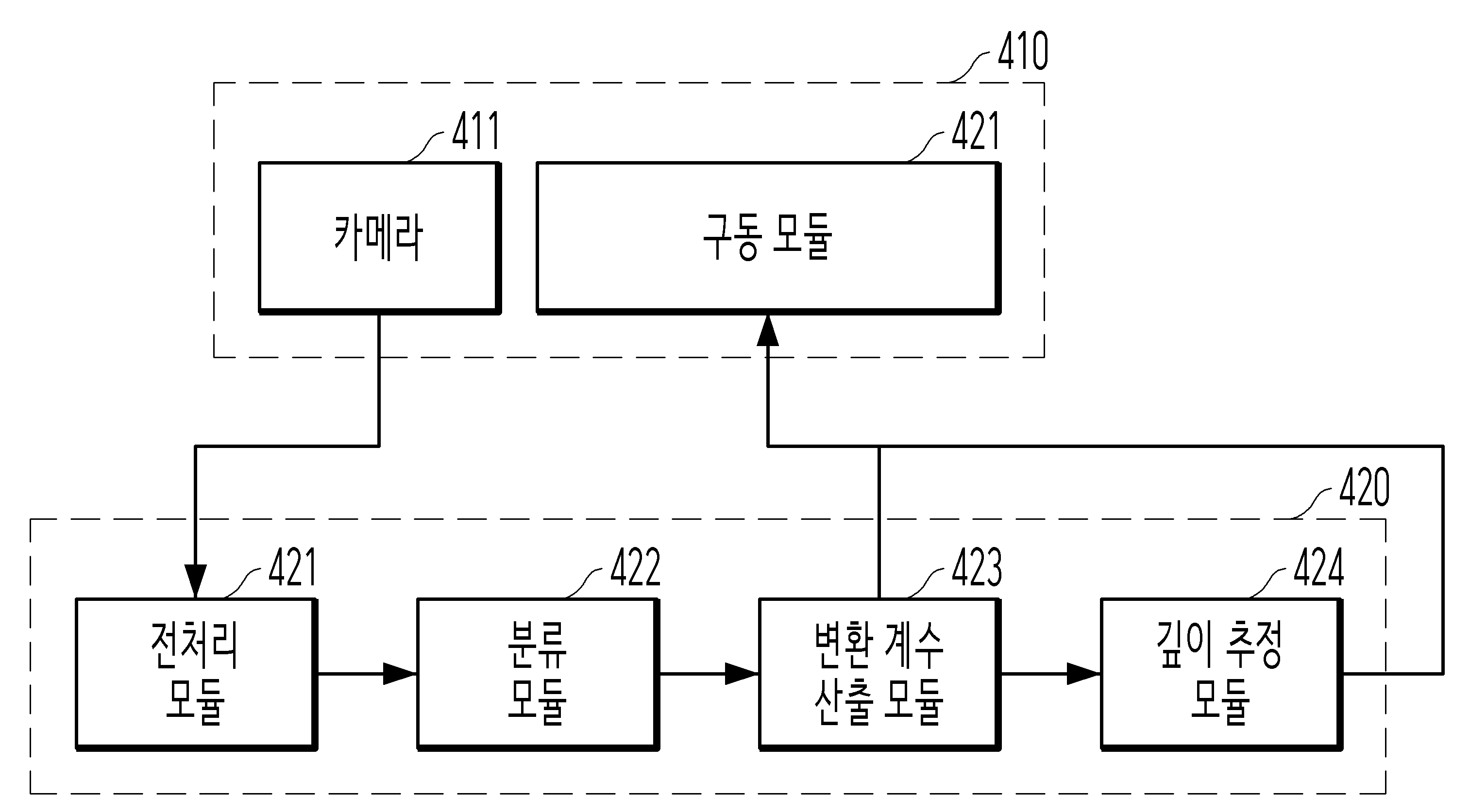
도 4는 본 개시의 일 실시예에 따른 이미지에 포함된 픽셀의 절대 깊이를 추정하고 차량 또는 로봇을 구동하는 과정을 설명하기 위한 개념도이다.FIG. 4 is a conceptual diagram for explaining a process of estimating the absolute depth of a pixel included in an image and driving a vehicle or robot according to one embodiment of the present disclosure.
본 개시에서, 이미지에 포함된 픽셀의 절대 깊이를 추정하는 방법은 자율주행 차량 또는 로봇(이하 '로봇')의 구동 시스템과 연동될 수 있다.In the present disclosure, a method for estimating the absolute depth of a pixel included in an image can be linked to a driving system of an autonomous vehicle or robot (hereinafter referred to as 'robot').
로봇의 카메라(411)는 제1 이미지 및 제2 이미지를 획득할 수 있다. 이 때 카메라(411)는 로봇에 부착되어 구동 모듈(421)에 의해 중심축을 중심으로 회전운동할 수 있고, 구동 모듈(421)에 의해 운동 중인 로봇의 운행에 의해 일정한 경로로 운동할 수 있다. The camera (411) of the robot can obtain the first image and the second image. At this time, the camera (411) is attached to the robot and can rotate around the central axis by the driving module (421), and can move along a certain path by the operation of the moving robot by the driving module (421).
전처리 모듈(421)은 카메라(411)에서 촬영된 제1 이미지 및 제2 이미지를 입력받아 상대 깊이 맵과 옵티컬 플로우 정보를 생성할 수 있다. 전처리 모듈(421)의 세부적인 구성은 도 5를 참조하여 후술한다.The preprocessing module (421) can receive the first image and the second image captured by the camera (411) and generate a relative depth map and optical flow information. The detailed configuration of the preprocessing module (421) is described later with reference to FIG. 5.
분류 모듈(422)은 상대 깊이 맵, 옵티컬 플로우 정보 및 구동 모듈(421)이 생성한 카메라(411)의 운동 및 위치와 관련된 정보에 더 기초하여, 각 변수 간 관계를 모델링할 수 있다. 또한 분류 모듈(422)은 옵티컬 플로우 정보에 기초하여 제1 이미지로부터 동적 객체를 검출할 수 있다.The classification module (422) can model the relationship between each variable based on the relative depth map, optical flow information, and information related to the movement and position of the camera (411) generated by the driving module (421). In addition, the classification module (422) can detect a dynamic object from the first image based on the optical flow information.
변환 계수 산출 모듈(423)은 옵티컬 플로우 정보에 기초하여 상대 깊이 맵으로부터 절대 깊이를 산출하기 위한 변환 계수를 산출할 수 있다. 본 개시의 일 실시예에서 변환 계수 산출 모듈(423)은 이미지를 구성하는 하나 이상의 픽셀에 대하여 후보 변환 계수를 연산하고 후보 변환 계수를 기초로 변환 계수를 결정할 수 있는 바, 변환 계수를 산출하는 구체적인 방법은 도 7을 참조하여 후술한다.The transformation coefficient calculation module (423) can calculate transformation coefficients for calculating absolute depth from a relative depth map based on optical flow information. In one embodiment of the present disclosure, the transformation coefficient calculation module (423) can calculate candidate transformation coefficients for one or more pixels constituting an image and determine transformation coefficients based on the candidate transformation coefficients. A specific method for calculating transformation coefficients will be described below with reference to FIG. 7.
깊이 추정 모듈(424)은 상대 깊이 맵, 옵티컬 플로우 정보 및 변환 계수를 기초로 카메라(411)로부터 획득된 제1 이미지에 포함된 적어도 하나의 픽셀에 대하여 절대 깊이를 산출할 수 있다. 또한 깊이 추정 모듈(424)은 제1 이미지 전체에 3D 맵을 생성할 수 있다. 본 개시에서 변환 계수 및 3D 맵은 로봇의 운행 시 특정 시간 간격으로 지속적으로 갱신될 수 있다.The depth estimation module (424) can calculate an absolute depth for at least one pixel included in a first image acquired from the camera (411) based on the relative depth map, optical flow information, and transformation coefficients. In addition, the depth estimation module (424) can generate a 3D map for the entire first image. In the present disclosure, the transformation coefficients and the 3D map can be continuously updated at specific time intervals during operation of the robot.
본 개시에서, 이미지를 구성하는 각 픽셀에 대응되는 후보 변환 계수가 연산되고, 각 후보 변환 계수 중 가장 적절한 값이 변환 계수로 결정될 수 있다. 로봇이 정지 상태인 경우, 깊이 추정 모듈(424)은 변환 계수 산출 모듈(423)에 의해 결정된 변환 계수 및 변환 계수에 대응되는 픽셀의 좌표 정보 (이미지에 포함된 픽셀의 좌표와 해당 픽셀의 절대 깊이에 대한 정보) 를 기초로, 정지 상태의 상대 깊이 맵에 대하여 절대 깊이를 산출할 수 있다. 변환 계수 이외에도 변환 계수에 대응되는 픽셀의 좌표 정보(이미지에 포함된 픽셀의 좌표와 해당 픽셀의 절대 깊이에 대한 정보)를 부가적으로 사용함으로써, 로봇이 정지 상태이지만 변환 계수에 대응되는 픽셀이 동적 객체를 포함하게 되는 경우(즉, 동적 객체가 해당 위치를 지나가는 경우) 다시 적절한 변환 계수를 결정할 수 있다. 예를 들어 t시점에서 결정된 변환 계수가 0.5이고 변환 계수가 0.5인 픽셀의 좌표가 (142, 322)인 경우, (142, 322)좌표의 픽셀이 동적 객체로 분류되는 시점에서 구동 모듈(421)이 로봇을 움직인 후, 움직이는 로봇에서 얻어진 새로운 이미지로부터 새로운 변환 계수를 결정할 수 있다.In the present disclosure, candidate transformation coefficients corresponding to each pixel constituting an image are calculated, and the most appropriate value among each candidate transformation coefficient can be determined as the transformation coefficient. When the robot is stationary, the depth estimation module (424) can calculate an absolute depth for a relative depth map in the stationary state based on the transformation coefficients determined by the transformation coefficient calculation module (423) and the coordinate information of the pixel corresponding to the transformation coefficients (information on the coordinates of the pixel included in the image and the absolute depth of the corresponding pixel). In addition to the transformation coefficients, by additionally using the coordinate information of the pixel corresponding to the transformation coefficients (information on the coordinates of the pixel included in the image and the absolute depth of the corresponding pixel), when the robot is stationary but the pixel corresponding to the transformation coefficients includes a dynamic object (i.e., when the dynamic object passes by the corresponding location), an appropriate transformation coefficient can be determined again. For example, if the transformation coefficient determined at time t is 0.5 and the coordinate of the pixel with the transformation coefficient of 0.5 is (142, 322), then after the driving module (421) moves the robot at the time when the pixel with the coordinate (142, 322) is classified as a dynamic object, a new transformation coefficient can be determined from a new image obtained from the moving robot.
구동 모듈(421)은 깊이 추정 모듈(424)로부터 제1 이미지에 대한 3D 맵을 기초로 로봇의 주행 경로를 결정할 수 있다. 예를 들어, 구동 모듈(421)은 제1 이미지에 대한 3D 맵을 기초로 현재 로봇 주변에 존재하는 정적 객체 및 동적 객체를 인식하고, 동적 객체의 예상 이동 경로를 계산함으로써 각 객체에 충돌하지 않는 주행 경로를 결정할 수 있다.The driving module (421) can determine the driving path of the robot based on the 3D map for the first image from the depth estimation module (424). For example, the driving module (421) can recognize static objects and dynamic objects currently existing around the robot based on the 3D map for the first image, and determine a driving path that does not collide with each object by calculating the expected movement path of the dynamic object.
도 5는 본 개시의 일 실시예에 따른 전처리 모듈의 세부 구성을 나타낸 개념도이다.FIG. 5 is a conceptual diagram showing a detailed configuration of a preprocessing module according to one embodiment of the present disclosure.
본 개시에서 전처리 모듈(500)은 이미지 수신 서브모듈(510), 상대 깊이 추정 서브모듈(520) 및 옵티컬 플로우 연산 서브모듈(530)을 포함할 수 있다. In the present disclosure, the preprocessing module (500) may include an image receiving submodule (510), a relative depth estimation submodule (520), and an optical flow operation submodule (530).
도 6은 본 개시의 일 실시예에 따른 제1 이미지로부터 동적 객체를 검출하는 과정을 나타낸 개념도이다.FIG. 6 is a conceptual diagram illustrating a process of detecting a dynamic object from a first image according to one embodiment of the present disclosure.
본 개시에서 프로세서(110)는 옵티컬 플로우 정보 및 카메라의 위치 및 운동 정보를 기초로, 제1 이미지(610)에 포함된 픽셀을 동적 객체에 해당하는 픽셀(620)과 정적 객체에 해당하는 픽셀(630)으로 분류함으로써 동적 객체를 검출할 수 있다. 예를 들어, 프로세서(110)는 카메라의 각속도 정보, 카메라와 로봇 사이의 각도와 관련된 정보, 로봇의 속도와 관련된 정보를 카메라의 위치 및 운동 정보로 하여, 제1 이미지(610)에서 동적 객체를 검출할 수 있다.In the present disclosure, the processor (110) can detect a dynamic object by classifying pixels included in the first image (610) into pixels (620) corresponding to dynamic objects and pixels (630) corresponding to static objects based on optical flow information and position and movement information of the camera. For example, the processor (110) can detect a dynamic object in the first image (610) by using angular velocity information of the camera, information related to an angle between the camera and the robot, and information related to the speed of the robot as position and movement information of the camera.
본 개시의 일 실시예에서, 프로세서(110)는 옵티컬 플로우 정보에 포함된 픽셀의 이동 패턴과 카메라의 위치 및 운동 정보로 보정하여, 제1 이미지에 포함된 픽셀 또는 픽셀의 집합이 동적 객체에 포함되는지 여부를 결정할 수 있다. 예를 들어, 카메라가 정지해 있는 동안 촬영된 제1 이미지 및 제2 이미지로부터 옵티컬 플로우 정보가 생성된 경우 프로세서(110)는 '정지'라는 정보를 활용하여 이동하는 패턴을 보이는 픽셀 또는 픽셀의 집합에 대하여 동적 객체에 포함된다고 결정할 수 있다.In one embodiment of the present disclosure, the processor (110) can determine whether a pixel or a set of pixels included in a first image is included in a dynamic object by compensating for the movement pattern of pixels included in the optical flow information and the position and movement information of the camera. For example, if the optical flow information is generated from the first image and the second image captured while the camera is stationary, the processor (110) can determine that a pixel or a set of pixels showing a moving pattern is included in a dynamic object by utilizing the information of 'stationary'.
또 다른 예시로, 카메라가 로봇과 함께 등속운동하는 동안 촬영된 제1 이미지 및 제2 이미지로부터 옵티컬 플로우 정보가 생성된 경우 프로세서(110)는 '로봇의 속도 및 카메라의 위치'에 대한 정보를 활용하여 옵티컬 플로우 정보에 포함된 각 픽셀들의 움직임을 보정한 후, 이동하는 패턴을 보이는 픽셀 또는 픽셀의 집합에 대하여 동적 객체에 포함된다고 결정할 수 있다. 로봇의 속도 및 카메라의 위치에 대한 정보를 반영하는 과정에서 이미지에 포함된 픽셀의 좌표계와 카메라 기준의 좌표계, 지표면 기준의 좌표계 간 상호 변환이 일어날 수 있음은 통상의 기술자에게 명백하다.As another example, if optical flow information is generated from the first image and the second image captured while the camera is moving at a constant speed with the robot, the processor (110) may use information about the 'robot speed and camera position' to correct the movement of each pixel included in the optical flow information, and then determine that a pixel or a set of pixels showing a moving pattern are included in a dynamic object. It is obvious to a person skilled in the art that in the process of reflecting information about the robot speed and the camera position, mutual conversion may occur between the coordinate system of the pixels included in the image, the coordinate system based on the camera, and the coordinate system based on the ground surface.
위와 같은 실시예를 통해, 프로세서(110)는 카메라가 정지된 상태에서 동적 객체를 검출할 수 있을뿐만 아니라, 이동 중인 카메라에 대한 상대속도가 0인 객체 또한 동적 객체로 검출할 수 있다.Through the above embodiment, the processor (110) can not only detect a dynamic object when the camera is stationary, but also detect an object with a relative speed of 0 with respect to a moving camera as a dynamic object.
제1 이미지에서 동적 객체를 더 정확하게 검출하기 위해, 프로세서(110)는 제1 이미지에서 제1 동적 객체를 검출하고, 제1 동적 객체의 정보를 기초로 제1 이미지 중 제1 동적 객체 이외의 영역에서 추가적으로 제2 동적 객체를 검출할 수 있다. 예를 들어, 프로세서(110)는 최초로 제1 동적 객체를 검출한 후, 제1 동적 객체를 포함하는 제1 이미지에 포함된 모든 객체(픽셀 또는 픽셀의 집합)에 라벨(label)을 부여할 수 있다. 그 후 프로세서(110)는 라벨이 부여된 각 객체 중 제1 동적 객체의 움직임과 비교하여 유사한 움직임을 보이는 객체를 제2 동적 객체로 결정할 수 있다. 즉 프로세서(110)는 제1 동적 객체의 정보를 기초로 제1 이미지 중 제1 동적 객체 이외의 영역에서 제2 동적 객체를 검출할 수 있다. 그 후, 프로세서(110)는 제1 동적 객체 및 제2 동적 객체를 합하여 동적 객체로 결정할 수 있다.In order to more accurately detect a dynamic object in the first image, the processor (110) may detect a first dynamic object in the first image, and additionally detect a second dynamic object in an area other than the first dynamic object in the first image based on information about the first dynamic object. For example, the processor (110) may initially detect the first dynamic object, and then assign a label to all objects (pixels or a set of pixels) included in the first image including the first dynamic object. Thereafter, the processor (110) may determine an object that exhibits a similar movement to the movement of the first dynamic object among each labeled object as the second dynamic object. That is, the processor (110) may detect a second dynamic object in an area other than the first dynamic object in the first image based on information about the first dynamic object. Thereafter, the processor (110) may determine the first dynamic object and the second dynamic object as a dynamic object.
도 7은 본 개시의 일 실시예에 따른 변환 계수 산출 모듈에서 하나 이상의 후보 변환 계수를 기초로 변환 계수를 결정하는 과정을 나타낸 개념도이다.FIG. 7 is a conceptual diagram illustrating a process of determining a transform coefficient based on one or more candidate transform coefficients in a transform coefficient calculation module according to one embodiment of the present disclosure.
본 개시에서 제1 이미지(710)에 대하여 하나의 변환 계수(722)가 산출될 수 있고, 제1 이미지(710)를 분할하여 생성된 복수의 영역 각각에 대응되는 후보 변환 계수(721)가 산출된 후 후보 변환 계수(721)를 기초로 변환 계수(722)가 결정될 수 있다.In the present disclosure, one transformation coefficient (722) can be calculated for the first image (710), and candidate transformation coefficients (721) corresponding to each of a plurality of regions generated by dividing the first image (710) are calculated, and then the transformation coefficients (722) can be determined based on the candidate transformation coefficients (721).
예를 들어, 프로세서(110)는 제1 이미지(710)를 동적 객체를 제외한 9개의 영역으로 분할하고, 9개의 각 영역(712)에 대응되는 9개의 후보 변환 계수(721)를 생성할 수 있다. 그 후, 프로세서(110)는 9개의 후보 변환 계수(721)를 기초로 변환 계수를 결정할 수 있다.For example, the processor (110) may divide the first image (710) into nine regions excluding dynamic objects, and generate nine candidate transformation coefficients (721) corresponding to each of the nine regions (712). Thereafter, the processor (110) may determine transformation coefficients based on the nine candidate transformation coefficients (721).
일 실시예에서, 프로세서(110)는 복수의 후보 변환 계수 중 가장 작은 값을 변환 계수로 결정할 수 있다. 후보 변환 계수가 작을수록 픽셀과의 절대 깊이 추정값 즉 카메라와 픽셀에 대응되는 물체 간 거리가 가깝게 추정되므로, 작은 값을 변환 계수로 결정하는 경우 로봇이 더 안전하게 장애물을 회피할 수 있다. 그러나 본 개시에서 복수의 후보 변환 계수를 기초로 변환 계수를 결정하는 방법은 위 예시에 한정하지 아니하며, RANSAC(RANdom SAmple Consensus)알고리즘과 같은 별도의 알고리즘을 사용하여 후보 변환 계수로부터 적절한 값을 선택하거나, 일정 범위 내의 후보 변환 계수의 평균을 변환 계수로 결정하는 등 다양한 방법이 사용될 수 있다.In one embodiment, the processor (110) may determine a smallest value among a plurality of candidate transformation coefficients as the transformation coefficient. The smaller the candidate transformation coefficient, the closer the absolute depth estimation value with respect to the pixel, that is, the distance between the camera and the object corresponding to the pixel is estimated. Therefore, when a small value is determined as the transformation coefficient, the robot can avoid obstacles more safely. However, the method of determining the transformation coefficient based on a plurality of candidate transformation coefficients in the present disclosure is not limited to the above example, and various methods may be used, such as selecting an appropriate value from the candidate transformation coefficients using a separate algorithm such as the RANSAC (RANdom SAmple Consensus) algorithm, or determining an average of the candidate transformation coefficients within a certain range as the transformation coefficient.
본 개시에서 제1 이미지 및 제2 이미지를 획득하는 카메라가 주행 중인 로봇에 탑재되는 경우, 프로세서(110)는 각 시점에서 산출된 변환 계수를 메모리(130)에 저장하여 변환 계수의 집합을 생성할 수 있다. 예를 들어, 프로세서(110)는 로봇의 주행 과정 중 각 시점에서 카메라에 의해 다시 촬영된 제1 이미지 및 제2 이미지를 획득하고, 각 시점별 변환 계수를 산출할 수 있다. 그 후 프로세서(110)는 기존에 산출된 변환 계수의 집합들과 비교하여 변환 계수 집합을 업데이트할 수 있다. 이와 같이 시점별로 변환 계수를 지속적으로 산출하고 업데이트함으로써, 본 개시를 통해 추정된 절대 깊이를 기초로 장애물을 회피하도록 주행하는 로봇의 성능이 향상될 수 있다. In the present disclosure, when a camera for acquiring the first image and the second image is mounted on a moving robot, the processor (110) can store the transformation coefficients calculated at each point in time in the memory (130) to generate a set of transformation coefficients. For example, the processor (110) can acquire the first image and the second image captured again by the camera at each point in time during the driving process of the robot, and calculate the transformation coefficients for each point in time. Thereafter, the processor (110) can update the set of transformation coefficients by comparing it with the sets of previously calculated transformation coefficients. By continuously calculating and updating the transformation coefficients for each point in time in this way, the performance of the robot that drives to avoid obstacles based on the absolute depth estimated through the present disclosure can be improved.
도 8은 본 개시의 일 실시예에 따른 이미지에 대한 3D 맵을 나타낸 개념도이다.FIG. 8 is a conceptual diagram illustrating a 3D map for an image according to one embodiment of the present disclosure.
도 8에 도시된 것과 같이, 프로세서(110)는 좌측의 제1 이미지를 기초로 우측의 3D 맵을 생성할 수 있다. 제1 이미지 및 제2 이미지를 촬영한 카메라를 탑재한 로봇은 생성된 3D 맵을 기초로 장애물 회피를 위한 주행 경로를 생성할 수 있다.As illustrated in Fig. 8, the processor (110) can generate a 3D map on the right based on the first image on the left. A robot equipped with a camera that captures the first image and the second image can generate a driving path for obstacle avoidance based on the generated 3D map.
한편, 본 개시의 일 실시예에 따라 데이터 구조를 저장한 컴퓨터 판독가능 매체가 개시된다.Meanwhile, a computer-readable medium storing a data structure according to one embodiment of the present disclosure is disclosed.
데이터 구조는 데이터에 효율적인 접근 및 수정을 가능하게 하는 데이터의 조직, 관리, 저장을 의미할 수 있다. 데이터 구조는 특정 문제(예를 들어, 최단 시간으로 데이터 검색, 데이터 저장, 데이터 수정) 해결을 위한 데이터의 조직을 의미할 수 있다. 데이터 구조는 특정한 데이터 처리 기능을 지원하도록 설계된, 데이터 요소들 간의 물리적이거나 논리적인 관계로 정의될 수도 있다. 데이터 요소들 간의 논리적인 관계는 사용자 정의 데이터 요소들 간의 연결관계를 포함할 수 있다. 데이터 요소들 간의 물리적인 관계는 컴퓨터 판독가능 저장매체(예를 들어, 영구 저장 장치)에 물리적으로 저장되어 있는 데이터 요소들 간의 실제 관계를 포함할 수 있다. 데이터 구조는 구체적으로 데이터의 집합, 데이터 간의 관계, 데이터에 적용할 수 있는 함수 또는 명령어를 포함할 수 있다. 효과적으로 설계된 데이터 구조를 통해 컴퓨팅 장치는 컴퓨팅 장치의 자원을 최소한으로 사용하면서 연산을 수행할 수 있다. 구체적으로 컴퓨팅 장치는 효과적으로 설계된 데이터 구조를 통해 연산, 읽기, 삽입, 삭제, 비교, 교환, 검색의 효율성을 높일 수 있다.A data structure can refer to the organization, management, and storage of data that enables efficient access and modification of data. A data structure can refer to the organization of data to solve a specific problem (e.g., data retrieval in the shortest time, data storage, data modification). A data structure can also be defined as a physical or logical relationship between data elements designed to support a specific data processing function. A logical relationship between data elements can include a connection relationship between user-defined data elements. A physical relationship between data elements can include an actual relationship between data elements that are physically stored in a computer-readable storage medium (e.g., a persistent storage device). A data structure can specifically include a collection of data, a relationship between data, and a function or command that can be applied to the data. An effectively designed data structure enables a computing device to perform operations while using minimal resources of the computing device. Specifically, a computing device can increase the efficiency of operations, reading, insertion, deletion, comparison, exchange, and searching through an effectively designed data structure.
데이터 구조는 데이터 구조의 형태에 따라 선형 데이터 구조와 비선형 데이터 구조로 구분될 수 있다. 선형 데이터 구조는 하나의 데이터 뒤에 하나의 데이터만이 연결되는 구조일 수 있다. 선형 데이터 구조는 리스트(List), 스택(Stack), 큐(Queue), 데크(Deque)를 포함할 수 있다. 리스트는 내부적으로 순서가 존재하는 일련의 데이터 집합을 의미할 수 있다. 리스트는 연결 리스트(Linked List)를 포함할 수 있다. 연결 리스트는 각각의 데이터가 포인터를 가지고 한 줄로 연결되어 있는 방식으로 데이터가 연결된 데이터 구조일 수 있다. 연결 리스트에서 포인터는 다음이나 이전 데이터와의 연결 정보를 포함할 수 있다. 연결 리스트는 형태에 따라 단일 연결 리스트, 이중 연결 리스트, 원형 연결 리스트로 표현될 수 있다. 스택은 제한적으로 데이터에 접근할 수 있는 데이터 나열 구조일 수 있다. 스택은 데이터 구조의 한 쪽 끝에서만 데이터를 처리(예를 들어, 삽입 또는 삭제)할 수 있는 선형 데이터 구조일 수 있다. 스택에 저장된 데이터는 늦게 들어갈수록 빨리 나오는 데이터 구조(LIFO-Last in First Out)일 수 있다. 큐는 제한적으로 데이터에 접근할 수 있는 데이터 나열 구조로서, 스택과 달리 늦게 저장된 데이터일수록 늦게 나오는 데이터 구조(FIFO-First in First Out)일 수 있다. 데크는 데이터 구조의 양 쪽 끝에서 데이터를 처리할 수 있는 데이터 구조일 수 있다.Data structures can be divided into linear data structures and nonlinear data structures depending on the form of the data structure. A linear data structure can be a structure in which only one piece of data is connected after another piece of data. Linear data structures can include lists, stacks, queues, and deques. A list can mean a series of data sets that have an internal order. A list can include a linked list. A linked list can be a data structure in which data is connected in a way that each piece of data has a pointer and is connected in a single line. In a linked list, a pointer can include information on the connection to the next or previous piece of data. A linked list can be expressed as a singly linked list, a doubly linked list, or a circular linked list depending on its form. A stack can be a data listing structure that allows limited access to data. A stack can be a linear data structure in which data can be processed (e.g., inserted or deleted) only at one end of the data structure. Data stored in a stack can be a data structure in which the later it enters, the sooner it comes out (LIFO - Last in First Out). A queue is a data list structure that allows limited access to data, and unlike a stack, it can be a data structure that comes out later (FIFO - First in First Out) as data is stored later. A deck can be a data structure that can process data at both ends of the data structure.
비선형 데이터 구조는 하나의 데이터 뒤에 복수개의 데이터가 연결되는 구조일 수 있다. 비선형 데이터 구조는 그래프(Graph) 데이터 구조를 포함할 수 있다. 그래프 데이터 구조는 정점(Vertex)과 간선(Edge)으로 정의될 수 있으며 간선은 서로 다른 두개의 정점을 연결하는 선을 포함할 수 있다. 그래프 데이터 구조 트리(Tree) 데이터 구조를 포함할 수 있다. 트리 데이터 구조는 트리에 포함된 복수개의 정점 중에서 서로 다른 두개의 정점을 연결시키는 경로가 하나인 데이터 구조일 수 있다. 즉 그래프 데이터 구조에서 루프(loop)를 형성하지 않는 데이터 구조일 수 있다.A nonlinear data structure can be a structure in which multiple data are connected behind one data. A nonlinear data structure can include a graph data structure. A graph data structure can be defined by vertices and edges, and an edge can include a line connecting two different vertices. A graph data structure can include a tree data structure. A tree data structure can be a data structure in which there is only one path connecting two different vertices among multiple vertices included in the tree. In other words, it can be a data structure that does not form a loop in a graph data structure.
본 명세서에 걸쳐, 연산 모델, 신경망, 네트워크 함수, 뉴럴 네트워크(neural network)는 동일한 의미로 사용될 수 있다. 이하에서는 신경망으로 통일하여 기술한다. 데이터 구조는 신경망을 포함할 수 있다. 그리고 신경망을 포함한 데이터 구조는 컴퓨터 판독가능 매체에 저장될 수 있다. 신경망을 포함한 데이터 구조는 또한 신경망에 의한 처리를 위하여 전처리된 데이터, 신경망에 입력되는 데이터, 신경망의 가중치, 신경망의 하이퍼 파라미터, 신경망으로부터 획득한 데이터, 신경망의 각 노드 또는 레이어와 연관된 활성 함수, 신경망의 학습을 위한 손실 함수 등을 포함할 수 있다. 신경망을 포함한 데이터 구조는 상기 개시된 구성들 중 임의의 구성 요소들을 포함할 수 있다. 즉 신경망을 포함한 데이터 구조는 신경망에 의한 처리를 위하여 전처리된 데이터, 신경망에 입력되는 데이터, 신경망의 가중치, 신경망의 하이퍼 파라미터, 신경망으로부터 획득한 데이터, 신경망의 각 노드 또는 레이어와 연관된 활성 함수, 신경망의 학습을 위한 손실 함수 등 전부 또는 이들의 임의의 조합을 포함하여 구성될 수 있다. 전술한 구성들 이외에도, 신경망을 포함한 데이터 구조는 신경망의 특성을 결정하는 임의의 다른 정보를 포함할 수 있다. 또한, 데이터 구조는 신경망의 연산 과정에 사용되거나 발생되는 모든 형태의 데이터를 포함할 수 있으며 전술한 사항에 제한되는 것은 아니다. 컴퓨터 판독가능 매체는 컴퓨터 판독가능 기록 매체 및/또는 컴퓨터 판독가능 전송 매체를 포함할 수 있다. 신경망은 일반적으로 노드라 지칭될 수 있는 상호 연결된 계산 단위들의 집합으로 구성될 수 있다. 이러한 노드들은 뉴런(neuron)들로 지칭될 수도 있다. 신경망은 적어도 하나 이상의 노드들을 포함하여 구성된다.Throughout this specification, the terms computational model, neural network, network function, and neural network may be used interchangeably. Hereinafter, they are collectively described as neural networks. The data structure may include a neural network. And the data structure including the neural network may be stored in a computer-readable medium. The data structure including the neural network may also include preprocessed data for processing by the neural network, data input to the neural network, weights of the neural network, hyperparameters of the neural network, data obtained from the neural network, activation functions associated with each node or layer of the neural network, loss functions for learning the neural network, etc. The data structure including the neural network may include any of the components among the above-described configurations. That is, the data structure including the neural network may be configured to include all or any combination of preprocessed data for processing by the neural network, data input to the neural network, weights of the neural network, hyperparameters of the neural network, data obtained from the neural network, activation functions associated with each node or layer of the neural network, loss functions for learning the neural network, etc. In addition to the above-described configurations, the data structure including the neural network may include any other information that determines the characteristics of the neural network. In addition, the data structure may include all forms of data used or generated in the computational process of the neural network, and is not limited to the above-described matters. The computer-readable medium may include a computer-readable recording medium and/or a computer-readable transmission medium. The neural network may be composed of a set of interconnected computational units, which may generally be referred to as nodes. These nodes may also be referred to as neurons. The neural network is composed of at least one node.
데이터 구조는 신경망에 입력되는 데이터를 포함할 수 있다. 신경망에 입력되는 데이터를 포함하는 데이터 구조는 컴퓨터 판독가능 매체에 저장될 수 있다. 신경망에 입력되는 데이터는 신경망 학습 과정에서 입력되는 학습 데이터 및/또는 학습이 완료된 신경망에 입력되는 입력 데이터를 포함할 수 있다. 신경망에 입력되는 데이터는 전처리(pre-processing)를 거친 데이터 및/또는 전처리 대상이 되는 데이터를 포함할 수 있다. 전처리는 데이터를 신경망에 입력시키기 위한 데이터 처리 과정을 포함할 수 있다. 따라서 데이터 구조는 전처리 대상이 되는 데이터 및 전처리로 발생되는 데이터를 포함할 수 있다. 전술한 데이터 구조는 예시일 뿐 본 개시는 이에 제한되지 않는다.The data structure may include data input to the neural network. The data structure including the data input to the neural network may be stored in a computer-readable medium. The data input to the neural network may include training data input during the neural network training process and/or input data input to the neural network after training is completed. The data input to the neural network may include data that has undergone preprocessing and/or data that is the target of preprocessing. The preprocessing may include a data processing process for inputting data to the neural network. Accordingly, the data structure may include data that is the target of preprocessing and data generated by the preprocessing. The above-described data structure is merely an example, and the present disclosure is not limited thereto.
데이터 구조는 신경망의 가중치를 포함할 수 있다. (본 명세서에서 가중치, 파라미터는 동일한 의미로 사용될 수 있다.) 그리고 신경망의 가중치를 포함한 데이터 구조는 컴퓨터 판독가능 매체에 저장될 수 있다. 신경망은 복수개의 가중치를 포함할 수 있다. 가중치는 가변적일 수 있으며, 신경망이 원하는 기능을 수행하기 위해, 사용자 또는 알고리즘에 의해 가변 될 수 있다. 예를 들어, 하나의 출력 노드에 하나 이상의 입력 노드가 각각의 링크에 의해 상호 연결된 경우, 출력 노드는 상기 출력 노드와 연결된 입력 노드들에 입력된 값들 및 각각의 입력 노드들에 대응하는 링크에 설정된 가중치에 기초하여 출력 노드에서 출력되는 데이터 값을 결정할 수 있다. 전술한 데이터 구조는 예시일 뿐 본 개시는 이에 제한되지 않는다.The data structure may include weights of the neural network. (In this specification, the terms weight and parameter may be used interchangeably.) And the data structure including the weights of the neural network may be stored in a computer-readable medium. The neural network may include a plurality of weights. The weights may be variable and may be variable by a user or an algorithm so that the neural network may perform a desired function. For example, when one or more input nodes are interconnected to one output node by respective links, the output node may determine a data value output from the output node based on values input to the input nodes connected to the output node and weights set for links corresponding to each of the input nodes. The above-described data structure is merely an example, and the present disclosure is not limited thereto.
제한이 아닌 예로서, 가중치는 신경망 학습 과정에서 가변되는 가중치 및/또는 신경망 학습이 완료된 가중치를 포함할 수 있다. 신경망 학습 과정에서 가변되는 가중치는 학습 사이클이 시작되는 시점의 가중치 및/또는 학습 사이클 동안 가변되는 가중치를 포함할 수 있다. 신경망 학습이 완료된 가중치는 학습 사이클이 완료된 가중치를 포함할 수 있다. 따라서 신경망의 가중치를 포함한 데이터 구조는 신경망 학습 과정에서 가변되는 가중치 및/또는 신경망 학습이 완료된 가중치를 포함한 데이터 구조를 포함할 수 있다. 그러므로 상술한 가중치 및/또는 각 가중치의 조합은 신경망의 가중치를 포함한 데이터 구조에 포함되는 것으로 한다. 전술한 데이터 구조는 예시일 뿐 본 개시는 이에 제한되지 않는다.By way of example and not limitation, the weights may include weights that are variable during the neural network learning process and/or weights that have completed neural network learning. The weights that are variable during the neural network learning process may include weights at the start of a learning cycle and/or weights that are variable during a learning cycle. The weights that have completed neural network learning may include weights that have completed a learning cycle. Accordingly, the data structure including the weights of the neural network may include the data structure including the weights that are variable during the neural network learning process and/or weights that have completed neural network learning. Therefore, the above-described weights and/or combinations of each weight are included in the data structure including the weights of the neural network. The above-described data structures are merely examples and the present disclosure is not limited thereto.
신경망의 가중치를 포함한 데이터 구조는 직렬화(serialization) 과정을 거친 후 컴퓨터 판독가능 저장 매체(예를 들어, 메모리, 하드 디스크)에 저장될 수 있다. 직렬화는 데이터 구조를 동일하거나 다른 컴퓨팅 장치에 저장하고 나중에 다시 재구성하여 사용할 수 있는 형태로 변환하는 과정일 수 있다. 컴퓨팅 장치는 데이터 구조를 직렬화하여 네트워크를 통해 데이터를 송수신할 수 있다. 직렬화된 신경망의 가중치를 포함한 데이터 구조는 역직렬화(deserialization)를 통해 동일한 컴퓨팅 장치 또는 다른 컴퓨팅 장치에서 재구성될 수 있다. 신경망의 가중치를 포함한 데이터 구조는 직렬화에 한정되는 것은 아니다. 나아가 신경망의 가중치를 포함한 데이터 구조는 컴퓨팅 장치의 자원을 최소한으로 사용하면서 연산의 효율을 높이기 위한 데이터 구조(예를 들어, 비선형 데이터 구조에서 B-Tree, Trie, m-way search tree, AVL tree, Red-Black Tree)를 포함할 수 있다. 전술한 사항은 예시일 뿐 본 개시는 이에 제한되지 않는다.The data structure including the weights of the neural network can be stored in a computer-readable storage medium (e.g., memory, hard disk) after going through a serialization process. Serialization can be a process of converting the data structure into a form that can be stored in the same or different computing devices and reconstructed and used later. The computing device can serialize the data structure to transmit and receive data over a network. The data structure including the weights of the serialized neural network can be reconstructed in the same computing device or another computing device through deserialization. The data structure including the weights of the neural network is not limited to serialization. Furthermore, the data structure including the weights of the neural network can include a data structure (e.g., B-Tree, Trie, m-way search tree, AVL tree, Red-Black Tree in nonlinear data structures) for increasing the efficiency of computation while minimizing the use of computing device resources. The above are examples and the present disclosure is not limited thereto.
데이터 구조는 신경망의 하이퍼 파라미터(Hyper-parameter)를 포함할 수 있다. 그리고 신경망의 하이퍼 파라미터를 포함한 데이터 구조는 컴퓨터 판독가능 매체에 저장될 수 있다. 하이퍼 파라미터는 사용자에 의해 가변되는 변수일 수 있다. 하이퍼 파라미터는 예를 들어, 학습률(learning rate), 비용 함수(cost function), 학습 사이클 반복 횟수, 가중치 초기화(Weight initialization)(예를 들어, 가중치 초기화 대상이 되는 가중치 값의 범위 설정), Hidden Unit 개수(예를 들어, 히든 레이어의 개수, 히든 레이어의 노드 수)를 포함할 수 있다. 전술한 데이터 구조는 예시일 뿐 본 개시는 이에 제한되지 않는다.The data structure may include hyper-parameters of the neural network. And the data structure including the hyper-parameters of the neural network may be stored in a computer-readable medium. The hyper-parameters may be variables that are changed by the user. The hyper-parameters may include, for example, a learning rate, a cost function, a number of repetitions of a learning cycle, weight initialization (e.g., setting a range of weight values to be weight initialization targets), and the number of Hidden Units (e.g., the number of hidden layers, the number of nodes in the hidden layer). The above-described data structure is only an example, and the present disclosure is not limited thereto.
도 9는 본 개시의 실시예들이 구현될 수 있는 예시적인 컴퓨팅 환경에 대한 간략하고 일반적인 개략도이다.FIG. 9 is a simplified, general schematic diagram of an exemplary computing environment in which embodiments of the present disclosure may be implemented.
본 개시가 일반적으로 컴퓨팅 장치에 의해 구현될 수 있는 것으로 전술되었지만, 통상의 기술자라면 본 개시가 하나 이상의 컴퓨터 상에서 실행될 수 있는 컴퓨터 실행가능 명령어 및/또는 기타 프로그램 모듈들과 결합되어 및/또는 하드웨어와 소프트웨어의 조합으로써 구현될 수 있다는 것을 잘 알 것이다.Although the present disclosure has been described above as being generally implemented by a computing device, those skilled in the art will appreciate that the present disclosure may also be implemented in combination with computer-executable instructions and/or other program modules that may be executed on one or more computers and/or as a combination of hardware and software.
일반적으로, 프로그램 모듈은 특정의 태스크를 수행하거나 특정의 추상 데이터 유형을 구현하는 루틴, 프로그램, 컴포넌트, 데이터 구조, 기타 등등을 포함한다. 또한, 통상의 기술자라면 본 개시의 방법이 단일-프로세서 또는 멀티프로세서 컴퓨터 시스템, 미니컴퓨터, 메인프레임 컴퓨터는 물론 퍼스널 컴퓨터, 핸드헬드(handheld) 컴퓨팅 장치, 마이크로프로세서-기반 또는 프로그램가능 가전 제품, 기타 등등(이들 각각은 하나 이상의 연관된 장치와 연결되어 동작할 수 있음)을 비롯한 다른 컴퓨터 시스템 구성으로 실시될 수 있다는 것을 잘 알 것이다.In general, program modules include routines, programs, components, data structures, and the like that perform particular tasks or implement particular abstract data types. Furthermore, those skilled in the art will appreciate that the methods of the present disclosure can be practiced with other computer system configurations, including single-processor or multiprocessor computer systems, minicomputers, mainframe computers, as well as personal computers, handheld computing devices, microprocessor-based or programmable consumer electronics, and the like, each of which may be operatively connected to one or more associated devices.
본 개시의 설명된 실시예들은 또한 어떤 태스크들이 통신 네트워크를 통해 연결되어 있는 원격 처리 장치들에 의해 수행되는 분산 컴퓨팅 환경에서 실시될 수 있다. 분산 컴퓨팅 환경에서, 프로그램 모듈은 로컬 및 원격 메모리 저장 장치 둘 다에 위치할 수 있다.The described embodiments of the present disclosure can also be practiced in distributed computing environments where certain tasks are performed by remote processing devices that are linked through a communications network. In a distributed computing environment, program modules may be located in both local and remote memory storage devices.
컴퓨터는 통상적으로 다양한 컴퓨터 판독가능 매체를 포함한다. 컴퓨터에 의해 액세스 가능한 매체는 그 어떤 것이든지 컴퓨터 판독가능 매체가 될 수 있고, 이러한 컴퓨터 판독가능 매체는 휘발성 및 비휘발성 매체, 일시적(transitory) 및 비일시적(non-transitory) 매체, 이동식 및 비-이동식 매체를 포함한다. 제한이 아닌 예로서, 컴퓨터 판독가능 매체는 컴퓨터 판독가능 저장 매체 및 컴퓨터 판독가능 전송 매체를 포함할 수 있다. 컴퓨터 판독가능 저장 매체는 컴퓨터 판독가능 명령어, 데이터 구조, 프로그램 모듈 또는 기타 데이터와 같은 정보를 저장하는 임의의 방법 또는 기술로 구현되는 휘발성 및 비휘발성 매체, 일시적 및 비-일시적 매체, 이동식 및 비이동식 매체를 포함한다. 컴퓨터 판독가능 저장 매체는 RAM, ROM, EEPROM, 플래시 메모리 또는 기타 메모리 기술, CD-ROM, DVD(digital video disk) 또는 기타 광 디스크 저장 장치, 자기 카세트, 자기 테이프, 자기 디스크 저장 장치 또는 기타 자기 저장 장치, 또는 컴퓨터에 의해 액세스될 수 있고 원하는 정보를 저장하는 데 사용될 수 있는 임의의 기타 매체를 포함하지만, 이에 한정되지 않는다.Computers typically include a variety of computer-readable media. Any media that can be accessed by a computer can be a computer-readable media, and such computer-readable media includes both volatile and nonvolatile media, transitory and non-transitory media, removable and non-removable media. By way of example, and not limitation, computer-readable media can include computer-readable storage media and computer-readable transmission media. Computer-readable storage media includes both volatile and nonvolatile media, transitory and non-transitory media, removable and non-removable media implemented in any method or technology for storing information such as computer-readable instructions, data structures, program modules or other data. Computer-readable storage media includes, but is not limited to, RAM, ROM, EEPROM, flash memory or other memory technology, CD-ROM, digital video disks (DVD) or other optical disk storage, magnetic cassettes, magnetic tape, magnetic disk storage or other magnetic storage devices, or any other medium that can be accessed by a computer and used to store the desired information.
컴퓨터 판독가능 전송 매체는 통상적으로 반송파(carrier wave) 또는 기타 전송 메커니즘(transport mechanism)과 같은 피변조 데이터 신호(modulated data signal)에 컴퓨터 판독가능 명령어, 데이터 구조, 프로그램 모듈 또는 기타 데이터 등을 구현하고 모든 정보 전달 매체를 포함한다. 피변조 데이터 신호라는 용어는 신호 내에 정보를 인코딩하도록 그 신호의 특성들 중 하나 이상을 설정 또는 변경시킨 신호를 의미한다. 제한이 아닌 예로서, 컴퓨터 판독가능 전송 매체는 유선 네트워크 또는 직접 배선 접속(direct-wired connection)과 같은 유선 매체, 그리고 음향, RF, 적외선, 기타 무선 매체와 같은 무선 매체를 포함한다. 상술된 매체들 중 임의의 것의 조합도 역시 컴퓨터 판독가능 전송 매체의 범위 안에 포함되는 것으로 한다.Computer-readable transmission media typically includes any information delivery media that embodies computer-readable instructions, data structures, program modules, or other data in a modulated data signal, such as a carrier wave or other transport mechanism. The term modulated data signal means a signal that has one or more of its characteristics set or changed so as to encode information in the signal. By way of example, and not limitation, computer-readable transmission media includes wired media, such as a wired network or direct-wired connection, and wireless media, such as acoustic, RF, infrared, and other wireless media. Combinations of any of the above are also intended to be included within the scope of computer-readable transmission media.
컴퓨터(1102)를 포함하는 본 개시의 여러가지 측면들을 구현하는 예시적인 환경(1100)이 나타내어져 있으며, 컴퓨터(1102)는 처리 장치(1104), 시스템 메모리(1106) 및 시스템 버스(1108)를 포함한다. 시스템 버스(1108)는 시스템 메모리(1106)(이에 한정되지 않음)를 비롯한 시스템 컴포넌트들을 처리 장치(1104)에 연결시킨다. 처리 장치(1104)는 다양한 상용 프로세서들 중 임의의 프로세서일 수 있다. 듀얼 프로세서 및 기타 멀티프로세서 아키텍처도 역시 처리 장치(1104)로서 이용될 수 있다.An exemplary environment (1100) implementing various aspects of the present disclosure is illustrated, including a computer (1102) including a processing unit (1104), a system memory (1106), and a system bus (1108). The system bus (1108) couples system components, including but not limited to the system memory (1106), to the processing unit (1104). The processing unit (1104) may be any of a variety of commercially available processors. Dual processors and other multiprocessor architectures may also be utilized as the processing unit (1104).
시스템 버스(1108)는 메모리 버스, 주변장치 버스, 및 다양한 상용 버스 아키텍처 중 임의의 것을 사용하는 로컬 버스에 추가적으로 상호 연결될 수 있는 몇 가지 유형의 버스 구조 중 임의의 것일 수 있다. 시스템 메모리(1106)는 판독 전용 메모리(ROM)(1110) 및 랜덤 액세스 메모리(RAM)(1112)를 포함한다. 기본 입/출력 시스템(BIOS)은 ROM, EPROM, EEPROM 등의 비휘발성 메모리(1110)에 저장되며, 이 BIOS는 시동 중과 같은 때에 컴퓨터(1102) 내의 구성요소들 간에 정보를 전송하는 일을 돕는 기본적인 루틴을 포함한다. RAM(1112)은 또한 데이터를 캐싱하기 위한 정적 RAM 등의 고속 RAM을 포함할 수 있다.The system bus (1108) may be any of several types of bus structures that may additionally be interconnected to a memory bus, a peripheral bus, and a local bus using any of a variety of commercial bus architectures. The system memory (1106) includes read-only memory (ROM) (1110) and random access memory (RAM) (1112). A basic input/output system (BIOS) is stored in nonvolatile memory (1110), such as ROM, EPROM, EEPROM, and the BIOS contains basic routines that help transfer information between components within the computer (1102), such as during start-up. The RAM (1112) may also include high-speed RAM, such as static RAM, for caching data.
컴퓨터(1102)는 또한 내장형 하드 디스크 드라이브(HDD)(1114)(예를 들어, EIDE, SATA)-이 내장형 하드 디스크 드라이브(1114)는 또한 적당한 섀시(도시 생략) 내에서 외장형 용도로 구성될 수 있음-, 자기 플로피 디스크 드라이브(FDD)(1116)(예를 들어, 이동식 디스켓(1118)으로부터 판독을 하거나 그에 기록을 하기 위한 것임), 및 광 디스크 드라이브(1120)(예를 들어, CD-ROM 디스크(1122)를 판독하거나 DVD 등의 기타 고용량 광 매체로부터 판독을 하거나 그에 기록을 하기 위한 것임)를 포함한다. 하드 디스크 드라이브(1114), 자기 디스크 드라이브(1116) 및 광 디스크 드라이브(1120)는 각각 하드 디스크 드라이브 인터페이스(1124), 자기 디스크 드라이브 인터페이스(1126) 및 광 드라이브 인터페이스(1128)에 의해 시스템 버스(1108)에 연결될 수 있다. 외장형 드라이브 구현을 위한 인터페이스(1124)는 USB(Universal Serial Bus) 및 IEEE 1394 인터페이스 기술 중 적어도 하나 또는 그 둘 다를 포함한다.The computer (1102) also includes an internal hard disk drive (HDD) (1114) (e.g., EIDE, SATA)—which may also be configured for external use within a suitable chassis (not shown), a magnetic floppy disk drive (FDD) (1116) (e.g., for reading from or writing to a removable diskette (1118)), and an optical disk drive (1120) (e.g., for reading from or writing to a CD-ROM disk (1122) or other high capacity optical media such as a DVD). The hard disk drive (1114), the magnetic disk drive (1116), and the optical disk drive (1120) may be connected to the system bus (1108) by a hard disk drive interface (1124), a magnetic disk drive interface (1126), and an optical drive interface (1128), respectively. An interface (1124) for implementing an external drive includes at least one or both of Universal Serial Bus (USB) and IEEE 1394 interface technologies.
이들 드라이브 및 그와 연관된 컴퓨터 판독가능 매체는 데이터, 데이터 구조, 컴퓨터 실행가능 명령어, 기타 등등의 비휘발성 저장을 제공한다. 컴퓨터(1102)의 경우, 드라이브 및 매체는 임의의 데이터를 적당한 디지털 형식으로 저장하는 것에 대응한다. 상기에서의 컴퓨터 판독가능 매체에 대한 설명이 HDD, 이동식 자기 디스크, 및 CD 또는 DVD 등의 이동식 광 매체를 언급하고 있지만, 통상의 기술자라면 집 드라이브(zip drive), 자기 카세트, 플래쉬 메모리 카드, 카트리지, 기타 등등의 컴퓨터에 의해 판독가능한 다른 유형의 매체도 역시 예시적인 운영 환경에서 사용될 수 있으며 또 임의의 이러한 매체가 본 개시의 방법들을 수행하기 위한 컴퓨터 실행가능 명령어를 포함할 수 있다는 것을 잘 알 것이다.These drives and their associated computer-readable media provide nonvolatile storage of data, data structures, computer-executable instructions, and the like. In the case of a computer (1102), the drives and media correspond to storing any data in a suitable digital format. While the description of computer-readable media above has referred to HDDs, removable magnetic disks, and removable optical media such as CDs or DVDs, those of ordinary skill in the art will appreciate that other types of media readable by a computer, such as zip drives, magnetic cassettes, flash memory cards, cartridges, and the like, may also be used in the exemplary operating environment, and that any such media may contain computer-executable instructions for performing the methods of the present disclosure.
운영 체제(1130), 하나 이상의 애플리케이션 프로그램(1132), 기타 프로그램 모듈(1134) 및 프로그램 데이터(1136)를 비롯한 다수의 프로그램 모듈이 드라이브 및 RAM(1112)에 저장될 수 있다. 운영 체제, 애플리케이션, 모듈 및/또는 데이터의 전부 또는 그 일부분이 또한 RAM(1112)에 캐싱될 수 있다. 본 개시가 여러가지 상업적으로 이용가능한 운영 체제 또는 운영 체제들의 조합에서 구현될 수 있다는 것을 잘 알 것이다.A number of program modules, including an operating system (1130), one or more application programs (1132), other program modules (1134), and program data (1136), may be stored in the drive and RAM (1112). All or portions of the operating system, applications, modules, and/or data may also be cached in RAM (1112). It will be appreciated that the present disclosure may be implemented in a variety of commercially available operating systems or combinations of operating systems.
사용자는 하나 이상의 유선/무선 입력 장치, 예를 들어, 키보드(1138) 및 마우스(1140) 등의 포인팅 장치를 통해 컴퓨터(1102)에 명령 및 정보를 입력할 수 있다. 기타 입력 장치(도시 생략)로는 마이크, IR 리모콘, 조이스틱, 게임 패드, 스타일러스 펜, 터치 스크린, 기타 등등이 있을 수 있다. 이들 및 기타 입력 장치가 종종 시스템 버스(1108)에 연결되어 있는 입력 장치 인터페이스(1142)를 통해 처리 장치(1104)에 연결되지만, 병렬 포트, IEEE 1394 직렬 포트, 게임 포트, USB 포트, IR 인터페이스, 기타 등등의 기타 인터페이스에 의해 연결될 수 있다.A user may enter commands and information into the computer (1102) via one or more wired/wireless input devices, such as a keyboard (1138) and a pointing device such as a mouse (1140). Other input devices (not shown) may include a microphone, an IR remote control, a joystick, a game pad, a stylus pen, a touch screen, and the like. These and other input devices are often connected to the processing unit (1104) via an input device interface (1142) that is coupled to the system bus (1108), but may be connected by other interfaces such as a parallel port, an IEEE 1394 serial port, a game port, a USB port, an IR interface, and the like.
모니터(1144) 또는 다른 유형의 디스플레이 장치도 역시 비디오 어댑터(1146) 등의 인터페이스를 통해 시스템 버스(1108)에 연결된다. 모니터(1144)에 부가하여, 컴퓨터는 일반적으로 스피커, 프린터, 기타 등등의 기타 주변 출력 장치(도시 생략)를 포함한다.A monitor (1144) or other type of display device is also connected to the system bus (1108) via an interface, such as a video adapter (1146). In addition to the monitor (1144), the computer typically includes other peripheral output devices (not shown), such as speakers, a printer, and so on.
컴퓨터(1102)는 유선 및/또는 무선 통신을 통한 원격 컴퓨터(들)(1148) 등의 하나 이상의 원격 컴퓨터로의 논리적 연결을 사용하여 네트워크화된 환경에서 동작할 수 있다. 원격 컴퓨터(들)(1148)는 워크스테이션, 컴퓨팅 디바이스 컴퓨터, 라우터, 퍼스널 컴퓨터, 휴대용 컴퓨터, 마이크로프로세서-기반 오락 기기, 피어 장치 또는 기타 통상의 네트워크 노드일 수 있으며, 일반적으로 컴퓨터(1102)에 대해 기술된 구성요소들 중 다수 또는 그 전부를 포함하지만, 간략함을 위해, 메모리 저장 장치(1150)만이 도시되어 있다. 도시되어 있는 논리적 연결은 근거리 통신망(LAN)(1152) 및/또는 더 큰 네트워크, 예를 들어, 원거리 통신망(WAN)(1154)에의 유선/무선 연결을 포함한다. 이러한 LAN 및 WAN 네트워킹 환경은 사무실 및 회사에서 일반적인 것이며, 인트라넷 등의 전사적 컴퓨터 네트워크(enterprise-wide computer network)를 용이하게 해주며, 이들 모두는 전세계 컴퓨터 네트워크, 예를 들어, 인터넷에 연결될 수 있다.The computer (1102) may operate in a networked environment using logical connections to one or more remote computers, such as remote computer(s) (1148), via wired and/or wireless communications. The remote computer(s) (1148) may be a workstation, a computing device computer, a router, a personal computer, a portable computer, a microprocessor-based entertainment device, a peer device, or other conventional network node, and may generally include many or all of the components described for the computer (1102), but for simplicity, only the memory storage device (1150) is illustrated. The logical connections illustrated include wired/wireless connections to a local area network (LAN) (1152) and/or a larger network, such as a wide area network (WAN) (1154). Such LAN and WAN networking environments are common in offices and businesses, and facilitate enterprise-wide computer networks, such as intranets, all of which may be connected to a worldwide computer network, such as the Internet.
LAN 네트워킹 환경에서 사용될 때, 컴퓨터(1102)는 유선 및/또는 무선 통신 네트워크 인터페이스 또는 어댑터(1156)를 통해 로컬 네트워크(1152)에 연결된다. 어댑터(1156)는 LAN(1152)에의 유선 또는 무선 통신을 용이하게 해줄 수 있으며, 이 LAN(1152)은 또한 무선 어댑터(1156)와 통신하기 위해 그에 설치되어 있는 무선 액세스 포인트를 포함하고 있다. WAN 네트워킹 환경에서 사용될 때, 컴퓨터(1102)는 모뎀(1158)을 포함할 수 있거나, WAN(1154) 상의 통신 컴퓨팅 디바이스에 연결되거나, 또는 인터넷을 통하는 등, WAN(1154)을 통해 통신을 설정하는 기타 수단을 갖는다. 내장형 또는 외장형 및 유선 또는 무선 장치일 수 있는 모뎀(1158)은 직렬 포트 인터페이스(1142)를 통해 시스템 버스(1108)에 연결된다. 네트워크화된 환경에서, 컴퓨터(1102)에 대해 설명된 프로그램 모듈들 또는 그의 일부분이 원격 메모리/저장 장치(1150)에 저장될 수 있다. 도시된 네트워크 연결이 예시적인 것이며 컴퓨터들 사이에 통신 링크를 설정하는 기타 수단이 사용될 수 있다는 것을 잘 알 것이다.When used in a LAN networking environment, the computer (1102) is connected to the local network (1152) via a wired and/or wireless communications network interface or adapter (1156). The adapter (1156) may facilitate wired or wireless communications to the LAN (1152), which may also include a wireless access point installed therein for communicating with the wireless adapter (1156). When used in a WAN networking environment, the computer (1102) may include a modem (1158), be connected to a communications computing device on the WAN (1154), or have other means for establishing communications over the WAN (1154), such as via the Internet. The modem (1158), which may be internal or external and wired or wireless, is connected to the system bus (1108) via a serial port interface (1142). In a networked environment, program modules described for the computer (1102) or portions thereof may be stored in a remote memory/storage device (1150). It will be appreciated that the network connections depicted are exemplary and other means of establishing a communications link between the computers may be used.
컴퓨터(1102)는 무선 통신으로 배치되어 동작하는 임의의 무선 장치 또는 개체, 예를 들어, 프린터, 스캐너, 데스크톱 및/또는 휴대용 컴퓨터, PDA(portable data assistant), 통신 위성, 무선 검출가능 태그와 연관된 임의의 장비 또는 장소, 및 전화와 통신을 하는 동작을 한다. 이것은 적어도 Wi-Fi 및 블루투스 무선 기술을 포함한다. 따라서, 통신은 종래의 네트워크에서와 같이 미리 정의된 구조이거나 단순하게 적어도 2개의 장치 사이의 애드혹 통신(ad hoc communication)일 수 있다.The computer (1102) is configured to communicate with any wireless device or object that is configured and operates in wireless communication, such as a printer, a scanner, a desktop and/or portable computer, a portable data assistant (PDA), a communication satellite, any equipment or location associated with a wireless detectable tag, and a telephone. This includes at least Wi-Fi and Bluetooth wireless technologies. Accordingly, the communication may be a predefined structure as in a conventional network, or may simply be an ad hoc communication between at least two devices.
Wi-Fi(Wireless Fidelity)는 유선 없이도 인터넷 등으로의 연결을 가능하게 해준다. Wi-Fi는 이러한 장치, 예를 들어, 컴퓨터가 실내에서 및 실외에서, 즉 기지국의 통화권 내의 아무 곳에서나 데이터를 전송 및 수신할 수 있게 해주는 셀 전화와 같은 무선 기술이다. Wi-Fi 네트워크는 안전하고 신뢰성 있으며 고속인 무선 연결을 제공하기 위해 IEEE 802.11(a, b, g, 기타)이라고 하는 무선 기술을 사용한다. 컴퓨터를 서로에, 인터넷에 및 유선 네트워크(IEEE 802.3 또는 이더넷을 사용함)에 연결시키기 위해 Wi-Fi가 사용될 수 있다. Wi-Fi 네트워크는 비인가 2.4 및 5GHz 무선 대역에서, 예를 들어, 11Mbps(802.11a) 또는 54 Mbps(802.11b) 데이터 레이트로 동작하거나, 양 대역(듀얼 대역)을 포함하는 제품에서 동작할 수 있다.Wi-Fi (Wireless Fidelity) allows you to connect to the Internet and other things without wires. Wi-Fi is a wireless technology that allows devices, such as computers, to send and receive data, indoors and outdoors, anywhere within the coverage area of a base station, similar to a cell phone. Wi-Fi networks use a wireless technology called IEEE 802.11 (a, b, g, etc.) to provide secure, reliable, and high-speed wireless connections. Wi-Fi can be used to connect computers to each other, to the Internet, and to wired networks (using IEEE 802.3 or Ethernet). Wi-Fi networks can operate in the unlicensed 2.4 and 5 GHz radio bands, at data rates of, for example, 11 Mbps (802.11a) or 54 Mbps (802.11b), or in products that include both bands (dual band).
본 개시의 기술 분야에서 통상의 지식을 가진 자는 정보 및 신호들이 임의의 다양한 상이한 기술들 및 기법들을 이용하여 표현될 수 있다는 것을 이해할 것이다. 예를 들어, 위의 설명에서 참조될 수 있는 데이터, 지시들, 명령들, 정보, 신호들, 비트들, 심볼들 및 칩들은 전압들, 전류들, 전자기파들, 자기장들 또는 입자들, 광학장들 또는 입자들, 또는 이들의 임의의 결합에 의해 표현될 수 있다.Those skilled in the art will appreciate that information and signals may be represented using any of a variety of different technologies and techniques. For example, the data, instructions, commands, information, signals, bits, symbols, and chips referenced in the above description may be represented by voltages, currents, electromagnetic waves, magnetic fields or particles, optical fields or particles, or any combination thereof.
본 개시의 기술 분야에서 통상의 지식을 가진 자는 여기에 개시된 실시예들과 관련하여 설명된 다양한 예시적인 논리 블록들, 모듈들, 프로세서들, 수단들, 회로들 및 알고리즘 단계들이 전자 하드웨어, (편의를 위해, 여기에서 소프트웨어로 지칭되는) 다양한 형태들의 프로그램 또는 설계 코드 또는 이들 모두의 결합에 의해 구현될 수 있다는 것을 이해할 것이다. 하드웨어 및 소프트웨어의 이러한 상호 호환성을 명확하게 설명하기 위해, 다양한 예시적인 컴포넌트들, 블록들, 모듈들, 회로들 및 단계들이 이들의 기능과 관련하여 위에서 일반적으로 설명되었다. 이러한 기능이 하드웨어 또는 소프트웨어로서 구현되는지 여부는 특정한 애플리케이션 및 전체 시스템에 대하여 부과되는 설계 제약들에 따라 좌우된다. 본 개시의 기술 분야에서 통상의 지식을 가진 자는 각각의 특정한 애플리케이션에 대하여 다양한 방식들로 설명된 기능을 구현할 수 있으나, 이러한 구현 결정들은 본 개시의 범위를 벗어나는 것으로 해석되어서는 안 될 것이다.Those skilled in the art will appreciate that the various illustrative logical blocks, modules, processors, means, circuits, and algorithm steps described in connection with the embodiments disclosed herein may be implemented as electronic hardware, various forms of programs or design code (referred to herein for convenience as software), or a combination of both. To clearly illustrate this interchangeability of hardware and software, various illustrative components, blocks, modules, circuits, and steps have been described above generally in terms of their functionality. Whether such functionality is implemented as hardware or software depends upon the particular application and design constraints imposed on the overall system. Those skilled in the art may implement the described functionality in varying ways for each particular application, but such implementation decisions should not be interpreted as causing a departure from the scope of the present disclosure.
여기서 제시된 다양한 실시예들은 방법, 장치, 또는 표준 프로그래밍 및/또는 엔지니어링 기술을 사용한 제조 물품(article)으로 구현될 수 있다. 용어 제조 물품은 임의의 컴퓨터-판독가능 저장장치로부터 액세스 가능한 컴퓨터 프로그램, 캐리어, 또는 매체(media)를 포함한다. 예를 들어, 컴퓨터-판독가능 저장매체는 자기 저장 장치(예를 들면, 하드 디스크, 플로피 디스크, 자기 스트립, 등), 광학 디스크(예를 들면, CD, DVD, 등), 스마트 카드, 및 플래쉬 메모리 장치(예를 들면, EEPROM, 카드, 스틱, 키 드라이브, 등)를 포함하지만, 이들로 제한되는 것은 아니다. 또한, 여기서 제시되는 다양한 저장 매체는 정보를 저장하기 위한 하나 이상의 장치 및/또는 다른 기계-판독가능한 매체를 포함한다.The various embodiments presented herein can be implemented as a method, an apparatus, or an article of manufacture using standard programming and/or engineering techniques. The term article of manufacture includes a computer program, a carrier, or a medium accessible from any computer-readable storage device. For example, computer-readable storage media include, but are not limited to, magnetic storage devices (e.g., hard disks, floppy disks, magnetic strips, etc.), optical disks (e.g., CDs, DVDs, etc.), smart cards, and flash memory devices (e.g., EEPROMs, cards, sticks, key drives, etc.). Additionally, the various storage media presented herein include one or more devices and/or other machine-readable media for storing information.
제시된 프로세스들에 있는 단계들의 특정한 순서 또는 계층 구조는 예시적인 접근들의 일례임을 이해하도록 한다. 설계 우선순위들에 기반하여, 본 개시의 범위 내에서 프로세스들에 있는 단계들의 특정한 순서 또는 계층 구조가 재배열될 수 있다는 것을 이해하도록 한다. 첨부된 방법 청구항들은 샘플 순서로 다양한 단계들의 엘리먼트들을 제공하지만 제시된 특정한 순서 또는 계층 구조에 한정되는 것을 의미하지는 않는다.It is to be understood that the specific order or hierarchy of steps in the processes presented is an example of exemplary approaches. It is to be understood that the specific order or hierarchy of steps in the processes may be rearranged within the scope of the present disclosure based on design priorities. The appended method claims provide elements of various steps in a sample order, but are not meant to be limited to the specific order or hierarchy presented.
제시된 실시예들에 대한 설명은 임의의 본 개시의 기술 분야에서 통상의 지식을 가진 자가 본 개시를 이용하거나 또는 실시할 수 있도록 제공된다. 이러한 실시예들에 대한 다양한 변형들은 본 개시의 기술 분야에서 통상의 지식을 가진 자에게 명백할 것이며, 여기에 정의된 일반적인 원리들은 본 개시의 범위를 벗어남이 없이 다른 실시예들에 적용될 수 있다. 그리하여, 본 개시는 여기에 제시된 실시예들로 한정되는 것이 아니라, 여기에 제시된 원리들 및 신규한 특징들과 일관되는 최광의의 범위에서 해석되어야 할 것이다.The description of the disclosed embodiments is provided to enable any person skilled in the art to make or use the disclosure. Various modifications to these embodiments will be apparent to those skilled in the art, and the generic principles defined herein may be applied to other embodiments without departing from the scope of the disclosure. Thus, the disclosure is not intended to be limited to the embodiments disclosed herein, but is to be construed in the widest scope consistent with the principles and novel features disclosed herein.
Claims (11)
자율 주행 차량에 탑재된 하나의 카메라에서 촬영된 제1 이미지 및 제2 이미지를 기초로, 옵티컬 플로우(Optical Flow) 정보를 생성하는 단계;
상기 제1 이미지에 대하여, 상대 깊이 맵(Relative Depth Map)을 생성하는 단계;
상기 옵티컬 플로우 정보 및 상기 상대 깊이 맵을 기초로, 상기 제1 이미지에 포함된 적어도 하나의 픽셀에 대하여 절대 깊이(Absolute depth)를 추정하는 단계; 및
상기 절대 깊이를 기초로, 상기 자율 주행 차량의 주행 경로를 산출하는 단계;
를 포함하고,
상기 옵티컬 플로우 정보 및 상기 상대 깊이 맵을 기초로, 상기 제1 이미지에 포함된 적어도 하나의 픽셀에 대하여 절대 깊이를 추정하는 단계는:
상기 옵티컬 플로우 정보를 기초로, 상기 제1 이미지에 포함된 동적 객체를 검출하는 단계;
상기 동적 객체를 기초로, 변환 계수를 산출하는 단계; 및
상기 변환 계수 및 상기 상대 깊이 맵을 기초로, 상기 제1 이미지에 포함된 적어도 하나의 픽셀에 대하여 상기 절대 깊이를 추정하는 단계;
를 포함하고,
상기 동적 객체를 기초로, 변환 계수를 산출하는 단계는:
상기 제1 이미지 중 상기 동적 객체를 제외한 하나 이상의 영역 각각에 대하여 하나 이상의 후보 변환 계수를 산출하는 단계; 및
상기 하나 이상의 후보 변환 계수를 기초로, 상기 변환 계수를 결정하는 단계;
를 포함하는,
방법.A method performed by a computing device to estimate the absolute depth of a pixel contained in an image,
A step of generating optical flow information based on first and second images captured by a single camera mounted on an autonomous vehicle;
For the first image, a step of generating a relative depth map;
A step of estimating an absolute depth for at least one pixel included in the first image based on the optical flow information and the relative depth map; and
A step of calculating a driving path of the autonomous vehicle based on the absolute depth;
Including,
A step of estimating an absolute depth for at least one pixel included in the first image based on the optical flow information and the relative depth map comprises:
A step of detecting a dynamic object included in the first image based on the optical flow information;
A step of calculating a conversion coefficient based on the above dynamic object; and
A step of estimating the absolute depth for at least one pixel included in the first image based on the transformation coefficient and the relative depth map;
Including,
Based on the above dynamic object, the steps for calculating the conversion coefficient are:
A step of calculating one or more candidate transformation coefficients for each of one or more regions of the first image excluding the dynamic object; and
A step of determining the transformation coefficient based on the one or more candidate transformation coefficients;
Including,
method.
상기 옵티컬 플로우 정보를 기초로, 상기 제1 이미지에 포함된 동적 객체를 검출하는 단계는:
상기 카메라의 위치 및 운동 정보에 더 기초하여, 상기 제1 이미지에 포함된 제1 동적 객체를 검출하는 단계;
상기 제1 동적 객체의 정보를 기초로, 제1 이미지 중 제1 동적 객체 이외의 영역에서 제2 동적 객체를 검출하는 단계; 및
상기 제1 동적 객체 및 상기 제2 동적 객체를 상기 동적 객체로 결정하는 단계;
를 포함하는,
방법.
In paragraph 1,
Based on the optical flow information, the step of detecting a dynamic object included in the first image is:
A step of detecting a first dynamic object included in the first image further based on the position and movement information of the camera;
A step of detecting a second dynamic object in an area other than the first dynamic object in the first image based on information of the first dynamic object; and
A step of determining the first dynamic object and the second dynamic object as the dynamic objects;
Including,
method.
상기 하나 이상의 후보 변환 계수를 기초로, 상기 변환 계수를 결정하는 단계는:
상기 하나 이상의 후보 변환 계수의 분포를 기초로, 상기 변환 계수를 결정하는 단계;
를 포함하는,
방법.In paragraph 1,
Based on the one or more candidate transformation coefficients, the step of determining the transformation coefficients comprises:
A step of determining the transformation coefficient based on a distribution of the one or more candidate transformation coefficients;
Including,
method.
상기 적어도 하나의 픽셀에 대하여 추정된 절대 깊이를 기초로, 상기 제1 이미지에 대한 3D 맵을 생성하는 단계;
를 더 포함하는,
방법.
In paragraph 1,
A step of generating a 3D map for the first image based on the estimated absolute depth for at least one pixel;
Including more,
method.
상기 제1 이미지에 대한 3D 맵을 생성하는 단계는:
상기 적어도 하나의 픽셀에 대하여 추정된 절대 깊이 및 상기 상대 깊이 맵을 기초로, 상기 제1 이미지에 대한 3D 맵을 생성하는 단계;
를 포함하는,
방법.
In paragraph 6,
The steps for generating a 3D map for the first image above are:
A step of generating a 3D map for the first image based on the estimated absolute depth and the relative depth map for at least one pixel;
Including,
method.
상기 제1 이미지에 대한 3D 맵을 생성하는 단계는:
상기 옵티컬 플로우 정보에 더 기초하여, 상기 제1 이미지에 대한 3D 맵을 생성하는 단계;
를 포함하는,
방법.
In paragraph 7,
The steps for generating a 3D map for the first image above are:
A step of generating a 3D map for the first image further based on the optical flow information;
Including,
method.
상기 옵티컬 플로우 정보에 더 기초하여, 상기 제1 이미지에 대한 3D 맵을 생성하는 단계는:
상기 옵티컬 플로우를 기초로, 상기 제1 이미지에 포함된 동적 객체를 검출하는 단계;
상기 절대 깊이 및 상기 상대 깊이 맵을 기초로, 상기 동적 객체에 대한 3D 맵을 생성하는 단계; 및
상기 옵티컬 플로우 정보에 기초하여, 상기 제1 이미지 중 상기 동적 객체를 제외한 영역에 대한 3D 맵을 생성하는 단계;
를 포함하는,
방법.
In Article 8,
Further based on the optical flow information, the step of generating a 3D map for the first image comprises:
A step of detecting a dynamic object included in the first image based on the optical flow;
A step of generating a 3D map for the dynamic object based on the absolute depth and relative depth maps; and
A step of generating a 3D map for an area of the first image excluding the dynamic object based on the optical flow information;
Including,
method.
자율 주행 차량에 탑재된 하나의 카메라에서 촬영된 제1 이미지 및 제2 이미지를 기초로, 옵티컬 플로우 정보를 생성하는 동작;
상기 제1 이미지에 대하여, 상대 깊이 맵을 생성하는 동작;
상기 옵티컬 플로우 정보 및 상기 상대 깊이 맵을 기초로, 상기 제1 이미지에 포함된 적어도 하나의 픽셀에 대하여 절대 깊이를 추정하는 동작; 및
상기 절대 깊이를 기초로, 상기 자율 주행 차량의 주행 경로를 산출하는 동작;
을 포함하고,
상기 옵티컬 플로우 정보 및 상기 상대 깊이 맵을 기초로, 상기 제1 이미지에 포함된 적어도 하나의 픽셀에 대하여 절대 깊이를 추정하는 동작은:
상기 옵티컬 플로우 정보를 기초로, 상기 제1 이미지에 포함된 동적 객체를 검출하는 동작;
상기 동적 객체를 기초로, 변환 계수를 산출하는 동작; 및
상기 변환 계수 및 상기 상대 깊이 맵을 기초로, 상기 제1 이미지에 포함된 적어도 하나의 픽셀에 대하여 상기 절대 깊이를 추정하는 동작;
을 포함하고,
상기 동적 객체를 기초로, 변환 계수를 산출하는 동작은:
상기 제1 이미지 중 상기 동적 객체를 제외한 하나 이상의 영역 각각에 대하여 하나 이상의 후보 변환 계수를 산출하는 동작; 및
상기 하나 이상의 후보 변환 계수를 기초로, 상기 변환 계수를 결정하는 동작;
을 포함하는,
컴퓨터 판독가능 저장 매체에 저장된 컴퓨터 프로그램.A computer program stored on a computer-readable storage medium that causes a computing device to perform operations for estimating the absolute depth of a pixel included in an image, said operations comprising:
An operation of generating optical flow information based on first and second images captured by a single camera mounted on an autonomous vehicle;
For the first image, an operation of generating a relative depth map;
An operation of estimating an absolute depth for at least one pixel included in the first image based on the optical flow information and the relative depth map; and
An operation of calculating a driving path of the autonomous vehicle based on the absolute depth;
Including,
An operation of estimating an absolute depth for at least one pixel included in the first image based on the optical flow information and the relative depth map comprises:
An operation of detecting a dynamic object included in the first image based on the optical flow information;
An operation for calculating a conversion coefficient based on the above dynamic object; and
An operation of estimating the absolute depth for at least one pixel included in the first image based on the transformation coefficient and the relative depth map;
Including,
Based on the above dynamic object, the operation to calculate the conversion coefficient is:
An operation of calculating one or more candidate transformation coefficients for each of one or more regions of the first image excluding the dynamic object; and
An operation of determining the transform coefficient based on the one or more candidate transform coefficients;
Including,
A computer program stored on a computer-readable storage medium.
하나 이상의 프로세서; 및
메모리;
를 포함하고,
상기 하나 이상의 프로세서는,
자율 주행 차량에 탑재된 하나의 카메라에서 촬영된 제1 이미지 및 제2 이미지를 기초로, 옵티컬 플로우 정보를 생성하고,
상기 제1 이미지에 대하여, 상대 깊이 맵을 생성하고,
상기 옵티컬 플로우 정보 및 상기 상대 깊이 맵을 기초로, 상기 제1 이미지에 포함된 적어도 하나의 픽셀에 대하여 절대 깊이를 추정하고, 그리고
상기 절대 깊이를 기초로, 상기 자율 주행 차량의 주행 경로를 산출하고,
상기 옵티컬 플로우 정보 및 상기 상대 깊이 맵을 기초로, 상기 제1 이미지에 포함된 적어도 하나의 픽셀에 대하여 절대 깊이를 추정하는 것은:
상기 옵티컬 플로우 정보를 기초로, 상기 제1 이미지에 포함된 동적 객체를 검출하는 것;
상기 동적 객체를 기초로, 변환 계수를 산출하는 것; 및
상기 변환 계수 및 상기 상대 깊이 맵을 기초로, 상기 제1 이미지에 포함된 적어도 하나의 픽셀에 대하여 상기 절대 깊이를 추정하는 것;
을 포함하고,
상기 동적 객체를 기초로, 변환 계수를 산출하는 것은:
상기 제1 이미지 중 상기 동적 객체를 제외한 하나 이상의 영역 각각에 대하여 하나 이상의 후보 변환 계수를 산출하는 것; 및
상기 하나 이상의 후보 변환 계수를 기초로, 상기 변환 계수를 결정하는 것;
을 포함하는,
컴퓨팅 장치.A computing device for estimating the absolute depth of a pixel contained in an image,
one or more processors; and
memory;
Including,
One or more of the above processors,
Generate optical flow information based on the first image and the second image captured by a single camera mounted on an autonomous vehicle,
For the first image above, generate a relative depth map,
Based on the optical flow information and the relative depth map, an absolute depth is estimated for at least one pixel included in the first image, and
Based on the above absolute depth, the driving path of the autonomous vehicle is calculated,
Based on the optical flow information and the relative depth map, estimating an absolute depth for at least one pixel included in the first image:
Detecting a dynamic object included in the first image based on the optical flow information;
Calculating the conversion coefficient based on the above dynamic object; and
Estimating the absolute depth for at least one pixel included in the first image based on the transformation coefficient and the relative depth map;
Including,
Based on the above dynamic object, calculating the conversion coefficient is:
Calculating one or more candidate transformation coefficients for each of one or more regions of the first image excluding the dynamic object; and
Determining the transform coefficient based on the one or more candidate transform coefficients;
Including,
Computing device.
Priority Applications (1)
| Application Number | Priority Date | Filing Date | Title |
|---|---|---|---|
| KR1020250033307A KR20250040919A (en) | 2023-05-20 | 2025-03-14 | Method for estimating absolute depth based on relative depth map and optical flow |
Applications Claiming Priority (2)
| Application Number | Priority Date | Filing Date | Title |
|---|---|---|---|
| KR1020230065348 | 2023-05-20 | ||
| KR20230065348 | 2023-05-20 |
Related Child Applications (1)
| Application Number | Title | Priority Date | Filing Date |
|---|---|---|---|
| KR1020250033307A Division KR20250040919A (en) | 2023-05-20 | 2025-03-14 | Method for estimating absolute depth based on relative depth map and optical flow |
Publications (2)
| Publication Number | Publication Date |
|---|---|
| KR20240167573A KR20240167573A (en) | 2024-11-27 |
| KR102783986B1 true KR102783986B1 (en) | 2025-03-19 |
Family
ID=93702594
Family Applications (2)
| Application Number | Title | Priority Date | Filing Date |
|---|---|---|---|
| KR1020230150215A Active KR102783986B1 (en) | 2023-05-20 | 2023-11-02 | Method for estimating absolute depth based on relative depth map and optical flow |
| KR1020250033307A Pending KR20250040919A (en) | 2023-05-20 | 2025-03-14 | Method for estimating absolute depth based on relative depth map and optical flow |
Family Applications After (1)
| Application Number | Title | Priority Date | Filing Date |
|---|---|---|---|
| KR1020250033307A Pending KR20250040919A (en) | 2023-05-20 | 2025-03-14 | Method for estimating absolute depth based on relative depth map and optical flow |
Country Status (1)
| Country | Link |
|---|---|
| KR (2) | KR102783986B1 (en) |
Citations (1)
| Publication number | Priority date | Publication date | Assignee | Title |
|---|---|---|---|---|
| US20210343034A1 (en) * | 2015-12-18 | 2021-11-04 | Iris Automation, Inc. | Systems and methods for maneuvering a vehicle responsive to detecting a condition based on dynamic object trajectories |
Family Cites Families (3)
| Publication number | Priority date | Publication date | Assignee | Title |
|---|---|---|---|---|
| KR102345996B1 (en) * | 2019-10-29 | 2021-12-30 | 연세대학교 산학협력단 | Method and Device for Detecting Moving Object |
| CN112560769B (en) * | 2020-12-25 | 2023-08-29 | 阿波罗智联(北京)科技有限公司 | Method for detecting obstacle, electronic device, road side device and cloud control platform |
| CN114612544B (en) * | 2022-03-11 | 2024-01-02 | 北京百度网讯科技有限公司 | Image processing method, device, equipment and storage medium |
-
2023
- 2023-11-02 KR KR1020230150215A patent/KR102783986B1/en active Active
-
2025
- 2025-03-14 KR KR1020250033307A patent/KR20250040919A/en active Pending
Patent Citations (1)
| Publication number | Priority date | Publication date | Assignee | Title |
|---|---|---|---|---|
| US20210343034A1 (en) * | 2015-12-18 | 2021-11-04 | Iris Automation, Inc. | Systems and methods for maneuvering a vehicle responsive to detecting a condition based on dynamic object trajectories |
Also Published As
| Publication number | Publication date |
|---|---|
| KR20240167573A (en) | 2024-11-27 |
| KR20250040919A (en) | 2025-03-25 |
Similar Documents
| Publication | Publication Date | Title |
|---|---|---|
| US20230196745A1 (en) | Adversarial attack method for malfunctioning object detection model with super resolution | |
| KR102345892B1 (en) | Method and apparatus for detecting change | |
| KR102559913B1 (en) | Method for implementing camera movement by using a virtual camera | |
| US12277746B2 (en) | Anchor-free RPN-based object detection method | |
| KR102859376B1 (en) | Object recognition method based on lidar data | |
| KR20230059160A (en) | Training method of artificial intelligence for industrial robots | |
| KR102393951B1 (en) | Object-oriented data augmentation method | |
| KR102070730B1 (en) | Method for image segmentation | |
| KR102783986B1 (en) | Method for estimating absolute depth based on relative depth map and optical flow | |
| KR102364882B1 (en) | Method for detecting object | |
| KR102862543B1 (en) | Domain generalization mehtod and computer program for object recognition | |
| KR20230152266A (en) | Method for create a 3d model based on a 2d image | |
| KR102813053B1 (en) | Depth estimation method for monocular camera image | |
| KR102546176B1 (en) | Post-processing method for video stability | |
| KR102903134B1 (en) | Method for modeling position of item by analyzing a plurality of images | |
| KR102864041B1 (en) | Method and computer program for domain adaptation | |
| KR102804413B1 (en) | Method for Improving Semantic Segmentation Accuracy at Boundary Regions | |
| KR102588998B1 (en) | Method and device for performing a task with a deep learning model for an abnormal behavior detection | |
| KR102877782B1 (en) | Method for optimizing anomaly detection model | |
| KR102616081B1 (en) | Method for acquiring feature point of depth map | |
| US20250378576A1 (en) | Method for Detecting Pick Point of Objects Based on 2D Vision Technology | |
| KR102852718B1 (en) | Method for detecting object | |
| KR20210041919A (en) | Method to generate data | |
| KR102924934B1 (en) | Method for obtaining defect data by using multiple loss functions | |
| KR102285240B1 (en) | Method to train model |
Legal Events
| Date | Code | Title | Description |
|---|---|---|---|
| PA0109 | Patent application |
St.27 status event code: A-0-1-A10-A12-nap-PA0109 |
|
| PA0201 | Request for examination |
St.27 status event code: A-1-2-D10-D11-exm-PA0201 |
|
| R18-X000 | Changes to party contact information recorded |
St.27 status event code: A-3-3-R10-R18-oth-X000 |
|
| PA0302 | Request for accelerated examination |
St.27 status event code: A-1-2-D10-D17-exm-PA0302 St.27 status event code: A-1-2-D10-D16-exm-PA0302 |
|
| P11-X000 | Amendment of application requested |
St.27 status event code: A-2-2-P10-P11-nap-X000 |
|
| P13-X000 | Application amended |
St.27 status event code: A-2-2-P10-P13-nap-X000 |
|
| PE0902 | Notice of grounds for rejection |
St.27 status event code: A-1-2-D10-D21-exm-PE0902 |
|
| E13-X000 | Pre-grant limitation requested |
St.27 status event code: A-2-3-E10-E13-lim-X000 |
|
| P11-X000 | Amendment of application requested |
St.27 status event code: A-2-2-P10-P11-nap-X000 |
|
| P13-X000 | Application amended |
St.27 status event code: A-2-2-P10-P13-nap-X000 |
|
| PE0601 | Decision on rejection of patent |
St.27 status event code: N-2-6-B10-B15-exm-PE0601 |
|
| PG1501 | Laying open of application |
St.27 status event code: A-1-1-Q10-Q12-nap-PG1501 |
|
| E13-X000 | Pre-grant limitation requested |
St.27 status event code: A-2-3-E10-E13-lim-X000 |
|
| P11-X000 | Amendment of application requested |
St.27 status event code: A-2-2-P10-P11-nap-X000 |
|
| P13-X000 | Application amended |
St.27 status event code: A-2-2-P10-P13-nap-X000 |
|
| PX0901 | Re-examination |
St.27 status event code: A-2-3-E10-E12-rex-PX0901 |
|
| PX0701 | Decision of registration after re-examination |
St.27 status event code: A-3-4-F10-F13-rex-PX0701 |
|
| X701 | Decision to grant (after re-examination) | ||
| PA0107 | Divisional application |
St.27 status event code: A-0-1-A10-A16-div-PA0107 |
|
| PR0701 | Registration of establishment |
St.27 status event code: A-2-4-F10-F11-exm-PR0701 |
|
| PR1002 | Payment of registration fee |
St.27 status event code: A-2-2-U10-U11-oth-PR1002 |
|
| PG1601 | Publication of registration |
St.27 status event code: A-4-4-Q10-Q13-nap-PG1601 |
|
| R18-X000 | Changes to party contact information recorded |
St.27 status event code: A-5-5-R10-R18-oth-X000 |