KR102783713B1 - Front end module supporting a plurality of communication and electronic device comprising the front end module - Google Patents
Front end module supporting a plurality of communication and electronic device comprising the front end module Download PDFInfo
- Publication number
- KR102783713B1 KR102783713B1 KR1020200008378A KR20200008378A KR102783713B1 KR 102783713 B1 KR102783713 B1 KR 102783713B1 KR 1020200008378 A KR1020200008378 A KR 1020200008378A KR 20200008378 A KR20200008378 A KR 20200008378A KR 102783713 B1 KR102783713 B1 KR 102783713B1
- Authority
- KR
- South Korea
- Prior art keywords
- communication
- signal
- end module
- circuit
- switch
- Prior art date
- Legal status (The legal status is an assumption and is not a legal conclusion. Google has not performed a legal analysis and makes no representation as to the accuracy of the status listed.)
- Active
Links
- 238000004891 communication Methods 0.000 title claims abstract description 795
- 230000005540 biological transmission Effects 0.000 claims abstract description 150
- 230000004044 response Effects 0.000 claims description 26
- 230000003213 activating effect Effects 0.000 claims description 2
- 238000011017 operating method Methods 0.000 abstract 1
- 238000000034 method Methods 0.000 description 46
- 230000008569 process Effects 0.000 description 29
- 238000010586 diagram Methods 0.000 description 15
- 238000012545 processing Methods 0.000 description 12
- 230000006870 function Effects 0.000 description 10
- 230000008054 signal transmission Effects 0.000 description 6
- 230000010267 cellular communication Effects 0.000 description 4
- 238000004590 computer program Methods 0.000 description 4
- 238000004364 calculation method Methods 0.000 description 2
- 239000004020 conductor Substances 0.000 description 2
- 230000007423 decrease Effects 0.000 description 2
- 230000002093 peripheral effect Effects 0.000 description 2
- 230000001133 acceleration Effects 0.000 description 1
- 230000001413 cellular effect Effects 0.000 description 1
- 238000013461 design Methods 0.000 description 1
- 230000006866 deterioration Effects 0.000 description 1
- 238000005516 engineering process Methods 0.000 description 1
- 230000007613 environmental effect Effects 0.000 description 1
- 239000000446 fuel Substances 0.000 description 1
- 230000010354 integration Effects 0.000 description 1
- 230000003155 kinesthetic effect Effects 0.000 description 1
- 230000007774 longterm Effects 0.000 description 1
- 238000012986 modification Methods 0.000 description 1
- 230000004048 modification Effects 0.000 description 1
- 230000005236 sound signal Effects 0.000 description 1
- 230000000638 stimulation Effects 0.000 description 1
Images


Classifications
-
- H—ELECTRICITY
- H04—ELECTRIC COMMUNICATION TECHNIQUE
- H04B—TRANSMISSION
- H04B1/00—Details of transmission systems, not covered by a single one of groups H04B3/00 - H04B13/00; Details of transmission systems not characterised by the medium used for transmission
-
- H—ELECTRICITY
- H04—ELECTRIC COMMUNICATION TECHNIQUE
- H04B—TRANSMISSION
- H04B1/00—Details of transmission systems, not covered by a single one of groups H04B3/00 - H04B13/00; Details of transmission systems not characterised by the medium used for transmission
- H04B1/005—Details of transmission systems, not covered by a single one of groups H04B3/00 - H04B13/00; Details of transmission systems not characterised by the medium used for transmission adapting radio receivers, transmitters andtransceivers for operation on two or more bands, i.e. frequency ranges
- H04B1/0053—Details of transmission systems, not covered by a single one of groups H04B3/00 - H04B13/00; Details of transmission systems not characterised by the medium used for transmission adapting radio receivers, transmitters andtransceivers for operation on two or more bands, i.e. frequency ranges with common antenna for more than one band
-
- H—ELECTRICITY
- H04—ELECTRIC COMMUNICATION TECHNIQUE
- H04B—TRANSMISSION
- H04B1/00—Details of transmission systems, not covered by a single one of groups H04B3/00 - H04B13/00; Details of transmission systems not characterised by the medium used for transmission
- H04B1/005—Details of transmission systems, not covered by a single one of groups H04B3/00 - H04B13/00; Details of transmission systems not characterised by the medium used for transmission adapting radio receivers, transmitters andtransceivers for operation on two or more bands, i.e. frequency ranges
- H04B1/0064—Details of transmission systems, not covered by a single one of groups H04B3/00 - H04B13/00; Details of transmission systems not characterised by the medium used for transmission adapting radio receivers, transmitters andtransceivers for operation on two or more bands, i.e. frequency ranges with separate antennas for the more than one band
-
- H—ELECTRICITY
- H04—ELECTRIC COMMUNICATION TECHNIQUE
- H04B—TRANSMISSION
- H04B1/00—Details of transmission systems, not covered by a single one of groups H04B3/00 - H04B13/00; Details of transmission systems not characterised by the medium used for transmission
- H04B1/38—Transceivers, i.e. devices in which transmitter and receiver form a structural unit and in which at least one part is used for functions of transmitting and receiving
- H04B1/40—Circuits
- H04B1/401—Circuits for selecting or indicating operating mode
-
- H—ELECTRICITY
- H04—ELECTRIC COMMUNICATION TECHNIQUE
- H04B—TRANSMISSION
- H04B1/00—Details of transmission systems, not covered by a single one of groups H04B3/00 - H04B13/00; Details of transmission systems not characterised by the medium used for transmission
- H04B1/38—Transceivers, i.e. devices in which transmitter and receiver form a structural unit and in which at least one part is used for functions of transmitting and receiving
- H04B1/40—Circuits
- H04B1/44—Transmit/receive switching
Landscapes
- Engineering & Computer Science (AREA)
- Computer Networks & Wireless Communication (AREA)
- Signal Processing (AREA)
- Transceivers (AREA)
Abstract
다양한 실시예에 따른 전자 장치 및 전자 장치의 동작 방법에서, 전자 장치의 프론트 엔드 모듈(front end module)은 제 1 통신의 전송 포트와 연결되는 제 1 단자; 제 1 통신의 수신 포트와 연결되는 제 2 단자; 상기 제 1 단자와 연결되는 제1 증폭기; 제 2 증폭기 및 상기 제 2 증폭기와 병렬로 연결되는 바이패스 선로를 포함하는 증폭기 회로; 상기 제 2 단자, 제 2 통신의 수신 포트 또는 제2 통신의 전송 포트 중 하나의 포트와 연결되는 제 3 단자, 상기 제 2 통신의 수신 포트 또는 상기 제 2 통신의 전송 포트 중 하나의 포트와 연결되는 제 4 단자 중 하나의 단자와 증폭기 회로를 연결하는 제 1 스위치; 및 상기 증폭기 회로 및 상기 제 1 증폭기 중 하나와 안테나를 연결하는 제 2 스위치를 포함하고, 상기 제 2 통신의 전송 신호는 상기 증폭기 회로에 포함된 상기 제 2 증폭기와 병렬로 연결되는 바이패스 선로(bypass line)를 통해 상기 안테나로 전송되고, 상기 제 2 통신의 수신 신호는 상기 제 2 증폭기를 통해 상기 제 2 통신의 수신 포트로 전송되도록 구성될 수 있다.
이 밖에 다양한 실시예들이 가능할 수 있다.In various embodiments of an electronic device and an operating method of the electronic device, a front end module of the electronic device includes: a first terminal connected to a transmission port of a first communication; a second terminal connected to a reception port of the first communication; an amplifier circuit including a first amplifier connected to the first terminal; a second amplifier and a bypass line connected in parallel with the second amplifier; a first switch connecting one of the second terminal, a third terminal connected to one of the reception port of the second communication or the transmission port of the second communication, and a fourth terminal connected to one of the reception port of the second communication or the transmission port of the second communication, to the amplifier circuit; And a second switch connecting one of the amplifier circuits and the first amplifier and an antenna, wherein a transmission signal of the second communication is transmitted to the antenna through a bypass line connected in parallel with the second amplifier included in the amplifier circuit, and a reception signal of the second communication is configured to be transmitted to a reception port of the second communication through the second amplifier.
Various other embodiments may be possible.
Description
본 발명의 다양한 실시예는, 복수의 통신 방식을 지원하는 프론트 엔드 모듈 및 프론트 엔드 모듈을 구비한 전자 장치에 관한 것이다.Various embodiments of the present invention relate to a front-end module supporting multiple communication methods and an electronic device having the front-end module.
스마트 폰(smart phone), 태블릿 PC(tablet PC), PMP(portable multimedia player), PDA(personal digital assistant), 랩탑 PC(laptop personal computer) 또는 웨어러블 기기(wearable device)와 같은 다양한 전자 장치들이 보급되고 있다.Various electronic devices such as smart phones, tablet PCs, portable multimedia players (PMPs), personal digital assistants (PDAs), laptop personal computers, and wearable devices are becoming widespread.
최근의 전자 장치들은 NR(new radio), LTE(long-term evolution), 3세대 셀룰러 통신, 2세대 셀룰러 통신을 포함하는 셀룰러 통신, Wi-Fi, Bluetooth 또는 초 광대역 통신(ultra wide-band, UWB)를 포함하는 근거리 무선 통신을 지원하고 있으며, 지원하는 통신 방식이 증가할 때마다 지원하는 통신 방식에 대응하는 신호를 수신하거나, 출력하기 위한 프론트 엔드 모듈, 또는 안테나의 수가 증가할 수 있다. Recent electronic devices support cellular communications including new radio (NR), long-term evolution (LTE), third-generation cellular communications, and second-generation cellular communications, as well as short-range wireless communications including Wi-Fi, Bluetooth, or ultra wide-band (UWB) communications. As the number of supported communication methods increases, the number of front-end modules or antennas for receiving or outputting signals corresponding to the supported communication methods may also increase.
최근에는 다양한 통신 방식을 지원하기 위해서, 통신 방식에 대응하는 신호를 수신하거나, 출력하기 위한 안테나 또는 프론트 엔드 모듈의 개수는, 전자 장치가 지원하는 통신 방식이 증가함에 따라서, 증가할 수 있다. 안테나 또는 프론트 엔드 모듈의 개수가 증가하는 경우, 전자 장치에 안테나 또는 프론트 엔드 모듈을 배치하기 위한 공간이 증가할 수 있다. 전자 장치의 크기는 한정되어 있는 점에서, 안테나 또는 프론트 엔드 모듈의 배치 공간의 증가는 다른 부품의 배치 공간을 감소시킬 수 있다.Recently, in order to support various communication methods, the number of antennas or front-end modules for receiving or outputting signals corresponding to the communication method may increase as the number of communication methods supported by the electronic device increases. When the number of antennas or front-end modules increases, the space for arranging the antennas or front-end modules in the electronic device may increase. Since the size of the electronic device is limited, an increase in the space for arranging the antennas or front-end modules may reduce the space for arranging other components.
전자 장치에 안테나 또는 프론트 엔드 모듈을 배치하기 위한 공간이 한정되어 있어, 안테나의 개수가 증가함에 따라 안테나들 사이의 거리가 감소할 수 있다. 안테나들 사이의 거리가 감소하는 경우, 안테나 사이의 간섭이 발생할 수 있어, 통신 성능이 저하되는 현상이 발생할 수 있다.Since the space for arranging antennas or front-end modules in electronic devices is limited, as the number of antennas increases, the distance between antennas may decrease. When the distance between antennas decreases, interference between antennas may occur, which may result in a deterioration in communication performance.
본 발명의 다양한 실시예에 따른 프론트 엔드 모듈 및 프론트 엔드 모듈을 구비한 전자 장치는, 다양한 통신 방식들 중 주파수 대역이 일부 중복되는 통신들을 안테나 또는 프론트 엔드 모듈을 공통으로 사용함으로써, 통신 성능을 향상시키고, 부품이 차지하는 공간을 감소시킬 수 있다.The front-end module and the electronic device having the front-end module according to various embodiments of the present invention can improve communication performance and reduce the space occupied by components by commonly using an antenna or a front-end module for communications among various communication methods whose frequency bands partially overlap.
본 발명의 다양한 실시예에 따른 프론트 엔드 모듈은제 1 통신의 전송 포트와 연결되는 제 1 단자; 제 1 통신의 수신 포트와 연결되는 제 2 단자; 상기 제 1 단자와 연결되는 제1 증폭기; 제 2 증폭기 및 상기 제 2 증폭기와 병렬로 연결되는 바이패스 선로를 포함하는 증폭기 회로; 상기 제 2 단자, 제 2 통신의 수신 포트 또는 제2 통신의 전송 포트 중 하나의 포트와 연결되는 제 3 단자, 상기 제 2 통신의 수신 포트 또는 상기 제 2 통신의 전송 포트 중 하나의 포트와 연결되는 제 4 단자 중 하나의 단자와 증폭기 회로를 연결하는 제 1 스위치; 및 상기 증폭기 회로 및 상기 제 1 증폭기 중 하나와 안테나를 연결하는 제 2 스위치를 포함하고, 상기 제 2 통신의 전송 신호는 상기 증폭기 회로에 포함된 상기 제 2 증폭기와 병렬로 연결되는 바이패스 선로(bypass line)를 통해 상기 안테나로 전송되고, 상기 제 2 통신의 수신 신호는 상기 제 2 증폭기를 통해 상기 제 2 통신의 수신 포트로 전송되도록 구성될 수 있다.A front-end module according to various embodiments of the present invention comprises: a first terminal connected to a transmission port of a first communication; a second terminal connected to a reception port of the first communication; a first amplifier connected to the first terminal; an amplifier circuit including a second amplifier and a bypass line connected in parallel with the second amplifier; a first switch connecting the amplifier circuit to one of the second terminal, a third terminal connected to one of the reception port of the second communication or the transmission port of the second communication, and a fourth terminal connected to one of the reception port of the second communication or the transmission port of the second communication; and a second switch connecting one of the amplifier circuit and the first amplifier to an antenna, wherein a transmission signal of the second communication is transmitted to the antenna through a bypass line connected in parallel with the second amplifier included in the amplifier circuit, and a reception signal of the second communication is transmitted to the reception port of the second communication through the second amplifier.
본 발명의 다양한 실시예에 따른 전자 장치는 전자 장치에 있어서, 제 1 안테나; 제 1 통신의 전송 신호를 출력하는 상기 제 1 통신의 전송 포트 및 상기 제 1 통신의 수신 신호를 수신하는 상기 제1 통신의 수신 포트를 포함하는 제 1 통신 회로; 제 2 통신의 전송 신호를 출력하는 상기 제 2 통신의 전송 포트 및 상기 제 2 통신의 수신 신호를 수신하는 상기 제 2 통신의 수신 포트를 포함하는 제 2 통신 회로; 및 상기 제 1 통신 회로 및 상기 제 1 안테나와 전기적으로 연결되는 프론트 엔드 모듈을 포함하고, 상기 프론트 엔드 모듈은 상기 제 1 통신의 전송 포트와 연결되는 제 1 단자; 상기 제 1 통신의 수신 포트와 연결되는 제 2 단자; 상기 제 2 단자, 상기 제 2 통신의 수신 포트와 연결되는 제 3 단자, 상기 제 2 통신의 전송 포트와 연결되는 제 4 단자 중 하나의 단자와 증폭기 회로를 연결하는 제 1 스위치; 상기 증폭기 회로 및 상기 제 1 단자 중 하나와 제 1 안테나를 연결하는 제 2 스위치; 및 상기 제 1 스위치와 상기 제 2 스위치 사이에 연결되는 증폭기 회로를 포함하고, 상기 제 1 프로세서는 상기 제 2 통신의 전송 신호를 상기 증폭기 회로에 포함된 증폭기와 병렬로 연결되는 바이패스 선로(bypass line)를 통해 상기 제 1 안테나로 전송하도록 상기 프론트 엔드 모듈을 제어하도록 설정될 수 있다.An electronic device according to various embodiments of the present invention comprises: a first antenna; a first communication circuit including a first communication transmission port for outputting a first communication transmission signal and a first communication reception port for receiving a first communication reception signal; a second communication circuit including a second communication transmission port for outputting a second communication transmission signal and a second communication reception port for receiving a second communication reception signal; and a front-end module electrically connected to the first communication circuit and the first antenna, wherein the front-end module comprises: a first terminal connected to the first communication transmission port; a second terminal connected to the first communication reception port; a first switch connecting one of the second terminal, the third terminal connected to the second communication reception port, and the fourth terminal connected to the second communication transmission port and an amplifier circuit; a second switch connecting one of the amplifier circuit and the first terminal and a first antenna; And an amplifier circuit connected between the first switch and the second switch, wherein the first processor may be set to control the front end module to transmit a transmission signal of the second communication to the first antenna through a bypass line connected in parallel with an amplifier included in the amplifier circuit.
본 발명의 다양한 실시예에 따른 프론트 엔드 모듈 및 프론트 엔드 모듈을 구비한 전자 장치는, 일부 주파수 대역이 중복되는 제 1 통신 및 제 2 통신을 수행함에 있어, 동일한 프론트 엔드 모듈을 사용할 수 있다. 따라서, 제 1 통신을 지원하는 프론트 엔드 모듈 및 제 2 통신을 지원하는 프론트 엔드을 모두 배치하는 실시예에 비해서 프론트 엔드 모듈이 차지하는 공간을 감소시킬 수 있다.The front-end module and the electronic device having the front-end module according to various embodiments of the present invention can use the same front-end module when performing first communication and second communication in which some frequency bands overlap. Accordingly, the space occupied by the front-end module can be reduced compared to an embodiment in which both the front-end module supporting the first communication and the front-end supporting the second communication are disposed.
본 발명의 다양한 실시예에 따른 프론트 엔드 모듈 및 프론트 엔드 모듈을 구비한 전자 장치는, 제 1 통신의 수신 신호의 증폭에 사용되는 증폭기 회로에 구현된 바이패스 경로를 이용하여 제 2 통신의 전송 신호를 안테나로 전송할 수 있다. 상기와 같은 방식을 통해, 프론트 엔드 모듈은 제 2 통신의 전송에 이용되는 별도의 경로가 요구되지 않으므로, 프론트 엔드 모듈의 크기를 감소시킬 수 있다.The front-end module and the electronic device having the front-end module according to various embodiments of the present invention can transmit a transmission signal of a second communication to an antenna by using a bypass path implemented in an amplifier circuit used for amplifying a reception signal of a first communication. Through the above method, the front-end module does not require a separate path used for transmission of the second communication, so the size of the front-end module can be reduced.
본 발명의 다양한 실시예에 따른 프론트 엔드 모듈 및 프론트 엔드 모듈을 구비한 전자 장치는, 통신 프로세서가 제 2 통신을 수행하면서 프론트 엔드 모듈의 제어를 수행할 수 있다. 상기와 같은 방식을 통해, 제 2 통신을 제어하는 별도의 회로와 프론트 엔드 모듈 사이의 제어 신호가 전송되는 경로를 생략할 수 있어, 회로 설계가 용이해질 수 있다.The front-end module and the electronic device having the front-end module according to various embodiments of the present invention can control the front-end module while the communication processor performs second communication. Through the above method, the path for transmitting a control signal between a separate circuit controlling the second communication and the front-end module can be omitted, thereby facilitating circuit design.
도 1은 본 발명의 다양한 실시예에 따른, 전자 장치의 블록도이다.
도 2a는 본 발명의 다양한 실시예에 따른, 전자 장치의 통신 회로를 도시한 블록도이다.
도 2b는 본 발명의 다양한 실시예에 따른 전자 장치를 도시한 블록도이다.
도 3은 본 발명의 다양한 실시예에 따른, 전자 장치의 통신 회로에 구현되는 프론트 엔드 모듈의 블록도이다.
도 4는 본 발명의 다른 실시예에 따른, 전자 장치의 통신 회로에 구현되는 프론트 엔드 모듈의 블록도이다.
도 5는 본 발명의 다양한 실시예에 따른, 전자 장치의 통신 회로를 도시한 블록도이다.
도 6은 본 발명의 다양한 실시예에 따른, 전자 장치의 통신 회로를 도시한 블록도이다.
도 7은 본 발명의 다양한 실시예에 따른, 전자 장치의 동작 방법을 도시한 동작 흐름도이다.FIG. 1 is a block diagram of an electronic device according to various embodiments of the present invention.
FIG. 2A is a block diagram illustrating a communication circuit of an electronic device according to various embodiments of the present invention.
FIG. 2b is a block diagram illustrating an electronic device according to various embodiments of the present invention.
FIG. 3 is a block diagram of a front-end module implemented in a communication circuit of an electronic device according to various embodiments of the present invention.
FIG. 4 is a block diagram of a front-end module implemented in a communication circuit of an electronic device according to another embodiment of the present invention.
FIG. 5 is a block diagram illustrating a communication circuit of an electronic device according to various embodiments of the present invention.
FIG. 6 is a block diagram illustrating a communication circuit of an electronic device according to various embodiments of the present invention.
FIG. 7 is a flowchart illustrating a method of operating an electronic device according to various embodiments of the present invention.
도 1은, 다양한 실시예들에 따른, 네트워크 환경(100) 내의 전자 장치(101)의 블럭도이다. 도 1을 참조하면, 네트워크 환경(100)에서 전자 장치(101)는 제 1 네트워크(198)(예: 근거리 무선 통신 네트워크)를 통하여 전자 장치(102)와 통신하거나, 또는 제 2 네트워크(199)(예: 원거리 무선 통신 네트워크)를 통하여 전자 장치(104) 또는 서버(108)와 통신할 수 있다. 일실시예에 따르면, 전자 장치(101)는 서버(108)를 통하여 전자 장치(104)와 통신할 수 있다. 일실시예에 따르면, 전자 장치(101)는 프로세서(120), 메모리(130), 입력 장치(150), 음향 출력 장치(155), 표시 장치(160), 오디오 모듈(170), 센서 모듈(176), 인터페이스(177), 햅틱 모듈(179), 카메라 모듈(180), 전력 관리 모듈(188), 배터리(189), 통신 모듈(190), 가입자 식별 모듈(196), 또는 안테나 모듈(197)을 포함할 수 있다. 어떤 실시예에서는, 전자 장치(101)에는, 이 구성요소들 중 적어도 하나(예: 표시 장치(160) 또는 카메라 모듈(180))가 생략되거나, 하나 이상의 다른 구성 요소가 추가될 수 있다. 어떤 실시예에서는, 이 구성요소들 중 일부들은 하나의 통합된 회로로 구현될 수 있다. 예를 들면, 센서 모듈(176)(예: 지문 센서, 홍채 센서, 또는 조도 센서)은 표시 장치(160)(예: 디스플레이)에 임베디드된 채 구현될 수 있다FIG. 1 is a block diagram of an electronic device (101) in a network environment (100) according to various embodiments. Referring to FIG. 1, in the network environment (100), the electronic device (101) may communicate with the electronic device (102) through a first network (198) (e.g., a short-range wireless communication network), or may communicate with the electronic device (104) or a server (108) through a second network (199) (e.g., a long-range wireless communication network). According to one embodiment, the electronic device (101) may communicate with the electronic device (104) through the server (108). According to one embodiment, the electronic device (101) may include a processor (120), a memory (130), an input device (150), an audio output device (155), a display device (160), an audio module (170), a sensor module (176), an interface (177), a haptic module (179), a camera module (180), a power management module (188), a battery (189), a communication module (190), a subscriber identification module (196), or an antenna module (197). In some embodiments, the electronic device (101) may omit at least one of these components (e.g., the display device (160) or the camera module (180)), or may include one or more other components. In some embodiments, some of these components may be implemented as a single integrated circuit. For example, a sensor module (176) (e.g., a fingerprint sensor, an iris sensor, or a light sensor) may be implemented embedded in a display device (160) (e.g., a display).
프로세서(120)는, 예를 들면, 소프트웨어(예: 프로그램(140))를 실행하여 프로세서(120)에 연결된 전자 장치(101)의 적어도 하나의 다른 구성요소(예: 하드웨어 또는 소프트웨어 구성요소)을 제어할 수 있고, 다양한 데이터 처리 또는 연산을 수행할 수 있다. 일실시예에 따르면, 데이터 처리 또는 연산의 적어도 일부로서, 프로세서(120)는 다른 구성요소(예: 센서 모듈(176) 또는 통신 모듈(190))로부터 수신된 명령 또는 데이터를 휘발성 메모리(132)에 로드하고, 휘발성 메모리(132)에 저장된 명령 또는 데이터를 처리하고, 결과 데이터를 비휘발성 메모리(134)에 저장할 수 있다. 일실시예에 따르면, 프로세서(120)는 메인 프로세서(121)(예: 중앙 처리 장치 또는 어플리케이션 프로세서), 및 이와는 독립적으로 또는 함께 운영 가능한 보조 프로세서(123)(예: 그래픽 처리 장치, 이미지 시그널 프로세서, 센서 허브 프로세서, 또는 커뮤니케이션 프로세서)를 포함할 수 있다. 추가적으로 또는 대체적으로, 보조 프로세서(123)은 메인 프로세서(121)보다 저전력을 사용하거나, 또는 지정된 기능에 특화되도록 설정될 수 있다. 보조 프로세서(123)는 메인 프로세서(121)와 별개로, 또는 그 일부로서 구현될 수 있다.The processor (120) may control at least one other component (e.g., a hardware or software component) of the electronic device (101) connected to the processor (120) by executing, for example, software (e.g., a program (140)), and may perform various data processing or calculations. According to one embodiment, as at least a part of the data processing or calculations, the processor (120) may load a command or data received from another component (e.g., a sensor module (176) or a communication module (190)) into the volatile memory (132), process the command or data stored in the volatile memory (132), and store the resulting data in the nonvolatile memory (134). According to one embodiment, the processor (120) may include a main processor (121) (e.g., a central processing unit or an application processor), and a secondary processor (123) (e.g., a graphics processing unit, an image signal processor, a sensor hub processor, or a communication processor) that may operate independently or together therewith. Additionally or alternatively, the auxiliary processor (123) may be configured to use less power than the main processor (121), or to be specialized for a given function. The auxiliary processor (123) may be implemented separately from the main processor (121), or as a part thereof.
보조 프로세서(123)는, 예를 들면, 메인 프로세서(121)가 인액티브(예: 슬립) 상태에 있는 동안 메인 프로세서(121)를 대신하여, 또는 메인 프로세서(121)가 액티브(예: 어플리케이션 실행) 상태에 있는 동안 메인 프로세서(121)와 함께, 전자 장치(101)의 구성요소들 중 적어도 하나의 구성요소(예: 표시 장치(160), 센서 모듈(176), 또는 통신 모듈(190))와 관련된 기능 또는 상태들의 적어도 일부를 제어할 수 있다. 일실시예에 따르면, 보조 프로세서(123)(예: 이미지 시그널 프로세서 또는 커뮤니케이션 프로세서)는 기능적으로 관련 있는 다른 구성 요소(예: 카메라 모듈(180) 또는 통신 모듈(190))의 일부로서 구현될 수 있다. The auxiliary processor (123) may control at least a portion of functions or states associated with at least one of the components of the electronic device (101) (e.g., the display device (160), the sensor module (176), or the communication module (190)), for example, on behalf of the main processor (121) while the main processor (121) is in an inactive (e.g., sleep) state, or together with the main processor (121) while the main processor (121) is in an active (e.g., application execution) state. In one embodiment, the auxiliary processor (123) (e.g., an image signal processor or a communication processor) may be implemented as a part of another functionally related component (e.g., a camera module (180) or a communication module (190)).
메모리(130)는, 전자 장치(101)의 적어도 하나의 구성요소(예: 프로세서(120) 또는 센서모듈(176))에 의해 사용되는 다양한 데이터를 저장할 수 있다. 데이터는, 예를 들어, 소프트웨어(예: 프로그램(140)) 및, 이와 관련된 명령에 대한 입력 데이터 또는 출력 데이터를 포함할 수 있다. 메모리(130)는, 휘발성 메모리(132) 또는 비휘발성 메모리(134)를 포함할 수 있다. The memory (130) can store various data used by at least one component (e.g., processor (120) or sensor module (176)) of the electronic device (101). The data can include, for example, software (e.g., program (140)) and input data or output data for commands related thereto. The memory (130) can include volatile memory (132) or nonvolatile memory (134).
프로그램(140)은 메모리(130)에 소프트웨어로서 저장될 수 있으며, 예를 들면, 운영 체제(142), 미들 웨어(144) 또는 어플리케이션(146)을 포함할 수 있다. The program (140) may be stored as software in memory (130) and may include, for example, an operating system (142), middleware (144), or an application (146).
입력 장치(150)는, 전자 장치(101)의 구성요소(예: 프로세서(120))에 사용될 명령 또는 데이터를 전자 장치(101)의 외부(예: 사용자)로부터 수신할 수 있다. 입력 장치(150)은, 예를 들면, 마이크, 마우스, 또는 키보드를 포함할 수 있다. The input device (150) can receive commands or data to be used in a component of the electronic device (101) (e.g., a processor (120)) from an external source (e.g., a user) of the electronic device (101). The input device (150) can include, for example, a microphone, a mouse, or a keyboard.
음향 출력 장치(155)는 음향 신호를 전자 장치(101)의 외부로 출력할 수 있다. 음향 출력 장치(155)는, 예를 들면, 스피커 또는 리시버를 포함할 수 있다. 스피커는 멀티미디어 재생 또는 녹음 재생과 같이 일반적인 용도로 사용될 수 있고, 리시버는 착신 전화를 수신하기 위해 사용될 수 있다. 일실시예에 따르면, 리시버는 스피커와 별개로, 또는 그 일부로서 구현될 수 있다.The audio output device (155) can output an audio signal to the outside of the electronic device (101). The audio output device (155) can include, for example, a speaker or a receiver. The speaker can be used for general purposes such as multimedia playback or recording playback, and the receiver can be used to receive an incoming call. According to one embodiment, the receiver can be implemented separately from the speaker or as a part thereof.
표시 장치(160)는 전자 장치(101)의 외부(예: 사용자)로 정보를 시각적으로 제공할 수 있다. 표시 장치(160)은, 예를 들면, 디스플레이, 홀로그램 장치, 또는 프로젝터 및 해당 장치를 제어하기 위한 제어 회로를 포함할 수 있다. 일실시예에 따르면, 표시 장치(160)는 터치를 감지하도록 설정된 터치 회로(touch circuitry), 또는 상기 터치에 의해 발생되는 힘의 세기를 측정하도록 설정된 센서 회로(예: 압력 센서)를 포함할 수 있다. The display device (160) can visually provide information to an external party (e.g., a user) of the electronic device (101). The display device (160) can include, for example, a display, a holographic device, or a projector and a control circuit for controlling the device. According to one embodiment, the display device (160) can include touch circuitry configured to detect a touch, or a sensor circuitry configured to measure a strength of a force generated by the touch (e.g., a pressure sensor).
오디오 모듈(170)은 소리를 전기 신호로 변환시키거나, 반대로 전기 신호를 소리로 변환시킬 수 있다. 일실시예에 따르면, 오디오 모듈(170)은, 입력 장치(150) 를 통해 소리를 획득하거나, 음향 출력 장치(155), 또는 전자 장치(101)와 직접 또는 무선으로 연결된 외부 전자 장치(예: 전자 장치(102)) (예: 스피커 또는 헤드폰))를 통해 소리를 출력할 수 있다.The audio module (170) can convert sound into an electric signal, or vice versa, convert an electric signal into sound. According to one embodiment, the audio module (170) can obtain sound through an input device (150), or output sound through an audio output device (155), or an external electronic device (e.g., an electronic device (102)) (e.g., a speaker or a headphone) directly or wirelessly connected to the electronic device (101).
센서 모듈(176)은 전자 장치(101)의 작동 상태(예: 전력 또는 온도), 또는 외부의 환경 상태(예: 사용자 상태)를 감지하고, 감지된 상태에 대응하는 전기 신호 또는 데이터 값을 생성할 수 있다. 일실시예에 따르면, 센서 모듈(176)은, 예를 들면, 제스처 센서, 자이로 센서, 기압 센서, 마그네틱 센서, 가속도 센서, 그립 센서, 근접 센서, 컬러 센서, IR(infrared) 센서, 생체 센서, 온도 센서, 습도 센서, 또는 조도 센서를 포함할 수 있다. The sensor module (176) can detect an operating state (e.g., power or temperature) of the electronic device (101) or an external environmental state (e.g., user state) and generate an electrical signal or data value corresponding to the detected state. According to one embodiment, the sensor module (176) can include, for example, a gesture sensor, a gyro sensor, a barometric pressure sensor, a magnetic sensor, an acceleration sensor, a grip sensor, a proximity sensor, a color sensor, an IR (infrared) sensor, a biometric sensor, a temperature sensor, a humidity sensor, or an illuminance sensor.
인터페이스(177)는 전자 장치(101)이 외부 전자 장치(예: 전자 장치(102))와 직접 또는 무선으로 연결되기 위해 사용될 수 있는 하나 이상의 지정된 프로토콜들을 지원할 수 있다. 일실시예에 따르면, 인터페이스(177)는, 예를 들면, HDMI(high definition multimedia interface), USB(universal serial bus) 인터페이스, SD카드 인터페이스, 또는 오디오 인터페이스를 포함할 수 있다.The interface (177) may support one or more designated protocols that may be used to directly or wirelessly connect the electronic device (101) to an external electronic device (e.g., the electronic device (102)). In one embodiment, the interface (177) may include, for example, a high definition multimedia interface (HDMI), a universal serial bus (USB) interface, an SD card interface, or an audio interface.
연결 단자(178)는, 그를 통해서 전자 장치(101)가 외부 전자 장치(예: 전자 장치(102))와 물리적으로 연결될 수 있는 커넥터를 포함할 수 있다. 일실시예에 따르면, 연결 단자(178)은, 예를 들면, HDMI 커넥터, USB 커넥터, SD 카드 커넥터, 또는 오디오 커넥터(예: 헤드폰 커넥터)를 포함할 수 있다.The connection terminal (178) may include a connector through which the electronic device (101) may be physically connected to an external electronic device (e.g., the electronic device (102)). According to one embodiment, the connection terminal (178) may include, for example, an HDMI connector, a USB connector, an SD card connector, or an audio connector (e.g., a headphone connector).
햅틱 모듈(179)은 전기적 신호를 사용자가 촉각 또는 운동 감각을 통해서 인지할 수 있는 기계적인 자극(예: 진동 또는 움직임) 또는 전기적인 자극으로 변환할 수 있다. 일실시예에 따르면, 햅틱 모듈(179)은, 예를 들면, 모터, 압전 소자, 또는 전기 자극 장치를 포함할 수 있다.The haptic module (179) can convert an electrical signal into a mechanical stimulus (e.g., vibration or movement) or an electrical stimulus that a user can perceive through a tactile or kinesthetic sense. According to one embodiment, the haptic module (179) can include, for example, a motor, a piezoelectric element, or an electrical stimulation device.
카메라 모듈(180)은 정지 영상 및 동영상을 촬영할 수 있다. 일실시예에 따르면, 카메라 모듈(180)은 하나 이상의 렌즈들, 이미지 센서들, 이미지 시그널 프로세서들, 또는 플래시들을 포함할 수 있다.The camera module (180) can capture still images and moving images. According to one embodiment, the camera module (180) can include one or more lenses, image sensors, image signal processors, or flashes.
전력 관리 모듈(188)은 전자 장치(101)에 공급되는 전력을 관리할 수 있다. 일실시예에 따르면, 전력 관리 모듈(388)은, 예를 들면, PMIC(power management integrated circuit)의 적어도 일부로서 구현될 수 있다.The power management module (188) can manage power supplied to the electronic device (101). According to one embodiment, the power management module (388) can be implemented as, for example, at least a part of a power management integrated circuit (PMIC).
배터리(189)는 전자 장치(101)의 적어도 하나의 구성 요소에 전력을 공급할 수 있다. 일실시예에 따르면, 배터리(189)는, 예를 들면, 재충전 불가능한 1차 전지, 재충전 가능한 2차 전지 또는 연료 전지를 포함할 수 있다.The battery (189) can power at least one component of the electronic device (101). In one embodiment, the battery (189) can include, for example, a non-rechargeable primary battery, a rechargeable secondary battery, or a fuel cell.
통신 모듈(190)은 전자 장치(101)와 외부 전자 장치(예: 전자 장치(102), 전자 장치(104), 또는 서버(108))간의 직접(예: 유선) 통신 채널 또는 무선 통신 채널의 수립, 및 수립된 통신 채널을 통한 통신 수행을 지원할 수 있다. 통신 모듈(190)은 프로세서(120)(예: 어플리케이션 프로세서)와 독립적으로 운영되고, 직접(예: 유선) 통신 또는 무선 통신을 지원하는 하나 이상의 커뮤니케이션 프로세서를 포함할 수 있다. 일실시예에 따르면, 통신 모듈(190)은 무선 통신 모듈(192)(예: 셀룰러 통신 모듈, 근거리 무선 통신 모듈, 또는 GNSS(global navigation satellite system) 통신 모듈) 또는 유선 통신 모듈(194)(예: LAN(local area network) 통신 모듈, 또는 전력선 통신 모듈)을 포함할 수 있다. 이들 통신 모듈 중 해당하는 통신 모듈은 제 1 네트워크(198)(예: 블루투스, WiFi direct 또는 IrDA(infrared data association) 같은 근거리 통신 네트워크) 또는 제 2 네트워크(199)(예: 셀룰러 네트워크, 인터넷, 또는 컴퓨터 네트워크(예: LAN 또는 WAN)와 같은 원거리 통신 네트워크)를 통하여 외부 전자 장치와 통신할 수 있다. 이런 여러 종류의 통신 모듈들은 하나의 구성 요소(예: 단일 칩)으로 통합되거나, 또는 서로 별도의 복수의 구성 요소들(예: 복수 칩들)로 구현될 수 있다. 무선 통신 모듈(192)은 가입자 식별 모듈(196)에 저장된 가입자 정보(예: 국제 모바일 가입자 식별자(IMSI))를 이용하여 제 1 네트워크(198) 또는 제 2 네트워크(199)와 같은 통신 네트워크 내에서 전자 장치(101)를 확인 및 인증할 수 있다. The communication module (190) may support establishment of a direct (e.g., wired) communication channel or a wireless communication channel between the electronic device (101) and an external electronic device (e.g., the electronic device (102), the electronic device (104), or the server (108)), and performance of communication through the established communication channel. The communication module (190) may operate independently from the processor (120) (e.g., the application processor) and may include one or more communication processors that support direct (e.g., wired) communication or wireless communication. According to one embodiment, the communication module (190) may include a wireless communication module (192) (e.g., a cellular communication module, a short-range wireless communication module, or a GNSS (global navigation satellite system) communication module) or a wired communication module (194) (e.g., a local area network (LAN) communication module or a power line communication module). Any of these communication modules may communicate with an external electronic device via a first network (198) (e.g., a short-range communication network such as Bluetooth, WiFi direct, or infrared data association (IrDA)) or a second network (199) (e.g., a long-range communication network such as a cellular network, the Internet, or a computer network (e.g., a LAN or WAN)). These various types of communication modules may be integrated into a single component (e.g., a single chip) or implemented as multiple separate components (e.g., multiple chips). The wireless communication module (192) may use subscriber information stored in the subscriber identification module (196) (e.g., an international mobile subscriber identity (IMSI)) to identify and authenticate the electronic device (101) within a communication network such as the first network (198) or the second network (199).
안테나 모듈(197)은 신호 또는 전력을 외부(예: 외부 전자 장치)로 송신하거나 외부로부터 수신할 수 있다. 안테나 모듈은, 일실시예에 따르면, 도전체 또는 도전성 패턴으로 형성될 수 있고, 어떤 실시예에 따르면, 도전체 또는 도전성 패턴 이외에 추가적으로 다른 부품(예: RFIC)을 더 포함할 수 있다. 일실시예에 따르면, 안테나 모듈(197)은 하나 이상의 안테나들을 포함할 수 있고, 이로부터, 제 1 네트워크(198) 또는 제 2 네트워크(199)와 같은 통신 네트워크에서 사용되는 통신 방식에 적합한 적어도 하나의 안테나가, 예를 들면, 통신 모듈(190)에 의하여 선택될 수 있다. 신호 또는 전력은 상기 선택된 적어도 하나의 안테나를 통하여 통신 모듈(190)과 외부 전자 장치 간에 송신되거나 수신될 수 있다.The antenna module (197) can transmit or receive a signal or power to or from an external device (e.g., an external electronic device). According to one embodiment, the antenna module can be formed of a conductor or a conductive pattern, and according to some embodiments, in addition to the conductor or the conductive pattern, can further include another component (e.g., an RFIC). According to one embodiment, the antenna module (197) can include one or more antennas, from which at least one antenna suitable for a communication method used in a communication network, such as the first network (198) or the second network (199), can be selected, for example, by the communication module (190). A signal or power can be transmitted or received between the communication module (190) and the external electronic device via the at least one selected antenna.
상기 구성요소들 중 적어도 일부는 주변 기기들간 통신 방식(예: 버스, GPIO(general purpose input and output), SPI(serial peripheral interface), 또는 MIPI(mobile industry processor interface))를 통해 서로 연결되고 신호(예: 명령 또는 데이터)를 상호간에 교환할 수 있다.At least some of the above components may be connected to each other and exchange signals (e.g., commands or data) with each other via a communication method between peripheral devices (e.g., a bus, GPIO (general purpose input and output), SPI (serial peripheral interface), or MIPI (mobile industry processor interface)).
일실시예에 따르면, 명령 또는 데이터는 제 2 네트워크(199)에 연결된 서버(108)를 통해서 전자 장치(101)와 외부의 전자 장치(104)간에 송신 또는 수신될 수 있다. 전자 장치(102, 104) 각각은 전자 장치(101)와 동일한 또는 다른 종류의 장치일 수 있다. 일실시예에 따르면, 전자 장치(101)에서 실행되는 동작들의 전부 또는 일부는 외부 전자 장치들(102, 104, or 108) 중 하나 이상의 외부 장치들에서 실행될 수 있다. 예를 들면, 전자 장치(101)가 어떤 기능이나 서비스를 자동으로, 또는 사용자 또는 다른 장치로부터의 요청에 반응하여 수행해야 할 경우에, 전자 장치(101)는 기능 또는 서비스를 자체적으로 실행시키는 대신에 또는 추가적으로, 하나 이상의 외부 전자 장치들에게 그 기능 또는 그 서비스의 적어도 일부를 수행하라고 요청할 수 있다. 상기 요청을 수신한 하나 이상의 외부 전자 장치들은 요청된 기능 또는 서비스의 적어도 일부, 또는 상기 요청과 관련된 추가 기능 또는 서비스를 실행하고, 그 실행의 결과를 전자 장치(101)로 전달할 수 있다. 전자 장치(101)는 상기 결과를, 그대로 또는 추가적으로 처리하여, 상기 요청에 대한 응답의 적어도 일부로서 제공할 수 있다. 이를 위하여, 예를 들면, 클라우드 컴퓨팅, 분산 컴퓨팅, 또는 클라이언트-서버 컴퓨팅 기술이 이용될 수 있다.According to one embodiment, a command or data may be transmitted or received between the electronic device (101) and an external electronic device (104) via a server (108) connected to a second network (199). Each of the electronic devices (102, 104) may be the same or a different type of device as the electronic device (101). According to one embodiment, all or part of the operations executed in the electronic device (101) may be executed in one or more of the external electronic devices (102, 104, or 108). For example, when the electronic device (101) is to perform a certain function or service automatically or in response to a request from a user or another device, the electronic device (101) may, instead of executing the function or service itself or in addition, request one or more external electronic devices to perform at least a part of the function or service. One or more external electronic devices that have received the request may execute at least a part of the requested function or service, or an additional function or service related to the request, and transmit the result of the execution to the electronic device (101). The electronic device (101) may process the result as is or additionally and provide it as at least a part of a response to the request. For this purpose, for example, cloud computing, distributed computing, or client-server computing technology may be used.
도 2a는 본 발명의 다양한 실시예에 따른, 전자 장치를 도시한 블록도이다.FIG. 2A is a block diagram illustrating an electronic device according to various embodiments of the present invention.
도 2a를 참조하면, 본 발명의 다양한 실시예에 따른 전자 장치(예: 도 1의 전자 장치(101))는 제 1 통신 회로(211), 제 2 통신 회로(221), 제 1 다이플렉서(231), 제 2 다이플렉서(232), 제 1 안테나(241) 및 제 2 안테나(242)를 포함할 수 있다.Referring to FIG. 2A, an electronic device (e.g., electronic device (101) of FIG. 1) according to various embodiments of the present invention may include a first communication circuit (211), a second communication circuit (221), a first diplexer (231), a second diplexer (232), a first antenna (241), and a second antenna (242).
본 발명의 다양한 실시예에 따르면, 전자 장치(101)는 제 1 통신을 통한 신호의 수신 또는 제 1 통신을 통한 신호의 전송을 수행하기 위한 다양한 부품들(예: 프론트 엔드 모듈, 증폭기, 스위치 또는 스플리터)을 포함할 수 있다. 제 1 통신은 전자 장치(101)가 지원하는 다양한 무선 통신들 중 하나의 통신을 의미할 수 있다. 예를 들면, 제 1 통신은 전자 장치(101)가 지원하는 Wi-Fi 통신일 수 있다. 전자 장치(101)는 제 1 통신을 통한 신호의 전송 또는 신호의 수신을 제어하는 제 1 통신 회로(211)를 포함할 수 있다.According to various embodiments of the present invention, the electronic device (101) may include various components (e.g., a front-end module, an amplifier, a switch, or a splitter) for receiving a signal through the first communication or transmitting a signal through the first communication. The first communication may mean one of various wireless communications supported by the electronic device (101). For example, the first communication may be Wi-Fi communication supported by the electronic device (101). The electronic device (101) may include a first communication circuit (211) that controls transmitting a signal through the first communication or receiving a signal.
본 발명의 다양한 실시예에 따르면, 전자 장치(101)는 제 2 통신을 통한 신호의 수신 또는 제 2 통신을 통한 신호의 전송을 수행하기 위한 다양한 부품들(예: 증폭기, 스위치 또는 스플리터)을 포함할 수 있다. 제 2 통신은 전자 장치(101)가 지원하는 다양한 무선 통신들 중 하나의 통신으로, 제 1 통신과 다른 통신을 의미할 수 있다. 예를 들면, 제 2 통신은 전자 장치(101)가 지원하는 초 광대역 통신(ultra wideband communication, UWB)일 수 있다. 전자 장치(101)는 제 2 통신을 통한 신호의 전송 또는 신호의 수신을 제어하는 제 2 통신 회로(221)를 포함할 수 있다. 예를 들어, 제 2 통신 회로(221)는 제 2 통신의 전송 신호를 출력하는 적어도 하나 이상의 제 2 통신의 전송 포트 및 제 2 통신의 수신 신호를 수신하는 적어도 하나 이상의 제 2 통신의 수신 포트를 포함할 수 있다.According to various embodiments of the present invention, the electronic device (101) may include various components (e.g., an amplifier, a switch, or a splitter) for receiving a signal through the second communication or transmitting a signal through the second communication. The second communication may be one of various wireless communications supported by the electronic device (101) and may mean a different communication from the first communication. For example, the second communication may be ultra wideband communication (UWB) supported by the electronic device (101). The electronic device (101) may include a second communication circuit (221) that controls the transmission of a signal or the reception of a signal through the second communication. For example, the second communication circuit (221) may include at least one second communication transmission port that outputs a transmission signal of the second communication and at least one second communication reception port that receives a reception signal of the second communication.
본 발명의 다양한 실시예에 따르면, 제 1 통신의 주파수 대역과 제 2 통신의 주파수 대역은 적어도 일부가 중첩될 수 있다. 예를 들면, 제 1 통신이 IEEE 802.11 ax(또는, Wi-Fi 6)를 지원하는 통신인 경우, 제 1 통신의 주파수 대역은 5.15GHz ~ 7.125GHz일 수 있다. 예를 들어, 제 2 통신이 UWB인 경우, 제 2 통신의 주파수 대역은 6.24GHz ~ 8.24GHz일 수 있다. 제 1 통신의 주파수 대역과 제 2 통신의 주파수 대역은 6.24GHz ~ 7.125GHz 주파수 내에서 중복될 수 있다. According to various embodiments of the present invention, the frequency band of the first communication and the frequency band of the second communication may overlap at least partially. For example, if the first communication is communication supporting IEEE 802.11 ax (or, Wi-Fi 6), the frequency band of the first communication may be 5.15 GHz to 7.125 GHz. For example, if the second communication is UWB, the frequency band of the second communication may be 6.24 GHz to 8.24 GHz. The frequency band of the first communication and the frequency band of the second communication may overlap within the frequency range of 6.24 GHz to 7.125 GHz.
본 발명의 다양한 실시예에 따르면, 전자 장치(101)는 제 1 통신 회로(211), 제 2 통신 회로(221), 제 1 프론트 엔드 모듈(front end module, FEM)(212), 제 2 프론트 엔드 모듈(213), 제 3 프론트 엔드 모듈(214) 및/또는 제 4 프론트 엔드 모듈(215)을 포함할 수 있다. According to various embodiments of the present invention, the electronic device (101) may include a first communication circuit (211), a second communication circuit (221), a first front end module (FEM) (212), a second front end module (213), a third front end module (214), and/or a fourth front end module (215).
본 발명의 다양한 실시예에 따르면, 제 1 통신 회로(211)는 제 1 통신을 통한 신호의 전송 또는 신호의 수신을 제어할 수 있다. 제 1 통신 회로(211)는 제 1 프론트 엔드 모듈(212) 및/또는 제 2 프론트 엔드 모듈(213)과 전기적으로 연결될 수 있다.According to various embodiments of the present invention, the first communication circuit (211) can control transmission of a signal or reception of a signal through the first communication. The first communication circuit (211) can be electrically connected to the first front end module (212) and/or the second front end module (213).
본 발명의 다양한 실시예에 따르면, 제 1 프론트 엔드 모듈(212)은 제 1 안테나(241)를 통해 수신한 신호를 증폭하거나, 수신한 신호의 노이즈를 제거한 제 1 통신의 수신 신호를 제 1 통신 회로(211)로 전송할 수 있다. 제 1 프론트 엔드 모듈(212)은 제 1 통신 회로(211)가 전송한 제 1 통신의 전송 신호를 증폭하거나, 또는 노이즈를 제거하는 처리를 수행할 수 있다. 처리된 제 1 통신의 전송 신호는 제 1 다이플렉서(231)를 경유하여 제 1 안테나(241)를 통해 출력할 수 있다. 제 1 프론트 엔드 모듈(212)이 수신하거나, 출력하는 신호의 대역은 제 1 주파수 대역으로 정의할 수 있다. 예를 들어, 제 1 주파수 대역은 제 1 통신의 주파수 대역 중 일부의 주파수 대역(예: 2.4 GHz 내지 2.5GHz)일 수 있다.According to various embodiments of the present invention, the first front-end module (212) may amplify a signal received through the first antenna (241) or transmit a reception signal of the first communication with noise removed from the received signal to the first communication circuit (211). The first front-end module (212) may perform processing to amplify or remove noise from the transmission signal of the first communication transmitted by the first communication circuit (211). The processed transmission signal of the first communication may be output through the first antenna (241) via the first diplexer (231). The band of the signal received or output by the first front-end module (212) may be defined as a first frequency band. For example, the first frequency band may be a part of a frequency band of the first communication (e.g., 2.4 GHz to 2.5 GHz).
본 발명의 다양한 실시예에 따르면, 제 2 프론트 엔드 모듈(213)은 제 1 안테나(241)를 통해 수신한 신호를 증폭하거나, 또는 수신한 신호의 노이즈를 제거한 제 1 통신의 수신 신호를 제 1 통신 회로(211)로 전송할 수 있다. 제 2 프론트 엔드 모듈(213)은 제 1 통신 회로(211)가 전송한 제 1 통신의 전송 신호를 증폭하는 처리를 수행할 수 있다. 처리된 제 1 통신의 전송 신호는 제 1 다이플렉서(231)를 경유하여 제 1 안테나(241)를 통해 출력할 수 있다. 제 2 프론트 엔드 모듈(213)이 수신하거나, 출력하는 신호의 대역은 제 2 주파수 대역으로 정의할 수 있다. 예를 들어, 제 2 주파수 대역은 제 1 통신의 주파수 대역 중 일부의 주파수 대역(예: 5.15 GHz 내지 7.125GHz) 및 제 2 통신의 주파수 대역(6.24GHz ~ 8.24GHz)을 포함하는 주파수 대역일 수 있다.According to various embodiments of the present invention, the second front-end module (213) can amplify a signal received through the first antenna (241) or transmit a reception signal of the first communication with noise removed from the received signal to the first communication circuit (211). The second front-end module (213) can perform processing to amplify the transmission signal of the first communication transmitted by the first communication circuit (211). The processed transmission signal of the first communication can be output through the first antenna (241) via the first diplexer (231). The band of the signal received or output by the second front-end module (213) can be defined as a second frequency band. For example, the second frequency band may be a frequency band that includes a portion of a frequency band of the first communication (e.g., 5.15 GHz to 7.125 GHz) and a frequency band of the second communication (6.24 GHz to 8.24 GHz).
본 발명의 다양한 실시예에 따르면, 제 1 안테나(241)는 외부 전자 장치가 전송하는 신호를 수신할 수 있다. 제 1 안테나(241)는 제 1 통신의 주파수 대역(예: 2.4GHz 내지 2.5GHz 및 5.15GHz 내지 7.25GHz)의 신호 및 제 2 주파수 대역(예: 6.24GHz 내지 8.25GHz)의 신호를 수신하거나, 출력할 수 있다. 제 1 다이플렉서(231)는 제 1 안테나(241)가 수신한 신호를 주파수 대역에 따라서 필터링할 수 있다. 일 실시예에 따르면, 제 1 다이플렉서(231)는 수신한 신호 중 제 1 주파수 대역의 신호를 제 1 프론트 엔드 모듈(212)로 전송할 수 있다. 일 실시예에 따르면, 제 1 다이플렉서(231)는 수신한 신호 중 제 2 주파수 대역의 신호를 제 2 프론트 엔드 모듈(213)로 전송할 수 있다. According to various embodiments of the present invention, the first antenna (241) can receive a signal transmitted by an external electronic device. The first antenna (241) can receive or output a signal of a first communication frequency band (e.g., 2.4 GHz to 2.5 GHz and 5.15 GHz to 7.25 GHz) and a signal of a second frequency band (e.g., 6.24 GHz to 8.25 GHz). The first diplexer (231) can filter a signal received by the first antenna (241) according to the frequency band. According to one embodiment, the first diplexer (231) can transmit a signal of a first frequency band among the received signals to the first front-end module (212). According to one embodiment, the first diplexer (231) can transmit a signal of a second frequency band among the received signals to the second front-end module (213).
본 발명의 다양한 실시예에 따르면, 제 2 프론트 엔드 모듈(213)은 제 1 통신의 주파수 대역 중 적어도 일부의 주파수 대역 및 제 2 통신의 주파수 대역 중 적어도 일부의 주파수 대역의 신호의 송신 또는 수신을 지원할 수 있다. 일 실시 예에서, 제 2 프론트 엔드 모듈(213)은 제 1 통신을 통한 신호의 전송 또는 수신을 제어하는 제 1 통신 회로(211) 및 제 2 통신을 통한 신호의 전송 또는 수신을 제어하는 제 2 통신 회로(221)와 연결될 수 있다. 일 실시 예에서, 제 2 프론트 엔드 모듈(213)은 제 1 안테나(241)가 수신한 제 1 통신의 주파수 대역의 신호를 처리(예: 증폭 또는 노이즈 제거)하고, 처리된 신호를 제 1 프로세서(211)로 전송할 수 있다. 제 2 프론트 엔드 모듈(213)은 제 1 안테나(241)가 수신한 제 2 통신의 주파수 대역의 신호를 처리(예: 증폭 또는 노이즈 제거)하고, 처리된 신호를 제 2 통신 회로(221)으로 전송할 수 있다. 신호의 전송 관점에서, 제 2 프론트 엔드 모듈(213)은 제 1 통신 회로(211) 가 전송한 신호를 처리(예: 증폭)하고, 처리된 신호를 제 1 안테나(241)로 전송할 수 있다. 제 2 프론트 엔드 모듈(231)은 제 2 통신 회로(221)가 전송하는 신호를 처리(예: 증폭)하고, 처리된 신호를 제 1 안테나(241)로 전송할 수 있다.According to various embodiments of the present invention, the second front-end module (213) may support transmission or reception of a signal in at least a part of a frequency band of the first communication and in at least a part of a frequency band of the second communication. In one embodiment, the second front-end module (213) may be connected to a first communication circuit (211) that controls transmission or reception of a signal through the first communication and a second communication circuit (221) that controls transmission or reception of a signal through the second communication. In one embodiment, the second front-end module (213) may process (e.g., amplify or remove noise) a signal in the frequency band of the first communication received by the first antenna (241) and transmit the processed signal to the first processor (211). The second front-end module (213) can process (e.g., amplify or remove noise) a signal of a frequency band of the second communication received by the first antenna (241) and transmit the processed signal to the second communication circuit (221). In terms of signal transmission, the second front-end module (213) can process (e.g., amplify) a signal transmitted by the first communication circuit (211) and transmit the processed signal to the first antenna (241). The second front-end module (231) can process (e.g., amplify) a signal transmitted by the second communication circuit (221) and transmit the processed signal to the first antenna (241).
본 발명의 다양한 실시예에 따르면, 제 3 프론트 엔드 모듈(214)은 제 2 안테나(242)를 통해 수신한 신호를 증폭하거나, 수신한 신호의 노이즈를 제거한 제 1 통신의 수신 신호를 제 1 통신 회로(211)로 전송할 수 있다. 제 3 프론트 엔드 모듈(214)은 제 1 통신 회로(211)가 전송한 제 1 통신의 전송 신호를 증폭하는 처리를 수행할 수 있다. 처리된 제 1 통신의 송신 신호는 제 2 다이플렉서(232)를 경유하여 제 2 안테나(242)를 통해 출력될 수 있다. 일 실시 예에서, 제 3 프론트 엔드 모듈(214)이 수신하거나, 출력하는 신호의 대역은 제 1 프론트 엔드 모듈(212)이 수신하거나, 출력하는 신호의 대역인 제 1 주파수 대역과 실질적으로 동일할 수 있다.According to various embodiments of the present invention, the third front-end module (214) may amplify a signal received through the second antenna (242) or transmit a reception signal of the first communication with noise removed from the received signal to the first communication circuit (211). The third front-end module (214) may perform processing to amplify the transmission signal of the first communication transmitted by the first communication circuit (211). The processed transmission signal of the first communication may be output through the second antenna (242) via the second diplexer (232). In one embodiment, the band of the signal received or output by the third front-end module (214) may be substantially the same as the first frequency band, which is the band of the signal received or output by the first front-end module (212).
본 발명의 다양한 실시예에 따르면, 제 4 프론트 엔드 모듈(215)은 제 2 안테나(242)를 통해 수신한 신호를 증폭하거나, 수신한 신호의 노이즈를 제거한 제 1 통신의 수신 신호를 제 1 통신 회로(211)로 전송할 수 있다. 제 4 프론트 엔드 모듈(215)은 제 1 통신 회로(211)가 전송한 제 1 통신의 송신 신호를 증폭하는 처리를 수행할 수 있다. 처리된 제 1 통신의 송신 신호는 제 2 다이플렉서(232)를 경유하여 제 2 안테나(242)를 통해 출력할 수 있다. 일 실시 예에서, 제 4 프론트 엔드 모듈(215)이 수신하거나, 출력하는 신호의 대역은 제 2 프론트 엔드 모듈(213)이 수신하거나, 출력하는 신호의 대역인 제 2 주파수 대역과 실질적으로 동일할 수 있다. 예를 들어, 제 2 주파수 대역은 제 1 통신의 주파수 대역 중 일부의 주파수 대역(예: 5.15 GHz 내지 7.125GHz) 및 제 2 통신의 주파수 대역(6.24GHz ~ 8.24GHz)의 일부를 포함하는 주파수 대역일 수 있다.According to various embodiments of the present invention, the fourth front-end module (215) may amplify a signal received through the second antenna (242) or transmit a reception signal of the first communication with noise removed from the received signal to the first communication circuit (211). The fourth front-end module (215) may perform processing to amplify a transmission signal of the first communication transmitted by the first communication circuit (211). The processed transmission signal of the first communication may be output through the second antenna (242) via the second diplexer (232). In one embodiment, a band of a signal received or output by the fourth front-end module (215) may be substantially the same as a second frequency band, which is a band of a signal received or output by the second front-end module (213). For example, the second frequency band may be a frequency band that includes a portion of a frequency band of the first communication (e.g., 5.15 GHz to 7.125 GHz) and a portion of a frequency band of the second communication (6.24 GHz to 8.24 GHz).
본 발명의 다양한 실시예에 따르면, 제 2 안테나(242)는 외부 전자 장치가 전송하는 신호를 수신할 수 있다. 제 2 안테나(242)는 제 1 통신의 주파수 대역(예: 2.4GHz 내지 2.5GHz 및 5.15GHz 내지 7.25GHz)의 신호 및 제 2 통신의 주파수 대역(예: 6.24GHz 내지 8.25GHz)의 신호를 수신하거나, 출력할 수 있다. 제 2 다이플렉서(232)는 제 2 안테나(242)가 수신한 신호를 주파수 대역에 따라서 필터링할 수 있다. 일 실시예에 따르면, 제 2 다이플렉서(232)는 수신한 신호 중 제 1 주파수 대역의 신호를 제 3 프론트 엔드 모듈(214)로 전송할 수 있다. 일 실시예에 따르면, 제 2 다이플렉서(232)는 수신한 신호 중 제 2 주파수 대역의 신호를 제 4 프론트 엔드 모듈(215)로 전송할 수 있다. According to various embodiments of the present invention, the second antenna (242) can receive a signal transmitted by an external electronic device. The second antenna (242) can receive or output a signal of a frequency band of the first communication (e.g., 2.4 GHz to 2.5 GHz and 5.15 GHz to 7.25 GHz) and a signal of a frequency band of the second communication (e.g., 6.24 GHz to 8.25 GHz). The second diplexer (232) can filter the signal received by the second antenna (242) according to the frequency band. According to one embodiment, the second diplexer (232) can transmit a signal of a first frequency band among the received signals to the third front end module (214). According to one embodiment, the second diplexer (232) can transmit a signal of a second frequency band among the received signals to the fourth front end module (215).
본 발명의 다양한 실시예에 따르면, 제 4 프론트 엔드 모듈(215)은 제 1 통신의 주파수 대역 중 적어도 일부의 주파수 대역 및 제 2 통신의 주파수 대역 중 적어도 일부의 주파수 대역의 신호의 송신 또는 수신을 지원할 수 있다. 일 실시 예에서, 제 4 프론트 엔드 모듈(215)은 제 1 통신을 통한 신호의 전송 또는 수신을 제어하는 제 1 통신 회로(211) 및 제 2 통신을 통한 신호의 전송 또는 수신을 제어하는 제 2 통신 회로(221)와 연결될 수 있다. 일 실시 예에서, 제 4 프론트 엔드 모듈(215)은 제 2 안테나(242)가 수신한 제 1 통신의 주파수 대역의 신호를 처리(예: 증폭 또는 노이즈 제거)하고, 처리된 신호를 제 1 통신 회로(211)로 전송할 수 있다. 제 4 프론트 엔드 모듈(215)은 제 2 안테나(242)가 수신한 제 2 통신의 주파수 대역의 신호를 처리(예: 증폭 또는 노이즈 제거)하고, 처리된 신호를 제 2 통신 회로(221)로 전송할 수 있다. 일 실시 예에서, 제 4 프론트 엔드 모듈(215)은 제 1 통신 회로(211)가 전송한 신호를 처리(예: 증폭)하고, 처리된 신호를 제 2 안테나(242)로 전송할 수 있다. 제 4 프론트 엔드 모듈(235)은 제 2 통신 회로(221)가 전송하는 신호를 처리(예: 증폭)하고, 처리된 신호를 제 2 안테나(242)로 전송할 수 있다.According to various embodiments of the present invention, the fourth front-end module (215) may support transmission or reception of a signal in at least a part of a frequency band of the first communication and at least a part of a frequency band of the second communication. In one embodiment, the fourth front-end module (215) may be connected to a first communication circuit (211) that controls transmission or reception of a signal through the first communication and a second communication circuit (221) that controls transmission or reception of a signal through the second communication. In one embodiment, the fourth front-end module (215) may process (e.g., amplify or remove noise) a signal in the frequency band of the first communication received by the second antenna (242) and transmit the processed signal to the first communication circuit (211). The fourth front-end module (215) can process (e.g., amplify or remove noise) a signal of a frequency band of the second communication received by the second antenna (242) and transmit the processed signal to the second communication circuit (221). In one embodiment, the fourth front-end module (215) can process (e.g., amplify) a signal transmitted by the first communication circuit (211) and transmit the processed signal to the second antenna (242). The fourth front-end module (235) can process (e.g., amplify) a signal transmitted by the second communication circuit (221) and transmit the processed signal to the second antenna (242).
본 발명의 다양한 실시예에 따르면, 제 2 통신 회로(221)는 제 1 통신 회로(211)가 이용하는 프론트 엔드 모듈(예: 제 2 프론트 엔드 모듈(213) 또는 제 4 프론트 엔드 모듈(215))을 이용하여 제 2 통신을 수행할 수 있다. 일 실시 예에서, 제 2 통신 회로(221)는 제 1 통신 회로(211)가 이용하는 안테나(예: 제 1 안테나(241) 또는 제 2 안테나(242))를 이용하여 제 2 통신을 수행할 수 있다. 상기와 같이 제 1 통신 회로(211) 및 제 2 통신 회로(221)는 동일한 프론트 엔드 모듈(예: 제 2 프론트 엔드 모듈(213) 또는 제 4 프론트 엔드 모듈(215))을 사용함으로써, 프론트 엔드 모듈의 배치 공간을 감소시킬 수 있다. According to various embodiments of the present invention, the second communication circuit (221) can perform the second communication by using a front-end module (e.g., the second front-end module (213) or the fourth front-end module (215)) used by the first communication circuit (211). In one embodiment, the second communication circuit (221) can perform the second communication by using an antenna (e.g., the first antenna (241) or the second antenna (242)) used by the first communication circuit (211). As described above, the first communication circuit (211) and the second communication circuit (221) can reduce the layout space of the front-end module by using the same front-end module (e.g., the second front-end module (213) or the fourth front-end module (215)).
본 발명의 다양한 실시예에 따르면, 제 1 통신 회로(211)는 제 2 통신 회로(221)가 전송하는 신호에 기반하여 제 2 프론트 엔드 모듈(213) 또는 제 4 프론트 엔드 모듈(215)을 제어할 수 있다. 일 실시예에 따르면, 제 2 통신 회로(221)는 제 2 통신을 통해 신호를 전송할 것을 결정하고, 제 2 통신을 통한 전송 신호의 전송을 요청하는 요청 신호를 제 1 통신 회로(211)로 전송할 수 있다. 제 1 통신 회로(211)는 요청 신호를 제 2 통신 회로(221)로부터 수신함에 대응하여, 제 2 프론트 엔드 모듈(213) 또는 제 4 프론트 엔드 모듈(215)이 제 2 통신을 통한 전송 신호를 제 1 안테나(241) 또는 제 2 안테나(242)로 전송할 수 있도록 제 2 프론트 엔드 모듈(213) 또는 제 4 프론트 엔드 모듈(215)을 제어할 수 있다. 일 실시예에 따르면, 제 2 통신 회로(221)는 제 2 통신을 통해 신호를 수신할 것을 결정하고, 제 2 통신을 통한 신호의 수신을 요청하는 신호를 제 1 통신 회로(211)로 전송할 수 있다. 제 1 통신 회로(211)는 요청 신호를 제 2 통신 회로(221)로부터 수신함에 대응하여, 제 2 프론트 엔드 모듈(213) 또는 제 4 프론트 엔드 모듈(215)이 제 2 통신을 통한 전송 신호를 수신할 수 있도록 제 2 프론트 엔드 모듈(213) 또는 제 4 프론트 엔드 모듈(215)을 제어할 수 있다. 이하에서는, 제 2 프론트 엔드 모듈(213) 또는 제 4 프론트 엔드 모듈(215)의 구조 및 구체적인 제어 방법과 관련된 실시예는 도 3 내지 도 7에서 서술한다.According to various embodiments of the present invention, the first communication circuit (211) can control the second front-end module (213) or the fourth front-end module (215) based on a signal transmitted by the second communication circuit (221). According to one embodiment, the second communication circuit (221) can determine to transmit a signal through the second communication and transmit a request signal requesting transmission of the transmission signal through the second communication to the first communication circuit (211). In response to receiving the request signal from the second communication circuit (221), the first communication circuit (211) can control the second front-end module (213) or the fourth front-end module (215) so that the second front-end module (213) or the fourth front-end module (215) can transmit the transmission signal through the second communication to the first antenna (241) or the second antenna (242). According to one embodiment, the second communication circuit (221) may determine to receive a signal through the second communication, and may transmit a signal requesting reception of the signal through the second communication to the first communication circuit (211). In response to receiving the request signal from the second communication circuit (221), the first communication circuit (211) may control the second front-end module (213) or the fourth front-end module (215) so that the second front-end module (213) or the fourth front-end module (215) may receive the transmission signal through the second communication. Hereinafter, embodiments related to the structure and specific control method of the second front-end module (213) or the fourth front-end module (215) are described with reference to FIGS. 3 to 7.
도 2b는 본 발명의 다양한 실시예에 따른 전자 장치를 도시한 블록도이다.FIG. 2b is a block diagram illustrating an electronic device according to various embodiments of the present invention.
도 2b는 전자 장치(101)가 하나의 제 1 안테나(241)를 이용하여 제 1 통신의 전송 신호 및/또는 제 2 통신의 전송 신호를 출력하거나, 제 1 통신의 수신 신호 및/또는 제 2 통신의 수신 신호를 수신하는 실시예를 도시한 도면이다.FIG. 2b is a diagram illustrating an embodiment in which an electronic device (101) outputs a transmission signal of a first communication and/or a transmission signal of a second communication, or receives a reception signal of the first communication and/or a reception signal of the second communication using one first antenna (241).
도 2b를 참조하면, 본 발명의 다양한 실시예에 따른 전자 장치(예: 도 1의 전자 장치(101))는 제 2 프론트 엔드 모듈(213), 제 1 통신 회로(211), 제 2 통신 회로(221) 및 제 1 안테나(241)를 포함할 수 있다.Referring to FIG. 2b, an electronic device (e.g., electronic device (101) of FIG. 1) according to various embodiments of the present invention may include a second front-end module (213), a first communication circuit (211), a second communication circuit (221), and a first antenna (241).
본 발명의 다양한 실시예에 따르면, 제 1 통신 회로(211)는 제 1 통신을 통한 신호의 전송 또는 신호의 수신을 제어할 수 있다. 제 1 통신 회로(211)는 제 2 프론트 엔드 모듈(213)과 전기적으로 연결될 수 있다.According to various embodiments of the present invention, the first communication circuit (211) can control transmission of a signal or reception of a signal through the first communication. The first communication circuit (211) can be electrically connected to the second front-end module (213).
본 발명의 다양한 실시예에 따르면, 제 2 통신 회로(221)는 제 1 통신 회로(211)가 이용하는 제 2 프론트 엔드 모듈(213)을 이용하여 제 2 통신을 수행할 수 있다. 일 실시 예에서, 제 2 통신 회로(221)는 제 1 통신 회로(211)가 이용하는 제 1 안테나(241)를 이용하여 제 2 통신을 수행할 수 있다.According to various embodiments of the present invention, the second communication circuit (221) can perform the second communication by using the second front-end module (213) used by the first communication circuit (211). In one embodiment, the second communication circuit (221) can perform the second communication by using the first antenna (241) used by the first communication circuit (211).
본 발명의 다양한 실시예에 따르면, 제 1 안테나(241)는 외부 전자 장치가 전송하는 신호를 수신할 수 있다. 제 1 안테나(241)는 제 1 통신의 주파수 대역(예: 2.4GHz 내지 2.5GHz 및 5.15GHz 내지 7.25GHz)의 신호 및 제 2 주파수 대역(예: 6.24GHz 내지 8.25GHz)의 신호를 수신하거나, 송신할 수 있다.According to various embodiments of the present invention, the first antenna (241) can receive a signal transmitted by an external electronic device. The first antenna (241) can receive or transmit a signal of a first communication frequency band (e.g., 2.4 GHz to 2.5 GHz and 5.15 GHz to 7.25 GHz) and a signal of a second frequency band (e.g., 6.24 GHz to 8.25 GHz).
본 발명의 다양한 실시예에 따르면, 제 2 프론트 엔드 모듈(213)은 제 1 안테나(241)를 통해 수신한 신호를 증폭하거나, 또는 수신한 신호의 노이즈를 제거한 제 1 통신의 수신 신호를 제 1 통신 회로(211)로 전송할 수 있다. 제 2 프론트 엔드 모듈(213)은 제 1 통신 회로(211)가 전송한 제 1 통신의 전송 신호를 증폭하는 처리를 수행할 수 있다. 처리된 제 1 통신의 전송 신호는 제 1 안테나(241)를 통해 송신할 수 있다. According to various embodiments of the present invention, the second front-end module (213) can amplify a signal received through the first antenna (241) or transmit a reception signal of the first communication with noise removed from the received signal to the first communication circuit (211). The second front-end module (213) can perform processing to amplify the transmission signal of the first communication transmitted by the first communication circuit (211). The processed transmission signal of the first communication can be transmitted through the first antenna (241).
본 발명의 다양한 실시예에 따르면, 제 2 프론트 엔드 모듈(213)은 제 1 통신의 주파수 대역 중 적어도 일부의 주파수 대역 및 제 2 통신의 주파수 대역 중 적어도 일부의 주파수 대역의 신호의 송신 또는 수신을 지원할 수 있다. 일 실시 예에서, 제 2 프론트 엔드 모듈(213)은 제 1 통신을 통한 신호의 전송 또는 수신을 제어하는 제 1 통신 회로(211) 및 제 2 통신을 통한 신호의 전송 또는 수신을 제어하는 제 2 통신 회로(221)와 연결될 수 있다. 일 실시 예에서, 제 2 프론트 엔드 모듈(213)은 제 1 안테나(241)가 수신한 제 1 통신의 주파수 대역의 신호를 처리(예: 증폭 또는 노이즈 제거)하고, 처리된 신호를 제 1 통신 회로(211)로 전송할 수 있다. 제 2 프론트 엔드 모듈(213)은 제 1 안테나(241)가 수신한 제 2 통신의 주파수 대역의 신호를 처리(예: 증폭 또는 노이즈 제거)하고, 처리된 신호를 제 2 통신 회로(221)으로 전송할 수 있다. 일 실시 예에서, 제 2 프론트 엔드 모듈(213)은 제 1 통신 회로(211)가 전송한 신호를 처리(예: 증폭)하고, 처리된 신호를 제 1 안테나(241)로 전송할 수 있다. 제 2 프론트 엔드 모듈(231)은 제 2 통신 회로(221)가 전송하는 신호를 처리(예: 증폭)하고, 처리된 신호를 제 1 안테나(241)로 전송할 수 있다.According to various embodiments of the present invention, the second front-end module (213) may support transmission or reception of a signal in at least a part of a frequency band of the first communication and in at least a part of a frequency band of the second communication. In one embodiment, the second front-end module (213) may be connected to a first communication circuit (211) that controls transmission or reception of a signal through the first communication and a second communication circuit (221) that controls transmission or reception of a signal through the second communication. In one embodiment, the second front-end module (213) may process (e.g., amplify or remove noise) a signal in the frequency band of the first communication received by the first antenna (241) and transmit the processed signal to the first communication circuit (211). The second front-end module (213) can process (e.g., amplify or remove noise) a signal of a frequency band of the second communication received by the first antenna (241) and transmit the processed signal to the second communication circuit (221). In one embodiment, the second front-end module (213) can process (e.g., amplify) a signal transmitted by the first communication circuit (211) and transmit the processed signal to the first antenna (241). The second front-end module (231) can process (e.g., amplify) a signal transmitted by the second communication circuit (221) and transmit the processed signal to the first antenna (241).
상기와 같이 제 1 통신 회로(211) 및 제 2 통신 회로(221)는 동일한 프론트 엔드 모듈(예: 제 2 프론트 엔드 모듈(213))을 사용함으로써, 프론트 엔드 모듈의 배치 공간을 감소시킬 수 있다.As described above, the first communication circuit (211) and the second communication circuit (221) can reduce the layout space of the front-end module by using the same front-end module (e.g., the second front-end module (213)).
본 발명의 다양한 실시예에 따르면, 제 1 통신 회로(211)는 제 2 통신 회로(221)가 전송하는 신호에 기반하여 제 2 프론트 엔드 모듈(213)을 제어할 수 있다. 일 실시예에 따르면, 제 2 통신 회로(221)는 제 2 통신을 통해 신호를 전송할 것을 결정하고, 제 2 통신을 통한 전송 신호의 전송을 요청하는 요청 신호를 제 1 통신 회로(211)로 전송할 수 있다. 제 1 통신 회로(211)는 상기 요청 신호를 제 2 통신 회로(221)로부터 수신함에 대응하여, 제 2 프론트 엔드 모듈(213)이 제 2 통신을 통한 전송 신호를 제 1 안테나(241)로 전송할 수 있도록 제 2 프론트 엔드 모듈(213)을 제어할 수 있다. 일 실시예에 따르면, 제 2 통신 회로(221)는 제 2 통신을 통해 신호를 수신할 것을 결정하고, 제 2 통신을 통한 신호의 수신을 요청하는 신호를 제 1 통신 회로(211)로 전송할 수 있다. 제 1 통신 회로(211)는 상기 요청 신호를 제 2 통신 회로(221)로부터 수신함에 대응하여, 제 2 프론트 엔드 모듈(213)이 제 2 통신을 통한 전송 신호를 수신할 수 있도록 제 2 프론트 엔드 모듈(213)을 제어할 수 있다. According to various embodiments of the present invention, the first communication circuit (211) can control the second front-end module (213) based on a signal transmitted by the second communication circuit (221). According to one embodiment, the second communication circuit (221) can determine to transmit a signal through the second communication and transmit a request signal requesting transmission of the transmission signal through the second communication to the first communication circuit (211). In response to receiving the request signal from the second communication circuit (221), the first communication circuit (211) can control the second front-end module (213) so that the second front-end module (213) can transmit the transmission signal through the second communication to the first antenna (241). According to one embodiment, the second communication circuit (221) may determine to receive a signal through the second communication and transmit a signal requesting reception of the signal through the second communication to the first communication circuit (211). In response to receiving the request signal from the second communication circuit (221), the first communication circuit (211) may control the second front end module (213) so that the second front end module (213) may receive a transmission signal through the second communication.
도 3은 본 발명의 다양한 실시예에 따른, 전자 장치에 구현되는 프론트 엔드 모듈의 블록도이다.FIG. 3 is a block diagram of a front-end module implemented in an electronic device according to various embodiments of the present invention.
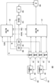
도 3을 참조하면, 본 발명의 다양한 실시예에 따른 프론트 엔드 모듈(예: 도 2a의 제 2 프론트 엔드 모듈(213) 또는 제 4 프론트 엔드 모듈(215))(300)은 제 1 통신 회로(예: 도 2a의 제 1 통신 회로(211))에 포함된 제 1 통신의 전송 포트와 연결되어 제 1 통신의 전송 신호를 수신하는 제 1 단자(301), 제 1 통신 회로(211)에 포함된 제 1 통신의 수신 포트와 연결되고, 제 1 통신의 수신 신호를 제 1 통신의 수신 포트로 전송하는 제 2 단자(303), 제 2 통신 회로(예; 도 2a의 제 2 통신 회로(221))에 포함된 제 2 통신의 수신 포트 또는 제 2 통신 회로(221)에 포함된 제 2 통신의 전송 포트와 연결되어, 제 2 통신의 전송 신호를 수신하거나, 제 2 통신의 수신 신호를 출력하는 제 3 단자(305) 및/또는 제 2 통신의 수신 포트 또는 제 2 통신의 전송 포트와 연결되어, 제 2 통신의 전송 신호를 수신하거나, 제 2 통신의 수신 신호를 출력하는 제 4 단자(307)를 포함할 수 있다. 프론트 엔드 모듈(300)은 제 1 단자(301)를 통해 제 1 통신 회로(예: 도 2a의 제 1 통신 회로(211))와 연결되어, 제 1 통신 회로(211)가 전송하는 신호를 수신하고, 수신한 신호를 제 1 증폭기(311)에 전송할 수 있다. 제 1 증폭기(311)는 수신한 신호를 증폭하고, 증폭된 신호를 안테나(예: 도 2의 제 1 안테나(241) 또는 제 2 안테나(242))로 전송할 수 있다.Referring to FIG. 3, a front-end module (e.g., the second front-end module (213) or the fourth front-end module (215) of FIG. 2A) (300) according to various embodiments of the present invention includes a first terminal (301) connected to a transmission port of a first communication included in a first communication circuit (e.g., the first communication circuit (211) of FIG. 2A) and receiving a transmission signal of the first communication, a second terminal (303) connected to a reception port of the first communication included in the first communication circuit (211) and transmitting a reception signal of the first communication to the reception port of the first communication, a third terminal (305) connected to a reception port of the second communication included in a second communication circuit (e.g., the second communication circuit (221) of FIG. 2A) or a transmission port of the second communication included in the second communication circuit (221) and receiving a transmission signal of the second communication or outputting a reception signal of the second communication, and/or a It may include a fourth terminal (307) connected to a receiving port of the second communication or a transmitting port of the second communication to receive a transmission signal of the second communication or output a reception signal of the second communication. The front-end module (300) may be connected to a first communication circuit (e.g., the first communication circuit (211) of FIG. 2A) via the first terminal (301), receive a signal transmitted by the first communication circuit (211), and transmit the received signal to the first amplifier (311). The first amplifier (311) may amplify the received signal and transmit the amplified signal to an antenna (e.g., the first antenna (241) or the second antenna (242) of FIG. 2).
본 발명의 다양한 실시예에 따르면, 프론트 엔드 모듈(300)은 제 2 단자(303), 제 3 단자(305) 및 제 4 단자(307) 중 하나의 단자와 증폭기 회로(323)를 연결하는 제 1 스위치(321)를 포함할 수 있다. 예를 들어, 제 1 스위치는 제 2 단자(303), 제 3 단자(305) 및 제 4 단자(307) 중 적어도 하나와 연결되는 복수의 출력 단자(throw)와 증폭기 회로(323)에 연결되는 하나의 극(pole)을 포함하는 스위치를 포함할 수 있다. 도 3에서의 제 1 스위치(321)는 SP3T(single pole three throw)로 구현될 수 있다.According to various embodiments of the present invention, the front end module (300) may include a first switch (321) connecting one of the second terminal (303), the third terminal (305), and the fourth terminal (307) and the amplifier circuit (323). For example, the first switch may include a switch including a plurality of output terminals (throws) connected to at least one of the second terminal (303), the third terminal (305), and the fourth terminal (307) and one pole connected to the amplifier circuit (323). The first switch (321) in FIG. 3 may be implemented as a single pole three throw (SP3T).
본 발명의 다양한 실시예에 따르면, 프론트 엔드 모듈(300)은 증폭기 회로(325)을 포함할 수 있다. 증폭기 회로(325)는 안테나(예: 도 2의 제 1 안테나(241), 또는 제 2 안테나(242))로부터 수신한 신호(예: 제 1 통신의 주파수 대역의 수신 신호 또는 제 2 통신의 주파수 대역의 수신 신호)를 증폭하는 제 2 증폭기(325) 및 제 2 증폭기(325)를 경유하지 않고 신호가 전송되는 경로인 바이패스 경로(327)를 포함할 수 있다. 예를 들어, 바이패스 경로(327)는 제 2 증폭기(325)를 경유하지 않기 위해서, 제 2 증폭기(325)와 병렬로 연결될 수 있다. 또 다른 예로, 바이패스 경로(327)는 안테나로부터 수신한 신호가 제 1 스위치(321)로 전송되는 경로로 이용될 수 있다. 일 실시예에 따르면, 바이패스 경로(327)는 제 2 통신 회로(221)가 전송하는 신호(예: 제 2 통신의 전송 신호)가 제 2 스위치(313) 및 안테나로 전송되는 경로로 이용될 수 있다. 일 실시예에 따르면, 바이패스 경로(327)는 스위치를 포함할 수 있다. 예를 들어, 제 1 통신 회로 (211), 또는 제 2 통신 회로(221)는 스위치를 닫힌 상태로 전환(또는, 유지)되도록 바이패스 경로(327)를 제어함으로써 바이패스 경로(327)를 활성화시킬수 있고, 제 2 통신 회로(221)가 전송하는 신호는 바이패스 경로(327)를 통해 안테나로 전송될 수 있다. 또 다른 예로, 제 1 통신 회로(211) 또는 제 2 통신 회로(221)는 스위치를 열린 상태로 전환(또는, 유지)되도록 바이패스 경로(327)를 제어함으로써 바이패스 경로(327)를 비활성화 시킬수 있고, 안테나가 수신한 신호(예: 제 1 통신의 수신 신호 또는 제 2 통신의 수신 신호)는 증폭기(325)를 통해 제 1 통신 회로(211) 또는 제 2 통신 회로(221)로 전송될 수 있다. 제 2 증폭기(325)는 바이패스 경로(327)가 활성화된 상태에서, 비활성화될 수 있다.According to various embodiments of the present invention, the front-end module (300) may include an amplifier circuit (325). The amplifier circuit (325) may include a second amplifier (325) that amplifies a signal (e.g., a reception signal of a frequency band of the first communication or a reception signal of a frequency band of the second communication) received from an antenna (e.g., a first antenna (241) or a second antenna (242) of FIG. 2) and a bypass path (327) that is a path through which a signal is transmitted without passing through the second amplifier (325). For example, the bypass path (327) may be connected in parallel with the second amplifier (325) in order to not pass through the second amplifier (325). As another example, the bypass path (327) may be used as a path through which a signal received from an antenna is transmitted to the first switch (321). According to one embodiment, the bypass path (327) may be used as a path through which a signal transmitted by the second communication circuit (221) (e.g., a transmission signal of the second communication) is transmitted to the second switch (313) and the antenna. According to one embodiment, the bypass path (327) may include a switch. For example, the first communication circuit (211) or the second communication circuit (221) may activate the bypass path (327) by controlling the bypass path (327) to switch (or maintain) the switch in a closed state, and the signal transmitted by the second communication circuit (221) may be transmitted to the antenna through the bypass path (327). As another example, the first communication circuit (211) or the second communication circuit (221) can disable the bypass path (327) by controlling the bypass path (327) to switch (or maintain) the switch in an open state, and a signal received by the antenna (e.g., a reception signal of the first communication or a reception signal of the second communication) can be transmitted to the first communication circuit (211) or the second communication circuit (221) through the amplifier (325). The second amplifier (325) can be disabled while the bypass path (327) is activated.
일 실시예에 따르면, 제 2 증폭기(325)는 저잡음 증폭기(low noise amplifier)를 포함할 수 있다.According to one embodiment, the second amplifier (325) may include a low noise amplifier.
본 발명의 다양한 실시예에 따르면, 프론트 엔드 모듈(300)은 증폭기 회로(323) 및 제 1 단자(301)(또는, 제 1 증폭기(311)) 중 하나와 안테나 포트(315)를 연결하는 제 2 스위치(313)를 포함할 수 있다. 제 2 스위치(313)는 제 1 통신의 전송 포트와 상기 제 1 스위치 중 적어도 하나와 연결되는 두 개의 출력 단자(throw)와 안테나 포트(315)와 연결되는 하나의 극(pole)을 포함하는 스위치를 포함할 수 있다. 도 3의 제 2 스위치는 SPDT(single pole double throws) 형태의 스위치를 포함할 수 있다. 일 실시 예에서, 안테나 포트(315)는 안테나(예: 제 1 안테나(241), 또는 제 2 안테나(242))와 연결될 수 있다.According to various embodiments of the present invention, the front end module (300) may include an amplifier circuit (323) and a second switch (313) connecting one of the first terminals (301) (or the first amplifier (311)) and the antenna port (315). The second switch (313) may include a switch having two output terminals (throws) connected to the transmission port of the first communication and at least one of the first switches and one pole connected to the antenna port (315). The second switch of FIG. 3 may include a switch of the SPDT (single pole double throws) type. In one embodiment, the antenna port (315) may be connected to an antenna (e.g., the first antenna (241) or the second antenna (242)).
본 발명의 다양한 실시예에 따르면, 제 2 통신 회로(221)는 제 2 통신을 통해 신호를 전송할 것을 결정하고, 제 2 통신을 통한 전송 신호의 전송을 요청하는 요청 신호를 제 1 통신 회로(211)로 전송할 수 있다. 제 1 통신 회로(211)는 요청 신호를 제 2 통신 회로(221)로부터 수신함에 대응하여, 프론트 엔드 모듈(300)이 제 2 통신을 통한 전송 신호를 제 1 안테나(241) 또는 제 2 안테나(242)로 전송할 수 있도록 프론트 엔드 모듈(300)을 제어할 수 있다.According to various embodiments of the present invention, the second communication circuit (221) may determine to transmit a signal through the second communication and transmit a request signal requesting transmission of the transmission signal through the second communication to the first communication circuit (211). In response to receiving the request signal from the second communication circuit (221), the first communication circuit (211) may control the front end module (300) so that the front end module (300) may transmit the transmission signal through the second communication to the first antenna (241) or the second antenna (242).
본 발명의 다양한 실시예에 따르면, 제 1 프로세서(211)는 요청 신호를 수신함에 대응하여, 제 2 통신의 전송 신호를 수신할 수 있도록 제 3 단자(305) 또는 제 4 단자(307) 중 어느 하나와 증폭기 회로(325)를 연결하도록 제 1 스위치를 제어할 수 있다. 일 실시 예에서, 제 1 통신 회로(211)는 제 2 증폭기(325)와 병렬로 구현된 바이패스 경로(327)를 활성화하도록 증폭기 회로(323)를 제어할 수 있다. 제 1 프로세서(211)는 제 2 증폭기(325)과 안테나 포트(315)를 연결하도록 제 2 스위치(313)를 제어할 수 있다. 예를 들어, 제 2 통신의 전송 신호는 제 1 스위치(321), 바이패스 경로(327) 및/또는 제 2 스위치(313)를 경유하여 안테나로 출력될 수 있다. 프론트 엔드 모듈(300)은 제 2 통신의 전송 신호가 바이패스 경로(327)를 통해 전송하도록 설계됨으로써, 제 1 통신 회로(211) 및 제 2 통신 회로(221)가 공통으로 이용할 수 있도록 구현될 수 있다. 제 2 증폭기(325)는 바이패스 경로(327)가 활성화된 상태에서, 비활성화될 수 있다.According to various embodiments of the present invention, in response to receiving a request signal, the first processor (211) may control the first switch to connect either the third terminal (305) or the fourth terminal (307) and the amplifier circuit (325) so as to receive a transmission signal of the second communication. In one embodiment, the first communication circuit (211) may control the amplifier circuit (323) to activate a bypass path (327) implemented in parallel with the second amplifier (325). The first processor (211) may control the second switch (313) to connect the second amplifier (325) and the antenna port (315). For example, the transmission signal of the second communication may be output to the antenna via the first switch (321), the bypass path (327), and/or the second switch (313). The front-end module (300) may be designed to transmit a transmission signal of the second communication through a bypass path (327), so that the first communication circuit (211) and the second communication circuit (221) can use it in common. The second amplifier (325) may be deactivated while the bypass path (327) is activated.
본 발명의 다양한 실시예에 따르면, 제 2 통신 회로(221)는 제 2 통신을 통해 신호를 수신할 것을 결정하고, 제 2 통신을 통한 신호의 수신을 요청하는 신호를 제 1 통신 회로(211)로 전송할 수 있다. 제 1 통신 회로(211)는 요청 신호를 제 2 통신 회로(221)로부터 수신함에 대응하여, 프론트 엔드 모듈(300)이 제 2 통신을 통한 수신 신호를 수신할 수 있도록 프론트 엔드 모듈(300)을 제어할 수 있다.According to various embodiments of the present invention, the second communication circuit (221) may determine to receive a signal through the second communication and transmit a signal requesting reception of the signal through the second communication to the first communication circuit (211). In response to receiving the request signal from the second communication circuit (221), the first communication circuit (211) may control the front end module (300) so that the front end module (300) may receive the reception signal through the second communication.
본 발명의 다양한 실시예에 따르면, 제 1 통신 회로(211)는 요청 신호를 수신함에 대응하여, 제 2 통신의 수신 신호를 수신할 수 있도록 제 3 단자(305) 또는 제 4 단자(307) 중 어느 하나와 증폭기 회로(323)를 연결하도록 제 1 스위치를 제어할 수 있다. 일 실시 예에서, 제 1 통신 회로(211)는 제 2 증폭기(325)와 병렬로 구현된 바이패스 경로(327)를 비활성화하도록 증폭기 회로(323)를 제어할 수 있다. 제 1 통신 회로(211)는 증폭기 회로(323)와 안테나 포트(315)를 연결하도록 제 2 스위치(313)를 제어할 수 있다. 예를 들어, 제 2 통신의 수신 신호는 제 2 스위치(313), 제 2 증폭기(325) 및/또는 제 1 스위치(321)를 경유하여 제 2 통신 회로(221)로 전송될 수 있다. 프론트 엔드 모듈(300)은 제 2 통신의 수신 신호가 증폭기 회로(323)를 통해 제 2 통신 회로(221)로 전송하도록 설계됨으로써, 제 1 통신 회로(211) 및 제 2 통신 회로(221)가 공통으로 이용할 수 있도록 구현될 수 있다.According to various embodiments of the present invention, the first communication circuit (211) may control the first switch to connect either the third terminal (305) or the fourth terminal (307) and the amplifier circuit (323) to receive a reception signal of the second communication in response to receiving the request signal. In one embodiment, the first communication circuit (211) may control the amplifier circuit (323) to deactivate a bypass path (327) implemented in parallel with the second amplifier (325). The first communication circuit (211) may control the second switch (313) to connect the amplifier circuit (323) and the antenna port (315). For example, the reception signal of the second communication may be transmitted to the second communication circuit (221) via the second switch (313), the second amplifier (325), and/or the first switch (321). The front-end module (300) is designed to transmit the reception signal of the second communication to the second communication circuit (221) through the amplifier circuit (323), so that it can be implemented so that the first communication circuit (211) and the second communication circuit (221) can use it in common.
본 발명의 다양한 실시예에 따르면, 제 1 통신 회로(211)는 제 1 통신을 통해 신호를 수신할 것을 결정하고, 프론트 엔드 모듈(300)이 제 1 통신을 통한 수신 신호를 수신할 수 있도록 프론트 엔드 모듈(300)을 제어할 수 있다.According to various embodiments of the present invention, the first communication circuit (211) may determine to receive a signal through the first communication and control the front end module (300) so that the front end module (300) can receive the reception signal through the first communication.
본 발명의 다양한 실시예에 따르면, 제 1 통신 회로(211)는 제 1 통신의 수신 신호를 수신할 수 있도록 제 2 단자(303)와 증폭기 회로(323)를 연결하도록 제 1 스위치를 제어할 수 있다. 일 실시 예에서, 제 1 프로세서(211)는 제 2 증폭기(325)와 병렬로 구현된 바이패스 경로(327)를 비활성화하도록 증폭기 회로(323)를 제어할 수 있다. 제 1 프로세서(211)는 증폭기 회로(323)와 안테나 포트(315)를 연결하도록 제 2 스위치(313)를 제어할 수 있다. 예를 들어, 제 1 통신의 수신 신호는 제 2 스위치(313), 제 2 증폭기(325) 및/또는 제 1 스위치(321)를 경유하여 제 1 프로세서(211)로 전송될 수 있다. 프론트 엔드 모듈(300)은 제 1 통신의 수신 신호가 증폭기 회로(323)를 통해 제 1 프로세서(211)로 전송하도록 설계됨으로써, 제 1 통신 회로(211) 및 제 2 통신 회로(221)가 공통으로 이용할 수 있도록 구현될 수 있다.According to various embodiments of the present invention, the first communication circuit (211) may control the first switch to connect the second terminal (303) and the amplifier circuit (323) so as to receive a reception signal of the first communication. In one embodiment, the first processor (211) may control the amplifier circuit (323) to deactivate a bypass path (327) implemented in parallel with the second amplifier (325). The first processor (211) may control the second switch (313) to connect the amplifier circuit (323) and the antenna port (315). For example, the reception signal of the first communication may be transmitted to the first processor (211) via the second switch (313), the second amplifier (325), and/or the first switch (321). The front-end module (300) is designed to transmit the reception signal of the first communication to the first processor (211) through the amplifier circuit (323), so that it can be implemented so that the first communication circuit (211) and the second communication circuit (221) can use it in common.
본 발명의 다양한 실시예에 따르면, 제 1 통신 회로(211)는 제 1 통신을 통해 신호를 전송할 것을 결정하고, 프론트 엔드 모듈(300)이 제 1 통신을 통한 전송 신호를 전송할 수 있도록 프론트 엔드 모듈(300)을 제어할 수 있다.According to various embodiments of the present invention, the first communication circuit (211) may determine to transmit a signal through the first communication and control the front end module (300) so that the front end module (300) can transmit the transmission signal through the first communication.
본 발명의 다양한 실시예에 따르면, 제 1 통신 회로(211)는 제 1 통신의 전송 신호를 전송할 수 있도록 제 1 단자(301)(또는, 제 1 증폭기(311))와 안테나 포트(315)를 연결하도록 제 2 스위치(313)를 제어할 수 있다. 예를 들어, 제 1 통신의 전송 신호는 제 1 증폭기(311) 및 제 2 스위치(313)를 경유하여 안테나로 전송될 수 있다.According to various embodiments of the present invention, the first communication circuit (211) can control the second switch (313) to connect the first terminal (301) (or, the first amplifier (311)) and the antenna port (315) so as to transmit a transmission signal of the first communication. For example, the transmission signal of the first communication can be transmitted to the antenna via the first amplifier (311) and the second switch (313).
본 발명의 다양한 실시예에 따르면, 제 2 통신 회로(221)는 프론트 엔드 모듈(예: 도 2의 제 1 프론트 엔드 모듈(212), 제 2 프론트 엔드 모듈(213), 제 3 프론트 엔드 모듈(214) 및/또는 제 4 프론트 엔드 모듈(215))을 직접적으로 제어하지 않을 수 있다. 예를 들어, 제 2 통신 회로(221)는 프론트 엔드 모듈의 제어를 요청하는 신호를 제 1 통신 회로(211)로 전송하고, 프론트 엔드 모듈의 제어는 제 1 통신 회로(211)에서 수행할 수 있다. 예를 들어, 제 2 통신 회로(221)와 프론트 엔드 모듈 사이의 제어 신호가 전송되지 않을 수 있어, 프론트 엔드 모듈의 제어 신호의 전송을 위한 별도의 선로가 요구되지 않으며, 회로 배치 공간을 감소시킬 수 있다.According to various embodiments of the present invention, the second communication circuit (221) may not directly control the front-end module (e.g., the first front-end module (212), the second front-end module (213), the third front-end module (214) and/or the fourth front-end module (215) of FIG. 2). For example, the second communication circuit (221) may transmit a signal requesting control of the front-end module to the first communication circuit (211), and the control of the front-end module may be performed by the first communication circuit (211). For example, since a control signal between the second communication circuit (221) and the front-end module may not be transmitted, a separate line for transmitting the control signal of the front-end module is not required, and the circuit layout space may be reduced.
도 4는 본 발명의 다른 실시예에 따른, 전자 장치의 통신 회로에 구현되는 프론트 엔드 모듈의 블록도이다.FIG. 4 is a block diagram of a front-end module implemented in a communication circuit of an electronic device according to another embodiment of the present invention.
도 4에 도시된 프론트 엔드 모듈(400)은 도 3에 도시된 프론트 엔드 모듈(300)에서, 보호 회로(410)가 추가될 수 있다. The front end module (400) illustrated in FIG. 4 may have a protection circuit (410) added to the front end module (300) illustrated in FIG. 3.
본 발명의 다양한 실시예에 따르면, 제 2 통신의 전송 신호가 전송되는 경로(예: 제 1 스위치(321), 바이패스 경로(327) 및 제 2 스위치(315)로 전송되는 경로)와 제 1 통신의 수신 신호 및 제 2 통신의 수신 신호가 전송되는 경로(예: 제 2 스위치(315), 제 2 증폭기(325) 및 제 1 스위치(321)로 전송되는 경로)가 서로 다를 수 있다. 일 실시 예에서, 제 2 통신의 전송 신호가 바이패스 경로(327) 및 제 2 증폭기(325)로 전송될 수 있다. 예를 들어, 제 2 통신의 전송 신호가 제 2 증폭기(325)의 출력단(420)으로 입력되는 상황이 발생하는 경우, 제 2 증폭기(325)가 파손되는 상황이 발생할 수 있다. 예를 들면, 제 2 통신이 초광대역 통신인 경우, 제 2 통신의 전송 신호의 세기가 상대적으로 높아, 제 2 증폭기(325)가 파손되는 상황이 발생할 수 있다.According to various embodiments of the present invention, a path along which a transmission signal of the second communication is transmitted (e.g., a path through which the transmission signal is transmitted to the first switch (321), the bypass path (327), and the second switch (315)) and a path along which a reception signal of the first communication and a reception signal of the second communication are transmitted (e.g., a path through which the reception signal of the second communication is transmitted to the second switch (315), the second amplifier (325), and the first switch (321)) may be different from each other. In one embodiment, the transmission signal of the second communication may be transmitted to the bypass path (327) and the second amplifier (325). For example, if a situation occurs in which a transmission signal of the second communication is input to an output terminal (420) of the second amplifier (325), a situation in which the second amplifier (325) is damaged may occur. For example, if the second communication is an ultra-wideband communication, the strength of the transmission signal of the second communication is relatively high, and a situation may occur in which the second amplifier (325) is damaged.
본 발명의 다양한 실시예에 따르면, 프론트 엔드 모듈(400)(예: 도 2a의 제 2 프론트 엔드 모듈(213) 또는 제 4 프론트 엔드 모듈(215))은 제 2 증폭기(325)의 출력단(420)과 제 1 스위치(321) 사이에 연결되는 보호 회로(410)를 더 포함할 수 있다. 일 실시 예에서, 보호 회로(410)는 수동 소자(passive element) 또는 능동 소자(active element)를 포함할 수 있다. 보호 회로(410)는 예를 들어, 제 2 통신의 전송 신호가 제 2 증폭기(325)로 입력되는 현상을 방지하거나, 또는 제 2 통신의 전송 신호가 제 2 증폭기(325)로 입력되는 현상을 감소시킬 수 있다. 예컨대, 보호 회로(410)는 제 2 증폭기(325)가 제 2 통신의 전송 신호에 의해 파손되는 현상을 감소시킬 수 있다.According to various embodiments of the present invention, the front-end module (400) (e.g., the second front-end module (213) or the fourth front-end module (215) of FIG. 2A) may further include a protection circuit (410) connected between the output terminal (420) of the second amplifier (325) and the first switch (321). In one embodiment, the protection circuit (410) may include a passive element or an active element. The protection circuit (410) may, for example, prevent a phenomenon in which a transmission signal of the second communication is input to the second amplifier (325), or reduce a phenomenon in which a transmission signal of the second communication is input to the second amplifier (325). For example, the protection circuit (410) may reduce a phenomenon in which the second amplifier (325) is damaged by a transmission signal of the second communication.
도 5는 본 발명의 다른 실시예에 따른, 전자 장치의 통신 회로를 도시한 블록도이다.FIG. 5 is a block diagram illustrating a communication circuit of an electronic device according to another embodiment of the present invention.
본 발명의 다양한 실시예에 따른 전자 장치(101)는 제 1 통신의 주파수 대역(예: 5.150GHz 내지 7.125GHz) 또는 제 2 통신의 주파수 대역(예: 6.24GHz 내지 8.2368GHz)과 일부 중복되는 주파수 대역을 갖는 제 3 통신을 통한 신호의 수신을 지원할 수 있다. 일 실시예에 따르면, 제 3 통신은 LAA(license assisted access) 통신 방식으로, 5.15GHz 내지 5.925GHz의 주파수 대역을 갖는 통신일 수 있다. 전자 장치(101)는 제 1 안테나(241) 또는 제 2 안테나(242)를 통해 제 3 통신의 수신 신호를 수신할 수 있다.An electronic device (101) according to various embodiments of the present invention may support reception of a signal through a third communication having a frequency band that partially overlaps with a frequency band of a first communication (e.g., 5.150 GHz to 7.125 GHz) or a frequency band of a second communication (e.g., 6.24 GHz to 8.2368 GHz). According to one embodiment, the third communication may be a communication having a frequency band of 5.15 GHz to 5.925 GHz in a license assisted access (LAA) communication manner. The electronic device (101) may receive a reception signal of the third communication through a first antenna (241) or a second antenna (242).
본 발명의 다양한 실시예에 따르면, 전자 장치(101)는 제 1 통신, 제 2 통신 또는 제 3 통신과 관련된 동작을 수행하는 커뮤니케이션 프로세서(예: 도 1의 통신 모듈(190))(520) 및/또는 제 1 통신, 제 2 통신 또는 제 3 통신을 이용한 데이터를 처리하는 어플리케이션 프로세서(예: 도 1의 프로세서(120))(530)를 포함할 수 있다. 일 실시 예에서, 커뮤니케이션 프로세서(520) 및 어플리케이션 프로세서(530)은 하나의 칩으로 형성될 수 있다.According to various embodiments of the present invention, the electronic device (101) may include a communication processor (e.g., a communication module (190) of FIG. 1) (520) that performs operations related to first communication, second communication, or third communication and/or an application processor (e.g., a processor (120) of FIG. 1) (530) that processes data using the first communication, second communication, or third communication. In one embodiment, the communication processor (520) and the application processor (530) may be formed into a single chip.
본 발명의 다양한 실시예에 따르면, 커뮤니케이션 프로세서(520)는 트랜시버(510)와 연결되고, 트랜시버(510)를 제어할 수 있다.According to various embodiments of the present invention, a communication processor (520) is connected to a transceiver (510) and can control the transceiver (510).
본 발명의 다양한 실시예에 따르면, 전자 장치(101)는 프론트 엔드 모듈(예: 도 2의 제 2 프론트 엔드 모듈(213) 또는 제 4 프론트 엔드 모듈(215), 도 3의 프론트 엔드 모듈(300), 도 4의 프론트 엔드 모듈(400)), 또는 제 3 통신을 통한 신호의 수신을 지원하기 위해서, 일부 구성 요소가 추가되거나, 수정될 수 있다.According to various embodiments of the present invention, the electronic device (101) may have some components added or modified to support reception of signals through a front-end module (e.g., the second front-end module (213) or the fourth front-end module (215) of FIG. 2, the front-end module (300) of FIG. 3, the front-end module (400) of FIG. 4), or a third communication.
본 발명의 다양한 실시예에 따르면, 제 2 프론트 엔드 모듈(213)은 제 1 안테나(241)를 통해 수신한 제 3 통신의 수신 신호를 제 3 스위치(501)를 통해 트랜시버(510)로 전송할 수 있다. 제 4 프론트 엔드 모듈(215)은 제 2 안테나(243)를 통해 수신한 제 3 통신의 수신 신호를 제 4 스위치(503)를 통해 트랜시버(510)로 전송할 수 있다.According to various embodiments of the present invention, the second front-end module (213) can transmit the reception signal of the third communication received through the first antenna (241) to the transceiver (510) through the third switch (501). The fourth front-end module (215) can transmit the reception signal of the third communication received through the second antenna (243) to the transceiver (510) through the fourth switch (503).
본 발명의 다양한 실시예에 따르면, 프론트 엔드 모듈(예: 도 2a의 제 2 프론트 엔드 모듈(213) 또는 제 4 프론트 엔드 모듈(215), 도 3의 프론트 엔드 모듈(300), 도 4의 프론트 엔드 모듈(400))에 구현된 제 1 스위치(예: 도 3의 제 1 스위치(321))는 제 3 통신의 수신 신호를 제 3 단자(예: 도 3의 제 3 단자 (305)) 또는 제 4 단자(예: 도 3의 제 4 단자(307))로 전송할 수 있다. According to various embodiments of the present invention, a first switch (e.g., a first switch (321) of FIG. 3) implemented in a front-end module (e.g., a second front-end module (213) or a fourth front-end module (215) of FIG. 2A, a front-end module (300) of FIG. 3, a front-end module (400) of FIG. 4) can transmit a reception signal of a third communication to a third terminal (e.g., a third terminal (305) of FIG. 3) or a fourth terminal (e.g., a fourth terminal (307) of FIG. 3).
일 실시예에 따르면, 제 3 통신의 수신 신호가 제 4 프론트 엔드 모듈(215)의 제 3 단자(305)로 전송되는 경우, 제 2 통신의 수신 신호는 제 2 프론트 엔드 모듈(213)의 제 3 단자(305)로 전송될 수 있다. 일 실시 예에서, 제 2 통신의 전송 신호 또는 수신 신호는 동일한 단자(예: 제 4 단자(307))를 통해 전송될 수 있다. 예를 들어, 제 2 통신의 전송 신호 또는 수신 신호가 동일한 단자(예: 제 4 단자(307))를 통해 전송되도록 제 2 프론트 엔드 모듈(213)이 설정되는 경우, 제 3 통신의 수신 신호는 다른 단자(예: 제 3 단자(305))를 통해 전송되도록 설정될 수 있다.According to one embodiment, when the reception signal of the third communication is transmitted to the third terminal (305) of the fourth front-end module (215), the reception signal of the second communication may be transmitted to the third terminal (305) of the second front-end module (213). In one embodiment, the transmission signal or the reception signal of the second communication may be transmitted through the same terminal (e.g., the fourth terminal (307)). For example, when the second front-end module (213) is set so that the transmission signal or the reception signal of the second communication is transmitted through the same terminal (e.g., the fourth terminal (307)), the reception signal of the third communication may be set to be transmitted through another terminal (e.g., the third terminal (305)).
본 발명의 다양한 실시예에 따르면, 제 2 통신의 전송 신호 및 제 2 통신의 수신 신호는 서로 상이한 단자를 통해 전송될 수 있다. 일 실시예에 따르면, 제 2 통신의 수신 신호와 제 3 통신의 수신 신호는 동일한 단자(예: 제 3 단자(305))를 통해 전송될 수 있으며, 제 2 통신의 전송 신호는 다른 단자(예: 제 4 단자(307))를 통해 출력될 수 있다.According to various embodiments of the present invention, the transmission signal of the second communication and the reception signal of the second communication may be transmitted through different terminals. According to one embodiment, the reception signal of the second communication and the reception signal of the third communication may be transmitted through the same terminal (e.g., the third terminal (305)), and the transmission signal of the second communication may be output through another terminal (e.g., the fourth terminal (307)).
본 발명의 다양한 실시예에 따르면, 제 2 통신의 수신 신호 또는 제 3 통신의 수신 신호가 동일한 단자(예: 제 3 단자(305))를 통해 전송되는 경우, 전자 장치(101)는 제 2 통신의 수신 신호 및 제 3 통신의 수신 신호의 전송 경로를 변경하는 제 3 스위치(501), 또는 제 4 스위치(503)를 더 포함할 수 있다. 일 실시 예에서, 제 3 스위치(501), 또는 제 4 스위치(503)는 제 2 통신의 수신 포트(또는, 제 2 프로세서(221))또는 제 3 통신의 수신 포트(또는, 제 3 통신의 수신 신호를 처리하는 트랜시버(510)) 중 하나의 포트와 제 1 스위치(321)(또는, 제 2 프론트 엔드 모듈(213) 또는 제 4 프론트 엔드 모듈(215))를 연결시킬 수 있다. 일 실시 예에서, 제 3 스위치(501), 또는 제 4 스위치(503)는 제 3 통신의 수신 신호를 처리하는 트랜시버(510), 제 1 통신 회로(211), 제 2 통신 회로(221) 또는 커뮤니케이션 프로세서(520) 에 의해 제어될 수 있다.According to various embodiments of the present invention, when the reception signal of the second communication or the reception signal of the third communication is transmitted through the same terminal (e.g., the third terminal (305)), the electronic device (101) may further include a third switch (501) or a fourth switch (503) that changes the transmission path of the reception signal of the second communication and the reception signal of the third communication. In one embodiment, the third switch (501) or the fourth switch (503) may connect one of the reception port of the second communication (or the second processor (221)) or the reception port of the third communication (or the transceiver (510) that processes the reception signal of the third communication) and the first switch (321) (or the second front-end module (213) or the fourth front-end module (215)). In one embodiment, the third switch (501) or the fourth switch (503) may be controlled by a transceiver (510), a first communication circuit (211), a second communication circuit (221), or a communication processor (520) that processes a received signal of the third communication.
본 발명의 다양한 실시예에 따르면, 제 1 통신 회로(211), 제 2 통신 회로(221) 또는 트랜시버(510)는 제 3 통신의 수신을 요청하는 신호를 커뮤니케이션 프로세서(520)로부터 수신함에 대응하여, 제 3 통신의 수신 포트와 제 1 스위치(321)를 연결하도록 제 3 스위치(501), 또는 제 4 스위치(503)를 제어할 수 있다. 예를 들어, 제 3 통신의 수신 신호는 제 1 안테나(241), 제 2 프론트 엔드 모듈(213), 제 3 스위치(501)를 통해 트랜시버(510)로 전달될 수 있다. 또 다른 예로, 제 3 통신의 수신 신호는 제 2 안테나(242), 제 4 프론트 엔드 모듈(215) 및 제 4 스위치(503)를 통해 트랜시버(510)로 전달될 수도 있다. 트랜시버(510)는 수신한 제 3 통신의 수신 신호를 처리하고, 처리된 수신 신호를 커뮤니케이션 프로세서(520)로 전송할 수 있다. 커뮤니케이션 프로세서(520)는 제 3 통신의 수신 신호에 포함된 데이터를 어플리케이션 프로세서(530)로 전송할 수 있다.According to various embodiments of the present invention, the first communication circuit (211), the second communication circuit (221), or the transceiver (510) may control the third switch (501) or the fourth switch (503) to connect the reception port of the third communication and the first switch (321) in response to receiving a signal requesting reception of the third communication from the communication processor (520). For example, the reception signal of the third communication may be transmitted to the transceiver (510) through the first antenna (241), the second front-end module (213), and the third switch (501). As another example, the reception signal of the third communication may be transmitted to the transceiver (510) through the second antenna (242), the fourth front-end module (215), and the fourth switch (503). The transceiver (510) can process the received third communication reception signal and transmit the processed reception signal to the communication processor (520). The communication processor (520) can transmit data included in the third communication reception signal to the application processor (530).
본 발명의 다양한 실시예에 따르면, 제 1 통신 회로(211) 또는 제 2 통신 회로(221)는 제 2 통신의 수신 신호의 수신을 위해, 제 3 스위치(501), 또는 제 4 스위치(503)를 제어할 수 있다. 예를 들어, 제 2 통신의 수신 신호는 제 1 안테나(241), 제 2 프론트 엔드 모듈(213), 제 3 스위치(501)를 통해 제 2 통신 회로(221)로 전달될 수 있다. 또 다른 예로, 제 3 통신의 수신 신호는 제 2 안테나(242), 제 4 프론트 엔드 모듈(215) 및 제 4 스위치(503)를 통해 제 2 통신 회로(221)로 전달될 수도 있다. 제 2 통신 회로(221)는 수신한 제 2 통신의 수신 신호를 처리하고, 처리된 수신 신호를 커뮤니케이션 프로세서(520)로 전송할 수 있다. 커뮤니케이션 프로세서(520)는 제 2 통신의 수신 신호에 포함된 데이터를 어플리케이션 프로세서(530)로 전송할 수 있다.According to various embodiments of the present invention, the first communication circuit (211) or the second communication circuit (221) may control the third switch (501) or the fourth switch (503) to receive a reception signal of the second communication. For example, the reception signal of the second communication may be transmitted to the second communication circuit (221) through the first antenna (241), the second front-end module (213), and the third switch (501). As another example, the reception signal of the third communication may be transmitted to the second communication circuit (221) through the second antenna (242), the fourth front-end module (215), and the fourth switch (503). The second communication circuit (221) may process the received reception signal of the second communication and transmit the processed reception signal to the communication processor (520). The communication processor (520) can transmit data included in the reception signal of the second communication to the application processor (530).
도 6은 본 발명의 다양한 실시예에 따른, 전자 장치의 통신 회로를 도시한 블록도이다.FIG. 6 is a block diagram illustrating a communication circuit of an electronic device according to various embodiments of the present invention.
도 6을 참조하면, 본 발명의 다양한 실시예에 따른 전자 장치(예; 도 1의 전자 장치(101))는 도 2a에 비해 제 2 통신을 통한 신호를 전송하거나, 수신하는데 이용하는 안테나 및 관련된 부품을 더 포함할 수 있다.Referring to FIG. 6, an electronic device (e.g., electronic device (101) of FIG. 1) according to various embodiments of the present invention may further include an antenna and related components used to transmit or receive a signal through second communication compared to FIG. 2A.
본 발명의 다양한 실시예에 따르면, 전자 장치(101)는 제 1 통신 회로 (예: 도 2a의 제 1 통신 회로 (211))(611), 제 2 통신 회로(예: 도 2a의 제 2 통신 회로(221))(621), 다이플렉서(예: 도 2a의 제 1 다이플렉서(231))(631), 제 5 스위치(634), 제 6 스위치(635), 제 1 필터(632), 제 2 필터(633), 제 3 필터(636), 제 4 필터(637), 제 1 안테나(예: 도 2의 제 1 안테나(241))(641), 제 2 안테나(642), 제 3 안테나(643), 제 4 안테나(644), 제 5 안테나(645) 트랜시버(650), 커뮤니케이션 프로세서(예: 도 1의 통신 모듈(190), 도 5의 커뮤니케이션 프로세서(520))(660) 및/또는 어플리케이션 프로세서(예: 도 1의 프로세서(120), 도 5의 어플리케이션 프로세서(530))(670)를 포함할 수 있다.According to various embodiments of the present invention, the electronic device (101) includes a first communication circuit (e.g., the first communication circuit (211) of FIG. 2A) (611), a second communication circuit (e.g., the second communication circuit (221) of FIG. 2A) (621), a diplexer (e.g., the first diplexer (231) of FIG. 2A) (631), a fifth switch (634), a sixth switch (635), a first filter (632), a second filter (633), a third filter (636), a fourth filter (637), a first antenna (e.g., the first antenna (241) of FIG. 2) (641), a second antenna (642), a third antenna (643), a fourth antenna (644), a fifth antenna (645), a transceiver (650), a communication processor (e.g., the communication module (190) of FIG. 1, FIG. 5 may include a communication processor (520))(660) and/or an application processor (e.g., the processor (120) of FIG. 1, the application processor (530))(670) of FIG. 5.
본 발명의 다양한 실시예에 따르면, 전자 장치(101)는 제 1 통신을 통한 신호의 수신 또는 제 1 통신을 통한 신호의 전송을 수행하기 위한 다양한 부품들(예: 프론트 엔드 모듈, 증폭기, 스위치 또는 스플리터)을 포함할 수 있다. 제 1 통신은 전자 장치(101)가 지원하는 다양한 무선 통신들 중 하나의 통신을 의미할 수 있다. 예를 들면, 제 1 통신은 전자 장치(101)가 지원하는 Wi-Fi 통신일 수 있다. 전자 장치(101)는 제 1 통신을 통한 신호의 전송 또는 신호의 수신을 제어하는 제 1 통신 회로(611)를 포함할 수 있다. 제 1 통신 회로(611)는 커뮤니케이션 프로세서(660)와 연결되어, 커뮤니케이션 프로세서(660)의 제어에 기반하여 동작할 수 있다.According to various embodiments of the present invention, the electronic device (101) may include various components (e.g., a front-end module, an amplifier, a switch, or a splitter) for receiving a signal through the first communication or transmitting a signal through the first communication. The first communication may mean one of various wireless communications supported by the electronic device (101). For example, the first communication may be Wi-Fi communication supported by the electronic device (101). The electronic device (101) may include a first communication circuit (611) that controls transmitting a signal through the first communication or receiving a signal. The first communication circuit (611) may be connected to a communication processor (660) and may operate based on the control of the communication processor (660).
본 발명의 다양한 실시예에 따르면, 전자 장치(101)는 제 2 통신을 통한 신호의 수신 또는 제 2 통신을 통한 신호의 전송을 수행하기 위한 다양한 부품들(예: 증폭기, 스위치 또는 스플리터)을 포함할 수 있다. 제 2 통신은 전자 장치(101)가 지원하는 다양한 무선 통신들 중 하나의 통신으로, 제 1 통신과 다른 통신을 의미할 수 있다. 예를 들면, 제 2 통신은 전자 장치(101)가 지원하는 초 광대역 통신(ultra wideband communication, UWB)일 수 있다. 전자 장치(101)는 제 2 통신을 통한 신호의 전송 또는 신호의 수신을 제어하는 제 2 통신 모듈(621) 를 포함할 수 있다. 제 2 통신 모듈(621)는 제 2 통신의 전송 신호를 출력하는 적어도 하나 이상의 제 2 통신의 전송 포트 및 제 2 통신의 수신 신호를 수신하는 적어도 하나 이상의 제 2 통신의 수신 포트를 포함할 수 있다. 제 2 통신 회로(621)는 커뮤니케이션 프로세서(660)와 연결되어, 커뮤니케이션 프로세서(660)의 제어에 기반하여 동작할 수 있다.According to various embodiments of the present invention, the electronic device (101) may include various components (e.g., an amplifier, a switch, or a splitter) for receiving a signal through the second communication or transmitting a signal through the second communication. The second communication may be one of various wireless communications supported by the electronic device (101) and may mean a different communication from the first communication. For example, the second communication may be ultra wideband communication (UWB) supported by the electronic device (101). The electronic device (101) may include a second communication module (621) for controlling the transmission of a signal through the second communication or the reception of a signal. The second communication module (621) may include at least one second communication transmission port for outputting a second communication transmission signal and at least one second communication reception port for receiving a second communication reception signal. The second communication circuit (621) is connected to the communication processor (660) and can operate based on the control of the communication processor (660).
본 발명의 다양한 실시예에 따르면, 트랜시버(650)는 제 3 통신을 통한 신호의 수신을 수행하기 위한 다양한 부품들(예: 증폭기, 스위치 또는 스플리터)을 포함할 수 있다. 제 3 통신은 전자 장치(101)가 지원하는 다양한 무선 통신들 중 하나의 통신으로, 제 1 통신 및 제 2 통신과 다른 통신을 의미할 수 있다. 예를 들면, 제 3 통신은 전자 장치(101)가 지원하는 LAA(lincensed assist access)일 수 있다.According to various embodiments of the present invention, the transceiver (650) may include various components (e.g., an amplifier, a switch, or a splitter) for performing reception of a signal through a third communication. The third communication may be one of various wireless communications supported by the electronic device (101), and may mean a communication different from the first communication and the second communication. For example, the third communication may be LAA (licensed assist access) supported by the electronic device (101).
본 발명의 다양한 실시예에 따르면, 제 1 통신의 주파수 대역, 제 2 통신의 주파수 대역 및 제 3 통신의 주파수 대역은 적어도 일부가 중첩될 수 있다. 예를 들면, 제 1 통신이 IEEE 802.11 ax(또는, Wi-Fi 6)를 지원하는 통신인 경우, 제 1 통신의 주파수 대역은 5.15GHz ~ 7.125GHz일 수 있다. 제 2 통신이 UWB인 경우, 제 2 통신의 주파수 대역은 6.24GHz ~ 8.24GHz일 수 있다. 제 3 통신이 LAA인 경우, 제 3 통신의 주파수 대역은 5.15 GHz ~ 5.925GHz일 수 있다. 제 1 통신의 주파수 대역, 제 2 통신의 주파수 대역은 6.24GHz ~ 7.125GHz 주파수 내에서 중복될 수 있으며, 제 1 통신의 주파수 대역 및 제 3 통신의 주파수 대역은 5.15GHz ~ 5.925GHz 내에서 중복될 수 있다.According to various embodiments of the present invention, the frequency band of the first communication, the frequency band of the second communication, and the frequency band of the third communication may overlap at least partially. For example, if the first communication is communication supporting IEEE 802.11 ax (or, Wi-Fi 6), the frequency band of the first communication may be 5.15 GHz to 7.125 GHz. If the second communication is UWB, the frequency band of the second communication may be 6.24 GHz to 8.24 GHz. If the third communication is LAA, the frequency band of the third communication may be 5.15 GHz to 5.925 GHz. The frequency band of the first communication and the frequency band of the second communication may overlap within a frequency of 6.24 GHz to 7.125 GHz, and the frequency band of the first communication and the frequency band of the third communication may overlap within a frequency of 5.15 GHz to 5.925 GHz.
본 발명의 다양한 실시예에 따르면, 전자 장치(101)는 제 1 통신 회로(611), 제 1 프론트 엔드 모듈(front end module, FEM)(예: 도 2a의 제 1 프론트 엔드 모듈(212))(612), 제 2 프론트 엔드 모듈(예: 도 2a의 제 2 프론트 엔드 모듈(213), 도 3의 프론트 엔드 모듈(300), 도 4의 프론트 엔드 모듈(300)) (613), 제 3 프론트 엔드 모듈(예: 도 2a의 제 3 프론트 엔드 모듈(214))(614) 및/또는 제 4 프론트 엔드 모듈(예: 도 2a의 제 4 프론트 엔드 모듈(215), 도 3의 프론트 엔드 모듈(300), 도 4의 프론트 엔드 모듈(300))(615)을 포함할 수 있다. According to various embodiments of the present invention, the electronic device (101) may include a first communication circuit (611), a first front end module (FEM) (e.g., the first front end module (212) of FIG. 2A) (612), a second front end module (e.g., the second front end module (213) of FIG. 2A, the front end module (300) of FIG. 3, the front end module (300) of FIG. 4) (613), a third front end module (e.g., the third front end module (214) of FIG. 2A) (614), and/or a fourth front end module (e.g., the fourth front end module (215) of FIG. 2A, the front end module (300) of FIG. 3, the front end module (300) of FIG. 4) (615).
본 발명의 다양한 실시예에 따르면, 제 1 통신 회로(611)는 제 1 통신을 통한 신호의 전송 또는 신호의 수신을 제어할 수 있다. According to various embodiments of the present invention, the first communication circuit (611) can control transmission of a signal or reception of a signal through the first communication.
본 발명의 다양한 실시예에 따르면, 제 1 프론트 엔드 모듈(612)은 제 1 안테나(641)를 통해 수신한 신호를 증폭하거나, 수신한 신호의 노이즈를 제거한 제 1 통신의 수신 신호를 제 1 통신 회로(611)로 전송할 수 있다. 제 1 프론트 엔드 모듈(612)은 제 1 통신 회로(611)가 전송한 제 1 통신의 전송 신호를 증폭하거나, 노이즈를 제거하는 처리를 수행할 수 있다. 처리된 신호는 다이플렉서(631)를 경유하여 제 1 안테나(641)를 통해 출력될 수 있다. 제 1 프론트 엔드 모듈(612)이 수신하거나, 출력하는 신호의 대역은 제 1 주파수 대역으로 정의할 수 있다. 예를 들어, 제 1 주파수 대역은 제 1 통신의 주파수 대역 중 일부의 주파수 대역(예: 2.4 GHz 내지 2.5GHz)일 수 있다.According to various embodiments of the present invention, the first front-end module (612) may amplify a signal received through the first antenna (641) or transmit a reception signal of the first communication with noise removed from the received signal to the first communication circuit (611). The first front-end module (612) may perform processing to amplify or remove noise from the transmission signal of the first communication transmitted by the first communication circuit (611). The processed signal may be output through the first antenna (641) via the diplexer (631). The band of the signal received or output by the first front-end module (612) may be defined as a first frequency band. For example, the first frequency band may be a part of a frequency band of the first communication (e.g., 2.4 GHz to 2.5 GHz).
본 발명의 다양한 실시예에 따르면, 제 2 프론트 엔드 모듈(613)은 제 1 안테나(641)를 통해 수신한 신호를 증폭하거나, 수신한 신호의 노이즈를 제거한 제 1 통신의 수신 신호를 제 1 통신 회로(611)로 전송할 수 있다. 제 2 프론트 엔드 모듈(613)은 제 1 통신 회로(611)가 전송한 제 1 통신의 전송 신호를 증폭하거나, 노이즈를 제거하는 처리를 수행할 수 있다. 처리된 신호는 다이플렉서(631)를 경유하여 제 1 안테나(641)를 통해 출력할 수 있다. 제 2 프론트 엔드 모듈(613)이 수신하거나, 출력하는 신호의 대역은 제 2 주파수 대역으로 정의할 수 있다. 예를 들어, 제 2 주파수 대역은 제 1 통신의 주파수 대역 중 일부의 주파수 대역(예: 5.15 GHz 내지 7.125GHz), 제 2 통신의 주파수 대역 중 일부의 주파수 대역(예: 6.24GHz ~ 7.25GHz) 및/또는 제 3 통신의 주파수 대역(예: 5.15 GHz ~ 5.925GHz)을 포함하는 주파수 대역(예: 5.15GHz ~ 7.25GHz)일 수 있다.According to various embodiments of the present invention, the second front-end module (613) may amplify a signal received through the first antenna (641) or transmit a reception signal of the first communication with noise removed from the received signal to the first communication circuit (611). The second front-end module (613) may perform processing to amplify or remove noise from the transmission signal of the first communication transmitted by the first communication circuit (611). The processed signal may be output through the first antenna (641) via the diplexer (631). The band of the signal received or output by the second front-end module (613) may be defined as a second frequency band. For example, the second frequency band may be a frequency band (e.g., 5.15 GHz to 7.125 GHz) that includes a portion of the frequency band of the first communication (e.g., 6.24 GHz to 7.25 GHz), a portion of the frequency band of the second communication (e.g., 6.24 GHz to 7.25 GHz), and/or a frequency band of the third communication (e.g., 5.15 GHz to 5.925 GHz).
본 발명의 다양한 실시예에 따르면, 제 1 안테나(641)는 외부 전자 장치가 전송하는 신호를 수신할 수 있다. 예를 들어, 제 1 안테나(641)는 제 1 주파수 대역(예: 2.4GHz 내지 2.5GHz)의 신호 및/또는 제 2 주파수 대역(예: 5.15GHz 내지 7.25GHz)의 신호를 수신하거나, 출력할 수 있다. 다이플렉서(631)는 제 1 안테나(641)가 수신한 신호를 주파수 대역에 따라서 필터링할 수 있다. 일 실시예에 따르면, 다이플렉서(631)는 수신한 신호 중 제 1 주파수 대역의 신호를 제 1 프론트 엔드 모듈(612)로 전송할 수 있다. 일 실시예에 따르면, 다이플렉서(631)는 수신한 신호 중 제 2 주파수 대역의 신호를 제 2 프론트 엔드 모듈(613)로 전송할 수 있다. According to various embodiments of the present invention, the first antenna (641) can receive a signal transmitted by an external electronic device. For example, the first antenna (641) can receive or output a signal of a first frequency band (e.g., 2.4 GHz to 2.5 GHz) and/or a signal of a second frequency band (e.g., 5.15 GHz to 7.25 GHz). The diplexer (631) can filter the signal received by the first antenna (641) according to the frequency band. According to one embodiment, the diplexer (631) can transmit a signal of the first frequency band among the received signals to the first front-end module (612). According to one embodiment, the diplexer (631) can transmit a signal of the second frequency band among the received signals to the second front-end module (613).
본 발명의 다양한 실시예에 따르면, 제 2 프론트 엔드 모듈(613)은 제 1 통신의 주파수 대역 중 적어도 일부의 주파수 대역, 또는 제 2 통신의 주파수 대역 중 적어도 일부의 주파수 대역의 신호의 전송 또는 수신을 지원할 수 있다. 제 2 프론트 엔드 모듈(613)은 제 3 통신의 주파수 대역의 신호의 수신을 지원할 수 있다. 일 실시 예에서, 제 2 프론트 엔드 모듈(613)은 제 1 통신을 통한 신호의 전송 또는 수신을 제어하는 제 1 프로세서(611), 제 2 통신을 통한 신호의 전송 또는 수신을 제어하는 제 2 프로세서(621), 또는 제 3 통신을 통한 신호의 수신을 제어하는 트랜시버(650)와 연결될 수 있다. 일 실시 예에서, 제 2 프론트 엔드 모듈(631)은 제 1 안테나(641)가 수신한 제 1 통신의 주파수 대역의 신호를 처리(예: 증폭 또는 노이즈 제거)하고, 처리된 제 1 통신의 수신 신호를 제 1 프로세서(611)로 전송할 수 있다. 제 2 프론트 엔드 모듈(613)은 제 1 안테나(641)가 수신한 제 2 통신의 주파수 대역의 신호를 처리(예: 증폭 또는 노이즈 제거)하고, 처리된 제 2 통신의 수신 신호를 제 5 스위치(634)를 통해 제 2 통신 모듈(620)으로 전송할 수 있다. 제 2 프론트 엔드 모듈(613)은 제1 안테나(641)가 수신한 제 3 통신의 주파수 대역의 신호를 처리(예: 증폭 또는 노이즈 제거)하고, 처리된 제 3 통신의 수신 신호를 트랜시버(650)로 전송할 수 있다.According to various embodiments of the present invention, the second front-end module (613) can support transmission or reception of a signal in at least a part of the frequency band of the first communication, or in at least a part of the frequency band of the second communication. The second front-end module (613) can support reception of a signal in the frequency band of the third communication. In one embodiment, the second front-end module (613) can be connected to a first processor (611) that controls transmission or reception of a signal through the first communication, a second processor (621) that controls transmission or reception of a signal through the second communication, or a transceiver (650) that controls reception of a signal through the third communication. In one embodiment, the second front-end module (631) may process (e.g., amplify or remove noise) a signal of a frequency band of a first communication received by the first antenna (641) and transmit the processed reception signal of the first communication to the first processor (611). The second front-end module (613) may process (e.g., amplify or remove noise) a signal of a frequency band of a second communication received by the first antenna (641) and transmit the processed reception signal of the second communication to the second communication module (620) via the fifth switch (634). The second front-end module (613) may process (e.g., amplify or remove noise) a signal of a frequency band of a third communication received by the first antenna (641) and transmit the processed reception signal of the third communication to the transceiver (650).
일 실시 예에서, 제 2 프론트 엔드 모듈(613)은 제 1 프로세서(611)가 전송한 제 1 통신의 전송 신호를 처리(예: 증폭 또는 노이즈 제거)하고, 처리된 신호를 제 1 안테나(641)로 전송할 수 있다. 제 2 프론트 엔드 모듈(631)은 제 2 프로세서(621)가 전송하는 제 2 통신의 전송 신호를 처리(예: 증폭 또는 노이즈 제거)하고, 처리된 신호를 제 1 안테나(641)로 전송할 수 있다.In one embodiment, the second front-end module (613) may process (e.g., amplify or remove noise) a transmission signal of a first communication transmitted by the first processor (611) and transmit the processed signal to the first antenna (641). The second front-end module (631) may process (e.g., amplify or remove noise) a transmission signal of a second communication transmitted by the second processor (621) and transmit the processed signal to the first antenna (641).
일 실시 예에 따르면, 상기에 기재된 동작은 제 1 프로세서(611)가 제 2 프론트 엔드 모듈(613)을 제어함으로써 구현될 수 있다. 예를 들어, 제 1 통신 회로(611)는 커뮤니케이션 프로세서(660)으로부터 제 1 통신을 통한 신호의 전송 또는 수신을 요청하는 신호, 제 2 통신 회로(622)로부터 제 2 통신을 통한 신호의 전송 또는 수신을 요청하는 신호 또는 트랜시버(650)로부터 또는 제 3 통신을 통한 신호의 수신을 요청하는 신호를 수신하고, 제 2 프론트 엔드 모듈(613) 내에 구현된 제 1 스위치(예: 도 3의 제 1 스위치(305)), 증폭기 회로(예: 도 3의 증폭기 회로(325)) 및/또는 제 2 스위치(예: 도 3의 제 2 스위치(313))를 제어함으로써, 제 1 통신을 통한 신호의 전송 또는 수신, 제 2 통신을 통한 신호의 전송 또는 수신, 또는 제 3 통신을 통한 신호의 수신을 수행할 수 있다.According to one embodiment, the above-described operation may be implemented by the first processor (611) controlling the second front-end module (613). For example, the first communication circuit (611) may receive a signal requesting transmission or reception of a signal through the first communication from the communication processor (660), a signal requesting transmission or reception of a signal through the second communication from the second communication circuit (622), or a signal requesting reception of a signal through the third communication from the transceiver (650), and control a first switch (e.g., the first switch (305) of FIG. 3), an amplifier circuit (e.g., the amplifier circuit (325) of FIG. 3), and/or a second switch (e.g., the second switch (313) of FIG. 3) implemented in the second front-end module (613), thereby performing transmission or reception of a signal through the first communication, transmission or reception of a signal through the second communication, or reception of a signal through the third communication.
본 발명의 다양한 실시예에 따르면, 제 3 프론트 엔드 모듈(614)은 제 2 안테나(642)를 통해 수신한 신호를 증폭하거나, 수신한 신호의 노이즈를 제거한 신호를 제 1 통신 회로(611)로 전송할 수 있다. 제 3 프론트 엔드 모듈(614)은 제 1 통신 회로(611)가 전송한 신호를 증폭하거나, 노이즈를 제거하는 처리를 수행할 수 있다. 처리된 신호는 제 1 필터(632)를 통해 제 2 안테나(642)를 통해 출력할 수 있다. 일 실시 예에서, 제 2 안테나(642)는 제 1 주파수 대역에 대응하는 신호를 수신하거나, 출력하는 안테나일 수 있다. 제 1 필터(632)는, 예를 들어, 제 3 프론트 엔드 모듈(614)이 전송한 신호 또는 제 2 안테나(642)가 전송한 신호 중 일부 주파수 대역(예: 2.4GHz ~ 2.5GHz)을 제외한 나머지 주파수 대역의 신호를 감소시키거나, 제거하는 필터일 수 있다. 일 실시 예에서, 제 3 프론트 엔드 모듈(614)이 수신하거나, 출력하는 신호의 대역은 제 1 프론트 엔드 모듈(212)이 수신하거나, 출력하는 신호의 대역인 제 1 주파수 대역과 실질적으로 동일할 수 있다.According to various embodiments of the present invention, the third front-end module (614) may amplify a signal received through the second antenna (642) or transmit a signal with noise removed from the received signal to the first communication circuit (611). The third front-end module (614) may perform processing to amplify or remove noise from the signal transmitted by the first communication circuit (611). The processed signal may be output through the second antenna (642) via the first filter (632). In one embodiment, the second antenna (642) may be an antenna that receives or outputs a signal corresponding to the first frequency band. The first filter (632) may be, for example, a filter that reduces or removes signals in a frequency band other than a portion of a frequency band (e.g., 2.4 GHz to 2.5 GHz) among the signals transmitted by the third front-end module (614) or the signals transmitted by the second antenna (642). In one embodiment, the band of the signal received or output by the third front-end module (614) may be substantially the same as the first frequency band, which is the band of the signal received or output by the first front-end module (212).
본 발명의 다양한 실시예에 따르면, 제 4 프론트 엔드 모듈(615)은 제 1 통신의 주파수 대역 중 적어도 일부의 주파수 대역, 제 2 통신의 주파수 대역 중 적어도 일부의 주파수 대역, 제 3 통신의 주파수 대역의 신호의 전송 또는 수신을 지원할 수 있다. 일 실시 예에서, 제 4 프론트 엔드 모듈(615)은 제 1 통신을 통한 신호의 전송 또는 수신을 제어하는 제 1 통신 회로(611), 제 2 통신을 통한 신호의 전송 또는 수신을 제어하는 제 2 통신 회로(621) 및 제 3 통신을 통한 신호의 수신을 제어하는 트랜시버(650)와 연결될 수 있다. 일 실시 예에서, 제 4 프론트 엔드 모듈(615)은 제 3 안테나(643)가 수신한 제 1 통신의 일부 주파수 대역(예: 5.15 GHz ~ 7.25GHz)의 신호를 처리(예: 증폭 또는 노이즈 제거)하고, 처리된 제 1 통신의 수신 신호를 제 1 통신 회로(611)로 전송할 수 있다. 제 4 프론트 엔드 모듈(615)은 제 3 안테나(643)가 수신한 제 2 통신의 일부 주파수 대역(예: 6.24 GHz ~ 7.25GHz)의 신호를 처리(예: 증폭 또는 노이즈 제거)하고, 처리된 제 2 통신의 수신 신호를 제 6 스위치(635)를 통해 제 2 통신 모듈(620)(또는, 제 2 프로세서(621))으로 전송할 수 있다. 제 4 프론트 엔드 모듈(615)은 제 3 안테나(643)가 수신한 제 3 통신의 주파수 대역 중 일부 대역(예: 6.24GHz ~ 7.25GHz)의 신호를 처리(예: 증폭 또는 노이즈 제거)하고, 처리된 제 3 통신의 수신 신호를 트랜시버(650)로 전송할 수 있다.According to various embodiments of the present invention, the fourth front-end module (615) can support transmission or reception of a signal in at least a part of a frequency band of the first communication, at least a part of a frequency band of the second communication, and a frequency band of the third communication. In one embodiment, the fourth front-end module (615) can be connected to a first communication circuit (611) that controls transmission or reception of a signal through the first communication, a second communication circuit (621) that controls transmission or reception of a signal through the second communication, and a transceiver (650) that controls reception of a signal through the third communication. In one embodiment, the fourth front-end module (615) may process (e.g., amplify or remove noise) a signal of a part of a frequency band (e.g., 5.15 GHz to 7.25 GHz) of the first communication received by the third antenna (643) and transmit the processed reception signal of the first communication to the first communication circuit (611). The fourth front-end module (615) may process (e.g., amplify or remove noise) a signal of a part of a frequency band (e.g., 6.24 GHz to 7.25 GHz) of the second communication received by the third antenna (643) and transmit the processed reception signal of the second communication to the second communication module (620) (or, the second processor (621)) via the sixth switch (635). The fourth front-end module (615) can process (e.g., amplify or remove noise) a signal of a portion of the frequency band (e.g., 6.24 GHz to 7.25 GHz) of the third communication received by the third antenna (643) and transmit the processed third communication reception signal to the transceiver (650).
일 실시 예에서, 제 4 프론트 엔드 모듈(615)은 제 1 프로세서(611)가 전송한 제 1 통신의 전송 신호를 처리(예: 증폭 또는 노이즈 제거)하고, 처리된 신호를 제 3 안테나(643)로 전송할 수 있다. 제 4 프론트 엔드 모듈(615)은 제 2 통신 회로(621)가 전송하는 제 2 통신의 전송 신호를 처리(예: 증폭 또는 노이즈 제거)하고, 처리된 신호를 제 3 안테나(643)로 전송할 수 있다.In one embodiment, the fourth front-end module (615) may process (e.g., amplify or remove noise) a transmission signal of a first communication transmitted by the first processor (611) and transmit the processed signal to the third antenna (643). The fourth front-end module (615) may process (e.g., amplify or remove noise) a transmission signal of a second communication transmitted by the second communication circuit (621) and transmit the processed signal to the third antenna (643).
본 발명의 다양한 실시예에 따르면, 제 3 안테나(643)는 제 1 통신의 일부 주파수 대역(예; 5.15 GHz ~ 7.25GHz), 제 2 통신의 일부 주파수 대역(예; 6.24GHz ~ 7.25GHz) 및 제 3 통신의 일부 주파수 대역(5.15 ~ 5.925GHz)의 신호를 수신하거나, 출력할 수 있다. 일 실시 예에서, 제 3 안테나(643)과 제 4 프론트 엔드 모듈(633) 사이에는 제 2 필터(633)가 배치될 수 있다. 예를 들어, 제 2 필터(633)는 제 4 프론트 엔드 모듈(615)이 전송한 신호 또는 제 3 안테나(643)가 전송한 신호 중 일부 주파수 대역(예: 5.15 GHz ~ 7.25GHz)을 제외한 나머지 주파수 대역의 신호를 감소시키거나, 제거하는 필터일 수 있다.According to various embodiments of the present invention, the third antenna (643) may receive or output signals of a portion of the frequency band (e.g., 5.15 GHz to 7.25 GHz) of the first communication, a portion of the frequency band (e.g., 6.24 GHz to 7.25 GHz) of the second communication, and a portion of the frequency band (5.15 to 5.925 GHz) of the third communication. In one embodiment, a second filter (633) may be arranged between the third antenna (643) and the fourth front-end module (633). For example, the second filter (633) may be a filter that reduces or removes signals of a frequency band other than a portion of the frequency band (e.g., 5.15 GHz to 7.25 GHz) of a signal transmitted by the fourth front-end module (615) or a signal transmitted by the third antenna (643).
일 실시 예에 따르면, 상기에 기재된 동작은 제 1 통신 회로(611)가 제 4 프론트 엔드 모듈(615)을 제어함으로써 구현될 수 있다. 예를 들어, 제 1 통신 회로(611)는 제 2 통신 회로 (622)로부터 제 2 통신을 통한 신호의 전송 또는 수신을 요청하는 신호 또는 트랜시버(650)로부터 또는 제 3 통신을 통한 신호의 수신을 요청하는 신호를 수신하고, 제 4 프론트 엔드 모듈(615) 내에 구현된 제 1 스위치(예: 도 3의 제 1 스위치(305)), 증폭기 회로(예: 도 3의 증폭기 회로(325)) 및/또는 제 2 스위치(예: 도 3의 제 2 스위치(313))를 제어함으로써, 제 1 통신을 통한 신호의 전송 또는 수신, 제 2 통신을 통한 신호의 전송 또는 수신 또는 제 3 통신을 통한 신호의 수신을 수행할 수 있다.According to one embodiment, the operation described above can be implemented by the first communication circuit (611) controlling the fourth front-end module (615). For example, the first communication circuit (611) receives a signal requesting transmission or reception of a signal through the second communication from the second communication circuit (622) or a signal requesting reception of a signal through the third communication from the transceiver (650), and controls a first switch (e.g., the first switch (305) of FIG. 3), an amplifier circuit (e.g., the amplifier circuit (325) of FIG. 3) and/or a second switch (e.g., the second switch (313) of FIG. 3) implemented in the fourth front-end module (615), thereby performing transmission or reception of a signal through the first communication, transmission or reception of a signal through the second communication, or reception of a signal through the third communication.
본 발명의 다양한 실시예에 따르면, 전자 장치(101)는 제 2 통신의 일부 주파수 대역(예: 7.25GHz 내지 8.25GHz)에 대응하는 신호의 전송 또는 수신을 위한 별도의 안테나(예: 제 4 안테나(644) 및 제 5 안테나(645)) 및 별도의 구성 요소(예: 제 5 스위치(634) 및 제 6 스위치(635))를 더 포함할 수 있다.According to various embodiments of the present invention, the electronic device (101) may further include separate antennas (e.g., the fourth antenna (644) and the fifth antenna (645)) and separate components (e.g., the fifth switch (634) and the sixth switch (635)) for transmitting or receiving signals corresponding to some frequency bands (e.g., 7.25 GHz to 8.25 GHz) of the second communication.
본 발명의 다양한 실시예에 따르면, 제 5스위치(634)는 제 2 통신 회로 (621)에 포함된 제 2 통신의 수신 포트(683) 및 제 2 통신 회로 (621)에 포함된 제 2 통신의 전송 포트(681) 중 하나와 제 3 필터(636) 및 제 2 프론트 엔드 모듈(613) 중 하나를 연결할 수 있다. 제 5 스위치(634)는 수신 포트 및 전송 포트 중 적어도 하나와 연결되는 복수의 출력 단자(throw)와 제 2 프론트 엔드 모듈(613)에 연결되는 포트 및/또는 제 3 필터(636)에 연결되는 포트 중 적어도 하나와 연결되는 복수의 극(pole)을 포함하는 스위치로 구현될 수 있다. 예를 들어, 도 6에서의 제 5 스위치(634)는 DPDT(double pole double throw)를 포함할 수 있다. 일 실시 예에서, 제 2 통신 회로(621)는 제 2 통신의 수신 신호의 주파수 대역 또는 제 2 통신의 전송 신호의 주파수 대역을 고려하여 제 5 스위치(634)를 제어할 수 있다. According to various embodiments of the present invention, the fifth switch (634) can connect one of the receiving port (683) of the second communication included in the second communication circuit (621) and the transmitting port (681) of the second communication included in the second communication circuit (621) with one of the third filter (636) and the second front-end module (613). The fifth switch (634) can be implemented as a switch including a plurality of output terminals (throws) connected to at least one of the receiving port and the transmitting port and a plurality of poles connected to at least one of the ports connected to the second front-end module (613) and/or the ports connected to the third filter (636). For example, the fifth switch (634) in FIG. 6 can include a DPDT (double pole double throw). In one embodiment, the second communication circuit (621) can control the fifth switch (634) by considering the frequency band of the reception signal of the second communication or the frequency band of the transmission signal of the second communication.
본 발명의 다양한 실시예에 따르면, 제 2 통신 회로 (621)는 제 2 통신의 전송 신호의 주파수 대역이 제 2 프론트 엔드 모듈(613)이 지원 가능한 주파수 대역(예: 6.24GHz ~ 7.25GHz)임을 확인함에 대응하여, 제 2 통신의 전송 포트(681)와 제 2 프론트 엔드 모듈(613)을 연결하도록 제 5 스위치(634)를 제어할 수 있다. According to various embodiments of the present invention, the second communication circuit (621) may control the fifth switch (634) to connect the transmission port (681) of the second communication and the second front end module (613) in response to confirming that the frequency band of the transmission signal of the second communication is a frequency band (e.g., 6.24 GHz to 7.25 GHz) that the second front end module (613) can support.
일 실시 예에 따르면, 제 2 통신 회로(621)는 제 2 통신을 통한 전송 신호의 전송을 요청하는 요청 신호를 제 1 통신 회로(611)로 전송할 수 있다. 제 2 통신 회로(621)는 제 2 통신의 전송 신호의 주파수 대역이 제 2 프론트 엔드 모듈(613)이 지원 가능하지 않음 주파수 대역(예: 7.25GHz ~ 8.25GHz) 임을 확인함에 대응하여, 제 2 통신의 전송 포트(681)와 제 3 필터(636)(또는, 제 4 안테나(644))를 연결하도록 제 5 스위치(634)를 제어할 수 있다. According to one embodiment, the second communication circuit (621) may transmit a request signal requesting transmission of a transmission signal through the second communication to the first communication circuit (611). In response to determining that the frequency band of the transmission signal of the second communication is a frequency band (e.g., 7.25 GHz to 8.25 GHz) that the second front-end module (613) cannot support, the second communication circuit (621) may control the fifth switch (634) to connect the transmission port (681) of the second communication and the third filter (636) (or, the fourth antenna (644)).
본 발명의 다양한 실시예에 따르면, 제 2 통신 회로(621)는 제 2 통신의 수신 신호의 주파수 대역이 제 2 프론트 엔드 모듈(613)이 지원 가능한 주파수 대역(예: 6.24GHz ~ 7.25GHz)임을 확인함에 대응하여, 제 2 통신의 수신 포트와 제 2 프론트 엔드 모듈(613)을 연결하도록 제어할 수 있다. 일 실시 예에 따르면, 제 2 통신 회로(621)는 제 2 통신을 통한 수신 신호의 수신을 요청하는 요청 신호를 제 1 통신 회로(611)로 전송할 수 있다. 제 2 통신 회로(621)는 제 2 통신의 수신 신호의 주파수 대역이 제 1 프론트 엔드 모듈(613)이 지원 가능하지 않음 주파수 대역(예: 7.25GHz ~ 8.25GHz) 임을 확인함에 대응하여, 제 2 통신의 수신 포트와 제 3 필터(636)(또는, 제 4 안테나(644)를 연결하도록 제어할 수 있다.According to various embodiments of the present invention, the second communication circuit (621) may control to connect the reception port of the second communication and the second front-end module (613) in response to confirming that the frequency band of the reception signal of the second communication is a frequency band (e.g., 6.24 GHz to 7.25 GHz) that the second front-end module (613) can support. According to one embodiment, the second communication circuit (621) may transmit a request signal requesting reception of the reception signal through the second communication to the first communication circuit (611). The second communication circuit (621) may control to connect the reception port of the second communication and the third filter (636) (or, the fourth antenna (644)) in response to confirming that the frequency band of the reception signal of the second communication is a frequency band (e.g., 7.25 GHz to 8.25 GHz) that the first front-end module (613) cannot support.
일 실시예에 따르면, 커뮤니케이션 프로세서(660)는 복수의 통신(예: 제 1 통신, 제 2 통신 및/또는 제 3 통신)을 동시에 사용하는 상황에서, 복수의 통신들 각각의 우선 순위에 기반하여 제 1 통신 회로(611), 제 2 통신 회로(621) 및/또는 트랜시버(650)를 제어할 수 있다. 제 1 통신 회로(611)는 커뮤니케이션 프로세서(660)의 제어에 기반하여 복수의 통신들 중 우선 순위가 가장 높은 통신을 통한 신호의 전송 또는 수신을 지원하기 위해서 제 1 프론트 엔드 모듈(612), 제 2 프론트 엔드 모듈(613), 제 3 프론트 엔드 모듈(614) 및/또는 제 4 프론트 엔드 모듈(615)을 제어할 수 있다. 일 실시 예에서, 커뮤니케이션 프로세서(660)는 우선 순위가 제 1 통신, 제 2 통신, 또는 제 3 통신 순일 경우, 상기 우선 순위에 기반하여 제 1 프론트 엔드 모듈(612), 제 2 프론트 엔드 모듈(613), 제 3 프론트 엔드 모듈(614) 및/또는 제 4 프론트 엔드 모듈(615)을 제어할 수 있다. 예를 들어, 제 1 통신 회로(611)를 이용하여 제 1 통신 사용 중에, 제 2 통신 회로(621)가 제 2 통신을 통한 수신 신호의 수신을 요청하는 요청 신호를 제 1 통신 회로(611), 또는 커뮤니케이션 프로세서(660)로 전송하는 경우, 제 1 통신 회로(611) 또는 커뮤니케이션 프로세서(660)은 상기 요청을 무시하고, 제 1 통신의 사용을 유지할 수 있다. 또 다른 예로, 트랜시버(650)를 이용하여 제 3 통신을 사용 중에, 제 2 통신 회로(621)는 제 2 통신을 통한 수신 신호의 수신을 요청하는 요청 신호를 제 1 통신 회로(611), 또는 커뮤니케이션 프로세서(660)로 전송하는 경우, 제 1 통신 회로(611) 또는 커뮤니케이션 프로세서(660)은 제 3 통신을 중지하고, 제 2 통신의 수신하도록 설정할 수 있다.According to one embodiment, the communication processor (660) may control the first communication circuit (611), the second communication circuit (621), and/or the transceiver (650) based on the priorities of each of the plurality of communications when using multiple communications (e.g., the first communication, the second communication, and/or the third communication) simultaneously. The first communication circuit (611) may control the first front-end module (612), the second front-end module (613), the third front-end module (614), and/or the fourth front-end module (615) to support transmission or reception of a signal through a communication having the highest priority among the plurality of communications based on the control of the communication processor (660). In one embodiment, the communication processor (660) may control the first front-end module (612), the second front-end module (613), the third front-end module (614), and/or the fourth front-end module (615) based on the priorities, when the priorities are the first communication, the second communication, or the third communication. For example, when the second communication circuit (621) transmits a request signal requesting reception of a reception signal through the second communication to the first communication circuit (611) or the communication processor (660) while the first communication is being used using the first communication circuit (611), the first communication circuit (611) or the communication processor (660) may ignore the request and maintain use of the first communication. As another example, when using the third communication using the transceiver (650), if the second communication circuit (621) transmits a request signal requesting reception of a reception signal through the second communication to the first communication circuit (611) or the communication processor (660), the first communication circuit (611) or the communication processor (660) can stop the third communication and set it to receive the second communication.
다른 실시예에 따르면, 커뮤니케이션 프로세서(660)는 복수의 통신(예: 제 1 통신, 제 2 통신 및/또는 제 3 통신)을 동시에 사용하는 상황에서, 시간 분할(time division) 방식을 이용하여 제 1 통신 회로(611), 제 2 통신 회로(621) 및/또는 트랜시버(650)를 제어할 수도 있다. 예를 들면, 커뮤니케이션 프로세서(660)는 특정 시간 동안 제 1 통신을 이용한 신호의 전송 또는 수신을 지원하기 위해서 제 1 프론트 엔드 모듈(612), 제 2 프론트 엔드 모듈(613), 제 3 프론트 엔드 모듈(614) 및/또는 제 4 프론트 엔드 모듈(615)을 제어할 수 있다. 커뮤니케이션 프로세서(660)는 다른 시간 동안 제 2 통신을 이용한 신호의 전송 또는 수신을 지원하기 위해서 제 1 프론트 엔드 모듈(612), 제 2 프론트 엔드 모듈(613), 제 3 프론트 엔드 모듈(614) 및/또는 제 4 프론트 엔드 모듈(615)을 제어할 수 있다. 커뮤니케이션 프로세서(660)는 또 다른 시간 동안 제 3 통신을 이용한 신호의 전송 또는 수신을 지원하기 위해서 제 1 프론트 엔드 모듈(612), 제 2 프론트 엔드 모듈(613), 제 3 프론트 엔드 모듈(614) 및/또는 제 4 프론트 엔드 모듈(615)을 제어할 수 있다.In another embodiment, the communication processor (660) may control the first communication circuit (611), the second communication circuit (621), and/or the transceiver (650) using a time division method in a situation where multiple communications (e.g., the first communication, the second communication, and/or the third communication) are used simultaneously. For example, the communication processor (660) may control the first front end module (612), the second front end module (613), the third front end module (614), and/or the fourth front end module (615) to support transmission or reception of a signal using the first communication during a specific time. The communication processor (660) may control the first front end module (612), the second front end module (613), the third front end module (614), and/or the fourth front end module (615) to support transmission or reception of a signal using the second communication during another time. The communication processor (660) may control the first front end module (612), the second front end module (613), the third front end module (614), and/or the fourth front end module (615) to support transmission or reception of signals using third communication for another time.
본 발명의 다양한 실시예에 따르면, 제 3 필터(636)는 제 5 스위치(634) 및 제 4 안테나(644) 사이에 연결될 수 있다. 예를 들어, 제 3 필터(636)는 제 4 안테나(644)가 전송하거나, 수신하는 신호 중 일부 주파수 대역(예: 7.25GHz ~ 8.25GHz)을 제외한 나머지 주파수 대역의 신호를 감소시키거나, 제거하는 필터일 수 있다. 제 4 안테나(644)는 예를 들어, 제 2 통신의 주파수 대역 중 일부 주파수 대역(예: 7.25GHz ~ 8.25GHz)의 신호를 출력하거나, 수신할 수 있는 안테나일 수 있다. 일 실시 예에 따르면, 제 5 스위치(634) 및 제 3 필터(636) 사이에는 추가적인 프론트 엔드 모듈이 배치될 수도 있다.According to various embodiments of the present invention, the third filter (636) may be connected between the fifth switch (634) and the fourth antenna (644). For example, the third filter (636) may be a filter that reduces or removes signals of a frequency band other than a portion of a frequency band (e.g., 7.25 GHz to 8.25 GHz) among signals transmitted or received by the fourth antenna (644). The fourth antenna (644) may be an antenna that can output or receive signals of a portion of a frequency band (e.g., 7.25 GHz to 8.25 GHz) among the frequency bands of the second communication, for example. According to one embodiment, an additional front-end module may be arranged between the fifth switch (634) and the third filter (636).
본 발명의 다양한 실시예에 따르면, 제 6 스위치(635)는 제 2 프로세서(621)에 포함된 제 2 통신의 수신 포트(685)와 제 4 필터(637) 및/또는 제 4 프론트 엔드 모듈(615) 중 하나를 연결할 수 있다. 제 6 스위치(635)는 수신 포트에 연결되는 하나의 극(pole)과 제 4 프론트 엔드 모듈(615) 및 제 4 필터(637) 중 적어도 하나와 연결되는 복수의 출력 단자(throw)를 포함하는 스위치로 구현될 수 있다. 예를 들어, 도 6에서의 제 6 스위치(635)는 SPDT(single pole double throw)를 포함할 수 있다. 일 실시 예에서, 제 2 통신 회로(621)는 제 2 통신의 수신 신호의 주파수 대역을 고려하여 제 6 스위치(635)를 제어할 수 있다.According to various embodiments of the present invention, the sixth switch (635) can connect the receiving port (685) of the second communication included in the second processor (621) and one of the fourth filter (637) and/or the fourth front-end module (615). The sixth switch (635) can be implemented as a switch including one pole connected to the receiving port and a plurality of output terminals (throws) connected to at least one of the fourth front-end module (615) and the fourth filter (637). For example, the sixth switch (635) in FIG. 6 can include a single pole double throw (SPDT). In one embodiment, the second communication circuit (621) can control the sixth switch (635) in consideration of the frequency band of the receiving signal of the second communication.
본 발명의 다양한 실시예에 따르면, 제 2 통신 회로(621)는 제 2 통신의 수신 신호의 주파수 대역이 제 4 프론트 엔드 모듈(615)이 지원 가능한 주파수 대역(예: 6.24GHz ~ 7.25GHz)임을 확인함에 대응하여, 제 2 통신의 수신 포트와 제 4 프론트 엔드 모듈(615)을 연결하도록 제 6 스위치(635)를 제어할 수 있다. 일 실시 예에 따르면, 제 2 통신 회로(621)는 제 2 통신을 통한 수신 신호의 수신을 요청하는 요청 신호를 제 1 통신 회로(611)로 전송할 수 있다. 제 2 통신 회로(621)는 제 2 통신의 수신 신호의 주파수 대역이 제 4 프론트 엔드 모듈(615)이 지원 가능하지 않음 주파수 대역(예: 7.25GHz ~ 8.25GHz) 임을 확인함에 대응하여, 제 2 통신의 수신 포트와 제 4 필터(637)(또는, 제 5 안테나(645)를 연결하도록 제 6 스위치(635)를 제어할 수 있다.According to various embodiments of the present invention, the second communication circuit (621) may control the sixth switch (635) to connect the reception port of the second communication and the fourth front-end module (615) in response to confirming that the frequency band of the reception signal of the second communication is a frequency band (e.g., 6.24 GHz to 7.25 GHz) that the fourth front-end module (615) can support. According to one embodiment, the second communication circuit (621) may transmit a request signal requesting reception of the reception signal through the second communication to the first communication circuit (611). The second communication circuit (621) can control the sixth switch (635) to connect the receiving port of the second communication and the fourth filter (637) (or, the fifth antenna (645)) in response to determining that the frequency band of the receiving signal of the second communication is a frequency band (e.g., 7.25 GHz to 8.25 GHz) that the fourth front-end module (615) cannot support.
본 발명의 다양한 실시예에 따르면, 제 4 필터(637)는 제 6 스위치(635) 및 제 5 안테나(645) 사이에 연결될 수 있다. 예를 들어, 제 4 필터(637)는 제 5 안테나(645)가 전송하거나, 수신하는 신호 중 일부 주파수 대역(예: 7.25GHz ~ 8.25GHz)을 제외한 나머지 주파수 대역의 신호를 감소시키거나, 제거하는 필터일 수 있다. 예를 들어, 제 5 안테나(645)는 제 2 통신의 주파수 대역 중 일부 주파수 대역(예: 7.25GHz ~ 8.25GHz)의 신호를 출력하거나, 수신할 수 있는 안테나일 수 있다. 일 실시 예에 따르면, 제 6 스위치(635) 및 제 4 필터(637) 사이에는 추가적인 프론트 엔드 모듈이 배치될 수도 있다.According to various embodiments of the present invention, the fourth filter (637) may be connected between the sixth switch (635) and the fifth antenna (645). For example, the fourth filter (637) may be a filter that reduces or removes signals of a frequency band other than a portion of a frequency band (e.g., 7.25 GHz to 8.25 GHz) among signals transmitted or received by the fifth antenna (645). For example, the fifth antenna (645) may be an antenna that can output or receive signals of a portion of a frequency band (e.g., 7.25 GHz to 8.25 GHz) among the frequency bands of the second communication. According to one embodiment, an additional front-end module may be arranged between the sixth switch (635) and the fourth filter (637).
도 7은 본 발명의 다양한 실시예에 따른, 전자 장치의 동작 방법(700)을 도시한 동작 흐름도이다.FIG. 7 is a flowchart illustrating an operation method (700) of an electronic device according to various embodiments of the present invention.
본 발명의 다양한 실시예에 따르면, 동작 710에서, 전자 장치(예: 도 1의 전자 장치(101))에 포함된 제 1 통신 회로 (예: 도 2a의 제 1 통신 회로(211) 또는 도 6의 제 1 통신 회로(611))는 제 2 통신의 전송 신호의 전송을 요청하는 신호를 제 2 통신 회로(예: 도 2a의 제 2 통신 회로(221) 또는 도 6의 제 2 통신 회로(621))로부터 수신할 수 있다. According to various embodiments of the present invention, in
본 발명의 다양한 실시예에 따르면, 동작 720에서, 제 1 통신 회로는 증폭기 회로(예: 도 3의 증폭기 회로(323))의 바이패스 선로(예: 도 3의 바이패스 선로(327))를 통한 전송 신호의 전송을 위해 프론트 엔드 모듈(예: 도 2의 제 2 프론트 엔드 모듈(213), 제 4 프론트 엔드 모듈(215), 도 3의 프론트 엔드 모듈(300), 도 4의 프론트 엔드 모듈(400), 도 6의 제 2 프론트 엔드 모듈(613) 또는 제 4 프론트 엔드 모듈(615))을 제어할 수 있다.According to various embodiments of the present invention, at
본 발명의 다양한 실시예에 따르면, 제 1 통신 회로(211, 611)는 요청 신호를 수신함에 대응하여, 제 2 통신의 전송 신호를 송신할 수 있도록 제 3 단자(예: 도 3의 제 3 단자(305)) 또는 제 4 단자(예: 도 3의 제 4 단자(307)) 중 어느 하나와 증폭기 회로(323)를 연결하도록 제 1 스위치(예: 도 3의 제 1 스위치(321))를 제어할 수 있다. 제 1 통신 회로(211, 611)는 제 2 증폭기(325)와 병렬로 구현된 바이패스 경로(327)를 활성화하도록 증폭기 회로(323)를 제어할 수 있다. 제 1 통신 회로(211, 611)는 증폭기 회로(323)와 안테나 포트(315)를 연결하도록 제 2 스위치(313)를 제어할 수 있다. 상기와 같은 방식을 통해 제 2 통신의 전송 신호는 제 1 스위치(321), 바이패스 경로(327) 및 제 2 스위치(313)를 경유하여 안테나(예: 도 2의 제 1 안테나(241), 도 2의 제 2 안테나(242))로 출력될 수 있다. 프론트 엔드 모듈(213, 215, 300, 400, 613, 615)은 제 2 통신의 전송 신호가 바이패스 경로(327)를 통해 전송하도록 설계됨으로써, 제 1 통신 회로(211, 611) 및 제 2 통신 회로(221, 621)가 공통으로 이용할 수 있도록 구현될 수 있다.According to various embodiments of the present invention, the first communication circuit (211, 611) may control the first switch (e.g., the first switch (321) of FIG. 3) to connect either the third terminal (e.g., the third terminal (305) of FIG. 3) or the fourth terminal (e.g., the fourth terminal (307) of FIG. 3) to the amplifier circuit (323) so as to transmit a transmission signal of the second communication in response to receiving the request signal. The first communication circuit (211, 611) may control the amplifier circuit (323) to activate a bypass path (327) implemented in parallel with the second amplifier (325). The first communication circuit (211, 611) may control the second switch (313) to connect the amplifier circuit (323) and the antenna port (315). Through the above method, the transmission signal of the second communication can be output to the antenna (e.g., the first antenna (241) of FIG. 2, the second antenna (242) of FIG. 2) via the first switch (321), the bypass path (327), and the second switch (313). The front-end modules (213, 215, 300, 400, 613, 615) are designed to transmit the transmission signal of the second communication through the bypass path (327), so that the first communication circuit (211, 611) and the second communication circuit (221, 621) can be implemented so that they can be commonly used.
본 발명의 다양한 실시예에 따르면, 동작 730에서, 프론트 엔드 모듈(213, 215, 300, 613, 615)은 제 2 통신 회로(221, 621)가 전송한 제 2 통신의 전송 신호를 바이패스 경로(327)를 통해 안테나(241, 242)로 전송할 수 있다.According to various embodiments of the present invention, in
본 발명의 다양한 실시예에 따르면, 동작 740에서, 전자 장치(101)는 안테나(241, 242)를 통한 제 2 통신의 전송 신호를 출력할 수 있다.According to various embodiments of the present invention, in
본 발명의 다양한 실시예에 따른 전자 장치(예: 도 1의 전자 장치(101))의 프론트 엔드 모듈(예: 도 2a의 제 2 프론트 엔드 모듈(213), 제 4 프론트 엔드 모듈(215), 도 3의 프론트 엔드 모듈(300), 도 4의 프론트 엔드 모듈(400), 도 6의 제 2 프론트 엔드 모듈(613) 또는 도 6의 제 4 프론트 엔드 모듈(615))은 제 1 통신의 전송 포트와 연결되는 제 1 단자(예: 도 3의 제 1 단자(301)), 제 1 통신의 수신 포트와 연결되는 제 2 단자(예: 도 3의 제 2 단자(303)), 상기 제 1 단자(301)와 연결되는 제1 증폭기(예: 도 3의 제 1 증폭기(311)), 제 2 증폭기(예: 도 3의 제 2 증폭기(325)) 및 상기 제 2 증폭기(325)와 병렬로 연결되는 바이패스 선로(예: 도 3의 바이패스 선로(327))를 포함하는 증폭기 회로(예: 도 3의 증폭기 회로(323)), 상기 제 2 단자(303), 제 2 통신의 수신 포트 또는 제2 통신의 전송 포트 중 하나의 포트와 연결되는 제 3 단자(예: 도 3의 제 3 단자(305)), 상기 제 2 통신의 수신 포트 또는 상기 제 2 통신의 전송 포트 중 하나의 포트와 연결되는 제 4 단자(예: 도 3의 제 4 단자(307)) 중 하나의 단자와 증폭기 회로(325)를 연결하는 제 1 스위치(예: 도 3의 제 1 스위치(321)), 및 상기 증폭기 회로(323) 및 상기 제 1 증폭기(311) 중 하나와 안테나(예: 도 2a의 제 1 안테나(241), 도 2a의 제 2 안테나(242)), 도 6의 제 1 안테나(641) 또는 도 6의 제 3 안테나(643))를 연결하는 제 2 스위치(예: 도 3의 제 2 스위치(313))를 포함하고, 상기 제 2 통신의 전송 신호는 상기 증폭기 회로(323)에 포함된 상기 제 2 증폭기(325)와 병렬로 연결되는 바이패스 선로(bypass line)(327)를 통해 상기 안테나로 전송되고, 상기 제 2 통신의 수신 신호는 상기 제 2 증폭기(325)를 통해 상기 제 2 통신의 수신 포트로 전송되도록 구성될 수 있다.A front-end module (e.g., the second front-end module (213) of FIG. 2A, the fourth front-end module (215) of FIG. 2A, the front-end module (300) of FIG. 3, the front-end module (400) of FIG. 4, the second front-end module (613) of FIG. 6, or the fourth front-end module (615) of FIG. 6) of an electronic device (e.g., the electronic device (101) of FIG. 1) according to various embodiments of the present invention comprises a first terminal (e.g., the first terminal (301) of FIG. 3) connected to a transmission port of a first communication, a second terminal (e.g., the second terminal (303) of FIG. 3) connected to a reception port of the first communication, a first amplifier (e.g., the first amplifier (311) of FIG. 3) connected to the first terminal (301), a second amplifier (e.g., the second amplifier (325) of FIG. 3) connected in parallel with the second amplifier (325) An amplifier circuit (e.g., an amplifier circuit (323) of FIG. 3) including a line (e.g., a bypass line (327) of FIG. 3), a first switch (e.g., a first switch (321) of FIG. 3) connecting one of the terminals of the second terminal (303), a third terminal (e.g., a third terminal (305) of FIG. 3) connected to one of the ports of the receiving port of the second communication or the transmitting port of the second communication), a fourth terminal (e.g., a fourth terminal (307) of FIG. 3) connected to one of the ports of the receiving port of the second communication or the transmitting port of the second communication) and the amplifier circuit (325), and one of the amplifier circuit (323) and the first amplifier (311) and an antenna (e.g., a first antenna (241) of FIG. 2A, a second antenna (242) of FIG. 2A), a first antenna (641) of FIG. 6 or a third antenna (641) of FIG. 6 The second switch (e.g., the second switch (313) of FIG. 3) that connects the antenna (643)) may be included, and the transmission signal of the second communication may be transmitted to the antenna through a bypass line (327) that is connected in parallel with the second amplifier (325) included in the amplifier circuit (323), and the reception signal of the second communication may be configured to be transmitted to the reception port of the second communication through the second amplifier (325).
본 발명의 다양한 실시예에 따른 프론트 엔드 모듈(213, 215, 300, 400, 613, 615)에 있어서, 상기 증폭기 회로(323)는 상기 제 2증폭기(325)로 입력되는 상기 제 2 통신의 전송 신호를 차단하는 보호 회로(예: 도 4의 보호 회로(410))를 포함하고, 상기 보호 회로(410)는 상기 제 2 증폭기(325) 및 상기 제 1 스위치(321) 사이에 연결될 수 있다.In the front-end module (213, 215, 300, 400, 613, 615) according to various embodiments of the present invention, the amplifier circuit (323) includes a protection circuit (e.g., protection circuit (410) of FIG. 4) that blocks a transmission signal of the second communication input to the second amplifier (325), and the protection circuit (410) can be connected between the second amplifier (325) and the first switch (321).
본 발명의 다양한 실시예에 따른 프론트 엔드 모듈(213, 215, 300, 400, 613, 615)에 있어서, 상기 제 1 스위치는 상기 제 2 단자, 상기 제 3 단자, 상기 제 4 단자 중 적어도 하나와 연결되는 복수의 단자(throw)와 상기 증폭기 회로에 연결되는 하나의 단자(pole)를 포함하는 스위치로 구현될 수 있다.In the front-end module (213, 215, 300, 400, 613, 615) according to various embodiments of the present invention, the first switch may be implemented as a switch including a plurality of terminals (throw) connected to at least one of the second terminal, the third terminal, and the fourth terminal, and one terminal (pole) connected to the amplifier circuit.
본 발명의 다양한 실시예에 따른 프론트 엔드 모듈(213, 215, 300, 400, 613, 615)에 있어서, 상기 제 2 스위치(313)는 상기 제 1 단자와 상기 제 1 스위치 중 적어도 하나와 두 개의 단자(throw)와 상기 안테나와 연결되는 하나의 단자(pole)를 포함하는 스위치로 구현될 수 있다.In the front-end module (213, 215, 300, 400, 613, 615) according to various embodiments of the present invention, the second switch (313) may be implemented as a switch including at least one of the first terminal and the first switch, two terminals (throw) and one terminal (pole) connected to the antenna.
본 발명의 다양한 실시예에 따른 프론트 엔드 모듈(213, 215, 300, 400, 613, 615)에 있어서, 상기 제 1 통신의 주파수 대역(예: 5.15GHz ~ 7.125GHz)은 상기 제 2 통신의 주파수 대역(6.24GHz ~ 8.24GHz)과 일부(6.24GHz ~ 7.125GHz) 중복될 수 있다.In the front-end modules (213, 215, 300, 400, 613, 615) according to various embodiments of the present invention, the frequency band of the first communication (e.g., 5.15 GHz to 7.125 GHz) may overlap with a portion (6.24 GHz to 7.125 GHz) of the frequency band of the second communication (6.24 GHz to 8.24 GHz).
본 발명의 다양한 실시예에 따른 프론트 엔드 모듈(213, 215, 300, 400, 613, 615)은 상기 제1 통신의 주파수 대역(예: 5.15GHz ~ 7.125GHz)과 일부 중복되는 주파수 대역(예: 5.15 GHz ~ 5.925GHz)을 갖는 제 3 통신의 수신을 지원하고, 상기 제 3 단자(305) 또는 상기 제 4 단자(307)는 상기 제 3 통신의 수신 포트와 연결될 수 있다.The front-end module (213, 215, 300, 400, 613, 615) according to various embodiments of the present invention supports reception of a third communication having a frequency band (e.g., 5.15 GHz to 5.925 GHz) that partially overlaps with the frequency band (e.g., 5.15 GHz to 7.125 GHz) of the first communication, and the third terminal (305) or the fourth terminal (307) can be connected to a reception port of the third communication.
본 발명의 다양한 실시예에 따른 프론트 엔드 모듈(213, 215, 300, 400, 613, 615)에 있어서, 상기 제 3 단자(305) 또는 상기 제 4 단자(307)는 상기 제 2 통신의 수신 포트 및 상기 제 3 통신의 수신 포트 중 하나의 포트와 선택적으로 연결되도록 구성된 제 3 스위치(예: 도 5의 제 3 스위치(501) 또는 도 5의 제 4 스위치(503))와 연결될 수 있다.In the front-end modules (213, 215, 300, 400, 613, 615) according to various embodiments of the present invention, the third terminal (305) or the fourth terminal (307) may be connected to a third switch (e.g., the third switch (501) of FIG. 5 or the fourth switch (503) of FIG. 5) configured to be selectively connected to one of the receiving ports of the second communication and the receiving ports of the third communication.
본 발명의 다양한 실시예에 따른 전자 장치(101)는 제 1 안테나(예 도2a의 제 1 안테나(241), 도 2a의 제 2 안테나(242), 도 6의 제 1 안테나(641) 또는 도 6의 제 3 안테나(643)); 제 1 통신의 전송 신호를 출력하는 상기 제 1 통신의 전송 포트 및 상기 제 1 통신의 수신 신호를 수신하는 상기 제1 통신의 수신 포트를 포함하는 제 1 통신 회로(예: 도 2a의 제 1 통신 회로(211) 또는 도 6의 제 1 통신 회로(611)); 제 2 통신의 전송 신호를 출력하는 상기 제 2 통신의 전송 포트 및 상기 제 2 통신의 수신 신호를 수신하는 상기 제 2 통신의 수신 포트를 포함하는 제 2 통신 회로(예: 도 2a의 제 2 통신 회로(221) 또는 도6의 제 2 통신 회로(621)); 및 상기 제 1 통신 회로(211, 221) 및 상기 제 1 안테나(241, 242, 641, 643)와 전기적으로 연결되는 프론트 엔드 모듈(예: 도 2a의 제 2 프론트 엔드 모듈(213), 도 2a의 제 4 프론트 엔드 모듈(215), 도 3의 프론트 엔드 모듈(300), 도 4의 프론트 엔드 모듈(400), 도 6의 제 2 프론트 엔드 모듈(613) 또는 도 6의 제 4 프론트 엔드 모듈(615))을 포함하고, 상기 프론트 엔드 모듈(213, 215, 300, 400, 613, 615)은 제 1 통신의 전송 포트와 연결되는 제 1 단자(예: 도 3의 제 1 단자(301)), 제 1 통신의 수신 포트와 연결되는 제 2 단자(예: 도 3의 제 2 단자(303)), 상기 제 1 단자(301)와 연결되는 제1 증폭기(예: 도 3의 제 1 증폭기(311)), 제 2 증폭기(예: 도 3의 제 2 증폭기(325)) 및 상기 제 2 증폭기(325)와 병렬로 연결되는 바이패스 선로(예: 도 3의 바이패스 선로(327))를 포함하는 증폭기 회로(예: 도 3의 증폭기 회로(323)), 상기 제 2 단자(303), 제 2 통신의 수신 포트 또는 제2 통신의 전송 포트 중 하나의 포트와 연결되는 제 3 단자(예: 도 3의 제 3 단자(305)), 상기 제 2 통신의 수신 포트 또는 상기 제 2 통신의 전송 포트 중 하나의 포트와 연결되는 제 4 단자(예: 도 3의 제 4 단자(307)) 중 하나의 단자와 증폭기 회로(325)를 연결하는 제 1 스위치(예: 도 3의 제 1 스위치(321)), 및 상기 증폭기 회로(323) 및 상기 제 1 증폭기(311) 중 하나와 안테나(예: 도 2a의 제 1 안테나(241), 도 2a의 제 2 안테나(242)), 도 6의 제 1 안테나(641) 또는 도 6의 제 3 안테나(643))를 연결하는 제 2 스위치(예: 도 3의 제 2 스위치(313))를 포함하고, 상기 제 2 통신의 전송 신호는 상기 증폭기 회로(323)에 포함된 상기 제 2 증폭기(325)와 병렬로 연결되는 바이패스 선로(bypass line)(327)를 통해 상기 안테나로 전송되고, 상기 제 2 통신의 수신 신호는 상기 제 2 증폭기(325)를 통해 상기 제 2 통신의 수신 포트로 전송되도록 상기 프론트 엔드 모듈(213, 215, 300, 400, 613 또는 615)을 제어하도록 설정될 수 있다.An electronic device (101) according to various embodiments of the present invention comprises: a first antenna (e.g., a first antenna (241) of FIG. 2A, a second antenna (242) of FIG. 2A, a first antenna (641) of FIG. 6, or a third antenna (643) of FIG. 6); a first communication circuit (e.g., a first communication circuit (211) of FIG. 2A or a first communication circuit (611) of FIG. 6) including a first communication transmission port for outputting a first communication transmission signal and a first communication reception port for receiving a first communication reception signal); a second communication circuit (e.g., a second communication circuit (221) of FIG. 2A or a second communication circuit (621) of FIG. 6) including a second communication transmission port for outputting a second communication transmission signal and a second communication reception port for receiving a second communication reception signal); And a front end module (e.g., the second front end module (213) of FIG. 2A, the fourth front end module (215) of FIG. 2A, the front end module (300) of FIG. 3, the front end module (400) of FIG. 4, the second front end module (613) of FIG. 6 or the fourth front end module (615) of FIG. 6) electrically connected to the first communication circuit (211, 221) and the first antenna (241, 242, 641, 643), and the front end module (213, 215, 300, 400, 613, 615) includes a first terminal (e.g., the first terminal (301) of FIG. 3) connected to a transmission port of the first communication, a second terminal (e.g., the second terminal (303) of FIG. 3) connected to a reception port of the first communication, and the first An amplifier circuit (e.g., an amplifier circuit (323) of FIG. 3) including a first amplifier (e.g., a first amplifier (311) of FIG. 3) connected to a terminal (301), a second amplifier (e.g., a second amplifier (325) of FIG. 3) and a bypass line (e.g., a bypass line (327) of FIG. 3) connected in parallel with the second amplifier (325), a first switch (e.g., a first switch (321) of FIG. 3) connecting the second terminal (303), a third terminal (e.g., a third terminal (305) of FIG. 3) connected to one of the ports of the receiving port of the second communication or the transmitting port of the second communication), a fourth terminal (e.g., a fourth terminal (307) of FIG. 3) connected to one of the ports of the receiving port of the second communication or the transmitting port of the second communication) and the amplifier circuit (325), and the amplifier circuit (323) and the first A second switch (e.g., a second switch (313) of FIG. 3) connecting one of the amplifiers (311) and an antenna (e.g., a first antenna (241) of FIG. 2A, a second antenna (242) of FIG. 2A, a first antenna (641) of FIG. 6 or a third antenna (643) of FIG. 6) may be included, and the front end module (213, 215, 300, 400, 613 or 615) may be set to control the second communication so that the transmission signal of the second communication is transmitted to the antenna through a bypass line (327) connected in parallel with the second amplifier (325) included in the amplifier circuit (323), and the reception signal of the second communication is transmitted to the reception port of the second communication through the second amplifier (325).
본 발명의 다양한 실시예에 따른 전자 장치(101)에서, 상기 제 1 통신 회로(211, 611)는 상기 제 2 통신의 전송 신호의 전송을 요청하는 요청 신호를 상기 제 2 통신 회로(221, 621)로부터 수신하고, 상기 요청 신호의 수신에 대응하여, 상기 바이패스 선로(327)를 활성화하도록 상기 증폭기 회로(323)를 제어하도록 설정될 수 있다.In an electronic device (101) according to various embodiments of the present invention, the first communication circuit (211, 611) may be configured to receive a request signal requesting transmission of a transmission signal of the second communication from the second communication circuit (221, 621), and control the amplifier circuit (323) to activate the bypass line (327) in response to reception of the request signal.
본 발명의 다양한 실시예에 따른 전자 장치(101)에서, 상기 제 1 통신 회로(211, 611)는 상기 바이패스 선로(327)를 활성화하는 동작의 일부로, 상기 증폭기(325)를 비활성화하도록 상기 증폭기 회로(323)를 제어하도록 설정될 수 있다.In an electronic device (101) according to various embodiments of the present invention, the first communication circuit (211, 611) may be configured to control the amplifier circuit (323) to deactivate the amplifier (325) as part of an operation of activating the bypass line (327).
본 발명의 다양한 실시예에 따른 전자 장치(101)에서, 상기 제 1 스위치(321)는 상기 제 2 단자(303), 상기 제 3 단자(305), 상기 제 4 단자(307) 중 적어도 하나와 연결되는 복수의 단자(throw)와 상기 증폭기 회로(323)에 연결되는 하나의 단자 (pole)를 포함하는 스위치로 구현될 수 있다.In an electronic device (101) according to various embodiments of the present invention, the first switch (321) may be implemented as a switch including a plurality of terminals (throw) connected to at least one of the second terminal (303), the third terminal (305), and the fourth terminal (307) and one terminal (pole) connected to the amplifier circuit (323).
본 발명의 다양한 실시예에 따른 전자 장치(101)에서, 상기 제 1 통신 회로(211, 611)는 상기 요청 신호의 수신에 대응하여, 상기 제 2 통신의 전송 포트와 연결된 단자(305 또는 307)와 상기 증폭기 회로(323)를 연결하도록 상기 제 1 스위치(321)를 제어하도록 설정될 수 있다.In an electronic device (101) according to various embodiments of the present invention, the first communication circuit (211, 611) may be set to control the first switch (321) to connect the terminal (305 or 307) connected to the transmission port of the second communication and the amplifier circuit (323) in response to reception of the request signal.
본 발명의 다양한 실시예에 따른 전자 장치(101)에서, 상기 제 1 통신의 주파수 대역(예: 5.15GHz ~ 7.125GHz)은 상기 제 2 통신의 주파수 대역(6.24GHz ~ 8.24GHz)과 일부(6.24GHz ~ 7.125GHz) 중복될 수 있다.In an electronic device (101) according to various embodiments of the present invention, the frequency band (e.g., 5.15 GHz to 7.125 GHz) of the first communication may overlap with a portion (6.24 GHz to 8.24 GHz) of the frequency band (6.24 GHz to 7.125 GHz) of the second communication.
본 발명의 다양한 실시예에 따른 전자 장치(101)는 상기 제1 통신의 주파수 대역(예: 5.15GHz ~ 7.125GHz)과 일부 중복되는 주파수 대역(예: 5.15 GHz ~ 5.925GHz)을 갖는 제 3 통신의 수신을 지원하고, 상기 제 3 단자(305) 또는 상기 제 4 단자(307)는 상기 제 3 통신의 수신 포트와 연결될 수 있다.An electronic device (101) according to various embodiments of the present invention supports reception of a third communication having a frequency band (e.g., 5.15 GHz to 5.925 GHz) that partially overlaps with a frequency band (e.g., 5.15 GHz to 7.125 GHz) of the first communication, and the third terminal (305) or the fourth terminal (307) can be connected to a reception port of the third communication.
본 발명의 다양한 실시예에 따른 전자 장치(101)는 상기 제 2 통신의 수신 포트 및 상기 제 3 통신의 수신 포트 중 하나의 포트와 상기 제1 스위치(321)를 연결하는 제 3 스위치(예: 도 5의 제3 스위치(501) 또는 도 5의 제 4 스위치(503))를 더 포함하고, 상기 제 1 통신 회로(211, 611)는 상기 제 2 통신의 수신 신호의 수신에 대응하여 상기 제 3 스위치(501, 503)를 제어하도록 설정될 수 있다.An electronic device (101) according to various embodiments of the present invention further includes a third switch (e.g., the third switch (501) of FIG. 5 or the fourth switch (503) of FIG. 5) connecting one of the receiving ports of the second communication and the receiving ports of the third communication and the first switch (321), and the first communication circuit (211, 611) may be set to control the third switch (501, 503) in response to reception of a receiving signal of the second communication.
본 발명의 다양한 실시예에 따른 전자 장치(101)는 상기 제 2 통신 회로(221, 621)와 동작적으로 연결되고, 상기 제 2 통신의 전송 신호를 출력하거나, 상기 제2 통신의 수신 신호를 수신하는 제 2안테나(예: 도 6의 제 4 안테나(644) 또는 도 6의 제 5 안테나(645)); 및 상기 제 2 안테나(644, 645)와 상기 제 2 통신 회로(211, 621) 사이에 연결되어, 상기 프론트 엔드 모듈(213, 215, 300, 400, 613, 615) 또는 상기 제 2 안테나(644, 645) 중 하나와 상기 제 2 통신 회로(211, 621) 사이를 연결하는 제 4 스위치(예: 도 6의 제 5 스위치(634) 또는 도 6의 제 6 스위치(635))를 더 포함하고, 상기 제 2 통신 회로(211, 621)는 상기 제 2 통신의 전송 신호 또는 상기 제 2 통신의 수신 신호의 주파수 대역에 기반하여 상기 프론트 엔드 모듈(213, 215, 300, 400, 613, 615) 또는 상기 제 2 안테나(644, 645) 중 하나와 상기 제 2 통신 회로(211, 621) 사이를 연결하도록 상기 제 4 스위치를 제어하도록 설정될 수 있다.An electronic device (101) according to various embodiments of the present invention includes a second antenna (e.g., a fourth antenna (644) of FIG. 6 or a fifth antenna (645) of FIG. 6) operatively connected to the second communication circuit (221, 621) and configured to output a transmission signal of the second communication or receive a reception signal of the second communication; And further including a fourth switch (e.g., the fifth switch (634) of FIG. 6 or the sixth switch (635) of FIG. 6) connected between the second antenna (644, 645) and the second communication circuit (211, 621), connecting between one of the front end module (213, 215, 300, 400, 613, 615) or the second antenna (644, 645) and the second communication circuit (211, 621), and the second communication circuit (211, 621) switches between one of the front end module (213, 215, 300, 400, 613, 615) or the second antenna (644, 645) and the second communication circuit (211, 621) based on the frequency band of the transmission signal of the second communication or the reception signal of the second communication. The fourth switch may be set to control the connection between the two communication circuits (211, 621).
본 발명의 다양한 실시예에 따른 전자 장치(101)에서, 상기 제 4 스위치는 상기 제 2 통신의 전송 포트, 상기 제 2 통신의 수신 포트 중 적어도 하나와 연결되는 두 개의 단자(poles) 및 상기 제 2안테나 및 상기 프론트 엔드 모듈 중 적어도 하나와 연결되는 두 개의 단자(throw)를 포함하는 DPDT(double poles and double throws)로 구현될 수 있다.In an electronic device (101) according to various embodiments of the present invention, the fourth switch may be implemented as a DPDT (double poles and double throws) including two terminals (poles) connected to at least one of the transmission port of the second communication, the reception port of the second communication, and two terminals (throws) connected to at least one of the second antenna and the front end module.
본 발명의 다양한 실시예에 따른 전자 장치(101)에서, 상기 제 2 안테나(644, 645)는 상기 제 2 통신의 주파수 대역(예: 6.24GHz ~ 8.24GHz) 중 상기 제 1 안테나가 수신하거나, 출력하는 신호의 주파수 대역(예: 6.24GHz ~ 7.25GHz)을 제외한 나머지 주파수 대역(예: 7.25GHz ~ 8.24GHz)의 신호를 수신하거나, 전송할 수 있다.In an electronic device (101) according to various embodiments of the present invention, the second antenna (644, 645) can receive or transmit a signal in a frequency band (e.g., 7.25 GHz to 8.24 GHz) other than a frequency band (e.g., 6.24 GHz to 7.25 GHz) of a signal received or output by the first antenna among the frequency bands (e.g., 6.24 GHz to 8.24 GHz) of the second communication.
본 발명의 다양한 실시예에 따른 전자 장치(101)에서, 상기 제 2 스위치(313)는 상기 제 1 단자(301)와 상기 제 1 스위치(321) 중 적어도 하나와 두 개의 단자(throw)와 제 1 안테나(241, 242)와 연결되는 하나의 단자(pole)를 포함하는 스위치로 구현되고, 상기 제1 통신 회로(211, 611)는 상기 요청 신호의 수신에 대응하여, 상기 제 1 스위치(321)와 상기 제 1 안테나(241, 242)를 연결하도록 상기 제2 스위치(313)를 제어하도록 설정될 수 있다.In an electronic device (101) according to various embodiments of the present invention, the second switch (313) is implemented as a switch including at least one of the first terminal (301) and the first switch (321), two terminals (throw) and one terminal (pole) connected to a first antenna (241, 242), and the first communication circuit (211, 611) can be set to control the second switch (313) to connect the first switch (321) and the first antenna (241, 242) in response to reception of the request signal.
본 발명의 다양한 실시예에 따른 전자 장치(101)에서, 상기 증폭기 회로(323)는 증폭기(325)로 입력되는 상기 제 2 통신의 전송 신호를 차단하는 보호 회로(410)를 포함하고, 상기 보호 회로(410)는 상기 증폭기(325) 및 상기 제 1 스위치(321) 사이에 연결될 수 있다.In an electronic device (101) according to various embodiments of the present invention, the amplifier circuit (323) includes a protection circuit (410) that blocks a transmission signal of the second communication input to the amplifier (325), and the protection circuit (410) can be connected between the amplifier (325) and the first switch (321).
본 문서에 개시된 다양한 실시예들에 따른 전자 장치는 다양한 형태의 장치가 될 수 있다. 전자 장치는, 예를 들면, 휴대용 통신 장치 (예: 스마트폰), 컴퓨터 장치, 휴대용 멀티미디어 장치, 휴대용 의료 기기, 카메라, 웨어러블 장치, 또는 가전 장치를 포함할 수 있다. 본 문서의 실시예에 따른 전자 장치는 전술한 기기들에 한정되지 않는다.Electronic devices according to various embodiments disclosed in this document may be devices of various forms. The electronic devices may include, for example, portable communication devices (e.g., smartphones), computer devices, portable multimedia devices, portable medical devices, cameras, wearable devices, or home appliance devices. Electronic devices according to embodiments of this document are not limited to the above-described devices.
본 문서의 다양한 실시예들 및 이에 사용된 용어들은 본 문서에 기재된 기술적 특징들을 특정한 실시예들로 한정하려는 것이 아니며, 해당 실시예의 다양한 변경, 균등물, 또는 대체물을 포함하는 것으로 이해되어야 한다. 도면의 설명과 관련하여, 유사한 또는 관련된 구성요소에 대해서는 유사한 참조 부호가 사용될 수 있다. 아이템에 대응하는 명사의 단수 형은 관련된 문맥상 명백하게 다르게 지시하지 않는 한, 상기 아이템 한 개 또는 복수 개를 포함할 수 있다. 본 문서에서, "A 또는 B", "A 및 B 중 적어도 하나","A 또는 B 중 적어도 하나,""A, B 또는 C," "A, B 및 C 중 적어도 하나,"및 "A, B, 또는 C 중 적어도 하나"와 같은 문구들 각각은 그 문구들 중 해당하는 문구에 함께 나열된 항목들 중 어느 하나, 또는 그들의 모든 가능한 조합을 포함할 수 있다. "제 1", "제 2", 또는 "첫째" 또는 "둘째"와 같은 용어들은 단순히 해당 구성요소를 다른 해당 구성요소와 구분하기 위해 사용될 수 있으며, 해당 구성요소들을 다른 측면(예: 중요성 또는 순서)에서 한정하지 않는다. 어떤(예: 제 1) 구성요소가 다른(예: 제 2) 구성요소에, "기능적으로" 또는 "통신적으로"라는 용어와 함께 또는 이런 용어 없이, "커플드" 또는 "커넥티드"라고 언급된 경우, 그것은 상기 어떤 구성요소가 상기 다른 구성요소에 직접적으로(예: 유선으로), 무선으로, 또는 제 3 구성요소를 통하여 연결될 수 있다는 것을 의미한다.The various embodiments of this document and the terminology used herein are not intended to limit the technical features described in this document to specific embodiments, but should be understood to encompass various modifications, equivalents, or substitutes of the embodiments. In connection with the description of the drawings, similar reference numerals may be used for similar or related components. The singular form of a noun corresponding to an item may include one or more of the items, unless the context clearly indicates otherwise. In this document, each of the phrases "A or B," "at least one of A and B," "at least one of A or B," "A, B, or C," "at least one of A, B, and C," and "at least one of A, B, or C" can include any one of the items listed together in the corresponding phrase, or all possible combinations thereof. Terms such as "first," "second," or "first" or "second" may be used merely to distinguish the corresponding component from other corresponding components, and do not limit the corresponding components in any other respect (e.g., importance or order). When a component (e.g., a first component) is referred to as being “coupled” or “connected” to another component (e.g., a second component), with or without the terms “functionally” or “communicatively,” it means that the component can be connected to the other component directly (e.g., wired), wirelessly, or through a third component.
본 문서에서 사용된 용어 "모듈"은 하드웨어, 소프트웨어 또는 펌웨어로 구현된 유닛을 포함할 수 있으며, 예를 들면, 로직, 논리 블록, 부품, 또는 회로 등의 용어와 상호 호환적으로 사용될 수 있다. 모듈은, 일체로 구성된 부품 또는 하나 또는 그 이상의 기능을 수행하는, 상기 부품의 최소 단위 또는 그 일부가 될 수 있다. 예를 들면, 일실시예에 따르면, 모듈은 ASIC(application-specific integrated circuit)의 형태로 구현될 수 있다. The term "module" as used in this document may include a unit implemented in hardware, software or firmware, and may be used interchangeably with terms such as logic, logic block, component, or circuit. A module may be an integrally configured component or a minimum unit of the component or a part thereof that performs one or more functions. For example, according to one embodiment, a module may be implemented in the form of an application-specific integrated circuit (ASIC).
본 문서의 다양한 실시예들은 기기(machine)(예: 전자 장치(101)) 의해 읽을 수 있는 저장 매체(storage medium)(예: 내장 메모리(136) 또는 외장 메모리(138))에 저장된 하나 이상의 명령어들을 포함하는 소프트웨어(예: 프로그램(140))로서 구현될 수 있다. 예를 들면, 기기(예: 전자 장치(101))의 프로세서(예: 프로세서(120))는, 저장 매체로부터 저장된 하나 이상의 명령어들 중 적어도 하나의 명령을 호출하고, 그것을 실행할 수 있다. 이것은 기기가 상기 호출된 적어도 하나의 명령어에 따라 적어도 하나의 기능을 수행하도록 운영되는 것을 가능하게 한다. 상기 하나 이상의 명령어들은 컴파일러에 의해 생성된 코드 또는 인터프리터에 의해 실행될 수 있는 코드를 포함할 수 있다. 기기로 읽을 수 있는 저장매체 는, 비일시적(non-transitory) 저장매체의 형태로 제공될 수 있다. 여기서, '비일시적'은 저장매체가 실재(tangible)하는 장치이고, 신호(signal)(예: 전자기파)를 포함하지 않는다는 것을 의미할 뿐이며, 이 용어는 데이터가 저장매체에 반영구적으로 저장되는 경우와 임시적으로 저장되는 경우를 구분하지 않는다.Various embodiments of the present document may be implemented as software (e.g., a program (140)) including one or more instructions stored in a storage medium (e.g., an internal memory (136) or an external memory (138)) readable by a machine (e.g., an electronic device (101)). For example, a processor (e.g., a processor (120)) of the machine (e.g., an electronic device (101)) may call at least one instruction among the one or more instructions stored from the storage medium and execute it. This enables the machine to operate to perform at least one function according to the called at least one instruction. The one or more instructions may include code generated by a compiler or code executable by an interpreter. The machine-readable storage medium may be provided in the form of a non-transitory storage medium. Here, 'non-transitory' simply means that the storage medium is a tangible device and does not contain signals (e.g. electromagnetic waves), and the term does not distinguish between cases where data is stored semi-permanently or temporarily on the storage medium.
일실시예에 따르면, 본 문서에 개시된 다양한 실시예들에 따른 방법은 컴퓨터 프로그램 제품(computer program product)에 포함되어 제공될 수 있다. 컴퓨터 프로그램 제품은 상품으로서 판매자 및 구매자 간에 거래될 수 있다. 컴퓨터 프로그램 제품은 기기로 읽을 수 있는 저장 매체(예: compact disc read only memory (CD-ROM))의 형태로 배포되거나, 또는 어플리케이션 스토어(예: 플레이 스토어TM)를 통해 또는 두개의 사용자 장치들(예: 스마트폰들) 간에 직접, 온라인으로 배포(예: 다운로드 또는 업로드)될 수 있다. 온라인 배포의 경우에, 컴퓨터 프로그램 제품의 적어도 일부는 제조사의 서버, 어플리케이션 스토어의 서버, 또는 중계 서버의 메모리와 같은 기기로 읽을 수 있는 저장 매체에 적어도 일시 저장되거나, 임시적으로 생성될 수 있다.According to one embodiment, the method according to various embodiments disclosed in the present document may be provided as included in a computer program product. The computer program product may be traded between a seller and a buyer as a commodity. The computer program product may be distributed in the form of a machine-readable storage medium (e.g., a compact disc read only memory (CD-ROM)), or may be distributed online (e.g., downloaded or uploaded) via an application store (e.g., Play StoreTM) or directly between two user devices (e.g., smartphones). In the case of online distribution, at least a part of the computer program product may be at least temporarily stored or temporarily generated in a machine-readable storage medium, such as a memory of a manufacturer's server, a server of an application store, or an intermediary server.
다양한 실시예들에 따르면, 상기 기술한 구성요소들의 각각의 구성요소(예: 모듈 또는 프로그램)는 단수 또는 복수의 개체를 포함할 수 있다. 다양한 실시예들에 따르면, 전술한 해당 구성요소들 중 하나 이상의 구성요소들 또는 동작들이 생략되거나, 또는 하나 이상의 다른 구성요소들 또는 동작들이 추가될 수 있다. 대체적으로 또는 추가적으로, 복수의 구성요소들(예: 모듈 또는 프로그램)은 하나의 구성요소로 통합될 수 있다. 이런 경우, 통합된 구성요소는 상기 복수의 구성요소들 각각의 구성요소의 하나 이상의 기능들을 상기 통합 이전에 상기 복수의 구성요소들 중 해당 구성요소에 의해 수행되는 것과 동일 또는 유사하게 수행할 수 있다. 다양한 실시예들에 따르면, 모듈, 프로그램 또는 다른 구성요소에 의해 수행되는 동작들은 순차적으로, 병렬적으로, 반복적으로, 또는 휴리스틱하게 실행되거나, 상기 동작들 중 하나 이상이 다른 순서로 실행되거나, 생략되거나, 또는 하나 이상의 다른 동작들이 추가될 수 있다.According to various embodiments, each component (e.g., a module or a program) of the above-described components may include a single or multiple entities. According to various embodiments, one or more components or operations of the above-described components may be omitted, or one or more other components or operations may be added. Alternatively or additionally, a plurality of components (e.g., a module or a program) may be integrated into a single component. In such a case, the integrated component may perform one or more functions of each component of the plurality of components identically or similarly to those performed by the corresponding component of the plurality of components prior to the integration. According to various embodiments, the operations performed by the module, program or other component may be executed sequentially, in parallel, repeatedly, or heuristically, or one or more of the operations may be executed in a different order, omitted, or one or more other operations may be added.
Claims (20)
제 1 통신을 수행하는 제1 통신 회로의 전송 포트와 연결되는 제 1 단자;
상기 제 1 통신 회로의 수신 포트와 연결되는 제 2 단자;
상기 제 1 단자와 연결되는 제1 증폭기;
제 2 증폭기 및 상기 제 2 증폭기와 병렬로 연결되는 바이패스 선로를 포함하는 증폭기 회로 ;
상기 제 2 단자, 제 2 통신을 수행하는 제2 통신 회로의 수신 포트 또는 상기 제2 통신 회로의 전송 포트 중 하나의 포트와 연결되는 제 3 단자, 상기 제 2 통신 회로의 수신 포트 또는 상기 제 2 통신 회로의 전송 포트 중 하나의 포트 와 연결되는 제 4 단자 중 하나의 단자와 증폭기 회로를 연결하는 제 1 스위치 ; 및
상기 증폭기 회로 및 상기 제 1 증폭기 중 하나와 안테나를 연결하는 제 2 스위치를 포함하고,
상기 제 2 통신의 전송 신호는 상기 증폭기 회로에 포함된 상기 제 2 증폭기와 병렬로 연결되는 바이패스 선로(bypass line) 를 통해 상기 안테나로 전송되고, 상기 제 2 통신의 수신 신호는 상기 제 2 증폭기를 통해 상기 제 2 통신 회로의 수신 포트로 전송되도록 구성된 프론트 엔드 모듈.
In the front end module (FEM) of an electronic device,
A first terminal connected to a transmission port of a first communication circuit performing first communication;
A second terminal connected to the receiving port of the first communication circuit;
A first amplifier connected to the first terminal;
An amplifier circuit comprising a second amplifier and a bypass line connected in parallel with the second amplifier;
A first switch connecting the amplifier circuit with one of the second terminals, a third terminal connected to one of the ports of the receiving port of the second communication circuit performing the second communication or the transmitting port of the second communication circuit, a fourth terminal connected to one of the ports of the receiving port of the second communication circuit or the transmitting port of the second communication circuit; and
comprising a second switch connecting one of the above amplifier circuits and the first amplifier to an antenna;
A front-end module configured such that the transmission signal of the second communication is transmitted to the antenna through a bypass line connected in parallel with the second amplifier included in the amplifier circuit, and the reception signal of the second communication is transmitted to the reception port of the second communication circuit through the second amplifier.
상기 증폭기 회로는
상기 제 2증폭기로 입력되는 상기 제 2 통신의 전송 신호를 차단하는 보호 회로를 포함하고,
상기 보호 회로는 상기 제 2 증폭기 및 상기 제 1 스위치 사이에 연결되는 프론트 엔드 모듈.
In paragraph 1,
The above amplifier circuit
Including a protection circuit that blocks the transmission signal of the second communication input to the second amplifier,
The above protection circuit is a front-end module connected between the second amplifier and the first switch.
상기 제 1 스위치는
상기 제 2 단자, 상기 제 3 단자, 상기 제 4 단자 중 적어도 하나와 연결되는 복수의 단자(throw)와 상기 증폭기 회로에 연결되는 하나의 단자(pole)를 포함하는 스위치로 구현되는 프론트 엔드 모듈.
In paragraph 1,
The above first switch
A front end module implemented as a switch including a plurality of terminals (throw) connected to at least one of the second terminal, the third terminal, and the fourth terminal and one terminal (pole) connected to the amplifier circuit.
상기 제 2 스위치는
상기 제 1 단자와 상기 제 1 스위치 중 적어도 하나와 두 개의 단자(throw)와 상기 안테나와 연결되는 하나의 단자(pole)를 포함하는 스위치로 구현되는 프론트 엔드 모듈.
In paragraph 1,
The second switch above
A front end module implemented as a switch including at least one of the first terminal and the first switch and two terminals (throw) and one terminal (pole) connected to the antenna.
상기 제 1 통신의 주파수 대역은 상기 제 2 통신의 주파수 대역과 일부 중복되는 프론트 엔드 모듈.
In paragraph 1,
A front-end module in which the frequency band of the first communication partially overlaps with the frequency band of the second communication.
상기 프론트 엔드 모듈은
상기 제1 통신의 주파수 대역과 일부 중복되는 주파수 대역을 갖는 제 3 통신의 수신을 지원하고,
상기 제 3 통신의 수신 신호는 상기 제 3 단자 또는 상기 제 4 단자를 통해 상기 전자 장치의 트랜시버로 전송되는 프론트 엔드 모듈.
In paragraph 1,
The above front-end module
Supports reception of a third communication having a frequency band that partially overlaps with the frequency band of the first communication,
A front-end module in which the reception signal of the third communication is transmitted to the transceiver of the electronic device through the third terminal or the fourth terminal.
상기 제 3 단자 또는 상기 제 4 단자는
상기 제 2 통신 회로의 수신 포트 및 상기 트랜시버 중 하나와 선택적으로 연결되도록 구성된 제 3 스위치와 연결되는 프론트 엔드 모듈.
In paragraph 6,
The third terminal or the fourth terminal
A front end module connected to a third switch configured to selectively connect to a receiving port of the second communication circuit and one of the transceivers.
제 1 프로세서;
제 1 안테나;
제 1 통신의 전송 신호를 출력하는 전송 포트 및 상기 제 1 통신의 수신 신호를 수신하는 수신 포트를 포함하는 제 1 통신 회로;
제 2 통신의 전송 신호를 출력하는 전송 포트 및 상기 제 2 통신의 수신 신호를 수신하는 수신 포트를 포함하는 제 2 통신 회로; 및
상기 제 1 통신 회로 및 상기 제 1 안테나와 전기적으로 연결되는 프론트 엔드 모듈을 포함하고,
상기 프론트 엔드 모듈은
상기 제 1 통신 회로의 전송 포트와 연결되는 제 1 단자;
상기 제 1 통신 회로의 수신 포트와 연결되는 제 2 단자;
상기 제 2 단자, 상기 제 2 통신 회로의 수신 포트와 연결되는 제 3 단자, 상기 제 2 통신 회로의 전송 포트와 연결되는 제 4 단자 중 하나의 단자와 증폭기 회로를 연결하는 제 1 스위치 ;
상기 증폭기 회로 및 상기 제 1 단자 중 하나와 제 1 안테나를 연결하는 제 2 스위치; 및
상기 제 1 스위치와 상기 제 2 스위치 사이에 연결되는 증폭기 회로를 포함하고,
상기 제 1 프로세서는
상기 제 2 통신의 전송 신호를 상기 증폭기 회로에 포함된 증폭기와 병렬로 연결되는 바이패스 선로(bypass line)를 통해 상기 제 1 안테나로 전송하도록 상기 프론트 엔드 모듈을 제어하도록 설정된 전자 장치.
In electronic devices,
first processor;
first antenna;
A first communication circuit including a transmission port for outputting a transmission signal of the first communication and a reception port for receiving a reception signal of the first communication;
A second communication circuit including a transmission port for outputting a transmission signal of the second communication and a reception port for receiving a reception signal of the second communication; and
A front end module electrically connected to the first communication circuit and the first antenna,
The above front-end module
A first terminal connected to the transmission port of the first communication circuit;
A second terminal connected to the receiving port of the first communication circuit;
A first switch connecting an amplifier circuit with one of the second terminal, a third terminal connected to a receiving port of the second communication circuit, and a fourth terminal connected to a transmitting port of the second communication circuit;
a second switch connecting the first antenna to the amplifier circuit and one of the first terminals; and
comprising an amplifier circuit connected between the first switch and the second switch;
The above first processor
An electronic device configured to control the front-end module to transmit the transmission signal of the second communication to the first antenna through a bypass line connected in parallel with an amplifier included in the amplifier circuit.
상기 제 1 통신 회로는
상기 제 2 통신의 전송 신호의 전송을 요청하는 요청 신호를 상기 제 2 통신 회로로부터 수신하고,
상기 요청 신호의 수신에 대응하여, 상기 바이패스 선로를 활성화하도록 상기 증폭기 회로를 제어하도록 설정된 전자 장치.
In Article 8,
The above first communication circuit
Receiving a request signal requesting transmission of a transmission signal of the second communication from the second communication circuit,
An electronic device configured to control the amplifier circuit to activate the bypass line in response to receipt of the request signal.
상기 제 1 통신 회로는
상기 바이패스 선로를 활성화하는 동작의 일부로, 상기 증폭기를 비활성화하도록 상기 증폭기 회로를 제어하도록 설정된 전자 장치.
In Article 9,
The above first communication circuit
An electronic device configured to control said amplifier circuit to deactivate said amplifier as part of the operation of activating said bypass line.
상기 제 1 스위치는
상기 제 2 단자, 상기 제 3 단자, 상기 제 4 단자 중 적어도 하나와 연결되는 복수의 단자(throw)와 상기 증폭기 회로에 연결되는 하나의 단자 (pole)를 포함하는 스위치로 구현되는 전자 장치.
In Article 10,
The above first switch
An electronic device implemented as a switch including a plurality of terminals (throw) connected to at least one of the second terminal, the third terminal, and the fourth terminal, and one terminal (pole) connected to the amplifier circuit.
상기 제 1 통신 회로는
상기 요청 신호의 수신에 대응하여, 상기 제 2 통신 회로의 전송 포트와 연결된 단자와 상기 증폭기 회로를 연결하도록 상기 제 1 스위치를 제어하도록 설정된 전자 장치.
In Article 11,
The above first communication circuit
An electronic device configured to control the first switch to connect the amplifier circuit to a terminal connected to the transmission port of the second communication circuit in response to receipt of the request signal.
상기 제 1 통신의 주파수 대역은 상기 제 2 통신의 주파수 대역과 일부 중복되는 전자 장치.
In Article 8,
An electronic device wherein the frequency band of the first communication partially overlaps with the frequency band of the second communication.
상기 전자 장치는 트랜시버를 더 포함하고,
상기 제1 통신의 주파수 대역과 일부 중복되는 주파수 대역을 갖는 제 3 통신의 수신을 지원하고,
상기 제 3 통신의 수신 신호는 상기 제 3 단자 또는 상기 제 4 단자를 통해 상기 트랜시버로 전송되는 전자 장치
In Article 8,
The electronic device further comprises a transceiver,
Supports reception of a third communication having a frequency band that partially overlaps with the frequency band of the first communication,
The electronic device that receives the signal of the third communication is transmitted to the transceiver through the third terminal or the fourth terminal.
상기 전자 장치는
상기 제 2 통신 회로의 수신 포트 및 상기 트랜시버 중 하나와 상기 제1 스위치를 연결하는 제 3 스위치를 더 포함하고,
상기 제 1 통신 회로는
상기 제 2 통신을 수행하기 위한 수신 신호의 수신에 대응하여 상기 제 3 스위치를 제어하도록 설정된 전자 장치.
In Article 14,
The above electronic device
Further comprising a third switch connecting the receiving port of the second communication circuit and one of the transceivers to the first switch,
The above first communication circuit
An electronic device configured to control the third switch in response to reception of a reception signal for performing the second communication.
상기 전자 장치는
상기 제 2 통신 회로와 동작적으로 연결되고, 상기 제 2 통신의 전송 신호를 출력하거나, 상기 제2 통신의 수신 신호를 수신하는 제 2안테나; 및
상기 제 2 안테나와 상기 제 2 통신 회로 사이에 연결되어, 상기 프론트 엔드 모듈 또는 상기 제 2 안테나 중 하나와 상기 제 2 통신 회로 사이를 연결하는 제 4 스위치를 더 포함하고,
상기 제 2 통신 회로는
상기 제 2 통신의 전송 신호 또는 상기 제 2 통신의 수신 신호의 주파수 대역에 기반하여 상기 프론트 엔드 모듈 또는 상기 제 2 안테나 중 하나와 상기 제 2 통신 회로 사이를 연결하도록 상기 제 4 스위치를 제어하도록 설정된 전자 장치.
In Article 8,
The above electronic device
A second antenna operatively connected to the second communication circuit and outputting a transmission signal of the second communication or receiving a reception signal of the second communication; and
Further comprising a fourth switch connected between the second antenna and the second communication circuit, connecting between the front end module or one of the second antennas and the second communication circuit;
The above second communication circuit
An electronic device configured to control the fourth switch to connect between one of the front end module or the second antenna and the second communication circuit based on a frequency band of a transmission signal of the second communication or a reception signal of the second communication.
상기 제 4 스위치는
상기 제 2 통신 회로의 전송 포트, 상기 제 2 통신 회로의 수신 포트 중 적어도 하나와 연결되는 두 개의 단자(poles) 및 상기 제 2안테나 및 상기 프론트 엔드 모듈 중 적어도 하나와 연결되는 두 개의 단자(throw)를 포함하는 DPDT(double poles and double throws)로 구현되는 전자 장치.
In Article 16,
The above fourth switch
An electronic device implemented with a double poles and double throws (DPDT) circuit, comprising two terminals (poles) connected to at least one of the transmitting port of the second communication circuit, the receiving port of the second communication circuit, and two terminals (throws) connected to at least one of the second antenna and the front end module.
상기 제 2 안테나는
상기 제 2 통신의 주파수 대역 중 상기 제 1 안테나가 수신하거나, 출력하는 신호의 주파수 대역을 제외한 나머지 주파수 대역의 신호를 수신하거나, 전송하는 전자 장치.
In Article 16,
The second antenna above
An electronic device that receives or transmits a signal in a frequency band other than the frequency band of a signal received or output by the first antenna among the frequency bands of the second communication.
상기 제 2 스위치는
상기 제 1 단자와 상기 제 1 스위치 중 적어도 하나와 두 개의 단자(throw)와 상기 안테나와 연결되는 하나의 단자(pole)를 포함하는 스위치로 구현되고,
상기 제1 통신 회로는
상기 제 2 통신의 전송 신호의 전송을 요청하는 요청 신호의 수신에 대응하여, 상기 제 1 스위치와 상기 제 1 안테나를 연결하도록 상기 제2 스위치를 제어하도록 설정된 전자 장치.
In Article 8,
The second switch above
It is implemented as a switch including at least one of the first terminal and the first switch and two terminals (throw) and one terminal (pole) connected to the antenna,
The above first communication circuit
An electronic device configured to control the second switch to connect the first switch and the first antenna in response to receiving a request signal requesting transmission of a transmission signal of the second communication.
상기 증폭기 회로는
상기 증폭기로 입력되는 상기 제 2 통신의 전송 신호를 차단하는 보호 회로를 포함하고,
상기 보호 회로는 상기 증폭기 및 상기 제 1 스위치 사이에 연결되는 전자 장치.
In Article 8,
The above amplifier circuit
Including a protection circuit that blocks the transmission signal of the second communication input to the above amplifier,
The above protection circuit is an electronic device connected between the amplifier and the first switch.
Priority Applications (3)
| Application Number | Priority Date | Filing Date | Title |
|---|---|---|---|
| KR1020200008378A KR102783713B1 (en) | 2020-01-22 | 2020-01-22 | Front end module supporting a plurality of communication and electronic device comprising the front end module |
| PCT/KR2021/000755 WO2021150002A1 (en) | 2020-01-22 | 2021-01-19 | Front end module for supporting multiple communications and electronic device having same |
| US17/832,938 US11909425B2 (en) | 2020-01-22 | 2022-06-06 | Front end module for supporting multiple communications and electronic device having same |
Applications Claiming Priority (1)
| Application Number | Priority Date | Filing Date | Title |
|---|---|---|---|
| KR1020200008378A KR102783713B1 (en) | 2020-01-22 | 2020-01-22 | Front end module supporting a plurality of communication and electronic device comprising the front end module |
Publications (2)
| Publication Number | Publication Date |
|---|---|
| KR20210094758A KR20210094758A (en) | 2021-07-30 |
| KR102783713B1 true KR102783713B1 (en) | 2025-03-21 |
Family
ID=76992398
Family Applications (1)
| Application Number | Title | Priority Date | Filing Date |
|---|---|---|---|
| KR1020200008378A Active KR102783713B1 (en) | 2020-01-22 | 2020-01-22 | Front end module supporting a plurality of communication and electronic device comprising the front end module |
Country Status (3)
| Country | Link |
|---|---|
| US (1) | US11909425B2 (en) |
| KR (1) | KR102783713B1 (en) |
| WO (1) | WO2021150002A1 (en) |
Families Citing this family (1)
| Publication number | Priority date | Publication date | Assignee | Title |
|---|---|---|---|---|
| CN115412104B (en) * | 2021-05-28 | 2024-12-24 | 北京小米移动软件有限公司 | Gesture recognition method and device, mobile terminal, and computer-readable storage medium |
Citations (3)
| Publication number | Priority date | Publication date | Assignee | Title |
|---|---|---|---|---|
| JP2013239775A (en) | 2012-05-11 | 2013-11-28 | Sharp Corp | High frequency circuit and high frequency module incorporating the same |
| US20180062694A1 (en) | 2013-10-30 | 2018-03-01 | Netgear, Inc. | Radio frequency front end module with high band selectivity |
| US20180262231A1 (en) | 2017-03-10 | 2018-09-13 | Skyworks Solutions, Inc. | Methods for operating radio frequency devices having transmit loopback functionality |
Family Cites Families (5)
| Publication number | Priority date | Publication date | Assignee | Title |
|---|---|---|---|---|
| US8908667B1 (en) * | 2007-09-07 | 2014-12-09 | Marvell International Ltd. | Method and apparatus for antenna path selection for multiple wireless communication components |
| US8467738B2 (en) | 2009-05-04 | 2013-06-18 | Rfaxis, Inc. | Multi-mode radio frequency front end module |
| US8331289B1 (en) * | 2009-05-11 | 2012-12-11 | Marvell International, Ltd. | Bluetooth / Wi-Fi coexistence |
| KR101341509B1 (en) | 2012-04-04 | 2013-12-13 | 전자부품연구원 | Radio frequency front end module for triple mode/band |
| KR102559978B1 (en) * | 2017-02-21 | 2023-07-26 | 삼성전자 주식회사 | Front end module supporting device to device communication using a plurality of frequency bands and electronic device comprising the front end module |
-
2020
- 2020-01-22 KR KR1020200008378A patent/KR102783713B1/en active Active
-
2021
- 2021-01-19 WO PCT/KR2021/000755 patent/WO2021150002A1/en not_active Ceased
-
2022
- 2022-06-06 US US17/832,938 patent/US11909425B2/en active Active
Patent Citations (3)
| Publication number | Priority date | Publication date | Assignee | Title |
|---|---|---|---|---|
| JP2013239775A (en) | 2012-05-11 | 2013-11-28 | Sharp Corp | High frequency circuit and high frequency module incorporating the same |
| US20180062694A1 (en) | 2013-10-30 | 2018-03-01 | Netgear, Inc. | Radio frequency front end module with high band selectivity |
| US20180262231A1 (en) | 2017-03-10 | 2018-09-13 | Skyworks Solutions, Inc. | Methods for operating radio frequency devices having transmit loopback functionality |
Also Published As
| Publication number | Publication date |
|---|---|
| US20220302933A1 (en) | 2022-09-22 |
| US11909425B2 (en) | 2024-02-20 |
| WO2021150002A1 (en) | 2021-07-29 |
| KR20210094758A (en) | 2021-07-30 |
Similar Documents
| Publication | Publication Date | Title |
|---|---|---|
| US20230300875A1 (en) | Electronic device for managing coexistence of multiple communication schemes and operating method thereof | |
| KR102694249B1 (en) | An electronic device for selecting an antenna to support a designated radio communication among a plurality of antennas | |
| KR102833887B1 (en) | electronic device for attenuating at least a portion of received signal via antenna and method for controlling communication signal | |
| US10985786B2 (en) | Method for multiband communication using single antenna and electronic device therefor | |
| KR102773503B1 (en) | Voltage protection circuit to prevent power amplifier burnout and electonic device including it | |
| US11082094B2 (en) | Electronic device including plurality of antennas and method of operating same | |
| US11171407B2 (en) | Electronic device, and method for controlling amplifier on basis of state of electronic device | |
| KR102783713B1 (en) | Front end module supporting a plurality of communication and electronic device comprising the front end module | |
| KR20200116250A (en) | Method for transmitting and receiving audio signal and electronic device performing thereof | |
| KR20210068827A (en) | Wireless communication structure and electronic device using the same | |
| US20230100731A1 (en) | Electronic device including antenna for supporting multiple communications | |
| KR20210121570A (en) | electronic device including antenna | |
| US12153855B2 (en) | Electronic device, external electronic device for audio, and method for using antenna signal of external electronic device for audio | |
| KR102782171B1 (en) | The electronic device performing wireless communication and the method for wireless communication | |
| KR102769068B1 (en) | Switch and electronic device having the switch | |
| US11742882B2 (en) | Electronic device for direct or indirect wireless communication between devices | |
| US11962341B2 (en) | Electronic device and method for wireless communication | |
| KR102909141B1 (en) | Electronic device and method for wireless communication | |
| US20250119165A1 (en) | Front end circuitry including power amplifier connected to another front end circuitry and electronic device including the same | |
| KR20250050652A (en) | Front end circuitry including power amplifier connected to another front end circuitry and electronic device including the same | |
| KR102701020B1 (en) | Audio electronic device having cable comprising antenna | |
| KR102857679B1 (en) | Electronic Devices that Output Audio Signals and Methods of Outputting the Audio Signals | |
| KR20210045787A (en) | Electronic device and method for implementing wireless communication circuit using resonance circuit | |
| KR20250090136A (en) | Switching component and electronic device comprising the same | |
| KR20240020628A (en) | Electronic device including a plurality of power amplifiers and method thereof |
Legal Events
| Date | Code | Title | Description |
|---|---|---|---|
| PA0109 | Patent application |
Patent event code: PA01091R01D Comment text: Patent Application Patent event date: 20200122 |
|
| PG1501 | Laying open of application | ||
| E902 | Notification of reason for refusal | ||
| PE0902 | Notice of grounds for rejection |
Comment text: Notification of reason for refusal Patent event date: 20240514 Patent event code: PE09021S01D |
|
| E701 | Decision to grant or registration of patent right | ||
| PE0701 | Decision of registration |
Patent event code: PE07011S01D Comment text: Decision to Grant Registration Patent event date: 20250114 |
|
| PG1601 | Publication of registration |