KR102781054B1 - Display device - Google Patents
Display device Download PDFInfo
- Publication number
- KR102781054B1 KR102781054B1 KR1020240125241A KR20240125241A KR102781054B1 KR 102781054 B1 KR102781054 B1 KR 102781054B1 KR 1020240125241 A KR1020240125241 A KR 1020240125241A KR 20240125241 A KR20240125241 A KR 20240125241A KR 102781054 B1 KR102781054 B1 KR 102781054B1
- Authority
- KR
- South Korea
- Prior art keywords
- generating device
- sound generating
- display panel
- sound
- vibration damping
- Prior art date
- Legal status (The legal status is an assumption and is not a legal conclusion. Google has not performed a legal analysis and makes no representation as to the accuracy of the status listed.)
- Active
Links
Images


Classifications
-
- G—PHYSICS
- G06—COMPUTING OR CALCULATING; COUNTING
- G06F—ELECTRIC DIGITAL DATA PROCESSING
- G06F3/00—Input arrangements for transferring data to be processed into a form capable of being handled by the computer; Output arrangements for transferring data from processing unit to output unit, e.g. interface arrangements
- G06F3/16—Sound input; Sound output
-
- H—ELECTRICITY
- H04—ELECTRIC COMMUNICATION TECHNIQUE
- H04R—LOUDSPEAKERS, MICROPHONES, GRAMOPHONE PICK-UPS OR LIKE ACOUSTIC ELECTROMECHANICAL TRANSDUCERS; DEAF-AID SETS; PUBLIC ADDRESS SYSTEMS
- H04R7/00—Diaphragms for electromechanical transducers; Cones
- H04R7/02—Diaphragms for electromechanical transducers; Cones characterised by the construction
- H04R7/04—Plane diaphragms
- H04R7/045—Plane diaphragms using the distributed mode principle, i.e. whereby the acoustic radiation is emanated from uniformly distributed free bending wave vibration induced in a stiff panel and not from pistonic motion
-
- H—ELECTRICITY
- H04—ELECTRIC COMMUNICATION TECHNIQUE
- H04R—LOUDSPEAKERS, MICROPHONES, GRAMOPHONE PICK-UPS OR LIKE ACOUSTIC ELECTROMECHANICAL TRANSDUCERS; DEAF-AID SETS; PUBLIC ADDRESS SYSTEMS
- H04R9/00—Transducers of moving-coil, moving-strip, or moving-wire type
- H04R9/06—Loudspeakers
-
- G—PHYSICS
- G06—COMPUTING OR CALCULATING; COUNTING
- G06F—ELECTRIC DIGITAL DATA PROCESSING
- G06F1/00—Details not covered by groups G06F3/00 - G06F13/00 and G06F21/00
- G06F1/16—Constructional details or arrangements
- G06F1/1601—Constructional details related to the housing of computer displays, e.g. of CRT monitors, of flat displays
- G06F1/1605—Multimedia displays, e.g. with integrated or attached speakers, cameras, microphones
-
- G—PHYSICS
- G06—COMPUTING OR CALCULATING; COUNTING
- G06F—ELECTRIC DIGITAL DATA PROCESSING
- G06F3/00—Input arrangements for transferring data to be processed into a form capable of being handled by the computer; Output arrangements for transferring data from processing unit to output unit, e.g. interface arrangements
- G06F3/16—Sound input; Sound output
- G06F3/165—Management of the audio stream, e.g. setting of volume, audio stream path
-
- G—PHYSICS
- G09—EDUCATION; CRYPTOGRAPHY; DISPLAY; ADVERTISING; SEALS
- G09G—ARRANGEMENTS OR CIRCUITS FOR CONTROL OF INDICATING DEVICES USING STATIC MEANS TO PRESENT VARIABLE INFORMATION
- G09G3/00—Control arrangements or circuits, of interest only in connection with visual indicators other than cathode-ray tubes
- G09G3/20—Control arrangements or circuits, of interest only in connection with visual indicators other than cathode-ray tubes for presentation of an assembly of a number of characters, e.g. a page, by composing the assembly by combination of individual elements arranged in a matrix no fixed position being assigned to or needed to be assigned to the individual characters or partial characters
- G09G3/22—Control arrangements or circuits, of interest only in connection with visual indicators other than cathode-ray tubes for presentation of an assembly of a number of characters, e.g. a page, by composing the assembly by combination of individual elements arranged in a matrix no fixed position being assigned to or needed to be assigned to the individual characters or partial characters using controlled light sources
- G09G3/30—Control arrangements or circuits, of interest only in connection with visual indicators other than cathode-ray tubes for presentation of an assembly of a number of characters, e.g. a page, by composing the assembly by combination of individual elements arranged in a matrix no fixed position being assigned to or needed to be assigned to the individual characters or partial characters using controlled light sources using electroluminescent panels
- G09G3/32—Control arrangements or circuits, of interest only in connection with visual indicators other than cathode-ray tubes for presentation of an assembly of a number of characters, e.g. a page, by composing the assembly by combination of individual elements arranged in a matrix no fixed position being assigned to or needed to be assigned to the individual characters or partial characters using controlled light sources using electroluminescent panels semiconductive, e.g. using light-emitting diodes [LED]
- G09G3/3208—Control arrangements or circuits, of interest only in connection with visual indicators other than cathode-ray tubes for presentation of an assembly of a number of characters, e.g. a page, by composing the assembly by combination of individual elements arranged in a matrix no fixed position being assigned to or needed to be assigned to the individual characters or partial characters using controlled light sources using electroluminescent panels semiconductive, e.g. using light-emitting diodes [LED] organic, e.g. using organic light-emitting diodes [OLED]
-
- G—PHYSICS
- G09—EDUCATION; CRYPTOGRAPHY; DISPLAY; ADVERTISING; SEALS
- G09G—ARRANGEMENTS OR CIRCUITS FOR CONTROL OF INDICATING DEVICES USING STATIC MEANS TO PRESENT VARIABLE INFORMATION
- G09G5/00—Control arrangements or circuits for visual indicators common to cathode-ray tube indicators and other visual indicators
- G09G5/003—Details of a display terminal, the details relating to the control arrangement of the display terminal and to the interfaces thereto
-
- G—PHYSICS
- G10—MUSICAL INSTRUMENTS; ACOUSTICS
- G10K—SOUND-PRODUCING DEVICES; METHODS OR DEVICES FOR PROTECTING AGAINST, OR FOR DAMPING, NOISE OR OTHER ACOUSTIC WAVES IN GENERAL; ACOUSTICS NOT OTHERWISE PROVIDED FOR
- G10K9/00—Devices in which sound is produced by vibrating a diaphragm or analogous element, e.g. fog horns, vehicle hooters or buzzers
- G10K9/12—Devices in which sound is produced by vibrating a diaphragm or analogous element, e.g. fog horns, vehicle hooters or buzzers electrically operated
- G10K9/122—Devices in which sound is produced by vibrating a diaphragm or analogous element, e.g. fog horns, vehicle hooters or buzzers electrically operated using piezoelectric driving means
- G10K9/125—Devices in which sound is produced by vibrating a diaphragm or analogous element, e.g. fog horns, vehicle hooters or buzzers electrically operated using piezoelectric driving means with a plurality of active elements
-
- G—PHYSICS
- G10—MUSICAL INSTRUMENTS; ACOUSTICS
- G10K—SOUND-PRODUCING DEVICES; METHODS OR DEVICES FOR PROTECTING AGAINST, OR FOR DAMPING, NOISE OR OTHER ACOUSTIC WAVES IN GENERAL; ACOUSTICS NOT OTHERWISE PROVIDED FOR
- G10K9/00—Devices in which sound is produced by vibrating a diaphragm or analogous element, e.g. fog horns, vehicle hooters or buzzers
- G10K9/12—Devices in which sound is produced by vibrating a diaphragm or analogous element, e.g. fog horns, vehicle hooters or buzzers electrically operated
- G10K9/128—Devices in which sound is produced by vibrating a diaphragm or analogous element, e.g. fog horns, vehicle hooters or buzzers electrically operated using magnetostrictive driving means
-
- H—ELECTRICITY
- H04—ELECTRIC COMMUNICATION TECHNIQUE
- H04R—LOUDSPEAKERS, MICROPHONES, GRAMOPHONE PICK-UPS OR LIKE ACOUSTIC ELECTROMECHANICAL TRANSDUCERS; DEAF-AID SETS; PUBLIC ADDRESS SYSTEMS
- H04R1/00—Details of transducers, loudspeakers or microphones
- H04R1/06—Arranging circuit leads; Relieving strain on circuit leads
-
- H—ELECTRICITY
- H04—ELECTRIC COMMUNICATION TECHNIQUE
- H04R—LOUDSPEAKERS, MICROPHONES, GRAMOPHONE PICK-UPS OR LIKE ACOUSTIC ELECTROMECHANICAL TRANSDUCERS; DEAF-AID SETS; PUBLIC ADDRESS SYSTEMS
- H04R1/00—Details of transducers, loudspeakers or microphones
- H04R1/20—Arrangements for obtaining desired frequency or directional characteristics
- H04R1/22—Arrangements for obtaining desired frequency or directional characteristics for obtaining desired frequency characteristic only
- H04R1/26—Spatial arrangements of separate transducers responsive to two or more frequency ranges
-
- H—ELECTRICITY
- H04—ELECTRIC COMMUNICATION TECHNIQUE
- H04R—LOUDSPEAKERS, MICROPHONES, GRAMOPHONE PICK-UPS OR LIKE ACOUSTIC ELECTROMECHANICAL TRANSDUCERS; DEAF-AID SETS; PUBLIC ADDRESS SYSTEMS
- H04R17/00—Piezoelectric transducers; Electrostrictive transducers
-
- H—ELECTRICITY
- H04—ELECTRIC COMMUNICATION TECHNIQUE
- H04R—LOUDSPEAKERS, MICROPHONES, GRAMOPHONE PICK-UPS OR LIKE ACOUSTIC ELECTROMECHANICAL TRANSDUCERS; DEAF-AID SETS; PUBLIC ADDRESS SYSTEMS
- H04R7/00—Diaphragms for electromechanical transducers; Cones
- H04R7/16—Mounting or tensioning of diaphragms or cones
- H04R7/18—Mounting or tensioning of diaphragms or cones at the periphery
- H04R7/20—Securing diaphragm or cone resiliently to support by flexible material, springs, cords, or strands
-
- H—ELECTRICITY
- H04—ELECTRIC COMMUNICATION TECHNIQUE
- H04R—LOUDSPEAKERS, MICROPHONES, GRAMOPHONE PICK-UPS OR LIKE ACOUSTIC ELECTROMECHANICAL TRANSDUCERS; DEAF-AID SETS; PUBLIC ADDRESS SYSTEMS
- H04R9/00—Transducers of moving-coil, moving-strip, or moving-wire type
- H04R9/02—Details
-
- H—ELECTRICITY
- H04—ELECTRIC COMMUNICATION TECHNIQUE
- H04R—LOUDSPEAKERS, MICROPHONES, GRAMOPHONE PICK-UPS OR LIKE ACOUSTIC ELECTROMECHANICAL TRANSDUCERS; DEAF-AID SETS; PUBLIC ADDRESS SYSTEMS
- H04R9/00—Transducers of moving-coil, moving-strip, or moving-wire type
- H04R9/02—Details
- H04R9/022—Cooling arrangements
-
- H—ELECTRICITY
- H05—ELECTRIC TECHNIQUES NOT OTHERWISE PROVIDED FOR
- H05K—PRINTED CIRCUITS; CASINGS OR CONSTRUCTIONAL DETAILS OF ELECTRIC APPARATUS; MANUFACTURE OF ASSEMBLAGES OF ELECTRICAL COMPONENTS
- H05K5/00—Casings, cabinets or drawers for electric apparatus
- H05K5/0017—Casings, cabinets or drawers for electric apparatus with operator interface units
-
- H—ELECTRICITY
- H04—ELECTRIC COMMUNICATION TECHNIQUE
- H04R—LOUDSPEAKERS, MICROPHONES, GRAMOPHONE PICK-UPS OR LIKE ACOUSTIC ELECTROMECHANICAL TRANSDUCERS; DEAF-AID SETS; PUBLIC ADDRESS SYSTEMS
- H04R2205/00—Details of stereophonic arrangements covered by H04R5/00 but not provided for in any of its subgroups
- H04R2205/022—Plurality of transducers corresponding to a plurality of sound channels in each earpiece of headphones or in a single enclosure
-
- H—ELECTRICITY
- H04—ELECTRIC COMMUNICATION TECHNIQUE
- H04R—LOUDSPEAKERS, MICROPHONES, GRAMOPHONE PICK-UPS OR LIKE ACOUSTIC ELECTROMECHANICAL TRANSDUCERS; DEAF-AID SETS; PUBLIC ADDRESS SYSTEMS
- H04R2499/00—Aspects covered by H04R or H04S not otherwise provided for in their subgroups
- H04R2499/10—General applications
- H04R2499/15—Transducers incorporated in visual displaying devices, e.g. televisions, computer displays, laptops
Landscapes
- Engineering & Computer Science (AREA)
- Physics & Mathematics (AREA)
- Acoustics & Sound (AREA)
- Multimedia (AREA)
- Theoretical Computer Science (AREA)
- Signal Processing (AREA)
- General Engineering & Computer Science (AREA)
- General Physics & Mathematics (AREA)
- Human Computer Interaction (AREA)
- Computer Hardware Design (AREA)
- Health & Medical Sciences (AREA)
- Audiology, Speech & Language Pathology (AREA)
- General Health & Medical Sciences (AREA)
- Otolaryngology (AREA)
- Devices For Indicating Variable Information By Combining Individual Elements (AREA)
- Microelectronics & Electronic Packaging (AREA)
- Piezo-Electric Transducers For Audible Bands (AREA)
Abstract
표시 장치와 그의 음향 제공 방법이 제공된다. 표시 장치는 표시 패널, 상기 표시 패널의 일면 상에 배치되며, 상기 표시 패널을 진동하여 제1 음향을 출력하는 제1 음향 발생 장치, 상기 표시 패널의 진동 변위를 줄이기 위해 상기 표시 패널과 상기 제1 음향 발생 장치 사이에 배치되는 제1 진동 감쇠 부재를 구비한다.A display device and a method for providing sound thereof are provided. The display device comprises a display panel, a first sound generating device arranged on one surface of the display panel and configured to vibrate the display panel to output a first sound, and a first vibration damping member arranged between the display panel and the first sound generating device to reduce vibration displacement of the display panel.
Description
본 발명은 표시 장치에 관한 것이다.The present invention relates to a display device.
정보화 사회가 발전함에 따라 영상을 표시하기 위한 표시 장치에 대한 요구가 다양한 형태로 증가하고 있다. 예를 들어, 표시 장치는 스마트폰, 태블릿 PC, 디지털 카메라, 노트북 컴퓨터, 네비게이션, 모니터 및 TV와 같이 다양한 전자기기에 적용되고 있다. 표시 장치는 액정 표시 장치(Liquid Crystal Display Device), 전계 방출 표시장치(Field Emission Display Device), 유기 발광 표시장치(Organic Light Emitting Display Device), 양자점 발광 표시장치(Quantum Dot Light Emitting Display Device) 등과 같은 평판 표시 장치일 수 있다.As the information society develops, the demand for display devices for displaying images is increasing in various forms. For example, display devices are applied to various electronic devices such as smart phones, tablet PCs, digital cameras, notebook computers, navigation devices, monitors, and TVs. The display device may be a flat panel display device such as a liquid crystal display device, a field emission display device, an organic light emitting display device, or a quantum dot light emitting display device.
표시 장치는 영상을 표시하기 위한 표시 패널, 표시 패널을 진동하여 고음을 출력하는 음향 발생 장치, 및 저음을 출력하는 우퍼를 포함할 수 있다. 음향 발생 장치에 의해 표시 패널을 진동하여 발생되는 고음은 표시 장치의 전면(前面) 방향으로 출력됨에 비해, 우퍼는 표시 장치의 배면(背面)에 배치되므로, 저음은 표시 장치의 전면(前面) 방향이 아닌 다른 방향으로 출력될 수 있다. 따라서, 표시 장치의 고음과 저음에 의해 사용자가 느끼는 임장감이 저하될 수 있다.The display device may include a display panel for displaying an image, a sound generating device for vibrating the display panel to output high-pitched sounds, and a woofer for outputting low-pitched sounds. While the high-pitched sounds generated by vibrating the display panel by the sound generating device are output toward the front of the display device, the woofer is arranged on the back of the display device, so the low-pitched sounds may be output in a direction other than the front of the display device. Therefore, the high-pitched and low-pitched sounds of the display device may reduce the sense of presence felt by the user.
본 발명이 해결하고자 하는 과제는 저음과 고음을 표시 장치의 전면 방향으로 출력함으로써, 음향 품질을 높일 수 있는 표시 장치를 제공하기 위한 것이다.The problem to be solved by the present invention is to provide a display device capable of improving sound quality by outputting low and high sounds toward the front of the display device.
본 발명의 과제들은 이상에서 언급한 과제로 제한되지 않으며, 언급되지 않은 또 다른 기술적 과제들은 아래의 기재로부터 당업자에게 명확하게 이해될 수 있을 것이다.The tasks of the present invention are not limited to the tasks mentioned above, and other technical tasks not mentioned will be clearly understood by those skilled in the art from the description below.
상기 과제를 해결하기 위한 일 실시예에 표시 장치는 표시 패널, 상기 표시 패널의 일면 상에 배치되며, 상기 표시 패널을 진동하여 제1 음향을 출력하는 제1 음향 발생 장치, 상기 표시 패널의 진동 변위를 줄이기 위해 상기 표시 패널과 상기 제1 음향 발생 장치 사이에 배치되는 제1 진동 감쇠 부재를 구비한다.In one embodiment for solving the above problem, a display device includes a display panel, a first sound generating device arranged on one surface of the display panel and configured to vibrate the display panel to output a first sound, and a first vibration damping member arranged between the display panel and the first sound generating device to reduce vibration displacement of the display panel.
상기 제1 진동 감쇠 부재는 서로 마주보는 제1 금속판과 제2 금속판, 및 상기 제1 금속판과 상기 제2 금속판 사이에 배치되는 접착층을 포함할 수 있다.The above first vibration damping member may include a first metal plate and a second metal plate facing each other, and an adhesive layer disposed between the first metal plate and the second metal plate.
상기 제1 금속판의 두께와 상기 제2 금속판의 두께는 상기 접착층의 두께보다 작을 수 있다.The thickness of the first metal plate and the thickness of the second metal plate may be smaller than the thickness of the adhesive layer.
상기 제1 진동 감쇠 부재는 평면 상 곡률을 갖는 코너를 포함할 수 있다.The first vibration damping member may include a corner having a curvature in a plane.
상기 제1 진동 감쇠 부재는 평면상 원 형태를 가질 수 있다.The above first vibration damping member may have a circular shape in a plane.
상기 제1 진동 감쇠 부재는 상기 표시 패널의 두께 방향으로 돌출되는 방열 핀을 포함할 수 있다.The above first vibration damping member may include a heat dissipation fin protruding in the thickness direction of the display panel.
상기 방열 핀은 상기 제1 음향 발생 장치를 둘러싸도록 배치될 수 있다.The above heat dissipation fins may be arranged to surround the first sound generating device.
상기 표시 패널의 일면 상에 배치되며, 상기 제1 음향 발생 장치를 둘러싸도록 배치되며, 상기 제1 음향 발생 장치가 배치되는 제1 영역을 정의하는 차단 부재들을 더 구비하고, 상기 제1 진동 감쇠 부재의 면적은 상기 제1 영역의 면적보다 작을 수 있다.The display panel further comprises blocking members arranged on one side thereof and surrounding the first sound generating device, the blocking members defining a first region where the first sound generating device is arranged, and the area of the first vibration damping member may be smaller than the area of the first region.
상기 표시 패널의 일면 상에 배치되며, 관통 홀을 포함하는 하부 섀시를 더 구비하고, 상기 관통 홀은 상기 제1 영역에 배치될 수 있다.The display panel is disposed on one side thereof and further comprises a lower chassis including a through hole, wherein the through hole can be disposed in the first region.
상기 제1 음향 발생 장치는 상기 제1 진동 감쇠 부재 상에 배치되는 보빈, 상기 보빈을 감싸는 보이스 코일, 및 상기 보빈 상에 배치되며 상기 보빈과 이격되는 마그넷을 포함할 수 있다.The first sound generating device may include a bobbin disposed on the first vibration damping member, a voice coil surrounding the bobbin, and a magnet disposed on the bobbin and spaced apart from the bobbin.
상기 표시 패널의 일면 상에 배치되며, 상기 표시 패널을 진동하여 상기 제1 음향보다 고음 대역의 제2 음향을 출력하는 제2 음향 발생 장치를 더 구비할 수 있다.The display panel may further include a second sound generating device that is arranged on one side of the display panel and vibrates the display panel to output a second sound of a higher pitch band than the first sound.
상기 제2 음향 발생 장치는 상기 표시 패널의 두께 방향에서 상기 제1 진동 감쇠 부재와 중첩하지 않을 수 있다.The second sound generating device may not overlap the first vibration damping member in the thickness direction of the display panel.
상기 표시 패널의 일면 상에 배치되며, 상기 표시 패널을 진동하여 상기 제1 음향보다 고음 대역의 제3 음향을 출력하는 제3 음향 발생 장치를 더 구비할 수 있다.The display panel may further include a third sound generating device that is arranged on one side of the display panel and vibrates the display panel to output a third sound of a higher pitch band than the first sound.
상기 표시 패널의 일면 상에 배치되며, 상기 제1 음향 발생 장치와 상기 제2 음향 발생 장치 사이와 상기 제1 음향 발생 장치와 상기 제3 음향 발생 장치 사이에 배치된 차단 부재들을 더 구비할 수 있다.The display panel may further include blocking members disposed on one side thereof, and disposed between the first sound generating device and the second sound generating device and between the first sound generating device and the third sound generating device.
상기 제2 음향 발생 장치와 상기 제3 음향 발생 장치 각각은 제1 구동 전압이 인가되는 제1 전극, 제2 구동 전압이 인가되는 제2 전극, 및 상기 제1 전극과 상기 제2 전극 사이에 배치되며 상기 제1 전극에 인가되는 제1 구동 전압과 상기 제2 전극에 인가되는 제2 구동 전압에 따라 수축 또는 팽창하는 압전 물질을 갖는 진동층을 포함할 수 있다.Each of the second sound generating device and the third sound generating device may include a first electrode to which a first driving voltage is applied, a second electrode to which a second driving voltage is applied, and a vibrating layer having a piezoelectric material disposed between the first electrode and the second electrode and configured to contract or expand in response to the first driving voltage applied to the first electrode and the second driving voltage applied to the second electrode.
상기 표시 패널의 일면 상에 배치되는 하부 섀시, 상기 표시 패널의 일 측에 부착되는 연성 필름, 및 상기 하부 섀시 상에 배치되며 상기 연성 필름에 전기적으로 연결되는 제어 회로 보드를 구비할 수 있다.It may include a lower chassis disposed on one side of the display panel, a flexible film attached to one side of the display panel, and a control circuit board disposed on the lower chassis and electrically connected to the flexible film.
상기 제1 음향 발생 장치는 상기 표시 패널의 두께 방향에서 상기 제어 회로 보드와 중첩하지 않을 수 있다.The above first sound generating device may not overlap the control circuit board in the thickness direction of the display panel.
상기 제어 회로 보드는 상기 제1 음향 발생 장치 상에 배치되며, 상기 제어 회로 보드는 상기 하부 섀시 상에 배치된 연결 지지부에 고정될 수 있다.The above control circuit board is disposed on the first sound generating device, and the control circuit board can be fixed to a connecting support disposed on the lower chassis.
상기 표시 패널의 일면 상에 배치되며, 상기 표시 패널을 진동하여 상기 제2 음향보다 저음 대역의 음향을 출력하는 제4 음향 발생 장치를 더 구비할 수 있다.A fourth sound generating device may be further provided, which is arranged on one side of the above display panel and vibrates the above display panel to output a sound in a lower frequency band than the second sound.
상기 제4 음향 발생 장치는 상기 제1 진동 감쇠 부재 상에 배치될 수 있다.The fourth sound generating device may be placed on the first vibration damping member.
상기 표시 패널의 진동 변위를 줄이기 위해 상기 표시 패널과 상기 제4 음향 발생 장치 사이에 배치되는 제2 진동 감쇠 부재를 더 구비할 수 있다.In order to reduce vibration displacement of the display panel, a second vibration damping member may be further provided between the display panel and the fourth sound generating device.
상기 표시 패널의 일면 상에 배치되며, 상기 표시 패널을 진동하여 상기 제1 음향보다 고음 대역의 제4 음향을 출력하는 제5 음향 발생 장치, 및 상기 표시 패널의 일면 상에 배치되며, 상기 표시 패널을 진동하여 상기 제1 음향보다 고음 대역의 제5 음향을 출력하는 제6 음향 발생 장치를 더 구비할 수 있다.The present invention may further include a fifth sound generating device arranged on one surface of the display panel and configured to vibrate the display panel to output a fourth sound having a higher pitch than the first sound, and a sixth sound generating device arranged on one surface of the display panel and configured to vibrate the display panel to output a fifth sound having a higher pitch than the first sound.
상기 제1 음향 발생 장치와 상기 제2 음향 발생 장치 사이, 상기 제1 음향 발생 장치와 상기 제3 음향 발생 장치 사이, 상기 제4 음향 발생 장치와 상기 제5 음향 발생 장치 사이, 상기 제4 음향 발생 장치와 상기 제6 음향 발생 장치 사이, 상기 제2 음향 발생 장치와 상기 제5 음향 발생 장치 사이, 상기 제3 음향 발생 장치와 상기 제6 음향 발생 장치 사이에 배치되는 차단 부재들을 더 구비할 수 있다.The device may further include blocking members disposed between the first sound generating device and the second sound generating device, between the first sound generating device and the third sound generating device, between the fourth sound generating device and the fifth sound generating device, between the fourth sound generating device and the sixth sound generating device, between the second sound generating device and the fifth sound generating device, and between the third sound generating device and the sixth sound generating device.
기타 실시예의 구체적인 사항들은 상세한 설명 및 도면들에 포함되어 있다.Specific details of other embodiments are included in the detailed description and drawings.
실시예들에 따른 표시 장치에 의하면, 제1 음향 발생 장치에 의해 표시 패널을 진동판으로 이용하여 저음 대역의 음향을 출력하고, 제2 음향 발생 장치와 제3 음향 발생 장치에 의해 표시 패널을 진동판으로 이용하여 고음 대역의 음향을 출력할 수 있다. 즉, 표시 장치의 전면(前面) 방향으로 저음 대역의 음향과 고음 대역의 음향을 출력할 수 있으므로, 음향 품질을 높일 수 있다.According to the display device according to the embodiments, a first sound generating device can output a sound in a low-pitched range by using the display panel as a diaphragm, and a second sound generating device and a third sound generating device can output a sound in a high-pitched range by using the display panel as a diaphragm. That is, since a low-pitched range sound and a high-pitched range sound can be output in the front direction of the display device, the sound quality can be improved.
실시예들에 따른 표시 장치에 의하면, 표시 패널과 제1 음향 발생 장치 사이에 높은 강성을 갖는 진동 감쇠 부재가 배치되므로, 제1 음향 발생 장치에 의해 발생되는 표시 패널의 진동 변위를 줄일 수 있다. 그러므로, 표시 패널의 진동이 화상을 시청하는 사용자에게 시인되는 것을 방지할 수 있다.According to the display device according to the embodiments, since a vibration damping member having high rigidity is arranged between the display panel and the first sound generating device, the vibration displacement of the display panel generated by the first sound generating device can be reduced. Therefore, the vibration of the display panel can be prevented from being recognized by a user viewing an image.
실시예들에 따른 효과는 이상에서 예시된 내용에 의해 제한되지 않으며, 더욱 다양한 효과들이 본 명세서 내에 포함되어 있다.The effects according to the embodiments are not limited to the contents exemplified above, and more diverse effects are included in the present specification.
도 1은 일 실시예에 따른 표시 장치를 보여주는 분해 사시도이다.
도 2는 도 1에서 연성 필름들이 펼쳐진 경우 표시 패널의 일 예를 보여주는 저면도이다.
도 3은 도 1에서 연성 필름들이 하부 섀시의 하부로 구부러진 경우 하부 섀시가 결합된 표시 패널의 일 예를 보여주는 저면도이다.
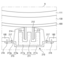
도 4는 도 2의 Ⅰ-Ⅰ’의 일 예를 보여주는 단면도이다.
도 5는 도 2의 Ⅱ-Ⅱ’의 일 예를 보여주는 단면도이다.
도 6은 진동 감쇠 부재의 일 예를 보여주는 측면도이다.
도 7은 진동 감쇠 부재의 유무에 따른 제1 음향 발생 장치에 의한 표시 패널의 진동 변위를 보여주는 그래프이다.
도 8은 진동 감쇠 부재 유무에 따른 제1 음향의 주파수에 따른 음압 레벨을 보여주는 그래프이다.
도 9는 표시 패널의 제1 기판, 제2 기판, 및 화소 어레이층의 일 예를 보여주는 단면도이다.
도 10과 도 11은 제1 음향 발생 장치에 의한 표시 패널의 진동을 보여주는 예시도면들이다.
도 12는 도 5의 제2 음향 발생 장치에 의한 표시 패널의 진동을 보여주는 예시도면들이다.
도 13은 제2 음향 발생 장치의 제1 가지 전극과 제2 가지 전극 사이에 배치된 진동층의 진동 방법을 보여주는 일 예시도면이다.
도 14는 도 1에서 연성 필름들이 펼쳐진 경우 표시 패널의 일 예를 보여주는 저면도이다.
도 15는 도 1에서 연성 필름들이 펼쳐진 경우 표시 패널의 일 예를 보여주는 저면도이다.
도 16은 도 1에서 연성 필름들이 펼쳐진 경우 표시 패널의 일 예를 보여주는 저면도이다.
도 17은 도 16의 Ⅲ-Ⅲ’의 일 예를 보여주는 단면도이다.
도 18은 도 1에서 연성 필름들이 하부 섀시의 하부로 구부러진 경우 하부 섀시가 결합된 표시 패널의 일 예를 보여주는 저면도이다.
도 19는 도 18의 Ⅳ-Ⅳ’의 일 예를 보여주는 단면도이다.
도 20은 도 1에서 연성 필름들이 펼쳐진 경우 표시 패널의 일 예를 보여주는 저면도이다.
도 21은 도 1에서 연성 필름들이 하부 섀시의 하부로 구부러진 경우 하부 섀시가 결합된 표시 패널의 일 예를 보여주는 저면도이다.
도 22는 도 21의 Ⅴ-Ⅴ’의 일 예를 보여주는 단면도이다.
도 23은 도 1에서 연성 필름들이 펼쳐진 경우 표시 패널의 일 예를 보여주는 저면도이다.
도 24는 도 1에서 연성 필름들이 하부 섀시의 하부로 구부러진 경우 하부 섀시가 결합된 표시 패널의 일 예를 보여주는 저면도이다.
도 25는 도 1에서 연성 필름들이 펼쳐진 경우 표시 패널의 일 예를 보여주는 저면도이다.
도 26은 도 1에서 연성 필름들이 하부 섀시의 하부로 구부러진 경우 하부 섀시가 결합된 표시 패널의 일 예를 보여주는 저면도이다.
도 27은 도 1에서 연성 필름들이 펼쳐진 경우 표시 패널의 일 예를 보여주는 저면도이다.
도 28은 도 1에서 연성 필름들이 하부 섀시의 하부로 구부러진 경우 하부 섀시가 결합된 표시 패널의 일 예를 보여주는 저면도이다.
도 29는 도 1에서 연성 필름들이 펼쳐진 경우 표시 패널의 일 예를 보여주는 저면도이다.
도 30은 도 1에서 연성 필름들이 하부 섀시의 하부로 구부러진 경우 하부 섀시가 결합된 표시 패널의 일 예를 보여주는 저면도이다.
도 31은 도 1에서 연성 필름들이 펼쳐진 경우 표시 패널의 일 예를 보여주는 저면도이다.
도 32는 도 1에서 연성 필름들이 하부 섀시의 하부로 구부러진 경우 하부 섀시가 결합된 표시 패널의 일 예를 보여주는 저면도이다.FIG. 1 is an exploded perspective view showing a display device according to one embodiment.
FIG. 2 is a bottom view showing an example of a display panel when the flexible films in FIG. 1 are unfolded.
FIG. 3 is a bottom view showing an example of a display panel with a lower chassis joined when the flexible films in FIG. 1 are bent toward the lower part of the lower chassis.
Figure 4 is a cross-sectional view showing an example of Ⅰ-Ⅰ' of Figure 2.
Figure 5 is a cross-sectional view showing an example of II-II' of Figure 2.
Figure 6 is a side view showing an example of a vibration damping member.
Fig. 7 is a graph showing the vibration displacement of the display panel by the first sound generating device depending on the presence or absence of a vibration damping member.
Figure 8 is a graph showing the sound pressure level according to the frequency of the first sound depending on the presence or absence of vibration damping.
FIG. 9 is a cross-sectional view showing an example of a first substrate, a second substrate, and a pixel array layer of a display panel.
Figures 10 and 11 are exemplary drawings showing vibration of a display panel by a first sound generating device.
Figure 12 is an example drawing showing vibration of a display panel by the second sound generating device of Figure 5.
Fig. 13 is an exemplary drawing showing a method of vibrating a vibrating layer disposed between the first electrode and the second electrode of the second sound generating device.
FIG. 14 is a bottom view showing an example of a display panel when the flexible films in FIG. 1 are unfolded.
FIG. 15 is a bottom view showing an example of a display panel when the flexible films in FIG. 1 are unfolded.
FIG. 16 is a bottom view showing an example of a display panel when the flexible films in FIG. 1 are unfolded.
Fig. 17 is a cross-sectional view showing an example of Ⅲ-Ⅲ' of Fig. 16.
FIG. 18 is a bottom view showing an example of a display panel with a lower chassis joined when the flexible films in FIG. 1 are bent toward the lower part of the lower chassis.
Fig. 19 is a cross-sectional view showing an example of Ⅳ-Ⅳ' of Fig. 18.
FIG. 20 is a bottom view showing an example of a display panel when the flexible films in FIG. 1 are unfolded.
FIG. 21 is a bottom view showing an example of a display panel with a lower chassis joined when the flexible films in FIG. 1 are bent toward the lower part of the lower chassis.
Fig. 22 is a cross-sectional view showing an example of V-V' of Fig. 21.
FIG. 23 is a bottom view showing an example of a display panel when the flexible films in FIG. 1 are unfolded.
FIG. 24 is a bottom view showing an example of a display panel with a lower chassis joined when the flexible films in FIG. 1 are bent toward the lower part of the lower chassis.
FIG. 25 is a bottom view showing an example of a display panel when the flexible films in FIG. 1 are unfolded.
FIG. 26 is a bottom view showing an example of a display panel with a lower chassis joined when the flexible films in FIG. 1 are bent toward the lower part of the lower chassis.
FIG. 27 is a bottom view showing an example of a display panel when the flexible films in FIG. 1 are unfolded.
FIG. 28 is a bottom view showing an example of a display panel with a lower chassis joined when the flexible films in FIG. 1 are bent toward the lower part of the lower chassis.
FIG. 29 is a bottom view showing an example of a display panel when the flexible films in FIG. 1 are unfolded.
FIG. 30 is a bottom view showing an example of a display panel with a lower chassis joined when the flexible films in FIG. 1 are bent toward the lower part of the lower chassis.
FIG. 31 is a bottom view showing an example of a display panel when the flexible films in FIG. 1 are unfolded.
FIG. 32 is a bottom view showing an example of a display panel with a lower chassis joined when the flexible films in FIG. 1 are bent toward the lower part of the lower chassis.
본 발명의 이점 및 특징, 그리고 그것들을 달성하는 방법은 첨부되는 도면과 함께 상세하게 후술되어 있는 실시예들을 참조하면 명확해질 것이다. 그러나 본 발명은 이하에서 개시되는 실시예들에 한정되는 것이 아니라 서로 다른 다양한 형태로 구현될 것이며, 단지 본 실시예들은 본 발명의 개시가 완전하도록 하며, 본 발명이 속하는 기술분야에서 통상의 지식을 가진 자에게 발명의 범주를 완전하게 알려주기 위해 제공되는 것이며, 본 발명은 청구항의 범주에 의해 정의될 뿐이다.The advantages and features of the present invention, and the methods for achieving them, will become clear with reference to the embodiments described in detail below together with the accompanying drawings. However, the present invention is not limited to the embodiments disclosed below, but may be implemented in various different forms, and these embodiments are provided only to make the disclosure of the present invention complete and to fully inform a person having ordinary skill in the art to which the present invention belongs of the scope of the invention, and the present invention is defined only by the scope of the claims.
소자(elements) 또는 층이 다른 소자 또는 층의 "상(on)"으로 지칭되는 것은 다른 소자 바로 위에 또는 중간에 다른 층 또는 다른 소자를 개재한 경우를 모두 포함한다. 명세서 전체에 걸쳐 동일 참조 부호는 동일 구성 요소를 지칭한다. 실시예들을 설명하기 위한 도면에 개시된 형상, 크기, 비율, 각도, 개수 등은 예시적인 것이므로 본 발명이 도시된 사항에 한정되는 것은 아니다. When elements or layers are referred to as being "on" another element or layer, it includes both cases where the other element is directly on top of the other element or layer or intervening layers or other elements. Like reference numerals refer to like elements throughout the specification. The shapes, sizes, ratios, angles, numbers, etc. disclosed in the drawings for explaining the embodiments are illustrative and therefore the present invention is not limited to the matters illustrated.
비록 제1, 제2 등이 다양한 구성요소들을 서술하기 위해서 사용되나, 이들 구성요소들은 이들 용어에 의해 제한되지 않음은 물론이다. 이들 용어들은 단지 하나의 구성요소를 다른 구성요소와 구별하기 위하여 사용하는 것이다. 따라서, 이하에서 언급되는 제1 구성요소는 본 발명의 기술적 사상 내에서 제2 구성요소일 수도 있음은 물론이다.Although the terms first, second, etc. are used to describe various components, it is to be understood that these components are not limited by these terms. These terms are merely used to distinguish one component from another. Accordingly, it is to be understood that the first component referred to below may also be the second component within the technical concept of the present invention.
본 발명의 여러 실시예들의 각각 특징들이 부분적으로 또는 전체적으로 서로 결합 또는 조합 가능하고, 기술적으로 다양한 연동 및 구동이 가능하며, 각 실시예들이 서로에 대하여 독립적으로 실시 가능할 수도 있고 연관 관계로 함께 실시할 수도 있다.The individual features of the various embodiments of the present invention may be partially or wholly combined or combined with each other, and may be technically linked and driven in various ways, and each embodiment may be implemented independently of each other or may be implemented together in a related relationship.
이하 첨부된 도면을 참조하여 구체적인 실시예들에 대해 설명한다.Specific embodiments are described below with reference to the attached drawings.
도 1은 일 실시예에 따른 표시 장치를 보여주는 분해 사시도이다.FIG. 1 is an exploded perspective view showing a display device according to one embodiment.
도 1을 참조하면, 일 실시예에 따른 표시 장치(10)는 상부 세트 커버(101), 하부 세트 커버(102), 표시 패널(110), 소스 구동 회로(121)들, 연성 필름(122)들, 방열 필름(130), 소스 회로 보드(140)들, 제1 케이블(150)들, 제어 회로 보드(160), 타이밍 제어 회로(170), 하부 섀시(180), 제1 음향 발생 장치(210), 제2 음향 발생 장치(220), 및 제3 음향 발생 장치(230)를 포함한다.Referring to FIG. 1, a display device (10) according to one embodiment includes an upper set cover (101), a lower set cover (102), a display panel (110), source driving circuits (121), flexible films (122), heat dissipation films (130), source circuit boards (140), first cables (150), a control circuit board (160), a timing control circuit (170), a lower chassis (180), a first sound generating device (210), a second sound generating device (220), and a third sound generating device (230).
본 명세서에서, “상부”, “탑”, “상면”은 표시 패널(110)의 제1 기판(111)을 기준으로 제2 기판(112)이 배치되는 방향, 즉 제3 방향(Z축 방향)을 가리키고, “하부”, “바텀”, “하면”은 표시 패널(110)의 제1 기판(111)을 기준으로 방열 필름(130)이 배치되는 방향, 즉 제3 방향(Z축 방향)의 반대 방향을 가리킨다. 또한, “좌”, “우”, “상”, “하”는 표시 패널(110)을 평면에서 바라보았을 때의 방향을 가리킨다. 예를 들어, “좌”는 제1 방향(X축 방향), “우”는 제1 방향(X축 방향)의 반대 방향, “상”은 제2 방향(Y축 방향), “하”는 제2 방향(Y축 방향)의 반대 방향을 가리킨다.In this specification, “upper”, “top”, and “upper surface” refer to the direction in which the second substrate (112) is arranged based on the first substrate (111) of the display panel (110), that is, the third direction (Z-axis direction), and “lower”, “bottom”, and “lower surface” refer to the direction opposite to the third direction (Z-axis direction) in which the heat dissipation film (130) is arranged based on the first substrate (111) of the display panel (110). In addition, “left”, “right”, “upper”, and “lower” refer to the direction when the display panel (110) is viewed from a plane. For example, “left” refers to the first direction (X-axis direction), “right” refers to the opposite direction to the first direction (X-axis direction), “upper” refers to the second direction (Y-axis direction), and “lower” refers to the opposite direction to the second direction (Y-axis direction).
상부 세트 커버(101)는 상면의 가장자리를 덮도록 배치될 수 있다. 상부 세트 커버(101)는 표시 패널(110)의 표시 영역을 제외한 비표시 영역을 덮을 수 있다. 하부 세트 커버(102)는 하부 섀시(180)의 하부에 배치될 수 있다. 하부 세트 커버(102)는 연성 필름(122)들이 구부러져 소스 회로 보드(140)들, 제1 케이블(150)들, 제어 회로 보드(160)가 표시 패널(110)의 하부에 배치되는 경우, 소스 회로 보드(140)들, 제1 케이블(150)들, 제어 회로 보드(160)를 덮도록 배치될 수 있다. 도 1에서는 하부 세트 커버(102)의 제2 방향(Y축 방향)의 길이가 하부 섀시(180)의 제2 방향(Y축 방향)의 길이보다 작은 것을 예시하였으나, 이에 한정되지 않는다. 하부 세트 커버(102)의 제2 방향(Y축 방향)의 길이는 하부 섀시(180)의 제2 방향(Y축 방향)의 길이보다 크거나 하부 섀시(180)의 제2 방향(Y축 방향)의 길이와 실질적으로 동일할 수 있다. 상부 세트 커버(101)와 하부 세트 커버(102)는 플라스틱 또는 금속으로 이루어지거나, 플라스틱과 금속을 모두 포함할 수 있다.The upper set cover (101) may be arranged to cover the edge of the upper surface. The upper set cover (101) may cover a non-display area excluding the display area of the display panel (110). The lower set cover (102) may be arranged at the lower portion of the lower chassis (180). The lower set cover (102) may be arranged to cover the source circuit boards (140), the first cables (150), and the control circuit board (160) when the flexible films (122) are bent so that the source circuit boards (140), the first cables (150), and the control circuit board (160) are arranged at the lower portion of the display panel (110). In FIG. 1, the length of the lower set cover (102) in the second direction (Y-axis direction) is exemplified as being smaller than the length of the lower chassis (180) in the second direction (Y-axis direction), but is not limited thereto. The length of the lower set cover (102) in the second direction (Y-axis direction) may be greater than the length of the lower chassis (180) in the second direction (Y-axis direction) or may be substantially equal to the length of the lower chassis (180) in the second direction (Y-axis direction). The upper set cover (101) and the lower set cover (102) may be made of plastic or metal, or may include both plastic and metal.
표시 패널(110)은 평면 상 직사각형 형태로 이루어질 수 있다. 예를 들어, 표시 패널(110)은 도 2와 같이 제1 방향(X축 방향)의 장변과 제2 방향(Y축 방향)의 단변을 갖는 직사각형의 평면 형태를 가질 수 있다. 제1 방향(X축 방향)의 장변과 제2 방향(Y축 방향)의 단변이 만나는 모서리는 직각으로 형성되거나 소정의 곡률을 갖도록 둥글게 형성될 수 있다. 표시 패널(110)의 평면 형태는 직사각형에 한정되지 않고, 다른 다각형, 원형 또는 타원형으로 형성될 수 있다.The display panel (110) may be formed in a rectangular shape on a plane. For example, the display panel (110) may have a rectangular shape on a plane having a long side in a first direction (X-axis direction) and a short side in a second direction (Y-axis direction), as shown in FIG. 2. An edge where the long side in the first direction (X-axis direction) and the short side in the second direction (Y-axis direction) meet may be formed at a right angle or rounded to have a predetermined curvature. The plane shape of the display panel (110) is not limited to a rectangle, and may be formed in another polygonal, circular, or oval shape.
도 2에서는 표시 패널(110)이 평탄하게 형성된 것을 예시하였으나, 본 명세서는 이에 한정되지 않는다. 표시 패널(110)은 소정의 곡률로 구부러지는 곡면부를 포함할 수 있다.In Fig. 2, the display panel (110) is exemplified as being formed flat, but the present specification is not limited thereto. The display panel (110) may include a curved portion that is bent at a predetermined curvature.
표시 패널(110)은 제1 기판(111)과 제2 기판(112)을 포함할 수 있다. 제2 기판(112)은 제1 기판(111)의 제1 면과 마주보게 배치될 수 있다. 제1 기판(111)과 제2 기판(112)은 리지드(rigid)하거나 플렉시블(flexible)하게 형성될 수 있다. 제1 기판(111)은 유리 또는 플라스틱으로 형성될 수 있다. 제2 기판(112)은 유리, 플라스틱, 봉지 필름, 또는 배리어 필름으로 형성될 수 있다. 또는, 제2 기판(112)은 생략될 수 있다. 제1 기판(111)과 제2 기판(112)은 플라스틱으로 형성되는 경우, 폴리에테르술폰(polyethersulphone: PES), 폴리아크릴레이트(polyacrylate: PA), 폴리아릴레이트(polyarylate: PAR), 폴리에테르이미드(polyetherimide: PEI), 폴리에틸렌나프탈레이트(polyethylenenapthalate: PEN), 폴리에틸렌 테레프탈레이드(polyethyleneterepthalate: PET), 폴리페닐렌설파이드 (polyphenylenesulfide: PPS), 폴리알릴레이트(polyallylate), 폴리이미드(polyimide: PI), 폴리카보네이트(polycarbonate: PC), 셀룰로오스 트리아세테이트(cellulosetriacetate: CAT), 셀룰로오스 아세테이트 프로피오네이트(cellulose acetate propionate: CAP) 또는 이들의 조합일 수 있다. 봉지 필름 또는 배리어 필름은 복수의 무기막들이 적층된 필름일 수 있다.The display panel (110) may include a first substrate (111) and a second substrate (112). The second substrate (112) may be positioned to face the first surface of the first substrate (111). The first substrate (111) and the second substrate (112) may be formed rigidly or flexibly. The first substrate (111) may be formed of glass or plastic. The second substrate (112) may be formed of glass, plastic, a sealing film, or a barrier film. Alternatively, the second substrate (112) may be omitted. When the first substrate (111) and the second substrate (112) are formed of plastic, they may be polyethersulphone (PES), polyacrylate (PA), polyarylate (PAR), polyetherimide (PEI), polyethylenenapthalate (PEN), polyethylene terephthalate (PET), polyphenylenesulfide (PPS), polyallylate, polyimide (PI), polycarbonate (PC), cellulosetriacetate (CAT), cellulose acetate propionate (CAP), or a combination thereof. The sealing film or barrier film may be a film in which a plurality of inorganic films are laminated.
표시 패널(110)은 제1 전극, 유기 발광층, 및 제2 전극을 포함하는 유기 발광 다이오드를 이용하는 유기 발광 표시 패널, 제1 전극, 무기 반도체층, 및 제2 전극을 포함하는 무기 발광 다이오드를 이용하는 무기 발광 표시 패널, 또는 제1 전극, 양자점 발광층, 및 제2 전극을 포함하는 양자점 발광 다이오드를 포함하는 양자점 발광 표시 패널일 수 있다.The display panel (110) may be an organic light-emitting display panel using an organic light-emitting diode including a first electrode, an organic light-emitting layer, and a second electrode, an inorganic light-emitting display panel using an inorganic light-emitting diode including a first electrode, an inorganic semiconductor layer, and a second electrode, or a quantum dot light-emitting display panel including a quantum dot light-emitting diode including a first electrode, a quantum dot light-emitting layer, and a second electrode.
이하에서는, 표시 패널(110)이 도 6과 같이 제1 기판(111)과 제2 기판(112) 사이에 배치된 박막 트랜지스터층(TFTL), 발광 소자층(EML), 충진재(FL), 광 변환층(QDL), 및 컬러필터층(CFL)을 포함하는 유기 발광 표시 패널인 것을 중심으로 설명하였다. 이 경우, 제1 기판(111)은 박막 트랜지스터층(TFTL), 발광 소자층(EML), 및 박막 봉지층(TFEL)이 형성되는 박막 트랜지스터 기판이고, 제2 기판(112)은 광 파장 변환층(QDL)과 컬러필터층(CFL)이 형성되는 컬러필터 기판이며, 제1 기판(111)의 박막 봉지층(TFEL)과 제2 기판(112)의 광 파장 변환층(QDL) 사이에는 충진재(FL)가 배치될 수 있다.Hereinafter, the display panel (110) is described as an organic light-emitting display panel including a thin film transistor layer (TFTL), a light emitting element layer (EML), a filler (FL), a light conversion layer (QDL), and a color filter layer (CFL) disposed between a first substrate (111) and a second substrate (112) as shown in FIG. 6. In this case, the first substrate (111) is a thin film transistor substrate on which a thin film transistor layer (TFTL), a light emitting element layer (EML), and a thin film encapsulation layer (TFEL) are formed, the second substrate (112) is a color filter substrate on which a light wavelength conversion layer (QDL) and a color filter layer (CFL) are formed, and a filler (FL) may be disposed between the thin film encapsulation layer (TFEL) of the first substrate (111) and the light wavelength conversion layer (QDL) of the second substrate (112).
또는, 표시 패널(110)의 제2 기판(112)은 생략될 수 있으며, 발광 소자층(EML) 상에 박막 봉지층이 배치될 수 있다. 이 경우, 충진재(FL)는 생략될 수 있으며, 광 변환층(QDL)과 컬러필터층(CFL)은 박막 봉지층 상에 배치될 수 있다.Alternatively, the second substrate (112) of the display panel (110) may be omitted, and a thin film encapsulation layer may be disposed on the light emitting element layer (EML). In this case, the filler (FL) may be omitted, and the light conversion layer (QDL) and the color filter layer (CFL) may be disposed on the thin film encapsulation layer.
연성 필름(122)들 각각의 일 측은 표시 패널(110)의 제1 기판(111)의 제1 면 상에 배치되며, 타 측은 소스 회로 보드(140)의 일면 상에 부착될 수 있다. 구체적으로, 제1 기판(111)의 크기가 제2 기판(112)의 크기보다 크기 때문에, 제1 기판(111)의 일 측은 제2 기판(112)에 의해 덮이지 않고 노출될 수 있다. 제2 기판(112)에 의해 덮이지 않고 노출된 제1 기판(111)의 일 측에는 연성 필름(122)들이 부착될 수 있다. 연성 필름(122)들 각각은 이방성 도전 필름(anisotropic conductive film)을 이용하여 제1 기판(111)의 제1 면과 소스 회로 보드(140)의 일면 상에 부착될 수 있다.Each of the flexible films (122) may have one side disposed on a first surface of a first substrate (111) of a display panel (110), and the other side attached to one surface of a source circuit board (140). Specifically, since the size of the first substrate (111) is larger than that of the second substrate (112), one side of the first substrate (111) may be exposed without being covered by the second substrate (112). The flexible films (122) may be attached to one surface of the first substrate (111) that is exposed without being covered by the second substrate (112). Each of the flexible films (122) may be attached to the first surface of the first substrate (111) and one surface of the source circuit board (140) using an anisotropic conductive film.
연성 필름(122)들 각각은 테이프 캐리어 패키지(tape carrier package) 또는 칩온 필름(chip on film)과 같은 플렉시블 필름(flexible film)일 수 있다. 연성 필름(122)들은 도 3, 도 4, 및 도 5와 같이 제1 기판(111)의 하부로 벤딩(bending)될 수 있으며, 이 경우 소스 회로 보드(140)들, 제1 케이블(150)들, 및 제어 회로 보드(160)는 하부 섀시(180)의 하면 상에 배치될 수 있다. 도 1에서는 8 개의 연성 필름(122)들이 표시 패널(110)의 제1 기판(111) 상에 부착되는 것을 예시하였으나, 본 명세서에서 연성 필름(122)들의 개수는 이에 한정되지 않는다.Each of the flexible films (122) may be a flexible film such as a tape carrier package or a chip on film. The flexible films (122) may be bent to the lower side of the first substrate (111) as shown in FIGS. 3, 4, and 5, in which case the source circuit boards (140), the first cables (150), and the control circuit board (160) may be arranged on the lower side of the lower chassis (180). In FIG. 1, eight flexible films (122) are attached to the first substrate (111) of the display panel (110), but the number of flexible films (122) in the present specification is not limited thereto.
연성 필름(122)들 각각의 일면 상에는 소스 구동 회로(121)가 배치될 수 있다. 소스 구동 회로(121)들은 집적 회로(integrated circuit, IC)로 형성될 수 있다. 소스 구동 회로(121)들 각각은 타이밍 제어 회로(170)의 소스 제어 신호에 따라 디지털 비디오 데이터를 아날로그 데이터 전압들로 변환하여 연성 필름(122)을 통해 표시 패널(110)의 데이터 라인들에 공급한다.A source driving circuit (121) may be arranged on one side of each of the flexible films (122). The source driving circuits (121) may be formed as an integrated circuit (IC). Each of the source driving circuits (121) converts digital video data into analog data voltages according to a source control signal of a timing control circuit (170) and supplies the same to data lines of a display panel (110) through the flexible film (122).
표시 패널(110)은 데이터 라인들과 교차하는 스캔 라인들, 및 데이터 라인들과 스캔 라인들에 의해 정의되는 영역들에 배치되는 화소들을 포함할 수 있다. 스캔 라인들은 표시 패널(110)에 형성되는 스캔 구동부로부터 스캔 신호들을 공급받을 수 있다. 스캔 구동부는 복수의 박막 트랜지스터들을 포함하여 타이밍 제어 회로(171)의 스캔 제어 신호에 따라 스캔 신호들을 생성할 수 있다. 화소들 각각은 적어도 하나의 데이터 라인과 적어도 하나의 스캔 라인에 접속되며, 스캔 라인에 스캔 신호가 공급되는 경우 데이터 라인의 데이터 전압을 공급 받는다.The display panel (110) may include scan lines intersecting data lines, and pixels arranged in areas defined by the data lines and the scan lines. The scan lines may receive scan signals from a scan driver formed in the display panel (110). The scan driver may include a plurality of thin film transistors and generate scan signals according to a scan control signal of a timing control circuit (171). Each of the pixels is connected to at least one data line and at least one scan line, and when a scan signal is supplied to the scan line, the pixels receive a data voltage of the data line.
소스 회로 보드(140)들 각각은 제1 케이블(150)들을 통해 제어 회로 보드(160)에 연결될 수 있다. 소스 회로 보드(140)들 각각은 제1 케이블(150)들에 연결되기 위한 제1 커넥터(151)들을 포함할 수 있다. 소스 회로 보드(140)들은 연성 인쇄회로보드(flexible printed circuit board) 또는 인쇄회로보드(printed circuit board)일 수 있다. 제1 케이블(150)들은 가요성 케이블(flexible cable)일 수 있다.Each of the source circuit boards (140) may be connected to a control circuit board (160) via first cables (150). Each of the source circuit boards (140) may include first connectors (151) for connecting to the first cables (150). The source circuit boards (140) may be flexible printed circuit boards or printed circuit boards. The first cables (150) may be flexible cables.
제어 회로 보드(160)는 제1 케이블(150)들을 통해 소스 회로 보드(140)들에 연결될 수 있다. 이를 위해, 제어 회로 보드(160)는 제1 케이블(150)들에 연결되기 위한 제2 커넥터(152)들을 포함할 수 있다. 제어 회로 보드(160)는 스크루(screw)와 같은 고정 부재를 통해 하부 섀시(180)의 일면 상에 고정될 수 있다. 제어 회로 보드(160)는 연성 인쇄회로보드 또는 인쇄회로보드일 수 있다.The control circuit board (160) may be connected to the source circuit boards (140) via the first cables (150). For this purpose, the control circuit board (160) may include second connectors (152) for connecting to the first cables (150). The control circuit board (160) may be fixed to one surface of the lower chassis (180) via a fixing member such as a screw. The control circuit board (160) may be a flexible printed circuit board or a printed circuit board.
도 2에서는 4 개의 제1 케이블(150)들이 소스 회로 보드(140)들과 제어 회로 보드(160)를 연결하는 것을 예시하였으나, 본 명세서에서 제1 케이블(150)들의 개수는 이에 한정되지 않는다. 또한, 도 2에서는 2 개의 소스 회로 보드(140)들을 예시하였으나, 본 명세서에서 소스 회로 보드(140)들의 개수는 이에 한정되지 않는다.In FIG. 2, four first cables (150) are exemplified as connecting the source circuit boards (140) and the control circuit board (160), but the number of first cables (150) in this specification is not limited thereto. In addition, in FIG. 2, two source circuit boards (140) are exemplified, but the number of source circuit boards (140) in this specification is not limited thereto.
또는, 연성 필름(122)들의 개수가 적은 경우, 소스 회로 보드(140)들은 생략될 수 있다. 이 경우, 연성 필름(122)들은 제어 회로 보드(160)에 직접 연결될 수 있다.Alternatively, when the number of flexible films (122) is small, the source circuit boards (140) may be omitted. In this case, the flexible films (122) may be directly connected to the control circuit board (160).
제어 회로 보드(160)의 일면 상에는 타이밍 제어 회로(170)가 배치될 수 있다. 타이밍 제어 회로(170)는 집적 회로로 형성될 수 있다. 타이밍 제어 회로(170)는 시스템 회로 보드의 시스템 온 칩으로부터 디지털 비디오 데이터와 타이밍 신호들을 입력 받으며, 타이밍 신호들에 따라 소스 구동 회로(121)들의 타이밍을 제어하기 위한 소스 제어 신호를 생성할 수 있다.A timing control circuit (170) may be arranged on one side of a control circuit board (160). The timing control circuit (170) may be formed as an integrated circuit. The timing control circuit (170) may receive digital video data and timing signals from a system-on-chip of a system circuit board, and may generate a source control signal for controlling the timing of source driving circuits (121) according to the timing signals.
제어 회로 보드(160)의 일면 상에는 음향 구동 회로(171)가 배치될 수 있다. 음향 구동 회로(171)는 집적 회로로 형성될 수 있다. 음향 구동 회로(171)는 시스템 회로 보드부터 음향 데이터를 입력 받을 수 있다. 음향 구동 회로(171)는 디지털 데이터인 음향 데이터를 아날로그 신호인 제1 음향 신호, 제2 음향 신호, 및 제3 음향 신호로 변환할 수 있다. 음향 구동 회로(171)는 제1 음향 신호를 제1 음향 발생 장치(210)로 출력하고, 제2 음향 신호를 제2 음향 발생 장치(220)로 출력하며, 제3 음향 신호를 제3 음향 발생 장치(230)로 출력할 수 있다.An acoustic driving circuit (171) may be arranged on one side of a control circuit board (160). The acoustic driving circuit (171) may be formed as an integrated circuit. The acoustic driving circuit (171) may receive acoustic data from a system circuit board. The acoustic driving circuit (171) may convert acoustic data, which is digital data, into a first acoustic signal, a second acoustic signal, and a third acoustic signal, which are analog signals. The acoustic driving circuit (171) may output the first acoustic signal to a first acoustic generating device (210), output the second acoustic signal to a second acoustic generating device (220), and output the third acoustic signal to a third acoustic generating device (230).
시스템 온 칩은 연성 케이블을 통해 제어 회로 보드(160)에 연결되는 시스템 회로 보드 상에 장착될 수 있으며, 집적 회로로 형성될 수 있다. 시스템 온 칩은 스마트 TV의 프로세서(processor), 컴퓨터 또는 노트북의 중앙 처리 장치(CPU) 또는 그래픽 카드, 또는 스마트폰 또는 태블릿 PC의 어플리케이션 프로세서(application processor)일 수 있다. 시스템 회로 보드는 연성 인쇄회로보드 또는 인쇄회로보드일 수 있다.The system on chip may be mounted on a system circuit board connected to a control circuit board (160) via a flexible cable and may be formed as an integrated circuit. The system on chip may be a processor of a smart TV, a central processing unit (CPU) or graphics card of a computer or laptop, or an application processor of a smartphone or tablet PC. The system circuit board may be a flexible printed circuit board or a printed circuit board.
제어 회로 보드(160)의 일면 상에는 전원 공급 회로가 추가로 접착될 수 있다. 전원 공급 회로는 시스템 회로 보드로부터 인가되는 메인 전원으로부터 표시 패널(110)의 구동에 필요한 전압들을 생성하여 표시 패널(110)에 공급할 수 있다. 예를 들어, 전원 공급 회로는 유기 발광 소자를 구동하기 위한 고전위 전압, 저전위 전압, 및 초기화 전압을 생성하여 표시 패널(110)에 공급할 수 있다. 또한, 전원 공급 회로는 소스 구동 회로(121)들, 타이밍 제어 회로(170) 등을 구동하기 위한 구동 전압들을 생성하여 공급할 수 있다. 전원 공급 회로는 집적 회로로 형성될 수 있다. 또는, 전원 공급 회로는 제어 회로 보드(160) 외에 별도로 형성되는 전원 회로 보드 상에 배치될 수 있다. 전원 회로 보드는 연성 인쇄회로보드 또는 인쇄회로보드일 수 있다.A power supply circuit may be additionally attached to one side of the control circuit board (160). The power supply circuit may generate voltages required for driving the display panel (110) from the main power applied from the system circuit board and supply the voltages to the display panel (110). For example, the power supply circuit may generate a high potential voltage, a low potential voltage, and an initialization voltage for driving an organic light emitting element and supply the voltages to the display panel (110). In addition, the power supply circuit may generate and supply driving voltages for driving source driving circuits (121), timing control circuits (170), etc. The power supply circuit may be formed as an integrated circuit. Alternatively, the power supply circuit may be arranged on a power circuit board formed separately from the control circuit board (160). The power circuit board may be a flexible printed circuit board or a printed circuit board.
제1 기판(111)의 제1 면의 반대면인 제2 면 상에는 제1 음향 발생 장치(210), 제2 음향 발생 장치(220), 및 제3 음향 발생 장치(230)가 배치될 수 있다. 제1 음향 발생 장치(210)는 음향 구동 회로(171)의 제1 음향 신호에 따라 표시 패널(110)을 제3 방향(Z축 방향)으로 진동시킬 수 있는 진동 장치일 수 있다. 제2 음향 발생 장치(220)는 음향 구동 회로(171)의 제2 음향 신호에 따라 표시 패널(110)을 제3 방향(Z축 방향)으로 진동시킬 수 있는 진동 장치일 수 있다. 제3 음향 발생 장치(230)는 음향 구동 회로(171)의 제3 음향 신호에 따라 표시 패널(110)을 제3 방향(Z축 방향)으로 진동시킬 수 있는 진동 장치일 수 있다.A first sound generating device (210), a second sound generating device (220), and a third sound generating device (230) may be arranged on a second surface opposite to the first surface of the first substrate (111). The first sound generating device (210) may be a vibration device capable of vibrating the display panel (110) in a third direction (Z-axis direction) according to a first sound signal of the sound driving circuit (171). The second sound generating device (220) may be a vibration device capable of vibrating the display panel (110) in a third direction (Z-axis direction) according to a second sound signal of the sound driving circuit (171). The third sound generating device (230) may be a vibration device capable of vibrating the display panel (110) in a third direction (Z-axis direction) according to a third sound signal of the sound driving circuit (171).
제1 음향 발생 장치(210)는 도 10 및 도 11과 같이 보이스 코일을 이용하여 자력을 생성함으로써 표시 패널(110)을 진동시키는 여진기(Exciter)일 수 있다. 제2 음향 발생 장치(220)와 제3 음향 발생 장치(230)는 도 12 및 도 13과 같이 인가된 전압에 따라 수축하거나 팽창하는 압전 물질을 이용하여 표시 패널(110)을 진동시키는 압전 소자(piezoelectric element, 壓電素子) 또는 압전 액츄에이터(piezoelectric actuator)일 수 있다.The first sound generating device (210) may be an exciter that vibrates the display panel (110) by generating magnetic force using a voice coil as shown in FIGS. 10 and 11. The second sound generating device (220) and the third sound generating device (230) may be a piezoelectric element or piezoelectric actuator that vibrates the display panel (110) by using a piezoelectric material that contracts or expands according to an applied voltage as shown in FIGS. 12 and 13.
제1 음향 발생 장치(210)는 저음 대역의 음향을 출력하기 위한 저음용 음향 발생 장치로 역할을 할 수 있다. 제2 음향 발생 장치(220)는 고음 대역의 음향을 출력하는 고음용 음향 발생 장치로 역할을 할 수 있다. 제3 음향 발생 장치(230)는 고음 대역의 음향을 출력하는 고음용 음향 발생 장치로 역할을 할 수 있다. 저음 대역의 음향은 800MHz 이하의 주파수를 갖는 저주파수 대역의 음향을 가리키고, 고음 대역의 음향은 800MHz보다 높은 주파수를 갖는 고주파수 대역의 음향을 가리킬 수 있다. 하지만, 본 명세서의 실시예는 이에 한정되지 않는다. 또한, 저음 대역의 음향이 800MHz 이하의 주파수를 갖는 저주파수 대역의 음향인 경우, 저음과 중음을 모두 포함할 수 있다.The first sound generating device (210) may function as a low-pitched sound generating device for outputting sound in a low-pitched band. The second sound generating device (220) may function as a high-pitched sound generating device for outputting sound in a high-pitched band. The third sound generating device (230) may function as a high-pitched sound generating device for outputting sound in a high-pitched band. The sound in the low-pitched band may refer to a low-frequency band sound having a frequency of 800 MHz or less, and the sound in the high-pitched band may refer to a high-frequency band sound having a frequency higher than 800 MHz. However, the embodiments of the present specification are not limited thereto. In addition, when the sound in the low-pitched band is a low-frequency band sound having a frequency of 800 MHz or less, it may include both low-pitched and mid-pitched sounds.
제1 기판(111)의 제2 면 상에는 하부 섀시(180)가 배치될 수 있다. 하부 섀시(180)에서 제1 음향 발생 장치(210)와 대응되는 영역에는 제1 음향 발생 장치(210)가 배치되는 홀(H)이 형성될 수 있다. 또한, 하부 섀시(180)에는 제어 회로 보드(160)와 제2 음향 발생 장치(220)를 연결하는 제1 음향 회로 보드(251)와 제어 회로 보드(160)가 통과하는 제1 관통 홀(CH1)과 제3 음향 발생 장치(230)를 연결하는 제2 음향 회로 보드(252)가 통과하는 제2 관통 홀(CH2)이 형성될 수 있다. 하부 섀시(180)는 금속 또는 강화 유리일 수 있다.A lower chassis (180) may be placed on the second surface of the first substrate (111). A hole (H) in which a first sound generating device (210) is placed may be formed in an area of the lower chassis (180) corresponding to the first sound generating device (210). In addition, a first through-hole (CH1) through which a first sound circuit board (251) connecting a control circuit board (160) and a second sound generating device (220) pass and a second through-hole (CH2) through which a second sound circuit board (252) connecting a third sound generating device (230) pass may be formed in the lower chassis (180). The lower chassis (180) may be made of metal or reinforced glass.
이상에서 살펴본 바와 같이, 도 1에 도시된 표시 장치(10)에 의하면, 제1 음향 발생 장치(210)에 의해 표시 패널(110)을 진동판으로 이용하여 저음 대역의 음향을 출력하고, 제2 음향 발생 장치(220)와 제3 음향 발생 장치(230)에 의해 표시 패널(110)을 진동판으로 이용하여 고음 대역의 음향을 출력할 수 있다. 즉, 표시 장치(10)의 전면(前面) 방향으로 저음 대역의 음향과 고음 대역의 음향을 출력할 수 있으므로, 음향 품질을 높일 수 있다.As described above, according to the display device (10) illustrated in FIG. 1, the first sound generating device (210) can output low-pitched sound by using the display panel (110) as a vibrating plate, and the second sound generating device (220) and the third sound generating device (230) can output high-pitched sound by using the display panel (110) as a vibrating plate. That is, since low-pitched sound and high-pitched sound can be output in the front direction of the display device (10), the sound quality can be improved.
한편, 도 1에서는 일 실시예에 따른 표시 장치(10)가 복수의 소스 구동 회로(121)들을 포함하는 중대형 표시 장치인 것을 예시하였으나, 이에 한정되지 않는다. 즉, 일 실시예에 따른 표시 장치(10)는 하나의 소스 구동 회로(121)를 포함하는 소형 표시 장치일 수 있다. 이 경우, 연성 필름(122)들과 소스 회로 보드(140)들, 및 케이블(150)들은 생략될 수 있다. 또한, 소스 구동 회로(121)와 타이밍 제어 회로(170)는 하나의 집적회로로 통합되어 하나의 연성 회로 보드 상에 접착되거나, 표시 패널(110)의 제1 기판(111) 상에 접착될 수 있다. 중대형 표시 장치의 예로는 모니터, TV 등이 있으며, 소형 표시 장치의 예로는 스마트폰, 태블릿 PC 등이 있다.Meanwhile, in FIG. 1, the display device (10) according to one embodiment is exemplified as a medium- to large-sized display device including a plurality of source driving circuits (121), but is not limited thereto. That is, the display device (10) according to one embodiment may be a small-sized display device including one source driving circuit (121). In this case, the flexible films (122), the source circuit boards (140), and the cables (150) may be omitted. In addition, the source driving circuit (121) and the timing control circuit (170) may be integrated into one integrated circuit and adhered to one flexible circuit board or adhered to the first substrate (111) of the display panel (110). Examples of medium- to large-sized display devices include monitors and TVs, and examples of small-sized display devices include smartphones and tablet PCs.
도 2는 도 1에서 연성 필름들이 펼쳐진 경우 표시 패널의 일 예를 보여주는 저면도이다. 도 3은 도 1에서 연성 필름들이 하부 섀시의 하부로 구부러진 경우 하부 섀시가 결합된 표시 패널의 일 예를 보여주는 저면도이다. 도 4는 도 2의 Ⅰ-Ⅰ’의 일 예를 보여주는 단면도이다. 도 5는 도 2의 Ⅱ-Ⅱ’의 일 예를 보여주는 단면도이다.FIG. 2 is a bottom view showing an example of a display panel when the flexible films are spread out in FIG. 1. FIG. 3 is a bottom view showing an example of a display panel to which a lower chassis is joined when the flexible films are bent toward the lower side of the lower chassis in FIG. 1. FIG. 4 is a cross-sectional view showing an example of I-I’ in FIG. 2. FIG. 5 is a cross-sectional view showing an example of II-II’ in FIG. 2.
도 2 내지 도 5를 참조하면, 제1 기판(111)의 제1 면과 제2 기판(112)의 제1 면은 서로 마주볼 수 있다. 제1 기판(111)의 제1 면과 제2 기판(112)의 제1 면 사이에는 화소 어레이층(113)이 배치될 수 있다. 화소 어레이층(113)은 도 6과 같이 광을 발광하는 복수의 화소들(PX1, PX2, PX3)을 포함할 수 있으며, 화소 어레이층(113)에 대한 자세한 설명은 도 6을 결부하여 후술한다.Referring to FIGS. 2 to 5, the first surface of the first substrate (111) and the first surface of the second substrate (112) may face each other. A pixel array layer (113) may be arranged between the first surface of the first substrate (111) and the first surface of the second substrate (112). The pixel array layer (113) may include a plurality of pixels (PX1, PX2, PX3) that emit light as shown in FIG. 6, and a detailed description of the pixel array layer (113) will be described later in conjunction with FIG. 6.
제1 기판(111)의 제2 면 상에는 방열 필름(130)이 배치될 수 있다. 방열 필름(130)의 일면 상에는 제1 음향 발생 장치(210)가 배치될 수 있다. 방열 필름(130)은 제1 음향 발생 장치(210)에 의해 발생되는 열을 방열하는 역할을 한다. 이를 위해, 방열 필름(130)은 열 전도율이 높은 그라파이트(graphite), 은(Ag), 구리(Cu), 또는 알루미늄(Al)과 같은 금속층을 포함할 수 있다.A heat dissipation film (130) may be placed on the second surface of the first substrate (111). A first sound generating device (210) may be placed on one surface of the heat dissipation film (130). The heat dissipation film (130) serves to dissipate heat generated by the first sound generating device (210). To this end, the heat dissipation film (130) may include a metal layer such as graphite, silver (Ag), copper (Cu), or aluminum (Al) having high thermal conductivity.
또한, 방열 필름(130)은 제1 방향(X축 방향)과 제2 방향(Y축 방향)으로 형성된 복수의 그라파이트층 또는 복수의 금속층을 포함할 수 있다. 이 경우, 제1 음향 발생 장치(210)에 의해 발생되는 열은 제1 방향(X축 방향)과 제2 방향(Y축 방향)으로 확산될 수 있으므로, 더욱 효과적으로 방출될 수 있다. 따라서, 방열 필름(130)으로 인해 제1 음향 발생 장치(210)에 의해 발생된 열이 표시 패널(110)에 영향을 미치는 것을 최소화할 수 있다. 또한, 제1 음향 발생 장치(210)에 의해 발생된 열이 표시 패널(110)에 영향을 미치는 것을 더욱 줄이기 위해, 방열 필름(130)의 두께(D1)는 제1 기판(111)의 두께(D2) 및 제2 기판(112)의 두께(D3)보다 두꺼울 수 있다. 본 명세서에서, 제1 방향(X축 방향)은 표시 패널(110)의 폭 방향, 제2 방향(Y축 방향)은 표시 패널(110)의 높이 방향, 제3 방향(Z축 방향)은 표시 패널(110)의 두께 방향일 수 있다.In addition, the heat dissipation film (130) may include a plurality of graphite layers or a plurality of metal layers formed in the first direction (X-axis direction) and the second direction (Y-axis direction). In this case, the heat generated by the first sound generating device (210) can spread in the first direction (X-axis direction) and the second direction (Y-axis direction), and thus can be dissipated more effectively. Accordingly, the heat generated by the first sound generating device (210) can minimize the influence of the heat generated by the first sound generating device (210) on the display panel (110). In addition, in order to further reduce the influence of the heat generated by the first sound generating device (210) on the display panel (110), the thickness (D1) of the heat dissipation film (130) can be thicker than the thickness (D2) of the first substrate (111) and the thickness (D3) of the second substrate (112). In this specification, the first direction (X-axis direction) may be the width direction of the display panel (110), the second direction (Y-axis direction) may be the height direction of the display panel (110), and the third direction (Z-axis direction) may be the thickness direction of the display panel (110).
방열 필름(130)의 크기는 제1 기판(111)의 크기보다 작을 수 있으며, 이로 인해 제1 기판(111)의 일 면의 가장자리가 방열 필름(130)에 의해 덮이지 않고 노출될 수 있다.The size of the heat dissipation film (130) may be smaller than the size of the first substrate (111), so that an edge of one side of the first substrate (111) may be exposed without being covered by the heat dissipation film (130).
한편, 방열 필름(130)은 생략될 수 있으며, 이 경우 방열 필름(130)의 일면 상에 배치되는 구성들은 제1 기판(111)의 제2 면 상에 배치될 수 있다.Meanwhile, the heat dissipation film (130) may be omitted, in which case the configurations arranged on one side of the heat dissipation film (130) may be arranged on the second side of the first substrate (111).
연성 필름(122)들은 하부 섀시(180)의 하부로 구부러지며, 하부 섀시(180)의 일면 상에서 소스 회로 보드(140)에 부착될 수 있다. 소스 회로 보드(140)와 제어 회로 보드(160)는 하부 섀시(180)의 일면 상에 배치되며, 제1 케이블(150)들을 통해 서로 연결될 수 있다.The flexible films (122) can be bent toward the lower side of the lower chassis (180) and attached to the source circuit board (140) on one side of the lower chassis (180). The source circuit board (140) and the control circuit board (160) are arranged on one side of the lower chassis (180) and can be connected to each other via the first cables (150).
제1 음향 발생 장치(210)는 제2 음향 발생 장치(220)와 제3 음향 발생 장치(230)에 비해 표시 패널(110)의 중앙에 가깝게 배치될 수 있다. 제2 음향 발생 장치(220)는 표시 패널(110)의 일 측, 예를 들어 표시 패널(110)의 우 측에 가깝게 배치될 수 있다. 제3 음향 발생 장치(230)는 표시 패널의 타 측, 예를 들어 표시 패널(110)의 좌 측에 가깝게 배치될 수 있다.The first sound generating device (210) may be positioned closer to the center of the display panel (110) than the second sound generating device (220) and the third sound generating device (230). The second sound generating device (220) may be positioned closer to one side of the display panel (110), for example, closer to the right side of the display panel (110). The third sound generating device (230) may be positioned closer to the other side of the display panel, for example, closer to the left side of the display panel (110).
제1 음향 발생 장치(210)는 도 10 및 도 11과 같이 마그넷(magnet, 211), 보빈(212), 보이스 코일(213), 및 플레이트(215)를 포함할 수 있다. 보빈(212)은 방열 필름(130)의 일면 상에 접착 부재에 의해 접착될 수 있다. 접착 부재는 양면 접착제 또는 양면 테이프일 수 있다. 보이스 코일(213)은 보빈(212)의 외주면에 권취(또는 권선)될 수 있다. 보빈(212)은 원통 형태로 형성되므로, 보빈(212)의 내측에는 마그넷(211)의 중앙 돌출부가 배치되며, 보빈(212)의 외측에는 마그넷(211)의 측벽부가 배치될 수 있다. 마그넷(211)의 하면에는 플레이트(215)가 배치될 수 있다. 플레이트(215)는 스크루(screw)와 같은 제1 고정 부재(216)를 통해 제어 회로 보드(160)의 일면 상에 고정될 수 있다.The first sound generating device (210) may include a magnet (211), a bobbin (212), a voice coil (213), and a plate (215) as shown in FIGS. 10 and 11. The bobbin (212) may be bonded to one surface of a heat-dissipating film (130) by an adhesive member. The adhesive member may be a double-sided adhesive or a double-sided tape. The voice coil (213) may be wound (or wound) on the outer surface of the bobbin (212). Since the bobbin (212) is formed in a cylindrical shape, the central protrusion of the magnet (211) may be arranged on the inner side of the bobbin (212), and the side wall of the magnet (211) may be arranged on the outer side of the bobbin (212). A plate (215) may be arranged on the lower surface of the magnet (211). The plate (215) can be fixed to one surface of the control circuit board (160) via a first fixing member (216), such as a screw.
마그넷(211)과 보빈(212)은 하부 섀시(180)의 홀(H) 내에 배치되는 반면에, 플레이트(215)는 하부 섀시(180)의 일면 상에 배치되며, 하부 섀시(180)의 홀(H) 내에 배치되지 않는다. 홀(H)의 크기는 플레이트(215)의 크기보다 작을 수 있다.The magnet (211) and the bobbin (212) are placed within the hole (H) of the lower chassis (180), while the plate (215) is placed on one side of the lower chassis (180) and is not placed within the hole (H) of the lower chassis (180). The size of the hole (H) may be smaller than the size of the plate (215).
도 3 내지 도 5에서는 마그넷(211)과 보빈(212)이 평면 상 원 형태를 가지며, 플레이트(215)가 평면 상 사각 형태를 가지고, 홀(H)이 평면 상 원 형태를 갖는 것을 예시하였다. 하지만, 평면 상 플레이트(215)의 형태, 보빈(212)의 형태, 및 홀(H)의 형태는 도 3 내지 도 5에 도시된 바에 한정되지 않는다. 예를 들어, 보빈(212)의 형태와 홀(H)의 형태는 타원 형태 또는 다각 형태를 가질 수 있다. 또한, 평면 상 플레이트(215)의 형태는 원 형태, 타원 형태 또는 다각 형태를 가질 수 있다.In FIGS. 3 to 5, the magnet (211) and the bobbin (212) have a circular shape on a plane, the plate (215) has a square shape on a plane, and the hole (H) has a circular shape on a plane. However, the shape of the plate (215) on a plane, the shape of the bobbin (212), and the shape of the hole (H) are not limited to those illustrated in FIGS. 3 to 5. For example, the shape of the bobbin (212) and the shape of the hole (H) may have an elliptical shape or a polygonal shape. In addition, the shape of the plate (215) on a plane may have a circular shape, an elliptical shape, or a polygonal shape.
제1 음향 발생 장치(210)의 보빈(212)은 방열 필름(130)의 일면 상에 고정되고, 마그넷(211)은 하부 섀시(180)에 고정될 수 있다. 그러므로, 보이스 코일(213) 주위에 형성되는 인가 자기장에 따라 보이스 코일(213)이 권취된 보빈(212)은 제3 방향(Z축 방향)으로 왕복 운동할 수 있으며, 이로 인해 표시 패널(110)은 진동할 수 있다.The bobbin (212) of the first sound generating device (210) is fixed on one side of the heat dissipation film (130), and the magnet (211) can be fixed to the lower chassis (180). Therefore, the bobbin (212) around which the voice coil (213) is wound can reciprocate in the third direction (Z-axis direction) according to the applied magnetic field formed around the voice coil (213), and thus the display panel (110) can vibrate.
제2 음향 발생 장치(220)와 제3 음향 발생 장치(230) 각각은 방열 필름(130)의 일면 상에 압력 민감 점착제(pressure sensitive adhesive)와 같은 접착 부재에 의해 접착될 수 있다. 제2 음향 발생 장치(220)는 제1 음향 회로 보드(251)에 의해 제어 회로 보드(160)에 전기적으로 연결되고, 제3 음향 발생 장치(230)는 제2 음향 회로 보드(252)에 의해 제어 회로 보드(160)에 전기적으로 연결될 수 있다. 제1 음향 회로 보드(251)와 제2 음향 회로 보드(252) 각각은 연성 인쇄 회로 보드(flexible printed circuit board) 또는 가요성 케이블(flexible cable)일 수 있다.Each of the second sound generating device (220) and the third sound generating device (230) may be bonded to one surface of the heat dissipation film (130) by an adhesive material such as a pressure sensitive adhesive. The second sound generating device (220) may be electrically connected to the control circuit board (160) by the first sound circuit board (251), and the third sound generating device (230) may be electrically connected to the control circuit board (160) by the second sound circuit board (252). Each of the first sound circuit board (251) and the second sound circuit board (252) may be a flexible printed circuit board or a flexible cable.
제1 음향 회로 보드(251)와 제2 음향 회로 보드(252) 각각의 일 측에는 제1 패드와 제2 패드가 형성될 수 있다. 제1 음향 회로 보드(251)의 제1 패드는 제2 음향 발생 장치(220)의 제1 전극에 연결되고, 제1 음향 회로 보드(251)의 제2 패드는 제2 음향 발생 장치(220)의 제2 전극에 연결될 수 있다. 제2 음향 회로 보드(252)의 제1 패드는 제3 음향 발생 장치(230)의 제1 전극에 연결되고, 제2 음향 회로 보드(252)의 제2 패드는 제3 음향 발생 장치(230)의 제2 전극에 연결될 수 있다.A first pad and a second pad may be formed on one side of each of the first acoustic circuit board (251) and the second acoustic circuit board (252). The first pad of the first acoustic circuit board (251) may be connected to a first electrode of the second acoustic generating device (220), and the second pad of the first acoustic circuit board (251) may be connected to a second electrode of the second acoustic generating device (220). The first pad of the second acoustic circuit board (252) may be connected to a first electrode of the third acoustic generating device (230), and the second pad of the second acoustic circuit board (252) may be connected to a second electrode of the third acoustic generating device (230).
제1 음향 회로 보드(251)와 제2 음향 회로 보드(252) 각각의 타 측에는 제어 회로 보드(160)의 제2B 커넥터(152b)에 연결되기 위한 접속부가 형성될 수 있다. 제2 음향 발생 장치(220)는 제1 음향 회로 보드(251)의 접속부에 의해 제어 회로 보드(160)의 제2B 커넥터(152b)에 연결될 수 있다. 제3 음향 발생 장치(230)는 제2 음향 회로 보드(252)의 접속부에 의해 제어 회로 보드(160)의 또 다른 제2B 커넥터(152b)에 연결될 수 있다.A connection portion may be formed on the other side of each of the first sound circuit board (251) and the second sound circuit board (252) to be connected to the second B connector (152b) of the control circuit board (160). The second sound generating device (220) may be connected to the second B connector (152b) of the control circuit board (160) by the connection portion of the first sound circuit board (251). The third sound generating device (230) may be connected to another second B connector (152b) of the control circuit board (160) by the connection portion of the second sound circuit board (252).
제어 회로 보드(160) 상에는 타이밍 제어 회로(170)와 음향 구동 회로(171)가 배치될 수 있다. 음향 구동 회로(171)는 제어 회로 보드(160)가 아닌 다른 회로 보드 상에 배치될 수 있다. 예를 들어, 음향 구동 회로(171)는 시스템 회로 보드, 전원 회로 보드, 또는 음향 회로 보드 상에 배치될 수 있다. 음향 회로 보드는 다른 집적 회로 없이 음향 구동 회로(171)만이 배치되는 회로 보드를 가리킨다.A timing control circuit (170) and an acoustic driving circuit (171) may be arranged on a control circuit board (160). The acoustic driving circuit (171) may be arranged on a circuit board other than the control circuit board (160). For example, the acoustic driving circuit (171) may be arranged on a system circuit board, a power circuit board, or an acoustic circuit board. An acoustic circuit board refers to a circuit board on which only an acoustic driving circuit (171) is arranged without other integrated circuits.
음향 구동 회로(171)는 음향 신호들을 디지털 처리하는 디지털 신호 처리부(digital signal processer, DSP), 디지털 신호 처리부에서 처리된 디지털 신호를 아날로그 신호인 구동 전압들로 변환하는 디지털 아날로그 변환부(digital analog converter, DAC), 디지털 아날로그 변환부에서 변환된 아날로그 구동 전압들을 증폭하여 출력하는 증폭기(amplifier, AMP) 등을 포함할 수 있다.The sound driving circuit (171) may include a digital signal processor (DSP) that digitally processes sound signals, a digital analog converter (DAC) that converts digital signals processed by the digital signal processor into analog signal driving voltages, and an amplifier (AMP) that amplifies and outputs analog driving voltages converted by the digital analog converter.
음향 구동 회로(171)는 스테레오 신호들에 따라 제1 음향 발생 장치(210)를 구동하기 위한 제1A 구동 전압과 제1B 구동 전압을 포함하는 제1 음향 신호를 생성할 수 있다. 음향 구동 회로(171)는 스테레오 신호들에 따라 제2 음향 발생 장치(220)를 구동하기 위한 제2A 구동 전압과 제2B 구동 전압을 포함하는 제2 음향 신호를 생성할 수 있다. 음향 구동 회로(171)는 스테레오 신호들에 따라 제3 음향 발생 장치(230)를 구동하기 위한 제3A 구동 전압과 제3B 구동 전압을 포함하는 제3 음향 신호를 생성할 수 있다.The sound driving circuit (171) can generate a first sound signal including a first A driving voltage and a first B driving voltage for driving a first sound generating device (210) according to stereo signals. The sound driving circuit (171) can generate a second sound signal including a second A driving voltage and a second B driving voltage for driving a second sound generating device (220) according to stereo signals. The sound driving circuit (171) can generate a third sound signal including a third A driving voltage and a third B driving voltage for driving a third sound generating device (230) according to stereo signals.
제1 음향 발생 장치(210)는 음향 구동 회로(171)로부터 제1A 구동 전압과 제1B 구동 전압을 포함하는 제1 음향 신호를 입력 받을 수 있다. 제1 음향 발생 장치(210)는 제1A 구동 전압과 제1B 구동 전압에 따라 표시 패널(110)을 진동시킴으로써 음향을 출력할 수 있다. 제1 음향 발생 장치(210)의 하부 플레이트(215)가 하부 섀시(180) 상에 배치되는 경우, 제1 음향 발생 장치(210)의 보이스 코일(213)의 일 단과 타 단은 제1 음향 배선(WL1)과 제2 음향 배선(WL2)에 연결될 수 있다. 제1 음향 배선(WL1)과 제2 음향 배선(WL2)은 제어 회로 보드(160)의 금속 라인들에 전기적으로 연결될 수 있다.The first sound generating device (210) can receive a first sound signal including a first A driving voltage and a first B driving voltage from the sound driving circuit (171). The first sound generating device (210) can output sound by vibrating the display panel (110) according to the first A driving voltage and the first B driving voltage. When the lower plate (215) of the first sound generating device (210) is disposed on the lower chassis (180), one end and the other end of the voice coil (213) of the first sound generating device (210) can be connected to the first sound wiring (WL1) and the second sound wiring (WL2). The first sound wiring (WL1) and the second sound wiring (WL2) can be electrically connected to metal lines of the control circuit board (160).
제2 음향 발생 장치(220)는 음향 구동 회로(171)로부터 제2A 구동 전압과 제2B 구동 전압을 포함하는 제2 음향 신호를 입력 받을 수 있다. 제2 음향 발생 장치(220)는 제2A 구동 전압과 제2B 구동 전압에 따라 표시 패널(110)을 진동시킴으로써 음향을 출력할 수 있다. 음향 구동 회로(171)의 제2 음향 신호는 제1 음향 회로 보드(251)를 통해 제2 음향 발생 장치(220)로 전송될 수 있다.The second sound generating device (220) can receive a second sound signal including a second A driving voltage and a second B driving voltage from the sound driving circuit (171). The second sound generating device (220) can output sound by vibrating the display panel (110) according to the second A driving voltage and the second B driving voltage. The second sound signal of the sound driving circuit (171) can be transmitted to the second sound generating device (220) through the first sound circuit board (251).
제3 음향 발생 장치(230)는 음향 구동 회로(171)로부터 제3A 구동 전압과 제3B 구동 전압을 포함하는 제3 음향 신호를 입력 받을 수 있다. 제3 음향 발생 장치(230)는 제3A 구동 전압과 제3B 구동 전압에 따라 표시 패널(110)을 진동시킴으로써 음향을 출력할 수 있다. 음향 구동 회로(171)의 제3 음향 신호는 제2 음향 회로 보드(252)를 통해 제3 음향 발생 장치(230)로 전송될 수 있다.The third sound generating device (230) can receive a third sound signal including a third A driving voltage and a third B driving voltage from the sound driving circuit (171). The third sound generating device (230) can output sound by vibrating the display panel (110) according to the third A driving voltage and the third B driving voltage. The third sound signal of the sound driving circuit (171) can be transmitted to the third sound generating device (230) through the second sound circuit board (252).
한편, 제2 음향 발생 장치(220)와 제3 음향 발생 장치(230)는 방열 필름(130)의 일면 상에 배치될 수 있다. 이 경우, 제2 음향 발생 장치(220)에 연결된 제1 음향 회로 보드(251)는 하부 섀시(180)를 관통하는 제1 케이블 홀(CH1)을 통해 제어 회로 보드(160)의 제2B 커넥터(152b)에 연결될 수 있다. 또한, 제3 음향 발생 장치(230)에 연결된 제2 음향 회로 보드(252)는 하부 섀시(180)를 관통하는 제2 케이블 홀(CH2)을 통해 제어 회로 보드(160)의 또 다른 제2B 커넥터(152b)에 연결될 수 있다. 제1 케이블 홀(CH1)은 평면 상에서 보았을 때 제어 회로 보드(160)의 일 측과 제2 음향 발생 장치(220) 사이에 배치될 수 있다. 제2 케이블 홀(CH2)은 평면 상에서 보았을 때 제어 회로 보드(160)의 타 측과 제3 음향 발생 장치(230) 사이에 배치될 수 있다.Meanwhile, the second sound generating device (220) and the third sound generating device (230) may be arranged on one surface of the heat dissipation film (130). In this case, the first sound circuit board (251) connected to the second sound generating device (220) may be connected to the second B connector (152b) of the control circuit board (160) through the first cable hole (CH1) passing through the lower chassis (180). In addition, the second sound circuit board (252) connected to the third sound generating device (230) may be connected to another second B connector (152b) of the control circuit board (160) through the second cable hole (CH2) passing through the lower chassis (180). The first cable hole (CH1) may be arranged between one side of the control circuit board (160) and the second sound generating device (220) when viewed in a plan view. The second cable hole (CH2) can be arranged between the other side of the control circuit board (160) and the third sound generating device (230) when viewed on a flat surface.
제1 차단 부재(191), 제2 차단 부재(192), 및 제3 차단 부재(193)는 음향 발생 장치들(210, 220, 230)에 의해 발생된 표시 패널(110)의 진동이 전파되거나 표시 패널(110)의 진동에 의해 발생된 음향이 전달되는 것을 차단하는 역할을 한다. 제1 차단 부재(191), 제2 차단 부재(192), 및 제3 차단 부재(193)는 방열 필름(130)의 일면과 하부 섀시(180)의 타면에 접착될 수 있다. 또는, 제1 차단 부재(191), 제2 차단 부재(192), 및 제3 차단 부재(193)는 방열 필름(130)이 생략되는 경우, 제1 기판(111)의 일면과 하부 섀시(180)의 타면에 접착될 수 있다.The first blocking member (191), the second blocking member (192), and the third blocking member (193) serve to block the vibration of the display panel (110) generated by the sound generating devices (210, 220, 230) from being transmitted or the sound generated by the vibration of the display panel (110) from being transmitted. The first blocking member (191), the second blocking member (192), and the third blocking member (193) may be adhered to one surface of the heat dissipation film (130) and the other surface of the lower chassis (180). Alternatively, the first blocking member (191), the second blocking member (192), and the third blocking member (193) may be adhered to one surface of the first substrate (111) and the other surface of the lower chassis (180) when the heat dissipation film (130) is omitted.
제1 차단 부재(191)는 도 2와 같이 방열 필름(130)의 네 측 가장자리에 배치될 수 있다. 제2 차단 부재(192)는 제2 방향(Y축 방향)으로 길게 연장되며, 제1 음향 발생 장치(210)와 제2 음향 발생 장치(220) 사이에 배치될 수 있다. 제3 차단 부재(193)는 제2 방향(Y축 방향)으로 길게 연장되며, 제1 음향 발생 장치(210)와 제3 음향 발생 장치(230) 사이에 배치될 수 있다. 이로 인해, 표시 패널(110)의 진동면은 도 2와 같이 3 개의 영역들(A1, A2, A3)로 구분될 수 있다.The first blocking member (191) may be arranged on the four edges of the heat-dissipating film (130) as shown in FIG. 2. The second blocking member (192) may be extended in the second direction (Y-axis direction) and may be arranged between the first sound generating device (210) and the second sound generating device (220). The third blocking member (193) may be extended in the second direction (Y-axis direction) and may be arranged between the first sound generating device (210) and the third sound generating device (230). As a result, the vibration surface of the display panel (110) may be divided into three regions (A1, A2, A3) as shown in FIG. 2.
제1 음향 발생 장치(210)는 제1 차단 부재(191), 제2 차단 부재(192), 및 제3 차단 부재(193)에 의해 둘러싸인 제1 영역(A1) 내에 배치될 수 있다. 제2 음향 발생 장치(220)는 제1 차단 부재(191)와 제2 차단 부재(192)에 의해 둘러싸인 제2 영역(A2) 내에 배치될 수 있다. 제3 음향 발생 장치(230)는 제1 차단 부재(191)와 제3 차단 부재(193)에 의해 둘러싸인 제3 영역(A3) 내에 배치될 있다. 제1 음향 발생 장치(210), 제2 음향 발생 장치(220), 및 제3 음향 발생 장치(230)가 제1 차단 부재(191), 제2 차단 부재(192), 및 제3 차단 부재(193)에 의해 차폐된 서로 다른 영역들(A1, A2, A3)에 배치되므로, 제1 음향 발생 장치(210)에 의해 발생된 표시 패널(110)의 진동, 제2 음향 발생 장치(220)에 의해 발생된 표시 패널(110)의 진동, 및 제3 음향 발생 장치(230)에 의해 발생된 표시 패널(110)의 진동이 서로 영향을 받는 것이 줄어들 수 있다.The first sound generating device (210) may be placed within a first area (A1) surrounded by the first blocking member (191), the second blocking member (192), and the third blocking member (193). The second sound generating device (220) may be placed within a second area (A2) surrounded by the first blocking member (191) and the second blocking member (192). The third sound generating device (230) may be placed within a third area (A3) surrounded by the first blocking member (191) and the third blocking member (193). Since the first sound generating device (210), the second sound generating device (220), and the third sound generating device (230) are arranged in different areas (A1, A2, A3) shielded by the first blocking member (191), the second blocking member (192), and the third blocking member (193), the mutual influence of the vibration of the display panel (110) generated by the first sound generating device (210), the vibration of the display panel (110) generated by the second sound generating device (220), and the vibration of the display panel (110) generated by the third sound generating device (230) can be reduced.
제1 음향 발생 장치(210), 제2 음향 발생 장치(220), 및 제3 음향 발생 장치(230)는 제1 차단 부재(191), 제2 차단 부재(192), 및 제3 차단 부재(193)에 의해 서로 다른 영역들에 배치될 수 있다. 예를 들어, 도 2와 같이 제1 음향 발생 장치(210)가 제1 영역(A1)에 배치되고, 제2 음향 발생 장치(220)가 제2 영역(A2)에 배치되며, 제3 음향 발생 장치(230)가 제3 영역(A3)에 배치될 수 있다. 그러므로, 제1 음향 발생 장치(210)가 표시 패널(110)의 제1 영역(A1)을 진동함으로써 저음 대역의 제1 음향이 출력될 수 있다. 또한, 제2 음향 발생 장치(220)가 표시 패널(110)의 제2 영역(A2)을 진동함으로써, 고음 대역의 우측 스테레오 음향인 제2 음향이 출력될 수 있다. 또한, 제3 음향 발생 장치(230)가 표시 패널(110)의 제3 영역(A3)을 진동함으로써, 고음 대역의 좌측 스테레오 음향인 제3 음향이 출력될 수 있다. 즉, 표시 장치(10)는 2.1 채널의 입체 음향을 사용자에게 제공할 수 있다.The first sound generating device (210), the second sound generating device (220), and the third sound generating device (230) can be arranged in different areas by the first blocking member (191), the second blocking member (192), and the third blocking member (193). For example, as shown in FIG. 2, the first sound generating device (210) can be arranged in the first area (A1), the second sound generating device (220) can be arranged in the second area (A2), and the third sound generating device (230) can be arranged in the third area (A3). Therefore, when the first sound generating device (210) vibrates the first area (A1) of the display panel (110), a first sound in a low-pitched band can be output. In addition, when the second sound generating device (220) vibrates the second area (A2) of the display panel (110), a second sound, which is a right stereo sound in a high-pitched band, can be output. In addition, by causing the third sound generating device (230) to vibrate the third area (A3) of the display panel (110), the third sound, which is a left stereo sound of a high-pitched band, can be output. That is, the display device (10) can provide a 2.1 channel stereo sound to the user.
제1 차단 부재(191), 제2 차단 부재(192), 및 제3 차단 부재(193) 각각은 도 4와 같이 베이스 필름(191a), 완충층(191b), 희생층(191c), 제1 접착층(191d), 및 제2 접착층(191e)을 포함할 수 있다.Each of the first blocking member (191), the second blocking member (192), and the third blocking member (193) may include a base film (191a), a buffer layer (191b), a sacrificial layer (191c), a first adhesive layer (191d), and a second adhesive layer (191e), as shown in FIG. 4.
베이스 필름(191a)은 플라스틱으로 형성될 수 있다. 예를 들어, 베이스 필름(191a)은 폴리에틸렌 테레프탈레이드(polyethyleneterepthalate: PET)일 수 있으나, 이에 한정되지 않는다.The base film (191a) may be formed of plastic. For example, the base film (191a) may be polyethylene terephthalate (PET), but is not limited thereto.
완충층(191b)은 베이스 필름(191a)의 일면 상에 배치될 수 있다. 완충층(191b)은 탄성을 갖는 폼(foam)으로 형성될 수 있다. 예를 들어, 완충층(191b)은 폴리우레탄, 실리콘, 고무, 또는 에어로겔(aerogel) 등으로 형성될 수 있으나, 이에 한정되지 않는다.The buffer layer (191b) may be arranged on one side of the base film (191a). The buffer layer (191b) may be formed of an elastic foam. For example, the buffer layer (191b) may be formed of polyurethane, silicone, rubber, or aerogel, but is not limited thereto.
희생층(191c)은 완충층(191b)의 일면 상에 배치될 수 있다. 희생층(191c)은 차단 부재(190)가 잘못 부착되어 차단 부재(190)를 탈착하여야 하는 경우, 분리되는 층으로 역할을 한다. 이 경우, 하부 섀시(180)의 타면 상에는 제1 접착층(191d)과 희생층(191c)의 일부가 남아 있을 수 있다. 희생층(191c)은 저탄성 물질로 형성될 수 있다. 예를 들어, 희생층(191c)은 폴리우레탄으로 형성될 수 있으나, 이에 한정되지 않는다. 희생층(191c)은 생략될 수 있다.The sacrificial layer (191c) may be arranged on one surface of the buffer layer (191b). The sacrificial layer (191c) serves as a layer to be separated when the blocking member (190) is incorrectly attached and needs to be detached. In this case, the first adhesive layer (191d) and a part of the sacrificial layer (191c) may remain on the other surface of the lower chassis (180). The sacrificial layer (191c) may be formed of a low-elasticity material. For example, the sacrificial layer (191c) may be formed of polyurethane, but is not limited thereto. The sacrificial layer (191c) may be omitted.
제1 접착층(191d)은 희생층(191c)의 일면 상에 배치될 수 있다. 제1 접착층(191d)은 하부 섀시(180)의 타면 상에 접착될 수 있다. 제2 접착층(191e)은 제2 베이스 필름(201)의 타면 상에 배치될 수 있다. 제2 접착층(191e)은 방열 필름(130)의 일면 상에 접착될 수 있다. 제1 접착층(191d)과 제2 접착층(191e)은 아크릴 접착제 또는 실리콘 접착제일 수 있으나, 이에 한정되지 않는다.The first adhesive layer (191d) may be disposed on one surface of the sacrificial layer (191c). The first adhesive layer (191d) may be adhered to the other surface of the lower chassis (180). The second adhesive layer (191e) may be disposed on the other surface of the second base film (201). The second adhesive layer (191e) may be adhered to one surface of the heat dissipation film (130). The first adhesive layer (191d) and the second adhesive layer (191e) may be, but are not limited to, an acrylic adhesive or a silicone adhesive.
제1 음향 발생 장치(210)가 도 10 및 도 11과 같이 보이스 코일을 이용하여 자력을 생성함으로써 표시 패널(110)을 진동시키는 여진기(Exciter)일 수 있다. 또한, 제2 음향 발생 장치(220)와 제3 음향 발생 장치(230)는 도 12 및 도 13과 같이 인가된 전압에 따라 수축하거나 팽창하는 압전 물질을 이용하여 표시 패널(110)을 진동시키는 압전 소자(piezoelectric element, 壓電素子) 또는 압전 액츄에이터(piezoelectric actuator)일 수 있다. 또한, 제1 음향 발생 장치(210)에 의해 표시 패널(110)을 진동하여 출력되는 제1 음향이 저음 대역의 음향일 수 있다. 그러므로, 제1 음향 발생 장치(210)에 의해 발생되는 표시 패널(110)의 진동 변위가 제2 음향 발생 장치(220)에 의해 발생되는 표시 패널(110)의 진동 변위 또는 제3 음향 발생 장치(230)에 의해 발생되는 표시 패널(110)의 진동 변위보다 클 수 있다. 제1 음향 발생 장치(210)에 의해 발생되는 표시 패널(110)의 진동 변위가 큰 경우, 표시 패널(110)의 진동이 화상을 시청하는 사용자에게 시인될 수 있다.The first sound generating device (210) may be an exciter that vibrates the display panel (110) by generating magnetic force using a voice coil as shown in FIGS. 10 and 11. In addition, the second sound generating device (220) and the third sound generating device (230) may be a piezoelectric element or a piezoelectric actuator that vibrates the display panel (110) by using a piezoelectric material that contracts or expands according to an applied voltage as shown in FIGS. 12 and 13. In addition, the first sound output by vibrating the display panel (110) by the first sound generating device (210) may be a sound in a low-pitched range. Therefore, the vibration displacement of the display panel (110) generated by the first sound generating device (210) may be greater than the vibration displacement of the display panel (110) generated by the second sound generating device (220) or the vibration displacement of the display panel (110) generated by the third sound generating device (230). When the vibration displacement of the display panel (110) generated by the first sound generating device (210) is large, the vibration of the display panel (110) may be recognized by a user viewing the image.
제1 음향 발생 장치(210)에 의해 발생되는 표시 패널(110)의 진동 변위를 줄이기 위해, 표시 패널(110)의 일면 상에 진동 감쇠 부재(400)가 배치되고, 진동 감쇠 부재(400) 상에 제1 음향 발생 장치(210)가 배치될 수 있다. 진동 감쇠 부재(400)는 제1 기판(111)의 제2 면 상에 배치된 방열 필름(130) 상에 부착될 수 있다. 제1 음향 발생 장치(210)는 진동 감쇠 부재(400)의 중앙에 배치될 수 있다. 진동 감쇠 부재(400)는 표시 패널(110)의 두께 방향에서 제2 음향 발생 장치(220) 및 제3 음향 발생 장치(230)와 중첩하지 않을 수 있다.In order to reduce the vibration displacement of the display panel (110) generated by the first sound generating device (210), a vibration damping member (400) may be disposed on one surface of the display panel (110), and the first sound generating device (210) may be disposed on the vibration damping member (400). The vibration damping member (400) may be attached on a heat dissipation film (130) disposed on the second surface of the first substrate (111). The first sound generating device (210) may be disposed at the center of the vibration damping member (400). The vibration damping member (400) may not overlap the second sound generating device (220) and the third sound generating device (230) in the thickness direction of the display panel (110).
진동 감쇠 부재(400)는 높은 강성을 가질 수 있다. 강성(rigidity)은 진동 감쇠 부재(400)가 하중을 받아 변형할 때 변형에 대한 저항의 정도를 가리킨다. 진동 감쇠 부재(400)는 높은 강성을 갖기 위해, 밀도가 작은 금속 물질을 포함할 수 있다. 예를 들어, 진동 감쇠 부재(400)는 알루미늄 금속판이거나, 도 6과 같이 제1 금속판(410), 제2 금속판(420), 및 제1 금속판(410)과 제2 금속판(420) 사이에 배치된 접착층(430)을 포함하는 복합 강판일 수 있다. 이때, 복합 강판의 강성은 탄성력에 비례하므로, 탄성력을 높이기 위해 접착층(430)의 두께(D6)는 제1 금속판(410)의 두께(D4) 및 제2 금속판(420)의 두께(D5)보다 클 수 있다.The vibration damping member (400) may have high rigidity. Rigidity refers to the degree of resistance to deformation when the vibration damping member (400) is deformed under a load. In order to have high rigidity, the vibration damping member (400) may include a metal material having a low density. For example, the vibration damping member (400) may be an aluminum metal plate, or may be a composite steel plate including a first metal plate (410), a second metal plate (420), and an adhesive layer (430) disposed between the first metal plate (410) and the second metal plate (420), as shown in FIG. 6. At this time, since the rigidity of the composite steel plate is proportional to the elastic force, the thickness (D6) of the adhesive layer (430) may be greater than the thickness (D4) of the first metal plate (410) and the thickness (D5) of the second metal plate (420) in order to increase the elastic force.
진동 감쇠 부재(400)는 평면 상 사각 형태를 가질 수 있다. 진동 감쇠 부재(400)의 코너들은 평면 상 곡률을 갖는 라운드 형태로 형성될 수 있다. 도 2와 같이 제1 음향 발생 장치(210)의 보빈(212)이 평면 상 원 형태로 형성되는 경우, 제1 음향 발생 장치(210)에 의한 진동은 평면 상 원 형태로 퍼져 나갈 수 있다. 이때, 진동 감쇠 부재(400)의 코너가 평면 상 직각 형태로 형성되는 경우, 진동이 퍼져 나가는 형태와 진동 감쇠 부재(400)의 코너의 형태가 상이하므로, 진동 감쇠 부재(400)의 코너에서 진동이 크게 감소하거나 진동의 형태가 변형될 수 있다. 이에 비해, 진동 감쇠 부재(400)의 코너들은 곡률을 갖는 라운드 형태로 형성되는 경우, 제1 음향 발생 장치(210)에 의한 진동은 그대로 퍼져 나갈 수 있다. 진동 감쇠 부재(400)의 코너들 각각의 곡률은 제1 음향 발생 장치(210)의 보빈(212)의 곡률과 실질적으로 동일할 수 있다.The vibration damping member (400) may have a square shape in a plane. The corners of the vibration damping member (400) may be formed in a round shape having a curvature in a plane. When the bobbin (212) of the first sound generating device (210) is formed in a circular shape in a plane as shown in FIG. 2, the vibration caused by the first sound generating device (210) may spread in a circular shape in a plane. At this time, when the corners of the vibration damping member (400) are formed in a right-angled shape in a plane, the shape in which the vibration spreads is different from the shape of the corners of the vibration damping member (400), so that the vibration may be significantly reduced or the shape of the vibration may be deformed at the corners of the vibration damping member (400). In contrast, when the corners of the vibration damping member (400) are formed in a round shape having a curvature, the vibration caused by the first sound generating device (210) may spread as is. The curvature of each corner of the vibration damping member (400) may be substantially the same as the curvature of the bobbin (212) of the first sound generating device (210).
진동 감쇠 부재(400)는 제1 차단 부재(191), 제2 차단 부재(192), 및 제3 차단 부재(193)에 의해 둘러싸인 제1 영역(A1) 내에 배치될 수 있다. 진동 감쇠 부재(400)의 면적은 제1 영역(A1)의 면적보다 작을 수 있다. 진동 감쇠 부재(400)는 제1 차단 부재(191)와 제2 차단 부재(192)에 의해 둘러싸인 제2 영역(A2)과 제1 차단 부재(191)와 제3 차단 부재(193)에 의해 둘러싸인 제3 영역(A3) 내에는 배치되지 않을 수 있다.The vibration damping member (400) may be arranged within a first region (A1) surrounded by the first blocking member (191), the second blocking member (192), and the third blocking member (193). An area of the vibration damping member (400) may be smaller than an area of the first region (A1). The vibration damping member (400) may not be arranged within a second region (A2) surrounded by the first blocking member (191) and the second blocking member (192) and a third region (A3) surrounded by the first blocking member (191) and the third blocking member (193).
진동 감쇠 부재(400)의 제1 방향(X축 방향)의 길이(L1)와 제2 방향(Y축 방향)의 길이(L2)는 도 2와 같이 실질적으로 동일하게 형성될 수 있으나, 이에 한정되지 않는다. 진동 감쇠 부재(400)의 제1 방향(X축 방향)의 길이(L1)와 제2 방향(Y축 방향)의 길이(L2)는 상이할 수 있다. 또한, 진동 감쇠 부재(400)는 도 4와 같이 표시 패널(110)의 두께 방향인 제3 방향(Z축 방향)에서 제어 회로 보드(160)와 중첩할 수 있다.The length (L1) of the first direction (X-axis direction) and the length (L2) of the second direction (Y-axis direction) of the vibration damping member (400) may be formed to be substantially the same as in FIG. 2, but are not limited thereto. The length (L1) of the first direction (X-axis direction) and the length (L2) of the second direction (Y-axis direction) of the vibration damping member (400) may be different. In addition, the vibration damping member (400) may overlap the control circuit board (160) in the third direction (Z-axis direction), which is the thickness direction of the display panel (110), as in FIG. 4.
도 2 내지 도 5에 도시된 실시예에 의하면, 표시 패널(110)과 제1 음향 발생 장치(210) 사이에 높은 강성을 갖는 진동 감쇠 부재(400)가 배치되므로, 제1 음향 발생 장치(210)에 의해 발생되는 표시 패널(110)의 진동 변위를 줄일 수 있다. 그러므로, 표시 패널(110)의 진동이 화상을 시청하는 사용자에게 시인되는 것을 방지할 수 있다.According to the embodiments illustrated in FIGS. 2 to 5, since a vibration damping member (400) having high rigidity is arranged between the display panel (110) and the first sound generating device (210), the vibration displacement of the display panel (110) generated by the first sound generating device (210) can be reduced. Therefore, the vibration of the display panel (110) can be prevented from being recognized by a user viewing an image.
도 2 내지 도 5에 도시된 실시예에 의하면, 제2 음향 발생 장치(220)에 연결된 제1 음향 회로 보드(251)가 하부 섀시(180)를 관통하는 제1 케이블 홀(CH1)을 통해 제어 회로 보드(160)와 연결되므로, 제2 음향 발생 장치(220)가 방열 필름(130)의 일면 상에 배치되고 제어 회로 보드(160)가 하부 섀시(180)의 일면 상에 배치되더라도, 제어 회로 보드(160)와 제2 음향 발생 장치(220)는 쉽게 전기적으로 연결될 수 있다.According to the embodiments illustrated in FIGS. 2 to 5, since the first sound circuit board (251) connected to the second sound generating device (220) is connected to the control circuit board (160) through the first cable hole (CH1) penetrating the lower chassis (180), even if the second sound generating device (220) is disposed on one surface of the heat dissipation film (130) and the control circuit board (160) is disposed on one surface of the lower chassis (180), the control circuit board (160) and the second sound generating device (220) can be easily electrically connected.
도 7은 진동 감쇠 부재의 유무에 따른 제1 음향 발생 장치에 의한 표시 패널의 진동 변위를 보여주는 그래프이다.Fig. 7 is a graph showing the vibration displacement of the display panel by the first sound generating device depending on the presence or absence of a vibration damping member.
도 7에서 X축은 제1 방향(X축 방향) 또는 제2 방향(Y축 방향)에서 제1 음향 발생 장치(210)의 중앙으로부터의 거리를 가리키고, Y축은 표시 패널(110)의 진동 변위를 가리킨다. In Fig. 7, the X-axis indicates the distance from the center of the first sound generating device (210) in the first direction (X-axis direction) or the second direction (Y-axis direction), and the Y-axis indicates the vibration displacement of the display panel (110).
도 7을 참조하면, 진동 감쇠 부재(400)가 생략되는 경우, 표시 패널(110)의 제3 방향(Z축 방향)의 진동 변위는 최대 0.45㎜일 수 있다. 이에 비해, 진동 감쇠 부재(400)가 표시 패널(110)과 제1 음향 발생 장치(210) 사이에 배치되는 경우, 표시 패널(110)의 제3 방향(Z축 방향)의 진동 변위는 최대 0.15㎜일 수 있다. 진동 감쇠 부재(400)의 유무에 따라 표시 패널(110)의 제3 방향(Z축 방향)의 진동 변위는 최대 0.3㎜ 차이가 발생할 수 있다. 즉, 도 7과 같이 진동 감쇠 부재(400)로 인해 제1 음향 발생 장치(210)에 의해 발생되는 표시 패널(110)의 진동 변위를 줄일 수 있다.Referring to FIG. 7, when the vibration damping member (400) is omitted, the vibration displacement of the display panel (110) in the third direction (Z-axis direction) can be at most 0.45 mm. In contrast, when the vibration damping member (400) is arranged between the display panel (110) and the first sound generating device (210), the vibration displacement of the display panel (110) in the third direction (Z-axis direction) can be at most 0.15 mm. Depending on the presence or absence of the vibration damping member (400), the vibration displacement of the display panel (110) in the third direction (Z-axis direction) can differ by at most 0.3 mm. That is, as shown in FIG. 7, the vibration displacement of the display panel (110) generated by the first sound generating device (210) can be reduced due to the vibration damping member (400).
도 8은 진동 감쇠 부재 유무에 따른 제1 음향의 주파수에 따른 음압 레벨을 보여주는 그래프이다.Figure 8 is a graph showing the sound pressure level according to the frequency of the first sound depending on the presence or absence of vibration damping.
도 8에서 X축은 제1 음향 발생 장치(210)에 의해 표시 패널(110)을 진동함으로써 출력되는 제1 음향의 주파수를 가리키고, Y축은 제1 음향의 음압 레벨을 가리킨다.In Fig. 8, the X-axis indicates the frequency of the first sound output by vibrating the display panel (110) by the first sound generating device (210), and the Y-axis indicates the sound pressure level of the first sound.
도 8을 참조하면, 진동 감쇠 부재(400)가 생략되는 경우와 표시 패널(110)과 제1 음향 발생 장치(210) 사이에 배치되는 경우에서 제1 음향의 주파수에 따른 음압 레벨은 거의 차이가 없다. 즉, 진동 감쇠 부재(400)에 의해 진동 감쇠 부재(400)로 인하여 제1 음향 발생 장치(210)에 의해 표시 패널(110)을 진동하는 힘이 분산되어 표시 패널(110)의 진동 변위가 줄어드는 것이므로, 제1 음향 발생 장치(210)에 의해 발생되는 표시 패널(110)의 진동 변위가 줄더라도, 제1 음향의 주파수에 따른 음압 레벨은 줄어들지 않는다. 즉, 제1 음향 발생 장치(210)에 의해 표시 패널(110)에 인가되는 진동 에너지는 거의 그대로 유지되는 것으로 볼 수 있다.Referring to FIG. 8, there is almost no difference in the sound pressure level according to the frequency of the first sound in the case where the vibration damping member (400) is omitted and in the case where it is placed between the display panel (110) and the first sound generating device (210). That is, since the force that vibrates the display panel (110) by the first sound generating device (210) is dispersed by the vibration damping member (400) and the vibration displacement of the display panel (110) is reduced, even if the vibration displacement of the display panel (110) generated by the first sound generating device (210) is reduced, the sound pressure level according to the frequency of the first sound is not reduced. That is, it can be seen that the vibration energy applied to the display panel (110) by the first sound generating device (210) is almost maintained as is.
도 9는 표시 패널의 제1 기판, 제2 기판, 및 화소 어레이층의 일 예를 보여주는 단면도이다.FIG. 9 is a cross-sectional view showing an example of a first substrate, a second substrate, and a pixel array layer of a display panel.
도 9를 참조하면, 표시 패널(110)은 제1 기판(111), 제2 기판(112), 및 화소 어레이층(113)을 포함할 수 있다. 화소 어레이층(113)은 박막 트랜지스터층(TFTL)과 발광 소자층(EML)을 포함할 수 있다.Referring to FIG. 9, the display panel (110) may include a first substrate (111), a second substrate (112), and a pixel array layer (113). The pixel array layer (113) may include a thin film transistor layer (TFTL) and an light emitting element layer (EML).
제2 기판(112)과 마주보는 제1 기판(111)의 일면 상에는 버퍼막(302)이 형성될 수 있다. 버퍼막(302)은 투습에 취약한 제1 기판(111)을 통해 침투하는 수분으로부터 박막 트랜지스터(335)들과 발광 소자들을 보호하기 위해 제1 기판(111) 상에 형성될 수 있다. 버퍼막(302)은 교번하여 적층된 복수의 무기막들로 이루어질 수 있다. 예를 들어, 버퍼막(302)은 실리콘 산화막(SiOx), 실리콘 질화막(SiNx), SiON 중 하나 이상의 무기막이 교번하여 적층된 다중막으로 형성될 수 있다. 버퍼막은 생략될 수 있다.A buffer film (302) may be formed on one surface of the first substrate (111) facing the second substrate (112). The buffer film (302) may be formed on the first substrate (111) to protect the thin film transistors (335) and the light-emitting elements from moisture penetrating through the first substrate (111) that is vulnerable to moisture permeation. The buffer film (302) may be formed of a plurality of inorganic films that are alternately laminated. For example, the buffer film (302) may be formed as a multi-film in which one or more inorganic films of a silicon oxide film (SiOx), a silicon nitride film (SiNx), and SiON are alternately laminated. The buffer film may be omitted.
버퍼막(302) 상에는 박막 트랜지스터층(TFTL)이 형성된다. 박막 트랜지스터층(TFTL)은 박막 트랜지스터(335)들, 게이트 절연막(336), 층간 절연막(337), 보호막(338), 및 평탄화막(339)을 포함한다.A thin film transistor layer (TFTL) is formed on the buffer film (302). The thin film transistor layer (TFTL) includes thin film transistors (335), a gate insulating film (336), an interlayer insulating film (337), a protective film (338), and a planarizing film (339).
버퍼막(302) 상에는 박막 트랜지스터(335)가 형성된다. 박막 트랜지스터(335)는 액티브층(331), 게이트전극(332), 소스전극(333) 및 드레인전극(334)을 포함한다. 도 9에서는 박막 트랜지스터(335)가 게이트전극(332)이 액티브층(331)의 상부에 위치하는 상부 게이트(탑 게이트, top gate) 방식으로 형성된 것을 예시하였으나, 이에 한정되지 않음에 주의하여야 한다. 즉, 박막 트랜지스터(335)들은 게이트전극(332)이 액티브층(331)의 하부에 위치하는 하부 게이트(보텀 게이트, bottom gate) 방식 또는 게이트전극(332)이 액티브층(331)의 상부와 하부에 모두 위치하는 더블 게이트(double gate) 방식으로 형성될 수 있다.A thin film transistor (335) is formed on the buffer film (302). The thin film transistor (335) includes an active layer (331), a gate electrode (332), a source electrode (333), and a drain electrode (334). In FIG. 9, the thin film transistor (335) is exemplified as being formed in a top gate manner in which the gate electrode (332) is positioned above the active layer (331), but it should be noted that the present invention is not limited thereto. That is, the thin film transistors (335) may be formed in a bottom gate manner in which the gate electrode (332) is positioned below the active layer (331), or in a double gate manner in which the gate electrode (332) is positioned above and below the active layer (331).
버퍼막(302) 상에는 액티브층(331)이 형성된다. 액티브층(331)은 실리콘계 반도체 물질 또는 산화물계 반도체 물질로 형성될 수 있다. 버퍼막과 액티브층(331) 사이에는 액티브층(331)으로 입사되는 외부광을 차단하기 위한 차광층이 형성될 수 있다.An active layer (331) is formed on the buffer film (302). The active layer (331) may be formed of a silicon-based semiconductor material or an oxide-based semiconductor material. A light-blocking layer may be formed between the buffer film and the active layer (331) to block external light incident on the active layer (331).
액티브층(331) 상에는 게이트 절연막(336)이 형성될 수 있다. 게이트 절연막(316)은 무기막, 예를 들어 실리콘 산화막(SiOx), 실리콘 질화막(SiNx), 또는 이들의 다중막으로 형성될 수 있다.A gate insulating film (336) may be formed on the active layer (331). The gate insulating film (316) may be formed of an inorganic film, for example, a silicon oxide film (SiOx), a silicon nitride film (SiNx), or a multi-film thereof.
게이트 절연막(316) 상에는 게이트전극(332)과 게이트 라인이 형성될 수 있다. 게이트전극(332)과 게이트 라인은 몰리브덴(Mo), 알루미늄(Al), 크롬(Cr), 금(Au), 티타늄(Ti), 니켈(Ni), 네오디뮴(Nd) 및 구리(Cu) 중 어느 하나 또는 이들의 합금으로 이루어진 단일층 또는 다중층으로 형성될 수 있다.A gate electrode (332) and a gate line may be formed on the gate insulating film (316). The gate electrode (332) and the gate line may be formed as a single layer or multiple layers made of one of molybdenum (Mo), aluminum (Al), chromium (Cr), gold (Au), titanium (Ti), nickel (Ni), neodymium (Nd), and copper (Cu), or an alloy thereof.
게이트전극(332)과 게이트 라인 상에는 층간 절연막(337)이 형성될 수 있다. 층간 절연막(337)은 무기막, 예를 들어 실리콘 산화막(SiOx), 실리콘 질화막(SiNx), 또는 이들의 다중막으로 형성될 수 있다.An interlayer insulating film (337) may be formed on the gate electrode (332) and the gate line. The interlayer insulating film (337) may be formed of an inorganic film, for example, a silicon oxide film (SiOx), a silicon nitride film (SiNx), or a multi-film thereof.
층간 절연막(337) 상에는 소스전극(333), 드레인전극(334), 및 데이터 라인이 형성될 수 있다. 소스전극(333)과 드레인전극(334) 각각은 게이트 절연막(336)과 층간 절연막(337)을 관통하는 콘택홀을 통해 액티브층(331)에 접속될 수 있다. 소스전극(333), 드레인전극(334), 및 데이터 라인은 몰리브덴(Mo), 알루미늄(Al), 크롬(Cr), 금(Au), 티타늄(Ti), 니켈(Ni), 네오디뮴(Nd) 및 구리(Cu) 중 어느 하나 또는 이들의 합금으로 이루어진 단일층 또는 다중층으로 형성될 수 있다.A source electrode (333), a drain electrode (334), and a data line may be formed on the interlayer insulating film (337). Each of the source electrode (333) and the drain electrode (334) may be connected to the active layer (331) through a contact hole penetrating the gate insulating film (336) and the interlayer insulating film (337). The source electrode (333), the drain electrode (334), and the data line may be formed as a single layer or multiple layers made of one of molybdenum (Mo), aluminum (Al), chromium (Cr), gold (Au), titanium (Ti), nickel (Ni), neodymium (Nd), and copper (Cu), or an alloy thereof.
소스전극(333), 드레인전극(334), 및 데이터 라인 상에는 박막 트랜지스터(335)를 절연하기 위한 보호막(338)이 형성될 수 있다. 보호막(338)은 무기막, 예를 들어 실리콘 산화막(SiOx), 실리콘 질화막(SiNx), 또는 이들의 다중막으로 형성될 수 있다.A protective film (338) for insulating a thin film transistor (335) may be formed on the source electrode (333), the drain electrode (334), and the data line. The protective film (338) may be formed of an inorganic film, for example, a silicon oxide film (SiOx), a silicon nitride film (SiNx), or a multi-film thereof.
보호막(338) 상에는 박막 트랜지스터(335)로 인한 단차를 평탄하게 하기 위한 평탄화막(339)이 형성될 수 있다. 평탄화막(339)은 아크릴 수지(acryl resin), 에폭시 수지(epoxy resin), 페놀 수지(phenolic resin), 폴리아미드 수지(polyamide resin), 폴리이미드 수지(polyimide resin) 등의 유기막으로 형성될 수 있다.A planarization film (339) may be formed on the protective film (338) to level the step caused by the thin film transistor (335). The planarization film (339) may be formed of an organic film such as an acrylic resin, an epoxy resin, a phenolic resin, a polyamide resin, or a polyimide resin.
박막 트랜지스터층(TFTL) 상에는 발광 소자층(EML)이 형성된다. 발광 소자층(EML)은 발광 소자들과 화소 정의막(344)을 포함한다.An emission layer (EML) is formed on a thin film transistor layer (TFTL). The emission layer (EML) includes emission elements and a pixel definition film (344).
발광 소자들과 화소 정의막(344)은 평탄화막(339) 상에 형성된다. 발광 소자는 유기 발광 소자(organic light emitting device)일 수 있다. 이 경우, 발광 소자는 애노드 전극(341), 발광층(342)들, 및 캐소드 전극(343)을 포함할 수 있다.Light-emitting elements and pixel defining film (344) are formed on the planarization film (339). The light-emitting element may be an organic light-emitting device. In this case, the light-emitting element may include an anode electrode (341), light-emitting layers (342), and a cathode electrode (343).
애노드 전극(341)은 평탄화막(339) 상에 형성될 수 있다. 애노드 전극(341)은 보호막(338)과 평탄화막(339)을 관통하는 콘택홀을 통해 박막 트랜지스터(335)의 소스전극(333)에 접속될 수 있다.The anode electrode (341) can be formed on the planarization film (339). The anode electrode (341) can be connected to the source electrode (333) of the thin film transistor (335) through a contact hole penetrating the protective film (338) and the planarization film (339).
화소 정의막(344)은 화소들을 구획하기 위해 평탄화막(339) 상에서 애노드 전극(341)의 가장자리를 덮도록 형성될 수 있다. 즉, 화소 정의막(344)은 서브 화소들(PX1, PX2, PX3)을 정의하는 화소 정의막으로서 역할을 한다. 서브 화소들(PX1, PX2, PX3) 각각은 애노드 전극(341), 발광층(342), 및 캐소드 전극(343)이 순차적으로 적층되어 애노드 전극(341)으로부터의 정공과 캐소드 전극(343)으로부터의 전자가 발광층(342)에서 서로 결합되어 발광하는 영역을 나타낸다.The pixel defining film (344) may be formed to cover the edge of the anode electrode (341) on the planarizing film (339) to partition the pixels. That is, the pixel defining film (344) serves as a pixel defining film that defines the sub-pixels (PX1, PX2, PX3). Each of the sub-pixels (PX1, PX2, PX3) represents a region in which an anode electrode (341), a light-emitting layer (342), and a cathode electrode (343) are sequentially laminated, and holes from the anode electrode (341) and electrons from the cathode electrode (343) are combined with each other in the light-emitting layer (342) to emit light.
애노드 전극(341)과 화소 정의막(344) 상에는 발광층(342)들이 형성된다. 발광층(342)은 유기 발광층일 수 있다. 발광층(342)은 청색(blue) 광 또는 자외선(ultraviolet) 광과 같은 단파장의 광을 발광할 수 있다. 청색 광의 피크 파장 범위는 약 450㎚ 내지 490㎚일 수 있으며, 자외선 광의 피크 파장 범위는 450㎚보다 작을 수 있다. 이 경우, 발광층(342)은 서브 화소들(PX1, PX2, PX3)에 공통적으로 형성되는 공통층일 수 있다. 이 경우, 표시 패널(110)은 발광층(342)에서 발광된 청색(blue) 광 또는 자외선(ultraviolet) 광과 같은 단파장의 광을 적색 광, 녹색 광, 및 청색 광으로 변환하기 위한 광 파장 변환층(QDL), 및 적색 광, 녹색 광, 및 청색 광을 각각 투과시키는 컬러필터층(CFL)을 포함할 수 있다.Light-emitting layers (342) are formed on the anode electrode (341) and the pixel defining film (344). The light-emitting layer (342) may be an organic light-emitting layer. The light-emitting layer (342) may emit light of a short wavelength, such as blue light or ultraviolet light. The peak wavelength range of the blue light may be about 450 nm to 490 nm, and the peak wavelength range of the ultraviolet light may be less than 450 nm. In this case, the light-emitting layer (342) may be a common layer formed commonly on the sub-pixels (PX1, PX2, PX3). In this case, the display panel (110) may include a light wavelength conversion layer (QDL) for converting short-wavelength light, such as blue light or ultraviolet light, emitted from the light-emitting layer (342) into red light, green light, and blue light, and a color filter layer (CFL) for transmitting the red light, green light, and blue light, respectively.
발광층(342)은 정공 수송층(hole transporting layer), 발광층(light emitting layer), 및 전자 수송층(electron transporting layer)을 포함할 수 있다. 또한, 발광층(342)은 2 스택(stack) 이상의 탠덤 구조로 형성될 수 있으며, 이 경우, 스택들 사이에는 전하 생성층이 형성될 수 있다. The light emitting layer (342) may include a hole transporting layer, a light emitting layer, and an electron transporting layer. In addition, the light emitting layer (342) may be formed in a tandem structure of two or more stacks, and in this case, a charge generation layer may be formed between the stacks.
캐소드 전극(343)은 발광층(342) 상에 형성된다. 제2 전극(343)은 발광층(342)을 덮도록 형성될 수 있다. 제2 전극(343)은 화소들에 공통적으로 형성되는 공통층일 수 있다.The cathode electrode (343) is formed on the light-emitting layer (342). The second electrode (343) may be formed to cover the light-emitting layer (342). The second electrode (343) may be a common layer formed commonly on the pixels.
발광 소자층(EML)은 제2 기판(112) 방향, 즉 상부 방향으로 발광하는 상부 발광(top emission) 방식으로 형성될 수 있다. 이 경우, 애노드 전극(341)은 알루미늄과 티타늄의 적층 구조(Ti/Al/Ti), 알루미늄과 ITO의 적층 구조(ITO/Al/ITO), APC 합금, 및 APC 합금과 ITO의 적층 구조(ITO/APC/ITO)와 같은 반사율이 높은 금속물질로 형성될 수 있다. APC 합금은 은(Ag), 팔라듐(Pd), 및 구리(Cu)의 합금이다. 또한, 캐소드 전극(263)은 광을 투과시킬 수 있는 ITO, IZO와 같은 투명한 금속물질(TCO, Transparent Conductive Material), 또는 마그네슘(Mg), 은(Ag), 또는 마그네슘(Mg)과 은(Ag)의 합금과 같은 반투과 금속물질(Semi-transmissive Conductive Material)로 형성될 수 있다. 캐소드 전극(343)이 반투과 금속물질로 형성되는 경우, 미세 공진(micro cavity)에 의해 출광 효율이 높아질 수 있다.The light emitting element layer (EML) can be formed in a top emission manner that emits light in the direction of the second substrate (112), i.e., in the upward direction. In this case, the anode electrode (341) can be formed of a highly reflective metal material, such as a laminated structure of aluminum and titanium (Ti/Al/Ti), a laminated structure of aluminum and ITO (ITO/Al/ITO), an APC alloy, and a laminated structure of an APC alloy and ITO (ITO/APC/ITO). The APC alloy is an alloy of silver (Ag), palladium (Pd), and copper (Cu). In addition, the cathode electrode (263) can be formed of a transparent metal material (TCO, Transparent Conductive Material) such as ITO or IZO that can transmit light, or a semi-transmissive metal material (Semi-transmissive Conductive Material) such as magnesium (Mg), silver (Ag), or an alloy of magnesium (Mg) and silver (Ag). When the cathode electrode (343) is formed of a semi-transparent metal material, the light emission efficiency can be increased by a micro cavity.
발광 소자층(EML) 상에는 봉지막(345)이 형성된다. 봉지막(345)은 발광층(342)과 캐소드 전극(343)에 산소 또는 수분이 침투하는 것을 방지하는 역할을 한다. 이를 위해, 봉지막(345)은 적어도 하나의 무기막을 포함할 수 있다. 무기막은 실리콘 질화물, 알루미늄 질화물, 지르코늄 질화물, 티타늄 질화물, 하프늄 질화물, 탄탈륨 질화물, 실리콘 산화물, 알루미늄 산화물, 또는 티타늄 산화물로 형성될 수 있다. 또한, 봉지막(345)은 적어도 하나의 유기막을 더 포함할 수 있다. 유기막은 이물들(particles)이 봉지막(345)을 뚫고 발광층(342)과 캐소드 전극(343)에 투입되는 것을 방지하기 위해 충분한 두께로 형성될 수 있다. 유기막은 에폭시, 아크릴레이트 또는 우레탄아크릴레이트 중 어느 하나를 포함할 수 있다.A sealing film (345) is formed on the light emitting element layer (EML). The sealing film (345) serves to prevent oxygen or moisture from penetrating into the light emitting layer (342) and the cathode electrode (343). To this end, the sealing film (345) may include at least one inorganic film. The inorganic film may be formed of silicon nitride, aluminum nitride, zirconium nitride, titanium nitride, hafnium nitride, tantalum nitride, silicon oxide, aluminum oxide, or titanium oxide. In addition, the sealing film (345) may further include at least one organic film. The organic film may be formed to a sufficient thickness to prevent foreign substances (particles) from penetrating the sealing film (345) and entering the light emitting layer (342) and the cathode electrode (343). The organic film may include any one of epoxy, acrylate, and urethane acrylate.
제1 기판(111)과 마주보는 제2 기판(112)의 일면 상에는 컬러필터층(CFL)이 배치된다. 컬러필터층(CFL)은 블랙 매트릭스(360)와 컬러필터들(370)을 포함할 수 있다.A color filter layer (CFL) is arranged on one surface of a second substrate (112) facing the first substrate (111). The color filter layer (CFL) may include a black matrix (360) and color filters (370).
제2 기판(112)의 일면 상에는 블랙 매트릭스(360)가 형성될 수 있다. 블랙 매트릭스(360)는 서브 화소들(PX1, PX2, PX3)과 중첩되지 않고, 화소 정의막(344)과 중첩되게 배치될 수 있다. 블랙 매트릭스(360)는 광을 투과시키지 않고 차단할 수 있는 블랙 염료를 포함하거나 불투명 금속 물질을 포함할 수 있다.A black matrix (360) may be formed on one side of the second substrate (112). The black matrix (360) may be arranged so as not to overlap with the sub-pixels (PX1, PX2, PX3) and to overlap with the pixel definition film (344). The black matrix (360) may include a black dye that can block light without transmitting it, or may include an opaque metal material.
컬러필터들(370)은 서브 화소들(PX1, PX2, PX3)과 중첩되게 배치될 수 있다. 제1 컬러필터(371)들은 제1 서브 화소(PX1)들에 각각 중첩되게 배치되고, 제2 컬러필터(372)들은 제2 서브 화소(PX2)들에 각각 중첩되게 배치되며, 제3 컬러필터(373)들은 제3 서브 화소(PX3)들에 각각 중첩되게 배치될 수 있다. 이 경우, 제1 컬러필터(371)는 제1 색의 광을 투과시키는 제1 색의 광 투과 필터이고, 제2 컬러필터(372)는 제2 색의 광을 투과시키는 제2 색의 광 투과 필터이며, 제3 컬러필터(373)는 제3 색의 광을 투과시키는 제3 색의 광 투과 필터일 수 있다. 예를 들어, 제1 색은 적색, 제2 색은 녹색, 제3 색은 청색일 수 있으나, 이에 한정되지 않는다. 이 경우, 제1 컬러필터(371)를 투과한 적색 광의 피크 파장 범위는 대략 620㎚ 내지 750㎚이고, 제2 컬러필터(372)를 투과한 녹색 광의 피크 파장 범위는 대략 500㎚ 내지 570㎚이며, 제3 컬러필터(373)를 투과한 청색 광의 피크 파장 범위는 대략 450㎚ 내지 490㎚일 수 있다.The color filters (370) may be arranged to overlap with the sub-pixels (PX1, PX2, PX3). The first color filters (371) may be arranged to overlap with the first sub-pixels (PX1), respectively, the second color filters (372) may be arranged to overlap with the second sub-pixels (PX2), respectively, and the third color filters (373) may be arranged to overlap with the third sub-pixels (PX3), respectively. In this case, the first color filter (371) may be a first color light transmission filter that transmits light of the first color, the second color filter (372) may be a second color light transmission filter that transmits light of the second color, and the third color filter (373) may be a third color light transmission filter that transmits light of the third color. For example, the first color may be red, the second color may be green, and the third color may be blue, but is not limited thereto. In this case, the peak wavelength range of red light transmitted through the first color filter (371) may be approximately 620 nm to 750 nm, the peak wavelength range of green light transmitted through the second color filter (372) may be approximately 500 nm to 570 nm, and the peak wavelength range of blue light transmitted through the third color filter (373) may be approximately 450 nm to 490 nm.
또한, 서로 인접한 두 개의 컬러필터들의 가장자리들은 블랙 매트릭스(360)와 중첩될 수 있다. 이로 인해, 어느 한 서브 화소의 발광층(342)에서 발광된 광이 인접한 서브 화소의 컬러필터로 진행하여 발생하는 혼색이 블랙 매트릭스(360)에 의해 방지될 수 있다.In addition, the edges of two adjacent color filters may overlap with the black matrix (360). As a result, color mixing caused by light emitted from the light emitting layer (342) of one sub-pixel traveling to the color filter of the adjacent sub-pixel can be prevented by the black matrix (360).
컬러필터들(370) 상에는 컬러필터들(370)과 블랙 매트릭스(360)로 인한 단차를 평탄화하기 위해 오버코트층이 형성될 수 있다. 오버코트층은 생략될 수 있다.An overcoat layer may be formed on the color filters (370) to level the steps caused by the color filters (370) and the black matrix (360). The overcoat layer may be omitted.
컬러필터층(CFL) 상에는 파장 변환층(QDL)이 배치된다. 파장 변환층(QDL)은 제1 캡핑층(351), 제1 파장 변환층(352), 제2 파장 변환층(353), 제3 파장 변환층(354), 제2 캡핑층(355), 층간 유기막(356), 및 제3 캡핑층(357)을 포함할 수 있다.A wavelength conversion layer (QDL) is disposed on the color filter layer (CFL). The wavelength conversion layer (QDL) may include a first capping layer (351), a first wavelength conversion layer (352), a second wavelength conversion layer (353), a third wavelength conversion layer (354), a second capping layer (355), an interlayer organic film (356), and a third capping layer (357).
제1 캡핑층(351)은 컬러필터층(CFL) 상에 배치될 수 있다. 제1 캡핑층(351)은 외부로부터 수분 또는 산소가 컬러필터층(CFL)을 통해 제1 파장 변환층(352), 제2 파장 변환층(353), 및 제3 파장 변환층(354)에 침투하는 것을 방지하는 역할을 한다. 제1 캡핑층(351)은 무기막, 예를 들어 실리콘 질화물, 알루미늄 질화물, 지르코늄 질화물, 티타늄 질화물, 하프늄 질화물, 탄탈륨 질화물, 실리콘 산화물, 알루미늄 산화물, 또는 티타늄 산화물로 형성될 수 있다.The first capping layer (351) may be disposed on the color filter layer (CFL). The first capping layer (351) serves to prevent moisture or oxygen from the outside from penetrating through the color filter layer (CFL) into the first wavelength conversion layer (352), the second wavelength conversion layer (353), and the third wavelength conversion layer (354). The first capping layer (351) may be formed of an inorganic film, for example, silicon nitride, aluminum nitride, zirconium nitride, titanium nitride, hafnium nitride, tantalum nitride, silicon oxide, aluminum oxide, or titanium oxide.
제1 캡핑층(351) 상에는 제1 파장 변환층(352), 제2 파장 변환층(353), 및 제3 파장 변환층(354)이 배치될 수 있다.A first wavelength conversion layer (352), a second wavelength conversion layer (353), and a third wavelength conversion layer (354) can be arranged on the first capping layer (351).
제1 파장 변환층(352)은 제1 서브 화소(PX1)와 중첩되게 배치될 수 있다. 제1 파장 변환층(352)은 제1 서브 화소(PX1)의 발광층(342)에서 발광된 청색 광 또는 자외선 광과 같은 단파장의 광을 제1 색의 광으로 변환할 수 있다. 이를 위해, 제1 파장 변환층(352)은 제1 베이스 수지, 제1 파장 시프터(shifter), 및 제1 산란체를 포함할 수 있다.The first wavelength conversion layer (352) may be arranged to overlap the first sub-pixel (PX1). The first wavelength conversion layer (352) may convert short-wavelength light, such as blue light or ultraviolet light, emitted from the light-emitting layer (342) of the first sub-pixel (PX1) into light of a first color. To this end, the first wavelength conversion layer (352) may include a first base resin, a first wavelength shifter, and a first scatterer.
제1 베이스 수지는 광 투과율이 높고, 제1 파장 시프터와 제1 산란체에 대한 분산 특성이 우수한 재료인 것이 바람직하다. 예를 들어, 제1 베이스 수지는 에폭시계 수지, 아크릴계 수지, 카도계 수지 또는 이미드계 수지 등의 유기 재료를 포함할 수 있다. It is preferable that the first base resin be a material having high light transmittance and excellent dispersion characteristics for the first wavelength shifter and the first scatterer. For example, the first base resin may include an organic material such as an epoxy resin, an acrylic resin, a cardo resin, or an imide resin.
제1 파장 시프터는 입사 광의 파장 범위를 변환 또는 시프트할 수 있다. 제1 파장 시프터는 양자점(quantum dot), 양자 막대, 또는 형광체일 수 있다. 제1 파장 시프터는 양자점인 경우, 반도체 나노 결정 물질로서 그의 조성 및 크기에 따라 특정 밴드 갭을 가질 수 있다. 그러므로, 제1 파장 시프터는 입사된 광을 흡수한 후 고유의 파장을 갖는 광을 방출할 수 있다. 또한, 제1 파장 시프터는 나노 결정을 포함하는 코어 및 상기 코어를 둘러싸는 쉘을 포함하는 코어-쉘 구조를 가질 수 있다. 이 경우, 코어를 이루는 나노 결정의 예로는 IV족계 나노 결정, II-VI족계 화합물 나노 결정, III-V족계 화합물 나노 결정, IV-VI족계 나노 결정 또는 이들의 조합 등을 들 수 있다. 쉘은 상기 코어의 화학적 변성을 방지하여 반도체 특성을 유지하기 위한 보호층 역할 및/또는 양자점에 전기 영동 특성을 부여하기 위한 충전층(charging layer)의 역할을 수행할 수 있다. 또한, 쉘은 단층 또는 다중층일 수 있으며, 쉘의 예로는 금속 또는 비금속의 산화물, 반도체 화합물 또는 이들의 조합 등을 들 수 있다.The first wavelength shifter can convert or shift the wavelength range of incident light. The first wavelength shifter can be a quantum dot, a quantum rod, or a phosphor. If the first wavelength shifter is a quantum dot, it can have a specific band gap depending on its composition and size as a semiconductor nanocrystal material. Therefore, the first wavelength shifter can absorb incident light and then emit light having a unique wavelength. In addition, the first wavelength shifter can have a core-shell structure including a core including a nanocrystal and a shell surrounding the core. In this case, examples of the nanocrystal forming the core include a group IV nanocrystal, a group II-VI compound nanocrystal, a group III-V compound nanocrystal, a group IV-VI nanocrystal, or a combination thereof. The shell can serve as a protective layer to prevent chemical modification of the core to maintain semiconductor properties and/or a charging layer to impart electrophoretic properties to the quantum dot. Additionally, the shell may be single-layered or multi-layered, and examples of the shell include oxides of metals or non-metals, semiconductor compounds, or combinations thereof.
제1 산란체는 제1 베이스 수지와 상이한 굴절률을 가지고 제1 베이스 수지와 광학 계면을 형성할 수 있다. 예를 들어, 제1 산란체는 광 산란 입자일 수 있다. 예를 들어, 제1 산란체는 산화 티타늄(TiO2), 산화 규소(SiO2), 산화 지르코늄(ZrO2), 산화 알루미늄(Al2O3), 산화 인듐(In2O3), 산화 아연(ZnO) 또는 산화 주석(SnO2) 등과 같은 금속 산화물 입자일 수 있다. 또는, 제1 산란체는 아크릴계 수지 또는 우레탄계 수지와 같은 유기 입자일 수 있다.The first scatterer can have a different refractive index from the first base resin and form an optical interface with the first base resin. For example, the first scatterer can be a light-scattering particle. For example, the first scatterer can be a metal oxide particle, such as titanium oxide (TiO2), silicon oxide (SiO2), zirconium oxide (ZrO2), aluminum oxide (Al2O3), indium oxide (In2O3), zinc oxide (ZnO), or tin oxide (SnO2). Alternatively, the first scatterer can be an organic particle, such as an acrylic resin or a urethane resin.
제1 산란체는 제1 파장 변환층(352)을 투과하는 광의 파장을 실질적으로 변환시키지 않으면서 입사광을 랜덤한 방향으로 산란시킬 수 있다. 이를 통해, 제1 파장 변환층(352)을 투과하는 광의 경로 길이를 증가시킬 수 있으므로, 제1 파장 시프터에 의한 색 변환 효율을 증가시킬 수 있다.The first scatterer can scatter incident light in a random direction without substantially converting the wavelength of light passing through the first wavelength conversion layer (352). This allows the path length of light passing through the first wavelength conversion layer (352) to increase, thereby increasing the color conversion efficiency by the first wavelength shifter.
또한, 제1 파장 변환층(352)은 제1 컬러필터(371)와 중첩될 수 있다. 그러므로, 제1 서브 화소(PX1)로부터 제공된 청색 광 또는 자외선 광과 같은 단파장의 광 중 일부는 제1 파장 시프터에 의해 제1 색의 광으로 변환되지 않고 제1 파장 변환층(352)을 그대로 투과할 수 있다. 하지만, 제1 파장 변환층(352)에 의해 변환되지 않고 제1 컬러필터(371)에 입사되는 청색 광 또는 자외선 광과 같은 단파장의 광은 제1 컬러필터(371)를 투과하지 못한다. 이에 비해, 제1 파장 변환층(352)에 의해 변환된 제1 색의 광은 제1 컬러필터(371)를 투과하여 제2 기판(112) 방향으로 출광될 수 있다.In addition, the first wavelength conversion layer (352) may overlap with the first color filter (371). Therefore, some of the short-wavelength light, such as blue light or ultraviolet light, provided from the first sub-pixel (PX1) may not be converted into light of the first color by the first wavelength shifter and may directly transmit through the first wavelength conversion layer (352). However, short-wavelength light, such as blue light or ultraviolet light, that is not converted by the first wavelength conversion layer (352) and is incident on the first color filter (371) may not transmit through the first color filter (371). In contrast, the light of the first color converted by the first wavelength conversion layer (352) may transmit through the first color filter (371) and be emitted toward the second substrate (112).
제2 파장 변환층(353)은 제2 서브 화소(PX2)와 중첩되게 배치될 수 있다. 제2 파장 변환층(353)은 제2 서브 화소(PX2)의 발광층(342)에서 발광된 청색 광 또는 자외선 광과 같은 단파장의 광을 제2 색의 광으로 변환할 수 있다. 이를 위해, 제2 파장 변환층(353)은 제2 베이스 수지, 제2 파장 시프터, 및 제2 산란체를 포함할 수 있다. 제2 파장 변환층(353)의 제2 베이스 수지, 제2 파장 쉬프터, 및 제2 산란체는 제1 파장 변환층(352)에서 설명한 바와 실질적으로 동일하므로, 이들에 대한 자세한 설명은 생략한다. 다만, 제1 파장 쉬프터와 제2 파장 시프터가 양자점인 경우, 제2 파장 쉬프터의 직경은 제1 쉬프터 직경보다 작을 수 있다.The second wavelength conversion layer (353) may be arranged to overlap the second sub-pixel (PX2). The second wavelength conversion layer (353) may convert short-wavelength light, such as blue light or ultraviolet light, emitted from the light-emitting layer (342) of the second sub-pixel (PX2) into light of a second color. To this end, the second wavelength conversion layer (353) may include a second base resin, a second wavelength shifter, and a second scatterer. Since the second base resin, the second wavelength shifter, and the second scatterer of the second wavelength conversion layer (353) are substantially the same as those described in the first wavelength conversion layer (352), a detailed description thereof will be omitted. However, when the first wavelength shifter and the second wavelength shifter are quantum dots, the diameter of the second wavelength shifter may be smaller than the diameter of the first shifter.
또한, 제2 파장 변환층(353)은 제2 컬러필터(372)와 중첩될 수 있다. 그러므로, 제2 서브 화소(PX2)로부터 제공된 청색 광 또는 자외선 광과 같은 단파장의 광 중 일부는 제2 파장 시프터에 의해 제2 색의 광으로 변환되지 않고 제2 파장 변환층(353)을 그대로 투과할 수 있다. 하지만, 제2 파장 변환층(353)에 의해 변환되지 않고 제2 컬러필터(372)에 입사되는 청색 광 또는 자외선 광과 같은 단파장의 광은 제2 컬러필터(372)를 투과하지 못한다. 이에 비해, 제2 파장 변환층(353)에 의해 변환된 제2 색의 광은 제2 컬러필터(372)를 투과하여 제2 기판(112) 방향으로 출광될 수 있다.In addition, the second wavelength conversion layer (353) may overlap with the second color filter (372). Therefore, some of the short-wavelength light, such as blue light or ultraviolet light, provided from the second sub-pixel (PX2) may not be converted into light of a second color by the second wavelength shifter and may directly transmit the second wavelength conversion layer (353). However, short-wavelength light, such as blue light or ultraviolet light, that is not converted by the second wavelength conversion layer (353) and is incident on the second color filter (372) may not transmit the second color filter (372). In contrast, the second-color light converted by the second wavelength conversion layer (353) may transmit the second color filter (372) and be emitted toward the second substrate (112).
제3 파장 변환층(354)은 제3 서브 화소(PX3)와 중첩되게 배치될 수 있다. 제3 파장 변환층(354)은 제3 서브 화소(PX3)의 발광층(342)에서 발광된 청색 광 또는 자외선 광과 같은 단파장의 광을 제3 색의 광으로 변환할 수 있다. 이를 위해, 제3 파장 변환층(354)은 제3 베이스 수지와 제3 산란체를 포함할 수 있다. 제3 파장 변환층(354)의 제3 베이스 수지와 제3 산란체는 제1 파장 변환층(352)에서 설명한 바와 실질적으로 동일하므로, 이들에 대한 자세한 설명은 생략한다.The third wavelength conversion layer (354) may be arranged to overlap with the third sub-pixel (PX3). The third wavelength conversion layer (354) may convert short-wavelength light, such as blue light or ultraviolet light, emitted from the light-emitting layer (342) of the third sub-pixel (PX3) into light of a third color. To this end, the third wavelength conversion layer (354) may include a third base resin and a third scatterer. Since the third base resin and the third scatterer of the third wavelength conversion layer (354) are substantially the same as those described in the first wavelength conversion layer (352), a detailed description thereof will be omitted.
또한, 제3 파장 변환층(354)은 제3 컬러필터(373)와 중첩될 수 있다. 그러므로, 제3 서브 화소(PX3)로부터 제공된 청색 광 또는 자외선 광과 같은 단파장의 광은 제3 파장 변환층(354)을 그대로 투과할 수 있으며, 제3 파장 변환층(353)을 투과한 광은 제3 컬러필터(373)를 투과하여 제2 기판(112) 방향으로 출광될 수 있다.In addition, the third wavelength conversion layer (354) may overlap with the third color filter (373). Therefore, short-wavelength light, such as blue light or ultraviolet light, provided from the third sub-pixel (PX3) may directly pass through the third wavelength conversion layer (354), and light that has passed through the third wavelength conversion layer (353) may pass through the third color filter (373) and be emitted toward the second substrate (112).
제2 캡핑층(355)은 제1 파장 변환층(352), 제2 파장 변환층(353), 제3 파장 변환층(354), 및 파장 변환층들(352, 353, 354)에 의해 덮이지 않고 노출된 제1 캡핑층(351) 상에 배치될 수 있다. 제2 캡핑층(355)은 외부로부터 수분 또는 산소가 제1 파장 변환층(352), 제2 파장 변환층(353), 및 제3 파장 변환층(354)에 침투하는 것을 방지하는 역할을 한다. 제2 캡핑층(355)은 무기막, 예를 들어 실리콘 질화물, 알루미늄 질화물, 지르코늄 질화물, 티타늄 질화물, 하프늄 질화물, 탄탈륨 질화물, 실리콘 산화물, 알루미늄 산화물, 또는 티타늄 산화물로 형성될 수 있다.The second capping layer (355) may be disposed on the first wavelength conversion layer (352), the second wavelength conversion layer (353), the third wavelength conversion layer (354), and the first capping layer (351) that is exposed and not covered by the wavelength conversion layers (352, 353, 354). The second capping layer (355) serves to prevent moisture or oxygen from penetrating from the outside into the first wavelength conversion layer (352), the second wavelength conversion layer (353), and the third wavelength conversion layer (354). The second capping layer (355) may be formed of an inorganic film, for example, silicon nitride, aluminum nitride, zirconium nitride, titanium nitride, hafnium nitride, tantalum nitride, silicon oxide, aluminum oxide, or titanium oxide.
층간 유기막(356)은 제2 캡핑층(355) 상에 배치될 수 있다. 층간 유기막(356)은 파장 변환층들(352, 353, 354)로 인한 단차를 평탄화하기 위한 평탄화층일 수 있다. 층간 유기막(356)은 아크릴 수지(acryl resin), 에폭시 수지(epoxy resin), 페놀 수지(phenolic resin), 폴리아미드 수지(polyamide resin), 폴리이미드 수지(polyimide resin) 등의 유기막으로 형성될 수 있다.The interlayer organic film (356) may be disposed on the second capping layer (355). The interlayer organic film (356) may be a planarization layer for planarizing the steps caused by the wavelength conversion layers (352, 353, 354). The interlayer organic film (356) may be formed of an organic film such as an acrylic resin, an epoxy resin, a phenolic resin, a polyamide resin, or a polyimide resin.
제3 캡핑층(357)은 층간 유기막(356) 상에 배치될 수 있다. 제3 캡핑층(357)은 무기막, 예를 들어 실리콘 질화물, 알루미늄 질화물, 지르코늄 질화물, 티타늄 질화물, 하프늄 질화물, 탄탈륨 질화물, 실리콘 산화물, 알루미늄 산화물, 또는 티타늄 산화물로 형성될 수 있다.The third capping layer (357) may be disposed on the interlayer organic film (356). The third capping layer (357) may be formed of an inorganic film, for example, silicon nitride, aluminum nitride, zirconium nitride, titanium nitride, hafnium nitride, tantalum nitride, silicon oxide, aluminum oxide, or titanium oxide.
충진재(FL)는 제1 기판(111) 상에 배치된 박막 봉지층(TFEL)과 제2 기판(112) 상에 배치된 제3 캡핑층(357) 사이에 배치될 수 있다. 충진재(FL)는 완충 기능을 가진 물질로 이루어질 수 있다. 예를 들어, 충진제(70)는 아크릴 수지(acryl resin), 에폭시 수지(epoxy resin), 페놀 수지(phenolic resin), 폴리아미드 수지(polyamide resin), 폴리이미드 수지(polyimide resin) 등의 유기막으로 형성될 수 있다.The filler (FL) may be placed between the thin film encapsulation layer (TFEL) placed on the first substrate (111) and the third capping layer (357) placed on the second substrate (112). The filler (FL) may be made of a material having a buffering function. For example, the filler (70) may be formed of an organic film such as an acrylic resin, an epoxy resin, a phenolic resin, a polyamide resin, or a polyimide resin.
표시 패널(110)의 비표시 영역에는 제1 기판(111)과 제2 기판(112)을 접착하는 밀봉재가 배치될 수 있으며, 평면 상에서 바라보았을 때 충진재(FL)는 밀봉재에 의해 둘러싸일 수 있다. 밀봉재는 유리 프릿(glass frit) 또는 실런트(sealant)일 수 있다.A sealant that adheres the first substrate (111) and the second substrate (112) may be placed in a non-display area of the display panel (110), and when viewed on a flat surface, the filler (FL) may be surrounded by the sealant. The sealant may be a glass frit or a sealant.
도 9에 도시된 실시예에 의하면, 제1 내지 제3 서브 화소들(PX1, PX2, PX3)이 청색 광 또는 자외선 광과 같은 단파장의 광을 발광하며, 제1 서브 화소(PX1)의 광을 제1 파장 변환층(352)을 통해 제1 색의 광으로 변환한 후 제1 컬러필터(CF1)를 통해 출력하고, 제2 서브 화소(PX2)의 광을 제2 파장 변환층(353)을 통해 제2 색의 광으로 변환한 후 제2 컬러필터(CF2)를 통해 출력하며, 제3 서브 화소(PX3)의 광을 제3 파장 변환층(354)과 제3 컬러필터(CF3)를 통해 출력하므로, 백색 광을 출력할 수 있다.According to the embodiment illustrated in FIG. 9, the first to third sub-pixels (PX1, PX2, and PX3) emit short-wavelength light such as blue light or ultraviolet light, convert light of the first sub-pixel (PX1) into light of a first color through the first wavelength conversion layer (352) and then output it through the first color filter (CF1), convert light of the second sub-pixel (PX2) into light of a second color through the second wavelength conversion layer (353) and then output it through the second color filter (CF2), and output light of the third sub-pixel (PX3) through the third wavelength conversion layer (354) and the third color filter (CF3), so that white light can be output.
도 9에 도시된 실시예에 의하면, 서브 화소들(PX1, PX2, PX3)이 제2 기판(112), 즉 상부 방향으로 광을 발광하는 상부 발광 방식으로 형성되므로, 그라파이트 또는 알루미늄과 같이 불투명한 물질을 포함하는 방열 필름(130)은 제1 기판(111)의 일면 상에 배치될 수 있다.According to the embodiment illustrated in FIG. 9, since the sub-pixels (PX1, PX2, PX3) are formed in a top-emitting manner that emits light in the upper direction, i.e., the second substrate (112), a heat-dissipating film (130) including an opaque material such as graphite or aluminum can be placed on one surface of the first substrate (111).
도 10과 도 11은 제1 음향 발생 장치에 의한 표시 패널의 진동을 보여주는 예시도면들이다.Figures 10 and 11 are exemplary drawings showing vibration of a display panel by a first sound generating device.
도 10과 도 11을 참조하면, 제1 음향 발생 장치(210)는 보이스 코일을 이용하여 자력을 생성함으로써 표시 패널(110)을 진동시키는 여진기(Exciter)일 수 있다. 이 경우, 하부 섀시(180)에서 제1 음향 발생 장치(210)가 배치되는 영역에는 홀이 형성될 수 있다.Referring to FIGS. 10 and 11, the first sound generating device (210) may be an exciter that vibrates the display panel (110) by generating magnetic force using a voice coil. In this case, a hole may be formed in the area where the first sound generating device (210) is placed in the lower chassis (180).
제1 음향 발생 장치(210)는 마그넷(magnet, 211), 보빈(212), 보이스 코일(213), 댐퍼(214), 플레이트(215), 제1 고정 부재(216)들, 및 제2 고정 부재(217)들을 포함할 수 있다.The first sound generating device (210) may include a magnet (211), a bobbin (212), a voice coil (213), a damper (214), a plate (215), first fixing members (216), and second fixing members (217).
마그넷(211)은 영구 자석으로, 바륨 훼라이트(barium ferrite) 등 소결(燒結) 자석을 이용할 수 있다. 마그넷(211)의 재질은 삼산화이철(Fe2O3), 탄산바륨(BaCO3), 네오디뮴 자석, 자력 성분이 개선된 스트론튬 훼라이트(strontium ferrite), 알루미늄(Al), 니켈(Ni), 또는 코발트(Co)의 합금 주조 자석 등이 사용될 수 있으나, 그에 한정되는 것은 아니다. 네오디뮴 자석은 예를 들면 네오디뮴-철-붕소(Nd-Fe-B)일 수 있다.The magnet (211) is a permanent magnet, and a sintered magnet such as barium ferrite can be used. The material of the magnet (211) may be, but is not limited to, iron trioxide (Fe2O3), barium carbonate (BaCO3), a neodymium magnet, strontium ferrite with improved magnetic properties, an alloy cast magnet of aluminum (Al), nickel (Ni), or cobalt (Co). The neodymium magnet may be, for example, neodymium-iron-boron (Nd-Fe-B).
마그넷(211)은 평탄부(211a), 평탄부(211a)의 중앙으로부터 돌출된 중앙 돌출부(211b), 및 평탄부(211a)의 가장자리로부터 돌출된 측벽부(211c)를 포함할 수 있다. 중앙 돌출부(211b)와 측벽부(211c)는 소정의 간격으로 이격될 수 있으며, 이로 인해 중앙 돌출부(211b)와 측벽부(211c) 사이에는 소정의 공간이 형성될 수 있다. 예를 들어, 마그넷(211)은 원기둥 형태를 가지며, 구체적으로 원기둥의 어느 한 밑면에는 원 형태의 공간이 형성된 형태를 가질 수 있다.The magnet (211) may include a flat portion (211a), a central protrusion (211b) protruding from the center of the flat portion (211a), and a side wall portion (211c) protruding from the edge of the flat portion (211a). The central protrusion (211b) and the side wall portion (211c) may be spaced apart from each other by a predetermined interval, and thus a predetermined space may be formed between the central protrusion (211b) and the side wall portion (211c). For example, the magnet (211) may have a cylindrical shape, and specifically, may have a shape in which a circular space is formed on one bottom surface of the cylindrical shape.
마그넷(211)의 중앙 돌출부(211b)는 N극의 자성을 갖고, 플레이트(211a)와 측벽부(211c)는 S극의 자성을 가질 수 있으며, 이로 인해 마그넷(211)의 중앙 돌출부(211b) 및 평탄부(211b) 사이와 중앙 돌출부(211b) 및 측벽부(211c) 사이에는 외부 자기장이 형성될 수 있다.The central protrusion (211b) of the magnet (211) may have N-pole magnetism, and the plate (211a) and the side wall portion (211c) may have S-pole magnetism, so that an external magnetic field may be formed between the central protrusion (211b) and the flat portion (211b) of the magnet (211) and between the central protrusion (211b) and the side wall portion (211c).
보빈(212)은 원통 형태로 형성될 수 있다. 보빈(212)의 내부에는 마그넷(211)의 중앙 돌출부(211b)가 배치될 수 있다. 즉, 보빈(212)은 마그넷(211)의 중앙 돌출부(211b)를 둘러싸도록 배치될 수 있다. 또한, 보빈(212)의 외부에는 마그넷(211)의 측벽부(211c)가 배치될 수 있다. 즉, 마그넷(211)의 측벽부(211c)는 보빈(212)을 둘러싸도록 배치될 수 있다. 보빈(212) 및 마그넷(211)의 중앙 돌출부(211b) 사이와 보빈(212) 및 마그넷(211)의 측벽부(211c) 사이에는 공간이 형성될 수 있다.The bobbin (212) may be formed in a cylindrical shape. A central protrusion (211b) of a magnet (211) may be arranged inside the bobbin (212). That is, the bobbin (212) may be arranged to surround the central protrusion (211b) of the magnet (211). In addition, a side wall portion (211c) of the magnet (211) may be arranged outside the bobbin (212). That is, the side wall portion (211c) of the magnet (211) may be arranged to surround the bobbin (212). A space may be formed between the central protrusion (211b) of the bobbin (212) and the magnet (211) and between the side wall portion (211c) of the bobbin (212) and the magnet (211).
보빈(212)은 펄프 또는 종이를 가공한 재질, 알루미늄이나 마그네슘 또는 그 합금, 폴리프로필렌(polypropylene) 등의 합성 수지, 또는 폴리아미드(polyamide)계 섬유 등으로 형성될 수 있다. 보빈(212)의 일 단은 접착 부재를 이용하여 방열 필름(130)에 접착될 수 있다. 접착 부재는 양면 테이프일 수 있다.The bobbin (212) may be formed of a material processed from pulp or paper, aluminum or magnesium or an alloy thereof, a synthetic resin such as polypropylene, or a polyamide-based fiber. One end of the bobbin (212) may be adhered to a heat-radiating film (130) using an adhesive material. The adhesive material may be a double-sided tape.
보이스 코일(213)은 보빈(212)의 외주면에 권취(또는 권선)된다. 보이스 코일(213)의 일 단은 제1 음향 배선(WL1)에 전기적으로 연결되고, 타 단은 제2 음향 배선(WL2)에 전기적으로 연결될 수 있다. 이로 인해, 보이스 코일(213)은 음향 구동 회로(171)로부터 제1A 구동 전압과 제1B 구동 전압을 인가받을 수 있다.The voice coil (213) is wound (or coiled) on the outer surface of the bobbin (212). One end of the voice coil (213) may be electrically connected to the first sound wire (WL1), and the other end may be electrically connected to the second sound wire (WL2). Accordingly, the voice coil (213) may receive the first A driving voltage and the first B driving voltage from the sound driving circuit (171).
댐퍼(214)는 보빈(212)과 플레이트(215) 사이에 배치된다. 댐퍼(214)의 일 측은 보빈(212)에 고정되고, 타 측은 스크루(screw)와 같은 제2 고정 부재(217)에 의해 플레이트(215)에 고정될 수 있다. 제2 고정 부재(217)들 각각은 댐퍼(214)의 댐퍼 홀과 플레이트(215)의 제2 고정 홀에 삽입되어 고정될 수 있다. 댐퍼(214)의 댐퍼 홀과 플레이트(215)의 제2 고정 홀은 스크루가 고정될 수 있는 나사 홀일 수 있다. 댐퍼(214)의 댐퍼 홀은 댐퍼(214)를 관통하는 홀이고, 플레이트(215)의 제2 고정 홀은 플레이트(215)를 관통하는 홀이거나 플레이트(215)의 일부가 뚫린 홀일 수 있다.The damper (214) is arranged between the bobbin (212) and the plate (215). One side of the damper (214) is fixed to the bobbin (212), and the other side can be fixed to the plate (215) by a second fixing member (217) such as a screw. Each of the second fixing members (217) can be inserted into and fixed to a damper hole of the damper (214) and a second fixing hole of the plate (215). The damper hole of the damper (214) and the second fixing hole of the plate (215) can be screw holes to which a screw can be fixed. The damper hole of the damper (214) is a hole penetrating the damper (214), and the second fixing hole of the plate (215) can be a hole penetrating the plate (215) or a hole in which a portion of the plate (215) is perforated.
댐퍼(214)는 탄력성을 가질 수 있으며, 도전성이 있는 물질로 형성될 수 있다. 댐퍼(214)는 보빈(212)의 상하 운동에 따라 수축 및 이완하면서 보빈(212)의 상하 진동을 조절할 수 있다. 즉, 댐퍼(214)가 보빈(212)과 플레이트(215)에 연결되기 때문에 보빈(212)의 상하 운동은 댐퍼(214)의 복원력에 의해 제한될 수 있다. 예를 들어, 보빈(212)이 일정 높이 이상으로 진동하거나 일정 높이 이하로 진동할 경우 댐퍼(214)의 복원력에 의해 보빈(212)은 원위치로 원상 복귀할 수 있다.The damper (214) may have elasticity and may be formed of a conductive material. The damper (214) may contract and relax according to the up-and-down movement of the bobbin (212) to control the up-and-down vibration of the bobbin (212). That is, since the damper (214) is connected to the bobbin (212) and the plate (215), the up-and-down movement of the bobbin (212) may be limited by the restoring force of the damper (214). For example, when the bobbin (212) vibrates above a certain height or below a certain height, the bobbin (212) may return to its original position by the restoring force of the damper (214).
플레이트(215)는 마그넷(211)의 하면에 배치될 수 있다. 플레이트(215)는 마그넷(211)과 일체로 형성되거나 마그넷(211)과 별도로 형성될 수 있다. 플레이트(215)가 마그넷(211)과 별도로 형성되는 경우, 마그넷(211)은 양면 테이프와 같은 접착 부재를 통해 플레이트(215)에 접착될 수 있다. 플레이트(215)는 스크루(screw)와 같은 제1 고정 부재(216)들을 통해 하부 섀시(180)에 고정될 수 있다. The plate (215) may be placed on the lower surface of the magnet (211). The plate (215) may be formed integrally with the magnet (211) or formed separately from the magnet (211). When the plate (215) is formed separately from the magnet (211), the magnet (211) may be adhered to the plate (215) through an adhesive member such as a double-sided tape. The plate (215) may be fixed to the lower chassis (180) through first fixing members (216) such as screws.
제1 고정 부재(216)들 각각의 고정 방향과 제2 고정 부재(217)들 각각의 고정 방향은 서로 반대일 수 있다. 예를 들어, 도 10 및 도 11과 같이 제1 고정 부재(216)들 각각은 제2 방향(Y축 방향)으로 고정되는 반면에, 제2 고정 부재(217)들 각각은 제2 방향(Y축 방향)의 반대 방향으로 고정될 수 있다.The fixing direction of each of the first fixing members (216) and the fixing direction of each of the second fixing members (217) may be opposite to each other. For example, as shown in FIGS. 10 and 11, each of the first fixing members (216) may be fixed in the second direction (Y-axis direction), while each of the second fixing members (217) may be fixed in the opposite direction of the second direction (Y-axis direction).
플레이트(215)는 제1 마그넷(211)이 배치되는 영역(215a)과 제1 고정 부재(216)들과 제2 고정 부재(217)들이 배치되는 영역(215b) 사이가 절곡된 형태를 가질 수 있다. 제1 마그넷(211)이 배치되는 영역(215a)은 제1 고정 부재(216)들과 제2 고정 부재(217)들이 배치되는 영역(215b)에 비해 오목하게 형성될 수 있다. 이로 인해, 제1 마그넷(211)이 배치되는 영역(215a)과 제1 기판(111) 또는 방열 필름(130) 사이의 거리는 제1 고정 부재(216)들과 제2 고정 부재(217)들이 배치되는 영역(215b)과 제1 기판(111) 또는 방열 필름(130) 사이의 거리보다 클 수 있다. 이에 따라, 제1 음향 발생 장치(210)의 높이를 줄이지 않더라도, 하부 섀시(180)와 제1 기판(111) 사이의 거리를 최소화할 수 있으므로, 표시 장치(10)의 두께를 줄일 수 있다. 제1 음향 발생 장치(210)의 높이는 방열 필름(130)과 접하는 보빈(212)의 일 단에서부터 마그넷(211)과 접하는 플레이트(215) 사이의 거리를 가리킨다.The plate (215) may have a folded shape between the area (215a) where the first magnet (211) is placed and the area (215b) where the first fixing members (216) and the second fixing members (217) are placed. The area (215a) where the first magnet (211) is placed may be formed concavely compared to the area (215b) where the first fixing members (216) and the second fixing members (217) are placed. Accordingly, the distance between the area (215a) where the first magnet (211) is placed and the first substrate (111) or the heat dissipation film (130) may be greater than the distance between the area (215b) where the first fixing members (216) and the second fixing members (217) are placed and the first substrate (111) or the heat dissipation film (130). Accordingly, even without reducing the height of the first sound generating device (210), the distance between the lower chassis (180) and the first substrate (111) can be minimized, thereby reducing the thickness of the display device (10). The height of the first sound generating device (210) refers to the distance between one end of the bobbin (212) in contact with the heat dissipation film (130) and the plate (215) in contact with the magnet (211).
보이스 코일(213)의 일 단은 제1 음향 배선(WL1)을 통해 음향 구동 회로(171)에 전기적으로 연결됨으로써, 음향 구동 회로(171)로부터 제1A 구동 전압을 인가받을 수 있다. 보이스 코일(213)의 타 단은 제2 음향 배선(WL2)을 통해 음향 구동 회로(171)에 전기적으로 연결됨으로써, 음향 구동 회로(171)로부터 제1B 구동 전압을 인가받을 수 있다. 보이스 코일(213)에는 제1 구동 전압과 제2 구동 전압에 따라 전류가 흐를 수 있다. 보이스 코일(213)에 흐르는 전류에 따라 보이스 코일(213) 주위에는 인가 자기장이 형성될 수 있다. 제1A 구동 전압이 정극성의 전압이고 제1B 구동 전압이 부극성의 전압인 경우와 제1A 구동 전압이 부극성의 전압이고 제1B 구동 전압이 정극성의 전압인 경우 보이스 코일(213)에 흐르는 전류의 방향은 반대가 된다. 그러므로, 제1A 구동 전압과 제1B 구동 전압의 교류 구동에 따라 보이스 코일(213) 주위에 형성되는 인가 자기장의 N극과 S극은 변경되며, 이로 인해 마그넷(211)과 보이스 코일(213)은 인력과 척력이 교대로 작용하게 된다. 그러므로, 보이스 코일(213)이 권취된 보빈(212)은 도 10 및 도 11과 같이 제3 방향(Z축 방향)으로 왕복 운동할 수 있다. 따라서, 표시 패널(110)은 도 10 및 도 11과 같이 제3 방향(Z축 방향)으로 진동하게 되며, 이로 인해 음향이 출력될 수 있다.One end of the voice coil (213) is electrically connected to the sound driving circuit (171) through the first sound wire (WL1), so that the first A driving voltage can be applied from the sound driving circuit (171). The other end of the voice coil (213) is electrically connected to the sound driving circuit (171) through the second sound wire (WL2), so that the first B driving voltage can be applied from the sound driving circuit (171). Current can flow through the voice coil (213) according to the first driving voltage and the second driving voltage. An applied magnetic field can be formed around the voice coil (213) according to the current flowing through the voice coil (213). When the first A driving voltage is a positive voltage and the first B driving voltage is a negative voltage, and when the first A driving voltage is a negative voltage and the first B driving voltage is a positive voltage, the direction of the current flowing through the voice coil (213) is opposite. Therefore, the N and S poles of the applied magnetic field formed around the voice coil (213) are changed according to the alternating driving of the 1A driving voltage and the 1B driving voltage, and as a result, the magnet (211) and the voice coil (213) alternately exert attractive and repulsive forces. Therefore, the bobbin (212) on which the voice coil (213) is wound can reciprocate in the third direction (Z-axis direction) as shown in FIGS. 10 and 11. Accordingly, the display panel (110) vibrates in the third direction (Z-axis direction) as shown in FIGS. 10 and 11, and thus sound can be output.
본 명세서에서는 마그넷(211)과 플레이트(215)가 하부 섀시(180)에 고정되는 것을 예시하였으나, 본 명세서의 실시예는 이에 한정되지 않는다. 즉, 마그넷(211)과 플레이트(215)는 하부 섀시(180) 대신에 제어 회로 보드(160), 시스템 회로 보드, 전원 회로 보드, 음향 회로 보드, 또는 더미 회로 보드에 고정될 수 있다. 이 경우, 제어 회로 보드(160), 시스템 회로 보드, 전원 회로 보드, 음향 회로 보드, 또는 더미 회로 보드에는 하부 섀시(180)의 홀(H)과 대응되는 홀이 형성될 수 있다. 더미 회로 보드는 제1 음향 발생 장치(210)의 마그넷(211)과 플레이트(215), 및 제1 음향 발생 장치(210)에 제공되는 제1 음향 신호를 증폭하는 증폭부 이외에 다른 구성이 배치되지 않는 회로 보드를 가리킨다. 더미 회로 보드는 연성 인쇄회로보드 또는 인쇄회로보드일 수 있다.In this specification, the magnet (211) and the plate (215) are exemplified as being fixed to the lower chassis (180), but the embodiment of this specification is not limited thereto. That is, the magnet (211) and the plate (215) may be fixed to a control circuit board (160), a system circuit board, a power circuit board, an acoustic circuit board, or a dummy circuit board instead of the lower chassis (180). In this case, a hole corresponding to the hole (H) of the lower chassis (180) may be formed in the control circuit board (160), the system circuit board, the power circuit board, the acoustic circuit board, or the dummy circuit board. The dummy circuit board refers to a circuit board in which no other configuration is arranged other than the magnet (211) and the plate (215) of the first acoustic generating device (210), and an amplifier that amplifies a first acoustic signal provided to the first acoustic generating device (210). The dummy circuit board may be a flexible printed circuit board or a printed circuit board.
도 10 및 도 11에 도시된 실시예에 의하면, 보빈(212)은 제1 기판(111) 또는 방열 필름(130)에 고정되며, 마그넷(211)이 결합된 플레이트(215)는 하부 섀시(180)에 고정된다. 마그넷(211)을 지지하는 하부 섀시(180)는 표시 패널(110)에 비해 강성이므로, 보이스 코일(213)이 권취된 보빈(212)은 인가 자기장에 따라 고정된 마그넷(211)으로부터 왕복 운동할 수 있다. 보빈(212)의 왕복 운동에 따라 표시 패널(110)은 도 10 및 도 11과 같이 제3 방향(Z축 방향)으로 진동하게 되며, 이로 인해 음향이 출력될 수 있다.According to the embodiment illustrated in FIGS. 10 and 11, the bobbin (212) is fixed to the first substrate (111) or the heat-dissipating film (130), and the plate (215) to which the magnet (211) is coupled is fixed to the lower chassis (180). Since the lower chassis (180) supporting the magnet (211) is more rigid than the display panel (110), the bobbin (212) on which the voice coil (213) is wound can reciprocate from the fixed magnet (211) according to the applied magnetic field. According to the reciprocating motion of the bobbin (212), the display panel (110) vibrates in the third direction (Z-axis direction) as illustrated in FIGS. 10 and 11, and thus sound can be output.
도 10 및 도 11에 도시된 실시예에 의하면, 플레이트(215)는 마그넷(211)이 배치되는 영역(215a)과 제1 고정 부재(216)들과 제2 고정 부재(217)들이 배치되는 영역(215b) 사이가 절곡된 형태를 가진다. 이에 따라, 제1 음향 발생 장치(210)의 높이를 줄이지 않더라도, 하부 섀시(180)와 제1 기판(111) 사이의 거리를 최소화할 수 있으므로, 표시 장치(10)의 두께를 줄일 수 있다.According to the embodiment illustrated in FIGS. 10 and 11, the plate (215) has a folded shape between the area (215a) where the magnet (211) is arranged and the area (215b) where the first fixing members (216) and the second fixing members (217) are arranged. Accordingly, even without reducing the height of the first sound generating device (210), the distance between the lower chassis (180) and the first substrate (111) can be minimized, thereby reducing the thickness of the display device (10).
도 12는 도 5의 제2 음향 발생 장치에 의한 표시 패널의 진동을 보여주는 예시도면들이다. 도 13은 제2 음향 발생 장치의 제1 가지 전극과 제2 가지 전극 사이에 배치된 진동층의 진동 방법을 보여주는 일 예시도면이다.Fig. 12 is an exemplary drawing showing the vibration of the display panel by the second sound generating device of Fig. 5. Fig. 13 is an exemplary drawing showing the vibration method of the vibration layer arranged between the first branch electrode and the second branch electrode of the second sound generating device.
도 12 및 도 13을 참조하면, 제2 음향 발생 장치(220)는 인가된 전압에 따라 수축하거나 팽창하는 압전 물질을 이용하여 표시 패널(110)을 진동시키는 압전 소자(piezoelectric element, 壓電素子) 또는 압전 액츄에이터(piezoelectric actuator)일 수 있다. 제2 음향 발생 장치(220)는 진동층(221), 제1 전극(5132), 및 제2 전극(223)을 포함할 수 있다.Referring to FIGS. 12 and 13, the second sound generating device (220) may be a piezoelectric element or piezoelectric actuator that vibrates the display panel (110) by using a piezoelectric material that contracts or expands according to an applied voltage. The second sound generating device (220) may include a vibrating layer (221), a first electrode (5132), and a second electrode (223).
제1 전극(222)은 제1 줄기 전극(2221)과 제1 가지 전극(2222)들을 포함할 수 있다. 제1 줄기 전극(2221)은 도 12와 같이 진동층(221)의 적어도 일 측면에 배치될 수 있다. 또는, 제1 줄기 전극(2221)은 진동층(221)의 일부를 관통하여 배치될 수 있다. 제1 줄기 전극(2221)은 진동층(221)의 상면에 배치될 수도 있다. 제1 가지 전극(2222)들은 제1 줄기 전극(2221)으로부터 분지될 수 있다. 제1 가지 전극(2222)들은 서로 나란하게 배치될 수 있다.The first electrode (222) may include a first stem electrode (2221) and first branch electrodes (2222). The first stem electrode (2221) may be arranged on at least one side of the vibration layer (221) as shown in FIG. 12. Alternatively, the first stem electrode (2221) may be arranged to penetrate a portion of the vibration layer (221). The first stem electrode (2221) may also be arranged on an upper surface of the vibration layer (221). The first branch electrodes (2222) may be branched from the first stem electrode (2221). The first branch electrodes (2222) may be arranged parallel to each other.
제2 전극(223)은 제2 줄기 전극(2231)과 제2 가지 전극(2232)들을 포함할 수 있다. 제2 전극(223)은 제1 전극(222)과 떨어져 배치될 수 있다. 이로 인해, 제2 전극(223)은 제1 전극(222)과 전기적으로 분리될 수 있다. 제2 줄기 전극(2231)은 진동층(221)의 적어도 일 측면에 배치될 수 있다. 이 경우, 제1 줄기 전극(2221)은 진동층(221)의 제1 측면에 배치되고, 제2 줄기 전극(2231)은 진동층(221)의 제2 측면에 배치될 수 있다. 또는, 제2 줄기 전극(2231)은 진동층(221)의 일부를 관통하여 배치될 수 있다. 제2 줄기 전극(2231)은 진동층(221)의 상면에 배치될 수 있다. 제2 가지 전극(2232)들은 제2 줄기 전극(2231)으로부터 분지될 수 있다. 제2 가지 전극(2232)들은 서로 나란하게 배치될 수 있다.The second electrode (223) may include a second stem electrode (2231) and second branch electrodes (2232). The second electrode (223) may be disposed apart from the first electrode (222). As a result, the second electrode (223) may be electrically isolated from the first electrode (222). The second stem electrode (2231) may be disposed on at least one side of the vibration layer (221). In this case, the first stem electrode (2221) may be disposed on the first side of the vibration layer (221), and the second stem electrode (2231) may be disposed on the second side of the vibration layer (221). Alternatively, the second stem electrode (2231) may be disposed to penetrate a portion of the vibration layer (221). The second stem electrode (2231) may be disposed on an upper surface of the vibration layer (221). The second branch electrodes (2232) may be branched from the second stem electrode (2231). The second branch electrodes (2232) may be arranged parallel to each other.
제1 가지 전극(2222)들과 제2 가지 전극(2232)들은 수평 방향(X축 방향 또는 Y축 방향)으로 서로 나란하게 배치될 수 있다. 또한, 제1 가지 전극(2222)들과 제2 가지 전극(2232)들은 수직 방향(Z축 방향)에서 교대로 배치될 수 있다. 즉, 제1 가지 전극(2222)들과 제2 가지 전극(2232)들은 수직 방향(Z축 방향)에서 제1 가지 전극(2222), 제2 가지 전극(2232), 제1 가지 전극(2222), 제2 가지 전극(2232)의 순서로 반복적으로 배치될 수 있다.The first branch electrodes (2222) and the second branch electrodes (2232) may be arranged parallel to each other in the horizontal direction (X-axis direction or Y-axis direction). In addition, the first branch electrodes (2222) and the second branch electrodes (2232) may be arranged alternately in the vertical direction (Z-axis direction). That is, the first branch electrodes (2222) and the second branch electrodes (2232) may be repeatedly arranged in the order of the first branch electrode (2222), the second branch electrode (2232), the first branch electrode (2222), and the second branch electrode (2232) in the vertical direction (Z-axis direction).
제1 전극(222)과 제2 전극(223)은 제1 음향 회로 보드(251) 또는 제2 음향 회로 보드(252)의 패드들에 연결될 수 있다. 제1 음향 회로 보드(251) 또는 제2 음향 회로 보드(252)의 패드들은 제2 음향 발생 장치(220)의 일면 상에 배치된 제1 전극(222)과 제2 전극(223)에 연결될 수 있다.The first electrode (222) and the second electrode (223) may be connected to pads of the first acoustic circuit board (251) or the second acoustic circuit board (252). The pads of the first acoustic circuit board (251) or the second acoustic circuit board (252) may be connected to the first electrode (222) and the second electrode (223) arranged on one surface of the second acoustic generating device (220).
진동층(221)은 제1 전극(222)에 인가된 제1 구동 전압과 제2 전극(223)에 인가되는 제2 구동 전압에 따라 변형되는 압전 소자일 수 있다. 이 경우, 진동층(221)은 PVDF(Poly Vinylidene Fluoride) 필름이나 PZT(Plumbum Ziconate Titanate(티탄산지르콘납)) 등의 압전체, 전기 활성 고분자(Electro Active Polymer) 중 어느 하나일 수 있다.The vibration layer (221) may be a piezoelectric element that deforms according to a first driving voltage applied to the first electrode (222) and a second driving voltage applied to the second electrode (223). In this case, the vibration layer (221) may be any one of a piezoelectric material such as a PVDF (Poly Vinylidene Fluoride) film or PZT (Plumbum Ziconate Titanate), or an electroactive polymer.
진동층(221)의 제조 온도가 높기 때문에, 제1 전극(222)과 제2 전극(223)은 녹는점이 높은 은(Ag) 또는 은(Ag)과 팔라듐(Pd)의 합금으로 형성될 수 있다. 제1 전극(222)과 제2 전극(223)의 녹는점을 높이기 위해, 제1 전극(222)과 제2 전극(223)이 은(Ag)과 팔라듐(Pd)의 합금으로 형성되는 경우, 은(Ag)의 함량이 팔라듐(Pd)의 함량보다 높을 수 있다.Since the manufacturing temperature of the vibration layer (221) is high, the first electrode (222) and the second electrode (223) may be formed of silver (Ag) having a high melting point or an alloy of silver (Ag) and palladium (Pd). In order to increase the melting points of the first electrode (222) and the second electrode (223), when the first electrode (222) and the second electrode (223) are formed of an alloy of silver (Ag) and palladium (Pd), the content of silver (Ag) may be higher than the content of palladium (Pd).
진동층(221)은 제1 가지 전극(2222)들과 제2 가지 전극(2232)들 사이마다 배치될 수 있다. 진동층(221)은 제1 가지 전극(2222)에 인가되는 제1 구동 전압과 제2 가지 전극(2232)에 인가되는 제2 구동 전압 간의 차이에 따라 수축하거나 팽창한다.The vibration layer (221) can be placed between the first branch electrodes (2222) and the second branch electrodes (2232). The vibration layer (221) contracts or expands depending on the difference between the first driving voltage applied to the first branch electrode (2222) and the second driving voltage applied to the second branch electrode (2232).
구체적으로, 도 13과 같이 제1 가지 전극(2222)과 제1 가지 전극(2222)의 하부에 배치된 제2 가지 전극(2232) 사이에 배치된 진동층(221)의 극성 방향이 상부 방향(↑)인 경우, 진동층(221)은 제1 가지 전극(2222)에 인접한 상부 영역에서 정극성을 가지며, 제2 가지 전극(2232)에 인접한 하부 영역에서 부극성을 가질 수 있다. 또한, 제2 가지 전극(2232)과 제2 가지 전극(2232)의 하부에 배치된 제1 가지 전극(2222) 사이에 배치된 진동층(221)의 극성 방향이 하부 방향(↓)인 경우, 진동층(221)은 제2 가지 전극(2232)에 인접한 상부 영역에서 부극성을 가지며, 제1 가지 전극(2222)에 인접한 하부 영역에서 정극성을 가질 수 있다. 진동층(221)의 극성 방향은 제1 가지 전극(2222)과 제2 가지 전극(2232)을 이용하여 진동층(221)에 전계를 가하는 폴링(poling) 공정에 의해 정해질 수 있다.Specifically, when the polarity direction of the vibration layer (221) disposed between the first branch electrode (2222) and the second branch electrode (2232) disposed below the first branch electrode (2222) is upward (↑) as shown in FIG. 13, the vibration layer (221) may have positive polarity in an upper region adjacent to the first branch electrode (2222) and negative polarity in a lower region adjacent to the second branch electrode (2232). In addition, when the polarity direction of the vibration layer (221) disposed between the second branch electrode (2232) and the first branch electrode (2222) disposed below the second branch electrode (2232) is downward (↓), the vibration layer (221) may have negative polarity in an upper region adjacent to the second branch electrode (2232) and positive polarity in a lower region adjacent to the first branch electrode (2222). The polarity direction of the vibrating layer (221) can be determined by a poling process of applying an electric field to the vibrating layer (221) using the first branch electrode (2222) and the second branch electrode (2232).
도 13과 같이 제1 가지 전극(2222)과 제1 가지 전극(2222)의 하부에 배치된 제2 가지 전극(2232) 사이에 배치된 진동층(221)의 극성 방향이 상부 방향(↑)인 경우, 제1 가지 전극(2222)에 정극성의 제2A 구동 전압이 인가되며, 제2 가지 전극(2232)에 부극성의 제2B 구동 전압이 인가되면, 진동층(221)은 제1 힘(F1)에 따라 수축될 수 있다. 제1 힘(F1)은 수축력일 수 있다. 또한, 제1 가지 전극(2222)에 부극성의 제2A 구동 전압이 인가되며, 제2 가지 전극(2232)에 정극성의 제2B 구동 전압이 인가되면, 진동층(221)은 제2 힘(F2)에 따라 팽창할 수 있다. 제2 힘(F2)은 신장력일 수 있다.As shown in FIG. 13, when the polarity direction of the vibration layer (221) disposed between the first branch electrode (2222) and the second branch electrode (2232) disposed below the first branch electrode (2222) is upward (↑), when a positive second A driving voltage is applied to the first branch electrode (2222) and a negative second B driving voltage is applied to the second branch electrode (2232), the vibration layer (221) can contract according to the first force (F1). The first force (F1) may be a contraction force. In addition, when a negative second A driving voltage is applied to the first branch electrode (2222) and a positive second B driving voltage is applied to the second branch electrode (2232), the vibration layer (221) can expand according to the second force (F2). The second force (F2) may be an extension force.
이와 유사하게, 제2 가지 전극(2232)과 제2 가지 전극(2232)의 하부에 배치된 제1 가지 전극(2222) 사이에 배치된 진동층(221)의 극성 방향이 하부 방향(↓)인 경우, 제2 가지 전극(2232)에 정극성의 제2A 구동 전압이 인가되며, 제1 가지 전극(2222)에 부극성의 제2B 구동 전압이 인가되면, 진동층(221)은 신장력에 따라 팽창할 수 있다. 또한, 제2 가지 전극(2232)에 부극성의 제2A 구동 전압이 인가되며, 제1 가지 전극(2222)에 정극성의 제2B 구동 전압이 인가되면, 진동층(221)은 수축력에 따라 수축될 수 있다.Similarly, when the polarity direction of the vibration layer (221) disposed between the second branch electrode (2232) and the first branch electrode (2222) disposed below the second branch electrode (2232) is downward (↓), when a positive second A driving voltage is applied to the second branch electrode (2232) and a negative second B driving voltage is applied to the first branch electrode (2222), the vibration layer (221) can expand according to the tensile force. In addition, when a negative second A driving voltage is applied to the second branch electrode (2232) and a positive second B driving voltage is applied to the first branch electrode (2222), the vibration layer (221) can contract according to the contractile force.
제1 전극(222)에 인가되는 제2A 구동 전압과 제2 전극(223)에 인가되는 제2B 구동 전압이 정극성과 부극성으로 교대로 반복되는 경우, 진동층(221)은 수축과 팽창을 반복하게 된다. 이로 인해, 제2 음향 발생 장치(220)는 진동하게 된다. 제2 음향 발생 장치(220)가 방열 필름(130)의 일면에 배치되므로, 제2 음향 발생 장치(220)의 진동층(221)이 수축과 팽창하는 경우, 표시 패널(110)은 응력에 의해 표시 패널(110)의 두께 방향인 제3 방향(Z축 방향)에서 진동하게 된다. 이와 같이, 제2 음향 발생 장치(220)에 의해 표시 패널(110)이 진동할 수 있으므로, 표시 장치(10)는 음향을 출력할 수 있다.When the second A driving voltage applied to the first electrode (222) and the second B driving voltage applied to the second electrode (223) alternately repeat positive and negative polarities, the vibration layer (221) repeats contraction and expansion. As a result, the second sound generating device (220) vibrates. Since the second sound generating device (220) is disposed on one surface of the heat dissipation film (130), when the vibration layer (221) of the second sound generating device (220) contracts and expands, the display panel (110) vibrates in the third direction (Z-axis direction), which is the thickness direction of the display panel (110), due to stress. In this way, since the display panel (110) can vibrate by the second sound generating device (220), the display device (10) can output sound.
한편, 제3 음향 발생 장치(230)는 도 12와 도 13을 결부하여 설명한 제2 음향 발생 장치(220)와 실질적으로 동일하므로, 제3 음향 발생 장치(230)에 대한 자세한 설명은 생략한다.Meanwhile, since the third sound generating device (230) is substantially the same as the second sound generating device (220) described in conjunction with FIGS. 12 and 13, a detailed description of the third sound generating device (230) is omitted.
도 14는 도 1에서 연성 필름들이 펼쳐진 경우 표시 패널의 일 예를 보여주는 저면도이다.FIG. 14 is a bottom view showing an example of a display panel when the flexible films in FIG. 1 are unfolded.
도 14에 도시된 실시예는 제1 차단 부재(191), 제2 차단 부재(192), 및 제3 차단 부재(193)가 생략된 것에서 도 2에 도시된 실시예와 차이점이 있다.The embodiment illustrated in FIG. 14 differs from the embodiment illustrated in FIG. 2 in that the first blocking member (191), the second blocking member (192), and the third blocking member (193) are omitted.
도 14를 참조하면, 제1 차단 부재(191), 제2 차단 부재(192), 및 제3 차단 부재(193)가 생략되는 경우, 표시 패널(110)은 하나의 진동면을 가진다. 그러므로, 제1 음향 발생 장치(210), 제2 음향 발생 장치(220), 및 제3 음향 발생 장치(230)에 의해 표시 패널(110)을 진동함으로써 하나의 음향이 출력될 수 있다.Referring to Fig. 14, when the first blocking member (191), the second blocking member (192), and the third blocking member (193) are omitted, the display panel (110) has one vibrating surface. Therefore, one sound can be output by vibrating the display panel (110) by the first sound generating device (210), the second sound generating device (220), and the third sound generating device (230).
도 15는 도 1에서 연성 필름들이 펼쳐진 경우 표시 패널의 일 예를 보여주는 저면도이다.FIG. 15 is a bottom view showing an example of a display panel when the flexible films in FIG. 1 are unfolded.
도 15에 도시된 실시예는 진동 감쇠 부재(400)가 평면 상 원 형태를 갖는 것에서 도 2에 도시된 실시예와 차이점이 있다.The embodiment illustrated in Fig. 15 differs from the embodiment illustrated in Fig. 2 in that the vibration damping member (400) has a planar circular shape.
도 15와 같이 제1 음향 발생 장치(210)의 보빈(212)이 평면 상 원 형태로 형성되는 경우, 제1 음향 발생 장치(210)에 의한 진동은 평면 상 원 형태로 퍼져 나갈 수 있다. 이때, 진동 감쇠 부재(400)의 코너가 평면 상 직각 형태로 형성되는 경우, 진동이 퍼져 나가는 형태와 진동 감쇠 부재(400)의 코너의 형태가 상이하므로, 진동 감쇠 부재(400)의 코너에서 진동이 크게 감소하거나 진동의 형태가 변형될 수 있다. 이에 비해, 진동 감쇠 부재(400)가 평면 상 원 형태를 갖는 경우, 제1 음향 발생 장치(210)에 의한 진동은 그대로 퍼져 나갈 수 있다.As shown in Fig. 15, when the bobbin (212) of the first sound generating device (210) is formed in a circular shape on a plane, the vibration caused by the first sound generating device (210) can spread out in a circular shape on a plane. At this time, when the corner of the vibration damping member (400) is formed in a right-angled shape on a plane, the shape in which the vibration spreads out is different from the shape of the corner of the vibration damping member (400), so that the vibration at the corner of the vibration damping member (400) can be greatly reduced or the shape of the vibration can be deformed. In contrast, when the vibration damping member (400) has a circular shape on a plane, the vibration caused by the first sound generating device (210) can spread out as is.
도 16은 도 1에서 연성 필름들이 펼쳐진 경우 표시 패널의 일 예를 보여주는 저면도이다. 도 17은 도 16의 Ⅲ-Ⅲ’의 일 예를 보여주는 단면도이다.Fig. 16 is a bottom view showing an example of a display panel when the flexible films are spread out in Fig. 1. Fig. 17 is a cross-sectional view showing an example of Ⅲ-Ⅲ’ of Fig. 16.
도 16 및 도 17에 도시된 실시예는 진동 감쇠 부재(400)가 제3 방향(Z축 방향)으로 돌출된 복수의 방열 핀(401)들을 포함하는 것에서 도 2 및 도 3에 도시된 실시예와 차이점이 있다.The embodiment illustrated in FIGS. 16 and 17 differs from the embodiment illustrated in FIGS. 2 and 3 in that the vibration damping member (400) includes a plurality of heat dissipation fins (401) protruding in the third direction (Z-axis direction).
도 16 및 도 17을 참조하면, 복수의 방열 핀(401)들 각각은 평면 상 사각 형태를 가질 수 있다. 도 16 및 도 17에서는 복수의 방열 핀(401)들 각각의 코너들은 평면 상 곡률을 갖는 라운드 형태로 형성될 수 있으나, 이에 한정되지 않는다. 예를 들어, 복수의 방열 핀(401)들 각각의 코너들은 평면 상 직각 형태로 형성될 수 있다. 복수의 방열 핀(401)들은 서로 나란하게 배치될 수 있다.Referring to FIGS. 16 and 17, each of the plurality of heat dissipation fins (401) may have a square shape in a plane. In FIGS. 16 and 17, the corners of each of the plurality of heat dissipation fins (401) may be formed in a round shape having a curvature in a plane, but are not limited thereto. For example, the corners of each of the plurality of heat dissipation fins (401) may be formed in a right-angled shape in a plane. The plurality of heat dissipation fins (401) may be arranged in parallel with each other.
진동 감쇠 부재(400)의 중앙에는 제1 음향 발생 장치(210)가 배치되고, 진동 감쇠 부재(400)의 가장자리에는 복수의 방열 핀(401)들이 배치될 수 있다. 복수의 방열 핀(401)들은 제1 음향 발생 장치(210)를 둘러싸도록 배치될 수 있다.A first sound generating device (210) may be arranged at the center of the vibration damping member (400), and a plurality of heat dissipation fins (401) may be arranged at the edge of the vibration damping member (400). The plurality of heat dissipation fins (401) may be arranged to surround the first sound generating device (210).
도 17과 같이 복수의 방열 핀(401)들 각각은 진동 감쇠 부재(400)의 일 면에서 제3 방향(Z축 방향)으로 돌출될 수 있다. 진동 감쇠 부재(400)는 복수의 방열 핀(401)들로 인해 공기와의 접촉 면접이 넓어질 수 있으므로, 진동 감쇠 부재(400)를 통해 제1 음향 발생 장치(210)의 진동에 의해 발생된 열을 효율적으로 방출할 수 있다.As shown in Fig. 17, each of the plurality of heat dissipation fins (401) may protrude in a third direction (Z-axis direction) from one surface of the vibration damping member (400). Since the vibration damping member (400) may have a wide contact surface area with the air due to the plurality of heat dissipation fins (401), heat generated by vibration of the first sound generating device (210) may be efficiently released through the vibration damping member (400).
도 18은 도 1에서 연성 필름들이 하부 섀시의 하부로 구부러진 경우 하부 섀시가 결합된 표시 패널의 일 예를 보여주는 저면도이다. 도 19는 도 18의 Ⅳ-Ⅳ’의 일 예를 보여주는 단면도이다.Fig. 18 is a bottom view showing an example of a display panel combined with a lower chassis when the flexible films in Fig. 1 are bent toward the lower side of the lower chassis. Fig. 19 is a cross-sectional view showing an example of Ⅳ-Ⅳ’ of Fig. 18.
도 18 및 도 19에서는 하부 섀시(180)에 제1 관통 홀(TH1)과 제2 관통 홀(TH2)이 형성된 것에서 도 2 및 도 3에 도시된 실시예와 차이점이 있다.In FIGS. 18 and 19, there is a difference from the embodiments illustrated in FIGS. 2 and 3 in that a first through hole (TH1) and a second through hole (TH2) are formed in the lower chassis (180).
도 18 및 도 19를 참조하면, 하부 섀시(180)에는 하부 섀시(180)를 관통하는 제1 관통 홀(TH1)과 제2 관통 홀(TH2)이 형성될 수 있다. 도 18에서는 제1 관통 홀(TH1)은 제1 음향 발생 장치(210)의 우측에 배치되고, 제2 관통 홀(TH2)은 제1 음향 발생 장치(210)의 좌측에 배치된 것을 예시하였으나, 이에 한정되지 않는다. 제1 관통 홀(TH1)은 제1 음향 발생 장치(210)의 네 측들 중 일 측에 배치되고, 제2 관통 홀(TH2)은 제1 음향 발생 장치(210)의 네 측들 중 타 측에 배치될 수 있다. 또는, 제1 관통 홀(TH1)과 제2 관통 홀(TH2)은 하나로 형성되며, 제1 음향 발생 장치(210)의 네 측들을 둘러싸도록 배치될 수 있다.Referring to FIGS. 18 and 19, a first through hole (TH1) and a second through hole (TH2) penetrating the lower chassis (180) may be formed. In FIG. 18, the first through hole (TH1) is arranged on the right side of the first sound generating device (210) and the second through hole (TH2) is arranged on the left side of the first sound generating device (210), but the present invention is not limited thereto. The first through hole (TH1) may be arranged on one side of the four sides of the first sound generating device (210) and the second through hole (TH2) may be arranged on the other side of the four sides of the first sound generating device (210). Alternatively, the first through hole (TH1) and the second through hole (TH2) may be formed as one and arranged to surround the four sides of the first sound generating device (210).
제1 관통 홀(TH1)과 제2 관통 홀(TH2)은 제1 차단 부재(191), 제2 차단 부재(192), 및 제3 차단 부재(193)에 의해 둘러싸인 제1 영역(A1)에 배치될 수 있다. 제1 관통 홀(TH1)과 제2 관통 홀(TH2)로 인하여, 제1 음향 발생 장치(210)에 의해 발생된 저음 대역의 제1 음향은 표시 패널(110)의 배면 방향으로 출력될 수 있다. 이에 따라, 사용자는 저음을 더 풍성하게 느낄 수 있으므로, 음향 품질을 높일 수 있다.The first through hole (TH1) and the second through hole (TH2) may be arranged in a first area (A1) surrounded by the first blocking member (191), the second blocking member (192), and the third blocking member (193). Due to the first through hole (TH1) and the second through hole (TH2), the first sound of the low-pitched band generated by the first sound generating device (210) may be output toward the rear surface of the display panel (110). Accordingly, the user may feel the low-pitched sound more richly, thereby improving the sound quality.
도 20은 도 1에서 연성 필름들이 펼쳐진 경우 표시 패널의 일 예를 보여주는 저면도이다. 도 21은 도 1에서 연성 필름들이 하부 섀시의 하부로 구부러진 경우 하부 섀시가 결합된 표시 패널의 일 예를 보여주는 저면도이다. 도 22는 도 21의 Ⅴ-Ⅴ’의 일 예를 보여주는 단면도이다.Fig. 20 is a bottom view showing an example of a display panel when the flexible films are spread out in Fig. 1. Fig. 21 is a bottom view showing an example of a display panel to which a lower chassis is joined when the flexible films are bent toward the lower part of the lower chassis in Fig. 1. Fig. 22 is a cross-sectional view showing an example of V-V’ of Fig. 21.
도 20 내지 도 22에 도시된 실시예는 제1 음향 발생 장치(210)가 제3 방향(Z축 방향)으로 소스 회로 보드(140) 및 제어 회로 보드(160)와 중첩하여 배치되는 것에서 도 2 내지 도 4에 도시된 실시예와 차이점이 있다.The embodiments illustrated in FIGS. 20 to 22 differ from the embodiments illustrated in FIGS. 2 to 4 in that the first sound generating device (210) is arranged to overlap the source circuit board (140) and the control circuit board (160) in the third direction (Z-axis direction).
도 20 내지 도 22를 참조하면, 제1 음향 발생 장치(210)는 표시 패널(110)의 하 측에 인접하게 배치되며, 이로 인해 제3 방향(Z축 방향)으로 소스 회로 보드(140) 및 제어 회로 보드(160)와 중첩하여 배치될 수 있다. 이 경우, 제1 음향 발생 장치(210)의 플레이트(215)로 인하여 제어 회로 보드(160)가 하부 섀시(180)에 직접 고정되기 어렵다. 그러므로, 도 22와 같이 하부 섀시(180) 상에는 제1 음향 발생 장치(210)의 플레이트(215)보다 높은 높이를 갖는 제1 연결 지지부(181)와 제2 연결 지지부(182)가 배치될 수 있다.Referring to FIGS. 20 to 22, the first sound generating device (210) is arranged adjacent to the lower side of the display panel (110), and thus can be arranged to overlap the source circuit board (140) and the control circuit board (160) in the third direction (Z-axis direction). In this case, it is difficult for the control circuit board (160) to be directly fixed to the lower chassis (180) due to the plate (215) of the first sound generating device (210). Therefore, as shown in FIG. 22, a first connection support member (181) and a second connection support member (182) having a height higher than the plate (215) of the first sound generating device (210) can be arranged on the lower chassis (180).
제1 연결 지지부(181)와 제2 연결 지지부(182)는 표시 패널과 마주보는 하부 섀시(180)의 일 면의 반대면에 고정될 수 있다. 제1 연결 지지부(181)와 제2 연결 지지부(182) 각각은 스크루와 같은 고정 부재가 체결될 수 있는 나사 홈을 포함할 수 있다. 제어 회로 보드(160)는 스크루와 같은 고정 부재를 통해 제1 연결 지지부(181)에 고정될 수 있다. 소스 회로 보드(140)는 스크루와 같은 고정 부재를 통해 제2 연결 지지부(182)에 고정될 수 있다. 하부 섀시(180)와 소스 회로 보드(140) 사이의 거리가 하부 섀시(180)와 제어 회로 보드(160) 사이의 거리보다 멀기 때문에, 제2 연결 지지부(182)의 높이는 제1 연결 지지부(181)의 높이보다 높을 수 있다.The first connection support member (181) and the second connection support member (182) may be fixed to opposite surfaces of one side of the lower chassis (180) facing the display panel. Each of the first connection support member (181) and the second connection support member (182) may include a screw groove to which a fixing member such as a screw may be fastened. The control circuit board (160) may be fixed to the first connection support member (181) through a fixing member such as a screw. The source circuit board (140) may be fixed to the second connection support member (182) through a fixing member such as a screw. Since the distance between the lower chassis (180) and the source circuit board (140) is longer than the distance between the lower chassis (180) and the control circuit board (160), the height of the second connection support member (182) may be higher than the height of the first connection support member (181).
도 20 내지 도 22에서는 제1 음향 발생 장치(210)가 소스 회로 보드(140) 및 제어 회로 보드(160)와 중첩하는 것을 예시하였으나, 이에 한정되지 않는다. 제1 음향 발생 장치(210)는 소스 회로 보드(140) 및 제어 회로 보드(160) 중 어느 하나와 중첩할 수 있다.In FIGS. 20 to 22, the first sound generating device (210) is exemplified as overlapping the source circuit board (140) and the control circuit board (160), but is not limited thereto. The first sound generating device (210) may overlap either the source circuit board (140) or the control circuit board (160).
도 23은 도 1에서 연성 필름들이 펼쳐진 경우 표시 패널의 일 예를 보여주는 저면도이다. 도 24는 도 1에서 연성 필름들이 하부 섀시의 하부로 구부러진 경우 하부 섀시가 결합된 표시 패널의 일 예를 보여주는 저면도이다.FIG. 23 is a bottom view showing an example of a display panel when the flexible films are spread out in FIG. 1. FIG. 24 is a bottom view showing an example of a display panel to which a lower chassis is joined when the flexible films are bent toward the lower part of the lower chassis in FIG. 1.
도 23 및 도 24에 도시된 실시예는 복수의 음향 발생 장치들(210, 240)이 진동 감쇠 부재(400) 상에 배치되는 것에서 도 2 및 도 3에 도시된 실시예와 차이점이 있다.The embodiment illustrated in FIGS. 23 and 24 differs from the embodiment illustrated in FIGS. 2 and 3 in that a plurality of sound generating devices (210, 240) are arranged on a vibration damping member (400).
도 23 및 도 24를 참조하면, 제1 음향 발생 장치(210)와 제4 음향 발생 장치(240)는 진동 감쇠 부재(400) 상에 배치될 수 있다. 제1 음향 발생 장치(210)와 제4 음향 발생 장치(240) 각각은 도 10 및 도 11과 같이 보이스 코일을 이용하여 자력을 생성함으로써 표시 패널(110)을 진동시키는 여진기(Exciter)일 수 있다. 제1 음향 발생 장치(210)와 제4 음향 발생 장치(240)는 도 2 내지 도 5, 도 10 및 도 11을 결부하여 설명한 바와 실질적으로 동일하므로, 이들에 대한 설명은 생략한다.Referring to FIGS. 23 and 24, the first sound generating device (210) and the fourth sound generating device (240) may be placed on a vibration damping member (400). Each of the first sound generating device (210) and the fourth sound generating device (240) may be an exciter that vibrates the display panel (110) by generating a magnetic force using a voice coil as shown in FIGS. 10 and 11. Since the first sound generating device (210) and the fourth sound generating device (240) are substantially the same as those described with reference to FIGS. 2 to 5, 10 and 11, a description thereof will be omitted.
복수의 음향 발생 장치들을 이용하여 표시 패널(110)을 진동하는 경우 표시 패널(110)에 인가되는 진동 에너지는 하나의 음향 발생 장치를 이용하여 표시 패널(110)을 진동할 때보다 클 수 있다. 그러므로, 제1 음향 발생 장치(210)와 제4 음향 발생 장치(240)를 이용하여 표시 패널(110)을 진동함으로써 저음 대역의 제1 음향을 출력하는 경우, 제1 음향의 음압 레벨을 높일 수 있다.When vibrating the display panel (110) using a plurality of sound generating devices, the vibration energy applied to the display panel (110) may be greater than when vibrating the display panel (110) using a single sound generating device. Therefore, when outputting a first sound in a low-pitched band by vibrating the display panel (110) using the first sound generating device (210) and the fourth sound generating device (240), the sound pressure level of the first sound can be increased.
한편, 도 7을 결부하여 설명한 바에 따르면, 진동 감쇠 부재(400)로 인해 제1 음향 발생 장치(210)에 의해 발생되는 표시 패널(110)의 진동 변위를 최대 0.3㎜ 줄일 수 있다. 또한, 진동 감쇠 부재(400)가 표시 패널(110)과 제1 음향 발생 장치(210) 사이에 배치되는 경우, 제1 음향 발생 장치(210)에 의해 발생되는 표시 패널(110)의 제3 방향(Z축 방향)의 진동 변위는 최대 0.15㎜이다. 그러므로, 제4 음향 발생 장치(240)를 추가하여 제1 음향 발생 장치(210)와 제4 음향 발생 장치(240)에 의해 표시 패널(110)을 진동하더라도, 표시 패널(110)의 제3 방향(Z축 방향)의 진동 변위는 종래 진동 감쇠 부재(400)가 생략되는 경우보다 줄어들 수 있다.Meanwhile, according to the explanation in conjunction with FIG. 7, the vibration displacement of the display panel (110) generated by the first sound generating device (210) can be reduced by up to 0.3 mm due to the vibration damping member (400). In addition, when the vibration damping member (400) is arranged between the display panel (110) and the first sound generating device (210), the vibration displacement of the display panel (110) in the third direction (Z-axis direction) generated by the first sound generating device (210) is up to 0.15 mm. Therefore, even if the fourth sound generating device (240) is added and the display panel (110) is vibrated by the first sound generating device (210) and the fourth sound generating device (240), the vibration displacement of the display panel (110) in the third direction (Z-axis direction) can be reduced compared to the case where the vibration damping member (400) is omitted in the related art.
도 23 및 도 24에서는 제1 음향 발생 장치(210)와 제4 음향 발생 장치(240)가 제1 방향(X축 방향)으로 배치되며, 진동 감쇠 부재(400)의 제1 방향(X축 방향)의 길이(L3)가 제2 방향(Y축 방향)의 길이(L4)보다 긴 것을 예시하였으나, 이에 한정되지 않는다. 제1 음향 발생 장치(210)와 제4 음향 발생 장치(240)는 도 25 및 도 26과 같이 제2 방향(Y축 방향)으로 배치되며, 진동 감쇠 부재(400)의 제2 방향(Y축 방향)의 길이(L5)가 제1 방향(X축 방향)의 길이(L6)보다 길 수 있다. 제1 음향 발생 장치(210)와 제4 음향 발생 장치(240)가 제2 방향(Y축 방향)으로 배치되는 경우, 제1 음향 발생 장치(210)와 제4 음향 발생 장치(240) 중 어느 하나는 도 20 내지 도 22와 같이 소스 회로 보드(140) 및 제어 회로 보드(160) 중 적어도 하나와 중첩할 수 있다. 또는, 제1 음향 발생 장치(210)와 제4 음향 발생 장치(240)는 제1 영역(A1) 내라면 어디에도 배치될 수 있다.In FIGS. 23 and 24, the first sound generating device (210) and the fourth sound generating device (240) are arranged in the first direction (X-axis direction), and the length (L3) of the vibration damping member (400) in the first direction (X-axis direction) is longer than the length (L4) in the second direction (Y-axis direction), but this is not limited thereto. The first sound generating device (210) and the fourth sound generating device (240) are arranged in the second direction (Y-axis direction) as shown in FIGS. 25 and 26, and the length (L5) of the vibration damping member (400) in the second direction (Y-axis direction) may be longer than the length (L6) in the first direction (X-axis direction). When the first sound generating device (210) and the fourth sound generating device (240) are arranged in the second direction (Y-axis direction), either one of the first sound generating device (210) and the fourth sound generating device (240) may overlap at least one of the source circuit board (140) and the control circuit board (160) as shown in FIGS. 20 to 22. Alternatively, the first sound generating device (210) and the fourth sound generating device (240) may be arranged anywhere within the first area (A1).
도 27은 도 1에서 연성 필름들이 펼쳐진 경우 표시 패널의 일 예를 보여주는 저면도이다. 도 28은 도 1에서 연성 필름들이 하부 섀시의 하부로 구부러진 경우 하부 섀시가 결합된 표시 패널의 일 예를 보여주는 저면도이다.FIG. 27 is a bottom view showing an example of a display panel when the flexible films are unfolded in FIG. 1. FIG. 28 is a bottom view showing an example of a display panel to which a lower chassis is joined when the flexible films are bent toward the lower part of the lower chassis in FIG. 1.
도 27 및 도 28에 도시된 실시예는 제1 음향 발생 장치(210)가 제1 진동 감쇠 부재(440) 상에 배치되고, 제4 음향 발생 장치(240)가 제2 진동 감쇠 부재(450) 상에 배치되는 것에서 도 2 및 도 3에 도시된 실시예와 차이점이 있다.The embodiment illustrated in FIGS. 27 and 28 differs from the embodiment illustrated in FIGS. 2 and 3 in that the first sound generating device (210) is disposed on the first vibration damping member (440) and the fourth sound generating device (240) is disposed on the second vibration damping member (450).
도 27 및 도 28을 참조하면, 제1 음향 발생 장치(210)는 제1 진동 감쇠 부재(440) 상에 배치되고, 제4 음향 발생 장치(240)는 제2 진동 감쇠 부재(450) 상에 배치될 수 있다. 제1 진동 감쇠 부재(440)와 제2 진동 감쇠 부재(450)는 도 2와 도 6 내지 도 9를 결부하여 설명한 진동 감쇠 부재(400)와 실질적으로 동일하므로, 이들에 대한 설명은 생략한다. 제1 음향 발생 장치(210)와 제4 음향 발생 장치(240) 각각은 도 10 및 도 11과 같이 보이스 코일을 이용하여 자력을 생성함으로써 표시 패널(110)을 진동시키는 여진기(Exciter)일 수 있다. 제1 음향 발생 장치(210)와 제4 음향 발생 장치(240)는 도 2 내지 도 5, 도 10 및 도 11을 결부하여 설명한 바와 실질적으로 동일하므로, 이들에 대한 설명은 생략한다.Referring to FIGS. 27 and 28, the first sound generating device (210) may be disposed on the first vibration damping member (440), and the fourth sound generating device (240) may be disposed on the second vibration damping member (450). The first vibration damping member (440) and the second vibration damping member (450) are substantially the same as the vibration damping member (400) described in conjunction with FIGS. 2 and 6 to 9, and therefore, a description thereof will be omitted. Each of the first sound generating device (210) and the fourth sound generating device (240) may be an exciter that vibrates the display panel (110) by generating a magnetic force using a voice coil, as shown in FIGS. 10 and 11. The first sound generating device (210) and the fourth sound generating device (240) are substantially the same as those described in conjunction with FIGS. 2 to 5, FIG. 10, and FIG. 11, so their description is omitted.
복수의 음향 발생 장치들을 이용하여 표시 패널(110)을 진동하는 경우 표시 패널(110)에 인가되는 진동 에너지는 하나의 음향 발생 장치를 이용하여 표시 패널(110)을 진동할 때보다 클 수 있다. 그러므로, 제1 음향 발생 장치(210)와 제4 음향 발생 장치(240)를 이용하여 표시 패널(110)을 진동함으로써 저음 대역의 제1 음향을 출력하는 경우, 제1 음향의 음압 레벨을 높일 수 있다.When vibrating the display panel (110) using a plurality of sound generating devices, the vibration energy applied to the display panel (110) may be greater than when vibrating the display panel (110) using a single sound generating device. Therefore, when outputting a first sound in a low-pitched band by vibrating the display panel (110) using the first sound generating device (210) and the fourth sound generating device (240), the sound pressure level of the first sound can be increased.
도 27 및 도 28에서는 제1 음향 발생 장치(210)와 제4 음향 발생 장치(240)가 제1 방향(X축 방향)으로 배치된 것을 예시하였으나, 이에 한정되지 않는다. 제1 음향 발생 장치(210)와 제4 음향 발생 장치(240)는 도 29 및 도 30과 같이 제2 방향(Y축 방향)으로 배치될 수 있다. 제1 음향 발생 장치(210)와 제4 음향 발생 장치(240)가 제2 방향(Y축 방향)으로 배치되는 경우, 제1 음향 발생 장치(210)와 제4 음향 발생 장치(240) 중 어느 하나는 도 20 내지 도 22와 같이 소스 회로 보드(140) 및 제어 회로 보드(160) 중 적어도 하나와 중첩할 수 있다. 또는, 제1 음향 발생 장치(210)와 제4 음향 발생 장치(240)는 제1 영역(A1) 내라면 어디에도 배치될 수 있다.In FIGS. 27 and 28, the first sound generating device (210) and the fourth sound generating device (240) are exemplified as being arranged in the first direction (X-axis direction), but the present invention is not limited thereto. The first sound generating device (210) and the fourth sound generating device (240) may be arranged in the second direction (Y-axis direction) as in FIGS. 29 and 30. When the first sound generating device (210) and the fourth sound generating device (240) are arranged in the second direction (Y-axis direction), either one of the first sound generating device (210) and the fourth sound generating device (240) may overlap at least one of the source circuit board (140) and the control circuit board (160) as in FIGS. 20 to 22. Alternatively, the first sound generating device (210) and the fourth sound generating device (240) may be arranged anywhere within the first area (A1).
도 31은 도 1에서 연성 필름들이 펼쳐진 경우 표시 패널의 일 예를 보여주는 저면도이다. 도 32는 도 1에서 연성 필름들이 하부 섀시의 하부로 구부러진 경우 하부 섀시가 결합된 표시 패널의 일 예를 보여주는 저면도이다.FIG. 31 is a bottom view showing an example of a display panel when the flexible films are spread out in FIG. 1. FIG. 32 is a bottom view showing an example of a display panel to which a lower chassis is joined when the flexible films are bent toward the lower part of the lower chassis in FIG. 1.
도 31 및 도 32에 도시된 실시예는 제4 음향 발생 장치(240), 제5 음향 발생 장치(250), 및 제6 음향 발생 장치(260)를 더 포함하는 것에서 도 2 및 도 3에 도시된 실시예와 차이점이 있다.The embodiments illustrated in FIGS. 31 and 32 differ from the embodiments illustrated in FIGS. 2 and 3 in that they further include a fourth sound generating device (240), a fifth sound generating device (250), and a sixth sound generating device (260).
도 31 및 도 32를 참조하면, 제1 음향 발생 장치(210)는 제2 음향 발생 장치(220)와 제3 음향 발생 장치(230)에 비해 표시 패널(110)의 중앙에 가깝게 배치될 수 있다. 제2 음향 발생 장치(220)는 표시 패널(110)의 일 측, 예를 들어 표시 패널(110)의 우 측에 가깝게 배치될 수 있다. 제3 음향 발생 장치(230)는 표시 패널의 타 측, 예를 들어 표시 패널(110)의 좌 측에 가깝게 배치될 수 있다.Referring to FIGS. 31 and 32, the first sound generating device (210) may be positioned closer to the center of the display panel (110) than the second sound generating device (220) and the third sound generating device (230). The second sound generating device (220) may be positioned closer to one side of the display panel (110), for example, closer to the right side of the display panel (110). The third sound generating device (230) may be positioned closer to the other side of the display panel, for example, closer to the left side of the display panel (110).
제4 음향 발생 장치(240)는 제5 음향 발생 장치(250)와 제6 음향 발생 장치(260)에 비해 표시 패널(110)의 중앙에 가깝게 배치될 수 있다. 제5 음향 발생 장치(250)는 표시 패널(110)의 일 측, 예를 들어 표시 패널(110)의 우 측에 가깝게 배치될 수 있다. 제6 음향 발생 장치(260)는 표시 패널의 타 측, 예를 들어 표시 패널(110)의 좌 측에 가깝게 배치될 수 있다.The fourth sound generating device (240) may be positioned closer to the center of the display panel (110) than the fifth sound generating device (250) and the sixth sound generating device (260). The fifth sound generating device (250) may be positioned closer to one side of the display panel (110), for example, closer to the right side of the display panel (110). The sixth sound generating device (260) may be positioned closer to the other side of the display panel, for example, closer to the left side of the display panel (110).
도 31 및 도 32에서는 제1 음향 발생 장치(210)와 제4 음향 발생 장치(240)가 제1 방향(X축 방향)으로 배치된 것을 예시하였으나, 이에 한정되지 않는다. 제1 음향 발생 장치(210)와 제4 음향 발생 장치(240)는 도 31 및 도 32와 같이 제2 방향(Y축 방향)으로 배치될 수 있다. 제1 음향 발생 장치(210)와 제4 음향 발생 장치(240)가 제2 방향(Y축 방향)으로 배치되는 경우, 제1 음향 발생 장치(210)와 제4 음향 발생 장치(240) 중 어느 하나는 도 20 내지 도 22와 같이 소스 회로 보드(140) 및 제어 회로 보드(160) 중 적어도 하나와 중첩할 수 있다. 또는, 제1 음향 발생 장치(210)와 제4 음향 발생 장치(240)는 제1 영역(A1) 내라면 어디에도 배치될 수 있다.In FIGS. 31 and 32, the first sound generating device (210) and the fourth sound generating device (240) are exemplified as being arranged in the first direction (X-axis direction), but the present invention is not limited thereto. The first sound generating device (210) and the fourth sound generating device (240) may be arranged in the second direction (Y-axis direction) as shown in FIGS. 31 and 32. When the first sound generating device (210) and the fourth sound generating device (240) are arranged in the second direction (Y-axis direction), either one of the first sound generating device (210) and the fourth sound generating device (240) may overlap at least one of the source circuit board (140) and the control circuit board (160) as shown in FIGS. 20 to 22. Alternatively, the first sound generating device (210) and the fourth sound generating device (240) may be arranged anywhere within the first area (A1).
제1 음향 발생 장치(210)와 제4 음향 발생 장치(240)는 도 10 및 도 11과 같이 보이스 코일을 이용하여 자력을 생성함으로써 표시 패널(110)을 진동시키는 여진기(Exciter)일 수 있다. 제1 음향 발생 장치(210)와 제4 음향 발생 장치(240)는 도 2 내지 도 5, 도 10 및 도 11을 결부하여 설명한 바와 실질적으로 동일하므로, 이들에 대한 설명은 생략한다.The first sound generating device (210) and the fourth sound generating device (240) may be exciters that vibrate the display panel (110) by generating magnetic force using a voice coil as shown in FIGS. 10 and 11. Since the first sound generating device (210) and the fourth sound generating device (240) are substantially the same as those described in conjunction with FIGS. 2 to 5, FIGS. 10 and 11, their descriptions are omitted.
제2 음향 발생 장치(220), 제3 음향 발생 장치(230), 제5 음향 발생 장치(250), 및 제6 음향 발생 장치(260)는 도 2 내지 도 5, 도 12 및 도 13과 같이 인가된 전압에 따라 수축하거나 팽창하는 압전 물질을 이용하여 표시 패널(110)을 진동시키는 압전 소자(piezoelectric element, 壓電素子) 또는 압전 액츄에이터(piezoelectric actuator)일 수 있다. 제2 음향 발생 장치(220), 제3 음향 발생 장치(230), 제5 음향 발생 장치(250), 및 제6 음향 발생 장치(260)는 도 12 및 도 13을 결부하여 설명한 바와 실질적으로 동일하므로, 이들에 대한 설명은 생략한다.The second sound generating device (220), the third sound generating device (230), the fifth sound generating device (250), and the sixth sound generating device (260) may be a piezoelectric element or a piezoelectric actuator that vibrates the display panel (110) by using a piezoelectric material that contracts or expands according to an applied voltage as shown in FIGS. 2 to 5, FIGS. 12 and 13. The second sound generating device (220), the third sound generating device (230), the fifth sound generating device (250), and the sixth sound generating device (260) are substantially the same as those described in conjunction with FIGS. 12 and 13, and therefore, a description thereof will be omitted.
제1 음향 발생 장치(210)는 제1 진동 감쇠 부재(440) 상에 배치되고, 제4 음향 발생 장치(240)는 제2 진동 감쇠 부재(450) 상에 배치될 수 있다. 제1 진동 감쇠 부재(440)와 제2 진동 감쇠 부재(450)는 도 2와 도 6 내지 도 9를 결부하여 설명한 진동 감쇠 부재(400)와 실질적으로 동일하므로, 이들에 대한 설명은 생략한다.The first sound generating device (210) may be placed on the first vibration damping member (440), and the fourth sound generating device (240) may be placed on the second vibration damping member (450). The first vibration damping member (440) and the second vibration damping member (450) are substantially the same as the vibration damping member (400) described in conjunction with FIG. 2 and FIGS. 6 to 9, and therefore, a description thereof will be omitted.
제1 차단 부재(191), 제2 차단 부재(192), 제3 차단 부재(193), 제4 차단 부재(194), 및 제5 차단 부재(195)는 음향 발생 장치들(210, 220, 230, 240, 250, 260)에 의해 발생된 표시 패널(110)의 진동이 전파되거나 표시 패널(110)의 진동에 의해 발생된 음향이 전달되는 것을 차단하는 역할을 한다. 제1 차단 부재(191), 제2 차단 부재(192), 제3 차단 부재(193), 제4 차단 부재(194), 및 제5 차단 부재(195)는 방열 필름(130)의 일면과 하부 섀시(180)의 타면에 접착될 수 있다. 또는, 제1 차단 부재(191), 제2 차단 부재(192), 제3 차단 부재(193), 제4 차단 부재(194), 및 제5 차단 부재(195)는 방열 필름(130)이 생략되는 경우, 제1 기판(111)의 일면과 하부 섀시(180)의 타면에 접착될 수 있다.The first blocking member (191), the second blocking member (192), the third blocking member (193), the fourth blocking member (194), and the fifth blocking member (195) serve to block the vibration of the display panel (110) generated by the sound generating devices (210, 220, 230, 240, 250, 260) from being transmitted or the sound generated by the vibration of the display panel (110) from being transmitted. The first blocking member (191), the second blocking member (192), the third blocking member (193), the fourth blocking member (194), and the fifth blocking member (195) can be adhered to one surface of the heat dissipation film (130) and the other surface of the lower chassis (180). Alternatively, the first blocking member (191), the second blocking member (192), the third blocking member (193), the fourth blocking member (194), and the fifth blocking member (195) may be adhered to one surface of the first substrate (111) and the other surface of the lower chassis (180) when the heat dissipation film (130) is omitted.
제1 차단 부재(191)는 도 2와 같이 방열 필름(130)의 네 측 가장자리에 배치될 수 있다. 제2 차단 부재(192)는 제2 방향(Y축 방향)으로 길게 연장되며, 제1 음향 발생 장치(210)와 제2 음향 발생 장치(220) 사이, 및 제4 음향 발생 장치(240)와 제5 음향 발생 장치(250) 사이에 배치될 수 있다. 제3 차단 부재(193)는 제2 방향(Y축 방향)으로 길게 연장되며, 제1 음향 발생 장치(210)와 제3 음향 발생 장치(230) 사이, 및 제4 음향 발생 장치(240)와 제6 음향 발생 장치(260) 사이에 배치될 수 있다. 제4 차단 부재(194)는 제1 방향(X축 방향)으로 길게 연장되며, 제2 음향 발생 장치(220)와 제5 음향 발생 장치(250) 사이에 배치될 수 있다. 제5 차단 부재(195)는 제1 방향(X축 방향)으로 길게 연장되며, 제3 음향 발생 장치(230)와 제6 음향 발생 장치(260) 사이에 배치될 수 있다. 이로 인해, 표시 패널(110)의 진동면은 도 2와 같이 5 개의 영역들(A1, A2, A3, A4, A5)로 구분될 수 있다.The first blocking member (191) may be arranged on the four edges of the heat-dissipating film (130) as shown in FIG. 2. The second blocking member (192) may be extended in the second direction (Y-axis direction) and may be arranged between the first sound generating device (210) and the second sound generating device (220), and between the fourth sound generating device (240) and the fifth sound generating device (250). The third blocking member (193) may be extended in the second direction (Y-axis direction) and may be arranged between the first sound generating device (210) and the third sound generating device (230), and between the fourth sound generating device (240) and the sixth sound generating device (260). The fourth blocking member (194) may be extended in the first direction (X-axis direction) and may be arranged between the second sound generating device (220) and the fifth sound generating device (250). The fifth blocking member (195) may be elongated in the first direction (X-axis direction) and may be positioned between the third sound generating device (230) and the sixth sound generating device (260). As a result, the vibration surface of the display panel (110) may be divided into five regions (A1, A2, A3, A4, A5) as shown in FIG. 2.
제1 음향 발생 장치(210)는 제1 차단 부재(191), 제2 차단 부재(192), 및 제3 차단 부재(193)에 의해 둘러싸인 제1 영역(A1) 내에 배치될 수 있다. 제2 음향 발생 장치(220)와 제5 음향 발생 장치(250) 각각은 제1 차단 부재(191), 제2 차단 부재(192), 및 제4 차단 부재(194)에 의해 둘러싸인 제2 영역(A2) 내에 배치될 수 있다. 제3 음향 발생 장치(230)와 제6 음향 발생 장치(260) 각각은 제1 차단 부재(191), 제3 차단 부재(193), 및 제5 차단 부재(195)에 의해 둘러싸인 제3 영역(A3) 내에 배치될 있다. The first sound generating device (210) may be placed within a first area (A1) surrounded by a first blocking member (191), a second blocking member (192), and a third blocking member (193). The second sound generating device (220) and the fifth sound generating device (250) may each be placed within a second area (A2) surrounded by a first blocking member (191), a second blocking member (192), and a fourth blocking member (194). The third sound generating device (230) and the sixth sound generating device (260) may each be placed within a third area (A3) surrounded by a first blocking member (191), a third blocking member (193), and a fifth blocking member (195).
제1 음향 발생 장치(210), 제2 음향 발생 장치(220), 제3 음향 발생 장치(230), 제4 음향 발생 장치(240), 제5 음향 발생 장치(250), 및 제6 음향 발생 장치(260)가 제1 차단 부재(191), 제2 차단 부재(192), 제3 차단 부재(193), 제4 차단 부재(194), 및 제5 차단 부재(195)에 의해 차폐된 서로 다른 영역들(A1, A2, A3, A4, A5)에 배치되므로, 제1 음향 발생 장치(210)에 의해 발생된 표시 패널(110)의 진동, 제2 음향 발생 장치(220)에 의해 발생된 표시 패널(110)의 진동, 제3 음향 발생 장치(230)에 의해 발생된 표시 패널(110)의 진동, 제4 음향 발생 장치(240)에 의해 발생된 표시 패널(110)의 진동, 및 제5 음향 발생 장치(250)에 의해 발생된 표시 패널(110)의 진동이 서로 영향을 받는 것이 줄어들 수 있다.Since the first sound generating device (210), the second sound generating device (220), the third sound generating device (230), the fourth sound generating device (240), the fifth sound generating device (250), and the sixth sound generating device (260) are arranged in different areas (A1, A2, A3, A4, A5) shielded by the first blocking member (191), the second blocking member (192), the third blocking member (193), the fourth blocking member (194), and the fifth blocking member (195), the vibration of the display panel (110) generated by the first sound generating device (210), the vibration of the display panel (110) generated by the second sound generating device (220), the vibration of the display panel (110) generated by the third sound generating device (230), the vibration of the display panel (110) generated by the fourth sound generating device (240), and the fifth sound generating device (260) are The mutual influence of vibrations of the display panel (110) generated by the device (250) can be reduced.
제1 음향 발생 장치(210), 제2 음향 발생 장치(220), 제3 음향 발생 장치(230), 제4 음향 발생 장치(240), 제5 음향 발생 장치(250), 및 제6 음향 발생 장치(260)는 제1 차단 부재(191), 제2 차단 부재(192), 제3 차단 부재(193), 제4 차단 부재(194), 및 제5 차단 부재(195)에 의해 서로 다른 영역들에 배치될 수 있다. 예를 들어, 도 31와 같이 제1 음향 발생 장치(210)와 제4 음향 발생 장치(240)가 제1 영역(A1)에 배치되고, 제2 음향 발생 장치(220)가 제2 영역(A2)에 배치되며, 제3 음향 발생 장치(230)가 제3 영역(A3)에 배치될 수 있다. 또한, 제5 음향 발생 장치(250)가 제5 영역(A5)에 배치되며, 제6 음향 발생 장치(260)가 제6 영역(A6)에 배치될 수 있다. 그러므로, 제1 음향 발생 장치(210)와 제4 음향 발생 장치(240)가 표시 패널(110)의 제1 영역(A1)을 진동함으로써 저음 대역의 제1 음향이 출력될 수 있다. 또한, 제2 음향 발생 장치(220)가 표시 패널(110)의 제2 영역(A2)을 진동함으로써, 고음 대역의 우상측 스테레오 음향인 제2 음향이 출력될 수 있다. 또한, 제3 음향 발생 장치(230)가 표시 패널(110)의 제3 영역(A3)을 진동함으로써, 고음 대역의 좌상측 스테레오 음향인 제3 음향이 출력될 수 있다. 또한, 제4 음향 발생 장치(240)가 표시 패널(110)의 제4 영역(A4)을 진동함으로써, 고음 대역의 우하측 스테레오 음향인 제4 음향이 출력될 수 있다. 또한, 제5 음향 발생 장치(250)가 표시 패널(110)의 제5 영역(A5)을 진동함으로써, 고음 대역의 좌하측 스테레오 음향인 제5 음향이 출력될 수 있다. 즉, 표시 장치(10)는 4.1 채널의 입체 음향을 사용자에게 제공할 수 있다.The first sound generating device (210), the second sound generating device (220), the third sound generating device (230), the fourth sound generating device (240), the fifth sound generating device (250), and the sixth sound generating device (260) can be arranged in different areas by the first blocking member (191), the second blocking member (192), the third blocking member (193), the fourth blocking member (194), and the fifth blocking member (195). For example, as shown in FIG. 31, the first sound generating device (210) and the fourth sound generating device (240) can be arranged in the first area (A1), the second sound generating device (220) can be arranged in the second area (A2), and the third sound generating device (230) can be arranged in the third area (A3). In addition, the fifth sound generating device (250) may be arranged in the fifth area (A5), and the sixth sound generating device (260) may be arranged in the sixth area (A6). Therefore, the first sound generating device (210) and the fourth sound generating device (240) may vibrate the first area (A1) of the display panel (110), so that a first sound in a low-pitched band may be output. In addition, the second sound generating device (220) may vibrate the second area (A2) of the display panel (110), so that a second sound, which is an upper-right stereo sound in a high-pitched band, may be output. In addition, the third sound generating device (230) may vibrate the third area (A3) of the display panel (110), so that a third sound, which is an upper-left stereo sound in a high-pitched band, may be output. In addition, when the fourth sound generating device (240) vibrates the fourth area (A4) of the display panel (110), the fourth sound, which is a stereo sound on the lower right side of the high-pitched band, can be output. In addition, when the fifth sound generating device (250) vibrates the fifth area (A5) of the display panel (110), the fifth sound, which is a stereo sound on the lower left side of the high-pitched band, can be output. In other words, the display device (10) can provide a 4.1 channel stereo sound to the user.
한편, 제1 음향 발생 장치(210)와 제4 음향 발생 장치(240) 사이에 추가로 차단 부재가 배치되는 경우, 제1 영역(A1)은 두 개의 영역들로 분할될 수 있다. 이 경우, 제1 음향 발생 장치(210)와 제4 음향 발생 장치(240) 각각에 의해 저음을 출력할 수 있으므로, 표시 장치(10)는 4.2 채널의 입체 음향을 사용자에게 제공할 수 있다.Meanwhile, if an additional blocking member is placed between the first sound generating device (210) and the fourth sound generating device (240), the first region (A1) can be divided into two regions. In this case, since each of the first sound generating device (210) and the fourth sound generating device (240) can output low-pitched sounds, the display device (10) can provide 4.2-channel stereoscopic sound to the user.
이상 첨부된 도면을 참조하여 본 발명의 실시예들을 설명하였지만, 본 발명이 속하는 기술분야에서 통상의 지식을 가진 자는 본 발명의 그 기술적 사상이나 필수적인 특징을 변경하지 않고서 다른 구체적인 형태로 실시될 수 있다는 것을 이해할 수 있을 것이다. 그러므로 이상에서 기술한 실시예들은 모든 면에서 예시적인 것이며 한정적이 아닌 것으로 이해해야만 한다.Although the embodiments of the present invention have been described with reference to the attached drawings, those skilled in the art will understand that the present invention can be implemented in other specific forms without changing the technical idea or essential features of the present invention. Therefore, it should be understood that the embodiments described above are exemplary in all respects and not restrictive.
10: 표시 장치 101: 상부 세트 커버
102: 하부 세트 커버 110: 표시 패널
121: 소스 구동 회로 122: 연성 필름
130: 방열 필름 140: 소스 회로 보드
150: 제1 케이블 160: 제어 회로 보드
170: 타이밍 제어 회로 171: 음향 구동 회로
180: 하부 섀시 210: 제1 음향 발생 장치
211: 마그넷 212: 보빈
213: 보이스 코일 214: 댐퍼
215: 플레이트 220: 제2 음향 발생 장치
221: 진동층 222: 제1 전극
223: 제2 전극 230: 제3 음향 발생 장치
240: 제4 음향 발생 장치 250: 제5 음향 발생 장치
251: 제1 음향 회로 보드 252: 제2 음향 회로 보드
260: 제6 음향 발생 장치 400: 진동 감쇠 부재
401: 방열 핀 410: 제1 금속판
420: 제2 금속판 430: 접착층
440: 제1 진동 감쇠 부재 450: 제2 진동 감쇠 부재10: Display device 101: Top set cover
102: Lower set cover 110: Display panel
121: Source driving circuit 122: Flexible film
130: Heat dissipation film 140: Source circuit board
150: 1st cable 160: Control circuit board
170: Timing control circuit 171: Sound driving circuit
180: Lower chassis 210: First sound generating device
211: Magnet 212: Bobbin
213: Voice coil 214: Damper
215: Plate 220: Second sound generating device
221: Vibration layer 222: First electrode
223: Second electrode 230: Third sound generating device
240: 4th sound generating device 250: 5th sound generating device
251: First sound circuit board 252: Second sound circuit board
260: 6th sound generating device 400: Vibration damping member
401: Radiating fin 410: First metal plate
420: Second metal plate 430: Adhesive layer
440: First vibration damping member 450: Second vibration damping member
Claims (20)
상기 표시 패널의 일면 상에 배치되며, 상기 표시 패널을 진동하여 제1 음향을 출력하는 제1 음향 발생 장치;
상기 표시 패널의 일면 상에 배치되며, 상기 표시 패널을 진동하여 상기 제1 음향보다 높은 주파수 대역의 제2 음향을 출력하는 제2 음향 발생 장치; 및
상기 표시 패널의 진동 변위를 줄이기 위해 상기 표시 패널과 상기 제1 음향 발생 장치 사이에 배치되는 진동 감쇠 부재를 구비하고,
상기 제2 음향 발생 장치는 상기 표시 패널의 일면에 접촉하며,
상기 진동 감쇠 부재의 면적은 상기 제1 음향 발생 장치의 면적보다 큰 표시 장치.display panel;
A first sound generating device arranged on one side of the display panel and configured to vibrate the display panel to output a first sound;
A second sound generating device arranged on one side of the display panel and vibrating the display panel to output a second sound having a higher frequency band than the first sound; and
In order to reduce vibration displacement of the above display panel, a vibration damping member is provided between the above display panel and the first sound generating device,
The second sound generating device is in contact with one surface of the display panel,
A display device wherein the area of the vibration damping member is larger than the area of the first sound generating device.
어떠한 진동 감쇠 부재도 상기 표시 패널과 상기 제2 음향 발생 장치 사이에 배치되지 않는 표시 장치.In the first paragraph,
A display device wherein no vibration damping member is arranged between the display panel and the second sound generating device.
상기 표시 패널의 일면 상에 배치되는 차단 부재들을 더 구비하고,
상기 차단 부재들은 평면 상에서 제1 영역과 제2 영역을 정의하며,
상기 제1 음향 발생 장치는 상기 제1 영역에 배치되고, 상기 제2 음향 발생 장치는 상기 제2 영역에 배치되는 표시 장치.In the first paragraph,
Further comprising blocking members arranged on one side of the above display panel,
The above blocking members define a first region and a second region on the plane,
A display device wherein the first sound generating device is disposed in the first area, and the second sound generating device is disposed in the second area.
상기 진동 감쇠 부재는 상기 제1 영역에 배치되며, 상기 제2 영역에 배치되지 않는 표시 장치.In the fourth paragraph,
A display device wherein the vibration damping member is disposed in the first region and is not disposed in the second region.
상기 제1 음향 발생 장치는,
상기 진동 감쇠 부재 상에 배치되는 보빈;
상기 보빈을 감싸는 보이스 코일;
상기 보빈 상에 배치되며 상기 보빈과 이격되는 마그넷; 및
상기 마그넷 상에 배치되는 플레이트를 포함하는 표시 장치.In the first paragraph,
The above first sound generating device is,
A bobbin disposed on the vibration damping member;
A voice coil wrapping the above bobbin;
A magnet disposed on the bobbin and spaced apart from the bobbin; and
A display device including a plate disposed on the magnet.
상기 진동 감쇠 부재의 면적은 상기 플레이트의 면적보다 큰 표시 장치.In Article 6,
A display device wherein the area of the vibration damping member is larger than the area of the plate.
상기 진동 감쇠 부재 상에 배치되는 하부 섀시를 더 구비하고,
상기 플레이트는 상기 하부 섀시에 고정되는 표시 장치.In Article 6,
Further comprising a lower chassis disposed on the vibration damping member;
The above plate is a display device fixed to the lower chassis.
상기 하부 섀시는 관통 홀을 포함하고,
상기 관통 홀은 평면 상에서 제1 영역에 배치되는 표시 장치.In Article 8,
The above lower chassis includes a through hole,
The above through hole is a display device arranged in a first area on a plane.
상기 보빈은 상기 진동 감쇠 부재와 접촉하는 표시 장치.In Article 6,
The above bobbin is an indicator device in contact with the vibration damping member.
상기 표시 패널 상에 배치되는 방열 필름;
상기 방열 필름의 일면 상에 배치되며, 상기 표시 패널을 진동하여 제1 음향을 출력하는 제1 음향 발생 장치;
상기 방열 필름의 일면 상에 배치되며, 상기 표시 패널을 진동하여 상기 제1 음향보다 높은 주파수 대역의 제2 음향을 출력하는 제2 음향 발생 장치; 및
상기 표시 패널의 진동 변위를 줄이기 위해 상기 방열 필름과 상기 제1 음향 발생 장치 사이에 배치되는 진동 감쇠 부재를 구비하고,
상기 제2 음향 발생 장치는 상기 방열 필름의 일면에 접촉하는 표시 장치.display panel;
A heat dissipation film disposed on the above display panel;
A first sound generating device disposed on one side of the heat-dissipating film and configured to vibrate the display panel to output a first sound;
A second sound generating device disposed on one side of the heat-dissipating film and configured to vibrate the display panel to output a second sound having a higher frequency band than the first sound; and
In order to reduce vibration displacement of the above display panel, a vibration damping member is provided between the heat dissipation film and the first sound generating device.
The second sound generating device is a display device that comes into contact with one surface of the heat-dissipating film.
어떠한 진동 감쇠 부재도 상기 방열 필름과 상기 제2 음향 발생 장치 사이에 배치되지 않는 표시 장치.In Article 11,
A display device wherein no vibration damping member is disposed between the heat-dissipating film and the second sound generating device.
상기 진동 감쇠 부재의 면적은 상기 제1 음향 발생 장치의 면적보다 큰 표시 장치.In Article 11,
A display device wherein the area of the vibration damping member is larger than the area of the first sound generating device.
상기 방열 필름의 일면 상에 배치되는 차단 부재들을 더 구비하고,
상기 차단 부재들은 평면 상에서 제1 영역과 제2 영역을 정의하며,
상기 제1 음향 발생 장치는 상기 제1 영역에 배치되고, 상기 제2 음향 발생 장치는 상기 제2 영역에 배치되는 표시 장치.In Article 11,
Further comprising blocking members arranged on one side of the above heat-dissipating film,
The above blocking members define a first region and a second region on the plane,
A display device wherein the first sound generating device is disposed in the first area, and the second sound generating device is disposed in the second area.
상기 진동 감쇠 부재는 상기 제1 영역에 배치되며, 상기 제2 영역에 배치되지 않는 표시 장치.In Article 14,
A display device wherein the vibration damping member is disposed in the first region and is not disposed in the second region.
상기 제1 음향 발생 장치는,
상기 진동 감쇠 부재 상에 배치되는 보빈;
상기 보빈을 감싸는 보이스 코일;
상기 보빈 상에 배치되며 상기 보빈과 이격되는 마그넷; 및
상기 마그넷 상에 배치되는 플레이트를 포함하는 표시 장치.In Article 11,
The above first sound generating device is,
A bobbin disposed on the vibration damping member;
A voice coil wrapping the above bobbin;
A magnet disposed on the bobbin and spaced apart from the bobbin; and
A display device including a plate disposed on the magnet.
상기 진동 감쇠 부재의 면적은 상기 플레이트의 면적보다 큰 표시 장치.In Article 16,
A display device wherein the area of the vibration damping member is larger than the area of the plate.
상기 진동 감쇠 부재 상에 배치되는 하부 섀시를 더 구비하고,
상기 플레이트는 상기 하부 섀시에 고정되는 표시 장치.In Article 16,
Further comprising a lower chassis disposed on the vibration damping member;
The above plate is a display device fixed to the lower chassis.
상기 하부 섀시는 관통 홀을 포함하고,
상기 관통 홀은 평면 상에서 상기 제1 영역에 배치되는 표시 장치.In Article 18,
The above lower chassis includes a through hole,
The above through hole is a display device arranged in the first area on a plane.
상기 보빈은 상기 진동 감쇠 부재와 접촉하는 표시 장치.In Article 16,
The above bobbin is an indicator device in contact with the vibration damping member.
Priority Applications (2)
| Application Number | Priority Date | Filing Date | Title |
|---|---|---|---|
| KR1020240125241A KR102781054B1 (en) | 2019-05-28 | 2024-09-13 | Display device |
| KR1020250030439A KR20250042125A (en) | 2019-05-28 | 2025-03-10 | Display device |
Applications Claiming Priority (2)
| Application Number | Priority Date | Filing Date | Title |
|---|---|---|---|
| KR1020190062683A KR102708253B1 (en) | 2019-05-28 | 2019-05-28 | Display device |
| KR1020240125241A KR102781054B1 (en) | 2019-05-28 | 2024-09-13 | Display device |
Related Parent Applications (1)
| Application Number | Title | Priority Date | Filing Date |
|---|---|---|---|
| KR1020190062683A Division KR102708253B1 (en) | 2019-05-28 | 2019-05-28 | Display device |
Related Child Applications (1)
| Application Number | Title | Priority Date | Filing Date |
|---|---|---|---|
| KR1020250030439A Division KR20250042125A (en) | 2019-05-28 | 2025-03-10 | Display device |
Publications (2)
| Publication Number | Publication Date |
|---|---|
| KR20240144016A KR20240144016A (en) | 2024-10-02 |
| KR102781054B1 true KR102781054B1 (en) | 2025-03-13 |
Family
ID=70779573
Family Applications (3)
| Application Number | Title | Priority Date | Filing Date |
|---|---|---|---|
| KR1020190062683A Active KR102708253B1 (en) | 2019-05-28 | 2019-05-28 | Display device |
| KR1020240125241A Active KR102781054B1 (en) | 2019-05-28 | 2024-09-13 | Display device |
| KR1020250030439A Pending KR20250042125A (en) | 2019-05-28 | 2025-03-10 | Display device |
Family Applications Before (1)
| Application Number | Title | Priority Date | Filing Date |
|---|---|---|---|
| KR1020190062683A Active KR102708253B1 (en) | 2019-05-28 | 2019-05-28 | Display device |
Family Applications After (1)
| Application Number | Title | Priority Date | Filing Date |
|---|---|---|---|
| KR1020250030439A Pending KR20250042125A (en) | 2019-05-28 | 2025-03-10 | Display device |
Country Status (4)
| Country | Link |
|---|---|
| US (3) | US11561756B2 (en) |
| EP (1) | EP3745740B1 (en) |
| KR (3) | KR102708253B1 (en) |
| CN (3) | CN119233171A (en) |
Families Citing this family (9)
| Publication number | Priority date | Publication date | Assignee | Title |
|---|---|---|---|---|
| KR102708253B1 (en) * | 2019-05-28 | 2024-09-23 | 삼성디스플레이 주식회사 | Display device |
| KR102693630B1 (en) * | 2019-07-04 | 2024-08-08 | 엘지디스플레이 주식회사 | Display apparatus |
| KR102689721B1 (en) * | 2019-07-22 | 2024-07-29 | 엘지디스플레이 주식회사 | Display apparatus and vehicle comprising the same |
| KR20210056094A (en) * | 2019-11-08 | 2021-05-18 | 엘지디스플레이 주식회사 | Display apparatus |
| KR102743312B1 (en) * | 2020-03-04 | 2024-12-13 | 엘지디스플레이 주식회사 | Display apparatus |
| KR102748558B1 (en) * | 2020-05-19 | 2024-12-30 | 엘지디스플레이 주식회사 | Display apparatus |
| KR102871267B1 (en) * | 2020-12-08 | 2025-10-14 | 엘지디스플레이 주식회사 | Display apparatus and vehicle comprising the same |
| US11617038B2 (en) | 2021-03-31 | 2023-03-28 | Samsung Display Co., Ltd. | Display device and method of fabricating the same |
| JP2023176238A (en) * | 2022-05-31 | 2023-12-13 | Tdk株式会社 | acoustic device |
Citations (2)
| Publication number | Priority date | Publication date | Assignee | Title |
|---|---|---|---|---|
| KR101534428B1 (en) | 2011-03-21 | 2015-07-06 | 애플 인크. | Electronic devices with flexible displays |
| KR101919454B1 (en) | 2017-07-31 | 2018-11-16 | 엘지디스플레이 주식회사 | Display apparatus and computing apparatus |
Family Cites Families (21)
| Publication number | Priority date | Publication date | Assignee | Title |
|---|---|---|---|---|
| JP5884048B2 (en) | 2010-12-02 | 2016-03-15 | パナソニックIpマネジメント株式会社 | Piezoelectric speaker and piezoelectric speaker array |
| US8934228B2 (en) * | 2011-03-21 | 2015-01-13 | Apple Inc. | Display-based speaker structures for electronic devices |
| KR102087196B1 (en) * | 2013-12-19 | 2020-03-11 | 삼성디스플레이 주식회사 | Liquid crystal display |
| KR101817102B1 (en) * | 2016-11-30 | 2018-01-10 | 엘지디스플레이 주식회사 | Display device for generating sound by panel vibration type |
| KR101817105B1 (en) | 2016-12-30 | 2018-02-22 | 엘지디스플레이 주식회사 | Actuator fixing apparatus and display device for generating sound by panel vibration type having the same |
| KR101817103B1 (en) | 2016-06-30 | 2018-01-10 | 엘지디스플레이 주식회사 | Display device for generating sound by panel vibration type |
| US10237656B2 (en) * | 2016-03-28 | 2019-03-19 | Lg Display Co., Ltd. | Panel vibration type sound generating display device |
| KR102546842B1 (en) | 2016-05-31 | 2023-06-23 | 엘지디스플레이 주식회사 | Display device for generating sound by panel vibration type |
| KR102663406B1 (en) | 2016-04-04 | 2024-05-14 | 엘지디스플레이 주식회사 | Sound generation actuator of panel vibration type and double faced display device with the same |
| KR20170114471A (en) | 2016-04-05 | 2017-10-16 | 엘지디스플레이 주식회사 | Organic light emitting display device |
| KR101704517B1 (en) | 2016-03-28 | 2017-02-09 | 엘지디스플레이 주식회사 | Display device for generating sound by panel vibration type |
| KR101780302B1 (en) | 2016-11-04 | 2017-09-22 | 엘지디스플레이 주식회사 | Display device for generating sound by panel vibration type |
| KR101746496B1 (en) | 2016-11-04 | 2017-06-14 | 엘지디스플레이 주식회사 | Display device for generating sound by panel vibration type |
| KR101780297B1 (en) | 2016-11-04 | 2017-10-11 | 엘지디스플레이 주식회사 | Display device for generating sound by panel vibration type |
| KR102259805B1 (en) | 2016-11-30 | 2021-06-02 | 엘지디스플레이 주식회사 | Display device |
| KR102770264B1 (en) | 2016-12-14 | 2025-02-20 | 삼성전자주식회사 | Method for feedback output based on piezoelectric element and electronic device supporting the same |
| KR102373433B1 (en) | 2017-04-29 | 2022-03-10 | 엘지디스플레이 주식회사 | Display apparatus |
| KR102266209B1 (en) | 2017-04-29 | 2021-06-16 | 엘지디스플레이 주식회사 | Display apparatus |
| KR102310176B1 (en) | 2017-06-23 | 2021-10-06 | 엘지디스플레이 주식회사 | Display apparatus |
| KR102416381B1 (en) | 2017-12-29 | 2022-07-01 | 엘지디스플레이 주식회사 | Display apparatus |
| KR102708253B1 (en) * | 2019-05-28 | 2024-09-23 | 삼성디스플레이 주식회사 | Display device |
-
2019
- 2019-05-28 KR KR1020190062683A patent/KR102708253B1/en active Active
-
2020
- 2020-04-07 US US16/841,680 patent/US11561756B2/en active Active
- 2020-05-19 CN CN202411339227.9A patent/CN119233171A/en active Pending
- 2020-05-19 CN CN202010425141.3A patent/CN112019981B/en active Active
- 2020-05-19 CN CN202411339228.3A patent/CN119233172A/en active Pending
- 2020-05-20 EP EP20175579.0A patent/EP3745740B1/en active Active
-
2023
- 2023-01-23 US US18/100,422 patent/US11954399B2/en active Active
-
2024
- 2024-04-08 US US18/629,032 patent/US12327063B2/en active Active
- 2024-09-13 KR KR1020240125241A patent/KR102781054B1/en active Active
-
2025
- 2025-03-10 KR KR1020250030439A patent/KR20250042125A/en active Pending
Patent Citations (2)
| Publication number | Priority date | Publication date | Assignee | Title |
|---|---|---|---|---|
| KR101534428B1 (en) | 2011-03-21 | 2015-07-06 | 애플 인크. | Electronic devices with flexible displays |
| KR101919454B1 (en) | 2017-07-31 | 2018-11-16 | 엘지디스플레이 주식회사 | Display apparatus and computing apparatus |
Also Published As
| Publication number | Publication date |
|---|---|
| US11954399B2 (en) | 2024-04-09 |
| CN112019981A (en) | 2020-12-01 |
| EP3745740A3 (en) | 2021-03-24 |
| EP3745740A2 (en) | 2020-12-02 |
| KR20200137083A (en) | 2020-12-09 |
| US11561756B2 (en) | 2023-01-24 |
| KR102708253B1 (en) | 2024-09-23 |
| US20240256213A1 (en) | 2024-08-01 |
| KR20240144016A (en) | 2024-10-02 |
| EP3745740B1 (en) | 2026-01-28 |
| KR20250042125A (en) | 2025-03-26 |
| US12327063B2 (en) | 2025-06-10 |
| US20200379709A1 (en) | 2020-12-03 |
| CN119233171A (en) | 2024-12-31 |
| US20230161546A1 (en) | 2023-05-25 |
| CN112019981B (en) | 2024-10-18 |
| CN119233172A (en) | 2024-12-31 |
Similar Documents
| Publication | Publication Date | Title |
|---|---|---|
| KR102781054B1 (en) | Display device | |
| KR102668665B1 (en) | Display device | |
| US11675224B2 (en) | Display device | |
| KR102668284B1 (en) | Display device | |
| KR102668395B1 (en) | Display device | |
| KR102706667B1 (en) | Display | |
| KR102771105B1 (en) | Display device and method for providing sound of the same | |
| KR102708557B1 (en) | Display device |
Legal Events
| Date | Code | Title | Description |
|---|---|---|---|
| A107 | Divisional application of patent | ||
| PA0107 | Divisional application |
Comment text: Divisional Application of Patent Patent event date: 20240913 Patent event code: PA01071R01D Filing date: 20190528 Application number text: 1020190062683 |
|
| PA0201 | Request for examination |
Patent event code: PA02011R04I Patent event date: 20240913 Comment text: Divisional Application of Patent |
|
| E902 | Notification of reason for refusal | ||
| PE0902 | Notice of grounds for rejection |
Comment text: Notification of reason for refusal Patent event date: 20240927 Patent event code: PE09021S01D |
|
| PG1501 | Laying open of application | ||
| E701 | Decision to grant or registration of patent right | ||
| PE0701 | Decision of registration |
Patent event code: PE07011S01D Comment text: Decision to Grant Registration Patent event date: 20241211 |
|
| GRNT | Written decision to grant | ||
| PR0701 | Registration of establishment |
Comment text: Registration of Establishment Patent event date: 20250310 Patent event code: PR07011E01D |
|
| PR1002 | Payment of registration fee |
Payment date: 20250310 End annual number: 3 Start annual number: 1 |
|
| PG1601 | Publication of registration |