KR102764364B1 - Touch apparatus and touch detection method thereof - Google Patents
Touch apparatus and touch detection method thereof Download PDFInfo
- Publication number
- KR102764364B1 KR102764364B1 KR1020190069472A KR20190069472A KR102764364B1 KR 102764364 B1 KR102764364 B1 KR 102764364B1 KR 1020190069472 A KR1020190069472 A KR 1020190069472A KR 20190069472 A KR20190069472 A KR 20190069472A KR 102764364 B1 KR102764364 B1 KR 102764364B1
- Authority
- KR
- South Korea
- Prior art keywords
- touch
- driving
- section
- signal
- driving signal
- Prior art date
- Legal status (The legal status is an assumption and is not a legal conclusion. Google has not performed a legal analysis and makes no representation as to the accuracy of the status listed.)
- Active
Links
Images


Classifications
-
- G—PHYSICS
- G06—COMPUTING OR CALCULATING; COUNTING
- G06F—ELECTRIC DIGITAL DATA PROCESSING
- G06F3/00—Input arrangements for transferring data to be processed into a form capable of being handled by the computer; Output arrangements for transferring data from processing unit to output unit, e.g. interface arrangements
- G06F3/01—Input arrangements or combined input and output arrangements for interaction between user and computer
- G06F3/03—Arrangements for converting the position or the displacement of a member into a coded form
- G06F3/041—Digitisers, e.g. for touch screens or touch pads, characterised by the transducing means
- G06F3/0416—Control or interface arrangements specially adapted for digitisers
- G06F3/0418—Control or interface arrangements specially adapted for digitisers for error correction or compensation, e.g. based on parallax, calibration or alignment
- G06F3/04186—Touch location disambiguation
-
- G—PHYSICS
- G06—COMPUTING OR CALCULATING; COUNTING
- G06F—ELECTRIC DIGITAL DATA PROCESSING
- G06F3/00—Input arrangements for transferring data to be processed into a form capable of being handled by the computer; Output arrangements for transferring data from processing unit to output unit, e.g. interface arrangements
- G06F3/01—Input arrangements or combined input and output arrangements for interaction between user and computer
- G06F3/03—Arrangements for converting the position or the displacement of a member into a coded form
- G06F3/041—Digitisers, e.g. for touch screens or touch pads, characterised by the transducing means
- G06F3/0416—Control or interface arrangements specially adapted for digitisers
- G06F3/04166—Details of scanning methods, e.g. sampling time, grouping of sub areas or time sharing with display driving
-
- G—PHYSICS
- G06—COMPUTING OR CALCULATING; COUNTING
- G06F—ELECTRIC DIGITAL DATA PROCESSING
- G06F3/00—Input arrangements for transferring data to be processed into a form capable of being handled by the computer; Output arrangements for transferring data from processing unit to output unit, e.g. interface arrangements
- G06F3/01—Input arrangements or combined input and output arrangements for interaction between user and computer
- G06F3/03—Arrangements for converting the position or the displacement of a member into a coded form
- G06F3/041—Digitisers, e.g. for touch screens or touch pads, characterised by the transducing means
- G06F3/0416—Control or interface arrangements specially adapted for digitisers
- G06F3/0418—Control or interface arrangements specially adapted for digitisers for error correction or compensation, e.g. based on parallax, calibration or alignment
- G06F3/04182—Filtering of noise external to the device and not generated by digitiser components
-
- G—PHYSICS
- G06—COMPUTING OR CALCULATING; COUNTING
- G06F—ELECTRIC DIGITAL DATA PROCESSING
- G06F3/00—Input arrangements for transferring data to be processed into a form capable of being handled by the computer; Output arrangements for transferring data from processing unit to output unit, e.g. interface arrangements
- G06F3/01—Input arrangements or combined input and output arrangements for interaction between user and computer
- G06F3/03—Arrangements for converting the position or the displacement of a member into a coded form
- G06F3/041—Digitisers, e.g. for touch screens or touch pads, characterised by the transducing means
- G06F3/0416—Control or interface arrangements specially adapted for digitisers
-
- G—PHYSICS
- G06—COMPUTING OR CALCULATING; COUNTING
- G06F—ELECTRIC DIGITAL DATA PROCESSING
- G06F3/00—Input arrangements for transferring data to be processed into a form capable of being handled by the computer; Output arrangements for transferring data from processing unit to output unit, e.g. interface arrangements
- G06F3/01—Input arrangements or combined input and output arrangements for interaction between user and computer
- G06F3/03—Arrangements for converting the position or the displacement of a member into a coded form
- G06F3/033—Pointing devices displaced or positioned by the user, e.g. mice, trackballs, pens or joysticks; Accessories therefor
- G06F3/0354—Pointing devices displaced or positioned by the user, e.g. mice, trackballs, pens or joysticks; Accessories therefor with detection of 2D relative movements between the device, or an operating part thereof, and a plane or surface, e.g. 2D mice, trackballs, pens or pucks
- G06F3/03545—Pens or stylus
-
- G—PHYSICS
- G06—COMPUTING OR CALCULATING; COUNTING
- G06F—ELECTRIC DIGITAL DATA PROCESSING
- G06F3/00—Input arrangements for transferring data to be processed into a form capable of being handled by the computer; Output arrangements for transferring data from processing unit to output unit, e.g. interface arrangements
- G06F3/01—Input arrangements or combined input and output arrangements for interaction between user and computer
- G06F3/03—Arrangements for converting the position or the displacement of a member into a coded form
- G06F3/033—Pointing devices displaced or positioned by the user, e.g. mice, trackballs, pens or joysticks; Accessories therefor
- G06F3/038—Control and interface arrangements therefor, e.g. drivers or device-embedded control circuitry
- G06F3/0383—Signal control means within the pointing device
-
- G—PHYSICS
- G06—COMPUTING OR CALCULATING; COUNTING
- G06F—ELECTRIC DIGITAL DATA PROCESSING
- G06F3/00—Input arrangements for transferring data to be processed into a form capable of being handled by the computer; Output arrangements for transferring data from processing unit to output unit, e.g. interface arrangements
- G06F3/01—Input arrangements or combined input and output arrangements for interaction between user and computer
- G06F3/03—Arrangements for converting the position or the displacement of a member into a coded form
- G06F3/041—Digitisers, e.g. for touch screens or touch pads, characterised by the transducing means
- G06F3/044—Digitisers, e.g. for touch screens or touch pads, characterised by the transducing means by capacitive means
- G06F3/0441—Digitisers, e.g. for touch screens or touch pads, characterised by the transducing means by capacitive means using active external devices, e.g. active pens, for receiving changes in electrical potential transmitted by the digitiser, e.g. tablet driving signals
-
- G—PHYSICS
- G06—COMPUTING OR CALCULATING; COUNTING
- G06F—ELECTRIC DIGITAL DATA PROCESSING
- G06F3/00—Input arrangements for transferring data to be processed into a form capable of being handled by the computer; Output arrangements for transferring data from processing unit to output unit, e.g. interface arrangements
- G06F3/01—Input arrangements or combined input and output arrangements for interaction between user and computer
- G06F3/03—Arrangements for converting the position or the displacement of a member into a coded form
- G06F3/041—Digitisers, e.g. for touch screens or touch pads, characterised by the transducing means
- G06F3/044—Digitisers, e.g. for touch screens or touch pads, characterised by the transducing means by capacitive means
- G06F3/0445—Digitisers, e.g. for touch screens or touch pads, characterised by the transducing means by capacitive means using two or more layers of sensing electrodes, e.g. using two layers of electrodes separated by a dielectric layer
Landscapes
- Engineering & Computer Science (AREA)
- General Engineering & Computer Science (AREA)
- Theoretical Computer Science (AREA)
- Human Computer Interaction (AREA)
- Physics & Mathematics (AREA)
- General Physics & Mathematics (AREA)
- Position Input By Displaying (AREA)
Abstract
일 실시 예에 따른 터치 장치는 복수의 터치 전극을 포함하는 터치 패널, 그리고 스타일러스 펜의 공진 주파수에 대응하는 주파수를 갖는 구동 신호들을 상기 복수의 터치 전극으로 인가하고, 상기 복수의 터치 전극으로부터 감지 신호들을 수신하는 구동/수신부를 포함하며, 상기 구동 신호는, 제1 구동 신호, 및 상기 제1 구동 신호와 위상이 상이한 제2 구동 신호를 포함할 수 있다. A touch device according to one embodiment includes a touch panel including a plurality of touch electrodes, and a driving/receiving unit that applies driving signals having a frequency corresponding to a resonant frequency of a stylus pen to the plurality of touch electrodes and receives detection signals from the plurality of touch electrodes, wherein the driving signals may include a first driving signal and a second driving signal having a different phase from the first driving signal.
Description
본 개시는 터치 장치 및 이의 터치 검출 방법에 관한 것이다. The present disclosure relates to a touch device and a touch detection method thereof.
휴대폰, 스마트 폰(smart phone), 태블릿(tablet) PC, 노트북 컴퓨터(laptop computer), 디지털방송용 단말기, PDA(Personal Digital Assistants), PMP(Portable Multimedia Player), 네비게이션과 같은 다양한 단말기에는 터치 센서가 구비된다. Touch sensors are installed in various terminals such as mobile phones, smart phones, tablet PCs, laptop computers, digital broadcasting terminals, PDAs (Personal Digital Assistants), PMPs (Portable Multimedia Players), and navigation devices.
이러한 단말기 내에서 터치 센서는 이미지를 표시하는 표시 패널 상에 위치하거나, 단말기 바디의 일 영역에 위치할 수 있다. 사용자가 터치 센서를 터치하여 단말기와 상호 작용함으로써, 단말기는 직관적인 사용자 인터페이스를 사용자에게 제공할 수 있다.Within such terminals, the touch sensor may be located on a display panel that displays an image, or may be located in an area of the terminal body. By allowing a user to interact with the terminal by touching the touch sensor, the terminal can provide an intuitive user interface to the user.
사용자는 정교한 터치 입력을 위해, 스타일러스 펜을 사용할 수 있다. 이러한 스타일러스 펜은 터치 센서와 전기적 및/또는 자기적 방식을 통해 신호를 송수신할 수 있다. 패시브 방식의 스타일러스 펜의 경우, 스타일러스 펜은 터치 센서에 인가되는 구동 신호에 공진하여 신호를 발생시키고, 터치 센서는 스타일러스 펜의 공진 신호를 수신하여 터치 위치를 검출한다. A user may use a stylus pen for precise touch input. The stylus pen may transmit and receive signals to and from the touch sensor in an electrical and/or magnetic manner. In the case of a passive stylus pen, the stylus pen resonates with a driving signal applied to the touch sensor to generate a signal, and the touch sensor receives the resonance signal of the stylus pen to detect a touch position.
터치 장치에는 다양한 이유로 노이즈가 존재하며, 이러한 노이즈는 터치 장치의 감지 성능을 떨어뜨리는 요인으로 작용할 수 있다. 특히, 스타일러스 펜의 경우 스타일러스 펜의 공진 주파수와 유사한 주파수 대역의 노이즈가 존재할 경우, 터치 감지의 정밀도가 많이 낮아질 수 있다. Touch devices have noise for various reasons, and this noise can act as a factor that reduces the detection performance of the touch device. In particular, in the case of a stylus pen, if there is noise in a frequency band similar to the resonant frequency of the stylus pen, the precision of touch detection can be significantly reduced.
실시 예들은 스타일러스 펜의 공진 신호와 유사한 주파수 대역의 노이즈가 존재하는 환경에서 스타일러스 펜에 의한 터치 감지 성능을 향상시킬 수 있는 터치 장치 및 이의 터치 검출 방법을 제공하기 위한 것이다. Embodiments are directed to providing a touch device and a touch detection method thereof capable of improving touch detection performance by a stylus pen in an environment where noise of a frequency band similar to a resonance signal of the stylus pen exists.
상기 또는 다른 목적을 달성하기 위해, 일 실시 예에 따른 터치 장치는 복수의 터치 전극을 포함하는 터치 패널, 그리고 스타일러스 펜의 공진 주파수에 대응하는 주파수를 갖는 구동 신호들을 상기 복수의 터치 전극으로 인가하고, 상기 복수의 터치 전극으로부터 감지 신호들을 수신하는 구동/수신부를 포함하며, 상기 구동 신호는, 제1 구동 신호, 및 상기 제1 구동 신호와 위상이 상이한 제2 구동 신호를 포함할 수 있다. To achieve the above or other purposes, a touch device according to one embodiment includes a touch panel including a plurality of touch electrodes, and a driving/receiving unit that applies driving signals having a frequency corresponding to a resonant frequency of a stylus pen to the plurality of touch electrodes and receives detection signals from the plurality of touch electrodes, wherein the driving signals may include a first driving signal and a second driving signal having a different phase from the first driving signal.
상기 터치 장치는, 제1 구간 동안 상기 복수의 터치 전극으로부터 수신되는 감지 신호들에 기초하여 제1 터치 데이터를 획득하는 제어부를 더 포함하며, 상기 구동/수신부는 제2 구간 동안 상기 제1 구동 신호를 상기 복수의 터치 전극으로 인가하고, 제3 구간 동안 상기 제2 구동 신호를 상기 복수의 터치 전극으로 인가하며, 상기 제1 구간은 상기 제2 구간과 상기 제3 구간을 적어도 하나씩 포함할 수 있다. The touch device further includes a control unit that obtains first touch data based on detection signals received from the plurality of touch electrodes during a first period, and the driving/receiving unit applies the first driving signal to the plurality of touch electrodes during a second period and applies the second driving signal to the plurality of touch electrodes during a third period, and the first period can include at least one of the second period and the third period.
상기 제어부는, 상기 제2 구간 및 상기 제3 구간 중 적어도 하나에서, 상기 복수의 터치 전극으로부터 수신되는 감지 신호들에 기초하여 제2 터치 데이터를 더 획득할 수 있다. The control unit can further obtain second touch data based on detection signals received from the plurality of touch electrodes in at least one of the second section and the third section.
상기 제1 구간에 포함되는 상기 제2 구간의 수와 상기 제3 구간의 수가 서로 동일할 수 있다. The number of the second sections included in the first section and the number of the third sections may be the same.
상기 제1 구간에 포함되는 상기 제2 구간의 수와 상기 제3 구간의 수가 서로 상이할 수도 있다. The number of the second sections included in the first section and the number of the third sections may be different from each other.
상기 제1 구간 내에서, 상기 제2 구간과 상기 제3 구간은 소정 주기로 번갈아 배치될 수 있다. Within the above first section, the second section and the third section can be arranged alternately at a predetermined cycle.
상기 제1 구간 내에서 상기 제2 구간과 상기 제3 구간은 적어도 1회 반복될 수도 있다. Within the above first section, the above second section and the above third section may be repeated at least once.
상기 제1 구간 내에서 상기 제2 구간과 상기 제3 구간 각각은 적어도 2회 연속할 수도 있다. Within the above first section, each of the above second section and the above third section may be performed consecutively at least twice.
상기 제1 구간 내에서 상기 제2 구간이 연속하는 횟수와 상기 제3 구간이 연속하는 횟수가 서로 상이할 수도 있다. The number of times the second section is continuous and the number of times the third section is continuous within the first section may be different from each other.
상기 제1 구간 내에서 상기 제2 구간이 연속하는 횟수와 상기 제3 구간이 연속하는 횟수가 동일할 수도 있다. The number of times the second section is continuous within the first section may be the same as the number of times the third section is continuous.
상기 제어부는, 감지 신호들이 상기 제1 구동 신호에 대응하여 상기 복수의 터치 전극으로부터 수신되는 제1 감지 신호이면, 상기 제1 감지 신호의 진폭 값에 제1 값을 곱하여 제1 진폭 값을 산출하고, 상기 감지 신호들이 상기 제2 구동 신호에 대응하여 상기 복수의 터치 전극으로부터 수신되는 제2 감지 신호이면, 상기 제2 감지 신호의 진폭 값에 제2 값을 곱하여 제2 진폭 값을 산출하며, 소정 시간 동안 획득되는 상기 제1 진폭 값 및 상기 제2 진폭 값에 기초하여 상기 제1 터치 데이터를 획득하고, 상기 제1 값과 상기 제2 값은 절댓값이 동일하고 부호가 상이할 수 있다. The control unit, if the detection signals are first detection signals received from the plurality of touch electrodes in response to the first driving signal, multiplies the amplitude value of the first detection signal by a first value to calculate a first amplitude value, and if the detection signals are second detection signals received from the plurality of touch electrodes in response to the second driving signal, multiplies the amplitude value of the second detection signal by a second value to calculate a second amplitude value, and acquires the first touch data based on the first amplitude value and the second amplitude value acquired over a predetermined period of time, and the first value and the second value may have the same absolute value and different signs.
상기 제1 터치 데이터 또는 상기 제2 터치 데이터는, 상기 터치 패널에 대한 상기 스타일러스 펜의 터치로 인한, 상기 터치 전극의 커패시턴스 변화량, 상기 감지 신호의 변화량, 또는 ADC(analog to digital converter) 출력에 대응할 수 있다. The first touch data or the second touch data may correspond to a change in capacitance of the touch electrode, a change in the detection signal, or an ADC (analog to digital converter) output due to a touch of the stylus pen on the touch panel.
또한, 일 실시 예에 따른 터치 장치의 터치 검출 방법은, 복수의 터치 전극을 포함하는 터치 패널로, 스타일러스 펜의 공진 주파수에 대응하는 주파수를 갖고 위상이 서로 상이한 제1 및 제2 구동 신호 중 어느 하나를 선택적으로 인가하는 단계, 상기 복수의 터치 전극으로부터 감지 신호들을 수신하는 단계, 상기 감지 신호들 각각의 진폭을 산출하는 단계, 상기 인가하는 단계, 상기 수신하는 단계, 및 상기 산출하는 단계를 기 설정된 횟수만큼 반복하는 단계, 상기 산출하는 단계가 수행될 때마다 산출된 상기 진폭을 이용하여, 상기 복수의 터치 전극 각각에 대응하는 최종 신호 크기를 획득하는 단계, 및 상기 최종 신호 크기에 기초하여, 상기 스타일러스 펜의 터치에 의한 터치 데이터를 획득하는 단계를 포함할 수 있다. In addition, a method for detecting a touch of a touch device according to an embodiment may include a step of selectively applying one of first and second driving signals having a frequency corresponding to a resonant frequency of a stylus pen and having different phases to a touch panel including a plurality of touch electrodes, a step of receiving detection signals from the plurality of touch electrodes, a step of calculating an amplitude of each of the detection signals, a step of repeating the applying step, the receiving step, and the calculating step a preset number of times, a step of obtaining a final signal magnitude corresponding to each of the plurality of touch electrodes using the calculated amplitude each time the calculating step is performed, and a step of obtaining touch data by a touch of the stylus pen based on the final signal magnitude.
상기 선택적으로 인가하는 단계는, 상기 기 설정된 횟수 내에서, 상기 제1 구동 신호가 인가된 횟수와 상기 제2 구동 신호가 인가된 횟수가 동일하도록 상기 제1 및 제2 구동 신호 중 어느 하나를 선택적으로 인가하는 단계를 포함할 수 있다. The selectively applying step may include a step of selectively applying one of the first and second driving signals such that the number of times the first driving signal is applied and the number of times the second driving signal is applied are the same within the preset number of times.
상기 선택적으로 인가하는 단계는, 상기 기 설정된 횟수 내에서, 상기 제1 구동 신호가 인가된 횟수와 상기 제2 구동 신호가 인가된 횟수가 상이하도록 상기 제1 및 제2 구동 신호 중 어느 하나를 선택적으로 인가하는 단계를 포함할 수 있다. The selectively applying step may include a step of selectively applying one of the first and second driving signals such that the number of times the first driving signal is applied and the number of times the second driving signal is applied are different within the preset number of times.
상기 선택적으로 인가하는 단계는, 상기 제1 구동 신호와 상기 제2 구동 신호가 소정 주기로 번갈아 인가되도록, 상기 제1 및 제2 구동 신호 중 어느 하나를 선택적으로 인가하는 단계를 포함할 수 있다. The selectively applying step may include a step of selectively applying one of the first and second driving signals such that the first driving signal and the second driving signal are applied alternately at a predetermined cycle.
상기 선택적으로 인가하는 단계는, 상기 기 설정된 횟수 내에서, 상기 제1 구동 신호 및 상기 제2 구동 신호가 각각 적어도 1회 반복 인가되도록, 상기 제1 및 제2 구동 신호 중 어느 하나를 선택적으로 인가하는 단계를 포함할 수 있다.The selectively applying step may include a step of selectively applying one of the first and second driving signals such that the first driving signal and the second driving signal are each repeatedly applied at least once within the preset number of times.
상기 선택적으로 인가하는 단계는, 상기 제1 구동 신호와 상기 제2 구동 신호 각각이 적어도 2회 연속 인가되도록, 상기 제1 및 제2 구동 신호 중 어느 하나를 선택적으로 인가하는 단계를 포함하며, 상기 기 설정된 횟수 내에서, 상기 제1 구동 신호가 연속 인가되는 횟수와 상기 제2 구동 신호가 연속 인가되는 횟수가 서로 상이할 수 있다. The selectively applying step includes a step of selectively applying one of the first and second driving signals such that each of the first driving signal and the second driving signal is applied continuously at least twice, and within the preset number of times, the number of times the first driving signal is applied continuously and the number of times the second driving signal is applied continuously may be different from each other.
상기 선택적으로 인가하는 단계는, 상기 제1 구동 신호와 상기 제2 구동 신호 각각이 적어도 2회 연속 인가되도록, 상기 제1 및 제2 구동 신호 중 어느 하나를 선택적으로 인가하는 단계를 포함하며, 상기 기 설정된 횟수 내에서, 상기 제1 구동 신호가 연속 인가되는 횟수와 상기 제2 구동 신호가 연속 인가되는 횟수가 서로 동일할 수 있다. The selectively applying step includes a step of selectively applying one of the first and second driving signals such that each of the first driving signal and the second driving signal is applied continuously at least twice, and within the preset number of times, the number of times the first driving signal is applied continuously and the number of times the second driving signal is applied continuously may be equal to each other.
상기 최종 신호 크기를 획득하는 단계는, 상기 감지 신호들이 상기 제1 구동 신호에 대응하여 상기 복수의 터치 전극으로부터 수신되는 제1 감지 신호이면, 상기 제1 감지 신호의 진폭 값에 제1 값을 곱하여 제1 진폭 값을 산출하는 단계, 상기 감지 신호들이 상기 제2 구동 신호에 대응하여 상기 복수의 터치 전극으로부터 수신되는 제2 감지 신호이면, 상기 제2 감지 신호의 진폭 값에 제2 값을 곱하여 제2 진폭 값을 산출하는 단계, 및 소정 시간 동안 획득되는 상기 제1 진폭 값 및 상기 제2 진폭 값에 기초하여 상기 최종 신호 크기를 획득하는 단계를 포함하며, 상기 제1 값과 상기 제2 값은 절댓값이 동일하고 부호가 상이할 수 있다. The step of obtaining the final signal magnitude includes: a step of calculating a first amplitude value by multiplying an amplitude value of the first detection signal by a first value if the detection signals are first detection signals received from the plurality of touch electrodes in response to the first drive signal; a step of calculating a second amplitude value by multiplying an amplitude value of the second detection signal by a second value if the detection signals are second detection signals received from the plurality of touch electrodes in response to the second drive signal; and a step of obtaining the final signal magnitude based on the first amplitude value and the second amplitude value obtained over a predetermined period of time, wherein the first value and the second value may have the same absolute value and different signs.
상기 터치 데이터를 획득하는 단계는, 상기 복수의 터치 전극들 중 대응하는 상기 최종 신호 크기가 임계치 이상인 터치 전극에 기초하여, 상기 터치 데이터를 획득하는 단계를 포함할 수 있다. The step of acquiring the touch data may include a step of acquiring the touch data based on a touch electrode among the plurality of touch electrodes whose corresponding final signal size is greater than or equal to a threshold value.
실시 예들에 따르면, 스타일러스 펜의 공진 신호와 유사한 주파수 대역의 노이즈가 존재하는 환경에서 스타일러스 펜에 의한 터치 감지 성능을 향상시킬 수 있는 장점이 있다.According to embodiments, there is an advantage in that touch detection performance by a stylus pen can be improved in an environment where noise of a frequency band similar to the resonance signal of the stylus pen exists.
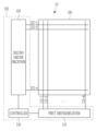
도 1은 일 실시 예에 따른 터치 장치를 개략적으로 나타낸 도면이다.
도 2는 일 실시 예에 따른 터치 장치에 스타일러스 펜이 터치된 일 예를 나타낸 도면이다.
도 3은 일 실시 예에 따른 터치 장치의 터치 검출 방법을 나타낸 순서도이다.
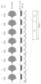
도 4는 도 3의 터치 검출 방법에 따른 구동 신호의 일례를 나타낸 파형도이다.
도 5는 도 4의 제1 구간에서의 제1 및 제2 구동/수신부의 동작을 보다 구체적으로 나타낸 도면이다.
도 6은 도 4의 제2 구간 중 제1 서브 구간에서의 제1 및 제2 구동/수신부의 동작을 보다 구체적으로 나타낸다.
도 7은 도 4의 제2 구간 중 제2 서브 구간에서의 제1 및 제2 구동/수신부의 동작을 보다 구체적으로 나타낸다.
도 8은 도 3의 터치 검출 방법에 따른 구동 신호와 수신 신호의 일례를 나타낸 파형도이다.
도 9는 도 8의 제1 구간에서의 감지 신호를 처리하는 일 예를 나타낸다.
도 10은 도 3의 터치 검출 방법에 따른 구동 신호와 수신 신호의 다른 예를 나타낸 파형도이다.
도 11은 도 10의 제2 구간에서의 감지 신호를 처리하는 일 예를 나타낸다.
도 12는 일 실시 예에 따른 터치 장치 및 호스트 장치를 나타내는 블록도이다.
도 13은 터치 장치로부터 호스트 장치에 제공되는 터치 데이터의 일 예를 나타내는 도면이다.
도 14는 터치 장치의 터치 감지 성능에 대한 노이즈의 영향을 설명하기 위한 도면이다.
도 15는 일 실시 예에 따른 터치 장치가 스타일러스 펜의 터치 입력을 검출하는 터치 검출 방법을 도시한 흐름도이다.
도 16은 도 15의 터치 검출 방법에서 노이즈를 필터링하는 방법을 설명하기 위한 도면이다.
도 17 내지 도 20은 터치 장치가 위상이 서로 다른 제1 및 제2 구동 신호를 출력하는 예들을 도시한 파형도들이다.FIG. 1 is a schematic drawing of a touch device according to one embodiment.
FIG. 2 is a drawing showing an example of a stylus pen touching a touch device according to one embodiment.
FIG. 3 is a flowchart illustrating a touch detection method of a touch device according to one embodiment.
Fig. 4 is a waveform diagram showing an example of a driving signal according to the touch detection method of Fig. 3.
FIG. 5 is a drawing showing in more detail the operation of the first and second driving/receiving units in the first section of FIG. 4.
Fig. 6 illustrates in more detail the operation of the first and second driving/receiving units in the first sub-section of the second section of Fig. 4.
Fig. 7 illustrates in more detail the operation of the first and second driving/receiving units in the second sub-section of the second section of Fig. 4.
Fig. 8 is a waveform diagram showing an example of a driving signal and a receiving signal according to the touch detection method of Fig. 3.
Figure 9 shows an example of processing a detection signal in the first section of Figure 8.
Fig. 10 is a waveform diagram showing another example of a driving signal and a receiving signal according to the touch detection method of Fig. 3.
Figure 11 shows an example of processing a detection signal in the second section of Figure 10.
FIG. 12 is a block diagram illustrating a touch device and a host device according to one embodiment.
FIG. 13 is a diagram showing an example of touch data provided from a touch device to a host device.
Figure 14 is a drawing for explaining the effect of noise on the touch detection performance of a touch device.
FIG. 15 is a flowchart illustrating a touch detection method for detecting touch input of a stylus pen by a touch device according to one embodiment.
FIG. 16 is a drawing for explaining a method of filtering noise in the touch detection method of FIG. 15.
Figures 17 to 20 are waveform diagrams illustrating examples in which a touch device outputs first and second drive signals having different phases.
이하, 첨부한 도면을 참고로 하여 본 발명의 여러 실시 예들에 대하여 본 발명이 속하는 기술 분야에서 통상의 지식을 가진 자가 용이하게 실시할 수 있도록 상세히 설명한다. 본 발명은 여러 가지 상이한 형태로 구현될 수 있으며 여기에서 설명하는 실시 예들에 한정되지 않는다.Hereinafter, various embodiments of the present invention will be described in detail with reference to the attached drawings so that those skilled in the art can easily implement the present invention. The present invention may be implemented in various different forms and is not limited to the embodiments described herein.
본 발명을 명확하게 설명하기 위해서 설명과 관계없는 부분은 생략하였으며, 명세서 전체를 통하여 동일 또는 유사한 구성요소에 대해서는 동일한 참조 부호를 붙이도록 한다.In order to clearly explain the present invention, parts irrelevant to the description are omitted, and the same reference numerals are used for identical or similar components throughout the specification.
본 문서에서 "제1", "제2", "제3" 등의 서수를 포함하는 용어는 다양한 구성요소들을 설명하는데 사용될 수 있지만, 상기 구성요소들은 상기 용어들에 의해 한정되지는 않는다. 상기 용어들은 하나의 구성요소를 다른 구성요소로부터 구별하는 목적으로만 사용된다. 예를 들어, 본 발명의 권리 범위를 벗어나지 않으면서 제2 구성요소는 제1 구성요소로 명명될 수 있고, 유사하게 제1 구성요소도 제2 구성요소로 명명될 수 있다. In this document, terms including ordinal numbers such as "first", "second", "third", etc. may be used to describe various components, but the components are not limited by the terms. The terms are used only for the purpose of distinguishing one component from another. For example, without departing from the scope of the present invention, a second component may be referred to as a first component, and similarly, a first component may also be referred to as a second component.
또한, 도면에서 나타난 각 구성의 크기 및 두께는 설명의 편의를 위해 임의로 나타내었으므로, 본 발명이 반드시 도시된 바에 한정되지 않는다. 도면에서 여러 층 및 영역을 명확하게 표현하기 위하여 두께를 확대하여 나타내었다. 그리고 도면에서, 설명의 편의를 위해, 일부 층 및 영역의 두께를 과장되게 나타내었다.In addition, the size and thickness of each component shown in the drawing are arbitrarily shown for the convenience of explanation, so the present invention is not necessarily limited to what is shown. In the drawing, the thickness is shown enlarged to clearly express several layers and regions. And in the drawing, the thickness of some layers and regions is shown exaggeratedly for the convenience of explanation.
또한, 층, 막, 영역, 판 등의 부분이 다른 부분 "위에" 또는 "상에" 있다고 할 때, 이는 다른 부분 "바로 위에" 있는 경우뿐 아니라 그 중간에 또 다른 부분이 있는 경우도 포함한다. 반대로 어떤 부분이 다른 부분 "바로 위에" 있다고 할 때에는 중간에 다른 부분이 없는 것을 뜻한다. 또한, 기준이 되는 부분 "위에" 또는 "상에" 있다고 하는 것은 기준이 되는 부분의 위 또는 아래에 위치하는 것이고, 반드시 중력 반대 방향 쪽으로 "위에" 또는 "상에" 위치하는 것을 의미하는 것은 아니다.Also, when we say that a part such as a layer, film, region, or plate is "over" or "on" another part, this includes not only cases where it is "directly over" the other part, but also cases where there is another part in between. Conversely, when we say that a part is "directly over" another part, it means that there is no other part in between. Also, when we say that a part is "over" or "on" a reference part, it means that it is located above or below the reference part, and does not necessarily mean that it is located "over" or "on" the opposite direction of gravity.
또한, 명세서 전체에서, 어떤 부분이 어떤 구성요소를 "포함" 한다고 할 때, 이는 특별히 반대되는 기재가 없는 한 다른 구성요소를 제외하는 것이 아니라 다른 구성요소를 더 포함할 수 있는 것을 의미한다.Additionally, throughout the specification, whenever a part is said to "include" a component, this does not mean that it excludes other components, but rather that it may include other components, unless otherwise specifically stated.
이하, 필요한 도면들을 참조하여 실시 예들에 따른 터치 장치 및 이의 터치 검출 방법에 대해 설명하기로 한다.Hereinafter, a touch device and a touch detection method thereof according to embodiments will be described with reference to necessary drawings.
도 1은 일 실시 예에 따른 터치 장치를 개략적으로 나타낸 도면이고, 도 2는 일 실시 예에 따른 터치 장치에 스타일러스 펜이 터치된 일 예를 나타낸 도면이다. FIG. 1 is a schematic diagram illustrating a touch device according to one embodiment, and FIG. 2 is a diagram illustrating an example of a stylus pen touching a touch device according to one embodiment.
도 1을 참조하면, 일 실시 예에 따른 터치 장치(10)는 터치 패널(touch panel, 100), 터치 패널(100)을 제어하는 터치 컨트롤러(102)(touch controller)를 포함한다. 터치 컨트롤러(102)는 터치 패널(100)과 신호를 송수신하는 제1 및 제2 구동/수신부(110, 120), 및 제어부(130)를 포함할 수 있다.Referring to FIG. 1, a touch device (10) according to one embodiment includes a touch panel (100) and a touch controller (102) that controls the touch panel (100). The touch controller (102) may include first and second driving/receiving units (110, 120) that transmit and receive signals with the touch panel (100), and a control unit (130).
터치 패널(100)은 복수의 터치 전극(111-1 내지 111-m, 121-1 내지 121-n)을 포함할 수 있다. The touch panel (100) may include a plurality of touch electrodes (111-1 to 111-m, 121-1 to 121-n).
도 1을 예로 들면, 터치 패널(100)은 제1 방향으로 연장된 형태를 갖는 복수의 제1 터치 전극(111-1 내지 111-m)과, 제1 방향과 교차하는 제2 방향으로 연장된 형태를 갖는 복수의 제2 터치 전극(121-1 내지 121-n)을 포함할 수 있다. 또한, 터치 패널(100) 내에서, 복수의 제1 터치 전극(111-1 내지 111-m)은 제2 방향을 따라 배열되고, 복수의 제2 터치 전극(121-1 내지 121-n)은 제1 방향을 따라 배열될 수 있다. 도 1에서는 터치 패널(100)이 사각형 형태인 경우를 예로 들어 도시하였으나, 터치 패널(100)의 형태는 이로 제한되지 않는다. 예를 들어, 터치 패널(100)은 원형, 타원형 등의 형태를 가질 수도 있다. Taking FIG. 1 as an example, the touch panel (100) may include a plurality of first touch electrodes (111-1 to 111-m) having a shape extending in a first direction, and a plurality of second touch electrodes (121-1 to 121-n) having a shape extending in a second direction intersecting the first direction. In addition, within the touch panel (100), the plurality of first touch electrodes (111-1 to 111-m) may be arranged along the second direction, and the plurality of second touch electrodes (121-1 to 121-n) may be arranged along the first direction. In FIG. 1, the case where the touch panel (100) has a rectangular shape is illustrated as an example, but the shape of the touch panel (100) is not limited thereto. For example, the touch panel (100) may have a shape such as a circle or an oval.
도 2를 참조하면, 터치 패널(100)은 기판(105)을 더 포함하며, 기판(105) 위에 복수의 터치 전극(111-1 내지 111-m, 121-1 내지 121-n)이 위치할 수 있다. 또한, 터치 패널(100)은 윈도우(103)를 더 포함하며, 복수의 터치 전극(111-1 내지 111-m, 121-1 내지 121-n) 위에 윈도우(103)가 위치할 수 있다. 도 2에서는 복수의 제1 터치 전극(111-1 내지 111-m)과 복수의 제2 터치 전극(121-1 내지 121-n)이 동일한 층에 위치하는 것으로 도시되어 있으나, 이에 제한되는 것은 아니다. 복수의 제1 터치 전극(111-1 내지 111-m)과 복수의 제2 터치 전극(121-1 내지 121-n)은 상이한 층에 각각 위치할 수도 있다. Referring to FIG. 2, the touch panel (100) further includes a substrate (105), and a plurality of touch electrodes (111-1 to 111-m, 121-1 to 121-n) may be positioned on the substrate (105). In addition, the touch panel (100) further includes a window (103), and the window (103) may be positioned on the plurality of touch electrodes (111-1 to 111-m, 121-1 to 121-n). In FIG. 2, a plurality of first touch electrodes (111-1 to 111-m) and a plurality of second touch electrodes (121-1 to 121-n) are illustrated as being positioned on the same layer, but are not limited thereto. The plurality of first touch electrodes (111-1 to 111-m) and the plurality of second touch electrodes (121-1 to 121-n) may be respectively positioned in different layers.
복수의 터치 전극(111-1 내지 111-m, 121-1 내지 121-n)은 각각 대응하는 터치 채널을 통해 구동/수신부(110, 120)에 연결될 수 있다. 도 1을 예로 들면, 복수의 제1 터치 전극(111-1 내지 111-m)은 제1 구동/수신부(110)에 연결되어 있고, 복수의 제2 터치 전극(121-1 내지 121-n)은 제2 구동/수신부(120)에 연결되어 있다. 도 1에서 제1 구동/수신부(110)와 제2 구동/수신부(120)를 분리하여 도시하였으나, 제1 구동/수신부(110)와 제2 구동/수신부(120)는 하나의 모듈, 유닛, 또는 칩(chip)으로 구현될 수도 있다. A plurality of touch electrodes (111-1 to 111-m, 121-1 to 121-n) may be connected to the driving/receiving unit (110, 120) through corresponding touch channels, respectively. Taking FIG. 1 as an example, a plurality of first touch electrodes (111-1 to 111-m) are connected to the first driving/receiving unit (110), and a plurality of second touch electrodes (121-1 to 121-n) are connected to the second driving/receiving unit (120). Although the first driving/receiving unit (110) and the second driving/receiving unit (120) are illustrated separately in FIG. 1, the first driving/receiving unit (110) and the second driving/receiving unit (120) may also be implemented as a single module, unit, or chip.
제1 구동/수신부(110)는 복수의 터치 채널을 통해 복수의 제1 터치 전극(111-1 내지 111-m)에 구동 신호를 인가할 수 있다. 또한, 제1 구동/수신부(110)는 복수의 터치 채널을 통해 복수의 제1 터치 전극(111-1 내지 111-m)으로부터 감지 신호를 수신할 수도 있다. 마찬가지로, 제2 구동/수신부(120)는 복수의 터치 채널을 통해 복수의 제2 터치 전극(121-1 내지 121-n)에 구동 신호를 인가할 수 있다. 또한, 제2 구동/수신부(120)는 복수의 터치 채널을 통해 복수의 제1 터치 전극(121-1 내지 121-n)으로부터 감지 신호를 수신할 수 있다. 즉, 제1 구동/수신부(110)와 제2 구동/수신부(120)는 신호를 송수신하는 일종의 트랜시버(transceiver)일 수 있다. The first driving/receiving unit (110) can apply driving signals to a plurality of first touch electrodes (111-1 to 111-m) through a plurality of touch channels. In addition, the first driving/receiving unit (110) can also receive detection signals from a plurality of first touch electrodes (111-1 to 111-m) through a plurality of touch channels. Similarly, the second driving/receiving unit (120) can apply driving signals to a plurality of second touch electrodes (121-1 to 121-n) through a plurality of touch channels. In addition, the second driving/receiving unit (120) can receive detection signals from a plurality of first touch electrodes (121-1 to 121-n) through a plurality of touch channels. That is, the first driving/receiving unit (110) and the second driving/receiving unit (120) can be a type of transceiver that transmits and receives signals.
제1 구동/수신부(110)로부터 복수의 제1 터치 전극(111-1 내지 111-m)으로 구동 신호 인가 시, 복수의 제1 터치 전극(111-1 내지 111-m)에 대응하는 터치 채널들은 구동 채널로 동작한다. 또한, 복수의 제1 터치 전극(111-1 내지 111-m)으로부터 제1 구동/수신부(110)로 감지 신호 전달 시, 복수의 제1 터치 전극(111-1 내지 111-m)에 대응하는 터치 채널들은 감지 채널로 동작한다. 마찬가지로, 제2 구동/수신부(110)로부터 복수의 제2 터치 전극(121-1 내지 121-n)으로 구동 신호 인가 시, 복수의 제2 터치 전극(121-1 내지 121-n)에 대응하는 터치 채널들은 구동 채널로 동작한다. 또한, 복수의 제2 터치 전극(121-1 내지 121-n)으로부터 제2 구동/수신부(120)로 감지 신호 전달 시, 복수의 제2 터치 전극(121-1 내지 121-n)에 대응하는 터치 채널들은 감지 채널로 동작한다. When a driving signal is applied from the first driving/receiving unit (110) to the plurality of first touch electrodes (111-1 to 111-m), the touch channels corresponding to the plurality of first touch electrodes (111-1 to 111-m) operate as driving channels. In addition, when a detection signal is transmitted from the plurality of first touch electrodes (111-1 to 111-m) to the first driving/receiving unit (110), the touch channels corresponding to the plurality of first touch electrodes (111-1 to 111-m) operate as detection channels. Similarly, when a driving signal is applied from the second driving/receiving unit (110) to the plurality of second touch electrodes (121-1 to 121-n), the touch channels corresponding to the plurality of second touch electrodes (121-1 to 121-n) operate as driving channels. In addition, when transmitting a detection signal from a plurality of second touch electrodes (121-1 to 121-n) to the second driving/receiving unit (120), the touch channels corresponding to the plurality of second touch electrodes (121-1 to 121-n) operate as detection channels.
터치 장치(10)는 터치 객체(touch object)에 의한 터치 입력(직접 터치 또는 근접 터치)을 감지하기 위해 사용될 수 있다. 예를 들어, 터치 장치(10)는 도 2에 도시된 바와 같이 스타일러스 펜(20)의 터치 입력을 감지하기 위해 사용될 수 있다. The touch device (10) can be used to detect a touch input (direct touch or proximity touch) by a touch object. For example, the touch device (10) can be used to detect a touch input of a stylus pen (20) as shown in FIG. 2.
도 2를 참조하면, 스타일러스 펜(20)은 전도성 팁(conductive tip)(21), 공진 회로부(23), 접지부(ground, 25), 및 바디부(body, 27)를 포함할 수 있다. Referring to FIG. 2, the stylus pen (20) may include a conductive tip (21), a resonant circuit (23), a ground (25), and a body (27).
전도성 팁(21)은 적어도 일부가 전도성 물질(예를 들어, 금속, 전도성 고무, 전도성 패브릭, 전도성 실리콘 등)로 형성되며, 공진 회로부(23)에 전기적으로 연결될 수 있다. The conductive tip (21) is formed at least in part of a conductive material (e.g., metal, conductive rubber, conductive fabric, conductive silicone, etc.) and can be electrically connected to the resonant circuit (23).
공진 회로부(23)는 LC 공진 회로로서, 전도성 팁(21)을 통해 제1 구동/수신부(110) 및 제2 구동/수신부(120) 중 적어도 하나로부터 복수의 제1 터치 전극(111-1 내지 111-m) 및 복수의 제2 터치 전극(121-1 내지 121-n) 중 적어도 한 종류의 전극에 인가된 구동 신호에 공진할 수 있다. 이를 위해, 터치 전극들(111-1 내지 111-m, 121-1 내지 121-n)에 인가된 구동 신호는, 스타일러스 펜(20)의 공진 주파수에 대응하는 주파수를 갖는 주파수 신호(예를 들어, 사인파, 구형파 등)를 포함할 수 있다. 스타일러스 펜(20)의 공진 주파수는 스타일러스 펜의 공진 회로부(23)의 설계 값에 따라 결정된다. The resonant circuit (23) is an LC resonant circuit and can resonate with a driving signal applied to at least one type of electrode among a plurality of first touch electrodes (111-1 to 111-m) and a plurality of second touch electrodes (121-1 to 121-n) from at least one of the first driving/receiving unit (110) and the second driving/receiving unit (120) through the conductive tip (21). To this end, the driving signal applied to the touch electrodes (111-1 to 111-m, 121-1 to 121-n) can include a frequency signal (e.g., a sine wave, a square wave, etc.) having a frequency corresponding to the resonant frequency of the stylus pen (20). The resonant frequency of the stylus pen (20) is determined according to a design value of the resonant circuit (23) of the stylus pen.
공진 회로부(23)가 터치 전극들(111-1 내지 111-m, 121-1 내지 121-n)에 인가된 구동 신호에 공진하여 발생된 공진 신호는, 전도성 팁(21)을 통해 터치 패널(100)에 출력된다. 공진 회로부(23)의 공진을 발생시킨 구동 신호가 터치 전극들(111-1 내지 111-m, 121-1 내지 121-n)로 인가되는 구간 및 그 이후의 구간에서, 공진 회로부(23)의 공진에 의한 공진 신호가 전도성 팁(21)에 전달될 수 있다. 공진 회로부(23)는 바디부(27) 내에 위치하며, 접지부(25)에 전기적으로 연결될 수 있다. The resonance signal generated by the resonance circuit (23) resonating with the driving signal applied to the touch electrodes (111-1 to 111-m, 121-1 to 121-n) is output to the touch panel (100) through the conductive tip (21). In the section where the driving signal that causes the resonance of the resonance circuit (23) is applied to the touch electrodes (111-1 to 111-m, 121-1 to 121-n) and the section thereafter, the resonance signal due to the resonance of the resonance circuit (23) can be transmitted to the conductive tip (21). The resonance circuit (23) is located within the body (27) and can be electrically connected to the ground (25).
이러한 방식의 스타일러스 펜(20)은 터치 전극들(111-1 내지 111-m, 121-1 내지 121-n) 중 적어도 하나에 인가되는 구동 신호에 응답하여 공진 신호를 발생시킴으로써 터치 입력을 발생시킬 수 있다. A stylus pen (20) of this type can generate a touch input by generating a resonance signal in response to a driving signal applied to at least one of the touch electrodes (111-1 to 111-m, 121-1 to 121-n).
스타일러스 펜(20)에 의해 터치 패널(100)이 터치되면, 터치 전극들(111-1 내지 111-m, 121-1 내지 121-n) 중 적어도 하나와 스타일러스 펜(20)의 전도성 팁(21)에 의해 커패시턴스(Cx)가 형성된다. 터치 전극들(111-1 내지 111-m, 121-1 내지 121-n) 중 적어도 하나와 전도성 팁(21) 사이의 커패시턴스(Cx)를 통해, 터치 패널(100)로 인가된 구동 신호가 스타일러스 펜(20) 측에 전달되고, 스타일러스 펜(20)의 공진 신호가 터치 패널(100) 측으로 전달될 수 있다. When the touch panel (100) is touched by the stylus pen (20), a capacitance (Cx) is formed by at least one of the touch electrodes (111-1 to 111-m, 121-1 to 121-n) and the conductive tip (21) of the stylus pen (20). Through the capacitance (Cx) between at least one of the touch electrodes (111-1 to 111-m, 121-1 to 121-n) and the conductive tip (21), a driving signal applied to the touch panel (100) can be transmitted to the stylus pen (20) side, and a resonance signal of the stylus pen (20) can be transmitted to the touch panel (100) side.
터치 장치(10)는 상기에서 설명한 공진 신호를 발생시키는 방식을 사용하는 스타일러스 펜(20) 이외의 터치 객체(예를 들어, 사용자의 신체 부위(손가락, 손바닥 등), 패시브(passive) 또는 액티브(active) 방식의 스타일러스 펜)에 의한 터치를 검출할 수도 있다. The touch device (10) may also detect a touch by a touch object (e.g., a user's body part (finger, palm, etc.), a passive or active stylus pen) other than a stylus pen (20) that uses the method of generating a resonance signal described above.
예를 들어, 터치 장치(10)는, 전기 신호를 입력 받아 이를 자기장 신호로 출력하는 스타일러스 펜에 의한 터치를 검출할 수 있다. 또한, 예를 들어, 터치 장치(10)는, 자기장 신호를 입력 받아 이에 의해 공진된 자기장 신호로 출력하는 스타일러스 펜에 의한 터치를 검출할 수도 있다.For example, the touch device (10) can detect a touch by a stylus pen that receives an electric signal and outputs it as a magnetic field signal. In addition, for example, the touch device (10) can also detect a touch by a stylus pen that receives a magnetic field signal and outputs it as a magnetic field signal resonated by the magnetic field signal.
터치 장치(10)는 디지타이저(digitizer)를 더 구비할 수도 있다. 이 경우, 스타일러스 펜에 의해 전자기 공진(또는 전자기 유도)된 자기장 신호가 디지타이저에 의해 검출됨으로써, 터치가 검출될 수 있다. The touch device (10) may further include a digitizer. In this case, a touch can be detected by detecting a magnetic field signal that is electromagnetically resonated (or electromagnetically induced) by a stylus pen by the digitizer.
터치 장치(10)는 디지타이저와 함께 구동 신호로서 전류를 인가하는 코일을 더 구비할 수도 있다. 이 경우, 전류가 인가된 코일에서 생성된 자기장 신호에 스타일러스 펜이 전자기 공진(또는 전자기 유도)하여 자기장 신호를 발생시키고, 스타일러이스 펜이 전자기 공진(또는 전자기 유도)하여 발생시킨 자기장 신호가 디지타이저에 의해 검출됨으로써, 터치가 검출될 수 있다.The touch device (10) may further include a coil that applies current as a driving signal together with the digitizer. In this case, the stylus pen generates a magnetic field signal by electromagnetic resonance (or electromagnetic induction) in response to a magnetic field signal generated from the coil to which the current is applied, and the magnetic field signal generated by the stylus pen by electromagnetic resonance (or electromagnetic induction) is detected by the digitizer, thereby allowing a touch to be detected.
제어부(130)는 터치 장치(10)의 구동을 제어하며, 터치 장치(10)의 터치 감지 결과에 대응하여 터치 좌표를 포함하는 터치 데이터를 출력할 수 있다.The control unit (130) controls the operation of the touch device (10) and can output touch data including touch coordinates in response to the touch detection result of the touch device (10).
다음으로, 도 3 및 도 4를 참조하여, 일 실시 예에 따른 터치 검출 방법을 설명한다. Next, a touch detection method according to one embodiment will be described with reference to FIGS. 3 and 4.
도 3은 일 실시 예에 따른 터치 검출 방법을 나타낸 순서도로서, 하나의 프레임 구간 내에서의 터치 검출 방법을 도시한 것이다. 도 3의 터치 검출 방법은, 도 1 및 도 2를 참조하여 설명한 터치 장치(10)에 의해 수행될 수 있다. Fig. 3 is a flowchart illustrating a touch detection method according to one embodiment, and illustrates a touch detection method within one frame section. The touch detection method of Fig. 3 can be performed by the touch device (10) described with reference to Figs. 1 and 2.
도 3을 참조하면, 터치 장치(10)는 제1 터치 구동 모드로 구동한다(S10). 제1 터치 구동 모드는 스타일러스 펜(20) 외의 다른 터치 객체(예를 들어, 손가락 등)에 의한 터치 입력을 검출하기 위한 모드이다. 터치 장치(10)가 제1 터치 구동 모드로 구동하는 동안, 제1 구동/수신부(110)는 복수의 제1 터치 전극(111-1 내지 111-m)에 구동 신호들을 출력하고, 제2 구동/수신부(120)는 복수의 제2 터치 전극(121-1 내지 121-n)으로부터 터치에 따른 감지 신호들을 수신할 수 있다. Referring to FIG. 3, the touch device (10) is driven in a first touch driving mode (S10). The first touch driving mode is a mode for detecting a touch input by a touch object (e.g., a finger, etc.) other than a stylus pen (20). While the touch device (10) is driven in the first touch driving mode, the first driving/receiving unit (110) can output driving signals to a plurality of first touch electrodes (111-1 to 111-m), and the second driving/receiving unit (120) can receive detection signals according to touch from a plurality of second touch electrodes (121-1 to 121-n).
제어부(130)는 터치 장치(10)가 제1 터치 구동 모드로 구동하는 동안 터치 패널(100)로부터 수신된 감지 신호들에 기초하여 터치 객체의 제1 터치 데이터를 획득한다(S11). 제1 터치 구동 모드에 획득되는 제1 터치 데이터는, 스타일러스 펜(20) 이외의 터치 객체(예를 들어, 사용자의 신체 부위(손가락, 손바닥 등), 패시브(passive) 또는 액티브(active) 방식의 스타일러스 펜)에 의한 터치 입력에 대응할 수 있다. 즉, 제1 터치 데이터는, 터치 객체의 터치 패널(100) 터치로 인한 터치 전극의 커패시턴스 변화량, 감지 신호의 변화량, ADC(analog to digital converter)(후술하는 ADC부(115, 125) 참조) 출력(또는 출력 변화량) 등에 대응하는 데이터일 수 있다. The control unit (130) acquires first touch data of a touch object based on detection signals received from the touch panel (100) while the touch device (10) is driven in the first touch driving mode (S11). The first touch data acquired in the first touch driving mode may correspond to a touch input by a touch object other than the stylus pen (20) (for example, a body part of the user (finger, palm, etc.), a passive or active stylus pen). That is, the first touch data may be data corresponding to a change in capacitance of a touch electrode due to a touch of the touch panel (100) of the touch object, a change in a detection signal, an ADC (analog to digital converter) (see the ADC unit (115, 125) described below) output (or output change), etc.
제1 터치 구동 모드가 종료되면, 터치 장치(10)는 제2 터치 구동 모드로 구동한다(S12). 제2 터치 구동 모드는 스타일러스 펜(20)에 의한 터치 입력을 검출하기 위한 모드이다. 터치 장치(10)가 제2 구동 모드로 구동하면, 제1 구동/수신부(110) 및 제2 구동/수신부(120)는 복수의 제1 터치 전극(111-1 내지 111-m) 및 복수의 제2 터치 전극(121-1 내지 121-n) 모두에 구동 신호를 동시에 인가할 수 있다. 그리고, 복수의 제1 터치 전극(111-1 내지 111-m) 및 복수의 제2 터치 전극(121-1 내지 121-n)에 인가된 구동 신호에 의해 스타일러스 펜(20)의 공진 회로부(23)가 공진하고, 이로 인해 발생된 공진 신호가 전도성 팁(21)을 통해 터치 패널(100)에 전달될 수 있다. 이에 따라, 제1 구동/수신부(110)는 복수의 제1 터치 전극(111-1 내지 111-m)으로부터 전달되는 감지 신호를 수신하고, 제2 구동/수신부(120)는 복수의 제2 터치 전극(121-1 내지 121-n)으로부터 전달되는 감지 신호를 수신하며, 제1 구동/수신부(110)와 제2 구동/수신부(120)는 수신된 감지 신호를 처리하여 제어부(130)에 전달할 수 있다. When the first touch driving mode is terminated, the touch device (10) is driven in the second touch driving mode (S12). The second touch driving mode is a mode for detecting a touch input by the stylus pen (20). When the touch device (10) is driven in the second driving mode, the first driving/receiving unit (110) and the second driving/receiving unit (120) can simultaneously apply driving signals to all of the plurality of first touch electrodes (111-1 to 111-m) and the plurality of second touch electrodes (121-1 to 121-n). Then, the resonance circuit unit (23) of the stylus pen (20) resonates by the driving signals applied to the plurality of first touch electrodes (111-1 to 111-m) and the plurality of second touch electrodes (121-1 to 121-n), and the resonance signal generated thereby can be transmitted to the touch panel (100) through the conductive tip (21). Accordingly, the first driving/receiving unit (110) receives a detection signal transmitted from a plurality of first touch electrodes (111-1 to 111-m), the second driving/receiving unit (120) receives a detection signal transmitted from a plurality of second touch electrodes (121-1 to 121-n), and the first driving/receiving unit (110) and the second driving/receiving unit (120) can process the received detection signal and transmit it to the control unit (130).
상기에서는 터치 장치(10)가 제2 구동 모드로 구동하는 동안 스타일러스 펜(20)의 공진 신호를 발생시키기 위해, 제1 구동/수신부(110) 및 제2 구동/수신부(120)가 복수의 제1 터치 전극(111-1 내지 111-m) 및 복수의 제2 터치 전극(121-1 내지 121-n)에 구동 신호를 동시에 인가되는 경우를 예로 들어 설명하였으나, 제1 구동/수신부(110)에 의해 복수의 제1 터치 전극(111-1 내지 111-m) 모두에만 구동 신호가 동시에 인가되거나, 제2 구동/수신부(120)에 의해 복수의 제2 터치 전극(121-1 내지 121-n) 모두에만 구동 신호가 동시에 인가될 수도 있다. 제1 구동/수신부(110) 및 제2 구동/수신부(120)가 복수의 제1 터치 전극(111-1 내지 111-m)과 복수의 제2 터치 전극(121-1 내지 121-n) 모두에 구동 신호를 동시 인가하는 경우, 복수의 제1 터치 전극(111-1 내지 111-m)에 인가되는 구동 신호와 복수의 제2 터치 전극(121-1 내지 121-n)에 인가되는 구동 신호의 위상은 동일한 것으로 가정하며, 이에 제한되지 않는다.In the above, the case where the first driving/receiving unit (110) and the second driving/receiving unit (120) simultaneously apply driving signals to the plurality of first touch electrodes (111-1 to 111-m) and the plurality of second touch electrodes (121-1 to 121-n) to generate a resonance signal of the stylus pen (20) while the touch device (10) is driven in the second driving mode has been described as an example. However, the driving signals may be simultaneously applied to only all of the plurality of first touch electrodes (111-1 to 111-m) by the first driving/receiving unit (110), or the driving signals may be simultaneously applied to only all of the plurality of second touch electrodes (121-1 to 121-n) by the second driving/receiving unit (120). When the first driving/receiving unit (110) and the second driving/receiving unit (120) simultaneously apply driving signals to both the plurality of first touch electrodes (111-1 to 111-m) and the plurality of second touch electrodes (121-1 to 121-n), the phases of the driving signals applied to the plurality of first touch electrodes (111-1 to 111-m) and the driving signals applied to the plurality of second touch electrodes (121-1 to 121-n) are assumed to be the same, but are not limited thereto.
제어부(130)는 터치 장치(10)가 제2 터치 구동 모드로 구동하는 동안 터치 패널(100)로부터 감지 신호들을 수신하고, 수신된 감지 신호들에 기초하여 터치 객체의 터치 좌표 등을 포함하는 제2 터치 데이터를 획득한다(S13). 제2 터치 구동 모드에서 획득되는 제2 터치 데이터는, 스타일러스 펜(20)에 의한 터치 입력에 대응할 수 있다. 즉, 제2 터치 데이터는, 스타일러스 펜(20)의 터치 패널(100) 터치로 인한 커패시턴스 변화량, 감지 신호의 변화량, ADC 출력(또는 출력 변화량) 등을 데이터화한 것이다.The control unit (130) receives detection signals from the touch panel (100) while the touch device (10) is driven in the second touch driving mode, and acquires second touch data including touch coordinates of a touch object, etc. based on the received detection signals (S13). The second touch data acquired in the second touch driving mode may correspond to a touch input by the stylus pen (20). That is, the second touch data is data that converts the amount of capacitance change due to the touch of the stylus pen (20) on the touch panel (100), the amount of change in the detection signal, the ADC output (or the amount of change in output), etc.
다음으로, 도 4를 참조하여, 제1 터치 구동 모드와 및 제2 터치 구동 모드에서 인가되는 구동 신호와, 스타일러스 펜(20)의 공진 신호를 설명한다.Next, referring to Fig. 4, the driving signals applied in the first touch driving mode and the second touch driving mode and the resonance signal of the stylus pen (20) will be described.
도 4는 도 3의 터치 검출 방법에 따른 구동 신호의 일례를 나타낸 파형도이다. 도 4에서, D_121 및 D_111은 각각 제1 구동/수신부(110) 및 제2 구동/수신부(120)에서 출력되는 구동 신호의 일례를 나타낸다. Fig. 4 is a waveform diagram showing an example of a driving signal according to the touch detection method of Fig. 3. In Fig. 4, D_121 and D_111 represent examples of driving signals output from the first driving/receiving unit (110) and the second driving/receiving unit (120), respectively.
도 4를 참조하면, 터치 장치(10)가 제1 터치 구동 모드로 구동하는 제1 구간(T1)에서, 제1 구동/수신부(110)는 복수의 제1 터치 전극(111-1 내지 111-m) 에 구동 신호(D_111)들을 출력한다. 또한, 제1 구동/수신부(110)가 복수의 제1 터치 전극(111-1 내지 111-m)으로 구동 신호들을 출력하면, 제2 구동/수신부(120)는 복수의 제2 터치 전극(121-1 내지 121-n)으로부터 감지 신호들을 수신한다. Referring to FIG. 4, in a first section (T1) in which the touch device (10) is driven in the first touch driving mode, the first driving/receiving unit (110) outputs driving signals (D_111) to a plurality of first touch electrodes (111-1 to 111-m). In addition, when the first driving/receiving unit (110) outputs driving signals to the plurality of first touch electrodes (111-1 to 111-m), the second driving/receiving unit (120) receives detection signals from a plurality of second touch electrodes (121-1 to 121-n).
터치 장치(10)가 제2 터치 구동 모드로 구동하는 제2 구간(T2) 중 제1 서브 구간(T21)에서, 제1 구동/수신부(110)는 복수의 제1 터치 전극(111-1 내지 111-m) 에 구동 신호(D_111)들을 동시에 인가하고, 제2 구동/수신부(120)는 복수의 제2 터치 전극(121-1 내지 121-n) 에 구동 신호(D_121)들을 동시에 인가한다. In a first sub-section (T21) of a second section (T2) in which the touch device (10) is driven in a second touch driving mode, the first driving/receiving unit (110) simultaneously applies driving signals (D_111) to a plurality of first touch electrodes (111-1 to 111-m), and the second driving/receiving unit (120) simultaneously applies driving signals (D_121) to a plurality of second touch electrodes (121-1 to 121-n).
제1 서브 구간(T21)에서, 복수의 제1 터치 전극(111-1 내지 111-m)에 인가되는 구동 신호(D_111) 및 복수의 제2 터치 전극(121-1 내지 121-n)에 인가되는 구동 신호(D_121)의 주파수는, 스타일러스 펜(20)의 공진 주파수에 대응한다. 예를 들어, 제1 서브 구간(T21) 동안 복수의 제1 터치 전극(111-1 내지 111-m) 및 복수의 제2 터치 전극(121-1 내지 121-n)에 출력되는 구동 신호들(D111, D121)의 주파수는 500kHz를 중심으로 25kHz의 오프셋 내의 주파수일 수 있다. 이에 반해, 제1 구간(T1)에서, 복수의 제1 터치 전극(111-1 내지 111-m)에 출력되는 구동 신호(D_111)들의 주파수는 스타일러스 펜(20)의 공진 주파수와 상이하게 설정된다. 예를 들어, 제1 구간(T1) 동안 복수의 제1 터치 전극(111-1 내지 111-m)에 출력되는 구동 신호(D_111)들의 주파수는 150kHz 내외로 설정될 수 있다. 이러한 구동 신호의 주파수 설정은 예시에 불과하며, 상기와는 다른 값으로 설정될 수 있다. In the first sub-section (T21), the frequency of the driving signal (D_111) applied to the plurality of first touch electrodes (111-1 to 111-m) and the driving signal (D_121) applied to the plurality of second touch electrodes (121-1 to 121-n) corresponds to the resonant frequency of the stylus pen (20). For example, the frequency of the driving signals (D111, D121) output to the plurality of first touch electrodes (111-1 to 111-m) and the plurality of second touch electrodes (121-1 to 121-n) during the first sub-section (T21) may be a frequency within an offset of 25 kHz centered on 500 kHz. In contrast, in the first section (T1), the frequency of the driving signals (D_111) output to the plurality of first touch electrodes (111-1 to 111-m) is set to be different from the resonance frequency of the stylus pen (20). For example, the frequency of the driving signals (D_111) output to the plurality of first touch electrodes (111-1 to 111-m) during the first section (T1) may be set to approximately 150 kHz. This frequency setting of the driving signals is merely an example, and may be set to a different value than the above.
터치 장치(10)가 제2 터치 구동 모드로 구동하는 제2 구간(T2) 중 제2 서브 구간(T22)에서, 제1 구동/수신부(110)는 복수의 제1 터치 전극(111-1 내지 111-m)으로부터 감지 신호들을 수신하고, 제2 구동/수신부(120)는 복수의 제2 터치 전극(121-1 내지 121-n)으로부터 감지 신호들을 수신할 수 있다. 제2 서브 구간(T22)에서는 구동 신호 인가가 종료된 후에도, 스타일러스 펜(20)의 공진 회로부(23)에 의해 출력되는 공진 신호가 복수의 제1 터치 전극(111-1 내지 111-m) 및 복수의 제2 터치 전극(121-1 내지 121-n) 중 적어도 하나에 의해 수신될 수 있다. In a second sub-section (T22) of a second section (T2) in which the touch device (10) is driven in a second touch driving mode, the first driving/receiving unit (110) can receive detection signals from a plurality of first touch electrodes (111-1 to 111-m), and the second driving/receiving unit (120) can receive detection signals from a plurality of second touch electrodes (121-1 to 121-n). In the second sub-section (T22), even after the application of the driving signal is terminated, a resonance signal output by the resonance circuit unit (23) of the stylus pen (20) can be received by at least one of the plurality of first touch electrodes (111-1 to 111-m) and the plurality of second touch electrodes (121-1 to 121-n).
제2 구간(T2)은 제1 서브 구간(T21)과 제2 서브 구간(T22)을 복수로 포함할 수 있다. 예를 들어, 제2 구간(T2) 내에서, 제1 서브 구간(T21)과 제2 서브 구간(T22)의 조합이 8회로 반복될 수 있다.The second section (T2) may include a plurality of first sub-sections (T21) and second sub-sections (T22). For example, within the second section (T2), the combination of the first sub-sections (T21) and the second sub-sections (T22) may be repeated eight times.
상기에서는 제1 구간(T1) 이후에 제2 구간(T2)이 존재하는 것으로 설명하였으나, 제2 구간(T2) 이후에 제1 구간(T1)이 존재할 수도 있으며, 제1 구간(T1)과 제2 구간(T2)의 시간 길이는 여러 프레임 구간 내에서 각각 변경될 수 있고, 실시 예의 터치 장치(10)의 구동 방식은 이에 제한되지 않는다. In the above, it is described that the second section (T2) exists after the first section (T1), but the first section (T1) may exist after the second section (T2), and the time lengths of the first section (T1) and the second section (T2) may each be changed within several frame sections, and the driving method of the touch device (10) of the embodiment is not limited thereto.
또한, 상기에서는 하나의 프레임 구간 내에 제1 구간(T1) 및 제2 구간(T2)이 한 번씩 포함되는 경우를 예로 들어 설명하였으나, 하나의 프레임 구간 내에 복수의 제1 구간(T1) 및 복수의 제2 구간(T2)이 포함될 수도 있다. 이 경우, 터치 장치(10)는 제1 터치 구동 모드로 구동하는 복수의 제1 구간(T1)에서 터치 패널(100)로부터 수신된 감지 신호들에 기초하여 제1 터치 데이터를 획득하고, 제2 터치 구동 모드로 구동하는 복수의 제2 구간(T2)에서 터치 패널(100)로부터 수신된 감지 신호들에 기초하여 제2 터치 데이터를 획득할 수 있다. In addition, although the above description was given as an example in which a first section (T1) and a second section (T2) are included once within one frame section, a plurality of first sections (T1) and a plurality of second sections (T2) may be included within one frame section. In this case, the touch device (10) may obtain first touch data based on detection signals received from the touch panel (100) in a plurality of first sections (T1) driven in a first touch driving mode, and may obtain second touch data based on detection signals received from the touch panel (100) in a plurality of second sections (T2) driven in a second touch driving mode.
또한, 상기에서는 제2 서브 구간(T22)에서 제1 구동/수신부(110)와 제2 구동/수신부(120)가 감지 신호를 수신하는 것으로 설명하였으나, 제1 구동/수신부(110)와 제2 구동/수신부(120)는 제1 서브 구간(T21)에서 복수의 제1 터치 전극(111-1 내지 111-m) 및 복수의 제2 터치 전극(121-1 내지 121-n)을 통해 감지 신호를 수신할 수도 있다. In addition, although it has been described above that the first driving/receiving unit (110) and the second driving/receiving unit (120) receive the detection signal in the second sub-section (T22), the first driving/receiving unit (110) and the second driving/receiving unit (120) may also receive the detection signal through the plurality of first touch electrodes (111-1 to 111-m) and the plurality of second touch electrodes (121-1 to 121-n) in the first sub-section (T21).
다음으로, 도 5 및 도 7을 참조하여 도 1의 터치 장치(10)에서 제1 및 제2 구동/수신부(110, 120)의 동작에 대해 구체적으로 설명한다.Next, the operations of the first and second driving/receiving units (110, 120) in the touch device (10) of Fig. 1 will be specifically described with reference to Figs. 5 and 7.
도 5 내지 도 7을 참조하면, 제1 구동/수신부(110)는 복수의 증폭부(amplifier)(112-1 내지 112-m), 복수의 차동 증폭부(또는 차분 증폭부)(113-1 내지 113-i), ADC(analog to digital converter)부(115), 및 신호 처리부(DSP, 117)를 포함한다. Referring to FIGS. 5 to 7, the first driving/receiving unit (110) includes a plurality of amplifiers (112-1 to 112-m), a plurality of differential amplifiers (or differential amplifiers) (113-1 to 113-i), an analog to digital converter (ADC) unit (115), and a signal processing unit (DSP, 117).
또한, 제2 구동/수신부(120)는, 복수의 제1 증폭부(122-1 내지 122-n), 복수의 제2 증폭부(123-1 내지 123-j)(또는 복수의 차동 증폭부(또는 차분 증폭부)(123-1 내지 123-j)), ADC부(125), 및 신호 처리부(DSP, 127)를 포함한다.In addition, the second driving/receiving unit (120) includes a plurality of first amplifier units (122-1 to 122-n), a plurality of second amplifier units (123-1 to 123-j) (or a plurality of differential amplifier units (or differential amplifier units) (123-1 to 123-j)), an ADC unit (125), and a signal processing unit (DSP, 127).
도 5는 도 4의 제1 구간(T1)에서의 제1 및 제2 구동/수신부(110, 120)의 동작을 보다 구체적으로 나타낸 도면이다.FIG. 5 is a drawing showing in more detail the operation of the first and second driving/receiving units (110, 120) in the first section (T1) of FIG. 4.
도 5를 참조하면, 제1 구간(T1)에서 제1 구동/수신부(110)에 포함된 복수의 증폭부(112-1 내지 112-m)는 각각, 터치 채널을 통해 복수의 제1 터치 전극(111-1 내지 111-m) 중 대응하는 하나의 제1 터치 전극에 연결되어 구동 신호를 출력한다. Referring to FIG. 5, in the first section (T1), a plurality of amplifier units (112-1 to 112-m) included in the first driving/receiving unit (110) are each connected to a corresponding first touch electrode among the plurality of first touch electrodes (111-1 to 111-m) through a touch channel to output a driving signal.
또한, 제1 구간(T1)에서 제2 구동/수신부(120)에 포함된 복수의 제2 증폭부(123-1 내지 123-n)는 각각, 터치 채널을 통해 복수의 제2 터치 전극(121-1 내지 121-n) 중 대응하는 하나의 제2 터치 전극에 연결되어 감지 신호를 수신한다. 복수의 제2 증폭부(123-1 내지 123-n) 각각은, 두 개의 입력단 중 하나의 입력단이 접지 또는 직류 전압이 연결되고, 나머지 입력단에 대응하는 제2 터치 전극의 감지 신호가 입력되는 증폭기로 구현될 수 있다. 즉, 복수의 제2 증폭부(123-1 내지 123-n) 각각은, 복수의 제2 터치 전극(121-1 내지 121-n)에서 전달되는 감지 신호를 병렬적으로 증폭하여 출력한다. In addition, in the first section (T1), the plurality of second amplifiers (123-1 to 123-n) included in the second driving/receiving unit (120) are each connected to a corresponding second touch electrode among the plurality of second touch electrodes (121-1 to 121-n) through a touch channel to receive a detection signal. Each of the plurality of second amplifiers (123-1 to 123-n) may be implemented as an amplifier in which one of the two input terminals is connected to ground or a DC voltage and the detection signal of the corresponding second touch electrode is input to the remaining input terminal. That is, each of the plurality of second amplifiers (123-1 to 123-n) amplifies and outputs the detection signal transmitted from the plurality of second touch electrodes (121-1 to 121-n) in parallel.
제1 구간(T1)에서 제2 구동/수신부(120)의 ADC부(125)는 복수의 제2 증폭부(123-1 내지 123-n)에 의해 증폭된 감지 신호들을 디지털 신호인 감지 데이터들로 변환한다. 즉, ADC부(125)는 복수의 제2 증폭부(123-1 내지 123-n)로부터 증폭된 감지 신호들이 입력되면, 주기적인 샘플링을 통해 이들을 감지 데이터로 변환한다. In the first section (T1), the ADC unit (125) of the second driving/receiving unit (120) converts the detection signals amplified by the plurality of second amplifier units (123-1 to 123-n) into detection data, which is a digital signal. That is, when the detection signals amplified from the plurality of second amplifier units (123-1 to 123-n) are input, the ADC unit (125) converts them into detection data through periodic sampling.
신호 처리부(127)는 ADC부(125)에 의해 디지털 신호로 변환된 감지 데이터들을 처리하여 제어부(130)에 전달한다.The signal processing unit (127) processes the detection data converted into digital signals by the ADC unit (125) and transmits them to the control unit (130).
도 6은 도 4의 제2 구간(T2) 중 제1 서브 구간(T21)에서의 제1 및 제2 구동/수신부(110, 120)의 동작을 보다 구체적으로 나타낸다.FIG. 6 illustrates in more detail the operation of the first and second driving/receiving units (110, 120) in the first sub-section (T21) of the second section (T2) of FIG. 4.
도 6을 참조하면, 제1 서브 구간(T21)에서 제1 구동/수신부(110)에 포함된 복수의 증폭부(112-1 내지 112-m)는 각각, 터치 채널을 통해 복수의 제1 터치 전극(111-1 내지 111-m) 중 대응하는 제1 터치 전극에 연결되어 구동 신호를 출력한다. 또한, 제2 구동/수신부(120)에 포함된 복수의 제1 증폭부(122-1 내지 122-n) 또한, 각각 터치 채널을 통해 복수의 제2 터치 전극(121-1 내지 121-n) 중 대응하는 제2 터치 전극에 연결되어 구동 신호를 출력한다.Referring to FIG. 6, in the first sub-section (T21), the plurality of amplifier units (112-1 to 112-m) included in the first driving/receiving unit (110) are each connected to a corresponding first touch electrode among the plurality of first touch electrodes (111-1 to 111-m) through a touch channel to output a driving signal. In addition, the plurality of first amplifier units (122-1 to 122-n) included in the second driving/receiving unit (120) are also each connected to a corresponding second touch electrode among the plurality of second touch electrodes (121-1 to 121-n) through a touch channel to output a driving signal.
도 7은 도 4의 제2 구간(T2) 중 제2 서브 구간(T22)에서의 제1 및 제2 구동/수신부(110, 120)의 동작을 보다 구체적으로 나타낸다.FIG. 7 illustrates in more detail the operation of the first and second driving/receiving units (110, 120) in the second sub-section (T22) of the second section (T2) of FIG. 4.
도 7을 참조하면, 제2 서브 구간(T22)에서 제1 구동/수신부(110)에 포함된 복수의 차동 증폭부(또는 차분 증폭부)(113-1 내지 113-i)와 제2 구동/수신부(120)에 포함된 복수의 차동 증폭부(또는 차분 증폭부)(123-1 내지 123-j) 각각은, 입력 단자들이 서로 이격 되어 있는 두 개의 터치 전극에 각각 연결된다. 또한, 각각의 차동 증폭부(113-1 내지 113-i, 123-1 내지 123-j)는 대응하는 터치 전극들에서 전달되는 두 개의 감지 신호를 차동 증폭하여 출력할 수 있다. 각각의 차동 증폭부(113-1 내지 113-i, 123-1 내지 123-j)는 두 개의 터치 전극으로부터 감지 신호를 수신하여 차동 증폭하므로, 구동 신호들을 복수의 터치 전극에 동시에 인가하더라도, 포화되지 않는다. Referring to FIG. 7, in the second sub-section (T22), each of the plurality of differential amplifiers (or differential amplifiers) (113-1 to 113-i) included in the first driving/receiving unit (110) and the plurality of differential amplifiers (or differential amplifiers) (123-1 to 123-j) included in the second driving/receiving unit (120) is respectively connected to two touch electrodes whose input terminals are spaced apart from each other. In addition, each of the differential amplifiers (113-1 to 113-i, 123-1 to 123-j) can differentially amplify and output two detection signals transmitted from corresponding touch electrodes. Since each of the differential amplifiers (113-1 to 113-i, 123-1 to 123-j) receives detection signals from two touch electrodes and differentially amplifies them, even if the driving signals are simultaneously applied to the plurality of touch electrodes, saturation does not occur.
각각의 차동 증폭부(113-1 내지 113-i, 123-1 내지 123-j)는 인접한 두 개의 터치 전극이 아닌, 서로 이격 되어 있는 두 개의 터치 전극으로부터 감지 신호들을 수신할 수 있다. 예를 들어, 각각의 차동 증폭부(113-1 내지 113-i, 123-1 내지 123-j)는 하나 이상의 터치 전극을 사이에 두고 이격 되어 있는 두 개의 터치 전극으로부터 감지 신호들을 수신할 수 있다. Each differential amplifier unit (113-1 to 113-i, 123-1 to 123-j) can receive detection signals from two touch electrodes that are spaced apart from each other, rather than from two adjacent touch electrodes. For example, each differential amplifier unit (113-1 to 113-i, 123-1 to 123-j) can receive detection signals from two touch electrodes that are spaced apart from each other with one or more touch electrodes therebetween.
도 7을 예로 들면, 차동 증폭부(113-1)는 터치 전극(111-1) 및 터치 전극(111-5)로부터 감지 신호들을 수신한다. 차동 증폭부(113-1)가 인접한 두 개의 터치 전극(예를 들어, 제1 터치 전극(111-1) 및 제1 터치 전극(111-2))으로부터 감지 신호들을 수신한다면, 제1 터치 전극(111-1)과 제1 터치 전극(111-2) 사이의 영역에서의 터치에 의한 감지 신호들은, 차동 증폭부(113-1)에 의해 차동 증폭되더라도 그 값이 충분히 크지 않다. 그러므로, 차동 증폭부(113-1)가 인접한 두 개의 터치 전극에 연결되면, 터치 감도가 저하된다. 그러나, 차동 증폭부(113-1)는 제1 터치 전극(111-1) 및 제1 터치 전극(111-5)로부터 감지 신호들을 수신하므로, 터치가 입력된 위치의 터치 전극에 의한 감지 신호가 충분히 큰 값을 갖도록 차동 증폭될 수 있으며, 터치 감도가 향상될 수 있다. Taking Fig. 7 as an example, the differential amplifier (113-1) receives detection signals from the touch electrode (111-1) and the touch electrode (111-5). If the differential amplifier (113-1) receives detection signals from two adjacent touch electrodes (for example, the first touch electrode (111-1) and the first touch electrode (111-2)), the detection signals due to touch in the area between the first touch electrode (111-1) and the first touch electrode (111-2) are not sufficiently large in value even if they are differentially amplified by the differential amplifier (113-1). Therefore, if the differential amplifier (113-1) is connected to two adjacent touch electrodes, the touch sensitivity is reduced. However, since the differential amplifier (113-1) receives detection signals from the first touch electrode (111-1) and the first touch electrode (111-5), the detection signal by the touch electrode at the location where the touch is input can be differentially amplified to have a sufficiently large value, and the touch sensitivity can be improved.
제2 서브 구간(T22)에서 제1 구동/수신부(110)의 ADC부(115) 및 제2 구동/수신부(120)의 ADC부(125)는, 복수의 차동 증폭부(113-1 내지 113-i, 123-1 내지 123-j) 중 대응하는 차등 증폭부에 의해 증폭된 신호들을 디지털 신호인 감지 데이터들로 변환한다. 즉, ADC부(115)는 복수의 차동 증폭부(113-1 내지 113-i)로부터 증폭된 신호들이 입력되면, 주기적인 샘플링을 통해 이들을 감지 데이터로 변환하고, ADC부(125)는 복수의 차동 증폭부(123-1 내지 123-j)로부터 증폭된 신호들이 입력되면, 주기적인 샘플링을 통해 이들을 감지 데이터로 변환한다.In the second sub-section (T22), the ADC unit (115) of the first driving/receiving unit (110) and the ADC unit (125) of the second driving/receiving unit (120) convert signals amplified by corresponding differential amplifier units among the plurality of differential amplifier units (113-1 to 113-i, 123-1 to 123-j) into digital signals, which are sensed data. That is, when the ADC unit (115) receives signals amplified from the plurality of differential amplifier units (113-1 to 113-i), it converts them into sensed data through periodic sampling, and when the ADC unit (125) receives signals amplified from the plurality of differential amplifier units (123-1 to 123-j), it converts them into sensed data through periodic sampling.
그리고 각각의 신호 처리부(117, 127)는 대응하는 ADC부(115, 125)로부터 출력되는 감지 데이터들을 신호 처리하여 제어부(130)에 전달한다.And each signal processing unit (117, 127) processes the detection data output from the corresponding ADC unit (115, 125) and transmits them to the control unit (130).
복수의 차동 증폭부(113-1 내지 113-i, 123-1 내지 123-j)는 복수의 증폭부(123-1 내지 123-n)의 입력단의 연결을 변경하여 구성될 수 있다. 즉, i+j=n일 수 있다. 구체적으로, 증폭부(123-1)의 두 입력단 중 접지 또는 직류 전압이 연결된 입력단을 대응하는 제2 터치 전극(121-4)에 연결하고, 증폭부(123-1)의 두 입력단 중 접지 또는 직류 전압이 연결된 입력단을 대응하는 제2 터치 전극(121-5)에 연결하여, 하나의 증폭부에 두 개의 터치 전극이 연결될 수 있다.A plurality of differential amplifiers (113-1 to 113-i, 123-1 to 123-j) can be configured by changing the connection of the input terminals of the plurality of amplifiers (123-1 to 123-n). That is, i+j=n. Specifically, an input terminal of the two input terminals of the amplifier (123-1) connected to the ground or DC voltage is connected to the corresponding second touch electrode (121-4), and an input terminal of the two input terminals of the amplifier (123-1) connected to the ground or DC voltage is connected to the corresponding second touch electrode (121-5), so that two touch electrodes can be connected to one amplifier.
다음으로, 도 8 내지 도 11을 참조하여 도 3의 터치 검출 방법에 대해 보다 구체적으로 설명한다. Next, the touch detection method of Fig. 3 will be described in more detail with reference to Figs. 8 to 11.
도 8은 도 3의 터치 검출 방법에 따른 구동 신호와 수신 신호의 일례를 나타낸 파형도이고, 도 9는 도 8의 제1 구간(T1)에서의 감지 신호를 처리하는 일 예를 나타낸다. 도 8 및 도 9는, 제1 터치 전극들(111-1, 111-2)과 제2 터치 전극들(121-1, 121-2, 121-3)이 교차하는 영역에 손가락에 의한 터치가 있는 것으로 가정한다. FIG. 8 is a waveform diagram showing an example of a driving signal and a receiving signal according to the touch detection method of FIG. 3, and FIG. 9 shows an example of processing a detection signal in the first section (T1) of FIG. 8. FIGS. 8 and 9 assume that a touch by a finger occurs in an area where first touch electrodes (111-1, 111-2) and second touch electrodes (121-1, 121-2, 121-3) intersect.
도 8에서, 제1 터치 전극들(111-1, 111-2)과 제2 터치 전극들(121-1, 121-2, 121-3)로 인가되는 구동 신호들(D_111, D_121)은 이네이블 레벨의 전압(VE)과 디세이블 레벨의 전압(VD)을 갖는 주파수 신호를 포함한다. 한편, 도 8에서는 구동 신호(D_111, D_121)가 펄스 파형의 주파수 신호인 경우를 예로 들어 도시하였으나, 구동 신호의 파형은 이로 제한되지 않는다.In Fig. 8, the driving signals (D_111, D_121) applied to the first touch electrodes (111-1, 111-2) and the second touch electrodes (121-1, 121-2, 121-3) include a frequency signal having an enable level voltage (VE) and a disable level voltage (VD). Meanwhile, in Fig. 8, the case where the driving signals (D_111, D_121) are frequency signals of a pulse waveform is illustrated as an example, but the waveform of the driving signals is not limited thereto.
제1 구간(T1)에서는, 복수의 구동 신호(D_111-1 내지 D_111-m)가 복수의 제1 터치 전극(111-1 내지 111-m)에 순차적으로 인가된다. 또한, 제2 구동/수신부(120)는 복수의 제2 터치 전극(121-1 내지 121-n)으로부터 감지 신호들(R_121-1 내지 R_121-n)을 수신한다.In the first section (T1), a plurality of driving signals (D_111-1 to D_111-m) are sequentially applied to a plurality of first touch electrodes (111-1 to 111-m). In addition, the second driving/receiving unit (120) receives detection signals (R_121-1 to R_121-n) from a plurality of second touch electrodes (121-1 to 121-n).
제1 구간(T1)에서 복수의 제1 터치 전극(111-1 내지 111-m)에 인가되는 구동 신호(D_111-1 내지 D_111-m)는, 스타일러스 펜(20) 외의 다른 터치 객체에 의한 터치 입력을 검출하기 위한 구동 신호이다. The driving signals (D_111-1 to D_111-m) applied to the plurality of first touch electrodes (111-1 to 111-m) in the first section (T1) are driving signals for detecting touch input by a touch object other than the stylus pen (20).
도 8에서는 제1 구간(T1) 동안 복수의 제1 터치 전극(111-1 내지 111-m)에 동일한 주파수를 가지는 구동 신호(D_111-1 내지 D_111-m)가 순차적으로 인가되는 것으로 도시하였으나, 복수의 제1 터치 전극(111-1 내지 111-m)에 서로 상이한 주파수(예를 들어, 서로 직교(orthogonal)의 관계를 갖는 주파수)를 갖는 구동 신호가 동시에 인가될 수도 있다. 이 경우, 제2 구동/수신부(120)는 복수의 제2 터치 전극(121-1 내지 121-n)으로부터 터치에 따른 감지 신호를 수신하고, 상이한 주파수 대역의 밴드 패스 필터들을 사용하여 감지 신호들을 제1 터치 전극(111-1 내지 111-m) 별로 분리할 수 있다. In FIG. 8, driving signals (D_111-1 to D_111-m) having the same frequency are sequentially applied to a plurality of first touch electrodes (111-1 to 111-m) during the first section (T1), but driving signals having different frequencies (for example, frequencies that are orthogonal to each other) may be simultaneously applied to a plurality of first touch electrodes (111-1 to 111-m). In this case, the second driving/receiving unit (120) may receive a detection signal according to a touch from the plurality of second touch electrodes (121-1 to 121-n) and separate the detection signals for each first touch electrode (111-1 to 111-m) by using bandpass filters of different frequency bands.
도 9에 도시된 바와 같이, 제1 구간(T1)에서는 제2 터치 전극(121-1)으로부터의 감지 신호(R_121-1)가 대응하는 증폭부(123-1)를 통해 증폭되어 출력되고, 제2 터치 전극(121-2)으로부터의 감지 신호(R_121-2)가 대응하는 증폭부(123-1)를 통해 증폭되어 출력되며, 제2 터치 전극(121-3)으로부터의 감지 신호(R_121-3)가 대응하는 증폭부(123-1)를 통해 증폭되어 출력되고, 제2 터치 전극(121-4)으로부터의 감지 신호(R_121-4)가 대응하는 증폭부(123-1)를 통해 증폭되어 출력될 수 있다. 각 증폭부(123-1, 123-2, 123-3, 123-4)에 의해 증폭된 감지 신호들은, ADC부(125)에 의해 디지털 신호인 감지 데이터로 변환된 후, 신호 처리부(127)에 의해 처리되어 제어부(130)로 전달된다. As illustrated in FIG. 9, in the first section (T1), a detection signal (R_121-1) from a second touch electrode (121-1) may be amplified and output through a corresponding amplifier (123-1), a detection signal (R_121-2) from a second touch electrode (121-2) may be amplified and output through a corresponding amplifier (123-1), a detection signal (R_121-3) from a second touch electrode (121-3) may be amplified and output through a corresponding amplifier (123-1), and a detection signal (R_121-4) from a second touch electrode (121-4) may be amplified and output through a corresponding amplifier (123-1). The detection signals amplified by each amplifier unit (123-1, 123-2, 123-3, 123-4) are converted into detection data, which is a digital signal, by the ADC unit (125), and then processed by the signal processing unit (127) and transmitted to the control unit (130).
제어부(130)는 감지 데이터들이 입력되면, 이로부터 각 감지 신호의 신호 크기(진폭) 변화를 검출할 수 있다. 그리고, 신호 크기 변화가 발생될 때의 구동 신호를 인가한 제1 터치 전극과 신호 크기 변화가 발생된 제2 터치 전극이 교차하는 지점을 터치 좌표로 획득할 수 있다. 도 8을 예로 들면, 제1 터치 전극들(111-1, 111-2)에 구동 신호가 인가되는 동안, 제2 터치 전극들(121-1, 121-2, 121-3)로부터 수신되는 감지 신호들(R_121-1, R_121-2, R_121-3)에는 터치에 의한 신호 크기 변화가 각각 △V0, △V1, △V2로 발생한다. 따라서, 제1 터치 전극들(111-1, 111-2)과 제2 터치 전극들(121-1, 121-2, 121-3)이 교차하는 지점이 터치 좌표로 획득될 수 있다. When the sensing data is input, the control unit (130) can detect a change in the signal size (amplitude) of each sensing signal therefrom. Then, the point where the first touch electrode to which the driving signal is applied when the signal size change occurs intersects with the second touch electrode where the signal size change occurs can be acquired as a touch coordinate. As an example of Fig. 8, while the driving signal is applied to the first touch electrodes (111-1, 111-2), the sensing signals (R_121-1, R_121-2, R_121-3) received from the second touch electrodes (121-1, 121-2, 121-3) have a change in the signal size due to the touch as △V0, △V1, and △V2, respectively. Accordingly, the point where the first touch electrodes (111-1, 111-2) and the second touch electrodes (121-1, 121-2, 121-3) intersect can be obtained as the touch coordinates.
다시 도 8을 보면, 다음으로, 제2 구간(T2) 내의 제1 서브 구간(T21)에서는, 복수의 제1 터치 전극(111-1 내지 111-m)과 복수의 제2 터치 전극(121-1 내지 121-n) 모두에 구동 신호(D_111, D_121)가 인가된다. 제1 서브 구간(T21) 동안 복수의 제1 터치 전극(111-1 내지 111-m) 및 복수의 제2 터치 전극(121-1 내지 121-n)에 인가되는 구동 신호들(D_111, D_121)은 스타일러스 펜(20)의 공진 주파수와 유사한 주파수를 갖는 주파수 신호이다. Referring again to FIG. 8, next, in the first sub-section (T21) within the second section (T2), the driving signals (D_111, D_121) are applied to both the plurality of first touch electrodes (111-1 to 111-m) and the plurality of second touch electrodes (121-1 to 121-n). The driving signals (D_111, D_121) applied to the plurality of first touch electrodes (111-1 to 111-m) and the plurality of second touch electrodes (121-1 to 121-n) during the first sub-section (T21) are frequency signals having a frequency similar to the resonant frequency of the stylus pen (20).
제2 서브 구간(T22)에서, 제1 구동/수신부(110)와 제2 구동/수신부(120)는 복수의 제1 터치 전극(111-1 내지 111-m)과 복수의 제2 터치 전극(121-1 내지 121-n) 모두로부터 감지 신호들을 수신할 수 있다. In the second sub-section (T22), the first driving/receiving unit (110) and the second driving/receiving unit (120) can receive detection signals from both the plurality of first touch electrodes (111-1 to 111-m) and the plurality of second touch electrodes (121-1 to 121-n).
제2 구간(T2)은, 제1 서브 구간(T21)과 제2 서브 구간(T22)을 복수로 포함할 수 있다. 예를 들어, 제2 구간(T2) 내에서, 제1 서브 구간(T21)과 제2 서브 구간(T22)의 조합이 8회로 반복될 수 있다.The second section (T2) may include a plurality of first sub-sections (T21) and second sub-sections (T22). For example, within the second section (T2), the combination of the first sub-sections (T21) and the second sub-sections (T22) may be repeated eight times.
도 8에서는 스타일러스 펜(20)에 의한 터치가 발생하지 않으므로, 제2 서브 구간(T22)에서 감지 신호가 수신되지 않는다.In Fig. 8, no touch occurs by the stylus pen (20), so no detection signal is received in the second sub-section (T22).
도 10은 도 3의 터치 검출 방법에 따른 구동 신호와 수신 신호의 다른 예를 나타낸 파형도이고, 도 11은 도 10의 제2 구간(T2)에서의 감지 신호를 처리하는 일 예를 나타낸다. 도 10 및 도 11에서는, 제1 터치 전극(111-2)과 제2 터치 전극(121-5)이 교차하는 영역에 스타일러스 펜(20)에 의한 터치가 있는 것으로 가정한다.Fig. 10 is a waveform diagram showing another example of a driving signal and a receiving signal according to the touch detection method of Fig. 3, and Fig. 11 shows an example of processing a detection signal in the second section (T2) of Fig. 10. In Figs. 10 and 11, it is assumed that a touch by a stylus pen (20) occurs in an area where a first touch electrode (111-2) and a second touch electrode (121-5) intersect.
도 10에서, 제1 터치 전극들(111-1, 111-2)과 제2 터치 전극들(121-1, 121-2, 121-3)로 인가되는 구동 신호들(D_111, D_121)은, 도 8에서와 마찬가지로 이네이블 레벨의 전압(VE)과 디세이블 레벨의 전압(VD)을 갖는 주파수 신호를 포함한다. 한편, 도 10에서는 구동 신호(D_111, D_121)가 펄스 파형의 주파수 신호인 경우를 예로 들어 도시하였으나, 구동 신호의 파형은 이로 제한되지 않는다.In Fig. 10, the driving signals (D_111, D_121) applied to the first touch electrodes (111-1, 111-2) and the second touch electrodes (121-1, 121-2, 121-3) include frequency signals having an enable level voltage (VE) and a disable level voltage (VD), similarly to Fig. 8. Meanwhile, in Fig. 10, the case where the driving signals (D_111, D_121) are frequency signals of a pulse waveform is illustrated as an example, but the waveform of the driving signals is not limited thereto.
도 10을 참조하면, 제1 구간(T1)에서, 복수의 제1 터치 전극(111-1 내지 111-m)에 순차적으로 구동 신호들(D_111-1 내지 D_111-m)이 인가된다. 또한, 제2 구동/수신부(120)는 복수의 제2 터치 전극(121-1 내지 121-n)으로부터 감지 신호들(R_121-1 내지 R_121-n)을 수신한다.Referring to FIG. 10, in the first section (T1), driving signals (D_111-1 to D_111-m) are sequentially applied to a plurality of first touch electrodes (111-1 to 111-m). In addition, the second driving/receiving unit (120) receives detection signals (R_121-1 to R_121-n) from a plurality of second touch electrodes (121-1 to 121-n).
스타일러스 펜(20)이 제2 터치 전극(121-5)에 근접해 있으므로, 제1 구간(T1)에서는, 터치가 있는 제2 터치 전극(121-5)으로부터의 감지 신호(R_121-5)의 신호 크기 변화 값(ΔV3)이 증폭부(123-5)를 통해 증폭되어 출력될 수 있다.Since the stylus pen (20) is close to the second touch electrode (121-5), in the first section (T1), the signal size change value (ΔV3) of the detection signal (R_121-5) from the second touch electrode (121-5) that is touched can be amplified and output through the amplifier (123-5).
다음으로, 제2 구간(T2) 내의 제1 서브 구간(T21)에서는, 복수의 제1 터치 전극(111-1 내지 111-m)과 복수의 제2 터치 전극(121-1 내지 121-n) 모두에 구동 신호(D_111, D_121)가 인가된다. 제1 서브 구간(T21) 동안 복수의 제1 터치 전극(111-1 내지 111-m) 및 복수의 제2 터치 전극(121-1 내지 121-n)에 인가되는 구동 신호들(D_111, D_121)은 스타일러스 펜(20)의 공진 주파수와 유사한 주파수를 갖는 주파수 신호이다. Next, in a first sub-section (T21) within a second section (T2), driving signals (D_111, D_121) are applied to both the plurality of first touch electrodes (111-1 to 111-m) and the plurality of second touch electrodes (121-1 to 121-n). The driving signals (D_111, D_121) applied to the plurality of first touch electrodes (111-1 to 111-m) and the plurality of second touch electrodes (121-1 to 121-n) during the first sub-section (T21) are frequency signals having a frequency similar to a resonant frequency of the stylus pen (20).
제1 서브 구간(T21)에서, 복수의 제1 터치 전극(111-1 내지 111-m)과 복수의 제2 터치 전극(121-1 내지 121-n)으로부터의 감지 신호의 수신은 수행되지 않는다.In the first sub-section (T21), reception of detection signals from the plurality of first touch electrodes (111-1 to 111-m) and the plurality of second touch electrodes (121-1 to 121-n) is not performed.
이후, 제1 서브 구간(T21)이 종료되면, 제1 구동/수신부(110)와 제2 구동/수신부(120)는 구동 신호의 인가를 중단한다. 즉, 제1 서브 구간(T21)에 이어지는 제2 서브 구간(T22) 동안에는, 복수의 제1 터치 전극(111-1 내지 111-m)과 복수의 제2 터치 전극(121-1 내지 121-n)에 구동 신호가 인가되지 않는다.Thereafter, when the first sub-section (T21) ends, the first driving/receiving unit (110) and the second driving/receiving unit (120) stop applying the driving signal. That is, during the second sub-section (T22) following the first sub-section (T21), the driving signal is not applied to the plurality of first touch electrodes (111-1 to 111-m) and the plurality of second touch electrodes (121-1 to 121-n).
제2 서브 구간(T22)에서, 제1 구동/수신부(110)와 제2 구동/수신부(120)는 복수의 제1 터치 전극(111-1 내지 111-m)과 복수의 제2 터치 전극(121-1 내지 121-n) 모두로부터 감지 신호들을 수신할 수 있다. 제1 구동/수신부(110)와 제2 구동/수신부(120)는 구동 신호(D_111, D_121)가 인가되지 않는 제2 서브 구간(T22)에서의 펜 공진 신호를, 감지 신호로서 수신할 수 있다. In the second sub-section (T22), the first driving/receiving unit (110) and the second driving/receiving unit (120) can receive detection signals from both the plurality of first touch electrodes (111-1 to 111-m) and the plurality of second touch electrodes (121-1 to 121-n). The first driving/receiving unit (110) and the second driving/receiving unit (120) can receive the pen resonance signal in the second sub-section (T22) to which the driving signal (D_111, D_121) is not applied, as the detection signal.
도 11에 도시된 바와 같이, 제2 서브 구간(T22)에서 스타일러스 펜(20)에 의해 터치된 영역의 제1 터치 전극(111-2)과 제2 터치 전극(121-5)으로부터 수신된 감지 신호(R_111-2, R_121-5)들은 각각 대응하는 차동 증폭부(113-2, 123-1)에 의해 증폭되어 출력될 수 있다. 각 차동 증폭부(113-2, 123-1)에는, 감지 신호(R_111-2, R_121-5)들 외에 터치되지 않은 영역의 터치 전극(111-6, 121-1)으로부터 수신된 감지 신호가 또 다른 입력으로 입력되므로, 실질적으로 각 차동 증폭부(113-2, 123-1)에서 출력되는 신호들은 제1 터치 전극(111-2)과 제2 터치 전극(121-5)으로부터 수신된 감지 신호(R_111-2, R_121-5)들이 증폭된 신호에 대응한다. 각 차동 증폭부(113-2, 123-1)에 의해 증폭된 감지 신호들은, 대응하는 ADC부(115, 125)에 의해 디지털 신호인 감지 데이터들로 변환된 후, 신호 처리부(117, 127)에 의해 처리되어 제어부(130)로 전달된다. As illustrated in FIG. 11, detection signals (R_111-2, R_121-5) received from the first touch electrode (111-2) and the second touch electrode (121-5) of the area touched by the stylus pen (20) in the second sub-section (T22) can be amplified and output by the corresponding differential amplifiers (113-2, 123-1), respectively. In addition to the detection signals (R_111-2, R_121-5), detection signals received from the touch electrodes (111-6, 121-1) of the untouched area are input as another input to each differential amplifier unit (113-2, 123-1). Therefore, the signals output from each differential amplifier unit (113-2, 123-1) actually correspond to the amplified signals of the detection signals (R_111-2, R_121-5) received from the first touch electrode (111-2) and the second touch electrode (121-5). The detection signals amplified by each differential amplifier unit (113-2, 123-1) are converted into detection data, which is a digital signal, by the corresponding ADC unit (115, 125), and then are processed by the signal processing unit (117, 127) and transmitted to the control unit (130).
제어부(130)는 감지 데이터들이 입력되면, 이를 사용하여 감지 신호들 중 신호 크기(진폭)가 소정치 이상인 유효 터치 신호를 검출할 수 있다. 그리고, 유효 터치 신호로 검출된 터치 전극들의 위치로부터 터치 좌표를 획득할 수 있다. 도 10을 예로 들면, 제1 터치 전극(111-2)과 제2 터치 전극(121-5)에서 소정치 이상의 감지 신호가 수신된다. 따라서, 제1 터치 전극(111-2)과 제2 터치 전극(121-5)이 교차하는 지점이 터치 좌표로 획득될 수 있다.When the sensing data is input, the control unit (130) can use the data to detect a valid touch signal among the sensing signals whose signal size (amplitude) is greater than or equal to a predetermined value. Then, the touch coordinates can be obtained from the positions of the touch electrodes detected as the valid touch signals. As an example of Fig. 10, a sensing signal greater than or equal to a predetermined value is received from the first touch electrode (111-2) and the second touch electrode (121-5). Therefore, the point where the first touch electrode (111-2) and the second touch electrode (121-5) intersect can be obtained as the touch coordinates.
일 실시 예에 따른 터치 장치(10)에 따르면, 제2 서브 구간(T22)에서 복수의 제1 터치 전극(111-1 내지 111-m)과 복수의 제2 터치 전극(121-1 내지 121-n) 모두를 통해 감지 신호를 수신하므로, 서로 교차하는 두 개의 축에 따른 터치 좌표를 빠른 시간 내에 획득할 수 있는 장점이 있다.According to a touch device (10) according to one embodiment, since a detection signal is received through both a plurality of first touch electrodes (111-1 to 111-m) and a plurality of second touch electrodes (121-1 to 121-n) in a second sub-section (T22), there is an advantage in that touch coordinates along two axes intersecting each other can be acquired in a short time.
또한, 제1 서브 구간(T21)에서 복수의 제1 터치 전극(111-1 내지 111-m)과 복수의 제2 터치 전극(121-1 내지 121-n) 모두에 동일한 구동 신호(D_111, D_121)를 동시에 인가하여, 이에 응답하는 스타일러스 펜(20)의 공진 신호 크기가 향상되는 장점이 있다. In addition, there is an advantage in that the resonance signal size of the stylus pen (20) responding to the same driving signal (D_111, D_121) is improved by simultaneously applying the same driving signal (D_111, D_121) to both the plurality of first touch electrodes (111-1 to 111-m) and the plurality of second touch electrodes (121-1 to 121-n) in the first sub-section (T21).
상기의 설명에서, 제1 구동/수신부(110)와 제2 구동/수신부(120) 중 적어도 하나에 의해, 제2 서브 구간(T22)에서 감지 신호 수신이 적어도 1회 수행될 수 있다. 또한, 감지 신호를 수신하는 시점은 제2 서브 구간(T22) 내의 적어도 하나의 시점일 수 있으며, 이에 제한되지 않는다.In the above description, the detection signal reception can be performed at least once in the second sub-section (T22) by at least one of the first driving/receiving unit (110) and the second driving/receiving unit (120). In addition, the point in time at which the detection signal is received can be at least one point in time within the second sub-section (T22), but is not limited thereto.
실시 예들에 따르면, 터치 장치(10)는 전술한 바와 같이 제1 터치 데이터 또는 제2 터치 데이터가 획득되면, 이로부터 터치 좌표를 검출하고, 터치 좌표를 포함하는 터치 데이터를 소정의 터치 리포트 주기(touch report period)마다 호스트 장치로 전달할 수 있다. 본 문서에서 터치 리포트 주기는, 터치 장치(10)가 터치 패널(100)을 구동하여 획득된 터치 데이터를 외부의 호스트 장치(미도시)로 리포팅하기 위해, 터치 데이터를 호스트 장치로 출력하는 주기를 나타낸다. According to embodiments, when the touch device (10) acquires the first touch data or the second touch data as described above, it can detect touch coordinates therefrom and transmit touch data including the touch coordinates to the host device at each touch report period. In this document, the touch report period refers to a period in which the touch device (10) outputs touch data to the host device in order to report the touch data acquired by driving the touch panel (100) to an external host device (not shown).
터치 데이터와 관련하여, 도 12 및 도 13을 참조하여 설명한다.Regarding touch data, this is explained with reference to FIGS. 12 and 13.
도 12는 일 실시 예에 따른 터치 장치 및 호스트를 나타내는 블록도이고, 도 13은 터치 장치로부터 호스트 장치에 제공되는 터치 데이터의 일 예를 나타내는 도면이다.FIG. 12 is a block diagram illustrating a touch device and a host according to one embodiment, and FIG. 13 is a diagram illustrating an example of touch data provided from a touch device to a host device.
도 12를 참조하면, 호스트 장치(50)는 터치 장치(10)에 포함된 터치 컨트롤러(102)로부터 터치 데이터를 제공받을 수 있다. 예를 들어, 호스트 장치(50)는 모바일 SoC(System-on-Chip), 어플리케이션 프로세서(AP: Application Processor), 미디어 프로세서(Media Processor), 마이크로프로세서, 중앙 처리 장치(CPU: Central Processing Unit), 또는 이와 유사한 장치일 수 있다.Referring to FIG. 12, the host device (50) may receive touch data from the touch controller (102) included in the touch device (10). For example, the host device (50) may be a mobile SoC (System-on-Chip), an application processor (AP), a media processor, a microprocessor, a central processing unit (CPU), or a similar device.
터치 장치(10)는 하나의 프레임 구간이 종료된 후에, 해당 프레임 구간 동안 입력된 터치에 관한 정보를 터치 데이터로 생성하여 호스트 장치(50)에 전달할 수 있다. After one frame section ends, the touch device (10) can generate information about a touch input during the frame section as touch data and transmit it to the host device (50).
도 13을 참조하면, 터치 데이터(60)는 터치 카운트 필드(61) 및 적어도 하나의 터치 엔티티 필드(62, 63)를 포함할 수 있다. Referring to FIG. 13, touch data (60) may include a touch count field (61) and at least one touch entity field (62, 63).
터치 카운트 필드(61)에는 하나의 프레임 구간 동안 입력된 터치의 개수를 나타내는 값이 기입될 수 있다. 예를 들어, 하나의 프레임 구간 내의 제1 구간(T1)에서 하나의 손가락에 의한 터치 좌표가 계산되고, 제2 구간(T2)에서 하나의 스타일러스 펜에 의한 터치 좌표가 계산되는 경우, 터치 카운트 필드(61)에는 두 개의 터치가 입력됨을 나타내는 값이 기입된다.A value indicating the number of touches input during one frame section may be entered in the touch count field (61). For example, if touch coordinates by one finger are calculated in the first section (T1) within one frame section, and touch coordinates by one stylus pen are calculated in the second section (T2), a value indicating that two touches are input is entered in the touch count field (61).
터치 엔티티 필드(62, 63)는 각각의 터치 입력에 대한 정보를 나타내는 필드를 포함한다. 예를 들어, 터치 엔티티 필드(62, 63)는 플래그 필드(620), X축 좌표 필드(621), Y축 좌표 필드(622), Z 값 필드(623), 면적 필드(624), 터치 액션 필드(625)를 포함한다.The touch entity fields (62, 63) include fields representing information about each touch input. For example, the touch entity fields (62, 63) include a flag field (620), an X-axis coordinate field (621), a Y-axis coordinate field (622), a Z value field (623), an area field (624), and a touch action field (625).
터치 엔티티 필드(62, 63)의 개수는 터치 카운트 필드(61)에 기입된 값과 동일할 수 있다.The number of touch entity fields (62, 63) may be equal to the value entered in the touch count field (61).
플래그 필드(620)에는 터치 객체를 나타내는 값이 기입될 수 있다. 예를 들어, 손가락, 손바닥, 및 스타일러스 펜은 서로 상이한 값으로 플래그 필드(620)에 기입될 수 있다. X축 좌표 필드(621)와 Y축 좌표 필드(622)에는 계산된 터치 좌표를 나타내는 값이 기입될 수 있다. Z 값 필드(623)에는 감지 신호의 신호 세기에 대응되는 값이 기입될 수 있다. 면적 필드(624)에는 터치된 영역의 면적에 대응되는 값이 기입될 수 있다. A value representing a touch object may be entered into the flag field (620). For example, a finger, a palm, and a stylus pen may be entered with different values into the flag field (620). A value representing calculated touch coordinates may be entered into the X-axis coordinate field (621) and the Y-axis coordinate field (622). A value corresponding to the signal strength of a detection signal may be entered into the Z value field (623). A value corresponding to the area of a touched area may be entered into the area field (624).
실시 예들에 따르면, 터치 데이터(60)를 전달 받은 호스트 장치(50)는 면적 필드(624)의 값을 사용하여, 터치 면적이 임계치보다 크면 터치 객체가 손가락(30)인 것으로 결정하고, 터치 면적이 임계치 이하이면 터치 객체가 스타일러스 펜(20)인 것으로 결정한다.According to embodiments, the host device (50) that receives touch data (60) uses the value of the area field (624) to determine that the touch object is a finger (30) if the touch area is greater than a threshold, and determines that the touch object is a stylus pen (20) if the touch area is less than the threshold.
실시 예들에 따르면, 터치 데이터(60)를 전달 받은 호스트 장치(50)는 플래그 필드(620)의 값을 사용하여, 터치 객체가 손가락(30)인지 또는 스타일러스 펜(20)인지를 식별할 수도 있다.According to embodiments, a host device (50) that receives touch data (60) may use the value of the flag field (620) to identify whether the touch object is a finger (30) or a stylus pen (20).
한편, 터치 장치(10)에는 다양한 이유로 노이즈가 존재하며, 이러한 노이즈는 터치 장치(10)의 감지 성능을 떨어뜨리는 요인으로 작용할 수 있다. 특히, 스타일러스 펜(20)의 경우 스타일러스 펜(20)의 공진 주파수와 유사한 주파수 대역의 노이즈가 존재할 경우, 터치 감지의 정밀도가 많이 낮아질 수 있다. Meanwhile, noise exists in the touch device (10) for various reasons, and such noise may act as a factor that reduces the detection performance of the touch device (10). In particular, in the case of a stylus pen (20), if noise in a frequency band similar to the resonant frequency of the stylus pen (20) exists, the precision of touch detection may be significantly reduced.
다음으로, 도 14를 참조하여 노이즈가 터치 감지에 영향을 미치는 현상에 대해 설명한다. Next, the phenomenon in which noise affects touch detection is explained with reference to Fig. 14.
도 14는 터치 장치의 터치 감지 성능에 대한 노이즈의 영향을 설명하기 위한 도면으로서, 스타일러스 펜(20)의 공진을 위해 터치 패널(100)로 인가되는 구동 신호와 주파수가 동일하거나, 2배, 3배의 주파수를 가지는 노이즈 신호가 발생하는 경우를 나타낸다.FIG. 14 is a drawing for explaining the influence of noise on the touch detection performance of a touch device, showing a case where a noise signal having the same frequency as, or twice or three times the frequency of, a driving signal applied to a touch panel (100) for resonance of a stylus pen (20) is generated.
도 14를 참조하면, 터치 장치(10)에서는 감지 신호의 신호 크기 즉, 진폭(amplitude)를 획득하기 위해, 구동 신호의 주파수의 n배, 예를 들어, 4배의 주파수를 가지는 클록 신호에 동기화되어 복수의 샘플링 지점(s0~s7)에서 감지 신호의 신호 값을 샘플링한다. 그리고, 샘플링된 신호 값들 중 적어도 일부를 사용하여 감지 신호의 신호 크기(진폭)를 획득한다. 도 14를 예로 예로 들면, s0 지점에서 샘플링된 신호 값(1)과, s2 지점에서 샘플링된 신호 값(-1) 간의 차이 값(ΔI)을 이용하여 감지 신호의 신호 크기를 획득한다. Referring to FIG. 14, in order to obtain the signal size, i.e., amplitude, of the detection signal, the touch device (10) samples the signal value of the detection signal at a plurality of sampling points (s0 to s7) in synchronization with a clock signal having a frequency that is n times, for example, 4 times, the frequency of the driving signal. Then, the signal size (amplitude) of the detection signal is obtained using at least some of the sampled signal values. As an example of FIG. 14, the signal size of the detection signal is obtained using the difference value (ΔI) between the signal value (1) sampled at point s0 and the signal value (-1) sampled at point s2.
도 14에 도시된 바와 같이, 스타일러스 펜(20)에 의해 터치 패널(100)이 터치된 경우, 터치된 터치 전극으로부터 출력되는 감지 신호의 진폭(ΔI)은 2가 된다. As shown in Fig. 14, when the touch panel (100) is touched by the stylus pen (20), the amplitude (ΔI) of the detection signal output from the touched touch electrode becomes 2.
이와 마찬가지로, 구동 신호의 주파수(f1)와 동일한 주파수를 가지는 노이즈 신호1 또한, 샘플링 시점 s0에서 샘플링된 신호 값이 1이고, 샘플링 시점 s2에서 샘플링된 신호 값이 -1로, 두 값 간의 차이 값(ΔI) 또한 2가 된다. 또한, 구동 신호의 주파수(f1)의 3배인 주파수를 가지는 노이즈 신호3은, 샘플링 시점 s0에서 샘플링된 신호 값이 -1이고, 샘플링 시점 s2에서 샘플링된 신호 값이 1로, 두 값 간의 차이 값(ΔI)이 -2가 된다. Similarly,
따라서, 노이즈 신호1 또는 노이즈 신호3이 구동 신호에 시간적으로 동기화되어 발생할 경우, 노이즈 신호1 또는 노이즈 신호3의 신호 값이 감지 신호의 진폭을 획득하는데 영향을 미치게 되고, 이는 터치 감지 성능을 떨어뜨리는 요인으로 작용할 수 있다. Therefore, when
따라서, 후술하는 실시 예에서는 이러한 문제를 해결하기 위해, 도 3의 제2 터치 구동 모드에서 터치 패널(100)로 출력되는 구동 신호가 서로 위상이 상이한 두 가지 종류의 구동 신호들이 포함하도록 하고, 감지 신호의 진폭을 획득하는 과정에서 대응하는 구동 신호의 위상에 따라 서로 다른 코드를 적용함으로써, 감지 신호로부터 노이즈 신호의 영향을 제거한다. Therefore, in order to solve this problem in the embodiment described below, the driving signal output to the touch panel (100) in the second touch driving mode of FIG. 3 includes two types of driving signals having different phases, and in the process of obtaining the amplitude of the detection signal, different codes are applied according to the phases of the corresponding driving signals, thereby removing the influence of noise signals from the detection signal.
이하, 도 15 내지 도 18을 참조하여, 터치 장치(10)가 제2 터치 구동 모드로 동작하는 동안의 터치 검출 방법(도 3의 S12 및 S13 단계 참조)에 대해 좀 더 상세히 설명하기로 한다.Hereinafter, with reference to FIGS. 15 to 18, a method for detecting a touch while the touch device (10) operates in the second touch driving mode (see steps S12 and S13 of FIG. 3) will be described in more detail.
도 15는 실시 예에 따른 터치 장치가 제2 터치 구동 모드로 동작하는 동안의 터치 검출 방법을 도시한 흐름도이다. 또한, 도 16은 도 15의 터치 검출 방법에서 노이즈를 필터링하는 방법을 설명하기 위한 도면이다.FIG. 15 is a flowchart illustrating a touch detection method while a touch device according to an embodiment operates in a second touch driving mode. In addition, FIG. 16 is a diagram for explaining a method of filtering noise in the touch detection method of FIG. 15.
도 15를 참조하면, 터치 장치(10)의 제어부(130)는 터치 장치(10)가 스타일러스 펜(20)의 터치를 감지하기 위한 제2 터치 구동 모드에 진입함에 따라(S20), 스타일러스 펜(20)의 공진 신호를 발생시키기 위한 구동 신호를 터치 패널(100)로 출력하도록 제1 및 제2 구동/수신부(110, 120)를 제어한다. Referring to FIG. 15, the control unit (130) of the touch device (10) controls the first and second driving/receiving units (110, 120) to output a driving signal for generating a resonance signal of the stylus pen (20) to the touch panel (100) as the touch device (10) enters the second touch driving mode for detecting the touch of the stylus pen (20) (S20).
이에 따라, 제1 및 제2 구동/수신부(110, 120)는 스타일러스 펜(20)의 공진 주파수와 유사한 주파수를 가지며 서로 위상이 상이한 제1 및 제2 구동 신호 중 하나를 터치 패널(100)로 선택적으로 인가한다(S21). 즉, 제1 및 제2 구동/수신부(110, 120)는, 정해진 순서 또는 패턴에 따라 서로 위상이 상이한 즉, 서로 위상이 반대인 제1 및 제2 구동 신호 중 하나를 선택하여, 소정 구간(도 4의 제1 서브 구간(T21) 참조) 동안 복수의 제1 터치 전극(111-1 내지 111-m) 및 복수의 제2 터치 전극(121-1 내지 121-n) 모두에 구동 신호를 출력한다. Accordingly, the first and second driving/receiving units (110, 120) selectively apply one of the first and second driving signals having a frequency similar to the resonant frequency of the stylus pen (20) and having different phases to the touch panel (100) (S21). That is, the first and second driving/receiving units (110, 120) select one of the first and second driving signals having different phases, that is, opposite phases, according to a predetermined order or pattern, and output the driving signal to both the plurality of first touch electrodes (111-1 to 111-m) and the plurality of second touch electrodes (121-1 to 121-n) during a predetermined section (see the first sub-section (T21) of FIG. 4).
또한, 제1 및 제2 구동/수신부(110, 120)는 터치 패널(100) 즉, 복수의 제1 터치 전극(111-1 내지 111-m) 및 복수의 제2 터치 전극(121-1 내지 121-n)으로부터 감지 신호들을 수신(S22)하여 이를 제어부(130)로 전달한다. 예를 들어, 상기 S21 단계에서의 구동 신호 인가가 종료된 후 소정 구간(도 4의 제2 서브 구간(T22) 참조)에서, 제1 구동/수신부(110)는 터치 패널(100)로 복수의 제1 터치 전극(111-1 내지 111-m)으로부터 감지 신호들을 수신하고, 제2 구동/수신부(120)는 복수의 제2 터치 전극(121-1 내지 121-n)으로부터 감지 신호들을 수신할 수 있다. 이 때, 제1 및 제2 구동/수신부(110, 120)는 각 터치 전극들로부터 수신된 감지 신호들을 (차등) 증폭하고, 디지털 신호인 감지 데이터로 변환한 후 제어부(130)로 전달한다. In addition, the first and second driving/receiving units (110, 120) receive detection signals from the touch panel (100), that is, the plurality of first touch electrodes (111-1 to 111-m) and the plurality of second touch electrodes (121-1 to 121-n) (S22) and transmit them to the control unit (130). For example, after the application of the driving signals in the step S21 is terminated, in a predetermined section (see the second sub-section (T22) of FIG. 4), the first driving/receiving unit (110) can receive detection signals from the plurality of first touch electrodes (111-1 to 111-m) of the touch panel (100), and the second driving/receiving unit (120) can receive detection signals from the plurality of second touch electrodes (121-1 to 121-n). At this time, the first and second driving/receiving units (110, 120) (differentially) amplify the detection signals received from each touch electrode, convert them into detection data, which is a digital signal, and then transmit them to the control unit (130).
여기서, 감지 데이터는 제1 및 제2 구동/수신부(110, 120)의 ADC부(115, 125)를 통해 감지 신호의 신호 값들을 샘플링한 데이터들이다. 도 16을 예로 들면, 제1 및 제2 구동/수신부(110, 120)의 ADC부(115, 125)는 구동 신호의 주파수(f1)의 n배 예를 들어, 4배의 주파수(4×f1)를 가지는 클록 신호에 동기화되어 복수의 시점(s0~s3, s10~s13)에서 감지 신호를 샘플링할 수 있다. 본 개시에서의 적어도 하나의 샘플링 시점(s0~s3, s10~s13)은, 구동 신호의 주파수와 관련되어 주기적으로 설정될 수 있는 임의의 타이밍일 수 있다.Here, the detection data is data obtained by sampling signal values of the detection signal through the ADC units (115, 125) of the first and second driving/receiving units (110, 120). Taking Fig. 16 as an example, the ADC units (115, 125) of the first and second driving/receiving units (110, 120) can sample the detection signal at multiple points in time (s0 to s3, s10 to s13) in synchronization with a clock signal having a frequency (4×f1) that is n times, for example, 4 times, the frequency (f1) of the driving signal. At least one sampling point in time (s0 to s3, s10 to s13) in the present disclosure can be any timing that can be set periodically in relation to the frequency of the driving signal.
제어부(130)는 제1 및 제2 구동/수신부(110, 120)로부터 각 터치 전극으로부터 수신된 감지 신호에 대응하는 감지 데이터들이 전달되면, 이들을 사용하여 각 감지 신호의 신호 크기 즉, 진폭을 획득한다(S23). When the control unit (130) receives detection data corresponding to the detection signals received from each touch electrode from the first and second driving/receiving units (110, 120), it uses these to obtain the signal size, i.e., the amplitude, of each detection signal (S23).
도 16을 예로 들면, 제어부(130)는 제1 및 제2 구동/수신부(110, 120)에 의해 샘플링된 신호 값들 중 적어도 일부를 이용하여 대응하는 감지 신호의 신호 크기 즉 진폭을 산출한다. 예를 들어, 제어부(130)는 샘플링 시점 s0 및 s2에서 샘플링된 신호 값들 간의 차이와, 샘플링 시점 s4 및 s6에서 샘플링된 신호 값들 간의 차이를 이용하여 감지 신호의 신호 크기를 산출한다. 이에 따라, 정위상의 구동 신호에 응답하여 수신된 감지 신호의 진폭은, s0 시점에서 샘플링 된 신호 값 1과, s2 시점에서 샘플링 된 신호 값 -1의 차이 값인 +2가 된다. 반면에, 역위상의 구동 신호에 응답하여 수신된 감지 신호의 진폭은, s4 시점에서 샘플링 된 신호 값 -1과, s6 시점에서 샘플링 된 신호 값 1의 차이 값인 -2가 된다.As an example of FIG. 16, the control unit (130) calculates the signal size, i.e., the amplitude, of the corresponding detection signal by using at least some of the signal values sampled by the first and second driving/receiving units (110, 120). For example, the control unit (130) calculates the signal size of the detection signal by using the difference between the signal values sampled at sampling points s0 and s2 and the difference between the signal values sampled at sampling points s4 and s6. Accordingly, the amplitude of the detection signal received in response to the positive-phase driving signal becomes +2, which is the difference value between the
터치 장치(10)가 제2 터치 구동 모드로 구동하는 동안, 제1 및 제2 구동/수신부(110, 120)는 터치 패널(100)로 구동 신호를 인가하고(S21), 이에 대응하여 터치 패널(100)로부터 감지 신호들을 수신(S22)하여 감지 신호들의 신호 크기를 획득(S23)는 동작을 N회 반복적으로 수행한다(S24). 즉, 터치 장치(10)가 제2 터치 구동 모드로 구동되는 제2 구간(T2)동안, 구동 신호가 인가되는 제1 서브 구간(T21)과 감지 신호를 수신하는 제2 서브 구간(T22)의 조합이 N회(예를 들어, 8회)에 걸쳐 반복될 수 있다. While the touch device (10) is driven in the second touch driving mode, the first and second driving/receiving units (110, 120) apply a driving signal to the touch panel (100) (S21), and in response thereto, receive detection signals from the touch panel (100) (S22) and obtain signal intensities of the detection signals (S23), and this operation is repeatedly performed N times (S24). That is, during the second period (T2) in which the touch device (10) is driven in the second touch driving mode, the combination of the first sub-period (T21) in which the driving signal is applied and the second sub-period (T22) in which the detection signal is received can be repeated N times (for example, 8 times).
상기 S21 단계 내지 S23 단계를 N회 반복한 후, 제어부(130)는 아래의 수학식 1을 통해, 각 감지 신호의 최종 신호 크기 즉, 최종 진폭을 획득한다(S25).After repeating the above steps S21 to S23 N times, the control unit (130) obtains the final signal size of each detection signal, i.e., the final amplitude, through the following mathematical expression 1 (S25).
[수학식 1][Mathematical Formula 1]
위 수학식 1에서, i는 상기 S21 단계 내지 S23 단계가 수행된 횟수에 대응하고, ΔIi는 i 번째 수행된 상기 S21 단계 내지 S23 단계에 의해 획득된 신호 진폭을 의미하며, '# of samples'는 한 번의 제2 터치 구동 모드가 수행되는 동안 감지 신호로부터 신호 진폭이 획득된 횟수(샘플링 횟수) 즉, 상기 S21 단계 내지 S23 단계가 수행된 횟수에 대응한다. In the above
위 수학식 1을 참조하면, 각 터치 전극에 대응하는 감지 신호의 최종 신호 크기(signal amplitude)는, 제2 터치 구동 모드가 수행되는 동안 여러 번에 걸쳐 구동 신호를 인가하고 획득한 감지 신호의 진폭(ΔIi)에 각각 대응하는 코드(code)를 곱한 후 합한 값()을, 샘플링 횟수로 나누어(# of samples) 평균을 구한 값에 대응된다. 여기서, 코드(code)는 절댓값이 동일하고 부호가 서로 상이한 제1 값과 제2 값 중 하나의 값을 갖는다. 예를 들어, 코드는 1과 -1 중 하나의 값을 가지며, 대응하는 구동 신호의 위상에 따라 다르게 적용될 수 있다. 도 16을 예로 들면, 정위상의 구동 신호(제1 구동 신호)를 터치 패널(100)로 인가하여 획득한 감지 신호의 신호 크기에는 코드 1이 곱해지고, 역위상의 구동 신호(제2 구동 신호)를 터치 패널(100)로 인가하여 획득한 감지 신호의 신호 크기에는 코드 -1이 곱해질 수 있다. Referring to the
전술한 방법을 통해, 각 터치 전극에 대응하는 감지 신호의 최종 신호 크기가 획득되면, 제어부(130)는 이를 정해진 임계치와 비교하여 감지 신호들 중 유효 터치 신호를 검출한다. 그리고, 유효 터치 신호가 검출된 터치 전극들에 대응하여 스타일러스 펜(20)의 터치 좌표 등을 포함하는 제2 터치 데이터를 획득한다(S26). Through the above-described method, when the final signal size of the detection signal corresponding to each touch electrode is obtained, the control unit (130) compares it with a set threshold value to detect a valid touch signal among the detection signals. Then, second touch data including the touch coordinates of the stylus pen (20) and the like are obtained corresponding to the touch electrodes for which a valid touch signal is detected (S26).
스타일러스 펜(20)에서 발생하는 공진 신호는, 터치 패널(100)로 인가되는 구동 신호의 위상에 대응하여 위상이 달라진다. 따라서, 스타일러스 펜(20)의 공진 신호를 감지하여 출력하는 터치 패널(100)의 감지 신호 또한 터치 패널(100)로 인가되는 구동 신호의 위상에 대응하여 그 위상이 달라질 수 있다. The resonance signal generated from the stylus pen (20) has a different phase corresponding to the phase of the driving signal applied to the touch panel (100). Accordingly, the detection signal of the touch panel (100) that detects and outputs the resonance signal of the stylus pen (20) may also have a different phase corresponding to the phase of the driving signal applied to the touch panel (100).
도 16을 예로 들면, 정위상의 구동 신호가 인가되어 발생한 감지 신호와, 역위상의 구동 신호가 인가되어 발생한 감지 신호는 위상이 서로 상이하게 나타난다. 따라서, 정위상의 구동 신호를 인가하여 수신된 감지 신호의 진폭(예를 들어, 샘플링 시점 s0 및 s2에서 샘플링된 감지 데이터들 간의 차이 값(ΔI))은 +2가 되고, 역위상의 구동 신호를 인가하여 수신된 감지 신호의 진폭(예를 들어, 샘플링 시점 s4 및 s6에서 샘플링된 감지 데이터들 간의 차이 값(ΔI))은 -2가 된다. 이렇게 획득된 진폭 값들을 위 수학식 1에 대입할 경우, 진폭 값들 간의 상쇄를 통해 최종 신호 크기 값이 작아질 수 있다. 즉, 정위상의 구동 신호가 인가되어 발생한 감지 신호의 진폭 값이 +2이고, 역위상의 구동 신호가 인가되어 발생한 감지 신호의 진폭 값이 -2이므로, 코드를 적용하지 않을 경우 획득되는 최종 신호 크기는 (2+(-2))/2 = 0이 된다. Taking Fig. 16 as an example, the detection signal generated by applying a positive-phase drive signal and the detection signal generated by applying an anti-phase drive signal appear to have different phases. Therefore, the amplitude of the detection signal received by applying a positive-phase drive signal (for example, the difference value (ΔI) between the detection data sampled at sampling points s0 and s2) becomes +2, and the amplitude of the detection signal received by applying a negative-phase drive signal (for example, the difference value (ΔI) between the detection data sampled at sampling points s4 and s6) becomes -2. When the amplitude values obtained in this way are substituted into the
따라서, 제어부(130)는 정위상의 구동 신호가 인가되어 획득된 감지 신호의 진폭에는 코드 1을 곱하고, 역위상의 구동 신호가 인가되어 획득된 감지 신호의 진폭에는 코드 -1을 곱함으로써, 진폭 값들 간에 상쇄가 발생하는 것을 방지한다. 즉, 구동 신호의 위상에 따른 코드를 적용할 경우 감지 신호의 최종 신호 크기는, ((2×1)+((-2) ×(-1))/2 = 2가 된다. Accordingly, the control unit (130) multiplies the amplitude of the detection signal acquired by applying the positive phase drive signal by
한편, 노이즈 신호들은 구동 신호에 영향을 받지 않는 신호들이므로, 도 16에 도시된 바와 같이, 구동 신호의 위상 변화와 상관 없이 위상이 유지된다. 따라서, 노이즈 신호들의 신호 크기를 위 수학식 1에 대입하여 획득할 경우, 코드가 곱해진 진폭 값들 간의 상쇄가 이루어진다. 노이즈 신호1을 예로 들면, 위 수학식 1에 의해 얻어지는 최종 신호 크기는, ((2×1)+((2 ×(-1))/2 = 0이 되어 필터링될 수 있다. 또한, 노이즈 신호3을 예로 들면, 위 수학식 1에 의해 얻어지는 최종 신호 크기는, (((-2)×1)+((-2) ×(-1))/2 = 0이 되어 필터링될 수 있다.Meanwhile, since the noise signals are signals that are not affected by the driving signal, the phase is maintained regardless of the phase change of the driving signal, as illustrated in Fig. 16. Therefore, when the signal magnitudes of the noise signals are obtained by substituting them into the
한편, 도 16에서는 정위상의 구동 신호와 역위상의 구동 신호가 연속적으로 터치 패널(100)로 인가되는 것처럼 도시하였으나, 이는 설명의 편의를 위한 것으로서, 하나의 제1 서브 기간(T21)에서는 정위상의 구동 신호와 역위상의 구동 신호 중 어느 하나만 터치 패널로 인가된다. 따라서, 실제 정위상의 구동 신호와 역위상의 구동 신호가 인가되는 구간 사이에는 적어도 하나의 제2 서브 구간(T21)이 배치될 수 있다. Meanwhile, in Fig. 16, it is illustrated that the positive phase driving signal and the reverse phase driving signal are continuously applied to the touch panel (100), but this is for convenience of explanation, and in one first sub-period (T21), only one of the positive phase driving signal and the reverse phase driving signal is applied to the touch panel. Therefore, at least one second sub-period (T21) may be arranged between the sections in which the actual positive phase driving signal and the reverse phase driving signal are applied.
터치 장치(10)가 제2 터치 구동 모드로 구동하는 동안 위상이 서로 상이한 제1 구동 신호가 출력되는 구간 및 제2 구동 신호가 출력되는 구간의 배열은 다양하게 변형이 가능하다. The arrangement of the section where the first driving signal with different phases is output and the section where the second driving signal is output while the touch device (10) is driven in the second touch driving mode can be modified in various ways.
이하, 도 17 및 도 20을 참조하여, 제2 터치 구동 모드로 구동하는 동안 위상이 서로 상이한 제1 및 제2 구동 신호가 출력되는 실시 예들에 대해 설명한다. Hereinafter, with reference to FIGS. 17 and 20, embodiments in which first and second driving signals having different phases are output while driving in the second touch driving mode will be described.
도 17 내지 도 20은 터치 장치가 위상이 서로 다른 제1 및 제2 구동 신호를 출력하는 예들을 도시한 파형도들이다.Figures 17 to 20 are waveform diagrams illustrating examples in which a touch device outputs first and second drive signals having different phases.
도 17 내지 도 19를 참조하면, 하나의 프레임 구간은 터치 장치(10)가 제1 터치 구동 모드로 구동하는 제1 구간(T1)과 제2 터치 구동 모드로 구동하는 제2 구간(T2)으로 구분되며, 현재 프레임 구간의 제2 구간(T2)이 종료되면, 다음 프레임 구간의 제1 구간(T1)이 개시된다.Referring to FIGS. 17 to 19, one frame section is divided into a first section (T1) in which the touch device (10) is driven in a first touch driving mode and a second section (T2) in which the touch device (10) is driven in a second touch driving mode, and when the second section (T2) of the current frame section ends, the first section (T1) of the next frame section begins.
하나의 프레임 구간 내에서 터치 장치(10)가 제2 터치 구동 모드로 구동하는 제2 구간(T2)은, 구동 신호가 인가되는 제1 서브 구간(T21)과 제1 서브 구간(T21)에 이어지며 구동 신호가 인가되지 않는 제2 서브 구간(T22)의 조합을 다수(예를 들어, 8회) 포함한다. 또한, 하나의 제2 구간(T2)에는 제1 구동 신호가 인가되는 제1 서브 구간(T21)과 제2 구동 신호가 인가되는 제1 서브 구간(T21)이 적어도 1회 포함될 수 있다. A second period (T2) in which the touch device (10) is driven in the second touch driving mode within one frame period includes a plurality (e.g., 8 times) of combinations of a first sub-period (T21) to which a driving signal is applied and a second sub-period (T22) that follows the first sub-period (T21) and to which the driving signal is not applied. In addition, one second period (T2) may include at least one first sub-period (T21) to which the first driving signal is applied and one first sub-period (T21) to which the second driving signal is applied.
도 17을 참조하면, 제1 및 제2 구동/수신부(110, 120)는 정위상의 제1 구동 신호와 역위상의 제2 구동 신호를 소정 주기에 따라(예를 들어, 매 제1 서브 구간(T21)마다) 교대로 인가할 수 있다. 이 경우, 제2 구간(T2)에 포함된 제1 서브 구간(T21)들 중 제1 구동 신호가 인가되는 구간의 횟수와, 제2 구동 신호가 인가되는 구간의 횟수가 서로 동일하다. Referring to FIG. 17, the first and second driving/receiving units (110, 120) can alternately apply a first driving signal of positive phase and a second driving signal of negative phase according to a predetermined cycle (for example, every first sub-section (T21)). In this case, the number of sections in which the first driving signal is applied among the first sub-sections (T21) included in the second section (T2) and the number of sections in which the second driving signal is applied are equal to each other.
한편, 하나의 제2 구간(T2) 내에서 제1 구동 신호가 인가되는 제1 서브 구간(T21)은 적어도 2회 연속될 수 있다. 이와 마찬가지로, 하나의 제2 구간(T2) 내에서 제2 구동 신호가 인가되는 제1 서브 구간(T21) 또한 적어도 2개 연속될 수 있다. 도 18을 예로 들면, 하나의 제2 하나의 제2 구간(T2) 내에서 초기 4개의 제1 서브 구간(T21)에서는 제1 구동 신호가 연속적으로 인가되고, 이어지는 4개의 제1 서브 구간(T21)에서는 제2 구동 신호가 연속적으로 인가된다. 도 18에서는 또한, 하나의 제2 구간(T2) 내에서 제1 구동 신호가 인가되는 제1 서브 구간(T21)이 연속하는 횟수(4개)와, 제2 구동 신호가 인가되는 제1 서브 구간(T21)이 연속하는 횟수(4개)가 서로 동일하다. Meanwhile, the first sub-section (T21) to which the first driving signal is applied within one second section (T2) can be continuous at least twice. Similarly, the first sub-section (T21) to which the second driving signal is applied within one second section (T2) can also be continuous at least twice. Taking Fig. 18 as an example, within one second section (T2), the first driving signal is continuously applied in the initial four first sub-sections (T21), and the second driving signal is continuously applied in the following four first sub-sections (T21). In Fig. 18, the number of times (4) that the first sub-sections (T21) to which the first driving signal is applied are continuous within one second section (T2) and the number of times (4) that the first sub-sections (T21) to which the second driving signal is applied are continuous are the same.
도 19에 따르면, 제1 및 제2 구동/수신부(110, 120)에 의해 정위상의 제1 구동 신호와 역위상의 제2 구동 신호가 인가되는 패턴은 불규칙하고 비 주기적일 수 있다. 도 19를 참조하면, 하나의 제2 구간(T2)에 포함된 제1 서브 구간(T21)들 중 제1 구동 신호가 인가되는 구간의 횟수와, 제2 구동 신호가 인가되는 구간의 횟수가 서로 상이할 수 있다. 또한, 하나의 제2 구간(T2) 내에서 제1 구동 신호가 인가되는 제1 서브 구간(T21)이 연속하는 횟수와, 제2 구동 신호가 인가되는 제1 서브 구간(T21)이 연속하는 횟수도 서로 상이할 수 있다. According to FIG. 19, the pattern in which the first driving signal in phase and the second driving signal in reverse phase are applied by the first and second driving/receiving units (110, 120) may be irregular and non-periodic. Referring to FIG. 19, the number of times the first driving signal is applied and the number of times the second driving signal is applied among the first sub-sections (T21) included in one second section (T2) may be different from each other. In addition, the number of times the first sub-sections (T21) to which the first driving signal is applied are continuous and the number of times the first sub-sections (T21) to which the second driving signal is applied are continuous within one second section (T2) may also be different from each other.
한편, 상기에서는 구동 신호의 위상 변화가 제1 서브 구간(T21) 단위로 발생하는 경우를 예로 들어 설명하였으나, 본 발명이 이에 한정되는 것은 아니다. 다른 실시 예에 따르면, 구동 신호의 위상 변화는 제2 구간(T2) 단위로 발생할 수도 있다. 도 20을 예로 들면, 첫 번째 프레임 구간의 제2 구간(T2) 내에서는 정위상의 제1 구동 신호가 터치 패널(100)로 인가되고, 두 번째 프레임 구간의 제2 구간(T2) 내에서는 역위상이 제2 구동 신호가 터치 패널(100)로 인가된다. 이 경우, 터치 장치(10)는 전술한 수학식 1에 기초하여 매 프레임 구간마다 제2 구간(T2)에서 터치 패널(100)로부터 수신된 감지 신호들로부터 감지 신호의 최종 신호 크기를 획득하고, 이를 이용하여 제2 터치 데이터를 획득할 수 있다. 또한, 터치 장치(10)는 전술한 수학식 1에 기초하여 첫 번째 프레임 구간의 제2 구간(T2)에서 터치 패널(100)로부터 수신된 감지 신호들과 두 번째 프레임 구간의 제2 구간(T2)에서 터치 패널(100)로부터 수신된 감지 신호들로부터 감지 신호의 최종 신호 크기를 획득하고, 이에 기초하여 제2 터치 데이터를 획득할 수도 있다. Meanwhile, the above has been described as an example in which the phase change of the driving signal occurs in units of the first sub-section (T21), but the present invention is not limited thereto. According to another embodiment, the phase change of the driving signal may occur in units of the second section (T2). Taking FIG. 20 as an example, in the second section (T2) of the first frame section, a first driving signal of positive phase is applied to the touch panel (100), and in the second section (T2) of the second frame section, a second driving signal of reverse phase is applied to the touch panel (100). In this case, the touch device (10) can obtain the final signal size of the detection signal from the detection signals received from the touch panel (100) in the second section (T2) for each frame section based on the aforementioned
전술한 실시 예들에 따르면, 스타일러스 펜의 공진 신호와 유사한 주파수 대역의 노이즈가 존재하는 환경에서도 감지 신호에 대한 노이즈 신호의 영향을 최소화할 수 있어, 스타일러스 펜에 의한 터치 감지 성능을 향상시킬 수 있는 장점이 있다.According to the above-described embodiments, even in an environment where noise of a frequency band similar to the resonance signal of the stylus pen exists, the influence of the noise signal on the detection signal can be minimized, so that the touch detection performance by the stylus pen can be improved, which has the advantage of being able to do so.
이상에서 본 발명의 실시 예에 대하여 상세하게 설명하였지만 본 발명의 권리범위는 이에 한정되는 것은 아니고 다음의 청구범위에서 정의하고 있는 본 발명의 기본 개념을 이용한 당업자의 여러 변형 및 개량 형태 또한 본 발명의 권리범위에 속하는 것이다.Although the embodiments of the present invention have been described in detail above, the scope of the present invention is not limited thereto, and various modifications and improvements made by those skilled in the art using the basic concept of the present invention defined in the following claims also fall within the scope of the present invention.
Claims (21)
스타일러스 펜의 공진 주파수에 대응하는 주파수를 갖는 구동 신호들을 상기 복수의 터치 전극으로 인가하고, 상기 복수의 터치 전극으로부터 감지 신호들을 수신하는 구동/수신부, 그리고
제1 구간 동안 상기 복수의 터치 전극으로부터 수신되는 감지 신호들에 기초하여 제1 터치 데이터를 획득하는 제어부를 포함하며,
상기 구동 신호는, 제1 구동 신호, 및 상기 제1 구동 신호와 위상이 상이한 제2 구동 신호를 포함하고,
상기 구동/수신부는 제2 구간 동안 상기 제1 구동 신호를 상기 복수의 터치 전극으로 인가하고, 제3 구간 동안 상기 제2 구동 신호를 상기 복수의 터치 전극으로 인가하며,
상기 제1 구간은 상기 제2 구간과 상기 제3 구간을 적어도 하나씩 포함하는 터치 장치.A touch panel comprising a plurality of touch electrodes,
A driving/receiving unit that applies driving signals having a frequency corresponding to the resonant frequency of the stylus pen to the plurality of touch electrodes and receives detection signals from the plurality of touch electrodes, and
A control unit for obtaining first touch data based on detection signals received from the plurality of touch electrodes during the first section,
The above driving signal includes a first driving signal and a second driving signal having a different phase from the first driving signal,
The above driving/receiving unit applies the first driving signal to the plurality of touch electrodes during a second period, and applies the second driving signal to the plurality of touch electrodes during a third period.
A touch device wherein the first section includes at least one of the second section and the third section.
상기 제어부는, 상기 제2 구간 및 상기 제3 구간 중 적어도 하나에서, 상기 복수의 터치 전극으로부터 수신되는 감지 신호들에 기초하여 제2 터치 데이터를 더 획득하는 터치 장치.In the first paragraph,
A touch device in which the control unit further obtains second touch data based on detection signals received from the plurality of touch electrodes in at least one of the second section and the third section.
상기 제1 구간에 포함되는 상기 제2 구간의 수와 상기 제3 구간의 수가 서로 동일한 터치 장치. In the first paragraph,
A touch device wherein the number of the second sections included in the first section and the number of the third sections are the same.
상기 제1 구간에 포함되는 상기 제2 구간의 수와 상기 제3 구간의 수가 서로 상이한 터치 장치. In the first paragraph,
A touch device wherein the number of the second sections included in the first section and the number of the third sections are different from each other.
상기 제1 구간 내에서, 상기 제2 구간과 상기 제3 구간은 소정 주기로 번갈아 배치되는 터치 장치. In the first paragraph,
A touch device in which, within the first section, the second section and the third section are arranged alternately at a predetermined cycle.
상기 제1 구간 내에서 상기 제2 구간과 상기 제3 구간은 적어도 1회 반복되는 터치 장치.In the first paragraph,
A touch device in which the second section and the third section are repeated at least once within the first section.
상기 제1 구간 내에서 상기 제2 구간과 상기 제3 구간 각각은 적어도 2회 연속하는 터치 장치.In the first paragraph,
A touch device in which each of the second section and the third section within the first section is performed at least twice consecutively.
상기 제1 구간 내에서 상기 제2 구간이 연속하는 횟수와 상기 제3 구간이 연속하는 횟수가 서로 상이한 터치 장치.In the first paragraph,
A touch device in which the number of times the second section is continuous and the number of times the third section is continuous are different from each other within the first section.
상기 제1 구간 내에서 상기 제2 구간이 연속하는 횟수와 상기 제3 구간이 연속하는 횟수가 동일한 터치 장치.In the first paragraph,
A touch device in which the number of times the second section is continuous and the number of times the third section is continuous are the same within the first section.
상기 제어부는, 감지 신호들이 상기 제1 구동 신호에 대응하여 상기 복수의 터치 전극으로부터 수신되는 제1 감지 신호이면, 상기 제1 감지 신호의 진폭 값에 제1 값을 곱하여 제1 진폭 값을 산출하고, 상기 감지 신호들이 상기 제2 구동 신호에 대응하여 상기 복수의 터치 전극으로부터 수신되는 제2 감지 신호이면, 상기 제2 감지 신호의 진폭 값에 제2 값을 곱하여 제2 진폭 값을 산출하며, 소정 시간 동안 획득되는 상기 제1 진폭 값 및 상기 제2 진폭 값에 기초하여 상기 제1 터치 데이터를 획득하고,
상기 제1 값과 상기 제2 값은 절댓값이 동일하고 부호가 상이한 터치 장치. In the first paragraph,
The control unit, if the detection signals are first detection signals received from the plurality of touch electrodes in response to the first driving signal, multiplies the amplitude value of the first detection signal by a first value to calculate a first amplitude value, and if the detection signals are second detection signals received from the plurality of touch electrodes in response to the second driving signal, multiplies the amplitude value of the second detection signal by a second value to calculate a second amplitude value, and acquires the first touch data based on the first amplitude value and the second amplitude value acquired for a predetermined period of time.
A touch device in which the first value and the second value have the same absolute value and different signs.
상기 제1 터치 데이터 또는 상기 제2 터치 데이터는, 상기 터치 패널에 대한 상기 스타일러스 펜의 터치로 인한, 상기 터치 전극의 커패시턴스 변화량, 상기 감지 신호의 변화량, 또는 ADC(analog to digital converter) 출력을 데이터화한 것인, 터치 장치. In the third paragraph
A touch device, wherein the first touch data or the second touch data is data obtained by converting a change in capacitance of the touch electrode, a change in the detection signal, or an ADC (analog to digital converter) output due to a touch of the stylus pen on the touch panel.
복수의 터치 전극을 포함하는 터치 패널로, 스타일러스 펜의 공진 주파수에 대응하는 주파수를 갖고 위상이 서로 상이한 제1 및 제2 구동 신호 중 어느 하나를 선택적으로 인가하는 단계,
상기 복수의 터치 전극으로부터 감지 신호들을 수신하는 단계,
상기 감지 신호들 각각의 진폭을 산출하는 단계,
제1 구간 동안, 상기 인가하는 단계, 상기 수신하는 단계, 및 상기 산출하는 단계를 기 설정된 횟수만큼 반복하는 단계,
상기 산출하는 단계가 수행될 때마다 산출된 상기 진폭을 이용하여, 상기 복수의 터치 전극 각각에 대응하는 최종 신호 크기를 획득하는 단계, 및
상기 최종 신호 크기에 기초하여, 상기 스타일러스 펜의 터치에 의한 터치 데이터를 획득하는 단계를 포함하며,
상기 제1 구간은 제2 구간과 제3 구간을 적어도 하나씩 포함하고,
상기 선택적으로 인가하는 단계에서, 상기 제1 구동 신호는 상기 제2 구간 동안 상기 복수의 터치 전극에 인가되고, 상기 제2 구동 신호는 상기 제3 구간 동안 상기 복수의 터치 전극에 인가되는, 터치 검출 방법. In a method for detecting a touch of a touch device,
A touch panel including a plurality of touch electrodes, the step of selectively applying one of first and second driving signals having a frequency corresponding to a resonant frequency of a stylus pen and having different phases;
A step of receiving detection signals from the plurality of touch electrodes,
A step of calculating the amplitude of each of the above detection signals,
During the first section, a step of repeating the above-described approving step, the above-described receiving step, and the above-described calculating step a preset number of times;
A step of obtaining a final signal size corresponding to each of the plurality of touch electrodes by using the amplitude calculated each time the above calculating step is performed, and
A step of obtaining touch data by a touch of the stylus pen based on the final signal size,
The first section includes at least one of a second section and a third section,
A touch detection method, wherein, in the selectively applying step, the first driving signal is applied to the plurality of touch electrodes during the second period, and the second driving signal is applied to the plurality of touch electrodes during the third period.
상기 선택적으로 인가하는 단계는,
상기 기 설정된 횟수 내에서, 상기 제1 구동 신호가 인가된 횟수와 상기 제2 구동 신호가 인가된 횟수가 동일하도록 상기 제1 및 제2 구동 신호 중 어느 하나를 선택적으로 인가하는 단계를 포함하는 터치 검출 방법. In Article 13,
The optionally authorizing step above is:
A touch detection method comprising a step of selectively applying one of the first and second driving signals such that the number of times the first driving signal is applied and the number of times the second driving signal is applied are the same within the above-mentioned preset number of times.
상기 선택적으로 인가하는 단계는,
상기 기 설정된 횟수 내에서, 상기 제1 구동 신호가 인가된 횟수와 상기 제2 구동 신호가 인가된 횟수가 상이하도록 상기 제1 및 제2 구동 신호 중 어느 하나를 선택적으로 인가하는 단계를 포함하는 터치 검출 방법. In Article 13,
The optionally authorizing step above is:
A touch detection method comprising a step of selectively applying one of the first and second driving signals such that the number of times the first driving signal is applied and the number of times the second driving signal is applied are different within the above-mentioned preset number of times.
상기 선택적으로 인가하는 단계는,
상기 제1 구동 신호와 상기 제2 구동 신호가 소정 주기로 번갈아 인가되도록, 상기 제1 및 제2 구동 신호 중 어느 하나를 선택적으로 인가하는 단계를 포함하는 터치 검출 방법.In Article 13,
The optionally authorizing step above is:
A touch detection method comprising a step of selectively applying one of the first and second driving signals such that the first driving signal and the second driving signal are alternately applied at a predetermined cycle.
상기 선택적으로 인가하는 단계는,
상기 기 설정된 횟수 내에서, 상기 제1 구동 신호 및 상기 제2 구동 신호가 각각 적어도 1회 반복 인가되도록, 상기 제1 및 제2 구동 신호 중 어느 하나를 선택적으로 인가하는 단계를 포함하는 터치 검출 방법.In Article 13,
The optionally authorizing step above is:
A touch detection method comprising a step of selectively applying one of the first and second driving signals such that the first driving signal and the second driving signal are each repeatedly applied at least once within the preset number of times.
상기 선택적으로 인가하는 단계는,
상기 제1 구동 신호와 상기 제2 구동 신호 각각이 적어도 2회 연속 인가되도록, 상기 제1 및 제2 구동 신호 중 어느 하나를 선택적으로 인가하는 단계를 포함하며,
상기 기 설정된 횟수 내에서, 상기 제1 구동 신호가 연속 인가되는 횟수와 상기 제2 구동 신호가 연속 인가되는 횟수가 서로 상이한 터치 검출 방법. In Article 13,
The optionally authorizing step above is:
A step of selectively applying one of the first and second driving signals so that each of the first driving signal and the second driving signal is applied at least twice consecutively,
A touch detection method wherein, within the above-mentioned preset number of times, the number of times the first driving signal is continuously applied and the number of times the second driving signal is continuously applied are different from each other.
상기 선택적으로 인가하는 단계는,
상기 제1 구동 신호와 상기 제2 구동 신호 각각이 적어도 2회 연속 인가되도록, 상기 제1 및 제2 구동 신호 중 어느 하나를 선택적으로 인가하는 단계를 포함하며,
상기 기 설정된 횟수 내에서, 상기 제1 구동 신호가 연속 인가되는 횟수와 상기 제2 구동 신호가 연속 인가되는 횟수가 서로 동일한 터치 검출 방법. In Article 13,
The optionally authorizing step above is:
A step of selectively applying one of the first and second driving signals so that each of the first driving signal and the second driving signal is applied at least twice consecutively,
A touch detection method wherein, within the above-mentioned preset number of times, the number of times the first driving signal is continuously applied and the number of times the second driving signal is continuously applied are the same.
상기 최종 신호 크기를 획득하는 단계는,
상기 감지 신호들이 상기 제1 구동 신호에 대응하여 상기 복수의 터치 전극으로부터 수신되는 제1 감지 신호이면, 상기 제1 감지 신호의 진폭 값에 제1 값을 곱하여 제1 진폭 값을 산출하는 단계,
상기 감지 신호들이 상기 제2 구동 신호에 대응하여 상기 복수의 터치 전극으로부터 수신되는 제2 감지 신호이면, 상기 제2 감지 신호의 진폭 값에 제2 값을 곱하여 제2 진폭 값을 산출하는 단계, 및
소정 시간 동안 획득되는 상기 제1 진폭 값 및 상기 제2 진폭 값에 기초하여 상기 최종 신호 크기를 획득하는 단계를 포함하며,
상기 제1 값과 상기 제2 값은 절댓값이 동일하고 부호가 상이한 터치 검출 방법.In Article 13,
The step of obtaining the final signal size is:
If the above detection signals are first detection signals received from the plurality of touch electrodes in response to the first driving signal, a step of calculating a first amplitude value by multiplying the amplitude value of the first detection signal by a first value;
If the above detection signals are second detection signals received from the plurality of touch electrodes in response to the second driving signal, a step of calculating a second amplitude value by multiplying the amplitude value of the second detection signal by a second value, and
A step of obtaining the final signal size based on the first amplitude value and the second amplitude value obtained over a predetermined period of time,
A touch detection method wherein the first value and the second value have the same absolute value and different signs.
상기 터치 데이터를 획득하는 단계는,
상기 복수의 터치 전극들 중 대응하는 상기 최종 신호 크기가 임계치 이상인 터치 전극에 기초하여, 상기 터치 데이터를 획득하는 단계를 포함하는 터치 검출 방법. In Article 20,
The step of acquiring the above touch data is:
A touch detection method comprising a step of acquiring the touch data based on a touch electrode among the plurality of touch electrodes having a corresponding final signal size greater than or equal to a threshold value.
Priority Applications (8)
| Application Number | Priority Date | Filing Date | Title |
|---|---|---|---|
| KR1020190069472A KR102764364B1 (en) | 2019-06-12 | 2019-06-12 | Touch apparatus and touch detection method thereof |
| CN202080043449.XA CN113950660B (en) | 2019-06-12 | 2020-06-11 | Touch device and touch detection method thereof |
| CN202410567046.5A CN118394236A (en) | 2019-06-12 | 2020-06-11 | Touch device and touch detection method thereof |
| US16/898,651 US11269441B2 (en) | 2019-06-12 | 2020-06-11 | Touch apparatus and touch detection method thereof |
| PCT/KR2020/007615 WO2020251288A1 (en) | 2019-06-12 | 2020-06-11 | Touch device and touch detection method therefor |
| US17/584,561 US11983353B2 (en) | 2019-06-12 | 2022-01-26 | Touch apparatus and touch detection method thereof |
| US18/632,511 US20240264691A1 (en) | 2019-06-12 | 2024-04-11 | Touch apparatus and touch detection method thereof |
| KR1020250013300A KR20250022739A (en) | 2019-06-12 | 2025-02-03 | Touch apparatus and touch detection method thereof |
Applications Claiming Priority (1)
| Application Number | Priority Date | Filing Date | Title |
|---|---|---|---|
| KR1020190069472A KR102764364B1 (en) | 2019-06-12 | 2019-06-12 | Touch apparatus and touch detection method thereof |
Related Child Applications (1)
| Application Number | Title | Priority Date | Filing Date |
|---|---|---|---|
| KR1020250013300A Division KR20250022739A (en) | 2019-06-12 | 2025-02-03 | Touch apparatus and touch detection method thereof |
Publications (2)
| Publication Number | Publication Date |
|---|---|
| KR20200142343A KR20200142343A (en) | 2020-12-22 |
| KR102764364B1 true KR102764364B1 (en) | 2025-02-07 |
Family
ID=73744549
Family Applications (2)
| Application Number | Title | Priority Date | Filing Date |
|---|---|---|---|
| KR1020190069472A Active KR102764364B1 (en) | 2019-06-12 | 2019-06-12 | Touch apparatus and touch detection method thereof |
| KR1020250013300A Pending KR20250022739A (en) | 2019-06-12 | 2025-02-03 | Touch apparatus and touch detection method thereof |
Family Applications After (1)
| Application Number | Title | Priority Date | Filing Date |
|---|---|---|---|
| KR1020250013300A Pending KR20250022739A (en) | 2019-06-12 | 2025-02-03 | Touch apparatus and touch detection method thereof |
Country Status (4)
| Country | Link |
|---|---|
| US (3) | US11269441B2 (en) |
| KR (2) | KR102764364B1 (en) |
| CN (2) | CN118394236A (en) |
| WO (1) | WO2020251288A1 (en) |
Families Citing this family (9)
| Publication number | Priority date | Publication date | Assignee | Title |
|---|---|---|---|---|
| KR20180135242A (en) * | 2017-06-12 | 2018-12-20 | 주식회사 하이딥 | Terminal and method for controlling the same |
| CN111610872B (en) * | 2019-02-26 | 2023-07-07 | 敦泰电子有限公司 | Touch control method, circuit system and touch device |
| KR102764364B1 (en) * | 2019-06-12 | 2025-02-07 | 주식회사 하이딥 | Touch apparatus and touch detection method thereof |
| KR102881054B1 (en) * | 2019-12-04 | 2025-11-05 | 삼성디스플레이 주식회사 | Input sensing unit and display device including the same |
| US11842022B2 (en) | 2020-12-23 | 2023-12-12 | Korea University Research And Business Foundation | Electronic device including capacitive sensor driven by stylus excited by magnetic field, touch system including the same, and operating method thereof |
| KR102593159B1 (en) * | 2020-12-23 | 2023-10-24 | 고려대학교 산학협력단 | Electronic device including a capacitive sensor driven by stylus excited by a magnetic field, touch system including the electronic device and operating method thereof |
| JP2022191080A (en) * | 2021-06-15 | 2022-12-27 | 株式会社ジャパンディスプレイ | Input detection system and detection apparatus |
| KR20230071918A (en) * | 2021-11-16 | 2023-05-24 | 삼성디스플레이 주식회사 | Sensor device and driving method thereof |
| KR102805439B1 (en) * | 2023-04-14 | 2025-05-13 | 주식회사 하이딥 | Touch sensor and touch input device thereof |
Citations (1)
| Publication number | Priority date | Publication date | Assignee | Title |
|---|---|---|---|---|
| KR101496183B1 (en) * | 2014-01-27 | 2015-02-27 | 성균관대학교산학협력단 | Touchscreen apparatus and touch sensing method for removing noise of touchscreen |
Family Cites Families (65)
| Publication number | Priority date | Publication date | Assignee | Title |
|---|---|---|---|---|
| US7042213B2 (en) * | 2004-07-13 | 2006-05-09 | Lucent Technologies Inc. | Magnetometer having an electromechanical resonator |
| US7944129B2 (en) * | 2007-07-13 | 2011-05-17 | Konica Minolta Opto, Inc. | Ultrasonic actuator and magnetic recording apparatus using the same |
| US9294157B2 (en) * | 2007-08-20 | 2016-03-22 | Gui-Yang Lu | Radio-frequency identification system |
| JP5295008B2 (en) * | 2009-06-18 | 2013-09-18 | 株式会社ワコム | Indicator detection device |
| US9389724B2 (en) * | 2010-09-09 | 2016-07-12 | 3M Innovative Properties Company | Touch sensitive device with stylus support |
| US10019119B2 (en) * | 2010-09-09 | 2018-07-10 | 3M Innovative Properties Company | Touch sensitive device with stylus support |
| US9823785B2 (en) * | 2010-09-09 | 2017-11-21 | 3M Innovative Properties Company | Touch sensitive device with stylus support |
| WO2012039837A1 (en) * | 2010-09-22 | 2012-03-29 | Cypress Semiconductor Corporation | Capacitive stylus for a touch screen |
| WO2012057888A1 (en) * | 2010-10-28 | 2012-05-03 | Cypress Semiconductor Corporation | Synchronizing a stylus with a capacitive sense array |
| KR101219273B1 (en) * | 2011-01-14 | 2013-01-08 | 삼성디스플레이 주식회사 | touch screen system |
| KR101848274B1 (en) * | 2011-09-29 | 2018-04-13 | 주식회사 지2터치 | Touch detecting means, method and touch screen panel using driving back, and display device embedding said the touch screen panel |
| US9001080B2 (en) * | 2011-11-11 | 2015-04-07 | Panasonic Intellectual Property Management Co., Ltd. | Touch-panel device |
| KR101328228B1 (en) * | 2011-11-21 | 2013-11-14 | 삼성전기주식회사 | Apparatus and method for sensing touch input |
| KR101319712B1 (en) * | 2011-12-26 | 2013-10-17 | 삼성전기주식회사 | Gyro sensor drive circuit, gyro sensor system and method for driving gyro sensor |
| KR102004329B1 (en) * | 2012-05-11 | 2019-07-26 | 삼성전자주식회사 | Coordinate indicating apparatus and coordinate measuring apparaturs which measures input position of coordinate indicating apparatus |
| JP5984259B2 (en) * | 2012-09-20 | 2016-09-06 | 株式会社ワコム | Position detection device |
| KR20140042425A (en) * | 2012-09-28 | 2014-04-07 | 삼성전자주식회사 | Interaction method between electronic papers, machine-readable storage medium and electronic paper |
| US9213455B2 (en) * | 2012-10-17 | 2015-12-15 | Atmel Corporation | Stylus with resonant circuit |
| KR101429925B1 (en) * | 2012-11-13 | 2014-08-13 | 엘지디스플레이 주식회사 | Input System |
| KR102073024B1 (en) * | 2012-11-30 | 2020-02-04 | 삼성전자주식회사 | Apparatus and method for editing memo in a user terminal |
| KR102092132B1 (en) * | 2012-11-30 | 2020-04-14 | 삼성전자주식회사 | Electronic apparatus providing hovering input effect and control method thereof |
| US9639199B2 (en) * | 2013-06-07 | 2017-05-02 | Samsung Electronics Co., Ltd. | Method and device for controlling a user interface |
| KR102111032B1 (en) * | 2013-08-14 | 2020-05-15 | 삼성디스플레이 주식회사 | Touch sensing display device |
| KR102108915B1 (en) * | 2013-08-30 | 2020-05-12 | 엘지전자 주식회사 | Touch panel |
| US10228786B2 (en) * | 2013-08-30 | 2019-03-12 | Lg Electronics Inc. | Mobile terminal comprising stylus pen and touch panel |
| KR102126531B1 (en) * | 2013-09-27 | 2020-06-24 | 엘지디스플레이 주식회사 | Touch sensing system and driving method thereof |
| CN104571732B (en) * | 2013-10-14 | 2018-09-21 | 深圳市汇顶科技股份有限公司 | Touch terminal, active stylus detection method and system |
| KR102125404B1 (en) * | 2013-10-15 | 2020-06-22 | 엘지디스플레이 주식회사 | Touch sensing system and diplay device |
| JP6240530B2 (en) * | 2014-02-21 | 2017-11-29 | 株式会社ワコム | Signal processing circuit, signal processing method, position detection device, and electronic apparatus |
| CN104020877B (en) * | 2014-05-21 | 2017-07-21 | 上海天马微电子有限公司 | Inductive touch screen, driving detection method thereof and coordinate input device |
| US10437358B2 (en) * | 2014-06-27 | 2019-10-08 | 3M Innovative Properties Company | Touch systems stylus and methods |
| CN106687907A (en) * | 2014-07-02 | 2017-05-17 | 3M创新有限公司 | Touch systems and methods including rejection of unintentional touch signals |
| KR101630047B1 (en) * | 2014-07-08 | 2016-06-14 | 한양대학교 산학협력단 | Appratus of Capacitive Touch Panel and Method of driving the same |
| CN104199587B (en) * | 2014-07-22 | 2018-09-07 | 上海天马微电子有限公司 | Inductive touch screen, driving detection method thereof and coordinate input device |
| KR20170044155A (en) * | 2014-08-25 | 2017-04-24 | 쓰리엠 이노베이티브 프로퍼티즈 컴파니 | Capacitive-based touch apparatus and method with reduced interference |
| KR20160025440A (en) * | 2014-08-27 | 2016-03-08 | 삼성전자주식회사 | Touch penel and coordinate indicating system having the same |
| EP2998834B1 (en) * | 2014-08-27 | 2020-01-22 | Samsung Electronics Co., Ltd. | Touch panel |
| KR101648446B1 (en) * | 2014-10-07 | 2016-09-01 | 삼성전자주식회사 | Electronic conference system, method for controlling the electronic conference system, and digital pen |
| KR20160092360A (en) * | 2015-01-27 | 2016-08-04 | 삼성전자주식회사 | Stylus pen and touch penel |
| KR102371820B1 (en) * | 2015-04-17 | 2022-03-07 | 주식회사 엘엑스세미콘 | Multi-chip touch system and control method thereof |
| US10268285B2 (en) * | 2015-08-31 | 2019-04-23 | Lg Display Co., Ltd. | Stylus pen, touch sensing system and driving method thereof |
| US10379661B2 (en) * | 2015-09-25 | 2019-08-13 | Samsung Electronics Co., Ltd. | Coordinate measuring apparatus and coordinate measuring system having the same |
| US10324547B2 (en) * | 2015-12-31 | 2019-06-18 | Lg Display Co., Ltd. | Active stylus pen, touch sensing system and driving method thereof |
| US10474280B2 (en) * | 2015-12-31 | 2019-11-12 | Lg Display Co., Ltd. | Touch sensing system including active stylus pen |
| KR102456350B1 (en) * | 2016-01-28 | 2022-10-20 | 엘지디스플레이 주식회사 | Active stylus pen and touch sensing system and driving method of the same |
| KR101800798B1 (en) | 2016-02-19 | 2017-11-29 | 엘지디스플레이 주식회사 | Driving circuit, touch display device, and method for driving the touch display device |
| KR102440965B1 (en) * | 2016-03-28 | 2022-09-07 | 삼성전자주식회사 | A stylus pen, an electronic device receiving a signal from the stylus pen, and a control method therefor |
| US20170293395A1 (en) * | 2016-04-12 | 2017-10-12 | Hyoung-Rae Kim | Touch controller having increased sensing sensitivity, and display driving circuit and display device and system having the touch controller |
| KR102523154B1 (en) * | 2016-04-22 | 2023-04-21 | 삼성전자주식회사 | Display apparatus, input device and control method thereof |
| US10394368B2 (en) * | 2016-05-31 | 2019-08-27 | Microsoft Technology Licensing, Llc | Touch-sensitive display device |
| CN107562259B (en) * | 2016-06-30 | 2020-07-31 | 乐金显示有限公司 | Display device having touch sensor and driving method thereof |
| US10795522B2 (en) * | 2016-10-06 | 2020-10-06 | Sharp Kabushiki Kaisha | Touch panel and touch panel system |
| KR102568925B1 (en) * | 2016-10-25 | 2023-08-22 | 엘지디스플레이 주식회사 | Dislay inculding touch senssor and touch sensing method for the same |
| KR102354204B1 (en) * | 2016-10-31 | 2022-01-24 | 엘지디스플레이 주식회사 | Touch display device, touch driving circuit, and touch sensing method |
| US9928700B1 (en) * | 2017-01-25 | 2018-03-27 | Immersion Corporation | Method and apparatus for controlling generation of electrostatic friction effects for a plurality of electrodes |
| US10234965B2 (en) * | 2017-02-02 | 2019-03-19 | Microsoft Technology Licensing, Llc | Active stylus differential synchronization |
| KR102318808B1 (en) * | 2017-05-26 | 2021-10-28 | 삼성전자주식회사 | Method for using various type of electronic pen and electronic device thereof |
| KR102324210B1 (en) * | 2017-06-30 | 2021-11-08 | 엘지디스플레이 주식회사 | Touch display device, pen, touch system, sensing circuit, and pen recognition method |
| JP6797775B2 (en) * | 2017-09-28 | 2020-12-09 | 株式会社日立製作所 | Video equipment |
| KR102534250B1 (en) | 2018-03-26 | 2023-05-18 | 삼성전자주식회사 | Touch screen controller, touch sensing device, and touch sensing method |
| KR102457994B1 (en) * | 2018-06-14 | 2022-10-24 | 엘지디스플레이 주식회사 | Touch display device, micro controller, and driving method |
| KR102553544B1 (en) * | 2018-07-20 | 2023-07-10 | 엘지디스플레이 주식회사 | Touch display device, touch circuit, and driving method |
| KR102159067B1 (en) | 2018-09-06 | 2020-09-23 | 주식회사 하이딥 | Touch sensor panel driving method and touch input apparatus |
| KR102224833B1 (en) * | 2019-02-01 | 2021-03-08 | 주식회사 하이딥 | Touch apparatus |
| KR102764364B1 (en) * | 2019-06-12 | 2025-02-07 | 주식회사 하이딥 | Touch apparatus and touch detection method thereof |
-
2019
- 2019-06-12 KR KR1020190069472A patent/KR102764364B1/en active Active
-
2020
- 2020-06-11 CN CN202410567046.5A patent/CN118394236A/en active Pending
- 2020-06-11 US US16/898,651 patent/US11269441B2/en active Active
- 2020-06-11 CN CN202080043449.XA patent/CN113950660B/en active Active
- 2020-06-11 WO PCT/KR2020/007615 patent/WO2020251288A1/en not_active Ceased
-
2022
- 2022-01-26 US US17/584,561 patent/US11983353B2/en active Active
-
2024
- 2024-04-11 US US18/632,511 patent/US20240264691A1/en not_active Abandoned
-
2025
- 2025-02-03 KR KR1020250013300A patent/KR20250022739A/en active Pending
Patent Citations (1)
| Publication number | Priority date | Publication date | Assignee | Title |
|---|---|---|---|---|
| KR101496183B1 (en) * | 2014-01-27 | 2015-02-27 | 성균관대학교산학협력단 | Touchscreen apparatus and touch sensing method for removing noise of touchscreen |
Also Published As
| Publication number | Publication date |
|---|---|
| US11983353B2 (en) | 2024-05-14 |
| US20220147177A1 (en) | 2022-05-12 |
| US20200393929A1 (en) | 2020-12-17 |
| WO2020251288A1 (en) | 2020-12-17 |
| CN113950660A (en) | 2022-01-18 |
| KR20200142343A (en) | 2020-12-22 |
| CN113950660B (en) | 2024-05-28 |
| US11269441B2 (en) | 2022-03-08 |
| KR20250022739A (en) | 2025-02-17 |
| CN118394236A (en) | 2024-07-26 |
| US20240264691A1 (en) | 2024-08-08 |
Similar Documents
| Publication | Publication Date | Title |
|---|---|---|
| KR102764364B1 (en) | Touch apparatus and touch detection method thereof | |
| KR102820721B1 (en) | Touch apparatus and touch detection method thereof | |
| KR102206051B1 (en) | Touch apparatus and touch detection method thereof | |
| KR102738420B1 (en) | Stylus pen, touch apparatus, and touch system | |
| KR102224833B1 (en) | Touch apparatus | |
| KR20210010601A (en) | Touch apparatus and touch detection method thereof | |
| KR20200045286A (en) | Touch device and touch detection method thereof | |
| KR102170298B1 (en) | Touch device and touch detection method thereof | |
| KR102459359B1 (en) | Touch apparatus | |
| KR102180034B1 (en) | Touch apparatus and touch detection method thereof | |
| KR102692045B1 (en) | Touch apparatus | |
| CN115461703B (en) | Touch devices and their touch detection methods | |
| KR102414225B1 (en) | Touch device and touch detection method thereof | |
| KR20200129085A (en) | Touch apparatus and touch detection method thereof |
Legal Events
| Date | Code | Title | Description |
|---|---|---|---|
| PA0109 | Patent application |
Patent event code: PA01091R01D Comment text: Patent Application Patent event date: 20190612 |
|
| PG1501 | Laying open of application | ||
| PN2301 | Change of applicant |
Patent event date: 20220531 Comment text: Notification of Change of Applicant Patent event code: PN23011R01D |
|
| PA0201 | Request for examination |
Patent event code: PA02012R01D Patent event date: 20220603 Comment text: Request for Examination of Application Patent event code: PA02011R01I Patent event date: 20190612 Comment text: Patent Application |
|
| E902 | Notification of reason for refusal | ||
| PE0902 | Notice of grounds for rejection |
Comment text: Notification of reason for refusal Patent event date: 20240222 Patent event code: PE09021S01D |
|
| E701 | Decision to grant or registration of patent right | ||
| PE0701 | Decision of registration |
Patent event code: PE07011S01D Comment text: Decision to Grant Registration Patent event date: 20241031 |
|
| GRNT | Written decision to grant | ||
| PR0701 | Registration of establishment |
Comment text: Registration of Establishment Patent event date: 20250203 Patent event code: PR07011E01D |
|
| PR1002 | Payment of registration fee |
Payment date: 20250203 End annual number: 3 Start annual number: 1 |
|
| PG1601 | Publication of registration |