KR102740307B1 - Restrictions on adaptive loop filtering parameter sets - Google Patents
Restrictions on adaptive loop filtering parameter sets Download PDFInfo
- Publication number
- KR102740307B1 KR102740307B1 KR1020217029770A KR20217029770A KR102740307B1 KR 102740307 B1 KR102740307 B1 KR 102740307B1 KR 1020217029770 A KR1020217029770 A KR 1020217029770A KR 20217029770 A KR20217029770 A KR 20217029770A KR 102740307 B1 KR102740307 B1 KR 102740307B1
- Authority
- KR
- South Korea
- Prior art keywords
- video
- temporal layer
- block
- layer index
- coding tool
- Prior art date
- Legal status (The legal status is an assumption and is not a legal conclusion. Google has not performed a legal analysis and makes no representation as to the accuracy of the status listed.)
- Active
Links
Images


Classifications
-
- H—ELECTRICITY
- H04—ELECTRIC COMMUNICATION TECHNIQUE
- H04N—PICTORIAL COMMUNICATION, e.g. TELEVISION
- H04N19/00—Methods or arrangements for coding, decoding, compressing or decompressing digital video signals
- H04N19/10—Methods or arrangements for coding, decoding, compressing or decompressing digital video signals using adaptive coding
- H04N19/102—Methods or arrangements for coding, decoding, compressing or decompressing digital video signals using adaptive coding characterised by the element, parameter or selection affected or controlled by the adaptive coding
- H04N19/117—Filters, e.g. for pre-processing or post-processing
-
- H—ELECTRICITY
- H04—ELECTRIC COMMUNICATION TECHNIQUE
- H04N—PICTORIAL COMMUNICATION, e.g. TELEVISION
- H04N19/00—Methods or arrangements for coding, decoding, compressing or decompressing digital video signals
- H04N19/10—Methods or arrangements for coding, decoding, compressing or decompressing digital video signals using adaptive coding
- H04N19/134—Methods or arrangements for coding, decoding, compressing or decompressing digital video signals using adaptive coding characterised by the element, parameter or criterion affecting or controlling the adaptive coding
- H04N19/136—Incoming video signal characteristics or properties
-
- H—ELECTRICITY
- H04—ELECTRIC COMMUNICATION TECHNIQUE
- H04N—PICTORIAL COMMUNICATION, e.g. TELEVISION
- H04N19/00—Methods or arrangements for coding, decoding, compressing or decompressing digital video signals
- H04N19/10—Methods or arrangements for coding, decoding, compressing or decompressing digital video signals using adaptive coding
- H04N19/169—Methods or arrangements for coding, decoding, compressing or decompressing digital video signals using adaptive coding characterised by the coding unit, i.e. the structural portion or semantic portion of the video signal being the object or the subject of the adaptive coding
- H04N19/17—Methods or arrangements for coding, decoding, compressing or decompressing digital video signals using adaptive coding characterised by the coding unit, i.e. the structural portion or semantic portion of the video signal being the object or the subject of the adaptive coding the unit being an image region, e.g. an object
- H04N19/174—Methods or arrangements for coding, decoding, compressing or decompressing digital video signals using adaptive coding characterised by the coding unit, i.e. the structural portion or semantic portion of the video signal being the object or the subject of the adaptive coding the unit being an image region, e.g. an object the region being a slice, e.g. a line of blocks or a group of blocks
-
- H—ELECTRICITY
- H04—ELECTRIC COMMUNICATION TECHNIQUE
- H04N—PICTORIAL COMMUNICATION, e.g. TELEVISION
- H04N19/00—Methods or arrangements for coding, decoding, compressing or decompressing digital video signals
- H04N19/10—Methods or arrangements for coding, decoding, compressing or decompressing digital video signals using adaptive coding
- H04N19/169—Methods or arrangements for coding, decoding, compressing or decompressing digital video signals using adaptive coding characterised by the coding unit, i.e. the structural portion or semantic portion of the video signal being the object or the subject of the adaptive coding
- H04N19/17—Methods or arrangements for coding, decoding, compressing or decompressing digital video signals using adaptive coding characterised by the coding unit, i.e. the structural portion or semantic portion of the video signal being the object or the subject of the adaptive coding the unit being an image region, e.g. an object
- H04N19/176—Methods or arrangements for coding, decoding, compressing or decompressing digital video signals using adaptive coding characterised by the coding unit, i.e. the structural portion or semantic portion of the video signal being the object or the subject of the adaptive coding the unit being an image region, e.g. an object the region being a block, e.g. a macroblock
-
- H—ELECTRICITY
- H04—ELECTRIC COMMUNICATION TECHNIQUE
- H04N—PICTORIAL COMMUNICATION, e.g. TELEVISION
- H04N19/00—Methods or arrangements for coding, decoding, compressing or decompressing digital video signals
- H04N19/10—Methods or arrangements for coding, decoding, compressing or decompressing digital video signals using adaptive coding
- H04N19/169—Methods or arrangements for coding, decoding, compressing or decompressing digital video signals using adaptive coding characterised by the coding unit, i.e. the structural portion or semantic portion of the video signal being the object or the subject of the adaptive coding
- H04N19/186—Methods or arrangements for coding, decoding, compressing or decompressing digital video signals using adaptive coding characterised by the coding unit, i.e. the structural portion or semantic portion of the video signal being the object or the subject of the adaptive coding the unit being a colour or a chrominance component
-
- H—ELECTRICITY
- H04—ELECTRIC COMMUNICATION TECHNIQUE
- H04N—PICTORIAL COMMUNICATION, e.g. TELEVISION
- H04N19/00—Methods or arrangements for coding, decoding, compressing or decompressing digital video signals
- H04N19/30—Methods or arrangements for coding, decoding, compressing or decompressing digital video signals using hierarchical techniques, e.g. scalability
- H04N19/31—Methods or arrangements for coding, decoding, compressing or decompressing digital video signals using hierarchical techniques, e.g. scalability in the temporal domain
-
- H—ELECTRICITY
- H04—ELECTRIC COMMUNICATION TECHNIQUE
- H04N—PICTORIAL COMMUNICATION, e.g. TELEVISION
- H04N19/00—Methods or arrangements for coding, decoding, compressing or decompressing digital video signals
- H04N19/46—Embedding additional information in the video signal during the compression process
- H04N19/463—Embedding additional information in the video signal during the compression process by compressing encoding parameters before transmission
-
- H—ELECTRICITY
- H04—ELECTRIC COMMUNICATION TECHNIQUE
- H04N—PICTORIAL COMMUNICATION, e.g. TELEVISION
- H04N19/00—Methods or arrangements for coding, decoding, compressing or decompressing digital video signals
- H04N19/70—Methods or arrangements for coding, decoding, compressing or decompressing digital video signals characterised by syntax aspects related to video coding, e.g. related to compression standards
-
- H—ELECTRICITY
- H04—ELECTRIC COMMUNICATION TECHNIQUE
- H04N—PICTORIAL COMMUNICATION, e.g. TELEVISION
- H04N19/00—Methods or arrangements for coding, decoding, compressing or decompressing digital video signals
- H04N19/80—Details of filtering operations specially adapted for video compression, e.g. for pixel interpolation
- H04N19/82—Details of filtering operations specially adapted for video compression, e.g. for pixel interpolation involving filtering within a prediction loop
-
- H—ELECTRICITY
- H04—ELECTRIC COMMUNICATION TECHNIQUE
- H04N—PICTORIAL COMMUNICATION, e.g. TELEVISION
- H04N19/00—Methods or arrangements for coding, decoding, compressing or decompressing digital video signals
- H04N19/90—Methods or arrangements for coding, decoding, compressing or decompressing digital video signals using coding techniques not provided for in groups H04N19/10-H04N19/85, e.g. fractals
- H04N19/98—Adaptive-dynamic-range coding [ADRC]
Landscapes
- Engineering & Computer Science (AREA)
- Multimedia (AREA)
- Signal Processing (AREA)
- Compression Or Coding Systems Of Tv Signals (AREA)
Abstract
비디오 코딩을 위한 인-루프 재성형을 포함하는 디지털 비디오 코딩을 위한 디바이스들, 시스템들 및 방법들이 설명된다. 예시적인 비디오 처리 방법은, 하나 이상의 비디오 데이터 유닛을 포함하는 비디오와 비디오의 비트스트림 표현 사이의 전환을 수행하는 단계를 포함하고, 비트스트림 표현은 코딩 모드가 인에이블되는 하나 이상의 비디오 데이터 유닛의 비디오 블록에 적용가능한 코딩 모드에 대한 디폴트 파라미터들을 표시하는 사이드 정보의 포함을 명시하는 포맷 규칙에 따르고, 사이드 정보는 원래 도메인 및 재성형된 도메인에서의 비디오 블록의 표현 및/또는 크로마 비디오 블록의 크로마 잔차의 루마-의존적 스케일링에 기초하여 비디오 블록을 구성하기 위한 파라미터들을 제공한다.Devices, systems and methods for digital video coding including in-loop reshaping for video coding are described. An exemplary video processing method includes performing a conversion between a video including one or more video data units and a bitstream representation of the video, the bitstream representation following a format rule specifying inclusion of side information indicating default parameters for a coding mode applicable to a video block of the one or more video data units for which the coding mode is enabled, the side information providing parameters for configuring the video block based on representations of the video block in the original domain and the reshaped domain and/or luma-dependent scaling of a chroma residual of the chroma video block.
Description
관련 출원들에 대한 교차 참조Cross-reference to related applications
본 출원은 2019년 3월 23일자로 출원된 국제 특허 출원 제PCT/CN2019/079393호의 우선권 및 이익을 주장하는, 2020년 3월 23일자로 출원된 국제 특허 출원 제PCT/CN2020/080600호에 기초한다. 이에 따라, 전술한 모든 특허 출원들은 그들 전체가 참조로 포함된다.This application is based on International Patent Application No. PCT/CN2020/080600, filed March 23, 2020, which claims the benefit of and priority to International Patent Application No. PCT/CN2019/079393, filed March 23, 2019. All of the aforementioned patent applications are hereby incorporated by reference in their entirety.
기술분야Technical field
본 특허 문서는 비디오 코딩 기법들, 디바이스들 및 시스템들에 관한 것이다.This patent document relates to video coding techniques, devices and systems.
비디오 압축의 진보에도 불구하고, 디지털 비디오는 인터넷 및 다른 디지털 통신 네트워크들에서 가장 큰 대역폭 사용을 여전히 차지한다. 비디오를 수신하고 디스플레이할 수 있는 접속된 사용자 디바이스들의 수가 증가함에 따라, 디지털 비디오 사용에 대한 대역폭 수요가 계속 증가할 것으로 예상된다.Despite advances in video compression, digital video continues to be the largest user of bandwidth on the Internet and other digital communication networks. As the number of connected user devices capable of receiving and displaying video increases, the demand for bandwidth for digital video usage is expected to continue to increase.
디지털 비디오 코딩, 및 구체적으로는, 비디오 코딩을 위한 인-루프 재성형(in-loop reshaping, ILR)에 관련된 디바이스들, 시스템들 및 방법들이 설명된다. 설명된 방법들은 기존의 비디오 코딩 표준들(예를 들어, 고효율 비디오 코딩(High Efficiency Video Coding, HEVC))과 장래의 비디오 코딩 표준들 또는 비디오 코덱들 양자 모두에 적용될 수 있다.Digital video coding, and more particularly, devices, systems and methods relating to in-loop reshaping (ILR) for video coding, are described. The described methods may be applied to both existing video coding standards (e.g., High Efficiency Video Coding (HEVC)) and future video coding standards or video codecs.
하나의 대표적인 양태에서, 개시된 기술은 비디오 처리 방법을 제공하기 위해 사용될 수 있다. 이 방법은 하나 이상의 비디오 데이터 유닛을 포함하는 비디오와 비디오의 비트스트림 표현 사이의 전환을 수행하는 단계를 포함하고, 비트스트림 표현은 코딩 모드가 인에이블되는 하나 이상의 비디오 데이터 유닛의 비디오 블록에 적용가능한 코딩 모드에 대한 디폴트 파라미터들을 표시하는 사이드 정보의 포함을 명시하는 포맷 규칙에 따르고, 사이드 정보는 원래 도메인 및 재성형된 도메인에서의 비디오 블록의 표현 및/또는 크로마 비디오 블록의 크로마 잔차의 루마-의존적 스케일링에 기초하여 비디오 블록을 구성하기 위한 파라미터들을 제공한다.In one exemplary aspect, the disclosed technology can be used to provide a method of video processing. The method comprises the steps of performing a conversion between a video comprising one or more video data units and a bitstream representation of the video, the bitstream representation following a format rule specifying inclusion of side information indicating default parameters for a coding mode applicable to a video block of the one or more video data units for which the coding mode is enabled, the side information providing parameters for configuring the video block based on representations of the video block in the original domain and in the reshaped domain and/or luma-dependent scaling of a chroma residual of the chroma video block.
다른 대표적인 양태에서, 개시된 기술은 비디오 처리 방법을 제공하기 위해 사용될 수 있다. 이 방법은 하나 이상의 비디오 데이터 유닛을 포함하는 비디오와 비디오의 비트스트림 표현 사이의 전환을 수행하는 단계를 포함하고, 비트스트림 표현은 코딩 모드가 인에이블되는 하나 이상의 비디오 데이터 유닛의 비디오 블록에 적용가능한 코딩 모드에 대한 디폴트 파라미터들을 표시하는 사이드 정보의 포함을 명시하는 포맷 규칙에 따르고, 디폴트 파라미터들은 비트스트림 표현에서 명시적으로 시그널링된 파라미터들의 부재 시에 코딩 모드에 사용되고, 코딩 모드는 원래 도메인 및 재성형된 도메인에서의 비디오 블록의 표현 및/또는 크로마 비디오 블록의 크로마 잔차의 루마-의존적 스케일링에 기초하여 비디오 블록을 구성하는 것을 포함한다.In another exemplary aspect, the disclosed technology can be used to provide a method of video processing. The method comprises switching between a video comprising one or more video data units and a bitstream representation of the video, wherein the bitstream representation conforms to a format rule specifying inclusion of side information indicating default parameters for a coding mode applicable to a video block of the one or more video data units for which a coding mode is enabled, the default parameters being used for the coding mode in the absence of parameters explicitly signaled in the bitstream representation, and wherein the coding mode comprises composing the video block based on representations of the video block in the original domain and in the reshaped domain and/or luma-dependent scaling of a chroma residual of the chroma video block.
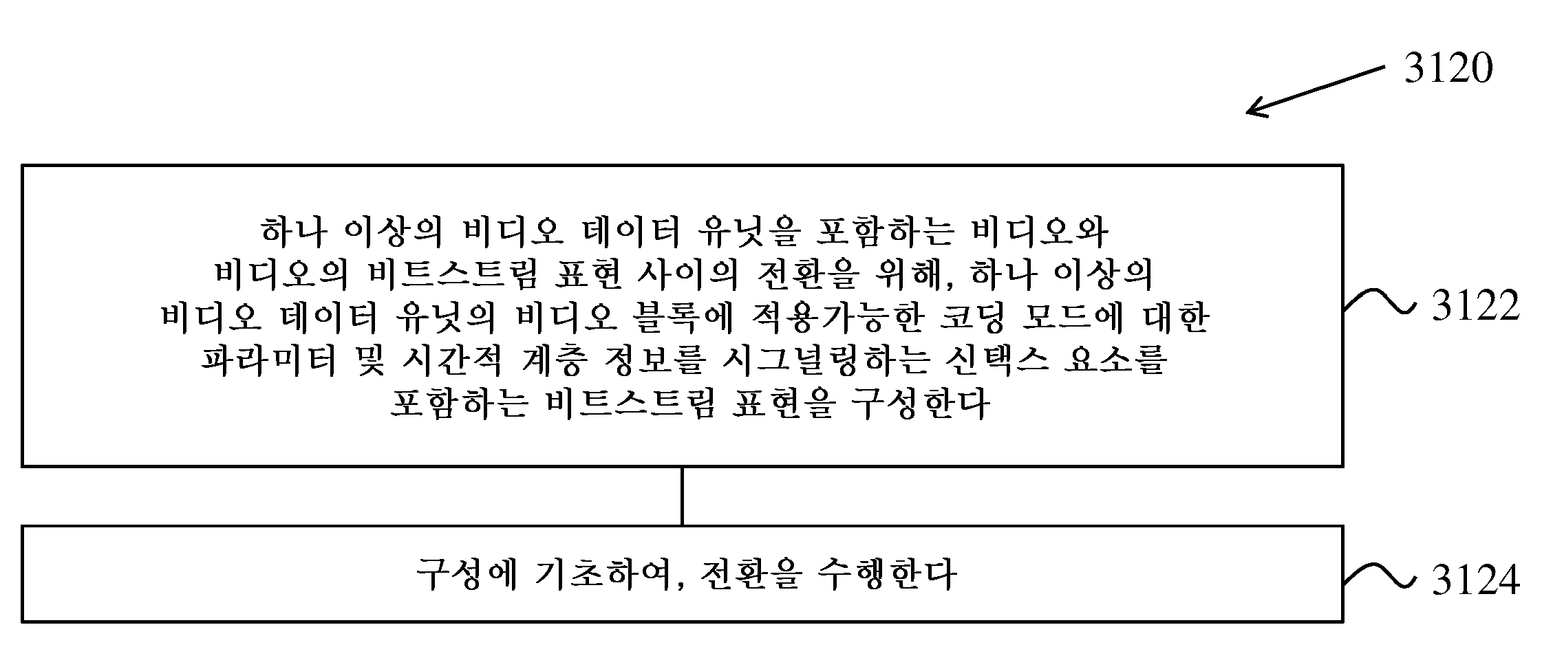
또 다른 대표적인 양태에서, 개시된 기술은 비디오 처리 방법을 제공하기 위해 사용될 수 있다. 이 방법은 하나 이상의 비디오 데이터 유닛을 포함하는 비디오와 비디오의 비트스트림 표현 사이의 전환을 위해, 하나 이상의 비디오 데이터 유닛의 비디오 블록에 적용가능한 코딩 모드에 대한 파라미터 및 시간적 계층 정보를 시그널링하는 신택스 요소를 포함하는 비트스트림 표현을 구성하는 단계, 및 구성에 기초하여, 전환을 수행하는 단계를 포함하고, 코딩 모드는 원래 도메인 및 재성형된 도메인 및/또는 크로마 비디오 블록의 크로마 잔차의 루마-의존적 스케일링에 기초하여 비디오 블록을 구성하는 것을 포함한다.In another exemplary aspect, the disclosed technology can be used to provide a video processing method. The method comprises the steps of constructing a bitstream representation including syntax elements signaling temporal layer information and parameters for a coding mode applicable to a video block of the one or more video data units for switching between a video including one or more video data units and a bitstream representation of the video, and performing the switching based on the configuration, wherein the coding mode comprises constructing the video block based on luma-dependent scaling of an original domain and a reshaped domain and/or chroma residual of a chroma video block.
또 다른 대표적인 양태에서, 개시된 기술은 비디오 처리 방법을 제공하기 위해 사용될 수 있다. 이 방법은 하나 이상의 비디오 데이터 유닛을 포함하는 비디오와 비디오의 비트스트림 표현 사이의 전환을 위해, 하나 이상의 비디오 데이터 유닛의 비디오 블록에 적용가능한 코딩 모드에 대한 파라미터 및 시간적 계층 정보를 시그널링하는 신택스 요소를 포함하는 비트스트림 표현을 파싱하는 단계, 및 구성에 기초하여, 전환을 수행하는 단계를 포함하고, 코딩 모드는 원래 도메인 및 재성형된 도메인 및/또는 크로마 비디오 블록의 크로마 잔차의 루마-의존적 스케일링에 기초하여 비디오 블록을 구성하는 것을 포함한다.In another exemplary aspect, the disclosed technology can be used to provide a video processing method. The method comprises parsing a bitstream representation including syntax elements signaling temporal layer information and parameters for a coding mode applicable to a video block of the one or more video data units for switching between a video including one or more video data units and a bitstream representation of the video, and performing the switching based on the configuration, wherein the coding mode comprises composing the video block based on original domain and reshaped domain and/or luma-dependent scaling of chroma residual of the chroma video block.
또 다른 대표적인 양태에서, 개시된 기술은 비디오 처리 방법을 제공하기 위해 사용될 수 있다. 이 방법은 비디오의 제1 비디오 데이터 유닛과 비디오의 비트스트림 표현 사이의 전환을 수행하는 단계를 포함하고, 제1 비디오 데이터 유닛의 비디오 블록에 코딩 모드가 적용가능하고, 코딩 모드는 코딩 모드에 관련된 사이드 정보에 기초하여 원래 도메인 및 재성형된 도메인 및/또는 크로마 비디오 블록의 크로마 잔차의 루마-의존적 스케일링에 기초하여 비디오 블록을 구성하는 것을 포함하고, 사이드 정보는 시간적 계층 인덱스에 기초하는 규칙에 따라 결정된다.In another exemplary aspect, the disclosed technology can be used to provide a video processing method. The method comprises the steps of performing a switch between a first video data unit of a video and a bitstream representation of the video, wherein a coding mode is applicable to a video block of the first video data unit, the coding mode comprises composing the video block based on luma-dependent scaling of an original domain and a reshaped domain and/or a chroma residual of a chroma video block based on side information related to the coding mode, wherein the side information is determined according to a rule based on a temporal layer index.
또 다른 대표적인 양태에서, 개시된 기술은 비디오 처리 방법을 제공하기 위해 사용될 수 있다. 이 방법은 하나 이상의 비디오 데이터 유닛을 포함하는 비디오와 비디오의 비트스트림 표현 사이의 전환을 위해, 하나 이상의 비디오 데이터 유닛의 비디오 블록에 적용가능한 코딩 모드에 대한 파라미터 및 시간적 계층 정보를 시그널링하는 신택스 요소를 포함하는 비트스트림 표현을 구성하는 단계, 및 구성에 기초하여, 전환을 수행하는 단계를 포함하고, 코딩 모드는 적응적 루프 필터(adaptive loop filter, ALF) 계수들을 사용하는 필터링 프로세스에 기초하여 비디오의 현재 블록을 구성하는 것을 포함한다.In another exemplary embodiment, the disclosed technology can be used to provide a video processing method. The method comprises the steps of configuring a bitstream representation including syntax elements signaling parameters for a coding mode applicable to a video block of the one or more video data units and temporal layer information for switching between a video including one or more video data units and a bitstream representation of the video, and performing the switching based on the configuration, wherein the coding mode comprises configuring a current block of the video based on a filtering process using adaptive loop filter (ALF) coefficients.
또 다른 대표적인 양태에서, 개시된 기술은 비디오 처리 방법을 제공하기 위해 사용될 수 있다. 이 방법은 하나 이상의 비디오 데이터 유닛을 포함하는 비디오와 비디오의 비트스트림 표현 사이의 전환을 위해, 하나 이상의 비디오 데이터 유닛의 비디오 블록에 적용가능한 코딩 모드에 대한 파라미터 및 시간적 계층 정보를 시그널링하는 신택스 요소를 포함하는 비트스트림 표현을 파싱하는 단계, 및 구성에 기초하여, 전환을 수행하는 단계를 포함하고, 코딩 모드는 적응적 루프 필터(adaptive loop filter, ALF) 계수들을 사용하는 필터링 프로세스에 기초하여 비디오의 현재 블록을 구성하는 것을 포함한다.In another exemplary embodiment, the disclosed technology can be used to provide a video processing method. The method comprises the steps of parsing a bitstream representation including syntax elements signaling parameters for a coding mode applicable to a video block of the one or more video data units and temporal layer information for switching between a video including one or more video data units and a bitstream representation of the video, and performing the switching based on the configuration, wherein the coding mode comprises configuring a current block of the video based on a filtering process using adaptive loop filter (ALF) coefficients.
또 다른 대표적인 양태에서, 개시된 기술은 비디오 처리 방법을 제공하기 위해 사용될 수 있다. 이 방법은 비디오의 제1 비디오 데이터 유닛과 비디오의 비트스트림 표현 사이의 전환을 수행하는 단계를 포함하고, 제1 비디오 데이터 유닛의 비디오 블록에 코딩 모드가 적용가능하고, 코딩 모드는, 코딩 모드에 관련된 사이드 정보에 기초하여, 적응적 루프 필터(ALF) 계수들을 사용하는 필터링 프로세스에 기초하여 비디오의 현재 블록을 구성하는 것을 포함하고, 사이드 정보는 시간적 계층 인덱스에 기초하는 규칙에 따라 결정된다.In another exemplary embodiment, the disclosed technology can be used to provide a video processing method. The method includes the steps of performing a switch between a first video data unit of a video and a bitstream representation of the video, wherein a coding mode is applicable to a video block of the first video data unit, the coding mode includes configuring a current block of the video based on a filtering process using adaptive loop filter (ALF) coefficients based on side information related to the coding mode, wherein the side information is determined according to a rule based on a temporal layer index.
또 다른 대표적인 양태에서, 위에서 설명한 방법은 프로세서 실행가능 코드의 형태로 구현되고 컴퓨터 판독가능 프로그램 매체에 저장된다.In another exemplary embodiment, the method described above is implemented in the form of processor-executable code and stored in a computer-readable program medium.
또 다른 대표적인 양태에서, 위에서 설명한 방법을 수행하도록 구성되거나 동작가능한 디바이스가 개시된다. 디바이스는 이 방법을 구현하도록 프로그래밍되는 프로세서를 포함할 수 있다.In another exemplary embodiment, a device configured or operable to perform the method described above is disclosed. The device may include a processor programmed to implement the method.
또 다른 대표적인 양태에서, 비디오 디코더 장치는 본 명세서에 설명된 바와 같은 방법을 구현할 수 있다.In another exemplary embodiment, a video decoder device can implement a method as described herein.
개시된 기술의 위의 및 또 다른 양태들 및 특징들은 도면들, 설명 및 청구항들에서 더 상세히 설명된다.The above and further aspects and features of the disclosed technology are described in more detail in the drawings, description and claims.
도 1은 병합 후보 리스트(merge candidate list)를 구성하는 예를 도시한다.
도 2는 공간적 후보들의 위치들의 예를 도시한다.
도 3은 공간적 병합 후보들의 중복 검사를 받은 후보 쌍들의 예를 도시한다.
도 4a 및 도 4b는 현재 블록의 크기 및 형상에 기초한 제2 예측 유닛(PU)의 위치의 예들을 도시한다.
도 5는 시간적 병합 후보들에 대한 모션 벡터 스케일링의 예를 도시한다.
도 6은 시간적 병합 후보들에 대한 후보 위치들의 예를 도시한다.
도 7은 조합된 양예측 병합 후보(combined bi-predictive merge candidate)를 생성하는 예를 도시한다.
도 8은 모션 벡터 예측 후보들을 구성하는 예를 도시한다.
도 9는 공간적 모션 벡터 후보들에 대한 모션 벡터 스케일링의 예를 도시한다.
도 10은 코딩 유닛(CU)에 대한 ATMVP(alternative temporal motion vector prediction) 알고리즘을 사용하는 모션 예측의 예를 도시한다.
도 11은 STMVP(spatial-temporal motion vector prediction) 알고리즘에 의해 사용되는 서브-블록들 및 이웃 블록들을 갖는 코딩 유닛(CU)의 예를 도시한다.
도 12는 조명 보상(illumination compensation, IC) 파라미터들을 도출하기 위한 이웃 샘플들의 예를 도시한다.
도 13a 및 도 13b는 각각 단순화된 4-파라미터 아핀 모델 및 단순화된 6-파라미터 아핀 모델의 예들을 도시한다.
도 14는 서브-블록 당 아핀 모션 벡터 필드(motion vector field, MVF)의 예를 도시한다.
도 15a 및 도 15b는 각각 4-파라미터 및 6-파라미터 아핀 모델들의 예들을 도시한다.
도 16은 상속된 아핀 후보들에 대한 AF_INTER에 대한 모션 벡터 예측의 예를 도시한다.
도 17은 구성된 아핀 후보들에 대한 AF_INTER에 대한 모션 벡터 예측의 예를 도시한다.
도 18a 및 도 18b는 AF_MERGE 모드에 대한 예시적인 후보 블록들 및 CPMV 예측자 도출을 각각 도시한다.
도 19는 아핀 병합 모드에 대한 후보 위치들의 예를 도시한다.
도 20은 UMVE 검색 프로세스의 예를 도시한다.
도 21은 UMVE 검색 포인트의 예를 도시한다.
도 22는 쌍방 템플릿 매칭(bilateral template matching)에 기초한 디코더측 모션 벡터 리파인먼트(decoder-side motion vector refinement, DMVR)의 예를 도시한다.
도 23은 재성형을 갖는 디코딩 흐름의 예시적인 흐름도를 도시한다.
도 24는 쌍방 필터에서 이용되는 이웃 샘플들의 예를 도시한다.
도 25는 가중치 계산에 이용되는 2개의 샘플을 커버하는 윈도우(window)들의 예를 도시한다.
도 26은 스캔 패턴의 예를 도시한다.
도 27은 모드-간 디코딩 프로세스의 예를 도시한다.
도 28은 모드-간 디코딩 프로세스의 또 다른 예를 도시한다.
도 29는 재구성-후 필터(post-reconstruction filter)들을 이용한 모드-간 디코딩 프로세스의 예를 도시한다.
도 30은 재구성-후 필터들을 이용한 모드-간 디코딩 프로세스의 또 다른 예를 도시한다.
도 31a 내지 도 31d는 비디오 처리를 위한 예시적인 방법들의 흐름도들을 도시한다.
도 32는 본 문서에서 설명되는 비주얼 미디어 디코딩 또는 비주얼 미디어 인코딩 기법을 구현하기 위한 하드웨어 플랫폼의 예의 블록도이다.
도 33은 개시된 기법들이 구현될 수 있는 예시적인 비디오 처리 시스템의 블록도이다.Figure 1 illustrates an example of constructing a merge candidate list.
Figure 2 shows examples of locations of spatial candidates.
Figure 3 shows examples of candidate pairs that have undergone overlap testing for spatial merging candidates.
Figures 4a and 4b illustrate examples of locations of second prediction units (PUs) based on the size and shape of the current block.
Figure 5 shows an example of motion vector scaling for temporal merging candidates.
Figure 6 shows examples of candidate locations for temporal merging candidates.
Figure 7 illustrates an example of generating a combined bi-predictive merge candidate.
Figure 8 illustrates an example of constructing motion vector prediction candidates.
Figure 9 shows an example of motion vector scaling for spatial motion vector candidates.
Figure 10 illustrates an example of motion prediction using the alternative temporal motion vector prediction (ATMVP) algorithm for a coding unit (CU).
Figure 11 illustrates an example of a coding unit (CU) having sub-blocks and neighboring blocks used by the spatial-temporal motion vector prediction (STMVP) algorithm.
Figure 12 shows examples of neighboring samples for deriving illumination compensation (IC) parameters.
Figures 13a and 13b illustrate examples of a simplified 4-parameter affine model and a simplified 6-parameter affine model, respectively.
Figure 14 shows an example of an affine motion vector field (MVF) per sub-block.
Figures 15a and 15b show examples of 4-parameter and 6-parameter affine models, respectively.
Figure 16 shows an example of motion vector prediction for AF_INTER for inherited affine candidates.
Figure 17 shows an example of motion vector prediction for AF_INTER for constructed affine candidates.
Figures 18a and 18b illustrate example candidate blocks and CPMV predictor derivation for AF_MERGE mode, respectively.
Figure 19 shows examples of candidate locations for the affine merge mode.
Figure 20 illustrates an example of the UMVE search process.
Figure 21 shows an example of UMVE search points.
Figure 22 illustrates an example of decoder-side motion vector refinement (DMVR) based on bilateral template matching.
Figure 23 illustrates an exemplary flow diagram of a decoding flow with reshaping.
Figure 24 shows an example of neighboring samples used in a bilateral filter.
Figure 25 shows an example of windows covering two samples used in weight calculation.
Figure 26 shows an example of a scan pattern.
Figure 27 illustrates an example of a mode-to-mode decoding process.
Figure 28 illustrates another example of a mode-to-mode decoding process.
Figure 29 illustrates an example of a mode-to-mode decoding process using post-reconstruction filters.
Figure 30 illustrates another example of a mode-to-mode decoding process using post-reconstruction filters.
Figures 31a to 31d illustrate flowcharts of exemplary methods for video processing.
FIG. 32 is a block diagram of an example of a hardware platform for implementing the visual media decoding or visual media encoding techniques described in this document.
FIG. 33 is a block diagram of an exemplary video processing system in which the disclosed techniques may be implemented.
고해상도 비디오의 수요 증가로 인해, 비디오 코딩 방법들 및 기법들은 현대 기술에서 널리 사용되고 있다. 비디오 코덱들은 전형적으로 디지털 비디오를 압축 또는 압축해제하는 전자 회로 또는 소프트웨어를 포함하며, 더 높은 코딩 효율을 제공하도록 계속적으로 개선되고 있다. 비디오 코덱은 압축되지 않은 비디오를 압축된 포맷으로 전환하거나, 그 반대로 전환한다. 비디오 품질, 비디오를 표현하는 데 사용되는 데이터의 양(비트 레이트에 의해 결정됨), 인코딩 및 디코딩 알고리즘들의 복잡도, 데이터 손실들 및 에러들에 대한 민감도, 편집의 용이성, 랜덤 액세스, 및 엔드-투-엔드 지연(레이턴시) 사이에 복잡한 관계들이 존재한다. 압축된 포맷은 보통 표준 비디오 압축 사양, 예를 들어, HEVC(High Efficiency Video Coding) 표준(H.265 또는 MPEG-H Part 2로도 알려짐), 완성될 다용도 비디오 코딩(Versatile Video Coding) 표준, 또는 다른 현재 및/또는 장래 비디오 코딩 표준들을 따른다.With the increasing demand for high-resolution video, video coding methods and techniques are widely used in modern technology. Video codecs typically include electronic circuits or software that compress or decompress digital video, and are continually being improved to provide greater coding efficiency. Video codecs convert uncompressed video into compressed formats, or vice versa. There are complex relationships between video quality, the amount of data used to represent the video (determined by the bit rate), the complexity of the encoding and decoding algorithms, the susceptibility to data losses and errors, the ease of editing, random access, and end-to-end delay (latency). Compressed formats usually follow a standard video compression specification, such as the High Efficiency Video Coding (HEVC) standard (also known as H.265 or MPEG-H Part 2), the upcoming Versatile Video Coding standard, or other current and/or future video coding standards.
개시된 기술의 실시예들은 압축 성능을 개선시키기 위해 기존의 비디오 코딩 표준들(예를 들어, HEVC, H.265) 및 장래의 표준들에 적용될 수 있다. 섹션 제목들은 본 문서에서 설명의 가독성을 개선시키기 위해 사용되며, 논의 또는 실시예들(및/또는 구현들)을 결코 각자의 섹션들에만 제한하지 않는다.Embodiments of the disclosed technology can be applied to existing video coding standards (e.g., HEVC, H.265) and future standards to improve compression performance. Section headings are used in this document to improve readability of the description and in no way limit the discussion or embodiments (and/or implementations) to their respective sections.
1 HEVC/H.265에서의 인터-예측(inter-prediction)의 예들1 Examples of inter-prediction in HEVC/H.265
비디오 코딩 표준들은 수년 동안 상당히 개선되었으며, 이제 부분적으로는 높은 코딩 효율 및 더 높은 해상도들에 대한 지원을 제공한다. HEVC 및 H.265와 같은 최근의 표준들은 시간적 예측 플러스 변환 코딩(temporal prediction plus transform coding)이 이용되는 하이브리드 비디오 코딩 구조에 기초한다.Video coding standards have improved significantly over the years, now offering support for higher coding efficiency and higher resolutions. Recent standards such as HEVC and H.265 are based on hybrid video coding architectures that utilize temporal prediction plus transform coding.
1.1 예측 모드들의 예들1.1 Examples of prediction modes
각각의 인터-예측된 PU(prediction unit)는 1개 또는 2개의 참조 픽처 리스트에 대한 모션 파라미터들을 갖는다. 일부 실시예들에서, 모션 파라미터들은 모션 벡터 및 참조 픽처 인덱스를 포함한다. 다른 실시예들에서, 2개의 참조 픽처 리스트 중 하나의 사용은 또한 inter_pred_idc를 사용하여 시그널링될 수 있다. 또 다른 실시예들에서, 모션 벡터들은 예측자들에 대해 델타들로서 명시적으로 코딩될 수 있다.Each inter-predicted prediction unit (PU) has motion parameters for one or two reference picture lists. In some embodiments, the motion parameters include motion vectors and reference picture indices. In other embodiments, the use of one of the two reference picture lists can also be signaled using inter_pred_idc. In still other embodiments, the motion vectors can be explicitly coded as deltas for the predictors.
CU가 스킵 모드로 코딩될 때, 하나의 PU는 CU와 연관되고, 어떠한 유의 잔여 계수(significant residual coefficient)도 없고, 어떠한 코딩된 모션 벡터 델타 또는 참조 픽처 인덱스도 없다. 공간적 및 시간적 후보들을 포함하는 이웃 PU들로부터 현재 PU에 대한 모션 파라미터들이 획득되는 병합 모드가 특정된다. 병합 모드는 스킵 모드에 대해서뿐만 아니라 임의의 인터-예측된 PU에 적용될 수 있다. 병합 모드에 대한 대안은 모션 파라미터들의 명시적 송신이며, 여기서 모션 벡터들(더 정확하게는, 모션 벡터 예측자와 비교한 모션 벡터 차이들(MVD)), 각각의 참조 픽처 리스트에 대한 대응하는 참조 픽처 인덱스 및 참조 픽처 리스트 사용이 각각의 PU마다 명시적으로 시그널링된다. 이러한 타입의 모드는 본 문서에서 AMVP(advanced motion vector prediction)로 명명된다.When a CU is coded in skip mode, a PU is associated with the CU, which has no significant residual coefficient and no coded motion vector delta or reference picture index. A merge mode is specified, in which motion parameters for the current PU are obtained from neighboring PUs including spatial and temporal candidates. The merge mode can be applied not only to skip mode but also to any inter-predicted PU. An alternative to the merge mode is explicit transmission of motion parameters, in which motion vectors (more precisely, motion vector differences (MVDs) compared to a motion vector predictor), the corresponding reference picture index for each reference picture list and the reference picture list usage are explicitly signaled for each PU. This type of mode is named advanced motion vector prediction (AMVP) in this document.
시그널링이 2개의 참조 픽처 리스트 중 하나가 사용될 것임을 나타낼 때, PU는 하나의 샘플 블록으로부터 생성된다. 이것을 '단예측(uni-prediction)'이라고 지칭한다. P-슬라이스와 B-슬라이스 양자 모두에 대해 단예측이 이용가능하다.When signaling indicates that one of two reference picture lists will be used, the PU is generated from one block of samples. This is called 'uni-prediction'. Uni-prediction is available for both P-slices and B-slices.
시그널링이 참조 픽처 리스트들 둘 다가 사용될 것임을 나타낼 때, PU는 2개의 샘플 블록으로부터 생성된다. 이것을 '양예측(bi-prediction)'이라고 지칭한다. 양예측은 B-슬라이스에 대해서만 이용가능하다.When signaling indicates that both reference picture lists will be used, the PU is generated from two sample blocks. This is called 'bi-prediction'. Bi-prediction is only available for B-slices.
참조 픽처 리스트Reference picture list
HEVC에서, 인터 예측이라는 용어는 현재 디코딩된 픽처 이외의 참조 픽처들의 데이터 요소들(예를 들어, 샘플 값들 또는 모션 벡터들)로부터 도출된 예측을 나타내기 위해 사용된다. H.264/AVC에서와 같이, 픽처는 다수의 참조 픽처들로부터 예측될 수 있다. 인터 예측에 사용되는 참조 픽처들은 하나 이상의 참조 픽처 리스트로 조직된다. 참조 인덱스는 리스트 내의 참조 픽처들 중 어느 것이 예측 신호를 생성하기 위해 사용되어야 하는지를 식별한다.In HEVC, the term inter prediction is used to indicate prediction derived from data elements (e.g., sample values or motion vectors) of reference pictures other than the currently decoded picture. As in H.264/AVC, a picture can be predicted from multiple reference pictures. The reference pictures used for inter prediction are organized into one or more reference picture lists. A reference index identifies which of the reference pictures in the list should be used to generate the prediction signal.
단일 참조 픽처 리스트, 즉, 리스트 0이 P 슬라이스에 사용되고 2개의 참조 픽처 리스트, 즉, 리스트 0과 리스트 1이 B 슬라이스에 사용된다. 리스트 0/1에 포함된 참조 픽처들은 캡처링/디스플레이 순서의 관점에서 과거 및 미래 픽처들로부터의 것일 수 있다는 점에 유의해야 한다.A single reference picture list, i.e.,
1.1.1 병합 모드에 대한 후보들을 구성하는 실시예들1.1.1 Embodiments of constructing candidates for merge mode
PU가 병합 모드를 사용하여 예측될 때, 병합 후보 리스트 내의 엔트리를 가리키는 인덱스가 비트스트림으로부터 파싱되고 모션 정보를 검색하는 데 사용된다. 이 리스트의 구성은 다음의 단계들의 시퀀스에 따라 요약될 수 있다:When a PU is predicted using merge mode, an index pointing to an entry in the merge candidate list is parsed from the bitstream and used to retrieve motion information. The construction of this list can be summarized by the following sequence of steps:
단계 1: 초기 후보 도출Step 1: Initial candidate derivation
단계 1.1: 공간적 후보 도출Step 1.1: Deriving spatial candidates
단계 1.2: 공간적 후보에 대한 중복 검사Step 1.2: Redundancy check for spatial candidates
단계 1.3: 시간적 후보 도출Step 1.3: Deriving temporal candidates
단계 2: 추가적인 후보 삽입Step 2: Insert additional candidates
단계 2.1: 양예측 후보들의 생성Step 2.1: Generating the two prediction candidates
단계 2.2: 제로 모션 후보들의 삽입Step 2.2: Insertion of zero motion candidates
도 1은 위에 요약된 단계들의 시퀀스에 기초하여 병합 후보 리스트를 구성하는 예를 도시한다. 공간적 병합 후보 도출의 경우, 5개의 상이한 위치에 위치하는 후보들 중에서 최대 4개의 병합 후보가 선택된다. 시간적 병합 후보 도출의 경우, 2개의 후보 중에서 최대 하나의 병합 후보가 선택된다. 디코더에서 각각의 PU에 대한 일정한 수의 후보들이 가정되기 때문에, 후보들의 수가 슬라이스 헤더에서 시그널링되는 병합 후보의 최대 수(MaxNumMergeCand)에 도달하지 않을 때 추가적인 후보들이 생성된다. 후보들의 수가 일정하기 때문에, 절단된 단항 이진화(truncated unary binarization, TU)를 사용하여 최상의 병합 후보의 인덱스가 인코딩된다. CU의 크기가 8과 같으면, 현재 CU의 모든 PU들은 2Nx2N 예측 유닛의 병합 후보 리스트와 동일한 단일 병합 후보 리스트를 공유한다.Figure 1 illustrates an example of constructing a merge candidate list based on the sequence of steps summarized above. For spatial merge candidate derivation, at most four merge candidates are selected from candidates located at five different locations. For temporal merge candidate derivation, at most one merge candidate is selected from two candidates. Since a constant number of candidates is assumed for each PU in the decoder, additional candidates are generated when the number of candidates does not reach the maximum number of merge candidates (MaxNumMergeCand) signaled in the slice header. Since the number of candidates is constant, the index of the best merge candidate is encoded using truncated unary binarization (TU). When the size of a CU is equal to 8, all PUs of the current CU share a single merge candidate list, which is identical to the merge candidate list of a 2Nx2N prediction unit.
1.1.2 공간적 병합 후보들의 구성1.1.2 Composition of spatial merge candidates
공간적 병합 후보들의 도출에서, 도 2에 도시된 위치들에 위치한 후보들 중에서 최대 4개의 병합 후보가 선택된다. 도출 순서는 A1, B1, B0, A0 및 B2이다. 위치 B2는 위치 A1, B1, B0, A0의 임의의 PU가 이용가능하지 않거나(예를 들어, 그것이 다른 슬라이스 또는 타일에 속하기 때문) 또는 인트라 코딩될 때에만 고려된다. 위치 A1에서의 후보가 추가된 후에, 나머지 후보들의 추가에 대해 중복 검사를 수행하여 동일한 모션 정보를 갖는 후보들이 리스트로부터 배제되는 것을 보장해서, 코딩 효율을 향상시킨다.In the derivation of spatial merging candidates, at most four merging candidates are selected from the candidates located at the positions shown in Fig. 2. The derivation order is A 1 , B 1 , B 0 , A 0 , and B 2 . Position B 2 is considered only when any PU at positions A 1 , B 1 , B 0 , A 0 is not available (e.g., because it belongs to another slice or tile) or is intra coded. After the candidate at position A 1 is added, a redundancy check is performed on the addition of the remaining candidates to ensure that candidates with the same motion information are excluded from the list, thereby improving the coding efficiency.
계산 복잡성을 감소시키기 위해, 모든 가능한 후보 쌍들이 언급된 중복 검사에서 고려되지는 않는다. 대신에, 도 3에서 화살표로 연결된 쌍들만이 고려되고, 중복 검사를 위해 사용되는 대응하는 후보가 동일한 모션 정보를 갖지 않는 경우에만 리스트에 후보가 추가된다. 복제 모션 정보(duplicate motion information)의 다른 소스는 2Nx2N과는 상이한 파티션들과 연관된 "제2 PU"이다. 예로서, 도 4a 및 도 4b는 각각 Nx2N 및 2NxN의 경우에 대한 제2 PU를 도시한다. 현재 PU가 Nx2N으로서 파티셔닝될 때, 위치 A1에서의 후보는 리스트 구성에 고려되지 않는다. 일부 실시예들에서, 이 후보를 추가하면, 코딩 유닛에서 단 하나의 PU를 갖기에는 중복인, 동일한 모션 정보를 갖는 2개의 예측 유닛으로 이어질 수 있다. 유사하게, 현재 PU가 2NxN으로서 파티셔닝될 때 위치 B1은 고려되지 않는다.To reduce computational complexity, not all possible candidate pairs are considered in the mentioned redundancy check. Instead, only the pairs connected by arrows in Fig. 3 are considered, and a candidate is added to the list only if the corresponding candidate used for the redundancy check does not have the same motion information. Another source of duplicate motion information is the "secondary PU" associated with partitions different from 2Nx2N. As an example, Figs. 4a and 4b illustrate the second PUs for the cases of Nx2N and 2NxN, respectively. When the current PU is partitioned as Nx2N, the candidate at position A 1 is not considered in the list construction. In some embodiments, adding this candidate may lead to two prediction units with the same motion information, which is redundant for having only one PU in the coding unit. Similarly, position B 1 is not considered when the current PU is partitioned as 2NxN.
1.1.3 시간적 병합 후보들의 구성1.1.3 Composition of temporal merge candidates
이 단계에서는, 하나의 후보만이 리스트에 추가된다. 특히, 이 시간적 병합 후보의 도출에서는, 주어진 참조 픽처 리스트 내의 현재 픽처와 가장 작은 POC 차이를 갖는 픽처에 속하는 동위치 PU에 기초하여 스케일링된 모션 벡터가 도출된다. 동위치 PU의 도출에 사용될 참조 픽처 리스트는 슬라이스 헤더에서 명시적으로 시그널링된다.In this step, only one candidate is added to the list. In particular, in the derivation of this temporal merge candidate, a scaled motion vector is derived based on the co-located PU belonging to the picture with the smallest POC difference from the current picture in the given reference picture list. The reference picture list to be used for deriving the co-located PU is explicitly signaled in the slice header.
도 5는 POC 거리들 tb 및 td를 사용하여 동위치 PU의 모션 벡터로부터 스케일링되는 (점선으로서의) 시간적 병합 후보에 대한 스케일링된 모션 벡터의 도출의 예를 도시하며, 여기서 tb는 현재 픽처의 참조 픽처와 현재 픽처 사이의 POC 차이인 것으로 정의되고, td는 동위치 픽처의 참조 픽처와 동위치 픽처 사이의 POC 차이인 것으로 정의된다. 시간적 병합 후보의 참조 픽처 인덱스는 제로와 동일하게 설정된다. B-슬라이스의 경우, 2개의 모션 벡터 - 하나는 참조 픽처 리스트 0에 대한 것이고 다른 하나는 참조 픽처 리스트 1에 대한 것임 - 가 획득되고 조합되어 양예측 병합 후보를 만든다.Figure 5 shows an example of derivation of scaled motion vectors for a temporal merge candidate (as a dashed line) scaled from the motion vectors of co-located PUs using POC distances tb and td, where tb is defined as the POC difference between the reference picture of the current picture and the current picture, and td is defined as the POC difference between the reference picture of the co-located picture and the co-located picture. The reference picture indices of the temporal merge candidate are set equal to zero. For B-slices, two motion vectors - one for
참조 프레임에 속하는 동위치 PU(Y)에서, 시간적 후보에 대한 위치는 도 6에 도시된 바와 같이 후보들 C0과 C1 사이에서 선택된다. 위치 C0에서의 PU가 이용가능하지 않거나, 인트라 코딩되거나, 현재 CTU의 외부에 있으면, 위치 C1이 사용된다. 그렇지 않으면, 위치 C0은 시간적 병합 후보의 도출에서 사용된다.For a co-located PU(Y) belonging to a reference frame, a location for a temporal candidate is selected between candidates C 0 and C 1 as illustrated in Fig. 6. If the PU at location C 0 is not available, is intra-coded, or is outside the current CTU, then location C 1 is used. Otherwise, location C 0 is used in the derivation of the temporal merging candidate.
1.1.4 추가적인 타입들의 병합 후보들의 구성1.1.4 Composition of merge candidates for additional types
시공간적 병합 후보들 이외에, 2개의 추가적인 타입의 병합 후보들이 있다: 조합된 양예측 병합 후보 및 제로 병합 후보. 조합된 양예측 병합 후보들은 시공간적 병합 후보들을 이용하여 생성된다. 조합된 양예측 병합 후보는 B-슬라이스에만 사용된다. 조합된 양예측 후보들은 초기 후보의 제1 참조 픽처 리스트 모션 파라미터들을 또 다른 초기 후보의 제2 참조 픽처 리스트 모션 파라미터들과 조합함으로써 생성된다. 이들 2개의 투플(tuple)이 상이한 모션 가설(motion hypotheses)을 제공하는 경우, 이들은 새로운 양예측 후보를 형성할 것이다.In addition to spatio-temporal merge candidates, there are two additional types of merge candidates: combined bi-predictive merge candidates and zero-merge candidates. Combined bi-predictive merge candidates are generated using spatio-temporal merge candidates. Combined bi-predictive merge candidates are used only for B-slices. Combined bi-predictive candidates are generated by combining the motion parameters of the first reference picture list of an initial candidate with the motion parameters of the second reference picture list of another initial candidate. If these two tuples provide different motion hypotheses, they will form a new bi-predictive candidate.
도 7은 이 프로세스의 예를 도시하며, 원래의 리스트(좌측의 710) 내의 2개의 후보 - 이는 mvL0 및 refIdxL0 또는 mvL1 및 refIdxL1을 가짐 - 를 사용하여 최종 리스트(우측의 720)에 추가되는 조합된 양예측 병합 후보를 생성한다. 이러한 추가적인 병합 후보들을 생성하기 위해 고려되는 조합들에 관한 다수의 규칙들이 있다.Figure 7 illustrates an example of this process, taking two candidates in the original list (710 on the left) - which have either mvL0 and refIdxL0 or mvL1 and refIdxL1 - and generating a combined positive-prediction merge candidate that is added to the final list (720 on the right). There are a number of rules regarding the combinations considered to generate these additional merge candidates.
제로 모션 후보들을 삽입하여 병합 후보 리스트 내의 나머지 엔트리들을 채우고 그에 따라 MaxNumMergeCand 용량에 도달(hit)한다. 이러한 후보들은 제로 공간적 변위 및 제로에서 시작하여 새로운 제로 모션 후보가 리스트에 추가될 때마다 증가하는 참조 픽처 인덱스를 갖는다. 이러한 후보들에 의해 사용되는 참조 프레임들의 수는 단방향 및 양방향 예측에 대해 각각 1 및 2이다. 일부 실시예들에서, 이러한 후보들에 대해서는 중복 검사가 수행되지 않는다.Insert zero motion candidates to fill the remaining entries in the merge candidate list, thus reaching the MaxNumMergeCand capacity. These candidates have zero spatial displacement and reference picture indices that start from zero and increase each time a new zero motion candidate is added to the list. The number of reference frames used by these candidates is 1 and 2 for unidirectional and bidirectional prediction, respectively. In some embodiments, no redundancy check is performed on these candidates.
1.2 AMVP(advanced motion vector prediction)의 실시예들1.2 Embodiments of AMVP (advanced motion vector prediction)
AMVP는 모션 벡터와 이웃 PU들의 시공간적 상관을 이용하며, 이는 모션 파라미터들의 명시적 송신을 위해 사용된다. 그것은 먼저 좌측 상부 시간적으로 이웃하는 PU 위치들의 이용가능성을 검사하고, 중복 후보들을 제거하고 제로 벡터를 추가하여 후보 리스트를 일정한 길이로 만드는 것에 의해 모션 벡터 후보 리스트를 구성한다. 이어서, 인코더는 후보 리스트로부터 최상의 예측자를 선택하고 선택된 후보를 나타내는 대응하는 인덱스를 송신할 수 있다. 병합 인덱스 시그널링과 유사하게, 최상의 모션 벡터 후보의 인덱스는 절단된 단항(truncated unary)을 사용하여 인코딩된다. 이 경우에 인코딩될 최대 값은 2이다(도 8 참조). 다음 섹션들에서는, 모션 벡터 예측 후보의 도출 프로세스에 관한 상세사항들이 제공된다.AMVP uses the spatiotemporal correlation of motion vectors and neighboring PUs, which is used for explicit transmission of motion parameters. It first checks the availability of the upper-left temporal neighboring PU positions, constructs a motion vector candidate list by removing duplicate candidates and adding zero vectors to make the candidate list have a fixed length. Then, the encoder can select the best predictor from the candidate list and transmit the corresponding index indicating the selected candidate. Similar to the merged index signaling, the index of the best motion vector candidate is encoded using a truncated unary. In this case, the maximum value to be encoded is 2 (see Fig. 8). In the following sections, the details of the derivation process of the motion vector prediction candidates are provided.
1.2.1 AMVP 후보들의 도출의 예들1.2.1 Examples of derivation of AMVP candidates
도 8은 모션 벡터 예측 후보에 대한 도출 프로세스를 요약하며, refidx를 입력으로 하여 각각의 참조 픽처 리스트에 대해 구현될 수 있다.Figure 8 summarizes the derivation process for motion vector prediction candidates, which can be implemented for each reference picture list with refidx as input.
모션 벡터 예측에서는, 2가지 타입의 모션 벡터 후보가 고려된다: 공간적 모션 벡터 후보 및 시간적 모션 벡터 후보. 공간적 모션 벡터 후보 도출의 경우, 궁극적으로 도 2에 이전에 도시된 바와 같이 5개의 상이한 위치에 위치하는 각각의 PU의 모션 벡터들에 기초하여 2개의 모션 벡터 후보가 도출된다.In motion vector prediction, two types of motion vector candidates are considered: spatial motion vector candidates and temporal motion vector candidates. In the case of spatial motion vector candidate derivation, two motion vector candidates are ultimately derived based on the motion vectors of each PU located at five different locations as previously illustrated in Fig. 2.
시간적 모션 벡터 후보 도출의 경우, 2개의 상이한 동위치된 위치들(co-located positions)에 기초하여 도출되는 2개의 후보로부터 하나의 모션 벡터 후보가 선택된다. 시공간적 후보들의 제1 리스트가 만들어진 후에, 리스트 내의 복제된 모션 벡터 후보들이 제거된다. 잠재적 후보들의 수가 2보다 크면, 연관된 참조 픽처 리스트 내의 참조 픽처 인덱스가 1보다 큰 모션 벡터 후보들이 리스트로부터 제거된다. 시공간적 모션 벡터 후보들의 수가 2보다 작으면, 추가적인 제로 모션 벡터 후보들이 리스트에 추가된다.For temporal motion vector candidate derivation, one motion vector candidate is selected from two candidates derived based on two different co-located positions. After a first list of spatio-temporal candidates is generated, duplicate motion vector candidates in the list are removed. If the number of potential candidates is greater than 2, motion vector candidates whose reference picture index in the associated reference picture list is greater than 1 are removed from the list. If the number of spatio-temporal motion vector candidates is less than 2, additional zero motion vector candidates are added to the list.
1.2.2 공간적 모션 벡터 후보들의 구성1.2.2 Composition of spatial motion vector candidates
공간적 모션 벡터 후보들의 도출에서, 도 2에 이전에 도시된 바와 같은 위치들에 위치하는 PU들로부터 도출되는 5개의 잠재적 후보 중에서 최대 2개의 후보가 고려되며, 그 위치들은 모션 병합의 위치들과 동일하다. 현재 PU의 좌측에 대한 도출 순서는 A0, A1, 및 스케일링된 A0, 스케일링된 A1로서 정의된다. 현재 PU의 상부측에 대한 도출 순서는 B0, B1, B2, 스케일링된 B0, 스케일링된 B1, 스케일링된 B2로서 정의된다. 따라서 각각의 측에 대해 모션 벡터 후보로서 사용될 수 있는 4가지 경우가 있으며, 2가지 경우는 공간적 스케일링을 사용할 필요가 없고, 2가지 경우는 공간적 스케일링을 사용한다. 4가지 상이한 경우는 다음과 같이 요약된다:In the derivation of spatial motion vector candidates, at most two candidates are considered among five potential candidates derived from PUs located at the positions as previously illustrated in Fig. 2, which are the same as the positions of motion merging. The derivation order for the left side of the current PU is defined as A 0 , A 1 , and scaled A 0 , scaled A 1 . The derivation order for the upper side of the current PU is defined as B 0 , B 1 , B 2 , scaled B 0 , scaled B 1 , scaled B 2 . Therefore, there are four cases for each side that can be used as motion vector candidates, two cases do not require spatial scaling and two cases do use spatial scaling. The four different cases are summarized as follows:
-- 공간적 스케일링 없음-- No spatial scaling
(1) 동일한 참조 픽처 리스트, 그리고 동일한 참조 픽처 인덱스(동일한 POC)(1) Same reference picture list, and same reference picture index (same POC)
(2) 상이한 참조 픽처 리스트, 그러나 동일한 참조 픽처(동일한 POC)(2) Different reference picture list, but same reference pictures (same POC)
-- 공간적 스케일링-- Spatial scaling
(3) 동일한 참조 픽처 리스트, 그러나 상이한 참조 픽처(상이한 POC)(3) Same reference picture list, but different reference pictures (different POCs)
(4) 상이한 참조 픽처 리스트, 그리고 상이한 참조 픽처(상이한 POC)(4) Different reference picture lists, and different reference pictures (different POCs).
공간적 스케일링이 없는 경우들(no-spatial-scaling cases)이 먼저 검사되고 이어서 공간적 스케일링을 허용하는 경우들이 검사된다. 참조 픽처 리스트에 관계없이 이웃 PU의 참조 픽처와 현재 PU의 참조 픽처 사이에 POC가 상이할 때 공간적 스케일링이 고려된다. 좌측 후보들의 모든 PU들이 이용가능하지 않거나 인트라 코딩되는 경우, 좌측 및 상부 MV 후보들의 병렬 도출을 돕기 위해 상부 모션 벡터에 대한 스케일링이 허용된다. 그렇지 않으면, 상부 모션 벡터에 대해 공간적 스케일링이 허용되지 않는다.The no-spatial-scaling cases are examined first, followed by the cases that allow spatial scaling. Spatial scaling is considered when the POC is different between the reference picture of the neighboring PU and the reference picture of the current PU, regardless of the reference picture list. If all the PUs of the left candidates are not available or are intra-coded, scaling for the upper motion vector is allowed to help parallel derivation of the left and upper MV candidates. Otherwise, spatial scaling is not allowed for the upper motion vector.
도 9의 예에 도시된 바와 같이, 공간적 스케일링 경우에 대해, 이웃 PU의 모션 벡터는 시간적 스케일링에 대한 것과 유사한 방식으로 스케일링된다. 하나의 차이점은 현재 PU의 참조 픽처 리스트 및 인덱스가 입력으로서 주어진다는 것이다; 실제 스케일링 프로세스는 시간적 스케일링의 것과 동일하다.As illustrated in the example in Fig. 9, for the spatial scaling case, the motion vectors of neighboring PUs are scaled in a similar way as for temporal scaling. One difference is that the reference picture list and index of the current PU are given as input; the actual scaling process is the same as that of temporal scaling.
1.2.3 시간적 모션 벡터 후보들의 구성1.2.3 Composition of temporal motion vector candidates
참조 픽처 인덱스 도출 외에도, 시간적 병합 후보들의 도출을 위한 모든 프로세스들은(도 6의 예에 도시된 바와 같은) 공간적 모션 벡터 후보들의 도출과 동일하다. 일부 실시예들에서, 참조 픽처 인덱스는 디코더에 시그널링된다.Apart from deriving the reference picture index, all the processes for deriving the temporal merging candidates are identical to the derivation of the spatial motion vector candidates (as illustrated in the example of Fig. 6). In some embodiments, the reference picture index is signaled to the decoder.
2. JEM(Joint Exploration Model)에서의 인터 예측 방법들의 예2. Examples of inter prediction methods in JEM (Joint Exploration Model)
일부 실시예들에서, 장래의 비디오 코딩 기술들은 JEM(Joint Exploration Model)으로 알려진 참조 소프트웨어를 사용하여 탐구된다. JEM에서, 서브-블록 기반 예측은 아핀 예측, ATMVP(alternative temporal motion vector prediction), STMVP(spatial-temporal motion vector prediction), BIO(bi-directional optical flow), FRUC(Frame-Rate Up Conversion), LAMVR(Locally Adaptive Motion Vector Resolution), OBMC(Overlapped Block Motion Compensation), LIC(Local Illumination Compensation), 및 DMVR(Decoder-side Motion Vector Refinement)과 같은 몇몇 코딩 툴들에서 채택된다.In some embodiments, future video coding techniques are explored using a reference software known as the Joint Exploration Model (JEM). In JEM, sub-block based prediction is adopted in several coding tools such as affine prediction, alternative temporal motion vector prediction (ATMVP), spatial-temporal motion vector prediction (STMVP), bi-directional optical flow (BIO), Frame-Rate Up Conversion (FRUC), Locally Adaptive Motion Vector Resolution (LAMVR), Overlapped Block Motion Compensation (OBMC), Local Illumination Compensation (LIC), and Decoder-side Motion Vector Refinement (DMVR).
2.1 서브-CU 기반 모션 벡터 예측의 예들2.1 Examples of sub-CU based motion vector prediction
QTBT(quadtrees plus binary trees)를 갖는 JEM에서, 각각의 CU는 각각의 예측 방향에 대해 많아야 하나의 모션 파라미터 세트를 가질 수 있다. 일부 실시예들에서, 2개의 서브-CU 레벨 모션 벡터 예측 방법은 큰 CU를 서브-CU들로 구분하고 큰 CU의 모든 서브-CU들에 대한 모션 정보를 도출함으로써 인코더에서 고려된다. ATMVP(alternative temporal motion vector prediction) 방법은 각각의 CU가 동위치 참조 픽처에서 현재 CU보다 작은 다수의 블록들로부터 다수의 모션 정보 세트들을 페치할 수 있게 한다. STMVP(spatial-temporal motion vector prediction) 방법에서, 서브-CU들의 모션 벡터들은 시간적 모션 벡터 예측자 및 공간적 이웃 모션 벡터를 사용함으로써 재귀적으로 도출된다. 일부 실시예들에서, 서브-CU 모션 예측을 위한 더 정확한 모션 필드를 보존하기 위해, 참조 프레임들에 대한 모션 압축은 디스에이블될 수 있다.In JEM with quadtrees plus binary trees (QTBT), each CU can have at most one set of motion parameters for each prediction direction. In some embodiments, two sub-CU level motion vector prediction methods are considered in the encoder by dividing the large CU into sub-CUs and deriving motion information for all sub-CUs of the large CU. The alternative temporal motion vector prediction (ATMVP) method allows each CU to fetch multiple sets of motion information from multiple blocks smaller than the current CU in the co-located reference picture. In the spatial-temporal motion vector prediction (STMVP) method, the motion vectors of the sub-CUs are recursively derived by using the temporal motion vector predictor and the spatial neighboring motion vectors. In some embodiments, motion compression for the reference frames can be disabled to preserve more accurate motion fields for sub-CU motion prediction.
2.1.1 ATMVP(alternative temporal motion vector prediction)의 예들2.1.1 Examples of alternative temporal motion vector prediction (ATVPP)
ATMVP 방법에서, TMVP(temporal motion vector prediction) 방법은 현재 CU보다 작은 블록들로부터 다수의 모션 정보 세트들(모션 벡터들 및 참조 인덱스들을 포함함)을 페치함으로써 수정된다.In the ATMVP method, the temporal motion vector prediction (TMVP) method is modified by fetching multiple motion information sets (including motion vectors and reference indices) from blocks smaller than the current CU.
도 10은 CU(1000)에 대한 ATMVP 모션 예측 프로세스의 예를 도시한다. ATMVP 방법은 2개의 단계에서 CU(1000) 내의 서브-CU들(1001)의 모션 벡터들을 예측한다. 제1 단계는 시간적 벡터로 참조 픽처(1050) 내의 대응하는 블록(1051)을 식별하는 것이다. 참조 픽처(1050)는 또한 모션 소스 픽처라고 지칭된다. 제2 단계는 현재 CU(1000)를 서브-CU들(1001)로 구분하고 각각의 서브-CU에 대응하는 블록으로부터 각각의 서브-CU의 참조 인덱스들뿐만 아니라 모션 벡터들을 획득하는 것이다.Fig. 10 illustrates an example of an ATMVP motion prediction process for a CU (1000). The ATMVP method predicts motion vectors of sub-CUs (1001) within a CU (1000) in two steps. The first step is to identify a corresponding block (1051) within a reference picture (1050) with a temporal vector. The reference picture (1050) is also referred to as a motion source picture. The second step is to divide the current CU (1000) into sub-CUs (1001) and obtain motion vectors as well as reference indices of each sub-CU from a block corresponding to each sub-CU.
제1 단계에서, 참조 픽처(1050) 및 대응하는 블록은 현재 CU(1000)의 공간적 이웃 블록들의 모션 정보에 의해 결정된다. 이웃 블록들의 반복적인 스캐닝 프로세스를 피하기 위해, 현재 CU(1000)의 병합 후보 리스트 내의 제1 병합 후보가 사용된다. 제1 이용가능한 모션 벡터 및 그의 연관된 참조 인덱스는 시간적 벡터 및 모션 소스 픽처에 대한 인덱스인 것으로 설정된다. 이러한 방식으로, TMVP와 비교하여 대응하는 블록이 더 정확하게 식별될 수 있고, 대응하는 블록(때때로 동위치 블록(collocated block)이라고 불림)은 항상 현재 CU에 대해 하단-우측 또는 중심 위치에 있다.In the first step, the reference picture (1050) and the corresponding block are determined by the motion information of the spatial neighboring blocks of the current CU (1000). In order to avoid the repetitive scanning process of the neighboring blocks, the first merge candidate in the merge candidate list of the current CU (1000) is used. The first available motion vector and its associated reference index are set to be the indexes for the temporal vector and the motion source picture. In this way, the corresponding block can be identified more accurately compared to TMVP, and the corresponding block (sometimes called a collocated block) is always at the bottom-right or center position with respect to the current CU.
제2 단계에서, 서브-CU(1051)의 대응하는 블록은 현재 CU의 좌표에 시간 벡터를 더함으로써, 모션 소스 픽처(1050)에서의 시간적 벡터에 의해 식별된다. 각각의 서브-CU에 대하여, 그의 대응하는 블록의 모션 정보(예를 들어, 중심 샘플을 커버하는 최소 모션 그리드)는 서브-CU에 대한 모션 정보를 도출하기 위해 사용된다. 대응하는 NxN 블록의 모션 정보가 식별된 후에, 그것은 HEVC의 TMVP와 동일한 방식으로, 현재 서브-CU의 모션 벡터들 및 참조 인덱스들로 전환되고, 모션 스케일링 및 다른 절차들이 적용된다. 예를 들어, 디코더는 저지연 조건(예를 들어, 현재 픽처의 모든 참조 픽처들의 POC들이 현재 픽처의 POC보다 작음)이 충족되는지를 검사하고, 가능하게는 모션 벡터 MVx(예를 들어, 참조 픽처 리스트 X에 대응하는 모션 벡터)를 사용하여 각각의 서브-CU에 대한 모션 벡터 MVy(예를 들어, X는 0 또는 1이고 Y는 1-X임)를 예측한다.In the second step, the corresponding block of the sub-CU (1051) is identified by the temporal vector in the motion source picture (1050) by adding the temporal vector to the coordinates of the current CU. For each sub-CU, the motion information of its corresponding block (e.g., the minimum motion grid covering the center sample) is used to derive the motion information for the sub-CU. After the motion information of the corresponding NxN block is identified, it is converted into motion vectors and reference indices of the current sub-CU in the same manner as TMVP of HEVC, and motion scaling and other procedures are applied. For example, the decoder checks whether the low-latency condition (e.g., the POCs of all reference pictures of the current picture are less than the POC of the current picture) is satisfied, and possibly predicts the motion vector MVy (e.g., X is 0 or 1 and Y is 1-X) for each sub-CU using the motion vector MVx (e.g., the motion vector corresponding to the reference picture list X).
2.1.2 STMVP(spatial-temporal motion vector prediction)의 예들2.1.2 Examples of STMVP (spatial-temporal motion vector prediction)
STMVP 방법에서, 서브-CU들의 모션 벡터들은, 래스터 스캔 순서에 따라, 재귀적으로 도출된다. 도 11은 4개의 서브-블록 및 이웃 블록들을 갖는 하나의 CU의 예를 도시한다. 4개의 4x4 서브-CU A(1101), B(1102), C(1103), 및 D(1104)를 포함하는 8x8 CU(1100)를 고려한다. 현재 프레임 내의 이웃하는 4x4 블록들은 a(1111), b(1112), c(1113), 및 d(1114)로서 라벨링된다.In the STMVP method, the motion vectors of sub-CUs are derived recursively according to the raster scan order. Fig. 11 shows an example of one CU having four sub-blocks and neighboring blocks. Consider an 8x8 CU (1100) containing four 4x4 sub-CUs A (1101), B (1102), C (1103), and D (1104). The neighboring 4x4 blocks in the current frame are labeled as a (1111), b (1112), c (1113), and d (1114).
서브-CU A에 대한 모션 도출은 그것의 2개의 공간적 이웃을 식별함으로써 시작된다. 제1 이웃은 서브-CU A(1101)의 상부에 있는 NxN 블록(블록 c(1113))이다. 이 블록 c(1113)가 이용가능하지 않거나 인트라 코딩된 경우, 서브-CU A(1101)의 상부에 있는 다른 NxN 블록들이 검사된다(블록 c(1113)에서 시작하여 좌측으로부터 우측으로). 제2 이웃은 서브-CU A(1101)의 좌측에 있는 블록(블록 b(1112))이다. 블록 b(1112)가 이용가능하지 않거나 인트라 코딩된 경우, 서브-CU A(1101)의 좌측에 있는 다른 블록들이 검사된다(블록 b(1112)에서 시작하여 상단으로부터 하단으로). 각각의 리스트에 대해 이웃 블록들로부터 획득된 모션 정보는 주어진 리스트에 대해 제1 참조 프레임으로 스케일링된다. 다음으로, 서브-블록 A(1101)의 시간적 모션 벡터 예측자(TMVP)는 HEVC에 명시된 것과 동일한 TMVP 도출 절차에 따라 도출된다. 블록 D(1104)에서의 동위치 블록의 모션 정보가 그에 따라 페치되고 스케일링된다. 마지막으로, 모션 정보를 검색하고 스케일링한 후에, 모든 이용가능한 모션 벡터가 각각의 참조 리스트에 대해 개별적으로 평균화된다. 평균화된 모션 벡터는 현재 서브-CU의 모션 벡터로서 할당된다.Motion derivation for a sub-CU A starts by identifying its two spatial neighbors. The first neighbor is the NxN block above the sub-CU A (1101) (block c (1113)). If block c (1113) is not available or is intra coded, then other NxN blocks above the sub-CU A (1101) are examined (from left to right, starting from block c (1113)). The second neighbor is the block to the left of the sub-CU A (1101) (block b (1112)). If block b (1112) is not available or is intra coded, then other blocks to the left of the sub-CU A (1101) are examined (from top to bottom, starting from block b (1112)). For each list, the motion information obtained from the neighboring blocks is scaled to the first reference frame for the given list. Next, the temporal motion vector predictor (TMVP) of sub-block A (1101) is derived following the same TMVP derivation procedure specified in HEVC. The motion information of the co-located block in block D (1104) is fetched and scaled accordingly. Finally, after retrieving and scaling the motion information, all available motion vectors are averaged individually for each reference list. The averaged motion vector is assigned as the motion vector of the current sub-CU.
2.1.3 서브-CU 모션 예측 모드 시그널링의 예들2.1.3 Examples of Sub-CU Motion Prediction Mode Signaling
일부 실시예들에서, 서브-CU 모드들은 추가적인 병합 후보들로서 인에이블되고 모드들을 시그널링하는데 요구되는 추가적인 신택스 요소가 없다. ATMVP 모드 및 STMVP 모드를 나타내기 위해 각각의 CU의 병합 후보 리스트에 2개의 추가적인 병합 후보가 추가된다. 다른 실시예들에서, 시퀀스 파라미터 세트가 ATMVP 및 STMVP가 인에이블되는 것을 나타내는 경우, 최대 7개의 병합 후보가 사용될 수 있다. 추가적인 병합 후보들의 인코딩 로직은 HM에서의 병합 후보들에 대한 것과 동일하며, 이는 P 또는 B 슬라이스의 각각의 CU의 경우, 2개의 추가적인 병합 후보에 대해 RD 검사가 2회 더 필요할 수 있다는 것을 의미한다. 일부 실시예들에서, 예를 들어, JEM에서, 병합 인덱스의 모든 빈(bin)들은 CABAC(Context-based Adaptive Binary Arithmetic Coding)에 의해 컨텍스트 코딩된다(context coded). 다른 실시예들에서, 예를 들어, HEVC에서, 제1 빈만이 컨텍스트 코딩되고 나머지 빈들은 컨텍스트 바이-패스 코딩된다(context by-pass coded).In some embodiments, the sub-CU modes are enabled as additional merge candidates and no additional syntax elements are required to signal the modes. Two additional merge candidates are added to the merge candidate list of each CU to indicate the ATMVP mode and the STMVP mode. In other embodiments, up to seven merge candidates may be used when the sequence parameter set indicates that ATMVP and STMVP are enabled. The encoding logic of the additional merge candidates is the same as for the merge candidates in HM, which means that for each CU of a P or B slice, two more RD checks may be required for the two additional merge candidates. In some embodiments, for example, in JEM, all bins of the merge index are context coded by Context-based Adaptive Binary Arithmetic Coding (CABAC). In other embodiments, for example, in HEVC, only the first bin is context coded and the remaining bins are context by-pass coded.
2.2 JEM에서의 LIC(local illumination compensation)의 예2.2 Example of local illumination compensation (LIC) in JEM
LIC(Local Illumination Compensation)는 스케일링 인자 a 및 오프셋 b를 사용하여 조명 변화에 대한 선형 모델에 기초한다. 그리고 이것은 각각의 인터-모드 코딩된 코딩 유닛(CU)에 대해 적응적으로 인에이블되거나 디스에이블된다.Local Illumination Compensation (LIC) is based on a linear model for illumination variations using a scaling factor a and an offset b, which is adaptively enabled or disabled for each inter-mode coded coding unit (CU).
LIC가 CU에 적용될 때, 현재 CU의 이웃 샘플들 및 그것들의 대응하는 참조 샘플들을 사용하여 파라미터들 a 및 b를 도출하기 위해 최소 제곱 오차 방법(least square error method)이 이용된다. 더 구체적으로, 도 12에 예시된 바와 같이, CU의 서브샘플링된(2:1 서브샘플링) 이웃 샘플들 및 참조 픽처에서의 대응하는 샘플들(현재 CU 또는 서브-CU의 모션 정보에 의해 식별됨)이 사용된다.When LIC is applied to a CU, the least square error method is used to derive the parameters a and b using the neighboring samples of the current CU and their corresponding reference samples. More specifically, the subsampled (2:1 subsampled) neighboring samples of the CU and the corresponding samples in the reference picture (identified by the motion information of the current CU or sub-CU) are used, as illustrated in Fig. 12.
2.2.1 예측 블록들의 도출2.2.1 Derivation of prediction blocks
IC 파라미터들은 각각의 예측 방향에 대해 개별적으로 도출되고 적용된다. 각각의 예측 방향에 대해, 디코딩된 모션 정보로 제1 예측 블록이 생성된 다음, LIC 모델을 적용하는 것을 통해 임시 예측 블록이 획득된다. 그 후, 2개의 임시 예측 블록은 최종 예측 블록을 도출하는 데 이용된다.The IC parameters are derived and applied individually for each prediction direction. For each prediction direction, a first prediction block is generated with the decoded motion information, and then a temporary prediction block is obtained by applying the LIC model. After that, the two temporary prediction blocks are used to derive the final prediction block.
CU가 병합 모드로 코딩될 때, 병합 모드에서의 모션 정보 카피와 유사한 방식으로, LIC 플래그는 이웃 블록들로부터 카피되며; 그렇지 않으면, LIC가 적용되는지 여부를 나타내기 위해 CU에 대해 LIC 플래그가 시그널링된다.When a CU is coded in merge mode, the LIC flag is copied from neighboring blocks in a similar manner to motion information copying in merge mode; otherwise, the LIC flag is signaled for the CU to indicate whether LIC is applied.
LIC가 픽처에 대해 인에이블될 때, CU에 대해 LIC가 적용되는지 여부를 결정하기 위해 추가적인 CU 레벨 RD 검사가 필요하다. LIC가 CU에 대해 인에이블될 때, MR-SAD(mean-removed sum of absolute difference) 및 MR-SATD(mean-removed sum of absolute Hadamard-transformed difference)가 정수 픽셀 모션 탐색 및 분수 픽셀 모션 탐색을 위해, SAD 및 SATD 대신에, 각각 사용된다.When LIC is enabled for a picture, additional CU-level RD checks are required to determine whether LIC applies to the CU. When LIC is enabled for a CU, mean-removed sum of absolute difference (MR-SAD) and mean-removed sum of absolute Hadamard-transformed difference (MR-SATD) are used instead of SAD and SATD for integer pixel motion search and fractional pixel motion search, respectively.
인코딩 복잡성을 감소시키기 위해, 다음의 인코딩 방식이 JEM에서 적용된다: 현재 픽처와 그것의 참조 픽처들 사이에 명백한 조명 변화가 없을 때 전체 픽처에 대해 LIC가 디스에이블된다. 이러한 상황을 식별하기 위해, 현재 픽처 및 현재 픽처의 모든 참조 픽처의 히스토그램들이 인코더에서 계산된다. 현재 픽처와 현재 픽처의 모든 참조 픽처 사이의 히스토그램 차이가 주어진 임계값보다 작으면, LIC는 현재 픽처에 대해 디스에이블되고; 그렇지 않으면, LIC는 현재 픽처에 대해 인에이블된다.To reduce the encoding complexity, the following encoding scheme is applied in JEM: LIC is disabled for the entire picture when there is no obvious illumination change between the current picture and its reference pictures. To identify this situation, histograms of the current picture and all its reference pictures are computed in the encoder. If the histogram difference between the current picture and all its reference pictures is less than a given threshold, LIC is disabled for the current picture; otherwise, LIC is enabled for the current picture.
2.3 VVC에서의 인터 예측 방법들의 예2.3 Examples of inter prediction methods in VVC
MVD를 시그널링하기 위한 AMVR(Adaptive motion vector difference resolution), 아핀 예측 모드, 삼각형 예측 모드(TPM), ATMVP, GBI(Generalized Bi-Prediction), BIO(Bi-directional Optical flow)와 같은 인터 예측 개선을 위한 몇몇 새로운 코딩 툴들이 있다.There are several new coding tools for improving inter prediction, such as Adaptive motion vector difference resolution (AMVR) for signaling MVD, affine prediction mode, triangle prediction mode (TPM), ATMVP, Generalized Bi-Prediction (GBI), and Bi-directional Optical flow (BIO).
2.3.1 VVC에서의 코딩 블록 구조의 예들2.3.1 Examples of coding block structures in VVC
VVC에서는, 쿼드트리(QuadTree)/이진트리(BinaryTree)/다중트리(MultipleTree)(QT/BT/TT) 구조를 채택하여 픽처를 정사각형 또는 직사각형 블록들로 분할한다. QT/BT/TT 외에, 별개의 트리(듀얼 코딩 트리라고도 함)가 또한 I-프레임에 대한 VVC에서 채택된다. 별개의 트리를 사용하여, 코딩 블록 구조는 루마 및 크로마 성분들에 대해 개별적으로 시그널링된다.In VVC, a picture is divided into square or rectangular blocks by adopting QuadTree/BinaryTree/MultipleTree (QT/BT/TT) structure. In addition to QT/BT/TT, a separate tree (also called dual coding tree) is also adopted in VVC for I-frame. Using the separate tree, the coding block structure is signaled separately for luma and chroma components.
2.3.2 적응적 모션 벡터 차이 해상도의 예들2.3.2 Examples of adaptive motion vector difference resolution
일부 실시예들에서, 슬라이스 헤더의 use_integer_mv_flag가 0일 때 (PU의 모션 벡터와 예측된 모션 벡터 사이의) 모션 벡터 차이(motion vector difference, MVD)는 1/4(quarter) 루마 샘플 단위로 시그널링된다. JEM에서, LAMVR(locally adaptive motion vector resolution)가 도입된다. JEM에서, MVD는 1/4 루마 샘플, 정수 루마 샘플 또는 4 루마 샘플 단위로 코딩될 수 있다. MVD 해상도는 코딩 유닛(CU) 레벨에서 제어되며, MVD 해상도 플래그들은 적어도 하나의 비-제로 MVD 성분을 갖는 각각의 CU에 대해 조건부로 시그널링된다.In some embodiments, when the use_integer_mv_flag of the slice header is 0, the motion vector difference (MVD) (between the motion vector of the PU and the predicted motion vector) is signaled in units of quarter luma samples. In JEM, locally adaptive motion vector resolution (LAMVR) is introduced. In JEM, the MVD can be coded in units of quarter luma samples, integer luma samples or 4 luma samples. The MVD resolution is controlled at the coding unit (CU) level, and the MVD resolution flags are conditionally signaled for each CU having at least one non-zero MVD component.
적어도 하나의 비-제로 MVD 성분을 갖는 CU에 대해, 제1 플래그는 CU에서 1/4 루마 샘플 MV 정밀도가 사용되는지를 지시하기 위해 시그널링된다. 제1 플래그(1과 같음)가 1/4 루마 샘플 MV 정밀도가 사용되지 않는다는 것을 나타낼 때, 정수 루마 샘플 MV 정밀도가 사용되는지 또는 4 루마 샘플 MV 정밀도가 사용되는지를 지시하기 위해 다른 플래그가 시그널링된다.For a CU having at least one non-zero MVD component, a first flag is signaled to indicate whether 1/4 luma sample MV precision is used in the CU. When the first flag (equal to 1) indicates that 1/4 luma sample MV precision is not used, another flag is signaled to indicate whether integer luma sample MV precision or 4 luma sample MV precision is used.
CU의 제1 MVD 해상도 플래그가 0이거나 CU에 대해 코딩되지 않을 때(CU에서의 모든 MVD들이 0임을 의미함), 1/4 루마 샘플 MV 해상도가 CU에 대해 사용된다. CU가 정수 루마 샘플 MV 정밀도 또는 4 루마 샘플 MV 정밀도를 사용할 때, CU에 대한 AMVP 후보 리스트 내의 MVP들은 대응하는 정밀도로 라운딩된다.When the first MVD resolution flag of a CU is 0 or not coded for the CU (meaning that all MVDs in the CU are 0), 1/4 luma sample MV resolution is used for the CU. When the CU uses integer luma sample MV precision or 4 luma sample MV precision, the MVPs in the AMVP candidate list for the CU are rounded to the corresponding precision.
2.3.3 아핀 모션 보상 예측의 예들2.3.3 Examples of affine motion compensation prediction
HEVC에서, 병진 모션 모델(translation motion model)만이 모션 보상 예측(MCP)에 적용된다. 그러나, 카메라 및 객체들은 많은 종류의 모션, 예를 들어, 줌 인/아웃, 회전, 원근 모션들, 및/또는 다른 불규칙한 모션들을 가질 수 있다. VVC에서, 단순화된 아핀 변환 모션 보상 예측은 4-파라미터 아핀 모델 및 6-파라미터 아핀 모델과 함께 적용된다. 도 13a 및 도 13b에 도시된 바와 같이, 블록의 아핀 모션 필드는 각각 2개(변수 a, b, e 및 f를 사용하는 4-파라미터 아핀 모델에서) 또는 3개(변수 a, b, c, d, e 및 f를 사용하는 6-파라미터 아핀 모델에서)의 제어 포인트 모션 벡터에 의해 설명된다.In HEVC, only translation motion model is applied for motion compensated prediction (MCP). However, cameras and objects may have many kinds of motions, for example, zoom in/out, rotation, perspective motions, and/or other irregular motions. In VVC, simplified affine transform motion compensated prediction is applied with both 4-parameter affine model and 6-parameter affine model. As illustrated in Fig. 13a and Fig. 13b, the affine motion field of a block is described by two (in 4-parameter affine model using variables a, b, e and f) or three (in 6-parameter affine model using variables a, b, c, d, e and f) control point motion vectors, respectively.
블록의 모션 벡터 필드(MVF)는 각각 4-파라미터 아핀 모델 및 6-파라미터 아핀 모델을 사용하여 다음 식에 의해 설명된다:The motion vector field (MVF) of the block is described by the following equations using a 4-parameter affine model and a 6-parameter affine model, respectively:
여기서 (mvh 0, mvh 0)는 상단-좌측 코너 제어 포인트(CP)의 모션 벡터이고, (mvh 1, mvh 1)은 상단-우측 코너 제어 포인트의 모션 벡터이고, (mvh 2, mvh 2)는 하단-좌측 코너 제어 포인트의 모션 벡터이고, (x, y)는 현재 블록 내의 상단-좌측 샘플에 대한 대표 포인트의 좌표를 나타낸다. CP 모션 벡터들은 (아핀 AMVP 모드에서와 같이) 시그널링되거나 (아핀 병합 모드에서와 같이) 온-더-플라이(on-the-fly)로 도출될 수 있다. w 및 h는 현재 블록의 폭 및 높이이다. 실제로, 나눗셈은 라운딩 연산과 함께 우측-시프트(right-shift)에 의해 구현된다. VTM에서, 대표 포인트는 서브-블록의 중심 위치인 것으로 정의되는데, 예를 들어, 현재 블록 내의 상단-좌측 샘플에 대한 서브-블록의 좌측-상단 코너의 좌표가 (xs, ys)일 때, 대표 포인트의 좌표는 (xs+2, ys+2)인 것으로 정의된다. 각각의 서브-블록(예를 들어, VTM에서 4x4)에 대해, 대표 포인트는 전체 서브-블록에 대한 모션 벡터를 도출하기 위해 이용된다.Here, (mv h 0 , mv h 0 ) is the motion vector of the top-left corner control point (CP), (mv h 1 , mv h 1 ) is the motion vector of the top-right corner control point, (mv h 2 , mv h 2 ) is the motion vector of the bottom-left corner control point, and (x, y) represent the coordinates of the representative point for the top-left sample within the current block. The CP motion vectors can be signaled (as in affine AMVP mode) or derived on-the-fly (as in affine merge mode). w and h are the width and height of the current block. In practice, the division is implemented by a right-shift together with a rounding operation. In VTM, a representative point is defined as the center location of a sub-block, for example, when the coordinates of the upper-left corner of the sub-block for the upper-left sample in the current block are (xs, ys), the coordinates of the representative point are defined as (xs+2, ys+2). For each sub-block (e.g., 4x4 in VTM), the representative point is used to derive a motion vector for the entire sub-block.
도 14는 블록(1300)에 대한 서브-블록 당 아핀 MVF의 예를 도시하며, 모션 보상 예측을 더 단순화하기 위해, 서브-블록 기반 아핀 변환 예측이 적용된다. 각각의 MxN 서브-블록의 모션 벡터를 도출하기 위해, 각각의 서브-블록의 중심 샘플의 모션 벡터는 식 (1) 및 식 (2)에 따라 계산되고, 모션 벡터 분수 정확도(예를 들어, JEM에서 1/16)로 라운딩될 수 있다. 이어서, 도출된 모션 벡터로 각각의 서브-블록의 예측을 생성하기 위해 모션 보상 보간 필터들이 적용될 수 있다. 1/16-픽셀에 대한 보간 필터들은 아핀 모드에 의해 도입된다. MCP 후에, 각각의 서브-블록의 고정확도 모션 벡터는 라운딩되어 정상 모션 벡터와 동일한 정확도로 세이브된다.Fig. 14 illustrates an example of per-sub-block affine MVF for block (1300), where sub-block based affine transform prediction is applied to further simplify motion compensated prediction. To derive a motion vector of each MxN sub-block, the motion vector of the center sample of each sub-block is computed according to Equations (1) and (2), and can be rounded to a motion vector fractional accuracy (e.g., 1/16 in JEM). Then, motion compensated interpolation filters can be applied to generate a prediction of each sub-block with the derived motion vector. The interpolation filters for 1/16-pixel are introduced by the affine mode. After MCP, the high-precision motion vector of each sub-block is rounded to save the same accuracy as the normal motion vector.
2.3.3.1 아핀 예측의 시그널링에 대한 예들2.3.3.1 Examples of signaling in affine prediction
병진 모션 모델과 유사하게, 아핀 예측으로 인한 사이드 정보를 시그널링하기 위한 2가지 모드가 또한 있다. 이들은 AFFINE_INTER 및 AFFINE_MERGE 모드들이다.Similar to the translational motion model, there are also two modes for signaling side information due to affine prediction. These are AFFINE_INTER and AFFINE_MERGE modes.
2.3.3.2 AF_INTER 모드의 예들2.3.3.2 Examples of AF_INTER mode
폭과 높이 둘 다가 8보다 큰 CU들의 경우, AF_INTER 모드가 적용될 수 있다. CU 레벨에서의 아핀 플래그는 AF_INTER 모드가 사용되는지를 지시하기 위해 비트스트림에서 시그널링된다.For CUs with both width and height greater than 8, AF_INTER mode can be applied. An affine flag at the CU level is signaled in the bitstream to indicate whether AF_INTER mode is used.
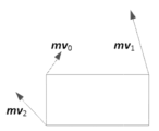
이 모드에서, 각각의 참조 픽처 리스트(리스트 0 또는 리스트 1)에 대해, 아핀 AMVP 후보 리스트는 다음의 순서로 3가지 타입의 아핀 모션 예측자로 구성되며, 각각의 후보는 현재 블록의 추정된 CPMV들을 포함한다. (도 17의 mv0 mv1 mv2 등의) 인코더측에서 발견된 최상의 CPMV들과 추정된 CPMV들의 차이들이 시그널링된다. 또한, 추정된 CPMV들이 도출되는 아핀 AMVP 후보의 인덱스가 추가로 시그널링된다.In this mode, for each reference picture list (
1) 상속된 아핀 모션 예측자들1) Inherited affine motion predictors
검사 순서는 HEVC AMVP 리스트 구성에서의 공간적 MVP들의 검사 순서와 유사하다. 첫째, 아핀 코딩되고 현재 블록에서와 동일한 참조 픽처를 갖는 {A1, A0}의 제1 블록으로부터 좌측 상속된 아핀 모션 예측자가 도출된다. 둘째, 아핀 코딩되고 현재 블록에서와 동일한 참조 픽처를 갖는 {B1, B0, B2}의 제1 블록으로부터 상부 상속된 아핀 모션 예측자가 도출된다. 도 16에 5개의 블록 A1, A0, B1, B0, B2가 도시되어 있다.The inspection order is similar to the inspection order of spatial MVPs in the HEVC AMVP list construction. First, a left-inherited affine motion predictor is derived from the first block of {A1, A0}, which is affine coded and has the same reference picture as that of the current block. Second, an upward-inherited affine motion predictor is derived from the first block of {B1, B0, B2}, which is affine coded and has the same reference picture as that of the current block. Five blocks A1, A0, B1, B0, and B2 are illustrated in Fig. 16.
이웃 블록이 아핀 모드로 코딩되는 것으로 발견되면, 이웃 블록을 커버하는 코딩 유닛의 CPMV들은 현재 블록의 CPMV들의 예측자들을 도출하는 데 사용된다. 예를 들어, A1이 비-아핀 모드로 코딩되고 A0이 4-파라미터 아핀 모드로 코딩되는 경우, 좌측 상속된 아핀 MV 예측자는 A0으로부터 도출될 것이다. 이 경우, 도 18b에서 상단-좌측 CPMV에 대한 MV0 N 및 상단-우측 CPMV에 대한 MV1 N으로 표시된 바와 같이, A0을 커버하는 CU의 CPMV들은 현재 블록의 상단-좌측(좌표 (x0, y0)을 가짐), 상단-우측(좌표 (x1, y1)을 가짐) 및 하단-우측(좌표 (x2, y2)를 가짐) 위치들에 대한 MV0 C, MV1 C, MV2 C로 표시된, 현재 블록의 추정된 CPMV들을 도출하는 데 이용된다.If the neighboring block is found to be coded in the affine mode, the CPMVs of the coding units covering the neighboring block are used to derive the predictors of the CPMVs of the current block. For example, if A1 is coded in the non-affine mode and A0 is coded in the 4-parameter affine mode, the left inherited affine MV predictor will be derived from A0. In this case, the CPMVs of the CU covering A0 are used to derive the estimated CPMVs of the current block, denoted as MV 0 C , MV 1 C , and MV 2 C for the top-left (with coordinates (x0, y0 )), top-right (with coordinates (x1, y1)) and bottom-right (with coordinates (x2, y2)) locations of the current block, as denoted as MV 0 N for the top-left CPMV and MV 1 N for the top-right CPMV in Fig. 18b .
2) 구성된 아핀 모션 예측자들2) Constructed affine motion predictors
구성된 아핀 모션 예측자는, 동일한 참조 픽처를 갖는, 도 17에 도시된 바와 같은, 이웃하는 인터 코딩된 블록들로부터 도출되는 CPMV(control-point motion vector)들로 이루어진다. 현재 아핀 모션 모델이 4-파라미터 아핀이면, CPMV의 수는 2이고, 그렇지 않고 현재 아핀 모션 모델이 6-파라미터 아핀이면, CPMV의 수는 3이다. 상단-좌측 CPMV 은 인터 코딩되고 현재 블록에서와 동일한 참조 픽처를 갖는 그룹 {A, B, C}의 제1 블록에서의 MV에 의해 도출된다. 상단-우측 CPMV 은 인터 코딩되고 현재 블록에서와 동일한 참조 픽처를 갖는 그룹 {D, E}의 제1 블록에서의 MV에 의해 도출된다. 하단-좌측 CPMV 은 인터 코딩되고 현재 블록에서와 동일한 참조 픽처를 갖는 그룹 {F, G}의 제1 블록에서의 MV에 의해 도출된다.The constructed affine motion predictor consists of control-point motion vectors (CPMVs) derived from neighboring inter-coded blocks having the same reference picture, as illustrated in Fig. 17. If the current affine motion model is 4-parameter affine, the number of CPMVs is 2, otherwise, if the current affine motion model is 6-parameter affine, the number of CPMVs is 3. Top-left CPMV is inter-coded and is derived by MV in the first block of group {A, B, C} that has the same reference picture as the current block. Top-right CPMV is inter-coded and is derived by MV in the first block of group {D, E} that has the same reference picture as in the current block. Bottom-left CPMV is inter-coded and is derived by MV in the first block of group {F, G} which has the same reference picture as in the current block.
- 현재 아핀 모션 모델이 4-파라미터 아핀이면, 구성된 아핀 모션 예측자는 과 양자 모두가 발견되는 경우에만 후보 리스트에 삽입되는데, 즉, 과 이 현재 블록의 상단-좌측(좌표 (x0, y0)을 가짐), 상단-우측(좌표 (x1, y1)을 가짐) 위치들에 대한 추정된 CPMV들로서 사용된다.- If the current affine motion model is 4-parameter affine, the constructed affine motion predictor is class It is inserted into the candidate list only if both are found, i.e., class These are used as estimated CPMVs for the top-left (with coordinates (x0, y0)) and top-right (with coordinates (x1, y1)) locations of the current block.
- 현재 아핀 모션 모델이 6-파라미터 아핀이면, 구성된 아핀 모션 예측자는 , 및 가 모두 발견되는 경우에만 후보 리스트에 삽입되는데, 즉, , 및 가 현재 블록의 상단-좌측(좌표 (x0, y0)을 가짐), 상단-우측(좌표 (x1, y1)을 가짐) 및 하단-우측(좌표 (x2, y2)를 가짐) 위치들에 대한 추정된 CPMV들로서 사용된다.- If the current affine motion model is 6-parameter affine, the constructed affine motion predictor is , and is inserted into the candidate list only if all are found, i.e., , and are used as estimated CPMVs for the top-left (with coordinates (x0, y0)), top-right (with coordinates (x1, y1)), and bottom-right (with coordinates (x2, y2)) locations of the current block.
구성된 아핀 모션 예측자를 후보 리스트에 삽입할 때 프루닝(pruning) 프로세스가 적용되지 않는다.No pruning process is applied when inserting the constructed affine motion predictor into the candidate list.
3) 정상 AMVP 모션 예측자들3) Normal AMVP motion predictors
아핀 모션 예측자들의 수가 최대에 도달할 때까지 다음과 같이 적용된다.The following is applied until the number of affine motion predictors reaches the maximum.
1) 이용가능한 경우 모든 CPMV를 로 설정함으로써 아핀 모션 예측자를 도출한다.1) All CPMVs, if available By setting , we derive an affine motion predictor.
2) 이용가능한 경우 모든 CPMV를 로 설정함으로써 아핀 모션 예측자를 도출한다.2) All CPMVs, if available By setting , we derive an affine motion predictor.
3) 이용가능한 경우 모든 CPMV를 으로 설정함으로써 아핀 모션 예측자를 도출한다.3) All CPMVs, if available By setting , we derive an affine motion predictor.
4) 이용가능한 경우 모든 CPMV를 HEVC TMVP로 설정함으로써 아핀 모션 예측자를 도출한다.4) Derive an affine motion predictor by setting all CPMVs to HEVC TMVP when available.
5) 모든 CPMV를 제로 MV로 설정함으로써 아핀 모션 예측자를 도출한다.5) Derive an affine motion predictor by setting all CPMVs to zero MV.
는 구성된 아핀 모션 예측자에서 이미 도출되었다는 점에 유의한다. Note that the is already derived from the constructed affine motion predictor.
AF_INTER 모드에서, 4/6 파라미터 아핀 모드가 사용될 때, 2/3 제어 포인트들이 요구되며, 따라서 도 15a 및 도 15b에 도시된 바와 같이 이들 제어 포인트들에 대해 2/3 MVD가 코딩될 필요가 있다. 기존의 구현에서, MV는 다음과 같이 도출될 수 있으며, 예를 들어, 이는 mvd0으로부터 mvd1 및 mvd2를 예측한다.In AF_INTER mode, when the 4/6 parameter affine mode is used, 2/3 control points are required, and therefore 2/3 MVDs need to be coded for these control points, as shown in Fig. 15a and Fig. 15b. In a conventional implementation, MV can be derived as follows, which predicts mvd 1 and mvd 2 from mvd 0 , for example.
여기서, , mvdi 및 mv1은 도 15b에 도시된 바와 같이 각각 상단-좌측 픽셀(i=0), 상단-우측 픽셀(i=1) 또는 좌측-하단 픽셀(i=2)의 예측된 모션 벡터, 모션 벡터 차이 및 모션 벡터이다. 일부 실시예들에서, 2개의 모션 벡터(예를 들어, mvA(xA, yA) 및 mvB(xB, yB))의 추가는 개별적으로 2개의 성분의 합산과 동일하다. 예를 들어, newMV=mvA+mvB는 newMV의 2개의 성분이 각각 (xA+xB) 및 (yA+yB)로 설정되어 있다는 것을 암시한다.Here, , mvd i and mv 1 are the predicted motion vector, motion vector difference and motion vector of the top-left pixel (i=0), top-right pixel (i=1) or bottom-left pixel (i=2), respectively, as illustrated in Fig. 15b. In some embodiments, addition of two motion vectors (e.g., mvA(xA, yA) and mvB(xB, yB)) is equivalent to the summation of the two components individually. For example, newMV=mvA+mvB implies that the two components of newMV are set to (xA+xB) and (yA+yB), respectively.
2.3.3.3 AF_MERGE 모드의 예들2.3.3.3 Examples of AF_MERGE mode
CU가 AF_MERGE 모드에서 적용될 때, 그것은 유효 이웃 재구성된 블록들로부터 아핀 모드로 코딩된 첫번째 블록을 얻는다. 그리고 후보 블록에 대한 선택 순서는 도 18a에 도시된 바와 같이 좌측, 상부, 상부 우측, 좌측 하단에서 상부 좌측 순이다(순서대로 A, B, C, D, E로 표시됨). 예를 들어, 이웃 좌측 하단 블록이 도 18b에서 A0으로 표시된 바와 같이 아핀 모드로 코딩되면, 블록 A를 포함하는 이웃 CU/PU의 상단 좌측 코너, 상부 우측 코너 및 좌측 하단 코너의 제어 포인트(CP) 모션 벡터들 mv0 N, mv1 N 및 mv2 N가 페치된다. 그리고 현재 CU/PU 상의 상단 좌측 코너/상단 우측/하단 좌측의 모션 벡터 mv0 C, mv1 C 및 mv2 C(6-파라미터 아핀 모델에 대해서만 사용됨)는 mv0 N, mv1 N 및 mv2 N에 기초하여 계산된다. VTM-2.0에서, 현재 블록이 아핀 코딩되는 경우 상단-좌측 코너에 위치한 서브-블록(예를 들어, VTM에서 4x4 블록)은 mv0을 저장하고, 상단-우측 코너에 위치한 서브-블록은 mv1을 저장한다는 점에 유의해야 한다. 현재 블록이 6-파라미터 아핀 모델로 코딩되는 경우, 하단-좌측 코너에 위치한 서브-블록은 mv2를 저장하며; 그렇지 않은 경우(4-파라미터 아핀 모델로 코딩되는 경우), LB는 mv2'를 저장한다. 다른 서브-블록들은 MC에 사용되는 MV들을 저장한다.When a CU is applied in AF_MERGE mode, it gets the first block coded in affine mode from the valid neighboring reconstructed blocks. And the selection order for the candidate block is left, top, top right, bottom left to top left in order as shown in Fig. 18a (indicated as A, B, C, D, and E, respectively). For example, if the neighboring bottom left block is coded in affine mode as indicated as A0 in Fig. 18b, the control point (CP) motion vectors mv 0 N , mv 1 N , and mv 2 N of the top left corner, top right corner, and bottom left corner of the neighboring CU/PU including block A are fetched. And the motion vectors mv 0 C , mv 1 C , and mv 2 C (used only for 6-parameter affine model) of the top left corner/top right/bottom left on the current CU/PU are computed based on mv 0 N , mv 1 N , and mv 2 N . Note that in VTM-2.0, if the current block is affine coded, the sub-block located at the top-left corner (e.g., a 4x4 block in VTM) stores mv0, and the sub-block located at the top-right corner stores mv1. If the current block is coded with a 6-parameter affine model, the sub-block located at the bottom-left corner stores mv2; otherwise (if coded with a 4-parameter affine model), the LB stores mv2'. The other sub-blocks store the MVs used for MC.
식 (1) 및 식 (2)의 아핀 모션 모델에 따라 현재 CU v0 및 v1의 CPMV가 계산된 후에, 현재 CU의 MVF가 생성될 수 있다. 현재 CU가 AF_MERGE 모드로 코딩되는지를 식별하기 위해, 아핀 모드로 코딩된 적어도 하나의 이웃 블록이 존재할 때 아핀 플래그가 비트스트림에서 시그널링될 수 있다.After the CPMV of the current CU v0 and v1 are calculated according to the affine motion model of Equation (1) and Equation (2), the MVF of the current CU can be generated. To identify whether the current CU is coded in AF_MERGE mode, an affine flag can be signaled in the bitstream when there is at least one neighboring block coded in the affine mode.
일부 실시예들(예를 들어, JVET-L0142 및 JVET-L0632)에서, 아핀 병합 후보 리스트는 다음의 단계들로 구성될 수 있다:In some embodiments (e.g., JVET-L0142 and JVET-L0632), the affine merge candidate list may consist of the following steps:
1) 상속된 아핀 후보들을 삽입1) Insert inherited affine candidates
상속된 아핀 후보는 후보가 그의 유효 이웃 아핀 코딩된 블록의 아핀 모션 모델로부터 도출된다는 것을 의미한다. 최대 2개의 상속된 아핀 후보들은 이웃 블록들의 아핀 모션 모델로부터 도출되고 후보 리스트에 삽입된다. 좌측 예측자의 경우, 스캔 순서는 {A0, A1}이고; 상부 예측자의 경우, 스캔 순서는 {B0, B1, B2}이다.Inherited affine candidate means that the candidate is derived from the affine motion models of its valid neighboring affine coded blocks. At most two inherited affine candidates are derived from the affine motion models of neighboring blocks and inserted into the candidate list. For the left predictor, the scan order is {A0, A1}; for the top predictor, the scan order is {B0, B1, B2}.
2) 구성된 아핀 후보들을 삽입2) Insert the constructed affine candidates
아핀 병합 후보 리스트 내의 후보들의 수가 MaxNumAffineCand(이 기고문에서는 5로 설정됨) 미만이면, 구성된 아핀 후보들이 후보 리스트에 삽입된다. 구성된 아핀 후보는 각각의 제어 포인트의 이웃 모션 정보를 조합하여 후보가 구성되는 것을 의미한다.If the number of candidates in the affine merge candidate list is less than MaxNumAffineCand (set to 5 in this contribution), the constructed affine candidates are inserted into the candidate list. The constructed affine candidates mean that the candidates are constructed by combining the neighboring motion information of each control point.
a) 제어 포인트에 대한 모션 정보는 먼저 도 19에 도시된 지정된 공간적 이웃 및 시간적 이웃으로부터 도출된다. CPk (k=1, 2, 3, 4)는 k번째 제어 포인트를 나타낸다. A0, A1, A2, B0, B1, B2 및 B3은 CPk (k=1, 2, 3)를 예측하기 위한 공간적 위치들이고; T는 CP4를 예측하기 위한 시간적 위치이다.a) Motion information for a control point is first derived from the designated spatial and temporal neighbors illustrated in Fig. 19. CPk (k=1, 2, 3, 4) represents the kth control point. A0, A1, A2, B0, B1, B2, and B3 are spatial locations for predicting CPk (k=1, 2, 3); and T is a temporal location for predicting CP4.
CP1, CP2, CP3 및 CP4의 좌표들은 각각 (0, 0), (W, 0), (H, 0) 및 (W, H)이며, 여기서 W 및 H는 현재 블록의 폭 및 높이이다.The coordinates of CP1, CP2, CP3, and CP4 are (0, 0), (W, 0), (H, 0), and (W, H), respectively, where W and H are the width and height of the current block.
각각의 제어 포인트의 모션 정보는 다음과 같은 우선순위 순서에 따라 획득된다:The motion information of each control point is obtained in the following priority order:
CP1의 경우, 검사 우선순위는 B2→B3→A2이다. B2가 이용가능한 경우 B2가 사용된다. 그렇지 않고, B2가 이용가능한 경우, B3이 사용된다. B2와 B3 양자 모두가 이용가능하지 않은 경우, A2가 사용된다. 3개의 후보 모두가 이용가능하지 않은 경우, CP1의 모션 정보가 획득될 수 없다.For CP1, the check priority is B2→B3→A2. If B2 is available, B2 is used. Otherwise, if B2 is available, B3 is used. If neither B2 nor B3 are available, A2 is used. If none of the three candidates are available, the motion information of CP1 cannot be obtained.
CP2의 경우, 검사 우선순위는 B1→B0이다.For CP2, the inspection priority is B1→B0.
CP3의 경우, 검사 우선순위는 A1→A0이다.For CP3, the inspection priority is A1→A0.
CP4의 경우, T가 사용된다.For CP4, T is used.
b) 둘째로, 제어 포인트들의 조합들은 아핀 병합 후보를 구성하는 데 사용된다.b) Second, combinations of control points are used to construct affine merge candidates.
I. 6-파라미터 아핀 후보를 구성하기 위해 3개의 제어 포인트의 모션 정보가 필요하다. 3개의 제어 포인트는 다음의 4개의 조합({CP1, CP2, CP4}, {CP1, CP2, CP3}, {CP2, CP3, CP4}, {CP1, CP3, CP4}) 중 하나로부터 선택될 수 있다. 조합들 {CP1, CP2, CP3}, {CP2, CP3, CP4}, {CP1, CP3, CP4}은 상단-좌측, 상단-우측 및 하단-좌측 제어 포인트들에 의해 표현되는 6-파라미터 모션 모델로 전환될 것이다.I. To construct a 6-parameter affine candidate, the motion information of three control points is required. The three control points can be selected from one of the following four combinations ({CP1, CP2, CP4}, {CP1, CP2, CP3}, {CP2, CP3, CP4}, {CP1, CP3, CP4}). The combinations {CP1, CP2, CP3}, {CP2, CP3, CP4}, {CP1, CP3, CP4} will be converted into a 6-parameter motion model represented by the top-left, top-right and bottom-left control points.
II. 4-파라미터 아핀 후보를 구성하기 위해 2개의 제어 포인트의 모션 정보가 필요하다. 2개의 제어 포인트는 다음의 6개의 조합({CP1, CP4}, {CP2, CP3}, {CP1, CP2}, {CP2, CP4}, {CP1, CP3}, {CP3, CP4}) 중 하나로부터 선택될 수 있다. 조합들 {CP1, CP4}, {CP2, CP3}, {CP2, CP4}, {CP1, CP3}, {CP3, CP4}은 상단-좌측 및 상단-우측 제어 포인트들에 의해 표현되는 4-파라미터 모션 모델로 전환될 것이다.II. To construct the 4-parameter affine candidates, the motion information of two control points is required. The two control points can be selected from one of the following six combinations ({CP1, CP4}, {CP2, CP3}, {CP1, CP2}, {CP2, CP4}, {CP1, CP3}, {CP3, CP4}). The combinations {CP1, CP4}, {CP2, CP3}, {CP2, CP4}, {CP1, CP3}, {CP3, CP4} will be converted into a 4-parameter motion model represented by the top-left and top-right control points.
III. 구성된 아핀 후보들의 조합들은 다음과 같은 순서로 후보 리스트에 삽입된다:III. The combinations of constructed affine candidates are inserted into the candidate list in the following order:
{CP1, CP2, CP3}, {CP1, CP2, CP4}, {CP1, CP3, CP4}, {CP2, CP3, CP4}, {CP1, CP2}, {CP1, CP3}, {CP2, CP3}, {CP1, CP4}, {CP2, CP4}, {CP3, CP4}{CP1, CP2, CP3}, {CP1, CP2, CP4}, {CP1, CP3, CP4}, {CP2, CP3, CP4}, {CP1, CP2}, {CP1, CP3}, {CP2, CP3}, {CP1, CP4}, {CP2, CP4}, {CP3, CP4}
i. 조합의 참조 리스트 X(X는 0 또는 1임)의 경우, 제어 포인트들에서 가장 높은 사용률을 갖는 참조 인덱스는 리스트 X의 참조 인덱스로서 선택되고, 차이 참조 픽처를 가리키는 모션 벡터들은 스케일링될 것이다.i. For a reference list X of combinations (X is 0 or 1), the reference index with the highest usage rate in the control points is selected as the reference index of the list X, and the motion vectors pointing to the difference reference pictures will be scaled.
후보가 도출된 후에, 동일한 후보가 리스트에 삽입되었는지를 검사하기 위해 완전 프루닝(full pruning) 프로세스가 수행된다. 동일한 후보가 존재하는 경우, 도출된 후보는 폐기된다.After the candidates are derived, a full pruning process is performed to check whether there are identical candidates inserted into the list. If there are identical candidates, the derived candidates are discarded.
3) 제로 모션 벡터들로 패딩3) Padding with zero motion vectors
아핀 병합 후보 리스트 내의 후보들의 수가 5보다 작으면, 제로 참조 인덱스들을 갖는 제로 모션 벡터들은 리스트가 가득 찰 때까지 후보 리스트에 삽입된다.If the number of candidates in the affine merge candidate list is less than 5, zero motion vectors with zero reference indices are inserted into the candidate list until the list is full.
더 구체적으로, 서브-블록 병합 후보 리스트에 대해, 4-파라미터 병합 후보는 (0, 0)으로 설정된 MV들 및 (P 슬라이스에 대해) 리스트 0으로부터의 단예측 및 (B 슬라이스에 대해) 양예측으로 설정된 예측 방향을 갖는다.More specifically, for the sub-block merge candidate list, the 4-parameter merge candidate has MVs set to (0, 0) and the prediction direction set to uniprediction from list 0 (for P slices) and biprediction (for B slices).
2.3.4 MMVD(Merge with Motion Vector Differences)의 예들2.3.4 Examples of Merge with Motion Vector Differences (MMVD)
JVET-L0054에서, UMVE(ultimate motion vector expression, MMVD로도 알려짐)가 제시된다. UMVE는 제안된 모션 벡터 표현 방법과 함께 스킵 또는 병합 모드들에 사용된다.In JVET-L0054, UMVE (ultimate motion vector expression, also known as MMVD) is presented. UMVE is used in skip or merge modes along with the proposed motion vector representation method.
UMVE는 VVC에서의 정규 병합 후보 리스트에 포함된 것들과 동일한 병합 후보를 재사용한다. 병합 후보들 중에서, 베이스 후보가 선택될 수 있고, 제안된 모션 벡터 표현 방법에 의해 추가로 확장된다.UMVE reuses the same merge candidates as those included in the regular merge candidate list in VVC. Among the merge candidates, a base candidate can be selected and further extended by the proposed motion vector representation method.
UMVE는 새로운 모션 벡터 차이(MVD) 표현 방법을 제공하고, 여기서 MVD를 표현하기 위해 시작 포인트, 모션 크기 및 모션 방향이 사용된다.UMVE provides a novel motion vector difference (MVD) representation, where starting point, motion magnitude and motion direction are used to represent the MVD.
이 제안된 기법은 병합 후보 리스트를 그대로 사용한다. 그러나, 디폴트 병합 타입(MRG_TYPE_DEFAULT_N)인 후보들만이 UMVE의 확장을 위해 고려된다.The proposed technique uses the merge candidate list as is. However, only candidates with the default merge type (MRG_TYPE_DEFAULT_N) are considered for the extension of UMVE.
베이스 후보 인덱스는 시작 포인트를 정의한다. 베이스 후보 인덱스는 다음과 같이 리스트 내의 후보들 중 최상의 후보를 나타낸다.The base candidate index defines the starting point. The base candidate index indicates the best candidate among the candidates in the list, as follows:
베이스 후보의 수가 1이면, 베이스 후보 IDX는 시그널링되지 않는다.If the number of base candidates is 1, the base candidate IDX is not signaled.
거리 인덱스는 모션 크기 정보이다. 거리 인덱스는 시작 포인트로부터의 미리 정의된 거리 정보를 나타낸다. 미리 정의된 거리는 다음과 같다:Distance index is motion size information. Distance index represents predefined distance information from the starting point. Predefined distances are as follows:
방향 인덱스는 시작 포인트에 대한 MVD의 방향을 나타낸다. 방향 인덱스는 아래에 도시된 바와 같은 4개의 방향을 나타낼 수 있다.The direction index indicates the direction of the MVD with respect to the starting point. The direction index can indicate four directions as shown below.
일부 실시예들에서, UMVE 플래그는 스킵 플래그 또는 병합 플래그를 전송한 직후에 시그널링된다. 스킵 또는 병합 플래그가 참이면, UMVE 플래그가 파싱된다. UMVE 플래그가 1이면, UMVE 신택스들이 파싱된다. 그러나, 1이 아니면, AFFINE 플래그가 파싱된다. AFFINE 플래그가 1이면, AFFINE 모드이지만, 1이 아니면, VTM의 스킵/병합 모드에 대해 스킵/병합 인덱스가 파싱된다.In some embodiments, the UMVE flag is signaled immediately after transmitting the skip flag or the merge flag. If the skip or merge flag is true, the UMVE flag is parsed. If the UMVE flag is 1, the UMVE syntaxes are parsed. However, if it is not 1, the AFFINE flag is parsed. If the AFFINE flag is 1, the AFFINE mode is present, but if it is not 1, the skip/merge index is parsed for the skip/merge mode of the VTM.
UMVE 후보들로 인한 추가적인 라인 버퍼는 필요하지 않다. 소프트웨어의 스킵/병합 후보는 베이스 후보로서 직접 사용되기 때문이다. 입력 UMVE 인덱스를 사용하여, MV의 보수(supplement)가 모션 보상 직전에 결정된다. 이를 위해 긴 라인 버퍼를 유지할 필요가 없다.No additional line buffer is required due to UMVE candidates, since the skip/merge candidates in software are used directly as base candidates. Using the input UMVE index, the supplement of the MV is determined just before motion compensation. This eliminates the need to maintain a long line buffer.
현재의 공통 테스트 조건에서, 병합 후보 리스트 내의 제1 또는 제2 병합 후보가 베이스 후보로서 선택될 수 있다.Under the current common test conditions, the first or second merge candidate in the merge candidate list can be selected as the base candidate.
2.3.5 DMVR(Decoder-side Motion Vector Refinement)의 예들2.3.5 Examples of DMVR(Decoder-side Motion Vector Refinement)
양예측 연산에서, 하나의 블록 영역의 예측을 위해, 리스트0의 모션 벡터(MV) 및 리스트1의 MV를 사용하여 각각 형성된 2개의 예측 블록이 조합되어 단일 예측 신호를 형성한다. DMVR(decoder-side motion vector refinement) 방법에서, 양예측의 2개의 모션 벡터는 추가로 리파인(refine)된다.In a bidirectional prediction operation, for prediction of one block region, two prediction blocks, each formed using the motion vectors (MVs) of
JEM 설계에서, 모션 벡터들은 쌍방 템플릿 매칭 프로세스에 의해 리파인된다. 쌍방 템플릿 매칭은 디코더에 적용되어 추가적인 모션 정보의 송신 없이 리파인된 MV를 획득하기 위해 참조 픽처들에서 재구성 샘플들과 쌍방 템플릿 사이의 왜곡-기반 탐색(distortion-based search)을 수행한다. 일 예가 도 22에 도시되어 있다. 도 22에 도시된 바와 같이, 쌍방 템플릿이 리스트0의 초기 MV0 및 리스트1의 MV1로부터 각각 2개의 예측 블록의 가중 조합(즉, 평균)으로서 생성된다. 템플릿 매칭 연산은, 생성된 템플릿과 참조 픽처의 샘플 영역(초기 예측 블록 주변) 사이의 비용 척도들(cost measures)을 계산하는 것을 포함한다. 2개의 참조 픽처 각각에 대해, 최소 템플릿 비용을 산출하는 MV가 원래의 것을 대체할 그 리스트의 업데이트된 MV로 간주된다. JEM에서, 각각의 리스트에 대해 9개의 MV 후보가 탐색된다. 9개의 MV 후보는 원래 MV와, 수평 또는 수직 방향으로, 또는 양자 모두로 원래 MV에 대한 하나의 루마 샘플 오프셋을 갖는 8개의 주변 MV를 포함한다. 마지막으로, 도 22에 도시된 바와 같은 2개의 새로운 MV, 즉, MV0' 및 MV1'은 최종 양예측 결과들을 생성하는 데 사용된다. SAD(sum of absolute differences)가 비용 척도로서 사용된다. 하나의 주변 MV에 의해 생성되는 예측 블록의 비용을 계산할 때, 실제 MV 대신에 예측 블록을 획득하기 위해 (정수 픽셀로의) 라운딩된 MV가 실제로 사용된다는 점에 주목한다.In the JEM design, motion vectors are refined by a bilateral template matching process. Bilateral template matching is applied to the decoder to perform a distortion-based search between reconstructed samples in reference pictures and bilateral templates to obtain refined MVs without transmitting additional motion information. An example is illustrated in Fig. 22. As illustrated in Fig. 22, bilateral templates are generated as weighted combinations (i.e., averages) of two prediction blocks, respectively, from the initial MV0 of
DMVR의 프로세스를 더 단순화하기 위해, JVET-M0147은 JEM에서의 설계에 대한 몇몇 변경들을 제안하였다. 더 구체적으로, (곧 릴리즈될) VTM-4.0에 대해 채택된 DMVR 설계는 다음과 같은 주요 특징들을 갖는다:To further simplify the DMVR process, JVET-M0147 proposed several changes to the design in JEM. More specifically, the DMVR design adopted for VTM-4.0 (to be released soon) has the following key features:
○ 리스트0과 리스트1 사이의 (0,0) 위치 SAD를 갖는 조기 종료○ Early termination with SAD at position (0,0) between list0 and list1
○ DMVR W*H>=64 && H>=8에 대한 블록 크기들○ Block sizes for DMVR W*H>=64 && H>=8
○ CU 크기 > 16*16의 DMVR에 대해 CU를 16x16 서브-블록들의 배수로 구분○ For DMVRs with CU size > 16*16, divide CUs into multiples of 16x16 sub-blocks.
○ (루마에 대한) 참조 블록 크기 (W+7)*(H+7)○ Reference block size (for luma) (W+7)*(H+7)
○ 25 포인트 SAD-기반 정수-픽셀 탐색(즉, (+-) 2 리파인먼트 탐색 범위, 단일 스테이지)○ 25-point SAD-based integer-pixel search (i.e. (+-) 2 refinement search range, single stage)
○ 이중선형-보간 기반 DMVR○ Bilinear-interpolation based DMVR
○ 쌍방 매칭을 허용하기 위한 리스트0과 리스트1 사이의 MVD 미러링○ MVD mirroring between List0 and List1 to allow bidirectional matching
○ "파라메트릭 오차 표면 방정식(Parametric error surface equation)" 기반 서브-픽셀 리파인먼트○ Sub-pixel refinement based on “Parametric error surface equation”
○ 참조 블록 패딩(필요한 경우)을 갖는 루마/크로마 MC○ Luma/chroma MC with reference block padding (if required)
○ MC 및 TMVP들에만 사용되는 리파인된 MV들○ Refined MVs used only for MC and TMVPs
2.3.6 조합된 인트라 및 인터 예측(CIIR)의 예들2.3.6 Examples of combined intra and inter prediction (CIIR)
JVET-L0100에서, 다중-가설 예측(multi-hypothesis prediction)이 제안되며, 조합된 인트라 및 인터 예측은 다수의 가설들을 생성하는 하나의 방식이다.In JVET-L0100, multi-hypothesis prediction is proposed, where combined intra and inter predictions are one way to generate multiple hypotheses.
다중-가설 예측이 인트라 모드를 개선하기 위해 적용될 때, 다중-가설 예측은 하나의 인트라 예측과 하나의 병합 인덱싱된 예측을 조합한다. 병합 CU에서, 하나의 플래그는 플래그가 참일 때 인트라 후보 리스트로부터 인트라 모드를 선택하기 위해 병합 모드에 대해 시그널링된다. 루마 성분의 경우, 인트라 후보 리스트는 DC, 평면, 수평, 및 수직 모드들을 포함하는 4개의 인트라 예측 모드로부터 도출되고, 인트라 후보 리스트의 크기는 블록 형상에 따라 3 또는 4일 수 있다. CU 폭이 CU 높이의 2배보다 클 때, 수평 모드는 인트라 모드 리스트를 배제하고, CU 높이가 CU 폭의 2배보다 클 때, 수직 모드는 인트라 모드 리스트로부터 제거된다. 인트라 모드 인덱스에 의해 선택되는 하나의 인트라 예측 모드와 병합 인덱스에 의해 선택되는 하나의 병합 인덱싱된 예측이 가중 평균(weighted average)을 사용하여 조합된다. 크로마 성분의 경우, DM은 추가의 시그널링 없이 항상 적용된다. 예측들을 조합하기 위한 가중치들은 다음과 같이 설명된다. DC 또는 평면 모드가 선택되거나, CB 폭 또는 높이가 4보다 작을 때, 동일한 가중치들이 적용된다. CB 폭 및 높이가 4 이상인 CB들의 경우, 수평/수직 모드가 선택될 때, 하나의 CB는 먼저 4개의 동일-면적 영역(equal-area region)으로 수직으로/수평으로 구분(split)된다. (w_intrai, w_interi)로 표시되는 각각의 가중치 세트 - 여기서 i는 1 내지 4이고 (w_intra1, w_inter1) = (6, 2), (w_intra2, w_inter2) = (5, 3), (w_intra3, w_inter3) = (3, 5), 및 (w_intra4, w_inter4) = (2, 6)임 - 가 대응하는 영역에 적용될 것이다. (w_intra1, w_inter1)는 참조 샘플들에 가장 가까운 영역에 대한 것이고, (w_intra4, w_inter4)는 참조 샘플들로부터 가장 멀리 떨어진 영역에 대한 것이다. 이어서, 2개의 가중된 예측을 합산하고 3 비트 우측-시프팅(right-shifting 3 bits)함으로써 조합된 예측이 계산될 수 있다. 또한, 예측자들의 인트라 가설(intra hypothesis)에 대한 인트라 예측 모드는 다음의 이웃 CU들의 참조를 위해 세이브될 수 있다.When multi-hypothesis prediction is applied to improve intra modes, multi-hypothesis prediction combines one intra prediction mode and one merge indexed prediction mode. In a merge CU, a flag is signaled for the merge mode to select an intra mode from the intra candidate list when the flag is true. For the luma component, the intra candidate list is derived from four intra prediction modes including DC, planar, horizontal, and vertical modes, and the size of the intra candidate list can be 3 or 4 depending on the block shape. When the CU width is greater than twice the CU height, the horizontal mode is excluded from the intra mode list, and when the CU height is greater than twice the CU width, the vertical mode is removed from the intra mode list. One intra prediction mode selected by the intra mode index and one merge indexed prediction selected by the merge index are combined using a weighted average. For the chroma component, DM is always applied without additional signaling. The weights for combining the predictions are described as follows. When DC or planar mode is selected, or CB width or height is less than 4, equal weights are applied. For CBs with CB width and height greater than 4, when horizontal/vertical mode is selected, one CB is first split vertically/horizontally into four equal-area regions. Each set of weights, denoted as (w_intra i , w_inter i ), where i is from 1 to 4 and (w_intra 1 , w_inter 1 ) = (6, 2), (w_intra 2 , w_inter 2 ) = (5, 3), (w_intra 3 , w_inter 3 ) = (3, 5), and (w_intra 4 , w_inter 4 ) = (2, 6), will be applied to the corresponding region. (w_intra 1 , w_inter 1 ) are for the region closest to the reference samples, and (w_intra 4 , w_inter 4 ) are for the region farthest from the reference samples. Then, a combined prediction can be computed by summing the two weighted predictions and right-shifting 3 bits. In addition, the intra prediction mode for the intra hypothesis of the predictors can be saved for reference to the next neighboring CUs.
2.4 JVET-M0427에서의 인-루프 재성형(ILR)2.4 In-loop reshaping (ILR) in JVET-M0427
인-루프 재성형(ILR)의 기본 아이디어는 원래의 (제1 도메인에서의) 신호(예측/재구성 신호)를 제2 도메인(재성형된 도메인)으로 전환하는 것이다.The basic idea of in-loop reshaping (ILR) is to transfer the original signal (in the first domain) (the prediction/reconstructed signal) to the second domain (the reshaped domain).
인-루프 루마 재성형기는 한 쌍의 룩업 테이블(LUT)로서 구현되지만, 2개의 LUT 중 하나만이 시그널링될 필요가 있는데, 그 이유는 다른 하나가 시그널링된 LUT로부터 계산될 수 있기 때문이다. 각각의 LUT는 1-차원, 10-비트, 1024-엔트리 맵핑 테이블(1D-LUT)이다. 하나의 LUT는 입력 루마 코드 값들 Yi를 변경된 값들 Yr에 맵핑하는 순방향 LUT, FwdLUT이다: . 다른 LUT는 변경된 코드 값들 Yr을 에 맵핑하는 역 LUT, InvLUT이다: . (는 Yi의 재구성 값들을 나타낸다.)The in-loop luma reshaper is implemented as a pair of lookup tables (LUTs), but only one of the two LUTs needs to be signaled, since the other can be computed from the signaled LUT. Each LUT is a one-dimensional, 10-bit, 1024-entry mapping table (1D-LUT). One LUT is a forward LUT, FwdLUT, that maps input luma code values Y i to modified values Y r : . Other LUTs change the code values Y r The inverse LUT, InvLUT, that maps to: . ( ) represent the reconstruction values of Y i .
2.4.1 PWL(piece-wise linear) 모델2.4.1 PWL(piece-wise linear) model
일부 실시예들에서, PWL(piece-wise linear)은 다음과 같은 방식으로 구현된다:In some embodiments, piece-wise linear (PWL) is implemented in the following manner:
x1, x2를 2개의 입력 피벗 포인트라고 하고, y1, y2를 하나의 피스(piece)에 대한 그것들의 대응하는 출력 피벗 포인트라고 한다. x1과 x2 사이의 임의의 입력 값 x에 대한 출력 값 y는 다음의 수학식에 의해 보간될 수 있다:Let x1, x2 be two input pivot points, and y1, y2 be their corresponding output pivot points for a piece. The output value y for any input value x between x1 and x2 can be interpolated by the following mathematical formula:
y = ((y2-y1)/(x2-x1)) * (x-x1) + y1y = ((y2-y1)/(x2-x1)) * (x-x1) + y1
고정 소수점 구현에서, 수학식은 다음과 같이 다시 쓰여질 수 있다:In a fixed-point implementation, the equation can be rewritten as:
y = ((m * x + 2FP_PREC-1) >> FP_PREC) + cy = ((m * x + 2FP_PREC-1) >> FP_PREC) + c
여기서, m은 스칼라이고, c는 오프셋이고, FP_PREC는 정밀도를 지정하기 위한 상수 값이다.Here, m is a scalar, c is an offset, and FP_PREC is a constant value to specify precision.
CE-12 소프트웨어에서, PWL 모델은 1024-엔트리 FwdLUT 및 InvLUT 맵핑 테이블들을 미리 계산하기 위해 사용되지만; PWL 모델은 또한 구현들이 LUT들을 미리 계산하지 않고 온-더-플라이로 동일한 맵핑 값들을 계산할 수 있게 한다는 점에 유의한다.In the CE-12 software, the PWL model is used to precompute the 1024-entry FwdLUT and InvLUT mapping tables; however, note that the PWL model also allows implementations to compute the same mapping values on-the-fly without precomputing the LUTs.
2.4.2 테스트 CE12-22.4.2 Test CE12-2
2.4.2.1 루마 재성형2.4.2.1 Luma Reshaping
인-루프 루마 재성형의 테스트 2(즉, 제안의 CE12-2)는 인터 슬라이스 재구성에서 블록-와이즈 인트라 예측(block-wise intra prediction)에 대한 디코딩 레이턴시를 또한 제거하는 더 낮은 복잡도의 파이프라인을 제공한다. 인트라 예측은 인터 및 인트라 슬라이스들 양자 모두에 대해 재성형된 도메인에서 수행된다.
인트라 예측은 슬라이스 타입에 관계없이 재성형된 도메인에서 항상 수행된다. 이러한 배열로, 인트라 예측은 이전 TU 재구성이 행해진 직후에 시작될 수 있다. 이러한 배열은 또한 슬라이스 종속적인 것 대신에 인트라 모드에 대한 통합 프로세스를 제공할 수 있다. 도 23은 모드에 기초한 CE12-2 디코딩 프로세스의 블록도를 도시한다.Intra prediction is always performed on the reshaped domain, regardless of the slice type. With this arrangement, intra prediction can start immediately after the previous TU reconstruction is performed. This arrangement can also provide an integrated process for intra modes instead of being slice-dependent. Fig. 23 illustrates a block diagram of a mode-based CE12-2 decoding process.
CE12-2는 또한 CE12-1의 32-피스 PWL(piece-wise linear) 모델들 대신에 루마 및 크로마 잔차 스케일링에 대한 16-피스 PWL 모델들을 테스트한다.CE12-2 also tests 16-piece piece-wise linear (PWL) models for luma and chroma residual scaling instead of the 32-piece PWL models of CE12-1.
CE12-2에서 인-루프 루마 재성형기를 갖는 인터 슬라이스 재구성(연한 녹색 음영 블록들은 재성형된 도메인에서의 신호를 나타낸다: 루마 잔차; 인트라 루마 예측됨; 및 인트라 루마 재구성됨).Inter-slice reconstruction with in-loop luma reshaping in CE12-2 (light green shaded blocks represent signal in the reshaped domain: luma residual; intra luma predicted; and intra luma reconstructed).
2.4.2.2 루마 종속적 크로마 잔차 스케일링(LCRS)2.4.2.2 Luma-dependent chroma residual scaling (LCRS)
루마 종속적 크로마 잔차 스케일링은 고정 소수점 정수 연산(fixed-point integer operation)으로 구현되는 곱셈 프로세스이다. 크로마 잔차 스케일링은 크로마 신호와의 루마 신호 상호작용을 보상한다. 크로마 잔차 스케일링은 TU 레벨에서 적용된다. 더 구체적으로, 다음과 같이 적용된다:Luma-dependent chroma residual scaling is a multiplication process implemented as a fixed-point integer operation. Chroma residual scaling compensates for the interaction of the luma signal with the chroma signal. Chroma residual scaling is applied at the TU level. More specifically, it is applied as follows:
○ 인트라에 대해, 재구성된 루마가 평균화된다.○ For Intra, the reconstructed luma is averaged.
○ 인터에 대해, 예측 루마가 평균화된다.○ For inter, the predicted luma is averaged.
평균은 PWL 모델에서 인덱스를 식별하는 데 사용된다. 인덱스는 스케일링 인자 cScaleInv를 식별한다. 크로마 잔차는 그 수로 곱해진다.The mean is used to identify the index in the PWL model. The index identifies the scaling factor cScaleInv. The chroma residuals are multiplied by that number.
크로마 스케일링 인자는 재구성된 루마 값들이 아니라 순방향-맵핑된 예측된 루마 값들로부터 계산된다는 점에 유의한다.Note that the chroma scaling factor is computed from the forward-mapped predicted luma values, not from the reconstructed luma values.
2.4.2.3 ILR 사이드 정보의 시그널링2.4.2.3 Signaling of ILR side information
파라미터들은 (ALF와 유사한) 타일 그룹 헤더에서 (현재) 전송된다. 이들은 전하는 바에 의하면 40-100 비트를 취한다. 다음의 표는 JVET-L1001의 버전 9에 기초한다. 추가된 신택스는 큰 볼드체로 표시된다. 삭제들은 [[삭제된 부분]]으로 둘러싸인 볼드 이중 대괄호(bolded double square brackets)를 사용하여 표시된다.Parameters are (currently) transmitted in the tile group header (similar to ALF). They reportedly take 40-100 bits. The following table is based on version 9 of JVET-L1001. Added syntax is shown in large bold . Deletions are indicated using bolded double square brackets surrounded by [[deleted part]].
sps_reshaper_enabled_flag가 1인 것은 재성형기가 CVS(coded video sequence)에서 사용되는 것을 명시한다. sps_reshaper_enabled_flag가 0인 것은 재성형기가 CVS에서 사용되지 않는 것을 명시한다. sps_reshaper_enabled_flag being 1 specifies that the reshaper is used on CVS (coded video sequence). sps_reshaper_enabled_flag being 0 specifies that the reshaper is not used on CVS.
tile_group_reshaper_model_present_flag가 1인 것은 tile_group_reshaper_model()이 타일 그룹 헤더에 존재하는 것을 명시한다. tile_group_reshaper_model_present_flag가 0인 것은 tile_group_reshaper_model()이 타일 그룹 헤더에 존재하지 않는 것을 명시한다. tile_group_reshaper_model_present_flag가 존재하지 않을 때, 그것은 0인 것으로 추론된다. tile_group_reshaper_model_present_flag being 1 specifies that tile_group_reshaper_model() is present in the tile group header. tile_group_reshaper_model_present_flag being 0 specifies that tile_group_reshaper_model() is not present in the tile group header. When tile_group_reshaper_model_present_flag is not present, it is inferred to be 0.
tile_group_reshaper_enabled_flag가 1인 것은 재성형기가 현재 타일 그룹에 대해 인에이블되는 것을 명시한다. tile_group_reshaper_enabled_flag가 0인 것은 재성형기가 현재 타일 그룹에 대해 인에이블되지 않는 것을 명시한다. tile_group_reshaper_enable_flag가 존재하지 않을 때, 그것은 0인 것으로 추론된다. tile_group_reshaper_enabled_flag being 1 specifies that the reshaper is enabled for the current tile group. tile_group_reshaper_enabled_flag being 0 specifies that the reshaper is not enabled for the current tile group. When tile_group_reshaper_enable_flag is not present, it is inferred to be 0.
tile_group_reshaper_chroma_residual_scale_flag가 1인 것은 크로마 잔차 스케일링이 현재 타일 그룹에 대해 인에이블되는 것을 명시한다. tile_group_reshaper_chroma_residual_scale_flag가 0인 것은 크로마 잔차 스케일링이 현재 타일 그룹에 대해 인에이블되지 않는 것을 명시한다. tile_group_reshaper_chroma_residual_scale_flag가 존재하지 않을 때, 그것은 0인 것으로 추론된다. tile_group_reshaper_chroma_residual_scale_flag being 1 specifies that chroma residual scaling is enabled for the current tile group. tile_group_reshaper_chroma_residual_scale_flag being 0 specifies that chroma residual scaling is not enabled for the current tile group. When tile_group_reshaper_chroma_residual_scale_flag is not present, it is inferred to be 0.
reshape_model_min_bin_idx는 재성형기 구성 프로세스에서 사용될 최소 빈(또는 피스) 인덱스를 명시한다. reshape_model_min_bin_idx의 값은 0으로부터 MaxBinIdx까지의 범위에 있어야 한다. MaxBinIdx의 값은 15일 것이다. reshape_model_min_bin_idx specifies the minimum bin (or piece) index to be used in the reshaping process. The value of reshape_model_min_bin_idx must be in the range of 0 to MaxBinIdx, inclusive. The value of MaxBinIdx will be 15.
reshape_model_delta_max_bin_idx는 최대 허용 빈(또는 피스) 인덱스 MaxBinIdx 마이너스 재성형기 구성 프로세스에서 사용될 최대 빈 인덱스를 명시한다. reshape_model_max_bin_idx의 값은 MaxBinIdx - reshape_model_delta_max_bin_idx와 동일하게 설정된다. reshape_model_delta_max_bin_idx specifies the maximum allowed bin (or piece) index MaxBinIdx minus the maximum bin index to be used in the reshaping process. The value of reshape_model_max_bin_idx is set equal to MaxBinIdx - reshape_model_delta_max_bin_idx.
reshaper_model_bin_delta_abs_cw_prec_minus1 플러스 1은 신택스 reshape_model_bin_delta_abs_CW[i]의 표현에 사용되는 비트들의 수를 명시한다. reshaper_model_bin_delta_abs_cw_prec_minus1 plus 1 specifies the number of bits used to represent the syntax reshape_model_bin_delta_abs_CW[i].
reshape_model_bin_delta_abs_CW[i]는 i번째 빈에 대한 절대 델타 코드워드 값을 명시한다. reshape_model_bin_delta_abs_CW[i] specifies the absolute delta codeword value for the i-th bin.
reshaper_model_bin_delta_sign_CW_flag[i]는 다음과 같이 reshape_model_bin_delta_abs_CW[i]의 부호를 명시한다: reshaper_model_bin_delta_sign_CW_flag[i] specifies the sign of reshape_model_bin_delta_abs_CW[i] as follows:
- reshape_model_bin_delta_sign_CW_flag[i]가 0이면, 대응하는 변수 RspDeltaCW[i]는 양의 값이다.- If reshape_model_bin_delta_sign_CW_flag[i] is 0, the corresponding variable RspDeltaCW[i] is a positive value.
- 그렇지 않으면(reshape_model_bin_delta_sign_CW_flag[i]가 0이 아니면), 대응하는 변수 RspDeltaCW[i]는 음의 값이다.- Otherwise (if reshape_model_bin_delta_sign_CW_flag[i] is not 0), the corresponding variable RspDeltaCW[i] is a negative value.
reshape_model_bin_delta_sign_CW_flag[i]가 존재하지 않을 때, 그것은 0인 것으로 추론된다.When reshape_model_bin_delta_sign_CW_flag[i] does not exist, it is inferred to be 0.
변수 RspDeltaCW[i] = (1 2*reshape_model_bin_delta_sign_CW[i]) * reshape_model_bin_delta_abs_CW[i];Variable RspDeltaCW[i] = (1 2*reshape_model_bin_delta_sign_CW[i]) * reshape_model_bin_delta_abs_CW[i];
변수 RspCW[i]는 다음과 같은 단계들로서 도출된다:The variable RspCW[i] is derived through the following steps:
변수 OrgCW는 (1 << BitDepthY) / (MaxBinIdx + 1)과 동일하게 설정된다.The variable OrgCW is set equal to (1 << BitDepth Y ) / (MaxBinIdx + 1).
- reshaper_model_min_bin_idx <= i <= reshaper_model_max_bin_idx이면 RspCW[i] = OrgCW + RspDeltaCW[i].- If reshaper_model_min_bin_idx <= i <= reshaper_model_max_bin_idx, RspCW[i] = OrgCW + RspDeltaCW[i].
- 그렇지 않으면, RspCW[i] = 0.- Otherwise, RspCW[i] = 0.
BitDepthY의 값이 10이면 RspCW[i]의 값은 32 내지 2 * OrgCW - 1의 범위에 있어야 한다.If the value of BitDepth Y is 10, the value of RspCW[i] must be in the range of 32 to 2 * OrgCW - 1.
변수들 InputPivot[i](i는 0으로부터 MaxBinIdx + 1까지의 범위에 있음)는 다음과 같이 도출된다.The variables InputPivot[i] (i ranges from 0 to MaxBinIdx + 1) are derived as follows:
InputPivot[i] = i * OrgCWInputPivot[i] = i * OrgCW
변수 ReshapePivot[i](i는 0으로부터 MaxBinIdx + 1까지의 범위에 있음), 변수 ScaleCoef[i] 및 InvScaleCoeff[i](i는 0으로부터 MaxBinIdx까지의 범위에 있음)는 다음과 같이 도출된다:The variables ReshapePivot[i] (i in the
변수 ChromaScaleCoef[i](i는 0으로부터 MaxBinIdx까지의 범위에 있음)는 다음과 같이 도출된다:The variable ChromaScaleCoef[i] (where i is in the
2.4.2.4 ILR의 사용2.4.2.4 Use of ILR
인코더 측에서, 각각의 픽처(또는 타일 그룹)는 먼저 재성형된 도메인으로 전환된다. 그리고 모든 코딩 프로세스는 재성형된 도메인에서 수행된다. 인트라 예측의 경우, 이웃 블록은 재성형된 도메인에 있고; 인터 예측의 경우, (디코딩된 픽처 버퍼로부터 원래 도메인으로부터 생성된) 참조 블록들이 먼저 재성형된 도메인으로 전환된다. 그 후, 잔차가 생성되고 비트스트림으로 코딩된다.On the encoder side, each picture (or group of tiles) is first converted to the reshaped domain. And all coding processes are performed in the reshaped domain. For intra prediction, neighboring blocks are in the reshaped domain; for inter prediction, reference blocks (generated from the original domain from the decoded picture buffer) are first converted to the reshaped domain. After that, the residual is generated and coded into the bitstream.
전체 픽처(또는 타일 그룹)가 인코딩/디코딩을 끝낸 후에, 재성형된 도메인에서의 샘플들이 원래 도메인으로 전환되고, 이어서 디블록킹 필터 및 다른 필터들이 적용된다.After the entire picture (or group of tiles) is encoded/decoded, samples in the reshaped domain are converted to the original domain, and then a deblocking filter and other filters are applied.
예측 신호에 대한 순방향 재성형은 다음과 같은 경우들에 대해 디스에이블된다:Forward reshaping on the prediction signal is disabled in the following cases:
○ 현재 블록은 인트라-코딩된다○ The current block is intra-coded
○ 현재 블록은 CPR(current picture referencing, IBC(intra block copy)로도 알려짐)로서 코딩된다○ The current block is coded as CPR (current picture referencing, also known as IBC (intra block copy)).
○ 현재 블록은 CIIP(combined inter-intra mode)로서 코딩되고, 순방향 재성형은 인트라 예측 블록에 대해 디스에이블된다○ The current block is coded as CIIP (combined inter-intra mode), and forward reshaping is disabled for intra prediction blocks.
JVET-N0805JVET-N0805
타일 그룹 헤더에서 ILR의 사이드 정보를 시그널링하는 것을 회피하기 위해, JVET-N0805에서는, APS에서 이들을 시그널링하는 것이 제안된다. 이는 다음과 같은 주요 아이디어들을 포함한다:To avoid signaling the side information of ILR in the tile group header, in JVET-N0805 it is proposed to signal them in the APS. This includes the following main ideas:
- 선택적으로 SPS에서 LMCS 파라미터들을 전송한다.- Optionally transmit LMCS parameters from SPS.
- ALF 및 LMCS 파라미터들에 대한 APS 타입들을 정의한다. 각각의 APS는 하나의 타입만을 갖는다.- Define APS types for ALF and LMCS parameters. Each APS has only one type.
- APS에서 LMCS 파라미터들을 전송한다.- Transmit LMCS parameters from APS.
- LMCS 툴이 인에이블된 경우, LMCS aps_id가 존재하는지 여부를 표시하기 위해 TGH에 플래그를 갖는다. 시그널링되지 않는 경우, SPS 파라미터들이 사용된다.- If the LMCS tool is enabled, there is a flag in the TGH to indicate whether an LMCS aps_id exists. If not signaled, the SPS parameters are used.
* 툴이 인에이블될 때 참조되는 유효한 무언가를 항상 갖기 위해 시맨틱 제약을 추가할 필요가 있다.* We need to add semantic constraints to ensure that we always have something valid referenced when the tool is enabled.
2.5.2.5.1 JVET-M1001(VVC 작업 초안 4) 위의 제안된 설계의 구현 2.5.2.5.1 Implementation of the proposed design above in JVET-M1001 (VVC Working Draft 4)
......
sps_lmcs_enabled_flag가 1인 것은 LMCS(luma mapping with chroma scaling)가 CVS(coded video sequence)에서 사용되는 것을 명시한다. sps_lmcs_enabled_flag가 0인 것은 LMCS(luma mapping with chroma scaling)가 CVS에서 사용되지 않는 것을 명시한다. sps_lmcs_enabled_flag being 1 specifies that LMCS (luma mapping with chroma scaling) is used in CVS (coded video sequence). sps_lmcs_enabled_flag being 0 specifies that LMCS (luma mapping with chroma scaling) is not used in CVS.
......
조항 3에 다음의 정의들을 추가한다:Add the following definitions to Article 3:
다음과 같은 시맨틱스 변경들을 행한다:The following semantic changes are made:
......
는 타일 그룹이 참조하는 APS의 adaptation_parameter_set_id를 명시한다. 와 동일한 adaptation_parameter_set_id를 갖는 APS NAL 유닛의 TemporalId는 코딩된 타일 그룹 NAL 유닛의 TemporalId보다 작거나 같아야 한다. is a tile group referenced Specifies the adaptation_parameter_set_id of APS. with the same adaptation_parameter_set_id as The TemporalId of the APS NAL unit must be less than or equal to the TemporalId of the coded tile group NAL unit.
동일한 값의 adaptation_parameter_set_id를 갖는 다수의 APS들이 동일한 픽처의 2개 이상의 타일 그룹에 의해 참조될 때, 동일한 값의 adaptation_parameter_set_id를 갖는 다수의 APS들은 동일한 내용을 가질 것이다.Multiple adaptation_parameter_set_id with the same value When APSs are referenced by two or more tile groups of the same picture, multiple adaptation_parameter_set_id with the same value APS will have the same content.
......
[[tile_group_reshaper_model_present_flag가 1인 것은 tile_group_reshaper_model()이 타일 그룹 헤더에 존재하는 것을 명시한다. tile_group_reshaper_model_present_flag가 0인 것은 tile_group_reshaper_model()이 타일 그룹 헤더에 존재하지 않는 것을 명시한다. tile_group_reshaper_model_present_flag가 존재하지 않을 때, 그것은 0인 것으로 추론된다.]] [[tile_group_reshaper_model_present_flag being 1 specifies that tile_group_reshaper_model() is present in the tile group header. tile_group_reshaper_model_present_flag being 0 specifies that tile_group_reshaper_model() is not present in the tile group header. When tile_group_reshaper_model_present_flag is not present, it is inferred to be 0. ]]
tile_group_lmcs_enabled_flag가 1인 것은 LMCS(luma mapping with chroma scaling)가 현재 타일 그룹에 대해 인에이블되는 것을 명시한다. tile_group_lmcs_enabled_flag가 0인 것은 LMCS(luma mapping with chroma scaling)가 현재 타일 그룹에 대해 인에이블되지 않는 것을 명시한다. tile_group_lmcs_enable_flag가 존재하지 않을 때, 그것은 0인 것으로 추론된다. tile_group_lmcs_enabled_flag being 1 specifies that luma mapping with chroma scaling (LMCS) is enabled for the current tile group. tile_group_lmcs_enabled_flag being 0 specifies that luma mapping with chroma scaling (LMCS) is not enabled for the current tile group. When tile_group_lmcs_enable_flag is not present, it is inferred to be 0.
tile_group_chroma_residual_scale_flag가 1인 것은 크로마 잔차 스케일링이 현재 타일 그룹에 대해 인에이블되는 것을 명시한다. tile_group_chroma_residual_scale_flag가 0인 것은 크로마 잔차 스케일링이 현재 타일 그룹에 대해 인에이블되지 않는 것을 명시한다. tile_group_chroma_residual_scale_flag가 존재하지 않을 때, 그것은 0인 것으로 추론된다. tile_group_chroma_residual_scale_flag being 1 specifies that chroma residual scaling is enabled for the current tile group. tile_group_chroma_residual_scale_flag being 0 specifies that chroma residual scaling is not enabled for the current tile group. When tile_group_chroma_residual_scale_flag is not present, it is inferred to be 0.
......
......
2.4.2.6 JVET-N01382.4.2.6 JVET-N0138
이 기고문은 ALF 파라미터들뿐만 아니라 재성형기 모델 파라미터들의 운반을 위한 적응 파라미터 세트(APS)의 확장된 사용을 제안한다. 마지막 회의에서는, 다수의 타일 그룹들에서의 파라미터들의 불필요한 중복 시그널링을 회피함으로써 코딩 효율 개선을 위해 ALF 파라미터들이 타일 그룹 헤더 대신에 APS에 의해 운반되는 것이 결정되었다. 동일한 이유에 기초하여, 타일 그룹 헤더 대신에 APS에 의해 재성형기 모델 파라미터들을 운반하는 것이 제안된다. APS에서의 파라미터들의 타입(적어도 ALF 모델이든 재성형기 모델이든)을 식별하기 위해, APS 타입 정보가 APS ID에 더하여 APS 신택스에서 요구된다.This contribution proposes an extended usage of the Adaptive Parameter Set (APS) to carry not only ALF parameters but also reshaper model parameters. In the last meeting, it was decided that the ALF parameters are carried by the APS instead of the tile group header, in order to improve coding efficiency by avoiding unnecessary redundant signaling of parameters in multiple tile groups. Based on the same reasoning, it is proposed to carry the reshaper model parameters by the APS instead of the tile group header. In order to identify the type of parameters in the APS (at least whether it is an ALF model or a reshaper model), the APS type information is required in the APS syntax in addition to the APS ID.
적응 파라미터 세트 신택스 및 시맨틱스Adaptive parameter set syntax and semantics
adaptation_parameter_set_type는 APS에서의 파라미터들의 타입을 식별한다. adaptation_parameter_set_type의 값은 0으로부터 1까지의 범위에 있어야 한다. Adaptation_parameter_set_type가 0이면, ALF 파라미터들이 시그널링된다. 그렇지 않으면, 재성형기 모델 파라미터들이 시그널링된다. adaptation_parameter_set_type identifies the type of parameters in the APS. The value of adaptation_parameter_set_type must be in the range of 0 to 1. If adaptation_parameter_set_type is 0, ALF parameters are signaled. Otherwise, reshaper model parameters are signaled.
일반 타일 그룹 헤더 신택스 및 시맨틱스General Tile Group Header Syntax and Semantics
2.5 VPDU(Virtual Pipelining Data Unit)2.5 Virtual Pipelining Data Unit (VPDU)
VPDU(virtual pipeline data unit)들은 픽처에서의 비-중첩 MxM-루마(L)/NxN-크로마(C) 유닛들로서 정의된다. 하드웨어 디코더들에서, 연속적인 VPDU들은 다수의 파이프라인 스테이지들에 의해 동시에 처리되며; 상이한 스테이지들은 상이한 VPDU들을 동시에 처리한다. VPDU 크기는 대부분의 파이프라인 스테이지들에서 버퍼 크기에 대략 비례하므로, VPDU 크기를 작게 유지하는 것이 매우 중요하다고 한다. HEVC 하드웨어 디코더들에서, VPDU 크기는 최대 변환 블록(transform block, TB) 크기로 설정된다. 최대 TB 크기를 (HEVC에서와 같이) 32x32-L/16x16-C로부터 (현재 VVC에서와 같이) 64x64-L/32x32-C로 확대하는 것은 코딩 이득들을 가져올 수 있고, 이는 HEVC와 비교하여 4X의 VPDU 크기(64x64-L/32x32-C)를 초래할 것으로 예상된다. 그러나, 쿼드트리(QT) 코딩 유닛(CU) 파티셔닝에 더하여, 추가적인 코딩 이득들을 달성하기 위해 VVC에서 삼진 트리(TT) 및 이진 트리(BT)가 채택되고, TT 및 BT 구분들은 128x128-L/64x64-C 코딩 트리 블록(CTU)들에 재귀적으로 적용될 수 있으며, 이는 HEVC와 비교하여 16X의 VPDU 크기(128x128-L/64x64-C)로 이어진다고 한다.Virtual pipeline data units (VPDUs) are defined as non-overlapping MxM-luma (L)/NxN-chroma (C) units in a picture. In hardware decoders, consecutive VPDUs are processed concurrently by multiple pipeline stages; different stages may process different VPDUs concurrently. Since the VPDU size is roughly proportional to the buffer size in most pipeline stages, it is very important to keep the VPDU size small. In HEVC hardware decoders, the VPDU size is set to the maximum transform block (TB) size. Increasing the maximum TB size from 32x32-L/16x16-C (as in HEVC) to 64x64-L/32x32-C (as in current VVC) may yield coding gains, which is expected to result in a VPDU size increase of 4X compared to HEVC (64x64-L/32x32-C). However, in addition to quadtree (QT) coding unit (CU) partitioning, ternary tree (TT) and binary tree (BT) are adopted in VVC to achieve additional coding gains, and the TT and BT partitions can be recursively applied to 128x128-L/64x64-C coding tree blocks (CTUs), which is said to lead to 16X the VPDU size (128x128-L/64x64-C) compared to HEVC.
VVC의 현재 설계에서, VPDU 크기는 64x64-L/32x32-C로서 정의된다.In the current design of VVC, the VPDU size is defined as 64x64-L/32x32-C.
2.6 적응 파라미터 세트2.6 Adaptation parameter set
적응 파라미터 세트(APS)는 ALF 파라미터들을 운반하기 위해 VVC에서 채택된다. 타일 그룹 헤더는 ALF가 인에이블될 때 조건부로 존재하는 aps_id를 포함한다. APS는 aps_id 및 ALF 파라미터들을 포함한다. 새로운 NUT(AVC 및 HEVC에서와 같은, NAL 유닛 타입) 값이 (JVET-M0132로부터의) APS에 대해 할당된다. VTM-4.0(나올 예정)에서의 공통 테스트 조건들에 대해, 단지 aps_id=0을 사용하고 각각의 픽처와 함께 APS를 전송하는 것이 제안된다. 이제, APS ID 값들의 범위는 0..31일 것이고, APS들은 픽처들에 걸쳐 공유될 수 있다(그리고 픽처 내의 상이한 타일 그룹들에서 상이할 수 있다). ID 값은 존재할 때 고정 길이 코딩되어야 한다. ID 값들은 동일한 픽처 내의 상이한 콘텐츠와 함께 재사용될 수 없다.Adaptation Parameter Set (APS) is adopted in VVC to carry ALF parameters. The tile group header contains an aps_id which is conditionally present when ALF is enabled. The APS contains an aps_id and ALF parameters. A new NUT (NAL unit type, like in AVC and HEVC) value is assigned for the APS (from JVET-M0132). For common test conditions in VTM-4.0 (forthcoming), it is proposed to use only aps_id=0 and transmit an APS with each picture. The range of APS ID values shall now be 0..31, and APSs may be shared across pictures (and may be different in different tile groups within a picture). The ID value, when present, shall be fixed-length coded. ID values cannot be reused with different contents within the same picture.
2.7 관련 툴들2.7 Related Tools
2.7.1 확산 필터(DF)2.7.1 Diffusion Filter (DF)
JVET-L0157에서, 확산 필터가 제안되며, 여기서 CU의 인트라/인터 예측 신호는 확산 필터들에 의해 추가로 수정될 수 있다.In JVET-L0157, diffusion filters are proposed, where the intra/inter prediction signals of CUs can be further modified by the diffusion filters.
균일 확산 필터. 균일 확산 필터(Uniform Diffusion Filter)는 예측 신호를 아래에 정의되는 hI 또는 hIV로서 주어지는 고정 마스크와 컨볼루션함으로써 실현된다. 예측 신호 자체 외에도, 블록의 좌측 및 상부에 있는 한 줄의 재구성된 샘플들이 필터링된 신호에 대한 입력으로서 사용되고, 여기서, 이들 재구성된 샘플들의 사용은 인터 블록들에서 회피될 수 있다. Uniform Diffusion Filter. The Uniform Diffusion Filter is realized by convolving the prediction signal with a fixed mask, which is given as h I or h IV , defined below. In addition to the prediction signal itself, a row of reconstructed samples on the left and top of the block are used as input to the filtered signal, where the use of these reconstructed samples can be avoided in inter-blocks.
pred를 인트라 또는 모션 보상된 예측에 의해 획득된 주어진 블록 상의 예측 신호라고 한다. 필터들에 대한 경계 포인트들을 처리하기 위해, 예측 신호는 예측 신호 predext로 확장될 필요가 있다. 이 확장된 예측은 2가지 방식으로 형성될 수 있다:Let pred be the prediction signal on a given block obtained by intra or motion compensated prediction. In order to handle the boundary points for the filters, the prediction signal needs to be extended to the prediction signal pred ext . This extended prediction can be formed in two ways:
어느 쪽이든, 중간 단계로서, 블록의 좌측 및 상부에 있는 한 줄의 재구성된 샘플들이 예측 신호에 추가되고, 이어서 그 결과 얻어진 신호가 모든 방향으로 미러링된다. 또는 예측 신호 자체만이 모든 방향으로 미러링된다. 후자의 확장은 인터 블록들에 사용된다. 이 경우, 예측 신호 자체만이 확장된 예측 신호 predext에 대한 입력을 포함한다.Either way, as an intermediate step, a row of reconstructed samples on the left and top of the block is added to the prediction signal, and then the resulting signal is mirrored in all directions. Or, only the prediction signal itself is mirrored in all directions. The latter extension is used for inter-blocks. In this case, only the prediction signal itself contains input to the extended prediction signal pred ext .
필터 hI가 사용될 경우, 위에서 언급한 경계 확장을 사용하여 예측 신호 pred를When filter h I is used, the predicted signal pred is obtained by using the boundary extension mentioned above.
로 대체하는 것이 제안된다. 여기서, 필터 마스크 hI는 다음과 같이 주어진다.It is proposed to replace with , where the filter mask h I is given as follows.
필터 hIV가 사용될 경우, 예측 신호 pred를 다음 식으로 대체하는 것이 제안된다.When filter h IV is used, it is proposed to replace the prediction signal pred with the following equation.
여기서, 필터 hIV는 다음과 같이 주어진다.Here, the filter h IV is given as follows.
방향성 확산 필터. 신호 적응적 확산 필터들을 사용하는 대신에, 여전히 고정 마스크를 갖는 방향성 필터들인, 수평 필터 hhor 및 수직 필터 hver이 사용된다. 더 정확하게는, 이전 섹션의 마스크 hI에 대응하는 균일 확산 필터링은 단순히 수직 방향을 따라서만 또는 수평 방향을 따라서만 적용되도록 제한된다. 수직 필터는 예측 신호에 고정 필터 마스크 Directional diffusion filters. Instead of using signal-adaptive diffusion filters, horizontal filters h hor and vertical filters h ver are used, which are still directional filters with fixed masks. More precisely, the uniform diffusion filtering corresponding to the mask h I in the previous section is simply restricted to be applied only along the vertical direction or only along the horizontal direction. The vertical filter is applied to the prediction signal using a fixed filter mask.
를 적용함으로써 실현되고 수평 필터는 전치 마스크 를 사용함으로써 실현된다.is realized by applying a horizontal filter and a pre-mask This is realized by using .
2.7.2 쌍방 필터(BF)2.7.2 Bilateral Filter (BF)
쌍방 필터는 JVET-L0406에서 제안되고, 그것은 17보다 큰 슬라이스 양자화 파라미터 및 비-제로 변환 계수들을 갖는 루마 블록들에 항상 적용된다. 따라서, 쌍방 필터의 사용을 시그널링할 필요가 없다. 쌍방 필터는, 적용되는 경우, 역변환 직후에 디코딩된 샘플들에 대해 수행된다. 또한, 필터 파라미터들, 즉, 가중치들은 코딩된 정보로부터 명시적으로 도출된다.The bilateral filter is proposed in JVET-L0406 and it is always applied to luma blocks with slice quantization parameters greater than 17 and non-zero transform coefficients. Therefore, there is no need to signal the use of the bilateral filter. The bilateral filter, if applied, is performed on decoded samples immediately after the inverse transform. Also, the filter parameters, i.e., weights, are explicitly derived from the coded information.
필터링 프로세스는 다음과 같이 정의된다:The filtering process is defined as follows:
여기서, P0,0은 현재 샘플의 강도이고, P'0,0은 현재 샘플의 수정된 강도이며, Pk,0 및 Wk는 각각 k번째 이웃 샘플에 대한 강도 및 가중 파라미터이다. 1개의 현재 샘플 및 그것의 4개의 이웃 샘플(즉, K=4)의 예가 도 24에 도시되어 있다.Here, P 0,0 is the intensity of the current sample, P' 0,0 is the modified intensity of the current sample, and P k,0 and W k are the intensity and weighting parameters for the k-th neighboring sample, respectively. An example of one current sample and its four neighboring samples (i.e., K=4) is shown in Fig. 24.
더 구체적으로, k번째 이웃 샘플과 연관된 가중치 Wk(x)는 다음과 같이 정의된다:More specifically, the weight W k (x) associated with the kth neighboring sample is defined as follows:
여기서,Here,
이고 이다. And am.
여기서, σd는 코딩된 모드 및 코딩 블록 크기들에 종속적이다. 설명된 필터링 프로세스는 병렬 처리를 가능하게 하기 위해 인트라-코딩된 블록들, 및 TU가 추가로 구분될 때 인터-코딩된 블록들에 적용된다.Here, σ d depends on the coded mode and coding block sizes. The described filtering process is applied to intra-coded blocks to enable parallel processing, and to inter-coded blocks when TUs are further separated.
비디오 신호의 통계적 특성들을 더 잘 캡처하고, 필터의 성능을 개선하기 위해, 식 (2)로부터 얻어지는 가중치 함수는 코딩 모드 및 블록 파티셔닝의 파라미터들(최소 크기)에 종속적인 것으로서 표 4에 나타낸 σd 파라미터에 의해 조정되고 있다.To better capture the statistical characteristics of the video signal and improve the performance of the filter, the weight function obtained from Equation (2) is adjusted by the σ d parameter, which is dependent on the parameters of coding mode and block partitioning (minimum size), as shown in Table 4.
코딩 성능을 더 개선하기 위해, TU가 구분되지 않을 때 인터-코딩된 블록들에 대해, 현재 샘플과 그것의 이웃 샘플들 중 하나 사이의 강도 차이는 현재 샘플과 이웃 샘플을 커버하는 2개의 윈도우 사이의 대표 강도 차이로 대체된다. 따라서, 필터링 프로세스의 수학식은 다음과 같이 수정된다:To further improve the coding performance, for inter-coded blocks when TUs are not separated, the intensity difference between the current sample and one of its neighboring samples is replaced by the representative intensity difference between two windows covering the current sample and the neighboring sample. Therefore, the mathematical expression of the filtering process is modified as follows:
여기서, Pk,m 및 P0,m은 각각 Pk,0 및 P0,0에 중심을 둔 윈도우들 내의 m번째 샘플 값을 나타낸다. 이 제안에서, 윈도우 크기는 3x3으로 설정된다. P2,0 및 P0,0을 커버하는 2개의 윈도우의 예가 도 25에 도시되어 있다.Here, P k,m and P 0,m represent the m-th sample value within the windows centered at P k,0 and P 0,0, respectively. In this proposal, the window size is set to 3x3. An example of two windows covering P 2,0 and P 0,0 is shown in Fig. 25.
2.7.3 아다마르 변환 도메인 필터(HF)2.7.3 Hadamard Transform Domain Filter (HF)
JVET-K0068에서, 재구성 이후 CU 레벨에 적용되고 곱셈 없는 구현을 갖는 1D 아다마르 변환 도메인에서의 인-루프 필터. 제안된 필터는 미리 정의된 조건을 충족시키는 모든 CU 블록들에 대해 적용되고, 필터 파라미터들은 코딩된 정보로부터 도출된다.In JVET-K0068, an in-loop filter in the 1D Hadamard transform domain with a multiplication-free implementation and applied at the CU level after reconstruction. The proposed filter is applied to all CU blocks that satisfy predefined conditions, and the filter parameters are derived from the coded information.
제안된 필터링은, 4x4 블록들을 제외하고 슬라이스 양자화 파라미터가 17보다 큰 경우, 비-제로 변환 계수들을 갖는 루마 재구성된 블록들에 항상 적용된다. 필터 파라미터들은 코딩된 정보로부터 명시적으로 도출된다. 제안된 필터는, 적용되는 경우, 역변환 직후에 디코딩된 샘플들에 대해 수행된다.The proposed filtering is always applied to luma reconstructed blocks with non-zero transform coefficients, except for 4x4 blocks, when the slice quantization parameter is greater than 17. The filter parameters are explicitly derived from the coded information. The proposed filter, when applied, is performed on decoded samples immediately after the inverse transform.
재구성된 블록으로부터의 각각의 픽셀에 대해, 픽셀 처리는 다음과 같은 단계들을 포함한다:For each pixel from the reconstructed block, pixel processing involves the following steps:
○ 스캔 패턴에 따라 현재 픽셀을 포함하여 처리 픽셀 주위의 4개의 이웃 픽셀을 스캔○ Scan four neighboring pixels around the processing pixel, including the current pixel, according to the scan pattern.
○ 판독 픽셀들의 4 포인트 아다마르 변환○ 4-point Hadamard transform of read pixels
○ 다음과 같은 공식에 기초한 스펙트럼 필터링:○ Spectral filtering based on the following formula:
여기서, (i)는 아다마르 스펙트럼에서의 스펙트럼 성분의 인덱스이고, R(i)는 인덱스에 대응하는 재구성된 픽셀들의 스펙트럼 성분이고, σ는 다음의 수학식을 사용하여 코덱 양자화 파라미터 QP로부터 도출되는 필터링 파라미터이다:Here, (i) is the index of the spectral component in the Hadamard spectrum, R(i) is the spectral component of the reconstructed pixels corresponding to the index, and σ is a filtering parameter derived from the codec quantization parameter QP using the following mathematical expression:
. .
스캔 패턴의 예가 도 26에 도시되어 있으며, 여기서, A는 현재 픽셀이고, {B,C,D}는 주변 픽셀들이다.An example of a scan pattern is shown in Fig. 26, where A is the current pixel and {B,C,D} are surrounding pixels.
CU 경계 상에 놓인 픽셀들에 대해, 스캔 패턴은 모든 요구되는 픽셀들이 현재 CU 내에 있는 것을 보장하도록 조정된다.For pixels that lie on the CU boundary, the scan pattern is adjusted to ensure that all required pixels are within the current CU.
3 기존 구현들의 단점들3 Disadvantages of existing implementations
기존 ILR 구현들에서는, 다음과 같은 단점들이 존재할 수 있다:Existing ILR implementations may have the following drawbacks:
1) 타일 그룹 헤더에서의 ILR 사이드 정보의 시그널링은 너무 많은 비트를 필요로 하기 때문에 적절하지 않다. 또한, 상이한 픽처들/타일 그룹들 사이의 예측은 허용되지 않는다. 따라서, 각각의 타일 그룹에 대해, ILR의 사이드 정보가 송신될 필요가 있고, 이는 특히 낮은 해상도에 대해 낮은 비트레이트들 하에서 코딩 손실을 야기할 수 있다.1) Signaling ILR side information in the tile group header is not appropriate because it requires too many bits. Also, prediction between different pictures/tile groups is not allowed. Therefore, for each tile group, ILR side information needs to be transmitted, which may cause coding loss under low bitrates, especially for low resolutions.
2) ILR과 DMVR(또는 다른 새로 도입된 코딩 툴들) 사이의 상호작용은 불명확하다. 예를 들어, ILR이 인터-예측 신호에 적용되어 원래 신호를 재성형된 도메인으로 전환하고 디코딩된 잔차들이 재성형된 도메인에 있다. DMVR은 또한 하나의 블록에 대한 모션 벡터들을 리파인하기 위해 예측 신호에 의존한다. 원래 도메인 또는 재성형된 도메인에서 DMVR을 적용할지는 불명확하다.2) The interaction between ILR and DMVR (or other newly introduced coding tools) is unclear. For example, ILR is applied to the inter-prediction signal to transform the original signal into the reshaped domain, and the decoded residuals are in the reshaped domain. DMVR also relies on the prediction signal to refine the motion vectors for a block. It is unclear whether DMVR should be applied in the original domain or in the reshaped domain.
3) ILR과 스크린 콘텐츠 코딩 툴들, 예를 들어, 팔레트, B-DPCM, IBC, 변환 스킵, 트랜스퀀트-바이패스, I-PCM 모드들 사이의 상호작용은 명확하지 않다.3) The interaction between ILR and screen content coding tools, e.g., palette, B-DPCM, IBC, transform skip, transquant-bypass, I-PCM modes, is unclear.
4) 루마 종속적 크로마 잔차 스케일링이 ILR에서 사용된다. 따라서, (루마와 크로마 사이의 종속성으로 인한) 추가적인 지연이 도입되며, 이는 하드웨어 설계에 유익하지 않다.4) Luma-dependent chroma residual scaling is used in ILR. Therefore, additional delay (due to dependency between luma and chroma) is introduced, which is not beneficial for hardware design.
5) VPDU의 목적은 다른 64x64 정사각형 영역들의 처리를 시작하기 전에 하나의 64x64 정사각형 영역의 처리의 완료를 보장하는 것이다. 그러나, ILR의 설계에 따르면, 크로마가 루마의 예측 신호에 의존하기 때문에 VPDU의 위반을 야기할 수 있는 ILR의 사용에 대한 제한이 없다.5) The purpose of the VPDU is to ensure that processing of one 64x64 square region is completed before processing of other 64x64 square regions begins. However, by design of ILR, there is no restriction on the use of ILR that could cause violation of VPDU since chroma depends on luma prediction signal.
6) 모든 제로 계수들이 하나의 CU에 대해 발생할 때, 예측 블록 및 재구성 블록은 여전히 순방향 및 역 재성형 프로세스들을 수행하며, 이는 계산 복잡도를 낭비한다.6) When all zero coefficients occur for one CU, the prediction block and the reconstruction block still perform forward and backward reshaping processes, which wastes computational complexity.
7) JVET-N0138에서는, APS에서 ILR 정보를 시그널링하는 것이 제안된다. 이 해결책에 의해 몇 가지 새로운 문제가 야기될 수 있다. 예를 들어, 두 종류의 APS가 설계된다. 그러나, ILR에 대해 시그널링된 adaptation_parameter_set_id는 ILR 정보를 포함하지 않는 APS를 참조할 수 있다. 유사하게, 적응적 루프 필터링(ALF)에 대해 시그널링된 adaptation_parameter_set_id는 ALF 정보를 포함하지 않는 APS를 참조할 수 있다7) In JVET-N0138, it is proposed to signal ILR information in APS. This solution may introduce some new issues. For example, two kinds of APS are designed. However, the adaptation_parameter_set_id signaled for ILR may refer to an APS that does not contain ILR information. Similarly, the adaptation_parameter_set_id signaled for adaptive loop filtering (ALF) may refer to an APS that does not contain ALF information.
4 비디오 코딩을 위한 인-루프 재성형을 위한 예시적인 방법들4 Exemplary methods for in-loop reshaping for video coding
현재 개시된 기술의 실시예들은 기존의 구현들의 단점들을 극복함으로써, 더 높은 코딩 효율들을 갖는 비디오 코딩을 제공한다. 개시된 기술에 기초하여, 기존의 및 장래의 비디오 코딩 표준들 양자 모두를 향상시킬 수 있는 인-루프 재성형의 방법들이 다양한 구현들에 대해 설명된 다음의 예들에서 설명된다. 아래에 제공되는 개시된 기술의 예들은 일반적인 개념들을 설명하는 것이며, 제한하는 것으로 해석되도록 의도되지 않는다. 일 예에서, 명시적으로 반대로 표시되지 않는 한, 이러한 예들에서 설명된 다양한 특징들은 조합될 수 있다. 제안된 기술들 중 일부는 기존의 후보 리스트 구성 프로세스에 적용될 수 있다는 점에 유의해야 한다.Embodiments of the presently disclosed technology provide video coding with higher coding efficiencies by overcoming the shortcomings of existing implementations. Methods of in-loop reshaping, which can improve both existing and future video coding standards based on the disclosed technology, are described in the following examples, which illustrate various implementations. The examples of the disclosed technology provided below illustrate general concepts and are not intended to be limiting. In one example, the various features described in these examples may be combined, unless explicitly indicated to the contrary. It should be noted that some of the proposed techniques may be applied to existing candidate list construction processes.
이 문서에서, DMVD(decoder side motion vector derivation)는 블록/서브-블록 모션 정보를 도출하거나 리파인하기 위해 모션 추정을 수행하는 DMVR과 FRUC, 및 샘플-와이즈 모션 리파인먼트(sample-wise motion refinement)를 수행하는 BIO와 같은 방법들을 포함한다.In this paper, decoder side motion vector derivation (DMVD) includes methods such as DMVR and FRUC that perform motion estimation to derive or refine block/sub-block motion information, and BIO that performs sample-wise motion refinement.
1. DMVR과 같은 DMVD 기술들에서의 모션 정보 리파인먼트 프로세스는 재성형된 도메인에서의 정보에 종속할 수 있다.1. The motion information refinement process in DMVD technologies such as DMVR may depend on information in the reshaped domain.
a. 일 예에서, 원래 도메인에서의 참조 픽처들로부터 생성된 예측 블록들은 모션 정보 리파인먼트를 위해 사용되기 전에 먼저 재성형된 도메인으로 전환될 수 있다.a. In one example, prediction blocks generated from reference pictures in the original domain can first be converted to the reshaped domain before being used for motion information refinement.
i. 대안적으로, 게다가, 비용 계산들(예를 들어, SAD, MR-SAD)/기울기 계산들이 재성형된 도메인에서 수행된다.i. Alternatively, in addition, cost calculations (e.g., SAD, MR-SAD)/gradient calculations are performed on the reshaped domain.
ii. 대안적으로, 게다가, 모션 정보가 리파인된 후에, 리파인된 모션 정보로 생성된 예측 블록들에 대해 재성형 프로세스가 디스에이블된다.ii. Alternatively, furthermore, after the motion information is refined, the reshaping process is disabled for the prediction blocks generated with the refined motion information.
b. 대안적으로, DMVR과 같은 DMVD 기술들에서의 모션 정보 리파인먼트 프로세스는 원래 도메인에서의 정보에 종속할 수 있다.b. Alternatively, the motion information refinement process in DMVD techniques such as DMVR may depend on information in the original domain.
i. DMVD 프로세스들은 원래 도메인에서 예측 블록들로 호출될 수 있다.i. DMVD processes can be called with predicted blocks in the original domain.
ii. 일 예에서, 모션 정보 리파인먼트 후에, 리파인된 모션 정보 또는 최종 예측 블록(예를 들어, 2개의 예측 블록의 가중 평균)으로 획득된 예측 블록들은 최종 재구성 블록을 생성하기 위해 재성형된 도메인으로 추가로 전환될 수 있다.ii. In one example, after motion information refinement, the prediction blocks obtained with the refined motion information or the final prediction block (e.g., a weighted average of two prediction blocks) can be further converted into a reshaped domain to generate a final reconstructed block.
iii. 대안적으로, 게다가, 모션 정보가 리파인된 후에, 리파인된 모션 정보로 생성된 예측 블록들에 대해 재성형 프로세스가 디스에이블된다.iii. Alternatively, furthermore, after the motion information is refined, the reshaping process is disabled for the prediction blocks generated with the refined motion information.
2. 현재 타일/타일 그룹/픽처 내의 샘플들 및 로컬 조명 보상(LIC) 파라미터들을 도출하는 데 이용되는 참조 픽처들(원래 도메인 또는 재성형된 도메인 양자 모두에서)로부터 도출된 샘플들에 대해 도메인을 정렬하는 것이 제안된다.2. It is proposed to align the domain with respect to the samples within the current tile/tile group/picture and the samples derived from reference pictures (either in the original domain or in the reshaped domain) used to derive the local illumination compensation (LIC) parameters.
a. 일 예에서, 재성형된 도메인은 LIC 파라미터들을 도출하는 데 이용된다.a. In one example, the reshaped domain is used to derive LIC parameters.
i. 대안적으로, 게다가, 샘플들(예를 들어, (보간을 통한 또는 통하지 않은) 참조 픽처들에서의 참조 샘플들은 물론 (보간을 통한 또는 통하지 않은) 참조 샘플들의 이웃하는/인접하지 않은 샘플들)은 LIC 파라미터들을 도출하는 데 사용되기 전에 먼저 재성형된 도메인으로 전환될 수 있다.i. Alternatively, furthermore, the samples (e.g., reference samples in reference pictures (with or without interpolation) as well as neighboring/non-adjacent samples of the reference samples (with or without interpolation)) can first be transformed into the reshaped domain before being used to derive the LIC parameters.
b. 일 예에서, 원래 도메인은 LIC 파라미터들을 도출하는 데 이용된다.b. In one example, the original domain is used to derive the LIC parameters.
i. 대안적으로, 게다가, (예를 들어, 현재 타일 그룹/픽처/타일에서의) 현재 블록의 공간적으로 이웃하는/인접하지 않은 샘플들은 LIC 파라미터들을 도출하는 데 사용되기 전에 먼저 원래 도메인으로 전환될 수 있다.i. Alternatively, in addition, spatially neighboring/non-adjacent samples of the current block (e.g. in the current tile group/picture/tile) can first be transformed to the original domain before being used to derive the LIC parameters.
c. LIC 파라미터들이 하나의 도메인에서 도출될 때, LIC 파라미터들을 예측 블록들에 적용할 때 예측 블록들의 동일한 도메인이 사용되어야 한다는 것이 제안된다.c. When LIC parameters are derived from one domain, it is suggested that the same domain of prediction blocks should be used when applying the LIC parameters to prediction blocks.
i. 일 예에서, 불릿 a.가 호출될 때, 참조 블록들은 재성형된 도메인으로 전환될 수 있고, LIC 모델이 재성형된 참조 블록들에 적용된다.i. In one example, when bullet a. is called, the reference blocks can be converted to a reshaped domain, and the LIC model is applied to the reshaped reference blocks.
ii. 일 예에서, 불릿 b.가 호출될 때, 참조 블록들은 원래 도메인에 유지되고, LIC 모델이 원래 도메인에서의 참조 블록들에 적용된다.ii. In one example, when bullet b. is called, the reference blocks are kept in the original domain, and the LIC model is applied to the reference blocks in the original domain.
d. 일 예에서, LIC 모델이 재성형된 도메인에서의 예측 블록들에 적용된다(예를 들어, 예측 블록들이 먼저 순방향 재성형을 통해 재성형된 도메인으로 전환된다).d. In one example, the LIC model is applied to predicted blocks in the reshaped domain (e.g., the predicted blocks are first transferred to the reshaped domain via forward reshaping).
e. 일 예에서, LIC 모델이 먼저 원래 도메인에서의 예측 블록들에 적용되고, 그 후, LIC-적용된 예측 블록들에 종속적인 최종 예측 블록이 다음으로 (예를 들어, 순방향 재성형을 통해) 재성형된 도메인으로 전환되고 재구성 블록을 도출하는 데 이용될 수 있다.e. In one example, the LIC model is first applied to predicted blocks in the original domain, and then the final predicted block dependent on the LIC-applied predicted blocks is then transferred to the reshaped domain (e.g., via forward reshaping) and used to derive the reconstructed block.
f. 위의 방법들은 공간적으로 이웃하는/인접하지 않은 샘플들과 참조 픽처들에서의 참조 샘플들 양자 모두에 의존하는 다른 코딩 툴들로 확장될 수 있다.f. The above methods can be extended to other coding tools that rely on both spatially neighboring/non-adjacent samples and reference samples in reference pictures.
3. 예측 신호에 적용되는 필터들(예컨대, 확산 필터(DF))의 경우, 필터는 원래 도메인에서의 예측 블록에 적용된다.3. For filters applied to the prediction signal (e.g., diffusion filter (DF)), the filter is applied to the prediction block in the original domain.
a. 대안적으로, 게다가, 그 후, 재구성 블록을 생성하기 위해 필터링된 예측 신호에 재성형이 적용된다.a. Alternatively, furthermore, reshaping is applied to the filtered prediction signal to generate reconstructed blocks thereafter.
b. 인터-코딩 프로세스의 예가 도 27에 도시되어 있다.b. An example of the inter-coding process is shown in Figure 27.
c. 대안적으로, 필터들은 재성형 도메인에서의 예측 신호에 적용된다.c. Alternatively, filters are applied to the prediction signal in the reshaping domain.
i. 대안적으로, 게다가, 재성형이 먼저 예측 블록에 적용되고; 그 후, 필터링 방법들이 재구성 블록을 생성하기 위해 재성형된 예측 블록에 추가로 적용될 수 있다.i. Alternatively, furthermore, reshaping may be applied first to the predicted block; and then filtering methods may be further applied to the reshaped predicted block to generate a reconstructed block.
ii. 인터-코딩 프로세스의 예가 도 28에 도시되어 있다.ii. An example of the inter-coding process is illustrated in Fig. 28.
d. 필터 파라미터들은 ILR이 인에이블되는지 여부에 종속할 수 있다.d. Filter parameters may depend on whether ILR is enabled.
4. 재구성 블록들에 적용되는 필터들(예를 들어, 쌍방 필터(BF), 아다마르 변환 도메인 필터(HF))의 경우, 필터들은 재성형된 도메인 대신에 원래 도메인에서의 재구성 블록들에 적용된다.4. For filters applied to the reconstructed blocks (e.g., bilateral filter (BF), Hadamard transform domain filter (HF)), the filters are applied to the reconstructed blocks in the original domain instead of the reshaped domain.
a. 대안적으로, 게다가, 재성형된 도메인에서의 재구성 블록은 먼저 원래 도메인으로 전환되고, 그 후, 필터들이 재구성 블록을 생성하기 위해 적용되고 이용될 수 있다.a. Alternatively, furthermore, the reconstructed block in the reshaped domain can first be converted to the original domain, and then the filters can be applied and utilized to generate the reconstructed block.
b. 인터-코딩 프로세스의 예가 도 29에 도시되어 있다.b. An example of the inter-coding process is shown in Fig. 29.
c. 대안적으로, 필터들은 재성형된 도메인에서의 재구성 블록에 적용될 수 있다.c. Alternatively, filters can be applied to the reconstructed blocks in the reshaped domain.
i. 대안적으로, 게다가, 역 재성형을 적용하기 전에, 필터들이 먼저 적용될 수 있다. 그 후, 필터링된 재구성 블록은 원래 도메인으로 전환될 수 있다.i. Alternatively, filters can be applied first before applying the inverse reshaping. Afterwards, the filtered reconstructed block can be converted to the original domain.
ii. 인터-코딩 프로세스의 예가 도 30에 도시되어 있다.ii. An example of the inter-coding process is illustrated in Fig. 30.
d. 필터 파라미터들은 ILR이 인에이블되는지 여부에 종속할 수 있다.d. Filter parameters may depend on whether ILR is enabled.
5. 재성형된 도메인에서 (예를 들어, 인트라/인터 또는 다른 종류의 예측 방법들 이후) 재구성 블록들에 적용할 수 있는 필터링 프로세스를 적용하는 것이 제안된다.5. It is proposed to apply a filtering process that can be applied to the reconstructed blocks in the reshaped domain (e.g. after intra/inter or other kinds of prediction methods).
a. 일 예에서, 디블록킹 필터(deblocking filter, DBF) 프로세스는 재성형된 도메인에서 수행된다. 이 경우에, 역 재성형이 DBF 이전에 적용되지 않는다.a. In one example, the deblocking filter (DBF) process is performed on the reshaped domain. In this case, reverse reshaping is not applied before the DBF.
i. 이 경우, DBF 파라미터들은 재성형이 적용되는지 여부에 따라 상이할 수 있다.i. In this case, the DBF parameters may differ depending on whether reshaping is applied.
ii. 일 예에서, DBF 프로세스는 재성형이 인에이블되는지 여부에 종속할 수 있다.ii. In one example, the DBF process may depend on whether reshaping is enabled.
1. 일 예에서, 이 방법은 DBF가 원래 도메인에서 호출될 때 적용된다.1. In one example, this method is applied when the DBF is called from its original domain.
2. 대안적으로, 이 방법은 DBF가 재성형된 도메인에서 호출될 때 적용된다.2. Alternatively, this method is applied when the DBF is called in a reshaped domain.
b. 일 예에서, 샘플 적응적 오프셋(sample adaptive offset, SAO) 필터링 프로세스는 재성형된 도메인에서 수행된다. 이 경우에, 역 재성형이 SAO 이전에 적용되지 않는다.b. In one example, the sample adaptive offset (SAO) filtering process is performed on the reshaped domain. In this case, inverse reshaping is not applied before SAO.
c. 일 예에서, 적응적 루프 필터(adaptive loop filter, ALF) 필터링 프로세스는 재성형된 도메인에서 수행된다. 이 경우에, 역 재성형이 ALF 이전에 적용되지 않는다.c. In one example, the adaptive loop filter (ALF) filtering process is performed on the reshaped domain. In this case, inverse reshaping is not applied before the ALF.
d. 대안적으로, 게다가, 역 재성형이 DBF 이후의 블록들에 적용될 수 있다.d. Alternatively, in addition, reverse reshaping can be applied to blocks after the DBF.
e. 대안적으로, 게다가, 역 재성형이 SAO 이후의 블록들에 적용될 수 있다.e. Alternatively, in addition, reverse reshaping can be applied to blocks after SAO.
f. 대안적으로, 게다가, 역 재성형이 ALF 이후의 블록들에 적용될 수 있다.f. Alternatively, in addition, reverse reshaping can be applied to blocks after ALF.
g. 위에서 언급한 필터링 방법은 다른 종류의 필터링 방법들로 대체될 수 있다.g. The filtering methods mentioned above can be replaced by other types of filtering methods.
6. 타일 그룹 헤더들 대신에 (ILR APS와 같은) 새로운 파라미터 세트에서 ILR 파라미터들을 시그널링하는 것이 제안된다.6. Instead of tile group headers, it is proposed to signal ILR parameters in a new parameter set (such as ILR APS).
a. 일 예에서, 타일 그룹 헤더는 aps_id를 포함할 수 있다. 대안적으로, 게다가, aps_id는 ILR이 인에이블될 때 조건부로 존재한다.a. In one example, the tile group header may include an aps_id. Alternatively, in addition, the aps_id is conditionally present when ILR is enabled.
b. 일 예에서, ILR APS는 aps_id 및 ILR 파라미터들을 포함한다.b. In one example, the ILR APS includes aps_id and ILR parameters.
c. 일 예에서, 새로운 NUT(AVC 및 HEVC에서와 같은, NAL 유닛 타입) 값이 ILR APS에 대해 할당된다.c. In one example, a new NUT (NAL unit type, such as in AVC and HEVC) value is allocated for the ILR APS.
d. 일 예에서, ILR APS ID 값들의 범위는 0...M(예를 들어, M=2K-1)일 것이다.d. In one example, the range of ILR APS ID values would be 0...M (e.g., M=2K-1).
e. 일 예에서, ILR APS들은 픽처들에 걸쳐 공유될 수 있다(그리고 픽처 내의 상이한 타일 그룹들에서 상이할 수 있다).e. In one example, ILR APSs can be shared across pictures (and can be different in different tile groups within a picture).
f. 일 예에서, ID 값은 존재할 때 고정 길이 코딩될 수 있다. 대안적으로, 이것은 지수-골룸(exponential-Golomb, EG) 코딩, 절단된 단항 또는 다른 이진화 방법들로 코딩될 수 있다.f. In one example, the ID value may be fixed-length coded when present. Alternatively, it may be coded with exponential-Golomb (EG) coding, truncated unary, or other binarization methods.
g. 일 예에서, ID 값들은 동일한 픽처 내의 상이한 콘텐츠와 함께 재사용될 수 없다.g. In one example, ID values cannot be reused with different content within the same picture.
h. 일 예에서, ALF 파라미터들에 대한 APS와 ILR APS는 동일한 NUT를 공유할 수 있다.h. In one example, the APS and ILR APS for ALF parameters can share the same NUT.
i. 대안적으로, ILR 파라미터들은 ALF 파라미터들에 대한 현재 APS와 함께 운반될 수 있다. 이 경우, ILR APS를 언급하는 위의 방법들은 현재 APS로 대체될 수 있다.i. Alternatively, the ILR parameters may be carried together with the current APS for the ALF parameters. In this case, the above methods referring to the ILR APS may be replaced by the current APS.
j. 대안적으로, ILR 파라미터들은 SPS/VPS/PPS/시퀀스 헤더/픽처 헤더에서 운반될 수 있다.j. Alternatively, ILR parameters can be carried in the SPS/VPS/PPS/sequence header/picture header.
k. 일 예에서, ILR 파라미터들은 재성형기 모델 정보, ILR 방법의 사용, 크로마 잔차 스케일링 인자들을 포함할 수 있다.k. In one example, the ILR parameters may include reshaping model information, the ILR method used, and chroma residual scaling factors.
l. 대안적으로, 게다가, ILR 파라미터들은 (APS에서와 같은) 하나의 레벨에서 시그널링될 수 있고, 그리고/또는 ILR의 사용은 (타일 그룹 헤더와 같은) 제2 레벨에서 추가로 시그널링될 수 있다.l. Alternatively, in addition, the ILR parameters could be signaled at one level (such as in the APS) and/or the use of ILR could be additionally signaled at a second level (such as in the tile group header).
m. 대안적으로, 게다가, 상이한 APS 인덱스들로 ILR 파라미터들을 코딩하기 위해 예측 코딩이 적용될 수 있다.m. Alternatively, predictive coding can be applied to code the ILR parameters with different APS indices.
7. 크로마 블록들에 루마 종속적 크로마 잔차 스케일링(LCRS)을 적용하는 대신에, 루마와 크로마 사이의 종속성을 제거하기 위해 크로마 블록들에 순방향/역 재성형 프로세스들을 적용하는 것이 제안된다.7. Instead of applying luma-dependent chroma residual scaling (LCRS) to chroma blocks, it is proposed to apply forward/inverse reshaping processes to chroma blocks to remove the dependency between luma and chroma.
a. 일 예에서, 하나의 크로마 성분에 대해 하나의 M-피스 PWL(piece-wise linear) 모델 및/또는 순방향/역방향 룩업 테이블이 이용될 수 있다. 대안적으로, 2개의 크로마 성분을 각각 코딩하기 위해 2개의 PWL 모델 및/또는 순방향/역방향 룩업 테이블이 이용될 수 있다.a. In one example, one M-piece PWL (piece-wise linear) model and/or forward/backward lookup table may be used for one chroma component. Alternatively, two PWL models and/or forward/backward lookup tables may be used to code two chroma components, respectively.
b. 일 예에서, 크로마의 PWL 모델 및/또는 순방향/역방향 룩업 테이블은 루마의 PWL 모델 및/또는 순방향/역방향 룩업 테이블로부터 도출될 수 있다.b. In one example, the PWL model and/or forward/reverse lookup table of chroma can be derived from the PWL model and/or forward/reverse lookup table of luma.
i. 일 예에서, 크로마의 PWL 모델들/룩업 테이블들을 추가로 시그널링할 필요가 없다.i. In one example, there is no need to additionally signal the PWL models/lookup tables of the chroma.
c. 일 예에서, 크로마의 PWL 모델 및/또는 순방향/역방향 룩업 테이블은 SPS/VPS/APS/PPS/시퀀스 헤더/픽처 헤더/타일 그룹 헤더/타일 헤더/CTU 행/CTU들의 그룹/영역들에서 시그널링될 수 있다.c. In one example, the PWL model and/or forward/backward lookup table of chroma can be signaled in SPS/VPS/APS/PPS/sequence header/picture header/tile group header/tile header/CTU row/group/region of CTUs.
8. 일 예에서, 하나의 픽처/타일 그룹의 ILR 파라미터들을 시그널링하는 방법은 이전에 코딩된 픽처들/타일 그룹들의 ILR 파라미터들에 종속할 수 있다.8. In one example, the method of signaling ILR parameters of a picture/tile group may depend on the ILR parameters of previously coded pictures/tile groups.
a. 예를 들어, 하나의 픽처/타일 그룹의 ILR 파라미터들은 하나 또는 다수의 이전에 코딩된 픽처/타일 그룹의 ILR 파라미터들에 의해 예측될 수 있다.a. For example, the ILR parameters of one picture/tile group can be predicted by the ILR parameters of one or more previously coded picture/tile groups.
9. 특정 블록 차원들/시간적 계층들/타일 그룹 타입들/픽처 타입들/코딩된 모드들/특정 타입의 모션 정보에 대해 루마 종속적 크로마 잔차 스케일링(LCRS)을 디스에이블하는 것이 제안된다.9. It is proposed to disable luma-dependent chroma residual scaling (LCRS) for certain block dimensions/temporal layers/tile group types/picture types/coded modes/certain types of motion information.
a. 일 예에서, 순방향/역 재성형 프로세스가 루마 블록들에 적용될 때에도, LCRS는 대응하는 크로마 블록들에 적용되지 않을 수 있다.a. In one example, even when the forward/inverse reshaping process is applied to luma blocks, LCRS may not be applied to the corresponding chroma blocks.
b. 대안적으로, 순방향/역 재성형 프로세스가 루마 블록들에 적용되지 않을 때에도, LCRS는 여전히 대응하는 크로마 블록들에 적용될 수 있다.b. Alternatively, even when the forward/inverse reshaping process is not applied to luma blocks, LCRS can still be applied to the corresponding chroma blocks.
c. 일 예에서, LCRS는 CCLM(cross-component linear model) 모드들이 적용될 때 사용되지 않는다. CCLM 모드들은 LM, LM-A 및 LM-L을 포함한다.c. In one example, LCRS is not used when cross-component linear model (CCLM) modes are applied. CCLM modes include LM, LM-A, and LM-L.
d. 일 예에서, LCRS는 CCLM(cross-component linear model) 모드들이 적용되지 않을 때 사용되지 않는다. CCLM 모드들은 LM, LM-A 및 LM-L을 포함한다.d. In one example, LCRS is not used when cross-component linear model (CCLM) modes are not applied. CCLM modes include LM, LM-A, and LM-L.
e. 일 예에서, 코딩된 루마 블록이 하나의 VPDU(예를 들어, 64x64)를 초과할 때.e. In one example, when a coded luma block exceeds one VPDU (e.g., 64x64).
i. 일 예에서, 루마 블록 크기가 M*H 샘플보다 작은 샘플, 예를 들어, 16 또는 32 또는 64 루마 샘플을 포함할 때, LCRS는 허용되지 않는다.i. In one example, LCRS is not allowed when the luma block size contains samples smaller than M*H samples, for example, 16 or 32 or 64 luma samples.
ii. 대안적으로, 루마 블록의 폭 또는/및 높이의 최소 크기가 X보다 작거나 크지 않을 때, LCRS는 허용되지 않는다. 일 예에서, X는 8로 설정된다.ii. Alternatively, LCRS is not allowed when the minimum dimensions of the width and/or height of the luma block are less than or equal to X. In one example, X is set to 8.
iii. 대안적으로, 루마 블록의 폭 또는/및 높이의 최소 크기가 X보다 작지 않을 때, LCRS는 허용되지 않는다. 일 예에서, X는 8로 설정된다.iii. Alternatively, LCRS is not allowed when the minimum dimensions of the width and/or height of the luma block are not less than X. In one example, X is set to 8.
iv. 대안적으로, 블록의 폭 > th1 또는 >=th1 및/또는 루마 블록의 높이 > th2 또는 >=th2일 때, LCRS는 허용되지 않는다. 일 예에서, th1 및/또는 th2는 8로 설정된다.iv. Alternatively, LCRS is not allowed when the width of the block is > th1 or >=th1 and/or the height of the luma block is > th2 or >=th2. In one example, th1 and/or th2 are set to 8.
1. 일 예에서, th1 및/또는 th2는 128로 설정된다.1. In one example, th1 and/or th2 are set to 128.
2. 일 예에서, th1 및/또는 th2는 64로 설정된다.2. In one example, th1 and/or th2 are set to 64.
v. 대안적으로, 루마 블록의 폭 < th1 또는 <=th1 및/또는 루마 블록의 높이 < th2 또는 <a=th2일 때, LCRS는 허용되지 않는다. 일 예에서, th1 및/또는 th2는 8로 설정된다.v. Alternatively, LCRS is not allowed when the width of the luma block is < th1 or <= th1 and/or the height of the luma block is < th2 or <a=th2. In one example, th1 and/or th2 are set to 8.
10. ILR(순방향 재성형 프로세스 및/또는 역 재성형 프로세스)을 디스에이블할지는 계수들에 종속할 수 있다.10. Whether ILR (forward reshaping process and/or reverse reshaping process) is disabled may depend on the coefficients.
a. 일 예에서, 하나의 블록이 모두 제로 계수(all zero coefficients)로 코딩될 때, 예측 블록들에 적용되는 순방향 재성형의 프로세스는 스킵된다.a. In one example, when a block is coded with all zero coefficients, the forward reshaping process applied to the predicted blocks is skipped.
b. 일 예에서, 하나의 블록이 모두 제로 계수로 코딩될 때, 재구성 블록들에 적용되는 역 재성형의 프로세스는 스킵된다.b. In one example, when a block is coded with all zero coefficients, the process of inverse reshaping applied to the reconstructed blocks is skipped.
c. 일 예에서, 하나의 블록이 특정 위치들에 위치한 단 하나의 비-제로 계수(예를 들어, 하나의 블록의 상단-좌측 위치에 위치한 DC 계수, 하나의 블록 내의 상단-좌측 코딩 그룹에 위치한 계수)로 코딩될 때, 예측 블록들에 적용되는 순방향 재성형 및/또는 재구성 블록들에 적용되는 역 재성형의 프로세스는 스킵된다.c. In one example, when a block is coded with only one non-zero coefficient located at specific locations (e.g., a DC coefficient located at the top-left location of a block, a coefficient located at the top-left coding group within a block), the process of forward reshaping applied to predicted blocks and/or inverse reshaping applied to reconstructed blocks is skipped.
d. 일 예에서, 하나의 블록이 M(예를 들어, M=1)개의 비-제로 계수만으로 코딩될 때, 예측 블록들에 적용되는 순방향 재성형 및/또는 재구성 블록들에 적용되는 역 재성형의 프로세스는 스킵된다.d. In one example, when a block is coded with only M (e.g., M=1) non-zero coefficients, the process of forward reshaping applied to predicted blocks and/or inverse reshaping applied to reconstructed blocks is skipped.
11. 코딩된 블록이 하나의 VPDU(virtual pipeline data unit)를 초과하는 경우 ILR 적용 영역을 VPDU 유닛들로 구분하는 것이 제안된다. 각각의 적용 영역(예를 들어, 최대 크기가 64x64임)은 ILR 연산을 위한 개별 CU로서 간주된다.11. If the coded block exceeds one virtual pipeline data unit (VPDU), it is proposed to divide the ILR application area into VPDU units. Each application area (e.g., with a maximum size of 64x64) is considered as a separate CU for ILR operation.
a. 일 예에서, 블록의 폭 > th1 또는 >= th1 및/또는 블록의 높이 > th2 또는 >= th2일 때, 그것은 폭 < th1 또는 <= th1 및/또는 높이 < th2 또는 <= th2를 갖는 서브-블록들로 구분될 수 있고, ILR은 각각의 서브-블록에 대해 수행될 수 있다.a. In one example, when the width of a block is > th1 or >= th1 and/or the height of a block is > th2 or >= th2, it can be divided into sub-blocks having width < th1 or <= th1 and/or height < th2 or <= th2, and ILR can be performed for each sub-block.
i. 일 예에서, 서브-블록들은 동일한 폭 또는/및 높이를 가질 수 있다.i. In one example, sub-blocks may have the same width and/or height.
ii. 일 예에서, 우측 경계 또는/및 하단 경계에 있는 것을 제외한 서브-블록들은 동일한 폭 또는/및 높이를 가질 수 있다.ii. In one example, sub-blocks except those on the right border and/or bottom border may have the same width and/or height.
iii. 일 예에서, 좌측 경계 또는/및 상단 경계에 있는 것을 제외한 서브-블록들은 동일한 폭 또는/및 높이를 가질 수 있다.iii. In one example, sub-blocks except those on the left border and/or top border may have the same width and/or height.
b. 일 예에서, 블록의 크기(즉, 폭*높이) > th3 또는 >= th3일 때, 그것은 크기 < th3 또는 <= th3을 갖는 서브-블록들로 구분될 수 있고, ILR은 각각의 서브-블록에 대해 수행될 수 있다.b. In one example, when the size of a block (i.e., width*height) is > th3 or >= th3, it can be divided into sub-blocks having sizes < th3 or <= th3, and ILR can be performed for each sub-block.
i. 일 예에서, 서브-블록들은 동일한 크기를 가질 수 있다.i. In one example, sub-blocks can have the same size.
ii. 일 예에서, 우측 경계 또는/및 하단 경계에 있는 것을 제외한 서브-블록들은 동일한 크기를 가질 수 있다.ii. In one example, sub-blocks except those on the right border and/or bottom border may have the same size.
iii. 일 예에서, 좌측 경계 또는/및 상단 경계에 있는 것을 제외한 서브-블록들은 동일한 크기를 가질 수 있다.iii. In one example, sub-blocks except those on the left border and/or top border may have the same size.
c. 대안적으로, ILR의 사용은 특정 블록 차원들로만 제한된다.c. Alternatively, the use of ILR is limited to certain block dimensions.
i. 일 예에서, 코딩된 블록이 하나의 VPDU(예를 들어, 64x64)를 초과할 때, ILR은 허용되지 않는다.i. In one example, ILR is not allowed when a coded block exceeds one VPDU (e.g., 64x64).
ii. 일 예에서, 블록 크기가 M*H 샘플보다 작은 샘플, 예를 들어, 16 또는 32 또는 64 루마 샘플을 포함할 때, ILR은 허용되지 않는다.ii. In one example, ILR is not allowed when the block size contains samples smaller than M*H samples, for example, 16 or 32 or 64 luma samples.
iii. 대안적으로, 블록의 폭 또는/및 높이의 최소 크기가 X보다 작거나 크지 않을 때, ILR은 허용되지 않는다. 일 예에서, X는 8로 설정된다.iii. Alternatively, ILR is not allowed when the minimum dimensions of the block width and/or height are less than or equal to X. In one example, X is set to 8.
iv. 대안적으로, 블록의 폭 또는/및 높이의 최소 크기가 X보다 작지 않을 때, ILR은 허용되지 않는다. 일 예에서, X는 8로 설정된다.iv. Alternatively, ILR is not allowed when the minimum dimensions of the block width and/or height are not less than X. In one example, X is set to 8.
v. 대안적으로, 블록의 폭 > th1 또는 >=th1 및/또는 블록의 높이 > th2 또는 >=th2일 때, ILR은 허용되지 않는다. 일 예에서, th1 및/또는 th2는 8로 설정된다.v. Alternatively, ILR is not allowed when the block width is > th1 or >=th1 and/or the block height is > th2 or >=th2. In one example, th1 and/or th2 are set to 8.
1. 일 예에서, th1 및/또는 th2는 128로 설정된다.1. In one example, th1 and/or th2 are set to 128.
2. 일 예에서, th1 및/또는 th2는 64로 설정된다.2. In one example, th1 and/or th2 are set to 64.
vi. 대안적으로, 블록의 폭 < th1 또는 <= th1 및/또는 블록의 높이 < th2 또는 <a=th2일 때, ILR은 허용되지 않는다. 일 예에서, th1 및/또는 th2는 8로 설정된다.vi. Alternatively, ILR is not allowed when the block width < th1 or <= th1 and/or the block height < th2 or <a=th2. In one example, th1 and/or th2 are set to 8.
12. 위의 방법들(예를 들어, ILR을 디스에이블할지 및/또는 LCRS를 디스에이블할지 및/또는 크로마 코딩을 위한 PWL/룩업 테이블들을 시그널링할지)은 4:4:4/4:2:0과 같은 컬러 포맷에 종속할 수 있다.12. The above methods (e.g. disabling ILR and/or disabling LCRS and/or signaling PWL/lookup tables for chroma coding) may depend on the color format, such as 4:4:4/4:2:0.
13. ILR을 인에이블하는 것의 표시(예를 들어, tile_group_reshaper_enable_flag)는 재성형기 모델의 존재의 표시들(예를 들어, tile_group_reshaper_model_present_flag)의 조건 하에서 코딩될 수 있다.13. The indication of enabling ILR (e.g., tile_group_reshaper_enable_flag) can be coded under the condition of the indications of the presence of the reshaper model (e.g., tile_group_reshaper_model_present_flag).
a. 대안적으로, tile_group_reshaper_model_present_flag는 tile_group_reshaper_enable_flag의 조건 하에서 코딩될 수 있다.a. Alternatively, tile_group_reshaper_model_present_flag can be coded under the condition of tile_group_reshaper_enable_flag.
b. 대안적으로, tile_group_reshaper_model_present_flag 및 tile_group_reshaper_enable_flag를 포함하는 2개의 신택스 요소 중 하나만이 코딩될 수 있다. 다른 하나의 값은 시그널링될 수 있는 하나와 동일하게 설정된다.b. Alternatively, only one of the two syntax elements containing tile_group_reshaper_model_present_flag and tile_group_reshaper_enable_flag can be coded. The other value is set equal to the one that can be signaled.
14. 상이한 클리핑 방법들이 예측 신호 및 재구성 프로세스에 적용될 수 있다.14. Different clipping methods can be applied to the prediction signal and reconstruction process.
a. 일 예에서, 적응적 클리핑 방법이 적용될 수 있고 클리핑될 최대 및 최소 값들이 재성형된 도메인에서 정의될 수 있다.a. In one example, an adaptive clipping method can be applied and the maximum and minimum values to be clipped can be defined in the reshaped domain.
b. 일 예에서, 적응적 클리핑은 재성형된 도메인에서 예측 신호에 적용될 수 있다.b. In one example, adaptive clipping can be applied to the prediction signal in the reshaped domain.
c. 대안적으로, 게다가, (예를 들어, 비트-깊이에 따른) 고정 클리핑이 재구성 블록에 적용될 수 있다.c. Alternatively, in addition, fixed clipping (e.g., depending on bit-depth) can be applied to the reconstructed blocks.
15. (DF, BF, HF에서 사용되는 것과 같은) 필터 파라미터들은 ILR이 인에이블되는지 여부에 종속할 수 있다.15. Filter parameters (such as those used in DF, BF, HF) may depend on whether ILR is enabled.
16. 팔레트 모드에서 코딩된 블록들의 경우, ILR이 디스에이블되거나 상이하게 적용되는 것이 제안된다.16. For blocks coded in palette mode, it is suggested that ILR be disabled or applied differently.
a. 일 예에서, 블록이 팔레트 모드에서 코딩될 때, 재성형 및 역 재성형이 스킵된다.a. In one example, when a block is coded in palette mode, reshaping and inverse reshaping are skipped.
b. 대안적으로, 블록이 팔레트 모드에서 코딩될 때, 상이한 재성형 및 역 재성형 함수들이 적용될 수 있다.b. Alternatively, when a block is coded in palette mode, different reshaping and inverse reshaping functions can be applied.
17. 대안적으로, ILR이 적용될 때, 팔레트 모드는 상이하게 코딩될 수 있다.17. Alternatively, when ILR is applied, the palette mode can be coded differently.
a. 일 예에서, ILR이 적용될 때, 팔레트 모드는 원래 도메인에서 코딩될 수 있다.a. In one example, when ILR is applied, the palette mode can be coded in the original domain.
b. 대안적으로, ILR이 적용될 때, 팔레트 모드는 재성형된 도메인에서 코딩될 수 있다.b. Alternatively, when ILR is applied, the palette mode can be coded in the reshaped domain.
c. 일 예에서, ILR이 적용될 때, 팔레트 예측자들은 원래 도메인에서 시그널링될 수 있다.c. In one example, when ILR is applied, palette predictors can be signaled in the original domain.
d. 대안적으로, 팔레트 예측자들은 재성형된 도메인에서 시그널링될 수 있다.d. Alternatively, palette predictors can be signaled in the reshaped domain.
18. IBC 모드에서 코딩된 블록들의 경우, ILR이 디스에이블되거나 상이하게 적용되는 것이 제안된다.18. For blocks coded in IBC mode, it is proposed that ILR be disabled or applied differently.
a. 일 예에서, 블록이 IBC 모드에서 코딩될 때, 재성형 및 역 재성형이 스킵된다.a. In one example, when a block is coded in IBC mode, reshaping and inverse reshaping are skipped.
b. 대안적으로, 블록이 IBC 모드에서 코딩될 때, 상이한 재성형 및 역 재성형이 적용된다.b. Alternatively, when the block is coded in IBC mode, different reshaping and inverse reshaping are applied.
19. 대안적으로, ILR이 적용될 때, IBC 모드는 상이하게 코딩될 수 있다.19. Alternatively, when ILR is applied, the IBC mode can be coded differently.
a. 일 예에서, ILR이 적용될 때, IBC는 원래 도메인에서 수행될 수 있다.a. In one example, when ILR is applied, IBC can be performed in the original domain.
b. 대안적으로, ILR이 적용될 때, IBC는 재성형된 도메인에서 수행될 수 있다.b. Alternatively, when ILR is applied, IBC can be performed in the reshaped domain.
20. B-DPCM 모드에서 코딩된 블록들의 경우, ILR이 디스에이블되거나 상이하게 적용되는 것이 제안된다.20. For blocks coded in B-DPCM mode, it is proposed that ILR be disabled or applied differently.
a. 일 예에서, 블록이 B-DPCM 모드에서 코딩될 때, 재성형 및 역 재성형이 스킵된다.a. In one example, when a block is coded in B-DPCM mode, reshaping and inverse reshaping are skipped.
b. 대안적으로, 블록이 B-DPCM 모드에서 코딩될 때, 상이한 재성형 및 역 재성형이 적용된다.b. Alternatively, when the block is coded in B-DPCM mode, different reshaping and inverse reshaping are applied.
21. 대안적으로, ILR이 적용될 때, B-DPCM 모드는 상이하게 코딩될 수 있다.21. Alternatively, when ILR is applied, the B-DPCM mode can be coded differently.
a. 일 예에서, ILR이 적용될 때, B-DPCM은 원래 도메인에서 수행될 수 있다.a. In one example, when ILR is applied, B-DPCM can be performed in the original domain.
b. 대안적으로, ILR이 적용될 때, B-DPCM은 재성형된 도메인에서 수행될 수 있다.b. Alternatively, when ILR is applied, B-DPCM can be performed in the reshaped domain.
22. 변환 스킵 모드에서 코딩된 블록들의 경우, ILR이 디스에이블되거나 상이하게 적용되는 것이 제안된다.22. For blocks coded in transform skip mode, it is proposed that ILR be disabled or applied differently.
a. 일 예에서, 블록이 변환 스킵 모드에서 코딩될 때, 재성형 및 역 재성형이 스킵된다.a. In one example, when a block is coded in transform skip mode, reshaping and inverse reshaping are skipped.
b. 대안적으로, 블록이 변환 스킵 모드에서 코딩될 때, 상이한 재성형 및 역 재성형이 적용될 수 있다.b. Alternatively, when a block is coded in transform skip mode, different reshaping and inverse reshaping can be applied.
23. 대안적으로, ILR이 적용될 때, 변환 스킵 모드는 상이하게 코딩될 수 있다.23. Alternatively, when ILR is applied, the transform skip mode can be coded differently.
a. 일 예에서, ILR이 적용될 때, 변환 스킵은 원래 도메인에서 수행될 수 있다.a. In one example, when ILR is applied, transformation skip can be performed in the original domain.
b. 대안적으로, ILR이 적용될 때, 변환 스킵은 재성형된 도메인에서 수행될 수 있다.b. Alternatively, when ILR is applied, the transformation skip can be performed in the reshaped domain.
24. I-PCM 모드에서 코딩된 블록들의 경우, ILR이 디스에이블되거나 상이하게 적용되는 것이 제안된다.24. For blocks coded in I-PCM mode, it is proposed that ILR be disabled or applied differently.
a. 일 예에서, 블록이 팔레트 모드에서 코딩될 때, 재성형 및 역 재성형이 스킵된다.a. In one example, when a block is coded in palette mode, reshaping and inverse reshaping are skipped.
b. 대안적으로, 블록이 팔레트 모드에서 코딩될 때, 상이한 재성형 및 역 재성형 함수들이 적용될 수 있다.b. Alternatively, when a block is coded in palette mode, different reshaping and inverse reshaping functions can be applied.
25. 대안적으로, ILR이 적용될 때, I-PCM 모드는 상이하게 코딩될 수 있다.25. Alternatively, when ILR is applied, the I-PCM mode can be coded differently.
a. 일 예에서, ILR이 적용될 때, I-PCM 모드는 원래 도메인에서 코딩될 수 있다.a. In one example, when ILR is applied, the I-PCM mode can be coded in the original domain.
b. 대안적으로, ILR이 적용될 때, I-PCM 모드는 재성형된 도메인에서 코딩될 수 있다.b. Alternatively, when ILR is applied, the I-PCM mode can be coded in the reshaped domain.
26. 트랜스퀀트-바이패스 모드에서 코딩된 블록들의 경우, ILR이 디스에이블되거나 상이하게 적용되는 것이 제안된다.26. For blocks coded in transquant-bypass mode, it is proposed that ILR be disabled or applied differently.
a. 일 예에서, 블록이 트랜스퀀트-바이패스 모드에서 코딩될 때, 재성형 및 역 재성형이 스킵된다.a. In one example, when a block is coded in transquant-bypass mode, reshaping and inverse reshaping are skipped.
27. 대안적으로, 블록이 트랜스퀀트-바이패스 모드에서 코딩될 때, 상이한 재성형 및 역 재성형 함수들이 적용된다.27. Alternatively, when a block is coded in transquant-bypass mode, different reshaping and inverse reshaping functions are applied.
28. 위의 불릿들에 대해, ILR이 디스에이블될 때, 순방향 재성형 및/또는 역 재성형 프로세스가 스킵될 수 있다.28. For the above bullets, when ILR is disabled, the forward reshaping and/or reverse reshaping process can be skipped.
a. 대안적으로, 예측 및/또는 재구성 및/또는 잔차 신호는 원래 도메인에 있다.a. Alternatively, the prediction and/or reconstruction and/or residual signals are in the original domain.
b. 대안적으로, 예측 및/또는 재구성 및/또는 잔차 신호는 재성형된 도메인에 있다.b. Alternatively, the prediction and/or reconstruction and/or residual signals are in the reshaped domain.
29. 하나의 픽처/하나의 타일 그룹/하나의 VPDU/하나의 영역/하나의 CTU 행/다수의 CU들을 코딩하기 위해 (다수의 PWL 모델들과 같은) 다수의 재성형/역 재성형 함수들이 허용될 수 있다.29. Multiple reshaping/inverse reshaping functions (such as multiple PWL models) may be allowed to code one picture/one tile group/one VPDU/one region/one CTU row/multiple CUs.
a. 다수의 함수들로부터 선택하는 방법은 블록 차원/코딩된 모드/픽처 타입/저지연 체크 플래그/모션 정보/참조 픽처들/비디오 콘텐츠 등에 종속할 수 있다.a. How to select from multiple functions may depend on block dimension/coded mode/picture type/low-latency check flag/motion information/reference pictures/video content, etc.
b. 일 예에서, 다수의 ILR 사이드 정보 세트들(예를 들어, 재성형/역 재성형 함수들)은 SPS/VPS/PPS/시퀀스 헤더/픽처 헤더/타일 그룹 헤더/타일 헤더/영역들/VPDU/ 등등마다 시그널링될 수 있다.b. In one example, multiple ILR side information sets (e.g., reshaping/inverse reshaping functions) can be signaled per SPS/VPS/PPS/sequence header/picture header/tile group header/tile header/regions/VPDU/etc.
i. 대안적으로, 게다가, ILR 사이드 정보의 예측 코딩이 이용될 수 있다.i. Alternatively, predictive coding of ILR side information can be utilized.
c. 일 예에서, 하나보다 많은 aps_idx가 PPS/픽처 헤더/타일 그룹 헤더/타일 헤더/영역/VPDU/ 등등에서 시그널링될 수 있다.c. In one example, more than one aps_idx can be signaled in a PPS/picture header/tile group header/tile header/area/VPDU/etc.
30. 일 예에서, 재성형 정보는 VPS, SPS, PPS, 또는 APS 이외의 새로운 신택스 세트에서 시그널링된다. 예를 들어, 재성형 정보는 inloop_reshaping_parameter_set()(IRPS, 또는 임의의 다른 이름)으로 표시되는 세트에서 시그널링된다.30. In one example, the reshaping information is signaled in a new syntax set other than VPS, SPS, PPS, or APS. For example, the reshaping information is signaled in the set denoted by inloop_reshaping_parameter_set() (IRPS, or any other name).
a. 예시적인 신택스 설계는 아래와 같다.a. An exemplary syntax design is as follows.
inloop_reshaping_parameter_set_id는 다른 신택스 요소들에 의한 참조를 위해 IRPS에 대한 식별자를 제공한다. inloop_reshaping_parameter_set_id provides an identifier for the IRPS for reference by other syntax elements.
주 - IRPS들은 픽처들에 걸쳐 공유될 수 있고 픽처 내의 상이한 타일 그룹들에서 상이할 수 있다.Note - IRPSs can be shared across pictures and can be different in different tile groups within a picture.
irps_extension_flag가 0인 것은 IRPS RBSP 신택스 구조에 irps_extension_data_flag 신택스 요소들이 존재하지 않는 것을 명시한다. irps_extension_flag가 1인 것은 IRPS RBSP 신택스 구조에 존재하는 irps_extension_data_flag 신택스 요소들이 있는 것을 명시한다. irps_extension_flag being 0 specifies that no irps_extension_data_flag syntax elements are present in the IRPS RBSP syntax structure. irps_extension_flag being 1 specifies that irps_extension_data_flag syntax elements are present in the IRPS RBSP syntax structure.
irps_extension_data_flag는 임의의 값을 가질 수 있다. 그의 존재 및 값은 본 명세서의 이 버전에서 명시된 프로파일들에 대한 디코더 적합성에 영향을 미치지 않는다. 본 명세서의 이 버전에 따르는 디코더들은 모든 irps_extension_data_flag 신택스 요소들을 무시해야 한다. irps_extension_data_flag can have any value. Its presence and value do not affect decoder conformance to the profiles specified in this version of this specification. Decoders conforming to this version of this specification must ignore all irps_extension_data_flag syntax elements.
b. 예시적인 신택스 설계는 아래와 같다.b. An exemplary syntax design is as follows.
일반 타일 그룹 헤더 신택스 및 시맨틱스General Tile Group Header Syntax and Semantics
tile_group_irps_id는 타일 그룹이 참조하는 IRPS의 inloop_reshaping_parameter_set_id를 명시한다. tile_group_irps_id와 동일한 inloop_reshaping_parameter_set_id를 갖는 IRPS NAL 유닛의 TemporalId는 코딩된 타일 그룹 NAL 유닛의 TemporalId보다 작거나 같아야 한다. tile_group_irps_id specifies the inloop_reshaping_parameter_set_id of the IRPS referenced by the tile group. The TemporalId of the IRPS NAL unit with the same inloop_reshaping_parameter_set_id as tile_group_irps_id must be less than or equal to the TemporalId of the coded tile group NAL unit.
31. 일 예에서, IRL 정보는 APS에서 ALF 정보와 함께 시그널링된다.31. In one example, IRL information is signaled together with ALF information in the APS.
a. 예시적인 신택스 설계는 아래와 같다.a. An exemplary syntax design is as follows.
적응 파라미터 세트 신택스 및 시맨틱스Adaptive parameter set syntax and semantics
b. 일 예에서, 하나의 tile_group_aps_id는 타일 그룹이 참조하는 APS의 adaptation_parameter_set_id를 명시하기 위해 타일 그룹 헤더에서 시그널링된다. 현재 타일 그룹에 대한 ALF 정보와 ILR 정보 양자 모두는 명시된 APS에서 시그널링된다. b. In one example, a tile_group_aps_id is signaled in the tile group header to specify the adaptation_parameter_set_id of the APS to which the tile group refers. Both the ALF information and the ILR information for the current tile group are signaled in the specified APS.
i. 예시적인 신택스 설계는 아래와 같다.i. An exemplary syntax design is as follows.
32. 일 예에서, ILR 정보 및 ALF 정보는 상이한 APS들에서 시그널링된다.32. In one example, ILR information and ALF information are signaled in different APSs.
a. 제1 ID(tile_group_aps_id_alf로 명명될 수 있음)는 타일 그룹이 참조하는 제1 APS의 제1 adaptation_parameter_set_id를 명시하기 위해 타일 그룹 헤더에서 시그널링된다. 현재 타일 그룹에 대한 ALF 정보는 명시된 제1 APS에서 시그널링된다. a. The first ID (which may be named tile_group_aps_id_alf ) is signaled in the tile group header to specify the first adaptation_parameter_set_id of the first APS referenced by the tile group. The ALF information for the current tile group is signaled in the specified first APS.
b. 제2 ID(tile_group_aps_id_irps로 명명될 수 있음)는 타일 그룹이 참조하는 제2 APS의 제2 adaptation_parameter_set_id를 명시하기 위해 타일 그룹 헤더에서 시그널링된다. 현재 타일 그룹에 대한 ILR 정보는 명시된 제2 APS에서 시그널링된다. b. A second ID (which may be named tile_group_aps_id_irps ) is signaled in the tile group header to specify the second adaptation_parameter_set_id of the second APS referenced by the tile group. The ILR information for the current tile group is signaled in the specified second APS.
c. 일 예에서, 제1 APS는 적합성 비트-스트림(conformance bit-stream)에 ALF 정보를 가져야 한다;c. In one example, the first APS must have ALF information in the conformance bit-stream;
d. 일 예에서, 제2 APS는 적합성 비트-스트림에 ILR 정보를 가져야 한다;d. In one example, the second APS must have ILR information in the conformance bit-stream;
e. 예시적인 신택스 설계는 아래와 같다.e. An exemplary syntax design is as follows.
33. 일 예에서, 명시된 adaptation_parameter_set_id를 갖는 일부 APS들은 ALF 정보를 가져야 한다. 다른 예로서, 명시된 adaptation_parameter_set_id를 갖는 일부 APS들은 ILR 정보를 가져야 한다.33. In one example, some APSs with a specified adaptation_parameter_set_id must have ALF information. In another example, some APSs with a specified adaptation_parameter_set_id must have ILR information.
a. 예를 들어, adaptation_parameter_set_id가 2N인 APS들은 ALF 정보를 가져야 한다. N은 임의의 정수이다;a. For example, APSs with adaptation_parameter_set_id of 2N must have ALF information, where N is an arbitrary integer;
b. 예를 들어, adaptation_parameter_set_id가 2N+1인 APS들은 ILR 정보를 가져야 한다. N은 임의의 정수이다;b. For example, APSs with adaptation_parameter_set_id of 2N+1 must have ILR information, where N is an arbitrary integer;
c. 예시적인 신택스 설계는 아래와 같다.c. An exemplary syntax design is as follows.
i. 예를 들어, 2* tile_group_aps_id_alf는 타일 그룹이 참조하는 제1 APS의 제1 adaptation_parameter_set_id를 명시한다. 현재 타일 그룹에 대한 ALF 정보는 명시된 제1 APS에서 시그널링된다. i. For example, 2* tile_group_aps_id_alf specifies the first adaptation_parameter_set_id of the first APS referenced by the tile group. The ALF information for the current tile group is signaled in the specified first APS.
ii. 예를 들어, 2* tile_group_aps_id_irps+1은 타일 그룹이 참조하는 제2 APS의 제2 adaptation_parameter_set_id를 명시한다. 현재 타일 그룹에 대한 ILR 정보는 명시된 제2 APS에서 시그널링된다. ii. For example, 2* tile_group_aps_id_irps +1 specifies the second adaptation_parameter_set_id of the second APS referenced by the tile group. The ILR information for the current tile group is signaled in the specified second APS.
34. 일 예에서, 타일 그룹은 현재 타일 그룹 전에 시그널링되는 명시된 타입의 네트워크 추상화 계층(network abstraction layer, NAL) 유닛 전에 시그널링되는 APS(또는 IRPS)를 참조할 수 없다.34. In one example, a tile group cannot reference an APS (or IRPS) signaled before a network abstraction layer (NAL) unit of a specified type signaled before the current tile group.
a. 일 예에서, 타일 그룹은 현재 타일 그룹 전에 시그널링되는 명시된 타입의 타일 그룹 전에 시그널링되는 APS(또는 IRPS)를 참조할 수 없다.a. In one example, a tile group cannot reference an APS (or IRPS) signaled before a tile group of a specified type that is signaled before the current tile group.
b. 예를 들어, 타일 그룹은 현재 타일 그룹 전에 시그널링되는 SPS 전에 시그널링되는 APS(또는 IRPS)를 참조할 수 없다.b. For example, a tile group cannot reference an APS (or IRPS) that is signaled before an SPS that is signaled before the current tile group.
c. 예를 들어, 타일 그룹은 현재 타일 그룹 전에 시그널링되는 PPS 전에 시그널링되는 APS(또는 IRPS)를 참조할 수 없다.c. For example, a tile group cannot reference an APS (or IRPS) that is signaled before a PPS that is signaled before the current tile group.
d. 예를 들어, 타일 그룹은 현재 타일 그룹 전에 시그널링되는 AUD(Access unit delimiter) NAL 전에 시그널링되는 APS(또는 IRPS)를 참조할 수 없다.d. For example, a tile group cannot reference an APS (or IRPS) signaled before an AUD (Access unit delimiter) NAL signaled before the current tile group.
e. 예를 들어, 타일 그룹은 현재 타일 그룹 전에 시그널링되는 EoB(End of bitstream) NAL 전에 시그널링되는 APS(또는 IRPS)를 참조할 수 없다.e. For example, a tile group cannot reference an APS (or IRPS) signaled before an End of bitstream (EoB) NAL signaled before the current tile group.
f. 예를 들어, 타일 그룹은 현재 타일 그룹 전에 시그널링되는 EoS(End of sequence) NAL 전에 시그널링되는 APS(또는 IRPS)를 참조할 수 없다.f. For example, a tile group cannot reference an APS (or IRPS) signaled before an End of sequence (EoS) NAL signaled before the current tile group.
g. 예를 들어, 타일 그룹은 현재 타일 그룹 전에 시그널링되는 IDR(instantaneous decoding refresh) NAL 전에 시그널링되는 APS(또는 IRPS)를 참조할 수 없다.g. For example, a tile group cannot reference an APS (or IRPS) signaled before an instantaneous decoding refresh (IDR) NAL signaled before the current tile group.
h. 예를 들어, 타일 그룹은 현재 타일 그룹 전에 시그널링되는 CRA(clean random access) NAL 전에 시그널링되는 APS(또는 IRPS)를 참조할 수 없다.h. For example, a tile group cannot reference an APS (or IRPS) signaled before a clean random access (CRA) NAL signaled before the current tile group.
i. 예를 들어, 타일 그룹은 현재 타일 그룹 전에 시그널링되는 IRAP(intra random access point) 액세스 유닛 전에 시그널링되는 APS(또는 IRPS)를 참조할 수 없다.i. For example, a tile group cannot reference an APS (or IRPS) signaled before an intra random access point (IRAP) access unit signaled before the current tile group.
j. 예를 들어, 타일 그룹은 현재 타일 그룹 전에 시그널링되는 I 타일 그룹(또는 픽처, 또는 슬라이스) 전에 시그널링되는 APS(또는 IRPS)를 참조할 수 없다.j. For example, a tile group cannot reference an APS (or IRPS) signaled before an I tile group (or picture, or slice) signaled before the current tile group.
k. IDF-P1903237401H 및 IDF-P1903234501H에 개시된 방법들은 또한 ILR 정보가 APS 또는 IRPS에서 운반될 때 적용될 수 있다.k. The methods disclosed in IDF-P1903237401H and IDF-P1903234501H can also be applied when ILR information is carried in APS or IRPS.
35. 적합성 비트스트림은, 인-루프 재성형 방법이 하나의 비디오 데이터 유닛(예컨대, 시퀀스)에 대해 인에이블될 때, 디폴트 모델과 같은 디폴트 ILR 파라미터들이 정의되어야 한다는 것을 충족시켜야 한다.35. The conformance bitstream shall satisfy that when the in-loop reshaping method is enabled for a video data unit (e.g., a sequence), default ILR parameters, such as the default model, shall be defined.
a. sps_lmcs_enabled_flag가 1로 설정될 때 sps_lmcs_default_model_present_flag는 1로 설정될 것이다. a. When sps_lmcs_enabled_flag is set to 1, sps_lmcs_default_model_present_flag will be set to 1.
b. 디폴트 파라미터들은 디폴트 모델 존재 플래그(예컨대, sps_lmcs_default_model_present_flag) 대신에 ILR 인에이블링 플래그의 조건 하에서 시그널링될 수 있다. b. Default parameters can be signaled under the condition of the ILR enabling flag instead of the default model presence flag (e.g., sps_lmcs_default_model_present_flag ).
c. 각각의 타일 그룹에 대해, 디폴트 모델 사용 플래그(예컨대, tile_group_lmcs_use_default_model_flag)는 SPS 디폴트 모델 사용 플래그를 참조하지 않고 시그널링될 수 있다. c. For each tile group, a default model use flag (e.g., tile_group_lmcs_use_default_model_flag ) can be signaled without referencing the SPS default model use flag.
d. 적합성 비트스트림은, ILR에 대한 대응하는 APS 타입들에 어떠한 ILR 정보도 없고, 하나의 비디오 데이터 유닛(예컨대, 타일 그룹)이 ILR 기술을 사용하도록 강제될 때, 디폴트 모델이 이용되어야 함을 충족해야 한다.d. The conformance bitstream shall satisfy that when there is no ILR information in the corresponding APS types for ILR and a video data unit (e.g., a group of tiles) is forced to use the ILR technique, the default model shall be used.
e. 대안적으로, 적합성 비트스트림은, ILR에 대한 대응하는 APS 타입들에 어떠한 ILR 정보도 없고, 하나의 비디오 데이터 유닛(예컨대, 타일 그룹)이 ILR 기술을 사용하도록 강제될 때(예컨대, tile_group_lmcs_enable_flag가 1임), 디폴트 모델 사용의 표시가 참이어야 하며, 예를 들어, tile_group_lmcs_use_default_model_flag가 1이어야 함을 충족해야 한다. e. Alternatively, the conformance bitstream shall satisfy that when there is no ILR information in the corresponding APS types for ILR and a video data unit (e.g., a tile group) is forced to use the ILR technique (e.g., tile_group_lmcs_enable_flag is 1), the indication of use default model shall be true, for example, tile_group_lmcs_use_default_model_flag shall be 1.
f. 디폴트 ILR 파라미터들(예컨대, 디폴트 모델)이 비디오 데이터 유닛(예컨대, SPS)에서 전송되어야 하는 것이 제약된다.f. It is constrained that default ILR parameters (e.g., default model) must be transmitted in the video data unit (e.g., SPS).
i. 대안적으로, 게다가, 디폴트 ILR 파라미터들은 ILR의 사용을 표시하는 SPS 플래그가 참일 때 전송되어야 한다.i. Alternatively, in addition, the default ILR parameters should be transmitted when the SPS flag indicating the use of ILR is true.
g. 비디오 데이터 유닛(예컨대, SPS)에서 전송되는 적어도 하나의 ILR APS가 존재하는 것이 제약된다.g. It is constrained that there is at least one ILR APS transmitted in a video data unit (e.g., SPS).
i. 일 예에서, 적어도 하나의 ILR APS는 디폴트 ILR 파라미터들(예컨대, 디폴트 모델)을 포함한다.i. In one example, at least one ILR APS includes default ILR parameters (e.g., a default model).
36. 디폴트 ILR 파라미터들은 하나의 플래그에 의해 표시될 수 있다. 이 플래그가 디폴트 ILR 파라미터들이 이용된다고 말할 때, ILR 데이터를 추가로 시그널링할 필요가 없다.36. Default ILR parameters can be indicated by a flag. When this flag indicates that default ILR parameters are used, there is no need to signal additional ILR data.
37. 디폴트 ILR 파라미터들은 시그널링되지 않을 때 미리 정의될 수 있다. 예를 들어, 디폴트 ILR 파라미터들은 아이덴티티 맵핑(identity mapping)에 대응할 수 있다.37. Default ILR parameters can be predefined when not signaled. For example, default ILR parameters can correspond to identity mapping.
38. 시간적 계층 정보는 ILR APS에서와 같이 ILR 파라미터들과 함께 시그널링될 수 있다.38. Temporal layer information can be signaled together with ILR parameters, as in ILR APS.
a. 일 예에서, 시간적 계층 인덱스는 lmcs_data()에서 시그널링될 수 있다.a. In one example, the temporal layer index can be signaled in lmcs_data().
b. 일 예에서, 시간적 계층 인덱스 마이너스 1은 lmcs_data()에서 시그널링될 수 있다.b. In one example, the temporal layer index minus 1 can be signaled in lmcs_data().
c. 대안적으로, 게다가, 하나의 타일 그룹/타일을 코딩/디코딩할 때, 더 작거나 같은 시간적 계층 인덱스와 연관된 ILR APS들을 참조하는 것이 제한된다.c. Alternatively, in addition, when coding/decoding a single tile group/tile, referencing ILR APSs associated with a smaller or equal temporal layer index is restricted.
d. 대안적으로, 하나의 타일 그룹/타일을 코딩/디코딩할 때, 더 작은 시간적 계층 인덱스와 연관된 ILR APS들을 참조하는 것이 제한된다.d. Alternatively, when coding/decoding a single tile group/tile, references to ILR APSs associated with smaller temporal layer indices are restricted.
e. 대안적으로, 하나의 타일 그룹/타일을 코딩/디코딩할 때, 더 큰 시간적 계층 인덱스와 연관된 ILR APS들을 참조하는 것이 제한된다.e. Alternatively, when coding/decoding a single tile group/tile, references to ILR APSs associated with larger temporal layer indices are restricted.
f. 대안적으로, 하나의 타일 그룹/타일을 코딩/디코딩할 때, 더 크거나 같은 시간적 계층 인덱스와 연관된 ILR APS들을 참조하는 것이 제한된다.f. Alternatively, when coding/decoding a single tile group/tile, references to ILR APSs associated with a greater or equal temporal layer index are restricted.
g. 대안적으로, 하나의 타일 그룹/타일을 코딩/디코딩할 때, 같은 시간적 계층 인덱스와 연관된 ILR APS들을 참조하는 것이 제한된다.g. Alternatively, when coding/decoding a single tile group/tile, references to ILR APSs associated with the same temporal layer index are restricted.
h. 일 예에서, 위의 제한들이 적용되는지는 디코더에 시그널링되거나 디코더에 의해 추론될 수 있는 정보에 종속할 수 있다.h. In one example, whether the above restrictions apply may depend on information that is signaled to or inferred by the decoder.
39. 시간적 계층 정보는 ALF APS에서와 같이 ALF 파라미터들과 함께 시그널링될 수 있다.39. Temporal layer information can be signaled together with ALF parameters as in ALF APS.
a. 일 예에서, 시간적 계층 인덱스는 alf_data()에서 시그널링될 수 있다.a. In one example, the temporal layer index can be signaled in alf_data().
b. 일 예에서, 시간적 계층 인덱스 마이너스 1은 alf_data()에서 시그널링될 수 있다.b. In one example, the temporal layer index minus 1 can be signaled in alf_data().
c. 대안적으로, 게다가, 하나의 타일 그룹/타일 또는 하나의 타일/타일 그룹 내의 하나의 CTU를 코딩/디코딩할 때, 더 작거나 같은 시간적 계층 인덱스와 연관된 ALF APS들을 참조하는 것이 제한된다.c. Alternatively, furthermore, when coding/decoding one tile group/tile or one CTU within one tile/tile group, referencing ALF APSs associated with a smaller or equal temporal layer index is restricted.
d. 대안적으로, 하나의 타일 그룹/타일을 코딩/디코딩할 때, 더 작은 시간적 계층 인덱스와 연관된 ALF APS들을 참조하는 것이 제한된다.d. Alternatively, when coding/decoding a single tile group/tile, references to ALF APSs associated with smaller temporal layer indices are restricted.
e. 대안적으로, 하나의 타일 그룹/타일을 코딩/디코딩할 때, 더 큰 시간적 계층 인덱스와 연관된 ALF APS들을 참조하는 것이 제한된다.e. Alternatively, when coding/decoding a single tile group/tile, references to ALF APSs associated with larger temporal layer indices are restricted.
f. 대안적으로, 하나의 타일 그룹/타일을 코딩/디코딩할 때, 더 크거나 같은 시간적 계층 인덱스와 연관된 ALF APS들을 참조하는 것이 제한된다.f. Alternatively, when coding/decoding a single tile group/tile, references to ALF APSs associated with a greater or equal temporal layer index are restricted.
g. 대안적으로, 하나의 타일 그룹/타일을 코딩/디코딩할 때, 같은 시간적 계층 인덱스와 연관된 ALF APS들을 참조하는 것이 제한된다.g. Alternatively, when coding/decoding a single tile group/tile, references to ALF APSs associated with the same temporal layer index are restricted.
h. 일 예에서, 위의 제한들이 적용되는지는 디코더에 시그널링되거나 디코더에 의해 추론될 수 있는 정보에 종속할 수 있다.h. In one example, whether the above restrictions apply may depend on information that is signaled to or inferred by the decoder.
40. 일 예에서, 원래 샘플들과 재성형된 샘플들 사이의 재성형 맵핑은 양의 관계(positive relationship)가 아닐 수 있는데, 즉, 하나의 더 큰 값이 더 작은 값에 맵핑되도록 허용되지 않는다.40. In one example, the reshaping mapping between the original samples and the reshaped samples may not be a positive relationship, i.e., a larger value is not allowed to map to a smaller value.
a. 예를 들어, 원래 샘플들과 재성형된 샘플들 사이의 재성형 맵핑은 음의 관계(negative relationship)일 수 있으며, 여기서, 2개의 값에 대해, 원래 도메인에서의 더 큰 하나의 값이 재성형된 도메인에서의 더 작은 값에 맵핑될 수 있다.a. For example, a reshaping mapping between original samples and reshaped samples may be a negative relationship, where for two values, a larger value in the original domain may map to a smaller value in the reshaped domain.
41. 적합성 비트스트림에서, 신택스 요소 aps_params_type는 단지 0 및 1과 같은 몇 개의 미리 정의된 값이 되도록 허용된다.41. In the conformance bitstream, the syntax element aps_params_type is allowed to be only a few predefined values, such as 0 and 1.
a. 다른 예에서, 그것은 단지 0 및 7인 것이 허용된다.a. In other examples, it is only allowed to be 0 and 7.
42. 일 예에서, 디폴트 ILR 정보는 ILR이 적용될 수 있다면(예를 들어, sps_lmcs_enabled_flag가 참이면) 시그널링되어야 한다.42. In one example, default ILR information should be signaled if ILR can be applied (e.g., sps_lmcs_enabled_flag is true).
위에 설명된 예들은 아래에 설명된 방법, 예를 들어, 방법(3100)의 맥락에서 통합될 수 있으며, 이는 비디오 디코더 또는 비디오 인코더에서 구현될 수 있다.The examples described above can be integrated in the context of a method described below, for example, method (3100), which can be implemented in a video decoder or a video encoder.
도 31a는 비디오 처리를 위한 예시적인 방법의 흐름도를 도시한다. 방법(3110)은, 동작(3112)에서, 하나 이상의 비디오 데이터 유닛을 포함하는 비디오와 비디오의 비트스트림 표현 사이의 전환을 수행하는 단계를 포함한다.FIG. 31A illustrates a flow diagram of an exemplary method for video processing. The method (3110) includes, at operation (3112), performing a conversion between a video comprising one or more video data units and a bitstream representation of the video.
일부 실시예들에서, 비트스트림 표현은 코딩 모드가 인에이블되는 하나 이상의 비디오 데이터 유닛의 비디오 블록에 적용가능한 코딩 모드에 대한 디폴트 파라미터들을 표시하는 사이드 정보의 포함을 명시하는 포맷 규칙에 따르고, 사이드 정보는 원래 도메인 및 재성형된 도메인에서의 비디오 블록의 표현 및/또는 크로마 비디오 블록의 크로마 잔차의 루마-의존적 스케일링에 기초하여 비디오 블록을 구성하기 위한 파라미터들을 제공한다.In some embodiments, the bitstream representation follows a format rule specifying inclusion of side information indicating default parameters for a coding mode applicable to a video block of one or more video data units for which the coding mode is enabled, the side information providing parameters for configuring the video block based on representations of the video block in the original domain and in the reshaped domain and/or luma-dependent scaling of chroma residual of the chroma video block.
다른 실시예들에서, 비트스트림 표현은 코딩 모드가 인에이블되는 하나 이상의 비디오 데이터 유닛의 비디오 블록에 적용가능한 코딩 모드에 대한 디폴트 파라미터들을 표시하는 사이드 정보의 포함을 명시하는 포맷 규칙에 따르고, 디폴트 파라미터들은 비트스트림 표현에서 명시적으로 시그널링된 파라미터들의 부재 시에 코딩 모드에 사용되고, 코딩 모드는 원래 도메인 및 재성형된 도메인에서의 비디오 블록의 표현 및/또는 크로마 비디오 블록의 크로마 잔차의 루마-의존적 스케일링에 기초하여 비디오 블록을 구성하는 것을 포함한다.In other embodiments, the bitstream representation follows a format rule specifying inclusion of side information indicating default parameters for a coding mode applicable to a video block of one or more video data units for which the coding mode is enabled, the default parameters being used for the coding mode in the absence of parameters explicitly signaled in the bitstream representation, the coding mode comprising composing the video block based on representations of the video block in the original domain and in the reshaped domain and/or luma-dependent scaling of chroma residual of the chroma video block.
도 31b는 비디오 처리를 위한 예시적인 방법의 흐름도를 도시한다. 방법(3120)은, 동작(3122)에서, 하나 이상의 비디오 데이터 유닛을 포함하는 비디오와 비디오의 비트스트림 표현 사이의 전환을 위해, 하나 이상의 비디오 데이터 유닛의 비디오 블록에 적용가능한 코딩 모드에 대한 파라미터 및 시간적 계층 정보를 시그널링하는 신택스 요소를 포함하는 비트스트림 표현을 구성하는 단계를 포함한다. 방법(3120)은, 동작(3124)에서, 구성에 기초하여, 전환을 수행하는 단계를 추가로 포함한다.FIG. 31B illustrates a flow diagram of an exemplary method for video processing. The method (3120) includes, at operation (3122), configuring a bitstream representation including syntax elements signaling parameters for coding modes applicable to video blocks of the one or more video data units and temporal layer information for switching between a video including one or more video data units and a bitstream representation of the video. The method (3120) further includes, at operation (3124), performing the switching based on the configuration.
도 31c는 비디오 처리를 위한 예시적인 방법의 흐름도를 도시한다. 방법(3130)은, 동작(3132)에서, 하나 이상의 비디오 데이터 유닛을 포함하는 비디오와 비디오의 비트스트림 표현 사이의 전환을 위해, 하나 이상의 비디오 데이터 유닛의 비디오 블록에 적용가능한 코딩 모드에 대한 파라미터 및 시간적 계층 정보를 시그널링하는 신택스 요소를 포함하는 비트스트림 표현을 파싱하는 단계를 포함한다. 방법(3130)은, 동작(3134)에서, 구성에 기초하여, 전환을 수행하는 단계를 추가로 포함한다.FIG. 31C illustrates a flow diagram of an exemplary method for video processing. The method (3130) includes, at operation (3132), parsing a bitstream representation including syntax elements signaling parameters for coding modes applicable to video blocks of one or more video data units and temporal layer information for switching between a video including one or more video data units and a bitstream representation of the video. The method (3130) further includes, at operation (3134), performing the switching based on the configuration.
일부 실시예들에서, 코딩 모드는 원래 도메인 및 재성형된 도메인 및/또는 크로마 비디오 블록의 크로마 잔차의 루마-의존적 스케일링에 기초하여 비디오 블록을 구성하는 것을 포함한다.In some embodiments, the coding mode includes composing a video block based on luma-dependent scaling of chroma residuals of the original domain and/or reshaped domain and/or chroma video blocks.
다른 실시예들에서, 코딩 모드는 적응적 루프 필터(ALF) 계수들을 사용하는 필터링 프로세스에 기초하여 비디오의 현재 블록을 구성하는 것을 포함한다.In other embodiments, the coding mode includes configuring a current block of video based on a filtering process using adaptive loop filter (ALF) coefficients.
도 31d는 비디오 처리를 위한 예시적인 방법의 흐름도를 도시한다. 방법(3140)은, 동작(3142)에서, 비디오의 제1 비디오 데이터 유닛과 비디오의 비트스트림 표현 사이의 전환을 수행하는 단계를 포함한다.FIG. 31d illustrates a flow diagram of an exemplary method for video processing. The method (3140) includes, at operation (3142), performing a conversion between a first video data unit of a video and a bitstream representation of the video.
일부 실시예들에서, 제1 비디오 데이터 유닛의 비디오 블록에 코딩 모드가 적용가능하고, 코딩 모드는 코딩 모드에 관련된 사이드 정보에 기초하여 원래 도메인 및 재성형된 도메인 및/또는 크로마 비디오 블록의 크로마 잔차의 루마-의존적 스케일링에 기초하여 비디오 블록을 구성하는 것을 포함하고, 사이드 정보는 시간적 계층 인덱스에 기초하는 규칙에 따라 결정된다.In some embodiments, a coding mode is applicable to a video block of the first video data unit, the coding mode comprising configuring the video block based on luma-dependent scaling of chroma residual of an original domain and a reshaped domain and/or chroma video block based on side information related to the coding mode, wherein the side information is determined according to a rule based on a temporal layer index.
다른 실시예들에서, 제1 비디오 데이터 유닛의 비디오 블록에 코딩 모드가 적용가능하고, 코딩 모드는, 코딩 모드에 관련된 사이드 정보에 기초하여, 적응적 루프 필터(ALF) 계수들을 사용하는 필터링 프로세스에 기초하여 비디오의 현재 블록을 구성하는 것을 포함하고, 사이드 정보는 시간적 계층 인덱스에 기초하는 규칙에 따라 결정된다.In other embodiments, a coding mode is applicable to a video block of the first video data unit, the coding mode including configuring a current block of video based on a filtering process using adaptive loop filter (ALF) coefficients based on side information related to the coding mode, wherein the side information is determined according to a rule based on a temporal layer index.
5 개시된 기술의 예시적인 구현들5 Exemplary implementations of the disclosed technology
일부 실시예들에서, tile_group_reshaper_enable_flag는 tile_group_reshaper_model_present_flag가 인에이블될 때 조건부로 존재한다.In some embodiments, tile_group_reshaper_enable_flag is conditionally present when tile_group_reshaper_model_present_flag is enabled.
대안적으로, tile_group_reshaper_model_present_flag는 tile_group_reshaper_enable_flag가 인에이블될 때 조건부로 존재한다.Alternatively, tile_group_reshaper_model_present_flag is conditionally present when tile_group_reshaper_enable_flag is enabled.
대안적으로, 2개의 신택스 요소 tile_group_reshaper_model_present_flag 또는 tile_group_reshaper_enable_flag 중 하나만이 시그널링될 수 있다. 시그널링되지 않은 하나는 시그널링될 수 있는 하나와 동일한 것으로 추론된다. 이 경우, 하나의 신택스 요소는 ILR의 사용을 제어한다.Alternatively, only one of the two syntax elements tile_group_reshaper_model_present_flag or tile_group_reshaper_enable_flag can be signaled. The unsignaled one is inferred to be identical to the signaled one. In this case, one syntax element controls the use of ILR.
대안적으로, 적합성 비트스트림은 tile_group_reshaper_model_present_flag가 tile_group_reshaper_enable_flag와 동일해야 하는 것을 요구한다.Alternatively, the conformance bitstream requires that tile_group_reshaper_model_present_flag be equal to tile_group_reshaper_enable_flag.
대안적으로, tile_group_reshaper_model_present_flag 및/또는 tile_group_reshaper_enable_flag 및/또는 tile_group_reshaper_model(), 및/또는 tile_group_reshaper_chroma_residual_scale_flag는 타일 그룹 헤더 대신에 APS에서 시그널링될 수 있다.Alternatively, tile_group_reshaper_model_present_flag and/or tile_group_reshaper_enable_flag and/or tile_group_reshaper_model(), and/or tile_group_reshaper_chroma_residual_scale_flag can be signaled in the APS instead of the tile group header.
JVET-N0805 위의 실시예 #2
......
sps_lmcs_enabled_flag가 1인 것은 LMCS(luma mapping with chroma scaling)가 CVS(coded video sequence)에서 사용되는 것을 명시한다. sps_lmcs_enabled_flag가 0인 것은 LMCS(luma mapping with chroma scaling)가 CVS에서 사용되지 않는 것을 명시한다. sps_lmcs_enabled_flag being 1 specifies that LMCS (luma mapping with chroma scaling) is used in CVS (coded video sequence). sps_lmcs_enabled_flag being 0 specifies that LMCS (luma mapping with chroma scaling) is not used in CVS.
sps_lmcs_default_model_present_flag가 1인 것은 디폴트 lmcs 데이터가 이 SPS에 존재하는 것을 명시한다. sps_lmcs_default_model_flag가 0인 것은 디폴트 lmcs 데이터가 이 SPS에 존재하지 않는 것을 명시한다. 존재하지 않을 때, sps_lmcs_default_model_present_flag의 값은 0인 것으로 추론된다. sps_lmcs_default_model_present_flag being 1 specifies that default lmcs data is present in this SPS. sps_lmcs_default_model_flag being 0 specifies that default lmcs data is not present in this SPS. When not present, the value of sps_lmcs_default_model_present_flag is inferred to be 0.
......
aps_params_type는 다음의 표에 명시된 바와 같이 APS에서 운반되는 APS 파라미터들의 타입을 명시한다: aps_params_type specifies the type of APS parameters carried in APS, as specified in the following table:
ALF APS: ALF_APS와 동일한 aps_params_type를 갖는 APS. ALF APS : APS with the same aps_params_type as ALF_APS.
LMCS APS: LMCS_APS와 동일한 aps_params_type를 갖는 APS. LMCS APS : APS with the same aps_params_type as LMCS_APS.
다음과 같은 시맨틱스 변경들을 행한다:The following semantic changes are made:
......
tile_group_alf_aps_id는 타일 그룹이 참조하는 ALF APS의 adaptation_parameter_set_id를 명시한다. tile_group_alf_aps_id와 동일한 adaptation_parameter_set_id를 갖는 ALF APS NAL 유닛의 TemporalId는 코딩된 타일 그룹 NAL 유닛의 TemporalId보다 작거나 같아야 한다. tile_group_alf_aps_id specifies the adaptation_parameter_set_id of the ALF APS referenced by the tile group. The TemporalId of the ALF APS NAL unit with the same adaptation_parameter_set_id as tile_group_alf_aps_id must be less than or equal to the TemporalId of the coded tile group NAL unit.
동일한 값의 adaptation_parameter_set_id를 갖는 다수의 ALF APS들이 동일한 픽처의 2개 이상의 타일 그룹에 의해 참조될 때, 동일한 값의 adaptation_parameter_set_id를 갖는 다수의 ALF APS들은 동일한 내용을 가질 것이다.When multiple ALF APSs with the same adaptation_parameter_set_id value are referenced by two or more tile groups of the same picture, multiple ALF APSs with the same adaptation_parameter_set_id value will have the same contents.
......
tile_group_lmcs_enabled_flag가 1인 것은 LMCS(luma mapping with chroma scaling)가 현재 타일 그룹에 대해 인에이블되는 것을 명시한다. tile_group_lmcs_enabled_flag가 0인 것은 LMCS(luma mapping with chroma scaling)가 현재 타일 그룹에 대해 인에이블되지 않는 것을 명시한다. tile_group_lmcs_enable_flag가 존재하지 않을 때, 그것은 0인 것으로 추론된다. tile_group_lmcs_enabled_flag being 1 specifies that luma mapping with chroma scaling (LMCS) is enabled for the current tile group. tile_group_lmcs_enabled_flag being 0 specifies that luma mapping with chroma scaling (LMCS) is not enabled for the current tile group. When tile_group_lmcs_enable_flag is not present, it is inferred to be 0.
tile_group_lmcs_use_default_model_flag가 1인 것은 타일 그룹에 대한 LMCS(luma mapping with chroma scaling) 연산이 디폴트 lmcs 모델을 사용하는 것을 명시한다. tile_group_lmcs_use_default_model_flag가 0인 것은 타일 그룹에 대한 LMCS(luma mapping with chroma scaling) 연산이 tile_group_lmcs_aps_id에 의해 참조되는 LMCS APS에서의 lmcs 모델을 사용하는 것을 명시한다. tile_group_reshaper_use_default_model_flag가 존재하지 않을 때, 그것은 0인 것으로 추론된다. tile_group_lmcs_use_default_model_flag being 1 specifies that luma mapping with chroma scaling (LMCS) operations on the tile group will use the default lmcs model. tile_group_lmcs_use_default_model_flag being 0 specifies that luma mapping with chroma scaling (LMCS) operations on the tile group will use the lmcs model in the LMCS APS referenced by tile_group_lmcs_aps_id. When tile_group_reshaper_use_default_model_flag is not present, it is inferred to be 0.
tile_group_lmcs_aps_id는 타일 그룹이 참조하는 LMCS APS의 adaptation_parameter_set_id를 명시한다. tile_group_lmcs_aps_id와 동일한 adaptation_parameter_set_id를 갖는 LMCS APS NAL 유닛의 TemporalId는 코딩된 타일 그룹 NAL 유닛의 TemporalId보다 작거나 같아야 한다. tile_group_lmcs_aps_id specifies the adaptation_parameter_set_id of the LMCS APS referenced by the tile group. The TemporalId of the LMCS APS NAL unit with the same adaptation_parameter_set_id as tile_group_lmcs_aps_id must be less than or equal to the TemporalId of the coded tile group NAL unit.
동일한 값의 adaptation_parameter_set_id를 갖는 다수의 LMCS APS들이 동일한 픽처의 2개 이상의 타일 그룹에 의해 참조될 때, 동일한 값의 adaptation_parameter_set_id를 갖는 다수의 LMCS APS들은 동일한 내용을 가질 것이다.When multiple LMCS APSs with the same adaptation_parameter_set_id value are referenced by two or more tile groups of the same picture, multiple LMCS APSs with the same adaptation_parameter_set_id value will have the same contents.
tile_group_chroma_residual_scale_flag가 1인 것은 크로마 잔차 스케일링이 현재 타일 그룹에 대해 인에이블되는 것을 명시한다. tile_group_chroma_residual_scale_flag가 0인 것은 크로마 잔차 스케일링이 현재 타일 그룹에 대해 인에이블되지 않는 것을 명시한다. tile_group_chroma_residual_scale_flag가 존재하지 않을 때, 그것은 0인 것으로 추론된다. tile_group_chroma_residual_scale_flag being 1 specifies that chroma residual scaling is enabled for the current tile group. tile_group_chroma_residual_scale_flag being 0 specifies that chroma residual scaling is not enabled for the current tile group. When tile_group_chroma_residual_scale_flag is not present, it is inferred to be 0.
......
......
LMCS(luma mapping with chroma scaling) 데이터 신택스LMCS(luma mapping with chroma scaling) data syntax
도 32는 비디오 처리 장치(3200)의 블록도이다. 장치(3200)는 본 명세서에 설명된 방법들 중 하나 이상을 구현하는 데 사용될 수 있다. 장치(3200)는 스마트폰, 태블릿, 컴퓨터, 사물 인터넷(IoT) 수신기 등으로 구체화될 수 있다. 장치(3200)는 하나 이상의 프로세서(3202), 하나 이상의 메모리(3204) 및 비디오 처리 하드웨어(3206)를 포함할 수 있다. 프로세서(들)(3202)는 본 문서에 설명된 하나 이상의 방법(방법(3100)을 포함하지만 이에 제한되지 않음)을 구현하도록 구성될 수 있다. 메모리(메모리들)(3204)는 본 명세서에 설명된 방법들 및 기법들을 구현하는 데 사용되는 데이터 및 코드를 저장하는 데 사용될 수 있다. 비디오 처리 하드웨어(3206)는 본 문서에 설명된 일부 기법들을 하드웨어 회로부에 구현하는 데 사용될 수 있다.FIG. 32 is a block diagram of a video processing device (3200). The device (3200) can be used to implement one or more of the methods described herein. The device (3200) can be embodied as a smart phone, a tablet, a computer, an Internet of Things (IoT) receiver, etc. The device (3200) can include one or more processors (3202), one or more memories (3204), and video processing hardware (3206). The processor(s) (3202) can be configured to implement one or more of the methods described herein (including but not limited to the method (3100)). The memory (memories) (3204) can be used to store data and code used to implement the methods and techniques described herein. The video processing hardware (3206) can be used to implement some of the techniques described herein in hardware circuitry.
일부 실시예들에서, 비디오 코딩 방법들은 도 32와 관련하여 설명된 바와 같이 하드웨어 플랫폼 상에 구현되는 장치를 사용하여 구현될 수 있다.In some embodiments, the video coding methods may be implemented using a device implemented on a hardware platform as described with respect to FIG. 32.
도 33은 본 명세서에 개시된 다양한 기법들이 구현될 수 있는 예시적인 비디오 처리 시스템(3300)을 도시하는 블록도이다. 다양한 구현들은 시스템(3300)의 컴포넌트들의 일부 또는 전부를 포함할 수 있다. 시스템(3300)은 비디오 콘텐츠를 수신하기 위한 입력(3302)을 포함할 수 있다. 비디오 콘텐츠는 미가공(raw) 또는 압축되지 않은 포맷, 예를 들어, 8 또는 10 비트 멀티-컴포넌트 픽셀 값들로 수신될 수 있거나, 압축된 또는 인코딩된 포맷일 수 있다. 입력(3302)은 네트워크 인터페이스, 주변 버스 인터페이스, 또는 저장 인터페이스를 나타낼 수 있다. 네트워크 인터페이스의 예들은 이더넷, PON(passive optical network) 등과 같은 유선 인터페이스들 및 Wi-Fi 또는 셀룰러 인터페이스들과 같은 무선 인터페이스들을 포함한다.FIG. 33 is a block diagram illustrating an exemplary video processing system (3300) in which various techniques disclosed herein may be implemented. Various implementations may include some or all of the components of the system (3300). The system (3300) may include an input (3302) for receiving video content. The video content may be received in a raw or uncompressed format, for example, as 8 or 10 bit multi-component pixel values, or may be in a compressed or encoded format. The input (3302) may represent a network interface, a peripheral bus interface, or a storage interface. Examples of network interfaces include wired interfaces, such as Ethernet, a passive optical network (PON), and the like, and wireless interfaces, such as Wi-Fi or cellular interfaces.
시스템(3300)은 본 문서에 설명된 다양한 코딩 또는 인코딩 방법들을 구현할 수 있는 코딩 컴포넌트(3304)를 포함할 수 있다. 코딩 컴포넌트(3304)는 비디오의 코딩된 표현을 생성하기 위해 입력(3302)으로부터 코딩 컴포넌트(3304)의 출력으로의 비디오의 평균 비트레이트를 감소시킬 수 있다. 따라서, 코딩 기법들은 때때로 비디오 압축 또는 비디오 트랜스코딩 기법들이라고 한다. 코딩 컴포넌트(3304)의 출력은 저장될 수 있거나, 또는 컴포넌트(3306)로 나타낸 바와 같이 연결된 통신을 통해 송신될 수 있다. 입력(3302)에서 수신된 비디오의 저장된 또는 통신된 비트스트림(또는 코딩된) 표현은 디스플레이 인터페이스(3310)에 전송되는 픽셀 값들 또는 디스플레이가능한 비디오를 생성하기 위해 컴포넌트(3308)에 의해 사용될 수 있다. 비트스트림 표현으로부터 사용자-시청가능 비디오를 생성하는 프로세스는 때때로 비디오 압축해제(video decompression)라고 한다. 게다가, 특정 비디오 처리 연산들이 "코딩" 연산들 또는 툴들로 지칭되지만, 코딩 툴들 또는 연산들이 인코더에서 사용되고 코딩의 결과들을 반대로 하는 대응하는 디코딩 툴들 또는 연산들이 디코더에 의해 수행될 것이라는 점이 이해될 것이다.The system (3300) may include a coding component (3304) that may implement various coding or encoding methods described herein. The coding component (3304) may reduce the average bitrate of video from an input (3302) to an output of the coding component (3304) to generate a coded representation of the video. Accordingly, the coding techniques are sometimes referred to as video compression or video transcoding techniques. The output of the coding component (3304) may be stored or transmitted via a connected communication, as indicated by component (3306). The stored or communicated bitstream (or coded) representation of the video received at the input (3302) may be used by component (3308) to generate pixel values or displayable video that are transmitted to a display interface (3310). The process of generating user-viewable video from the bitstream representation is sometimes referred to as video decompression. Furthermore, although certain video processing operations are referred to as "coding" operations or tools, it will be understood that the coding tools or operations are used by the encoder and corresponding decoding tools or operations that reverse the results of the coding will be performed by the decoder.
주변 버스 인터페이스 또는 디스플레이 인터페이스의 예들은 USB(universal serial bus) 또는 HDMI(high definition multimedia interface) 또는 디스플레이포트(Displayport) 등을 포함할 수 있다. 저장 인터페이스들의 예들은 SATA(serial advanced technology attachment), PCI, IDE 인터페이스 등을 포함한다. 본 문서에 설명된 기법들은 디지털 데이터 처리 및/또는 비디오 디스플레이를 수행할 수 있는 모바일 전화, 랩톱, 스마트폰 또는 다른 디바이스와 같은 다양한 전자 디바이스에서 구현될 수 있다.Examples of peripheral bus interfaces or display interfaces may include universal serial bus (USB) or high definition multimedia interface (HDMI) or Displayport. Examples of storage interfaces may include serial advanced technology attachment (SATA), PCI, IDE interfaces, etc. The techniques described in this document may be implemented in various electronic devices such as mobile phones, laptops, smartphones, or other devices capable of performing digital data processing and/or video display.
일부 실시예들에서, 다음의 기술적 해결책들이 구현될 수 있다:In some embodiments, the following technical solutions may be implemented:
A1. 비디오 처리 방법으로서, 하나 이상의 비디오 데이터 유닛을 포함하는 비디오와 상기 비디오의 비트스트림 표현 사이의 전환을 수행하는 단계를 포함하고, 상기 비트스트림 표현은 코딩 모드가 인에이블되는 상기 하나 이상의 비디오 데이터 유닛의 비디오 블록에 적용가능한 코딩 모드에 대한 디폴트 파라미터들을 표시하는 사이드 정보의 포함을 명시하는 포맷 규칙에 따르고, 상기 사이드 정보는 원래 도메인 및 재성형된 도메인에서의 상기 비디오 블록의 표현 및/또는 크로마 비디오 블록의 크로마 잔차의 루마-의존적 스케일링에 기초하여 상기 비디오 블록을 구성하기 위한 파라미터들을 제공하는, 방법.A1. A method of video processing, comprising the step of performing a conversion between a video comprising one or more video data units and a bitstream representation of the video, wherein the bitstream representation follows a format rule specifying inclusion of side information indicating default parameters for a coding mode applicable to a video block of the one or more video data units for which the coding mode is enabled, the side information providing parameters for configuring the video block based on representations of the video block in the original domain and in the reshaped domain and/or luma-dependent scaling of chroma residual of a chroma video block.
A2. 해결책 A1에 있어서, 상기 비트스트림 표현은 상기 비트스트림 표현이 1로 설정되는 상기 크로마 잔차의 루마-의존적 스케일링의 표시(sps_lmcs_enabled_flag)를 포함한다는 결정 시에 1로 설정되는 디폴트 모델을 사용하는 것의 표시(sps_lmcs_default_model_present_flag)를 추가로 포함하는, 방법.A2. In solution A1, the method further comprises an indication of using a default model (sps_lmcs_default_model_present_flag) that is set to 1 when determining that the bitstream representation includes an indication of luma-dependent scaling of the chroma residual (sps_lmcs_enabled_flag) that is set to 1.
A3. 해결책 A1에 있어서, 상기 비트스트림 표현 내의 적응 파라미터 세트(APS)는 상기 코딩 모드와 연관된 파라미터를 배제하고, 상기 코딩 모드는 상기 디폴트 파라미터들을 사용하여 상기 비디오 블록 데이터에 적용되는, 방법.A3. In solution A1, the method wherein the adaptation parameter set (APS) in the bitstream representation excludes parameters associated with the coding mode, and the coding mode is applied to the video block data using the default parameters.
A4. 해결책 A3에 있어서, 상기 하나 이상의 비디오 데이터 유닛은 타일 그룹을 포함하고, 상기 비트스트림 표현은 1로 설정되는 상기 타일 그룹에 대한 디폴트 모델을 사용하는 것의 표시(tile_group_lmcs_use_default_model_flag)를 추가로 포함하는, 방법.A4. A method according to solution A3, wherein the one or more video data units include a tile group, and the bitstream representation further includes an indication of using a default model for the tile group (tile_group_lmcs_use_default_model_flag) set to 1.
A5. 해결책 A1에 있어서, 상기 비트스트림 표현은 상기 디폴트 파라미터들을 포함하는 시퀀스 파라미터 세트(SPS)를 추가로 포함하는, 방법.A5. A method according to solution A1, wherein the bitstream representation further comprises a sequence parameter set (SPS) including the default parameters.
A6. 해결책 A5에 있어서, 상기 비트스트림 표현은 상기 코딩 모드가 인에이블되어 있다는 것을 표시하는 플래그를 상기 SPS에 추가로 포함하는, 방법.A6. In solution A5, the method further comprises a flag in the SPS indicating that the coding mode is enabled.
A7. 해결책 A1에 있어서, 상기 비트스트림 표현은 상기 코딩 모드에 대한 적어도 하나의 적응 파라미터 세트(APS)를 포함하는 시퀀스 파라미터 세트(SPS)를 추가로 포함하는, 방법.A7. A method according to solution A1, wherein the bitstream representation further comprises a sequence parameter set (SPS) comprising at least one adaptation parameter set (APS) for the coding mode.
A8. 해결책 A7에 있어서, 상기 적어도 하나의 APS는 상기 디폴트 파라미터들을 포함하는, 방법.A8. A method according to solution A7, wherein said at least one APS comprises said default parameters.
A9. 해결책 A1에 있어서, 상기 코딩 모드에 대한 상기 디폴트 파라미터들을 인에이블하는 것의 표시가 상기 비트스트림 표현에서 하나의 플래그를 사용하여 시그널링되는, 방법.A9. A method according to solution A1, wherein an indication of enabling the default parameters for the coding mode is signaled using a flag in the bitstream representation.
A10. 해결책 A1에 있어서, 상기 비트스트림 표현은 상기 비트스트림 표현이 상기 크로마 잔차의 루마-의존적 스케일링의 표시(sps_lmcs_enabled_flag)를 포함한다는 결정 시에 상기 디폴트 파라미터들을 포함하는, 방법.A10. In solution A1, the method includes the default parameters when determining that the bitstream representation includes an indication of luma-dependent scaling of the chroma residual (sps_lmcs_enabled_flag).
A11. 비디오 코딩 방법으로서, 하나 이상의 비디오 데이터 유닛을 포함하는 비디오와 상기 비디오의 비트스트림 표현 사이의 전환을 수행하는 단계를 포함하고, 상기 비트스트림 표현은 코딩 모드가 인에이블되는 상기 하나 이상의 비디오 데이터 유닛의 비디오 블록에 적용가능한 코딩 모드에 대한 디폴트 파라미터들을 표시하는 사이드 정보의 포함을 명시하는 포맷 규칙에 따르고, 상기 디폴트 파라미터들은 상기 비트스트림 표현에서 명시적으로 시그널링된 파라미터들의 부재 시에 상기 코딩 모드에 사용되고, 상기 코딩 모드는 원래 도메인 및 재성형된 도메인에서의 상기 비디오 블록의 표현 및/또는 크로마 비디오 블록의 크로마 잔차의 루마-의존적 스케일링에 기초하여 상기 비디오 블록을 구성하는 것을 포함하는, 방법.A11. A video coding method, comprising: performing a switch between a video comprising one or more video data units and a bitstream representation of the video, wherein the bitstream representation conforms to a format rule specifying inclusion of side information indicating default parameters for a coding mode applicable to a video block of the one or more video data units for which a coding mode is enabled, the default parameters being used for the coding mode in the absence of parameters explicitly signaled in the bitstream representation, the coding mode comprising configuring the video block based on representations of the video block in the original domain and in the reshaped domain and/or luma-dependent scaling of a chroma residual of a chroma video block.
A12. 해결책 A11에 있어서, 상기 사이드 정보는 상기 디폴트 파라미터들에 대한 미리 정의된 값들에 대한 인덱스를 포함하는, 방법.A12. A method according to solution A11, wherein the side information includes indices to predefined values for the default parameters.
A13. 해결책 A12에 있어서, 상기 디폴트 파라미터들에 대한 상기 미리 정의된 값들은 아이덴티티 맵핑(identity mapping)에 대응하는, 방법.A13. In solution A12, the predefined values for the default parameters correspond to identity mapping.
A14. 해결책 A11에 있어서, 상기 사이드 정보는 상기 디폴트 파라미터들을 포함하는, 방법.A14. In solution A11, the method wherein the side information includes the default parameters.
A15. 해결책 A1 내지 해결책 A14 중 어느 하나에 있어서, 상기 코딩 모드는 인-루프 재성형(ILR) 모드인, 방법.A15. A method according to any one of solutions A1 to A14, wherein the coding mode is an in-loop reshaping (ILR) mode.
A16. 해결책 A1 내지 해결책 A15 중 어느 하나에 있어서, 상기 전환은 상기 비트스트림 표현으로부터 상기 하나 이상의 비디오 데이터 유닛 중 적어도 하나를 생성하는, 방법.A16. A method according to any one of solutions A1 to A15, wherein the conversion generates at least one of the one or more video data units from the bitstream representation.
A17. 해결책 A1 내지 해결책 A15 중 어느 하나에 있어서, 상기 전환은 상기 하나 이상의 비디오 데이터 유닛 중 적어도 하나로부터 상기 비트스트림 표현을 생성하는, 방법.A17. A method according to any one of solutions A1 to A15, wherein the conversion generates the bitstream representation from at least one of the one or more video data units.
A18. 프로세서 및 명령어들을 갖는 비일시적 메모리를 포함하는 비디오 시스템에서의 장치로서, 상기 명령어들은 상기 프로세서에 의한 실행시에, 상기 프로세서로 하여금 해결책 A1 내지 해결책 A17 중 어느 하나의 방법을 구현하게 하는, 장치.A18. A device in a video system including a processor and non-transitory memory having instructions, the instructions, when executed by the processor, causing the processor to implement any one of the methods of Solutions A1 to A17.
A19. 비일시적 컴퓨터 판독가능 매체 상에 저장되는 컴퓨터 프로그램 제품으로서, 상기 컴퓨터 프로그램 제품은 해결책 A1 내지 해결책 A17 중 어느 하나의 방법을 실행하기 위한 프로그램 코드를 포함하는, 컴퓨터 프로그램 제품.A19. A computer program product stored on a non-transitory computer-readable medium, said computer program product comprising a program code for executing any one of the methods of Solutions A1 to A17.
일부 실시예들에서, 다음의 기술적 해결책들이 구현될 수 있다:In some embodiments, the following technical solutions may be implemented:
B1. 비디오 처리 방법으로서, 비디오의 제1 비디오 데이터 유닛과 상기 비디오의 비트스트림 표현 사이의 전환을 수행하는 단계를 포함하고, 상기 제1 비디오 데이터 유닛의 비디오 블록에 코딩 모드가 적용가능하고, 상기 코딩 모드는 상기 코딩 모드에 관련된 사이드 정보에 기초하여 원래 도메인 및 재성형된 도메인 및/또는 크로마 비디오 블록의 크로마 잔차의 루마-의존적 스케일링에 기초하여 상기 비디오 블록을 구성하는 것을 포함하고, 상기 사이드 정보는 시간적 계층 인덱스에 기초하는 규칙에 따라 결정되는, 방법.B1. A video processing method, comprising the step of performing a switch between a first video data unit of a video and a bitstream representation of the video, wherein a coding mode is applicable to a video block of the first video data unit, the coding mode comprising configuring the video block based on luma-dependent scaling of an original domain and a reshaped domain and/or chroma residual of a chroma video block based on side information related to the coding mode, wherein the side information is determined according to a rule based on a temporal layer index.
B2. 해결책 B1에 있어서, 상기 사이드 정보는 상기 비디오의 제2 비디오 데이터 유닛의 코딩 모드에 대한 사이드 정보에 기초하여 결정되는, 방법.B2. A method according to solution B1, wherein the side information is determined based on side information about a coding mode of a second video data unit of the video.
B3. 해결책 B2에 있어서, 상기 제2 비디오 데이터 유닛의 시간적 계층 인덱스는 상기 제1 비디오 데이터 유닛의 시간적 계층 인덱스 이하인, 방법.B3. In solution B2, the method wherein the temporal layer index of the second video data unit is less than or equal to the temporal layer index of the first video data unit.
B4. 해결책 B2에 있어서, 상기 제2 비디오 데이터 유닛의 시간적 계층 인덱스는 상기 제1 비디오 데이터 유닛의 시간적 계층 인덱스 미만인, 방법.B4. In solution B2, the method wherein the temporal layer index of the second video data unit is less than the temporal layer index of the first video data unit.
B5. 해결책 B2에 있어서, 상기 제2 비디오 데이터 유닛의 시간적 계층 인덱스는 상기 제1 비디오 데이터 유닛의 시간적 계층 인덱스와 동일한, 방법.B5. In solution B2, the method wherein the temporal layer index of the second video data unit is the same as the temporal layer index of the first video data unit.
B6. 해결책 B2에 있어서, 상기 제2 비디오 데이터 유닛의 시간적 계층 인덱스는 상기 제1 비디오 데이터 유닛의 시간적 계층 인덱스 초과인, 방법.B6. In solution B2, the method wherein the temporal layer index of the second video data unit exceeds the temporal layer index of the first video data unit.
B7. 해결책 B1에 있어서, 상기 사이드 정보는 상기 코딩 모드에 대한 하나 이상의 적응 파라미터 세트(APS)에 기초하여 결정되는, 방법.B7. A method according to solution B1, wherein the side information is determined based on one or more adaptation parameter sets (APS) for the coding mode.
B8. 해결책 B7에 있어서, 상기 하나 이상의 APS는 임계값 이하인 상기 시간적 계층 인덱스와 연관되는, 방법.B8. A method according to solution B7, wherein said one or more APSs are associated with a temporal layer index that is less than or equal to a threshold value.
B9. 해결책 B7에 있어서, 상기 하나 이상의 APS는 임계값 초과인 상기 시간적 계층 인덱스와 연관되는, 방법.B9. A method according to solution B7, wherein said one or more APSs are associated with said temporal layer index exceeding a threshold value.
B10. 해결책 B7에 있어서, 상기 하나 이상의 APS는 임계값 이상인 상기 시간적 계층 인덱스와 연관되는, 방법.B10. In solution B7, the method wherein said one or more APSs are associated with said temporal layer index greater than or equal to a threshold value.
B11. 해결책 B7에 있어서, 상기 하나 이상의 APS는 임계값과 동일한 상기 시간적 계층 인덱스와 연관되는, 방법.B11. In solution B7, the method wherein said one or more APS are associated with said temporal layer index equal to a threshold value.
B12. 해결책 B8 내지 해결책 B11 중 어느 하나에 있어서, 상기 임계값은 상기 제1 비디오 데이터 유닛의 시간적 계층 인덱스인, 방법.B12. A method according to any one of solutions B8 to B11, wherein the threshold is a temporal layer index of the first video data unit.
B13. 비디오 처리 방법으로서, 하나 이상의 비디오 데이터 유닛을 포함하는 비디오와 상기 비디오의 비트스트림 표현 사이의 전환을 위해, 상기 하나 이상의 비디오 데이터 유닛의 비디오 블록에 적용가능한 코딩 모드에 대한 파라미터 및 시간적 계층 정보를 시그널링하는 신택스 요소를 포함하는 상기 비트스트림 표현을 구성하는 단계; 및 상기 구성에 기초하여, 상기 전환을 수행하는 단계를 포함하고, 상기 코딩 모드는 원래 도메인 및 재성형된 도메인 및/또는 크로마 비디오 블록의 크로마 잔차의 루마-의존적 스케일링에 기초하여 상기 비디오 블록을 구성하는 것을 포함하는, 방법.B13. A video processing method, comprising: configuring a bitstream representation including syntax elements signaling temporal layer information and parameters for a coding mode applicable to a video block of the one or more video data units for switching between the video and the bitstream representation of the video; and performing the switching based on the configuration, wherein the coding mode comprises configuring the video block based on luma-dependent scaling of an original domain and a reshaped domain and/or chroma residual of a chroma video block.
B14. 비디오 처리 방법으로서, 하나 이상의 비디오 데이터 유닛을 포함하는 비디오와 상기 비디오의 비트스트림 표현 사이의 전환을 위해, 상기 하나 이상의 비디오 데이터 유닛의 비디오 블록에 적용가능한 코딩 모드에 대한 파라미터 및 시간적 계층 정보를 시그널링하는 신택스 요소를 포함하는 상기 비트스트림 표현을 파싱하는 단계; 및 상기 구성에 기초하여, 상기 전환을 수행하는 단계를 포함하고, 상기 코딩 모드는 원래 도메인 및 재성형된 도메인 및/또는 크로마 비디오 블록의 크로마 잔차의 루마-의존적 스케일링에 기초하여 상기 비디오 블록을 구성하는 것을 포함하는, 방법.B14. A video processing method, comprising: parsing a bitstream representation including syntax elements signaling parameters for a coding mode applicable to a video block of the one or more video data units and temporal layer information for switching between a video including one or more video data units and a bitstream representation of the video; and performing the switching based on the configuration, wherein the coding mode comprises configuring the video block based on luma-dependent scaling of an original domain and a reshaped domain and/or chroma residual of a chroma video block.
B15. 해결책 B13 또는 해결책 B14에 있어서, 상기 시간적 계층 정보는 상기 루마-의존적 방식으로 스케일링되는 상기 크로마 잔차와 연관된 데이터(lmcs_data())에서 시그널링되는 시간적 계층 인덱스에 기초한 시그널링된 값을 포함하는, 방법.B15. The method according to any one of solution B13 or solution B14, wherein the temporal layer information comprises a signaled value based on a temporal layer index signaled in data (lmcs_data()) associated with the chroma residual scaled in a luma-dependent manner.
B16. 해결책 B15에 있어서, 상기 시그널링된 값은 상기 시간적 계층 인덱스인, 방법.B16. A method according to solution B15, wherein the signaled value is the temporal layer index.
B17. 해결책 B15에 있어서, 상기 시그널링된 값은 상기 시간적 계층 인덱스 마이너스 1인, 방법.B17. In solution B15, the signaled value is the temporal layer index minus 1, the method.
B18. 해결책 B1 또는 해결책 B13 또는 해결책 B14 중 어느 하나에 있어서, 상기 전환을 수행하는 것은 상기 비트스트림 표현에서 시그널링되는 정보 피스(a piece of information)에 추가로 기초하는, 방법.B18. A method according to any one of solution B1 or solution B13 or solution B14, wherein performing said switching is further based on a piece of information signaled in said bitstream representation.
B19. 해결책 B1 또는 해결책 B13 또는 해결책 B14 중 어느 하나에 있어서, 상기 전환을 수행하는 것은 상기 비트스트림 표현에서 시그널링된 정보로부터 추론되는 정보 피스에 추가로 기초하는, 방법.B19. A method according to any one of solution B1 or solution B13 or solution B14, wherein performing said switching is further based on an information piece inferred from information signaled in said bitstream representation.
B20. 해결책 B1 내지 해결책 B19 중 어느 하나에 있어서, 상기 코딩 모드는 LMCS(luma mapping with chroma scaling) 모드이고, 상기 APS는 LMCS APS인, 방법.B20. A method according to any one of solutions B1 to B19, wherein the coding mode is a LMCS (luma mapping with chroma scaling) mode and the APS is an LMCS APS.
B21. 해결책 B1 내지 해결책 B20 중 어느 하나에 있어서, 상기 전환은 상기 비트스트림 표현으로부터 상기 현재 블록을 생성하는, 방법.B21. A method according to any one of solutions B1 to B20, wherein the conversion generates the current block from the bitstream representation.
B22. 해결책 B1 내지 해결책 B20 중 어느 하나에 있어서, 상기 전환은 상기 현재 블록으로부터 상기 비트스트림 표현을 생성하는, 방법.B22. A method according to any one of solutions B1 to B20, wherein the conversion generates the bitstream representation from the current block.
B23. 프로세서 및 명령어들을 갖는 비일시적 메모리를 포함하는 비디오 시스템에서의 장치로서, 상기 명령어들은 상기 프로세서에 의한 실행시에, 상기 프로세서로 하여금 해결책 B1 내지 해결책 B22 중 어느 하나의 방법을 구현하게 하는, 장치.B23. A device in a video system including a processor and a non-transitory memory having instructions, the instructions, when executed by the processor, causing the processor to implement any one of the methods of solutions B1 to B22.
B24. 비일시적 컴퓨터 판독가능 매체 상에 저장되는 컴퓨터 프로그램 제품으로서, 상기 컴퓨터 프로그램 제품은 해결책 B1 내지 해결책 B22 중 어느 하나의 방법을 실행하기 위한 프로그램 코드를 포함하는, 컴퓨터 프로그램 제품.B24. A computer program product stored on a non-transitory computer-readable medium, said computer program product comprising a program code for executing any one of the methods of Solutions B1 to B22.
일부 실시예들에서, 다음의 기술적 해결책들이 구현될 수 있다:In some embodiments, the following technical solutions may be implemented:
C1. 비디오 처리 방법으로서, 비디오의 제1 비디오 데이터 유닛과 상기 비디오의 비트스트림 표현 사이의 전환을 수행하는 단계를 포함하고, 상기 제1 비디오 데이터 유닛의 비디오 블록에 코딩 모드가 적용가능하고, 상기 코딩 모드는, 상기 코딩 모드에 관련된 사이드 정보에 기초하여, 적응적 루프 필터(ALF) 계수들을 사용하는 필터링 프로세스에 기초하여 상기 비디오의 현재 블록을 구성하는 것을 포함하고, 상기 사이드 정보는 시간적 계층 인덱스에 기초하는 규칙에 따라 결정되는, 방법.C1. A video processing method, comprising the step of performing a switch between a first video data unit of a video and a bitstream representation of the video, wherein a coding mode is applicable to a video block of the first video data unit, the coding mode comprising configuring a current block of the video based on a filtering process using adaptive loop filter (ALF) coefficients based on side information related to the coding mode, wherein the side information is determined according to a rule based on a temporal layer index.
C2. 해결책 C1에 있어서, 상기 사이드 정보는 상기 비디오의 제2 비디오 데이터 유닛의 코딩 모드에 대한 사이드 정보에 기초하여 결정되는, 방법.C2. A method according to solution C1, wherein the side information is determined based on side information about a coding mode of a second video data unit of the video.
C3. 해결책 C2에 있어서, 상기 제2 비디오 데이터 유닛의 시간적 계층 인덱스는 상기 제1 비디오 데이터 유닛의 시간적 계층 인덱스 이하인, 방법.C3. In solution C2, the method wherein the temporal layer index of the second video data unit is less than or equal to the temporal layer index of the first video data unit.
C4. 해결책 C2에 있어서, 상기 제2 비디오 데이터 유닛의 시간적 계층 인덱스는 상기 제1 비디오 데이터 유닛의 시간적 계층 인덱스 미만인, 방법.C4. In solution C2, the method wherein the temporal layer index of the second video data unit is less than the temporal layer index of the first video data unit.
C5. 해결책 C2에 있어서, 상기 제2 비디오 데이터 유닛의 시간적 계층 인덱스는 상기 제1 비디오 데이터 유닛의 시간적 계층 인덱스와 동일한, 방법.C5. In solution C2, the temporal layer index of the second video data unit is the same as the temporal layer index of the first video data unit.
C6. 해결책 C2에 있어서, 상기 제2 비디오 데이터 유닛의 시간적 계층 인덱스는 상기 제1 비디오 데이터 유닛의 시간적 계층 인덱스 초과인, 방법.C6. In solution C2, the method wherein the temporal layer index of the second video data unit exceeds the temporal layer index of the first video data unit.
C7. 해결책 C1에 있어서, 상기 사이드 정보는 상기 코딩 모드에 대한 하나 이상의 적응 파라미터 세트(APS)에 기초하여 결정되는, 방법.C7. A method according to solution C1, wherein the side information is determined based on one or more adaptation parameter sets (APS) for the coding mode.
C8. 해결책 C7에 있어서, 상기 하나 이상의 APS는 임계값 이하인 상기 시간적 계층 인덱스와 연관되는, 방법.C8. A method according to solution C7, wherein said one or more APSs are associated with said temporal layer index being less than or equal to a threshold value.
C9. 해결책 C7에 있어서, 상기 하나 이상의 APS는 임계값 초과인 상기 시간적 계층 인덱스와 연관되는, 방법.C9. A method according to solution C7, wherein said one or more APSs are associated with said temporal layer index exceeding a threshold value.
C10. 해결책 C7에 있어서, 상기 하나 이상의 APS는 임계값 이상인 상기 시간적 계층 인덱스와 연관되는, 방법.C10. In solution C7, the method wherein said one or more APS are associated with said temporal layer index greater than or equal to a threshold value.
C11. 해결책 C7에 있어서, 상기 하나 이상의 APS는 임계값과 동일한 상기 시간적 계층 인덱스와 연관되는, 방법.C11. In solution C7, the method wherein said one or more APS are associated with said temporal layer index equal to a threshold value.
C12. 해결책 C8 내지 해결책 C11 중 어느 하나에 있어서, 상기 임계값은 상기 제1 비디오 데이터 유닛의 시간적 계층 인덱스인, 방법.C12. A method according to any one of solutions C8 to C11, wherein the threshold is a temporal layer index of the first video data unit.
C13. 비디오 처리 방법으로서, 하나 이상의 비디오 데이터 유닛을 포함하는 비디오와 상기 비디오의 비트스트림 표현 사이의 전환을 위해, 상기 하나 이상의 비디오 데이터 유닛의 비디오 블록에 적용가능한 코딩 모드에 대한 파라미터 및 시간적 계층 정보를 시그널링하는 신택스 요소를 포함하는 상기 비트스트림 표현을 구성하는 단계; 및 상기 구성에 기초하여, 상기 전환을 수행하는 단계를 포함하고, 상기 코딩 모드는 적응적 루프 필터(adaptive loop filter, ALF) 계수들을 사용하는 필터링 프로세스에 기초하여 상기 비디오의 현재 블록을 구성하는 것을 포함하는, 방법.C13. A video processing method, comprising: configuring a bitstream representation including syntax elements signaling parameters for a coding mode applicable to a video block of the one or more video data units and temporal layer information for switching between the video including one or more video data units and the bitstream representation of the video; and performing the switching based on the configuration, wherein the coding mode comprises configuring a current block of the video based on a filtering process using adaptive loop filter (ALF) coefficients.
C14. 비디오 처리 방법으로서, 하나 이상의 비디오 데이터 유닛을 포함하는 비디오와 상기 비디오의 비트스트림 표현 사이의 전환을 위해, 상기 하나 이상의 비디오 데이터 유닛의 비디오 블록에 적용가능한 코딩 모드에 대한 파라미터 및 시간적 계층 정보를 시그널링하는 신택스 요소를 포함하는 상기 비트스트림 표현을 파싱하는 단계; 및 상기 구성에 기초하여, 상기 전환을 수행하는 단계를 포함하고, 상기 코딩 모드는 적응적 루프 필터(adaptive loop filter, ALF) 계수들을 사용하는 필터링 프로세스에 기초하여 상기 비디오의 현재 블록을 구성하는 것을 포함하는, 방법.C14. A video processing method, comprising: parsing a bitstream representation including syntax elements signaling parameters and temporal layer information for a coding mode applicable to a video block of the one or more video data units for switching between the video and the bitstream representation of the video; and performing the switching based on the configuration, wherein the coding mode comprises configuring a current block of the video based on a filtering process using adaptive loop filter (ALF) coefficients.
C15. 해결책 C13 또는 해결책 C14에 있어서, 상기 시간적 계층 정보는 상기 코딩 모드와 연관된 데이터(alf_data())에서 시그널링되는 시간적 계층 인덱스에 기초한 시그널링된 값을 포함하는, 방법.C15. A method according to any one of solution C13 or solution C14, wherein the temporal layer information includes a signaled value based on a temporal layer index signaled in data (alf_data()) associated with the coding mode.
C16. 해결책 C15에 있어서, 상기 시그널링된 값은 상기 시간적 계층 인덱스인, 방법.C16. A method according to solution C15, wherein the signaled value is the temporal layer index.
C17. 해결책 C15에 있어서, 상기 시그널링된 값은 상기 시간적 계층 인덱스 마이너스 1인, 방법.C17. In solution C15, the signaled value is the temporal layer index minus 1, the method.
C18. 해결책 C1 또는 해결책 C13 또는 해결책 C14 중 어느 하나에 있어서, 상기 전환을 수행하는 것은 상기 비트스트림 표현에서 시그널링되는 정보 피스(a piece of information)에 추가로 기초하는, 방법.C18. A method according to any one of solution C1 or solution C13 or solution C14, wherein performing said conversion is further based on a piece of information signaled in said bitstream representation.
C19. 해결책 C1 또는 해결책 C13 또는 해결책 C14 중 어느 하나에 있어서, 상기 전환을 수행하는 것은 상기 비트스트림 표현에서 시그널링된 정보로부터 추론되는 정보 피스에 추가로 기초하는, 방법.C19. A method according to any one of solutions C1, C13 or C14, wherein performing said conversion is further based on information pieces inferred from information signaled in said bitstream representation.
C20. 해결책 C1 내지 해결책 C19 중 어느 하나에 있어서, 상기 코딩 모드는 적응적 루프 필터링(ALF) 모드이고, 상기 APS는 ALF APS인, 방법.C20. A method according to any one of solutions C1 to C19, wherein the coding mode is an adaptive loop filtering (ALF) mode and the APS is an ALF APS.
C21. 해결책 C1 내지 해결책 C20 중 어느 하나에 있어서, 상기 전환은 상기 비트스트림 표현으로부터 상기 현재 블록을 생성하는, 방법.C21. A method according to any one of solutions C1 to C20, wherein the conversion generates the current block from the bitstream representation.
C22. 해결책 C1 내지 해결책 C20 중 어느 하나에 있어서, 상기 전환은 상기 현재 블록으로부터 상기 비트스트림 표현을 생성하는, 방법.C22. A method according to any one of solutions C1 to C20, wherein the conversion generates the bitstream representation from the current block.
C23. 프로세서 및 명령어들을 갖는 비일시적 메모리를 포함하는 비디오 시스템에서의 장치로서, 상기 명령어들은 상기 프로세서에 의한 실행시에, 상기 프로세서로 하여금 해결책 C1 내지 해결책 C22 중 어느 하나의 방법을 구현하게 하는, 장치.C23. A device in a video system including a processor and a non-transitory memory having instructions, the instructions, when executed by the processor, causing the processor to implement any one of the methods of solutions C1 to C22.
C24. 비일시적 컴퓨터 판독가능 매체 상에 저장되는 컴퓨터 프로그램 제품으로서, 상기 컴퓨터 프로그램 제품은 해결책 C1 내지 해결책 C22 중 어느 하나의 방법을 실행하기 위한 프로그램 코드를 포함하는, 컴퓨터 프로그램 제품.C24. A computer program product stored on a non-transitory computer-readable medium, said computer program product comprising a program code for executing any one of the methods of Solutions C1 to C22.
개시된 기술의 일부 실시예들은 비디오 처리 툴 또는 모드를 인에이블하라는 판정 또는 결정을 하는 것을 포함한다. 일 예에서, 비디오 처리 툴 또는 모드가 인에이블될 때, 인코더는 비디오의 블록의 처리에서 툴 또는 모드를 사용하거나 구현할 것이지만, 툴 또는 모드의 사용에 기초하여 결과적인 비트스트림을 반드시 수정할 필요는 없을 수 있다. 즉, 비디오의 블록으로부터 비디오의 비트스트림 표현으로의 전환은 판정 또는 결정에 기초하여 인에이블될 때 비디오 처리 툴 또는 모드를 사용할 것이다. 다른 예에서, 비디오 처리 툴 또는 모드가 인에이블될 때, 디코더는 비디오 처리 툴 또는 모드에 기초하여 비트스트림이 수정되었다는 것을 알고서 비트스트림을 처리할 것이다. 즉, 비디오의 비트스트림 표현으로부터 비디오의 블록으로의 전환은 판정 또는 결정에 기초하여 인에이블된 비디오 처리 툴 또는 모드를 사용하여 수행될 것이다.Some embodiments of the disclosed technology include making a determination or decision to enable a video processing tool or mode. In one example, when a video processing tool or mode is enabled, the encoder will use or implement the tool or mode in processing a block of video, but may not necessarily modify the resulting bitstream based on the use of the tool or mode. That is, the conversion from a block of video to a bitstream representation of the video will use the video processing tool or mode when enabled based on the determination or decision. In another example, when a video processing tool or mode is enabled, the decoder will process the bitstream knowing that the bitstream has been modified based on the video processing tool or mode. That is, the conversion from a bitstream representation of the video to a block of video will be performed using the video processing tool or mode enabled based on the determination or decision.
개시된 기술의 일부 실시예들은 비디오 처리 툴 또는 모드를 디스에이블하라는 판정 또는 결정을 하는 것을 포함한다. 일 예에서, 비디오 처리 툴 또는 모드가 디스에이블될 때, 인코더는 비디오의 블록을 비디오의 비트스트림 표현으로 전환함에 있어서 툴 또는 모드를 사용하지 않을 것이다. 다른 예에서, 비디오 처리 툴 또는 모드가 디스에이블될 때, 디코더는 판정 또는 결정에 기초하여 디스에이블된 비디오 처리 툴 또는 모드를 사용하여 비트스트림이 수정되지 않았다는 것을 알고서 비트스트림을 처리할 것이다.Some embodiments of the disclosed technology include making a determination or decision to disable a video processing tool or mode. In one example, when a video processing tool or mode is disabled, an encoder will not use the tool or mode in converting a block of video into a bitstream representation of the video. In another example, when a video processing tool or mode is disabled, a decoder will process the bitstream knowing that the bitstream has not been modified using the disabled video processing tool or mode based on the determination or decision.
본 문서에서, "비디오 처리"라는 용어는 비디오 인코딩, 비디오 디코딩, 비디오 트랜스코딩, 비디오 압축 또는 비디오 압축해제를 지칭할 수 있다. 예를 들어, 비디오의 픽셀 표현으로부터 대응하는 비트스트림 표현으로 또는 그 반대로 전환하는 동안 비디오 압축 알고리즘들이 적용될 수 있다. 현재 비디오 블록의 비트스트림 표현은, 예를 들어, 신택스에 의해 정의되는 바와 같이, 비트스트림 내의 상이한 곳들에 동위치(co-locate)되거나 확산되는 비트들에 대응할 수 있다. 예를 들어, 변환되고 코딩된 에러 잔차 값들의 관점에서 그리고 또한 비트스트림 내의 헤더들 및 다른 필드들에서의 비트들을 사용하여 매크로블록이 인코딩될 수 있다. 또한, 전환 동안, 디코더는, 위의 해결책들에서 설명된 바와 같이, 결정에 기초하여, 일부 필드들이 존재하거나 존재하지 않을 수 있다는 것을 알고서 비트스트림을 파싱할 수 있다. 유사하게, 인코더는 특정 신택스 필드들이 포함되거나 포함되지 않아야 한다고 결정하고, 코딩된 표현으로부터 신택스 필드들을 포함하거나 배제함으로써 그에 따라 코딩된 표현(비트스트림 표현)을 생성할 수 있다.In this document, the term "video processing" may refer to video encoding, video decoding, video transcoding, video compression, or video decompression. For example, video compression algorithms may be applied during conversion from a pixel representation of a video to a corresponding bitstream representation or vice versa. The bitstream representation of a current video block may correspond to bits that are co-located or spread at different places in the bitstream, for example, as defined by the syntax. For example, a macroblock may be encoded in terms of transformed and coded error residual values and also using bits in headers and other fields in the bitstream. Also, during conversion, the decoder may parse the bitstream knowing that some fields may or may not be present, based on the decisions made in the above solutions. Similarly, the encoder may determine that certain syntax fields should or should not be included, and generate a coded representation (bitstream representation) accordingly by including or excluding the syntax fields from the coded representation.
전술한 것으로부터, 본 개시된 기술의 특정 실시예들은 예시를 위해 본 명세서에 설명되었지만, 다양한 수정들이 본 발명의 범위로부터 벗어나지 않고 이루어질 수 있는 것이 이해될 것이다. 따라서, 본 개시된 기술은, 첨부된 청구항들에 의한 것을 제외하고는 제한되지 않는다.From the foregoing, it will be appreciated that while specific embodiments of the presently disclosed technology have been described herein for illustrative purposes, various modifications may be made without departing from the scope of the present invention. Accordingly, the presently disclosed technology is not to be limited except as by the appended claims.
본 특허 문서에 설명된 주제 및 기능적 동작들의 구현들은 다양한 시스템들, 디지털 전자 회로에서, 또는 본 명세서에 개시된 구조들 및 그들의 구조적 균등물들을 포함하는 컴퓨터 소프트웨어, 펌웨어, 또는 하드웨어에서, 또는 이들 중 하나 이상의 것의 조합들에서 구현될 수 있다. 본 명세서에 설명된 주제의 구현들은 하나 이상의 컴퓨터 프로그램 제품, 즉, 데이터 처리 장치에 의한 실행을 위해 또는 데이터 처리 장치의 동작을 제어하기 위해 유형의 그리고 비일시적 컴퓨터 판독가능 매체 상에 인코딩된 컴퓨터 프로그램 명령어들의 하나 이상의 모듈로서 구현될 수 있다. 컴퓨터 판독가능 매체는 머신 판독가능 저장 디바이스, 머신 판독가능 저장 기판, 메모리 디바이스, 머신 판독가능 전파 신호를 달성하는 물질의 합성, 또는 이들 중 하나 이상의 것의 조합일 수 있다. "데이터 처리 유닛" 또는 "데이터 처리 장치"라는 용어는, 예로서 프로그램가능 프로세서, 컴퓨터, 또는 다중 프로세서 또는 컴퓨터를 포함한, 데이터를 처리하기 위한 모든 장치, 디바이스, 및 머신을 포함한다. 장치는, 하드웨어 외에도, 문제의(in question) 컴퓨터 프로그램을 위한 실행 환경을 생성하는 코드, 예를 들어, 프로세서 펌웨어, 프로토콜 스택, 데이터베이스 관리 시스템, 운영 체제, 또는 이들 중 하나 이상의 것의 조합을 구성하는 코드를 포함할 수 있다.The subject matter and implementations of the functional acts described in this patent document may be implemented in various systems, digital electronic circuitry, or in computer software, firmware, or hardware that includes the structures disclosed herein and their structural equivalents, or in combinations of one or more of these. Implementations of the subject matter described in this specification may be implemented as one or more computer program products, i.e., one or more modules of computer program instructions encoded on a tangible and non-transitory computer-readable medium for execution by a data processing apparatus or for controlling the operation of the data processing apparatus. The computer-readable medium may be a machine-readable storage device, a machine-readable storage substrate, a memory device, a composition of matter that achieves a machine-readable propagated signal, or a combination of one or more of these. The term "data processing unit" or "data processing apparatus" includes any apparatus, device, or machine for processing data, including, for example, a programmable processor, a computer, or multiple processors or computers. The device may, in addition to hardware, include code that creates an execution environment for the computer program in question, for example, code that constitutes processor firmware, a protocol stack, a database management system, an operating system, or a combination of one or more of these.
컴퓨터 프로그램(프로그램, 소프트웨어, 소프트웨어 애플리케이션, 스크립트 또는 코드로도 알려짐)은 컴파일되거나 해석된 언어를 포함하는 임의의 형태의 프로그래밍 언어로 쓰여질 수 있고, 이는 독립형(stand-alone) 프로그램으로서 또는 모듈, 컴포넌트, 서브루틴 또는 컴퓨팅 환경에서 사용을 위해 적합한 다른 유닛으로서를 포함하는 임의의 형태로 배치될 수 있다. 컴퓨터 프로그램은 파일 시스템 내의 파일에 반드시 대응하지는 않는다. 프로그램은 다른 프로그램들 또는 데이터(예를 들어, 마크업 언어 문서에 저장된 하나 이상의 스크립트)를 유지하는 파일의 일부분에, 문제의 프로그램에 전용된 단일 파일에, 또는 다수의 조정된 파일(coordinated file)(예를 들어, 하나 이상의 모듈, 서브 프로그램(sub program), 또는 코드 부분(portion of code)을 저장하는 파일)에 저장될 수 있다. 컴퓨터 프로그램은 하나의 컴퓨터 상에서, 또는 한 사이트에 배치되거나 다수의 사이트에 걸쳐 분산되어 통신 네트워크에 의해 상호연결되는 다수의 컴퓨터 상에서 실행되도록 배치될 수 있다.A computer program (also known as a program, software, software application, script, or code) may be written in any form of programming language, including compiled or interpreted languages, and may be deployed in any form, including as a stand-alone program or as a module, component, subroutine, or other unit suitable for use in a computing environment. A computer program does not necessarily correspond to a file in a file system. A program may be stored in a portion of a file that holds other programs or data (e.g., one or more scripts stored in a markup language document), in a single file dedicated to the program in question, or in a number of coordinated files (e.g., a file that stores one or more modules, subprograms, or portions of code). A computer program may be deployed to be executed on a single computer, or on multiple computers that are located at one site or distributed across multiple sites and interconnected by a communications network.
본 명세서에 설명된 프로세스들 및 논리 흐름들은, 입력 데이터에 대해 동작하여 출력을 생성함으로써 기능들을 수행하기 위해 하나 이상의 컴퓨터 프로그램을 실행하는 하나 이상의 프로그램가능 프로세서에 의해 수행될 수 있다. 프로세스들 및 논리 흐름들은, 또한 특수 목적 논리 회로, 예를 들어, FPGA(field programmable gate array) 또는 ASIC(application specific integrated circuit)로서 구현될 수 있다.The processes and logic flows described herein can be performed by one or more programmable processors executing one or more computer programs to perform functions by operating on input data and generating output. The processes and logic flows can also be implemented as special purpose logic circuitry, such as a field programmable gate array (FPGA) or an application specific integrated circuit (ASIC).
컴퓨터 프로그램을 실행하는데 적합한 프로세서들은, 예로서, 범용 마이크로프로세서와 특수 목적 마이크로프로세서 둘 다, 및 임의의 종류의 디지털 컴퓨터의 임의의 하나 이상의 프로세서를 포함한다. 일반적으로, 프로세서는 판독 전용 메모리 또는 랜덤 액세스 메모리 또는 양자 모두로부터 명령어들과 데이터를 수신할 것이다. 컴퓨터의 필수 요소들은, 명령어들을 수행하기 위한 프로세서 및 명령어들과 데이터를 저장하기 위한 하나 이상의 메모리 디바이스이다. 일반적으로, 컴퓨터는 또한 자기, 광 자기 디스크 또는 광 디스크와 같은 데이터를 저장하기 위한 하나 이상의 대용량 저장 디바이스를 포함하거나, 또는 이들로부터 데이터를 수신하거나 이들로 데이터를 전송하거나 둘 다를 행하도록 동작적으로 결합될 것이다. 그러나, 컴퓨터가 이러한 디바이스들을 가질 필요는 없다. 컴퓨터 프로그램 명령어들과 데이터를 저장하기에 적합한 컴퓨터 판독가능 매체는 예로서 반도체 메모리 디바이스들, 예를 들어, EPROM, EEPROM, 및 플래시 메모리 디바이스들을 포함한 모든 형태의 비휘발성 메모리, 매체 및 메모리 디바이스들을 포함한다. 프로세서 및 메모리는 특수 목적 논리 회로에 의해 보완되거나 그에 통합될 수 있다.Processors suitable for executing a computer program include, for example, both general-purpose microprocessors and special-purpose microprocessors, and any one or more processors of any type of digital computer. Typically, the processor will receive instructions and data from a read-only memory or a random access memory or both. Essential elements of a computer are a processor for performing instructions and one or more memory devices for storing instructions and data. Typically, the computer will also include, or be operatively coupled to receive data from, transfer data to, or both, mass storage devices for storing data, such as magnetic, magneto-optical, or optical disks. However, the computer need not have such devices. Computer-readable media suitable for storing computer program instructions and data include, for example, all forms of nonvolatile memory, media, and memory devices, including semiconductor memory devices, such as EPROMs, EEPROMs, and flash memory devices. The processor and memory may be supplemented by, or incorporated into, special purpose logic circuitry.
본 특허 문서는 많은 세부사항들을 포함하지만, 이들은 임의의 발명의 또는 청구될 수 있는 것의 범위에 관한 제한들로서 해석되어서는 안 되고, 오히려 특정 발명들의 특정 실시예들에 특정할 수 있는 특징들의 설명들로서 해석되어야 한다. 별개의 실시예들의 맥락에서 본 특허 문서에 설명된 특정 특징들은 또한 단일 실시예에서 조합하여 구현될 수 있다. 반대로, 단일 실시예의 맥락에서 설명된 다양한 특징들이 또한 다수의 실시예들에서 개별적으로 또는 임의의 적합한 하위 조합으로 구현될 수 있다. 또한, 위에서는 특징들이 특정 조합들로 동작하는 것으로서 설명되고 심지어 처음에 이와 같이 청구될 수 있지만, 일부 경우들에서는 청구된 조합으로부터의 하나 이상의 특징이 조합으로부터 삭제될 수 있으며, 청구된 조합은 하위 조합 또는 하위 조합의 변형에 대한 것일 수 있다.While this patent document contains many specifics, these should not be construed as limitations on the scope of any invention or what may be claimed, but rather as descriptions of features that may be specific to particular embodiments of particular inventions. Certain features described in this patent document in the context of separate embodiments may also be implemented in combination in a single embodiment. Conversely, various features described in the context of a single embodiment may also be implemented in multiple embodiments separately or in any suitable subcombination. Furthermore, although features may be described above as operating in particular combinations, and even initially claimed as such, in some cases one or more features from a claimed combination may be excised from the combination, and the claimed combination may be directed to a subcombination or variation of a subcombination.
유사하게, 도면들에는 동작들이 특정 순서로 도시되지만, 이것은 바람직한 결과들을 달성하기 위해 그러한 동작들이 도시된 특정 순서로 또는 순차적 순서로 수행되어야 하거나, 모든 예시된 동작들이 수행되어야 하는 것을 요구하는 것으로 이해되어서는 안 된다. 또한, 본 특허 문서에 설명된 실시예들에서의 다양한 시스템 컴포넌트들의 분리는 모든 실시예들에서 이러한 분리를 요구하는 것으로 이해되어서는 안 된다.Similarly, although the drawings depict operations in a particular order, this should not be construed as requiring that such operations be performed in the particular order depicted or in sequential order, or that all illustrated operations be performed, to achieve desirable results. Furthermore, the separation of various system components in the embodiments described in this patent document should not be construed as requiring such separation in all embodiments.
단지 몇 개의 구현들 및 예들만이 설명되며, 본 특허 문서에서 설명되고 예시된 것에 기초하여 다른 구현들, 개선들 및 변형들이 만들어질 수 있다.Only a few implementations and examples are described, and other implementations, improvements and variations can be made based on what is described and exemplified in this patent document.
Claims (24)
비디오의 제1 시간적 계층 인덱스를 갖는 제1 비디오 데이터 유닛과 상기 비디오의 비트스트림 사이의 전환을 수행하는 단계를 포함하고,
제1 코딩 툴이 상기 제1 비디오 데이터 유닛의 제1 비디오 블록에 적용가능하고, 상기 제1 코딩 툴은, 상기 제1 코딩 툴과 관련된 제1 사이드 정보에 기초하여, 적응적 루프 필터 계수들을 사용한 필터링 프로세스에 기초하여 상기 제1 비디오 블록을 처리하는 것을 포함하고,
상기 제1 사이드 정보는 상기 제1 코딩 툴에 대한 하나 이상의 제1 적응 파라미터 세트에 기초하여 결정되고, 상기 하나 이상의 제1 적응 파라미터 세트는 제2 시간적 계층 인덱스와 연관되고, 상기 제2 시간적 계층 인덱스는 상기 제1 시간적 계층 인덱스 이하이고,
제2 코딩 툴이 상기 제1 비디오 데이터 유닛에 조건부로 적용되고, 상기 전환 동안 상기 제2 코딩 툴을 적용하는 것에 응답하여, 상기 제2 코딩 툴과 관련된 제2 사이드 정보에 기초하여 상기 제1 비디오 데이터 유닛의 제2 비디오 블록에 맵핑 프로세스 또는 스케일링 프로세스 중 적어도 하나가 적용되고,
상기 제2 사이드 정보는 상기 제2 코딩 툴에 대한 하나 이상의 제2 적응 파라미터 세트에 기초하여 결정되고, 상기 하나 이상의 제2 적응 파라미터 세트는 제3 시간적 계층 인덱스와 연관되고, 상기 제3 시간적 계층 인덱스는 상기 제1 시간적 계층 인덱스 이하이고,
상기 맵핑 프로세스에서, 구분적(piecewise) 선형 모델이 상기 제2 비디오 블록의 루마 성분에 대해 사용되고, 상기 스케일링 프로세스에서, 상기 제2 비디오 블록의 크로마 성분의 잔차 샘플들이 스케일링되는, 방법.As a method of processing video data,
Comprising a step of performing a transition between a first video data unit having a first temporal layer index of the video and a bitstream of the video,
A first coding tool is applicable to a first video block of the first video data unit, wherein the first coding tool processes the first video block based on a filtering process using adaptive loop filter coefficients based on first side information associated with the first coding tool,
The first side information is determined based on one or more first adaptation parameter sets for the first coding tool, the one or more first adaptation parameter sets are associated with a second temporal layer index, the second temporal layer index is less than or equal to the first temporal layer index,
A second coding tool is conditionally applied to the first video data unit, and in response to applying the second coding tool during the transition, at least one of a mapping process or a scaling process is applied to a second video block of the first video data unit based on second side information associated with the second coding tool.
The second side information is determined based on one or more second adaptation parameter sets for the second coding tool, the one or more second adaptation parameter sets are associated with a third temporal layer index, the third temporal layer index is less than or equal to the first temporal layer index,
A method wherein in the above mapping process, a piecewise linear model is used for the luma component of the second video block, and in the above scaling process, residual samples of the chroma component of the second video block are scaled.
프로세서 및 명령어들을 갖는 비일시적 메모리를 포함하고, 상기 명령어들은 상기 프로세서에 의해 실행될 때, 상기 프로세서로 하여금:
비디오의 제1 시간적 계층 인덱스를 갖는 제1 비디오 데이터 유닛과 상기 비디오의 비트스트림 사이의 전환을 수행하게 하고,
제1 코딩 툴이 상기 제1 비디오 데이터 유닛의 제1 비디오 블록에 적용가능하고, 상기 제1 코딩 툴은, 상기 제1 코딩 툴과 관련된 제1 사이드 정보에 기초하여, 적응적 루프 필터 계수들을 사용한 필터링 프로세스에 기초하여 상기 제1 비디오 블록을 처리하는 것을 포함하고,
상기 제1 사이드 정보는 상기 제1 코딩 툴에 대한 하나 이상의 제1 적응 파라미터 세트에 기초하여 결정되고, 상기 하나 이상의 제1 적응 파라미터 세트는 제2 시간적 계층 인덱스와 연관되고, 상기 제2 시간적 계층 인덱스는 상기 제1 시간적 계층 인덱스 이하이고,
제2 코딩 툴이 상기 제1 비디오 데이터 유닛에 조건부로 적용되고, 상기 전환 동안 상기 제2 코딩 툴을 적용하는 것에 응답하여, 상기 제2 코딩 툴과 관련된 제2 사이드 정보에 기초하여 상기 제1 비디오 데이터 유닛의 제2 비디오 블록에 맵핑 프로세스 또는 스케일링 프로세스 중 적어도 하나가 적용되고,
상기 제2 사이드 정보는 상기 제2 코딩 툴에 대한 하나 이상의 제2 적응 파라미터 세트에 기초하여 결정되고, 상기 하나 이상의 제2 적응 파라미터 세트는 제3 시간적 계층 인덱스와 연관되고, 상기 제3 시간적 계층 인덱스는 상기 제1 시간적 계층 인덱스 이하이고,
상기 맵핑 프로세스에서, 구분적(piecewise) 선형 모델이 상기 제2 비디오 블록의 루마 성분에 대해 사용되고, 상기 스케일링 프로세스에서, 상기 제2 비디오 블록의 크로마 성분의 잔차 샘플들이 스케일링되는, 장치.As a device for processing video data,
A non-transitory memory having a processor and instructions, the instructions, when executed by the processor, causing the processor to:
Performing a transition between a first video data unit having a first temporal layer index of the video and a bitstream of the video,
A first coding tool is applicable to a first video block of the first video data unit, wherein the first coding tool processes the first video block based on a filtering process using adaptive loop filter coefficients based on first side information associated with the first coding tool,
The first side information is determined based on one or more first adaptation parameter sets for the first coding tool, the one or more first adaptation parameter sets are associated with a second temporal layer index, the second temporal layer index is less than or equal to the first temporal layer index,
A second coding tool is conditionally applied to the first video data unit, and in response to applying the second coding tool during the transition, at least one of a mapping process or a scaling process is applied to a second video block of the first video data unit based on second side information associated with the second coding tool.
The second side information is determined based on one or more second adaptation parameter sets for the second coding tool, the one or more second adaptation parameter sets are associated with a third temporal layer index, the third temporal layer index is less than or equal to the first temporal layer index,
A device wherein in the above mapping process, a piecewise linear model is used for the luma component of the second video block, and in the above scaling process, residual samples of the chroma component of the second video block are scaled.
상기 명령어들은, 프로세서로 하여금,
비디오의 제1 시간적 계층 인덱스를 갖는 제1 비디오 데이터 유닛과 상기 비디오의 비트스트림 사이의 전환을 수행하게 하고,
제1 코딩 툴이 상기 제1 비디오 데이터 유닛의 제1 비디오 블록에 적용가능하고, 상기 제1 코딩 툴은, 상기 제1 코딩 툴과 관련된 제1 사이드 정보에 기초하여, 적응적 루프 필터 계수들을 사용한 필터링 프로세스에 기초하여 상기 제1 비디오 블록을 처리하는 것을 포함하고,
상기 제1 사이드 정보는 상기 제1 코딩 툴에 대한 하나 이상의 제1 적응 파라미터 세트에 기초하여 결정되고, 상기 하나 이상의 제1 적응 파라미터 세트는 제2 시간적 계층 인덱스와 연관되고, 상기 제2 시간적 계층 인덱스는 상기 제1 시간적 계층 인덱스 이하이고,
제2 코딩 툴이 상기 제1 비디오 데이터 유닛에 조건부로 적용되고, 상기 전환 동안 상기 제2 코딩 툴을 적용하는 것에 응답하여, 상기 제2 코딩 툴과 관련된 제2 사이드 정보에 기초하여 상기 제1 비디오 데이터 유닛의 제2 비디오 블록에 맵핑 프로세스 또는 스케일링 프로세스 중 적어도 하나가 적용되고,
상기 제2 사이드 정보는 상기 제2 코딩 툴에 대한 하나 이상의 제2 적응 파라미터 세트에 기초하여 결정되고, 상기 하나 이상의 제2 적응 파라미터 세트는 제3 시간적 계층 인덱스와 연관되고, 상기 제3 시간적 계층 인덱스는 상기 제1 시간적 계층 인덱스 이하이고,
상기 맵핑 프로세스에서, 구분적(piecewise) 선형 모델이 상기 제2 비디오 블록의 루마 성분에 대해 사용되고, 상기 스케일링 프로세스에서, 상기 제2 비디오 블록의 크로마 성분의 잔차 샘플들이 스케일링되는, 비일시적 컴퓨터 판독가능 저장 매체.A non-transitory computer-readable storage medium storing instructions,
The above instructions cause the processor to:
Performing a transition between a first video data unit having a first temporal layer index of the video and a bitstream of the video,
A first coding tool is applicable to a first video block of the first video data unit, wherein the first coding tool processes the first video block based on a filtering process using adaptive loop filter coefficients based on first side information associated with the first coding tool,
The first side information is determined based on one or more first adaptation parameter sets for the first coding tool, the one or more first adaptation parameter sets are associated with a second temporal layer index, the second temporal layer index is less than or equal to the first temporal layer index,
A second coding tool is conditionally applied to the first video data unit, and in response to applying the second coding tool during the transition, at least one of a mapping process or a scaling process is applied to a second video block of the first video data unit based on second side information associated with the second coding tool.
The second side information is determined based on one or more second adaptation parameter sets for the second coding tool, the one or more second adaptation parameter sets are associated with a third temporal layer index, the third temporal layer index is less than or equal to the first temporal layer index,
A non-transitory computer-readable storage medium, wherein in the mapping process, a piecewise linear model is used for the luma component of the second video block, and in the scaling process, residual samples of the chroma component of the second video block are scaled.
상기 방법은,
상기 비디오의 제1 시간적 계층 인덱스를 갖는 제1 비디오 데이터 유닛에 기초하여 상기 비트스트림을 생성하는 단계를 포함하고,
제1 코딩 툴이 상기 제1 비디오 데이터 유닛의 제1 비디오 블록에 적용가능하고, 상기 제1 코딩 툴은, 상기 제1 코딩 툴과 관련된 제1 사이드 정보에 기초하여, 적응적 루프 필터 계수들을 사용한 필터링 프로세스에 기초하여 상기 제1 비디오 블록을 처리하는 것을 포함하고,
상기 제1 사이드 정보는 상기 제1 코딩 툴에 대한 하나 이상의 제1 적응 파라미터 세트에 기초하여 결정되고, 상기 하나 이상의 제1 적응 파라미터 세트는 제2 시간적 계층 인덱스와 연관되고, 상기 제2 시간적 계층 인덱스는 상기 제1 시간적 계층 인덱스 이하이고,
제2 코딩 툴이 상기 제1 비디오 데이터 유닛에 조건부로 적용되고, 전환 동안 상기 제2 코딩 툴을 적용하는 것에 응답하여, 상기 제2 코딩 툴과 관련된 제2 사이드 정보에 기초하여 상기 제1 비디오 데이터 유닛의 제2 비디오 블록에 맵핑 프로세스 또는 스케일링 프로세스 중 적어도 하나가 적용되고,
상기 제2 사이드 정보는 상기 제2 코딩 툴에 대한 하나 이상의 제2 적응 파라미터 세트에 기초하여 결정되고, 상기 하나 이상의 제2 적응 파라미터 세트는 제3 시간적 계층 인덱스와 연관되고, 상기 제3 시간적 계층 인덱스는 상기 제1 시간적 계층 인덱스 이하이고,
상기 맵핑 프로세스에서, 구분적(piecewise) 선형 모델이 상기 제2 비디오 블록의 루마 성분에 대해 사용되고, 상기 스케일링 프로세스에서, 상기 제2 비디오 블록의 크로마 성분의 잔차 샘플들이 스케일링되는, 비일시적 컴퓨터 판독가능 기록 매체.A non-transitory computer-readable recording medium storing a bitstream of a video generated by a method performed by a video processing device,
The above method,
A step of generating the bitstream based on a first video data unit having a first temporal layer index of the video,
A first coding tool is applicable to a first video block of the first video data unit, wherein the first coding tool processes the first video block based on a filtering process using adaptive loop filter coefficients based on first side information associated with the first coding tool,
The first side information is determined based on one or more first adaptation parameter sets for the first coding tool, the one or more first adaptation parameter sets are associated with a second temporal layer index, the second temporal layer index is less than or equal to the first temporal layer index,
A second coding tool is conditionally applied to the first video data unit, and in response to applying the second coding tool during the transition, at least one of a mapping process or a scaling process is applied to a second video block of the first video data unit based on second side information associated with the second coding tool.
The second side information is determined based on one or more second adaptation parameter sets for the second coding tool, the one or more second adaptation parameter sets are associated with a third temporal layer index, the third temporal layer index is less than or equal to the first temporal layer index,
A non-transitory computer-readable recording medium, wherein in the mapping process, a piecewise linear model is used for the luma component of the second video block, and in the scaling process, residual samples of the chroma component of the second video block are scaled.
Applications Claiming Priority (3)
| Application Number | Priority Date | Filing Date | Title |
|---|---|---|---|
| CN2019079393 | 2019-03-23 | ||
| CNPCT/CN2019/079393 | 2019-03-23 | ||
| PCT/CN2020/080600 WO2020192614A1 (en) | 2019-03-23 | 2020-03-23 | Restrictions on adaptive-loop filtering parameter sets |
Publications (2)
| Publication Number | Publication Date |
|---|---|
| KR20210139272A KR20210139272A (en) | 2021-11-22 |
| KR102740307B1 true KR102740307B1 (en) | 2024-12-10 |
Family
ID=72610961
Family Applications (1)
| Application Number | Title | Priority Date | Filing Date |
|---|---|---|---|
| KR1020217029770A Active KR102740307B1 (en) | 2019-03-23 | 2020-03-23 | Restrictions on adaptive loop filtering parameter sets |
Country Status (6)
| Country | Link |
|---|---|
| US (2) | US11375188B2 (en) |
| EP (1) | EP3925216A4 (en) |
| JP (2) | JP7417624B2 (en) |
| KR (1) | KR102740307B1 (en) |
| CN (3) | CN113632476B (en) |
| WO (3) | WO2020192614A1 (en) |
Families Citing this family (11)
| Publication number | Priority date | Publication date | Assignee | Title |
|---|---|---|---|---|
| US11528484B2 (en) * | 2018-12-06 | 2022-12-13 | Lg Electronics Inc. | Method and apparatus for processing video signal on basis of inter prediction |
| KR102617221B1 (en) | 2019-02-01 | 2023-12-27 | 베이징 바이트댄스 네트워크 테크놀로지 컴퍼니, 리미티드 | Signaling of in-loop reshaping information using parameter sets |
| CN113574889B (en) | 2019-03-14 | 2024-01-12 | 北京字节跳动网络技术有限公司 | Signaling and syntax of loop shaping information |
| JP7417624B2 (en) | 2019-03-23 | 2024-01-18 | 北京字節跳動網絡技術有限公司 | Limitations on the adaptive loop filtering parameter set |
| GB2592957A (en) * | 2020-03-11 | 2021-09-15 | Canon Kk | High level syntax for video coding and decoding |
| KR20220157455A (en) * | 2020-03-20 | 2022-11-29 | 인터디지털 브이씨 홀딩스 프랑스 | Methods and devices for image encoding and decoding |
| US11638019B2 (en) * | 2020-07-29 | 2023-04-25 | Alibaba Group Holding Limited | Methods and systems for prediction from multiple cross-components |
| CN118056403A (en) * | 2021-09-29 | 2024-05-17 | Lg 电子株式会社 | Image encoding/decoding method and apparatus, and recording medium storing bit stream |
| WO2023113224A1 (en) * | 2021-12-17 | 2023-06-22 | 현대자동차주식회사 | In-loop filtering in mapping-based video coding |
| US12432372B2 (en) * | 2022-03-16 | 2025-09-30 | Tencent America LLC | Systems and methods for template matching for adaptive MVD resolution |
| US20240373050A1 (en) * | 2023-05-03 | 2024-11-07 | Tencent America LLC | Multiple models for block adaptive weighted prediction |
Family Cites Families (119)
| Publication number | Priority date | Publication date | Assignee | Title |
|---|---|---|---|---|
| US5544284A (en) | 1992-02-11 | 1996-08-06 | Eastman Kodak Company | Sequential product code quantization of digital color image |
| US20020145610A1 (en) | 1999-07-16 | 2002-10-10 | Steve Barilovits | Video processing engine overlay filter scaler |
| US7412003B2 (en) | 2003-09-17 | 2008-08-12 | Texas Instruments Incorporated | Transcoders and methods |
| CN101669367A (en) | 2007-03-02 | 2010-03-10 | Lg电子株式会社 | Method and device for decoding/encoding video signal |
| CN101674149B (en) * | 2008-09-08 | 2012-11-14 | 中兴通讯股份有限公司 | Adaptive code modulation method |
| CN102177426B (en) | 2008-10-08 | 2014-11-05 | 弗兰霍菲尔运输应用研究公司 | Multi-resolution switching audio encoding/decoding scheme |
| CN101615395B (en) | 2008-12-31 | 2011-01-12 | 华为技术有限公司 | Methods, devices and systems for encoding and decoding signals |
| BR112012009447B1 (en) | 2009-10-20 | 2021-10-13 | Voiceage Corporation | AUDIO SIGNAL ENCODER, STNAI, AUDIO DECODER, METHOD FOR ENCODING OR DECODING AN AUDIO SIGNAL USING AN ALIASING CANCEL |
| CN102648628B (en) | 2009-12-04 | 2017-09-29 | 汤姆森许可贸易公司 | For the method and apparatus for improving chromaticity transformation of inter-frame in Video coding and decoding |
| US8611414B2 (en) | 2010-02-17 | 2013-12-17 | University-Industry Cooperation Group Of Kyung Hee University | Video signal processing and encoding |
| US9100661B2 (en) | 2010-04-05 | 2015-08-04 | Samsung Electronics Co., Ltd. | Method and apparatus for encoding video by using dynamic-range transformation, and method and apparatus for decoding video by using dynamic-range transformation |
| US9094658B2 (en) * | 2010-05-10 | 2015-07-28 | Mediatek Inc. | Method and apparatus of adaptive loop filtering |
| US8630356B2 (en) * | 2011-01-04 | 2014-01-14 | The Chinese University Of Hong Kong | High performance loop filters in video compression |
| US9001883B2 (en) | 2011-02-16 | 2015-04-07 | Mediatek Inc | Method and apparatus for slice common information sharing |
| KR20140018873A (en) | 2011-04-07 | 2014-02-13 | 엘지전자 주식회사 | Method for encoding and decoding image information |
| EP3220641B1 (en) | 2011-04-21 | 2019-01-02 | HFI Innovation Inc. | Method and apparatus for improved in-loop filtering |
| US9277228B2 (en) | 2011-07-18 | 2016-03-01 | Qualcomm Incorporated | Adaptation parameter sets for video coding |
| US9948938B2 (en) | 2011-07-21 | 2018-04-17 | Texas Instruments Incorporated | Methods and systems for chroma residual data prediction |
| US9083983B2 (en) | 2011-10-04 | 2015-07-14 | Qualcomm Incorporated | Motion vector predictor candidate clipping removal for video coding |
| EP4009640A1 (en) | 2011-11-08 | 2022-06-08 | Electronics and Telecommunications Research Institute | Method and device for sharing a candidate list |
| KR20130053645A (en) * | 2011-11-15 | 2013-05-24 | 한국전자통신연구원 | Method and apparatus for video encoding/decoding using adaptive loop filter |
| US9451252B2 (en) * | 2012-01-14 | 2016-09-20 | Qualcomm Incorporated | Coding parameter sets and NAL unit headers for video coding |
| WO2013109505A2 (en) | 2012-01-19 | 2013-07-25 | Vid Scale, Inc. | Methods, apparatus and systems for signaling video coding adaptation parameters |
| JP5947405B2 (en) | 2012-02-01 | 2016-07-06 | ノキア テクノロジーズ オーユー | Video encoding method and apparatus |
| US9438905B2 (en) | 2012-04-12 | 2016-09-06 | Futurewei Technologies, Inc. | LM mode with uniform bit-width multipliers |
| GB2501125B (en) | 2012-04-13 | 2015-08-19 | Canon Kk | Method and device for providing adaptation parameters to a decoder |
| US9300984B1 (en) | 2012-04-18 | 2016-03-29 | Matrox Graphics Inc. | Independent processing of data streams in codec |
| WO2013162454A1 (en) | 2012-04-24 | 2013-10-31 | Telefonaktiebolaget L M Ericsson (Publ) | Identifying a parameter set for decoding a multi-layer video representation |
| US20130287093A1 (en) | 2012-04-25 | 2013-10-31 | Nokia Corporation | Method and apparatus for video coding |
| US9497465B2 (en) | 2012-06-29 | 2016-11-15 | Electronics And Telecommunications Research Institute | Method and device for encoding/decoding images |
| US9967583B2 (en) * | 2012-07-10 | 2018-05-08 | Qualcomm Incorporated | Coding timing information for video coding |
| KR102657912B1 (en) * | 2012-10-01 | 2024-04-15 | 지이 비디오 컴프레션, 엘엘씨 | Scalable video coding using subblock-based coding of transform coefficient blocks in the enhancement layer |
| KR20150048804A (en) * | 2012-11-08 | 2015-05-07 | 캐논 가부시끼가이샤 | Method, apparatus and system for encoding and decoding the transform units of a coding unit |
| JP6290924B2 (en) | 2013-01-07 | 2018-03-07 | ノキア テクノロジーズ オサケユイチア | Method and apparatus for video coding and decoding |
| US9491460B2 (en) | 2013-03-29 | 2016-11-08 | Qualcomm Incorporated | Bandwidth reduction for video coding prediction |
| US10440365B2 (en) * | 2013-06-28 | 2019-10-08 | Velos Media, Llc | Methods and devices for emulating low-fidelity coding in a high-fidelity coder |
| EP3598751B1 (en) * | 2013-06-28 | 2024-04-10 | Velos Media International Limited | Methods and devices for emulating low-fidelity coding in a high-fidelity coder |
| CN105453563B (en) * | 2013-07-30 | 2019-08-16 | 株式会社Kt | Image encoding and decoding method supporting multiple layers and device using same |
| WO2015054307A2 (en) | 2013-10-07 | 2015-04-16 | Vid Scale, Inc. | Combined scalability processing for multi-layer video coding |
| CN106165422A (en) * | 2013-10-22 | 2016-11-23 | 华为技术有限公司 | Image decoding device and image decoding method |
| US10397607B2 (en) | 2013-11-01 | 2019-08-27 | Qualcomm Incorporated | Color residual prediction for video coding |
| US10148895B2 (en) | 2013-12-19 | 2018-12-04 | Flir Systems Ab | Generating a combined infrared/visible light image having an enhanced transition between different types of image information |
| TWI536811B (en) | 2013-12-27 | 2016-06-01 | 財團法人工業技術研究院 | Method and system for image processing, decoding method, encoder and decoder |
| WO2015100522A1 (en) | 2013-12-30 | 2015-07-09 | Mediatek Singapore Pte. Ltd. | Methods for inter-component residual prediction |
| KR102268090B1 (en) | 2014-03-14 | 2021-06-23 | 브이아이디 스케일, 인크. | Palette coding for screen content coding |
| US10271052B2 (en) | 2014-03-14 | 2019-04-23 | Qualcomm Incorporated | Universal color-space inverse transform coding |
| CN108182672A (en) * | 2014-05-28 | 2018-06-19 | 皇家飞利浦有限公司 | Method and apparatus for the method and apparatus encoded to HDR image and for using such coded image |
| AU2014202921B2 (en) | 2014-05-29 | 2017-02-02 | Canon Kabushiki Kaisha | Method, apparatus and system for de-blocking a block of video samples |
| US9948949B2 (en) | 2014-06-20 | 2018-04-17 | Qualcomm Incorporated | Intra block copy block vector signaling for video coding |
| US9667829B2 (en) | 2014-08-12 | 2017-05-30 | Digimarc Corporation | System and methods for encoding information for printed articles |
| GB2531005A (en) | 2014-10-06 | 2016-04-13 | Canon Kk | Improved encoding process using a palette mode |
| WO2016057323A1 (en) | 2014-10-06 | 2016-04-14 | Huawei Technologies Co., Ltd. | Improved palette mode in high efficiency video coding (hevc) screen content coding (scc) |
| WO2016074147A1 (en) | 2014-11-11 | 2016-05-19 | Mediatek Singapore Pte. Ltd. | Separated coding tree for luma and chroma |
| CN104320671A (en) | 2014-11-13 | 2015-01-28 | 山东财经大学 | Online video transcoding method based on H.264 standard |
| CN110753223B (en) | 2014-12-19 | 2021-08-06 | 寰发股份有限公司 | Video decoding method and device |
| CN107211147A (en) | 2015-01-14 | 2017-09-26 | Vid拓展公司 | Palette encoding for non-4:4:4 screen content video |
| US9998742B2 (en) * | 2015-01-27 | 2018-06-12 | Qualcomm Incorporated | Adaptive cross component residual prediction |
| US9591325B2 (en) | 2015-01-27 | 2017-03-07 | Microsoft Technology Licensing, Llc | Special case handling for merged chroma blocks in intra block copy prediction mode |
| US20160234498A1 (en) | 2015-02-05 | 2016-08-11 | Sharp Laboratories Of America, Inc. | Methods and systems for palette table coding |
| US10057574B2 (en) * | 2015-02-11 | 2018-08-21 | Qualcomm Incorporated | Coding tree unit (CTU) level adaptive loop filter (ALF) |
| CN109068139B (en) | 2015-04-06 | 2022-02-22 | 杜比实验室特许公司 | Method, apparatus, and computer-readable storage medium for in-ring reshaping |
| CN107615765A (en) | 2015-06-03 | 2018-01-19 | 联发科技股份有限公司 | Method and apparatus for resource sharing between intra block copy mode and inter prediction mode in video coding and decoding system |
| GB2539211A (en) | 2015-06-08 | 2016-12-14 | Canon Kk | Enhanced coding and decoding using intra block copy mode |
| KR102390073B1 (en) | 2015-06-08 | 2022-04-25 | 브이아이디 스케일, 인크. | Intra block copy mode for screen content coding |
| EP3308540B1 (en) | 2015-06-09 | 2020-04-15 | Microsoft Technology Licensing, LLC | Robust encoding/decoding of escape-coded pixels in palette mode |
| EP3329679A1 (en) | 2015-07-28 | 2018-06-06 | VID SCALE, Inc. | High dynamic range video coding architectures with multiple operating modes |
| EP3354032A1 (en) | 2015-09-21 | 2018-08-01 | VID SCALE, Inc. | Inverse reshaping for high dynamic range video coding |
| US20170105014A1 (en) * | 2015-10-08 | 2017-04-13 | Qualcomm Incorporated | Luma-driven chroma scaling for high dynamic range and wide color gamut contents |
| CN108293113B (en) | 2015-10-22 | 2022-01-21 | Lg电子株式会社 | Modeling-based image decoding method and apparatus in image encoding system |
| US20170124497A1 (en) | 2015-10-28 | 2017-05-04 | Fractal Industries, Inc. | System for automated capture and analysis of business information for reliable business venture outcome prediction |
| US10311558B2 (en) | 2015-11-16 | 2019-06-04 | Dolby Laboratories Licensing Corporation | Efficient image processing on content-adaptive PQ signal domain |
| CN106937121B (en) | 2015-12-31 | 2021-12-10 | 中兴通讯股份有限公司 | Image decoding and encoding method, decoding and encoding device, decoder and encoder |
| WO2017133660A1 (en) * | 2016-02-04 | 2017-08-10 | Mediatek Inc. | Method and apparatus of non-local adaptive in-loop filters in video coding |
| US11032550B2 (en) | 2016-02-25 | 2021-06-08 | Mediatek Inc. | Method and apparatus of video coding |
| US10701375B2 (en) | 2016-03-23 | 2020-06-30 | Dolby Laboratories Licensing Corporation | Encoding and decoding reversible production-quality single-layer video signals |
| US10397586B2 (en) * | 2016-03-30 | 2019-08-27 | Dolby Laboratories Licensing Corporation | Chroma reshaping |
| US20170310969A1 (en) | 2016-04-20 | 2017-10-26 | Mediatek Inc. | Image encoding method and apparatus with color space transform performed upon predictor and associated image decoding method and apparatus |
| WO2017195532A1 (en) | 2016-05-13 | 2017-11-16 | シャープ株式会社 | Image decoding device and image encoding device |
| EP3244616A1 (en) | 2016-05-13 | 2017-11-15 | Thomson Licensing | A method for encoding an input video comprising a luma component and two chroma components, the method comprising reshaping of said input video based on reshaping functions |
| EP3459248B1 (en) | 2016-05-19 | 2024-07-24 | Dolby Laboratories Licensing Corporation | Chroma reshaping for high dynamic range images |
| US10645403B2 (en) | 2016-05-19 | 2020-05-05 | Dolby Laboratories Licensing Corporation | Chroma reshaping for high dynamic range images |
| CN109479137B (en) | 2016-05-28 | 2021-09-21 | 联发科技股份有限公司 | Method and apparatus for palette mode encoding and decoding of color video data |
| CN113452999B (en) * | 2016-07-22 | 2023-12-05 | 夏普株式会社 | Systems and methods for encoding video data using adaptive component scaling |
| WO2018044803A1 (en) * | 2016-08-30 | 2018-03-08 | Dolby Laboratories Licensing Corporation | Real-time reshaping of single-layer backwards-compatible codec |
| EP3510772B1 (en) | 2016-09-09 | 2020-12-09 | Dolby Laboratories Licensing Corporation | Coding of high dynamic range video using segment-based reshaping |
| US10652575B2 (en) | 2016-09-15 | 2020-05-12 | Qualcomm Incorporated | Linear model chroma intra prediction for video coding |
| US20200036985A1 (en) | 2016-09-30 | 2020-01-30 | Lg Electronics Inc. | Method and apparatus for block partitioning and intra prediction in image coding system |
| KR102287414B1 (en) | 2016-12-23 | 2021-08-06 | 후아웨이 테크놀러지 컴퍼니 리미티드 | Low Complexity Mixed Domain Cooperative In-Loop Filter for Lossy Video Coding |
| US10506230B2 (en) * | 2017-01-04 | 2019-12-10 | Qualcomm Incorporated | Modified adaptive loop filter temporal prediction for temporal scalability support |
| US11025903B2 (en) | 2017-01-13 | 2021-06-01 | Qualcomm Incorporated | Coding video data using derived chroma mode |
| US10694181B2 (en) | 2017-01-27 | 2020-06-23 | Qualcomm Incorporated | Bilateral filters in video coding with reduced complexity |
| US11310532B2 (en) | 2017-02-24 | 2022-04-19 | Interdigital Vc Holdings, Inc. | Method and device for reconstructing image data from decoded image data |
| CN108123778B (en) | 2017-03-24 | 2023-04-11 | 中兴通讯股份有限公司 | Transmission and transmission configuration method, device, base station and terminal |
| US10735761B2 (en) | 2017-05-19 | 2020-08-04 | Mediatek Inc | Method and apparatus of video coding |
| US10602180B2 (en) | 2017-06-13 | 2020-03-24 | Qualcomm Incorporated | Motion vector prediction |
| US20190007699A1 (en) | 2017-06-28 | 2019-01-03 | Futurewei Technologies, Inc. | Decoder Side Motion Vector Derivation in Video Coding |
| CN116095315A (en) * | 2017-06-29 | 2023-05-09 | 杜比实验室特许公司 | Integrated image shaping and video coding |
| US10757442B2 (en) | 2017-07-05 | 2020-08-25 | Qualcomm Incorporated | Partial reconstruction based template matching for motion vector derivation |
| CN107360433B (en) | 2017-07-20 | 2020-06-19 | 北京奇艺世纪科技有限公司 | Inter-frame prediction coding method and device |
| WO2019082770A1 (en) | 2017-10-24 | 2019-05-02 | Sharp Kabushiki Kaisha | Systems and methods for determining quantization parameter predictive values |
| US10986349B2 (en) | 2017-12-29 | 2021-04-20 | Microsoft Technology Licensing, Llc | Constraints on locations of reference blocks for intra block copy prediction |
| UA126871C2 (en) | 2018-02-14 | 2023-02-15 | Долбі Лабораторіс Лайсензін Корпорейшн | IMAGE CONVERSION IN VIDEO ENCODING USING BIT RATE OPTIMIZATION |
| US10757428B2 (en) | 2018-10-10 | 2020-08-25 | Apple Inc. | Luma and chroma reshaping of HDR video encoding |
| CN112889277B (en) | 2018-10-22 | 2024-07-23 | 松下电器(美国)知识产权公司 | Coding device, decoding device, coding method and decoding method |
| WO2020086421A1 (en) | 2018-10-25 | 2020-04-30 | Interdigital Vc Holdings, Inc. | Video encoding and decoding using block-based in-loop reshaping |
| CN114189694B (en) | 2018-11-07 | 2022-11-08 | 华为技术有限公司 | Parameter sets for video coding |
| US11122264B2 (en) * | 2018-12-06 | 2021-09-14 | Qualcomm Incorporated | Adaptive loop filter (ALF) coefficients in video coding |
| CN113273215B (en) | 2019-01-04 | 2024-09-17 | 交互数字Vc控股公司 | Inverse Mapping Simplification |
| KR102617221B1 (en) | 2019-02-01 | 2023-12-27 | 베이징 바이트댄스 네트워크 테크놀로지 컴퍼니, 리미티드 | Signaling of in-loop reshaping information using parameter sets |
| CN113475079A (en) | 2019-02-01 | 2021-10-01 | 北京字节跳动网络技术有限公司 | Interaction between loop shaping and intra block copy |
| CN113508397A (en) * | 2019-02-27 | 2021-10-15 | 华为技术有限公司 | Adaptive parameter set identifier value space in video coding |
| EP3935847A4 (en) | 2019-03-04 | 2022-12-07 | Alibaba Group Holding Limited | METHOD AND SYSTEM FOR PROCESSING VIDEO CONTENT |
| US10742972B1 (en) | 2019-03-08 | 2020-08-11 | Tencent America LLC | Merge list construction in triangular prediction |
| CN113574889B (en) | 2019-03-14 | 2024-01-12 | 北京字节跳动网络技术有限公司 | Signaling and syntax of loop shaping information |
| JP7417624B2 (en) | 2019-03-23 | 2024-01-18 | 北京字節跳動網絡技術有限公司 | Limitations on the adaptive loop filtering parameter set |
| US11388406B2 (en) | 2019-05-20 | 2022-07-12 | Dolby Laboratories Licensing Corporation | Piece-wise-linear mapping for in-loop reshaping in image coding |
| US11509938B2 (en) | 2019-11-05 | 2022-11-22 | Hfi Innovation Inc. | Method and apparatus of signaling subpicture information in video coding |
| US20210168406A1 (en) | 2019-11-29 | 2021-06-03 | Tencent America LLC | Signaling of video coding tools supporting various chroma formats |
| US11303914B2 (en) | 2020-01-08 | 2022-04-12 | Tencent America LLC | Method and apparatus for video coding |
-
2020
- 2020-03-23 JP JP2021555615A patent/JP7417624B2/en active Active
- 2020-03-23 WO PCT/CN2020/080600 patent/WO2020192614A1/en not_active Ceased
- 2020-03-23 CN CN202080023784.3A patent/CN113632476B/en active Active
- 2020-03-23 EP EP20780075.6A patent/EP3925216A4/en active Pending
- 2020-03-23 KR KR1020217029770A patent/KR102740307B1/en active Active
- 2020-03-23 WO PCT/CN2020/080598 patent/WO2020192612A1/en not_active Ceased
- 2020-03-23 CN CN202080023707.8A patent/CN113632469B/en active Active
- 2020-03-23 CN CN202080023706.3A patent/CN113632462B/en active Active
- 2020-03-23 WO PCT/CN2020/080599 patent/WO2020192613A1/en not_active Ceased
-
2021
- 2021-06-29 US US17/361,837 patent/US11375188B2/en active Active
-
2022
- 2022-05-19 US US17/748,687 patent/US12063362B2/en active Active
-
2024
- 2024-01-04 JP JP2024000129A patent/JP2024038245A/en active Pending
Non-Patent Citations (2)
| Title |
|---|
| Jianle Chen et al: "Algorithm description for Versatile Video Coding and Test Model 4 (VTM 4)"< JVET-M1002, 2019.1.18. |
| Taoran Lu et al., "CE12: Mapping functions (test CE12-1 and CE12-2)", JVET-M0427, ver3, 2019.1.15. |
Also Published As
| Publication number | Publication date |
|---|---|
| KR20210139272A (en) | 2021-11-22 |
| WO2020192612A1 (en) | 2020-10-01 |
| WO2020192613A1 (en) | 2020-10-01 |
| US11375188B2 (en) | 2022-06-28 |
| JP7417624B2 (en) | 2024-01-18 |
| EP3925216A4 (en) | 2022-06-15 |
| EP3925216A1 (en) | 2021-12-22 |
| CN113632476B (en) | 2024-03-19 |
| JP2024038245A (en) | 2024-03-19 |
| CN113632476A (en) | 2021-11-09 |
| US20220103815A1 (en) | 2022-03-31 |
| US12063362B2 (en) | 2024-08-13 |
| CN113632462A (en) | 2021-11-09 |
| JP2022525226A (en) | 2022-05-11 |
| CN113632462B (en) | 2023-08-22 |
| CN113632469A (en) | 2021-11-09 |
| WO2020192614A1 (en) | 2020-10-01 |
| US20220279178A1 (en) | 2022-09-01 |
| CN113632469B (en) | 2022-12-13 |
Similar Documents
| Publication | Publication Date | Title |
|---|---|---|
| KR102712508B1 (en) | Composition of luma-dependent chroma residual scaling for video coding | |
| US12238305B2 (en) | Signaling and syntax for in-loop reshaping information | |
| US11553203B2 (en) | Signaling of in-loop reshaping information using parameter sets | |
| KR102740307B1 (en) | Restrictions on adaptive loop filtering parameter sets | |
| WO2020182219A1 (en) | Signaling and syntax for in-loop reshaping information |
Legal Events
| Date | Code | Title | Description |
|---|---|---|---|
| PA0105 | International application |
Patent event date: 20210915 Patent event code: PA01051R01D Comment text: International Patent Application |
|
| PG1501 | Laying open of application | ||
| A302 | Request for accelerated examination | ||
| PA0302 | Request for accelerated examination |
Patent event date: 20230705 Patent event code: PA03022R01D Comment text: Request for Accelerated Examination |
|
| E902 | Notification of reason for refusal | ||
| PE0902 | Notice of grounds for rejection |
Comment text: Notification of reason for refusal Patent event date: 20231031 Patent event code: PE09021S01D |
|
| E601 | Decision to refuse application | ||
| PE0601 | Decision on rejection of patent |
Patent event date: 20240522 Comment text: Decision to Refuse Application Patent event code: PE06012S01D Patent event date: 20231031 Comment text: Notification of reason for refusal Patent event code: PE06011S01I |
|
| AMND | Amendment | ||
| PX0901 | Re-examination |
Patent event code: PX09012R01I Patent event date: 20240822 Comment text: Amendment to Specification, etc. |
|
| PX0701 | Decision of registration after re-examination |
Patent event date: 20240904 Comment text: Decision to Grant Registration Patent event code: PX07013S01D |
|
| X701 | Decision to grant (after re-examination) | ||
| GRNT | Written decision to grant | ||
| PR0701 | Registration of establishment |
Comment text: Registration of Establishment Patent event date: 20241204 Patent event code: PR07011E01D |
|
| PR1002 | Payment of registration fee |
Payment date: 20241205 End annual number: 3 Start annual number: 1 |
|
| PG1601 | Publication of registration |