KR102718339B1 - Antenna and electronic device with the same - Google Patents
Antenna and electronic device with the same Download PDFInfo
- Publication number
- KR102718339B1 KR102718339B1 KR1020170026679A KR20170026679A KR102718339B1 KR 102718339 B1 KR102718339 B1 KR 102718339B1 KR 1020170026679 A KR1020170026679 A KR 1020170026679A KR 20170026679 A KR20170026679 A KR 20170026679A KR 102718339 B1 KR102718339 B1 KR 102718339B1
- Authority
- KR
- South Korea
- Prior art keywords
- antenna
- electronic device
- display
- battery
- circuit board
- Prior art date
- Legal status (The legal status is an assumption and is not a legal conclusion. Google has not performed a legal analysis and makes no representation as to the accuracy of the status listed.)
- Active
Links
Images


Classifications
-
- G—PHYSICS
- G07—CHECKING-DEVICES
- G07F—COIN-FREED OR LIKE APPARATUS
- G07F7/00—Mechanisms actuated by objects other than coins to free or to actuate vending, hiring, coin or paper currency dispensing or refunding apparatus
- G07F7/08—Mechanisms actuated by objects other than coins to free or to actuate vending, hiring, coin or paper currency dispensing or refunding apparatus by coded identity card or credit card or other personal identification means
- G07F7/0873—Details of the card reader
- G07F7/0893—Details of the card reader the card reader reading the card in a contactless manner
-
- H—ELECTRICITY
- H01—ELECTRIC ELEMENTS
- H01Q—ANTENNAS, i.e. RADIO AERIALS
- H01Q1/00—Details of, or arrangements associated with, antennas
- H01Q1/12—Supports; Mounting means
- H01Q1/22—Supports; Mounting means by structural association with other equipment or articles
- H01Q1/2208—Supports; Mounting means by structural association with other equipment or articles associated with components used in interrogation type services, i.e. in systems for information exchange between an interrogator/reader and a tag/transponder, e.g. in Radio Frequency Identification [RFID] systems
- H01Q1/2216—Supports; Mounting means by structural association with other equipment or articles associated with components used in interrogation type services, i.e. in systems for information exchange between an interrogator/reader and a tag/transponder, e.g. in Radio Frequency Identification [RFID] systems used in interrogator/reader equipment
-
- H—ELECTRICITY
- H01—ELECTRIC ELEMENTS
- H01Q—ANTENNAS, i.e. RADIO AERIALS
- H01Q21/00—Antenna arrays or systems
- H01Q21/28—Combinations of substantially independent non-interacting antenna units or systems
-
- G—PHYSICS
- G04—HOROLOGY
- G04G—ELECTRONIC TIME-PIECES
- G04G21/00—Input or output devices integrated in time-pieces
- G04G21/04—Input or output devices integrated in time-pieces using radio waves
-
- G—PHYSICS
- G04—HOROLOGY
- G04R—RADIO-CONTROLLED TIME-PIECES
- G04R60/00—Constructional details
- G04R60/06—Antennas attached to or integrated in clock or watch bodies
-
- H—ELECTRICITY
- H01—ELECTRIC ELEMENTS
- H01Q—ANTENNAS, i.e. RADIO AERIALS
- H01Q1/00—Details of, or arrangements associated with, antennas
- H01Q1/12—Supports; Mounting means
- H01Q1/22—Supports; Mounting means by structural association with other equipment or articles
- H01Q1/2208—Supports; Mounting means by structural association with other equipment or articles associated with components used in interrogation type services, i.e. in systems for information exchange between an interrogator/reader and a tag/transponder, e.g. in Radio Frequency Identification [RFID] systems
-
- H—ELECTRICITY
- H01—ELECTRIC ELEMENTS
- H01Q—ANTENNAS, i.e. RADIO AERIALS
- H01Q1/00—Details of, or arrangements associated with, antennas
- H01Q1/27—Adaptation for use in or on movable bodies
- H01Q1/273—Adaptation for carrying or wearing by persons or animals
-
- H—ELECTRICITY
- H01—ELECTRIC ELEMENTS
- H01Q—ANTENNAS, i.e. RADIO AERIALS
- H01Q7/00—Loop antennas with a substantially uniform current distribution around the loop and having a directional radiation pattern in a plane perpendicular to the plane of the loop
- H01Q7/06—Loop antennas with a substantially uniform current distribution around the loop and having a directional radiation pattern in a plane perpendicular to the plane of the loop with core of ferromagnetic material
-
- H—ELECTRICITY
- H04—ELECTRIC COMMUNICATION TECHNIQUE
- H04B—TRANSMISSION
- H04B5/00—Near-field transmission systems, e.g. inductive or capacitive transmission systems
- H04B5/20—Near-field transmission systems, e.g. inductive or capacitive transmission systems characterised by the transmission technique; characterised by the transmission medium
- H04B5/24—Inductive coupling
- H04B5/26—Inductive coupling using coils
-
- H—ELECTRICITY
- H04—ELECTRIC COMMUNICATION TECHNIQUE
- H04B—TRANSMISSION
- H04B5/00—Near-field transmission systems, e.g. inductive or capacitive transmission systems
- H04B5/40—Near-field transmission systems, e.g. inductive or capacitive transmission systems characterised by components specially adapted for near-field transmission
- H04B5/43—Antennas
Landscapes
- Engineering & Computer Science (AREA)
- Computer Networks & Wireless Communication (AREA)
- Signal Processing (AREA)
- Physics & Mathematics (AREA)
- General Physics & Mathematics (AREA)
- Support Of Aerials (AREA)
Abstract
본 발명의 다양한 실시 예에 따른 전자 장치는, 배터리; 상기 배터리의 전방에 구비되는 적어도 하나의 제1 안테나; 및 상기 배터리의 후방에 구비되는 적어도 하나의 제 2 안테나를 포함하고, 상기 제1, 2 안테나는, 자성체; 및 상기 자성체에 복수회 감기는 도선을 포함할 수 있다. 이외에 다양한 실시 예들이 가능할 수 있다.An electronic device according to various embodiments of the present invention includes: a battery; at least one first antenna provided in front of the battery; and at least one second antenna provided in the rear of the battery, wherein the first and second antennas may include: a magnetic body; and a conductor wound multiple times around the magnetic body. In addition, various embodiments may be possible.
Description
본 발명의 다양한 실시 예는 전자 장치에 관한 것으로서, 예를 들면, 안테나를 구비하는 전자 장치에 관한 것이다.Various embodiments of the present invention relate to electronic devices, for example, to electronic devices having an antenna.
전자 장치라 함은, 가전제품으로부터, 전자 수첩, 휴대용 멀티미디어 재생기, 이동통신 단말기, 태블릿 PC, 영상/음향 장치, 데스크톱/랩톱 컴퓨터, 차량용 내비게이션 등, 탑재된 프로그램에 따라 특정 기능을 수행하는 장치를 의미할 수 있다. 예를 들면, 이러한 전자 장치들은 저장된 정보를 음향이나 영상으로 출력할 수 있다. 휴대 목적의 전자 장치, 예컨대, 랩톱 컴퓨터, 태블릿 PC, 전자 수첩, 휴대용 멀티미디어 재생기, 이동통신 단말기 등은 일반적으로 디스플레이 장치와 배터리를 탑재하고 있다. Electronic devices may refer to devices that perform specific functions according to the programs installed on them, such as home appliances, electronic notebooks, portable multimedia players, mobile communication terminals, tablet PCs, audio/video devices, desktop/laptop computers, and car navigation systems. For example, these electronic devices can output stored information as audio or video. Portable electronic devices, such as laptop computers, tablet PCs, electronic notebooks, portable multimedia players, and mobile communication terminals, generally have display devices and batteries installed.
전자 장치들은 이동 통신 단말기를 필두로 최근에는 인체에 착용하는 웨어러블(wearable) 전자 장치가 가세하여, 점차 경박 단소화됨과 동시에 다양한 기능을 구비하여 소비자의 욕구를 충족시키고 있다.Electronic devices, starting with mobile communication terminals and recently with the addition of wearable electronic devices that are worn on the body, are gradually becoming lighter and simpler while also providing various functions to meet the needs of consumers.
최근에는 전자 장치에 사용자 인증 정보 등을 탑재하여 온/오프라인 결제에 활용하기에 이르렀다. 예컨대, 전자 장치에 신용카드 정보 등을 탑재함으로써, 별도의 신용카드를 휴대하지 않더라도 전자 장치를 신용카드로 활용할 수 있다. 전자 장치에 신용카드 기능이 탑재된 경우, 근접 무선 통신(NFC; near field communicaiton) 방식 또는 마그네틱 보안 전송(MST; Magnetic Secure Transmission) 방식으로 결제가 이루어질 수 있다.Recently, electronic devices have been equipped with user authentication information and other information to be used for online/offline payments. For example, by installing credit card information, etc. on electronic devices, the electronic device can be used as a credit card without having to carry a separate credit card. If an electronic device is equipped with a credit card function, payment can be made using near field communication (NFC) or magnetic secure transmission (MST).
전자 장치는 근접무선통신을 위한 안테나를 구비하여, 신용 카드 정보를 결제 리더기에 전달할 수 있다. 기존의 안테나는 디스플레이와 수직한 방향을 중심으로 무선 신호를 발생시켜, 디스플레이를 결제 리더기에 향하도록 각도를 조절해야 하는 불편함이 있을 수 있다.The electronic device can be equipped with an antenna for near field communication to transmit credit card information to a payment reader. Existing antennas generate wireless signals centered on a direction perpendicular to the display, which can be inconvenient because the display must be angled to face the payment reader.
본 발명의 다양한 실시 예에 따른 전자 장치는, 무선 신호를 디스플레이의 수직한 방향으로만 발생하지 않고, 전자 장치에서 다양한 방향에서 발생시켜, 무선 신호를 보다 편리하게 수신하고자 한다.An electronic device according to various embodiments of the present invention generates wireless signals not only in a vertical direction of a display, but also in various directions in the electronic device, thereby receiving wireless signals more conveniently.
본 발명의 다양한 실시 예에 따른 전자 장치는, 배터리; 상기 배터리의 전방에 구비되는 적어도 하나의 제1 안테나; 및 상기 배터리의 후방에 구비되는 적어도 하나의 제 2 안테나를 포함하고, 상기 제1, 2 안테나는, 자성체; 및 상기 자성체에 복수회 감기는 도선을 포함할 수 있다.An electronic device according to various embodiments of the present invention includes: a battery; at least one first antenna provided in front of the battery; and at least one second antenna provided in a rear of the battery, wherein the first and second antennas may include: a magnetic body; and a conductor wound multiple times around the magnetic body.
본 발명의 다양한 실시 예에 따른 전자 장치는, 배터리; 및 상기 배터리의 전방에 구비되는 적어도 하나의 안테나를 포함하고; 상기 적어도 하나의 안테나는, 제1 축 방향으로 복수회 감기는 제 1 도선; 및 상기 제1 도선과 이격되어 배치됨과 아울러 공간을 형성하며, 상기 제1 축 방향으로 복수회 감기는 제2 도선을 포함할 수 있다.An electronic device according to various embodiments of the present invention comprises: a battery; and at least one antenna provided in front of the battery; and the at least one antenna may include: a first conductor wound multiple times in a first axial direction; and a second conductor wound multiple times in the first axial direction while being spaced apart from the first conductor and forming a space.
본 발명의 다양한 실시 예에 따른 전자 장치의 동작 방법은, 상기 전자 장치의 디스플레이와 디스플레이 회로 기판의 사이에 배치된 제 1 안테나는 상기 전자 장치의 하우징의 측면을 관통하는 제 1 무선 신호를 발생하는 동작; 상기 제 1 무선 신호는 상기 전자 장치의 측면/상측/하측에 방사하는 동작; 상기 제 1 안테나에 이격되게 제 1 도선 및 제 2 도선을 감겨서 배치시키고, 상기 제 1, 2 도선의 사이 공간에 제 2 무선 신호를 발생하는 동작; 및 상기 제 2 무선 신호는 상기 사이 공간을 통하여 상기 전자 장치의 방사되는 동작을 포함할 수 있다.According to various embodiments of the present invention, a method of operating an electronic device may include: an operation in which a first antenna disposed between a display and a display circuit board of the electronic device generates a first wireless signal penetrating a side surface of a housing of the electronic device; an operation in which the first wireless signal is radiated to a side surface/upper side/lower side of the electronic device; an operation in which a first conductive wire and a second conductive wire are wound and disposed spaced apart from the first antenna and a second conductive wire are generated in a space between the first and second conductive wires; and an operation in which the second wireless signal is radiated from the electronic device through the space between the first and second conductive wires.
본 발명의 다양한 실시 예에 따른 전자 장치에 구비되는 안테나는, 자성체; 상기 자성체에 제1 방향을 따라 감기는 제1 도선; 및 상기 제 1 도선의 상부에 적층으로 상기 제1 방향과 다른 방향인 제2 방향을 따라 감기는 제2 도선을 포함할 수 있다.An antenna provided in an electronic device according to various embodiments of the present invention may include: a magnetic body; a first conductive wire wound around the magnetic body along a first direction; and a second conductive wire wound along a second direction, which is a direction different from the first direction, in a laminated manner on top of the first conductive wire.
본 발명의 다양한 실시 예에 따른 전자 장치는, 제1 안테나가 디스플레이와 배터리 사이에 구비되면서 도선에 감긴 자성체가 디스플레이의 일면과 평행하게 배치됨에 따라, 제1 안테나에서 발생되는 무선 신호가 디스플레이와 배터리를 회피하여 전자 장치의 외부로 방사될 수 있다. 예를 들면, 제1 안테나에서 발생된 무선 신호는 디스플레이에 의한 간섭을 받지 않아, 방사 성능을 향상시킬 수 있다.In an electronic device according to various embodiments of the present invention, a first antenna is provided between a display and a battery, and a magnetic body wound around a wire is arranged parallel to one surface of the display, so that a wireless signal generated from the first antenna can avoid the display and the battery and be radiated to the outside of the electronic device. For example, a wireless signal generated from the first antenna is not interfered with by the display, so that radiation performance can be improved.
본 발명의 다양한 실시 예에 따른 전자 장치는, 제1 도선이 제2 도선과 이격되어 배치됨과 아울러 공간을 형성함으로써, 공간을 통해 전자 장치의 방사 성능을 향상시킬 수 있다.An electronic device according to various embodiments of the present invention can improve the radiation performance of the electronic device through space by forming a space while arranging the first conductor apart from the second conductor.
도 1은 본 발명의 다양한 실시 예에 따른 전자 장치를 나타내는 사시도이다.
도 2는 본 발명의 다양한 실시 예 중 하나에 따른 전자 장치를 나타내는 단면도이다.
도 3은 본 발명의 다양한 실시 예 중 하나에 따른 전자 장치의 제1 안테나를 나타내는 평면도이다.
도 4은 본 발명의 다양한 실시 예 중 하나에 따른 전자 장치의 제1 안테나를 나타내는 단면도이다.
도 5는 본 발명의 다양한 실시 예 중 하나에 따른 전자 장치의 제1 안테나를 개략적으로 나타내는 측면도이다.
도 6은 본 발명의 다양한 실시 예 중 하나에 따른 전자 장치의 제1 안테나의 무선 신호를 나타내는 도면이다.
도 7은 본 발명의 다양한 실시 예 중 하나에 따른 전자 장치의 무선 신호를 나타내는 단면도이다.
도 8은 본 발명의 다양한 실시 예 중 하나에 따른 전자 장치의 무선 신호를 나타내는 평면도이다.
도 9는 본 발명의 다양한 실시 예 중 하나에 따른 전자 장치의 무선 신호를 나타내는 측면도이다.
도 10은 본 발명의 다양한 실시 예 중 하나에 따른 전자 장치의 디스플레이 와 디스플레이 회로 기판을 나타내는 평면도이다.
도 11은 본 발명의 다양한 실시 예 중 하나에 따른 전자 장치의 디스플레이 상에 제1 안테나가 안착된 모습을 나타내는 평면도이다.
도 12은 본 발명의 다양한 실시 예 중 하나에 따른 전자 장치의 디스플레이와 디스플레이 회로 기판이 조립된 모습을 나타내는 평면도이다.
도 13은 본 발명의 다양한 실시 예 중 다른 하나에 따른 전자 장치를 나타내는 단면도이다.
도 14는 본 발명의 다양한 실시 예 중 또 다른 하나에 따른 전자 장치를 나타내는 단면도이다.
도 15는 본 발명의 다양한 실시 예에 따른 전자 장치의 동작을 나타내는 흐름도이다.
도 16은 본 발명의 다양한 실시 예에 따른 전자 장치에 구비되는 안테나를 나타내는 평면도이다.
도 17은 본 발명의 다양한 실시 예에 따른 전자 장치에 구비되는 안테나 및 무선 신호를 나타내는 평면도이다.
도 18은 본 발명의 다양한 실시 예에 따른 전자 장치의 네트워크 환경을 나타내는 도면이다.
도 19은 본 발명의 다양한 실시 예에 따른 전자 장치의 블록도이다.
도 20은 본 발명의 다양한 실시 예에 따른 전자 장치의 프로그램의 블록도이다.
도 21은 본 발명의 다양한 실시 예에 따른 전자 장치에 구비되는 제2 안테나를 나타내는 평면도이다.
도 22는 본 발명의 다양한 실시 예에 따른 전자 장치에 구비되는 제2 안테나를 나타내는 측면도이다.
도 23은 본 발명의 다양한 실시 예에 따른 전자 장치에 구비되는 제2 안테나를 나타내는 단면도이다.
도 24는 본 발명의 다양한 실시 예에 따른 전자 장치에 구비되는 제2 안테나가 전기적으로 연결되는 모습을 나타내는 평면도이다.
도 25는 본 발명의 다양한 실시 예에 따른 전자 장치에 구비되는 제2 안테나 및 무선 신호를 나타내는 평면도이다.
도 26는 본 발명의 다양한 실시 예에 따른 전자 장치에 구비되는 제2 안테나가 회로 기판에 배치된 모습을 나타내는 평면도이다.
도 27은 본 발명의 다양한 실시 예에 따른 전자 장치에 구비되는 제2 안테나가 배치되는 위치를 나타내는 평면도이다.
도 28은 본 발명의 다양한 실시 예에 따른 전자 장치 및 무선 신호를 나타내는 평면도이다.
도 29는 본 발명의 다양한 실시 예에 따른 전자 장치 및 무선 신호를 나타내는 사시도이다.FIG. 1 is a perspective view showing an electronic device according to various embodiments of the present invention.
FIG. 2 is a cross-sectional view illustrating an electronic device according to one of various embodiments of the present invention.
FIG. 3 is a plan view illustrating a first antenna of an electronic device according to one of various embodiments of the present invention.
FIG. 4 is a cross-sectional view showing a first antenna of an electronic device according to one of various embodiments of the present invention.
FIG. 5 is a side view schematically illustrating a first antenna of an electronic device according to one of various embodiments of the present invention.
FIG. 6 is a diagram showing a wireless signal of a first antenna of an electronic device according to one of various embodiments of the present invention.
FIG. 7 is a cross-sectional view showing a wireless signal of an electronic device according to one of various embodiments of the present invention.
FIG. 8 is a plan view showing a wireless signal of an electronic device according to one of various embodiments of the present invention.
FIG. 9 is a side view illustrating a wireless signal of an electronic device according to one of various embodiments of the present invention.
FIG. 10 is a plan view illustrating a display and a display circuit board of an electronic device according to one of various embodiments of the present invention.
FIG. 11 is a plan view showing a first antenna mounted on a display of an electronic device according to one of various embodiments of the present invention.
FIG. 12 is a plan view showing an assembled appearance of a display and a display circuit board of an electronic device according to one of various embodiments of the present invention.
FIG. 13 is a cross-sectional view showing an electronic device according to another one of various embodiments of the present invention.
FIG. 14 is a cross-sectional view showing an electronic device according to another one of various embodiments of the present invention.
FIG. 15 is a flowchart showing the operation of an electronic device according to various embodiments of the present invention.
FIG. 16 is a plan view showing an antenna provided in an electronic device according to various embodiments of the present invention.
FIG. 17 is a plan view showing an antenna and a wireless signal provided in an electronic device according to various embodiments of the present invention.
FIG. 18 is a diagram showing a network environment of an electronic device according to various embodiments of the present invention.
FIG. 19 is a block diagram of an electronic device according to various embodiments of the present invention.
FIG. 20 is a block diagram of a program of an electronic device according to various embodiments of the present invention.
FIG. 21 is a plan view showing a second antenna provided in an electronic device according to various embodiments of the present invention.
FIG. 22 is a side view showing a second antenna provided in an electronic device according to various embodiments of the present invention.
FIG. 23 is a cross-sectional view showing a second antenna provided in an electronic device according to various embodiments of the present invention.
FIG. 24 is a plan view showing a second antenna electrically connected to an electronic device according to various embodiments of the present invention.
FIG. 25 is a plan view showing a second antenna and a wireless signal provided in an electronic device according to various embodiments of the present invention.
FIG. 26 is a plan view showing a second antenna provided in an electronic device according to various embodiments of the present invention arranged on a circuit board.
FIG. 27 is a plan view showing the location where a second antenna is arranged in an electronic device according to various embodiments of the present invention.
FIG. 28 is a plan view showing an electronic device and a wireless signal according to various embodiments of the present invention.
FIG. 29 is a perspective view showing an electronic device and a wireless signal according to various embodiments of the present invention.
이하, 본 발명의 다양한 실시 예가 첨부된 도면을 참조하여 기재된다. 그러나, 이는 본 발명에 기재된 기술을 특정한 실시 형태에 대해 한정하려는 것이 아니며, 본 발명의 실시 예의 다양한 변경(modifications), 균등물(equivalents), 및/또는 대체물(alternatives)을 포함하는 것으로 이해되어야 한다. 도면의 설명과 관련하여, 유사한 구성요소에 대해서는 유사한 참조 부호가 사용될 수 있다.Hereinafter, various embodiments of the present invention will be described with reference to the accompanying drawings. However, it should be understood that the technology described in the present invention is not limited to specific embodiments, but includes various modifications, equivalents, and/or alternatives of the embodiments of the present invention. In connection with the description of the drawings, similar reference numerals may be used for similar components.
본 발명의 다양한 실시 예에서, "가진다", "가질 수 있다", "포함한다" 또는 "포함할 수 있다" 등의 표현은 해당 특징(예: 수치, 기능, 동작, 또는 부품 등의 구성요소)의 존재를 가리키며, 추가적인 특징의 존재를 배제하지 않는다.In various embodiments of the present invention, expressions such as “have,” “can have,” “include,” or “may include” indicate the presence of a corresponding feature (e.g., a component such as a number, function, operation, or part), and do not exclude the presence of additional features.
본 발명의 다양한 실시 예에서, "A 또는 B", "A 또는/및 B 중 적어도 하나" 또는 "A 또는/및 B 중 하나 또는 그 이상"등의 표현은 함께 나열된 항목들의 모든 가능한 조합을 포함할 수 있다. 예를 들면, "A 또는 B," "A 및 B 중 적어도 하나," 또는 "A 또는 B 중 적어도 하나"는, (1) 적어도 하나의 A를 포함, (2) 적어도 하나의 B를 포함, 또는 (3) 적어도 하나의 A 및 적어도 하나의 B 모두를 포함하는 경우를 모두 지칭할 수 있다.In various embodiments of the present invention, expressions such as “A or B,” “at least one of A and/or B,” or “one or more of A or/and B” can include all possible combinations of the listed items. For example, “A or B,” “at least one of A and B,” or “at least one of A or B” can all refer to (1) including at least one A, (2) including at least one B, or (3) including both at least one A and at least one B.
본 발명에서 사용되는 "제 1", "제 2", "첫째" 또는 "둘째"등의 표현들은 다양한 구성요소들을, 순서 및/또는 중요도에 상관없이 수식할 수 있고, 한 구성요소를 다른 구성요소와 구분하기 위해 사용될 뿐 해당 구성요소들을 한정하지 않는다. 예를 들면, 제 1 사용자 기기와 제 2 사용자 기기는, 순서 또는 중요도와 무관하게, 서로 다른 사용자 기기를 나타낼 수 있다. 예를 들면, 본 발명에 기재된 권리 범위를 벗어나지 않으면서 제 1 구성요소는 제 2 구성요소로 명명될 수 있고, 유사하게 제 2 구성요소도 제 1 구성요소로 바꾸어 명명될 수 있다.The expressions "first", "second", "first", or "second" used in the present invention can describe various components, regardless of order and/or importance, and are only used to distinguish one component from another component, but do not limit the components. For example, a first user device and a second user device may represent different user devices, regardless of order or importance. For example, without departing from the scope of the rights described in the present invention, a first component may be named a second component, and similarly, a second component may also be renamed as a first component.
어떤 구성요소(예: 제 1 구성요소)가 다른 구성요소(예: 제 2 구성요소)에 "(기능적으로 또는 통신적으로) 연결되어((operatively or communicatively) coupled with/to)" 있다거나 "접속되어(connected to)" 있다고 언급된 때에는, 상기 어떤 구성요소가 상기 다른 구성요소에 직접적으로 연결되거나, 다른 구성요소(예: 제 3 구성요소)를 통하여 연결될 수 있다고 이해되어야 할 것이다. 반면에, 어떤 구성요소(예: 제 1 구성요소)가 다른 구성요소(예: 제 2 구성요소)에 "직접 연결되어" 있다거나 "직접 접속되어" 있다고 언급된 때에는, 상기 어떤 구성요소와 상기 다른 구성요소 사이에 다른 구성요소(예: 제 3 구성요소)가 존재하지 않는 것으로 이해될 수 있다.When it is stated that a component (e.g., a first component) is "(operatively or communicatively) coupled with/to" or "connected to" another component (e.g., a second component), it should be understood that the component can be directly coupled to the other component, or can be connected via another component (e.g., a third component). On the other hand, when it is stated that a component (e.g., a first component) is "directly coupled to" or "directly connected" to another component (e.g., a second component), it should be understood that no other component (e.g., a third component) exists between the component and the other component.
본 발명에서 사용된 용어들은 단지 특정한 실시 예를 설명하기 위해 사용된 것으로, 다른 실시 예의 범위를 한정하려는 의도가 아닐 수 있다. 단수의 표현은 문맥상 명백하게 다르게 뜻하지 않는 한, 복수의 표현을 포함할 수 있다. 기술적이거나 과학적인 용어를 포함해서 여기서 사용되는 용어들은 본 발명에 기재된 기술 분야에서 통상의 지식을 가진 자에 의해 일반적으로 이해되는 것과 동일한 의미를 가질 수 있다. 본 발명에 사용된 용어들 중 일반적인 사전에 정의된 용어들은, 관련 기술의 문맥상 가지는 의미와 동일 또는 유사한 의미로 해석될 수 있으며, 본 발명에서 명백하게 정의되지 않는 한, 이상적이거나 과도하게 형식적인 의미로 해석되지 않는다. 경우에 따라서, 본 발명에서 정의된 용어일지라도 본 발명의 실시 예들을 배제하도록 해석될 수 없다.The terms used in the present invention are only used to describe specific embodiments and may not be intended to limit the scope of other embodiments. The singular expression may include the plural expression unless the context clearly indicates otherwise. The terms used herein, including technical or scientific terms, may have the same meaning as commonly understood by a person having ordinary skill in the art described in the present invention. Among the terms used in the present invention, terms defined in general dictionaries may be interpreted as having the same or similar meaning as the meaning they have in the context of the related art, and shall not be interpreted in an ideal or excessively formal meaning unless explicitly defined in the present invention. In some cases, even if a term is defined in the present invention, it cannot be interpreted to exclude embodiments of the present invention.
도 1은 본 발명의 다양한 실시 예에 따른 전자 장치를 나타내는 사시도이다.FIG. 1 is a perspective view showing an electronic device according to various embodiments of the present invention.
본 발명의 다양한 실시 예에 따른 전자 장치는, 이동통신 단말기 등의 휴대용 전자 장치나 사용자의 신체에 착용 가능한 웨어러블 전자 장치일 수 있다. 본 발명의 다양한 실시 예에 따른 전자 장치를 스마트 시계(smart watch)로 예를 들어 설명하기로 한다. An electronic device according to various embodiments of the present invention may be a portable electronic device such as a mobile communication terminal or a wearable electronic device that can be worn on a user's body. An electronic device according to various embodiments of the present invention will be described by way of example, using a smart watch.
도 1을 참조하면, 본 발명의 다양한 실시 예에 따른 전자 장치(100)는 하우징(101), 전면 커버(111), 베젤(113) 및 착용부(115)를 포함할 수 있다. 본 발명의 다양한 실시 예를 설명하기 위해 기재된 "전방"은 상기 전면 커버(111)의 일면으로부터 수직한 방향을 의미할 수 있고, "후방"은 상기 "전방"의 반대 방향을 의미할 수 있다.Referring to FIG. 1, an electronic device (100) according to various embodiments of the present invention may include a housing (101), a front cover (111), a bezel (113), and a wearing part (115). “Front” described to explain various embodiments of the present invention may mean a direction perpendicular to one side of the front cover (111), and “rear” may mean a direction opposite to the “front”.
상기 하우징(101)은 프로세서(예: 어플리케이션 프로세서(application processor: AP)), 통신 모듈, 메모리, 배터리 등 각종 회로 장치들을 내장할 수 있다. 상기 하우징(101)은 금속 재질로 이루어질 수 있다. 본 발명의 다양한 실시 예에 따르면, 상기 하우징(101)의 일부분(예: 테두리)가 금속 재질로 이루어지고, 상기 하우징(101)의 다른 부분은 플라스틱 재질로 이루어질 수 있다.The housing (101) above can house various circuit devices such as a processor (e.g., an application processor (AP)), a communication module, a memory, a battery, etc. The housing (101) can be made of a metal material. According to various embodiments of the present invention, a part of the housing (101) (e.g., a frame) can be made of a metal material, and another part of the housing (101) can be made of a plastic material.
상기 전면 커버(111)는 상기 하우징(101)의 일면에 배치될 수 있다. 상기 전면 커버(111)는 투명한 소재, 예를 들면, 유리나 수지(예: 아크릴, 폴리카보네이트)로 제작되어 디스플레이(102, 도 2)로부터 출력되는 화면을 구현할 수 있다. 예를 들면, 상기 전면 커버(111)에는 아날로그 시계 형태의 화면이 출력될 수 있다.The front cover (111) may be placed on one side of the housing (101). The front cover (111) may be made of a transparent material, for example, glass or resin (e.g., acrylic, polycarbonate), to implement a screen output from the display (102, FIG. 2). For example, an analog clock-shaped screen may be output on the front cover (111).
상기 베젤(113)은 상기 전면 커버(111)의 테두리에 배치될 수 있다. 상기 베젤(113)은 상기 전면 커버(111)의 테두리를 따라 회전되도록 상기 하우징(101)과 회전 가능하게 결합될 수 있다. 상기 베젤(113)은 금속 재질로 이루어져 상기 전자 장치(100)의 외관을 미려하게 할 수 있다. 본 발명의 다양한 실시 예에 따르면, 상기 베젤(113)이 금속 재질로 이루어진 경우, 안테나 방사체로 활용될 수 있다.The bezel (113) may be placed on the edge of the front cover (111). The bezel (113) may be rotatably coupled with the housing (101) so as to rotate along the edge of the front cover (111). The bezel (113) may be made of a metal material to make the appearance of the electronic device (100) attractive. According to various embodiments of the present invention, when the bezel (113) is made of a metal material, it may be utilized as an antenna radiator.
상기 착용부(115)는 상기 하우징(101)의 양 끝단로부터 각각 서로 멀어지는 방향으로 연장될 수 있다. 상기 착용부(115)의 일부분은 서로 중첩된 상태로 겨록되어 상기 전자 장치(100)를 사용자의 신체(예: 손목)에 착용 가능하게 할 수 있다.The above-mentioned wearing portion (115) may extend in a direction away from each other from both ends of the housing (101). Parts of the above-mentioned wearing portion (115) may be overlapped with each other to enable the electronic device (100) to be worn on the user's body (e.g., wrist).
도 2는 본 발명의 다양한 실시 예 중 하나에 따른 전자 장치를 나타내는 단면도이다.FIG. 2 is a cross-sectional view illustrating an electronic device according to one of various embodiments of the present invention.
도 2를 참조하면, 본 발명의 다양한 실시 예 중 하나에 따른 전자 장치(100)는 하우징(101), 디스플레이(102), 제1 안테나(103), 디스플레이 회로 기판(122), 전자 부품(104), 배터리(105), 회로 기판(106), 무선충전 안테나(107), 제2 안테나(165) 및 후면 커버(108)를 포함할 수 있다.Referring to FIG. 2, an electronic device (100) according to one of various embodiments of the present invention may include a housing (101), a display (102), a first antenna (103), a display circuit board (122), an electronic component (104), a battery (105), a circuit board (106), a wireless charging antenna (107), a second antenna (165), and a rear cover (108).
상기 하우징(101)은 상기 디스플레이(102), 상기 제1 안테나(103), 상기 제2 안테나(165), 상기 디스플레이 회로 기판(122), 상기 배터리(105), 회로 기판(106) 또는 무선충전 안테나(107) 등 각종 전자 부품들을 수용할 수 있다. 상기 하우징(101)의 일부분, 예를 들면, 상기 하우징(101)의 측면은 적어도 부분적으로 무선 신호 또는 자기장을 투과하는 물질로 제작될 수 있다.The housing (101) can accommodate various electronic components such as the display (102), the first antenna (103), the second antenna (165), the display circuit board (122), the battery (105), the circuit board (106), or the wireless charging antenna (107). A portion of the housing (101), for example, a side surface of the housing (101), can be made of a material that is at least partially transparent to a wireless signal or magnetic field.
상기 디스플레이(102)는 전면 커버(111)의 하면에 결합될 수 있다. 상기 디스플레이(111)는 이미지(예: 사진, 동영상)을 출력할 수 있고, 사용자의 조작에 따라 다양한 어플리케이션(예: 게임, 인터넷 뱅킹, 일정 관리 등)의 실행 화면을 출력할 수 있다. 상기 디스플레이 장치(111)는, 액정 디스플레이(LCD), 발광 다이오드(LED) 디스플레이, 유기 발광 다이오드(OLED) 디스플레이, 또는 마이크로 전자기계 시스템(microelectromechanical system: MEMS) 디스플레이, 또는 전자 종이(electronic paper) 디스플레이를 포함할 수 있다. 상기 디스플레이(111)는 터치 스크린 패널이 일체로 구비되어, 터치 스크린 기능을 수행할 수 있다. 본 발명의 다양한 실시 예에 따르면, 상기 디스플레이(111)는 상측 면에 안테나 방사체가 구성되어, 무선 통신 기능을 수행할 수 있다.The display (102) may be coupled to the lower surface of the front cover (111). The display (111) may output images (e.g., photos, videos) and may output execution screens of various applications (e.g., games, Internet banking, schedule management, etc.) according to a user's operation. The display device (111) may include a liquid crystal display (LCD), a light emitting diode (LED) display, an organic light emitting diode (OLED) display, a microelectromechanical system (MEMS) display, or an electronic paper display. The display (111) may be provided with a touch screen panel integrally and may perform a touch screen function. According to various embodiments of the present invention, the display (111) may have an antenna radiator configured on an upper surface and may perform a wireless communication function.
상기 제1 안테나(103)는 상기 디스플레이(111)의 하면에 부착될 수 있다. 상기 제1 안테나(103)는 마그네틱 보안 전송(Magnetic Secure Transmission; MST) 방식으로 무선 신호를 송수신할 수 있다. 예를 들면, 상기 제1 안테나(103)는 MST 안테나일 수 있다. 본 발명의 다양한 실시 예에 따르면, 상기 제1 안테나(103)는 MST 안테나에 한정되지 않고, 후술할 NFC 안테나일 수 있다. 상기 제1 안테나(103)에 대한 자세한 설명은 후술하기로 한다.The first antenna (103) may be attached to the lower surface of the display (111). The first antenna (103) may transmit and receive a wireless signal in a Magnetic Secure Transmission (MST) manner. For example, the first antenna (103) may be an MST antenna. According to various embodiments of the present invention, the first antenna (103) is not limited to an MST antenna, and may be an NFC antenna, which will be described later. A detailed description of the first antenna (103) will be described later.
상기 디스플레이 회로 기판(122)는 상기 제1 안테나(103)의 하면에 부착될 수 있다. 상기 디스플레이 회로 기판(122)는 상기 디스플레이(102)와 전기적으로 연결되어, 상기 디스플레이(102)를 구동하기 위한 전기적인 신호를 전달할 수 있다.The display circuit board (122) may be attached to the lower surface of the first antenna (103). The display circuit board (122) may be electrically connected to the display (102) and may transmit an electrical signal for driving the display (102).
상기 전자 부품(104)은 상기 디스플레이 회로 기판(122)과 상기 제1 안테나(103)를 관통하면서 상기 하우징(101)의 중앙에 배치될 수 있다. 상기 전자 부품(104)은 상기 조도 센서 또는 카메라일 수 있다. 상기 전자 부품(104)은 제2 회로 기판(141)을 통해 전기적인 신호를 전달받을 수 있다.The electronic component (104) may be placed at the center of the housing (101) while penetrating the display circuit board (122) and the first antenna (103). The electronic component (104) may be the light sensor or the camera. The electronic component (104) may receive an electrical signal through the second circuit board (141).
상기 배터리(105)는 상기 디스플레이 회로 기판(122)의 후방에 배치될 수 있다. 본 발명의 다양한 실시 예에 따른 전자 장치(100)는 상기 배터리(105)의 측면에 인접하게 배치되는 스피커(153)를 더 포함할 수 있다. 상기 스피커(153)는 자성체를 포함할 수 있다.The battery (105) may be placed at the rear of the display circuit board (122). The electronic device (100) according to various embodiments of the present invention may further include a speaker (153) placed adjacent to a side of the battery (105). The speaker (153) may include a magnetic material.
상기 회로 기판(106)은 상기 배터리(105)의 후방에 배치될 수 있다. 상기 회로 기판(106)은 프로세서, 통신 모듈 등이 집적회로 칩 형태로 장착될 수 있다. 상기 회로 기판(106)은 상기 배터리(105)와 전기적으로 연결될 수 있다. 본 발명의 다양한 실시 예에 따르면, 상기 회로 기판(106)은 커넥터(135)를 통해 상기 제1 안테나(103)와 전기적으로 연결될 수 있다. 상기 제1 안테나(103)는 상기 커넥터(135)를 통해 전기적인 신호를 전달받을 수 있다.The circuit board (106) may be placed at the rear of the battery (105). The circuit board (106) may be equipped with a processor, a communication module, etc. in the form of an integrated circuit chip. The circuit board (106) may be electrically connected to the battery (105). According to various embodiments of the present invention, the circuit board (106) may be electrically connected to the first antenna (103) through a connector (135). The first antenna (103) may receive an electrical signal through the connector (135).
상기 회로 기판(106)과 상기 배터리(105) 사이에는 방열 장치(151)가 구비될 수 있다. 예를 들면, 상기 방열 장치(151)는 상기 회로 기판(106)에서 발생되는 열을 전달받아, 상기 회로 기판(106)이 과열되는 것을 방지할 수 있다.A heat dissipation device (151) may be provided between the circuit board (106) and the battery (105). For example, the heat dissipation device (151) may receive heat generated from the circuit board (106) and prevent the circuit board (106) from overheating.
상기 무선충전 안테나(107)는 상기 회로 기판(106)의 아래에 배치될 수 있다. 상기 무선 충전 안테나(107)는 평판형 코일 형태로 이루어질 수 있다. 상기 무선 충전 안테나(107)는 도전성 재질로 이루어져, 상기 회로 기판(106)과 전기적으로 연결될 수 있다. 상기 무선충전 안테나(107)는 외부의 전자 장치로부터 발생된 전자기 유도에 의해 전류를 발생시킬 수 있다. 상기 무선 충전 안테나(107)에서 발생된 전류는 상기 회로 기판(106)을 통해 상기 배터리(105)를 충전시킬 수 있다.The wireless charging antenna (107) may be placed below the circuit board (106). The wireless charging antenna (107) may be formed in a flat coil shape. The wireless charging antenna (107) may be formed of a conductive material and may be electrically connected to the circuit board (106). The wireless charging antenna (107) may generate current by electromagnetic induction generated from an external electronic device. The current generated from the wireless charging antenna (107) may charge the battery (105) through the circuit board (106).
상기 후면 커버(108)는 상기 하우징의 다른 일면(108)을 형성할 수 있다. 상기 후면 커버(108)는 유리 재질로 이루어질 수 있다. 상기 후면 커버(108)는 신체의 일부(예: 손목)에 접촉할 수 있다. 본 발명의 다양한 실시 예에 따르면, 상기 후면 커버(108)는 유리 재질로 이루어진 것에 한정되지 않고, 투명한 강화플라스틱 등 투명한 소재로 이루어질 수 있다.The rear cover (108) may form another side (108) of the housing. The rear cover (108) may be made of glass. The rear cover (108) may come into contact with a part of the body (e.g., a wrist). According to various embodiments of the present invention, the rear cover (108) is not limited to being made of glass, and may be made of a transparent material such as transparent reinforced plastic.
본 발명의 다양한 실시 예에 따른 전자 장치(100)는, 상기 회로 기판(106)의 후면에 배치되는 심박 측정 장치(HRM; heart Rate monitoring, 167)를 포함할 수 있다. 상기 심박 측정 장치(167)는 상기 후면 커버(108)를 통해 신체의 피부 내의 혈관 내의 혈액량의 변화에 따른 빛의 반사에 의한 혈관 수축/팽창을 감지할 수 있다. 상기 프로세서는 상기 심박 측정 장치(167)의 전기적인 신호를 전달받아 심장박동을 계산할 수 있다.The electronic device (100) according to various embodiments of the present invention may include a heart rate monitoring (HRM) device (167) disposed on the rear surface of the circuit board (106). The heart rate monitoring device (167) may detect blood vessel contraction/expansion by light reflection according to a change in the amount of blood in blood vessels within the skin of the body through the rear cover (108). The processor may receive an electrical signal from the heart rate monitoring device (167) and calculate a heartbeat.
본 발명의 다양한 실시 예에 따른 전자 장치(100)는, 상기 회로 기판(106)의 후면에 배치되는 제2 안테나(165)를 포함할 수 있다. 상기 제2 안테나(165)는 근접 무선 통신(NFC; near field communication) 방식으로 무선 신호를 송수신하는 NFC 안테나일 수 있다. 본 발명의 다양한 실시 예에 따르면, 상기 제1 안테나(103)가 NFC 안테나일 경우, 상기 제2 안테나(165)는 MST 안테나일 수 있다.An electronic device (100) according to various embodiments of the present invention may include a second antenna (165) arranged on the rear surface of the circuit board (106). The second antenna (165) may be an NFC antenna that transmits and receives a wireless signal in a near field communication (NFC) manner. According to various embodiments of the present invention, when the first antenna (103) is an NFC antenna, the second antenna (165) may be an MST antenna.
상기 제1 안테나(103)와 상기 제2 안테나(165) 사이에는 상기 디스플레이 회로 기판(122), 상기 배터리(105), 상기 스피커(153), 상기 회로 기판(106) 등 각종 전자 부품이 배치되어, 각종 전자 부품들이 상기 제1 안테나(103)와 상기 제2 안테나(165) 사이의 자기력을 차단할 수 있다. 예를 들면, 상기 배터리(105)는, 배터리 금속막을 포함하여 상기 배터리(105)를 통해 자기력이 이동되는 것을 간섭할 수 있다. 상기 스피커(153)는 자성체를 포함하여, 상기 제1 안테나(103)와 상기 제2 안테나(165) 사이의 자기력이 이동되는 것을 간섭할 수 있다.Between the first antenna (103) and the second antenna (165), various electronic components such as the display circuit board (122), the battery (105), the speaker (153), and the circuit board (106) are arranged so that the various electronic components can block the magnetic force between the first antenna (103) and the second antenna (165). For example, the battery (105) may include a battery metal film to interfere with the magnetic force moving through the battery (105). The speaker (153) may include a magnetic body to interfere with the magnetic force moving between the first antenna (103) and the second antenna (165).
도 3은 본 발명의 다양한 실시 예 중 하나에 따른 전자 장치의 제1 안테나를 나타내는 평면도이다. 도 4은 본 발명의 다양한 실시 예 중 하나에 따른 전자 장치의 제1 안테나를 나타내는 단면도이다.FIG. 3 is a plan view illustrating a first antenna of an electronic device according to one of various embodiments of the present invention. FIG. 4 is a cross-sectional view illustrating a first antenna of an electronic device according to one of various embodiments of the present invention.
도 3 및 도 4를 참조하면, 제1 안테나(103)는 자성체(137) 및 도선(103)을 포함할 수 있다.Referring to FIGS. 3 and 4, the first antenna (103) may include a magnetic body (137) and a conductor (103).
상기 자성체(137)은 디스플레이(102)의 일면과 평행한 플레이트 형태로 이루어질 수 있다. 상기 자성체(137)는 나노크리스탈(nanocrystal)로 이루어질 수 있다. 예를 들면, 상기 자성체(137)는 페라이트로 이루어질 수 있다. 상기 도선(103)는 상기 디스플레이(102)의 일면과 실질적으로 평행한 제1 축을 중심으로 제1 방향으로 상기 자성체(137)에 복수회 감길 수 있다. 상기 도선(103)은 제1 도선(131) 및 상기 제1 도선(131)과 이격되어 배치되는 제2 도선(133)을 포함할 수 있다. 상기 제1 도선(131)은 연결선(134)을 통해 상기 제2 도선(133)과 전기적으로 연결될 수 있다.The above magnetic body (137) may be formed in a plate shape parallel to one side of the display (102). The magnetic body (137) may be formed of a nanocrystal. For example, the magnetic body (137) may be formed of a ferrite. The conductor (103) may be wound multiple times around the magnetic body (137) in a first direction centered on a first axis substantially parallel to one side of the display (102). The conductor (103) may include a first conductor (131) and a second conductor (133) spaced apart from the first conductor (131). The first conductor (131) may be electrically connected to the second conductor (133) through a connecting line (134).
상기 제1 도선(131)과 상기 제2 도선(133) 사이에는 공간(A)이 형성될 수 있다. 상기 공간(A)에는 상기 전자 부품(104)이 배치될 수 있다. 상기 전자 부품(104)은 조도 센서 또는 카메라일 수 있다.A space (A) may be formed between the first conductor (131) and the second conductor (133). The electronic component (104) may be placed in the space (A). The electronic component (104) may be a light sensor or a camera.
본 발명의 다양한 실시 예에 따르면, 상기 자성체(137)와 상기 도선(예: 제1 도선(131)) 사이에는 접착 부재(138)가 구비될 수 있다. 상기 접착 부재(138)는 상기 자성체(137)와 상기 도선(131)을 부착시킬 수 있다.According to various embodiments of the present invention, an adhesive member (138) may be provided between the magnetic body (137) and the conductor (e.g., the first conductor (131)). The adhesive member (138) may attach the magnetic body (137) and the conductor (131).
본 발명의 다양한 실시 예에 따르면, 상기 제1 안테나(103)는 상기 자성체(137)를 포함하지 않고, 상기 도선(131)의 내부에 자속을 발생시킬 수 있다.According to various embodiments of the present invention, the first antenna (103) may generate magnetic flux inside the conductor (131) without including the magnetic body (137).
본 발명의 다양한 실시 예에 따르면, 제2 안테나(165, 도 2)는, 자성체 및 자성체에 복수의 감기는 도선을 포함할 수 있다. 상기 제2 안테나(165, 도 2)는 자성체와 도선을 포함하는 칩 형태로 이루어져, 상기 회로 기판(106, 도 2)의 하면에 장착될 수 있다. According to various embodiments of the present invention, the second antenna (165, FIG. 2) may include a magnetic body and a plurality of wires wound around the magnetic body. The second antenna (165, FIG. 2) may be formed in a chip form including the magnetic body and the wires, and may be mounted on the lower surface of the circuit board (106, FIG. 2).
본 발명의 다양한 실시 예에 따르면, 상기 제2 안테나(165, 도 2)는 배터리(105)와 상기 회로 기판 사이에 위치할 수 있다. 상기 제2 안테나(165, 도 2)는 칩 형태로 이루어지는 것에 한정되지 않고, 평판 형태로 상기 배터리(105)와 상기 회로 기판 사이의 적층될 수 있다. 상기 제2 안테나(165, 도 2)는 상기 회로 기판(106)을 사이에 두면서 상기 무선충전 안테나(107)와 이격되어 배치될 수 있다.According to various embodiments of the present invention, the second antenna (165, FIG. 2) may be positioned between the battery (105) and the circuit board. The second antenna (165, FIG. 2) is not limited to being formed in a chip form, and may be laminated between the battery (105) and the circuit board in a flat form. The second antenna (165, FIG. 2) may be positioned apart from the wireless charging antenna (107) while interposing the circuit board (106) therebetween.
도 5는 본 발명의 다양한 실시 예 중 하나에 따른 전자 장치의 제1 안테나를 개략적으로 나타내는 측면도이다.FIG. 5 is a side view schematically illustrating a first antenna of an electronic device according to one of various embodiments of the present invention.
도 5를 참조하면, 제1 안테나(103a)는 도선이 복수회로 감긴 솔레노이드 형태로 이루어질 수 있다. Referring to FIG. 5, the first antenna (103a) may be formed in the form of a solenoid in which the conductor is wound in multiple turns.
상기 제1 안테나(103a)의 양 끝단(103c, 103b)에서는 무선 신호(M)가 발생될 수 있다. 예를 들면, 상기 무선 신호(M)에 해당되는 자기력은 제1 끝단(103c)로부터 발생되어, 상기 제1 안테나(103a)의 위/아래를 경유하여 제2 끝단(103b)과 연결될 수 있다. A wireless signal (M) can be generated at both ends (103c, 103b) of the first antenna (103a). For example, a magnetic force corresponding to the wireless signal (M) can be generated from the first end (103c) and connected to the second end (103b) via the top/bottom of the first antenna (103a).
도 6은 본 발명의 다양한 실시 예 중 하나에 따른 전자 장치의 제1 안테나의 무선 신호를 나타내는 도면이다.FIG. 6 is a diagram showing a wireless signal of a first antenna of an electronic device according to one of various embodiments of the present invention.
도 6을 참조하면, 제1 안테나(103a)는 도 5에 도시된 제1 안테나(103a)와 유사하게, 도선이 복수회로 감긴 솔레노이드 형태로 이루어지면서 평면을 가지는 디스플레이(102)의 하단에 배치될 수 있다.Referring to FIG. 6, the first antenna (103a) may be placed at the bottom of a display (102) having a flat surface and formed in the shape of a solenoid with multiple turns of conductor wire, similar to the first antenna (103a) illustrated in FIG. 5.
제1 안테나(103)의 양 끝단(131a, 131c)에서는 무선 신호(M)가 발생될 수 있다. 예를 들면, 상기 무선 신호(M)에 해당되는 자기력은 제1 끝단(133a)로부터 발생되어, 상기 무선 신호(M)는 하우징(101)의 측면을 통해 방사될 수 있다. 상기 무선 신호(M)는 상기 제1 안테나(103)의 위를 경유하여 제2 끝단(131a)과 연결될 수 있다.A wireless signal (M) may be generated at both ends (131a, 131c) of the first antenna (103). For example, a magnetic force corresponding to the wireless signal (M) may be generated from the first end (133a), and the wireless signal (M) may be radiated through the side of the housing (101). The wireless signal (M) may be connected to the second end (131a) via the top of the first antenna (103).
본 발명의 다양한 실시 예에 따르면, 상기 무선 신호(M)는 상기 도선(103)에 인가되는 교류 전류에 따라, 상기 제2 끝단(131a)로부터 발생되어, 상기 제1 안테나(103)의 위를 경유하여 상기 제1 끝단(133a)과 연결될 수 있다.According to various embodiments of the present invention, the wireless signal (M) may be generated from the second end (131a) according to an alternating current applied to the conductor (103) and connected to the first end (133a) via the first antenna (103).
도 7은 본 발명의 다양한 실시 예 중 하나에 따른 전자 장치의 무선 신호를 나타내는 단면도이다.FIG. 7 is a cross-sectional view showing a wireless signal of an electronic device according to one of various embodiments of the present invention.
도 6 및 도 7을 참조하면, 제1 안테나(103)는 디스플레이(102)와 디스플레이 회로 기판(122) 사이에 구비될 수 있다. 상기 제1 안테나(103)의 양 끝단(133a, 131a)는 하우징(101)의 측면과 대면할 수 있다.Referring to FIGS. 6 and 7, the first antenna (103) may be provided between the display (102) and the display circuit board (122). Both ends (133a, 131a) of the first antenna (103) may face the side of the housing (101).
상기 제1 안테나(103)의 양 끝단에서는 무선 신호(M1, M2)가 발생될 수 있다. 예를 들면, 상기 무선 신호 중 적어도 하나(M1)는 상기 하우징(101)의 측면을 관통한 후, 상기 하우징(101)의 외측을 따라 회절할 수 있다. 상기 무선 신호 중 적어도 하나(M1)는 디스플레이(102) 또는 배터리(105)를 우회하여 상기 하우징(101)의 외부로 방사될 수 있다.At both ends of the first antenna (103), wireless signals (M1, M2) may be generated. For example, at least one (M1) of the wireless signals may penetrate the side surface of the housing (101) and then diffract along the outer side of the housing (101). At least one (M1) of the wireless signals may bypass the display (102) or the battery (105) and be radiated to the outside of the housing (101).
종래의 안테나는 디스플레이(102)의 수직한 방향을 중심으로 무선 신호를 방사함에 따라, 무선 신호가 디스플레이(102)에 의해 간섭을 받아 방사 성능이 저하될 수 있다. 또한, 종래의 안테나는, 디스플레이(102)의 수직한 방향으로 무선 신호를 방사함에 따라, 금속으로 이루어진 베젤(113)에 의한 간섭을 받아 방사 성능이 저하될 수 있다.Since the conventional antenna radiates a wireless signal centered on the vertical direction of the display (102), the wireless signal may be interfered with by the display (102), resulting in a deterioration in radiation performance. In addition, since the conventional antenna radiates a wireless signal in the vertical direction of the display (102), the radiation performance may be deteriorated due to interference by the bezel (113) made of metal.
본 발명의 다양한 실시 예 중 하나에 따른 전자 장치(100)의 제1 안테나(102)는 상기 하우징(101)의 측면을 향해 무선 신호 중 적어도 하나(M1)를 방사함에 따라, 무선 신호가 상기 디스플레이(102)에 의해 간섭을 받는 것을 방지할 수 있다.The first antenna (102) of the electronic device (100) according to one of various embodiments of the present invention can prevent the wireless signal from being interfered with by the display (102) by radiating at least one (M1) of the wireless signal toward the side of the housing (101).
본 발명의 다양한 실시 예에 따르면, 상기 제1 도선(131)과 상기 제2 도선(133) 사이에는 공간(134)이 형성될 수 있다. 상기 제1 안테나(103)는 상기 공간(134)을 통해 무선 신호 중 다른 하나(M2)를 방사할 수 있다. 상기 무선 신호 중 다른 하나(M2)는 상기 디스플레이(102)와 상기 전면 커버(111)를 통해 상기 하우징(101)의 외부로 방사될 수 있다. 상기 무선 신호 중 다른 하나(M2)는 상기 무선 신호 중 하나(M1)에 추가됨에 따라, 상기 무선 신호의 방사 성능을 전체적으로 향상시킬 수 있다.According to various embodiments of the present invention, a space (134) may be formed between the first conductor (131) and the second conductor (133). The first antenna (103) may radiate another one (M2) of the wireless signals through the space (134). The other one (M2) of the wireless signals may be radiated to the outside of the housing (101) through the display (102) and the front cover (111). Since the other one (M2) of the wireless signals is added to one (M1) of the wireless signals, the radiation performance of the wireless signals may be improved overall.
도 8은 본 발명의 다양한 실시 예 중 하나에 따른 전자 장치의 무선 신호를 나타내는 평면도이다.FIG. 8 is a plan view showing a wireless signal of an electronic device according to one of various embodiments of the present invention.
도 8을 참조하면, 전자 장치(100)에 구비된 제1 안테나는, 상기 전자 장치(100)의 측면에 무선 신호(M1, M2)를 발생시킬 수 있다. 예를 들면, 상기 전자 장치(100)의 제1 측면에 배치된 제1 리더기(l1)는 상기 무선 신호(M1, M2)를 전달받아 전류(F1)를 발생시킬 수 있다. 상기 전자 장치(100)의 제2 측면에 배치된 제2 리더기(11)는 상기 무선 신호(M1, M2)를 전달받아 전류(F2)를 발생시킬 수 있다. 종래의 안테나는 무선 신호를 디스플레이의 수직한 방향으로 방사하여, 상기 전자 장치의 측면에 배치된 리더기는 무선 신호를 수신하기 곤란할 수 있었다.Referring to FIG. 8, a first antenna provided in an electronic device (100) can generate a wireless signal (M1, M2) on a side of the electronic device (100). For example, a first reader (l1) disposed on a first side of the electronic device (100) can receive the wireless signal (M1, M2) and generate a current (F1). A second reader (11) disposed on a second side of the electronic device (100) can receive the wireless signal (M1, M2) and generate a current (F2). Since a conventional antenna radiates a wireless signal in a direction perpendicular to a display, it may be difficult for a reader disposed on the side of the electronic device to receive the wireless signal.
본 발명의 다양한 실시 예에 따른 전자 장치(100)에 구비된 제1 안테나는, 종래의 안테나에 비해 전자 장치(100)의 측면에 무선 신호를 발생시킬 수 있다.The first antenna provided in the electronic device (100) according to various embodiments of the present invention can generate a wireless signal on the side of the electronic device (100) compared to a conventional antenna.
도 9는 본 발명의 다양한 실시 예 중 하나에 따른 전자 장치의 무선 신호를 나타내는 측면도이다.FIG. 9 is a side view illustrating a wireless signal of an electronic device according to one of various embodiments of the present invention.
도 9를 참조하면, 전자 장치(100)에 구비된 제1 안테나는, 상기 전자 장치(100)의 위/아래에 무선 신호(M1, M2)를 발생시킬 수 있다. 예를 들면, 상기 전자 장치(100)의 위에 배치된 제3 리더기(l3)는 상기 무선 신호(M1, M2)를 전달받아 전류(F3)를 발생시킬 수 있다. 상기 제1 안테나는, 상기 전자 장치(100)의 측면을 향해 무선 신호(M1, M2)를 발생시키더라도 상기 전자 장치(100)의 위/아래에 무선 신호(M1, M2)를 발생시킬 수 있다.Referring to FIG. 9, the first antenna provided in the electronic device (100) can generate wireless signals (M1, M2) above/below the electronic device (100). For example, the third reader (l3) positioned above the electronic device (100) can receive the wireless signals (M1, M2) and generate a current (F3). Even if the first antenna generates the wireless signals (M1, M2) toward the side of the electronic device (100), the first antenna can generate the wireless signals (M1, M2) above/below the electronic device (100).
도 10은 본 발명의 다양한 실시 예 중 하나에 따른 전자 장치의 디스플레이 와 디스플레이 회로 기판을 나타내는 평면도이다. 도 11은 본 발명의 다양한 실시 예 중 하나에 따른 전자 장치의 디스플레이 상에 제1 안테나가 안착된 모습을 나타내는 평면도이다. 도 12은 본 발명의 다양한 실시 예 중 하나에 따른 전자 장치의 디스플레이와 디스플레이 회로 기판이 조립된 모습을 나타내는 평면도이다.FIG. 10 is a plan view showing a display and a display circuit board of an electronic device according to one of various embodiments of the present invention. FIG. 11 is a plan view showing a first antenna mounted on a display of an electronic device according to one of various embodiments of the present invention. FIG. 12 is a plan view showing a display and a display circuit board of an electronic device assembled according to one of various embodiments of the present invention.
도 10 내지 도 12를 참조하여, 본 발명의 다양한 실시 예 중 하나에 따른 전자 장치의 제1 안테나가 조립되는 과정을 살펴보기로 한다.Referring to FIGS. 10 to 12, a process of assembling a first antenna of an electronic device according to one of various embodiments of the present invention will be described.
디스플레이(102)는 디스플레이 회로 기판(122)과 회동 가능하게 연결될 수 있다. 상기 디스플레이(102) 상에는 전자 부품(104)이 배치될 수 있다.The display (102) can be rotatably connected to a display circuit board (122). An electronic component (104) can be placed on the display (102).
제1 안테나(103)는 상기 전자 부품(104)이 배치된 부분을 제외한 상기 디스플레이(102) 상에 안착될 수 있다. The first antenna (103) can be mounted on the display (102) except for the portion where the electronic component (104) is placed.
상기 디스플레이 회로 기판(122)는 상기 디스플레이(102)에 대해 회동하여 상기 제1 안테나(103)를 덮을 수 있다. 상기 제1 안테나(103)는 상기 디스플레이(102)와 상기 디스플레이 회로 기판(122) 사이에 배치되면서, 하우징(101, 도 2)의 측면을 향해 무선 신호를 방사할 수 있다. 상기 제1 안테나(103)로부터 방사된 무선 신호는 디스플레이(102, 도 2)와 배터리(105)을 우회함에 따라, 상기 하우징(101, 도 2)의 외부로 방출되는 무선 신호의 방사 성능을 향상시킬 수 있다.The display circuit board (122) may rotate with respect to the display (102) to cover the first antenna (103). The first antenna (103) may be disposed between the display (102) and the display circuit board (122) and may radiate a wireless signal toward the side of the housing (101, FIG. 2). The wireless signal radiated from the first antenna (103) may improve the radiation performance of the wireless signal emitted to the outside of the housing (101, FIG. 2) by bypassing the display (102, FIG. 2) and the battery (105).
도 13은 본 발명의 다양한 실시 예 중 다른 하나에 따른 전자 장치를 나타내는 단면도이다.FIG. 13 is a cross-sectional view showing an electronic device according to another one of various embodiments of the present invention.
도 13을 참조하면, 본 발명의 다양한 실시 예 중 다른 하나에 따른 전자 장치(200a)는 하우징(101), 디스플레이(102), 제1 안테나(103a), 디스플레이 회로 기판(122a), 배터리(105), 회로 기판(106), 무선충전 안테나(107) 및 제2 안테나(165)를 포함할 수 있다.Referring to FIG. 13, an electronic device (200a) according to another one of various embodiments of the present invention may include a housing (101), a display (102), a first antenna (103a), a display circuit board (122a), a battery (105), a circuit board (106), a wireless charging antenna (107), and a second antenna (165).
상기 하우징(101)은 상기 디스플레이(102), 상기 제1 안테나(103a), 상기 제2 안테나(165), 상기 디스플레이 회로 기판(122), 상기 배터리(105), 회로 기판(106) 또는 무선충전 안테나(107) 등 각종 전자 부품들을 수용할 수 있다. The housing (101) above can accommodate various electronic components such as the display (102), the first antenna (103a), the second antenna (165), the display circuit board (122), the battery (105), the circuit board (106), or the wireless charging antenna (107).
상기 디스플레이(102)는 전면 커버(111)의 하면에 결합될 수 있다. The above display (102) can be attached to the lower surface of the front cover (111).
상기 디스플레이 회로 기판(122a)는 디스플레이(122)의 하면에 부착될 수 있다.The above display circuit board (122a) can be attached to the lower surface of the display (122).
상기 제1 안테나(103a)는 상기 디스플레이 회로 기판(122a)과 배터리(105) 사이에 구비될 수 있다. 상기 제1 안테나(103)는 마그네틱 보안 전송(Magnetic Secure Transmission; MST) 방식으로 무선 신호를 송수신할 수 있다.The first antenna (103a) may be provided between the display circuit board (122a) and the battery (105). The first antenna (103) may transmit and receive a wireless signal in a magnetic secure transmission (MST) manner.
상기 배터리(105)는 상기 제1 안테나(103a)의 후방에 배치될 수 있다. The above battery (105) can be placed at the rear of the first antenna (103a).
상기 회로 기판(106)은 상기 배터리(105)의 후방에 배치될 수 있다. 상기 회로 기판(106)은 프로세서, 통신 모듈 등이 집적회로 칩 형태로 장착될 수 있다.The circuit board (106) may be placed at the rear of the battery (105). The circuit board (106) may be equipped with a processor, a communication module, etc. in the form of an integrated circuit chip.
상기 무선충전 안테나(107)는 상기 회로 기판(106)의 아래에 배치될 수 있다.The above wireless charging antenna (107) can be placed below the circuit board (106).
상기 제2 안테나(165)는 근접 무선 통신(NFC; near field communication) 방식으로 무선 신호를 송수신하는 NFC 안테나일 수 있다.The above second antenna (165) may be an NFC antenna that transmits and receives wireless signals in a near field communication (NFC) manner.
상기 제1 안테나(103a)와 상기 제2 안테나(165) 사이에는 상기 배터리(105), 상기 스피커(153), 상기 회로 기판(106) 등 각종 전자 부품이 배치되어, 각종 전자 부품들이 상기 제1 안테나(103a)와 상기 제2 안테나(165) 사이의 자기력을 차단할 수 있다. 예를 들면, 상기 배터리(105)는, 배터리 금속막을 포함하여 상기 배터리(105)를 통해 자기력이 이동되는 것을 간섭할 수 있다. 상기 스피커(153)는 자성체를 포함하여, 상기 제1 안테나(103a)와 상기 제2 안테나(165) 사이의 자기력이 이동되는 것을 간섭할 수 있다.Between the first antenna (103a) and the second antenna (165), various electronic components such as the battery (105), the speaker (153), and the circuit board (106) are arranged so that the various electronic components can block the magnetic force between the first antenna (103a) and the second antenna (165). For example, the battery (105) may include a battery metal film to interfere with the magnetic force moving through the battery (105). The speaker (153) may include a magnetic body to interfere with the magnetic force moving between the first antenna (103a) and the second antenna (165).
도 14는 본 발명의 다양한 실시 예 중 또 다른 하나에 따른 전자 장치를 나타내는 단면도이다.FIG. 14 is a cross-sectional view showing an electronic device according to another one of various embodiments of the present invention.
도 14를 참조하면, 본 발명의 다양한 실시 예 중 또 다른 하나에 따른 전자 장치(200b)는 하우징(101), 디스플레이(102), 제1 안테나(103b), 디스플레이 회로 기판(122a), 배터리(105), 회로 기판(106) 및 제2 안테나(165)를 포함할 수 있다. Referring to FIG. 14, an electronic device (200b) according to another one of various embodiments of the present invention may include a housing (101), a display (102), a first antenna (103b), a display circuit board (122a), a battery (105), a circuit board (106), and a second antenna (165).
상기 하우징(101)은 상기 디스플레이(102), 상기 제1 안테나(103b), 상기 제2 안테나(165), 상기 디스플레이 회로 기판(122), 상기 배터리(105), 회로 기판(106) 또는 무선충전 안테나(107) 등 각종 전자 부품들을 수용할 수 있다. The housing (101) above can accommodate various electronic components such as the display (102), the first antenna (103b), the second antenna (165), the display circuit board (122), the battery (105), the circuit board (106), or the wireless charging antenna (107).
상기 디스플레이(102)는 전면 커버(111)의 하면에 결합될 수 있다. The above display (102) can be attached to the lower surface of the front cover (111).
상기 디스플레이 회로 기판(122a)는 디스플레이(122)의 하면에 부착될 수 있다.The above display circuit board (122a) can be attached to the lower surface of the display (122).
상기 배터리(105)는 상기 디스플레이 회로 기판(122a)의 후방에 배치될 수 있다. The above battery (105) can be placed at the rear of the display circuit board (122a).
상기 회로 기판(106)은 상기 배터리(105)의 후방에 배치될 수 있다. 상기 회로 기판(106)은 프로세서, 통신 모듈 등이 집적회로 칩 형태로 장착될 수 있다.The circuit board (106) may be placed at the rear of the battery (105). The circuit board (106) may be equipped with a processor, a communication module, etc. in the form of an integrated circuit chip.
상기 제1 안테나(103)는 마그네틱 보안 전송(Magnetic Secure Transmission; MST) 방식으로 무선 신호를 송수신할 수 있다. 상기 제2 안테나(165)는 근접 무선 통신(NFC; near field communication) 방식으로 무선 신호를 송수신하는 NFC 안테나일 수 있다.The first antenna (103) can transmit and receive wireless signals in a Magnetic Secure Transmission (MST) manner. The second antenna (165) can be an NFC antenna that transmits and receives wireless signals in a near field communication (NFC) manner.
상기 제1 안테나(103b)는 배터리(105)와 회로 기판(106) 사이에 구비될 수 있다. 상기 제1 안테나(103b)는 회로 기판(106)을 사이에 두면서 상기 제2 안테나(165)와 이격되어 배치될 수 있다. 상기 회로 기판(106)은 상기 제1 안테나(103b)와 상기 제2 안테나(165) 사이의 자기력의 영향을 감소시킬 수 있다.The first antenna (103b) may be provided between the battery (105) and the circuit board (106). The first antenna (103b) may be positioned spaced apart from the second antenna (165) while the circuit board (106) is interposed therebetween. The circuit board (106) may reduce the influence of the magnetic force between the first antenna (103b) and the second antenna (165).
도 15는 본 발명의 다양한 실시 예에 따른 전자 장치의 동작을 나타내는 흐름도이다.FIG. 15 is a flowchart showing the operation of an electronic device according to various embodiments of the present invention.
도 15를 참조하면, 본 발명의 다양한 실시 예에 따른 전자 장치의 동작 방법은, 동작 31에서, 상기 제1 안테나는 상기 디스플레이와 디스플레이 회로 기판 사이에 배치된 상기 하우징의 측면을 관통하는 제1 무선 신호를 발생시키고, 동작 33에서, 상기 제1 무선 신호는 상기 전자 장치의 측면/상측/하측에 방사되고, 동작 35에서, 상기 제1 안테나는 상기 제1 도선과 상기 제2 도선 사이의 공간에 제2 무선 신호를 발생시키고, 동작 37에서, 상기 제2 무선 신호는 상기 공간을 통해 상기 디스플레이를 관통하여 상기 전자 장치의 외부에 방사될 수 있다. 본 발명의 다양한 실시 예에 따르면, 상기 동작 31과 상기 동작 35는 순차적으로 진행되는 것에 한정되지 않고, 상기 동작 35가 상기 동작 31보다 먼저 진행되거나, 상기 동작 31과 상기 동작 35가 동시에 진행될 수 있다.Referring to FIG. 15, a method of operating an electronic device according to various embodiments of the present invention includes: in
본 발명의 다양한 실시 예에 따르면, 상기 제1 안테나는 자기 플럭스를 생성할 수 있다. 예를 들면, 상기 제1 안테나는 제1, 제2 도선 중 적어도 하나를 통해 자기 플럭스를 생성함으로써 외부 장치(예: 자기 판독 방식의 포스 달말)로 정보(예: 결제 정보)를 전송할 수 있다. 예를 들어, 상기 전자 장치는 상기 제1 안테나를 통해 결제 정보가 포함된 무신 신호를 주기적으로 여러 번 송출할 수 있다.According to various embodiments of the present invention, the first antenna can generate a magnetic flux. For example, the first antenna can transmit information (e.g., payment information) to an external device (e.g., a magnetic reading type POS terminal) by generating a magnetic flux through at least one of the first and second conductors. For example, the electronic device can periodically transmit a wireless signal including payment information multiple times through the first antenna.
본 발명의 다양한 실시 예에 따르면, 프로세서(720, 도 18)는 상기 제1 안테나를 제어하여 무선 신호를 송수신할 수 있다. 예를 들면, 상기 프로세서(720, 도 18)는 적어도 하나의 결제 정보를 외부 장치로 전송하도록 상기 제1 안테나를 제어할 수 있다.According to various embodiments of the present invention, the processor (720, FIG. 18) may control the first antenna to transmit and receive a wireless signal. For example, the processor (720, FIG. 18) may control the first antenna to transmit at least one payment information to an external device.
도 16은 본 발명의 다양한 실시 예에 따른 전자 장치에 구비되는 안테나를 나타내는 평면도이다. 도 17은 본 발명의 다양한 실시 예에 따른 전자 장치에 구비되는 안테나 및 무선 신호를 나타내는 평면도이다.FIG. 16 is a plan view showing an antenna equipped in an electronic device according to various embodiments of the present invention. FIG. 17 is a plan view showing an antenna and a wireless signal equipped in an electronic device according to various embodiments of the present invention.
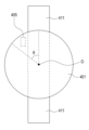
도 16 및 도 17을 참조하면, 본 발명의 다양한 실시 예에 따른 전자 장치에 구비되는 안테나(300)는 자성체(302), 제1 도선(303) 및 제2 도선(304)를 포함할 수 있다.Referring to FIGS. 16 and 17, an antenna (300) provided in an electronic device according to various embodiments of the present invention may include a magnetic body (302), a first conductor (303), and a second conductor (304).
상기 자성체(302)는 평행한 플레이트 형태로 이루어질 수 있다. 본 발명의 다양한 실시 예에 따르면, 상기 자성체(302)은 원판 형태로 이루어질 수 있다.The above magnetic body (302) may be formed in a parallel plate shape. According to various embodiments of the present invention, the magnetic body (302) may be formed in a disc shape.
상기 제1 도선(303)은 상기 자성체(302)에 제1 방향을 따라 복수회 감길 수 있다. The above first conductor (303) can be wound multiple times along the first direction around the magnetic body (302).
상기 제2 도선(304)은 상기 제1 도선(303)의 상부에 적층될 수 있다. 상기 제2 도선(304)은 상기 제1 방향과 다른 제2 방향을 따라 상기 제1 도선(303)의 상부에 감길 수 있다. 상기 제2 방향은 상기 제1 방향과 사선 방향일 수 있다. The second conductor (304) may be laminated on top of the first conductor (303). The second conductor (304) may be wound on top of the first conductor (303) along a second direction different from the first direction. The second direction may be diagonal to the first direction.
상기 제1 도선(303)과 상기 제2 도선(304)은 회로 기판(106, 도 2)을 통해 프로세서(720, 도 18)와 전기적으로 연결될 수 있다. 상기 프로세서(720, 도 18)는 상기 제1 도선(303)과 상기 제2 도선(304)에 공급되는 전기적인 신호를 제어할 수 있다. 상기 프로세서(720, 도 18)는 상기 제1 도선(303)과 상기 제2 도선(304)에 교대로 전기적인 신호를 공급하도록 제어할 수 있다.The first conductor (303) and the second conductor (304) can be electrically connected to a processor (720, FIG. 18) through a circuit board (106, FIG. 2). The processor (720, FIG. 18) can control electrical signals supplied to the first conductor (303) and the second conductor (304). The processor (720, FIG. 18) can control electrical signals to be supplied alternately to the first conductor (303) and the second conductor (304).
상기 제1 도선(303)과 상기 제2 도선(304)은 상기 프로세서(720, 도 18)의 제어에 따라, 교대로 무선 신호(M)를 방사할 수 있다.The above first conductor (303) and the above second conductor (304) can alternately radiate wireless signals (M) under the control of the processor (720, FIG. 18).
본 발명의 다양한 실시 예에 따르면, 상기 프로세서(720, 도 18)가 상기 제1 도선(303)과 상기 제2 도선(304)에 공급되는 전기적인 신호를 제어하는 것에 한정되지 않고, 상기 회로 기판(106, 도 2)에 장착된 별도의 스위칭 구조에 의해 제1 도선(303)과 상기 제2 도선(304)에 공급되는 전기적인 신호가 교대로 공급되도록 제어할 수 있다.According to various embodiments of the present invention, the processor (720, FIG. 18) is not limited to controlling the electrical signals supplied to the first conductor (303) and the second conductor (304), but may control the electrical signals supplied to the first conductor (303) and the second conductor (304) to be supplied alternately by a separate switching structure mounted on the circuit board (106, FIG. 2).
도 18은 본 발명의 다양한 실시 예에 따른 전자 장치의 네트워크 환경을 나타내는 도면이다.FIG. 18 is a diagram showing a network environment of an electronic device according to various embodiments of the present invention.
도 18을 참조하여, 다양한 실시 예에서의, 네트워크 환경(700) 내의 전자 장치(701)가 기재된다. 전자 장치(701)는 버스(710), 프로세서(720), 메모리(730), 입출력 인터페이스(750), 디스플레이(760), 및 통신 인터페이스(770)를 포함할 수 있다. 어떤 실시 예에서는, 전자 장치(701)는, 구성요소들 중 적어도 하나를 생략하거나 다른 구성요소를 추가적으로 구비할 수 있다. 버스(710)는 구성요소들(710-770)을 서로 연결하고, 구성요소들 간의 통신(예: 제어 메시지 또는 데이터)을 전달하는 회로를 포함할 수 있다. 프로세서(720)는, 중앙처리장치, 어플리케이션 프로세서, 또는 커뮤니케이션 프로세서(communication processor(CP)) 중 하나 또는 그 이상을 포함할 수 있다. 프로세서(720)는, 예를 들면, 전자 장치(701)의 적어도 하나의 다른 구성요소들의 제어 및/또는 통신에 관한 연산이나 데이터 처리를 실행할 수 있다. Referring to FIG. 18, in various embodiments, an electronic device (701) within a network environment (700) is described. The electronic device (701) may include a bus (710), a processor (720), a memory (730), an input/output interface (750), a display (760), and a communication interface (770). In some embodiments, the electronic device (701) may omit at least one of the components or additionally include other components. The bus (710) may include a circuit that connects the components (710-770) to each other and transmits communication (e.g., control messages or data) between the components. The processor (720) may include one or more of a central processing unit, an application processor, or a communication processor (CP). The processor (720) may execute, for example, calculations or data processing related to control and/or communication of at least one other component of the electronic device (701).
메모리(730)는, 휘발성 및/또는 비휘발성 메모리를 포함할 수 있다. 메모리(730)는, 예를 들면, 전자 장치(701)의 적어도 하나의 다른 구성요소에 관계된 명령 또는 데이터를 저장할 수 있다. 한 실시 예에 따르면, 메모리(730)는 소프트웨어 및/또는 프로그램(740)을 저장할 수 있다. 프로그램(740)은, 예를 들면, 커널(741), 미들웨어(743), 어플리케이션 프로그래밍 인터페이스(API)(745), 및/또는 어플리케이션 프로그램(또는 "어플리케이션")(747) 등을 포함할 수 있다. 커널(741), 미들웨어(743), 또는 API(745)의 적어도 일부는, 운영 시스템으로 지칭될 수 있다. 커널(741)은, 예를 들면, 다른 프로그램들(예: 미들웨어(743), API(745), 또는 어플리케이션 프로그램(747))에 구현된 동작 또는 기능을 실행하는 데 사용되는 시스템 리소스들(예: 버스(710), 프로세서(720), 또는 메모리(730) 등)을 제어 또는 관리할 수 있다. 또한, 커널(741)은 미들웨어(743), API(745), 또는 어플리케이션 프로그램(747)에서 전자 장치(701)의 개별 구성요소에 접근함으로써, 시스템 리소스들을 제어 또는 관리할 수 있는 인터페이스를 제공할 수 있다. The memory (730) may include volatile and/or non-volatile memory. The memory (730) may store, for example, instructions or data related to at least one other component of the electronic device (701). According to one embodiment, the memory (730) may store software and/or programs (740). The programs (740) may include, for example, a kernel (741), middleware (743), an application programming interface (API) (745), and/or an application program (or “application”) (747). At least a portion of the kernel (741), the middleware (743), or the API (745) may be referred to as an operating system. The kernel (741) may control or manage system resources (e.g., a bus (710), a processor (720), or a memory (730)) used to execute operations or functions implemented in other programs (e.g., a middleware (743), an API (745), or an application program (747)). In addition, the kernel (741) may provide an interface that allows the middleware (743), the API (745), or the application program (747) to control or manage system resources by accessing individual components of the electronic device (701).
미들웨어(743)는, 예를 들면, API(745) 또는 어플리케이션 프로그램(747)이 커널(741)과 통신하여 데이터를 주고받을 수 있도록 중개 역할을 수행할 수 있다. 또한, 미들웨어(743)는 어플리케이션 프로그램(747)으로부터 수신된 하나 이상의 작업 요청들을 우선 순위에 따라 처리할 수 있다. 예를 들면, 미들웨어(743)는 어플리케이션 프로그램(747) 중 적어도 하나에 전자 장치(701)의 시스템 리소스(예: 버스(710), 프로세서(720), 또는 메모리(730) 등)를 사용할 수 있는 우선 순위를 부여하고, 상기 하나 이상의 작업 요청들을 처리할 수 있다. API(745)는 어플리케이션(747)이 커널(741) 또는 미들웨어(743)에서 제공되는 기능을 제어하기 위한 인터페이스로, 예를 들면, 파일 제어, 창 제어, 영상 처리, 또는 문자 제어 등을 위한 적어도 하나의 인터페이스 또는 함수(예: 명령어)를 포함할 수 있다. 입출력 인터페이스(750)는, 예를 들면, 사용자 또는 다른 외부 기기로부터 입력된 명령 또는 데이터를 전자 장치(701)의 다른 구성요소(들)에 전달하거나, 또는 전자 장치(701)의 다른 구성요소(들)로부터 수신된 명령 또는 데이터를 사용자 또는 다른 외부 기기로 출력할 수 있다. The middleware (743) may, for example, act as an intermediary so that the API (745) or the application program (747) may communicate with the kernel (741) to exchange data. In addition, the middleware (743) may process one or more task requests received from the application program (747) according to priorities. For example, the middleware (743) may give priority to at least one of the application programs (747) to use the system resources (e.g., the bus (710), the processor (720), the memory (730), etc.) of the electronic device (701) and process the one or more task requests. The API (745) is an interface for the application (747) to control functions provided by the kernel (741) or the middleware (743), and may include at least one interface or function (e.g., a command) for, for example, file control, window control, image processing, or character control. The input/output interface (750) may, for example, transmit commands or data input from a user or another external device to other component(s) of the electronic device (701), or output commands or data received from other component(s) of the electronic device (701) to the user or another external device.
디스플레이(760)는, 예를 들면, 액정 디스플레이(LCD), 발광 다이오드(LED) 디스플레이, 유기 발광 다이오드(OLED) 디스플레이, 또는 마이크로 전자기계 시스템 (MEMS) 디스플레이, 또는 전자종이(electronic paper) 디스플레이를 포함할 수 있다. 디스플레이(760)는, 예를 들면, 사용자에게 각종 콘텐츠(예: 텍스트, 이미지, 비디오, 아이콘, 및/또는 심볼 등)을 표시할 수 있다. 디스플레이(760)는, 터치 스크린을 포함할 수 있으며, 예를 들면, 전자 펜 또는 사용자의 신체의 일부를 이용한 터치, 제스쳐, 근접, 또는 호버링 입력을 수신할 수 있다. 통신 인터페이스(770)는, 예를 들면, 전자 장치(701)와 외부 장치(예: 제 1 외부 전자 장치(702), 제 2 외부 전자 장치(704), 또는 서버(706)) 간의 통신을 설정할 수 있다. 예를 들면, 통신 인터페이스(770)는 무선 통신 또는 유선 통신을 통해서 네트워크(762)에 연결되어 외부 장치(예: 제 2 외부 전자 장치(704) 또는 서버(706))와 통신할 수 있다.The display (760) can include, for example, a liquid crystal display (LCD), a light emitting diode (LED) display, an organic light emitting diode (OLED) display, a micro electro mechanical systems (MEMS) display, or an electronic paper display. The display (760) can, for example, display various contents (e.g., text, images, videos, icons, and/or symbols) to the user. The display (760) can include a touch screen and can receive touch, gesture, proximity, or hovering inputs, for example, using an electronic pen or a part of the user's body. The communication interface (770) can establish communication between, for example, the electronic device (701) and an external device (e.g., the first external electronic device (702), the second external electronic device (704), or the server (706)). For example, the communication interface (770) may be connected to a network (762) via wireless or wired communication to communicate with an external device (e.g., a second external electronic device (704) or a server (706)).
무선 통신은, 예를 들면, LTE, LTE-A(LTE Advance), CDMA(code division multiple access), WCDMA(wideband CDMA), UMTS(universal mobile telecommunications system), WiBro(Wireless Broadband), 또는 GSM(Global System for Mobile Communications) 등 중 적어도 하나를 사용하는 셀룰러 통신을 포함할 수 있다. 한 실시 예에 따르면, 무선 통신은, 예를 들면, WiFi(wireless fidelity), 블루투스, 블루투스 저전력(BLE), 지그비(Zigbee), NFC(near field communication), 자력 시큐어 트랜스미션(Magnetic Secure Transmission), 라디오 프리퀀시(RF), 또는 보디 에어리어 네트워크(BAN) 중 적어도 하나를 포함할 수 있다. 한실시 예에 따르면, 무선 통신은 GNSS를 포함할 수 있다. GNSS는, 예를 들면, GPS(Global Positioning System), Glonass(Global Navigation Satellite System), Beidou Navigation Satellite System(이하 "Beidou") 또는 Galileo, the European global satellite-based navigation system일 수 있다. 이하, 본 문서에서는, "GPS"는 "GNSS"와 상호 호환적으로 사용될 수 있다. 유선 통신은, 예를 들면, USB(universal serial bus), HDMI(high definition multimedia interface), RS-232(recommended standard232), 전력선 통신, 또는 POTS(plain old telephone service) 등 중 적어도 하나를 포함할 수 있다. 네트워크(762)는 텔레커뮤니케이션 네트워크, 예를 들면, 컴퓨터 네트워크(예: LAN 또는 WAN), 인터넷, 또는 텔레폰 네트워크 중 적어도 하나를 포함할 수 있다.The wireless communication may include, for example, cellular communication using at least one of LTE, LTE-A (LTE Advance), CDMA (code division multiple access), WCDMA (wideband CDMA), UMTS (universal mobile telecommunications system), WiBro (Wireless Broadband), or GSM (Global System for Mobile Communications). According to one embodiment, the wireless communication may include, for example, at least one of WiFi (wireless fidelity), Bluetooth, Bluetooth low energy (BLE), Zigbee, near field communication (NFC), Magnetic Secure Transmission, Radio Frequency (RF), or Body Area Network (BAN). According to one embodiment, the wireless communication may include GNSS. GNSS can be, for example, GPS (Global Positioning System), Glonass (Global Navigation Satellite System), Beidou Navigation Satellite System (hereinafter "Beidou"), or Galileo, the European global satellite-based navigation system. Hereinafter, in this document, "GPS" can be used interchangeably with "GNSS". The wired communication can include, for example, at least one of USB (universal serial bus), HDMI (high definition multimedia interface), RS-232 (recommended standard232), power line communication, or POTS (plain old telephone service). The network (762) can include at least one of a telecommunications network, for example, a computer network (e.g., LAN or WAN), the Internet, or a telephone network.
제 1 및 제 2 외부 전자 장치(702, 704) 각각은 전자 장치(701)와 동일한 또는 다른 종류의 장치일 수 있다. 다양한 실시 예에 따르면, 전자 장치(701)에서 실행되는 동작들의 전부 또는 일부는 다른 하나 또는 복수의 전자 장치(예: 전자 장치(702,704), 또는 서버(706)에서 실행될 수 있다. 한 실시 예에 따르면, 전자 장치(701)가 어떤 기능이나 서비스를 자동으로 또는 요청에 의하여 수행해야 할 경우에, 전자 장치(701)는 기능 또는 서비스를 자체적으로 실행시키는 대신에 또는 추가적으로, 그와 연관된 적어도 일부 기능을 다른 장치(예: 전자 장치(702, 704), 또는 서버(706))에게 요청할 수 있다. 다른 전자 장치(예: 전자 장치(702, 704), 또는 서버(706))는 요청된 기능 또는 추가 기능을 실행하고, 그 결과를 전자 장치(701)로 전달할 수 있다. 전자 장치(701)는 수신된 결과를 그대로 또는 추가적으로 처리하여 요청된 기능이나 서비스를 제공할 수 있다. 이를 위하여, 예를 들면, 클라우드 컴퓨팅, 분산 컴퓨팅, 또는 클라이언트-서버 컴퓨팅 기술이 이용될 수 있다.Each of the first and second external electronic devices (702, 704) may be the same or a different type of device as the electronic device (701). According to various embodiments, all or part of the operations executed in the electronic device (701) may be executed in another or more electronic devices (e.g., electronic devices (702, 704), or server (706). According to one embodiment, when the electronic device (701) is to perform a certain function or service automatically or upon request, the electronic device (701) may request at least some functions related thereto from another device (e.g., electronic device (702, 704), or server (706)) instead of executing the function or service by itself or in addition. The other electronic device (e.g., electronic device (702, 704), or server (706)) may execute the requested function or additional function and transmit the result to the electronic device (701). The electronic device (701) may process the received result as is or additionally to provide the requested function or service. For this purpose, for example, cloud computing, distributed computing, or client-server computing technology may be used.
도 19은 다양한 실시 예에 따른 전자 장치(801)의 블록도이다. 전자 장치(801)는, 예를 들면, 도 18에 도시된 전자 장치(801)의 전체 또는 일부를 포함할 수 있다. 전자 장치(801)는 하나 이상의 프로세서(예: AP)(810), 통신 모듈(820), (가입자 식별 모듈(824), 메모리(830), 센서 모듈(840), 입력 장치(850), 디스플레이(860), 인터페이스(870), 오디오 모듈(880), 카메라 모듈(891), 전력 관리 모듈(895), 배터리(896), 인디케이터(897), 및 모터(898) 를 포함할 수 있다. 프로세서(810)는, 예를 들면, 운영 체제 또는 응용 프로그램을 구동하여 프로세서(810)에 연결된 다수의 하드웨어 또는 소프트웨어 구성요소들을 제어할 수 있고, 각종 데이터 처리 및 연산을 수행할 수 있다. 프로세서(810)는, 예를 들면, SoC(system on chip) 로 구현될 수 있다. 한 실시 예에 따르면, 프로세서(810)는 GPU(graphic processing unit) 및/또는 이미지 신호 프로세서를 더 포함할 수 있다. 프로세서(810)는 도 19에 도시된 구성요소들 중 적어도 일부(예: 셀룰러 모듈(821))를 포함할 수도 있다. 프로세서(810) 는 다른 구성요소들(예: 비휘발성 메모리) 중 적어도 하나로부터 수신된 명령 또는 데이터를 휘발성 메모리에 로드)하여 처리하고, 결과 데이터를 비휘발성 메모리에 저장할 수 있다.FIG. 19 is a block diagram of an electronic device (801) according to various embodiments. The electronic device (801) may include, for example, all or part of the electronic device (801) illustrated in FIG. 18. The electronic device (801) may include one or more processors (e.g., AP) (810), a communication module (820), a subscriber identification module (824), a memory (830), a sensor module (840), an input device (850), a display (860), an interface (870), an audio module (880), a camera module (891), a power management module (895), a battery (896), an indicator (897), and a motor (898). The processor (810) may control a number of hardware or software components connected to the processor (810) by, for example, driving an operating system or an application program, and may perform various data processing and calculations. The processor (810) may be implemented as, for example, a system on chip (SoC). According to one embodiment, the processor (810) may further include a GPU (graphic processing unit) and/or an image signal processor. The processor (810) may include at least some of the components (e.g., The processor (810) may include a cellular module (821). The processor (810) may load commands or data received from at least one of the other components (e.g., non-volatile memory) into the volatile memory and process them, and store the resulting data in the non-volatile memory.
통신 모듈(820)(예: 통신 인터페이스(870))와 동일 또는 유사한 구성을 가질 수 있다. 통신 모듈(820)은, 예를 들면, 셀룰러 모듈(821), WiFi 모듈(823), 블루투스 모듈(825), GNSS 모듈(827), NFC 모듈(828) 및 RF 모듈(829)를 포함할 수 있다. 셀룰러 모듈(821)은, 예를 들면, 통신망을 통해서 음성 통화, 영상 통화, 문자 서비스, 또는 인터넷 서비스 등을 제공할 수 있다. 한 실시 예에 따르면, 셀룰러 모듈(821)은 가입자 식별 모듈(예: SIM 카드)(824)을 이용하여 통신 네트워크 내에서 전자 장치(801)의 구별 및 인증을 수행할 수 있다. 한 실시 예에 따르면, 셀룰러 모듈(821)은 프로세서(810)가 제공할 수 있는 기능 중 적어도 일부 기능을 수행할 수 있다. 한 실시 예에 따르면, 셀룰러 모듈(821)은 커뮤니케이션 프로세서(CP)를 포함할 수 있다. 어떤 실시 예에 따르면, 셀룰러 모듈(821), WiFi 모듈(823), 블루투스 모듈(825), GNSS 모듈(827) 또는 NFC 모듈(828) 중 적어도 일부(예: 두 개 이상)는 하나의 integrated chip(IC) 또는 IC 패키지 내에 포함될 수 있다. RF 모듈(829)은, 예를 들면, 통신 신호(예: RF 신호)를 송수신할 수 있다. RF 모듈(829)은, 예를 들면, 트랜시버, PAM(power amp module), 주파수 필터, LNA(low noise amplifier), 또는 안테나 등을 포함할 수 있다. 다른 실시 예에 따르면, 셀룰러 모듈(821), WiFi 모듈(823), 블루투스 모듈(825), GNSS 모듈(827) 또는 NFC 모듈(828) 중 적어도 하나는 별개의 RF 모듈을 통하여 RF 신호를 송수신할 수 있다. 가입자 식별 모듈(824)은, 예를 들면, 가입자 식별 모듈을 포함하는 카드 또는 임베디드 SIM을 포함할 수 있으며, 고유한 식별 정보(예: ICCID(integrated circuit card identifier)) 또는 가입자 정보(예: IMSI(international mobile subscriber identity))를 포함할 수 있다. The communication module (820) may have the same or similar configuration as or similar to the communication interface (870). The communication module (820) may include, for example, a cellular module (821), a WiFi module (823), a Bluetooth module (825), a GNSS module (827), an NFC module (828), and an RF module (829). The cellular module (821) may provide, for example, a voice call, a video call, a text service, or an Internet service through a communication network. According to one embodiment, the cellular module (821) may perform differentiation and authentication of the electronic device (801) within a communication network by using a subscriber identification module (e.g., a SIM card) (824). According to one embodiment, the cellular module (821) may perform at least some of the functions that the processor (810) may provide. According to one embodiment, the cellular module (821) may include a communication processor (CP). In some embodiments, at least some (e.g., two or more) of the cellular module (821), the WiFi module (823), the Bluetooth module (825), the GNSS module (827), or the NFC module (828) may be included in a single integrated chip (IC) or IC package. The RF module (829) may, for example, transmit and receive communication signals (e.g., RF signals). The RF module (829) may include, for example, a transceiver, a power amp module (PAM), a frequency filter, a low noise amplifier (LNA), or an antenna. In other embodiments, at least one of the cellular module (821), the WiFi module (823), the Bluetooth module (825), the GNSS module (827), or the NFC module (828) may transmit and receive RF signals via a separate RF module. The subscriber identification module (824) may include, for example, a card or embedded SIM including a subscriber identification module and may include unique identification information (e.g., an integrated circuit card identifier (ICCID)) or subscriber information (e.g., an international mobile subscriber identity (IMSI)).
메모리(830)(예: 메모리(830))는, 예를 들면, 내장 메모리(832) 또는 외장 메모리(834)를 포함할 수 있다. 내장 메모리(832)는, 예를 들면, 휘발성 메모리(예: DRAM, SRAM, 또는 SDRAM 등), 비휘발성 메모리(예: OTPROM(one time programmable ROM), PROM, EPROM, EEPROM, mask ROM, flash ROM, 플래시 메모리, 하드 드라이브, 또는 솔리드 스테이트 드라이브 (SSD) 중 적어도 하나를 포함할 수 있다. 외장 메모리(834)는 플래시 드라이브(flash drive), 예를 들면, CF(compact flash), SD(secure digital), Micro-SD, Mini-SD, xD(extreme digital), MMC(multi-media card) 또는 메모리 스틱 등을 포함할 수 있다. 외장 메모리(834)는 다양한 인터페이스를 통하여 전자 장치(801)와 기능적으로 또는 물리적으로 연결될 수 있다.The memory (830) (e.g., the memory (830)) may include, for example, an internal memory (832) or an external memory (834). The internal memory (832) may include, for example, at least one of a volatile memory (e.g., a DRAM, an SRAM, an SDRAM, etc.), a nonvolatile memory (e.g., a one time programmable ROM (OTPROM), a PROM, an EPROM, an EEPROM, a mask ROM, a flash ROM, a flash memory, a hard drive, or a solid state drive (SSD). The external memory (834) may include a flash drive, for example, a compact flash (CF), a secure digital (SD), a Micro-SD, a Mini-SD, an extreme digital (xD), a multi-media card (MMC), or a memory stick. The external memory (834) may be functionally or physically connected to the electronic device (801) via various interfaces.
센서 모듈(840)은, 예를 들면, 물리량을 계측하거나 전자 장치(801)의 작동 상태를 감지하여, 계측 또는 감지된 정보를 전기 신호로 변환할 수 있다. 센서 모듈(840)은, 예를 들면, 제스처 센서(840A), 자이로 센서(840B), 기압 센서(840C), 마그네틱 센서(840D), 가속도 센서(840E), 그립 센서(840F), 근접 센서(840G), 컬러(color) 센서(840H)(예: RGB(red, green, blue) 센서), 생체 센서(840I), 온/습도 센서(840J), 조도 센서(840K), 또는 UV(ultra violet) 센서(840M) 중의 적어도 하나를 포함할 수 있다. 추가적으로 또는 대체적으로, 센서 모듈(840)은, 예를 들면, 후각(e-nose) 센서, 일렉트로마이오그라피(EMG) 센서, 일렉트로엔씨팔로그램(EEG) 센서, 일렉트로카디오그램(ECG) 센서, IR(infrared) 센서, 홍채 센서 및/또는 지문 센서를 포함할 수 있다. 센서 모듈(840)은 그 안에 속한 적어도 하나 이상의 센서들을 제어하기 위한 제어 회로를 더 포함할 수 있다. 어떤 실시 예에서는, 전자 장치(801)는 프로세서(810)의 일부로서 또는 별도로, 센서 모듈(840)을 제어하도록 구성된 프로세서를 더 포함하여, 프로세서(810)가 슬립(sleep) 상태에 있는 동안, 센서 모듈(840)을 제어할 수 있다.The sensor module (840) may, for example, measure a physical quantity or detect an operating state of an electronic device (801), and convert the measured or detected information into an electrical signal. The sensor module (840) may include, for example, at least one of a gesture sensor (840A), a gyro sensor (840B), a pressure sensor (840C), a magnetic sensor (840D), an acceleration sensor (840E), a grip sensor (840F), a proximity sensor (840G), a color sensor (840H) (e.g., an RGB (red, green, blue) sensor), a biometric sensor (840I), a temperature/humidity sensor (840J), an illuminance sensor (840K), or a UV (ultra violet) sensor (840M). Additionally or alternatively, the sensor module (840) may include, for example, an e-nose sensor, an electromyography (EMG) sensor, an electroencephalogram (EEG) sensor, an electrocardiogram (ECG) sensor, an infrared (IR) sensor, an iris sensor, and/or a fingerprint sensor. The sensor module (840) may further include a control circuit for controlling at least one or more sensors included therein. In some embodiments, the electronic device (801) further includes a processor configured to control the sensor module (840), either as part of or separately from the processor (810), such that the sensor module (840) can be controlled while the processor (810) is in a sleep state.
입력 장치(850)는, 예를 들면, 터치 패널(852), (디지털) 펜 센서(854), 키(856), 또는 초음파 입력 장치(858)를 포함할 수 있다. 터치 패널(852)은, 예를 들면, 정전식, 감압식, 적외선 방식, 또는 초음파 방식 중 적어도 하나의 방식을 사용할 수 있다. 또한, 터치 패널(852)은 제어 회로를 더 포함할 수도 있다. 터치 패널(852)은 택타일 레이어(tactile layer)를 더 포함하여, 사용자에게 촉각 반응을 제공할 수 있다. (디지털) 펜 센서(854)는, 예를 들면, 터치 패널의 일부이거나, 별도의 인식용 쉬트를 포함할 수 있다. 키(856)는, 예를 들면, 물리적인 버튼, 광학식 키, 또는 키패드를 포함할 수 있다. 초음파 입력 장치(858)는 마이크(예: 마이크(888))를 통해, 입력 도구에서 발생된 초음파를 감지하여, 상기 감지된 초음파에 대응하는 데이터를 확인할 수 있다.The input device (850) may include, for example, a touch panel (852), a (digital) pen sensor (854), a key (856), or an ultrasonic input device (858). The touch panel (852) may use, for example, at least one of a capacitive, a pressure-sensitive, an infrared, or an ultrasonic method. In addition, the touch panel (852) may further include a control circuit. The touch panel (852) may further include a tactile layer to provide a tactile response to the user. The (digital) pen sensor (854) may be, for example, a part of the touch panel or may include a separate recognition sheet. The key (856) may include, for example, a physical button, an optical key, or a keypad. The ultrasonic input device (858) may detect ultrasonic waves generated from an input tool through a microphone (e.g., a microphone (888)) and confirm data corresponding to the detected ultrasonic waves.
디스플레이(860)(예: 디스플레이(760))는 패널(862), 홀로그램 장치(864), 프로젝터(866), 및/또는 이들을 제어하기 위한 제어 회로를 포함할 수 있다. 패널(862)은, 예를 들면, 유연하게, 투명하게, 또는 착용할 수 있게 구현될 수 있다. 패널(862)은 터치 패널(852)과 하나 이상의 모듈로 구성될 수 있다. 한 실시 예에 따르면, 패널(862)은 사용자의 터치에 대한 압력의 세기를 측정할 수 있는 압력 센서(또는 포스 센서)를 포함할 수 있다. 상기 압력 센서는 터치 패널(852)과 일체형으로 구현되거나, 또는 터치 패널(852)과는 별도의 하나 이상의 센서로 구현될 수 있다. 홀로그램 장치(864)는 빛의 간섭을 이용하여 입체 영상을 허공에 보여줄 수 있다. 프로젝터(866)는 스크린에 빛을 투사하여 영상을 표시할 수 있다. 스크린은, 예를 들면, 전자 장치(801)의 내부 또는 외부에 위치할 수 있다. 인터페이스(870)는, 예를 들면, HDMI(872), USB(874), 광 인터페이스(optical interface)(876), 또는 D-sub(D-subminiature)(878)를 포함할 수 있다. 인터페이스(870)는, 예를 들면, 도 18에 도시된 통신 인터페이스(770)에 포함될 수 있다. 추가적으로 또는 대체적으로, 인터페이스(870)는, 예를 들면, MHL(mobile high-definition link) 인터페이스, SD카드/MMC(multi-media card) 인터페이스, 또는 IrDA(infrared data association) 규격 인터페이스를 포함할 수 있다. The display (860) (e.g., the display (760)) may include a panel (862), a holographic device (864), a projector (866), and/or a control circuit for controlling them. The panel (862) may be implemented to be, for example, flexible, transparent, or wearable. The panel (862) may be composed of a touch panel (852) and one or more modules. According to one embodiment, the panel (862) may include a pressure sensor (or force sensor) capable of measuring the intensity of pressure for a user's touch. The pressure sensor may be implemented as an integral part of the touch panel (852), or may be implemented as one or more sensors separate from the touch panel (852). The holographic device (864) may display a three-dimensional image in the air by utilizing interference of light. The projector (866) may display an image by projecting light onto a screen. The screen may be located, for example, inside or outside the electronic device (801). The interface (870) may include, for example, HDMI (872), USB (874), an optical interface (876), or D-sub (D-subminiature) (878). The interface (870) may be included, for example, in the communication interface (770) illustrated in FIG. 18. Additionally or alternatively, the interface (870) may include, for example, a mobile high-definition link (MHL) interface, an SD card/multi-media card (MMC) interface, or an infrared data association (IrDA) standard interface.
오디오 모듈(880)은, 예를 들면, 소리와 전기 신호를 쌍방향으로 변환시킬 수 있다. 오디오 모듈(880)의 적어도 일부 구성요소는, 예를 들면, 도 18 에 도시된 입출력 인터페이스(845)에 포함될 수 있다. 오디오 모듈(880)은, 예를 들면, 스피커(882), 리시버(884), 이어폰(886), 또는 마이크(888) 등을 통해 입력 또는 출력되는 소리 정보를 처리할 수 있다. 카메라 모듈(891)은, 예를 들면, 정지 영상 및 동영상을 촬영할 수 있는 장치로서, 한 실시 예에 따르면, 하나 이상의 이미지 센서(예: 전면 센서 또는 후면 센서), 렌즈, 이미지 시그널 프로세서(ISP), 또는 플래시(예: LED 또는 xenon lamp 등)를 포함할 수 있다. 전력 관리 모듈(895)은, 예를 들면, 전자 장치(801)의 전력을 관리할 수 있다. 한 실시 예에 따르면, 전력 관리 모듈(895)은 PMIC(power management integrated circuit), 충전 IC, 또는 배터리 또는 연료 게이지를 포함할 수 있다. PMIC는, 유선 및/또는 무선 충전 방식을 가질 수 있다. 무선 충전 방식은, 예를 들면, 자기공명 방식, 자기유도 방식 또는 전자기파 방식 등을 포함하며, 무선 충전을 위한 부가적인 회로, 예를 들면, 코일 루프, 공진 회로, 또는 정류기 등을 더 포함할 수 있다. 배터리 게이지는, 예를 들면, 배터리(896)의 잔량, 충전 중 전압, 전류, 또는 온도를 측정할 수 있다. 배터리(896)는, 예를 들면, 충전식 전지 및/또는 태양 전지를 포함할 수 있다. The audio module (880) can convert, for example, sound and electrical signals bidirectionally. At least some components of the audio module (880) can be included, for example, in the input/output interface (845) illustrated in FIG. 18. The audio module (880) can process sound information input or output through, for example, a speaker (882), a receiver (884), an earphone (886), or a microphone (888). The camera module (891) is, for example, a device capable of capturing still images and moving images, and according to one embodiment, can include one or more image sensors (e.g., a front sensor or a rear sensor), a lens, an image signal processor (ISP), or a flash (e.g., an LED or a xenon lamp, etc.). The power management module (895) can manage power of the electronic device (801), for example. According to one embodiment, the power management module (895) can include a power management integrated circuit (PMIC), a charging IC, or a battery or fuel gauge. The PMIC may have a wired and/or wireless charging method. The wireless charging method includes, for example, a magnetic resonance method, a magnetic induction method, or an electromagnetic wave method, and may further include additional circuits for wireless charging, for example, a coil loop, a resonant circuit, or a rectifier. The battery gauge may measure, for example, the remaining capacity of the battery (896), voltage, current, or temperature during charging. The battery (896) may include, for example, a rechargeable battery and/or a solar cell.
인디케이터(297)는 전자 장치(801) 또는 그 일부(예: 프로세서(810))의 특정 상태, 예를 들면, 부팅 상태, 메시지 상태 또는 충전 상태 등을 표시할 수 있다. 모터(898)는 전기적 신호를 기계적 진동으로 변환할 수 있고, 진동, 또는 햅틱 효과 등을 발생시킬 수 있다. 전자 장치(801)는, 예를 들면, DMB(digital multimedia broadcasting), DVB(digital video broadcasting), 또는 미디어플로(mediaFloTM) 등의 규격에 따른 미디어 데이터를 처리할 수 있는 모바일 TV 지원 장치(예: GPU)를 포함할 수 있다. 본 문서에서 기술된 구성요소들 각각은 하나 또는 그 이상의 부품(component)으로 구성될 수 있으며, 해당 구성요소의 명칭은 전자 장치의 종류에 따라서 달라질 수 있다. 다양한 실시 예에서, 전자 장치(예: 전자 장치(801))는 일부 구성요소가 생략되거나, 추가적인 구성요소를 더 포함하거나, 또는, 구성요소들 중 일부가 결합되어 하나의 개체로 구성되되, 결합 이전의 해당 구성요소들의 기능을 동일하게 수행할 수 있다.The indicator (297) can indicate a specific state of the electronic device (801) or a part thereof (e.g., the processor (810)), for example, a booting state, a message state, or a charging state. The motor (898) can convert an electrical signal into a mechanical vibration and generate a vibration, a haptic effect, or the like. The electronic device (801) can include a mobile TV support device (e.g., a GPU) capable of processing media data according to a standard such as DMB (digital multimedia broadcasting), DVB (digital video broadcasting), or mediaFloTM. Each of the components described in this document can be composed of one or more components, and the names of the corresponding components can vary depending on the type of the electronic device. In various embodiments, the electronic device (e.g., the electronic device (801)) may omit some components, include additional components, or combine some of the components to form a single entity, but may perform the functions of the corresponding components before combination in the same manner.
도 20는 본 발명의 다양한 실시 예에 따른 프로그램 모듈의 블록도이다. 한 실시 예에 따르면, 프로그램 모듈(910)(예: 프로그램(740))은 전자 장치(예: 전자 장치(701))에 관련된 자원을 제어하는 운영 체제 및/또는 운영 체제 상에서 구동되는 다양한 어플리케이션(예: 어플리케이션 프로그램(747))을 포함할 수 있다. 운영 체제는, 예를 들면, AndroidTM, iOSTM, WindowsTM, SymbianTM, TizenTM, 또는 BadaTM를 포함할 수 있다. 도 18을 참조하면, 프로그램 모듈(910)은 커널(920)(예: 커널(741)), 미들웨어(930)(예: 미들웨어(743)), API(960)(예: API(745)), 및/또는 어플리케이션(970)(예: 어플리케이션 프로그램(747))을 포함할 수 있다. 프로그램 모듈(910)의 적어도 일부는 전자 장치 상에 프리로드 되거나, 외부 전자 장치(예: 전자 장치(702, 704), 서버(706) 등)로부터 다운로드 가능하다.FIG. 20 is a block diagram of a program module according to various embodiments of the present invention. According to one embodiment, a program module (910) (e.g., a program (740)) may include an operating system that controls resources related to an electronic device (e.g., an electronic device (701)) and/or various applications (e.g., an application program (747)) running on the operating system. The operating system may include, for example, AndroidTM, iOSTM, WindowsTM, SymbianTM, TizenTM, or BadaTM. Referring to FIG. 18, the program module (910) may include a kernel (920) (e.g., a kernel (741)), a middleware (930) (e.g., a middleware (743)), an API (960) (e.g., an API (745)), and/or an application (970) (e.g., an application program (747)). At least a portion of the program module (910) may be preloaded on the electronic device or may be downloadable from an external electronic device (e.g., electronic device (702, 704), server (706), etc.).
커널(920)은, 예를 들면, 시스템 리소스 매니저(921) 및/또는 디바이스 드라이버(923)를 포함할 수 있다. 시스템 리소스 매니저(921)는 시스템 리소스의 제어, 할당, 또는 회수를 수행할 수 있다. 한 실시 예에 따르면, 시스템 리소스 매니저(921)는 프로세스 관리부, 메모리 관리부, 또는 파일 시스템 관리부를 포함할 수 있다. 디바이스 드라이버(923)는, 예를 들면, 디스플레이 드라이버, 카메라 드라이버, 블루투스 드라이버, 공유 메모리 드라이버, USB 드라이버, 키패드 드라이버, WiFi 드라이버, 오디오 드라이버, 또는 IPC(inter-process communication) 드라이버를 포함할 수 있다. 미들웨어(930)는, 예를 들면, 어플리케이션(970)이 공통적으로 필요로 하는 기능을 제공하거나, 어플리케이션(970)이 전자 장치 내부의 제한된 시스템 자원을 사용할 수 있도록 API(960)를 통해 다양한 기능들을 어플리케이션(970)으로 제공할 수 있다. 한 실시 예에 따르면, 미들웨어(930) 는 런타임 라이브러리(935), 어플리케이션 매니저(941), 윈도우 매니저(942), 멀티미디어 매니저(943), 리소스 매니저(944), 파워 매니저(945), 데이터베이스 매니저(946), 패키지 매니저(947), 커넥티비티 매니저(948), 노티피케이션 매니저(949), 로케이션 매니저(950), 그래픽 매니저(951), 또는 시큐리티 매니저(952) 중 적어도 하나를 포함할 수 있다.The kernel (920) may include, for example, a system resource manager (921) and/or a device driver (923). The system resource manager (921) may perform control, allocation, or recovery of system resources. According to one embodiment, the system resource manager (921) may include a process management unit, a memory management unit, or a file system management unit. The device driver (923) may include, for example, a display driver, a camera driver, a Bluetooth driver, a shared memory driver, a USB driver, a keypad driver, a WiFi driver, an audio driver, or an IPC (inter-process communication) driver. The middleware (930) may provide, for example, functions commonly required by applications (970) or provide various functions to applications (970) through APIs (960) so that applications (970) may use limited system resources within the electronic device. According to one embodiment, the middleware (930) may include at least one of a runtime library (935), an application manager (941), a window manager (942), a multimedia manager (943), a resource manager (944), a power manager (945), a database manager (946), a package manager (947), a connectivity manager (948), a notification manager (949), a location manager (950), a graphics manager (951), or a security manager (952).
런타임 라이브러리(935)는, 예를 들면, 어플리케이션(970)이 실행되는 동안에 프로그래밍 언어를 통해 새로운 기능을 추가하기 위해 컴파일러가 사용하는 라이브러리 모듈을 포함할 수 있다. 런타임 라이브러리(935)는 입출력 관리, 메모리 관리, 또는 산술 함수 처리를 수행할 수 있다. 어플리케이션 매니저(941)는, 예를 들면, 어플리케이션(970)의 생명 주기를 관리할 수 있다. 윈도우 매니저(942)는 화면에서 사용되는 GUI 자원을 관리할 수 있다. 멀티미디어 매니저(943)는 미디어 파일들의 재생에 필요한 포맷을 파악하고, 해당 포맷에 맞는 코덱을 이용하여 미디어 파일의 인코딩 또는 디코딩을 수행할 수 있다. 리소스 매니저(944)는 어플리케이션(970)의 소스 코드 또는 메모리의 공간을 관리할 수 있다. 파워 매니저(945)는, 예를 들면, 배터리의 용량 또는 전원을 관리하고, 전자 장치의 동작에 필요한 전력 정보를 제공할 수 있다. 한 실시 예에 따르면, 파워 매니저(945)는 바이오스(BIOS: basic input/output system)와 연동할 수 있다. 데이터베이스 매니저(946)는, 예를 들면, 어플리케이션(970)에서 사용될 데이터베이스를 생성, 검색, 또는 변경할 수 있다. 패키지 매니저(947)는 패키지 파일의 형태로 배포되는 어플리케이션의 설치 또는 갱신을 관리할 수 있다. The runtime library (935) may include, for example, library modules used by a compiler to add new functions through a programming language while the application (970) is running. The runtime library (935) may perform input/output management, memory management, or arithmetic function processing. The application manager (941) may manage, for example, the life cycle of the application (970). The window manager (942) may manage GUI resources used on the screen. The multimedia manager (943) may identify a format required for playing media files and perform encoding or decoding of the media files using a codec suitable for the format. The resource manager (944) may manage the source code of the application (970) or the space of the memory. The power manager (945) may manage, for example, the capacity or power of a battery and provide power information required for the operation of the electronic device. According to one embodiment, the power manager (945) may be linked with a basic input/output system (BIOS). A database manager (946) can, for example, create, retrieve, or modify a database to be used by an application (970). A package manager (947) can manage the installation or update of an application distributed in the form of a package file.
커넥티비티 매니저(948)는, 예를 들면, 무선 연결을 관리할 수 있다. 노티피케이션 매니저(949)는, 예를 들면, 도착 메시지, 약속, 근접성 알림 등의 이벤트를 사용자에게 제공할 수 있다. 로케이션 매니저(950)는, 예를 들면, 전자 장치의 위치 정보를 관리할 수 있다. 그래픽 매니저(951)는, 예를 들면, 사용자에게 제공될 그래픽 효과 또는 이와 관련된 사용자 인터페이스를 관리할 수 있다. 보안 매니저(952)는, 예를 들면, 시스템 보안 또는 사용자 인증을 제공할 수 있다. 한 실시 예에 따르면, 미들웨어(930)는 전자 장치의 음성 또는 영상 통화 기능을 관리하기 위한 통화(telephony) 매니저 또는 전술된 구성요소들의 기능들의 조합을 형성할 수 있는 하는 미들웨어 모듈을 포함할 수 있다. 한 실시 예에 따르면, 미들웨어(930)는 운영 체제의 종류 별로 특화된 모듈을 제공할 수 있다. 미들웨어(930)는 동적으로 기존의 구성요소를 일부 삭제하거나 새로운 구성요소들을 추가할 수 있다. API(960)는, 예를 들면, API 프로그래밍 함수들의 집합으로, 운영 체제에 따라 다른 구성으로 제공될 수 있다. 예를 들면, 안드로이드 또는 iOS의 경우, 플랫폼 별로 하나의 API 셋을 제공할 수 있으며, 타이젠의 경우, 플랫폼 별로 두 개 이상의 API 셋을 제공할 수 있다.The connectivity manager (948) may, for example, manage wireless connections. The notification manager (949) may, for example, provide events such as arrival messages, appointments, and proximity notifications to the user. The location manager (950) may, for example, manage location information of the electronic device. The graphics manager (951) may, for example, manage graphic effects to be provided to the user or a user interface related thereto. The security manager (952) may, for example, provide system security or user authentication. According to one embodiment, the middleware (930) may include a telephony manager for managing voice or video call functions of the electronic device or a middleware module that may form a combination of the functions of the aforementioned components. According to one embodiment, the middleware (930) may provide specialized modules for each type of operating system. The middleware (930) may dynamically delete some of the existing components or add new components. API (960) is, for example, a set of API programming functions, and may be provided in different configurations depending on the operating system. For example, in the case of Android or iOS, one set of APIs may be provided for each platform, and in the case of Tizen, two or more sets of APIs may be provided for each platform.
어플리케이션(970)은, 예를 들면, 홈(971), 다이얼러(972), SMS/MMS(973), IM(instant message)(974), 브라우저(975), 카메라(976), 알람(977), 컨택트(978), 음성 다이얼(979), 이메일(980), 달력(981), 미디어 플레이어(982), 앨범(983), 와치(984), 헬스 케어(예: 운동량 또는 혈당 등을 측정), 또는 환경 정보(예: 기압, 습도, 또는 온도 정보) 제공 어플리케이션을 포함할 수 있다. 한 실시 예에 따르면, 어플리케이션(970)은 전자 장치와 외부 전자 장치 사이의 정보 교환을 지원할 수 있는 정보 교환 어플리케이션을 포함할 수 있다. 정보 교환 어플리케이션은, 예를 들면, 외부 전자 장치에 특정 정보를 전달하기 위한 노티피케이션 릴레이 어플리케이션, 또는 외부 전자 장치를 관리하기 위한 장치 관리 어플리케이션을 포함할 수 있다. 예를 들면, 알림 전달 어플리케이션은 전자 장치의 다른 어플리케이션에서 발생된 알림 정보를 외부 전자 장치로 전달하거나, 또는 외부 전자 장치로부터 알림 정보를 수신하여 사용자에게 제공할 수 있다. 장치 관리 어플리케이션은, 예를 들면, 전자 장치와 통신하는 외부 전자 장치의 기능(예: 외부 전자 장치 자체(또는, 일부 구성 부품)의 턴-온/턴-오프 또는 디스플레이의 밝기(또는, 해상도) 조절), 또는 외부 전자 장치에서 동작하는 어플리케이션을 설치, 삭제, 또는 갱신할 수 있다. 한 실시 예에 따르면, 어플리케이션(970)은 외부 전자 장치의 속성에 따라 지정된 어플리케이션(예: 모바일 의료 기기의 건강 관리 어플리케이션)을 포함할 수 있다. 한 실시 예에 따르면, 어플리케이션(970)은 외부 전자 장치로부터 수신된 어플리케이션을 포함할 수 있다. 프로그램 모듈(910)의 적어도 일부는 소프트웨어, 펌웨어, 하드웨어(예: 프로세서(810)), 또는 이들 중 적어도 둘 이상의 조합으로 구현(예: 실행)될 수 있으며, 하나 이상의 기능을 수행하기 위한 모듈, 프로그램, 루틴, 명령어 세트 또는 프로세스를 포함할 수 있다.The application (970) may include, for example, a home (971), a dialer (972), an SMS/MMS (973), an IM (instant message) (974), a browser (975), a camera (976), an alarm (977), a contact (978), a voice dial (979), an email (980), a calendar (981), a media player (982), an album (983), a watch (984), a healthcare (e.g., measuring the amount of exercise or blood sugar, etc.), or an environmental information (e.g., barometric pressure, humidity, or temperature information) providing application. According to one embodiment, the application (970) may include an information exchange application that can support information exchange between the electronic device and an external electronic device. The information exchange application may include, for example, a notification relay application for transmitting specific information to an external electronic device, or a device management application for managing the external electronic device. For example, a notification delivery application may deliver notification information generated from another application of the electronic device to an external electronic device, or receive notification information from an external electronic device and provide it to a user. A device management application may, for example, install, delete, or update a function of an external electronic device that communicates with the electronic device (e.g., turning on/off the external electronic device itself (or some components) or adjusting the brightness (or resolution) of the display), or an application operating on the external electronic device. According to one embodiment, the application (970) may include an application specified according to the property of the external electronic device (e.g., a health management application of a mobile medical device). According to one embodiment, the application (970) may include an application received from an external electronic device. At least a part of the program module (910) may be implemented (e.g., executed) by software, firmware, hardware (e.g., processor (810)), or a combination of at least two or more of these, and may include modules, programs, routines, instruction sets, or processes for performing one or more functions.
본 문서에서 사용된 용어 "모듈"은 하드웨어, 소프트웨어 또는 펌웨어로 구성된 유닛을 포함하며, 예를 들면, 로직, 논리 블록, 부품, 또는 회로 등의 용어와 상호 호환적으로 사용될 수 있다. "모듈"은, 일체로 구성된 부품 또는 하나 또는 그 이상의 기능을 수행하는 최소 단위 또는 그 일부가 될 수 있다. "모듈"은 기계적으로 또는 전자적으로 구현될 수 있으며, 예를 들면, 어떤 동작들을 수행하는, 알려졌거나 앞으로 개발될, ASIC(application-specific integrated circuit) 칩, FPGAs(field-programmable gate arrays), 또는 프로그램 가능 논리 장치를 포함할 수 있다. 다양한 실시 예에 따른 장치(예: 모듈들 또는 그 기능들) 또는 방법(예: 동작들)의 적어도 일부는 프로그램 모듈의 형태로 컴퓨터로 판독 가능한 저장 매체(예:메모리(730))에 저장된 명령어로 구현될 수 있다. 상기 명령어가 프로세서(예: 프로세서(720))에 의해 실행될 경우, 프로세서가 상기 명령어에 해당하는 기능을 수행할 수 있다. 컴퓨터로 판독 가능한 기록 매체는, 하드디스크, 플로피디스크, 마그네틱 매체(예: 자기테이프), 광기록 매체(예: CD-ROM, DVD, 자기-광 매체 (예: 플롭티컬 디스크), 내장 메모리 등을 포함할 수 있다. 명령어는 컴파일러에 의해 만들어지는 코드 또는 인터프리터에 의해 실행될 수 있는 코드를 포함할 수 있다. 다양한 실시 예에 따른 모듈 또는 프로그램 모듈은 전술한 구성요소들 중 적어도 하나 이상을 포함하거나, 일부가 생략되거나, 또는 다른 구성요소를 더 포함할 수 있다. 다양한 실시 예에 따른, 모듈, 프로그램 모듈 또는 다른 구성요소에 의해 수행되는 동작들은 순차적, 병렬적, 반복적 또는 휴리스틱하게 실행되거나, 적어도 일부 동작이 다른 순서로 실행되거나, 생략되거나, 또는 다른 동작이 추가될 수 있다.The term "module" as used in this document includes a unit composed of hardware, software or firmware, and may be used interchangeably with terms such as logic, logic block, component, or circuit. A "module" may be an integrally composed component or a minimum unit or a part thereof that performs one or more functions. A "module" may be implemented mechanically or electronically, and may include, for example, an ASIC (application-specific integrated circuit) chip, FPGAs (field-programmable gate arrays), or a programmable logic device, known or to be developed in the future, that performs certain operations. At least a portion of a device (e.g., modules or functions thereof) or a method (e.g., operations) according to various embodiments may be implemented as an instruction stored in a computer-readable storage medium (e.g., memory (730)) in the form of a program module. When the instruction is executed by a processor (e.g., processor (720)), the processor may perform a function corresponding to the instruction. The computer-readable recording medium may include a hard disk, a floppy disk, a magnetic medium (e.g., a magnetic tape), an optical recording medium (e.g., a CD-ROM, a DVD, a magneto-optical medium (e.g., a floptical disk), a built-in memory, etc. The instructions may include codes generated by a compiler or codes executable by an interpreter. A module or program module according to various embodiments may include at least one or more of the above-described components, some of them may be omitted, or other components may be further included. Operations performed by a module, a program module, or other components according to various embodiments may be executed sequentially, in parallel, iteratively, or heuristically, or at least some of the operations may be executed in a different order, omitted, or other operations may be added.
도 21은 본 발명의 다양한 실시 예에 따른 전자 장치에 구비되는 제2 안테나를 나타내는 평면도이다. 도 22는 본 발명의 다양한 실시 예에 따른 전자 장치에 구비되는 제2 안테나를 나타내는 측면도이다. 도 23은 본 발명의 다양한 실시 예에 따른 전자 장치에 구비되는 제2 안테나를 나타내는 단면도이다. 도 24는 본 발명의 다양한 실시 예에 따른 전자 장치에 구비되는 제2 안테나가 전기적으로 연결되는 모습을 나타내는 평면도이다.FIG. 21 is a plan view showing a second antenna equipped in an electronic device according to various embodiments of the present invention. FIG. 22 is a side view showing a second antenna equipped in an electronic device according to various embodiments of the present invention. FIG. 23 is a cross-sectional view showing a second antenna equipped in an electronic device according to various embodiments of the present invention. FIG. 24 is a plan view showing a second antenna equipped in an electronic device according to various embodiments of the present invention being electrically connected.
도 21 내지 도 24를 참조하면, 제2 안테나(405)는 자성체(451) 및 도선(453)를 포함할 수 있다.Referring to FIGS. 21 to 24, the second antenna (405) may include a magnetic body (451) and a conductor (453).
상기 자성체(451)는 길이 방향을 가지면서 막대 형태로 이루어질 수 있다. 상기 자성체(451)는 페라이트(ferrite)를 포함할 수 있다.The above magnetic body (451) may be formed in a rod shape with a longitudinal direction. The above magnetic body (451) may include ferrite.
상기 도선(453)는 제1 방향으로 상기 자성체(451)에 복수회로 감길 수 있다. 상기 제1 방향은 상기 자성체(451)의 길이 방향과 교차하는 방향일 수 있다.The above conductor (453) can be wound multiple times around the magnetic body (451) in a first direction. The first direction can be a direction intersecting the longitudinal direction of the magnetic body (451).
상기 도선(453)는 구리(Cu) 재질로 이루어질 수 있다. 본 발명의 다양한 실시 예에 따르면, 상기 도선(453)는 구리 재질로 이루어지는 것에 한정되지 않고, 구리합금, 은(Ag) 등 다양한 도전성 재질로 이루어질 수 있다.The above conductor (453) may be made of copper (Cu). According to various embodiments of the present invention, the conductor (453) is not limited to being made of copper, and may be made of various conductive materials such as copper alloy and silver (Ag).
본 발명의 다양한 실시 예에 따르면, 상기 도선(453)은 수지(455)에 의해 감싸질 수 있다. 상기 수지(455)는 폴리우레탄, 폴리아미드 또는 폴리우레탄과 폴리아미드의 혼합물일 수 있다. 상기 수지(455)는 자외선(UV; Ultraviolet Ray) 본드 방식을 통해 상기 도선(453)의 외측면을 감쌀 수 있다.According to various embodiments of the present invention, the conductor (453) may be wrapped by a resin (455). The resin (455) may be polyurethane, polyamide, or a mixture of polyurethane and polyamide. The resin (455) may wrap the outer surface of the conductor (453) through an ultraviolet (UV) ray bonding method.
본 발명의 다양한 실시 예에 따르면, 상기 자성체(451)의 제1 가장자리에는 제1 단자(457a)가 배치되고, 상기 자성체(451)의 제2 가장자리에는 제2 단자(457b)가 배치될 수 있다. 상기 제1, 제2 단자(457a, 457b)는 은(Ag), 니켈(Ni) 또는 주석(Sn) 중 적어도 하나로 이루어질 수 있다. 본 발명의 다양한 실시 예에 따르면, 상기 제1, 제2 단자(457a, 457b)는 은(Ag), 니켈(Ni) 또는 주석(Sn)으로 이루어지는 것에 한정되지 않고, 구리(Cu) 등 다양한 도전성 재질로 이루어질 수 있다.According to various embodiments of the present invention, a first terminal (457a) may be arranged on a first edge of the magnetic body (451), and a second terminal (457b) may be arranged on a second edge of the magnetic body (451). The first and second terminals (457a, 457b) may be made of at least one of silver (Ag), nickel (Ni), or tin (Sn). According to various embodiments of the present invention, the first and second terminals (457a, 457b) are not limited to being made of silver (Ag), nickel (Ni), or tin (Sn), and may be made of various conductive materials such as copper (Cu).
본 발명의 다양한 실시 예에 따르면, 상기 도선(453)는 제1 단(453a) 및 제2 단(453b)를 포함할 수 있다. 상기 도선의 제1 단(453a)은 상기 제1 단자(457a)에 부착될 수 있고, 상기 도선의 제2 단(453b)은 상기 제2 단자(457b)에 부착될 수 있다.According to various embodiments of the present invention, the conductor (453) may include a first end (453a) and a second end (453b). The first end (453a) of the conductor may be attached to the first terminal (457a), and the second end (453b) of the conductor may be attached to the second terminal (457b).
도 25는 본 발명의 다양한 실시 예에 따른 전자 장치에 구비되는 제2 안테나 및 무선 신호를 나타내는 평면도이다.FIG. 25 is a plan view showing a second antenna and a wireless signal provided in an electronic device according to various embodiments of the present invention.
도 25를 참조하면, 제2 안테나(405)의 양 끝단에서는 무선 신호(M3)가 발생될 수 있다. 상기 무선 신호(M3)는 자성체(451, 도 21)에 감긴 도선(453, 도 21)의 제1 방향과 수직한 방향으로 발생될 수 있다. 예를 들면, 상기 무선 신호(M3)은 상기 제2 안테나(405)의 제1 단로부터 발생되며, 상기 제2 안테나(405)의 외부를 경유하여 상기 제2 안테나(405)의 제2 단과 연결될 수 있다.Referring to Fig. 25, a wireless signal (M3) may be generated at both ends of the second antenna (405). The wireless signal (M3) may be generated in a direction perpendicular to the first direction of the wire (453, Fig. 21) wound around the magnetic body (451, Fig. 21). For example, the wireless signal (M3) may be generated from the first end of the second antenna (405) and connected to the second end of the second antenna (405) via the exterior of the second antenna (405).
본 발명의 다양한 실시 예에 따르면, 상기 무선 신호(M3)는 상기 도선(453, 도 21)에 인가되는 교류 전류에 따라, 상기 제2 안테나(405)의 제2 단로부터 발생되어, 상기 제2 안테나(405)의 외부를 경유하여 상기 제2 안테나(405)의 제1 단과 연결될 수 있다.According to various embodiments of the present invention, the wireless signal (M3) may be generated from the second end of the second antenna (405) according to an alternating current applied to the wire (453, FIG. 21) and may be connected to the first end of the second antenna (405) via the exterior of the second antenna (405).
도 26는 본 발명의 다양한 실시 예에 따른 전자 장치에 구비되는 제2 안테나가 회로 기판에 배치된 모습을 나타내는 평면도이다.FIG. 26 is a plan view showing a second antenna provided in an electronic device according to various embodiments of the present invention arranged on a circuit board.
도 26을 참조하면, 본 발명의 다양한 실시 예에 따른 전자 장치에 구비되는 제2 안테나(405)는 회로 기판(403)에 배치될 수 있다. 상기 제2 안테나(405)는 도 2에 도시된 제2 안테나(165)일 수 있고, 상기 회로 기판(403)는 도 2에 도시된 회로 기판(106)일 수 있다.Referring to FIG. 26, a second antenna (405) provided in an electronic device according to various embodiments of the present invention may be placed on a circuit board (403). The second antenna (405) may be the second antenna (165) illustrated in FIG. 2, and the circuit board (403) may be the circuit board (106) illustrated in FIG. 2.
상기 회로 기판(403)에는 프로세서(431)과 통신 모듈(432, 433, 434)이 장착될 수 있다. 상기 프로세서(431)는 도 18에 도시된 프로세서(720)일 수 있다. 상기 통신 모듈(432, 433, 434)는 NFC 모듈(432), WIFI 모듈(433) 및 RF 모듈(434)들을 포함할 수 있다. 상기 NFC 모듈(432)은 상기 제2 안테나(405)와 전기적으로 연결될 수 있다. 상기 NFC 모듈(432)은 도 18에 도시된 NFC 모듈(828)일 수 있다. 상기 WIFI 모듈(433)은 도 18에 도시된 WIFI 모듈(823)일 수 있다. 상기 RF 모듈(434)은 도 18에 도시된 RF 모듈(829)들일 수 있다. 상기 RF 모듈(829)들은 상기 제2 안테나(405)와 인접한 영역(C)에 배치될 수 있다.The circuit board (403) may be equipped with a processor (431) and communication modules (432, 433, 434). The processor (431) may be the processor (720) illustrated in FIG. 18. The communication modules (432, 433, 434) may include an NFC module (432), a WIFI module (433), and an RF module (434). The NFC module (432) may be electrically connected to the second antenna (405). The NFC module (432) may be the NFC module (828) illustrated in FIG. 18. The WIFI module (433) may be the WIFI module (823) illustrated in FIG. 18. The RF module (434) may be the RF modules (829) illustrated in FIG. 18. The above RF modules (829) can be placed in an area (C) adjacent to the second antenna (405).
상기 제2 안테나(405)는 상기 회로 기판(403)의 가장자리에 실장될 수 있다. 상기 제2 안테나(405)는 상기 회로 기판(403)의 가장자리에 소형화되어 실장됨에 따라, 상기 전자 장치에 상기 제2 안테나(405)에 의한 실장 공간을 줄여, 상기 전자 장치를 소형화할 수 있다.The second antenna (405) may be mounted on the edge of the circuit board (403). Since the second antenna (405) is mounted in a miniaturized manner on the edge of the circuit board (403), the mounting space for the second antenna (405) in the electronic device may be reduced, thereby miniaturizing the electronic device.
도 27은 본 발명의 다양한 실시 예에 따른 전자 장치에 구비되는 제2 안테나가 배치되는 위치를 나타내는 평면도이다.FIG. 27 is a plan view showing the location where a second antenna is arranged in an electronic device according to various embodiments of the present invention.
도 27을 참조하면, 본 발명의 다양한 실시 예에 따른 전자 장치는 하우징(401), 착용부(411) 및 제2 안테나(405)를 포함할 수 있다. 상기 전자 장치는 웨어러블 시계일 수 있다.Referring to FIG. 27, an electronic device according to various embodiments of the present invention may include a housing (401), a wearing part (411), and a second antenna (405). The electronic device may be a wearable watch.
상기 하우징(401)의 전면은 원 형태로 이루어질 수 있다. 본 발명의 다양한 실시 예에 따르면, 상기 하우징(401)의 전면은 원 형태에 한정되지 않고, 사각형 등 다양한 형태로 이루어질 수 있다.The front of the housing (401) may be formed in a circular shape. According to various embodiments of the present invention, the front of the housing (401) is not limited to a circular shape and may be formed in various shapes such as a square shape.
상기 착용부(411)는 길이 방향을 가지면서 사용자의 손목에 장착될 수 있다.The above-mentioned wearing part (411) can be mounted on the user's wrist while having a longitudinal direction.
상기 제2 안테나(405)는, 상기 하우징(401)의 전면에서 볼 때, 상기 하우징(401)의 중심(O)으로부터 상기 착용부(411)에 대해 예각(θ)의 범위에 위치할 수 있다. 예를 들면, 상기 예각(θ)은 0~30도일 수 있다. 본 발명의 다양한 실시 예에 따르면, 상기 예각은, 상기 하우징(401)의 전면에서 볼 때, 상기 하우징(401)의 중심(O)으로부터 상기 착용부(411)에 대해 왼쪽으로 0 ~ 30도일 수 있다. The second antenna (405) may be positioned at an acute angle (θ) from the center (O) of the housing (401) to the wearing portion (411) when viewed from the front of the housing (401). For example, the acute angle (θ) may be 0 to 30 degrees. According to various embodiments of the present invention, the acute angle may be 0 to 30 degrees to the left of the center (O) of the housing (401) to the wearing portion (411) when viewed from the front of the housing (401).
본 발명의 다양한 실시 예에 따르면, 상기 하우징(401)의 전면은, 1시부터 12시가 방사 형태로 표시된 아날로그 시계로 구현될 수 있다. 상기 아날로그 시계는 시침과 분침이 회전할 수 있다. 상기 제2 안테나(405)는 상기 하우징(401)의 전면에서 볼 때, 11시 ~ 12시 방향 사이에 위치할 수 있다.According to various embodiments of the present invention, the front surface of the housing (401) may be implemented as an analog clock in which 1 o'clock to 12 o'clock are displayed in a radial shape. The analog clock may have rotating hour and minute hands. The second antenna (405) may be positioned between 11 o'clock and 12 o'clock when viewed from the front surface of the housing (401).
본 발명의 다양한 실시 예에 따르면, 상기 제2 안테나(405)의 자성체(453, 도 21)는 상기 착용부(411)의 길이 방향과 평행할 수 있다.According to various embodiments of the present invention, the magnetic body (453, FIG. 21) of the second antenna (405) may be parallel to the longitudinal direction of the wearing part (411).
도 28은 본 발명의 다양한 실시 예에 따른 전자 장치 및 무선 신호를 나타내는 평면도이다. 도 29는 본 발명의 다양한 실시 예에 따른 전자 장치 및 무선 신호를 나타내는 사시도이다.FIG. 28 is a plan view showing an electronic device and a wireless signal according to various embodiments of the present invention. FIG. 29 is a perspective view showing an electronic device and a wireless signal according to various embodiments of the present invention.
도 28 및 도 29를 참조하면, 본 발명의 다양한 실시 예에 따른 전자 장치는 하우징(401a), 착용부(411a) 및 제2 안테나(405)를 포함하고, 선행 실시예의 구성요소와 동일하거나 유사한 구성요소에 대한 설명은 생략하기로 한다.Referring to FIGS. 28 and 29, an electronic device according to various embodiments of the present invention includes a housing (401a), a wearing part (411a), and a second antenna (405), and a description of components that are identical or similar to those of the preceding embodiment will be omitted.
상기 제2 안테나(405)는 상기 하우징(401a)의 전면에서 볼 때, 상기 하우징(401a)의 중심에서 상기 착용부(405)에 대해 예각의 범위에 위치할 수 있다. 상기 제2 안테나(405)는 상기 착용부(411a)의 길이 방향에 대해 예각을 가진 방향으로 무선 신호를 발생시킬 수 있다.The second antenna (405) may be positioned at an acute angle relative to the wearing part (405) from the center of the housing (401a) when viewed from the front of the housing (401a). The second antenna (405) may generate a wireless signal in a direction having an acute angle relative to the longitudinal direction of the wearing part (411a).
사용자는 상기 전자 장치를 착용한 상태에서, 리더기(R)에 근접하는 경우, 착용부(411a)의 길이 방향과 상기 리더기(R)의 일면은 수직하지 않을 수 있다. 상기 제2 안테나(405)는 상기 착용부(411a)의 길이 방향에 대해 예각을 가진 방향으로 무선 신호를 발생시킴에 따라, 상기 무선 신호의 방향은 상기 리더기(R)의 일면과 수직하게 되어, 상기 무선 신호에 의한 리더기의 인식률을 개선할 수 있다.When a user wears the electronic device and approaches the reader (R), the longitudinal direction of the wearing part (411a) and one side of the reader (R) may not be perpendicular. Since the second antenna (405) generates a wireless signal in a direction having an acute angle with respect to the longitudinal direction of the wearing part (411a), the direction of the wireless signal becomes perpendicular to one side of the reader (R), thereby improving the recognition rate of the reader by the wireless signal.
상술한 바와 같이, 본 발명의 다양한 실시 예에 따른 전자 장치는, 배터리; 상기 배터리의 전방에 구비되는 적어도 하나의 제1 안테나; 및 상기 배터리의 후방에 구비되는 적어도 하나의 제 2 안테나를 포함하고, 상기 제1, 2 안테나는, 자성체; 및 상기 자성체에 복수회 감기는 도선을 포함할 수 있다.As described above, an electronic device according to various embodiments of the present invention includes a battery; at least one first antenna provided in front of the battery; and at least one second antenna provided in the rear of the battery, wherein the first and second antennas may include a magnetic body; and a conductor wound multiple times around the magnetic body.
본 발명의 다양한 실시 예에 따르면, 상기 제1 안테나는 MST 안테나를 포함하여 이루어지고, 상기 제 2 안테나는 NFC 안테나를 포함할 수 있다.According to various embodiments of the present invention, the first antenna may include an MST antenna, and the second antenna may include an NFC antenna.
본 발명의 다양한 실시 예에 따르면, 상기 제1, 2 안테나는, 상기 도선이 상기 자성체에 감겨 솔레노이드 형태를 이룰 수 있다.According to various embodiments of the present invention, the first and second antennas may have a solenoid shape in which the conductor is wound around the magnetic body.
본 발명의 다양한 실시 예에 따르면, 상기 제 1 안테나는 상기 전자 장치의 디스플레이와 상기 배터리의 사이에 구비되고, 상기 제 2 안테나는 상기 배터리의 후방에 구비된 회로 기판상에 구비될 수 있다.According to various embodiments of the present invention, the first antenna may be provided between the display of the electronic device and the battery, and the second antenna may be provided on a circuit board provided at the rear of the battery.
본 발명의 다양한 실시 예에 따르면, 상기 제2 안테나는 상기 배터리와 상기 회로 기판 사이에 구비될 수 있다.According to various embodiments of the present invention, the second antenna may be provided between the battery and the circuit board.
본 발명의 다양한 실시 예에 따른 전자 장치는, 상기 배터리에 대해 상기 제1 안테나와 반대편에 배치되는 회로 기판; 및 상기 회로 기판의 아래에 배치되는 무선충전 안테나를 더 포함하고, 상기 배터리는 상기 제1 안테나와 상기 무선 충전 안테나 사이의 자기력을 차단할 수 있다.An electronic device according to various embodiments of the present invention further includes a circuit board disposed opposite the first antenna with respect to the battery; and a wireless charging antenna disposed below the circuit board, wherein the battery can block a magnetic force between the first antenna and the wireless charging antenna.
본 발명의 다양한 실시 예에 따른 전자 장치는, 상기 제1 안테나와 상기 회로 기판을 연결하는 커넥터를 더 포함하고, 상기 제1 안테나는 상기 커넥터를 통해 전기적인 신호를 전달받을 수 있다.An electronic device according to various embodiments of the present invention further includes a connector connecting the first antenna and the circuit board, wherein the first antenna can receive an electrical signal through the connector.
본 발명의 다양한 실시 예에 따른 전자 장치는, 배터리; 및 상기 배터리의 전방에 구비되는 적어도 하나의 안테나를 포함하고; 상기 적어도 하나의 안테나는, 제1 축 방향으로 복수회 감기는 제 1 도선; 및 상기 제1 도선과 이격되어 배치됨과 아울러 공간을 형성하며, 상기 제1 축 방향으로 복수회 감기는 제2 도선을 포함할 수 있다.An electronic device according to various embodiments of the present invention comprises: a battery; and at least one antenna provided in front of the battery; and the at least one antenna may include: a first conductor wound multiple times in a first axial direction; and a second conductor wound multiple times in the first axial direction while being spaced apart from the first conductor and forming a space.
본 발명의 다양한 실시 예에 따른 전자 장치는, 상기 배터리의 후방에 구비되는 적어도 다른 하나의 안테나를 더 포함하고, 상기 적어도 하나의 안테나는 MST 안테나를 포함하여 이루어지고, 상기 적어도 다른 하나의 안테나는 NFC 안테나를 포함할 수 있다.An electronic device according to various embodiments of the present invention may further include at least one other antenna provided at a rear side of the battery, wherein the at least one antenna may include an MST antenna, and the at least one other antenna may include an NFC antenna.
본 발명의 다양한 실시 예에 따르면, 상기 제1 도선은 상기 제2 도선과 전기적으로 연결될 수 있다.According to various embodiments of the present invention, the first conductor can be electrically connected to the second conductor.
본 발명의 다양한 실시 예에 따르면, 상기 적어도 하나의 안테나는 상기 제1 도선과 상기 제2 도선 사이의 공간을 경유하여 상기 디스플레이를 관통하는 무선 신호를 발생시킬 수 있다.According to various embodiments of the present invention, the at least one antenna can generate a wireless signal that penetrates the display via a space between the first conductor and the second conductor.
본 발명의 다양한 실시 예에 따르면, 상기 공간에는 전자 부품이 배치되고, 상기 전자 부품은 조도 센서 또는 카메라일 수 있다.According to various embodiments of the present invention, electronic components are arranged in the space, and the electronic components may be light sensors or cameras.
본 발명의 다양한 실시 예에 따르면, 상기 배터리의 전방에 디스플레이 및 디스플레이 회로 기판을 더 포함하고, 상기 적어도 하나의 안테나는 상기 디스플레이와 상기 디스플레이 회로 기판의 사이에 배치될 수 있다.According to various embodiments of the present invention, the battery may further include a display and a display circuit board in front of the battery, and the at least one antenna may be disposed between the display and the display circuit board.
본 발명의 다양한 실시 예에 따르면, 상기 배터리의 전방에 디스플레이 및 디스플레이 회로 기판을 더 포함하고, 상기 적어도 하나의 안테나는 상기 디스플레이 회로 기판의 후면에 배치될 수 있다.According to various embodiments of the present invention, the battery may further include a display and a display circuit board in front of the battery, and the at least one antenna may be arranged on a rear side of the display circuit board.
본 발명의 다양한 실시 예에 따르면, 상기 적어도 하나의 안테나는 상기 배터리의 후방과 상기 배터리의 후방에 구비된 회로기판의 사이에 배치될 수 있다.According to various embodiments of the present invention, the at least one antenna may be disposed between the rear of the battery and a circuit board provided at the rear of the battery.
본 발명의 다양한 실시 예에 따른 전자 장치의 동작 방법은, 상기 전자 장치의 디스플레이와 디스플레이 회로 기판의 사이에 배치된 적어도 하나의 안테나는 상기 전자 장치의 하우징의 측면을 관통하는 제 1 무선 신호를 발생하는 동작; 상기 제 1 무선 신호는 상기 전자 장치의 측면/상측/하측에 방사하는 동작; 상기 제 1 안테나에 이격되게 제 1 도선 및 제 2 도선을 감겨서 배치시키고, 상기 제 1, 2 도선의 사이 공간에 제 2 무선 신호를 발생하는 동작; 및 상기 제 2 무선 신호는 상기 사이 공간을 통하여 상기 전자 장치의 방사되는 동작을 포함할 수 있다.According to various embodiments of the present invention, a method of operating an electronic device may include: an operation in which at least one antenna disposed between a display and a display circuit board of the electronic device generates a first wireless signal penetrating a side surface of a housing of the electronic device; an operation in which the first wireless signal is radiated to a side surface/upper side/lower side of the electronic device; an operation in which a first conductive wire and a second conductive wire are wound and disposed spaced apart from the first antenna and a second conductive wire are generated in a space between the first and second conductive wires; and an operation in which the second wireless signal is radiated from the electronic device through the space between the first and second conductive wires.
본 발명의 다양한 실시 예에 따른 전자 장치에 구비되는 안테나는, 자성체; 상기 자성체에 제1 방향을 따라 감기는 제1 도선; 및 상기 제 1 도선의 상부에 적층으로 상기 제1 방향과 다른 방향인 제2 방향을 따라 감기는 제2 도선을 포함할 수 있다.An antenna provided in an electronic device according to various embodiments of the present invention may include: a magnetic body; a first conductive wire wound around the magnetic body along a first direction; and a second conductive wire wound along a second direction, which is a direction different from the first direction, in a laminated manner on top of the first conductive wire.
본 발명의 다양한 실시 예에 따른 전자 장치는, 하우징; 상기 하우징의 내부에 배치되며, 상기 제2 안테나가 장착되는 회로 기판; 및 상기 하우징에 결합되며, 길이방향을 가지면서 사용자의 손목에 장착되는 착용부를 포함하고, 상기 제2 안테나는, 상기 하우징의 전면에서 볼 때, 상기 하우징의 중심으로부터 상기 착용부에 대하여 예각의 범위에 위치할 수 있다.An electronic device according to various embodiments of the present invention comprises: a housing; a circuit board disposed inside the housing and having the second antenna mounted thereon; and a wearable part coupled to the housing and having a longitudinal direction and mounted on a user's wrist, wherein the second antenna may be positioned within an acute angle range with respect to the wearable part from the center of the housing when viewed from the front of the housing.
본 발명의 다양한 실시 예에 따르면, 상기 제2 안테나는, 상기 회로 기판의 가장자리에 인접하게 배치될 수 있다.According to various embodiments of the present invention, the second antenna may be positioned adjacent to an edge of the circuit board.
본 발명의 다양한 실시 예에 따르면, 상기 제2 안테나의 자성체는 상기 착용부의 길이 방향과 평행할 수 있다.According to various embodiments of the present invention, the magnetic body of the second antenna may be parallel to the longitudinal direction of the wearing part.
본 발명의 다양한 실시 예에 따르면, 상기 제2 안테나의 자성체는, 페라이트(Ferrite)로 이루어질 수 있다.According to various embodiments of the present invention, the magnetic body of the second antenna may be made of ferrite.
본 발명의 다양한 실시 예에 따르면, 상기 예각은 0 ~ 30도일 수 있다.According to various embodiments of the present invention, the acute angle may be from 0 to 30 degrees.
본 발명의 다양한 실시 예에 따르면, 상기 예각은, 상기 하우징의 전면에서 볼 때, 상기 하우징의 중심으로부터 상기 착용부에 대하여 왼쪽으로 0 ~ 30도일 수 있다.According to various embodiments of the present invention, the acute angle may be 0 to 30 degrees to the left of the wearing portion from the center of the housing when viewed from the front of the housing.
본 발명의 다양한 실시 예에 따르면, 상기 하우징의 전면은, 아날로그 시계로 구현되고, 상기 제2 안테나는, 상기 하우징의 전면에서 볼 때, 11시 ~ 12시 방향 사이에 위치할 수 있다.According to various embodiments of the present invention, the front of the housing is implemented as an analog clock, and the second antenna can be positioned between 11 o'clock and 12 o'clock when viewed from the front of the housing.
이상, 본 발명의 상세한 설명에서는 구체적인 실시 예에 관해서 설명하였으나, 본 발명의 범위에서 벗어나지 않는 한도 내에서 여러 가지 변형이 가능함은 당해 분야에서 통상의 지식을 가진 자에게 있어서 자명하다 할 것이다.Although the detailed description of the present invention has described specific embodiments, it will be apparent to those skilled in the art that various modifications may be made without departing from the scope of the present invention.
100: 전자 장치 101: 하우징
111: 전면 커버 102: 디스플레이
103: 제1 안테나 105: 제2 안테나
106: 회로 기판 165: 제2 안테나
108: 후면 커버100: Electronics 101: Housings
111: Front cover 102: Display
103: 1st antenna 105: 2nd antenna
106: Circuit board 165: Second antenna
108: Back cover
Claims (24)
배터리;
상기 배터리와 이격된 디스플레이;
상기 배터리와 상기 디스플레이 사이에 배치된 적어도 하나의 제1 안테나;
상기 적어도 하나의 제1 안테나와 상기 배터리 사이에 배치되는 디스플레이 회로 기판;
상기 배터리에 대하여 상기 적어도 하나의 제1 안테나와 반대되는 위치에 배치되는 회로 기판;
상기 회로 기판의 아래에 배치되는 무선 충전 안테나; 및
상기 배터리에 대하여 상기 적어도 하나의 제1 안테나와 반대되는 위치에 배치되는 적어도 하나의 제 2 안테나를 포함하고,
상기 제1, 2 안테나는,
상기 디스플레이의 일면과 마주하는 판형의 자성체; 및
상기 디스플레이의 일면과 평행한 제1 축을 중심으로 상기 자성체에 복수회 감기는 도선을 포함하는 전자 장치.
In electronic devices,
battery;
A display separated from the above battery;
At least one first antenna disposed between the battery and the display;
A display circuit board disposed between the at least one first antenna and the battery;
A circuit board positioned opposite to said at least one first antenna with respect to said battery;
A wireless charging antenna positioned below the circuit board; and
At least one second antenna is disposed opposite to the at least one first antenna with respect to the battery,
The above first and second antennas,
A plate-shaped magnetic body facing one side of the above display; and
An electronic device including a conductor wound multiple times around a first axis parallel to one side of the display.
An electronic device according to claim 1, wherein the first antenna comprises an MST antenna, and the second antenna comprises an NFC antenna.
In the first paragraph, the first and second antennas are electronic devices in which the conductor is wound around the magnetic body to form a solenoid shape.
An electronic device according to claim 1, wherein the first antenna is provided between the display and the battery, and the second antenna is provided on the circuit board.
In the fourth paragraph, the second antenna is an electronic device provided between the battery and the circuit board.
상기 배터리는 상기 제1 안테나와 상기 무선 충전 안테나 사이의 자기력을 차단하는 전자 장치.
In the first paragraph,
The above battery is an electronic device that blocks the magnetic force between the first antenna and the wireless charging antenna.
상기 제1 안테나와 상기 회로 기판을 연결하는 커넥터를 더 포함하고,
상기 제1 안테나는 상기 커넥터를 통해 전기적인 신호를 전달받는 전자 장치.
In the first paragraph,
Further comprising a connector connecting the first antenna and the circuit board,
The above first antenna is an electronic device that receives an electrical signal through the connector.
배터리;
상기 배터리와 이격된 디스플레이; 및
상기 배터리와 상기 디스플레이 사이에 배치된 적어도 하나의 안테나를 포함하고;
상기 적어도 하나의 안테나는,
상기 디스플레이의 일면과 마주하는 판형의 자성체;
상기 디스플레이의 일면과 평행한 제1 축을 중심으로 상기 자성체에 복수회 감기는 제 1 도선; 및
상기 제1 도선과 이격되어 배치되고, 상기 제1 도선과의 사이에 공간을 형성하며, 상기 제1 축을 중심으로 상기 자성체에 복수회 감기는 제2 도선을 포함하는 전자 장치.
In electronic devices,
battery;
a display separated from the battery; and
comprising at least one antenna disposed between the battery and the display;
At least one antenna above,
A plate-shaped magnetic body facing one side of the above display;
A first conductor wound multiple times around the magnetic body around a first axis parallel to one side of the display; and
An electronic device including a second conductor that is arranged spaced apart from the first conductor, forms a space between the first conductor and the second conductor, and is wound multiple times around the magnetic body centered on the first axis.
상기 배터리의 후방에 구비되는 적어도 다른 하나의 안테나를 더 포함하고,
상기 적어도 하나의 안테나는 MST 안테나를 포함하여 이루어지고, 상기 적어도 다른 하나의 안테나는 NFC 안테나를 포함하는 전자 장치.
In Article 8,
further comprising at least one other antenna provided at the rear of the battery;
An electronic device wherein said at least one antenna comprises an MST antenna, and wherein said at least another antenna comprises an NFC antenna.
In the 8th paragraph, the first conductor is an electronic device electrically connected to the second conductor.
In the 8th paragraph, the electronic device wherein the at least one antenna generates a wireless signal that penetrates the display via the space between the first conductor and the second conductor.
An electronic device in accordance with claim 8, wherein an electronic component is arranged in the space, and the electronic component is a light sensor or a camera.
상기 배터리의 전방에 배치된 디스플레이 회로 기판을 더 포함하고,
상기 적어도 하나의 안테나는 상기 디스플레이와 상기 디스플레이 회로 기판의 사이에 배치되는 전자 장치.
In Article 8,
Further comprising a display circuit board positioned in front of the above battery,
An electronic device wherein said at least one antenna is disposed between said display and said display circuit board.
상기 배터리의 전방에 배치된 디스플레이 회로 기판을 더 포함하고,
상기 적어도 하나의 안테나는 상기 디스플레이 회로 기판의 후면에 배치되는 전자 장치.
In Article 8,
Further comprising a display circuit board positioned in front of the above battery,
An electronic device wherein at least one antenna is disposed on a rear surface of the display circuit board.
An electronic device in accordance with claim 8, wherein the at least one antenna is disposed between the rear of the battery and a circuit board provided at the rear of the battery.
하우징; 및
상기 하우징에 결합되며, 길이방향을 가지면서 사용자의 손목에 장착되는 착용부를 포함하고,
상기 제2 안테나는, 상기 하우징의 전면에서 볼 때, 상기 하우징의 중심으로부터 상기 착용부에 대하여 예각의 범위에 위치하는 전자 장치.
In the first paragraph,
Housing; and
It is coupled to the above housing and includes a wearable part that has a longitudinal direction and is mounted on the user's wrist,
The second antenna is an electronic device positioned at an acute angle from the center of the housing to the wearing part when viewed from the front of the housing.
In the 18th paragraph, the second antenna is an electronic device arranged adjacent to an edge of the circuit board.
In the 18th paragraph, the magnetic body of the second antenna is an electronic device parallel to the longitudinal direction of the wearing part.
In the 18th paragraph, the magnetic body of the second antenna is an electronic device made of ferrite.
An electronic device in accordance with claim 18, wherein the acute angle is 0 to 30 degrees.
In the 18th paragraph, the acute angle is an electronic device in which, when viewed from the front of the housing, the acute angle is 0 to 30 degrees to the left of the wearing portion from the center of the housing.
상기 제2 안테나는, 상기 하우징의 전면에서 볼 때, 11시 ~ 12시 방향 사이에 위치하는 전자 장치.In the 18th paragraph, the front of the housing is implemented as an analog clock,
The second antenna is an electronic device positioned between 11 o'clock and 12 o'clock when viewed from the front of the housing.
Priority Applications (4)
| Application Number | Priority Date | Filing Date | Title |
|---|---|---|---|
| EP17846997.9A EP3476003B1 (en) | 2016-08-31 | 2017-08-30 | Antenna and electronic device with the same |
| PCT/KR2017/009494 WO2018044072A1 (en) | 2016-08-31 | 2017-08-30 | Antenna and electronic device with the same |
| US15/692,828 US11005193B2 (en) | 2016-08-31 | 2017-08-31 | Antenna and electronic device with the same |
| US17/314,711 US11757207B2 (en) | 2016-08-31 | 2021-05-07 | Antenna and electronic device with the same |
Applications Claiming Priority (2)
| Application Number | Priority Date | Filing Date | Title |
|---|---|---|---|
| KR1020160111518 | 2016-08-31 | ||
| KR20160111518 | 2016-08-31 |
Publications (2)
| Publication Number | Publication Date |
|---|---|
| KR20180025126A KR20180025126A (en) | 2018-03-08 |
| KR102718339B1 true KR102718339B1 (en) | 2024-10-18 |
Family
ID=61726135
Family Applications (1)
| Application Number | Title | Priority Date | Filing Date |
|---|---|---|---|
| KR1020170026679A Active KR102718339B1 (en) | 2016-08-31 | 2017-02-28 | Antenna and electronic device with the same |
Country Status (2)
| Country | Link |
|---|---|
| EP (1) | EP3476003B1 (en) |
| KR (1) | KR102718339B1 (en) |
Families Citing this family (15)
| Publication number | Priority date | Publication date | Assignee | Title |
|---|---|---|---|---|
| US11678445B2 (en) | 2017-01-25 | 2023-06-13 | Apple Inc. | Spatial composites |
| KR20190130140A (en) | 2017-03-29 | 2019-11-21 | 애플 인크. | Devices with Integrated Interface System |
| WO2019067772A1 (en) | 2017-09-29 | 2019-04-04 | Mikael Silvanto | Multi-part device enclosure |
| KR102458690B1 (en) * | 2018-04-04 | 2022-10-25 | 삼성전자주식회사 | Electronic device having wireless charging module and flexible display |
| EP3685253A1 (en) | 2018-05-25 | 2020-07-29 | Apple Inc. | Portable computer with dynamic display interface |
| US11175769B2 (en) | 2018-08-16 | 2021-11-16 | Apple Inc. | Electronic device with glass enclosure |
| US11189909B2 (en) | 2018-08-30 | 2021-11-30 | Apple Inc. | Housing and antenna architecture for mobile device |
| US10705570B2 (en) | 2018-08-30 | 2020-07-07 | Apple Inc. | Electronic device housing with integrated antenna |
| US11258163B2 (en) | 2018-08-30 | 2022-02-22 | Apple Inc. | Housing and antenna architecture for mobile device |
| KR102232478B1 (en) * | 2019-03-29 | 2021-03-26 | (주)파트론 | Wearable device |
| CN114399014B (en) | 2019-04-17 | 2024-11-29 | 苹果公司 | Wireless locatable tag |
| KR102687456B1 (en) * | 2019-04-17 | 2024-07-25 | 애플 인크. | Wirelessly locatable tag |
| US12009576B2 (en) | 2019-12-03 | 2024-06-11 | Apple Inc. | Handheld electronic device |
| EP4150411A1 (en) | 2020-05-13 | 2023-03-22 | Apple Inc. | Wearable electronic device with glass shell |
| WO2024019450A1 (en) * | 2022-07-19 | 2024-01-25 | 삼성전자 주식회사 | Electronic device comprising motor housing |
Citations (5)
| Publication number | Priority date | Publication date | Assignee | Title |
|---|---|---|---|---|
| US20090305657A1 (en) * | 2008-06-05 | 2009-12-10 | Casio Computer Co., Ltd. | Antenna device and radio wave-using apparatus |
| US20140035793A1 (en) * | 2011-04-18 | 2014-02-06 | Murata Manufacturing Co., Ltd. | Antenna device and communication terminal apparatus |
| US20150244062A1 (en) * | 2014-02-21 | 2015-08-27 | Jieng Tai International Electric Corp. | Electronic device |
| WO2015147133A1 (en) * | 2014-03-28 | 2015-10-01 | 株式会社村田製作所 | Antenna device and electronic apparatus |
| US20160210616A1 (en) * | 2015-01-21 | 2016-07-21 | Samsung Electronics Co., Ltd. | Electronic device and transaction method using the same |
Family Cites Families (4)
| Publication number | Priority date | Publication date | Assignee | Title |
|---|---|---|---|---|
| JP5304156B2 (en) * | 2008-02-07 | 2013-10-02 | セイコーエプソン株式会社 | Electronic clock with built-in antenna |
| US9281118B2 (en) * | 2012-12-10 | 2016-03-08 | Intel Corporation | Cascaded coils for multi-surface coverage in near field communication |
| DE102015115574A1 (en) * | 2014-11-13 | 2016-05-19 | Samsung Electronics Co., Ltd. | Near field communication chip embedded in a portable electronic device and portable electronic device |
| US10333200B2 (en) * | 2015-02-17 | 2019-06-25 | Samsung Electronics Co., Ltd. | Portable device and near field communication chip |
-
2017
- 2017-02-28 KR KR1020170026679A patent/KR102718339B1/en active Active
- 2017-08-30 EP EP17846997.9A patent/EP3476003B1/en active Active
Patent Citations (5)
| Publication number | Priority date | Publication date | Assignee | Title |
|---|---|---|---|---|
| US20090305657A1 (en) * | 2008-06-05 | 2009-12-10 | Casio Computer Co., Ltd. | Antenna device and radio wave-using apparatus |
| US20140035793A1 (en) * | 2011-04-18 | 2014-02-06 | Murata Manufacturing Co., Ltd. | Antenna device and communication terminal apparatus |
| US20150244062A1 (en) * | 2014-02-21 | 2015-08-27 | Jieng Tai International Electric Corp. | Electronic device |
| WO2015147133A1 (en) * | 2014-03-28 | 2015-10-01 | 株式会社村田製作所 | Antenna device and electronic apparatus |
| US20160210616A1 (en) * | 2015-01-21 | 2016-07-21 | Samsung Electronics Co., Ltd. | Electronic device and transaction method using the same |
Also Published As
| Publication number | Publication date |
|---|---|
| EP3476003A1 (en) | 2019-05-01 |
| KR20180025126A (en) | 2018-03-08 |
| EP3476003B1 (en) | 2023-12-06 |
| EP3476003A4 (en) | 2019-08-07 |
Similar Documents
| Publication | Publication Date | Title |
|---|---|---|
| KR102718339B1 (en) | Antenna and electronic device with the same | |
| US11757207B2 (en) | Antenna and electronic device with the same | |
| CN109906533B (en) | wearable device | |
| EP3656018B1 (en) | Antenna for wearable device | |
| US10608323B2 (en) | Electronic device including multi-band antenna | |
| KR102405446B1 (en) | Antenna device and electronic device | |
| US10447080B2 (en) | Wearable electronic device including communication circuit | |
| US10608329B2 (en) | Electronic device including antenna device | |
| US10203587B2 (en) | Electronic device and method for manufacturing the same | |
| US11145951B2 (en) | Antenna device and electronic device having same | |
| US10462903B2 (en) | Electronic device and method for assembling the same | |
| US10133910B2 (en) | Electronic device with key module and method of manufacturing the same | |
| EP3522296B1 (en) | Electronic device comprising an antenna | |
| KR20170066944A (en) | Electronic device including antenna | |
| KR20170071348A (en) | Electronic device including shield structure | |
| KR20170121954A (en) | Electronic Device for Transmitting Electromagnetic Wave in Multi-Direction | |
| KR20160105269A (en) | Wearable Electronic Device Including Communication Circuit | |
| KR20170058206A (en) | Electronic apparatus and operating method thereof | |
| US20170285776A1 (en) | Touch pad for electronic device | |
| KR102514383B1 (en) | Device Including Printed Circuit Board |
Legal Events
| Date | Code | Title | Description |
|---|---|---|---|
| PA0109 | Patent application |
St.27 status event code: A-0-1-A10-A12-nap-PA0109 |
|
| PG1501 | Laying open of application |
St.27 status event code: A-1-1-Q10-Q12-nap-PG1501 |
|
| PA0201 | Request for examination |
St.27 status event code: A-1-2-D10-D11-exm-PA0201 |
|
| E902 | Notification of reason for refusal | ||
| PE0902 | Notice of grounds for rejection |
St.27 status event code: A-1-2-D10-D21-exm-PE0902 |
|
| E13-X000 | Pre-grant limitation requested |
St.27 status event code: A-2-3-E10-E13-lim-X000 |
|
| P11-X000 | Amendment of application requested |
St.27 status event code: A-2-2-P10-P11-nap-X000 |
|
| P13-X000 | Application amended |
St.27 status event code: A-2-2-P10-P13-nap-X000 |
|
| E90F | Notification of reason for final refusal | ||
| PE0902 | Notice of grounds for rejection |
St.27 status event code: A-1-2-D10-D21-exm-PE0902 |
|
| P11-X000 | Amendment of application requested |
St.27 status event code: A-2-2-P10-P11-nap-X000 |
|
| P13-X000 | Application amended |
St.27 status event code: A-2-2-P10-P13-nap-X000 |
|
| E701 | Decision to grant or registration of patent right | ||
| PE0701 | Decision of registration |
St.27 status event code: A-1-2-D10-D22-exm-PE0701 |
|
| PR0701 | Registration of establishment |
St.27 status event code: A-2-4-F10-F11-exm-PR0701 |
|
| PR1002 | Payment of registration fee |
St.27 status event code: A-2-2-U10-U11-oth-PR1002 Fee payment year number: 1 |
|
| PG1601 | Publication of registration |
St.27 status event code: A-4-4-Q10-Q13-nap-PG1601 |