KR102706133B1 - Augmented reality providing device - Google Patents
Augmented reality providing device Download PDFInfo
- Publication number
- KR102706133B1 KR102706133B1 KR1020190023931A KR20190023931A KR102706133B1 KR 102706133 B1 KR102706133 B1 KR 102706133B1 KR 1020190023931 A KR1020190023931 A KR 1020190023931A KR 20190023931 A KR20190023931 A KR 20190023931A KR 102706133 B1 KR102706133 B1 KR 102706133B1
- Authority
- KR
- South Korea
- Prior art keywords
- lens
- light
- display device
- lens unit
- augmented reality
- Prior art date
- Legal status (The legal status is an assumption and is not a legal conclusion. Google has not performed a legal analysis and makes no representation as to the accuracy of the status listed.)
- Active
Links
Images


Classifications
-
- G—PHYSICS
- G02—OPTICS
- G02B—OPTICAL ELEMENTS, SYSTEMS OR APPARATUS
- G02B30/00—Optical systems or apparatus for producing three-dimensional [3D] effects, e.g. stereoscopic images
-
- G—PHYSICS
- G02—OPTICS
- G02B—OPTICAL ELEMENTS, SYSTEMS OR APPARATUS
- G02B5/00—Optical elements other than lenses
- G02B5/08—Mirrors
-
- G—PHYSICS
- G02—OPTICS
- G02B—OPTICAL ELEMENTS, SYSTEMS OR APPARATUS
- G02B27/00—Optical systems or apparatus not provided for by any of the groups G02B1/00 - G02B26/00, G02B30/00
- G02B27/01—Head-up displays
- G02B27/017—Head mounted
- G02B27/0172—Head mounted characterised by optical features
-
- G—PHYSICS
- G02—OPTICS
- G02B—OPTICAL ELEMENTS, SYSTEMS OR APPARATUS
- G02B26/00—Optical devices or arrangements for the control of light using movable or deformable optical elements
- G02B26/08—Optical devices or arrangements for the control of light using movable or deformable optical elements for controlling the direction of light
-
- G—PHYSICS
- G02—OPTICS
- G02B—OPTICAL ELEMENTS, SYSTEMS OR APPARATUS
- G02B27/00—Optical systems or apparatus not provided for by any of the groups G02B1/00 - G02B26/00, G02B30/00
- G02B27/01—Head-up displays
- G02B27/017—Head mounted
-
- G—PHYSICS
- G02—OPTICS
- G02B—OPTICAL ELEMENTS, SYSTEMS OR APPARATUS
- G02B27/00—Optical systems or apparatus not provided for by any of the groups G02B1/00 - G02B26/00, G02B30/00
- G02B27/01—Head-up displays
- G02B27/0101—Head-up displays characterised by optical features
- G02B2027/0127—Head-up displays characterised by optical features comprising devices increasing the depth of field
-
- G—PHYSICS
- G02—OPTICS
- G02B—OPTICAL ELEMENTS, SYSTEMS OR APPARATUS
- G02B27/00—Optical systems or apparatus not provided for by any of the groups G02B1/00 - G02B26/00, G02B30/00
- G02B27/01—Head-up displays
- G02B27/0101—Head-up displays characterised by optical features
- G02B2027/013—Head-up displays characterised by optical features comprising a combiner of particular shape, e.g. curvature
-
- G—PHYSICS
- G02—OPTICS
- G02B—OPTICAL ELEMENTS, SYSTEMS OR APPARATUS
- G02B27/00—Optical systems or apparatus not provided for by any of the groups G02B1/00 - G02B26/00, G02B30/00
- G02B27/01—Head-up displays
- G02B27/0101—Head-up displays characterised by optical features
- G02B2027/014—Head-up displays characterised by optical features comprising information/image processing systems
-
- G—PHYSICS
- G02—OPTICS
- G02B—OPTICAL ELEMENTS, SYSTEMS OR APPARATUS
- G02B27/00—Optical systems or apparatus not provided for by any of the groups G02B1/00 - G02B26/00, G02B30/00
- G02B27/01—Head-up displays
- G02B27/017—Head mounted
- G02B2027/0178—Eyeglass type
-
- G—PHYSICS
- G02—OPTICS
- G02B—OPTICAL ELEMENTS, SYSTEMS OR APPARATUS
- G02B27/00—Optical systems or apparatus not provided for by any of the groups G02B1/00 - G02B26/00, G02B30/00
- G02B27/0075—Optical systems or apparatus not provided for by any of the groups G02B1/00 - G02B26/00, G02B30/00 with means for altering, e.g. increasing, the depth of field or depth of focus
-
- G—PHYSICS
- G02—OPTICS
- G02B—OPTICAL ELEMENTS, SYSTEMS OR APPARATUS
- G02B27/00—Optical systems or apparatus not provided for by any of the groups G02B1/00 - G02B26/00, G02B30/00
- G02B27/10—Beam splitting or combining systems
- G02B27/108—Beam splitting or combining systems for sampling a portion of a beam or combining a small beam in a larger one, e.g. wherein the area ratio or power ratio of the divided beams significantly differs from unity, without spectral selectivity
-
- G—PHYSICS
- G06—COMPUTING OR CALCULATING; COUNTING
- G06T—IMAGE DATA PROCESSING OR GENERATION, IN GENERAL
- G06T19/00—Manipulating 3D models or images for computer graphics
- G06T19/006—Mixed reality
Landscapes
- Physics & Mathematics (AREA)
- General Physics & Mathematics (AREA)
- Optics & Photonics (AREA)
- Spectroscopy & Molecular Physics (AREA)
- Engineering & Computer Science (AREA)
- Computer Graphics (AREA)
- Computer Hardware Design (AREA)
- General Engineering & Computer Science (AREA)
- Software Systems (AREA)
- Theoretical Computer Science (AREA)
Abstract
증강 현실 제공 장치가 제공된다. 증강 현실 제공 장치는 출사면과 복수의 측면들을 포함하는 렌즈, 상기 렌즈의 상기 복수의 측면들 중 제1 측면 상에 배치되며, 상기 렌즈의 상기 제1 측면에 광을 제공하는 표시 장치, 및 상기 렌즈 내에 배치되며, 상기 렌즈의 상기 복수의 측면들 중 제2 측면에서 반사된 상기 광을 상기 출사면으로 반사하는 제1 반사 부재를 구비한다.An augmented reality providing device is provided. The augmented reality providing device comprises a lens including an exit surface and a plurality of side surfaces, a display device disposed on a first side of the plurality of side surfaces of the lens and providing light to the first side surface of the lens, and a first reflective member disposed within the lens and reflecting the light reflected from a second side surface of the plurality of side surfaces of the lens to the exit surface.
Description
본 발명은 증강 현실 제공 장치에 관한 것이다. The present invention relates to an augmented reality providing device.
증강 현실은 사용자의 눈으로 보이는 현실의 이미지에 가상의 이미지를 겹쳐서 하나의 영상으로 보여주는 기술을 가리킨다. 가상의 이미지는 텍스트 또는 그래픽 형태의 이미지가 될 수 있으며, 실제 영상은 장치의 시야에 관찰된 실제 물체에 관한 정보가 될 수 있다.Augmented reality refers to a technology that superimposes a virtual image on the image of reality seen by the user's eyes and displays it as a single image. The virtual image can be an image in the form of text or graphics, and the real image can be information about an actual object observed in the device's field of view.
증강 현실은 헤드 마운트 디스플레이(Head Mounted Display, HMD), 헤드 업 디스플레이(Head-Up Display, HUD) 등을 이용하여 구현될 수 있다. 증강 현실이 헤드 마운트 디스플레이를 이용하여 구현되는 경우, 사용자가 용이하게 휴대할 수 있을 뿐만 아니라, 쉽게 입거나 벗을 수 있도록 안경 형태로 제공될 수 있다.Augmented reality can be implemented using a head mounted display (HMD), a head-up display (HUD), etc. If augmented reality is implemented using a head mounted display, it can be provided in the form of glasses so that the user can easily carry it and put it on or take it off.
하지만, 안경 형태의 디스플레이 장치를 이용하여 증강 현실을 구현하는 경우, 가상의 이미지를 표시하는 표시 장치와 표시 장치로부터의 이미지를 반사하여 사용자의 눈에 제공하기 위한 반사 부재 사이의 거리가 가깝다. 표시 장치가 표시하는 가상의 이미지의 심도(depth of field)는 표시 장치로부터 반사 부재 사이의 광학 거리에 비례할 수 있다.However, when implementing augmented reality using a display device in the form of glasses, the distance between the display device that displays the virtual image and the reflective member that reflects the image from the display device and provides it to the user's eyes is close. The depth of field of the virtual image displayed by the display device can be proportional to the optical distance between the display device and the reflective member.
본 발명이 해결하고자 하는 과제는 가상의 이미지를 표시하는 표시 장치와 표시 장치로부터의 이미지를 반사하여 사용자의 눈에 제공하기 위한 반사 부재 사이의 광학 거리를 늘릴 수 있는 증강 현실 제공 장치를 제공하기 위한 것이다.The problem to be solved by the present invention is to provide an augmented reality providing device capable of increasing the optical distance between a display device displaying a virtual image and a reflective member for reflecting the image from the display device and providing it to the user's eyes.
본 발명의 과제들은 이상에서 언급한 과제로 제한되지 않으며, 언급되지 않은 또 다른 기술적 과제들은 아래의 기재로부터 당업자에게 명확하게 이해될 수 있을 것이다.The tasks of the present invention are not limited to the tasks mentioned above, and other technical tasks not mentioned will be clearly understood by those skilled in the art from the description below.
상기 과제를 해결하기 위한 일 실시예에 따른 증강 현실 제공 장치는 출사면과 복수의 측면들을 포함하는 렌즈, 상기 렌즈의 상기 복수의 측면들 중 제1 측면 상에 배치되며, 상기 렌즈의 상기 제1 측면에 광을 제공하는 표시 장치, 및 상기 렌즈 내에 배치되며, 상기 렌즈의 상기 복수의 측면들 중 제2 측면에서 반사된 상기 광을 상기 출사면으로 반사하는 제1 반사 부재를 구비한다.According to one embodiment of the present invention for solving the above problem, an augmented reality providing device comprises a lens including an exit surface and a plurality of side surfaces, a display device disposed on a first side surface of the plurality of side surfaces of the lens and providing light to the first side surface of the lens, and a first reflective member disposed within the lens and reflecting the light reflected from a second side surface of the plurality of side surfaces of the lens to the exit surface.
상기 표시 장치의 상기 광은 상기 렌즈의 상기 복수의 측면들 중 제3 측면에서 반사되어 상기 복수의 측면들 중 제4 측면으로 진행하고, 상기 복수의 측면들 중 제4 측면에서 반사되어 상기 렌즈의 상기 제2 측면으로 진행하며, 상기 제3 측면은 상기 제1 측면의 일 측으로부터 연장되고, 상기 제4 측면은 상기 제2 측면과 상기 제3 측면 사이에 배치될 수 있다.The light of the display device may be reflected from a third side of the plurality of side surfaces of the lens and travel to a fourth side of the plurality of side surfaces, and may be reflected from the fourth side of the plurality of side surfaces and travel to the second side of the lens, wherein the third side may extend from one side of the first side, and the fourth side may be disposed between the second side and the third side.
상기 렌즈의 상기 제1 측면과 상기 표시 장치 사이에 배치되며, 상기 표시 장치의 광이 상기 렌즈의 상기 제3 측면으로 진행하도록 상기 광의 경로를 변환하는 광 경로 변환 부재를 더 구비할 수 있다. The method may further include providing a light path conversion member that is arranged between the first side of the lens and the display device and converts the path of the light so that the light of the display device proceeds to the third side of the lens.
상기 광 경로 변환 부재는, 베이스층, 상기 베이스층으로부터 제1 각도로 기울어진 제1 광 출사면, 및 상기 베이스층으로부터 제2 각도로 형성된 제2 광 출사면을 포함하고, 상기 제1 각도는 상기 제2 각도보다 작을 수 있다.The above optical path conversion member includes a base layer, a first light exit surface inclined at a first angle from the base layer, and a second light exit surface formed at a second angle from the base layer, wherein the first angle may be smaller than the second angle.
상기 렌즈의 상기 제1 측면과 상기 제1 광 경로 변환 부재 사이에 배치된 편광 필름을 더 구비할 수 있다.The above lens may further include a polarizing film disposed between the first side surface and the first optical path conversion member.
상기 렌즈의 상기 제2 측면, 상기 제3 측면, 및 상기 제4 측면 상에 배치된 반사시트를 더 구비할 수 있다.The lens may further include reflective sheets disposed on the second side, the third side, and the fourth side.
상기 렌즈의 제1 측면은 곡면이며, 상기 표시 장치는 상기 렌즈의 상기 제1 측면 상에서 구부러져 배치될 수 있다.A first side of the lens is curved, and the display device can be arranged to be curved on the first side of the lens.
상기 렌즈 내에 배치되며, 상기 렌즈의 상기 제2 측면에서 반사된 상기 표시 장치의 광을 상기 출사면으로 반사하는 제2 반사 부재를 더 구비할 수 있다.The invention may further include a second reflective member disposed within the lens and reflecting light of the display device reflected from the second side of the lens toward the emission surface.
상기 렌즈의 상기 제1 측면과 상기 제2 측면은 서로 마주볼 수 있다. The first side and the second side of the above lens can face each other.
상기 렌즈의 상기 제2 측면 상에 배치되는 반사시트를 더 구비할 수 있다.A reflective sheet may further be provided on the second side of the lens.
상기 제2 측면은 상기 렌즈의 상기 제2 측면의 바깥쪽 방향으로 만곡되며, 상기 반사시트는 상기 렌즈의 상기 제2 측면 상에서 구부러져 배치될 수 있다.The second side surface is curved in an outward direction of the second side surface of the lens, and the reflective sheet can be arranged to be curved on the second side surface of the lens.
상기 제2 측면은 상기 렌즈의 중심 방향으로 만곡되며, 상기 반사시트는 상기 렌즈의 상기 제2 측면 상에서 구부러져 배치될 수 있다.The second side surface is curved toward the center of the lens, and the reflective sheet can be arranged to be curved on the second side surface of the lens.
상기 표시 장치의 광은 상기 렌즈의 상기 제1 측면으로 입사하여 상기 렌즈의 상기 출사면의 반대면에서 반사되어 상기 렌즈의 상기 출사면으로 진행하고, 상기 렌즈의 상기 출사면에서 반사되어 상기 렌즈의 상기 제2 측면으로 진행하며, 상기 렌즈의 상기 제2 측면에서 반사되어 상기 렌즈의 상기 출사면으로 진행하고, 상기 렌즈의 출사면에서 반사되어 상기 제1 반사 부재로 진행할 수 있다.Light of the display device may be incident on the first side of the lens, reflected from a surface opposite to the exit surface of the lens, travel to the exit surface of the lens, reflected from the exit surface of the lens, travel to the second side of the lens, reflected from the second side of the lens, travel to the exit surface of the lens, and reflected from the exit surface of the lens, travel to the first reflective member.
상기 렌즈의 상기 제1 측면과 상기 표시 장치 사이에 배치되며, 상기 광을 상기 렌즈의 상기 출사면의 반대면으로 진행하도록 상기 표시 장치의 광의 경로를 변환하는 광 경로 변환 부재를 더 구비할 수 있다.The method may further include providing an optical path conversion member that is arranged between the first side of the lens and the display device and converts the path of light of the display device so that the light proceeds to a surface opposite to the exit surface of the lens.
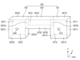
상기 과제를 해결하기 위한 일 실시예에 따른 증강 현실 제공 장치는 제1 렌즈부, 제2 렌즈부, 및 상기 제1 렌즈부와 상기 제2 렌즈부 사이에 배치되는 제3 렌즈부를 포함하는 렌즈, 상기 제1 렌즈부의 제1 측면 상에 배치되며, 상기 제1 렌즈부의 상기 제1 측면에 제1 광을 제공하는 제1 표시 장치, 상기 제2 렌즈부의 제1 측면 상에 배치되며, 상기 제2 렌즈부의 상기 제1 측면에 제2 광을 제공하는 제2 표시 장치, 상기 제1 렌즈부 내에 배치되며, 상기 제3 렌즈부의 제1 측면에서 반사된 상기 제1 광을 상기 제1 렌즈부의 출사면으로 반사하는 제1 반사 부재, 및 상기 제2 렌즈부 내에 배치되며, 상기 제3 렌즈부의 상기 제1 측면에서 반사된 상기 제2 광을 상기 제2 렌즈부의 상기 출사면으로 반사하는 제2 반사 부재를 구비한다.According to one embodiment of the present invention for solving the above problem, an augmented reality providing device comprises: a lens including a first lens unit, a second lens unit, and a third lens unit disposed between the first lens unit and the second lens unit; a first display device disposed on a first side of the first lens unit and providing a first light to the first side of the first lens unit; a second display device disposed on the first side of the second lens unit and providing a second light to the first side of the second lens unit; a first reflective member disposed within the first lens unit and reflecting the first light reflected from the first side of the third lens unit to an exit surface of the first lens unit; and a second reflective member disposed within the second lens unit and reflecting the second light reflected from the first side of the third lens unit to the exit surface of the second lens unit.
상기 제1 표시 장치의 제1 광은 상기 제1 렌즈부의 상기 제1 측면으로 입사하며, 상기 제1 렌즈부의 제2 측면에서 반사되어 상기 제3 렌즈부의 제2 측면으로 진행하고, 상기 제3 렌즈부의 상기 제2 측면에서 반사되어 상기 제3 렌즈부의 상기 제1 측면으로 진행하며, 상기 제3 렌즈부의 상기 제1 측면에서 반사되어 상기 제2 반사 부재로 진행할 수 있다.The first light of the first display device may be incident on the first side of the first lens unit, reflected from the second side of the first lens unit and traveled to the second side of the third lens unit, reflected from the second side of the third lens unit and traveled to the first side of the third lens unit, and reflected from the first side of the third lens unit and traveled to the second reflective member.
상기 제3 렌즈부의 상기 제1 측면은 상기 제1 렌즈부의 상기 제2 측면과 상기 제2 렌즈부의 상기 제2 측면 사이에 배치되며, 상기 제3 렌즈부의 상기 제2 측면은 상기 제1 측면의 반대면일 수 있다.The first side of the third lens unit is positioned between the second side of the first lens unit and the second side of the second lens unit, and the second side of the third lens unit may be an opposite surface of the first side.
상기 제1 렌즈부의 상기 제2 측면, 상기 제2 렌즈부의 상기 제2 측면, 및 상기 제3 렌즈부의 상기 제1 측면 상에 배치되는 제1 반사시트, 및 상기 제3 렌즈부의 상기 제2 측면 상에 배치되는 제2 반사시트를 더 구비할 수 있다.The device may further include a first reflective sheet disposed on the second side of the first lens unit, the second side of the second lens unit, and the first side of the third lens unit, and a second reflective sheet disposed on the second side of the third lens unit.
상기 제1 렌즈부의 상기 제1 측면과 상기 제1 표시 장치 사이에 배치되며, 상기 제1 표시 장치의 제1 광을 상기 제1 렌즈부의 상기 제2 측면으로 진행하도록 상기 제1 표시 장치의 제1 광의 경로를 변환하는 제1 광 경로 변환 부재를 더 구비할 수 있다.The first light path conversion member may be further provided, which is positioned between the first side of the first lens unit and the first display device, and converts the path of the first light of the first display device so that the first light of the first display device passes to the second side of the first lens unit.
상기 제2 표시 장치의 제2 광은 상기 제2 렌즈부의 상기 제1 측면으로 입사하며, 상기 제2 렌즈부의 제2 측면에서 반사되어 상기 제3 렌즈부의 제2 측면으로 진행하고, 상기 제3 렌즈부의 상기 제2 측면에서 반사되어 상기 제3 렌즈부의 상기 제1 측면으로 진행하며, 상기 제3 렌즈부의 상기 제1 측면에서 반사되어 상기 제1 반사 부재로 진행할 수 있다.The second light of the second display device may be incident on the first side of the second lens unit, reflected from the second side of the second lens unit and traveled to the second side of the third lens unit, reflected from the second side of the third lens unit and traveled to the first side of the third lens unit, and reflected from the first side of the third lens unit and traveled to the first reflective member.
상기 제2 렌즈부의 상기 제1 측면과 상기 제2 표시 장치 사이에 배치되며, 상기 제2 표시 장치의 제2 광을 상기 제2 렌즈부의 상기 제2 측면으로 진행하도록 상기 제2 표시 장치의 제2 광의 경로를 변환하는 제2 광 경로 변환 부재를 더 구비할 수 있다.The second display device may further include a second light path conversion member that is positioned between the first side of the second lens unit and the second display device and converts the path of the second light of the second display device so that the second light of the second display device passes to the second side of the second lens unit.
상기 제1 렌즈부의 상기 제1 측면은 곡면이며, 상기 제1 표시 장치는 상기 제1 렌즈부의 상기 제1 측면 상에서 구부러져 배치될 수 있다.The first side surface of the first lens portion is curved, and the first display device can be arranged to be curved on the first side surface of the first lens portion.
상기 제2 렌즈부의 상기 제1 측면은 곡면이며, 상기 제2 표시 장치는 상기 제2 렌즈부의 상기 제1 측면 상에서 구부러져 배치될 수 있다.The first side of the second lens unit is curved, and the second display device can be arranged to be curved on the first side of the second lens unit.
기타 실시예의 구체적인 사항들은 상세한 설명 및 도면들에 포함되어 있다.Specific details of other embodiments are included in the detailed description and drawings.
일 실시예에 따른 증강 현실 제공 장치에 의하면, 렌즈의 제1 측면 상에 배치된 표시 장치의 광이 렌즈의 적어도 하나의 측면에서 전반사된 후, 반사 부재에 의해 렌즈의 출사면으로 출사되어 사용자의 눈에 제공될 수 있다. 그러므로, 표시 장치와 반사 부재 사이의 광학 거리를 늘릴 수 있다. 따라서, 표시 장치에 표시되는 가상의 이미지의 심도가 깊어질 수 있다.According to an augmented reality providing device according to one embodiment, light from a display device arranged on a first side of a lens can be totally reflected by at least one side of the lens and then emitted to an exit surface of the lens by a reflective member to be provided to a user's eyes. Therefore, the optical distance between the display device and the reflective member can be increased. Therefore, the depth of a virtual image displayed on the display device can be deepened.
일 실시예에 따른 증강 현실 제공 장치에 의하면, 복수의 반사 부재들로 인해 사용자의 눈에 제공되는 가상의 이미지의 휘도가 증가할 수 있으며, 사용자의 눈에 보여지는 표시 장치의 영역, 즉 사용자의 뷰 영역(Field of View, FOV)이 넓어질 수 있다.According to an augmented reality providing device according to one embodiment, the brightness of a virtual image provided to the user's eyes may increase due to a plurality of reflective members, and an area of the display device visible to the user's eyes, i.e., the user's field of view (FOV), may be expanded.
일 실시예에 따른 증강 현실 제공 장치에 의하면, 표시 장치가 배치되는 렌즈의 제1 측면을 제외한 나머지 측면들 상에 반사시트를 배치하고, 반사시트에 의해 표시 장치의 광을 반사함으로써, 사용자의 눈에 제공되는 표시 장치의 가상의 이미지의 휘도를 높일 수 있다.According to an augmented reality providing device according to one embodiment, a reflective sheet is placed on the remaining sides of a lens except for a first side on which a display device is placed, and by reflecting light of the display device by the reflective sheet, the brightness of a virtual image of the display device provided to the user's eyes can be increased.
일 실시예에 따른 증강 현실 제공 장치에 의하면, 표시 장치가 유연성을 갖는 플렉시블 표시 장치로서, 곡면으로 형성된 렌즈의 제1 측면 상에서 구부러진 형태로 배치될 수 있으므로, 표시 장치의 광은 광 경로 변환층 없이도 제3 측면으로 진행하여 제3 측면에서 전반사될 수 있다.According to an augmented reality providing device according to one embodiment, since the display device is a flexible display device having flexibility and can be arranged in a curved shape on a first side of a lens formed into a curved surface, light from the display device can travel to a third side and be totally reflected at the third side without a light path conversion layer.
일 실시예에 따른 증강 현실 제공 장치에 의하면, 반사시트가 곡면으로 형성된 렌즈의 일 측면 상에서 구부러진 형태로 배치됨으로써, 오목 거울과 같은 역할을 할 수 있다. 이에 따라, 렌즈의 일 측면 상에 배치된 반사시트에서 반사되는 표시 장치의 광이 반사 부재로 집광될 수 있으므로, 반사 부재에 의해 사용자의 눈에 제공되는 표시 장치의 가상의 이미지의 휘도를 높일 수 있다.According to an augmented reality providing device according to one embodiment, a reflective sheet is arranged in a curved shape on one side of a lens formed into a curved surface, thereby acting as a concave mirror. Accordingly, light of a display device reflected by the reflective sheet arranged on one side of the lens can be focused by a reflective member, thereby increasing the brightness of a virtual image of the display device provided to a user's eyes by the reflective member.
일 실시예에 따른 증강 현실 제공 장치에 의하면, 반사시트가 곡면으로 형성된 렌즈의 일 측면 상에서 구부러진 형태로 배치됨으로써, 볼록 거울과 같은 역할을 할 수 있다. 이에 따라, 렌즈의 일 측면 상에 배치된 반사시트에서 반사되는 표시 장치의 광이 퍼질 수 있으므로, 반사 부재에 의해 사용자의 눈에 제공되는 표시 장치의 가상의 이미지는 사용자에게 확대되어 보일 수 있다.According to an augmented reality providing device according to one embodiment, a reflective sheet may be arranged in a curved shape on one side of a lens formed into a curved surface, thereby acting as a convex mirror. Accordingly, light from a display device reflected by the reflective sheet arranged on one side of the lens may spread, so that a virtual image of the display device provided to the user's eyes by the reflective member may appear enlarged to the user.
실시예들에 따른 효과는 이상에서 예시된 내용에 의해 제한되지 않으며, 더욱 다양한 효과들이 본 명세서 내에 포함되어 있다.The effects according to the embodiments are not limited to the contents exemplified above, and more diverse effects are included in the present specification.
도 1은 일 실시예에 따른 증강 현실 제공 장치를 보여주는 사시도이다.
도 2a 및 도 2b는 도 1의 렌즈의 예들을 보여주는 사시도들이다.
도 3은 도 1의 표시 장치를 상세히 보여주는 단면도이다.
도 4a 및 도 4b는 도 1의 광 경로 변환층의 예들을 보여주는 예시도면들이다.
도 5는 일 실시예에 따른 증강 현실 제공 장치를 보여주는 사시도이다.
도 6은 일 실시예에 따른 증강 현실 제공 장치를 보여주는 사시도이다.
도 7은 일 실시예에 따른 증강 현실 제공 장치를 보여주는 사시도이다.
도 8은 일 실시예에 따른 증강 현실 제공 장치를 보여주는 사시도이다.
도 9는 도 8의 렌즈의 일 예를 보여주는 사시도이다.
도 10은 도 9에서 표시 장치의 광의 경로의 일 예를 보여주는 측면도이다.
도 11은 도 9에서 표시 장치의 광의 경로의 일 예를 보여주는 측면도이다.
도 12는 일 실시예에 따른 증강 현실 제공 장치를 보여주는 사시도이다.
도 13은 일 실시예에 따른 증강 현실 제공 장치를 보여주는 사시도이다.
도 14는 일 실시예에 따른 증강 현실 제공 장치를 보여주는 사시도이다.
도 15는 일 실시예에 따른 증강 현실 제공 장치를 보여주는 사시도이다.
도 16은 도 15의 렌즈의 일 예를 보여주는 사시도이다.
도 17은 제1 표시 장치의 제1 광과 제2 표시 장치의 제2 표시 영상의 제2 광의 경로의 일 예를 보여주는 사시도이다.
도 18a 및 도 18b는 일 실시예에 따른 증강 현실 제공 장치를 보여주는 사시도들이다.
도 19는 일 실시예에 따른 증강 현실 제공 장치를 보여주는 사시도이다.
도 20은 일 실시예에 따른 증강 현실 제공 장치를 보여주는 사시도이다.
도 21은 다양한 실시예들에 따른 증강 현실 제공 장치를 포함하는 안경형 디스플레이의 일 예시도면이다.FIG. 1 is a perspective view showing an augmented reality providing device according to one embodiment.
Figures 2a and 2b are perspective views showing examples of the lenses of Figure 1.
Figure 3 is a cross-sectional view showing the display device of Figure 1 in detail.
FIGS. 4A and 4B are exemplary drawings showing examples of the optical path conversion layer of FIG. 1.
FIG. 5 is a perspective view showing an augmented reality providing device according to one embodiment.
FIG. 6 is a perspective view showing an augmented reality providing device according to one embodiment.
FIG. 7 is a perspective view showing an augmented reality providing device according to one embodiment.
FIG. 8 is a perspective view showing an augmented reality providing device according to one embodiment.
Fig. 9 is a perspective view showing an example of the lens of Fig. 8.
FIG. 10 is a side view showing an example of the light path of the display device in FIG. 9.
FIG. 11 is a side view showing an example of the light path of the display device in FIG. 9.
FIG. 12 is a perspective view showing an augmented reality providing device according to one embodiment.
FIG. 13 is a perspective view showing an augmented reality providing device according to one embodiment.
FIG. 14 is a perspective view showing an augmented reality providing device according to one embodiment.
FIG. 15 is a perspective view showing an augmented reality providing device according to one embodiment.
Fig. 16 is a perspective view showing an example of the lens of Fig. 15.
Figure 17 is a perspective view showing an example of the path of the first light of the first display device and the second light of the second display image of the second display device.
FIGS. 18a and 18b are perspective views showing an augmented reality providing device according to one embodiment.
FIG. 19 is a perspective view showing an augmented reality providing device according to one embodiment.
FIG. 20 is a perspective view showing an augmented reality providing device according to one embodiment.
FIG. 21 is an exemplary drawing of a glasses-type display including an augmented reality providing device according to various embodiments.
본 발명의 이점 및 특징, 그리고 그것들을 달성하는 방법은 첨부되는 도면과 함께 상세하게 후술되어 있는 실시예들을 참조하면 명확해질 것이다. 그러나 본 발명은 이하에서 개시되는 실시예들에 한정되는 것이 아니라 서로 다른 다양한 형태로 구현될 것이며, 단지 본 실시예들은 본 발명의 개시가 완전하도록 하며, 본 발명이 속하는 기술분야에서 통상의 지식을 가진 자에게 발명의 범주를 완전하게 알려주기 위해 제공되는 것이며, 본 발명은 청구항의 범주에 의해 정의될 뿐이다.The advantages and features of the present invention, and the methods for achieving them, will become clear with reference to the embodiments described in detail below together with the accompanying drawings. However, the present invention is not limited to the embodiments disclosed below, but may be implemented in various different forms, and these embodiments are provided only to make the disclosure of the present invention complete and to fully inform a person having ordinary skill in the art to which the present invention belongs of the scope of the invention, and the present invention is defined only by the scope of the claims.
소자(elements) 또는 층이 다른 소자 또는 층의 "상(on)"으로 지칭되는 것은 다른 소자 바로 위에 또는 중간에 다른 층 또는 다른 소자를 개재한 경우를 모두 포함한다. 명세서 전체에 걸쳐 동일 참조 부호는 동일 구성 요소를 지칭한다. 실시예들을 설명하기 위한 도면에 개시된 형상, 크기, 비율, 각도, 개수 등은 예시적인 것이므로 본 발명이 도시된 사항에 한정되는 것은 아니다. When elements or layers are referred to as being "on" another element or layer, it includes both cases where the other element is directly on top of the other element or layer or intervening layers or other elements. Like reference numerals refer to like elements throughout the specification. The shapes, sizes, ratios, angles, numbers, etc. disclosed in the drawings for explaining the embodiments are illustrative and therefore the present invention is not limited to the matters illustrated.
비록 제1, 제2 등이 다양한 구성요소들을 서술하기 위해서 사용되나, 이들 구성요소들은 이들 용어에 의해 제한되지 않음은 물론이다. 이들 용어들은 단지 하나의 구성요소를 다른 구성요소와 구별하기 위하여 사용하는 것이다. 따라서, 이하에서 언급되는 제1 구성요소는 본 발명의 기술적 사상 내에서 제2 구성요소일 수도 있음은 물론이다.Although the terms first, second, etc. are used to describe various components, it is to be understood that these components are not limited by these terms. These terms are merely used to distinguish one component from another. Accordingly, it is to be understood that the first component referred to below may also be the second component within the technical concept of the present invention.
본 발명의 여러 실시예들의 각각 특징들이 부분적으로 또는 전체적으로 서로 결합 또는 조합 가능하고, 기술적으로 다양한 연동 및 구동이 가능하며, 각 실시예들이 서로에 대하여 독립적으로 실시 가능할 수도 있고 연관 관계로 함께 실시할 수도 있다.The individual features of the various embodiments of the present invention may be partially or wholly combined or combined with each other, and may be technically linked and driven in various ways, and each embodiment may be implemented independently of each other or implemented together in a related relationship.
도 1은 일 실시예에 따른 증강 현실 제공 장치를 보여주는 사시도이다. 도 2a 및 도 2b는 도 1의 렌즈의 예들을 보여주는 사시도들이다. 도 3은 도 1의 표시 장치를 상세히 보여주는 단면도이다. 도 4a 및 도 4b는 도 1의 광 경로 변환층의 예들을 보여주는 예시도면들이다.FIG. 1 is a perspective view showing an augmented reality providing device according to one embodiment. FIGS. 2a and 2b are perspective views showing examples of lenses of FIG. 1. FIG. 3 is a cross-sectional view showing in detail the display device of FIG. 1. FIGS. 4a and 4b are exemplary drawings showing examples of the optical path conversion layer of FIG. 1.
도 1 내지 도 4를 참조하면, 일 실시예에 따른 증강 현실 제공 장치(10)는 렌즈(100), 표시 장치(200), 광 경로 변환층(310), 편광 필름(320), 및 제1 반사 부재(410)를 구비한다.Referring to FIGS. 1 to 4, an augmented reality providing device (10) according to one embodiment includes a lens (100), a display device (200), an optical path conversion layer (310), a polarizing film (320), and a first reflective member (410).
렌즈(100)는 유리(glass) 또는 플라스틱(plastic)으로 투명 또는 반투명하게 형성될 수 있다. 이로 인해, 사용자는 렌즈(100)를 통해 현실의 이미지를 볼 수 있다. 렌즈(100)는 사용자의 시력을 고려하여 소정의 굴절력을 가질 수 있다.The lens (100) can be formed transparently or translucently using glass or plastic. As a result, the user can see an image of reality through the lens (100). The lens (100) can have a predetermined refractive power considering the user's eyesight.
렌즈(100)는 도 2a와 같이 육각형의 제1 면(SF1)과 제2 면(SF2), 및 제1 내지 제6 측면들(SIF1~SIF6)로 이루어진 팔면체로 형성될 수 있다. 렌즈(100)가 도 2a와 같이 팔면체로 형성되는 경우, 제2 측면(SIF2)은 제1 측면(SIF1)의 일 측으로부터 연장되고, 제3 측면(SIF3)은 제1 측면(SIF1)의 일 측에 반대되는 타 측으로부터 연장될 수 있다. 제2 측면(SIF2)과 제3 측면(SIF3)은 서로 대향하며, 제2 측면(SIF2)의 제1 방향(X축 방향)의 길이와 제3 측면(SIF3)의 제1 방향(X축 방향)의 길이는 실질적으로 동일할 수 있다. 제4 측면(SIF4)은 제2 측면(SIF3)과 제3 측면(SIF3) 사이에 배치되며, 제5 측면(SIF5)은 제3 측면(SIF3)과 제4 측면(SIF4) 사이에 배치되고, 제6 측면(SIF6)은 제2 측면(SIF2)과 제4 측면(SIF6) 사이에 배치될 수 있다. 제1 면(SF1)은 상면, 제2 면(SF2)은 하면일 수 있다. 제1 면(SF1)은 사용자의 눈(E)이 위치하는 면으로, 제1 반사 부재(410)에 의해 표시 장치(200)의 광이 출사되는 출사면이고, 제2 면은 렌즈(100)의 바깥면일 수 있다.The lens (100) may be formed as an octahedron composed of a first face (SF1), a second face (SF2), and first to sixth side faces (SIF1 to SIF6) of a hexagon, as shown in FIG. 2A. When the lens (100) is formed as an octahedron, as shown in FIG. 2A, the second side face (SIF2) may extend from one side of the first side face (SIF1), and the third side face (SIF3) may extend from the other side opposite to the one side of the first side face (SIF1). The second side face (SIF2) and the third side face (SIF3) may face each other, and the length of the second side face (SIF2) in the first direction (X-axis direction) and the length of the third side face (SIF3) in the first direction (X-axis direction) may be substantially the same. The fourth side (SIF4) may be positioned between the second side (SIF3) and the third side (SIF3), the fifth side (SIF5) may be positioned between the third side (SIF3) and the fourth side (SIF4), and the sixth side (SIF6) may be positioned between the second side (SIF2) and the fourth side (SIF6). The first side (SF1) may be the upper side, and the second side (SF2) may be the lower side. The first side (SF1) is the side where the user's eye (E) is positioned, and is an exit side through which light of the display device (200) is emitted by the first reflective member (410), and the second side may be the outer surface of the lens (100).
또는, 렌즈(100)는 도 2b와 같이 사각형의 제1 면(SF1)과 제2 면(SF2), 및 제1 내지 제4 측면들(SIF1~SIF4)로 이루어진 육면체로 형성될 수도 있다. 렌즈(100)가 도 2b와 같이 육면체로 형성되는 경우, 제2 측면(SIF2)은 제1 측면(SIF1)의 일 측으로부터 연장되고, 제3 측면(SIF3)은 제1 측면(SIF1)의 일 측에 반대되는 타 측으로부터 연장되며, 제4 측면(SIF4)은 제1 측면(SIF1)과 대향할 수 있다. 제1 면(SF1)은 상면, 제2 면(SF2)은 하면일 수 있다. 제1 면(SF1)은 사용자의 눈(E)이 위치하는 면으로, 제1 반사 부재(410)에 의해 표시 장치(200)의 광이 출사되는 출사면이고, 제2 면은 렌즈(100)의 바깥면일 수 있다.Alternatively, the lens (100) may be formed as a hexahedron composed of a first surface (SF1), a second surface (SF2), and first to fourth surface sides (SIF1 to SIF4) of a square shape as shown in FIG. 2B. When the lens (100) is formed as a hexahedron as shown in FIG. 2B, the second surface side (SIF2) may extend from one side of the first surface side (SIF1), the third surface side (SIF3) may extend from the other side opposite to one side of the first surface side (SIF1), and the fourth surface side (SIF4) may face the first surface side (SIF1). The first surface side (SF1) may be an upper surface, and the second surface side (SF2) may be a lower surface. The first surface (SF1) is the surface where the user's eye (E) is located and is an emission surface through which light from the display device (200) is emitted by the first reflective member (410), and the second surface may be the outer surface of the lens (100).
렌즈(100)는 도 2a 및 도 2b에 도시된 바에 한정되지 않으며, 다각형의 제1 면과 제2 면, 및 측면들로 이루어진 다면체로 형성될 수 있다. 또한, 렌즈(100)는 다면체 이외에 원기둥, 타원기둥, 반원기둥, 반타원기둥, 찌그러진 원기둥, 또는 찌그러진 반원기둥과 같이 다른 형태로 형성될 수도 있다. 찌그러진 원기둥과 반원기둥은 지름이 일정하지 않은 원기둥과 반원기둥을 가리킨다.The lens (100) is not limited to that shown in FIGS. 2A and 2B, and may be formed as a polyhedron consisting of a first face, a second face, and side faces of a polygon. In addition, the lens (100) may be formed in other shapes, such as a cylinder, an elliptical cylinder, a semi-cylinder, a semi-elliptical cylinder, a dented cylinder, or a dented semi-cylinder, in addition to a polyhedron. A dented cylinder and a semi-cylinder refer to a cylinder and a semi-cylinder having an irregular diameter.
제1 반사 부재(410)는 렌즈(100) 내에 배치된다. 제1 반사 부재(410)는 핀 미러(pin mirror)와 같은 소형의 미러일 수 있다. 도 1에서는 제1 반사 부재(410)가 원형의 단면을 갖는 것을 예시하였으나, 원형 이외에 타원형 또는 다각형의 단면을 가질 수도 있다.The first reflective member (410) is placed within the lens (100). The first reflective member (410) may be a small mirror such as a pin mirror. In Fig. 1, the first reflective member (410) is exemplified as having a circular cross-section, but may also have an elliptical or polygonal cross-section in addition to a circular cross-section.
제1 반사 부재(410)는 눈(E)의 동공의 크기보다 작게 형성되며, 예를 들어 제1 반사 부재(410)의 직경은 500㎛ 내지 4㎜로 형성될 수 있다. 이 경우, 사용자는 현실의 이미지에 초점을 맞추고 있기 때문에, 제1 반사 부재(410)를 인지하기 어렵다. 하지만, 제1 반사 부재(410)의 크기가 작아질수록 플렉서블 디스플레이 장치(200)에 의해 사용자의 눈(E)에 제공되는 가상의 이미지의 휘도도 감소하므로, 제1 반사 부재(410)의 크기는 이를 고려하여 설정될 수 있다.The first reflective member (410) is formed smaller than the size of the pupil of the eye (E), and for example, the diameter of the first reflective member (410) may be formed to be 500 μm to 4 mm. In this case, since the user is focusing on the real image, it is difficult to recognize the first reflective member (410). However, as the size of the first reflective member (410) decreases, the brightness of the virtual image provided to the user's eye (E) by the flexible display device (200) also decreases, and therefore, the size of the first reflective member (410) may be set in consideration of this.
제1 반사 부재(410)는 도 1과 같이 원기둥 형태를 가질 수 있으며, 이 경우 2 개의 밑면들 중 어느 하나가 미러로 구현되는 반사면일 수 있으며, 2 개의 밑면들 중 다른 하나와 옆면은 미러로 구현되지 않는 것이 바람직하다. 렌즈(100)의 제2 측면(SIF2)에서 전반사된 광(L)을 렌즈(100)의 제1 면(SF1)으로 출사하기 위해서는, 도 5와 같이 제1 반사 부재(410)의 하부의 밑면이 반사면일 수 있다.The first reflective member (410) may have a cylindrical shape as shown in FIG. 1, and in this case, one of the two bottom surfaces may be a reflective surface implemented as a mirror, and it is preferable that the other of the two bottom surfaces and the side surface are not implemented as a mirror. In order to emit the light (L) totally reflected at the second side surface (SIF2) of the lens (100) to the first surface (SF1) of the lens (100), the bottom surface of the lower part of the first reflective member (410) may be a reflective surface as shown in FIG. 5.
제1 반사 부재(410)는 표시 장치(200)에 표시되는 가상의 이미지를 반사하여 사용자의 눈(E)에 제공할 수 있다. 표시 장치(200)에 표시되는 가상의 이미지는 제1 반사 부재(410)에 의해 반사되므로, 표시 장치(200)와 제1 반사 부재(410) 사이의 광학 거리를 늘릴 수 있다. 이에 따라, 표시 장치(200)에 표시되는 가상의 이미지의 심도(depth of field)가 깊어지게 된다.The first reflective member (410) can reflect a virtual image displayed on the display device (200) and provide it to the user's eyes (E). Since the virtual image displayed on the display device (200) is reflected by the first reflective member (410), the optical distance between the display device (200) and the first reflective member (410) can be increased. Accordingly, the depth of field of the virtual image displayed on the display device (200) becomes deeper.
표시 장치(200)는 증강 현실을 구현하기 위한 가상의 이미지를 표시한다. 표시 장치(200)는 렌즈(100)의 측면들 중 어느 한 측면 상에 배치될 수 있다. 예를 들어, 표시 장치(200)는 렌즈(100)의 제1 측면(SIF1) 상에 배치될 수 있다. The display device (200) displays a virtual image for implementing augmented reality. The display device (200) may be placed on one of the side surfaces of the lens (100). For example, the display device (200) may be placed on the first side surface (SIF1) of the lens (100).
표시 장치(200)는 유연성을 갖는 플렉시블 표시 장치일 수 있으며, 이로 인해 휘어지거나 구부러지거나 벤딩될 수 있다. 예를 들어, 표시 장치(200)는 도 3과 같이 유기 발광 표시 장치 또는 양자점을 포함하는 유기 발광 표시 장치일 수 있다.The display device (200) may be a flexible display device having flexibility, and thus may be bent, curved, or bent. For example, the display device (200) may be an organic light-emitting display device or an organic light-emitting display device including quantum dots, as shown in FIG. 3.
도 3을 참조하면, 표시 장치(1100)는 기판(1100), 박막 트랜지스터층(1230), 발광 소자층(1240), 및 박막 봉지층(1300)을 포함할 수 있다.Referring to FIG. 3, the display device (1100) may include a substrate (1100), a thin film transistor layer (1230), a light emitting element layer (1240), and a thin film encapsulation layer (1300).
기판(1100) 상에는 박막 트랜지스터층(1230)이 형성된다. 박막 트랜지스터층(1230)은 박막 트랜지스터(1235)들, 게이트 절연막(1236), 층간 절연막(1237), 보호막(1238), 및 평탄화막(1239)을 포함한다.A thin film transistor layer (1230) is formed on a substrate (1100). The thin film transistor layer (1230) includes thin film transistors (1235), a gate insulating film (1236), an interlayer insulating film (1237), a protective film (1238), and a planarizing film (1239).
기판(1100) 상에는 버퍼막이 형성될 수 있다. 버퍼막은 투습에 취약한 기판(1100)을 통해 침투하는 수분으로부터 박막 트랜지스터(1235)들과 발광 소자들을 보호하기 위해 기판(1100) 상에 형성될 수 있다. 버퍼막은 교번하여 적층된 복수의 무기막들로 이루어질 수 있다. 예를 들어, 버퍼막은 실리콘 산화막(SiOx), 실리콘 질화막(SiNx), SiON 중 하나 이상의 무기막이 교번하여 적층된 다중막으로 형성될 수 있다. 버퍼막은 생략될 수 있다.A buffer film may be formed on the substrate (1100). The buffer film may be formed on the substrate (1100) to protect the thin film transistors (1235) and light-emitting elements from moisture penetrating through the substrate (1100) which is vulnerable to moisture permeation. The buffer film may be formed of a plurality of inorganic films alternately laminated. For example, the buffer film may be formed as a multi-film in which one or more inorganic films of a silicon oxide film (SiOx), a silicon nitride film (SiNx), and SiON are alternately laminated. The buffer film may be omitted.
버퍼막 상에는 박막 트랜지스터(1235)들이 형성된다. 박막 트랜지스터(1235)들 각각은 액티브층(1231), 게이트전극(1232), 소스전극(1233) 및 드레인전극(1234)을 포함한다. 도 3에서 박막 트랜지스터(1235)들 각각은 게이트전극(1232)이 액티브층(1231)의 상부에 위치하는 상부 게이트(탑 게이트, top gate) 방식으로 형성된 것을 예시하였으나, 이에 한정되지 않음에 주의하여야 한다. 즉, 박막 트랜지스터(1235)들 각각은 게이트전극(1232)이 액티브층(1231)의 하부에 위치하는 하부 게이트(보텀 게이트, bottom gate) 방식 또는 게이트전극(1232)이 액티브층(1231)의 상부와 하부에 모두 위치하는 더블 게이트(double gate) 방식으로 형성될 수 있다.Thin film transistors (1235) are formed on the buffer film. Each of the thin film transistors (1235) includes an active layer (1231), a gate electrode (1232), a source electrode (1233), and a drain electrode (1234). In FIG. 3, each of the thin film transistors (1235) is exemplified as being formed in a top gate manner in which the gate electrode (1232) is positioned above the active layer (1231), but it should be noted that the present invention is not limited thereto. That is, each of the thin film transistors (1235) may be formed in a bottom gate manner in which the gate electrode (1232) is positioned below the active layer (1231), or in a double gate manner in which the gate electrode (1232) is positioned above and below the active layer (1231).
버퍼막 상에는 액티브층(1231)이 형성된다. 액티브층(1231)은 실리콘계 반도체 물질 또는 산화물계 반도체 물질로 형성될 수 있다. 버퍼막과 액티브층(1231) 사이에는 액티브층(1231)으로 입사되는 외부광을 차단하기 위한 차광층이 형성될 수 있다.An active layer (1231) is formed on the buffer film. The active layer (1231) may be formed of a silicon-based semiconductor material or an oxide-based semiconductor material. A light-blocking layer may be formed between the buffer film and the active layer (1231) to block external light incident on the active layer (1231).
액티브층(1231) 상에는 게이트 절연막(1236)이 형성될 수 있다. 게이트 절연막(1216)은 무기막, 예를 들어 실리콘 산화막(SiOx), 실리콘 질화막(SiNx), 또는 이들의 다중막으로 형성될 수 있다.A gate insulating film (1236) may be formed on the active layer (1231). The gate insulating film (1216) may be formed of an inorganic film, for example, a silicon oxide film (SiOx), a silicon nitride film (SiNx), or a multi-film thereof.
게이트 절연막(1216) 상에는 게이트전극(1232)과 게이트 라인이 형성될 수 있다. 게이트전극(1232)과 게이트 라인은 몰리브덴(Mo), 알루미늄(Al), 크롬(Cr), 금(Au), 티타늄(Ti), 니켈(Ni), 네오디뮴(Nd) 및 구리(Cu) 중 어느 하나 또는 이들의 합금으로 이루어진 단일층 또는 다중층으로 형성될 수 있다.A gate electrode (1232) and a gate line may be formed on the gate insulating film (1216). The gate electrode (1232) and the gate line may be formed as a single layer or multiple layers made of one or an alloy of molybdenum (Mo), aluminum (Al), chromium (Cr), gold (Au), titanium (Ti), nickel (Ni), neodymium (Nd), and copper (Cu).
게이트전극(1232)과 게이트 라인 상에는 층간 절연막(1237)이 형성될 수 있다. 층간 절연막(1237)은 무기막, 예를 들어 실리콘 산화막(SiOx), 실리콘 질화막(SiNx), 또는 이들의 다중막으로 형성될 수 있다.An interlayer insulating film (1237) may be formed on the gate electrode (1232) and the gate line. The interlayer insulating film (1237) may be formed of an inorganic film, for example, a silicon oxide film (SiOx), a silicon nitride film (SiNx), or a multi-film thereof.
층간 절연막(1237) 상에는 소스전극(1233), 드레인전극(1234), 및 데이터 라인이 형성될 수 있다. 소스전극(1233)과 드레인전극(1234) 각각은 게이트 절연막(1236)과 층간 절연막(1237)을 관통하는 콘택홀을 통해 액티브층(1231)에 접속될 수 있다. 소스전극(1233), 드레인전극(1234), 및 데이터 라인은 몰리브덴(Mo), 알루미늄(Al), 크롬(Cr), 금(Au), 티타늄(Ti), 니켈(Ni), 네오디뮴(Nd) 및 구리(Cu) 중 어느 하나 또는 이들의 합금으로 이루어진 단일층 또는 다중층으로 형성될 수 있다.A source electrode (1233), a drain electrode (1234), and a data line may be formed on an interlayer insulating film (1237). Each of the source electrode (1233) and the drain electrode (1234) may be connected to the active layer (1231) through a contact hole penetrating the gate insulating film (1236) and the interlayer insulating film (1237). The source electrode (1233), the drain electrode (1234), and the data line may be formed as a single layer or multiple layers made of any one of molybdenum (Mo), aluminum (Al), chromium (Cr), gold (Au), titanium (Ti), nickel (Ni), neodymium (Nd), and copper (Cu), or an alloy thereof.
소스전극(1233), 드레인전극(1234), 및 데이터 라인 상에는 박막 트랜지스터(1235)를 절연하기 위한 보호막(1238)이 형성될 수 있다. 보호막(1238)은 무기막, 예를 들어 실리콘 산화막(SiOx), 실리콘 질화막(SiNx), 또는 이들의 다중막으로 형성될 수 있다.A protective film (1238) for insulating a thin film transistor (1235) may be formed on the source electrode (1233), the drain electrode (1234), and the data line. The protective film (1238) may be formed of an inorganic film, for example, a silicon oxide film (SiOx), a silicon nitride film (SiNx), or a multi-film thereof.
보호막(1238) 상에는 박막 트랜지스터(1235)로 인한 단차를 평탄하게 하기 위한 평탄화막(1239)이 형성될 수 있다. 평탄화막(1239)은 아크릴 수지(acryl resin), 에폭시 수지(epoxy resin), 페놀 수지(phenolic resin), 폴리아미드 수지(polyamide resin), 폴리이미드 수지(polyimide resin) 등의 유기막으로 형성될 수 있다.A planarization film (1239) may be formed on the protective film (1238) to level the step caused by the thin film transistor (1235). The planarization film (1239) may be formed of an organic film such as an acrylic resin, an epoxy resin, a phenolic resin, a polyamide resin, or a polyimide resin.
박막 트랜지스터층(1230) 상에는 발광 소자층(1240)이 형성된다. 발광 소자층(1240)은 발광 소자들과 화소 정의막(1244)을 포함한다.A light-emitting element layer (1240) is formed on the thin film transistor layer (1230). The light-emitting element layer (1240) includes light-emitting elements and a pixel defining film (1244).
발광 소자들과 화소 정의막(1244)은 평탄화막(1239) 상에 형성된다. 발광 소자는 유기 발광 소자(organic light emitting device)일 수 있다. 이 경우, 발광 소자는 애노드 전극(1241), 발광층(1242)들, 및 캐소드 전극(1243)을 포함할 수 있다.Light-emitting elements and pixel defining film (1244) are formed on the planarization film (1239). The light-emitting element may be an organic light-emitting device. In this case, the light-emitting element may include an anode electrode (1241), light-emitting layers (1242), and a cathode electrode (1243).
애노드 전극(1241)은 평탄화막(1239) 상에 형성될 수 있다. 애노드 전극(1241)은 보호막(1238)과 평탄화막(1239)을 관통하는 콘택홀을 통해 박막 트랜지스터(1235)의 소스전극(1233)에 접속될 수 있다.The anode electrode (1241) can be formed on the planarization film (1239). The anode electrode (1241) can be connected to the source electrode (1233) of the thin film transistor (1235) through a contact hole penetrating the protective film (1238) and the planarization film (1239).
화소 정의막(1244)은 화소들을 구획하기 위해 평탄화막(1239) 상에서 애노드 전극(1241)의 가장자리를 덮도록 형성될 수 있다. 즉, 화소 정의막(1244)은 화소들을 정의하는 화소 정의막으로서 역할을 한다. 화소들 각각은 애노드 전극(1241), 발광층(1242), 및 캐소드 전극(1243)이 순차적으로 적층되어 애노드 전극(1241)으로부터의 정공과 캐소드 전극(1243)으로부터의 전자가 발광층(1242)에서 서로 결합되어 발광하는 영역을 나타낸다.The pixel defining film (1244) may be formed to cover the edge of the anode electrode (1241) on the planarizing film (1239) to define pixels. That is, the pixel defining film (1244) serves as a pixel defining film that defines pixels. Each pixel represents a region in which an anode electrode (1241), a light-emitting layer (1242), and a cathode electrode (1243) are sequentially laminated, and holes from the anode electrode (1241) and electrons from the cathode electrode (1243) are combined with each other in the light-emitting layer (1242) to emit light.
애노드 전극(1241)과 화소 정의막(1244) 상에는 발광층(1242)들이 형성된다. 발광층(1242)은 유기 발광층일 수 있다. 발광층(1242)은 적색(red) 광, 녹색(green) 광 및 청색(blue) 광 중 하나를 발광할 수 있다. 적색 광의 피크 파장 범위는 약 620㎚ 내지 750㎚일 수 있으며, 녹색 광의 피크 파장 범위는 약 495㎚ 내지 570㎚일 수 있다. 또한, 청색 광의 피크 파장 범위는 약 450㎚ 내지 495㎚일 수 있다. 또는, 발광층(1242)은 백색 광을 발광하는 백색 발광층일 수 있으며, 이 경우 적색 발광층, 녹색 발광층 및 청색 발광층이 적층된 형태를 가질 수 있으며, 화소들에 공통적으로 형성되는 공통층일 수 있다. 이 경우, 표시 장치(200)는 적색, 녹색 및 청색을 표시하기 위한 별도의 컬러 필터(Color Filter)를 더 포함할 수도 있다.Emission layers (1242) are formed on the anode electrode (1241) and the pixel defining film (1244). The emission layer (1242) may be an organic emission layer. The emission layer (1242) may emit one of red light, green light, and blue light. The peak wavelength range of the red light may be about 620 nm to 750 nm, and the peak wavelength range of the green light may be about 495 nm to 570 nm. In addition, the peak wavelength range of the blue light may be about 450 nm to 495 nm. Alternatively, the emission layer (1242) may be a white emission layer that emits white light, and in this case, the red emission layer, the green emission layer, and the blue emission layer may be laminated and may be a common layer commonly formed on the pixels. In this case, the display device (200) may further include separate color filters for displaying red, green, and blue.
발광층(1242)은 정공 수송층(hole transporting layer), 발광층(light emitting layer), 및 전자 수송층(electron transporting layer)을 포함할 수 있다. 또한, 발광층(1242)은 2 스택(stack) 이상의 탠덤 구조로 형성될 수 있으며, 이 경우, 스택들 사이에는 전하 생성층이 형성될 수 있다. The light emitting layer (1242) may include a hole transporting layer, a light emitting layer, and an electron transporting layer. In addition, the light emitting layer (1242) may be formed in a tandem structure of two or more stacks, and in this case, a charge generation layer may be formed between the stacks.
캐소드 전극(1243)은 발광층(1242) 상에 형성된다. 제2 전극(1243)은 발광층(1242)을 덮도록 형성될 수 있다. 제2 전극(1243)은 화소들에 공통적으로 형성되는 공통층일 수 있다.The cathode electrode (1243) is formed on the light-emitting layer (1242). The second electrode (1243) may be formed to cover the light-emitting layer (1242). The second electrode (1243) may be a common layer formed commonly on the pixels.
발광 소자층(1240)이 상부 방향으로 발광하는 상부 발광(top emission) 방식으로 형성되는 경우, 애노드 전극(1241)은 알루미늄과 티타늄의 적층 구조(Ti/Al/Ti), 알루미늄과 ITO의 적층 구조(ITO/Al/ITO), APC 합금, 및 APC 합금과 ITO의 적층 구조(ITO/APC/ITO)와 같은 반사율이 높은 금속물질로 형성될 수 있다. APC 합금은 은(Ag), 팔라듐(Pd), 및 구리(Cu)의 합금이다. 또한, 캐소드 전극(1243)은 광을 투과시킬 수 있는 ITO, IZO와 같은 투명한 금속물질(TCO, Transparent Conductive Material), 또는 마그네슘(Mg), 은(Ag), 또는 마그네슘(Mg)과 은(Ag)의 합금과 같은 반투과 금속물질(Semi-transmissive Conductive Material)로 형성될 수 있다. 캐소드 전극(1243)이 반투과 금속물질로 형성되는 경우, 미세 공진(micro cavity)에 의해 출광 효율이 높아질 수 있다.When the light-emitting element layer (1240) is formed in a top emission manner in which light is emitted upward, the anode electrode (1241) can be formed of a metal material having a high reflectivity, such as a laminated structure of aluminum and titanium (Ti/Al/Ti), a laminated structure of aluminum and ITO (ITO/Al/ITO), an APC alloy, and a laminated structure of an APC alloy and ITO (ITO/APC/ITO). The APC alloy is an alloy of silver (Ag), palladium (Pd), and copper (Cu). In addition, the cathode electrode (1243) can be formed of a transparent metal material (TCO, Transparent Conductive Material) such as ITO or IZO that can transmit light, or a semi-transmissive metal material (Semi-transmissive Conductive Material) such as magnesium (Mg), silver (Ag), or an alloy of magnesium (Mg) and silver (Ag). When the cathode electrode (1243) is formed of a semi-transparent metal material, the light emission efficiency can be increased by a micro cavity.
발광 소자층(1240)이 하부 방향으로 발광하는 하부 발광(bottom emission) 방식으로 형성되는 경우, 애노드 전극(1241)은 ITO, IZO와 같은 투명한 금속물질(TCO, Transparent Conductive Material) 또는 마그네슘(Mg), 은(Ag), 또는 마그네슘(Mg)과 은(Ag)의 합금과 같은 반투과 금속물질(Semi-transmissive Conductive Material)로 형성될 수 있다. 제2 전극(1243)은 알루미늄과 티타늄의 적층 구조(Ti/Al/Ti), 알루미늄과 ITO의 적층 구조(ITO/Al/ITO), APC 합금, 및 APC 합금과 ITO의 적층 구조(ITO/APC/ITO)와 같은 반사율이 높은 금속물질로 형성될 수 있다. 애노드 전극(1241)이 반투과 금속물질로 형성되는 경우, 미세 공진(micro cavity)에 의해 출광 효율이 높아질 수 있다. When the light-emitting element layer (1240) is formed in a bottom emission manner that emits light in a downward direction, the anode electrode (1241) may be formed of a transparent conductive material (TCO) such as ITO or IZO, or a semi-transmissive conductive material such as magnesium (Mg), silver (Ag), or an alloy of magnesium (Mg) and silver (Ag). The second electrode (1243) may be formed of a metal material having a high reflectivity, such as a laminated structure of aluminum and titanium (Ti/Al/Ti), a laminated structure of aluminum and ITO (ITO/Al/ITO), an APC alloy, and a laminated structure of an APC alloy and ITO (ITO/APC/ITO). When the anode electrode (1241) is formed of a semi-transmissive metal material, the light emission efficiency may be increased by a micro cavity.
발광 소자층(1240) 상에는 박막 봉지층(1300)이 형성된다. 박막 봉지층(1300)은 발광층(1242)과 캐소드 전극(1243)에 산소 또는 수분이 침투되는 것을 방지하는 역할을 한다. 이를 위해, 박막 봉지층(1300)은 적어도 하나의 무기막을 포함할 수 있다. 무기막은 실리콘 질화물, 알루미늄 질화물, 지르코늄 질화물, 티타늄 질화물, 하프늄 질화물, 탄탈륨 질화물, 실리콘 산화물, 알루미늄 산화물, 또는 티타늄 산화물로 형성될 수 있다. 또한, 박막 봉지층(1300)은 적어도 하나의 유기막을 더 포함할 수 있다. 유기막은 이물들(particles)이 박막 봉지층(1300)을 뚫고 발광층(1242)과 캐소드 전극(1243)에 투입되는 것을 방지하기 위해 충분한 두께로 형성될 수 있다. 유기막은 에폭시, 아크릴레이트 또는 우레탄아크릴레이트 중 어느 하나를 포함할 수 있다. 발광 소자층(1240) 상에는 박막 봉지층(1300) 대신에 봉지 기판이 배치될 수도 있다.A thin film encapsulation layer (1300) is formed on the light emitting element layer (1240). The thin film encapsulation layer (1300) serves to prevent oxygen or moisture from penetrating into the light emitting layer (1242) and the cathode electrode (1243). To this end, the thin film encapsulation layer (1300) may include at least one inorganic film. The inorganic film may be formed of silicon nitride, aluminum nitride, zirconium nitride, titanium nitride, hafnium nitride, tantalum nitride, silicon oxide, aluminum oxide, or titanium oxide. In addition, the thin film encapsulation layer (1300) may further include at least one organic film. The organic film may be formed to a sufficient thickness to prevent foreign substances (particles) from penetrating the thin film encapsulation layer (1300) and entering the light emitting layer (1242) and the cathode electrode (1243). The organic film may include any one of epoxy, acrylate, and urethane acrylate. Instead of a thin film encapsulation layer (1300), an encapsulation substrate may be placed on the light emitting element layer (1240).
표시 장치(200)의 일 단에는 회로 보드(210)가 부착된다. 또는, 회로 보드(210)는 표시 장치(200)의 타 단에 부착될 수 있다. 또는, 표시 장치(200)를 구동하기 위한 신호 라인들 및 전압 라인들이 많은 경우, 두 개의 연성 회로 보드(210)들이 표시 장치(200)의 일 단과 타 단에 각각 부착될 수 있다. 회로 보드(210)는 플렉서블 인쇄회로기판(flexible printed circuit board)일 수 있다.A circuit board (210) is attached to one end of the display device (200). Alternatively, the circuit board (210) may be attached to the other end of the display device (200). Alternatively, when there are many signal lines and voltage lines for driving the display device (200), two flexible circuit boards (210) may be attached to one end and the other end of the display device (200), respectively. The circuit board (210) may be a flexible printed circuit board.
통합 구동회로(220)는 회로 보드(210) 상에 실장될 수 있다. 통합 구동회로(220)는 표시 장치(200)를 구동하기 위한 데이터 전압들, 스캔 제어 신호들, 전원 전압 등을 표시 장치(200)에 공급할 수 있다. 통합 구동회로(220)는 집적회로(integrated circuit)일 수 있다.The integrated driving circuit (220) may be mounted on a circuit board (210). The integrated driving circuit (220) may supply data voltages, scan control signals, power voltages, etc. for driving the display device (200) to the display device (200). The integrated driving circuit (220) may be an integrated circuit.
광 경로 변환층(310)은 렌즈(100)의 제1 측면(SIF1)과 표시 장치(200) 사이에 배치될 수 있다. 광 경로 변환층(310)은 도 1과 같이 렌즈(100)의 제1 측면(SIF1)으로 입사된 표시 장치(200)의 광(L)이 렌즈(100)의 제3 측면(SIF3)으로 진행하도록 광(L)의 경로를 변경할 수 있다.The optical path conversion layer (310) may be placed between the first side (SIF1) of the lens (100) and the display device (200). The optical path conversion layer (310) may change the path of the light (L) so that the light (L) of the display device (200) incident on the first side (SIF1) of the lens (100) proceeds to the third side (SIF3) of the lens (100), as shown in FIG. 1.
광 경로 변환층(310)은 도 4a 내지 도 4c와 같이 베이스층(311a)과 베이스층(311a) 상에 배치된 광 경로 변환 패턴(311b)을 포함할 수 있다. 광 경로 변환 패턴(311b)은 제1 광 출사면(3111)과 제2 광 출사면(3112)을 포함할 수 있다.The optical path conversion layer (310) may include a base layer (311a) and an optical path conversion pattern (311b) arranged on the base layer (311a), as shown in FIGS. 4a to 4c. The optical path conversion pattern (311b) may include a first light exit surface (3111) and a second light exit surface (3112).
광 경로 변환 패턴(311b)은 삼각형의 측면을 가질 수 있다. 예를 들어, 광 경로 변환 패턴(311b)은 도 4a 및 도 4b와 같이 베이스층(311a)의 상면과 제1 광 출사면(3111)이 이루는 제1 각도(θ1)와 베이스층(311a)의 상면과 제2 광 출사면(3112)이 이루는 제2 각도(θ2)가 실질적으로 동일한 이등변 삼각형의 측면을 가질 수 있다. 또는, 제1 각도(θ1)가 제2 각도(θ2)보다 작을 수 있으며, 제1 광 출사면(3111)의 길이가 제2 광 출사면(3112)의 길이보다 길 수 있다. 일 예로, 광 경로 변환 패턴(311b)은 도 4c와 같이 제2 각도(θ2)가 90°이고, 제1 각도가 30°인 직각 삼각형의 측면을 가질 수 있다.The optical path conversion pattern (311b) may have triangular sides. For example, the optical path conversion pattern (311b) may have sides of an isosceles triangle in which a first angle (θ1) formed between the upper surface of the base layer (311a) and the first light exit surface (3111) and a second angle (θ2) formed between the upper surface of the base layer (311a) and the second light exit surface (3112) are substantially equal, as shown in FIGS. 4a and 4b. Alternatively, the first angle (θ1) may be smaller than the second angle (θ2), and the length of the first light exit surface (3111) may be longer than the length of the second light exit surface (3112). As an example, the optical path conversion pattern (311b) may have sides of a right triangle in which the second angle (θ2) is 90° and the first angle is 30°, as shown in FIG. 4c.
광 경로 변환 패턴(311b) 상에는 도 4b 및 도 4c와 같이 상부 평탄화층(313)이 형성될 수 있다. 광 경로 변환 패턴(311b)의 굴절률과 상부 평탄화층(313)의 굴절률은 상이할 수 있다.An upper planarization layer (313) may be formed on the optical path conversion pattern (311b) as shown in FIGS. 4b and 4c. The refractive index of the optical path conversion pattern (311b) and the refractive index of the upper planarization layer (313) may be different.
광 경로 변환 패턴(311b)이 도 4a 및 도 4b와 같이 제1 각도(θ1)와 제2 각도(θ2)가 실질적으로 동일한 이등변 삼각형의 측면을 갖는 경우, 광 경로 변환 패턴(311b)에 입사하는 광(L)은 제1 광 출사면(3111)과 제2 광 출사면(3112)에서 굴절될 수 있다. 이로 인해, 광 경로 변환층(310)에 입사하는 광(L)은 광 경로 변환층(310)에 의해 확산될 수 있다.When the optical path conversion pattern (311b) has a side surface of an isosceles triangle in which the first angle (θ1) and the second angle (θ2) are substantially equal as shown in FIGS. 4a and 4b, light (L) incident on the optical path conversion pattern (311b) can be refracted at the first light exit surface (3111) and the second light exit surface (3112). As a result, light (L) incident on the optical path conversion layer (310) can be diffused by the optical path conversion layer (310).
광 경로 변환 패턴(311b)이 도 4c와 같이 제1 각도(θ1)가 제2 각도(θ2)보다 작으며, 제1 광 출사면(3111)의 길이가 제2 광 출사면(3112)의 길이보다 긴 경우, 광 경로 변환 패턴(311b)에 입사하는 광(L)은 제1 광 출사면(3111)에 의해 굴절될 수 있다. 이로 인해, 광 경로 변환층(310)에 입사하는 광(L)의 대부분은 광 경로 변환층(310)에 의해 도 4c와 같이 광 경로 변환층(310)의 상부 우측 방향으로 굴절될 수 있다.When the first angle (θ1) of the optical path conversion pattern (311b) is smaller than the second angle (θ2) as shown in FIG. 4c and the length of the first light exit surface (3111) is longer than the length of the second light exit surface (3112), the light (L) incident on the optical path conversion pattern (311b) can be refracted by the first light exit surface (3111). As a result, most of the light (L) incident on the optical path conversion layer (310) can be refracted by the optical path conversion layer (310) toward the upper right side of the optical path conversion layer (310) as shown in FIG. 4c.
표시 장치(200)의 광(L)은 광 경로 변환층(310)에 의해 렌즈(100)의 제3 측면(SIF3) 방향으로 진행할 수 있다. 렌즈(100)의 굴절률이 공기의 굴절률보다 크고, 렌즈(100)의 제3 측면(SIF3)에 입사되는 광(L)의 입사각이 임계각보다 큰 경우, 표시 장치(200)의 광(L)은 렌즈(100)의 제3 측면(SIF3)에서 전반사될 수 있다. 렌즈(100)의 제3 측면(SIF3)에서 전반사된 표시 장치(200)의 광(L)의 일부는 렌즈(100)의 제4 측면(SIF4)에서 전반사될 수 있다. 렌즈(100)의 제4 측면(SIF4)에서 전반사된 표시 장치(200)의 광(L)의 일부는 렌즈(100)의 제2 측면(SIF2)에서 전반사될 수 있다. 렌즈(100)의 제2 측면(SIF2)에서 전반사된 광(L)의 일부는 제1 반사 부재(410)에 의해 렌즈(100)의 제1 면(SF1)으로 출사되어 사용자의 눈(E)에 제공될 수 있다.The light (L) of the display device (200) can propagate toward the third side (SIF3) of the lens (100) by the light path conversion layer (310). When the refractive index of the lens (100) is greater than the refractive index of air and the incident angle of the light (L) incident on the third side (SIF3) of the lens (100) is greater than the critical angle, the light (L) of the display device (200) can be totally reflected at the third side (SIF3) of the lens (100). A portion of the light (L) of the display device (200) totally reflected at the third side (SIF3) of the lens (100) can be totally reflected at the fourth side (SIF4) of the lens (100). A portion of the light (L) of the display device (200) totally reflected at the fourth side (SIF4) of the lens (100) can be totally reflected at the second side (SIF2) of the lens (100). A portion of the light (L) totally reflected from the second side (SIF2) of the lens (100) may be emitted to the first side (SF1) of the lens (100) by the first reflective member (410) and provided to the user's eye (E).
도 1에서는 표시 장치(200)의 광(L)이 렌즈(100)의 3 개의 측면들에서 전반사된 후, 제1 반사 부재(410)에서 반사되어 렌즈(100)의 제1 면(SF1)으로 출사되어 사용자의 눈(E)에 제공되는 것을 예시하였으나, 본 명세서의 실시예들은 이에 한정되지 않는다. 예를 들어, 표시 장치(200)의 광(L)은 렌즈(100)의 제3 측면(SIF3)과 제4 측면(SIF4)에서 전반사된 후, 제1 반사 부재(410)에 의해 렌즈(100)의 제1 면(SF1)으로 출사되어 사용자의 눈(E)에 제공될 수 있다. 또는, 표시 장치(200)의 광(L)은 렌즈(100)의 제3 측면(SIF3)에서 전반사된 후, 제1 반사 부재(410)에 의해 렌즈(100)의 제1 면(SF1)으로 출사되어 사용자의 눈(E)에 제공될 수 있다. 그러므로, 사용자가 렌즈(100)를 통해 현실의 이미지에 초점을 맞추고 있더라도, 표시 장치(200)가 표시하는 가상 이미지를 뚜렷하게 볼 수 있다. 즉, 사용자가 현실의 이미지에 맞춰진 초점을 이동시키지 않더라도, 표시 장치(200)가 표시하는 가상의 이미지를 뚜렷하게 볼 수 있다.In FIG. 1, the light (L) of the display device (200) is totally reflected by the three sides of the lens (100), then reflected by the first reflective member (410) and emitted to the first surface (SF1) of the lens (100) and provided to the user's eye (E), but the embodiments of the present specification are not limited thereto. For example, the light (L) of the display device (200) may be totally reflected by the third side (SIF3) and the fourth side (SIF4) of the lens (100), then emitted to the first surface (SF1) of the lens (100) by the first reflective member (410) and provided to the user's eye (E). Alternatively, the light (L) of the display device (200) may be totally reflected at the third side (SIF3) of the lens (100) and then emitted to the first side (SF1) of the lens (100) by the first reflective member (410) to be provided to the user's eyes (E). Therefore, even if the user focuses on a real image through the lens (100), the virtual image displayed by the display device (200) can be clearly seen. That is, even if the user does not move the focus aligned with the real image, the virtual image displayed by the display device (200) can be clearly seen.
표시 장치(200)의 광(L)이 전반사되는 렌즈(100)의 측면들의 개수가 많을수록 표시 장치(200)에 표시되는 가상의 이미지의 심도는 깊어질 수 있으나, 표시 장치(200)의 광(L)의 손실이 커지므로, 사용자의 눈(E)에 제공되는 표시 장치(200)의 가상의 이미지의 휘도가 줄어들 수 있다. 따라서, 표시 장치(200)의 광(L)이 전반사되는 렌즈(100)의 측면들의 개수는 표시 장치(200)에 표시되는 가상의 이미지의 심도와 사용자의 눈(E)에 제공되는 표시 장치(200)의 가상의 이미지의 휘도를 고려하여 설정될 수 있다.As the number of sides of the lens (100) through which the light (L) of the display device (200) is totally reflected increases, the depth of the virtual image displayed on the display device (200) can become deeper. However, since the loss of the light (L) of the display device (200) increases, the brightness of the virtual image of the display device (200) provided to the user's eyes (E) can decrease. Therefore, the number of sides of the lens (100) through which the light (L) of the display device (200) is totally reflected can be set in consideration of the depth of the virtual image displayed on the display device (200) and the brightness of the virtual image of the display device (200) provided to the user's eyes (E).
렌즈(100)의 제1 측면(SIF1)과 광 경로 변환층(310) 사이에는 편광 필름(320)이 배치될 수 있다. 편광 필름(320)은 선편광판과 λ/4 판(quarter-wave plate)과 같은 위상지연필름을 포함할 수 있다. 이 경우, 선편광판이 렌즈(100)의 제1 측면(SIF1) 상에 배치되고, 위상지연필름이 선편광판과 광 경로 변환층(310) 사이에 배치될 수 있다. 이로 인해, 편광 필름(320)은 표시 장치(200)의 광(L)을 렌즈(100)의 제1 측면(SIF1)으로 진행시키는 반면에, 렌즈(100)의 제1 측면(SIF1)으로부터의 광이 표시 장치(200)에 의해 반사되어 렌즈(100)의 제1 측면(SIF1)으로 출사하는 것을 차단하는 역할을 할 수 있다.A polarizing film (320) may be placed between the first side (SIF1) of the lens (100) and the optical path conversion layer (310). The polarizing film (320) may include a linear polarizing plate and a phase retardation film such as a λ/4 plate (quarter-wave plate). In this case, the linear polarizing plate may be placed on the first side (SIF1) of the lens (100), and the phase retardation film may be placed between the linear polarizing plate and the optical path conversion layer (310). Accordingly, the polarizing film (320) may play a role of allowing light (L) of the display device (200) to advance to the first side (SIF1) of the lens (100), while blocking light from the first side (SIF1) of the lens (100) from being reflected by the display device (200) and emitting to the first side (SIF1) of the lens (100).
도 1 내지 도 4에 도시된 실시예에 의하면, 렌즈(100)의 제1 측면(SIF1) 상에 배치된 표시 장치(200)의 광이 렌즈(100)의 적어도 하나의 측면에서 전반사된 후, 제1 반사 부재(410)에 의해 렌즈(100)의 제1 면(SF1)으로 출사되어 사용자의 눈(E)에 제공될 수 있다. 그러므로, 표시 장치(200)와 제1 반사 부재(410) 사이의 광학 거리를 늘릴 수 있다. 따라서, 표시 장치(200)에 표시되는 가상의 이미지의 심도가 깊어질 수 있다.According to the embodiments illustrated in FIGS. 1 to 4, light from a display device (200) positioned on a first side surface (SIF1) of a lens (100) may be totally reflected by at least one side surface of the lens (100) and then emitted to a first surface (SF1) of the lens (100) by the first reflective member (410) to be provided to the user's eye (E). Therefore, the optical distance between the display device (200) and the first reflective member (410) may be increased. Accordingly, the depth of a virtual image displayed on the display device (200) may be deepened.
도 5는 일 실시예에 따른 증강 현실 제공 장치를 보여주는 사시도이다.FIG. 5 is a perspective view showing an augmented reality providing device according to one embodiment.
도 5에 도시된 실시예는 증강 현실 제공 장치(10)가 복수의 반사 부재들(410, 420)을 구비하는 것에서 도 1 내지 도 4에 도시된 실시예와 차이점이 있다. 도 5에서는 도 1 내지 도 4에 도시된 실시예와 중복된 설명은 생략하고, 도 1 내지 도 4에 도시된 실시예와 차이점 위주로 설명한다.The embodiment illustrated in FIG. 5 differs from the embodiments illustrated in FIGS. 1 to 4 in that the augmented reality providing device (10) is provided with a plurality of reflective members (410, 420). In FIG. 5, overlapping descriptions with the embodiments illustrated in FIGS. 1 to 4 are omitted, and differences from the embodiments illustrated in FIGS. 1 to 4 are mainly described.
도 5를 참조하면, 증강 현실 제공 장치(10)는 복수의 반사 부재들(410, 420)을 구비한다. 도 5에서는 증강 현실 제공 장치(10)가 2 개의 반사 부재들(410, 420)을 구비하는 것을 예시하였으나, 본 명세서의 실시예들은 이에 한정되지 않는다. 증강 현실 제공 장치(10)는 3 개 이상의 반사 부재들을 구비할 수 있다. 반사 부재들의 개수가 증가할수록 사용자의 눈(E)에 제공되는 가상의 이미지의 휘도가 증가할 수 있으며, 사용자의 눈(E)에 보여지는 표시 장치(200)의 영역, 즉 사용자의 뷰 영역(Field of View, FOV)이 넓어질 수 있다.Referring to FIG. 5, the augmented reality providing device (10) has a plurality of reflective members (410, 420). FIG. 5 illustrates that the augmented reality providing device (10) has two reflective members (410, 420), but the embodiments of the present specification are not limited thereto. The augmented reality providing device (10) may have three or more reflective members. As the number of reflective members increases, the brightness of a virtual image provided to the user's eyes (E) may increase, and the area of the display device (200) shown to the user's eyes (E), i.e., the user's field of view (FOV), may widen.
증강 현실 제공 장치(10)는 도 5와 같이 제1 반사 부재(410)와 제2 반사 부재(420)를 구비할 수 있다.The augmented reality providing device (10) may be equipped with a first reflective member (410) and a second reflective member (420) as shown in FIG. 5.
제1 반사 부재(410)와 제2 반사 부재(420)는 렌즈(100) 내에 배치된다. 제1 반사 부재(410)와 제2 반사 부재(420)는 핀 미러와 같은 소형의 미러일 수 있다. 도 5에서는 제1 반사 부재(410)와 제2 반사 부재(420)가 원형의 단면을 갖는 것을 예시하였으나, 원형 이외에 타원형 또는 다각형의 단면을 가질 수도 있다.The first reflective member (410) and the second reflective member (420) are arranged within the lens (100). The first reflective member (410) and the second reflective member (420) may be small mirrors such as pin mirrors. In FIG. 5, the first reflective member (410) and the second reflective member (420) are exemplified as having a circular cross-section, but may also have an elliptical or polygonal cross-section in addition to a circular cross-section.
제1 반사 부재(410)와 제2 반사 부재(420)는 눈(E)의 동공의 크기보다 작게 형성되며, 예를 들어 제1 반사 부재(410)와 제2 반사 부재(420) 각각의 직경은 500㎛ 내지 4㎜로 형성될 수 있다. 이 경우, 사용자는 현실의 이미지에 초점을 맞추고 있기 때문에, 제1 반사 부재(410)와 제2 반사 부재(420)를 인지하기 어렵다. 하지만, 제1 반사 부재(410)와 제2 반사 부재(420)의 크기가 작아질수록 플렉서블 디스플레이 장치(200)에 의해 사용자의 눈(E)에 제공되는 가상의 이미지의 휘도도 감소하므로, 제1 반사 부재(410)와 제2 반사 부재(420)의 크기는 이를 고려하여 설정될 수 있다.The first reflective member (410) and the second reflective member (420) are formed smaller than the size of the pupil of the eye (E), and for example, the diameter of each of the first reflective member (410) and the second reflective member (420) can be formed to be 500 ㎛ to 4 mm. In this case, since the user is focusing on the real image, it is difficult to recognize the first reflective member (410) and the second reflective member (420). However, as the sizes of the first reflective member (410) and the second reflective member (420) decrease, the brightness of the virtual image provided to the user's eye (E) by the flexible display device (200) also decreases, and therefore, the sizes of the first reflective member (410) and the second reflective member (420) can be set in consideration of this.
제1 반사 부재(410)와 제2 반사 부재(420)는 도 5와 같이 원기둥 형태를 가질 수 있으며, 이 경우 2 개의 밑면들 중 어느 하나가 미러로 구현되는 반사면일 수 있으며, 2 개의 밑면들 중 다른 하나와 옆면은 미러로 구현되지 않는 것이 바람직하다. 렌즈(100)의 제2 측면(SIF2)에서 전반사된 광(L)을 렌즈(100)의 제1 면(SF1)으로 출사하기 위해서는, 제1 반사 부재(410)의 하부의 밑면과 제2 반사 부재(420)의 하부의 밑면이 반사면일 수 있다.The first reflective member (410) and the second reflective member (420) may have a cylindrical shape as shown in FIG. 5, and in this case, one of the two bottom surfaces may be a reflective surface implemented as a mirror, and it is preferable that the other of the two bottom surfaces and the side surface are not implemented as a mirror. In order to emit the light (L) totally reflected at the second side surface (SIF2) of the lens (100) to the first surface (SF1) of the lens (100), the bottom surface of the lower part of the first reflective member (410) and the bottom surface of the lower part of the second reflective member (420) may be reflective surfaces.
렌즈(100)의 제2 측면(SIF2)에서 전반사된 광(L)의 일부는 제1 반사 부재(410)와 제2 반사 부재(420)에 의해 반사되어 렌즈(100)의 제1 면(SF1)으로 출사되어 사용자의 눈(E)에 제공될 수 있다. 표시 장치(200)에 표시되는 가상의 이미지는 제1 반사 부재(410)와 제2 반사 부재(420)에 의해 반사되므로, 심도가 깊어지게 된다.A portion of the light (L) totally reflected on the second side (SIF2) of the lens (100) may be reflected by the first reflective member (410) and the second reflective member (420) and may be emitted to the first surface (SF1) of the lens (100) and provided to the user's eye (E). Since the virtual image displayed on the display device (200) is reflected by the first reflective member (410) and the second reflective member (420), the depth of field becomes deeper.
도 5에서는 표시 장치(200)의 광(L)이 렌즈(100)의 3 개의 측면들에서 전반사된 후, 제1 반사 부재(410)와 제2 반사 부재(402)에 의해 렌즈(100)의 제1 면(SF1)으로 출사되어 사용자의 눈(E)에 제공되는 것을 예시하였으나, 본 명세서의 실시예들은 이에 한정되지 않는다. 예를 들어, 표시 장치(200)의 광(L)은 렌즈(100)의 2 개의 측면들, 즉 제3 측면(SIF3)과 제4 측면(SIF4)에서 전반사된 후, 제1 반사 부재(410)와 제2 반사 부재(420)에 의해 렌즈(100)의 제1 면(SF1)으로 출사되어 사용자의 눈(E)에 제공될 수 있다. 또는, 표시 장치(200)의 광(L)은 렌즈(100)의 1 개의 측면, 즉 제3 측면(SIF3)에서 전반사된 후, 제1 반사 부재(410)와 제2 반사 부재(420)에 의해 렌즈(100)의 제1 면(SF1)으로 출사되어 사용자의 눈(E)에 제공될 수 있다.Although FIG. 5 illustrates that light (L) of a display device (200) is totally reflected at three sides of a lens (100) and then emitted to the first surface (SF1) of the lens (100) by the first reflective member (410) and the second reflective member (402) and provided to the user's eye (E), the embodiments of the present specification are not limited thereto. For example, light (L) of a display device (200) may be totally reflected at two sides of a lens (100), that is, the third surface (SIF3) and the fourth surface (SIF4), and then emitted to the first surface (SF1) of the lens (100) by the first reflective member (410) and the second reflective member (420) and provided to the user's eye (E). Alternatively, the light (L) of the display device (200) may be totally reflected on one side of the lens (100), that is, the third side (SIF3), and then emitted to the first surface (SF1) of the lens (100) by the first reflective member (410) and the second reflective member (420) to be provided to the user's eye (E).
표시 장치(200)의 광(L)이 전반사되는 렌즈(100)의 측면들의 개수가 많을수록 표시 장치(200)에 표시되는 가상의 이미지의 심도는 깊어질 수 있으나, 표시 장치(200)의 광(L)의 손실이 커지므로, 사용자의 눈(E)에 제공되는 표시 장치(200)의 가상의 이미지의 휘도가 줄어들 수 있다. 따라서, 표시 장치(200)의 광(L)이 전반사되는 렌즈(100)의 측면들의 개수는 표시 장치(200)에 표시되는 가상의 이미지의 심도와 사용자의 눈(E)에 제공되는 표시 장치(200)의 가상의 이미지의 휘도를 고려하여 설정될 수 있다.As the number of sides of the lens (100) through which the light (L) of the display device (200) is totally reflected increases, the depth of the virtual image displayed on the display device (200) can become deeper. However, since the loss of the light (L) of the display device (200) increases, the brightness of the virtual image of the display device (200) provided to the user's eyes (E) can decrease. Therefore, the number of sides of the lens (100) through which the light (L) of the display device (200) is totally reflected can be set in consideration of the depth of the virtual image displayed on the display device (200) and the brightness of the virtual image of the display device (200) provided to the user's eyes (E).
도 5에 도시된 실시예에 의하면, 증강 현실 제공 장치(10)가 복수의 반사 부재들(410, 420)을 구비하므로, 한 개의 반사 부재를 구비할 때보다 사용자의 눈(E)에 제공되는 가상의 이미지의 휘도가 증가할 수 있으며, 사용자의 눈(E)에 보여지는 표시 장치(200)의 영역, 즉 사용자의 뷰 영역(Field of View, FOV)이 넓어질 수 있다.According to the embodiment illustrated in FIG. 5, since the augmented reality providing device (10) has a plurality of reflective members (410, 420), the brightness of the virtual image provided to the user's eye (E) can increase compared to when a single reflective member is provided, and the area of the display device (200) visible to the user's eye (E), i.e., the user's field of view (FOV), can be widened.
도 6은 일 실시예에 따른 증강 현실 제공 장치를 보여주는 사시도이다.FIG. 6 is a perspective view showing an augmented reality providing device according to one embodiment.
도 6에 도시된 실시예는 렌즈(100)의 제1 측면(SIF1)을 제외한 나머지 측면들(SIF2~SIF6) 상에 반사시트(330)가 형성된 것에서 도 1 내지 도 4에 도시된 실시예와 차이점이 있다. 도 6에서는 도 1 내지 도 4에 도시된 실시예와 중복된 설명은 생략하고, 도 1 내지 도 4에 도시된 실시예와 차이점 위주로 설명한다.The embodiment illustrated in FIG. 6 differs from the embodiments illustrated in FIGS. 1 to 4 in that a reflective sheet (330) is formed on the remaining sides (SIF2 to SIF6) of the lens (100) except for the first side (SIF1). In FIG. 6, overlapping descriptions with the embodiments illustrated in FIGS. 1 to 4 will be omitted, and differences from the embodiments illustrated in FIGS. 1 to 4 will be mainly described.
도 6을 참조하면, 증강 현실 제공 장치(10)는 렌즈(100)의 제2 측면(SIF2), 제3 측면(SIF3), 제4 측면(SIF4), 제5 측면(SIF5), 및 제6 측면(SIF6) 상에 배치된 반사시트(330)를 더 구비한다. 렌즈(100)의 제2 측면(SIF2), 제3 측면(SIF3), 제4 측면(SIF4), 제5 측면(SIF5), 및 제6 측면(SIF6)이 대향하는 반사시트(330)의 일면은 미러로 구현될 수 있다.Referring to FIG. 6, the augmented reality providing device (10) further includes a reflective sheet (330) disposed on the second side (SIF2), the third side (SIF3), the fourth side (SIF4), the fifth side (SIF5), and the sixth side (SIF6) of the lens (100). One side of the reflective sheet (330) facing the second side (SIF2), the third side (SIF3), the fourth side (SIF4), the fifth side (SIF5), and the sixth side (SIF6) of the lens (100) may be implemented as a mirror.
표시 장치(200)의 광(L)은 광 경로 변환층(310)에 의해 렌즈(100)의 제3 측면(SIF3) 방향으로 진행하며, 제3 측면(SIF3) 상에 배치된 반사시트(330)에 의해 반사될 수 있다. 또한, 렌즈(100)의 제3 측면(SIF3) 상에 배치된 반사시트(330)에 의해 반사된 표시 장치(200)의 광(L)의 일부는 렌즈(100)의 제4 측면(SIF4) 상에 배치된 반사시트(330)에 의해 반사될 수 있다. 또한, 렌즈(100)의 제4 측면(SIF4) 상에 배치된 반사시트(330)에 의해 반사된 표시 장치(200)의 광(L)의 일부는 렌즈(100)의 제2 측면(SIF2) 상에 배치된 반사시트(330)에 의해 반사될 수 있다. 렌즈(100)의 제2 측면(SIF2) 상에 배치된 반사시트(330)에 의해 반사된 표시 장치(200)의 광(L)의 일부는 제1 반사 부재(410)에 의해 렌즈(100)의 제1 면(SF1)으로 출사되어 사용자의 눈(E)에 제공될 수 있다. 그러므로, 사용자가 렌즈(100)를 통해 현실의 이미지에 초점을 맞추고 있더라도, 표시 장치(200)가 표시하는 가상 이미지를 뚜렷하게 볼 수 있다. 즉, 사용자가 현실의 이미지에 맞춰진 초점을 이동시키지 않더라도, 표시 장치(200)가 표시하는 가상의 이미지를 뚜렷하게 볼 수 있다.The light (L) of the display device (200) propagates toward the third side (SIF3) of the lens (100) by the light path conversion layer (310) and can be reflected by the reflective sheet (330) arranged on the third side (SIF3). In addition, a portion of the light (L) of the display device (200) reflected by the reflective sheet (330) arranged on the third side (SIF3) of the lens (100) can be reflected by the reflective sheet (330) arranged on the fourth side (SIF4) of the lens (100). In addition, a portion of the light (L) of the display device (200) reflected by the reflective sheet (330) arranged on the fourth side (SIF4) of the lens (100) can be reflected by the reflective sheet (330) arranged on the second side (SIF2) of the lens (100). A portion of the light (L) of the display device (200) reflected by the reflective sheet (330) disposed on the second side (SIF2) of the lens (100) may be emitted to the first side (SF1) of the lens (100) by the first reflective member (410) and provided to the user's eyes (E). Therefore, even if the user focuses on a real image through the lens (100), the virtual image displayed by the display device (200) can be clearly seen. That is, even if the user does not move the focus aligned with the real image, the virtual image displayed by the display device (200) can be clearly seen.
도 1 내지 도 4에 도시된 실시예는 렌즈(100)의 적어도 하나의 측면에서 전반사된 광을 제1 반사 부재(410)에 의해 렌즈(100)의 제1 면(SF1)으로 출사하는 반면에, 도 6에 도시된 실시예는 렌즈(100)의 적어도 하나의 측면 상에 배치된 반사시트(330)에서 반사된 광을 제1 반사 부재(410)에 의해 렌즈(100)의 제1 면(SF1)으로 출사한다. 전반사는 입사각이 임계각보다 큰 경우에만 발생하는 반면에, 반사시트(330)는 입사된 광을 거의 그대로 반사하므로, 반사시트(330)를 이용하는 경우, 전반사를 이용할 때보다 입사되는 광 대비 반사되는 광의 비율을 높일 수 있다.The embodiments illustrated in FIGS. 1 to 4 emit light totally reflected from at least one side of the lens (100) to the first surface (SF1) of the lens (100) by the first reflective member (410), whereas the embodiment illustrated in FIG. 6 emits light reflected from a reflective sheet (330) disposed on at least one side of the lens (100) to the first surface (SF1) of the lens (100) by the first reflective member (410). Total reflection occurs only when the incident angle is greater than the critical angle, whereas the reflective sheet (330) reflects the incident light almost as it is, so when the reflective sheet (330) is used, the ratio of reflected light to incident light can be increased compared to when total reflection is used.
도 6에 도시된 실시예에 의하면, 렌즈(100)의 제1 측면(SIF1)을 제외한 나머지 측면들(SIF2~SIF6) 상에 반사시트(330)를 배치하고, 반사시트(330)에 의해 표시 장치(200)의 광(L)을 반사함으로써, 사용자의 눈(E)에 제공되는 표시 장치(200)의 가상의 이미지의 휘도를 높일 수 있다.According to the embodiment illustrated in FIG. 6, a reflective sheet (330) is placed on the remaining sides (SIF2 to SIF6) of the lens (100) except for the first side (SIF1), and by reflecting the light (L) of the display device (200) by the reflective sheet (330), the brightness of the virtual image of the display device (200) provided to the user's eye (E) can be increased.
도 7은 일 실시예에 따른 증강 현실 제공 장치를 보여주는 사시도이다.FIG. 7 is a perspective view showing an augmented reality providing device according to one embodiment.
도 7에 도시된 실시예는 렌즈(100)의 제1 측면(SIF1)이 소정의 곡률로 구부러진 곡면으로 형성된 것에서 도 1 내지 도 4에 도시된 실시예와 차이점이 있다. 도 7에서는 도 1 내지 도 4에 도시된 실시예와 중복된 설명은 생략하고, 도 1 내지 도 4에 도시된 실시예와 차이점 위주로 설명한다.The embodiment illustrated in FIG. 7 differs from the embodiments illustrated in FIGS. 1 to 4 in that the first side surface (SIF1) of the lens (100) is formed as a curved surface with a predetermined curvature. In FIG. 7, overlapping descriptions with the embodiments illustrated in FIGS. 1 to 4 will be omitted, and descriptions will be focused on differences from the embodiments illustrated in FIGS. 1 to 4.
도 7을 참조하면, 렌즈(100)의 제1 측면(SIF1)이 소정의 곡률로 구부러진 곡면일 수 있다. 렌즈(100)의 제1 측면(SIF1)은 제1 측면(SIF1)의 바깥쪽 방향(예를 들어 제1 방향(X축 방향))으로 만곡된 형태를 가질 수 있다. 이로 인해, 렌즈(100)의 제1 측면(SIF1)의 일부는 제3 측면(SIF3)의 일부와 대향할 수 있다.Referring to FIG. 7, the first side surface (SIF1) of the lens (100) may be a curved surface bent at a predetermined curvature. The first side surface (SIF1) of the lens (100) may have a shape that is curved in an outward direction of the first side surface (SIF1) (for example, in the first direction (X-axis direction)). Accordingly, a part of the first side surface (SIF1) of the lens (100) may face a part of the third side surface (SIF3).
표시 장치(200)는 유연성을 갖는 플렉시블 표시 장치일 수 있으며, 이로 인해 휘어지거나 구부러지거나 벤딩될 수 있다. 그러므로, 표시 장치(200)는 곡면으로 형성된 렌즈(100)의 제1 측면(SIF1) 상에서 구부러진 형태로 배치될 수 있다. 또한, 렌즈(100)의 제1 측면(SIF1)의 일부는 제3 측면(SIF3)의 일부와 대향할 수 있으므로, 표시 장치(200)의 광(L)은 제3 측면(SIF3)으로 진행하여 제3 측면(SIF3)에서 전반사될 수 있다. 그러므로, 광 경로 변환층(310)은 생략될 수 있다.The display device (200) may be a flexible display device having flexibility, and thus may be bent, curved, or folded. Therefore, the display device (200) may be arranged in a curved shape on the first side (SIF1) of the lens (100) formed into a curved surface. In addition, since a part of the first side (SIF1) of the lens (100) may face a part of the third side (SIF3), light (L) of the display device (200) may proceed to the third side (SIF3) and be totally reflected at the third side (SIF3). Therefore, the optical path conversion layer (310) may be omitted.
도 7에서는 렌즈(100)의 제1 측면(SIF1)이 곡면으로 형성되는 것을 예시하였으나, 본 명세서의 실시예들은 이에 한정되지 않는다. 예를 들어, 렌즈(100)의 제2 측면(SIF2)의 제1 방향(X축 방향)의 길이가 제3 측면(SIF3)의 제1 방향(X축 방향)의 길이보다 짧은 경우, 제1 측면(SIF1)이 경사지게 배치되어 렌즈(100)의 제1 측면(SIF1)의 일부는 제3 측면(SIF3)의 일부와 대향할 수 있다. 이 경우, 제1 측면(SIF1)은 곡면이 아닌 평면으로 형성될 수 있다.In Fig. 7, the first side surface (SIF1) of the lens (100) is formed as a curved surface, but the embodiments of the present specification are not limited thereto. For example, if the length of the second side surface (SIF2) of the lens (100) in the first direction (X-axis direction) is shorter than the length of the third side surface (SIF3) in the first direction (X-axis direction), the first side surface (SIF1) may be arranged to be inclined so that a part of the first side surface (SIF1) of the lens (100) may face a part of the third side surface (SIF3). In this case, the first side surface (SIF1) may be formed as a flat surface rather than a curved surface.
도 7에 도시된 실시예에 의하면, 표시 장치(200)가 유연성을 갖는 플렉시블 표시 장치로서, 곡면으로 형성된 렌즈(100)의 제1 측면(SIF1) 상에서 구부러진 형태로 배치될 수 있으므로, 표시 장치(200)의 광(L)은 광 경로 변환층(310) 없이도 제3 측면(SIF3)으로 진행하여 제3 측면(SIF3)에서 전반사될 수 있다.According to the embodiment illustrated in FIG. 7, since the display device (200) is a flexible display device having flexibility and can be arranged in a curved shape on the first side (SIF1) of the lens (100) formed into a curve, the light (L) of the display device (200) can proceed to the third side (SIF3) and be totally reflected at the third side (SIF3) without the light path conversion layer (310).
도 8은 일 실시예에 따른 증강 현실 제공 장치를 보여주는 사시도이다. 도 9는 도 8의 렌즈의 일 예를 보여주는 사시도이다. 도 10은 도 9에서 표시 장치의 광의 경로의 일 예를 보여주는 측면도이다. 도 11은 도 9에서 표시 장치의 광의 경로의 일 예를 보여주는 측면도이다.FIG. 8 is a perspective view showing an augmented reality providing device according to one embodiment. FIG. 9 is a perspective view showing an example of a lens of FIG. 8. FIG. 10 is a side view showing an example of a light path of the display device in FIG. 9. FIG. 11 is a side view showing an example of a light path of the display device in FIG. 9.
도 8 내지 도 11에 도시된 실시예는 렌즈(100)의 제1 측면(SIF1)에 배치된 표시 장치(200)의 광(L)이 렌즈(100)의 제1 측면(SIF1)과 대향하는 제2 측면(SIF2) 상에 배치된 반사시트(330)에 의해 반사된 후, 제1 반사 부재(410)에서 반사되어 렌즈(100)의 제1 면(SF1)으로 출사되는 것에서 도 1 내지 도 4에 도시된 실시예와 차이점이 있다. 도 8 내지 도 11에서는 도 1 내지 도 4에 도시된 실시예와 중복된 설명은 생략하고, 도 1 내지 도 4에 도시된 실시예와 차이점 위주로 설명한다.The embodiments illustrated in FIGS. 8 to 11 differ from the embodiments illustrated in FIGS. 1 to 4 in that the light (L) of the display device (200) disposed on the first side (SIF1) of the lens (100) is reflected by the reflective sheet (330) disposed on the second side (SIF2) of the lens (100) opposite the first side (SIF1), and then reflected by the first reflective member (410) and emitted to the first surface (SF1) of the lens (100). In FIGS. 8 to 11, any description overlapping with the embodiments illustrated in FIGS. 1 to 4 will be omitted, and differences from the embodiments illustrated in FIGS. 1 to 4 will be mainly described.
도 8 내지 도 11을 참조하면, 렌즈(100)는 팔각형의 제1 면(SF1)과 제2 면(SF2), 및 제1 내지 제8 측면들(SIF1~SIF8)로 이루어진 십면체로 형성될 수 있다. 렌즈(100)가 도 9와 같이 십면체로 형성되는 경우, 제1 측면(SIF1)과 제2 측면(SIF2)은 서로 마주보며, 제1 측면(SIF1)의 일 측과 제2 측면(SIF2)의 일 측 사이에는 제3 측면(SIF3)이 배치되고, 제1 측면(SIF1)의 타 측과 제2 측면(SIF2)의 타 측 사이에는 제4 측면(SIF4)이 배치될 수 있다. 제1 측면(SIF1)과 제3 측면(SIF3) 사이에는 제5 측면(SIF5)이 배치되고, 제2 측면(SIF2)과 제3 측면(SIF3) 사이에는 제6 측면(SIF6)이 배치될 수 있다. 제1 측면(SIF1)과 제4 측면(SIF4) 사이에는 제7 측면(SIF7)이 배치되고, 제2 측면(SIF2)과 제4 측면(SIF4) 사이에는 제8 측면(SIF8)이 배치될 수 있다. 제1 면(SF1)은 사용자의 눈(E)이 위치하는 면으로, 제1 반사 부재(410)에 의해 표시 장치(200)의 광이 출사되는 출사면이고, 제2 면은 렌즈(100)의 바깥면일 수 있다.Referring to FIGS. 8 to 11, the lens (100) may be formed as an icosahedron composed of a first surface (SF1) and a second surface (SF2) of an octagon, and first to eighth surface sides (SIF1 to SIF8). When the lens (100) is formed as an icosahedron as in FIG. 9, the first surface side (SIF1) and the second surface side (SIF2) face each other, a third surface side (SIF3) may be arranged between one side of the first surface side (SIF1) and one side of the second surface side (SIF2), and a fourth surface side (SIF4) may be arranged between the other side of the first surface side (SIF1) and the other side of the second surface side (SIF2). A fifth side (SIF5) may be arranged between the first side (SIF1) and the third side (SIF3), and a sixth side (SIF6) may be arranged between the second side (SIF2) and the third side (SIF3). A seventh side (SIF7) may be arranged between the first side (SIF1) and the fourth side (SIF4), and an eighth side (SIF8) may be arranged between the second side (SIF2) and the fourth side (SIF4). The first side (SF1) is a side where the user's eye (E) is located, and is an exit side through which light of the display device (200) is emitted by the first reflective member (410), and the second side may be an outer surface of the lens (100).
렌즈(100)는 도 9에 도시된 바에 한정되지 않으며, 다각형의 제1 면과 제2 면, 및 측면들로 이루어진 다면체로 형성될 수 있다. 또한, 렌즈(100)는 다면체 이외에 원기둥, 타원기둥, 반원기둥, 반타원기둥, 찌그러진 원기둥, 또는 찌그러진 반원기둥과 같이 다른 형태로 형성될 수도 있다. 찌그러진 원기둥과 반원기둥은 지름이 일정하지 않은 원기둥과 반원기둥을 가리킨다.The lens (100) is not limited to that illustrated in FIG. 9, and may be formed as a polyhedron consisting of a first face, a second face, and side faces of a polygon. In addition, the lens (100) may be formed in other shapes, such as a cylinder, an elliptical cylinder, a semi-cylinder, a semi-elliptical cylinder, a dented cylinder, or a dented semi-cylinder, in addition to a polyhedron. A dented cylinder and a semi-cylinder refer to a cylinder and a semi-cylinder having an irregular diameter.
광 경로 변환층(310)은 도 10과 같이 렌즈(100)의 제1 측면(SIF1)으로 입사된 표시 장치(200)의 광(L)이 렌즈(100)의 제2 면(SF2)으로 진행하도록 광(L)의 경로를 변경할 수 있다.The optical path conversion layer (310) can change the path of light (L) so that light (L) of a display device (200) incident on the first side (SIF1) of the lens (100) proceeds to the second side (SF2) of the lens (100), as shown in FIG. 10.
또는, 도 11과 같이 광 경로 변환층(310) 대신에 표시 장치(200)가 렌즈(100)의 제1 측면(SIF1)을 기준으로 제3 각도(θ3)만큼 기울어지게 배치하기 위한 경사층(340)이 렌즈(100)의 제1 측면(SIF1)과 표시 장치(200) 사이에 배치될 수 있다. 제3 각도(θ3)는 제3 방향(Z축 방향)의 반대 방향을 기준으로 제2 방향(Y축 방향)으로 기울어진 각도를 가리킨다.Alternatively, as shown in FIG. 11, instead of the optical path conversion layer (310), an inclined layer (340) may be placed between the first side (SIF1) of the lens (100) and the display device (200) to allow the display device (200) to be inclined at a third angle (θ3) based on the first side (SIF1) of the lens (100). The third angle (θ3) refers to an angle inclined in the second direction (Y-axis direction) based on the opposite direction of the third direction (Z-axis direction).
반사시트(330)는 렌즈(100)의 제2 측면(SIF2) 상에 배치될 수 있다. 렌즈(100)의 제2 측면(SIF2)과 대향하는 반사시트(330)의 일면은 미러로 구현될 수 있다. 반사시트(330)는 제1 방향(X축 방향)과 제3 방향(Z축 방향)으로 평탄하게 형성될 수 있다.The reflective sheet (330) may be placed on the second side (SIF2) of the lens (100). One side of the reflective sheet (330) facing the second side (SIF2) of the lens (100) may be implemented as a mirror. The reflective sheet (330) may be formed flat in the first direction (X-axis direction) and the third direction (Z-axis direction).
도 10 및 도 11과 같이 표시 장치(200)의 광(L)은 렌즈(100)의 제2 면(SF2) 방향으로 진행할 수 있다. 렌즈(100)의 굴절률이 공기의 굴절률보다 크고, 렌즈(100)의 제2 면(SF2)에 입사되는 광(L)의 입사각이 임계각보다 큰 경우, 표시 장치(200)의 광(L)은 렌즈(100)의 제2 면(SF2)에서 전반사될 수 있다. 렌즈(100)의 제2 면(SF2)에서 전반사된 광(L)의 일부는 렌즈(100)의 제1 면(SF1)에서 전반사될 수 있다. 렌즈(100)의 제1 면(SF1)에서 전반사된 광(L)의 일부는 렌즈(100)의 제2 면(SF2)에서 다시 전반사될 수 있다. 렌즈(100)의 제2 면(SF2)에서 다시 전반사된 광(L)의 일부는 렌즈(100)의 제2 측면(SIF2) 상에 배치된 반사시트(330)에서 반사될 수 있다. 렌즈(100)의 제2 측면(SIF2) 상에 배치된 반사시트(330)에서 반사된 광(L)의 일부는 렌즈(100)의 제1 면(SF1)에서 다시 전반사될 수 있다. 렌즈(100)의 제1 면(SF1)에서 다시 전반사된 광(L)의 일부는 제1 반사 부재(410)에 의해 렌즈(100)의 제1 면(SF1)으로 출사되어 사용자의 눈(E)에 제공될 수 있다. 그러므로, 사용자가 렌즈(100)를 통해 현실의 이미지에 초점을 맞추고 있더라도, 표시 장치(200)가 표시하는 가상 이미지를 뚜렷하게 볼 수 있다. 즉, 사용자가 현실의 이미지에 맞춰진 초점을 이동시키지 않더라도, 표시 장치(200)가 표시하는 가상의 이미지를 뚜렷하게 볼 수 있다.As shown in FIG. 10 and FIG. 11, light (L) of the display device (200) can propagate toward the second surface (SF2) of the lens (100). When the refractive index of the lens (100) is greater than the refractive index of air and the incident angle of light (L) incident on the second surface (SF2) of the lens (100) is greater than the critical angle, light (L) of the display device (200) can be totally reflected on the second surface (SF2) of the lens (100). A portion of light (L) totally reflected on the second surface (SF2) of the lens (100) can be totally reflected on the first surface (SF1) of the lens (100). A portion of light (L) totally reflected on the first surface (SF1) of the lens (100) can be totally reflected again on the second surface (SF2) of the lens (100). A portion of the light (L) totally reflected again on the second surface (SF2) of the lens (100) may be reflected on the reflective sheet (330) disposed on the second side surface (SIF2) of the lens (100). A portion of the light (L) reflected on the reflective sheet (330) disposed on the second side surface (SIF2) of the lens (100) may be totally reflected again on the first surface (SF1) of the lens (100). A portion of the light (L) totally reflected again on the first surface (SF1) of the lens (100) may be emitted to the first surface (SF1) of the lens (100) by the first reflective member (410) and provided to the user's eye (E). Therefore, even if the user focuses on a real image through the lens (100), the virtual image displayed by the display device (200) may be clearly seen. That is, even if the user does not move the focus aligned with the real image, the virtual image displayed by the display device (200) can be clearly seen.
도 8 내지 도 11에 도시된 실시예에 의하면, 렌즈(100)의 제1 측면(SIF1) 상에 배치된 표시 장치(200)의 광이 렌즈(100)의 적어도 하나의 측면에서 전반사된 후, 제1 반사 부재(410)에 의해 렌즈(100)의 제1 면(SF1)으로 출사되어 사용자의 눈(E)에 제공될 수 있다. 그러므로, 표시 장치(200)와 제1 반사 부재(410) 사이의 광학 거리를 늘릴 수 있다. 따라서, 표시 장치(200)에 표시되는 가상의 이미지의 심도가 깊어질 수 있다.According to the embodiments illustrated in FIGS. 8 to 11, light from a display device (200) positioned on a first side surface (SIF1) of a lens (100) may be totally reflected by at least one side surface of the lens (100) and then emitted to a first surface (SF1) of the lens (100) by the first reflective member (410) to be provided to the user's eye (E). Therefore, the optical distance between the display device (200) and the first reflective member (410) may be increased. Accordingly, the depth of a virtual image displayed on the display device (200) may be deepened.
도 12는 일 실시예에 따른 증강 현실 제공 장치를 보여주는 사시도이다. FIG. 12 is a perspective view showing an augmented reality providing device according to one embodiment.
도 12에 도시된 실시예는 증강 현실 제공 장치(10)가 복수의 반사 부재들(410, 420)을 구비하는 것에서 도 8 내지 도 11에 도시된 실시예와 차이점이 있다. 도 12에서는 도 8 내지 도 11에 도시된 실시예와 중복된 설명은 생략하고, 도 8 내지 도 11에 도시된 실시예와 차이점 위주로 설명한다.The embodiment illustrated in FIG. 12 differs from the embodiments illustrated in FIGS. 8 to 11 in that the augmented reality providing device (10) is provided with a plurality of reflective members (410, 420). In FIG. 12, overlapping descriptions with the embodiments illustrated in FIGS. 8 to 11 will be omitted, and differences from the embodiments illustrated in FIGS. 8 to 11 will be mainly described.
도 12를 참조하면, 증강 현실 제공 장치(10)는 복수의 반사 부재들(410, 420)을 구비한다. 도 12에서는 증강 현실 제공 장치(10)가 2 개의 반사 부재들(410, 420)을 구비하는 것을 예시하였으나, 본 명세서의 실시예들은 이에 한정되지 않는다. 증강 현실 제공 장치(10)는 3 개 이상의 반사 부재들을 구비할 수 있다. 반사 부재들의 개수가 증가할수록 사용자의 눈(E)에 제공되는 가상의 이미지의 휘도가 증가할 수 있으며, 사용자의 눈(E)에 보여지는 표시 장치(200)의 영역, 즉 사용자의 뷰 영역이 넓어질 수 있다.Referring to FIG. 12, the augmented reality providing device (10) has a plurality of reflective members (410, 420). FIG. 12 illustrates that the augmented reality providing device (10) has two reflective members (410, 420), but the embodiments of the present specification are not limited thereto. The augmented reality providing device (10) may have three or more reflective members. As the number of reflective members increases, the brightness of a virtual image provided to the user's eyes (E) may increase, and the area of the display device (200) shown to the user's eyes (E), i.e., the user's view area, may expand.
증강 현실 제공 장치(10)는 도 12와 같이 제1 반사 부재(410)와 제2 반사 부재(420)를 구비할 수 있다.The augmented reality providing device (10) may be equipped with a first reflective member (410) and a second reflective member (420) as shown in FIG. 12.
제1 반사 부재(410)와 제2 반사 부재(420)는 렌즈(100) 내에 배치된다. 제1 반사 부재(410)와 제2 반사 부재(420)는 핀 미러와 같은 소형의 미러일 수 있다. 도 12에서는 제1 반사 부재(410)와 제2 반사 부재(420)가 원형의 단면을 갖는 것을 예시하였으나, 원형 이외에 타원형 또는 다각형의 단면을 가질 수도 있다.The first reflective member (410) and the second reflective member (420) are arranged within the lens (100). The first reflective member (410) and the second reflective member (420) may be small mirrors such as pin mirrors. In Fig. 12, the first reflective member (410) and the second reflective member (420) are exemplified as having a circular cross-section, but may also have an elliptical or polygonal cross-section in addition to a circular cross-section.
제1 반사 부재(410)와 제2 반사 부재(420)는 눈(E)의 동공의 크기보다 작게 형성되며, 예를 들어 제1 반사 부재(410)와 제2 반사 부재(420) 각각의 직경은 500㎛ 내지 4㎜로 형성될 수 있다. 이 경우, 사용자는 현실의 이미지에 초점을 맞추고 있기 때문에, 제1 반사 부재(410)와 제2 반사 부재(420)를 인지하기 어렵다. 하지만, 제1 반사 부재(410)와 제2 반사 부재(420)의 크기가 작아질수록 플렉서블 디스플레이 장치(200)에 의해 사용자의 눈(E)에 제공되는 가상의 이미지의 휘도도 감소하므로, 제1 반사 부재(410)와 제2 반사 부재(420)의 크기는 이를 고려하여 설정될 수 있다.The first reflective member (410) and the second reflective member (420) are formed smaller than the size of the pupil of the eye (E), and for example, the diameter of each of the first reflective member (410) and the second reflective member (420) can be formed to be 500 ㎛ to 4 mm. In this case, since the user is focusing on the real image, it is difficult to recognize the first reflective member (410) and the second reflective member (420). However, as the sizes of the first reflective member (410) and the second reflective member (420) decrease, the brightness of the virtual image provided to the user's eye (E) by the flexible display device (200) also decreases, and therefore, the sizes of the first reflective member (410) and the second reflective member (420) can be set in consideration of this.
제1 반사 부재(410)와 제2 반사 부재(420)는 도 5와 같이 원기둥 형태를 가질 수 있으며, 이 경우 2 개의 밑면들 중 어느 하나가 미러로 구현되는 반사면일 수 있으며, 2 개의 밑면들 중 다른 하나와 옆면은 미러로 구현되지 않는 것이 바람직하다. 렌즈(100)의 제2 측면(SIF2)에서 전반사된 광(L)을 렌즈(100)의 제1 면(SF1)으로 출사하기 위해서는, 제1 반사 부재(410)의 하부의 밑면과 제2 반사 부재(420)의 하부의 밑면이 반사면일 수 있다.The first reflective member (410) and the second reflective member (420) may have a cylindrical shape as shown in FIG. 5, and in this case, one of the two bottom surfaces may be a reflective surface implemented as a mirror, and it is preferable that the other of the two bottom surfaces and the side surface are not implemented as a mirror. In order to emit the light (L) totally reflected at the second side surface (SIF2) of the lens (100) to the first surface (SF1) of the lens (100), the bottom surface of the lower part of the first reflective member (410) and the bottom surface of the lower part of the second reflective member (420) may be reflective surfaces.
렌즈(100)의 제2 측면(SIF2)에서 전반사된 광(L)의 일부는 제1 반사 부재(410)와 제2 반사 부재(420)에 의해 반사되어 렌즈(100)의 제1 면(SF1)으로 출사되어 사용자의 눈(E)에 제공될 수 있다. 표시 장치(200)에 표시되는 가상의 이미지는 제1 반사 부재(410)와 제2 반사 부재(420)에 의해 반사되므로, 심도가 깊어지게 된다.A portion of the light (L) totally reflected on the second side (SIF2) of the lens (100) may be reflected by the first reflective member (410) and the second reflective member (420) and may be emitted to the first surface (SF1) of the lens (100) and provided to the user's eye (E). Since the virtual image displayed on the display device (200) is reflected by the first reflective member (410) and the second reflective member (420), the depth of field becomes deeper.
도 12에 도시된 실시예에 의하면, 증강 현실 제공 장치(10)가 복수의 반사 부재들(410, 420)을 구비하므로, 한 개의 반사 부재를 구비할 때보다 사용자의 눈(E)에 제공되는 가상의 이미지의 휘도가 증가할 수 있으며, 사용자의 눈(E)에 보여지는 표시 장치(200)의 영역, 즉 사용자의 뷰 영역(Field of View, FOV)이 넓어질 수 있다.According to the embodiment illustrated in FIG. 12, since the augmented reality providing device (10) has a plurality of reflective members (410, 420), the brightness of the virtual image provided to the user's eye (E) can increase compared to when a single reflective member is provided, and the area of the display device (200) visible to the user's eye (E), i.e., the user's field of view (FOV), can be widened.
도 13은 일 실시예에 따른 증강 현실 제공 장치를 보여주는 사시도이다.FIG. 13 is a perspective view showing an augmented reality providing device according to one embodiment.
도 13에 도시된 실시예는 렌즈(100)의 제2 측면(SIF2)이 소정의 곡률로 구부러진 곡면으로 형성된 것에서 도 8 내지 도 11에 도시된 실시예와 차이점이 있다. 도 13에서는 도 8 내지 도 11에 도시된 실시예와 중복된 설명은 생략하고, 도 8 내지 도 11에 도시된 실시예와 차이점 위주로 설명한다.The embodiment illustrated in FIG. 13 differs from the embodiments illustrated in FIGS. 8 to 11 in that the second side surface (SIF2) of the lens (100) is formed as a curved surface with a predetermined curvature. In FIG. 13, overlapping descriptions with the embodiments illustrated in FIGS. 8 to 11 will be omitted, and descriptions will be focused on differences from the embodiments illustrated in FIGS. 8 to 11.
도 13을 참조하면, 렌즈(100)의 제2 측면(SIF2)이 소정의 곡률로 구부러진 곡면일 수 있다. 렌즈(100)의 제2 측면(SIF2)은 제2 측면(SIF2)의 바깥쪽 방향(예를 들어 제2 방향(Y축 방향)의 반대 방향)으로 만곡된 형태를 가질 수 있다. Referring to FIG. 13, the second side surface (SIF2) of the lens (100) may be a curved surface bent at a predetermined curvature. The second side surface (SIF2) of the lens (100) may have a shape that is curved in an outward direction of the second side surface (SIF2) (for example, in a direction opposite to the second direction (Y-axis direction)).
반사시트(330)는 렌즈(100)의 제2 측면(SIF2) 상에 배치되므로, 렌즈(100)의 제2 측면(SIF2)의 곡률을 따라 구부러진 형태로 배치될 수 있다. 렌즈(100)의 제2 측면(SIF2)은 제2 측면(SIF2)의 바깥쪽 방향(예를 들어 제2 방향(Y축 방향)의 반대 방향)으로 만곡되므로, 반사시트(330)는 오목 거울과 같은 역할을 할 수 있다. 이로 인해, 렌즈(100)의 제2 측면(SIF2) 상에 배치된 반사시트(330)에서 반사되는 표시 장치(200)의 광(L)은 제1 반사 부재(410)로 집광될 수 있다. 그러므로, 제1 반사 부재(410)에 의해 사용자의 눈(E)에 제공되는 표시 장치(200)의 가상의 이미지의 휘도를 높일 수 있다.Since the reflective sheet (330) is disposed on the second side surface (SIF2) of the lens (100), it can be disposed in a curved shape along the curvature of the second side surface (SIF2) of the lens (100). Since the second side surface (SIF2) of the lens (100) is curved in an outward direction of the second side surface (SIF2) (for example, in a direction opposite to the second direction (Y-axis direction)), the reflective sheet (330) can function as a concave mirror. Accordingly, the light (L) of the display device (200) reflected by the reflective sheet (330) disposed on the second side surface (SIF2) of the lens (100) can be focused onto the first reflective member (410). Therefore, the brightness of the virtual image of the display device (200) provided to the user's eye (E) by the first reflective member (410) can be increased.
도 13에 도시된 실시예에 의하면, 반사시트(330)가 곡면으로 형성된 렌즈(100)의 제2 측면(SIF2) 상에서 구부러진 형태로 배치됨으로써, 오목 거울과 같은 역할을 할 수 있다. 이에 따라, 렌즈(100)의 제2 측면(SIF2) 상에 배치된 반사시트(330)에서 반사되는 표시 장치(200)의 광(L)이 제1 반사 부재(410)로 집광될 수 있으므로, 제1 반사 부재(410)에 의해 사용자의 눈(E)에 제공되는 표시 장치(200)의 가상의 이미지의 휘도를 높일 수 있다.According to the embodiment illustrated in FIG. 13, the reflective sheet (330) is arranged in a curved shape on the second side (SIF2) of the lens (100) formed into a curve, thereby acting as a concave mirror. Accordingly, the light (L) of the display device (200) reflected by the reflective sheet (330) arranged on the second side (SIF2) of the lens (100) can be focused onto the first reflective member (410), thereby increasing the brightness of the virtual image of the display device (200) provided to the user's eye (E) by the first reflective member (410).
도 14는 일 실시예에 따른 증강 현실 제공 장치를 보여주는 사시도이다.FIG. 14 is a perspective view showing an augmented reality providing device according to one embodiment.
도 14에 도시된 실시예는 렌즈(100)의 제2 측면(SIF2)이 소정의 곡률로 구부러진 곡면으로 형성된 것에서 도 8 내지 도 11에 도시된 실시예와 차이점이 있다. 도 14에서는 도 8 내지 도 11에 도시된 실시예와 중복된 설명은 생략하고, 도 8 내지 도 11에 도시된 실시예와 차이점 위주로 설명한다.The embodiment illustrated in FIG. 14 differs from the embodiments illustrated in FIGS. 8 to 11 in that the second side (SIF2) of the lens (100) is formed as a curved surface with a predetermined curvature. In FIG. 14, overlapping descriptions with the embodiments illustrated in FIGS. 8 to 11 will be omitted, and descriptions will be focused on differences from the embodiments illustrated in FIGS. 8 to 11.
도 14를 참조하면, 렌즈(100)의 제2 측면(SIF2)이 소정의 곡률로 구부러진 곡면일 수 있다. 렌즈(100)의 제2 측면(SIF2)은 렌즈(100)의 중심 방향(예를 들어 제2 방향(Y축 방향))으로 만곡된 형태를 가질 수 있다.Referring to FIG. 14, the second side surface (SIF2) of the lens (100) may be a curved surface bent at a predetermined curvature. The second side surface (SIF2) of the lens (100) may have a shape that is curved in the center direction of the lens (100) (for example, in the second direction (Y-axis direction)).
반사시트(330)는 렌즈(100)의 제2 측면(SIF2) 상에 배치되므로, 렌즈(100)의 제2 측면(SIF2)의 곡률을 따라 구부러진 형태로 배치될 수 있다. 렌즈(100)의 제2 측면(SIF2)은 렌즈(100)의 중심 방향(예를 들어 제2 방향(Y축 방향))으로 만곡되므로, 반사시트(330)는 볼록 거울과 같은 역할을 할 수 있다. 이로 인해, 렌즈(100)의 제2 측면(SIF2) 상에 배치된 반사시트(330)에서 반사되는 표시 장치(200)의 광(L)은 퍼지게 된다. 그러므로, 제1 반사 부재(410)에 의해 사용자의 눈(E)에 제공되는 표시 장치(200)의 가상의 이미지는 사용자에게 확대되어 보일 수 있다.Since the reflective sheet (330) is arranged on the second side surface (SIF2) of the lens (100), it can be arranged in a curved shape along the curvature of the second side surface (SIF2) of the lens (100). Since the second side surface (SIF2) of the lens (100) is curved in the center direction of the lens (100) (for example, the second direction (Y-axis direction)), the reflective sheet (330) can function as a convex mirror. Due to this, the light (L) of the display device (200) reflected by the reflective sheet (330) arranged on the second side surface (SIF2) of the lens (100) is spread out. Therefore, the virtual image of the display device (200) provided to the user's eye (E) by the first reflective member (410) can be enlarged and appear to the user.
도 14에 도시된 실시예에 의하면, 반사시트(330)가 곡면으로 형성된 렌즈(100)의 제2 측면(SIF2) 상에서 구부러진 형태로 배치됨으로써, 볼록 거울과 같은 역할을 할 수 있다. 이에 따라, 렌즈(100)의 제2 측면(SIF2) 상에 배치된 반사시트(330)에서 반사되는 표시 장치(200)의 광(L)은 퍼질 수 있으므로, 제1 반사 부재(410)에 의해 사용자의 눈(E)에 제공되는 표시 장치(200)의 가상의 이미지는 사용자에게 확대되어 보일 수 있다.According to the embodiment illustrated in FIG. 14, the reflective sheet (330) is arranged in a curved shape on the second side (SIF2) of the lens (100) formed into a curved surface, thereby acting as a convex mirror. Accordingly, the light (L) of the display device (200) reflected by the reflective sheet (330) arranged on the second side (SIF2) of the lens (100) can spread, so that the virtual image of the display device (200) provided to the user's eye (E) by the first reflective member (410) can be enlarged and appear to the user.
도 15는 일 실시예에 따른 증강 현실 제공 장치를 보여주는 사시도이다. 도 16은 도 15의 렌즈의 일 예를 보여주는 사시도이다. 도 17은 제1 표시 장치의 제1 광과 제2 표시 장치의 제2 표시 영상의 제2 광의 경로의 일 예를 보여주는 사시도이다.Fig. 15 is a perspective view showing an augmented reality providing device according to one embodiment. Fig. 16 is a perspective view showing an example of a lens of Fig. 15. Fig. 17 is a perspective view showing an example of a path of a first light of a first display device and a second light of a second display image of a second display device.
도 15 내지 도 17을 참조하면, 일 실시예에 따른 증강 현실 제공 장치(10)는 렌즈(100), 제1 표시 장치(201), 제2 표시 장치(202), 제1 광 경로 변환층(311), 제2 광 경로 변환층(312), 제1 편광 필름(321), 제2 편광 필름(322), 제1 반사 부재(410), 및 제2 반사 부재(420)를 구비한다.Referring to FIGS. 15 to 17, an augmented reality providing device (10) according to one embodiment includes a lens (100), a first display device (201), a second display device (202), a first light path conversion layer (311), a second light path conversion layer (312), a first polarizing film (321), a second polarizing film (322), a first reflective member (410), and a second reflective member (420).
렌즈(100)는 유리(glass) 또는 플라스틱(plastic)으로 투명 또는 반투명하게 형성될 수 있다. 이로 인해, 사용자는 렌즈(100)를 통해 현실의 이미지를 볼 수 있다. 렌즈(100)는 사용자의 시력을 고려하여 소정의 굴절력을 가질 수 있다.The lens (100) can be formed transparently or translucently using glass or plastic. As a result, the user can see an image of reality through the lens (100). The lens (100) can have a predetermined refractive power considering the user's eyesight.
렌즈(100)는 도 16과 같이 제1 렌즈부(101), 제2 렌즈부(102), 및 제1 렌즈부(101)와 제2 렌즈부(102) 사이에 배치되는 제3 렌즈부(103)를 포함할 수 있다. 제1 렌즈부(101)는 사각형의 제11 면(SF11)과 제12 면(SF12), 및 제11 내지 제14 측면들(SIF11~SIF14)로 이루어진 육면체로 형성될 수 있다. 제2 렌즈부(102)는 사각형의 제21 면(SF21)과 제22 면(SF22), 및 제21 내지 제24 측면들(SIF21~SIF24)로 이루어진 육면체로 형성될 수도 있다. 제3 렌즈부(103)는 사각형의 제31 면(SF31)과 제32 면(SF32), 제31 내지 제34 측면들(SIF31~SIF34)로 이루어진 육면체로 형성될 수 있다.The lens (100) may include a first lens unit (101), a second lens unit (102), and a third lens unit (103) positioned between the first lens unit (101) and the second lens unit (102), as shown in FIG. 16. The first lens unit (101) may be formed as a hexahedron having a square eleventh face (SF11), a square twelfth face (SF12), and eleventh to fourteenth side surfaces (SIF11 to SIF14). The second lens unit (102) may also be formed as a hexahedron having a square twenty-first face (SF21), a square twenty-second face (SF22), and twenty-first to twenty-fourth side surfaces (SIF21 to SIF24). The third lens unit (103) can be formed as a hexahedron composed of a 31st face (SF31), a 32nd face (SF32), and 31st to 34th side surfaces (SIF31 to SIF34) of a square.
제1 렌즈부(101)의 제12 측면(SIF12)은 제11 측면(SIF11)의 일 측으로부터 연장되고, 제13 측면(SIF13)은 제11 측면(SIF11)의 일 측에 반대되는 타 측으로부터 연장되며, 제14 측면(SIF14)은 제11 측면(SIF11)과 대향할 수 있다. 제11 면(SF11)은 상면, 제12 면(SF12)은 하면일 수 있다. 제11 면(SF11)은 사용자의 좌안(LE)이 위치하는 면으로, 제1 반사 부재(410)에 의해 제2 표시 장치(202)의 광이 출사되는 출사면이고, 제12 면(SF12)은 렌즈(100)의 바깥면일 수 있다.The 12th side surface (SIF12) of the first lens unit (101) extends from one side of the 11th side surface (SIF11), the 13th side surface (SIF13) extends from the other side opposite to the one side of the 11th side surface (SIF11), and the 14th side surface (SIF14) may face the 11th side surface (SIF11). The 11th side surface (SF11) may be a top surface, and the 12th side surface (SF12) may be a bottom surface. The 11th side surface (SF11) is a surface where the user's left eye (LE) is located, and is an exit surface through which light of the second display device (202) is emitted by the first reflective member (410), and the 12th side surface (SF12) may be an outer surface of the lens (100).
제2 렌즈부(102)의 제22 측면(SIF22)은 제21 측면(SIF21)의 일 측으로부터 연장되고, 제23 측면(SIF23)은 제21 측면(SIF21)의 일 측에 반대되는 타 측으로부터 연장되며, 제24 측면(SIF24)은 제21 측면(SIF21)과 대향할 수 있다. 제21 면(SF21)은 상면, 제22 면(SF22)은 하면일 수 있다. 제21 면(SF21)은 사용자의 우안(RE)이 위치하는 면으로, 제2 반사 부재(420)에 의해 제1 표시 장치(201)의 광이 출사되는 출사면이고, 제22 면(SF22)은 렌즈(100)의 바깥면일 수 있다.The 22nd side surface (SIF22) of the second lens unit (102) extends from one side of the 21st side surface (SIF21), the 23rd side surface (SIF23) extends from the other side opposite to the one side of the 21st side surface (SIF21), and the 24th side surface (SIF24) may face the 21st side surface (SIF21). The 21st side surface (SF21) may be an upper surface, and the 22nd side surface (SF22) may be a lower surface. The 21st side surface (SF21) is a surface where the user's right eye (RE) is located, and is an exit surface through which light of the first display device (201) is emitted by the second reflective member (420), and the 22nd side surface (SF22) may be an outer surface of the lens (100).
제3 렌즈부(103)의 제32 측면(SIF32)은 제31 측면(SIF31)의 일 측으로부터 연장되고, 제33 측면(SIF33)은 제31 측면(SIF31)의 일 측에 반대되는 타 측으로부터 연장되며, 제34 측면(SIF34)은 제31 측면(SIF31)과 대향할 수 있다. 제31 면(SF31)은 상면, 제32 면(SF32)은 하면일 수 있다.The 32nd side surface (SIF32) of the third lens unit (103) extends from one side of the 31st side surface (SIF31), the 33rd side surface (SIF33) extends from the other side opposite to the one side of the 31st side surface (SIF31), and the 34th side surface (SIF34) can face the 31st side surface (SIF31). The 31st side surface (SF31) can be an upper surface, and the 32nd side surface (SF32) can be a lower surface.
제1 렌즈부(101)의 제14 측면(SIF14)과 제3 렌즈부(103)의 제32 측면(SIF32)은 서로 접하고, 제2 렌즈부(102)의 제24 측면(SIF24)과 제3 렌즈부(103)의 제33 측면(SIF33)은 서로 접할 수 있다.The 14th side surface (SIF14) of the first lens unit (101) and the 32nd side surface (SIF32) of the third lens unit (103) are in contact with each other, and the 24th side surface (SIF24) of the second lens unit (102) and the 33rd side surface (SIF33) of the third lens unit (103) can be in contact with each other.
도 16에서는 렌즈(100)의 제1 렌즈부(101), 제2 렌즈부(102), 및 제3 렌즈부(103)가 육면체로 형성된 것을 예시하였으나, 본 명세서의 실시예들은 이에 한정되지 않는다. 즉, 렌즈(100)의 제1 렌즈부(101), 제2 렌즈부(102), 및 제3 렌즈부(103) 각각은 다각형의 제1 면과 제2 면, 및 측면들로 이루어진 다면체로 형성될 수 있다. 또한, 렌즈(100)의 제1 렌즈부(101), 제2 렌즈부(102), 및 제3 렌즈부(103) 각각은 다면체 이외에 원기둥, 타원기둥, 반원기둥, 반타원기둥, 찌그러진 원기둥, 또는 찌그러진 반원기둥과 같이 다른 형태로 형성될 수도 있다. 찌그러진 원기둥과 반원기둥은 지름이 일정하지 않은 원기둥과 반원기둥을 가리킨다.In FIG. 16, the first lens portion (101), the second lens portion (102), and the third lens portion (103) of the lens (100) are exemplified as being formed as a hexahedron, but the embodiments of the present specification are not limited thereto. That is, each of the first lens portion (101), the second lens portion (102), and the third lens portion (103) of the lens (100) may be formed as a polyhedron composed of a first face, a second face, and side faces of a polygon. In addition, each of the first lens portion (101), the second lens portion (102), and the third lens portion (103) of the lens (100) may be formed in a shape other than a polyhedron, such as a cylinder, an elliptical cylinder, a semi-cylinder, a semi-elliptical cylinder, a dented cylinder, or a dented semi-cylinder. Distorted cylinders and semi-cylinders are cylinders and semi-cylinders whose diameters are not constant.
제1 반사 부재(410)는 렌즈(100)의 제1 렌즈부(101) 내에 배치된다. 제2 반사 부재(420)는 렌즈(100)의 제2 렌즈부(102) 내에 배치된다. 제1 반사 부재(410)와 제2 반사 부재(420)는 핀 미러(pin mirror)와 같은 소형의 미러일 수 있다. 도 15에서는 제1 반사 부재(410)와 제2 반사 부재(420)가 원형의 단면을 갖는 것을 예시하였으나, 원형 이외에 타원형 또는 다각형의 단면을 가질 수도 있다.The first reflective member (410) is positioned within the first lens section (101) of the lens (100). The second reflective member (420) is positioned within the second lens section (102) of the lens (100). The first reflective member (410) and the second reflective member (420) may be small mirrors such as pin mirrors. In FIG. 15, the first reflective member (410) and the second reflective member (420) are exemplified as having a circular cross-section, but may also have an elliptical or polygonal cross-section in addition to a circular cross-section.
제1 반사 부재(410)와 제2 반사 부재(420)는 눈(E)의 동공의 크기보다 작게 형성되며, 예를 들어 제1 반사 부재(410)와 제2 반사 부재(420)의 직경은 500㎛ 내지 4㎜로 형성될 수 있다. 이 경우, 사용자는 현실의 이미지에 초점을 맞추고 있기 때문에, 제1 반사 부재(410)와 제2 반사 부재(420)를 인지하기 어렵다. 하지만, 제1 반사 부재(410)와 제2 반사 부재(420)의 크기가 작아질수록 플렉서블 디스플레이 장치(200)에 의해 사용자의 눈(E)에 제공되는 가상의 이미지의 휘도도 감소하므로, 제1 반사 부재(410)와 제2 반사 부재(420)의 크기는 이를 고려하여 설정될 수 있다.The first reflective member (410) and the second reflective member (420) are formed smaller than the size of the pupil of the eye (E), and for example, the diameter of the first reflective member (410) and the second reflective member (420) can be formed to be 500 ㎛ to 4 mm. In this case, since the user is focusing on the real image, it is difficult to recognize the first reflective member (410) and the second reflective member (420). However, as the sizes of the first reflective member (410) and the second reflective member (420) decrease, the brightness of the virtual image provided to the user's eye (E) by the flexible display device (200) also decreases, and therefore, the sizes of the first reflective member (410) and the second reflective member (420) can be set in consideration of this.
제1 반사 부재(410)와 제2 반사 부재(420)는 도 15와 같이 원기둥 형태를 가질 수 있으며, 이 경우 2 개의 밑면들 중 어느 하나가 미러로 구현되는 반사면일 수 있으며, 2 개의 밑면들 중 다른 하나와 옆면은 미러로 구현되지 않는 것이 바람직하다. 렌즈(100)의 제3 렌즈부(103)의 제31 측면(SIF31)에서 전반사된 광(L)을 제1 렌즈부(101)의 제11 면(SF11)으로 출사하기 위해서는, 도 15와 같이 제1 반사 부재(410)의 상부의 밑면이 반사면일 수 있다. 또한, 렌즈(100)의 제3 렌즈부(103)의 제31 측면(SIF31)에서 전반사된 광(L)을 제2 렌즈부(102)의 제21 면(SF21)으로 출사하기 위해서는, 도 15와 같이 제2 반사 부재(420)의 상부의 밑면이 반사면일 수 있다.The first reflective member (410) and the second reflective member (420) may have a cylindrical shape as shown in FIG. 15, and in this case, one of the two bottom surfaces may be a reflective surface implemented as a mirror, and it is preferable that the other of the two bottom surfaces and the side surface are not implemented as a mirror. In order to emit the light (L) totally reflected at the 31st side surface (SIF31) of the third lens unit (103) of the lens (100) to the 11th surface (SF11) of the first lens unit (101), the bottom surface of the upper part of the first reflective member (410) may be a reflective surface as shown in FIG. 15. In addition, in order to emit the light (L) totally reflected from the 31st side surface (SIF31) of the 3rd lens unit (103) of the lens (100) to the 21st surface (SF21) of the 2nd lens unit (102), the bottom surface of the upper portion of the 2nd reflective member (420) may be a reflective surface, as shown in FIG. 15.
제1 반사 부재(410)는 제2 표시 장치(202)에 표시되는 가상의 이미지를 반사하여 사용자의 좌안(LE)에 제공할 수 있다. 제2 반사 부재(420)는 제1 표시 장치(201)에 표시되는 가상의 이미지를 반사하여 사용자의 우안(RE)에 제공할 수 있다. 제1 표시 장치(201)에 표시되는 가상의 이미지는 제2 반사 부재(420)에 의해 반사되므로, 심도(depth of field)가 깊어지게 된다. 제2 표시 장치(202)에 표시되는 가상의 이미지는 제1 반사 부재(410)에 의해 반사되므로, 심도(depth of field)가 깊어지게 된다.The first reflective member (410) can reflect a virtual image displayed on the second display device (202) and provide it to the user's left eye (LE). The second reflective member (420) can reflect a virtual image displayed on the first display device (201) and provide it to the user's right eye (RE). Since the virtual image displayed on the first display device (201) is reflected by the second reflective member (420), the depth of field becomes deeper. Since the virtual image displayed on the second display device (202) is reflected by the first reflective member (410), the depth of field becomes deeper.
제1 표시 장치(201)와 제2 표시 장치(202)는 증강 현실을 구현하기 위한 가상의 이미지를 표시한다. 제1 표시 장치(201)는 제1 렌즈부(101)의 측면들 중 어느 한 측면 상에 배치되고, 제2 표시 장치(202)는 제2 렌즈부(102)의 측면들 중 어느 한 측면 상에 배치될 수 있다. 예를 들어, 표시 장치(200)는 제1 렌즈부(101)의 제11 측면(SIF11) 상에 배치되고, 제2 렌즈부(102)의 제21 측면(SIF21) 상에 배치될 수 있다.The first display device (201) and the second display device (202) display virtual images for implementing augmented reality. The first display device (201) may be placed on one of the side surfaces of the first lens unit (101), and the second display device (202) may be placed on one of the side surfaces of the second lens unit (102). For example, the display device (200) may be placed on the eleventh side surface (SIF11) of the first lens unit (101) and on the twenty-first side surface (SIF21) of the second lens unit (102).
제1 표시 장치(201)의 일 단에는 제1 회로 보드(211)가 부착된다. 또는, 제1 회로 보드(211)는 제1 표시 장치(201)의 타 단에 부착될 수 있다. 또는, 제1 표시 장치(201)를 구동하기 위한 신호 라인들 및 전압 라인들이 많은 경우, 두 개의 제1 회로 보드(211)들이 제1 표시 장치(201)의 일 단과 타 단에 각각 부착될 수 있다.A first circuit board (211) is attached to one end of the first display device (201). Alternatively, the first circuit board (211) may be attached to the other end of the first display device (201). Alternatively, when there are many signal lines and voltage lines for driving the first display device (201), two first circuit boards (211) may be attached to one end and the other end of the first display device (201), respectively.
제2 표시 장치(202)의 일 단에는 제2 회로 보드(212)가 부착된다. 또는, 제2 회로 보드(212)는 제2 표시 장치(202)의 타 단에 부착될 수 있다. 또는, 제2 표시 장치(202)를 구동하기 위한 신호 라인들 및 전압 라인들이 많은 경우, 두 개의 제2 회로 보드(212)들이 제2 표시 장치(202)의 일 단과 타 단에 각각 부착될 수 있다.A second circuit board (212) is attached to one end of the second display device (202). Alternatively, the second circuit board (212) may be attached to the other end of the second display device (202). Alternatively, when there are many signal lines and voltage lines for driving the second display device (202), two second circuit boards (212) may be attached to one end and the other end of the second display device (202), respectively.
제1 회로 보드(211)와 제2 회로 보드(212)는 플렉서블 인쇄회로기판(flexible printed circuit board)일 수 있다.The first circuit board (211) and the second circuit board (212) may be flexible printed circuit boards.
제1 통합 구동회로(221)는 제1 회로 보드(211) 상에 실장될 수 있다. 제2 통합 구동회로(222)는 제2 회로 보드(212) 상에 실장될 수 있다. 제1 통합 구동회로(221)는 제1 표시 장치(201)를 구동하기 위한 데이터 전압들, 스캔 제어 신호들, 전원 전압 등을 제1 표시 장치(201)에 공급할 수 있다. 제2 통합 구동회로(222)는 제2 표시 장치(202)를 구동하기 위한 데이터 전압들, 스캔 제어 신호들, 전원 전압 등을 제2 표시 장치(202)에 공급할 수 있다. 제1 통합 구동회로(221)와 제2 통합 구동회로(222)는 집적회로일 수 있다.The first integrated driving circuit (221) may be mounted on the first circuit board (211). The second integrated driving circuit (222) may be mounted on the second circuit board (212). The first integrated driving circuit (221) may supply data voltages, scan control signals, power voltage, etc. for driving the first display device (201) to the first display device (201). The second integrated driving circuit (222) may supply data voltages, scan control signals, power voltage, etc. for driving the second display device (202) to the second display device (202). The first integrated driving circuit (221) and the second integrated driving circuit (222) may be integrated circuits.
제1 광 경로 변환층(311)은 제1 렌즈부(101)의 제11 측면(SIF11)과 제1 표시 장치(201) 사이에 배치될 수 있다. 제1 광 경로 변환층(311)은 도 15와 같이 제1 렌즈부(101)의 제11 측면(SIF11)으로 입사된 제1 표시 장치(201)의 제1 광(L1)이 제1 렌즈부(101)의 제12 측면(SIF12)으로 진행하도록 제1 광(L1)의 경로를 변경할 수 있다.The first optical path conversion layer (311) may be arranged between the 11th side (SIF11) of the first lens unit (101) and the first display device (201). The first optical path conversion layer (311) may change the path of the first light (L1) of the first display device (201) so that the first light (L1) incident on the 11th side (SIF11) of the first lens unit (101) proceeds to the 12th side (SIF12) of the first lens unit (101), as shown in FIG. 15.
제2 광 경로 변환층(312)은 제2 렌즈부(102)의 제21 측면(SIF21)과 제2 표시 장치(202) 사이에 배치될 수 있다. 제2 광 경로 변환층(312)은 도 15와 같이 제2 렌즈부(102)의 제21 측면(SIF21)으로 입사된 제2 표시 장치(202)의 제2 광(L2)이 제2 렌즈부(102)의 제22 측면(SIF22)으로 진행하도록 제2 광(L2)의 경로를 변경할 수 있다.The second optical path conversion layer (312) may be arranged between the 21st side (SIF21) of the second lens unit (102) and the second display device (202). The second optical path conversion layer (312) may change the path of the second light (L2) of the second display device (202) so that the second light (L2) incident on the 21st side (SIF21) of the second lens unit (102) proceeds to the 22nd side (SIF22) of the second lens unit (102), as shown in FIG. 15.
제1 광 경로 변환층(311)과 제2 광 경로 변환층(312)은 도 4a 내지 도 4c를 결부하여 설명한 바와 같이 구현될 수 있다.The first optical path conversion layer (311) and the second optical path conversion layer (312) can be implemented as described in conjunction with FIGS. 4a to 4c.
제1 렌즈부(101)의 제11 측면(SIF11)과 제1 광 경로 변환층(311) 사이에는 제1 편광 필름(321)이 배치될 수 있다. 제2 렌즈부(102)의 제21 측면(SIF21)과 제2 광 경로 변환층(312) 사이에는 제2 편광 필름(322)이 배치될 수 있다.A first polarizing film (321) may be placed between the 11th side surface (SIF11) of the first lens unit (101) and the first optical path conversion layer (311). A second polarizing film (322) may be placed between the 21st side surface (SIF21) of the second lens unit (102) and the second optical path conversion layer (312).
제1 편광 필름(321)과 제2 편광 필름(322) 각각은 선편광판과 λ/4 판(quarter-wave plate)과 같은 위상지연필름을 포함할 수 있다. 제1 편광 필름(321)의 경우, 선편광판이 제1 렌즈부(101)의 제11 측면(SIF11) 상에 배치되고, 위상지연필름이 선편광판과 제1 광 경로 변환층(311) 사이에 배치될 수 있다. 이로 인해, 제1 편광 필름(321)은 제1 표시 장치(201)의 제1 광(L1)을 제1 렌즈부(101)의 제11 측면(SIF11)으로 진행시키는 반면에, 제1 렌즈부(101)의 제11 측면(SIF11)으로부터의 광이 제1 표시 장치(201)에 의해 반사되어 제1 렌즈부(101)의 제11 측면(SIF11)으로 출사되는 것을 차단하는 역할을 할 수 있다.Each of the first polarizing film (321) and the second polarizing film (322) may include a linear polarizing plate and a phase retardation film such as a λ/4 plate (quarter-wave plate). In the case of the first polarizing film (321), the linear polarizing plate may be disposed on the eleventh side (SIF11) of the first lens unit (101), and the phase retardation film may be disposed between the linear polarizing plate and the first optical path conversion layer (311). Accordingly, the first polarizing film (321) can play a role of allowing the first light (L1) of the first display device (201) to advance to the eleventh side (SIF11) of the first lens unit (101), while blocking the light from the eleventh side (SIF11) of the first lens unit (101) from being reflected by the first display device (201) and being emitted to the eleventh side (SIF11) of the first lens unit (101).
제2 편광 필름(322)의 경우, 선편광판이 제2 렌즈부(102)의 제21 측면(SIF21) 상에 배치되고, 위상지연필름이 선편광판과 제2 광 경로 변환층(312) 사이에 배치될 수 있다. 이로 인해, 제2 편광 필름(322)은 제2 표시 장치(202)의 제2 광(L2)을 제2 렌즈부(102)의 제21 측면(SIF21)으로 진행시키는 반면에, 제2 렌즈부(102)의 제21 측면(SIF21)으로부터의 광이 제2 표시 장치(202)에 의해 반사되어 제2 렌즈부(102)의 제21 측면(SIF21)으로 출사되는 것을 차단하는 역할을 할 수 있다.In the case of the second polarizing film (322), a linear polarizing plate may be placed on the 21st side surface (SIF21) of the second lens unit (102), and a phase delay film may be placed between the linear polarizing plate and the second light path conversion layer (312). Accordingly, the second polarizing film (322) may play a role in allowing the second light (L2) of the second display device (202) to advance to the 21st side surface (SIF21) of the second lens unit (102), while blocking the light from the 21st side surface (SIF21) of the second lens unit (102) from being reflected by the second display device (202) and being emitted to the 21st side surface (SIF21) of the second lens unit (102).
도 17과 같이 제1 표시 장치(201)의 제1 광(L1)은 제1 광 경로 변환층(311)에 의해 제1 렌즈부(101)의 제12 측면(SIF12) 방향으로 진행할 수 있다. 렌즈(100)의 굴절률이 공기의 굴절률보다 크고, 제1 렌즈부(101)의 제12 측면(SIF12)에 입사되는 제1 광(L1)의 입사각이 임계각보다 큰 경우, 제1 표시 장치(201)의 제1 광(L1)의 일부는 제1 렌즈부(101)의 제12 측면(SIF12)에서 전반사될 수 있다. 제1 렌즈부(101)의 제12 측면(SIF12)에서 전반사된 제1 광(L1)의 일부는 제3 렌즈부(103)의 제32 측면(SIF32)에서 전반사될 수 있다. 제3 렌즈부(103)의 제32 측면(SIF32)에서 전반사된 제1 광(L1)의 일부는 제3 렌즈부(103)의 제31 측면(SIF31)에서 전반사될 수 있다. 제3 렌즈부(103)의 제31 측면(SIF31)에서 전반사된 제1 광(L1)의 일부는 제2 반사 부재(420)에 의해 제2 렌즈부(102)의 제21 면(SF21)으로 출사되어 사용자의 우안(RE)에 제공될 수 있다.As shown in FIG. 17, the first light (L1) of the first display device (201) can propagate toward the 12th side surface (SIF12) of the first lens unit (101) by the first light path conversion layer (311). When the refractive index of the lens (100) is greater than the refractive index of air and the incident angle of the first light (L1) incident on the 12th side surface (SIF12) of the first lens unit (101) is greater than the critical angle, a portion of the first light (L1) of the first display device (201) can be totally reflected at the 12th side surface (SIF12) of the first lens unit (101). A portion of the first light (L1) totally reflected at the 12th side surface (SIF12) of the first lens unit (101) can be totally reflected at the 32nd side surface (SIF32) of the third lens unit (103). A portion of the first light (L1) totally reflected at the 32nd side surface (SIF32) of the third lens unit (103) may be totally reflected at the 31st side surface (SIF31) of the third lens unit (103). A portion of the first light (L1) totally reflected at the 31st side surface (SIF31) of the third lens unit (103) may be emitted to the 21st side surface (SF21) of the second lens unit (102) by the second reflective member (420) and provided to the user's right eye (RE).
또한, 도 17과 같이 제2 표시 장치(202)의 제2 광(L2)은 제2 광 경로 변환층(312)에 의해 제2 렌즈부(102)의 제22 측면(SIF22) 방향으로 진행할 수 있다. 렌즈(100)의 굴절률이 공기의 굴절률보다 크고, 제2 렌즈부(102)의 제22 측면(SIF22)에 입사되는 제2 광(L2)의 입사각이 임계각보다 큰 경우, 제2 표시 장치(202)의 제2 광(L2)의 일부는 제2 렌즈부(102)의 제22 측면(SIF22)에서 전반사될 수 있다. 제2 렌즈부(102)의 제22 측면(SIF22)에서 전반사된 제2 광(L2)의 일부는 제3 렌즈부(103)의 제32 측면(SIF32)에서 전반사될 수 있다. 제3 렌즈부(103)의 제32 측면(SIF32)에서 전반사된 제2 광(L2)의 일부는 제3 렌즈부(103)의 제31 측면(SIF31)에서 전반사될 수 있다. 제3 렌즈부(103)의 제31 측면(SIF31)에서 전반사된 제2 광(L2)의 일부는 제1 반사 부재(410)에 의해 제1 렌즈부(101)의 제11 면(SF11)으로 출사되어 사용자의 좌안(LE)에 제공될 수 있다.In addition, as shown in FIG. 17, the second light (L2) of the second display device (202) can proceed toward the 22nd side surface (SIF22) of the second lens unit (102) by the second light path conversion layer (312). When the refractive index of the lens (100) is greater than the refractive index of air and the incident angle of the second light (L2) incident on the 22nd side surface (SIF22) of the second lens unit (102) is greater than the critical angle, a portion of the second light (L2) of the second display device (202) can be totally reflected at the 22nd side surface (SIF22) of the second lens unit (102). A portion of the second light (L2) totally reflected at the 22nd side surface (SIF22) of the second lens unit (102) can be totally reflected at the 32nd side surface (SIF32) of the third lens unit (103). A portion of the second light (L2) totally reflected at the 32nd side surface (SIF32) of the third lens unit (103) may be totally reflected at the 31st side surface (SIF31) of the third lens unit (103). A portion of the second light (L2) totally reflected at the 31st side surface (SIF31) of the third lens unit (103) may be emitted to the 11th side surface (SF11) of the first lens unit (101) by the first reflective member (410) and provided to the user's left eye (LE).
도 17에서는 제1 표시 장치(201)의 제1 광(L1)이 3 번의 전반사, 즉 제1 렌즈부(101)의 제12 측면(SIF12)과 제3 렌즈부(103)의 제31 측면(SIF31)과 제32 측면(SIF32)에서 전반사된 후, 제2 반사 부재(420)에서 반사되어 제2 렌즈부(102)의 제21 면(SF21)으로 출사되어 사용자의 우안(RE)에 제공되는 것을 예시하였다. 또한, 제2 표시 장치(202)의 제2 광(L2)이 3 번의 전반사, 즉 제2 렌즈부(102)의 제22 측면(SIF22)과 제3 렌즈부(103)의 제31 측면(SIF31)과 제32 측면(SIF32)에서 전반사된 후, 제1 반사 부재(410)에서 반사되어 제1 렌즈부(101)의 제11 면(SF11)으로 출사되어 사용자의 좌안(LE)에 제공되는 것을 예시하였다. 하지만, 본 명세서의 실시예들에서 제1 표시 장치(201)의 제1 광(L1)의 전반사 횟수와 제2 표시 장치(202)의 제2 광(L2)의 전반사 횟수는 이에 한정되지 않는다. 제1 표시 장치(201)의 제1 광(L1)이 전반사되는 횟수가 증가할수록 제1 표시 장치(201)에 표시되는 가상의 이미지의 심도는 깊어질 수 있으나, 제1 표시 장치(201)의 제1 광(L1)의 손실이 커지므로, 사용자의 우안(RE)에 제공되는 제1 표시 장치(201)의 가상의 이미지의 휘도가 줄어들 수 있다. 제2 표시 장치(202)의 제2 광(L2)이 전반사되는 횟수가 증가할수록 제2 표시 장치(202)에 표시되는 가상의 이미지의 심도는 깊어질 수 있으나, 제2 표시 장치(202)의 제2 광(L2)의 손실이 커지므로, 사용자의 좌안(LE)에 제공되는 제2 표시 장치(202)의 가상의 이미지의 휘도가 줄어들 수 있다. 따라서, 제1 표시 장치(201)의 제1 광(L1)의 전반사 횟수와 제2 표시 장치(202)의 제2 광(L2)의 전반사 횟수는 제1 표시 장치(201)와 제2 표시 장치(202)에 표시되는 가상의 이미지들의 심도들, 사용자의 우안(RE)에 제공되는 제1 표시 장치(201)의 가상의 이미지의 휘도, 및 사용자의 좌안(LE)에 제공되는 제2 표시 장치(202)의 가상의 이미지의 휘도를 고려하여 설정될 수 있다.In Fig. 17, it is exemplified that the first light (L1) of the first display device (201) is totally reflected three times, that is, totally reflected at the 12th side (SIF12) of the first lens unit (101) and the 31st side (SIF31) and 32nd side (SIF32) of the third lens unit (103), and then reflected at the second reflective member (420) and emitted to the 21st side (SF21) of the second lens unit (102) to be provided to the user's right eye (RE). In addition, it is exemplified that the second light (L2) of the second display device (202) is totally reflected three times, that is, totally reflected at the 22nd side (SIF22) of the second lens unit (102) and the 31st side (SIF31) and 32nd side (SIF32) of the third lens unit (103), and then reflected at the first reflective member (410) and emitted through the 11th side (SF11) of the first lens unit (101) to be provided to the left eye (LE) of the user. However, in the embodiments of the present specification, the number of total reflections of the first light (L1) of the first display device (201) and the number of total reflections of the second light (L2) of the second display device (202) are not limited thereto. As the number of times the first light (L1) of the first display device (201) is totally reflected increases, the depth of the virtual image displayed on the first display device (201) may deepen. However, since the loss of the first light (L1) of the first display device (201) increases, the brightness of the virtual image of the first display device (201) provided to the user's right eye (RE) may decrease. As the number of times the second light (L2) of the second display device (202) is totally reflected increases, the depth of the virtual image displayed on the second display device (202) may deepen. However, since the loss of the second light (L2) of the second display device (202) increases, the brightness of the virtual image of the second display device (202) provided to the user's left eye (LE) may decrease. Accordingly, the number of total reflections of the first light (L1) of the first display device (201) and the number of total reflections of the second light (L2) of the second display device (202) can be set in consideration of the depths of virtual images displayed on the first display device (201) and the second display device (202), the luminance of the virtual image of the first display device (201) provided to the user's right eye (RE), and the luminance of the virtual image of the second display device (202) provided to the user's left eye (LE).
한편, 제1 표시 장치(201)의 제1 광(L1)과 제2 표시 장치(202)의 제2 광(L2)이 제3 렌즈부(103)의 제1 측면(SIF1)과 제2 측면(SIF2)에서 전반사되기 위해서는, 제3 렌즈부(103)의 제1 방향(X축 방향)의 길이는 제1 렌즈부(101)의 제1 방향(X축 방향)의 길이와 제2 렌즈부(101)의 제1 방향(X축 방향)의 길이보다 길 수 있다.Meanwhile, in order for the first light (L1) of the first display device (201) and the second light (L2) of the second display device (202) to be totally reflected at the first side (SIF1) and the second side (SIF2) of the third lens unit (103), the length of the third lens unit (103) in the first direction (X-axis direction) may be longer than the length of the first lens unit (101) in the first direction (X-axis direction) and the length of the second lens unit (101) in the first direction (X-axis direction).
도 15 내지 도 17에 도시된 실시예에 의하면, 제1 렌즈부(101)의 제11 측면(SIF11) 상에 배치된 제1 표시 장치(201)의 제1 광(L1)이 제1 렌즈부(101)와 제2 렌즈부(102)를 연결하는 제3 렌즈부(103)의 적어도 하나의 측면에서 전반사된 후, 제2 렌즈부(102) 내에 배치되는 제2 반사 부재(420)에 의해 제2 렌즈부(102)의 제21 면(SF21)으로 출사되어 사용자의 우안(RE)에 제공될 수 있다. 또한, 제2 렌즈부(102)의 제21 측면(SIF21) 상에 배치된 제2 표시 장치(202)의 제2 광(L2)이 제3 렌즈부(103)의 적어도 하나의 측면에서 전반사된 후, 제1 렌즈부(101) 내에 배치되는 제1 반사 부재(410)에 의해 제1 렌즈부(101)의 제11 면(SF21)으로 출사되어 사용자의 좌안(LE)에 제공될 수 있다. 그러므로, 제1 표시 장치(201)와 제2 반사 부재(420) 사이의 광학 거리와 제2 표시 장치(202)와 제1 반사 부재(410) 사이의 광학 거리를 늘릴 수 있다. 따라서, 제1 표시 장치(201)에 표시되는 가상의 이미지의 심도와 제2 표시 장치(202)에 표시되는 가상의 이미지의 심도가 깊어질 수 있다.According to the embodiments illustrated in FIGS. 15 to 17, the first light (L1) of the first display device (201) disposed on the eleventh side surface (SIF11) of the first lens unit (101) is totally reflected by at least one side surface of the third lens unit (103) connecting the first lens unit (101) and the second lens unit (102), and then is emitted to the twenty-first surface (SF21) of the second lens unit (102) by the second reflective member (420) disposed within the second lens unit (102) to be provided to the user's right eye (RE). In addition, the second light (L2) of the second display device (202) disposed on the 21st side surface (SIF21) of the second lens unit (102) may be totally reflected by at least one side surface of the third lens unit (103) and then emitted to the 11th side surface (SF21) of the first lens unit (101) by the first reflective member (410) disposed in the first lens unit (101) to be provided to the left eye (LE) of the user. Therefore, the optical distance between the first display device (201) and the second reflective member (420) and the optical distance between the second display device (202) and the first reflective member (410) may be increased. Accordingly, the depth of the virtual image displayed on the first display device (201) and the depth of the virtual image displayed on the second display device (202) may be deepened.
도 18a 및 도 18b 는 일 실시예에 따른 증강 현실 제공 장치를 보여주는 사시도들이다. FIGS. 18a and 18b are perspective views showing an augmented reality providing device according to one embodiment.
도 18a 및 도 18b에 도시된 실시예는 증강 현실 제공 장치(10)가 제1 반사 부재(410)에 이웃하여 배치된 제3 반사 부재(430)와 제2 반사 부재(420)에 이웃하여 배치된 제4 반사 부재(440)를 더 구비하는 것에서 도 15 내지 도 17에 도시된 실시예와 차이점이 있다. 도 18a 및 도 18b에서는 도 15 내지 도 17에 도시된 실시예와 중복된 설명은 생략하고, 도 15 내지 도 17에 도시된 실시예와 차이점 위주로 설명한다.The embodiment illustrated in FIGS. 18a and 18b differs from the embodiment illustrated in FIGS. 15 to 17 in that the augmented reality providing device (10) further includes a third reflective member (430) positioned adjacent to the first reflective member (410) and a fourth reflective member (440) positioned adjacent to the second reflective member (420). In FIGS. 18a and 18b, any description overlapping with the embodiment illustrated in FIGS. 15 to 17 will be omitted, and differences from the embodiment illustrated in FIGS. 15 to 17 will be mainly described.
도 18a 및 도 18b를 참조하면, 증강 현실 제공 장치(10)는 제1 반사 부재(410)에 이웃하여 배치된 제3 반사 부재(430)와 제2 반사 부재(420)에 이웃하여 배치된 제4 반사 부재(440)를 더 구비한다. 한편, 증강 현실 제공 장치(10)의 반사 부재들의 개수는 도 18a 및 도 18b에 도시된 바에 한정되지 않는다. 증강 현실 제공 장치(10)에서 반사 부재들의 개수가 증가할수록 사용자의 좌안(LE)과 우안(RE)에 제공되는 가상의 이미지의 휘도가 증가할 수 있으며, 사용자의 좌안(LE)과 우안(RE)에 보여지는 표시 장치(200)의 영역, 즉 사용자의 뷰 영역이 넓어질 수 있다.Referring to FIGS. 18a and 18b, the augmented reality providing device (10) further includes a third reflective member (430) positioned adjacent to the first reflective member (410) and a fourth reflective member (440) positioned adjacent to the second reflective member (420). Meanwhile, the number of reflective members of the augmented reality providing device (10) is not limited to that shown in FIGS. 18a and 18b. As the number of reflective members in the augmented reality providing device (10) increases, the brightness of a virtual image provided to the user's left eye (LE) and right eye (RE) may increase, and an area of the display device (200) shown to the user's left eye (LE) and right eye (RE), i.e., the user's view area, may expand.
제3 반사 부재(430)는 렌즈(100)의 제1 렌즈부(101) 내에 배치된다. 제4 반사 부재(440)는 렌즈(100)의 제2 렌즈부(102) 내에 배치된다. 제3 반사 부재(430)와 제4 반사 부재(440)는 핀 미러와 같은 소형의 미러일 수 있다. 도 18a 및 도 18b에서는 제3 반사 부재(430)와 제4 반사 부재(440)가 원형의 단면을 갖는 것을 예시하였으나, 원형 이외에 타원형 또는 다각형의 단면을 가질 수도 있다.The third reflective member (430) is positioned within the first lens portion (101) of the lens (100). The fourth reflective member (440) is positioned within the second lens portion (102) of the lens (100). The third reflective member (430) and the fourth reflective member (440) may be small mirrors such as pin mirrors. In FIGS. 18A and 18B , the third reflective member (430) and the fourth reflective member (440) are exemplified as having a circular cross-section, but may also have an elliptical or polygonal cross-section in addition to a circular cross-section.
제3 반사 부재(430)와 제4 반사 부재(440)는 눈(E)의 동공의 크기보다 작게 형성되며, 예를 들어 제 제3 반사 부재(430)와 제4 반사 부재(440) 각각의 직경은 500㎛ 내지 4㎜로 형성될 수 있다. 이 경우, 사용자는 현실의 이미지에 초점을 맞추고 있기 때문에, 제3 반사 부재(430)와 제4 반사 부재(440)를 인지하기 어렵다. 하지만, 제3 반사 부재(430)와 제4 반사 부재(440)의 크기가 작아질수록 플렉서블 디스플레이 장치(200)에 의해 사용자의 눈(E)에 제공되는 가상의 이미지의 휘도도 감소하므로, 제3 반사 부재(430)와 제4 반사 부재(440)의 크기는 이를 고려하여 설정될 수 있다.The third reflective member (430) and the fourth reflective member (440) are formed smaller than the size of the pupil of the eye (E), and for example, the diameter of each of the third reflective member (430) and the fourth reflective member (440) can be formed to be 500 ㎛ to 4 mm. In this case, since the user is focusing on the real image, it is difficult for the user to recognize the third reflective member (430) and the fourth reflective member (440). However, since the brightness of the virtual image provided to the user's eye (E) by the flexible display device (200) decreases as the sizes of the third reflective member (430) and the fourth reflective member (440) decrease, the sizes of the third reflective member (430) and the fourth reflective member (440) can be set in consideration of this.
제3 반사 부재(430)와 제4 반사 부재(440)는 도 18a 및 도 18b와 같이 원기둥 형태를 가질 수 있으며, 이 경우 2 개의 밑면들 중 어느 하나가 미러로 구현되는 반사면일 수 있으며, 2 개의 밑면들 중 다른 하나와 옆면은 미러로 구현되지 않는 것이 바람직하다. 렌즈(100)의 제3 렌즈부(103)의 제31 측면(SIF31)에서 전반사된 광(L)을 제1 렌즈부(101)의 제11 면(SF11)으로 출사하기 위해서는, 도 18a 및 도 18b와 같이 제3 반사 부재(430)의 상부의 밑면이 반사면일 수 있다. 또한, 렌즈(100)의 제3 렌즈부(103)의 제31 측면(SIF31)에서 전반사된 광(L)을 제2 렌즈부(102)의 제21 면(SF21)으로 출사하기 위해서는, 도 18a 및 도 18b와 같이 제4 반사 부재(440)의 상부의 밑면이 반사면일 수 있다.The third reflective member (430) and the fourth reflective member (440) may have a cylindrical shape as shown in FIGS. 18a and 18b, in which case one of the two bottom surfaces may be a reflective surface implemented as a mirror, and it is preferable that the other of the two bottom surfaces and the side surface are not implemented as a mirror. In order to emit the light (L) totally reflected at the 31st side surface (SIF31) of the third lens unit (103) of the lens (100) to the 11th surface (SF11) of the first lens unit (101), the bottom surface of the upper portion of the third reflective member (430) may be a reflective surface as shown in FIGS. 18a and 18b. In addition, in order to emit the light (L) totally reflected from the 31st side surface (SIF31) of the 3rd lens unit (103) of the lens (100) to the 21st surface (SF21) of the 2nd lens unit (102), the bottom surface of the upper portion of the 4th reflective member (440) may be a reflective surface, as shown in FIGS. 18a and 18b.
제3 반사 부재(430)는 제2 표시 장치(202)에 표시되는 가상의 이미지를 반사하여 사용자의 좌안(LE)에 제공할 수 있다. 제4 반사 부재(440)는 제1 표시 장치(201)에 표시되는 가상의 이미지를 반사하여 사용자의 우안(RE)에 제공할 수 있다. 제1 표시 장치(201)에 표시되는 가상의 이미지는 제4 반사 부재(440)에 의해 반사되므로, 심도(depth of field)가 깊어지게 된다. 제2 표시 장치(202)에 표시되는 가상의 이미지는 제3 반사 부재(430)에 의해 반사되므로, 심도(depth of field)가 깊어지게 된다.The third reflective member (430) can reflect a virtual image displayed on the second display device (202) and provide it to the user's left eye (LE). The fourth reflective member (440) can reflect a virtual image displayed on the first display device (201) and provide it to the user's right eye (RE). Since the virtual image displayed on the first display device (201) is reflected by the fourth reflective member (440), the depth of field becomes deeper. Since the virtual image displayed on the second display device (202) is reflected by the third reflective member (430), the depth of field becomes deeper.
도 18a와 같이 제1 표시 장치(201)의 제1 광(L1)은 제1 광 경로 변환층(311)에 의해 제1 렌즈부(101)의 제12 측면(SIF12) 방향으로 진행할 수 있다. 렌즈(100)의 굴절률이 공기의 굴절률보다 크고, 제1 렌즈부(101)의 제12 측면(SIF12)에 입사되는 제1 광(L1)의 입사각이 임계각보다 큰 경우, 제1 표시 장치(201)의 제1 광(L1)의 일부는 제1 렌즈부(101)의 제12 측면(SIF12)에서 전반사될 수 있다. 제1 렌즈부(101)의 제12 측면(SIF12)에서 전반사된 제1 광(L1)의 일부는 제3 렌즈부(103)의 제32 측면(SIF32)에서 전반사될 수 있다. 제3 렌즈부(103)의 제32 측면(SIF32)에서 전반사된 제1 광(L1)의 일부는 제3 렌즈부(103)의 제31 측면(SIF31)에서 전반사될 수 있다. 제3 렌즈부(103)의 제31 측면(SIF31)에서 전반사된 제1 광(L1)의 일부는 제2 반사 부재(420)와 제4 반사 부재(440)에 의해 제2 렌즈부(102)의 제21 면(SF21)으로 출사되어 사용자의 우안(RE)에 제공될 수 있다.As shown in FIG. 18a, the first light (L1) of the first display device (201) can propagate toward the 12th side surface (SIF12) of the first lens unit (101) by the first light path conversion layer (311). When the refractive index of the lens (100) is greater than the refractive index of air and the incident angle of the first light (L1) incident on the 12th side surface (SIF12) of the first lens unit (101) is greater than the critical angle, a portion of the first light (L1) of the first display device (201) can be totally reflected at the 12th side surface (SIF12) of the first lens unit (101). A portion of the first light (L1) totally reflected at the 12th side surface (SIF12) of the first lens unit (101) can be totally reflected at the 32nd side surface (SIF32) of the third lens unit (103). A portion of the first light (L1) totally reflected at the 32nd side surface (SIF32) of the third lens unit (103) may be totally reflected at the 31st side surface (SIF31) of the third lens unit (103). A portion of the first light (L1) totally reflected at the 31st side surface (SIF31) of the third lens unit (103) may be emitted to the 21st side surface (SF21) of the second lens unit (102) by the second reflection member (420) and the fourth reflection member (440) and provided to the user's right eye (RE).
또한, 도 18b와 같이 제2 표시 장치(202)의 제2 광(L2)은 제2 광 경로 변환층(312)에 의해 제2 렌즈부(102)의 제22 측면(SIF22) 방향으로 진행할 수 있다. 렌즈(100)의 굴절률이 공기의 굴절률보다 크고, 제2 렌즈부(102)의 제22 측면(SIF22)에 입사되는 제2 광(L2)의 입사각이 임계각보다 큰 경우, 제2 표시 장치(202)의 제2 광(L2)의 일부는 제2 렌즈부(102)의 제22 측면(SIF22)에서 전반사될 수 있다. 제2 렌즈부(102)의 제22 측면(SIF22)에서 전반사된 제2 광(L2)의 일부는 제3 렌즈부(103)의 제32 측면(SIF32)에서 전반사될 수 있다. 제3 렌즈부(103)의 제32 측면(SIF32)에서 전반사된 제2 광(L2)의 일부는 제3 렌즈부(103)의 제31 측면(SIF31)에서 전반사될 수 있다. 제3 렌즈부(103)의 제31 측면(SIF31)에서 전반사된 제2 광(L2)의 일부는 제1 반사 부재(410)와 제3 반사 부재(430)에 의해 제1 렌즈부(101)의 제11 면(SF11)으로 출사되어 사용자의 좌안(LE)에 제공될 수 있다.In addition, as shown in FIG. 18b, the second light (L2) of the second display device (202) can proceed toward the 22nd side surface (SIF22) of the second lens unit (102) by the second light path conversion layer (312). When the refractive index of the lens (100) is greater than the refractive index of air and the incident angle of the second light (L2) incident on the 22nd side surface (SIF22) of the second lens unit (102) is greater than the critical angle, a portion of the second light (L2) of the second display device (202) can be totally reflected at the 22nd side surface (SIF22) of the second lens unit (102). A portion of the second light (L2) totally reflected at the 22nd side surface (SIF22) of the second lens unit (102) can be totally reflected at the 32nd side surface (SIF32) of the third lens unit (103). A portion of the second light (L2) totally reflected at the 32nd side surface (SIF32) of the third lens unit (103) may be totally reflected at the 31st side surface (SIF31) of the third lens unit (103). A portion of the second light (L2) totally reflected at the 31st side surface (SIF31) of the third lens unit (103) may be emitted to the 11th side surface (SF11) of the first lens unit (101) by the first reflection member (410) and the third reflection member (430) and provided to the user's left eye (LE).
도 18a 및 도 18b에 도시된 실시예에 의하면, 제1 렌즈부(101)와 제2 렌즈부(102) 각각이 복수의 반사 부재들을 포함하므로, 한 개의 반사 부재를 포함할 때보다 사용자의 좌안(LE)과 우안(RE)에 제공되는 가상의 이미지의 휘도가 증가할 수 있으며, 사용자의 좌안(LE)과 우안(RE)에 보여지는 표시 장치(200)의 영역, 즉 사용자의 뷰 영역이 넓어질 수 있다.According to the embodiment illustrated in FIGS. 18a and 18b, since each of the first lens unit (101) and the second lens unit (102) includes a plurality of reflective members, the brightness of a virtual image provided to the user's left eye (LE) and right eye (RE) can increase compared to when a single reflective member is included, and the area of the display device (200) shown to the user's left eye (LE) and right eye (RE), i.e., the user's viewing area, can be expanded.
도 19 는 일 실시예에 따른 증강 현실 제공 장치를 보여주는 사시도이다.FIG. 19 is a perspective view showing an augmented reality providing device according to one embodiment.
도 19에 도시된 실시예는 제1 렌즈부(101)의 제12 측면(SIF12), 제2 렌즈부(102)의 제22 측면(SIF22), 및 제3 렌즈부(103)의 제31 측면(SIF31) 상에 제1 반사시트(331)가 배치되고, 제3 렌즈부(103)의 제32 측면(SIF32) 상에 제2 반사시트(333) 가 배치되는 것에서 도 15 내지 도 17에 도시된 실시예와 차이점이 있다. 도 19에서는 도 15 내지 도 17에 도시된 실시예와 중복된 설명은 생략하고, 도 15 내지 도 17에 도시된 실시예와 차이점 위주로 설명한다.The embodiment illustrated in FIG. 19 differs from the embodiments illustrated in FIGS. 15 to 17 in that the first reflection sheet (331) is disposed on the 12th side (SIF12) of the first lens unit (101), the 22nd side (SIF22) of the second lens unit (102), and the 31st side (SIF31) of the third lens unit (103), and the second reflection sheet (333) is disposed on the 32nd side (SIF32) of the third lens unit (103). In FIG. 19, any description overlapping with the embodiments illustrated in FIGS. 15 to 17 will be omitted, and differences from the embodiments illustrated in FIGS. 15 to 17 will be mainly described.
도 19를 참조하면, 증강 현실 제공 장치(10)는 제1 렌즈부(101)의 제12 측면(SIF12), 제2 렌즈부(102)의 제22 측면(SIF22), 및 제3 렌즈부(103)의 제31 측면(SIF31) 상에 배치된 제1 반사시트(331), 및 제3 렌즈부(103)의 제32 측면(SIF32) 상에 배치된 제2 반사시트(333)를 더 구비한다. 제1 렌즈부(101)의 제12 측면(SIF12), 제2 렌즈부(102)의 제22 측면(SIF22), 및 제3 렌즈부(103)의 제31 측면(SIF31)과 대향하는 제1 반사시트(331)의 일면은 미러로 구현될 수 있다. 제3 렌즈부(103)의 제32 측면(SIF32)과 대향하는 제2 반사시트(333)의 일면은 미러로 구현될 수 있다.Referring to FIG. 19, the augmented reality providing device (10) further includes a first reflective sheet (331) disposed on a 12th side (SIF12) of the first lens unit (101), a 22nd side (SIF22) of the second lens unit (102), and a 31st side (SIF31) of the third lens unit (103), and a second reflective sheet (333) disposed on a 32nd side (SIF32) of the third lens unit (103). One side of the first reflective sheet (331) facing the 12th side (SIF12) of the first lens unit (101), the 22nd side (SIF22) of the second lens unit (102), and the 31st side (SIF31) of the third lens unit (103) may be implemented as a mirror. One side of the second reflection sheet (333) facing the 32nd side surface (SIF32) of the third lens unit (103) can be implemented as a mirror.
제1 표시 장치(201)의 제1 광(L1)은 제1 광 경로 변환층(311)에 의해 제1 렌즈부(101)의 제12 측면(SIF12) 방향으로 진행할 수 있다. 제1 표시 장치(201)의 제1 광(L1)은 제1 렌즈부(101)의 제12 측면(SIF12) 상에 배치된 제1 반사시트(331)에서 반사될 수 있다. 제1 렌즈부(101)의 제12 측면(SIF12) 상에 배치된 제1 반사시트(331)에서 반사된 제1 광(L1)의 일부는 제3 렌즈부(103)의 제32 측면(SIF32) 상에 배치된 제2 반사시트(333)에서 반사될 수 있다. 제3 렌즈부(103)의 제32 측면(SIF32) 상에 배치된 제2 반사시트(333)에서 제1 광(L1)의 일부는 제3 렌즈부(103)의 제31 측면(SIF31) 상에 배치된 제1 반사시트(331)에서 반사될 수 있다. 제3 렌즈부(103)의 제31 측면(SIF31) 상에 배치된 제1 반사시트(331)에서 반사된 제1 광(L1)의 일부는 제2 반사 부재(420)에 의해 제2 렌즈부(102)의 제21 면(SF21)으로 출사되어 사용자의 우안(RE)에 제공될 수 있다.The first light (L1) of the first display device (201) can travel toward the 12th side surface (SIF12) of the first lens unit (101) by the first light path conversion layer (311). The first light (L1) of the first display device (201) can be reflected by the first reflective sheet (331) arranged on the 12th side surface (SIF12) of the first lens unit (101). A portion of the first light (L1) reflected by the first reflective sheet (331) arranged on the 12th side surface (SIF12) of the first lens unit (101) can be reflected by the second reflective sheet (333) arranged on the 32nd side surface (SIF32) of the third lens unit (103). A portion of the first light (L1) from the second reflective sheet (333) disposed on the 32nd side surface (SIF32) of the third lens unit (103) may be reflected from the first reflective sheet (331) disposed on the 31st side surface (SIF31) of the third lens unit (103). A portion of the first light (L1) reflected from the first reflective sheet (331) disposed on the 31st side surface (SIF31) of the third lens unit (103) may be emitted to the 21st side surface (SF21) of the second lens unit (102) by the second reflective member (420) and provided to the user's right eye (RE).
또한, 제2 표시 장치(202)의 제2 광(L2)은 제2 광 경로 변환층(312)에 의해 제2 렌즈부(102)의 제22 측면(SIF22) 방향으로 진행할 수 있다. 제2 표시 장치(202)의 제2 광(L2)의 일부는 제2 렌즈부(102)의 제22 측면(SIF22) 상에 배치된 제1 반사시트(331)에서 반사될 수 있다. 제2 렌즈부(102)의 제22 측면(SIF22) 상에 배치된 제1 반사시트(331)에서 반사된 제2 광(L2)의 일부는 제3 렌즈부(103)의 제32 측면(SIF32) 상에 배치된 제2 반사시트(333)에서 반사될 수 있다. 제3 렌즈부(103)의 제32 측면(SIF32) 상에 배치된 제2 반사시트(333)에서 반사된 제2 광(L2)의 일부는 제3 렌즈부(103)의 제31 측면(SIF31) 상에 배치된 제1 반사시트(331)에서 반사될 수 있다. 제3 렌즈부(103)의 제31 측면(SIF31)에서 전반사된 제2 광(L2)의 일부는 제1 반사 부재(410)에 의해 제1 렌즈부(101)의 제11 면(SF11)으로 출사되어 사용자의 좌안(LE)에 제공될 수 있다.In addition, the second light (L2) of the second display device (202) can proceed toward the 22nd side surface (SIF22) of the second lens unit (102) by the second light path conversion layer (312). A portion of the second light (L2) of the second display device (202) can be reflected by the first reflective sheet (331) disposed on the 22nd side surface (SIF22) of the second lens unit (102). A portion of the second light (L2) reflected by the first reflective sheet (331) disposed on the 22nd side surface (SIF22) of the second lens unit (102) can be reflected by the second reflective sheet (333) disposed on the 32nd side surface (SIF32) of the third lens unit (103). A portion of the second light (L2) reflected by the second reflective sheet (333) disposed on the 32nd side surface (SIF32) of the third lens unit (103) may be reflected by the first reflective sheet (331) disposed on the 31st side surface (SIF31) of the third lens unit (103). A portion of the second light (L2) totally reflected by the 31st side surface (SIF31) of the third lens unit (103) may be emitted to the 11th side surface (SF11) of the first lens unit (101) by the first reflective member (410) and provided to the user's left eye (LE).
전반사는 입사각이 임계각보다 큰 경우에만 발생하는 반면에, 제1 반사시트(331)와 제2 반사시트(333)는 입사된 광을 거의 그대로 반사한다. 그러므로, 제1 반사시트(331)와 제2 반사시트(333)를 이용하는 경우, 전반사를 이용할 때보다 입사되는 광 대비 반사되는 광의 비율을 높일 수 있다.Total reflection occurs only when the angle of incidence is greater than the critical angle, whereas the first reflection sheet (331) and the second reflection sheet (333) reflect the incident light almost as it is. Therefore, when the first reflection sheet (331) and the second reflection sheet (333) are used, the ratio of reflected light to incident light can be increased compared to when total reflection is used.
도 19에 도시된 실시예에 의하면, 제1 렌즈부(101)의 제12 측면(SIF12), 제2 렌즈부(102)의 제22 측면(SIF22), 및 제3 렌즈부(103)의 제31 측면(SIF31) 상에 배치된 제1 반사시트(331)와 제3 렌즈부(103)의 제32 측면(SIF32) 상에 배치된 제2 반사시트(333)에 의해 제1 표시 장치(201)의 제1 광(L1)과 제2 표시 장치(202)의 제2 광(L2)을 반사함으로써, 사용자의 좌안(LE)과 우안(RE)에 제공되는 제1 표시 장치(201)와 제2 표시 장치(202)의 가상의 이미지들의 휘도를 높일 수 있다.According to the embodiment illustrated in FIG. 19, by reflecting the first light (L1) of the first display device (201) and the second light (L2) of the second display device (202) by the first reflective sheet (331) disposed on the 12th side (SIF12) of the first lens unit (101), the 22nd side (SIF22) of the second lens unit (102), and the 31st side (SIF31) of the third lens unit (103) and the second reflective sheet (333) disposed on the 32nd side (SIF32) of the third lens unit (103), the brightness of virtual images of the first display device (201) and the second display device (202) provided to the user's left eye (LE) and right eye (RE) can be increased.
도 20은 일 실시예에 따른 증강 현실 제공 장치를 보여주는 사시도이다.FIG. 20 is a perspective view showing an augmented reality providing device according to one embodiment.
도 20에 도시된 실시예는 제1 렌즈부(101)의 제11 측면(SIF11)과 제2 렌즈부(102)의 제21 측면(SIF21)이 소정의 곡률로 구부러진 곡면으로 형성된 것에서 도 15 내지 도 17에 도시된 실시예와 차이점이 있다. 도 20에서는 도 15 내지 도 17에 도시된 실시예와 중복된 설명은 생략하고, 도 15 내지 도 17에 도시된 실시예와 차이점 위주로 설명한다.The embodiment illustrated in FIG. 20 differs from the embodiments illustrated in FIGS. 15 to 17 in that the 11th side surface (SIF11) of the first lens portion (101) and the 21st side surface (SIF21) of the second lens portion (102) are formed as curved surfaces with a predetermined curvature. In FIG. 20, any description overlapping with the embodiments illustrated in FIGS. 15 to 17 will be omitted, and the description will focus on the differences from the embodiments illustrated in FIGS. 15 to 17.
도 20을 참조하면, 제1 렌즈부(101)의 제11 측면(SIF11)과 제2 렌즈부(102)의 제21 측면(SIF21)이 소정의 곡률로 구부러진 곡면일 수 있다. 제1 렌즈부(101)의 제11 측면(SIF11)은 제11 측면(SIF11)의 바깥쪽 방향(예를 들어 제1 방향(X축 방향))으로 만곡된 형태를 가질 수 있다. 제2 렌즈부(102)의 제21 측면(SIF21)은 제21 측면(SIF21)의 바깥쪽 방향(예를 들어 제1 방향(X축 방향)의 반대 방향)으로 만곡된 형태를 가질 수 있다. 이로 인해, 제1 렌즈부(101)의 제11 측면(SIF11)의 일부는 제12 측면(SIF12)의 일부와 대향할 수 있다. 제2 렌즈부(102)의 제21 측면(SIF21)의 일부는 제22 측면(SIF22)의 일부와 대향할 수 있다.Referring to FIG. 20, the eleventh side surface (SIF11) of the first lens unit (101) and the twenty-first side surface (SIF21) of the second lens unit (102) may be curved surfaces having a predetermined curvature. The eleventh side surface (SIF11) of the first lens unit (101) may have a shape that is curved in an outward direction of the eleventh side surface (SIF11) (for example, in the first direction (X-axis direction)). The twenty-first side surface (SIF21) of the second lens unit (102) may have a shape that is curved in an outward direction of the twenty-first side surface (SIF21) (for example, in a direction opposite to the first direction (X-axis direction)). Accordingly, a part of the eleventh side surface (SIF11) of the first lens unit (101) may face a part of the twelfth side surface (SIF12). A part of the 21st side surface (SIF21) of the second lens unit (102) may face a part of the 22nd side surface (SIF22).
제1 표시 장치(201)는 유연성을 갖는 플렉시블 표시 장치일 수 있으며, 이로 인해 휘어지거나 구부러지거나 벤딩될 수 있다. 그러므로, 제1 표시 장치(201)는 곡면으로 형성된 제1 렌즈부(101)의 제11 측면(SIF11) 상에서 구부러진 형태로 배치될 수 있다. 또한, 제1 렌즈부(101)의 제11 측면(SIF11)의 일부는 제12 측면(SIF12)의 일부와 대향할 수 있으므로, 제1 표시 장치(201)의 제1 광(L1)은 제1 광 경로 변환층(311) 없이도 제12 측면(SIF12)으로 진행하여 제12 측면(SIF12)에서 전반사될 수 있다. 그러므로, 제1 광 경로 변환층(311)은 생략될 수 있다.The first display device (201) may be a flexible display device having flexibility, and thus may be bent, curved, or bent. Therefore, the first display device (201) may be arranged in a curved form on the eleventh side surface (SIF11) of the first lens unit (101) formed as a curved surface. In addition, a part of the eleventh side surface (SIF11) of the first lens unit (101) may face a part of the twelfth side surface (SIF12), so that the first light (L1) of the first display device (201) may proceed to the twelfth side surface (SIF12) and be totally reflected at the twelfth side surface (SIF12) without the first light path conversion layer (311). Therefore, the first light path conversion layer (311) may be omitted.
제2 표시 장치(202)는 유연성을 갖는 플렉시블 표시 장치일 수 있으며, 이로 인해 휘어지거나 구부러지거나 벤딩될 수 있다. 그러므로, 제2 표시 장치(202)는 곡면으로 형성된 제2 렌즈부(102)의 제21 측면(SIF21) 상에서 구부러진 형태로 배치될 수 있다. 또한, 제2 렌즈부(102)의 제21 측면(SIF21)의 일부는 제22 측면(SIF22)의 일부와 대향할 수 있으므로, 제2 표시 장치(202)의 제2 광(L2)은 제2 광 경로 변환층(312) 없이도 제22 측면(SIF22)으로 진행하여 제22 측면(SIF22)에서 전반사될 수 있다. 그러므로, 제2 광 경로 변환층(312)은 생략될 수 있다.The second display device (202) may be a flexible display device having flexibility, and thus may be bent, curved, or folded. Therefore, the second display device (202) may be arranged in a curved shape on the 21st side surface (SIF21) of the second lens unit (102) formed as a curved surface. In addition, since a part of the 21st side surface (SIF21) of the second lens unit (102) may face a part of the 22nd side surface (SIF22), the second light (L2) of the second display device (202) may proceed to the 22nd side surface (SIF22) and be totally reflected at the 22nd side surface (SIF22) without the second light path conversion layer (312). Therefore, the second light path conversion layer (312) may be omitted.
도 20에서는 제1 렌즈부(101)의 제11 측면(SIF11)과 제2 렌즈부(102)의 제21 측면(SIF21)이 곡면으로 형성되는 것을 예시하였으나, 본 명세서의 실시예들은 이에 한정되지 않는다. 예를 들어, 제1 렌즈부(101)의 제13 측면(SIF13)의 제1 방향(X축 방향)의 길이가 제12 측면(SIF12)의 제1 방향(X축 방향)의 길이보다 짧은 경우, 제11 측면(SIF11)이 경사지게 배치되어 제1 렌즈부(101)의 제11 측면(SIF11)의 일부는 제12 측면(SIF12)의 일부와 대향할 수 있으므로, 제1 표시 장치(201)의 제1 광(L1)은 제1 광 경로 변환층(311) 없이도 제12 측면(SIF12)으로 진행하여 제12 측면(SIF12)에서 전반사될 수 있다. 이 경우, 제1 렌즈부(101)의 제11 측면(SIF11)은 곡면이 아닌 평면으로 형성될 수 있다. In FIG. 20, the 11th side surface (SIF11) of the first lens unit (101) and the 21st side surface (SIF21) of the second lens unit (102) are exemplified as being formed as curved surfaces, but the embodiments of the present specification are not limited thereto. For example, when the length of the 13th side surface (SIF13) of the first lens unit (101) in the first direction (X-axis direction) is shorter than the length of the 12th side surface (SIF12) in the first direction (X-axis direction), the 11th side surface (SIF11) may be arranged to be inclined so that a part of the 11th side surface (SIF11) of the first lens unit (101) may face a part of the 12th side surface (SIF12), and thus the first light (L1) of the first display device (201) may proceed to the 12th side surface (SIF12) and be totally reflected at the 12th side surface (SIF12) without the first light path conversion layer (311). In this case, the 11th side surface (SIF11) of the first lens unit (101) may be formed as a flat surface rather than a curved surface.
또한, 제2 렌즈부(102)의 제23 측면(SIF23)의 제1 방향(X축 방향)의 길이가 제22 측면(SIF22)의 제1 방향(X축 방향)의 길이보다 짧은 경우, 제21 측면(SIF21)이 경사지게 배치되어 제2 렌즈부(102)의 제21 측면(SIF21)의 일부는 제22 측면(SIF22)의 일부와 대향할 수 있으므로, 제2 표시 장치(202)의 제2 광(L2)은 제2 광 경로 변환층(312) 없이도 제22 측면(SIF22)으로 진행하여 제22 측면(SIF22)에서 전반사될 수 있다. 이 경우, 제2 렌즈부(102)의 제21 측면(SIF21)은 곡면이 아닌 평면으로 형성될 수 있다.In addition, when the length of the 23rd side surface (SIF23) of the second lens unit (102) in the first direction (X-axis direction) is shorter than the length of the 22nd side surface (SIF22) in the first direction (X-axis direction), the 21st side surface (SIF21) may be arranged to be inclined so that a part of the 21st side surface (SIF21) of the second lens unit (102) may face a part of the 22nd side surface (SIF22), and thus the second light (L2) of the second display device (202) may proceed to the 22nd side surface (SIF22) and be totally reflected at the 22nd side surface (SIF22) without the second light path conversion layer (312). In this case, the 21st side surface (SIF21) of the second lens unit (102) may be formed as a flat surface rather than a curved surface.
도 20에 도시된 실시예에 의하면, 제1 표시 장치(201)와 제2 표시 장치(202)가 유연성을 갖는 플렉시블 표시 장치로 형성되며, 제1 표시 장치(201)가 곡면으로 형성된 제1 렌즈부(101)의 제11 측면(SIF11) 상에서 구부러진 형태로 배치되고, 제2 표시 장치(202)가 곡면으로 형성된 제2 렌즈부(102)의 제21 측면(SIF21) 상에서 구부러진 형태로 배치될 수 있다. 그러므로, 제1 표시 장치(201)의 제1 광(L1)은 제1 광 경로 변환층(311) 없이도 제12 측면(SIF12)으로 진행하여 제12 측면(SIF12)에서 전반사될 수 있다. 또한, 제2 표시 장치(202)의 제2 광(L2)은 제2 광 경로 변환층(312) 없이도 제22 측면(SIF22)으로 진행하여 제22 측면(SIF12)에서 전반사될 수 있다.According to the embodiment illustrated in FIG. 20, the first display device (201) and the second display device (202) are formed as flexible display devices having flexibility, and the first display device (201) can be arranged in a curved shape on the eleventh side surface (SIF11) of the first lens unit (101) formed in a curved shape, and the second display device (202) can be arranged in a curved shape on the twenty-first side surface (SIF21) of the second lens unit (102) formed in a curved shape. Therefore, the first light (L1) of the first display device (201) can proceed to the twelfth side surface (SIF12) and be totally reflected at the twelfth side surface (SIF12) without the first light path conversion layer (311). Additionally, the second light (L2) of the second display device (202) can proceed to the 22nd side (SIF22) and be totally reflected at the 22nd side (SIF12) without the second light path conversion layer (312).
도 21은 다양한 실시예들에 따른 증강 현실 제공 장치를 포함하는 안경형 디스플레이의 일 예시도면이다. 도 21은 안경형 디스플레이(1)에 본 명세서의 실시예들에 따른 증강 현실 제공 장치(10a, 10b)가 적용될 수 있음을 보여준다. Fig. 21 is an exemplary drawing of a glasses-type display including an augmented reality providing device according to various embodiments. Fig. 21 shows that an augmented reality providing device (10a, 10b) according to embodiments of the present specification can be applied to a glasses-type display (1).
도 21을 참조하면, 안경형 디스플레이(1)는 제1 증강 현실 제공 장치(10a), 제2 증강 현실 제공 장치(10b), 지지 프레임(20), 및 안경테 다리들(30a, 30b)을 구비할 수 있다. 도 21에서는 안경테 다리들(30a, 30b)를 포함하는 안경형 디스플레이(1)를 예시하였으나, 본 명세서의 실시예들에 따른 증강 현실 제공 장치(10a, 10b)는 안경테 다리들(30a, 30b) 대신에 머리에 장착할 수 있는 머리 장착 밴드를 포함하는 헤드 장착형 디스플레이(head mounted display)에 적용될 수도 있다.Referring to FIG. 21, the glasses-type display (1) may include a first augmented reality providing device (10a), a second augmented reality providing device (10b), a support frame (20), and glasses frame legs (30a, 30b). In FIG. 21, the glasses-type display (1) including the glasses frame legs (30a, 30b) is exemplified, but the augmented reality providing devices (10a, 10b) according to the embodiments of the present specification may also be applied to a head mounted display including a head-mounted band that can be mounted on the head instead of the glasses frame legs (30a, 30b).
증강 현실 제공 장치가 적용되는 예는 도 21에 도시된 것에 한정되지 않으며, 그 밖에 다양한 전자 장치에서 다양한 형태로 적용 가능하다.Examples of applications of the augmented reality providing device are not limited to those illustrated in Fig. 21, and can be applied in various forms to various other electronic devices.
이상 첨부된 도면을 참조하여 본 발명의 실시예들을 설명하였지만, 본 발명이 속하는 기술분야에서 통상의 지식을 가진 자는 본 발명의 그 기술적 사상이나 필수적인 특징을 변경하지 않고서 다른 구체적인 형태로 실시될 수 있다는 것을 이해할 수 있을 것이다. 그러므로 이상에서 기술한 실시예들은 모든 면에서 예시적인 것이며 한정적이 아닌 것으로 이해해야만 한다.Although the embodiments of the present invention have been described with reference to the attached drawings, those skilled in the art will understand that the present invention can be implemented in other specific forms without changing the technical idea or essential features of the present invention. Therefore, it should be understood that the embodiments described above are exemplary in all respects and not restrictive.
10: 증강 현실 제공 장치 100: 렌즈
101: 제1 렌즈부 102: 제2 렌즈부
103: 제3 렌즈부 200: 표시 장치
201: 제1 표시 장치 202: 제2 표시 장치
210: 회로 보드 211: 제1 회로 보드
212: 제2 회로 보드 220: 통합 구동회로
221: 제1 통합 구동회로 222: 제2 통합 구동회로
310: 광 경로 변환층 311: 제1 광 경로 변환층
312: 제2 광 경로 변환층 320: 편광 필름
321: 제1 편광 필름 323: 제2 편광 필름
410: 제1 반사 부재 420: 제2 반사 부재
430: 제3 반사 부재 440: 제4 반사 부재10: Augmented reality providing device 100: Lens
101: 1st lens section 102: 2nd lens section
103: Third lens section 200: Display device
201: First display device 202: Second display device
210: Circuit board 211: First circuit board
212: Second circuit board 220: Integrated driving circuit
221: First integrated driving circuit 222: Second integrated driving circuit
310: Optical path conversion layer 311: First optical path conversion layer
312: Second optical path conversion layer 320: Polarizing film
321: First polarizing film 323: Second polarizing film
410: First reflector member 420: Second reflector member
430: 3rd reflection absence 440: 4th reflection absence
Claims (23)
상기 렌즈의 상기 복수의 측면들 중 제1 측면 상에 배치되며, 상기 렌즈의 상기 제1 측면에 광을 제공하는 표시 장치; 및
상기 렌즈 내에 배치되며, 상기 렌즈의 상기 복수의 측면들 중 제2 측면에서 반사된 상기 광을 상기 출사면으로 반사하는 제1 반사 부재를 구비하고,
상기 표시 장치의 상기 광은 상기 렌즈의 상기 복수의 측면들 중 제3 측면에서 반사되어 상기 복수의 측면들 중 제4 측면으로 진행하고, 상기 복수의 측면들 중 제4 측면에서 반사되어 상기 렌즈의 상기 제2 측면으로 진행하며,
상기 제3 측면은 상기 제1 측면의 일 측으로부터 연장되고, 상기 제4 측면은 상기 제2 측면과 상기 제3 측면 사이에 배치되는 증강 현실 제공 장치.A lens comprising an exit surface and a plurality of side surfaces;
A display device disposed on a first side among the plurality of sides of the lens and providing light to the first side of the lens; and
A first reflective member is provided that is arranged within the lens and reflects the light reflected from the second side among the plurality of side surfaces of the lens to the emission surface.
The light of the display device is reflected from the third side of the plurality of sides of the lens and travels to the fourth side of the plurality of sides, and is reflected from the fourth side of the plurality of sides and travels to the second side of the lens.
An augmented reality providing device, wherein the third side extends from one side of the first side, and the fourth side is positioned between the second side and the third side.
상기 렌즈의 상기 제1 측면과 상기 표시 장치 사이에 배치되며, 상기 표시 장치의 광이 상기 렌즈의 상기 제3 측면으로 진행하도록 상기 광의 경로를 변환하는 광 경로 변환 부재를 더 구비하는 증강 현실 제공 장치.In the first paragraph,
An augmented reality providing device further comprising a light path conversion member disposed between the first side of the lens and the display device, the light path conversion member converting the path of the light so that the light of the display device proceeds to the third side of the lens.
상기 광 경로 변환 부재는,
베이스층;
상기 베이스층으로부터 제1 각도로 기울어진 제1 광 출사면; 및
상기 베이스층으로부터 제2 각도로 형성된 제2 광 출사면을 포함하고,
상기 제1 각도는 상기 제2 각도보다 작은 증강 현실 제공 장치.In the third paragraph,
The above optical path conversion member is,
base layer;
a first light-emitting surface inclined at a first angle from the base layer; and
Including a second light emitting surface formed at a second angle from the above base layer,
An augmented reality providing device wherein the first angle is smaller than the second angle.
상기 렌즈의 상기 제1 측면과 상기 광 경로 변환 부재 사이에 배치된 편광 필름을 더 구비하는 증강 현실 제공 장치.In the third paragraph,
An augmented reality providing device further comprising a polarizing film disposed between the first side of the lens and the optical path conversion member.
상기 렌즈의 상기 제2 측면, 상기 제3 측면, 및 상기 제4 측면 상에 배치된 반사시트를 더 구비하는 증강 현실 제공 장치.In the first paragraph,
An augmented reality providing device further comprising reflective sheets arranged on the second side, the third side, and the fourth side of the lens.
상기 렌즈의 제1 측면은 곡면이며,
상기 표시 장치는 상기 렌즈의 상기 제1 측면 상에서 구부러져 배치되는 증강 현실 제공 장치.In the first paragraph,
The first side of the above lens is curved,
An augmented reality providing device wherein the display device is arranged to be bent on the first side of the lens.
상기 렌즈 내에 배치되며, 상기 렌즈의 상기 제2 측면에서 반사된 상기 표시 장치의 광을 상기 출사면으로 반사하는 제2 반사 부재를 더 구비하는 증강 현실 제공 장치.In the first paragraph,
An augmented reality providing device further comprising a second reflective member disposed within the lens and reflecting light of the display device reflected from the second side of the lens toward the emission surface.
상기 렌즈의 상기 제1 측면과 상기 제2 측면은 서로 마주보는 증강 현실 제공 장치.In the first paragraph,
An augmented reality providing device wherein the first side and the second side of the lens face each other.
상기 렌즈의 상기 제2 측면 상에 배치되는 반사시트를 더 구비하는 증강 현실 제공 장치.In Article 9,
An augmented reality providing device further comprising a reflective sheet arranged on the second side of the lens.
상기 제2 측면은 상기 렌즈의 상기 제2 측면의 바깥쪽 방향으로 만곡되며,
상기 반사시트는 상기 렌즈의 상기 제2 측면 상에서 구부러져 배치되는 증강 현실 제공 장치.In Article 10,
The second side surface is curved in an outward direction of the second side surface of the lens,
An augmented reality providing device in which the above reflective sheet is bent and arranged on the second side of the above lens.
상기 제2 측면은 상기 렌즈의 중심 방향으로 만곡되며,
상기 반사시트는 상기 렌즈의 상기 제2 측면 상에서 구부러져 배치되는 증강 현실 제공 장치.In Article 10,
The second side surface is curved toward the center of the lens,
An augmented reality providing device in which the above reflective sheet is bent and arranged on the second side of the above lens.
상기 표시 장치의 광은 상기 렌즈의 상기 제1 측면으로 입사하여 상기 렌즈의 상기 출사면의 반대면에서 반사되어 상기 렌즈의 상기 출사면으로 진행하고, 상기 렌즈의 상기 출사면에서 반사되어 상기 렌즈의 상기 제2 측면으로 진행하며, 상기 렌즈의 상기 제2 측면에서 반사되어 상기 렌즈의 상기 출사면으로 진행하고, 상기 렌즈의 출사면에서 반사되어 상기 제1 반사 부재로 진행하는 증강 현실 제공 장치.In Article 9,
An augmented reality providing device in which light of the display device is incident on the first side of the lens, reflected from a surface opposite to the exit surface of the lens, travels to the exit surface of the lens, is reflected from the exit surface of the lens, travels to the second side of the lens, is reflected from the second side of the lens, travels to the exit surface of the lens, and is reflected from the exit surface of the lens and travels to the first reflective member.
상기 렌즈의 상기 제1 측면과 상기 표시 장치 사이에 배치되며, 상기 광을 상기 렌즈의 상기 출사면의 반대면으로 진행하도록 상기 표시 장치의 광의 경로를 변환하는 광 경로 변환 부재를 더 구비하는 증강 현실 제공 장치.In Article 13,
An augmented reality providing device further comprising a light path conversion member disposed between the first side of the lens and the display device, the light path conversion member converting the light path of the display device so that the light proceeds to a surface opposite to the emission surface of the lens.
상기 제1 렌즈부의 제1 측면 상에 배치되며, 상기 제1 렌즈부의 상기 제1 측면에 제1 광을 제공하는 제1 표시 장치;
상기 제2 렌즈부의 제1 측면 상에 배치되며, 상기 제2 렌즈부의 상기 제1 측면에 제2 광을 제공하는 제2 표시 장치;
상기 제1 렌즈부 내에 배치되며, 상기 제3 렌즈부의 제1 측면에서 반사된 상기 제1 광을 상기 제1 렌즈부의 출사면으로 반사하는 제1 반사 부재; 및
상기 제2 렌즈부 내에 배치되며, 상기 제3 렌즈부의 상기 제1 측면에서 반사된 상기 제2 광을 상기 제2 렌즈부의 상기 출사면으로 반사하는 제2 반사 부재를 구비하는 증강 현실 제공 장치.A lens comprising a first lens unit, a second lens unit, and a third lens unit disposed between the first lens unit and the second lens unit;
A first display device disposed on a first side of the first lens unit and providing a first light to the first side of the first lens unit;
A second display device disposed on the first side of the second lens unit and providing second light to the first side of the second lens unit;
A first reflection member disposed within the first lens unit and reflecting the first light reflected from the first side of the third lens unit to the emission surface of the first lens unit; and
An augmented reality providing device having a second reflection member disposed within the second lens unit and reflecting the second light reflected from the first side of the third lens unit to the emission surface of the second lens unit.
상기 제1 표시 장치의 제1 광은 상기 제1 렌즈부의 상기 제1 측면으로 입사하며, 상기 제1 렌즈부의 제2 측면에서 반사되어 상기 제3 렌즈부의 제2 측면으로 진행하고, 상기 제3 렌즈부의 상기 제2 측면에서 반사되어 상기 제3 렌즈부의 상기 제1 측면으로 진행하며, 상기 제3 렌즈부의 상기 제1 측면에서 반사되어 상기 제2 반사 부재로 진행하는 증강 현실 제공 장치.In Article 15,
An augmented reality providing device wherein the first light of the first display device is incident on the first side of the first lens unit, is reflected from the second side of the first lens unit and travels to the second side of the third lens unit, is reflected from the second side of the third lens unit and travels to the first side of the third lens unit, and is reflected from the first side of the third lens unit and travels to the second reflective member.
상기 제3 렌즈부의 상기 제1 측면은 상기 제1 렌즈부의 상기 제2 측면과 상기 제2 렌즈부의 상기 제2 측면 사이에 배치되며,
상기 제3 렌즈부의 상기 제2 측면은 상기 제1 측면의 반대면인 증강 현실 제공 장치.In Article 16,
The first side of the third lens portion is positioned between the second side of the first lens portion and the second side of the second lens portion,
An augmented reality providing device wherein the second side of the third lens unit is the opposite side of the first side.
상기 제1 렌즈부의 상기 제2 측면, 상기 제2 렌즈부의 상기 제2 측면, 및 상기 제3 렌즈부의 상기 제1 측면 상에 배치되는 제1 반사시트; 및
상기 제3 렌즈부의 상기 제2 측면 상에 배치되는 제2 반사시트를 더 구비하는 증강 현실 제공 장치.In Article 17,
A first reflective sheet disposed on the second side of the first lens portion, the second side of the second lens portion, and the first side of the third lens portion; and
An augmented reality providing device further comprising a second reflective sheet arranged on the second side of the third lens unit.
상기 제1 렌즈부의 상기 제1 측면과 상기 제1 표시 장치 사이에 배치되며, 상기 제1 표시 장치의 제1 광을 상기 제1 렌즈부의 상기 제2 측면으로 진행하도록 상기 제1 표시 장치의 제1 광의 경로를 변환하는 제1 광 경로 변환 부재를 더 구비하는 증강 현실 제공 장치.In Article 16,
An augmented reality providing device further comprising a first light path conversion member disposed between the first side of the first lens unit and the first display device, the first light path conversion member converting the path of the first light of the first display device so that the first light of the first display device passes to the second side of the first lens unit.
상기 제2 표시 장치의 제2 광은 상기 제2 렌즈부의 상기 제1 측면으로 입사하며, 상기 제2 렌즈부의 제2 측면에서 반사되어 상기 제3 렌즈부의 제2 측면으로 진행하고, 상기 제3 렌즈부의 상기 제2 측면에서 반사되어 상기 제3 렌즈부의 상기 제1 측면으로 진행하며, 상기 제3 렌즈부의 상기 제1 측면에서 반사되어 상기 제1 반사 부재로 진행하는 증강 현실 제공 장치.In Article 19,
An augmented reality providing device wherein the second light of the second display device is incident on the first side of the second lens unit, reflected from the second side of the second lens unit and travels to the second side of the third lens unit, reflected from the second side of the third lens unit and travels to the first side of the third lens unit, and reflected from the first side of the third lens unit and travels to the first reflective member.
상기 제2 렌즈부의 상기 제1 측면과 상기 제2 표시 장치 사이에 배치되며, 상기 제2 표시 장치의 제2 광을 상기 제2 렌즈부의 상기 제2 측면으로 진행하도록 상기 제2 표시 장치의 제2 광의 경로를 변환하는 제2 광 경로 변환 부재를 더 구비하는 증강 현실 제공 장치.In Article 20,
An augmented reality providing device further comprising a second light path conversion member disposed between the first side of the second lens unit and the second display device, the second light path conversion member converting the path of the second light of the second display device so that the second light of the second display device passes to the second side of the second lens unit.
상기 제1 렌즈부의 상기 제1 측면은 곡면이며,
상기 제1 표시 장치는 상기 제1 렌즈부의 상기 제1 측면 상에서 구부러져 배치되는 증강 현실 제공 장치.In Article 15,
The first side surface of the first lens portion is curved,
An augmented reality providing device in which the first display device is arranged to be bent on the first side of the first lens unit.
상기 제2 렌즈부의 상기 제1 측면은 곡면이며,
상기 제2 표시 장치는 상기 제2 렌즈부의 상기 제1 측면 상에서 구부러져 배치되는 증강 현실 제공 장치.In Article 15,
The first side of the second lens portion is curved,
An augmented reality providing device in which the second display device is arranged to be bent on the first side of the second lens unit.
Priority Applications (3)
| Application Number | Priority Date | Filing Date | Title |
|---|---|---|---|
| KR1020190023931A KR102706133B1 (en) | 2019-02-28 | 2019-02-28 | Augmented reality providing device |
| US16/793,933 US11740461B2 (en) | 2019-02-28 | 2020-02-18 | Near eye display device including internal reflector |
| CN202010127244.1A CN111624769B (en) | 2019-02-28 | 2020-02-28 | Optical device |
Applications Claiming Priority (1)
| Application Number | Priority Date | Filing Date | Title |
|---|---|---|---|
| KR1020190023931A KR102706133B1 (en) | 2019-02-28 | 2019-02-28 | Augmented reality providing device |
Publications (2)
| Publication Number | Publication Date |
|---|---|
| KR20200105578A KR20200105578A (en) | 2020-09-08 |
| KR102706133B1 true KR102706133B1 (en) | 2024-09-12 |
Family
ID=72236856
Family Applications (1)
| Application Number | Title | Priority Date | Filing Date |
|---|---|---|---|
| KR1020190023931A Active KR102706133B1 (en) | 2019-02-28 | 2019-02-28 | Augmented reality providing device |
Country Status (3)
| Country | Link |
|---|---|
| US (1) | US11740461B2 (en) |
| KR (1) | KR102706133B1 (en) |
| CN (1) | CN111624769B (en) |
Families Citing this family (3)
| Publication number | Priority date | Publication date | Assignee | Title |
|---|---|---|---|---|
| JP7183003B2 (en) * | 2018-11-16 | 2022-12-05 | キヤノン株式会社 | Image display device, eyepiece optical system, and eyepiece optical system manufacturing method |
| KR102425375B1 (en) * | 2020-10-15 | 2022-07-27 | 주식회사 레티널 | Compact type optical device for augmented reality having optical structure arranged in straight line and manufacturing method for optical means |
| US20250085546A1 (en) * | 2022-01-04 | 2025-03-13 | Vuzix Corporation | Head mounted imaging apparatus with rotating optical coupling |
Citations (2)
| Publication number | Priority date | Publication date | Assignee | Title |
|---|---|---|---|---|
| US20180203229A1 (en) * | 2017-01-13 | 2018-07-19 | Jorjin Technologies Inc. | See-through eyepiece for near-eye display |
| JP2018524621A (en) * | 2015-05-04 | 2018-08-30 | マジック リープ, インコーポレイテッドMagic Leap,Inc. | Separate pupil optical system for virtual and augmented reality and method of image display using it |
Family Cites Families (41)
| Publication number | Priority date | Publication date | Assignee | Title |
|---|---|---|---|---|
| US5982343A (en) * | 1903-11-29 | 1999-11-09 | Olympus Optical Co., Ltd. | Visual display apparatus |
| US5886822A (en) * | 1996-10-08 | 1999-03-23 | The Microoptical Corporation | Image combining system for eyeglasses and face masks |
| US6671100B1 (en) * | 1999-10-14 | 2003-12-30 | Stratos Product Development Llc | Virtual imaging system |
| GB2431728A (en) * | 2005-10-31 | 2007-05-02 | Sharp Kk | Multi-depth displays |
| IL177618A (en) * | 2006-08-22 | 2015-02-26 | Lumus Ltd | Substrate- guided optical device |
| US20100149073A1 (en) | 2008-11-02 | 2010-06-17 | David Chaum | Near to Eye Display System and Appliance |
| JP2010266787A (en) * | 2009-05-18 | 2010-11-25 | Canon Inc | Image display device |
| US9069115B2 (en) * | 2013-04-25 | 2015-06-30 | Google Inc. | Edge configurations for reducing artifacts in eyepieces |
| US9761051B2 (en) | 2013-12-26 | 2017-09-12 | Empire Technology Development Llc | Out-of focus micromirror to display augmented reality images |
| US9671613B2 (en) * | 2014-09-26 | 2017-06-06 | Osterhout Group, Inc. | See-through computer display systems |
| JP6096713B2 (en) * | 2014-05-21 | 2017-03-15 | 株式会社東芝 | Display device |
| KR101660519B1 (en) * | 2015-03-09 | 2016-09-29 | 하정훈 | Apparatus for augmented reality |
| EP3190447B1 (en) * | 2016-01-06 | 2020-02-05 | Ricoh Company, Ltd. | Light guide and virtual image display device |
| KR101830364B1 (en) * | 2016-03-18 | 2018-02-20 | 주식회사 레티널 | Apparatus for augmented reality with function of adjust depth of field |
| US10353203B2 (en) * | 2016-04-05 | 2019-07-16 | Ostendo Technologies, Inc. | Augmented/virtual reality near-eye displays with edge imaging lens comprising a plurality of display devices |
| US9897811B2 (en) * | 2016-04-07 | 2018-02-20 | Google Llc | Curved eyepiece with color correction for head wearable display |
| KR101894556B1 (en) * | 2016-09-08 | 2018-10-04 | 주식회사 레티널 | Optical device |
| US10989922B2 (en) * | 2017-12-29 | 2021-04-27 | Letinar Co., Ltd. | Augmented reality optics system with pin mirror |
| US10989921B2 (en) * | 2017-12-29 | 2021-04-27 | Letinar Co., Ltd. | Augmented reality optics system with pinpoint mirror |
| US10527863B2 (en) * | 2018-03-16 | 2020-01-07 | Sharp Kabushiki Kaisha | Compact head-mounted display system |
| US10451882B2 (en) * | 2018-03-16 | 2019-10-22 | Sharp Kabushiki Kaisha | Hinged lens configuration for a compact portable head-mounted display system |
| US10558038B2 (en) * | 2018-03-16 | 2020-02-11 | Sharp Kabushiki Kaisha | Interpupillary distance adjustment mechanism for a compact head-mounted display system |
| KR102664392B1 (en) * | 2018-06-28 | 2024-05-08 | 삼성전자주식회사 | Display apparatus |
| KR102637412B1 (en) * | 2018-10-23 | 2024-02-16 | 엘지전자 주식회사 | Optical device |
| CN109239926A (en) * | 2018-10-29 | 2019-01-18 | 京东方科技集团股份有限公司 | Display device and its display methods, display equipment |
| WO2020138640A1 (en) * | 2018-12-26 | 2020-07-02 | 엘지전자 주식회사 | Electronic device |
| US20200257124A1 (en) * | 2018-12-26 | 2020-08-13 | Lg Electronics Inc. | Electronic device |
| US11509883B2 (en) * | 2019-03-19 | 2022-11-22 | Lg Electronics Inc. | Electronic device |
| KR20190106879A (en) * | 2019-05-08 | 2019-09-18 | 엘지전자 주식회사 | Electronic device |
| KR102827084B1 (en) * | 2019-08-12 | 2025-06-27 | 엘지전자 주식회사 | Electronic device |
| KR102821828B1 (en) * | 2019-08-28 | 2025-06-17 | 엘지전자 주식회사 | Electronic device |
| US11221458B2 (en) * | 2019-08-28 | 2022-01-11 | Lg Electronics Inc. | Electronic device |
| KR20190106878A (en) * | 2019-08-28 | 2019-09-18 | 엘지전자 주식회사 | Electronic device |
| US11307416B2 (en) * | 2019-08-28 | 2022-04-19 | Lg Electronics Inc. | Wearable electronic device on head |
| WO2021040097A1 (en) * | 2019-08-30 | 2021-03-04 | 엘지전자 주식회사 | Head-wearable electronic device |
| KR102899052B1 (en) * | 2019-08-30 | 2025-12-11 | 엘지전자 주식회사 | Electronic device |
| CN112789543B (en) * | 2019-09-10 | 2024-01-16 | Lg电子株式会社 | Electronic equipment |
| KR102836053B1 (en) * | 2019-09-23 | 2025-07-17 | 엘지전자 주식회사 | Electronic device |
| KR20210085286A (en) * | 2019-12-30 | 2021-07-08 | 엘지전자 주식회사 | Electronic device |
| US11789275B2 (en) * | 2019-12-30 | 2023-10-17 | Lg Electronics Inc. | Electronic device |
| KR102847844B1 (en) * | 2019-12-30 | 2025-08-19 | 엘지전자 주식회사 | Electronic device |
-
2019
- 2019-02-28 KR KR1020190023931A patent/KR102706133B1/en active Active
-
2020
- 2020-02-18 US US16/793,933 patent/US11740461B2/en active Active
- 2020-02-28 CN CN202010127244.1A patent/CN111624769B/en active Active
Patent Citations (2)
| Publication number | Priority date | Publication date | Assignee | Title |
|---|---|---|---|---|
| JP2018524621A (en) * | 2015-05-04 | 2018-08-30 | マジック リープ, インコーポレイテッドMagic Leap,Inc. | Separate pupil optical system for virtual and augmented reality and method of image display using it |
| US20180203229A1 (en) * | 2017-01-13 | 2018-07-19 | Jorjin Technologies Inc. | See-through eyepiece for near-eye display |
Also Published As
| Publication number | Publication date |
|---|---|
| CN111624769B (en) | 2025-02-21 |
| KR20200105578A (en) | 2020-09-08 |
| CN111624769A (en) | 2020-09-04 |
| US20200278548A1 (en) | 2020-09-03 |
| US11740461B2 (en) | 2023-08-29 |
Similar Documents
| Publication | Publication Date | Title |
|---|---|---|
| KR102808957B1 (en) | Optical device | |
| KR102819956B1 (en) | Display module and method for head mounted display | |
| KR102808926B1 (en) | Flexible display device and augmented reality providing device including the same | |
| CN110783479A (en) | Display device | |
| WO2019166018A1 (en) | Display component and display device | |
| JP7548655B2 (en) | Illumination device with passive optical nanostructures - Patents.com | |
| KR102706133B1 (en) | Augmented reality providing device | |
| US11586042B2 (en) | Optical device | |
| JP2013213932A (en) | Display device | |
| KR102833896B1 (en) | Optical device | |
| US12153214B2 (en) | Optical device | |
| KR102717296B1 (en) | Augmented reality providing device and method for driving the same | |
| JP2004259607A (en) | Display panel and display device | |
| CN114068642A (en) | Electro-optical device and electronic apparatus | |
| CN115425057B (en) | Display panel and display device | |
| KR20200111308A (en) | Augmented reality providing device | |
| KR20230096457A (en) | Organic light emitting diodes display | |
| CN116134966A (en) | Light emitting element and display device | |
| KR102717300B1 (en) | Head mounted display | |
| US20240268192A1 (en) | Display device | |
| EP3658981A1 (en) | Front-lit reflective display | |
| CN114114775A (en) | Electro-optical devices and electronic equipment | |
| KR20240123865A (en) | Display device | |
| CN115566012A (en) | display device |
Legal Events
| Date | Code | Title | Description |
|---|---|---|---|
| PA0109 | Patent application |
Patent event code: PA01091R01D Comment text: Patent Application Patent event date: 20190228 |
|
| PG1501 | Laying open of application | ||
| A201 | Request for examination | ||
| PA0201 | Request for examination |
Patent event code: PA02012R01D Patent event date: 20220215 Comment text: Request for Examination of Application Patent event code: PA02011R01I Patent event date: 20190228 Comment text: Patent Application |
|
| E902 | Notification of reason for refusal | ||
| PE0902 | Notice of grounds for rejection |
Comment text: Notification of reason for refusal Patent event date: 20231220 Patent event code: PE09021S01D |
|
| E701 | Decision to grant or registration of patent right | ||
| PE0701 | Decision of registration |
Patent event code: PE07011S01D Comment text: Decision to Grant Registration Patent event date: 20240711 |
|
| GRNT | Written decision to grant | ||
| PR0701 | Registration of establishment |
Comment text: Registration of Establishment Patent event date: 20240909 Patent event code: PR07011E01D |
|
| PR1002 | Payment of registration fee |
Payment date: 20240909 End annual number: 3 Start annual number: 1 |
|
| PG1601 | Publication of registration |