KR102697452B1 - Nonvolatile memory device - Google Patents
Nonvolatile memory device Download PDFInfo
- Publication number
- KR102697452B1 KR102697452B1 KR1020160156059A KR20160156059A KR102697452B1 KR 102697452 B1 KR102697452 B1 KR 102697452B1 KR 1020160156059 A KR1020160156059 A KR 1020160156059A KR 20160156059 A KR20160156059 A KR 20160156059A KR 102697452 B1 KR102697452 B1 KR 102697452B1
- Authority
- KR
- South Korea
- Prior art keywords
- bit line
- latch
- forcing
- setup
- information
- Prior art date
- Legal status (The legal status is an assumption and is not a legal conclusion. Google has not performed a legal analysis and makes no representation as to the accuracy of the status listed.)
- Active
Links
Images


Classifications
-
- G—PHYSICS
- G11—INFORMATION STORAGE
- G11C—STATIC STORES
- G11C16/00—Erasable programmable read-only memories
- G11C16/02—Erasable programmable read-only memories electrically programmable
- G11C16/04—Erasable programmable read-only memories electrically programmable using variable threshold transistors, e.g. FAMOS
- G11C16/0483—Erasable programmable read-only memories electrically programmable using variable threshold transistors, e.g. FAMOS comprising cells having several storage transistors connected in series
-
- G—PHYSICS
- G11—INFORMATION STORAGE
- G11C—STATIC STORES
- G11C16/00—Erasable programmable read-only memories
- G11C16/02—Erasable programmable read-only memories electrically programmable
- G11C16/06—Auxiliary circuits, e.g. for writing into memory
- G11C16/08—Address circuits; Decoders; Word-line control circuits
-
- G—PHYSICS
- G11—INFORMATION STORAGE
- G11C—STATIC STORES
- G11C16/00—Erasable programmable read-only memories
- G11C16/02—Erasable programmable read-only memories electrically programmable
- G11C16/06—Auxiliary circuits, e.g. for writing into memory
- G11C16/10—Programming or data input circuits
-
- G—PHYSICS
- G11—INFORMATION STORAGE
- G11C—STATIC STORES
- G11C16/00—Erasable programmable read-only memories
- G11C16/02—Erasable programmable read-only memories electrically programmable
- G11C16/06—Auxiliary circuits, e.g. for writing into memory
- G11C16/24—Bit-line control circuits
-
- G—PHYSICS
- G11—INFORMATION STORAGE
- G11C—STATIC STORES
- G11C16/00—Erasable programmable read-only memories
- G11C16/02—Erasable programmable read-only memories electrically programmable
- G11C16/06—Auxiliary circuits, e.g. for writing into memory
- G11C16/26—Sensing or reading circuits; Data output circuits
-
- G—PHYSICS
- G11—INFORMATION STORAGE
- G11C—STATIC STORES
- G11C16/00—Erasable programmable read-only memories
- G11C16/02—Erasable programmable read-only memories electrically programmable
- G11C16/06—Auxiliary circuits, e.g. for writing into memory
- G11C16/34—Determination of programming status, e.g. threshold voltage, overprogramming or underprogramming, retention
- G11C16/3436—Arrangements for verifying correct programming or erasure
- G11C16/3454—Arrangements for verifying correct programming or for detecting overprogrammed cells
- G11C16/3459—Circuits or methods to verify correct programming of nonvolatile memory cells
-
- G—PHYSICS
- G11—INFORMATION STORAGE
- G11C—STATIC STORES
- G11C7/00—Arrangements for writing information into, or reading information out from, a digital store
- G11C7/10—Input/output [I/O] data interface arrangements, e.g. I/O data control circuits, I/O data buffers
- G11C7/1078—Data input circuits, e.g. write amplifiers, data input buffers, data input registers, data input level conversion circuits
- G11C7/1084—Data input buffers, e.g. comprising level conversion circuits, circuits for adapting load
-
- G—PHYSICS
- G11—INFORMATION STORAGE
- G11C—STATIC STORES
- G11C2211/00—Indexing scheme relating to digital stores characterized by the use of particular electric or magnetic storage elements; Storage elements therefor
- G11C2211/56—Indexing scheme relating to G11C11/56 and sub-groups for features not covered by these groups
- G11C2211/564—Miscellaneous aspects
- G11C2211/5642—Multilevel memory with buffers, latches, registers at input or output
Landscapes
- Engineering & Computer Science (AREA)
- Microelectronics & Electronic Packaging (AREA)
- Read Only Memory (AREA)
Abstract
비휘발성 메모리 장치가 개시된다. 본 개시에 따른 비휘발성 메모리 장치는 하나의 비트라인과 연결되는 다수의 메모리 셀들을 포함하는 셀 스트링; 및 센싱 노드를 통해 상기 비트라인과 연결되고, 상기 비트라인을 통해 상기 셀 스트링에 연결되는 페이지 버퍼를 포함하고, 상기 페이지 버퍼는 비트라인 셋업 정보를 저장하는 제1 래치 및 포싱 정보를 저장하는 제2 래치를 포함하고, 상기 제1 래치는 상기 비트라인 셋업 정보를 상기 센싱 노드에 출력하고, 상기 제2 래치는 상기 포싱 정보를 상기 제1 래치와 독립적으로 상기 센싱 노드에 출력하는 것을 특징으로 할 수 있다.A nonvolatile memory device is disclosed. A nonvolatile memory device according to the present disclosure includes a cell string including a plurality of memory cells connected to one bit line; and a page buffer connected to the bit line through a sensing node and connected to the cell string through the bit line, wherein the page buffer includes a first latch storing bit line setup information and a second latch storing forcing information, wherein the first latch outputs the bit line setup information to the sensing node, and the second latch outputs the forcing information to the sensing node independently of the first latch.
Description
본 개시의 기술적 사상은 비휘발성 메모리 장치에 관한 것으로서, 자세하게는 메모리 셀에 대한 프로그램 동작을 수행하는 페이지 버퍼를 포함하는 비휘발성 메모리 장치에 관한 것이다.The technical idea of the present disclosure relates to a nonvolatile memory device, and more particularly, to a nonvolatile memory device including a page buffer that performs a program operation on a memory cell.
반도체 메모리 장치(semiconductor memory device)는 실리콘(Si, silicon), 게르마늄(Ge, Germanium), 비화 갈륨(GaAs, gallium arsenide), 인화 인듐(InP, indium phospide) 등과 같은 반도체를 이용하여 구현되는 기억 장치이다. 반도체 메모리 장치는 크게 휘발성 메모리 장치(Volatile Memory Device) 및 비휘발성 메모리 장치(Nonvolatile Memory Device)로 구분될 수 있다. A semiconductor memory device is a memory device implemented using semiconductors such as silicon (Si), germanium (Ge), gallium arsenide (GaAs), and indium phosphide (InP). Semiconductor memory devices can be broadly divided into volatile memory devices and nonvolatile memory devices.
비휘발성 메모리 장치는 전원 공급이 차단되어도 저장하고 있던 데이터가 소멸하지 않는 메모리 장치이다. 비휘발성 메모리 장치에는 ROM, PROM, EPROM, EEPROM, 플래시 메모리장치, PRAM, MRAM, RRAM, FRAM 등이 있다. 플래시 메모리 장치는 크게 노어 타입과 낸드 타입으로 구분될 수 있다.Nonvolatile memory devices are memory devices that do not lose stored data even when power is cut off. Nonvolatile memory devices include ROM, PROM, EPROM, EEPROM, flash memory devices, PRAM, MRAM, RRAM, FRAM, etc. Flash memory devices can be broadly divided into NOR type and NAND type.
본 개시의 기술적 사상이 해결하고자 하는 과제는 비휘발성 메모리 장치의 프로그램 수행 과정에서 덤핑 동작 없이 직접 포싱 동작을 수행할 수 있는 비휘발성 메모리 장치를 제공하는데 있다.The technical idea of the present disclosure is to provide a nonvolatile memory device capable of performing a direct forcing operation without a dumping operation during a program execution process of the nonvolatile memory device.
상기와 같은 목적을 달성하기 위하여, 본 개시의 기술적 사상의 일측면에 따른 비휘발성 메모리 장치는, 하나의 비트라인과 연결되는 다수의 메모리 셀들을 포함하는 셀 스트링; 및 센싱 노드를 통해 상기 비트라인과 연결되고, 상기 비트라인을 통해 상기 셀 스트링에 연결되는 페이지 버퍼를 포함하고, 상기 페이지 버퍼는 비트라인 셋업 정보를 저장하는 제1 래치 및 포싱 정보를 저장하는 제2 래치를 포함하고, 상기 제1 래치는 상기 비트라인 셋업 정보를 상기 센싱 노드에 출력하고, 상기 제2 래치는 상기 포싱 정보를 상기 제1 래치와 독립적으로 상기 센싱 노드에 출력하는 것을 특징으로 할 수 있다.In order to achieve the above object, a nonvolatile memory device according to one aspect of the technical idea of the present disclosure may include a cell string including a plurality of memory cells connected to one bit line; and a page buffer connected to the bit line through a sensing node and connected to the cell string through the bit line, wherein the page buffer includes a first latch storing bit line setup information and a second latch storing forcing information, and the first latch outputs the bit line setup information to the sensing node, and the second latch outputs the forcing information to the sensing node independently of the first latch.
본 개시의 기술적 사상의 또 다른 측면에 따른 비휘발성 메모리 장치는 다수의 메모리 셀들을 포함하는 복수 개의 셀 스트링; 및 복수 개의 비트라인을 통해 상기 복수 개의 셀 스트링들과 연결되는 쉴드(Shield) 비트라인 구조를 갖는 페이지 버퍼를 포함하고, 상기 페이지 버퍼는 비트라인 셋업 정보를 센싱 노드에 출력하는 제1 패쓰(Path) 및 포싱 정보를 상기 센싱 노드에 출력하는 제2 패쓰(Path)를 포함하는 것을 특징으로 할 수 있다.According to another aspect of the technical idea of the present disclosure, a nonvolatile memory device may include a plurality of cell strings including a plurality of memory cells; and a page buffer having a shield bitline structure connected to the plurality of cell strings via a plurality of bitlines, wherein the page buffer may be characterized by including a first path for outputting bitline setup information to a sensing node and a second path for outputting forcing information to the sensing node.
본 개시의 기술적 사상에 따르면, 페이지 버퍼가 메모리 셀에 대한 프로그램 동작 수행시, 비트라인 셋업 동작 후 덤핑 동작 없이 직접 포싱 동작을 수행할 수 있어서 프로그램 동작의 성능이 향상될 수 있다.According to the technical idea of the present disclosure, when a page buffer performs a program operation on a memory cell, the performance of the program operation can be improved because the page buffer can directly perform a forcing operation without a dumping operation after a bit line setup operation.
도 1은 본 개시의 예시적 실시예에 따른 비휘발성 메모리 장치를 나타내는 블록도이다.
도 2는 본 개시의 예시적 실시예에 따른 비휘발성 메모리 장치를 나타내는 블록도이다.
도 3은 본 개시의 예시적 실시예에 따른 메모리 블록을 나타내는 회로도이다.
도 4는 본 개시의 예시적 실시예들에 따른 메모리 셀 어레이에 포함된 메모리 블록의 다른 예(BLK0’)를 나타내는 회로도이다.
도 5은 도 4의 메모리 블록(BLK0’)을 나타내는 사시도이다.
도 6은 본 개시의 예시적 실시예에 따른 메모리 셀들의 문턱 전압 산포를 나타내는 그래프이다.
도 7은 본 개시의 예시적 실시예에 다른 비휘발성 메모리 장치의 동작을 나타내는 순서도이다.
도 8은 본 개시의 예시적 실시예에 따른 비휘발성 메모리 장치의 동작을 나타내는 순서도이다.
도 9는 본 개시의 예시적 실시예에 따른 비휘발성 메모리 장치를 나타내는 회로도이다.
도 10은 본 개시의 예시적 실시예에 따른 비휘발성 메모리 장치의 프로그램 과정을 나타내는 타이밍 도이다.
도 11은 본 개시의 예시적 실시예에 따른 페이지 버퍼를 나타내는 회로도이다.
도 12는 본 개시의 예시적 실시예에 따른 비휘발성 메모리 장치를 나타내는 블록도이다.
도 13은 본 개시의 예시적 실시예에 따른 비휘발성 메모리 장치를 나타내는 회로도이다.
도 14는 본 개시의 예시적 실시예에 따른 비휘발성 메모리 장치의 프로그램 과정을 나타내는 타이밍 도이다.
도 15는 본 개시의 예시적 실시예에 따른 페이지 버퍼를 나타내는 블록도이다.
도 16은 본 개시의 예시적 실시예에 따른 비휘발성 메모리 장치를 구비하는 컴퓨팅 시스템 장치를 나타내는 도면이다.FIG. 1 is a block diagram illustrating a nonvolatile memory device according to an exemplary embodiment of the present disclosure.
FIG. 2 is a block diagram illustrating a nonvolatile memory device according to an exemplary embodiment of the present disclosure.
FIG. 3 is a circuit diagram illustrating a memory block according to an exemplary embodiment of the present disclosure.
FIG. 4 is a circuit diagram illustrating another example (BLK0') of a memory block included in a memory cell array according to exemplary embodiments of the present disclosure.
Figure 5 is a perspective view showing the memory block (BLK0') of Figure 4.
FIG. 6 is a graph showing the threshold voltage distribution of memory cells according to an exemplary embodiment of the present disclosure.
FIG. 7 is a flowchart illustrating the operation of another nonvolatile memory device according to an exemplary embodiment of the present disclosure.
FIG. 8 is a flowchart illustrating the operation of a nonvolatile memory device according to an exemplary embodiment of the present disclosure.
FIG. 9 is a circuit diagram illustrating a nonvolatile memory device according to an exemplary embodiment of the present disclosure.
FIG. 10 is a timing diagram showing a programming process of a nonvolatile memory device according to an exemplary embodiment of the present disclosure.
FIG. 11 is a circuit diagram illustrating a page buffer according to an exemplary embodiment of the present disclosure.
FIG. 12 is a block diagram illustrating a nonvolatile memory device according to an exemplary embodiment of the present disclosure.
FIG. 13 is a circuit diagram illustrating a nonvolatile memory device according to an exemplary embodiment of the present disclosure.
FIG. 14 is a timing diagram showing a programming process of a nonvolatile memory device according to an exemplary embodiment of the present disclosure.
FIG. 15 is a block diagram illustrating a page buffer according to an exemplary embodiment of the present disclosure.
FIG. 16 is a diagram illustrating a computing system device having a nonvolatile memory device according to an exemplary embodiment of the present disclosure.
도 1은 본 개시의 예시적 실시예에 따른 비휘발성 메모리 장치를 나타내는 블록도이다.FIG. 1 is a block diagram illustrating a nonvolatile memory device according to an exemplary embodiment of the present disclosure.
도 1을 참조하면, 비휘발성 메모리 장치(10)는 페이지 버퍼 회로(110), 메모리 셀 어레이(120), 로우 디코더(130) 및 제어 로직(140)을 포함할 수 있다. 예시적으로, 비휘발성 메모리 장치(10)는 플래시 메모리 장치인 것으로 도시되어 있으나, 본 발명의 기술적 사상은 플래시 메모리 장치에만 적용되는 것으로 한정되지 않고 모든 형태의 비휘발성 메모리 장치들(예를 들면, ROM, PROM, EEPROM, 플래시 메모리 장치, PRAM, MRAM, RRAM, FRAM 등)에 적용될 수 있음은 이해되어야 할 것이다.Referring to FIG. 1, a nonvolatile memory device (10) may include a page buffer circuit (110), a memory cell array (120), a row decoder (130), and control logic (140). By way of example, the nonvolatile memory device (10) is illustrated as a flash memory device, but it should be understood that the technical idea of the present invention is not limited to being applied only to flash memory devices, but may be applied to all forms of nonvolatile memory devices (e.g., ROM, PROM, EEPROM, flash memory devices, PRAM, MRAM, RRAM, FRAM, etc.).
페이지 버퍼 회로(110)는 동작 모드에 따라 라이트 드라이버로서 또는 감지 증폭기로서 동작할 수 있다. 프로그램 동작시, 페이지 버퍼 회로(110)는 메모리 셀 어레이(120)의 비트 라인으로 프로그램 될 데이터에 대응하는 비트 라인 전압을 전달할 수 있다. 리드 동작시, 페이지 버퍼 회로(110)는 선택된 메모리 셀에 저장된 데이터를 비트 라인을 통해서 감지할 수 있다. 페이지 버퍼 회로(110)는 감지된 데이터를 래치하여 외부로 출력할 수 있다. 또한, 페이지 버퍼 회로(110)는 하나 이상의 페이지 버퍼를 포함할 수 있고, 각 페이지 버퍼는 프로그램 동작을 위해 필요한 정보를 포함하는 제1 래치(111) 및 제2 래치(112)를 포함할 수 있다. 본 발명의 일 실시예에 따르면, 제1 래치(111)는 비트라인 셋업에 관한 정보를 저장할 수 있고, 제2 래치(112)는 포싱에 관한 정보를 저장할 수 있다. 이에 관해서는 도 2 등에서 후술한다.The page buffer circuit (110) can operate as a write driver or a sense amplifier depending on the operation mode. During a program operation, the page buffer circuit (110) can transmit a bit line voltage corresponding to data to be programmed to a bit line of the memory cell array (120). During a read operation, the page buffer circuit (110) can sense data stored in a selected memory cell through a bit line. The page buffer circuit (110) can latch the sensed data and output it to the outside. In addition, the page buffer circuit (110) can include one or more page buffers, and each page buffer can include a first latch (111) and a second latch (112) including information necessary for the program operation. According to one embodiment of the present invention, the first latch (111) can store information regarding bit line setup, and the second latch (112) can store information regarding forcing. This will be described later in FIG. 2 and elsewhere.
메모리 셀 어레이(120)는 워드 라인들(WLs), 셀 스트링 선택 라인(SSL) 및 접지 선택 라인(GSL)을 통해 로우 디코더(130)에 연결될 수 있다. 메모리 셀 어레이(120)는 비트 라인들(BL0~BLm-1)을 통해서 페이지 버퍼 회로(110)에 연결될 수 있다. 메모리 셀 어레이(120)는 복수의 낸드형 셀 스트링들(NAND Cell Strings)을 포함할 수 있다. 각각의 셀 스트링들은 셀 스트링 선택 트랜지스터(SST)를 통해서 비트 라인과 연결될 수 있다. 메모리 셀 어레이(120)는 복수의 메모리 블록들을 포함하는 플레인들로 구성될 수 있고, 복수의 메모리 블록들은 복수의 페이지들로 구성될 수 있다. 복수의 페이지들은 복수의 메모리 셀들을 포함할 수 있다.The memory cell array (120) may be connected to a row decoder (130) via word lines (WLs), a cell string select line (SSL), and a ground select line (GSL). The memory cell array (120) may be connected to a page buffer circuit (110) via bit lines (BL0 to BLm-1). The memory cell array (120) may include a plurality of NAND cell strings. Each of the cell strings may be connected to a bit line via a cell string select transistor (SST). The memory cell array (120) may be composed of planes including a plurality of memory blocks, and the plurality of memory blocks may be composed of a plurality of pages. The plurality of pages may include a plurality of memory cells.
본 발명의 기술적 사상에 의한 일 실시예에서, 2 차원(2D) 메모리 어레이 또는 3 차원 (3D) 메모리 어레이가 제공된다. 상기 3D 메모리 어레이는 실리콘 기판 위에 배치되는 활성 영역과, 메모리 셀들의 동작과 관련된 회로로서 상기 기판상에 또는 상기 기판 내에 형성된 회로를 가지는 메모리 셀 어레이들의 적어도 하나의 물리적 레벨에 모놀리식으로 형성된다. 상기 용어 “모놀리식”은 상기 어레이를 구성하는 각 레벨의 층들이 상기 어레이 중 각 하부 레벨의 층들의 바로 위에 적층되어 있음을 의미한다. In one embodiment of the technical idea of the present invention, a two-dimensional (2D) memory array or a three-dimensional (3D) memory array is provided. The 3D memory array is monolithically formed on at least one physical level of memory cell arrays having an active region disposed on a silicon substrate, and circuitry formed on or within the substrate as circuitry related to the operation of the memory cells. The term “monolithically” means that layers of each level constituting the array are stacked directly above layers of each lower level of the array.
본 발명의 기술적 사상에 의한 일 실시예에서, 상기 3D 메모리 어레이는 적어도 하나의 메모리 셀이 다른 메모리 셀의 위에 위치하도록 수직 방향으로 배치된 버티칼 NAND 셀 스트링들을 포함한다. 상기 적어도 하나의 메모리 셀은 전하 트랩층을 포함할 수 있다. In one embodiment of the technical idea of the present invention, the 3D memory array includes vertical NAND cell strings arranged vertically such that at least one memory cell is positioned above another memory cell. The at least one memory cell may include a charge trap layer.
미국 특허공개공보 제7,679,133호, 동 제8,553,466호, 동 제8,654,587호, 동 제8,559,235호, 및 미국 특허출원공개공보 제2011/0233648호는 3D 메모리 어레이가 복수 레벨로 구성되고 워드 라인들 및/또는 비트 라인들이 레벨들간에 공유되어 있는 3D 메모리 어레이에 대한 적절한 구성들을 상술하는 것들로서, 본 명세서에 인용 형식으로 결합된다. 메모리 셀 어레이(120)는 도 3 내지 5 참조하여 더욱 상세하게 설명한다.U.S. Patent Publication Nos. 7,679,133, 8,553,466, 8,654,587, 8,559,235, and U.S. Patent Application Publication No. 2011/0233648 are incorporated herein by reference in their entirety, which describe suitable configurations for a 3D memory array in which the 3D memory array is configured in multiple levels and word lines and/or bit lines are shared between the levels. The memory cell array (120) is described in further detail with reference to FIGS. 3-5 .
로우 디코더(130)는 어드레스(ADDR)에 응답하여 메모리 셀 어레이(120)의 메모리 블록들 중 어느 하나를 선택할 수 있다. 로우 디코더(130)는 선택된 메모리 블록의 워드 라인들 중 어느 하나를 선택할 수 있다. 로우 디코더(130)는 선택된 메모리 블록의 워드 라인에 전압 발생기(미도시)로부터의 워드 라인 전압을 전달할 수 있다. The row decoder (130) can select one of the memory blocks of the memory cell array (120) in response to an address (ADDR). The row decoder (130) can select one of the word lines of the selected memory block. The row decoder (130) can transmit a word line voltage from a voltage generator (not shown) to the word line of the selected memory block.
제어 로직(140)은 프로그램 커맨드(CMD)를 수신하고 이에 응답하여 프로그램 동작을 수행하도록 페이지 버퍼 회로(110) 및 로우 디코더(130)를 제어하기 위한 각종 제어신호들을 출력할 수 있다. The control logic (140) can receive a program command (CMD) and output various control signals to control the page buffer circuit (110) and the row decoder (130) to perform a program operation in response thereto.
도 2는 본 개시의 예시적 실시예에 따른 비휘발성 메모리 장치를 나타내는 블록도이다. 도 1과 중복되는 내용은 생략한다.Fig. 2 is a block diagram illustrating a nonvolatile memory device according to an exemplary embodiment of the present disclosure. Any duplicate content from Fig. 1 is omitted.
도 1 및 도 2를 참조하면, 비휘발성 메모리 장치(20)는 페이지 버퍼(210) 및 셀 스트링(220)을 포함할 수 있고, 페이지 버퍼(210)는 제1 래치(211), 제2 래치(212), 스위칭 회로(213) 및 비트라인 선택 회로(214)를 포함할 수 있다. 또한, 셀 스트링(220)은 도 1의 메모리 셀 어레이(120)에 포함된 셀 스트링과 실질적으로 동일하거나 유사할 수 있고, 이에 관해서는 도 3에서 후술한다.Referring to FIGS. 1 and 2, a nonvolatile memory device (20) may include a page buffer (210) and a cell string (220), and the page buffer (210) may include a first latch (211), a second latch (212), a switching circuit (213), and a bit line selection circuit (214). In addition, the cell string (220) may be substantially the same as or similar to a cell string included in the memory cell array (120) of FIG. 1, which will be described later with reference to FIG. 3.
제1 래치(211)는 프로그램 동작 과정 중 비트라인 셋업 동작에 대한 정보를 저장할 수 있다. 자세하게는, 제1 래치(211)는 프로그램 되는 셀과 인히빗 되는 셀에 대한 구분 정보를 포함할 수 있다. 페이지 버퍼(210)는 비트라인 셋업 동작시에, 제1 래치(211)가 센싱 노드(SO)에 인가하는 프로그램/인히빗 구분 정보를 이용하여 프로그램 되는 셀과 인히빗 되는 셀에 대해 서로 다른 전압을 인가할 수 있다. The first latch (211) can store information about a bit line setup operation during a program operation process. Specifically, the first latch (211) can include distinction information about a cell to be programmed and a cell to be inhibited. The page buffer (210) can apply different voltages to the cell to be programmed and the cell to be inhibited by using the program/inhibit distinction information that the first latch (211) applies to the sensing node (SO) during the bit line setup operation.
제2 래치(212)는 프로그램 동작 과정 중 포싱 동작에 대한 정보를 저장할 수 있다. 자세하게는, 제2 래치(212)는 포싱 되는 셀과 포싱 되지 않는 셀에 대한 구분 정보를 포함할 수 있다. 페이지 버퍼(210)는 포싱 동작시에, 제2 래치(212)에 저장되어 있는 포싱 구분 정보를 이용하여 포싱 되는 셀과 포싱 되지 않는 셀에 대해 서로 다른 전압을 인가할 수 있다. 본 발명의 일 실시예에서, 제2 래치(212)는 제1 래치(211)에 대한 덤핑 동작 없이 스위칭 회로(213)의 제어에 따라 센싱 노드(SO)에 포싱 구분 정보를 직접 인가할 수 있다. 이에 따라, 페이지 버퍼(210)가 셀 스트링(220)에 대한 프로그램 동작 과정 중 포싱 동작을 수행할 때 제1 래치(211)에 대한 덤핑 동작이 없이 바로 포싱 동작을 수행할 수 있으므로, 프로그램 성능이 향상될 수 있다. The second latch (212) can store information about a forcing operation during a program operation. Specifically, the second latch (212) can include distinction information about a cell that is forced and a cell that is not forced. The page buffer (210) can apply different voltages to the cell that is forced and the cell that is not forced by using the forcing distinction information stored in the second latch (212) during the forcing operation. In one embodiment of the present invention, the second latch (212) can directly apply the forcing distinction information to the sensing node (SO) under the control of the switching circuit (213) without a dumping operation for the first latch (211). Accordingly, when the page buffer (210) performs a forcing operation during a program operation for the cell string (220), the forcing operation can be performed directly without a dumping operation for the first latch (211), so that the program performance can be improved.
스위칭 회로(213)는 제1 래치(211) 및 제2 래치(212)와 센싱 노드(SO)의 연결을 제어할 수 있다. 자세하게는, 스위칭 회로(213)는 비트라인 셋업 동작시에는 제1 래치(211)를 센싱 노드(SO)와 연결시키고, 포싱 동작시에는 제2 래치(212)를 센싱 노드(SO)와 연결시킬 수 있다. 따라서, 포싱 정보를 포함하는 제2 래치(212)는 스위칭 회로(213)를 통해 제1 래치(211)에 대한 덤핑 동작을 수행하지 않고도 직접 센싱 노드(SO)에 연결되어 포싱 정보를 인가할 수 있고, 페이지 버퍼(210)는 포싱 정보를 이용하여 셀 스트링(220)에 대한 포싱 동작을 수행할 수 있다. 이를 위하여 스위칭 회로(213)는 스위칭 동작을 수행하는 하나 이상의 스위칭 소자를 포함할 수 있다. The switching circuit (213) can control the connection of the first latch (211) and the second latch (212) with the sensing node (SO). Specifically, the switching circuit (213) can connect the first latch (211) to the sensing node (SO) during the bit line setup operation, and can connect the second latch (212) to the sensing node (SO) during the forcing operation. Accordingly, the second latch (212) including the forcing information can be directly connected to the sensing node (SO) to apply the forcing information without performing the dumping operation on the first latch (211) through the switching circuit (213), and the page buffer (210) can perform the forcing operation on the cell string (220) using the forcing information. To this end, the switching circuit (213) can include one or more switching elements that perform the switching operation.
비트라인 선택 회로(214)는 센싱 노드(SO)와 비트라인의 연결을 제어할 수 있다. 이를 위해서, 비트라인 선택 회로(214)는 스위칭 동작을 수행하는 하나 이상의 스위칭 소자를 포함할 수 있다. 비트라인 선택 회로(214)는 제1 래치(211) 또는 제2 래치(212)에 의해 센싱 노드(SO)에 인가되는 프로그램/인히빗 구분 정보 또는 포싱 정보를 셀 스트링(220)에 인가할 수 있다. 이에 관해서는 도 10에서 후술한다.The bit line selection circuit (214) can control the connection between the sensing node (SO) and the bit line. To this end, the bit line selection circuit (214) can include one or more switching elements that perform a switching operation. The bit line selection circuit (214) can apply program/inhibit distinction information or forcing information applied to the sensing node (SO) by the first latch (211) or the second latch (212) to the cell string (220). This will be described later with reference to FIG. 10.
도 3은 본 개시의 예시적 실시예에 따른 메모리 블록을 나타내는 회로도이다.FIG. 3 is a circuit diagram illustrating a memory block according to an exemplary embodiment of the present disclosure.
도 3을 참조하면, 메모리 셀 어레이(예를 들어, 도 1의 100)는 수평 낸드 플래시 메모리의 메모리 셀 어레이일 수 있고, 복수의 메모리 블록들을 포함할 수 있다. 각 메모리 블록(BLK0)은 비트 라인(BL0 ~ BLn-1) 방향으로, 다수 개의 메모리 셀(MC)들이 직렬로 연결되는 n(n는 2 이상의 정수)개의 셀 스트링(STR)들을 포함할 수 있다. 일 예로서, 도 3에는 각각의 셀 스트링(STR)이 8 개의 메모리 셀들을 포함하는 예가 도시된다. Referring to FIG. 3, a memory cell array (e.g., 100 of FIG. 1) may be a memory cell array of a horizontal NAND flash memory and may include a plurality of memory blocks. Each memory block (BLK0) may include n (n is an integer greater than or equal to 2) cell strings (STR) in which a plurality of memory cells (MC) are connected in series in the direction of bit lines (BL0 to BLn-1). As an example, FIG. 3 illustrates an example in which each cell string (STR) includes 8 memory cells.
도 3와 같은 구조를 갖는 낸드 플래시 메모리 장치는 블록 단위로 소거가 수행되고, 각 워드 라인(WL0 ~ WL7)에 대응되는 페이지(PAGE) 단위로 프로그램을 수행한다. 도 3는 하나의 블록에 n개의 워드 라인들(WL1 ~ WLn)에 대한 n개의 페이지들이 구비되는 예를 도시한다. 또한, 도 1의 비휘발성 메모리 장치(10)는 이상에서 설명된 메모리 셀 어레이(120)와 동일한 구조로 동일한 동작을 수행하는 복수의 메모리 셀 어레이들을 포함할 수도 있다.A NAND flash memory device having a structure such as that of FIG. 3 performs erasure in block units and programs in page units corresponding to each word line (WL0 to WL7). FIG. 3 illustrates an example in which n pages for n word lines (WL1 to WLn) are provided in one block. In addition, the nonvolatile memory device (10) of FIG. 1 may include a plurality of memory cell arrays that perform the same operation with the same structure as the memory cell array (120) described above.
도 4는 본 개시의 예시적 실시예들에 따른 메모리 셀 어레이에 포함된 메모리 블록의 다른 예(BLK0’)를 나타내는 회로도이다.FIG. 4 is a circuit diagram illustrating another example (BLK0’) of a memory block included in a memory cell array according to exemplary embodiments of the present disclosure.
도 4를 참조하면, 메모리 셀 어레이(예를 들어, 도 1의 130)는 수직 낸드 플래시 메모리의 메모리 셀 어레이일 수 있고, 복수의 메모리 블록들을 포함할 수 있다. 각 메모리 블록(BLK0’)은 복수의 낸드 셀 스트링들(NS11 ~ NS33), 복수의 워드 라인들(WL1 ~ WL8), 복수의 비트 라인들(BL1 ~ BL3), 복수의 그라운드 선택 라인들(GSL1 ~ GSL3), 복수의 셀 스트링 선택 라인들(SSL1 ~ SSL3) 및 공통 소스 라인(CSL)을 포함할 수 있다. 여기서, 낸드 셀 스트링들의 개수, 워드 라인들의 개수, 비트 라인들의 개수, 그라운드 선택 라인의 개수 및 셀 스트링 선택 라인들의 개수는 실시예에 따라 다양하게 변경될 수 있다. Referring to FIG. 4, a memory cell array (e.g., 130 of FIG. 1) may be a memory cell array of a vertical NAND flash memory and may include a plurality of memory blocks. Each memory block (BLK0') may include a plurality of NAND cell strings (NS11 to NS33), a plurality of word lines (WL1 to WL8), a plurality of bit lines (BL1 to BL3), a plurality of ground select lines (GSL1 to GSL3), a plurality of cell string select lines (SSL1 to SSL3), and a common source line (CSL). Here, the number of NAND cell strings, the number of word lines, the number of bit lines, the number of ground select lines, and the number of cell string select lines may vary depending on the embodiment.
제1 비트 라인(BL1)과 공통 소스 라인(CSL) 사이에 낸드 셀 스트링들(NS11, NS21, NS31)이 제공되고, 제2 비트 라인(BL2)과 공통 소스 라인(CSL) 사이에 낸드 셀 스트링들(NS12, NS22, NS32)이 제공되고 제3 비트 라인(BL3)과 공통 소스 라인(CSL) 사이에 낸드 셀 스트링들(NS13, NS23, NS33)이 제공된다. 각 낸드 셀 스트링(예를 들면, NS11)은 직렬로 연결된 셀 스트링 선택 트랜지스터(SST), 복수의 메모리 셀들(MC1 내지 MC8) 및 그라운드 선택 트랜지스터(GST)를 포함할 수 있다. NAND cell strings (NS11, NS21, NS31) are provided between a first bit line (BL1) and a common source line (CSL), NAND cell strings (NS12, NS22, NS32) are provided between a second bit line (BL2) and the common source line (CSL), and NAND cell strings (NS13, NS23, NS33) are provided between a third bit line (BL3) and the common source line (CSL). Each NAND cell string (e.g., NS11) may include a cell string select transistor (SST), a plurality of memory cells (MC1 to MC8) and a ground select transistor (GST) that are connected in series.
하나의 비트 라인에 공통으로 연결된 셀 스트링들은 하나의 칼럼을 구성한다. 예를 들어, 제1 비트 라인(BL1)에 공통으로 연결된 셀 스트링들(NS11, NS21, NS31)은 제1 칼럼에 대응되고, 제2 비트 라인(BL2)에 공통으로 연결된 셀 스트링들(NS12, NS22, NS32)은 제2 칼럼에 대응되며, 제3 비트 라인(BL3)에 공통으로 연결된 셀 스트링들(NS13, NS23, NS33)은 제3 칼럼에 대응될 수 있다.Cell strings commonly connected to one bit line form one column. For example, cell strings (NS11, NS21, NS31) commonly connected to a first bit line (BL1) may correspond to a first column, cell strings (NS12, NS22, NS32) commonly connected to a second bit line (BL2) may correspond to a second column, and cell strings (NS13, NS23, NS33) commonly connected to a third bit line (BL3) may correspond to a third column.
하나의 셀 스트링 선택 라인에 연결되는 셀 스트링들은 하나의 로우를 구성한다. 예를 들어, 제1 셀 스트링 선택 라인(SSL1)에 연결된 셀 스트링들(NS11, NS12, NS13)은 제1 로우에 대응되고, 제2 셀 스트링 선택 라인(SSL2)에 연결된 셀 스트링들(NS21, NS22, NS23)은 제2 로우에 대응되며, 제3 셀 스트링 선택 라인(SSL3)에 연결된 셀 스트링들(NS31, NS32, NS33)은 제3 로우에 대응될 수 있다.Cell strings connected to one cell string selection line constitute one row. For example, cell strings (NS11, NS12, NS13) connected to a first cell string selection line (SSL1) may correspond to a first row, cell strings (NS21, NS22, NS23) connected to a second cell string selection line (SSL2) may correspond to a second row, and cell strings (NS31, NS32, NS33) connected to a third cell string selection line (SSL3) may correspond to a third row.
셀 스트링 선택 트랜지스터(SST)는 대응하는 셀 스트링 선택 라인(SSL1 ~ SSL3)에 연결된다. 복수의 메모리 셀들(MC1 ~ MC8)은 각각 대응하는 워드 라인(WL1 내지 WL8)에 연결된다. 그라운드 선택 트랜지스터(GST)는 대응하는 그라운드 선택 라인(GSL1 ~ GSL3)에 연결된다. 셀 스트링 선택 트랜지스터(SST)는 대응하는 비트 라인(BL1 ~ BL3)에 연결되고, 그라운드 선택 트랜지스터(GST)는 공통 소스 라인(CSL)에 연결된다.A cell string select transistor (SST) is connected to a corresponding cell string select line (SSL1 to SSL3). A plurality of memory cells (MC1 to MC8) are respectively connected to a corresponding word line (WL1 to WL8). A ground select transistor (GST) is connected to a corresponding ground select line (GSL1 to GSL3). The cell string select transistor (SST) is connected to a corresponding bit line (BL1 to BL3), and the ground select transistor (GST) is connected to a common source line (CSL).
동일 높이의 워드 라인(예를 들면, WL1)은 서로 공통으로 연결되어 있고, 셀 스트링 선택 라인들(SSL1 ~ SSL3)은 서로 분리되어 있고, 그라운드 선택 라인들(GSL1 ~ GSL3)도 서로 분리되어 있다. 예를 들어, 제 1 워드 라인(WL1)에 연결되어 있고 셀 스트링(NS11, NS12, NS13)에 속해 있는 메모리 셀들을 프로그램하는 경우에는, 제1 워드 라인(WL1)과 제1 셀 스트링 선택 라인(SSL1)이 선택된다. 그라운드 선택 라인들(GSL1 ~ GSL3)은 서로 공통으로 연결될 수도 있다.Word lines of the same height (e.g., WL1) are commonly connected to each other, cell string select lines (SSL1 to SSL3) are separated from each other, and ground select lines (GSL1 to GSL3) are also separated from each other. For example, when programming memory cells that are connected to the first word line (WL1) and belong to the cell strings (NS11, NS12, NS13), the first word line (WL1) and the first cell string select line (SSL1) are selected. The ground select lines (GSL1 to GSL3) may be commonly connected to each other.
도 5은 도 4의 메모리 블록(BLK0’)을 나타내는 사시도이다.Figure 5 is a perspective view showing the memory block (BLK0’) of Figure 4.
도 5를 참조하면, 메모리 셀 어레이(예를 들어, 도 1의 130)에 포함된 각 메모리 블록은 기판(SUB)에 대해 수직 방향으로 형성되어 있다. 도 5에서는, 메모리 블록이 2개의 선택 라인들(GSL, SSL), 8개의 워드 라인들(WL1 ~ WL8), 그리고 3개의 비트 라인들(BL1 ~ BL3)을 포함하는 것으로 도시되어 있으나, 실제로는 이것들보다 더 많거나 적을 수 있다.Referring to FIG. 5, each memory block included in the memory cell array (e.g., 130 of FIG. 1) is formed in a vertical direction with respect to the substrate (SUB). In FIG. 5, the memory block is illustrated as including two selection lines (GSL, SSL), eight word lines (WL1 to WL8), and three bit lines (BL1 to BL3), but in reality, there may be more or less than these.
기판(SUB)은 제1 도전형(예를 들어, p 타입)을 가지며, 기판(SUB) 상에 제1 방향(예를 들어, Y 방향)을 따라 신장되고, 제2 도전형(예를 들어, n 타입)의 불순물들이 도핑된 공통 소스 라인(CSL)이 제공된다. 인접한 두 공통 소스 라인(CSL) 사이의 기판(SUB)의 영역 상에, 제1 방향을 따라 신장되는 복수의 절연막들(IL)이 제3 방향(예를 들어, Z 방향)을 따라 순차적으로 제공되며, 복수의 절연막들(IL)은 제3 방향을 따라 특정 거리만큼 이격된다. 예를 들어, 복수의 절연막들(IL)은 실리콘 산화물과 같은 절연 물질을 포함할 수 있다.A substrate (SUB) has a first conductivity type (e.g., p-type), and a common source line (CSL) is provided on the substrate (SUB) extending along a first direction (e.g., Y direction) and doped with impurities of a second conductivity type (e.g., n-type). A plurality of insulating films (IL) extending along the first direction are sequentially provided along a third direction (e.g., Z direction) on a region of the substrate (SUB) between two adjacent common source lines (CSL), and the plurality of insulating films (IL) are spaced apart from each other by a specific distance along the third direction. For example, the plurality of insulating films (IL) may include an insulating material such as silicon oxide.
인접한 두 공통 소스 라인들(CSL) 사이의 기판(SUB)의 영역 상에, 제1 방향을 따라 순차적으로 배치되며, 제3 방향을 따라 복수의 절연막들(IL)을 관통하는 복수의 필라들(pillars)(P)이 제공된다. 예를 들어, 복수의 필라들(P)은 복수의 절연막들(IL)을 관통하여 기판(SUB)과 컨택할 것이다. 구체적으로, 각 필라(P)의 표면층(surface layer)(S)은 제1 타입을 갖는 실리콘 물질을 포함할 수 있고, 채널 영역으로 기능할 수 있다. 한편, 각 필라(P)의 내부층(I)은 실리콘 산화물과 같은 절연 물질 또는 에어 갭(air gap)을 포함할 수 있다.A plurality of pillars (P) are provided on a region of a substrate (SUB) between two adjacent common source lines (CSL), which are sequentially arranged along a first direction and penetrate a plurality of insulating films (IL) along a third direction. For example, the plurality of pillars (P) will penetrate the plurality of insulating films (IL) and contact the substrate (SUB). Specifically, a surface layer (S) of each pillar (P) may include a silicon material having a first type and may function as a channel region. Meanwhile, an inner layer (I) of each pillar (P) may include an insulating material such as silicon oxide or an air gap.
인접한 두 공통 소스 라인들(CSL) 사이의 영역에서, 절연막들(IL), 필라들(P) 및 기판(SUB)의 노출된 표면을 따라 전하 저장층(charge storage layer, CS)이 제공된다. 전하 저장층(CS)은 게이트 절연층(또는 '터널링 절연층'이라고 지칭함), 전하 트랩층 및 블로킹 절연층을 포함할 수 있다. 예를 들어, 전하 저장층(CS)은 ONO(oxide-nitride-oxide) 구조를 가질 수 있다. 또한, 인접한 두 공통 소스 라인들(CSL) 사이의 영역에서, 전하 저장층(CS)의 노출된 표면 상에, 선택 라인들(GSL, SSL) 및 워드 라인들(WL1 ~ WL8)과 같은 게이트 전극(GE)이 제공된다.In a region between two adjacent common source lines (CSL), a charge storage layer (CS) is provided along exposed surfaces of insulating films (IL), pillars (P), and a substrate (SUB). The charge storage layer (CS) may include a gate insulating layer (or referred to as a 'tunneling insulating layer'), a charge trap layer, and a blocking insulating layer. For example, the charge storage layer (CS) may have an oxide-nitride-oxide (ONO) structure. In addition, in a region between two adjacent common source lines (CSL), gate electrodes (GE), such as selection lines (GSL, SSL) and word lines (WL1 to WL8), are provided on the exposed surfaces of the charge storage layer (CS).
복수의 필라들(P) 상에는 드레인들 또는 드레인 컨택들(DR)이 각각 제공된다. 예를 들어, 드레인들 또는 드레인 컨택들(DR)은 제2 도전형을 갖는 불순물들이 도핑된 실리콘 물질을 포함할 수 있다. 드레인들(DR) 상에, 제2 방향(예를 들어, X 방향)으로 신장되고 제1 방향을 따라 특정 거리만큼 이격되어 배치된 비트 라인들(BL1 내지 BL3)이 제공된다.On the plurality of pillars (P), drains or drain contacts (DR) are respectively provided. For example, the drains or drain contacts (DR) may include a silicon material doped with impurities having a second conductivity type. On the drains (DR), bit lines (BL1 to BL3) are provided that extend in a second direction (e.g., an X direction) and are spaced apart from each other by a specific distance along the first direction.
도 6은 본 개시의 예시적 실시예에 따른 메모리 셀들의 문턱 전압 산포를 나타내는 그래프이다.FIG. 6 is a graph showing the threshold voltage distribution of memory cells according to an exemplary embodiment of the present disclosure.
도 2 및 도 6을 참조하면, 제1 래치(211)는 베리파이 레벨(Lver)에 대응한 제1 래치 정보(Lch1)를 저장할 수 있다. 본 발명의 일 실시예에서, 문턱 전압의 전압레벨이 베리파이 레벨(Lver)보다 더 큰 메모리 셀들은 인히빗 셀들일 수 있다. 이 경우, 제1 래치(211)는 제1 래치 정보(Lch1)로서 ‘1’을 저장할 수 있다. 또한, 문턱 전압의 전압레벨이 베리파이 레벨(Lver)보다 작은 메모리 셀들은 프로그램 셀들일 수 있다. 이 경우, 제1 래치(211)는 제1 래치 정보(Lch1)로서 ‘0’을 저장할 수 있다.Referring to FIG. 2 and FIG. 6, the first latch (211) can store first latch information (Lch1) corresponding to the verify level (Lver). In one embodiment of the present invention, memory cells having a voltage level of a threshold voltage greater than the verify level (Lver) may be inhibit cells. In this case, the first latch (211) can store ‘1’ as the first latch information (Lch1). In addition, memory cells having a voltage level of a threshold voltage less than the verify level (Lver) may be program cells. In this case, the first latch (211) can store ‘0’ as the first latch information (Lch1).
제2 래치(212)는 포싱 동작을 위한 포싱 정보로서, 포싱 레벨(Lfc)에 대응한 제2 래치 정보(Lch2)를 포함할 수 있다. 포싱 레벨(Lfc)은 베리파이 레벨(Lver)보다 더 낮은 전압 레벨일 수 있다. 본 발명의 일 실시예에서, 문턱 전압의 전압레벨이 포싱 레벨(Lfc)보다 크고, 베리파이 레벨(Lver)보다 작은 메모리 셀들은 포싱 셀들일 수 있다. 문턱 전압의 전압 레벨이 포싱 레벨(Lfc)보다 큰 경우, 제2 래치(212)는 제2 래치 정보(Lch2)로서 ‘1’을 저장할 수 있다. 또한, 문턱 전압의 전압레벨이 포싱 레벨(Lfc)보다 더 작은 포싱 셀들이 아닌 프로그램 셀들에 대해서는 제2 래치(212)는 제2 래치 정보(Lch2)로서 ‘0’을 저장할 수 있다. 페이지 버퍼(210)는 제1 래치 정보(Lch1) 및 제2 래치 정보(Lch2)를 이용하여 셀 별로 서로 다른 전압(Vap)을 인가할 수 있다.The second latch (212) may include second latch information (Lch2) corresponding to the forcing level (Lfc) as forcing information for a forcing operation. The forcing level (Lfc) may be a lower voltage level than the verify level (Lver). In one embodiment of the present invention, memory cells having a voltage level of a threshold voltage that is higher than the forcing level (Lfc) and lower than the verify level (Lver) may be forcing cells. When the voltage level of the threshold voltage is higher than the forcing level (Lfc), the second latch (212) may store ‘1’ as the second latch information (Lch2). In addition, for program cells that are not forcing cells and have a voltage level of a threshold voltage that is lower than the forcing level (Lfc), the second latch (212) may store ‘0’ as the second latch information (Lch2). The page buffer (210) can apply different voltages (Vap) to each cell using the first latch information (Lch1) and the second latch information (Lch2).
페이지 버퍼(210)는 2-스텝 검증 방법을 이용하여 포싱 동작을 포함하는 프로그램 동작을 수행할 수 있다. 프로그램 셀들에 대해 하나의 전압 레벨로만 프로그램을 수행하는 경우 전압 산포가 넓어질 수 있다. 따라서, 본 발명의 페이지 버퍼(210)는 포싱 레벨(Lfc)을 기준으로 포싱 대상이 아닌 셀들에 대해서는 프로그램 전압(Vpgm)으로 제1 프로그램을 수행하고, 포싱 대상인 셀들은 포싱 전압(Vfc)으로 제2 프로그램을 수행할 수 있다. 자세하게는, 페이지 버퍼(210)는 포싱 대상 셀들에 대해 프로그램 전압(Vpgm)보다 높고, 인히빗 전압(Vinh)보다 낮은 포싱 전압(Vfc)을 인가하여 비트라인 포싱 동작을 수행할 수 있다. The page buffer (210) can perform a program operation including a forcing operation using a two-step verification method. If a program is performed on program cells with only one voltage level, the voltage distribution may become wide. Therefore, the page buffer (210) of the present invention can perform a first program with a program voltage (Vpgm) on cells that are not a force target based on a forcing level (Lfc), and can perform a second program with a forcing voltage (Vfc) on cells that are a force target. In detail, the page buffer (210) can perform a bit line forcing operation by applying a forcing voltage (Vfc) that is higher than the program voltage (Vpgm) and lower than the inhibit voltage (Vinh) to the force target cells.
일 예로서, 프로그램 전압(Vpgm)은 접지 전압(GND), 인히빗 전압(Vinh)은 전원 전압(VDD)일 수 있고, 포싱 전압(Vfc)은 전원 전압(VDD)과 접지 전압(GND) 사이의 전압 레벨을 가질 수 있다. 따라서, 페이지 버퍼(210)는 제1 래치 정보(Lch1) 및 제2 래치 정보(Lch2)에 기초하여 인히빗 대상 셀, 포싱 셀 및 포싱 대상이 아닌 프로그램 셀을 구분 할 수 있다. 자세하게는, 페이지 버퍼(210)는 비트라인 셋업 동작에서 제1 래치 정보(Lch1)를 이용하여 프로그램 셀과 인히빗 셀을 구분할 수 있고, 포싱 동작에서 제2 래치 정보(Lch2)를 이용하여 포싱 셀과 포싱 대상이 아닌 프로그램 셀을 구분할 수 있다. 이에 따라 페이지 버퍼(210)는 인히빗 대상 셀에는 인히빗 전압(Vinh)을 인가하고, 포싱 대상 셀에는 포싱 전압(Vfc)을 인가하고, 포싱 대상이 아닌 프로그램 셀에는 프로그램 전압(Vpgm)을 인가할 수 있다. 이후 본 명세서에서는 제1 래치 정보(Lch1)를 비트라인 셋업 정보로 칭하고, 제2 래치 정보(Lch2)를 포싱 정보로 칭한다.For example, the program voltage (Vpgm) may be the ground voltage (GND), the inhibit voltage (Vinh) may be the power supply voltage (VDD), and the forcing voltage (Vfc) may have a voltage level between the power supply voltage (VDD) and the ground voltage (GND). Accordingly, the page buffer (210) may distinguish between an inhibit target cell, a forcing cell, and a non-force target program cell based on the first latch information (Lch1) and the second latch information (Lch2). In detail, the page buffer (210) may distinguish between a program cell and an inhibit cell using the first latch information (Lch1) in a bit line setup operation, and may distinguish between a forcing cell and a non-force target program cell using the second latch information (Lch2) in a forcing operation. Accordingly, the page buffer (210) can apply an inhibit voltage (Vinh) to an inhibit target cell, a forcing voltage (Vfc) to a forcing target cell, and a program voltage (Vpgm) to a program cell that is not a force target. Hereinafter, in this specification, the first latch information (Lch1) is referred to as bit line setup information, and the second latch information (Lch2) is referred to as forcing information.
도 7은 본 개시의 예시적 실시예에 다른 비휘발성 메모리 장치의 동작을 나타내는 순서도이다.FIG. 7 is a flowchart illustrating the operation of another nonvolatile memory device according to an exemplary embodiment of the present disclosure.
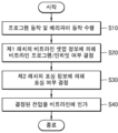
도 1 및 도 7을 참조하면, 제어 로직(140)은 호스트로부터 프로그램 커맨드(CMD)를 수신하여, 프로그램 동작 및 베리파이 동작을 수행할 수 있다(S10). 상기 프로그램 동작에는 초기 프로그램 동작이 포함될 수 있다. 제어 로직(140)은 프로그램 커맨드(CMD)에 대응하여 페이지 버퍼 회로(110)에 대응되는 제어신호를 출력할 수 있다. 페이지 버퍼 회로(110)는 제1 래치(111)에 저장된 비트라인 셋업 정보에 의해 비트라인에 대한 프로그램/인히빗 여부를 결정할 수 있다(S20). 또한, 페이지 버퍼 회로(110)는 제2 래치(112)에 저장된 포싱 정보에 의해 비트라인에 대한 포싱 여부를 결정할 수 있다(S30). 페이지 버퍼 회로(110)는 비트라인 셋업 정보 및 포싱 정보에 기초하여 포싱 셀, 포싱 대상이 아닌 프로그램 셀 및 인히빗 셀을 구분할 수 있고, 이에 대응하는 전압을 비트라인에 인가할 수 있다(S40).Referring to FIG. 1 and FIG. 7, the control logic (140) may receive a program command (CMD) from the host and perform a program operation and a verify operation (S10). The program operation may include an initial program operation. The control logic (140) may output a control signal corresponding to the page buffer circuit (110) in response to the program command (CMD). The page buffer circuit (110) may determine whether to program/inhibit a bit line based on bit line setup information stored in the first latch (111) (S20). In addition, the page buffer circuit (110) may determine whether to force a bit line based on forcing information stored in the second latch (112) (S30). The page buffer circuit (110) may distinguish a forcing cell, a program cell that is not a force target, and an inhibit cell based on the bit line setup information and the forcing information, and may apply a voltage corresponding thereto to the bit line (S40).
도 8은 본 개시의 예시적 실시예에 따른 비휘발성 메모리 장치의 동작을 나타내는 순서도이다.FIG. 8 is a flowchart illustrating the operation of a nonvolatile memory device according to an exemplary embodiment of the present disclosure.
도 2, 도 6 및 도 8을 참조하면, 제어 로직(140)은 호스트로부터 프로그램 커맨드(CMD)를 수신하여, 프로그램 동작 및 베리파이 동작을 수행할 수 있다(S110). 상기 프로그램 동작에는 초기 프로그램 동작이 포함될 수 있다. 그 후, 페이지 버퍼(210)는 베리파이 레벨(Lver)에 의해 프로그램/인히빗 셀의 구분 정보가 포함된 비트라인 셋업 정보를 결정할 수 있다(S120). 비트라인 셋업 과정에서, 스위칭 회로(213)에 의해 제1 래치(211)가 센싱 노드(SO)에 연결되고, 제1 래치(211)에 포함된 비트라인 셋업 정보가 센싱 노드(SO)에 인가될 수 있다(S130). 페이지 버퍼(210)는 비트라인 셋업 정보에 따라 연결된 메모리 셀이 프로그램 셀인지 여부를 결정할 수 있다(S140). 프로그램 셀이 아닌 경우(S140), 페이지 버퍼(210)는 비트라인에 인히빗 전압(Vinh)을 인가할 수 있다(S193). Referring to FIGS. 2, 6, and 8, the control logic (140) may receive a program command (CMD) from the host and perform a program operation and a verify operation (S110). The program operation may include an initial program operation. Thereafter, the page buffer (210) may determine bit line setup information including distinction information of a program/inhibit cell by a verify level (Lver) (S120). In the bit line setup process, the first latch (211) may be connected to the sensing node (SO) by the switching circuit (213), and the bit line setup information included in the first latch (211) may be applied to the sensing node (SO) (S130). The page buffer (210) may determine whether a connected memory cell is a program cell according to the bit line setup information (S140). If it is not a program cell (S140), the page buffer (210) can apply an inhibit voltage (Vinh) to the bit line (S193).
프로그램 셀인 경우(S140), 스위칭 회로(213)에 의해 제1 래치(211)와 센싱 노드(SO)가 분리 되고(S150), 포싱 레벨(Lfc)에 의해 포싱 정보가 결정될 수 있다(S160). 포싱 과정에서, 스위칭 회로(213)에 의해 제2 래치(212)가 센싱 노드(SO)에 연결되고, 제2 래치(212)에 포함된 포싱 정보가 센싱 노드(SO)에 인가될 수 있다(S170). 페이지 버퍼(210)는 포싱 정보에 따라 프로그램 셀이 포싱 셀인지 여부를 결정할 수 있다(S180). 포싱 셀이 아닌 경우(S180), 연결된 메모리 셀은 포싱 대상이 아닌 프로그램 셀이므로 페이지 버퍼(210)는 비트라인에 프로그램 전압(Vpgm)을 인가할 수 있다(S191). 포싱 셀인 경우(S180), 페이지 버퍼(210)는 비트라인에 포싱 전압(Vfc)을 인가할 수 있다(S192).In the case of a program cell (S140), the first latch (211) and the sensing node (SO) are separated by the switching circuit (213) (S150), and forcing information can be determined by the forcing level (Lfc) (S160). In the forcing process, the second latch (212) is connected to the sensing node (SO) by the switching circuit (213), and the forcing information included in the second latch (212) can be applied to the sensing node (SO) (S170). The page buffer (210) can determine whether the program cell is a forcing cell according to the forcing information (S180). In the case of not being a forcing cell (S180), since the connected memory cell is a program cell that is not a force target, the page buffer (210) can apply a program voltage (Vpgm) to the bit line (S191). In case of a forcing cell (S180), the page buffer (210) can apply a forcing voltage (Vfc) to the bit line (S192).
도 8에서는, 스위칭 회로(213)에 의해 제1 래치(211)와 센싱 노드(SO)가 분리되고(S150) 포싱 정보가 결정된 후(S160), 스위칭 회로(213)에 의해 제2 래치(212)에 저장된 포싱 정보가 센싱 노드(SO)에 인가되는 것(S170)으로 도시되고 있으나, 이는 일 예시일 뿐이고, 본 발명의 프로그램 방법은 제1 래치(211)와 센싱 노드(SO)가 분리되는 단계(S150), 포싱 정보가 결정되는 단계(S160) 및 포싱 정보가 센싱 노드(SO)에 인가되는 단계(S170)의 선후가 바뀔 수 있음은 이해되어야 할 것이다.In FIG. 8, the first latch (211) and the sensing node (SO) are separated by the switching circuit (213) (S150), and forcing information is determined (S160), and then the forcing information stored in the second latch (212) by the switching circuit (213) is applied to the sensing node (SO) (S170). However, this is only an example, and it should be understood that in the program method of the present invention, the order of the step (S150) in which the first latch (211) and the sensing node (SO) are separated, the step (S160) in which the forcing information is determined, and the step (S170) in which the forcing information is applied to the sensing node (SO) may be changed.
도 9는 본 개시의 예시적 실시예에 따른 비휘발성 메모리 장치를 나타내는 회로도이다. 자세하게는 도 9는 도 2의 일 예시에 따른 실제적인 회로도이다. 도 2와 중복되는 내용은 생략한다.FIG. 9 is a circuit diagram showing a nonvolatile memory device according to an exemplary embodiment of the present disclosure. In detail, FIG. 9 is an actual circuit diagram according to an example of FIG. 2. Any content overlapping with FIG. 2 is omitted.
도 9를 참조하면, 페이지 버퍼(30)는 제1 래치(311), 제2 래치(312), 스위칭 회로(313), 비트라인 선택 회로(314) 및 셀 스트링(320)을 포함할 수 있다. 제1 래치(311)는 하나 이상의 인버터로 구성될 수 있다. 본 발명의 일 실시예에서 제1 래치(311)는 별도의 로직 회로와 연결될 수 있고, 로직 회로를 통해 전원 전압(VDD) 또는 접지 전압(GND)을 인가 받을 수 있다. 제2 래치(312) 역시 하나 이상의 인버터로 구성될 수 있다. 본 발명의 일 실시예에서 제2 래치(312)는 별도의 로직 회로와 연결될 수 있고, 로직 회로를 통해 전원 전압(VDD) 또는 접지 전압(GND)을 인가 받을 수 있다. 본 발명의 또 다른 실시예에서, 제2 래치(312)는 로직 회로를 통해 전원 전압(VDD) 만을 인가 받을 수 있다.Referring to FIG. 9, the page buffer (30) may include a first latch (311), a second latch (312), a switching circuit (313), a bit line selection circuit (314), and a cell string (320). The first latch (311) may be composed of one or more inverters. In one embodiment of the present invention, the first latch (311) may be connected to a separate logic circuit and may receive a power supply voltage (VDD) or a ground voltage (GND) through the logic circuit. The second latch (312) may also be composed of one or more inverters. In one embodiment of the present invention, the second latch (312) may be connected to a separate logic circuit and may receive a power supply voltage (VDD) or a ground voltage (GND) through the logic circuit. In another embodiment of the present invention, the second latch (312) may receive only a power supply voltage (VDD) through the logic circuit.
스위칭 회로(313)는 제1 래치 스위치(LS1) 및 제2 래치 스위치(LS2)를 포함할 수 있다. 도 9에서는 제1 래치 스위치(LS1) 및 제2 래치 스위치(LS2)가 트랜지스터로 도시되어 있으나 이는 일 예시일 뿐이고, 제1 래치 스위치(LS1) 및 제2 래치 스위치(LS2)는 스위칭 동작을 수행할 수 있는 모든 소자를 포함할 수 있다. 제1 래치 스위치(LS1)는 셋업 신호(SS)에 대응하여 제1 래치(311)를 센싱 노드(SO)에 연결할 수 있다. 제2 래치 스위치(LS2)는 포싱 신호(SF)에 대응하여 제2 래치(312)를 센싱 노드(SO)에 연결할 수 있다.The switching circuit (313) may include a first latch switch (LS1) and a second latch switch (LS2). In FIG. 9, the first latch switch (LS1) and the second latch switch (LS2) are illustrated as transistors, but this is only an example, and the first latch switch (LS1) and the second latch switch (LS2) may include any element that can perform a switching operation. The first latch switch (LS1) may connect the first latch (311) to the sensing node (SO) in response to the setup signal (SS). The second latch switch (LS2) may connect the second latch (312) to the sensing node (SO) in response to the forcing signal (SF).
비트라인 선택 회로(314)는 비트라인 스위치(BLTr)를 포함할 수 있다. 비트라인 스위치(BLTr)는 비트라인 선택 신호(SBL)에 대응하여 센싱 노드(SO)에 인가된 전압을 셀 스트링(320)에 인가할 수 있다. 본 발명의 일 실시예에서, 비트라인 스위치(BLTr)는 비트라인 선택 신호(SBL)의 전압 레벨에 따라 셀 스트링(320)에 인가되는 전압을 조절할 수 있다. 이에 관해서는 도 10에서 후술한다. 도 9에서는 비트라인 스위치(BLTr)가 트랜지스터로 도시되어 있으나 이는 일 예시일 뿐이고, 비트라인 스위치(BLTr)는 스위칭 동작을 수행할 수 있는 모든 소자를 포함할 수 있다. 셀 스트링(320)은 도 2 등에서 상술한 셀 스트링(220)과 동일하거나 유사한 바 설명을 생략한다.The bit line selection circuit (314) may include a bit line switch (BLTr). The bit line switch (BLTr) may apply a voltage applied to the sensing node (SO) to the cell string (320) in response to the bit line selection signal (SBL). In one embodiment of the present invention, the bit line switch (BLTr) may adjust the voltage applied to the cell string (320) according to the voltage level of the bit line selection signal (SBL). This will be described later with reference to FIG. 10. In FIG. 9, the bit line switch (BLTr) is illustrated as a transistor, but this is only an example, and the bit line switch (BLTr) may include any element capable of performing a switching operation. The cell string (320) is the same as or similar to the cell string (220) described above in FIG. 2, and thus a description thereof will be omitted.
도 10은 본 개시의 예시적 실시예에 따른 비휘발성 메모리 장치의 프로그램 과정을 나타내는 타이밍 도이다. 도 9와 중복되는 내용은 생략한다.Fig. 10 is a timing diagram showing a programming process of a nonvolatile memory device according to an exemplary embodiment of the present disclosure. Any content overlapping with Fig. 9 is omitted.
도 9 및 도 10을 참조하면, 비트라인 셋업 동작시에, 제1 래치 스위치(LS1)의 게이트에 인가되는 셋업 신호(SS)가 로직 하이로 천이되고 제2 래치 스위치(LS2)의 게이트에 인가되는 포싱 신호(SF)는 로직 로우를 유지할 수 있다. 이에 따라, 제1 래치 스위치(LS1)가 ON 상태로 변경될 수 있고, 제1 래치(311)와 센싱 노드(SO)가 전기적으로 연결될 수 있다. 또한, 제1 래치(311)에 저장된 비트라인 셋업 정보가 센싱 노드(SO)에 인가될 수 있다. 비트라인 스위치(BLTr)의 게이트에 인가되는 비트라인 선택 신호(SBL)는 제1 전압 레벨(VL1)로 천이될 수 있다. 이에 따라, 비트라인 스위치(BLTR)는 ON 상태로 변경될 수 있고, 센싱 노드(SO)에 인가되는 비트라인 셋업 정보에 따라, 셀 스트링(320)에 프로그램 전압(Vpgm)이 인가될 수 있다. Referring to FIGS. 9 and 10, during a bit line setup operation, a setup signal (SS) applied to a gate of a first latch switch (LS1) may transition to a logic high, and a forcing signal (SF) applied to a gate of a second latch switch (LS2) may maintain a logic low. Accordingly, the first latch switch (LS1) may be changed to an ON state, and the first latch (311) and the sensing node (SO) may be electrically connected. In addition, bit line setup information stored in the first latch (311) may be applied to the sensing node (SO). A bit line selection signal (SBL) applied to a gate of the bit line switch (BLTr) may transition to a first voltage level (VL1). Accordingly, the bit line switch (BLTR) can be changed to the ON state, and the program voltage (Vpgm) can be applied to the cell string (320) according to the bit line setup information applied to the sensing node (SO).
포싱 동작시에, 셋업 신호(SS) 및 비트라인 선택 신호(SBL)가 로직 로우로 천이됨에 따라 제1 래치 스위치(LS1) 및 비트라인 스위치(BLTR)가 OFF 상태로 변경되고, 그 후 포싱 신호(SF)가 로직 하이로 천이됨에 따라 제2 래치 스위치(LS2)가 ON 상태로 변경될 수 있다. 이에 따라, 제2 래치(312)와 센싱 노드(SO)가 전기적으로 연결될 수 있고, 제2 래치(312)에 저장된 포싱 정보가 센싱 노드(SO)에 인가될 수 있다. 비트라인 선택 신호(SBL)는 다시 제2 전압 레벨(VL2)로 천이될 수 있다. 이에 따라, 비트라인 스위치(BLTr)는 ON 상태로 변경되고, 센싱 노드(SO)에 인가되는 포싱 정보에 따라, 셀 스트링(320)에 포싱 전압(Vfc)이 인가될 수 있다. 이때, 제2 전압 레벨(VL2)은 제1 전압 레벨(VL1)보다 더 낮기 때문에, 셀 스트링(320)에 인가되는 포싱 전압(Vfc)과 인히빗 전압(Vinh)은 서로 다른 전압 레벨을 가질 수 있다.During a forcing operation, as the setup signal (SS) and the bit line select signal (SBL) transition to logic low, the first latch switch (LS1) and the bit line switch (BLTR) may be turned OFF, and then as the forcing signal (SF) transitions to logic high, the second latch switch (LS2) may be turned ON. Accordingly, the second latch (312) and the sensing node (SO) may be electrically connected, and the forcing information stored in the second latch (312) may be applied to the sensing node (SO). The bit line select signal (SBL) may transition to the second voltage level (VL2) again. Accordingly, the bit line switch (BLTr) may be turned ON, and the forcing voltage (Vfc) may be applied to the cell string (320) according to the forcing information applied to the sensing node (SO). At this time, since the second voltage level (VL2) is lower than the first voltage level (VL1), the forcing voltage (Vfc) and the inhibiting voltage (Vinh) applied to the cell string (320) may have different voltage levels.
도 11은 본 개시의 예시적 실시예에 따른 페이지 버퍼를 나타내는 회로도이다. 도 9와 중복되는 내용은 생략한다.Fig. 11 is a circuit diagram showing a page buffer according to an exemplary embodiment of the present disclosure. Any content overlapping with Fig. 9 is omitted.
도 9 및 도 11을 참조하면, 페이지 버퍼(30)는 제1 래치(311) 및 제1 래치 스위치(LS1)를 통해서 셀 스트링(320)과 연결되는 제1 패쓰(Path1) 및 제2 래치(312) 및 제2 래치 스위치(LS2)를 통해서 셀 스트링(320)과 연결되는 제2 패쓰(Path2)를 포함할 수 있다. 제1 패쓰(Path1) 및 제2 패쓰(Path2)는 스위칭 회로(313)에 의해 제어될 수 있다. 본 발명의 일 실시예에 따르면, 비트라인 셋업 동작시에 제1 래치 스위치(LS1)가 ON 상태로 천이됨에 따라, 제1 패쓰(Path1)가 활성화될 수 있고, 비트라인 셋업 동작이 종료되면 제1 래치 스위치(LS1)가 OFF 상태로 천이됨에 따라, 제1 패쓰(Path1)가 비활성화될 수 있다. 그 다음 포싱 동작시에 제2 래치 스위치(LS2)가 ON 상태로 천이됨에 따라, 제2 패쓰(Path2)가 활성화될 수 있다.Referring to FIGS. 9 and 11, the page buffer (30) may include a first path (Path1) connected to a cell string (320) through a first latch (311) and a first latch switch (LS1), and a second path (Path2) connected to a cell string (320) through a second latch (312) and a second latch switch (LS2). The first path (Path1) and the second path (Path2) may be controlled by a switching circuit (313). According to one embodiment of the present invention, when the first latch switch (LS1) transitions to an ON state during a bit line setup operation, the first path (Path1) may be activated, and when the bit line setup operation is terminated, the first latch switch (LS1) transitions to an OFF state, and the first path (Path1) may be deactivated. Then, when the second latch switch (LS2) transitions to the ON state during the forcing operation, the second path (Path2) can be activated.
제1 패쓰(Path1)에 따라 제1 래치(311)에 포함된 비트라인 셋업 정보가 센싱 노드(SO)에 인가될 수 있고, 페이지 버퍼(30)는 비트라인 셋업 정보에 기초하여 비트라인 셋업 동작을 수행할 수 있다. 제2 패쓰(Path2)에 따라 제2 래치(312)에 포함된 포싱 정보가 센싱 노드(SO)에 인가될 수 있고, 페이지 버퍼(30)는 포싱 정보에 기초하여 포싱 동작을 수행할 수 있다.According to the first pass (Path1), bit line setup information included in the first latch (311) can be applied to the sensing node (SO), and the page buffer (30) can perform a bit line setup operation based on the bit line setup information. According to the second pass (Path2), forcing information included in the second latch (312) can be applied to the sensing node (SO), and the page buffer (30) can perform a forcing operation based on the forcing information.
도 12는 본 개시의 예시적 실시예에 따른 비휘발성 메모리 장치를 나타내는 블록도이다. 도 2와 중복되는 내용은 생략한다.Fig. 12 is a block diagram illustrating a nonvolatile memory device according to an exemplary embodiment of the present disclosure. Any content overlapping with Fig. 2 is omitted.
도 2 및 도 12를 참조하면, 비휘발성 메모리 장치(40)는 복수 개의 페이지 버퍼(410_1, 410_2, 410_3, 410_4) 및 메모리 셀 어레이(420)를 포함하고, 복수 개의 페이지 버퍼(410_1, 410_2, 410_3, 410_4) 각각은 제1 래치(411), 제2 래치(412), 스위칭 회로(413) 및 비트라인 선택 회로(414)를 포함할 수 있다. 내부 구성이 도시되지 않은 페이지 버퍼(410_2, 410_3, 410_4) 역시 내부 구성이 도시된 페이지 버퍼(410_1)와 같은 구성을 포함할 수 있다. 제1 래치(411), 제2 래치(412) 및 스위칭 회로(413)는 도 2의 제1 래치(211), 제2 래치(212) 및 스위칭 회로(213)와 실질적으로 동일하거나 유사할 수 있으므로 설명은 생략한다.Referring to FIG. 2 and FIG. 12, a nonvolatile memory device (40) includes a plurality of page buffers (410_1, 410_2, 410_3, 410_4) and a memory cell array (420), and each of the plurality of page buffers (410_1, 410_2, 410_3, 410_4) may include a first latch (411), a second latch (412), a switching circuit (413), and a bit line selection circuit (414). The page buffers (410_2, 410_3, 410_4) whose internal configuration is not illustrated may also include the same configuration as the page buffer (410_1) whose internal configuration is illustrated. The first latch (411), the second latch (412), and the switching circuit (413) may be substantially the same as or similar to the first latch (211), the second latch (212), and the switching circuit (213) of FIG. 2, and therefore, a description thereof is omitted.
복수 개의 페이지 버퍼(410_1, 410_2, 410_3, 410_4) 각각은 쉴드(Shield) 비트라인 구조를 가질 수 있다. 복수 개의 페이지 버퍼(410_1, 410_2, 410_3, 410_4) 각각은 복수 개의 비트라인과 동시에 연결되어 있을 수 있다. 도 12에서는 복수 개의 페이지 버퍼(410_1, 410_2, 410_3, 410_4) 각각이 4 개의 비트라인과 연결되는 것으로 도시되어 있으나, 이는 일 예시일 뿐이고, 복수 개의 페이지 버퍼(410_1, 410_2, 410_3, 410_4) 각각은 2개 이상의 비트라인과 연결될 수 있다. 이하에서 하나의 페이지 버퍼(410_1)에 대해서만 설명하나, 이는 다른 모든 페이지 버퍼(410_2, 410_3, 410_4)에도 적용될 수 있다.Each of the plurality of page buffers (410_1, 410_2, 410_3, 410_4) may have a shield bitline structure. Each of the plurality of page buffers (410_1, 410_2, 410_3, 410_4) may be simultaneously connected to multiple bitlines. In FIG. 12, each of the plurality of page buffers (410_1, 410_2, 410_3, 410_4) is illustrated as being connected to four bitlines, but this is only an example, and each of the plurality of page buffers (410_1, 410_2, 410_3, 410_4) may be connected to two or more bitlines. Below, only one page buffer (410_1) is described, but this can also be applied to all other page buffers (410_2, 410_3, 410_4).
비트라인 선택 회로(414)는 복수 개의 비트라인과 연결될 수 있다. 복수 개의 비트라인은 프로그램 동작의 대상이 되는 셋업 비트라인 및 나머지 프로그램 동작의 대상이 되지 않은 쉴드 비트라인을 포함할 수 있다. 비트라인 선택 회로(414)는 복수 개의 비트라인 중 하나 이상의 비트라인을 셋업 비트라인으로 설정할 수 있다. 비트라인 선택 회로(414)는 셋업 비트라인에 대한 프로그램 동작이 완료되면 순차적으로 다음 비트라인을 셋업 비트라인으로 설정하고 프로그램 동작을 수행할 수 있다. 셋업 비트라인에 대한 프로그램 동작이 수행될 때, 쉴드 비트라인에는 인히빗 전압이 인가되어 인히빗 상태가 유지될 수 있다. 쉴드 비트라인이 인히빗 상태가 됨에 따라, 다른 페이지 버퍼(410_2, 410_3, 410_4)로부터의 셋업 비트라인에 대한 커플링이 영향이 방지 될 수 있다. 본 발명의 일 실시예에 따르면, 셋업 비트라인이 포싱 동작 수행 중 플로팅 상태가 되더라도 쉴드 비트라인에 의해 커플링 영향을 방지할 수 있다. 또한 본 발명의 또 다른 실시예에 따르면, 페이지 버퍼(410_1)는 커플링 정도에 따라 복수 개의 비트라인에 대한 쉴드 비트라인의 비율을 조절할 수 있다. 이에 관해서는 도 16에서 후술한다.The bit line selection circuit (414) can be connected to a plurality of bit lines. The plurality of bit lines can include a setup bit line that is a target of a program operation and a shield bit line that is not a target of the remaining program operations. The bit line selection circuit (414) can set one or more bit lines among the plurality of bit lines as a setup bit line. When a program operation for a setup bit line is completed, the bit line selection circuit (414) can sequentially set the next bit line as a setup bit line and perform a program operation. When a program operation for a setup bit line is performed, an inhibit voltage can be applied to the shield bit line so that the inhibit state can be maintained. As the shield bit line becomes the inhibit state, the coupling to the setup bit line from other page buffers (410_2, 410_3, 410_4) can be prevented. According to one embodiment of the present invention, even if the setup bit line becomes floating during the forcing operation, the coupling effect can be prevented by the shield bit line. In addition, according to another embodiment of the present invention, the page buffer (410_1) can adjust the ratio of the shield bit line to the plurality of bit lines according to the degree of coupling. This will be described later in FIG. 16.
도 13은 본 개시의 예시적 실시예에 따른 비휘발성 메모리 장치를 나타내는 회로도이다. 도 9 및 도 12와 중복되는 내용은 생략한다.Fig. 13 is a circuit diagram showing a nonvolatile memory device according to an exemplary embodiment of the present disclosure. Any content overlapping with Figs. 9 and 12 is omitted.
도 9, 도 12 및 도 13을 참조하면, 페이지 버퍼(50)는 제1 래치(511), 제2 래치(512), 스위칭 회로(513), 비트라인 선택 회로(514) 및 바이어스 회로(515)를 포함할 수 있다. 제1 래치(511), 제2 래치(512) 및 스위칭 회로(513)는 도 9의 제1 래치(311), 제2 래치(312) 및 스위칭 회로(313)와 실질적으로 동일하거나 유사할 수 있으므로 설명은 생략한다. Referring to FIGS. 9, 12, and 13, the page buffer (50) may include a first latch (511), a second latch (512), a switching circuit (513), a bit line selection circuit (514), and a bias circuit (515). The first latch (511), the second latch (512), and the switching circuit (513) may be substantially the same as or similar to the first latch (311), the second latch (312), and the switching circuit (313) of FIG. 9, and therefore, a description thereof is omitted.
비트라인 선택 회로(514)는 복수 개의 비트라인과 연결될 수 있다. 복수 개의 비트라인은 프로그램의 대상이 되는 셋업 비트라인 및 나머지 프로그램의 대상이 되지 않은 쉴드 비트라인을 포함할 수 있다. 도 13에서는 비트라인 선택 회로(514)가 4개의 비트라인과 연결되어 있도록 도시되어 있으나 이는 일 예시일 뿐이고, 비트라인 선택 회로(514)는 2개 이상의 비트라인과 연결될 수 있다. 또한, 도시되지 않았으나 각 비트라인은 셀 스트링과 각각 연결될 수 있다.The bit line selection circuit (514) may be connected to a plurality of bit lines. The plurality of bit lines may include a setup bit line that is a target of a program and a shield bit line that is not a target of the remaining programs. In FIG. 13, the bit line selection circuit (514) is illustrated as being connected to four bit lines, but this is only an example, and the bit line selection circuit (514) may be connected to two or more bit lines. In addition, although not illustrated, each bit line may be connected to a cell string, respectively.
비트라인 선택 회로(514)는 비트라인 각각과 연결되는 스위치(SeTr, ShTr1, ShTr2, ShTr3)를 포함할 수 있다. 자세하게는, 비트라인 선택 회로(514)는 셋업 스위치(SeTr) 및 쉴드 스위치(ShTr1, ShTr2, ShTr3)를 포함할 수 있다. 도 13에서는 스위치(SeTr, ShTr1, ShTr2, ShTr3)가 트랜지스터로 도시되어 있으나 이는 일 예시일 뿐이고, 스위치(SeTr, ShTr1, ShTr2, ShTr3)는 스위칭 동작을 수행할 수 있는 모든 소자를 포함할 수 있다.The bit line selection circuit (514) may include switches (SeTr, ShTr1, ShTr2, ShTr3) connected to each bit line. In detail, the bit line selection circuit (514) may include a setup switch (SeTr) and a shield switch (ShTr1, ShTr2, ShTr3). In FIG. 13, the switches (SeTr, ShTr1, ShTr2, ShTr3) are illustrated as transistors, but this is only an example, and the switches (SeTr, ShTr1, ShTr2, ShTr3) may include any elements capable of performing a switching operation.
스위치(SeTr, ShTr1, ShTr2, ShTr3)는 각각 비트라인과 연결되어 센싱 노드(SO)와 비트라인의 연결을 제어할 수 있다. 셋업 스위치(SeTr)는 프로그램 동작의 대상이 되는 셋업 비트라인과 연결될 수 있고, 쉴드 스위치(ShTr1, ShTr2, ShTr3)는 셋업 비트라인에 대한 커플링 현상을 방지하는 쉴드 비트라인과 연결될 수 있다. 셋업 스위치(SeTr)는 셋업 선택 신호(SSe)에 대응하여 셋업 비트라인에 대한 전압 인가를 제어하여 비트라인 셋업 동작 및 포싱 동작을 수행할 수 있다. 셋업 선택 신호(SSe) 및 셋업 스위치(SeTr)의 구체적인 동작에 관해서는 도 14에서 후술한다. 쉴드 스위치(ShTr1, ShTr2, ShTr3)는 쉴드 선택 신호(SSh)에 대응하여 셋업 비트라인에 대한 비트라인 셋업 동작 및 포싱 동작을 수행하는 동안 OFF 상태를 유지하여 쉴드 비트라인에 센싱 노드(SO)의 전압이 인가되지 않도록 할 수 있다. The switches (SeTr, ShTr1, ShTr2, ShTr3) are each connected to a bit line and can control the connection of the sensing node (SO) and the bit line. The setup switch (SeTr) can be connected to a setup bit line that is a target of a program operation, and the shield switches (ShTr1, ShTr2, ShTr3) can be connected to a shield bit line that prevents a coupling phenomenon for the setup bit line. The setup switch (SeTr) can perform a bit line setup operation and a forcing operation by controlling voltage application to the setup bit line in response to a setup select signal (SSe). The specific operations of the setup select signal (SSe) and the setup switch (SeTr) are described later in FIG. 14. The shield switches (ShTr1, ShTr2, ShTr3) can be kept in an OFF state while performing a bit line setup operation and a forcing operation for the setup bit line in response to a shield select signal (SSh), thereby preventing the voltage of the sensing node (SO) from being applied to the shield bit line.
바이어스 회로(515)는 바이어스 신호(VSe, VSh)에 제어에 따라 비트라인에 일정한 전압을 인가할 수 있다. 자세하게는, 셋업 비트라인은 셋업 바이어스 신호(VSe)에 의해 전원 전압(VDD)이 인가될 수 있고, 쉴드 비트라인은 쉴드 바이어스 신호(VSh)에 의해 전원 전압(VDD)이 인가될 수 있다. 본 발명의 일 실시예에 따르면, 셋업 비트라인에 대한 비트라인 셋업 동작이 수행되는 동안 쉴드 비트라인은 전원 전압(VDD)으로 바이어스 되어 인히빗 상태를 유지할 수 있다. 쉴드 비트라인이 인히빗 상태로 유지됨에 따라 셋업 비트라인에 대한 커플링을 방지할 수 있다. 도 13에서 바이어스 회로(515)는 전원 전압(VDD)만이 연결되어 있는 것으로 도시되어 있으나, 본 발명의 또 다른 실시예에서 바이어스 회로(515)는 전원 전압(VDD)외에 접지 전압(GND)에도 연결될 수 있다.The bias circuit (515) can apply a constant voltage to the bit line according to the control of the bias signal (VSe, VSh). In detail, the setup bit line can be applied with the power voltage (VDD) by the setup bias signal (VSe), and the shield bit line can be applied with the power voltage (VDD) by the shield bias signal (VSh). According to one embodiment of the present invention, while a bit line setup operation for the setup bit line is performed, the shield bit line can be biased with the power voltage (VDD) to maintain an inhibited state. As the shield bit line is maintained in the inhibited state, coupling to the setup bit line can be prevented. Although the bias circuit (515) is illustrated as being connected only to the power voltage (VDD) in FIG. 13, in another embodiment of the present invention, the bias circuit (515) can be connected to a ground voltage (GND) in addition to the power voltage (VDD).
페이지 버퍼(50)는 제1 래치(511) 및 제1 래치 스위치(LS1)를 통해서 셋업비트라인과 연결되는 제1 패쓰(Path1) 및 제2 래치(512) 및 제2 래치 스위치(LS2)를 통해서 셋업 비트라인과 연결되는 제2 패쓰(Path2)를 포함할 수 있다. 제1 패쓰(Path1) 및 제2 패쓰(Path2)는 스위칭 회로(513)에 의해 제어될 수 있다. 본 발명의 일 실시예에 따르면, 비트라인 셋업 동작시에 제1 래치 스위치(LS1)가 ON 상태로 천이됨에 따라, 제1 패쓰(Path1)가 활성화될 수 있고, 비트라인 셋업 동작이 종료되면 제1 래치 스위치(LS1)가 OFF 상태로 천이됨에 따라, 제1 패쓰(Path1)가 비활성화될 수 있다. 그 다음 포싱 동작시에 제2 래치 스위치(LS2)가 ON 상태로 천이됨에 따라, 제2 패쓰(Path2)가 활성화될 수 있다.The page buffer (50) may include a first path (Path1) connected to the setup bit line through the first latch (511) and the first latch switch (LS1), and a second path (Path2) connected to the setup bit line through the second latch (512) and the second latch switch (LS2). The first path (Path1) and the second path (Path2) may be controlled by the switching circuit (513). According to one embodiment of the present invention, when the first latch switch (LS1) transitions to an ON state during a bit line setup operation, the first path (Path1) may be activated, and when the bit line setup operation is terminated, when the first latch switch (LS1) transitions to an OFF state, the first path (Path1) may be deactivated. Then, when the second latch switch (LS2) transitions to an ON state during a forcing operation, the second path (Path2) may be activated.
도 14는 본 개시의 예시적 실시예에 따른 비휘발성 메모리 장치의 프로그램 과정을 나타내는 타이밍 도이다. 도 13과 중복되는 내용은 생략한다.Fig. 14 is a timing diagram showing a programming process of a nonvolatile memory device according to an exemplary embodiment of the present disclosure. Any duplicate content from Fig. 13 is omitted.
도 13 및 도 14을 참조하면, 비트라인 셋업 동작시에, 제1 래치 스위치(LS1)의 게이트에 인가되는 셋업 신호(SS)가 로직 하이로 천이되고 제2 래치 스위치(LS2)의 게이트에 인가되는 포싱 신호(SF)는 로직 로우를 유지할 수 있다. 이에 따라, 제1 래치 스위치(LS1)가 ON 상태로 변경될 수 있고, 제1 래치(511)와 센싱 노드(SO)가 전기적으로 연결될 수 있다. 또한, 제1 래치(511)에 저장된 비트라인 셋업 정보가 센싱 노드(SO)에 인가될 수 있다. Referring to FIGS. 13 and 14, during a bit line setup operation, a setup signal (SS) applied to a gate of a first latch switch (LS1) may transition to logic high, and a forcing signal (SF) applied to a gate of a second latch switch (LS2) may maintain logic low. Accordingly, the first latch switch (LS1) may be changed to an ON state, and the first latch (511) and the sensing node (SO) may be electrically connected. In addition, bit line setup information stored in the first latch (511) may be applied to the sensing node (SO).
셋업 스위치(SeTr)의 게이트에 인가되는 셋업 선택 신호(SSe)는 제1 전압 레벨(VL1)로 천이될 수 있다. 이에 따라, 셋업 스위치(SeTr)는 ON 상태로 변경될 수 있고, 센싱 노드(SO)에 인가되는 비트라인 셋업 정보에 따라, 셋업 비트라인과 연결되는 셀 스트링에 프로그램 전압(Vpgm)이 인가될 수 있다. 또한, 셋업 바이어스 신호(VSe)가 로직 로우로 유지되어 바이어스 전압이 셋업 비트라인에 인가되는 것을 방지할 수 있다.A setup select signal (SSe) applied to a gate of a setup switch (SeTr) can be transitioned to a first voltage level (VL1). Accordingly, the setup switch (SeTr) can be changed to an ON state, and a program voltage (Vpgm) can be applied to a cell string connected to the setup bit line according to bit line setup information applied to a sensing node (SO). In addition, the setup bias signal (VSe) can be maintained at a logic low to prevent a bias voltage from being applied to the setup bit line.
쉴드 스위치(ShTr)의 게이트에 인가되는 쉴드 선택 신호(SSh)는 로직 로우를 유지함에 따라 쉴드 스위치(ShTr1, ShTr2, ShTr3)는 OFF 상태를 유지하고, 쉴드 바이어스 신호(VSh)가 로직 하이를 유지함에 따라 쉴드 비트라인에 전원 전압(VDD)이 인가될 수 있다. 이런 과정에 의해 쉴드 비트라인은 인히빗 상태를 유지할 수 있다.As the shield select signal (SSh) applied to the gate of the shield switch (ShTr) maintains a logic low, the shield switches (ShTr1, ShTr2, ShTr3) are maintained in the OFF state, and as the shield bias signal (VSh) maintains a logic high, a power voltage (VDD) can be applied to the shield bit line. Through this process, the shield bit line can be maintained in an inhibited state.
포싱 동작시에, 셋업 신호(SS) 및 셋업 선택 신호(SSe)가 로직 로우로 천이됨에 따라 제1 래치 스위치(LS1) 및 셋업 스위치(SeTr)가 OFF 상태로 변경되고, 그 후 포싱 신호(SF)가 로직 하이로 천이됨에 따라 제2 래치 스위치(LS2)가 ON 상태로 변경될 수 있다. 이에 따라, 제2 래치(512)와 센싱 노드(SO)가 전기적으로 연결될 수 있고, 제2 래치(512)에 저장된 포싱 정보가 센싱 노드(SO)에 인가될 수 있다. 셋업 선택 신호(SSe)는 다시 제2 전압 레벨(VL2)로 천이될 수 있다. 이에 따라, 셋업 스위치(SeTr)는 ON 상태로 변경되고, 센싱 노드(SO)에 인가되는 포싱 정보에 따라, 셋업 비트라인과 연결된 셀 스트링에 포싱 전압(Vfc)이 인가될 수 있다. 이때, 제2 전압 레벨(VL2)은 제1 전압 레벨(VL1)보다 더 낮기 때문에, 셋업 비트라인과 연결된 셀 스트링에 인가되는 포싱 전압(Vfc)은 프로그램 전압(Vpgm)과 다른 전압 레벨을 가질 수 있다.During a forcing operation, as the setup signal (SS) and the setup select signal (SSe) transition to logic low, the first latch switch (LS1) and the setup switch (SeTr) may be turned OFF, and then as the forcing signal (SF) transitions to logic high, the second latch switch (LS2) may be turned ON. Accordingly, the second latch (512) and the sensing node (SO) may be electrically connected, and the forcing information stored in the second latch (512) may be applied to the sensing node (SO). The setup select signal (SSe) may transition to the second voltage level (VL2) again. Accordingly, the setup switch (SeTr) may be turned ON, and the forcing voltage (Vfc) may be applied to the cell string connected to the setup bit line according to the forcing information applied to the sensing node (SO). At this time, since the second voltage level (VL2) is lower than the first voltage level (VL1), the forcing voltage (Vfc) applied to the cell string connected to the setup bit line may have a voltage level different from the program voltage (Vpgm).
포싱 동작 동안 쉴드 선택 신호(SSh)는 로직 로우를 유지하여 포싱 전압(Vfc)이 쉴드 비트라인에 인가되는 것을 방지할 수 있다. 또한, 셋업 바이어스 신호(VSe) 역시 로직 로우를 유지하여 셋업 비트라인이 전원 전압(VDD)으로 바이어스 되는 것을 방지할 수 있다. 쉴드 바이어스 신호(VSh)는 로직 하이를 유지하여 쉴드 비트라인이 인히빗 상태를 유지할 수 있다. 본 발명의 일 실시예에서는 도 14와 상이하게, 쉴드 바이어스 신호(VSh)가 포싱 단계에서 로직 로우로 천이될 수 있다. 포싱 단계에서는 쉴드 비트라인이 인히빗 상태를 유지하고 있을 필요가 없을 수 있다. 이에 따라, 쉴드 바이어스 신호(VSh)가 로직 로우로 천이되더라도 셋업 비트라인이 커플링 영향을 받지 않을 수 있다.During the forcing operation, the shield select signal (SSh) can be maintained at logic low to prevent the forcing voltage (Vfc) from being applied to the shield bit line. In addition, the setup bias signal (VSe) can also be maintained at logic low to prevent the setup bit line from being biased to the power supply voltage (VDD). The shield bias signal (VSh) can be maintained at logic high to maintain the shield bit line in an inhibited state. In one embodiment of the present invention, unlike FIG. 14, the shield bias signal (VSh) can transition to logic low during the forcing phase. It may not be necessary for the shield bit line to be maintained in the inhibited state during the forcing phase. Accordingly, even if the shield bias signal (VSh) transitions to logic low, the setup bit line may not be affected by coupling.
도 15는 본 개시의 예시적 실시예에 따른 페이지 버퍼를 나타내는 블록도이다. 도 13와 중복되는 내용은 생략한다.Fig. 15 is a block diagram illustrating a page buffer according to an exemplary embodiment of the present disclosure. Any duplicate content from Fig. 13 is omitted.
도 13 및 도 15를 참조하면, 페이지 버퍼(60)는 제1 래치(611), 제2 래치(612), 스위칭 회로(613), 비트라인 선택 회로(614) 및 쉴드 비트라인 결정부(615)를 포함할 수 있다. 제1 래치(611), 제2 래치(612), 스위칭 회로(613) 및 비트라인 선택 회로(614)는 도 13의 제1 래치(511), 제2 래치(512), 스위칭 회로(513) 및 비트라인 선택 회로(514)와 동일하거나 유사할 수 있다. Referring to FIGS. 13 and 15, the page buffer (60) may include a first latch (611), a second latch (612), a switching circuit (613), a bit line selection circuit (614), and a shield bit line decision unit (615). The first latch (611), the second latch (612), the switching circuit (613), and the bit line selection circuit (614) may be identical to or similar to the first latch (511), the second latch (512), the switching circuit (513), and the bit line selection circuit (514) of FIG. 13.
쉴드 비트라인 결정부(615)는 비트라인 선택 회로(614)를 제어하여 전체 비트라인 대비 쉴드 비트라인의 비율을 조절할 수 있다. 커플링의 정도가 높으면 셋업 비트라인에 대한 커플링을 방지하기 위해 비교적 많은 쉴드 비트라인이 필요할 수 있고, 커플링의 정도가 낮으면 비교적 적은 쉴드 비트라인이 필요할 수 있다. 쉴드 비트라인 결정부(615)는 커플링의 정도에 따라 비트라인 선택 회로(514)에 인가되는 셋업 선택 신호(SSe) 및 쉴드 선택 신호(SSh)의 비율을 조절하여 쉴드 비트라인의 비율을 조절할 수 있다. 자세하게는, 쉴드 비트라인 결정부(615)는 커플링 현상이 많이 발생하는 경우 쉴드 비트라인의 비율을 높이고, 커플링 현상이 적게 발생하는 경우 쉴드 비트라인의 비율을 낮출 수 있다. 본 발명의 일 실시예에서, 쉴드 비트라인 결정부(615)는 커플링 정도에 관한 정보를 수신하고 이에 따라, 쉴드 비트라인의 비율을 조절할 수 있다. The shield bitline decision unit (615) can control the bitline selection circuit (614) to adjust the ratio of the shield bitline to the total bitline. If the degree of coupling is high, a relatively large number of shield bitlines may be required to prevent coupling to the setup bitline, and if the degree of coupling is low, a relatively small number of shield bitlines may be required. The shield bitline decision unit (615) can adjust the ratio of the shield bitline by adjusting the ratio of the setup selection signal (SSe) and the shield selection signal (SSh) applied to the bitline selection circuit (514) according to the degree of coupling. In detail, the shield bitline decision unit (615) can increase the ratio of the shield bitline when a lot of coupling phenomenon occurs, and can decrease the ratio of the shield bitline when a little coupling phenomenon occurs. In one embodiment of the present invention, the shield bitline decision unit (615) can receive information about the degree of coupling and adjust the ratio of the shield bitline accordingly.
도 16은 본 개시의 예시적 실시예에 따른 비휘발성 메모리 장치를 구비하는 컴퓨팅 시스템 장치를 나타내는 도면이다.FIG. 16 is a diagram illustrating a computing system device having a nonvolatile memory device according to an exemplary embodiment of the present disclosure.
도 16을 참조하면, 상기 컴퓨팅 시스템 장치(900)는 버스(960)에 전기적으로 연결된 마이크로프로세서(930), 사용자 인터페이스(950), 그리고 메모리 컨트롤러(912) 및 비휘발성 메모리 장치(911)를 구비하는 비휘발성 메모리 시스템(910)을 포함할 수 있다. 비휘발성 메모리 장치(911)에는 마이크로프로세서(930)에 의해서 처리된/처리될 데이터가 메모리 컨트롤러(912)를 통해 저장될 수 있다. 또한 비휘발성 메모리 장치(911)는 도 1 내지 도 15에서 설명한 비휘발성 메모리 장치를 포함할 수 있다. 컴퓨팅 시스템 장치(900)는 나아가, 램(940) 및 파워 공급 장치(920)를 더 구비할 수 있다.Referring to FIG. 16, the computing system device (900) may include a nonvolatile memory system (910) having a microprocessor (930), a user interface (950), a memory controller (912), and a nonvolatile memory device (911) electrically connected to a bus (960). In the nonvolatile memory device (911), data processed/to be processed by the microprocessor (930) may be stored through the memory controller (912). In addition, the nonvolatile memory device (911) may include the nonvolatile memory devices described in FIGS. 1 to 15. The computing system device (900) may further include a RAM (940) and a power supply device (920).
컴퓨팅 시스템 장치(900)가 모바일 장치인 경우, 컴퓨팅 시스템의 동작 전압을 공급하기 위한 배터리 및 베이스밴드 칩셋(baseband chipset)과 같은 모뎀이 추가적으로 제공될 수 있다. 또한, 컴퓨팅 시스템 장치(900)에는 응용 칩셋(application chipset), 카메라 이미지 프로세서(Camera Image Processor: CIS), 모바일 디램 등이 더 제공될 수 있음은 이 분야의 통상적인 지식을 습득한 자들에게 자명한 사항인 바, 더 자세한 설명은 생략한다.If the computing system device (900) is a mobile device, a battery for supplying the operating voltage of the computing system and a modem such as a baseband chipset may be additionally provided. In addition, it is obvious to those with general knowledge in this field that the computing system device (900) may further be provided with an application chipset, a camera image processor (CIS), a mobile DRAM, etc., and thus a detailed description thereof will be omitted.
바람직하게는, 메모리 컨트롤러(912)와 비휘발성 메모리 장치(911)는, 예를 들면, 데이터를 저장하는 데 비휘발성 메모리를 사용하는 SSD(Solid State Drive/Disk)를 구성할 수 있다. Preferably, the memory controller (912) and the nonvolatile memory device (911) may configure, for example, an SSD (Solid State Drive/Disk) that uses nonvolatile memory to store data.
이상에서와 같이 도면과 명세서에서 예시적인 실시예들이 개시되었다. 본 명세서에서 특정한 용어를 사용하여 실시예들을 설명되었으나, 이는 단지 본 개시의 기술적 사상을 설명하기 위한 목적에서 사용된 것이지 의미 한정이나 특허청구범위에 기재된 본 개시의 범위를 제한하기 위하여 사용된 것은 아니다. 그러므로 본 기술분야의 통상의 지식을 가진 자라면 이로부터 다양한 변형 및 균등한 타 실시예가 가능하다는 점을 이해할 것이다. 따라서, 본 개시의 진정한 기술적 보호범위는 첨부된 특허청구범위의 기술적 사상에 의해 정해져야 할 것이다. As described above, exemplary embodiments have been disclosed in the drawings and the specification. Although specific terms have been used in the specification to describe the embodiments, these have been used only for the purpose of explaining the technical idea of the present disclosure and have not been used to limit the meaning or the scope of the present disclosure described in the claims. Therefore, those skilled in the art will understand that various modifications and equivalent other embodiments are possible therefrom. Accordingly, the true technical protection scope of the present disclosure should be determined by the technical idea of the appended claims.
Claims (10)
센싱 노드를 통해 상기 비트라인과 연결되고, 상기 비트라인을 통해 상기 셀 스트링에 연결되는 페이지 버퍼를 포함하고,
상기 페이지 버퍼는 비트라인 셋업 정보를 저장하는 제1 래치 및 포싱 정보를 저장하는 제2 래치를 포함하고,
상기 제1 래치는 상기 비트라인 셋업 정보를 상기 센싱 노드에 출력하고, 상기 제2 래치는 상기 포싱 정보를 상기 제1 래치와 독립적으로 상기 센싱 노드에 출력하고,
상기 페이지 버퍼는,
상기 제1 래치와 센싱 노드 간의 연결을 제어하는 제1 스위치 및 상기 제2 래치와 상기 센싱 노드 간의 연결을 제어하는 제2 스위치를 더 포함하는 것을 특징으로 하는 비휘발성 메모리 장치.A cell string comprising a plurality of memory cells connected to one bit line; and
A page buffer is connected to the bit line through the sensing node and connected to the cell string through the bit line,
The above page buffer includes a first latch storing bitline setup information and a second latch storing forcing information,
The first latch outputs the bitline setup information to the sensing node, and the second latch outputs the forcing information to the sensing node independently of the first latch.
The above page buffer is,
A nonvolatile memory device further comprising a first switch controlling a connection between the first latch and the sensing node, and a second switch controlling a connection between the second latch and the sensing node.
상기 제2 래치는, 상기 포싱 정보를 상기 센싱 노드에 출력하는 포싱 동작 시, 상기 제1 래치에 대한 덤핑 동작을 수행하지 않는 것을 특징으로 하는 비휘발성 메모리 장치.In the first paragraph,
A nonvolatile memory device characterized in that the second latch does not perform a dumping operation on the first latch during a forcing operation that outputs the forcing information to the sensing node.
상기 제1 래치는 상기 비트라인 셋업 정보로서, 베리파이 레벨을 기준으로 프로그램 대상 셀과 인히빗 대상 셀에 대해 구분하는 정보를 저장하고,
상기 제2 래치는 상기 포싱 정보로서, 포싱 레벨을 기준으로 상기 프로그램 대상 셀 중 포싱 대상 셀을 구분하는 정보를 저장하는 것을 특징으로 하는 비휘발성 메모리 장치.In the first paragraph,
The above first latch stores information for distinguishing between a program target cell and an inhibit target cell based on the verify level as the bit line setup information.
A nonvolatile memory device characterized in that the second latch stores information for distinguishing a force target cell among the program target cells based on a force level as the force information.
상기 페이지 버퍼는,
상기 비트라인 셋업 정보 및 상기 포싱 정보에 기초하여 상기 포싱 대상 셀이 아닌 상기 프로그램 대상 셀에는 프로그램 전압을 인가하고, 상기 인히빗 대상 셀에는 인히빗 전압을 인가하고,
상기 포싱 대상 셀에는 상기 프로그램 전압의 전압 레벨보다 크고 상기 인히빗 전압의 전압 레벨보다 작은 전압 레벨을 갖는 포싱 전압을 인가하는 것을 특징으로 하는 비휘발성 메모리 장치.In the third paragraph,
The above page buffer is,
Based on the bit line setup information and the forcing information, a program voltage is applied to the program target cell other than the forcing target cell, and an inhibit voltage is applied to the inhibit target cell.
A nonvolatile memory device characterized in that a forcing voltage having a voltage level greater than the voltage level of the program voltage and less than the voltage level of the inhibit voltage is applied to the forcing target cell.
상기 페이지 버퍼는 상기 다수의 메모리 셀에 대한 프로그램 동작시 비트라인 셋업 동작 및 포싱 동작을 수행하고,
상기 제1 스위치는 상기 비트라인 셋업 동작시에 상기 제1 래치와 상기 센싱 노드를 연결시키고,
상기 제2 스위치는 상기 포싱 동작시에 상기 제2 래치와 상기 센싱 노드를 연결시키는 것을 특징으로 하는 비휘발성 메모리 장치.In the first paragraph,
The above page buffer performs bit line setup operation and forcing operation during program operation for the above multiple memory cells,
The first switch connects the first latch and the sensing node during the bit line setup operation,
A nonvolatile memory device characterized in that the second switch connects the second latch and the sensing node during the forcing operation.
상기 페이지 버퍼는 복수 개의 비트라인과 연결되는 쉴드(Shield) 비트라인 구조를 갖고,
상기 복수 개의 비트라인은 상기 비트라인 셋업 동작의 대상이 되는 셋업 비트라인과 상기 비트라인 셋업 동작이 되지 않는 쉴드 비트라인을 포함하고,
상기 쉴드 비트라인은 상기 셋업 비트라인에 대한 포싱 동작 수행시에 인히빗 상태를 유지하면서 이웃 비트라인으로부터 커플링 현상을 막는 것을 특징으로 하는 비휘발성 메모리 장치.In the first paragraph,
The above page buffer has a shield bitline structure connected to multiple bitlines,
The above plurality of bit lines include a setup bit line that is a target of the bit line setup operation and a shield bit line that is not subject to the bit line setup operation.
A nonvolatile memory device characterized in that the shield bit line maintains an inhibited state when a forcing operation is performed on the setup bit line and prevents a coupling phenomenon from a neighboring bit line.
복수 개의 비트라인을 통해 상기 복수 개의 셀 스트링들과 연결되는 쉴드(Shield) 비트라인 구조를 갖는 페이지 버퍼를 포함하고,
상기 페이지 버퍼는 비트라인 셋업 정보를 센싱 노드에 출력하는 제1 패쓰(Path) 및 상기 제1 패쓰와 서로 다르고, 포싱 정보를 상기 센싱 노드에 출력하는 제2 패쓰(Path)를 포함하고, 제1 패쓰와 제2 패쓰는 독립적으로 활성화되고,
상기 페이지 버퍼는 상기 다수의 메모리 셀들에 대한 프로그램 동작 시 비트라인 셋업 동작 및 포싱 동작을 수행하고, 상기 비트라인 셋업 동작 시 상기 제1 패쓰를 활성화시키고, 상기 포싱 동작 시 상기 제2 패쓰를 활성화시키는 스위칭 회로를 포함하는 것을 특징으로 하는 비휘발성 메모리 장치.a plurality of cell strings comprising a plurality of memory cells; and
A page buffer having a shield bitline structure connected to the plurality of cell strings through a plurality of bitlines,
The above page buffer includes a first path for outputting bitline setup information to a sensing node and a second path, which is different from the first path and outputs forcing information to the sensing node, and the first path and the second path are independently activated.
A nonvolatile memory device characterized in that the page buffer includes a switching circuit that performs a bit line setup operation and a forcing operation during a program operation for the plurality of memory cells, and activates the first pass during the bit line setup operation and activates the second pass during the forcing operation.
상기 복수 개의 비트라인은 비트라인 셋업 동작의 대상이 되는 셋업 비트라인과 상기 비트라인 셋업 동작이 되지 않는 쉴드 비트라인을 포함하고,
상기 쉴드 비트라인은,
상기 셋업 비트라인에 대한 포싱 동작 수행시에 인히빗 상태를 유지하면서 커플링 현상을 방지하는 것을 특징으로 하는 비휘발성 메모리 장치.In Article 8,
The above plurality of bit lines include a setup bit line that is a target of a bit line setup operation and a shield bit line that is not subject to the bit line setup operation.
The above shield bitline is,
A nonvolatile memory device characterized in that a coupling phenomenon is prevented while maintaining an inhibited state when performing a forcing operation on the above setup bit line.
Priority Applications (4)
| Application Number | Priority Date | Filing Date | Title |
|---|---|---|---|
| KR1020160156059A KR102697452B1 (en) | 2016-11-22 | 2016-11-22 | Nonvolatile memory device |
| US15/484,580 US10102909B2 (en) | 2016-11-22 | 2017-04-11 | Nonvolatile memory device |
| CN201710547418.8A CN108091365B (en) | 2016-11-22 | 2017-07-06 | Nonvolatile memory device |
| US16/139,921 US10395741B2 (en) | 2016-11-22 | 2018-09-24 | Nonvolatile memory device |
Applications Claiming Priority (1)
| Application Number | Priority Date | Filing Date | Title |
|---|---|---|---|
| KR1020160156059A KR102697452B1 (en) | 2016-11-22 | 2016-11-22 | Nonvolatile memory device |
Publications (2)
| Publication Number | Publication Date |
|---|---|
| KR20180057431A KR20180057431A (en) | 2018-05-30 |
| KR102697452B1 true KR102697452B1 (en) | 2024-08-21 |
Family
ID=62147214
Family Applications (1)
| Application Number | Title | Priority Date | Filing Date |
|---|---|---|---|
| KR1020160156059A Active KR102697452B1 (en) | 2016-11-22 | 2016-11-22 | Nonvolatile memory device |
Country Status (3)
| Country | Link |
|---|---|
| US (2) | US10102909B2 (en) |
| KR (1) | KR102697452B1 (en) |
| CN (1) | CN108091365B (en) |
Families Citing this family (25)
| Publication number | Priority date | Publication date | Assignee | Title |
|---|---|---|---|---|
| KR102581331B1 (en) * | 2018-05-31 | 2023-09-25 | 삼성전자주식회사 | Memory device and operating method thereof |
| KR102576849B1 (en) * | 2018-07-13 | 2023-09-14 | 에스케이하이닉스 주식회사 | Memory device |
| CN109273035B (en) * | 2018-08-02 | 2020-03-17 | 北京知存科技有限公司 | Control method and terminal of flash memory chip |
| CN109671451B (en) * | 2018-12-24 | 2020-12-01 | 成都海光集成电路设计有限公司 | Memory and memory coding layout method |
| KR102740256B1 (en) * | 2019-05-28 | 2024-12-10 | 삼성전자주식회사 | Page buffer and memory device including the same |
| KR102693239B1 (en) * | 2019-06-07 | 2024-08-09 | 에스케이하이닉스 주식회사 | Memory device and operating method thereof |
| KR102781829B1 (en) * | 2019-08-16 | 2025-03-19 | 삼성전자주식회사 | Page buffer and memory device including the same |
| KR102797247B1 (en) * | 2019-10-16 | 2025-04-21 | 에스케이하이닉스 주식회사 | Memory device and operating method thereof |
| US11049578B1 (en) * | 2020-02-19 | 2021-06-29 | Sandisk Technologies Llc | Non-volatile memory with program verify skip |
| KR102790221B1 (en) * | 2020-06-10 | 2025-04-03 | 에스케이하이닉스 주식회사 | Semiconductor memory apparatus, operating method thereof, and semiconductor memory system |
| KR20210156649A (en) * | 2020-06-18 | 2021-12-27 | 에스케이하이닉스 주식회사 | Page buffer and semiconductor memory device having the same |
| KR102793251B1 (en) * | 2020-07-17 | 2025-04-08 | 삼성전자주식회사 | Page buffer circuit and memory device including the same |
| KR102753223B1 (en) | 2020-07-24 | 2025-01-14 | 에스케이하이닉스 주식회사 | Page buffer and operating method thereof |
| CN112466372B (en) * | 2020-12-23 | 2021-12-21 | 芯天下技术股份有限公司 | Small-size Latch unit circuit and Flash chip |
| KR102856969B1 (en) * | 2021-03-04 | 2025-09-09 | 에스케이하이닉스 주식회사 | Nonvolatile memory device for performing double sensing operation |
| US11532370B1 (en) | 2021-05-25 | 2022-12-20 | Sandisk Technologies Llc | Non-volatile memory with fast multi-level program verify |
| WO2023272470A1 (en) | 2021-06-29 | 2023-01-05 | Yangtze Memory Technologies Co., Ltd. | Page buffer circuits in three-dimensional memory devices |
| WO2023272471A1 (en) | 2021-06-29 | 2023-01-05 | Yangtze Memory Technologies Co., Ltd. | Page buffer circuits in three-dimensional memory devices |
| KR20230061029A (en) * | 2021-10-28 | 2023-05-08 | 삼성전자주식회사 | Non-volatile Memory Device |
| CN114168491A (en) * | 2021-11-29 | 2022-03-11 | 长江存储科技有限责任公司 | Page buffer, memory device, operating method of page buffer and memory system |
| CN116569152A (en) * | 2021-11-29 | 2023-08-08 | 长江存储科技有限责任公司 | Device with page buffer, memory system and method of operation thereof |
| US12094546B2 (en) | 2022-01-31 | 2024-09-17 | Sandisk Technologies Llc | Non-volatile memory with zone based program speed adjustment |
| CN119296613A (en) * | 2022-03-14 | 2025-01-10 | 长江存储科技有限责任公司 | Page buffer, programming method, memory device and system |
| EP4449416A4 (en) | 2022-03-14 | 2025-10-22 | Yangtze Memory Tech Co Ltd | Page buffer, memory device and method for programming the same |
| KR20240123120A (en) | 2023-02-06 | 2024-08-13 | 에스케이하이닉스 주식회사 | Memory device, operating method of memory device, and memory system |
Family Cites Families (28)
| Publication number | Priority date | Publication date | Assignee | Title |
|---|---|---|---|---|
| US6480419B2 (en) | 2001-02-22 | 2002-11-12 | Samsung Electronics Co., Ltd. | Bit line setup and discharge circuit for programming non-volatile memory |
| US7298648B2 (en) | 2004-11-19 | 2007-11-20 | Samsung Electronics Co., Ltd. | Page buffer and multi-state nonvolatile memory device including the same |
| KR100732257B1 (en) * | 2004-11-30 | 2007-06-25 | 주식회사 하이닉스반도체 | Page buffer and erase verification method of flash memory device using same |
| KR100729351B1 (en) | 2004-12-31 | 2007-06-15 | 삼성전자주식회사 | Nand flash memory device and its program method |
| EP1750460A1 (en) | 2005-08-05 | 2007-02-07 | Samsung SDI Co., Ltd. | 3D graphics processor and autostereoscopic display device using the same |
| KR100666183B1 (en) * | 2006-02-01 | 2007-01-09 | 삼성전자주식회사 | 3-level nonvolatile semiconductor memory device and driving method thereof |
| US7746701B2 (en) | 2008-01-10 | 2010-06-29 | Micron Technology, Inc. | Semiconductor memory device having bit line pre-charge unit separated from data register |
| JP4635068B2 (en) | 2008-03-25 | 2011-02-16 | 株式会社東芝 | Semiconductor memory device |
| KR101468099B1 (en) | 2008-07-24 | 2014-12-03 | 삼성전자주식회사 | Program method of nonvolatile memory device |
| KR101453969B1 (en) | 2008-07-31 | 2014-10-22 | 삼성전자주식회사 | Resistive memory device and writing method thereof |
| KR101468149B1 (en) * | 2008-09-19 | 2014-12-03 | 삼성전자주식회사 | Flash memory device and systems and reading methods thereof |
| KR20100049184A (en) * | 2008-11-03 | 2010-05-12 | 삼성전자주식회사 | Method of programming a non-volatile memory device and non-volatile memory device for performing the same |
| KR101024154B1 (en) * | 2009-02-02 | 2011-03-22 | 주식회사 하이닉스반도체 | Page buffer circuit |
| US8180500B2 (en) * | 2009-07-29 | 2012-05-15 | Nanya Technology Corp. | Temperature sensing system and related temperature sensing method |
| US7986573B2 (en) | 2009-11-24 | 2011-07-26 | Sandisk Technologies Inc. | Programming memory with direct bit line driving to reduce channel-to-floating gate coupling |
| KR20110078725A (en) | 2009-12-31 | 2011-07-07 | 주식회사 하이닉스반도체 | Nonvolatile Memory Devices and How to Program The Same |
| KR20110131648A (en) * | 2010-05-31 | 2011-12-07 | 삼성전자주식회사 | Non-volatile memory device, memory system and memory card including it and program method thereof |
| KR20120045202A (en) | 2010-10-29 | 2012-05-09 | 에스케이하이닉스 주식회사 | Program method of non-volatile memory apparatus |
| KR20130011058A (en) * | 2011-07-20 | 2013-01-30 | 에스케이하이닉스 주식회사 | Semiconductor device and operating method thereof |
| US8743623B2 (en) | 2011-08-01 | 2014-06-03 | Micron Technology, Inc. | Apparatus and methods of bit line setup |
| KR20130022228A (en) | 2011-08-25 | 2013-03-06 | 에스케이하이닉스 주식회사 | Semiconductor memory device and operating method thereof |
| KR101996004B1 (en) * | 2012-05-29 | 2019-07-03 | 삼성전자주식회사 | Programming method of nonvolatile memory device and memory system having the same |
| KR20140026115A (en) | 2012-08-24 | 2014-03-05 | 에스케이하이닉스 주식회사 | Semiconductor memory device and operating method thereof |
| US8953386B2 (en) | 2012-10-25 | 2015-02-10 | Sandisk Technologies Inc. | Dynamic bit line bias for programming non-volatile memory |
| KR20140093855A (en) * | 2013-01-18 | 2014-07-29 | 삼성전자주식회사 | Memory system comprising nonvolatile memory device and control method thereof |
| KR102111579B1 (en) * | 2013-06-21 | 2020-05-18 | 에스케이하이닉스 주식회사 | Semiconductor memory device and operating method thereof |
| KR102118979B1 (en) * | 2013-09-13 | 2020-06-05 | 삼성전자주식회사 | Non-volatile memory device and program method thereof |
| KR102290448B1 (en) * | 2014-09-04 | 2021-08-19 | 삼성전자주식회사 | Nonvolatile memory and operating method of nonvolatile memory |
-
2016
- 2016-11-22 KR KR1020160156059A patent/KR102697452B1/en active Active
-
2017
- 2017-04-11 US US15/484,580 patent/US10102909B2/en active Active
- 2017-07-06 CN CN201710547418.8A patent/CN108091365B/en active Active
-
2018
- 2018-09-24 US US16/139,921 patent/US10395741B2/en active Active
Also Published As
| Publication number | Publication date |
|---|---|
| US20180144800A1 (en) | 2018-05-24 |
| KR20180057431A (en) | 2018-05-30 |
| US10395741B2 (en) | 2019-08-27 |
| CN108091365A (en) | 2018-05-29 |
| CN108091365B (en) | 2021-11-09 |
| US20190035471A1 (en) | 2019-01-31 |
| US10102909B2 (en) | 2018-10-16 |
Similar Documents
| Publication | Publication Date | Title |
|---|---|---|
| KR102697452B1 (en) | Nonvolatile memory device | |
| KR102462503B1 (en) | Nonvolatile memory device having vertical structure and memory system including the same | |
| KR102341260B1 (en) | Nonvolatile memory device and method of erasing the same | |
| KR102670996B1 (en) | Nonvolatile memory device and program method of the same | |
| KR102547947B1 (en) | Non-volatile memory | |
| KR102465965B1 (en) | Vertical memory device with improved electrical characteristics and method of operation thereof | |
| KR20210026963A (en) | Non-Volatile Memory Device | |
| KR20160137793A (en) | 3-dimsional semiconductor memory device and operation method thereof | |
| US10680013B2 (en) | Three-dimensional memory devices having plurality of vertical channel structures | |
| KR102601213B1 (en) | Non volatile memory devices and method of fabricating the same | |
| KR20100024256A (en) | Non-volatile memory device and operation method of the same | |
| CN109524045B (en) | Non-volatile memory devices and methods of operating the same | |
| US10545880B2 (en) | Memory device and memory system performing an unmapped read | |
| US11315646B2 (en) | Memory device having improved data reliability by varying program sequences | |
| US10923195B2 (en) | Nonvolatile memory device, an operating method thereof, and a storage system including the nonvolatile memory device | |
| US10790021B2 (en) | EEPROM, and methods for erasing, programming and reading the EEPROM | |
| US20130182521A1 (en) | Semiconductor memory device and method of operating the same | |
| US20240282377A1 (en) | Nonvolatile memory device and operating method of nonvolatile memory device | |
| US20170025179A1 (en) | Non-volatile memory device for reducing bit line recovery time | |
| KR101098445B1 (en) | Nonvolatile memory device |
Legal Events
| Date | Code | Title | Description |
|---|---|---|---|
| PA0109 | Patent application |
St.27 status event code: A-0-1-A10-A12-nap-PA0109 |
|
| PG1501 | Laying open of application |
St.27 status event code: A-1-1-Q10-Q12-nap-PG1501 |
|
| A201 | Request for examination | ||
| PA0201 | Request for examination |
St.27 status event code: A-1-2-D10-D11-exm-PA0201 |
|
| E902 | Notification of reason for refusal | ||
| PE0902 | Notice of grounds for rejection |
St.27 status event code: A-1-2-D10-D21-exm-PE0902 |
|
| E13-X000 | Pre-grant limitation requested |
St.27 status event code: A-2-3-E10-E13-lim-X000 |
|
| P11-X000 | Amendment of application requested |
St.27 status event code: A-2-2-P10-P11-nap-X000 |
|
| P13-X000 | Application amended |
St.27 status event code: A-2-2-P10-P13-nap-X000 |
|
| E701 | Decision to grant or registration of patent right | ||
| PE0701 | Decision of registration |
St.27 status event code: A-1-2-D10-D22-exm-PE0701 |
|
| PR0701 | Registration of establishment |
St.27 status event code: A-2-4-F10-F11-exm-PR0701 |
|
| PR1002 | Payment of registration fee |
St.27 status event code: A-2-2-U10-U11-oth-PR1002 Fee payment year number: 1 |
|
| PG1601 | Publication of registration |
St.27 status event code: A-4-4-Q10-Q13-nap-PG1601 |