KR102693470B1 - Method for transmitting and receiving camera data and sensor data and communication device - Google Patents
Method for transmitting and receiving camera data and sensor data and communication device Download PDFInfo
- Publication number
- KR102693470B1 KR102693470B1 KR1020217035310A KR20217035310A KR102693470B1 KR 102693470 B1 KR102693470 B1 KR 102693470B1 KR 1020217035310 A KR1020217035310 A KR 1020217035310A KR 20217035310 A KR20217035310 A KR 20217035310A KR 102693470 B1 KR102693470 B1 KR 102693470B1
- Authority
- KR
- South Korea
- Prior art keywords
- tcu
- data
- sensor
- camera
- data rate
- Prior art date
- Legal status (The legal status is an assumption and is not a legal conclusion. Google has not performed a legal analysis and makes no representation as to the accuracy of the status listed.)
- Active
Links
Images


Classifications
-
- H—ELECTRICITY
- H04—ELECTRIC COMMUNICATION TECHNIQUE
- H04B—TRANSMISSION
- H04B7/00—Radio transmission systems, i.e. using radiation field
- H04B7/02—Diversity systems; Multi-antenna system, i.e. transmission or reception using multiple antennas
- H04B7/04—Diversity systems; Multi-antenna system, i.e. transmission or reception using multiple antennas using two or more spaced independent antennas
- H04B7/0404—Diversity systems; Multi-antenna system, i.e. transmission or reception using multiple antennas using two or more spaced independent antennas the mobile station comprising multiple antennas, e.g. to provide uplink diversity
-
- H—ELECTRICITY
- H04—ELECTRIC COMMUNICATION TECHNIQUE
- H04W—WIRELESS COMMUNICATION NETWORKS
- H04W28/00—Network traffic management; Network resource management
- H04W28/02—Traffic management, e.g. flow control or congestion control
-
- H—ELECTRICITY
- H04—ELECTRIC COMMUNICATION TECHNIQUE
- H04W—WIRELESS COMMUNICATION NETWORKS
- H04W28/00—Network traffic management; Network resource management
- H04W28/02—Traffic management, e.g. flow control or congestion control
- H04W28/0231—Traffic management, e.g. flow control or congestion control based on communication conditions
-
- H—ELECTRICITY
- H04—ELECTRIC COMMUNICATION TECHNIQUE
- H04W—WIRELESS COMMUNICATION NETWORKS
- H04W28/00—Network traffic management; Network resource management
- H04W28/02—Traffic management, e.g. flow control or congestion control
- H04W28/10—Flow control between communication endpoints
-
- H—ELECTRICITY
- H04—ELECTRIC COMMUNICATION TECHNIQUE
- H04W—WIRELESS COMMUNICATION NETWORKS
- H04W28/00—Network traffic management; Network resource management
- H04W28/16—Central resource management; Negotiation of resources or communication parameters, e.g. negotiating bandwidth or QoS [Quality of Service]
- H04W28/18—Negotiating wireless communication parameters
- H04W28/22—Negotiating communication rate
-
- H—ELECTRICITY
- H04—ELECTRIC COMMUNICATION TECHNIQUE
- H04W—WIRELESS COMMUNICATION NETWORKS
- H04W4/00—Services specially adapted for wireless communication networks; Facilities therefor
- H04W4/30—Services specially adapted for particular environments, situations or purposes
- H04W4/38—Services specially adapted for particular environments, situations or purposes for collecting sensor information
-
- H—ELECTRICITY
- H04—ELECTRIC COMMUNICATION TECHNIQUE
- H04W—WIRELESS COMMUNICATION NETWORKS
- H04W4/00—Services specially adapted for wireless communication networks; Facilities therefor
- H04W4/30—Services specially adapted for particular environments, situations or purposes
- H04W4/40—Services specially adapted for particular environments, situations or purposes for vehicles, e.g. vehicle-to-pedestrians [V2P]
-
- H—ELECTRICITY
- H04—ELECTRIC COMMUNICATION TECHNIQUE
- H04W—WIRELESS COMMUNICATION NETWORKS
- H04W72/00—Local resource management
- H04W72/50—Allocation or scheduling criteria for wireless resources
- H04W72/54—Allocation or scheduling criteria for wireless resources based on quality criteria
- H04W72/542—Allocation or scheduling criteria for wireless resources based on quality criteria using measured or perceived quality
-
- H—ELECTRICITY
- H04—ELECTRIC COMMUNICATION TECHNIQUE
- H04W—WIRELESS COMMUNICATION NETWORKS
- H04W88/00—Devices specially adapted for wireless communication networks, e.g. terminals, base stations or access point devices
- H04W88/18—Service support devices; Network management devices
-
- H—ELECTRICITY
- H04—ELECTRIC COMMUNICATION TECHNIQUE
- H04W—WIRELESS COMMUNICATION NETWORKS
- H04W72/00—Local resource management
- H04W72/50—Allocation or scheduling criteria for wireless resources
- H04W72/56—Allocation or scheduling criteria for wireless resources based on priority criteria
Landscapes
- Engineering & Computer Science (AREA)
- Computer Networks & Wireless Communication (AREA)
- Signal Processing (AREA)
- Quality & Reliability (AREA)
- Mobile Radio Communication Systems (AREA)
Abstract
본 명세서의 일 개시는 차량에 장착된 TCU를 제공한다. 상기 TCU는 하나 이상의 안테나를 포함하는 복수의 송수신부; 및 상기 복수의 송수신부를 제어하는 프로세서를 포함하고, 상기 프로세서는, 상기 복수의 송수신부를 제어하여 상기 TCU와 기지국 간의 무선 채널에 대한 채널 상태 정보를 상기 기지국으로부터 수신하는 과정; 상기 수신된 채널 상태 정보에 기초하여 상기 기지국에 대한 데이터 전송에 이용 가능한 최대 데이터 레이트를 결정하는 과정; 상기 차량에 장착된 적어도 하나의 카메라의 데이터 레이트 및 상기 차량에 장착된 적어도 하나의 센서의 데이터 레이트를 결정하는 과정; 및 상기 복수의 송수신부를 제어하여 상기 적어도 하나의 카메라로부터 카메라 데이터를 수신하고, 상기 적어도 하나의 센서로부터 센서 데이터를 수신하는 과정을 수행할 수 있다.One disclosure of the present specification provides a TCU mounted on a vehicle. The TCU includes a plurality of transceivers including one or more antennas; and a processor controlling the plurality of transceivers, wherein the processor is configured to perform a process of controlling the plurality of transceivers to receive channel state information on a wireless channel between the TCU and a base station from the base station; a process of determining a maximum data rate available for data transmission to the base station based on the received channel state information; a process of determining a data rate of at least one camera mounted on the vehicle and a data rate of at least one sensor mounted on the vehicle; and a process of controlling the plurality of transceivers to receive camera data from the at least one camera and receive sensor data from the at least one sensor.

Description
본 발명은 차세대 이동 통신에 관한 것이다.The present invention relates to next-generation mobile communications.
4세대 이동통신을 위한 E-UTRAN(Evolved Universal Terrestrial Radio Access Network), 즉 LTE(long term evolution)/LTE-Advanced(LTE-A)의 성공에 힘입어, 차세대, 즉 5세대(소위 5G) 이동통신에 대한 관심도 높아지고 있고, 연구도 속속 진행되고 있다.Following the success of E-UTRAN (Evolved Universal Terrestrial Radio Access Network), or LTE (long term evolution)/LTE-Advanced (LTE-A) for 4th generation mobile communications, interest in the next generation, or 5th generation (so-called 5G) mobile communications is also growing, and research is also progressing rapidly.
상기 5세대(소위 5G) 이동통신을 위해서 새로운 무선 액세스 기술(new radio access technology: New RAT 또는 NR)이 연구되어 왔다. 특히, 자율 주행(Automotive driving)은 차량에 대한 이동 통신의 다양한 사용 예와 함께 5G에 있어 중요한 새로운 동력이 될 것으로 예상된다.For the above-mentioned fifth generation (so-called 5G) mobile communication, new radio access technology (New RAT or NR) has been studied. In particular, autonomous driving is expected to be an important new driving force for 5G along with various use cases of mobile communication for vehicles.
서버가 원격으로 차량을 제어하는 자율 주행의 경우, 5G에서 규정하는 초-신뢰 및 저 지연 통신(URLLC; ultra-reliable and low latency communications)을 달성하기 위해, 차량이 서버에 데이터를 전송하고, 차량이 서버로부터 제어 데이터를 수신하여 동작할 때까지 5msec 이하의 시간이 소요되어야 한다.For autonomous driving where a server remotely controls a vehicle, in order to achieve ultra-reliable and low latency communications (URLLC) stipulated in 5G, it must take less than 5 msec from the time the vehicle transmits data to the server until the vehicle receives control data from the server and takes action.
하지만, 종래의 클라우드 서버 기반 네트워크 구조(예를 들어, 기지국-유선 네트워크 - 클라우드 서버)에서는 기지국이 차량으로부터 수신한 데이터를 클라우드 서버로 전송하고, 클라우드 서버에서 데이터를 분석하여 기지국으로 데이터를 전송하고, 기지국이 이를 수신하는 데만 30~40msec 정도가 소요된다는 문제점이 있다.However, in the conventional cloud server-based network structure (e.g., base station-wired network-cloud server), there is a problem in that it takes about 30 to 40 msec for the base station to transmit data received from a vehicle to the cloud server, for the cloud server to analyze the data and transmit the data to the base station, and for the base station to receive the data.
종래의 네트워크 구조를 개선하고 URLLC를 달성하기 위해, ETSI(European Telecommunications Standards Institute)와 5GAA에서는 Multi-access Edge Computing(MEC)에 관한 논의가 이뤄지고 있다. 하지만, 기존에는 MEC 서버와 차량에 장착된 TCU 간의 데이터 송수신이 신속하고 효율적으로 수행될 수 있는 방안이 없었다.To improve the existing network structure and achieve URLLC, the European Telecommunications Standards Institute (ETSI) and 5GAA are discussing Multi-access Edge Computing (MEC). However, there was no existing method to quickly and efficiently transmit and receive data between the MEC server and the TCU mounted on the vehicle.
예를 들어, TCU는 차량에 장착된 적어도 하나의 카메라 및 센서(예: 라이다 센서, 레이다 센서 등)로부터 카메라 데이터 및 센서 데이터를 수신하고, 수신된 카메라 데이터 및 센서 데이터를 MEC 서버로 전송한다. MEC 서버는 딥 러닝 알고리즘과 같은 자율 주행용 알고리즘을 이용하여 카메라 및 센서 데이터에 대한 객체 검출(object detection)을 수행할 수 있다. 그리고, MEC 서버는 객체 검출 결과에 기초하여 차량의 주행을 제어하는 제어 데이터(차량의 속도, 방향 등을 제어하는 제어 명령어 포함)를 생성할 수 있다. 이때, 객체 검출의 정확도를 높이기 위해서, 자동차 제조사들은 TCU가 카메라 데이터 및 센서 데이터를 로 데이터(raw data)와 같이 고해상도로 전송할 것을 요구하고 있다. 하지만, 기존에는 TCU가 차량에 장착된 카메라 및 센서의 중요도, TCU와 기지국 간의 채널 상태 또는 차량의 주행 상태 등을 고려하여 카메라 데이터를 고해상도로 전송하는 방안이 없었다.For example, the TCU receives camera data and sensor data from at least one camera and sensor (e.g., lidar sensor, radar sensor, etc.) mounted on the vehicle, and transmits the received camera data and sensor data to the MEC server. The MEC server can perform object detection on the camera and sensor data using an autonomous driving algorithm such as a deep learning algorithm. Then, the MEC server can generate control data for controlling the driving of the vehicle (including control commands for controlling the speed and direction of the vehicle) based on the object detection result. At this time, in order to increase the accuracy of object detection, automobile manufacturers require the TCU to transmit the camera data and sensor data in high resolution as raw data. However, previously, there was no method for the TCU to transmit camera data in high resolution by considering the importance of the cameras and sensors mounted on the vehicle, the channel status between the TCU and the base station, or the driving status of the vehicle.
따라서, 본 명세서의 개시들은 전술한 문제점들을 해결하는 것을 목적으로 한다.Accordingly, the disclosures of the present specification aim to solve the problems described above.
상기와 같은 목적을 달성하기 위하여, 본 명세서의 일 개시는 차량에 장착된 TCU를 제공한다. 상기 TCU는 하나 이상의 안테나를 포함하는 복수의 송수신부(transceiver); 및 상기 복수의 송수신부를 제어하는 프로세서를 포함하고, 상기 프로세서는, 상기 복수의 송수신부를 제어하여 상기 TCU와 기지국 간의 무선 채널에 대한 채널 상태 정보를 상기 기지국으로부터 수신하는 과정; 상기 수신된 채널 상태 정보에 기초하여 상기 기지국에 대한 데이터 전송에 이용 가능한 최대 데이터 레이트를 결정하는 과정; 상기 차량에 장착된 적어도 하나의 카메라의 데이터 레이트 및 상기 차량에 장착된 적어도 하나의 센서의 데이터 레이트를 결정하는 과정, 상기 적어도 하나의 카메라의 데이터 레이트 및 상기 적어도 하나의 센서의 데이터 레이트는, 상기 적어도 하나의 카메라와 상기 적어도 하나의 센서에 대한 우선 순위 및 상기 결정된 최대 데이터 레이트에 기초하여 결정되고; 및 상기 복수의 송수신부를 제어하여 상기 적어도 하나의 카메라의 데이터 레이트에 기초하여 상기 적어도 하나의 카메라로부터 카메라 데이터를 수신하고, 상기 적어도 하나의 센서의 데이터 레이트에 기초하여 상기 적어도 하나의 센서로부터 센서 데이터를 수신하는 과정을 수행할 수 있다.In order to achieve the above object, one disclosure of the present specification provides a TCU mounted on a vehicle. The TCU includes a plurality of transceivers including one or more antennas; and a processor controlling the plurality of transceivers, wherein the processor is configured to perform a process of controlling the plurality of transceivers to receive channel state information on a wireless channel between the TCU and a base station from the base station; a process of determining a maximum data rate available for data transmission to the base station based on the received channel state information; a process of determining a data rate of at least one camera mounted on the vehicle and a data rate of at least one sensor mounted on the vehicle, wherein the data rate of the at least one camera and the data rate of the at least one sensor are determined based on priorities for the at least one camera and the at least one sensor and the determined maximum data rate; and a process of controlling the plurality of transceivers to receive camera data from the at least one camera based on the data rate of the at least one camera and to receive sensor data from the at least one sensor based on the data rate of the at least one sensor.
상기 프로세서는, 상기 복수의 송수신부를 제어하여 상기 수신된 카메라 데이터 및 상기 수신된 센서 데이터를 상기 기지국으로 전송하는 과정을 더 수행할 수 있다.The above processor can further perform a process of controlling the plurality of transceivers to transmit the received camera data and the received sensor data to the base station.
상기 프로세서는, 상기 복수의 송수신부를 제어하여 상기 적어도 하나의 카메라의 데이터 레이트와 상기 적어도 하나의 센서의 데이터 레이트에 대한 정보를 상기 기지국에 전송하는 과정을 더 수행할 수 있다.The above processor may further perform a process of controlling the plurality of transceivers to transmit information about the data rate of the at least one camera and the data rate of the at least one sensor to the base station.
상기 프로세서는, 상기 복수의 송수신부를 제어하여 MEC(Multi-access Edge Computing) 서버가 상기 TCU에 할당한 데이터 레이트에 대한 정보를 상기 기지국으로부터 수신하는 과정을 더 수행할 수 있다.The above processor may further perform a process of controlling the plurality of transceivers to receive information about a data rate allocated to the TCU by an MEC (Multi-access Edge Computing) server from the base station.
상기 프로세서는, 상기 적어도 하나의 카메라와 상기 적어도 하나의 센서에 대한 우선 순위 및 상기 TCU에 할당한 데이터 레이트에 대한 정보에 기초하여, 상기 적어도 하나의 카메라의 데이터 레이트 및 상기 적어도 하나의 센서의 데이터 레이트를 조절하는 과정을 더 수행할 수 있다.The processor may further perform a process of adjusting a data rate of the at least one camera and a data rate of the at least one sensor based on information about priorities for the at least one camera and the at least one sensor and a data rate assigned to the TCU.
상기 적어도 하나의 센서는, 적어도 하나의 레이다(RADAR) 센서 및 적어도 하나의 라이다(LIDAR) 센서를 포함할 수 있다.The at least one sensor may include at least one RADAR sensor and at least one LIDAR sensor.
싱기 프로세서는, 상기 차량의 주행 속도에 기초하여 상기 적어도 하나의 카메라와 상기 적어도 하나의 센서에 대한 우선 순위를 설정하는 과정을 더 수행할 수 있다.The singi processor may further perform a process of setting priorities for the at least one camera and the at least one sensor based on a driving speed of the vehicle.
상기 프로세서는, 상기 복수의 송수신부를 제어하여 파일럿 신호(pilot signal)을 상기 기지국으로 전송하는 과정을 더 수행하는 것을 특징으로 하고, 상기 수신된 채널 상태 정보는 상기 파일럿 신호에 기초하여 MEC 서버에 의해 생성되는 것을 특징으로 할 수 있다.The above processor may further perform a process of controlling the plurality of transceivers to transmit a pilot signal to the base station, and the received channel state information may be generated by the MEC server based on the pilot signal.
상기 차량에는, DCU(Domain Control Unit), ECU(Electronic Control Unit), LIN(Local Interconnect Network) 마스터, LIN 슬레이브, MOST(Media Oriented System Transport) 마스터, MOST 슬레이브, 이더넷 스위치, 레이더 센서, 라이더 센서, 카메라, AVN(Audio, Video, Navigation) 또는 RSE(Rear Side Entertainment) 중 적어도 하나 이상이 장착될 수 있다.The above vehicle may be equipped with at least one of a DCU (Domain Control Unit), an ECU (Electronic Control Unit), a LIN (Local Interconnect Network) master, a LIN slave, a MOST (Media Oriented System Transport) master, a MOST slave, an Ethernet switch, a radar sensor, a lidar sensor, a camera, an AVN (Audio, Video, Navigation), or an RSE (Rear Side Entertainment).
상기 복수의 송수신부는, LTE(long term evolution) 송수신부, 5G 송수신부 및 Wi-Fi 송수신부를 포함할 수 있다.The above-mentioned plurality of transceivers may include an LTE (long term evolution) transceiver, a 5G transceiver, and a Wi-Fi transceiver.
상기와 같은 목적을 달성하기 위하여, 본 명세서의 일 개시는 차세대 이동통신 시스템에서 차량에 장착된 TCU(Telematics Communication Unit)를 제어하는 서버를 제공한다. 상기 서버는 송수신부; 및 상기 송수신부를 제어하는 프로세서를 포함하고, 상기 프로세서는, 상기 TCU가 기지국으로 전송한 파일럿 신호(pilot signal)을 상기 기지국을 포함하는 이동통신 네트워크로부터 수신하는 과정; 상기 수신된 파일럿 신호에 기초하여 상기 TCU와 상기 기지국 간의 무선 채널에 대한 상태 정보를 결정하는 과정; 상기 결정된 무선 채널에 대한 상태 정보를 상기 기지국을 포함하는 상기 이동통신 네트워크로 전송하는 과정; 상기 TCU가 전송한 카메라 데이터와 센서 테이터를 상기 기지국을 포함하는 상기 이동통신 네트워크로부터 수신하는 과정; 및 상기 카메라 데이터 및 상기 센서 데이터에 기초하여 상기 차량의 주행을 제어하는 제어 데이터를 생성하는 과정을 수행할 수 있다.In order to achieve the above object, one disclosure of the present specification provides a server for controlling a TCU (Telematics Communication Unit) mounted on a vehicle in a next-generation mobile communication system. The server includes a transceiver; and a processor for controlling the transceiver, wherein the processor can perform a process of receiving a pilot signal transmitted by the TCU to a base station from a mobile communication network including the base station; a process of determining status information on a wireless channel between the TCU and the base station based on the received pilot signal; a process of transmitting the status information on the determined wireless channel to the mobile communication network including the base station; a process of receiving camera data and sensor data transmitted by the TCU from the mobile communication network including the base station; and a process of generating control data for controlling driving of the vehicle based on the camera data and the sensor data.
상기 프로세서는, 상기 생성된 제어 데이터를 상기 기지국을 포함하는 상기 이동통신 네트워크를 통해 상기 TCU로 전송하는 과정을 더 수행할 수 있다.The above processor may further perform a process of transmitting the generated control data to the TCU through the mobile communication network including the base station.
상기 프로세서는, 상기 차량에 장착된 적어도 하나의 카메라의 데이터 레이트와 상기 차량에 장착된 적어도 하나의 센서의 데이터 레이트에 대한 정보를 수신하는 과정을 더 수행할 수 있다.The above processor may further perform a process of receiving information about a data rate of at least one camera mounted on the vehicle and a data rate of at least one sensor mounted on the vehicle.
상기 프로세서는, 상기 적어도 하나의 카메라의 데이터 레이트 및 상기 적어도 하나의 센서의 데이터 레이트의 합에 기초하여 상기 TCU에 데이터 레이트를 할당하는 과정을 더 수행할 수 있다.The processor may further perform a process of assigning a data rate to the TCU based on a sum of a data rate of the at least one camera and a data rate of the at least one sensor.
상기 프로세서는, 상기 송수신부를 제어하여 상기 TCU에 할당한 데이터 레이트에 대한 정보를 상기 기지국을 포함하는 상기 이동통신 네트워크를 통해 상기 TCU로 전송하는 과정을 더 수행할 수 있다.The above processor may further perform a process of controlling the transceiver to transmit information about a data rate allocated to the TCU to the TCU through the mobile communication network including the base station.
상기 서버는 MEC(Multi-access Edge Computing) 서버일 수 있다.The above server may be a MEC (Multi-access Edge Computing) server.
본 명세서의 개시에 의하면 기존 문제점이 해결되게 된다. According to the disclosure of this specification, the existing problems are solved.
도 1은 5G 사용 시나리오의 예를 나타낸다.
도 2는 차세대 이동 통신 네트워크의 구조도이다.
도 3은 차세대 이동통신 네트워크의 예상 구조를 노드 관점에서 나타낸 예시도이다.
도 4는 2개의 데이터 네트워크에 대한 동시 액세스를 지원하기 위한 아키텍처를 나타낸 예시도이다.
도 5는 UE과 gNB 사이의 무선 인터페이스 프로토콜(Radio Interface Protocol)의 구조를 나타낸 다른 예시도이다.
도 6a 내지 도 6d 는 MEC 서버의 구현 예시를 나타낸다.
도 7는 MEC 서버가 차량을 원격으로 제어하는 예시를 나타낸다.
도 8는 본 명세서의 개시에 따른 MEC 서버의 예시와 TCU의 예시를 나타낸 블록도이다.
도 9는 본 명세서의 개시에 따른 TCU의 동작의 예시를 나타낸다.
도 10은 본 명세서의 개시에 따른 MEC 서버의 동작의 예시를 나타낸다.
도 11은 본 명세서의 개시에 따른 TCU, MEC 서버 및 이동통신 네트워크의 동작의 예시를 나타낸 신호 흐름도이다.
도 12a 및 도 12b는 도 11의 S1105의 일 예를 나타낸 흐름도이다.
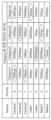
도 13a는 차량에 장착된 카메라 및 센서의 우선 순위, 카테고리, 카테고리에 따른 데이터 레이트를 나타내는 테이블의 일 예이다.
도 13b는 TCU가 도 12b의 S1208에 따라 도 13a의 테이블의 데이터 레이트를 조절한 일 예이다.
도 14는 MEC 서버가 도 11의 S1103을 수행한 이후 수행하는 동작의 예시를 나타내는 흐름도이다.
도 15는 일 실시 예에 따른 MEC 서버와 TCU의 구성 블록도이다.
도 16은 본 발명의 실시예에 따른 TCU의 구성을 상세하게 나타낸 블록도이다.Figure 1 shows an example of a 5G usage scenario.
Figure 2 is a structural diagram of the next-generation mobile communications network.
Figure 3 is an example diagram showing the expected structure of the next-generation mobile communications network from a node perspective.
Figure 4 is an example diagram illustrating an architecture for supporting simultaneous access to two data networks.
Figure 5 is another example diagram showing the structure of a radio interface protocol between a UE and a gNB.
Figures 6a to 6d illustrate examples of implementation of a MEC server.
Figure 7 shows an example of a MEC server remotely controlling a vehicle.
FIG. 8 is a block diagram illustrating an example of an MEC server and an example of a TCU according to the disclosure of this specification.
FIG. 9 illustrates an example of operation of a TCU according to the disclosure of this specification.
FIG. 10 illustrates an example of the operation of a MEC server according to the disclosure of this specification.
FIG. 11 is a signal flow diagram illustrating an example of the operation of a TCU, a MEC server, and a mobile communication network according to the disclosure of this specification.
FIG. 12a and FIG. 12b are flowcharts showing an example of S1105 of FIG. 11.
Figure 13a is an example of a table showing the priorities, categories, and data rates by category of cameras and sensors mounted on a vehicle.
Figure 13b is an example in which the TCU adjusts the data rate of the table of Figure 13a according to S1208 of Figure 12b.
FIG. 14 is a flowchart illustrating an example of operations performed by the MEC server after performing S1103 of FIG. 11.
Figure 15 is a block diagram of a configuration of a MEC server and a TCU according to one embodiment.
Figure 16 is a block diagram showing in detail the configuration of a TCU according to an embodiment of the present invention.
이하에서는 3GPP(3rd Generation Partnership Project) 3GPP LTE(long term evolution), 3GPP LTE-A(LTE-Advanced), Wi-Fi 또는 3GPP NR(New RAT, 즉 5G)를 기반으로 본 발명이 적용되는 것을 기술한다. 이는 예시에 불과하고, 본 발명은 다양한 무선 통신 시스템에 적용될 수 있다. 이하에서, LTE라 함은 LTE 및/또는 LTE-A를 포함한다. Hereinafter, the present invention is described as being applied based on 3GPP (3rd Generation Partnership Project) 3GPP LTE (long term evolution), 3GPP LTE-A (LTE-Advanced), Wi-Fi or 3GPP NR (New RAT, i.e. 5G). This is only an example, and the present invention can be applied to various wireless communication systems. Hereinafter, LTE includes LTE and/or LTE-A.
본 명세서에서 사용되는 기술적 용어는 단지 특정한 실시 예를 설명하기 위해 사용된 것으로, 본 발명을 한정하려는 의도가 아님을 유의해야 한다. 또한, 본 명세서에서 사용되는 기술적 용어는 본 명세서에서 특별히 다른 의미로 정의되지 않는 한, 본 발명이 속하는 기술 분야에서 통상의 지식을 가진 자에 의해 일반적으로 이해되는 의미로 해석되어야 하며, 과도하게 포괄적인 의미로 해석되거나, 과도하게 축소된 의미로 해석되지 않아야 한다. 또한, 본 명세서에서 사용되는 기술적인 용어가 본 발명의 사상을 정확하게 표현하지 못하는 잘못된 기술적 용어일 때에는, 당업자가 올바르게 이해할 수 있는 기술적 용어로 대체되어 이해되어야 할 것이다. 또한, 본 발명에서 사용되는 일반적인 용어는 사전에 정의되어 있는 바에 따라, 또는 전후 문맥상에 따라 해석되어야 하며, 과도하게 축소된 의미로 해석되지 않아야 한다.It should be noted that the technical terms used in this specification are only used to describe specific embodiments and are not intended to limit the present invention. In addition, the technical terms used in this specification should be interpreted as having a meaning generally understood by a person having ordinary skill in the art to which the present invention belongs, unless specifically defined otherwise in this specification, and should not be interpreted in an excessively comprehensive or excessively narrow sense. In addition, when the technical terms used in this specification are incorrect technical terms that do not accurately express the idea of the present invention, they should be replaced with technical terms that can be correctly understood by a person skilled in the art and understood. In addition, the general terms used in the present invention should be interpreted as defined in the dictionary or according to the context, and should not be interpreted in an excessively narrow sense.
또한, 본 명세서에서 사용되는 단수의 표현은 문맥상 명백하게 다르게 뜻하지 않는 한, 복수의 표현을 포함한다. 본 출원에서, "구성된다" 또는 "가지다" 등의 용어는 명세서 상에 기재된 여러 구성 요소들, 또는 여러 단계들을 반드시 모두 포함하는 것으로 해석되지 않아야 하며, 그 중 일부 구성 요소들 또는 일부 단계들은 포함되지 않을 수도 있고, 또는 추가적인 구성 요소 또는 단계들을 더 포함할 수 있는 것으로 해석되어야 한다.In addition, the singular expressions used in this specification include plural expressions unless the context clearly indicates otherwise. In this application, the terms "consisting of" or "having" should not be construed as necessarily including all of the various components or various steps described in the specification, and should be construed as not including some of the components or some of the steps, or may include additional components or steps.
또한, 본 명세서에서 사용되는 제1, 제2 등과 같이 서수를 포함하는 용어는 다양한 구성 요소들을 설명하는데 사용될 수 있지만, 상기 구성 요소들은 상기 용어들에 의해 한정되어서는 안 된다. 상기 용어들은 하나의 구성 요소를 다른 구성 요소로부터 구별하는 목적으로만 사용된다. 예를 들어, 본 발명의 권리 범위를 벗어나지 않으면서 제1 구성 요소는 제2 구성 요소로 명명될 수 있고, 유사하게 제2 구성 요소도 제1 구성 요소로 명명될 수 있다. In addition, terms including ordinal numbers such as first, second, etc. used in this specification may be used to describe various components, but the components should not be limited by the terms. The terms are used only for the purpose of distinguishing one component from another. For example, without departing from the scope of the present invention, the first component may be referred to as the second component, and similarly, the second component may also be referred to as the first component.
어떤 구성 요소가 다른 구성 요소에 "연결되어" 있다거나 "접속되어" 있다고 언급된 때에는, 그 다른 구성 요소에 직접적으로 연결되어 있거나 또는 접속되어 있을 수도 있지만, 중간에 다른 구성 요소가 존재할 수도 있다. 반면에, 어떤 구성 요소가 다른 구성 요소에 "직접 연결되어" 있다거나 "직접 접속되어" 있다고 언급된 때에는, 중간에 다른 구성 요소가 존재하지 않는 것으로 이해되어야 할 것이다.When it is said that a component is "connected" or "connected" to another component, it may be directly connected or connected to that other component, but there may be other components in between. On the other hand, when it is said that a component is "directly connected" or "connected" to another component, it should be understood that there are no other components in between.
이하, 첨부된 도면을 참조하여 본 발명에 따른 바람직한 실시예를 상세히 설명하되, 도면 부호에 관계없이 동일하거나 유사한 구성 요소는 동일한 참조 번호를 부여하고 이에 대한 중복되는 설명은 생략하기로 한다. 또한, 본 발명을 설명함에 있어서 관련된 공지 기술에 대한 구체적인 설명이 본 발명의 요지를 흐릴 수 있다고 판단되는 경우 그 상세한 설명을 생략한다. 또한, 첨부된 도면은 본 발명의 사상을 쉽게 이해할 수 있도록 하기 위한 것일뿐, 첨부된 도면에 의해 본 발명의 사상이 제한되는 것으로 해석되어서는 아니됨을 유의해야 한다. 본 발명의 사상은 첨부된 도면외에 모든 변경, 균등물 내지 대체물에 까지도 확장되는 것으로 해석되어야 한다.Hereinafter, preferred embodiments of the present invention will be described in detail with reference to the attached drawings. Regardless of the reference numerals in the drawings, identical or similar components will be given the same reference numerals and redundant descriptions thereof will be omitted. In addition, when describing the present invention, if it is determined that a detailed description of a related known technology may obscure the gist of the present invention, the detailed description thereof will be omitted. In addition, it should be noted that the attached drawings are only intended to facilitate easy understanding of the spirit of the present invention, and should not be construed as limiting the spirit of the present invention by the attached drawings. The spirit of the present invention should be construed to extend to all modifications, equivalents, and substitutes other than the attached drawings.
이하에서 사용되는 용어인 기지국은, 일반적으로 무선기기와 통신하는 고정된 지점(fixed station)을 말하며, eNodeB(evolved-NodeB), eNB(evolved-NodeB), BTS(Base Transceiver System), 액세스 포인트(Access Point), gNB(Next generation NodeB) 등 다른 용어로 불릴 수 있다. The term base station used below generally refers to a fixed station that communicates with wireless devices, and may be called by other terms such as eNodeB (evolved-NodeB), eNB (evolved-NodeB), BTS (Base Transceiver System), Access Point, and gNB (Next generation NodeB).
그리고 이하, 사용되는 용어인 UE(User Equipment)는, 고정되거나 이동성을 가질 수 있으며, 기기(Device), 무선기기(Wireless Device), 무선 통신 기기(Wireless Communication Device), 단말(Terminal), MS(mobile station), UT(user terminal), SS(subscriber station), MT(mobile terminal) 등 다른 용어로 불릴 수 있다.And, hereinafter, the term UE (User Equipment) used may be fixed or mobile, and may be called by other terms such as device, wireless device, wireless communication device, terminal, MS (mobile station), UT (user terminal), SS (subscriber station), and MT (mobile terminal).
도 1은 5G 사용 시나리오의 예를 나타낸다.Figure 1 shows an example of a 5G usage scenario.
도 1은 본 발명의 기술적 특징이 적용될 수 있는 5G 사용 시나리오의 예를 나타낸다. 도 1에 도시된 5G 사용 시나리오는 단지 예시적인 것이며, 본 발명의 기술적 특징은 도 1에 도시되지 않은 다른 5G 사용 시나리오에도 적용될 수 있다. Fig. 1 illustrates an example of a 5G usage scenario to which the technical features of the present invention can be applied. The 5G usage scenario illustrated in Fig. 1 is merely exemplary, and the technical features of the present invention can also be applied to other 5G usage scenarios not illustrated in Fig. 1.
도 1을 참조하면, 5G의 세 가지 주요 요구 사항 영역은 (1) 개선된 모바일 광대역(eMBB; enhanced mobile broadband) 영역, (2) 다량의 머신 타입 통신(mMTC; massive machine type communication) 영역 및 (3) 초-신뢰 및 저 지연 통신(URLLC; ultra-reliable and low latency communications) 영역을 포함한다. 일부 사용 예는 최적화를 위해 다수의 영역을 요구할 수 있고, 다른 사용 예는 단지 하나의 핵심 성능 지표(KPI; key performance indicator)에만 포커싱 할 수 있다. 5G는 이러한 다양한 사용 예들을 유연하고 신뢰할 수 있는 방법으로 지원하는 것이다.Referring to Figure 1, the three major requirement areas for 5G include (1) enhanced mobile broadband (eMBB), (2) massive machine type communication (mMTC), and (3) ultra-reliable and low latency communications (URLLC). Some use cases may require multiple areas to be optimized, while other use cases may focus on only one key performance indicator (KPI). 5G supports these diverse use cases in a flexible and reliable manner.
eMBB는 데이터 속도, 지연, 사용자 밀도, 모바일 광대역 접속의 용량 및 커버리지의 전반적인 향상에 중점을 둔다. eMBB는 10Gbps 정도의 처리량을 목표로 한다. eMBB는 기본적인 모바일 인터넷 접속을 훨씬 능가하게 하며, 풍부한 양방향 작업, 클라우드 또는 증강 현실에서 미디어 및 엔터테인먼트 애플리케이션을 커버한다. 데이터는 5G의 핵심 동력 중 하나이며, 5G 시대에서 처음으로 전용 음성 서비스를 볼 수 없을 수 있다. 5G에서, 음성은 단순히 통신 시스템에 의해 제공되는 데이터 연결을 사용하여 응용 프로그램으로서 처리될 것으로 기대된다. 증가된 트래픽 양의 주요 원인은 콘텐츠 크기의 증가 및 높은 데이터 전송률을 요구하는 애플리케이션 수의 증가이다. 스트리밍 서비스(오디오 및 비디오), 대화형 비디오 및 모바일 인터넷 연결은 더 많은 장치가 인터넷에 연결될수록 더 널리 사용될 것이다. 이러한 많은 애플리케이션은 사용자에게 실시간 정보 및 알림을 푸쉬하기 위해 항상 켜져 있는 연결성을 필요로 한다. 클라우드 스토리지 및 애플리케이션은 모바일 통신 플랫폼에서 급속히 증가하고 있으며, 이것은 업무 및 엔터테인먼트 모두에 적용될 수 있다. 클라우드 스토리지는 상향링크 데이터 전송률의 성장을 견인하는 특별한 사용 예이다. 5G는 또한 클라우드 상의 원격 업무에도 사용되며, 촉각 인터페이스가 사용될 때 우수한 사용자 경험을 유지하도록 훨씬 더 낮은 단-대-단(end-to-end) 지연을 요구한다. 엔터테인먼트에서 예를 들면, 클라우드 게임 및 비디오 스트리밍은 모바일 광대역 능력에 대한 요구를 증가시키는 또 다른 핵심 요소이다. 엔터테인먼트는 기차, 차 및 비행기와 같은 높은 이동성 환경을 포함하여 어떤 곳에서든지 스마트폰 및 태블릿에서 필수적이다. 또 다른 사용 예는 엔터테인먼트를 위한 증강 현실 및 정보 검색이다. 여기서, 증강 현실은 매우 낮은 지연과 순간적인 데이터 양을 필요로 한다.eMBB focuses on improving data rates, latency, user density, and overall capacity and coverage of mobile broadband connections. eMBB targets throughputs of around 10 Gbps. eMBB goes far beyond basic mobile Internet access, and covers rich interactive tasks, media and entertainment applications in the cloud or augmented reality. Data is one of the key drivers of 5G, and for the first time in the 5G era, we may not see dedicated voice services. In 5G, voice is expected to be handled as an application simply using the data connection provided by the communication system. The main reasons for the increased traffic volume are the increase in content size and the increase in the number of applications that require high data rates. Streaming services (audio and video), interactive video, and mobile Internet connections will become more prevalent as more devices are connected to the Internet. Many of these applications require always-on connectivity to push real-time information and notifications to users. Cloud storage and applications are rapidly growing on mobile communication platforms, and this can be applied to both work and entertainment. Cloud storage is a particular use case that is driving the growth in uplink data rates. 5G is also used for remote work in the cloud, which requires much lower end-to-end latency to maintain a good user experience when tactile interfaces are used. In entertainment, for example, cloud gaming and video streaming are other key factors driving the demand for mobile broadband capabilities. Entertainment is essential on smartphones and tablets everywhere, including in high-mobility environments such as trains, cars and airplanes. Another use case is augmented reality and information retrieval for entertainment, where augmented reality requires very low latency and instantaneous data volumes.
mMTC는 배터리에 의해 구동되는 다량의 저비용 장치 간의 통신을 가능하게 하기 위하여 설계되며, 스마트 계량, 물류, 현장 및 신체 센서와 같은 애플리케이션을 지원하기 위한 것이다. mMTC는 10년 정도의 배터리 및/또는 1km2 당 백만 개 정도의 장치를 목표로 한다. mMTC는 모든 분야에서 임베디드 센서를 원활하게 연결할 수 있게 하며, 가장 많이 예상되는 5G 사용 예 중 하나이다. 잠재적으로 2020년까지 IoT 장치들은 204억 개에 이를 것으로 예측된다. 산업 IoT는 5G가 스마트 도시, 자산 추적(asset tracking), 스마트 유틸리티, 농업 및 보안 인프라를 가능하게 하는 주요 역할을 수행하는 영역 중 하나이다.mMTC is designed to enable communication between large numbers of low-cost, battery-powered devices, supporting applications such as smart metering, logistics, field and body sensors. mMTC targets a battery life of around 10 years and/or around 1 million devices per square kilometer. mMTC enables seamless connectivity of embedded sensors across all verticals and is one of the most anticipated 5G use cases. It is predicted that there will be 20.4 billion IoT devices by 2020. Industrial IoT is one area where 5G will play a key role, enabling smart cities, asset tracking, smart utilities, agriculture and security infrastructure.
URLLC는 장치 및 기계가 매우 신뢰성 있고 매우 낮은 지연 및 높은 가용성으로 통신할 수 있도록 함으로써 차량 통신, 산업 제어, 공장 자동화, 원격 수술, 스마트 그리드 및 공공 안전 애플리케이션에 이상적이다. URLLC는 1ms의 정도의 지연을 목표로 한다. URLLC는 주요 인프라의 원격 제어 및 자율 주행 차량과 같은 초 신뢰/지연이 적은 링크를 통해 산업을 변화시킬 새로운 서비스를 포함한다. 신뢰성과 지연의 수준은 스마트 그리드 제어, 산업 자동화, 로봇 공학, 드론 제어 및 조정에 필수적이다.URLLC is ideal for vehicle communications, industrial control, factory automation, remote surgery, smart grid and public safety applications by enabling devices and machines to communicate with high reliability, very low latency and high availability. URLLC targets latency on the order of 1ms. URLLC includes new services that will transform industries through ultra-reliable/low latency links, such as remote control of critical infrastructure and autonomous vehicles. Reliability and latency levels are essential for smart grid control, industrial automation, robotics, drone control and coordination.
다음으로, 도 1의 삼각형 안에 포함된 다수의 사용 예에 대해 보다 구체적으로 살펴본다.Next, we will look more specifically at a number of use cases included within the triangle in Fig. 1.
5G는 초당 수백 메가 비트에서 초당 기가 비트로 평가되는 스트림을 제공하는 수단으로 FTTH(fiber-to-the-home) 및 케이블 기반 광대역(또는 DOCSIS)을 보완할 수 있다. 이러한 빠른 속도는 가상 현실(VR; virtual reality)과 증강 현실(AR; augmented reality) 뿐 아니라 4K 이상(6K, 8K 및 그 이상)의 해상도로 TV를 전달하는 데에 요구될 수 있다. VR 및 AR 애플리케이션은 거의 몰입형(immersive) 스포츠 경기를 포함한다. 특정 애플리케이션은 특별한 네트워크 설정이 요구될 수 있다. 예를 들어, VR 게임의 경우, 게임 회사가 지연을 최소화하기 위해 코어 서버를 네트워크 오퍼레이터의 에지 네트워크 서버와 통합해야 할 수 있다.5G can complement fiber-to-the-home (FTTH) and cable-based broadband (or DOCSIS) by delivering streams rated at hundreds of megabits per second to gigabits per second. These high speeds may be required to deliver television at resolutions of 4K and beyond (6K, 8K, and beyond), as well as virtual reality (VR) and augmented reality (AR). VR and AR applications include near-immersive sporting events. Certain applications may require special network configurations. For example, for VR gaming, a gaming company may need to integrate its core servers with a network operator’s edge network servers to minimize latency.
스마트 사회로서 언급되는 스마트 도시와 스마트 홈은 고밀도 무선 센서 네트워크로 임베디드 될 것이다. 지능형 센서의 분산 네트워크는 도시 또는 집의 비용 및 에너지 효율적인 유지에 대한 조건을 식별할 것이다. 유사한 설정이 각 가정을 위해 수행될 수 있다. 온도 센서, 창 및 난방 컨트롤러, 도난 경보기 및 가전 제품은 모두 무선으로 연결된다. 이러한 센서 중 많은 것들이 전형적으로 낮은 데이터 전송 속도, 저전력 및 저비용을 요구한다. 하지만, 예를 들어, 실시간 HD 비디오는 감시를 위해 특정 타입의 장치에서 요구될 수 있다.Smart cities and smart homes, referred to as smart societies, will be embedded with dense wireless sensor networks. A distributed network of intelligent sensors will identify conditions for cost- and energy-efficient maintenance of a city or home. A similar setup can be done for each home. Temperature sensors, window and heating controllers, burglar alarms, and appliances are all connected wirelessly. Many of these sensors typically require low data rates, low power, and low cost. However, for example, real-time HD video may be required from certain types of devices for surveillance.
열 또는 가스를 포함한 에너지의 소비 및 분배는 고도로 분산화되고 있어, 분산 센서 네트워크의 자동화된 제어가 요구된다. 스마트 그리드는 정보를 수집하고 이에 따라 행동하도록 디지털 정보 및 통신 기술을 사용하여 이런 센서를 상호 연결한다. 이 정보는 공급 업체와 소비자의 행동을 포함할 수 있으므로, 스마트 그리드가 효율성, 신뢰성, 경제성, 생산의 지속 가능성 및 자동화된 방식으로 전기와 같은 연료의 분배를 개선하도록 할 수 있다. 스마트 그리드는 지연이 적은 다른 센서 네트워크로 볼 수도 있다.The consumption and distribution of energy, including heat or gas, is becoming highly decentralized, requiring automated control of distributed sensor networks. Smart grids interconnect these sensors using digital information and communication technologies to collect information and act on it. This information can include the actions of suppliers and consumers, allowing smart grids to improve efficiency, reliability, economy, sustainability of production, and distribution of fuels such as electricity in an automated manner. Smart grids can also be viewed as another sensor network with low latency.
건강 부문은 이동 통신의 혜택을 누릴 수 있는 많은 애플리케이션을 보유하고 있다. 통신 시스템은 멀리 떨어진 곳에서 임상 진료를 제공하는 원격 진료를 지원할 수 있다. 이는 거리에 대한 장벽을 줄이는 데에 도움을 주고, 거리가 먼 농촌에서 지속적으로 이용하지 못하는 의료 서비스로의 접근을 개선시킬 수 있다. 이는 또한 중요한 진료 및 응급 상황에서 생명을 구하기 위해 사용된다. 이동 통신 기반의 무선 센서 네트워크는 심박수 및 혈압과 같은 파라미터에 대한 원격 모니터링 및 센서를 제공할 수 있다.The health sector has many applications that can benefit from mobile communications. Telecommunication systems can support telemedicine, which provides clinical care from a distance. This can help reduce distance barriers and improve access to health services that are not always available in remote rural areas. It can also be used to save lives in critical care and emergency situations. Mobile-based wireless sensor networks can provide remote monitoring and sensors for parameters such as heart rate and blood pressure.
무선 및 모바일 통신은 산업 응용 분야에서 점차 중요해지고 있다. 배선은 설치 및 유지 비용이 높다. 따라서, 케이블을 재구성할 수 있는 무선 링크로의 교체 가능성은 많은 산업 분야에서 매력적인 기회이다. 그러나, 이를 달성하는 것은 무선 연결이 케이블과 비슷한 지연, 신뢰성 및 용량으로 동작하는 것과, 그 관리가 단순화될 것을 요구한다. 낮은 지연과 매우 낮은 오류 확률은 5G로 연결될 필요가 있는 새로운 요구 사항이다.Wireless and mobile communications are becoming increasingly important in industrial applications. Wiring is expensive to install and maintain. Therefore, the possibility of replacing cables with reconfigurable wireless links is an attractive opportunity for many industries. However, achieving this requires that wireless connections operate with similar delay, reliability and capacity as cables, and that their management is simplified. Low latency and very low error probability are the new requirements that need to be connected with 5G.
물류 및 화물 추적은 위치 기반 정보 시스템을 사용하여 어디에서든지 인벤토리(inventory) 및 패키지의 추적을 가능하게 하는 이동 통신에 대한 중요한 사용 예이다. 물류 및 화물 추적의 사용 예는 전형적으로 낮은 데이터 속도를 요구하지만 넓은 범위와 신뢰성 있는 위치 정보가 필요하다.Logistics and freight tracking is an important use case for mobile communications, enabling the tracking of inventory and packages from anywhere using location-based information systems. Logistics and freight tracking use cases typically require low data rates, but require wide range and reliable location information.
특히, 자동차(Automotive)는 차량에 대한 이동 통신을 위한 많은 사용 예와 함께 5G에 있어 중요한 새로운 동력이 될 것으로 예상된다. 예를 들어, 승객을 위한 엔터테인먼트는 높은 용량과 높은 모바일 광대역을 동시에 요구한다. 그 이유는 미래의 사용자는 그들의 위치 및 속도와 관계 없이 고품질의 연결을 계속해서 기대하기 때문이다. 자동차 분야의 다른 사용 예는 증강 현실 대시보드이다. 운전자는 증강 현실 대비보드를 통해 앞면 창을 통해 보고 있는 것 위에 어둠 속에서 물체를 식별할 수 있다. 증강 현실 대시보드는 물체의 거리와 움직임에 대해 운전자에게 알려줄 정보를 겹쳐서 디스플레이 한다. 미래에, 무선 모듈은 차량 간의 통신, 차량과 지원하는 인프라구조 사이에서 정보 교환 및 자동차와 다른 연결된 장치(예를 들어, 보행자에 의해 수반되는 장치) 사이에서 정보 교환을 가능하게 한다. 안전 시스템은 운전자가 보다 안전한 운전을 할 수 있도록 행동의 대체 코스를 안내하여 사고의 위험을 낮출 수 있게 한다. 다음 단계는 원격 조종 차량 또는 자율 주행 차량이 될 것이다. 이는 서로 다른 자율 주행 차량 사이 및/또는 자동차와 인프라 사이에서 매우 신뢰성이 있고 매우 빠른 통신을 요구한다. 미래에, 자율 주행 차량이 모든 운전 활동을 수행하고, 운전자는 차량 자체가 식별할 수 없는 교통 이상에만 집중하도록 할 것이다. 자율 주행 차량의 기술적 요구 사항은 트래픽 안전을 사람이 달성할 수 없을 정도의 수준까지 증가하도록 초 저 지연과 초고속 신뢰성을 요구한다.In particular, automotive is expected to be an important new driver for 5G, with many use cases for mobile communications in vehicles. For example, entertainment for passengers requires both high capacity and high mobile broadband, as future users will continue to expect high-quality connectivity regardless of their location and speed. Another use case in the automotive sector is the augmented reality dashboard. The driver can identify objects in the dark on top of what he or she sees through the windshield via an augmented reality dashboard. The augmented reality dashboard displays information that superimposes information to the driver about the distance and movement of objects. In the future, wireless modules will enable communication between vehicles, information exchange between vehicles and supporting infrastructure, and information exchange between vehicles and other connected devices (e.g. devices accompanied by pedestrians). Safety systems can guide drivers to alternative courses of action to drive more safely, thus reducing the risk of accidents. The next step will be remotely controlled vehicles or autonomous vehicles. This will require very reliable and very fast communication between different autonomous vehicles and/or between vehicles and infrastructure. In the future, autonomous vehicles will perform all driving activities, leaving drivers to focus only on traffic anomalies that the vehicle itself cannot identify. The technical requirements for autonomous vehicles will require ultra-low latency and ultra-high reliability to increase traffic safety to levels that humans cannot achieve.
도 2는 차세대 이동 통신 네트워크의 구조도이다.Figure 2 is a structural diagram of the next-generation mobile communications network.
차세대 이동통신 네트워크(5G System)은 다양한 구성요소들을 포함할 수 있으며, 도 2에서는 그 중에서 일부에 해당하는 AMF(액세스 및 이동성 관리 기능: Access and Mobility Management Function)(51), SMF(세션 관리 기능: Session Management Function)(52), PCF(정책 제어 기능: Policy Control Function)(53), AF(애플리케이션 기능: Application Function)(55), N3IWF(비-3GPP 인터워킹 기능: Non-3GPP Interworking Function)(59), UPF(사용자 평면 기능: User Plane Function)(54), UDM(통합 데이터 관리: Unified Data Management) 데이터 네트워크(56)을 도시한다. The next generation mobile communication network (5G System) may include various components, and FIG. 2 illustrates some of them, including AMF (Access and Mobility Management Function) (51), SMF (Session Management Function) (52), PCF (Policy Control Function) (53), AF (Application Function) (55), N3IWF (Non-3GPP Interworking Function) (59), UPF (User Plane Function) (54), and UDM (Unified Data Management) data network (56).
UE(10)는 gNB(20)를 포함하는 NG-RAN(Next Generation Radio Access Network)를 통해 UPF(55)를 거쳐 데이터 네트워크(60)으로 연결된다.The UE (10) is connected to a data network (60) via the UPF (55) through the NG-RAN (Next Generation Radio Access Network) including the gNB (20).
UE(10)는 신뢰되지 않는 비-3GPP 액세스, 예컨대, WLAN(Wireless Local Area Network)를 통해서도 데이터 서비스를 제공받을 수 있다. 상기 비-3GPP 액세스를 코어 네트워크에 접속시키기 위하여, N3IWF(59)가 배치될 수 있다. The UE (10) can also receive data services through untrusted non-3GPP access, for example, a Wireless Local Area Network (WLAN). To connect the non-3GPP access to the core network, an N3IWF (59) can be deployed.
도시된 N3IWF는 비-3GPP 액세스와 5G 시스템 간의 인터워킹을 관리하는 기능을 수행한다. UE(10)가 비-3GPP 액세스(e.g., IEEE 801.11로 일컬어 지는 WiFi)와 연결된 경우, UE(10)는 N3IWF를 통해 5G 시스템과 연결될 수 있다. N3IWF는 제어 시그너링은 AMF와 수행하고, 데이터 전송을 위해 N3 인터페이스를 통해 UPF와 연결된다.The illustrated N3IWF performs the function of managing interworking between non-3GPP access and 5G system. When UE (10) is connected to non-3GPP access (e.g., WiFi referred to as IEEE 801.11), UE (10) can be connected to 5G system through N3IWF. N3IWF performs control signaling with AMF and is connected to UPF through N3 interface for data transmission.
도시된 AMF는 5G 시스템에서 액세스 및 이동성을 관리할 수 있다. AMF는 NAS 보안을 관리하는 기능을 수행할 수 있다. AMF는 아이들 상태(Idle State)에서 이동성을 핸들링하는 기능을 수행할 수 있다.The depicted AMF can manage access and mobility in a 5G system. The AMF can perform the function of managing NAS security. The AMF can perform the function of handling mobility in the idle state.
도시된 UPF는 사용자의 데이터가 송수신되는 게이트웨이의 일종이다. 상기 UPF 노드는 4세대 이동통신의 S-GW(Serving Gateway) 및 P-GW(Packet Data Network Gateway)의 사용자 평면 기능의 전부 또는 일부를 수행할 수 있다.The illustrated UPF is a type of gateway through which user data is transmitted and received. The UPF node can perform all or part of the user plane functions of the S-GW (Serving Gateway) and P-GW (Packet Data Network Gateway) of 4th generation mobile communications.
UPF는 차세대 무선 접속 네트워크(NG-RAN: next generation RAN)와 코어 네트워크 사이의 경계점으로 동작하고, gNB(20)와 SMF 사이의 데이터 경로를 유지하는 요소이다. 또한 UE(10)가 gNB(20)에 의해서 서빙되는 영역에 걸쳐 이동하는 경우, UPF는 이동성 앵커 포인트(mobility anchor point)역할을 한다. UPF는 PDU를 핸들링하는 기능을 수행할 수 있다. NG-RAN(3GPP 릴리즈-15 이후에서 정의되는 Next Generation-Radio Access Network) 내에서의 이동성을 위해 UPF는 패킷들이 라우팅될 수 있다. 또한, UPF는 다른 3GPP 네트워크(3GPP 릴리즈-15 전에 정의되는 RAN, 예를 들어, UTRAN, E-UTRAN(Evolved-UMTS(Universal Mobile Telecommunications System) Terrestrial Radio Access Network)) 또는 GERAN(GSM(Global System for Mobile Communication)/EDGE(Enhanced Data rates for Global Evolution) Radio Access Network)와의 이동성을 위한 앵커 포인트로서 기능할 수도 있다. UPF는 데이터 네트워크를 향한 데이터 인터페이스의 종료점(termination point)에 해당할 수 있다The UPF acts as a boundary point between the next generation radio access network (NG-RAN) and the core network, and is an element that maintains a data path between the gNB (20) and the SMF. In addition, when the UE (10) moves across the area served by the gNB (20), the UPF acts as a mobility anchor point. The UPF can perform a function of handling PDUs. For mobility within the NG-RAN (Next Generation-Radio Access Network defined after 3GPP Release-15), the UPF can route packets. Additionally, UPF can also serve as an anchor point for mobility with other 3GPP networks (RANs defined before 3GPP Release-15, e.g. UTRAN, E-UTRAN (Evolved-UMTS (Universal Mobile Telecommunications System) Terrestrial Radio Access Network)) or GERAN (GSM (Global System for Mobile Communication)/EDGE (Enhanced Data rates for Global Evolution) Radio Access Network). UPF can correspond to the termination point of the data interface towards the data network.
도시된 PCF는 사업자의 정책을 제어하는 노드이다. The PCF shown is a node that controls the operator's policy.
도시된 AF는 UE(10)에게 여러 서비스를 제공하기 위한 서버이다. The illustrated AF is a server for providing various services to the UE (10).
도시된 UDM은 4세대 이동통신의 HSS(Home subscriber Server)와 같이, 가입자 정보를 관리하는 서버의 일종이다. 상기 UDM은 상기 가입자 정보를 통합 데이터 저장소(Unified Data Repository: UDR)에 저장하고 관리한다.The illustrated UDM is a type of server that manages subscriber information, such as the HSS (Home Subscriber Server) of 4th generation mobile communications. The UDM stores and manages the subscriber information in a Unified Data Repository (UDR).
도시된 SMF는 UE의 IP(Internet Protocol) 주소를 할당하는 기능을 수행할 수 있다. 그리고, SMF는 PDU(protocol data unit) 세션을 제어할 수 있다.The illustrated SMF can perform the function of allocating an IP (Internet Protocol) address of a UE. In addition, the SMF can control a PDU (protocol data unit) session.
도 3은 차세대 이동통신 네트워크의 예상 구조를 노드 관점에서 나타낸 예시도이다.Figure 3 is an example diagram showing the expected structure of the next-generation mobile communications network from a node perspective.
도 3을 참조하여 알 수 있는 바와 같이, UE는 차세대 RAN(Radio Access Network)를 통해 데이터 네트워크(DN)와 연결된다.As can be seen from FIG. 3, the UE is connected to a data network (DN) via a next-generation RAN (Radio Access Network).
도시된 제어 평면 기능(Control Plane Function; CPF) 노드는 4세대 이동통신의 MME(Mobility Management Entity)의 기능 전부 또는 일부, S-GW(Serving Gateway) 및 P-GW(PDN Gateway)의 제어 평면 기능의 전부 또는 일부를 수행한다. 상기 CPF 노드는 AMF와 SMF을 포함한다.The illustrated Control Plane Function (CPF) node performs all or part of the functions of the Mobility Management Entity (MME) of 4th generation mobile communication, and all or part of the control plane functions of the Serving Gateway (S-GW) and the PDN Gateway (P-GW). The CPF node includes the AMF and the SMF.
도시된 인증 서버 기능(Authentication Server Function: AUSF)는 UE를 인증 및 관리한다.The illustrated Authentication Server Function (AUSF) authenticates and manages the UE.
도시된 네트워크 슬라이스 선택 기능(Network Slice Selection Function: NSSF)은 5G에서 도입되는 네트워크 슬라이싱을 위한 노드이다.The illustrated Network Slice Selection Function (NSSF) is a node for network slicing introduced in 5G.
도시된 네트워크 공개 기능(Network Exposure Function: NEF)는 5G 코어의 서비스와 기능을 안전하게 공개하는 메커니즘을 제공하기 위한 노드이다. 예를 들어, NEF는 기능들과 이벤트들을 공개하고, 외부 애플리케이션으로부터 3GPP 네트워크로 안전하게 정보를 제공하고, 내부/외부 정보를 번역하고, 제어 평면 파라미터를 제공하고, 패킷 흐름 설명(Packet Flow Description: PFD)를 관리할 수 있다.The Network Exposure Function (NEF) illustrated is a node that provides a mechanism to securely expose services and functions of the 5G core. For example, NEF can expose functions and events, securely provide information from external applications to the 3GPP network, translate internal/external information, provide control plane parameters, and manage Packet Flow Description (PFD).
도 4에서는 UE가 2개의 데이터 네트워크에 다중 PDU(Protocol Data Unit) 세션을 이용하여 동시에 접속할 수 있다. In Figure 4, a UE can simultaneously connect to two data networks using multiple Protocol Data Unit (PDU) sessions.
도 4는 2개의 데이터 네트워크에 대한 동시 액세스를 지원하기 위한 아키텍처를 나타낸 예시도이다.Figure 4 is an example diagram illustrating an architecture for supporting simultaneous access to two data networks.
도 4에서는 UE가 하나의 PDU 세션을 사용하여 2개의 데이터 네트워크에 동시 액세스하기 위한 아키텍처가 나타나 있다. Figure 4 shows an architecture for a UE to access two data networks simultaneously using one PDU session.
참고로, 도 2 내지 도 4에 도시된 레퍼런스 포인트에 대한 설명은 아래와 같다.For reference, the descriptions of the reference points illustrated in FIGS. 2 to 4 are as follows.
N1: UE와 AMF 간의 레퍼런스 포인트N1: Reference point between UE and AMF
N2: NG-RAN과 AMF 간의 레퍼런스 포인트N2: Reference points between NG-RAN and AMF
N3: NG-RAN과 UPF 간의 레퍼런스 포인트N3: Reference points between NG-RAN and UPF
N4: SMF와 UPF 간의 레퍼런스 포인트N4: Reference points between SMF and UPF
N5: PCF와 AF 간의 레퍼런스 포인트N5: Reference points between PCF and AF
N6: UPF와 DN 간의 레퍼런스 포인트N6: Reference points between UPF and DN
N7: SMF와 PCF 간의 레퍼런스 포인트N7: Reference points between SMF and PCF
N8: UDM과 AMF 간의 레퍼런스 포인트N8: Reference points between UDM and AMF
N10: UDM과 SMF 간의 레퍼런스 포인트N10: Reference points between UDM and SMF
N11: AMF와 SMF 간의 레퍼런스 포인트N11: Reference points between AMF and SMF
N12: AMF와 AUSF 간의 레퍼런스 포인트N12: Reference points between AMF and AUSF
N13: UDM과 AUSF 간의 레퍼런스 포인트N13: Reference points between UDM and AUSF
N15: 비-로밍 시나리오(non-roaming scenario)에서, PCF와 AMF 간의 레퍼런스 포인트. 로밍 시나리오에서, AMF와 방문 네트워크(visited network)의 PCF 간의 레퍼런스 포인트N15: Reference point between PCF and AMF in non-roaming scenario. Reference point between AMF and PCF of visited network in roaming scenario.
N22: AMF와 NSSF 간의 레퍼런스 포인트N22: Reference points between AMF and NSSF
N30: PCF와 NEF 간의 레퍼런스 포인트N30: Reference point between PCF and NEF
N33: AF와 NEF 간의 레퍼런스 포인트N33: Reference points between AF and NEF
도 3 및 도 4에서 사업자(operator) 이외의 제3자(third party)에 의한 AF는 NEF를 통해 5GC에 접속될 수 있다.In FIGS. 3 and 4, an AF by a third party other than the operator can be connected to 5GC through NEF.
도 5는 UE과 gNB 사이의 무선 인터페이스 프로토콜(Radio Interface Protocol)의 구조를 나타낸 다른 예시도이다.Figure 5 is another example diagram showing the structure of a radio interface protocol between a UE and a gNB.
상기 무선인터페이스 프로토콜은 3GPP 무선접속망 규격을 기반으로 한다. 상기 무선 인터페이스 프로토콜은 수평적으로 물리계층(Physical 계층), 데이터링크계층(Data Link 계층) 및 네트워크계층(Network 계층)으로 이루어지며, 수직적으로는 데이터정보 전송을 위한 사용자평면(User Plane)과 제어신호(Signaling)전달을 위한 제어평면(Control Plane)으로 구분된다. The above wireless interface protocol is based on the 3GPP wireless access network standard. The above wireless interface protocol is horizontally composed of a physical layer, a data link layer, and a network layer, and vertically divided into a user plane for transmitting data information and a control plane for transmitting control signals.
상기 프로토콜 계층들은 통신시스템에서 널리 알려진 개방형 시스템간 상호접속(Open System Interconnection; OSI) 기준모델의 하위 3개 계층을 바탕으로 L1(제1계층), L2(제2계층), L3(제3계층)로 구분될 수 있다.The above protocol layers can be divided into L1 (layer 1), L2 (layer 2), and L3 (layer 3) based on the three lower layers of the Open System Interconnection (OSI) reference model, which is widely known in communication systems.
이하에서, 상기 무선 프로토콜의 각 계층을 설명한다. Below, each layer of the wireless protocol is described.
제1 계층인 물리계층은 물리채널(Physical Channel)을 이용하여 정보전송서비스(정보 Transfer Service)를 제공한다. 상기 물리계층은 상위에 있는 매체접속제어(Medium Access Control) 계층과는 전송 채널(Transport Channel)을 통해 연결되어 있으며, 상기 전송 채널을 통해 매체접속제어계층과 물리계층 사이의 데이터가 전달된다. 그리고, 서로 다른 물리계층 사이, 즉 송신 측과 수신 측의 물리계층 사이는 물리채널을 통해 데이터가 전달된다.The first layer, the physical layer, provides information transfer service using a physical channel. The physical layer is connected to the upper medium access control layer through a transport channel, and data between the medium access control layer and the physical layer is transferred through the transport channel. In addition, data is transferred between different physical layers, that is, between the physical layers of the transmitting side and the receiving side, through the physical channel.
제2계층은 매체접속제어(Medium Access Control; MAC) 계층, 무선링크제어(Radio Link Control; RLC) 계층 그리고 패킷 데이터 수렴(Packet Data Convergence Protocol; PDCP) 계층을 포함한다.
제3 계층은 무선자원제어(Radio Resource Control; 이하 RRC라 약칭함)을 포함한다. 상기 RRC 계층은 제어평면에서만 정의되며, 무선 베어러(Radio Bearer; RB라 약칭함)들의 설정(설정), 재설정(Re-설정) 및 해제(Release)와 관련되어 논리 채널, 전송 채널 및 물리 채널들의 제어를 담당한다. 이때, RB는 단말과 E-UTRAN간의 데이터 전달을 위해 제2계층에 의해 제공되는 서비스를 의미한다.The third layer includes Radio Resource Control (RRC). The RRC layer is defined only in the control plane and is responsible for controlling logical channels, transport channels, and physical channels in relation to the establishment (establishment), re-establishment (re-establishment), and release (release) of radio bearers (RBs). Here, RB means a service provided by the second layer for data transmission between the terminal and E-UTRAN.
상기 NAS(Non-Access Stratum) 계층은 연결관리(세션 Management)와 이동성 관리(Mobility Management)등의 기능을 수행한다.The above NAS (Non-Access Stratum) layer performs functions such as session management and mobility management.
NAS 계층은 MM(Mobility Management)을 위한 NAS 엔티티와 SM(session Management)을 위한 NAS 엔티티로 구분된다.The NAS layer is divided into NAS entities for MM (Mobility Management) and NAS entities for SM (session Management).
1) MM을 위한 NAS 엔티티는 일반적인 다음과 같은 기능을 제공한다.1) NAS entities for MM provide the following general functions:
AMF와 관련된 NAS 절차로서, 다음을 포함한다.As NAS procedures related to AMF, including:
- 등록 관리 및 접속 관리 절차. AMF는 다음과 같은 기능을 지원한다. - Registration management and access management procedures. AMF supports the following functions:
- UE와 AMF간에 안전한 NAS 신호 연결(무결성 보호, 암호화)- Secure NAS signal connection between UE and AMF (integrity protection, encryption)
2) SM을 위한 NAS 엔티티는 UE와 SMF간에 세션 관리를 수행한다. 2) The NAS entity for SM performs session management between the UE and SMF.
SM 시그널링 메시지는 UE 및 SMF의 NAS-SM 계층에서 처리, 즉 생성 및 처리된다. SM 시그널링 메시지의 내용은 AMF에 의해 해석되지 않는다.SM signaling messages are processed, i.e. generated and processed, at the NAS-SM layer of the UE and SMF. The content of SM signaling messages is not interpreted by the AMF.
- SM 시그널링 전송의 경우, - In case of SM signaling transmission,
- MM을 위한 NAS 엔티티는 SM 시그널링의 NAS 전송을 나타내는 보안 헤더, 수신하는 NAS-MM에 대한 추가 정보를 통해 SM 시그널링 메시지를 전달하는 방법과 위치를 유도하는 NAS-MM 메시지를 생성합니다.- The NAS entity for MM generates a NAS-MM message that includes a security header indicating the NAS transport of SM signaling, and additional information for the receiving NAS-MM to induce how and where to deliver the SM signaling message.
- SM 시그널링 수신시, SM을 위한 NAS 엔티티는 NAS-MM 메시지의 무결성 검사를 수행하고, 추가 정보를 해석하여 SM 시그널링 메시지를 도출할 방법 및 장소를 유도한다.- Upon receiving SM signaling, the NAS entity for SM performs an integrity check of the NAS-MM message and interprets additional information to derive how and where to derive the SM signaling message.
도 5에서 NAS 계층 아래에 위치하는 RRC 계층, RLC 계층, MAC 계층, PHY 계층을 묶어서 액세스 계층(Access Stratum: AS)이라고 부르기도 한다.In Figure 5, the RRC layer, RLC layer, MAC layer, and PHY layer located below the NAS layer are collectively called the Access Stratum (AS).
한편, 5GAA(5G Automotive Association), 5G에 규정된 URLLC을 달성하기 위해서는 서버가 차량으로부터 차량의 상태 정보를 수신하고, 차량이 서버로부터 제어 데이터를 수신하여 동작할 때까지 5msec 이하의 시간이 소요되어야 한다. 즉, 차량 내 센서데이터를 클라우드 서버에서 수집하여, 분석 작업을 완료한 이후에, 클라우드 서버가 제어명령을 TCU(Telematics Communication Unit)에 전송하고, TCU가 이를 타겟 ECU(Electronic Control Unit)에게 전달하는 동작이 5msec 이내에 완료되어야 한다.Meanwhile, in order to achieve URLLC stipulated in 5GAA (5G Automotive Association) and 5G, it should take less than 5 msec for the server to receive vehicle status information from the vehicle and for the vehicle to receive control data from the server and operate. In other words, the operation of collecting in-vehicle sensor data from a cloud server, completing the analysis task, and then the cloud server transmitting a control command to the TCU (Telematics Communication Unit), and then the TCU transmitting it to the target ECU (Electronic Control Unit) should be completed within 5 msec.
종래의 클라우드 서버 기반 네트워크 구조(예를 들어, 기지국-유선 네트워크 - 클라우드 서버)에서는 기지국에서 클라우드 서버로 데이터를 전송하고, 클라우드 서버에서 데이터를 분석하여 기지국으로 데이터를 전송하고, 기지국이 이를 수신하는 데까지 30~40msec 정도가 소요된다.In a conventional cloud server-based network structure (e.g., base station-wired network-cloud server), it takes about 30 to 40 msec for data to be transmitted from the base station to the cloud server, for the cloud server to analyze the data and transmit the data to the base station, and for the base station to receive the data.
초-신뢰 및 저 지연 통신(URLLC; ultra-reliable and low latency communications)을 달성하기 위해, ETSI(European Telecommunications Standards Institute)와 5GAA에서는 Multi-access Edge Computing(MEC)에 관한 논의가 이뤄지고 있다.To achieve ultra-reliable and low latency communications (URLLC), the European Telecommunications Standards Institute (ETSI) and 5GAA are discussing Multi-access Edge Computing (MEC).
<< Multi-access Edge Computing(MEC)>Multi-access Edge Computing (MEC)>
MEC는 클라우드 컴퓨팅 기능과 IT 서비스 환경을 셀룰러 네트워크의 가장자리(edge) (일반적으로, 모든 네트워크의 가장자리)에서 가능하게 하는 네트워크 아키텍쳐이다. MEC의 기본 아이디어는 어플리케이션(응용 프로그램)들을 실행하고, 셀룰러 고객(cellular customer)과 관련된 프로세싱 작업을 수행함으로써, 네트워크 혼잡을 감소시키고 어플리케이션을 더 잘 수행하는 것이다. MEC 기술은 셀룰러 기지국 또는 기타 에지 노드(edge node)에서 구현되도록 설계된다. MEC 기술은 고객을 위해 새로운 오플리케이션과 새로운 서비스를 유연하고 신속하게 배포할 수 있다. MEC는 셀룰러 사업자(operator)들이 어플리케이션 개발자 및 컨텐츠 제공자와 같은 공인된 제3자(authorized third parties)에게 무선 액세스 네트워크(RAN: Radio Access network)를 개방할 수 있게 한다.MEC is a network architecture that enables cloud computing capabilities and IT service environments at the edge of a cellular network (typically, the edge of any network). The basic idea of MEC is to reduce network congestion and improve application performance by running applications and performing processing tasks related to cellular customers. MEC technology is designed to be implemented at cellular base stations or other edge nodes. MEC technology enables flexible and rapid deployment of new applications and new services for customers. MEC enables cellular operators to open their Radio Access Networks (RAN) to authorized third parties such as application developers and content providers.
본 명세서에서 설명하는 MEC 서버는 네트워크의 가장자리에서 클라우드 컴퓨팅 기능 또는 IT 서비스 환경을 제공하는 통신 기기를 의미한다.The MEC server described in this specification means a communication device that provides cloud computing functions or IT service environments at the edge of the network.
도 6A 내지 도 6D 는 MEC 서버의 구현 예시를 나타낸다.Figures 6A to 6D illustrate examples of implementation of a MEC server.
도 6A 내지 도 6D 의 사용자 평면 기능(User Plane Function; UPF) 노드(630)는 사용자의 데이터가 송수신되는 게이트 웨이의 일종이다. 상기 UPF 노드(630)는 4세대 이동통신의 S-GW(serving-gateway) 및 P-GW(Packet Data Network-gateway)의 사용자 평면 기능의 전부 또는 일부를 수행할 수 있다. 코어 네트워크(640)는 EPC(Evolved Packet Core) 또는 5GC(5G Core Network)일 수 있다. N3는 (R)AN과 UPF 노드(630) 간의 레퍼런스 포인트이다. N6는 UPF 노드(630)와 데이터 네트워크 간의 레퍼런스 포인트이다. 기지국(620)은 5G 기지국(gNB) 또는 LTE 기지국(eNB)일 수 있다. 기지국(620)은 gNB와 eNB를 모두 포함하는 기지국일 수도 있다.The User Plane Function (UPF) node (630) of FIGS. 6A to 6D is a type of gateway through which user data is transmitted and received. The UPF node (630) may perform all or part of the user plane functions of the S-GW (serving-gateway) and P-GW (Packet Data Network-gateway) of 4th generation mobile communication. The core network (640) may be an Evolved Packet Core (EPC) or a 5G Core Network (5GC). N3 is a reference point between the (R)AN and the UPF node (630). N6 is a reference point between the UPF node (630) and a data network. The base station (620) may be a 5G base station (gNB) or an LTE base station (eNB). The base station (620) may also be a base station including both a gNB and an eNB.
AMF(650)는 Access and Mobility Management Function으로, 액세스 및 이동성을 관리하는 제어 평면 기능(Control Plane Function: CPF)이다. SMF(660)는 Session Management Function으로 PDU(Protocol Data Unit) 세션 등 데이터 세션을 관리하는 제어 평면 기능이다.AMF (650) is the Access and Mobility Management Function, a control plane function (CPF) that manages access and mobility. SMF (660) is the Session Management Function, a control plane function that manages data sessions such as PDU (Protocol Data Unit) sessions.
논리적으로 MEC 서버(MEC 호스트)(610)는 에지 또는 중앙 데이터 네트워크에 구현될 수 있다. UPF는 사용자 평면(user plane: UP) 트래픽을 데이터 네트워크의 타겟 MEC 어플리케이션(MEC 서버(610) 내의 어플리케이션)으로 조정하는 역할을 수행할 수 있다. 데이터 네트워크 및 UPF의 위치는 네트워크 사업자가 선택할 수 있다. 네트워크 사업자는 가용한 설비, 지원되는 어플리케이션 및 어플리케이션의 요구 사항, 측정된 또는 추정된 사용자 부하 등과 같은 기술 및 비즈니스 변수에 기초하여 물리적인 컴퓨팅 자원을 배치할 수 있다. MEC 관리 시스템은 MEC 서버(610)(MEC 호스트) 및 어플리케이션의 작동을 조정하여 MEC 어플리케이션을 배포할 위치를 동적으로 결정할 수 있다.Logically, the MEC server (MEC host) (610) can be implemented in an edge or central data network. The UPF can be responsible for directing user plane (UP) traffic to target MEC applications (applications within the MEC server (610)) in the data network. The location of the data network and the UPF can be selected by the network operator. The network operator can deploy physical computing resources based on technical and business variables such as available facilities, supported applications and application requirements, measured or estimated user loads, etc. The MEC management system can dynamically determine where to deploy the MEC application by coordinating the operation of the MEC server (610) (MEC host) and the applications.
도 6A는 MEC 서버(610)와 UPF 노드(630)가 기지국(620)과 함께 배치되는 구현 예시이다. 도 6B는 MEC 서버(610)가 송신 노드(예를 들어, UPF 노드(630))와 함께 배치되는 구현 예시이다. 도 6B에서 코어 네트워크(640)는 네트워크 어그리게이션 포인트(network aggregation point)를 통해 UPF 노드(630) 및 MEC 서버(610)와 통신할 수 있다. 도 6C는 MEC 서버(610) 및 UPF 노드(630)가 네트워크 어그리게이션 포인트와 함께 배치되는 구현 예시이다. 도 6D는 MEC 서버(610)가 코어 네트워크(640) 기능들(core network functions)들과 함께 배치되는 구현 예시이다. 도 6D에서 MEC 서버(610)는 코어 네트워크(640) 기능들과 동일한 데이터 센터에 배치될 수 있다.FIG. 6A is an implementation example where the MEC server (610) and the UPF node (630) are deployed together with the base station (620). FIG. 6B is an implementation example where the MEC server (610) is deployed together with a transmitting node (e.g., the UPF node (630)). In FIG. 6B, the core network (640) can communicate with the UPF node (630) and the MEC server (610) through a network aggregation point. FIG. 6C is an implementation example where the MEC server (610) and the UPF node (630) are deployed together with the network aggregation point. FIG. 6D is an implementation example where the MEC server (610) is deployed together with core network functions (640). In FIG. 6D, the MEC server (610) can be deployed in the same data center as the core network functions (640).
<본 명세서의 개시><Disclosure of this specification>
도 7은 MEC 서버가 차량을 원격으로 제어하는 예시를 나타낸다.Figure 7 shows an example of a MEC server remotely controlling a vehicle.
도 7을 참조하면, MEC 서버(610), 기지국(620) 및 차량(660a~660c)이 도시된다. 기지국(620)은 gNB 또는 eNB일 수 있다. 기지국(620)은 gNB와 eNB를 모두 포함하는 기지국일 수도 있다. MEC 서버(610)는 기지국(620)과 유선 통신 또는 무선 통신을 통해 연결될 수 있다. MEC 서버(610)는 기지국(620)으로 데이터를 전송하거나 기지국(620)으로부터 데이터를 수신할 수 있다. 도면에는 MEC 서버(610)와 기지국(620)이 직접적으로 연결된 것을 도시되나, 이는 예시에 불과하며, MEC 서버(610)는 다른 네트워크 노드를 거쳐 기지국(620)과 연결될 수도 있다. 기지국(620)은 차량(660a~660c) 내에 장착된 TCU(Telematics Communication Unit)와 데이터를 송수신할 수 있다.Referring to FIG. 7, a MEC server (610), a base station (620), and vehicles (660a to 660c) are illustrated. The base station (620) may be a gNB or an eNB. The base station (620) may also be a base station including both a gNB and an eNB. The MEC server (610) may be connected to the base station (620) via wired communication or wireless communication. The MEC server (610) may transmit data to the base station (620) or receive data from the base station (620). Although the drawing illustrates that the MEC server (610) and the base station (620) are directly connected, this is merely an example, and the MEC server (610) may be connected to the base station (620) via another network node. The base station (620) may transmit and receive data with a TCU (Telematics Communication Unit) mounted in the vehicles (660a to 660c).
TCU 는 차량(660a~660c)에 장착된 장치들로부터 상태 정보를 획득할 수 있고, 상태 정보는 각종 센서 데이터, 비디오 데이터 등을 포함할 수 있다. TCU는 상태 정보(또는 상태 정보를 포함하는 차량에 관련된 정보)를 기지국(620)에 전송하고, 기지국(620)은 상태 정보를 MEC 서버(610)에 전달할 수 있다. 그러면, MEC 서버(610)는 상태 정보에 기초하여 차량(660a~660c)을 제어하기 위한 데이터를 기지국(620)에 전송할 수 있다. 기지국(620)이 차량(660a~660c)을 제어하기 위한 데이터를 TCU에 전송하면, TCU는 수신된 데이터를 차량(660a~660c)에 장착된 장치들로 전송함으로써 차량(660a~660c)을 제어할 수 있다. 그리고, MEC 서버(610)는 맵(map) 정보를 기지국(620)에 전송하고, 기지국(620)은 이를 TCU에 전송할 수 있다. TCU 는 맵 정보를 이용하여 차량(660a~660c)을 제어할 수 있다.The TCU can obtain status information from devices mounted on the vehicles (660a to 660c), and the status information can include various sensor data, video data, etc. The TCU can transmit the status information (or vehicle-related information including the status information) to the base station (620), and the base station (620) can transfer the status information to the MEC server (610). Then, the MEC server (610) can transmit data for controlling the vehicles (660a to 660c) to the base station (620) based on the status information. When the base station (620) transmits data for controlling the vehicles (660a to 660c) to the TCU, the TCU can control the vehicles (660a to 660c) by transmitting the received data to devices mounted on the vehicles (660a to 660c). And, the MEC server (610) can transmit map information to the base station (620), and the base station (620) can transmit it to the TCU. The TCU can control the vehicle (660a to 660c) using the map information.
도 8을 참조하여 MEC 서버(610) 및 차량(660a~660c)에 장착된 TCU를 구체적으로 설명한다.Referring to FIG. 8, the MEC server (610) and the TCU mounted on the vehicle (660a to 660c) are specifically described.
도 8은 본 명세서의 개시에 따른 MEC 서버의 예시와 TCU의 예시를 나타낸 블록도이다.FIG. 8 is a block diagram illustrating an example of an MEC server and an example of a TCU according to the disclosure of this specification.
MEC 서버는 도 6A 내지 6D와 도 7에서 설명한 MEC 서버(610)이며, 이하에서는 도면 부호를 생략하여 설명한다. TCU(100)는 도 7에서 설명한 차량(660a~660c)에 장착된 TCU이며, 이하에서는 도면 부호를 생략하여 설명한다.The MEC server is the MEC server (610) described in FIGS. 6A to 6D and FIG. 7, and will be described below with the drawing symbols omitted. The TCU (100) is a TCU mounted on a vehicle (660a to 660c) described in FIG. 7, and will be described below with the drawing symbols omitted.
MEC 서버는 도 6A 내지 도 6D에서 설명한 예시들과 같이 구현될 수 있다. 도 8에는 MEC 서버가 기지국들과 직접적으로 통신하는 것으로 도시되어 있으나 이는 예시에 불과하며, MEC 서버는 다른 네트워크 노드(예를 들어, UPF 노드)를 통해 기지국들과 통신할 수도 있다. MEC 서버는 프로세서(미도시) 및 메모리(미도시)를 포함할 수 있다. 메모리는 MEC 서버 앱을 저장할 수 있다. 프로세서는 메모리에 저장된 MEC 서버 앱을 이용하여 본 명세서의 개시에서 설명하는 동작들을 수행할 수 있다. MEC 서버 앱은 예를 들어, VR/AR 앱, 카메라 데이터 분석 앱, 센서 데이터 분석 앱(라이다 센서 데이터 분석 앱 및 레이다 센서 데이터 분석 앱 포함) 엔진 ECU 데이터 분석 앱, 속도 ECU 데이터 분석 앱, HVAC ECU 데이터 분석 앱, ECU 제어 앱, 제어 명령 송신 앱, 야구 앱, 골프 앱 등일 수 있다.The MEC server can be implemented as in the examples described in FIGS. 6A to 6D. Although FIG. 8 illustrates the MEC server communicating directly with base stations, this is merely an example, and the MEC server may communicate with base stations via another network node (e.g., a UPF node). The MEC server may include a processor (not shown) and a memory (not shown). The memory may store an MEC server app. The processor may perform the operations described in the disclosure of this specification using the MEC server app stored in the memory. The MEC server app may be, for example, a VR/AR app, a camera data analysis app, a sensor data analysis app (including a lidar sensor data analysis app and a radar sensor data analysis app), an engine ECU data analysis app, a speed ECU data analysis app, an HVAC ECU data analysis app, an ECU control app, a control command transmission app, a baseball app, a golf app, etc.
5G 기지국 (sub6GHz)은 FR1(Frequency Range 1) 대역 (7125 MHz 이하의 주파수 대역)에서 5G 표준에 기초한 통신을 수행하는 기지국이다. 5G 기지국 (mmWave)은 FR2(Frequency Range 2) 대역 (24250 - 52600MHz의 주파수 대역)에서 5G 표준에 기초한 통신을 수행하는 기지국이다. LTE 기지국은 LTE 표준에 기초한 통신을 수행하는 기지국이다. Wi-Fi 기지국은 Wi-Fi 표준에 기초한 통신을 수행하는 기지국이다. MEC 서버는 5G 기지국 (sub6GHz), 5G 기지국 (mmWave), LTE 기지국 및 Wi-Fi 기지국 중 적어도 하나의 기지국을 이용하여 TCU와 통신할 수 있다.A 5G base station (sub6GHz) is a base station that performs communication based on the 5G standard in the FR1 (Frequency Range 1) band (a frequency band of 7125 MHz or less). A 5G base station (mmWave) is a base station that performs communication based on the 5G standard in the FR2 (Frequency Range 2) band (a frequency band of 24250 - 52600 MHz). An LTE base station is a base station that performs communication based on the LTE standard. A Wi-Fi base station is a base station that performs communication based on the Wi-Fi standard. The MEC server can communicate with the TCU using at least one of the 5G base station (sub6GHz), the 5G base station (mmWave), the LTE base station, and the Wi-Fi base station.
TCU는 LTE 모듈, 5G 모듈 (sub6GHz), 5G 모듈 (mmWave), WiFi 모듈, 프로세서 및 메모리를 포함할 수 있다. LTE 모듈은 LTE 표준에 기초한 통신(데이터의 송수신)을 수행하는 통신 모듈(즉, 송수신부)이다. 5G 모듈 (sub6GHz)은 FR 1 대역에서 5G 표준에 기초한 통신(데이터의 송수신)을 수행하는 통신 모듈(즉, 송수신부)이다. 5G 모듈 (mmWave)은 FR 2 대역에서 5G 표준에 기초한 통신(데이터의 송수신)을 수행하는 통신 모듈(즉, 송수신부)이다. WiFi 모듈은 WiFi 표준에 기초한 통신(데이터의 송수신)을 수행하는 통신 모듈(즉, 송수신부)이다. LTE 모듈, 5G 모듈 (sub6GHz), 5G 모듈 (mmWave) 및 WiFi 모듈은 PCIe(PCI express)와 같은 인터페이스를 통해 프로세서와 연결될 수 있다. 또한, LTE 모듈, 5G 모듈 (sub6GHz), 5G 모듈 (mmWave) 및 WiFi 모듈은 각각 별개의 객체로 도시되어 있으나, 하나의 통신 모듈이 LTE 모듈, 5G 모듈 (sub6GHz), 5G 모듈 (mmWave) 및 WiFi 모듈의 기능을 수행할 수도 있다.The TCU may include an LTE module, a 5G module (sub6GHz), a 5G module (mmWave), a WiFi module, a processor, and a memory. The LTE module is a communication module (i.e., a transceiver) that performs communication (transmission and reception of data) based on the LTE standard. The 5G module (sub6GHz) is a communication module (i.e., a transceiver) that performs communication (transmission and reception of data) based on the 5G standard in the
TCU의 프로세서는 LTE/5G 모듈 (sub6GHz), LTE/5G 모듈 (mmWave), WiFi 모듈 및 메모리와 연결된다. 메모리는 MEC 클라이언트 앱을 저장할 수 있다. 프로세서는 LTE 모듈, 5G 모듈 (sub6GHz), 5G 모듈 (mmWave) 및 WiFi 모듈을 이용하여 기지국들 또는 단말들(단말 1 및 단말 2)이 전송한 데이터를 수신할 수 있다. 프로세서는 LTE 모듈, 5G 모듈 (sub6GHz), 5G 모듈 (mmWave) 및 WiFi 모듈을 이용하여 기지국들 또는 또는 단말들(단말 1 및 단말 2)로 데이터를 전송할 수 있다. 여기서, 단말들(단말 1 및 단말 2)은 차량에 탑승한 사용자가 사용하는 무선 통신 기기일 수 있다. 또한, TCU의 프로세서는 메모리에 저장된 MEC 클라이언트 앱을 이용하여 본 명세서의 개시에서 설명하는 동작들을 수행할 수 있다.The processor of the TCU is connected to an LTE/5G module (sub6GHz), an LTE/5G module (mmWave), a WiFi module, and a memory. The memory can store an MEC client app. The processor can receive data transmitted by base stations or terminals (
TCU의 프로세서는 차량에 장착된 장치들과 연결될 수 있다. 예를 들어, 프로세서는 DCU(Domain Control Unit), LIN(Local Interconnect Network) 마스터, MOST(Media Oriented System Transport) 마스터, 이더넷 스위치와 연결될 수 있다. TCU의 프로세서는 CAN(Controller Area Network) 통신 기술을 이용하여 DCU와 통신할 수 있다. TCU의 프로세서는 LIN(Local Interconnect Network) 통신 기술을 이용하여 LIN 마스터와 통신할 수 있다. TCU의 프로세서는 MOST 통신 기술을 이용하여 광 섬유(Fiber Optics)로 연결된 MOST 마스터와 통신할 수 있다. TCU의 프로세서는 이더넷 통신 기술을 이용하여 이더넷 스위치 및 이더넷 스위치에 연결된 장치들과 통신할 수 있다.The processor of the TCU can be connected to devices mounted on the vehicle. For example, the processor can be connected to a DCU (Domain Control Unit), a LIN (Local Interconnect Network) master, a MOST (Media Oriented System Transport) master, and an Ethernet switch. The processor of the TCU can communicate with the DCU using CAN (Controller Area Network) communication technology. The processor of the TCU can communicate with the LIN master using LIN (Local Interconnect Network) communication technology. The processor of the TCU can communicate with the MOST master connected via fiber optics using MOST communication technology. The processor of the TCU can communicate with the Ethernet switch and devices connected to the Ethernet switch using Ethernet communication technology.
DCU는 복수의 ECU를 제어하는 장치이다. DCU는 CAN 통신 기술을 이용하여 복수의 ECU와 통신할 수 있다. 여기서, CAN은 차량 내에서 마이크로 컨트롤러나 장치들이 서로 통신하기 위해 설계된 표준 통신 기술이다. CAN은 각 컨트롤러 사이의 통신을 위해 주로 사용되는 비-호스트 버스(non-host bus) 방식의 메시지 기반 네트워크 프로토콜이다.DCU is a device that controls multiple ECUs. DCU can communicate with multiple ECUs using CAN communication technology. Here, CAN is a standard communication technology designed for microcontrollers or devices within a vehicle to communicate with each other. CAN is a message-based network protocol in the form of a non-host bus that is mainly used for communication between each controller.
DCU는 엔진을 제어하는 엔진 ECU, 브레이크를 제어하는 브레이크(Brake) ECU, HVAC(heating, ventilation, & air conditioning) 장치를 제어하는 HVAC ECU 등의 ECU와 통신할 수 있다. DCU는 TCU의 프로세서로부터 수신한 데이터를 각각의 ECU에 전송할 수 있다. 또한 DCU는 각각의 ECU로부터 수신한 데이터를 TCU의 프로세서로 전송할 수 있다.The DCU can communicate with ECUs such as the engine ECU that controls the engine, the brake ECU that controls the brakes, and the HVAC ECU that controls the HVAC (heating, ventilation, & air conditioning) device. The DCU can transmit data received from the processor of the TCU to each ECU. Also, the DCU can transmit data received from each ECU to the processor of the TCU.
LIN 마스터는 LIN 통신 기술을 이용하여 LIN 슬레이브들(LIN Slave #1 및 LIN Slave #2)과 통신할 수 있다. 예를 들어, LIN Slave #1은 스티어링 휠(steering wheel), 루프 탑(roof top), 문(door), 시트(seat), 스몰 모터(small motor) 중 하나를 제어하는 슬레이브일 수 있다. 여기서, LIN은 자동차 네트워크에서 컴포넌트들 사이의 통신을 위한 직렬 통신 기술이다. LIN 마스터는 TCU의 프로세서로부터 데이터를 수신하여 LIN 슬레이브들(LIN Slave #1 및 LIN Slave #2)에 전송할 수 있다. 또한 LIN 마스터는 LIN 슬레이브들로부터 수신한 데이터를 TCU의 프로세서로 전송할 수 있다.The LIN master can communicate with the LIN slaves (
MOST 마스터는 MOST 통신 기술을 이용하여 MOST 슬레이브들(MOST Slave #1 및 MOST Slave #2)과 통신할 수 있다. 여기서, MOST는 광케이블을 이용하여 오디오, 비디오 및 제어 정보를 전송하는 시리얼 통신 기술이다. MOST 마스터는 TCU의 프로세서로부터 수신한 데이터를 MOST 슬레이브들로 전송할 수 있다. 또한 MOST 마스터는 MOST 슬레이브들로부터 수신한 데이터를 TCU의 프로세서로 전송할 수 있다.The MOST master can communicate with the MOST slaves (
이더넷은 local area networks (LAN), metropolitan area networks (MAN) 및 wide area networks (WAN) 등에서 사용되는 컴퓨터 네트워킹 기술이다. TCU의 프로세서는 이더넷 통신 기술을 사용하여 이더넷 스위치를 통해 각각의 장치들에 데이터를 전송할 수 있다. 각각의 장치들은 이더넷 통신 기술을 사용하여 이더넷 스위치를 통해 TCU의 프로세서로 데이터를 전송할 수 있다.Ethernet is a computer networking technology used in local area networks (LAN), metropolitan area networks (MAN), and wide area networks (WAN). The processor of the TCU can transmit data to each device through the Ethernet switch using Ethernet communication technology. Each device can transmit data to the processor of the TCU through the Ethernet switch using Ethernet communication technology.
레이다(Radar: radio detection and ranging)는 전파를 사용하여 목표물의 거리, 방향, 각도 및 속도를 측정하는 기술이다. 레이다 센서 1 내지 5는 차량에 구비되어 차량 주위의 물체의 거리, 방향, 각도 및 속도를 측정한다. 레이다 센서 1 내지 5는 측정된 센서 데이터를 TCU의 프로세서에 전송할 수 있다.Radar (radio detection and ranging) is a technology that uses radio waves to measure the distance, direction, angle, and speed of a target.
라이다(LiDAR: light detection and ranging)는 광원과 수신기를 사용하여 원격의 개체를 탐지하고 거리를 측정하는 센싱 기술이다. 구체적으로, 라이다는 펄스 레이저 광으로 대상을 비추고 센서로 반사된 펄스를 측정하여 대상까지의 거리, 강도, 속도 등을 측정하는 기술이다. 라이다 센서 1 내지 5는 대상까지의 거리, 속도 등을 측정한다. 라이다 센서 1 내지 5는 측정된 센서 데이터를 TCU의 프로세서에 전송할 수 있다.LiDAR (light detection and ranging) is a sensing technology that detects remote objects and measures distances using a light source and a receiver. Specifically, LiDAR is a technology that illuminates a target with pulsed laser light and measures the reflected pulse with a sensor to measure the distance, intensity, speed, etc. to the target.
참고로, 도 8에는 레이다 센서들 및 라이다 센서들이 이더넷 통신 기술을 사용하는 것으로 도시되었지만, 레이다 센서들 및 라이다 센서들은 CAN 통신 기술을 사용할 수도 있다.For reference, although the radar sensors and lidar sensors in FIG. 8 are depicted as using Ethernet communication technology, the radar sensors and lidar sensors may also use CAN communication technology.
AVN(Audio, Video, Navigation)은 차량에 구비되어 소리, 영상, 네비게이션을 제공하는 장치이다. AVN은 이더넷 통신 기술을 이용하여 TCU의 프로세서로부터 데이터를 수신하고, 수신된 데이터에 기초하여 소리, 영상, 네비게이션을 제공할 수 있다. AVN은 이더넷 통신 기술을 이용하여 TCU의 프로세서로 데이터를 전송할 수 있다.AVN (Audio, Video, Navigation) is a device installed in a vehicle that provides sound, video, and navigation. AVN can receive data from the processor of the TCU using Ethernet communication technology, and provide sound, video, and navigation based on the received data. AVN can transmit data to the processor of the TCU using Ethernet communication technology.
카메라(전방)과 카메라(후방)은 차량의 전방 및 후방에서 영상을 촬영할 수 있다. 도 8에는 카메라가 전방에 하나 후방에 하나만 있는 것으로 도시되었으나, 이는 예시에 불과하고, 좌측, 우측에도 카메라가 구비될 수 있다. 또한, 전방 및 후방 각각에 복수에 카메라가 구비될 수도 있다. 카메라들은 이더넷 통신 기술을 사용하여 TCU의 프로세서에 카메라 데이터를 전송하고, TCU의 프로세서로부터 데이터를 수신할 수도 있다.The camera (front) and the camera (rear) can capture images from the front and rear of the vehicle. In Fig. 8, only one camera is shown in the front and one camera in the rear, but this is only an example, and cameras may be installed on the left and right sides. In addition, multiple cameras may be installed on the front and rear, respectively. The cameras may use Ethernet communication technology to transmit camera data to the processor of the TCU, and may also receive data from the processor of the TCU.
Rear Side Entertainment(RSE)는 뒷자석 엔터테인먼트를 의미한다. RSE는 차량의 조수석 뒷편 또는 운전석 뒷편에 장착되어 탑승자에게 엔터테인먼트를 제공하는 장치이다. 태블릿(Tablet)도 차량 내부에 구비될 수 있다. RSE 또는 태블릿은 이더넷 통신 기술을 이용하여 TCU의 프로세서로부터 데이터를 수신하고, TCU의 프로세서로 데이터를 전송할 수 있다.Rear Side Entertainment (RSE) stands for rear seat entertainment. RSE is a device installed behind the passenger seat or behind the driver seat of a vehicle to provide entertainment to passengers. A tablet can also be installed inside the vehicle. The RSE or tablet can receive data from the TCU's processor and transmit data to the TCU's processor using Ethernet communication technology.
종래의 클라우드 서버 기반 네트워크 구조(예를 들어, 기지국-유선 네트워크 - 클라우드 서버)에서는 기지국에서 클라우드 서버로 데이터를 전송하고, 클라우드 서버에서 데이터를 분석하여 기지국으로 데이터를 전송하고, 기지국이 이를 수신하는 데까지 30~40msec 정도가 소요된다.In a conventional cloud server-based network structure (e.g., base station-wired network-cloud server), it takes about 30 to 40 msec for data to be transmitted from the base station to the cloud server, for the cloud server to analyze the data and transmit the data to the base station, and for the base station to receive the data.
구체적으로, 사람이 종래의 클라우드 서버를 통해서 원격으로 차량을 제어(Remote Driving Control)하거나, 종래의 클라우드 서버가 차량의 전방카메라/후방카메라/각종 센서의 데이터를 분석하여 차량의 ECU 등 차량에 장착된 장치를 원격 제어할 수 있다. 이때, 차량에 장착된 장치 또는 사용자의 단말이 고용량의 실시간 데이터 서비스(VR/AR, 8K Video스트리밍 등 멀티미디어 데이터)를 사용하고 있으면 원격 제어 데이터를 5msec이내에 차량에 장착된 장치들에게 전달하여 차량을 제어하는 동작(브레이크/속도/방향 제어 등)을 수행할 할 수 없어서 사고발생 가능성이 높아질 수 있다.Specifically, a person can remotely control a vehicle (Remote Driving Control) through a conventional cloud server, or a conventional cloud server can analyze data from the vehicle's front camera/rear camera/various sensors to remotely control devices mounted on the vehicle, such as the vehicle's ECU. At this time, if the device mounted on the vehicle or the user's terminal is using a high-capacity real-time data service (multimedia data such as VR/AR and 8K Video streaming), the remote control data may not be transmitted to the devices mounted on the vehicle within 5 msec to perform vehicle control operations (such as brake/speed/direction control), which may increase the possibility of an accident.
본 명세서의 개시에 따른 MEC 서버는 종래의 클라우드 서버에서 수행하던 비디오(카메라)/오디오/센서 데이터 등 각종 데이터를 수신/저장/전송/분석하는 기능, TCU 및 차량에 장착된 장치들을 관리하는 기능을 수행할 수 있다.The MEC server according to the disclosure of this specification can perform functions of receiving/storing/transmitting/analyzing various data such as video (camera)/audio/sensor data, etc., which were performed by conventional cloud servers, and managing TCUs and devices mounted on vehicles.
본 명세서의 개시에 따른 MEC 서버에는 다양한 목적에 따른 동작을 수행하기 위한 MEC 서버 애플리케이션(MEC 서버 앱)이 존재할 수 있다. MEC 서버는 MEC 서버 애플리케이션을 이용하여 본 명세서의 개시에서 설명하는 동작을 수행할 수 있다.A MEC server according to the disclosure of this specification may have a MEC server application (MEC server app) for performing operations for various purposes. The MEC server may perform the operations described in the disclosure of this specification using the MEC server application.
또한, 본 명세서의 개시에 따른 TCU에는 다양한 목적에 따른 동작을 수행하기 위한 MEC 클라이언트 애플리케이션(MEC 클라이언트 앱)이 존재할 수 있다. TCU는 MEC 클라이언트 애플리케이션을 이용하여 본 명세서의 개시에서 설명하는 동작을 수행할 수 있다.Additionally, the TCU according to the disclosure of this specification may have a MEC client application (MEC client app) for performing operations for various purposes. The TCU may perform the operations described in the disclosure of this specification using the MEC client application.
본 명세서의 개시에서 설명할 MEC 서버, 이동통신 네트워크 및 TCU의 동작을 간단하게 설명하면 아래와 같다. 다만, 아래의 설명은 예시에 불과하며, 도 9 내지 도 16에서 MEC 서버, 이동통신 네트워크 및 TCU의 동작을 구체적으로 설명하기로 한다.The operation of the MEC server, mobile communication network, and TCU to be described in the disclosure of this specification is briefly described below. However, the description below is only an example, and the operation of the MEC server, mobile communication network, and TCU will be described specifically in FIGS. 9 to 16.
MEC 서버는 도로교통법, ISO26262(산업 안전 관련 표준, Road vehicles - Functional safety) 또는 SAE(System Architecture Evolution) 표준 등의 규정을 준수하기 위하여 TCU와 차량 내 ECU의 동작을 감시한다. TCU와 차량 내 ECU의 동작이 규정을 위반하는 경우 사전에 정의된 시나리오에 근거하여 차량의 ECU의 동작을 제어함The MEC server monitors the operation of the TCU and ECUs in the vehicle to comply with regulations such as the Road Traffic Act, ISO26262 (Road vehicles - Functional safety), or SAE (System Architecture Evolution) standards. If the operation of the TCU and ECUs in the vehicle violates the regulations, the operation of the ECUs in the vehicle is controlled based on predefined scenarios.
MEC 서버는 차량 내의 TCU로부터 수신된 차량에 관련된 정보(예: 엔진 ECU 관련 데이터, RPM(revolutions per minute) ECU 관련 데이터, 휠(Wheel) 관련 데이터, 브레이크 (Brake) 관련 데이터, HVAC(heating, ventilation, & air conditioning) 관련 데이터 등과 같은 차량 내에 장착된 장치들의 상태 정보)를 분석하고, 사전에 정의된 동작 시나리오에 기초하여 TCU와 연결된 차량 내 장치의 동작을 제어하는 기능The MEC server analyzes vehicle-related information received from the TCU in the vehicle (e.g., engine ECU-related data, RPM (revolutions per minute) ECU-related data, wheel-related data, brake-related data, HVAC (heating, ventilation, & air conditioning)-related data, and status information of devices installed in the vehicle) and controls the operation of in-vehicle devices connected to the TCU based on predefined operation scenarios.
MEC 서버가 차량 내의 복수의 타겟 장치에 대한 제어 데이터를 한번에 송신하는 경우, TCU가 복수의 타겟 장치에 제어 데이터를 효율적으로 송신하기 위하여 복수의 통신 기술(CAN/LIN/Flexray/MOST/이더넷)에 기초한 데이터 프레임을 합쳐서 한 개의 메시지로 전송할 수 있다. TCU에서 각각의 통신 기술에 기초한 데이터 프레임을 차량 내의 타겟 장치(예를 들어, ECU, LIN master와 같은 Controller/master)로 전송할 수 있다. MEC 서버로부터 제공받은 제어 데이터의 실행 결과를 TCU가 MEC 서버에 송신하고, MEC 서버는 제어 데이터 전송의 실패/성공 (FAIL/SUCCESS)를 판단할 수 있다.When the MEC server transmits control data for multiple target devices in a vehicle at once, the TCU can combine data frames based on multiple communication technologies (CAN/LIN/Flexray/MOST/Ethernet) into a single message to efficiently transmit the control data to the multiple target devices. The TCU can transmit data frames based on each communication technology to the target device (e.g., Controller/master such as ECU, LIN master) in the vehicle. The TCU transmits the execution result of the control data received from the MEC server to the MEC server, and the MEC server can determine failure/success (FAIL/SUCCESS) of the control data transmission.
타겟 장치(MEC 서버가 전송하는 데이터를 수신할 장치)가 제어 데이터(MEC 서버에 의해 전송됨)를 실행한 결과가 FAIL이거나 타겟 장치에서 지연(delay)이 발생한 경우에는 MEC 서버가 동일한 제어 데이터를 미리 결정된 횟수(예를 들어, 10회) 재전송할 수 있다. 이때 MEC 서버는 데이터 레이트가 가장 높은 빔을 이용하여 제어 데이터를 재전송할 수 있다.If the result of executing the control data (transmitted by the MEC server) by the target device (the device that receives the data transmitted by the MEC server) is FAIL or a delay occurs in the target device, the MEC server can retransmit the same control data a predetermined number of times (for example, 10 times). In this case, the MEC server can retransmit the control data using the beam with the highest data rate.
안전성(Safety) 확보를 위하여, MEC 서버는 제어 데이터를 5G_sub6Ghz 기지국의 빔 중에서 데이터 레이트가 가장 높은 빔, 5G_mmWave 기지국의 빔 중에서 가장 데이터 레이트가 높은 빔 및 LTE 기지국의 빔 중에서 데이터 레이트가 가장 높은 빔 중 적어도 하나를 선택하여 동일한 제어 명령을 재전송할 수 있다.To ensure safety, the MEC server may retransmit the same control command by selecting at least one of the beams with the highest data rate among the beams of the 5G_sub6Ghz base station, the beam with the highest data rate among the beams of the 5G_mmWave base station, and the beam with the highest data rate among the beams of the LTE base station.
MEC 서버는 TCU의 동작 상태를 모니터링하고, TCU의 현재 상태를 결정할 수 있다. 예를 들어, MEC 서버는 TCU의 동작 상태를 모니터링하고, TUC의 현재 상태를 inactive, active, sleeping 및 moving 중 하나로 결정할 수 있다.The MEC server can monitor the operating status of the TCU and determine the current status of the TCU. For example, the MEC server can monitor the operating status of the TCU and determine the current status of the TCU as one of inactive, active, sleeping, and moving.
MEC 서버는 TCU 로부터 차량에 관련된 정보(예: 차량의 위치에 관련된 정보)를 수신하여 차량의 위치를 관리(예: 수집/분석/제어/기록)할 수 있다.The MEC server can receive vehicle-related information (e.g., information related to the vehicle's location) from the TCU and manage (e.g., collect/analyze/control/record) the vehicle's location.
MEC 서버는 TCU로부터 차량에 관련된 정보(예: 차량의 속도와 관련된 정보)를 수신하여 차량의 속도와 관련된 정보를 관리(예: 수집/분석/제어/기록)할 수 있다. MEC 서버는 차량의 속도와 관련된 정보를 관리하여 차량의 과속 여부, 차량의 안전 속도 준수 여부 등을 판단할 수 있다.The MEC server can receive vehicle-related information (e.g., information related to the vehicle's speed) from the TCU and manage (e.g., collect/analyze/control/record) information related to the vehicle's speed. The MEC server can manage information related to the vehicle's speed to determine whether the vehicle is speeding or whether the vehicle is complying with a safe speed.
MEC 서버는 TCU로부터 차량에 관련된 정보(예: 엔진 ECU 정보)를 수신하여 엔진 ECU(엔진을 제어하는 ECU) 정보를 관리(예: 수집/분석/제어/기록)할 수 있다.The MEC server can receive vehicle-related information (e.g., engine ECU information) from the TCU and manage (e.g., collect/analyze/control/record) engine ECU (ECU that controls the engine) information.
MEC 서버는 TCU로부터 차량에 관련된 정보(예: 차량에 장착된 센서 및 카메라로부터 수신된 정보)를 수신하여 차량 센서 및 카메라(Lidar, Radar, 및 전방/후방/측정/캐빈 카메라) 정보 관리 (예: 수집/분석/제어/기록)할 수 있다.The MEC server can receive vehicle-related information (e.g., information received from sensors and cameras mounted on the vehicle) from the TCU and manage (e.g., collect/analyze/control/record) vehicle sensor and camera (Lidar, Radar, and front/rear/measurement/cabin camera) information.
MEC 서버는 차량 센서 및 카메라 정보를 분석한 결과, 보행자, 장애물 등과 차량의 충돌이 예상되면 응급 상황 대응 시나리오에 기초하여 TCU에 제어 데이터를 전송함으로써 차량 내의 ECU(엔진 ECU, 브레이크 ECU 등)를 제어할 수 있다.The MEC server analyzes vehicle sensor and camera information and, if a collision between the vehicle and a pedestrian, obstacle, etc. is expected, transmits control data to the TCU based on an emergency response scenario, thereby controlling the ECUs (engine ECU, brake ECU, etc.) in the vehicle.
차량에 장착된 장치들(ECU 등)에 전송하는 제어 데이터(ECU, MOST, LIN, FlexRay 등에 기초한 데이터)와 멀티미디어 서비스(AR/VR/비디오/오디오 등 고용량 실시간 데이터)에 사용되는 일반 데이터를 구분할 수 있도록, MEC 서버는 TCU에 전송할 데이터의 종류별로 태그를 포함시킨 메시지를 TCU에게 송신할 수 있다.In order to distinguish between control data (data based on ECU, MOST, LIN, FlexRay, etc.) transmitted to devices installed in vehicles (ECU, etc.) and general data used for multimedia services (high-capacity real-time data such as AR/VR/video/audio), the MEC server can send a message to the TCU that includes tags according to the type of data to be transmitted to the TCU.
TCU는 MEC 서버로부터 수신한 메시지에 포함된 데이터의 태그를 확인한 후, 차량 제어에 사용되는 제어 데이터를 먼저 메모리의 버퍼에 저장할 수 있다. 그리고 TCU는 제어 데이터를 메모리에서 먼저 ECU 컨트롤러 등의 장치에 전송하고, 이후에 고용량 실시간 데이터(즉, 일반 데이터)는 제어 데이터를 전송한 이후에 전송할 수 있다.After the TCU verifies the tag of the data included in the message received from the MEC server, the TCU can first store the control data used for vehicle control in the buffer of the memory. Then, the TCU can first transmit the control data from the memory to a device such as an ECU controller, and then transmit the high-capacity real-time data (i.e., general data) after transmitting the control data.
TCU는 MEC 서버로수터 수신한 제어 데이터가 다수인 경우, 제어 데이터의 태그의 우선 순위에 따라 높은 우선 순위의 제어 데이터부터 차량에 장착된 장치에 전송할 수 있다.When the TCU receives multiple control data from the MEC server, it can transmit control data with higher priority to the device installed in the vehicle according to the priority of the tag of the control data.
MEC 서버는 일반 데이터의 요구 사항(Requirement)(지연 시간 등)을 고려하여 일반 데이터의 서비스 별로 타임 아웃이 발생하지 않도록 일반 데이터를 TCU에 전송할 수 있다.The MEC server can transmit general data to the TCU without timeout for each general data service by considering the requirements (delay time, etc.) of the general data.
또한, 일반 데이터의 요구 사항(Requirement)(지연 시간 등)을 고려하여 일반 데이터의 서비스 별로 타임 아웃이 발생하지 않도록, TCU도 MEC 서버로부터 수신한 일반 데이터를 차량에 장착된 장치들에 전송할 수 있다.In addition, the TCU can also transmit general data received from the MEC server to devices installed in the vehicle so that timeouts do not occur for each general data service, taking into account the requirements (delay time, etc.) of general data.
참고로, 본 명세서에서 제어 데이터는 차량에 장착된 장치 중 자율 주행에 관련된 장치 및 차량을 제어하는 장치를 제어하는 명령어를 포함하는 데이터를 의미한다. 제어 데이터는 예를 들어, CAN, LIN, Flexray, MOST 등의 통신 기술에 기초한 데이터와 HD-MAP 등 자율 주행에 사용되는 지형에 관한 데이터를 포함할 수 있다.For reference, control data in this specification means data including commands for controlling devices related to autonomous driving and devices controlling the vehicle among devices mounted on the vehicle. The control data may include, for example, data based on communication technologies such as CAN, LIN, Flexray, MOST, and data on terrain used for autonomous driving such as HD-MAP.
본 명세서에서 일반 데이터는 차량에 장착된 장치 중 자율 주행에 직접적으로 관련되지 않은 장치 및 차량에 탑승한 사용자의 단말에 전송할 데이터를 의미한다. 일반 데이터는 멀티미디어 서비스(AR/VR/비디오/오디오)에 연관된 데이터 및 기타 고용량 실시간 데이터를 포함한다.In this specification, general data refers to devices mounted on a vehicle that are not directly related to autonomous driving and data to be transmitted to a terminal of a user riding in the vehicle. General data includes data related to multimedia services (AR/VR/video/audio) and other high-volume real-time data.
배경기술 항목에서 설명한 바와 같이, 기존에는 MEC 서버와 차량에 장착된 TCU 간의 데이터 송수신이 신속하고 효율적으로 수행될 수 있는 방안이 없었다.As described in the background technology section, there was no existing method to quickly and efficiently transmit and receive data between the MEC server and the TCU mounted on the vehicle.
예를 들어, TCU는 차량에 장착된 적어도 하나의 카메라 및 센서(예: 라이다 센서, 레이다 센서 등)로부터 카메라 데이터 및 센서 데이터를 수신하고, 수신된 카메라 데이터 및 센서 데이터를 MEC 서버로 전송한다. MEC 서버는 딥 러닝 알고리즘과 같은 자율 주행용 알고리즘을 이용하여 카메라 및 센서 데이터에 대한 객체 검출(object detection)을 수행할 수 있다. 그리고, MEC 서버는 객체 검출 결과에 기초하여 차량의 주행을 제어하는 제어 데이터(차량의 속도, 방향 등을 제어하는 제어 명령어 포함)를 생성할 수 있다. 이때, 객체 검출의 정확도를 높이기 위해서, 자동차 제조사들은 TCU가 카메라 데이터 및 센서 데이터를 로 데이터(raw data)와 같이 고해상도로 전송할 것을 요구하고 있다.For example, the TCU receives camera data and sensor data from at least one camera and sensor (e.g., a lidar sensor, a radar sensor, etc.) mounted on the vehicle, and transmits the received camera data and sensor data to the MEC server. The MEC server can perform object detection on the camera and sensor data using an autonomous driving algorithm, such as a deep learning algorithm. Then, the MEC server can generate control data for controlling driving of the vehicle (including control commands for controlling the speed, direction, etc. of the vehicle) based on the object detection result. At this time, in order to increase the accuracy of object detection, automobile manufacturers are requiring the TCU to transmit the camera data and sensor data in high resolution, such as raw data.
예를 들어, 차량에는 복수 개의 자율주행 카메라가 장착될 수 있다. 예를 들어, 차량에는 전방 카메라 4개, 후방 카메라 4개, 측방(좌측) 카메라 2개, 측방(우측) 카메라 2개, 차량 내부 카메라(예: 캐빈 카메라) 1개가 장착될 수 있다. 이와 같이 총 13개의 카메라가 차량에 장착되는 경우, 모든 카메라가 로 데이터를 전송하게 되면 최소한 19.37~37.57Gbits/sec의 업링크 속도가 확보되어야 한다.For example, a vehicle may be equipped with multiple autonomous driving cameras. For example, a vehicle may be equipped with four front cameras, four rear cameras, two side (left) cameras, two side (right) cameras, and one vehicle interior camera (e.g., cabin camera). In this case, if a total of 13 cameras are equipped on the vehicle, when all cameras transmit raw data, an uplink speed of at least 19.37 to 37.57 Gbits/sec must be secured.
그리고, 차량에 장착된 라이더 센서 또는 레이더 센서의 센서 데이터가 로 데이터로 전송되는 경우, 센서 데이터의 데이터 레이트는 10Gbits/sec 이상일 수 있다. 이하의 설명에서 사용되는 센서 데이터는 라이다 센서의 센서 데이터 또는 레이더 센서의 센서 데이터 중 적어도 하나를 포함하는 용어이다.And, when sensor data of a lidar sensor or radar sensor mounted on a vehicle is transmitted as raw data, the data rate of the sensor data may be 10 Gbits/sec or more. The sensor data used in the following description is a term including at least one of sensor data of a lidar sensor or sensor data of a radar sensor.
하지만, 기존에는 TCU가 차량에 장착된 카메라 및 센서의 중요도, TCU와 기지국 간의 채널 상태 또는 차량의 주행 상태 등을 고려하여 카메라 데이터 또는 센서 데이터를 고해상도로 전송하는 방안이 없었다.However, previously, there was no way for the TCU to transmit camera data or sensor data in high resolution while taking into account the importance of cameras and sensors mounted on the vehicle, the channel status between the TCU and the base station, or the driving status of the vehicle.
구체적으로, MEC 서버가 딥러닝 알고리즘을 이용하여 사물을 인식하기 위하여 고해상도 카메라로 촬영한 카메라 데이터(예: RGB 데이터)가 필요하다. 예를 들어, 차량에 장착된 카메라는 1.49Gbits/sec~2.89Gbits/sec의 데이터 레이트의 비압축 카메라 데이터(uncompressed camera data)를 지원해야 한다.Specifically, the MEC server requires camera data (e.g., RGB data) captured by a high-resolution camera to recognize objects using a deep learning algorithm. For example, a camera mounted on a vehicle must support uncompressed camera data with a data rate of 1.49 Gbits/sec to 2.89 Gbits/sec.
본 명세서의 개시는 전술한 문제점을 해결하기 위한 방안을 제안한다.The disclosure of this specification proposes a solution to the above-mentioned problems.
예를 들어, TCU는 LTE 모듈, 5G 모듈(sub 6GHz), 5G 모듈(mmWave) 및 WiFi 모듈을 모두 활용하여 업링크 전송 속도를 20Gbps 이상으로 높일 수 있다.For example, the TCU can leverage LTE modules, 5G modules (sub 6 GHz), 5G modules (mmWave), and WiFi modules to increase uplink transmission rates to over 20 Gbps.
또한, TCU는 적어도 하나의 카메라의 카메라 데이터 및 적어도 하나의 센서의 센서 데이터를 MEC 서버에 전송할 수 있다. 예를 들어, 카메라 데이터 및 센서 데이터는 MEC 서버의 메모리에 저장된 카메라 데이터 분석 앱과 센서 데이터 분석 앱(라이다 센서 데이터 분석 앱 및 레이다 센서 데이터 분석 앱 포함)에 전달될 수 있다. 그러면, MEC 서버는 카메라 데이터 분석 앱 및 센서 데이터 분석 앱 각각을 이용하여 카메라 데이터 및 센서 데이터를 딥 러닝 엔진에 입력함으로써 카메라 데이터 및 센서 데이터 내의 객체를 검출할 수 있다. 그리고, MEC 서버는 MEC 센서 퓨전앱을 이용하여 카메라 데이터 및 센서 데이터에서 검출된 객체들에 기초하여 차량의 주행을 제어하는 제어 데이터를 생성하고, 제어 데이터를 TCU에 전송할 수 있다. 이때, MEC 서버는 메모리에 저장된 MEC 네트워크 관리 앱을 통해서 제어 데이터를 TCU에 전송할 수 있다.In addition, the TCU can transmit camera data of at least one camera and sensor data of at least one sensor to the MEC server. For example, the camera data and the sensor data can be transmitted to a camera data analysis app and a sensor data analysis app (including a lidar sensor data analysis app and a radar sensor data analysis app) stored in the memory of the MEC server. Then, the MEC server can detect objects in the camera data and the sensor data by inputting the camera data and the sensor data into a deep learning engine using each of the camera data analysis app and the sensor data analysis app. Then, the MEC server can generate control data for controlling driving of the vehicle based on objects detected from the camera data and the sensor data using the MEC sensor fusion app, and transmit the control data to the TCU. At this time, the MEC server can transmit the control data to the TCU through the MEC network management app stored in the memory.
여기서, MEC 서버는 MEC 센서 퓨전앱을 이용하여 센서 데이터와 카메라 데이터에서 객체를 추출하고, 추출된 객체의 위치를 인식할 수 있다. 예를 들어, MEC 서버는 MEC 센서 퓨전앱을 이용하여 차량에 장착된 라이다 센서가 측정한 전방(또는 후방, 측방) 객체에 대한 센서 데이터에서 특징(feature)를 추출하여 해당 객체의 위치를 파악할 수 있다. 그리고, MEC 서버는 MEC 센서 퓨전앱을 이용하여 해당 객체의 위치를 글로벌 HD-MAP(Global HD-MAP) 상의 좌표로 변환할 수 있다. 그리고, MEC 서버는 MEC 센서 퓨전앱을 이용하여 차량에 장착된 카메라의 카메라 데이터로부터 해당 객체의 특징을 추출한 이후에 센서 데이터에서 추출한 특징 값들과 카메라 데이터에서 추출한 이미지 특징 값을 인공 지능(예: DNN(Deconvolutional Neural Network)) 학습기에 입력하여 객체의 종류(예: 승용차, 화물차, 보행자, 오토바이 등)을 구분/인식할 수 있다. 즉, MEC 서버는 MEC 센서 퓨전앱을 이용하여 라이다 센서 데이터와 카메라 데이터에 기초하여 객체와 객체의 글로벌 위치를 인식할 수 있다.TCU는 MEC 서버가 전송한 제어 데이터에 기초하여 차량에 장착된 타겟 장치(예: 타겟 ECU)를 제어하고, 동작 결과를 MEC 서버에 전송할 수 있다. MEC 서버는 동작 결과를 MEC 네트워크 관리 앱으로 전송할 수 있다.Here, the MEC server can extract objects from sensor data and camera data using the MEC sensor fusion app, and recognize the location of the extracted objects. For example, the MEC server can extract features from sensor data of a front (or rear, side) object measured by a lidar sensor mounted on a vehicle using the MEC sensor fusion app, and identify the location of the object. Then, the MEC server can convert the location of the object into coordinates on Global HD-MAP using the MEC sensor fusion app. Then, the MEC server can extract the features of the object from the camera data of the camera mounted on the vehicle using the MEC sensor fusion app, and then input the feature values extracted from the sensor data and the image feature values extracted from the camera data into an artificial intelligence (e.g., DNN (Deconvolutional Neural Network)) learner to distinguish/recognize the type of object (e.g., passenger car, truck, pedestrian, motorcycle, etc.). That is, the MEC server can recognize objects and their global locations based on lidar sensor data and camera data using the MEC sensor fusion app. The TCU can control a target device (e.g., target ECU) mounted on a vehicle based on the control data transmitted by the MEC server, and transmit the operation result to the MEC server. The MEC server can transmit the operation result to the MEC network management app.
TCU는 차량에 장착된 적어도 하나의 카메라 및 적어도 하나의 센서의 우선 순위를 고려하여 신속하게 카메라 데이터 및 센서 데이터를 MEC 서버에 전송할 수 있다. 이에 따라, MEC 서버는 수신된 카메라 데이터 및 센서 데이터를 이용하여 효율적으로 객체 검출을 수행하고, 차량을 제어할 수 있다.The TCU can quickly transmit camera data and sensor data to the MEC server by considering the priority of at least one camera and at least one sensor mounted on the vehicle. Accordingly, the MEC server can efficiently perform object detection and control the vehicle by using the received camera data and sensor data.
이하에서, 도 9 내지 도 16을 참조하여 본 명세서의 개시에 따른 MEC 서버, TCU 및 이동통신 네트워크(기지국을 포함)의 동작을 상세히 설명하기로 한다. 이하에서 하나의 TCU가 존재하는 경우를 설명하지만, 이는 예시에 불과하며, 복수의 TCU가 존재하는 경우에도 본 발명에서 설명하는 동작들이 적용될 수 있다.Hereinafter, the operation of the MEC server, TCU, and mobile communication network (including base station) according to the disclosure of the present specification will be described in detail with reference to FIGS. 9 to 16. Although the case where one TCU exists is described below, this is only an example, and the operations described in the present invention can also be applied even when multiple TCUs exist.
도 9는 본 명세서의 개시에 따른 TCU의 동작의 예시를 나타낸다.FIG. 9 illustrates an example of operation of a TCU according to the disclosure of this specification.
도 9를 참조하면, 단계(S901)에서, TCU는 TCU와 기지국 간의 무선 채널에 대한 채널 상태 정보를 기지국으로부터 수신할 수 있다. 참고로, TCU는 단계(S901)을 수행하기 이전에 파일럿 신호를 기지국으로 전송할 수 있다. 채널 상태 정보는 TCU 가 전송한 파일럿 신호에 기초하여 MEC 서버에 의해 생성될 수 있다.Referring to FIG. 9, in step (S901), the TCU may receive channel state information for a wireless channel between the TCU and the base station from the base station. For reference, the TCU may transmit a pilot signal to the base station before performing step (S901). The channel state information may be generated by the MEC server based on the pilot signal transmitted by the TCU.
단계(S902)에서, TCU는 채널 상태 정보에 기초하여 기지국에 대한 데이터 전송에 이용 가능한 최대 데이터 레이트를 결정할 수 있다.In step (S902), the TCU can determine the maximum data rate available for data transmission to the base station based on channel state information.
단계(S903)에서, TCU는 차량에 장착된 적어도 하나의 카메라의 데이터 레이트 및 상기 차량에 장착된 적어도 하나의 센서의 데이터 레이트를 결정할 수 있다. 여기서, TCU는 적어도 하나의 카메라와 적어도 하나의 센서에 대한 우선 순위 및 최대 데이터 레이트 중 적어도 하나에 기초하여 적어도 하나의 카메라의 데이터 레이트 및 적어도 하나의 센서의 데이터 레이트를 결정할 수 있다. 적어도 하나의 센서는 적어도 하나의 레이다 센서 및 적어도 하나의 라이다 센서를 포함할 수 있다. 적어도 하나의 카메라와 적어도 하나의 센서에 대한 우선 순위는 미리 설정될 수 있다. 또는, TCU는 차량의 주행 속도에 기초하여 적어도 하나의 카메라와 적어도 하나의 센서에 대한 우선 순위를 설정할 수도 있다. 예를 들어, 차량이 일정 속도(예: 30km/h) 이하로 저속 주행하는 경우, TCU는 적어도 하나의 센서 중에서 장거리 센서의 우선 순위를 낮게 설정하고, 단거리 센서의 우선 순위를 높게 설정할 수 있다. 차량이 일정 속도(예: 30km/h) 초과로 고속 주행하는 경우, TCU는 적어도 하나의 센서 중에서 장거리 센서의 우선 순위를 저속 주행의 경우보다 높게 설정할 수 있다.In step (S903), the TCU can determine a data rate of at least one camera mounted on the vehicle and a data rate of at least one sensor mounted on the vehicle. Here, the TCU can determine the data rate of the at least one camera and the data rate of the at least one sensor based on at least one of a priority and a maximum data rate for the at least one camera and the at least one sensor. The at least one sensor can include at least one radar sensor and at least one lidar sensor. The priorities for the at least one camera and the at least one sensor can be preset. Alternatively, the TCU can set the priorities for the at least one camera and the at least one sensor based on a driving speed of the vehicle. For example, when the vehicle is driving at a low speed (e.g., 30 km/h) or less, the TCU can set a low priority for a long-range sensor among the at least one sensor and a high priority for a short-range sensor. When the vehicle is driving at high speeds (e.g. 30 km/h), the TCU can set the priority of the long-range sensor among at least one sensor to be higher than that for low-speed driving.
TCU는 적어도 하나의 카메라의 데이터 레이트와 적어도 하나의 센서의 데이터 레이트에 대한 정보를 기지국에 전송할 수 있다. 그리고, TCU는 MEC 서버가 TCU에 할당한 데이터 레이트에 대한 정보를 기지국으로부터 수신할 수 있다. 여기서, MEC 서버가 TCU에 할당한 데이터 레이트에 대한 정보는 TCU에 할당된 송신 빔에 대한 정보(즉, TCU가 기지국으로 업링크 통신을 수행할 때 사용되는 송신 빔에 대한 정보 또는 TCU가 기지국과 다운링크 통신을 수행할 때 사용되는 수신 빔에 대한 정보 중 적어도 하나의 정보를 포함함)와 TCU에 할당된 송신 빔 각각의 데이터 레이트에 대한 정보를 포함할 수 있다. TCU는 적어도 하나의 카메라와 적어도 하나의 센서에 대한 우선 순위 및 TCU에 할당한 데이터 레이트에 대한 정보에 기초하여, 적어도 하나의 카메라의 데이터 레이트 및 적어도 하나의 센서의 데이터 레이트를 조절할 수 있다.The TCU can transmit information about a data rate of at least one camera and a data rate of at least one sensor to the base station. Further, the TCU can receive, from the base station, information about a data rate assigned to the TCU by the MEC server. Here, the information about the data rate assigned to the TCU by the MEC server can include information about a transmission beam assigned to the TCU (i.e., information about at least one of a transmission beam used when the TCU performs uplink communication to the base station or information about a reception beam used when the TCU performs downlink communication with the base station) and information about a data rate of each transmission beam assigned to the TCU. The TCU can adjust the data rate of the at least one camera and the at least one sensor based on the information about the priorities of the at least one camera and the at least one sensor and the data rate assigned to the TCU.
단계(S904)에서, TCU는 적어도 하나의 카메라로부터 카메라 데이터를 수신하고, 적어도 하나의 센서로부터 센서 데이터를 수신할 수 있다. 이때, TCU는 단계(S903)에서 결정된 적어도 하나의 카메라의 데이터 레이트 및 적어도 하나의 센서의 데이터 레이트에 기초하여 적어도 하나의 카메라로부터 카메라 데이터를 수신하고, 적어도 하나의 센서로부터 센서 데이터를 수신할 수 있다.In step (S904), the TCU can receive camera data from at least one camera and sensor data from at least one sensor. At this time, the TCU can receive camera data from at least one camera and sensor data from at least one sensor based on the data rate of at least one camera and the data rate of at least one sensor determined in step (S903).
TCU는 단계(S904) 이후에, 카메라 데이터 및 센서 데이터를 기지국으로 전송할 수 있다. 그러면, 기지국을 포함하는 이동통신 네트워크는 카메라 데이터 및 센서 데이터를 MEC 서버로 전송할 수 있다.After step (S904), the TCU can transmit camera data and sensor data to the base station. Then, the mobile communication network including the base station can transmit the camera data and sensor data to the MEC server.
도 10은 본 명세서의 개시에 따른 MEC 서버의 동작의 예시를 나타낸다.FIG. 10 illustrates an example of the operation of a MEC server according to the disclosure of this specification.
도 10을 참조하면, 단계(S1001)에서, MEC 서버는 TCU가 기지국으로 전송한 파일럿 신호를 수신할 수 있다. 구체적으로, MEC 서버는 TCU가 기지국으로 전송한 파일럿 신호를 기지국을 포함하는 이동통신 네트워크로부터 수신할 수 있다.Referring to FIG. 10, in step S1001, the MEC server can receive a pilot signal transmitted from the TCU to the base station. Specifically, the MEC server can receive the pilot signal transmitted from the TCU to the base station from a mobile communication network including the base station.
단계(S1002)에서, MEC 서버는 파일럿 신호에 기초하여 TCU와 기지국 간의 무선 채널에 대한 상태 정보를 결정할 수 있다.In step (S1002), the MEC server can determine status information for a wireless channel between the TCU and the base station based on the pilot signal.
단계(S1003)에서, MEC 서버는 TCU와 기지국 간의 무선 채널에 대한 상태 정보를 기지국을 포함하는 이동통신 네트워크로 전송할 수 있다.In step (S1003), the MEC server can transmit status information on a wireless channel between the TCU and the base station to a mobile communication network including the base station.
MEC 서버는 차량에 장착된 적어도 하나의 카메라의 데이터 레이트와 차량에 장착된 적어도 하나의 센서의 데이터 레이트에 대한 정보를 수신할 수 있다. MEC 서버는 적어도 하나의 카메라의 데이터 레이트 및 적어도 하나의 센서의 데이터 레이트의 합에 기초하여 TCU에 데이터 레이트를 할당할 수 있다. 예를 들어, MEC 서버는 후술할 예시 S1401 내지 S1405의 동작을 수행하여 TCU에 데이터 레이트를 할당할 수 있다. 그리고, MEC 서버는 TCU에 할당한 데이터 레이트에 대한 정보를 기지국을 포함하는 이동통신 네트워크를 통해 TCU로 전송할 수 있다.The MEC server can receive information about a data rate of at least one camera mounted on the vehicle and a data rate of at least one sensor mounted on the vehicle. The MEC server can assign a data rate to the TCU based on a sum of the data rate of the at least one camera and the data rate of the at least one sensor. For example, the MEC server can assign a data rate to the TCU by performing operations of examples S1401 to S1405 described below. Then, the MEC server can transmit information about the data rate assigned to the TCU to the TCU through a mobile communication network including a base station.
단계(S1004)에서, MEC 서버는 TCU가 전송한 카메라 데이터와 센서 데이터를 수신할 수 있다. MEC 서버는 기지국을 포함하는 이동통신 네트워크로부터 카메라 데이터와 센서 데이터를 수신할 수 있다.In step (S1004), the MEC server can receive camera data and sensor data transmitted by the TCU. The MEC server can receive camera data and sensor data from a mobile communication network including a base station.
단계(S1005)에서, MEC 서버는 카메라 데이터 및 센서 데이터에 기초하여 차량의 주행을 제어하는 제어 데이터를 생성할 수 있다.In step (S1005), the MEC server can generate control data for controlling driving of the vehicle based on camera data and sensor data.
MEC 서버는 생성된 제어 데이터를 기지국을 포함하는 이동통신 네트워크에 전송할 수 있다. 그러면, 제어 데이터를 수신한 기지국은 제어 데이터를 TCU에 전송할 수 있다.The MEC server can transmit the generated control data to a mobile communication network including a base station. Then, the base station that receives the control data can transmit the control data to the TCU.
이하에서, 도 11 내지 도 14를 참조하여 도 9 및 도 10에서 설명한 TCU의 동작 및 MEC 서버의 동작의 구체적인 예시를 설명한다.Hereinafter, specific examples of the operation of the TCU and the operation of the MEC server described in FIGS. 9 and 10 will be described with reference to FIGS. 11 to 14.
도 11은 본 명세서의 개시에 따른 TCU, MEC 서버 및 이동통신 네트워크의 동작의 예시를 나타낸 신호 흐름도이다.FIG. 11 is a signal flow diagram illustrating an example of the operation of a TCU, a MEC server, and a mobile communication network according to the disclosure of this specification.
도 11을 참조하면, 단계(S1101)에서, TCU는 파일럿 신호를 기지국에 전송할 수 있다. 그러면, 기지국을 포함하는 이동통신 네트워크는 TCU가 전송한 파일럿 신호를 MEC 서버로 전송할 수 있다. 구체적으로, 업링크 채널의 상태를 파악하기 위해, TCU는 MEC 클라이언트 앱을 이용하여 기지국이 사용하는 채널로 파일럿 신호를 브로드캐스팅 할 수 있다.Referring to FIG. 11, in step S1101, the TCU can transmit a pilot signal to the base station. Then, the mobile communication network including the base station can transmit the pilot signal transmitted by the TCU to the MEC server. Specifically, in order to determine the status of the uplink channel, the TCU can broadcast the pilot signal on the channel used by the base station using the MEC client app.
단계(S1101) 이전에, MEC 서버는 특정 시간(예:t1)에 MEC 서버에 연결되어 있는 모든 TCU의 업링크 채널의 상태를 파악하기 위해, 파일럿 신호의 전송을 요청하는 메시지를 브로드캐스팅할 수 있다. 그러면, TCU는 단계(S1101)에서, 랜덤한 시간 구간(슬롯) T1 범위 이내에 존재하는 임의의 시점 t2에 파일럿 신호를 브로드캐스팅 할 수 있다.Prior to step (S1101), the MEC server may broadcast a message requesting transmission of a pilot signal to determine the status of the uplink channel of all TCUs connected to the MEC server at a specific time (e.g., t1). Then, the TCU may broadcast the pilot signal at any time t2 within a random time interval (slot) T1 in step (S1101).
단계(S1102)에서, MEC 서버는 파일럿 신호에 기초하여 TCU와 기지국 간의 무선 채널에 대한 채널 상태 정보를 결정할 수 있다. 예를 들어, 채널 상태는 CQI(Channel Quality Indicator)일 수 있다.In step (S1102), the MEC server may determine channel state information for a wireless channel between the TCU and the base station based on the pilot signal. For example, the channel state may be a Channel Quality Indicator (CQI).
단계(S1103)에서, MEC 서버는 이동통신 네트워크로 채널 상태 정보를 전송할 수 있다. 그러면, 이동통신 네트워크에 포함된 기지국은 채널 상태 정보를 TCU로 전송할 수 있다.In step (S1103), the MEC server can transmit channel state information to the mobile communication network. Then, a base station included in the mobile communication network can transmit the channel state information to the TCU.
단계(S1104)에서, TCU는 채널 상태 정보에 기초하여 기지국에 대한 데이터 전송에 이용 가능한 최대 데이터 레이트를 결정할 수 있다. 구체적으로, TCU는 채널 상태 정보에 기초하여 TCU와 기지국 사이의 무선 채널 상태를 파악하고, 채널 상태 정보에 기초하여 TCU의 복수의 송수신부 각각의 빔에 대한 데이터 레이트를 결정할 수 있다.In step (S1104), the TCU can determine the maximum data rate available for data transmission to the base station based on the channel state information. Specifically, the TCU can determine the state of a wireless channel between the TCU and the base station based on the channel state information, and determine the data rate for each beam of each of the plurality of transceivers of the TCU based on the channel state information.
예를 들어, TCU는 아래 표와 같이 복수의 송수신부 각각의 빔에 대한 데이터 레이트 그룹을 결정할 수 있다.For example, the TCU can determine a data rate group for each beam of multiple transceivers as shown in the table below.
t는 TCU가 데이터 레이트를 결정한 시점일 수 있다. 여기서, i는 TCU를 나타내는 인덱스이고, j는 송수신부의 종류를 나타내는 인덱스이고, k는 각각의 송수신부에서 안테나의 순번을 나타내는 인덱스일 수 있다.t may be the time point at which the TCU determines the data rate. Here, i may be an index indicating the TCU, j may be an index indicating the type of the transceiver, and k may be an index indicating the order of the antennas in each transceiver.
예를 들어, j의 예시는 아래와 같다.For example, an example of j is as follows.
j=1 : 5G 송수신부(mmWave)j=1: 5G transceiver (mmWave)
j=2 : 5G 송수신부(sub6Ghz)j=2: 5G transceiver (sub6Ghz)
j=3 : LTE 송수신부j=3: LTE transceiver
j=4 : WiFi 송수신부j=4: WiFi transceiver
k는 각각의 송수신부에 대해, 해당 송수신부의 최대 빔 개수만큼 존재할 수 있다. 예를 들어, 5G 송수신부(mmWave)의 최대 빔 개수가 U개인 경우, j=1일 때 k=1~U일 수 있다. 5G 송수신부(sub6Ghz)의 최대 빔 개수가 X개인 경우, j=2일 때 k=1~X일 수 있다. LTE 송수신부의 최대 빔 개수가 Y개인 경우, j=3일 때 k=1~Y일 수 있다. WiFi 송수신부의 최대 빔 개수가 Z개인 경우, j=4일 때 k=1~Z일 수 있다.For each transceiver, k can exist as much as the maximum number of beams of the transceiver. For example, if the maximum number of beams of a 5G transceiver (mmWave) is U, when j = 1, k = 1 to U. If the maximum number of beams of a 5G transceiver (sub6Ghz) is X, when j = 2, k = 1 to X. If the maximum number of beams of an LTE transceiver is Y, when j = 3, k = 1 to Y. If the maximum number of beams of a WiFi transceiver is Z, when j = 4, k = 1 to Z.
단계(S1105)에서, TCU는 차량에 장착된 적어도 하나의 카메라의 데이터 레이트 및 차량에 장착된 적어도 하나의 센서의 데이터 레이트를 결정할 수 있다.In step (S1105), the TCU can determine a data rate of at least one camera mounted on the vehicle and a data rate of at least one sensor mounted on the vehicle.
단계(S1106)에서, TCU는 차량에 장착된 적어도 하나의 카메라로부터 카메라 데이터를 수신하고, 차량에 장착된 적어도 하나의 센서로부터 센서 데이터를 수신할 수 있다.In step (S1106), the TCU can receive camera data from at least one camera mounted on the vehicle and sensor data from at least one sensor mounted on the vehicle.
단계(S1107)에서, TCU는 카메라 데이터 및 센서 데이터를 기지국으로 전송할 수 있다. 그러면, 기지국을 포함하는 이동통신 네트워크는 카메라 데이터 및 센서 데이터를 MEC 서버로 전송할 수 있다.In step (S1107), the TCU can transmit camera data and sensor data to the base station. Then, the mobile communication network including the base station can transmit the camera data and sensor data to the MEC server.
TCU는 MEC 서버로부터 TCU에 할당한 데이터 레이트에 대한 정보를 수신할 수 있다. 여기서, TCU에 할당한 데이터 레이트에 대한 정보는 TCU에 할당된 송신 빔에 대한 정보와 TCU에 할당된 송신 빔 각각의 데이터 레이트에 대한 정보를 포함할 수 있다. TCU는 TCU에 할당된 송신 빔을 이용하여 카메라 데이터 및 센서 데이터를 전송할 수 있다.The TCU can receive information about a data rate assigned to the TCU from the MEC server. Here, the information about the data rate assigned to the TCU can include information about a transmission beam assigned to the TCU and information about a data rate of each transmission beam assigned to the TCU. The TCU can transmit camera data and sensor data using the transmission beam assigned to the TCU.
TCU는 5G 송수신부(mmWave)의 적어도 하나의 빔, 5G 송수신부(sub6Ghz)의 적어도 하나의 빔, LTE 송수신부의 적어도 하나의 빔 및 WiFi 송수신부의 적어도 하나의 빔을 조합하여 카메라 데이터 및 센서 데이터를 기지국으로 전송할 수 있다.The TCU can transmit camera data and sensor data to the base station by combining at least one beam of a 5G transceiver (mmWave), at least one beam of a 5G transceiver (sub6Ghz), at least one beam of an LTE transceiver, and at least one beam of a WiFi transceiver.
참고로, 이때 MEC 서버는 MEC 서버의 수신 버퍼 사이즈에 기초하여 카메라 데이터 및 센서 데이터(라이다 센서의 센서 데이터, 레이다 센서의 센서 데이터)의 데이터 스트림의 업로딩 속도를 제어하는 요청 메시지를 TCU로 전송할 수 있다.For reference, at this time, the MEC server can transmit a request message to the TCU for controlling the uploading speed of the data stream of camera data and sensor data (sensor data of a lidar sensor, sensor data of a radar sensor) based on the reception buffer size of the MEC server.
단계(S1108)에서, MEC 서버는 카메라 데이터 및 센서 데이터에 기초하여 차량의 주행을 제어하는 제어 데이터를 생성할 수 있다.In step (S1108), the MEC server can generate control data for controlling driving of the vehicle based on camera data and sensor data.
구체적으로, MEC 서버는 수신된 센서 데이터 및 카메라 데이터를 MEC 서버의 메모리에 저장된 카메라 데이터 분석 앱, 라이다 센서 데이터 분석 앱 및 레이다 센서 데이터 분석 앱으로 전달할 수 있다.Specifically, the MEC server can transmit the received sensor data and camera data to a camera data analysis app, a lidar sensor data analysis app, and a radar sensor data analysis app stored in the memory of the MEC server.
그러면, 카메라 데이터 분석 앱은 각각의 카메라의 카메라 데이터를 딥 러닝 분석 엔진에 입력하여 카메라 데이터로부터 객체 정보를 추출할 수 있다. 그리고, MEC 서버 라이다/레이다 센서 데이터 분석 앱은 각각의 센서의 센서 데이터를 딥 러닝 분석 엔진에 입력하여 센서 데이터로부터 객체 정보를 추출할 수 있다.Then, the camera data analysis app can input the camera data of each camera into the deep learning analysis engine to extract object information from the camera data. And, the MEC server lidar/radar sensor data analysis app can input the sensor data of each sensor into the deep learning analysis engine to extract object information from the sensor data.
MEC 서버는 카메라 데이터로부터 추출된 객체 정보와 센서 데이터로부터 추출된 객체 정보를 MEC 센서 퓨전 앱에 입력하고, MEC 서버는 MEC 센서 퓨전 앱을 이용하여 차량을 제어하는 제어 데이터를 생성할 수 있다. 제어 데이터는 예를 들어, 차량의 충돌을 방지하기 위한 명령어 또는 차량의 속도를 제어하기 위한 명령어 등을 포함할 수 있다. MEC 서버는 MEC 서버에 연결된 제1 5G 기지국(sub6Ghz)의 적어도 하나의 송신 빔, 제2 5G 기지국(mmWave)의 적어도 하나의 송신 빔, LTE 기지국의 적어도 하나의 송신 빔 및 WiFi 기지국의 적어도 하나의 송신 빔 중에서 가장 전송 속도가 높은 빔부터 전송 속도가 높은 순서대로 적어도 하나의 송신 빔을 선택하여 제어 데이터를 TCU에 전송할 수 있다.The MEC server inputs object information extracted from camera data and object information extracted from sensor data into the MEC sensor fusion app, and the MEC server can generate control data for controlling a vehicle using the MEC sensor fusion app. The control data can include, for example, a command for preventing a collision of the vehicle or a command for controlling the speed of the vehicle. The MEC server can select at least one transmission beam in order of a highest transmission speed from among at least one transmission beam of a first 5G base station (sub6Ghz), at least one transmission beam of a second 5G base station (mmWave), at least one transmission beam of an LTE base station, and at least one transmission beam of a WiFi base station connected to the MEC server, and transmit control data to the TCU.
단계(S1109)에서, MEC 서버는 제어 데이터를 이동통신 네트워크로 전송할 수 있다. 그러면, 이동통신 네트워크에 포함된 기지국은 제어 데이터를 TCU로 전송할 수 있다.In step (S1109), the MEC server can transmit control data to the mobile communication network. Then, a base station included in the mobile communication network can transmit the control data to the TCU.
단계(S1110)에서, TCU는 제어 데이터를 차량에 장착된 적어도 하나의 장치에 전송할 수 있다.At step (S1110), the TCU can transmit control data to at least one device mounted on the vehicle.
TCU는 제어 데이터에 기초하여 CAN 프레임을 생성하고, 제어 데이터에 포함된 우선 순위 값에 따라서 CAN 프레임 각각에 arbitration 값을 기재할 수 있다. 그리고, TCU는 제어 데이터 내의 제어 동작에 해당하는 Control Bit를 CAN 프레임에 기재할 수 있다. TCU는 CAN 프레임을 타겟 장치(예: 엔진 ECU, Brake ECU, HVAC ECU, RPM ECU 등)에 전송할 수 있다.The TCU can generate a CAN frame based on the control data, and can record an arbitration value in each CAN frame according to the priority value included in the control data. In addition, the TCU can record a Control Bit corresponding to a control operation in the control data in the CAN frame. The TCU can transmit the CAN frame to a target device (e.g., engine ECU, Brake ECU, HVAC ECU, RPM ECU, etc.).
타겟 장치가 CAN 프레임을 수신한 후에, 타겟 장치가 CAN 프레임에 따른 동작을 완료하면, 타겟 장치는 CAN 컨트롤러(예: DCU)에게 ACK를 전송할 수 있다. 그러면, CAN 컨트롤러는 ACK를 TCU에 전송하고, TCU는 MEC 서버에게 제어 데이터에 따른 타겟 장치의 동작이 성공적으로 수행되었다는 메시지(SUCCESS)를 MEC 서버에 전송할 수 있다. After the target device receives the CAN frame, if the target device completes the operation according to the CAN frame, the target device can transmit an ACK to the CAN controller (e.g., DCU). Then, the CAN controller can transmit the ACK to the TCU, and the TCU can transmit a message (SUCCESS) to the MEC server indicating that the operation of the target device according to the control data was successfully performed.
도 12a 및 도 12b는 도 11의 S1105의 일 예를 나타낸 흐름도이다.FIG. 12a and FIG. 12b are flowcharts showing an example of S1105 of FIG. 11.
도 12a 및 도 12b에는 도 11의 S1105의 예시가 도시된다. 단계(S1201)에서, TCU는 차량에 장착된 적어도 하나의 카메라 및 적어도 하나의 센서로부터 현재 데이터 레이트에 대한 정보를 획득할 수 있다. 여기서, 현재 데이터 레이트는 TCU가 적어도 하나의 카메라 및 적어도 하나의 센서로부터 정보를 획득하는 시점에 적어도 하나의 카메라 및 적어도 하나의 센서 각각이 카메라 데이터 또는 센서 데이터의 전송에 사용하는 데이터 레이트를 의미할 수 있다. TCU는 적어도 하나의 카메라가 지원 가능한 최대 데이터 레이트 및 적어도 하나의 카메라가 지원 가능한 최대 데이터 레이트에 대한 정보도 획득할 수 있다.FIG. 12A and FIG. 12B illustrate examples of S1105 of FIG. 11. In step S1201, the TCU can obtain information about a current data rate from at least one camera and at least one sensor mounted on the vehicle. Here, the current data rate may mean a data rate that each of the at least one camera and the at least one sensor uses to transmit camera data or sensor data at a time when the TCU obtains information from the at least one camera and the at least one sensor. The TCU can also obtain information about a maximum data rate that the at least one camera can support and a maximum data rate that the at least one camera can support.
또한, TCU는 차량에 장착된 라이다 센서를 제어하는 라이다 센서 컨트롤러, 차량에 장착된 레이다 센서를 제어하는 레이다 센서 컨트롤러 및 차량에 장착된 카메라를 제어하는 카메라 컨트롤러에게 각각의 라이다 센서, 레이다 센서 및 카메라의 데이터 레이트에 관련된 테이블을 요청할 수 있다. 예를 들어, TCU는 라이다 센서 컨트롤러, 레이다 센서 컨트롤러 및 카메라 컨트롤러로부터 도 13a의 예시와 같은 테이블을 요청하고, 획득할 수 있다. 라이다 센서, 레이다 센서 및 카메라의 데이터 레이트에 관련된 테이블은 라이다 센서, 레이다 센서 및 카메라 각각의 최대 데이터 레이트 및 라이다 센서, 레이다 센서 및 카메라 각각이 지원하는 샘플링 레이트에 대응하는 카테고리에 따른 데이터 레이트에 대한 정보를 포함할 수 있다. 라이다 센서, 레이다 센서 및 카메라의 데이터 레이트에 관련된 테이블은 TCU가 라이다 센서, 레이다 센서 및 카메라의 데이터 레이트를 낮출 필요가 있을 때, 데이터 레이트를 낮출 수 잇는 능력의 값들을 포함할 수 있다.In addition, the TCU can request a table related to the data rates of each of the lidar sensor, the radar sensor, and the camera from the lidar sensor controller controlling the lidar sensor mounted on the vehicle, the radar sensor controller controlling the radar sensor mounted on the vehicle, and the camera controller controlling the camera mounted on the vehicle. For example, the TCU can request and obtain a table such as the example of FIG. 13a from the lidar sensor controller, the radar sensor controller, and the camera controller. The table related to the data rates of the lidar sensor, the radar sensor, and the camera can include information about the maximum data rates of each of the lidar sensor, the radar sensor, and the camera, and the data rates according to categories corresponding to the sampling rates supported by each of the lidar sensor, the radar sensor, and the camera. The table related to the data rates of the lidar sensor, the radar sensor, and the camera can include values of the capability of the TCU to lower the data rates of the lidar sensor, the radar sensor, and the camera when it is necessary to lower the data rates.
단계(S1202)에서, TCU는 적어도 하나의 카메라 및 적어도 하나의 센서의 현재 데이터 레이트의 합을 결정할 수 있다. 예를 들어, TCU는 아래의 수학식에 기초하여 적어도 하나의 카메라 및 적어도 하나의 센서의 현재 데이터 레이트의 합을 결정할 수도 있다.In step (S1202), the TCU may determine a sum of current data rates of at least one camera and at least one sensor. For example, the TCU may determine a sum of current data rates of at least one camera and at least one sensor based on the following mathematical formula:
![]()
![]()
여기서, Li,l(t)는 TCU-i(인덱스가 i인 TCU)와 연결된 l 번째 라이다 센서의 현재(시점 t) 데이터 레이트이다. l_max는 차량에 장착된 라이다 센서의 개수를 의미한다. Rdi,m(t)는 TCU-i와 연결된 m 번째 레이다 센서의 현재 데이터 레이트이다. m_max는 차량에 장착된 레이다 센서의 개수를 의미한다. Ci,n(t)는 TCU-i와 연결된 n번째 카메라의 현재 데이터 레이트이다. n_max는 차량에 장착된 카메라의 개수를 의미한다. Ti(t)는 TCU와 연결된 모든 센서 및 카메라의 현재 데이터 레이트의 합이다.Here, L i,l (t) is the current (time t) data rate of the lth lidar sensor connected to TCU-i (TCU with index i). l_max denotes the number of lidar sensors mounted on the vehicle. Rd i,m (t) is the current data rate of the mth radar sensor connected to TCU-i. m_max denotes the number of radar sensors mounted on the vehicle. C i,n (t) is the current data rate of the nth camera connected to TCU-i. n_max denotes the number of cameras mounted on the vehicle. T i (t) is the sum of the current data rates of all sensors and cameras connected to the TCU.
단계(S1203)에서, TCU는 적어도 하나의 카메라 및 적어도 하나의 센서의 현재 데이터 레이트의 합이 기지국에 대한 데이터 전송에 이용 가능한 최대 데이터 레이트보다 큰지 여부를 결정할 수 있다. 예를 들어, TCU는 아래의 수학식이 만족되는지 여부를 판단할 수 있다.In step (S1203), the TCU may determine whether the sum of the current data rates of at least one camera and at least one sensor is greater than the maximum data rate available for data transmission to the base station. For example, the TCU may determine whether the following mathematical expression is satisfied:

여기서, Ti(t)는 수학식 1의 Ti(t)이다. SUM(R(t))는 표 1의 R(t)의 원소들을 모두 합한 값을 의미한다.Here, T i (t) is T i (t) in
수학식 2가 만족되는 경우, TCU는 단계(S1204)를 수행할 수 있다. 수학식 2가 만족되지 않는 경우(즉, Ti(t)가 SUM(R(t)) 이하인 경우), TCU는 단계(S1205)를 수행할 수 있다.If
단계(S1204)에서, TCU는 적어도 하나의 카메라의 우선 순위, 적어도 하나의 센서의 우선 순위 및 기지국에 대한 데이터 전송에 이용 가능한 최대 데이터 레이트에 기초하여 적어도 하나의 카메라의 데이터 레이트 및 적어도 하나의 센서의 데이터 레이트를 결정할 수 있다.In step (S1204), the TCU can determine a data rate of the at least one camera and a data rate of the at least one sensor based on a priority of the at least one camera, a priority of the at least one sensor, and a maximum data rate available for data transmission to the base station.
도 13a의 예시를 참조하여 단계(S1204)를 구체적으로 설명하기로 한다.Step (S1204) will be described in detail with reference to the example of Fig. 13a.
도 13a는 차량에 장착된 카메라 및 센서의 우선 순위, 카테고리, 카테고리에 따른 데이터 레이트를 나타내는 테이블의 일 예이다.Figure 13a is an example of a table showing the priorities, categories, and data rates by category of cameras and sensors mounted on a vehicle.
도 13a는 단계(S1201)에서 설명한 라이다 센서, 레이다 센서 및 카메라의 데이터 레이트에 관련된 테이블의 예시이다. 도면에는 카메라 3개, 라이다 센서 2개, 레이다 센서 2개가 도시되지만, 이는 예시에 불과하며 카메라, 라이다 센서 및 레이다 센서의 개수는 도면에 도시된 예와 다를 수 있다.FIG. 13a is an example of a table related to data rates of a lidar sensor, a radar sensor, and a camera described in step (S1201). Although the drawing shows three cameras, two lidar sensors, and two radar sensors, this is only an example, and the number of cameras, lidar sensors, and radar sensors may be different from the example shown in the drawing.
도면에는 1부터 7까지의 우선 순위(priority)가 도시 된다. 도 13a에서 우선 순위는 카메라, 라이다 센서 및 레이다 센서 전체에 대해 1부터 7까지 설정되지만, 이는 예시에 불과하며, 각각의 장치별로 별개의 우선 순위가 설정될 수도 있다. 예를 들어, 카메라1 내지 카메라 3에 대해 우선 순위 1 내지 3이 설정되고, 라이다 센서1 내지 라이다 센서2에 대해 우선 순위 1 내지 2가 설정될 수도 있다.The drawing illustrates priorities from 1 to 7. In FIG. 13a, priorities are set from 1 to 7 for all cameras, lidar sensors, and radar sensors, but this is only an example, and separate priorities may be set for each device. For example,
도면에는 각각의 장치에 대한 카테고리가 도시된다. 여기서, 카테고리는 각각의 장치가 설정할 수 있는 샘플링 레이트에 대응할 수 있다. 예를 들어, 카테고리 4는 해당 장치가 지원하는 최대 샘플링 레이트에 대응할 수 있고, 카테고리 1은 해당 장치가 지원하는 최소 샘플링 레이트에 대응할 수 있다. 도면에는 4개의 카테고리만 도시되지만, 이는 예시에 불과하며, 카테고리의 개수는 4개 미만 또는 4개 초과일 수도 있다. 그리고, 각각의 장치별로 카테고리의 개수가 다를 수도 있다.The drawing illustrates a category for each device. Here, the category may correspond to a sampling rate that each device can set. For example,
적어도 하나의 카메라와 적어도 하나의 센서에 대한 우선 순위는 미리 설정될 수 있다. 또는, TCU는 차량의 주행 속도에 기초하여 적어도 하나의 카메라와 적어도 하나의 센서에 대한 우선 순위를 설정할 수도 있다.The priorities for at least one camera and at least one sensor can be preset. Alternatively, the TCU can set priorities for at least one camera and at least one sensor based on the driving speed of the vehicle.
예를 들어, 라이다 센서 1은 차량의 전면에 장착된 단거리 라이다 센서이고, 라이다 센서 2는 차량의 전면에 장착된 장거리 라이다 센서일 수 있다. 차량이 일정 속도(예: 30km/h) 이하로 저속 주행하는 경우, 장거리 센서의 센서 데이터의 중요도가 낮아질 수 있으므로, TCU는 장거리 센서(예: 라이다 센서 2)의 우선 순위를 낮게 설정(7로 설정)하고, 단거리 센서의 우선 순위(예: 라이다 센서 1)를 높게 설정(1로 설정)할 수 있다. 차량이 일정 속도(예: 30km/h) 초과로 고속 주행하는 경우, TCU는 장거리 센서(예: 라이다 센서 2)의 우선 순위를 저속 주행의 경우보다 높게 설정(3으로 설정)할 수 있다.For example,
도 13a의 예시에 따르면, 카메라 2의 경우, 샘플링 레이트를 최대로 한 로 데이터를 전송할 때(카테고리 4), 데이터 레이트는 2.89Gbps이고, 카테고리 3의 샘플링 레이트로 데이터를 전송하면 데이터 레이트는 1.49Gbps이고, 카테고리 2의 샘플링 레이트로 데이터를 전송하면 데이터 레이트는 100Mbps이고, 카테고리 1의 샘플링 레이트로 데이터를 전송하면 데이터 레이트는 10Mbps일 수 있다.According to the example of FIG. 13a, for
TCU는 카메라, 라이다 센서, 레이다 센서의 우선 순위와 기지국에 대한 데이터 전송에 이용 가능한 최대 데이터 레이트에 기초하여 카메라, 라이다 센서, 레이다 센서의 데이터 레이트를 결정할 수 있다.The TCU can determine the data rates of the cameras, lidar sensors, and radar sensors based on the priorities of the cameras, lidar sensors, and radar sensors and the maximum data rate available for data transmission to the base station.
예를 들어, TCU는 우선 순위가 높은 장치의 카테고리가 우선 순위가 낮은 장치의 카테고리 이상으로 설정되도록, 우선 순위 순서대로 각각의 장치의 카테고리 조합을 복수 개 결정할 수 있다. 그리고, TCU는 각각의 장치의 카테고리 조합에 따른 데이터 레이트의 합을 계산하고, 계산된 합이 기지국에 대한 데이터 전송에 이용 가능한 최대 데이터 레이트 이하가 되는지 판단할 수 있다. 그리고, TCU는 이용 가능한 최대 데이터 레이트 이하가 되는 각각의 장치의 카테고리 조합을 기초로 적어도 하나의 카메라의 데이터 레이트 및 적어도 하나의 센서의 데이터 레이트를 결정할 수 있다.For example, the TCU can determine a plurality of category combinations of each device in order of priority, such that a category of a device with a higher priority is set higher than a category of a device with a lower priority. Then, the TCU can calculate a sum of data rates according to the category combinations of each device, and determine whether the calculated sum is less than or equal to a maximum data rate available for data transmission to the base station. Then, the TCU can determine a data rate of at least one camera and a data rate of at least one sensor based on the category combination of each device that is less than or equal to the maximum available data rate.
구체적으로, 이용 가능한 최대 데이터 레이트가 9Gbps인 경우, TCU는 도 13a에 도시된 바와 같이 각각의 우선 순위에 대한 카테고리를 결정할 수 있다. 도 13a를 참조하면, 우선 순위가 높은 장치의 카테고리는 우선 순위가 낮은 장치의 카테고리보다 높다는 것을 알 수 있다. 도 13a의 예시에 따른 카테고리 조합의 데이터 레이트를 합하면, 5Gbps + 1Gbps + 1.49Gbps + 100Mbps + 1Gbps + 10Mbps + 1Mbps =8.601Gbps이므로, 데이터 레이트의 합은 이용 가능한 최대 데이터 레이트 9Gbps보다 작다.Specifically, if the maximum available data rate is 9 Gbps, the TCU can determine a category for each priority as illustrated in FIG. 13a. Referring to FIG. 13a, it can be seen that the category of a device with a higher priority is higher than the category of a device with a lower priority. The sum of the data rates of the category combinations according to the example of FIG. 13a is 5 Gbps + 1 Gbps + 1.49 Gbps + 100 Mbps + 1 Gbps + 10 Mbps + 1 Mbps = 8.601 Gbps, so the sum of the data rates is less than the maximum available data rate of 9 Gbps.
또는, 이용 가능한 최대 데이터 레이트의 값에 따라 카메라와 센서 각각의 우선 순위에 대한 카테고리의 조합이 미리 결정되어 TCU에 저장될 수 있다. 예를 들어, 최대 데이터 레이트의 값의 구간에 따라 각각의 우선 순위에 따른 각각의 장치의 카테고리 조합이 미리 결정되어 TCU에 저장되고, TCU는 최대 데이터 레이트의 값을 결정하면, 결정된 최대 데이터 레이트의 값에 대응하는 카테고리 조합을 선택하여 사용할 수 있다. 예를 들어, 이용 가능한 최대 데이터 레이트가 35.88Gbps 이상인 경우, TCU는 저장된 카테고리의 조합 중에서, 도 13a의 모든 장치에 대해 카테고리 4가 선택된 조합을 사용할 수 있다.Alternatively, a combination of categories for each priority of the camera and sensor may be determined in advance and stored in the TCU according to the value of the maximum data rate available. For example, a combination of categories for each device according to each priority may be determined in advance and stored in the TCU according to an interval of the value of the maximum data rate, and when the TCU determines the value of the maximum data rate, it may select and use a combination of categories corresponding to the determined value of the maximum data rate. For example, when the maximum data rate available is 35.88 Gbps or higher, the TCU may use a combination in which
다시 도 12a 및 도 12b를 참조하면, 단계(S1205)에서, TCU는 적어도 하나의 카메라의 데이터 레이트와 적어도 하나의 센서의 데이터 레이트에 대한 정보를 전송할 수 있다. 여기서, 적어도 하나의 카메라의 데이터 레이트와 적어도 하나의 센서의 데이터 레이트에 대한 정보는 적어도 하나의 카메라 및 적어도 하나의 센서의 데이터 레이트의 합(예: TCU가 업로딩할 데이터 레이트의 합 ri(t)로 표현)에 대한 정보를 포함할 수 있다. 여기서, 적어도 하나의 카메라 및 적어도 하나의 센서의 데이터 레이트의 합은 i) 단계(S1204)가 수행된 경우, 단계(S1204)에 따라 결정된 데이터 레이트의 합이고, ii) 단계(S1204)가 수행되지 않은 경우, 단계(S1202)에 따라 결정된 데이터 레이트의 합이다.Referring again to FIGS. 12a and 12b, in step S1205, the TCU may transmit information about a data rate of at least one camera and a data rate of at least one sensor. Here, the information about the data rate of the at least one camera and the data rate of the at least one sensor may include information about a sum of the data rates of the at least one camera and the at least one sensor (e.g., expressed as a sum r i (t) of data rates to be uploaded by the TCU). Here, the sum of the data rates of the at least one camera and the at least one sensor is i) the sum of the data rates determined according to step S1204 if step S1204 is performed, and ii) the sum of the data rates determined according to step S1202 if step S1204 is not performed.
참고로, 단계(S1205)가 수행되기 전에, TCU는 MEC 서버로부터 적어도 하나의 카메라의 데이터 레이트와 적어도 하나의 센서의 데이터 레이트에 대한 정보를 요청하는 메시지를 수신할 수도 있다. 그리고, TCU는 상기 요청하는 메시지를 수신하면, 단계(S1205)를 수행할 수도 있다.For reference, before step (S1205) is performed, the TCU may receive a message requesting information about a data rate of at least one camera and a data rate of at least one sensor from the MEC server. Then, when the TCU receives the requesting message, it may perform step (S1205).
단계(S1206)에서, TCU는 MEC 서버가 TCU에 할당한 데이터 레이트에 대한 정보를 수신할 수 있다. MEC 서버가 TCU에 할당한 데이터 레이트에 대한 정보를 이동통신 네트워크로 전송하면, 기지국은 TCU에게 TCU에 할당한 데이터 레이트에 대한 정보를 전송할 수 있다. 여기서, MEC 서버가 TCU에 할당한 데이터 레이트에 대한 정보는 TCU에 할당된 송신 빔에 대한 정보(즉, TCU가 기지국으로 업링크 통신을 수행할 때 사용되는 송신 빔에 대한 정보 또는 TCU가 기지국과 다운링크 통신을 수행할 때 사용되는 수신 빔에 대한 정보 중 적어도 하나의 정보를 포함함)와 TCU에 할당된 송신 빔 각각의 데이터 레이트에 대한 정보를 포함할 수 있다.In step (S1206), the TCU can receive information about the data rate assigned to the TCU by the MEC server. When the MEC server transmits information about the data rate assigned to the TCU to the mobile communication network, the base station can transmit information about the data rate assigned to the TCU to the TCU. Here, the information about the data rate assigned to the TCU by the MEC server can include information about a transmission beam assigned to the TCU (i.e., information about a transmission beam used when the TCU performs uplink communication to the base station or information about a reception beam used when the TCU performs downlink communication with the base station) and information about the data rate of each transmission beam assigned to the TCU.
단계(S1207)에서, TCU는 적어도 하나의 카메라 및 적어도 하나의 센서의 데이터 레이트의 합이 TCU에 할당된 데이터 레이트보다 큰지 여부를 결정할 수 있다. 여기서, 적어도 하나의 카메라 및 적어도 하나의 센서의 데이터 레이트의 합은 i) 단계(S1204)가 수행된 경우, 단계(S1204)에 따라 결정된 데이터 레이트의 합이고, ii) 단계(S1204)가 수행되지 않은 경우, 단계(S1202)에 따라 결정된 데이터 레이트의 합이다.In step (S1207), the TCU can determine whether the sum of data rates of at least one camera and at least one sensor is greater than a data rate allocated to the TCU. Here, the sum of the data rates of the at least one camera and the at least one sensor is i) the sum of the data rates determined according to step (S1204) if step (S1204) is performed, and ii) the sum of the data rates determined according to step (S1202) if step (S1204) is not performed.
적어도 하나의 카메라 및 적어도 하나의 센서의 데이터 레이트의 합이 TCU에 할당된 데이터 레이트보다 큰 경우, TCU는 단계(S1208)을 수행할 수 있다. 적어도 하나의 카메라 및 적어도 하나의 센서의 데이터 레이트의 합이 TCU에 할당된 데이터 레이트 이하인 경우, TCU는 단계(S1106)을 수행할 수 있다.If the sum of the data rates of at least one camera and at least one sensor is greater than the data rate assigned to the TCU, the TCU may perform step (S1208). If the sum of the data rates of at least one camera and at least one sensor is less than or equal to the data rate assigned to the TCU, the TCU may perform step (S1106).
단계(S1208)에서, TCU는 적어도 하나의 카메라의 데이터 레이트 및 적어도 하나의 센서의 데이터 레이트를 조절할 수 있다.In step (S1208), the TCU can adjust the data rate of at least one camera and the data rate of at least one sensor.
도 13b를 참조하여 단계(S1208)의 구체적인 예시를 설명한다.A specific example of step (S1208) is described with reference to FIG. 13b.
도 13b는 TCU가 도 12b의 S1208에 따라 도 13a의 테이블의 데이터 레이트를 조절한 일 예이다.Figure 13b is an example in which the TCU adjusts the data rate of the table of Figure 13a according to S1208 of Figure 12b.
TCU는 단계(S1204) 또는 단계(S1202)에 따라 도 13a와 같이 각각의 장치에 설정된 카테고리 및 데이터 레이트를 결정할 수 있다. 단계(S1207)을 수행한 결과, TCU가 적어도 하나의 카메라 및 적어도 하나의 센서의 데이터 레이트의 합이 TCU에 할당된 데이터 레이트보다 큰 것으로 결정하면, TCU는 적어도 하나의 카메라 및 적어도 하나의 센서의 데이터 레이트의 합을 감소시킬 필요가 있다.The TCU can determine the category and data rate set for each device as in Fig. 13a according to step (S1204) or step (S1202). As a result of performing step (S1207), if the TCU determines that the sum of the data rates of at least one camera and at least one sensor is greater than the data rate allocated to the TCU, the TCU needs to reduce the sum of the data rates of at least one camera and at least one sensor.
구체적으로, TCU는 도 13a의 예시를 참조하여 위에서 설명한 단계(S1204)와 같은 방식으로 적어도 하나의 카메라의 데이터 레이트 및 적어도 하나의 센서의 데이터 레이트를 조절할 수 있다. 참고로, TCU는 단계(S1208)에서 TCU에 할당된 데이터 레이트를 단계(S1204)의 기지국에 대한 데이터 전송에 이용 가능한 최대 데이터 레이트와 동일한 용도로 사용할 수 있다.Specifically, the TCU can adjust the data rate of at least one camera and the data rate of at least one sensor in the same manner as step (S1204) described above with reference to the example of FIG. 13a. Of note, the TCU can use the data rate assigned to the TCU in step (S1208) for the same purpose as the maximum data rate available for data transmission to the base station in step (S1204).
예를 들어, TCU는 카메라, 라이다 센서, 레이다 센서의 우선 순위와 TCU에 할당된 데이터 레이트에 기초하여 카메라, 라이다 센서, 레이다 센서의 데이터 레이트를 조절할 수 있다. TCU는 우선 순위가 높은 장치의 카테고리가 우선 순위가 낮은 장치의 카테고리 이상으로 설정되도록, 우선 순위 순서대로 각각의 장치의 카테고리 조합을 복수 개 결정할 수 있다. 그리고, TCU는 각각의 장치의 카테고리 조합에 따른 데이터 레이트의 합을 계산하고, 계산된 합이 TCU에 할당된 데이터 레이트 이하가 되는지 판단할 수 있다. 그리고, TCU는 TCU에 할당된 데이터 레이트 이하가 되는 각각의 장치의 카테고리 조합을 기초로 적어도 하나의 카메라의 데이터 레이트 및 적어도 하나의 센서의 데이터 레이트를 조절할 수 있다.For example, the TCU can adjust the data rates of the camera, the lidar sensor, and the radar sensor based on the priorities of the camera, the lidar sensor, and the radar sensor and the data rates assigned to the TCU. The TCU can determine a plurality of category combinations of each device in order of priorities so that the category of a device with a higher priority is set higher than the category of a device with a lower priority. Then, the TCU can calculate the sum of the data rates according to the category combinations of each device and determine whether the calculated sum is less than or equal to the data rate assigned to the TCU. Then, the TCU can adjust the data rate of at least one camera and the data rate of at least one sensor based on the category combination of each device that is less than or equal to the data rate assigned to the TCU.
예를 들어, TCU에 할당된 데이터 레이트가 1.3Gbps인 경우, TCU는 도 13b의 예시와 같이 카테고리 조합을 결정하여 적어도 하나의 카메라 데이터 레이트 및 적어도 하나의 센서의 데이터 레이트를 조절할 수 있다. 도 13b의 예시에 따른 카테고리 조합의 데이터 레이트를 합하면, 500Mbps + 500Mbps + 100Mbps + 10Mbps + 100Mbps + 10Mbps + 1Mbps = 1.221 Gbps로, 1.3Gbps보다 작은 것을 알 수 있다.For example, if the data rate allocated to the TCU is 1.3 Gbps, the TCU can adjust the data rate of at least one camera and at least one sensor by determining a category combination as in the example of Fig. 13b. If the data rates of the category combinations according to the example of Fig. 13b are combined, it can be seen that it is 500 Mbps + 500 Mbps + 100 Mbps + 10 Mbps + 100 Mbps + 10 Mbps + 1 Mbps = 1.221 Gbps, which is less than 1.3 Gbps.
또는, TCU는 단계(S1204)에서 설명한 TCU에 저장된 카테고리의 조합을 이용할 수 있다. TCU는 저장된 카테고리의 조합 중에서 TCU에 할당된 데이터 레이트에 대응하는 카테고리 조합을 선택할 수 있다.Alternatively, the TCU may utilize a combination of categories stored in the TCU as described in step (S1204). The TCU may select a combination of categories corresponding to a data rate assigned to the TCU from among the combinations of stored categories.
또는 TCU는 단계(S1208)에서 모든 장치의 카테고리를 한 단계씩 낮추고, 한 단계씩 낮춘 카테고리 조합에 따른 데이터 레이트의 합이 TCU에 할당된 데이터 레이트보다 작은지 여부를 판단할 수 있다. 한 단계씩 낮춘 카테고리 조합에 따른 데이터 레이트의 합이 TCU에 할당된 데이터 레이트보다 작은 경우, TCU는 낮춘 카테고리 조합에 기초하여 적어도 하나의 카메라 및 적어도 하나의 센서로부터 카메라 데이터 및 센서 데이터를 수신할 수 있다. 한 단계씩 낮춘 카테고리 조합에 따른 테이터 레이트의 합이 TCU에 할당된 데이터 레이트 이상인 경우, TCU는 다시 모든 장치의 카테고리를 한 단계씩 낮출 수 있다. 또는, TCU는 우선 순위가 낮은 장치의 카테고리부터 한 단계씩 낮추면서 한 단계씩 낮춘 카테고리 조합에 따른 데이터 레이트의 합이 TCU에 할당된 데이터 레이트보다 작은 카테고리 조합을 결정할 수 있다.Alternatively, the TCU may determine, in step (S1208), to lower the categories of all devices by one level and determine whether the sum of data rates according to the category combinations lowered by one level is less than the data rate assigned to the TCU. If the sum of data rates according to the category combinations lowered by one level is less than the data rate assigned to the TCU, the TCU may receive camera data and sensor data from at least one camera and at least one sensor based on the lowered category combination. If the sum of data rates according to the category combinations lowered by one level is greater than or equal to the data rate assigned to the TCU, the TCU may lower the categories of all devices by one level again. Alternatively, the TCU may determine a category combination in which the sum of data rates according to the category combinations lowered by one level is less than the data rate assigned to the TCU while lowering the categories of devices with lower priority by one level.
도 14는 MEC 서버가 도 11의 S1103을 수행한 이후 수행하는 동작의 예시를 나타내는 흐름도이다.FIG. 14 is a flowchart illustrating an example of operations performed by the MEC server after performing S1103 of FIG. 11.
도 14를 참조하면, 단계(S1401)에서, MEC 서버는 TCU와 기지국 간의 무선 채널에 대한 상태 정보에 기초하여 기지국의 복수의 수신 빔과 TCU의 복수의 송신 빔의 조합에 대해 이용 가능한 데이터 레이트를 결정할 수 있다.Referring to FIG. 14, in step S1401, the MEC server can determine an available data rate for a combination of multiple receiving beams of the base station and multiple transmitting beams of the TCU based on status information about a wireless channel between the TCU and the base station.
MEC 서버가 복수의 TCU와 연결된 경우, MEC 서버는 TCU와 기지국 간의 무선 채널에 대한 상태 정보에 기초하여 표 1의 예시와 같은 방식으로 각 빔별 데이터 레이트 그룹 G_R(t) = {R1,1,1(t), ...., Ri,j,k(t), .... Ri_max,j_max,k_max(t)}를 결정할 수 있다. 여기서, i_max는 TCU 인덱스의 최대값이고, j_max는 TCU-i_max의 송수신부의 종류의 개수이고, k_max는 TCU-i_max의 송수신부 중 j_max에 대응하는 송수신부의 송신 빔 개수일 수 있다.When the MEC server is connected to multiple TCUs, the MEC server can determine the data rate group G_R(t) = {R 1,1,1 (t), ...., R i,j,k (t), .... R i_max,j_max,k_max (t)} for each beam in a manner similar to the example in Table 1 based on the status information on the wireless channel between the TCU and the base station. Here, i_max may be the maximum value of the TCU index, j_max may be the number of types of transceivers of TCU-i_max, and k_max may be the number of transmission beams of the transceiver corresponding to j_max among the transceivers of TCU-i_max.
단계(S1402)에서, MEC 서버는 적어도 하나의 카메라의 데이터 레이트와 적어도 하나의 센서의 데이터 레이트에 대한 정보를 TCU로부터 수신할 수 있다. MEC 서버는 TCU가 단계(S1205)에서 전송한 적어도 하나의 카메라의 데이터 레이트와 적어도 하나의 센서의 데이터 레이트에 대한 정보를 수신할 수 있다.In step (S1402), the MEC server can receive information about the data rate of at least one camera and the data rate of at least one sensor from the TCU. The MEC server can receive information about the data rate of at least one camera and the data rate of at least one sensor transmitted by the TCU in step (S1205).
단계(1402)를 수행하기 이전에, MEC 서버는 TCU에게 적어도 하나의 카메라의 데이터 레이트와 적어도 하나의 센서의 데이터 레이트에 대한 정보를 요청하는 메시지를 전송할 수도 있다. MEC 서버는 요청하는 메시지를 유니캐스트 방식으로 전송할 수도 있다.Prior to performing step (1402), the MEC server may transmit a message to the TCU requesting information about the data rate of at least one camera and the data rate of at least one sensor. The MEC server may transmit the requesting message in a unicast manner.
MEC 서버가 복수의 TCU와 연결된 경우, MEC 서버는 복수의 TCU 각각으로부터 적어도 하나의 카메라의 데이터 레이트와 적어도 하나의 센서의 데이터 레이트에 대한 정보를 수신할 수 있다. MEC 서버는 TCU-I 가 전송한 ri(t)를 그룹 Gr(t)={r1(t), ... , ri_max(t)}에 넣어서 저장할 수 있다. 여기서 i_max는 MEC 서버가 제어하는 TCU의 인덱스의 최대값일 수 있다.When the MEC server is connected to multiple TCUs, the MEC server can receive information about the data rate of at least one camera and the data rate of at least one sensor from each of the multiple TCUs. The MEC server can store r i (t) transmitted by TCU-I in a group G r (t) = {r 1 (t), ..., r i_max (t)}. Here, i_max can be the maximum value of the index of the TCU controlled by the MEC server.
단계(S1403)에서, MEC 서버는 복수의 TCU를 제어하는 경우, 복수의 TCU 각각에 대해, 지연 요구사항(delay requirement)에 기초하여 timeout이 발생하기 전까지 남은 시간 d2를 결정할 수 있다. 예를 들어, TCU-2의 지연 요구사항이 5ms인데, 2ms가 경과한 경우, MEC 서버는 TCU-2의 d2를 3ms로 결정할 수 있다.In step (S1403), when the MEC server controls multiple TCUs, the MEC server may determine the remaining time d2 before a timeout occurs for each of the multiple TCUs based on a delay requirement. For example, if the delay requirement of TCU-2 is 5 ms and 2 ms have elapsed, the MEC server may determine d2 of TCU-2 to be 3 ms.
MEC 서버는 TCU-i의 그룹인 X={TCU-1, TCU-2,...., TCU-i_max}를 구성하고, 선택된 TCU-i*를 저장할 그룹인 Y={}를 생성할 수 있다. 그리고, MEC 서버는 단계(S1401)의 G_R(t) = {R1,1,1(t), ...., Ri,j,k(t), .... Ri_max,j_max,k_max(t)} 각각에 대응하는 빔의 그룹 B={B1,1,1(t), ...., Bi,j,k(t), .... Bi_max,j_max,k_max(t)}를 구성하고, 할당된 빔을 저장할 그룹인 Y(t)={}를 생성할 수 있다.The MEC server can configure a group of TCU-i, X={TCU-1, TCU-2, ...., TCU-i_max}, and create a group Y={} to store the selected TCU-i*. Then, the MEC server can configure a group B={B 1,1,1 (t), ...., B i,j,k (t), .... B i_max,j_max,k_max (t)} of beams corresponding to each of G_R(t) = {R 1,1,1 (t), ...., R i,j,k (t), .... R i_max,j_max,k_max (t)} of step (S1401), and create a group Y(t)={} to store the allocated beams.
참고로, 단계(S1403)은 MEC 서버에 연결된 TCU가 한 개인 경우, 생략될 수도 있다.For reference, step (S1403) may be omitted if there is only one TCU connected to the MEC server.
단계(S1404)에서, MEC 서버는 ri(t)/d2가 큰 순서대로 TCU에 데이터 레이트를 할당할 수 있다.In step (S1404), the MEC server can allocate data rates to the TCUs in the order of increasing r i (t)/d2.
MEC 서버는 ri(t)/d2가 큰 순서대로 TCU를 TCU-i*로 선택하여 Y={TCU-i*}에 추가하고, X에서 TCU-i*를 삭제할 수 있다. 선택된 적어도 하나의 Ri,j,k(t)의 합이 ri(t)보다 커질 수 있도록, MEC 서버는 G_R(t)에서 TCU-i*와 관련된 Ri,j,k(t) 중 적어도 하나를 선택할 수 있다. 그러면, MEC 서버는 선택된 적어도 하나의 Ri,j,k(t)에 대응하는 빔 Bi,j,k(t)를 Y(t)에 저장할 수 있다.The MEC server can select a TCU as TCU-i* in the order of increasing r i (t)/d2 to add to Y={TCU-i*} and delete TCU-i* from X. The MEC server can select at least one R i,j,k (t) associated with TCU-i* in G_R(t) such that the sum of at least one selected R i,j,k (t) can be greater than r i (t). Then, the MEC server can store the beam B i, j,k (t) corresponding to the at least one selected R i, j,k (t) in Y(t).
예를 들어, MEC 서버는 G_R(t)에서 TCU-i*와 관련된 Ri,j,k(t) 중에서 데이터 레이트가 작은 값을 갖는 데이터 레이트부터 적어도 하나의 Ri,j,k(t)를 선택할 수 있다. 이러한 경우, 데이터 레이트가 낮은 빔들을 묶어서 업링크 전송에 사용함으로써 가장 좋은 빔은 중요도가 매우 높은 통신을 위해 남겨둘 수도 있다.For example, the MEC server can select at least one R i,j,k (t) with a data rate smaller than that among R i, j,k (t) associated with TCU-i* in G_R(t). In this case, by grouping beams with lower data rates and using them for uplink transmission, the best beams can be reserved for very high-critical communications.
단계(S1405)에서, MEC 서버는 TCU에 할당된 데이터 레이트에 대한 정보를 전송할 수 있다. 여기서, MEC 서버가 TCU에 할당한 데이터 레이트에 대한 정보는 TCU에 할당된 송신 빔에 대한 정보(즉, Y(t)에 포함된 적어도 하나의 빔 Bi,j,k(t)에 대한 정보)와 TCU에 할당된 송신 빔 각각의 데이터 레이트에 대한 정보(즉, Y(t)에 포함된 적어도 하나의 빔 Bi,j,k(t)에 대응하는 데이터 레이트 Ri,j,k(t)에 대한 정보)를 포함할 수 있다.In step (S1405), the MEC server can transmit information about a data rate assigned to the TCU. Here, the information about the data rate assigned by the MEC server to the TCU can include information about a transmission beam assigned to the TCU (i.e., information about at least one beam B i,j,k (t) included in Y(t)) and information about a data rate of each transmission beam assigned to the TCU (i.e., information about a data rate R i ,j,k (t) corresponding to at least one beam B i, j,k (t) included in Y(t)).
본 명세서의 개시에서 설명한 내용에 따르면, TCU는 20Gbps 이상의 데이터 레이트로 카메라 데이터 및 센서 데이터를 MEC 서버에 전송할 수 있다.As described in the disclosure of this specification, the TCU can transmit camera data and sensor data to the MEC server at a data rate of 20 Gbps or more.
본 명세서의 개시에서 설명한 내용에 따르면, TCU의 업링크 전송 능력의 증대로 인해, MEC 서버는 고해상도의 카메라 데이터 및 센서 데이터를 이용하여 객체 검출의 정확도를 높일 수 있다.As described in the disclosure of this specification, due to the increase in the uplink transmission capability of the TCU, the MEC server can improve the accuracy of object detection by utilizing high-resolution camera data and sensor data.
본 명세서의 개시에서 설명한 내용에 따르면, TCU는 차량에 장착된 카메라 및 센서의 중요도, TCU와 기지국 간의 채널 상태 또는 차량의 주행 상태 등을 고려하여 카메라 데이터 또는 센서 데이터를 고해상도로 전송할 수 있다.According to the disclosure described in this specification, the TCU can transmit camera data or sensor data in high resolution by considering the importance of cameras and sensors mounted on the vehicle, channel conditions between the TCU and the base station, or the driving conditions of the vehicle.
본 명세서의 개시에서 설명한 내용에 따르면, MEC 서버는 카메라 데이터를 분석한 정보와 센서 데이터를 분석한 정보를 융합하는 기능을 수행하여 차량을 원격으로 제어함으로써, 차량 내부에 auto driving system computer(ADSC)를 설치하지 않아도 된다. 이에 따라, 자율 주행 차량의 제조 단가를 낮출 수 있다.According to the disclosure described in this specification, the MEC server performs a function of fusing information analyzed from camera data and information analyzed from sensor data to remotely control a vehicle, thereby eliminating the need to install an auto driving system computer (ADSC) inside the vehicle. Accordingly, the manufacturing cost of autonomous vehicles can be reduced.
도 15는 일 실시 예에 따른 MEC 서버와 TCU의 구성 블록도이다.Figure 15 is a block diagram of a configuration of a MEC server and a TCU according to one embodiment.
도 15을 참조하면, 상기 MEC 서버(610)와 TCU(100)는 각기 메모리, 프로세서 그리고 송수신부를 포함할 수 있다.Referring to FIG. 15, the MEC server (610) and TCU (100) may each include a memory, a processor, and a transceiver.
도시된 프로세서, 메모리 및 트랜시버는 각각 별도의 칩으로 구현되거나, 적어도 둘 이상의 블록/기능이 하나의 칩을 통해 구현될 수 있다.The illustrated processor, memory and transceiver may be implemented as separate chips, or at least two blocks/functions may be implemented via a single chip.
상기 송수신부는 송신기(transmitter) 및 수신기(receiver)를 포함한다. 특정한 동작이 수행되는 경우 송신기 및 수신기 중 어느 하나의 동작만이 수행되거나, 송신기 및 수신기 동작이 모두 수행될 수 있다. 상기 송수신부는 무선 신호를 전송 및/또는 수신하는 하나 이상의 안테나를 포함할 수 있다. 또한, 상기 송수신부는 수신 신호 및/또는 송신 신호의 증폭을 위한 증폭기와 특정한 주파수 대역 상으로의 송신을 위한 밴드패스 필터를 포함할 수 있다. The above transceiver includes a transmitter and a receiver. When a specific operation is performed, only one operation of the transmitter and the receiver may be performed, or both the transmitter and the receiver operations may be performed. The transceiver may include one or more antennas for transmitting and/or receiving wireless signals. In addition, the transceiver may include an amplifier for amplifying a received signal and/or a transmitted signal, and a bandpass filter for transmitting over a specific frequency band.
상기 TCU의 송수신부는 전술한 바와 같이, 제1 5G 송수신부(즉, sub 6GHz를 이용하는 모뎀/안테나), 제2 5G 송수신부(즉, mmWave를 이용하는 모뎀/안테나), LTE 송수신부(즉, LTE를 이용하는 모뎀/안테나)를 포함할 수 있다. As described above, the transceiver of the above TCU may include a first 5G transceiver (i.e., a modem/
상기 프로세서는 본 명세서에서 제안된 기능, 과정 및/또는 방법을 구현할 수 있다. 상기 프로세서는 인코더와 디코더를 포함할 수 있다. 예를 들어, 프로세서는 전술한 내용에 따른 동작을 수행할 수 있다. 이러한 프로세서는 ASIC(애플리케이션-specific integrated circuit), 다른 칩셋, 논리 회로, 데이터 처리 장치 및/또는 베이스밴드 신호 및 무선 신호를 상호 변환하는 변환기를 포함할 수 있다. The processor may implement the functions, processes and/or methods proposed in the present specification. The processor may include an encoder and a decoder. For example, the processor may perform operations according to the above. The processor may include an application-specific integrated circuit (ASIC), other chipsets, logic circuits, data processing devices and/or converters for converting baseband signals and wireless signals to each other.
메모리는 ROM(read-only memory), RAM(random access memory), 플래쉬 메모리, 메모리 카드, 저장 매체 및/또는 다른 저장 장치를 포함할 수 있다.Memory may include read-only memory (ROM), random access memory (RAM), flash memory, memory cards, storage media, and/or other storage devices.
도 16은 본 발명의 실시예에 따른 TCU의 구성을 상세하게 나타낸 블록도이다.Figure 16 is a block diagram showing in detail the configuration of a TCU according to an embodiment of the present invention.
도시된 TCU(100)는 송수신부(110), 프로세서(120), 메모리(130), 하나 이상의 안테나, 그리고 SIM(subscriber identification module) 카드를 포함한다.The illustrated TCU (100) includes a transceiver (110), a processor (120), memory (130), one or more antennas, and a subscriber identification module (SIM) card.
도시된 TCU(100)는 필요에 따라 스피커(161) 및 마이크(162)를 더 포함할 수 있다. The illustrated TCU (100) may further include a speaker (161) and a microphone (162) as needed.
도시된 TCU(100)는 필요에 따라 디스플레이(151), 입력부(152)를 더 포함할 수 있다. The illustrated TCU (100) may further include a display (151) and an input unit (152) as needed.
프로세서(120)는 본 명세서에서 설명된 제안된 기능, 절차 및/ 또는 방법을 구현하도록 구성될 수 있다. 무선 인터페이스 프로토콜의 계층들은 프로세서(120)에서 구현될 수 있다. 프로세서(120)는 ASIC(애플리케이션-specific integrated circuit), 다른 칩셋, 논리 회로 및/또는 데이터 처리 장치를 포함할 수 있다. 프로세서(102)는 AP(애플리케이션 processor)일 수 있다. 프로세서(120)는 DSP(digital signal processor), CPU(central processing unit), GPU(graphics processing unit), 모뎀(Modem; modulator and demodulator) 중 적어도 하나를 포함할 수 있다. 프로세서(120)의 예는 Qualcomm®에 의해 제조된 SNAPDRAGONTM 시리즈 프로세서, Samsung®에 의해 제조된 EXYNOSTM 시리즈 프로세서, Apple®에 의해 제조된 A 시리즈 프로세서, MediaTek®에 의해 제조된 HELIOTM 시리즈 프로세서, INTEL®에 의해 제조된 ATOMTM 시리즈 프로세서 또는 대응하는 차세대 프로세서일 수 있다.The processor (120) may be configured to implement the proposed functions, procedures and/or methods described herein. Layers of a wireless interface protocol may be implemented in the processor (120). The processor (120) may include an application-specific integrated circuit (ASIC), other chipsets, logic circuits and/or data processing devices. The processor (102) may be an application processor (AP). The processor (120) may include at least one of a digital signal processor (DSP), a central processing unit (CPU), a graphics processing unit (GPU), and a modem (modulator and demodulator). Examples of the processor (120) may be a SNAPDRAGONTM series processor manufactured by Qualcomm®, an EXYNOSTM series processor manufactured by Samsung®, an A series processor manufactured by Apple®, a HELIOTM series processor manufactured by MediaTek®, an ATOMTM series processor manufactured by INTEL®, or a corresponding next-generation processor.
디스플레이(151)는 프로세서(120)에 의해 처리된 결과를 출력한다. 입력부(152)는 프로세서(120)에 의해 사용될 입력을 수신한다. 입력부(152)는 디스플레이(151) 상에 표시될 수 있다. SIM 카드는 휴대 전화 및 컴퓨터와 같은 휴대 전화 장치에서 가입자를 식별하고 인증하는 데에 사용되는 IMSI(international mobile subscriber identity) 및 그와 관련된 키를 안전하게 저장하기 위하여 사용되는 집적 회로이다. 상기 SIM 카드는 물리적으로 구현되지 않고, 컴퓨터 프로그램으로 구현되어, 상기 메모리에 저장될 수도 있다.The display (151) outputs the result processed by the processor (120). The input unit (152) receives an input to be used by the processor (120). The input unit (152) can be displayed on the display (151). A SIM card is an integrated circuit used to securely store an international mobile subscriber identity (IMSI) and a key related thereto, which are used to identify and authenticate subscribers in mobile phone devices such as mobile phones and computers. The SIM card may not be physically implemented, but may be implemented as a computer program and stored in the memory.
메모리(130)는 프로세서(120)와 동작 가능하게 결합되고, 프로세서(120)를 동작시키기 위한 다양한 정보를 저장한다. 메모리(130)는 ROM(read-only memory), RAM(random access memory), 플래시 메모리, 메모리 카드, 저장 매체 및/또는 다른 저장 장치를 포함할 수 있다. 실시예가 소프트웨어로 구현되는 경우, 본 명세서에서 설명된 기술들은 본 명세서에서 설명된 기능을 수행하는 모듈(예컨대, 절차, 기능 등)로 구현될 수 있다. 모듈은 메모리(130)에 저장될 수 있고 프로세서(120)에 의해 실행될 수 있다. 메모리(130)는 프로세서(120) 내부에 구현될 수 있다. 또는, 메모리(130)는 프로세서(120) 외부에 구현될 수 있으며, 기술 분야에서 공지된 다양한 수단을 통해 프로세서(120)에 통신 가능하게 연결될 수 있다.The memory (130) is operably coupled with the processor (120) and stores various information for operating the processor (120). The memory (130) may include a read-only memory (ROM), a random access memory (RAM), a flash memory, a memory card, a storage medium, and/or other storage devices. When the embodiment is implemented in software, the techniques described herein may be implemented as modules (e.g., procedures, functions, etc.) that perform the functions described herein. The modules may be stored in the memory (130) and executed by the processor (120). The memory (130) may be implemented within the processor (120). Alternatively, the memory (130) may be implemented outside the processor (120) and may be communicatively connected to the processor (120) via various means known in the art.
송수신부(110)는 프로세서(120)와 동작 가능하게 결합되고, 무선 신호를 송신 및/또는 수신한다. 송수신부(110)는 전송기와 수신기를 포함한다. 송수신부(110)는 무선 주파수 신호를 처리하기 위한 기저 대역 회로를 포함할 수 있다. 송수신부는 무선 신호를 송신 및/또는 수신하도록 하나 이상의 안테나를 제어한다.The transceiver (110) is operably coupled to the processor (120) and transmits and/or receives a radio signal. The transceiver (110) includes a transmitter and a receiver. The transceiver (110) may include a baseband circuit for processing a radio frequency signal. The transceiver controls one or more antennas to transmit and/or receive a radio signal.
스피커(161)는 프로세서(120)에 의해 처리된 소리 관련 결과를 출력한다. 마이크(162)는 프로세서(120)에 의해 사용될 소리 관련 입력을 수신한다.The speaker (161) outputs sound-related results processed by the processor (120). The microphone (162) receives sound-related input to be used by the processor (120).
이상에서는 본 발명의 바람직한 실시예를 예시적으로 설명하였으나, 본 발명의 범위는 이와 같은 특정 실시예에만 한정되는 것은 아니므로, 본 발명은 본 발명의 사상 및 특허청구범위에 기재된 범주 내에서 다양한 형태로 수정, 변경, 또는 개선될 수 있다.Although the preferred embodiments of the present invention have been described above as examples, the scope of the present invention is not limited to these specific embodiments, and the present invention may be modified, changed, or improved in various forms within the scope described in the spirit and claims of the present invention.
상술한 예시적인 시스템에서, 방법들은 일련의 단계 또는 블록으로써 순서도를 기초로 설명되고 있지만, 본 발명은 단계들의 순서에 한정되는 것은 아니며, 어떤 단계는 상술한 바와 다른 단계와 다른 순서로 또는 동시에 발생할 수 있다. 또한, 당업자라면 순서도에 나타낸 단계들이 배타적이지 않고, 다른 단계가 포함되거나 순서도의 하나 또는 그 이상의 단계가 본 발명의 범위에 영향을 미치지 않고 삭제될 수 있음을 이해할 수 있을 것이다.In the exemplary system described above, the methods are described based on a flow chart as a series of steps or blocks, but the present invention is not limited to the order of the steps, and some steps may occur in a different order or simultaneously with other steps than those described above. Furthermore, those skilled in the art will appreciate that the steps depicted in the flow chart are not exclusive, and other steps may be included or one or more of the steps in the flow chart may be deleted without affecting the scope of the present invention.
본 명세서에 기재된 청구항들은 다양한 방식으로 조합될 수 있다. 예를 들어, 본 명세서의 방법 청구항의 기술적 특징이 조합되어 장치로 구현될 수 있고, 본 명세서의 장치 청구항의 기술적 특징이 조합되어 방법으로 구현될 수 있다. 또한, 본 명세서의 방법 청구항의 기술적 특징과 장치 청구항의 기술적 특징이 조합되어 장치로 구현될 수 있고, 본 명세서의 방법 청구항의 기술적 특징과 장치 청구항의 기술적 특징이 조합되어 방법으로 구현될 수 있다.The claims set forth in this specification may be combined in various ways. For example, the technical features of the method claims of this specification may be combined and implemented as a device, and the technical features of the device claims of this specification may be combined and implemented as a method. In addition, the technical features of the method claims of this specification and the technical features of the device claims of this specification may be combined and implemented as a device, and the technical features of the method claims of this specification and the technical features of the device claims of this specification may be combined and implemented as a method.
Claims (16)
하나 이상의 안테나를 포함하는 복수의 송수신부(transceiver); 및
상기 복수의 송수신부를 제어하는 프로세서를 포함하고,
상기 프로세서는,
상기 복수의 송수신부를 제어하여 상기 TCU와 기지국 간의 무선 채널에 대한 채널 상태 정보를 상기 기지국으로부터 수신하는 과정;
상기 수신된 채널 상태 정보에 기초하여 상기 기지국에 대한 데이터 전송에 이용 가능한 최대 데이터 레이트를 결정하는 과정;
상기 차량에 장착된 적어도 하나의 카메라와 상기 차량에 장착된 적어도 하나의 센서의 우선 순위 및 상기 결정된 최대 데이터 레이트에 기초하여, 상기 적어도 하나의 카메라의 데이터 레이트와 상기 적어도 하나의 센서의 데이터 레이트의 합이 상기 이용 가능한 최대 데이터 레이트 이하가 되도록, 상기 적어도 하나의 카메라의 데이터 레이트와 상기 적어도 하나의 센서의 데이터 레이트를 결정하는 과정;
상기 적어도 하나의 카메라의 데이터 레이트에 기초하여, 상기 적어도 하나의 카메라로부터 카메라 데이터를 수신하는 과정; 및
상기 적어도 하나의 센서의 데이터 레이트에 기초하여 상기 적어도 하나의 센서로부터 센서 데이터를 수신하는 과정을 수행하는 TCU.As a TCU (Telematics Communication Unit) installed in a vehicle,
A plurality of transceivers including one or more antennas; and
Including a processor that controls the plurality of transmitters and receivers,
The above processor,
A process of controlling the plurality of transceivers to receive channel state information on a wireless channel between the TCU and the base station from the base station;
A process of determining a maximum data rate available for data transmission to the base station based on the received channel state information;
A process of determining a data rate of the at least one camera and a data rate of the at least one sensor such that a sum of the data rate of the at least one camera and the data rate of the at least one sensor is less than or equal to the available maximum data rate, based on priorities of at least one camera mounted on the vehicle and at least one sensor mounted on the vehicle and the determined maximum data rate;
A process of receiving camera data from at least one camera based on a data rate of at least one camera; and
A TCU that performs a process of receiving sensor data from at least one sensor based on a data rate of the at least one sensor.
상기 프로세서는,
상기 복수의 송수신부를 제어하여 상기 수신된 카메라 데이터 및 상기 수신된 센서 데이터를 상기 기지국으로 전송하는 과정을 더 수행하는 TCU.In the first paragraph,
The above processor,
A TCU further performing a process of controlling the plurality of transceivers to transmit the received camera data and the received sensor data to the base station.
상기 프로세서는,
상기 복수의 송수신부를 제어하여 상기 적어도 하나의 카메라의 데이터 레이트와 상기 적어도 하나의 센서의 데이터 레이트에 대한 정보를 상기 기지국에 전송하는 과정을 더 수행하는 TCU.In the second paragraph,
The above processor,
A TCU further performing a process of controlling the plurality of transceivers to transmit information about the data rate of the at least one camera and the data rate of the at least one sensor to the base station.
상기 프로세서는,
상기 복수의 송수신부를 제어하여 MEC(Multi-access Edge Computing) 서버가 상기 TCU에 할당한 데이터 레이트에 대한 정보를 상기 기지국으로부터 수신하는 과정을 더 수행하는 TCU.In the third paragraph,
The above processor,
A TCU further performing a process of receiving information about a data rate allocated to the TCU by an MEC (Multi-access Edge Computing) server from the base station by controlling the plurality of transceivers.
상기 프로세서는,
상기 적어도 하나의 카메라와 상기 적어도 하나의 센서에 대한 우선 순위 및 상기 TCU에 할당한 데이터 레이트에 대한 정보에 기초하여, 상기 적어도 하나의 카메라의 데이터 레이트 및 상기 적어도 하나의 센서의 데이터 레이트를 조절하는 과정을 더 수행하는 TCU.In paragraph 4,
The above processor,
A TCU further performing a process of adjusting a data rate of the at least one camera and a data rate of the at least one sensor based on information about priorities for the at least one camera and the at least one sensor and a data rate assigned to the TCU.
상기 적어도 하나의 센서는,
적어도 하나의 레이다(RADAR) 센서 및 적어도 하나의 라이다(LIDAR) 센서를 포함하는 것을 특징으로 하는 TCU.In the first paragraph,
At least one sensor above,
A TCU characterized by including at least one RADAR sensor and at least one LIDAR sensor.
싱기 프로세서는,
상기 차량의 주행 속도에 기초하여 상기 적어도 하나의 카메라와 상기 적어도 하나의 센서에 대한 우선 순위를 설정하는 과정을 더 수행하는 TCU.In the first paragraph,
The singi processor is,
A TCU further performing a process of setting priorities for said at least one camera and said at least one sensor based on a driving speed of said vehicle.
상기 프로세서는,
상기 복수의 송수신부를 제어하여 파일럿 신호(pilot signal)을 상기 기지국으로 전송하는 과정을 더 수행하는 것을 특징으로 하고,
상기 수신된 채널 상태 정보는 상기 파일럿 신호에 기초하여 a Multi-access Edge Computing (MEC)서버에 의해 생성되는 것을 특징으로 하는 TCU.In the first paragraph,
The above processor,
It is characterized by further performing a process of controlling the plurality of transceivers to transmit a pilot signal to the base station,
A TCU characterized in that the received channel state information is generated by a Multi-access Edge Computing (MEC) server based on the pilot signal.
상기 차량에는,
DCU(Domain Control Unit), ECU(Electronic Control Unit), LIN(Local Interconnect Network) 마스터, LIN 슬레이브, MOST(Media Oriented System Transport) 마스터, MOST 슬레이브, 이더넷 스위치, 레이더 센서, 라이더 센서, 카메라, AVN(Audio, Video, Navigation) 또는 RSE(Rear Side Entertainment) 중 적어도 하나 이상이 장착되는 TCU.In the first paragraph,
In the above vehicle,
A TCU equipped with at least one of a DCU (Domain Control Unit), ECU (Electronic Control Unit), LIN (Local Interconnect Network) master, LIN slave, MOST (Media Oriented System Transport) master, MOST slave, Ethernet switch, radar sensor, lidar sensor, camera, AVN (Audio, Video, Navigation), or RSE (Rear Side Entertainment).
상기 복수의 송수신부는,
LTE(long term evolution) 송수신부, 5G 송수신부 및 Wi-Fi 송수신부를 포함하는 TCU.In the first paragraph,
The above multiple transmitters and receivers,
TCU including LTE (long term evolution) transceiver, 5G transceiver, and Wi-Fi transceiver.
Applications Claiming Priority (1)
| Application Number | Priority Date | Filing Date | Title |
|---|---|---|---|
| PCT/KR2019/010900 WO2021040069A1 (en) | 2019-08-27 | 2019-08-27 | Method and communication device for transmitting and receiving camera data and sensor data |
Publications (2)
| Publication Number | Publication Date |
|---|---|
| KR20210138112A KR20210138112A (en) | 2021-11-18 |
| KR102693470B1 true KR102693470B1 (en) | 2024-08-08 |
Family
ID=74685093
Family Applications (1)
| Application Number | Title | Priority Date | Filing Date |
|---|---|---|---|
| KR1020217035310A Active KR102693470B1 (en) | 2019-08-27 | 2019-08-27 | Method for transmitting and receiving camera data and sensor data and communication device |
Country Status (3)
| Country | Link |
|---|---|
| US (1) | US11894887B2 (en) |
| KR (1) | KR102693470B1 (en) |
| WO (1) | WO2021040069A1 (en) |
Families Citing this family (1)
| Publication number | Priority date | Publication date | Assignee | Title |
|---|---|---|---|---|
| JP7402887B2 (en) * | 2019-10-04 | 2023-12-21 | 株式会社Nttドコモ | User plane equipment, communication system, and buffer method |
Citations (1)
| Publication number | Priority date | Publication date | Assignee | Title |
|---|---|---|---|---|
| US20170064591A1 (en) * | 2015-08-28 | 2017-03-02 | Jdsu Uk Limited | Modeling mobile network performance |
Family Cites Families (8)
| Publication number | Priority date | Publication date | Assignee | Title |
|---|---|---|---|---|
| KR101394884B1 (en) | 2012-06-18 | 2014-05-13 | 현대모비스 주식회사 | Congestion Control Device and Method for Inter-Vehicle Communication |
| DE102013215728B4 (en) * | 2013-03-26 | 2025-10-16 | Bayerische Motoren Werke Aktiengesellschaft | Method and device for selecting a radio transmission channel in a radio system |
| WO2015017541A1 (en) | 2013-07-30 | 2015-02-05 | Robert Bosch Gmbh | Adaptive methods for wireless camera communication |
| KR101728326B1 (en) | 2015-03-19 | 2017-05-02 | 현대자동차주식회사 | Vehicle, server and vehicle monitoring system comprising the same |
| KR102003940B1 (en) | 2016-11-11 | 2019-10-01 | 엘지전자 주식회사 | Autonomous vehicle and control method thereof |
| JP6926708B2 (en) * | 2017-06-14 | 2021-08-25 | 住友電気工業株式会社 | In-vehicle communication system, switch device, communication control method and communication control program |
| KR102725841B1 (en) * | 2019-07-03 | 2024-11-05 | 엘지전자 주식회사 | Telematics communication unit and server controlling it in next-generation mobile communication system |
| EP3852404B1 (en) * | 2020-01-14 | 2022-10-05 | Deutsche Telekom AG | Efficient use of a ran for safely operating a vehicle |
-
2019
- 2019-08-27 KR KR1020217035310A patent/KR102693470B1/en active Active
- 2019-08-27 WO PCT/KR2019/010900 patent/WO2021040069A1/en not_active Ceased
- 2019-08-27 US US17/753,056 patent/US11894887B2/en active Active
Patent Citations (1)
| Publication number | Priority date | Publication date | Assignee | Title |
|---|---|---|---|---|
| US20170064591A1 (en) * | 2015-08-28 | 2017-03-02 | Jdsu Uk Limited | Modeling mobile network performance |
Also Published As
| Publication number | Publication date |
|---|---|
| US20220294494A1 (en) | 2022-09-15 |
| US11894887B2 (en) | 2024-02-06 |
| WO2021040069A1 (en) | 2021-03-04 |
| KR20210138112A (en) | 2021-11-18 |
Similar Documents
| Publication | Publication Date | Title |
|---|---|---|
| CN111630933B (en) | Method and apparatus for performing side-link communication by UE in NR V2X | |
| US20220386276A1 (en) | Method and device for adjusting transmission parameter by sidelink terminal in nr v2x | |
| EP4149154B1 (en) | Communication related to congestion control | |
| US11672035B2 (en) | Method and apparatus for performing sidelink communication by UE in NR V2X | |
| US11503483B2 (en) | Method and apparatus for supporting redundant PDU sessions | |
| US11412570B2 (en) | Method and apparatus for reporting cast type by UE in NR V2X | |
| US12160731B2 (en) | Method and apparatus for supporting UP security for MO-EDT in CU-DU split in a wireless communication system | |
| US20210368373A1 (en) | Ma pdu session method and device | |
| US20220086935A1 (en) | Method and apparatus for controlling radio resource for a redundant route for a dual-connecting iab-node in a wireless communication system | |
| US20240214832A1 (en) | Method and apparatus for adaptive qoe management in a ran node in a wireless communication system | |
| KR102791177B1 (en) | A method for effectively transmitting downlink data from a server controlling a TCU mounted on a vehicle | |
| US12369224B2 (en) | Method and apparatus for switching of multicast and broadcast service between multicast and unicast in a wireless communication system | |
| EP4020918B1 (en) | Efficient processing method according to relocation of application server in 5g | |
| KR102794518B1 (en) | Method for transmitting and receiving data using available buffer size and communication device | |
| KR102567386B1 (en) | Methods and communication devices for transmitting and receiving data | |
| KR102725841B1 (en) | Telematics communication unit and server controlling it in next-generation mobile communication system | |
| KR102693470B1 (en) | Method for transmitting and receiving camera data and sensor data and communication device | |
| US12382364B2 (en) | Method and apparatus for congestion control in wireless communication system | |
| JP2025525850A (en) | Relay UE operation method related to ID setting etc. in UE-to-UE relay in wireless communication system | |
| KR20260009848A (en) | Method and device for split QoS operation of relay UE in UE-to-UE relay in wireless communication system | |
| KR20250133312A (en) | Operation method of a server and terminal receiving real-time driving data by class in a wireless communication system | |
| KR20250138627A (en) | Operation method and device related to QoS-related settings and reporting in UE-to-UE relay in wireless communication system | |
| KR20240021206A (en) | UE operation method related to MRS of VRU in wireless communication system | |
| CN117280761A (en) | Operation method and device for UE related to measurement and relay reselection based on SD-RSRP and SL-RSRP in secondary link in wireless communication system |
Legal Events
| Date | Code | Title | Description |
|---|---|---|---|
| PA0105 | International application |
St.27 status event code: A-0-1-A10-A15-nap-PA0105 |
|
| PA0201 | Request for examination |
St.27 status event code: A-1-2-D10-D11-exm-PA0201 |
|
| PG1501 | Laying open of application |
St.27 status event code: A-1-1-Q10-Q12-nap-PG1501 |
|
| AMND | Amendment | ||
| E13-X000 | Pre-grant limitation requested |
St.27 status event code: A-2-3-E10-E13-lim-X000 |
|
| P11-X000 | Amendment of application requested |
St.27 status event code: A-2-2-P10-P11-nap-X000 |
|
| P13-X000 | Application amended |
St.27 status event code: A-2-2-P10-P13-nap-X000 |
|
| AMND | Amendment | ||
| P11-X000 | Amendment of application requested |
St.27 status event code: A-2-2-P10-P11-nap-X000 |
|
| P13-X000 | Application amended |
St.27 status event code: A-2-2-P10-P13-nap-X000 |
|
| PA0302 | Request for accelerated examination |
St.27 status event code: A-1-2-D10-D17-exm-PA0302 St.27 status event code: A-1-2-D10-D16-exm-PA0302 |
|
| E902 | Notification of reason for refusal | ||
| PE0902 | Notice of grounds for rejection |
St.27 status event code: A-1-2-D10-D21-exm-PE0902 |
|
| AMND | Amendment | ||
| E13-X000 | Pre-grant limitation requested |
St.27 status event code: A-2-3-E10-E13-lim-X000 |
|
| P11-X000 | Amendment of application requested |
St.27 status event code: A-2-2-P10-P11-nap-X000 |
|
| P13-X000 | Application amended |
St.27 status event code: A-2-2-P10-P13-nap-X000 |
|
| E601 | Decision to refuse application | ||
| PE0601 | Decision on rejection of patent |
St.27 status event code: N-2-6-B10-B15-exm-PE0601 |
|
| AMND | Amendment | ||
| E13-X000 | Pre-grant limitation requested |
St.27 status event code: A-2-3-E10-E13-lim-X000 |
|
| P11-X000 | Amendment of application requested |
St.27 status event code: A-2-2-P10-P11-nap-X000 |
|
| P13-X000 | Application amended |
St.27 status event code: A-2-2-P10-P13-nap-X000 |
|
| PX0901 | Re-examination |
St.27 status event code: A-2-3-E10-E12-rex-PX0901 |
|
| PX0701 | Decision of registration after re-examination |
St.27 status event code: A-3-4-F10-F13-rex-PX0701 |
|
| X701 | Decision to grant (after re-examination) | ||
| GRNT | Written decision to grant | ||
| PR0701 | Registration of establishment |
St.27 status event code: A-2-4-F10-F11-exm-PR0701 |
|
| PR1002 | Payment of registration fee |
St.27 status event code: A-2-2-U10-U12-oth-PR1002 Fee payment year number: 1 |
|
| PG1601 | Publication of registration |
St.27 status event code: A-4-4-Q10-Q13-nap-PG1601 |