KR102649348B1 - Gas sensing device, electronic device including the same, and gas sensing system - Google Patents
Gas sensing device, electronic device including the same, and gas sensing system Download PDFInfo
- Publication number
- KR102649348B1 KR102649348B1 KR1020180130241A KR20180130241A KR102649348B1 KR 102649348 B1 KR102649348 B1 KR 102649348B1 KR 1020180130241 A KR1020180130241 A KR 1020180130241A KR 20180130241 A KR20180130241 A KR 20180130241A KR 102649348 B1 KR102649348 B1 KR 102649348B1
- Authority
- KR
- South Korea
- Prior art keywords
- gas
- resonator
- sensing
- sensing result
- sensor
- Prior art date
- Legal status (The legal status is an assumption and is not a legal conclusion. Google has not performed a legal analysis and makes no representation as to the accuracy of the status listed.)
- Active
Links
Images


Classifications
-
- G—PHYSICS
- G01—MEASURING; TESTING
- G01N—INVESTIGATING OR ANALYSING MATERIALS BY DETERMINING THEIR CHEMICAL OR PHYSICAL PROPERTIES
- G01N29/00—Investigating or analysing materials by the use of ultrasonic, sonic or infrasonic waves; Visualisation of the interior of objects by transmitting ultrasonic or sonic waves through the object
- G01N29/22—Details, e.g. general constructional or apparatus details
- G01N29/32—Arrangements for suppressing undesired influences, e.g. temperature or pressure variations, compensating for signal noise
- G01N29/326—Arrangements for suppressing undesired influences, e.g. temperature or pressure variations, compensating for signal noise compensating for temperature variations
-
- G—PHYSICS
- G01—MEASURING; TESTING
- G01N—INVESTIGATING OR ANALYSING MATERIALS BY DETERMINING THEIR CHEMICAL OR PHYSICAL PROPERTIES
- G01N33/00—Investigating or analysing materials by specific methods not covered by groups G01N1/00 - G01N31/00
- G01N33/0004—Gaseous mixtures, e.g. polluted air
- G01N33/0009—General constructional details of gas analysers, e.g. portable test equipment
- G01N33/0027—General constructional details of gas analysers, e.g. portable test equipment concerning the detector
- G01N33/0031—General constructional details of gas analysers, e.g. portable test equipment concerning the detector comprising two or more sensors, e.g. a sensor array
-
- G—PHYSICS
- G01—MEASURING; TESTING
- G01N—INVESTIGATING OR ANALYSING MATERIALS BY DETERMINING THEIR CHEMICAL OR PHYSICAL PROPERTIES
- G01N29/00—Investigating or analysing materials by the use of ultrasonic, sonic or infrasonic waves; Visualisation of the interior of objects by transmitting ultrasonic or sonic waves through the object
- G01N29/02—Analysing fluids
- G01N29/036—Analysing fluids by measuring frequency or resonance of acoustic waves
-
- G—PHYSICS
- G01—MEASURING; TESTING
- G01N—INVESTIGATING OR ANALYSING MATERIALS BY DETERMINING THEIR CHEMICAL OR PHYSICAL PROPERTIES
- G01N29/00—Investigating or analysing materials by the use of ultrasonic, sonic or infrasonic waves; Visualisation of the interior of objects by transmitting ultrasonic or sonic waves through the object
- G01N29/02—Analysing fluids
- G01N29/022—Fluid sensors based on microsensors, e.g. quartz crystal-microbalance [QCM], surface acoustic wave [SAW] devices, tuning forks, cantilevers, flexural plate wave [FPW] devices
-
- G—PHYSICS
- G01—MEASURING; TESTING
- G01N—INVESTIGATING OR ANALYSING MATERIALS BY DETERMINING THEIR CHEMICAL OR PHYSICAL PROPERTIES
- G01N29/00—Investigating or analysing materials by the use of ultrasonic, sonic or infrasonic waves; Visualisation of the interior of objects by transmitting ultrasonic or sonic waves through the object
- G01N29/22—Details, e.g. general constructional or apparatus details
- G01N29/30—Arrangements for calibrating or comparing, e.g. with standard objects
-
- G—PHYSICS
- G01—MEASURING; TESTING
- G01N—INVESTIGATING OR ANALYSING MATERIALS BY DETERMINING THEIR CHEMICAL OR PHYSICAL PROPERTIES
- G01N29/00—Investigating or analysing materials by the use of ultrasonic, sonic or infrasonic waves; Visualisation of the interior of objects by transmitting ultrasonic or sonic waves through the object
- G01N29/22—Details, e.g. general constructional or apparatus details
- G01N29/32—Arrangements for suppressing undesired influences, e.g. temperature or pressure variations, compensating for signal noise
-
- G—PHYSICS
- G01—MEASURING; TESTING
- G01N—INVESTIGATING OR ANALYSING MATERIALS BY DETERMINING THEIR CHEMICAL OR PHYSICAL PROPERTIES
- G01N2291/00—Indexing codes associated with group G01N29/00
- G01N2291/01—Indexing codes associated with the measuring variable
- G01N2291/014—Resonance or resonant frequency
-
- G—PHYSICS
- G01—MEASURING; TESTING
- G01N—INVESTIGATING OR ANALYSING MATERIALS BY DETERMINING THEIR CHEMICAL OR PHYSICAL PROPERTIES
- G01N2291/00—Indexing codes associated with group G01N29/00
- G01N2291/02—Indexing codes associated with the analysed material
- G01N2291/021—Gases
-
- G—PHYSICS
- G01—MEASURING; TESTING
- G01N—INVESTIGATING OR ANALYSING MATERIALS BY DETERMINING THEIR CHEMICAL OR PHYSICAL PROPERTIES
- G01N2291/00—Indexing codes associated with group G01N29/00
- G01N2291/04—Wave modes and trajectories
- G01N2291/042—Wave modes
- G01N2291/0426—Bulk waves, e.g. quartz crystal microbalance, torsional waves
Landscapes
- Physics & Mathematics (AREA)
- Chemical & Material Sciences (AREA)
- Health & Medical Sciences (AREA)
- Life Sciences & Earth Sciences (AREA)
- Immunology (AREA)
- Biochemistry (AREA)
- General Health & Medical Sciences (AREA)
- General Physics & Mathematics (AREA)
- Analytical Chemistry (AREA)
- Pathology (AREA)
- Acoustics & Sound (AREA)
- Engineering & Computer Science (AREA)
- Combustion & Propulsion (AREA)
- Food Science & Technology (AREA)
- Medicinal Chemistry (AREA)
- Investigating Or Analyzing Materials By The Use Of Electric Means (AREA)
Abstract
가스 감지 장치, 이를 포함하는 전자 장치 및 가스 감지 시스템이 개시된다. 본 개시의 기술적 사상에 따른 가스 감지 시스템은, 구동 회로 칩, 및 구동 회로 칩 상에 배치된 가스 센서, 온도 센서 및 습도 센서를 포함하며, 온도 센싱 결과 및 습도 센싱 결과 중 적어도 하나를 기초로 가스 센싱 결과를 보정함으로써 가스 감지 신호를 생성한다. 가스 센서는 제1 공진기 및 제1 공진기 상에서 외부에 노출되도록 배치됨으로써 제1 가스를 감지하는 제1 감지막을 포함하고, 온도 센서는 제2 공진기 및 제2 공진기가 외부에 노출되지 않도록 제2 공진기의 상부에 배치된 밀폐층을 포함하며, 습도 센서는 제3 공진기를 포함한다.A gas detection device, an electronic device including the same, and a gas detection system are disclosed. A gas detection system according to the technical idea of the present disclosure includes a driving circuit chip, and a gas sensor, a temperature sensor, and a humidity sensor disposed on the driving circuit chip, and detects gas based on at least one of a temperature sensing result and a humidity sensing result. A gas detection signal is generated by correcting the sensing results. The gas sensor includes a first resonator and a first sensing film disposed on the first resonator to be exposed to the outside, thereby detecting the first gas, and the temperature sensor includes a second resonator and a first sensing film of the second resonator so that the second resonator is not exposed to the outside. It includes a sealing layer disposed on top, and the humidity sensor includes a third resonator.
Description
본 개시의 기술적 사상은 가스 감지 장치에 관한 것이며, 더욱 상세하게는, 공진형 가스 감지 장치, 이를 포함하는 전자 장치 및 가스 감지 시스템에 관한 것이다.The technical idea of the present disclosure relates to a gas detection device, and more specifically, to a resonant gas detection device, an electronic device including the same, and a gas detection system.
가스 감지 장치는 공진기(resonator)를 포함하는 가스 센서를 포함할 수 있고, 공진기는 예를 들어, FBAR(Film Bulk Acoustic Resonator)로 구현될 수 있다. FBAR은 하부 전극, 압전층 및 상부 전극이 차례로 적층된 구조를 갖는 공진기로서, 하부 전극 및 상부 전극에 전기적 에너지를 가하면 압전 효과에 의해 음향파(acoustic wave)가 발생되고, 이로 인해 적층 방향을 따라 공진이 발생하는 원리를 이용한다. 가스 센서는 FBAR 상에 코팅된 폴리머와 같은 감지막을 더 포함할 수 있으며, 감지막에 흡착된 가스 분자에 따라 FBAR의 공진 주파수는 변경될 수 있다. 그러나, FBAR의 공진 주파수는 온도와 수분과 같은 환경 인자의 영향을 받을 수 있다. 예를 들어, 온도가 증가함에 따라 FBAR의 공진 주파수는 감소할 수 있고, 습도가 증가함에 따라 FBAR의 공진 주파수는 증가할 수 있다.The gas detection device may include a gas sensor including a resonator, and the resonator may be implemented as, for example, a Film Bulk Acoustic Resonator (FBAR). FBAR is a resonator with a structure in which a lower electrode, a piezoelectric layer, and an upper electrode are sequentially stacked. When electrical energy is applied to the lower electrode and the upper electrode, an acoustic wave is generated by the piezoelectric effect, which causes the sound to move along the stacking direction. It uses the principle of resonance occurring. The gas sensor may further include a sensing film such as a polymer coated on the FBAR, and the resonance frequency of the FBAR may be changed depending on the gas molecules adsorbed on the sensing film. However, the resonant frequency of an FBAR can be affected by environmental factors such as temperature and moisture. For example, as temperature increases, the resonant frequency of the FBAR may decrease, and as humidity increases, the resonant frequency of the FBAR may increase.
본 개시의 기술적 사상은, 가스 센서의 가스 센싱 결과에서 환경 인자의 영향을 보정함으로써, 가스 센싱 정확도가 향상된 가스 감지 장치, 이를 포함하는 전자 장치 및 가스 감지 시스템을 제공한다.The technical idea of the present disclosure provides a gas sensing device with improved gas sensing accuracy by correcting the influence of environmental factors on gas sensing results of a gas sensor, an electronic device including the same, and a gas sensing system.
본 개시의 기술적 사상에 따른 가스 감지 시스템은, 구동 회로 칩; 제1 공진기, 및 상기 제1 공진기 상에서 외부에 노출되도록 배치됨으로써 제1 가스를 감지하는 제1 감지막을 포함하고, 상기 구동 회로 칩 상에 배치된 가스 센서; 제2 공진기, 및 상기 제2 공진기가 외부에 노출되지 않도록 상기 제2 공진기의 상부에 배치된 밀폐층을 포함하고, 상기 구동 회로 칩 상에 배치된 온도 센서; 및 제3 공진기를 포함하고, 상기 구동 회로 칩 상에 배치된 습도 센서를 포함하고, 상기 가스 감지 시스템은, 상기 온도 센서의 온도 센싱 결과 및 상기 습도 센서의 습도 센싱 결과 중 적어도 하나를 기초로 상기 가스 센서의 가스 센싱 결과를 보정함으로써, 가스 감지 신호를 생성하도록 구성된다.A gas detection system according to the technical idea of the present disclosure includes a driving circuit chip; a gas sensor disposed on the driving circuit chip, including a first resonator and a first sensing film exposed to the outside on the first resonator and detecting a first gas; a temperature sensor disposed on the driving circuit chip, including a second resonator and a sealing layer disposed on an upper portion of the second resonator to prevent the second resonator from being exposed to the outside; and a third resonator, and a humidity sensor disposed on the driving circuit chip, wherein the gas detection system detects the gas based on at least one of a temperature sensing result of the temperature sensor and a humidity sensing result of the humidity sensor. It is configured to generate a gas detection signal by correcting the gas sensing result of the gas sensor.
본 개시의 기술적 사상에 따른 가스 감지 장치는, 구동 회로 칩, 제1 공진기 및 상기 제1 공진기 상에서 외부에 노출되도록 배치됨으로써 제1 가스를 감지하는 제1 감지막을 포함하고, 상기 구동 회로 칩 상에 배치된 제1 센서, 및 제2 공진기 및 상기 제2 공진기가 외부에 노출되지 않도록 상기 제2 공진기의 상부에 배치된 밀폐층을 포함하고, 상기 구동 회로 칩 상에 배치된 제2 센서를 포함하고, 상기 구동 회로 칩은, 상기 제2 센서의 제2 센싱 결과를 기초로 상기 제1 센서의 제1 센싱 결과를 보정함으로써, 제1 가스 감지 신호를 생성하도록 구성된다.A gas sensing device according to the technical idea of the present disclosure includes a driving circuit chip, a first resonator, and a first sensing film that is disposed on the first resonator to be exposed to the outside and detects the first gas, and is disposed on the driving circuit chip. It includes a first sensor disposed, a second resonator, and a sealing layer disposed on top of the second resonator to prevent the second resonator from being exposed to the outside, and a second sensor disposed on the driving circuit chip; , the driving circuit chip is configured to generate a first gas detection signal by correcting the first sensing result of the first sensor based on the second sensing result of the second sensor.
또한, 본 개시의 기술적 사상에 따른 전자 장치는, 가스 감지 장치; 및 상기 가스 감지 장치에 전기적으로 연결된 어플리케이션 프로세서를 포함하고, 상기 가스 감지 장치는, 구동 회로 칩; 제1 공진기, 및 상기 제1 공진기 상에서 외부에 노출되도록 배치됨으로써 제1 가스를 감지하는 제1 감지막을 포함하고, 상기 구동 회로 칩 상에 배치된 가스 센서; 제2 공진기, 및 상기 제2 공진기가 외부에 노출되지 않도록 상기 제2 공진기의 상부에 배치된 밀폐층을 포함하고, 상기 구동 회로 칩 상에 배치된 온도 센서; 및 제3 공진기를 포함하고, 상기 구동 회로 칩 상에 배치된 습도 센서를 포함한다.Additionally, an electronic device according to the technical idea of the present disclosure may include a gas detection device; and an application processor electrically connected to the gas detection device, wherein the gas detection device includes: a driving circuit chip; a gas sensor disposed on the driving circuit chip, including a first resonator and a first sensing film exposed to the outside on the first resonator and detecting a first gas; a temperature sensor disposed on the driving circuit chip, including a second resonator and a sealing layer disposed on an upper portion of the second resonator to prevent the second resonator from being exposed to the outside; and a third resonator and a humidity sensor disposed on the driving circuit chip.
본 개시의 기술적 사상에 따르면, 가스 감지 장치는 각각 공진기를 포함하는 가스 센서 및 환경 센서를 포함하고, 가스 센서의 센싱 결과에서 환경 센서의 센싱 결과를 보정함으로써, 가스 센싱 정확도를 향상시킬 수 있다. 이로써, 가스 센서를 이용하여 가스 및 냄새(aroma)를 감지하는 경우, 주변 온도 및 습도 변화에 의한 영향을 제거할 수 있다.According to the technical idea of the present disclosure, a gas sensing device includes a gas sensor and an environmental sensor, each including a resonator, and can improve gas sensing accuracy by correcting the sensing result of the environmental sensor from the sensing result of the gas sensor. Accordingly, when detecting gas and odor (aroma) using a gas sensor, the influence of changes in ambient temperature and humidity can be eliminated.
또한, 가스 감지 장치에 포함된 가스 센서 및 환경 센서는 각각 FBAR를 포함함으로써, 반도체 공정을 이용하여 집적화할 수 있고, 이에 따라, 저비용으로 소형화된 가스 감지 장치를 구현할 수 있다. 또한, 가스 감지 장치는 집적화된 멀티 센서 어레이를 포함함으로써, 환경 인자의 영향을 실시간으로 보정할 수 있다.In addition, the gas sensor and the environmental sensor included in the gas detection device each include an FBAR, so they can be integrated using a semiconductor process, and thus, a miniaturized gas detection device can be implemented at low cost. Additionally, the gas detection device can correct the influence of environmental factors in real time by including an integrated multi-sensor array.
도 1은 본 개시의 일 실시예에 따른 가스 감지 장치를 개략적으로 나타내는 블록도이다.
도 2는 본 개시의 일 실시예에 따른 가스 감지 장치를 나타내는 블록도이다.
도 3a는 도 2의 가스 센서를 예시적으로 나타내는 단면도이고, 도 3b는 도 2의 온도 센서를 예시적으로 나타내는 단면도이다.
도 4는 도 3a의 가스 센서의 공진 주파수 변화를 나타내는 그래프이다.
도 5는 본 개시의 일 실시예에 따른 가스 감지 장치를 나타내는 평면도이다.
도 6은 본 개시의 일 실시예에 따른 가스 감지 장치를 나타내는 단면도이다.
도 7은 본 개시의 일 실시예에 따른 가스 감지 장치를 나타내는 사시도이다.
도 8a는 도 6의 가스 센서 칩을 나타내는 단면도이고, 도 8b는 도 6의 온도센서 칩을 나타내는 단면도이다.
도 9는 본 개시의 일 실시예에 따른 가스 감지 장치를 나타내는 블록도이다.
도 10은 본 개시의 일 실시예에 따른 가스 감지 장치를 나타내는 블록도이다.
도 11은 본 개시의 일 실시예에 따른 가스 감지 장치를 나타내는 블록도이다.
도 12는 본 개시의 일 실시예에 따라, 도 11의 가스 감지 장치의 일 구현예를 나타낸다.
도 13은 본 개시의 일 실시예에 따라, 도 12의 XIII-XIII' 선에 따른 단면도이다.
도 14는 본 개시의 일 실시예에 따라, 도 11의 가스 감지 장치의 다른 구현예를 나타낸다.
도 15는 본 개시의 일 실시예에 따라, 도 14의 XV-XV' 선에 따른 단면도이다.
도 16은 본 개시의 실시예들에 따라 가스 감지 장치에서 환경 인자 보정을 수행한 결과를 나타내는 그래프이다.
도 17a 내지 도 17c는 본 개시의 일부 실시예들에 따른 전자 장치들을 각각 예시적으로 나타낸다.
도 18은 본 개시의 일 실시예에 가스 감지 시스템을 나타내는 블록도이다.
도 19는 본 개시의 일 실시예에 따른 가스 감지 시스템의 가스 감지 방법을 나타내는 흐름도이다.1 is a block diagram schematically showing a gas detection device according to an embodiment of the present disclosure.
Figure 2 is a block diagram showing a gas detection device according to an embodiment of the present disclosure.
FIG. 3A is a cross-sectional view exemplarily showing the gas sensor of FIG. 2, and FIG. 3B is a cross-sectional view exemplarily showing the temperature sensor of FIG. 2.
Figure 4 is a graph showing the change in resonance frequency of the gas sensor of Figure 3a.
Figure 5 is a plan view showing a gas detection device according to an embodiment of the present disclosure.
Figure 6 is a cross-sectional view showing a gas detection device according to an embodiment of the present disclosure.
Figure 7 is a perspective view showing a gas detection device according to an embodiment of the present disclosure.
FIG. 8A is a cross-sectional view showing the gas sensor chip of FIG. 6, and FIG. 8B is a cross-sectional view showing the temperature sensor chip of FIG. 6.
Figure 9 is a block diagram showing a gas detection device according to an embodiment of the present disclosure.
Figure 10 is a block diagram showing a gas detection device according to an embodiment of the present disclosure.
Figure 11 is a block diagram showing a gas detection device according to an embodiment of the present disclosure.
FIG. 12 illustrates an implementation of the gas sensing device of FIG. 11, according to an embodiment of the present disclosure.
FIG. 13 is a cross-sectional view taken along line XIII-XIII' of FIG. 12, according to an embodiment of the present disclosure.
Figure 14 shows another implementation of the gas sensing device of Figure 11, according to one embodiment of the present disclosure.
FIG. 15 is a cross-sectional view taken along line XV-XV' of FIG. 14, according to an embodiment of the present disclosure.
Figure 16 is a graph showing the results of environmental factor correction in a gas detection device according to embodiments of the present disclosure.
17A to 17C exemplarily illustrate electronic devices according to some embodiments of the present disclosure.
Figure 18 is a block diagram showing a gas detection system in one embodiment of the present disclosure.
Figure 19 is a flowchart showing a gas detection method of a gas detection system according to an embodiment of the present disclosure.
이하, 첨부한 도면을 참조하여 본 발명의 실시 예에 대해 상세히 설명한다. Hereinafter, embodiments of the present invention will be described in detail with reference to the attached drawings.
도 1은 본 개시의 일 실시예에 따른 가스 감지 장치(10)를 개략적으로 나타내는 블록도이다.Figure 1 is a block diagram schematically showing a
도 1을 참조하면, 가스 감지 장치(10)는 가스 센서(Gas Sensor)(GS), 환경 센서(Environmental Sensor)(ES) 및 구동 회로(Driving Circuit)(DC)를 포함할 수 있다. 가스 감지 장치(10)는 냄새나 가스 등을 감지 및 측정할 수 있고, 이에 따라, "전자 후각 시스템(Electronic Nose System)"으로 지칭될 수 있다. 일 실시예에서, 가스 센서(GS), 환경 센서(ES) 및 구동 회로(DC)는 각각 반도체 칩으로 구현될 수 있고, 이에 따라, 가스 감지 장치(10)는 반도체 패키지로 구현될 수 있다.Referring to FIG. 1, the
가스 센서(GS)는 공기 중의 가스를 감지함으로써 제1 센싱 결과(OUT1)를 출력할 수 있다. 환경 센서(ES)는 예를 들어, 온도, 습도, 대기압, 광 등과 같은 환경 인자를 감지함으로써 제2 센싱 결과(OUT2)를 출력할 수 있다. 구동 회로(DC)는 제1 및 제2 센싱 결과들(OUT1, OUT2)을 수신하고, 제2 센싱 결과(OUT2)를 기초로 제1 센싱 결과(OUT1)를 보정함으로써, 가스 센싱 신호(GSS)를 생성할 수 있다.The gas sensor GS may output the first sensing result OUT1 by detecting gas in the air. For example, the environmental sensor ES may output a second sensing result OUT2 by detecting environmental factors such as temperature, humidity, atmospheric pressure, and light. The driving circuit (DC) receives the first and second sensing results (OUT1, OUT2) and corrects the first sensing result (OUT1) based on the second sensing result (OUT2), thereby generating the gas sensing signal (GSS) can be created.
구체적으로, 제1 센싱 결과(OUT1)의 주파수 변화량이 △fOUT1이고, 제2 센싱 결과(OUT2)의 주파수 변화량이 △fOUT2이면, 가스 센싱 신호(GSS)의 주파수 변화량(△fGSS)는 제1 센싱 결과(OUT1)의 주파수 변화량과 제2 센싱 결과(OUT2)의 주파수 변화량의 차이에 대응할 수 있다(즉, △fGSS = △fOUT1-△fOUT2). 이로써, 가스 센서(GS)의 출력인 제1 센싱 결과(OUT1)에서 주변 환경으로 인한 영향을 제거함으로써, 가스 감지 장치(10)의 센싱 정밀도를 향상시킬 수 있다.Specifically, if the frequency change amount of the first sensing result (OUT1) is △f OUT1 and the frequency change amount of the second sensing result (OUT2) is △f OUT2 , the frequency change amount (△f GSS ) of the gas sensing signal (GSS) is It can correspond to the difference between the frequency change amount of the first sensing result (OUT1) and the frequency change amount of the second sensing result (OUT2) (i.e., △f GSS = △f OUT1 -△f OUT2 ). Accordingly, the sensing precision of the
일 실시예에서, 가스 센싱 신호(GSS)는 아래의 수학식 1과 같이 나타낼 수 있다.In one embodiment, the gas sensing signal (GSS) can be expressed as Equation 1 below.
[수학식 1][Equation 1]
f(가스) = f(측정) - f(환경)f(gas) = f(measurement) - f(environment)
여기서, f(측정)은 실제 센서의 출력, 즉, 가스 센서(GS)의 출력인 제1 센싱 결과(OUT1)와 환경 센서(ES)의 출력인 제2 센싱 결과(OUT2)를 포함할 수 있다. 여기서, f(환경)은 실험실에서 측정된 모델식을 통해 유추할 수 있고, 이에 따라, f(환경)은 f(환경_계산)이라고 할 수 있다. 일 실시예에서, f(환경_계산)은 아래의 수학식 2와 같이 나타낼 수 있다.Here, f (measurement) may include the output of the actual sensor, that is, the first sensing result (OUT1), which is the output of the gas sensor (GS), and the second sensing result (OUT2), which is the output of the environmental sensor (ES). . Here, f (environment) can be inferred through a model equation measured in the laboratory, and accordingly, f (environment) can be said to be f (environment_calculation). In one embodiment, f (environment_calculation) can be expressed as Equation 2 below.
[수학식 2][Equation 2]
f(환경_계산) = A*fT + B*fH + C*fP + D*fU + Ef(environment_calculation) = A*f T + B*f H + C*f P + D*f U + E
여기서, A, B, C, D, E는 실험을 통해 생성된 계수들이며, fT는 온도 센서의 출력 값, fH는 습도 센서의 출력 값, fP는 압력 센서의 출력 값, fU는 조도 센서의 출력 값일 수 있다. 이와 같이, 다수의 환경 센서들로부터 획득한 값들을 통해, f(환경_계산)을 유추할 수 있으므로, f(환경_측정)이 f(환경_계산)에 대응하는 것으로 가정할 수 있다.Here, A, B, C, D, E are coefficients generated through experiments, f T is the output value of the temperature sensor, f H is the output value of the humidity sensor, f P is the output value of the pressure sensor, and f U is the output value of the pressure sensor. It may be the output value of an illumination sensor. In this way, since f (environment_calculation) can be inferred through values obtained from multiple environmental sensors, it can be assumed that f (environment_measurement) corresponds to f (environment_calculation).
일 실시예에서, 가스 센서(GS) 및 환경 센서(ES)는 각각 공진기를 포함하는 공진식 소자(resonance type device)로 구현될 수 있다. 예를 들어, 가스 센서(GS) 및 환경 센서(ES)는 각각 FBAR(Film Bulk Acoustic Resonator)를 포함할 수 있다. 이에 따라, 가스 센서(GS) 및 환경 센서(ES)를 FBAR 센서라고 지칭할 수 있다. 이러한 FBAR 센서를 포함하는 가스 감지 장치(10) 또는 시스템은 전자 후각 시스템으로 이용되어 인체에 해로운 다양한 종류의 가스들, 예를 들어, 일산화탄소(CO), 벤젠(Benzene), TVOC(Total Volatile Organic Compound) 등을 감지할 수 있다. 실시예들에 따라, 가스 감지 장치(10)는 특정 가스에 각각 반응하는 폴리머들이 코팅된 다수의 FBAR들을 이용하여 구현될 수 있으며, 작은 크기의 모바일 제품에도 효율적으로 탑재될 수 있다.In one embodiment, the gas sensor GS and the environmental sensor ES may each be implemented as a resonance type device including a resonator. For example, the gas sensor (GS) and the environmental sensor (ES) may each include a Film Bulk Acoustic Resonator (FBAR). Accordingly, the gas sensor (GS) and the environmental sensor (ES) may be referred to as FBAR sensors. The
일 실시예에서, 가스 센서(GS)는 FBAR 및 폴리머를 포함할 수 있고, 폴리머에 가스가 흡착되면, FBAR의 공진 주파수가 변경될 수 있다. 그러나, 가스 센서(GS)에 포함된 FBAR의 공진 주파수는 가스의 흡착 이외에 다른 환경 요소들, 예를 들어, 온도, 습도, 먼지(particles), 대기압, 광, 유량(flow) 등에 의해서도 변화될 수 있다. 다시 말해, 가스 센서(GS)의 제1 센싱 결과(OUT1)는 가스 감지 결과와 함께 다른 환경 요소들에 의한 영향을 포함할 수 있다. 따라서, 제1 센싱 결과(OUT1)에서 다른 환경 요소들에 의한 영향을 제거하도록 제1 센싱 결과(OUT1)를 보정하는 것이 요구된다.In one embodiment, the gas sensor GS may include an FBAR and a polymer, and when gas is adsorbed on the polymer, the resonant frequency of the FBAR may change. However, the resonant frequency of the FBAR included in the gas sensor (GS) can be changed by other environmental factors, such as temperature, humidity, dust (particles), atmospheric pressure, light, flow, etc., in addition to gas adsorption. there is. In other words, the first sensing result OUT1 of the gas sensor GS may include the influence of other environmental factors along with the gas sensing result. Therefore, it is required to correct the first sensing result (OUT1) to remove the influence of other environmental factors on the first sensing result (OUT1).
일 실시예에서, 가스 센서(GS) 및 환경 센서(ES)는 개별적인 센서 다이들 또는 개별적인 센서 칩들로 구현될 수 있다. 다시 말해, 가스 센서(GS)와 환경 센서(ES)는 서로 다른 웨이퍼들 상에 각각 형성될 수 있다. 일 실시예에서, 가스 센서(GS)는 가스를 감지하기 위한 감지막이 노출되도록 구현될 수 있고, 환경 센서(ES)는 외부에 노출되지 않도록 밀폐형 구조를 가질 수 있다. 이로써, 환경 센서(ES)의 제2 센싱 결과(OUT2)는 가스에 의한 영향을 포함하지 않을 수 있다. 구동 회로(DC)는 제1 센싱 결과(OUT1)에서 제2 센싱 결과(OUT2)를 감산하여, 가스 감지 결과에 따른 가스 센싱 신호(GSS)를 생성함으로써, 가스 감지 장치(10)의 센싱 정밀도를 향상시킬 수 있다.In one embodiment, the gas sensor (GS) and environmental sensor (ES) may be implemented as separate sensor dies or separate sensor chips. In other words, the gas sensor GS and the environmental sensor ES may be formed on different wafers. In one embodiment, the gas sensor GS may be implemented so that a sensing film for detecting gas is exposed, and the environmental sensor ES may have a sealed structure so as not to be exposed to the outside. Accordingly, the second sensing result OUT2 of the environmental sensor ES may not include the influence of gas. The driving circuit (DC) subtracts the second sensing result (OUT2) from the first sensing result (OUT1) and generates a gas sensing signal (GSS) according to the gas sensing result, thereby improving the sensing precision of the
일부 실시예들에서, 구동 회로(DC)는 어플리케이션 프로세서(Application Processor)에 대응할 수 있고, 가스 센서(GS) 및 환경 센서(ES)는 어플리케이션 프로세서에 연결될 수 있다. 이에 따라, 어플리케이션 프로세서는 제1 및 제2 센싱 결과들(OUT1, OUT2)을 처리할 수 있고, 이때, 가스 감지 장치(10)는 가스 감지 시스템이라고 지칭할 수 있다. 또한, 일부 실시예들에서, 가스 감지 장치(10)는 가스 센서(GS) 및 환경 센서(ES)만을 포함할 수 있고, 제1 및 제2 센싱 결과들(OUT1, OUT2)은 클라우드 서버 상의 알고리즘에 의해 처리될 수도 있다. 이때, 가스 센서(GS), 환경 센서(ES) 및 클라우드 서버는 가스 감지 시스템을 구성할 수 있다.In some embodiments, the driving circuit (DC) may correspond to an application processor (Application Processor), and the gas sensor (GS) and the environmental sensor (ES) may be connected to the application processor. Accordingly, the application processor may process the first and second sensing results OUT1 and OUT2, and at this time, the
도 2는 본 개시의 일 실시예에 따른 가스 감지 장치(20)를 나타내는 블록도이다.Figure 2 is a block diagram showing a
도 2를 참조하면, 가스 감지 장치(20)는 가스 센서(110), 온도 센서(120), 및 구동 회로 칩(200)을 포함할 수 있고, 구동 회로 칩(200)은 제1 발진기(oscillator)(210), 제2 발진기(220) 및 보정 회로(calibration circuit)(270)를 포함할 수 있다. 가스 감지 장치(20)는 도 1의 가스 감지 장치(10)의 일 구현 예일 수 있다. 가스 센서(110)는 도 1의 가스 센서(GS)의 일 예이고, 온도 센서(120)는 도 1의 환경 센서(ES)의 일 예일 수 있으며, 구동 회로 칩(200)은 도 1의 구동 회로(DC)의 일 예일 수 있다.Referring to FIG. 2, the
가스 센서(110), 온도 센서(120) 및 구동 회로 칩(200)은 다양한 방식에 따라 구현되고, 또한 다양하게 정의될 수 있다. 예컨대, 가스 센서(110) 및 온도 센서(120)는 구동 회로 칩(200)와 서로 다른 웨이퍼 상에 다른 공정으로 구현될 수 있으며, 또한 다양한 종류의 레벨(예컨대, 다이 레벨, 패키징 레벨 등)의 칩으로서 구현될 수 있다. 예를 들어, 가스 센서(110) 및 온도 센서(120)는 각각 Micro Electro Mechanical System(MEMS) 공정에 의해 구현되는 하나 이상의 공진기를 포함하는 칩일 수 있다. 예를 들어, 구동 회로 칩(200)은 CMOS 공정에 의해 구현되는 다양한 회로들을 포함할 수 있으며, 이에 따라, "CMOS 칩" 또는 "반도체 칩"이라고 지칭할 수도 있다. 구동 회로 칩(200)이 발진 신호를 출력하기 위한 발진기 기능을 수행하는 경우, 구동 회로 칩(200)은 "발진기 칩"으로 지칭될 수도 있다.The
일 실시예에 따라, 가스 센서(110) 및 온도 센서(120)는 각각 FBAR로 구현될 수 있으며, 가스 센서(110) 및 온도 센서(120)는 각각 FBAR의 구조에 따른 공진 주파수를 가질 수 있다. 가스 센서(110)는 도 3에 예시된 공진기 센서 소자(RS)와 같이 구현될 수 있다. 한편, 온도 센서(120)는 도 3에 예시된 공진기 센서 소자(RS)에서 감지막(112)이 제거된 구조를 가질 수 있다.. 공진기 센서 소자(RS)에 대해 도 3을 참조하여 후술하기로 한다.According to one embodiment, the
제1 발진기(210)는 가스 센서(110)의 공진 주파수에 상응하는 주파수를 갖는 발진 신호, 즉, 제1 센싱 신호(SS1)를 출력할 수 있다. 제2 발진기(220)는 온도 센서(120)의 공진 주파수에 상응하는 주파수를 갖는 발진 신호, 즉, 제2 센싱 신호(SS2)를 출력할 수 있다. 보정 회로(270)는 제2 센싱 신호(SS2)를 기초로 제1 센싱 신호(SS1)를 보정함으로써 가스 센싱 신호(GSS)를 생성할 수 있다. 이때, 온도에 따른 주파수는 아래의 수학식 3과 같이 나타낼 수 있다. [수학식 3]The
f(temp) = A*fSS2 + Ef(temp) = A*f SS2 + E
여기서, A는 온도 계수이고, E는 상수이며, fSS2는 제2 센싱 신호(SS2)의 주파수이다. 따라서, 수학식 3을 이용하여, 가스 센싱 신호(GSS)의 주파수(fGSS)는 아래의 수학식 4와 같이 나타낼 수 있다.Here, A is the temperature coefficient, E is a constant, and f SS2 is the frequency of the second sensing signal (SS2). Therefore, using Equation 3, the frequency (f GSS ) of the gas sensing signal (GSS) can be expressed as Equation 4 below.
[수학식 4][Equation 4]
fGSS = fSS1 - (A*fSS2 + E)f GSS = f SS1 - (A*f SS2 + E)
이와 같이, 가스 센싱 신호(GSS)의 주파수(fGSS)는 가스의 흡착에 의한 주파수에 대응할 수 있고, 따라서, 가스 센서(110)의 센싱 결과에서 온도에 의한 영향이 제거된 센싱 결과를 얻을 수 있다.In this way, the frequency (f GSS ) of the gas sensing signal (GSS) can correspond to the frequency due to gas adsorption, and therefore, a sensing result in which the influence of temperature is removed from the sensing result of the
도 3a는 도 2의 가스 센서(110)를 예시적으로 나타내는 단면도이다.FIG. 3A is a cross-sectional view illustrating the
도 3a를 참조하면, 가스 센서(110)는 기판(SUB), FBAR(111) 및 감지막(112)을 포함할 수 있다. 기판(SUB)은 실리콘, 게르마늄, 실리콘 게르마늄, 갈륨 비소, 인듐 포스파이드 등의 반도체 기판을 포함할 수 있다. FBAR(111)는 하부 전극(111a), 압전층(111b), 상부 전극(111c), 및 상부 패시베이션층(111d)을 포함할 수 있다. 기판(SUB) 상에는 하부 패시베이션층(101)이 배치될 수 있다. 하부 패시베이션층(101)은 예를 들어, 실리콘 질화물(SiN), 알루미늄 질화물(AlN), 실리콘 탄화물(SiC), 및 실리콘 산화탄화물(SiOC) 등을 포함할 수 있다. Referring to FIG. 3A, the
기판(SUB)의 일부 영역과 하부 패시베이션층(101) 사이에 캐비티(AC)가 배치될 수 있다. 예를 들어, 캐비티(AC)와 수직 오버랩되는 영역에서 기판(SUB)은 하부 패시베이션층(101)과 접촉하지 않으며 캐비티(AC)와 수직 오버랩되지 않는 영역에서 기판(SUB)은 하부 패시베이션층(101)과 접촉할 수 있다. 도시되지는 않았으나, 평면에서 볼 때 캐비티(AC)는 원형, 사각형, 삼각형, 다각형 등 다양한 형상을 가질 수 있다. 하부 패시베이션층(101) 상에는 하부 전극(111a), 압전층(111b), 상부 전극(111c), 및 상부 패시베이션층(111d)이 순차적으로 적층된 적층 구조가 배치될 수 있다. 상부 패시베이션층(111d) 상에는 감지막(112)이 배치될 수 있다. A cavity AC may be disposed between a portion of the substrate SUB and the
압전층(111b)은 박막 형태로 구현될 수 있으며, 산화아연(ZnO), 질화알루미늄(AlN), 수정(Quartz Crystal), PZT(Lead Zirconate Titanate) 또는 그 외의 다양한 종류들의 압전 물질들을 포함할 수 있다. FBAR(111)의 공진 주파수는 압전층(111b)의 두께 및 기타 설계 특성에 의해 결정될 수 있으며, 하부 전극(111a) 및 상부 전극(111c)으로 공진 주파수에 해당하는 RF(Radio Frequency) 전압이 인가되는 경우 FBAR(111)는 하부 전극(111a), 압전층(111b) 및 상부 전극(111c)이 적층된 방향을 따라 공진할 수 있다. 감지막(112)은 타겟(target) 가스를 감지하거나 측정하기 위해 FBAR(111) 상에 코팅(coating)될 수 있다.The
도 4는 도 3a의 가스 센서(110)의 공진 주파수 변화를 나타내는 그래프이다.FIG. 4 is a graph showing the change in resonance frequency of the
도 4를 참조하면, 가로축은 주파수를 나타내고, 세로축은 음향 임피던스를 나타낸다. 이때, 제1 그래프(41)는 감지막(112)에 타겟 가스 분자가 감지되지 않은 경우, 가스 센서(110)의 공진 주파수를 나타내고, 제2 그래프(41)는 감지막(112)에 타겟 가스 분자가 감지된 경우, 가스 센서(110)의 공진 주파수를 나타낸다. 이와 같이, 감지막(112)에 타겟 가스 분자가 감지되면, 가스 센서(110)의 공진 주파수는 변화되고, 이에 따라, 제1 발진기(210)로부터 출력되는 발진 신호, 즉, 제1 센싱 신호(SS1)의 주파수도 변화된다. 따라서, 제1 센싱 신호(SS1)의 주파수를 검출함으로써 타겟 가스를 감지 또는 측정할 수 있다.Referring to Figure 4, the horizontal axis represents frequency and the vertical axis represents acoustic impedance. At this time, the
다시 도 3a를 참조하면, 감지막(112)에 포함된 물질은, 감지하는 가스의 종류, 즉, 타겟 가스의 종류에 따라 다양하게 변경될 수 있다. 또한, 감지막(112)의 수용체(receptor)는 다양한 종류의 물질들을 포함할 수 있고, FBAR(111)의 공진 주파수는 감지막(112)이 감지하는 가스의 종류 또는 가스의 농도에 따라 변경될 수 있다. 예를 들어, 감지막(112)은 폴리머(polymer)로 구현될 수 있다. Referring again to FIG. 3A, the material included in the
도 3b는 도 2의 온도 센서(120)를 예시적으로 나타내는 단면도이다.FIG. 3B is a cross-sectional view illustrating the
도 3b를 참조하면, 온도 센서(120)는 기판(SUB) 및 FBAR(121)를 포함할 수 있고, FBAR(121)sms 하부 전극(121a), 압전층(121b), 상부 전극(121c) 및 상부 패시베이션층(121d)이 차례로 적층된 구조를 포함할 수 있고, 이에 따라, FBAR 온도 센서라고 지칭할 수 있다.Referring to FIG. 3B, the
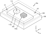
도 5는 본 개시의 일 실시예에 따른 가스 감지 장치(20a)를 나타내는 평면도이다. 도 6은 본 개시의 일 실시예에 따른 가스 감지 장치(20a)를 나타내는 단면도이다. 도 7은 본 개시의 일 실시예에 따른 가스 감지 장치(20a)를 나타내는 사시도이다. 예를 들어, 가스 감지 장치(20a)는 도 2의 가스 감지 장치(20)의 일 구현 예에 대응할 수 있다.Figure 5 is a plan view showing a
도 5 내지 도 7을 함께 참조하면, 가스 감지 장치(20a)는 기판(300), 기판(300) 상에 배치된 구동 회로 칩(200), 구동 회로 칩(200) 상에 배치된 제1 센서 칩(CHIP1)(110a) 및 제2 센서 칩(CHIP2)(120a)을 포함할 수 있다. 이와 같이, 가스 감지 장치(20a)는 다수의 칩들을 포함하는 패키지로 구현될 수 있고, 이에 따라, 가스 감지 패키지 또는 가스 감지 시스템이라고 지칭할 수도 있다.Referring to FIGS. 5 to 7 together, the
기판(300)은 패키지 기판 또는 인쇄 회로 기판(Printed Circuit Board)(PCB)일 수 있다. 구동 회로 칩(200)은 기판(300) 상에 실장될 수 있고, 본딩 와이어(Bonding Wire)(BW)를 통해 기판(300)에 전기적으로 연결될 수 있다. 구체적으로, 본딩 와이어(BW)는 구동 회로 칩(200) 상의 본딩 패드(Bonding Pad)(BP)와 기판(300) 상의 본딩 패드(BP)에 연결될 수 있다. 도시되지는 않았으나, 기판(300) 상에 구동 회로 칩(200) 외의 다른 반도체 칩이 더 배치될 수 있다. The
제1 센서 칩(110a)은 예를 들어, 도 2의 가스 센서(110)의 일 구현 예에 대응할 수 있고, 이하에서는 제1 센서 칩(110a)을 "가스 센서 칩"이라고 지칭하기로 한다. 가스 센서 칩(110a)은 구동 회로 칩(200) 상에 배치될 수 있고, 본딩 와이어(BW)를 통해 구동 회로 칩(200)에 전기적으로 연결될 수 있다. 구체적으로, 본딩 와이어(BW)는 가스 센서 칩(110a) 상의 본딩 패드(BP)와 구동 회로 칩(200) 상의 본딩 패드(BP)에 연결될 수 있다. 가스 센서 칩(110a)은 외부에 노출된 감지막(112)을 포함할 수 있다.For example, the
제2 센서 칩(120a)은 예를 들어, 도 2의 온도 센서(120)의 일 구현 예에 대응할 수 있고, 이하에서는 제2 센서 칩(120a)을 "온도 센서 칩"이라고 지칭하기로 한다. 온도 센서 칩(120a)은 구동 회로 칩(200) 상에 배치될 수 있고, 본딩 와이어(BW)를 통해 구동 회로 칩(200)에 전기적으로 연결될 수 있다. 구체적으로, 본딩 와이어(BW)는 온도 센서 칩(120a) 상의 본딩 패드(BP)와 구동 회로 칩(200) 상의 본딩 패드(BP)에 연결될 수 있다.The
가스 감지 장치(20a)는 기판(300), 구동 회로 칩(200), 가스 센서 칩(110a) 및 온도 센서 칩(120a)의 상부에 배치된 케이스 부재(400)를 더 포함할 수 있다. 케이스 부재(400)에는 제1 홀(hole)(H1) 및 제2 홀(H2)이 형성될 수 있다. 제1 및 제2 홀들(H1, H2)을 통해 가스 감지 장치(20a) 내로 가스가 유입 또는 배출될 수 있고, 이로써, 가스 센서 칩(110a) 상의 감지막(112)이 타겟 가스를 감지할 수 있다. 케이스 부재(400)는 커버 부재 또는 하우징이라고 지칭할 수도 있다. 예를 들어, 케이스 부재(400)는 스테인리스 스틸(stainless steel) 또는 플라스틱으로 구현될 수 있다. 일부 실시예에서, 케이스 부재(400)의 상면은 메쉬 형상으로 구현될 수 있고, 이에 따라, 가스의 유입 또는 배출이 더욱 활발하게 이루어질 수 있다.The
도 8a는 도 6의 가스 센서 칩(110a)을 나타내는 단면도이다. FIG. 8A is a cross-sectional view showing the
도 8a를 참조하면, 가스 센서 칩(110a)은 기판(SUB) 상에 배치된 FBAR(111), 및 FBAR(111) 상에 코팅된 감지막(112)을 포함할 수 있다. 일부 실시예들에서, 가스 센서 칩(110a)은 몰딩층(molding layer)(113)을 더 포함할 수 있으나, 본 발명은 이에 한정되지 않는다. FBAR(111) 및 감지막(112)은 도 3a에 예시된 실시예와 유사하므로, 이에 대한 설명은 생략하기로 한다. 몰딩층(113)은 감지막(112)의 적어도 일부가 노출되도록 기판(SUB), FBAR(111) 및 감지막(112) 상에 형성될 수 있다.Referring to FIG. 8A, the
도 8b는 도 6의 온도 센서 칩(120a)을 나타내는 단면도이다. FIG. 8B is a cross-sectional view showing the
도 8b를 참조하면, 온도 센서 칩(120a)은 기판(SUB) 상에 배치된 FBAR(121), 밀폐층(encapsulation layer)(123), 및 FBAR(121)와 밀폐층(123) 사이의 에어 캐비티(air cavity)(AC)를 포함할 수 있다. 이때, 하부 전극(121a) 및 상부 전극(121c) 중 적어도 하나는 밀폐층(123)의 상부와 전기적으로 연결될 수 있다. FBAR(121)는 도 3b에 예시된 실시예와 유사하므로, 이에 대한 설명은 생략하기로 한다. 밀폐층(123)은 FBAR(121)가 외부에 노출되지 않도록 기판(SUB) 및 FBAR(121)의 상부에 배치될 수 있다. 예를 들어, 밀폐층(123)은 실리콘 또는 유리로 구현될 수 있다. 도시되지는 않았으나, 온도 센서 칩(120a)은 밀폐층(123)의 상부에 몰딩층을 더 포함할 수 있다.Referring to FIG. 8B, the
도 9는 본 개시의 일 실시예에 따른 가스 감지 장치(40)를 나타내는 블록도이다. 예를 들어, 가스 감지 장치(40)는 도 2의 가스 감지 장치(20)의 일 변형 예일 수 있다.Figure 9 is a block diagram showing a
도 9를 참조하면, 가스 감지 장치(40)는 가스 센서(110), 온도 센서(120), 가스 센서(130) 및 구동 회로 칩(200a)을 포함할 수 있고, 구동 회로 칩(200a)은 제1 내지 제3 발진기들(210, 220, 230) 및 보정 회로(270a)를 포함할 수 있다. 가스 감지 장치(40)는 도 2의 가스 감지 장치(20)에 비해 가스 센서(130) 및 이에 대응하는 제3 발진기(230)를 더 포함할 수 있다. 이와 같이, 본 실시예에 따르면, 가스 감지 장치(40)는 복수의 가스 센서들(110, 130)을 포함할 수 있고, 이에 따라, 다양한 가스들을 감지할 수 있다. 도 2를 참조하여 상술된 내용은 본 실시예에도 적용될 수 있으며, 중복된 설명은 생략하기로 한다.Referring to FIG. 9, the
가스 센서(130)는 FBAR로 구현될 수 있으며, 가스 센서(130)는 FBAR의 구조에 따른 공진 주파수를 가질 수 있다. 이때, 가스 센서(130)는 가스 센서(110)와 실질적으로 유사하게 구현될 수 있다. 이하에서는, 가스 센서(110)를 "제1 가스 센서"로, 가스 센서(130)를 "제2 가스 센서"로 지칭하기로 한다. 제1 가스 센서(110)는 제1 타겟 가스를 감지하기 위한 제1 감지막(예를 들어, 도 12의 112)을 포함할 수 있고, 제2 가스 센서(130)는 제2 타겟 가스를 감지하기 위한 제2 감지막(예를 들어, 도 12의 132)을 포함할 수 있다. 이때, 제1 감지막과 제2 감지막은 서로 다른 물질을 포함할 수 있다.The
제1 발진기(210)는 제1 가스 센서(110)의 공진 주파수에 상응하는 주파수를 갖는 발진 신호, 즉, 제1 센싱 신호(SS1)를 출력할 수 있다. 제2 발진기(220)는 온도 센서(120)의 공진 주파수에 상응하는 주파수를 갖는 발진 신호, 즉, 제2 센싱 신호(SS2)를 출력할 수 있다. 제3 발진기(230)는 제2 가스 센서(130)의 공진 주파수에 상응하는 주파수를 갖는 발진 신호, 즉, 제3 센싱 신호(SS3)를 출력할 수 있다. The
보정 회로(270a)는 제2 센싱 신호(SS2)를 기초로 제1 센싱 신호(SS1)를 보정함으로써 제1 가스 센싱 신호(GSS)를 생성할 수 있다. 또한, 보정 회로(270a)는 제2 센싱 신호(SS2)를 기초로 제3 센싱 신호(SS3)를 보정함으로써 제2 가스 센싱 신호(GSS2)를 생성할 수 있다. 이와 같이, 본 실시예에 따르면, 제1 가스 센서(110)및 제2 가스 센서(130)에서 감지된 센싱 결과에서 온도에 의한 영향을 제거할 수 있으므로, 제1 가스 및 제2 가스의 센싱 결과에 대한 정확도가 더욱 향상될 수 있다.The
도 9에서는, 보정 회로(270a)가 구동 회로 칩(200a)에 포함되는 것으로 도시되었으나, 본 발명은 이에 한정되지 않는다. 일부 실시예들에서, 보정 회로(270a)는 어플리케이션 프로세서 또는 MCU(Micro Controller Unit)에 포함될 수 있다. 또한, 일부 실시예에서, 제1 내지 제3 센싱 신호들(SS1 내지 SS3)은 어플리케이션 프로세서 또는 MCU에 제공될 수 있고, 어플리케이션 프로세서 또는 MCU가 제2 센싱 신호(SS2)를 기초로 제1 센싱 신호(SS1)를 보정함으로써 제1 가스 센싱 신호(GSS)를 생성하거나, 제2 센싱 신호(SS2)를 기초로 제3 센싱 신호(SS3)를 보정함으로써 제2 가스 센싱 신호(GSS2)를 생성할 수 있다.In FIG. 9, the
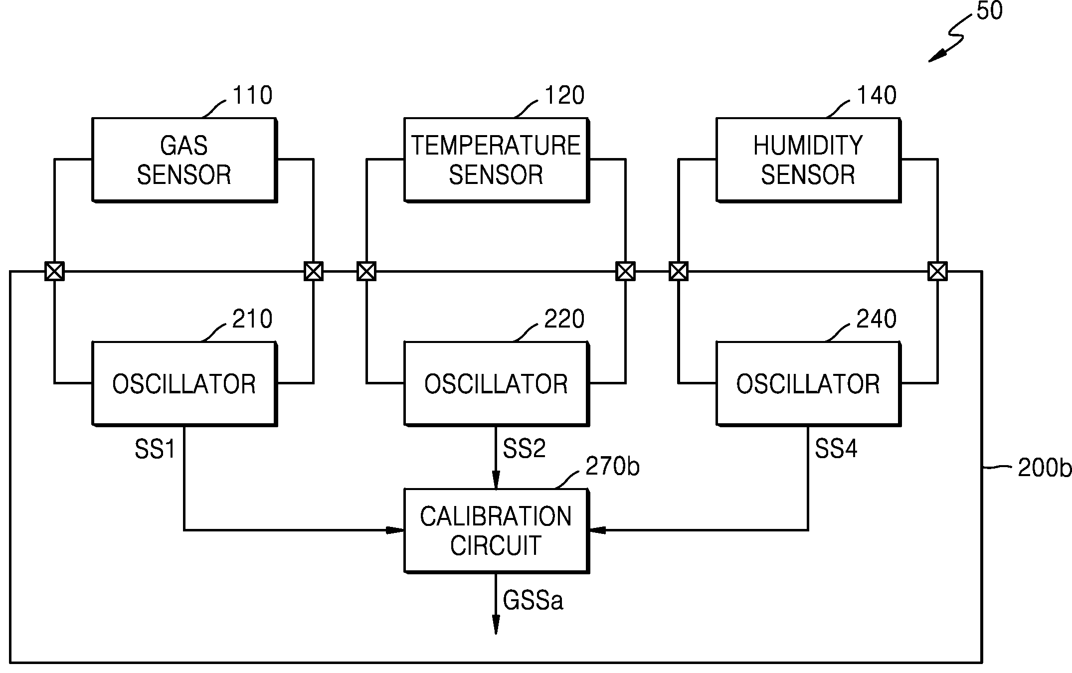
도 10은 본 개시의 일 실시예에 따른 가스 감지 장치(50)를 나타내는 블록도이다. 예를 들어, 가스 감지 장치(50)는 도 2의 가스 감지 장치(20)의 다른 변형 예일 수 있다.Figure 10 is a block diagram showing a
도 10을 참조하면, 가스 감지 장치(50)는 제1 가스 센서(110), 온도 센서(120), 습도 센서(140) 및 구동 회로 칩(200b)을 포함할 수 있고, 구동 회로 칩(200b)은 제1 및 제2 발진기들(210, 220), 제4 발진기(240) 및 보정 회로(270b)를 포함할 수 있다. 가스 감지 장치(50)는 도 2의 가스 감지 장치(20)에 비해 습도 센서(140) 및 이에 대응하는 제4 발진기(240)를 더 포함할 수 있다. 이와 같이, 본 실시예에 따르면, 가스 감지 장치(50)는 온도 센서(120) 및 습도 센서(140)를 포함하는 복수의 환경 센서들을 포함할 수 있고, 이에 따라, 가스 감지의 정확도를 더욱 향상시킬 수 있다. 도 2를 참조하여 상술된 내용은 본 실시예에도 적용될 수 있으며, 중복된 설명은 생략하기로 한다.Referring to FIG. 10, the
습도 센서(140)는 주변의 습도를 감지할 수 있고, FBAR로 구현됨으로써 FBAR의 구조에 따른 공진 주파수를 가질 수 있다. 이때, 습도 센서(140)는 제1 가스 센서(110)와 실질적으로 유사하게 구현될 수 있다. 제1 가스 센서(110)는 제1 타겟 가스를 감지하기 위한 제1 감지막(예를 들어, 도 12의 112)을 포함할 수 있고, 습도 센서(140)는 습도를 감지하기 위한 제3 감지막(예를 들어, 도 12의 142)을 포함할 수 있다. 이때, 제1 감지막과 제3 감지막은 서로 다른 물질을 포함할 수 있다.The
제1 발진기(210)는 제1 가스 센서(110)의 공진 주파수에 상응하는 주파수를 갖는 발진 신호, 즉, 제1 센싱 신호(SS1)를 출력할 수 있다. 제2 발진기(220)는 온도 센서(120)의 공진 주파수에 상응하는 주파수를 갖는 발진 신호, 즉, 제2 센싱 신호(SS2)를 출력할 수 있다. 제3 발진기(240)는 습도 센서(140)의 공진 주파수에 상응하는 주파수를 갖는 발진 신호, 즉, 제4 센싱 신호(SS4)를 출력할 수 있다. The
보정 회로(270b)는 제2 센싱 신호(SS2) 및 제4 센싱 신호(SS4)를 기초로 제1 센싱 신호(SS1)를 보정함으로써 제1 가스 센싱 신호(GSSa)를 생성할 수 있다. 제1 가스 센싱 신호(GSSa)의 주파수(fGSSa)는 아래의 수학식 5와 같이 나타낼 수 있다.The
[수학식 5] [Equation 5]
fGSSa = fSS1 - (A*fSS2 + B*fSS4 + E)f GSSa = f SS1 - (A*f SS2 + B*f SS4 + E)
여기서, fSS1은 제1 센싱 신호(SS1)의 주파수이고, A는 온도 계수이고, fSS2는 제2 센싱 신호(SS2)의 주파수이며,B는 습도 계수이고, fSS4는 제4 센싱 신호(SS4)의 주파수이다. Here, f SS1 is the frequency of the first sensing signal (SS1), A is the temperature coefficient, f SS2 is the frequency of the second sensing signal (SS2), B is the humidity coefficient, and f SS4 is the fourth sensing signal ( SS4) is the frequency.
이와 같이, 본 실시예에 따르면, 제1 가스 센서(110)에서 감지된 센싱 결과에서 온도 및 습도에 의한 영향을 제거할 수 있으므로, 제1 가스의 센싱 결과에 대한 정확도가 더욱 향상될 수 있다.In this way, according to this embodiment, the influence of temperature and humidity can be removed from the sensing result detected by the
도 10에서는, 보정 회로(270b)가 구동 회로 칩(200b)에 포함되는 것으로 도시되었으나, 본 발명은 이에 한정되지 않는다. 일부 실시예들에서, 보정 회로(270b)는 어플리케이션 프로세서 또는 MCU에 포함될 수 있다. 또한, 일부 실시예에서, 제1 및 제2 센싱 신호들(SS1, SS2) 및 제4 센싱 신호(SS4)는 어플리케이션 프로세서 또는 MCU에 제공될 수 있고, 어플리케이션 프로세서 또는 MCU가 제2 센싱 신호(SS2) 및 제4 센싱 신호(SS4)를 기초로 제1 센싱 신호(SS1)를 보정함으로써 제1 가스 센싱 신호(GSSa)를 생성할 수 있다.In FIG. 10, the
도 11은 본 개시의 일 실시예에 따른 가스 감지 장치(60)를 나타내는 블록도이다.Figure 11 is a block diagram showing a
도 11을 참조하면, 가스 감지 장치(60)는 제1 가스 센서(110), 온도 센서(120), 제2 가스 센서(130), 습도 센서(140), 압력 센서(150) 및 드리프트 보정(drift compensation) 센서(160)를 포함할 수 있다. 여기서, 온도 센서(120), 습도 센서(140), 압력 센서(150) 및 드리프트 보정 센서(160)는 환경 센서들일 수 있다. 일부 실시예들에서, 가스 감지 장치(60)는 다수의 가스 센서들 또는 다수의 환경 센서들을 더 포함할 수 있다. 예를 들어, 가스 감지 장치(60)는 광 센서를 더 포함할 수 있다. 일부 실시예들에서, 가스 감지 장치(60)는 온도 센서(120), 습도 센서(140), 압력 센서(150) 및 드리프트 보정 센서(160) 중 적어도 하나를 포함할 수 있다. 일부 실시예들에서, 가스 감지 장치(60)는 제1 및 제2 가스 센서들(110, 130) 중 하나를 포함할 수도 있다.Referring to FIG. 11, the
가스 감지 장치(60)는 제1 가스 센서(110), 온도 센서(120), 제2 가스 센서(130), 습도 센서(140), 압력 센서(150) 및 드리프트 보정 센서(160)는 각각 FBAR로 구현될 수 있고, 구동 회로 칩(200c) 상에 배치될 수 있다. 제1 가스 센서(110)는 제1 가스를 감지할 수 있고, 제2 가스 센서(130)는 제2 가스를 감지할 수 있다. 일 실시예에서, 제1 및 제2 가스 센서들(110, 130)은 서로 다른 웨이퍼들에 각각 형성될 수 있고, 이에 따라, 개별적인 반도체 다이들 또는 반도체 칩들로 구현될 수 있다. 일 실시예에서, 제1 및 제2 가스 센서들(110, 130)은 동일한 웨이퍼에 형성될 수 있고, 이에 따라, 단일 반도체 다이 또는 단일 반도체 칩으로 구현될 수 있다.The
습도 센서(140)는 주변의 습도를 감지함으로써, 습도 센싱 결과를 출력할 수 있다. 압력 센서(150)는 대기압을 감지함으로써, 대기압 센싱 결과를 출력할 수 있다. 예를 들어, 압력 센서(150)는 기판과 FBAR의 사이에 밀폐형 캐비티를 가질 수 있고, 이로써, 대기압을 감지할 수 있다. 드리프트 보정 센서(160)는 FBAR의 노화(aging)를 감지함으로써, 드리프트 센싱 결과를 출력할 수 있다. 예를 들어, 드리프트 보정 센서(160)는 감지막이 코팅되지 않은 FBAR을 포함할 수 있다. FBAR의 노화에 따라, 센싱 결과에서 베이스라인(baseline)이 이동할 수 있으므로, 드리프트 센싱 결과를 이용하여 가스 센싱 결과에서 FBAR의 노화에 따른 영향을 제거할 수 있다.The
구동 회로 칩(200c)은 제1 가스 센서(110), 온도 센서(120), 제2 가스 센서(130), 습도 센서(140), 압력 센서(150) 및 드리프트 보정 센서(160)에 각각 대응하는 제1 내지 제6 발진기들(210 내지 260)을 포함할 수 있다. 제1 발진기(210)는 제1 가스 센서(110)의 공진 주파수 변화에 대응하는 제1 센싱 신호(SS1)를 생성하고, 제2 발진기(220)는 온도 센서(120)의 공진 주파수 변화에 대응하는 제2 센싱 신호(SS2)를 생성하며, 제3 발진기(230)는 제2 가스 센서(130)의 공진 주파수 변화에 대응하는 제3 센싱 신호(SS3)를 생성할 수 있다. 또한, 제4 발진기(240)는 습도 센서(140)의 공진 주파수 변화에 대응하는 제4 센싱 신호(SS4)를 생성하고, 제5 발진기(250)는 압력 센서(150)의 공진 주파수 변화에 대응하는 제5 센싱 신호(SS5)를 생성하고, 제6 발진기(260)는 드리프트 보정 센서(160)의 공진 주파수 변화에 대응하는 제6 센싱 신호(SS6)를 생성할 수 있다.The driving
또한, 구동 회로 칩(200c)는 보정 회로(270c)를 더 포함할 수 있고, 보정 회로(270c)는 제1, 제4 내지 제6 센싱 신호들(SS1, SS4, SS5, SS6)을 기초로 제1 센싱 신호(SS1)를 보정함으로써, 제1 가스 센싱 신호(GSS1a)를 생성할 수 있다. 제1 가스 센싱 신호(GSS1a)의 주파수(fGSS1a)는 아래의 수학식 6과 같이 나타낼 수 있다.In addition, the driving
[수학식 6] [Equation 6]
fGSS1a = fSS1 - (A*fSS2 - B*fSS4 - C*fSS5 - F*fSS6 - E)f GSS1a = f SS1 - (A*f SS2 - B*f SS4 - C*f SS5 - F*f SS6 - E)
여기서, fSS1은 제1 센싱 신호(SS1)의 주파수이고, C는 압력 계수이고, fSS5는 제5 센싱 신호(SS5)의 주파수이다. 또한, F는 드리프트 계수이고, fSS6는 제6 센싱 신호(SS6)의 주파수이다. 또한, 보정 회로(270c)는 제1, 제4 내지 제6 센싱 신호들(SS1, SS4, SS5, SS6)을 기초로 제2 센싱 신호(SS3)를 보정함으로써, 제2 가스 센싱 신호(GSS2a)를 생성할 수 있다. 이때, 제2 가스 센싱 신호(GSS2a)의 주파수(fGSS2a)는 아래의 수학식 7과 같이 나타낼 수 있다.Here, f SS1 is the frequency of the first sensing signal SS1, C is the pressure coefficient, and f SS5 is the frequency of the fifth sensing signal SS5. Additionally, F is the drift coefficient, and f SS6 is the frequency of the sixth sensing signal (SS6). In addition, the
[수학식 7][Equation 7]
fGSS2a = fSS3 - (A*fSS2 - B*fSS4 - C*fSS5 - F*fSS6 - E)f GSS2a = f SS3 - (A*f SS2 - B*f SS4 - C*f SS5 - F*f SS6 - E)
이와 같이, 본 실시예에 따르면, 제1 및 제2 가스 센서들(110, 130)에서 감지된 센싱 결과에서 온도, 습도, 대기압 및 드리프트에 의한 영향을 제거할 수 있으므로, 제1 및 제2 가스의 센싱 결과에 대한 정확도가 더욱 향상될 수 있다. In this way, according to this embodiment, the influence of temperature, humidity, atmospheric pressure, and drift can be removed from the sensing results detected by the first and
도 11에서는, 보정 회로(270c)가 구동 회로 칩(200c)에 포함되는 것으로 도시되었으나, 본 발명은 이에 한정되지 않는다. 일부 실시예들에서, 보정 회로(270c)는 어플리케이션 프로세서 또는 MCU에 포함될 수 있다. 또한, 일부 실시예에서, 제1 내지 제6 센싱 신호들(SS1 내지 SS6)은 어플리케이션 프로세서 또는 MCU에 제공될 수 있고, 어플리케이션 프로세서 또는 MCU가 제1, 제4 내지 제6 센싱 신호들(SS1, SS4, SS5, SS6)을 기초로 제1 센싱 신호(SS1)를 보정함으로써 제1 가스 센싱 신호(GSS1a)를 생성하거나, 제1, 제4 내지 제6 센싱 신호들(SS1, SS4, SS5, SS6)을 기초로 제2 센싱 신호(SS3)를 보정함으로써 제2 가스 센싱 신호(GSS2a)를 생성할 수 있다.In FIG. 11, the
도 12는 본 개시의 일 실시예에 따라, 도 11의 가스 감지 장치의 일 구현예(60a)를 나타낸다. 도 13은 본 개시의 일 실시예에 따라, 도 12의 XIII-XIII' 선에 따른 단면도이다.FIG. 12 illustrates one
도 12 및 도 13을 함께 참조하면, 가스 감지 장치(60a)는 기판(300), 기판(300) 상에 배치된 구동 회로 칩(200d), 구동 회로 칩(200d) 상에 배치된 제1 센서 칩(CHIP1)(110a), 제2 센서 칩(CHIP2)(120a), 제3 센서 칩(CHIP3)(130a), 제4 센서 칩(CHIP4)(140a), 제5 센서 칩(CHIP5)(150a), 및 제6 센서 칩(CHIP6)(160a)을 포함할 수 있다. 가스 감지 장치(60a)는 도 5 내지 도 7에 예시된 가스 감지 장치(20a)의 일 변형 예에 대응하며, 도 5 내지 도 7을 참조하여 상술된 내용은 본 실시예에도 적용될 수 있다.Referring to FIGS. 12 and 13 together, the
제1 센서 칩(110a), 제2 센서 칩(120a), 제3 센서 칩(130a), 제4 센서 칩(140a), 제5 센서 칩(150a), 및 제6 센서 칩(160a)은 각각 도 11의 제1 가스 센서(110), 온도 센서(120), 제2 가스 센서(130), 습도 센서(140), 압력 센서(150) 및 드리프트 보정 센서(160)의 일 구현 예에 대응할 수 있다. 이하에서는, 제1 센서 칩(110a), 제2 센서 칩(120a), 제3 센서 칩(130a), 제4 센서 칩(140a), 제5 센서 칩(150a), 및 제6 센서 칩(160a)을 각각 온도 센서 칩(110a), 제1 가스 센서 칩(120a), 제2 가스 센서 칩(130a), 습도 센서 칩(140a), 압력 센서 칩(150a), 및 드리프트 보정 센서 칩(160a)이라고 지칭하기로 한다. 구동 회로 칩(200d)은 도 11의 구동 회로 칩(200c)의 일 구현 예에 대응할 수 있다.The
온도 센서 칩(110a), 제1 가스 센서 칩(120a), 제2 가스 센서 칩(130a), 습도 센서 칩(140a), 압력 센서 칩(150a), 및 드리프트 보정 센서 칩(160a)은 서로 다른 웨이퍼들에 각각 형성될 수 있고, 이에 따라, 개별적인 반도체 다이들 또는 개별적인 반도체 칩들로 제조될 수 있다. 이때, 온도 센서 칩(110a), 제1 가스 센서 칩(120a), 제2 가스 센서 칩(130a), 습도 센서 칩(140a), 압력 센서 칩(150a), 및 드리프트 보정 센서 칩(160a)은 각각 FBAR를 포함할 수 있고, 이에 따라, "FBAR 센서 칩"이라고 지칭할 수 있다.The
온도 센서 칩(120a)은 FBAR가 외부에 노출되지 않도록 밀폐된 구조를 가질 수 있고, 이에 따라, 밀폐층을 포함할 수 있다. 온도 센서 칩(120a)은 도 7b와 실질적으로 유사하게 구현될 수 있는바, 이에 대한 상세한 설명은 생략하기로 한다. 제1 가스 센서 칩(110a)은 FBAR 상에 코팅된 제1 감지막(112)을 포함할 수 있고, 제1 감지막(112)은 외부에 노출됨으로써 제1 가스를 감지할 수 있다. 제2 가스 센서 칩(130a)은 FBAR 상에 코팅된 제2 감지막(132)을 포함할 수 있고, 제2 감지막(132)은 외부에 노출됨으로써 제2 가스를 감지할 수 있다.The
습도 센서 칩(140a)은 FBAR 상에 코팅된 제3 감지막(142)을 포함할 수 있고, 제3 감지막(142)은 외부에 노출됨으로써 습도를 감지할 수 있다. 압력 센서 칩(150a)은 FBAR 상에 코팅된 제4 감지막(152) 및 FBAR 하부의 밀폐형 캐비티를 포함함으로써 대기압을 감지할 수 있다. 드리프트 보정 센서 칩(160a)은 FBAR의 노화(aging)에 따른 주파수 변화량을 보정하기 위하여, 감지막을 포함하지 않도록 구현될 수 있다.The
도 14는 본 개시의 일 실시예에 따라, 도 11의 가스 감지 장치의 다른 구현예(70)를 나타낸다. 도 15는 본 개시의 일 실시예에 따라, 도 14의 XV-XV' 선에 따른 단면도이다.FIG. 14 illustrates another
도 14 및 도 15를 함께 참조하면, 가스 감지 장치(70)는 기판(300), 기판(300) 상에 배치된 구동 회로 칩(200e), 구동 회로 칩(200e) 상에 배치된 센서 칩(CHIP1)(170), 온도 센서 칩(CHIP2)(120a), 및 드리프트 센서 칩(CHIP6)(160a)을 포함할 수 있다. 센서 칩(170)은 제1 가스 센서(110b), 제2 가스 센서(130b), 습도 센서(140b) 및 압력 센서(150b)를 포함할 수 있다. 가스 감지 장치(70)는 도 5 내지 도 7에 예시된 가스 감지 장치(20a)의 다른 변형 예에 대응하며, 도 5 내지 도 7을 참조하여 상술된 내용은 본 실시예에도 적용될 수 있다.Referring to FIGS. 14 and 15 together, the
본 실시예에 따르면, 상부에 감지막이 코팅된 FBAR 센서들은 단일 센서 칩으로 구현될 수 있다. 제1 가스 센서(110b)는 제1 감지막(112)을 포함할 수 있고, 제2 가스 센서(130b)는 제2 감지막(132)을 포함할 수 있고, 습도 센서(140b)는 제3 감지막(142)을 포함할 수 있고, 압력 센서(150b)는 제4 감지막(152)을 포함할 수 있다. 따라서, 제1 및 제2 가스 센서들(110b, 130b), 습도 센서(140b) 및 압력 센서(150b)는 동일한 웨이퍼에 형성됨으로써, 센서 칩(170)으로 구현될 수 있다. 이때, 감지막을 포함하지 않는 온도 센서 칩(120a) 및 드리프트 센서 칩(160a)은 개별 센서 칩들로 구현될 수 있다.According to this embodiment, FBAR sensors coated with a sensing film on the top can be implemented as a single sensor chip. The
그러나, 본 발명은 이에 한정되지 않으며, 제1 가스 센서(110b), 제2 가스 센서(130b), 습도 센서(140b) 및 압력 센서(150b) 중 적어도 하나는 개별 다이 또는 칩으로 구현될 수 있다. 예를 들어, 제1 가스 센서(110b), 제2 가스 센서(130b) 및 습도 센서(140b)는 하나의 칩으로 구현되고, 압력 센서(150b)는 다른 칩으로 구현될 수 있다. 또한, 일부 실시예들에서, 제1 및 제2 가스 센서들(110b, 130b)은 제1 웨이퍼에 형성됨으로써 하나의 칩으로 구현되고, 습도 센서(140b) 및 압력 센서(150b)는 제2 웨이퍼에 형성됨으로써 다른 칩으로 구현될 수도 있다. 또한, 일부 실시예들에서, 센서 칩(170)은 다양한 가스 센서들 및 환경 센서들을 더 포함할 수도 있다.However, the present invention is not limited to this, and at least one of the
도 16은 본 개시의 실시예들에 따라 가스 감지 장치에서 환경 센서의 센싱 측정 결과와 센싱 계산 결과를 나타내는 그래프이다.FIG. 16 is a graph showing sensing measurement results and sensing calculation results of an environmental sensor in a gas detection device according to embodiments of the present disclosure.
도 16을 참조하면, 가로축은 시간을 나타내고, 세로축은 주파수를 나타낸다. 제1 그래프(81)와 제2 그래프(82)는 모두 타겟 가스가 감지되지 않은 상황에서 시간에 따라 주파수 변화를 나타낸다. 제1 그래프(81)는 타겟 가스가 감지되지 않은 상황에서 환경 센서의 센싱 측정 결과를 나타내며, 예를 들어, 도 1의 환경 센서(ES)의 제2 센싱 결과(OUT2)에 대응할 수 있다(즉, fOUT2). 한편, 제2 그래프(82)는 타겟 가스가 감지되지 않은 상황에서 환경 센서의 센싱 계산 결과를 나타낸다 Referring to Figure 16, the horizontal axis represents time and the vertical axis represents frequency. Both the
일 실시예에서, 환경 센서가 온도 센서, 습도 센서, 압력 센서, 조도 센서를 포함하는 경우, 환경 센서의 센싱 측정 결과는 제1 그래프(81)에 대응하고, 환경 센서의 센싱 계산 결과는 아래의 수학식 8와 같이 나타낼 수 있다.In one embodiment, when the environmental sensor includes a temperature sensor, a humidity sensor, a pressure sensor, and an illuminance sensor, the sensing measurement result of the environmental sensor corresponds to the
[수학식 8][Equation 8]
f(환경_계산) = A*fT + B*fH + C*fP + D*fU + Ef(environment_calculation) = A*f T + B*f H + C*f P + D*f U + E
여기서, f(환경_계산)은 제2 그래프(82)에 대응하고, A는 온도 계수, B는 습도 계수, C는 압력 계수, D는 조도 계수, E는 상수이다. 또한, fT는 온도 센서(예를 들어, 도 11의 12)의 출력이고, fH는 습도 센서(예를 들어, 도 11의 140)의 출력이며, fP는 압력 센서(예를 들어, 도 11의 150)의 출력이고, fU는 조도 센서의 출력이다. 복수 번의 센싱을 통해 온도 계수(A), 습도 계수(B), 압력 계수(C), 조도 계수(D) 및 상수(E)를 산출할 수 있다. 이와 같이, 환경 측정 결과(81)와 환경 계산 결과(82)는 시간에 따라 상당히 유사한 주파수를 가질 수 있다.Here, f (environment_calculation) corresponds to the
그러나, 본 발명은 이에 한정되지 않으며, 일부 실시예들에서, 환경 센서의 보정은 선형 관계 또는 비선형 관계를 포함할 수 있다. 일 실시예에서, 환경 센서가 온도 센서, 습도 센서, 압력 센서, 조도 센서를 포함하는 경우, 환경 센서의 센싱 결과는 각 센서의 센싱 결과를 비선형적으로 반영할 수 있다. f(환경)은 다양한 환경 센서의 출력에 기초한 다양한 알고리즘으로 구현될 수 있다. 또한, f(환경)은 다양한 환경 센서의 출력에 기초한 머신 러닝(machine learning)을 이용한 알고리즘으로 구현될 수도 있다.However, the present invention is not limited thereto, and in some embodiments, calibration of an environmental sensor may include a linear relationship or a non-linear relationship. In one embodiment, when the environmental sensor includes a temperature sensor, a humidity sensor, a pressure sensor, and an illuminance sensor, the sensing results of the environmental sensor may non-linearly reflect the sensing results of each sensor. f(environment) can be implemented with various algorithms based on the output of various environmental sensors. Additionally, f (environment) may be implemented as an algorithm using machine learning based on the output of various environmental sensors.
제1 및 제2 그래프들(81, 82)에 따르면, 타겟 가스가 감지되지 않은 상황에서 가스 센서의 센싱 결과와 환경 센서의 센싱 결과가 실질적으로 유사한 것을 알 수 있다. 따라서, 환경 센서의 센싱 결과를 이용하여 가스 센서의 센싱 결과를 보정함으로써 가스 센싱 정확도를 향상시킬 수 있다.According to the first and
도 17a는 본 개시의 일 실시예에 따른 전자 장치의 일 예(500)를 나타낸다.FIG. 17A shows an example 500 of an electronic device according to an embodiment of the present disclosure.
도 17a를 참조하면, 전자 장치(500)는 멀티 센서 어레이(510), 발진기 칩(520) 및 어플리케이션 프로세서(Application Processor, AP)(530)를 포함할 수 있다. 멀티 센서 어레이(510)는 복수의 FBAR 센서들을 포함할 수 있고, 복수의 FBAR 센서들은 개별적인 센서 칩들 또는 다이들로 구현될 수 있다. 예를 들어, 멀티 센서 어레이(510)는 도 11의 제1 가스 센서(110), 온도 센서(120), 제2 가스 센서(130), 습도 센서(140), 압력 센서(150) 및 드리프트 보정 센서(160) 중 적어도 두 개를 포함할 수 있다.Referring to FIG. 17A , the
발진기 칩(520)은 발진기(521) 및 보정 회로(522)를 포함할 수 있다. 예를 들어, 발진기(521)는 멀티 센서 어레이(510)에 포함된 FBAR 센서들의 개수에 대응하는 복수의 발진기들을 포함할 수 있고, 복수의 발진기들은 대응하는 FBAR 센서들의 공진 주파수에 상응하는 주파수를 갖는 발진 신호들을 출력할 수 있다. 예를 들어, 발진기(521)는 도 11의 제1 내지 제6 발진기들(210 내지 260)을 포함할 수 있다. 보정 회로(522)는 가스 센싱 결과에서 환경 센싱 결과를 보정할 수 있다. 이에 따라, 발진기 칩(520)은 환경 인자가 보정된 센서 신호(FOSC)를 출력할 수 있다. 일 예로서, 발진기 칩(520)로부터의 센서 신호(FOSC)는 어플리케이션 프로세서(530)로 제공될 수 있다.The
도 17b는 본 개시의 일 실시예에 따른 전자 장치의 다른 예(500a)를 나타낸다.FIG. 17B shows another example 500a of an electronic device according to an embodiment of the present disclosure.
도 17b를 참조하면, 전자 장치(500a)는 멀티 센서 어레이(510) 및 어플리케이션 프로세서(530a)를 포함할 수 있다. 전자 장치(500a)는 도 17a의 전자 장치(500)의 변형 예에 대응할 수 있고, 중복된 설명은 생략하기로 한다. 발진기(520a)에 구비되는 각종 회로들(예컨대, 발진 회로 및 보정 회로)은 어플리케이션 프로세서(530a) 내부에 구현될 수 있으며, 발진기(520a)는 멀티 센서 어레이(510)에 연결되어 발진 신호(FOSC)를 출력할 수 있다.Referring to FIG. 17B, the
도 17c는 본 개시의 일 실시예에 따른 전자 장치의 다른 예(500b)를 나타낸다.FIG. 17C shows another example 500b of an electronic device according to an embodiment of the present disclosure.
도 17c를 참조하면, 전자 장치(500c)는 멀티 센서 어레이(510) 및 어플리케이션 프로세서(530b)를 포함할 수 있다. 전자 장치(500c)는 도 17a의 전자 장치(500)의 변형 예에 대응할 수 있고, 중복된 설명은 생략하기로 한다. 어플리케이션 프로세서(530b)는 멀티 센서 어레이(510)로부터 각종 센싱 신호들을 수신할 수 있다. 또한, 어플리케이션 프로세서(530b)는 보정 모듈(531)을 포함할 수 있고, 보정 모듈(531)은 수신한 각종 센싱 신호들을 기초로 가스 센싱 결과를 보정함으로써 가스 센싱 신호를 생성할 수 있다. 예를 들어, 보정 모듈(531)은 소프트웨어로 구현될 수 있고, 메모리에 로딩될 수 있다. 예를 들어, 보정 모듈(531)은 하드웨어로 구현될 수도 있다.Referring to FIG. 17C, the electronic device 500c may include a
도 18은 본 개시의 일 실시예에 가스 감지 시스템(600)을 나타내는 블록도이다.FIG. 18 is a block diagram illustrating a
도 18을 참조하면, 가스 감지 시스템(600)은 가스 감지 장치(610) 및 어플리케이션 프로세서(620)를 포함할 수 있다. 가스 감지 장치(610)는 멀티 센서 어레이(611), 하나 이상의 발진기들을 포함하는 발진기 블록(OSC BLOCK)(612) 및 발진기들에서 생성되는 발진 신호들에 대한 카운팅 동작에 기반하여 가스 감지 결과(Result_sen)를 생성하는 주파수 카운팅 로직(613)을 포함할 수 있다. 일부 실시예들에서, 가스 감지 장치(610)는 노이즈 리덕션(noise reduction) 회로 등을 더 포함할 수도 있다.Referring to FIG. 18 , the
멀티 센서 어레이(611)은 다양한 종류의 센서들을 포함할 수 있다. 전술한 실시예에 따라, 멀티 센서 어레이(611)은 하나 이상의 종류의 가스들을 감지하기 위한 FBAR 가스 센서들 및 환경 인자를 보정하기 위한 적어도 하나의 FBAR 환경 센서를 포함할 수 있다. 일부 실시예에서, 멀티 센서 어레이(611)은 다른 다양한 종류의 공진기들을 포함하여도 무방하며, 일 예로서 멀티 센서 어레이(611)은 벌크 음향파 공진기(bulk acoustic wave resonator, BAW), 표면 음향파 공진기(surface acoustic wave resonator, SAW) 및 고정 실장형 공진기(solidly mounted resonator, SMR) 등 다양한 종류의 공진기들을 포함하여도 무방하다.The
발진기 블록(612)은 복수의 발진기들을 포함할 수 있고, 복수의 발진기들은 멀티 센서 어레이(611)에 포함된 센서들에 각각 연결될 수 있다. 일 실시예에서, 보정 회로(예를 들어, 도 2의 270)는 발진기 블록(612)에 포함될 수 있다. 보정 회로는 FBAR 환경 센서의 센싱 결과를 기초로 FBAR 가스 센서의 센싱 결과를 보정함으로써 가스 센싱 신호, 즉 보정된 발진 신호를 생성할 수 있다. 그러나, 본 발명은 이에 한정되지 않으며, 일부 실시예들에서, 보정 회로는 주파수 카운팅 로직(613)에 포함될 수도 있다.The
주파수 카운팅 로직(613)은 발진기 블록(612)으로부터의 다수의 발진 신호들 또는 보정된 발진 신호들에 대한 카운팅 동작에 기반하여 가스 감지 결과(Result_sen)를 생성할 수 있다. 일 실시예에 따라, 주파수 카운팅 로직(613)은 레퍼런스 신호(REF)를 이용하여 다수의 발진 신호들 또는 보정된 발진 신호들에 대한 카운팅 동작을 수행할 수 있다. 카운팅 결과는 전술한 가스 감지 결과(Result_sen)로서 출력될 수 있으며, 예컨대, 상기 가스 감지 결과(Result_sen)는 소정 개수의 비트들을 갖는 디지털 코드(N-bit Output)에 해당할 수 있다.The
디지털 코드(N-bit Output)를 갖는 가스 감지 결과(Result_sen)는 외부의 장치에서 이용될 수 있다. 예컨대, 가스 감지 장치(610)가 스마트 폰 등의 모바일 장치에 채용되는 경우 어플리케이션 프로세서(620)가 모바일 장치 내에 구비되어 장치의 전반적인 동작을 제어할 수 있으며, 가스 감지 장치(610)로부터의 가스 감지 결과(Result_sen)는 어플리케이션 프로세서(620)로 제공될 수 있다. 어플리케이션 프로세서(620)는 가스 감지 결과(Result_sen)를 이용한 연산을 수행함으로써 감지된 가스들의 농도를 산출할 수 있다. 또한, 어플리케이션 프로세서(620)는 가스 감지 결과(Result_sen)를 처리함으로써 가스 감지에 관련된 각종 화면을 디스플레이에 출력하는 등의 각종 동작들을 수행할 수 있다.The gas detection result (Result_sen) with a digital code (N-bit Output) can be used in an external device. For example, when the
변형 가능한 실시예로서, 가스 감지 장치(610) 내에서 디지털 코드(N-bit Output)를 이용한 추가의 처리가 수행될 수도 있다. 예컨대, 전술한 가스들의 농도의 산출 동작 등 다양한 동작들이 가스 감지 장치(610) 내에서 수행되어도 무방할 것이다.As a variant embodiment, additional processing using a digital code (N-bit output) may be performed within the
도 19는 본 개시의 일 실시예에 따른 가스 감지 시스템의 가스 감지 방법을 나타내는 흐름도이다.Figure 19 is a flowchart showing a gas detection method of a gas detection system according to an embodiment of the present disclosure.
도 19를 참조하면, 본 실시예에 따른 가스 감지 방법은 예를 들어, 도 18의 가스 감지 시스템(600)에서 시계열적으로 수행되는 단계들을 포함할 수 있다. 이하에서는 도 18 및 도 19를 함께 참조하여 가스 감지 방법에 대해 설명하기로 한다.Referring to FIG. 19, the gas detection method according to this embodiment may include, for example, steps performed in time series in the
가스 감지 시스템(600)은 다수의 FBAR 센서들을 포함할 수 있고, FBAR 센서들은 각각 고유한 공진 주파수를 가질 수 있다. 다수의 FBAR 센서들은 적어도 하나의 가스 센서 및 적어도 하나의 환경 센서를 포함할 수 있다. 가스 감지 시스템(600)은 다수의 FBAR 센서들에 각각 대응하는 다수의 발진기들을 더 포함할 수 있다. 가스 감지 시스템(600)은 가스 센서로부터 제1 센싱 결과를 수신하고, 환경 센서로부터 제2 센싱 결과를 수신한다(S110). 다수의 FBAR 센서들에 구비되는 폴리머들의 특성에 따라, 발진기들은 서로 다른 종류의 가스들을 감지한 결과를 나타내는 발진 신호들을 생성할 수 있다. 가스 감지 시스템(600)은 제2 센싱 결과를 기초로 제1 센싱 결과를 보정함으로써, 가스 센싱 신호를 생성한다(S130).
가스 감지 시스템(600)은 가스 센싱 신호와 레퍼런스 신호(REF)를 연산한다(S150). 일 실시예에서, 레퍼런스 신호(REF)는 각 센서의 초기 주파수 값일 수 있고, 다수의 발진기들로부터 생성된 다수의 발진 신호들 각각에 대해 또는 보정된 발진 신호, 즉, 가스 센싱 신호에 대해 각 센서의 초기 주파수 값을 이용한 연산 동작이 수행될 수 있다. 각 센서의 초기 주파수 값과 가스 센싱 신호를 이용한 다양한 연산 동작이 수행될 수 있으며, 예를 들어, 각 센서의 초기 주파수 값과 가스 센싱 신호에 대한 AND/OR 연산이 수행되고, AND/OR 연산 결과로서 출력되는 신호(예컨대, 카운터 입력)를 카운팅하기 위한 카운팅 연산이 수행될 수 있다.The
가스 감지 시스템(600)은 연산 결과에 따라 가스 감지 결과를 나타내는 디지털 코드(Result_sen)를 생성한다(S170). 디지털 코드(Result_sen)는 레퍼런스 신호(REF) 대비 발진 신호 또는 가스 센싱 신호의 주파수의 비에 관련된 값이 포함될 수 있으며, 가스 감지 시스템(600)은 디지털 코드(Result_sen)에 해당하는 가스 감지 결과를 출력할 수 있다. The
가스 감지 시스템(600)은 디지털 코드(Result_sen)를 이용한 처리 동작을 수행하여 감지된 가스의 농도를 측정한다(S190). 가스 감지 시스템(600)으로부터의 가스 감지 결과는 다양한 방식에 따라 이용될 수 있으며, 일 실시예에 따라 가스 감지 결과는 가스 감지 시스템(600)이 채용된 디바이스 내의 어플리케이션 프로세서 등의 반도체 칩으로 제공될 수 있다. 어플리케이션 프로세서는 디지털 코드(Result_sen)를 이용한 처리 동작을 수행함으로써 가스 감지와 관련된 다양한 기능을 수행할 수 있으며, 일 실시예에 따라 감지된 가스의 농도가 측정될 수 있다.The
이상에서와 같이 도면과 명세서에서 예시적인 실시예들이 개시되었다. 본 명세서에서 특정한 용어를 사용하여 실시예들을 설명되었으나, 이는 단지 본 개시의 기술적 사상을 설명하기 위한 목적에서 사용된 것이지 의미 한정이나 특허청구범위에 기재된 본 개시의 범위를 제한하기 위하여 사용된 것은 아니다. 그러므로 본 기술분야의 통상의 지식을 가진 자라면 이로부터 다양한 변형 및 균등한 타 실시예가 가능하다는 점을 이해할 것이다. 따라서, 본 개시의 진정한 기술적 보호범위는 첨부된 특허청구범위의 기술적 사상에 의해 정해져야 할 것이다.As above, exemplary embodiments have been disclosed in the drawings and specification. Although embodiments have been described in this specification using specific terms, this is only used for the purpose of explaining the technical idea of the present disclosure and is not used to limit the meaning or scope of the present disclosure as set forth in the claims. . Therefore, those skilled in the art will understand that various modifications and other equivalent embodiments are possible therefrom. Therefore, the true technical protection scope of the present disclosure should be determined by the technical spirit of the attached patent claims.
Claims (20)
기판 상에 배치된 구동 회로 칩;
제1 공진기, 및 상기 제1 공진기 상에서 상기 가스 감지 시스템의 외부에 노출되도록 배치됨으로써 제1 가스를 감지하는 제1 감지막을 포함하고, 상기 구동 회로 칩 상에 배치되어 가스 센싱 결과를 생성하는 가스 센서 칩;
제2 공진기, 상기 제2 공진기가 상기 가스 감지 시스템의 외부에 노출되지 않도록 상기 제2 공진기의 상부에 배치된 밀폐층, 및 상기 제2 공진기와 상기 밀폐층 사이의 에어 캐비티(air cavity)를 포함하고, 상기 구동 회로 칩 상에 배치되어 온도를 감지함으로써 온도 센싱 결과를 생성하는 온도 센서 칩; 및
제3 공진기를 포함하고, 상기 구동 회로 칩 상에 배치되어 습도를 감지함으로써 습도 센싱 결과를 생성하는 습도 센서 칩을 포함하고,
상기 가스 감지 시스템은, 상기 가스 센싱 결과의 제1 주파수와, 상기 온도 센싱 결과 및 상기 습도 센싱 결과 중 적어도 하나의 제2 주파수 사이의 주파수 변화량을 판단하고, 상기 주파수 변화량을 기초로 상기 가스 센싱 결과를 보정함으로써, 가스 감지 신호를 생성하도록 구성되고,
상기 밀폐층은 상기 제2 공진기와 상기 밀폐층 사이에 상기 에어 캐비티가 있도록 상기 제2 공진기를 밀폐하는 것을 특징으로 하는 가스 감지 시스템.As a gas detection system,
a driving circuit chip disposed on a substrate;
A gas sensor including a first resonator and a first sensing film disposed on the first resonator to be exposed to the outside of the gas detection system to detect the first gas, and disposed on the driving circuit chip to generate a gas sensing result. chip;
It includes a second resonator, a sealing layer disposed on top of the second resonator so that the second resonator is not exposed to the outside of the gas detection system, and an air cavity between the second resonator and the sealing layer. and a temperature sensor chip disposed on the driving circuit chip to sense temperature and generate a temperature sensing result; and
A humidity sensor chip that includes a third resonator and is disposed on the driving circuit chip to detect humidity and generate a humidity sensing result,
The gas sensing system determines a frequency change amount between a first frequency of the gas sensing result and a second frequency of at least one of the temperature sensing result and the humidity sensing result, and determines the gas sensing result based on the frequency change amount. configured to generate a gas detection signal by correcting,
The gas detection system, wherein the sealing layer seals the second resonator such that the air cavity is between the second resonator and the sealing layer.
상기 구동 회로 칩은, 상기 주파수 변화량을 기초로 상기 가스 센싱 결과를 보정함으로써, 상기 가스 감지 신호를 생성하도록 구성된 보정 회로를 포함하는 것을 특징으로 하는 가스 감지 시스템.According to paragraph 1,
The driving circuit chip includes a correction circuit configured to generate the gas detection signal by correcting the gas sensing result based on the frequency change.
상기 보정 회로는, 상기 가스 센싱 결과의 상기 제1 주파수의 변화량에서, 상기 온도 센싱 결과 및 상기 습도 센싱 결과 중 적어도 하나의 상기 제2 주파수의 변화량을 감산함으로써 상기 주파수 변화량을 판단하고, 상기 주파수 변화량을 기초로 상기 가스 감지 신호를 생성하는 것을 특징으로 하는 가스 감지 시스템.According to paragraph 2,
The correction circuit determines the frequency change amount by subtracting the change amount of the second frequency of at least one of the temperature sensing result and the humidity sensing result from the change amount of the first frequency of the gas sensing result, and the frequency change amount A gas detection system characterized in that it generates the gas detection signal based on .
상기 가스 센서 칩으로부터 제1 센싱 신호를 수신하고, 상기 온도 센서 칩으로부터 제2 센싱 신호를 수신하며, 상기 습도 센서 칩으로부터 제3 센싱 신호를 수신하는 어플리케이션 프로세서를 더 포함하고,
상기 어플리케이션 프로세서는, 상기 제2 센싱 신호 및 상기 제3 센싱 신호 중 적어도 하나를 기초로 상기 제3 센싱 신호를 보정함으로써, 상기 가스 감지 신호를 생성하는 것을 특징으로 하는 가스 감지 시스템.According to paragraph 1,
It further includes an application processor that receives a first sensing signal from the gas sensor chip, a second sensing signal from the temperature sensor chip, and a third sensing signal from the humidity sensor chip,
The application processor generates the gas detection signal by correcting the third sensing signal based on at least one of the second sensing signal and the third sensing signal.
상기 가스 센서 칩으로부터 제1 센싱 신호를 수신하고, 상기 온도 센서 칩으로부터 제2 센싱 신호를 수신하며, 상기 습도 센서 칩으로부터 제3 센싱 신호를 수신하는 클라우드 서버를 더 포함하고,
상기 클라우드 서버는, 상기 제2 센싱 신호 및 상기 제3 센싱 신호 중 적어도 하나를 기초로 상기 제3 센싱 신호를 보정함으로써, 상기 가스 감지 신호를 생성하는 것을 특징으로 하는 가스 감지 시스템.According to paragraph 1,
It further includes a cloud server that receives a first sensing signal from the gas sensor chip, a second sensing signal from the temperature sensor chip, and a third sensing signal from the humidity sensor chip,
The cloud server generates the gas detection signal by correcting the third sensing signal based on at least one of the second sensing signal and the third sensing signal.
상기 제1 내지 제3 공진기들은 각각 FBAR(Film Bulk Acoustic Resonator)를 포함하는 것을 특징으로 하는 가스 감지 시스템.According to paragraph 1,
A gas detection system wherein the first to third resonators each include a Film Bulk Acoustic Resonator (FBAR).
기판 상에 배치된 구동 회로 칩;
제1 공진기, 및 상기 제1 공진기 상에서 상기 가스 감지 시스템의 외부에 노출되도록 배치됨으로써 제1 가스를 감지하여 가스 센싱 결과를 생성하는 제1 감지막을 포함하고, 상기 구동 회로 칩 상에 배치된 가스 센서 칩;
제2 공진기, 상기 제2 공진기가 상기 가스 감지 시스템의 외부에 노출되지 않도록 상기 제2 공진기의 상부에 배치된 밀폐층, 및 상기 제2 공진기와 상기 밀폐층 사이의 에어 캐비티(air cavity)를 포함하고, 상기 구동 회로 칩 상에 배치되어 온도를 감지함으로써 온도 센싱 결과를 생성하는 온도 센서 칩; 및
제3 공진기를 포함하고, 상기 구동 회로 칩 상에 배치되어 습도를 감지함으로써 습도 센싱 결과를 생성하는 습도 센서 칩을 포함하고,
상기 가스 감지 시스템은, 상기 온도 센싱 결과 및 상기 습도 센싱 결과 중 적어도 하나를 기초로 상기 가스 센싱 결과를 보정함으로써 가스 감지 신호를 생성하고,
상기 밀폐층은 상기 제2 공진기와 상기 밀폐층 사이에 상기 에어 캐비티가 있도록 상기 제2 공진기를 밀폐하며,
상기 제2 공진기는, 하부 전극, 상기 하부 전극 상의 압전층, 및 상기 압전층 상의 상부 전극을 포함하는 것을 특징으로 하는 가스 감지 시스템.As a gas detection system,
a driving circuit chip disposed on a substrate;
A gas sensor comprising a first resonator and a first sensing film disposed on the first resonator to be exposed to the outside of the gas detection system to sense the first gas and generate a gas sensing result, and disposed on the driving circuit chip. chip;
It includes a second resonator, a sealing layer disposed on top of the second resonator so that the second resonator is not exposed to the outside of the gas detection system, and an air cavity between the second resonator and the sealing layer. and a temperature sensor chip disposed on the driving circuit chip to sense temperature and generate a temperature sensing result; and
A humidity sensor chip that includes a third resonator and is disposed on the driving circuit chip to detect humidity and generate a humidity sensing result,
The gas detection system generates a gas detection signal by correcting the gas sensing result based on at least one of the temperature sensing result and the humidity sensing result,
The sealing layer seals the second resonator so that the air cavity is between the second resonator and the sealing layer,
The second resonator includes a lower electrode, a piezoelectric layer on the lower electrode, and an upper electrode on the piezoelectric layer.
제4 공진기를 포함하고, 상기 구동 회로 칩 상에 배치된 기압 센서 칩; 및
제5 공진기를 포함하고, 상기 구동 회로 칩 상에 배치된 광 센서 칩 중 적어도 하나를 더 포함하고,
상기 구동 회로 칩은, 상기 기압 센서 칩의 기압 센싱 결과 및 상기 광 센서 칩의 광 센싱 결과 중 적어도 하나를 기초로 상기 가스 센싱 결과를 보정함으로써, 상기 가스 감지 신호를 생성하도록 구성된 것을 특징으로 하는 가스 감지 시스템.According to paragraph 1,
an atmospheric pressure sensor chip including a fourth resonator and disposed on the driving circuit chip; and
It includes a fifth resonator, and further includes at least one of an optical sensor chip disposed on the driving circuit chip,
The driving circuit chip is configured to generate the gas detection signal by correcting the gas sensing result based on at least one of an atmospheric pressure sensing result of the atmospheric pressure sensor chip and an optical sensing result of the optical sensor chip. Detection system.
제6 공진기를 포함하고, 상기 제6 공진기의 노화(aging)에 따른 환경 인자를 보정하기 위하여 상기 구동 회로 칩 상에 배치된 드리프트 보정 센서 칩을 더 포함하고,
상기 구동 회로 칩은, 상기 드리프트 보정 센서 칩의 센싱 결과를 기초로 상기 가스 센싱 결과를 보정함으로써, 상기 가스 감지 신호를 생성하도록 구성된 것을 특징으로 하는 가스 감지 시스템.According to paragraph 1,
It includes a sixth resonator, and further includes a drift correction sensor chip disposed on the driving circuit chip to correct environmental factors due to aging of the sixth resonator,
The driving circuit chip is configured to generate the gas detection signal by correcting the gas sensing result based on the sensing result of the drift correction sensor chip.
제1 공진기, 및 상기 제1 공진기 상에서 상기 가스 감지 장치의 외부에 노출되도록 배치됨으로써 제1 가스를 감지하는 제1 감지막을 포함하고, 제1 센싱 결과를 생성하는 제1 센서 칩;
제2 공진기, 상기 제2 공진기가 상기 가스 감지 장치의 외부에 노출되지 않도록 상기 제2 공진기의 상부에 배치된 밀폐층, 및 상기 제2 공진기와 상기 밀폐층 사이의 에어 캐비티(air cavity)를 포함하고, 제2 센싱 결과를 생성하는 제2 센서 칩;
제3 공진기, 및 상기 제3 공진기 상에서 외부에 노출되도록 배치됨으로써 제2 가스를 감지하는 제2 감지막을 포함하고, 제3 센싱 결과를 생성하는 제3 센서 칩; 및
상기 제2 센싱 결과를 기초로 상기 제1 센싱 결과를 보정함으로써, 제1 가스 감지 신호를 생성하고, 상기 제2 센싱 결과를 기초로 상기 제3 센싱 결과를 보정함으로써 제2 가스 감지 신호를 생성하는 구동 회로 칩을 포함하고,
상기 구동 회로 칩은, 상기 제1 센싱 결과에 의한 제1 주파수 변화량에서 상기 제2 센싱 결과에 의한 제2 주파수 변화량을 감산함으로써 주파수 변화량을 판단하고, 상기 주파수 변화량을 기초로 상기 제1 가스 센싱 신호를 생성하며,
상기 밀폐층은 상기 제2 공진기와 상기 밀폐층 사이에 상기 에어 캐비티가 있도록 상기 제2 공진기를 밀폐하고,
상기 구동 회로 칩은 기판 상에 배치되고, 상기 제1 센서 칩, 상기 제2 센서 칩, 및 제3 센서 칩은 상기 구동 회로 칩 상에 배치되는 것을 특징으로 하는 가스 감지 장치.As a gas detection device,
a first sensor chip including a first resonator and a first sensing film disposed on the first resonator to be exposed to the outside of the gas sensing device to sense the first gas, and generating a first sensing result;
It includes a second resonator, a sealing layer disposed on top of the second resonator so that the second resonator is not exposed to the outside of the gas detection device, and an air cavity between the second resonator and the sealing layer. and a second sensor chip that generates a second sensing result;
a third sensor chip including a third resonator and a second sensing film disposed on the third resonator to be exposed to the outside to sense a second gas, and generating a third sensing result; and
Generating a first gas detection signal by correcting the first sensing result based on the second sensing result, and generating a second gas detection signal by correcting the third sensing result based on the second sensing result. Includes a driving circuit chip,
The driving circuit chip determines the frequency change amount by subtracting the second frequency change amount due to the second sensing result from the first frequency change amount due to the first sensing result, and generates the first gas sensing signal based on the frequency change amount. creates,
The sealing layer seals the second resonator so that the air cavity is between the second resonator and the sealing layer,
The driving circuit chip is disposed on a substrate, and the first sensor chip, the second sensor chip, and the third sensor chip are disposed on the driving circuit chip.
상기 제1 및 제2 공진기들은 각각 FBAR(Film Bulk Acoustic Resonator)를 포함하는 것을 특징으로 하는 가스 감지 장치.According to clause 11,
A gas sensing device wherein the first and second resonators each include a Film Bulk Acoustic Resonator (FBAR).
상기 제2 센서 칩은, 온도에 따라 상기 제2 센싱 결과를 출력하는 온도 센서 칩인 것을 특징으로 하는 가스 감지 장치. According to clause 11,
The second sensor chip is a temperature sensor chip that outputs the second sensing result according to temperature.
상기 제2 공진기는, 하부 전극, 상기 하부 전극 상의 압전층, 및 상기 압전층 상의 상부 전극을 포함하는 것을 특징으로 하는 가스 감지 장치.According to clause 11,
The second resonator is a gas sensing device comprising a lower electrode, a piezoelectric layer on the lower electrode, and an upper electrode on the piezoelectric layer.
상기 구동 회로 칩은, 상기 제1 센싱 결과에 따른 상기 제1 주파수 변화량에서 상기 제2 센싱 결과에 따른 상기 제2 주파수 변화량을 감산함으로써 상기 주파수 변화량을 생성하고, 상기 주파수 변화량을 기초로 상기 제1 가스 감지 신호를 생성하는 보정 회로를 포함하는 것을 특징으로 하는 가스 감지 장치.According to clause 11,
The driving circuit chip generates the frequency change by subtracting the second frequency change according to the second sensing result from the first frequency change according to the first sensing result, and generates the first frequency change based on the frequency change. A gas detection device comprising a correction circuit that generates a gas detection signal.
가스 감지 장치; 및
상기 가스 감지 장치에 전기적으로 연결된 어플리케이션 프로세서를 포함하고,
상기 가스 감지 장치는,
기판 상에 배치된 구동 회로 칩;
제1 공진기, 및 상기 제1 공진기 상에서 상기 가스 감지 장치의 외부에 노출되도록 배치됨으로써 제1 가스를 감지하는 제1 감지막을 포함하고, 상기 구동 회로 칩 상에 배치되어 가스 센싱 결과를 생성하는 가스 센서 칩;
제2 공진기, 상기 제2 공진기가 상기 가스 감지 시스템의 외부에 노출되지 않도록 상기 제2 공진기의 상부에 배치된 밀폐층, 및 상기 제2 공진기와 상기 밀폐층 사이의 에어 캐비티(air cavity)를 포함하고, 상기 구동 회로 칩 상에 배치되어 온도를 감지함으로써 온도 센싱 결과를 생성하는 온도 센서 칩; 및
제3 공진기를 포함하고, 상기 구동 회로 칩 상에 배치되어 습도를 감지함으로써 습도 센싱 결과를 생성하는 습도 센서 칩을 포함하고,
상기 전자 장치는, 상기 가스 센싱 결과의 제1 주파수와, 상기 온도 센싱 결과 및 상기 습도 센싱 결과 중 적어도 하나의 제2 주파수 사이의 주파수 변화량을 판단하고, 상기 주파수 변화량을 기초로 상기 가스 센싱 결과를 보정함으로써, 가스 감지 신호를 생성하도록 구성되고,
상기 밀폐층은 상기 제2 공진기와 상기 밀폐층 사이에 상기 에어 캐비티가 있도록 상기 제2 공진기를 밀폐하는 것을 특징으로 하는 전자 장치.As an electronic device,
gas detection device; and
Includes an application processor electrically connected to the gas detection device,
The gas detection device,
a driving circuit chip disposed on a substrate;
A gas sensor including a first resonator and a first sensing film disposed on the first resonator to be exposed to the outside of the gas sensing device to sense the first gas, and disposed on the driving circuit chip to generate a gas sensing result. chip;
It includes a second resonator, a sealing layer disposed on top of the second resonator so that the second resonator is not exposed to the outside of the gas detection system, and an air cavity between the second resonator and the sealing layer. and a temperature sensor chip disposed on the driving circuit chip to sense temperature and generate a temperature sensing result; and
A humidity sensor chip that includes a third resonator and is disposed on the driving circuit chip to detect humidity and generate a humidity sensing result,
The electronic device determines a frequency change amount between a first frequency of the gas sensing result and a second frequency of at least one of the temperature sensing result and the humidity sensing result, and generates the gas sensing result based on the frequency change amount. configured to generate a gas detection signal by calibrating,
The sealing layer seals the second resonator so that the air cavity is between the second resonator and the sealing layer.
상기 구동 회로 칩은, 상기 온도 센싱 결과 및 상기 습도 센싱 결과 중 적어도 하나를 기초로 상기 가스 센싱 결과를 보정함으로써, 상기 가스 감지 신호를 생성하도록 구성된 것을 특징으로 하는 전자 장치.According to clause 18,
The driving circuit chip is configured to generate the gas detection signal by correcting the gas sensing result based on at least one of the temperature sensing result and the humidity sensing result.
상기 어플리케이션 프로세서는, 상기 온도 센싱 결과 및 상기 습도 센싱 결과 중 적어도 하나를 기초로 상기 가스 센싱 결과를 보정함으로써, 상기 가스 감지 신호를 생성하도록 구성된 것을 특징으로 하는 전자 장치.According to clause 18,
The application processor is configured to generate the gas detection signal by correcting the gas sensing result based on at least one of the temperature sensing result and the humidity sensing result.
Priority Applications (3)
| Application Number | Priority Date | Filing Date | Title |
|---|---|---|---|
| KR1020180130241A KR102649348B1 (en) | 2018-10-29 | 2018-10-29 | Gas sensing device, electronic device including the same, and gas sensing system |
| US16/416,704 US11181508B2 (en) | 2018-10-29 | 2019-05-20 | Gas sensing device, electronic device including the gas sensing device, and gas sensing system |
| CN201910491331.2A CN111103395B (en) | 2018-10-29 | 2019-06-06 | Gas sensing device, electronic device comprising same and gas sensing system |
Applications Claiming Priority (1)
| Application Number | Priority Date | Filing Date | Title |
|---|---|---|---|
| KR1020180130241A KR102649348B1 (en) | 2018-10-29 | 2018-10-29 | Gas sensing device, electronic device including the same, and gas sensing system |
Publications (2)
| Publication Number | Publication Date |
|---|---|
| KR20200048294A KR20200048294A (en) | 2020-05-08 |
| KR102649348B1 true KR102649348B1 (en) | 2024-03-20 |
Family
ID=70326731
Family Applications (1)
| Application Number | Title | Priority Date | Filing Date |
|---|---|---|---|
| KR1020180130241A Active KR102649348B1 (en) | 2018-10-29 | 2018-10-29 | Gas sensing device, electronic device including the same, and gas sensing system |
Country Status (3)
| Country | Link |
|---|---|
| US (1) | US11181508B2 (en) |
| KR (1) | KR102649348B1 (en) |
| CN (1) | CN111103395B (en) |
Families Citing this family (20)
| Publication number | Priority date | Publication date | Assignee | Title |
|---|---|---|---|---|
| US8206353B2 (en) | 2008-04-11 | 2012-06-26 | Medtronic Minimed, Inc. | Reservoir barrier layer systems and methods |
| US8356644B2 (en) | 2009-08-07 | 2013-01-22 | Medtronic Minimed, Inc. | Transfer guard systems and methods |
| US8308679B2 (en) | 2009-12-30 | 2012-11-13 | Medtronic Minimed, Inc. | Alignment systems and methods |
| US8882710B2 (en) | 2009-09-02 | 2014-11-11 | Medtronic Minimed, Inc. | Insertion device systems and methods |
| US8900190B2 (en) | 2009-09-02 | 2014-12-02 | Medtronic Minimed, Inc. | Insertion device systems and methods |
| US8998840B2 (en) | 2009-12-30 | 2015-04-07 | Medtronic Minimed, Inc. | Connection and alignment systems and methods |
| US8858500B2 (en) | 2009-12-30 | 2014-10-14 | Medtronic Minimed, Inc. | Engagement and sensing systems and methods |
| US8435209B2 (en) | 2009-12-30 | 2013-05-07 | Medtronic Minimed, Inc. | Connection and alignment detection systems and methods |
| US20120215163A1 (en) | 2009-12-30 | 2012-08-23 | Medtronic Minimed, Inc. | Sensing systems and methods |
| US9326708B2 (en) | 2010-03-26 | 2016-05-03 | Medtronic Minimed, Inc. | Ambient temperature sensor systems and methods |
| JP5917565B2 (en) | 2011-01-27 | 2016-05-18 | メドトロニック ミニメド インコーポレイテッド | Insertion device system and method |
| JP7214464B2 (en) * | 2018-12-20 | 2023-01-30 | キオクシア株式会社 | semiconductor storage device |
| JP6901038B1 (en) * | 2020-05-29 | 2021-07-14 | I−Pex株式会社 | Smell detector, odor detection method and program |
| US11353381B1 (en) * | 2020-06-09 | 2022-06-07 | Applied Materials, Inc. | Portable disc to measure chemical gas contaminants within semiconductor equipment and clean room |
| KR20210153481A (en) | 2020-06-10 | 2021-12-17 | 삼성전자주식회사 | Gas sensor, sensor array module and mobile device including the same |
| CN112033865A (en) * | 2020-09-14 | 2020-12-04 | 北京中立格林传感科技股份有限公司 | Gas detection system and detection method |
| CN112858394B (en) * | 2020-12-31 | 2022-12-23 | 广州奥松电子股份有限公司 | Temperature and humidity compensation method and detection device of a detection system |
| JP7665381B2 (en) | 2021-03-31 | 2025-04-21 | 太陽誘電株式会社 | Odor detection device and odor detection method |
| CN119001034B (en) * | 2024-10-25 | 2024-12-27 | 深圳市智芯微纳科技有限公司 | MEMS hydrogen sensor and temperature compensation method thereof |
| KR102894096B1 (en) * | 2025-05-23 | 2025-12-02 | 위더스 주식회사 | Apparatus for Measuring Usage of Fluid or Gas and Determining Flow Direction Using Resonant Frequency |
Citations (5)
| Publication number | Priority date | Publication date | Assignee | Title |
|---|---|---|---|---|
| JP2002525578A (en) * | 1998-09-11 | 2002-08-13 | フェムトメトリクス,インコーポレイテッド | Chemical sensor array |
| US20110113856A1 (en) * | 2009-11-13 | 2011-05-19 | Honeywell International | All-differential resonant nanosensor apparatus and method |
| US20140377877A1 (en) * | 2013-06-21 | 2014-12-25 | Sensirion Ag | Concentration measurements with a mobile device |
| US20170122892A1 (en) * | 2015-10-30 | 2017-05-04 | Industrial Technology Research Institute | Sensor device and method of manufacturing the same |
| JP2018080947A (en) * | 2016-11-14 | 2018-05-24 | 日本電波工業株式会社 | Substance detection system and substance detection method |
Family Cites Families (21)
| Publication number | Priority date | Publication date | Assignee | Title |
|---|---|---|---|---|
| KR970002501B1 (en) | 1993-11-11 | 1997-03-05 | 엘지전자 주식회사 | Gas sensor and manufacturing method |
| US5605612A (en) | 1993-11-11 | 1997-02-25 | Goldstar Electron Co., Ltd. | Gas sensor and manufacturing method of the same |
| JP3143060B2 (en) * | 1996-05-07 | 2001-03-07 | 日本電信電話株式会社 | Gas detection method |
| US7989851B2 (en) | 2002-06-06 | 2011-08-02 | Rutgers, The State University Of New Jersey | Multifunctional biosensor based on ZnO nanostructures |
| US7253495B2 (en) | 2002-10-15 | 2007-08-07 | Marvell World Trade Ltd. | Integrated circuit package with air gap |
| US7194891B2 (en) * | 2004-04-20 | 2007-03-27 | Massachusetts Institute Of Technology | High-temperature gas sensors |
| US7492241B2 (en) | 2005-06-02 | 2009-02-17 | The Regents Of The University Of California | Contour-mode piezoelectric micromechanical resonators |
| CN100410654C (en) * | 2006-01-13 | 2008-08-13 | 南京埃森环境技术有限公司 | On-line resistance-capacitance detection method and instrument for sulfur hexafluoride micro-water |
| US20100007444A1 (en) | 2006-04-20 | 2010-01-14 | Anis Nurashikin Nordin | GHz Surface Acoustic Resonators in RF-CMOS |
| US7385334B1 (en) | 2006-11-20 | 2008-06-10 | Sandia Corporation | Contour mode resonators with acoustic reflectors |
| US7923790B1 (en) | 2007-03-09 | 2011-04-12 | Silicon Laboratories Inc. | Planar microshells for vacuum encapsulated devices and damascene method of manufacture |
| US9255912B2 (en) | 2009-04-29 | 2016-02-09 | The Trustees Of Columbia University In The City Of New York | Monolithic FBAR-CMOS structure such as for mass sensing |
| CN101788440B (en) * | 2010-01-15 | 2011-12-28 | 清华大学 | Electronic nose used for food safety monitoring |
| WO2012108419A1 (en) | 2011-02-07 | 2012-08-16 | 独立行政法人理化学研究所 | Composition that augments plant disease resistance and/or branching |
| US20120293520A1 (en) | 2011-05-19 | 2012-11-22 | Qualcomm Mems Technologies, Inc. | Piezoelectric resonators with configurations having no ground connections to enhance electromechanical coupling |
| GB201121660D0 (en) * | 2011-12-15 | 2012-01-25 | Cambridge Entpr Ltd | Measurement method using a sensor, sensor system and sensor |
| EP2693183A1 (en) * | 2012-08-01 | 2014-02-05 | Honeywell International Inc. | On-chip resonant acceleration and pressure sensor |
| US20140117815A1 (en) | 2012-10-26 | 2014-05-01 | Avago Technologies General Ip (Singapore) Pte. Ltd | Temperature compensated resonator device having low trim sensitivy and method of fabricating the same |
| US9683968B2 (en) * | 2014-06-17 | 2017-06-20 | Nxp B.V. | Combination sensor |
| CN104535251B (en) * | 2015-01-12 | 2017-02-22 | 中国科学院电子学研究所 | Temperature self-compensating method and measuring mode for double-resonator pressure sensor |
| KR102799340B1 (en) * | 2016-11-16 | 2025-04-23 | 삼성전자주식회사 | FBAR Oscillator and Gas Sensing System using the FBAR Oscillator |
-
2018
- 2018-10-29 KR KR1020180130241A patent/KR102649348B1/en active Active
-
2019
- 2019-05-20 US US16/416,704 patent/US11181508B2/en active Active
- 2019-06-06 CN CN201910491331.2A patent/CN111103395B/en active Active
Patent Citations (5)
| Publication number | Priority date | Publication date | Assignee | Title |
|---|---|---|---|---|
| JP2002525578A (en) * | 1998-09-11 | 2002-08-13 | フェムトメトリクス,インコーポレイテッド | Chemical sensor array |
| US20110113856A1 (en) * | 2009-11-13 | 2011-05-19 | Honeywell International | All-differential resonant nanosensor apparatus and method |
| US20140377877A1 (en) * | 2013-06-21 | 2014-12-25 | Sensirion Ag | Concentration measurements with a mobile device |
| US20170122892A1 (en) * | 2015-10-30 | 2017-05-04 | Industrial Technology Research Institute | Sensor device and method of manufacturing the same |
| JP2018080947A (en) * | 2016-11-14 | 2018-05-24 | 日本電波工業株式会社 | Substance detection system and substance detection method |
Also Published As
| Publication number | Publication date |
|---|---|
| CN111103395A (en) | 2020-05-05 |
| US11181508B2 (en) | 2021-11-23 |
| US20200132630A1 (en) | 2020-04-30 |
| KR20200048294A (en) | 2020-05-08 |
| CN111103395B (en) | 2024-02-06 |
Similar Documents
| Publication | Publication Date | Title |
|---|---|---|
| KR102649348B1 (en) | Gas sensing device, electronic device including the same, and gas sensing system | |
| US8381595B2 (en) | Pressure detecting device | |
| US8448494B2 (en) | Integrated electronic microbalance plus chemical sensor | |
| KR20190022378A (en) | Mems sensors, methods for providing same and method for measuring a fluid constituent | |
| US20180088088A1 (en) | Gas sensor and gas detection method | |
| US20090217760A1 (en) | Sensing apparatus | |
| CN105606844A (en) | Accelerometer with strain compensation | |
| JP2009236607A (en) | QCM device | |
| CN102484462B (en) | Manufacturing method for piezoelectric oscillator | |
| CN102209890A (en) | Detection sensor and detection sensor transducer | |
| CN108931292B (en) | Method for calibrating at least one sensor | |
| JP4973718B2 (en) | Pressure detection unit and pressure sensor | |
| CN111610344B (en) | Abnormal judgment method of sensor module, sensor system and inertial sensor | |
| US7397593B2 (en) | Deformable mirror | |
| EP2333532A1 (en) | Carbon dioxide sensor with functionalized resonating beams | |
| WO2006064954A1 (en) | Quartz sensor and sensing device | |
| CN101313203A (en) | torque sensor | |
| CN111103353A (en) | Resonant sensor device | |
| JP7665381B2 (en) | Odor detection device and odor detection method | |
| US20230118564A1 (en) | Power module for producing structure-borne sound, device for detecting an ic package delamination having such a power module, and method for detecting an ic package delamination | |
| JP4039284B2 (en) | Method for manufacturing mass measuring piezoelectric vibrator, mass measuring piezoelectric vibrator and mass measuring apparatus | |
| JP2009222669A (en) | Mass measuring apparatus | |
| JP2016206048A (en) | Physical quantity sensor circuit, physical quantity sensor, and method for manufacturing physical quantity sensor | |
| JP4741311B2 (en) | Surface treatment method for sensor for measuring minute mass | |
| CN1800797A (en) | Sensing Device Using Thin Film Bulk Acoustic Resonator |
Legal Events
| Date | Code | Title | Description |
|---|---|---|---|
| PA0109 | Patent application |
St.27 status event code: A-0-1-A10-A12-nap-PA0109 |
|
| PG1501 | Laying open of application |
St.27 status event code: A-1-1-Q10-Q12-nap-PG1501 |
|
| P11-X000 | Amendment of application requested |
St.27 status event code: A-2-2-P10-P11-nap-X000 |
|
| P13-X000 | Application amended |
St.27 status event code: A-2-2-P10-P13-nap-X000 |
|
| PA0201 | Request for examination |
St.27 status event code: A-1-2-D10-D11-exm-PA0201 |
|
| D13-X000 | Search requested |
St.27 status event code: A-1-2-D10-D13-srh-X000 |
|
| D14-X000 | Search report completed |
St.27 status event code: A-1-2-D10-D14-srh-X000 |
|
| E902 | Notification of reason for refusal | ||
| PE0902 | Notice of grounds for rejection |
St.27 status event code: A-1-2-D10-D21-exm-PE0902 |
|
| E13-X000 | Pre-grant limitation requested |
St.27 status event code: A-2-3-E10-E13-lim-X000 |
|
| P11-X000 | Amendment of application requested |
St.27 status event code: A-2-2-P10-P11-nap-X000 |
|
| P13-X000 | Application amended |
St.27 status event code: A-2-2-P10-P13-nap-X000 |
|
| E701 | Decision to grant or registration of patent right | ||
| PE0701 | Decision of registration |
St.27 status event code: A-1-2-D10-D22-exm-PE0701 |
|
| PR0701 | Registration of establishment |
St.27 status event code: A-2-4-F10-F11-exm-PR0701 |
|
| PR1002 | Payment of registration fee |
St.27 status event code: A-2-2-U10-U11-oth-PR1002 Fee payment year number: 1 |
|
| PG1601 | Publication of registration |
St.27 status event code: A-4-4-Q10-Q13-nap-PG1601 |