KR102626098B1 - Method for controlling a walking assist device and electronic device performing the method - Google Patents
Method for controlling a walking assist device and electronic device performing the method Download PDFInfo
- Publication number
- KR102626098B1 KR102626098B1 KR1020180160922A KR20180160922A KR102626098B1 KR 102626098 B1 KR102626098 B1 KR 102626098B1 KR 1020180160922 A KR1020180160922 A KR 1020180160922A KR 20180160922 A KR20180160922 A KR 20180160922A KR 102626098 B1 KR102626098 B1 KR 102626098B1
- Authority
- KR
- South Korea
- Prior art keywords
- force
- frame
- assistance device
- walking
- walking assistance
- Prior art date
- Legal status (The legal status is an assumption and is not a legal conclusion. Google has not performed a legal analysis and makes no representation as to the accuracy of the status listed.)
- Active
Links
Images


Classifications
-
- B—PERFORMING OPERATIONS; TRANSPORTING
- B25—HAND TOOLS; PORTABLE POWER-DRIVEN TOOLS; MANIPULATORS
- B25J—MANIPULATORS; CHAMBERS PROVIDED WITH MANIPULATION DEVICES
- B25J9/00—Programme-controlled manipulators
- B25J9/0006—Exoskeletons, i.e. resembling a human figure
-
- A—HUMAN NECESSITIES
- A61—MEDICAL OR VETERINARY SCIENCE; HYGIENE
- A61H—PHYSICAL THERAPY APPARATUS, e.g. DEVICES FOR LOCATING OR STIMULATING REFLEX POINTS IN THE BODY; ARTIFICIAL RESPIRATION; MASSAGE; BATHING DEVICES FOR SPECIAL THERAPEUTIC OR HYGIENIC PURPOSES OR SPECIFIC PARTS OF THE BODY
- A61H3/00—Appliances for aiding patients or disabled persons to walk about
- A61H3/008—Appliances for aiding patients or disabled persons to walk about using suspension devices for supporting the body in an upright walking or standing position, e.g. harnesses
-
- A—HUMAN NECESSITIES
- A61—MEDICAL OR VETERINARY SCIENCE; HYGIENE
- A61B—DIAGNOSIS; SURGERY; IDENTIFICATION
- A61B5/00—Measuring for diagnostic purposes; Identification of persons
- A61B5/103—Measuring devices for testing the shape, pattern, colour, size or movement of the body or parts thereof, for diagnostic purposes
- A61B5/1036—Measuring load distribution, e.g. podologic studies
- A61B5/1038—Measuring plantar pressure during gait
-
- A—HUMAN NECESSITIES
- A61—MEDICAL OR VETERINARY SCIENCE; HYGIENE
- A61B—DIAGNOSIS; SURGERY; IDENTIFICATION
- A61B5/00—Measuring for diagnostic purposes; Identification of persons
- A61B5/103—Measuring devices for testing the shape, pattern, colour, size or movement of the body or parts thereof, for diagnostic purposes
- A61B5/11—Measuring movement of the entire body or parts thereof, e.g. head or hand tremor or mobility of a limb
- A61B5/1121—Determining geometric values, e.g. centre of rotation or angular range of movement
-
- A—HUMAN NECESSITIES
- A61—MEDICAL OR VETERINARY SCIENCE; HYGIENE
- A61H—PHYSICAL THERAPY APPARATUS, e.g. DEVICES FOR LOCATING OR STIMULATING REFLEX POINTS IN THE BODY; ARTIFICIAL RESPIRATION; MASSAGE; BATHING DEVICES FOR SPECIAL THERAPEUTIC OR HYGIENIC PURPOSES OR SPECIFIC PARTS OF THE BODY
- A61H1/00—Apparatus for passive exercising; Vibrating apparatus; Chiropractic devices, e.g. body impacting devices, external devices for briefly extending or aligning unbroken bones
- A61H1/02—Stretching or bending or torsioning apparatus for exercising
- A61H1/0237—Stretching or bending or torsioning apparatus for exercising for the lower limbs
- A61H1/024—Knee
-
- A—HUMAN NECESSITIES
- A61—MEDICAL OR VETERINARY SCIENCE; HYGIENE
- A61H—PHYSICAL THERAPY APPARATUS, e.g. DEVICES FOR LOCATING OR STIMULATING REFLEX POINTS IN THE BODY; ARTIFICIAL RESPIRATION; MASSAGE; BATHING DEVICES FOR SPECIAL THERAPEUTIC OR HYGIENIC PURPOSES OR SPECIFIC PARTS OF THE BODY
- A61H1/00—Apparatus for passive exercising; Vibrating apparatus; Chiropractic devices, e.g. body impacting devices, external devices for briefly extending or aligning unbroken bones
- A61H1/02—Stretching or bending or torsioning apparatus for exercising
- A61H1/0237—Stretching or bending or torsioning apparatus for exercising for the lower limbs
- A61H1/0244—Hip
-
- A—HUMAN NECESSITIES
- A61—MEDICAL OR VETERINARY SCIENCE; HYGIENE
- A61H—PHYSICAL THERAPY APPARATUS, e.g. DEVICES FOR LOCATING OR STIMULATING REFLEX POINTS IN THE BODY; ARTIFICIAL RESPIRATION; MASSAGE; BATHING DEVICES FOR SPECIAL THERAPEUTIC OR HYGIENIC PURPOSES OR SPECIFIC PARTS OF THE BODY
- A61H1/00—Apparatus for passive exercising; Vibrating apparatus; Chiropractic devices, e.g. body impacting devices, external devices for briefly extending or aligning unbroken bones
- A61H1/02—Stretching or bending or torsioning apparatus for exercising
- A61H1/0237—Stretching or bending or torsioning apparatus for exercising for the lower limbs
- A61H1/0266—Foot
-
- B—PERFORMING OPERATIONS; TRANSPORTING
- B25—HAND TOOLS; PORTABLE POWER-DRIVEN TOOLS; MANIPULATORS
- B25J—MANIPULATORS; CHAMBERS PROVIDED WITH MANIPULATION DEVICES
- B25J13/00—Controls for manipulators
- B25J13/08—Controls for manipulators by means of sensing devices, e.g. viewing or touching devices
- B25J13/088—Controls for manipulators by means of sensing devices, e.g. viewing or touching devices with position, velocity or acceleration sensors
-
- B—PERFORMING OPERATIONS; TRANSPORTING
- B25—HAND TOOLS; PORTABLE POWER-DRIVEN TOOLS; MANIPULATORS
- B25J—MANIPULATORS; CHAMBERS PROVIDED WITH MANIPULATION DEVICES
- B25J9/00—Programme-controlled manipulators
- B25J9/16—Programme controls
- B25J9/1602—Programme controls characterised by the control system, structure, architecture
- B25J9/1607—Calculation of inertia, jacobian matrixes and inverses
-
- B—PERFORMING OPERATIONS; TRANSPORTING
- B62—LAND VEHICLES FOR TRAVELLING OTHERWISE THAN ON RAILS
- B62D—MOTOR VEHICLES; TRAILERS
- B62D57/00—Vehicles characterised by having other propulsion or other ground- engaging means than wheels or endless track, alone or in addition to wheels or endless track
- B62D57/02—Vehicles characterised by having other propulsion or other ground- engaging means than wheels or endless track, alone or in addition to wheels or endless track with ground-engaging propulsion means, e.g. walking members
- B62D57/032—Vehicles characterised by having other propulsion or other ground- engaging means than wheels or endless track, alone or in addition to wheels or endless track with ground-engaging propulsion means, e.g. walking members with alternately or sequentially lifted supporting base and legs; with alternately or sequentially lifted feet or skid
-
- G—PHYSICS
- G06—COMPUTING OR CALCULATING; COUNTING
- G06F—ELECTRIC DIGITAL DATA PROCESSING
- G06F17/00—Digital computing or data processing equipment or methods, specially adapted for specific functions
- G06F17/10—Complex mathematical operations
- G06F17/16—Matrix or vector computation, e.g. matrix-matrix or matrix-vector multiplication, matrix factorization
-
- A—HUMAN NECESSITIES
- A61—MEDICAL OR VETERINARY SCIENCE; HYGIENE
- A61B—DIAGNOSIS; SURGERY; IDENTIFICATION
- A61B2562/00—Details of sensors; Constructional details of sensor housings or probes; Accessories for sensors
- A61B2562/02—Details of sensors specially adapted for in-vivo measurements
- A61B2562/0219—Inertial sensors, e.g. accelerometers, gyroscopes, tilt switches
-
- A—HUMAN NECESSITIES
- A61—MEDICAL OR VETERINARY SCIENCE; HYGIENE
- A61H—PHYSICAL THERAPY APPARATUS, e.g. DEVICES FOR LOCATING OR STIMULATING REFLEX POINTS IN THE BODY; ARTIFICIAL RESPIRATION; MASSAGE; BATHING DEVICES FOR SPECIAL THERAPEUTIC OR HYGIENIC PURPOSES OR SPECIFIC PARTS OF THE BODY
- A61H3/00—Appliances for aiding patients or disabled persons to walk about
- A61H2003/007—Appliances for aiding patients or disabled persons to walk about secured to the patient, e.g. with belts
-
- A—HUMAN NECESSITIES
- A61—MEDICAL OR VETERINARY SCIENCE; HYGIENE
- A61H—PHYSICAL THERAPY APPARATUS, e.g. DEVICES FOR LOCATING OR STIMULATING REFLEX POINTS IN THE BODY; ARTIFICIAL RESPIRATION; MASSAGE; BATHING DEVICES FOR SPECIAL THERAPEUTIC OR HYGIENIC PURPOSES OR SPECIFIC PARTS OF THE BODY
- A61H2201/00—Characteristics of apparatus not provided for in the preceding codes
- A61H2201/01—Constructive details
- A61H2201/0165—Damping, vibration related features
-
- A—HUMAN NECESSITIES
- A61—MEDICAL OR VETERINARY SCIENCE; HYGIENE
- A61H—PHYSICAL THERAPY APPARATUS, e.g. DEVICES FOR LOCATING OR STIMULATING REFLEX POINTS IN THE BODY; ARTIFICIAL RESPIRATION; MASSAGE; BATHING DEVICES FOR SPECIAL THERAPEUTIC OR HYGIENIC PURPOSES OR SPECIFIC PARTS OF THE BODY
- A61H2201/00—Characteristics of apparatus not provided for in the preceding codes
- A61H2201/12—Driving means
- A61H2201/1207—Driving means with electric or magnetic drive
- A61H2201/1215—Rotary drive
-
- A—HUMAN NECESSITIES
- A61—MEDICAL OR VETERINARY SCIENCE; HYGIENE
- A61H—PHYSICAL THERAPY APPARATUS, e.g. DEVICES FOR LOCATING OR STIMULATING REFLEX POINTS IN THE BODY; ARTIFICIAL RESPIRATION; MASSAGE; BATHING DEVICES FOR SPECIAL THERAPEUTIC OR HYGIENIC PURPOSES OR SPECIFIC PARTS OF THE BODY
- A61H2201/00—Characteristics of apparatus not provided for in the preceding codes
- A61H2201/16—Physical interface with patient
- A61H2201/1602—Physical interface with patient kind of interface, e.g. head rest, knee support or lumbar support
- A61H2201/1628—Pelvis
-
- A—HUMAN NECESSITIES
- A61—MEDICAL OR VETERINARY SCIENCE; HYGIENE
- A61H—PHYSICAL THERAPY APPARATUS, e.g. DEVICES FOR LOCATING OR STIMULATING REFLEX POINTS IN THE BODY; ARTIFICIAL RESPIRATION; MASSAGE; BATHING DEVICES FOR SPECIAL THERAPEUTIC OR HYGIENIC PURPOSES OR SPECIFIC PARTS OF THE BODY
- A61H2201/00—Characteristics of apparatus not provided for in the preceding codes
- A61H2201/16—Physical interface with patient
- A61H2201/1602—Physical interface with patient kind of interface, e.g. head rest, knee support or lumbar support
- A61H2201/164—Feet or leg, e.g. pedal
- A61H2201/1642—Holding means therefor
-
- A—HUMAN NECESSITIES
- A61—MEDICAL OR VETERINARY SCIENCE; HYGIENE
- A61H—PHYSICAL THERAPY APPARATUS, e.g. DEVICES FOR LOCATING OR STIMULATING REFLEX POINTS IN THE BODY; ARTIFICIAL RESPIRATION; MASSAGE; BATHING DEVICES FOR SPECIAL THERAPEUTIC OR HYGIENIC PURPOSES OR SPECIFIC PARTS OF THE BODY
- A61H2201/00—Characteristics of apparatus not provided for in the preceding codes
- A61H2201/16—Physical interface with patient
- A61H2201/1602—Physical interface with patient kind of interface, e.g. head rest, knee support or lumbar support
- A61H2201/165—Wearable interfaces
-
- A—HUMAN NECESSITIES
- A61—MEDICAL OR VETERINARY SCIENCE; HYGIENE
- A61H—PHYSICAL THERAPY APPARATUS, e.g. DEVICES FOR LOCATING OR STIMULATING REFLEX POINTS IN THE BODY; ARTIFICIAL RESPIRATION; MASSAGE; BATHING DEVICES FOR SPECIAL THERAPEUTIC OR HYGIENIC PURPOSES OR SPECIFIC PARTS OF THE BODY
- A61H2201/00—Characteristics of apparatus not provided for in the preceding codes
- A61H2201/50—Control means thereof
- A61H2201/5007—Control means thereof computer controlled
-
- A—HUMAN NECESSITIES
- A61—MEDICAL OR VETERINARY SCIENCE; HYGIENE
- A61H—PHYSICAL THERAPY APPARATUS, e.g. DEVICES FOR LOCATING OR STIMULATING REFLEX POINTS IN THE BODY; ARTIFICIAL RESPIRATION; MASSAGE; BATHING DEVICES FOR SPECIAL THERAPEUTIC OR HYGIENIC PURPOSES OR SPECIFIC PARTS OF THE BODY
- A61H2201/00—Characteristics of apparatus not provided for in the preceding codes
- A61H2201/50—Control means thereof
- A61H2201/5058—Sensors or detectors
- A61H2201/5069—Angle sensors
-
- A—HUMAN NECESSITIES
- A61—MEDICAL OR VETERINARY SCIENCE; HYGIENE
- A61H—PHYSICAL THERAPY APPARATUS, e.g. DEVICES FOR LOCATING OR STIMULATING REFLEX POINTS IN THE BODY; ARTIFICIAL RESPIRATION; MASSAGE; BATHING DEVICES FOR SPECIAL THERAPEUTIC OR HYGIENIC PURPOSES OR SPECIFIC PARTS OF THE BODY
- A61H2201/00—Characteristics of apparatus not provided for in the preceding codes
- A61H2201/50—Control means thereof
- A61H2201/5058—Sensors or detectors
- A61H2201/5071—Pressure sensors
-
- A—HUMAN NECESSITIES
- A61—MEDICAL OR VETERINARY SCIENCE; HYGIENE
- A61H—PHYSICAL THERAPY APPARATUS, e.g. DEVICES FOR LOCATING OR STIMULATING REFLEX POINTS IN THE BODY; ARTIFICIAL RESPIRATION; MASSAGE; BATHING DEVICES FOR SPECIAL THERAPEUTIC OR HYGIENIC PURPOSES OR SPECIFIC PARTS OF THE BODY
- A61H2201/00—Characteristics of apparatus not provided for in the preceding codes
- A61H2201/50—Control means thereof
- A61H2201/5058—Sensors or detectors
- A61H2201/5079—Velocity sensors
-
- A—HUMAN NECESSITIES
- A61—MEDICAL OR VETERINARY SCIENCE; HYGIENE
- A61H—PHYSICAL THERAPY APPARATUS, e.g. DEVICES FOR LOCATING OR STIMULATING REFLEX POINTS IN THE BODY; ARTIFICIAL RESPIRATION; MASSAGE; BATHING DEVICES FOR SPECIAL THERAPEUTIC OR HYGIENIC PURPOSES OR SPECIFIC PARTS OF THE BODY
- A61H2201/00—Characteristics of apparatus not provided for in the preceding codes
- A61H2201/50—Control means thereof
- A61H2201/5058—Sensors or detectors
- A61H2201/5084—Acceleration sensors
-
- A—HUMAN NECESSITIES
- A61—MEDICAL OR VETERINARY SCIENCE; HYGIENE
- A61H—PHYSICAL THERAPY APPARATUS, e.g. DEVICES FOR LOCATING OR STIMULATING REFLEX POINTS IN THE BODY; ARTIFICIAL RESPIRATION; MASSAGE; BATHING DEVICES FOR SPECIAL THERAPEUTIC OR HYGIENIC PURPOSES OR SPECIFIC PARTS OF THE BODY
- A61H2203/00—Additional characteristics concerning the patient
- A61H2203/04—Position of the patient
- A61H2203/0406—Standing on the feet
-
- A—HUMAN NECESSITIES
- A61—MEDICAL OR VETERINARY SCIENCE; HYGIENE
- A61H—PHYSICAL THERAPY APPARATUS, e.g. DEVICES FOR LOCATING OR STIMULATING REFLEX POINTS IN THE BODY; ARTIFICIAL RESPIRATION; MASSAGE; BATHING DEVICES FOR SPECIAL THERAPEUTIC OR HYGIENIC PURPOSES OR SPECIFIC PARTS OF THE BODY
- A61H2205/00—Devices for specific parts of the body
- A61H2205/10—Leg
- A61H2205/106—Leg for the lower legs
-
- A—HUMAN NECESSITIES
- A61—MEDICAL OR VETERINARY SCIENCE; HYGIENE
- A61H—PHYSICAL THERAPY APPARATUS, e.g. DEVICES FOR LOCATING OR STIMULATING REFLEX POINTS IN THE BODY; ARTIFICIAL RESPIRATION; MASSAGE; BATHING DEVICES FOR SPECIAL THERAPEUTIC OR HYGIENIC PURPOSES OR SPECIFIC PARTS OF THE BODY
- A61H2205/00—Devices for specific parts of the body
- A61H2205/12—Feet
-
- A—HUMAN NECESSITIES
- A61—MEDICAL OR VETERINARY SCIENCE; HYGIENE
- A61H—PHYSICAL THERAPY APPARATUS, e.g. DEVICES FOR LOCATING OR STIMULATING REFLEX POINTS IN THE BODY; ARTIFICIAL RESPIRATION; MASSAGE; BATHING DEVICES FOR SPECIAL THERAPEUTIC OR HYGIENIC PURPOSES OR SPECIFIC PARTS OF THE BODY
- A61H2230/00—Measuring physical parameters of the user
- A61H2230/08—Other bio-electrical signals
- A61H2230/10—Electroencephalographic signals
-
- A—HUMAN NECESSITIES
- A61—MEDICAL OR VETERINARY SCIENCE; HYGIENE
- A61H—PHYSICAL THERAPY APPARATUS, e.g. DEVICES FOR LOCATING OR STIMULATING REFLEX POINTS IN THE BODY; ARTIFICIAL RESPIRATION; MASSAGE; BATHING DEVICES FOR SPECIAL THERAPEUTIC OR HYGIENIC PURPOSES OR SPECIFIC PARTS OF THE BODY
- A61H2230/00—Measuring physical parameters of the user
- A61H2230/60—Muscle strain, i.e. measured on the user, e.g. Electromyography [EMG]
-
- A—HUMAN NECESSITIES
- A61—MEDICAL OR VETERINARY SCIENCE; HYGIENE
- A61H—PHYSICAL THERAPY APPARATUS, e.g. DEVICES FOR LOCATING OR STIMULATING REFLEX POINTS IN THE BODY; ARTIFICIAL RESPIRATION; MASSAGE; BATHING DEVICES FOR SPECIAL THERAPEUTIC OR HYGIENIC PURPOSES OR SPECIFIC PARTS OF THE BODY
- A61H2230/00—Measuring physical parameters of the user
- A61H2230/62—Posture
- A61H2230/625—Posture used as a control parameter for the apparatus
Landscapes
- Health & Medical Sciences (AREA)
- Engineering & Computer Science (AREA)
- Life Sciences & Earth Sciences (AREA)
- Physics & Mathematics (AREA)
- Public Health (AREA)
- Veterinary Medicine (AREA)
- Animal Behavior & Ethology (AREA)
- General Health & Medical Sciences (AREA)
- Rehabilitation Therapy (AREA)
- Physical Education & Sports Medicine (AREA)
- Pain & Pain Management (AREA)
- Epidemiology (AREA)
- Mechanical Engineering (AREA)
- Mathematical Physics (AREA)
- Robotics (AREA)
- General Physics & Mathematics (AREA)
- Medical Informatics (AREA)
- Surgery (AREA)
- Pure & Applied Mathematics (AREA)
- Computational Mathematics (AREA)
- Data Mining & Analysis (AREA)
- Mathematical Optimization (AREA)
- Molecular Biology (AREA)
- Mathematical Analysis (AREA)
- Theoretical Computer Science (AREA)
- Heart & Thoracic Surgery (AREA)
- Biomedical Technology (AREA)
- Dentistry (AREA)
- Oral & Maxillofacial Surgery (AREA)
- Biophysics (AREA)
- Pathology (AREA)
- Algebra (AREA)
- Geometry (AREA)
- General Engineering & Computer Science (AREA)
- Software Systems (AREA)
- Databases & Information Systems (AREA)
- Computing Systems (AREA)
- Physiology (AREA)
- Human Computer Interaction (AREA)
- Automation & Control Theory (AREA)
Abstract
발목-타입 보행 보조 장치를 제어하기 위한 방법 및 그 방법을 수행하는 전자 장치가 제공된다. 보행 보조 장치를 제어하기 위해, 보행 보조 장치의 관절의 각도를 측정하고, 보행 보조 장치의 어느 한 프레임에 부착된 관성 측정 장치(Inertial Measurement Unit: IMU)를 이용하여 상기의 프레임의 각속도 및 선속도를 계산하고, 관절의 각도, 프레임의 각속도 및 선속도에 기초하여 보행 보조 장치에 대한 동역학 모델을 생성하고, 동역학 모델에 기초하여 보행 보조 장치에 가해진 외란을 계산하고, 계산된 외란에 기초하여 보행 보조 장치를 제어한다.A method for controlling an ankle-type walking assistance device and an electronic device for performing the method are provided. In order to control the walking assistance device, the angles of the joints of the walking assistance device are measured, and the angular velocity and linear velocity of the frame are measured using an inertial measurement unit (IMU) attached to a frame of the walking assistance device. Calculate, generate a dynamic model for the walking assistance device based on the angle of the joint, the angular velocity and linear velocity of the frame, calculate the disturbance applied to the walking assistance device based on the dynamic model, and calculate the walking assistance device based on the calculated disturbance. Controls auxiliary devices.
Description
아래의 실시예들은 보행 보조 장치를 제어하기 위한 기술에 관한 것으로, 보다 상세하게는 보행 보조 장치에 가해지는 외란을 추측하고, 추측한 외란에 기초하여 보행 보조 장치를 제어하는 기술에 관한 것이다.The following embodiments relate to technology for controlling a walking assistance device. More specifically, they relate to technology for estimating a disturbance applied to a walking assistance device and controlling the walking assistance device based on the estimated disturbance.
고령화 사회로 진입하면서 노화로 인한 근력 약화 또는 관절 이상으로 보행에 불편과 고통을 호소하는 사람들이 증가하고 있고, 근력이 약화된 노인이나 근관절이 불편한 환자들이 보행을 원활하게 할 수 있는 보행 보조 장치에 대한 관심이 높아지고 있다. 또한, 군사용 등의 목적으로 인체의 근력을 강화시키기 위한 보행 보조 장치들이 개발되고 있다As we enter an aging society, the number of people complaining of discomfort and pain while walking due to muscle weakness or joint abnormalities due to aging is increasing. Walking assistance devices that can help elderly people with weakened muscles or patients with joint problems walk smoothly Interest in is increasing. In addition, walking assistance devices are being developed to strengthen human muscle strength for military purposes, etc.
일 측면에 따른, 제1 프레임, 제2 프레임 및 상기 제1 프레임 및 상기 제2 프레임을 연결하는 관절을 포함하는 보행 보조 장치를 제어하는 방법은, 상기 관절에 부착된 각도 센서로부터 수신한 각도 정보에 기초하여 상기 관절의 각도를 측정하는 단계, 상기 제1 프레임에 부착된 관성 측정 장치(Inertial Measurement Unit: IMU)로부터 수신한 관성 정보에 기초하여 상기 제1 프레임의 각속도 및 선속도를 계산하는 단계, 상기 측정된 각도, 상기 각속도 및 상기 선속도에 기초하여 상기 보행 보조 장치에 대한 동역학 모델을 갱신하는 단계, 상기 갱신된 동역학 모델에 기초하여 상기 제1 프레임에 가해진 제1 힘 및 상기 제2 프레임에 가해진 제2 힘을 결정하는 단계, 및 상기 제1 힘 및 상기 제2 힘에 기초하여 상기 보행 보조 장치를 제어하는 단계를 포함한다.According to one aspect, a method of controlling a walking assistance device including a first frame, a second frame, and a joint connecting the first frame and the second frame includes angle information received from an angle sensor attached to the joint. Measuring the angle of the joint based on, calculating the angular velocity and linear velocity of the first frame based on inertial information received from an inertial measurement unit (IMU) attached to the first frame. , updating a dynamic model for the walking assistance device based on the measured angle, the angular velocity and the linear velocity, a first force applied to the first frame and the second frame based on the updated dynamic model determining a second force applied to the walking assistance device, and controlling the walking assistance device based on the first force and the second force.
상기 동역학 모델을 갱신하는 단계는, 상기 각도, 상기 각속도 및 상기 선속도 중 적어도 하나에 기초하여 상기 동역학 모델 내의 관성 질량 매트릭스(inertia matrix)를 계산하는 단계, 상기 각도, 상기 각속도 및 상기 선속도 중 적어도 하나에 기초하여 상기 동역학 모델 내의 코리올리 매트릭스(Coriolis matrix)를 계산하는 단계, 및 상기 계산된 관성 질량 매트릭스 및 상기 코리올리 매트릭스를 상기 동역학 모델에 설정하는 단계를 포함할 수 있다.The step of updating the dynamics model may include calculating an inertia matrix in the dynamics model based on at least one of the angle, the angular velocity, and the linear velocity, among the angle, the angular velocity, and the linear velocity. It may include calculating a Coriolis matrix in the dynamical model based on at least one of the parameters, and setting the calculated inertial mass matrix and the Coriolis matrix in the dynamical model.
상기 제1 힘 및 상기 제2 힘을 결정하는 단계는, 상기 갱신된 동역학 모델에 기초하여 상기 보행 보조 장치에 가해진 복합 힘 및 복합 토크를 계산하는 단계, 및 상기 복합 힘 및 상기 복합 토크에 기초하여 상기 제1 힘 및 상기 제2 힘을 계산하는 단계를 포함할 수 있다.Determining the first force and the second force includes calculating a composite force and a composite torque applied to the walking assistance device based on the updated dynamic model, and based on the composite force and the composite torque It may include calculating the first force and the second force.
상기 갱신된 동역학 모델에 기초하여 상기 복합 힘 복합 토크를 계산하는 단계는, 상기 갱신된 동역학 모델을 저역 통과 필터로 필터링함으로써 상기 복합 힘 및 복합 토크를 계산하는 단계를 포함할 수 있다.Calculating the composite force and composite torque based on the updated dynamic model may include calculating the composite force and composite torque by filtering the updated dynamic model with a low-pass filter.
상기 복합 힘 및 상기 복합 토크에 기초하여 상기 제1 힘 및 상기 제2 힘을 계산하는 단계는, 상기 관절에서 작용하는 토크, 상기 복합 힘 및 상기 복합 토크를 이용하여 상기 제1 힘 및 상기 제2 힘을 계산하는 단계를 포함할 수 있다.Calculating the first force and the second force based on the composite force and the composite torque may include calculating the first force and the second force using the torque acting on the joint, the composite force, and the composite torque. It may include calculating the force.
상기 제1 힘 및 상기 제2 힘에 기초하여 상기 보행 보조 장치를 제어하는 단계는, 상기 제1 힘 및 상기 제2 힘에 기초하여 상기 보행 보조 장치를 착용한 사용자의 보행 위상(gait phase)을 결정하는 단계, 및 상기 결정된 보행 위상에 기초하여 상기 관절을 제어하는 단계를 포함할 수 있다.The step of controlling the walking assistance device based on the first force and the second force includes determining the gait phase of the user wearing the walking assistance device based on the first force and the second force. It may include determining, and controlling the joint based on the determined gait phase.
상기 결정된 보행 위상에 기초하여 상기 관절의 각도를 조절하는 단계는, 상기 결정된 보행 위상이 발꿈치 닿기(heel strike)인 경우, 상기 보행 보조 장치가 감쇄(damping)하도록 상기 관절을 제어하는 단계를 포함할 수 있다.The step of adjusting the angle of the joint based on the determined walking phase may include controlling the joint so that the walking assistance device damps when the determined walking phase is a heel strike. You can.
상기 결정된 보행 위상에 기초하여 상기 관절의 각도를 조절하는 단계는, 상기 결정된 보행 위상이 푸쉬-오프(push-off)인 경우, 보행 가속이 발생하도록 상기 관절을 제어하는 단계를 포함할 수 있다.Adjusting the angle of the joint based on the determined walking phase may include controlling the joint so that walking acceleration occurs when the determined walking phase is push-off.
상기 제1 힘 및 상기 제2 힘에 기초하여 상기 보행 보조 장치를 제어하는 단계는, 상기 제1 힘 및 상기 제2 힘에 기초하여 상기 보행 보조 장치를 착용한 사용자의 보행 밸런스의 정도를 결정하는 단계, 및 상기 결정된 보행 밸런스의 정도에 기초하여 상기 보행 보조 장치를 제어하는 단계를 포함할 수 있다.The step of controlling the walking assistance device based on the first force and the second force includes determining the degree of walking balance of the user wearing the walking assistance device based on the first force and the second force. and controlling the walking assistance device based on the determined degree of walking balance.
상기 제1 힘 및 상기 제2 힘에 기초하여 상기 보행 보조 장치를 제어하는 단계는, 상기 제1 힘 및 상기 제2 힘에 기초하여 상기 보행 보조 장치를 착용한 사용자의 보행 밸런스의 정도를 결정하는 단계, 및 상기 결정된 보행 밸런스의 정도를 추가 보행 보조 장치로 전송하는 단계를 포함하고, 상기 추가 보행 보조 장치에 의해 사용자의 보행 밸런스가 제어될 수 있다.The step of controlling the walking assistance device based on the first force and the second force includes determining the degree of walking balance of the user wearing the walking assistance device based on the first force and the second force. and transmitting the determined degree of walking balance to an additional walking assistance device, wherein the user's walking balance can be controlled by the additional walking assistance device.
상기 제1 프레임은 사용자의 종아리에 부착되고, 상기 관절은 상기 사용자의 발목 관절을 제어할 수 있다.The first frame is attached to the user's calf, and the joint can control the user's ankle joint.
다른 일 측면에 따른, 제1 프레임, 제2 프레임 및 상기 제1 프레임 및 상기 제2 프레임을 연결하는 관절을 포함하는 보행 보조 장치를 제어하는 전자 장치는, 상기 보행 보조 장치를 제어하는 프로그램이 기록된 메모리, 및 상기 프로그램을 수행하는 프로세서를 포함하고, 상기 프로그램은, 상기 관절에 부착된 각도 센서로부터 수신한 각도 정보에 기초하여 상기 관절의 각도를 측정하는 단계, 상기 제1 프레임에 부착된 관성 측정 장치(Inertial Measurement Unit: IMU)로부터 수신한 관성 정보에 기초하여 상기 제1 프레임의 각속도 및 선속도를 계산하는 단계, 상기 측정된 각도, 상기 각속도 및 상기 선속도에 기초하여 상기 보행 보조 장치에 대한 동역학 모델을 갱신하는 단계, 상기 갱신된 동역학 모델에 기초하여 상기 제1 프레임에 가해진 제1 힘 및 상기 제2 프레임에 가해진 제2 힘을 결정하는 단계, 및 상기 제1 힘 및 상기 제2 힘에 기초하여 상기 보행 보조 장치를 제어하는 단계를 수행한다.According to another aspect, an electronic device for controlling a walking assistance device including a first frame, a second frame, and a joint connecting the first frame and the second frame, a program for controlling the walking assistance device is recorded. a memory, and a processor for executing the program, the program comprising: measuring the angle of the joint based on angle information received from an angle sensor attached to the joint; Calculating an angular velocity and a linear velocity of the first frame based on inertial information received from an Inertial Measurement Unit (IMU), and providing the walking assistance device based on the measured angle, the angular velocity, and the linear velocity. updating a dynamic model for, determining a first force applied to the first frame and a second force applied to the second frame based on the updated dynamic model, and the first force and the second force Based on this, the step of controlling the walking assistance device is performed.
상기 동역학 모델을 갱신하는 단계는, 상기 각도, 상기 각속도 및 상기 선속도 중 적어도 하나에 기초하여 상기 동역학 모델 내의 관성 질량 매트릭스(inertia matrix)를 계산하는 단계, 상기 각도, 상기 각속도 및 상기 선속도 중 적어도 하나에 기초하여 상기 동역학 모델 내의 코리올리 매트릭스(Coriolis matrix)를 계산하는 단계, 및 상기 계산된 관성 질량 매트릭스 및 상기 코리올리 매트릭스를 상기 동역학 모델에 설정하는 단계를 포함할 수 있다.The step of updating the dynamics model may include calculating an inertia matrix in the dynamics model based on at least one of the angle, the angular velocity, and the linear velocity, among the angle, the angular velocity, and the linear velocity. It may include calculating a Coriolis matrix in the dynamical model based on at least one of the parameters, and setting the calculated inertial mass matrix and the Coriolis matrix in the dynamical model.
상기 제1 힘 및 상기 제2 힘을 결정하는 단계는, 상기 갱신된 동역학 모델에 기초하여 상기 보행 보조 장치에 가해진 복합 힘 복합 토크를 계산하는 단계, 및 상기 복합 힘 및 상기 복합 토크에 기초하여 상기 제1 힘 및 상기 제2 힘을 계산하는 단계를 포함할 수 있다.Determining the first force and the second force includes calculating a composite force composite torque applied to the walking assistance device based on the updated dynamic model, and based on the composite force and the composite torque It may include calculating the first force and the second force.
상기 갱신된 동역학 모델에 기초하여 상기 복합 힘 복합 토크를 계산하는 단계는, 상기 갱신된 동역학 모델을 외란 관측기(Disturbance Observer: DOB)에 대한 모델로 변환하는 단계, 및 상기 외란 관측기 모델에 기초하여 상기 복합 힘 및 복합 토크를 계산하는 단계를 포함할 수 있다.Calculating the complex force complex torque based on the updated dynamic model includes converting the updated dynamic model into a model for a disturbance observer (DOB), and based on the disturbance observer model, the step of calculating the complex force complex torque. It may include calculating the composite force and composite torque.
상기 제1 힘 및 상기 제2 힘에 기초하여 상기 보행 보조 장치를 제어하는 단계는, 상기 제1 힘 및 상기 제2 힘에 기초하여 상기 보행 보조 장치를 착용한 사용자의 보행 위상(gait phase)을 결정하는 단계, 및 상기 결정된 보행 위상에 기초하여 상기 관절을 제어하는 단계를 포함할 수 있다.The step of controlling the walking assistance device based on the first force and the second force includes determining the gait phase of the user wearing the walking assistance device based on the first force and the second force. It may include determining, and controlling the joint based on the determined gait phase.
또 다른 일 측면에 따른, 제1 프레임, 제2 프레임 및 상기 제1 프레임 및 상기 제2 프레임을 연결하는 관절을 포함하는 보행 보조 장치를 제어하는 방법은, 상기 관절에 부착된 각도 센서로부터 수신한 각도 정보에 기초하여 상기 관절의 각도를 측정하는 단계, 상기 제1 프레임에 부착된 관성 측정 장치(Inertial Measurement Unit: IMU)로부터 획득한 관성 정보에 기초하여 상기 제1 프레임의 각속도 및 선속도를 계산하는 단계, 상기 측정된 각도, 상기 각속도 및 상기 선속도에 기초하여 상기 보행 보조 장치에 대한 동역학 모델을 갱신하는 단계, 상기 갱신된 동역학 모델에 기초하여 상기 보행 보조 장치에 가해진 복합 힘을 결정하는 단계, 상기 복합 힘에 기초하여 보행 위상(gait phase)을 결정하는 단계, 및 상기 보행 위상에 기초하여 상기 보행 보조 장치를 제어하는 단계를 포함한다.According to another aspect, a method of controlling a walking assistance device including a first frame, a second frame, and a joint connecting the first frame and the second frame includes receiving information from an angle sensor attached to the joint. Measuring the angle of the joint based on angle information, calculating the angular velocity and linear velocity of the first frame based on the inertial information obtained from an inertial measurement unit (IMU) attached to the first frame. updating a dynamic model for the walking assistance device based on the measured angle, the angular velocity and the linear velocity, and determining a complex force applied to the walking assistance device based on the updated dynamic model. , determining a gait phase based on the complex force, and controlling the walking assistance device based on the gait phase.
상기 보행 위상을 결정하는 단계는, 상기 복합 힘의 특징을 검출하는 단계, 및 상기 특징에 기초하여 상기 보행 위상을 결정하는 단계를 포함할 수 있다.Determining the gait phase may include detecting a characteristic of the complex force, and determining the gait phase based on the characteristic.
상기 보행 보조 장치를 제어하는 단계는, 상기 결정된 보행 위상에 대응하는 출력 토크가 결정하는 단계, 및 상기 출력 토크가 출력되도록 상기 보행 보조 장치를 제어하는 단계를 포함할 수 있다.Controlling the walking assistance device may include determining an output torque corresponding to the determined walking phase, and controlling the walking assistance device to output the output torque.
도 1은 일 예에 따른 보행 위상을 도시한다.
도 2는 일 예에 따른 보행 위상들 간의 천이를 도시한다.
도 3은 일 예에 따른 보행 보조 장치이다.
도 4는 다른 일 예에 따른 보행 보조 장치이다.
도 5는 일 실시예에 따른 보행 보조 장치의 구성도이다.
도 6은 일 실시예에 따른 보행 보조 장치를 제어하는 방법의 흐름도이다.
도 7은 일 예에 따른 동역학을 이용하여 모델링된 보행 보조 장치를 도시한다.
도 8은 일 예에 따른 보행 보조 장치에 대한 동역학 모델을 갱신하는 방법의 흐름도이다.
도 9는 일 예에 따른 보행 보조 장치의 제1 프레임에 가해진 제1 힘 및 제2 프레임에 가해진 제2 힘을 결정하는 방법의 흐름도이다.
도 10은 일 예에 따른 보행 보조 장치에 가해진 복합 힘 및 복합 토크를 계산하는 방법의 흐름도이다.
도 11은 일 예에 따른 외란 관측기를 도시한다.
도 12는 일 예에 따른 제1 힘 및 제2 힘에 기초하여 보행 보조 장치를 제어하는 방법의 흐름도이다.
도 13는 일 예에 따른 보행 싸이클에서 발생하는 힘 및 토크를 도시한다.
도 14는 다른 일 예에 따른 제1 힘 및 제2 힘에 기초하여 보행 보조 장치를 제어하는 방법의 흐름도이다.
도 15는 또 다른 일 예에 따른 제1 힘 및 제2 힘에 기초하여 보행 보조 장치를 제어하는 방법의 흐름도이다.
도 16 및 17는 일 예에 따른 힙-타입 보행 보조 장치를 도시한다.
도 18 내지 도 20은 다른 일 예에 따른 전신-타입 보행 보조 장치를 도시한다.1 shows a walking phase according to an example.
Figure 2 shows transitions between gait phases according to one example.
3 shows a walking assistance device according to an example.
Figure 4 shows a walking assistance device according to another example.
Figure 5 is a configuration diagram of a walking assistance device according to an embodiment.
Figure 6 is a flowchart of a method for controlling a walking assistance device according to an embodiment.
Figure 7 shows a walking assistance device modeled using dynamics according to an example.
Figure 8 is a flowchart of a method for updating a dynamic model for a walking assistance device according to an example.
9 is a flowchart of a method for determining a first force applied to a first frame and a second force applied to a second frame of a walking assistance device according to an example.
Figure 10 is a flowchart of a method for calculating a composite force and a composite torque applied to a walking assistance device according to an example.
11 shows a disturbance observer according to an example.
Figure 12 is a flowchart of a method for controlling a walking assistance device based on a first force and a second force according to an example.
Figure 13 shows forces and torques generated in a walking cycle according to an example.
Figure 14 is a flowchart of a method of controlling a walking assistance device based on a first force and a second force according to another example.
Figure 15 is a flowchart of a method of controlling a walking assistance device based on a first force and a second force according to another example.
16 and 17 show a hip-type walking assistance device according to an example.
18 to 20 show a full body-type walking assistance device according to another example.
이하에서, 첨부된 도면을 참조하여 실시예들을 상세하게 설명한다. 그러나, 특허출원의 범위가 이러한 실시예들에 의해 제한되거나 한정되는 것은 아니다. 각 도면에 제시된 동일한 참조 부호는 동일한 부재를 나타낸다.Hereinafter, embodiments will be described in detail with reference to the attached drawings. However, the scope of the patent application is not limited or limited by these examples. The same reference numerals in each drawing indicate the same members.
아래 설명하는 실시예들에는 다양한 변경이 가해질 수 있다. 아래 설명하는 실시예들은 실시 형태에 대해 한정하려는 것이 아니며, 이들에 대한 모든 변경, 균등물 내지 대체물을 포함하는 것으로 이해되어야 한다.Various changes may be made to the embodiments described below. The embodiments described below are not intended to limit the embodiments, but should be understood to include all changes, equivalents, and substitutes therefor.
실시예에서 사용한 용어는 단지 특정한 실시예를 설명하기 위해 사용된 것으로, 실시예를 한정하려는 의도가 아니다. 단수의 표현은 문맥상 명백하게 다르게 뜻하지 않는 한, 복수의 표현을 포함한다. 본 명세서에서, "포함하다" 또는 "가지다" 등의 용어는 명세서 상에 기재된 특징, 숫자, 단계, 동작, 구성요소, 부품 또는 이들을 조합한 것이 존재함을 지정하려는 것이지, 하나 또는 그 이상의 다른 특징들이나 숫자, 단계, 동작, 구성요소, 부품 또는 이들을 조합한 것들의 존재 또는 부가 가능성을 미리 배제하지 않는 것으로 이해되어야 한다.Terms used in the examples are merely used to describe specific examples and are not intended to limit the examples. Singular expressions include plural expressions unless the context clearly dictates otherwise. In this specification, terms such as “comprise” or “have” are intended to designate the presence of features, numbers, steps, operations, components, parts, or combinations thereof described in the specification, but are not intended to indicate the presence of one or more other features. It should be understood that this does not exclude in advance the possibility of the existence or addition of elements, numbers, steps, operations, components, parts, or combinations thereof.
다르게 정의되지 않는 한, 기술적이거나 과학적인 용어를 포함해서 여기서 사용되는 모든 용어들은 실시예가 속하는 기술 분야에서 통상의 지식을 가진 자에 의해 일반적으로 이해되는 것과 동일한 의미를 가지고 있다. 일반적으로 사용되는 사전에 정의되어 있는 것과 같은 용어들은 관련 기술의 문맥 상 가지는 의미와 일치하는 의미를 가지는 것으로 해석되어야 하며, 본 출원에서 명백하게 정의하지 않는 한, 이상적이거나 과도하게 형식적인 의미로 해석되지 않는다.Unless otherwise defined, all terms used herein, including technical or scientific terms, have the same meaning as generally understood by a person of ordinary skill in the technical field to which the embodiments belong. Terms defined in commonly used dictionaries should be interpreted as having a meaning consistent with the meaning in the context of the related technology, and unless explicitly defined in the present application, should not be interpreted in an ideal or excessively formal sense. No.
또한, 첨부 도면을 참조하여 설명함에 있어, 도면 부호에 관계없이 동일한 구성 요소는 동일한 참조부호를 부여하고 이에 대한 중복되는 설명은 생략하기로 한다. 실시예를 설명함에 있어서 관련된 공지 기술에 대한 구체적인 설명이 실시예의 요지를 불필요하게 흐릴 수 있다고 판단되는 경우 그 상세한 설명을 생략한다.In addition, when describing with reference to the accompanying drawings, identical components will be assigned the same reference numerals regardless of the reference numerals, and overlapping descriptions thereof will be omitted. In describing the embodiments, if it is determined that detailed descriptions of related known technologies may unnecessarily obscure the gist of the embodiments, the detailed descriptions are omitted.
도 1은 일 예에 따른 보행 위상을 도시한다.1 shows a walking phase according to an example.
보행(gait)에 대한 사용자의 어느 한쪽의 다리의 보행 위상(gait phase)들은 미리 정의될 수 있다. 예를 들어, 보행 위상들은 입각기(stance) 및 유각기(swing)를 포함할 수 있다. 왼쪽 다리의 보행 위상들은 왼쪽 입각기(left stance: LSt) 및 왼쪽 유각기(left swing: LSw)로 구분될 수 있다. 오른쪽 다리의 보행 위상들은 오른쪽 입각기(right stance: St) 및 오른쪽 유각기(right swing: RSw)로 구분될 수 있다. 용어 '보행 위상'은 용어 '보행 상태(gait state)'와 서로 교환적으로 사용될 수 있다.The gait phases of either leg of the user for gait may be predefined. For example, gait phases may include stance and swing. The gait phases of the left leg can be divided into left stance (LSt) and left swing (LSw). The gait phases of the right leg can be divided into right stance (St) and right swing (RSw). The term 'gait phase' may be used interchangeably with the term 'gait state'.
유한 상태 기계(Finite State Machine: FSM) 에는 보행 위상에 대해 미리 보행 싸이클(gait cycle)이 매핑(mapping)될 수 있다. 예를 들어, 입각기가 시작되는 시점으로부터 입각기가 종료되는 시점에는 보행 싸이클 0% 내지 60%가 매핑될 수 있고, 유각기가 시작되는 시점으로부터 유각기가 종료되는 시점에는 보행 싸이클 60% 내지 100%가 매핑될 수 있다.In a finite state machine (FSM), the gait cycle can be mapped in advance to the gait phase. For example, 0% to 60% of the gait cycle may be mapped from the start of the stance phase to the end of the stance phase, and 60% to 100% of the gait cycle may be mapped from the start of the swing phase to the end of the swing phase. can be mapped.
일 측면에 따르면, 입각기 및 유각기는 복수의 위상들로 더욱 세분화될 수 있다. 예를 들어, 입각기는 초기 접촉(initial contact), 체중 부하(weight bearing), 입각기 중기(middle stance), 입각기 말기(terminal stance), 및 전 유각기(pre swing)으로 세분화될 수 있다. 유각기는 초기 유각기(initial swing), 중간 유각기(middle swing) 및 말기 유각기(terminal swing)로 세분화될 수 있다. 입각기 및 유각기는 실시예에 따라 다르게 세분화될 수 있고, 기재된 실시예로 한정되지 않는다.According to one aspect, the stance phase and swing phase may be further subdivided into a plurality of phases. For example, the stance phase can be subdivided into initial contact, weight bearing, middle stance, terminal stance, and pre swing. The swing phase can be subdivided into initial swing, middle swing, and terminal swing. The stance phase and swing phase may be subdivided differently depending on the embodiment, and are not limited to the described embodiment.
다른 예로, 입각기는 발꿈치 닿기(heel strike), 부하 반응기(Landing response), 중간 입각기(mid-stance), 말기 입각기(terminal stance), 및 전-유각기(pre-swing)으로 세분화될 수 있다. 유각기는 초기 유각기(initial swing), 중간 유각기(mid-swing) 및 말기 유각기(terminal swing)으로 세분화될 수 있다. 입각기 및 유각기는 실시예에 따라 다르게 세분화될 수 있고, 기재된 실시예로 한정되지 않는다.As another example, the stance phase can be subdivided into heel strike, landing response, mid-stance, terminal stance, and pre-swing. there is. The swing phase can be subdivided into initial swing, mid-swing, and terminal swing. The stance phase and swing phase may be subdivided differently depending on the embodiment, and are not limited to the described embodiment.
도 2는 일 예에 따른 보행 위상들 간의 천이를 도시한다.Figure 2 shows transitions between gait phases according to one example.
일반적인 보행 메카니즘(gait mechanism)에 따르면, 각각의 다리의 보행 위상들은 입각기 및 유각기를 포함하고, 보행을 위해 입각기 및 유각기가 번갈아 가면서 수행된다.According to a general gait mechanism, the gait phases of each leg include a stance phase and a swing phase, and the stance phase and swing phase are performed alternately for walking.
보행에 따른 오른쪽 다리의 변화(200)에 대한 오른쪽 보행 위상(210)는 오른쪽 입각기 및 오른쪽 유각기를 포함한다. 입각기는 체중 부하, 입각기 중기, 및 입각기 말기를 포함할 수 있으나, 개시 및 도시된 실시예에 한정되지 않는다. 오른쪽 다리의 변화(200)에 대해, 왼쪽의 다리의 변화(도시되지 않음)에 대한 왼쪽 보행 위상(220)은 왼쪽 입각기 및 왼쪽 유각기를 포함한다.The right walking phase (210) for the right leg change (200) according to walking includes the right stance phase and the right swing phase. The stance phase may include weight bearing, mid-stance phase, and end-stance phase, but is not limited to the disclosed and illustrated embodiments. For a
정상적의 보행 위상의 천이는, 보행 시작 시의 보행 위상에 따라 다를 수 있으나, 각각의 보행 위상의 시작을 나타내는 이벤트의 발생 순서의 기준으로, 오른쪽 입각기, 왼쪽 유각기, 왼쪽 입각기 및 오른쪽 유각기의 순서로 보행 위상들이 천이한다. 오른쪽 유각기 이후에는 오른쪽 입각기가 재 수행된다.Normal gait phase transitions may differ depending on the gait phase at the start of gait, but are based on the order of occurrence of events indicating the start of each gait phase: right stance phase, left swing phase, left stance phase, and right swing phase. The walking phases transition in their respective order. After the right swing phase, the right stance phase is performed again.
사용자의 노화 또는 질병에 의해 사용자의 발목의 근력이 약해지는 경우, 보행에 불편함이 발생한다. 예를 들어, 다리가 스윙을 시작할 때 발의 끝 부분이 들려야 하는데, 들리지 않는 경우 스윙하는 다리가 바닥에 걸릴 수 있다. 다시 말하자면, 보행 위상의 진행 또는 보행 위상의 변화에 따라, 발목의 각도가 조절되어야 한다. 발목의 근력이 약해져서 스스로 발목의 각도를 조절하기 어려운 사용자에게 보행 보조 장치가 제공될 수 있다. 보행 보조 장치는 사용자의 발목 부근에 착용될 수 있고, 사용자의 보행 위상을 결정하며, 결정된 보행 위상에 대응하도록 보조 토크를 출력할 수 있다. 보조 토크에 의해 사용자의 발목 각도가 조절될 수 있다.If the user's ankle strength weakens due to aging or disease, discomfort occurs when walking. For example, when the leg begins to swing, the tip of the foot should be lifted, but if it is not lifted, the swinging leg may get stuck on the floor. In other words, the angle of the ankle must be adjusted as the gait phase progresses or the gait phase changes. A walking assistance device may be provided to users who have difficulty adjusting the angle of their ankles on their own due to weakened ankle muscles. The walking assistance device may be worn near the user's ankle, determines the user's walking phase, and outputs assistance torque to correspond to the determined walking phase. The user's ankle angle may be adjusted by auxiliary torque.
아래에서, 도 3 내지 도 15를 참조하여 사용자의 발목에 보조 토크를 제공하는 보행 보조 장치의 제어 방법에 대해 상세히 설명된다.Below, the control method of the walking assistance device that provides assistance torque to the user's ankle is described in detail with reference to FIGS. 3 to 15.
도 3은 일 예에 따른 보행 보조 장치이다.3 shows a walking assistance device according to an example.
일 측면에 따르면, 보행 보조 장치(300)는 발바닥 프레임(310), 전방 압력 센서(311), 후방 압력 센서(312), 하단 체결부(320), 상단 체결부(330), 제1 지지 프레임(340) 및 제2 지지 프레임(350)을 포함할 수 있다. 용어 "프레임"은 용어 "바디(body)" 또는 "바디 프레임"과 서로 상호교환적으로 사용될 수 있다. 즉, 아래의 "프레임"은 "바디" 또는 "바디 프레임"으로 해석될 수 있다.According to one side, the
예를 들어, 전방 압력 센서(311)는 발바닥의 앞쪽에 배치되어 발바닥의 볼 부분에 가해지는 압력을 측정하고, 후방 압력 센서(312)는 발바닥의 뒤쪽에 배치되어 뒤꿈치에 가해지는 압력을 측정할 수 있다.For example, the
제1 지지 프레임(340)은 하단 체결부(320) 및 상단 체결부(330) 간을 연결할 수 있다. 하단 체결부(320)는 발바닥 프레임(310)과 연결되어 있다. 제2 지지 프레임(350)은 발바닥 프레임(310) 및 상단 체결부(320) 간을 연결할 수 있다. 상단 체결부(320)는 사용자의 종아리 또는 정강이에 착용될 수 있다.The
제1 지지 프레임(340)의 길이 및 제2 지지 프레임(350)의 길이가 조절될 수 있다. 예를 들어, 제1 지지 프레임(340)의 길이 및 제2 지지 프레임(350)의 길이는 구동부(미도시)에 의해 조절될 수 있다. 구동부는 기계적인 장치를 이용하여 제1 지지 프레임(340)의 길이 및 제2 지지 프레임(350)의 길이를 조절할 수 있다.The length of the
제1 지지 프레임(340)의 길이가 줄어들고, 제2 지지 프레임(350)의 길이가 늘어나는 경우, 사용자의 발목이 들릴 수 있다. 반대로, 제1 지지 프레임(340)의 길이가 늘어지고, 제2 지지 프레임(350)의 길이가 줄어드는 경우, 사용자의 발목이 펴질 수 있다.When the length of the
보행 보조 장치(300)가 제1 지지 프레임(340) 및 제2 지지 프레임(350)을 포함하는 것으로 예시되었으나, 지지 프레임의 개수는 기재된 실시예로 한정되지 않는다. 예를 들어, 보행 보조 장치(300)는 제1 지지 프레임(340)만을 포함할 수 있고, 다른 예로, 3 개 이상의 지지 프레임들을 포함할 수도 있다.Although the
도 4는 다른 일 예에 따른 보행 보조 장치이다.Figure 4 shows a walking assistance device according to another example.
다른 일 측면에 따르면, 보행 보조 장치(400)는 발바닥 프레임(410), 전방 압력 센서(411), 후방 압력 센서(412), 하단 체결부(420), 상단 체결부(430) 및 모터 (440)를 포함할 수 있다.According to another aspect, the
예를 들어, 전방 압력 센서(411)는 발바닥의 앞쪽에 배치되어 발바닥의 볼 부분에 가해지는 압력을 측정하고, 후방 압력 센서(412)는 발바닥의 뒤쪽에 배치되어 뒤꿈치에 가해지는 압력을 측정할 수 있다.For example, the
모터(440)는 하단 체결부(420) 및 상단 체결부(430)와 연결될 수 있다. 구동부(미도시)는 모터(440)가 토크를 출력할 수 있도록 제어할 수 있다. 모터(440)가 토크를 출력하는 경우, 하단 체결부(420) 및 상단 체결부(430) 간의 각도가 조절될 수 있다. 예를 들어, 하단 체결부(420) 및 상단 체결부(430) 간의 각도를 줄이는 경우, 사용자의 발목이 들릴 수 있다. 다른 예로, 하단 체결부(420) 및 상단 체결부(430) 간의 각도를 증가시키는 경우, 사용자의 발목이 펴질 수 있다.The
도 5는 일 실시예에 따른 전자 장치의 구성도이다.Figure 5 is a configuration diagram of an electronic device according to an embodiment.
전자 장치(500)는 적어도 하나의 센서(510), 통신부(520), 프로세서(530), 메모리(540) 및 구동부(550)를 포함한다. 전자 장치(500)는 보행 보조 장치를 제어하는 장치일 수 있다. 예를 들어, 전자 장치(500)는 도 3 및 4를 참조하여 전술된 보행 보조 장치(300) 및 보행 보조 장치(400)에 포함될 수 있으나, 보행 보조 장치가 발목-타입으로 한정되는 것은 아니며, 힙-타입 또는 전신-타입의 보행 보조 장치일 수 있다.The
적어도 하나의 센서(510)는 압력 센서, IMU(Inertia measurement Unit) 및 각도 센서를 포함할 수 있다. 압력 센서는 압력 센서에 가해지는 압력의 크기를 전압의 형태로 변환하여 출력할 수 있다. IMU는 IMU의 움직임에 의해 발생하는 가속도를 측정할 수 있다. 예를 들어, IMU는 3 축에 대한 가속도를 측정할 수 있다. 각도 센서(예를 들어, 인코더(encoder))는 발목 각도, 무릎 각도 및 고관절 각도 중 적어도 하나를 측정할 수 있다. 예를 들어, 보행 보조 장치의 제1 프레임 및 제2 프레임이 관절부로 연결되는 경우, 인코더는 관절부에 위치하여 제1 프레임 및 제2 프레임의 간의 각도를 측정할 수 있다.At least one
통신부(520)는 센서(510), 프로세서(530) 및 메모리(540)와 연결되어 데이터를 송수신한다. 통신부(520)는 외부의 다른 장치와 연결되어 데이터를 송수신할 수 있다. 이하에서 "A"를 송수신한다라는 표현은 "A를 나타내는 정보(information) 또는 데이터"를 송수신하는 것을 나타낼 수 있다.The
통신부(520)는 전자 장치(500) 내의 회로망(circuitry)으로 구현될 수 있다. 예를 들어, 통신부(520)는 내부 버스(internal bus) 및 외부 버스(external bus)를 포함할 수 있다. 다른 예로, 통신부(520)는 전자 장치(500)와 외부의 장치를 연결하는 요소일 수 있다. 통신부(520)는 인터페이스(interface)일 수 있다. 통신부(520)는 외부의 장치로부터 데이터를 수신하여, 프로세서(530) 및 메모리(540)에 데이터를 전송할 수 있다.The
프로세서(530)는 통신부(520)가 수신한 데이터 및 메모리(540)에 저장된 데이터를 처리한다. "프로세서"는 목적하는 동작들(desired operations)을 실행시키기 위한 물리적인 구조를 갖는 회로를 가지는 하드웨어로 구현된 데이터 처리 장치일 수 있다. 예를 들어, 목적하는 동작들은 프로그램에 포함된 코드(code) 또는 인스트럭션들(instructions)을 포함할 수 있다. 예를 들어, 하드웨어로 구현된 데이터 처리 장치는 마이크로프로세서(microprocessor), 중앙 처리 장치(central processing unit), 프로세서 코어(processor core), 멀티-코어 프로세서(multi-core processor), 멀티프로세서(multiprocessor), ASIC(Application-Specific Integrated Circuit), FPGA(Field Programmable Gate Array)를 포함할 수 있다.The
프로세서(530)는 메모리(예를 들어, 메모리(540))에 저장된 컴퓨터로 읽을 수 있는 코드(예를 들어, 소프트웨어) 및 프로세서(530)에 의해 유발된 인스트럭션들을 실행한다.
메모리(540)는 통신부(520)가 수신한 데이터 및 프로세서(530)가 처리한 데이터를 저장한다. 예를 들어, 메모리(540)는 프로그램을 저장할 수 있다. 저장되는 프로그램은 사용자의 보행을 보조할 수 있도록 코딩되어 프로세서(520)에 의해 실행 가능한 신텍스(syntax)들의 집합일 수 있다.The
일 측면에 따르면, 메모리(540)는 하나 이상의 휘발성 메모리, 비휘발성 메모리 및 RAM(Random Access Memory), 플래시 메모리, 하드 디스크 드라이브 및 광학 디스크 드라이브를 포함할 수 있다.According to one aspect, the
메모리(540)는 전자 장치(500)를 동작 시키는 명령어 세트(예를 들어, 소프트웨어)를 저장한다. 전자 장치(500)를 동작 시키는 명령어 세트는 프로세서(530)에 의해 실행된다.The
구동부(550)는 사용자의 발목, 무릎 및 고관절 중 적어도 하나의 각도를 조절하기 기계적인 장치들을 포함할 수 있다. 예를 들어, 구동부(550)는 모터를 포함할 수 있고, 모터에 의해 출력되는 토크는 발목, 무릎 및 고관절 중 적어도 하나의 각도를 조절할 수 있다. 다른 예로, 구동부(550)는 지지 프레임의 길이를 조절할 수 있는 동력 변환 장치를 포함할 수 있다. 동력 변환 장치는 구동부(550)에 의해 발생하는 회전 운동을 직선 운동으로 변환할 수 있다.The driving
센서(510), 통신부(520), 프로세서(530), 메모리(540) 및 구동부(550)에 대해, 아래에서 도 6 내지 도 15을 참조하여 상세히 설명된다.The
도 6은 일 실시예에 따른 보행 보조 장치를 제어하는 방법의 흐름도이다.Figure 6 is a flowchart of a method for controlling a walking assistance device according to an embodiment.
보행 보조 장치가 발목-타입인 경우, FSR(Force Sensitive Resistor) 센서를 이용하여 획득된 발바닥의 지면 접촉 여부에 대한 정보 및 IMU를 이용한 장치의 이동 정보에 기초하여 사용자의 보행 위상이 추정될 수 있다. 여기에, 보행의 운동(kinetic) 정보를 더 이용할 수 있다면, 사용자의 보행 의도가 더 명확하게 예측될 수 있다. 특히, GRF(ground reaction force) 정보를 실시간으로 획득할 있다면 보행 시에 보행 보조 장치에 작용하는 힘의 방향을 알 수 있으므로, 정확한 보행 보조 기능이 제공될 수 있다. 다만, GRF 정보를 실시간으로 획득하는 것은 장비, 비용 및 장소의 제한 조건에 의해 수행되기 어렵다.If the walking assistance device is an ankle-type, the user's walking phase can be estimated based on information on whether the sole of the foot is in contact with the ground obtained using a Force Sensitive Resistor (FSR) sensor and movement information of the device using an IMU. . Here, if more kinetic information of walking is available, the user's walking intention can be predicted more clearly. In particular, if GRF (ground reaction force) information is acquired in real time, the direction of the force acting on the walking assistance device during walking can be known, so an accurate walking assistance function can be provided. However, acquiring GRF information in real time is difficult due to limitations in equipment, cost, and location.
발목-타입의 보행 보조 장치가 공간상에서 움직이는 것은 전적으로 사용자의 보행에 의해서만 발생하므로, 보행 보조 장치가 사용자의 발목에 제공하는 보조 토크를 제외한, 보행 보조 장치에 작용하는 나머지의 힘은 사용자로부터 유래한 것이다. 이에 따라, 발목-타입의 보행 보조 장치에 작용하는 외력의 합을 알 수 있다면, 사용자가 보행 보조 장치에 가하는 힘을 도출할 수 있고, 보행 보조 장치에 가해지는 힘에 기초하여 사용자의 현재 보행 위상이 결정될 수 있다.Since the movement of the ankle-type walking aid device in space is solely caused by the user's walking, the remaining force acting on the walking assist device, excluding the assistance torque provided by the walking assist device to the user's ankle, originates from the user. will be. Accordingly, if the sum of the external forces acting on the ankle-type walking assistance device is known, the force applied by the user to the walking assistance device can be derived, and the user's current walking phase can be determined based on the force applied to the walking assistance device. This can be decided.
일 측면에 따르면, 전자 장치(500)의 IMU에 의해 측정된 보행 보조 장치의 각속도 및 선속도와 각도 센서에 의해 측정된 발목 각도에 기초하여 보행 보조 장치에 가해진 힘이 계산될 수 있고, 계산된 힘에 기초하여 보행 보조 장치가 제어될 수 있다. 상기의 방법은 전자 장치(500)에 의해 수행될 수 있고, 상기의 방법에 대해 아래의 단계들(610 내지 670)을 통해 상세히 설명된다.According to one aspect, the force applied to the walking assistance device may be calculated based on the angular velocity and linear velocity of the walking assistance device measured by the IMU of the
단계(610)가 수행되기 전, 보행 보조 장치에 대한 동역학 모델이 미리 생성되어 있을 수 있다. 도 7에 도시된 바와 같이, 발목-타입의 보행 보조 장치는 제1 프레임(710), 제2 프레임(720) 및 회전 관절(730)로 모델링될 수 있다. 제1 프레임(710)의 질량 중심(711)에 가해지는 제1 힘(F1) 및 제2 프레임(720)의 질량 중심(721)에 가해지는 제2 힘(F2)은 외력이고, 회전 관절(730)을 동작시키는 토크는 보행 보조 장치에 의해 가해지는 힘이다.Before
도 7의 회전 관절(730)은 발목 관절에 대한 것으로 도시되었으나, 회전 관절은 무릎 관절 또는 고관절일 수 있다.Rotation joint 730 in FIG. 7 is shown as an ankle joint, but the rotation joint may be a knee joint or a hip joint.
제1 프레임(710), 제2 프레임(720) 및 회전 관절(730)이 움직이는 경우에도, 변화하지 않는 동역학 모델의 파라미터들은 미리 계산 또는 설정되어 있을 수 있다. 예를 들어, 제1 프레임(710) 및 제2 프레임(720)의 질량 등이 미리 설정된다.Even when the
제1 프레임(710), 제2 프레임(720) 및 회전 관절(730)이 움직이는 경우, 변화하는 동역학 모델의 파라미터들은 시스템의 동작 주기에 따라 실시간적으로 계산되어 갱신될 수 있다. 예를 들어, 보행 보조 장치 전체의 관성 질량(moment of inertia)과 같은 파라미터(또는, 보행 보조 장치의 관성 질량 매트릭스)는 회전 관절(730)의 변화에 따라 제1 프레임(710) 및 제2 프레임(720)의 관계가 달라지므로, 변화할 수 있는 값이다.When the
예를 들어, 두 개의 프레임들(710, 720)이 회전 관절(730)로 연결된 상태에서 공간 상에 떠다니는 것으로 보행 보조 장치를 가정하는 경우 보행 보조 장치의 동역학 모델은 아래의 [수학식 1]과 같이 정의될 수 있다.For example, if the walking assistance device is assumed to be floating in space with the two
[수학식 1] 뿐만 아니라, 아래의 수학식들 내의 기호에 대한 표기법 및 정의는 i) Murray, Richard M. A mathematical introduction to robotic manipulation. CRC press, 2017. ii) Park, J. (2005). Principle of dynamical balance for multibody systems. Multibody System Dynamics, 14(3-4), 269-299. iii) Han, J., Park, J., & Chung, W. K. (2011). Robust coordinated motion control of an underwater vehicle-manipulator system with minimizing restoring moments. Ocean Engineering, 38(10), 1197-1206.). 등에 기재된 기호에 대한 표기법 및 정의를 일반적으로 따른다.[Equation 1] In addition, the notation and definitions of symbols in the equations below are i) Murray, Richard M. A mathematical introduction to robotic manipulation. CRC press, 2017. ii) Park, J. (2005). Principle of dynamic balance for multibody systems. Multibody System Dynamics, 14(3-4), 269-299. iii) Han, J., Park, J., & Chung, W. K. (2011). Robust coordinated motion control of an underwater vehicle-manipulator system with minimizing restoring moments. Ocean Engineering, 38(10), 1197-1206.). Generally follow the notation and definitions for symbols listed in etc.
[수학식 1][Equation 1]
[수학식 1]의 WF는 보행 보조 장치에 가해진 외력 힘의 영향을 나타내고, Lτ는 보행 보조 장치의 관절에 작용하는 외부 토크의 영향을 나타낸다.WF in [Equation 1] represents the influence of external force applied to the walking assistance device, and Lτ represents the effect of external torque acting on the joints of the walking assistance device.
W는 렌치 영향 매트릭스(wrench influence matrix)이고, F1은 제1 프레임(710) 및 F2는 제2 프레임(720)에 작용하는 외력 바디 렌치에 대한 매트릭스이다. 보행 보조 장치에 작용하는 모든 외력 바디 렌치들이 합쳐져서 작용하는 최종 바디 렌치(ΣF)는 복합 힘으로 명명된다. 복합 힘은 바디 렌치이기 때문에 그 성분은 외력(f)와 외력 토크(또는 모멘트 n)을 동시에 포함할 수 있다. 복합 힘에 대한 표기법은 나사 이론(screw theory)에 기반한 표기법이므로 외력과 외력 토크가 하나로 표기될 수 있다.W is a wrench influence matrix, F 1 is a matrix for the external force body wrench acting on the
L은 토크 영향 매트릭스(torque influence matrix)이고, τ는 회전 관절(730)에 작용된 토크이다. 회전 관절(730)에 작용하는 모든 외부의 토크들이 합쳐져서 회전 관절(730)에 작용하는 최종 토크(Στ)는 복합 토크로 명명된다. 보행 보조 장치의 두 개의 프레임들(710, 720)이 회전 관절(730)로 연결된 상태에서 공간 상에 떠다니는 것으로 가정되었으므로, 복합 힘은 제1 프레임(710)을 기준으로 표현되고, 복합 토크는 회전 관절(730)을 기준으로 표현될 수 있다. L is the torque influence matrix, and τ is the torque applied to the rotary joint 730. The final torque (Στ) acting on the rotary joint 730 by combining all external torques acting on the rotary joint 730 is called a composite torque. Since the two
Ad1는 제2 프레임(720)에 작용하는 바디 렌치(F2)를 제1 프레임(710)에 대해 표현하기 위한 수반 변환 매트릭스(adjoint transformation matrix)를 나타낸다. Ad2는 제2 프레임(720)에 작용하는 외력 바디 렌치(F2)에 의해 발생하는 회전 관절(730)에서의 토크를 나타내는 관절 변환 매트릭스(joint transformation matrix)를 나타낸다. 수반 변환 매트릭스 및 관절 변환 매트릭스가 나사 이론 및 이를 설명한 문헌으로부터 큰 어려움 없이 유도될 수 있다.Ad 1 represents an adjoint transformation matrix for expressing the body wrench F 2 acting on the
[수학식 1]은 다시 아래의 [수학식 2]로 표현될 수 있다.[Equation 1] can be expressed again as [Equation 2] below.
[수학식 2][Equation 2]
[수학식 2]에서, M0는 관성 질량 매트릭스(inertia matrix)이고, V는 바디 프레임 좌표계(body frame coordinate)로 표현된 바디 트위스트(body twist)이고, q는 회전 관절(730)의 각도이고, C0는 코리올리 매트릭스(Coriolis matrix)이다. 바디 트위스트(V)는 선속도(υ) 및 각속도(ω)를 포함한다In [Equation 2], M 0 is the inertia matrix, V is the body twist expressed in body frame coordinates, and q is the angle of the rotation joint 730. , C 0 is the Coriolis matrix. Body twist (V) includes linear velocity (υ) and angular velocity (ω)
추가적으로, 단계(610)가 수행되기 전, 센서들 간의 캘리브레이션이 더 수행될 수 있다.Additionally, before
단계(610)에서, 전자 장치(500)는 IMU를 이용하여 보행 보조 장치의 관성 정보를 생성한다. 예를 들어, IMU가 제1 프레임(710)에 부착된 경우, 관성 정보는 제1 프레임(710)의 관성 정보이다.In
단계(620)에서, 전자 장치(500)는 관성 정보에 기초하여 제1 프레임(710)의 각속도 및 선속도를 계산한다. 각속도 및 선속도에 기초하여 제1 프레임(710)의 바디 트위스트(V)가 계산될 수 있다. 예를 들어, 바디 트위스트(V)는 제1 프레임(710)의 각속도 및 선속도를 제1 프레임(710)의 좌표계로 변환함으로써 계산될 수 있다.In
단계(630)에서, 전자 장치(500)는 각도 센서로부터 각도 정보를 수신한다. 각도 정보는 각도 센서의 동작 주기에 따라 주기적으로 생성될 수 있다In
단계(640)에서, 전자 장치(500)는 각도 정보에 기초하여 회전 관절(730)의 각도(q)를 측정한다.In
단계(650)에서, 전자 장치(500)는 관절의 각도(q), 제1 프레임(710)의 선속도(υ) 및 각속도(ω)에 기초하여 보행 보조 장치에 대한 동역학 모델을 갱신한다. 예를 들어, [수학식 2]의 M0 및 C0가 관절의 각도(q), 제1 프레임(710)의 선속도(υ) 및 각속도(ω)에 기초하여 계산되고, 계산된 값이 [수학식 2]에 설정될 수 있다. 동역학 모델을 갱신하는 방법에 대해, 아래에서 도 8을 참조하여 상세히 설명된다.In
단계(660)에서, 전자 장치(500)는 갱신된 동역학 모델에 기초하여 제1 프레임(710)에 가해진 제1 힘 및 제2 프레임(720)에 가해진 제2 힘을 결정한다.In
갱신된 [수학식 2]는 현재의 관절의 각도(q), 제1 프레임의 선속도(υ) 및 각속도(ω)에 대한 수학식이고, [수학식 2]의 우변은 모두 계산된 값이므로, [수학식 2]의 좌변이 계산될 수 있다.The updated [Equation 2] is an equation for the angle (q) of the current joint, the linear velocity (υ) and the angular velocity (ω) of the first frame, and the right side of [Equation 2] is all calculated values. , the left side of [Equation 2] can be calculated.
일 측면에 따르면, 외란 관측기(Disturbance Observer: DOB)를 이용하여 복합 힘 및 복합 토크가 계산될 수 있고, 복합 힘 및 복합 토크에 의해 제1 프레임(710)에 가해지는 제1 힘 및 제2 프레임(720)에 가해지는 제2 힘이 각각 계산될 수 있다. 외란 관측기의 일 실시예가 도 11에 도시되었으나, 외란 관측기는 도시된 실시예로 한정되지 않는다.According to one aspect, the composite force and composite torque may be calculated using a disturbance observer (DOB), and the first force and second frame applied to the
단계(670)에서, 전자 장치(500)는 제1 힘 및 제2 힘에 기초하여 보행 보조 장치를 제어한다. 예를 들어, 전자 장치(500)는 제1 힘 및 제2 힘에 기초하여 사용자의 보행 위상을 결정하고, 결정된 보행 위상에 대응하는 토크를 사용자의 발목, 무릎 및 고관절 중 적어도 하나에 제공할 수 있다. 아래에서 도 12 내지 도 15를 참조하여, 보행 보조 장치를 제어하는 방법에 대해 상세히 설명된다.In
도 8은 일 예에 따른 보행 보조 장치에 대한 동역학 모델을 갱신하는 방법의 흐름도이다.Figure 8 is a flowchart of a method for updating a dynamic model for a walking assistance device according to an example.
도 6의 참조하여 전술된 단계(650)는 아래의 단계들(810 내지 830)을 포함한다.Step 650 described above with reference to FIG. 6 includes
단계(810)에서, 전자 장치(500)는 관절의 각도(q), 제1 프레임(710)의 선속도(υ) 및 각속도(ω)에 기초하여 동역학 모델 내의 관성 질량 매트릭스(M0)를 계산한다.In
관절의 각도(q), 제1 프레임(710)의 선속도(υ) 및 각속도(ω)를 이용하여 제1 프레임(710), 제2 프레임(720) 및 회전 관절(730)의 공간 상의 위치 관계를 결정할 수 있고, 결정된 위치 관계에 기초하여 보행 보조 장치의 관성 질량 매트릭스(M0)가 계산될 수 있다.The spatial positions of the
단계(820)에서, 전자 장치(500)는 관절의 각도(q), 제1 프레임(710)의 선속도(υ) 및 각속도(ω)에 기초하여 동역학 모델 내의 코리올리 매트릭스(C0)를 계산한다.In
보행 보조 장치가 동작하는 동안 보행 보조 장치는 3차원 공간을 이동하므로 강체 회전 운동을 갖으며, 이러한 회전 운동에 대한 코리올리 매트릭스(C0)가 계산될 수 있다.While the walking assistance device operates, the walking assistance device moves in three-dimensional space and thus has a rigid body rotational motion, and the Coriolis matrix (C 0 ) for this rotational movement can be calculated.
단계(830)에서, 전자 장치(500)는 관성 질량 매트릭스(M0) 및 코리올리 매트릭스(C0)를 동역학 모델에 설정한다. 예를 들어, [수학식 2]의 관성 질량 매트릭스(M0) 및 코리올리 매트릭스(C0)의 파라미터의 값을 계산된 값으로 설정한다.In
도 9는 일 예에 따른 보행 보조 장치의 제1 프레임에 가해진 제1 힘 및 제2 프레임에 가해진 제2 힘을 결정하는 방법의 흐름도이다.9 is a flowchart of a method for determining a first force applied to a first frame and a second force applied to a second frame of a walking assistance device according to an example.
도 7의 참조하여 전술된 단계(660)는 아래의 단계들(910 및 920)을 포함한다.Step 660 described above with reference to FIG. 7 includes
단계(910)에서, 전자 장치(500)는 갱신된 동역학 모델에 기초하여 보행 보조 장치에 가해진 복합 힘 및 복합 토크를 계산한다. 복합 힘 및 복합 토크를 계산하는 것은 전술된 [수학식 1]의 우변을 계산하는 것으로 이해될 수 있다. 복합 힘 및 복합 토크를 계산하는 방법에 대해, 아래에서 도 10 및 11을 참조하여 상세히 설명된다.In
단계(920)에서, 전자 장치(500)는 복합 힘 및 복합 토크에 기초하여 제1 힘 및 제2 힘을 계산한다. 예를 들어, 복합 힘, 복합 토크 및 관절의 토크에 기초하여 제1 힘 및 제2 힘이 각각 계산될 수 있다. 제1 힘은 제1 프레임(710)에 가해지는 렌치 힘(F1)이고, 제2 힘은 제2 프레임(720)에 가해지는 렌치 힘(F2)일 수 있다. 전술된 [수학식 1]의 복합 힘(ΣF) 및 복합 토크(Στ)가 계산되었고, 렌치 영향 매트릭스(W) 및 토크 영향 매트릭스(L)를 알고 있으므로, 제1 힘(F1) 및 제2 힘(F2)이 계산될 수 있다. 계산된 제1 힘 및 제2 힘의 각각은 그 힘의 크기 및 힘이 가해지는 방향을 포함할 수 있다.In
도 10은 일 예에 따른 보행 보조 장치에 가해진 복합 힘 및 복합 토크를 계산하는 방법의 흐름도이다.Figure 10 is a flowchart of a method for calculating a composite force and a composite torque applied to a walking assistance device according to an example.
일 측면에 따르면, 갱신된 동력학 모델을 저역 통과 필터로 필터링하는 경우, 복합 힘 및 복합 토크가 계산될 수 있다. 예를 들어, 저역 통과 필터는 외란 관측기(DOB)의 구조를 이용하여 생성된 필터일 수 있다. 아래의 단계들(1010 및 1020)는 외란 관측기(DOB)를 이용하여 복합 힘 및 복합 토크를 계산하는 방법에 관한 것이다.According to one aspect, when filtering the updated dynamics model with a low-pass filter, the composite force and composite torque may be calculated. For example, the low-pass filter may be a filter created using the structure of a disturbance observer (DOB).
도 9의 참조하여 전술된 단계(910)는 아래의 단계들(1010 및 1020)을 포함한다.Step 910 described above with reference to FIG. 9 includes
단계(1010)에서, 전자 장치(500)는 갱신된 동력학 모델을 외란 관측기에 대한 모델로 변환한다.At
외란 관측기의 일 예가 도 11에 도시되어 있다. 도 11에서 ur(s)는 참조 제어 입력(reference control input)이고, u(s)는 제어 입력(control input)이고, d(s)는 외란(disturbance)이고, ξ(s)는 측정된 노이즈(measurement noise)이고, P(s)는 시스템 플랜트(system plant)이고, Pn(s)는 시스템 플랜트의 명목 모델(nominal model)이고, Q(s)는 Q-필터이다. 예를 들어, Q-필터는 1차 이상의 저역 통과 필터(low pass filter)일 수 있다. 만일, ξ(s)가 주로 고주파 성분을 가지고 있고(즉, ξ(s) ![]()
![]()
![]()
![]()
상기의 외란 관측기(DOB)에서 시스템 플랜트 P(s)로 입력되는 입력 에 대해 아래의 [수학식 3]이 성립한다.Input from the above disturbance observer (DOB) to the system plant P(s) [Equation 3] below holds true.
[수학식 3][Equation 3]
상기와 같은 명목 시스템 플랜트의 모델에 저역 통과 필터를 적용하면 시스템 플랜트 P(s)로 들어오는 입력 을 측정할 수 있다. 외란 관측기의 입력 을 보행 보조 장치의 동력학 모델의 외란(즉, [수학식 1]의 좌변)에 대응시키고, 외란 관측기의 y+ξ를 보행 보조 장치의 동력학 모델의 출력(즉, [수학식 2]의 q, υ 및 ω)에 대응시키는 경우, 아래의 [수학식 5]가 성립될 수 있다.If a low-pass filter is applied to the model of the nominal system plant as above, the input to the system plant P(s) can be measured. Input from disturbance observer corresponds to the disturbance of the dynamics model of the walking assistance device (i.e., the left side of [Equation 1]), and y+ξ of the disturbance observer is the output of the dynamics model of the walking assistance device (i.e., q in [Equation 2], When corresponding to υ and ω), [Equation 5] below can be established.
[수학식 5][Equation 5]
TDYNA(s)는 보행 보조 장치의 시스템의 동역학 모델일 수 있고, 아래의 [수학식 6]으로 표현된다.T DYNA (s) may be a dynamic model of the walking assistance device system, and is expressed as [Equation 6] below.
[수학식 6][Equation 6]
[수학식 6]을 Z-변환하는 경우, 아래의 [수학식 7]로 표현된다.When Z-transforming [Equation 6], it is expressed as [Equation 7] below.
[수학식 7][Equation 7]
단계(1020)에서, 전자 장치(500)는 외란 관측기에 대한 모델에 기초하여 복합 힘 및 복합 토크를 계산한다.At
[수학식 7]에서, Q(s)는 외란 관측기의 Q-필터이고, 필터 설계자에게 그 구조가 알려져 있으므로, 측정된 관절의 각도(q), 제1 프레임(710)의 선속도(υ) 및 각속도(ω)에 기초하여 갱신된 보행 보조 장치의 동역학 모델(TDYNA(s))을 Q-필터 및 sQ-필터로 필터링(예를 들어, 디지털 필터링)함으로써 복합 힘 및 복합 토크가 계산될 수 있다.In [Equation 7], Q(s) is the Q-filter of the disturbance observer, and its structure is known to the filter designer, so the measured joint angle (q), linear velocity (υ) of the
도 12는 일 예에 따른 제1 힘 및 제2 힘에 기초하여 보행 보조 장치를 제어하는 방법의 흐름도이다.Figure 12 is a flowchart of a method for controlling a walking assistance device based on a first force and a second force according to an example.
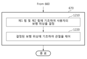
일 측면에 따른, 도 6을 참조하여 전술된 단계(670)는 아래의 단계들(1210 및 1220)을 포함한다.According to one aspect, step 670 described above with reference to FIG. 6 includes
단계(1210)에서, 전자 장치(500)는 제1 힘 및 제2 힘에 기초하여 사용자의 보행 위상을 결정한다. 예를 들어, 전자 장치(500)는 측정된 각도(q), 선속도(υ), 각속도(ω), 제1 힘 및 제2 힘에 기초하여 사용자의 보행 위상을 결정할 수 있다.In
예를 들어, 보행 위상은 FSM을 이용하여 계산될 수 있다. 미리 정해진 개수의 보행 위상들에 대해 미리 설정된 파라미터들과 측정된 각도(q), 선속도(υ), 각속도(ω), 제1 힘 및 제2 힘을 비교함으로써 보행 위상들 중 어느 하나가 결정될 수 있다.For example, gait phase can be calculated using FSM. One of the walking phases can be determined by comparing the measured angle (q), linear velocity (υ), angular velocity (ω), first force and second force with preset parameters for a predetermined number of walking phases. You can.
다른 예로, 보행 위상은 PSAO(Particularly Shaped Adaptive Oscillator)를 이용하여 계산될 수 있다. 보행 싸이클에 대한 특정 파라미터의 궤적이 미리 정의될 수 있고, 측정된 파라미터가 상기의 궤적의 어느 구간에 해당되는지를 결정함으로써 보행 위상이 결정될 수 있다.As another example, the gait phase may be calculated using a Particularly Shaped Adaptive Oscillator (PSAO). The trajectory of specific parameters for the gait cycle may be defined in advance, and the gait phase may be determined by determining which section of the trajectory the measured parameter corresponds to.
다른 일 측면에 따르면, 전자 장치(500)는 복합 힘에 기초하여 사용자의 보행 위상을 결정할 수 있다. 예를 들어, 전자 장치(500)는 복합 힘의 특징을 검출하고, 검출된 특징에 기초하여 보행 위상이 결정될 수 있다. 예를 들어, 복합 힘의 특징은 계산된 복합 힘 및 이전 복합 힘 간의 차이, 시간에 따른 차이의 변화량을 포함할 수 있다.According to another aspect, the
단계(1220)에서, 전자 장치(500)는 결정된 보행 위상에 기초하여 보행 보조 장치의 관절을 제어한다. 보행 보조 장치의 관절을 제어하는 방법에 대해, 아래에서 도 13을 참조하여 상세히 설명된다.In
도 13는 일 예에 따른 보행 싸이클에서 발생하는 힘 및 토크를 도시한다.Figure 13 shows forces and torques generated in a walking cycle according to an example.
보행 싸이클에서의 사용자의 오른쪽 다리의 움직임(1310)이 도시된다. 보행 싸이클에 대한 힘의 궤적(1320) 및 토크(또는, 모멘트)의 궤적(1330)가 미리 설정될 수 있다. 힘 및 토크를 동시에 고려한 표현이 복합 힘일 수 있다.
전자 장치(500)는 계산된 복합 힘이 복합 힘의 궤적의 어느 구간에 해당되는지 여부를 결정함으로써 보행 위상을 결정할 수 있다. 전자 장치(500)는 결정된 보행 위상에 대응하는 출력 토크를 결정할 수 있다. 예를 들어, 미리 설정된 보행 싸이클에 대한 토크 궤적을 이용하여 결정된 보행 위상에 대응하는 출력 토크가 결정될 수 있다.The
특정한 보행 위상에서 수행되는 사용자의 동작을 보조하기 위해 토크 궤적이 미리 설정될 수 있다. 예를 들어, 결정된 보행 위상이 발꿈치 닿기(heel strike)인 경우, 보행 보조 장치가 감쇄(damping)하도록 관절이 제어될 수 있다. 다른 예로, 결정된 보행 위상이 푸쉬-오프(push-off)인 경우, 보행 가속이 발생하도록 관절이 제어될 수 있다.A torque trajectory may be preset to assist the user's movements performed in a specific gait phase. For example, if the determined walking phase is heel strike, the joint may be controlled so that the walking assistance device damps. As another example, when the determined gait phase is push-off, the joint may be controlled to cause gait acceleration.
도 14는 다른 일 예에 따른 제1 힘 및 제2 힘에 기초하여 보행 보조 장치를 제어하는 방법의 흐름도이다.Figure 14 is a flowchart of a method of controlling a walking assistance device based on a first force and a second force according to another example.
다른 일 측면에 따른, 도 6을 참조하여 전술된 단계(670)는 아래의 단계들(1410 및 1420)을 포함한다.According to another aspect, step 670 described above with reference to FIG. 6 includes
단계(1410)에서, 전자 장치(500)는 제1 힘 및 제2 힘에 기초하여 사용자의 보행 밸런스의 정도를 결정한다. 제1 힘 및 제2 힘의 각각은 그 힘의 방향을 포함하고 있으므로, 힘의 방향에 기초하여 보행 밸런스의 정도가 결정될 수 있다. 예를 들어, 발바닥을 기준으로 좌우 방향으로 힘이 발생하는 경우 보행 밸런스의 정도가 낮은 것으로 결정될 수 있다. 다른 예로, 오른쪽 발과 왼쪽 발의 보행 싸이클이 불일치하는 경우에도, 보행 밸런스의 정도가 낮은 것으로 결정될 수 있다.In
단계(1420)에서, 전자 장치(500)는 보행 밸런스의 정도에 기초하여 보행 보조 장치를 제어한다. 예를 들어, 보행 보조 장치에 가해지는 힘의 방향이 분산되지 않도록 전자 장치(500)는 사용자의 발목, 무릎 및 고관절 중 적어도 하나의 각도를 제어할 수 있다. 다른 예로, 오른쪽 다리와 왼쪽 다리의 보행 싸이클이 불일치하는 경우에는 낙상의 위험이 높으므로, 낙상을 방지하도록 보행 보조 장치가 제어될 수 있다.In
도 15는 또 다른 일 예에 따른 제1 힘 및 제2 힘에 기초하여 보행 보조 장치를 제어하는 방법의 흐름도이다.Figure 15 is a flowchart of a method of controlling a walking assistance device based on a first force and a second force according to another example.
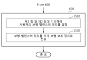
또 다른 일 측면에 따른, 도 6을 참조하여 전술된 단계(670)는 아래의 단계들(1510 및 1520)을 포함한다. 예를 들어, 전자 장치(500)가 발목-타입 보행 보조 장치에 포함된 경우, 전자 장치(500)는 결정된 보행 밸런스의 정도를 추가 보행 보조 장치로 전송한다.According to another aspect, step 670 described above with reference to FIG. 6 includes
단계(1410)에서, 전자 장치(500)는 제1 힘 및 제2 힘에 기초하여 사용자의 보행 밸런스의 정도를 결정한다.In
단계(1420)에서, 전자 장치(500)는 결정된 보행 밸런스의 정도를 추가 보행 보조 장치로 전송한다. 추가 보행 보조 장치는 보행 보조 장치와 함께 동작하는 장치일 수 있다. 예를 들어, 추가 보행 보조 장치는 힙-타입 보행 보조 장치일 수 있다. 힙-타입 보행 보조 장치는 사용자의 고관절에 보조력을 제공하여 사용자의 보행을 보조할 수 있다. 예를 들어, 오른쪽 다리와 왼쪽 다리의 보행 싸이클이 불일치하는 경우에는, 불일치의 정도를 줄일 수 있도록 힙-타입 보행 보조 장치가 동작될 수 있다.In
아래에서 도 16 및 17을 참조하여 힙-타입 보행 보조 장치에 대해 상세히 설명되고, 도 18 내지 도 20을 참조하여 전신-타입 보행 보조 장치에 대해 상세히 설명된다.Below, the hip-type walking assistance device will be described in detail with reference to FIGS. 16 and 17, and the full body-type walking assistance device will be described in detail with reference to FIGS. 18 to 20.
<힙-타입 보행 보조 장치의 개요><Overview of hip-type walking assistance devices>
도 16 및 17는 일 예에 따른 힙-타입 보행 보조 장치를 도시한다.16 and 17 show a hip-type walking assistance device according to an example.
도 16을 참조하면, 힙-타입 보행 보조 장치(1600)는 사용자에게 장착되어 사용자의 보행을 보조한다. 보행 보조 장치(1600)는 웨어러블 장치(wearable device)일 수 있다. 예를 들어, 전자 장치(500)는 보행 보조 장치(1600)에 포함될 수 있다.Referring to FIG. 16, the hip-type
도 16 및 17을 참조하여 설명되는 실시예들은 힙-타입에 대해 적용될 수 있으나, 이에 한정되는 것이 아니며 사용자의 보행을 보조하는 장치에 대해서 모두 적용될 수 있다.The embodiments described with reference to FIGS. 16 and 17 may be applied to hip-type devices, but are not limited thereto and can be applied to any device that assists the user's walking.
일 측면에 따르면, 힙-타입 보행 보조 장치(1600)는 구동부(1610), 센서부(1620), IMU(1630) 및 제어부(1640)를 포함한다.According to one aspect, the hip-type
구동부(1610)는 사용자의 고관절에 구동력을 제공한다. 예를 들어, 구동부(1610)는 사용자의 오른쪽 힙 및/또는 왼쪽 힙 부분에 위치할 수 있다. 구동부(1610)는 회전 토크를 발생시킬 수 있는 모터를 포함할 수 있다.The
센서부(1620)는 보행 시 사용자의 고관절의 각도를 측정할 수 있다. 센서부(1620)에서 센싱되는 고관절의 각도에 대한 정보는 오른쪽 고관절의 각도, 왼쪽 고관절의 각도, 양쪽 고관절 각도들 간의 차이 및 고관절 운동 방향을 포함할 수 있다. 예를 들어, 센서부(1620)는 구동부(1610) 내에 위치할 수 있다.The
일 측면에 따르면, 센서부(1620)는 포텐셔미터를 포함할 수 있다. 포텐셔미터는 사용자의 보행 동작에 따른 오른쪽(Right: R) 축, 왼쪽(Light: L) 축 관절 각도 및 R축, L축 관절 각속도를 센싱할 수 있다.According to one aspect, the
IMU(1630)는 보행 시 가속도 정보와 자세 정보를 측정할 수 있다. 예를 들어, IMU(1630)는 사용자의 보행 동작에 따른 X축, Y축, Z축 가속도 및 X축, Y축, Z축 각속도를 각각 센싱할 수 있다.The IMU (1630) can measure acceleration information and posture information while walking. For example, the
힙-타입 보행 보조 장치(1600)는 IMU(1630)에서 측정된 가속도 정보에 기반하여 사용자의 발이 착지하는 지점을 검출할 수 있다.The hip-type
힙-타입 보행 보조 장치(1600)는 앞서 설명한 센서부(1620) 및 IMU(1630) 이외에, 보행 동작에 따른 사용자의 운동량 또는 생체 신호 등의 변화를 센싱할 수 있는 다른 센서(예를 들어, 근전도 센서(ElectroMyoGram sensor: EMG sensor) 및 뇌전도 센서(ElectroEncephaloGram sensor: EEG sensor))를 포함할 수 있다.In addition to the
제어부(1640)는 구동부(1610)가 사용자의 보행을 돕기 위한 보조력을 출력하도록, 구동부(1610)를 제어한다. 예를 들어, 힙-타입 보행 보조 장치(1600)에서, 구동부(1610)는 두 개(왼쪽 힙 및 오른쪽 힙)일 수 있고, 제어부(1640)는 토크가 발생하도록 구동부(1610)를 제어하는 제어 신호를 출력할 수 있다. 제어부(1640)는 통신부, 프로세서 및 메모리를 포함할 수 있다.The
구동부(1610)는 제어부(1640)가 출력한 제어 신호에 기반하여, 토크를 발생시킨다. 일 측면에 따르면, 힙-타입 보행 보조 장치(1600)는 오른쪽 다리를 위한 구동부(1610) 및 왼쪽 다리를 위한 구동부(1610)를 포함할 수 있다. 예를 들어, 제어부(1640)는 어느 하나의 구동부(1610)를 제어하도록 설계될 수 있다. 제어부(1640)가 어느 하나의 구동부(1610)만을 제어하는 경우, 제어부(1640)는 복수 개일 수 있다. 다른 예로, 제어부(1640)는 양쪽의 구동부(1610)들을 모두 제어하도록 설계될 수 있다.The
<전신-타입 보행 보조 장치의 개요><Overview of full-body-type walking assistance devices>
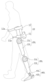
도 18 내지 도 20은 다른 일 예에 따른 전신-타입 보행 보조 장치를 도시한다. 도 18은 전신-타입 보행 보조 장치(1)의 일 실시예에 대한 정면도이고, 도 19는 전신-타입 보행 보조 장치(1)의 측면도이고, 도 20은 전신-타입 보행 보조 장치(1)의 배면도이다. 예를 들어, 전자 장치(500)는 보행 보조 장치(1)에 포함될 수 있다.18 to 20 show a full body-type walking assistance device according to another example. FIG. 18 is a front view of an embodiment of the full body-type
일 측면에 따르면, 전신-타입 보행 보조 장치(1)는 전술된 구동부(1610), 센서부(1620), IMU(1630) 및 제어부(1640)를 포함할 수 있다.According to one aspect, the full body-type
도 18 내지 도 20에 도시된 바와 같이, 전신-타입 보행 보조 장치(1)는 사용자의 왼쪽 다리 및 오른쪽 다리에 각각 착용될 수 있도록 외골격(外骨格) 구조를 가진다. 사용자는 보행 보조 장치(1)를 착용한 상태에서 폄(extension), 굽힘(flexion), 모음(adduction), 벌림(abduction) 등의 동작을 수행할 수 있다. 폄 동작은 관절을 펴는 운동이고, 구부림 동작은 관절을 구부리는 운동이다. 모음 동작은 다리를 몸의 중심축으로 가까이 하는 운동이다. 벌림 동작은 몸의 중심축에서 멀어지는 방향으로 다리를 뻗는 운동이다.As shown in FIGS. 18 to 20, the full body-type
도 18 내지 도 20을 참조하면, 전신-타입 보행 보조 장치(1)는 본체부(10) 및 기구부(20R, 20L, 30R, 30L, 40R, 40L)를 포함할 수 있다.18 to 20, the full body-type
본체부(10)는 하우징(11)을 포함할 수 있다. 하우징(11)에는 각종 부품이 내장될 수 있다. 하우징(11)에 내장되는 부품으로는, 중앙 처리 장치(Central Processing Unit: CPU), 인쇄 회로 기판 및 다양한 종류의 저장 장치 및 전원을 예로 들 수 있다. 본체부(10)는 전술된 제어부(1640)를 포함할 수 있다. 제어부(1640)는 CPU 및 인쇄 회로 기판을 포함할 수 있다.The
CPU는 마이크로 프로세서(micro processor)일 수 있다. 마이크로 프로세서는 실리콘 칩에 산술 논리 연산기, 레지스터, 프로그램 카운터, 명령 디코더 및/또는 제어 회로 등이 설치될 수 있다. CPU는 보행 환경에 적합한 제어 모드를 선택하고, 선택된 제어 모드에 따라 기구부(20, 30, 40)의 동작을 제어하기 위한 제어 신호를 생성할 수 있다.The CPU may be a microprocessor. A microprocessor may have an arithmetic logic operator, a register, a program counter, an instruction decoder, and/or a control circuit installed on a silicon chip. The CPU may select a control mode suitable for the walking environment and generate a control signal to control the operation of the
인쇄 회로 기판은 소정의 회로가 인쇄되어 있는 기판으로, 인쇄 회로 기판에는 CPU 또는/및 다양한 저장 장치가 설치될 수 있다. 인쇄 회로 기판은 하우징(11)의 내측면에 고정될 수 있다.A printed circuit board is a board on which a predetermined circuit is printed, and a CPU and/or various storage devices may be installed on the printed circuit board. The printed circuit board may be fixed to the inner side of the
하우징(11)에 내장된 저장 장치는 다양한 종류를 포함할 수 있다. 저장 장치는 자기 디스크 표면을 자화시켜 데이터를 저장하는 자기 디스크 저장 장치, 다양한 종류의 메모리 반도체를 이용하여 데이터를 저장하는 반도체 메모리 장치일 수 있다.Storage devices built into the
하우징(11)에 내장된 전원은 하우징(11)에 내장된 각종 부품 또는 기구부(20, 30, 40)에 동력을 공급할 수 있다.The power source built into the
본체부(10)는 사용자의 허리를 지지하기 위한 허리 지지부(12)를 더 포함할 수 있다. 허리 지지부(12)는 사용자의 허리를 지지할 수 있도록 만곡된 평면판의 형상을 가질 수 있다.The
본체부(10)는 사용자의 힙 부분에 하우징(11)을 고정하기 위한 고정부(11a) 및 사용자의 허리에 허리 지지부(12)를 고정하기 위한 고정부(12a)를 더 포함할 수 있다. 고정부(11a, 12a)는 탄성력을 구비한 밴드, 벨트, 끈(strap) 중 하나로 구현될 수 있다.The
본체부(10)는 전술된 IMU(1630)를 포함할 수 있다. 예를 들어, IMU(1630)는 하우징(11)의 외부 또는 내부에 설치될 수 있다. IMU(1630)는 하우징(11)의 내부에 마련된 인쇄회로기판 상에 설치될 수 있다. IMU(1630)는 가속도 및 각속도를 측정할 수 있다.
기구부(20, 30, 40)는 도 18 내지 도 20에 도시된 바와 같이 제1 구조부(20), 제2 구조부(30) 및 제3 구조부(40)를 포함할 수 있다.The
제1 구조부(20R, 20L)는 보행 동작에 있어서 사용자의 대퇴부 및 고관절의 움직임을 보조할 수 있다. 제1 구조부(20R, 20L)는 제1 구동부(21R, 21L), 제1 지지부(22R, 22L) 및 제1 고정부(23R, 23L)를 포함할 수 있다.The
전술된 구동부(1610)는 제1 구동부(21R, 21L)를 포함할 수 있으며, 도 16 내지 도 17을 참조하여 설명된 구동부(1610)에 대한 설명은 제1 구동부(21R, 21L)에 대한 설명으로 대체될 수 있다.The above-described
제1 구동부(21R, 21L)는 제1 구조부(20R, 20L)의 고관절에 위치할 수 있으며, 소정의 방향으로 다양한 크기의 회전력을 발생시킬 수 있다. 제1 구동부(21R, 21L)에서 발생된 회전력은 제1 지지부(22R, 22L)에 인가될 수 있다. 제1 구동부(21R, 21L)는 인체의 고관절의 동작 범위 내에서 회전하도록 설정될 수 있다.The
제1 구동부(21R, 21L)는 본체부(10)에서 제공되는 제어 신호에 따라 구동될 수 있다. 제1 구동부(21R, 21L)는 모터, 진공 펌프(vacuum pump) 및 수압 펌프(hydraulic pump) 중 하나로 구현될 수 있으나, 이에 한정되는 것은 아니다.The
제1 구동부(21R, 21L)의 주변에는 관절 각도 센서가 설치될 수 있다. 관절 각도 센서는 제1 구동부(21R, 21L)가 회전 축을 중심으로 회전한 각도를 검출할 수 있다. 전술된 센서부(1420)는 관절 각도 센서를 포함할 수 있다.A joint angle sensor may be installed around the
제1 지지부(22R, 22L)는 제1 구동부(21R, 21L)와 물리적으로 연결된다. 제1 지지부(22R, 22L)는 제1 구동부(21R, 21L)에서 발생한 회전력에 따라 소정의 방향으로 회전될 수 있다.The
제1 지지부(22R, 22L)는 다양한 형상으로 구현될 수 있다. 예를 들어, 제1 지지부(22R, 22L)는 복수의 마디가 서로 연결되어 있는 형상으로 구현될 수 있다. 이 때, 마디와 마디 사이에는 관절이 마련될 수 있으며, 제1 지지부(22R, 22L)는 이 관절에 의해 일정 범위 내에서 휘어질 수 있다. 다른 예로, 제1 지지부(22R, 22L)는 막대 형상으로 구현될 수 있다. 이 때, 제1 지지부(22R, 22L)는 일정한 범위 내에서 휘어질 수 있도록 가요성 있는 소재로 구현될 수 있다.The first supports 22R and 22L may be implemented in various shapes. For example, the
제1 고정부(23R, 23L)는 제1 지지부(22R, 22L)에 마련될 수 있다. 제1 고정부(23R, 23L)는 제1 지지부(22R, 22L)를 사용자의 대퇴부에 고정시키는 역할을 한다.The
도 18 내지 도 20은 제1 지지부(22R, 22L)가 제1 고정부(23R, 23L)에 의해 사용자의 대퇴부의 외측에 고정되는 경우를 도시하고 있다. 제1 구동부(21R, 21L)가 구동됨에 따라 제1 지지부(22R, 22L)가 회전하게 되면, 제1 지지부(22R, 22L)가 고정된 대퇴부 역시 제1 지지부(22R, 22L)의 회전 방향과 동일한 방향으로 회전한다.18 to 20 show a case where the
제1 고정부(23R, 23L)은 탄성력을 구비한 밴드, 벨트, 끈 중 하나로 구현되거나, 금속 소재로 구현될 수도 있다. 도 18은 제1 고정부(23R, 23L)가 체인(chain)인 경우를 도시하고 있다.The
제2 구조부(30R, 30L)는 보행 동작에 있어서 사용자의 하퇴부 및 무릎 관절의 움직임을 보조할 수 있다. 제2 구조부(30R, 30L)는 제2 구동부(31R, 31L), 제2 지지부(32R, 32L) 및 제2 고정부(33R, 33L)를 포함할 수 있다.The
제2 구동부(31R, 31L)는 제2 구조부(30R, 30L)의 무릎 관절에 위치할 수 있으며, 소정의 방향으로 다양한 크기의 회전력을 발생시킬 수 있다. 제2 구동부(31R, 31L)에서 발생된 회전력은 제2 지지부(22R, 22L)에 인가될 수 있다. 제2 구동부(31R, 31L)는 인체의 무릎 관절의 동작 범위 내에서 회전하도록 설정될 수 있다.The
전술된 구동부(1410)는 제2 구동부(31R, 31L)를 포함할 수 있다. 도 16 내지 도 17을 참조하여 설명된 고관절과 관련된 설명이 무릎 관절과 관련된 설명으로 유사하게 적용될 수 있다.The above-described
제2 구동부(31R, 31L)는 본체부(10)에서 제공되는 제어 신호에 따라 구동될 수 있다. 제2 구동부(31R, 31L)는 모터, 진공 펌프 및 수압 펌프 중 하나로 구현될 수 있으나, 이에 한정되는 것은 아니다.The
제2 구동부(31R, 31L)의 주변에는 관절 각도 센서가 설치될 수 있다. 관절 각도 센서는 제2 구동부(31R, 31L)가 회전 축을 중심으로 회전한 각도를 검출할 수 있다. 전술된 센서부(1620)는 관절 각도 센서를 포함할 수 있다.Joint angle sensors may be installed around the
제2 지지부(32R, 32L)는 제2 구동부(31R, 31L)와 물리적으로 연결된다. 제2 지지부(32R, 32L)는 제2 구동부(31R, 31L)에서 발생한 회전력에 따라 소정의 방향으로 회전될 수 있다.The
제2 고정부(33R, 33L)는 제2 지지부(32R, 32L)에 마련될 수 있다. 제2 고정부(33R, 33L)는 제2 지지부(32R, 32L)를 사용자의 하퇴부에 고정시키는 역할을 한다. 도 18 내지 도 20은 제2 지지부(32R, 32L)가 제2 고정부(33R, 33L)에 의해 사용자의 하퇴부의 외측에 고정되는 경우를 도시하고 있다. 제2 구동부(31R, 31L)가 구동됨에 따라 제2 지지부(22R, 22L)가 회전하게 되면, 제2 지지부(22R, 22L)가 고정된 대퇴부 역시 제2 지지부(22R, 22L)의 회전 방향과 동일한 방향으로 회전한다.The
제2 고정부(33R, 33L)은 탄성력을 구비한 밴드, 벨트, 끈 중 하나로 구현되거나, 금속 소재로 구현될 수 있다.The
제3 구조부(40R, 40L)는 보행 동작에 있어서 사용자의 발목 관절 및 관련 근육의 움직임을 보조할 수 있다. 제3 구조부(40R, 40L)는 제3 구동부(41R, 41L), 발 받침부(42R, 42L) 및 제3 고정부(43R, 43L)를 포함할 수 있다.The third
전술된 구동부(1410)는 제3 구동부(41R, 41L)를 포함할 수 있다. 도 16 내지 도 17을 참조하여 설명된 고관절과 관련된 설명이 발목 관절과 관련된 설명으로 유사하게 적용될 수 있다.The above-described
제3 구동부(41R, 41L)는 제3 구조부(40R, 40L)의 발목 관절에 마련될 수 있으며, 본체부(10)에서 제공되는 제어 신호에 따라 구동될 수 있다. 제3 구동부(41R, 41L)도 제1 구동부(21R, 21L) 또는 제2 구동부(31R, 31L)와 마찬가지로 모터로 구현될 수 있다.The
제3 구동부(41R, 41L)의 주변에는 관절 각도 센서가 설치될 수 있다. 관절 각도 센서는 제3 구동부(41R, 41L)가 회전 축을 중심으로 회전한 각도를 검출할 수 있다. 전술된 센서부(1420)는 관절 각도 센서를 포함할 수 있다.Joint angle sensors may be installed around the
발 받침부(42R, 42L)는 사용자의 발바닥에 대응하는 위치에 마련되며, 제3 구동부(41R, 41L)와 물리적으로 연결된다.The foot rests 42R and 42L are provided at positions corresponding to the soles of the user's feet and are physically connected to the
발 받침부(42R, 42L)에는 사용자의 무게를 감지하기 위한 압력 센서가 설치될 수 있다. 압력 센서의 감지 결과는 사용자가 보행 보조 장치(1)를 착용하였는지 여부, 사용자가 일어섰는지 여부, 사용자의 발과 지면의 접촉 여부 등을 판단하는데 사용될 수 있다.A pressure sensor may be installed in the
제3 고정부(43R, 43L)는 발 받침부(42R, 42L)에 마련될 수 있다. 제3 고정부(43R, 43L)는 사용자의 발을 발 받침부(42R, 42L)에 고정시키는 역할을 한다.The
실시예에 따른 방법은 다양한 컴퓨터 수단을 통하여 수행될 수 있는 프로그램 명령 형태로 구현되어 컴퓨터 판독 가능 매체에 기록될 수 있다. 상기 컴퓨터 판독 가능 매체는 프로그램 명령, 데이터 파일, 데이터 구조 등을 단독으로 또는 조합하여 포함할 수 있다. 상기 매체에 기록되는 프로그램 명령은 실시예를 위하여 특별히 설계되고 구성된 것들이거나 컴퓨터 소프트웨어 당업자에게 공지되어 사용 가능한 것일 수도 있다. 컴퓨터 판독 가능 기록 매체의 예에는 하드 디스크, 플로피 디스크 및 자기 테이프와 같은 자기 매체(magnetic media), CD-ROM, DVD와 같은 광기록 매체(optical media), 플롭티컬 디스크(floptical disk)와 같은 자기-광 매체(magneto-optical media), 및 롬(ROM), 램(RAM), 플래시 메모리 등과 같은 프로그램 명령을 저장하고 수행하도록 특별히 구성된 하드웨어 장치가 포함된다. 프로그램 명령의 예에는 컴파일러에 의해 만들어지는 것과 같은 기계어 코드뿐만 아니라 인터프리터 등을 사용해서 컴퓨터에 의해서 실행될 수 있는 고급 언어 코드를 포함한다. 상기된 하드웨어 장치는 실시예의 동작을 수행하기 위해 하나 이상의 소프트웨어 모듈로서 작동하도록 구성될 수 있으며, 그 역도 마찬가지이다.The method according to the embodiment may be implemented in the form of program instructions that can be executed through various computer means and recorded on a computer-readable medium. The computer-readable medium may include program instructions, data files, data structures, etc., singly or in combination. Program instructions recorded on the medium may be specially designed and configured for the embodiment or may be known and available to those skilled in the art of computer software. Examples of computer-readable recording media include magnetic media such as hard disks, floppy disks, and magnetic tapes, optical media such as CD-ROMs and DVDs, and magnetic media such as floptical disks. -Includes optical media (magneto-optical media) and hardware devices specifically configured to store and execute program instructions, such as ROM, RAM, flash memory, etc. Examples of program instructions include machine language code, such as that produced by a compiler, as well as high-level language code that can be executed by a computer using an interpreter, etc. The hardware devices described above may be configured to operate as one or more software modules to perform the operations of the embodiments, and vice versa.
이상과 같이 실시예들이 비록 한정된 도면에 의해 설명되었으나, 해당 기술분야에서 통상의 지식을 가진 자라면 상기를 기초로 다양한 기술적 수정 및 변형을 적용할 수 있다. 예를 들어, 설명된 기술들이 설명된 방법과 다른 순서로 수행되거나, 및/또는 설명된 시스템, 구조, 장치, 회로 등의 구성요소들이 설명된 방법과 다른 형태로 결합 또는 조합되거나, 다른 구성요소 또는 균등물에 의하여 대치되거나 치환되더라도 적절한 결과가 달성될 수 있다.Although the embodiments have been described with limited drawings as described above, those skilled in the art can apply various technical modifications and variations based on the above. For example, the described techniques are performed in a different order than the described method, and/or components of the described system, structure, device, circuit, etc. are combined or combined in a different form than the described method, or other components are used. Alternatively, appropriate results may be achieved even if substituted or substituted by an equivalent.
그러므로, 다른 구현들, 다른 실시예들 및 특허청구범위와 균등한 것들도 후술하는 청구범위의 범위에 속한다.Therefore, other implementations, other embodiments, and equivalents of the claims also fall within the scope of the following claims.
500: 전자 장치
510: 센서
520: 통신부
530: 프로세서
540: 메모리
550: 구동부500: Electronic device
510: sensor
520: Department of Communications
530: processor
540: Memory
550: driving unit
Claims (20)
상기 관절에 부착된 각도 센서로부터 수신한 각도 정보에 기초하여 상기 관절의 각도를 측정하는 단계;
상기 제1 프레임에 부착된 관성 측정 장치(Inertial Measurement Unit: IMU)로부터 수신한 관성 정보에 기초하여 상기 제1 프레임의 각속도 및 선속도를 계산하는 단계;
상기 측정된 각도, 상기 각속도 및 상기 선속도에 기초하여 상기 보행 보조 장치에 대한 동역학 모델을 갱신하는 단계;
상기 갱신된 동역학 모델에 기초하여 상기 제1 프레임에 가해진 제1 힘 및 상기 제2 프레임에 가해진 제2 힘을 결정하는 단계; 및
상기 제1 힘 및 상기 제2 힘에 기초하여 상기 보행 보조 장치를 제어하는 단계
를 포함하고,
상기 제1 힘 및 상기 제2 힘에 기초하여 상기 보행 보조 장치를 제어하는 단계는,
상기 제1 힘 및 상기 제2 힘에 기초하여 상기 보행 보조 장치를 착용한 사용자의 보행 위상(gait phase)을 결정하는 단계; 및
상기 결정된 보행 위상에 기초하여 상기 관절을 제어하는 단계
를 포함하는,
보행 보조 장치 제어 방법.
A method of controlling a walking assistance device including a first frame, a second frame, and a joint connecting the first frame and the second frame,
measuring the angle of the joint based on angle information received from an angle sensor attached to the joint;
calculating the angular velocity and linear velocity of the first frame based on inertial information received from an inertial measurement unit (IMU) attached to the first frame;
updating a dynamic model for the walking assistance device based on the measured angle, the angular velocity, and the linear velocity;
determining a first force applied to the first frame and a second force applied to the second frame based on the updated dynamic model; and
Controlling the walking assistance device based on the first force and the second force
Including,
Controlling the walking assistance device based on the first force and the second force,
determining a gait phase of a user wearing the walking assistance device based on the first force and the second force; and
Controlling the joint based on the determined gait phase
Including,
How to control walking aids.
상기 동역학 모델을 갱신하는 단계는,
상기 각도, 상기 각속도 및 상기 선속도 중 적어도 하나에 기초하여 상기 동역학 모델 내의 관성 질량 매트릭스(inertia matrix)를 계산하는 단계;
상기 각도, 상기 각속도 및 상기 선속도 중 적어도 하나에 기초하여 상기 동역학 모델 내의 코리올리 매트릭스(Coriolis matrix)를 계산하는 단계; 및
상기 계산된 관성 질량 매트릭스 및 상기 코리올리 매트릭스를 상기 동역학 모델에 설정하는 단계
를 포함하는,
보행 보조 장치 제어 방법.
According to paragraph 1,
The step of updating the dynamics model is,
calculating an inertia matrix in the dynamic model based on at least one of the angle, the angular velocity, and the linear velocity;
calculating a Coriolis matrix in the dynamic model based on at least one of the angle, the angular velocity, and the linear velocity; and
Setting the calculated inertial mass matrix and the Coriolis matrix in the dynamic model
Including,
How to control walking aids.
상기 제1 힘 및 상기 제2 힘을 결정하는 단계는,
상기 갱신된 동역학 모델에 기초하여 상기 보행 보조 장치에 가해진 복합 힘 및 복합 토크를 계산하는 단계; 및
상기 복합 힘 및 상기 복합 토크에 기초하여 상기 제1 힘 및 상기 제2 힘을 계산하는 단계
를 포함하는,
보행 보조 장치 제어 방법.
According to paragraph 1,
Determining the first force and the second force includes:
calculating a composite force and a composite torque applied to the walking assistance device based on the updated dynamic model; and
calculating the first force and the second force based on the composite force and the composite torque.
Including,
How to control walking aids.
상기 갱신된 동역학 모델에 기초하여 상기 복합 힘 및 복합 토크를 계산하는 단계는,
상기 갱신된 동역학 모델을 저역 통과 필터로 필터링함으로써 상기 복합 힘 및 복합 토크를 계산하는 단계
를 포함하는,
보행 보조 장치 제어 방법.
According to paragraph 3,
The step of calculating the composite force and composite torque based on the updated dynamic model includes:
Calculating the composite force and composite torque by filtering the updated dynamic model with a low-pass filter.
Including,
How to control walking aids.
상기 복합 힘 및 상기 복합 토크에 기초하여 상기 제1 힘 및 상기 제2 힘을 계산하는 단계는,
상기 관절에서 작용하는 토크, 상기 복합 힘 및 상기 복합 토크를 이용하여 상기 제1 힘 및 상기 제2 힘을 계산하는 단계
를 포함하는,
보행 보조 장치 제어 방법.
According to paragraph 3,
Calculating the first force and the second force based on the composite force and the composite torque includes:
Calculating the first force and the second force using the torque acting on the joint, the composite force, and the composite torque.
Including,
How to control walking aids.
상기 결정된 보행 위상에 기초하여 상기 관절의 각도를 조절하는 단계는,
상기 결정된 보행 위상이 발꿈치 닿기(heel strike)인 경우, 상기 보행 보조 장치가 감쇄(damping)하도록 상기 관절을 제어하는 단계
를 포함하는,
보행 보조 장치 제어 방법.
According to paragraph 1,
The step of adjusting the angle of the joint based on the determined gait phase includes:
When the determined walking phase is heel strike, controlling the joint to cause damping of the walking assistance device.
Including,
How to control walking aids.
상기 결정된 보행 위상에 기초하여 상기 관절의 각도를 조절하는 단계는,
상기 결정된 보행 위상이 푸쉬-오프(push-off)인 경우, 보행 가속이 발생하도록 상기 관절을 제어하는 단계
를 포함하는,
보행 보조 장치 제어 방법.
According to paragraph 1,
The step of adjusting the angle of the joint based on the determined gait phase includes:
If the determined gait phase is push-off, controlling the joint to cause gait acceleration
Including,
How to control walking aids.
상기 관절에 부착된 각도 센서로부터 수신한 각도 정보에 기초하여 상기 관절의 각도를 측정하는 단계;
상기 제1 프레임에 부착된 관성 측정 장치(Inertial Measurement Unit: IMU)로부터 수신한 관성 정보에 기초하여 상기 제1 프레임의 각속도 및 선속도를 계산하는 단계;
상기 측정된 각도, 상기 각속도 및 상기 선속도에 기초하여 상기 보행 보조 장치에 대한 동역학 모델을 갱신하는 단계;
상기 갱신된 동역학 모델에 기초하여 상기 제1 프레임에 가해진 제1 힘 및 상기 제2 프레임에 가해진 제2 힘을 결정하는 단계; 및
상기 제1 힘 및 상기 제2 힘에 기초하여 상기 보행 보조 장치를 제어하는 단계
를 포함하고,
상기 제1 힘 및 상기 제2 힘에 기초하여 상기 보행 보조 장치를 제어하는 단계는,
상기 제1 힘 및 상기 제2 힘에 기초하여 상기 보행 보조 장치를 착용한 사용자의 보행 밸런스의 정도를 결정하는 단계; 및
상기 결정된 보행 밸런스의 정도에 기초하여 상기 보행 보조 장치를 제어하는 단계
를 포함하는,
보행 보조 장치 제어 방법.
A method of controlling a walking assistance device including a first frame, a second frame, and a joint connecting the first frame and the second frame,
measuring the angle of the joint based on angle information received from an angle sensor attached to the joint;
calculating the angular velocity and linear velocity of the first frame based on inertial information received from an inertial measurement unit (IMU) attached to the first frame;
updating a dynamic model for the walking assistance device based on the measured angle, the angular velocity, and the linear velocity;
determining a first force applied to the first frame and a second force applied to the second frame based on the updated dynamic model; and
Controlling the walking assistance device based on the first force and the second force
Including,
Controlling the walking assistance device based on the first force and the second force,
determining a degree of walking balance of a user wearing the walking assistance device based on the first force and the second force; and
Controlling the walking assistance device based on the determined degree of walking balance
Including,
How to control walking aids.
상기 관절에 부착된 각도 센서로부터 수신한 각도 정보에 기초하여 상기 관절의 각도를 측정하는 단계;
상기 제1 프레임에 부착된 관성 측정 장치(Inertial Measurement Unit: IMU)로부터 수신한 관성 정보에 기초하여 상기 제1 프레임의 각속도 및 선속도를 계산하는 단계;
상기 측정된 각도, 상기 각속도 및 상기 선속도에 기초하여 상기 보행 보조 장치에 대한 동역학 모델을 갱신하는 단계;
상기 갱신된 동역학 모델에 기초하여 상기 제1 프레임에 가해진 제1 힘 및 상기 제2 프레임에 가해진 제2 힘을 결정하는 단계; 및
상기 제1 힘 및 상기 제2 힘에 기초하여 상기 보행 보조 장치를 제어하는 단계
를 포함하고,
상기 제1 힘 및 상기 제2 힘에 기초하여 상기 보행 보조 장치를 제어하는 단계는,
상기 제1 힘 및 상기 제2 힘에 기초하여 상기 보행 보조 장치를 착용한 사용자의 보행 밸런스의 정도를 결정하는 단계; 및
상기 결정된 보행 밸런스의 정도를 추가 보행 보조 장치로 전송하는 단계
를 포함하고,
상기 추가 보행 보조 장치에 의해 사용자의 보행 밸런스가 제어되는,
보행 보조 장치 제어 방법.
A method of controlling a walking assistance device including a first frame, a second frame, and a joint connecting the first frame and the second frame,
measuring the angle of the joint based on angle information received from an angle sensor attached to the joint;
calculating the angular velocity and linear velocity of the first frame based on inertial information received from an inertial measurement unit (IMU) attached to the first frame;
updating a dynamic model for the walking assistance device based on the measured angle, the angular velocity, and the linear velocity;
determining a first force applied to the first frame and a second force applied to the second frame based on the updated dynamic model; and
Controlling the walking assistance device based on the first force and the second force
Including,
Controlling the walking assistance device based on the first force and the second force,
determining a degree of walking balance of a user wearing the walking assistance device based on the first force and the second force; and
Transmitting the determined degree of walking balance to an additional walking assistance device
Including,
The user's walking balance is controlled by the additional walking assistance device,
How to control walking aids.
상기 제1 프레임은 사용자의 종아리에 부착되고, 상기 관절은 상기 사용자의 발목 관절을 제어하는,
보행 보조 장치 제어 방법.
According to clause 10,
The first frame is attached to the user's calf, and the joint controls the user's ankle joint,
How to control walking aids.
Contains a program that performs the method of any one of paragraphs 1, 2, 3, 4, 5, 7, 8, 9, 10, and 11. A computer-readable recording medium.
상기 보행 보조 장치를 제어하는 프로그램이 기록된 메모리; 및
상기 프로그램을 수행하는 프로세서
를 포함하고,
상기 프로그램은,
상기 관절에 부착된 각도 센서로부터 수신한 각도 정보에 기초하여 상기 관절의 각도를 측정하는 단계;
상기 제1 프레임에 부착된 관성 측정 장치(Inertial Measurement Unit: IMU)로부터 수신한 관성 정보에 기초하여 상기 제1 프레임의 각속도 및 선속도를 계산하는 단계;
상기 측정된 각도, 상기 각속도 및 상기 선속도에 기초하여 상기 보행 보조 장치에 대한 동역학 모델을 갱신하는 단계;
상기 갱신된 동역학 모델에 기초하여 상기 제1 프레임에 가해진 제1 힘 및 상기 제2 프레임에 가해진 제2 힘을 결정하는 단계; 및
상기 제1 힘 및 상기 제2 힘에 기초하여 상기 보행 보조 장치를 제어하는 단계
를 수행하고,
상기 제1 힘 및 상기 제2 힘에 기초하여 상기 보행 보조 장치를 제어하는 단계는,
상기 제1 힘 및 상기 제2 힘에 기초하여 상기 보행 보조 장치를 착용한 사용자의 보행 위상(gait phase)을 결정하는 단계; 및
상기 결정된 보행 위상에 기초하여 상기 관절을 제어하는 단계
를 포함하는,
전자 장치.
An electronic device for controlling a walking assistance device including a first frame, a second frame, and a joint connecting the first frame and the second frame,
a memory in which a program for controlling the walking assistance device is recorded; and
Processor that executes the above program
Including,
The above program is,
measuring the angle of the joint based on angle information received from an angle sensor attached to the joint;
calculating the angular velocity and linear velocity of the first frame based on inertial information received from an inertial measurement unit (IMU) attached to the first frame;
updating a dynamic model for the walking assistance device based on the measured angle, the angular velocity, and the linear velocity;
determining a first force applied to the first frame and a second force applied to the second frame based on the updated dynamic model; and
Controlling the walking assistance device based on the first force and the second force
Do this,
Controlling the walking assistance device based on the first force and the second force,
determining a gait phase of a user wearing the walking assistance device based on the first force and the second force; and
Controlling the joint based on the determined gait phase
Including,
Electronic devices.
상기 동역학 모델을 갱신하는 단계는,
상기 각도, 상기 각속도 및 상기 선속도 중 적어도 하나에 기초하여 상기 동역학 모델 내의 관성 질량 매트릭스(inertia matrix)를 계산하는 단계;
상기 각도, 상기 각속도 및 상기 선속도 중 적어도 하나에 기초하여 상기 동역학 모델 내의 코리올리 매트릭스(Coriolis matrix)를 계산하는 단계; 및
상기 계산된 관성 질량 매트릭스 및 상기 코리올리 매트릭스를 상기 동역학 모델에 설정하는 단계
를 포함하는,
전자 장치.
According to clause 13,
The step of updating the dynamics model is,
calculating an inertia matrix in the dynamic model based on at least one of the angle, the angular velocity, and the linear velocity;
calculating a Coriolis matrix in the dynamic model based on at least one of the angle, the angular velocity, and the linear velocity; and
Setting the calculated inertial mass matrix and the Coriolis matrix in the dynamic model
Including,
Electronic devices.
상기 제1 힘 및 상기 제2 힘을 결정하는 단계는,
상기 갱신된 동역학 모델에 기초하여 상기 보행 보조 장치에 가해진 복합 힘 및 복합 토크를 계산하는 단계; 및
상기 복합 힘 및 상기 복합 토크에 기초하여 상기 제1 힘 및 상기 제2 힘을 계산하는 단계
를 포함하는,
전자 장치.
According to clause 13,
Determining the first force and the second force includes:
calculating a composite force and a composite torque applied to the walking assistance device based on the updated dynamic model; and
calculating the first force and the second force based on the composite force and the composite torque.
Including,
Electronic devices.
상기 갱신된 동역학 모델에 기초하여 상기 복합 힘 및 복합 토크를 계산하는 단계는,
상기 갱신된 동역학 모델을 외란 관측기(Disturbance Observer: DOB)에 대한 모델로 변환하는 단계; 및
상기 외란 관측기 모델에 기초하여 상기 복합 힘 및 복합 토크를 계산하는 단계
를 포함하는,
전자 장치.
According to clause 15,
The step of calculating the composite force and composite torque based on the updated dynamic model includes:
Converting the updated dynamic model into a model for a disturbance observer (DOB); and
calculating the composite force and composite torque based on the disturbance observer model.
Including,
Electronic devices.
상기 관절에 부착된 각도 센서로부터 수신한 각도 정보에 기초하여 상기 관절의 각도를 측정하는 단계;
상기 제1 프레임에 부착된 관성 측정 장치(Inertial Measurement Unit: IMU)로부터 획득한 관성 정보에 기초하여 상기 제1 프레임의 각속도 및 선속도를 계산하는 단계;
상기 측정된 각도, 상기 각속도 및 상기 선속도에 기초하여 상기 보행 보조 장치에 대한 동역학 모델을 갱신하는 단계;
상기 갱신된 동역학 모델에 기초하여 상기 보행 보조 장치에 가해진 복합 힘을 결정하는 단계;
상기 복합 힘에 기초하여 보행 위상(gait phase)을 결정하는 단계; 및
상기 보행 위상에 기초하여 상기 보행 보조 장치를 제어하는 단계
를 포함하는,
보행 보조 장치 제어 방법.
A method of controlling a walking assistance device including a first frame, a second frame, and a joint connecting the first frame and the second frame,
measuring the angle of the joint based on angle information received from an angle sensor attached to the joint;
calculating the angular velocity and linear velocity of the first frame based on inertial information obtained from an inertial measurement unit (IMU) attached to the first frame;
updating a dynamic model for the walking assistance device based on the measured angle, the angular velocity, and the linear velocity;
determining a complex force applied to the walking assistance device based on the updated dynamic model;
determining a gait phase based on the composite force; and
Controlling the walking assistance device based on the walking phase
Including,
How to control walking aids.
상기 보행 위상을 결정하는 단계는,
상기 복합 힘의 특징을 검출하는 단계; 및
상기 특징에 기초하여 상기 보행 위상을 결정하는 단계
를 포함하는,
보행 보조 장치 제어 방법.
According to clause 18,
The step of determining the walking phase is,
detecting characteristics of the complex force; and
determining the walking phase based on the characteristics
Including,
How to control walking aids.
상기 보행 보조 장치를 제어하는 단계는,
상기 결정된 보행 위상에 대응하는 출력 토크가 결정하는 단계; 및
상기 출력 토크가 출력되도록 상기 보행 보조 장치를 제어하는 단계
를 포함하는,
보행 보조 장치 제어 방법.According to clause 18,
The step of controlling the walking assistance device is,
determining an output torque corresponding to the determined walking phase; and
Controlling the walking assistance device to output the output torque
Including,
How to control walking aids.
Priority Applications (2)
| Application Number | Priority Date | Filing Date | Title |
|---|---|---|---|
| KR1020180160922A KR102626098B1 (en) | 2018-12-13 | 2018-12-13 | Method for controlling a walking assist device and electronic device performing the method |
| US16/678,543 US11633320B2 (en) | 2018-12-13 | 2019-11-08 | Method of controlling walking assistance device and electronic device performing the method |
Applications Claiming Priority (1)
| Application Number | Priority Date | Filing Date | Title |
|---|---|---|---|
| KR1020180160922A KR102626098B1 (en) | 2018-12-13 | 2018-12-13 | Method for controlling a walking assist device and electronic device performing the method |
Publications (2)
| Publication Number | Publication Date |
|---|---|
| KR20200072867A KR20200072867A (en) | 2020-06-23 |
| KR102626098B1 true KR102626098B1 (en) | 2024-01-18 |
Family
ID=71073855
Family Applications (1)
| Application Number | Title | Priority Date | Filing Date |
|---|---|---|---|
| KR1020180160922A Active KR102626098B1 (en) | 2018-12-13 | 2018-12-13 | Method for controlling a walking assist device and electronic device performing the method |
Country Status (2)
| Country | Link |
|---|---|
| US (1) | US11633320B2 (en) |
| KR (1) | KR102626098B1 (en) |
Families Citing this family (9)
| Publication number | Priority date | Publication date | Assignee | Title |
|---|---|---|---|---|
| US11298287B2 (en) * | 2020-06-02 | 2022-04-12 | Dephy, Inc. | Systems and methods for a compressed controller for an active exoskeleton |
| US11148279B1 (en) | 2020-06-04 | 2021-10-19 | Dephy, Inc. | Customized configuration for an exoskeleton controller |
| US11173093B1 (en) | 2020-09-16 | 2021-11-16 | Dephy, Inc. | Systems and methods for an active exoskeleton with local battery |
| CN113244090B (en) * | 2021-07-16 | 2021-09-14 | 中国科学院自动化研究所 | Hip joint lower limb exoskeleton control method and device, electronic equipment and storage medium |
| CN113712788B (en) * | 2021-08-13 | 2022-06-28 | 浙江益恒悦医疗科技有限公司 | Anti-falling control method of intelligent walking aid, intelligent walking aid and controller |
| EP4509108A4 (en) * | 2022-09-20 | 2025-07-30 | Samsung Electronics Co Ltd | Method for controlling a wearable device for the safety of a user and wearable device for carrying out the same |
| CN115416003B (en) * | 2022-10-10 | 2024-07-30 | 电子科技大学 | Auxiliary control method for lower limb exoskeleton as required for old people |
| KR20250015074A (en) * | 2023-07-24 | 2025-02-03 | 삼성전자주식회사 | Wearable apparatus and operating method therefor |
| KR20250163445A (en) * | 2024-05-13 | 2025-11-21 | 삼성전자주식회사 | Drive module and electronic device including the drive module |
Citations (1)
| Publication number | Priority date | Publication date | Assignee | Title |
|---|---|---|---|---|
| JP2016097300A (en) | 2014-11-26 | 2016-05-30 | 三星電子株式会社Samsung Electronics Co.,Ltd. | Assisting force setting method and apparatus |
Family Cites Families (16)
| Publication number | Priority date | Publication date | Assignee | Title |
|---|---|---|---|---|
| JP3870403B2 (en) | 1996-03-15 | 2007-01-17 | 株式会社安川電機 | Limb body drive device |
| JP4611580B2 (en) | 2001-06-27 | 2011-01-12 | 本田技研工業株式会社 | Torque application system |
| JP4188607B2 (en) | 2001-06-27 | 2008-11-26 | 本田技研工業株式会社 | Method for estimating floor reaction force of bipedal mobile body and method for estimating joint moment of bipedal mobile body |
| US8353854B2 (en) * | 2007-02-14 | 2013-01-15 | Tibion Corporation | Method and devices for moving a body joint |
| US20110112447A1 (en) * | 2009-10-05 | 2011-05-12 | The Board Of Trustees Of The University Of Illinois | Portable active fluid powered ankle-foot orthosis |
| JP5982767B2 (en) * | 2011-09-26 | 2016-08-31 | ソニー株式会社 | Exercise assistance device, exercise assistance method, computer program, and program recording medium |
| US9566705B2 (en) * | 2012-06-15 | 2017-02-14 | Vanderbilt University | Movement assistance device |
| JP2015528316A (en) | 2012-08-07 | 2015-09-28 | ドーサヴィ ピーティーワイ. エルティーディー. | Reaction force measuring method and measuring apparatus |
| JP6272735B2 (en) * | 2014-06-19 | 2018-01-31 | 本田技研工業株式会社 | Walking assistance device and walking control program |
| US10799373B2 (en) * | 2014-09-12 | 2020-10-13 | Rehabilitation Institute Of Chicago | Stance controller and related methods |
| EP3217942B1 (en) * | 2014-11-11 | 2022-01-05 | Ekso Bionics, Inc. | Exoskeleton |
| KR101654290B1 (en) | 2014-11-27 | 2016-09-05 | 숭실대학교산학협력단 | Method for calculating ground reaction force of walking assistance robot using multiple sensor |
| KR102094852B1 (en) * | 2015-08-04 | 2020-03-30 | 삼성전자주식회사 | Method and apparatus for setting torque |
| KR102485718B1 (en) * | 2015-08-11 | 2023-01-06 | 삼성전자주식회사 | Method and apparatus for calculating torque of walking assist device |
| KR102496574B1 (en) * | 2015-11-11 | 2023-02-06 | 삼성전자주식회사 | Method and apparatus for adjusting torque output timing |
| KR102546547B1 (en) | 2018-01-11 | 2023-06-22 | 삼성전자주식회사 | Method and apparatus for assisting walking |
-
2018
- 2018-12-13 KR KR1020180160922A patent/KR102626098B1/en active Active
-
2019
- 2019-11-08 US US16/678,543 patent/US11633320B2/en active Active
Patent Citations (1)
| Publication number | Priority date | Publication date | Assignee | Title |
|---|---|---|---|---|
| JP2016097300A (en) | 2014-11-26 | 2016-05-30 | 三星電子株式会社Samsung Electronics Co.,Ltd. | Assisting force setting method and apparatus |
Also Published As
| Publication number | Publication date |
|---|---|
| US11633320B2 (en) | 2023-04-25 |
| US20200188215A1 (en) | 2020-06-18 |
| KR20200072867A (en) | 2020-06-23 |
Similar Documents
| Publication | Publication Date | Title |
|---|---|---|
| KR102626098B1 (en) | Method for controlling a walking assist device and electronic device performing the method | |
| KR102546547B1 (en) | Method and apparatus for assisting walking | |
| KR102485718B1 (en) | Method and apparatus for calculating torque of walking assist device | |
| KR102614779B1 (en) | Method and apparatus for assisting walking | |
| KR102550887B1 (en) | Method and apparatus for updatting personalized gait policy | |
| KR102566102B1 (en) | Walking assistance apparatus and method for controlling the walking assistance apparatus | |
| JP4503311B2 (en) | Method for controlling generated torque of leg exercise assistive device | |
| KR102186859B1 (en) | a walking assist device and a method for controlling the the walking assist device | |
| EP3363601B1 (en) | Motion assistance apparatus | |
| KR102550854B1 (en) | Method and device for assisting walking | |
| US20150141878A1 (en) | Method and apparatus for providing deficit-adjusted adaptive assistance during movement phases of an impaired joint | |
| KR20160062933A (en) | Method and apparatus for setting assistant torque | |
| KR102550861B1 (en) | Method and device for assisting walking | |
| KR20170053989A (en) | Method and apparatus of standing assistance | |
| KR102094852B1 (en) | Method and apparatus for setting torque | |
| KR102391967B1 (en) | Method and apparatus for setting assistant torque | |
| KR102133939B1 (en) | Method and apparatus for calculating assistance torque | |
| JP2016043092A (en) | Movement measuring device | |
| US20190209415A1 (en) | Sensor device and walking assist device using the sensor device | |
| US20250205103A1 (en) | Wearable device and operating method therefor | |
| JP2024517584A (en) | Method and device for measuring user's muscle strength using a wearable device | |
| JP6887059B2 (en) | Walking phase estimation device and walking assist device equipped with this | |
| US20250032002A1 (en) | Wearable device and operating method thereof | |
| KR20250165861A (en) | Wearable device determining gait state of user and method of operating the wearable device | |
| JP2021090512A (en) | Walking state detection apparatus |
Legal Events
| Date | Code | Title | Description |
|---|---|---|---|
| PA0109 | Patent application |
St.27 status event code: A-0-1-A10-A12-nap-PA0109 |
|
| PG1501 | Laying open of application |
St.27 status event code: A-1-1-Q10-Q12-nap-PG1501 |
|
| A201 | Request for examination | ||
| PA0201 | Request for examination |
St.27 status event code: A-1-2-D10-D11-exm-PA0201 |
|
| E902 | Notification of reason for refusal | ||
| PE0902 | Notice of grounds for rejection |
St.27 status event code: A-1-2-D10-D21-exm-PE0902 |
|
| E13-X000 | Pre-grant limitation requested |
St.27 status event code: A-2-3-E10-E13-lim-X000 |
|
| P11-X000 | Amendment of application requested |
St.27 status event code: A-2-2-P10-P11-nap-X000 |
|
| P13-X000 | Application amended |
St.27 status event code: A-2-2-P10-P13-nap-X000 |
|
| E701 | Decision to grant or registration of patent right | ||
| PE0701 | Decision of registration |
St.27 status event code: A-1-2-D10-D22-exm-PE0701 |
|
| PR0701 | Registration of establishment |
St.27 status event code: A-2-4-F10-F11-exm-PR0701 |
|
| PR1002 | Payment of registration fee |
St.27 status event code: A-2-2-U10-U11-oth-PR1002 Fee payment year number: 1 |
|
| PG1601 | Publication of registration |
St.27 status event code: A-4-4-Q10-Q13-nap-PG1601 |