KR102622421B1 - Light emitting diode display apparatus and multi screen display apparatus using the same - Google Patents
Light emitting diode display apparatus and multi screen display apparatus using the same Download PDFInfo
- Publication number
- KR102622421B1 KR102622421B1 KR1020180173389A KR20180173389A KR102622421B1 KR 102622421 B1 KR102622421 B1 KR 102622421B1 KR 1020180173389 A KR1020180173389 A KR 1020180173389A KR 20180173389 A KR20180173389 A KR 20180173389A KR 102622421 B1 KR102622421 B1 KR 102622421B1
- Authority
- KR
- South Korea
- Prior art keywords
- light emitting
- light
- line
- driving power
- power line
- Prior art date
- Legal status (The legal status is an assumption and is not a legal conclusion. Google has not performed a legal analysis and makes no representation as to the accuracy of the status listed.)
- Active
Links
Images


Classifications
-
- H—ELECTRICITY
- H10—SEMICONDUCTOR DEVICES; ELECTRIC SOLID-STATE DEVICES NOT OTHERWISE PROVIDED FOR
- H10H—INORGANIC LIGHT-EMITTING SEMICONDUCTOR DEVICES HAVING POTENTIAL BARRIERS
- H10H29/00—Integrated devices, or assemblies of multiple devices, comprising at least one light-emitting semiconductor element covered by group H10H20/00
- H10H29/10—Integrated devices comprising at least one light-emitting semiconductor component covered by group H10H20/00
- H10H29/14—Integrated devices comprising at least one light-emitting semiconductor component covered by group H10H20/00 comprising multiple light-emitting semiconductor components
- H10H29/142—Two-dimensional arrangements, e.g. asymmetric LED layout
-
- G—PHYSICS
- G09—EDUCATION; CRYPTOGRAPHY; DISPLAY; ADVERTISING; SEALS
- G09G—ARRANGEMENTS OR CIRCUITS FOR CONTROL OF INDICATING DEVICES USING STATIC MEANS TO PRESENT VARIABLE INFORMATION
- G09G3/00—Control arrangements or circuits, of interest only in connection with visual indicators other than cathode-ray tubes
- G09G3/20—Control arrangements or circuits, of interest only in connection with visual indicators other than cathode-ray tubes for presentation of an assembly of a number of characters, e.g. a page, by composing the assembly by combination of individual elements arranged in a matrix no fixed position being assigned to or needed to be assigned to the individual characters or partial characters
- G09G3/22—Control arrangements or circuits, of interest only in connection with visual indicators other than cathode-ray tubes for presentation of an assembly of a number of characters, e.g. a page, by composing the assembly by combination of individual elements arranged in a matrix no fixed position being assigned to or needed to be assigned to the individual characters or partial characters using controlled light sources
- G09G3/30—Control arrangements or circuits, of interest only in connection with visual indicators other than cathode-ray tubes for presentation of an assembly of a number of characters, e.g. a page, by composing the assembly by combination of individual elements arranged in a matrix no fixed position being assigned to or needed to be assigned to the individual characters or partial characters using controlled light sources using electroluminescent panels
- G09G3/32—Control arrangements or circuits, of interest only in connection with visual indicators other than cathode-ray tubes for presentation of an assembly of a number of characters, e.g. a page, by composing the assembly by combination of individual elements arranged in a matrix no fixed position being assigned to or needed to be assigned to the individual characters or partial characters using controlled light sources using electroluminescent panels semiconductive, e.g. using light-emitting diodes [LED]
-
- G—PHYSICS
- G09—EDUCATION; CRYPTOGRAPHY; DISPLAY; ADVERTISING; SEALS
- G09F—DISPLAYING; ADVERTISING; SIGNS; LABELS OR NAME-PLATES; SEALS
- G09F9/00—Indicating arrangements for variable information in which the information is built-up on a support by selection or combination of individual elements
- G09F9/30—Indicating arrangements for variable information in which the information is built-up on a support by selection or combination of individual elements in which the desired character or characters are formed by combining individual elements
- G09F9/33—Indicating arrangements for variable information in which the information is built-up on a support by selection or combination of individual elements in which the desired character or characters are formed by combining individual elements being semiconductor devices, e.g. diodes
-
- H—ELECTRICITY
- H10—SEMICONDUCTOR DEVICES; ELECTRIC SOLID-STATE DEVICES NOT OTHERWISE PROVIDED FOR
- H10D—INORGANIC ELECTRIC SEMICONDUCTOR DEVICES
- H10D86/00—Integrated devices formed in or on insulating or conducting substrates, e.g. formed in silicon-on-insulator [SOI] substrates or on stainless steel or glass substrates
- H10D86/40—Integrated devices formed in or on insulating or conducting substrates, e.g. formed in silicon-on-insulator [SOI] substrates or on stainless steel or glass substrates characterised by multiple TFTs
- H10D86/411—Integrated devices formed in or on insulating or conducting substrates, e.g. formed in silicon-on-insulator [SOI] substrates or on stainless steel or glass substrates characterised by multiple TFTs characterised by materials, geometry or structure of the substrates
-
- H—ELECTRICITY
- H10—SEMICONDUCTOR DEVICES; ELECTRIC SOLID-STATE DEVICES NOT OTHERWISE PROVIDED FOR
- H10D—INORGANIC ELECTRIC SEMICONDUCTOR DEVICES
- H10D86/00—Integrated devices formed in or on insulating or conducting substrates, e.g. formed in silicon-on-insulator [SOI] substrates or on stainless steel or glass substrates
- H10D86/40—Integrated devices formed in or on insulating or conducting substrates, e.g. formed in silicon-on-insulator [SOI] substrates or on stainless steel or glass substrates characterised by multiple TFTs
- H10D86/441—Interconnections, e.g. scanning lines
-
- H—ELECTRICITY
- H10—SEMICONDUCTOR DEVICES; ELECTRIC SOLID-STATE DEVICES NOT OTHERWISE PROVIDED FOR
- H10H—INORGANIC LIGHT-EMITTING SEMICONDUCTOR DEVICES HAVING POTENTIAL BARRIERS
- H10H20/00—Individual inorganic light-emitting semiconductor devices having potential barriers, e.g. light-emitting diodes [LED]
- H10H20/80—Constructional details
- H10H20/85—Packages
- H10H20/852—Encapsulations
-
- H—ELECTRICITY
- H10—SEMICONDUCTOR DEVICES; ELECTRIC SOLID-STATE DEVICES NOT OTHERWISE PROVIDED FOR
- H10H—INORGANIC LIGHT-EMITTING SEMICONDUCTOR DEVICES HAVING POTENTIAL BARRIERS
- H10H20/00—Individual inorganic light-emitting semiconductor devices having potential barriers, e.g. light-emitting diodes [LED]
- H10H20/80—Constructional details
- H10H20/85—Packages
- H10H20/857—Interconnections, e.g. lead-frames, bond wires or solder balls
-
- H—ELECTRICITY
- H10—SEMICONDUCTOR DEVICES; ELECTRIC SOLID-STATE DEVICES NOT OTHERWISE PROVIDED FOR
- H10H—INORGANIC LIGHT-EMITTING SEMICONDUCTOR DEVICES HAVING POTENTIAL BARRIERS
- H10H29/00—Integrated devices, or assemblies of multiple devices, comprising at least one light-emitting semiconductor element covered by group H10H20/00
- H10H29/30—Active-matrix LED displays
- H10H29/34—Active-matrix LED displays characterised by the geometry or arrangement of subpixels within a pixel, e.g. relative disposition of the RGB subpixels
-
- H—ELECTRICITY
- H10—SEMICONDUCTOR DEVICES; ELECTRIC SOLID-STATE DEVICES NOT OTHERWISE PROVIDED FOR
- H10H—INORGANIC LIGHT-EMITTING SEMICONDUCTOR DEVICES HAVING POTENTIAL BARRIERS
- H10H29/00—Integrated devices, or assemblies of multiple devices, comprising at least one light-emitting semiconductor element covered by group H10H20/00
- H10H29/30—Active-matrix LED displays
- H10H29/39—Connection of the pixel electrodes to the driving transistors
-
- H—ELECTRICITY
- H10—SEMICONDUCTOR DEVICES; ELECTRIC SOLID-STATE DEVICES NOT OTHERWISE PROVIDED FOR
- H10H—INORGANIC LIGHT-EMITTING SEMICONDUCTOR DEVICES HAVING POTENTIAL BARRIERS
- H10H29/00—Integrated devices, or assemblies of multiple devices, comprising at least one light-emitting semiconductor element covered by group H10H20/00
- H10H29/30—Active-matrix LED displays
- H10H29/49—Interconnections, e.g. wiring lines or terminals
-
- H10W90/00—
-
- G—PHYSICS
- G09—EDUCATION; CRYPTOGRAPHY; DISPLAY; ADVERTISING; SEALS
- G09G—ARRANGEMENTS OR CIRCUITS FOR CONTROL OF INDICATING DEVICES USING STATIC MEANS TO PRESENT VARIABLE INFORMATION
- G09G2300/00—Aspects of the constitution of display devices
- G09G2300/02—Composition of display devices
- G09G2300/026—Video wall, i.e. juxtaposition of a plurality of screens to create a display screen of bigger dimensions
-
- G—PHYSICS
- G09—EDUCATION; CRYPTOGRAPHY; DISPLAY; ADVERTISING; SEALS
- G09G—ARRANGEMENTS OR CIRCUITS FOR CONTROL OF INDICATING DEVICES USING STATIC MEANS TO PRESENT VARIABLE INFORMATION
- G09G2300/00—Aspects of the constitution of display devices
- G09G2300/04—Structural and physical details of display devices
- G09G2300/0421—Structural details of the set of electrodes
- G09G2300/0426—Layout of electrodes and connections
-
- G—PHYSICS
- G09—EDUCATION; CRYPTOGRAPHY; DISPLAY; ADVERTISING; SEALS
- G09G—ARRANGEMENTS OR CIRCUITS FOR CONTROL OF INDICATING DEVICES USING STATIC MEANS TO PRESENT VARIABLE INFORMATION
- G09G2330/00—Aspects of power supply; Aspects of display protection and defect management
- G09G2330/02—Details of power systems and of start or stop of display operation
- G09G2330/021—Power management, e.g. power saving
-
- G—PHYSICS
- G09—EDUCATION; CRYPTOGRAPHY; DISPLAY; ADVERTISING; SEALS
- G09G—ARRANGEMENTS OR CIRCUITS FOR CONTROL OF INDICATING DEVICES USING STATIC MEANS TO PRESENT VARIABLE INFORMATION
- G09G2330/00—Aspects of power supply; Aspects of display protection and defect management
- G09G2330/08—Fault-tolerant or redundant circuits, or circuits in which repair of defects is prepared
Landscapes
- Engineering & Computer Science (AREA)
- Physics & Mathematics (AREA)
- General Physics & Mathematics (AREA)
- Theoretical Computer Science (AREA)
- Computer Hardware Design (AREA)
- Electroluminescent Light Sources (AREA)
- Power Engineering (AREA)
- Microelectronics & Electronic Packaging (AREA)
- Devices For Indicating Variable Information By Combining Individual Elements (AREA)
- Condensed Matter Physics & Semiconductors (AREA)
- Control Of Indicators Other Than Cathode Ray Tubes (AREA)
Abstract
본 출원은 불량 화소를 리페어할 수 있는 발광 다이오드 디스플레이 장치 및 이를 이용한 멀티 스크린 디스플레이 장치를 제공하는 것으로, 본 출원에 따른 발광 다이오드 디스플레이 장치는 기판 상에 배치되어 영상을 표시하는 화소를 포함하며, 화소는 제 1 방향을 따라 배치된 제 1 게이트 라인, 제 1 방향과 교차하는 제 2 방향을 따라 배치된 데이터 라인, 및 데이터 라인과 나란한 제 1 구동 전원 라인에 연결된 제 1 발광부, 제 1 게이트 라인과 나란한 제 2 게이트 라인과 데이터 라인 및 제 1 구동 전원 라인에 연결된 제 2 발광부; 제 1 발광부와 제 2 발광부에 공통적으로 연결된 공통 연결 패턴; 및 제 2 구동 전원 라인과 공통 연결 패턴 사이에 연결된 제 3 발광부를 포함하며, 공통 연결 패턴의 일부는 제 2 구동 전원 라인과 중첩되는 포함할 수 있다.The present application provides a light emitting diode display device capable of repairing defective pixels and a multi-screen display device using the same. The light emitting diode display device according to the present application includes a pixel disposed on a substrate and displays an image, and the pixel is a first gate line disposed along a first direction, a data line disposed along a second direction intersecting the first direction, and a first light emitting unit connected to a first driving power line parallel to the data line, the first gate line a second light emitting unit connected to a second gate line parallel to the data line and a first driving power line; A common connection pattern commonly connected to the first light emitting unit and the second light emitting unit; and a third light emitting unit connected between the second driving power line and the common connection pattern, and a portion of the common connection pattern may include a portion overlapping with the second driving power line.
Description
본 출원은 발광 다이오드 디스플레이 장치 및 이를 이용한 멀티 스크린 디스플레이 장치에 관한 것이다.This application relates to a light emitting diode display device and a multi-screen display device using the same.
디스플레이 장치는 텔레비전 또는 모니터의 표시 화면 이외에도 노트북 컴퓨터, 태블릿 컴퓨터, 스마트 폰, 휴대용 표시 기기, 휴대용 정보 기기 등의 표시 화면으로 널리 사용되고 있다.In addition to display screens for televisions and monitors, display devices are widely used as display screens for laptop computers, tablet computers, smart phones, portable display devices, and portable information devices.
액정 디스플레이와 유기 발광 디스플레이 장치는 스위칭 다이오드 소자로서 트랜지스터(Thin Film Transistor)를 이용하여 영상을 표시한다. 액정 디스플레이 장치는 자체 발광 방식이 아니기 때문에 액정 디스플레이 패널의 하부에 배치된 백라이트 유닛으로부터 조사되는 광을 이용하여 영상을 표시하게 된다. 이러한 액정 디스플레이 장치는 백라이트 유닛을 가지므로 디자인에 제약이 있으며, 휘도 및 응답 속도가 저하될 수 있다. 유기 발광 디스플레이 장치는 유기물을 포함하기 때문에 수분에 취약하여 신뢰성 및 수명이 저하될 수 있다.Liquid crystal displays and organic light emitting display devices display images using transistors (thin film transistors) as switching diode elements. Since the liquid crystal display device is not self-luminous, it displays images using light emitted from a backlight unit disposed at the bottom of the liquid crystal display panel. Since these liquid crystal display devices have a backlight unit, there are limitations in design, and luminance and response speed may be reduced. Because organic light emitting display devices contain organic substances, they are vulnerable to moisture, which may reduce their reliability and lifespan.
최근에는, 마이크로 발광 소자를 이용한 발광 다이오드 디스플레이 장치에 대한 연구 및 개발이 진행되고 있으며, 이러한 발광 다이오드 디스플레이 장치는 고화질과 고신뢰성을 갖기 때문에 차세대 디스플레이로서 각광받고 있다.Recently, research and development on light-emitting diode display devices using micro light-emitting devices are in progress, and these light-emitting diode display devices are attracting attention as next-generation displays because they have high image quality and high reliability.
그러나, 종래의 발광 다이오드 디스플레이 장치는 마이크로 발광 다이오드 소자를 박막 트랜지스터 어레이 기판에 전사하는 공정에서 발생되는 마이크로 발광 다이오드 소자의 불량으로 인한 불량 화소로 인하여 신뢰성과 생산성이 저하되는 문제점이 있다.However, conventional light emitting diode display devices have a problem in that reliability and productivity are reduced due to defective pixels caused by defects in the micro light emitting diode elements generated in the process of transferring the micro light emitting diode elements to a thin film transistor array substrate.
본 출원은 불량 화소를 리페어할 수 있는 발광 다이오드 디스플레이 장치 및 이를 이용한 멀티 스크린 디스플레이 장치를 제공하는 것을 기술적 과제로 한다.The technical task of this application is to provide a light emitting diode display device capable of repairing defective pixels and a multi-screen display device using the same.
또한, 본 출원은 소비 전력이 감소될 수 있는 발광 다이오드 디스플레이 장치 및 이를 이용한 멀티 스크린 디스플레이 장치를 제공하는 것을 기술적 과제로 한다.In addition, the technical task of this application is to provide a light emitting diode display device that can reduce power consumption and a multi-screen display device using the same.
위에서 언급된 본 발명의 기술적 과제 외에도, 본 발명의 다른 특징 및 이점들이 이하에서 기술되거나, 그러한 기술 및 설명으로부터 본 발명이 속하는 기술분야에서 통상의 지식을 가진 자에게 명확하게 이해될 수 있을 것이다.In addition to the technical problems of the present invention mentioned above, other features and advantages of the present invention are described below, or can be clearly understood by those skilled in the art from such description and description.
본 출원에 따른 발광 다이오드 디스플레이 장치는 기판 상에 배치되어 영상을 표시하는 화소를 포함하며, 화소는 제 1 방향을 따라 배치된 제 1 게이트 라인, 제 1 방향과 교차하는 제 2 방향을 따라 배치된 데이터 라인, 및 데이터 라인과 나란한 제 1 구동 전원 라인에 연결된 제 1 발광부, 제 1 게이트 라인과 나란한 제 2 게이트 라인과 데이터 라인 및 제 1 구동 전원 라인에 연결된 제 2 발광부; 제 1 발광부와 제 2 발광부에 공통적으로 연결된 공통 연결 패턴; 및 제 2 구동 전원 라인과 공통 연결 패턴 사이에 연결된 제 3 발광부를 포함하며, 공통 연결 패턴의 일부는 제 2 구동 전원 라인과 중첩되는 포함할 수 있다.The light emitting diode display device according to the present application includes a pixel disposed on a substrate to display an image, and the pixel includes a first gate line disposed along a first direction, and a second direction intersecting the first direction. A first light emitting unit connected to a data line and a first driving power line parallel to the data line, a second light emitting unit connected to a second gate line parallel to the first gate line, the data line, and the first driving power line; A common connection pattern commonly connected to the first light emitting unit and the second light emitting unit; and a third light emitting unit connected between the second driving power line and the common connection pattern, and a portion of the common connection pattern may include a portion overlapping with the second driving power line.
본 출원에 따른 발광 다이오드 디스플레이 장치는 기판 상에 배치되어 영상을 표시하는 화소를 포함하며, 화소는 데이터 라인, 데이터 라인과 교차하는 제 1 및 제 2 게이트 라인, 및 데이터 라인과 나란한 제 1 구동 전원 라인에 연결된 화소 회로; 화소 회로에 연결된 제 1 발광 소자와 제 2 발광 소자; 제 1 발광 소자와 제 2 발광 소자에 공통적으로 연결된 공통 연결 패턴; 및 제 2 구동 전원 라인과 공통 연결 패턴 사이에 연결된 제 3 발광 소자를 포함하며, 제 1 발광 소자와 제 2 발광 소자 중 적어도 하나는 공통 연결 패턴을 통해 제 2 구동 전원 라인과 연결될 수 있다.The light emitting diode display device according to the present application includes a pixel disposed on a substrate to display an image, and the pixel includes a data line, first and second gate lines crossing the data line, and a first driving power parallel to the data line. Pixel circuit connected to a line; a first light emitting element and a second light emitting element connected to a pixel circuit; a common connection pattern commonly connected to the first light-emitting device and the second light-emitting device; and a third light-emitting element connected between the second driving power line and the common connection pattern, wherein at least one of the first light-emitting element and the second light-emitting element may be connected to the second driving power line through the common connection pattern.
본 출원에 따른 멀티 스크린 디스플레이 장치는 서로 나란한 측면끼리 밀착된 복수의 스크린 모듈을 포함하며, 복수의 스크린 모듈 각각은 발광 다이오드 디스플레이 장치를 가지며, 발광 다이오드 디스플레이 장치는 기판 상에 배치되어 영상을 표시하는 화소를 포함하며, 화소는 제 1 방향을 따라 배치된 제 1 게이트 라인, 제 1 방향과 교차하는 제 2 방향을 따라 배치된 데이터 라인, 및 데이터 라인과 나란한 제 1 구동 전원 라인에 연결된 제 1 발광부, 제 1 게이트 라인과 나란한 제 2 게이트 라인과 데이터 라인 및 제 1 구동 전원 라인에 연결된 제 2 발광부; 제 1 발광부와 제 2 발광부에 공통적으로 연결된 공통 연결 패턴; 및 제 2 구동 전원 라인과 공통 연결 패턴 사이에 연결된 제 3 발광부를 포함하며, 공통 연결 패턴의 일부는 제 2 구동 전원 라인과 중첩될 수 있다.The multi-screen display device according to the present application includes a plurality of screen modules with side surfaces in close contact with each other, and each of the plurality of screen modules has a light-emitting diode display device, and the light-emitting diode display device is disposed on a substrate to display an image. A pixel comprising: a first gate line disposed along a first direction, a data line disposed along a second direction intersecting the first direction, and a first light emitting line connected to a first driving power line parallel to the data line. A second light emitting unit connected to a second gate line parallel to the first gate line, a data line, and a first driving power line; A common connection pattern commonly connected to the first light emitting unit and the second light emitting unit; and a third light emitting unit connected between the second driving power line and the common connection pattern, and a portion of the common connection pattern may overlap the second driving power line.
본 출원은 불량 화소를 리페어할 수 있어 발광 다이오드 디스플레이 장치의 신뢰성과 생산수율을 증가시킬 수 있다.This application can repair defective pixels and increase the reliability and production yield of light emitting diode display devices.
본 출원은 발광 다이오드 디스플레이 장치의 소비 전력을 감소시킬 수 있다.This application can reduce power consumption of a light emitting diode display device.
위에서 언급된 본 출원의 효과 외에도, 본 출원의 다른 특징 및 이점들이 이하에서 기술되거나, 그러한 기술 및 설명으로부터 본 출원이 속하는 기술분야에서 통상의 지식을 가진 자에게 명확하게 이해될 수 있을 것이다.In addition to the effects of the present application mentioned above, other features and advantages of the present application are described below, or can be clearly understood by those skilled in the art from such description and description.
도 1은 본 출원의 일 예에 따른 발광 다이오드 디스플레이 장치를 설명하기 위한 도면이다.
도 2는 도 1에 도시된 하나의 화소를 설명하기 위한 회로도이다.
도 3은 도 2에 도시된 제 1 내지 제 3 발광 소자를 설명하기 위한 단면도이다.
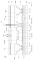
도 4는 도 2에 도시된 화소의 레이아웃을 나타내는 도면이다.
도 5는 도 4에 도시된 선 I-I'의 단면도이다.
도 6은 도 4에 도시된 선 II-II'의 단면도이다.
도 7은 본 출원의 일 예에 따른 발광 다이오드 디스플레이 장치에서, 정상 화소의 발광을 설명하기 위한 도면이다.
도 8은 본 출원의 일 예에 따른 발광 다이오드 디스플레이 장치에서, 리페어 화소의 발광을 설명하기 위한 도면이다.
도 9는 도 8에 도시된 리페어 화소의 리페어 방법을 나타내는 도면이다.
도 10은 본 출원에 따른 멀티 스크린 디스플레이 장치를 설명하기 위한 도면이다.1 is a diagram for explaining a light emitting diode display device according to an example of the present application.
FIG. 2 is a circuit diagram for explaining one pixel shown in FIG. 1.
FIG. 3 is a cross-sectional view for explaining the first to third light emitting devices shown in FIG. 2.
FIG. 4 is a diagram showing the layout of the pixel shown in FIG. 2.
Figure 5 is a cross-sectional view taken along line II' shown in Figure 4.
FIG. 6 is a cross-sectional view taken along line II-II' shown in FIG. 4.
FIG. 7 is a diagram for explaining light emission of a normal pixel in a light emitting diode display device according to an example of the present application.
FIG. 8 is a diagram for explaining light emission of a repair pixel in a light emitting diode display device according to an example of the present application.
FIG. 9 is a diagram illustrating a repair method of the repair pixel shown in FIG. 8.
Figure 10 is a diagram for explaining a multi-screen display device according to the present application.
본 출원의 이점 및 특징, 그리고 그것들을 달성하는 방법은 첨부되는 도면과 함께 상세하게 후술되어 있는 일 예들을 참조하면 명확해질 것이다. 그러나 본 출원은 이하에서 개시되는 일 예들에 한정되는 것이 아니라 서로 다른 다양한 형태로 구현될 것이며, 단지 본 출원의 일 예들은 본 출원의 개시가 완전하도록 하며, 본 출원의 발명이 속하는 기술분야에서 통상의 지식을 가진 자에게 발명의 범주를 완전하게 알려주기 위해 제공되는 것이며, 본 출원의 발명은 청구항의 범주에 의해 정의될 뿐이다.The advantages and features of the present application and methods for achieving them will become clear by referring to examples described in detail below along with the accompanying drawings. However, the present application is not limited to the examples disclosed below and will be implemented in various different forms, and only the examples of the present application ensure that the disclosure of the present application is complete, and are commonly used in the technical field to which the invention of the present application pertains. It is provided to fully inform those with knowledge of the scope of the invention, and the invention of this application is only defined by the scope of the claims.
본 출원의 일 예를 설명하기 위한 도면에 개시된 형상, 크기, 비율, 각도, 개수 등은 예시적인 것이므로 본 출원이 도시된 사항에 한정되는 것은 아니다. 명세서 전체에 걸쳐 동일 참조 부호는 동일 구성 요소를 지칭한다. 또한, 본 출원의 예를 설명함에 있어서, 관련된 공지 기술에 대한 구체적인 설명이 본 출원의 요지를 불필요하게 흐릴 수 있다고 판단되는 경우 그 상세한 설명은 생략한다.The shape, size, ratio, angle, number, etc. disclosed in the drawings for explaining an example of the present application are illustrative, and the present application is not limited to the matters shown. Like reference numerals refer to like elements throughout the specification. Additionally, in describing examples of the present application, if it is determined that detailed descriptions of related known technologies may unnecessarily obscure the gist of the present application, the detailed descriptions will be omitted.
본 명세서에서 언급된 '포함한다', '갖는다', '이루어진다' 등이 사용되는 경우 '~만'이 사용되지 않는 이상 다른 부분이 추가될 수 있다. 구성 요소를 단수로 표현한 경우에 특별히 명시적인 기재 사항이 없는 한 복수를 포함하는 경우를 포함한다.When 'includes', 'has', 'consists of', etc. mentioned in this specification are used, other parts may be added unless 'only' is used. When a component is expressed in the singular, the plural is included unless specifically stated otherwise.
구성 요소를 해석함에 있어서, 별도의 명시적 기재가 없더라도 오차 범위를 포함하는 것으로 해석한다.When interpreting a component, it is interpreted to include the margin of error even if there is no separate explicit description.
위치 관계에 대한 설명일 경우, 예를 들어, '~상에', '~상부에', '~하부에', '~옆에' 등으로 두 부분의 위치 관계가 설명되는 경우, '바로' 또는 '직접'이 사용되지 않는 이상 두 부분 사이에 하나 이상의 다른 부분이 위치할 수도 있다.In the case of a description of a positional relationship, for example, if the positional relationship of two parts is described as 'on top', 'on the top', 'on the bottom', 'next to', etc., 'immediately' Alternatively, there may be one or more other parts placed between the two parts, unless 'directly' is used.
시간 관계에 대한 설명일 경우, 예를 들어, '~후에', '~에 이어서', '~다음에', '~전에' 등으로 시간적 선후 관계가 설명되는 경우, '바로' 또는 '직접'이 사용되지 않는 이상 연속적이지 않은 경우도 포함할 수 있다.In the case of a description of a temporal relationship, for example, if a temporal relationship is described as 'after', 'successfully after', 'after', 'before', etc., 'immediately' or 'directly' Unless used, non-consecutive cases may also be included.
제 1, 제 2 등이 다양한 구성요소들을 서술하기 위해서 사용되나, 이들 구성요소들은 이들 용어에 의해 제한되지 않는다. 이들 용어들은 단지 하나의 구성요소를 다른 구성요소와 구별하기 위하여 사용하는 것이다. 따라서, 이하에서 언급되는 제 1 구성요소는 본 출원의 기술적 사상 내에서 제 2 구성요소일 수도 있다.Although first, second, etc. are used to describe various components, these components are not limited by these terms. These terms are merely used to distinguish one component from another. Accordingly, the first component mentioned below may also be the second component within the technical spirit of the present application.
"적어도 하나"의 용어는 하나 이상의 관련 항목으로부터 제시 가능한 모든 조합을 포함하는 것으로 이해되어야 한다. 예를 들어, "제 1 항목, 제 2 항목 및 제 3 항목 중에서 적어도 하나"의 의미는 제 1 항목, 제 2 항목 또는 제 3 항목 각각 뿐만 아니라 제 1 항목, 제 2 항목 및 제 3 항목 중에서 2개 이상으로부터 제시될 수 있는 모든 항목의 조합을 의미할 수 있다. The term “at least one” should be understood to include all possible combinations from one or more related items. For example, “at least one of the first, second, and third items” means each of the first, second, or third items, as well as two of the first, second, and third items. It can mean a combination of all items that can be presented from more than one.
본 출원의 여러 예들의 각각 특징들이 부분적으로 또는 전체적으로 서로 결합 또는 조합 가능하고, 기술적으로 다양한 연동 및 구동이 가능하며, 각 예들이 서로에 대하여 독립적으로 실시 가능할 수도 있고 연관 관계로 함께 실시할 수도 있다.Each feature of the various examples of the present application can be combined or combined with each other partially or entirely, and various technological interconnections and operations are possible, and each example can be implemented independently of each other or together in a related relationship. .
이하에서는 본 출원에 따른 발광 다이오드 디스플레이 장치 및 이를 이용한 멀티 스크린 디스플레이 장치의 예를 첨부된 도면을 참조하여 상세히 설명한다. 각 도면의 구성요소들에 참조부호를 부가함에 있어서, 동일한 구성요소들에 대해서는 비록 다른 도면상에 표시되더라도 가능한 한 동일한 부호를 가질 수 있다. 그리고, 첨부된 도면에 도시된 구성요소들의 스케일은 설명의 편의를 위해 실제와 다른 스케일을 가지므로, 도면에 도시된 스케일에 한정되지 않는다.Hereinafter, an example of a light emitting diode display device and a multi-screen display device using the same according to the present application will be described in detail with reference to the attached drawings. In adding reference numerals to components in each drawing, identical components may have the same reference numerals as much as possible even if they are shown in different drawings. Additionally, the scale of the components shown in the attached drawings has a different scale from the actual scale for convenience of explanation, and is therefore not limited to the scale shown in the drawings.
도 1은 본 출원의 일 예에 따른 발광 다이오드 디스플레이 장치를 설명하기 위한 도면이다.1 is a diagram for explaining a light emitting diode display device according to an example of the present application.
도 1을 참조하면, 본 출원의 일 예에 따른 발광 다이오드 디스플레이 장치는 기판(100) 및 패널 구동 회로부(700)를 포함할 수 있다.Referring to FIG. 1, a light emitting diode display device according to an example of the present application may include a
상기 기판(100)은 트랜지스터 어레이 기판으로서, 글라스 재질 또는 플라스틱 재질로 이루어질 수 있다.The
일 예에 따른 기판(100)은 복수의 게이트 라인(GL), 복수의 데이터 라인(DL), 복수의 제 1 구동 전원 라인(PL1), 복수의 제 2 구동 전원 라인(PL2), 및 복수의 화소(P)를 포함할 수 있다.The
상기 복수의 게이트 라인(GL) 각각은 제 1 방향(X)을 따라 길게 연장되고, 제 1 방향(X)과 교차하는 제 2 방향(Y)을 따라 일정한 간격을 가지도록 기판(100) 상에 배치될 수 있다. 이 경우, 제 1 방향(X)은 기판(100)의 장변 길이 방향과 나란한 방향으로 정의될 수 있으며, 제 2 방향(Y)은 기판(100)의 단변 길이 방향과 나란한 방향으로 정의될 수 있지만, 그 반대 방향으로 정의될 수도 있다.Each of the plurality of gate lines GL extends long along the first direction (X) and is disposed on the
상기 복수의 데이터 라인(DL)은 복수의 게이트 라인(GL)과 교차하도록 기판(100) 상에 마련되는 것으로, 제 2 방향(Y)을 따라 길게 연장되고, 제 1 방향(X)을 따라 일정한 간격으로 이격될 수 있다.The plurality of data lines DL are provided on the
상기 복수의 구동 전원 라인(PL)은 데이터 라인(DL)과 나란하도록 기판(100) 상에 마련되는 것으로, 복수의 데이터 라인(DL) 각각과 함께 형성될 수 있다. 이러한 복수의 구동 전원 라인(PL) 각각은 패널 구동 회로로부터 제공되는 제 1 화소 구동 전원을 인접한 화소(P)에 공급한다.The plurality of driving power lines PL are provided on the
상기 복수의 제 2 구동 전원 라인(PL2)은 데이터 라인(DL)과 나란하도록 기판(100) 상에 마련되는 것으로, 복수의 데이터 라인(DL) 각각과 함께 형성될 수 있다. 이러한 복수의 제 2 구동 전원 라인(PL2) 각각은 패널 구동 회로로부터 제공되는 제 1 화소 구동 전원과 다른 제 2 화소 구동 전원을 인접한 화소(P)에 공급한다. 예를 들어, 제 2 화소 구동 전원은 캐소드 전원 또는 그라운드 전압일 수 있다.The plurality of second driving power lines PL2 are provided on the
상기 복수의 화소(P) 각각은 게이트 라인(GL)과 데이터 라인(DL)에 의해 정의되는 화소 영역에 마련될 수 있다. 복수의 화소(P) 각각은 실제 광을 방출하는 최소 단위로 정의될 수 있다. 인접한 적어도 3개의 화소(P)는 컬러 표시를 위한 하나의 단위 화소를 구성할 수 있다. 예를 들어, 하나의 단위 화소는 인접한 적색 화소, 녹색 화소 및 청색 화소를 포함하며, 휘도 향상을 위해 백색 화소를 더 포함할 수도 있다.Each of the plurality of pixels P may be provided in a pixel area defined by the gate line GL and the data line DL. Each of the plurality of pixels (P) may be defined as the minimum unit that actually emits light. At least three adjacent pixels (P) may constitute one unit pixel for color display. For example, one unit pixel includes adjacent red pixels, green pixels, and blue pixels, and may further include white pixels to improve luminance.
일 예에 따른 단위 화소을 구성하는 적어도 3개의 화소(P)은 하나의 제 1 구동 전원 라인(PL1)을 서로 공유할 수 있으며, 이 경우, 제 1 구동 전원 라인(PL1)은 단위 화소마다 하나씩 마련되고, 이로 인하여 기판(100) 상에 마련되는 제 1 구동 전원 라인(PL1)의 개수가 감소될 수 있다.At least three pixels P constituting a unit pixel according to an example may share one first driving power line PL1. In this case, one first driving power line PL1 is provided for each unit pixel. As a result, the number of first driving power lines PL1 provided on the
상기 패널 구동 회로(700)는 기판(100)에 마련된 패드부에 연결되어 디스플레이 구동 시스템으로부터 공급되는 영상 데이터에 대응되는 영상 신호를 복수의 화소(P)에 공급한다.The
일 예에 따른 패널 구동 회로부(700)는 게이트 구동 회로부(710), 데이터 구동 회로부(730), 및 타이밍 제어 회로(750)를 포함할 수 있다.The panel
상기 게이트 구동 회로부(710)는 기판(100) 상에 배치된 복수의 게이트 라인(GL)과 연결된다. 게이트 구동 회로부(710)는 타이밍 제어 회로(750)로부터 공급되는 게이트 제어 신호를 기반으로 정해진 순서에 따라 게이트 신호를 생성하여 해당하는 게이트 라인(GL)에 공급한다.The gate
상기 데이터 구동 회로부(730)는 기판(100) 상에 배치된 복수의 데이터 라인(DL)과 연결된다. 데이터 구동 회로부(730)는 타이밍 제어 회로(750)로부터 제공되는 화소별 화소 데이터와 데이터 제어 신호를 수신하고, 전원 회로로부터 제공되는 복수의 기준 감마 전압을 수신한다. 데이터 구동 회로부(730)는 데이터 제어 신호와 복수의 기준 감마 전압을 이용하여 화소별 화소 데이터를 화소별 데이터 신호로 변환하고, 변환된 화소별 데이터 신호를 해당 데이터 라인(DL)에 공급한다.The data driving
상기 타이밍 제어 회로(750)는 디스플레이 구동 시스템으로부터 제공되는 영상 데이터와 타이밍 동기 신호를 수신한다. 타이밍 제어 회로(750)는 타이밍 동기 신호에 기초해 영상 데이터를 기판(100)의 화소 배치 구조에 알맞도록 정렬하여 화소 데이터를 생성하고, 생성된 화소 데이터를 데이터 구동 회로부(730)에 제공한다. 또한, 타이밍 제어 회로(750)는 타이밍 동기 신호에 기초해 데이터 제어 신호와 게이트 제어 신호 각각을 생성하여 데이터 구동 회로부(730)와 게이트 구동 회로부(710) 각각의 구동 타이밍을 제어한다.The
도 2는 도 1에 도시된 하나의 화소를 설명하기 위한 회로도이고, 도 3은 도 2에 도시된 제 1 내지 제 3 발광 소자를 설명하기 위한 단면도이며, 도 4는 도 2에 도시된 화소의 레이아웃을 나타내는 도면이다. 도 3의 회로도에서, 검정색 원형 점은 라인들이 전기적으로 연결된 부분을 나타내며, 검정색 원형 점이 표시되지 않은 라인들의 교차 부분과 중첩 부분은 전기적으로 분리(또는 절연)된 부분을 나타낸다.FIG. 2 is a circuit diagram for explaining one pixel shown in FIG. 1, FIG. 3 is a cross-sectional view for explaining the first to third light emitting elements shown in FIG. 2, and FIG. 4 is a circuit diagram for explaining the pixel shown in FIG. 2. This is a drawing showing the layout. In the circuit diagram of FIG. 3, black circular dots represent portions where lines are electrically connected, and intersections and overlapping portions of lines not marked with black circular dots represent electrically separated (or insulated) portions.
도 1 내지 도 4를 참조하면, 본 출원의 일 예에 따른 화소(P)는 화소 회로(PC), 제 1 발광 소자(ED1), 제 2 발광 소자(ED2), 공통 연결 패턴(CCP), 및 제 3 발광 소자(ED3)를 포함할 수 있다.1 to 4, the pixel P according to an example of the present application includes a pixel circuit (PC), a first light-emitting device (ED1), a second light-emitting device (ED2), a common connection pattern (CCP), and a third light emitting device (ED3).
상기 화소 회로(PC)는 인접한 데이터 라인(DL), 데이터 라인(DL)과 교차하는 제 1 및 제 2 게이트 라인(GLa, GLb), 및 데이터 라인(DL)과 나란한 제 1 구동 전원 라인(PL1)에 연결될 수 있다. 이 경우, 제 2 게이트 라인(GLb)은 제 1 발광 소자(ED1)의 구동 불량(또는 동작 불량)을 대비하여 미리 마련되는 리던던시 게이트 라인일 수 있다. 이러한 화소 회로(PC)는 데이터 라인(DL)에 공급되는 데이터 신호에 대응되는 데이터 전류를 제 1 발광 소자(ED1)와 제 2 발광 소자(ED2) 중 적어도 하나에 공급할 수 있다. 일 예에 따른 화소 회로(PC)는 제 1 화소 회로(PC1) 및 제 2 화소 회로(PC2)를 포함할 수 있다.The pixel circuit (PC) includes an adjacent data line (DL), first and second gate lines (GLa, GLb) crossing the data line (DL), and a first driving power line (PL1) parallel to the data line (DL). ) can be connected to. In this case, the second gate line GLb may be a redundancy gate line prepared in advance in preparation for a malfunction (or malfunction) of the first light-emitting device ED1. This pixel circuit (PC) can supply a data current corresponding to the data signal supplied to the data line (DL) to at least one of the first light-emitting device (ED1) and the second light-emitting device (ED2). The pixel circuit PC according to one example may include a first pixel circuit PC1 and a second pixel circuit PC2.
상기 제 1 화소 회로(PC1)는 제 1 게이트 라인(GLa), 데이터 라인(DL), 및 제 1 구동 전원 라인(PL1)에 연결되고, 제 1 게이트 라인(GLa)에 공급되는 제 1 게이트 신호에 응답하여 데이터 라인(DL)을 통해 공급되는 데이터 신호에 대응되는 데이터 전류를 제 1 발광 소자(ED1)에 공급한다. 일 예에 따른 제 1 화소 회로(PC1)는 제 1 스위칭 박막 트랜지스터(Tsw1), 제 1 구동 박막 트랜지스터(Tdr1), 및 제 1 커패시터(Cst1)를 포함할 수 있다.The first pixel circuit (PC1) is connected to the first gate line (GLa), the data line (DL), and the first driving power line (PL1), and the first gate signal supplied to the first gate line (GLa) In response, a data current corresponding to the data signal supplied through the data line DL is supplied to the first light emitting device ED1. The first pixel circuit PC1 according to an example may include a first switching thin film transistor Tsw1, a first driving thin film transistor Tdr1, and a first capacitor Cst1.
상기 제 1 스위칭 박막 트랜지스터(Tsw1)는 인접한 제 1 게이트 라인(GLa)에 연결된 게이트 전극, 데이터 라인(DL)에 연결된 제 1 소스/드레인 전극, 및 제 1 구동 박막 트랜지스터(Tdr1)의 게이트 전극과 연결되는 제 1 노드(N1)에 연결된 제 2 소스/드레인 전극을 포함할 수 있다. 이러한 제 1 스위칭 박막 트랜지스터(Tsw1)는 제 1 게이트 라인(GLa)에 공급되는 게이트 신호에 따라 스위칭되어 데이터 라인(DL)을 통해 공급되는 데이터 신호를 제 1 구동 박막 트랜지스터(Tdr1)의 게이트 전극에 공급한다.The first switching thin film transistor (Tsw1) includes a gate electrode connected to the adjacent first gate line (GLa), a first source/drain electrode connected to the data line (DL), and a gate electrode of the first driving thin film transistor (Tdr1) It may include a second source/drain electrode connected to the first node N1. This first switching thin film transistor (Tsw1) is switched according to the gate signal supplied to the first gate line (GLa) and sends the data signal supplied through the data line (DL) to the gate electrode of the first driving thin film transistor (Tdr1). supply.
상기 제 1 구동 박막 트랜지스터(Tdr1)는 제 1 스위칭 박막 트랜지스터(Tsw1)로부터 공급되는 전압 및/또는 제 1 커패시터(Cst1)의 전압에 의해 턴-온됨으로써 제 1 구동 전원 라인(PL1)으로부터 제 1 발광 소자(ED1)로 흐르는 전류 량을 제어한다. 일 예에 따른 제 1 구동 박막 트랜지스터(Tdr1)는 제 1 스위칭 박막 트랜지스터(Tsw1)의 제 2 소스/드레인 전극(또는 제 1 노드(N1))에 연결된 게이트 전극, 제 1 구동 전원 라인(PL1)에 연결된 소스 전극, 및 제 1 발광 소자(ED1)에 연결되는 드레인 전극을 포함할 수 있다. 이 경우, 제 1 구동 박막 트랜지스터(Tdr1)는 P형 불순물이 도핑된 반도체층을 포함하는 P 타입의 박막 트랜지스터이지만, 이에 한정되지 않고 N형 불순물이 도핑된 반도체층을 포함하는 N 타입의 박막 트랜지스터로 변경될 수 있다. N 타입의 제 1 구동 박막 트랜지스터(Tdr1)의 경우, 소스 전극은 제 1 발광 소자(ED1)에 연결되며 드레인 전극은 제 1 구동 전원 라인(PL1)에 연결될 수 있다.The first driving thin film transistor (Tdr1) is turned on by the voltage supplied from the first switching thin film transistor (Tsw1) and/or the voltage of the first capacitor (Cst1), thereby receiving the first voltage from the first driving power line (PL1). Controls the amount of current flowing to the light emitting device (ED1). The first driving thin film transistor Tdr1 according to an example includes a gate electrode connected to the second source/drain electrode (or first node N1) of the first switching thin film transistor Tsw1, and a first driving power line PL1. It may include a source electrode connected to and a drain electrode connected to the first light emitting device ED1. In this case, the first driving thin film transistor Tdr1 is a P-type thin film transistor including a semiconductor layer doped with a P-type impurity, but is not limited to this and is an N-type thin film transistor including a semiconductor layer doped with an N-type impurity. It can be changed to . In the case of the N-type first driving thin film transistor Tdr1, the source electrode may be connected to the first light emitting element ED1 and the drain electrode may be connected to the first driving power line PL1.
상기 제 1 커패시터(Cst1)는 제 1 구동 박막 트랜지스터(Tdr1)의 게이트 전극과 소스 전극 사이의 중첩 영역에 마련되어 제 1 구동 박막 트랜지스터(Tdr1)의 게이트 전극에 공급되는 데이터 신호에 대응되는 전압을 저장하고, 저장된 전압으로 제 1 구동 박막 트랜지스터(Tdr1)를 턴-온시킨다.The first capacitor Cst1 is provided in an overlapping area between the gate electrode and the source electrode of the first driving thin film transistor Tdr1 and stores a voltage corresponding to the data signal supplied to the gate electrode of the first driving thin film transistor Tdr1. And, the first driving thin film transistor (Tdr1) is turned on using the stored voltage.
상기 제 1 화소 회로(PC2)는 제 2 게이트 라인(GLb), 데이터 라인(DL), 및 제 1 구동 전원 라인(PL1)에 연결되고, 제 2 게이트 라인(GLb)에 공급되는 제 2 게이트 신호에 응답하여 데이터 라인(DL)을 통해 공급되는 데이터 신호에 대응되는 데이터 전류를 제 2 발광 소자(ED2)에 공급한다. 일 예에 따른 제 2 화소 회로(PC2)는 제 2 스위칭 박막 트랜지스터(Tsw2), 제 2 구동 박막 트랜지스터(Tdr2), 및 제 2 커패시터(Cst2)를 포함할 수 있다.The first pixel circuit PC2 is connected to the second gate line GLb, the data line DL, and the first driving power line PL1, and the second gate signal is supplied to the second gate line GLb. In response, a data current corresponding to the data signal supplied through the data line DL is supplied to the second light emitting device ED2. The second pixel circuit PC2 according to an example may include a second switching thin film transistor Tsw2, a second driving thin film transistor Tdr2, and a second capacitor Cst2.
상기 제 2 스위칭 박막 트랜지스터(Tsw2)는 인접한 제 2 게이트 라인(GLb)에 연결된 게이트 전극, 데이터 라인(DL)에 연결된 제 1 소스/드레인 전극, 및 제 2 구동 박막 트랜지스터(Tdr2)의 게이트 전극과 연결되는 제 2 노드(N2)에 연결된 제 2 소스/드레인 전극을 포함할 수 있다. 이러한 제 2 스위칭 박막 트랜지스터(Tsw2)는 제 2 게이트 라인(GLb)에 공급되는 게이트 신호에 따라 스위칭되어 데이터 라인(DL)을 통해 공급되는 데이터 신호를 제 2 구동 박막 트랜지스터(Tdr2)의 게이트 전극에 공급한다.The second switching thin film transistor (Tsw2) includes a gate electrode connected to the adjacent second gate line (GLb), a first source/drain electrode connected to the data line (DL), and a gate electrode of the second driving thin film transistor (Tdr2) It may include a second source/drain electrode connected to the second node N2. This second switching thin film transistor (Tsw2) is switched according to the gate signal supplied to the second gate line (GLb) and sends the data signal supplied through the data line (DL) to the gate electrode of the second driving thin film transistor (Tdr2). supply.
상기 제 2 구동 박막 트랜지스터(Tdr2)는 제 2 스위칭 박막 트랜지스터(Tsw2)로부터 공급되는 전압 및/또는 제 2 커패시터(Cst2)의 전압에 의해 턴-온됨으로써 제 1 구동 전원 라인(PL1)으로부터 제 2 발광 소자(ED2)로 흐르는 전류 량을 제어한다. 일 예에 따른 제 2 구동 박막 트랜지스터(Tdr2)는 제 2 스위칭 박막 트랜지스터(Tsw2)의 제 2 소스/드레인 전극(또는 제 2 노드(N2))에 연결된 게이트 전극, 제 1 구동 전원 라인(PL1)에 연결된 소스 전극, 및 제 2 발광 소자(ED2)에 연결되는 드레인 전극을 포함할 수 있다. 이 경우, 제 2 구동 박막 트랜지스터(Tdr2)는 P형 불순물이 도핑된 반도체층을 포함하는 P 타입의 박막 트랜지스터이지만, 이에 한정되지 않고 N형 불순물이 도핑된 반도체층을 포함하는 N 타입의 박막 트랜지스터로 변경될 수 있다. N 타입의 제 2 구동 박막 트랜지스터(Tdr2)의 경우, 소스 전극은 제 2 발광 소자(ED2)에 연결되며 드레인 전극은 제 1 구동 전원 라인(PL1)에 연결될 수 있다.The second driving thin film transistor (Tdr2) is turned on by the voltage supplied from the second switching thin film transistor (Tsw2) and/or the voltage of the second capacitor (Cst2), thereby generating the second voltage from the first driving power line (PL1). Controls the amount of current flowing to the light emitting device (ED2). The second driving thin film transistor Tdr2 according to an example includes a gate electrode connected to the second source/drain electrode (or second node N2) of the second switching thin film transistor Tsw2, and a first driving power line PL1. It may include a source electrode connected to and a drain electrode connected to the second light emitting device ED2. In this case, the second driving thin film transistor Tdr2 is a P-type thin film transistor including a semiconductor layer doped with a P-type impurity, but is not limited to this and is an N-type thin film transistor including a semiconductor layer doped with an N-type impurity. It can be changed to . In the case of the N-type second driving thin film transistor Tdr2, the source electrode may be connected to the second light emitting element ED2 and the drain electrode may be connected to the first driving power line PL1.
상기 제 2 커패시터(Cst2)는 제 2 구동 박막 트랜지스터(Tdr2)의 게이트 전극과 소스 전극 사이의 중첩 영역에 마련되어 제 2 구동 박막 트랜지스터(Tdr2)의 게이트 전극에 공급되는 데이터 신호에 대응되는 전압을 저장하고, 저장된 전압으로 제 2 구동 박막 트랜지스터(Tdr2)를 턴-온시킨다.The second capacitor Cst2 is provided in an overlapping area between the gate electrode and the source electrode of the second driving thin film transistor Tdr2 and stores a voltage corresponding to the data signal supplied to the gate electrode of the second driving thin film transistor Tdr2. And, the second driving thin film transistor (Tdr2) is turned on using the stored voltage.
선택적으로, 제 1 및 제 2 화소 회로(PC1, PC2) 각각은 구동 박막 트랜지스터(Tdr1, Tdr2)의 문턱 전압 변화를 보상하기 위한 적어도 하나의 보상 박막 트랜지스터를 더 포함할 수 있으며, 나아가 적어도 하나의 보조 커패시터를 더 포함할 수 있다. 이러한 제 1 및 제 2 화소 회로(PC1, PC2) 각각은 박막 트랜지스터와 보조 커패시터의 개수에 따라 초기화 전압 등의 보상 전원을 추가로 공급받을 수도 있다. 따라서, 본 출원의 예에 따른 제 1 및 제 2 화소 회로(PC1, PC2) 각각은 유기 발광 디스플레이 장치의 각 화소와 동일하게 전류 구동 방식을 통해 발광 소자(ED1, ED2)를 구동하기 때문에 공지된 유기 발광 디스플레이 장치의 화소 회로로 변경 가능하다. 예를 들어, 본 출원의 예에 따른 제 1 및 제 2 화소 회로(PC1, PC2) 각각은 본 출원인에 의해 공지된 대한민국 등록특허 제10-1749752호, 대한민국 공개특허 제10-2017-0037729호, 대한민국 공개특허 제10-2017-0062603호, 또는 대한민국 공개특허 제10-2017-0081078호에 개시된 화소 회로로 변경될 수 있다.Optionally, each of the first and second pixel circuits (PC1, PC2) may further include at least one compensation thin film transistor for compensating for changes in the threshold voltage of the driving thin film transistors (Tdr1, Tdr2), and further, at least one It may further include an auxiliary capacitor. Each of the first and second pixel circuits PC1 and PC2 may be additionally supplied with compensation power such as an initialization voltage depending on the number of thin film transistors and auxiliary capacitors. Therefore, each of the first and second pixel circuits (PC1, PC2) according to the example of the present application drives the light emitting elements (ED1, ED2) through the same current driving method as each pixel of the organic light emitting display device, and thus known It can be changed to the pixel circuit of an organic light emitting display device. For example, each of the first and second pixel circuits (PC1, PC2) according to the example of the present application is Republic of Korea Patent No. 10-1749752, Republic of Korea Patent Publication No. 10-2017-0037729, which are known by the present applicant. It can be changed to the pixel circuit disclosed in Korean Patent Publication No. 10-2017-0062603 or Korean Patent Publication No. 10-2017-0081078.
일 예에 따른 제 2 화소 회로(PC2)는 제 1 발광 소자(ED1)를 기판(100)에 실장하는 공정에서 발생되는 미스 얼라인 또는 전기적 충격에 의해 구동 불량일 경우를 대비하여 미리 마련된 리던던시(redundancy) 회로로 사용될 수 있다. The second pixel circuit (PC2) according to an example has a redundancy (redundancy) prepared in advance in case of a driving failure due to misalignment or electrical shock generated during the process of mounting the first light emitting element (ED1) on the
상기 제 1 발광 소자(ED1)는 제 1 화소 회로(PC1)와 제 3 발광 소자(ED3) 사이에 전기적으로 연결된다. 이러한 제 1 발광 소자(ED1)는 제 1 화소 회로(PC1), 즉 제 1 구동 박막 트랜지스터(Tdr1)로부터 제 3 발광 소자(ED3)를 통해 제 2 구동 전원 라인(PL2)으로 흐르는 전류에 의해 발광할 수 있다. 일 예에 따른 제 1 발광 소자(ED1)는 적색 광, 녹색 광, 청색 광, 및 백색 광 중 어느 하나의 광을 방출하는 마이크로 발광 다이오드 칩일 수 있다.The first light emitting device ED1 is electrically connected between the first pixel circuit PC1 and the third light emitting device ED3. This first light emitting element (ED1) emits light by the current flowing from the first pixel circuit (PC1), that is, the first driving thin film transistor (Tdr1), through the third light emitting element (ED3) to the second driving power line (PL2). can do. The first light emitting device ED1 according to an example may be a micro light emitting diode chip that emits any one of red light, green light, blue light, and white light.
일 예에 따른 제 1 발광 소자(ED1)는 제 1 화소 회로(PC1)에 연결된 제 1 단자와 공통 연결 패턴(CCP)에 연결된 제 2 단자를 포함할 수 있다. 이와 같은, 제 1 발광 소자(ED1)는 제 1 화소 회로(PC1)와 함께 화소(P)의 제 1 발광부를 구성할 수 있다. 이 경우, 제 1 발광부는 제 2 방향(Y)을 기준으로, 제 1 게이트 라인(GLa)에 인접한 화소(P)의 상측 영역에 배치될 수 있다.The first light emitting device ED1 according to an example may include a first terminal connected to the first pixel circuit PC1 and a second terminal connected to the common connection pattern CCP. As such, the first light emitting element ED1 may form the first light emitting unit of the pixel P together with the first pixel circuit PC1. In this case, the first light emitting unit may be disposed in the upper area of the pixel (P) adjacent to the first gate line (GLa) based on the second direction (Y).
상기 제 2 발광 소자(ED2)는 제 2 화소 회로(PC2)와 제 3 발광 소자(ED3) 사이에 전기적으로 연결된다. 이러한 제 2 발광 소자(ED2)는 제 2 화소 회로(PC2), 즉 제 2 구동 박막 트랜지스터(Tdr2)로부터 제 3 발광 소자(ED3)를 통해 제 2 구동 전원 라인(PL2)으로 흐르는 전류에 의해 발광할 수 있다. 일 예에 따른 제 2 발광 소자(ED2)는 제 1 발광 소자(ED1)와 동일한 광을 방출하는 마이크로 발광 다이오드 칩일 수 있다. 제 2 발광 소자(ED2)는 제 1 발광 소자(ED1)를 기판(100)에 실장되는 공정에서 발생되는 미스 얼라인 또는 전기적 충격에 의해 구동 불량일 경우를 대비하여 미리 마련된 리던던시(redundancy) 발광 소자로 사용될 수 있다.The second light emitting device ED2 is electrically connected between the second pixel circuit PC2 and the third light emitting device ED3. This second light emitting element (ED2) emits light by the current flowing from the second pixel circuit (PC2), that is, the second driving thin film transistor (Tdr2), through the third light emitting element (ED3) to the second driving power line (PL2). can do. The second light emitting device ED2 according to an example may be a micro light emitting diode chip that emits the same light as the first light emitting device ED1. The second light emitting device (ED2) is a redundancy light emitting device prepared in advance in case of a malfunction due to misalignment or electrical shock occurring during the process of mounting the first light emitting device (ED1) on the
일 예에 따른 제 2 발광 소자(ED2)는 제 2 화소 회로(PC2)에 연결된 제 1 단자와 공통 연결 패턴(CCP)에 연결된 제 2 단자를 포함할 수 있다. 이와 같은, 제 2 발광 소자(ED2)는 제 2 화소 회로(PC2)와 함께 화소(P)의 제 2 발광부를 구성할 수 있다. 이 경우, 제 2 발광부는 제 2 방향(Y)을 기준으로, 제 2 게이트 라인(GLb)에 인접한 화소(P)의 하측 영역에 배치될 수 있다.The second light emitting device ED2 according to an example may include a first terminal connected to the second pixel circuit PC2 and a second terminal connected to the common connection pattern CCP. As such, the second light emitting element ED2 may form the second light emitting unit of the pixel P together with the second pixel circuit PC2. In this case, the second light emitting unit may be disposed in the lower area of the pixel P adjacent to the second gate line GLb based on the second direction Y.
상기 제 3 발광 소자(ED3)는 제 2 구동 전원 라인(PL2)과 공통 연결 패턴(CCP) 사이에 연결된다. 예를 들어, 제 3 발광 소자(ED3)는 공통 연결 패턴(CCP)을 통해 제 1 발광 소자(ED1)와 전기적으로 직렬 연결되면서 제 2 발광 소자(ED2)와도 전기적으로 직렬 연결된다. 이에 따라, 제 1 발광 소자(ED1)와 제 2 발광 소자(ED2)는 공통 연결 패턴(CCP)에 의해 서로 병렬 연결되면서 제 3 발광 소자(ED3)와 각각 직렬 연결된다. 일 예에 따른 제 3 발광 소자(ED3)는 제 1 발광 소자(ED1)와 동일한 광을 방출하는 마이크로 발광 다이오드 칩일 수 있다. 이러한 제 3 발광 소자(ED3)는 제 1 발광 소자(ED1) 또는 제 2 발광 소자(ED2)와 전기적으로 직렬 접속됨으로써 화소(P)의 발광 휘도를 증가시키면서 화소(P)에 공급되는 입력 전류를 절반으로 감소시켜 화소(P)의 소비전력을 감소시킴으로써 발광 다이오드 디스플레이 장치의 전체적인 소비전력을 감소시키는데 기여할 수 있다. 그리고, 제 3 발광 소자(ED3)는 제 1 발광 소자(ED1)의 구동 불량시, 화소(P)의 리던던시 구동에 따라 제 2 발광 소자(ED2)와 전기적으로 직렬 접속되어 화소(P)의 정상 구동을 가능하게 한다.The third light emitting device ED3 is connected between the second driving power line PL2 and the common connection pattern CCP. For example, the third light-emitting device ED3 is electrically connected in series with the first light-emitting device ED1 and the second light-emitting device ED2 through the common connection pattern CCP. Accordingly, the first light-emitting device (ED1) and the second light-emitting device (ED2) are connected in parallel to each other through the common connection pattern (CCP) and are respectively connected in series to the third light-emitting device (ED3). The third light emitting device ED3 according to an example may be a micro light emitting diode chip that emits the same light as the first light emitting device ED1. This third light-emitting element (ED3) is electrically connected in series with the first light-emitting element (ED1) or the second light-emitting element (ED2), thereby increasing the light emission luminance of the pixel (P) and reducing the input current supplied to the pixel (P). By reducing the power consumption of the pixel (P) by half, it can contribute to reducing the overall power consumption of the light emitting diode display device. In addition, when the first light-emitting element ED1 is driven poorly, the third light-emitting element ED3 is electrically connected in series with the second light-emitting element ED2 according to the redundancy driving of the pixel P to ensure normal operation of the pixel P. Makes operation possible.
일 예에 따른 제 3 발광 소자(ED3)는 공통 연결 패턴(CCP)에 연결된 제 1 단자, 및 제 2 구동 전원 라인(PL2)과 연결된 제 2 단자를 포함할 수 있다. 이와 같은, 제 3 발광 소자(ED3)는 화소(P)의 제 3 발광부를 구성할 수 있다. 이 경우, 제 3 발광부는 제 2 방향(Y)을 기준으로, 제 1 게이트 라인(GLa)과 제 2 게이트 라인(GLb) 사이에 대응되는 화소(P)의 중간 영역에 배치될 수 있다. 이에 따라, 제 3 발광 소자(ED3)는 제 1 발광 소자(ED1)와 제 2 발광 소자(ED2) 사이에 배치될 수 있다. 이때, 제 3 발광 소자(ED3)를 기준으로 제 1 발광 소자(ED1)와 제 2 발광 소자(ED2) 간의 거리(D1, D2)가 비대칭일 경우, 화소별 휘도 균일성이 저하되어 화질이 저하되며, 줄무늬 같은 화질 불량이 발생될 수 있다. 따라서, 제 1 내지 제 3 발광 소자(ED1, ED2, ED3)는 제 2 방향(Y)을 따라 일렬로 배치되며, 제 3 발광 소자(ED3)와 제 1 발광 소자(ED1) 사이의 제 1 거리(L1)는 제 3 발광 소자(ED3)와 제 2 발광 소자(ED2) 사이의 제 2 거리(L1)와 동일하게 설정됨으로써 제 1 내지 제 3 발광 소자(ED1, ED2, ED3)의 비대칭 배치로 인한 화질 저하가 방지될 수 있다.The third light emitting device ED3 according to an example may include a first terminal connected to the common connection pattern CCP and a second terminal connected to the second driving power line PL2. As such, the third light emitting element ED3 may form the third light emitting unit of the pixel P. In this case, the third light emitting unit may be disposed in the middle area of the pixel (P) corresponding to the first gate line (GLa) and the second gate line (GLb) based on the second direction (Y). Accordingly, the third light-emitting device ED3 may be disposed between the first light-emitting device ED1 and the second light-emitting device ED2. At this time, if the distances (D1, D2) between the first light-emitting device (ED1) and the second light-emitting device (ED2) with respect to the third light-emitting device (ED3) are asymmetric, the luminance uniformity for each pixel is lowered and the image quality deteriorates. This may cause image quality defects such as stripes. Accordingly, the first to third light-emitting elements ED1, ED2, and ED3 are arranged in a row along the second direction Y, and the first distance between the third light-emitting element ED3 and the first light-emitting element ED1 is (L1) is set equal to the second distance (L1) between the third light-emitting device (ED3) and the second light-emitting device (ED2), resulting in an asymmetrical arrangement of the first to third light-emitting devices (ED1, ED2, ED3) Deterioration in image quality can be prevented.
상기 공통 연결 패턴(CCP)은 제 1 발광 소자(ED1)와 제 2 발광 소자(ED2)에 공통적으로 연결됨으로써 제 1 발광 소자(ED1)와 제 2 발광 소자(ED2)를 전기적으로 병렬 연결한다. 공통 연결 패턴(CCP)의 일부는 제 2 구동 전원 라인(PL2)과 중첩되도록 기판(100) 상에 배치될 수 있다. 공통 연결 패턴(CCP)의 일부는 제 3 발광 소자(ED3)가 구동 불량일 경우, 제 1 발광 소자(ED1)와 제 2 발광 소자(ED2) 중 적어도 하나를 제 2 구동 전원 라인(PL2)에 전기적으로 연결할 수 있다. 이 경우, 공통 연결 패턴(CCP)의 일부는 레이저 리페어 공정에 따른 레이저 웰딩(laser welding)을 위한 레이저 웰딩부(또는 리페어 포인트)로 사용될 수 있다.The common connection pattern (CCP) is commonly connected to the first light-emitting device (ED1) and the second light-emitting device (ED2), thereby electrically connecting the first light-emitting device (ED1) and the second light-emitting device (ED2) in parallel. A portion of the common connection pattern (CCP) may be disposed on the
일 예에 따른 공통 연결 패턴(CCP)은 제 1 단자 연결 라인(TCL1), 제 1 중첩 라인(OL1), 제 2 단자 연결 라인(TCL2), 제 2 중첩 라인(OL2), 및 제 3 단자 연결 라인(TCL3)을 포함할 수 있다.The common connection pattern (CCP) according to an example includes a first terminal connection line (TCL1), a first overlapping line (OL1), a second terminal connection line (TCL2), a second overlapping line (OL2), and a third terminal connection. It may include a line (TCL3).
상기 제 1 단자 연결 라인(TCL1)은 제 1 방향(X)과 나란하도록 기판(100) 상에 배치되어 제 1 발광 소자(ED1)의 제 2 단자와 전기적으로 연결된다. 예를 들어, 제 1 단자 연결 라인(TCL1)의 일단은 제 1 발광 소자(ED1)의 제 2 단자와 전기적으로 연결될 수 있다. 그리고, 제 1 단자 연결 라인(TCL1)의 타단은 제 2 구동 전원 라인(PL2)과 중첩될 수 있다.The first terminal connection line (TCL1) is disposed on the
상기 제 1 중첩 라인(OL1)은 제 2 방향(Y)과 나란하도록 제 1 단자 연결 라인(TCL1)으로부터 연장되어 제 2 구동 전원 라인(PL2)과 중첩된다. 예를 들어, 제 1 중첩 라인(OL1)의 일단은 제 2 구동 전원 라인(PL2) 상에서 제 1 단자 연결 라인(TCL1)의 타단과 연결될 수 있다. 그리고, 제 1 중첩 라인(OL1)의 타단은 제 1 게이트 라인(GLa)과 제 2 게이트 라인(GLb) 사이에 배치된 제 2 구동 전원 라인(PL2) 상에 배치될 수 있다. 이와 같은, 제 1 중첩 라인(OL1)은 제 2 구동 전원 라인(PL2)과 중첩됨으로써 제 3 발광 소자(ED3)의 구동 불량시, 제 2 구동 전원 라인(PL2)과 전기적으로 연결될 수 있으며, 이로 인하여 제 1 중첩 라인(OL1)의 적어도 일부는 레이저 리페어 공정에 따른 레이저 웰딩(laser welding)을 위한 제 1 레이저 웰딩부(또는 리페어 포인트)(LWP1)로 설정된다.The first overlapping line OL1 extends from the first terminal connection line TCL1 parallel to the second direction Y and overlaps the second driving power line PL2. For example, one end of the first overlap line OL1 may be connected to the other end of the first terminal connection line TCL1 on the second driving power line PL2. Additionally, the other end of the first overlap line OL1 may be disposed on the second driving power line PL2 disposed between the first gate line GLa and the second gate line GLb. In this way, the first overlap line OL1 overlaps the second driving power line PL2 and can be electrically connected to the second driving power line PL2 when the third light emitting element ED3 is malfunctioning. Therefore, at least a portion of the first overlap line OL1 is set as the first laser welding portion (or repair point) LWP1 for laser welding according to the laser repair process.
상기 제 2 단자 연결 라인(TCL2)은 제 1 중첩 라인(OL1)으로부터 연장되어 제 3 발광 소자(ED3)의 제 1 단자에 연결된다. 예를 들어, 제 2 단자 연결 라인(TCL2)의 일단은 제 2 구동 전원 라인(PL2) 상에서 제 1 중첩 라인(OL1)의 타단과 연결될 수 있다. 그리고, 제 2 단자 연결 라인(TCL2)의 타단은 제 2 구동 전원 라인(PL2)과 중첩될 수 있다. 또한, 제 2 단자 연결 라인(TCL2)의 일단과 타단 사이의 중간부는 제 3 발광 소자(ED3)를 둘러싸는 형태로 배치되어 제 3 발광 소자(ED3)의 제 1 단자와 연결될 수 있다. 일 예에 따른 제 2 단자 연결 라인(TCL2)는 평면적으로 "⊃"자 형태를 가질 수 있다.The second terminal connection line TCL2 extends from the first overlap line OL1 and is connected to the first terminal of the third light emitting device ED3. For example, one end of the second terminal connection line (TCL2) may be connected to the other end of the first overlap line (OL1) on the second driving power line (PL2). Also, the other end of the second terminal connection line (TCL2) may overlap the second driving power line (PL2). Additionally, the middle portion between one end and the other end of the second terminal connection line (TCL2) may be arranged to surround the third light-emitting device (ED3) and connected to the first terminal of the third light-emitting device (ED3). The second terminal connection line TCL2 according to one example may have a “ ⊃ ” shape in plan view.
상기 제 2 중첩 라인(OL2)은 제 2 방향(Y)과 나란하도록 제 2 단자 연결 라인(TCL2)으로부터 연장되어 제 2 구동 전원 라인(PL2)과 중첩된다. 예를 들어, 제 2 중첩 라인(OL2)의 일단은 제 2 구동 전원 라인(PL2) 상에서 제 2 단자 연결 라인(TCL2)의 타단과 연결될 수 있다. 그리고, 제 2 중첩 라인(OL2)의 타단은 제 2 구동 전원 라인(PL2) 상에 배치될 수 있다. 이와 같은, 제 2 중첩 라인(OL2)은 제 2 구동 전원 라인(PL2)과 중첩됨으로써 제 3 발광 소자(ED3)의 구동 불량시, 제 2 구동 전원 라인(PL2)과 전기적으로 연결될 수 있으며, 이로 인하여 제 2 중첩 라인(OL2)의 적어도 일부는 레이저 리페어 공정에 따른 레이저 웰딩(laser welding)을 위한 제 2 레이저 웰딩부(또는 리페어 포인트)(LWP2)로 설정된다.The second overlapping line OL2 extends from the second terminal connection line TCL2 parallel to the second direction Y and overlaps the second driving power line PL2. For example, one end of the second overlapping line OL2 may be connected to the other end of the second terminal connection line TCL2 on the second driving power line PL2. And, the other end of the second overlap line OL2 may be disposed on the second driving power line PL2. As such, the second overlapping line OL2 overlaps the second driving power line PL2 and can be electrically connected to the second driving power line PL2 when the third light emitting element ED3 is malfunctioning. Therefore, at least a portion of the second overlap line OL2 is set as a second laser welding portion (or repair point) LWP2 for laser welding according to a laser repair process.
상기 제 3 단자 연결 라인(TCL3)은 제 1 방향(X)과 나란하도록 제 2 중첩 라인(OL2)의 타단으로부터 연장되어 제 2 발광 소자(ED2)의 제 2 단자와 전기적으로 연결된다. 예를 들어, 제 3 단자 연결 라인(TCL3)의 일단은 제 2 구동 전원 라인(PL2) 상에서 제 2 중첩 라인(OL2)의 타단과 연결될 수 있다. 그리고, 제 3 단자 연결 라인(TCL3)의 타단은 제 2 발광 소자(ED2)의 제 2 단자와 전기적으로 연결될 수 있다.The third terminal connection line (TCL3) extends from the other end of the second overlapping line (OL2) parallel to the first direction (X) and is electrically connected to the second terminal of the second light emitting device (ED2). For example, one end of the third terminal connection line (TCL3) may be connected to the other end of the second overlap line (OL2) on the second driving power line (PL2). Additionally, the other end of the third terminal connection line (TCL3) may be electrically connected to the second terminal of the second light emitting device (ED2).
이와 같은, 공통 연결 패턴(CCP)은 제 1 발광 소자(ED1)와 제 2 발광 소자(ED2) 각각의 제 2 단자와 제 3 발광 소자(ED3)의 제 1 단자에 공통적으로 연결됨으로써, 제 1 발광 소자(ED1)와 제 2 발광 소자(ED2) 및 제 3 발광 소자(ED3)를 전기적으로 직렬과 병렬로 연결하며, 제 3 발광 소자(ED3)의 구동 불량시 제 1 중첩 라인(OL1)과 제 2 중첩 라인(OL2) 중 적어도 하나가 레이저 리페어 공정에 의해 제 2 구동 전원 라인(PL2)과 전기적으로 연결됨으로써 화소(P)의 신뢰성과 생산 수율을 향상시킬 수 있다.As such, the common connection pattern (CCP) is commonly connected to the second terminal of each of the first light-emitting device (ED1) and the second light-emitting device (ED2) and the first terminal of the third light-emitting device (ED3), thereby The light-emitting element ED1, the second light-emitting element ED2, and the third light-emitting element ED3 are electrically connected in series and parallel, and when the third light-emitting element ED3 is malfunctioning, the first overlap line OL1 and At least one of the second overlapping lines OL2 is electrically connected to the second driving power line PL2 through a laser repair process, thereby improving the reliability and production yield of the pixel P.
본 출원의 일 예에 따른 화소(P)는 제 1 내지 제 3 브리지 전극 패턴(BEP1, BEP2, BEP3)을 더 포함할 수 있다.The pixel P according to an example of the present application may further include first to third bridge electrode patterns BEP1, BEP2, and BEP3.
상기 제 1 브리지 전극 패턴(BEP1)은 제 1 화소 회로(PC1)와 제 1 발광 소자(ED1)의 제 1 단자를 전기적으로 연결한다. 예를 들어, 제 1 브리지 전극 패턴(BEP1)은 제 1 구동 박막 트랜지스터(Tdr1)의 소스 전극와 제 1 발광 소자(ED1)의 제 1 단자를 전기적으로 연결할 수 있다.The first bridge electrode pattern BEP1 electrically connects the first pixel circuit PC1 and the first terminal of the first light emitting element ED1. For example, the first bridge electrode pattern BEP1 may electrically connect the source electrode of the first driving thin film transistor Tdr1 and the first terminal of the first light emitting device ED1.
상기 제 2 브리지 전극 패턴(BEP2)은 제 2 화소 회로(PC2)와 제 2 발광 소자(ED2)의 제 1 단자를 전기적으로 연결한다. 예를 들어, 제 2 브리지 전극 패턴(BEP2)은 제 2 구동 박막 트랜지스터(Tdr2)의 소스 전극와 제 2 발광 소자(ED2)의 제 1 단자를 전기적으로 연결할 수 있다.The second bridge electrode pattern BEP2 electrically connects the second pixel circuit PC2 and the first terminal of the second light emitting device ED2. For example, the second bridge electrode pattern BEP2 may electrically connect the source electrode of the second driving thin film transistor Tdr2 and the first terminal of the second light emitting device ED2.
상기 제 3 브리지 전극 패턴(BEP3)은 제 3 발광 소자(ED3)의 제 2 단자와 제 2 구동 전원 라인(PL2)를 전기적으로 연결한다. 이 경우, 공통 연결 패턴(CCP)의 제 2 단자 연결 라인(TCL2)은 제 3 브리지 전극 패턴(BEP3)을 우회하도록 제 1 중첩 라인(OL1)으로부터 연장되어 제 2 중첩 라인(OL2)과 연결된다.The third bridge electrode pattern BEP3 electrically connects the second terminal of the third light emitting device ED3 and the second driving power line PL2. In this case, the second terminal connection line (TCL2) of the common connection pattern (CCP) extends from the first overlap line (OL1) to bypass the third bridge electrode pattern (BEP3) and is connected to the second overlap line (OL2). .
상기 공통 연결 패턴(CCP) 및 제 1 내지 제 3 브리지 전극 패턴(BEP1, BEP2, BEP3) 각각은 투명 도전성 재질로 이루어질 수 있다. 예를 들어, 투명 도전성 재질은 ITO(Indium Tin Oxide) 또는 IZO(Indium Zinc Oxide) 등이 될 수 있지만, 이에 한정되지 않는다.Each of the common connection pattern (CCP) and the first to third bridge electrode patterns (BEP1, BEP2, and BEP3) may be made of a transparent conductive material. For example, the transparent conductive material may be ITO (Indium Tin Oxide) or IZO (Indium Zinc Oxide), but is not limited thereto.
도 3을 참조하면, 일 예에 따른 제 1 내지 제 3 발광 소자(ED1, ED2, ED3) 각각은 발광층(EL), 제 1 단자(또는 애노드 단자)(T1), 및 제 2 단자(또는 캐소드 단자) (T2)를 포함한다.Referring to FIG. 3, each of the first to third light emitting devices (ED1, ED2, and ED3) according to an example includes a light emitting layer (EL), a first terminal (or anode terminal) (T1), and a second terminal (or cathode). terminal) (T2).
상기 발광층(EL)은 제 1 단자(T1)과 제 2 단자(T2) 사이에 흐르는 전류에 따른 전자와 정공의 재결합에 따라 발광한다. 일 예에 따른 발광층(EL)은 제 1 반도체층(SL1), 활성층(ACL), 및 제 2 반도체층(SL2)을 포함한다.The light emitting layer (EL) emits light according to recombination of electrons and holes according to the current flowing between the first terminal (T1) and the second terminal (T2). The light emitting layer EL according to one example includes a first semiconductor layer SL1, an active layer ACL, and a second semiconductor layer SL2.
상기 제 1 반도체층(SL1)은 활성층(ACL)에 전자를 제공한다. 일 예에 따른 제 1 반도체층(SL1)은 n-GaN계 반도체 물질로 이루어질 수 있으며, n-GaN계 반도체 물질로는 GaN, AlGaN, InGaN, 또는 AlInGaN 등이 될 수 있다. 여기서, 제 1 반도체층(SL1)의 도핑에 사용되는 불순물로는 Si, Ge, Se, Te, 또는 C 등이 사용될 수 있다.The first semiconductor layer SL1 provides electrons to the active layer ACL. The first semiconductor layer SL1 according to an example may be made of an n-GaN-based semiconductor material, and the n-GaN-based semiconductor material may be GaN, AlGaN, InGaN, or AlInGaN. Here, Si, Ge, Se, Te, or C may be used as an impurity for doping the first semiconductor layer SL1.
상기 활성층(ACL)은 제 1 반도체층(SL1)의 일측 상에 마련된다. 이러한 활성층(ACL)은 우물층과 우물층보다 밴드 갭이 높은 장벽층을 갖는 다중 양자 우물(MQW; Multi Quantum Well) 구조를 갖는다. 일 예에 따른 활성층(ACL)은 InGaN/GaN 등의 다중 양자 우물 구조를 가질 수 있다.The active layer (ACL) is provided on one side of the first semiconductor layer (SL1). This active layer (ACL) has a multi quantum well (MQW) structure with a well layer and a barrier layer with a higher band gap than the well layer. The active layer (ACL) according to one example may have a multi-quantum well structure such as InGaN/GaN.
상기 제 2 반도체층(SL2)은 활성층(ACL) 상에 마련되어, 활성층(ACL)에 정공을 제공한다. 일 예에 따른 제 2 반도체층(SL2)은 p-GaN계 반도체 물질로 이루어질 수 있으며, p-GaN계 반도체 물질로는 GaN, AlGaN, InGaN, 또는 AlInGaN 등이 될 수 있다. 여기서, 제 2 반도체층(SL2)의 도핑에 사용되는 불순물로는 Mg, Zn, 또는 Be 등이 이용될 수 있다.The second semiconductor layer SL2 is provided on the active layer ACL and provides holes to the active layer ACL. The second semiconductor layer SL2 according to an example may be made of a p-GaN-based semiconductor material, and the p-GaN-based semiconductor material may be GaN, AlGaN, InGaN, or AlInGaN. Here, Mg, Zn, or Be may be used as an impurity for doping the second semiconductor layer SL2.
상기 제 1 단자(T1)는 제 2 반도체층(SL2) 상에 마련된다.The first terminal T1 is provided on the second semiconductor layer SL2.
상기 제 2 단자(T2)는 활성층(ACL)과 제 2 반도체층(SL2)으로부터 전기적으로 분리되도록 제 1 반도체층(SL1)의 타측 상에 마련된다.The second terminal T2 is provided on the other side of the first semiconductor layer SL1 to be electrically separated from the active layer ACL and the second semiconductor layer SL2.
일 예에 따른 제 1 및 제 2 단자(T1, T2) 각각은 Au, W, Pt, Si, Ir, Ag, Cu, Ni, Ti, 또는 Cr 등의 금속 물질 및 그 합금 중 하나 이상을 포함한 물질로 이루어질 수 있다. 다른 예에 따른 제 1 및 제 2 단자(T1, T2) 각각은 투명 도전성 재질로 이루어질 수 있으며, 상기 투명 도전성 재질은 ITO(Indium Tin Oxide) 또는 IZO(Indium Zinc Oxide) 등이 될 수 있지만, 이에 한정되지 않는다.Each of the first and second terminals T1 and T2 according to an example includes a material including one or more of metal materials such as Au, W, Pt, Si, Ir, Ag, Cu, Ni, Ti, or Cr, and alloys thereof. It can be done with Each of the first and second terminals T1 and T2 according to another example may be made of a transparent conductive material, and the transparent conductive material may be ITO (Indium Tin Oxide) or IZO (Indium Zinc Oxide), etc. It is not limited.
부가적으로, 제 1 반도체층(SL1)과 활성층(ACL) 및 제 2 반도체층(SL2) 각각은 반도체 기판 상에 순차적으로 적층되는 구조로 마련될 수 있다. 여기서, 반도체 기판은 사파이어 기판(sapphire substrate) 또는 실리콘 기판 등의 반도체 물질을 포함한다. 이러한 반도체 기판은 제 1 반도체층(SL1)과 활성층(ACL) 및 제 2 반도체층(SL2) 각각을 성장시키기 위한 성장용 기판으로 사용된 후, 기판 분리 공정에 의해 제 1 반도체층(SL1)으로부터 분리될 수 있다. 여기서, 기판 분리 공정은 레이저 리프트 오프(Laser Lift Off) 또는 케미컬 리프트 오프(Chemical Lift Off) 등이 될 수 있다. 이에 따라, 발광 소자에서 성장용 반도체 기판이 제거됨에 따라 발광 소자는 상대적으로 얇은 두께를 가질 수 있으며, 이로 인하여 각 화소(P)에 배치될 수 있다.Additionally, the first semiconductor layer SL1, the active layer ACL, and the second semiconductor layer SL2 may each be sequentially stacked on a semiconductor substrate. Here, the semiconductor substrate includes a semiconductor material such as a sapphire substrate or a silicon substrate. This semiconductor substrate is used as a growth substrate to grow each of the first semiconductor layer (SL1), the active layer (ACL), and the second semiconductor layer (SL2), and then is separated from the first semiconductor layer (SL1) through a substrate separation process. can be separated. Here, the substrate separation process may be laser lift off or chemical lift off. Accordingly, as the semiconductor substrate for growth is removed from the light emitting device, the light emitting device can have a relatively thin thickness, and thus can be disposed in each pixel (P).
이와 같은, 제 1 내지 제 3 발광 소자(ED1, ED2, ED3) 각각은 제 1 단자(T1)과 제 2 전극(T2) 사이에 흐르는 전류에 따른 전자와 정공의 재결합에 따라 발광한다. 이때, 제 1 내지 제 3 발광 소자(ED1, ED2, ED3)에서 방출되는 광은 제 1 및 제 2 단자(T1, T2) 각각을 투과하여 외부로 방출된다. 다시 말하여, 제 1 내지 제 3 발광 소자(ED1, ED2, ED3)에서 방출되는 광은 제 1 및 제 2 단자(T1, T2) 각각을 투과하여 외부로 방출됨으로써 영상을 표시한다.As such, each of the first to third light emitting devices (ED1, ED2, and ED3) emits light according to the recombination of electrons and holes according to the current flowing between the first terminal (T1) and the second electrode (T2). At this time, the light emitted from the first to third light emitting devices (ED1, ED2, ED3) passes through each of the first and second terminals (T1, T2) and is emitted to the outside. In other words, the light emitted from the first to third light emitting devices (ED1, ED2, ED3) passes through each of the first and second terminals (T1, T2) and is emitted to the outside to display an image.
상기 제 1 내지 제 3 발광 소자(ED1, ED2, ED3)는 제 1 및 제 2 단자(T1, T2)를 갖는 제 1 부분(또는 전면부)(FP), 및 제 1 부분(FP)과 반대되는 제 2 부분(또는 후면부)(RP)을 포함한다. 이때, 제 1 부분(FP)은 제 2 부분(RP)보다 기판(100)으로부터 상대적으로 멀리 이격된다. 여기서, 제 1 부분(FP)은 제 2 부분(RP)보다 작은 크기를 가질 수 있으며, 이 경우, 제 1 내지 제 3 발광 소자(ED1, ED2, ED3) 각각은 제 1 부분(FP)과 대응되는 윗변과 제 2 부분(RP)과 대응되는 밑변을 갖는 사다리꼴 형태의 단면을 가질 수 있다. 이와 같은, 제 1 내지 제 3 발광 소자(ED1, ED2, ED3) 각각은 접착 부재를 매개로 하여 기판(100) 상에 고정될 수 있다.The first to third light emitting elements (ED1, ED2, ED3) are a first part (or front part) (FP) having first and second terminals (T1, T2), and opposite to the first part (FP) It includes a second part (or rear part) (RP). At this time, the first part FP is spaced relatively further away from the
선택적으로, 제 1 내지 제 3 발광 소자(ED1, ED2, ED3) 각각은 도 3에 도시된 Lateral Chip 구조에 한정되지 않고, Vertical Chip 구조 또는 Flip Chip 구조를 가질 수 있다.Optionally, each of the first to third light emitting devices (ED1, ED2, and ED3) is not limited to the Lateral Chip structure shown in FIG. 3 and may have a Vertical Chip structure or a Flip Chip structure.
도 5는 도 4에 도시된 선 I-I'의 단면도이며, 도 6은 도 4에 도시된 선 II-II'의 단면도로서, 이는 도 2에 도시된 화소의 단면 구조를 설명하기 위한 도면이다.FIG. 5 is a cross-sectional view taken along line II-I' shown in FIG. 4, and FIG. 6 is a cross-sectional view taken along line II-II' shown in FIG. 4, which is a diagram for explaining the cross-sectional structure of the pixel shown in FIG. 2. .
도 5 및 도 6을 도 3과 결부하면, 본 예에 따른 발광 다이오드 디스플레이 장치의 화소(P)는 기판(100), 화소 회로층(PCL), 반사 패턴(130), 접착층(150), 제 1 내지 제 3 발광 소자(ED1, ED2, ED3), 평탄화층(170), 제 1 내지 제 3 브리지 전극 패턴(BEP1, BEP2, BEP3), 공통 연결 패턴(CCP), 뱅크 패턴(BNK), 보호층(190), 및 봉지 기판(300)을 포함할 수 있다.5 and 6 in conjunction with FIG. 3, the pixel P of the light emitting diode display device according to this example includes a
상기 기판(100)은 트랜지스터 어레이 기판으로서, 글라스 재질 또는 플라스틱 재질로 이루어질 수 있다.The
상기 화소 회로층(PCL)는 데이터 라인(DL), 제 1 및 제 2 게이트 라인(GLa, GLb), 제 1 구동 전원 라인(PL1), 제 2 구동 전원 라인(PL2), 및 화소 회로(PC)를 포함할 수 있다.The pixel circuit layer (PCL) includes a data line (DL), first and second gate lines (GLa, GLb), a first driving power line (PL1), a second driving power line (PL2), and a pixel circuit (PC) ) may include.
상기 화소 회로(PC)는 제 1 스위칭 박막 트랜지스터(Tsw1)와 제 1 구동 트랜지스터(Tdr1) 및 제 1 커패시터(Cst1)를 갖는 제 1 화소 회로(PC1), 및 제 2 스위칭 박막 트랜지스터(Tsw2)와 제 2 구동 트랜지스터(Tdr2) 및 제 2 커패시터(Cst2)를 갖는 제 2 화소 회로(PC2)를 포함할 수 있다.The pixel circuit (PC) includes a first pixel circuit (PC1) having a first switching thin film transistor (Tsw1), a first driving transistor (Tdr1), and a first capacitor (Cst1), and a second switching thin film transistor (Tsw2) It may include a second pixel circuit (PC2) having a second driving transistor (Tdr2) and a second capacitor (Cst2).
상기 제 1 및 제 2 스위칭 박막 트랜지스터(Tsw1, Tsw2) 및 제 1 및 제 2 구동 박막 트랜지스터(Tdr1, Tdr2) 각각은 액티브층(111), 게이트 절연층(112), 게이트 전극(GE), 층간 절연층(113), 드레인 전극(DE), 소스 전극(SE), 및 패시베이션층(115)을 포함할 수 있다.The first and second switching thin film transistors (Tsw1, Tsw2) and the first and second driving thin film transistors (Tdr1, Tdr2) each have an
상기 액티브층(111)은 제 1 방향(X)과 나란한 길이 방향을 가지도록 화소 영역의 트랜지스터 영역에 섬 형태로 형성된다. 예를 들어, 액티브층(111)은 채널 영역(CA)과 드레인 영역(DA) 및 소스 영역(SA)을 포함한다. 이 경우, 드레인 영역(DA)과 소스 영역(SA)은 채널 영역(CA)을 사이에 두고 서로 나란하도록 이격될 수 있다. 이러한 액티브층(111)은 비정질 실리콘(amorphous silicon), 다결정 실리콘(polycrystalline silicon), 및 산화물(oxide) 중 어느 하나로 이루어지면서 P형 불순물이 도핑된 반도체 물질로 구성될 수 있지만, 이에 제한되지 않는다.The
일 예에 따른 게이트 절연층(112)은 액티브층(111)을 포함하는 기판(100)의 전면(前面) 전체에 형성될 수 있다. 다른 예에 따른 게이트 절연층(112)은 액티브층(111)의 채널 영역(CA) 상에만 섬 형태로 형성될 수 있다.The
상기 게이트 전극(GE)은 액티브층(111)의 채널 영역(CA)과 중첩되도록 게이트 절연층(112) 상에 형성된다. 예를 들어, 제 1 스위칭 박막 트랜지스터(Tsw1)의 게이트 전극(GE)은 제 1 게이트 라인(GLa)의 일측으로부터 액티브층(111)의 채널 영역(CA) 쪽으로 돌출될 수 있다. 제 2 스위칭 박막 트랜지스터(Tsw2)의 게이트 전극(GE)은 제 2 게이트 라인(GLb)의 일측으로부터 액티브층(111)의 채널 영역(CA) 쪽으로 돌출될 수 있다. 제 1 구동 박막 트랜지스터(Tdr1)의 게이트 전극(GE)은 제 1 게이트 라인(GLa)과 나란하도록 형성되며, 제 1 스토리지 커패시터(Cst1)의 제 1 하부 커패시터 전극(LCE1)의 역할을 겸한다. 제 2 구동 박막 트랜지스터(Tdr2)의 게이트 전극(GE)은 제 2 게이트 라인(GLb)과 나란하도록 형성되며, 제 2 스토리지 커패시터(Cst2)의 제 2 하부 커패시터 전극(LCE2)의 역할을 겸한다. 일 예에 따른 제 1 게이트 라인(GLa)과 제 2 게이트 라인(GLb) 및 게이트 전극(GE)은 몰리브덴(Mo), 알루미늄(Al), 크롬(Cr), 금(Au), 티타늄(Ti), 니켈(Ni), 네오듐(Nd), 구리(Cu), 또는 그들의 합금으로 이루어질 수 있으며, 상기 금속 또는 합금의 단일층 또는 2층 이상의 다중층으로 이루어질 수 있다.The gate electrode GE is formed on the
상기 층간 절연층(113)은 게이트 전극(GE)을 덮도록 게이트 절연층(112)의 전체에 형성될 수 있다. 예를 들어, 층간 절연층(113)은 실리콘 산화물(SiOx), 실리콘 질화물(SiNx)과 같은 무기 물질로 이루어질 수 있다.The interlayer insulating
상기 소스 전극(SE)은 액티브층(111)의 소스 영역(SA)과 중첩되는 층간 절연층(113)에 마련되어 액티브층(111)의 소스 영역(SA)과 전기적으로 연결된다. 예를 들어, 제 1 스위칭 박막 트랜지스터(Tsw1)의 소스 전극(SE)은 데이터 라인(DL)의 제 1 측으로부터 액티브층(111)의 소스 영역(SA) 쪽으로 돌출되고 제 1 소스 콘택홀(Hs1)을 통해 액티브층(111)의 소스 영역(SA)과 전기적으로 연결된다. 제 2 스위칭 박막 트랜지스터(Tsw2)의 소스 전극(SE)은 데이터 라인(DL)의 제 2 측으로부터 액티브층(111)의 소스 영역(SA) 쪽으로 돌출되고 제 2 소스 콘택홀(Hs2)을 통해 액티브층(111)의 소스 영역(SA)과 전기적으로 연결된다. 제 1 구동 박막 트랜지스터(Tdr1)의 소스 전극(SE)은 제 1 구동 전원 라인(PL1)의 제 1 측으로부터 액티브층(111)의 소스 영역(SA) 쪽으로 돌출되고 제 3 소스 콘택홀(Hs3)을 통해 액티브층(111)의 소스 영역(SA)과 전기적으로 연결된다. 제 2 구동 박막 트랜지스터(Tdr2)의 소스 전극(SE)은 제 1 구동 전원 라인(PL1)의 제 2 측으로부터 액티브층(111)의 소스 영역(SA) 쪽으로 돌출되고 제 4 소스 콘택홀(Hs4)을 통해 액티브층(111)의 소스 영역(SA)과 전기적으로 연결된다.The source electrode SE is provided on the
상기 드레인 전극(DE)은 액티브층(111)의 드레인 영역(DA)과 중첩되는 층간 절연층(113)에 마련되어 액티브층(111)의 드레인 영역(DA)과 전기적으로 연결된다. 예를 들어, 제 1 스위칭 박막 트랜지스터(Tsw1)의 드레인 전극(DE)은 액티브층(111)의 드레인 영역(DA)과 중첩되는 층간 절연층(113) 상에 섬 형태로 형성됨으로써 제 1 드레인 콘택홀(Hd1)을 통해 액티브층(111)의 드레인 영역(DA)과 전기적으로 연결되며 제 1 노드 컨택홀(Hn1)을 통해 제 1 구동 박막 트랜지스터(Tdr1)의 게이트 전극(GE)과 전기적으로 연결된다. 제 2 스위칭 박막 트랜지스터(Tsw2)의 드레인 전극(DE)은 액티브층(111)의 드레인 영역(DA)과 중첩되는 층간 절연층(113) 상에 섬 형태로 형성됨으로써 제 2 드레인 콘택홀(Hd2)을 통해 액티브층(111)의 드레인 영역(DA)과 전기적으로 연결되며 제 2 노드 컨택홀(Hn2)을 통해 제 2 구동 박막 트랜지스터(Tdr2)의 게이트 전극(GE)과 전기적으로 연결된다. 제 1 구동 박막 트랜지스터(Tdr1)의 드레인 전극(DE)은 액티브층(111)의 드레인 영역(DA)과 중첩되는 층간 절연층(113) 상에 섬 형태로 형성되고 제 3 드레인 콘택홀(Hd3)을 통해 액티브층(111)의 드레인 영역(DA)과 전기적으로 연결된다. 제 2 구동 박막 트랜지스터(Tdr2)의 드레인 전극(DE)은 액티브층(111)의 드레인 영역(DA)과 중첩되는 층간 절연층(113) 상에 섬 형태로 형성되고 제 4 드레인 콘택홀(Hd4)을 통해 액티브층(111)의 드레인 영역(DA)과 전기적으로 연결된다.The drain electrode DE is provided on the
상기 제 2 구동 전원 라인(PL2)은 데이터 라인(DL)과 드레인 전극(DE) 및 소스 전극(SE) 그리고 제 1 구동 전원 라인(PL1)과 함께 층간 절연층(113) 상에 형성된다.The second driving power line PL2 is formed on the
상기 데이터 라인(DL), 드레인 전극(DE), 소스 전극(SE), 제 1 구동 전원 라인(PL1) 및 제 2 구동 전원 라인(PL2) 각각은 동일한 금속 재질로 이루어지며, 예를 들어, 몰리브덴(Mo), 알루미늄(Al), 크롬(Cr), 금(Au), 티타늄(Ti), 니켈(Ni), 네오듐(Nd), 구리(Cu), 또는 그들의 합금으로 이루어질 수 있으며, 상기 금속 또는 합금의 단일층 또는 2층 이상의 다중층으로 이루어질 수 있다.Each of the data line (DL), drain electrode (DE), source electrode (SE), first driving power line (PL1), and second driving power line (PL2) is made of the same metal material, for example, molybdenum. (Mo), aluminum (Al), chromium (Cr), gold (Au), titanium (Ti), nickel (Ni), neodymium (Nd), copper (Cu), or an alloy thereof, and the metal Alternatively, it may be made of a single layer or two or more layers of alloy.
상기 화소 회로(PC)는 제 1 구동 전원 라인(PL1)의 제 3 측으로부터 제 1 구동 박막 트랜지스터(Tdr1)의 게이트 전극(GE) 쪽으로 돌출된 제 1 상부 커패시터 전극(UCE1), 및 제 1 구동 전원 라인(PL1)의 제 4 측으로부터 제 2 구동 박막 트랜지스터(Tdr2)의 게이트 전극(GE) 쪽으로 돌출된 제 2 상부 커패시터 전극(UCE2)을 더 포함한다. 이에 따라, 층간 절연층(113)을 사이에 두고 서로 중첩되는 제 1 하부 커패시터 전극(LCE1)와 제 1 상부 커패시터 전극(UCE1)는 제 1 스토리지 커패시터(Cst1)를 형성한다. 층간 절연층(113)을 사이에 두고 서로 중첩되는 제 2 하부 커패시터 전극(LCE2)와 제 2 상부 커패시터 전극(UCE2)는 제 2 스토리지 커패시터(Cst2)를 형성한다.The pixel circuit (PC) includes a first upper capacitor electrode (UCE1) protruding from the third side of the first driving power line (PL1) toward the gate electrode (GE) of the first driving thin film transistor (Tdr1), and a first driving capacitor electrode (UCE1) It further includes a second upper capacitor electrode UCE2 protruding from the fourth side of the power line PL1 toward the gate electrode GE of the second driving thin film transistor Tdr2. Accordingly, the first lower capacitor electrode LCE1 and the first upper capacitor electrode UCE1, which overlap each other with the interlayer insulating
상기 패시베이션층(115)은 제 1 및 제 2 구동 박막 트랜지스터(Tdr1, Tdr2) 각각의 드레인 전극(DE)과 제 2 구동 전원 라인(PL2)을 제외한 나머지 층간 절연층(113)을 덮도록 기판(100) 상에 형성된다.The
일 예에 따른 패시베이션층(115)은 공통 연결 패턴(CCP)의 중첩 라인(OL1, OL2)에 설정된 레이저 웨딩부(LWP1, LWP2)에서 중첩 라인(OL1, OL2)과 제 2 구동 전원 라인(PL2) 간의 전기적으로 쇼트를 방지하기 위하여, 0.04마이크로미터 이상의 두께를 가질 수 있으며, 두꺼울수록 전기적인 효과를 증가하지만, 재료비 및 공정시간을 고려할 때, 0.04 ~ 0.5마이크로미터의 두께를 가질 수 있다.The
상기 반사 패턴(130)은 패시베이션층(115) 상에 설정된 제 1 내지 제 3 소자 실장 영역에 배치되어 제 1 내지 제 3 발광 소자(ED1, ED2 ED3) 각각과 중첩된다. 예를 들어, 반사 패턴(130)은 제 1 내지 제 3 발광 소자(ED1, ED2 ED3) 각각과 기판(100) 사이에 배치될 수 있다. 또한, 반사 패턴(130)은 제 1 및 제 2 구동 박막 트랜지스터(Tdr1, Tdr2) 각각의 드레인 전극(DE)과 제 2 구동 전원 라인(PL2) 각각에 추가로 적층될 수 있으며, 이 경우, 반사 패턴(130)은 드레인 전극(DE)과 제 2 구동 전원 라인(PL2)의 형성을 위한 패터닝 공정시, 드레인 전극(DE)과 제 2 구동 전원 라인(PL2)을 보호하는 역할을 할 수 있다.The
일 예에 따른 반사 패턴(130)은 상대적으로 반사율이 높은 금속 재질로 이루어질 수 있다. 이러한 반사 패턴(130)은 제 1 내지 제 3 발광 소자(ED1, ED2 ED3) 각각으로부터 입사되는 광을 봉지 기판(300) 쪽으로 반사시킨다. 이에 따라, 본 예에 따른 발광 다이오드 디스플레이 장치는 반사 패턴(130)을 포함함에 따라 전면 발광(top emission) 구조를 가질 수 있다.The
추가적으로, 반사 패턴(130)은 도 5에 도시된 확대도(A)와 같이, 공통 연결 패턴(CCP)의 중첩 라인(OL1, OL2)에 설정된 레이저 웨딩부(LWP1, LWP2)와 중첩되는 패시베이션층(115) 상에 추가로 배치될 수 있다. 이 경우, 공통 연결 패턴(CCP)의 중첩 라인(OL1, OL2)의 일부는 반사 패턴(130)과 직접적으로 연결될 수 있으며, 반사 패턴(130)은 패시베이션층(115)을 사이에 두고 제 2 구동 전원 라인(PL2)과 중첩됨으로써 후속되는 평탄화층(170)의 패터닝 공정에 의해 공통 연결 패턴(CCP)의 중첩 라인(OL1, OL2)의 일부과 중첩되는 패시베이션층(115)이 제거되는 것을 방지하고, 이를 통해 패시베이션층(115)의 두께 감소에 따른 공통 연결 패턴(CCP)의 중첩 라인(OL1, OL2)과 제 2 구동 전원 라인(PL2) 간의 전기적으로 쇼트를 방지할 수 있다. 이에 따라, 공통 연결 패턴(CCP)과 전기적으로 연결되면서 패시베이션층(115)을 사이에 두고 제 2 구동 전원 라인(PL2)과 중첩되는 반사 패턴(130)은 레이저 웨딩부(LWP1, LWP2)와 중첩되는 패시베이션층(115)의 식각을 방지하는 식각 방지층(또는 식각 저지층)의 역할을 한다.Additionally, the
상기 접착층(150)은 제 1 내지 제 3 소자 실장 영역 상에 배치된 반사 패턴(130) 상에 형성된다. 접착층(150)은 제 2 구동 전원 라인(PL2) 상에 설정된 패턴 컨택 영역을 제외한 나머지 패시베이션층(115) 상에도 형성될 수 있다. 예를 들어, 접착층(150)은 광경화성 접착 수지로 이루어질 수 있다.The
상기 제 1 내지 제 3 발광 소자(ED1, ED2, ED3) 각각은 해당하는 소자 실장 영역에 배치된 접착층(150)에 접착됨으로써 화소(P) 내에 고정된다. 이때, 제 1 내지 제 3 발광 소자(ED1, ED2, ED3) 각각의 제 2 부분(RP)은 접착층(150)에 접착되며, 제 1 내지 제 3 발광 소자(ED1, ED2, ED3) 각각의 제 1 부분(FP)에 배치된 제 1 단자(T1)와 제 2 단자(T2)는 기판(100)을 향하는 방향과 반대되는 방향을 향한다.Each of the first to third light emitting devices ED1, ED2, and ED3 is fixed within the pixel P by being adhered to the
상기 평탄화층(170)은 상대적으로 두꺼운 두께를 가지도록 기판(100) 상에 형성되어 제 1 내지 제 3 발광 소자(ED1, ED2, ED3)를 모두 덮음으로써 제 1 내지 제 3 발광 소자(ED1, ED2, ED3)를 완전히 고정한다. 일 예에 따른 평탄화층(170)은 벤조사이클로부텐(benzocyclobutene) 또는 포토 아크릴(photo acryl)과 같은 유기 물질로 이루어질 수 있으나, 공정의 편의를 위해 포토 아크릴 물질로 이루어지는 것이 바람직하다.The
상기 평탄화층(170)은 제 1 전극 컨택홀(He1), 제 2 전극 컨택홀(He2), 제 1 내지 제 3 애노드 컨택홀(Ha1, Ha2, Ha3), 제 1 내지 제 3 캐소드 컨택홀(Hc1, Hc2, Hc3), 및 전원 컨택홀(Hp)을 포함한다.The
상 제 1 전극 컨택홀(He1)은 제 1 구동 박막 트랜지스터(Tdr1)의 드레인 전극(DE) 일부를 노출시킨다. 상기 제 2 전극 컨택홀(He2)은 제 2 구동 박막 트랜지스터(Tdr2)의 드레인 전극(DE) 일부를 노출시킨다.The first electrode contact hole He1 exposes a portion of the drain electrode DE of the first driving thin film transistor Tdr1. The second electrode contact hole He2 exposes a portion of the drain electrode DE of the second driving thin film transistor Tdr2.
상기 제 1 애노드 컨택홀(Ha1)은 제 1 발광 소자(ED1)의 제 1 단자(T1) 일부를 노출시킨다. 상기 제 2 애노드 컨택홀(Ha2)은 제 2 발광 소자(ED2)의 제 1 단자(T1) 일부를 노출시킨다. 상기 제 3 애노드 컨택홀(Ha3)은 제 3 발광 소자(ED3)의 제 1 단자(T1) 일부를 노출시킨다.The first anode contact hole Ha1 exposes a portion of the first terminal T1 of the first light emitting device ED1. The second anode contact hole (Ha2) exposes a portion of the first terminal (T1) of the second light emitting device (ED2). The third anode contact hole (Ha3) exposes a portion of the first terminal (T1) of the third light emitting device (ED3).
상기 제 1 캐소드 컨택홀(Hc1)은 제 1 발광 소자(ED1)의 제 2 단자(T2) 일부를 노출시킨다. 상기 제 2 캐소드 컨택홀(Hc2)은 제 2 발광 소자(ED2)의 제 2 단자(T2) 일부를 노출시킨다. 상기 제 3 캐소드 컨택홀(Hc3)은 제 3 발광 소자(ED3)의 제 2 단자(T2) 일부를 노출시킨다.The first cathode contact hole (Hc1) exposes a portion of the second terminal (T2) of the first light emitting device (ED1). The second cathode contact hole Hc2 exposes a portion of the second terminal T2 of the second light emitting device ED2. The third cathode contact hole Hc3 exposes a portion of the second terminal T2 of the third light emitting device ED3.
상기 전원 컨택홀(Hp)은 제 1 게이트 라인(GLa)과 제 2 게이트 라인(GLb) 사이에 위치한 제 2 구동 전원 라인(PL2)의 일부를 노출시킨다.The power contact hole (Hp) exposes a portion of the second driving power line (PL2) located between the first gate line (GLa) and the second gate line (GLb).
추가적으로, 상기 평탄화층(170)은 화소(P)의 상측 영역을 지나는 제 2 구동 전원 라인(PL2)의 일부와 중첩되는 제 1 홈부(GP1), 및 화소(P)의 하측 영역을 지나는 제 2 구동 전원 라인(PL2)의 일부와 중첩되는 제 2 홈부(GP2)를 더 포함할 수 있다.Additionally, the
상기 제 1 홈부(GP1)는 화소(P)의 상측 영역을 지나는 제 2 구동 전원 라인(PL2)의 일부 상에 설정된 레이저 리페어 영역 상에 형성되어 있는 패시베이션층(115)(또는 반사 패턴(130))의 일부를 노출시킨다. 즉, 제 1 홈부(GP1)는 레이저 리페어 공정시 제 2 구동 전원 라인(PL2)의 일부와 공통 연결 패턴(CCP) 간의 전기적으로 연결이 용이하도록 제 2 구동 전원 라인(PL2)의 일부와 공통 연결 패턴(CCP) 사이의 두께를 최소화시키기 위해 형성된다.The first groove GP1 is formed on a passivation layer 115 (or reflection pattern 130) formed on a laser repair area set on a portion of the second driving power line PL2 passing through the upper area of the pixel P. ) exposes part of the That is, the first groove GP1 is commonly connected to a part of the second driving power line PL2 to facilitate electrical connection between the part of the second driving power line PL2 and the common connection pattern CCP during the laser repair process. It is formed to minimize the thickness between patterns (CCP).
상기 제 2 홈부(GP2)는 화소(P)의 하측 영역을 지나는 제 2 구동 전원 라인(PL2)의 일부 상에 설정된 레이저 리페어 영역 상에 형성되어 있는 패시베이션층(115)(또는 반사 패턴(130))의 일부를 노출시킨다. 즉, 제 2 홈부(GP2)는 레이저 리페어 공정시 제 2 구동 전원 라인(PL2)의 일부와 공통 연결 패턴(CCP) 간의 전기적으로 연결이 용이하도록 제 2 구동 전원 라인(PL2)의 일부와 공통 연결 패턴(CCP) 사이의 두께를 최소화시키기 위해 형성된다.The second groove GP2 is a passivation layer 115 (or reflection pattern 130) formed on a laser repair area set on a portion of the second driving power line PL2 passing through the lower area of the pixel P. ) exposes part of the That is, the second groove GP2 is commonly connected to a part of the second driving power line PL2 to facilitate electrical connection between the part of the second driving power line PL2 and the common connection pattern CCP during the laser repair process. It is formed to minimize the thickness between patterns (CCP).
선택적으로, 상기 평탄화층(170)은 발광 소자(ED1, ED2, ED3)의 전체 높이(또는 두께)에 따라 하부 평탄화층과 상부 평탄화층을 포함할 수 있다.Optionally, the
상기 하부 평탄화층은 발광 소자(ED1, ED2, ED3)의 전체 높이보다 낮은 높이(또는 두께)를 가지도록 형성되어 접착층(150)에 고정된 발광 소자(ED1, ED2, ED3)를 추가로 고정할 수 있다. 상부 평탄화층은 하부 평턴화층과 동일하거나 높은 두께를 가지도록 형성되어 제 1 내지 제 3 발광 소자(ED1, ED2, ED3)를 모두 덮음으로써 제 1 내지 제 3 발광 소자(ED1, ED2, ED3)를 완전히 고정한다. 이와 같이, 평탄화층이 하부 평탄화층과 상부 평탄화층을 포함하는 경우, 평탄화층(170)에 형성되는 컨택홀은 이중 컨택홀 구조를 가질 수 있으며, 이중 컨택홀은 하부 평탄화층과 상부 평탄화층 각각에 컨택홀을 2번 형성함에 따라 하부 평탄화층에 형성되는 1차 컨택홀의 크기보다 상부 평탄화층에 형성되는 2차 컨택홀의 크기가 더 큰 구조를 가질 수 있다.The lower planarization layer is formed to have a height (or thickness) lower than the total height of the light-emitting devices (ED1, ED2, and ED3) to additionally fix the light-emitting devices (ED1, ED2, and ED3) fixed to the
상기 제 1 브리지 전극 패턴(BEP1)은 제 1 전극 컨택홀(He1)과 제 1 애노드 컨택홀(Ha1)을 덮도록 평탄화층(170) 상에 섬 형태로 형성됨으로써 제 1 구동 박막 트랜지스터(Tdr1)의 드레인 전극(DE)과 제 1 발광 소자(ED1)의 제 1 단자(T1)를 전기적으로 연결한다.The first bridge electrode pattern (BEP1) is formed in an island shape on the
상기 제 2 브리지 전극 패턴(BEP2)은 제 2 전극 컨택홀(He2)과 제 2 애노드 컨택홀(Ha2)을 덮도록 평탄화층(170) 상에 섬 형태로 형성됨으로써 제 2 구동 박막 트랜지스터(Tdr2)의 드레인 전극(DE)과 제 2 발광 소자(ED2)의 제 1 단자(T1)를 전기적으로 연결한다.The second bridge electrode pattern (BEP2) is formed in an island shape on the
상기 제 3 브리지 전극 패턴(BEP3)은 제 3 캐소드 컨택홀(Hc3)과 전원 컨택홀(Hp)을 덮도록 평탄화층(170) 상에 섬 형태로 형성됨으로써 제 2 구동 전원 라인(PL2)과 제 3 발광 소자(ED3)의 제 2 단자(T2)를 전기적으로 연결한다.The third bridge electrode pattern BEP3 is formed in an island shape on the
상기 공통 연결 패턴(CCP)은 제 1 캐소드 컨택홀(Hc1), 화소(P)의 상측 영역에 배치된 제 2 구동 전원 라인(PL2), 제 1 스위칭 박막 트랜지스터(Tsw1), 제 1 게이트 라인(GLa), 제 3 애노드 컨택홀(Ha3), 제 2 게이트 라인(GLb), 제 2 스위칭 박막 트랜지스터(Tsw2), 화소(P)의 하측 영역에 배치된 제 2 구동 전원 라인(PL2), 및 제 2 캐소드 컨택홀(Hc2) 각각을 연속적으로 덮도록 평탄화층(170) 상에 지그재그 라인 형태로 형성됨으로써 제 1 발광 소자(ED1)의 제 2 단자(T2)와 제 2 발광 소자(ED2)의 제 2 단자(T2) 및 제 3 발광 소자(ED3)의 제 1 단자(T1)를 공통적으로 연결한다. 이 경우, 공통 연결 패턴(CCP)은 평탄화층(170) 상에 배치된 제 1 단자 연결 라인(TCL1), 제 1 중첩 라인(CL1), 제 2 단자 연결 라인(TCL2), 제 2 중첩 라인(CL2), 및 제 3 단자 연결 라인(TCL3)을 포함할 수 있다.The common connection pattern (CCP) includes a first cathode contact hole (Hc1), a second driving power line (PL2) disposed in the upper area of the pixel (P), a first switching thin film transistor (Tsw1), and a first gate line ( GLa), a third anode contact hole (Ha3), a second gate line (GLb), a second switching thin film transistor (Tsw2), a second driving power line (PL2) disposed in the lower region of the pixel (P), and It is formed in a zigzag line shape on the
상기 제 1 단자 연결 라인(TCL1)은 제 1 캐소드 컨택홀(Hc1)을 통해 제 1 발광 소자(ED1)의 제 2 단자(T2)와 연결된다.The first terminal connection line (TCL1) is connected to the second terminal (T2) of the first light emitting device (ED1) through the first cathode contact hole (Hc1).
상기 제 1 중첩 라인(OL1)은 제 1 단자 연결 라인(TCL1)으로부터 연장되어 화소(P)의 상측 영역에 배치된 제 2 구동 전원 라인(PL2)과 중첩된다. 제 1 중첩 라인(OL1)의 일부는 평탄화층(170)의 제 1 홈부(GP1)를 통해 패시베이션층(115)(또는 반사 패턴(130))의 노출면에 형성됨으로써 패시베이션층(115)(또는 반사 패턴(130))을 사이에 두고 제 2 구동 전원 라인(PL2)에 상대적으로 가깝게 배치되는 제 1 레이저 웰딩부(LWP1)로 설정된다.The first overlapping line OL1 extends from the first terminal connection line TCL1 and overlaps the second driving power line PL2 disposed in the upper area of the pixel P. A portion of the first overlapping line OL1 is formed on the exposed surface of the passivation layer 115 (or the reflective pattern 130) through the first groove GP1 of the
상기 제 2 단자 연결 라인(TCL2)은 제 1 스위칭 박막 트랜지스터(Tsw1), 제 1 게이트 라인(GLa), 제 3 애노드 컨택홀(Ha3), 제 2 게이트 라인(GLb) 및 제 2 스위칭 박막 트랜지스터(Tsw2)와 끊김 없이 중첩되도록 평면적으로 "⊃"자 형태를 가지도록 제 1 중첩 라인(OL1)으로부터 연장됨으로써 제 3 애노드 컨택홀(Ha3)을 통해 제 3 발광 소자(ED3)의 제 1 단자(T1)와 연결된다.The second terminal connection line (TCL2) includes a first switching thin film transistor (Tsw1), a first gate line (GLa), a third anode contact hole (Ha3), a second gate line (GLb), and a second switching thin film transistor ( The first terminal (T1) of the third light emitting device (ED3) extends from the first overlap line (OL1) to have a "⊃" shape in plan so as to seamlessly overlap with (Tsw2), and passes through the third anode contact hole (Ha3). ) is connected to.
상기 제 2 중첩 라인(OL2)은 제 2 단자 연결 라인(TCL2)으로부터 연장되어 화소(P)의 하측 영역에 배치된 제 2 구동 전원 라인(PL2)과 중첩된다. 제 2 중첩 라인(OL2)의 일부는 평탄화층(170)의 제 2 홈부(GP2)를 통해 패시베이션층(115)(또는 반사 패턴(130))의 노출면에 형성됨으로써 패시베이션층(115)(또는 반사 패턴(130))을 사이에 두고 제 2 구동 전원 라인(PL2)에 상대적으로 가깝게 배치되는 제 2 레이저 웰딩부(LWP2)로 설정된다.The second overlapping line OL2 extends from the second terminal connection line TCL2 and overlaps the second driving power line PL2 disposed in the lower area of the pixel P. A portion of the second overlapping line OL2 is formed on the exposed surface of the passivation layer 115 (or the reflective pattern 130) through the second groove GP2 of the
상기 제 3 단자 연결 라인(TCL3)은 제 1 중첩 라인(OL1)으로부터 연장되어 제 2 캐소드 컨택홀(Hc2)을 통해 제 2 발광 소자(ED2)의 제 2 단자(T2)와 연결된다.The third terminal connection line (TCL3) extends from the first overlap line (OL1) and is connected to the second terminal (T2) of the second light emitting device (ED2) through the second cathode contact hole (Hc2).
상기 뱅크 패턴(BNK)은 제 1 내지 제 3 발광 소자(ED1, ED2, ED3) 각각의 발광에 따른 개구 영역(또는 광방출 영역)을 정의한다. 뱅크 패턴(BNK)은 제 1 내지 제 3 발광 소자(ED1, ED2, ED3) 각각 상에 정의된 개구 영역을 제외한 나머지 부분 전체를 덮도록 평탄화층(170) 상에 형성된다. 예를 들어, 제 1 내지 제 3 발광 소자(ED1, ED2, ED3) 각각 상에 정의된 개구 영역과 중첩되는 오픈부를 포함하는 메쉬 구조 또는 매트릭스 구조로 형성될 수 있다.The bank pattern BNK defines an opening area (or light emission area) according to the light emission of each of the first to third light emitting elements ED1, ED2, and ED3. The bank pattern BNK is formed on the
상기 뱅크 패턴(BNK)은 인접한 화소들(P) 간의 혼색으로 원천적으로 차단하여 디스플레이 장치의 블랙 휘도를 감소시켜 디스플레이 장치가 리얼 블랙(real black)을 구현할 수 있도록 한다. 이를 위해, 뱅크 패턴(BNK)은 광차단 물질 또는 광흡수 물질을 포함할 수 있다. 예를 들어, 뱅크 패턴(BNK)은 블랙 매트릭스 패턴일 수 있다.The bank pattern (BNK) fundamentally blocks color mixing between adjacent pixels (P) and reduces the black luminance of the display device, allowing the display device to implement real black. To this end, the bank pattern (BNK) may include a light blocking material or a light absorbing material. For example, the bank pattern (BNK) may be a black matrix pattern.
상기 보호층(190)은 제 1 내지 제 3 발광 소자(ED1, ED2, ED3) 각각의 개구 영역과 뱅크 패턴(BNK)을 덮도록 형성된다. 일 예에 따른 보호층(190)은 열 및/또는 광 경화성 수지로 이루어져 액상 상태로 기판(100)의 상면에 전면 코팅된 후, 열 및/또는 광을 이용한 경화 공정에 의해 경화될 수 있다. 이때, 보호층(190)의 경화 공정은 기판(100)의 상면에 코팅된 보호층(190)과 봉지 기판(300)의 합착 공정 이후에 수행될 수 있다. 이러한 보호층(190)은 기판(100)과 봉지 기판(300)의 합착 공정시 봉지 기판(300)의 눌림을 완충하는 역할도 한다. 예를 들어, 보호층(190)은 OCA(optical clear adhesive) 또는 OCR(optical clear resin)이 될 수 있지만, 이에 한정되지 않는다.The
상기 봉지 기판(300)은 기판(100)의 패드부를 제외한 나머지 부분을 덮도록 배치됨으로써 기판(100) 상에 마련된 화소 어레이를 보호한다.The
일 예에 따른 봉지 기판(300)은 블랙 매트릭스(310)를 포함할 수 있다.The
상기 블랙 매트릭스(310)는 기판(100)에 마련된 각 화소(P)의 개구 영역을 정의한다. 즉, 블랙 매트릭스(310)는 각 화소(P)의 개구 영역을 제외한 나머지 차광 영역과 중첩되는 봉지 기판(300) 상에 마련됨으로써 인접한 개구 영역 사이의 혼색을 추가로 방지한다. 일 예에 따른 블랙 매트릭스(310)는 복수의 게이트 라인(GL)과 각 화소(P)의 화소 회로(PC) 각각을 덮는 복수의 제 1 차광 패턴, 복수의 데이터 라인(DL)과 복수의 구동 전원 라인(PL1, PL2) 각각을 덮는 복수의 제 2 차광 패턴, 및 봉지 기판(300)의 가장자리 부분을 덮는 제 3 차광 패턴을 포함할 수 있다. 여기서, 제 1 내지 제 3 차광 패턴은 동일한 층에 마련될 수 있고, 이로 인하여 블랙 매트릭스(310)는 메쉬 형태를 가질 수 있다.The
추가적으로, 봉지 기판(300)은 블랙 매트릭스(310)에 의해 정의되는 개구 영역에 마련된 광추출층(330)을 더 포함할 수 있다. 상기 광추출층(330)은 투명 물질로 이루어져 화소(P)로부터 방출되는 광을 외부로 추출하는 역할을 하며, 봉지 기판(300)에 마련된 블랙 매트릭스(310)와 개구 영역 간의 단차를 최소화하는 역할을 겸할 수 있다.Additionally, the
한편, 각 화소(P)에 배치된 발광 소자들(ED1, ED2, ED3)가 백색 광을 방출할 경우, 봉지 기판(300)은 상기 광추출층(330) 대신에 개구 영역에 마련된 컬러필터층을 포함한다. 이 경우, 컬러필터층은 복수의 화소(P) 각각에 정의된 색상에 대응되는 적색 컬러필터, 녹색 컬러필터, 및 청색 컬러필터를 포함할 수 있다. 이러한 컬러필터층은 화소(S)에서 방출되는 방출되는 백색 광 중에서 해당 화소와 대응되는 색상의 파장을 갖는 광만을 투과시킨다.Meanwhile, when the light emitting elements (ED1, ED2, ED3) disposed in each pixel (P) emit white light, the
도 7은 본 출원의 일 예에 따른 발광 다이오드 디스플레이 장치에서, 정상 화소의 발광을 설명하기 위한 도면이다.FIG. 7 is a diagram for explaining light emission of a normal pixel in a light emitting diode display device according to an example of the present application.
도 7에서 알 수 있듯이, 본 출원에 따른 화소(P)의 화소 회로(PC) 및 제 1 발광 소자(ED1)와 제 3 발광 소자(ED3)가 제조 공정 및 제조 공정 이후에도 정상적으로 구동될 경우, 화소(P)의 제 1 발광 소자(ED1)와 제 3 발광 소자(ED3)는 제 1 게이트 라인(GLa)에 공급되는 게이트 신호와 데이터 라인(DL)에 공급되는 데이터 신호에 따라 제 1 화소 회로(PC1)로부터 출력되는 데이터 전류에 의해 정상적으로 발광한다. 제 1 발광 소자(ED1)와 제 3 발광 소자(ED3)가 정상적으로 구동할 경우, 제 2 화소 회로(PC2) 및 제 2 발광 소자(ED2)를 포함하는 제 2 발광부는 동작하지 않는 리던던시 회로로 사용된다.As can be seen in FIG. 7, when the pixel circuit (PC) and the first light-emitting element (ED1) and the third light-emitting element (ED3) of the pixel (P) according to the present application are driven normally even after the manufacturing process and the manufacturing process, the pixel The first light-emitting device (ED1) and the third light-emitting device (ED3) of (P) are connected to the first pixel circuit according to the gate signal supplied to the first gate line GLa and the data signal supplied to the data line DL. It emits light normally due to the data current output from PC1). When the first light-emitting element (ED1) and the third light-emitting element (ED3) operate normally, the second light-emitting unit including the second pixel circuit (PC2) and the second light-emitting element (ED2) is used as a redundancy circuit that does not operate. do.
도 8은 본 출원의 일 예에 따른 발광 다이오드 디스플레이 장치에서, 리페어 화소의 발광을 설명하기 위한 도면이며, 도 9는 도 8에 도시된 리페어 화소의 리페어 방법을 나타내는 도면이다.FIG. 8 is a diagram illustrating light emission of a repair pixel in a light emitting diode display device according to an example of the present application, and FIG. 9 is a diagram illustrating a repair method of the repair pixel shown in FIG. 8 .
도 8 및 도 9를 도 4와 결부하면, 본 출원에 따른 화소(P)의 제 3 발광 소자(ED3)가 제조 공정 및 제조 공정 이후에 쇼트(short) 또는 오픈(open) 등의 구동 불량이 발생될 경우, 화소(P)는 제 3 발광 소자(ED3)의 구동 불량으로 인하여 영상을 표시하지 못하게 된다. 이와 같이, 화소(P)의 제 3 발광 소자(ED3)가 구동 불량일 경우, 제 2 구동 전원 라인(PL2)과 중첩되는 공통 연결 패턴(CCP)의 제 1 중첩 라인(OL1)과 제 2 중첩 라인(OL2) 중 적어도 하나에 설정된 레이저 웰딩부(LWP1, LWP2)에 레이저(LL)를 조사하여 제 1 중첩 라인(OL1)과 제 2 중첩 라인(OL2) 중 적어도 하나를 제 2 구동 전원 라인(PL2)에 전기적으로 연결시킨다. 이에 따라, 화소(P)의 제 1 발광 소자(ED1)는 제 1 게이트 라인(GLa)에 공급되는 게이트 신호와 데이터 라인(DL)에 공급되는 데이터 신호에 따라 제 1 화소 회로(PC1)로부터 출력되는 데이터 전류에 의해 정상적으로 발광하고, 이와 동시에 제 2 발광 소자(ED2)는 제 2 게이트 라인(GLb)에 공급되는 게이트 신호와 데이터 라인(DL)에 공급되는 데이터 신호에 따라 제 2 화소 회로(PC2)로부터 출력되는 데이터 전류에 의해 정상적으로 발광할 수 있다.When FIGS. 8 and 9 are combined with FIG. 4, it can be seen that the third light emitting element (ED3) of the pixel (P) according to the present application has a driving defect such as short or open during and after the manufacturing process. When this occurs, the pixel P cannot display an image due to poor driving of the third light emitting element ED3. As such, when the third light emitting element (ED3) of the pixel (P) has a driving failure, the first overlap line (OL1) and the second overlap line (OL1) of the common connection pattern (CCP) overlapping the second driving power line (PL2) The laser LL is irradiated to the laser welding portions LWP1 and LWP2 set in at least one of the lines OL2 to form at least one of the first overlap line OL1 and the second overlap line OL2 into a second driving power line ( Electrically connect to PL2). Accordingly, the first light emitting element ED1 of the pixel P outputs output from the first pixel circuit PC1 according to the gate signal supplied to the first gate line GLa and the data signal supplied to the data line DL. It emits light normally by the data current, and at the same time, the second light emitting element (ED2) emits light in the second pixel circuit (PC2) according to the gate signal supplied to the second gate line (GLb) and the data signal supplied to the data line (DL). ) can emit light normally by the data current output from ).
따라서, 본 출원은 불량 화소에 대한 리페어가 가능하고 신뢰성과 생산수율이 증가될 수 있는 발광 다이오드 디스플레이 장치를 제공할 수 있다.Therefore, the present application can provide a light emitting diode display device in which defective pixels can be repaired and reliability and production yield can be increased.
도 10은 본 출원에 따른 멀티 스크린 디스플레이 장치를 설명하기 위한 도면이다.Figure 10 is a diagram for explaining a multi-screen display device according to the present application.
도 10을 참조하면, 본 출원의 일 예에 따른 멀티 스크린 디스플레이 장치(10)는 복수의 스크린 모듈(10-1, 10-2, 10-3, 10-4) 및 하우징(30)을 포함할 수 있다.Referring to FIG. 10, the
상기 복수의 스크린 모듈(10-1, 10-2, 10-3, 10-4) 각각은 N(N은 2 이상의 양의 정수)×M(M은 2 이상의 양의 정수) 형태로 배치됨으로써 개별 영상을 표시하거나 하나의 영상을 분할하여 표시한다. 이러한 복수의 스크린 모듈(10-1, 10-2, 10-3, 10-4) 각각은 도 1 내지 도 9에 도시된 본 출원에 따른 발광 다이오드 디스플레이 장치를 포함하는 것으로, 이에 대한 중복 설명은 생략하기로 한다.Each of the plurality of screen modules 10-1, 10-2, 10-3, and 10-4 is arranged in the form of N (N is a positive integer of 2 or more) × M (M is a positive integer of 2 or more) Displays an image or divides and displays one image. Each of these plurality of screen modules 10-1, 10-2, 10-3, and 10-4 includes a light emitting diode display device according to the present application shown in FIGS. 1 to 9, and the duplicate description thereof is provided in Decided to omit it.
복수의 스크린 모듈(10-1, 10-2, 10-3, 10-4) 각각은 본 출원에 따른 발광 다이오드 디스플레이 장치를 포함할 수 있다.Each of the plurality of screen modules 10-1, 10-2, 10-3, and 10-4 may include a light emitting diode display device according to the present application.
일 예에 따른 복수의 스크린 모듈(10-1, 10-2, 10-3, 10-4) 각각은 상호 대응되는 측면끼리 서로 밀착되어 결합될 수 있다. 이때, 인접한 스크린 모듈들(10-1, 10-2, 10-3, 10-4)의 측면은 접착제 또는 양면 테이프를 매개로 하여 측면 결합될 수 있다.Each of the plurality of screen modules 10-1, 10-2, 10-3, and 10-4 according to an example may be coupled with corresponding side surfaces in close contact with each other. At this time, the sides of adjacent screen modules 10-1, 10-2, 10-3, and 10-4 may be side-joined via adhesive or double-sided tape.
상기 하우징(30)은 복수의 스크린 모듈(10-1, 10-2, 10-3, 10-4) 각각의 후면 가장자리를 지지하면서 복수의 스크린 모듈(10-1, 10-2, 10-3, 10-4)의 후면을 덮는다. 일 예에 따른 하우징(30)은 복수의 스크린 모듈(10-1, 10-2, 10-3, 10-4)의 후면을 덮는 하우징 플레이트, 및 하우징 플레이트에 수직하게 마련되어 복수의 스크린 모듈(10-1, 10-2, 10-3, 10-4) 각각의 후면 가장자리를 지지하는 하우징 측벽을 포함한다.The
상기 하우징 플레이트는 복수의 스크린 모듈(10-1, 10-2, 10-3, 10-4) 각각의 후면 전체를 덮는 단일 몸체로 이루어지거나, 복수의 스크린 모듈(10-1, 10-2, 10-3, 10-4) 각각의 후면과 중첩되도록 분할된 복수의 분할 플레이트로 이루어질 수 있다.The housing plate is made of a single body that covers the entire back of each of the plurality of screen modules (10-1, 10-2, 10-3, 10-4), or is composed of a plurality of screen modules (10-1, 10-2, 10-3, 10-4) It may be composed of a plurality of split plates divided to overlap each rear surface.
상기 하우징 측벽은 복수의 스크린 모듈(10-1, 10-2, 10-3, 10-4) 각각의 후면 가장자리와 중첩되는 하우징 플레이트의 상면으로부터 수직하게 설치되어 복수의 스크린 모듈(10-1, 10-2, 10-3, 10-4) 각각의 후면 가장자리를 개별적으로 지지한다. 이때, 하우징 측벽은 탄성 부재, 폼 패드, 양면 테이프 등의 지지 부재를 매개로 하여 복수의 스크린 모듈(10-1, 10-2, 10-3, 10-4) 각각의 후면 가장자리를 지지할 수 있다.The housing side wall is installed vertically from the upper surface of the housing plate overlapping the rear edge of each of the plurality of screen modules 10-1, 10-2, 10-3, and 10-4 to form a plurality of screen modules 10-1, 10-2, 10-3, 10-4) Support each rear edge individually. At this time, the housing side wall can support the rear edge of each of the plurality of screen modules (10-1, 10-2, 10-3, 10-4) through support members such as elastic members, foam pads, and double-sided tape. there is.
이와 같은, 본 출원에 따른 발광 다이오드 디스플레이 장치를 스크린 모듈들로 사용한 멀티 스크린 디스플레이 장치는 대형 크기의 화면에 표시되는 영상의 시각적 몰입도를 향상시킬 수 있으며, 크기 확장성이 증가될 수 있다.As such, a multi-screen display device using the light emitting diode display device according to the present application as screen modules can improve visual immersion of images displayed on a large screen and increase size scalability.
본 출원에 따른 발광 다이오드 디스플레이 장치는 아래와 같이 설명될 수 있다.The light emitting diode display device according to the present application can be described as follows.
본 출원에 따른 발광 다이오드 디스플레이 장치는 기판 상에 배치되어 영상을 표시하는 화소를 포함하며, 화소는 제 1 방향을 따라 배치된 제 1 게이트 라인, 제 1 방향과 교차하는 제 2 방향을 따라 배치된 데이터 라인, 및 데이터 라인과 나란한 제 1 구동 전원 라인에 연결된 제 1 발광부, 제 1 게이트 라인과 나란한 제 2 게이트 라인과 데이터 라인 및 제 1 구동 전원 라인에 연결된 제 2 발광부; 제 1 발광부와 제 2 발광부에 공통적으로 연결된 공통 연결 패턴; 및 제 2 구동 전원 라인과 공통 연결 패턴 사이에 연결된 제 3 발광부를 포함하며, 공통 연결 패턴의 일부는 제 2 구동 전원 라인과 중첩될 수 있다.The light emitting diode display device according to the present application includes a pixel disposed on a substrate to display an image, and the pixel includes a first gate line disposed along a first direction, and a second direction intersecting the first direction. A first light emitting unit connected to a data line and a first driving power line parallel to the data line, a second light emitting unit connected to a second gate line parallel to the first gate line, the data line, and the first driving power line; A common connection pattern commonly connected to the first light emitting unit and the second light emitting unit; and a third light emitting unit connected between the second driving power line and the common connection pattern, and a portion of the common connection pattern may overlap the second driving power line.
본 출원의 일 예에 따르면, 상기 제 3 발광부는 상기 제 1 게이트 라인과 상기 제 2 게이트 라인 사이에 배치될 수 있다.According to an example of the present application, the third light emitting unit may be disposed between the first gate line and the second gate line.
본 출원의 일 예에 따르면, 제 1 발광부는 제 1 게이트 라인과 데이터 라인 및 제 1 구동 전원 라인에 연결된 제 1 화소 회로; 및 제 1 화소 회로에 연결된 제 1 단자와 공통 연결 패턴에 연결된 제 2 단자를 갖는 제 1 발광 소자를 포함할 수 있다.According to an example of the present application, the first light emitting unit includes a first pixel circuit connected to a first gate line, a data line, and a first driving power line; and a first light emitting device having a first terminal connected to the first pixel circuit and a second terminal connected to a common connection pattern.
본 출원의 일 예에 따르면, 제 2 발광부는 제 2 게이트 라인과 데이터 라인 및 제 1 구동 전원 라인에 연결된 제 2 화소 회로, 및 제 2 화소 회로에 연결된 제 1 단자와 공통 연결 패턴에 연결된 제 2 단자를 갖는 제 2 발광 소자를 포함할 수 있다.According to an example of the present application, the second light emitting unit includes a second pixel circuit connected to a second gate line, a data line, and a first driving power line, and a second terminal connected to a first terminal connected to the second pixel circuit and a common connection pattern. It may include a second light emitting device having a terminal.
본 출원의 일 예에 따르면, 제 3 발광부는 공통 연결 패턴에 연결된 제 1 단자와 제 2 구동 전원 라인에 연결된 제 2 단자를 갖는 제 3 발광 소자를 포함할 수 있다.According to an example of the present application, the third light emitting unit may include a third light emitting element having a first terminal connected to a common connection pattern and a second terminal connected to a second driving power line.
본 출원의 일 예에 따르면, 화소는 제 1 화소 회로와 제 1 발광 소자의 제 1 단자를 연결하는 제 1 브리지 전극 패턴, 제 2 화소 회로와 제 2 발광 소자의 제 1 단자를 연결하는 제 2 브리지 전극 패턴, 및 제 3 발광 소자의 제 2 단자와 제 2 구동 전원 라인을 연결하는 제 3 브리지 전극 패턴을 더 포함하며, 제 2 단자 연결 라인은 제 3 브리지 전극 패턴을 우회하도록 제 1 중첩 라인으로부터 연장되어 제 2 중첩 라인과 연결될 수 있다.According to an example of the present application, the pixel includes a first bridge electrode pattern connecting the first pixel circuit and the first terminal of the first light-emitting device, and a second electrode pattern connecting the second pixel circuit and the first terminal of the second light-emitting device. It further includes a bridge electrode pattern, and a third bridge electrode pattern connecting the second terminal of the third light emitting element and the second driving power line, wherein the second terminal connection line is a first overlapping line so as to bypass the third bridge electrode pattern. It may extend from and be connected to the second overlap line.
본 출원에 따른 발광 다이오드 디스플레이 장치는 기판 상에 배치되어 영상을 표시하는 화소를 포함하며, 화소는 데이터 라인, 데이터 라인과 교차하는 제 1 및 제 2 게이트 라인, 및 데이터 라인과 나란한 제 1 구동 전원 라인에 연결된 화소 회로; 화소 회로에 연결된 제 1 발광 소자와 제 2 발광 소자; 제 1 발광 소자와 제 2 발광 소자에 공통적으로 연결된 공통 연결 패턴; 및 제 2 구동 전원 라인과 공통 연결 패턴 사이에 연결된 제 3 발광 소자를 포함하며, 제 1 발광 소자와 제 2 발광 소자 중 적어도 하나는 공통 연결 패턴을 통해 제 2 구동 전원 라인과 연결될 수 있다.The light emitting diode display device according to the present application includes a pixel disposed on a substrate to display an image, and the pixel includes a data line, first and second gate lines crossing the data line, and a first driving power parallel to the data line. Pixel circuit connected to a line; a first light emitting element and a second light emitting element connected to a pixel circuit; a common connection pattern commonly connected to the first light-emitting device and the second light-emitting device; and a third light-emitting element connected between the second driving power line and the common connection pattern, wherein at least one of the first light-emitting element and the second light-emitting element may be connected to the second driving power line through the common connection pattern.
본 출원의 일 예에 따르면, 공통 연결 패턴의 일부는 레이저 리페어 공정에 의해 제 2 구동 전원 라인과 전기적으로 연결될 수 있다.According to an example of the present application, a portion of the common connection pattern may be electrically connected to the second driving power line through a laser repair process.
본 출원의 일 예에 따르면, 제 3 발광 소자는 제 1 발광 소자와 제 2 발광 소자 사이에 배치되고, 제 1 발광 소자와 제 2 발광 소자 및 제 3 발광 소자는 제 2 방향을 따라 일렬로 배치될 수 있다.According to an example of the present application, the third light-emitting device is disposed between the first light-emitting device and the second light-emitting device, and the first light-emitting device, the second light-emitting device, and the third light-emitting device are arranged in a row along the second direction. It can be.
본 출원의 일 예에 따르면, 제 3 발광 소자는 제 1 발광 소자와 제 2 발광 소자 사이에 배치되고, 제 3 발광 소자와 제 1 발광 소자 사이의 제 1 거리는 제 3 발광 소자와 제 2 발광 소자 사이의 제 2 거리와 동일할 수 있다.According to an example of the present application, the third light-emitting device is disposed between the first light-emitting device and the second light-emitting device, and the first distance between the third light-emitting device and the first light-emitting device is equal to the distance between the third light-emitting device and the second light-emitting device. It may be equal to the second distance between.
본 출원의 일 예에 따르면, 공통 연결 패턴은 제 1 발광 소자의 제 2 단자에 연결된 제 1 단자 연결 라인, 제 1 단자 연결부로부터 연장되어 제 2 구동 전원 라인과 중첩되는 제 1 중첩 라인, 제 1 중첩 라인으로부터 연장되어 제 3 발광 소자의 제 1 단자에 연결된 제 2 단자 연결 라인, 제 2 단자 연결부로부터 연장되어 제 2 구동 전원 라인과 중첩되는 제 2 중첩 라인, 및 제 2 중첩 라인으로부터 연장되어 제 2 발광 소자의 제 2 단자에 연결된 제 3 단자 연결 라인을 포함할 수 있다.According to an example of the present application, the common connection pattern includes a first terminal connection line connected to the second terminal of the first light emitting device, a first overlapping line extending from the first terminal connection portion and overlapping the second driving power line, and a first terminal connection line. A second terminal connection line extending from the overlap line and connected to the first terminal of the third light emitting element, a second overlap line extending from the second terminal connection portion and overlapping the second driving power line, and a second overlap line extending from the second overlap line and connected to the first terminal of the third light emitting device. 2 It may include a third terminal connection line connected to the second terminal of the light emitting device.
본 출원의 일 예에 따르면, 제 1 중첩 라인과 제 2 중첩 라인 중 적어도 하나는 레이저 리페어 공정에 의해 제 2 구동 전원 라인과 전기적으로 연결될 수 있다.According to an example of the present application, at least one of the first overlap line and the second overlap line may be electrically connected to the second driving power line through a laser repair process.
본 출원에 따른 발광 다이오드 디스플레이 장치는 제 2 구동 전원 라인을 덮는 패시베이션층, 및 제 1 내지 제 3 발광 소자를 덮으며 제 1 중첩 라인과 제 2 중첩 라인 각각의 일부와 제 2 구동 전원 라인 사이에 마련된 홈부를 갖는 평탄화층을 더 포함하며, 제 1 중첩 라인과 제 2 중첩 라인 각각의 일부는 평탄화층의 홈부에 배치되며, 패시베이션층을 사이에 두고 제 2 구동 전원 라인과 중첩될 수 있다.The light emitting diode display device according to the present application includes a passivation layer covering the second driving power line, and a passivation layer covering the first to third light emitting elements and between a portion of each of the first and second overlapping lines and the second driving power line. It further includes a planarization layer having a groove, and a portion of each of the first and second overlap lines is disposed in the groove of the planarization layer and may overlap the second driving power line with the passivation layer interposed therebetween.
본 출원의 일 예에 따르면, 제 3 발광 소자는 제 1 발광 소자과 제 2 발광 소자 사이에 배치되고, 제 1 발광 소자와 제 2 발광 소자 및 제 3 발광 소자는 제 2 방향을 따라 일렬로 배치될 수 있다.According to an example of the present application, the third light-emitting device is disposed between the first light-emitting device and the second light-emitting device, and the first light-emitting device, the second light-emitting device, and the third light-emitting device are arranged in a row along the second direction. You can.
본 출원의 일 예에 따르면, 제 1 발광 소자와 제 2 발광 소자 및 제 3 발광 소자 각각은 마이크로 발광 다이오드 칩일 수 있다.According to an example of the present application, each of the first light-emitting device, the second light-emitting device, and the third light-emitting device may be a micro light-emitting diode chip.
본 출원의 일 예에 따르면, 화소는 제 1 발광 소자와 제 2 발광 소자 및 제 3 발광 소자 각각과 기판 사이에 배치된 반사 패턴을 더 포함할 수 있다.According to an example of the present application, the pixel may further include a reflection pattern disposed between each of the first light-emitting device, the second light-emitting device, and the third light-emitting device and the substrate.
본 출원에 따른 발광 다이오드 디스플레이 장치는 제 2 구동 전원 라인을 덮는 패시베이션층, 및 제 1 내지 제 3 발광 소자를 덮으며 제 1 중첩 라인과 제 2 중첩 라인 각각의 일부와 제 2 구동 전원 라인 사이에 마련된 홈부를 갖는 평탄화층을 더 포함하며, 제 1 중첩 라인과 제 2 중첩 라인 각각의 일부는 평탄화층의 홈부에 배치되며, 패시베이션층을 사이에 두고 제 2 구동 전원 라인과 중첩되며, 반사 패턴은 제 1 중첩 라인과 제 2 중첩 라인 각각의 일부와 패시베이션층 사이에 추가로 배치될 수 있다.The light emitting diode display device according to the present application includes a passivation layer covering the second driving power line, and a passivation layer covering the first to third light emitting elements and between a portion of each of the first and second overlapping lines and the second driving power line. It further includes a planarization layer having a provided groove, wherein a portion of each of the first and second overlap lines is disposed in the groove of the planarization layer and overlaps the second driving power line with the passivation layer interposed therebetween, and the reflection pattern is It may be further disposed between a portion of each of the first overlap line and the second overlap line and the passivation layer.
본 출원의 일 예에 따르면, 화소는 제 1 발광 소자와 제 2 발광 소자 및 제 3 발광 소자 각각과 반사 패턴 사이에 배치된 접착층을 더 포함할 수 있다.According to an example of the present application, the pixel may further include an adhesive layer disposed between each of the first light-emitting device, the second light-emitting device, and the third light-emitting device and the reflective pattern.
본 출원에 따른 멀티 스크린 디스플레이 장치는 서로 나란한 측면끼리 밀착된 복수의 스크린 모듈을 포함하며, 복수의 스크린 모듈 각각은 발광 다이오드 디스플레이 장치를 가지며, 발광 다이오드 디스플레이 장치는 기판 상에 배치되어 영상을 표시하는 화소를 포함하며, 화소는 제 1 방향을 따라 배치된 제 1 게이트 라인, 제 1 방향과 교차하는 제 2 방향을 따라 배치된 데이터 라인, 및 데이터 라인과 나란한 제 1 구동 전원 라인에 연결된 제 1 발광부, 제 1 게이트 라인과 나란한 제 2 게이트 라인과 데이터 라인 및 제 1 구동 전원 라인에 연결된 제 2 발광부; 제 1 발광부와 제 2 발광부에 공통적으로 연결된 공통 연결 패턴; 및 제 2 구동 전원 라인과 공통 연결 패턴 사이에 연결된 제 3 발광부를 포함하며, 공통 연결 패턴의 일부는 제 2 구동 전원 라인과 중첩될 수 있다.The multi-screen display device according to the present application includes a plurality of screen modules with side surfaces in close contact with each other, and each of the plurality of screen modules has a light-emitting diode display device, and the light-emitting diode display device is disposed on a substrate to display an image. A pixel comprising: a first gate line disposed along a first direction, a data line disposed along a second direction intersecting the first direction, and a first light emitting line connected to a first driving power line parallel to the data line. A second light emitting unit connected to a second gate line parallel to the first gate line, a data line, and a first driving power line; A common connection pattern commonly connected to the first light emitting unit and the second light emitting unit; and a third light emitting unit connected between the second driving power line and the common connection pattern, and a portion of the common connection pattern may overlap the second driving power line.
본 출원의 일 예에 따르면, 공통 연결 패턴의 일부는 레이저 리페어 공정에 의해 제 2 구동 전원 라인과 전기적으로 연결될 수 있다.According to an example of the present application, a portion of the common connection pattern may be electrically connected to the second driving power line through a laser repair process.
상술한 본 출원의 예에 설명된 특징, 구조, 효과 등은 본 출원의 적어도 하나의 예에 포함되며, 반드시 하나의 예에만 한정되는 것은 아니다. 나아가, 본 출원의 적어도 하나의 예에서 예시된 특징, 구조, 효과 등은 본 출원이 속하는 분야의 통상의 지식을 가지는 자에 의하여 다른 예들에 대해서도 조합 또는 변형되어 실시 가능하다. 따라서 이러한 조합과 변형에 관계된 내용들은 본 출원의 범위에 포함되는 것으로 해석되어야 할 것이다.The features, structures, effects, etc. described in the examples of the present application described above are included in at least one example of the present application, and are not necessarily limited to only one example. Furthermore, the features, structures, effects, etc. exemplified in at least one example of the present application can be combined or modified for other examples by those skilled in the art to which the present application pertains. Therefore, contents related to such combinations and modifications should be construed as being included in the scope of the present application.
이상에서 설명한 본 출원은 전술한 실시 예 및 첨부된 도면에 한정되는 것이 아니고, 본 출원의 기술적 사항을 벗어나지 않는 범위 내에서 여러 가지 치환, 변형 및 변경이 가능하다는 것이 본 출원이 속하는 기술 분야에서 통상의 지식을 가진 자에게 있어 명백할 것이다. 그러므로, 본 출원의 범위는 후술하는 특허청구범위에 의하여 나타내어지며, 특허청구범위의 의미 및 범위 그리고 그 등가 개념으로부터 도출되는 모든 변경 또는 변형된 형태가 본 출원의 범위에 포함되는 것으로 해석되어야 한다.The present application described above is not limited to the above-described embodiments and the accompanying drawings, and it is common in the technical field to which this application belongs that various substitutions, modifications, and changes are possible without departing from the technical details of the present application. It will be clear to those who have the knowledge of. Therefore, the scope of the present application is indicated by the claims described later, and the meaning and scope of the claims and all changes or modified forms derived from the equivalent concept should be interpreted as being included in the scope of the present application.
100: 기판 115: 패시베이션층
130: 반사 패턴 150: 접착층
170: 평탄화층 300: 봉지 기판100: substrate 115: passivation layer
130: Reflective pattern 150: Adhesive layer
170: Planarization layer 300: Encapsulation substrate
Claims (20)
상기 화소는,
제 1 방향을 따라 배치된 제 1 게이트 라인, 상기 제 1 방향과 교차하는 제 2방향을 따라 배치된 데이터 라인, 및 상기 데이터 라인과 나란한 제 1 구동 전원 라인에 연결되고 제 1 발광 소자를 갖는 제 1 발광부;
상기 제 1 게이트 라인과 나란한 제 2 게이트 라인과 상기 데이터 라인 및 상기 제 1 구동 전원 라인에 연결되고 제 2 발광 소자를 갖는 제 2 발광부;
상기 제 1 발광 소자와 상기 제 2 발광 소자에 공통적으로 연결된 공통 연결 패턴;
제 2 구동 전원 라인과 상기 공통 연결 패턴 사이에 연결되고 제 3 발광 소자를 갖는 제 3 발광부; 및
상기 제 1 발광 소자와 상기 제 2 발광 소자 및 상기 제 3 발광 소자 각각과 상기 기판 사이에 배치된 반사 패턴을 포함하며,
상기 공통 연결 패턴의 일부는 상기 제 2 구동 전원 라인과 중첩되는, 발광 다이오드 디스플레이 장치.It includes pixels disposed on a substrate to display an image,
The pixel is,
A first gate line disposed along a first direction, a data line disposed along a second direction intersecting the first direction, and a first light emitting device connected to a first driving power line parallel to the data line. 1 light emitting part;
a second light emitting unit connected to a second gate line parallel to the first gate line, the data line, and the first driving power line, and having a second light emitting element;
a common connection pattern commonly connected to the first light-emitting device and the second light-emitting device;
a third light emitting unit connected between a second driving power line and the common connection pattern and having a third light emitting element; and
It includes a reflection pattern disposed between each of the first light-emitting device, the second light-emitting device, and the third light-emitting device and the substrate,
A light emitting diode display device, wherein a portion of the common connection pattern overlaps the second driving power line.
상기 제 3 발광부는 상기 제 1 게이트 라인과 상기 제 2 게이트 라인 사이에 배치된, 발광 다이오드 디스플레이 장치.According to claim 1,
The third light emitting unit is disposed between the first gate line and the second gate line.
상기 제 1 발광부는 상기 제 1 게이트 라인과 상기 데이터 라인 및 제 1 구동 전원 라인에 연결된 제 1 화소 회로를 더 포함하며,
상기 제 1 발광 소자는 상기 제 1 화소 회로에 연결된 제 1 단자와 상기 공통 연결 패턴에 연결된 제 2 단자를 포함하는, 발광 다이오드 디스플레이 장치.According to claim 1,
The first light emitting unit further includes a first pixel circuit connected to the first gate line, the data line, and the first driving power line,
The first light emitting element includes a first terminal connected to the first pixel circuit and a second terminal connected to the common connection pattern.
상기 제 2 발광부는 상기 제 2 게이트 라인과 상기 데이터 라인 및 제 1 구동 전원 라인에 연결된 제 2 화소 회로를 더 포함하며,
상기 제 2 발광 소자는 상기 제 2 화소 회로에 연결된 제 1 단자와 상기 공통 연결 패턴에 연결된 제 2 단자를 포함하는, 발광 다이오드 디스플레이 장치.According to claim 3,
The second light emitting unit further includes a second pixel circuit connected to the second gate line, the data line, and the first driving power line,
The second light emitting element includes a first terminal connected to the second pixel circuit and a second terminal connected to the common connection pattern.
상기 제 3 발광 소자는 상기 공통 연결 패턴에 연결된 제 1 단자와 제 2 구동 전원 라인에 연결된 제 2 단자를 포함하는, 발광 다이오드 디스플레이 장치.According to claim 4,
The third light emitting element includes a first terminal connected to the common connection pattern and a second terminal connected to a second driving power line.
상기 화소는,
상기 제 1 화소 회로와 상기 제 1 발광 소자의 제 1 단자를 연결하는 제 1 브리지 전극 패턴;
상기 제 2 화소 회로와 상기 제 2 발광 소자의 제 1 단자를 연결하는 제 2 브리지 전극 패턴; 및
상기 제 3 발광 소자의 제 2 단자와 상기 제 2 구동 전원 라인을 연결하는 제 3 브리지 전극 패턴을 더 포함하며,
상기 공통 연결 패턴은 상기 제 3 브리지 전극 패턴을 우회하도록 구성된, 발광 다이오드 디스플레이 장치.According to claim 5,
The pixel is,
a first bridge electrode pattern connecting the first pixel circuit and a first terminal of the first light emitting device;
a second bridge electrode pattern connecting the second pixel circuit and a first terminal of the second light emitting device; and
It further includes a third bridge electrode pattern connecting the second terminal of the third light emitting device and the second driving power line,
A light emitting diode display device, wherein the common connection pattern is configured to bypass the third bridge electrode pattern.
상기 화소는,
데이터 라인, 상기 데이터 라인과 교차하는 제 1 및 제 2 게이트 라인, 및 상기 데이터 라인과 나란한 제 1 구동 전원 라인에 연결된 화소 회로;
상기 화소 회로에 연결된 제 1 발광 소자와 제 2 발광 소자;
상기 제 1 발광 소자와 상기 제 2 발광 소자에 공통적으로 연결된 공통 연결 패턴;
제 2 구동 전원 라인과 상기 공통 연결 패턴 사이에 연결된 제 3 발광 소자; 및
상기 제 1 발광 소자와 상기 제 2 발광 소자 및 상기 제 3 발광 소자 각각과 상기 기판 사이에 배치된 반사 패턴을 포함하며,
상기 제 1 발광 소자와 상기 제 2 발광 소자 중 적어도 하나는 상기 공통 연결 패턴을 통해 상기 제 2 구동 전원 라인과 연결된, 발광 다이오드 디스플레이 장치.It includes pixels disposed on a substrate to display an image,
The pixel is,
a pixel circuit connected to a data line, first and second gate lines crossing the data line, and a first driving power line parallel to the data line;
a first light emitting device and a second light emitting device connected to the pixel circuit;
a common connection pattern commonly connected to the first light-emitting device and the second light-emitting device;
a third light emitting element connected between the second driving power line and the common connection pattern; and
It includes a reflection pattern disposed between each of the first light-emitting device, the second light-emitting device, and the third light-emitting device and the substrate,
A light emitting diode display device, wherein at least one of the first light emitting element and the second light emitting element is connected to the second driving power line through the common connection pattern.
상기 공통 연결 패턴의 일부는 레이저 리페어 공정에 의해 상기 제 2 구동 전원 라인과 전기적으로 연결된, 발광 다이오드 디스플레이 장치.The method according to any one of claims 1 to 7,
A light emitting diode display device wherein a portion of the common connection pattern is electrically connected to the second driving power line by a laser repair process.
상기 제 3 발광 소자는 상기 제 1 발광 소자와 상기 제 2 발광 소자 사이에 배치되고,
상기 제 1 발광 소자와 상기 제 2 발광 소자 및 상기 제 3 발광 소자는 상기 데이터 라인과 나란한 방향을 따라 일렬로 배치된, 발광 다이오드 디스플레이 장치.The method according to any one of claims 1 to 7,
The third light-emitting element is disposed between the first light-emitting element and the second light-emitting element,
The first light-emitting element, the second light-emitting element, and the third light-emitting element are arranged in a line along a direction parallel to the data line.
상기 제 3 발광 소자는 상기 제 1 발광 소자와 상기 제 2 발광 소자 사이에 배치되고,
상기 제 3 발광 소자와 상기 제 1 발광 소자 사이의 제 1 거리는 상기 제 3 발광 소자와 상기 제 2 발광 소자 사이의 제 2 거리와 동일한, 발광 다이오드 디스플레이 장치.The method according to any one of claims 1 to 7,
The third light-emitting element is disposed between the first light-emitting element and the second light-emitting element,
A light emitting diode display device, wherein the first distance between the third light emitting element and the first light emitting element is equal to the second distance between the third light emitting element and the second light emitting element.
상기 공통 연결 패턴은,
상기 제 1 발광 소자의 제 2 단자에 연결된 제 1 단자 연결 라인;
상기 제 1 단자 연결 라인으로부터 연장되어 상기 제 2 구동 전원 라인과 중첩되는 제 1 중첩 라인;
상기 제 1 중첩 라인으로부터 연장되어 상기 제 3 발광 소자의 제 1 단자에 연결된 제 2 단자 연결 라인;
상기 제 2 단자 연결 라인으로부터 연장되어 상기 제 2 구동 전원 라인과 중첩되는 제 2 중첩 라인; 및
상기 제 2 중첩 라인으로부터 연장되어 상기 제 2 발광 소자의 제 2 단자에 연결된 제 3 단자 연결 라인을 포함하는, 발광 다이오드 디스플레이 장치.According to any one of claims 5 to 7,
The common connection pattern is,
a first terminal connection line connected to a second terminal of the first light emitting device;
a first overlapping line extending from the first terminal connection line and overlapping the second driving power line;
a second terminal connection line extending from the first overlapping line and connected to the first terminal of the third light emitting device;
a second overlapping line extending from the second terminal connection line and overlapping the second driving power line; and
A light emitting diode display device comprising a third terminal connection line extending from the second overlapping line and connected to a second terminal of the second light emitting element.
상기 제 1 중첩 라인과 상기 제 2 중첩 라인 중 적어도 하나는 레이저 리페어 공정에 의해 상기 제 2 구동 전원 라인과 전기적으로 연결된, 발광 다이오드 디스플레이 장치.According to claim 11,
A light emitting diode display device, wherein at least one of the first overlap line and the second overlap line is electrically connected to the second driving power line by a laser repair process.
상기 제 2 구동 전원 라인을 덮는 패시베이션층; 및
상기 제 1 내지 제 3 발광 소자를 덮으며 상기 제 1 중첩 라인과 상기 제 2 중첩 라인 각각의 일부와 상기 제 2 구동 전원 라인 사이에 마련된 홈부를 갖는 평탄화층을 더 포함하며,
상기 제 1 중첩 라인과 상기 제 2 중첩 라인 각각의 일부는 상기 평탄화층의 홈부에 배치되며, 상기 패시베이션층을 사이에 두고 상기 제 2 구동 전원 라인과 중첩된, 발광 다이오드 디스플레이 장치.According to claim 12,
a passivation layer covering the second driving power line; and
It further includes a planarization layer covering the first to third light emitting elements and having a groove provided between a portion of each of the first and second overlap lines and the second driving power line,
A portion of each of the first overlapping line and the second overlapping line is disposed in a groove of the planarization layer and overlaps the second driving power line with the passivation layer interposed therebetween.
상기 제 3 발광 소자는 상기 제 1 게이트 라인과 상기 제 2 게이트 라인 사이에 배치된, 발광 다이오드 디스플레이 장치.According to claim 7,
The third light emitting element is disposed between the first gate line and the second gate line.
상기 제 1 발광 소자와 상기 제 2 발광 소자 및 상기 제 3 발광 소자 각각은 마이크로 발광 다이오드 칩인, 발광 다이오드 디스플레이 장치.The method according to any one of claims 1 to 7,
A light emitting diode display device, wherein each of the first light emitting element, the second light emitting element, and the third light emitting element is a micro light emitting diode chip.
상기 제 2 구동 전원 라인을 덮는 패시베이션층; 및
상기 제 1 내지 제 3 발광 소자를 덮으며 상기 제 1 중첩 라인과 상기 제 2 중첩 라인 각각의 일부와 상기 제 2 구동 전원 라인 사이에 마련된 홈부를 갖는 평탄화층을 더 포함하며,
상기 제 1 중첩 라인과 상기 제 2 중첩 라인 각각의 일부는 상기 평탄화층의 홈부에 배치되며, 상기 패시베이션층을 사이에 두고 상기 제 2 구동 전원 라인과 중첩되며,
상기 반사 패턴은 상기 제 1 중첩 라인과 상기 제 2 중첩 라인 각각의 일부와 상기 패시베이션층 사이에 추가로 배치된, 발광 다이오드 디스플레이 장치.According to claim 11,
a passivation layer covering the second driving power line; and
It further includes a planarization layer covering the first to third light emitting elements and having a groove provided between a portion of each of the first and second overlap lines and the second driving power line,
A portion of each of the first overlapping line and the second overlapping line is disposed in a groove of the planarization layer and overlaps the second driving power line with the passivation layer interposed therebetween,
The reflection pattern is further disposed between the passivation layer and a portion of each of the first and second overlap lines.
상기 화소는 상기 제 1 발광 소자와 상기 제 2 발광 소자 및 상기 제 3 발광 소자 각각과 상기 반사 패턴 사이에 배치된 접착층을 더 포함하는, 발광 다이오드 디스플레이 장치.The method according to any one of claims 1 to 7,
The pixel further includes an adhesive layer disposed between each of the first light-emitting device, the second light-emitting device, and the third light-emitting device and the reflective pattern.
상기 복수의 스크린 모듈 각각은 청구항 1 내지 7 중 어느 하나에 따른 발광 다이오드 디스플레이 장치를 포함하는, 멀티 스크린 디스플레이 장치.It includes a plurality of screen modules with sides in close contact with each other,
A multi-screen display device, wherein each of the plurality of screen modules includes a light emitting diode display device according to any one of claims 1 to 7.
상기 공통 연결 패턴의 일부는 레이저 리페어 공정에 의해 상기 제 2 구동 전원 라인과 전기적으로 연결된, 멀티 스크린 디스플레이 장치.
According to claim 19,
A portion of the common connection pattern is electrically connected to the second driving power line by a laser repair process.
Priority Applications (8)
| Application Number | Priority Date | Filing Date | Title |
|---|---|---|---|
| KR1020180173389A KR102622421B1 (en) | 2018-12-31 | 2018-12-31 | Light emitting diode display apparatus and multi screen display apparatus using the same |
| CN202210301497.5A CN114695424A (en) | 2018-12-31 | 2019-12-16 | Light emitting diode display device |
| CN201911293086.0A CN111402745B (en) | 2018-12-31 | 2019-12-16 | Light emitting diode display device |
| EP25165397.8A EP4557368A3 (en) | 2018-12-31 | 2019-12-17 | Light emitting diode display apparatus and multi screen display apparatus using the same |
| EP19216790.6A EP3675165B1 (en) | 2018-12-31 | 2019-12-17 | Light emitting diode display apparatus and multi screen display apparatus using the same |
| US16/728,413 US11289635B2 (en) | 2018-12-31 | 2019-12-27 | Light emitting diode display apparatus and multi screen display apparatus using the same |
| US17/675,700 US12477876B2 (en) | 2018-12-31 | 2022-02-18 | Light emitting diode display apparatus and multi screen display apparatus using the same |
| KR1020240000975A KR20240007699A (en) | 2018-12-31 | 2024-01-03 | Light emitting diode display apparatus and multi screen display apparatus using the same |
Applications Claiming Priority (1)
| Application Number | Priority Date | Filing Date | Title |
|---|---|---|---|
| KR1020180173389A KR102622421B1 (en) | 2018-12-31 | 2018-12-31 | Light emitting diode display apparatus and multi screen display apparatus using the same |
Related Child Applications (1)
| Application Number | Title | Priority Date | Filing Date |
|---|---|---|---|
| KR1020240000975A Division KR20240007699A (en) | 2018-12-31 | 2024-01-03 | Light emitting diode display apparatus and multi screen display apparatus using the same |
Publications (2)
| Publication Number | Publication Date |
|---|---|
| KR20200082629A KR20200082629A (en) | 2020-07-08 |
| KR102622421B1 true KR102622421B1 (en) | 2024-01-05 |
Family
ID=68917764
Family Applications (2)
| Application Number | Title | Priority Date | Filing Date |
|---|---|---|---|
| KR1020180173389A Active KR102622421B1 (en) | 2018-12-31 | 2018-12-31 | Light emitting diode display apparatus and multi screen display apparatus using the same |
| KR1020240000975A Pending KR20240007699A (en) | 2018-12-31 | 2024-01-03 | Light emitting diode display apparatus and multi screen display apparatus using the same |
Family Applications After (1)
| Application Number | Title | Priority Date | Filing Date |
|---|---|---|---|
| KR1020240000975A Pending KR20240007699A (en) | 2018-12-31 | 2024-01-03 | Light emitting diode display apparatus and multi screen display apparatus using the same |
Country Status (4)
| Country | Link |
|---|---|
| US (2) | US11289635B2 (en) |
| EP (2) | EP3675165B1 (en) |
| KR (2) | KR102622421B1 (en) |
| CN (2) | CN114695424A (en) |
Families Citing this family (13)
| Publication number | Priority date | Publication date | Assignee | Title |
|---|---|---|---|---|
| KR102622421B1 (en) * | 2018-12-31 | 2024-01-05 | 엘지디스플레이 주식회사 | Light emitting diode display apparatus and multi screen display apparatus using the same |
| TWI740484B (en) * | 2020-05-04 | 2021-09-21 | 宏碁股份有限公司 | Display device and manufacturing method thereof |
| KR102740408B1 (en) * | 2020-05-13 | 2024-12-11 | 보에 테크놀로지 그룹 컴퍼니 리미티드 | Driving substrate, method for manufacturing driving substrate and display device |
| KR102913454B1 (en) * | 2020-07-16 | 2026-01-15 | 엘지디스플레이 주식회사 | Light Emitting Display Device |
| CN111933630B (en) * | 2020-07-28 | 2025-04-22 | 华为技术有限公司 | LED chip packaging module, display screen and manufacturing method thereof |
| JP7490504B2 (en) * | 2020-08-28 | 2024-05-27 | 株式会社ジャパンディスプレイ | Display device |
| TWI778732B (en) * | 2020-09-04 | 2022-09-21 | 瑞鼎科技股份有限公司 | Multi-screen display device |
| JP7368338B2 (en) * | 2020-10-07 | 2023-10-24 | エルジー ディスプレイ カンパニー リミテッド | Micro LED display device |
| KR102907184B1 (en) * | 2020-12-30 | 2025-12-31 | 엘지디스플레이 주식회사 | Light emitting display panel and light emitting display apparatus using the same |
| KR20230089247A (en) * | 2021-12-13 | 2023-06-20 | 엘지디스플레이 주식회사 | Pixel circuit and display device |
| KR102853020B1 (en) * | 2021-12-17 | 2025-09-01 | 엘지디스플레이 주식회사 | Back light unit and display device comprising it |
| KR102891660B1 (en) | 2021-12-31 | 2025-11-27 | 엘지디스플레이 주식회사 | Display Device |
| KR20230145635A (en) | 2022-04-08 | 2023-10-18 | 삼성디스플레이 주식회사 | Pixel and display device having the same |
Citations (1)
| Publication number | Priority date | Publication date | Assignee | Title |
|---|---|---|---|---|
| US20040222746A1 (en) | 2003-05-06 | 2004-11-11 | Eastman Kodak Company | Reducing the effects of shorts in pixels of an active matrix organic electroluminescent device |
Family Cites Families (23)
| Publication number | Priority date | Publication date | Assignee | Title |
|---|---|---|---|---|
| JP4865512B2 (en) * | 2006-11-27 | 2012-02-01 | 株式会社 日立ディスプレイズ | Image display device with screen input function |
| KR101749752B1 (en) | 2010-10-21 | 2017-06-21 | 엘지디스플레이 주식회사 | Organic Light Emitting Display Device |
| JP5854212B2 (en) * | 2011-12-16 | 2016-02-09 | 日本精機株式会社 | Light emitting device and organic EL element driving method |
| TWI534993B (en) * | 2013-09-25 | 2016-05-21 | 友達光電股份有限公司 | Pixel structure of inorganic light-emitting diode |
| KR102123979B1 (en) * | 2013-12-09 | 2020-06-17 | 엘지디스플레이 주식회사 | Organic light emitting display device having repair structure |
| KR102148487B1 (en) | 2014-05-08 | 2020-08-26 | 엘지디스플레이 주식회사 | Organic light emitting display and repairing method of the same |
| KR20150142821A (en) * | 2014-06-11 | 2015-12-23 | 삼성디스플레이 주식회사 | Organic light emitting display apparatus and method of repairing the same |
| KR102418615B1 (en) * | 2015-08-21 | 2022-07-11 | 삼성디스플레이 주식회사 | Display Device and Repairing Method Thereof |
| KR102509185B1 (en) | 2015-09-25 | 2023-03-13 | 엘지디스플레이 주식회사 | Organic light emitting diode display pannel, organic light emitting diode display device comprising the same and method for driving thereof |
| KR102628884B1 (en) | 2015-11-27 | 2024-01-26 | 엘지디스플레이 주식회사 | Organic light emitting display device |
| KR102526292B1 (en) | 2015-12-31 | 2023-05-02 | 엘지디스플레이 주식회사 | Organic Light Emitting Display and Device for driving the same |
| KR20170122008A (en) | 2016-04-26 | 2017-11-03 | 엘지이노텍 주식회사 | Led display device, backlight unit and lighting device |
| TWI616116B (en) * | 2016-12-02 | 2018-02-21 | PlayNitride Inc. | Display and its repair method |
| KR102605174B1 (en) * | 2016-12-19 | 2023-11-22 | 엘지디스플레이 주식회사 | Light emitting diode display apparatus |
| KR102772357B1 (en) * | 2016-12-20 | 2025-02-21 | 엘지디스플레이 주식회사 | Light emitting diode chip and light emitting diode display apparatus comprising the same |
| KR102687577B1 (en) * | 2016-12-30 | 2024-07-22 | 엘지디스플레이 주식회사 | Light emitting diode display apparatus and multi screen display apparatus using the same |
| KR102582059B1 (en) * | 2016-12-30 | 2023-09-21 | 엘지디스플레이 주식회사 | Display apparatus and multi screen display apparatus using the same |
| TWI626738B (en) * | 2017-04-06 | 2018-06-11 | 宏碁股份有限公司 | Display device and method of manufacturing same |
| KR101902566B1 (en) * | 2017-07-25 | 2018-09-28 | 엘지디스플레이 주식회사 | Light emitting diode display apparatus and manufacturing method of the same |
| US10693042B2 (en) * | 2017-11-23 | 2020-06-23 | Lg Display Co., Ltd. | Light-emitting device and display device using the same |
| KR102546733B1 (en) * | 2018-03-30 | 2023-06-23 | 삼성디스플레이 주식회사 | Display device |
| US11024220B2 (en) * | 2018-05-31 | 2021-06-01 | Invensas Corporation | Formation of a light-emitting diode display |
| KR102622421B1 (en) * | 2018-12-31 | 2024-01-05 | 엘지디스플레이 주식회사 | Light emitting diode display apparatus and multi screen display apparatus using the same |
-
2018
- 2018-12-31 KR KR1020180173389A patent/KR102622421B1/en active Active
-
2019
- 2019-12-16 CN CN202210301497.5A patent/CN114695424A/en active Pending
- 2019-12-16 CN CN201911293086.0A patent/CN111402745B/en active Active
- 2019-12-17 EP EP19216790.6A patent/EP3675165B1/en active Active
- 2019-12-17 EP EP25165397.8A patent/EP4557368A3/en active Pending
- 2019-12-27 US US16/728,413 patent/US11289635B2/en active Active
-
2022
- 2022-02-18 US US17/675,700 patent/US12477876B2/en active Active
-
2024
- 2024-01-03 KR KR1020240000975A patent/KR20240007699A/en active Pending
Patent Citations (1)
| Publication number | Priority date | Publication date | Assignee | Title |
|---|---|---|---|---|
| US20040222746A1 (en) | 2003-05-06 | 2004-11-11 | Eastman Kodak Company | Reducing the effects of shorts in pixels of an active matrix organic electroluminescent device |
Also Published As
| Publication number | Publication date |
|---|---|
| EP3675165A1 (en) | 2020-07-01 |
| US11289635B2 (en) | 2022-03-29 |
| US20220173297A1 (en) | 2022-06-02 |
| CN111402745A (en) | 2020-07-10 |
| US20200212279A1 (en) | 2020-07-02 |
| CN111402745B (en) | 2022-04-19 |
| US12477876B2 (en) | 2025-11-18 |
| KR20200082629A (en) | 2020-07-08 |
| EP3675165B1 (en) | 2025-04-30 |
| KR20240007699A (en) | 2024-01-16 |
| EP4557368A3 (en) | 2025-09-03 |
| EP4557368A2 (en) | 2025-05-21 |
| CN114695424A (en) | 2022-07-01 |
Similar Documents
| Publication | Publication Date | Title |
|---|---|---|
| KR102622421B1 (en) | Light emitting diode display apparatus and multi screen display apparatus using the same | |
| KR102769848B1 (en) | Display apparatus and multi screen display apparatus using the same | |
| KR102767277B1 (en) | Light emitting diode display apparatus | |
| KR102772357B1 (en) | Light emitting diode chip and light emitting diode display apparatus comprising the same | |
| KR102595735B1 (en) | Light emitting diode display apparatus and multi screen display apparatus using the same | |
| KR102687577B1 (en) | Light emitting diode display apparatus and multi screen display apparatus using the same | |
| KR102582059B1 (en) | Display apparatus and multi screen display apparatus using the same | |
| KR102605174B1 (en) | Light emitting diode display apparatus | |
| KR102745677B1 (en) | Light emitting diode display apparatus and multi screen display apparatus using the same | |
| KR101895600B1 (en) | Display device and manufacturing method of the same | |
| CN118117026A (en) | Display device | |
| KR20240133243A (en) | Display device | |
| US20250056955A1 (en) | Display device | |
| KR20240133357A (en) | Display device | |
| KR20250053460A (en) | Display device | |
| KR20250018584A (en) | Display device | |
| CN118571880A (en) | Display device | |
| KR20240133309A (en) | Display device | |
| CN119653959A (en) | Display device |
Legal Events
| Date | Code | Title | Description |
|---|---|---|---|
| PA0109 | Patent application |
Patent event code: PA01091R01D Comment text: Patent Application Patent event date: 20181231 |
|
| PG1501 | Laying open of application | ||
| A201 | Request for examination | ||
| PA0201 | Request for examination |
Patent event code: PA02012R01D Patent event date: 20211118 Comment text: Request for Examination of Application Patent event code: PA02011R01I Patent event date: 20181231 Comment text: Patent Application |
|
| E902 | Notification of reason for refusal | ||
| PE0902 | Notice of grounds for rejection |
Comment text: Notification of reason for refusal Patent event date: 20230329 Patent event code: PE09021S01D |
|
| E902 | Notification of reason for refusal | ||
| PE0902 | Notice of grounds for rejection |
Comment text: Notification of reason for refusal Patent event date: 20230923 Patent event code: PE09021S01D |
|
| E701 | Decision to grant or registration of patent right | ||
| PE0701 | Decision of registration |
Patent event code: PE07011S01D Comment text: Decision to Grant Registration Patent event date: 20231124 |
|
| GRNT | Written decision to grant | ||
| PR0701 | Registration of establishment |
Comment text: Registration of Establishment Patent event date: 20240103 Patent event code: PR07011E01D |
|
| PR1002 | Payment of registration fee |
Payment date: 20240103 End annual number: 3 Start annual number: 1 |
|
| PG1601 | Publication of registration |