KR102604034B1 - protective helmet - Google Patents
protective helmet Download PDFInfo
- Publication number
- KR102604034B1 KR102604034B1 KR1020207006553A KR20207006553A KR102604034B1 KR 102604034 B1 KR102604034 B1 KR 102604034B1 KR 1020207006553 A KR1020207006553 A KR 1020207006553A KR 20207006553 A KR20207006553 A KR 20207006553A KR 102604034 B1 KR102604034 B1 KR 102604034B1
- Authority
- KR
- South Korea
- Prior art keywords
- visor
- protective helmet
- receiving sheet
- protrusion
- outer shell
- Prior art date
- Legal status (The legal status is an assumption and is not a legal conclusion. Google has not performed a legal analysis and makes no representation as to the accuracy of the status listed.)
- Active
Links
Images


Classifications
-
- A—HUMAN NECESSITIES
- A42—HEADWEAR
- A42B—HATS; HEAD COVERINGS
- A42B3/00—Helmets; Helmet covers ; Other protective head coverings
- A42B3/04—Parts, details or accessories of helmets
- A42B3/18—Face protection devices
- A42B3/22—Visors
- A42B3/221—Attaching visors to helmet shells, e.g. on motorcycle helmets
-
- A—HUMAN NECESSITIES
- A42—HEADWEAR
- A42B—HATS; HEAD COVERINGS
- A42B3/00—Helmets; Helmet covers ; Other protective head coverings
- A42B3/04—Parts, details or accessories of helmets
- A42B3/18—Face protection devices
- A42B3/22—Visors
- A42B3/227—Visors with sun visors, e.g. peaks above face opening
-
- A—HUMAN NECESSITIES
- A42—HEADWEAR
- A42B—HATS; HEAD COVERINGS
- A42B3/00—Helmets; Helmet covers ; Other protective head coverings
- A42B3/32—Collapsible helmets; Helmets made of separable parts ; Helmets with movable parts, e.g. adjustable
-
- A—HUMAN NECESSITIES
- A42—HEADWEAR
- A42B—HATS; HEAD COVERINGS
- A42B3/00—Helmets; Helmet covers ; Other protective head coverings
- A42B3/04—Parts, details or accessories of helmets
- A42B3/06—Impact-absorbing shells, e.g. of crash helmets
- A42B3/062—Impact-absorbing shells, e.g. of crash helmets with reinforcing means
-
- A—HUMAN NECESSITIES
- A42—HEADWEAR
- A42B—HATS; HEAD COVERINGS
- A42B3/00—Helmets; Helmet covers ; Other protective head coverings
- A42B3/04—Parts, details or accessories of helmets
- A42B3/18—Face protection devices
- A42B3/22—Visors
Landscapes
- Helmets And Other Head Coverings (AREA)
Abstract
본 발명은 보호 헬멧(10)에 관한 것으로서, 외부 쉘(12); 및 바이저(14)로서, 상기 외부 쉘(12)과 상기 바이저(14)의 페이싱 표면들에 배치된 파스닝 기구(20)에 의해 상기 외부 쉘(12)과 탈착 가능하게 커플링된 바이저;를 포함하는 보호 헬멧에 관한 것이다.
본 발명에 따르면, 상기 파스닝 기구(20)는 상호보완적 형태의 요소들(22, 24)을 포함하고, 상기 상호보완적 형태의 요소들은 적어도 하나의 돌출부(22); 및 플렉서블 홀딩부(26)를 구비한 적어도 하나의 수용 시트(24);를 포함한다. 상기 적어도 하나의 돌출부(22)는 상기 플렉서블 홀딩부(26)와 결합함으로써 상기 적어도 하나의 수용 시트(24) 내부에 탈착 가능하게 고정되도록 구성된다. The present invention relates to a protective helmet (10), comprising: an outer shell (12); and a visor (14), the visor detachably coupled to the outer shell (12) by a fastening mechanism (20) disposed on the outer shell (12) and the facing surfaces of the visor (14). It relates to protective helmets, including:
According to the invention, the fastening mechanism (20) comprises elements (22, 24) of complementary shape, said elements (22, 24) having at least one projection (22); and at least one receiving sheet 24 provided with a flexible holding portion 26. The at least one protrusion 22 is configured to be detachably fixed inside the at least one receiving sheet 24 by engaging with the flexible holding part 26.
Description
본 발명은 보호 헬멧에 관한 것이다. 특히, 본 발명은, 비제한적일지라도, 모터크로스(motorcross)와 같은 모터스포츠(motor sports)에서 사용되기 적합한 보호 헬멧에 대한 것이다. The present invention relates to protective helmets. In particular, but not limited to, the present invention relates to a protective helmet suitable for use in motor sports such as motorcross.
이러한 유형의 헬멧들은 일반적으로 사용자의 머리를 보호할 수 있도록 설계된 돔(dome)형 구조의 쉘(shell)을 포함하고, 쉘의 전면(front)에는 개구(opening)가 구비된다. These types of helmets generally include a shell with a dome-shaped structure designed to protect the user's head, and the front of the shell is provided with an opening.
통상적으로 모터크로스 헬멧들은 또한, 전면 개구와 가깝게 배치되고 쉘에 돌출된 바이저(visor)를 구비한다. 바이저는 오프로드 주행(off-road riding)을 하는 동안 비산하는 파편으로부터 사용자를 보호하고 눈부심을 감소시키는 기능을 한다. Motocross helmets typically also have a visor positioned close to the front opening and protruding from the shell. The visor protects the user from flying debris and reduces glare while off-road riding.
일반적으로 바이저는 스냅(snaps), 스트랩(straps), 혹은 스크류(screws)와 같은 기계식 파스너들(mechanical fasteners)에 의해 쉘의 양 측면 및 전면에 커플링(coupled) 되어있다. Typically, the visor is coupled to the sides and front of the shell by mechanical fasteners such as snaps, straps, or screws.
측면 파스너(side fasteners)는 바이저가 헬멧에 견고하게 부착되도록 하며, 한편 중앙 파스너(central fastener)는 바이저를 라이더(rider)의 눈에 맞추어 올리거나 내릴 수 있게 하는 기능 또한 갖는다. Side fasteners ensure that the visor is securely attached to the helmet, while a central fastener also allows the visor to be raised or lowered to fit the rider's eyes.
바이저를 쉘에 연결하기 위하여, 열가소성 재료로 만들어지고 부서지기 쉬운(frangible) 형태의 스크류를 사용하는 것이 알려져 있다. 그러나, 이러한 유형의 스크류를 사용할 경우 바이저는 쉘과 지나치게 단단하게 커플링되고 충격이 있을 경우 쉘로부터 쉽게 분리되지 못한다. To connect the visor to the shell, it is known to use screws made of thermoplastic materials and of frangible type. However, when using this type of screw, the visor is too tightly coupled to the shell and cannot be easily separated from the shell in the event of an impact.
이는, 바이저가 쉘로부터 돌출되어 있어 땅에 부딪힐 경우 헬멧이 원치 않게 회전할 수 있다는 점에서 사용자에게 잠재적인 위험이 될 수 있다.This poses a potential risk to the user as the visor protrudes from the shell and could cause the helmet to rotate undesirably if it hits the ground.
이러한 헬멧의 회전은 심각한 뇌 손상을 야기할 수 있고, 궁극적으로 척추의 문제를 일으킬 수 있으며, 최악의 경우 치명적인 결과를 낳을 수도 있다. This rotation of the helmet can cause serious brain damage, ultimately lead to spinal problems, and in the worst cases, can have fatal consequences.
나아가, “실제 상황(real conditions)”에서, 충격이 일어나는 동안 바이저와 쉘 사이의 연결부(attachment area)에 작용하는 분리력(detaching force)은, 접선 요소(tangential component)와 수직 요소(normal component)로 나누어질 수 있다. 바이저가 부서지기 쉬운 스크류에 의해 쉘에 고정될 경우, 분리력의 접선 요소만이 바이저를 쉘로부터 분리하는데 유효하게 작용한다. 사실상, 접선 요소에 의해 발생한 전단력(shearing force)은 스크류를 부서지게 한다. 다시 말해서, 바이저는 스크류를 “절단”한다. Furthermore, in “real conditions,” the detaching force acting on the attachment area between the visor and the shell during an impact is divided into a tangential component and a normal component. It can be divided. When the visor is fastened to the shell by fragile screws, only the tangential component of the separation force is effective in separating the visor from the shell. In fact, the shearing force generated by the tangential elements causes the screw to break. In other words, the visor “cuts” the screw.
결과적으로, 충격력(impact force)의 수직 요소는 바이저를 쉘로부터 분리하는데 보다 덜 효과적이다. As a result, the vertical component of the impact force is less effective in separating the visor from the shell.
반대로, 예컨대 문헌 EP2759219 및 US6009561에 개시된 바와 같이, 바이저가 스냅 파스너에 의해 쉘에 고정된 경우, 분리력의 수직 요소만이 바이저를 쉘로부터 분리하는데 유효하게 작용한다. Conversely, when the visor is fastened to the shell by snap fasteners, as disclosed for example in documents EP2759219 and US6009561, only the vertical component of the separation force acts effectively to separate the visor from the shell.
따라서, 두 경우 모두에 있어서, 분리력이 작용하게 되는 방향은, 사용자에게 미칠 수 있는 심각한 위험과 함께 바이저의 쉘과의 분리에 영향을 준다. Therefore, in both cases, the direction in which the separation force acts affects the separation of the visor from the shell, with significant risk to the user.
또한 비강성 열가소성 재료, 예컨대 사출된 폴리프로필렌(injected polypropylene)으로 만들어진 바이저를 사용하는 것이 알려져 있다. 이 경우, 충돌이 발생하면 바이저는 구부러질 수 있으며, 그에 따라 회전 가속도(rotational acceleration)를 감소시킬 수 있다. It is also known to use visors made of non-rigid thermoplastic materials, such as injected polypropylene. In this case, if a collision occurs, the visor may bend, thereby reducing rotational acceleration.
그러나, 바이저가 비강성 재료로 만들어졌더라도, 그 기하학적 구조가 지나치게 복잡하여 바이저의 유연성이 감소하고 원치 않는 회전의 위험성이 여전히 높을 수 있다. However, even if the visor is made of a non-rigid material, its geometry may be overly complex, reducing the flexibility of the visor and still increasing the risk of unwanted rotation.
또한 쉘과 바이저의 페이싱부(facing portions)에 사용된 자성 부재(magnetic elements)를 이용하여 바이저를 쉘에 부착하는 것이 알려져 있다. It is also known to attach a visor to a shell using magnetic elements used in the facing portions of the shell and visor.
자성 파스너 수단(magnetic fastener means)은 사고가 일어날 경우 바이저가 쉘로부터 보다 쉽게 분리될 수 있도록 한다. 그러나, 바이저가 비산하는 파편에 맞을 경우, 바이저가 의도치 않게 쉘로부터 분리될 위험이 높아진다. Magnetic fastener means allow the visor to be more easily separated from the shell in the event of an accident. However, if the visor is hit by flying debris, there is an increased risk of the visor unintentionally detaching from the shell.
나아가, 경우에 따라서는 바이저가 쉘에 부착되었을 때 쉘의 외면과 바이저의 내면 사이에 틈이 형성된다. 이 갭은 충돌이 일어날 경우 헬멧의 회전력(rotational force)을 증가시킬 수 있다. Furthermore, in some cases, when the visor is attached to the shell, a gap is formed between the outer surface of the shell and the inner surface of the visor. This gap can increase the rotational force of the helmet in the event of a collision.
본 발명의 목적은, 전술한 문제들과 단점들을 적어도 부분적으로 해결하는 바이저를 갖춘 보호 헬멧을 제공하는 것이다.The object of the present invention is to provide a protective helmet with a visor that at least partially solves the problems and disadvantages described above.
특히, 본 발명의 목표는, 정상적인 사용 시에는 쉘에 단단하게 부착되어 있고, 충격 시에는 쉽게 분리되어 헬멧의 원치 않는 회전을 줄이기에 적합한 바이저를 갖춘 보호 헬멧을 제공하는 것이다.In particular, the object of the present invention is to provide a protective helmet with a visor that is securely attached to the shell during normal use and is easily detached in case of impact, thereby reducing unwanted rotation of the helmet.
또한, 본 발명의 목표는, 예컨대 헬멧의 정비와 세척을 위해, 쉘로부터 쉽게 분리될 수 있는 바이저를 갖춘 보호 헬멧을 제공하는 것이다.Furthermore, the aim of the invention is to provide a protective helmet with a visor that can be easily separated from the shell, for example for servicing and cleaning the helmet.
본 발명의 다른 목표는, 쉘과 동일 평면으로(flush) 배치될 수 있는 바이저를 갖춘 보호 헬멧을 제공하는 것이다.Another aim of the invention is to provide a protective helmet with a visor that can be placed flush with the shell.
나아가, 본 발명의 목표는, 분리력이 가해지는 방향과 무관하게 쉘로부터 쉽게 분리될 수 있는 바이저를 갖춘 보호 헬멧을 제공하는 것이다. Furthermore, the aim of the present invention is to provide a protective helmet with a visor that can be easily separated from the shell regardless of the direction in which the separation force is applied.
또한, 본 발명의 목표는, 충돌에 의하여 쉘로부터 분리된 후에, 구조적 손상이 발견되지 않는 경우, 쉘에 쉽게 재연결될 수 있는 바이저를 갖춘 보호 헬멧을 제공하는 것이다.Furthermore, the aim of the present invention is to provide a protective helmet with a visor that, after separation from the shell in a crash, can be easily reconnected to the shell if no structural damage is found.
마지막으로, 본 발명의 또 다른 목표는, 라이더의 눈에 맞추어 쉽게 조정될 수 있는 바이저를 갖춘 보호 헬멧을 제공하는 것이다.Finally, another goal of the present invention is to provide a protective helmet with a visor that can be easily adjusted to the rider's eyes.
상기 및 다른 목적과 목표들은 청구범위 제1항에 따른 보호 헬멧에 의해 달성된다. The above and other aims and objectives are achieved by the protective helmet according to claim 1.
본 발명의 장점 및 특징들은 첨부된 도면들을 참조하여 다음의 바람직한, 그러나 비제한적인, 보호 헬멧의 실시예에 의해 보다 자명해질 것이다. 도면에서:
도 1은 본 발명에 따른 보호 헬멧의 사시도를 나타낸다;
도 2는 도 1과 유사한 도면으로서, 바이저가 쉘로부터 분리된 것을 나타낸다;
도 3은 도 2의 바이저의 저면 사시도를 나타낸다;
도 4, 5 및 6은 각각 바이저를 쉘에 커플링하기 위하여 도 1의 헬멧에 사용된 파스닝 요소(fastening element)의 정면도, 측면도 및 사시도이다;
도 7, 8 및 9는 각각 도 4, 5 및 6에 나타난 파스닝 요소에 대한 보완 요소(complementary element)의 저면도, 측면도 및 사시도이다;
도 10은 도 4, 5 및 6의 파스닝 요소가 어떻게 본 발명에 따른 헬멧의 쉘에 부착될 수 있는지를 나타내는 개략적인 사시도이다;
도 11은 도 10의 개략적인 측면도이다;
도 12는 도 7, 8 및 9의 파스닝 보완 요소가 어떻게 본 발명에 따른 헬멧의 바이저에 부착될 수 있는지를 나타내는 개략적인 사시도이다;
도 13은 도 12의 개략적인 측면도이다;
도 14는 도 4, 5 및 6의 파스닝 요소가 도 7, 8 및 9의 보완 요소와 커플링 되었을 때의 개략적인 단면도를 나타낸다;
도 14a 및 도 14b는 도 14에서 문자 A에 의해 식별되는 항목의 각기 다른 실시예들의 확대도이다;
도 15는 본 발명에 따른 헬멧의 바이저의 파스닝 요소의 상세도를 나타낸다;
도 16a, 16b 및 16c는 도 15의 파스닝 요소의 가능한 조정들(adjustments)을 나타낸다;
도 17은 쉘에 있어서 도 15의 파스닝 요소에 의해 구현될 수 있는 바이저의 다른 조정들을 나타낸다.The advantages and features of the present invention will become more apparent by the following preferred, but non-limiting, embodiment of a protective helmet with reference to the accompanying drawings. In the drawing:
Figure 1 shows a perspective view of a protective helmet according to the invention;
Figure 2 is a view similar to Figure 1, showing the visor separated from the shell;
Figure 3 shows a bottom perspective view of the visor of Figure 2;
Figures 4, 5 and 6 are front, side and perspective views, respectively, of the fastening element used in the helmet of Figure 1 to couple the visor to the shell;
Figures 7, 8 and 9 are bottom, side and perspective views, respectively, of a complementary element to the fastening element shown in Figures 4, 5 and 6;
Figure 10 is a schematic perspective view showing how the fastening elements of Figures 4, 5 and 6 can be attached to the shell of a helmet according to the invention;
Figure 11 is a schematic side view of Figure 10;
Figure 12 is a schematic perspective view showing how the fastening complement of Figures 7, 8 and 9 can be attached to the visor of a helmet according to the invention;
Figure 13 is a schematic side view of Figure 12;
Figure 14 shows a schematic cross-sectional view of the fastening elements of Figures 4, 5 and 6 when coupled with the complementary elements of Figures 7, 8 and 9;
Figures 14A and 14B are enlarged views of different embodiments of the item identified by the letter A in Figure 14;
Figure 15 shows a detailed view of the fastening element of the visor of the helmet according to the invention;
Figures 16a, 16b and 16c show possible adjustments of the fastening element of Figure 15;
Figure 17 shows different adjustments of the visor that can be implemented by the fastening element of Figure 15 in the shell.
첨부된 도면들을 참조하면, 본 발명에 따른 보호 헬멧의 예시는 전체적으로 참조번호 10에 의해 표시된다. 상기 보호 헬멧(10)은 특히 모터크로스 라이더에 의해 사용되기에 적합하다. 그러나, 이하의 설명에 의해 더욱 자명하게 드러나듯이, 보호 헬멧(10)은 또한 바람직하게는 사이클리스트(cyclists), 스키어(skiers)에 의해 또는 사용자의 머리를 효과적으로 보호할 것이 요구되는 다른 분야에서도 사용될 수 있다. Referring to the accompanying drawings, an example of a protective helmet according to the invention is indicated throughout by
도 1에 나타나 있듯이, 보호 헬멧(10)은, 바람직하게는 강성 재료로 만들어지고 사용자의 머리 위로 피팅(fit)되도록 돔 형태로 이루어진 외부 쉘(outer shell, 12); 및 바람직하게는 강성 재료로 만들어지고 외부 쉘(12)과 탈착 가능하게 커플링되도록 설계된 바이저(14);를 포함한다. 바이저(14)는 바람직하게는 외부 쉘(12)의 전면 개구(16) 위로 돌출되도록 외부 쉘(12)과 커플링된다. As shown in Figure 1, the
도 1에는, 턱 가드(chin guard, 18)가 구비된 보호 헬멧(10)이 나타나 있다. 그러나, 본 발명의 교시는 또한 바람직하게는 이른바 “오픈 페이스 헬멧(open-face helmets)”에도 적용될 수 있다. In Figure 1 a
바이저(14)는 파스닝 기구(fastening mechanism, 20)에 의해 외부 쉘(12)과 탈착 가능하게 커플링된다. The
도 2 및 3에 나타나 있듯이, 파스닝 기구 (20)는 외부 쉘(12)과 바이저(14)의 페이싱 표면들(facing surfaces)에 배치된다. 2 and 3,
본 발명에 의하면, 파스닝 기구(20)는 상호보완적 형태의 요소들(22, 24)을 포함하며, 위 상호보완적 형태의 요소들은 돌출부(protrusion, 22);와 (도 7 내지 9 참조), 플렉서블 홀딩부(flexible holding portion, 26)를 구비한 수용 시트(receiving seat, 24);를 포함한다(도 4 내지 6 참조).According to the invention, the
이하에서, “플렉서블 홀딩부”는, 그에 힘이 가해질 때는 변형이 가능하고 힘이 제거되면 원래의 형태로 돌아오게 되는 홀딩부를 가리킨다. Hereinafter, “flexible holding part” refers to a holding part that can be deformed when force is applied to it and returns to its original form when the force is removed.
도 14에 나타나 있듯이, 돌출부(22)는 플렉서블 홀딩부(26)와 결합함으로써 수용 시트(24) 내부에 탈착 가능하게 고정되도록 구성된다. As shown in FIG. 14, the
바람직하게는, 도 1 내지 3에 나타나 있듯이, 두 돌출부들(22)이 바이저(14)의 내부 측단들에 배치되고, 두 수용 시트들(24)이 외부 쉘(12)의 대응하는 위치에 배치된다. Preferably, as shown in FIGS. 1 to 3, two
바람직하게는, 제 3 수용 시트(24)가 외부 쉘(12)의 중간선(midline)을 따라 배치될 수 있고, 제 3 돌출부(22)가 바이저(14) 내면 상의 대응하는 위치에 배치될 수 있다.Preferably, the
대안적으로는, 수용 시트들(24)이 바이저(14) 위에 제공될 수 있고, 돌출부들(22)이 외부 쉘(12)의 대응하는 위치에 배치될 수 있다. Alternatively, receiving
도 10에 나타나 있듯이, 각 수용 시트(24)는 바람직하게는 외부 쉘(12)의 오목부(recessed area, 28)에 제공된다. As shown in Figure 10, each receiving
바람직하게는, 수용 시트(24)는 외부 쉘(12)과 동일 평면에 배치되기 위해 오목부(28)에 삽입될 수 있다. Preferably, the receiving
바람직하게는, 수용 시트(24)는 오목부(28) 내부에 탈착 가능하게 삽입된다. Preferably, the receiving
예상하듯이, 각 수용 시트(24)는 플렉서블 홀딩부(26)를 구비한다. As expected, each receiving
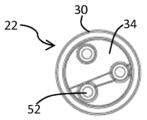
도 4 내지 9를 참조하면, 플렉서블 홀딩부(26)는 바람직하게 하나 또는 그 이상의 플렉서블 암(arms)을 포함하고, 이 플렉서블 암은 후크 형태의 말단부들(26a)을 가지며, 대응하는 돌출부(22)의 주연부(perimetral portion, 30)를 둘러싸고 후킹(hook)하기에 적합하다.4 to 9, the
바람직하게는, 수용 시트(24)는 중공체(hollow body, 32)를 포함하고, 바람직하게는 플렉서블 암들(26)이 중공체(32)의 주연부에 제공된다. Preferably, the receiving
도 4 내지 6에 나타나 있듯이, 중공체(32)는 바람직하게는 원형이다. 이 경우, 플렉서블 암들(26)은 실질적으로 홀딩 링(holding ring)을 형성한다. 4-6, the
바람직하게는, 돌출부(22)는 중공체(32) 내부로 삽입되도록 구성되어, 돌출부(22)가 수용 시트(24) 내부로 들어가지 않도록 막는 돌출부(22)의 주연부(30)가 플렉서블 암들(26)과 결합하게 된다. Preferably, the
이로써, 돌출부(22)의 주연부(30)를 따라 구비된 플렉서블 암들에 의하여 가해지는 홀딩 동작(holding action)은, 바이저(14)를 외부 쉘(12)과 견고하게 커플링하기에 적합하다(도 14 참조). Accordingly, the holding action applied by the flexible arms provided along the
동시에, 바이저(14)에 당김 동작(pull action)을 가함으로써, 플렉서블 암들(26)을 서로 이격시키기에 적합한 돌출부(22)의 주연부(30)에 의해, 돌출부(22)는 딱 맞게 피팅된 수용 시트(24)로부터 쉽게 풀릴 수 있고, 그에 따라 바이저(14)가 외부 쉘(12)로부터 분리될 수 있다. At the same time, by applying a pull action on the
도 7 내지 9에 나타난 실시예에 의하면, 돌출부(22)는 원형 중공체(32)를 갖는 수용 시트에 삽입되기 위해 원형으로 구성된다. According to the embodiment shown in FIGS. 7 to 9, the
이 실시예에서, 플렉서블 암들(26)은, 돌출부(22)가 중공체(32) 내부로 삽입되고 나면, 돌출부(22)의 주연부를 둘러싼다. 수용 시트(24)에 의해 가해지는 홀딩력(holding force)은 다수의 플렉서블 암들(26) 사이에 실질적으로 균등하게 분배된다. 바람직하게는, 돌출부(22)의 사방을 둘러싸고 배치된 플렉서블 암들(26)로 인해, 충돌이 일어날 경우 바이저(14)는 분리력이 작용하는 방향에 영향 받지 않고 쉘(12)로부터 분리되게 된다. In this embodiment,
사실상, 분리력의 두 구성요소, 즉 접선 요소와 수직 요소 모두, 바이저를 쉘로부터 해제하는데 있어서 유효하다. In fact, both components of the separation force, the tangential component and the vertical component, are effective in releasing the visor from the shell.
다시 말해서, 분리력이 특정 방향을 따라, 예컨대 쉘에 수직인 방향을 따라 작용되어야만 하는 것은 아니다. In other words, the separating force does not have to act along a specific direction, for example perpendicular to the shell.
대안적인 실시예에서, 돌출부(22)는 돌출부(22)의 측면에 제공된 라운드 벌지(rounded bulge, 23)를 포함할 수 있다. 바람직하게는, 벌지(23)는 돌출부(22)와 일체형이다. In an alternative embodiment, the
이 경우 수용 시트(24)의 플렉서블 홀딩부(26)는, 돌출부(22)가 수용 시트(24) 내부에 고정되었을 때, 라운드 벌지(23)와 결합되도록 설계된 대응하는 홈(groove, 27)을 포함한다(도 14a 참조).In this case, the
다른 실시예에서, 바람직하게는 강성 재료로 만들어진 돌출부(22)는 블로킹 요소(blocking elements, 29)를 구비할 수 있으며, 이 블로킹 요소는 바람직하게는 탄성 재료로 만들어지고 돌출부(22)의 측면에 제공된 대응하는 요홈부(indentation, 31)에 부착되도록 설계되었다. In another embodiment, the
이 경우 수용 시트(24)의 플렉서블 홀딩부(26)는, 돌출부(22)가 수용 시트(24) 내부에 고정되었을 때, 블로킹 요소(29)와 결합되도록 설계된 대응하는 홈(33)을 포함한다(도 14b 참조). In this case the flexible holding
또한 도 14a 및 14b의 실시예에서, 돌출부(22) 및 홀딩부(26)는 원형일 수 있다. 그 결과, 벌지(23) 및 블로킹 요소(29)는 돌출부의 주연 링(perimetral ring)을 형성한다. 또한 이들 실시예에서, 바이저의 쉘로부터의 분리는 그 어떤 방향으로 가해지는 힘에 의해서도 이루어질 수 있다. Also in the embodiment of FIGS. 14A and 14B, the
물론, 다른 특정한 필요를 충족시키기 위해, 벌지(23)와 블로킹 요소(29)는 다르게 배열될 수도 있다. 예를 들어, 플렉서블 홀딩부(26)는 이전에 개시된 것과 같은 벌지와 블로킹 요소를 구비할 수도 있다. 이 경우, 돌출부(22)는 대응하는 홈들을 구비하게 된다. Of course, to meet other specific needs, the
바람직하게는, 수용 시트(24)는 주연 방향의 틈(perimetral gap)을 남긴 채로 오목부(28) 내부에 삽입된다. 이로써, 플렉서블 암들(26)은, 돌출부(22)가 수용 시트(24)에 삽입되거나 그로부터 분리될 수 있도록 외향으로 구부러질 수 있다. Preferably, the receiving
바람직하게는, 첨부된 도면들에 나타나 있듯이, 플렉서블 암들의 후크 형태 말단부들(26a)은, 돌출부(22)를 대응하는 수용 시트(24)와 보다 쉽게 커플링하고 분리하기 위해, 라운드 엣지들(rounded edges)을 갖는다. Preferably, as shown in the accompanying drawings, the hook-shaped distal portions 26a of the flexible arms have rounded edges ( It has rounded edges.
유사하게, 돌출부의 주연부(30)는 둥근 형태일 수 있다. 바람직하게는, 첨부된 도면들에 나타나 있듯이, 주연부(30)는 돌출부(22)의 견고한 레그부(leg portion, 34)로부터 외향으로 돌출되어 있다.Similarly, the
상기에 언급하였듯이, 첨부된 도면들에서, 주연부(30), 그리고 그에 따라 홀딩부(26)는, 원형이다. As mentioned above, in the accompanying drawings the
이로써, 돌출부는 대응하는 수용 시트 내부에서 횡축 T(transversal axis T)를 중심으로 회전할 수 있다(도 8 및 14 참조). 바람직하게는, 만약 원형 주연부(30)를 갖춘 두 돌출부들(22)이 바이저(14)의 양 측면에 배치된다면, 바이저는, 수용 시트 내부에서 발생 가능한 각 돌출부(22)의 회전 덕분에, 외부 쉘(12)과 맞추어 조정될 수 있고, 이는 외부 쉘에 단단히 결합되어 있더라도 마찬가지이다. Thereby, the protrusion can rotate about the transversal axis T inside the corresponding receiving sheet (see FIGS. 8 and 14). Preferably, if two
물론, 다른 특정한 필요를 충족시키기 위해, 돌출부(22) 및 그에 따라 수용 시트(24)는, 다양한 형태일 수 있다. 예를 들어, 돌출부(22)는 타원형 혹은 삼각형의 단면을 가질 수 있다.Of course, in order to meet other specific needs, the
바람직하게는, 바이저(14)의 돌출부(22)가 외부 쉘(12)에 제공되는 대응하는 수용 시트(24)와 결합할 때, 바이저의 내부면은 쉘의 인접 표면과 접촉하고, 이로써 바이저는 쉘에 부착되어 있을 수 있다. Preferably, when the
도 2의 실시예에 의하면, 외부 쉘(12)은 바이저(14)의 주연부를 보완하는 형태로 형성된 오목부(36)를 포함할 수 있고, 이로써 바이저(14)는 외부 쉘(12)과 동일 평면으로 커플링될 수 있다. According to the embodiment of FIG. 2, the
도 10 및 11을 참조하면, 바람직하게 각 수용 시트(24)는 외부 쉘(12)에 제공된 오목부(28)의 내부에 탈착 가능하게 삽입되고, 두 강성 파스너들(38, 40) 사이에 끼워넣어진다. 10 and 11, preferably each receiving
구체적으로, 제 1 파스너(38)는, 제 1 파스너(38) 내에 제공되고 대응하는 시트들과 결합하도록 설계된 제 1 스크류(42)에 의해, 오목부(28)의 내부에 탈착 가능하게 부착된다. Specifically, the
수용 시트(24)의 하부면은, 제 1 파스너(38)와 접촉하고 제 2 파스너(40)에 의해 그 안에 블로킹(blocked)되도록 설계되었으며, 한편 제 2 파스너(40)는, 제 1 파스너(38)의 대응하는 구멍들과 결합하는 제 2 스크류(44)에 의해, 제 1 파스너(38)에 연결되도록 구성된다. The lower surface of the receiving
이 특정 배열은 필요한 경우 수용 시트(24)의 수월한 교체가 가능하게 한다. This particular arrangement allows easy replacement of the receiving
도 12 및 13을 참조하면, 바람직하게 각 돌출부(22)는, 바이저(14)의 외면에 제공되고 대응하는 리세스(recess, 48)와 상호보완적으로 피팅되는 형태를 갖춘 클립(46)에 의해, 바이저(14)의 내부면에 파스닝 되어있다.12 and 13, preferably each
클립(46)은 바람직하게는 바이저(14)의 외면과 동일 평면에 장착되고, 리세스(48)의 구멍들(52) 안으로 삽입되도록 설계된 돌출부(50)를 구비한다. The
돌출부들(50)은, 바람직하게는 돌출부(22)의 레그부(34)에 제공된 대응하는 시트들(52)과 결합하고 스크류(54)에 의해 파스닝될 수 있다. The
도 14에 나타나 있듯이, 돌출부(22)가 대응하는 수용 시트(24) 내부에 삽입되고 나면, 돌출부의 상부면은 제 2 강성 파스너(40)와 접촉하도록 설계되어, 바이저와 쉘 사이에 보다 견고한 연결을 제공한다. As shown in Figure 14, once the
유리하게는, 수용 시트(24)의 플렉서블 홀딩부(26)는 탄성 중합체 재료(elastic polymeric material)로 만들어지고, 바람직하게는, 예컨대 TPE(열가소성 엘라스토머, thermoplastic elastomer), TPEE(열가소성 폴리에스테르 엘라스토머, thermoplastic polyester elastomer) 또는 TPU(열가소성 폴리우레탄, thermoplastic polyurethane) 등의 열가소성 중합체 재료(thermoplastic polymeric material)로 만들어진다. Advantageously, the
탄성 중합체 재료들, 그리고 특히 열가소성 중합체 재료들은, 고탄성(high elasticity) 및 고저항(high resistance)과 우수한 내충격성(good resistance to impact)을 갖춘다. 나아가, 열가소성 중합체 재료들의 사용, 특히 TPE, TPEE 및 TPU의 사용은, 넓은 온도 범위(-30°C에서 +70°C까지)에 있어서 홀딩부(26)의 균일한 행동(uniform behavior)을 보장한다. Elastomeric materials, and especially thermoplastic polymer materials, have high elasticity and high resistance and good resistance to impact. Furthermore, the use of thermoplastic polymer materials, in particular TPE, TPEE and TPU, ensures a uniform behavior of the holding
바람직하게는, 탄성 중합체 재료로 만들어진 홀딩부(26)는 Shore D 수치가 58에서 68 사이로 구성된 경도를 갖는다. Preferably, the holding
탄성 중합체 재료로 만들어진 홀딩부(26)는, 그 안에 돌출부가 삽입되면 일시적으로 형태의 변형을 겪게 된다. 이 변형은 돌출부가 수용 시트(24)로부터 뽑히거나 그에 다시 삽입되면 스스로 원래의 모양으로 돌아온다. The holding
대안적으로, 수용 시트의 플렉서블 홀딩부(26)는, 예를 들면 나일론(nylon) 또는 아세탈 중합체(acetalic polymer)와 같은 강성 중합체 재료(rigid polymeric material)로 만들어질 수 있다. Alternatively, the
이 경우, 홀딩부(26)는 Shore D 수치가 80에서 100 사이로 구성된 경도를 갖는다.In this case, the holding
이 경우, 홀딩부(26)는 탄성이 아니며, 암들(arms)을 적절한 모양으로 형성함으로써 가요성을 갖추도록 만들어진다. 특히, 암들은 탄성 재료로 제조되었을 때에 비해 상대적으로 더 길고 얇도록 설계될 수 있다. In this case, the holding
이 형태는 암들이, 형태의 변형을 겪지 않더라도, 돌출부(22)의 삽입을 허용할 수 있도록 구부러질 수 있게 한다. This shape allows the arms to be bent to allow insertion of the
바람직하게는, 돌출부(22)는 나일론 또는 아세탈 중합체와 같은 강성 중합체 재료로 만들어진다. Preferably, the
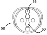
도 15를 참조하여, 본 발명의 일 실시예에 따르면, 바이저(14)의 내면의 중간선을 따라 파스너 핀(fastener pin, 56)이 배치되고, 외부 쉘(12)의 대응하는 위치에 수용 시트(58)가 배치된다. 15, according to one embodiment of the present invention, a
수용 시트(58)는 바람직하게는 파스너 핀(56)과 결합하도록 설계된 중앙 슬롯(central slot, 60)을 구비한다. Receiving
바람직하게는, 중앙 슬롯(60)은 파스너 핀(56)이 수용 시트(58)와 다양한 위치로, 예컨대 세 가지의 다른 위치로 (도 16a-16c 참조) 결합할 수 있게끔 형성된다. Preferably, the
이로써, 바람직하게는 바이저(14)가 외부 쉘(12)에 맞게, 특히 수평면에 맞게 조정될 수 있다. This allows the
예를 들어, 파스너 핀(56)이 슬롯의 중앙부와 결합한 도 16b에서 시작하여, 파스너 핀(56)을 중앙 슬롯(60)의 상부에 삽입함으로써, 바이저(14)는 더 높은 위치로 배치될 수 있다(도 16a 참조).For example, starting in FIG. 16B where
유사하게, 파스너 핀(56)을 중앙 슬롯(60)의 하부에 삽입함으로써, 바이저(14)는 더 낮은 위치로 배치될 수 있다(도 16c 참조).Similarly, by inserting the
이 올려진 위치 및 내려진 위치는 도 17에서 점선에 의해 도시되어 있다. These raised and lowered positions are shown by dotted lines in Figure 17.
현 시점에서, 소정의 목적들이 어떻게 본 발명에 따른 보호 헬멧(10)에 의해 달성될 수 있는지는 명백하다. At this point, it is clear how certain objectives can be achieved by means of the
사실상, 파스닝 기구(20)는 정상적인 사용 시에 바이저(14)와 외부 쉘(12) 간의 견고한 커플링을 보장하고, 각 돌출부(22)는 대응하는 수용 시트(24)의 홀딩부에 의해 안정적으로 지지된다. 동시에, 홀딩부(26)의 가요성은, 돌출부(22)가 대응하는 수용 시트로부터 쉽게 분리될 수 있도록 함으로써, 충격이 있거나 필요할 경우 바이저가 쉘(12)로부터 분리될 수 있게 한다. In effect, the
나아가, 돌출부와 수용 시트의 특정한 형태로 인해, 특히 가요성과 탄성을 갖춘 암들이 돌출부를 둘러싼 특정한 배치 덕분에, 바이저와 쉘은 어떠한 방향으로부터 충격이 오더라도 분리될 수 있다. 다시 말해서, 바이저는, 충격이 쉘 표면과 수직인 면을 따라 작용하는 경우뿐만 아니라, 충격이 쉘과 경사지도록 또는 평행하게 작용하는 경우에도 쉘로부터 해제될 수 있다. Furthermore, due to the specific shape of the protrusions and the receiving sheet, and thanks to the specific arrangement of the particularly flexible and elastic arms surrounding the protrusions, the visor and shell can be separated upon impact from any direction. In other words, the visor can be released from the shell not only when the impact acts along a plane perpendicular to the shell surface, but also when the impact acts obliquely or parallel to the shell.
사실상, 충격력의 두 구성요소, 즉 접선 요소와 수직 요소 모두, 바이저를 쉘로부터 해제하는데 있어서 유효하다. In fact, both components of the impact force, the tangential component and the vertical component, are effective in releasing the visor from the shell.
이로써, 정상적인 사용 시에 바이저와 헬멧 간 연결의 신뢰성에 영향을 주지 않으면서, 충격 시 헬멧의 위험한 회전에 대해 보다 강한 보호가 보장된다. This ensures greater protection against dangerous rotation of the helmet during impact, without affecting the reliability of the connection between visor and helmet during normal use.
뿐만 아니라, 대응하는 오목부(28) 내부의 수용 시트(24)는, 탈착 가능하게 고정됨으로써, 필요한 경우 수용 시트가 수월하게 교체될 수 있도록 한다. 사실상, 이와 같은 교체는 제 1 파스너와 제 2 파스너를 연결하는 스크류들을 단순히 제거함으로써 이루어질 수 있다. In addition, the receiving
나아가, 돌출부(22)가 수용 시트(24) 내부에 완전히 삽입됨으로써, 바이저의 내면이 쉘의 외면에 어떠한 틈도 없이 부착되도록 배치될 수 있다. Furthermore, by completely inserting the
나아가, 외부 쉘이 바이저의 주연부에 맞게 형성된 오목부를 구비할 경우, 바이저는 바람직하게는 외부 쉘과 동일 평면에 장착될 수 있다. Furthermore, if the outer shell has a recess formed to fit the periphery of the visor, the visor may preferably be mounted flush with the outer shell.
마지막으로, 중앙 슬롯(60)에 의해, 바이저와 외부 쉘 사이의 커플링에 영향을 미치지 않으면서, 바이저를 라이더의 눈에 맞추어 손쉽게 조정할 수 있다. Finally, the
상기의 장점들은 출원인이 수행한 실험에 의해 확인되었다. 이하에는 세 가지 실험에 따른 데이터를 기재하였다.The above advantages were confirmed by experiments performed by the applicant. Below, data from three experiments are described.
제 1 실험: 바이저 커넥터 강도 (visor connectors strength)Experiment 1: Visor connectors strength
구체적으로, 이 실험은 바이저를 쉘로부터 분리하기 위해 요구되는 충격력의 측정에 관한 것이다. Specifically, this experiment concerns the measurement of the impact force required to separate the visor from the shell.
두 파스닝 기구(원형 돌출부 및 대응하는 수용 시트로 구성된 것)에 대해 실험이 이루어졌다. Experiments were made on two fastening mechanisms (consisting of a circular protrusion and a corresponding receiving sheet).
두 기구는 크기에 있어서 차이가 있다: 제 1 기구의 원형 돌출부는 27mm의 직경과 4mm의 높이를 갖고, 대응하는 수용 시트는 32mm의 직경과 10.5mm의 높이를 갖는다(이하 “대형(big)”).The two devices differ in size: the circular protrusion of the first device has a diameter of 27 mm and a height of 4 mm, and the corresponding receiving seat has a diameter of 32 mm and a height of 10.5 mm (hereinafter “big”). ).
제 2 기구의 원형 돌출부는 17.7mm의 직경과 3.9mm의 높이를 갖고, 대응하는 수용 시트는 22mm의 직경과 8.5mm의 높이를 갖는다(이하 “소형(small)”).The circular protrusion of the second device has a diameter of 17.7 mm and a height of 3.9 mm, and the corresponding receiving sheet has a diameter of 22 mm and a height of 8.5 mm (hereinafter “small”).
두 경우 모두에서 수용 시트는 TPEE (탄성 중합체 재료)로 만들어졌다. In both cases the receiving sheet was made of TPEE (elastomeric material).
파스닝 기구에 수직으로, 그러나 기구의 종방향 축으로부터 27.5mm 떨어진 곳에서 충격력을 가하는 시뮬레이션을 통하여, 파스닝 기구를 분리하기 위해 요구되는 힘을 측정하였다. The force required to separate the fastening mechanism was measured by simulating an impact force applied perpendicular to the fastening mechanism but at a distance of 27.5 mm from the longitudinal axis of the fastening mechanism.
실험 결과는 아래와 같다: The experimental results are as follows:
상기 데이터는, 수용 시트가 탄성 재료로 만들어지더라도, 정상적인 사용 시에 바이저가 쉘에 견고하게 연결되어 있을 수 있음을 증명한다. The above data prove that the visor can remain securely connected to the shell during normal use, even if the receiving sheet is made of an elastic material.
제 2 실험: 다방향 충격 실험 (multiple directions impact test)2nd experiment: multiple directions impact test
구체적으로, 이 실험은 다방향에서의 충격이 있을 경우 본 발명에 따른 헬멧의 바이저의 분리 능력을 측정한다. Specifically, this experiment measures the detachment ability of the visor of a helmet according to the present invention when subjected to impacts from multiple directions.
두 가지의 헬멧(사이즈 M)에 대해 실험 및 비교가 이루어졌다.Two helmets (size M) were tested and compared.
제 1 헬멧은, 본 발명에 따른 쉘과 커플링된 바이저로서, 특히 원형 돌출부 및 대응하는 수용 시트에 의해 커플링되고 상기 수용 시트는 TPEE로 만들어진 바이저를 구비한다(이하 “탈착식 바이저”).The first helmet is a visor coupled with the shell according to the invention, in particular coupled by a circular projection and a corresponding receiving sheet, which has a visor made of TPEE (hereinafter “removable visor”).
제 2 헬멧은, 제 1 헬멧과 같이 바이저와 쉘을 구비하지만, 상기 바이저는 스크류에 의해 쉘에 블로킹(blocked) 되어있다(이하 “고정식 바이저”).The second helmet has a visor and a shell like the first helmet, but the visor is blocked to the shell by screws (hereinafter “fixed visor”).
충격의 시뮬레이션은, 특정 리그(rig)를 따라 2.5-2.75 m/s의 속도에 의해 수직으로 떨어지며 바이저의 끝(tip) 부근을 충격하는 로드(rod)에 의해 이루어졌다.The impact simulation was achieved by a rod falling vertically at a speed of 2.5-2.75 m/s along a specific rig and impacting near the tip of the visor.
두 가지 유형의 충격, 즉 위에서 아래로의 충격 (이하 “수직 구성(normal configuration)”) 및 아래에서 위로의 충격 (이하 “반전 구성(upside down configuration)”)에 대한 시뮬레이션이 이루어졌다. Two types of shocks were simulated: top-down shock (“normal configuration”) and bottom-up shock (“upside down configuration”).
충격이 일어나는 동안 로드의 감속을 측정하기 위하여, 가속도계가 설치되었다.To measure the deceleration of the rod during impact, an accelerometer was installed.
선형 가속도의 추세가 기록되었고 “피크 선형 가속도(PLA, peak of linear acceleration)”가 측정되었다; 또한, 속도의 추세가 계산되었으며 최초 속도와 최종 속도 간의 차이(Δv)가 측정되었다.Trends in linear acceleration were recorded and the “peak of linear acceleration” (PLA) was measured; Additionally, the trend of velocity was calculated and the difference (Δv) between initial and final velocity was measured.
PLA는 충격이 일어나는 동안 헬멧에 가해지는 힘의 지표를 제공한다; 즉, 이 값이 작을수록, 헬멧/라이더의 머리에 가해지는 힘이 적다.PLA provides an indication of the forces acting on the helmet during an impact; In other words, the smaller this value, the less force is applied to the helmet/rider's head.
Δv는 충격이 일어나는 동안 헬멧에 의해 흡수되는 에너지의 지표를 제공한다; 즉, 이 값이 작을수록, 라이더의 머리에 전도되는 에너지가 적다.Δv provides an indication of the energy absorbed by the helmet during an impact; In other words, the smaller this value, the less energy is conducted to the rider's head.
실험 결과는 아래와 같다:The experimental results are as follows:
바이저removable
visor
바이저fixed
visor
바이저removable
visor
바이저fixed
visor
상기 데이터에 의해, 본 발명에 따른 헬멧으로서 충격 시에 쉽게 탈착 가능한 바이저가 구비된 헬멧은, 사고가 일어나는 동안 사용자의 머리에 전도되는 힘과 에너지를 감소시키는데 적합하다는 것이 명백하게 나타난다. The above data clearly show that the helmet according to the invention, which is equipped with a visor that is easily removable in the event of an impact, is suitable for reducing the forces and energy transmitted to the user's head during an accident.
동시에, 상기 데이터를 비교하면, 충격의 방향에 관계없이, 바이저를 쉘로부터 분리하기 위해서는 실질적으로 같은 양의 힘이 필요하다는 것이 또한 확인된다. At the same time, comparing the above data, it is also confirmed that, regardless of the direction of impact, substantially the same amount of force is required to separate the visor from the shell.
제 3 실험: 충격이 일어나는 동안 바이저의 영향 (effect of the visor during an impact)Experiment 3: Effect of the visor during an impact
전술했듯이, 바이저는 충격이 일어나는 동안 헬멧의 “레버리지 효과(leverage effect)”를 증가시킨다는 점에서 영향을 미친다. As mentioned above, the visor has an impact in that it increases the “leverage effect” of the helmet during an impact.
이 실험은 세 가지 헬멧(사이즈 M)의 움직임(behaviour)을 비교하기 위해 수행되었다:This experiment was performed to compare the behavior of three helmets (size M):
바이저가 없는 헬멧으로서, 인증(homologation)을 위해 통상적으로 실험되는 것 (제 1 샘플);Helmet without visor, routinely tested for homologation (first sample);
본 발명에 따른 헬멧으로서, 바이저가 탄성 중합체 재료로 만들어진 수용 시트에 의해 쉘에 부착되어 있는 것 (제 2 샘플); A helmet according to the invention, wherein the visor is attached to the shell by a receiving sheet made of elastomeric material (second sample);
제 2 샘플과 동일한 헬멧으로서, 바이저가 스크류에 의해 쉘에 고정되어 있는 것 (제 3 샘플)The same helmet as the second sample, with the visor fixed to the shell by screws (third sample)
실험은 7.5m/s의 충격 속도로, 경사진 앤빌(oblique anvil) 위에서 수행되었다. The experiment was performed on an oblique anvil, with an impact velocity of 7.5 m/s.
바이저가 조립된 헬멧(제 2 및 제 3 샘플)은, 바이저의 팁으로부터 5cm 정도 떨어진 곳에서 충격이 발생하도록 배치되었다; 바이저가 없는 헬멧(제 1 샘플)은, 쉘의 전면부에서 충격이 발생하도록 배치되었다.Helmets with assembled visors (samples 2 and 3) were placed so that the impact occurred approximately 5 cm from the tip of the visor; The helmet without a visor (sample 1) was positioned so that the impact occurred at the front of the shell.
충격이 일어나는 동안, “피크 선형 가속도(PLA)”및 “피크 회전 가속도(PRA, peak of rotational accelerations)”가 측정되었다.During the impact, “peak linear acceleration (PLA)” and “peak of rotational accelerations (PRA)” were measured.
실험 결과는 아래와 같다:The experimental results are as follows:
바이저가 없는 샘플이 가장 낮은 PRA 수치를 갖는다는 점에서, 상기 결과들은 충격이 일어나는 동안 바이저가 “레버리지 효과”를 갖는다는 것을 명백하게 증명한다. The results clearly demonstrate that the visor has a “leverage effect” during impact, in that the sample without visor has the lowest PRA value.
상기 결과들은 또한, 본 발명에 따른 헬멧이, 제 3 샘플보다 낮은 PLA 및 PRA 값을 갖는다는 점에서, 이 “레버리지 효과”를 감소시키는 추가적인 장점을 갖추고 있음을 보여준다. The results also show that the helmet according to the invention has the additional advantage of reducing this “leverage effect” in that it has lower PLA and PRA values than the third sample.
전술한 보호 헬멧(10)의 실시예들에 있어서, 해당 분야의 통상의 기술자는, 특정한 요구들을 충족시키기 위하여, 본 청구 범위에서 벗어나지 않는 선에서, 상기 요소들에 변형을 가하거나 그리고/또는 등가(equivalent)의 요소들로 대체할 수 있다.In the above-described embodiments of the
Claims (18)
외부 쉘(12); 및
바이저(14)로서, 상기 외부 쉘(12)과 상기 바이저(14)의 페이싱 표면들(facing surfaces)에 배치된 파스닝 기구(20)에 의해 상기 외부 쉘(12)과 탈착 가능하게 커플링된 바이저;를 포함하고,
상기 파스닝 기구(20)는, 상호보완적 형태의 요소들(22, 24)을 포함하고,
상기 상호보완적 형태의 요소들(22, 24)은, 적어도 하나의 돌출부(22); 및 플렉서블 홀딩부(26)를 구비한 적어도 하나의 수용 시트(24);를 포함하며,
상기 적어도 하나의 돌출부(22)는, 상기 플렉서블 홀딩부(26)와 결합함으로써 상기 적어도 하나의 수용 시트(24) 내부에 탈착 가능하게 고정되도록 구성된 것이며,
상기 플렉서블 홀딩부(26)는 탄성 중합체 재료로 만들어진 것을 특징으로 하는 보호 헬멧(10).As a protective helmet 10,
outer shell (12); and
A visor (14), detachably coupled to the outer shell (12) by a fastening mechanism (20) disposed on the outer shell (12) and facing surfaces of the visor (14). Includes a visor;
The fastening mechanism (20) comprises elements (22, 24) of complementary shape,
The complementary shaped elements 22, 24 include at least one protrusion 22; and at least one receiving sheet 24 provided with a flexible holding portion 26,
The at least one protrusion 22 is configured to be detachably fixed inside the at least one receiving sheet 24 by engaging with the flexible holding part 26,
Protective helmet (10), characterized in that the flexible holding part (26) is made of an elastomeric material.
적어도 두 개의 돌출부들(22)이 상기 바이저(14)의 내부 측단들에 배치되고, 적어도 두 개의 수용 시트들(24)이 상기 외부 쉘(12)의 대응하는 위치들에 배치되는 것을 특징으로 하는 보호 헬멧(10).According to paragraph 1,
Characterized in that at least two protrusions (22) are arranged on the inner side ends of the visor (14) and at least two receiving sheets (24) are arranged at corresponding positions of the outer shell (12). Protective helmet (10).
상기 적어도 하나의 수용 시트(24)는 상기 외부 쉘(12)의 오목부(28)에 제공되고;
상기 적어도 하나의 수용 시트(24)는 상기 외부 쉘(12)과 동일 평면인 것을 특징으로 하는 보호 헬멧(10).According to paragraph 1,
The at least one receiving sheet (24) is provided in a recess (28) of the outer shell (12);
Protective helmet (10), characterized in that the at least one receiving sheet (24) is flush with the outer shell (12).
상기 플렉서블 홀딩부는, 하나 또는 그 이상의 플렉서블 암들을 포함하고,
상기 플렉서블 암들은, 후크 형태의 말단부들(26a)을 가지며 상기 적어도 하나의 돌출부(22)의 주연부(30)를 둘러싸고 후킹(hook)하도록 구성된 것을 특징으로 하는 보호 헬멧(10).According to paragraph 1,
The flexible holding unit includes one or more flexible arms,
The protective helmet (10), characterized in that the flexible arms have hook-shaped distal ends (26a) and are configured to surround and hook the peripheral portion (30) of the at least one protrusion (22).
상기 적어도 하나의 수용 시트(24)는, 상기 바이저(14)와 상기 외부 쉘(12)이 서로 커플링 되었을 때, 상기 적어도 하나의 돌출부(22)를 수용하도록 구성된 중공체(32)를 포함하는 것을 특징으로 하는 보호 헬멧(10).According to paragraph 1,
The at least one receiving sheet 24 includes a hollow body 32 configured to receive the at least one protrusion 22 when the visor 14 and the outer shell 12 are coupled to each other. A protective helmet (10), characterized in that.
플렉서블 암들이 상기 수용 시트(24)의 상기 중공체(32)의 주연부에 제공되는 것을 특징으로 하는 보호 헬멧(10).According to clause 5,
Protective helmet (10), characterized in that flexible arms are provided on the periphery of the hollow body (32) of the receiving sheet (24).
상기 적어도 하나의 돌출부(22)는, 상기 적어도 하나의 돌출부(22)의 측면에 제공되는 라운드 벌지(23)를 포함하고;
상기 적어도 하나의 수용 시트(24)의 상기 플렉서블 홀딩부(26)는, 상기 적어도 하나의 돌출부(22)가 상기 수용 시트(24) 내부에 고정되었을 때, 상기 라운드 벌지(23)와 결합하도록 설계된 대응하는 홈(27)을 포함하는 것을 특징으로 하는 보호 헬멧(10).According to paragraph 1,
The at least one protrusion 22 includes a round bulge 23 provided on a side of the at least one protrusion 22;
The flexible holding portion 26 of the at least one receiving sheet 24 is designed to engage with the round bulge 23 when the at least one protrusion 22 is fixed inside the receiving sheet 24. Protective helmet (10), characterized in that it comprises corresponding grooves (27).
상기 적어도 하나의 돌출부(22)는, 상기 적어도 하나의 돌출부(22)의 측면에 제공된 대응하는 요홈부(31)에 부착되도록 설계된 블로킹 요소(29)를 구비하고;
상기 수용 시트(24)의 상기 플렉서블 홀딩부(26)는, 상기 적어도 하나의 돌출부(22)가 상기 수용 시트(24) 내부에 고정되었을 때, 상기 블로킹 요소(29)와 결합하도록 설계된 대응하는 홈(33)을 포함하는 것을 특징으로 하는 보호 헬멧(10).According to paragraph 1,
The at least one projection (22) has a blocking element (29) designed to be attached to a corresponding groove (31) provided on the side of the at least one projection (22);
The flexible holding portion 26 of the receiving sheet 24 has a corresponding groove designed to engage with the blocking element 29 when the at least one protrusion 22 is secured inside the receiving sheet 24. A protective helmet (10) comprising (33).
상기 바이저(14)의 내면은, 상기 적어도 하나의 돌출부(22)가 대응하는 수용 시트(24)와 결합할 때, 상기 외부 쉘(12)의 인접 표면과 접촉하도록 설계되는 것을 특징으로 하는 보호 헬멧(10).According to paragraph 1,
Protective helmet, characterized in that the inner surface of the visor (14) is designed to contact the adjacent surface of the outer shell (12) when the at least one projection (22) engages with the corresponding receiving sheet (24). (10).
상기 후크 형태의 말단부들(26a)은 라운드 엣지들을 갖는 것을 특징으로 하는 보호 헬멧(10).According to paragraph 4,
Protective helmet (10), characterized in that the hook-shaped distal ends (26a) have rounded edges.
상기 바이저(14)의 내면의 중간선을 따라 적어도 하나의 파스너 핀(56)이 배치되고, 상기 외부 쉘(12)의 대응하는 위치에 적어도 하나의 수용 시트(58)가 배치되는 것을 특징으로 하는 보호 헬멧(10).According to paragraph 1,
Characterized in that at least one fastener pin (56) is disposed along the midline of the inner surface of the visor (14), and at least one receiving sheet (58) is disposed at a corresponding position of the outer shell (12). Protective helmet (10).
상기 적어도 하나의 수용 시트(58)는, 상기 적어도 하나의 파스너 핀(56)과 결합하도록 설계된 적어도 하나의 중앙 슬롯(60)을 구비하는 것을 특징으로 하는 보호 헬멧(10).According to clause 13,
A protective helmet (10), characterized in that the at least one receiving seat (58) has at least one central slot (60) designed to engage with the at least one fastener pin (56).
상기 중앙 슬롯(60)은, 상기 적어도 하나의 파스너 핀(56)이 결합 가능한 상부, 중앙부, 하부 구조로 구분되도록 형성됨으로써, 상기 바이저(14)가 상기 외부 쉘(12)에 맞게 조정될 수 있도록 하는 것을 특징으로 하는 보호 헬멧(10). According to clause 14,
The central slot 60 is formed to be divided into an upper, central, and lower structure to which the at least one fastener pin 56 can be coupled, so that the visor 14 can be adjusted to fit the outer shell 12. A protective helmet (10), characterized in that.
상기 적어도 하나의 돌출부(22) 및 상기 플렉서블 홀딩부(26)는 원형인 것을 특징으로 하는 보호 헬멧(10).According to paragraph 1,
A protective helmet (10), wherein the at least one protrusion (22) and the flexible holding part (26) are circular.
상기 플렉서블 홀딩부(26)는, 상기 적어도 하나의 돌출부(22)의 주연부에 대한 홀딩 링을 형성하는 것을 특징으로 하는 보호 헬멧(10).According to any one of paragraphs 4 and 16,
The protective helmet (10), wherein the flexible holding portion (26) forms a holding ring for the periphery of the at least one protrusion (22).
상기 적어도 하나의 수용 시트(24)는, 상기 쉘(12)의 오목부(28) 내부에 탈착 가능하게 삽입되는 것을 특징으로 하는 보호 헬멧(10).According to paragraph 1,
The protective helmet (10), wherein the at least one receiving sheet (24) is detachably inserted into the recess (28) of the shell (12).
Applications Claiming Priority (3)
| Application Number | Priority Date | Filing Date | Title |
|---|---|---|---|
| IT102017000103682 | 2017-09-15 | ||
| IT102017000103682A IT201700103682A1 (en) | 2017-09-15 | 2017-09-15 | Protective helmet |
| PCT/EP2018/074868 WO2019053183A1 (en) | 2017-09-15 | 2018-09-14 | Protective helmet |
Publications (2)
| Publication Number | Publication Date |
|---|---|
| KR20200052878A KR20200052878A (en) | 2020-05-15 |
| KR102604034B1 true KR102604034B1 (en) | 2023-11-20 |
Family
ID=60813901
Family Applications (1)
| Application Number | Title | Priority Date | Filing Date |
|---|---|---|---|
| KR1020207006553A Active KR102604034B1 (en) | 2017-09-15 | 2018-09-14 | protective helmet |
Country Status (8)
| Country | Link |
|---|---|
| US (1) | US11540586B2 (en) |
| EP (1) | EP3681328B1 (en) |
| KR (1) | KR102604034B1 (en) |
| CN (1) | CN111093414B (en) |
| AU (1) | AU2018332264B2 (en) |
| ES (1) | ES2949455T3 (en) |
| IT (1) | IT201700103682A1 (en) |
| WO (1) | WO2019053183A1 (en) |
Families Citing this family (7)
| Publication number | Priority date | Publication date | Assignee | Title |
|---|---|---|---|---|
| CN111194965B (en) * | 2020-03-19 | 2025-02-07 | 上海和汇安全用品有限公司 | A car helmet |
| IT202200000914A1 (en) * | 2022-01-20 | 2023-07-20 | Alpinestars Res Spa | Protective helmet |
| IT202200018033A1 (en) * | 2022-09-02 | 2024-03-02 | Alpinestars Res Spa | Protective helmet with means of attachment for at least one appendage |
| US12302978B2 (en) | 2022-11-03 | 2025-05-20 | Western Power Sports, Llc | Breakaway visor |
| USD1102040S1 (en) * | 2023-02-27 | 2025-11-11 | Fox Head, Inc. | Helmet |
| IT202300005889A1 (en) | 2023-03-28 | 2024-09-28 | Alpinestars Res Spa | PROTECTIVE HELMET |
| USD1094899S1 (en) | 2023-08-22 | 2025-09-23 | Liding Tang | Motorcycle helmet |
Family Cites Families (16)
| Publication number | Priority date | Publication date | Assignee | Title |
|---|---|---|---|---|
| DE1790999U (en) * | 1959-04-06 | 1959-06-25 | Pag Presswerk A G | PROTECTIVE HELMET. |
| US3239842A (en) * | 1964-04-07 | 1966-03-15 | Joseph Buegeleisen Company | Safety helmet |
| DK159524C (en) * | 1986-06-25 | 1991-04-02 | Kemira Oy | HEAD PROTECTION |
| US5522091A (en) * | 1994-03-21 | 1996-06-04 | Gentex Corporation | Sighter's protective helmet |
| JP3049207U (en) * | 1997-11-26 | 1998-06-09 | 田辺ボーグ株式会社 | Helmet with shield and its shield |
| US6009561A (en) * | 1998-08-26 | 2000-01-04 | Bell Sports Inc. | Helmet with rotatable accessory mount and method of making the same |
| US6718559B1 (en) * | 2002-01-31 | 2004-04-13 | Howard Davidson | Motorcycle helmut snap-on decorative device |
| CN2827044Y (en) * | 2005-10-25 | 2006-10-18 | 王明仁 | Anti-collision anti-slip safety helmet |
| SE534868C2 (en) * | 2010-05-07 | 2012-01-24 | Mips Ab | Helmet with sliding promoter provided at an energy absorbing bearing |
| EP2624716A4 (en) * | 2010-10-05 | 2017-03-29 | Fox Head, Inc. | Attachment system for frontal helmet extension to a helmet |
| EP2759219B1 (en) * | 2013-01-07 | 2016-09-21 | Strategic Sports Limited | Bicycle helmet with visor |
| WO2015111231A1 (en) | 2014-01-22 | 2015-07-30 | ナックス株式会社 | Retainer |
| US20150216247A1 (en) * | 2014-02-05 | 2015-08-06 | The Charlotte-Mecklenburg Hospital Authority D/B/A Carolinas Healthcare System | Impact reducing protective headgear |
| CN105077857B (en) * | 2014-05-13 | 2018-08-28 | 菲玛股份公司 | The pressure snap-fastener being closed with twin-stage |
| SE539137C2 (en) * | 2015-05-15 | 2017-04-18 | Poc Sweden Ab | An attachment arrangement for a visor on a helmet |
| US20170367425A1 (en) * | 2016-06-27 | 2017-12-28 | Navstar Electronics Co., Ltd. | Structure for fixing riding recorder with helmet visor fastener |
-
2017
- 2017-09-15 IT IT102017000103682A patent/IT201700103682A1/en unknown
-
2018
- 2018-09-14 WO PCT/EP2018/074868 patent/WO2019053183A1/en not_active Ceased
- 2018-09-14 ES ES18766268T patent/ES2949455T3/en active Active
- 2018-09-14 KR KR1020207006553A patent/KR102604034B1/en active Active
- 2018-09-14 US US16/646,877 patent/US11540586B2/en active Active
- 2018-09-14 EP EP18766268.9A patent/EP3681328B1/en active Active
- 2018-09-14 CN CN201880059012.8A patent/CN111093414B/en active Active
- 2018-09-14 AU AU2018332264A patent/AU2018332264B2/en active Active
Also Published As
| Publication number | Publication date |
|---|---|
| IT201700103682A1 (en) | 2019-03-15 |
| US20200275725A1 (en) | 2020-09-03 |
| KR20200052878A (en) | 2020-05-15 |
| CN111093414A (en) | 2020-05-01 |
| AU2018332264B2 (en) | 2023-12-07 |
| US11540586B2 (en) | 2023-01-03 |
| ES2949455T3 (en) | 2023-09-28 |
| WO2019053183A1 (en) | 2019-03-21 |
| EP3681328A1 (en) | 2020-07-22 |
| AU2018332264A1 (en) | 2020-03-05 |
| EP3681328B1 (en) | 2023-06-07 |
| CN111093414B (en) | 2023-06-16 |
Similar Documents
| Publication | Publication Date | Title |
|---|---|---|
| KR102604034B1 (en) | protective helmet | |
| US12156561B2 (en) | Helmet for impact protection | |
| US20200253314A1 (en) | Omnidirectional energy management systems and methods | |
| EP2672853B1 (en) | Helmet omnidirectional energy management systems | |
| US6202223B1 (en) | Padding with embedded fastener for use in a helmet | |
| US20170215507A1 (en) | Protective Helmet for Lateral and Direct Impacts | |
| KR102207958B1 (en) | Helmet | |
| US12336585B2 (en) | Omnidirectional energy management systems and methods | |
| US20240000180A1 (en) | Helmet | |
| US4631758A (en) | Protective headgear | |
| CN107847002B (en) | Helmet omnidirectional energy management system and method | |
| CN106455738A (en) | helmet | |
| US20180077990A1 (en) | Helmet for Tangential and Direct Impacts | |
| US20210022429A1 (en) | Protective Helmet | |
| US11612206B2 (en) | Detachable pad fastening structure of helmet and helmet including same | |
| JP2020066835A (en) | Protective cap | |
| CN109744631A (en) | protective helmet | |
| KR20250165304A (en) | protective helmet |
Legal Events
| Date | Code | Title | Description |
|---|---|---|---|
| PA0105 | International application |
Patent event date: 20200305 Patent event code: PA01051R01D Comment text: International Patent Application |
|
| PG1501 | Laying open of application | ||
| PA0201 | Request for examination |
Patent event code: PA02012R01D Patent event date: 20210804 Comment text: Request for Examination of Application |
|
| E902 | Notification of reason for refusal | ||
| PE0902 | Notice of grounds for rejection |
Comment text: Notification of reason for refusal Patent event date: 20221118 Patent event code: PE09021S01D |
|
| E90F | Notification of reason for final refusal | ||
| PE0902 | Notice of grounds for rejection |
Comment text: Final Notice of Reason for Refusal Patent event date: 20230627 Patent event code: PE09021S02D |
|
| E701 | Decision to grant or registration of patent right | ||
| PE0701 | Decision of registration |
Patent event code: PE07011S01D Comment text: Decision to Grant Registration Patent event date: 20230905 |
|
| GRNT | Written decision to grant | ||
| PR0701 | Registration of establishment |
Comment text: Registration of Establishment Patent event date: 20231115 Patent event code: PR07011E01D Comment text: Decision to Grant Registration Patent event date: 20230905 Patent event code: PE07011S01D |
|
| PR1002 | Payment of registration fee |
Payment date: 20231116 End annual number: 3 Start annual number: 1 |
|
| PG1601 | Publication of registration |