KR102589950B1 - Insole and shoes comprising the same - Google Patents
Insole and shoes comprising the same Download PDFInfo
- Publication number
- KR102589950B1 KR102589950B1 KR1020190025343A KR20190025343A KR102589950B1 KR 102589950 B1 KR102589950 B1 KR 102589950B1 KR 1020190025343 A KR1020190025343 A KR 1020190025343A KR 20190025343 A KR20190025343 A KR 20190025343A KR 102589950 B1 KR102589950 B1 KR 102589950B1
- Authority
- KR
- South Korea
- Prior art keywords
- base
- cover
- electronic device
- controller
- insole
- Prior art date
- Legal status (The legal status is an assumption and is not a legal conclusion. Google has not performed a legal analysis and makes no representation as to the accuracy of the status listed.)
- Active
Links
- 230000000149 penetrating effect Effects 0.000 claims abstract description 5
- 210000004744 fore-foot Anatomy 0.000 claims description 14
- 239000000463 material Substances 0.000 claims description 12
- 210000002683 foot Anatomy 0.000 description 29
- 230000008878 coupling Effects 0.000 description 18
- 238000010168 coupling process Methods 0.000 description 18
- 238000005859 coupling reaction Methods 0.000 description 18
- 238000000034 method Methods 0.000 description 12
- 230000008569 process Effects 0.000 description 7
- 230000000638 stimulation Effects 0.000 description 5
- 230000006870 function Effects 0.000 description 4
- 238000004519 manufacturing process Methods 0.000 description 4
- 238000005516 engineering process Methods 0.000 description 2
- 239000005038 ethylene vinyl acetate Substances 0.000 description 2
- 210000000452 mid-foot Anatomy 0.000 description 2
- 229920001200 poly(ethylene-vinyl acetate) Polymers 0.000 description 2
- 230000001133 acceleration Effects 0.000 description 1
- 238000005452 bending Methods 0.000 description 1
- 230000008859 change Effects 0.000 description 1
- 238000004891 communication Methods 0.000 description 1
- 230000006866 deterioration Effects 0.000 description 1
- 239000013013 elastic material Substances 0.000 description 1
- 239000004744 fabric Substances 0.000 description 1
- 210000000454 fifth toe Anatomy 0.000 description 1
- 238000005187 foaming Methods 0.000 description 1
- 230000005021 gait Effects 0.000 description 1
- 210000001255 hallux Anatomy 0.000 description 1
- 230000004048 modification Effects 0.000 description 1
- 238000012986 modification Methods 0.000 description 1
- 230000008439 repair process Effects 0.000 description 1
- 229920005989 resin Polymers 0.000 description 1
- 239000011347 resin Substances 0.000 description 1
- 230000035807 sensation Effects 0.000 description 1
- 230000001235 sensitizing effect Effects 0.000 description 1
- 238000005406 washing Methods 0.000 description 1
Images


Classifications
-
- A—HUMAN NECESSITIES
- A43—FOOTWEAR
- A43B—CHARACTERISTIC FEATURES OF FOOTWEAR; PARTS OF FOOTWEAR
- A43B13/00—Soles; Sole-and-heel integral units
-
- A—HUMAN NECESSITIES
- A43—FOOTWEAR
- A43B—CHARACTERISTIC FEATURES OF FOOTWEAR; PARTS OF FOOTWEAR
- A43B13/00—Soles; Sole-and-heel integral units
- A43B13/02—Soles; Sole-and-heel integral units characterised by the material
- A43B13/12—Soles with several layers of different materials
- A43B13/125—Soles with several layers of different materials characterised by the midsole or middle layer
-
- A—HUMAN NECESSITIES
- A43—FOOTWEAR
- A43B—CHARACTERISTIC FEATURES OF FOOTWEAR; PARTS OF FOOTWEAR
- A43B13/00—Soles; Sole-and-heel integral units
- A43B13/14—Soles; Sole-and-heel integral units characterised by the constructive form
-
- A—HUMAN NECESSITIES
- A43—FOOTWEAR
- A43B—CHARACTERISTIC FEATURES OF FOOTWEAR; PARTS OF FOOTWEAR
- A43B13/00—Soles; Sole-and-heel integral units
- A43B13/14—Soles; Sole-and-heel integral units characterised by the constructive form
- A43B13/141—Soles; Sole-and-heel integral units characterised by the constructive form with a part of the sole being flexible, e.g. permitting articulation or torsion
-
- A—HUMAN NECESSITIES
- A43—FOOTWEAR
- A43B—CHARACTERISTIC FEATURES OF FOOTWEAR; PARTS OF FOOTWEAR
- A43B13/00—Soles; Sole-and-heel integral units
- A43B13/37—Sole and heel units
-
- A—HUMAN NECESSITIES
- A43—FOOTWEAR
- A43B—CHARACTERISTIC FEATURES OF FOOTWEAR; PARTS OF FOOTWEAR
- A43B13/00—Soles; Sole-and-heel integral units
- A43B13/38—Built-in insoles joined to uppers during the manufacturing process, e.g. structural insoles; Insoles glued to shoes during the manufacturing process
-
- A—HUMAN NECESSITIES
- A43—FOOTWEAR
- A43B—CHARACTERISTIC FEATURES OF FOOTWEAR; PARTS OF FOOTWEAR
- A43B17/00—Insoles for insertion, e.g. footbeds or inlays, for attachment to the shoe after the upper has been joined
-
- A—HUMAN NECESSITIES
- A43—FOOTWEAR
- A43B—CHARACTERISTIC FEATURES OF FOOTWEAR; PARTS OF FOOTWEAR
- A43B17/00—Insoles for insertion, e.g. footbeds or inlays, for attachment to the shoe after the upper has been joined
- A43B17/18—Arrangements for attaching removable insoles to footwear
-
- A—HUMAN NECESSITIES
- A43—FOOTWEAR
- A43B—CHARACTERISTIC FEATURES OF FOOTWEAR; PARTS OF FOOTWEAR
- A43B23/00—Uppers; Boot legs; Stiffeners; Other single parts of footwear
- A43B23/02—Uppers; Boot legs
- A43B23/0245—Uppers; Boot legs characterised by the constructive form
-
- A—HUMAN NECESSITIES
- A43—FOOTWEAR
- A43B—CHARACTERISTIC FEATURES OF FOOTWEAR; PARTS OF FOOTWEAR
- A43B3/00—Footwear characterised by the shape or the use
- A43B3/34—Footwear characterised by the shape or the use with electrical or electronic arrangements
-
- A—HUMAN NECESSITIES
- A43—FOOTWEAR
- A43B—CHARACTERISTIC FEATURES OF FOOTWEAR; PARTS OF FOOTWEAR
- A43B3/00—Footwear characterised by the shape or the use
- A43B3/34—Footwear characterised by the shape or the use with electrical or electronic arrangements
- A43B3/38—Footwear characterised by the shape or the use with electrical or electronic arrangements with power sources
-
- A—HUMAN NECESSITIES
- A61—MEDICAL OR VETERINARY SCIENCE; HYGIENE
- A61B—DIAGNOSIS; SURGERY; IDENTIFICATION
- A61B5/00—Measuring for diagnostic purposes; Identification of persons
- A61B5/103—Measuring devices for testing the shape, pattern, colour, size or movement of the body or parts thereof, for diagnostic purposes
- A61B5/1036—Measuring load distribution, e.g. podologic studies
- A61B5/1038—Measuring plantar pressure during gait
-
- A—HUMAN NECESSITIES
- A61—MEDICAL OR VETERINARY SCIENCE; HYGIENE
- A61B—DIAGNOSIS; SURGERY; IDENTIFICATION
- A61B5/00—Measuring for diagnostic purposes; Identification of persons
- A61B5/103—Measuring devices for testing the shape, pattern, colour, size or movement of the body or parts thereof, for diagnostic purposes
- A61B5/11—Measuring movement of the entire body or parts thereof, e.g. head or hand tremor or mobility of a limb
- A61B5/112—Gait analysis
-
- A—HUMAN NECESSITIES
- A61—MEDICAL OR VETERINARY SCIENCE; HYGIENE
- A61B—DIAGNOSIS; SURGERY; IDENTIFICATION
- A61B5/00—Measuring for diagnostic purposes; Identification of persons
- A61B5/68—Arrangements of detecting, measuring or recording means, e.g. sensors, in relation to patient
- A61B5/6801—Arrangements of detecting, measuring or recording means, e.g. sensors, in relation to patient specially adapted to be attached to or worn on the body surface
- A61B5/6802—Sensor mounted on worn items
- A61B5/6804—Garments; Clothes
- A61B5/6807—Footwear
-
- G—PHYSICS
- G01—MEASURING; TESTING
- G01D—MEASURING NOT SPECIALLY ADAPTED FOR A SPECIFIC VARIABLE; ARRANGEMENTS FOR MEASURING TWO OR MORE VARIABLES NOT COVERED IN A SINGLE OTHER SUBCLASS; TARIFF METERING APPARATUS; MEASURING OR TESTING NOT OTHERWISE PROVIDED FOR
- G01D21/00—Measuring or testing not otherwise provided for
- G01D21/02—Measuring two or more variables by means not covered by a single other subclass
-
- G—PHYSICS
- G01—MEASURING; TESTING
- G01K—MEASURING TEMPERATURE; MEASURING QUANTITY OF HEAT; THERMALLY-SENSITIVE ELEMENTS NOT OTHERWISE PROVIDED FOR
- G01K1/00—Details of thermometers not specially adapted for particular types of thermometer
- G01K1/14—Supports; Fastening devices; Arrangements for mounting thermometers in particular locations
-
- G—PHYSICS
- G01—MEASURING; TESTING
- G01L—MEASURING FORCE, STRESS, TORQUE, WORK, MECHANICAL POWER, MECHANICAL EFFICIENCY, OR FLUID PRESSURE
- G01L5/00—Apparatus for, or methods of, measuring force, work, mechanical power, or torque, specially adapted for specific purposes
- G01L5/0028—Force sensors associated with force applying means
-
- G—PHYSICS
- G01—MEASURING; TESTING
- G01P—MEASURING LINEAR OR ANGULAR SPEED, ACCELERATION, DECELERATION, OR SHOCK; INDICATING PRESENCE, ABSENCE, OR DIRECTION, OF MOVEMENT
- G01P15/00—Measuring acceleration; Measuring deceleration; Measuring shock, i.e. sudden change of acceleration
- G01P15/02—Measuring acceleration; Measuring deceleration; Measuring shock, i.e. sudden change of acceleration by making use of inertia forces using solid seismic masses
-
- A—HUMAN NECESSITIES
- A61—MEDICAL OR VETERINARY SCIENCE; HYGIENE
- A61B—DIAGNOSIS; SURGERY; IDENTIFICATION
- A61B2562/00—Details of sensors; Constructional details of sensor housings or probes; Accessories for sensors
- A61B2562/02—Details of sensors specially adapted for in-vivo measurements
- A61B2562/0219—Inertial sensors, e.g. accelerometers, gyroscopes, tilt switches
-
- A—HUMAN NECESSITIES
- A61—MEDICAL OR VETERINARY SCIENCE; HYGIENE
- A61B—DIAGNOSIS; SURGERY; IDENTIFICATION
- A61B2562/00—Details of sensors; Constructional details of sensor housings or probes; Accessories for sensors
- A61B2562/22—Arrangements of medical sensors with cables or leads; Connectors or couplings specifically adapted for medical sensors
- A61B2562/225—Connectors or couplings
- A61B2562/227—Sensors with electrical connectors
Landscapes
- Health & Medical Sciences (AREA)
- Life Sciences & Earth Sciences (AREA)
- Engineering & Computer Science (AREA)
- Physics & Mathematics (AREA)
- Microelectronics & Electronic Packaging (AREA)
- General Physics & Mathematics (AREA)
- Biomedical Technology (AREA)
- Molecular Biology (AREA)
- Veterinary Medicine (AREA)
- Public Health (AREA)
- Biophysics (AREA)
- Pathology (AREA)
- General Health & Medical Sciences (AREA)
- Heart & Thoracic Surgery (AREA)
- Medical Informatics (AREA)
- Animal Behavior & Ethology (AREA)
- Surgery (AREA)
- Dentistry (AREA)
- Oral & Maxillofacial Surgery (AREA)
- Chemical & Material Sciences (AREA)
- Analytical Chemistry (AREA)
- Physiology (AREA)
- Materials Engineering (AREA)
- Footwear And Its Accessory, Manufacturing Method And Apparatuses (AREA)
Abstract
일 실시 예에 따른 인솔은 베이스; 상기 베이스에 배치되는 전자 소자; 상기 전자 소자로부터 연장되고 상기 베이스를 관통하는 연결 라인; 및 상기 전자 소자를 커버하도록 상기 베이스의 상면에 배치되고, 상기 베이스로부터 분리될 수 있는 커버를 포함할 수 있다.The insole according to one embodiment includes a base; Electronic elements disposed on the base; a connection line extending from the electronic device and penetrating the base; and a cover disposed on the upper surface of the base to cover the electronic device and detachable from the base.
Description
아래의 설명은 인솔 및 이를 포함하는 신발에 관한 것이다.The description below relates to insoles and shoes including them.
사용자는 일상에서 필수적으로 신발을 착용한다. 신발은 사용자의 발을 편하고 안전하게 보호한다. 최근, 신발에 센서 및/또는 구동기를 배치함으로써, 사용자의 보행 패턴을 감지하거나, 사용자가 안정적으로 보행할 수 있도록 보조하는 웨어러블 디바이스들이 개발되고 있는 실정이다.Users essentially wear shoes in their daily lives. Shoes protect the user's feet comfortably and safely. Recently, wearable devices that sense a user's walking pattern or assist the user in walking stably by placing sensors and/or actuators in shoes are being developed.
전술한 배경기술은 발명자가 본 발명의 도출과정에서 보유하거나 습득한 것으로서, 반드시 본 발명의 출원 전에 일반 공중에 공개된 공지기술이라고 할 수는 없다.The above-mentioned background technology is possessed or acquired by the inventor in the process of deriving the present invention, and cannot necessarily be said to be known technology disclosed to the general public before the application for the present invention.
일 실시 예에 따른 인솔은, 베이스; 상기 베이스에 배치되는 전자 소자; 상기 전자 소자로부터 연장되고 상기 베이스를 관통하는 연결 라인; 및 상기 전자 소자를 커버하도록 상기 베이스의 상면에 배치되고, 상기 베이스로부터 분리될 수 있는 커버를 포함할 수 있다.An insole according to one embodiment includes a base; Electronic elements disposed on the base; a connection line extending from the electronic device and penetrating the base; and a cover disposed on the upper surface of the base to cover the electronic device and detachable from the base.
상기 베이스는, 상기 전자 소자를 지지하는 베이스 바디; 및 상기 베이스 바디로부터 돌출되어 상기 커버에 끼워맞춤(fit)되고, 상기 전자 소자를 둘러싸는 베이스 돌기를 포함할 수 있다.The base includes a base body supporting the electronic device; and a base protrusion that protrudes from the base body, fits into the cover, and surrounds the electronic device.
상기 인솔은, 상기 전자 소자 및 연결 라인을 지지하고 상기 베이스 돌기의 내측에 끼워맞춤되는 지지 레이어를 더 포함할 수 있다.The insole may further include a support layer that supports the electronic device and the connection line and is fitted inside the base protrusion.
상기 베이스는, 상기 베이스 바디에 관통 형성되는 베이스 홀; 및 상기 베이스 홀의 전방에 형성되고, 상기 베이스 바디의 후방 및 하방으로 경사진 형상을 갖는 가이드를 더 포함할 수 있다.The base includes a base hole formed through the base body; And it may further include a guide formed in front of the base hole and having a shape inclined toward the rear and downward of the base body.
상기 지지 레이어는, 상기 베이스 바디의 상면에 배치되는 레이어 바디; 및 상기 레이어 바디의 중앙부에 형성되고, 상기 레이어 바디에 대해 하방으로 절곡되어 상기 가이드에 배치되는 경사 파트를 포함할 수 있다.The support layer includes a layer body disposed on the upper surface of the base body; and an inclined part formed in the center of the layer body, bent downward with respect to the layer body, and disposed on the guide.
상기 전자 소자는 복수 개가 구비되고, 상기 복수 개의 전자 소자는, 상기 베이스에 수직한 방향을 기준으로 사용자의 전족부(forefoot)에 오버랩되는 전방 전자 소자; 및 상기 베이스에 수직한 방향을 기준으로 사용자의 후족부(rearfoot)에 오버랩되는 후방 전자 소자를 포함할 수 있다.A plurality of electronic devices are provided, and the plurality of electronic devices include: a front electronic device that overlaps the user's forefoot in a direction perpendicular to the base; and a rear electronic element that overlaps the user's rearfoot in a direction perpendicular to the base.
상기 베이스 홀은 상기 전방 전자 소자 및 후방 전자 소자 사이에 형성될 수 있다.The base hole may be formed between the front electronic device and the rear electronic device.
상기 커버는, 상기 베이스 돌기를 수용하는 커버 그루브을 구비한 커버 바디; 및 상기 커버 바디로부터 돌출되고, 상기 지지 레이어를 가압하는 커버 돌기를 포함할 수 있다.The cover includes a cover body having a cover groove that accommodates the base protrusion; and a cover protrusion that protrudes from the cover body and presses the support layer.
상기 인솔은, 상기 베이스에 삽입되고 상기 베이스를 기준으로 상기 전자 소자의 반대편에 구비되는 컨트롤러를 더 포함할 수 있다.The insole may further include a controller inserted into the base and provided on an opposite side of the electronic device with respect to the base.
상기 컨트롤러는, 제 1 방향으로 상기 베이스에 삽입되는 컨트롤러 바디; 및 상기 컨트롤러 바디로부터 후방으로 연장되고, 상기 제 1 방향에 대해 수직한 제 2 방향으로 상기 베이스에 삽입되는 컨트롤러 돌기를 포함할 수 있다.The controller includes a controller body inserted into the base in a first direction; and a controller protrusion extending rearward from the controller body and inserted into the base in a second direction perpendicular to the first direction.
상기 인솔은, 상기 베이스의 내부에 배치되고, 상기 베이스 보다 강성한 재질로 형성되는 인서트를 더 포함하고, 상기 컨트롤러 및 인서트는 상기 연결 라인을 사이에 배치한 상태로 결합할 수 있다.The insole may further include an insert disposed inside the base and made of a material stronger than the base, and the controller and the insert may be coupled with the connection line disposed therebetween.
상기 전자 소자는 진동자(vibrator), 압력 센서, 온도 센서 또는 관성 센서를 포함할 수 있다.The electronic device may include a vibrator, a pressure sensor, a temperature sensor, or an inertial sensor.
일 실시 예에 따른 신발은 미드솔; 상기 미드솔의 상면에 장착되는 어퍼(upper); 및 상기 어퍼의 내측으로 삽입될 수 있는 베이스와, 상기 베이스에 배치되는 전자 소자와, 상기 전자 소자로부터 연장되고 상기 베이스를 관통하는 연결 라인과, 상기 전자 소자를 커버하도록 상기 베이스의 상면에 배치되고, 상기 베이스로부터 분리될 수 있는 커버를 구비하는 인솔을 포함할 수 있다.A shoe according to one embodiment includes a midsole; An upper mounted on the upper surface of the midsole; and a base that can be inserted into the upper, an electronic element disposed on the base, a connection line extending from the electronic element and passing through the base, and disposed on the upper surface of the base to cover the electronic element. , may include an insole having a cover that can be separated from the base.
상기 신발은, 상기 베이스를 기준으로 상기 전자 소자의 반대편에 구비되고, 상기 연결 라인과 접속하는 컨트롤러를 더 포함할 수 있다.The shoe may further include a controller provided on an opposite side of the electronic device based on the base and connected to the connection line.
상기 신발은, 상기 어퍼를 관통하여 상기 컨트롤러에 연결되는 인터페이스를 더 포함할 수 있다.The shoe may further include an interface that penetrates the upper and is connected to the controller.
상기 인터페이스는, 상기 미드솔에 고정되는 인터페이스 바디; 전원 단자를 포함하고, 상기 인터페이스 바디에 탈착 가능한 인터페이스 커버; 및 상기 어퍼를 관통하고, 상기 전원 단자 및 컨트롤러를 연결하는 커넥터를 포함할 수 있다.The interface includes an interface body fixed to the midsole; an interface cover including a power terminal and detachable from the interface body; And it may include a connector that penetrates the upper and connects the power terminal and the controller.
상기 인터페이스 바디는 바디 자석을 포함하고, 상기 인터페이스 커버는 상기 바디 자석과 반대 극성으로 마주하는 커버 자석을 더 포함할 수 있다.The interface body may include a body magnet, and the interface cover may further include a cover magnet facing the body magnet with an opposite polarity.
상기 베이스는, 상기 전자 소자를 지지하는 베이스 바디; 및 상기 베이스 바디로부터 돌출되어 상기 커버에 끼워맞춤되고, 상기 전자 소자를 둘러싸는 베이스 돌기를 포함할 수 있다.The base includes a base body supporting the electronic device; and a base protrusion that protrudes from the base body, fits into the cover, and surrounds the electronic device.
상기 미드솔은, 상기 인솔을 지지하는 미드솔 바디; 및 상기 미드솔 바디의 상면에서 함몰 형성되고, 상기 미드솔 바디의 길이 방향과 교차하는 방향으로 형성되고, 상기 전자 소자의 전방에 구비되는 복수 개의 미드솔 그루브를 포함할 수 있다.The midsole includes a midsole body supporting the insole; and a plurality of midsole grooves that are recessed in the upper surface of the midsole body, are formed in a direction intersecting the longitudinal direction of the midsole body, and are provided in front of the electronic device.
일 실시 예에 따른 신발은, 미드솔; 상기 미드솔의 상면에 장착되는 어퍼(upper); 및 상기 어퍼의 내측으로 삽입될 수 있는 베이스와, 상기 베이스에 배치되는 전자 소자와, 상기 베이스를 기준으로 상기 전자 소자의 반대편에 구비되는 컨트롤러와, 상기 전자 소자 및 컨트롤러를 연결하는 연결 라인을 구비하는 인솔을 포함할 수 있다.A shoe according to one embodiment includes a midsole; An upper mounted on the upper surface of the midsole; and a base that can be inserted into the upper, an electronic element disposed on the base, a controller provided on an opposite side of the electronic element with respect to the base, and a connection line connecting the electronic element and the controller. It may include an insole.
도 1은 일 실시 예에 따른 신발의 사시도이다.
도 2는 일 실시 예에 따른 신발의 분해 사시도이다.
도 3은 일 실시 예에 따른 인솔의 분해 사시도이다.
도 4는 일 실시 예에 따른 컨트롤러의 측면도이다.
도 5는 일 실시 예에 따른 커버의 평면도이다.
도 6은 일 실시 예에 따른 커버의 저면도이다.
도 7은 일 실시 예에 따른 커버의 단면도이다.
도 8은 일 실시 예에 따른 베이스, 전자 소자, 연결 라인 및 지지 레이어를 도시하는 평면도이다.
도 9는 일 실시 예에 따른 베이스의 사시도이다.
도 10은 도 9의 베이스를 다른 각도에서 도시한 사시도이다.
도 11은 일 실시 예에 따른 커버가 교체되는 모습을 도시하는 측면도이다.
도 12는 일 실시 예에 따른 인솔의 단면도이다.
도 13은 일 실시 예에 따른 미드솔 및 인터페이스를 도시하는 사시도이다.
도 14는 일 실시 예에 따른 인터페이스 커버가 인터페이스 바디로부터 분리된 상태를 도시하는 사시도이다.1 is a perspective view of a shoe according to one embodiment.
Figure 2 is an exploded perspective view of a shoe according to one embodiment.
Figure 3 is an exploded perspective view of an insole according to an embodiment.
Figure 4 is a side view of a controller according to one embodiment.
Figure 5 is a top view of a cover according to one embodiment.
Figure 6 is a bottom view of a cover according to one embodiment.
Figure 7 is a cross-sectional view of a cover according to one embodiment.
Figure 8 is a plan view showing a base, electronic elements, connection lines, and support layers according to one embodiment.
Figure 9 is a perspective view of the base according to one embodiment.
Figure 10 is a perspective view showing the base of Figure 9 from another angle.
Figure 11 is a side view showing a cover being replaced according to one embodiment.
Figure 12 is a cross-sectional view of an insole according to one embodiment.
Figure 13 is a perspective view showing a midsole and an interface according to one embodiment.
Figure 14 is a perspective view showing an interface cover separated from the interface body according to one embodiment.
이하, 실시 예들을 예시적인 도면을 통해 상세하게 설명한다. 각 도면의 구성요소들에 참조부호를 부가함에 있어서, 동일한 구성요소들에 대해서는 비록 다른 도면상에 표시되더라도 가능한 한 동일한 부호를 가지도록 하고 있음에 유의해야 한다. 또한, 실시 예를 설명함에 있어, 관련된 공지 구성 또는 기능에 대한 구체적인 설명이 실시 예에 대한 이해를 방해한다고 판단되는 경우에는 그 상세한 설명은 생략한다. Hereinafter, embodiments will be described in detail through illustrative drawings. When adding reference numerals to components in each drawing, it should be noted that identical components are given the same reference numerals as much as possible even if they are shown in different drawings. Additionally, when describing an embodiment, if a detailed description of a related known configuration or function is judged to impede understanding of the embodiment, the detailed description will be omitted.
또한, 실시 예의 구성 요소를 설명하는 데 있어서, 제 1, 제 2, A, B, (a), (b) 등의 용어를 사용할 수 있다. 이러한 용어는 그 구성 요소를 다른 구성 요소와 구별하기 위한 것일 뿐, 그 용어에 의해 해당 구성 요소의 본질이나 차례 또는 순서 등이 한정되지 않는다. 어떤 구성 요소가 다른 구성요소에 "연결", "결합" 또는 "접속"된다고 기재된 경우, 그 구성 요소는 그 다른 구성요소에 직접적으로 연결, 결합되거나 접속될 수 있지만, 각 구성 요소 사이에 또 다른 구성 요소가 "연결", "결합" 또는 "접속"될 수도 있다고 이해되어야 할 것이다. Additionally, in describing the components of the embodiment, terms such as first, second, A, B, (a), and (b) may be used. These terms are only used to distinguish the component from other components, and the nature, sequence, or order of the component is not limited by the term. When a component is described as being “connected,” “coupled,” or “connected” to another component, that component can be connected, coupled, or connected directly to that other component, but there is no other component between each component. It will be understood that components may be “connected,” “coupled,” or “connected.”
어느 하나의 실시 예에 포함된 구성요소와, 공통적인 기능을 포함하는 구성요소는, 다른 실시 예에서 동일한 명칭을 사용하여 설명하기로 한다. 반대되는 기재가 없는 이상, 어느 하나의 실시 예에 기재한 설명은 다른 실시 예에도 적용될 수 있으며, 중복되는 범위에서 구체적인 설명은 생략하기로 한다.Components included in one embodiment and components including common functions will be described using the same names in other embodiments. Unless stated to the contrary, the description given in one embodiment may be applied to other embodiments, and detailed description will be omitted to the extent of overlap.
도 1은 일 실시 예에 따른 신발의 사시도이고, 도 2는 일 실시 예에 따른 신발의 분해 사시도이고, 도 3은 일 실시 예에 따른 인솔의 분해 사시도이고, 도 4는 일 실시 예에 따른 컨트롤러의 측면도이다.Figure 1 is a perspective view of a shoe according to an embodiment, Figure 2 is an exploded perspective view of a shoe according to an embodiment, Figure 3 is an exploded perspective view of an insole according to an embodiment, and Figure 4 is a controller according to an embodiment. This is a side view.
도 1 내지 도 4를 참조하면, 신발(100)은 인솔(1), 미드솔(2), 어퍼(3) 및 인터페이스(4)를 포함할 수 있다. 신발(100)은 인솔(1)에 구비된 전자 소자(12)를 이용하여 사용자의 발에 자극을 인 가하거나, 사용자의 발의 움직임을 측정할 수 있다. 전자 소자(12)는 인솔(1)에 수직한 방향을 기준으로 사용자의 전족부(forefoot)에 오버랩되는 전방 전자 소자(121)와, 사용자의 후족부(rearfoot)에 오버랩되는 후방 전자 소자(122)를 포함할 수 있다. 여기서, 인솔(1)에 수직한 방향이란 인솔(1)의 상면, 즉 인솔(1) 중 사용자의 발바닥에 접촉하는 면에 대해 수직한 방향을 의미하며, 도 1에 도시된 좌표축을 기준으로 대략 z축 방향을 의미한다. 이하에서, 설명되는 인솔(1)의 길이 방향이란 도 1에 도시된 좌표축을 기준으로 대략 x축 방향을 의미한다. 이하 반대되는 기재가 없는 이상, "전방"은 도 1에 도시된 좌표계의 +x축 방향을 의미하고, "후방"은 -x축 방향을 의미하는 것으로 이해될 수 있다. Referring to FIGS. 1 to 4 , the
인솔(1)은 사용자의 발바닥이 접촉하는 표면을 포함하며, 사용자의 발을 지지할 수 있다. 인솔(1)은 유연한 재질로 구성되어 사용자의 착용감을 향상시킬 수 있다. 인솔(1)은 어퍼(3) 상측의 개구부를 통해 어퍼(3) 내측으로 삽입될 수 있다. 인솔(1)은 어퍼(3)의 어퍼 바닥(32) 상에 배치될 수 있다. 예를 들어, 어퍼(3)가 어퍼 바닥(32)을 구비하지 않는 경우, 인솔(1)은 미드솔(2)의 상면에 직접 배치될 수 있다. 예를 들어, 인솔(1)은 어퍼(3)로부터 분리될 수 있다. 인솔(1)은 베이스(11), 전자 소자(12), 연결 라인(13), 지지 레이어(14), 컨트롤러(15), 인서트(16), 커버(19) 및 결합 부재(81, 82)를 포함할 수 있다. 베이스(11) 및 커버(19)는 서로 결합되거나, 분리될 수 있다. 사용자는 커버(19)만을 베이스(11)로부터 분리하여, 커버(19)를 세척 및/또는 교체할 수 있다. 인솔(1)이 구비하고 있는 전자 요소들, 예를 들어 전자 소자(12) 및 컨트롤러(15)는 모두 베이스(11)에 구비되고, 커버(19)에는 어떠한 전자 요소들도 구비되지 않을 수 있다. 커버(19)는 사용자의 발바닥과 직접 접촉하는 부분이므로, 사용자의 발바닥과 직접 접촉하지 않는 부분인 베이스(11)에 비해 상대적으로 쉽게 오염될 수 있다. 사용자는 커버(19)만을 분리하고 세척함으로써, 신발(100)의 위생 상태를 양호하게 유지할 수 있다.The
베이스(11)는 어퍼(3)의 내측 공간에 대응하는 형상을 가질 수 있다. 베이스(11)는, 예를 들어, 어퍼(3)의 상부에 개구된 부분을 통하여 어퍼(3)의 내측으로 삽입될 수 있다. 베이스(11)는 베이스 바디(111), 베이스 돌기(112), 베이스 홀(113) 및 가이드(114)를 포함할 수 있다.The base 11 may have a shape corresponding to the inner space of the upper 3. The base 11 may be inserted into the upper 3 through, for example, an opening in the upper part of the upper 3 . The base 11 may include a
베이스 바디(111)는 전자 소자(12)를 지지할 수 있다. 베이스 바디(111)의 전방에는 전방 전자 소자(121)가 배치될 수 있고, 베이스 바디(111)의 후방에는 후방 전자 소자(122)가 배치될 수 있다. 베이스 바디(111)는 사용자의 발바닥을 지지하는 베이스 바닥(111a)과, 베이스 바닥(111a)의 후방 테두리부로부터 상방으로 돌출되는 베이스 날개(111b)를 포함할 수 있다. 베이스 날개(111b)는 베이스 바디(111)의 상면에 올려지는 커버(19)의 테두리부의 적어도 일부를 감싸고, 커버(19)가 -x 방향으로 후방으로 밀리거나, y축 방향으로 흔들리는 것을 방지할 수 있다.The
베이스 돌기(112)는 베이스 바디(111)로부터 돌출되어 커버(19)에 삽입될 수 있다. 예를 들어, 베이스 돌기(112)는 커버(19)에 끼워맞춤(fit)될 수 있다. 여기서 끼워맞춤(fit)이란, 억지 끼움(tight fit) 방식 뿐만 아니라, 베이스(11)에 대하여 커버(19)의 미끄러짐 현상이 줄어들 수 있도록 상호 형상적으로 결합되는 방식을 포함하는 결합임을 밝혀 둔다. 커버(19)는 하면에 함몰 형성되는 커버 그루브를 구비할 수 있고, 베이스 돌기(112)는 상기 커버 그루브에 삽입될 수 있다. 베이스 돌기(112)는 커버(19)가 수평 방향, 예를 들어 x축 방향 또는 y축 방향으로 흔들리는 것을 방지할 수 있다. 베이스 돌기(112)는 전자 소자(12)를 둘러쌀 수 있다. 예를 들어, 베이스 돌기(112)는 전방 전자 소자(121) 및 후방 전자 소자(122)를 모두 둘러싸는 형상을 가질 수 있다. 베이스 돌기(112)는 폐곡선을 이루는 형상으로 도시되어 있으나, 이에 제한되지 않는다. 예를 들어, 베이스 돌기(112)는 복수 개로 단위체로 이루어진 형상을 가질 수도 있다.The
베이스 홀(113)은 베이스 바디(111)에 관통 형성될 수 있다. 베이스 홀(113)은 인솔(1)에 수직한 방향, 즉 z축 방향으로 형성될 수 있다. 베이스 홀(113)은 연결 라인(13)을 베이스(11)의 상면으로부터 하면으로 안내하는 경로로 기능할 수 있다. 베이스 홀(113)을 통과한 연결 라인(13)은 컨트롤러(15)에 연결될 수 있다. 이와 같은 구조에 의하면, 사용자의 발과 상호 작용하는 전자 소자(12)를 사용자의 발에 밀접하게 배치시킬 수 있으면서도, 사용자의 발에 의해 작용하는 압력이 컨트롤러(15)에 미치는 영향을 줄여주어 컨트롤러(15)의 내구성을 향상시킬 수 있다. The
베이스 홀(113)은 전방 전자 소자(121) 및 후방 전자 소자(122) 사이에 형성될 수 있다. 다시 말하면, 베이스 홀(113)은 중족부(midfoot)에 오버랩되는 부분에 형성될 수 있다. 이와 같은 구조에 의하면, 사용자가 보행하는 동안 베이스 홀(113) 및 이를 지나는 연결 라인(13)에 가해지는 압력은 상대적으로 작아지게 되어 연결 라인(13)의 단선 위험을 줄여줄 수 있다. 예를 들어, 푸쉬 오프(push off)가 진행되는 동안, 인솔(1) 중 전족부에 오버랩되는 부분, 즉 전방 전자 소자(121)가 배치된 부분에는 강한 압력이 가해질 수 있다. 마찬가지로, 힐 스트라이크(heel strike)가 진행되는 동안, 인솔(1) 중 후족부에 오버랩되는 부분, 즉 후방 전자 소자(122)가 배치된 부분에는 강한 압력이 가해질 수 있다. 한편, 보행 주기 전방적으로 인솔(1) 중 중족부에 오버랩되는 부분, 즉 베이스 홀(113) 부근에는 상대적으로 작은 압력이 가해질 수 있다.The
가이드(114)는 베이스 홀(113)의 전방에 형성되고, 베이스 바디(111)의 후방 및 하방으로 경사진 형상을 가질 수 있다. 가이드(114)는 베이스 홀(113)을 통해 연결 라인(13)을 베이스(11)의 상면으로부터 하면으로 안내할 수 있다. 가이드(114)는 후방 및 하방으로 경사진 형상을 가지므로, 연결 라인(13)은 완만한 각도로 절곡될 수 있다. 가이드(114)는 연결 라인(13)의 절곡 각도를 줄여줌으로써, 연결 라인(13)의 내구성을 향상시킬 수 있다. 가이드(114)는 연결 라인(13) 및 컨트롤러(15)가 서로 용이하게 접점을 확보할 수 있도록 보조할 수 있다.The
전자 소자(12)는 베이스 바디(111)에 배치될 수 있다. 예를 들어, 베이스 바디(111)에는 유연한 재질의 지지 레이어(14)가 배치되고, 전자 소자(12)는 지지 레이어(14)의 상면 또는 하면에 배치되거나, 지지 레이어(14)에 내장될 수도 있다. 한편, 지지 레이어(14) 없이 전자 소자(12)가 직접 베이스 바디(111)에 배치될 수도 있음을 밝혀 둔다.The
전자 소자(12)는 사용자의 발에 자극을 인가하거나, 사용자의 발로부터 인가되는 압력을 측정하거나, 사용자의 발의 움직임을 감지할 수 있다. 예를 들어, 전자 소자(12)는 진동자(vibrator), 압력 센서, 온도 센서 또는 관성 센서를 포함할 수 있다. The
전자 소자(12)는, 예를 들어, 편심 모터 등의 진동자를 포함할 수 있다. 진동자는 사용자의 발바닥에 확률공명(stochastic resonance)를 일으킬 수 있다. 예를 들어, 진동자는 사용자의 발바닥이 감지할 수 있는 촉각의 역치 이하의 진동 노이즈를 생성하여 사용자의 발바닥에 제공할 수 있다. 이 경우, 실제 사용자의 발바닥에 전달되는 촉각 신호가 진동 노이즈와의 공진에 의해 증폭되므로, 사용자의 발바닥의 감각을 민감하게 할 수 있다. The
전자 소자(12)는, 예를 들어, 피에조(piezo) 압력 센서 또는 FSR(force sensitive resistor) 압력 센서 등의 압력 센서를 포함할 수 있다. 압력 센서는 사용자의 발바닥으로부터 인가되는 압력의 크기를 측정할 수 있다. 압력 센서에 의해 측정된 정보는 사용자의 보행 자세를 분석하는데 사용될 수 있다.The
전자 소자(12)는 온도 센서를 포함할 수 있다. 전자 소자(12)는 전족부 및 후족부의 온도를 각각 측정할 수 있다.
전자 소자(12)는 관성 센서를 포함할 수 있다. 관성 센서는 사용자의 발의 각 부분, 예를 들어, 전족부 또는 후족부의 가속도의 크기 및/또는 방향을 측정할 수 있다. 관성 센서에 의해 측정된 정보는 사용자의 보행 패턴을 분석하는데 사용될 수 있다.
전자 소자(12)는 복수 개가 구비될 수 있다. 전자 소자(12)는 도면에 도시된 것과 같이 4개일 수 있으나, 이에 제한되지 않는다. 또한, 전자 소자(12)는 1개로 구성될 수도 있음을 밝혀 둔다. 전자 소자(12)는 전방 전자 소자(121) 및 후방 전자 소자(122)를 포함할 수 있다.A plurality of
전방 전자 소자(121)는 인솔(1)의 폭 방향으로 배열되는 제 1 전방 전자 소자(121a) 및 제 2 전방 전자 소자(121b)를 포함할 수 있다. 제 1 전방 전자 소자(121a)는 인솔(1)에 수직한 방향을 기준으로 사용자의 새끼 발가락 쪽 전족부에 오버랩되는 위치, 다시 말하면 전족부의 외측부에 오버랩되는 위치에 배치될 수 있다. 제 2 전방 소자(121b)는 사용자의 엄지 발가락 쪽 전족부에 오버랩되는 위치, 다시 말하면 전족부의 내측부에 오버랩되는 위치에 배치될 수 있다. 제 1 전방 전자 소자(121a) 및 제 2 전방 전자 소자(121b)가 진동자를 포함할 경우, 제 1 전방 전자 소자(121a)는 사용자의 전족부의 외측부에 자극을 인가할 수 있고, 제 2 전방 전자 소자(121b)는 사용자의 전족부의 내측부에 자극을 인가할 수 있다. 한편, 제 1 전방 전자 소자(121a) 및 제 2 전방 전자 소자(121b)가 압력 센서를 포함할 경우, 제 1 전방 전자 소자(121a) 및 제 2 전방 전자 소자(121b)는 사용자의 전족부의 외측 및 내측에 인가되는 압력을 측정할 수 있고, 측정된 압력 정보는 사용자가 현재 내번(inversion) 동작을 하고 있는지 또는 외번(eversion) 동작을 하고 있는지 감지하는 데 사용될 수 있다.The front
후방 전자 소자(122)는 인솔(1)의 길이 방향으로 배열되는 제 1 후방 전자 소자(122a) 및 제 2 후방 전자 소자(122b)를 포함할 수 있다. 제 1 후방 전자 소자(122a)는 제 2 후방 전자 소자(122b)에 비해 상대적으로 후방에 배치될 수 있다. 제 1 후방 전자 소자(122a) 및 제 2 후방 전자 소자(122b)가 압력 센서를 포함할 경우, 제 1 후방 전자 소자(122a) 및 제 2 후방 전자 소자(122b)에서 측정된 압력 정보를 이용하여 사용자의 보행 상태를 보다 정밀하게 감지할 수 있다. 예를 들어, 힐 스트라이크(heel strike)가 진행되는 동안, 제 2 후방 전자 소자(122b)는 압력을 감지하지 않고, 제 1 후방 전자 소자(122a)는 압력을 감지할 수 있다. 미드 스탠스(mid stance)가 진행되는 동안, 제 1 후방 전자 소자(122a) 및 제 2 후방 전자 소자(122b)에서 감지된 압력의 크기는 대략 유사할 수 있다.The rear
연결 라인(13)은 전자 소자(12)에 전기적으로 연결될 수 있다. 연결 라인(13)은 전자 소자(12)로부터 연장되고 베이스(11)를 관통할 수 있다. 연결 라인(13)은 베이스(11)의 상면으로부터 가이드(114)를 따라 베이스 홀(113)로 진입할 수 있다. 연결 라인(13)의 단부는 베이스(11)의 하측에 구비된 컨트롤러(15)에 연결될 수 있다. 연결 라인(13)의 일단부는 전자 소자(12)에 연결되고, 타단부는 컨트롤러(15)에 연결될 수 있다. 전자 소자(12) 및 컨트롤러(15)는 연결 라인(13)을 통해 접속될 수 있다. 예를 들어, 연결 라인(13)은 지지 레이어(14)의 상면 또는 하면에 배치되거나, 지지 레이어(14)에 내장될 수도 있다. 한편, 지지 레이어(14) 없이 연결 라인(13)이 직접 베이스 바디(111)에 배치될 수도 있음을 밝혀 둔다.The
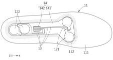
지지 레이어(14)는 전자 소자(12) 및 연결 라인(13)을 지지하고, 베이스 돌기(112)의 내측에 삽입될 수 있다. 지지 레이어(14)는 베이스 돌기(112)에 끼워맞춤될 수 있다. 지지 레이어(14)는 베이스 돌기(112)의 내측에 흔들림 없이 고정될 수 있다. 예를 들어, 지지 레이어(14) 및 전자 소자(12)의 총 두께는, 베이스 바디(111) 중 베이스 돌기(112)의 내측 공간으로부터 베이스 돌기(112)가 상방으로 돌출된 높이와 동일할 수 있다. 예를 들어, 전자 소자(12)의 상면과 베이스 돌기(112)의 상면은 동일한 높이를 가질 수 있다. 지지 레이어(14)는 레이어 바디(141) 및 경사 파트(142, slope part)를 포함할 수 있다.The
레이어 바디(141)는 베이스 바디(111)의 상면에 배치될 수 있다. 레이어 바디(141)는 전자 소자(12) 및/또는 연결 라인(13)을 지지할 수 있다. 레이어 바디(141)는 예를 들어 유연한 재질의 필름으로 형성될 수 있다.The
경사 파트(142)는 레이어 바디(141)의 중앙부에 형성되고, 레이어 바디(141)에 대해 하방으로 절곡되어 가이드(114)에 배치될 수 있다. 경사 파트(142)는 연결 라인(13)을 컨트롤러(15)로 안내할 수 있다. 경사 파트(142)는 레이어 바디(141)의 상부로부터 하방 및 후방으로 경사진 형상을 가질 수 있다. The
예를 들어, 하나의 레이어로 제작된 지지 레이어(14)의 일부를 절개 및 절곡시켜 경사 파트(142)를 형성하고, 경사 파트(142)의 나머지 부분이 레이어 바디(141)를 형성하는 것으로 이해될 수도 있다. For example, it is understood that a portion of the
컨트롤러(15)는 전자 소자(12)와 전기적으로 연결되어, 전자 소자(12)를 제어할 수 있다. 예를 들어, 전자 소자(12)가 진동자를 포함할 경우, 컨트롤러(15)는 전자 소자(12)의 진동수 및/또는 진폭 등을 조절할 수 있다. 한편, 컨트롤러(15)는 전자 소자(12)로부터 정보를 수신할 수 있다. 예를 들어, 전자 소자(12)가 압력 센서 또는 관성 센서를 포함할 경우, 컨트롤러(15)는 전자 소자(12)에서 감지된 정보를 수신할 수 있다.The
컨트롤러(15)는 인솔(1)에 장착될 수 있다. 예를 들어, 컨트롤러(15)는 베이스(11)의 하측에 삽입될 수 있다. 이와 같은 구조에 의하면, 미드솔(2)에 컨트롤러(15)를 수용할 공간을 마련할 필요가 없다. 다시 말하면, 미드솔(2) 및 어퍼(3)는 각각 일반적인 신발의 제조 공정과 유사한 방식으로 제작되어, 컨트롤러(15)의 장착 여부와 관계없이 상호 결합될 수 있다. 다시 말하면, 신발의 제조 공정과, 전자 부품을 포함하는 베이스(11) 등의 제조 공정을 분리하여 수행할 수 있다. 예를 들어, 어퍼(3)가 어퍼 바닥(32)을 포함할 경우, 어퍼 바닥(32)은 미드솔(2)의 상면에 부착될 수 있다. 다른 예로, 어퍼(3)가 어퍼 바닥(32)을 포함하지 않을 경우, 어퍼(3)는 미드솔(2)의 테두리를 따라 미드솔(2)에 결합될 수 있다. 미드솔(2) 및 어퍼(3)는 컨트롤러(15)를 수용하기 위한 공간을 마련할 필요가 없으며, 컨트롤러(15)에 의해 조립 순서에 영향을 받지 않는다. 따라서, 신발(100)은 상대적으로 가격이 높고 내구성이 약한 각종 전자 부품의 파손이나, 연결 라인의 단선의 염려 없이, 간단한 자동화 공정을 통하여 대량 생산 가능하다. 컨트롤러(15)는 컨트롤러 바디(151), 컨트롤러 돌기(152), 접속 포트(153), 전원부(158) 및 제어부(159)를 포함할 수 있다. 제어부(159)는, 인터페이스(4) 또는 무선 통신을 통하여 입력된 제어 신호를 기초로 전자 소자(12)를 제어할 수 있다.The
컨트롤러 바디(151)는 제 1 방향으로 베이스(11)에 삽입될 수 있다. 예를 들어, 제 1 방향은 베이스(11)의 하측으로부터 상측을 향하는 +z 방향일 수 있다. 컨트롤러 바디(151)는 전원부(158) 및/또는 제어부(159)를 수용할 수 있다. 컨트롤러 바디(151)는 인서트(16)와 결합하기 위한 컨트롤러 결합 홀(151a, 151b)을 포함할 수 있다. 예를 들어, 컨트롤러 결합 홀(151a, 151b)은 접속 포트(153)를 기준으로 서로 반대편에 마련되는 제 1 컨트롤러 결합 홀(151a) 및 제 2 컨트롤러 결합 홀(151b)을 포함할 수 있다.The
컨트롤러 돌기(152)는 컨트롤러 바디(151)로부터 후방으로 연장될 수 있다. 컨트롤러 돌기(152)는 제 1 방향에 대해 수직한 제 2 방향으로 베이스(11)에 삽입될 수 있다. 여기서, 제 2 방향은, 베이스(11)의 전방으로부터 후방을 향하는 -x 방향일 수 있다. 제 2 방향은, 제 1 방향에 직교하므로, 컨트롤러 바디(151)를 베이스(11)에 장착하는 과정에서, 컨트롤러 바디(151)가 하방으로 분리되는 것을 방지할 수 있다. 컨트롤러 돌기(152)는 컨트롤러 바디(151)를 장착하기 전에, 컨트롤러(15)의 일단을 베이스(11)에 걸리게 함으로써, 임시적으로 고정된 상태를 제공할 수 있다. 컨트롤러 바디(151)의 전방부는 인서트(16)에 결합되고, 컨트롤러 바디(151)로부터 후방으로 연장되는 컨트롤러 돌기(152)는 베이스(11)에 삽입되므로, 컨트롤러(15)는 사용자가 보행하는 동안 안정적으로 베이스(11)에 삽입된 상태를 유지할 수 있다. 예를 들어, 사용자가 푸쉬 오프 동작을 수행하여 베이스(11)의 중앙부가 변형되더라도, 컨트롤러(15)는 강성한 재질의 인서트(16)에 결합되어 있으므로, 베이스(11)로부터 분리되지 않을 수 있다. 또한, 사용자가 힐 스트라이크 동작을 수행하여 베이스(11)의 후방부가 변형되더라도, 컨트롤러 돌기(152)가 베이스(11)에 삽입되어 있으므로, 컨트롤러(15)는 베이스(11)로부터 분리되는 문제를 줄여줄 수 있다. The
접속 포트(153)는 컨트롤러 바디(151)의 상면에 마련될 수 있다. 접속 포트(153)는 베이스 홀(113)을 통과한 연결 라인(13)과 연결될 수 있다. 접속 포트(153)는, 예를 들어, 포고 핀(pogo pin) 등 연결 라인(13)과의 접속 방향으로 탄성 변형 가능한 부재일 수 있다. 이와 같은 구조에 의하면, 사용자의 보행 과정에서도 안정적인 전기 접점을 제공할 수 있다. The
전원부(158)는 전자 소자(12)에 전원을 공급할 수 있다. 전원부(158)는 인터페이스(4)를 통해 외부로부터 전원을 공급받아 충전되거나, 무선으로 충전될 수 있다.The
인서트(16)는 베이스(11)의 내부에 배치되고, 베이스(11) 보다 강성한 재질로 형성될 수 있다. 예를 들어, 인서트(16)는 베이스(11)를 형성하는 성형틀에 미리 배치된 상태에서, 수지 발포 공정 등을 통하여 베이스(11)를 형성함으로써, 베이스(11)의 내부에 일체로 형성될 수 있다. 인서트(16)는 베이스 홀(113) 근방에 위치되고, 인솔(1)에 수직한 방향을 기준으로 컨트롤러(15)에 오버랩될 수 있다. 인서트(16)는 컨트롤러(15)와 결합하기 위한 인서트 결합 홀(16a, 16b)을 포함할 수 있다. 인서트 결합 홀(16a, 16b)은 예를 들어 내측에 나사산을 구비할 수 있다. 인서트 결합 홀(16a, 16b)은 제 1 컨트롤러 결합 홀(151a)에 대응되는 제 1 인서트 결합 홀(16a)과, 제 2 컨트롤러 결합 홀(151b)에 대응되는 제 2 인서트 결합 홀(16b)을 포함할 수 있다. 한편, 도 3에는 하나의 인서트(16)가 컨트롤러(15)의 전방 단부를 고정시키는 실시 예를 도시하였으나, 인서트(16)는 복수 개로 제공되어 컨트롤러(15)의 다른 부분도 고정시킬 수 있다. 또한, 인서트(16)가 컨트롤러(15)의 여러 부분을 고정시킬 수 있도록 다른 형상을 가질 수도 있음을 밝혀 둔다. The
커버(19)는 전자 소자(12)가 사용자의 발에 직접 접촉하지 않게 전자 소자(12)를 커버하도록 베이스(11)의 상면에 배치될 수 있다. 커버(19)의 형상은 베이스(11)의 형상과 대략 유사할 수 있다. 인솔(1)의 수직한 방향을 기준으로 커버(19)는 베이스(11)와 대부분 오버랩될 수 있다. 커버(19)는 커버 바닥(19a)과, 커버 바닥(19a)의 후방 테두리부로부터 상방으로 돌출 형성되는 커버 날개(19b)를 포함할 수 있다. 커버 날개(19b)는 사용자의 후족부의 후방부 및 측부를 둘러싸는 방식으로 후족부를 안정적으로 지지할 수 있다. 예를 들어, 커버(19)의 내부에는 전자 부품이 구비되지 않을 수 있다. 이와 같은 구조에 의하면, 사용자는 커버(19)만을 신발(100)로부터 분리하여 세척하거나, 교환할 수 있다. 또한, 각종 전자 부품을 포함하는 베이스(11) 등의 구조를 변경할 필요 없이, 다양한 사용자의 발의 형상에 커스터마이징된 형상의 커버(19)를 제공할 수 있으므로, 전체 신발(100)의 제조 비용 및 노력을 절감할 수 있다. The
결합 부재(81, 82)는 컨트롤러(15) 및 인서트(16)를 결합할 수 있다. 예를 들어, 결합 부재(81, 82)는 컨트롤러(15) 및 인서트(16)에 나사 결합 가능한 볼트일 수 있다.The
미드솔(2)은 신발(100)의 하측 외형의 적어도 일부를 형성할 수 있다. 미드솔(2)은 후방으로 갈수록 점차 두꺼워지는 형상을 가져서 사용자의 발 앞쪽을 지지하는 전방부가, 사용자의 발 뒤꿈치를 지지하는 부분보다 얇을 수 있다. 미드솔(2)은 미드솔 바디(21) 및 복수 개의 미드솔 그루브(22)를 포함할 수 있다. 미드솔(2)은 필요에 따라 미드솔 바디(21)의 바닥면에 형성되고, 미드솔 바디(21) 보다 강성한 재질을 갖는 아웃솔(미도시)을 포함할 수도 있다.The
미드솔 바디(21)는 인솔(1)을 지지할 수 있다. 미드솔 바디(21)의 상측에는 어퍼(3)가 결합될 수 있다. 미드솔 바디(21)는 예를 들어 파일론(Phylon), 쿠실론(Cushlon), 에틸렌초산비닐 공중합체(EVA) 또는 소라이트(Solyte) 등의 재질로 형성될 수 있다.The
복수 개의 미드솔 그루브(22)는 미드솔 바디(21)의 길이 방향(x 방향)과 교차하는 방향, 예를 들어 y 방향으로 형성되고, 전자 소자(12)와 오버랩되지 않는 위치에 구비될 수 있다. 예를 들어, 미드솔 그루브(22)는 전자 소자(12)의 전방에 구비될 수 있다. 복수 개의 미드솔 그루브(22)는 미드솔 바디(21)가 접히는 위치를 가이드할 수 있다. 복수 개의 미드솔 그루브(22)는 미드솔 바디(21)가 전자 소자(12)와 오버랩되지 않는 위치에서 접히도록 보조함으로써, 전자 소자(12)가 파손될 위험성을 줄여줄 수 있다. 예를 들어, 미드솔 그루브(22)는, 도 2와 같이 미드솔 바디(21)의 상면에서 함몰 형성될 수 있다. 예를 들어, 복수 개의 미드솔 그루브(22)는 서로 평행하게 형성될 수 있다.The plurality of
어퍼(3)는 신발의 상부 외형을 형성하고 사용자의 발을 감쌀 수 있다. 어퍼(3)는 어퍼 바디(31)와, 미드솔 바디(21)의 상면에 접촉하는 어퍼 바닥(32)을 포함할 수 있다. 어퍼 바디(31)는 인터페이스(4)를 컨트롤러(15)에 접속시키기 위한 어퍼 홀(31a)을 포함할 수 있다. 인터페이스(4)는 어퍼 홀(31a)을 관통하여 컨트롤러(15)에 연결될 수 있다. 어퍼 홀(31a)은 어퍼 바디(31)의 후면에 형성될 수 있다. The upper 3 forms the upper outline of the shoe and may surround the user's foot. The upper 3 may include an
인터페이스(4)는 컨트롤러(15)에 전기적으로 연결될 수 있다. 예를 들어, 인터페이스(4)의 일부는 미드솔(2)의 후방에 설치되어 외부로 노출되고, 나머지 일부는 컨트롤러(15)에 연결될 수 있다. 예를 들어, 인터페이스(4)는 사용자로부터 제어 신호를 입력받기 위한 버튼 등의 입력부를 포함하고, 제어부(159)로 제어 신호를 전달할 수 있다. 예를 들어, 인터페이스(4)는 외부로부터 전력을 공급받아 전원부(158)로 공급할 수 있다.
도 5는 일 실시 예에 따른 커버의 평면도이고, 도 6은 일 실시 예에 따른 커버의 저면도이고, 도 7은 일 실시 예에 따른 커버의 단면도이고, 도 8은 일 실시 예에 따른 베이스, 전자 소자, 연결 라인 및 지지 레이어를 도시하는 평면도이고, 도 9는 일 실시 예에 따른 베이스의 사시도이고, 도 10은 도 9의 베이스를 다른 각도에서 도시한 사시도이다.Figure 5 is a top view of a cover according to an embodiment, Figure 6 is a bottom view of a cover according to an embodiment, Figure 7 is a cross-sectional view of a cover according to an embodiment, Figure 8 is a base according to an embodiment, It is a top view showing electronic elements, connection lines, and support layers, FIG. 9 is a perspective view of a base according to one embodiment, and FIG. 10 is a perspective view showing the base of FIG. 9 from another angle.
도 5 내지 도 10을 참조하면, 커버(19)는 베이스(11)로부터 분리될 수 있다. 커버(19)는 커버 바닥(19a) 및 커버 날개(19b)를 포함할 수 있다. 또한, 커버(19)는 커버 그루브(191a)를 포함하는 커버 바디(191)와, 커버 바디(191)로부터 돌출 형성되는 커버 돌기(192)를 포함할 수 있다.5 to 10, the
커버 그루브(191a)는 전자 소자(12) 및 지지 레이어(14)를 수용하는 형상을 가질 수 있다. 예를 들어, 커버 그루브(191a)의 전방부는 전방 전자 소자(121)를 수용하고, 후방부는 후방 전자 소자(122)를 수용할 수 있다. 커버 그루브(191a)의 전방부는 후방부 보다 상대적으로 폭이 넓을 수 있다. 커버 그루브(191a)가 커버 바디(191)의 하면으로부터 함몰된 깊이는, 지지 레이어(14) 및 전자 소자(12)의 두께의 합과 대략 동일할 수 있다. 커버(19)가 베이스(11)에 커버될 경우, 전자 소자(12)는 커버 그루브(191a)의 바닥면에 접촉할 수 있다. 커버 그루브(191a)에는 베이스 돌기(112)가 끼워맞춤될 수 있다. 커버 그루브(191a)는 베이스 돌기(112)와 대응되는 형상을 가질 수 있다.The
커버 돌기(192)는 지지 레이어(14)를 가압할 수 있다. 커버 돌기(192)는 지지 레이어(14) 중 전자 소자(12)를 지지하고 있지 않은 부분을 가압할 수 있다. 예를 들어, 커버 돌기(192)는 전자 소자(12)의 두께에 해당하는 길이 만큼 커버 바디(191)로부터 돌출 형성될 수 있다. 커버(19)가 베이스(11)에 커버될 경우, 지지 레이어(14)는 커버 돌기(192)에 접촉할 수 있다. 커버 돌기(192)는 사용자가 보행하는 동안, 지지 레이어(14)의 중앙 부분이 상하로 흔들거리지 않도록 보조할 수 있다.The
지지 레이어(14)는 베이스 돌기(112)의 내측에 끼워맞춤될 수 있다. 예를 들어, 레이어 바디(141)의 테두리부는 베이스 돌기(112)의 내벽에 접촉한 상태를 유지할 수 있다. 전방 전자 소자(121) 및 후방 전자 소자(122)의 수평 방향 흔들림은 제한될 수 있다.The
지지 레이어(14)는 필요에 따라 베이스(11)로부터 분리되어, 수리 및/또는 교체될 수 있다. 예를 들어, 여러 종류의 지지 레이어(14)는 다양한 전자 소자(12)를 지지할 수 있다. 예를 들어, 지지 레이어(14)는 편심 모터를 포함하는 전자 소자, 압력 센서를 포함하는 전자 소자 및 관성 센서를 포함하는 전자 소자 중 어느 하나의 전자 소자를 지지할 수 있다. 사용자는 원하는 전자 소자를 지지하고 있는 지지 레이어(14)를 선택적으로 베이스(11)에 배치시킬 수 있다. The
베이스 바디(111)는 베이스 바디(111)의 하면으로부터 함몰 형성되는 베이스 메인 그루브(111c)와, 베이스 메인 그루브(111c)의 일측면으로부터 베이스(11)의 후방을 향한 방향으로 함몰 형성되는 베이스 보조 그루브(111d)와, 라인 수용 홈(111e)을 포함할 수 있다.The
베이스 메인 그루브(111c)는 컨트롤러 바디(151, 도 3 참조)를 수용할 수 있고, 베이스 보조 그루브(111d)는 컨트롤러 돌기(152, 도 3 참조)를 수용할 수 있다. 사용자는 컨트롤러 바디(151)를 기울인 상태로 컨트롤러 돌기(152)를 베이스 보조 그루브(111d)에 삽입한 뒤, 컨트롤러 바디(151)를 들어올려 베이스 메인 그루브(111c)에 완전히 삽입할 수 있다.The base
라인 수용 홈(111e)은, 전력 라인(44a, 도 13 참조)을 수용할 수 있다. 라인 수용 홈(111e)에 의하면, 사용자의 보행 과정 등에서 발생하는 인솔(1)과의 마찰에 의해, 전력 라인(44a)이 노후화되는 문제를 방지하면서도, 컨트롤러(15) 및 인터페이스(4)가 안정적으로 연결되게 할 수 있다. 예를 들어, 라인 수용 홈(111e)은, 베이스 바디(111)의 후면 및 하면에 걸쳐서 형성될 수 있다. 라인 수용 홈(111e)은, 베이스 메인 그루브(111c)와 연통되는 형상을 가질 수 있다. The line receiving groove 111e can accommodate the
도 11은 일 실시 예에 따른 커버가 교체되는 모습을 도시하는 측면도이다.Figure 11 is a side view showing a cover being replaced according to one embodiment.
도 11을 참조하면, 베이스(11) 및 베이스(11)에 장착되는 전자 요소들은 그대로 둔 상태에서 커버(19)는 교체될 수 있다. 예를 들어, 사용자는 후족부를 지지하는 부분의 높이가 h1인 커버(19)를, 높이가 h2인 커버(19')로 교체할 수 있다. 사용자는 커스터마이징된 커버(19)를 사용할 수 있다.Referring to FIG. 11, the
도 12는 일 실시 예에 따른 인솔의 단면도이고, 도 13은 일 실시 예에 따른 미드솔 및 인터페이스를 도시하는 사시도이고, 도 14는 일 실시 예에 따른 인터페이스 커버가 인터페이스 바디로부터 분리된 상태를 도시하는 사시도이다.Figure 12 is a cross-sectional view of an insole according to an embodiment, Figure 13 is a perspective view showing a midsole and an interface according to an embodiment, and Figure 14 shows an interface cover separated from the interface body according to an embodiment. It is a perspective view.
도 12 내지 도 14를 참조하면, 인터페이스(4)는, 인터페이스 바디(41), 인터페이스 커버(42), 연결부(43) 및 커넥터(44)를 포함할 수 있다.Referring to FIGS. 12 to 14 , the
인터페이스 바디(41)는 미드솔(2)에 고정될 수 있다. 인터페이스 바디(41)는 예를 들어 미드솔(2)의 후방 테두리부에 고정될 수 있다. 인터페이스 바디(41)는 어퍼(3, 도 1 참조)보다 강성한 재질로 형성되어, 신발의 백 카운터(back counter)로 기능할 수 있다. 인터페이스 바디(41)는 인터페이스 커버(42)에 자력을 인가하기 위한 바디 자석(411)을 포함할 수 있다. 바디 자석(411)은 복수 개로 구비될 수 있다.The
인터페이스 커버(42)는 인터페이스 바디(41)에 탈착 가능하다. 인터페이스 커버(42)는 바디 자석(411)과 반대 극성으로 마주하는 커버 자석(421)과, 전원부(158, 도 4 참조)로 공급되는 전원을 입력 받기 위한 전원 단자(422)를 포함할 수 있다. 커버 자석(421)은 복수 개로 구비될 수 있다. 전원 단자(422)에는 외부 충전 장치(C)가 연결될 수 있다.The
연결부(43)는 상단부(43a)가 인터페이스 커버(42)에 연결되고, 하단부(43b)가 인터페이스 바디(41)에 고정될 수 있다. 연결부(43)는 인터페이스 커버(42)가 인터페이스 바디(41)로부터 분리되더라도, 신발 자체로부터 분리되지 않도록 보조할 수 있다. 사용자는 인터페이스 커버(42)의 상단을 잡아당기는 방식으로, 인터페이스 커버(42)를 인터페이스 바디(41)로부터 분리시킬 수 있다. 예를 들어, 연결부(43)는 탄성을 갖는 탄성 재질로 형성될 수 있다. The
커넥터(44)는 어퍼(3)의 어퍼 홀(31a, 도 2 참조)를 관통하고, 전원 단자(422) 및 컨트롤러(15, 도 3 참조)를 연결할 수 있다. 커넥터(44)는 어퍼(3)를 관통하는 전력 라인(44a)과, 전력 라인(44a)의 단부에 마련되고 컨트롤러(15)에 연결되는 커넥터 단자(44b)를 포함할 수 있다. The
전력 라인(44a)은 베이스(11, 도 2 참조)의 후면 및 하면을 따라 연장할 수 있다. 예를 들어, 전력 라인(44a)은 패브릭 소재 등의 유연한 재질을 포함할 수 있다. 이와 같은 구조에 의하면, 보행 과정에서 신발(100)의 내부에서 다소간 컨트롤러(15)의 유격이 발생되더라도, 유연한 전력 라인(44a)이 해당 유격을 용인함으로써, 단선의 위험을 줄여줄 수 있다. 다시 말하면, 커넥터(44)가 전체적으로 강성한 구조를 갖는 경우와 비교하여, 제품의 내구성을 향상시킬 수 있다. The
커넥터 단자(44b)는, 컨트롤러(15)의 하면에 탈부착 가능하게 제공될 수 있다. 이와 같은 구조에 의하면, 베이스(11)에 설치된 전자 부품들의 수리 또는 교체가 필요할 경우에, 커넥터 단자(44b)를 컨트롤러(15)로부터 분리시키는 방식으로, 베이스(11) 전체를 신발(100)으로부터 분리하여 용이하게 작업할 수 있다.The
연결 라인(13)은 경사 파트(142)에 의해 베이스(11)의 하측으로 안내될 수 있다. 결합 부재(81, 82)가 컨트롤러 바디(151) 및 인서트(16)를 결합하면, 접속 포트(153)는 연결 라인(13)에 접촉될 수 있다. 예를 들어, 컨트롤러 바디(151)는 접속 포트(153)에 상방으로의 탄성력을 제공하는 탄성체(미도시)를 구비할 수 있다.The
이상과 같이 비록 한정된 도면에 의해 실시 예들이 설명되었으나, 해당 기술분야에서 통상의 지식을 가진 자라면 상기의 기재로부터 다양한 수정 및 변형이 가능하다. 예를 들어, 설명된 기술들이 설명된 방법과 다른 순서로 수행되거나, 및/또는 설명된 구조, 장치 등의 구성요소들이 설명된 방법과 다른 형태로 결합 또는 조합되거나, 다른 구성요소 또는 균등물에 의하여 대치되거나 치환되더라도 적절한 결과가 달성될 수 있다.As described above, although the embodiments have been described with limited drawings, various modifications and variations can be made by those skilled in the art from the above description. For example, the described techniques may be performed in a different order than the described method, and/or components of the described structure, device, etc. may be combined or combined in a form different from the described method, or may be used with other components or equivalents. Appropriate results can be achieved even if replaced or substituted by .
Claims (20)
상기 베이스에 배치되는 전자 소자;
상기 전자 소자로부터 연장되고 상기 베이스를 관통하는 연결 라인;
상기 전자 소자를 커버하도록 상기 베이스의 상면에 배치되고, 상기 베이스로부터 분리될 수 있는 커버; 및
상기 전자 소자 및 연결 라인을 지지하는 지지 레이어를 포함하고,
상기 베이스는, 상기 전자 소자를 지지하는 베이스 바디와, 상기 베이스 바디로부터 돌출되는 베이스 돌기를 포함하고,
상기 지지 레이어는 상기 베이스 돌기의 내측에 끼워 맞춤되고,
상기 베이스는,
상기 베이스 바디에 관통 형성되고, 상기 지지 레이어의 적어도 일부를 통과시키는 베이스 홀; 및
상기 베이스 홀의 전방에 형성되고, 상기 베이스 바디의 후방 및 하방으로 경사진 형상을 갖는 가이드를 더 포함하는 인솔.Base;
Electronic elements disposed on the base;
a connection line extending from the electronic device and penetrating the base;
a cover disposed on the upper surface of the base to cover the electronic device and detachable from the base; and
It includes a support layer that supports the electronic elements and connection lines,
The base includes a base body supporting the electronic device, and a base protrusion protruding from the base body,
The support layer is fitted inside the base protrusion,
The base is,
a base hole formed through the base body and allowing at least a portion of the support layer to pass through; and
The insole further includes a guide formed in front of the base hole and having a shape inclined backward and downward of the base body.
상기 베이스 돌기는, 상기 커버에 끼워맞춤(fit)되고, 상기 전자 소자를 둘러싸는 인솔.According to claim 1,
The base protrusion fits into the cover and surrounds the electronic device.
상기 지지 레이어는,
상기 베이스 바디의 상면에 배치되는 레이어 바디; 및
상기 레이어 바디의 중앙부에 형성되고, 상기 레이어 바디에 대해 하방으로 절곡되어 상기 가이드에 배치되는 경사 파트를 포함하는 인솔.According to claim 1,
The support layer is,
a layer body disposed on the upper surface of the base body; and
An insole formed in the center of the layer body and including an inclined part bent downward with respect to the layer body and disposed on the guide.
상기 전자 소자는 복수 개가 구비되고,
상기 복수 개의 전자 소자는,
상기 베이스에 수직한 방향을 기준으로 사용자의 전족부(forefoot)에 오버랩되는 전방 전자 소자; 및
상기 베이스에 수직한 방향을 기준으로 사용자의 후족부(rearfoot)에 오버랩되는 후방 전자 소자를 포함하는 인솔.According to claim 1,
A plurality of the electronic elements are provided,
The plurality of electronic elements are:
a front electronic element that overlaps the user's forefoot in a direction perpendicular to the base; and
An insole including a rear electronic element that overlaps the user's rearfoot in a direction perpendicular to the base.
상기 베이스 홀은 상기 전방 전자 소자 및 후방 전자 소자 사이에 형성되는 인솔.According to claim 6,
The base hole is an insole formed between the front electronic element and the rear electronic element.
상기 커버는,
상기 베이스 돌기를 수용하는 커버 그루브을 구비한 커버 바디; 및
상기 커버 바디로부터 돌출되고, 상기 지지 레이어를 가압하는 커버 돌기를 포함하는 인솔.According to claim 1,
The cover is,
a cover body having a cover groove accommodating the base protrusion; and
An insole including a cover protrusion that protrudes from the cover body and presses the support layer.
상기 베이스에 삽입되고, 상기 베이스를 기준으로 상기 전자 소자의 반대편에 구비되는 컨트롤러를 더 포함하는 인솔.According to claim 1,
The insole is inserted into the base and further includes a controller provided on an opposite side of the electronic device with respect to the base.
상기 컨트롤러는,
제 1 방향으로 상기 베이스에 삽입되는 컨트롤러 바디; 및
상기 컨트롤러 바디로부터 후방으로 연장되고, 상기 제 1 방향에 대해 수직한 제 2 방향으로 상기 베이스에 삽입되는 컨트롤러 돌기를 포함하는 인솔.According to clause 9,
The controller is,
a controller body inserted into the base in a first direction; and
An insole extending rearward from the controller body and including a controller protrusion inserted into the base in a second direction perpendicular to the first direction.
상기 베이스의 내부에 배치되고, 상기 베이스 보다 강성한 재질로 형성되는 인서트를 더 포함하고,
상기 컨트롤러 및 인서트는 상기 연결 라인을 사이에 배치한 상태로 결합 가능한 인솔.According to clause 9,
It further includes an insert disposed inside the base and made of a material stronger than the base,
An insole where the controller and the insert can be combined with the connection line disposed therebetween.
상기 전자 소자는 진동자(vibrator), 압력 센서, 온도 센서 또는 관성 센서를 포함하는 인솔.According to claim 1,
The electronic device is an insole including a vibrator, a pressure sensor, a temperature sensor, or an inertial sensor.
상기 미드솔의 상면에 장착되는 어퍼(upper);
상기 어퍼의 내측으로 삽입될 수 있는 베이스와, 상기 베이스에 배치되는 전자 소자와, 상기 전자 소자로부터 연장되고 상기 베이스를 관통하는 연결 라인과, 상기 전자 소자를 커버하도록 상기 베이스의 상면에 배치되고, 상기 베이스로부터 분리될 수 있는 커버와, 상기 베이스를 기준으로 상기 전자 소자의 반대편에 구비되고, 상기 연결 라인과 접속하는 컨트롤러를 구비하는 인솔; 및
상기 어퍼를 관통하여 상기 컨트롤러에 연결되는 인터페이스를 포함하고,
상기 인터페이스는,
상기 미드솔에 고정되는 인터페이스 바디;
전원 단자를 포함하고, 상기 인터페이스 바디에 탈착 가능한 인터페이스 커버; 및
상기 어퍼를 관통하고, 상기 전원 단자 및 컨트롤러를 연결하는 커넥터를 포함하는 신발.midsole;
An upper mounted on the upper surface of the midsole;
A base that can be inserted into the upper, an electronic element disposed on the base, a connection line extending from the electronic element and passing through the base, and disposed on the upper surface of the base to cover the electronic element, an insole including a cover detachable from the base, a controller provided on an opposite side of the electronic device with respect to the base, and connected to the connection line; and
Comprising an interface that penetrates the upper and is connected to the controller,
The interface is,
An interface body fixed to the midsole;
an interface cover including a power terminal and detachable from the interface body; and
A shoe penetrating the upper and including a connector connecting the power terminal and the controller.
상기 인터페이스 바디는 바디 자석을 포함하고,
상기 인터페이스 커버는 상기 바디 자석과 반대 극성으로 마주하는 커버 자석을 더 포함하는 신발.According to claim 13,
The interface body includes a body magnet,
The interface cover further includes a cover magnet facing the body magnet with an opposite polarity.
상기 베이스는,
상기 전자 소자를 지지하는 베이스 바디; 및
상기 베이스 바디로부터 돌출되어 상기 커버에 끼워맞춤되고, 상기 전자 소자를 둘러싸는 베이스 돌기를 포함하는 신발.According to claim 13,
The base is,
a base body supporting the electronic device; and
A shoe comprising a base protrusion that protrudes from the base body, fits into the cover, and surrounds the electronic device.
상기 미드솔은,
상기 인솔을 지지하는 미드솔 바디; 및
상기 미드솔 바디의 상면에서 함몰 형성되고, 상기 미드솔 바디의 길이 방향과 교차하는 방향으로 형성되고, 상기 전자 소자의 전방에 구비되는 복수 개의 미드솔 그루브를 포함하는 신발.According to claim 13,
The midsole is,
A midsole body supporting the insole; and
A shoe comprising a plurality of midsole grooves that are recessed in the upper surface of the midsole body, are formed in a direction intersecting the longitudinal direction of the midsole body, and are provided in front of the electronic device.
Priority Applications (4)
| Application Number | Priority Date | Filing Date | Title |
|---|---|---|---|
| KR1020190025343A KR102589950B1 (en) | 2019-03-05 | 2019-03-05 | Insole and shoes comprising the same |
| CN201910783445.4A CN111657620B (en) | 2019-03-05 | 2019-08-23 | Insoles and shoes |
| US16/661,338 US11464274B2 (en) | 2019-03-05 | 2019-10-23 | Insole and shoes comprising the same |
| EP19214921.9A EP3704986B1 (en) | 2019-03-05 | 2019-12-10 | Insole and shoes comprising the same |
Applications Claiming Priority (1)
| Application Number | Priority Date | Filing Date | Title |
|---|---|---|---|
| KR1020190025343A KR102589950B1 (en) | 2019-03-05 | 2019-03-05 | Insole and shoes comprising the same |
Publications (2)
| Publication Number | Publication Date |
|---|---|
| KR20200106746A KR20200106746A (en) | 2020-09-15 |
| KR102589950B1 true KR102589950B1 (en) | 2023-10-16 |
Family
ID=68848102
Family Applications (1)
| Application Number | Title | Priority Date | Filing Date |
|---|---|---|---|
| KR1020190025343A Active KR102589950B1 (en) | 2019-03-05 | 2019-03-05 | Insole and shoes comprising the same |
Country Status (4)
| Country | Link |
|---|---|
| US (1) | US11464274B2 (en) |
| EP (1) | EP3704986B1 (en) |
| KR (1) | KR102589950B1 (en) |
| CN (1) | CN111657620B (en) |
Families Citing this family (5)
| Publication number | Priority date | Publication date | Assignee | Title |
|---|---|---|---|---|
| US20220142292A1 (en) * | 2019-03-27 | 2022-05-12 | Nec Corporation | Insole-type electronic device and method for manufacturing insole-type electronic device |
| GB2617388A (en) * | 2022-04-08 | 2023-10-11 | Walk With Path Ltd | Footwear article |
| KR102831073B1 (en) * | 2022-08-29 | 2025-07-07 | 솔티드 주식회사 | Wireless chargable insole and wireless charging system |
| KR102796377B1 (en) * | 2023-03-03 | 2025-04-18 | 주식회사 오투랩 | Smart insoles |
| USD1032158S1 (en) * | 2023-05-15 | 2024-06-25 | Skechers U.S.A., Inc. Ii | Shoe midsole periphery |
Citations (3)
| Publication number | Priority date | Publication date | Assignee | Title |
|---|---|---|---|---|
| US20020133973A1 (en) * | 2001-03-23 | 2002-09-26 | Ku-Shen Lin | Heat sole |
| JP2007503900A (en) * | 2003-09-02 | 2007-03-01 | タリク ミルザ, | Insole for shoes, and accessories for it |
| US20180055140A1 (en) * | 2016-08-26 | 2018-03-01 | Aria S.R.L. | Insole for controlling and adjusting the temperature of the foot |
Family Cites Families (26)
| Publication number | Priority date | Publication date | Assignee | Title |
|---|---|---|---|---|
| US5846063A (en) * | 1987-05-26 | 1998-12-08 | Nikola Lakic | Miniature universal pump and valve for inflatable liners |
| US5592759A (en) * | 1995-01-26 | 1997-01-14 | Co-Jo Sports, Inc. | Vibrating footwear |
| US6195921B1 (en) * | 1999-09-28 | 2001-03-06 | Vinncente Hoa Gia Truong | Virtual intelligence shoe with a podiatric analysis system |
| US8308665B2 (en) | 2003-03-06 | 2012-11-13 | Trustees Of Boston University | Method and apparatus for improving human balance and gait and preventing foot injury |
| US8141276B2 (en) * | 2004-11-22 | 2012-03-27 | Frampton E. Ellis | Devices with an internal flexibility slit, including for footwear |
| US8398570B2 (en) | 2006-04-14 | 2013-03-19 | Engineering Acoustics, Inc. | Wide band vibrational stimulus device |
| US7347831B2 (en) * | 2006-07-10 | 2008-03-25 | Hsao-Hsing Chiu | Shoe with massaging and warming arrangements |
| US7997007B2 (en) * | 2006-09-15 | 2011-08-16 | Early Success, Inc. | Stimulus training system and apparatus to effectuate therapeutic treatment |
| KR100795830B1 (en) | 2006-11-01 | 2008-01-17 | 주식회사 지맨 | Functional shoes |
| US7913428B2 (en) * | 2007-07-20 | 2011-03-29 | Ching-Hung Wang | Electromagnetic fitness shoes with a conductor structure |
| US8384551B2 (en) * | 2008-05-28 | 2013-02-26 | MedHab, LLC | Sensor device and method for monitoring physical stresses placed on a user |
| WO2011057142A2 (en) * | 2009-11-05 | 2011-05-12 | Columbia Sportswear North America, Inc. | Footwear temperature control method and apparatus |
| US20110251520A1 (en) | 2010-04-08 | 2011-10-13 | Yuan Ze University | Fall-risk Evaluation and Balance Stability Enhancement System and method |
| EP2675355B1 (en) * | 2011-02-17 | 2020-01-01 | NIKE Innovate C.V. | Footwear having sensor system |
| KR101608480B1 (en) | 2011-02-17 | 2016-04-01 | 나이키 이노베이트 씨.브이. | Footwear having sensor system |
| JP4988942B1 (en) | 2011-05-20 | 2012-08-01 | 英治 川西 | Linear shoes |
| KR101115495B1 (en) | 2011-08-24 | 2012-03-05 | 김미영 | Shoes with means of electrical stimulation including flexible electrode |
| EP3549471B1 (en) * | 2012-02-22 | 2025-05-07 | NIKE Innovate C.V. | Footwear having sensor system |
| US10369075B2 (en) * | 2015-03-03 | 2019-08-06 | Avex, Llc | Insole foot compression system and methods |
| US10617597B2 (en) | 2015-10-22 | 2020-04-14 | President And Fellows Of Harvard College | Insole design and actuator placement for balance and gait |
| CN105533905A (en) * | 2016-03-04 | 2016-05-04 | 林镕 | Intelligent and healthy running shoe capable of stably and rapidly conducting self-charging |
| US11337487B2 (en) * | 2016-08-11 | 2022-05-24 | Nike, Inc. | Sole structure for an article of footwear having a nonlinear bending stiffness |
| AT518546B1 (en) * | 2016-09-27 | 2017-11-15 | Stapptronics Gmbh | Insole or shoe sole |
| KR101878254B1 (en) | 2016-10-31 | 2018-07-13 | 부산외국어대학교 산학협력단 | Smart Shoes System And Method for Realizing The Same |
| CN207784459U (en) * | 2017-12-29 | 2018-08-31 | 重庆小爱科技有限公司 | A kind of intelligent heating insole |
| KR102514651B1 (en) | 2018-08-27 | 2023-03-28 | 삼성전자주식회사 | Insole and shoes comprising the same |
-
2019
- 2019-03-05 KR KR1020190025343A patent/KR102589950B1/en active Active
- 2019-08-23 CN CN201910783445.4A patent/CN111657620B/en active Active
- 2019-10-23 US US16/661,338 patent/US11464274B2/en active Active
- 2019-12-10 EP EP19214921.9A patent/EP3704986B1/en active Active
Patent Citations (3)
| Publication number | Priority date | Publication date | Assignee | Title |
|---|---|---|---|---|
| US20020133973A1 (en) * | 2001-03-23 | 2002-09-26 | Ku-Shen Lin | Heat sole |
| JP2007503900A (en) * | 2003-09-02 | 2007-03-01 | タリク ミルザ, | Insole for shoes, and accessories for it |
| US20180055140A1 (en) * | 2016-08-26 | 2018-03-01 | Aria S.R.L. | Insole for controlling and adjusting the temperature of the foot |
Also Published As
| Publication number | Publication date |
|---|---|
| EP3704986B1 (en) | 2021-08-11 |
| CN111657620A (en) | 2020-09-15 |
| EP3704986A1 (en) | 2020-09-09 |
| US11464274B2 (en) | 2022-10-11 |
| US20200281303A1 (en) | 2020-09-10 |
| KR20200106746A (en) | 2020-09-15 |
| CN111657620B (en) | 2024-09-03 |
Similar Documents
| Publication | Publication Date | Title |
|---|---|---|
| KR102589950B1 (en) | Insole and shoes comprising the same | |
| KR102514691B1 (en) | Shoes | |
| US11234478B2 (en) | Insole and shoes comprising the same | |
| US8056261B2 (en) | Footwear sole construction | |
| US9968159B2 (en) | Footwear with interchangeable sole structure elements | |
| US9743712B2 (en) | Sole structure with electrically controllable damping element | |
| KR102144412B1 (en) | Electrorheological fluid structure and manufacturing method with anti-deformation element | |
| EP3616549B1 (en) | Method of manufacturing an insole | |
| EP3797626B1 (en) | Smart insole and balance enhancement device comprising smart insoles | |
| KR102248967B1 (en) | Smart insole | |
| JP7793241B1 (en) | Body temperature responsive insole for tarsal bone correction and footwear using the same | |
| KR101866663B1 (en) | Sensor assembly install in outsole of wearable robot | |
| JPH05228003A (en) | Footwear having conductive protrusion on top plate |
Legal Events
| Date | Code | Title | Description |
|---|---|---|---|
| PA0109 | Patent application |
Patent event code: PA01091R01D Comment text: Patent Application Patent event date: 20190305 |
|
| PG1501 | Laying open of application | ||
| A201 | Request for examination | ||
| PA0201 | Request for examination |
Patent event code: PA02012R01D Patent event date: 20220307 Comment text: Request for Examination of Application Patent event code: PA02011R01I Patent event date: 20190305 Comment text: Patent Application |
|
| E902 | Notification of reason for refusal | ||
| PE0902 | Notice of grounds for rejection |
Comment text: Notification of reason for refusal Patent event date: 20230620 Patent event code: PE09021S01D |
|
| E701 | Decision to grant or registration of patent right | ||
| PE0701 | Decision of registration |
Patent event code: PE07011S01D Comment text: Decision to Grant Registration Patent event date: 20230919 |
|
| GRNT | Written decision to grant | ||
| PR0701 | Registration of establishment |
Comment text: Registration of Establishment Patent event date: 20231011 Patent event code: PR07011E01D |
|
| PR1002 | Payment of registration fee |
Payment date: 20231012 End annual number: 3 Start annual number: 1 |
|
| PG1601 | Publication of registration |