KR102579762B1 - Hinge device of foldable mobile device using flexible display panel - Google Patents
Hinge device of foldable mobile device using flexible display panel Download PDFInfo
- Publication number
- KR102579762B1 KR102579762B1 KR1020210111963A KR20210111963A KR102579762B1 KR 102579762 B1 KR102579762 B1 KR 102579762B1 KR 1020210111963 A KR1020210111963 A KR 1020210111963A KR 20210111963 A KR20210111963 A KR 20210111963A KR 102579762 B1 KR102579762 B1 KR 102579762B1
- Authority
- KR
- South Korea
- Prior art keywords
- hinge
- wings
- folding
- wing
- swash plates
- Prior art date
- Legal status (The legal status is an assumption and is not a legal conclusion. Google has not performed a legal analysis and makes no representation as to the accuracy of the status listed.)
- Active
Links
Images


Classifications
-
- F—MECHANICAL ENGINEERING; LIGHTING; HEATING; WEAPONS; BLASTING
- F16—ENGINEERING ELEMENTS AND UNITS; GENERAL MEASURES FOR PRODUCING AND MAINTAINING EFFECTIVE FUNCTIONING OF MACHINES OR INSTALLATIONS; THERMAL INSULATION IN GENERAL
- F16C—SHAFTS; FLEXIBLE SHAFTS; ELEMENTS OR CRANKSHAFT MECHANISMS; ROTARY BODIES OTHER THAN GEARING ELEMENTS; BEARINGS
- F16C11/00—Pivots; Pivotal connections
- F16C11/04—Pivotal connections
-
- H—ELECTRICITY
- H05—ELECTRIC TECHNIQUES NOT OTHERWISE PROVIDED FOR
- H05K—PRINTED CIRCUITS; CASINGS OR CONSTRUCTIONAL DETAILS OF ELECTRIC APPARATUS; MANUFACTURE OF ASSEMBLAGES OF ELECTRICAL COMPONENTS
- H05K5/00—Casings, cabinets or drawers for electric apparatus
- H05K5/02—Details
- H05K5/0217—Mechanical details of casings
- H05K5/0226—Hinges
-
- G—PHYSICS
- G06—COMPUTING OR CALCULATING; COUNTING
- G06F—ELECTRIC DIGITAL DATA PROCESSING
- G06F1/00—Details not covered by groups G06F3/00 - G06F13/00 and G06F21/00
- G06F1/16—Constructional details or arrangements
-
- G—PHYSICS
- G06—COMPUTING OR CALCULATING; COUNTING
- G06F—ELECTRIC DIGITAL DATA PROCESSING
- G06F1/00—Details not covered by groups G06F3/00 - G06F13/00 and G06F21/00
- G06F1/16—Constructional details or arrangements
- G06F1/1613—Constructional details or arrangements for portable computers
- G06F1/1615—Constructional details or arrangements for portable computers with several enclosures having relative motions, each enclosure supporting at least one I/O or computing function
- G06F1/1616—Constructional details or arrangements for portable computers with several enclosures having relative motions, each enclosure supporting at least one I/O or computing function with folding flat displays, e.g. laptop computers or notebooks having a clamshell configuration, with body parts pivoting to an open position around an axis parallel to the plane they define in closed position
-
- G—PHYSICS
- G06—COMPUTING OR CALCULATING; COUNTING
- G06F—ELECTRIC DIGITAL DATA PROCESSING
- G06F1/00—Details not covered by groups G06F3/00 - G06F13/00 and G06F21/00
- G06F1/16—Constructional details or arrangements
- G06F1/1613—Constructional details or arrangements for portable computers
- G06F1/1633—Constructional details or arrangements of portable computers not specific to the type of enclosures covered by groups G06F1/1615 - G06F1/1626
- G06F1/1637—Details related to the display arrangement, including those related to the mounting of the display in the housing
- G06F1/1652—Details related to the display arrangement, including those related to the mounting of the display in the housing the display being flexible, e.g. mimicking a sheet of paper, or rollable
-
- G—PHYSICS
- G06—COMPUTING OR CALCULATING; COUNTING
- G06F—ELECTRIC DIGITAL DATA PROCESSING
- G06F1/00—Details not covered by groups G06F3/00 - G06F13/00 and G06F21/00
- G06F1/16—Constructional details or arrangements
- G06F1/1613—Constructional details or arrangements for portable computers
- G06F1/1633—Constructional details or arrangements of portable computers not specific to the type of enclosures covered by groups G06F1/1615 - G06F1/1626
- G06F1/1675—Miscellaneous details related to the relative movement between the different enclosures or enclosure parts
- G06F1/1681—Details related solely to hinges
Landscapes
- Engineering & Computer Science (AREA)
- Theoretical Computer Science (AREA)
- Computer Hardware Design (AREA)
- Physics & Mathematics (AREA)
- General Engineering & Computer Science (AREA)
- Human Computer Interaction (AREA)
- General Physics & Mathematics (AREA)
- Mathematical Physics (AREA)
- Microelectronics & Electronic Packaging (AREA)
- Mechanical Engineering (AREA)
- Telephone Set Structure (AREA)
- Pivots And Pivotal Connections (AREA)
Abstract
본 발명은 제1 본체와 제2 본체를 접은상태에서 플렉서블 디스플레이패널의 폴딩부에 소정의 곡률반경이 형성되게 하면서도 제1 본체와 제2 본체의 외측과 내측의 형상이 평행을 이룰 수 있게 함으로써 외형이 심플하고 제1 본체와 제2 본체 사이에 틈새가 없어 이물질 유입에 의한 플렉서블 디스플레이패널의 오염을 방지할 수 있는 힌지장치를 제공한다.
본 발명의 힌지장치는, 연동되어 상대운동하는 제1 본체와 제2 본체의 일끝단 사이에 위치하는 하우징; 상기 제1 본체와 제2 본체에 각각 고정되고, 상기 하우징에 각각 회전지지되어 제1 본체와 제2 본체가 동일 수평선상에 놓이는 '펼침위치'와, 제1 본체와 제2 본체가 서로 마주하여 접하는 '접힘위치' 사이에서 소정각도 회전운동하는 제1 및 제2 힌지날개; 상기 제1 힌지날개와 제2 힌지날개에 각각 설치되고, 상기 제1 힌지날개와 제2 힌지날개의 회전운동시 가압에 의해 연동하여, 상기 '펼침위치'에서 제1 본체 및 제2 본체의 수평선상과 일치하는 수평위치와 상기 '접힘위치'에서 제1 힌지날개와 제2 힌지날개 사이에 폴딩공간이 형성되도록 제1 본체와 제2 본체의 수평선상으로부터 각각 경사지게 배치되는 경사위치 사이에서 이동하는 제1 경사판 및 제2 경사판을 포함하여 이루어진다.The present invention allows the outer and inner shapes of the first and second bodies to be parallel while forming a predetermined radius of curvature in the folding portion of the flexible display panel when the first and second bodies are folded, thereby creating an external shape. A hinge device is provided that is simple and has no gap between the first body and the second body, thereby preventing contamination of the flexible display panel due to the inflow of foreign substances.
The hinge device of the present invention includes a housing located between one end of a first body and a second body that are linked and move relative to each other; An 'unfolding position' is fixed to the first body and the second body, respectively, and is rotationally supported by the housing, so that the first body and the second body are placed on the same horizontal line, and the first body and the second body face each other. First and second hinge wings rotating at a predetermined angle between adjacent 'folded positions'; It is installed on the first hinge wing and the second hinge wing, respectively, and is interlocked by pressure during the rotational movement of the first hinge wing and the second hinge wing, so that the horizontal line of the first body and the second body in the 'unfolded position' It moves between a horizontal position that coincides with the image and an inclined position that is respectively disposed at an angle from the horizontal line of the first body and the second body so that a folding space is formed between the first hinge wing and the second hinge wing at the 'folding position'. It includes a first inclined plate and a second inclined plate.

Description
본 발명은 플렉서블 디스플레이패널을 이용한 폴딩식 휴대단말기의 힌지장치에 관한 것으로, 더욱 상세하게는 폴딩(folding) 가능한 제1 본체와 제2 본체가 펼침위치에 있을 때에는 플렉서블 디스플레이패널의 수평을 유지할 수 있고 또한 제1 본체와 제2 본체가 접힘위치에 있을 때에는 플렉서블 디스플레이패널의 폴딩부에 소정의 곡률반경이 형성되도록 하면서도 본체의 내측이 접한 상태에서 외측과 내측을 평행하게 형성할 수 있는 힌지장치에 관한 것이다. The present invention relates to a hinge device for a foldable portable terminal using a flexible display panel, and more specifically, when the foldable first and second bodies are in the unfolded position, the flexible display panel can be maintained horizontally; In addition, when the first main body and the second main body are in the folded position, a predetermined radius of curvature is formed in the folding part of the flexible display panel, and the hinge device is capable of forming the outer and inner sides in parallel while the inner side of the main body is in contact with the other. will be.
최근 테블릿 PC, 스마트폰 등과 같은 휴대단말기는 반도체, 소프트웨어 및 통신분야의 발전으로 편리성 향상을 위한 다양한 기능이 추가되거나 개선되어 적용되고 있다.Recently, various functions have been added or improved to improve convenience in portable terminals such as tablet PCs and smartphones due to developments in the semiconductor, software, and communication fields.
예를 들어, 도 1a 및 도 1b에 도시된 바와 같이 휴대단말기를 제1 본체(1)와 제2 본체(2)로 분할 형성하고, 제1 본체(1)와 제2 본체(2)를 접어 크기를 축소시킬 수 있도록 하는 폴딩식 휴대단말기의 경우, 플렉서블 디스플레이패널(3)을 적용함으로써 도 1a에서와 같이 펼침위치에서 플렉서블 디스플레이패널(3)의 화면을 크게 볼 수 있도록 개선하였다. For example, as shown in FIGS. 1A and 1B, the portable terminal is divided into a first body (1) and a second body (2), and the first body (1) and the second body (2) are folded. In the case of a folding portable terminal that can be reduced in size, the flexible display panel (3) has been applied so that the screen of the flexible display panel (3) can be viewed larger in the unfolded position as shown in Figure 1a.
이러한 폴딩식 휴대단말기에 플렉서블 디스플레이패널(3)을 적용하기 위해서는, 도 1b에서와 같이 제1 본체(1)와 제2 본체(2)의 접힘위치에서 플렉서블 디스플레이패널(3)의 폴딩부(P)에 소정의 곡률반경(R)을 형성하는 것이 매우 중요하다. 폴딩부(P)에 소정의 곡률반경(R)이 형성되지 않을 경우 꺽임 현상에 의해 플렉서블 디스플레이패널(3)이 손상되거나, 반복되는 폴딩동작에 의해 폴딩부(P)가 열화되어 수명을 단축시키게 된다.In order to apply the
따라서 종래에도 제1 본체(1)와 제2 본체(2)를 접은 위치에서 플랙시블 디스플레이패널(3)의 폴딩부(P)에 소정의 곡률반경(R)이 형성되도록 하는 힌지장치가 제안되어 있고, 국내 공개특허공보 10-2019-0124110호, 10-2020-0011100호 등에 개시되어 있다.Accordingly, a hinge device has been proposed so that a predetermined radius of curvature (R) is formed in the folding portion (P) of the flexible display panel (3) at the folded position of the first body (1) and the second body (2). It is disclosed in Domestic Patent Publication Nos. 10-2019-0124110 and 10-2020-0011100.
그러나 상기한 종래기술은 도 1b에서와 같이, 제1 본체(1)와 제2 본체(2)를 접은 위치에서 플렉서블 디스플레이패널(3)의 폴딩부(P)에 형성되는 소정의 곡률반경(R)을 수용하는 폴딩공간을 확보하기 위해, 제1 본체(1)와 제2 본체(2)의 내측면은 끝단에서 폴딩부(P)로 갈수록 틈새가 점점 넓어지는 테이퍼형이 된다.However, the above-described prior art has a predetermined radius of curvature (R) formed in the folding portion (P) of the flexible display panel (3) at the folded position of the first body (1) and the second body (2), as shown in FIG. 1b. ), the inner surfaces of the first body (1) and the second body (2) have a tapered shape with the gap gradually widening from the end to the folding portion (P).
또한 제1 본체(1)와 제2 본체(2)의 두께가 일정한 것이므로, 제1 본체(1)와 제2 본체(2)의 외측면은 상호 접촉된 끝단에서부터 폴딩부(P)로 갈수록 두께가 점점 커지는 테이퍼형태가 된다.In addition, since the thickness of the first body (1) and the second body (2) is constant, the outer surfaces of the first body (1) and the second body (2) become thicker from the ends where they are in contact with each other to the folding portion (P). It becomes a tapered shape that gradually becomes larger.
따라서, 종래의 플렉서블 디스플레이패널을 이용한 폴딩식 휴대단말기는 제1 및 제2 본체(1,2)를 접은상태에서의 외형이 폴딩부(P)쪽은 두껍고 끝단쪽은 얇은 테이퍼형으로 되어 제1 및 제2 본체(1,2)의 외형이 평행을 이루어진 것에 비하여 심플하지 못하고, 휴대시 제1 본체(1)와 제2 본체(2) 사이에 형성된 틈새를 통해 이물질이 유입되어 플렉서블 디스플레이패널(3)의 표면을 오염시키는 단점이 있다.Accordingly, the folding type mobile terminal using a conventional flexible display panel has an external appearance of the first and second
본 발명은 상기와 같은 종래의 문제점을 해결하기 위한 것으로, 그 목적은 제1 본체와 제2 본체를 접은상태에서 플렉서블 디스플레이패널의 폴딩부에 소정의 곡률반경이 형성되게 하면서도 제1 본체와 제2 본체의 내측을 접하게 하여 외측과 내측의 형상이 평행을 이룰 수 있게 함으로써 외형이 심플하고 제1 본체와 제2 본체 사이에 틈새가 없어 이물질 유입에 의한 플렉서블 디스플레이패널의 오염을 방지할 수 있는 플렉서블 디스플레이패널을 이용한 폴딩식 휴대단말기의 힌지장치를 제공하는데 있다.The present invention is intended to solve the above-described conventional problems, and its purpose is to form a predetermined radius of curvature in the folding portion of the flexible display panel while the first and second bodies are folded. A flexible display that has a simple appearance by touching the inside of the main body so that the outer and inner shapes can be parallel, and there is no gap between the first and second main bodies, preventing contamination of the flexible display panel due to the inflow of foreign substances. The aim is to provide a hinge device for a folding portable terminal using a panel.
상기의 목적을 달성하기 위한 본 발명에 따른 힌지장치는, 연동되어 상대운동하는 제1 본체와 제2 본체의 일끝단 사이에 위치하는 하우징; 상기 제1 본체와 제2 본체에 각각 고정되고, 상기 하우징에 각각 회전지지되어 제1 본체와 제2 본체가 동일 수평선상에 놓이는 '펼침위치'와, 제1 본체와 제2 본체가 서로 마주하여 접하는 '접힘위치' 사이에서 소정각도 회전운동하는 제1 힌지날개 및 제2 힌지날개; 상기 제1 힌지날개와 제2 힌지날개에 소정각도 회전되도록 지지되어 각각 설치되고, 일측에 하나의 회전방향으로 유지되도록 하는 가압수단과 타측에 반대의 회전방향으로 유지되도록 하는 가압수단이 적용되어, 상기 제1 힌지날개와 제2 힌지날개의 회전운동시 상기 '펼침위치'에서 제1 본체 및 제2 본체의 수평선상과 일치하는 수평위치와 상기 '접힘위치'에서 제1 힌지날개와 제2 힌지날개 사이에 폴딩공간이 형성되도록 제1 본체와 제2 본체의 수평선상으로부터 각각 경사지게 배치되는 경사위치 사이에서 이동하는 제1 경사판 및 제2 경사판을 포함하여 이루어진 것에 특징이 있다. A hinge device according to the present invention for achieving the above object includes a housing located between one end of a first body and a second body that are linked and move relative to each other; An 'unfolding position' is fixed to the first body and the second body, respectively, and is rotationally supported by the housing, so that the first body and the second body are placed on the same horizontal line, and the first body and the second body face each other. First and second hinge wings rotating at a predetermined angle between adjacent 'folded positions'; The first hinge wing and the second hinge wing are each supported and installed to rotate at a predetermined angle, and a pressing means for maintaining one rotational direction on one side and a pressing means for maintaining the opposite rotational direction on the other side are applied, When the first hinge wing and the second hinge wing rotate, the first hinge wing and the second hinge are positioned in a horizontal position that coincides with the horizontal lines of the first and second main bodies at the 'unfolded position' and at the 'folded position'. It is characterized in that it includes a first swash plate and a second swash plate that move between inclined positions that are respectively inclined from the horizontal line of the first body and the second body to form a folding space between the wings.
또한 본 발명에 있어서, 상기 제1 경사판 및 제2 경사판은 제1 가압수단에 의해 연동하며, 상기 제1 가압수단은 상기 제1 경사판 및 제2 경사판이 항상 상기 경사위치에 있도록 탄성력을 부여하는 제1 탄성부재와, 상기 제1 힌지날개 및 제2 힌지날개가 상기 '펼침위치'로 회전할 때, 제1 경사판 및 제2 경사판을 각각 가압하여 제1 힌지날개 및 제2 힌지날개를 수평위치에서 유지되게 하는 제1 가압돌기로 이루어진 것에 특징이 있다. In addition, in the present invention, the first swash plate and the second swash plate are interlocked by a first pressing means, and the first pressing means provides an elastic force so that the first swash plate and the second swash plate are always in the inclined position. 1 When the elastic member and the first and second hinge wings rotate to the ‘unfolded position’, the first and second swash plates are pressed, respectively, so that the first and second hinge wings are held in a horizontal position. It is characterized by being composed of a first pressing protrusion that is maintained.
또한 본 발명에 있어서, 상기 제1 힌지날개 및 제2 힌지날개에는 회전지지홈이 형성되고, 상기 제1 경사판 및 제2 경사판에는 회전지지돌기가 형성되어 제1 및 제2 경사판이 회전지지돌기를 중심으로 수평위치와 경사위치 사이에서 소정각도 회전할 수 있도록 이루어진 것에 특징이 있다.In addition, in the present invention, rotation support grooves are formed on the first and second hinge wings, and rotation support protrusions are formed on the first and second swash plates, so that the first and second swash plates have rotation support protrusions. It is characterized by being able to rotate at a predetermined angle between the horizontal position and the inclined position.
또한, 본 발명에 있어서, 상기 제1 경사판 및 제2 경사판과 결합되는 상기 제1 힌지날개 및 제2 힌지날개의 조립구멍은 제1 경사판 및 제2 경사판의 회전방향으로 약간 길게 형성하여 제1 경사판 및 제2 경사판이 소정각도 회전하는 것을 가이드하는 것에 특징이 있다.In addition, in the present invention, the assembly holes of the first hinge blade and the second hinge blade coupled to the first swash plate and the second swash plate are formed to be slightly elongated in the rotation direction of the first swash plate and the second swash plate, so that the first swash plate And it is characterized by guiding the second swash plate to rotate at a predetermined angle.
또한 본 발명에 있어서, 상기 제1 힌지날개 및 제2 힌지날개에는 상기 제1 경사판 및 제2 경사판의 경사위치에서 제1 경사판 및 제2 경사판과 밀착할 수 있는 경사면이 형성되어 가압부재에 의해 항상 일정한 경사위치에서 폴딩공간을 형성하도록 이루어진 특징이 있다.In addition, in the present invention, the first and second hinge wings are formed with inclined surfaces that can come into close contact with the first and second swash plates at the inclined positions of the first and second swash plates, so that they are always kept in close contact with the first and second swash plates by the pressing member. It has the characteristic of forming a folding space at a certain inclined position.
또한 본 발명에 따른 힌지장치는, 상기 하우징에 설치되어 제1 경사판 및 제2 경사판 사이의 폴딩공간에 위치하고, 상기 제1 힌지날개와 제2 힌지날개의 회전운동시 가압에 의해 연동하여, 상기 펼침위치에서 상기 제1 경사판과 제2 경사판 사이를 동일 수평선상으로 연결하도록 상기 하우징으로부터 이격하는 상승위치와, 상기 접힘위치에서 제1 힌지날개와 제2 힌지날개 사이에 상기 폴딩공간이 형성되도록 상기 하우징에 근접하는 하강위치 사이에서 이동하는 승강판을 더 포함하여 이루어진 것에 특징이 있다.In addition, the hinge device according to the present invention is installed in the housing and located in the folding space between the first and second swash plates, and is interlocked by pressure during the rotational movement of the first and second hinge wings, so that the unfolding The housing has a raised position spaced apart from the housing to connect the first and second swash plates on the same horizontal line, and a folding space is formed between the first and second hinge wings in the folded position. It is characterized in that it further includes a lifting plate that moves between lowered positions adjacent to .
또한 본 발명에 있어서, 상기 승강판은 제2 가압수단에 의해 연동하며, 상기 제2 가압수단은 상기 승강판이 항상 상기 하강위치에 있도록 탄성력을 부여하는 제2 탄성부재와, 상기 승강판을 가압하여 상승위치와 하강위치로 이동시키는 제2 및 제3 가압돌기로 이루어진 것을 특징으로 한다.In addition, in the present invention, the lifting plate is interlocked by a second pressing means, and the second pressing means includes a second elastic member that provides elastic force so that the lifting plate is always in the lowered position, and pressurizes the lifting plate. It is characterized by consisting of second and third pressing protrusions that move to the rising and falling positions.
또한, 본 발명에 따른 힌지장치는 상기 제 1본체 및 제 2본체에 부착되는 디스플레이패널을 폴딩부에서 소정의 곡률반경을 형성하면서 폴딩부 외에서는 평행하게 접히게 하는 것을 특징으로 한다.In addition, the hinge device according to the present invention is characterized in that the display panel attached to the first body and the second body is folded in parallel outside the folding portion while forming a predetermined radius of curvature.
상기의 특징적 구성을 가지는 본 발명에 의하면, 본체의 펼침위치에서는 힌지장치의 제1 및 제2 경사판이 수평위치로 이동하여 플렉서블 디스플레이패널의 폴딩부를 수평상태로 유지하고, 본체의 접힘위치에서는 제1 및 제2 경사판이 경사위치로 이동하여 플렉서블 디스플레이패널의 폴딩부에 형성되는 소정의 곡률반경을 수용할 수 있는 폴딩공간을 형성함으로써, 폴딩부에 곡률반경을 형성하면서도 본체의 내측이 접한 상태에서 외측과 내측을 평행하게 형성할 수 있다. 이로 인해 휴대단말기의 외형이 심플해짐과 동시에 본체 사이에 틈새가 제거되어 이물질 유입에 의한 플렉서블 디스플레이패널의 오염을 방지하는 효과가 있다.According to the present invention having the above characteristic configuration, in the unfolded position of the main body, the first and second inclined plates of the hinge device move to the horizontal position to maintain the folding portion of the flexible display panel in a horizontal state, and in the folded position of the main body, the first and second inclined plates of the hinge device are moved to the horizontal position. And the second inclined plate moves to an inclined position to form a folding space that can accommodate a predetermined radius of curvature formed in the folding part of the flexible display panel, thereby forming a radius of curvature in the folding part and allowing the outer side of the main body to be in contact with the inner side of the main body. and the inner side can be formed parallel to each other. This has the effect of simplifying the appearance of the portable terminal and eliminating gaps between the main bodies, thereby preventing contamination of the flexible display panel due to the inflow of foreign substances.
또한 본 발명에 의하면, 본체의 접힘위치에서 승강판이 하강위치로 이동하여 플렉서블 디스플레이패널의 폴딩부에 형성되는 소정의 곡률반경을 수용할 수 있는 폴딩공간을 형성하고, 본체의 펼침위치에서는 힌지장치의 승강판이 상승위치로 이동하여 수평위치에 있는 제1 및 제2 경사판 사이의 틈새를 동일 수평선상으로 연결하게 되므로, 상기 펼침위치에서 플렉서블 디스플레이패널의 폴딩부에 대한 수평상태를 연속적으로 확실하게 유지하는 효과가 있다.In addition, according to the present invention, the lifting plate moves from the folded position of the main body to the lowered position to form a folding space that can accommodate a predetermined radius of curvature formed in the folding part of the flexible display panel, and in the unfolded position of the main body, the hinge device Since the lifting plate moves to the raised position and connects the gap between the first and second inclined plates in the horizontal position on the same horizontal line, the horizontal state of the folding portion of the flexible display panel is continuously and reliably maintained in the unfolding position. It works.
도 1a 및 도 1b는 종래의 폴딩식 휴대단말기의 펼침위치와 접힘위치를 나타낸 측면도.
도 2a 및 도 2b는 본 발명에 따른 폴딩식 휴대단말기의 펼침위치와 접힘위치를 나타낸 측면도.
도 3은 본 발명에 따른 휴대단말기의 펼침위치에서 플렉서블 디스플레이패널을 제1 및 제2 본체로부터 분리한 상태의 사시도.
도 4는 도 3에서 제1 및 제2 본체와 힌지장치의 결합관계를 나타낸 분리 사시도.
도 5는 본 발명에 따른 힌지장치의 주요구성을 분리하여 나타낸 사시도.
도 6은 본 발명의 힌지장치에서 제1 및 제2 힌지날개의 회전지지구성을 나타낸 제1 및 힌지날개와 하우징의 분리 사시도.
도 7a 및 도 7b는 도 6에서 제1 및 제2 힌지날개의 회전지지구성을 나타낸 단면도.
도 8은 본 발명의 힌지장치에서 제1 및 제2 힌지날개와 슬라이드부재의 연동구조를 나타낸 분리 사시도.
도 9는 도 8에서 하우징과 슬라이드부재의 저면부분을 나타낸 분리 사시도.
도 10은 본 발명의 힌지장치에서 텐션기구를 나타낸 일부 분해 사시도.
도 11는 본 발명의 힌지장치에서 텐션기구와 제1 및 제2 힌지날개의 연결구성을 나타낸 분리 사시도.
도 12a 및 도 12b는 도 4의 A-A선 단면도로서, 본 발명의 힌지장치에서 제1 및 제2 경사판의 설치구성 및 제1 가압수단의 제1 탄성부재에 의한 동작상태를 나타낸 단면도.
도 13a 및 도 13b는 제1 가압수단의 제1 가압돌기에 의한 제1 및 제2 경사판의 작동상태를 나타낸 단면도.
도 14은 본 발명의 힌지장치에서 승강판과 텐션기구의 설치상태를 나타낸 분리 사시도.
도 15a 및 도 15b는 도 14에서 승강판의 설치구성 및 제2 가압수단의 제2 탄성부재에 의한 동작상태를 나타낸 단면도.
도 16a 및 도 16b는 도 14에서 제2 가압수단의 제2 및 제3 가압돌기에 의한 승강판의 동작상태를 나타낸 단면도. 1A and 1B are side views showing the unfolding and folding positions of a conventional folding portable terminal.
Figures 2a and 2b are side views showing the unfolding and folding positions of the folding portable terminal according to the present invention.
Figure 3 is a perspective view of the flexible display panel separated from the first and second bodies in the unfolded position of the portable terminal according to the present invention.
Figure 4 is an exploded perspective view showing the coupling relationship between the first and second bodies and the hinge device in Figure 3.
Figure 5 is a perspective view showing the main components of the hinge device according to the present invention in isolation.
Figure 6 is an exploded perspective view of the first and second hinge wings and the housing showing the rotation support configuration of the first and second hinge wings in the hinge device of the present invention.
Figures 7a and 7b are cross-sectional views showing the rotation support configuration of the first and second hinge wings in Figure 6.
Figure 8 is an exploded perspective view showing the interlocking structure of the first and second hinge wings and the slide member in the hinge device of the present invention.
Figure 9 is an exploded perspective view showing the bottom portion of the housing and the slide member in Figure 8.
Figure 10 is a partially exploded perspective view showing the tension mechanism in the hinge device of the present invention.
Figure 11 is an exploded perspective view showing the connection configuration of the tension mechanism and the first and second hinge wings in the hinge device of the present invention.
FIGS. 12A and 12B are cross-sectional views taken along line AA of FIG. 4, showing the installation configuration of the first and second inclined plates and the operating state of the first elastic member of the first pressing means in the hinge device of the present invention.
13A and 13B are cross-sectional views showing the operating state of the first and second inclined plates by the first pressing protrusion of the first pressing means.
Figure 14 is an exploded perspective view showing the installation state of the lifting plate and tension mechanism in the hinge device of the present invention.
Figures 15a and 15b are cross-sectional views showing the installation configuration of the lifting plate and the operating state of the second elastic member of the second pressing means in Figure 14.
FIGS. 16A and 16B are cross-sectional views showing the operating state of the lifting plate by the second and third pressing protrusions of the second pressing means in FIG. 14.
이하, 본 발명의 바람직한 실시예를 첨부도면에 의거하여 상세하게 설명한다.Hereinafter, preferred embodiments of the present invention will be described in detail based on the accompanying drawings.
도 2a 및 도 2b는 본 발명에 따른 폴딩식 휴대단말기의 펼침위치와 접힘위치를 나타낸 측면도로서, 도 2a에서와 같이 분리형성된 제1 본체(11)와 제2 본체(12)를 수평방향으로 펼친 '펼침위치'에서는 제1 본체(11)와 제2 본체(12)의 내측면이 동일 수평선상에 위치하고, 제1 본체(11)와 제2 본체(12)의 내측면에 설치된 플렉서블 디스플레이패널(13)도 수평상태를 유지하여 넓은 화면을 사용할 수 있게 되어 있다.Figures 2a and 2b are side views showing the unfolding and folding positions of the folding portable terminal according to the present invention, where the
또한 도 2b에서와 같이 제1 본체(11)와 제2 본체(12)의 내측면이 서로 접하는 '접힘위치'에서는 플렉서블 디스플레이패널(13)이 폴딩부(P)에 소정의 곡률반경(R)을 형성하면서도 폴딩부 외에서는 평행하게 접히는 형상(이하, '덤벨 형상'이라고 한다.)으로 접히게 되어 '접힘위치'에서 제1 본체(11)와 제2 본체(12)의 내측이 접하고 외측과 내측의 형상을 평행하게 함으로써 휴대단말기의 외형이 심플하고, 제1 본체(11)와 제2 본체(12) 사이의 틈새를 없애 이물질 유입에 의한 플렉서블 디스플레이패널(13)의 오염을 방지하는 기능을 구비하고 있다. 본 발명은 현재 플렉서블 디스플레이패널을 적용한 폴딩식 휴대단말기의 폴딩부 곡률반경(R)인 1.5R(반지름 1.5mm 곡률반경)을 물론이고 이보다 작은 곡률반경에서도 적용이 가능하다. 이러한 기능은 이하에 상세히 설명하는 본 발명의 힌지장치에 의해 수행된다. In addition, as shown in FIG. 2b, at the 'folded position' where the inner surfaces of the
도 3은 본 발명에 따른 휴대단말기의 펼침위치에서 플렉서블 디스플레이패널(13)을 제1 및 제2 본체(11,12)로부터 분리한 사시도로서, 제1 본체(11)와 제2 본체(12)의 폴딩부가 마주하는 일끝단 사이에 힌지장치(14)가 연결되어 설치된다.Figure 3 is a perspective view of the
플렉서블 디스플레이패널(13)은 힌지장치(14)를 포함하는 제1 및 제2 본체(11,12)의 전체 면적을 덮을 수 있는 크기로 형성되고, 힌지장치(14)를 제외한 제1 및 제2 본체(11,12)의 내면에 접착제 등의 부착수단으로 고정된다. The
도 4는 제1 및 제2 본체(11,12)와 힌지장치(14)의 결합관계를 나타낸 분리 사시도로서, 힌지장치(14)는 제1 및 제2 힌지날개(21,22)를 구비하고, 제1 및 제2 힌지날개(21,22)를 제1 본체(11)와 제2 본체(12)에 각각 나사(도시안됨)로 고정함으로써 제1 및 제2 본체(11,12)와 결합된다.Figure 4 is an exploded perspective view showing the coupling relationship between the first and second
도 5는 힌지장치(14)의 주요구성을 분해하여 나타낸 사시도이다. 도시된 바와 같이 힌지장치(14)는 상기 제1 및 제2 힌지날개(21,22)가 소정각도, 즉 제1 및 제2 본체(11,12)의 '펼침위치'와 '접힘위치' 사이에서 회전하도록 지지하는 하우징(31)과, 제1 및 제2 힌지날개(21,22)의 회전운동시 '펼침위치'와 '접힘위치' 사이에서 프리스톱기능을 수행하는 텐션기구(50)를 구비한다.Figure 5 is an exploded perspective view showing the main components of the
상기 제1 및 제2 힌지날개(21,22), 하우징(31) 및 텐션기구(50)는 제1 및 제2 본체(11,12)의 안정된 폴딩동작을 위해 제1 및 제2 본체(11,12)의 연결끝단 양쪽 가장자리에 동일한 구성으로 각각 설치되고, 양쪽의 하우징(31)과 텐션기구(50)는 하나의 힌지커버(32)와 나사(도시안됨)로 고정된다. The first and second hinge wings (21, 22), housing (31), and tension mechanism (50) are used for stable folding of the first and second bodies (11, 12). , 12) are installed on both edges of the connection ends in the same configuration, and the
도 6, 도 7a 및 도 7b는 본 발명의 힌지장치(14)에서 제1 및 제2 힌지날개(21,22)의 회전지지구성을 나타낸다. 도시된 바와 같이 제1 및 제2 힌지날개(21,22)의 회전지지구성은, 하우징(31)의 양측 내벽면에 각각 소정간격으로 배치하여 형성한 한쌍의 반원형돌기(31a,31b)와, 상기 제1 및 제2 힌지날개(21,22)에 각각 형성되고 상기 반원형돌기(31a,31b)가 끼워맞춤되어 회전지지되는 반원형홈(21a,22a)으로 이루어진다.Figures 6, 7a and 7b show the rotation support configuration of the first and
제1 및 제2 힌지날개(21,22)의 반원형홈(21a,22a)은 제1 및 제2 본체(11,12)가 고정되는 고정부(21b,22b)의 반대쪽 끝단부에 형성하여 반원형홈(21a,22a)을 중심으로 하여 고정부(21b,22b)측이 소정각도 회전되게 함으로써 제1 및 제2 본체(11,12)를 '펼침위치'와 '접힘위치' 사이에서 회전지지할 수 있다. The semicircular grooves (21a, 22a) of the first and second hinge wings (21, 22) are formed at opposite ends of the fixing parts (21b, 22b) to which the first and second main bodies (11, 12) are fixed and have a semicircular shape. By rotating the fixing parts (21b, 22b) at a predetermined angle around the grooves (21a, 22a), the first and second main bodies (11, 12) can be rotated and supported between the 'unfolded position' and the 'folded position'. You can.
이때 상기 반원형돌기(31a,31b)의 간격은 '접힘위치'에서 플렉서블 디스플레이패널(13)의 폴딩부(P)에 형성되는 소정의 곡률반경(R)을 수용할 수 있는 폴딩공간이 제1 및 제2 힌지날개(21,22) 사이에 형성될 수 있도록 설정한다.At this time, the spacing between the
본 실시예에서는, 상기 제1 및 제2 힌지날개(21,22)에 반원형홈(21a,22a)을 형성하고, 하우징(31)에 반원형돌기(31a,31b)를 형성한 것을 예시하였으나, 반대로 제1 및 제2 힌지날개(21,22)에 반원형돌기(31a,31b)를 형성하고, 하우징(31)에 반원형홈(21a,22a)을 형성하여도 좋다.In this embodiment,
이상에서 힌지날개의 회전지지구성의 일실시예에 대해 설명하였으나, 본체(11,12)를 회전지지할 수 있는 구성이라면 어떠한 것도 후술할 연동수단, 경사수단 또는 승강수단을 포함하는 특징적인 구성에 결합하여 본 발명에 적용될 수 있다.In the above, an embodiment of the rotation support configuration of the hinge wing has been described, but any configuration that can rotate and support the
도 8, 도 9는 제1 및 제2 힌지날개(21,22), 하우징(31) 및 연동수단을 나타낸 것으로, 하우징(31)에는 상기 제1 힌지날개(21)와 제2 힌지날개(22)를 서로 상대운동시키는 연동수단으로서, 슬라이드부재(41)를 구비한다.8 and 9 show the first and
슬라이드부재(41)는 제1 및 제2 힌지날개(21,22)의 회전축선(이하, '힌지축선'이라 함.)방향으로 소정거리 왕복 이동가능하게 하우징(31)에 설치된다.The
슬라이드부재(41)의 이동구조는 하우징(31)에 상기 힌지축선방향으로 장방형의 슬라이드구멍(42a)을 형성하고, 슬라이드부재(41)의 저면에는 상기 슬라이드구멍(42a)으로 끼워져 안내되는 슬라이드돌기(42b)를 형성하여 이루어진다.The moving structure of the
또한 연동수단은, 제1 및 제2 힌지날개(21,22)의 저면에 각각 형성한 경사가이드돌기(43a,43b)와, 이에 대응하여 슬라이드부재(41) 상면에 형성한 제1 및 제2 경사가이드홈(44a,44b)을 구비한다. 슬라이드부재(41)에 형성한 제1 및 제2 경사가이드홈(44a,44b)은 슬라이드부재(41)의 이동방향에 대하여 서로 반대방향으로 경사지게 형성된다. In addition, the interlocking means includes inclined guide protrusions (43a, 43b) formed on the bottom of the first and second hinge wings (21, 22), respectively, and first and second protrusions (43a, 43b) formed on the upper surface of the slide member (41) correspondingly. It is provided with inclined guide grooves (44a, 44b). The first and second
따라서, 제1 및 제2 힌지날개(21,22)중 어느 한쪽만 '접힘위치' 또는 '펼침위치'로 회전시켜도 상기 경사가이드돌기(43a,43b)와 제1 및 제2 경사가이드홈(44a,44b)에 의해 다른 한쪽이 상대운동하여 동시에 '접힘위치' 또는 '펼침위치'로 회전하게 되어 있다. Therefore, even if only one of the first and
이상에서 힌지날개를 서로 상대 운동시키는 연동수단의 일실시예에 대해 설명하였으나, 힌지날개 또는 본체를 상대 운동시키는 구성이라면 어떠한 것도 후술할 경사수단 또는 승강수단을 포함하는 특징적인 구성에 결합하여 본 발명에 적용될 수 있다.In the above, an embodiment of the interlocking means for moving the hinge wings relative to each other has been described. However, any configuration for moving the hinge wings or the main body relative to each other can be combined with the characteristic configuration including the tilting means or elevating means to be described later. can be applied to
도 10은 본 발명의 힌지장치(14)에서 일부구성을 분리하여 나타낸 텐션기구(50)의 사시도이다.Figure 10 is a perspective view of the
도시된 바와 같이, 텐션기구(50)는 힌지커버(32)(도 5 참조)에 고정되는 텐션고정부재(51)를 구비하고, 텐션고정부재(51)에는 제1 및 제2 가이드축(52a,52b)이 힌지축선방향으로 구비된다. 제1 및 제2 가이드축(52a,52b)에는 텐션가동부재(53,54)가 끼워져 축방향으로 이동가능하게 설치되며, 텐션가동부재(53,54)에는 제1 및 제2 가이드축(52a,52b)을 중심으로 하는 원주방향으로 복수개의 경사돌기(53a,54a)가 각각 힌지축선방향으로 돌출하여 형성된다.As shown, the
또한 텐션기구(50)는 제1 및 제2 가이드축(52a,52b)에 끼워져 회전지지되고 축방향으로 이동가능하게 설치되는 제1 및 제2 텐션날개(55,56)를 구비한다. 제1 및 제2 텐션날개(55,56)에는 텐션가동부재(53,54)의 경사돌기(53a,54a)에 대응하여 사이사이에 끼워맞춤 가능한 또 다른 경사돌기(55a,56a)를 형성한다.In addition, the
텐션가동부재(53)와 제1 및 제2 텐션날개(55,56) 사이에는 제1 스프링(57a)이 설치되고, 텐션가동부재(54)와 텐션고정부재(51) 사이에는 제2 스프링(57b)이 탄력설치된다. 상기 제1 및 제2 스프링(57a,57b)은 텐션가동부재(53,54)의 경사돌기(53a,54a)가 제1 및 제2 텐션날개(55,56)의 경사돌기(55a,56a)에 끼워맞춤하는 방향으로 항상 탄성력을 부여하도록 설치된다.A first spring (57a) is installed between the tension
도 11은 상기 텐션기구(50)와 제1 및 제2 힌지날개(21,22)의 연결구성을 나타낸 것으로, 상기 연결구성은 제1 및 제2 힌지날개(21,22)의 일측에 장방형의 텐션가이드구멍(58a)을 형성하고, 텐션기구(50)의 제1 및 제2 텐션날개(55,56)에는 상기 텐션가이드구멍(58a)에 끼워져 안내되는 텐션가이드돌기(58b)를 형성하여 이루어진다.Figure 11 shows the connection configuration of the
따라서 텐션기구(50)의 제1 및 제2 텐션날개(55,56)는 제1 및 제2 힌지날개(21,22)에 연동하여 함께 '펼침위치'와 '접힘위치' 사이에서 회전하게 된다.Accordingly, the first and second tension wings (55, 56) of the tension mechanism (50) rotate between the ‘unfolded position’ and the ‘folded position’ in conjunction with the first and second hinge wings (21, 22). .
텐션기구(50)는 제1 및 제2 텐션날개(55,56)의 회전에 따라 텐션가동부재(53,54)의 경사돌기(53a,54a)에 제1 및 제2 텐션날개(55,56)의 경사돌기(55a,56a)가 끼워맞춤 또는 이탈하고, 이로 인해 제1 및 제2 스프링(57a,57b)의 탄성력이 가감되어 '펼침위치' 또는 '접힘위치'에서는 제1 및 제2 본체(11,12)의 회전조작을 적은 힘으로 쉽게 하고, '펼침위치'와 '접힘위치' 사이에서는 프리스톱기능을 수행하게 된다.The
프리스톱기능은 제1 및 제2 본체(11,12)를 '펼침위치' 또는 '접힘위치'로 회전시키는 도중에 회전력을 제거하여 회전을 멈출 경우, 제1 및 제2 본체(11,12)가 회전을 멈춘위치에서 그대로 유지되게 하는 것을 말한다. The free stop function removes the rotational force while rotating the first and second bodies (11, 12) to the 'unfolded position' or 'folded position', so that when the rotation is stopped, the first and second bodies (11, 12) are This means that the rotation remains in the position where it stopped.
이상에서 텐션기구(50)의 일실시예에 대해 설명하였으나, 본체(11,12)의 회전조작을 적은 힘으로 쉽게 하고, 프리스톱기능을 수행할 수 있는 구성이라면 어떠한 것도 후술할 경사수단 또는 승강수단을 포함하는 특징적인 구성에 결합하여 본 발명에 적용될 수 있다.Although an embodiment of the
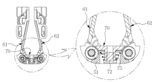
다시 도 4 및 도 5를 참조하면, 본 발명의 힌지장치(14)는 제1 힌지날개(21)와 제2 힌지날개(22)에 각각 설치되는 제1 및 제2 경사판(61,62)을 포함하는 경사수단을 구비한다.Referring again to Figures 4 and 5, the
제1 및 제2 경사판(61,62)은 제1 힌지날개(21)와 제2 힌지날개(22)의 회전운동시 후술하는 제1 가압수단에 의해 연동하여 '펼침위치'에서 제1 및 제2 본체(11,12)의 수평선상과 일치하는 수평위치(도 13a 참조)와, '접힘위치'에서 제1 힌지날개(21)와 제2 힌지날개(22) 사이에 폴딩공간이 형성되도록 제1 본체(11)와 제2 본체(12)의 수평선상으로부터 각각 외측으로 경사지게 배치되는 경사위치(도 13b 참조) 사이에서 이동하도록 설치된다.The first and
도 12a 및 도 12b는 제1 및 제2 경사판(61,62)의 설치구성 및 동작상태를 나타낸 것으로, 도 12a는 도 4의 A-A선 단면도로서 펼침위치를 나타낸 것이고, 도 12b는 접힘위치를 나타낸 것이다.FIGS. 12A and 12B show the installation configuration and operating state of the first and
도시된 바와 같이 제1 및 제2 경사판(61,62)은 제1 및 제2 힌지날개(21,22)에 소정각도 회전되도록 설치되는데, 힌지축선으로부터 소정길이 떨어진 부위에 나사(64)로 고정설치된다. 나사(64)로 고정되는 부위의 제1 및 제2 힌지날개(21,22)에는 반원형의 회전지지홈(65a)이 형성되고, 제1 및 제2 경사판(61,62)에는 반원형의 회전지지돌기(65b)가 형성되어 제1 및 제2 경사판(61,62)이 반원형의 회전지지돌기(65b)를 중심으로 상기 수평위치와 경사위치 사이에서 소정각도 회전할 수 있게 되어 있다. As shown, the first and
이때 상기 나사(64)가 관통하는 제1 및 제2 힌지날개(21,22)의 조립구멍(65c)은 제 및 제2 경사판(61,62)의 회전방향으로 약간 길게 형성하여 제1 및 제2 경사판(61,62)이 소정각도 회전하는 것을 가이드할 수 있게 한다.At this time, the assembly hole (65c) of the first and second hinge wings (21, 22) through which the screw (64) passes is formed to be slightly long in the rotation direction of the first and second swash plates (61, 62) to 2 The
또한 제1 가압수단은 상기 제1 및 제2 힌지날개(21,22)와 제1 및 제2 경사판(61,62) 사이에 탄력설치되어 제1 및 제2 경사판(61,62)이 항상 경사위치에 있도록 탄성력을 부여하는 제1 탄성부재(63a)와, 하우징(31)에 구비되고 '펼침위치'에서 제1 및 제2 경사판(61,62)의 일측을 각각 가압하여 수평위치를 유지하는 제1 가압돌기(63b)(도 8 및 도 13a 참조)로 이루어진다. 즉, 제1 탄성부재(63a)는 제1 및 제2 경사판(61,62)이 항상 경사위치에 있도록 유지하는 회전방향으로 가압하고, 제1 가압돌기(63b)는 제1 및 제2 경사판(61,62)이 수평위치에 있도록 유지하는 반대의 회전방향으로 가압한다.In addition, the first pressing means is elastically installed between the first and second hinge wings (21, 22) and the first and second swash plates (61, 62) so that the first and second swash plates (61, 62) are always inclined. A first elastic member (63a) that provides elastic force to keep in position, is provided in the housing (31) and maintains a horizontal position by pressing one side of the first and second swash plates (61, 62) in the 'unfolded position', respectively. It consists of a first
또한 제1 및 제2 힌지날개(21,22)에는 '접힘위치'에서 폴딩공간을 형성하기 위한 경사면(63c)이 형성된다. 경사면(63c)은 제1 본체(21)와 제2 본체(22)의 내측면과 대응하는 수평선상으로부터 외측으로 소정각도 경사지게 형성된 것으로, 제1 및 제2 경사판(61,62)이 경사위치에서 제1 탄성부재(63a)의 탄성력에 의해 상기 경사면(63c)에 밀착함으로써 항상 일정한 경사위치에서 폴딩공간을 형성하도록 되어 있다.
따라서, 제1 및 제2 경사판(61,62)은 '펼침위치'와 '접힘위치' 사이에서 제1 및 제2 본체(21, 22)의 회전방향과 반대방향으로 제1 및 제2 힌지날개(21,22)에 대하여 소정각도 회전하여 수평위치와 경사위치를 유지할 수 있다.Additionally, an
Accordingly, the first and
다시 도 4 및 도 5를 참조하면, 본 발명의 힌지장치(14)는 제1 및 제2 경사판(61,62) 사이에 배치되는 승강판(70)을 포함하는 승강수단을 구비한다.Referring again to Figures 4 and 5, the
도 14, 도 15a 및 도 15b에 도시된 바와 같이, 승강판(70)은 텐션기구(50)의 텐션고정부재(51) 상에 위치하고, 텐션고정부재(51)의 저면에서 나사(72)가 관통하여 승강판(70)에 체결됨으로써 설치된다. As shown in Figures 14, 15a, and 15b, the lifting
승강판(70)은 제1 및 제2 텐션날개(55,56)의 회전운동시 후술하는 제2 가압수단에 의해 연동하여 '펼침위치'에서 상기 제1 경사판(61,62)과 제2 경사판(61,62) 사이를 동일 수평선상으로 연결하는 상승위치(도 15a 참조)와, '접힘위치'에서 제1 힌지날개(21)와 제2 힌지날개(22) 사이에 폴딩공간이 형성되게 하는 하강위치(도 15b) 사이에서 이동하도록 구성된다.The lifting
제2 가압수단은 텐션고정부재(51)와 나사(72) 사이에 탄력설치되어 승강판(70)이 항상 하강위치에 있도록 탄성력을 부여하는 제2 탄성부재(75)와, 도 16a 및 도 16b에 도시된 바와 같이 텐션기구(50)의 제1 및 제2 텐션날개(55,56)에 형성한 제2 및 제3 가압돌기(73,74)로 이루어진다. The second pressing means includes a second
제2 탄성부재(75)는 도 15a에서와 같이 승강판(70)이 상승위치에 있을 때에는 압축되고, 도 15b에서와 같이 승강판(70)이 하강위치에 있을 때에는 신장되어 승강판(70)이 항상 하강위치로 이동하는 방향으로 탄성력을 부여하게 된다.The second
제2 및 제3 가압돌기(73,74)는 도 16a 및 도 16b에 도시된 바와 같이 힌지축선을 중심으로 하는 원주방향으로 배치된 것으로, 제2 가압돌기(73)는 도 16a에서와 같이 제1 및 제2 텐션날개(55,56)가 펼침위치로 회전할 때, 승강판(70)의 일측(70a)을 가압하여 승강판(70)을 상승위치에 유지시키고, 제3 가압돌기(74)는 도 16b에서와 같이 제1 및 제2 텐션날개(55,56)가 접힘위치로 회전할 때, 승강판(70)의 일측을 가압하여 승강판(70)을 하강위치에 유지시키도록 구성된다.The second and third
이러한 구성으로 이루어진 본 발명에 따른 힌지장치의 작용을 설명하면 다음과 같다.The operation of the hinge device according to the present invention configured as described above will be described as follows.
제1 및 제2 본체(11,12)를 도 2a에서와 같은 '펼침위치'와, 도 2b에서와 같은 '접힘위치' 사이에서 이동시키면, 도 7a 및 도 7b에서와 같이 제1 및 제2 본체(11,12)에 각각 고정된 제1 및 제2 힌지날개(21,22)의 반원형홈(21a,22a)이 하우징(31)의 반원형돌기(31a,31b)에 안내되어 회전지지하므로, 제1 및 제2 본체(11,12)를 "펼침위치'에서 "접힘위치" 사이에서 이동시키는 동작이 원활하게 이루어진다.When the first and
또한 제1 본체(11) 또는 제2 본체(12)중 어느 한쪽만 회전시켜도 연동수단에 의해 다른 한쪽이 상대운동하여 함께 회전한다.In addition, even if only one of the
또한 본 발명의 힌지장치(14)는 제1 및 제2 본체(11,12)의 회전위치가 '펼침위치"와 '접힘위치' 사이에 있을 때 텐션기구(50)에 의해 프리스톱기능이 수행된다.In addition, the
텐션기구(50)는 도 11에서와 같이 제1 및 제2 텐션날개(55,56)의 텐션가이드돌기(58b)가 제1 및 제2 힌지날개(21,22)의 텐션가이드구멍(58a)에 안내된 것이므로, 제1 및 제2 힌지날개(21,22)의 회전시 제1 및 제2 텐션날개(55,56)가 연동하여 함께 회전한다.As shown in FIG. 11, the
이로 인해 텐션가동부재(53,54)는 제1 및 제2 가이드축(52a,52b)을 따라 이동하여 제1 및 제2 스프링(57a,57b)을 압축시키게 되므로, 텐션가동부재(53,54)를 제1 및 제2 텐션날개(55,56)쪽으로 가압하는 제1 및 제2 스프링(57a,57b)의 탄성력은 증가되고, 이 증가된 탄성력으로 제1 및 제2 본체(11,12)를 회전 도중 정지시킬 때 정지위치에 그대로 유지시키는 프리스톱기능을 수행할 수 있다.Because of this, the tension
또한 본 발명의 힌지장치(14)는, 제1 및 제2 힌지날개(21,22)가 '펼침위치'와 '접힘위치' 사이에서 회전할 때 제1 및 제2 경사판(61,62)과 승강판(70)이 연동하는 것에 의해, 도 2a에서와 같이 제1 및 제2 본체(11,12)의 '펼침위치'에서 플렉서블 디스플레이패널(13)의 폴딩부(P)가 수평상태를 유지할 수 있고, 또한 도 2b에서와 같이 제1 및 제2 본체(11,12)의 '접힘위치'에서 디스플레이패널의 폴딩부(P)에 형성되는 소정의 곡률반경(R)을 수용할 수 있는 폴딩공간을 형성할 수 있다.In addition, the
즉, 도 12b에서와 같이 제1 및 제2 힌지날개(21,22)가 '접힘위치'에 있을 때, 제1 및 제2 경사판(61,62)은 제1 탄성부재(63a)의 탄성력에 의해 제1 및 제2 힌지날개(21,22)의 경사면(63c)에 밀착하는 경사위치에 있게 되고, 도 13b에서와 같이 제1 및 제2 경사판(61,62)의 일끝단부는 하우징(31)의 제1 가압돌기(63b) 위에 위치되어 있다.That is, when the first and
또한 승강판(70)은 도 15b에서와 같이 제2 탄성부재(75)의 탄성력에 의해 하강위치에 있고, 도 16b에서와 같이 텐션기구(50)의 제1 및 제2 텐션날개(55,56)에 구비된 제3 가압돌기(74)가 승강판(70)의 일측(70a)을 가압하여 유지하고 있다.In addition, the lifting
이러한 '접힘위치'에서 제1 및 제2 본체(11,12)를 '펼침위치'로 회전시키게 되면, 도 13a에서와 같이 제1 및 제2 본체(11,12)에 각각 고정된 제1 및 제2 힌지날개(21,22)가 함께 회전하게 된다. 이때 제1 및 제2 경사판(61,62)의 끝단부가 하우징(31)의 제1 가압돌기(63b)에 접촉되면서 제1 및 제2 경사판(61,62)은 도 12a에서와 같이 회전지지돌기(65b)를 중심으로 회전하여 경사면(63c)으로부터 이격된 수평위치로 이동하고, 제1 탄성부재(63a)는 압축된 상태가 된다.When the first and
또한 승강판(70)은 도 16a에서와 같이 제1 및 제2 텐션날개(55,56)의 회전에 의해 제3 가압돌기(74)가 승강판(70)으로부터 이격되고, 제2 가압돌기(73)가 승강판(70)의 일측(70a)을 가압하여 하강위치에서 상승위치로 이동시키게 되므로, 도 15a에서와 같이 제2 탄성부재(75)는 압축된 상태가 된다.In addition, the lifting
이와 같이 제1 및 제2 경사판(61,62)은 수평위치로 이동하고, 승강판(70)은 상승위치로 이동하면, 도 15a에서와 같이 제1 및 제2 경사판(61,62)이 수평위치에서 제1 및 제2 본체(11,12)의 수평선상과 일치되므로, 플렉서블 디스플레이패널(13)의 폴딩부(P)를 수평상태로 유지할 수 있고(도 2a 참조), 승강판(70)이 상승위치에서 제1 및 제2 경사판(61,62) 사이의 틈새를 동일 수평선상으로 연결하게 되므로, 플렉서블 디스플레이패널(13)의 폴딩부(P)에 대한 수평상태를 연이어서 확실하게 유지할 수 있다.In this way, when the first and
이어서, 상기와 같은 '펼침위치'에서 제1 및 제2 본체(11,12)를 '접힘위치'로 회전시키게 되면, 도 12b에서와 같이 제1 및 제2 본체(11,12)에 각각 고정된 제1 및 제2 힌지날개(21,22)가 함께 회전하게 된다. 이때 제1 및 제2 경사판(61,62)은 압축된 제1 탄성부재(63a)에 의해 경사위치로 회전하려는 탄성력을 부여받고 있는 것이므로, 제1 및 제2 경사판(61,62)은 회전지지돌기(65b)를 중심으로 회전하여 경사면(63c)에 밀착하는 경사위치로 이동하게 된다.Subsequently, when the first and second
또한 승강판(70)은 도 16b에서와 같이 제2 가압돌기(73)가 승강판(70)으로부터 이격되고, 제3 가압돌기(73)가 승강판(70)의 일측(70a)을 가압하여 상승위치에서 하강위치로 이동시킴과 동시에, 도 15b에서와 같이 압축되어 있던 제2 탄성부재(75)의 탄성력이 승강판(70)의 하강이동을 돕게 된다. In addition, the lifting
이와 같이 제1 및 제2 경사판(61,62)은 경사위치로 이동하고, 승강판(70)은 하강위치로 이동하면, 제1 및 제2 힌지날개(21,22) 사이의 공간이 넓게 확보되고, 이로써 플렉서블 디스플레이패널(13)의 폴딩부(P)에 형성되는 소정의 곡률반경(R)을 수용할 수 있는 폴딩공간을 형성할 수 있다. 따라서, 본 발명의 힌지장치는 제 1 및 제2 본체(11, 12)에 부착되는 디스플레이패널을 '접힘위치'에서 폴딩부(P)에서는 소정의 곡률반경을 형성하면서도 폴딩부 외에서는 평행하게 접히게 할 수 있다(도 2b '덤벨형상' 참고).In this way, when the first and second
이와 같이 본 발명의 힌지장치(14)는, 제1 및 제2 본체(11,12)의 '펼침위치'에서 플렉서블 디스플레이패널(13)의 폴딩부(P)를 수평상태로 유지하고, '접힘위치'에서 플렉서블 디스플레이부패널(13)의 폴딩부(P)에 형성되는 소정의 곡률반경(R)을 수용하는 폴딩공간을 형성하면서도 '접힘위치'에서 제1 본체(11)와 제2 본체(12)의 내측이 접한 상태에서 외측과 내측을 평행하게 형성하는 것이 가능하고, 이로써 휴대단말기의 외관을 심플하게 하면서, 제1 및 제2 본체(11,12) 사이의 틈새를 없애 휴대시 이물질이 플렉서블 디스플레이부패널을 오염시키는 것을 방지할 수 있다. In this way, the
이상에서는 본 발명의 힌지장치에서 '펼침위치'에서 수평상태로 유지하고 '접힘위치'에서 소정의 곡률반경(R)을 수용하는 폴딩공간을 형성하여 디스플레이패널이 덤벨 형상으로 접히게 되어 '접힘위치'에서 본체 내측이 접하고 외측과 내측을 평행하게 형성할 수 있도록 하는 경사수단 또는 승강수단은 이와 결합할 수 있는 전술한 일실시예의 회전지지구성, 연동수단 또는 텐션기구 외에도 다양한 회전지지구성, 연동수단 또는 텐션기구에 결합하여 적용될 수 있다. In the above, the hinge device of the present invention maintains a horizontal state in the 'unfolded position' and forms a folding space that accommodates a predetermined radius of curvature (R) in the 'folded position', so that the display panel is folded into a dumbbell shape and is in the 'folded position'. 'In addition to the rotation support structure, interlocking means, or tension mechanism of the above-described embodiment, the inclined means or elevating means that allow the inner side of the main body to contact and form the outer and inner sides in parallel are various rotational support structures and interlocking means. Alternatively, it can be applied in conjunction with a tension mechanism.
본 발명의 힌지장치는 핸드폰과 같은 휴대단말기 외에도 노트북 등 힌지 구조가 적용되는 각종 기기에도 사용될 수 있다.The hinge device of the present invention can be used not only in portable terminals such as mobile phones, but also in various devices to which a hinge structure is applied, such as laptops.
이상과 같이 도면과 명세서에서 최적 실시 예가 개시되었다. 여기서 특정한 용어들이 사용되었으나, 이는 단지 본 발명을 설명하기 위한 목적에서 사용된 것이지 의미 한정이나 특허청구범위에 기재된 본 발명의 범위를 제한하기 위하여 사용된 것은 아니다. 그러므로 본 기술 분야의 통상의 지식을 가진 자라면 이로부터 다양한 변형 및 균등한 타 실시 예가 가능하다는 점을 이해할 것이다. 따라서 본 발명의 진정한 기술적 보호 범위는 첨부된 특허청구범위의 기술적 사상에 의해 정해져야 할 것이다.As described above, the optimal embodiment is disclosed in the drawings and specifications. Although specific terms are used here, they are used only for the purpose of describing the present invention and are not used to limit the meaning or scope of the present invention described in the claims. Therefore, those skilled in the art will understand that various modifications and other equivalent embodiments are possible therefrom. Therefore, the true scope of technical protection of the present invention should be determined by the technical spirit of the attached patent claims.
11,12 : 제1 및 제2 본체 13 : 플렉서블 디스플레이패널
14 : 힌지장치 21,22 : 제1 및 제2 힌지날개
31 : 하우징 50 : 텐션기구
55,56 : 제1 및 제2 텐션날개 61,62 : 제1 및 제2 경사판
63a : 제1 탄성부재 63b : 제1 가압돌기
63c : 경사면 70 : 승강판
73,74 : 제2 및 제3 가압돌기 75 : 제2 탄성부재
P : 폴딩부 R : 곡률반경 11, 12: first and second bodies 13: flexible display panel
14:
31: Housing 50: Tension mechanism
55,56: first and
63a: first
63c: Inclined plane 70: Elevating plate
73,74: second and third pressing protrusions 75: second elastic member
P: Folding part R: Curvature radius
Claims (8)
상기 제1 본체와 제2 본체에 각각 고정되고, 상기 하우징에 각각 회전지지되어 제1 본체와 제2 본체가 동일 수평선상에 놓이는 '펼침위치'와, 제1 본체와 제2 본체가 서로 마주하여 접하는 '접힘위치' 사이에서 소정각도 회전운동하는 제1 힌지날개 및 제2 힌지날개;
상기 제1 힌지날개와 제2 힌지날개에 소정각도 회전되도록 지지되어 각각 설치되고, 일측에 하나의 회전방향으로 유지되도록 하는 가압수단과 타측에 반대의 회전방향으로 유지되도록 하는 가압수단이 적용되어, 상기 제1 힌지날개와 제2 힌지날개의 회전운동시 상기 '펼침위치'에서 제1 본체 및 제2 본체의 수평선상과 일치하는 수평위치와 상기 '접힘위치'에서 제1 힌지날개와 제2 힌지날개 사이에 폴딩공간이 형성되도록 제1 본체와 제2 본체의 수평선상으로부터 각각 경사지게 배치되는 경사위치 사이에서 이동하는 제1 경사판 및 제2 경사판을 포함하는 경사수단을 포함하여 이루어진 것을 특징으로 하는 힌지장치.
A housing located between one end of the first and second bodies that are linked and move relative to each other;
An 'unfolding position' is fixed to the first body and the second body, respectively, and is rotationally supported by the housing, so that the first body and the second body are placed on the same horizontal line, and the first body and the second body face each other. First and second hinge wings rotating at a predetermined angle between adjacent 'folded positions';
The first hinge wing and the second hinge wing are each supported and installed to rotate at a predetermined angle, and a pressing means for maintaining one rotational direction on one side and a pressing means for maintaining the opposite rotational direction on the other side are applied, When the first hinge wing and the second hinge wing rotate, the first hinge wing and the second hinge are positioned in a horizontal position that coincides with the horizontal lines of the first and second main bodies at the 'unfolded position' and at the 'folded position'. A hinge characterized in that it includes a tilting means including a first swash plate and a second swash plate that moves between inclined positions each inclined from the horizontal line of the first body and the second body to form a folding space between the wings. Device.
상기 제1 경사판 및 제2 경사판은 제1 가압수단에 의해 연동하며,
상기 제1 가압수단은,
상기 제1 경사판 및 제2 경사판이 항상 상기 경사위치에 있도록 탄성력을 부여하는 제1 탄성부재와,
상기 제1 힌지날개 및 제2 힌지날개가 상기 '펼침위치'로 회전할 때, 제1 경사판 및 제2 경사판을 각각 가압하여 제1 힌지날개 및 제2 힌지날개를 수평위치에서 유지되게 하는 제1 가압돌기로 이루어진 것을 특징으로 하는 힌지장치.
According to claim 1,
The first swash plate and the second swash plate are interlocked by a first pressing means,
The first pressing means is,
a first elastic member that provides an elastic force so that the first and second swash plates are always in the inclined position;
When the first hinge wing and the second hinge wing rotate to the 'unfolded position', the first hinge wing and the second hinge wing are maintained in a horizontal position by pressing the first swash plate and the second swash plate, respectively. A hinge device characterized by consisting of a pressing protrusion.
상기 제1 힌지날개 및 제2 힌지날개에는 회전지지홈이 형성되고, 상기 제1 경사판 및 제2 경사판에는 회전지지돌기가 형성되어 제1 및 제2 경사판이 회전지지돌기를 중심으로 수평위치와 경사위치 사이에서 소정각도 회전할 수 있도록 이루어진 것을 특징으로 하는 힌지장치.
According to clause 1,
Rotation support grooves are formed on the first and second hinge wings, and rotation support protrusions are formed on the first and second swash plates, so that the first and second swash plates are in a horizontal position and inclined around the rotation support protrusions. A hinge device characterized in that it can rotate at a predetermined angle between positions.
상기 제1 경사판 및 제2 경사판과 결합되는 상기 제1 힌지날개 및 제2 힌지날개의 조립구멍은 제1 경사판 및 제2 경사판의 회전방향으로 약간 길게 형성하여 제1 경사판 및 제2 경사판이 소정각도 회전하는 것을 가이드하는 것을 특징으로 하는 힌지장치.
According to clause 3,
The assembly holes of the first and second hinge wings coupled to the first and second swash plates are formed to be slightly elongated in the rotation direction of the first and second swash plates so that the first and second swash plates are tilted at a predetermined angle. A hinge device characterized in that it guides rotation.
상기 제1 힌지날개 및 제2 힌지날개에는 상기 제1 경사판 및 제2 경사판의 경사위치에서 제1 경사판 및 제2 경사판과 밀착할 수 있는 경사면이 형성되어 가압부재에 의해 항상 일정한 경사위치에서 폴딩공간을 형성하도록 된 것을 특징으로 하는 힌지장치.
According to claim 1,
The first and second hinge wings are formed with inclined surfaces that can come into close contact with the first and second swash plates at the inclined positions of the first and second swash plates, so that the folding space is always maintained at a constant inclined position by a pressing member. A hinge device characterized in that it is configured to form a.
상기 하우징에 설치되어 제1 경사판 및 제2 경사판 사이의 폴딩공간에 위치하고,
상기 제1 힌지날개와 제2 힌지날개의 회전운동시 가압에 의해 연동하여, 상기 펼침위치에서 상기 제1 경사판과 제2 경사판 사이를 동일 수평선상으로 연결하도록 상기 하우징으로부터 이격하는 상승위치와, 상기 접힘위치에서 제1 힌지날개와 제2 힌지날개 사이에 상기 폴딩공간이 형성되도록 상기 하우징에 근접하는 하강위치 사이에서 이동하는 승강판을 포함하는 승강수단을 더 포함하여 이루어진 것을 특징으로 하는 힌지장치.
According to claim 1,
It is installed in the housing and located in the folding space between the first and second swash plates,
A rising position spaced apart from the housing so as to connect the first and second swash plates on the same horizontal line in the unfolded position by interlocking them with pressure during the rotational movement of the first and second hinge wings, and The hinge device further comprises a lifting means including a lifting plate that moves between a lowered position close to the housing so that the folding space is formed between the first hinge blade and the second hinge blade in the folded position.
상기 승강판은 제2 가압수단에 의해 연동하며,
상기 제2 가압수단은,
상기 승강판이 항상 상기 하강위치에 있도록 탄성력을 부여하는 제2 탄성부재와,
상기 승강판을 가압하여 상승위치와 하강위치로 이동시키는 제2 및 제3 가압돌기로 이루어진 것을 특징으로 하는 힌지장치.
According to claim 6,
The lifting plate is linked by a second pressurizing means,
The second pressing means is,
a second elastic member that provides elastic force so that the lifting plate is always in the lowered position;
A hinge device characterized in that it consists of second and third pressing protrusions that pressurize the lifting plate and move it to the raised and lowered positions.
상기 제 1본체 및 제 2본체에 부착되는 디스플레이패널을 '접힘위치'에서 폴딩부에서는 소정의 곡률반경을 형성하면서 폴딩부 외에서는 평행하게 접히게 하는 것을 특징으로 하는 힌지장치.
According to clause 1,
A hinge device characterized in that the display panel attached to the first body and the second body is folded in a 'folded position' to form a predetermined radius of curvature in the folding portion and to be parallel to the outside of the folding portion.
Priority Applications (5)
| Application Number | Priority Date | Filing Date | Title |
|---|---|---|---|
| KR1020210111963A KR102579762B1 (en) | 2021-08-24 | 2021-08-24 | Hinge device of foldable mobile device using flexible display panel |
| US18/293,791 US20240247683A1 (en) | 2021-08-24 | 2022-08-24 | Hinge device of foldable mobile device using flexible display panel |
| CN202280056952.8A CN117859105A (en) | 2021-08-24 | 2022-08-24 | Hinge device for foldable mobile device using flexible display panel |
| PCT/KR2022/012630 WO2023027496A1 (en) | 2021-08-24 | 2022-08-24 | Hinge device of foldable mobile device using flexible display panel |
| KR1020230035435A KR20230042247A (en) | 2021-08-24 | 2023-03-17 | Hinge device of foldable mobile device using flexible display panel |
Applications Claiming Priority (1)
| Application Number | Priority Date | Filing Date | Title |
|---|---|---|---|
| KR1020210111963A KR102579762B1 (en) | 2021-08-24 | 2021-08-24 | Hinge device of foldable mobile device using flexible display panel |
Related Child Applications (1)
| Application Number | Title | Priority Date | Filing Date |
|---|---|---|---|
| KR1020230035435A Division KR20230042247A (en) | 2021-08-24 | 2023-03-17 | Hinge device of foldable mobile device using flexible display panel |
Publications (2)
| Publication Number | Publication Date |
|---|---|
| KR20230029454A KR20230029454A (en) | 2023-03-03 |
| KR102579762B1 true KR102579762B1 (en) | 2023-09-19 |
Family
ID=85321914
Family Applications (2)
| Application Number | Title | Priority Date | Filing Date |
|---|---|---|---|
| KR1020210111963A Active KR102579762B1 (en) | 2021-08-24 | 2021-08-24 | Hinge device of foldable mobile device using flexible display panel |
| KR1020230035435A Withdrawn KR20230042247A (en) | 2021-08-24 | 2023-03-17 | Hinge device of foldable mobile device using flexible display panel |
Family Applications After (1)
| Application Number | Title | Priority Date | Filing Date |
|---|---|---|---|
| KR1020230035435A Withdrawn KR20230042247A (en) | 2021-08-24 | 2023-03-17 | Hinge device of foldable mobile device using flexible display panel |
Country Status (4)
| Country | Link |
|---|---|
| US (1) | US20240247683A1 (en) |
| KR (2) | KR102579762B1 (en) |
| CN (1) | CN117859105A (en) |
| WO (1) | WO2023027496A1 (en) |
Families Citing this family (3)
| Publication number | Priority date | Publication date | Assignee | Title |
|---|---|---|---|---|
| CN118202316A (en) * | 2021-11-04 | 2024-06-14 | 三星电子株式会社 | Electronic device including hinge assembly |
| CN114244926B (en) * | 2021-11-30 | 2022-08-26 | 荣耀终端有限公司 | Foldable electronic equipment |
| CN117780770A (en) * | 2022-09-20 | 2024-03-29 | 荣耀终端有限公司 | Rotating mechanism and electronic equipment |
Citations (4)
| Publication number | Priority date | Publication date | Assignee | Title |
|---|---|---|---|---|
| US20190390703A1 (en) | 2018-06-21 | 2019-12-26 | Jarllytec Co., Ltd | Hinge module for a foldable type device |
| US20200103935A1 (en) * | 2018-09-27 | 2020-04-02 | Jarllytec Co.,Ltd. | Hinge module for a foldable type device |
| JP2021505822A (en) | 2017-12-06 | 2021-02-18 | 杭州安費諾飛鳳通信部品有限公司 | Hinge of inward folding flexible screen / mobile terminal and inward folding flexible screen / mobile terminal |
| CN113053238A (en) * | 2019-12-27 | 2021-06-29 | 华为技术有限公司 | Flexible screen and foldable equipment |
Family Cites Families (8)
| Publication number | Priority date | Publication date | Assignee | Title |
|---|---|---|---|---|
| TWI660260B (en) * | 2017-10-13 | 2019-05-21 | 富世達股份有限公司 | Flexible display apparatus and supporting device |
| KR102883463B1 (en) * | 2019-04-28 | 2025-11-11 | (주)에이유플렉스 | Folding Hinge for Foldable Device |
| KR102884796B1 (en) * | 2019-11-15 | 2025-11-12 | 삼성전자주식회사 | Foldable Electronic device |
| KR102668216B1 (en) * | 2019-12-02 | 2024-05-23 | 삼성전자주식회사 | Foldable electronic device including hinge assembly |
| CN113090149B (en) * | 2019-12-23 | 2022-08-09 | 北京小米移动软件有限公司 | Hinge structure and folding electronic device |
| KR102641514B1 (en) * | 2020-02-10 | 2024-02-27 | 삼성전자주식회사 | Foldable electronic device including hinge assembly |
| JP7668516B2 (en) * | 2020-10-29 | 2025-04-25 | 株式会社ナチュラレーザ・ワン | Multi-axis hinge device and electronic device using the multi-axis hinge device |
| WO2022119353A1 (en) * | 2020-12-03 | 2022-06-09 | 주식회사 파인테크닉스 | Hinge device of portable terminal with foldable structure |
-
2021
- 2021-08-24 KR KR1020210111963A patent/KR102579762B1/en active Active
-
2022
- 2022-08-24 CN CN202280056952.8A patent/CN117859105A/en active Pending
- 2022-08-24 WO PCT/KR2022/012630 patent/WO2023027496A1/en not_active Ceased
- 2022-08-24 US US18/293,791 patent/US20240247683A1/en active Pending
-
2023
- 2023-03-17 KR KR1020230035435A patent/KR20230042247A/en not_active Withdrawn
Patent Citations (4)
| Publication number | Priority date | Publication date | Assignee | Title |
|---|---|---|---|---|
| JP2021505822A (en) | 2017-12-06 | 2021-02-18 | 杭州安費諾飛鳳通信部品有限公司 | Hinge of inward folding flexible screen / mobile terminal and inward folding flexible screen / mobile terminal |
| US20190390703A1 (en) | 2018-06-21 | 2019-12-26 | Jarllytec Co., Ltd | Hinge module for a foldable type device |
| US20200103935A1 (en) * | 2018-09-27 | 2020-04-02 | Jarllytec Co.,Ltd. | Hinge module for a foldable type device |
| CN113053238A (en) * | 2019-12-27 | 2021-06-29 | 华为技术有限公司 | Flexible screen and foldable equipment |
Also Published As
| Publication number | Publication date |
|---|---|
| KR20230029454A (en) | 2023-03-03 |
| US20240247683A1 (en) | 2024-07-25 |
| KR20230042247A (en) | 2023-03-28 |
| WO2023027496A1 (en) | 2023-03-02 |
| CN117859105A (en) | 2024-04-09 |
Similar Documents
| Publication | Publication Date | Title |
|---|---|---|
| KR102579762B1 (en) | Hinge device of foldable mobile device using flexible display panel | |
| EP4227547B1 (en) | Rotating shaft assembly and electronic device | |
| EP4350672A1 (en) | Folding display device | |
| US11487321B2 (en) | Foldable electronic device | |
| US9388614B2 (en) | Parallelism fixing device applied to dual-shaft system | |
| KR100948443B1 (en) | Portable terminal device | |
| EP2574014B1 (en) | Opening/closing device | |
| US12396112B2 (en) | Foldable display apparatus | |
| KR20220084076A (en) | Hinge device of a portable terminal having a foldable structure | |
| KR20220115380A (en) | Hinge module and electronic device including the same | |
| US20130192140A1 (en) | Cover mechanism for opening and closing device | |
| KR102579763B1 (en) | Hinge device of foldable mobile device using flexible display panel | |
| EP2509287B1 (en) | Slide-tilt mechanism | |
| WO2018137535A1 (en) | Housing assembly and electronic device | |
| US20240419221A1 (en) | Rotating shaft apparatus, foldable housing and electronic device | |
| TWM575953U (en) | Bending mechanism and display device with flexible screen | |
| JP5420486B2 (en) | Switchgear | |
| CN102461131B (en) | Tilting structure and sliding device | |
| KR102579765B1 (en) | Hinge device of foldable mobile device using flexible display panel | |
| KR102575372B1 (en) | Hinge device of foldable mobile device using flexible display panel | |
| KR102523273B1 (en) | Hinge device of foldable mobile device using flexible display panel | |
| KR102579764B1 (en) | Hinge device of foldable mobile device using flexible display panel | |
| KR102552471B1 (en) | Hinge device of in-out foldable mobile device using flexible display panel | |
| CN115854213A (en) | Rotary screen splicing support mechanism | |
| KR102598621B1 (en) | Tension mechanism of hinge device for foldable portable terminal |
Legal Events
| Date | Code | Title | Description |
|---|---|---|---|
| PA0109 | Patent application |
Patent event code: PA01091R01D Comment text: Patent Application Patent event date: 20210824 |
|
| PA0201 | Request for examination | ||
| PE0902 | Notice of grounds for rejection |
Comment text: Notification of reason for refusal Patent event date: 20221027 Patent event code: PE09021S01D |
|
| PG1501 | Laying open of application | ||
| E701 | Decision to grant or registration of patent right | ||
| PE0701 | Decision of registration |
Patent event code: PE07011S01D Comment text: Decision to Grant Registration Patent event date: 20230713 |
|
| GRNT | Written decision to grant | ||
| PR0701 | Registration of establishment |
Comment text: Registration of Establishment Patent event date: 20230913 Patent event code: PR07011E01D |
|
| PR1002 | Payment of registration fee |
Payment date: 20230914 End annual number: 3 Start annual number: 1 |
|
| PG1601 | Publication of registration |