KR102555269B1 - Posture estimation fusion method and system using omnidirectional image sensor and inertial measurement sensor - Google Patents
Posture estimation fusion method and system using omnidirectional image sensor and inertial measurement sensor Download PDFInfo
- Publication number
- KR102555269B1 KR102555269B1 KR1020210029598A KR20210029598A KR102555269B1 KR 102555269 B1 KR102555269 B1 KR 102555269B1 KR 1020210029598 A KR1020210029598 A KR 1020210029598A KR 20210029598 A KR20210029598 A KR 20210029598A KR 102555269 B1 KR102555269 B1 KR 102555269B1
- Authority
- KR
- South Korea
- Prior art keywords
- inertial measurement
- image
- measurement sensor
- sensor
- posture estimation
- Prior art date
- Legal status (The legal status is an assumption and is not a legal conclusion. Google has not performed a legal analysis and makes no representation as to the accuracy of the status listed.)
- Active
Links
Images


Classifications
-
- G—PHYSICS
- G01—MEASURING; TESTING
- G01C—MEASURING DISTANCES, LEVELS OR BEARINGS; SURVEYING; NAVIGATION; GYROSCOPIC INSTRUMENTS; PHOTOGRAMMETRY OR VIDEOGRAMMETRY
- G01C21/00—Navigation; Navigational instruments not provided for in groups G01C1/00 - G01C19/00
- G01C21/10—Navigation; Navigational instruments not provided for in groups G01C1/00 - G01C19/00 by using measurements of speed or acceleration
- G01C21/12—Navigation; Navigational instruments not provided for in groups G01C1/00 - G01C19/00 by using measurements of speed or acceleration executed aboard the object being navigated; Dead reckoning
- G01C21/16—Navigation; Navigational instruments not provided for in groups G01C1/00 - G01C19/00 by using measurements of speed or acceleration executed aboard the object being navigated; Dead reckoning by integrating acceleration or speed, i.e. inertial navigation
- G01C21/165—Navigation; Navigational instruments not provided for in groups G01C1/00 - G01C19/00 by using measurements of speed or acceleration executed aboard the object being navigated; Dead reckoning by integrating acceleration or speed, i.e. inertial navigation combined with non-inertial navigation instruments
- G01C21/1656—Navigation; Navigational instruments not provided for in groups G01C1/00 - G01C19/00 by using measurements of speed or acceleration executed aboard the object being navigated; Dead reckoning by integrating acceleration or speed, i.e. inertial navigation combined with non-inertial navigation instruments with passive imaging devices, e.g. cameras
-
- G—PHYSICS
- G01—MEASURING; TESTING
- G01P—MEASURING LINEAR OR ANGULAR SPEED, ACCELERATION, DECELERATION, OR SHOCK; INDICATING PRESENCE, ABSENCE, OR DIRECTION, OF MOVEMENT
- G01P15/00—Measuring acceleration; Measuring deceleration; Measuring shock, i.e. sudden change of acceleration
- G01P15/02—Measuring acceleration; Measuring deceleration; Measuring shock, i.e. sudden change of acceleration by making use of inertia forces using solid seismic masses
- G01P15/08—Measuring acceleration; Measuring deceleration; Measuring shock, i.e. sudden change of acceleration by making use of inertia forces using solid seismic masses with conversion into electric or magnetic values
-
- G—PHYSICS
- G06—COMPUTING OR CALCULATING; COUNTING
- G06N—COMPUTING ARRANGEMENTS BASED ON SPECIFIC COMPUTATIONAL MODELS
- G06N20/00—Machine learning
-
- G—PHYSICS
- G06—COMPUTING OR CALCULATING; COUNTING
- G06V—IMAGE OR VIDEO RECOGNITION OR UNDERSTANDING
- G06V20/00—Scenes; Scene-specific elements
- G06V20/40—Scenes; Scene-specific elements in video content
- G06V20/46—Extracting features or characteristics from the video content, e.g. video fingerprints, representative shots or key frames
-
- G—PHYSICS
- G06—COMPUTING OR CALCULATING; COUNTING
- G06V—IMAGE OR VIDEO RECOGNITION OR UNDERSTANDING
- G06V20/00—Scenes; Scene-specific elements
- G06V20/60—Type of objects
- G06V20/64—Three-dimensional objects
-
- G—PHYSICS
- G06—COMPUTING OR CALCULATING; COUNTING
- G06V—IMAGE OR VIDEO RECOGNITION OR UNDERSTANDING
- G06V40/00—Recognition of biometric, human-related or animal-related patterns in image or video data
- G06V40/20—Movements or behaviour, e.g. gesture recognition
Landscapes
- Engineering & Computer Science (AREA)
- Physics & Mathematics (AREA)
- General Physics & Mathematics (AREA)
- Theoretical Computer Science (AREA)
- Radar, Positioning & Navigation (AREA)
- Remote Sensing (AREA)
- Multimedia (AREA)
- Software Systems (AREA)
- Computer Vision & Pattern Recognition (AREA)
- Evolutionary Computation (AREA)
- Computing Systems (AREA)
- Human Computer Interaction (AREA)
- Psychiatry (AREA)
- Health & Medical Sciences (AREA)
- Artificial Intelligence (AREA)
- Social Psychology (AREA)
- Medical Informatics (AREA)
- Data Mining & Analysis (AREA)
- Automation & Control Theory (AREA)
- General Health & Medical Sciences (AREA)
- General Engineering & Computer Science (AREA)
- Mathematical Physics (AREA)
- Image Analysis (AREA)
- Length Measuring Devices By Optical Means (AREA)
Abstract
전방향 영상센서 및 관성측정센서의 자세추정 융합 방법 및 시스템이 개시된다. 자세 추정 시스템에 의해 수행되는 자세 추정 방법은, 영상 센서 및 관성측정 센서의 융합을 통해 영상 정보 내 추정되는 특징점의 위치 데이터를 예측하는 단계; 및 상기 예측된 특징점의 위치 데이터에 기초하여 상기 영상 센서 및 관성측정 센서 간의 상대적 자세 정보를 추정하기 위한 외부 파라미터를 조정하는 단계를 포함할 수 있다. A posture estimation fusion method and system of an omnidirectional image sensor and an inertial measurement sensor are disclosed. A posture estimation method performed by a posture estimation system includes predicting position data of feature points estimated in image information through fusion of an image sensor and an inertial measurement sensor; and adjusting an external parameter for estimating relative attitude information between the image sensor and the inertial measurement sensor based on the positional data of the predicted feature point.
Description
아래의 설명은 영상 정보를 이용하여 자세를 추정하는 기술에 관한 것이다. The following description relates to a technique for estimating a posture using image information.
종래의 영상 기반 주행 움직임 추정 기술(Visual Odometry, Visual SLAM)은 단안(monocular) 혹은 스테레오(stereo) 카메라를 사용하여 시공간 상의 영상 내 대응점들을 구하고, 이들 간의 기하학적 정합성을 가장 잘 설명하는 6자유도 자세와 주변 정적 환경의 3차원 점을 최적화를 통해 동시에 추정하는 기술이다. 그러나, 영상 기반 주행 움직임 추정 기술은 단안 카메라의 경우 실제 환경의 절대적인 거리 정보를 추정할 수 없고 스테레오 카메라 시스템의 경우 하드웨어 구성 측면에서의 제약으로 인해 센싱 영역이 180도 이상이 되기 어렵다. 이로 인해 도심과 같은 혼잡한 환경에서 영산 내 동적 물체에 취약한 visual SLAM 기술의 자세 추정 정확도가 매우 떨어진다. Conventional image-based driving motion estimation technology (Visual Odometry, Visual SLAM) uses a monocular or stereo camera to obtain corresponding points in the image in space and time, and to obtain a six-degree-of-freedom posture that best describes the geometric consistency between them It is a technology that simultaneously estimates the 3D points of the surrounding static environment through optimization. However, the image-based driving motion estimation technology cannot estimate absolute distance information of the real environment in the case of a monocular camera, and in the case of a stereo camera system, it is difficult for the sensing area to be greater than 180 degrees due to limitations in terms of hardware configuration. Because of this, the posture estimation accuracy of the visual SLAM technology, which is vulnerable to dynamic objects in Yeongsan, is very poor in a congested environment such as a city center.
레이저 센서를 이용한 주행 움직임 추정 기술(LiDAR SLAM)은 LiDAR와 같은 매우 높은 정확도의 거리 측정 센서를 사용하여 구해진 3차원 점 간의 구조적 정합성을 가장 잘 설명하는 6자유도 자세를 최적화 방법에 기반하여 추정하는 기술이다. 상기 레이저 센서를 이용한 주행 움직임 추정 기술은 센서 하드웨어 설계의 물리적 한계와 간섭에 영향을 받는 센싱 방식으로 인해 안정성이 떨어지고 단위 시간 취득 정보량이 적어 빠른 움직임 추정 시 현저한 성능 저하를 보인다는 한계가 있다. Driving motion estimation technology using a laser sensor (LiDAR SLAM) is based on an optimization method for estimating the 6-DOF posture that best describes the structural consistency between 3D points obtained using a very high-accuracy distance measurement sensor such as LiDAR. It is a skill. The technology for estimating driving motion using the laser sensor has a limitation in that stability is poor due to physical limitations of sensor hardware design and a sensing method that is affected by interference, and significant performance degradation is observed when estimating fast motion due to a small amount of information obtained per unit time.
관성측정 센서 융합을 통한 어안 영상 내 특징점 위치 예측을 추적하는 방법 및 시스템을 제공할 수 있다. It is possible to provide a method and system for tracking feature point position prediction in a fisheye image through inertial measurement sensor fusion.
다중 카메라 및 관성센서측정 센서 간 외부 파라미터를 포함한 자세 및 환경지도를 동시에 최적화하는 방법 및 시스템을 제공할 수 있다. It is possible to provide a method and system for simultaneously optimizing attitude and environment maps including external parameters between multiple cameras and inertial sensor measurement sensors.
자세 추정 시스템에 의해 수행되는 자세 추정 방법은, 영상 센서 및 관성측정 센서의 융합을 통해 영상 정보 내 추정되는 특징점의 위치 데이터를 예측하는 단계; 및 상기 예측된 특징점의 위치 데이터에 기초하여 상기 영상 센서 및 관성측정 센서 간의 상대적 자세 정보를 추정하기 위한 외부 파라미터를 조정하는 단계를 포함할 수 있다. A posture estimation method performed by a posture estimation system includes predicting position data of feature points estimated in image information through fusion of an image sensor and an inertial measurement sensor; and adjusting an external parameter for estimating relative attitude information between the image sensor and the inertial measurement sensor based on the positional data of the predicted feature point.
상기 예측하는 단계는, 현재 영상을 기준으로 상기 현재 영상의 이전 영상과 현재 영상 사이에 관측된 관성측정센서 값을 시간축 상에 누적하여 상대적 움직임을 계산하는 단계를 포함할 수 있다. The predicting may include calculating a relative motion by accumulating inertial measurement sensor values observed between a previous image of the current image and the current image on a time axis based on the current image.
상기 예측하는 단계는, 상기 상대적 움직임을 계산함에 따라, 이전 영상 내에서 관측되는 3차원 특정점이 존재할 경우, 상기 3차원 특징점을 상기 계산된 상대적 움직임으로 재투영하여 현재 영상 내의 3차원 특징점의 위치 데이터를 예측하는 단계를 포함할 수 있다. In the predicting step, as the relative motion is calculated, if there is a 3D feature point observed in the previous image, the 3D feature point is re-projected as the calculated relative motion, and the position data of the 3D feature point in the current image is re-projected. It may include predicting.
상기 예측하는 단계는, 상기 상대적 움직임을 계산함에 따라, 이전 영상 내에서 3차원 특징점이 존재하지 않을 경우, 관성측정 센서의 상대적 회전 움직임만을 적용하여 현재 영상 내의 3차원 특징점의 위치 데이터를 예측하는 단계를 포함할 수 있다. The predicting step may include predicting position data of a 3D feature point in the current image by applying only the relative rotational movement of the inertial measurement sensor when the 3D feature point does not exist in the previous image as the relative motion is calculated. can include
상기 예측하는 단계는, 상기 예측된 3차원 특징점의 위치 데이터를 추적기의 초기값으로 사용하여 현재 영상 내에서 추적된 3차원 특징점의 위치 데이터를 보정하는 단계를 포함할 수 있다. The predicting may include correcting the location data of the 3D feature points tracked in the current image by using the predicted location data of the 3D feature points as an initial value of the tracker.
상기 영상 센서는, 복수 개의 카메라로 구성된 전방향 영상 센서를 포함하고, 상기 자세 추정 시스템은, 상기 복수 개의 카메라로 구성된 전방향 영상 센서 및 관성측정 센서를 포함하고, 상기 복수 개의 카메라로 구성된 전방향 영상 센서의 주변에 관성측정 센서가 위치될 수 있다. The image sensor includes an omnidirectional image sensor composed of a plurality of cameras, and the attitude estimation system includes an omnidirectional image sensor composed of the plurality of cameras and an inertial measurement sensor, and the omnidirectional image sensor composed of the plurality of cameras. An inertial measurement sensor may be located around the image sensor.
상기 파라미터를 조정하는 단계는, 상기 예측된 특징점의 위치 데이터 중 재투영 오차가 기준 임계치의 특정값 이하로 선별된 관성측정 센서의 관측값들을 사용하여 영상 센서와 관성측정 센서 간 외부 파라미터의 오차를 최소화하는 방식을 반복적으로 수행함에 따라 외부 파라미터를 조정하고, 상기 영상 정보 내 추정되는 특징점의 위치 데이터를 예측하기 위하여 상기 조정된 외부 파라미터를 사용하는 단계를 포함할 수 있다. The adjusting of the parameter may include measuring an error of an external parameter between an image sensor and an inertial measurement sensor using observation values of an inertial measurement sensor selected to have a reprojection error of less than or equal to a specific value of a reference threshold among the positional data of the predicted feature point. The method may include adjusting an external parameter by repeatedly performing a minimization method and using the adjusted external parameter to predict position data of feature points estimated in the image information.
상기 파라미터를 조정하는 단계는, 상기 예측된 특징점의 위치 데이터 중 재투영 오차가 기준 임계치의 2배 이하인 관성측정 센서의 관측값을 선별하고, 상기 선별된 관측값을 사용하여 움직임 정보, 3차원 특징점, 영상 센서와 관성측정센서 간 외부 파라미터의 기하학적 오차를 최소화하는 방식으로 외부 파라미터를 최적화하는 단계를 포함할 수 있다. The adjusting of the parameter may include selecting an observation value of an inertial measurement sensor having a reprojection error of less than twice a reference threshold among the position data of the predicted feature point, and using the selected observation value to obtain motion information and a 3D feature point. , optimizing the external parameters in a manner that minimizes the geometric error of the external parameters between the image sensor and the inertial measurement sensor.
상기 파라미터를 조정하는 단계는, 상기 선별된 관측값을 이용하여 움직임 정보, 3차원 특징점, 영상 센서와 관성측정센서 간 외부 파라미터의 기하학적 오차를 최소화하는 방식으로 최적화 과정을 재진행함에 따라, 기준 임계치의 1.5배 이하의 관성측정 센서의 관측값을 재선별하는 단계를 포함할 수 있다. In the step of adjusting the parameters, the optimization process is re-performed by using the selected observation values to minimize geometrical errors of motion information, 3D feature points, and external parameters between the image sensor and the inertial measurement sensor. It may include re-selecting observation values of the inertial measurement sensor that are 1.5 times or less of .
상기 파라미터를 조정하는 단계는, 상기 재선별된 관측값을 이용하여 움직임 정보, 3차원 특징점, 영상 센서와 관성측정센서 간 외부 파라미터의 기하학적 오차를 최소화하는 방식으로 최적화 과정을 재진행하고, 기준 임계치 이하의 관성측정 센서의 관측값들을 재선별하고, 재선별을 통해 조정된 최적화된 움직임 정보, 3차원 특징점 및 외부 파라미터를 획득하는 단계를 포함할 수 있다. In the adjusting of the parameters, the optimization process is performed again in such a manner as to minimize geometrical errors of motion information, 3D feature points, and external parameters between the image sensor and the inertial measurement sensor using the re-selected observation values, and the reference threshold It may include re-selecting observation values of the following inertial measurement sensors and obtaining adjusted optimized motion information, 3D feature points, and external parameters through the re-selection.
자세 추정 방법을 상기 자세 추정 시스템에 실행시키기 위해 비-일시적인 컴퓨터 판독가능한 기록 매체에 저장되는 컴퓨터 프로그램이 포함될 수 있다. A computer program stored in a non-transitory computer readable recording medium may be included to execute a posture estimation method in the posture estimation system.
자세 추정 시스템은, 영상 센서 및 관성측정 센서의 융합을 통해 영상 정보 내 추정되는 특징점의 위치 데이터를 예측하는 위치 예측부; 및 상기 예측된 특징점의 위치 데이터에 기초하여 상기 영상 센서 및 관성측정 센서 간의 상대적 자세 정보를 추정하기 위한 외부 파라미터를 조정하는 최적화부를 포함할 수 있다. The posture estimation system includes a position prediction unit that predicts position data of feature points estimated in image information through fusion of an image sensor and an inertial measurement sensor; and an optimization unit adjusting an external parameter for estimating relative attitude information between the image sensor and the inertial measurement sensor based on the positional data of the predicted feature point.
상기 위치 예측부는, 현재 영상을 기준으로 상기 현재 영상의 이전 영상과 현재 영상 사이에 관측된 관성측정센서 값을 시간축 상에 누적하여 상대적 움직임을 계산하고, 상기 상대적 움직임을 계산함에 따라, 이전 영상 내에서 관측되는 3차원 특징점이 존재할 경우, 상기 3차원 특징점을 상기 계산된 상대적 움직임으로 재투영하여 현재 영상 내의 3차원 특징점의 위치 데이터를 예측하고, 상기 상대적 움직임을 계산함에 따라, 이전 영상 내에서 특징점에 3차원 특징점이 존재하지 않을 경우, 관성측정 센서의 상대적 회전 움직임만을 적용하여 현재 영상 내의 3차원 특징점의 위치 데이터를 예측하고, 상기 예측된 3차원 특징점의 위치 데이터를 추적기의 초기값으로 사용하여 현재 영상 내에서 추적된 3차원 특징점의 위치 데이터를 보정할 수 있다. The position predictor calculates relative motion by accumulating inertial measurement sensor values observed between the previous video of the current video and the current video on the time axis based on the current video, and calculating the relative motion, within the previous video. If there is a 3D feature point observed in , the position data of the 3D feature point in the current image is predicted by re-projecting the 3D feature point with the calculated relative motion, and as the relative motion is calculated, the feature point in the previous image is predicted. When there is no 3D feature point in , the position data of the 3D feature point in the current image is predicted by applying only the relative rotational motion of the inertial measurement sensor, and the position data of the predicted 3D feature point is used as the initial value of the tracker. Position data of 3D feature points tracked in the current image may be corrected.
상기 최적화부는, 상기 예측된 특징점의 위치 데이터 중 재투영 오차가 기준 임계치의 특정값 이하로 선별된 관성측정 센서의 관측값들을 사용하여 영상 센서와 관성측정 센서 간 외부 파라미터의 오차를 최소화하는 방식을 반복적으로 수행함에 따라 외부 파라미터를 조정하고, 상기 영상 정보 내 추정되는 특징점의 위치 데이터를 예측하기 위하여 상기 조정된 외부 파라미터를 사용할 수 있다. The optimization unit minimizes the error of external parameters between the image sensor and the inertial measurement sensor by using the observed values of the inertial measurement sensor whose reprojection error is selected to be less than or equal to a specific value of a reference threshold among the positional data of the predicted feature point. As it is repeatedly performed, the external parameter may be adjusted, and the adjusted external parameter may be used to predict position data of feature points estimated in the image information.
상기 최적화부는, 상기 예측된 특징점의 위치 데이터 중 재투영 오차가 기준 임계치의 2배 이하인 관성측정 센서의 관측값을 선별하고, 상기 선별된 관측값을 사용하여 움직임 정보, 3차원 특징점, 영상 센서와 관성측정센서 간 외부 파라미터의 기하학적 오차를 최소화하는 방식으로 외부 파라미터를 최적화하고, 상기 선별된 관측값을 이용하여 움직임 정보, 3차원 특징점, 영상 센서와 관성측정센서 간 외부 파라미터의 기하학적 오차를 최소화하는 방식으로 최적화 과정을 재진행함에 따라, 기준 임계치의 1.5배 이하의 관성측정 센서의 관측값을 재선별하고, 상기 재선별된 관측값을 이용하여 움직임 정보, 3차원 특징점, 영상 센서와 관성측정센서 간 외부 파라미터의 기하학적 오차를 최소화하는 방식으로 최적화 과정을 재진행하고, 기준 임계치 이하의 관성측정 센서의 관측값들을 재선별하고, 재선별을 통해 조정된 최적화된 움직임 정보, 3차원 특징점 및 외부 파라미터를 획득할 수 있다. The optimizer selects an observation value of an inertial measurement sensor whose reprojection error is less than twice the reference threshold among the position data of the predicted feature point, and uses the selected observation value to obtain motion information, a 3D feature point, and an image sensor. Optimizing external parameters by minimizing geometric errors of external parameters between inertial measurement sensors, and minimizing geometric errors of external parameters between motion information, 3D feature points, image sensors and inertial measurement sensors using the selected observation values As the optimization process is re-executed in this way, the observed values of the inertial measurement sensor that are less than 1.5 times the reference threshold are re-selected, and the re-selected observation values are used to obtain motion information, 3D feature points, image sensors, and inertial measurement sensors. The optimization process is re-progressed in a way that minimizes the geometric error of the external parameters of the liver, the observed values of the inertial measurement sensor below the reference threshold are re-selected, and the optimized motion information, 3D feature points and external parameters adjusted through the re-selection are re-selected. can be obtained.
모션 블러로 인하여 영상의 선명도가 저하되는 상황에서도 강건한 특징점 추적과 최적화 방법으로 자세 추정을 가능하게 하여 빠른 속도의 로봇에서도 자율주행을 가능하게 한다. 또한, 다양한 주변 환경 인지 기술과 연계하여 새로운 기술을 개발할 수 있다. Even in a situation where the sharpness of the image is degraded due to motion blur, it enables posture estimation with a robust feature point tracking and optimization method, enabling autonomous driving even in fast-speed robots. In addition, new technologies can be developed in connection with various surrounding environment recognition technologies.
영상 센서와 관성측정 센서와의 융합을 통해 영상 정보 내 특징점의 위치를 측정할 뿐만 아니라 물리적 요인으로 인해 초기값이 틀릴 수 있는 외부 파라미터를 동시에 최적화하여 정확한 자세를 추정할 수 있다. Through the convergence of the image sensor and the inertial measurement sensor, it is possible to estimate the exact posture by simultaneously optimizing external parameters whose initial values may be incorrect due to physical factors as well as measuring the position of feature points in the image information.
도 1은 일 실시예에 있어서, 자세 추정 시스템에 구성된 다중 카메라 및 관성측정 센서를 설명하기 위한 예이다.
도 2는 일 실시예에 있어서, 자세 추정 방법의 실외환경에서의 정성적 결과를 나타낸 예이다.
도 3은 일 실시예에 있어서, 자세 추정 방법의 실내환경에서의 정성적 결과를 나타낸 예이다.
도 4는 일 실시예에 있어서, 실내 환경에서의 정량적 결과 및 효과를 설명하기 위한 도면이다.
도 5는 일 실시예에 있어서, 자세 추정 시스템에 구성된 다중 카메라와 관성측정 센서의 물리적 상관관계를 설명하기 위한 도면이다.
도 6은 일 실시예에 있어서, 자세 추정 시스템의 구성을 설명하기 위한 블록도이다.
도 7은 일 실시예에 따른 자세 추정 시스템에서 자세 추정 방법을 설명하기 위한 흐름도이다.
도 8은 일 실시예에 따른 자세 추정 시스템에서 자세 추정 동작을 설명하기 위한 도면이다.
도 9는 일 실시예에 따른 자세 추정 시스템에서 외부 파라미터 최적화 동작을 설명하기 위한 도면이다. 1 is an example for explaining multiple cameras and an inertial measurement sensor configured in a posture estimation system according to an embodiment.
2 is an example showing qualitative results in an outdoor environment of a posture estimation method according to an embodiment.
3 is an example showing qualitative results in an indoor environment of a posture estimation method according to an embodiment.
4 is a diagram for explaining quantitative results and effects in an indoor environment according to an embodiment.
5 is a diagram for explaining a physical correlation between multiple cameras configured in a posture estimation system and an inertial measurement sensor according to an embodiment.
6 is a block diagram illustrating a configuration of a posture estimation system according to an exemplary embodiment.
7 is a flowchart illustrating a posture estimation method in a posture estimation system according to an exemplary embodiment.
8 is a diagram for explaining a posture estimation operation in a posture estimation system according to an exemplary embodiment.
9 is a diagram for explaining an external parameter optimization operation in a posture estimation system according to an exemplary embodiment.
이하, 실시예를 첨부한 도면을 참조하여 상세히 설명한다.Hereinafter, an embodiment will be described in detail with reference to the accompanying drawings.
도 1은 일 실시예에 있어서, 자세 추정 시스템에 구성된 다중 카메라 및 관성측정 센서를 설명하기 위한 예이다. 1 is an example for explaining multiple cameras and an inertial measurement sensor configured in a posture estimation system according to an embodiment.
자세 추정 시스템은 복수 개의 카메라 및 적어도 하나의 관성측정 센서를 포함할 수 있다. 이때, 카메라는 특정 범위 또는 전방향을 촬영할 수 있으며, 다양한 종류(type)의 카메라가 사용될 수 있다. 관성측정 센서란 이동 물체(object)의 속도와 방향, 중력, 가속도를 측정하는 장치를 의미하며 센서 기반의 방식으로 동작되는 것을 의미한다. 관성측정 센서는 가속도계, 각속도계, 지자기계 및 고도계를 이용하여 보행자 및 이동 물체의 움직임 상황을 인식할 수 있다. The posture estimation system may include a plurality of cameras and at least one inertial measurement sensor. At this time, the camera may photograph a specific range or all directions, and various types of cameras may be used. An inertial measurement sensor means a device that measures the speed, direction, gravity, and acceleration of a moving object, and means that it operates in a sensor-based manner. The inertial measurement sensor can recognize the motion situation of a pedestrian and a moving object by using an accelerometer, an angular speedometer, a geomagnetic machine, and an altimeter.
예를 들면, 4개의 wideFOV 어안 카메라와 1개의 관성측정 센서가 리그(rig)에 부착될 수 있다. 도 1에 표시된 노란색 점선 원은 관성측정 센서의 위치를 나타낸 것이다. 카메라는 모션 블러(blur)가 심한 이미지로 매우 까다로운 데이터 셋(data set)을 캡쳐할 수 있다. 상세하게는, Xsens Mti-10 관성측정 센서와 4개의 220도 wideFOV 어안 카메라와 함께 정사각형 모양의 리그(0.3 X 0.3 m)가 사용됨으로써 데이터가 캡쳐될 수 있다. For example, four wideFOV fisheye cameras and one inertial measurement sensor can be attached to a rig. The yellow dotted circle in FIG. 1 indicates the position of the inertial measurement sensor. The camera can capture very challenging data sets with images with heavy motion blur. Specifically, data can be captured by using a square shaped rig (0.3 X 0.3 m) with an Xsens Mti-10 inertial measurement sensor and four 220 degree wideFOV fisheye cameras.
도 5를 참고하면, 자세 추정 시스템에 구성된 다중 카메라와 관성측정 센서의 물리적 상관관계를 설명하기 위한 도면이다. 모션 추정을 위해 4개의 wideFOV 어안 카메라가 사용될 수 있다. wideFOV 어안 카메라에는 추적된 특징의 스테레오 일치를 위해 중첩되는 영역을 최대화하기 위해 220도 시야를 갖는 FOV렌즈가 장착될 수 있다. Referring to FIG. 5 , it is a diagram for explaining a physical correlation between multiple cameras configured in a posture estimation system and an inertial measurement sensor. Four wideFOV fisheye cameras can be used for motion estimation. A wideFOV fisheye camera can be equipped with a FOV lens with a 220 degree field of view to maximize the overlapping area for stereo matching of the tracked features.
도 5를 참고하면, 관성측정 센서 b는 규칙적인 시간 간격 ![]()
![]()
![]()
![]()
![]()
![]()
![]()
![]()
![]()
![]()
![]()
![]()
![]()
![]()
![]()
![]()
![]()
![]()
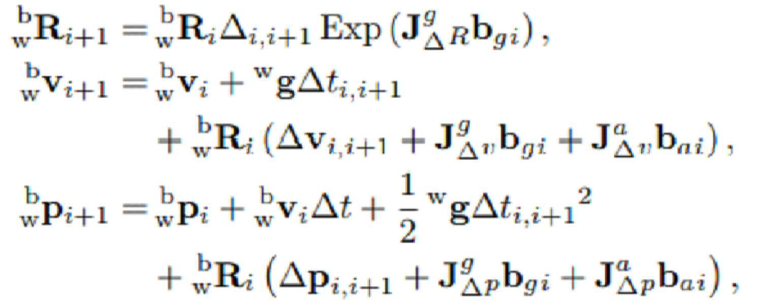
여기서, 자코비안(Jacobian) ![]()
![]()
![]()
![]()
강체 변환 T는 R3에서 회전 벡터 및 변환 벡터 t 로 파라미터화될 수 있다. 기본적으로 3차원 점 X를 ![]()
![]()
![]()
![]()
![]()
![]()
![]()
![]()
![]()
![]()
카메라의 고유 파라미터는 영상에서 3차원 점 ![]()
![]()
![]()
![]()
![]()
![]()
![]()
![]()
![]()
![]()
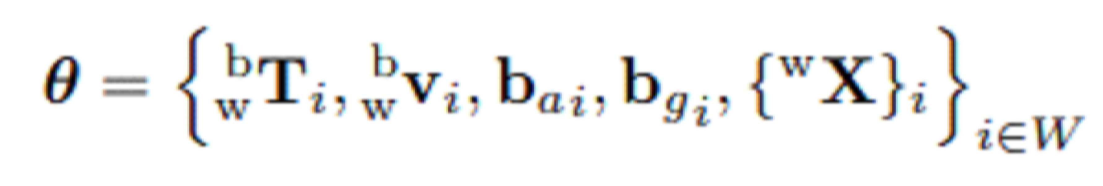
여기서, T와 v는 월드 좌표계의 신체 자세와 속도를 나타내며, ![]()
![]()
![]()
![]()
도 2는 일 실시예에 있어서, 자세 추정 방법의 실외환경에서의 정성적 결과를 나타낸 예이다.2 is an example showing qualitative results in an outdoor environment of a posture estimation method according to an embodiment.
파란색 선은 실시예에서 제안된 자세 추정 방법(ROVINS)의 실외환경에서의 정성적 결과를 나타낸 것이고, 빨간색 선은 비교용 영상 기반의 방법의 실외환경에서의 정성적 결과를 나타낸 것이고, 검정색 선은 실제 궤적(Ground truth)을 나타낸 것이다. 실시예에서 제안된 자세 추정 방법에 따른 결과가 실제 궤적과 비슷한 것을 확인할 수 있다. The blue line shows the qualitative results in the outdoor environment of the posture estimation method (ROVINS) proposed in the example, the red line shows the qualitative results in the outdoor environment of the image-based method for comparison, and the black line shows the results in the outdoor environment. It represents the ground truth. It can be confirmed that the result according to the posture estimation method proposed in the embodiment is similar to the actual trajectory.
도 3은 일 실시예에 있어서, 자세 추정 방법의 실내환경에서의 정성적 결과를 나타낸 예이다. 3 is an example showing qualitative results in an indoor environment of a posture estimation method according to an embodiment.
도 3을 참고하면, 실시예에서 제안된 자세 추정 방법(ROVINS)이 카메라의 움직임에 관계없이 실제 궤적(Ground truth)과 같이 부드러운 궤적 추정을 보여주는 것을 확인할 수 있다. 까다로운 상황에서도 정확하고 강력한 방식으로 작동됨을 알 수 있다. Referring to FIG. 3 , it can be confirmed that the ROVINS method proposed in the embodiment shows a smooth trajectory estimation like a ground truth regardless of camera movement. You can see that it works in a precise and powerful way even in difficult situations.
도 4는 일 실시예에 있어서, 실내 환경에서의 정량적 결과 및 효과를 설명하기 위한 도면이다. 4 is a diagram for explaining quantitative results and effects in an indoor environment according to an embodiment.
특징 추적에 대하여 수행된 평가에 대하여 설명하기로 한다. 관성측정 센서의 특징 추적이 있는 알고리즘(실시예)과 관성측정 센서의 특징 추적이 없는 알고리즘(종래 기술) 간의 평균 inliers 및 ATEtrans를 비교한 것이다. 도 4의 결과에 따르면, 관성측정 센서의 특징 추적이 있는 알고리즘이 두 측정 모두, 관성측정 센서의 특징 추적이 없는 알고리즘보다 더 나은 성능을 보였으며, 시스템의 전체 성능을 높이는데 도움이 되는 inliers의 수를 개선하였음을 확인할 수 있다. An evaluation performed on feature tracking will be described. A comparison of average inliers and ATEtrans between an algorithm with feature tracking of an inertial measurement sensor (Example) and an algorithm without feature tracking of an inertial measurement sensor (prior art). According to the results of FIG. 4, the algorithm with feature tracking of the inertial measurement sensor showed better performance than the algorithm without feature tracking of the inertial measurement sensor for both measurements, and the number of inliers that help increase the overall performance of the system was improved. It can be seen that the number has improved.
도 6은 일 실시예에 있어서, 자세 추정 시스템의 구성을 설명하기 위한 블록도이고, 도 7은 일 실시예에 따른 자세 추정 시스템에서 자세 추정 방법을 설명하기 위한 흐름도이다.6 is a block diagram illustrating a configuration of a posture estimation system according to an exemplary embodiment, and FIG. 7 is a flowchart illustrating a posture estimation method in the posture estimation system according to an exemplary embodiment.
자세 추정 시스템(100)의 프로세서는 위치 예측부(610) 및 최적화부(620)를 포함할 수 있다. 이러한 프로세서의 구성요소들은 자세 추정 시스템에 저장된 프로그램 코드가 제공하는 제어 명령에 따라 프로세서에 의해 수행되는 서로 다른 기능들(different functions)의 표현들일 수 있다. 프로세서 및 프로세서의 구성요소들은 도 7의 자세 추정 방법이 포함하는 단계들(710 내지 720)을 수행하도록 자세 추정 시스템을 제어할 수 있다. 이때, 프로세서 및 프로세서의 구성요소들은 메모리가 포함하는 운영체제의 코드와 적어도 하나의 프로그램의 코드에 따른 명령(instruction)을 실행하도록 구현될 수 있다.The processor of the
프로세서는 자세 추정 방법을 위한 프로그램의 파일에 저장된 프로그램 코드를 메모리에 로딩할 수 있다. 예를 들면, 자세 추정 시스템에서 프로그램이 실행되면, 프로세서는 운영체제의 제어에 따라 프로그램의 파일로부터 프로그램 코드를 메모리에 로딩하도록 자세 추정 시스템을 제어할 수 있다. 이때, 위치 예측부(610) 및 최적화부(620) 각각은 메모리에 로딩된 프로그램 코드 중 대응하는 부분의 명령을 실행하여 이후 단계들(710 내지 720)을 실행하기 위한 프로세서의 서로 다른 기능적 표현들일 수 있다.The processor may load a program code stored in a program file for a posture estimation method into a memory. For example, when a program is executed in the posture estimation system, the processor may control the posture estimation system to load a program code from a program file into a memory under the control of an operating system. At this time, each of the
단계(710)에서 위치 예측부(610)는 영상 센서 및 관성측정 센서의 융합을 통해 영상 정보 내 추정되는 특징점의 위치 데이터를 예측할 수 있다. 위치 예측부(610)는 현재 영상을 기준으로 현재 영상의 이전 영상과 현재 영상 사이에 관측된 관성측정센서 값을 시간축 상에 누적하여 상대적 움직임을 계산할 수 있다. 위치 예측부(610)는 상대적 움직임을 계산함에 따라, 이전 영상 내에서 관측되는 3차원 특징점이 존재할 경우, 3차원 특징점을 계산된 상대적 움직임으로 재투영하여 현재 영상 내의 특징점의 위치 데이터를 예측할 수 있다. 위치 예측부(610)는 상대적 움직임을 계산함에 따라, 이전 영상 내에서 3차원 특징점이 존재하지 않을 경우, 관성측정 센서의 상대적 회전 움직임만을 적용하여 현재 영상 내의 3차원 특징점의 위치 데이터를 예측할 수 있다. 위치 예측부(610)는 예측된 3차원 특징점의 위치 데이터를 추적기의 초기값으로 사용하여 현재 영상 내에서 추적된 3차원 특징점의 위치 데이터를 보정할 수 있다. In
단계(720)에서 최적화부(720)는 예측된 특징점의 위치 데이터에 기초하여 상기 영상 센서 및 관성측정 센서 간의 상대적 자세 정보를 추정하기 위한 외부 파라미터를 조정할 수 있다. 최적화부(720)는 예측된 특징점의 위치 데이터 중 재투영 오차가 기준 임계치의 특정값 이하로 선별된 관성측정 센서의 측정값들을 사용하여 영상 센서와 관성측정 센서 간 외부 파라미터의 오차를 최소화하는 방식을 반복적으로 수행함에 따라 외부 파라미터를 조정하고, 영상 정보 내 추정되는 특징점의 위치 데이터를 예측하기 위하여 조정된 외부 파라미터를 사용할 수 있다. 최적화부(720)는 예측된 특징점의 위치 데이터 중 재투영 오차가 기준 임계치의 2배 이하인 관성측정 센서의 관측값을 선별하고, 선별된 관측값을 사용하여 움직임 정보, 3차원 특징점, 영상 센서와 관성측정센서 간 외부 파라미터의 기하학적 오차를 최소화하는 방식으로 외부 파라미터를 최적화할 수 있다. 최적화부(720)는 선별된 관측값을 이용하여 움직임 정보, 3차원 특징점, 영상 센서와 관성측정센서 간 외부 파라미터의 기하학적 오차를 최소화하는 방식으로 최적화 과정을 재진행함에 따라, 기준 임계치의 1.5배 이하의 관성측정 센서의 관측값을 재선별할 수 있다. 최적화부(720)는 재선별된 관측값을 이용하여 움직임 정보, 3차원 특징점, 영상 센서와 관성측정센서 간 외부 파라미터의 기하학적 오차를 최소화하는 방식으로 최적화 과정을 재진행하고, 기준 임계치 이하의 관성측정 센서의 관측값들을 재선별하고, 재선별을 통해 조정된 최적화된 움직임 정보, 3차원 특징점 및 외부 파라미터를 획득할 수 있다. In
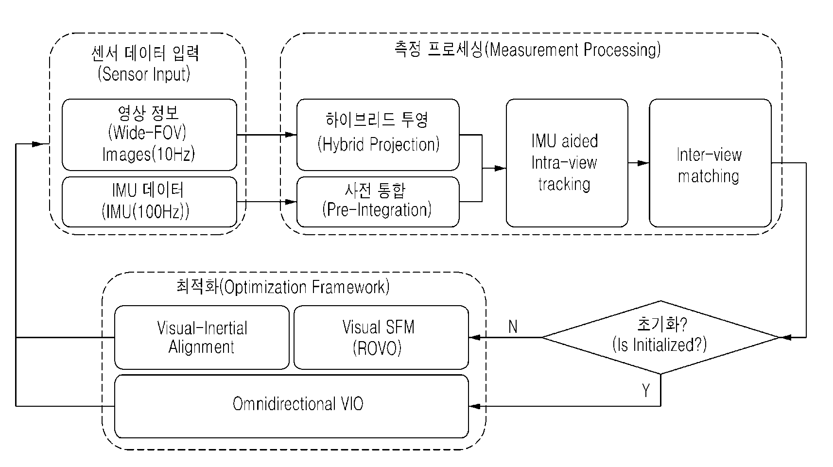
도 8은 일 실시예에 따른 자세 추정 시스템에서 자세 추정 동작을 설명하기 위한 도면이다. 8 is a diagram for explaining a posture estimation operation in a posture estimation system according to an exemplary embodiment.
실시예에서 카메라의 고유 파라미터 및 관성측정 센서와 카메라의 외부 파라미터는 보정 및 제공되는 것으로 가정하기로 한다. 모든 카메라는 카메라와 시간적으로 동기화된 관성측정 센서의 데이터와 동시에 영상 정보를 캡쳐할 수 있다. 먼저, 원시 입력 영상을 하이브리드 투영 영상으로 만들고, 관성측정 센서 데이터의 움직임이 중간점 사전 통합을 통해 전파될 수 있다. 다음으로, 하이브리드 투영 영상에서 특징이 검출될 수 있고, 관성측정 센서에서 특징 추적이 수행될 수 있다. 관성측정 센서의 회전 데이터는 현재 프레임에서 특징 위치를 예측하기 위해 관성측정 센서 지원 특징 추적기에 입력될 수 있다. 카메라 간의 특징 대응성을 찾기 위해 뷰 간 스테레오 특징 매칭이 이어질 수 있다. 데이터 처리 과정이 완료되면 카메라와 관성측정 센서가 초기화 되었는지 여부가 확인될 수 있다. 카메라와 관성측정 센서가 초기화되지 않은 경우 시각적 관성 정렬을 처리하기 위해 비전 전용 SFM(Structure-From-Motion)이 수행될 수 있다. 이후, 비선형 최적화를 사용하여 자세 추정 시스템에 접근하도록 초기화될 수 있다.In the embodiment, it is assumed that intrinsic parameters of the camera and external parameters of the inertial measurement sensor and the camera are calibrated and provided. All cameras can capture video information simultaneously with data from inertial measurement sensors synchronized in time with the camera. First, the raw input image is made into a hybrid projection image, and the motion of the inertial measurement sensor data can be propagated through midpoint pre-integration. Next, features can be detected in the hybrid projection image, and feature tracking can be performed in the inertial measurement sensor. Rotational data from the inertial measurement sensor can be input to the inertial measurement sensor supported feature tracker to predict feature positions in the current frame. Stereo feature matching between views may follow to find feature correspondence between cameras. When the data processing process is completed, it can be confirmed whether the camera and the inertial measurement sensor have been initialized. A vision-only Structure-From-Motion (SFM) may be performed to handle visual inertial alignment if the camera and inertial measurement sensor are not initialized. Then, it can be initialized to access the attitude estimation system using non-linear optimization.
자세 추정 시스템은 관성측정 센서의 융합을 통한 어안 영상 내 특징점 위치 예측을 추적할 수 있다. 종래의 영상 내 특징점 위치 추적 알고리즘의 경우, 영상 정보만을 사용함으로 빠른 움직임으로 인한 모션 블러(motion blur) 등이 발생할 경우, 성능이 현저히 저하되는 한계가 있다. 이에, 실시예에서는 관성측정센서의 센서 값을 통해 연속적으로 관측되는 영산 간의 상대적 자세 정보를 추정하고, 추정된 상대적 자세 정보를 이전 영상에서 관측된 특징점의 현재 영상 내 위치 데이터를 예측하고 초기 값으로 사용하여 특징점 위치 추적의 정확도를 향상시키는 동작을 설명하기로 한다. 추정된 특징점의 위치 데이터는 이후 자세 및 환경지도 동시 최적화 방법론에서 성능 향상에 기여를 한다. The attitude estimation system can track the position prediction of the feature point in the fisheye image through the fusion of the inertial measurement sensor. In the case of a conventional feature point location tracking algorithm in an image, there is a limitation in that performance is significantly deteriorated when motion blur or the like due to fast movement occurs because only image information is used. Therefore, in the embodiment, the relative attitude information between the continuously observed young mountains is estimated through the sensor value of the inertial measurement sensor, and the position data of the feature points observed in the previous image in the current image is predicted using the estimated relative attitude information as the initial value. An operation for improving the accuracy of feature point location tracking using the above method will be described. The location data of the estimated feature points contributes to performance improvement in the methodology for simultaneous optimization of posture and environment maps.
상세하게는, 자세 추정 시스템은 센서 데이터를 입력받을 수 있다. 이때, 센서 데이터란, 카메라(영상 센서)로부터 획득된 영상 정보 및 관성측정 센서로부터 획득된 데이터를 의미할 수 있다. 자세 추정 시스템은 카메라로부터 획득된 영상 정보와 관성측정 센서로부터 획득된 데이터의 융합을 통해 자세 정보를 추정할 수 있다. In detail, the posture estimation system may receive sensor data. In this case, the sensor data may refer to image information obtained from a camera (image sensor) and data obtained from an inertial measurement sensor. The attitude estimation system may estimate attitude information through convergence of image information obtained from a camera and data acquired from an inertial measurement sensor.
자세 추정 시스템은 하이브리드 투영 과정 및 사전 통합과정을 수행할 수 있다. 원시(raw) 입력 영상을 하이브리드 투영 영상으로 변환하여 특징 추출, 추적 및 일치를 위해 사용될 수 있다. 하이브리도 투영 영상을 활용하려면 왜곡을 최소화하고 뷰 전반에서 특징 일치 및 추적을 최대화해야 한다. 지향적 FAST 및 회전 BRIFF(ORB) 특징은 하이브리드 투영 영상에서 뷰 내 추적 및 뷰 간 일치를 위한 입력 데이터로 추출될 수 있다. 동시에, 관성측정 센서 데이터의 움직임을 중간점 사전 통합과정을 사용하여 전파할 수 있다. 사전 통합과정은 이전 영상 프레임에서 상대적인 자세 변화와 자세 공분산 행렬의 불확실성을 계산한다. 카메라에 하나의 영상 정보가 획득될 때, 관성측정 센서에 10개의 데이터가 획득될 수 있다. 이를 통해 카메라 사이의 러프한 자세가 추정될 수 있다. 하이브리드 투영 과정 및 사전 통합과정이 모두 처리된 후, 사전 통합된 관성측정 센서의 움직임이 특징 추적 성능을 향상시키기 위해 활용될 수 있고, 스테레오 특징은 뷰(view) 간 일치시킬 수 있다. The attitude estimation system can perform a hybrid projection process and a pre-integration process. A raw input image is converted into a hybrid projection image, which can be used for feature extraction, tracking, and matching. Utilizing hybrido projection imaging requires minimizing distortion and maximizing feature matching and tracking across views. Directional FAST and rotational BRIFF (ORB) features can be extracted as input data for intra-view tracking and inter-view matching in hybrid projection images. At the same time, the motion of the inertial measurement sensor data can be propagated using a midpoint pre-integration process. The pre-integration process calculates the uncertainty of the relative pose change and the pose covariance matrix in the previous image frame. When one image information is obtained from the camera, 10 pieces of data may be obtained from the inertial measurement sensor. Through this, a rough posture between cameras can be estimated. After both the hybrid projection process and the pre-integration process have been processed, the motion of the pre-integrated inertial measurement sensor can be utilized to improve feature tracking performance, and stereo features can be matched between views.
자세 추정 시스템은 예측을 통한 특징 정보를 추적할 수 있다. KLT 추적 기법은 영상 간의 특징이 일치되는 지점을 찾는데 사용된다. KLT 추적기는 이전 영상의 특징 위치에서 시작하여 사진 일관성을 사용하여 현재 영상에 대한 특징 위치를 검색한다. 큰 움직임을 처리할 때, KLT 추적기는 거친 위치가 먼저 계산된 다음 미세한 움직임이 업데이트되는 영상 파라미드를 사용할 수 있다. 정확하고 빠른 특징 추적을 위해 새로운 프레임에서 좋은 초기 위치를 찾는 것이 중요하다. 실시예에서는 KLT 추적기에서 예측되는 위치에서 초기화되기 전에 사전 통합된 관성측정 센서의 자세 정보를 사용하여 예측되는 특징 위치가 계산될 수 있다. 정확한 특징 위치를 예측하기 위하여 정확한 자세와 특징 깊이가 필요하다. The posture estimation system may track feature information through prediction. The KLT tracking technique is used to find a point where features between images match. The KLT tracker searches for feature locations for the current image using photo coherence, starting from the feature locations of the previous image. When processing large motion, the KLT tracker can use image parameters where the coarse position is calculated first and then the fine motion is updated. Finding a good initial position in a new frame is important for accurate and fast feature tracking. In an embodiment, the predicted feature position may be calculated using attitude information of the pre-integrated inertial measurement sensor before being initialized at the predicted position in the KLT tracker. Accurate posture and feature depth are needed to predict the exact feature location.
자세 추정 시스템은 3차원 특징점을 사용할 수 있을 때, 관성측정 센서의 움직임 정보를 사용하여 3차원 특징점을 현재 영상의 평면에 재투영하여 특징 위치를 예측할 수 있다. 이때, 특징 정보가 아직 등록되지 않은 경우, 관성측정 센서의 회전만을 고려하여 특징 위치가 예측될 수 있다. 또한, 다른 시점뿐만 아니라 같은 시점에서도 특징점 매칭이 수행될 수 있다. When the posture estimation system can use the 3D feature point, it can predict the feature position by re-projecting the 3D feature point onto the plane of the current image using the motion information of the inertial measurement sensor. At this time, when the feature information is not yet registered, the feature position may be predicted considering only the rotation of the inertial measurement sensor. In addition, feature point matching may be performed not only at different viewpoints but also at the same viewpoint.
다시 말해서, 자세 추정 시스템은 이전 영상과 현재 영상 사이에 관측된 관성측정 센서 값을 시간축 상에 누적하여 상대적 움직임을 계산할 수 있다. 자세 추정 시스템은 이전 영상 내에서 관측된 3차원 특징점이 존재할 경우, 3차원 특징점을 계산된 상대적 움직임으로 재투영하여 현재 영상 내 특징점의 위치를 예측할 수 있다. 자세 추정 시스템은 이전 영상 내에서 3차원 특징점이 존재하지 않을 경우, 관성측정 센서의 상대적 회전 움직임만을 적용하여 현재 영상 내의 특징점의 위치를 예측할 수 있다. 자세 추정 시스템은 예측된 특징점의 위치를 KLT 추적기의 초기값으로 사용하여 현재 영상 내의 추적된 특징점의 정확한 위치를 보정할 수 있다. In other words, the posture estimation system may calculate relative motion by accumulating inertial measurement sensor values observed between the previous image and the current image on the time axis. The posture estimation system may predict the position of the feature point in the current image by re-projecting the 3D feature point with the calculated relative motion, if there is a 3D feature point observed in the previous image. When the 3D feature point does not exist in the previous image, the posture estimation system may predict the position of the feature point in the current image by applying only the relative rotational motion of the inertial measurement sensor. The posture estimation system may correct the exact position of the tracked feature point in the current image by using the position of the predicted feature point as an initial value of the KLT tracker.
자세 추정 시스템은 초기화 과정을 수행할 수 있다. 초기화 과정은 두 가지의 매우 다른 측정, 즉, 중력 방향과 관성측정 센서의 편향을 통합하기 위한 과정을 의미한다. 이러한 파라미터는 처음에 알 수 없으므로 시각 및 관성 측정을 통해 부트스트랩 해야 한다. The posture estimation system may perform an initialization process. The initialization process refers to the process of integrating two very different measurements: the direction of gravity and the deflection of the inertial measurement sensor. Since these parameters are initially unknown, they must be bootstrapped with visual and inertial measurements.
자세 추정 시스템은 다중 카메라 및 관성측정 센서 간 외부 파라미터를 포함한 자세 및 환경지도를 동시에 최적화할 수 있다. 영상 내의 특징점이 다음 영상에서 추적된 특징점과 동일하다는 기학학적 가정을 이용하여 전체적인 자세 정보를 구하고, 관성측정 센서의 노이즈를 잡아낼 수 있다. The attitude estimation system can simultaneously optimize attitude and environment maps including external parameters between multiple cameras and inertial measurement sensors. By using the geometrical assumption that the feature point in the image is the same as the feature point tracked in the next image, overall attitude information can be obtained and noise of the inertial measurement sensor can be captured.
실시예에서는 두 가지의 이종 센서를 사용하므로 카메라와 관성측정 센서를 이용하여 상대적 자세의 정확한 측량이 어려운 한계가 존재한다. 또한, 자세 추정 시스템의 움직임으로 인해 발생한 떨림과 같은 물리적 요인으로 인해 변동이 생겨 초기 값의 정확한 신뢰가 어렵고, 전체 시스템의 성능을 저하하는 경우가 발생한다. 실시예에서는 움직임 및 환경지도에 더불어 카메라와 관성측정 센서 간 상대적 자세, 즉 외부 파라미터를 동시에 최적화하여 전체 시스템의 안정성을 확보하기 위한 최적화 과정이 수행될 수 있다. 기존의 기하학적 정합성을 이용하여 자세 정보와 3차원 특징점을 동시에 추정하는 LBA(Local Bundle Adjustment)가 존재한다. 하지만, 다중 카메라와 관성측정 센서 간의 외부 파라미터에 대한 최적화가 동시에 이루어지지 않기 때문에 실시예에 적용이 불가능하다. In the embodiment, since two types of heterogeneous sensors are used, there is a limit in that it is difficult to accurately measure a relative posture using a camera and an inertial measurement sensor. In addition, fluctuations occur due to physical factors such as shaking caused by movement of the posture estimation system, making it difficult to accurately trust the initial value and deteriorating the performance of the entire system. In the embodiment, an optimization process may be performed to secure the stability of the entire system by simultaneously optimizing the relative posture between the camera and the inertial measurement sensor, that is, an external parameter, in addition to movement and environmental maps. There is an LBA (Local Bundle Adjustment) that simultaneously estimates posture information and 3D feature points using existing geometric matching. However, since optimization of external parameters between the multiple cameras and the inertial measurement sensor is not performed at the same time, it is not applicable to the embodiment.
자세 추정 시스템은 관측된 영상 정보 내의 3차원 특징점 정보들 중 재투영 오차가 기준 임계치 2배 이하인 관성측정 센서의 관측값을 선별할 수 있다. 자세 추정 시스템은 선별된 관측값을 사용하여 움직임 정보(자세, 속도, 센서 편향치), 3차원 특징점, 카메라와 관성측정 센서 간의 외부 파라미터를 기하학적 오차를 최소화하는 방식으로 동시에 최적화할 수 있다. 자세 추정 시스템은 선별된 관측값을 이용하여 최적과 과정을 다시 한번 진행하고, 이 중 기준 임계치의 1.5배 이하의 관측값을 재선별하고, 재선별된 관측값을 이용하여 최적화 과정을 진행하고 기준 임계치 이하의 관측값들을 선별하고 최적화된 카메라 자세와 3차원 특징점과 외부 파라미터를 최종 산출물로 사용할 수 있다. 또한, 최종 산출물을 자세 추정 시스템에서 재사용할 수 있다. The posture estimation system may select an observed value of an inertial measurement sensor having a reprojection error of less than twice a reference threshold among 3D feature point information in the observed image information. The attitude estimation system can simultaneously optimize motion information (posture, speed, sensor deflection), 3D feature points, and external parameters between the camera and the inertial measurement sensor in a way that minimizes geometric errors using selected observation values. The attitude estimation system proceeds with the optimization process again using the selected observation values, re-selects the observation values that are 1.5 times or less of the reference threshold value, and proceeds with the optimization process using the re-selection observation values. Observations below the threshold can be selected, and the optimized camera posture, 3D feature points, and external parameters can be used as the final output. Also, the final product can be reused in the attitude estimation system.
보다 상세하게는, 비주얼 SFM 및 시각적 관성 정렬에 대하여 설명하기로 한다. 예를 들면, SFM은 시각적 SFM 결과에 따라 달라지는 초기화에 잘 작동될 수 있다. 전방향 다중 뷰 설정을 완전히 활용하여 동적 장면과 질감없는 실내 환경에서 높은 견고성을 달성하도록 한다. 전방향 모든 방향이 관측됨으로써 초기 움직임이 퇴보할 가능성이 거의 없다. 실패 사례는 자세 정상치 수(>50)를 점검함으로써 필터링될 수 있다. 초기 SFM이 성공하고 리그가 충분한 거리를 이동하는 한 합리적으로 정확한 자세를 반환한다고 가정할 수 있다. 먼저 충분한 움직임(현재 설정에서 15개의 키 프레임)이 생성되었는지 모니터링 후, 시각적 관성 정렬이 수행될 수 있다. 또한, 시각적 관성 정렬은 측정 스케일이 전방향 다중 뷰 스테레오 설정에서 직접 관측될 수 있으며, 초기 스케일 추정 및 스케일 업데이트에 대한 걱정없이 관성측정 센서와 카메라의 측정을 결합할 수 있다. More specifically, visual SFM and visual inertial alignment will be described. For example, SFM can work well for initialization that depends on visual SFM results. It fully utilizes the omnidirectional multi-view setup to achieve high robustness in dynamic scenes and textureless indoor environments. Since all forward directions are observed, there is little possibility that the initial movement will be regressed. Failure cases can be filtered out by checking the posture normality count (>50). As long as the initial SFM succeeds and the rig moves a sufficient distance, it can be assumed to return a reasonably accurate attitude. After first monitoring that enough movement has been created (15 keyframes in the current setup), visual inertial alignment can be performed. In addition, visual inertial alignment allows measurement scales to be observed directly in an omnidirectional multi-view stereo setup, combining measurements from inertial measurement sensors and cameras without worrying about initial scale estimation and scale updates.
자세 추정 시스템은 최적화 기반의 시각적 관성 주행 기록을 측정할 수 있다. 프레임 레이트(rate)로 바디 자세, 속도 및 관성측정 센서의 편향을 지속적으로 추정하여 자세 추적 시스템의 궤적이 계산될 수 있다. 초기화가 완료되면, 현재 프레임 자세가 관성측정 센서의 사전 통합 자세로 업데이트되고, 그 후 재투영 오류 또는 초광각 FOV 설정에서 단위 광선의 접선 오류를 기반으로 이상치 특징이 제거될 수 있다. 이상치 제거 후, 현재 프레임과 활성 로컬 윈도우 W의 키 프레임의 상태 벡터 θ는 시각 및 관성측정 센서의 제약 조건에서 최적화될 수 있다. 최적화 문제는 Ceres solver를 사용하여 최적의 상태가 산출될 수 있다. The posture estimation system can measure an optimization-based visual inertial driving record. The trajectory of the posture tracking system can be calculated by continuously estimating the body posture, velocity, and deflection of the inertial measurement sensor at a frame rate. When initialization is complete, the current frame attitude is updated to the pre-integration attitude of the inertial measurement sensor, after which outlier features can be removed based on reprojection errors or tangential errors of unit rays in the ultra-wide FOV setting. After removing the outliers, the state vector θ of the current frame and the key frame of the active local window W can be optimized under the constraints of the visual and inertial sensors. Optimization problems can be calculated using the Ceres solver.
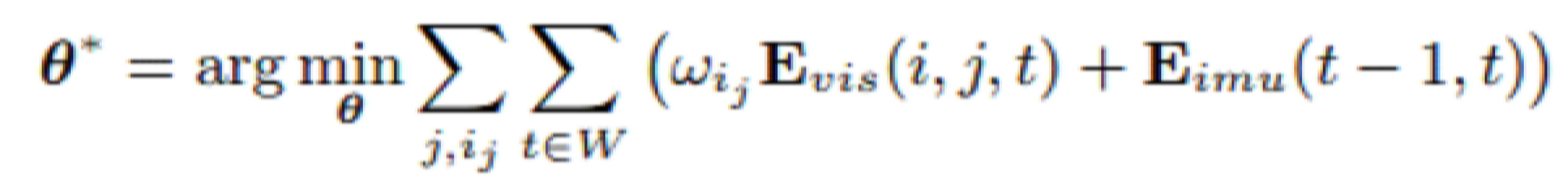
여기서, Evis는 시각적 제약 조건, Eimu는 관성측정 센서의 제약 조건, ![]()
![]()
![]()
![]()
시각적 제약은 주어진 신체 자세, 외적 및 지도 지점에서, 특징점의 재투영 오류를 기반으로 계산될 수 있다. 시각적 제약은 많은 특징 기반의 시각적 기반의 시스템에 대한 기하학적 오류 조건으로 널리 사용된다. 재투영 오류 Evis 는 다음과 같이 주어질 수 있다. The visual constraints can be calculated based on the reprojection error of the feature points, given the body posture, extrinsic and map points. Visual constraints are widely used as geometrical error conditions for many feature-based visual-based systems. The reprojection error E vis can be given as
![]()
![]()
바디에서 j번째 카메라 ![]()
![]()
![]()
![]()
![]()
![]()
관성측정 센서 제약 조건은 연속된 두 개의 키 프레임 사이의 관성측 센서값을 사전 통합하여 상대적 관성측정 센서 제약 조건을 획득할 수 있다. 통합 전 오류 Eimu는 다음과 같이 정의될 수 있다.For the inertial measurement sensor constraints, the relative inertial measurement sensor constraints may be obtained by pre-integrating the inertial side sensor values between two consecutive key frames. The pre-integration error E imu can be defined as:

여기서, ![]()
![]()
![]()
![]()
도 9는 일 실시예에 따른 자세 추정 시스템에서 외부 파라미터 최적화 동작을 설명하기 위한 도면이다. 9 is a diagram for explaining an external parameter optimization operation in a posture estimation system according to an exemplary embodiment.
도 9를 참고하면, 관측 정보와 파라미터를 나타낸 것이다. 2차원 정보로부터 생성된 3차원 점들과 키 프레임 또는 프레임의 자세, 관성측정 센서에서 누적된 자세값들을 동시에 조정하여 외부 파라미터와 자세 정보, 속도, 편향 등이 최적화될 수 있다. Referring to FIG. 9 , observation information and parameters are shown. External parameters, attitude information, speed, deflection, etc. can be optimized by simultaneously adjusting the 3D points generated from 2D information, the attitude of the key frame or frame, and the attitude values accumulated from the inertial measurement sensor.
이상에서 설명된 장치는 하드웨어 구성요소, 소프트웨어 구성요소, 및/또는 하드웨어 구성요소 및 소프트웨어 구성요소의 조합으로 구현될 수 있다. 예를 들어, 실시예들에서 설명된 장치 및 구성요소는, 예를 들어, 프로세서, 콘트롤러, ALU(arithmetic logic unit), 디지털 신호 프로세서(digital signal processor), 마이크로컴퓨터, FPGA(field programmable gate array), PLU(programmable logic unit), 마이크로프로세서, 또는 명령(instruction)을 실행하고 응답할 수 있는 다른 어떠한 장치와 같이, 하나 이상의 범용 컴퓨터 또는 특수 목적 컴퓨터를 이용하여 구현될 수 있다. 처리 장치는 운영 체제(OS) 및 상기 운영 체제 상에서 수행되는 하나 이상의 소프트웨어 애플리케이션을 수행할 수 있다. 또한, 처리 장치는 소프트웨어의 실행에 응답하여, 데이터를 접근, 저장, 조작, 처리 및 생성할 수도 있다. 이해의 편의를 위하여, 처리 장치는 하나가 사용되는 것으로 설명된 경우도 있지만, 해당 기술분야에서 통상의 지식을 가진 자는, 처리 장치가 복수 개의 처리 요소(processing element) 및/또는 복수 유형의 처리 요소를 포함할 수 있음을 알 수 있다. 예를 들어, 처리 장치는 복수 개의 프로세서 또는 하나의 프로세서 및 하나의 콘트롤러를 포함할 수 있다. 또한, 병렬 프로세서(parallel processor)와 같은, 다른 처리 구성(processing configuration)도 가능하다.The devices described above may be implemented as hardware components, software components, and/or a combination of hardware components and software components. For example, devices and components described in the embodiments may include, for example, a processor, a controller, an arithmetic logic unit (ALU), a digital signal processor, a microcomputer, a field programmable gate array (FPGA) , a programmable logic unit (PLU), microprocessor, or any other device capable of executing and responding to instructions. A processing device may run an operating system (OS) and one or more software applications running on the operating system. A processing device may also access, store, manipulate, process, and generate data in response to execution of software. For convenience of understanding, there are cases in which one processing device is used, but those skilled in the art will understand that the processing device includes a plurality of processing elements and/or a plurality of types of processing elements. It can be seen that it can include. For example, a processing device may include a plurality of processors or a processor and a controller. Other processing configurations are also possible, such as parallel processors.
소프트웨어는 컴퓨터 프로그램(computer program), 코드(code), 명령(instruction), 또는 이들 중 하나 이상의 조합을 포함할 수 있으며, 원하는 대로 동작하도록 처리 장치를 구성하거나 독립적으로 또는 결합적으로(collectively) 처리 장치를 명령할 수 있다. 소프트웨어 및/또는 데이터는, 처리 장치에 의하여 해석되거나 처리 장치에 명령 또는 데이터를 제공하기 위하여, 어떤 유형의 기계, 구성요소(component), 물리적 장치, 가상 장치(virtual equipment), 컴퓨터 저장 매체 또는 장치에 구체화(embody)될 수 있다. 소프트웨어는 네트워크로 연결된 컴퓨터 시스템 상에 분산되어서, 분산된 방법으로 저장되거나 실행될 수도 있다. 소프트웨어 및 데이터는 하나 이상의 컴퓨터 판독 가능 기록 매체에 저장될 수 있다.Software may include a computer program, code, instructions, or a combination of one or more of the foregoing, which configures a processing device to operate as desired or processes independently or collectively. The device can be commanded. Software and/or data may be any tangible machine, component, physical device, virtual equipment, computer storage medium or device, intended to be interpreted by or provide instructions or data to a processing device. can be embodied in Software may be distributed on networked computer systems and stored or executed in a distributed manner. Software and data may be stored on one or more computer readable media.
실시예에 따른 방법은 다양한 컴퓨터 수단을 통하여 수행될 수 있는 프로그램 명령 형태로 구현되어 컴퓨터 판독 가능 매체에 기록될 수 있다. 상기 컴퓨터 판독 가능 매체는 프로그램 명령, 데이터 파일, 데이터 구조 등을 단독으로 또는 조합하여 포함할 수 있다. 상기 매체에 기록되는 프로그램 명령은 실시예를 위하여 특별히 설계되고 구성된 것들이거나 컴퓨터 소프트웨어 당업자에게 공지되어 사용 가능한 것일 수도 있다. 컴퓨터 판독 가능 기록 매체의 예에는 하드 디스크, 플로피 디스크 및 자기 테이프와 같은 자기 매체(magnetic media), CD-ROM, DVD와 같은 광기록 매체(optical media), 플롭티컬 디스크(floptical disk)와 같은 자기-광 매체(magneto-optical media), 및 롬(ROM), 램(RAM), 플래시 메모리 등과 같은 프로그램 명령을 저장하고 수행하도록 특별히 구성된 하드웨어 장치가 포함된다. 프로그램 명령의 예에는 컴파일러에 의해 만들어지는 것과 같은 기계어 코드뿐만 아니라 인터프리터 등을 사용해서 컴퓨터에 의해서 실행될 수 있는 고급 언어 코드를 포함한다. The method according to the embodiment may be implemented in the form of program instructions that can be executed through various computer means and recorded on a computer readable medium. The computer readable medium may include program instructions, data files, data structures, etc. alone or in combination. Program commands recorded on the medium may be specially designed and configured for the embodiment or may be known and usable to those skilled in computer software. Examples of computer-readable recording media include magnetic media such as hard disks, floppy disks and magnetic tapes, optical media such as CD-ROMs and DVDs, and magnetic media such as floptical disks. - includes hardware devices specially configured to store and execute program instructions, such as magneto-optical media, and ROM, RAM, flash memory, and the like. Examples of program instructions include high-level language codes that can be executed by a computer using an interpreter, as well as machine language codes such as those produced by a compiler.
이상과 같이 실시예들이 비록 한정된 실시예와 도면에 의해 설명되었으나, 해당 기술분야에서 통상의 지식을 가진 자라면 상기의 기재로부터 다양한 수정 및 변형이 가능하다. 예를 들어, 설명된 기술들이 설명된 방법과 다른 순서로 수행되거나, 및/또는 설명된 시스템, 구조, 장치, 회로 등의 구성요소들이 설명된 방법과 다른 형태로 결합 또는 조합되거나, 다른 구성요소 또는 균등물에 의하여 대치되거나 치환되더라도 적절한 결과가 달성될 수 있다.As described above, although the embodiments have been described with limited examples and drawings, those skilled in the art can make various modifications and variations from the above description. For example, the described techniques may be performed in an order different from the method described, and/or components of the described system, structure, device, circuit, etc. may be combined or combined in a different form than the method described, or other components may be used. Or even if it is replaced or substituted by equivalents, appropriate results can be achieved.
그러므로, 다른 구현들, 다른 실시예들 및 특허청구범위와 균등한 것들도 후술하는 특허청구범위의 범위에 속한다.Therefore, other implementations, other embodiments, and equivalents of the claims are within the scope of the following claims.
Claims (15)
영상 센서 및 관성측정 센서의 융합을 통해 영상 정보 내 추정되는 특징점의 위치 데이터를 예측하는 단계; 및
상기 예측된 특징점의 위치 데이터에 기초하여 상기 영상 센서 및 관성측정 센서 간의 상대적 자세 정보를 추정하기 위한 외부 파라미터를 조정하는 단계
를 포함하고,
상기 예측하는 단계는,
현재 영상을 기준으로 상기 현재 영상의 이전 영상과 현재 영상 사이에 관측된 관성측정센서 값을 시간축 상에 누적하여 상대적 움직임을 계산하고, 상기 상대적 움직임을 계산함에 따라, 이전 영상 내에서 관측되는 3차원 특징점이 존재할 경우, 상기 3차원 특징점을 상기 계산된 상대적 움직임으로 재투영하여 현재 영상 내의 3차원 특징점의 위치 데이터를 예측하는 단계
를 포함하는 자세 추정 방법.In the posture estimation method performed by the posture estimation system,
Predicting positional data of feature points estimated in image information through fusion of an image sensor and an inertial measurement sensor; and
Adjusting an external parameter for estimating relative attitude information between the image sensor and the inertial measurement sensor based on the positional data of the predicted feature point
including,
The predicting step is
Based on the current image, relative motion is calculated by accumulating inertial measurement sensor values observed between the current image and the previous image of the current image on the time axis, and as the relative motion is calculated, the three-dimensional data observed in the previous image If there is a feature point, predicting position data of the 3D feature point in the current image by re-projecting the 3D feature point with the calculated relative motion
Posture estimation method comprising a.
상기 예측하는 단계는,
상기 상대적 움직임을 계산함에 따라, 이전 영상 내에서 3차원 특징점이 존재하지 않을 경우, 관성측정 센서의 상대적 회전 움직임만을 적용하여 현재 영상 내의 3차원 특징점의 위치 데이터를 예측하는 단계
를 포함하는 자세 추정 방법.According to claim 1,
The predicting step is
Predicting positional data of a 3D feature point in the current image by applying only the relative rotational movement of the inertial measurement sensor when the 3D feature point does not exist in the previous image as the relative motion is calculated.
Posture estimation method comprising a.
상기 예측하는 단계는,
상기 예측된 3차원 특징점의 위치 데이터를 추적기의 초기값으로 사용하여 현재 영상 내에서 추적된 3차원 특징점의 위치 데이터를 보정하는 단계
를 포함하는 자세 추정 방법.According to any one of claims 1 or 4,
The predicting step is
Correcting the location data of the 3D feature points tracked in the current image by using the predicted 3D feature point location data as an initial value of the tracker.
Posture estimation method comprising a.
상기 영상 센서는, 복수 개의 카메라로 구성된 전방향 영상 센서를 포함하고,
상기 자세 추정 시스템은, 상기 복수 개의 카메라로 구성된 전방향 영상 센서 및 관성측정 센서를 포함하고, 상기 복수 개의 카메라로 구성된 전방향 영상 센서의 주변에 관성측정 센서가 위치되는, 것을 특징으로 하는 자세 추정 방법.According to claim 1,
The image sensor includes an omnidirectional image sensor composed of a plurality of cameras,
The posture estimation system includes an omnidirectional image sensor and an inertial measurement sensor composed of the plurality of cameras, and the inertial measurement sensor is located around the omnidirectional image sensor composed of the plurality of cameras. method.
상기 파라미터를 조정하는 단계는,
상기 예측된 특징점의 위치 데이터 중 재투영 오차가 기준 임계치의 특정값 이하로 선별된 관성측정 센서의 관측값들을 사용하여 영상 센서와 관성측정 센서 간 외부 파라미터의 오차를 최소화하는 방식을 반복적으로 수행함에 따라 외부 파라미터를 조정하고, 상기 영상 정보 내 추정되는 특징점의 위치 데이터를 예측하기 위하여 상기 조정된 외부 파라미터를 사용하는 단계
를 포함하는 자세 추정 방법.According to claim 1,
Adjusting the parameters,
Among the positional data of the predicted feature point, a method of minimizing the error of external parameters between the image sensor and the inertial measurement sensor is repeatedly performed using the observed values of the inertial measurement sensor whose reprojection error is selected to be less than a specific value of the reference threshold. Adjusting an external parameter according to the image information, and using the adjusted external parameter to predict position data of feature points estimated in the image information.
Posture estimation method comprising a.
영상 센서 및 관성측정 센서의 융합을 통해 영상 정보 내 추정되는 특징점의 위치 데이터를 예측하는 단계; 및
상기 예측된 특징점의 위치 데이터에 기초하여 상기 영상 센서 및 관성측정 센서 간의 상대적 자세 정보를 추정하기 위한 외부 파라미터를 조정하는 단계
를 포함하고,
상기 파라미터를 조정하는 단계는,
상기 예측된 특징점의 위치 데이터 중 재투영 오차가 기준 임계치의 특정값 이하로 선별된 관성측정 센서의 관측값들을 사용하여 영상 센서와 관성측정 센서 간 외부 파라미터의 오차를 최소화하는 방식을 반복적으로 수행함에 따라 외부 파라미터를 조정하고, 상기 영상 정보 내 추정되는 특징점의 위치 데이터를 예측하기 위하여 상기 조정된 외부 파라미터를 사용하고, 상기 예측된 특징점의 위치 데이터 중 재투영 오차가 기준 임계치의 2배 이하인 관성측정 센서의 관측값을 선별하고, 상기 선별된 관측값을 사용하여 움직임 정보, 3차원 특징점, 영상 센서와 관성측정센서 간 외부 파라미터의 기하학적 오차를 최소화하는 방식으로 외부 파라미터를 최적화하는 단계
를 포함하는 자세 추정 방법.In the posture estimation method performed by the posture estimation system,
Predicting positional data of feature points estimated in image information through fusion of an image sensor and an inertial measurement sensor; and
Adjusting an external parameter for estimating relative attitude information between the image sensor and the inertial measurement sensor based on the positional data of the predicted feature point
including,
Adjusting the parameters,
Among the positional data of the predicted feature point, a method of minimizing the error of external parameters between the image sensor and the inertial measurement sensor is repeatedly performed using the observed values of the inertial measurement sensor whose reprojection error is selected to be less than a specific value of the reference threshold. Inertial measurement in which an external parameter is adjusted according to the image information, the adjusted external parameter is used to predict position data of feature points estimated in the image information, and a reprojection error among the predicted feature point position data is less than twice the reference threshold. Selecting observation values of sensors and optimizing external parameters by using the selected observation values to minimize geometric errors of motion information, 3D feature points, and external parameters between an image sensor and an inertial measurement sensor.
Posture estimation method comprising a.
상기 파라미터를 조정하는 단계는,
상기 선별된 관측값을 이용하여 움직임 정보, 3차원 특징점, 영상 센서와 관성측정센서 간 외부 파라미터의 기하학적 오차를 최소화하는 방식으로 최적화 과정을 재진행함에 따라, 기준 임계치의 1.5배 이하의 관성측정 센서의 관측값을 재선별하는 단계
를 포함하는 자세 추정 방법.According to claim 8,
Adjusting the parameters,
By using the selected observation values, the optimization process is re-progressed in such a way as to minimize the geometrical errors of motion information, 3D feature points, and external parameters between the image sensor and the inertial measurement sensor, so that the inertial measurement sensor is less than 1.5 times the reference threshold. step of re-screening observations of
Posture estimation method comprising a.
상기 파라미터를 조정하는 단계는,
상기 재선별된 관측값을 이용하여 움직임 정보, 3차원 특징점, 영상 센서와 관성측정센서 간 외부 파라미터의 기하학적 오차를 최소화하는 방식으로 최적화 과정을 재진행하고, 기준 임계치 이하의 관성측정 센서의 관측값들을 재선별하고, 재선별을 통해 조정된 최적화된 움직임 정보, 3차원 점 및 외부 파라미터를 획득하는 단계
를 포함하는 자세 추정 방법.According to claim 9,
Adjusting the parameters,
Using the re-selected observation values, the optimization process is re-progressed in such a way as to minimize the geometrical errors of motion information, 3D feature points, and external parameters between the image sensor and the inertial measurement sensor, and the observed value of the inertial measurement sensor below the reference threshold. re-screening and acquiring optimized motion information, 3D points, and external parameters adjusted through the re-screening
Posture estimation method comprising a.
영상 센서 및 관성측정 센서의 융합을 통해 영상 정보 내 추정되는 특징점의 위치 데이터를 예측하는 위치 예측부; 및
상기 예측된 특징점의 위치 데이터에 기초하여 상기 영상 센서 및 관성측정센서 간의 상대적 자세 정보를 추정하기 위한 외부 파라미터를 조정하는 최적화부
를 포함하고,
상기 위치 예측부는,
현재 영상을 기준으로 상기 현재 영상의 이전 영상과 현재 영상 사이에 관측된 관성측정센서 값을 시간축 상에 누적하여 상대적 움직임을 계산하고, 상기 상대적 움직임을 계산함에 따라, 이전 영상 내에서 관측되는 3차원 특징점이 존재할 경우, 상기 3차원 특징점을 상기 계산된 상대적 움직임으로 재투영하여 현재 영상 내의 특징점의 위치 데이터를 예측하고, 상기 상대적 움직임을 계산함에 따라, 이전 영상 내에서 3차원 특징점이 존재하지 않을 경우, 관성측정 센서의 상대적 회전 움직임만을 적용하여 현재 영상 내의 3차원 특징점의 위치 데이터를 예측하고, 상기 예측된 3차원 특징점의 위치 데이터를 추적기의 초기값으로 사용하여 현재 영상 내에서 추적된 3차원 특징점의 위치 데이터를 보정하는
자세 추정 시스템.In the posture estimation system,
a position prediction unit that predicts position data of feature points estimated in image information through fusion of an image sensor and an inertial measurement sensor; and
An optimization unit for adjusting an external parameter for estimating relative attitude information between the image sensor and the inertial measurement sensor based on the position data of the predicted feature point.
including,
The position prediction unit,
Based on the current image, relative motion is calculated by accumulating inertial measurement sensor values observed between the current image and the previous image of the current image on the time axis, and as the relative motion is calculated, the three-dimensional data observed in the previous image When a feature point exists, the 3D feature point is re-projected with the calculated relative motion to predict the location data of the feature point in the current image, and when the 3D feature point does not exist in the previous image as the relative motion is calculated. , Predicting the location data of 3D feature points in the current image by applying only the relative rotational motion of the inertial measurement sensor, and using the position data of the predicted 3D feature points as the initial value of the tracker to track the 3D feature points in the current image to calibrate the positional data of
Posture estimation system.
상기 최적화부는,
상기 예측된 특징점의 위치 데이터 중 재투영 오차가 기준 임계치의 특정값 이하로 선별된 관성측정 센서의 관측값들을 사용하여 영상 센서와 관성측정 센서 간 외부 파라미터의 오차를 최소화하는 방식을 반복적으로 수행함에 따라 외부 파라미터를 조정하고, 상기 영상 정보 내 추정되는 특징점의 위치 데이터를 예측하기 위하여 상기 조정된 외부 파라미터를 사용하는
것을 특징으로 하는 자세 추정 시스템.According to claim 12,
The optimization unit,
Among the positional data of the predicted feature point, a method of minimizing the error of external parameters between the image sensor and the inertial measurement sensor is repeatedly performed using the observed values of the inertial measurement sensor whose reprojection error is selected to be less than a specific value of the reference threshold. Adjusting the external parameter according to the image information, and using the adjusted external parameter to predict the position data of the feature point estimated in the image information
Characterized in that the posture estimation system.
영상 센서 및 관성측정 센서의 융합을 통해 영상 정보 내 추정되는 특징점의 위치 데이터를 예측하는 위치 예측부; 및
상기 예측된 특징점의 위치 데이터에 기초하여 상기 영상 센서 및 관성측정 센서 간의 상대적 자세 정보를 추정하기 위한 외부 파라미터를 조정하는 최적화부
를 포함하고,
상기 최적화부는,
상기 예측된 특징점의 위치 데이터 중 재투영 오차가 기준 임계치의 특정값 이하로 선별된 관성측정 센서의 관측값들을 사용하여 영상 센서와 관성측정 센서 간 외부 파라미터의 오차를 최소화하는 방식을 반복적으로 수행함에 따라 외부 파라미터를 조정하고, 상기 영상 정보 내 추정되는 특징점의 위치 데이터를 예측하기 위하여 상기 조정된 외부 파라미터를 사용하고, 상기 예측된 특징점의 위치 데이터 중 재투영 오차가 기준 임계치의 2배 이하인 관성측정 센서의 관측값을 선별하고, 상기 선별된 관측값을 사용하여 움직임 정보, 3차원 특징점, 영상 센서와 관성측정센서 간 외부 파라미터의 기하학적 오차를 최소화하는 방식으로 외부 파라미터를 최적화하고, 상기 선별된 관측값을 이용하여 움직임 정보, 3차원 특징점, 영상 센서와 관성측정센서 간 외부 파라미터의 기하학적 오차를 최소화하는 방식으로 최적화 과정을 재진행함에 따라, 기준 임계치의 1.5배 이하의 관성측정 센서의 관측값을 재선별하고, 상기 재선별된 관측값을 이용하여 움직임 정보, 3차원 특징점, 영상 센서와 관성측정센서 간 외부 파라미터의 기하학적 오차를 최소화하는 방식으로 최적화 과정을 재진행하고, 기준 임계치 이하의 관성측정 센서의 관측값들을 재선별하고, 재선별을 통해 조정된 최적화된 움직임 정보, 3차원 특징점 및 외부 파라미터를 획득하는
것을 특징으로 하는 자세 추정 시스템.
In the posture estimation system,
a position prediction unit that predicts position data of feature points estimated in image information through fusion of an image sensor and an inertial measurement sensor; and
An optimization unit for adjusting an external parameter for estimating relative attitude information between the image sensor and the inertial measurement sensor based on the position data of the predicted feature point.
including,
The optimization unit,
Among the positional data of the predicted feature point, a method of minimizing the error of external parameters between the image sensor and the inertial measurement sensor is repeatedly performed using the observed values of the inertial measurement sensor whose reprojection error is selected to be less than a specific value of the reference threshold. Inertial measurement in which an external parameter is adjusted according to the image information, the adjusted external parameter is used to predict position data of feature points estimated in the image information, and a reprojection error among the predicted feature point position data is less than twice the reference threshold. Observation values of the sensor are selected, motion information, 3D feature points, and external parameters are optimized in such a manner as to minimize the geometric error of the external parameters between the image sensor and the inertial measurement sensor using the selected observation values, and the selected observations are performed. As the optimization process is re-progressed in a way that minimizes the geometric error of motion information, 3D feature points, and external parameters between the image sensor and the inertial measurement sensor using the value, the observed value of the inertial measurement sensor that is 1.5 times or less of the reference threshold is obtained. Re-selection, and using the re-selected observation values, the optimization process is re-progressed by minimizing the geometric error of motion information, 3D feature points, and external parameters between the image sensor and the inertial measurement sensor, and the inertial measurement below the reference threshold is performed. Obtaining optimized motion information, 3D feature points, and external parameters adjusted through re-selection by re-selecting the observed values of the sensor
Characterized in that the posture estimation system.
Applications Claiming Priority (2)
| Application Number | Priority Date | Filing Date | Title |
|---|---|---|---|
| KR20200175218 | 2020-12-15 | ||
| KR1020200175218 | 2020-12-15 |
Publications (2)
| Publication Number | Publication Date |
|---|---|
| KR20220085682A KR20220085682A (en) | 2022-06-22 |
| KR102555269B1 true KR102555269B1 (en) | 2023-07-14 |
Family
ID=82216361
Family Applications (1)
| Application Number | Title | Priority Date | Filing Date |
|---|---|---|---|
| KR1020210029598A Active KR102555269B1 (en) | 2020-12-15 | 2021-03-05 | Posture estimation fusion method and system using omnidirectional image sensor and inertial measurement sensor |
Country Status (1)
| Country | Link |
|---|---|
| KR (1) | KR102555269B1 (en) |
Families Citing this family (2)
| Publication number | Priority date | Publication date | Assignee | Title |
|---|---|---|---|---|
| CN116091622A (en) * | 2023-01-03 | 2023-05-09 | 清华大学 | Object action data processing method and device, electronic equipment and storage medium |
| CN118568657B (en) * | 2024-05-16 | 2025-01-21 | 江苏久创电气科技有限公司 | A multi-sensor information fusion system and method based on blockchain |
Citations (1)
| Publication number | Priority date | Publication date | Assignee | Title |
|---|---|---|---|---|
| JP2009204385A (en) | 2008-02-27 | 2009-09-10 | Mitsubishi Electric Corp | Targeting device, method, and program |
Family Cites Families (1)
| Publication number | Priority date | Publication date | Assignee | Title |
|---|---|---|---|---|
| KR102016551B1 (en) * | 2014-01-24 | 2019-09-02 | 한화디펜스 주식회사 | Apparatus and method for estimating position |
-
2021
- 2021-03-05 KR KR1020210029598A patent/KR102555269B1/en active Active
Patent Citations (1)
| Publication number | Priority date | Publication date | Assignee | Title |
|---|---|---|---|---|
| JP2009204385A (en) | 2008-02-27 | 2009-09-10 | Mitsubishi Electric Corp | Targeting device, method, and program |
Also Published As
| Publication number | Publication date |
|---|---|
| KR20220085682A (en) | 2022-06-22 |
Similar Documents
| Publication | Publication Date | Title |
|---|---|---|
| KR101725060B1 (en) | Apparatus for recognizing location mobile robot using key point based on gradient and method thereof | |
| KR101776622B1 (en) | Apparatus for recognizing location mobile robot using edge based refinement and method thereof | |
| US11830216B2 (en) | Information processing apparatus, information processing method, and storage medium | |
| KR101708659B1 (en) | Apparatus for recognizing location mobile robot using search based correlative matching and method thereof | |
| KR101776621B1 (en) | Apparatus for recognizing location mobile robot using edge based refinement and method thereof | |
| US11668571B2 (en) | Simultaneous localization and mapping (SLAM) using dual event cameras | |
| KR101776620B1 (en) | Apparatus for recognizing location mobile robot using search based correlative matching and method thereof | |
| JP5832341B2 (en) | Movie processing apparatus, movie processing method, and movie processing program | |
| CN105469405B (en) | Positioning and map constructing method while view-based access control model ranging | |
| Zhang et al. | Visual-lidar odometry and mapping: Low-drift, robust, and fast | |
| KR102209008B1 (en) | Apparatus for estimating camera pose and method for estimating camera pose | |
| CN112219087A (en) | Pose prediction method, map construction method, movable platform and storage medium | |
| CN115406447B (en) | Autonomous positioning method of quad-rotor unmanned aerial vehicle based on visual inertia in rejection environment | |
| KR20190042187A (en) | Method and apparatus of estimating depth value | |
| JP6782903B2 (en) | Self-motion estimation system, control method and program of self-motion estimation system | |
| KR102455632B1 (en) | Mehtod and apparatus for stereo matching | |
| KR20200037502A (en) | Method and apparatus of outputting pose information | |
| US20250076069A1 (en) | Information processing apparatus, information processing method, and storage medium | |
| KR102555269B1 (en) | Posture estimation fusion method and system using omnidirectional image sensor and inertial measurement sensor | |
| JP7723473B2 (en) | Information processing device, information processing method, and mobile robot | |
| JP7789782B2 (en) | Systems and methods for estimating the pose of a location device using reflective landmarks and other features - Patents.com | |
| KR20200122967A (en) | System and method for building road space information through linkage between image information and position information acquired from a plurality of image sensors | |
| Wang et al. | Mapping Quality Evaluation of Monocular Slam Solutions for Micro Aerial Vehicles | |
| Wang et al. | Research on visual odometry based on large-scale aerial images taken by UAV | |
| KR20250138618A (en) | Electronic device and method for computer vision |
Legal Events
| Date | Code | Title | Description |
|---|---|---|---|
| PA0109 | Patent application |
Patent event code: PA01091R01D Comment text: Patent Application Patent event date: 20210305 |
|
| PA0201 | Request for examination | ||
| PG1501 | Laying open of application | ||
| E902 | Notification of reason for refusal | ||
| PE0902 | Notice of grounds for rejection |
Comment text: Notification of reason for refusal Patent event date: 20221013 Patent event code: PE09021S01D |
|
| E701 | Decision to grant or registration of patent right | ||
| PE0701 | Decision of registration |
Patent event code: PE07011S01D Comment text: Decision to Grant Registration Patent event date: 20230412 |
|
| GRNT | Written decision to grant | ||
| PR0701 | Registration of establishment |
Comment text: Registration of Establishment Patent event date: 20230710 Patent event code: PR07011E01D |
|
| PR1002 | Payment of registration fee |
Payment date: 20230711 End annual number: 3 Start annual number: 1 |
|
| PG1601 | Publication of registration |