KR102543596B1 - An electronic device and a method for caculating at least one parameter for measuring an external force - Google Patents
An electronic device and a method for caculating at least one parameter for measuring an external force Download PDFInfo
- Publication number
- KR102543596B1 KR102543596B1 KR1020180103583A KR20180103583A KR102543596B1 KR 102543596 B1 KR102543596 B1 KR 102543596B1 KR 1020180103583 A KR1020180103583 A KR 1020180103583A KR 20180103583 A KR20180103583 A KR 20180103583A KR 102543596 B1 KR102543596 B1 KR 102543596B1
- Authority
- KR
- South Korea
- Prior art keywords
- coordinate system
- electronic device
- force sensor
- external force
- measurement value
- Prior art date
- Legal status (The legal status is an assumption and is not a legal conclusion. Google has not performed a legal analysis and makes no representation as to the accuracy of the status listed.)
- Active
Links
Images


Classifications
-
- B—PERFORMING OPERATIONS; TRANSPORTING
- B25—HAND TOOLS; PORTABLE POWER-DRIVEN TOOLS; MANIPULATORS
- B25J—MANIPULATORS; CHAMBERS PROVIDED WITH MANIPULATION DEVICES
- B25J19/00—Accessories fitted to manipulators, e.g. for monitoring, for viewing; Safety devices combined with or specially adapted for use in connection with manipulators
- B25J19/02—Sensing devices
-
- B—PERFORMING OPERATIONS; TRANSPORTING
- B25—HAND TOOLS; PORTABLE POWER-DRIVEN TOOLS; MANIPULATORS
- B25J—MANIPULATORS; CHAMBERS PROVIDED WITH MANIPULATION DEVICES
- B25J13/00—Controls for manipulators
- B25J13/08—Controls for manipulators by means of sensing devices, e.g. viewing or touching devices
- B25J13/085—Force or torque sensors
-
- B—PERFORMING OPERATIONS; TRANSPORTING
- B25—HAND TOOLS; PORTABLE POWER-DRIVEN TOOLS; MANIPULATORS
- B25J—MANIPULATORS; CHAMBERS PROVIDED WITH MANIPULATION DEVICES
- B25J9/00—Programme-controlled manipulators
- B25J9/16—Programme controls
- B25J9/1628—Programme controls characterised by the control loop
- B25J9/1638—Programme controls characterised by the control loop compensation for arm bending/inertia, pay load weight/inertia
-
- B—PERFORMING OPERATIONS; TRANSPORTING
- B25—HAND TOOLS; PORTABLE POWER-DRIVEN TOOLS; MANIPULATORS
- B25J—MANIPULATORS; CHAMBERS PROVIDED WITH MANIPULATION DEVICES
- B25J13/00—Controls for manipulators
- B25J13/08—Controls for manipulators by means of sensing devices, e.g. viewing or touching devices
-
- B—PERFORMING OPERATIONS; TRANSPORTING
- B25—HAND TOOLS; PORTABLE POWER-DRIVEN TOOLS; MANIPULATORS
- B25J—MANIPULATORS; CHAMBERS PROVIDED WITH MANIPULATION DEVICES
- B25J9/00—Programme-controlled manipulators
- B25J9/16—Programme controls
- B25J9/1628—Programme controls characterised by the control loop
- B25J9/1633—Programme controls characterised by the control loop compliant, force, torque control, e.g. combined with position control
-
- B—PERFORMING OPERATIONS; TRANSPORTING
- B25—HAND TOOLS; PORTABLE POWER-DRIVEN TOOLS; MANIPULATORS
- B25J—MANIPULATORS; CHAMBERS PROVIDED WITH MANIPULATION DEVICES
- B25J9/00—Programme-controlled manipulators
- B25J9/16—Programme controls
- B25J9/1628—Programme controls characterised by the control loop
- B25J9/1641—Programme controls characterised by the control loop compensation for backlash, friction, compliance, elasticity in the joints
-
- B—PERFORMING OPERATIONS; TRANSPORTING
- B25—HAND TOOLS; PORTABLE POWER-DRIVEN TOOLS; MANIPULATORS
- B25J—MANIPULATORS; CHAMBERS PROVIDED WITH MANIPULATION DEVICES
- B25J9/00—Programme-controlled manipulators
- B25J9/16—Programme controls
- B25J9/1694—Programme controls characterised by use of sensors other than normal servo-feedback from position, speed or acceleration sensors, perception control, multi-sensor controlled systems, sensor fusion
-
- G—PHYSICS
- G05—CONTROLLING; REGULATING
- G05B—CONTROL OR REGULATING SYSTEMS IN GENERAL; FUNCTIONAL ELEMENTS OF SUCH SYSTEMS; MONITORING OR TESTING ARRANGEMENTS FOR SUCH SYSTEMS OR ELEMENTS
- G05B2219/00—Program-control systems
- G05B2219/30—Nc systems
- G05B2219/37—Measurements
- G05B2219/37581—Measuring errors
-
- G—PHYSICS
- G05—CONTROLLING; REGULATING
- G05B—CONTROL OR REGULATING SYSTEMS IN GENERAL; FUNCTIONAL ELEMENTS OF SUCH SYSTEMS; MONITORING OR TESTING ARRANGEMENTS FOR SUCH SYSTEMS OR ELEMENTS
- G05B2219/00—Program-control systems
- G05B2219/30—Nc systems
- G05B2219/40—Robotics, robotics mapping to robotics vision
- G05B2219/40599—Force, torque sensor integrated in joint
Landscapes
- Engineering & Computer Science (AREA)
- Robotics (AREA)
- Mechanical Engineering (AREA)
- Human Computer Interaction (AREA)
- Manipulator (AREA)
Abstract
본 발명의 다양한 실시 예에 따르면, 지정된 물체가 부착되는 역각 센서(force sensor)와 연결되기 위한 적어도 하나의 연결부가 배치되는 로봇 암(arm), 상기 적어도 하나의 연결부의 위치가 변경되도록 상기 로봇 암을 구동하는 적어도 하나의 액츄에이터(actuator), 및 상기 액츄에이터와 전기적으로 연결된 프로세서를 포함하고, 상기 프로세서는, 상기 적어도 하나의 연결부의 제1 위치에 대하여, 상기 지정된 물체의 무게에 의한 상기 역각 센서의 제1 측정 값을 수신하고, 상기 적어도 하나의 연결부의 제2 위치에 대하여, 상기 지정된 물체의 무게에 의한 상기 역각 센서의 제2 측정 값을 수신하고, 상기 적어도 하나의 연결부의 제3 위치에 대하여, 상기 지정된 물체의 무게에 의한 상기 역각 센서의 제3 측정 값을 수신하고, 상기 지정된 물체에 작용하는 외력의 크기를 산출하기 위해, 상기 제1 측정 값, 상기 제2 측정 값, 및 상기 제3 측정 값에 적어도 기반하여 전자 장치가 위치하는 지면을 기준으로 한 제1 좌표계 및 상기 역각 센서를 기준으로 한 제2 좌표계 사이의 관계식을 추정하도록 설정되는 것을 특징으로 하는 전자 장치가 개시된다. 이 외에도 명세서를 통해 파악되는 다양한 실시 예가 가능하다.According to various embodiments of the present disclosure, a robot arm in which at least one connection part is disposed to be connected to a force sensor to which a designated object is attached, and the robot arm such that the position of the at least one connection part is changed. and a processor electrically connected to the actuator, wherein the processor, with respect to a first position of the at least one connection part, determines the force of the force sensor by the weight of the specified object. A first measurement value is received, and a second measurement value of the force sensor by the weight of the specified object is received with respect to a second position of the at least one connection unit, and with respect to a third position of the at least one connection unit , the first measurement value, the second measurement value, and the third measurement value to receive the third measurement value of the force sensor by the weight of the designated object and calculate the magnitude of the external force acting on the designated object. An electronic device characterized in that it is configured to estimate a relational expression between a first coordinate system based on the ground on which the electronic device is located and a second coordinate system based on the force sensor based on at least a measurement value. In addition to this, various embodiments identified through the specification are possible.
Description
본 문서에서 개시되는 실시 예들은, 외력의 측정을 위한 적어도 하나의 파라미터를 산출하는 방법 및 이를 수행하는 전자 장치에 관한 것이다.Embodiments disclosed in this document relate to a method for calculating at least one parameter for measuring an external force and an electronic device performing the same.
기술의 발달에 따라 다양한 형태의 전자 장치가 개발되고 있다. 특히 다양한 기능을 수행할 수 있는 로봇과 같은 전자 장치가 광범위한 분야에서 등장하고 있다. 상기 로봇은 종래에는 주로 산업상 로봇에 한정되었으나 최근에는 일반 서비스 또는 의료 서비스 등 로봇의 용도 및 적용 분야가 점차 확대되고 있다.With the development of technology, various types of electronic devices are being developed. In particular, electronic devices such as robots capable of performing various functions are appearing in a wide range of fields. Conventionally, the robots were mainly limited to industrial robots, but recently, the use and application fields of robots such as general service or medical service are gradually expanding.
상기 로봇은 사람의 팔과 유사한 기능을 하도록 설정될 수 있다. 예를 들면, 로봇은 지정된 물체를 파지할 수 있고, 지정된 위치에 대하여 지정된 작업, 예컨대, 도장, 용접 등을 수행할 수 있다. 상기 로봇과 같은 전자 장치는 사람의 팔과 유사한 로봇 암(arm)을 포함하고, 상기 로봇 암에는 역각 센서가 연결될 수 있다. 상기 역각 센서에는 다양한 작업을 수행하기 위한 지정된 물체가 부착될 수 있다.The robot may be set to function similar to a human arm. For example, the robot can hold a designated object and perform a designated task, such as painting, welding, and the like, with respect to a designated location. The electronic device such as the robot includes a robot arm similar to a human arm, and a force sensor may be connected to the robot arm. Designated objects for performing various tasks may be attached to the force sensor.
사용자는 상기 전자 장치에 포함되는 상기 지정된 물체에 대하여 외력을 제공할 수 있다. 예를 들면, 사용자는 상기 전자 장치가 특정 위치에 대하여 지정된 동작을 수행할 수 있도록 상기 지정된 물체의 위치를 상기 특정 위치로 변경시키기 위해 외력을 제공할 수 있다. 이 경우, 상기 외력에 대한 순응 또는 응답을 위해, 전자 장치는 상기 외력을 정확히 측정할 필요가 있다. 예를 들면, 전자 장치는 역각 센서에 대한 외력, 예컨대, 역각 센서에서 감지되는 힘을 통해 상기 지정된 물체에 대해 발생한 실제 외력의 세기 또는 방향을 산출할 수 있다. 이를 위해, 전자 장치는 역각 센서에서 감지되는 힘의 세기 또는 방향에 대한 좌표 변환을 수행할 필요가 있다.A user may provide an external force to the designated object included in the electronic device. For example, the user may provide an external force to change the position of the designated object to the specific position so that the electronic device can perform a designated operation with respect to the specific position. In this case, in order to adapt or respond to the external force, the electronic device needs to accurately measure the external force. For example, the electronic device may calculate the strength or direction of the actual external force generated on the designated object through the external force applied to the force sensor, eg, the force sensed by the force sensor. To this end, the electronic device needs to perform coordinate conversion on the intensity or direction of the force sensed by the force sensor.
상기 좌표 변환을 수행하는 경우에 있어, 전자 장치는 역각 센서가 전자 장치의 일 면에 정확하게 조립 또는 부착되는 것을 전제로 할 수 있다. 예를 들면, 전자 장치는 전자 장치의 연결부와 역각 센서 사이의 좌표 변환 행렬을 고정된 값으로 전제할 수 있다. 그러나, 다양한 실시 예에서, 역각 센서는 탈부착될 수 있고, 전자 장치에 부착되는 과정에서 오차가 발생할 수 있다. 상기 오차는 전자 장치가 산출하는 실제 외력의 세기 또는 방향에 대해 영향을 줄 수 있다. 이를 통해, 전자 장치는 상기 외력을 정확하게 산출하지 못할 수 있고 상기 외력에 대한 순응 또는 응답도 부자연스러울 수 있다.In the case of performing the coordinate conversion, the electronic device may assume that the force sensor is accurately assembled or attached to one surface of the electronic device. For example, the electronic device may presuppose a coordinate transformation matrix between a connection unit of the electronic device and a force sensor as a fixed value. However, in various embodiments, the force sensor may be detachable, and an error may occur in the process of being attached to the electronic device. The error may affect the strength or direction of the actual external force calculated by the electronic device. Through this, the electronic device may not be able to accurately calculate the external force, and adaptation or response to the external force may be unnatural.
본 문서에서 개시되는 실시 예들은, 전술한 문제 및 본 문서에서 제기되는 과제들을 해결하기 위한 전자 장치를 제공하고자 한다.Embodiments disclosed in this document are intended to provide an electronic device for solving the above problems and problems raised in this document.
본 문서에 개시되는 일 실시 예에 따른 전자 장치는, 지정된 물체가 부착되는 역각 센서(force sensor)와 연결되기 위한 적어도 하나의 연결부가 배치되는 로봇 암(arm), 상기 적어도 하나의 연결부의 위치가 변경되도록 상기 로봇 암을 구동하는 적어도 하나의 액츄에이터(actuator), 및 상기 액츄에이터와 전기적으로 연결된 프로세서를 포함하고, 상기 프로세서는, 상기 적어도 하나의 연결부의 제1 위치에 대하여, 상기 지정된 물체의 무게에 의한 상기 역각 센서의 제1 측정 값을 수신하고, 상기 적어도 하나의 연결부의 제2 위치에 대하여, 상기 지정된 물체의 무게에 의한 상기 역각 센서의 제2 측정 값을 수신하고, 상기 적어도 하나의 연결부의 제3 위치에 대하여, 상기 지정된 물체의 무게에 의한 상기 역각 센서의 제3 측정 값을 수신하고, 상기 지정된 물체에 작용하는 외력의 크기를 산출하기 위해, 상기 제1 측정 값, 상기 제2 측정 값, 및 상기 제3 측정 값에 적어도 기반하여 상기 전자 장치가 위치하는 지면을 기준으로 한 제1 좌표계 및 상기 역각 센서를 기준으로 한 제2 좌표계 사이의 관계식을 추정하도록 설정되는 것을 특징으로 할 수 있다.An electronic device according to an embodiment disclosed in this document includes a robot arm in which at least one connection part is disposed to be connected to a force sensor to which a designated object is attached, and a position of the at least one connection part At least one actuator that drives the robot arm to be changed, and a processor electrically connected to the actuator, wherein the processor determines, with respect to a first position of the at least one connection part, a weight of the specified object. Receive a first measurement value of the force sensor by the force sensor, and receive a second measurement value of the force sensor by the weight of the designated object with respect to a second position of the at least one connection unit, and receive a second measurement value of the at least one connection unit. With respect to the third position, the first measurement value and the second measurement value are received to receive a third measurement value of the force sensor by the weight of the designated object, and to calculate the magnitude of an external force acting on the designated object. , and a relational expression between a first coordinate system based on the ground where the electronic device is located and a second coordinate system based on the force sensor based on at least the third measurement value. .
본 문서에 개시되는 일 실시 예에 따른 외력의 측정을 위한 적어도 하나의 파라미터를 산출하는 방법은, 지정된 물체가 부착되는 역각 센서와 연결되기 위한 적어도 하나의 연결부의 제1 위치에 대하여, 상기 지정된 물체의 무게에 의한 상기 역각 센서의 제1 측정 값을 수신하는 동작, 상기 적어도 하나의 연결부의 제2 위치에 대하여, 상기 지정된 물체의 무게에 의한 상기 역각 센서의 제2 측정 값을 수신하는 동작, 상기 적어도 하나의 연결부의 제3 위치에 대하여, 상기 지정된 물체의 무게에 의한 상기 역각 센서의 제3 측정 값을 수신하는 동작, 및 상기 지정된 물체에 작용하는 외력의 크기를 산출하기 위해, 상기 제1 측정 값, 상기 제2 측정 값, 및 상기 제3 측정 값에 적어도 기반하여 전자 장치가 위치하는 지면을 기준으로 한 제1 좌표계 및 상기 역각 센서를 기준으로 한 제2 좌표계 사이의 관계식을 추정하는 동작을 포함하는 것을 특징으로 할 수 있다.A method for calculating at least one parameter for measuring an external force according to an embodiment disclosed in this document includes a specified object with respect to a first position of at least one connection unit for connection with a force sensor to which the specified object is attached. Receiving a first measurement value of the force sensor by the weight of the force sensor, Receiving a second measurement value of the force sensor by the weight of the designated object with respect to the second position of the at least one connection part, wherein the An operation of receiving a third measurement value of the force sensor by the weight of the designated object with respect to a third position of the at least one connection unit, and the first measurement to calculate the magnitude of an external force acting on the designated object. value, the second measurement value, and the operation of estimating a relational expression between a first coordinate system based on the ground where the electronic device is located and a second coordinate system based on the force sensor based at least on the second measurement value and the third measurement value. It may be characterized by including.
본 문서에 개시되는 일 실시 예에 따른 프로세서에 의하여 실행 가능한 명령어들을 저장하는 컴퓨터 판독가능(computer-readable) 저장 매체는, 상기 명령어들은 실행되었을 때 전자 장치의 프로세서로 하여금 지정된 물체가 부착되는 역각 센서와 연결되기 위한 적어도 하나의 연결부의 제1 위치에 대하여, 상기 지정된 물체의 무게에 의한 상기 역각 센서의 제1 측정 값을 수신하고, 상기 적어도 하나의 연결부의 제2 위치에 대하여, 상기 지정된 물체의 무게에 의한 상기 역각 센서의 제2 측정 값을 수신하고, 상기 적어도 하나의 연결부의 제3 위치에 대하여, 상기 지정된 물체의 무게에 의한 상기 역각 센서의 제3 측정 값을 수신하고, 및 상기 지정된 물체에 작용하는 외력의 크기를 산출하기 위해, 상기 제1 측정 값, 상기 제2 측정 값, 및 상기 제3 측정 값에 적어도 기반하여 전자 장치가 위치하는 지면을 기준으로 한 제1 좌표계 및 상기 역각 센서를 기준으로 한 제2 좌표계 사이의 관계식을 추정하도록 하는 것을 특징으로 할 수 있다.A computer-readable storage medium storing instructions executable by a processor according to an embodiment disclosed in this document, when the instructions are executed, causes a processor of an electronic device to have a force sensor to which a specified object is attached. Receive a first measurement value of the force sensor by the weight of the designated object with respect to a first position of at least one connection unit to be connected with, and with respect to a second position of the at least one connection unit, of the designated object Receiving a second measurement value of the force sensor by weight, receiving a third measurement value of the force sensor by the weight of the designated object with respect to a third position of the at least one connection part, and receiving a third measurement value of the force sensor by the designated object A first coordinate system based on the ground where the electronic device is located and the force sensor based on at least the first measurement value, the second measurement value, and the third measurement value to calculate the magnitude of the external force acting on It may be characterized in that the relational expression between the second coordinate system based on is estimated.
본 문서에 개시되는 실시 예들에 따르면, 전자 장치는 외력을 보다 정확하게 측정할 수 있다. 또한, 전자 장치는 역각 센서의 탈부착 과정에서 발생할 수 있는 오차를 보상할 수 있고, 로봇 암에 대한 제어 능력을 향상시킬 수 있다. 이 외에, 본 문서를 통해 직접적 또는 간접적으로 파악되는 다양한 효과들이 제공될 수 있다.According to embodiments disclosed in this document, an electronic device may more accurately measure an external force. In addition, the electronic device may compensate for an error that may occur in a process of attaching or detaching the force sensor and improve control capability of the robot arm. In addition to this, various effects identified directly or indirectly through this document may be provided.
도 1은 일 실시 예에 따른, 역각 센서가 연결된 전자 장치의 사시도 및 일부 확대도를 나타낸다.
도 2는 일 실시 예에 따른, 전자 장치의 블록도를 나타낸다.
도 3은 일 실시 예에 따른, 프로세서의 블록도를 나타낸다.
도 4는 일 실시 예에 따른, 전자 장치가 제1 좌표계 및 제2 좌표계 사이의 관계식을 추정하는 방법에 대한 흐름도를 나타낸다.
도 5a는 일 실시 예에 따른, 전자 장치가 외력을 측정하는 방법에 대한 흐름도를 나타낸다.
도 5b는 다른 실시 예에 따른, 전자 장치가 외력의 측정하는 방법에 대한 흐름도를 나타낸다.
도 6은 일 실시 예에 따른, 전자 장치가 측정된 외력에 기초하여 동작하는 방법에 대한 흐름도를 나타낸다.
도 7은 다양한 실시 예에 따른, 네트워크 환경 내의 전자 장치의 블록도이다.
도면의 설명과 관련하여, 동일 또는 유사한 구성요소에 대해서는 동일 또는 유사한 참조 부호가 사용될 수 있다.1 illustrates a perspective view and a partially enlarged view of an electronic device to which a force sensor is connected, according to an exemplary embodiment.
2 shows a block diagram of an electronic device according to an embodiment.
3 shows a block diagram of a processor, according to one embodiment.
4 is a flowchart of a method for estimating a relational expression between a first coordinate system and a second coordinate system by an electronic device according to an embodiment.
5A is a flowchart of a method of measuring an external force by an electronic device, according to an exemplary embodiment.
5B is a flowchart of a method of measuring an external force by an electronic device according to another embodiment.
6 is a flowchart of a method of operating an electronic device based on a measured external force, according to an embodiment.
7 is a block diagram of an electronic device in a network environment according to various embodiments.
In connection with the description of the drawings, the same or similar reference numerals may be used for the same or similar elements.
도 1은 일 실시 예에 따른, 역각 센서가 연결된 전자 장치의 사시도 및 일부 확대도를 나타낸다.1 illustrates a perspective view and a partially enlarged view of an electronic device to which a force sensor is connected, according to an exemplary embodiment.
도 1을 참조하면, 전자 장치(100)는 로봇 암(110) 및 로봇 암(110)을 제어하는 액츄에이터(actuator)(120)를 포함할 수 있다. 다양한 실시 예에 따르면, 전자 장치(100)는 도 1에 도시된 바에 한정되지 않는다. 예를 들면, 전자 장치(100)에 포함되는 로봇 암(110)의 형태 또는 액츄에이터(120)의 개수, 위치 등은 도 1에 도시된 바와 상이할 수 있다. 일 실시 예에 따르면, 일부 확대도(10b)는 전자 장치(100)의 일부, 예컨대, 역각 센서(101)가 부착된 연결부(111)를 포함하는 제1 부분(10a)을 확대하고 측면을 나타낸 도면일 수 있다. 도 1의 설명에서, 상기 측면은 제1 부분(10a)을 Y1축 방향으로 바라본 것으로 이해될 수 있다.Referring to FIG. 1 , the
일 실시 예에 따르면, 로봇 암(110)은 복수의 관절을 포함할 수 있고, 상기 복수의 관절에 각각 배치된 액츄에이터(120)에 의해 움직일 수 있다. 예를 들면, 로봇 암(110)은 액츄에이터(120)의 동작에 기초하여 로봇 암(110)의 일 단, 예컨대, 연결부(111)가 배치된 위치가 변경되도록 움직일 수 있다. 일 실시 예에 따르면 로봇 암(110)은 액츄에이터(120)의 제어와 무관하게 로봇 암(110)의 적어도 일부에 작용하는 외력에 기초하여 움직일 수도 있다. 예를 들면, 로봇 암(110)의 적어도 일부와 직접적으로 또는 간접적으로 연결된 역각 센서(101) 또는 지정된 물체에 외력이 작용할 수 있고, 로봇 암(110)은 상기 외력에 기초하여 로봇 암(110)의 일 단, 예컨대, 연결부(111)가 배치된 위치가 변경되도록 움직일 수 있다. 본 문서에서, 외력은 힘 및/또는 토크(torque)를 포함하는 것으로 이해될 수 있다.According to one embodiment, the
일 실시 예에 따르면, 액츄에이터(120)는 적어도 하나 이상일 수 있다. 예를 들면, 액츄에이터(120)는 제1 액츄에이터(121), 제2 액츄에이터(122), 및/또는 제3 액츄에이터(123)를 포함할 수 있다. 다양한 실시 예에서, 액츄에이터(120)는 로봇 암(110)의 적어도 일부를 지정된 각도만큼 회전시킬 수 있고 로봇 암(110)의 일 단, 예컨대, 연결부(111)가 배치된 위치를 지정된 위치로 변경시킬 수 있다.According to one embodiment, the number of
일부 확대도(10b)를 참조하면, 로봇 암(110)의 일단에는 연결부(111)가 배치될 수 있다. 다양한 실시 예에서, 연결부(111)는 적어도 하나 이상일 수 있다. 예를 들면, 연결부(111)는 로봇 암(110)의 일 단에 적어도 하나의 방향을 향해 배치될 수 있다. 예컨대, 연결부(111)는 도 1에 도시된 바와 같이 로봇 암(110)으로부터 제1 방향(예: -Z1 방향)을 향해 배치될 수도 있고, 도 1에 도시된 바와 다르게 로봇 암(110)으로부터 제1 방향(예: -Z1 방향) 및/또는 제2 방향(예: X1 방향)을 향해 배치될 수도 있다. Referring to the partially enlarged
일 실시 예에 따르면, 연결부(111)는 역각 센서(101)와 연결될 수 있다. 일 실시 예에 따르면, 역각 센서(101)는 연결부(111)와 탈착 또는 부착이 가능할 수 있다. 예를 들면, 전자 장치(100)가 외력의 측정이 불필요한 동작을 수행하는 경우 역각 센서(101)는 연결부(111)로부터 탈착될 수 있고, 전자 장치(100)가 외력의 측정이 필요한 동작을 수행하는 경우 역각 센서(101)는 연결부(111)에 부착될 수 있다. According to an embodiment, the
다양한 실시 예에서, 역각 센서(101)는 힘 및/또는 토크(torque)를 감지할 수 있다. 예를 들면, 역각 센서(101)는 역각 센서(101)의 지정된 위치에 작용하는 힘의 세기 또는 방향을 감지할 수 있고, 이를 이용하여 역각 센서(101)의 상기 지정된 위치로부터 지정된 거리만큼 이격된 위치에서 작용하는 힘에 의해 상기 지정된 위치에 작용하는 토크를 감지할 수도 있다.In various embodiments,
일 실시 예에 따르면, 역각 센서(101)는 지정된 물체(102)가 부착될 수 있다. 본 문서에서, 지정된 물체(102)는 “툴(tool)(102)”로 참조될 수 있다. 일 실시 예에서, 툴(102)은 전자 장치(100)의 다양한 동작을 위해 역각 센서(101)를 통해 전자 장치(100)의 일단과 간접적으로 연결될 수 있다. 다양한 실시 예에 따르면, 툴(102)은 전자 장치(100)가 수행하는 동작에 따른 적합한 물체를 포함할 수 있다. 예를 들면, 툴(102)은 물체를 집는 동작을 수행하기 위한 집게를 포함할 수도 있고, 용접을 수행하기 위한 토치(torch) 등을 포함할 수도 있다. 다른 예를 들면, 툴(102)은 도장을 수행하기 위한 스프레이(spray) 등을 포함할 수도 있다.According to one embodiment, the
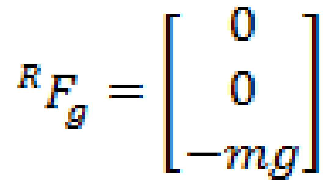
일 실시 예에 따르면, 툴(102)에는 중력이 작용할 수 있다. 예를 들면, 툴(102)에는 중력 방향에 대하여, 툴(102)의 질량 m에 대응하는 중력 mg가 작용할 수 있다. 중력 mg는 툴(102)의 무게 중심에 작용하는 것으로 이해될 수 있다. 일 실시 예에서, 상기 무게 중심은 역각 센서(101)로부터 제1 거리(11)만큼 이격될 수 있다. 이에 따라, 역각 센서(101)는 상기 중력 mg로 인해 힘을 감지할 수 있지만, 상기 감지된 힘의 세기 또는 방향은 상기 중력 mg와 상이할 수 있다.According to one embodiment, gravity may act on the
일 실시 예에 따르면, 툴(102)에는 외력이 작용할 수 있다. 예를 들면, 사용자는 전자 장치(100)가 지정된 위치에 대하여 지정된 동작을 수행하도록 툴(102)에 외력을 가하고 툴(102)의 위치를 상기 지정된 위치로 변경시킬 수 있다. 일 실시 예에서, 전자 장치(100)는 툴(102)과 연결된 역각 센서(101)를 이용하여 지정된 세기와 방향을 포함하는 힘을 감지할 수 있다. 다만, 상기 역각 센서(101)에서 감지된 힘은 상기 툴(102)에 대한 외력과 작용점이 상이하기 때문에 힘의 세기 및/또는 방향이 상이할 수 있다. 예를 들면, 상기 툴(102)에 대한 외력은 툴(102)의 무게 중심에 작용하는 것으로 이해될 수 있고, 상기 툴(102)의 무게 중심은 역각 센서(101)와 제1 거리(11)만큼 이격되기 때문에 상기 역각 센서(101)에서 감지된 힘은 상기 외력과 상이할 수 있다. 일 실시 예에서, 전자 장치(100)는 지정된 수식을 포함하는 알고리즘을 이용하여 상기 역각 센서(101)에서 감지된 힘으로부터 상기 툴(102)에 대한 외력의 세기 및/또는 방향을 산출할 수 있다.According to one embodiment, an external force may act on the
일 실시 예에 따르면, 전자 장치(100)는 외력의 측정을 위해 복수의 좌표계를 이용할 수 있다. 예를 들면, 전자 장치(100)는 X1, Y1, 및 Z1으로 이루어진 제1 좌표계, X2, Y2, 및 Z2으로 이루어진 제2 좌표계, 및/또는 X3, Y3, 및 Z3으로 이루어진 제3 좌표계를 이용할 수 있다. According to an embodiment, the
본 문서에서, 상기 제1 좌표계는 전자 장치(100), 예컨대, 전자 장치(100)가 위치하는 지면을 기준으로 한 좌표계일 수 있다. 본 문서에서, 상기 제2 좌표계는 역각 센서(101)를 기준으로 한 좌표계일 수 있다. 일 실시 예에서, 로봇 암(110)의 움직임에 따라 역각 센서(101)가 움직이면 상기 제2 좌표계도 움직일 수 있다. 본 문서에서, 상기 제3 좌표계는 연결부(111)를 기준으로 한 좌표계일 수 있다. 일 실시 예에서, 로봇 암(110)의 움직임에 따라 연결부(111)가 움직이면 상기 제3 좌표계도 움직일 수 있다. In this document, the first coordinate system may be a coordinate system based on the
도 1의 일부 확대도(10b)를 참조하면, 제2 좌표계 및 제3 좌표계에 있어서, 각각의 축들(예: X2 축과 X3 축 또는 Y2 축과 Y3 축)이 서로 평행한 것으로 이해될 수도 있다. 그러나 다양한 실시 예에 따르면, 역각 센서(101)가 연결부(111)에 부착될 때 발생할 수 있는 조립 편차에 따라 상기 각각의 축들은 평행하지 않을 수도 있다. 예를 들면, 상기 제2 좌표계 및 상기 제3 좌표계 사이의 관계는 역각 센서(101)가 탈부착 될 때마다 달라질 수 있다.Referring to the partially
일 실시 예에 따르면, 툴(102)에 대한 외력은 역각 센서(101)에서 측정된 외력으로부터 역각 센서(101) 자체의 바이어스 값 및 툴(102)의 무게를 제외한 값으로 산출될 수 있다. 이를 수식으로 나타내면 다음과 같다.According to an embodiment, the external force for the
![]()
![]()
일 실시 예에서, ![]()
![]()
![]()
![]()
![]()
![]()
![]()
![]()
일 실시 예에서, ![]()
![]()
![]()
![]()
![]()
![]()
![]()
![]()
일 실시 예에 따르면, 제1 좌표계를 제2 좌표계로 변환하기 위한 관계식인 ![]()
![]()
![]()
![]()
![]()
![]()
![]()
![]()
![]()
![]()
![]()
![]()
일 실시 예에 따르면, 전자 장치(100)는 역각 센서(101)로부터 역각 센서(101)를 통해 측정된 값 ![]()
![]()
![]()
![]()
![]()
![]()
![]()
![]()
![]()
![]()
![]()
![]()
이하, 본 문서에서는 툴(102)에 대해 가해진 외력을 산출하기 위한 적어도 하나의 오프셋 파라미터(offset parameter), 예컨대, 역각 센서(101)의 바이어스 값, 툴(102)의 중력, 제1 좌표계 및 제2 좌표계 사이의 관계식, 및/또는 제1 거리(11)를 산출하는 방법 및 이를 통해 상기 툴(102)에 대해 가해진 외력을 산출하는 방법에 대하여 설명될 수 있다. 본 문서에서, 도 1에 도시된 구성과 동일한 참조 번호를 가지는 구성에는 도 1에서 설명된 내용이 동일하게 적용될 수 있다.Hereinafter, in this document, at least one offset parameter for calculating the external force applied to the
도 2는 일 실시 예에 따른, 전자 장치의 블록도를 나타낸다.2 shows a block diagram of an electronic device according to an embodiment.
도 2을 참조하면, 전자 장치(100)는 로봇 암(110), 액츄에이터(120), 및 프로세서(130)를 포함할 수 있다. 다양한 실시 예에 따르면, 전자 장치(100)는 도 2에 도시되지 않은 구성을 추가로 더 포함하거나, 도 2에 도시된 구성 중 일부를 생략할 수도 있다. 예를 들면, 전자 장치(100)는 프로세서(130)와 전기적으로 연결되는 메모리를 더 포함할 수도 있다.Referring to FIG. 2 , the
일 실시 예에 따르면, 로봇 암(110)은 연결부(111)를 포함할 수 있다. 일 실시 예에서, 연결부(111)는 역각 센서(예: 도 1의 역각 센서(101))와 전기적 및/또는 물리적으로 연결될 수 있다. 연결부(111)는 상기 역각 센서를 통해 상기 역각 센서와 연결된 툴(예: 도 1의 툴(102))과 간접적으로 연결될 수 있다. 다른 실시 에에서, 연결부(111)는 역각 센서 없이 상기 툴과 직접 연결될 수도 있다.According to one embodiment, the
일 실시 예에 따르면, 로봇 암(110)은 액츄에이터(120)와 전기적으로 연결될 수 있고, 액츄에이터(120)의 제어에 기초하여 연결부(111)를 지정된 위치로 이동시킬 수 있다. 일 실시 예에 따르면, 로봇 암(110)은 외력에 기초하여 연결부(111)를 지정된 위치로 이동시킬 수도 있다. 예를 들면, 사용자는 로봇 암(110) 또는 로봇 암(110)과 연결부(111)를 통해 연결되는 역각 센서 또는 툴에 대하여 외력을 가할 수 있고, 로봇 암(110)은 상기 외력에 기초하여 연결부(111)의 위치를 이동시킬 수 있다.According to one embodiment, the
일 실시 예에 따르면, 액츄에이터(120)는 적어도 하나 이상일 수 있다. 일 실시 예에서, 액츄에이터(120)는 프로세서(130)의 제어에 기초하여 로봇 암(110)을 구동할 수 있다. 예를 들면, 액츄에이터(120)는 프로세서(130)로부터 지정된 위치에 대한 좌표 정보를 수신할 수 있고, 상기 수신된 정보에 기초하여 연결부(111)가 상기 좌표 정보에 대응하는 위치로 이동하도록 로봇 암(110)을 구동할 수 있다.According to one embodiment, the number of
일 실시 예에 따르면, 프로세서(130)는 전자 장치(100)에 포함되는 구성들과 전기적으로 연결되고 상기 구성들로부터 지정된 정보를 수신하고 상기 수신된 정보에 기초한 연산을 수행할 수 있다. 일 실시 예에서, 프로세서(130)는 상기 수행된 연산에 기초하여 상기 구성들을 제어할 수도 있다. 예를 들면, 프로세서(130)는 연결부(111)를 통해 역각 센서로부터 외력에 대한 정보를 수신할 수 있다. 프로세서(130)는 상기 수신된 정보에 기초하여 연산을 수행하고 상기 외력의 세기 또는 방향을 산출할 수 있다. 프로세서(130)는 상기 외력이 지정된 수준 이상인 경우 로봇 암(110)이 상기 외력에 순응하여 움직이도록 상기 액츄에이터(120)를 제어할 수 있다.According to an embodiment, the
일 실시 예에 따르면, 전자 장치(100)는 메모리를 더 포함할 수도 있다. 메모리는 프로세서(130)가 수행하는 동작에 대한 명령어들(instructions)을 저장할 수 있고, 프로세서(130)가 수신한 정보 또는 프로세서(130)가 연산한 결과를 저장할 수 있다.According to an embodiment, the
본 문서에서, 도 2에 도시된 전자 장치(100)의 구성과 동일한 참조 번호를 가지는 구성에는 도 2에서 설명된 내용이 동일하게 적용될 수 있다.In this document, the contents described in FIG. 2 may be equally applied to components having the same reference numerals as those of the
도 3은 일 실시 예에 따른, 프로세서의 블록도를 나타낸다.3 shows a block diagram of a processor, according to one embodiment.
도 3을 참조하면, 프로세서(130)는 인터페이스(131), 오프셋 추정기(132), 오프셋 보상기(133), 모션 계획부(134), 및 모터 제어부(135)를 포함할 수 있다. 다양한 실시 예에 따르면, 프로세서(130)는 도 3에 도시되지 않은 구성을 추가로 더 포함할 수 있고, 도 3에 도시된 구성 중 일부를 생략할 수도 있다. 일 실시 예에서, 도 3에 도시된 구성 중 적어도 일부는 하나의 구성으로 통합될 수도 있다. 다양한 실시 예에 따르면, 도 3에 도시된 프로세서(130)의 구성들은 하드웨어적 또는 소프트웨어적으로 구현될 수 있다. Referring to FIG. 3 , the
일 실시 예에 따르면, 인터페이스(131)는 역각 센서(예: 도 1의 역각 센서(101))와 전기적으로 연결되기 위한 입출력 단자를 포함할 수 있다. 다양한 실시 예에서, 인터페이스(131)는 GPIO(general purpose input output), 또는 MIPI(mobile industry processor interface)를 포함할 수 있다. 일 실시 예에 따르면, 인터페이스(131)를 통해 프로세서(130)는 역각 센서로부터 측정된 결과로부터 역각 센서에서 감지되는 힘 또는 토크의 값을 획득할 수 있다. 예를 들면, 인터페이스(131)는 역각 센서로부터 수신된 측정 값에 대한 신호 처리를 통해 상기 힘 또는 토크의 값, 예컨대, ![]()
![]()
일 실시 예에 따르면, 오프셋 추정기(132)는 인터페이스(131)를 통해 획득된 역각 센서에서 감지되는 힘 또는 토크를 이용하여, 툴에 대해 가해진 외력을 산출하기 위한 적어도 하나의 파라미터를 산출할 수 있다. 상기 적어도 하나의 파라미터는, 예컨대, 역각 센서(101)의 바이어스 값, 툴(예: 도 1의 툴(102))의 중력(또는 툴의 질량), 제1 좌표계 및 제2 좌표계 사이의 관계식, 및/또는 툴의 무게 중심까지의 거리(예: 도 1의 제1 거리(11))를 포함할 수 있다. 일 실시 예에서, 상기 산출된 적어도 하나의 파라미터는 오프셋 보정기로 전달될 수 있다.According to an embodiment, the offset
일 실시 예에 따르면, 오프셋 보상기(133)는 인터페이스(131)를 통해 획득된 역각 센서에서 감지되는 힘 또는 토크 및 오프셋 추정기(132)로부터 수신된 상기 적어도 하나의 파라미터를 적어도 이용하여 툴에 작용하는 외력, 예컨대, ![]()
![]()
일 실시 예에 따르면, 오프셋 보상기(133)는 모션 계획부(134)에 대하여 상기 산출된 외력, 예컨대, ![]()
![]()
일 실시 예에 따르면, 모션 계획부(134)는 오프셋 보상기(133)로부터 수신된 툴에 작용하는 외력, 예컨대, ![]()
![]()
일 실시 예에 따르면, 모터 제어부(135)는 모션 계획부(134)로부터 수신된 지정된 신호에 기초하여 액츄에이터(예: 도 1의 액츄에이터(120))를 제어할 수 있다. 예를 들어, 모터 제어부(135)는 모션 계획부(134)로부터 상기 외력에 기초하여 로봇 암을 제어하는 신호를 수신하는 경우 상기 외력에 순응하여 동작하도록 액츄에이터를 구동할 수 있다. 다른 예를 들면, 모터 제어부(135)는 모션 계획부(134)로부터 상기 외력에 기초하여 로봇 암을 제어하지 않도록 하는 신호를 수신하는 경우 상기 외력에 순응하여 동작하지 않도록 액츄에이터를 구동할 수 있다. 일 실시 예에 따르면, 모터 제어부(135)는 액츄에이터로부터 연결부의 위치 정보를 획득할 수도 있다.According to an embodiment, the
도 4는 일 실시 예에 따른, 전자 장치가 제1 좌표계 및 제2 좌표계 사이의 관계식을 추정하는 방법에 대한 흐름도를 나타낸다.4 is a flowchart of a method for estimating a relational expression between a first coordinate system and a second coordinate system by an electronic device according to an embodiment.
도 4를 참조하면, 전자 장치가 제1 좌표계 및 제2 좌표계 사이의 관계식을 추정하는 방법(400)은 동작 401 내지 동작 407을 포함할 수 있다. 다양한 실시 예에 따르면, 상기 동작 401 내지 상기 동작 407은 도 2에 도시된 전자 장치(100) 또는 프로세서(130)에 의해 수행되는 것으로 이해될 수 있다. Referring to FIG. 4 , a
동작 401에서, 전자 장치는 역각 센서로부터 연결부의 위치가 제1 위치인 경우에 대하여 역각 센서의 제1 측정값, 예컨대, 제1 힘 또는 제1 토크를 수신할 수 있다. 이 경우, 전자 장치, 역각 센서 또는 툴에 대하여 외력은 작용하지 않는 상태일 수 있다. 이 경우, 상기 제1 힘에 대한 제1 수식은 다음과 같이 나타낼 수 있다.In
![]()
![]()
일 실시 예에서, ![]()
![]()
![]()
![]()
![]()
![]()
![]()
![]()
![]()
![]()
![]()
![]()
![]()
![]()
![]()
![]()
![]()
![]()
동작 403에서, 전자 장치는 역각 센서로부터 연결부의 위치가 제2 위치인 경우에 대하여 역각 센서의 제2 측정값, 예컨대, 제2 힘 또는 제2 토크를 수신할 수 있다. 이 경우, 전자 장치, 역각 센서 또는 툴에 대하여 외력은 작용하지 않는 상태일 수 있다. 이 경우, 상기 제2 힘에 대한 제2 수식은 다음과 같이 나타낼 수 있다.In
![]()
![]()
일 실시 예에서, ![]()
![]()
![]()
![]()
![]()
![]()
![]()
![]()
![]()
![]()
동작 405에서, 전자 장치는 역각 센서로부터 연결부의 위치가 제3 위치인 경우에 대하여 역각 센서의 제3 측정값, 예컨대, 제3 힘 또는 제3 토크를 수신할 수 있다. 이 경우, 전자 장치, 역각 센서 또는 툴에 대하여 외력은 작용하지 않는 상태일 수 있다. 이 경우, 상기 제3 힘에 대한 제3 수식은 다음과 같이 나타낼 수 있다.In
![]()
![]()
일 실시 예에서, ![]()
![]()
![]()
![]()
![]()
![]()
![]()
![]()
![]()
![]()
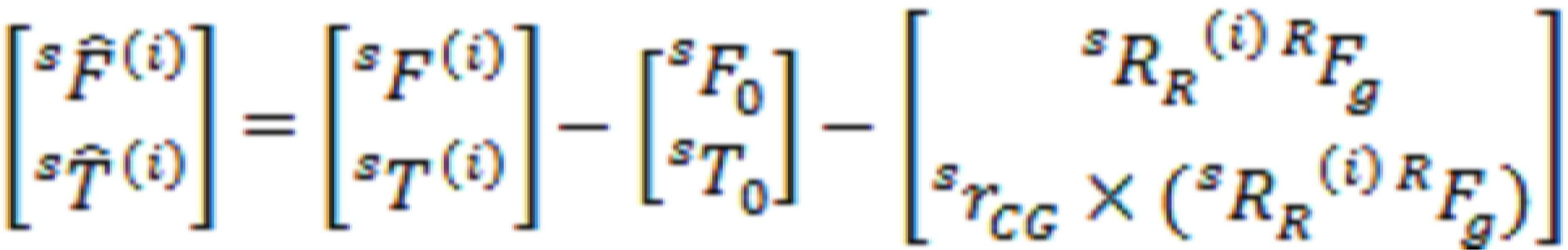
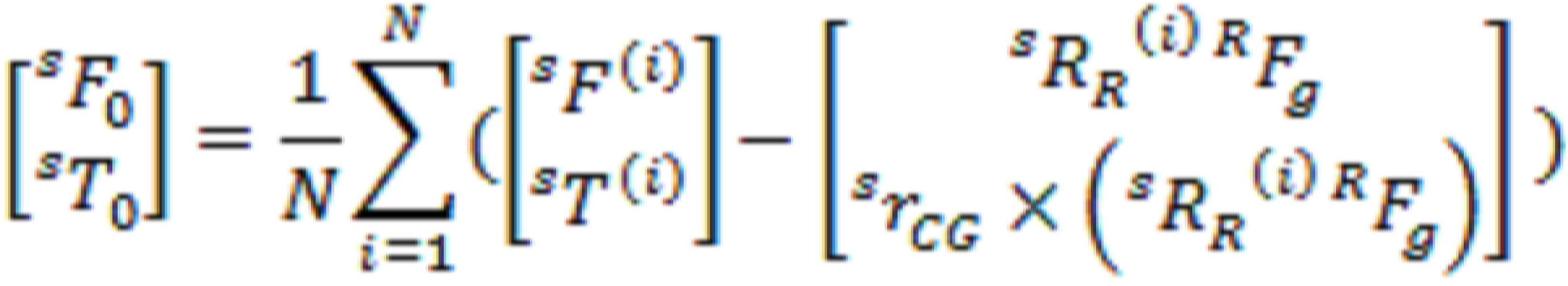
동작 407에서, 전자 장치는 상기 동작 401 내지 상기 동작 405에서 획득된 상기 제1 수식 내지 상기 제3 수식을 이용하여 제1 좌표계 및 제2 좌표계 사이의 관계식을 추정할 수 있다. In
일 실시 예에 따르면, 전자 장치는 상기 제1 수식 내지 상기 제3 수식 중 어느 하나의 수식에서 다른 하나의 수식을 뺄 수 있다. 예를 들면, 상기 제1 수식에서 상기 제2 수식을 뺄 수 있고, 상기 제1 수식에서 상기 제3 수식을 뺄 수 있고, 상기 제2 수식에서 상기 제3 수식을 뺄 수 있다. 이를 통해, 상기 제1 수식 내지 상기 제3 수식 중 공통 부분, 예컨대, 역각 센서의 바이어스 값 ![]()
![]()
![]()
![]()
![]()
![]()
![]()
![]()
![]()
![]()
일 실시 예에서, i 및 j는 1 내지 3 중 서로 다른 임의의 숫자일 수 있다. 상기 수식에 대하여 ![]()
![]()
![]()
![]()
![]()
![]()
일 실시 예에서 k의 최대값은 상기 어느 하나의 수식에서 다른 하나의 수식을 뺀 결과로 획득된 수식의 개수일 수 있다. 예를 들어, 상기 제1 수식 및 상기 제3 수식을 이용하는 경우 ![]()
![]()
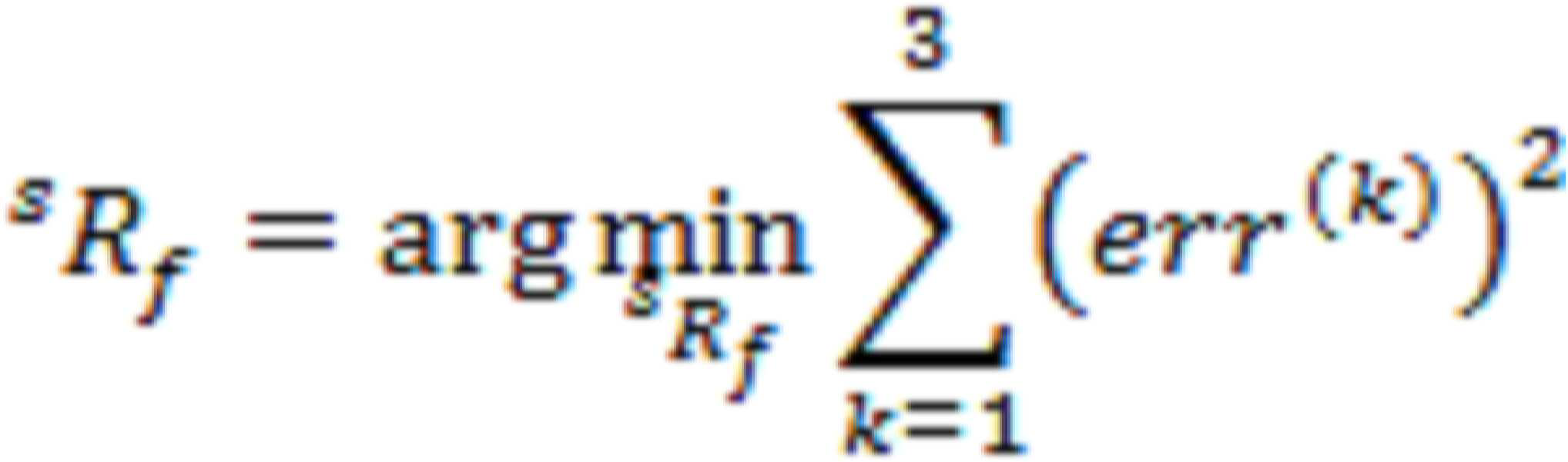
일 실시 예에 따르면, 전자 장치는 상기 재표현된 수식에 대하여 양변을 정규화(normalize)하고, 양변의 차이를 오차로 정의할 수 있다. 예를 들면, 전자 장치는 상기 오차를 아래와 같이 정의할 수 있다.According to an embodiment, the electronic device may normalize both sides of the re-expressed equation and define a difference between both sides as an error. For example, the electronic device may define the error as follows.
![]()
![]()
일 실시 예에서, 전자 장치는 상기 오차가 최소가 되도록 하는 ![]()
![]()
![]()
![]()
일 실시 예에 따르면, 전자 장치는 상기 획득된 ![]()
![]()
![]()
![]()
![]()
![]()
![]()
![]()
![]()
![]()
![]()
![]()
![]()
![]()
![]()
![]()
상기 동작 401 내지 상기 동작 407을 통해, 전자 장치는 연결부와 역각 센서 사이의 조립 오차를 고려한 제1 좌표계 및 제2 좌표계 사이의 관계, 예컨대, ![]()
![]()
다양한 실시 예에 따르면, 도 4에 도시된 전자 장치가 제1 좌표계 및 제2 좌표계 사이의 관계식을 추정하는 방법(400)은 도 4에 도시되지 않는 동작을 더 포함할 수도 있다. 예를 들면, 전자 장치는 상기 동작 405를 수행하고 상기 동작 407을 수행하기 전에 제4 위치에서 역각 센서의 제4 측정값을 수신하는 동작을 더 수행할 수도 있다. 이 경우 상기 동작 407에서 i 및 j는 1 내지 4 중 서로 다른 임의의 숫자일 수 있고, ![]()
![]()
도 5a는 일 실시 예에 따른, 전자 장치가 외력을 측정하는 방법에 대한 흐름도를 나타낸다.5A is a flowchart of a method of measuring an external force by an electronic device, according to an exemplary embodiment.
도 5a를 참조하면, 전자 장치는 도 4에서 획득된 제1 좌표계 및 제2 좌표계 사이의 관계, 예컨대, ![]()
![]()
동작 501a에서, 전자 장치는 제1 좌표계 및 제2 좌표계 사이의 관계식을 추정할 수 있다. 일 실시 에에 따르면, 상기 관계식, 예컨대, 제1 좌표계를 제2 좌표계로 변환하기 위한 관계식 ![]()
![]()
동작 503a에서, 전자 장치는 상기 동작 501a에서 획득된 ![]()
![]()
![]()
![]()
일 실시 예에서, ![]()
![]()
![]()
![]()
![]()
![]()
![]()
![]()
동작 505a에서, 전자 장치는 상기 동작 501a에서 획득된 ![]()
![]()
![]()
![]()
![]()
![]()
![]()
![]()
일 실시 예에 따르면, 전자 장치는 상기 수식들 중 어느 하나의 수식에서 다른 하나의 수식을 뺄 수 있다. 또한, 다양한 실시 예에서, 외력이 0이면 ![]()
![]()
![]()
![]()
![]()
![]()
![]()
![]()
일 실시 예에 따르면, 상기 수식은 ![]()
![]()
![]()
![]()
![]()
![]()
일 실시 예에 따르면, 전자 장치는 상기 수식에서 ![]()
![]()
![]()
![]()
![]()
![]()
![]()
![]()
![]()
![]()
![]()
![]()
![]()
![]()
![]()
![]()
![]()
![]()

동작 507a에서, 전자 장치는 역각 센서의 바이어스 값을 추정할 수 있다. 예를 들면, 전자 장치는 도 4에 도시된 동작 401 내지 동작 407과 같이, 역각 센서로부터 셋 이상의 위치에서 셋 이상의 측정 값을 수신할 수 있다. 다양한 실시 예에서, i번째 측정 값을 이용한 수식은 다음과 같을 수 있다. In
다양한 실시 예에 따르면, 역각 센서에 작용하는 외력은 언제나 0인 상태로 측정된 것이므로 ![]()
![]()
![]()
![]()
![]()
![]()
![]()
![]()
![]()
![]()
![]()
![]()
![]()
![]()
![]()
![]()
상기 동작 501a 내지 상기 동작 507a에 따르면, 전자 장치는 전자 장치의 연결부와 역각 센서 사이의 관계식을 사전에 알지 못하더라도 상기 관계식을 추정하고 획득할 수 있다. 이를 통해 전자 장치는 외력의 측정에 필요한 적어도 하나의 파라미터를 획득할 수 있고, 상기 외력을 보다 정확하게 측정할 수 있다.According to
도 5b는 다른 실시 예에 따른, 전자 장치가 외력의 측정하는 방법에 대한 흐름도를 나타낸다.5B is a flowchart of a method of measuring an external force by an electronic device according to another embodiment.
도 5b를 참조하면, 전자 장치는 툴의 질량을 산출할 수 있고 상기 산출된 툴의 질량으로부터 획득된 제1 좌표계 및 제2 좌표계 사이의 관계, 예컨대, ![]()
![]()
동작 501b에서, 전자 장치는 역각 센서(예: 도 1의 역각 센서(101))에 부착된 지정된 물체, 예컨대, 툴(예: 도 1의 툴(102))의 질량을 추정할 수 있다. 일 실시 예에 따르면, 전자 장치는 도 4에 도시된 동작 401 내지 동작 407과 같이, 역각 센서로부터 셋 이상의 위치에서 셋 이상의 측정 값을 수신할 수 있다. 일 실시 예에서, 상기 측정 값은 역각 센서에서 측정된 힘을 포함할 수 있다. 다양한 실시 예에 대하여, 상기 힘에 대한 수식은 각각 다음과 같이 나타낼 수 있다.In
![]()
![]()
![]()
![]()
![]()
![]()
일 실시 예에 따르면, 전자 장치는 상기 수식들 중 어느 하나의 수식에서 다른 하나의 수식을 뺄 수 있다. 또한, 다양한 실시 예에서, 외력이 0이면 ![]()
![]()
![]()
![]()
![]()
![]()
![]()
![]()
일 실시 예에서, i 및 j는 1 내지 3 중 서로 다른 임의의 숫자일 수 있다. 상기 수식에 대하여 ![]()
![]()
![]()
![]()
![]()
![]()
일 실시 예에서 k의 최대값은 상기 어느 하나의 수식에서 다른 하나의 수식을 뺀 결과로 획득된 수식의 개수일 수 있다. 예를 들어, 상기 제1 수식 및 상기 제3 수식을 이용하는 경우 ![]()
![]()
일 실시 예에 따르면, 상기 재표현된 수식은 양변에 대하여 전치 행렬(transition matrix)를 내적하면 다음과 같이 표현될 수 있다. 일 실시 예에서, ![]()
![]()

일 실시 예에 따르면, 전자 장치는 상기 수식에서 양 변의 차이를 오차로 정의할 수 있고 상기 오차가 최소가 되도록 하는 ![]()
![]()
![]()
![]()
동작 503b에서, 전자 장치는 제1 좌표계 및 제2 좌표계 사이의 관계식을 추정할 수 있다. 예를 들면, 전자 장치는 상기 동작 501b에서 획득된 툴의 질량 m을 이용하여 제1 좌표계를 제2 좌표계로 변환하기 위한 관계식 ![]()
![]()
일 실시 예에 따르면, 전자 장치는 상기 동작 501a에서 획득한 수식 중 ![]()
![]()
![]()
![]()
![]()
![]()
![]()
![]()

동작 505b에서, 전자 장치는 툴의 무게 중심 위치를 추정할 수 있다. 예를 들면, 전자 장치는 도 5a의 동작 505a와 동일 또는 유사하게, 동작 501b에서 획득된 ![]()
![]()
동작 507b에서, 전자 장치는 역각 센서의 바이어스 값을 추정할 수 있다. 예를 들면, 전자 장치는 도 5a의 동작 505a와 동일 또는 유사하게, 동작 501b에서 획득된 ![]()
![]()
![]()
![]()
상기 동작 501a 내지 상기 동작 507a에 따르면, 전자 장치는 전자 장치의 연결부(예: 도 2의 연결부(111))와 역각 센서 사이의 관계식을 사전에 알지 못하더라도 상기 관계식을 추정하고 획득할 수 있다. 이를 통해 전자 장치는 외력의 측정에 필요한 적어도 하나의 파라미터를 획득할 수 있고, 상기 외력을 보다 정확하게 측정할 수 있다.According to
도 6은 일 실시 예에 따른, 전자 장치가 측정된 외력에 기초하여 동작하는 방법에 대한 흐름도를 나타낸다.6 is a flowchart of a method of operating an electronic device based on a measured external force, according to an embodiment.
도 6을 참조하면, 전자 장치가 측정된 외력에 기초하여 동작하는 방법(600)은 동작 601 내지 동작 607을 포함할 수 있다. 다양한 실시 예에 따르면, 상기 동작 601 내지 상기 동작 607은 도 2에 도시된 전자 장치(100) 또는 프로세서(130)에 의해 수행되는 것으로 이해될 수 있다. 도 6의 설명에 있어서 도 4, 도 5a 또는 도 5b의 설명과 중복되는 내용은 생략될 수 있다.Referring to FIG. 6 , a
동작 601에서, 전자 장치는 역각 센서 기준의 외력, 예컨대, 힘 또는 토크를 측정할 수 있다. 예를 들면, 전자 장치는 툴에 대해 작용한 외력을 역각 센서를 기준으로 한 제2 좌표계 기준으로 측정할 수 있다. 예컨대, 전자 장치는 도 5a에 도시된 방법(500a) 또는 도 5b에 도시된 방법(500b)을 통해 외력 측정을 위한 오프셋 파라미터들을 획득할 수 있고, 상기 획득된 오프셋 파라미터들을 이용하여 상기 제2 좌표계를 기준으로 한 상기 외력의 세기 또는 방향을 획득할 수 있다. 일 실시 예에 따르면, 상기 획득한 외력은 ![]()
![]()
![]()
![]()
동작 603에서, 전자 장치는 상기 동작 601에서 측정된 외력을 전자 장치 기준의 외력으로 변환할 수 있다. 예를 들면, 전자 장치는 상기 제2 좌표계 기준으로 측정된 외력을 전자 장치를 기준으로 한 제1 좌표계 기준으로 변환할 수 있다. 일 실시 예에 따르면, 상기 변환된 외력은 ![]()
![]()
![]()
![]()
일 실시 예에 따르면, 전자 장치는 제2 좌표계를 제3 좌표계로 변환하기 위한 관계식 ![]()
![]()
![]()
![]()
![]()
![]()
![]()
![]()
일 실시 예에서, 전자 장치는 도 4의 동작 407에서 획득된 ![]()
![]()
![]()
![]()
![]()
![]()
동작 605에서, 전자 장치는 상기 동작 603에서 변환된 외력에 기초하여 전자 장치의 속도 명령을 생성할 수 있다. 다양한 실시 예에 따르면, 상기 속도 명령은 전자 장치에 대한 속도(![]()
![]()
![]()
![]()
![]()
![]()
![]()
![]()
![]()
![]()
![]()
![]()
동작 607에서, 전자 장치는 상기 동작 605에서 생성된 속도 명령에 기초하여 전자 장치의 로봇 암을 제어할 수 있다. 예를 들면, 전자 장치는 상기 획득된 ![]()
![]()
![]()
![]()
상기 동작 601 내지 상기 동작 607을 이용하여, 전자 장치는 작용된 외력에 순응하고 상기 외력에 기초한 속도 또는 각속도에 기초하여 로봇 암을 제어할 수 있다.Using
도 7은, 다양한 실시 예들에 따른, 네트워크 환경(700) 내의 전자 장치(701)의 블록도이다. 7 is a block diagram of an electronic device 701 within a
도 7을 참조하면, 네트워크 환경(700)에서 전자 장치(701)는 제 1 네트워크(798)(예: 근거리 무선 통신 네트워크)를 통하여 전자 장치(702)와 통신하거나, 또는 제 2 네트워크(799)(예: 원거리 무선 통신 네트워크)를 통하여 전자 장치(704) 또는 서버(708)와 통신할 수 있다. 일 실시 예에 따르면, 전자 장치(701)는 서버(708)를 통하여 전자 장치(704)와 통신할 수 있다. 일 실시 예에 따르면, 전자 장치(701)는 프로세서(720), 메모리(730), 입력 장치(750), 음향 출력 장치(755), 표시 장치(760), 오디오 모듈(770), 센서 모듈(776), 인터페이스(777), 햅틱 모듈(779), 카메라 모듈(780), 전력 관리 모듈(788), 배터리(789), 통신 모듈(790), 가입자 식별 모듈(796), 또는 안테나 모듈(797)을 포함할 수 있다. 어떤 실시 예에서는, 전자 장치(701)에는, 이 구성요소들 중 적어도 하나(예: 표시 장치(760) 또는 카메라 모듈(780))가 생략되거나, 하나 이상의 다른 구성 요소가 추가될 수 있다. 어떤 실시 예에서는, 이 구성요소들 중 일부들은 하나의 통합된 회로로 구현될 수 있다. 예를 들면, 센서 모듈(776)(예: 지문 센서, 홍채 센서, 또는 조도 센서)은 표시 장치(760)(예: 디스플레이)에 임베디드된 채 구현될 수 있다Referring to FIG. 7 , in a
프로세서(720)는, 예를 들면, 소프트웨어(예: 프로그램(740))를 실행하여 프로세서(720)에 연결된 전자 장치(701)의 적어도 하나의 다른 구성요소(예: 하드웨어 또는 소프트웨어 구성요소)을 제어할 수 있고, 다양한 데이터 처리 또는 연산을 수행할 수 있다. 일 실시 예에 따르면, 데이터 처리 또는 연산의 적어도 일부로서, 프로세서(720)는 다른 구성요소(예: 센서 모듈(776) 또는 통신 모듈(790))로부터 수신된 명령 또는 데이터를 휘발성 메모리(732)에 로드하고, 휘발성 메모리(732)에 저장된 명령 또는 데이터를 처리하고, 결과 데이터를 비휘발성 메모리(734)에 저장할 수 있다. 일 실시 예에 따르면, 프로세서(720)는 메인 프로세서(721)(예: 중앙 처리 장치 또는 어플리케이션 프로세서), 및 이와는 독립적으로 또는 함께 운영 가능한 보조 프로세서(723)(예: 그래픽 처리 장치, 이미지 시그널 프로세서, 센서 허브 프로세서, 또는 커뮤니케이션 프로세서)를 포함할 수 있다. 추가적으로 또는 대체적으로, 보조 프로세서(723)은 메인 프로세서(721)보다 저전력을 사용하거나, 또는 지정된 기능에 특화되도록 설정될 수 있다. 보조 프로세서(723)는 메인 프로세서(721)와 별개로, 또는 그 일부로서 구현될 수 있다.The processor 720, for example, executes software (eg, the program 740) to cause at least one other component (eg, hardware or software component) of the electronic device 701 connected to the processor 720. It can control and perform various data processing or calculations. According to one embodiment, as at least part of data processing or operation, the processor 720 transfers instructions or data received from other components (eg,
보조 프로세서(723)는, 예를 들면, 메인 프로세서(721)가 인액티브(예: 슬립) 상태에 있는 동안 메인 프로세서(721)를 대신하여, 또는 메인 프로세서(721)가 액티브(예: 어플리케이션 실행) 상태에 있는 동안 메인 프로세서(721)와 함께, 전자 장치(701)의 구성요소들 중 적어도 하나의 구성요소(예: 표시 장치(760), 센서 모듈(776), 또는 통신 모듈(790))와 관련된 기능 또는 상태들의 적어도 일부를 제어할 수 있다. 일 실시 예에 따르면, 보조 프로세서(723)(예: 이미지 시그널 프로세서 또는 커뮤니케이션 프로세서)는 기능적으로 관련 있는 다른 구성 요소(예: 카메라 모듈(780) 또는 통신 모듈(790))의 일부로서 구현될 수 있다. The
메모리(730)는, 전자 장치(701)의 적어도 하나의 구성요소(예: 프로세서(720) 또는 센서모듈(776))에 의해 사용되는 다양한 데이터를 저장할 수 있다. 데이터는, 예를 들어, 소프트웨어(예: 프로그램(740)) 및, 이와 관련된 명령에 대한 입력 데이터 또는 출력 데이터를 포함할 수 있다. 메모리(730)는, 휘발성 메모리(732) 또는 비휘발성 메모리(734)를 포함할 수 있다. The memory 730 may store various data used by at least one component (eg, the processor 720 or the sensor module 776) of the electronic device 701 . The data may include, for example, input data or output data for software (eg, the program 740) and commands related thereto. The memory 730 may include volatile memory 732 or non-volatile memory 734 .
프로그램(740)은 메모리(730)에 소프트웨어로서 저장될 수 있으며, 예를 들면, 운영 체제(742), 미들 웨어(744) 또는 어플리케이션(746)을 포함할 수 있다. The program 740 may be stored as software in the memory 730 and may include, for example, an operating system 742 , middleware 744 , or an application 746 .
입력 장치(750)는, 전자 장치(701)의 구성요소(예: 프로세서(720))에 사용될 명령 또는 데이터를 전자 장치(701)의 외부(예: 사용자)로부터 수신할 수 있다. 입력 장치(750)은, 예를 들면, 마이크, 마우스, 또는 키보드를 포함할 수 있다. The
음향 출력 장치(755)는 음향 신호를 전자 장치(701)의 외부로 출력할 수 있다. 음향 출력 장치(755)는, 예를 들면, 스피커 또는 리시버를 포함할 수 있다. 스피커는 멀티미디어 재생 또는 녹음 재생과 같이 일반적인 용도로 사용될 수 있고, 리시버는 착신 전화를 수신하기 위해 사용될 수 있다. 일 실시 예에 따르면, 리시버는 스피커와 별개로, 또는 그 일부로서 구현될 수 있다.The
표시 장치(760)는 전자 장치(701)의 외부(예: 사용자)로 정보를 시각적으로 제공할 수 있다. 표시 장치(760)은, 예를 들면, 디스플레이, 홀로그램 장치, 또는 프로젝터 및 해당 장치를 제어하기 위한 제어 회로를 포함할 수 있다. 일 실시 예에 따르면, 표시 장치(760)는 터치를 감지하도록 설정된 터치 회로(touch circuitry), 또는 상기 터치에 의해 발생되는 힘의 세기를 측정하도록 설정된 센서 회로(예: 압력 센서)를 포함할 수 있다. The display device 760 can visually provide information to the outside of the electronic device 701 (eg, a user). The display device 760 may include, for example, a display, a hologram device, or a projector and a control circuit for controlling the device. According to an embodiment, the display device 760 may include a touch circuitry set to sense a touch or a sensor circuit (eg, a pressure sensor) set to measure the intensity of force generated by the touch. there is.
오디오 모듈(770)은 소리를 전기 신호로 변환시키거나, 반대로 전기 신호를 소리로 변환시킬 수 있다. 일 실시 예에 따르면, 오디오 모듈(770)은, 입력 장치(750)를 통해 소리를 획득하거나, 음향 출력 장치(755), 또는 전자 장치(701)와 직접 또는 무선으로 연결된 외부 전자 장치(예: 전자 장치(702)) (예: 스피커 또는 헤드폰))를 통해 소리를 출력할 수 있다.The audio module 770 may convert sound into an electrical signal or vice versa. According to an embodiment, the audio module 770 acquires sound through the
센서 모듈(776)은 전자 장치(701)의 작동 상태(예: 전력 또는 온도), 또는 외부의 환경 상태(예: 사용자 상태)를 감지하고, 감지된 상태에 대응하는 전기 신호 또는 데이터 값을 생성할 수 있다. 일 실시 예에 따르면, 센서 모듈(776)은, 예를 들면, 제스처 센서, 자이로 센서, 기압 센서, 마그네틱 센서, 가속도 센서, 그립 센서, 근접 센서, 컬러 센서, IR(infrared) 센서, 생체 센서, 온도 센서, 습도 센서, 또는 조도 센서를 포함할 수 있다. The
인터페이스(777)는 전자 장치(701)이 외부 전자 장치(예: 전자 장치(702))와 직접 또는 무선으로 연결되기 위해 사용될 수 있는 하나 이상의 지정된 프로토콜들을 지원할 수 있다. 일 실시 예에 따르면, 인터페이스(777)는, 예를 들면, HDMI(high definition multimedia interface), USB(universal serial bus) 인터페이스, SD카드 인터페이스, 또는 오디오 인터페이스를 포함할 수 있다.The
연결 단자(778)는, 그를 통해서 전자 장치(701)가 외부 전자 장치(예: 전자 장치(702))와 물리적으로 연결될 수 있는 커넥터를 포함할 수 있다. 일 실시 예에 따르면, 연결 단자(778)은, 예를 들면, HDMI 커넥터, USB 커넥터, SD 카드 커넥터, 또는 오디오 커넥터(예: 헤드폰 커넥터)를 포함할 수 있다.The
햅틱 모듈(779)은 전기적 신호를 사용자가 촉각 또는 운동 감각을 통해서 인지할 수 있는 기계적인 자극(예: 진동 또는 움직임) 또는 전기적인 자극으로 변환할 수 있다. 일 실시 예에 따르면, 햅틱 모듈(779)은, 예를 들면, 모터, 압전 소자, 또는 전기 자극 장치를 포함할 수 있다.The haptic module 779 may convert electrical signals into mechanical stimuli (eg, vibration or motion) or electrical stimuli that a user may perceive through tactile or kinesthetic senses. According to one embodiment, the haptic module 779 may include, for example, a motor, a piezoelectric element, or an electrical stimulation device.
카메라 모듈(780)은 정지 영상 및 동영상을 촬영할 수 있다. 일 실시 예에 따르면, 카메라 모듈(780)은 하나 이상의 렌즈들, 이미지 센서들, 이미지 시그널 프로세서들, 또는 플래시들을 포함할 수 있다.The camera module 780 may capture still images and moving images. According to one embodiment, the camera module 780 may include one or more lenses, image sensors, image signal processors, or flashes.
전력 관리 모듈(788)은 전자 장치(701)에 공급되는 전력을 관리할 수 있다. 일 실시 예에 따르면, 전력 관리 모듈(388)은, 예를 들면, PMIC(power management integrated circuit)의 적어도 일부로서 구현될 수 있다.The power management module 788 may manage power supplied to the electronic device 701 . According to one embodiment, the power management module 388 may be implemented as at least part of a power management integrated circuit (PMIC), for example.
배터리(789)는 전자 장치(701)의 적어도 하나의 구성 요소에 전력을 공급할 수 있다. 일 실시 예에 따르면, 배터리(789)는, 예를 들면, 재충전 불가능한 1차 전지, 재충전 가능한 2차 전지 또는 연료 전지를 포함할 수 있다.The
통신 모듈(790)은 전자 장치(701)와 외부 전자 장치(예: 전자 장치(702), 전자 장치(704), 또는 서버(708))간의 직접(예: 유선) 통신 채널 또는 무선 통신 채널의 수립, 및 수립된 통신 채널을 통한 통신 수행을 지원할 수 있다. 통신 모듈(790)은 프로세서(720)(예: 어플리케이션 프로세서)와 독립적으로 운영되고, 직접(예: 유선) 통신 또는 무선 통신을 지원하는 하나 이상의 커뮤니케이션 프로세서를 포함할 수 있다. 일 실시 예에 따르면, 통신 모듈(790)은 무선 통신 모듈(792)(예: 셀룰러 통신 모듈, 근거리 무선 통신 모듈, 또는 GNSS(global navigation satellite system) 통신 모듈) 또는 유선 통신 모듈(794)(예: LAN(local area network) 통신 모듈, 또는 전력선 통신 모듈)을 포함할 수 있다. 이들 통신 모듈 중 해당하는 통신 모듈은 제 1 네트워크(798)(예: 블루투스, WiFi direct 또는 IrDA(infrared data association) 같은 근거리 통신 네트워크) 또는 제 2 네트워크(799)(예: 셀룰러 네트워크, 인터넷, 또는 컴퓨터 네트워크(예: LAN 또는 WAN)와 같은 원거리 통신 네트워크)를 통하여 외부 전자 장치와 통신할 수 있다. 이런 여러 종류의 통신 모듈들은 하나의 구성 요소(예: 단일 칩)으로 통합되거나, 또는 서로 별도의 복수의 구성 요소들(예: 복수 칩들)로 구현될 수 있다. 무선 통신 모듈(792)은 가입자 식별 모듈(796)에 저장된 가입자 정보(예: 국제 모바일 가입자 식별자(IMSI))를 이용하여 제 1 네트워크(798) 또는 제 2 네트워크(799)와 같은 통신 네트워크 내에서 전자 장치(701)를 확인 및 인증할 수 있다. The communication module 790 is a direct (eg, wired) communication channel or a wireless communication channel between the electronic device 701 and an external electronic device (eg, the
안테나 모듈(797)은 신호 또는 전력을 외부(예: 외부 전자 장치)로 송신하거나 외부로부터 수신할 수 있다. 안테나 모듈은, 일 실시 예에 따르면, 도전체 또는 도전성 패턴으로 형성될 수 있고, 어떤 실시 예에 따르면, 도전체 또는 도전성 패턴 이외에 추가적으로 다른 부품(예: RFIC)을 더 포함할 수 있다. 일 실시 예에 따르면, 안테나 모듈(797)은 하나 이상의 안테나들을 포함할 수 있고, 이로부터, 제 1 네트워크(798) 또는 제 2 네트워크(799)와 같은 통신 네트워크에서 사용되는 통신 방식에 적합한 적어도 하나의 안테나가, 예를 들면, 통신 모듈(790)에 의하여 선택될 수 있다. 신호 또는 전력은 상기 선택된 적어도 하나의 안테나를 통하여 통신 모듈(790)과 외부 전자 장치 간에 송신되거나 수신될 수 있다.The
상기 구성요소들 중 적어도 일부는 주변 기기들간 통신 방식(예: 버스, GPIO(general purpose input and output), SPI(serial peripheral interface), 또는 MIPI(mobile industry processor interface))를 통해 서로 연결되고 신호(예: 명령 또는 데이터)를 상호간에 교환할 수 있다.At least some of the components are connected to each other through a communication method between peripheral devices (eg, a bus, general purpose input and output (GPIO), serial peripheral interface (SPI), or mobile industry processor interface (MIPI)) and signal ( e.g. commands or data) can be exchanged with each other.
일 실시 예에 따르면, 명령 또는 데이터는 제 2 네트워크(799)에 연결된 서버(708)를 통해서 전자 장치(701)와 외부의 전자 장치(704)간에 송신 또는 수신될 수 있다. 전자 장치(702, 704) 각각은 전자 장치(701)와 동일한 또는 다른 종류의 장치일 수 있다. 일 실시 예에 따르면, 전자 장치(701)에서 실행되는 동작들의 전부 또는 일부는 외부 전자 장치들(702, 704, or 708) 중 하나 이상의 외부 장치들에서 실행될 수 있다. 예를 들면, 전자 장치(701)가 어떤 기능이나 서비스를 자동으로, 또는 사용자 또는 다른 장치로부터의 요청에 반응하여 수행해야 할 경우에, 전자 장치(701)는 기능 또는 서비스를 자체적으로 실행시키는 대신에 또는 추가적으로, 하나 이상의 외부 전자 장치들에게 그 기능 또는 그 서비스의 적어도 일부를 수행하라고 요청할 수 있다. 상기 요청을 수신한 하나 이상의 외부 전자 장치들은 요청된 기능 또는 서비스의 적어도 일부, 또는 상기 요청과 관련된 추가 기능 또는 서비스를 실행하고, 그 실행의 결과를 전자 장치(701)로 전달할 수 있다. 전자 장치(701)는 상기 결과를, 그대로 또는 추가적으로 처리하여, 상기 요청에 대한 응답의 적어도 일부로서 제공할 수 있다. 이를 위하여, 예를 들면, 클라우드 컴퓨팅, 분산 컴퓨팅, 또는 클라이언트-서버 컴퓨팅 기술이 이용될 수 있다. According to an embodiment, commands or data may be transmitted or received between the electronic device 701 and the external
본 문서에 개시되는 일 실시 예에 따른 전자 장치는, 지정된 물체가 부착되는 역각 센서(force sensor)와 연결되기 위한 적어도 하나의 연결부가 배치되는 로봇 암(arm), 상기 적어도 하나의 연결부의 위치가 변경되도록 상기 로봇 암을 구동하는 적어도 하나의 액츄에이터(actuator), 및 상기 액츄에이터와 전기적으로 연결된 프로세서를 포함하고, 상기 프로세서는, 상기 적어도 하나의 연결부의 제1 위치에 대하여, 상기 지정된 물체의 무게에 의한 상기 역각 센서의 제1 측정 값을 수신하고, 상기 적어도 하나의 연결부의 제2 위치에 대하여, 상기 지정된 물체의 무게에 의한 상기 역각 센서의 제2 측정 값을 수신하고, 상기 적어도 하나의 연결부의 제3 위치에 대하여, 상기 지정된 물체의 무게에 의한 상기 역각 센서의 제3 측정 값을 수신하고, 상기 지정된 물체에 작용하는 외력의 크기를 산출하기 위해, 상기 제1 측정 값, 상기 제2 측정 값, 및 상기 제3 측정 값에 적어도 기반하여 상기 전자 장치가 위치하는 지면을 기준으로 한 제1 좌표계 및 상기 역각 센서를 기준으로 한 제2 좌표계 사이의 관계식을 추정하도록 설정될 수 있다.An electronic device according to an embodiment disclosed in this document includes a robot arm in which at least one connection part is disposed to be connected to a force sensor to which a designated object is attached, and a position of the at least one connection part At least one actuator that drives the robot arm to be changed, and a processor electrically connected to the actuator, wherein the processor determines, with respect to a first position of the at least one connection part, a weight of the specified object. Receive a first measurement value of the force sensor by the force sensor, and receive a second measurement value of the force sensor by the weight of the designated object with respect to a second position of the at least one connection unit, and receive a second measurement value of the at least one connection unit. With respect to the third position, the first measurement value and the second measurement value are received to receive a third measurement value of the force sensor by the weight of the designated object, and to calculate the magnitude of an external force acting on the designated object. , and a relational expression between a first coordinate system based on the ground on which the electronic device is located and a second coordinate system based on the force sensor may be set based on at least the third measurement value.
일 실시 예에 따르면, 상기 프로세서는 상기 제1 측정 값, 상기 제2 측정 값, 및 상기 제3 측정 값에 적어도 기반하여 상기 지정된 물체의 질량을 추정하고, 상기 추정된 질량에 기초하여 상기 제1 좌표계 및 상기 제2 좌표계 사이의 관계식을 추정하도록 설정될 수 있다.According to an embodiment, the processor estimates a mass of the specified object based on at least the first measurement value, the second measurement value, and the third measurement value, and the first measurement value based on the estimated mass. It may be set to estimate a relational expression between a coordinate system and the second coordinate system.
일 실시 예에 따르면, 상기 프로세서는 상기 추정된 상기 제1 좌표계 및 상기 제2 좌표계 사이의 상기 관계식에 기초하여 상기 역각 센서의 오프셋 파라미터(offset parameter)를 추정하도록 설정될 수 있다.According to an embodiment, the processor may be configured to estimate an offset parameter of the force sensor based on the relational expression between the estimated first coordinate system and the second coordinate system.
일 실시 예에서, 상기 오프셋 파라미터는 상기 지정된 물체의 질량, 상기 제2 좌표계의 원점으로부터 상기 지정된 물체의 무게 중심 사이의 거리, 상기 역각 센서의 바이어스 힘, 또는 상기 역각 센서의 바이어스 토크 중 적어도 하나를 포함할 수 있다.In one embodiment, the offset parameter is at least one of a mass of the specified object, a distance between an origin of the second coordinate system and a center of gravity of the specified object, a bias force of the force sensor, or a bias torque of the force sensor. can include
일 실시 예에 따르면, 상기 프로세서는 상기 추정된 관계식에 적어도 기반하여 상기 제2 좌표계를 기준으로 한 상기 외력을 측정하도록 설정될 수 있다.According to an embodiment, the processor may be set to measure the external force based on the second coordinate system based at least on the estimated relational expression.
일 실시 예에서, 상기 프로세서는, 상기 측정된 상기 제2 좌표계를 기준으로 한 상기 외력에 기초하여 상기 제1 좌표계를 기준으로 한 상기 외력을 산출하고, 상기 산출된 상기 제1 좌표계를 기준으로 한 상기 외력에 적어도 기반하여 적어도 하나의 속도 명령을 산출하고, 상기 산출된 속도 명령에 기초하여 상기 로봇 암을 구동하도록 상기 액츄에이터를 제어할 수 있다.In one embodiment, the processor calculates the external force based on the first coordinate system based on the external force based on the measured second coordinate system, and calculates the external force based on the calculated first coordinate system. At least one speed command may be calculated based on at least the external force, and the actuator may be controlled to drive the robot arm based on the calculated speed command.
일 실시 예에 따르면, 상기 프로세서는, 상기 적어도 하나의 연결부의 위치 정보를 획득하고, 상기 획득된 위치 정보에 기초하여 상기 제1 좌표계 및 상기 적어도 하나의 연결부를 기준으로 한 제3 좌표계 사이의 관계식을 획득할 수 있다.According to an embodiment, the processor obtains location information of the at least one connection unit, and a relational expression between the first coordinate system and a third coordinate system based on the at least one connection unit based on the obtained location information. can be obtained.
본 문서에 개시되는 일 실시 예에 따른 외력의 측정을 위한 적어도 하나의 파라미터를 산출하는 방법은, 지정된 물체가 부착되는 역각 센서와 연결되기 위한 적어도 하나의 연결부의 제1 위치에 대하여, 상기 지정된 물체의 무게에 의한 상기 역각 센서의 제1 측정 값을 수신하는 동작, 상기 적어도 하나의 연결부의 제2 위치에 대하여, 상기 지정된 물체의 무게에 의한 상기 역각 센서의 제2 측정 값을 수신하는 동작, 상기 적어도 하나의 연결부의 제3 위치에 대하여, 상기 지정된 물체의 무게에 의한 상기 역각 센서의 제3 측정 값을 수신하는 동작, 및 상기 지정된 물체에 작용하는 외력의 크기를 산출하기 위해, 상기 제1 측정 값, 상기 제2 측정 값, 및 상기 제3 측정 값에 적어도 기반하여 전자 장치가 위치하는 지면을 기준으로 한 제1 좌표계 및 상기 역각 센서를 기준으로 한 제2 좌표계 사이의 관계식을 추정하는 동작을 포함할 수 있다.A method for calculating at least one parameter for measuring an external force according to an embodiment disclosed in this document includes a specified object with respect to a first position of at least one connection unit for connection with a force sensor to which the specified object is attached. Receiving a first measurement value of the force sensor by the weight of the force sensor, Receiving a second measurement value of the force sensor by the weight of the designated object with respect to the second position of the at least one connection part, wherein the An operation of receiving a third measurement value of the force sensor by the weight of the designated object with respect to a third position of the at least one connection unit, and the first measurement to calculate the magnitude of an external force acting on the designated object. value, the second measurement value, and the operation of estimating a relational expression between a first coordinate system based on the ground where the electronic device is located and a second coordinate system based on the force sensor based at least on the second measurement value and the third measurement value. can include
일 실시 예에 따르면, 상기 방법은 상기 제1 측정 값, 상기 제2 측정 값, 및 상기 제3 측정 값에 적어도 기반하여 상기 지정된 물체의 질량을 추정하는 동작을 더 포함하고, 상기 지정된 물체에 작용하는 외력의 크기를 산출하기 위해, 상기 제1 측정 값, 상기 제2 측정 값, 및 상기 제3 측정 값에 적어도 기반하여 전자 장치가 위치하는 지면을 기준으로 한 제1 좌표계 및 상기 역각 센서를 기준으로 한 제2 좌표계 사이의 관계식을 추정하는 상기 동작은, 상기 추정된 질량에 기초하여 상기 제1 좌표계 및 상기 제2 좌표계 사이의 관계식을 추정하는 동작을 포함할 수 있다.According to an embodiment, the method further comprises estimating a mass of the designated object based at least on the first measurement value, the second measurement value, and the third measurement value, and acting on the designated object. In order to calculate the magnitude of the external force, a first coordinate system based on the ground on which the electronic device is located and the force sensor are based on at least the first measurement value, the second measurement value, and the third measurement value. The operation of estimating the relational expression between the second coordinate system with ? may include estimating the relational expression between the first coordinate system and the second coordinate system based on the estimated mass.
일 실시 예에 따르면, 상기 방법은 상기 추정된 상기 제1 좌표계 및 상기 제2 좌표계 사이의 상기 관계식에 기초하여 상기 역각 센서의 오프셋 파라미터(offset parameter)를 추정하는 동작을 더 포함할 수 있다.According to an embodiment, the method may further include estimating an offset parameter of the force sensor based on the relational expression between the estimated first coordinate system and the second coordinate system.
일 실시 예에서, 상기 오프셋 파라미터는 상기 지정된 물체의 질량, 상기 제2 좌표계의 원점으로부터 상기 지정된 물체의 무게 중심 사이의 거리, 상기 역각 센서의 바이어스 힘, 또는 상기 역각 센서의 바이어스 토크 중 적어도 하나를 포함할 수 있다.In one embodiment, the offset parameter is at least one of a mass of the specified object, a distance between an origin of the second coordinate system and a center of gravity of the specified object, a bias force of the force sensor, or a bias torque of the force sensor. can include
일 실시 예에 따르면, 상기 방법은 상기 추정된 관계식에 적어도 기반하여 상기 제2 좌표계를 기준으로 한 상기 외력을 측정하는 동작을 더 포함할 수 있다.According to an embodiment, the method may further include measuring the external force based on the second coordinate system based at least on the estimated relational expression.
일 실시 예에서, 상기 방법은 상기 측정된 상기 제2 좌표계를 기준으로 한 상기 외력에 기초하여 상기 제1 좌표계를 기준으로 한 상기 외력을 산출하는 동작, 상기 산출된 상기 제1 좌표계를 기준으로 한 상기 외력에 적어도 기반하여 적어도 하나의 속도 명령을 산출하는 동작, 및 상기 산출된 속도 명령에 기초하여 상기 로봇 암을 구동하도록 상기 액츄에이터를 제어하는 동작을 더 포함할 수 있다.In one embodiment, the method includes an operation of calculating the external force based on the first coordinate system based on the external force based on the measured second coordinate system, The method may further include calculating at least one speed command based on at least the external force, and controlling the actuator to drive the robot arm based on the calculated speed command.
일 실시 예에 따르면, 상기 방법은 상기 적어도 하나의 연결부의 위치 정보를 획득하는 동작 및 상기 획득된 위치 정보에 기초하여 상기 제1 좌표계 및 상기 적어도 하나의 연결부를 기준으로 한 제3 좌표계 사이의 관계식을 획득하는 동작을 더 포함할 수 있다.According to an embodiment, the method includes an operation of obtaining location information of the at least one connection unit and a relational expression between the first coordinate system and a third coordinate system based on the at least one connection unit based on the obtained location information. It may further include an operation of obtaining.
본 문서에 개시되는 일 실시 예에 따른 프로세서에 의하여 실행 가능한 명령어들을 저장하는 컴퓨터 판독가능(computer-readable) 저장 매체는, 상기 명령어들은 실행되었을 때 전자 장치의 프로세서로 하여금 지정된 물체가 부착되는 역각 센서와 연결되기 위한 적어도 하나의 연결부의 제1 위치에 대하여, 상기 지정된 물체의 무게에 의한 상기 역각 센서의 제1 측정 값을 수신하고, 상기 적어도 하나의 연결부의 제2 위치에 대하여, 상기 지정된 물체의 무게에 의한 상기 역각 센서의 제2 측정 값을 수신하고, 상기 적어도 하나의 연결부의 제3 위치에 대하여, 상기 지정된 물체의 무게에 의한 상기 역각 센서의 제3 측정 값을 수신하고, 및 상기 지정된 물체에 작용하는 외력의 크기를 산출하기 위해, 상기 제1 측정 값, 상기 제2 측정 값, 및 상기 제3 측정 값에 적어도 기반하여 전자 장치가 위치하는 지면을 기준으로 한 제1 좌표계 및 상기 역각 센서를 기준으로 한 제2 좌표계 사이의 관계식을 추정하도록 할 수 있다.A computer-readable storage medium storing instructions executable by a processor according to an embodiment disclosed in this document, when the instructions are executed, causes a processor of an electronic device to have a force sensor to which a specified object is attached. Receive a first measurement value of the force sensor by the weight of the designated object with respect to a first position of at least one connection unit to be connected with, and with respect to a second position of the at least one connection unit, of the designated object Receiving a second measurement value of the force sensor by weight, receiving a third measurement value of the force sensor by the weight of the designated object with respect to a third position of the at least one connection part, and receiving a third measurement value of the force sensor by the designated object A first coordinate system based on the ground where the electronic device is located and the force sensor based on at least the first measurement value, the second measurement value, and the third measurement value to calculate the magnitude of the external force acting on It is possible to estimate the relational expression between the second coordinate system based on .
일 실시 예에 따르면, 상기 명령어들은 실행되었을 때 전자 장치의 프로세서로 하여금 상기 제1 측정 값, 상기 제2 측정 값, 및 상기 제3 측정 값에 적어도 기반하여 상기 지정된 물체의 질량을 추정하고, 상기 추정된 질량에 기초하여 상기 제1 좌표계 및 상기 제2 좌표계 사이의 관계식을 추정하도록 할 수 있다.According to an embodiment, when the instructions are executed, the processor of the electronic device estimates the mass of the specified object based on at least the first measurement value, the second measurement value, and the third measurement value, and A relational expression between the first coordinate system and the second coordinate system may be estimated based on the estimated mass.
일 실시 예에 따르면, 상기 명령어들은 실행되었을 때 전자 장치의 프로세서로 하여금 상기 프로세서는 상기 추정된 상기 제1 좌표계 및 상기 제2 좌표계 사이의 상기 관계식에 기초하여 상기 역각 센서의 오프셋 파라미터(offset parameter)를 추정하도록 할 수 있다.According to an embodiment, when the instructions are executed, the processor of the electronic device determines an offset parameter of the force sensor based on the relationship between the estimated first coordinate system and the second coordinate system. can be estimated.
일 실시 예에 따르면, 상기 명령어들은 실행되었을 때 전자 장치의 프로세서로 하여금 상기 추정된 관계식에 적어도 기반하여 상기 제2 좌표계를 기준으로 한 상기 외력을 측정하도록 할 수 있다.According to an embodiment, when the instructions are executed, the processor of the electronic device may measure the external force based on the second coordinate system based on at least the estimated relational expression.
일 실시 예에서, 상기 명령어들은 실행되었을 때 전자 장치의 프로세서로 하여금 상기 측정된 상기 제2 좌표계를 기준으로 한 상기 외력에 기초하여 상기 제1 좌표계를 기준으로 한 상기 외력을 산출하고, 상기 산출된 상기 제1 좌표계를 기준으로 한 상기 외력에 적어도 기반하여 적어도 하나의 속도 명령을 산출하고, 상기 산출된 속도 명령에 기초하여 상기 로봇 암을 구동하도록 상기 액츄에이터를 제어하도록 할 수 있다.In one embodiment, when the instructions are executed, the processor of the electronic device calculates the external force based on the first coordinate system based on the measured external force based on the second coordinate system, and the calculated At least one speed command may be calculated based on at least the external force based on the first coordinate system, and the actuator may be controlled to drive the robot arm based on the calculated speed command.
일 실시 예에 따르면, 상기 명령어들은 실행되었을 때 전자 장치의 프로세서로 하여금 상기 적어도 하나의 연결부의 위치 정보를 획득하고, 상기 획득된 위치 정보에 기초하여 상기 제1 좌표계 및 상기 적어도 하나의 연결부를 기준으로 한 제3 좌표계 사이의 관계식을 획득하도록 할 수 있다.According to an embodiment, when the instructions are executed, a processor of the electronic device obtains location information of the at least one connection unit, and based on the obtained location information, the first coordinate system and the at least one connection unit are referenced. It is possible to obtain a relational expression between the third coordinate system.
본 문서에 개시되는 실시 예들에 따르면, 전자 장치는 전자 장치의 연결부와 역각 센서 사이의 관계식을 사전에 알지 못하더라도 상기 관계식을 추정하고 획득할 수 있다. 이를 통해, 전자 장치는 외력을 보다 정확하게 측정할 수 있다. 또한 전자 장치는 역각 센서의 탈부착 과정에서 발생할 수 있는 오차를 보상할 수 있고, 로봇 암에 대한 제어 능력을 향상시킬 수 있다.According to the embodiments disclosed in this document, the electronic device may estimate and obtain the relational expression between the connection part of the electronic device and the force sensor without knowing the relational expression in advance. Through this, the electronic device can more accurately measure the external force. In addition, the electronic device may compensate for an error that may occur during the attachment/detachment process of the force sensor, and improve the controllability of the robot arm.
본 문서에 개시된 다양한 실시 예들에 따른 전자 장치는 다양한 형태의 장치가 될 수 있다. 전자 장치는, 예를 들면, 휴대용 통신 장치 (예: 스마트폰), 컴퓨터 장치, 휴대용 멀티미디어 장치, 휴대용 의료 기기, 카메라, 웨어러블 장치, 또는 가전 장치를 포함할 수 있다. 본 문서의 실시 예에 따른 전자 장치는 전술한 기기들에 한정되지 않는다.Electronic devices according to various embodiments disclosed in this document may be devices of various types. The electronic device may include, for example, a portable communication device (eg, a smart phone), a computer device, a portable multimedia device, a portable medical device, a camera, a wearable device, or a home appliance. An electronic device according to an embodiment of this document is not limited to the aforementioned devices.
본 문서의 다양한 실시 예들 및 이에 사용된 용어들은 본 문서에 기재된 기술적 특징들을 특정한 실시 예들로 한정하려는 것이 아니며, 해당 실시 예의 다양한 변경, 균등물, 또는 대체물을 포함하는 것으로 이해되어야 한다. 도면의 설명과 관련하여, 유사한 또는 관련된 구성요소에 대해서는 유사한 참조 부호가 사용될 수 있다. 아이템에 대응하는 명사의 단수 형은 관련된 문맥상 명백하게 다르게 지시하지 않는 한, 상기 아이템 한 개 또는 복수 개를 포함할 수 있다. 본 문서에서, "A 또는 B", "A 및 B 중 적어도 하나",“A 또는 B 중 적어도 하나,”"A, B 또는 C," "A, B 및 C 중 적어도 하나,”및 “A, B, 또는 C 중 적어도 하나"와 같은 문구들 각각은 그 문구들 중 해당하는 문구에 함께 나열된 항목들 중 어느 하나, 또는 그들의 모든 가능한 조합을 포함할 수 있다. "제 1", "제 2", 또는 "첫째" 또는 "둘째"와 같은 용어들은 단순히 해당 구성요소를 다른 해당 구성요소와 구분하기 위해 사용될 수 있으며, 해당 구성요소들을 다른 측면(예: 중요성 또는 순서)에서 한정하지 않는다. 어떤(예: 제 1) 구성요소가 다른(예: 제 2) 구성요소에, “기능적으로” 또는 “통신적으로”라는 용어와 함께 또는 이런 용어 없이, “커플드” 또는 “커넥티드”라고 언급된 경우, 그것은 상기 어떤 구성요소가 상기 다른 구성요소에 직접적으로(예: 유선으로), 무선으로, 또는 제 3 구성요소를 통하여 연결될 수 있다는 것을 의미한다.Various embodiments of this document and terms used therein are not intended to limit the technical features described in this document to specific embodiments, and should be understood to include various modifications, equivalents, or substitutes of the embodiments. In connection with the description of the drawings, like reference numbers may be used for like or related elements. The singular form of a noun corresponding to an item may include one item or a plurality of items, unless the relevant context clearly dictates otherwise. In this document, “A or B”, “at least one of A and B”, “at least one of A or B,” “A, B or C,” “at least one of A, B and C,” and “A Each of the phrases such as "at least one of , B, or C" may include any one of the items listed together in that phrase, or all possible combinations thereof. Terms such as "first", "second", or "first" or "secondary" may simply be used to distinguish a given component from other corresponding components, and may be used to refer to a given component in another aspect (eg, importance or order) is not limited. A (e.g. first) component is said to be “coupled” or “connected” to another (e.g. second) component, with or without the terms “functionally” or “communicatively”. When mentioned, it means that the certain component may be connected to the other component directly (eg by wire), wirelessly, or through a third component.
본 문서에서 사용된 용어 "모듈"은 하드웨어, 소프트웨어 또는 펌웨어로 구현된 유닛을 포함할 수 있으며, 예를 들면, 로직, 논리 블록, 부품, 또는 회로 등의 용어와 상호 호환적으로 사용될 수 있다. 모듈은, 일체로 구성된 부품 또는 하나 또는 그 이상의 기능을 수행하는, 상기 부품의 최소 단위 또는 그 일부가 될 수 있다. 예를 들면, 일 실시 예에 따르면, 모듈은 ASIC(application-specific integrated circuit)의 형태로 구현될 수 있다. The term "module" used in this document may include a unit implemented by hardware, software, or firmware, and may be used interchangeably with terms such as logic, logic block, component, or circuit, for example. A module may be an integrally constructed component or a minimal unit of components or a portion thereof that performs one or more functions. For example, according to one embodiment, the module may be implemented in the form of an application-specific integrated circuit (ASIC).
본 문서의 다양한 실시 예들은 기기(machine)(예: 전자 장치(701)) 의해 읽을 수 있는 저장 매체(storage medium)(예: 내장 메모리(736) 또는 외장 메모리(738))에 저장된 하나 이상의 명령어들을 포함하는 소프트웨어(예: 프로그램(740))로서 구현될 수 있다. 예를 들면, 기기(예: 전자 장치(701))의 프로세서(예: 프로세서(720))는, 저장 매체로부터 저장된 하나 이상의 명령어들 중 적어도 하나의 명령을 호출하고, 그것을 실행할 수 있다. 이것은 기기가 상기 호출된 적어도 하나의 명령어에 따라 적어도 하나의 기능을 수행하도록 운영되는 것을 가능하게 한다. 상기 하나 이상의 명령어들은 컴파일러에 의해 생성된 코드 또는 인터프리터에 의해 실행될 수 있는 코드를 포함할 수 있다. 기기로 읽을 수 있는 저장매체는, 비일시적(non-transitory) 저장매체의 형태로 제공될 수 있다. 여기서, ‘비일시적’은 저장매체가 실재(tangible)하는 장치이고, 신호(signal)(예: 전자기파)를 포함하지 않는다는 것을 의미할 뿐이며, 이 용어는 데이터가 저장매체에 반영구적으로 저장되는 경우와 임시적으로 저장되는 경우를 구분하지 않는다.Various embodiments of this document describe one or more instructions stored in a storage medium (eg, internal memory 736 or external memory 738) readable by a machine (eg, electronic device 701). It may be implemented as software (eg, the program 740) including them. For example, a processor (eg, the processor 720) of a device (eg, the electronic device 701) may call at least one command among one or more instructions stored from a storage medium and execute it. This enables the device to be operated to perform at least one function according to the at least one command invoked. The one or more instructions may include code generated by a compiler or code executable by an interpreter. The device-readable storage medium may be provided in the form of a non-transitory storage medium. Here, 'non-temporary' only means that the storage medium is a tangible device and does not contain signals (e.g., electromagnetic waves), and this term refers to the case where data is stored semi-permanently in the storage medium. It does not discriminate when it is temporarily stored.
일 실시 예에 따르면, 본 문서에 개시된 다양한 실시 예들에 따른 방법은 컴퓨터 프로그램 제품(computer program product)에 포함되어 제공될 수 있다. 컴퓨터 프로그램 제품은 상품으로서 판매자 및 구매자 간에 거래될 수 있다. 컴퓨터 프로그램 제품은 기기로 읽을 수 있는 저장 매체(예: compact disc read only memory (CD-ROM))의 형태로 배포되거나, 또는 어플리케이션 스토어(예: 플레이 스토어TM)를 통해 또는 두개의 사용자 장치들(예: 스마트폰들) 간에 직접, 온라인으로 배포(예: 다운로드 또는 업로드)될 수 있다. 온라인 배포의 경우에, 컴퓨터 프로그램 제품의 적어도 일부는 제조사의 서버, 어플리케이션 스토어의 서버, 또는 중계 서버의 메모리와 같은 기기로 읽을 수 있는 저장 매체에 적어도 일시 저장되거나, 임시적으로 생성될 수 있다.According to one embodiment, the method according to various embodiments disclosed in this document may be included and provided in a computer program product. Computer program products may be traded between sellers and buyers as commodities. A computer program product is distributed in the form of a device-readable storage medium (e.g. compact disc read only memory (CD-ROM)), or through an application store (e.g. Play Store™) or on two user devices (e.g. It can be distributed (eg downloaded or uploaded) online, directly between smartphones. In the case of online distribution, at least part of the computer program product may be temporarily stored or temporarily created in a device-readable storage medium such as a manufacturer's server, an application store server, or a relay server's memory.
다양한 실시 예들에 따르면, 상기 기술한 구성요소들의 각각의 구성요소(예: 모듈 또는 프로그램)는 단수 또는 복수의 개체를 포함할 수 있다. 다양한 실시 예들에 따르면, 전술한 해당 구성요소들 중 하나 이상의 구성요소들 또는 동작들이 생략되거나, 또는 하나 이상의 다른 구성요소들 또는 동작들이 추가될 수 있다. 대체적으로 또는 추가적으로, 복수의 구성요소들(예: 모듈 또는 프로그램)은 하나의 구성요소로 통합될 수 있다. 이런 경우, 통합된 구성요소는 상기 복수의 구성요소들 각각의 구성요소의 하나 이상의 기능들을 상기 통합 이전에 상기 복수의 구성요소들 중 해당 구성요소에 의해 수행되는 것과 동일 또는 유사하게 수행할 수 있다. 다양한 실시 예들에 따르면, 모듈, 프로그램 또는 다른 구성요소에 의해 수행되는 동작들은 순차적으로, 병렬적으로, 반복적으로, 또는 휴리스틱하게 실행되거나, 상기 동작들 중 하나 이상이 다른 순서로 실행되거나, 생략되거나, 또는 하나 이상의 다른 동작들이 추가될 수 있다.According to various embodiments, each component (eg, module or program) of the components described above may include a singular object or a plurality of entities. According to various embodiments, one or more components or operations among the aforementioned components may be omitted, or one or more other components or operations may be added. Alternatively or additionally, a plurality of components (eg modules or programs) may be integrated into a single component. In this case, the integrated component may perform one or more functions of each of the plurality of components identically or similarly to those performed by a corresponding component of the plurality of components prior to the integration. . According to various embodiments, operations performed by modules, programs, or other components are executed sequentially, in parallel, iteratively, or heuristically, or one or more of the operations are executed in a different order, omitted, or , or one or more other operations may be added.
Claims (20)
지정된 물체가 부착되는 역각 센서(force sensor)와 연결되기 위한 적어도 하나의 연결부가 배치되는 로봇 암(arm);
상기 적어도 하나의 연결부의 위치가, 상기 역각 센서로부터 이격된 제1 위치, 제2 위치 및 제3 위치로 변경되도록 상기 로봇 암을 구동하는 적어도 하나의 액츄에이터(actuator); 및
상기 액츄에이터와 전기적으로 연결된 프로세서;를 포함하고, 상기 프로세서는,
상기 지정된 물체에 대하여 외력이 작용하지 않은 상태에서, 상기 적어도 하나의 연결부의 상기 제1 위치에 대하여, 상기 지정된 물체의 무게에 의한 상기 역각 센서의 제1 측정 값을 수신하고,
상기 지정된 물체에 대하여 상기 외력이 작용하지 않은 상태에서, 상기 적어도 하나의 연결부의 상기 제2 위치에 대하여, 상기 지정된 물체의 무게에 의한 상기 역각 센서의 제2 측정 값을 수신하고,
상기 지정된 물체에 대하여 상기 외력이 작용하지 않은 상태에서, 상기 적어도 하나의 연결부의 상기 제3 위치에 대하여, 상기 지정된 물체의 무게에 의한 상기 역각 센서의 제3 측정 값을 수신하고,
상기 지정된 물체에 작용하는 상기 외력의 크기를 산출하기 위해, 상기 제1 측정 값, 상기 제2 측정 값, 및 상기 제3 측정 값에 적어도 기반하여 상기 전자 장치가 위치하는 지면을 기준으로 한 제1 좌표계 및 상기 역각 센서를 기준으로 한 제2 좌표계 사이의 관계식을 추정하도록 설정되며,
상기 제1 위치, 상기 제2 위치 및 상기 제3 위치가 서로 다른, 전자 장치.In electronic devices,
a robot arm disposed with at least one connection part for connecting with a force sensor to which a designated object is attached;
at least one actuator that drives the robot arm so that the position of the at least one connecting part is changed to a first position, a second position, and a third position spaced apart from the force sensor; and
And a processor electrically connected to the actuator, wherein the processor,
Receiving a first measurement value of the force sensor by the weight of the designated object at the first position of the at least one connection part in a state in which no external force acts on the designated object;
Receiving a second measurement value of the force sensor by the weight of the designated object at the second position of the at least one connection part in a state in which the external force does not act on the designated object;
receiving a third measurement value of the force sensor by the weight of the designated object at the third position of the at least one connection part in a state in which the external force does not act on the designated object;
A first reference to the ground on which the electronic device is located based on at least the first measurement value, the second measurement value, and the third measurement value to calculate the magnitude of the external force acting on the designated object. It is set to estimate a relational expression between a coordinate system and a second coordinate system based on the force sensor,
The first position, the second position, and the third position are different from each other, the electronic device.
상기 프로세서는
상기 제1 측정 값, 상기 제2 측정 값, 및 상기 제3 측정 값에 적어도 기반하여 상기 지정된 물체의 질량을 추정하고,
상기 추정된 질량에 기초하여 상기 제1 좌표계 및 상기 제2 좌표계 사이의 관계식을 추정하도록 설정된, 전자 장치.The method of claim 1,
The processor
estimating a mass of the specified object based at least on the first measurement, the second measurement, and the third measurement;
An electronic device configured to estimate a relational expression between the first coordinate system and the second coordinate system based on the estimated mass.
상기 프로세서는 상기 추정된 상기 제1 좌표계 및 상기 제2 좌표계 사이의 상기 관계식에 기초하여 상기 역각 센서의 오프셋 파라미터(offset parameter)를 추정하도록 설정된, 전자 장치.The method of claim 1,
Wherein the processor is configured to estimate an offset parameter of the force sensor based on the relational expression between the estimated first coordinate system and the second coordinate system.
상기 오프셋 파라미터는 상기 지정된 물체의 질량, 상기 제2 좌표계의 원점으로부터 상기 지정된 물체의 무게 중심 사이의 거리, 상기 역각 센서의 바이어스 힘, 또는 상기 역각 센서의 바이어스 토크 중 적어도 하나를 포함하는, 전자 장치.The method of claim 3,
The offset parameter includes at least one of a mass of the specified object, a distance between an origin of the second coordinate system and a center of gravity of the specified object, a bias force of the force sensor, or a bias torque of the force sensor. .
상기 프로세서는 상기 추정된 관계식에 적어도 기반하여 상기 제2 좌표계를 기준으로 한 상기 외력을 측정하도록 설정되는, 전자 장치.The method of claim 1,
The electronic device, wherein the processor is set to measure the external force based on the second coordinate system based on at least the estimated relational expression.
상기 프로세서는,
상기 측정된 상기 제2 좌표계를 기준으로 한 상기 외력에 기초하여 상기 제1 좌표계를 기준으로 한 상기 외력을 산출하고,
상기 산출된 상기 제1 좌표계를 기준으로 한 상기 외력에 적어도 기반하여 적어도 하나의 속도 명령을 산출하고,
상기 산출된 속도 명령에 기초하여 상기 로봇 암을 구동하도록 상기 액츄에이터를 제어하는, 전자 장치.The method of claim 5,
the processor,
Calculating the external force based on the first coordinate system based on the external force based on the measured second coordinate system;
Calculate at least one speed command based on at least the external force based on the calculated first coordinate system;
An electronic device that controls the actuator to drive the robot arm based on the calculated speed command.
상기 프로세서는,
상기 적어도 하나의 연결부의 위치 정보를 획득하고,
상기 획득된 위치 정보에 기초하여 상기 제1 좌표계 및 상기 적어도 하나의 연결부를 기준으로 한 제3 좌표계 사이의 관계식을 획득하는, 전자 장치.The method of claim 1,
the processor,
Obtaining location information of the at least one connection unit;
An electronic device that obtains a relational expression between the first coordinate system and a third coordinate system based on the at least one connection unit based on the obtained location information.
상기 지정된 물체에 대하여 외력이 작용하지 않은 상태에서, 상기 적어도 하나의 연결부의 위치가 상기 역각 센서로부터 이격된 제1 위치인 경우에 대하여, 상기 지정된 물체의 무게에 의한 상기 역각 센서의 제1 측정 값을 수신하는 동작;
상기 지정된 물체에 대하여 상기 외력이 작용하지 않은 상태에서, 상기 적어도 하나의 연결부의 위치가 상기 역각 센서로부터 이격된 제2 위치인 경우에 대하여, 상기 지정된 물체의 무게에 의한 상기 역각 센서의 제2 측정 값을 수신하는 동작;
상기 지정된 물체에 대하여 상기 외력이 작용하지 않은 상태에서, 상기 적어도 하나의 연결부의 위치가 상기 역각 센서로부터 이격된 제3 위치인 경우에 대하여, 상기 지정된 물체의 무게에 의한 상기 역각 센서의 제3 측정 값을 수신하는 동작; 및
상기 지정된 물체에 작용하는 상기 외력의 크기를 산출하기 위해, 상기 제1 측정 값, 상기 제2 측정 값, 및 상기 제3 측정 값에 적어도 기반하여 상기 전자 장치가 위치하는 지면을 기준으로 한 제1 좌표계 및 상기 역각 센서를 기준으로 한 제2 좌표계 사이의 관계식을 추정하는 동작;을 포함하며,
상기 제1 위치, 상기 제2 위치 및 상기 제3 위치가 서로 다른, 방법.A method for controlling a robot arm of an electronic device including at least one connection part for connecting with a force sensor to which a designated object is attached, comprising:
A first measured value of the force sensor by the weight of the designated object when the position of the at least one connection part is a first position spaced apart from the force sensor in a state in which no external force acts on the designated object operation of receiving;
In a state in which the external force does not act on the designated object, the second measurement of the force sensor by the weight of the designated object when the position of the at least one connection part is a second position spaced apart from the force sensor receiving a value;
A third measurement of the force sensor by the weight of the designated object when the position of the at least one connection part is a third position spaced apart from the force sensor in a state in which the external force does not act on the designated object receiving a value; and
A first reference to the ground on which the electronic device is located based on at least the first measurement value, the second measurement value, and the third measurement value to calculate the magnitude of the external force acting on the designated object. Estimating a relational expression between a coordinate system and a second coordinate system based on the force sensor;
wherein the first location, the second location and the third location are different.
상기 제1 측정 값, 상기 제2 측정 값, 및 상기 제3 측정 값에 적어도 기반하여 상기 지정된 물체의 질량을 추정하는 동작;을 더 포함하고,
상기 지정된 물체에 작용하는 상기 외력의 크기를 산출하기 위해, 상기 제1 측정 값, 상기 제2 측정 값, 및 상기 제3 측정 값에 적어도 기반하여 상기 전자 장치가 위치하는 지면을 기준으로 한 제1 좌표계 및 상기 역각 센서를 기준으로 한 제2 좌표계 사이의 관계식을 추정하는 상기 동작;은,
상기 추정된 질량에 기초하여 상기 제1 좌표계 및 상기 제2 좌표계 사이의 관계식을 추정하는 동작;을 포함하는, 방법.The method of claim 8,
Further comprising: estimating the mass of the designated object based at least on the first measurement value, the second measurement value, and the third measurement value;
A first reference to the ground on which the electronic device is located based on at least the first measurement value, the second measurement value, and the third measurement value to calculate the magnitude of the external force acting on the designated object. The operation of estimating a relational expression between a coordinate system and a second coordinate system based on the force sensor;
and estimating a relational expression between the first coordinate system and the second coordinate system based on the estimated mass.
상기 추정된 상기 제1 좌표계 및 상기 제2 좌표계 사이의 상기 관계식에 기초하여 상기 역각 센서의 오프셋 파라미터(offset parameter)를 추정하는 동작;을 더 포함하는, 방법.The method of claim 8,
The method further includes estimating an offset parameter of the force sensor based on the relational expression between the estimated first coordinate system and the second coordinate system.
상기 오프셋 파라미터는 상기 지정된 물체의 질량, 상기 제2 좌표계의 원점으로부터 상기 지정된 물체의 무게 중심 사이의 거리, 상기 역각 센서의 바이어스 힘, 또는 상기 역각 센서의 바이어스 토크 중 적어도 하나를 포함하는, 방법.The method of claim 10,
The offset parameter includes at least one of a mass of the specified object, a distance between an origin of the second coordinate system and a center of gravity of the specified object, a bias force of the force sensor, or a bias torque of the force sensor.
상기 추정된 관계식에 적어도 기반하여 상기 제2 좌표계를 기준으로 한 상기 외력을 측정하는 동작;을 더 포함하는, 방법.The method of claim 8,
The method further includes measuring the external force based on the second coordinate system based on at least the estimated relational expression.
상기 측정된 상기 제2 좌표계를 기준으로 한 상기 외력에 기초하여 상기 제1 좌표계를 기준으로 한 상기 외력을 산출하는 동작;
상기 산출된 상기 제1 좌표계를 기준으로 한 상기 외력에 적어도 기반하여 적어도 하나의 속도 명령을 산출하는 동작; 및
상기 산출된 속도 명령에 기초하여 상기 로봇 암을 구동하도록 액츄에이터를 제어하는 동작;을 더 포함하는, 방법.The method of claim 12,
calculating the external force based on the first coordinate system based on the external force based on the measured second coordinate system;
calculating at least one speed command based on at least the external force based on the calculated first coordinate system; and
Controlling an actuator to drive the robot arm based on the calculated speed command; further comprising the method.
상기 적어도 하나의 연결부의 위치 정보를 획득하는 동작; 및
상기 획득된 위치 정보에 기초하여 상기 제1 좌표계 및 상기 적어도 하나의 연결부를 기준으로 한 제3 좌표계 사이의 관계식을 획득하는 동작;을 더 포함하는, 방법.The method of claim 8,
obtaining location information of the at least one connection unit; and
An operation of obtaining a relational expression between the first coordinate system and a third coordinate system based on the at least one connection part based on the obtained location information; further comprising the method.
상기 명령어들은 실행되었을 때 상기 전자 장치의 프로세서로 하여금:
상기 지정된 물체에 대하여 외력이 작용하지 않은 상태에서, 상기 적어도 하나의 연결부의 위치가 상기 역각 센서로부터 이격된 제1 위치인 경우에 대하여, 상기 지정된 물체의 무게에 의한 상기 역각 센서의 제1 측정 값을 수신하고,
상기 지정된 물체에 대하여 상기 외력이 작용하지 않은 상태에서, 상기 적어도 하나의 연결부의 위치가 상기 역각 센서로부터 이격된 제2 위치인 경우에 대하여, 상기 지정된 물체의 무게에 의한 상기 역각 센서의 제2 측정 값을 수신하고,
상기 지정된 물체에 대하여 외력이 작용하지 않은 상태에서, 상기 적어도 하나의 연결부의 위치가 상기 역각 센서로부터 이격된 제3 위치인 경우에 대하여, 상기 지정된 물체의 무게에 의한 상기 역각 센서의 제3 측정 값을 수신하고, 및
상기 지정된 물체에 작용하는 상기 외력의 크기를 산출하기 위해, 상기 제1 측정 값, 상기 제2 측정 값, 및 상기 제3 측정 값에 적어도 기반하여 상기 전자 장치가 위치하는 지면을 기준으로 한 제1 좌표계 및 상기 역각 센서를 기준으로 한 제2 좌표계 사이의 관계식을 추정하며,
상기 제1 위치, 상기 제2 위치 및 상기 제3 위치가 서로 다른, 컴퓨터 판독가능 저장 매체.A computer-readable storage medium storing instructions executable by a processor of an electronic device including a robot arm having at least one connection part to be connected to a force sensor to which a designated object is attached. ,
The instructions, when executed, cause the processor of the electronic device to:
A first measured value of the force sensor by the weight of the designated object when the position of the at least one connection part is a first position spaced apart from the force sensor in a state in which no external force acts on the designated object receive,
In a state in which the external force does not act on the designated object, the second measurement of the force sensor by the weight of the designated object when the position of the at least one connection part is a second position spaced apart from the force sensor receive a value,
A third measured value of the force sensor by the weight of the designated object when the position of the at least one connection part is a third position spaced apart from the force sensor in a state in which no external force acts on the designated object. receive, and
A first reference to the ground on which the electronic device is located based on at least the first measurement value, the second measurement value, and the third measurement value to calculate the magnitude of the external force acting on the designated object. Estimating a relational expression between a coordinate system and a second coordinate system based on the force sensor;
Wherein the first location, the second location and the third location are different from each other, a computer readable storage medium.
상기 명령어들은 실행되었을 때 전자 장치의 프로세서로 하여금:
상기 제1 측정 값, 상기 제2 측정 값, 및 상기 제3 측정 값에 적어도 기반하여 상기 지정된 물체의 질량을 추정하고,
상기 추정된 질량에 기초하여 상기 제1 좌표계 및 상기 제2 좌표계 사이의 관계식을 추정하는, 컴퓨터 판독가능 저장 매체.The method of claim 15
The instructions, when executed, cause the processor of the electronic device to:
estimating a mass of the specified object based at least on the first measurement, the second measurement, and the third measurement;
Estimating a relational expression between the first coordinate system and the second coordinate system based on the estimated mass.
상기 명령어들은 실행되었을 때 전자 장치의 프로세서로 하여금:
상기 프로세서는 상기 추정된 상기 제1 좌표계 및 상기 제2 좌표계 사이의 상기 관계식에 기초하여 상기 역각 센서의 오프셋 파라미터(offset parameter)를 추정하는, 컴퓨터 판독가능 저장 매체.The method of claim 15
The instructions, when executed, cause the processor of the electronic device to:
wherein the processor estimates an offset parameter of the force sensor based on the relational expression between the estimated first coordinate system and the second coordinate system.
상기 명령어들은 실행되었을 때 전자 장치의 프로세서로 하여금:
상기 추정된 관계식에 적어도 기반하여 상기 제2 좌표계를 기준으로 한 상기 외력을 측정하는, 컴퓨터 판독가능 저장 매체.The method of claim 15
The instructions, when executed, cause the processor of the electronic device to:
A computer-readable storage medium for measuring the external force based on the second coordinate system based at least on the estimated relational expression.
상기 명령어들은 실행되었을 때 전자 장치의 프로세서로 하여금:
상기 측정된 상기 제2 좌표계를 기준으로 한 상기 외력에 기초하여 상기 제1 좌표계를 기준으로 한 상기 외력을 산출하고,
상기 산출된 상기 제1 좌표계를 기준으로 한 상기 외력에 적어도 기반하여 적어도 하나의 속도 명령을 산출하고,
상기 산출된 속도 명령에 기초하여 상기 로봇 암을 구동하도록 액츄에이터를 제어하는, 컴퓨터 판독가능 저장 매체.The method of claim 18
The instructions, when executed, cause the processor of the electronic device to:
Calculating the external force based on the first coordinate system based on the external force based on the measured second coordinate system;
Calculate at least one speed command based on at least the external force based on the calculated first coordinate system;
A computer-readable storage medium for controlling an actuator to drive the robot arm based on the calculated speed command.
상기 명령어들은 실행되었을 때 전자 장치의 프로세서로 하여금:
상기 적어도 하나의 연결부의 위치 정보를 획득하고,
상기 획득된 위치 정보에 기초하여 상기 제1 좌표계 및 상기 적어도 하나의 연결부를 기준으로 한 제3 좌표계 사이의 관계식을 획득하는, 컴퓨터 판독가능 저장 매체.The method of claim 15
The instructions, when executed, cause the processor of the electronic device to:
Obtaining location information of the at least one connection unit;
Acquiring a relational expression between the first coordinate system and the third coordinate system based on the at least one connection unit based on the obtained location information, the computer-readable storage medium.
Priority Applications (2)
| Application Number | Priority Date | Filing Date | Title |
|---|---|---|---|
| KR1020180103583A KR102543596B1 (en) | 2018-08-31 | 2018-08-31 | An electronic device and a method for caculating at least one parameter for measuring an external force |
| US16/433,247 US11325268B2 (en) | 2018-08-31 | 2019-06-06 | Electronic device and method for calculating at least one parameter for measuring external force |
Applications Claiming Priority (1)
| Application Number | Priority Date | Filing Date | Title |
|---|---|---|---|
| KR1020180103583A KR102543596B1 (en) | 2018-08-31 | 2018-08-31 | An electronic device and a method for caculating at least one parameter for measuring an external force |
Publications (2)
| Publication Number | Publication Date |
|---|---|
| KR20200025749A KR20200025749A (en) | 2020-03-10 |
| KR102543596B1 true KR102543596B1 (en) | 2023-06-19 |
Family
ID=69641921
Family Applications (1)
| Application Number | Title | Priority Date | Filing Date |
|---|---|---|---|
| KR1020180103583A Active KR102543596B1 (en) | 2018-08-31 | 2018-08-31 | An electronic device and a method for caculating at least one parameter for measuring an external force |
Country Status (2)
| Country | Link |
|---|---|
| US (1) | US11325268B2 (en) |
| KR (1) | KR102543596B1 (en) |
Families Citing this family (5)
| Publication number | Priority date | Publication date | Assignee | Title |
|---|---|---|---|---|
| CN118382516A (en) * | 2021-12-21 | 2024-07-23 | 发那科株式会社 | Controls and Mechanical Systems |
| JP7171102B1 (en) | 2022-03-22 | 2022-11-15 | 株式会社トライフォース・マネジメント | Method of using force sensor, program for using force sensor and force sensor |
| CN116901058A (en) * | 2023-06-09 | 2023-10-20 | 北京理工大学 | A control method for collaborative operation of robot arms based on internal force detection |
| CN117387834B (en) * | 2023-12-04 | 2024-02-23 | 杭州灵西机器人智能科技有限公司 | Force sensor calibration method, system, electronic equipment and storage medium |
| WO2025263899A1 (en) * | 2024-06-21 | 2025-12-26 | 삼성전자 주식회사 | Electronic device for robot-vision calibration, and calibration method using same |
Citations (1)
| Publication number | Priority date | Publication date | Assignee | Title |
|---|---|---|---|---|
| JP2014014902A (en) * | 2012-07-10 | 2014-01-30 | Seiko Epson Corp | Control system, program and control method for mechanical device |
Family Cites Families (23)
| Publication number | Priority date | Publication date | Assignee | Title |
|---|---|---|---|---|
| DE3240251A1 (en) * | 1982-10-30 | 1984-05-03 | Deutsche Forschungs- und Versuchsanstalt für Luft- und Raumfahrt e.V., 5000 Köln | METHOD FOR PROGRAMMING MOVEMENTS AND, IF REQUIRED, MACHINING FORCES OR -MOMENTS OF A ROBOT OR MANIPULATOR AND DEVICE FOR CARRYING OUT THIS |
| US4621332A (en) * | 1983-06-20 | 1986-11-04 | Hitachi, Ltd. | Method and apparatus for controlling a robot utilizing force, position, velocity, spring constant, mass coefficient, and viscosity coefficient |
| US4974210A (en) * | 1989-05-01 | 1990-11-27 | General Electric Company | Multiple arm robot with force control and inter-arm position accommodation |
| US5497061A (en) * | 1993-03-31 | 1996-03-05 | Hitachi, Ltd. | Method of controlling robot's compliance |
| KR100291850B1 (en) | 1998-09-28 | 2001-06-01 | 박호군 | The automaticcompensation method of force and torque sensor for gravity weight |
| US7212886B2 (en) * | 2002-12-12 | 2007-05-01 | Kabushiki Kaisha Yaskawa Denki | Robot control apparatus and method |
| CN101390027A (en) * | 2006-02-23 | 2009-03-18 | Abb公司 | A system that controls the position and orientation of an object by means of forces and torques received from a user |
| JP4635971B2 (en) * | 2006-06-27 | 2011-02-23 | トヨタ自動車株式会社 | External force detection method, manipulator control method, and manipulator control system |
| DE102009049329A1 (en) * | 2009-10-14 | 2011-04-21 | Kuka Roboter Gmbh | Method for controlling a welding robot, for welding with a welding tong and a force detecting device for detecting reaction forces on the welding tong, comprises determining a sum of reaction forces on the welding tong |
| KR101665543B1 (en) * | 2009-08-12 | 2016-10-13 | 삼성전자 주식회사 | Tabilization apparatus for humanoid robot and method thereof |
| WO2011018117A1 (en) * | 2009-08-14 | 2011-02-17 | Abb Technology Ab | An industrial robot and a method for adjusting a robot program |
| JP5327722B2 (en) * | 2010-05-07 | 2013-10-30 | 株式会社安川電機 | Robot load estimation apparatus and load estimation method |
| JP5198514B2 (en) * | 2010-07-22 | 2013-05-15 | 株式会社東芝 | Robot controller |
| JP5618066B2 (en) * | 2010-08-18 | 2014-11-05 | 株式会社Ihi | Force control robot calibration apparatus and method |
| KR101901580B1 (en) * | 2011-12-23 | 2018-09-28 | 삼성전자주식회사 | Surgical robot and control method thereof |
| KR20140008728A (en) * | 2012-07-11 | 2014-01-22 | 삼성전자주식회사 | Palpation apparatus and method using robot |
| JP6007636B2 (en) * | 2012-07-20 | 2016-10-12 | セイコーエプソン株式会社 | Robot control system and robot control apparatus |
| JP5893664B2 (en) * | 2014-04-14 | 2016-03-23 | ファナック株式会社 | Robot control device for controlling a robot to be moved according to an applied force |
| JP5893665B2 (en) * | 2014-04-14 | 2016-03-23 | ファナック株式会社 | Robot control device for controlling a robot to be moved according to an applied force |
| US20180169854A1 (en) * | 2015-06-22 | 2018-06-21 | Mitsubishi Electric Corporation | Calibration device and robot system using same |
| EP3342551B1 (en) * | 2015-08-25 | 2024-12-25 | Kawasaki Jukogyo Kabushiki Kaisha | Robot system |
| JP2017177255A (en) * | 2016-03-29 | 2017-10-05 | ソニー株式会社 | Control apparatus and control method |
| US9827678B1 (en) * | 2016-05-16 | 2017-11-28 | X Development Llc | Kinematic design for robotic arm |
-
2018
- 2018-08-31 KR KR1020180103583A patent/KR102543596B1/en active Active
-
2019
- 2019-06-06 US US16/433,247 patent/US11325268B2/en active Active
Patent Citations (1)
| Publication number | Priority date | Publication date | Assignee | Title |
|---|---|---|---|---|
| JP2014014902A (en) * | 2012-07-10 | 2014-01-30 | Seiko Epson Corp | Control system, program and control method for mechanical device |
Also Published As
| Publication number | Publication date |
|---|---|
| US11325268B2 (en) | 2022-05-10 |
| KR20200025749A (en) | 2020-03-10 |
| US20200070369A1 (en) | 2020-03-05 |
Similar Documents
| Publication | Publication Date | Title |
|---|---|---|
| KR102543596B1 (en) | An electronic device and a method for caculating at least one parameter for measuring an external force | |
| US10391631B2 (en) | Modular robot with smart device | |
| KR102565444B1 (en) | Method and apparatus for identifying object | |
| WO2021132107A1 (en) | Robot, control method, and program | |
| KR102696593B1 (en) | Input Device and Electronic Device which interact with the Input Device | |
| KR20220115433A (en) | Method and apparatus for displaying an ar object | |
| CN115446844B (en) | Robot control method, robot and control terminal | |
| KR102572675B1 (en) | Method and electronic device for adaptively configuring user interface | |
| EP3760394B1 (en) | Electronic device and method for controlling external electronic device | |
| JP2017061025A (en) | Robot control apparatus, robot control method, and computer program | |
| US20180215044A1 (en) | Image processing device, robot control device, and robot | |
| CN113752236B (en) | Apparatus, calibration bar and method for manipulator arm teaching | |
| CN110977959A (en) | Control device, robot, control method, and storage medium | |
| KR20210101518A (en) | Electronic device and method for arranging augmented reality object | |
| CN115641383A (en) | Calibration method, device, robot and computer readable storage medium | |
| US20220277625A1 (en) | Force sense presentation apparatus, force sense presentation method | |
| CN113490576B (en) | Electronic device for providing feedback corresponding to input to the housing | |
| CN115952389A (en) | Real-time compensation method, device, equipment and storage medium for automatic machinery | |
| US20230026266A1 (en) | Deformable sensors and methods for modifying run-time membrane stiffness | |
| US11042223B2 (en) | Electronic device for recognizing user's gesture | |
| US20240086509A1 (en) | Information processing device, information processing method, and information processing program | |
| KR20210108232A (en) | Apparatus and method for echo cancelling | |
| KR20230114656A (en) | Image-based inertial sensor calibration method and electronic apparatus performing the same | |
| KR20250140286A (en) | Battery status calculating system and electronic device including the same | |
| CN114791284A (en) | Calibration method and device for electronic compass in robot and robot |
Legal Events
| Date | Code | Title | Description |
|---|---|---|---|
| PA0109 | Patent application |
St.27 status event code: A-0-1-A10-A12-nap-PA0109 |
|
| PG1501 | Laying open of application |
St.27 status event code: A-1-1-Q10-Q12-nap-PG1501 |
|
| A201 | Request for examination | ||
| PA0201 | Request for examination |
St.27 status event code: A-1-2-D10-D11-exm-PA0201 |
|
| E902 | Notification of reason for refusal | ||
| PE0902 | Notice of grounds for rejection |
St.27 status event code: A-1-2-D10-D21-exm-PE0902 |
|
| P11-X000 | Amendment of application requested |
St.27 status event code: A-2-2-P10-P11-nap-X000 |
|
| P13-X000 | Application amended |
St.27 status event code: A-2-2-P10-P13-nap-X000 |
|
| E701 | Decision to grant or registration of patent right | ||
| PE0701 | Decision of registration |
St.27 status event code: A-1-2-D10-D22-exm-PE0701 |
|
| PR0701 | Registration of establishment |
St.27 status event code: A-2-4-F10-F11-exm-PR0701 |
|
| PR1002 | Payment of registration fee |
St.27 status event code: A-2-2-U10-U11-oth-PR1002 Fee payment year number: 1 |
|
| PG1601 | Publication of registration |
St.27 status event code: A-4-4-Q10-Q13-nap-PG1601 |