KR102533382B1 - Thermal management system - Google Patents
Thermal management system Download PDFInfo
- Publication number
- KR102533382B1 KR102533382B1 KR1020190002727A KR20190002727A KR102533382B1 KR 102533382 B1 KR102533382 B1 KR 102533382B1 KR 1020190002727 A KR1020190002727 A KR 1020190002727A KR 20190002727 A KR20190002727 A KR 20190002727A KR 102533382 B1 KR102533382 B1 KR 102533382B1
- Authority
- KR
- South Korea
- Prior art keywords
- refrigerant
- cooling
- cooling water
- line
- water
- Prior art date
- Legal status (The legal status is an assumption and is not a legal conclusion. Google has not performed a legal analysis and makes no representation as to the accuracy of the status listed.)
- Active
Links
Images


Classifications
-
- F—MECHANICAL ENGINEERING; LIGHTING; HEATING; WEAPONS; BLASTING
- F25—REFRIGERATION OR COOLING; COMBINED HEATING AND REFRIGERATION SYSTEMS; HEAT PUMP SYSTEMS; MANUFACTURE OR STORAGE OF ICE; LIQUEFACTION SOLIDIFICATION OF GASES
- F25B—REFRIGERATION MACHINES, PLANTS OR SYSTEMS; COMBINED HEATING AND REFRIGERATION SYSTEMS; HEAT PUMP SYSTEMS
- F25B41/00—Fluid-circulation arrangements
- F25B41/30—Expansion means; Dispositions thereof
- F25B41/39—Dispositions with two or more expansion means arranged in series, i.e. multi-stage expansion, on a refrigerant line leading to the same evaporator
-
- B—PERFORMING OPERATIONS; TRANSPORTING
- B60—VEHICLES IN GENERAL
- B60H—ARRANGEMENTS OF HEATING, COOLING, VENTILATING OR OTHER AIR-TREATING DEVICES SPECIALLY ADAPTED FOR PASSENGER OR GOODS SPACES OF VEHICLES
- B60H1/00—Heating, cooling or ventilating [HVAC] devices
- B60H1/00271—HVAC devices specially adapted for particular vehicle parts or components and being connected to the vehicle HVAC unit
- B60H1/00278—HVAC devices specially adapted for particular vehicle parts or components and being connected to the vehicle HVAC unit for the battery
-
- B—PERFORMING OPERATIONS; TRANSPORTING
- B60—VEHICLES IN GENERAL
- B60H—ARRANGEMENTS OF HEATING, COOLING, VENTILATING OR OTHER AIR-TREATING DEVICES SPECIALLY ADAPTED FOR PASSENGER OR GOODS SPACES OF VEHICLES
- B60H1/00—Heating, cooling or ventilating [HVAC] devices
- B60H1/00357—Air-conditioning arrangements specially adapted for particular vehicles
- B60H1/00385—Air-conditioning arrangements specially adapted for particular vehicles for vehicles having an electrical drive, e.g. hybrid or fuel cell
- B60H1/00392—Air-conditioning arrangements specially adapted for particular vehicles for vehicles having an electrical drive, e.g. hybrid or fuel cell for electric vehicles having only electric drive means
-
- B—PERFORMING OPERATIONS; TRANSPORTING
- B60—VEHICLES IN GENERAL
- B60H—ARRANGEMENTS OF HEATING, COOLING, VENTILATING OR OTHER AIR-TREATING DEVICES SPECIALLY ADAPTED FOR PASSENGER OR GOODS SPACES OF VEHICLES
- B60H1/00—Heating, cooling or ventilating [HVAC] devices
- B60H1/32—Cooling devices
- B60H1/3204—Cooling devices using compression
- B60H1/3223—Cooling devices using compression characterised by the arrangement or type of the compressor
-
- B—PERFORMING OPERATIONS; TRANSPORTING
- B60—VEHICLES IN GENERAL
- B60H—ARRANGEMENTS OF HEATING, COOLING, VENTILATING OR OTHER AIR-TREATING DEVICES SPECIALLY ADAPTED FOR PASSENGER OR GOODS SPACES OF VEHICLES
- B60H1/00—Heating, cooling or ventilating [HVAC] devices
- B60H1/32—Cooling devices
- B60H1/3204—Cooling devices using compression
- B60H1/3227—Cooling devices using compression characterised by the arrangement or the type of heat exchanger, e.g. condenser, evaporator
-
- B—PERFORMING OPERATIONS; TRANSPORTING
- B60—VEHICLES IN GENERAL
- B60H—ARRANGEMENTS OF HEATING, COOLING, VENTILATING OR OTHER AIR-TREATING DEVICES SPECIALLY ADAPTED FOR PASSENGER OR GOODS SPACES OF VEHICLES
- B60H1/00—Heating, cooling or ventilating [HVAC] devices
- B60H1/32—Cooling devices
- B60H1/3204—Cooling devices using compression
- B60H1/3228—Cooling devices using compression characterised by refrigerant circuit configurations
- B60H1/32284—Cooling devices using compression characterised by refrigerant circuit configurations comprising two or more secondary circuits, e.g. at evaporator and condenser side
-
- B—PERFORMING OPERATIONS; TRANSPORTING
- B60—VEHICLES IN GENERAL
- B60K—ARRANGEMENT OR MOUNTING OF PROPULSION UNITS OR OF TRANSMISSIONS IN VEHICLES; ARRANGEMENT OR MOUNTING OF PLURAL DIVERSE PRIME-MOVERS IN VEHICLES; AUXILIARY DRIVES FOR VEHICLES; INSTRUMENTATION OR DASHBOARDS FOR VEHICLES; ARRANGEMENTS IN CONNECTION WITH COOLING, AIR INTAKE, GAS EXHAUST OR FUEL SUPPLY OF PROPULSION UNITS IN VEHICLES
- B60K1/00—Arrangement or mounting of electrical propulsion units
-
- B—PERFORMING OPERATIONS; TRANSPORTING
- B60—VEHICLES IN GENERAL
- B60K—ARRANGEMENT OR MOUNTING OF PROPULSION UNITS OR OF TRANSMISSIONS IN VEHICLES; ARRANGEMENT OR MOUNTING OF PLURAL DIVERSE PRIME-MOVERS IN VEHICLES; AUXILIARY DRIVES FOR VEHICLES; INSTRUMENTATION OR DASHBOARDS FOR VEHICLES; ARRANGEMENTS IN CONNECTION WITH COOLING, AIR INTAKE, GAS EXHAUST OR FUEL SUPPLY OF PROPULSION UNITS IN VEHICLES
- B60K11/00—Arrangement in connection with cooling of propulsion units
- B60K11/02—Arrangement in connection with cooling of propulsion units with liquid cooling
- B60K11/04—Arrangement or mounting of radiators, radiator shutters, or radiator blinds
-
- B—PERFORMING OPERATIONS; TRANSPORTING
- B60—VEHICLES IN GENERAL
- B60L—PROPULSION OF ELECTRICALLY-PROPELLED VEHICLES; SUPPLYING ELECTRIC POWER FOR AUXILIARY EQUIPMENT OF ELECTRICALLY-PROPELLED VEHICLES; ELECTRODYNAMIC BRAKE SYSTEMS FOR VEHICLES IN GENERAL; MAGNETIC SUSPENSION OR LEVITATION FOR VEHICLES; MONITORING OPERATING VARIABLES OF ELECTRICALLY-PROPELLED VEHICLES; ELECTRIC SAFETY DEVICES FOR ELECTRICALLY-PROPELLED VEHICLES
- B60L53/00—Methods of charging batteries, specially adapted for electric vehicles; Charging stations or on-board charging equipment therefor; Exchange of energy storage elements in electric vehicles
- B60L53/30—Constructional details of charging stations
- B60L53/32—Constructional details of charging stations by charging in short intervals along the itinerary, e.g. during short stops
-
- B—PERFORMING OPERATIONS; TRANSPORTING
- B60—VEHICLES IN GENERAL
- B60L—PROPULSION OF ELECTRICALLY-PROPELLED VEHICLES; SUPPLYING ELECTRIC POWER FOR AUXILIARY EQUIPMENT OF ELECTRICALLY-PROPELLED VEHICLES; ELECTRODYNAMIC BRAKE SYSTEMS FOR VEHICLES IN GENERAL; MAGNETIC SUSPENSION OR LEVITATION FOR VEHICLES; MONITORING OPERATING VARIABLES OF ELECTRICALLY-PROPELLED VEHICLES; ELECTRIC SAFETY DEVICES FOR ELECTRICALLY-PROPELLED VEHICLES
- B60L58/00—Methods or circuit arrangements for monitoring or controlling batteries or fuel cells, specially adapted for electric vehicles
- B60L58/10—Methods or circuit arrangements for monitoring or controlling batteries or fuel cells, specially adapted for electric vehicles for monitoring or controlling batteries
- B60L58/24—Methods or circuit arrangements for monitoring or controlling batteries or fuel cells, specially adapted for electric vehicles for monitoring or controlling batteries for controlling the temperature of batteries
- B60L58/26—Methods or circuit arrangements for monitoring or controlling batteries or fuel cells, specially adapted for electric vehicles for monitoring or controlling batteries for controlling the temperature of batteries by cooling
-
- F—MECHANICAL ENGINEERING; LIGHTING; HEATING; WEAPONS; BLASTING
- F25—REFRIGERATION OR COOLING; COMBINED HEATING AND REFRIGERATION SYSTEMS; HEAT PUMP SYSTEMS; MANUFACTURE OR STORAGE OF ICE; LIQUEFACTION SOLIDIFICATION OF GASES
- F25B—REFRIGERATION MACHINES, PLANTS OR SYSTEMS; COMBINED HEATING AND REFRIGERATION SYSTEMS; HEAT PUMP SYSTEMS
- F25B25/00—Machines, plants or systems, using a combination of modes of operation covered by two or more of the groups F25B1/00 - F25B23/00
- F25B25/005—Machines, plants or systems, using a combination of modes of operation covered by two or more of the groups F25B1/00 - F25B23/00 using primary and secondary systems
-
- F—MECHANICAL ENGINEERING; LIGHTING; HEATING; WEAPONS; BLASTING
- F25—REFRIGERATION OR COOLING; COMBINED HEATING AND REFRIGERATION SYSTEMS; HEAT PUMP SYSTEMS; MANUFACTURE OR STORAGE OF ICE; LIQUEFACTION SOLIDIFICATION OF GASES
- F25B—REFRIGERATION MACHINES, PLANTS OR SYSTEMS; COMBINED HEATING AND REFRIGERATION SYSTEMS; HEAT PUMP SYSTEMS
- F25B41/00—Fluid-circulation arrangements
- F25B41/30—Expansion means; Dispositions thereof
- F25B41/31—Expansion valves
-
- F—MECHANICAL ENGINEERING; LIGHTING; HEATING; WEAPONS; BLASTING
- F25—REFRIGERATION OR COOLING; COMBINED HEATING AND REFRIGERATION SYSTEMS; HEAT PUMP SYSTEMS; MANUFACTURE OR STORAGE OF ICE; LIQUEFACTION SOLIDIFICATION OF GASES
- F25B—REFRIGERATION MACHINES, PLANTS OR SYSTEMS; COMBINED HEATING AND REFRIGERATION SYSTEMS; HEAT PUMP SYSTEMS
- F25B41/00—Fluid-circulation arrangements
- F25B41/40—Fluid line arrangements
-
- F—MECHANICAL ENGINEERING; LIGHTING; HEATING; WEAPONS; BLASTING
- F25—REFRIGERATION OR COOLING; COMBINED HEATING AND REFRIGERATION SYSTEMS; HEAT PUMP SYSTEMS; MANUFACTURE OR STORAGE OF ICE; LIQUEFACTION SOLIDIFICATION OF GASES
- F25B—REFRIGERATION MACHINES, PLANTS OR SYSTEMS; COMBINED HEATING AND REFRIGERATION SYSTEMS; HEAT PUMP SYSTEMS
- F25B7/00—Compression machines, plants or systems, with cascade operation, i.e. with two or more circuits, the heat from the condenser of one circuit being absorbed by the evaporator of the next circuit
-
- H—ELECTRICITY
- H01—ELECTRIC ELEMENTS
- H01M—PROCESSES OR MEANS, e.g. BATTERIES, FOR THE DIRECT CONVERSION OF CHEMICAL ENERGY INTO ELECTRICAL ENERGY
- H01M10/00—Secondary cells; Manufacture thereof
- H01M10/60—Heating or cooling; Temperature control
- H01M10/61—Types of temperature control
- H01M10/613—Cooling or keeping cold
-
- H—ELECTRICITY
- H01—ELECTRIC ELEMENTS
- H01M—PROCESSES OR MEANS, e.g. BATTERIES, FOR THE DIRECT CONVERSION OF CHEMICAL ENERGY INTO ELECTRICAL ENERGY
- H01M10/00—Secondary cells; Manufacture thereof
- H01M10/60—Heating or cooling; Temperature control
- H01M10/62—Heating or cooling; Temperature control specially adapted for specific applications
- H01M10/625—Vehicles
-
- H—ELECTRICITY
- H01—ELECTRIC ELEMENTS
- H01M—PROCESSES OR MEANS, e.g. BATTERIES, FOR THE DIRECT CONVERSION OF CHEMICAL ENERGY INTO ELECTRICAL ENERGY
- H01M10/00—Secondary cells; Manufacture thereof
- H01M10/60—Heating or cooling; Temperature control
- H01M10/65—Means for temperature control structurally associated with the cells
- H01M10/655—Solid structures for heat exchange or heat conduction
- H01M10/6556—Solid parts with flow channel passages or pipes for heat exchange
-
- H—ELECTRICITY
- H01—ELECTRIC ELEMENTS
- H01M—PROCESSES OR MEANS, e.g. BATTERIES, FOR THE DIRECT CONVERSION OF CHEMICAL ENERGY INTO ELECTRICAL ENERGY
- H01M10/00—Secondary cells; Manufacture thereof
- H01M10/60—Heating or cooling; Temperature control
- H01M10/65—Means for temperature control structurally associated with the cells
- H01M10/656—Means for temperature control structurally associated with the cells characterised by the type of heat-exchange fluid
- H01M10/6567—Liquids
- H01M10/6568—Liquids characterised by flow circuits, e.g. loops, located externally to the cells or cell casings
-
- B—PERFORMING OPERATIONS; TRANSPORTING
- B60—VEHICLES IN GENERAL
- B60K—ARRANGEMENT OR MOUNTING OF PROPULSION UNITS OR OF TRANSMISSIONS IN VEHICLES; ARRANGEMENT OR MOUNTING OF PLURAL DIVERSE PRIME-MOVERS IN VEHICLES; AUXILIARY DRIVES FOR VEHICLES; INSTRUMENTATION OR DASHBOARDS FOR VEHICLES; ARRANGEMENTS IN CONNECTION WITH COOLING, AIR INTAKE, GAS EXHAUST OR FUEL SUPPLY OF PROPULSION UNITS IN VEHICLES
- B60K1/00—Arrangement or mounting of electrical propulsion units
- B60K2001/003—Arrangement or mounting of electrical propulsion units with means for cooling the electrical propulsion units
- B60K2001/005—Arrangement or mounting of electrical propulsion units with means for cooling the electrical propulsion units the electric storage means
-
- B—PERFORMING OPERATIONS; TRANSPORTING
- B60—VEHICLES IN GENERAL
- B60K—ARRANGEMENT OR MOUNTING OF PROPULSION UNITS OR OF TRANSMISSIONS IN VEHICLES; ARRANGEMENT OR MOUNTING OF PLURAL DIVERSE PRIME-MOVERS IN VEHICLES; AUXILIARY DRIVES FOR VEHICLES; INSTRUMENTATION OR DASHBOARDS FOR VEHICLES; ARRANGEMENTS IN CONNECTION WITH COOLING, AIR INTAKE, GAS EXHAUST OR FUEL SUPPLY OF PROPULSION UNITS IN VEHICLES
- B60K1/00—Arrangement or mounting of electrical propulsion units
- B60K2001/003—Arrangement or mounting of electrical propulsion units with means for cooling the electrical propulsion units
- B60K2001/006—Arrangement or mounting of electrical propulsion units with means for cooling the electrical propulsion units the electric motors
-
- B—PERFORMING OPERATIONS; TRANSPORTING
- B60—VEHICLES IN GENERAL
- B60L—PROPULSION OF ELECTRICALLY-PROPELLED VEHICLES; SUPPLYING ELECTRIC POWER FOR AUXILIARY EQUIPMENT OF ELECTRICALLY-PROPELLED VEHICLES; ELECTRODYNAMIC BRAKE SYSTEMS FOR VEHICLES IN GENERAL; MAGNETIC SUSPENSION OR LEVITATION FOR VEHICLES; MONITORING OPERATING VARIABLES OF ELECTRICALLY-PROPELLED VEHICLES; ELECTRIC SAFETY DEVICES FOR ELECTRICALLY-PROPELLED VEHICLES
- B60L2240/00—Control parameters of input or output; Target parameters
- B60L2240/40—Drive Train control parameters
- B60L2240/54—Drive Train control parameters related to batteries
- B60L2240/545—Temperature
-
- B—PERFORMING OPERATIONS; TRANSPORTING
- B60—VEHICLES IN GENERAL
- B60Y—INDEXING SCHEME RELATING TO ASPECTS CROSS-CUTTING VEHICLE TECHNOLOGY
- B60Y2200/00—Type of vehicle
- B60Y2200/90—Vehicles comprising electric prime movers
- B60Y2200/91—Electric vehicles
-
- B—PERFORMING OPERATIONS; TRANSPORTING
- B60—VEHICLES IN GENERAL
- B60Y—INDEXING SCHEME RELATING TO ASPECTS CROSS-CUTTING VEHICLE TECHNOLOGY
- B60Y2306/00—Other features of vehicle sub-units
- B60Y2306/05—Cooling
-
- B—PERFORMING OPERATIONS; TRANSPORTING
- B60—VEHICLES IN GENERAL
- B60Y—INDEXING SCHEME RELATING TO ASPECTS CROSS-CUTTING VEHICLE TECHNOLOGY
- B60Y2400/00—Special features of vehicle units
- B60Y2400/11—Electric energy storages
- B60Y2400/112—Batteries
-
- F—MECHANICAL ENGINEERING; LIGHTING; HEATING; WEAPONS; BLASTING
- F25—REFRIGERATION OR COOLING; COMBINED HEATING AND REFRIGERATION SYSTEMS; HEAT PUMP SYSTEMS; MANUFACTURE OR STORAGE OF ICE; LIQUEFACTION SOLIDIFICATION OF GASES
- F25B—REFRIGERATION MACHINES, PLANTS OR SYSTEMS; COMBINED HEATING AND REFRIGERATION SYSTEMS; HEAT PUMP SYSTEMS
- F25B5/00—Compression machines, plants or systems, with several evaporator circuits, e.g. for varying refrigerating capacity
- F25B5/02—Compression machines, plants or systems, with several evaporator circuits, e.g. for varying refrigerating capacity arranged in parallel
-
- F—MECHANICAL ENGINEERING; LIGHTING; HEATING; WEAPONS; BLASTING
- F25—REFRIGERATION OR COOLING; COMBINED HEATING AND REFRIGERATION SYSTEMS; HEAT PUMP SYSTEMS; MANUFACTURE OR STORAGE OF ICE; LIQUEFACTION SOLIDIFICATION OF GASES
- F25B—REFRIGERATION MACHINES, PLANTS OR SYSTEMS; COMBINED HEATING AND REFRIGERATION SYSTEMS; HEAT PUMP SYSTEMS
- F25B6/00—Compression machines, plants or systems, with several condenser circuits
- F25B6/04—Compression machines, plants or systems, with several condenser circuits arranged in series
-
- H—ELECTRICITY
- H01—ELECTRIC ELEMENTS
- H01M—PROCESSES OR MEANS, e.g. BATTERIES, FOR THE DIRECT CONVERSION OF CHEMICAL ENERGY INTO ELECTRICAL ENERGY
- H01M2220/00—Batteries for particular applications
- H01M2220/20—Batteries in motive systems, e.g. vehicle, ship, plane
-
- Y—GENERAL TAGGING OF NEW TECHNOLOGICAL DEVELOPMENTS; GENERAL TAGGING OF CROSS-SECTIONAL TECHNOLOGIES SPANNING OVER SEVERAL SECTIONS OF THE IPC; TECHNICAL SUBJECTS COVERED BY FORMER USPC CROSS-REFERENCE ART COLLECTIONS [XRACs] AND DIGESTS
- Y02—TECHNOLOGIES OR APPLICATIONS FOR MITIGATION OR ADAPTATION AGAINST CLIMATE CHANGE
- Y02E—REDUCTION OF GREENHOUSE GAS [GHG] EMISSIONS, RELATED TO ENERGY GENERATION, TRANSMISSION OR DISTRIBUTION
- Y02E60/00—Enabling technologies; Technologies with a potential or indirect contribution to GHG emissions mitigation
- Y02E60/10—Energy storage using batteries
-
- Y—GENERAL TAGGING OF NEW TECHNOLOGICAL DEVELOPMENTS; GENERAL TAGGING OF CROSS-SECTIONAL TECHNOLOGIES SPANNING OVER SEVERAL SECTIONS OF THE IPC; TECHNICAL SUBJECTS COVERED BY FORMER USPC CROSS-REFERENCE ART COLLECTIONS [XRACs] AND DIGESTS
- Y02—TECHNOLOGIES OR APPLICATIONS FOR MITIGATION OR ADAPTATION AGAINST CLIMATE CHANGE
- Y02T—CLIMATE CHANGE MITIGATION TECHNOLOGIES RELATED TO TRANSPORTATION
- Y02T10/00—Road transport of goods or passengers
- Y02T10/60—Other road transportation technologies with climate change mitigation effect
- Y02T10/70—Energy storage systems for electromobility, e.g. batteries
-
- Y—GENERAL TAGGING OF NEW TECHNOLOGICAL DEVELOPMENTS; GENERAL TAGGING OF CROSS-SECTIONAL TECHNOLOGIES SPANNING OVER SEVERAL SECTIONS OF THE IPC; TECHNICAL SUBJECTS COVERED BY FORMER USPC CROSS-REFERENCE ART COLLECTIONS [XRACs] AND DIGESTS
- Y02—TECHNOLOGIES OR APPLICATIONS FOR MITIGATION OR ADAPTATION AGAINST CLIMATE CHANGE
- Y02T—CLIMATE CHANGE MITIGATION TECHNOLOGIES RELATED TO TRANSPORTATION
- Y02T10/00—Road transport of goods or passengers
- Y02T10/60—Other road transportation technologies with climate change mitigation effect
- Y02T10/7072—Electromobility specific charging systems or methods for batteries, ultracapacitors, supercapacitors or double-layer capacitors
-
- Y—GENERAL TAGGING OF NEW TECHNOLOGICAL DEVELOPMENTS; GENERAL TAGGING OF CROSS-SECTIONAL TECHNOLOGIES SPANNING OVER SEVERAL SECTIONS OF THE IPC; TECHNICAL SUBJECTS COVERED BY FORMER USPC CROSS-REFERENCE ART COLLECTIONS [XRACs] AND DIGESTS
- Y02—TECHNOLOGIES OR APPLICATIONS FOR MITIGATION OR ADAPTATION AGAINST CLIMATE CHANGE
- Y02T—CLIMATE CHANGE MITIGATION TECHNOLOGIES RELATED TO TRANSPORTATION
- Y02T90/00—Enabling technologies or technologies with a potential or indirect contribution to GHG emissions mitigation
- Y02T90/10—Technologies relating to charging of electric vehicles
- Y02T90/12—Electric charging stations
Landscapes
- Engineering & Computer Science (AREA)
- Mechanical Engineering (AREA)
- Physics & Mathematics (AREA)
- Thermal Sciences (AREA)
- Chemical & Material Sciences (AREA)
- Transportation (AREA)
- General Chemical & Material Sciences (AREA)
- Electrochemistry (AREA)
- Chemical Kinetics & Catalysis (AREA)
- Manufacturing & Machinery (AREA)
- General Engineering & Computer Science (AREA)
- Power Engineering (AREA)
- Combustion & Propulsion (AREA)
- Life Sciences & Earth Sciences (AREA)
- Sustainable Development (AREA)
- Sustainable Energy (AREA)
- Air-Conditioning For Vehicles (AREA)
- Other Air-Conditioning Systems (AREA)
Abstract
본 발명은 제1수랭식 응축기를 통해 냉각수와 열교환되는 제1냉매를 순환시켜 상기 제1냉매를 냉각시키는 1차 냉매 순환시스템; 상기 1차 냉매 순환시스템의 제1냉매와 열교환되는 제2냉매를 이용해 상기 배터리 칠러를 냉각시키는 2차 냉매 순환시스템; 및 상기 배터리 칠러를 통해 열교환되는 냉각수를 순환시켜 배터리를 냉각시키는 제2냉각라인; 을 포함하며, 상기 1차 냉매 순환시스템의 제1압축기의 회전수가 상기 2차 냉매 순환시스템의 제2압축기의 회전수보다 낮게 작동되거나, 상기 제1냉매 및 제2냉매가 냉각수를 매개체로 하여 열교환되어, 배터리의 급속 충전 시 효율적으로 배터리를 냉각시킬 수 있는 열관리 시스템에 관한 것이다.The present invention provides a primary refrigerant circulation system for cooling the first refrigerant by circulating a first refrigerant that exchanges heat with cooling water through a first water-cooled condenser; a secondary refrigerant circulation system for cooling the battery chiller using a second refrigerant that exchanges heat with the first refrigerant of the primary refrigerant circulation system; and a second cooling line cooling the battery by circulating cooling water heat-exchanged through the battery chiller. Including, the rotation speed of the first compressor of the primary refrigerant circulation system is operated lower than the rotation speed of the second compressor of the secondary refrigerant circulation system, or the first refrigerant and the second refrigerant exchange heat using cooling water as a medium The present invention relates to a thermal management system capable of efficiently cooling a battery during rapid charging of the battery.
Description
본 발명은 열관리 시스템에 관한 것으로, 보다 상세하게는 전기자동차의 배터리를 급속 충전할 때 배터리를 효율적으로 냉각시킬 수 있는 열관리 시스템에 관한 것이다.The present invention relates to a thermal management system, and more particularly, to a thermal management system capable of efficiently cooling a battery of an electric vehicle when rapidly charging the battery.
최근 자동차 분야에서 환경 친화적 기술의 구현 및 에너지 고갈 등의 문제 해결책으로서 각광받고 있는 것이 전기 자동차이다.Recently, an electric vehicle has been in the spotlight as a solution to problems such as implementation of environmentally friendly technology and energy depletion in the field of automobiles.
전기 자동차는 배터리 또는 연료전지로부터 전력을 공급받아 구동되는 모터를 이용해 주행하기 때문에 탄소 배출이 적고 소음이 작다. 또한, 전기 자동차는 기존의 엔진보다 에너지 효율이 우수한 모터를 사용하기 때문에 친환경적이다.Since electric vehicles drive using motors that are powered by power from batteries or fuel cells, carbon emissions are low and noise is low. In addition, electric vehicles are environmentally friendly because they use motors that are more energy efficient than conventional engines.
이러한 전기 자동차는 배터리 및 구동 모터의 작동 시 많은 열이 발생하기 때문에 열관리가 중요하며, 특히 운전자의 요구에 따라 10분 이내에 배터리의 충전이 완료되도록 하는 급속 충전이 점점 대중화 되고 있어 배터리의 냉각이 중요하다.Since a lot of heat is generated during the operation of the battery and driving motor in these electric vehicles, thermal management is important. In particular, as fast charging, which allows the battery to be charged within 10 minutes according to the driver's request, is becoming more and more popular, cooling the battery is important. do.
그런데 전기 자동차의 배터리를 급속 충전하기 위해서는 높은 냉각 용량이 요구되어, 기존의 냉각 시스템에는 과도한 부하가 걸리며 충분한 냉각 용량을 얻기에는 역부족이었다.However, high cooling capacity is required to rapidly charge the battery of an electric vehicle, and an excessive load is applied to the existing cooling system, and it is not enough to obtain sufficient cooling capacity.
이를 해결하기 위해 냉난방을 위한 히트펌프 시스템에 고용량 압축기를 사용해 배터리의 냉각 용량을 높일 수는 있으나, 고용량의 압축기는 소음 및 진동이 매우 심하며 높은 압력 및 높은 회전수에 대한 내구성을 만족하지 못하는 경우가 발생하여 적용하는데 어려움이 있다.In order to solve this problem, it is possible to increase the cooling capacity of the battery by using a high-capacity compressor in a heat pump system for cooling and heating, but a high-capacity compressor has very severe noise and vibration and does not satisfy durability against high pressure and high rotation speed. It is difficult to generate and apply.
본 발명은 상술한 바와 같은 문제점을 해결하기 위하여 안출된 것으로서, 본 발명의 목적은 배터리의 급속 충전 시 충분한 배터리의 냉각 용량을 확보할 수 있으며, 효율적으로 배터리를 냉각시킬 수 있어 압축기의 작동에 필요한 에너지를 줄일 수 있는 열관리 시스템을 제공하는 것이다.The present invention has been made to solve the above problems, and an object of the present invention is to secure sufficient battery cooling capacity during rapid charging of the battery and to efficiently cool the battery, which is necessary for the operation of the compressor. It is to provide a thermal management system that can reduce energy.
상기한 바와 같은 목적을 달성하기 위한 본 발명의 열관리 시스템은, 실내 공조를 위해 제1냉매를 순환시키는 1차 냉매 순환시스템(200); 및 상기 제1냉매와 열교환하여 배터리를 냉각하기 위해, 제2냉매를 순환시키는 2차 냉매 순환시스템(500)을 포함할 수 있다.A thermal management system of the present invention for achieving the above object includes a primary
또한, 상기 제1냉매 및 제2냉매는 냉각수를 매개로 열교환될 수 있다.In addition, the first refrigerant and the second refrigerant may exchange heat through cooling water.
또한, 상기 1차 냉매 순환시스템(200) 및 2차 냉매 순환시스템(500)은 각각 압축기, 응축기, 팽창밸브, 칠러를 포함하며, 상기 2차 냉매 순환시스템(500)의 압축기는 상기 1차 냉매 순환시스템(200)의 압축기보다 회전수(RPM)가 더 높게 작동될 수 있다.In addition, the primary
또한, 상기 1차 냉매 순환시스템(200)의 압축기와 상기 2차 냉매 순환시스템(500)의 압축기 간 회전수(RPM)의 비율은 1:4일 수 있다.Also, the ratio of revolutions (RPM) between the compressor of the primary
또한, 냉각수를 순환시켜 상기 1차 냉매 순환시스템(200)의 응축기를 냉각시키는 제1냉각라인(301); 및 상기 2차 냉매 순환시스템(500)의 칠러를 통해 열교환되는 냉각수를 순환시켜 배터리를 냉각시키는 제2냉각라인(302)을 더 포함할 수 있다.In addition, a
또한, 상기 제1냉각라인(301) 및 제2냉각라인(302)은 각각 냉각수를 공기로 냉각시키기 위한 라디에이터를 더 포함할 수 있다.In addition, each of the
또한, 상기 1차 냉매 순환시스템(200)은 상기 2차 냉매 순환시스템(500)의 제2냉매를 냉각시키기 위한 별도의 시스템으로 구비될 수 있다.In addition, the primary
그리고 본 발명의 열관리 시스템은, 냉각수를 순환시켜 제1수랭식 응축기(220)를 냉각시키는 제1냉각라인(301); 제1압축기(210) 및 제1수랭식 응축기(220)를 포함하며, 상기 제1수랭식 응축기(220)를 통해 냉각수와 열교환되는 제1냉매를 순환시켜 상기 제1냉매를 냉각시키는 1차 냉매 순환시스템(200); 제2압축기(510) 및 배터리 칠러(540)를 포함하며, 상기 1차 냉매 순환시스템(200)의 제1냉매와 열교환되는 제2냉매를 이용해 상기 배터리 칠러(540)를 냉각시키는 2차 냉매 순환시스템(500); 및 상기 배터리 칠러(540)를 통해 열교환되는 냉각수를 순환시켜 배터리(350)를 냉각시키는 제2냉각라인(302); 을 포함하며, 상기 제1압축기(210)의 회전수가 상기 제2압축기(510)의 회전수보다 낮게 작동될 수 있다.And the thermal management system of the present invention, the
또한, 상기 1차 냉매 순환시스템(200)은 상기 2차 냉매 순환시스템(500)의 제2냉매를 냉각시키기 위한 별도의 시스템으로 구비될 수 있다.In addition, the primary
또한, 상기 1차 냉매 순환시스템(200)의 제1냉매와 2차 냉매 순환시스템(500)의 제2냉매는 냉각수를 매개체로 하여 열교환될 수 있다.In addition, the first refrigerant of the primary
또한, 상기 1차 냉매 순환시스템(200)은 제1수랭식 응축기(220)에서 토출된 제1냉매를 교축하거나 바이패스 시키거나 흐름을 차단하는 제3팽창밸브(251) 및 상기 제3팽창밸브(251)에서 토출된 제1냉매를 냉각수와 열교환시키는 제1칠러(252)를 더 포함하고, 상기 2차 냉매 순환시스템(500)은 상기 제1칠러(252)와 열교환된 냉각수와 제2냉매를 열교환시키는 제2수랭식 응축기(520) 및 상기 제2수랭식 응축기(520)에서 토출된 제2냉매를 교축하거나 바이패스 시키거나 흐름을 차단하는 제4팽창밸브(530)를 더 포함할 수 있다.In addition, the primary
또한, 상기 제1냉매와 제2냉매를 열교환 매개체인 냉각수를 순환시키기 위한 제3냉각라인(303)은 상기 제1냉각라인(301) 및 제2냉각라인(302)과는 별도의 시스템으로 구비될 수 있다.In addition, the
또한, 상기 제1냉각라인(301)은 냉각수를 공기로 냉각시키기 위한 제1라디에이터(310)를 포함하며, 상기 제3냉각라인(303)은 냉각수를 공기로 냉각시키기 위한 제2라디에이터(380)를 포함할 수 있다.In addition, the
또한 본 발명의 열관리 시스템은, 냉각수를 순환시켜 제1수랭식 응축기(220)를 냉각시키는 제1냉각라인(301); 제1압축기(210) 및 제1수랭식 응축기(220)를 포함하며, 상기 제1수랭식 응축기(220)를 통해 냉각수와 열교환되는 제1냉매를 순환시켜 상기 제1냉매를 냉각시키는 1차 냉매 순환시스템(200); 제2압축기(510) 및 배터리 칠러(540)를 포함하며, 상기 1차 냉매 순환시스템(200)의 제1냉매와 열교환되는 제2냉매를 이용해 상기 배터리 칠러(540)를 냉각시키는 2차 냉매 순환시스템(500); 및 상기 배터리 칠러(540)를 통해 열교환되는 냉각수를 순환시켜 배터리(350)를 냉각시키는 제2냉각라인(302); 을 포함하며, 상기 1차 냉매 순환시스템(200)과 2차 냉매 순환시스템(500)은 상기 제1냉매 및 제2냉매와는 다른 종류의 열교환매체를 통해 열교환될 수 있다.In addition, the thermal management system of the present invention includes a
또한, 상기 1차 냉매 순환시스템(200)은 상기 2차 냉매 순환시스템(500)의 제2냉매를 냉각시키기 위한 별도의 시스템으로 구비될 수 있다.In addition, the primary
또한, 상기 1차 냉매 순환시스템(200)의 제1냉매와 2차 냉매 순환시스템(500)의 제2냉매는 냉각수를 매개체로 하여 열교환될 수 있다.In addition, the first refrigerant of the primary
또한, 상기 1차 냉매 순환시스템(200)은 제1수랭식 응축기(220)에서 토출된 제1냉매를 교축하거나 바이패스 시키거나 흐름을 차단하는 제3팽창밸브(251) 및 상기 제3팽창밸브(251)에서 토출된 제1냉매를 냉각수와 열교환시키는 제1칠러(252)를 더 포함하고, 상기 2차 냉매 순환시스템(500)은 상기 제1칠러(252)와 열교환된 냉각수와 제2냉매를 열교환시키는 제2수랭식 응축기(520) 및 상기 제2수랭식 응축기(520)에서 토출된 제2냉매를 교축하거나 바이패스 시키거나 흐름을 차단하는 제4팽창밸브(530)를 더 포함할 수 있다.In addition, the primary
또한, 상기 제1냉매와 제2냉매를 열교환 매개체인 냉각수를 순환시키기 위한 제3냉각라인(303)은 상기 제1냉각라인(301) 및 제2냉각라인(302)과는 별도의 시스템으로 구비될 수 있다.In addition, the
또한, 상기 제1냉각라인(301)은 냉각수를 공기로 냉각시키기 위한 제1라디에이터(310)를 포함하며, 상기 제3냉각라인(303)은 냉각수를 공기로 냉각시키기 위한 제2라디에이터(380)를 포함할 수 있다.In addition, the
또한, 상기 1차 냉매 순환시스템(200)은, 제1압축기(210), 제1수랭식 응축기(220), 제1팽창밸브(225), 공랭식 응축기(230), 제3팽창밸브(251) 및 제1칠러(252)가 순차적으로 연결되어 냉매를 유통하는 냉매 폐루프; 상기 공랭식 응축기(230)와 제3팽창밸브(251) 사이와 상기 제1칠러(252)와 제1압축기(210) 사이에 배치되어 상기 냉매를 유통하고 제2팽창밸브(225)와 증발기(242)를 포함하는 냉방라인; 및 상기 냉방라인에 배치되고 상기 제2팽창밸브(225)로 유입되는 냉매와 상기 증발기(242)에서 배출되는 냉매를 상호 열교환하는 냉매 열교환기(233); 를 포함할 수 있다.In addition, the primary
또한, 상기 열관리 시스템은, 냉각수를 순환시켜 실내를 난방하는 난방라인(301-1); 및 공기 또는 상기 냉각수를 순환시켜 배터리(350) 또는 전장부품(460)을 냉각시키는 냉각라인(301-2); 을 더 포함할 수 있다.In addition, the thermal management system, the heating line (301-1) for heating the room by circulating the cooling water; and a cooling line 301-2 for cooling the
또한, 상기 2차 냉매 순환시스템(500)은, 상기 제1칠러(252)와 열교환된 냉각수와 제2냉매를 열교환시키는 제2수랭식 응축기(520); 및 상기 제2수랭식 응축기(520)에서 토출된 제2냉매를 교축하거나 바이패스 시키거나 흐름을 차단하는 제4팽창밸브(530); 를 더 포함할 수 있다.In addition, the secondary
또한, 상기 냉각라인(301-2)은, 상기 냉각라인(301-2)의 일측에서 분기되어 상기 난방라인(301-1)과 연결되는 제1연결라인(302-1); 및 상기 냉각라인(301-2)의 타측에서 분기되어 상기 난방라인(301-1)과 연결되는 제2연결라인(302-2); 을 포함할 수 있다.In addition, the cooling line 301-2 may include a first connection line 302-1 branched from one side of the cooling line 301-2 and connected to the heating line 301-1; and a second connection line 302-2 branched from the other side of the cooling line 301-2 and connected to the heating line 301-1; can include
또한, 상기 제1연결라인(302-1), 제2연결라인(302-2) 및 난방라인(301-1)은 제1방향전환밸브(410)에 연결되며, 상기 제1방향전환밸브(410)에 의해 냉각라인(301-2)과 난방라인(301-1)이 서로 연결되거나 연결이 차단될 수 있다.In addition, the first connection line 302-1, the second connection line 302-2, and the heating line 301-1 are connected to the first
또한, 상기 전장부품(460), 제1칠러(252) 및 제2수랭식 응축기(520)는 상기 제2연결라인(302-2) 상에 배치될 수 있다.Also, the
또한, 상기 제2냉각라인(302)은, 상기 배터리(350)와 병렬로 연결된 제3연결라인(302-3)을 포함하고, 상기 제3연결라인(302-3)은 제3방향전환밸브(330)에 의해 냉각라인(301-2)에 연결되어, 상기 제3방향전환밸브(330)에 의해 제3연결라인(302-3)에 냉각수가 흐르거나 흐름이 차단될 수 있다.In addition, the
또한, 상기 난방라인(301-1)은, 상기 제1수랭식 응축기(220)를 통해 제1냉매와 열교환되는 냉각수와 실내로 유입되는 공기를 열교환하여 가열된 공기를 이용해 실내를 난방하는 히터 코어(440), 및 냉각수의 유동 방향으로 상기 히터 코어(440)의 전방에 배치되어 냉각수를 가열하는 냉각수 히터(430)를 포함할 수 있다.In addition, the heating line 301-1 is a heater core that heats the room by using air heated by exchanging heat between cooling water that exchanges heat with the first refrigerant through the first water-cooled
본 발명의 열관리 시스템은 배터리의 급속 충전 시 충분한 배터리의 냉각 용량을 확보할 수 있으며, 효율적으로 배터리를 냉각시킬 수 있어 압축기의 작동에 필요한 에너지를 줄일 수 있는 장점이 있다.The thermal management system of the present invention can secure sufficient cooling capacity of the battery when rapidly charging the battery, and can efficiently cool the battery, thereby reducing the energy required for operating the compressor.
또한, 상대적으로 낮은 압력과 낮은 회전수에서 압축기가 작동되므로, 소음 및 진동이 감소하며 압축기의 내구성이 향상되는 장점이 있다.In addition, since the compressor operates at a relatively low pressure and low rotational speed, noise and vibration are reduced and durability of the compressor is improved.
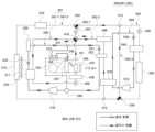
도 1은 본 발명의 일 실시예에 따른 열관리 시스템을 나타낸 구성도이다.
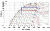
도 2 및 도 3은 하나의 냉매 순환시스템을 이용한 종래의 열교환 시스템의 작동 시뮬레이션 결과를 나타낸 도면 및 PH 선도이다.
도 4 및 도 5는 본 발명의 일 실시예에 따른 열관리 시스템의 작동 시뮬레이션 결과를 나타낸 도면 및 PH 선도이다.
도 6은 본 발명의 다른 실시예에 따른 열관리 시스템의 배터리 전용 냉각 모드 시 작동상태를 나타낸 구성도이다.
도 7은 본 발명의 다른 실시예에 따른 열관리 시스템의 최대 냉방 모드 시 작동상태를 나타낸 구성도이다.
도 8은 본 발명의 다른 실시예에 따른 열관리 시스템의 마일드(Mild) 냉방 모드 시 작동상태를 나타낸 구성도이다.
도 9는 본 발명의 다른 실시예에 따른 열관리 시스템의 최대 난방 모드 시 작동상태를 나타낸 구성도이다.
도 10은 본 발명의 다른 실시예에 따른 열관리 시스템의 마일드(Mild) 난방 모드 시 작동상태를 나타낸 구성도이다.
도 11은 본 발명의 다른 실시예에 따른 열관리 시스템의 제습 난방 모드 시 작동상태를 나타낸 구성도이다.
도 12는 본 발명의 다른 실시예에 따른 열관리 시스템의 배터리 승온 모드 시 작동상태를 나타낸 구성도이다.1 is a configuration diagram showing a thermal management system according to an embodiment of the present invention.
2 and 3 are diagrams and PH diagrams showing operation simulation results of a conventional heat exchange system using a single refrigerant circulation system.
4 and 5 are diagrams and PH diagrams illustrating operation simulation results of a thermal management system according to an embodiment of the present invention.
6 is a block diagram showing an operating state of a thermal management system according to another embodiment of the present invention in a battery-only cooling mode.
7 is a configuration diagram showing an operating state of a thermal management system according to another embodiment of the present invention in a maximum cooling mode.
8 is a configuration diagram showing an operating state of a thermal management system according to another embodiment of the present invention in a mild cooling mode.
9 is a block diagram showing an operating state of a thermal management system according to another embodiment of the present invention in the maximum heating mode.
10 is a configuration diagram showing an operating state of a thermal management system according to another embodiment of the present invention in a mild heating mode.
11 is a block diagram showing an operating state of a thermal management system according to another embodiment of the present invention in a dehumidifying heating mode.
12 is a configuration diagram illustrating an operating state of a thermal management system according to another embodiment of the present invention in a battery temperature raising mode.
이하, 상기한 바와 같은 구성을 갖는 본 발명의 열관리 시스템을 첨부된 도면을 참고하여 상세하게 설명한다.Hereinafter, a thermal management system according to the present invention having the configuration described above will be described in detail with reference to the accompanying drawings.
도 1은 본 발명의 일 실시예에 따른 열관리 시스템을 나타낸 구성도이다.1 is a configuration diagram showing a thermal management system according to an embodiment of the present invention.
도 1을 참조하면, 본 발명의 열관리 시스템은 크게 냉매가 순환되어 실내를 냉방하는 냉매 순환라인 및 냉각수가 순환되어 부품들을 냉각하는 냉각수 순환라인으로 구성될 수 있다. 그리고 냉매 순환라인은 제1냉매를 순환시키는 1차 냉매 순환시스템(200) 및 제2냉매를 순환시키는 2차 냉매 순환시스템(500)으로 구성될 수 있다. 또한, 냉각수 순환라인은 냉각수가 순환되며 제1냉매를 냉각시키는 제1냉각라인(301), 냉각수가 순환되며 제2냉매와 열교환되어 냉각되며 냉각수를 이용해 배터리(350)를 냉각시키는 제2냉각라인(302), 및 냉각수를 매개체로 하여 제1냉매와 제2냉매를 상호 열교환시키는 제3냉각라인(303)으로 구성될 수 있다.Referring to FIG. 1 , the thermal management system of the present invention may be largely composed of a refrigerant circulation line in which a refrigerant circulates to cool a room and a cooling water circulation line in which cooling water circulates to cool components. The refrigerant circulation line may include a primary
우선, 제1냉각라인(301)은 제1라디에이터(310), 냉각수 펌프(P1) 및 제1수랭식 응축기(220)를 포함할 수 있다.First, the
제1라디에이터(310)는 제1냉각라인(301)을 따라 순환되는 냉각수를 냉각시키는 열교환기이며, 제1라디에이터(310)는 그 일측에 구비된 냉각팬(311)에 의해 공랭식으로 냉각될 수 있다.The
냉각수 펌프(P1)는 제1냉각라인(301)을 따라 냉각수가 순환되도록 냉각수를 압송하는 수단이다. 그리고 냉각수 펌프(P1)는 제1라디에이터(310)와 제1수랭식 응축기(220) 사이의 냉각수 라인 상에 설치되어, 냉각수 펌프(P1)의 작동에 의해 제1라디에이터(310)에서 냉각된 냉각수가 제1수랭식 응축기(220)로 공급될 수 있다.The cooling water pump P1 is a means for pumping the cooling water so that the cooling water circulates along the
제1수랭식 응축기(220)는 제1냉각라인(301)을 따라 흐르는 냉각수와 1차 냉매 순환시스템(200)을 따라 흐르는 제1냉매를 서로 열교환시키는 열교환기이다.The first water-cooled
그리고 1차 냉매 순환시스템(200)은 제1압축기(210), 제1수랭식 응축기(220), 제3팽창밸브(251) 및 제1칠러(252)를 포함할 수 있다. 여기서, 1차 냉매 순환시스템(200)은 차량 실내를 냉방하기 위해 냉매 루프에서 병렬로 분기된 별도의 팽창밸브와 증발기를 더 포함할 수도 있고, 경우에 따라 제1칠러(252)를 증발기로 활용할 수도 있다.Also, the primary
제1압축기(210)는 전력을 공급받아 구동되는 전동 압축기일 수 있으며, 제1냉매를 흡입 및 압축하여 제1수랭식 응축기(220)쪽으로 토출하는 역할을 한다.The
제1수랭식 응축기(220)는 제1압축기(210)에서 토출된 제1냉매를 제1냉각라인(301)을 따라 흐르는 냉각수와 열교환시켜 액상 냉매로 응축하여 제3팽창밸브(251)쪽으로 보내는 역할을 한다.The first water-cooled
제3팽창밸브(251)는 냉매를 교축하거나 바이패스 시키거나 냉매의 흐름을 차단하는 역할을 할 수 있으며, 냉매의 유동 방향으로 제1수랭식 응축기(220)의 후방에 배치될 수 있다.The
제1칠러(252)는 냉매의 유동 방향으로 제3팽창밸브(251)의 후방에 배치되며, 냉각수와 열교환되어 제3냉각라인(303)을 따라 흐르는 냉각수를 냉각시킬 수 있다. The
또한, 제3냉각라인(303)은 제2라디에이터(380), 냉각수 펌프(P3), 제1칠러(252) 및 제2수랭식 응축기(520)를 포함할 수 있다.Also, the
제2라디에이터(380)는 제3냉각라인(303)을 따르 순환되는 냉각수를 냉각시키는 열교환기이며, 제2라디에이터(380)는 제1라디에이터(310)에 근접하여 나란하게 배치될 수 있으며, 냉각팬(311)에 의해 공랭식으로 냉각될 수 있다.The
냉각수 펌프(P3)는 제3냉각라인(303)을 따라 냉각수가 순환되도록 냉각수를 압송하는 수단이다. 그리고 냉각수 펌프(P3)는 제2라디에이터(380)와 제1칠러(252) 사이의 냉각수 라인 상에 설치되어, 냉각수 펌프(P3)의 작동에 의해 제2라디에이터(380)에서 냉각된 냉각수가 제1칠러(252)로 공급될 수 있다.The cooling water pump P3 is a means for pumping the cooling water so that the cooling water circulates along the
제1칠러(252)는 상기한 바와 같이 제3냉각라인(303)을 따라 흐르는 냉각수를 냉각시키며, 냉각된 냉각수가 제2수랭식 응축기(520)로 공급되어 제2수랭식 응축기(520)를 통과하는 제2냉매를 냉각시킬 수 있다.As described above, the
제2수랭식 응축기(520)는 제3냉각라인(303)을 따라 흐르는 냉각수와 2차 냉매 순환시스템(500)을 따라 흐르는 제2냉매를 서로 열교환시키는 열교환기이다. 그리고 제2수랭식 응축기(520)는 제2압축기(510)에서 토출된 제2냉매를 제3냉각라인(303)을 따라 흐르는 냉각수와 열교환시켜 액상 냉매로 응축하여 제4팽창밸브(251)쪽으로 보내는 역할을 한다.The second water-cooled
또한, 2차 냉매 순환시스템(500)은 제2압축기(510), 제2수랭식 응축기(520), 제4팽창밸브(530) 및 배터리 칠러(540)를 포함할 수 있다.In addition, the secondary
제2압축기(510)는 전력을 공급받아 구동되는 전동 압축기일 수 있으며, 제2냉매를 흡입 및 압축하여 제2수랭식 응축기(520)쪽으로 토출하는 역할을 한다.The
제2수랭식 응축기(520)는 제2압축기(510)에서 토출된 제2냉매를 제3냉각라인(303)을 따라 흐르는 냉각수와 열교환시켜 액상 냉매로 응축하여 제4팽창밸브(530)쪽으로 보내는 역할을 한다.The second water-cooled
제4팽창밸브(530)는 냉매를 교축하거나 바이패스 시키거나 냉매의 흐름을 차단하는 역할을 할 수 있으며, 냉매의 유동 방향으로 제2수랭식 응축기(520)의 후방에 배치될 수 있다.The
배터리 칠러(540)는 냉매의 유동 방향으로 제4팽창밸브(530)의 후방에 배치되며, 냉각수와 열교환되어 제2냉각라인(302)을 따라 흐르는 냉각수를 냉각시킬 수 있다.The
또한, 제2냉각라인(302)은 배터리 칠러(540), 냉각수 펌프(P2) 및 배터리(350)를 포함할 수 있다.Also, the
배터리 칠러(540)는 2차 냉매 순환시스템(500)을 따라 흐르는 제2냉매와 제2냉각라인(302)을 따라 흐르는 냉각수를 열교환시키는 열교환기이다.The
냉각수 펌프(P2)는 제2냉각라인(302)을 따라 냉각수가 순환되도록 냉각수를 압송하는 수단이다. 그리고 냉각수 펌프(P2)는 배터리 칠러(540)와 배터리(350) 사이의 냉각수 라인 상에 설치되어, 냉각수 펌프(P2)의 작동에 의해 배터리 칠러(540)에서 냉각된 냉각수가 배터리(350)로 공급되어 배터리(350)를 냉각시킬 수 있다.The cooling water pump P2 is a means for pumping the cooling water so that the cooling water is circulated along the
그리하여 제1냉각라인(301)을 따라 흐르는 냉각수는 제1라디에이터(310)를 통과하며 냉각된 후 제1수랭식 응축기(220)에서 1차 냉매 순환시스템(200)을 따라 흐르는 제1냉매를 냉각시키고, 1차 냉매 순환시스템(200)을 따라 흐르는 제1냉매는 제1칠러(252)에서 제3냉각라인(303)을 따라 흐르는 냉각수를 냉각시키며, 제3냉각라인(303)을 따라 흐르는 냉각수는 제2수랭식 응축기(520)에서 2차 냉매 순환시스템(500)을 따라 흐르는 제2냉매를 냉각시킨 다음, 2차 냉매 순환시스템(500)을 따라 흐르는 제2냉매는 배터리 칠러(540)에서 제2냉각라인(302)을 따라 흐르는 냉각수를 냉각시키며, 제2냉각라인(302)에서는 냉각된 냉각수를 이용해 배터리(350)를 냉각시키게 된다.Thus, the cooling water flowing along the
즉, 1차 냉매 순환시스템(200)과 2차 냉매 순환시스템(500)은 각각 독립된 2개의 냉매 시스템으로 구비되어 각각 압축기가 구비되며, 폐루프인 1차 냉매 순환시스템(200)을 따라 순환되는 제1냉매와 폐루프인 2차 냉매 순환시스템(500)을 따라 순환되는 제2냉매는 별도의 시스템인 제3냉각라인(303)을 따라 순환되는 냉각수를 매개체로 하여 열교환될 수 있다.That is, the primary
그리하여 1차 냉매 순환시스템(200)에 비해 2차 냉매 순환시스템(500)에는 냉매의 압력이 상대적으로 낮게 형성되어, 압축기의 압축 효율이 향상되면서 최대 성능을 낼 수 있다.Thus, the pressure of the refrigerant is relatively low in the secondary
또한, 상대적으로 용량이 큰 하나의 압축기를 사용해 배터리를 냉각하는 것에 비해, 본 발명과 같이 상대적으로 용량이 작은 두 개의 압축기를 사용해 배터리를 냉각시키도록 구성되어, 전기 자동차의 배터리를 급속 충전하는데 충분한 냉각 성능을 확보할 수 있으며 아울러 압축기의 내구성이 향상될 수 있다. 또한, 두 개의 압축기로 소음 및 진동이 분산되어, 하나의 용량이 큰 압축기를 사용하는 것에 비해 소음 및 진동을 줄일 수 있다. 또한, 본 발명은 하나의 용량이 큰 압축기를 사용하는 것에 비해 압축기들에서의 소비동력이 적게 사용되므로 시스템의 효율이 높다. 또한, 전기자동차의 배터리 급속 충전 시 정차되어 있으므로 라디에이터에서의 방열을 위한 풍량이 부족하게 되는데, 본 발명에서는 적은 풍량으로도 냉각 성능을 만족시킬 수 있다. In addition, compared to cooling the battery using one compressor with a relatively large capacity, it is configured to cool the battery using two compressors with a relatively small capacity as in the present invention, which is sufficient to rapidly charge the battery of an electric vehicle. Cooling performance can be secured and durability of the compressor can be improved. In addition, since noise and vibration are distributed with two compressors, noise and vibration can be reduced compared to using one large-capacity compressor. In addition, since the present invention consumes less power in the compressors compared to using one large-capacity compressor, the efficiency of the system is high. In addition, since the vehicle is stopped during rapid charging of the battery of the electric vehicle, the air volume for heat dissipation from the radiator is insufficient. In the present invention, the cooling performance can be satisfied even with a small air volume.
여기에서 본 발명은 1차 냉매 순환시스템(200)의 제1압축기(210)의 회전수(RPM)가 2차 냉매 순환시스템(500)의 제2압축기(510)의 회전수(RPM)보다 낮게 작동될 수 있다. 또는, 제1압축기(210) 및 제2압축기(510)는 동일하지 않은 서로 다른 회전수로 구동될 수도 있다. 그리하여 두 압축기의 소음 및 진동이 중첩되지 않아 전체적인 소음 및 진동을 더욱 줄일 수 있다.Here, in the present invention, the rotation speed (RPM) of the
그리고 1차 냉매 순환시스템(200)의 제1칠러(252)와 2차 냉매 순환시스템(500)의 제2수랭식 응축기(520)는 서로 이격되게 배치되어, 제1칠러(252)와 제2수랭식 응축기(520) 간의 열충격을 줄일 수 있다. 또한, 제3냉각라인(303)의 냉각수 라인 상에서 제1칠러(252)와 제2수랭식 응축기(520)의 사이에는 어떠한 구성품도 구비되지 않을 수 있다. 또한, 제1냉매와 제2냉매와는 다른 종류의 열교환매체인 냉각수 매개체로 하여 제1냉매와 제2냉매가 열교환되도록 제1칠러(252)와 제2수랭식 응축기(520)를 일체로 구성할 수도 있다.In addition, the
도 2 및 도 3은 하나의 냉매 순환시스템을 이용한 종래의 열교환 시스템의 작동 시뮬레이션 결과를 나타낸 도면 및 PH 선도이며, 도 4 및 도 5는 본 발명의 일 실시예에 따른 열관리 시스템의 작동 시뮬레이션 결과를 나타낸 도면 및 PH 선도이다.2 and 3 are diagrams and PH diagrams showing operation simulation results of a conventional heat exchange system using one refrigerant circulation system, and FIGS. 4 and 5 show operation simulation results of a thermal management system according to an embodiment of the present invention. These are the drawings and PH diagrams shown.
도시된 바와 같이, 하나의 냉매 순환시스템을 이용해 10kW 용량의 배터리를 급속으로 냉각시키는 종래의 열교환 시스템에서는 상대적으로 압축기의 소비동력이 6.69kW로 크고 회전수가 10,000RPM으로 높은 반면, 본 발명의 두 개의 냉매 순환시스템을 이용해 배터리를 냉각시키는 경우 압축기의 소비동력이 각각 0.86kW 및 4.69kW로 상대적으로 작고 회전수가 각각 2,000RPM 및 8,000PRM으로 상대적으로 낮다. 그러므로 종래에 비해 본 발명에서는 용량이 작은 압축기를 사용할 수 있으며, 종래의 하나의 압축기의 소비동력보다 본 발명의 두 개의 압축기의 소비동력의 합이 작아 전체적인 시스템의 효율이 높아지는 것을 알 수 있다. 그리고 종래에는 하나의 압축기가 분담하던 부하가 본 발명에서는 2개의 압축기로 부하가 분산되고 서로 다른 회전수에서 압축기들이 작동되므로 소음 및 진동을 저감시킬 수 있다. 또한, 압축기의 유입측과 배출측의 냉매의 압력 및 PH 선도들을 참조하면, 종래에는 압축기의 배출측 압력이 상대적으로 높은 반면 본 발명에서는 압축기의 배출측 압력이 상대적으로 낮게 형성되어 냉매의 압축에 필요한 압축기의 소비동력을 줄일 수 있어 시스템의 효율이 향상될 수 있다.As shown, in the conventional heat exchange system for rapidly cooling a battery with a capacity of 10 kW using one refrigerant circulation system, the power consumption of the compressor is relatively high as 6.69 kW and the rotation speed is as high as 10,000 RPM, whereas the two of the present invention When the battery is cooled using a refrigerant circulation system, the power consumption of the compressor is relatively small at 0.86 kW and 4.69 kW, respectively, and the rotation speed is relatively low at 2,000 RPM and 8,000 PRM, respectively. Therefore, it can be seen that a compressor having a smaller capacity can be used in the present invention than in the prior art, and the sum of the power consumption of the two compressors of the present invention is smaller than the power consumption of one conventional compressor, thereby increasing the efficiency of the overall system. In addition, since the load shared by one compressor in the prior art is distributed to two compressors in the present invention and the compressors operate at different rotational speeds, noise and vibration can be reduced. In addition, referring to the pressure and PH diagrams of the refrigerant on the inlet side and the discharge side of the compressor, the pressure on the discharge side of the compressor is relatively high in the prior art, whereas the pressure on the discharge side of the compressor is relatively low in the present invention, which affects the compression of the refrigerant. The required power consumption of the compressor can be reduced and the efficiency of the system can be improved.
도 6은 본 발명의 다른 실시예에 따른 열관리 시스템을 나타낸 구성도이다.6 is a configuration diagram illustrating a thermal management system according to another embodiment of the present invention.
도 6을 참조하면, 본 발명의 열관리 시스템은 크게 제1냉매가 순환되어 실내를 냉방하고 냉각수를 냉각시키는 1차 냉매 순환시스템(200), 제2냉매가 순환되어 냉각수를 냉각시키는 2차 냉매 순환시스템(500), 및 냉각수가 순환되어 실내를 난방하고 부품들을 냉각하는 냉각수 순환라인(300)으로 구성될 수 있다. 그리고 냉각수 순환라인(300)은 실내 난방을 위한 난방라인(301-1)과 전장부품(460) 또는 배터리(350)의 냉각을 위한 냉각라인(301-2)을 포함하는 제1냉각라인(301), 및 배터리(350)의 냉각을 위한 제2냉각라인(302)로 구성될 수 있다.Referring to FIG. 6, the thermal management system of the present invention largely includes a primary
1차 냉매 순환시스템(200)은 제1압축기(210), 제1수랭식 응축기(220), 제1팽창밸브(225), 공랭식 응축기(230), 냉매 분기부(241), 제2팽창밸브(240), 증발기(242), 냉매 열교환기(233), 어큐뮬레이터(260), 제3팽창밸브(251) 및 제1칠러(252)를 포함할 수 있다.The primary
제1압축기(210)는 전력을 공급받아 구동되는 전동 압축기일 수 있으며, 냉매를 흡입 및 압축하여 제1수랭식 응축기(220)쪽으로 토출하는 역할을 한다.The
제1수랭식 응축기(220)는 제1압축기(210)에서 토출된 냉매를 냉각수와 열교환시켜 액상 냉매로 응축하여 제1팽창밸브(225)쪽으로 보내는 역할을 한다.The first water-cooled
제1팽창밸브(225)는 냉매를 교축하거나 바이패스 시키거나 냉매의 흐름을 차단하는 역할을 할 수 있으며, 냉매의 유동 방향으로 제1수랭식 응축기(220)의 후방에 배치될 수 있다.The
공랭식 응축기(230)는 응축기 또는 증발기 역할을 하며, 제1팽창밸브(225)의 역할에 따라 공랭식 응축기(230)의 기능이 가변될 수 있다. 즉, 1차 냉매 순환시스템(200)이 에어컨 루프로 사용되는 경우 제1팽창밸브(225)는 완전 개방되어 냉매를 통과시키고 공랭식 응축기(230)는 제1수랭식 응축기(220)와 함께 응축기의 역할을 하며, 냉매 1차 냉매 순환시스템(200)이 히트펌프 루프로 사용되는 경우 제1팽창밸브(225)에서는 냉매를 교축하며 공랭식 응축기(230)는 증발기 역할을 한다. 그리고 공랭식 응축기(230)는 외부 공기에 의해 공랭식으로 냉각 또는 가열될 수 있다.The air-cooled
냉매 분기부(241)는 냉매의 유동방향으로 공랭식 응축기(230)의 후방측에 형성될 수 있으며, 냉매 분기부(241)에서 2개의 라인으로 분기되어 하나의 라인은 증발기(242)와 연결되고 다른 하나의 라인은 제1칠러(252)와 연결되도록 구성될 수 있다.The
제2팽창밸브(240) 및 제3팽창밸브(251)는 냉매를 교축하거나 통과시키거나 냉매의 흐름을 차단하는 역할을 할 수 있다. 그리고 제2팽창밸브(240) 및 제3팽창밸브(251)는 병렬로 구성될 수 있다. 즉, 냉배 분기부(241)에서 두 개의 라인으로 냉매라인이 분기되며, 분기된 두 개의 냉매 라인 중 하나의 냉매 라인에 제2팽창밸브(240)가 배치되고 다른 하나의 냉매 라인에 제3팽창밸브(251)가 배치될 수 있다. 이때, 제2팽창밸브(240)는 증발기(242)의 전방에 배치되고, 제3팽창밸브(251)는 제1칠러(252)의 전방에 배치될 수 있다.The
증발기(242)는 냉매의 유동 방향으로 제2팽창밸브(240)의 후방에 배치되며, 차량의 공조장치(150) 내부에 구비되어 공조장치의 송풍기(152)에 의해 유동되는 공기가 증발기(242)를 거치며 냉각되어 차량의 실내로 공급되어 차량의 실내 냉방에 이용될 수 있다.The
냉매 열교환기(233)는 제2팽창밸브(240)로 유입되는 냉매와 증발기(242)에서 배출되는 냉매를 상호 열교환시켜 냉방 성능을 향상시키는 역할을 한다. 여기에서 냉매 열교환기(233)는 냉매 분기부(241)와 제2팽창밸브(240)를 연결하는 증발기(242)로 냉매가 유입되는 유입측 냉매 라인이 통과하고, 증발기(242)와 어큐뮬레이터(260)를 연결하는 증발기(242)에서 냉매가 배출되는 배출측 냉매 라인이 통과하며, 유입측 냉매 라인과 배출측 냉매 라인을 통과하는 냉매들 간 열교환이 일어날 수 있다. 그리하여 냉매 열교환기(233)에 의해 제2팽창밸브(240)로 유입되기 전에 냉매는 더욱 냉각될 수 있으며, 증발기(242)를 통한 냉방 성능이 향상됨과 동시에 냉방 시스템의 효율이 향상될 수 있다.The
특히, 냉매 열교환기(233)는 공랭식 응축기(230) 및 칠러(252)와 병렬로 연결된다. 즉, 냉매 열교환기(233)는 공랭식 응축기(230)와 칠러(252) 사이 냉매 라인에 직렬 배치되는 것이 아닌, 증발기(242)와 인접하게 배치되어 냉매 열교환기(233) 및 증발기(242)는 직렬로 배치되어 연결될 수 있다. 만약, 냉매 열교환기(233)가 공랭식 응축기(230)와 칠러(252) 사이에 직렬로 배치될 경우, 난방 모드 시 저압측 압력 강하로 작용하여 난방 성능이 감소될 수 있다. 반대로, 냉매 열교환기(233)가 병렬로 연결될 경우 냉방 성능은 물론 난방 성능도 증가되는데, 이는 난방 모드의 냉매 흐름 상 응축기(220, 230)와 칠러(252) 사이에 냉매 열교환기(233)가 없기 때문이다. In particular, the
제1칠러(252)는 냉매의 유동 방향으로 제3팽창밸브(251)의 후방에 배치되며, 냉각수와 열교환되어 냉각수가 냉각될 수 있다. 그리하여 제2팽창밸브(240)와 증발기(242)가 한 조를 이루고 제3팽창밸브(251)와 제1칠러(252)가 다른 한 조를 이루어, 두 조가 냉매 라인 상에서 병렬로 구성된다. 또한, 냉매 유동 방향으로 증발기(242)와 칠러(252)의 후방쪽은 냉매 라인이 합류되어 하나의 냉매 라인으로 형성될 수 있다.The
그리고 어큐뮬레이터(260)는 냉매 중 액상 냉매와 기상 냉매를 분리하여 기상 냉매만 제1압축기(210)로 공급할 수 있다. 여기에서 증발기(242)의 후방측과 제1칠러(252)의 후방측 냉매라인이 합류된 지점에 어큐뮬레이터(260)가 배치되어 연결되며, 어큐뮬레이터(260)는 냉매 유동 방향으로 제1압축기(210)의 전방에 배치될 수 있다.The
제1냉각라인(301)에서 난방라인(301-1)은 제1수랭식 응축기(220), 제1냉각수 펌프(450), 냉각수 히터(430), 히터코어(440) 및 제1방향전환밸브(410)를 포함할 수 있다.In the
제1수랭식 응축기(220)는 상기한 바와 같이 냉매 및 냉각수가 통과하면서 서로 열교환될 수 있다.As described above, the first water-cooled
제1냉각수 펌프(450)는 난방라인(301-1)을 따라 냉각수가 순환되도록 냉각수를 압송하는 수단이며, 제1냉각수 펌프(450)는 냉각수의 유동 방향으로 제1수랭식 응축기(220)의 후방에 배치되어 냉각수라인 상에 설치될 수 있다.The first
냉각수 히터(430)는 냉각수를 가열하는 장치이며, 냉각수의 유동 방향으로 제1냉각수 펌프(450)의 후방 및 히터코어(440)의 전방에 배치되어 연결될 수 있다. 그리고 냉각수 히터(430)는 냉각수의 온도가 특정한 온도 이하일 경우 가동될 수 있으며, 전력을 이용해 발열할 수 있는 인덕션 히터, 씨즈 히터, 피티씨 히터, 필름 히터 등 다양하게 형성될 수 있다.The cooling
히터코어(440)는 차량의 공조장치(150) 내에 배치될 수 있으며, 송풍기(152)에 의해 유동되는 공기가 히터코어(440)를 거치며 승온되어 차량의 실내로 공급되어 차량의 실내 난방에 이용될 수 있다. 그리고 히터코어(440)는 냉각수의 유동 방향으로 냉각수 히터(430)의 후방에 배치되어 연결될 수 있다.The
여기에서 공조장치(150)는 공기를 송풍시킬 수 있도록 일측에 송풍기(152)가 설치되어 있으며, 공조장치(150)의 내부에는 온도조절도어(151)가 설치될 수 있다. 또한, 공조장치 내에 배치된 증발기(242) 및 히터코어(440)는 온도조절도어(151)의 작동에 따라 송풍기(152)에서 토출된 공기가 증발기(242)만을 거친 후 실내로 유입되도록 하거나, 증발기(242)를 거친 후 히터코어(440)를 통과하여 실내로 유입될 수 있도록 배치 및 구성될 수 있다.Here, the
제1방향전환밸브(410)는 히터코어(440)와 제1수랭식 응축기(220)의 사이에 설치될 수 있으며, 난방라인(301-1)과 이후에 설명할 냉각라인(301-2)을 선택적으로 연결하거나 연결을 차단하도록 구성될 수 있다. 보다 상세하게 제1방향전환밸브(410)는 난방라인(301-1) 상에 설치되어 2개의 냉각수 라인 배관이 제1방향전환밸브(410)에 연결되고, 냉각라인(301-2)의 일측에서 분기된 1개의 제1연결라인(302-1)이 제1방향전환밸브(410)에 연결되며, 냉각라인(301-2)의 타측에서 분기된 1개의 제2연결라인(302-2)이 제1방향전환밸브(410)에 연결될 수 있다. 즉, 제1방향전환밸브(410)에서는 4개의 냉각수 라인이 만나도록 연결되며, 제1방향전환밸브(410)는 4개의 냉각수 라인들이 서로 연결되거나 차단된 상태를 조절할 수 있는 4방향의 방향전환밸브가 될 수 있다.The first
제1냉각라인(301)에서 냉각라인(301-2)은 제1라디에이터(310), 리저버 탱크(370), 제2방향전환밸브(320), 제2냉각수 펌프(420), 제1방향전환밸브(410), 전장부품(460) 및 제2냉각수 조인트(312)를 포함할 수 있다.In the
제1라디에이터(310)는 전장부품(460) 또는 배터리(350)와 열교환된 냉각수를 냉각시키는 열교환기이며, 제1라디에이터(310)는 냉각팬(311)에 의해 공랭식으로 냉각될 수 있다.The
리저버 탱크(370)는 냉각수를 저장 및 냉각수 라인 상에 부족한 냉각수를 보충하는 역할을 할 수 있으며, 리저버 탱크(370)는 냉각수의 유동방향으로 제2냉각수 펌프(420)와 제3냉각수 펌프(340) 전방의 냉각수 라인 상에 설치될 수 있다.The
제2방향전환밸브(320)는 냉각라인(301-2) 상에 설치되어 2개의 냉각수 배관이 제2방향전환밸브(320)에 연결되고, 난방라인(301-1)과 냉각라인(301-2)이 연결되도록 제1방향전환밸브(410)와 제2방향전환밸브(320)가 제1연결라인(302-1)으로 연결될 수 있다. 즉, 제2방향전환밸브(320)는 3개의 냉각수라인이 만나도록 연결되며, 제2방향전환밸브(320)는 3개의 냉각수라인들이 서로 연결되거나 차단된 상태를 조절할 수 있는 3방향의 방향전환밸브가 될 수 있다.The second
제2냉각수 펌프(420)는 냉각라인(301-2)을 따라 냉각수가 순환되도록 냉각수를 압송하는 수단이다. 그리고 제2냉각수 펌프(420)는 제1방향전환밸브(410)와 제2방향전환밸브(320) 사이의 제1연결라인(302-1) 상에 설치되어, 제2냉각수 펌프(420)의 작동에 의해 제2방향전환밸브(320)에서 제1방향전환밸브(410)쪽으로 냉각수가 흐를 수 있다.The second
제1방향전환밸브(410)는 상기한 난방라인(301-1)에서 설명한 바와 같다. The first
전장부품(460)은 제1방향전환밸브(410)와 제2냉각수 조인트(312)를 연결하는 제2연결라인(302-2) 상에 배치되어, 냉각수에 의해 전장부품(460)이 냉각될 수 있다. 그리고 전장부품(460)은 구동 모터, 인버터, 충전기(OBC; On Board Charger) 등이 될 수 있다.The
제2냉각수 조인트(312)는 제2연결라인(302-2)의 후단이 냉각라인(301-2)과 만나는 지점에 설치될 수 있으며, 제2냉각수 조인트(312)에서 3개의 냉각수라인이 만나도록 연결된다. 즉, 제2냉각수 조인트(312)는 냉각라인(301-2) 상에 양측이 연결되도록 설치되며, 상측에는 제2연결라인(302-2)이 연결될 수 있다.The
제1칠러(252)는 상기한 난방라인(301-1)에서 설명한 바와 같다. The
또한, 2차 냉매 순환시스템(500)은 제2압축기(510), 제2수랭식 응축기(520), 제4팽창밸브(530) 및 배터리 칠러(540)를 포함할 수 있다.In addition, the secondary
제2압축기(510)는 전력을 공급받아 구동되는 전동 압축기일 수 있으며, 제2냉매를 흡입 및 압축하여 제2수랭식 응축기(520)쪽으로 토출하는 역할을 한다.The
제2수랭식 응축기(520)는 제2압축기(510)에서 토출된 제2냉매를 제2연결라인(302-2)을 따라 흐르는 냉각수와 열교환시켜 액상 냉매로 응축하여 제4팽창밸브(530)쪽으로 보내는 역할을 한다.The second water-cooled
제4팽창밸브(530)는 냉매를 교축하거나 바이패스 시키거나 냉매의 흐름을 차단하는 역할을 할 수 있으며, 냉매의 유동 방향으로 제2수랭식 응축기(520)의 후방에 배치될 수 있다.The
배터리 칠러(540)는 냉매의 유동 방향으로 제4팽창밸브(530)의 후방에 배치되며, 냉각수와 열교환되어 제2냉각라인(302)을 따라 흐르는 냉각수를 냉각시킬 수 있다.The
또한, 제2냉각라인(302)은 제3냉각수 펌프(340), 배터리 칠러(540), 배터리(350), 제3방향전환밸브(330) 및 제1냉각수 조인트(313)를 포함할 수 있다.In addition, the
제3냉각수 펌프(340)는 제2냉각라인(302)을 따라 냉각수가 순환되도록 냉각수를 압송하는 수단이다. 그리고 제3냉각수 펌프(340)는 냉각수의 유동방향으로 배터리 칠러(540) 전방의 냉각수 라인 상에 설치되어, 제3냉각수 펌프(340)의 작동에 의해 배터리 칠러(540)에서 냉각된 냉각수가 배터리(350)쪽으로 공급되어 배터리(350)를 냉각시킬 수 있다.The third
배터리 칠러(540)는 제3냉각수 펌프(340)와 배터리 칠러(540) 사이의 냉각수 라인 상에 설치되어 제2냉각라인(302)을 따라 흐르는 냉각수를 냉각시킬 수 있다.The
제3방향전환밸브(330)는 배터리(350)와 제2냉각수 조인트(312) 사이의 냉각수 라인 상에 설치되며, 2개의 냉각수 배관이 제3방향전환밸브(330)에 연결되고, 제3방향전환밸브(330)의 상측에 제3연결라인(302-3)이 연결되어 배터리(350)와 제3연결라인(302-3)이 병렬로 연결되도록 구성될 수 있다. 이때, 제2방향전환밸브(320)는 3개의 냉각수 라인들이 서로 연결되거나 차단된 상태를 조절할 수 있는 3방향의 방향전환밸브가 될 수 있다.The third
제1냉각수 조인트(313)는 냉각수의 유동방향으로 제2방향전환밸브(320)의 후방의 냉각수라인에 설치되며, 제1냉각수 조인트(313)는 3개의 냉각수라인이 만나도록 연결된다. 즉, 제1냉각수 조인트(313)는 냉각라인(301-2)과 제2냉각라인(302)에 양측이 연결되도록 설치되며, 하측에는 제3연결라인(302-3)이 연결될 수 있다. 여기에서 제3연결라인(302-3)은 제2냉각라인(302)의 일부분이다.The
여기에서 제2연결라인(302-2) 상에는 냉각수의 유동방향으로 전장부품(460), 제1칠러(252) 및 제2수랭식 응축기(520)가 차례대로 이격되게 배치될 수 있다.Here, on the second connection line 302-2, the
이하 앞에서 설명한 본 발명의 다른 실시예에 따른 열관리 시스템의 작동 모드에 따른 동작에 대해 설명한다.Hereinafter, operations according to operating modes of the thermal management system according to another embodiment of the present invention described above will be described.
1. 배터리 전용 냉각 모드 시(배터리 급속 충전 시)1. In the battery-only cooling mode (when the battery is rapidly charged)
도 6은 본 발명의 다른 실시예에 따른 열관리 시스템의 배터리 전용 냉각 모드 시 작동상태를 나타낸 구성도이다.6 is a block diagram showing an operating state of a thermal management system according to another embodiment of the present invention in a battery-only cooling mode.
도 6을 참조하면, 1차 냉매 순환시스템(200)에서는 제1압축기(210)가 작동하여 제1압축기(210)에서 고온고압의 냉매가 토출된다. 그리고 제1압축기(210)에서 토출된 냉매는 제1수랭식 응축기(220)에서 냉각수와 열교환되어 냉각된다. 이어서 제1수랭식 응축기(220)에서 냉각된 냉매는 완전히 개방된 상태의 제1팽창밸브(225)를 통과하여 공랭식 응축기(230)로 유입되며, 냉매는 공랭식 응축기(230)에서 외부 공기와 열교환되어 냉각된다. 즉, 제1수랭식 응축기(220) 및 공랭식 응축기(230)가 모두 응축기의 역할을 하여 냉매를 응축시킨다. 응축된 냉매는 이후 냉매 분기부(241)를 지나 제3팽창밸브(251)를 통과하면서 교축되어 냉매가 팽창되며, 이후 팽창된 냉매는 제1칠러(252)를 거치면서 냉각수와 열교환되어 냉매가 증발되면서 냉각수가 냉각된다. 그리고 제1칠러(252)를 거치며 증발된 냉매는 어큐뮬레이터(260)를 거쳐 다시 제1압축기(210)로 유입된다. 이때, 제2팽창밸브(240)는 차단되어 증발기(242)로 냉매가 흐르지 않을 수 있다. 그리하여 상기한 바와 같은 과정을 반복하면서 냉매가 순환된다.Referring to FIG. 6 , in the primary
또한, 2차 냉매 순환시스템(500)에서는 제2압축기(510)가 작동하여 제2압축기(510)에서 고온고압의 냉매가 토출된다. 그리고 제2압축기(510)에서 토출된 냉매는 제2수랭식 응축기(520)에서 냉각수와 열교환되어 냉각된다. 이어서 제2수랭식 응축기(520)에서 냉각된 냉매는 제4팽창밸브(540)를 통과하며 교축되어 냉매가 팽창되며, 이후 팽창된 냉매는 배터리 칠러(540)를 거치면서 제2냉각라인(302)을 따라 순환되는 냉각수와 열교환되어 냉각수를 냉각시킨다. 그리고 배터리 칠러(540)를 통과한 냉매는 다시 제2압축기(510)로 유입되어 순환되는 과정이 반복된다.In addition, in the secondary
한편, 냉각수 순환라인(300) 중 제1냉각라인(301)의 냉각수는 제1냉각수 펌프(450) 및 제2냉각수 펌프(420)의 작동에 의해 순환된다. 그리고 냉각수에 의해 제1수랭식 응축기(220)를 통과하는 냉매, 전장부품(460) 및 제2수랭식 응축기(520)를 통과하는 냉매가 냉각될 수 있으며, 가열된 냉각수는 제1라디에이터(310)에서 냉각팬(311)의 작동에 의해 외부 공기와 열교환되어 냉각될 수 있다. 또한, 전장부품(460)을 통과한 후 냉각수는 제1칠러(252)를 통과하며 냉각될 수 있다.Meanwhile, the cooling water of the
이때, 제1방향전환밸브(410) 및 제2방향전환밸브(320)는 난방라인(301-1)과 냉각라인(301-2)을 연결하는 방향으로 조절될 수 있다. 보다 상세하게는 제1방향전환밸브(410)는 상측과 좌측이 서로 연결되어 냉각수가 유통되고 하측과 우측이 서로 연결되어 냉각수가 유통될 수 있다. 그리고 제2방향전환밸브(320)는 좌측과 하측이 서로 연결되어 냉각수가 유통되고 우측은 연결이 차단될 수 있다. 또한, 제3방향전환밸브(330)는 상측과 우측이 서로 연결되어 있고 좌측은 차단되어 있을 수 있다.At this time, the first
그리하여 제1냉각라인(301)의 냉각수는 제1라디에이터(310)에서부터 리저버 탱크(370), 제2방향전환밸브(320), 제2냉각수 펌프(420), 제1방향전환밸브(410), 제1수랭식 응축기(220), 제1냉각수 펌프(450), 냉각수 히터(430), 히터코어(440), 제1방향전환밸브(410), 전장부품(460), 제1칠러(252), 제2수랭식 응축기(520), 제2냉각수 조인트(312)를 차례대로 거쳐 다시 제1라디에이터(310)로 유입되어 순환되는 사이클이 반복된다. 여기에서 제2방향전환밸브(320)에 의해 제2방향전환밸브(320)에서부터 제1냉각수 조인트(313)까지에는 냉각수가 흐르지 않으며, 제3방향전환밸브(330)에 의해 제3방향전환밸브(330)에서부터 제2냉각수 조인트(312)까지에는 냉각수가 흐르지 않을 수 있다.Thus, the cooling water of the
또한, 제2냉각라인(302)의 냉각수는 제3냉각수 펌프(340)의 작동에 의해 순환되며, 제3냉각수 펌프(340)에서부터 배터리 칠러(540), 배터리(350), 제3방향전환밸브(330), 제1냉각수 조인트(313)를 차례대로 거쳐 다시 제3냉각수 펌프(340)로 유입되어 순환되는 사이클이 반복된다. 즉, 제2방향전환밸브(320) 및 제3방향전환밸브(330)에 의해 냉각수가 순환되는 별개의 폐루프로 냉각라인이 형성되어 배터리(350)가 별도로 냉각될 수 있다.In addition, the cooling water of the
여기에서 배터리 전용 냉각 모드는 실내의 냉방을 하지 않으면서 배터리의 급속 충전이 필요한 경우 작동될 수 있다. 이때, 제1압축기(210)는 2,000rpm으로 제2압축기(510)는 8,000rpm으로 회전될 수 있다.Here, the battery-only cooling mode may be operated when rapid charging of the battery is required without cooling the room. At this time, the
2. 최대 냉방 모드 시2. In maximum cooling mode
도 7은 본 발명의 다른 실시예에 따른 열관리 시스템의 최대 냉방 모드 시 작동상태를 나타낸 구성도이다.7 is a configuration diagram showing an operating state of a thermal management system according to another embodiment of the present invention in a maximum cooling mode.
도 7을 참조하면, 1차 냉매 순환시스템(200)에서는 제1압축기(210)가 작동하여 제1압축기(210)에서 고온고압의 냉매가 토출된다. 그리고 제1압축기(210)에서 토출된 냉매는 제1수랭식 응축기(220)에서 냉각수와 열교환되어 냉각된다. 이어서 제1수랭식 응축기(220)에서 냉각된 냉매는 완전히 개방된 상태의 제1팽창밸브(225)를 통과하여 공랭식 응축기(230)로 유입되며, 냉매는 공랭식 응축기(230)에서 외부 공기와 열교환되어 냉각된다. 즉, 제1수랭식 응축기(220) 및 공랭식 응축기(230)가 모두 응축기의 역할을 하여 냉매를 응축시킨다. 응축된 냉매는 이후 냉매 분기부(241)에서 분기되어 냉매의 일부는 냉매 열교환기(233)를 통과한 후 제2팽창밸브(240)를 통과하면서 교축되어 냉매가 팽창되며, 이후 팽창된 냉매는 증발기(242)를 거치면서 공조장치(150)의 송풍기(152)에 의해 송풍되는 공기와 열교환되어 냉매가 증발되면서 공기가 냉각되어, 냉각된 공기를 차량의 실내로 공급하여 실내 냉방이 이루어진다. 그리고 증발기(242)에서 증발된 냉매는 냉매 열교환기(233)를 거치며 제2팽창밸브(240)로 유입되기 전의 냉매와 열교환된 후 어큐뮬레이터(260)를 거쳐 다시 제1압축기(210)로 유입된다. 또한, 냉매 분기부(241)에서 분기된 냉매의 나머지는 제3팽창밸브(251)를 통과하면서 교축되어 냉매가 팽창되며, 이후 팽창된 냉매는 제1칠러(252)를 거치면서 냉각수와 열교환되어 냉매가 증발되면서 냉각수가 냉각된다. 그리고 제1칠러(252)를 거치며 증발된 냉매는 어큐뮬레이터(260)를 거쳐 다시 제1압축기(210)로 유입된다. 이와 같이 증발기(242)를 통과한 냉매와 제1칠러(252)를 통과한 냉매가 어큐뮬레이터(260)에서 합류되어 제1압축기(210)로 유입된 후, 상기한 바와 같은 과정을 반복하면서 냉매가 순환된다.Referring to FIG. 7 , in the primary
또한, 2차 냉매 순환시스템(500)에서는 제2압축기(510)가 작동하여 제2압축기(510)에서 고온고압의 냉매가 토출된다. 그리고 제2압축기(510)에서 토출된 냉매는 제2수랭식 응축기(520)에서 냉각수와 열교환되어 냉각된다. 이어서 제2수랭식 응축기(520)에서 냉각된 냉매는 제4팽창밸브(540)를 통과하며 교축되어 냉매가 팽창되며, 이후 팽창된 냉매는 배터리 칠러(540)를 거치면서 제2냉각라인(302)을 따라 순환되는 냉각수와 열교환되어 냉각수를 냉각시킨다. 그리고 배터리 칠러(540)를 통과한 냉매는 다시 제2압축기(510)로 유입되어 순환되는 과정이 반복된다.In addition, in the secondary
한편, 냉각수 순환라인(300) 중 제1냉각라인(301)의 냉각수는 제1냉각수 펌프(450), 제2냉각수 펌프(420) 및 제3냉각수 펌프(340)의 작동에 의해 순환된다. 그리고 냉각수에 의해 제1수랭식 응축기(220)를 통과하는 냉매, 전장부품(460) 및 제2수랭식 응축기(520)를 통과하는 냉매가 냉각될 수 있으며, 가열된 냉각수는 제1라디에이터(310)에서 냉각팬(311)의 작동에 의해 외부 공기와 열교환되어 냉각될 수 있다. 또한, 전장부품(460)을 통과한 후 냉각수는 제1칠러(252)를 통과하면서 냉각되고, 제1칠러(252)에 의해 냉각된 냉각수는 제2수랭식 응축기(520)를 통과하면서 제2냉각라인(302)을 따라 순환되는 냉매를 냉각시킨다.Meanwhile, the cooling water of the
이때, 제1방향전환밸브(410) 및 제2방향전환밸브(320)는 난방라인(301-1)과 냉각라인(301-2)을 연결하는 방향으로 조절될 수 있다. 보다 상세하게는 제1방향전환밸브(410)는 상측과 좌측이 서로 연결되어 냉각수가 유통되고 하측과 우측이 서로 연결되어 냉각수가 유통될 수 있다. 그리고 제2방향전환밸브(320)는 좌측과 하측이 서로 연결되어 냉각수가 유통되고 우측은 연결이 차단될 수 있다. 또한, 제3방향전환밸브(330)는 상측과 우측이 서로 연결되어 있고 좌측은 차단되어 있을 수 있다.At this time, the first
그리하여 제1냉각라인(301)의 냉각수는 제1라디에이터(310)에서부터 리저버 탱크(370), 제2방향전환밸브(320), 제2냉각수 펌프(420), 제1방향전환밸브(410), 제1수랭식 응축기(220), 제1냉각수 펌프(450), 냉각수 히터(430), 히터코어(440), 제1방향전환밸브(410), 전장부품(460), 제1칠러(252), 제2수랭식 응축기(520), 제2냉각수 조인트(312)를 차례대로 거쳐 다시 제1라디에이터(310)로 유입되어 순환되는 사이클이 반복된다. 여기에서 제2방향전환밸브(320)에 의해 제2방향전환밸브(320)에서부터 제1냉각수 조인트(313)까지에는 냉각수가 흐르지 않으며, 제3방향전환밸브(330)에 의해 제3방향전환밸브(330)에서부터 제2냉각수 조인트(312)까지에는 냉각수가 흐르지 않을 수 있다.Thus, the cooling water of the
또한, 제2냉각라인(302)의 냉각수는 제3냉각수 펌프(340)에서부터 배터리 칠러(540), 배터리(350), 제3방향전환밸브(330), 제1냉각수 조인트(313)를 차례대로 거쳐 다시 제3냉각수 펌프(340)로 유입되어 순환되는 사이클이 반복된다. 즉, 제2방향전환밸브(320) 및 제3방향전환밸브(330)에 의해 냉각수가 순환되는 별개의 폐루프로 냉각라인이 형성되어 배터리(350)가 별도로 냉각될 수 있다.In addition, the cooling water of the
여기에서 최대 냉방 모드는 외부 공기의 온도가 섭씨 30도 내지 45도 범위일 경우에 작동될 수 있으며, 이때 제1압축기(210) 및 제2압축기(510)는 각각 최대 회전수로 회전될 수 있다. 그리고 배터리(350)의 냉각이 불필요할 경우에는 제3팽창밸브(251)가 차단되어 제1칠러(252)쪽으로 냉매가 흐르지 않을 수 있다. 이때 제3냉각수 펌프(340)는 작동되지 않을 수 있으며, 2차 냉매 순환시스템(500)이 작동되지 않을 수도 있다.Here, the maximum cooling mode may be operated when the temperature of the outside air is in the range of 30 to 45 degrees Celsius, and at this time, the
3. 마일드(Mild) 냉방 모드 시3. In mild cooling mode
도 8은 본 발명의 다른 실시예에 따른 열관리 시스템의 마일드(Mild) 냉방 모드 시 작동상태를 나타낸 구성도이다.8 is a configuration diagram showing an operating state of a thermal management system according to another embodiment of the present invention in a mild cooling mode.
도 8을 참조하면, 1차 냉매 순환시스템(200)에서는 제1압축기(210)가 작동하여 제1압축기(210)에서 고온고압의 냉매가 토출된다. 그리고 제1압축기(210)에서 토출된 냉매는 제1수랭식 응축기(220)에서 냉각수와 열교환되어 냉각된다. 이어서 제1수랭식 응축기(220)에서 냉각된 냉매는 완전히 개방된 상태의 제1팽창밸브(225)를 통과하여 공랭식 응축기(230)로 유입되며, 냉매는 공랭식 응축기(230)에서 외부 공기와 열교환되어 냉각된다. 즉, 제1수랭식 응축기(220) 및 공랭식 응축기(230)가 모두 응축기의 역할을 하여 냉매를 응축시킨다. 응축된 냉매는 이후 냉매 분기부(241)에서 분기되어 냉매의 일부는 냉매 열교환기(233)를 통과한 후 제2팽창밸브(240)를 통과하면서 교축되어 냉매가 팽창되며, 이후 팽창된 냉매는 증발기(242)를 거치면서 공조장치(150)의 송풍기(152)에 의해 송풍되는 공기와 열교환되어 냉매가 증발되면서 공기가 냉각되어, 냉각된 공기를 차량의 실내로 공급하여 실내 냉방이 이루어진다. 그리고 증발기(242)에서 증발된 냉매는 냉매 열교환기(233)를 거치며 제2팽창밸브(240)로 유입되기 전의 냉매와 열교환된 후 어큐뮬레이터(260)를 거쳐 다시 제1압축기(210)로 유입된다. 이때, 제3팽창밸브(251)는 차단되어 제1칠러(252)로 냉매가 흐르지 않을 수 있다. 그리하여 증발기(242)를 통과한 냉매는 어큐뮬레이터(260)를 거쳐 제1압축기(210)로 유입된 후, 상기한 바와 같은 과정을 반복하면서 냉매가 순환된다.Referring to FIG. 8 , in the primary
또한, 2차 냉매 순환시스템(500)에서는 제2압축기(510)가 작동하지 않아 냉매가 흐르지 않을 수 있다.Also, in the secondary
한편, 냉각수 순환라인(300)의 냉각수는 제1냉각수 펌프(450), 제2냉각수 펌프(420) 및 제3냉각수 펌프(340)의 작동에 의해 순환된다. 그리고 냉각수에 의해 제1수랭식 응축기(220)를 통과하는 냉매, 전장부품(460) 및 배터리(350)가 냉각될 수 있으며, 가열된 냉각수는 제1라디에이터(310)에서 냉각팬(311)의 작동에 의해 외부 공기와 열교환되어 냉각될 수 있다. 이때, 제1방향전환밸브(410) 및 제2방향전환밸브(320)는 제1냉각라인(301)의 난방라인(301-1)과 냉각라인(301-2)을 연결하는 방향으로 조절될 수 있으며, 제2방향전환밸브(320) 및 제3방향전환밸브(330)는 제1냉각라인(301)과 제2냉각라인(302)을 연결하는 방향으로 조절될 수 있다. 보다 상세하게는 제1방향전환밸브(410)는 상측과 좌측이 서로 연결되어 냉각수가 유통되고 하측과 우측이 서로 연결되어 냉각수가 유통될 수 있다. 그리고 제2방향전환밸브(320)는 셋방향인 좌측, 하측 및 우측이 모두 연결되어 냉각수가 유통될 수 있다. 또한, 제3방향전환밸브(330)는 좌측과 우측이 서로 연결되어 있고 상측은 차단되어 있을 수 있다.Meanwhile, the cooling water in the cooling
그리하여 냉각수는 제1라디에이터(310)에서부터 리저버 탱크(370), 제2방향전환밸브(320), 제2냉각수 펌프(420), 제1방향전환밸브(410), 수랭식 응축기(220), 제1냉각수 펌프(450), 냉각수 히터(430), 히터코어(440), 제1방향전환밸브(410), 전장부품(460), 제1칠러(252), 제2수랭식 응축기(520), 제2냉각수 조인트(312)를 차례대로 거쳐 다시 제1라디에이터(310)로 유입되어 순환되는 사이클이 반복된다. 여기에서 제2방향전환밸브(320)에 의해 냉각수 중 일부는 우측으로 유동되어 제1냉각수 조인트(313), 제3냉각수 펌프(340), 배터리 칠러(540), 배터리(350), 제3방향전환밸브(330), 제2냉각수 조인트(312)를 차례대로 거쳐 다시 제1라디에이터(310)로 유입되어 순환되는 사이클이 반복된다. 이때, 전장부품(460)을 통과한 냉각수와 배터리(350)를 통과한 냉각수는 제2냉각수 조인트(312)에서 합류되어 제1라디에이터(310)로 유입될 수 있다. 또한, 제3방향전환밸브(330)에 의해 제3연결라인(302-3)에는 냉각수가 흐르지 않을 수 있다.Thus, the cooling water flows from the
여기에서 마일드 냉방 모드는 외부 공기의 온도가 섭씨 15도 내지 25도 범위일 경우에 작동될 수 있으며, 이때 배터리는 제1라디에이터에 의해 냉각될 수 있어, 냉매가 1차 냉매 순환시스템(200)의 제1칠러(252)쪽을 순환하지 않으며 2차 냉매 순환시스템(500)도 작동하지 않을 수 있으므로 압축기의 구동에 소모되는 동력을 저감할 수 있는 장점이 있다.Here, the mild cooling mode can be operated when the temperature of the outside air is in the range of 15 to 25 degrees Celsius, and at this time, the battery can be cooled by the first radiator, so that the refrigerant is Since it does not circulate toward the
4. 최대 난방 모드 시4. In maximum heating mode
도 9는 본 발명의 다른 일실시예에 따른 열관리 시스템의 최대 난방 모드 시 작동상태를 나타낸 구성도이다.9 is a block diagram showing an operating state of the thermal management system according to another embodiment of the present invention in the maximum heating mode.
도 9를 참조하면, 1차 냉매 순환시스템(200)에서는 제1압축기(210)가 작동하여 제1압축기(210)에서 고온고압의 냉매가 토출된다. 그리고 제1압축기(210)에서 토출된 냉매는 제1수랭식 응축기(220)에서 냉각수와 열교환되어 냉각된다. 이어서 제1수랭식 응축기(220)에서 냉각된 냉매는 제1팽창밸브(225)를 통과하면서 교축되어 냉매가 팽창되며, 팽창된 냉매는 공랭식 응축기(230)를 거치면서 외부 공기와 열교환되어 냉매가 증발되면서 외부 공기의 열을 흡수한다. 이후 냉매는 냉매 분기부(241)를 지나 완전 개방된 상태의 제3팽창밸브(251)를 통과하여 제1칠러(252)로 유입되며, 제1칠러(252)에서는 냉매와 냉각수가 열교환되어 냉매가 가열될 수 있다. 그 다음 제1칠러(252)를 통과한 냉매는 어큐뮬레이터(260)를 거쳐 다시 제1압축기(210)로 유입된다. 이때, 제2팽창밸브(240)는 차단되어 증발기(242)로 냉매가 흐르지 않을 수 있다. 그리하여 상기한 바와 같은 과정을 반복하면서 냉매가 순환된다.Referring to FIG. 9 , in the primary
또한, 2차 냉매 순환시스템(500)에서는 제2압축기(510)가 작동하여 제2압축기(510)에서 고온고압의 냉매가 토출된다. 그리고 제2압축기(510)에서 토출된 냉매는 제2수랭식 응축기(520)에서 냉각수와 열교환되어 냉각된다. 이어서 제2수랭식 응축기(520)에서 냉각된 냉매는 완전히 개방된 상태의 제4팽창밸브(540)를 통과하여 배터리 칠러(540)로 유입되며, 이후 배터리 칠러(540)를 통과한 냉매는 다시 제2압축기(510)로 유입되어 순환되는 과정이 반복될 수 있다. 또는, 2차 냉매 순환시스템(500)에서는 제2압축기(510)가 작동하지 않아 냉매가 흐르지 않을 수도 있다.In addition, in the secondary
한편, 냉각수 순환라인(300)의 냉각수는 제1냉각수 펌프(450) 및 제2냉각수 펌프(420)의 작동에 의해 순환된다. 그리고 냉각수는 제1수랭식 응축기(220)를 통과하면서 가열되고, 냉각수 히터(430)에 의해 가열되며, 전장부품(460)의 폐열로 가열될 수 있으며, 제1칠러(252)를 통과하면서 냉각될 수 있다. 이때, 제1방향전환밸브(410), 제2방향전환밸브(320) 및 제3방향전환밸브(330)는 제1냉각라인(301)의 난방라인(301-1)과 냉각라인(301-2)을 분리하는 방향으로 조절되며, 제1냉각라인(301)과 제2냉각라인(302)을 연결하는 방향으로 조절될 수 있다. 보다 상세하게는 제1방향전환밸브(410)는 상측과 우측이 서로 연결되어 냉각수가 유통되고 하측과 좌측이 서로 연결되어 냉각수가 유통될 수 있다. 그리고 제2방향전환밸브(320)는 우측과 하측이 서로 연결되어 냉각수가 유통되고 좌측은 연결이 차단될 수 있다. 또한, 제3방향전환밸브(330)는 상측과 좌측이 서로 연결되고 우측은 차단될 수 있다.Meanwhile, the cooling water in the cooling
그리하여 난방라인(301-1)의 냉각수는 제1냉각수 펌프(450), 냉각수 히터(430), 히터코어(440), 제1방향전환밸브(410) 및 제1수랭식 응축기(220)를 차례대로 거쳐 다시 제1냉각수 펌프(450)로 유입되어 순환되는 사이클이 반복된다. 그리고 난방라인(301-1)과 분리된 냉각라인(301-2)의 냉각수는 제2냉각수 펌프(420)에서부터 제1방향전환밸브(410), 전장부품(460), 제1칠러(252), 제2수랭식 응축기(520), 제2냉각수 조인트(312), 제3방향전환밸브(330), 제1냉각수 조인트(313), 제2방향전환밸브(320)를 차례대로 거쳐 다시 제2냉각수 펌프(420)로 유입되어 순환되는 사이클이 반복된다. 여기에서 제2방향전환밸브(320)에 의해 제2방향전환밸브(320)에서부터 제1라디에이터(310)를 거쳐 제2냉각수 조인트(312)까지에는 냉각수가 흐르지 않을 수 있으며, 제3방향전환밸브(330)에 의해 제3방향전환밸브(330)에서부터 배터리(350), 배터리 칠러(540) 및 제3냉각수 펌프(340)를 거쳐 제1냉각수 조인트(313)까지에는 냉각수가 흐르지 않을 수 있다. 그리고 냉각수는 히터코어(440)를 거치면서 공조장치(150)의 송풍기(152)에 의해 송풍되는 공기와 열교환되어 공기가 가열되며, 가열된 공기를 차량의 실내로 공급하여 실내 난방이 이루어진다.Thus, the cooling water of the heating line 301-1 passes through the first
또한, 본 발명에 따른 열관리 시스템은 난방라인(301-1)과는 별도로 구성되며 실내로 유입되는 공기를 직접 가열하여 실내를 난방하는 공기 가열식 히터를 더 포함할 수 있다. 즉, 히터코어(440)에 근접하여 공기 가열식 히터가 구비될 수 있으며, 공기 가열식 히터는 일례로 전기로 작동되며 상대적으로 발열 용량이 작은 저전압 피티씨 히터로 형성되어 빠르게 공기를 가열할 수 있다. 그리하여 실내 난방의 속효성을 증대시킬 수 있다. In addition, the thermal management system according to the present invention may further include an air heating type heater that is configured separately from the heating line 301-1 and directly heats air introduced into the room to heat the room. That is, an air-heated heater may be provided close to the
여기에서 최대 난방 모드는 외부 공기의 온도가 섭씨 -20도 내지 -5도 범위일 경우에 작동될 수 있으며, 제3방향전환밸브(330) 및 제3냉각수 펌프(340)를 제어하여 배터리(350)를 냉각시킬 수도 있다.Here, the maximum heating mode may be operated when the temperature of the outside air is in the range of -20 degrees Celsius to -5 degrees Celsius, and the
5. 마일드(Mild) 난방 모드 시5. In Mild heating mode
도 10은 본 발명의 다른 실시예에 따른 열관리 시스템의 마일드(Mild) 난방 모드 시 작동상태를 나타낸 구성도이다.10 is a block diagram showing an operating state of a thermal management system according to another embodiment of the present invention in a mild heating mode.
도 10을 참조하면, 1차 냉매 순환시스템(200) 및 2차 냉매 순환시스템(500)은 작동하지 않아 냉매가 순환되지 않는다.Referring to FIG. 10 , the primary
한편, 냉각수 순환라인(300)의 냉각수는 제1냉각수 펌프(450) 및 제2냉각수 펌프(420)의 작동에 의해 순환된다. 그리고 냉각수는 전장부품(460)의 폐열만으로 가열될 수 있다. 이때, 제1방향전환밸브(410), 제2방향전환밸브(320) 및 제3방향전환밸브(330)는 제1냉각라인(301)의 난방라인(301-1)과 냉각라인(301-2)을 연결하는 방향으로 조절되며, 제1냉각라인(301)과 제2냉각라인(302)을 연결하는 방향으로 조절될 수 있다. 보다 상세하게는 제1방향전환밸브(410)는 상측과 좌측이 서로 연결되어 냉각수가 유통되고 하측과 우측이 서로 연결되어 냉각수가 유통될 수 있다. 그리고 제2방향전환밸브(320)는 우측과 하측이 서로 연결되어 냉각수가 유통되고 좌측은 연결이 차단될 수 있다. 또한, 제3방향전환밸브(330)는 좌측과 상측이 서로 연결되고 우측은 차단될 수 있다.Meanwhile, the cooling water in the cooling
그리하여 냉각수는 제2냉각수 펌프(420)에서부터 제1방향전환밸브(410), 제1수랭식 응축기(220), 제1냉각수 펌프(450), 냉각수 히터(430), 히터코어(440), 제1방향전환밸브(410), 전장부품(460), 제1칠러(252), 제2수랭식 응축기(520), 제2냉각수 조인트(312), 제3방향전환밸브(330), 제1냉각수 조인트(313), 제2방향전환밸브(320)를 차례대로 거쳐 다시 제2냉각수 펌프(420)로 유입되어 순환되는 사이클이 반복된다. 이때, 제3방향전환밸브(330)에 의해 제3방향전환밸브(330)에서부터 배터리(350), 배터리 칠러(540), 제3냉각수 펌프(340), 제1냉각수 조인트(313)까지에는 냉각수가 흐르지 않을 수 있으며, 제2방향전환밸브(320)에 의해 제2방향전환밸브(320)에서부터 제1라디에이터(310)를 거쳐 제2냉각수 조인트(312)까지에는 냉각수가 흐르지 않을 수 있다. 그리하여 난방 수요가 적을 때 전장부품(460)의 폐열만을 이용해 냉각수를 가열하여 실내 난방에 활용할 수 있다.Thus, the cooling water is supplied from the second
여기에서 마일드 난방 모드는 외부 공기의 온도가 섭씨 5도 내지 15도 범위일 경우에 작동될 수 있다.Here, the mild heating mode may be operated when the temperature of outside air is in the range of 5 degrees Celsius to 15 degrees Celsius.
6. 제습 난방 모드 시6. In dehumidification heating mode
도 11은 본 발명의 일실시예에 따른 열관리 시스템의 제습 난방 모드 시 작동상태를 나타낸 구성도이다.11 is a block diagram showing an operating state of a thermal management system according to an embodiment of the present invention in a dehumidifying heating mode.
도 11을 참조하면, 1차 냉매 순환시스템(200)에서는 제1압축기(210)가 작동하여 제1압축기(210)에서 고온고압의 냉매가 토출된다. 그리고 제1압축기(210)에서 토출된 냉매는 제1수랭식 응축기(220)에서 냉각수와 열교환되어 냉각된다. 이어서 제1수랭식 응축기(220)에서 냉각된 냉매는 제1팽창밸브(225)를 통과하면서 교축되어 냉매가 팽창되며, 팽창된 냉매는 공랭식 응축기(230)를 지나 분기부(241)에서 분기되어 냉매의 일부는 냉매 열교환기(233)를 통과한 후 제2팽창밸브(240)를 바이패스하고, 이후 냉매는 증발기(242)를 거치면서 공조장치(150)의 송풍기(152)에 의해 송풍되는 공기와 열교환되면서 공기 중의 수분이 제거된다. 그리고 증발기(242)를 통과한 냉매는 냉매 열교환기(233)를 지나 어큐뮬레이터(260)를 거쳐 다시 제1압축기(210)로 유입된다. 또한, 냉매 분기부(241)에서 분기된 냉매의 나머지는 제3팽창밸브(240)를 바이패스하고, 이후 냉매는 제1칠러(252)를 통과한 다음 어큐뮬레이터(260)에서 합류되어 제1압축기(210)로 유입된 후, 상기한 바와 같은 과정을 반복하면서 냉매가 순환된다.Referring to FIG. 11 , in the primary
또한, 2차 냉매 순환시스템(500)에서는 제2압축기(510)가 작동하여 제2압축기(510)에서 고온고압의 냉매가 토출된다. 그리고 제2압축기(510)에서 토출된 냉매는 제2수랭식 응축기(520)에서 냉각수와 열교환되어 냉각된다. 이어서 제2수랭식 응축기(520)에서 냉각된 냉매는 완전히 개방된 상태의 제4팽창밸브(540)를 통과하여 배터리 칠러(540)로 유입되며, 이후 배터리 칠러(540)를 통과한 냉매는 다시 제2압축기(510)로 유입되어 순환되는 과정이 반복될 수 있다. 또는, 2차 냉매 순환시스템(500)에서는 제2압축기(510)가 작동하지 않아 냉매가 흐르지 않을 수도 있다.In addition, in the secondary
한편, 냉각수 순환라인(300)의 냉각수는 제1냉각수 펌프(450) 및 제2냉각수 펌프(420)의 작동에 의해 순환된다. 그리고 냉각수는 제1수랭식 응축기(220)를 통과하면서 가열되고, 냉각수 히터(430)에 의해 가열되며, 전장부품(460)의 폐열로 가열될 수 있으며, 제1칠러(252)를 통과하면서 냉각될 수 있다. 이때, 제1방향전환밸브(410), 제2방향전환밸브(320) 및 제3방향전환밸브(330)는 제1냉각라인(301)의 난방라인(301-1)과 냉각라인(301-2)을 분리하는 방향으로 조절되며, 제1냉각라인(301)과 제2냉각라인(302)을 연결하는 방향으로 조절될 수 있다. 보다 상세하게는 제1방향전환밸브(410)는 상측과 우측이 서로 연결되어 냉각수가 유통되고 하측과 좌측이 서로 연결되어 냉각수가 유통될 수 있다. 그리고 제2방향전환밸브(320)는 우측과 하측이 서로 연결되어 냉각수가 유통되고 좌측은 연결이 차단될 수 있다. 또한, 제3방향전환밸브(330)는 상측과 좌측이 서로 연결되고 우측은 차단될 수 있다.Meanwhile, the cooling water in the cooling
그리하여 난방라인(301-1)의 냉각수는 제1냉각수 펌프(450), 냉각수 히터(430), 히터코어(440), 제1방향전환밸브(410) 및 제1수랭식 응축기(220)를 차례대로 거쳐 다시 제1냉각수 펌프(450)로 유입되어 순환되는 사이클이 반복된다. 그리고 난방라인(301-1)과 분리된 냉각라인(301-2)의 냉각수는 제2냉각수 펌프(420)에서부터 제1방향전환밸브(410), 전장부품(460), 제1칠러(252), 제2수랭식 응축기(520), 제2냉각수 조인트(312), 제3방향전환밸브(330), 제1냉각수 조인트(313), 제2방향전환밸브(320)를 차례대로 거쳐 다시 제2냉각수 펌프(420)로 유입되어 순환되는 사이클이 반복된다. 여기에서 제2방향전환밸브(320)에 의해 제2방향전환밸브(320)에서부터 제1라디에이터(310)를 거쳐 제2냉각수 조인트(312)까지에는 냉각수가 흐르지 않을 수 있으며, 제3방향전환밸브(330)에 의해 제3방향전환밸브(330)에서부터 배터리(350), 배터리 칠러(540) 및 제3냉각수 펌프(340)를 거쳐 제1냉각수 조인트(313)까지에는 냉각수가 흐르지 않을 수 있다. 그리고 냉각수는 히터코어(440)를 거치면서 공조장치(150)의 송풍기(152)에 의해 송풍되는 공기와 열교환되어 공기가 가열되며, 가열된 공기를 차량의 실내로 공급하여 실내 난방이 이루어진다. 여기에서 냉각수 히터(430)는 작동되지 않을 수도 있으며, 증발기(242)를 통과하면서 제습된 공기는 히터코어(440)를 통과하면서 가열되어 실내 난방에 이용될 수 있다.Thus, the cooling water of the heating line 301-1 passes through the first
여기에서 제습 난방 모드는 외부 공기의 온도가 섭씨 5도 내지 15도 범위일 경우에 작동될 수 있다.Here, the dehumidifying heating mode may be operated when the temperature of the outside air is in the range of 5 degrees Celsius to 15 degrees Celsius.
7. 배터리 승온 모드 시7. In battery temperature rising mode
도 12는 본 발명의 다른 실시예에 따른 열관리 시스템의 배터리 승온 모드 시 작동상태를 나타낸 구성도이다.12 is a configuration diagram illustrating an operating state of a thermal management system according to another embodiment of the present invention in a battery temperature raising mode.
도 12를 참조하면, 1차 냉매 순환시스템(200) 및 2차 냉매 순환시스템(500)은 작동하지 않아 냉매가 순환되지 않는다.Referring to FIG. 12, the primary
한편, 냉각수 순환라인(300)의 냉각수는 제1냉각수 펌프(450), 제2냉각수 펌프(420) 및 제3냉각수 펌프(340)의 작동에 의해 순환된다. 그리고 냉각수는 냉각수 히터(430) 및 전장부품(460)의 폐열로 가열될 수 있다. 이때, 제1방향전환밸브(410), 제2방향전환밸브(320) 및 제3방향전환밸브(330)는 제1냉각라인(301)의 난방라인(301-1)과 냉각라인(301-2)을 연결하는 방향으로 조절되며, 제1냉각라인(301)과 제2냉각라인(302)을 연결하는 방향으로 조절될 수 있다. 보다 상세하게는 제1방향전환밸브(410)는 상측과 좌측이 서로 연결되어 냉각수가 유통되고 하측과 우측이 서로 연결되어 냉각수가 유통될 수 있다. 그리고 제2방향전환밸브(320)는 우측과 하측이 서로 연결되어 냉각수가 유통되고 좌측은 연결이 차단될 수 있다. 또한, 제3방향전환밸브(330)는 좌측과 상측과 우측이 모두 연결될 수 있다.Meanwhile, the cooling water in the cooling
그리하여 냉각수는 제2냉각수 펌프(420)에서부터 제1방향전환밸브(410), 제1수랭식 응축기(220), 제1냉각수 펌프(450), 냉각수 히터(430), 히터코어(440), 제1방향전환밸브(410), 전장부품(460), 제1칠러(252), 제2수랭식 응축기(520), 제2냉각수 조인트(312), 제3방향전환밸브(330), 제1냉각수 조인트(313), 제2방향전환밸브(320)를 차례대로 거쳐 다시 제2냉각수 펌프(420)로 유입되어 순환되는 사이클이 반복된다. 이때, 배터리(350)를 통과한 냉각수는 제3방향전환밸브(330)에서 합류되어 승온되며 상측으로 유동된 후 제1냉각수 조인트(313)에서 양쪽으로 분기될 수 있다. 그리하여 제1냉각수 조인트(313)에서 우측으로 분기된 냉각수가 제3냉각수 펌프(340) 및 배터리 칠러(540)를 거쳐 배터리(350)쪽으로 유입되는 순환 과정이 반복될 수 있다. 여기에서 제2방향전환밸브(320)에 의해 제2방향전환밸브(320)에서부터 제1라디에이터(310)를 거쳐 제2냉각수 조인트(312)까지에는 냉각수가 흐르지 않을 수 있다. 그리하여 가열된 냉각수가 배터리(350)를 승온시켜 외기 온도가 낮은 동절기에 배터리(350)의 초기 성능을 빠르게 향상시킬 수 있다.Thus, the cooling water is supplied from the second
여기에서 배터리 승온 모드는 외부 공기의 온도가 섭씨 -20도 내지 -5도 범위일 경우에 작동될 수 있다.Here, the battery temperature increase mode may be operated when the temperature of the outside air is in the range of -20 degrees Celsius to -5 degrees Celsius.
본 발명은 상기한 실시예에 한정되지 아니하며, 적용범위가 다양함은 물론이고, 청구범위에서 청구하는 본 발명의 요지를 벗어남이 없이 당해 본 발명이 속하는 분야에서 통상의 지식을 가진 자라면 누구든지 다양한 변형 실시가 가능한 것은 물론이다.The present invention is not limited to the above embodiments, and the scope of application is diverse, and anyone with ordinary knowledge in the field to which the present invention belongs without departing from the gist of the present invention claimed in the claims Of course, various modifications are possible.
150 : 공조장치 151 : 온도조절도어
152 : 송풍기
200 : 1차 냉매 순환시스템 210 : 제1압축기
220 : 제1수랭식 응축기 225 : 제1팽창밸브
230 : 공랭식 응축기 233 : 냉매 열교환기
240 : 제2팽창밸브 241 : 냉매 분기부
242 : 증발기 251 : 제3팽창밸브
252 : 제1칠러 260 : 어큐뮬레이터
300 : 냉각수 순환라인 301 : 제1냉각라인
301-1 : 난방라인 301-2 : 냉각라인
302 : 제2냉각라인 303 : 제3냉각라인
302-1 : 제1연결라인 302-2 : 제2연결라인
302-3 : 제3연결라인 310 : 제1라디에이터
311 : 냉각팬 312 : 제2냉각수 조인트
313 : 제1냉각수 조인트 320 : 제2방향전환밸브
330 : 제3방향전환밸브 340 : 제3냉각수 펌프
350 : 배터리 370 : 리저버 탱크
380 : 제2라디에이터
410 : 제1방향전환밸브 420 : 제2냉각수 펌프
430 : 냉각수 히터 440 : 히터코어
450 : 제1냉각수 펌프 460 : 전장부품
500 : 2차 냉매 순환시스템 510 : 제2압축기
520 : 제2수랭식 응축기 530 : 제4팽창밸브
540 : 배터리 칠러150: air conditioner 151: temperature control door
152: blower
200: Primary refrigerant circulation system 210: First compressor
220: first water-cooled condenser 225: first expansion valve
230: air-cooled condenser 233: refrigerant heat exchanger
240: second expansion valve 241: refrigerant branch
242: evaporator 251: third expansion valve
252: first chiller 260: accumulator
300: cooling water circulation line 301: first cooling line
301-1: heating line 301-2: cooling line
302: second cooling line 303: third cooling line
302-1: first connection line 302-2: second connection line
302-3: third connection line 310: first radiator
311: cooling fan 312: second cooling water joint
313: first cooling water joint 320: second direction switching valve
330: third direction conversion valve 340: third coolant pump
350: battery 370: reservoir tank
380: second radiator
410: first directional control valve 420: second coolant pump
430: coolant heater 440: heater core
450: first cooling water pump 460: electrical components
500: Secondary refrigerant circulation system 510: Second compressor
520: second water-cooled condenser 530: fourth expansion valve
540: battery chiller
Claims (27)
상기 제1냉매와 열교환하여 배터리를 냉각하기 위해, 제2냉매를 순환시키는 2차 냉매 순환시스템(500)을 포함하고,
상기 제1냉매 및 제2냉매는 냉각수를 매개로 열교환하며,
상기 1차 냉매 순환시스템(200) 및 2차 냉매 순환시스템(500)은 각각 압축기, 응축기, 팽창밸브, 칠러를 포함하며, 상기 2차 냉매 순환시스템(500)의 압축기는 상기 1차 냉매 순환시스템(200)의 압축기보다 회전수(RPM)가 더 높은 것을 특징으로 하는 열관리 시스템.
A primary refrigerant circulation system 200 for circulating a first refrigerant for indoor air conditioning; and
A secondary refrigerant circulation system 500 circulating a second refrigerant to cool the battery by exchanging heat with the first refrigerant,
The first refrigerant and the second refrigerant exchange heat through cooling water,
The primary refrigerant circulation system 200 and the secondary refrigerant circulation system 500 include a compressor, a condenser, an expansion valve, and a chiller, respectively, and the compressor of the secondary refrigerant circulation system 500 is the primary refrigerant circulation system. A thermal management system characterized in that the number of revolutions (RPM) is higher than that of the compressor of (200).
상기 1차 냉매 순환시스템(200)의 압축기와 상기 2차 냉매 순환시스템(500)의 압축기 간 회전수(RPM)의 비율은 1:4인 것을 특징으로 하는 열관리 시스템.
According to claim 1,
The thermal management system, characterized in that the ratio of the number of revolutions (RPM) between the compressor of the primary refrigerant circulation system (200) and the compressor of the secondary refrigerant circulation system (500) is 1:4.
냉각수를 순환시켜 상기 1차 냉매 순환시스템(200)의 응축기를 냉각시키는 제1냉각라인(301); 및
상기 2차 냉매 순환시스템(500)의 칠러를 통해 열교환되는 냉각수를 순환시켜 배터리를 냉각시키는 제2냉각라인(302)
을 더 포함하는 열관리 시스템.
According to claim 1,
a first cooling line 301 for cooling the condenser of the primary refrigerant circulation system 200 by circulating cooling water; and
A second cooling line 302 for cooling the battery by circulating the cooling water heat exchanged through the chiller of the secondary refrigerant circulation system 500
Thermal management system further comprising a.
상기 제1냉각라인(301) 및 제2냉각라인(302)은 각각 냉각수를 공기로 냉각시키기 위한 라디에이터를 더 포함하는 열관리 시스템.
According to claim 5,
The first cooling line 301 and the second cooling line 302 each further include a radiator for cooling the cooling water with air.
상기 1차 냉매 순환시스템(200)은 상기 2차 냉매 순환시스템(500)의 제2냉매를 냉각시키기 위한 별도의 시스템으로 구비된 것을 특징으로 하는 열관리 시스템.
According to claim 1,
The primary refrigerant circulation system 200 is a thermal management system, characterized in that provided as a separate system for cooling the second refrigerant of the secondary refrigerant circulation system 500.
제1압축기(210) 및 제1수랭식 응축기(220)를 포함하며, 상기 제1수랭식 응축기(220)를 통해 냉각수와 열교환되는 제1냉매를 순환시켜 상기 제1냉매를 냉각시키는 1차 냉매 순환시스템(200);
제2압축기(510) 및 배터리 칠러(540)를 포함하며, 상기 1차 냉매 순환시스템(200)의 제1냉매와 열교환되는 제2냉매를 이용해 상기 배터리 칠러(540)를 냉각시키는 2차 냉매 순환시스템(500); 및
상기 배터리 칠러(540)를 통해 열교환되는 냉각수를 순환시켜 배터리(350)를 냉각시키는 제2냉각라인(302); 을 포함하며,
상기 제1압축기(210)의 회전수가 상기 제2압축기(510)의 회전수보다 낮게 작동되는 것을 특징으로 하는 열관리 시스템.
a first cooling line 301 for cooling the first water-cooled condenser 220 by circulating cooling water;
A primary refrigerant circulation system including a first compressor 210 and a first water-cooled condenser 220 and cooling the first refrigerant by circulating a first refrigerant that exchanges heat with cooling water through the first water-cooled condenser 220. (200);
It includes a second compressor 510 and a battery chiller 540, and the secondary refrigerant circulation cools the battery chiller 540 using a second refrigerant that exchanges heat with the first refrigerant of the primary refrigerant circulation system 200. system 500; and
a second cooling line 302 cooling the battery 350 by circulating the cooling water heat-exchanged through the battery chiller 540; Including,
The thermal management system, characterized in that the rotational speed of the first compressor (210) is operated lower than the rotational speed of the second compressor (510).
상기 1차 냉매 순환시스템(200)은 상기 2차 냉매 순환시스템(500)의 제2냉매를 냉각시키기 위한 별도의 시스템으로 구비된 것을 특징으로 하는 열관리 시스템.
According to claim 8,
The primary refrigerant circulation system 200 is a thermal management system, characterized in that provided as a separate system for cooling the second refrigerant of the secondary refrigerant circulation system 500.
상기 1차 냉매 순환시스템(200)의 제1냉매와 2차 냉매 순환시스템(500)의 제2냉매는 냉각수를 매개체로 하여 열교환되는 것을 특징으로 하는 열관리 시스템.
According to claim 8,
The first refrigerant of the primary refrigerant circulation system (200) and the second refrigerant of the secondary refrigerant circulation system (500) exchange heat using cooling water as a medium.
상기 1차 냉매 순환시스템(200)은 제1수랭식 응축기(220)에서 토출된 제1냉매를 교축하거나 바이패스 시키거나 흐름을 차단하는 제3팽창밸브(251) 및 상기 제3팽창밸브(251)에서 토출된 제1냉매를 냉각수와 열교환시키는 제1칠러(252)를 더 포함하고,
상기 2차 냉매 순환시스템(500)은 상기 제1칠러(252)와 열교환된 냉각수와 제2냉매를 열교환시키는 제2수랭식 응축기(520) 및 상기 제2수랭식 응축기(520)에서 토출된 제2냉매를 교축하거나 바이패스 시키거나 흐름을 차단하는 제4팽창밸브(530)를 더 포함하는 열관리 시스템.
According to claim 10,
The primary refrigerant circulation system 200 includes a third expansion valve 251 that throttles, bypasses, or blocks the flow of the first refrigerant discharged from the first water-cooled condenser 220 and the third expansion valve 251 ) Further comprising a first chiller 252 for exchanging heat with the cooling water of the first refrigerant discharged from,
The secondary refrigerant circulation system 500 includes a second water-cooled condenser 520 that exchanges heat between the cooling water that has exchanged heat with the first chiller 252 and the second refrigerant, and the second refrigerant discharged from the second water-cooled condenser 520. A thermal management system further comprising a fourth expansion valve 530 for throttling, bypassing, or blocking the flow.
상기 제1냉매와 제2냉매를 열교환시키는 매개체인 냉각수를 순환시키기 위한 제3냉각라인(303)은 상기 제1냉각라인(301) 및 제2냉각라인(302)과는 별도의 시스템으로 구비된 것을 특징으로 하는 열관리 시스템.
According to claim 10,
The third cooling line 303 for circulating cooling water, which is a medium for heat exchange between the first refrigerant and the second refrigerant, is provided as a separate system from the first cooling line 301 and the second cooling line 302 A thermal management system, characterized in that.
상기 제1냉각라인(301)은 냉각수를 공기로 냉각시키기 위한 제1라디에이터(310)를 포함하며, 상기 제3냉각라인(303)은 냉각수를 공기로 냉각시키기 위한 제2라디에이터(380)를 포함하는 열관리 시스템.
According to claim 12,
The first cooling line 301 includes a first radiator 310 for cooling the cooling water with air, and the third cooling line 303 includes a second radiator 380 for cooling the cooling water with air. thermal management system.
제1압축기(210) 및 제1수랭식 응축기(220)를 포함하며, 상기 제1수랭식 응축기(220)를 통해 냉각수와 열교환되는 제1냉매를 순환시켜 상기 제1냉매를 냉각시키는 1차 냉매 순환시스템(200);
제2압축기(510) 및 배터리 칠러(540)를 포함하며, 상기 1차 냉매 순환시스템(200)의 제1냉매와 열교환되는 제2냉매를 이용해 상기 배터리 칠러(540)를 냉각시키는 2차 냉매 순환시스템(500); 및
상기 배터리 칠러(540)를 통해 열교환되는 냉각수를 순환시켜 배터리(350)를 냉각시키는 제2냉각라인(302); 을 포함하며,
상기 1차 냉매 순환시스템(200)과 2차 냉매 순환시스템(500)은 상기 제1냉매 및 제2냉매와는 다른 종류의 열교환매체를 통해 열교환되는 것을 특징으로 하는 열관리 시스템.
a first cooling line 301 for cooling the first water-cooled condenser 220 by circulating cooling water;
A primary refrigerant circulation system including a first compressor 210 and a first water-cooled condenser 220 and cooling the first refrigerant by circulating a first refrigerant that exchanges heat with cooling water through the first water-cooled condenser 220. (200);
Secondary refrigerant circulation including a second compressor 510 and a battery chiller 540, wherein the battery chiller 540 is cooled using a second refrigerant that exchanges heat with the first refrigerant of the primary refrigerant circulation system 200. system 500; and
a second cooling line 302 cooling the battery 350 by circulating the cooling water heat-exchanged through the battery chiller 540; Including,
The primary refrigerant circulation system 200 and the secondary refrigerant circulation system 500 are heat-exchanged through a heat exchange medium of a different type from the first refrigerant and the second refrigerant.
상기 1차 냉매 순환시스템(200)은 상기 2차 냉매 순환시스템(500)의 제2냉매를 냉각시키기 위한 별도의 시스템으로 구비된 것을 특징으로 하는 열관리 시스템.
According to claim 14,
The primary refrigerant circulation system 200 is a thermal management system, characterized in that provided as a separate system for cooling the second refrigerant of the secondary refrigerant circulation system 500.
상기 1차 냉매 순환시스템(200)의 제1냉매와 2차 냉매 순환시스템(500)의 제2냉매는 냉각수를 매개체로 하여 열교환되는 것을 특징으로 하는 열관리 시스템.
According to claim 14,
The first refrigerant of the primary refrigerant circulation system (200) and the second refrigerant of the secondary refrigerant circulation system (500) exchange heat using cooling water as a medium.
상기 1차 냉매 순환시스템(200)은 제1수랭식 응축기(220)에서 토출된 제1냉매를 교축하거나 바이패스 시키거나 흐름을 차단하는 제3팽창밸브(251) 및 상기 제3팽창밸브(251)에서 토출된 제1냉매를 냉각수와 열교환시키는 제1칠러(252)를 더 포함하고,
상기 2차 냉매 순환시스템(500)은 상기 제1칠러(252)와 열교환된 냉각수와 제2냉매를 열교환시키는 제2수랭식 응축기(520) 및 상기 제2수랭식 응축기(520)에서 토출된 제2냉매를 교축하거나 바이패스 시키거나 흐름을 차단하는 제4팽창밸브(530)를 더 포함하는 열관리 시스템.
According to claim 16,
The primary refrigerant circulation system 200 includes a third expansion valve 251 that throttles, bypasses, or blocks the flow of the first refrigerant discharged from the first water-cooled condenser 220 and the third expansion valve 251 ) Further comprising a first chiller 252 for exchanging heat with the cooling water of the first refrigerant discharged from,
The secondary refrigerant circulation system 500 includes a second water-cooled condenser 520 that exchanges heat between the cooling water that has exchanged heat with the first chiller 252 and the second refrigerant, and the second refrigerant discharged from the second water-cooled condenser 520. A thermal management system further comprising a fourth expansion valve 530 for throttling, bypassing, or blocking the flow.
상기 제1냉매와 제2냉매를 열교환 매개체인 냉각수를 순환시키기 위한 제3냉각라인(303)은 상기 제1냉각라인(301) 및 제2냉각라인(302)과는 별도의 시스템으로 구비된 것을 특징으로 하는 열관리 시스템.
According to claim 16,
The third cooling line 303 for circulating cooling water as a heat exchange medium between the first refrigerant and the second refrigerant is provided as a separate system from the first cooling line 301 and the second cooling line 302. Features a thermal management system.
상기 제1냉각라인(301)은 냉각수를 공기로 냉각시키기 위한 제1라디에이터(310)를 포함하며, 상기 제3냉각라인(303)은 냉각수를 공기로 냉각시키기 위한 제2라디에이터(380)를 포함하는 열관리 시스템.
According to claim 18,
The first cooling line 301 includes a first radiator 310 for cooling the cooling water with air, and the third cooling line 303 includes a second radiator 380 for cooling the cooling water with air. thermal management system.
상기 1차 냉매 순환시스템(200)은,
제1압축기(210), 제1수랭식 응축기(220), 제1팽창밸브(225), 공랭식 응축기(230), 제3팽창밸브(251) 및 제1칠러(252)가 순차적으로 연결되어 냉매를 유통하는 냉매 폐루프; 상기 공랭식 응축기(230)와 제3팽창밸브(251) 사이와 상기 제1칠러(252)와 제1압축기(210) 사이에 배치되어 상기 냉매를 유통하고 제2팽창밸브(225)와 증발기(242)를 포함하는 냉방라인; 및 상기 냉방라인에 배치되고 상기 제2팽창밸브(225)로 유입되는 냉매와 상기 증발기(242)에서 배출되는 냉매를 상호 열교환하는 냉매 열교환기(233); 를 포함하는 열관리 시스템.
The method of claim 8 or 14,
The primary refrigerant circulation system 200,
The first compressor 210, the first water-cooled condenser 220, the first expansion valve 225, the air-cooled condenser 230, the third expansion valve 251, and the first chiller 252 are sequentially connected to supply the refrigerant. circulating refrigerant closed loop; It is disposed between the air-cooled condenser 230 and the third expansion valve 251 and between the first chiller 252 and the first compressor 210 to distribute the refrigerant and to distribute the refrigerant between the second expansion valve 225 and the evaporator 242. ) A cooling line comprising; and a refrigerant heat exchanger 233 disposed in the cooling line and exchanging heat between the refrigerant flowing into the second expansion valve 225 and the refrigerant discharged from the evaporator 242; Thermal management system comprising a.
상기 열관리 시스템은,
냉각수를 순환시켜 실내를 난방하는 난방라인(301-1); 및
공기 또는 상기 냉각수를 순환시켜 배터리(350) 또는 전장부품(460)을 냉각시키는 냉각라인(301-2); 을 더 포함하는 열관리 시스템.
According to claim 20,
The thermal management system,
A heating line (301-1) for heating the room by circulating cooling water; and
a cooling line 301-2 for cooling the battery 350 or the electrical component 460 by circulating air or the cooling water; Thermal management system further comprising a.
상기 2차 냉매 순환시스템(500)은,
상기 제1칠러(252)와 열교환된 냉각수와 제2냉매를 열교환시키는 제2수랭식 응축기(520); 및 상기 제2수랭식 응축기(520)에서 토출된 제2냉매를 교축하거나 바이패스 시키거나 흐름을 차단하는 제4팽창밸브(530); 를 더 포함하는 열관리 시스템.
According to claim 21,
The secondary refrigerant circulation system 500,
a second water-cooled condenser 520 that exchanges heat between the cooling water that has exchanged heat with the first chiller 252 and the second refrigerant; and a fourth expansion valve 530 throttling, bypassing, or blocking the flow of the second refrigerant discharged from the second water-cooled condenser 520; Thermal management system further comprising a.
상기 냉각라인(301-2)은,
상기 냉각라인(301-2)의 일측에서 분기되어 상기 난방라인(301-1)과 연결되는 제1연결라인(302-1); 및 상기 냉각라인(301-2)의 타측에서 분기되어 상기 난방라인(301-1)과 연결되는 제2연결라인(302-2);을 포함하는 열관리 시스템.
According to claim 21,
The cooling line 301-2,
a first connection line 302-1 branched from one side of the cooling line 301-2 and connected to the heating line 301-1; and a second connection line 302-2 branched from the other side of the cooling line 301-2 and connected to the heating line 301-1.
상기 제1연결라인(302-1), 제2연결라인(302-2) 및 난방라인(301-1)은 제1방향전환밸브(410)에 연결되며, 상기 제1방향전환밸브(410)에 의해 냉각라인(301-2)과 난방라인(301-1)이 서로 연결되거나 연결이 차단되는 것을 특징으로 하는 열관리 시스템.
According to claim 23,
The first connection line 302-1, the second connection line 302-2, and the heating line 301-1 are connected to the first directional control valve 410, and the first directional control valve 410 A thermal management system characterized in that the cooling line 301-2 and the heating line 301-1 are connected to each other or disconnected by the.
상기 전장부품(460), 제1칠러(252) 및 제2수랭식 응축기(520)는 상기 제2연결라인(302-2) 상에 배치된 것을 특징으로 하는 열관리 시스템.
According to claim 24,
The thermal management system, characterized in that the electric component (460), the first chiller (252) and the second water-cooled condenser (520) are disposed on the second connection line (302-2).
상기 제2냉각라인(302)은,
상기 배터리(350)와 병렬로 연결된 제3연결라인(302-3)을 포함하고, 상기 제3연결라인(302-3)은 제3방향전환밸브(330)에 의해 냉각라인(301-2)에 연결되어, 상기 제3방향전환밸브(330)에 의해 제3연결라인(302-3)에 냉각수가 흐르거나 흐름이 차단되는 것을 특징으로 하는 열관리 시스템.
According to claim 21,
The second cooling line 302,
It includes a third connection line 302-3 connected in parallel with the battery 350, and the third connection line 302-3 is connected to the cooling line 301-2 by the third directional control valve 330. Is connected to, the thermal management system characterized in that the flow of cooling water in the third connection line (302-3) or the flow is blocked by the third directional control valve (330).
상기 난방라인(301-1)은,
상기 제1수랭식 응축기(220)를 통해 제1냉매와 열교환되는 냉각수와 실내로 유입되는 공기를 열교환하여 가열된 공기를 이용해 실내를 난방하는 히터 코어(440), 및 냉각수의 유동 방향으로 상기 히터 코어(440)의 전방에 배치되어 냉각수를 가열하는 냉각수 히터(430)를 포함하는 열관리 시스템.According to claim 21,
The heating line 301-1,
A heater core 440 that heats the room by using the heated air by exchanging heat between the cooling water that is heat-exchanged with the first refrigerant through the first water-cooled condenser 220 and the air introduced into the room, and the heater core 440 in the flow direction of the cooling water A thermal management system including a cooling water heater 430 disposed in front of 440 to heat cooling water.
Priority Applications (3)
| Application Number | Priority Date | Filing Date | Title |
|---|---|---|---|
| KR1020190002727A KR102533382B1 (en) | 2019-01-09 | 2019-01-09 | Thermal management system |
| US17/421,812 US12281823B2 (en) | 2019-01-09 | 2019-12-12 | Thermal management system |
| PCT/KR2019/017554 WO2020145527A1 (en) | 2019-01-09 | 2019-12-12 | Thermal management system |
Applications Claiming Priority (1)
| Application Number | Priority Date | Filing Date | Title |
|---|---|---|---|
| KR1020190002727A KR102533382B1 (en) | 2019-01-09 | 2019-01-09 | Thermal management system |
Publications (2)
| Publication Number | Publication Date |
|---|---|
| KR20200086494A KR20200086494A (en) | 2020-07-17 |
| KR102533382B1 true KR102533382B1 (en) | 2023-05-19 |
Family
ID=71520772
Family Applications (1)
| Application Number | Title | Priority Date | Filing Date |
|---|---|---|---|
| KR1020190002727A Active KR102533382B1 (en) | 2019-01-09 | 2019-01-09 | Thermal management system |
Country Status (3)
| Country | Link |
|---|---|
| US (1) | US12281823B2 (en) |
| KR (1) | KR102533382B1 (en) |
| WO (1) | WO2020145527A1 (en) |
Families Citing this family (27)
| Publication number | Priority date | Publication date | Assignee | Title |
|---|---|---|---|---|
| KR20190124899A (en) * | 2018-04-27 | 2019-11-06 | 한온시스템 주식회사 | Thermal management system |
| US11390137B2 (en) * | 2020-01-15 | 2022-07-19 | Ford Global Technologies, Llc | Thermal management for electrified vehicle |
| CN113547888B (en) * | 2020-04-26 | 2023-11-10 | 华为数字能源技术有限公司 | Refrigerant thermal management module, thermal management system and vehicle |
| JP6946535B1 (en) * | 2020-10-08 | 2021-10-06 | マレリ株式会社 | Temperature control system |
| KR102745843B1 (en) * | 2020-11-26 | 2024-12-23 | 한온시스템 주식회사 | Thermal management system |
| KR102545648B1 (en) * | 2021-01-07 | 2023-06-20 | 송과모터스 주식회사 | Thermal management system for electric vehicle |
| KR20220135340A (en) * | 2021-03-30 | 2022-10-07 | 현대자동차주식회사 | Thermal management system for vehicle |
| US20240375475A1 (en) * | 2021-05-31 | 2024-11-14 | Valeo Japan Co., Ltd. | Battery cooling unit and battery cooling system |
| KR20220166932A (en) * | 2021-06-11 | 2022-12-20 | 현대자동차주식회사 | A cooling system for vehicle |
| US12199259B1 (en) | 2021-07-14 | 2025-01-14 | Nier Engineering, LLC | Housing as added outer layers with medium circulation |
| KR20230020285A (en) * | 2021-08-03 | 2023-02-10 | 현대자동차주식회사 | Vehicle thermal management system |
| AU2022283667B1 (en) * | 2021-08-10 | 2023-02-09 | Knorr-Bremse Australia Pty Ltd | A cooling system for cooling the battery of an electric vehicle |
| KR20230046465A (en) * | 2021-09-30 | 2023-04-06 | 에스케이온 주식회사 | Battery pack |
| KR102588981B1 (en) * | 2021-11-23 | 2023-10-13 | 에스트라오토모티브시스템 주식회사 | Integrated plate-type heat exchanger |
| KR20230086358A (en) | 2021-12-08 | 2023-06-15 | 현대자동차주식회사 | Vehicle thermal management system |
| KR20230149103A (en) * | 2022-04-19 | 2023-10-26 | 현대자동차주식회사 | Vehicle thermal management system |
| KR20230158861A (en) * | 2022-05-12 | 2023-11-21 | 현대자동차주식회사 | Integrated thermal management system for fuel cell vehicle |
| US12179561B2 (en) * | 2022-08-02 | 2024-12-31 | Ford Global Technologies, Llc | Control of dual compressor climate system |
| US12504206B2 (en) * | 2022-08-22 | 2025-12-23 | Tyco Fire & Security Gmbh | Low charge series chiller and free cooling |
| EP4461596A4 (en) * | 2022-09-01 | 2025-08-13 | Johnson Electric Int Ag | HEAT MANAGEMENT SYSTEM |
| DE102022210733A1 (en) | 2022-10-12 | 2024-04-18 | Volkswagen Aktiengesellschaft | Thermally optimized method for charging a vehicle battery |
| KR20240073348A (en) * | 2022-11-18 | 2024-05-27 | 현대자동차주식회사 | Heat pump system for vehicle |
| KR20240080982A (en) * | 2022-11-30 | 2024-06-07 | 현대자동차주식회사 | Air conditioner system for mobility |
| KR20240083403A (en) * | 2022-12-05 | 2024-06-12 | 현대자동차주식회사 | Heat pump system for vehicle |
| JP7522878B1 (en) * | 2023-02-15 | 2024-07-25 | 本田技研工業株式会社 | Temperature Control System |
| CN116587837B (en) * | 2023-03-31 | 2025-09-23 | 宇通客车股份有限公司 | Vehicle thermal management liquid flow circulation system and vehicle |
| US20250319737A1 (en) * | 2024-04-16 | 2025-10-16 | Hyundai Motor Company | Heat pump system for a vehicle |
Family Cites Families (41)
| Publication number | Priority date | Publication date | Assignee | Title |
|---|---|---|---|---|
| US20080245503A1 (en) * | 2007-04-09 | 2008-10-09 | Wilson Michael J | Heat exchange system for vehicles and method of operating the same |
| EP2495510B1 (en) * | 2009-10-27 | 2017-08-16 | Mitsubishi Electric Corporation | Heat pump |
| KR101558611B1 (en) * | 2010-06-08 | 2015-10-07 | 현대자동차주식회사 | Integrated heat management system of clean car |
| US9239193B2 (en) * | 2011-02-17 | 2016-01-19 | Delphi Technologies, Inc. | Unitary heat pump air conditioner having a heat exchanger with an integral receiver and sub-cooler |
| US9016080B2 (en) * | 2011-03-18 | 2015-04-28 | Denso International America, Inc. | Battery heating and cooling system |
| DE102011108729A1 (en) * | 2011-07-28 | 2013-01-31 | Volkswagen Aktiengesellschaft | Air conditioning for tempering components and an interior of a motor vehicle |
| DE102013105747B4 (en) * | 2012-07-18 | 2022-06-09 | Hanon Systems | Devices for distributing heat in a motor vehicle |
| KR101436960B1 (en) | 2012-11-20 | 2014-09-16 | 대한칼소닉주식회사 | Electric vehicle battery temperature management system conjunction with the HVAC system and its operating method |
| KR102097394B1 (en) | 2013-06-19 | 2020-04-10 | 주식회사 두원공조 | Integrated heat Management system in Vehicle |
| KR102168630B1 (en) * | 2013-11-05 | 2020-10-21 | 엘지전자 주식회사 | Refrigeration cycle of refrigerator |
| US10254028B2 (en) * | 2015-06-10 | 2019-04-09 | Vertiv Corporation | Cooling system with direct expansion and pumped refrigerant economization cooling |
| DE102016112089B4 (en) * | 2016-07-01 | 2021-10-21 | Hanon Systems | Air conditioning system for a motor vehicle |
| CN109476212B (en) * | 2016-07-05 | 2023-02-28 | 开利公司 | Dual Compressor Transport Refrigeration Units |
| KR101875649B1 (en) * | 2016-10-26 | 2018-07-06 | 현대자동차 주식회사 | Betterly cooling system for vehicle |
| KR102579716B1 (en) * | 2016-12-07 | 2023-09-18 | 한온시스템 주식회사 | Vehicle thermal management system |
| KR102626010B1 (en) * | 2016-12-07 | 2024-01-17 | 한온시스템 주식회사 | Vehicle thermal management system |
| KR102685305B1 (en) * | 2017-02-10 | 2024-07-17 | 한온시스템 주식회사 | Integrated heat management system of vehicle |
| DE102017202472B4 (en) * | 2017-02-15 | 2023-03-02 | Volkswagen Aktiengesellschaft | Air conditioning device for a motor vehicle |
| US10639957B2 (en) * | 2017-03-29 | 2020-05-05 | Ford Global Technologies, Llc | Vehicle compressor system |
| CN110494702B (en) * | 2017-04-17 | 2021-06-15 | 三菱电机株式会社 | Refrigeration cycle device |
| DE102017109311B4 (en) * | 2017-05-02 | 2022-04-21 | Hanon Systems | Device for an air conditioning system of a motor vehicle and method for operating the device |
| DE102017118424A1 (en) * | 2017-08-13 | 2019-02-14 | Konvekta Aktiengesellschaft | Circulatory system for a fuel cell vehicle |
| CN109599626B (en) * | 2017-09-30 | 2021-01-19 | 比亚迪股份有限公司 | Temperature adjusting method and temperature adjusting system for vehicle |
| CN109599632B (en) * | 2017-09-30 | 2020-11-20 | 比亚迪股份有限公司 | Temperature regulation method and temperature regulation system of vehicle battery |
| FR3074272B1 (en) * | 2017-11-28 | 2019-10-18 | Valeo Systemes Thermiques | THERMAL MANAGEMENT CIRCUIT OF A HYBRID OR ELECTRIC VEHICLE |
| KR102474364B1 (en) * | 2017-12-04 | 2022-12-05 | 현대자동차 주식회사 | Thermal management system for vehicle |
| DE102018104301A1 (en) * | 2018-02-26 | 2019-08-29 | Hanon Systems | Device for an air conditioning system of a motor vehicle and method for operating the device |
| DE102019207993A1 (en) * | 2018-06-08 | 2019-12-12 | Mahle International Gmbh | Thermal management system for a vehicle |
| JP2020026197A (en) * | 2018-08-10 | 2020-02-20 | サンデン・オートモーティブクライメイトシステム株式会社 | Vehicular air-conditioning system |
| US10864824B2 (en) * | 2018-08-13 | 2020-12-15 | Ford Global Technologies, Llc | Thermal management system for electrified vehicle |
| FR3086334B1 (en) * | 2018-09-26 | 2020-09-04 | Valeo Systemes Thermiques | REFRIGERANT FLUID CIRCUIT FOR VEHICLE |
| JP7189423B2 (en) * | 2018-10-02 | 2022-12-14 | ダイキン工業株式会社 | refrigeration cycle equipment |
| CN118024849A (en) * | 2018-11-29 | 2024-05-14 | 比亚迪股份有限公司 | Vehicle thermal management system and vehicle |
| KR102712332B1 (en) * | 2018-12-06 | 2024-10-02 | 현대자동차주식회사 | Thermal management system for vehicle |
| JP7215162B2 (en) * | 2018-12-27 | 2023-01-31 | 株式会社デンソー | vehicle air conditioner |
| EP3920520A4 (en) * | 2019-02-01 | 2022-06-08 | Koito Manufacturing Co., Ltd. | Cleaner for vehicles, bracket for cleaners for vehicles, and cleaner unit for vehicles |
| FR3092651B1 (en) * | 2019-02-13 | 2021-04-30 | Valeo Systemes Thermiques | Thermal management device for an electric or hybrid motor vehicle |
| KR102673161B1 (en) * | 2019-02-25 | 2024-06-10 | 현대자동차주식회사 | Cooling system for temperature regulation and Method thereof |
| FR3096449B1 (en) * | 2019-05-21 | 2022-05-20 | Valeo Systemes Thermiques | Refrigerant / coolant heat exchanger |
| CN112406494B (en) * | 2019-08-23 | 2022-08-09 | 华为技术有限公司 | Thermal management system for automobile and thermal management method based on system |
| JP7243694B2 (en) * | 2019-10-15 | 2023-03-22 | 株式会社デンソー | refrigeration cycle equipment |
-
2019
- 2019-01-09 KR KR1020190002727A patent/KR102533382B1/en active Active
- 2019-12-12 WO PCT/KR2019/017554 patent/WO2020145527A1/en not_active Ceased
- 2019-12-12 US US17/421,812 patent/US12281823B2/en active Active
Also Published As
| Publication number | Publication date |
|---|---|
| KR20200086494A (en) | 2020-07-17 |
| WO2020145527A1 (en) | 2020-07-16 |
| US20220097487A1 (en) | 2022-03-31 |
| US12281823B2 (en) | 2025-04-22 |
Similar Documents
| Publication | Publication Date | Title |
|---|---|---|
| KR102533382B1 (en) | Thermal management system | |
| KR102537052B1 (en) | Thermal management system | |
| CN112867615B (en) | Thermal Management System | |
| KR102556799B1 (en) | Thermal management system | |
| KR102619018B1 (en) | Thermal management system | |
| CN112888584B (en) | Thermal Management System | |
| JP7034220B2 (en) | Thermal management system | |
| US11807066B2 (en) | Thermal management system | |
| JP7250658B2 (en) | Vehicle heat pump system | |
| KR102598394B1 (en) | Thermal management system | |
| US10406886B2 (en) | Heat management system for vehicle | |
| KR20210026705A (en) | Heat pump system for vehicle | |
| KR102024077B1 (en) | Battery heating device for vehicle | |
| KR102280621B1 (en) | Thermal management system of battery for vehicle | |
| CN114761261B (en) | Vehicle heat pump system | |
| KR20190124931A (en) | Heat exchange system for vehicle | |
| KR102512008B1 (en) | Thermal management system | |
| KR20220016652A (en) | Integrated thermal management system | |
| KR20200144801A (en) | Air conditioning system | |
| KR102587577B1 (en) | Air conditioning system | |
| KR20210070066A (en) | Heatpump system for vehicle | |
| KR20200138455A (en) | Air conditioning system | |
| KR20220059698A (en) | Valve assembly and heatpump system for vehicle using the same |
Legal Events
| Date | Code | Title | Description |
|---|---|---|---|
| PA0109 | Patent application |
St.27 status event code: A-0-1-A10-A12-nap-PA0109 |
|
| PG1501 | Laying open of application |
St.27 status event code: A-1-1-Q10-Q12-nap-PG1501 |
|
| P22-X000 | Classification modified |
St.27 status event code: A-2-2-P10-P22-nap-X000 |
|
| P22-X000 | Classification modified |
St.27 status event code: A-2-2-P10-P22-nap-X000 |
|
| P22-X000 | Classification modified |
St.27 status event code: A-2-2-P10-P22-nap-X000 |
|
| P22-X000 | Classification modified |
St.27 status event code: A-2-2-P10-P22-nap-X000 |
|
| P11-X000 | Amendment of application requested |
St.27 status event code: A-2-2-P10-P11-nap-X000 |
|
| P13-X000 | Application amended |
St.27 status event code: A-2-2-P10-P13-nap-X000 |
|
| PA0201 | Request for examination |
St.27 status event code: A-1-2-D10-D11-exm-PA0201 |
|
| P22-X000 | Classification modified |
St.27 status event code: A-2-2-P10-P22-nap-X000 |
|
| D13-X000 | Search requested |
St.27 status event code: A-1-2-D10-D13-srh-X000 |
|
| P11-X000 | Amendment of application requested |
St.27 status event code: A-2-2-P10-P11-nap-X000 |
|
| P13-X000 | Application amended |
St.27 status event code: A-2-2-P10-P13-nap-X000 |
|
| D14-X000 | Search report completed |
St.27 status event code: A-1-2-D10-D14-srh-X000 |
|
| E902 | Notification of reason for refusal | ||
| PE0902 | Notice of grounds for rejection |
St.27 status event code: A-1-2-D10-D21-exm-PE0902 |
|
| E13-X000 | Pre-grant limitation requested |
St.27 status event code: A-2-3-E10-E13-lim-X000 |
|
| P11-X000 | Amendment of application requested |
St.27 status event code: A-2-2-P10-P11-nap-X000 |
|
| P13-X000 | Application amended |
St.27 status event code: A-2-2-P10-P13-nap-X000 |
|
| E701 | Decision to grant or registration of patent right | ||
| PE0701 | Decision of registration |
St.27 status event code: A-1-2-D10-D22-exm-PE0701 |
|
| PR0701 | Registration of establishment |
St.27 status event code: A-2-4-F10-F11-exm-PR0701 |
|
| PR1002 | Payment of registration fee |
St.27 status event code: A-2-2-U10-U11-oth-PR1002 Fee payment year number: 1 |
|
| PG1601 | Publication of registration |
St.27 status event code: A-4-4-Q10-Q13-nap-PG1601 |
|
| PN2301 | Change of applicant |
St.27 status event code: A-5-5-R10-R13-asn-PN2301 St.27 status event code: A-5-5-R10-R11-asn-PN2301 |
|
| R11 | Change to the name of applicant or owner or transfer of ownership requested |
Free format text: ST27 STATUS EVENT CODE: A-5-5-R10-R11-ASN-PN2301 (AS PROVIDED BY THE NATIONAL OFFICE) |
|
| R13 | Change to the name of applicant or owner recorded |
Free format text: ST27 STATUS EVENT CODE: A-5-5-R10-R13-ASN-PN2301 (AS PROVIDED BY THE NATIONAL OFFICE) |