KR102521767B1 - Lighting device with ceramic garnet - Google Patents
Lighting device with ceramic garnet Download PDFInfo
- Publication number
- KR102521767B1 KR102521767B1 KR1020177015855A KR20177015855A KR102521767B1 KR 102521767 B1 KR102521767 B1 KR 102521767B1 KR 1020177015855 A KR1020177015855 A KR 1020177015855A KR 20177015855 A KR20177015855 A KR 20177015855A KR 102521767 B1 KR102521767 B1 KR 102521767B1
- Authority
- KR
- South Korea
- Prior art keywords
- light
- ceramic body
- elongated
- radiation
- lighting device
- Prior art date
- Legal status (The legal status is an assumption and is not a legal conclusion. Google has not performed a legal analysis and makes no representation as to the accuracy of the status listed.)
- Active
Links
- 239000000919 ceramic Substances 0.000 title claims abstract description 174
- 239000002223 garnet Substances 0.000 title description 11
- 230000005855 radiation Effects 0.000 claims abstract description 79
- 229910010293 ceramic material Inorganic materials 0.000 claims abstract description 37
- 229910052782 aluminium Inorganic materials 0.000 claims abstract description 23
- 230000004907 flux Effects 0.000 claims abstract description 20
- 239000007787 solid Substances 0.000 claims abstract description 20
- 229910052688 Gadolinium Inorganic materials 0.000 claims abstract description 16
- 229910052765 Lutetium Inorganic materials 0.000 claims abstract description 15
- 229910052727 yttrium Inorganic materials 0.000 claims abstract description 13
- XAGFODPZIPBFFR-UHFFFAOYSA-N aluminium Chemical compound [Al] XAGFODPZIPBFFR-UHFFFAOYSA-N 0.000 claims abstract description 11
- OHSVLFRHMCKCQY-UHFFFAOYSA-N lutetium atom Chemical compound [Lu] OHSVLFRHMCKCQY-UHFFFAOYSA-N 0.000 claims abstract description 10
- VWQVUPCCIRVNHF-UHFFFAOYSA-N yttrium atom Chemical compound [Y] VWQVUPCCIRVNHF-UHFFFAOYSA-N 0.000 claims abstract description 10
- UIWYJDYFSGRHKR-UHFFFAOYSA-N gadolinium atom Chemical compound [Gd] UIWYJDYFSGRHKR-UHFFFAOYSA-N 0.000 claims abstract description 9
- 238000000034 method Methods 0.000 claims description 49
- 238000000137 annealing Methods 0.000 claims description 38
- 230000008569 process Effects 0.000 claims description 30
- 239000013078 crystal Substances 0.000 claims description 19
- 230000003287 optical effect Effects 0.000 claims description 18
- 239000007858 starting material Substances 0.000 claims description 18
- 238000005245 sintering Methods 0.000 claims description 14
- 229910052684 Cerium Inorganic materials 0.000 claims description 11
- 239000000203 mixture Substances 0.000 claims description 11
- 229910052760 oxygen Inorganic materials 0.000 claims description 11
- GWXLDORMOJMVQZ-UHFFFAOYSA-N cerium Chemical compound [Ce] GWXLDORMOJMVQZ-UHFFFAOYSA-N 0.000 claims description 9
- 229910052733 gallium Inorganic materials 0.000 claims description 9
- 239000001301 oxygen Substances 0.000 claims description 9
- QVGXLLKOCUKJST-UHFFFAOYSA-N atomic oxygen Chemical compound [O] QVGXLLKOCUKJST-UHFFFAOYSA-N 0.000 claims description 8
- 238000004020 luminiscence type Methods 0.000 claims description 7
- 238000000462 isostatic pressing Methods 0.000 claims description 6
- 238000005286 illumination Methods 0.000 claims description 5
- 230000007935 neutral effect Effects 0.000 claims description 5
- 238000004519 manufacturing process Methods 0.000 claims description 4
- 238000007731 hot pressing Methods 0.000 claims description 3
- 238000011144 upstream manufacturing Methods 0.000 claims description 3
- 238000012545 processing Methods 0.000 claims description 2
- 239000000463 material Substances 0.000 description 18
- 230000001590 oxidative effect Effects 0.000 description 18
- 238000006243 chemical reaction Methods 0.000 description 10
- 230000005284 excitation Effects 0.000 description 10
- 238000001513 hot isostatic pressing Methods 0.000 description 10
- 230000003595 spectral effect Effects 0.000 description 7
- 238000009826 distribution Methods 0.000 description 6
- 238000010438 heat treatment Methods 0.000 description 6
- 239000000843 powder Substances 0.000 description 6
- 239000002131 composite material Substances 0.000 description 5
- 230000008878 coupling Effects 0.000 description 5
- 238000010168 coupling process Methods 0.000 description 5
- 238000005859 coupling reaction Methods 0.000 description 5
- GYHNNYVSQQEPJS-UHFFFAOYSA-N Gallium Chemical compound [Ga] GYHNNYVSQQEPJS-UHFFFAOYSA-N 0.000 description 4
- 229910052786 argon Inorganic materials 0.000 description 4
- 230000000875 corresponding effect Effects 0.000 description 4
- 238000000605 extraction Methods 0.000 description 4
- 238000005498 polishing Methods 0.000 description 4
- 229910010271 silicon carbide Inorganic materials 0.000 description 4
- OAICVXFJPJFONN-UHFFFAOYSA-N Phosphorus Chemical compound [P] OAICVXFJPJFONN-UHFFFAOYSA-N 0.000 description 3
- 229910052796 boron Inorganic materials 0.000 description 3
- 239000003086 colorant Substances 0.000 description 3
- 238000001816 cooling Methods 0.000 description 3
- 230000002596 correlated effect Effects 0.000 description 3
- 229910052738 indium Inorganic materials 0.000 description 3
- 239000002245 particle Substances 0.000 description 3
- 238000001228 spectrum Methods 0.000 description 3
- 238000002834 transmittance Methods 0.000 description 3
- -1 0.01 ppm-100% Chemical compound 0.000 description 2
- XKRFYHLGVUSROY-UHFFFAOYSA-N Argon Chemical compound [Ar] XKRFYHLGVUSROY-UHFFFAOYSA-N 0.000 description 2
- OKTJSMMVPCPJKN-UHFFFAOYSA-N Carbon Chemical compound [C] OKTJSMMVPCPJKN-UHFFFAOYSA-N 0.000 description 2
- 229910052771 Terbium Inorganic materials 0.000 description 2
- 238000010521 absorption reaction Methods 0.000 description 2
- 239000012190 activator Substances 0.000 description 2
- CSDREXVUYHZDNP-UHFFFAOYSA-N alumanylidynesilicon Chemical compound [Al].[Si] CSDREXVUYHZDNP-UHFFFAOYSA-N 0.000 description 2
- PNEYBMLMFCGWSK-UHFFFAOYSA-N aluminium oxide Inorganic materials [O-2].[O-2].[O-2].[Al+3].[Al+3] PNEYBMLMFCGWSK-UHFFFAOYSA-N 0.000 description 2
- 230000008901 benefit Effects 0.000 description 2
- 239000011230 binding agent Substances 0.000 description 2
- 230000000694 effects Effects 0.000 description 2
- 238000000295 emission spectrum Methods 0.000 description 2
- 239000007789 gas Substances 0.000 description 2
- 230000006872 improvement Effects 0.000 description 2
- 238000001748 luminescence spectrum Methods 0.000 description 2
- 239000002994 raw material Substances 0.000 description 2
- 239000000523 sample Substances 0.000 description 2
- 229910052706 scandium Inorganic materials 0.000 description 2
- 239000000126 substance Substances 0.000 description 2
- 238000012360 testing method Methods 0.000 description 2
- FRWYFWZENXDZMU-UHFFFAOYSA-N 2-iodoquinoline Chemical compound C1=CC=CC2=NC(I)=CC=C21 FRWYFWZENXDZMU-UHFFFAOYSA-N 0.000 description 1
- 229910052582 BN Inorganic materials 0.000 description 1
- PZNSFCLAULLKQX-UHFFFAOYSA-N Boron nitride Chemical compound N#B PZNSFCLAULLKQX-UHFFFAOYSA-N 0.000 description 1
- RYGMFSIKBFXOCR-UHFFFAOYSA-N Copper Chemical compound [Cu] RYGMFSIKBFXOCR-UHFFFAOYSA-N 0.000 description 1
- 229910052777 Praseodymium Inorganic materials 0.000 description 1
- BQCADISMDOOEFD-UHFFFAOYSA-N Silver Chemical compound [Ag] BQCADISMDOOEFD-UHFFFAOYSA-N 0.000 description 1
- 229910000831 Steel Inorganic materials 0.000 description 1
- 229910001080 W alloy Inorganic materials 0.000 description 1
- 239000008272 agar Substances 0.000 description 1
- 238000013459 approach Methods 0.000 description 1
- 230000009286 beneficial effect Effects 0.000 description 1
- LTPBRCUWZOMYOC-UHFFFAOYSA-N beryllium oxide Inorganic materials O=[Be] LTPBRCUWZOMYOC-UHFFFAOYSA-N 0.000 description 1
- 230000015572 biosynthetic process Effects 0.000 description 1
- 229910052799 carbon Inorganic materials 0.000 description 1
- CETPSERCERDGAM-UHFFFAOYSA-N ceric oxide Chemical compound O=[Ce]=O CETPSERCERDGAM-UHFFFAOYSA-N 0.000 description 1
- 229910000422 cerium(IV) oxide Inorganic materials 0.000 description 1
- 229910019990 cerium-doped yttrium aluminum garnet Inorganic materials 0.000 description 1
- 150000001875 compounds Chemical class 0.000 description 1
- 230000021615 conjugation Effects 0.000 description 1
- 229910052802 copper Inorganic materials 0.000 description 1
- 239000010949 copper Substances 0.000 description 1
- SBYXRAKIOMOBFF-UHFFFAOYSA-N copper tungsten Chemical compound [Cu].[W] SBYXRAKIOMOBFF-UHFFFAOYSA-N 0.000 description 1
- PMHQVHHXPFUNSP-UHFFFAOYSA-M copper(1+);methylsulfanylmethane;bromide Chemical compound Br[Cu].CSC PMHQVHHXPFUNSP-UHFFFAOYSA-M 0.000 description 1
- 229910052593 corundum Inorganic materials 0.000 description 1
- 230000007423 decrease Effects 0.000 description 1
- 230000001419 dependent effect Effects 0.000 description 1
- 238000013461 design Methods 0.000 description 1
- 230000001627 detrimental effect Effects 0.000 description 1
- 238000010586 diagram Methods 0.000 description 1
- 229910003460 diamond Inorganic materials 0.000 description 1
- 239000010432 diamond Substances 0.000 description 1
- 239000002019 doping agent Substances 0.000 description 1
- 238000000695 excitation spectrum Methods 0.000 description 1
- 238000002474 experimental method Methods 0.000 description 1
- 239000000835 fiber Substances 0.000 description 1
- 239000012467 final product Substances 0.000 description 1
- CMIHHWBVHJVIGI-UHFFFAOYSA-N gadolinium(III) oxide Inorganic materials [O-2].[O-2].[O-2].[Gd+3].[Gd+3] CMIHHWBVHJVIGI-UHFFFAOYSA-N 0.000 description 1
- PCHJSUWPFVWCPO-UHFFFAOYSA-N gold Chemical compound [Au] PCHJSUWPFVWCPO-UHFFFAOYSA-N 0.000 description 1
- 229910052737 gold Inorganic materials 0.000 description 1
- 239000010931 gold Substances 0.000 description 1
- 239000008187 granular material Substances 0.000 description 1
- 229910002804 graphite Inorganic materials 0.000 description 1
- 239000010439 graphite Substances 0.000 description 1
- APFVFJFRJDLVQX-UHFFFAOYSA-N indium atom Chemical compound [In] APFVFJFRJDLVQX-UHFFFAOYSA-N 0.000 description 1
- 239000011261 inert gas Substances 0.000 description 1
- 150000002500 ions Chemical class 0.000 description 1
- 229910052747 lanthanoid Inorganic materials 0.000 description 1
- 150000002602 lanthanoids Chemical class 0.000 description 1
- 229910003443 lutetium oxide Inorganic materials 0.000 description 1
- 238000000386 microscopy Methods 0.000 description 1
- 238000003801 milling Methods 0.000 description 1
- 150000003891 oxalate salts Chemical class 0.000 description 1
- 150000002926 oxygen Chemical class 0.000 description 1
- PUDIUYLPXJFUGB-UHFFFAOYSA-N praseodymium atom Chemical compound [Pr] PUDIUYLPXJFUGB-UHFFFAOYSA-N 0.000 description 1
- 239000002243 precursor Substances 0.000 description 1
- 238000003825 pressing Methods 0.000 description 1
- 238000005086 pumping Methods 0.000 description 1
- 229910052761 rare earth metal Inorganic materials 0.000 description 1
- 238000005215 recombination Methods 0.000 description 1
- 230000006798 recombination Effects 0.000 description 1
- 230000009467 reduction Effects 0.000 description 1
- SIXSYDAISGFNSX-UHFFFAOYSA-N scandium atom Chemical compound [Sc] SIXSYDAISGFNSX-UHFFFAOYSA-N 0.000 description 1
- SBEQWOXEGHQIMW-UHFFFAOYSA-N silicon Chemical compound [Si].[Si] SBEQWOXEGHQIMW-UHFFFAOYSA-N 0.000 description 1
- 229910052710 silicon Inorganic materials 0.000 description 1
- HBMJWWWQQXIZIP-UHFFFAOYSA-N silicon carbide Chemical compound [Si+]#[C-] HBMJWWWQQXIZIP-UHFFFAOYSA-N 0.000 description 1
- 229910052709 silver Inorganic materials 0.000 description 1
- 239000004332 silver Substances 0.000 description 1
- 238000001694 spray drying Methods 0.000 description 1
- 239000010959 steel Substances 0.000 description 1
- 239000000725 suspension Substances 0.000 description 1
- 238000003786 synthesis reaction Methods 0.000 description 1
- GZCRRIHWUXGPOV-UHFFFAOYSA-N terbium atom Chemical compound [Tb] GZCRRIHWUXGPOV-UHFFFAOYSA-N 0.000 description 1
- 238000000904 thermoluminescence Methods 0.000 description 1
- XLYOFNOQVPJJNP-UHFFFAOYSA-N water Substances O XLYOFNOQVPJJNP-UHFFFAOYSA-N 0.000 description 1
- 229910001845 yogo sapphire Inorganic materials 0.000 description 1
- RUDFQVOCFDJEEF-UHFFFAOYSA-N yttrium(III) oxide Inorganic materials [O-2].[O-2].[O-2].[Y+3].[Y+3] RUDFQVOCFDJEEF-UHFFFAOYSA-N 0.000 description 1
Images


Classifications
-
- G—PHYSICS
- G03—PHOTOGRAPHY; CINEMATOGRAPHY; ANALOGOUS TECHNIQUES USING WAVES OTHER THAN OPTICAL WAVES; ELECTROGRAPHY; HOLOGRAPHY
- G03B—APPARATUS OR ARRANGEMENTS FOR TAKING PHOTOGRAPHS OR FOR PROJECTING OR VIEWING THEM; APPARATUS OR ARRANGEMENTS EMPLOYING ANALOGOUS TECHNIQUES USING WAVES OTHER THAN OPTICAL WAVES; ACCESSORIES THEREFOR
- G03B21/00—Projectors or projection-type viewers; Accessories therefor
- G03B21/14—Details
- G03B21/20—Lamp housings
- G03B21/2006—Lamp housings characterised by the light source
- G03B21/2033—LED or laser light sources
- G03B21/204—LED or laser light sources using secondary light emission, e.g. luminescence or fluorescence
-
- F—MECHANICAL ENGINEERING; LIGHTING; HEATING; WEAPONS; BLASTING
- F21—LIGHTING
- F21V—FUNCTIONAL FEATURES OR DETAILS OF LIGHTING DEVICES OR SYSTEMS THEREOF; STRUCTURAL COMBINATIONS OF LIGHTING DEVICES WITH OTHER ARTICLES, NOT OTHERWISE PROVIDED FOR
- F21V7/00—Reflectors for light sources
- F21V7/22—Reflectors for light sources characterised by materials, surface treatments or coatings, e.g. dichroic reflectors
-
- C—CHEMISTRY; METALLURGY
- C04—CEMENTS; CONCRETE; ARTIFICIAL STONE; CERAMICS; REFRACTORIES
- C04B—LIME, MAGNESIA; SLAG; CEMENTS; COMPOSITIONS THEREOF, e.g. MORTARS, CONCRETE OR LIKE BUILDING MATERIALS; ARTIFICIAL STONE; CERAMICS; REFRACTORIES; TREATMENT OF NATURAL STONE
- C04B35/00—Shaped ceramic products characterised by their composition; Ceramics compositions; Processing powders of inorganic compounds preparatory to the manufacturing of ceramic products
- C04B35/01—Shaped ceramic products characterised by their composition; Ceramics compositions; Processing powders of inorganic compounds preparatory to the manufacturing of ceramic products based on oxide ceramics
- C04B35/44—Shaped ceramic products characterised by their composition; Ceramics compositions; Processing powders of inorganic compounds preparatory to the manufacturing of ceramic products based on oxide ceramics based on aluminates
-
- C—CHEMISTRY; METALLURGY
- C04—CEMENTS; CONCRETE; ARTIFICIAL STONE; CERAMICS; REFRACTORIES
- C04B—LIME, MAGNESIA; SLAG; CEMENTS; COMPOSITIONS THEREOF, e.g. MORTARS, CONCRETE OR LIKE BUILDING MATERIALS; ARTIFICIAL STONE; CERAMICS; REFRACTORIES; TREATMENT OF NATURAL STONE
- C04B35/00—Shaped ceramic products characterised by their composition; Ceramics compositions; Processing powders of inorganic compounds preparatory to the manufacturing of ceramic products
- C04B35/622—Forming processes; Processing powders of inorganic compounds preparatory to the manufacturing of ceramic products
- C04B35/64—Burning or sintering processes
- C04B35/645—Pressure sintering
- C04B35/6455—Hot isostatic pressing
-
- C—CHEMISTRY; METALLURGY
- C09—DYES; PAINTS; POLISHES; NATURAL RESINS; ADHESIVES; COMPOSITIONS NOT OTHERWISE PROVIDED FOR; APPLICATIONS OF MATERIALS NOT OTHERWISE PROVIDED FOR
- C09K—MATERIALS FOR MISCELLANEOUS APPLICATIONS, NOT PROVIDED FOR ELSEWHERE
- C09K11/00—Luminescent, e.g. electroluminescent, chemiluminescent materials
- C09K11/08—Luminescent, e.g. electroluminescent, chemiluminescent materials containing inorganic luminescent materials
- C09K11/77—Luminescent, e.g. electroluminescent, chemiluminescent materials containing inorganic luminescent materials containing rare earth metals
- C09K11/7766—Luminescent, e.g. electroluminescent, chemiluminescent materials containing inorganic luminescent materials containing rare earth metals containing two or more rare earth metals
- C09K11/7774—Aluminates
-
- F—MECHANICAL ENGINEERING; LIGHTING; HEATING; WEAPONS; BLASTING
- F21—LIGHTING
- F21V—FUNCTIONAL FEATURES OR DETAILS OF LIGHTING DEVICES OR SYSTEMS THEREOF; STRUCTURAL COMBINATIONS OF LIGHTING DEVICES WITH OTHER ARTICLES, NOT OTHERWISE PROVIDED FOR
- F21V29/00—Protecting lighting devices from thermal damage; Cooling or heating arrangements specially adapted for lighting devices or systems
- F21V29/50—Cooling arrangements
- F21V29/502—Cooling arrangements characterised by the adaptation for cooling of specific components
- F21V29/503—Cooling arrangements characterised by the adaptation for cooling of specific components of light sources
-
- F—MECHANICAL ENGINEERING; LIGHTING; HEATING; WEAPONS; BLASTING
- F21—LIGHTING
- F21V—FUNCTIONAL FEATURES OR DETAILS OF LIGHTING DEVICES OR SYSTEMS THEREOF; STRUCTURAL COMBINATIONS OF LIGHTING DEVICES WITH OTHER ARTICLES, NOT OTHERWISE PROVIDED FOR
- F21V9/00—Elements for modifying spectral properties, polarisation or intensity of the light emitted, e.g. filters
- F21V9/08—Elements for modifying spectral properties, polarisation or intensity of the light emitted, e.g. filters for producing coloured light, e.g. monochromatic; for reducing intensity of light
-
- G—PHYSICS
- G02—OPTICS
- G02B—OPTICAL ELEMENTS, SYSTEMS OR APPARATUS
- G02B27/00—Optical systems or apparatus not provided for by any of the groups G02B1/00 - G02B26/00, G02B30/00
- G02B27/30—Collimators
-
- G—PHYSICS
- G02—OPTICS
- G02B—OPTICAL ELEMENTS, SYSTEMS OR APPARATUS
- G02B6/00—Light guides; Structural details of arrangements comprising light guides and other optical elements, e.g. couplings
- G02B6/0001—Light guides; Structural details of arrangements comprising light guides and other optical elements, e.g. couplings specially adapted for lighting devices or systems
- G02B6/0005—Light guides; Structural details of arrangements comprising light guides and other optical elements, e.g. couplings specially adapted for lighting devices or systems the light guides being of the fibre type
- G02B6/0006—Coupling light into the fibre
-
- G—PHYSICS
- G02—OPTICS
- G02B—OPTICAL ELEMENTS, SYSTEMS OR APPARATUS
- G02B6/00—Light guides; Structural details of arrangements comprising light guides and other optical elements, e.g. couplings
- G02B6/0001—Light guides; Structural details of arrangements comprising light guides and other optical elements, e.g. couplings specially adapted for lighting devices or systems
- G02B6/0005—Light guides; Structural details of arrangements comprising light guides and other optical elements, e.g. couplings specially adapted for lighting devices or systems the light guides being of the fibre type
- G02B6/0008—Light guides; Structural details of arrangements comprising light guides and other optical elements, e.g. couplings specially adapted for lighting devices or systems the light guides being of the fibre type the light being emitted at the end of the fibre
-
- G—PHYSICS
- G03—PHOTOGRAPHY; CINEMATOGRAPHY; ANALOGOUS TECHNIQUES USING WAVES OTHER THAN OPTICAL WAVES; ELECTROGRAPHY; HOLOGRAPHY
- G03B—APPARATUS OR ARRANGEMENTS FOR TAKING PHOTOGRAPHS OR FOR PROJECTING OR VIEWING THEM; APPARATUS OR ARRANGEMENTS EMPLOYING ANALOGOUS TECHNIQUES USING WAVES OTHER THAN OPTICAL WAVES; ACCESSORIES THEREFOR
- G03B21/00—Projectors or projection-type viewers; Accessories therefor
- G03B21/14—Details
- G03B21/20—Lamp housings
- G03B21/2006—Lamp housings characterised by the light source
- G03B21/2013—Plural light sources
-
- G—PHYSICS
- G03—PHOTOGRAPHY; CINEMATOGRAPHY; ANALOGOUS TECHNIQUES USING WAVES OTHER THAN OPTICAL WAVES; ELECTROGRAPHY; HOLOGRAPHY
- G03B—APPARATUS OR ARRANGEMENTS FOR TAKING PHOTOGRAPHS OR FOR PROJECTING OR VIEWING THEM; APPARATUS OR ARRANGEMENTS EMPLOYING ANALOGOUS TECHNIQUES USING WAVES OTHER THAN OPTICAL WAVES; ACCESSORIES THEREFOR
- G03B21/00—Projectors or projection-type viewers; Accessories therefor
- G03B21/14—Details
- G03B21/20—Lamp housings
- G03B21/2066—Reflectors in illumination beam
-
- C—CHEMISTRY; METALLURGY
- C04—CEMENTS; CONCRETE; ARTIFICIAL STONE; CERAMICS; REFRACTORIES
- C04B—LIME, MAGNESIA; SLAG; CEMENTS; COMPOSITIONS THEREOF, e.g. MORTARS, CONCRETE OR LIKE BUILDING MATERIALS; ARTIFICIAL STONE; CERAMICS; REFRACTORIES; TREATMENT OF NATURAL STONE
- C04B2235/00—Aspects relating to ceramic starting mixtures or sintered ceramic products
- C04B2235/02—Composition of constituents of the starting material or of secondary phases of the final product
- C04B2235/30—Constituents and secondary phases not being of a fibrous nature
- C04B2235/32—Metal oxides, mixed metal oxides, or oxide-forming salts thereof, e.g. carbonates, nitrates, (oxy)hydroxides, chlorides
- C04B2235/3217—Aluminum oxide or oxide forming salts thereof, e.g. bauxite, alpha-alumina
- C04B2235/3222—Aluminates other than alumino-silicates, e.g. spinel (MgAl2O4)
-
- C—CHEMISTRY; METALLURGY
- C04—CEMENTS; CONCRETE; ARTIFICIAL STONE; CERAMICS; REFRACTORIES
- C04B—LIME, MAGNESIA; SLAG; CEMENTS; COMPOSITIONS THEREOF, e.g. MORTARS, CONCRETE OR LIKE BUILDING MATERIALS; ARTIFICIAL STONE; CERAMICS; REFRACTORIES; TREATMENT OF NATURAL STONE
- C04B2235/00—Aspects relating to ceramic starting mixtures or sintered ceramic products
- C04B2235/02—Composition of constituents of the starting material or of secondary phases of the final product
- C04B2235/30—Constituents and secondary phases not being of a fibrous nature
- C04B2235/32—Metal oxides, mixed metal oxides, or oxide-forming salts thereof, e.g. carbonates, nitrates, (oxy)hydroxides, chlorides
- C04B2235/3224—Rare earth oxide or oxide forming salts thereof, e.g. scandium oxide
- C04B2235/3225—Yttrium oxide or oxide-forming salts thereof
-
- C—CHEMISTRY; METALLURGY
- C04—CEMENTS; CONCRETE; ARTIFICIAL STONE; CERAMICS; REFRACTORIES
- C04B—LIME, MAGNESIA; SLAG; CEMENTS; COMPOSITIONS THEREOF, e.g. MORTARS, CONCRETE OR LIKE BUILDING MATERIALS; ARTIFICIAL STONE; CERAMICS; REFRACTORIES; TREATMENT OF NATURAL STONE
- C04B2235/00—Aspects relating to ceramic starting mixtures or sintered ceramic products
- C04B2235/02—Composition of constituents of the starting material or of secondary phases of the final product
- C04B2235/30—Constituents and secondary phases not being of a fibrous nature
- C04B2235/32—Metal oxides, mixed metal oxides, or oxide-forming salts thereof, e.g. carbonates, nitrates, (oxy)hydroxides, chlorides
- C04B2235/3224—Rare earth oxide or oxide forming salts thereof, e.g. scandium oxide
- C04B2235/3229—Cerium oxides or oxide-forming salts thereof
-
- C—CHEMISTRY; METALLURGY
- C04—CEMENTS; CONCRETE; ARTIFICIAL STONE; CERAMICS; REFRACTORIES
- C04B—LIME, MAGNESIA; SLAG; CEMENTS; COMPOSITIONS THEREOF, e.g. MORTARS, CONCRETE OR LIKE BUILDING MATERIALS; ARTIFICIAL STONE; CERAMICS; REFRACTORIES; TREATMENT OF NATURAL STONE
- C04B2235/00—Aspects relating to ceramic starting mixtures or sintered ceramic products
- C04B2235/60—Aspects relating to the preparation, properties or mechanical treatment of green bodies or pre-forms
- C04B2235/604—Pressing at temperatures other than sintering temperatures
-
- C—CHEMISTRY; METALLURGY
- C04—CEMENTS; CONCRETE; ARTIFICIAL STONE; CERAMICS; REFRACTORIES
- C04B—LIME, MAGNESIA; SLAG; CEMENTS; COMPOSITIONS THEREOF, e.g. MORTARS, CONCRETE OR LIKE BUILDING MATERIALS; ARTIFICIAL STONE; CERAMICS; REFRACTORIES; TREATMENT OF NATURAL STONE
- C04B2235/00—Aspects relating to ceramic starting mixtures or sintered ceramic products
- C04B2235/65—Aspects relating to heat treatments of ceramic bodies such as green ceramics or pre-sintered ceramics, e.g. burning, sintering or melting processes
- C04B2235/656—Aspects relating to heat treatments of ceramic bodies such as green ceramics or pre-sintered ceramics, e.g. burning, sintering or melting processes characterised by specific heating conditions during heat treatment
-
- C—CHEMISTRY; METALLURGY
- C04—CEMENTS; CONCRETE; ARTIFICIAL STONE; CERAMICS; REFRACTORIES
- C04B—LIME, MAGNESIA; SLAG; CEMENTS; COMPOSITIONS THEREOF, e.g. MORTARS, CONCRETE OR LIKE BUILDING MATERIALS; ARTIFICIAL STONE; CERAMICS; REFRACTORIES; TREATMENT OF NATURAL STONE
- C04B2235/00—Aspects relating to ceramic starting mixtures or sintered ceramic products
- C04B2235/65—Aspects relating to heat treatments of ceramic bodies such as green ceramics or pre-sintered ceramics, e.g. burning, sintering or melting processes
- C04B2235/658—Atmosphere during thermal treatment
- C04B2235/6581—Total pressure below 1 atmosphere, e.g. vacuum
-
- C—CHEMISTRY; METALLURGY
- C04—CEMENTS; CONCRETE; ARTIFICIAL STONE; CERAMICS; REFRACTORIES
- C04B—LIME, MAGNESIA; SLAG; CEMENTS; COMPOSITIONS THEREOF, e.g. MORTARS, CONCRETE OR LIKE BUILDING MATERIALS; ARTIFICIAL STONE; CERAMICS; REFRACTORIES; TREATMENT OF NATURAL STONE
- C04B2235/00—Aspects relating to ceramic starting mixtures or sintered ceramic products
- C04B2235/65—Aspects relating to heat treatments of ceramic bodies such as green ceramics or pre-sintered ceramics, e.g. burning, sintering or melting processes
- C04B2235/658—Atmosphere during thermal treatment
- C04B2235/6583—Oxygen containing atmosphere, e.g. with changing oxygen pressures
- C04B2235/6584—Oxygen containing atmosphere, e.g. with changing oxygen pressures at an oxygen percentage below that of air
-
- C—CHEMISTRY; METALLURGY
- C04—CEMENTS; CONCRETE; ARTIFICIAL STONE; CERAMICS; REFRACTORIES
- C04B—LIME, MAGNESIA; SLAG; CEMENTS; COMPOSITIONS THEREOF, e.g. MORTARS, CONCRETE OR LIKE BUILDING MATERIALS; ARTIFICIAL STONE; CERAMICS; REFRACTORIES; TREATMENT OF NATURAL STONE
- C04B2235/00—Aspects relating to ceramic starting mixtures or sintered ceramic products
- C04B2235/65—Aspects relating to heat treatments of ceramic bodies such as green ceramics or pre-sintered ceramics, e.g. burning, sintering or melting processes
- C04B2235/66—Specific sintering techniques, e.g. centrifugal sintering
- C04B2235/661—Multi-step sintering
- C04B2235/662—Annealing after sintering
- C04B2235/663—Oxidative annealing
-
- C—CHEMISTRY; METALLURGY
- C04—CEMENTS; CONCRETE; ARTIFICIAL STONE; CERAMICS; REFRACTORIES
- C04B—LIME, MAGNESIA; SLAG; CEMENTS; COMPOSITIONS THEREOF, e.g. MORTARS, CONCRETE OR LIKE BUILDING MATERIALS; ARTIFICIAL STONE; CERAMICS; REFRACTORIES; TREATMENT OF NATURAL STONE
- C04B2235/00—Aspects relating to ceramic starting mixtures or sintered ceramic products
- C04B2235/65—Aspects relating to heat treatments of ceramic bodies such as green ceramics or pre-sintered ceramics, e.g. burning, sintering or melting processes
- C04B2235/66—Specific sintering techniques, e.g. centrifugal sintering
- C04B2235/661—Multi-step sintering
- C04B2235/662—Annealing after sintering
- C04B2235/664—Reductive annealing
-
- C—CHEMISTRY; METALLURGY
- C04—CEMENTS; CONCRETE; ARTIFICIAL STONE; CERAMICS; REFRACTORIES
- C04B—LIME, MAGNESIA; SLAG; CEMENTS; COMPOSITIONS THEREOF, e.g. MORTARS, CONCRETE OR LIKE BUILDING MATERIALS; ARTIFICIAL STONE; CERAMICS; REFRACTORIES; TREATMENT OF NATURAL STONE
- C04B2235/00—Aspects relating to ceramic starting mixtures or sintered ceramic products
- C04B2235/70—Aspects relating to sintered or melt-casted ceramic products
- C04B2235/74—Physical characteristics
- C04B2235/76—Crystal structural characteristics, e.g. symmetry
- C04B2235/762—Cubic symmetry, e.g. beta-SiC
- C04B2235/764—Garnet structure A3B2(CO4)3
-
- C—CHEMISTRY; METALLURGY
- C04—CEMENTS; CONCRETE; ARTIFICIAL STONE; CERAMICS; REFRACTORIES
- C04B—LIME, MAGNESIA; SLAG; CEMENTS; COMPOSITIONS THEREOF, e.g. MORTARS, CONCRETE OR LIKE BUILDING MATERIALS; ARTIFICIAL STONE; CERAMICS; REFRACTORIES; TREATMENT OF NATURAL STONE
- C04B2235/00—Aspects relating to ceramic starting mixtures or sintered ceramic products
- C04B2235/70—Aspects relating to sintered or melt-casted ceramic products
- C04B2235/94—Products characterised by their shape
-
- C—CHEMISTRY; METALLURGY
- C04—CEMENTS; CONCRETE; ARTIFICIAL STONE; CERAMICS; REFRACTORIES
- C04B—LIME, MAGNESIA; SLAG; CEMENTS; COMPOSITIONS THEREOF, e.g. MORTARS, CONCRETE OR LIKE BUILDING MATERIALS; ARTIFICIAL STONE; CERAMICS; REFRACTORIES; TREATMENT OF NATURAL STONE
- C04B2235/00—Aspects relating to ceramic starting mixtures or sintered ceramic products
- C04B2235/70—Aspects relating to sintered or melt-casted ceramic products
- C04B2235/95—Products characterised by their size, e.g. microceramics
-
- F—MECHANICAL ENGINEERING; LIGHTING; HEATING; WEAPONS; BLASTING
- F21—LIGHTING
- F21V—FUNCTIONAL FEATURES OR DETAILS OF LIGHTING DEVICES OR SYSTEMS THEREOF; STRUCTURAL COMBINATIONS OF LIGHTING DEVICES WITH OTHER ARTICLES, NOT OTHERWISE PROVIDED FOR
- F21V29/00—Protecting lighting devices from thermal damage; Cooling or heating arrangements specially adapted for lighting devices or systems
- F21V29/50—Cooling arrangements
- F21V29/70—Cooling arrangements characterised by passive heat-dissipating elements, e.g. heat-sinks
-
- F—MECHANICAL ENGINEERING; LIGHTING; HEATING; WEAPONS; BLASTING
- F21—LIGHTING
- F21Y—INDEXING SCHEME ASSOCIATED WITH SUBCLASSES F21K, F21L, F21S and F21V, RELATING TO THE FORM OR THE KIND OF THE LIGHT SOURCES OR OF THE COLOUR OF THE LIGHT EMITTED
- F21Y2115/00—Light-generating elements of semiconductor light sources
- F21Y2115/10—Light-emitting diodes [LED]
-
- F—MECHANICAL ENGINEERING; LIGHTING; HEATING; WEAPONS; BLASTING
- F21—LIGHTING
- F21Y—INDEXING SCHEME ASSOCIATED WITH SUBCLASSES F21K, F21L, F21S and F21V, RELATING TO THE FORM OR THE KIND OF THE LIGHT SOURCES OR OF THE COLOUR OF THE LIGHT EMITTED
- F21Y2115/00—Light-generating elements of semiconductor light sources
- F21Y2115/30—Semiconductor lasers
-
- G—PHYSICS
- G03—PHOTOGRAPHY; CINEMATOGRAPHY; ANALOGOUS TECHNIQUES USING WAVES OTHER THAN OPTICAL WAVES; ELECTROGRAPHY; HOLOGRAPHY
- G03B—APPARATUS OR ARRANGEMENTS FOR TAKING PHOTOGRAPHS OR FOR PROJECTING OR VIEWING THEM; APPARATUS OR ARRANGEMENTS EMPLOYING ANALOGOUS TECHNIQUES USING WAVES OTHER THAN OPTICAL WAVES; ACCESSORIES THEREFOR
- G03B21/00—Projectors or projection-type viewers; Accessories therefor
- G03B21/14—Details
- G03B21/16—Cooling; Preventing overheating
Landscapes
- Engineering & Computer Science (AREA)
- Chemical & Material Sciences (AREA)
- Physics & Mathematics (AREA)
- Ceramic Engineering (AREA)
- Manufacturing & Machinery (AREA)
- Materials Engineering (AREA)
- Organic Chemistry (AREA)
- General Physics & Mathematics (AREA)
- Inorganic Chemistry (AREA)
- Structural Engineering (AREA)
- Optics & Photonics (AREA)
- General Engineering & Computer Science (AREA)
- Multimedia (AREA)
- Spectroscopy & Molecular Physics (AREA)
- Luminescent Compositions (AREA)
- Projection Apparatus (AREA)
- Non-Portable Lighting Devices Or Systems Thereof (AREA)
- Planar Illumination Modules (AREA)
Abstract
본 발명은 복수의 고상 광원(10) 및 가늘고 긴 세라믹 바디(100)를 포함하는 조명 디바이스(1)를 제공하고, 가늘고 긴 세라믹 바디(100)는 가늘고 긴 세라믹 바디(100)의 길이(L)를 정하는 제1 면(141)과 제2 면(142)을 가지며, 가늘고 긴 세라믹 바디(100)는 하나 이상의 방사선 입력 면(111) 및 방사선 출사 창(112)을 포함하고, 제2 면(142)은 상기 방사선 출사 창(112)을 포함하고, 복수의 고상 광원(10)은 하나 이상의 방사선 입력 면(111)에 청색 광원 광(11)을 제공하도록 구성되고 방사선 입력 면들(111) 중 적어도 하나에 적어도 1.0*1017광자/(s.㎟)의 광자 플럭스를 제공하도록 구성되고, 가늘고 긴 세라믹 바디(100)는 청색 광원 광(11)의 적어도 일부를 적어도 변환기 광(101)으로 파장 변환하도록 구성된 세라믹 재료(120)를 포함하고, 세라믹 재료(120)는 A3B5O12:Ce3 + 세라믹 재료를 포함하며, 여기서 A는 이트륨(Y), 가돌리늄(Gd) 및 루테튬(Lu) 중 하나 이상을 포함하며, B는 알루미늄(Al)을 포함하는 조명 디바이스(1)를 제공한다.The present invention provides a lighting device (1) including a plurality of solid state light sources (10) and an elongated ceramic body (100), wherein the elongated ceramic body (100) has a length (L) of the elongated ceramic body (100) has a first surface 141 and a second surface 142 defining , and the elongated ceramic body 100 includes at least one radiation input surface 111 and a radiation exit window 112, and the second surface 142 ) includes the radiation exit window 112, the plurality of solid state light sources 10 are configured to provide blue light source light 11 to one or more radiation input surfaces 111, and at least one of the radiation input surfaces 111 is configured to provide a photon flux of at least 1.0*10 17 photons/(s.mm2), and the elongated ceramic body 100 wavelength converts at least a portion of the blue light source light 11 into at least the converter light 101. and a ceramic material 120 configured, wherein the ceramic material 120 includes an A 3 B 5 O 12 :Ce 3 + ceramic material, where A is selected from among yttrium (Y), gadolinium (Gd), and lutetium (Lu). At least one, wherein B provides a lighting device 1 comprising aluminum (Al).
Description
본 발명은 예를 들어, 프로젝터에 사용하기 위한 조명 디바이스에 관한 것이다. 본 발명은 또한 이러한 조명 디바이스에 사용하기 위한 세라믹 가넷뿐만 아니라, 이러한 세라믹 가넷의 제조 방법에 관한 것이다.The present invention relates to a lighting device, for example for use in a projector. The present invention also relates to ceramic garnets for use in such lighting devices, as well as methods of making such ceramic garnets.
발광 로드들은 본 기술 분야에 공지되어 있다. WO2006/054203은 예를 들어, 파장 범위 >220㎚ 내지 <550㎚에서의 광을 방출하는 적어도 하나의 LED 및 광학 접촉없이 적어도 하나의 LED를 향해 배치되고, 적어도 하나의 LED로부터의 광을 파장 범위 >300㎚ 내지 ≤1000㎚의 광으로 적어도 부분적으로 변환하는 적어도 하나의 변환 구조를 포함하는 발광 디바이스로서, 상기 적어도 하나의 변환 구조는 그 굴절률 n이 >1.5 및 <3이며 비율 A:E는 >2:1 및 <50000:1이고, 여기서 A 및 E는 다음과 같이 정의되고: 적어도 하나의 변환 구조는 적어도 하나의 LED에 의해 방출된 광이 변환 구조에 들어갈 수 있는 적어도 하나의 입사 표면 및 광이 적어도 하나의 변환 구조에서 출사할 수 있는 적어도 하나의 출사 표면을 포함하고, 적어도 하나의 입사 표면들 각각은 입사 표면 면적을 갖고, 입사 표면 면적(들)은 A1 ... An으로 번호가 매겨지고, 적어도 하나의 출사 표면(들) 각각은 출사 표면 면적을 갖고, 출사 표면 면적(들)은 E1 ... En으로 번호가 매겨지고 적어도 하나의 입사 표면(들) 면적(들) A의 각각의 합은 A = A1 + A2 ... + An이고 적어도 하나의 출사 표면(들) 면적(들) E의 각각의 합은 E = E1 + E2 ... + En인 것을 특징으로 하는 발광 디바이스를 기술한다.Light-emitting rods are known in the art. WO2006/054203 describes, for example, at least one LED emitting light in the wavelength range >220 nm to <550 nm and disposed towards the at least one LED without optical contact, directing light from the at least one LED in the wavelength range A light emitting device comprising at least one conversion structure that at least partially converts into light from >300 nm to <1000 nm, wherein the at least one conversion structure has a refractive index n of >1.5 and <3 and a ratio A:E of > 2:1 and <50000:1, where A and E are defined as: the at least one conversion structure comprises at least one incident surface through which light emitted by the at least one LED can enter the conversion structure and at least one exit surface capable of exiting from the at least one conversion structure, each of the at least one entrance surface having an entrance surface area, the entrance surface area(s) numbered A 1 ... A n is numbered, each of the at least one exit surface(s) has an exit surface area, the exit surface area(s) numbered E 1 ...E n and at least one entrance surface(s) area(s) ) A is A = A 1 + A 2 ... + A n and each sum of area (s) E of at least one exit surface(s) is E = E 1 + E 2 ... + A light emitting device characterized in that E n is described.
US2007/279914는 제1 파장 범위의 광을 발생할 수 있는 비간섭성 광원과 제1 파장 범위의 광에 의해 조명될 때 제2 파장 범위의 광을 방출하는 가늘고 긴 바디를 포함하는 조명 시스템을 기술한다. 바디는 길이 치수, 폭 치수 및 높이 치수를 갖는다. 바디의 적어도 일부는 길이 치수를 따라 폭 및/또는 높이가 증가하도록 테이퍼진다. 바디는 추출 표면을 더 포함한다. 제1 비추출 표면은 바디의 길이의 적어도 일부를 따라 연장되고 추출 표면과 공통 에지를 공유하도록 배치된다. 제2 파장의 광 중 적어도 일부는 비추출 표면에서 내부 전반사된다. 적어도 하나의 외부 반사기가 외부 반사기와 비추출 표면 사이에 갭을 생성하도록 비추출 표면에 근접하여 배치된다.US2007/279914 describes an illumination system comprising an incoherent light source capable of generating light in a first wavelength range and an elongated body that emits light in a second wavelength range when illuminated by light in the first wavelength range. . The body has a length dimension, a width dimension and a height dimension. At least a portion of the body is tapered to increase in width and/or height along a length dimension. The body further includes an extraction surface. The first non-extraction surface extends along at least a portion of the length of the body and is disposed to share a common edge with the extraction surface. At least some of the light of the second wavelength is totally internally reflected at the non-excitation surface. At least one external reflector is disposed proximate the non-extrinsic surface to create a gap between the external reflector and the non-extrinsic surface.
US2011/210658은 파장 변환 층 및 비방출 층을 포함하고, 적어도 0.650의 파장 변환 효율(WCE)을 갖는 세라믹 복합체 라미네이트를 기재하고 있다. 세라믹 복합체 라미네이트는 방출 재료 및 산란 재료를 포함하는 파장 변환 세라믹 층을 또한 포함할 수 있으며, 라미네이트된 복합체는 약 40% 내지 약 85%의 전체 투과율을 갖는다. 파장 변환 층은 플라즈마 YAG:Ce 분말로부터 형성될 수 있다.US2011/210658 describes a ceramic composite laminate comprising a wavelength converting layer and a non-emissive layer and having a wavelength conversion efficiency (WCE) of at least 0.650. The ceramic composite laminate may also include a wavelength converting ceramic layer that includes an emissive material and a scattering material, and the laminated composite has an overall transmittance of about 40% to about 85%. The wavelength conversion layer may be formed from plasma YAG:Ce powder.
Ce3 +(3가 세륨)로 도핑된 발광 세라믹 가넷들은 청색 광을, 예를 들어 약 500-750㎚의 범위와 같은, 녹색 내지 적색 파장 영역 내, 때로는 심지어 청색 영역에서의, 더 긴 파장의 광으로 변환하는 데 사용될 수 있다. 원하는 방향들로 충분한 흡수 및 광 출력을 획득하기 위해서, 투명 로드들을 사용하는 것이 유리하다. 이러한 로드는 LED들(발광 다이오드들)과 같은 광원들로부터의 그들의 길이 광원 광에 집광하여, 이 광원 광을 변환기 광으로 변환하고 출사 표면에 상당량의 변환기 광을 제공하는, 집광기(light concentrator)로서 사용될 수 있다. 집광기들에 기초한 조명 디바이스들은 예를 들어, 프로젝터 응용들에서 관심이 있을 수 있다.Luminescent ceramic garnets doped with Ce 3+ (trivalent cerium) emit blue light at longer wavelengths , eg, in the green to red wavelength region, such as in the range of about 500-750 nm, and sometimes even in the blue region. It can be used to convert light into light. In order to obtain sufficient absorption and light output in desired directions, it is advantageous to use transparent rods. These rods act as light concentrators, concentrating their length source light from light sources such as LEDs (light emitting diodes), converting this source light to converter light and providing a significant amount of converter light to the exit surface. can be used Lighting devices based on concentrators may be of interest, for example, in projector applications.
가넷들은 입방 결정 대칭성을 가지기 때문에, 단결정들 및 세라믹 로드들(즉, 소결된 다결정 재료) 모두가 사용될 수 있는 것으로 여겨진다. 그러나, 놀랍게도, 세라믹 가넷 조성물들은 포화되기 쉽다는, 즉, (펌프 광의) 광 세기가 증가할 때, 로드 내부의 광 발생의 효율이 감소된다는 것이 밝혀졌다. 또한, 놀랍게도 (거의) 동일한 조건들 하에서 단결정들이 이 효과를 나타내지 않거나, 세라믹들보다 훨씬 적은 정도로 나타낸다는 것을 발견했다. 따라서, 높은 여기 플럭스들을 사용하는 조명 디바이스들은 단결정들을 사용할 때보다 세라믹들을 사용할 때 상당히 낮은 효율을 가질 수 있다. 또한, 이러한 조명 디바이스들은 바람직하지 않은, 세라믹 바디의 출력 및/또는 길이의 상당한 비선형적 의존성을 (따라서) 가질 수 있다. 그러나, 세라믹들(즉, 소결된 세라믹 바디들)이 보다 쉽게 제조됨에 따라, 세라믹들을 사용하려는 요구가 있다.Since garnets have cubic crystal symmetry, it is believed that both single crystals and ceramic rods (ie, sintered polycrystalline material) can be used. Surprisingly, however, it has been found that ceramic garnet compositions are prone to saturation, ie the efficiency of light generation inside the rod decreases when the light intensity (of the pump light) increases. It was also surprisingly found that single crystals do not exhibit this effect, or to a much lesser extent than ceramics, under (nearly) identical conditions. Accordingly, lighting devices using high excitation fluxes may have significantly lower efficiency when using ceramics than when using single crystals. Additionally, these lighting devices can (hence) have a significant non-linear dependence of the output and/or length of the ceramic body, which is undesirable. However, as ceramics (ie, sintered ceramic bodies) become more easily manufactured, there is a desire to use ceramics.
따라서, 전술한 단점들 중 하나 이상을 적어도 부분적으로 바람직하게 더 제거하는 대안적인 조명 디바이스를 제공하는 것이 본 발명의 한 양태이다. 또한, 전술한 단점들 중 하나 이상을 적어도 부분적으로 바람직하게 더 제거하는 대안적인 프로젝터 또는 프로젝터 디바이스를 제공하는 것이 본 발명의 한 양태이다. 또한, 전술한 단점들 중 하나 이상을 적어도 부분적으로 바람직하게 더 제거하는 그러한 조명 디바이스(및 프로젝터)용 집광기를 제공하는 방법을 제공하는 것이 본 발명의 한 양태이다.Accordingly, it is an aspect of the present invention to provide an alternative lighting device that advantageously further obviates, at least in part, one or more of the foregoing disadvantages. It is also an aspect of the present invention to provide an alternative projector or projector device that advantageously further obviates, at least in part, one or more of the aforementioned disadvantages. It is also an aspect of the present invention to provide a method of providing a light collector for such a lighting device (and projector) that advantageously further, at least in part, obviates one or more of the aforementioned disadvantages.
제1 양태에서, 본 발명은 복수의 고상 광원(적어도 50개와 같이, 예컨대 적어도 10개) 및 제1 면과 제2 면을 갖는 가늘고 긴 세라믹 바디(여기서 "집광기"라고도 함)을 포함하고, 이들 제1 면 및 제2 면은 특히 상기 가늘고 긴 세라믹 바디(여기서 "세라믹 바디"라고도 함)의 길이(L)를 정하며, 상기 가늘고 긴 세라믹 바디는 하나 이상의 방사선 입력 면 및 방사선 출사 창을 포함하고, 상기 제2 면은 상기 방사선 출사 창을 포함하고, 상기 복수의 고상 광원은 (청색) 광원 광을 상기 하나 이상의 방사선 입력 면에 제공하도록 구성되며 (고상 광원은) 특히 (평균적으로) 적어도 1.0*1017광자/(s.㎟), 예를 들어 더욱 특히 적어도 4.5*1017광자/(s.㎟)의 범위의 광자 플럭스를 방사선 입력 면들 중 적어도 하나에 제공하도록 구성된 조명 디바이스("디바이스")를 제공한다. 청색(여기) 광을 가정하면, 이것은 예를 들어, 평균적으로 적어도 각각, 0.067와트/㎟ 및 0.2와트/㎟의 방사선 입력 면들 중 적어도 하나에 제공되는 청색 출력(Wopt)에 대응할 수 있다. 여기서, "평균적으로"라는 용어는 특히 (방사선 입력 표면들 중 적어도 하나의) 면적에 걸치는 평균을 나타낸다. 하나 초과의 방사선 입력 표면이 조사될 때, 특히 이들 방사선 입력 표면 각각은 이러한 광자 플럭스를 수용한다. 또한, 특히 표시된 광자 플럭스(또는 청색 광원 광이 인가될 때 청색 출력)는 또한 시간에 따른 평균이다. 특히, 가늘고 긴 세라믹 바디는 (청색) 광원 광의 적어도 일부를, 녹색 내지 적색의 범위의 광과 같은 변환기 광으로 파장 변환하도록 구성된 세라믹 재료를 포함하며, 여기서 변환기 광은 방사선 출사 창으로부터 적어도 부분적으로 빠져나가며, 세라믹 재료는 특히 A3B5O12:Ce3 + 세라믹 재료("세라믹 가넷")를 포함하고, 여기서 A는 이트륨(Y), 가돌리늄(Gd) 및 루테튬(Lu) 중 하나 이상을 포함하고, B는 알루미늄(Al) 및/또는 갈륨(Ga)을 포함한다. 아래에서 추가로 언급되는 바와 같이, A는 다른 희토류 원소들을 지칭할 수도 있고 B는 Al 만을 포함할 수 있지만, 선택적으로 갈륨을 포함할 수도 있다. 식 A3B5O12:Ce3 +는 특히 화학식, 즉, 상이한 유형의 원소들 A, B, 및 O(3:5:12)의 화학양론을 나타낸다. 그러나, 본 기술 분야에 공지된 바와 같이, 이러한 식에 의해 나타내지는 화합물들은 선택적으로 또한 화학량론으로부터 약간 벗어난 것을 포함할 수 있다.In a first aspect, the present invention includes a plurality of solid state light sources (such as at least 50, such as at least 10) and an elongated ceramic body having a first side and a second side (also referred to herein as a "concentrator"), comprising: The first face and the second face in particular define the length L of the elongated ceramic body (herein also referred to as “ceramic body”), the elongated ceramic body comprising at least one radiation input face and a radiation exit window; The second surface comprises the radiation exit windows, wherein the plurality of solid state light sources are configured to provide (blue) light source light to the at least one radiation input surface, (the solid state light sources) in particular (on average) at least 1.0*10 17 photons/(s.mm2), for example more particularly at least 4.5*10 17 photons/(s.mm2) configured to provide a photon flux to at least one of the radiation input faces ("device"); to provide. Assuming blue (excitation) light, this may correspond, for example, to a blue output (W opt ) provided to at least one of the radiation input faces of at least 0.067 watts/
또 다른 양태에서, 본 발명은 또한 이러한 가늘고 긴 세라믹 바디 자체, 즉 제1 면 및 제2 면을 갖는 가늘고 긴 세라믹 바디를 제공하며, 이들 면은 특히 가늘고 긴 세라믹 바디의 길이(L)를 정하고, 가늘고 긴 세라믹 바디는 하나 이상의 방사선 입력 면 및 방사선 출사 창을 포함하며, 제2 면은 상기 방사선 출사 창을 포함하고, 가늘고 긴 세라믹 바디는 (청색) 광원 광의 적어도 일부를 (가늘고 긴 세라믹 바디가 청색 광원 광으로 조사될 때 방사선 출사 창으로부터 적어도 부분적으로 빠져나가는) 녹색 및 적색 변환기 광 중 (적어도) 하나 이상과 같은 변환기 광으로 파장 변환하도록 구성된 세라믹 재료를 포함하고, 세라믹 재료는 A3B5O12:Ce3 + 세라믹 재료를 포함하고, 여기서 A는 이트륨(Y), 가돌리늄(Gd) 및 루테튬(Lu) 중 하나 이상을 포함할 수 있고, B는 알루미늄(Al)을 포함할 수 있다.In another aspect, the present invention also provides such an elongated ceramic body itself, i.e. an elongated ceramic body having a first face and a second face, these faces in particular defining the length (L) of the elongated ceramic body, The elongated ceramic body includes at least one radiation input surface and a radiation output window, the second surface includes the radiation output window, and the elongated ceramic body transmits at least a portion of (blue) light source light (the elongated ceramic body is blue). a ceramic material configured to convert wavelengths into converter light, such as (at least) one or more of green and red converter light (which at least partially escapes from the radiation exit window when illuminated with light from the light source), the ceramic material comprising A 3 B 5 O A 12 :Ce 3+ ceramic material, wherein A may include at least one of yttrium (Y), gadolinium (Gd ) , and lutetium (Lu), and B may include aluminum (Al).
이러한 조명 디바이스 및 이러한 세라믹 바디는 특히 상당한 포화 손실없이, 적어도 2.0*1017광자/(s.㎟), 예컨대, 적어도 2.5*1017광자/(s.㎟), 예건대, 특히 적어도 4.5*1017광자/(s.㎟)와 같은, 고 출력 조사 하에서 사용될 수 있는 것으로 여겨진다. 특히 관심의 대상은 로드와 같은 세라믹 바디로 제공된 후에 (일부) 산소가 있는 상태에서 어닐링 단계를 거친 그들 세라믹 가넷이다. 이 역 직관적인 어닐링(3가 세륨은 4가 세륨으로 산화하는 경향이 있어, 발광에 해를 끼침)은 세라믹 바디에서의 산소 결손들의 제거 및/또는 재분배에 유익한 효과가 있는 것으로 여겨진다. 따라서, 특히 집광기는 산소를 포함하는 분위기에서 어닐링 단계를 거친다.Such a lighting device and such a ceramic body may have, in particular, at least 2.0*10 17 photons/(s.mm2), eg at least 2.5*10 17 photons/(s.mm2), e.g., in particular at least 4.5*10 photons/(s.mm2), without significant saturation loss. It is believed that it can be used under high power irradiation, such as 17 photons/(s.mm). Of particular interest are those ceramic garnets that have been subjected to an annealing step in the presence of (partial) oxygen after being provided as a rod-like ceramic body. This counterintuitive annealing (trivalent cerium tends to oxidize to tetravalent cerium, detrimental to luminescence) is believed to have a beneficial effect on the removal and/or redistribution of oxygen vacancies in the ceramic body. Therefore, in particular, the collector is subjected to an annealing step in an atmosphere containing oxygen.
세라믹 재료는 가넷 재료를 포함한다. 따라서, 가늘고 긴 바디는 특히 발광 세라믹을 포함한다. 가넷 재료, 특히 세라믹 가넷 재료는 여기서 "발광 재료"라고도 한다. 발광 재료는 A3B5O12:Ce3 +(가넷 재료)를 포함하며, 여기서 A는 특히 Sc, Y, Tb, Gd, 및 Lu로 이루어진 그룹으로부터 선택되며, B는 특히 Al 및 Ga로 이루어진 그룹으로부터 선택된다. 보다 특히, A는 이트륨(Y), 가돌리늄(Gd) 및 루테튬(Lu) 중 하나 이상을 포함하고, B는 알루미늄(Al)을 포함한다. 이러한 가넷은 세륨(Ce)으로 도핑될 수 있고, 선택적으로 프라세오디뮴(Pr)과 같은 다른 발광 종들로 도핑될 수 있다. 특정 실시예에서, B는 약 40% 이상의 Al 및 60% 이하의 Ga로 이루어진다. 특히, B는 알루미늄(Al)을 포함하지만, 또한 B는 부분적으로 갈륨(Ga) 및/또는 스칸듐(Sc) 및/또는 인듐(In)을 포함할 수 있고, 특히 약 20%까지의 Al, 보다 특히 약 10%까지의 Al이 대체될 수 있고(즉, A 이온들은 본질적으로 90몰% 이상의 Al 및 10몰% 이하의 Ga, Sc 및 In 중 하나 이상으로 이루어짐); B는 특히 약 10%까지의 갈륨을 포함할 수 있다. 다른 변형예에서, B 및 O는 적어도 부분적으로 Si 및 N으로 대체될 수 있다. 위에 언급된 바와 같이, 원소 A는 특히 이트륨(Y), 가돌리늄(Gd), 테르븀(Tb) 및 루테튬(Lu)으로 이루어진 그룹으로부터 선택될 수 있다.Ceramic materials include garnet materials. Thus, the elongated body particularly includes a luminescent ceramic. Garnet materials, particularly ceramic garnet materials, are also referred to herein as "luminescent materials". The luminescent material comprises A 3 B 5 O 12 :Ce 3+ (garnet material), wherein A is particularly selected from the group consisting of Sc, Y, Tb, Gd, and Lu, and B specifically consists of Al and Ga. selected from the group. More particularly, A includes at least one of yttrium (Y), gadolinium (Gd), and lutetium (Lu), and B includes aluminum (Al). These garnets can be doped with cerium (Ce) and optionally with other emissive species such as praseodymium (Pr). In certain embodiments, B consists of at least about 40% Al and up to 60% Ga. In particular, B comprises aluminum (Al), but B may also partially comprise gallium (Ga) and/or scandium (Sc) and/or indium (In), in particular up to about 20% Al, In particular, up to about 10% Al may be substituted (ie, the A ions consist essentially of at least 90 mol% Al and up to 10 mol% of one or more of Ga, Sc and In); B may in particular contain up to about 10% gallium. In other variations, B and O may be at least partially replaced by Si and N. As mentioned above, element A may in particular be selected from the group consisting of yttrium (Y), gadolinium (Gd), terbium (Tb) and lutetium (Lu).
특정 실시예에서, 제1 옵션에서 세라믹 재료에서의 A는 적어도 90% Lu를 포함하거나, 제2 옵션에서 세라믹 재료에서의 A는 50-95% 범위의 Y 및 5-50% 범위의 Gd를 포함하고, 두 옵션에서 세라믹 재료에서의 B는 적어도 95% Al 및 Ga를 포함하되, 적어도 40% Al, 보다 더 특히 적어도 80% Al, 예를 들어, 적어도 90% Al을 포함한다. 제1 옵션은 녹색 광(녹색 변환기 광)의 발생에 특히 사용될 수 있는 세라믹 바디를 제공할 수 있고, 제2 옵션은 적색 광(적색 변환기 광)의 발생에 특히 사용될 수 있는 세라믹 바디를 제공할 수 있다. 두 실시예 모두 일반적으로 단일 색상보다 많은 것을 커버하는, 상대적 광대역 방출들을 제공한다. 예를 들어, 제1 세라믹 재료의 방출은 또한 스펙트럼의 황색 및 적색 부분의 세기를 포함할 수 있고 제2 세라믹 재료의 방출은 또한 스펙트럼의 녹색, 황색 및 적색 부분의 세기를 포함할 수 있다. 원하지 않는 광은 광학 필터(하기 참조)로 필터링 제거될 수 있다(그리고/또는 원하지 않는 광이 짧은 파장일 때 예를 들어, 간섭 필터를 사용하여 세라믹 로드 내로 다시 반사될 수 있다). 또 다른 실시예에서, A3B5O12:Ce3 +는 Y3Al5O12:Ce3+를 포함한다.In certain embodiments, in a first option A in the ceramic material comprises at least 90% Lu, or in a second option A in the ceramic material comprises Y in the range of 50-95% and Gd in the range of 5-50%. and in both options B in the ceramic material comprises at least 95% Al and Ga, but at least 40% Al, even more particularly at least 80% Al, eg at least 90% Al. The first option can provide a ceramic body that can be specifically used for generating green light (green converter light), and the second option can provide a ceramic body that can be specifically used for generating red light (red converter light). there is. Both embodiments provide relatively broadband emissions, generally covering more than a single color. For example, the emission of the first ceramic material may also include intensities in the yellow and red portions of the spectrum and the emission of the second ceramic material may also include intensities in the green, yellow, and red portions of the spectrum. Unwanted light can be filtered out with an optical filter (see below) (and/or reflected back into the ceramic rod when the unwanted light is of short wavelength, eg using an interference filter). In another embodiment, A 3 B 5 O 12 :Ce 3+ includes Y 3 Al 5 O 12 :Ce 3+ .
본 발명의 가늘고 긴 세라믹 바디의 또 다른 흥미로운 특징은 소정의 길이에 걸쳐, 바디의 크기를 줄이거나 늘릴 수 있으며, 광 출력(플럭스)이 그 길이에 따라 확대된다는 사실이다. 종래 기술의 세라믹 바디들, 특히 본원에서 기술된 어닐링이 없는 세라믹 바디로는, 이것이 가능하지 않을 수 있다. 따라서, 다른 실시예에서, 조명 디바이스는 방사선 출사 창으로부터 다운스트림에 있는 변환기 광의 루멘 출력을 가지며, 여기서 (방사선 입력 면(들)에서의) 고정 광자 플럭스(㎟ 당)에서 루멘 출력은 적어도 20-100㎜의 길이(L) 범위 내에서 세라믹 바디의 길이(L)에 따라 확대가능(scalable)하다. 이는 적어도 1*1017광자/(s.㎟), 예를 들어 적어도 2.0*1017광자/(s.㎟), 특히 예를 들어, 적어도 4.5*1017광자/(s.㎟)와 같이, 표시된 (높은) 광자 플럭스들에서 특히 적절할 수 있다.Another interesting feature of the elongated ceramic body of the present invention is the fact that over a given length, the size of the body can be reduced or increased, and the light output (flux) is magnified along that length. With prior art ceramic bodies, particularly the non-annealed ceramic body described herein, this may not be possible. Thus, in another embodiment, the lighting device has a lumen output of the transducer light downstream from the radiation exit window, wherein the lumen output at a fixed photon flux (per mm2) (at the radiation input face(s)) is at least 20- It is scalable according to the length L of the ceramic body within the range of the length L of 100 mm. This is at least 1*10 17 photons/(s.mm2), for example at least 2.0*10 17 photons/(s.mm2), in particular for example at least 4.5*10 17 photons/(s.mm2), It may be particularly appropriate at marked (high) photon fluxes.
여기서 언급된 바와 같이, 어닐링 후의 세라믹 바디의 스펙트럼 특성들은 또한 어닐링되지 않은 세라믹 바디와 상이할 수 있다. 예를 들어, 세라믹 재료의 열 발광 스펙트럼은 50-100℃의 범위에서 최대를 나타내며, 이 최대 세기는 동일한 재료의 동일한 범위에서 단결정으로서 제공되는 경우에만 최대 세기와 동일하거나 더 높은 범위에 있는데, 예를 들어, 동일한 재료의 동일한 범위에서 단결정으로서 제공되는 경우에만 최대 세기보다 약 1.5배 이상 더 높으며, 예를 들어 2-10배 더 높다. 따라서, 열 발광은 단결정의 열 발광과 비교적 유사하다. 그러나, 어닐링되지 않은 세라믹 바디의 열 발광 스펙트럼은 단결정(및 어닐링된 세라믹 바디)의 것보다 1배 이상 더 높은 크기인 최대 세기를 가지며, 예를 들어 대응하는 단결정(즉, 세라믹과 동일한 조성을 갖는 결정)의 것보다 적어도 15배 높다. 따라서, 산소 결손들의 농도는 상당히 감소한다. 또한, 가장 낮은 여기 대역 이외의 것의 세기에 대한 가장 낮은 여기 대역의 세기의 비율은 산화성 어닐링으로 인해 증가하는 것으로 보인다. 예를 들어, 어닐링 전에 이 비율은 1.2 정도일 수 있고, 어닐링 후에 이 비율은 1.4 정도일 수 있다. 그러므로, 일 실시예에서 이 비율은 1.25-1.6의 범위에 있다. 또한, 일 실시예에서, 이 비율은 산화성 어닐링이 (아직)되지 않은 동일한 세라믹 바디에 대한 것보다 산화성 어닐링된 세라믹 바디에서 적어도 15% 더 높고, 특히 적어도 20% 더 높다.As noted herein, the spectral characteristics of a ceramic body after annealing may also differ from that of an unannealed ceramic body. For example, the thermal luminescence spectrum of a ceramic material exhibits a maximum in the range of 50-100 °C, and this maximum intensity is in the same or higher range as the maximum intensity only if it is provided as a single crystal in the same range of the same material, e.g. For example, at least about 1.5 times higher than the maximum intensity, for example 2-10 times higher, only when provided as a single crystal in the same range of the same material. Thus, thermal luminescence is relatively similar to that of a single crystal. However, the thermal luminescence spectrum of an unannealed ceramic body has a maximum intensity that is an order of magnitude or more higher than that of a single crystal (and annealed ceramic body), for example a corresponding single crystal (i.e. a crystal having the same composition as the ceramic). ) is at least 15 times higher than that of Thus, the concentration of oxygen vacancies is significantly reduced. Also, the ratio of the intensity of the lowest excitation band to that of the lowest excitation band appears to increase due to oxidative annealing. For example, before annealing, this ratio may be on the order of 1.2, and after annealing, this ratio may be on the order of 1.4. Therefore, in one embodiment this ratio is in the range of 1.25-1.6. Also in one embodiment, this ratio is at least 15% higher, in particular at least 20% higher for an oxidatively annealed ceramic body than for the same ceramic body that has not (yet) been oxidatively annealed.
아래에 언급되는 바와 같이, 특히 세라믹 재료는 소결 공정 및/또는 핫 프레싱 공정에 이어서, (약간) 산화성 분위기에서의 어닐링에 의해 획득가능하다. 그러므로, 특정 실시예에서 가늘고 긴 세라믹 바디는 가늘고 긴 세라믹 바디를 제공하기 위한, (상승된 온도들에서 사전 소결될 수 있는) 출발 재료의 상승된 온도들에서의 진공 소결 공정 및 아이소스태틱 프레싱 공정(isostatic pressing process)(하기 또한 참조)을 포함하는 방법에 이어서, 적어도 1000℃의 온도에서의 산화성 분위기에서의 어닐링 공정을 포함하는 방법에 의해 획득가능하다. 더욱 더 특히, 가늘고 긴 세라믹 바디는 가늘고 긴 세라믹 바디를 제공하기 위한, 중성 또는 환원성 분위기에서의 출발 재료의 상승된 온도들에서의 진공 소결 공정 및 아이소스태틱 프레싱 공정을 포함하는 방법에 이어서, (적어도 1000℃에서의 산화성 분위기에서의) 상기 어닐링 공정을 포함하는 상기 방법에 의해 획득가능하다. 따라서, 특히 본원에서 기술된 가늘고 긴 세라믹 바디의 제조 방법은 상승된 온도들에서 출발 재료를 처리하는 단계를 포함하는 방법을 포함하며, 이는 중성 또는 환원성 분위기에서 특히 수행된다. 출발 재료는 (상승된 온도들에서 특히 사전 소결될 수 있는) 출발 분말들의 혼합물을 포함할 수 있다. 그러나, 출발 재료는 분말 컴팩트 또는 녹색 바디(예를 들어 건식 프레싱에 의해 획득가능한 성형된 출발 분말)를 포함할 수도 있다. 산화성 분위기는 N2, CO2, Ar, He, Kr 등 중 하나 이상뿐만 아니라, (일부) O2를 포함할 수 있다.As will be mentioned below, in particular ceramic materials are obtainable by a sintering process and/or a hot pressing process followed by annealing in a (slightly) oxidizing atmosphere. Therefore, in a specific embodiment, the elongated ceramic body is formed by a vacuum sintering process at elevated temperatures of the starting material (which may be pre-sintered at elevated temperatures) and an isostatic pressing process (to provide an elongated ceramic body). isostatic pressing process) (see also below) followed by an annealing process in an oxidizing atmosphere at a temperature of at least 1000°C. Even more particularly, an elongated ceramic body is produced following a method comprising a vacuum sintering process and an isostatic pressing process at elevated temperatures of a starting material in a neutral or reducing atmosphere to provide an elongated ceramic body (at least in an oxidizing atmosphere at 1000° C.). Thus, in particular, the method of manufacturing an elongated ceramic body described herein includes a method comprising treating a starting material at elevated temperatures, which is particularly performed in a neutral or reducing atmosphere. The starting material may comprise a mixture of starting powders (which may be pre-sintered in particular at elevated temperatures). However, the starting material may also include powder compacts or green bodies (eg shaped starting powder obtainable by dry pressing). The oxidizing atmosphere may include (some) O 2 as well as one or more of N 2 , CO 2 , Ar, He, Kr, and the like.
이러한 방식으로 처리된 세라믹 바디들은 처리되지 않은 세라믹 바디들보다 상당히 더 우수하다((높은 광원 출력들에서) 집광 효율이 더 높다). 광학 특성들 및/또는 효율은 단결정들의 것들에 가깝다(상기 또한 참조). 그러나, 위에 언급된 바와 같이, 세라믹 바디들은 단결정들보다 훨씬 더 빠르고 더 쉽고 제조될 수 있고 이런 이유로 단결정들보다 비용이 상당히 덜 든다.Ceramic bodies treated in this way are significantly better (higher light collection efficiency (at high light source outputs)) than untreated ceramic bodies. The optical properties and/or efficiency are close to those of single crystals (see also above). However, as mentioned above, ceramic bodies can be manufactured much faster and easier than monocrystals and for this reason cost considerably less than monocrystals.
"세라믹"이라는 용어는 특히 다른 것들 중에서 - 적어도 500℃, 특히 적어도 800℃, 예컨대 적어도 1000℃, 적어도 1400℃의 온도에서, 감소된 압력, 대기압 또는 고압, 예컨대 10-8 내지 500MPa의 범위, 특히 적어도 0.5MPa, 특히 적어도 1MPa, 예컨대, 적어도 5MPa, 또는 적어도 10MPa의, 1 내지 약 500MPa의 압력 하에서, 특히 단일축 또는 아이소스태틱 압력 하에서, 특히 아이소스태틱 압력하에서 (다결정) 분말을 가열하여 획득가능한 무기 재료에 관한 것이다. 세라믹을 획득하기 위한 특정 방법은 핫 아이소스태틱 프레싱(hot isostatic pressing, HIP)이며, HIP 공정은 상기한 바와 같은 온도 및 압력 조건들 하에서와 같이, 사후-소결 HIP, 캡슐 HIP 또는 조합된 소결-HIP 공정을 포함할 수 있다. 이러한 방법에 의해 획득가능한 세라믹은 그대로 사용되거나, (연마와 같이) 추가로 처리될 수 있다. 세라믹은 특히 이론적 밀도(즉, 단결정의 밀도)의 적어도 90%(또는 그 이상, 하기 참조), 예를 들어 97-100%의 범위와 같이 적어도 95%인 밀도를 갖는다. 세라믹은 여전히 다결정일 수 있지만, 입자들(프레싱된 입자들 또는 프레싱된 응집체 입자들) 사이의 부피가 감소하거나, 크게 감소한다. HIP와 같은, 상승된 압력 하에서의 가열은 예를 들어, N2 및 아르곤(Ar) 중 하나 이상을 포함하는, 불활성 가스에서 수행될 수 있다. 특히, 상승된 압력 하에서의 가열에 앞서 1400-1900℃의 범위, 예컨대 1500-1800℃의 범위로부터 선택된 온도에서의 소결 공정이 선행된다. 이러한 소결은 10-2Pa 이하의 압력과 같은, 감소된 압력 하에서 수행될 수 있다. 이러한 소결은 이미 이론적 밀도의 적어도 95% 정도, 더욱 더 특히 적어도 99%의 밀도를 초래할 수 있다. 사전-소결 및 가열 후에, 특히 HIP와 같은 상승된 압력 하에서, 세라믹 바디의 밀도는 단결정의 밀도에 근접할 수 있다. 그러나, 차이점은 세라믹 바디는 다결정이므로, 입자 경계들이 세라믹 바디에서 가용하다는 것이다. 이러한 입자 경계들은 예를 들어, 광학 현미경 또는 SEM에 의해 검출될 수 있다. 따라서, 여기서 세라믹 바디는 특히 (동일한 재료의) 단결정과 실질적으로 동일한 밀도를 갖는 소결된 다결정을 지칭한다. 그러므로, 이러한 바디는 (특히 Ce3 +와 같은 광 흡수 종들에 의한 흡수를 제외하고) 가시 광에 대해 매우 투명할 수 있다.The term “ceramic” is used in particular at a temperature of, among other things, at least 500° C., in particular at least 800° C., such as at least 1000° C., at least 1400° C., at reduced pressure, atmospheric pressure or high pressure, such as in the range of 10 −8 to 500 MPa, in particular Inorganic obtainable by heating (polycrystalline) powder under a pressure of at least 0.5 MPa, in particular at least 1 MPa, such as at least 5 MPa, or at least 10 MPa, from 1 to about 500 MPa, in particular under uniaxial or isostatic pressure, in particular under isostatic pressure. It's about materials. A particular method for obtaining ceramics is hot isostatic pressing (HIP), the HIP process being post-sinter HIP, encapsulated HIP or combined sinter-HIP, such as under temperature and pressure conditions as described above. process may be included. Ceramics obtainable by this method may be used as such or may be further processed (such as polishing). The ceramic especially has a density that is at least 90% (or higher, see below) of the theoretical density (ie, the density of a single crystal), for example at least 95%, such as in the range of 97-100%. The ceramic may still be polycrystalline, but the volume between the particles (pressed particles or pressed agglomerate particles) is reduced or greatly reduced. Heating under elevated pressure, such as HIP, may be performed in an inert gas, including, for example, one or more of N 2 and argon (Ar). In particular, heating under elevated pressure is preceded by a sintering process at a temperature selected from the range of 1400-1900°C, for example 1500-1800°C. Such sintering may be conducted under reduced pressure, such as a pressure of 10 −2 Pa or less. Such sintering can already result in densities of the order of at least 95%, even more particularly of at least 99% of the theoretical density. After pre-sintering and heating, particularly under elevated pressure such as HIP, the density of the ceramic body can approach that of a single crystal. However, the difference is that since the ceramic body is polycrystalline, grain boundaries are available in the ceramic body. These grain boundaries can be detected, for example, by light microscopy or SEM. Accordingly, a ceramic body here refers in particular to a sintered polycrystal having substantially the same density as a single crystal (of the same material). Therefore, such a body can be highly transparent to visible light (especially except for absorption by light absorbing species such as Ce 3+ ).
따라서, 또 다른 양태에서, 본 발명은 특히 길이(L)를 가지며 더 특히 L>W 및 L>H인 폭(W) 및 높이(H)를 갖는 가늘고 긴 세라믹 바디의 제조 방법을 제공하는데, 상기 가늘고 긴 세라믹 바디는 하나 이상의 방사선 입력 면 및 방사선 출사 창을 포함하며, 상기 가늘고 긴 세라믹 바디는 (청색) 광원 광의 적어도 일부를 녹색 및 적색 변환기 광 중 적어도 하나 이상으로 파장 변환하도록 구성된 세라믹 재료를 포함하고, 상기 세라믹 재료는 A3B5O12:Ce3 + 세라믹 재료를 포함하고, 여기서 A는 특히 이트륨, 가돌리늄 및 루테튬 중 하나 이상을 포함하고, B는 특히 알루미늄을 포함하며, 상기 방법은 상승된 온도들에서 출발 재료를 처리하여 가늘고 긴 세라믹 바디를 제공하는 단계, 어닐링 공정에서 적어도 1000℃, 예를 들어 특히 적어도 1200℃의 온도에서의 산화성 분위기에서 상기 가늘고 긴 세라믹 바디를 어닐링하는 단계를 포함한다. 출발 재료는 예를 들어, 산화물들 또는 옥살산염들 또는 이트륨을 비롯한 란타나이드들의 및 알루미늄 등의 다른 전구체 재료들을 포함할 수 있다. 분말 컴팩트와 같은 출발 재료는 일반적으로 적어도 1500℃의 온도로, 일반적으로 환원성 또는 불활성 분위기에서, 즉 산소(O2) 또는 다른 산화성 종들의 부재 또는 실질적인 부재에서, 그리고 특히 1.10- 4바 미만과 같은 진공 하에서 가열된다. 따라서, 일 실시예에서, 상승된 온도들에서 출발 재료를 처리하는 단계를 포함하는 방법은 중성 또는 환원성 분위기에서 수행될 수 있다. 따라서, 본 방법은 사전-소결 후에 이어지는, 상승된 압력에서의 가열을 포함할 수 있다. 본원에 기술된 세라믹 바디는 본원에 기술된 상기 세라믹 바디의 제조 방법에 의해 특히 획득가능하다(또는 보다 특히 획득된다).Accordingly, in another aspect, the present invention provides a method for manufacturing an elongated ceramic body, in particular having a length (L) and more particularly having a width (W) and a height (H) such that L>W and L>H, wherein the An elongated ceramic body includes one or more radiation input surfaces and a radiation exit window, wherein the elongated ceramic body includes a ceramic material configured to wavelength convert at least a portion of light from a (blue) light source to at least one of green and red converter light. and wherein the ceramic material comprises an A 3 B 5 O 12 :Ce 3+ ceramic material, wherein A specifically comprises one or more of yttrium, gadolinium and lutetium, and B specifically comprises aluminum, and the method is treating the starting material at temperatures specified to provide an elongated ceramic body, annealing the elongated ceramic body in an oxidizing atmosphere at a temperature of at least 1000° C., for example at least 1200° C. in an annealing process. do. The starting material may include, for example, oxides or oxalates or lanthanides including yttrium and other precursor materials such as aluminum. The starting material, such as a powder compact, is generally at a temperature of at least 1500 °C, generally in a reducing or inert atmosphere, ie in the absence or substantial absence of oxygen (O 2 ) or other oxidizing species, and in particular such as less than 1.10 - 4 bar. heated under vacuum. Thus, in one embodiment, a method comprising treating a starting material at elevated temperatures may be performed in a neutral or reducing atmosphere. Thus, the method may include pre-sintering followed by heating at elevated pressure. The ceramic body described herein is particularly obtainable (or more particularly obtained) by the method of manufacturing said ceramic body described herein.
상이한 방출 특성들을 갖는 발광 세라믹들을 제공하기 위해서, 출발 재료들 및/또는 출발 재료의 조성이 상이할 수 있다. 따라서, 또 다른 실시예에서, 출발 재료는 제1 옵션에서 적어도 90% Lu를 포함하는 세라믹 재료에서의 A를 제공하거나, 제2 옵션에서 50-95% 범위의 Y 및 5-50% 범위의 Gd를 포함하는 세라믹 재료에서의 A를 제공하도록 선택되고, 두 옵션에서 세라믹 재료에서의 B는 적어도 95% Al + Ga를 포함한다. 다른 발광 세라믹들을 위해, 출발 재료의 다른 조성물이 선택될 수 있다.In order to provide luminescent ceramics with different emission properties, the starting materials and/or the composition of the starting materials may be different. Thus, in another embodiment, the starting material provides A in a ceramic material comprising at least 90% Lu in a first option, or Y in the range of 50-95% and Gd in the range of 5-50% in the second option. In both options B in the ceramic material comprises at least 95% Al + Ga. For other luminescent ceramics, other compositions of starting materials may be selected.
위에 설명된 공정은 특히 HIP(상기 참조)와 같은, 상승된 온도들에서의 고압 공정을 특히 거친 소결된 가넷 바디를 제공한다. 따라서, 특히 상승된 온도들에서 출발 재료를 처리하는 단계를 포함하는 방법은 진공 소결 공정 및 아이소스태틱 프레싱 공정, 보다 특히 상승된 압력에서 사전 소결하는 것에 이어서 상승된 온도들에서 상기 고압 공정을 수행하는 방법을 포함한다.The process described above provides a sintered garnet body that has been subjected, in particular, to a high-pressure process at elevated temperatures, in particular HIP (see above). Thus, a method comprising treating a starting material, in particular at elevated temperatures, includes a vacuum sintering process and an isostatic pressing process, more particularly performing pre-sintering at elevated pressures followed by said high-pressure process at elevated temperatures. include method
세라믹 바디를 획득한 후, 이 바디는 연마될 수 있다. 연마 전 또는 후에, 특히 연마 전에, (산화성 분위기에서의) 어닐링 공정이 실행될 수 있다. 다른 특정 실시예에서, 상기 어닐링 공정은 적어도 2시간 동안, 예를 들어 적어도 1200℃에서 적어도 2시간 동안 지속된다. 더욱이, 특히 산화성 분위기는 예를 들어 O2를 포함한다. 일부 실시예들에서, 특히 약 0.5%보다 큰 세륨 농도에서, 이미 5-100ppm 정도의 O2 농도가 충분하거나, 또는 더 낮을 수 있다는 것이 밝혀졌다. 적어도 0.01ppm(10- 8바 O2)과 같은 낮은 O2 압력에서도 좋은 결과들이 획득되었다. 이 산소(부분적) 압력은 본 기술 분야의 통상의 기술자에게 공지된 여러 방식으로 획득될 수 있다. 따라서, 산화성 분위기는 공기를 포함할 수 있지만, 실시예들에서 예를 들어, 1-100,000ppm의 범위, 예컨대 10-1000ppm O2의, 0.01ppm-100%와 같이, 일부 산소를 갖는, N2, He, Ne, Ar 등 중 하나 이상을 포함하는 가스와 같은 불활성 가스를 또한 포함할 수 있다.After obtaining the ceramic body, this body may be polished. Before or after polishing, in particular before polishing, an annealing process (in an oxidizing atmosphere) may be performed. In another specific embodiment, the annealing process is continued for at least 2 hours, such as at least 1200° C. for at least 2 hours. Moreover, the particularly oxidizing atmosphere contains, for example, O 2 . It has been found that already O 2 concentrations on the order of 5-100 ppm are sufficient, or even lower, in some embodiments, particularly at cerium concentrations greater than about 0.5%. Good results were obtained even at low O 2 pressures, such as at least 0.01 ppm (10 - 8 bar O 2 ). This oxygen (partial) pressure can be obtained in several ways known to those skilled in the art. Thus, the oxidizing atmosphere can include air, but in
세라믹 바디는 도광 특성 또는 도파 특성을 갖는다. 따라서, 세라믹 바디는 여기서 도파관 또는 광 가이드로 또한 표시된다. 세라믹 바디가 집광기로서 사용되기 때문에, 세라믹 바디는 또한 여기서 집광기로 표시된다. 세라믹 바디는 일반적으로 세라믹 바디의 길이에 수직인 방향으로 가시 광을 (일부) 투과한다. 3가 세륨과 같은 활성제가 없으면, 가시 광의 투과율은 100%에 가까울 수 있다.The ceramic body has light guiding properties or guiding properties. Accordingly, the ceramic body is also denoted herein as a waveguide or light guide. Since the ceramic body is used as a concentrator, the ceramic body is also denoted here as a concentrator. The ceramic body generally transmits (partially) visible light in a direction perpendicular to the length of the ceramic body. In the absence of an activator such as trivalent cerium, the transmittance of visible light can be close to 100%.
본원에서, "가시 광"이라는 용어는 특히 380-780㎚의 범위로부터 선택된 파장을 갖는 광에 관련된다. 투과율은 수직 방사선 하에서 세라믹 바디에 제1 세기를 갖는 특정 파장의 광을 제공하고 재료를 투과한 후에 측정된 그 파장에서의 광의 세기를 그 재료에 그 특정 파장에서 제공되는 광의 제1 세기와 관련시킴으로써 결정될 수 있다(CRC Handbook of Chemistry and Physics, 69th edition, 1088-1989의 E-208 및 E-406 또한 참조).As used herein, the term “visible light” relates specifically to light having a wavelength selected from the range of 380-780 nm. Transmittance is determined by providing light of a particular wavelength with a first intensity to a ceramic body under normal radiation and relating the intensity of light at that wavelength measured after passing through a material to the first intensity of light provided at that particular wavelength to the material. can be determined (see also E-208 and E-406 in CRC Handbook of Chemistry and Physics, 69th edition, 1088-1989).
세라믹 바디는 빔형 또는 로드형과 같은 임의의 형상을 가질 수 있다. 그러나, 세라믹 바디는 디스크형 등일 수도 있다. 본 발명은 형상들의 특정 실시예로 제한되지 않으며, 본 발명은 단일 출사 창 또는 아웃커플링 면을 갖는 실시예로 제한되지 않는다. 이하, 일부 특정 실시예들이 보다 상세하게 설명된다. 세라믹 바디가 원형 단면을 가지면, 폭 및 높이가 동일할 수 있다(그리고 직경으로서 정의될 수 있다).The ceramic body may have any shape such as a beam shape or a rod shape. However, the ceramic body may also be disc-shaped or the like. The present invention is not limited to specific embodiments of shapes, and the present invention is not limited to embodiments having a single exit window or outcoupling face. Some specific embodiments are described in more detail below. If the ceramic body has a circular cross section, the width and height can be equal (and can be defined as a diameter).
특정 실시예에서, 세라믹 바디는 특히 1보다 큰 종횡비를 갖는데, 즉 길이가 폭보다 크다. 일반적으로, 세라믹 바디는 로드 또는 바(빔)이지만, 세라믹 바디는 반드시 정사각형, 직사각형 또는 둥근 단면을 가질 필요는 없다. 일반적으로, 광원은 여기서 방사선 입력 면으로 표시된 긴 면들(측부 엣지) 중 하나를 조사하도록 구성되고, 여기서 방사선 출사 창으로 표시된 전방(전방 에지)에서의 면으로부터 방사선이 빠져나간다. 특히, 실시예들에서, 고상 광원, 또는 다른 광원은 세라믹 바디와 물리적으로 접촉하지 않는다. 물리적 접촉은 바람직하지 않은 아웃커플링을 초래하여 집광기 효율을 저하시킬 수 있다. 또한, 일반적으로 세라믹 바디는 2개의 실질적으로 평행한 면, 즉 방사선 입력 면 및 그에 대향하는 대향 면을 포함한다. 이들 2개의 면은 여기서 세라믹 바디의 폭을 정한다. 일반적으로, 이들 면의 길이는 세라믹 바디의 길이를 정한다. 그러나, 위에 또한 이하에서 언급되는 바와 같이, 세라믹 바디는 임의의 형상을 가질 수 있고, 또한 형상들의 조합을 포함할 수 있다. 특히, 방사선 입력 면은 방사선 입력 면 면적(A)을 가지며, 상기 방사선 출사 창은 방사선 출사 창 면적(E)을 가지며, 상기 방사선 입력 면 면적(A)은 방사선 출사 창 면적(E)보다 적어도 1.5배, 더욱 더 특히 적어도 2배, 특히 적어도 5배 이상, 예건대 2-50,000배 범위로, 특히 5-5,000배 이상 크다. 따라서, 특히 가늘고 긴 세라믹 바디는 방사선 입력 면들의 면적과 방사선 출사 창의 면적의 비율로서 적어도 1.5, 적어도 2와 같이, 예컨대 적어도 5, 또는 그보다 훨씬 더 큰(상기 참조) 기하학적 집속 팩터를 포함한다. 이것은 예를 들어, 복수의 고상 광원의 사용을 가능하게 한다(하기 또한 참조). 자동차 또는 디지털 프로젝터들과 같은 전형적인 응용들을 위해, 작지만 높은 세기의 방출 표면이 요구된다. 이것은 단일 LED로는 획득될 수 없지만, 본원의 조명 디바이스로 획득될 수 있다. 특히, 방사선 출사 창은 1-100㎟의 범위로부터 선택된 방사선 출사 창 면적(E)을 갖는다. 이러한 치수들로, 방출 표면은 작을 수 있지만, 그럼에도 불구하고 높은 세기가 달성될 수 있다. 위에 언급된 바와 같이, 세라믹 바디는 일반적으로 (길이/폭의) 종횡비를 갖는다. 이것은 작은 방사선 출사 표면이지만, 예를 들어, 복수의 고상 광원으로 조사되는 큰 방사선 입력 표면을 가능하게 한다. 특정 실시예에서, 세라믹 바디는 0.5-100㎜의 범위로부터 선택된 폭(W)을 갖는다. 따라서, 세라믹 바디는 특히 본원에서 언급된 면들을 갖는 일체형 바디이다.In certain embodiments, the ceramic body particularly has an aspect ratio greater than 1, i.e., the length is greater than the width. Generally, the ceramic body is a rod or bar (beam), but the ceramic body need not necessarily have a square, rectangular or round cross section. In general, the light source is configured to illuminate one of the long faces (side edges), here denoted as radiation input faces, from which radiation exits from the face at the front (front edge), denoted here as radiation exit windows. In particular, in embodiments, the solid state light source, or other light source, does not physically contact the ceramic body. Physical contact can result in undesirable outcoupling, reducing concentrator efficiency. In addition, the ceramic body generally includes two substantially parallel faces, namely a radiation input face and an opposing face facing the radiation input face. These two faces here define the width of the ceramic body. Generally, the length of these faces determines the length of the ceramic body. However, as noted above and below, the ceramic body may have any shape, and may also include a combination of shapes. In particular, the radiation input surface has a radiation input surface area (A), the radiation exit window has a radiation exit window area (E), and the radiation input surface area (A) is at least 1.5 larger than the radiation exit window area (E). times, even more particularly at least 2 times, in particular at least 5 times or more, e.g. in the range of 2-50,000 times, in particular 5-5,000 times or more. Thus, a particularly elongated ceramic body comprises a geometrical convergence factor, such as at least 1.5, at least 2, for example at least 5, or even greater (see above), as a ratio of the area of the radiation input faces to the area of the radiation exit window. This enables, for example, the use of multiple solid state light sources (see also below). For typical applications such as automobiles or digital projectors, a small but high intensity emitting surface is required. This cannot be achieved with a single LED, but can be achieved with the lighting device of the present application. In particular, the radiation exit window has a radiation exit window area E selected from the range of 1-100
일반적으로 로드 형상 또는 바 형상의 세라믹 바디는 임의의 단면 형상을 가질 수 있지만, 실시예들에서는 단면이 사각형, 직사각형, 원형, 타원형, 삼각형, 오각형, 또는 육각형의 형상을 갖는다. 일반적으로 세라믹 바디들은 입방체이지만, 입방체와는 상이한 형상으로 제공될 수 있고, 광 입력 표면은 다소 사다리꼴 형상을 가질 수 있다. 이렇게 함으로써, 광 플럭스가 더욱 향상될 수 있으며, 이는 일부 응용들에 유리할 수 있다. 따라서, 일부 예들에서는(상기 또한 참조), "폭"이라는 용어는 원형 단면을 갖는 세라믹 바디의 경우와 같이, 직경을 지칭할 수도 있다. 따라서, 실시예들에서, 가늘고 긴 세라믹 바디는 특히 L>W 및 L>H인, 폭(W) 및 높이(H)를 갖는다. 특히, 제1 면과 제2 면은 길이를 정하는데, 즉 이들 면 사이의 거리는 가늘고 긴 세라믹 바디의 길이이다. 이들 면은 특히 평행하게 배열될 수 있다.In general, the rod-shaped or bar-shaped ceramic body may have any cross-sectional shape, but in embodiments, the cross-section has a square, rectangular, circular, elliptical, triangular, pentagonal, or hexagonal shape. Ceramic bodies are generally cubic, but may be provided in a shape different from cubic, and the light input surface may have a somewhat trapezoidal shape. By doing so, the light flux can be further improved, which can be advantageous for some applications. Thus, in some instances (see also above), the term “width” may refer to a diameter, such as in the case of a ceramic body having a circular cross section. Thus, in embodiments, the elongated ceramic body has a width W and a height H, in particular L>W and L>H. In particular, the first face and the second face define the length, that is, the distance between these faces is the length of the elongated ceramic body. These faces can in particular be arranged parallel.
실시예들에서, 가늘고 긴 세라믹 바디는 제1 면과 제2 면 사이의 거리를 연결하는 하나 이상의 면(또는 에지)을 갖는, 가늘고 긴 바디의 길이와 실질적으로 동일한 서로와의 거리에 있는 제1 면 및 제2 면을 포함한다(그리고 제1 면과 제2 면과 함께) 바디의 둘레를 정한다). 이들 하나 이상의 면(또는 에지)은 특히 가늘고 긴 바디의 길이를 가질 수 있다. 입방체의 경우에, 가늘고 긴 바디는 그러므로 본질적으로 바디의 길이를 정하는 단부 면들로서의 제1 면 및 제2 면인, 그러한 면들을 4개 포함할 수 있다.In embodiments, the elongated ceramic body has first surfaces (or edges) at a distance from each other substantially equal to the length of the elongated body, having one or more faces (or edges) connecting the distance between the first face and the second face. It includes a face and a second face (and together with the first face and the second face defines the circumference of the body). These one or more faces (or edges) may have the length of a particularly elongated body. In the case of a cube, an elongated body may therefore contain four such faces, the first and second faces being essentially the end faces defining the length of the body.
세라믹 바디는 또한 원통형 로드일 수 있다. 실시예들에서, 원통형 로드는 로드의 종 방향을 따라 하나의 평탄한 표면을 가지며, 그 표면에 광원들에 의해 방출된 광의 세라믹 바디 내로의 효율적인 인커플링을 위해 광원들이 위치할 수 있다. 평탄한 표면은 방열판들을 배치하는 데 사용될 수도 있다. 원통형 세라믹 바디는 또한 예를 들어 서로 마주 보거나 서로 수직으로 배치된 두 개의 평탄한 표면을 가질 수 있다. 실시예들에서, 평탄한 표면은 원통형 로드의 길이 방향의 부분을 따라 연장한다.The ceramic body can also be a cylindrical rod. In embodiments, the cylindrical rod has one flat surface along the longitudinal direction of the rod, on which surface the light sources may be positioned for efficient incoupling of light emitted by the light sources into the ceramic body. A flat surface may be used to place the heat spreaders. The cylindrical ceramic body can also have two flat surfaces, for example arranged opposite to each other or perpendicular to each other. In embodiments, the flat surface extends along a longitudinal portion of the cylindrical rod.
본 발명에 따른 실시예들에서 아래에 기술되는 바와 같은 세라믹 바디는 또한 길이 방향으로 접혀지고, 구부려지고 및/또는 성형되어 세라믹 바디가 직선형의 선형 바 또는 로드가 아니지만, 예를 들어, 90도 또는 180도 굴곡, U자형, 원형 또는 타원형, 루프 또는 다중 루프를 갖는 3차원 나선형의 형태의 둥근 모서리를 포함할 수 있다. 이것은 일반적으로 광이 안내되는 전체 길이가 비교적 커서, 비교적 높은 루멘 출력을 유도하지만, 동시에 비교적 작은 공간 내로 배열될 수 있는 소형 세라믹 바디를 제공한다. 예를 들어, 세라믹 바디의 발광 부분들은 경질일 수 있고, 세라믹 바디의 투명한 부분들은 그것의 길이 방향을 따라 세라믹 바디의 형상을 제공할 수 있도록 가요성이다. 광원들은 접힌, 굽은 및/또는 성형된 세라믹 바디의 길이를 따라 어디에나 배치될 수 있다.In embodiments according to the present invention, the ceramic body as described below may also be longitudinally folded, bent and/or formed such that the ceramic body is not a straight linear bar or rod, but is, for example, 90 degrees or It may include rounded corners in the form of a 180 degree bend, a U-shape, a circle or an ellipse, a three-dimensional spiral with loops or multiple loops. This generally results in a relatively large overall length over which the light is guided, leading to a relatively high lumen output, but at the same time providing a compact ceramic body that can be arranged into a relatively small space. For example, the light emitting portions of the ceramic body may be rigid, and the transparent portions of the ceramic body may be flexible to give the shape of the ceramic body along its length direction. The light sources may be disposed anywhere along the length of the folded, bent and/or molded ceramic body.
광 인커플링 영역 또는 광 출사 창으로서 사용되지 않는 세라믹 바디의 부분들에는 반사기가 제공될 수 있다. 따라서, 일 실시예에서, 조명 디바이스는 발광 재료 광을 세라믹 바디 내로 다시 반사시키도록 구성된 반사기를 더 포함한다. 그러므로, 조명 디바이스는 방사선 출사 창보다 하나 이상의 다른 면으로부터 빠져나가는 세라믹 바디 내로 다시 방사선을 반사시키도록 특히 구성된, 하나 이상의 반사기를 더 포함할 수 있다. 특히, 일 실시예에서 그들과 물리적으로 접촉하지 않지만, 방사선 출사 창의 대향 면은 이러한 반사기를 포함할 수 있다. 따라서, 반사기들은 특히 세라믹 바디와 물리적으로 접촉하지 않을 수 있다. 그러므로, 일 실시예에서, 조명 디바이스는 제1 면의 다운스트림에 (적어도) 구성되고 광을 가늘고 긴 세라믹 바디 내로 다시 반사시키도록 구성된 광학 반사기를 더 포함한다. 대안적으로 또는 부가적으로, 광학 반사기들은 또한 광원 광을 커플링 인하거가 발광 광을 커플링 아웃하는데 사용되지 않는 다른 면들 및/또는 면들의 부분들에 배열될 수 있다. 특히, 이러한 광학 반사기들은 세라믹 바디와 물리적으로 접촉하지 않을 수 있다. 또한, 이러한 광학 반사기(들)는 발광 및 광원 광 중 하나 이상을 세라믹 바디 내로 다시 반사시키도록 구성될 수 있다. 따라서, 실질적으로 모든 광원 광은 발광 재료(즉, 특히 Ce3 +와 같은 활성제 요소(들))에 의한 변환을 위해 확보될 수 있고, 발광의 상당한 부분은 방사선 출사 창으로부터의 아웃커플링을 위해 확보될 수 있다. "반사기"라는 용어는 복수의 반사기를 지칭할 수도 있다. 반사기는 예를 들어, 제1 면 및/또는 하나 이상의 다른 면으로부터 0.1-10㎜의 거리에 구성될 수 있다.Reflectors may be provided in portions of the ceramic body not used as light incoupling regions or light exit windows. Thus, in one embodiment, the lighting device further comprises a reflector configured to reflect the phosphor light back into the ceramic body. Therefore, the lighting device may further comprise one or more reflectors, particularly configured to reflect radiation back into the ceramic body exiting from one or more other surfaces than the radiation exit window. In particular, opposite surfaces of the radiation exit windows may include such reflectors, although in one embodiment they are not in physical contact with them. Accordingly, the reflectors may not in particular be in physical contact with the ceramic body. Therefore, in one embodiment, the lighting device further comprises an optical reflector configured (at least) downstream of the first face and configured to reflect light back into the elongated ceramic body. Alternatively or additionally, optical reflectors may also be arranged on other faces and/or parts of faces that are not used for coupling in light from the light source or for coupling out light emitted from the light source. In particular, these optical reflectors may not physically contact the ceramic body. Additionally, such optical reflector(s) may be configured to reflect one or more of the luminescent and light source light back into the ceramic body. Thus, substantially all of the light source light can be reserved for conversion by the luminescent material (ie activator element(s), in particular Ce 3+ ), with a significant portion of the luminescence for outcoupling from the radiation exit window. can be secured The term "reflector" may refer to a plurality of reflectors. The reflector may be configured, for example, at a distance of 0.1-10 mm from the first face and/or one or more other faces.
용어들 "커플링 인"과 이와 유사한 용어들 및 "커플링 아웃"과 이와 유사한 용어들은 광이 매체(각각, 세라믹 바디 외부에서 세라믹 바디 내로, 또는 그 반대로)로부터 변화하는 것을 표시한다. 일반적으로, 광 출사 창은 도파관의 하나 이상의 다른 면에 (실질적으로) 수직으로 구성된 면(또는 면의 일부)이 될 것이다. 일반적으로, 세라믹 바디는 (길이 축, 폭 축 또는 높이 축과 같은) 하나 이상의 바디 축을 포함할 것이고, 출사 창은 이러한 축에 (실질적으로) 수직으로 구성된다. 따라서, 일반적으로, 광 입력 면(들)은 광 출사 창에 대해 (실질적으로) 수직으로 구성될 것이다. 그러므로, 방사선 출사 창은 특히 하나 이상의 방사선 입력 면에 수직으로 구성된다. 따라서, 특히 광 출사 창을 포함하는 면은 광 입력 면을 포함하지 않는다.The terms "coupling in" and like terms and "coupling out" and like terms indicate that light changes from a medium (out of a ceramic body into a ceramic body or vice versa, respectively). Generally, the light exit window will be a plane (or part of a plane) configured (substantially) perpendicular to one or more other planes of the waveguide. Typically, a ceramic body will include one or more body axes (such as a length axis, a width axis, or a height axis), and the exit window is configured (substantially) perpendicular to these axes. Thus, generally, the light input face(s) will be configured (substantially) perpendicular to the light exit window. Therefore, the radiation exit window is configured in particular perpendicular to the one or more radiation input planes. Therefore, in particular, the surface including the light exit window does not include the light input surface.
방사선 출사 창의 다운스트림에, 선택적으로 광학 필터가 배열될 수 있다. 이러한 광학 필터는 원하지 않는 방사선을 제거하는 데 사용될 수 있다. 예를 들어, 조명 디바이스가 녹색 광을 제공해야 하는 경우, 녹색 이외의 모든 광이 제거될 수 있으며, 조명 디바이스가 적색 광을 제공해야 하는 경우, 적색 이외의 모든 광이 제거될 수 있다. 마찬가지로, 이것은 황색 또는 주황색 광 등을 제공하도록 구성된 조명 디바이스에 적용될 수 있다. 조명 디바이스가 녹색 및 적색 광을 제공하는 것이 요구될 때, 녹색 및 적색 이외의 모든 광은 필터링 제거될 수 있다. 따라서, 또 다른 실시예에서, 조명 디바이스는 방사선 출사 창의 다운스트림에 구성되고 변환기 광에서 하나 이상의 비-녹색 및 비-적색 광의 상대적 기여도를 감소시키도록 구성된 광학 필터를 더 포함한다. 광원 광을 필터링 제거하기 위해, 선택적으로 간섭 필터가 적용될 수 있다. 마찬가지로 녹색과 적색이 아닌 다른 색상이 요구되는 경우, 이것은 다른 색상에 적용될 수 있다. 광학 필터는 예를 들어, 제2 면으로부터 0.1-10㎜의 거리에, 또는 선택적으로 제로 거리(즉, 물리적 접촉하여)에 구성될 수 있다. 특히, 광학 필터는 예를 들어, 방사선 출사 창으로부터 0.1-10㎜의 거리에, 또는 선택적으로 제로 거리에 구성될 수 있다.Downstream of the radiation exit window, an optical filter may optionally be arranged. Such optical filters can be used to remove unwanted radiation. For example, if the lighting device is to provide green light, all light other than green can be removed, and if the lighting device is to provide red light, all light other than red can be removed. Likewise, this may apply to lighting devices configured to provide yellow or orange light or the like. When a lighting device is required to provide green and red light, all light other than green and red can be filtered out. Thus, in another embodiment, the lighting device further comprises an optical filter configured downstream of the radiation exit window and configured to reduce the relative contributions of the one or more non-green and non-red lights in the converter light. An interference filter may optionally be applied to filter out light from the light source. Likewise, if a color other than green and red is desired, this may be applied to the other color. The optical filter may be configured, for example, at a distance of 0.1-10 mm from the second face, or optionally at zero distance (ie, in physical contact). In particular, the optical filter may be configured at a distance of, for example, 0.1-10 mm from the radiation exit window, or optionally at zero distance.
또 다른 실시예에서, 조명 디바이스는 방사선 출사 창의 다운스트림에 구성되고 변환기 광을 시준하도록 구성된 시준기를 더 포함한다. 예를 들어, CPC(복합 파라볼릭 집광 요소)와 같은, 이러한 시준기는 방사선 출사 창으로부터 빠져나가는 광을 시준하고 시준된 광 빔을 제공하는 데 사용될 수 있다.In another embodiment, the lighting device further comprises a collimator configured downstream of the radiation exit window and configured to collimate the transducer light. For example, such a collimator, such as a CPC (Composite Parabolic Concentrating Element), may be used to collimate light exiting the radiation exit window and to provide a collimated light beam.
또한, 조명 디바이스는 고상 광원 및/또는 발광 집광기의 냉각을 용이하게 하도록 구성된 방열판을 포함할 수 있다. 방열판은 구리, 알루미늄, 은, 금, 탄화 규소, 질화 알루미늄, 질화 붕소, 알루미늄 탄화 규소, 산화 베릴륨, 규소-탄화 규소, 알루미늄 탄화 규소, 구리 텅스텐 합금들, 구리 몰리브덴 탄화물들, 탄소, 다이아몬드, 흑연, 및 이들 중 둘 이상의 조합들을 포함할 수 있다. 조명 디바이스는 세라믹 바디를 냉각하도록 구성된 하나 이상의 냉각 요소를 더 포함할 수 있다.Additionally, the lighting device may include a heat spreader configured to facilitate cooling of the solid state light source and/or the light emitting concentrator. The heatsink is made of copper, aluminum, silver, gold, silicon carbide, aluminum nitride, boron nitride, aluminum silicon carbide, beryllium oxide, silicon-silicon carbide, aluminum silicon carbide, copper tungsten alloys, copper molybdenum carbides, carbon, diamond, graphite , and combinations of two or more of these. The lighting device may further include one or more cooling elements configured to cool the ceramic body.
특히, 광원들은 동작 중에 200-490㎚의 범위로부터 선택된 파장의 광(광원 광)을 적어도 방출하는 광원들, 특히 동작 중에 400-490㎚의 범위, 더욱 특히 440-490㎚의 범위로부터 선택된 파장의 광을 적어도 방출하는 광원들이다. 이 광은 발광 재료에 의해 부분적으로 사용될 수 있다. 따라서, 특정 실시예에서, 광원은 청색 광을 발생하도록 구성된다. 특정 실시예에서, 광원은 (LED 또는 레이저 다이오드와 같은) 고상 LED 광원을 포함한다. "광원"이라는 용어는 또한 예를 들어, 2-20개의 (고상) LED 광원들과 같은 복수의 광원과 관련될 수 있지만, 더 많은 광원들이 적용될 수 있다. 따라서, LED라는 용어는 복수의 LED를 지칭할 수도 있다. 따라서, 본원에서 언급된 바와 같이, "고상 광원"이라는 용어는 또한 복수의 고상 광원을 지칭할 수 있다. 일 실시예(하기 또한 참조)에서, 이들은 실질적으로 동일한 고상 광원들인데, 즉 고상 광원 방사선의 실질적으로 동일한 스펙트럼 분포들을 제공한다. 실시예들에서, 고상 광원은 세라믹 바디의 상이한 면들을 조사하도록 구성될 수 있다.In particular, the light sources are light sources that emit at least light (source light) of a wavelength selected from the range of 200-490 nm during operation, particularly of a wavelength selected from the range of 400-490 nm and more particularly from the range of 440-490 nm during operation. They are light sources that emit at least some light. This light can be partially used by the luminescent material. Thus, in certain embodiments, the light source is configured to generate blue light. In certain embodiments, the light source comprises a solid state LED light source (such as an LED or laser diode). The term “light source” may also relate to a plurality of light sources, such as eg 2-20 (solid state) LED light sources, although more light sources may be applied. Accordingly, the term LED may refer to a plurality of LEDs. Accordingly, as referred to herein, the term “solid state light source” may also refer to a plurality of solid state light sources. In one embodiment (see also below), these are substantially identical solid state light sources, ie they provide substantially identical spectral distributions of the solid state light source radiation. In embodiments, the solid state light source may be configured to illuminate different faces of the ceramic body.
조명 디바이스는 복수의 광원을 포함한다. 특히, 복수(m)의 광원의 광원 광은 스펙트럼 중첩을 가지며, 더욱 특히, 이들은 동일한 유형으로 되고 실질적으로 동일한 광(따라서 실질적으로 동일한 스펙트럼 분포를 가짐)을 제공한다. 따라서, 광원들은 10㎚의 대역폭 내에서와 같이, 실질적으로 동일한 방출 최대를 가질 수 있다.The lighting device includes a plurality of light sources. In particular, the light source lights of the plurality (m) of light sources have spectral overlap, and more particularly, they are of the same type and provide substantially the same light (and thus have substantially the same spectral distribution). Thus, the light sources can have substantially the same emission maxima, such as within a bandwidth of 10 nm.
광원들은 특히 세라믹 바디에, 즉 방사선 입력 면(들)에 적어도 0.2와트/㎟의 청색 광 출력(Wopt)을 제공하도록 구성된다. 청색 광 출력은 스펙트럼의 청색 부분으로 정의된 에너지 범위 내에 있는 에너지로 정의된다(하기 또한 참조). 특히, 광자 플럭스는 평균적으로 적어도 6.0*1017광자/(s.㎟)와 같이, 적어도 4.5*1017광자/(s.㎟)이다. 또한, 특정 실시예에서 길이(L)는 적어도 20㎜이다. 또 다른 특정 실시예에서, 세륨 농도는 A의 0.1-3.0% 범위에 있고, 예를 들면, 98% 루테튬 및 2% 세륨과 같다.The light sources are in particular configured to provide a blue light output (W opt ) of at least 0.2 Watts/
또 다른 실시예에서, 특히 프로젝터 응용들을 위해, 복수의 광원은 25-70%와 같이, 10-80%의 범위로부터 선택된 듀티 사이클을 갖는 펄스 동작으로 동작된다.In another embodiment, particularly for projector applications, the plurality of light sources are operated in pulsed operation with a duty cycle selected from the range of 10-80%, such as 25-70%.
또 다른 양태에서, 본 발명은 가시 광을 제공하도록 구성된 조명 유닛을 제공하며, 상기 조명 유닛은 본원에 정의된 바와 같은 적어도 하나의 조명 디바이스를 포함한다. 예를 들어, 이러한 조명 유닛은 광학 필터들, 시준기들, 반사기들, 파장 변환기들 등 중 하나 이상과 같은, 하나 이상의 (추가의) 광학 요소를 또한 포함할 수 있다. 조명 유닛은 예를 들어, 헤드라이트와 같은 자동차 응용에 사용하기 위한 조명 유닛일 수 있다. 따라서, 본 발명은 또한 가시 광을 제공하도록 구성된 자동차 조명 유닛을 제공하며, 자동차 조명 유닛은 본원에 정의된 바와 같은 적어도 하나의 조명 디바이스를 포함하고 및/또는 디지털 프로젝터 유닛은 본원에서 정의된 바와 같은 적어도 하나의 조명 디바이스를 포함한다. 특히, 조명 디바이스는 녹색 광 또는 적색 광(및/또는 다른 색의 광)을 제공하도록 (이러한 응용들에서) 구성될 수 있다. 특정 실시예에서, 이러한 조명 유닛은 녹색 광을 제공하도록 구성된 적어도 하나의 제1 조명 디바이스 및 적색 광을 제공하도록 구성된 적어도 하나의 제2 조명 디바이스(및 선택적으로 다른 색의 광을 제공하도록 구성된 추가 조명 디바이스)를 포함한다.In another aspect, the present invention provides a lighting unit configured to provide visible light, said lighting unit comprising at least one lighting device as defined herein. For example, such an illumination unit may also include one or more (additional) optical elements, such as one or more of optical filters, collimators, reflectors, wavelength converters, and the like. The lighting unit may be, for example, a lighting unit for use in automotive applications, such as headlights. Accordingly, the present invention also provides an automotive lighting unit configured to provide visible light, the automotive lighting unit comprising at least one lighting device as defined herein and/or a digital projector unit as defined herein. It includes at least one lighting device. In particular, the lighting device can be configured (in these applications) to provide green light or red light (and/or other colored light). In certain embodiments, this lighting unit comprises at least one first lighting device configured to provide green light and at least one second lighting device configured to provide red light (and optionally additional lights configured to provide other colored light). device) is included.
조명 디바이스는 예를 들어, 사무실 조명 시스템, 가정용 응용 시스템, 상점 조명 시스템, 가정용 조명 시스템, 액센트 조명 시스템, 스폿 조명 시스템, 극장 조명 시스템, 광섬유 응용 시스템, 프로젝션 시스템, 자체 조명 디스플레이 시스템, 픽셀화 디스플레이 시스템, 세그먼트 디스플레이 시스템, 경보 표시등 시스템, 의료용 조명 응용 시스템, 표시등 시스템, 장식 조명 시스템, 휴대용 시스템, 자동차 응용들, 그린 하우스 조명 시스템, 원예 조명, 또는 LCD 백라이팅 등의 일부이거나 이들에 적용될 수 있다.Lighting devices include, for example, office lighting systems, home application systems, shop lighting systems, home lighting systems, accent lighting systems, spot lighting systems, theater lighting systems, fiber optic application systems, projection systems, self-illuminated display systems, pixelated displays It may be part of or applied to a system, segment display system, alarm light system, medical lighting application system, light system, decorative lighting system, portable system, automotive applications, green house lighting system, horticultural lighting, or LCD backlighting. there is.
또 다른 양태에서, 본 발명은 전항들 중 어느 한 항에 따른 조명 디바이스를 포함하는 프로젝터를 제공한다. 특히, 본 발명은 제1항 내지 제9항 중 어느 한 항에 따른 적어도 2개의 조명 디바이스를 포함하는 프로젝터를 제공하며, 제1 조명 디바이스는 녹색 광을 제공하도록 구성되고, 제2 조명 디바이스는 적색 광을 제공하도록 구성된다.In another aspect, the present invention provides a projector comprising a lighting device according to any one of the preceding claims. In particular, the present invention provides a projector comprising at least two lighting devices according to any one of
용어들 "업스트림" 및 "다운스트림"은 광 발생 수단(여기서 특히 제1 광원)으로부터의 광의 전파에 대한 아이템들 또는 피쳐들의 배열에 관련되고, 여기서 광 발생 수단으로부터의 광 빔 내의 제1 위치에 대해, 광 발생 수단에 가까운 광 빔 내의 제2 위치는 "업스트림"이고, 광 발생 수단으로부터 더 멀리 있는 광 빔 내의 제3 위치는 "다운스트림"이다.The terms "upstream" and "downstream" relate to the arrangement of items or features for the propagation of light from a light generating means (here in particular a first light source), wherein at a first location within a light beam from the light generating means. , a second position in the light beam closer to the light generating means is "upstream", and a third position in the light beam farther from the light generating means is "downstream".
본원에서 백색 광이라는 용어는 본 기술 분야의 통상의 기술자에게 공지되어 있다. 그것은 특히, 특히 약 2700K 내지 6500K의 범위의 일반적인 조명에 대해, 약 2000 내지 20000K, 특히 2700-20000K의 상관 색 온도(CCT)를 갖는 광, 및 특히 약 7000K 내지 20000K 범위의, 특히 BBL(흑체 궤적)으로부터 약 15SDCM(배색 표준 편차) 내의, 특히 BBL로부터 약 10SDCM 내의, 보다 더 특히 BBL로부터 약 5SDCM 내의 백라이팅 목적을 위한 광에 관련된다. The term white light herein is known to a person skilled in the art. It is particularly suitable for light with a correlated color temperature (CCT) of about 2000 to 20000K, in particular 2700-20000K, especially for general illumination in the range of about 2700K to 6500K, and in particular in the range of about 7000K to 20000K, especially BBL (blackbody locus). ), in particular within about 10 SDCM from BBL, and even more particularly within about 5 SDCM from BBL.
일 실시예에서, 광원은 또한 약 5000 내지 20000K의 상관 색 온도(CCT)를 갖는 광원 광, 예를 들어, 직접 인광체 변환된 LED들(예를 들어, 10000K의 획득을 위한 인광체의 박층을 갖는 청색 발광 다이오드)을 제공할 수 있다. 따라서, 특정 실시예에서 광원은 5000-20000K의 범위, 보다 더 특히 6000-20000K의 범위, 예를 들어 8000-20000K의 범위의 상관 색 온도를 갖는 광원 광을 제공하도록 구성된다. 상대적인 높은 색 온도의 장점은 광원 광에 상대적으로 높은 청색 성분이 있을 수 있다는 것일 수 있다.In one embodiment, the light source also has a light source light having a correlated color temperature (CCT) of about 5000 to 20000K, eg, direct phosphor converted LEDs (eg, blue with a thin layer of phosphor for obtaining 10000K). light emitting diode). Accordingly, in certain embodiments the light source is configured to provide light source light having a correlated color temperature in the range of 5000-20000K, more particularly in the range of 6000-20000K, for example in the range of 8000-20000K. An advantage of a relatively high color temperature may be that there may be a relatively high blue component in the light source light.
"보라색 광" 또는 "보라색 방출"이라는 용어들은 특히 약 380-440㎚ 범위의 파장을 갖는 광에 관련된다. "청색 광" 또는 "청색 방출"이라는 용어들은 특히 약 440-490㎚의 범위의 파장을 갖는 광(일부 보라색 및 시안 색상을 포함함)에 관련된다. "녹색 광" 또는 "녹색 방출"이라는 용어들은 특히 약 490-560㎚의 범위의 파장을 갖는 광에 관련된다. "황색 광" 또는 "황색 방출"이라는 용어들은 특히 약 560-570㎚의 범위의 파장을 갖는 광에 관련된다. "주황색 광" 또는 "주황색 방출"이라는 용어들은 특히 약 570-600의 범위의 파장을 갖는 광에 관련된다. "적색 광" 또는 "적색 방출"이라는 용어들은 특히 약 600-780㎚의 범위의 파장을 갖는 광에 관련된다. "분홍색 광" 또는 "분홍색 방출"이라는 용어들은 청색과 적색 구성 성분을 갖는 광을 지칭한다. "가시", "가시 광 "또는 "가시 방출"이라는 용어들은 약 380-780㎚의 범위의 파장을 갖는 광을 지칭한다.The terms "violet light" or "violet emission" specifically relate to light having a wavelength in the range of about 380-440 nm. The terms "blue light" or "blue emission" relate specifically to light having a wavelength in the range of about 440-490 nm (including some violet and cyan colors). The terms “green light” or “green emission” specifically relate to light having a wavelength in the range of about 490-560 nm. The terms "yellow light" or "yellow emission" particularly relate to light having a wavelength in the range of about 560-570 nm. The terms "orange light" or "orange emission" specifically relate to light having a wavelength in the range of about 570-600. The terms "red light" or "red emission" specifically relate to light having a wavelength in the range of about 600-780 nm. The terms "pink light" or "pink emission" refer to light having blue and red components. The terms “visible”, “visible light” or “visible emission” refer to light having a wavelength in the range of about 380-780 nm.
"실질적으로 모든 광 "또는 "실질적으로 이루어진"에서와 같이 본원에서 용어 "실질적으로"는 본 기술 분야의 통상의 기술자에 의해 이해될 것이다. "실질적으로"라는 용어는 또한 "전체적으로", "완전히", "모두" 등의 실시예들을 포함할 수 있다. 따라서, 실시예들에서 형용사 "실질적으로"는 또한 제거될 수 있다. 적용 가능한 경우, "실질적으로"라는 용어는 90% 이상, 예를 들어 95% 이상, 특히 99% 이상, 보다 특히 100%를 포함하는 99.5% 이상과 관련될 수도 있다. "포함한다"라는 용어는 또한 "포함한다"라는 용어가 "구성되는"을 의미하는 실시예들을 포함한다. "및/또는"이라는 용어는 특히 "및/또는" 전후 언급된 항목들 중 하나 이상과 관련된다. 예를 들어, 문구 "항목 1 및/또는 항목 2" 및 유사한 문구들은 항목 1 및 항목 2 중 하나 이상과 관련될 수 있다. 일 실시예에서 "포함하는"이라는 용어는 "로 구성되는"을 지칭하지만 다른 실시예들에서 "정의된 종 및 선택적으로 하나 이상의 다른 종을 적어도 포함하는"을 지칭한다.The term “substantially” herein, as in “substantially all light” or “consisting of substantially” will be understood by one of ordinary skill in the art. The term “substantially” may also include examples such as “entirely,” “completely,” “all,” and the like. Thus, in embodiments the adjective "substantially" may also be removed. Where applicable, the term “substantially” may also relate to greater than 90%, such as greater than 95%, particularly greater than 99%, and more particularly greater than 99.5%, including greater than 100%. The term “comprises” also includes embodiments where the term “comprises” means “consisting of”. The term “and/or” specifically relates to one or more of the items mentioned before and after “and/or”. For example, the phrase "
또한, 상세한 설명 및 청구범위에서의 제1, 제2, 제3 등의 용어는 유사한 요소를 구별하기 위해 사용되며, 반드시 순차적 또는 연대순으로 설명하는 것은 아니다. 이렇게 사용된 용어는 적절한 상황들 하에서 교환 가능하고, 본원에 기술된 본 발명의 실시예들은 본원에 기재되거나 예시된 것 이외의 다른 순차들로 동작할 수 있다는 것을 이해해야 한다.Also, terms such as first, second, third, etc. in the detailed description and claims are used to distinguish similar elements, and are not necessarily described in sequential or chronological order. It is to be understood that the terms so used are interchangeable under appropriate circumstances, and that the embodiments of the invention described herein may operate in other sequences than those described or illustrated herein.
본원의 디바이스들은 다른 것들 중에서 동작 중에 설명된다. 본 기술 분야의 통상의 기술자에게 명백한 바와 같이, 본 발명은 동작의 방법들 또는 동작 중인 디바이스들로 제한되지 않는다.Devices herein are described in operation among other things. As will be clear to those skilled in the art, the present invention is not limited to methods of operation or devices in operation.
전술한 실시예들은 본 발명을 제한하기보다는 설명하는 것이고, 본 기술 분야의 통상의 기술자는 첨부된 청구범위의 범위에서 벗어나지 않고 많은 대안적인 실시예를 설계할 수 있을 것이다. 청구 범위에서, 괄호 안의 임의의 참조 부호는 청구 범위를 제한하는 것으로 해석되어서는 안된다. "포함한다"라는 동사와 그것의 활용들은 청구항에 명시된 것들 이외의 요소들 또는 단계들의 존재를 배제하지 않는다. 단수 표현은 이러한 복수의 요소의 존재를 배제하지 않는다. 본 발명은 몇몇 별개의 요소들을 포함하는 하드웨어에 의해 그리고 적절하게 프로그래밍된 컴퓨터에 의해 구현될 수 있다. 몇몇 수단들을 열거하는 디바이스 청구항에서, 이들 수단들 중 몇몇은 하나의 동일한 하드웨어 아이템에 의해 실시될 수 있다. 특정 수단들이 서로 다른 종속항에 나열되어 있다는 단순한 사실만으로 이러한 수단들의 조합을 활용할 수 없다는 것을 의미하지는 않는다.The foregoing embodiments are illustrative rather than limiting of the invention, and those skilled in the art will be able to design many alternative embodiments without departing from the scope of the appended claims. In the claims, any reference signs placed between parentheses shall not be construed as limiting the claim. The verb "comprise" and its conjugations do not exclude the presence of elements or steps other than those specified in a claim. The singular expression does not exclude the presence of such plural elements. The invention may be implemented by means of hardware comprising several discrete elements and by means of a suitably programmed computer. In the device claim enumerating several means, several of these means can be embodied by one and the same item of hardware. The mere fact that certain measures are recited in mutually different dependent claims does not mean that a combination of these measures cannot be utilized.
본 발명은 또한 상세한 설명에 설명되고 및/또는 첨부 도면에 도시된 특징부들 중 하나 이상을 포함하는 디바이스에 적용된다. 본 발명은 또한 상세한 설명에 설명되고 및/또는 첨부 도면에 도시된 특징부들 중 하나 이상을 포함하는 방법 또는 공정에 관한 것이다.The invention also applies to a device comprising one or more of the features described in the detailed description and/or shown in the accompanying drawings. The invention also relates to a method or process comprising one or more of the features described in the detailed description and/or shown in the accompanying drawings.
본 특허에서 논의된 다양한 양태들은 추가적인 장점을 제공하기 위해 조합될 수 있다. 또한, 특징들 중 일부는 하나 이상의 분할 출원을 위한 기반을 형성할 수 있다.The various aspects discussed in this patent can be combined to provide additional advantages. Also, some of the features may form the basis for one or more divisional applications.
본 발명의 실시예들이 대응하는 참조 부호가 대응하는 부분을 표시하는 첨부된 개략도들을 참조하여 단지 예로서 이제부터 설명될 것이다.
도 1a-1e는 본 발명의 일부 양태들을 개략적으로 도시한다.
도 2a-2d는 제조된 일부 세라믹 바디들 및 조명 디바이스들의 일부 결과를 도시한다.
개략도들은 반드시 축척에 맞는 것은 아니다.Embodiments of the present invention will now be described by way of example only with reference to the accompanying schematic diagrams in which corresponding reference numerals indicate corresponding parts.
1A-1E schematically depict some aspects of the present invention.
2a-2d show some results of some ceramic bodies and lighting devices fabricated.
Schematics are not necessarily to scale.
본 발명에 따른 발광 디바이스는 램프, 광 모듈, 등기구, 스폿 라이트, 플래시 라이트, 프로젝터, (디지털) 프로젝션 디바이스, 예를 들면, 자동차의 헤드라이트 또는 미등과 같은 자동차 조명, 경기장 조명, 극장 조명 및 건축 조명을 포함하지만, 이들로 제한되지 않는 응용들에서 사용될 수 있다.The light emitting device according to the present invention is suitable for lamps, light modules, luminaires, spot lights, flash lights, projectors, (digital) projection devices, for example automotive lighting such as headlights or taillights of automobiles, stadium lighting, theater lighting and architecture. It can be used in applications including, but not limited to, lighting.
이하에 기술되는 본 발명에 따른 실시예들의 일부인 광원들은 동작시 제1 스펙트럼 분포로 광을 방출하도록 적응될 수 있다. 이 광은 이후에 여기서는 세라믹 바디인, 광 가이드 또는 도파관 내로 결합된다. 광 가이드 또는 도파관은 제1 스펙트럼 분포의 광을 또 다른 스펙트럼 분포로 변환하여 이 광을 출사 표면으로 안내할 수 있다.Light sources that are part of the embodiments according to the invention described below may be adapted to emit light in a first spectral distribution in operation. This light is then coupled into a light guide or waveguide, here a ceramic body. A light guide or waveguide can convert light from a first spectral distribution to another spectral distribution and direct this light to the exit surface.
본원에서 정의된 바와 같은 조명 디바이스의 일 실시예가 도 1a에 개략적으로 도시된다. 도 1a는 복수의 고상 광원(10) 및 가늘고 긴 세라믹 바디(100)의 길이 L을 정하는 제1 면(141)과 제2 면(142)을 갖는 가늘고 긴 세라믹 바디(100)를 포함하는 조명 디바이스(1)를 개략적으로 도시한다. 가늘고 긴 세라믹 바디(100)는 (예를 들어, 폭 W를 정하는) 참조 부호들(143 및 144)로 표시된, 여기서 예로서 2개의 대향하여 배열된 면들인, 하나 이상의 방사선 입력 면(111)을 포함한다. 또한, 세라믹 바디(100)는 방사선 출사 창(112)을 포함하며, 제2 면(142)은 방사선 출사 창(112)을 포함한다. 전체적인 제2 면(142)은 방사선 출사 창으로 사용되거나 구성될 수 있다. 복수의 고상 광원(10)은 하나 이상의 방사선 입력 면(111)에 (청색) 광원 광(11)을 제공하도록 구성된다. 위에 언급된 바와 같이, 이들은 특히 방사선 입력 면들(111) 중 적어도 하나에 평균 적어도 0.067와트/㎟의 청색 출력 Wopt를 제공하도록 구성된다.One embodiment of a lighting device as defined herein is schematically shown in FIG. 1A . 1A is a lighting device including a plurality of solid state
가늘고 긴 세라믹 바디(100)는 (청색) 광원 광(11)의 적어도 일부를 녹색 및 적색 변환기 광(101) 중 적어도 하나 이상과 같은 변환기 광(101)으로 파장 변환하도록 구성된 세라믹 재료(120)를 포함한다. 위에 언급된 바와 같이 세라믹 재료(120)는 A3B5O12:Ce3+ 세라믹 재료를 포함하며, 여기서 A는 예를 들어, 이트륨(Y), 가돌리늄(Gd) 및 루테튬(Lu) 중 하나 이상을 포함하며, B는 예를 들어, 알루미늄(Al)을 포함한다. 참조 번호들(20 및 21)은 각각 광학 필터 및 반사기를 표시한다. 전자는 예를 들어, 녹색 광이 요구될 때 비-녹색 광을 감소시키고 또는 적색 광이 요구될 때 비-적색 광을 감소시킬 수 있다. 후자는 광을 다시 세라믹 바디 또는 도파관 내로 반사시켜서, 효율을 향상시키는 데 사용될 수 있다. 개략적으로 도시된 반사기보다 더 많은 반사기들이 사용될 수 있다는 점에 유의해야 한다.The elongated
광원들은 원칙적으로 임의 유형의 점 광원일 수 있지만, 일 실시예에서는 고상 광원 예컨대, 발광 다이오드(LED), 레이저 다이오드 또는 유기 발광 다이오드(OLED), 복수의 LED들 또는 레이저 다이오드들 또는 OLED들 또는 LED들 또는 레이저 다이오드들 또는 OLED들의 어레이, 또는 이들의 임의의 조합이다. LED는 원칙적으로 임의의 색상의 LED, 또는 이들의 조합일 수 있지만, 일 실시예에서 380㎚ 내지 490㎚의 파장 범위로서 정해진 UV 및/또는 청색-범위의 광원 광을 발생하는 청색 광원이다. 다른 실시예에서, 광원은 UV 또는 보라색 광원, 즉 420㎚ 미만의 파장 범위에서 발광하는 광원이다. 복수의 LED들 또는 레이저 다이오드들 또는 OLED들 또는 이들의 어레이의 경우에, LED들 또는 레이저 다이오드들 또는 OLED들은 원칙적으로 UV, 청색, 녹색, 황색 또는 적색과 같지만, 이들로 제한되지 않는 2개 이상의 상이한 색상의 LED들, 레이저 다이오드들 또는 OLED일 수 있다.The light sources can in principle be any type of point light source, but in one embodiment a solid state light source such as a light emitting diode (LED), a laser diode or an organic light emitting diode (OLED), a plurality of LEDs or laser diodes or OLEDs or an LED or an array of laser diodes or OLEDs, or any combination thereof. The LED can in principle be an LED of any color, or a combination thereof, but in one embodiment is a blue light source generating UV and/or blue-range light source light defined as a wavelength range of 380 nm to 490 nm. In another embodiment, the light source is a UV or violet light source, ie a light source that emits light in a wavelength range less than 420 nm. In the case of a plurality of LEDs or laser diodes or OLEDs or an array thereof, the LEDs or laser diodes or OLEDs are in principle two or more such as but not limited to UV, blue, green, yellow or red. It can be LEDs of different colors, laser diodes or OLEDs.
도 1a-1b는 조명 디바이스의 유사한 실시예들을 개략적으로 도시한다. 또한, 조명 디바이스는 도파관과 별개로 및/또는 그 안에 통합된, 예를 들어, 복합 파라볼릭 집광 요소(CPC)와 같은 집광 요소인 다른 광학 요소들을 포함할 수 있다. 도 1b의 조명 디바이스들(1)은 CPC와 같은 시준기(24)를 더 포함한다.1a - 1b schematically depict similar embodiments of a lighting device. Further, the lighting device may include other optical elements separate from the waveguide and/or integrated therein, eg a light collecting element such as a composite parabolic light concentrating element (CPC). The
도 1c는 세라믹 도파관들의 (비)확대성을 개략적으로 도시한다. 광원들을 갖는 세라믹 바디가 확대가능할 때, 조명 디바이스 광(101)의 세기는 세라믹 바디의 길이에 따라 확대된다(도 1b-1c 참조). 길이는 rl(상대적 로드 길이; x축)로 표시되며 세기는 I(상대적 루멘; y축)로 표시된다. 완벽한 확대성은 도 1c에서 곡선 a(이상적인 확대성)일 것이다. 단결정은 일반적으로 이러한 확대가능한 도파관에 매우 가깝게 된다. 곡선 b(확대가능하지만, 이상적이 아님)는 실질적으로 확대가능한 도파관을 보여 준다. 본원에 기술된 세라믹 바디는 (특히 산소 분위기에서의 사후-어닐링으로 인해) 이상적으로 확대가능한 것에 가깝다. 20-100㎜의 범위와 같은 실질적인 길이 변화에 대해, 본원에 기술된 세라믹 바디들 또는 도파관들은 확대성이 있는 것으로 보인다. 비확대성은 곡선 c(확대가능하지 않음)로 표시된다. 예를 들어, 사후-어닐링을 거치지 않은 세라믹 바디들은 실질적으로 확대성이 더 적거나 심지어 없다.Fig. 1c schematically illustrates the (non-)expandability of ceramic waveguides. When the ceramic body with the light sources is scalable, the intensity of the
도 1d는 도파관들 또는 발광 집광기들로서 가능한 세라믹 바디들의 일부 실시예들을 개략적으로 도시한다. 면들은 참조 번호들(141-146)로 표시된다. 제1 변형예인, 판형 또는 빔형 세라믹 바디는 면들(141-146)을 갖는다. 도시되지 않은 광원들은 면들(143-146) 중 하나 이상에 배열될 수 있다. 제2 변형예는 제1 및 제2 면들(141 및 142) 및 원주 면(143)을 갖는 관형 로드이다. 도시되지 않은 광원들은 세라믹 바디 주위의 하나 이상의 위치에 배열될 수 있다. 이러한 세라믹 바디는 (실질적으로) 원형 또는 둥근 단면을 가질 것이다. 제3 변형예는 사실상 2개의 만곡부 및 2개의 편평한 면을 갖는 2개의 상기 변형예들의 조합이다. 도 1d에 도시한 변형예들은 제한적이지 않다. 더 많은 형상들이 가능하고, 예를 들어 WO2006/054203에 언급되어 있으며, 이는 본원에 참조로 포함된다. 광 가이드들로서 사용되는 세라믹 바디들은 일반적으로 서로 수직 방향으로 연장하는 높이 H, 폭 W, 및 길이 L을 포함하는 로드 형상 또는 바 형상의 광 가이드일 수 있으며 실시예들에서 투명하거나, 또는 투명하고 발광한다. 광은 일반적으로 길이 L 방향으로 안내된다. 높이 H는 실시예들에서 <10㎜, 다른 실시예들에서 <5㎜, 또 다른 실시예들에서 <2㎜이다. 폭 W는 실시예들에서 <10㎜이고, 다른 실시예들에서 <5㎜, 또 다른 실시예들에서 <2㎜이다. 길이 L은 실시예들에서 폭 W 및 높이 H보다 크고, 다른 실시예들에서 폭 W의 적어도 2배 또는 높이 H의 2배, 또 다른 실시예들에서 폭 W의 적어도 3배 또는 높이 H의 3배이다. 따라서, (길이/폭의) 종횡비는 특히 1보다 크고, 예를 들어 2보다 크다. 달리 명시되지 않는 한, 용어 "종횡비"는 길이/폭의 비를 지칭한다.Figure 1d schematically shows some embodiments of ceramic bodies possible as waveguides or light emitting concentrators. Faces are indicated by reference numbers 141-146. A first variant, a plate-shaped or beam-shaped ceramic body, has faces 141-146. Light sources not shown may be arranged on one or more of the faces 143-146. A second variant is a tubular rod with first and
높이 H : 폭 W의 종횡비는 전형적으로 1:1(예를 들어, 일반 광원 응용들용) 또는 1:2, 1:3 또는 1:4(예를 들어, 전조등과 같은 특수 광원 응용들용) 또는 4:3, 16:10, 16:9 또는 256:135(예를 들어, 디스플레이 응용들용)이다. 광 가이드들은 일반적으로 평행한 평면들에 배열되지 않은 광 입력 표면 및 광 출사 표면을 포함하고, 실시예들에서 광 입력 표면은 광 출사 표면에 수직이다. 고휘도의 집속된 광 출력을 달성하기 위해서, 광 출사 표면의 면적은 광 입력 표면의 면적보다 작을 수 있다. 광 출사 표면은 임의의 형상을 가질 수 있지만, 일 실시예에서 사각형, 직사각형, 원형, 타원형, 삼각형, 오각형 또는 육각형과 같은 형상일 수 있다.The aspect ratio of height H : width W is typically 1:1 (e.g. for general light source applications) or 1:2, 1:3 or 1:4 (e.g. for special light source applications such as headlights). or 4:3, 16:10, 16:9 or 256:135 (eg for display applications). Light guides generally include a light input surface and a light exit surface that are not arranged in parallel planes, and in embodiments the light input surface is perpendicular to the light exit surface. In order to achieve a focused light output of high brightness, the area of the light exit surface may be smaller than the area of the light input surface. The light exit surface may have any shape, but in one embodiment may be a shape such as a square, rectangle, circle, ellipse, triangle, pentagon or hexagon.
도 1e는 본원에 정의된 바와 같은 조명 디바이스(1)를 포함하는 프로젝터 또는 프로젝터 디바이스(2)를 매우 개략적으로 도시한다. 예를 들어, 여기서 프로젝터(2)는 적어도 2개의 조명 디바이스(1)를 포함하며, 제1 조명 디바이스(1a)는 예를 들어, 녹색 광(101)을 제공하도록 구성되고, 제2 조명 디바이스(1b)는 예를 들어, 적색 광(101)을 제공하도록 구성된다. 광원(5)은 청색 광을 제공하도록 구성된다. 이들 광원은 투사(3)를 제공하는 데 사용될 수 있다.1e shows very schematically a projector or
여러 개의 조명 디바이스가 제작 및/또는 평가되었다. 아래에, 48㎜ 길이 로드들; 로드 크기: 1.2(냉각 측) × 1.9(펌프 측) × 48㎜의 펌핑을 위한 청색 플럭스 밀도:Several lighting devices have been built and/or evaluated. Below, 48 mm long rods; Rod size: 1.2 (cooling side) × 1.9 (pump side) × 48 mm Blue flux density for pumping:

2.24A(암페어; Amp)의 값은 사용된 테스트 모듈의 최대 전류이다. 4A 값들이 외삽된다. 로드와의 커플링 효율은 100%로 가정하고, 실제로는 85-90%가 더 가능성이 높다. 또한, 로드 표면 위에서 입사한 균일한 청색 플럭스 분포가 가정된다. 실제로 일부 핫 스폿들이 발생할 수 있지만, 항상 LED들 자체 상의 플럭스 밀도보다 덜 심각하다. 로드는 2개의 측으로부터 펌핑되는데; 로드 상의 입사 청색 플럭스 밀도는 측 당 계산되고, 한 측이 대응하는 측 상에 위치한 LED들에 의해 여기된다고 가정한다. 이것은 도펀트 농도, 전형적으로 Ce가 얇은 층 위에 청색 광을 흡수하기에 충분히 높을 때 유지될 것이다. 표 안의 데이터는 45%의 듀티 사이클(DC)에서 펄스 동작을 유지한다. DC를 예를 들어, 60%까지 증가시킴으로써 동일한 피크 전류에서 보다 많은 출력이 발생될 수 있지만, DLP 프로젝터 내의 다른 2개 색상 채널을 순차적으로 전환하는 데 필요한 시간이 또한 있기 때문에 DC는 그보다 훨씬 높지는 않다. LCD 프로젝터의 경우 직류 드라이브가 사용된다(100% DC).The value of 2.24A (Amp) is the maximum current of the test module used. 4A values are extrapolated. Coupling efficiency with the load is assumed to be 100%, in practice 85-90% is more likely. Also, a uniform blue flux distribution incident on the rod surface is assumed. In practice some hot spots may occur, but they are always less severe than the flux density on the LEDs themselves. The rod is pumped from two sides; Assume that the incident blue flux density on the rod is calculated per side and that one side is excited by the LEDs located on the corresponding side. This will hold when the dopant concentration, typically Ce, is high enough to absorb blue light over the thin layer. The data in the table holds the pulse operation at 45% duty cycle (DC). More power can be generated at the same peak current by increasing the DC by, say, 60%, but the DC is not much higher than that because there is also the time required to sequentially switch the other two color channels in a DLP projector. not. For LCD projectors, a DC drive is used (100% DC).
다른 예에서, 녹색과 적색 발광 세라믹들이 비교되었다. 플럭스 출력 밀도는 로드가 청색 LED 펌프 모듈 내부에 배치된 CPC 추출 광학계로부터의 출력으로서 취해진다. 로드 길이=48㎜; LED 개수: 52×2㎟ 고출력 LED들. 로드 단면적은 1.2 × 1.9㎜ = 2.28㎟:In another example, green and red luminescent ceramics were compared. The flux power density is taken as the output from the CPC extraction optics where the load is placed inside the blue LED pump module. rod length = 48 mm; Number of LEDs: 52×2mm2 high power LEDs. The rod cross section is 1.2 × 1.9 mm = 2.28 mm2:
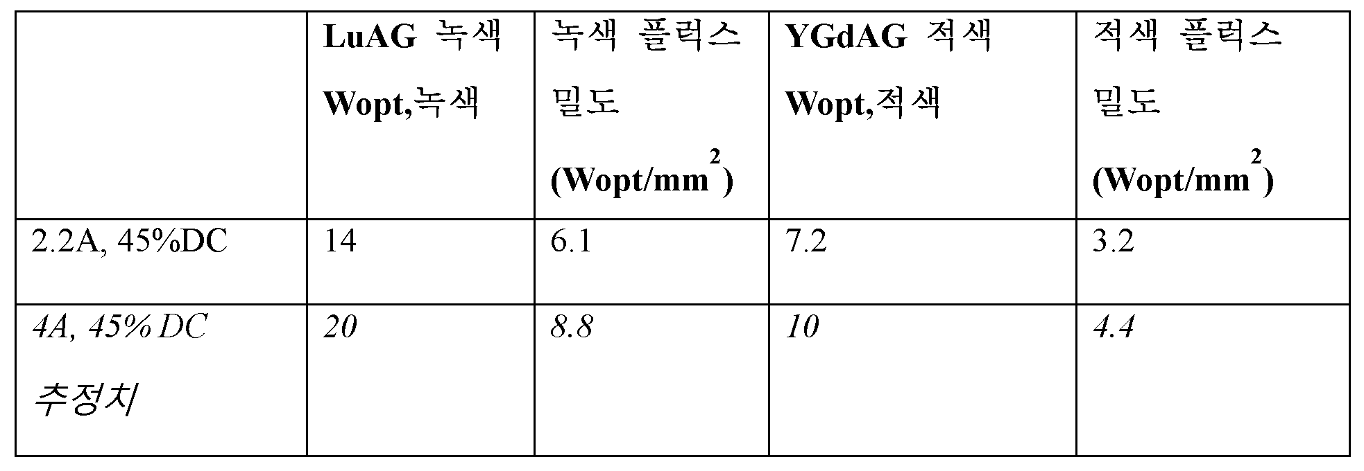
LuAG(Lu3Al5O12:Ce3 +) 가넷은 녹색 방출에 사용되고; YGdAG((Y+Gd)3Al5O12:Ce3 +) 가넷은 적색에 사용된다. YGdAG는 실제로 녹색과 적색을 또한 포함하는 황색 방출이다. 비머에서 적색 부분을 사용하기 위해 녹색 부분이 필터링 제거된다. 광의 일부가 로드 내부에서 여러 번 위 아래로 산란할 수 있다. 녹색 및 특히 적색에서 잠재적인 개선이 더 있다. 보다 최적화된 적색은 녹색보다 성능이 단지 약간 낮을 수 있다. 52개의 LED 대신, 56개의 1㎟의 LED를 사용하여 52㎜ 로드를 펌핑하여 플럭스를 8% 증가시킬 수 있다. 청색 LED 출력(이전 슬라이드)에 대한 개선들은 동일한 팩터로 녹색/적색 출력을 직접 개선시킨다. 로드 길이(및 LED 개수)를 두 배로 늘리면 이상적으로 출력이 두 배가 되므로, 밀도가 두 배가 된다. 그러므로 10cm 로드는 노즈 출구 상에서 18-20Wopt/㎟의 녹색 밀도를 가질 수 있었다.LuAG (Lu 3 Al 5 O 12 :Ce 3+ ) garnet is used for green emission; YGdAG ((Y+Gd) 3 Al 5 O 12 :Ce 3 + ) Garnet is used for red. YGdAG is actually a yellow emission that also contains green and red colors. The green part is filtered out to use the red part in the beamer. Some of the light may scatter up and down several times inside the rod. There is further potential improvement in green and especially red. A more optimized red may have only slightly lower performance than green. Instead of 52 LEDs, 56 LEDs of 1 mm2 can be used to pump a 52 mm rod to increase the flux by 8%. The improvements to the blue LED output (previous slide) directly improve the green/red output by the same factor. Doubling the rod length (and number of LEDs) ideally doubles the output, and therefore doubles the density. Therefore, a 10 cm rod could have a green density of 18-20 Wopt/mm on the nose exit.
도 2a는 본 발명에 따른 조성물, 여기서는 LuAG를 갖는 세라믹 가넷 로드의 여기 스펙트럼을 도시한다. H2O와의 H2/N2 혼합물에서 처리되고(a) 본원에서 정의된 것과 같은 산화성 조건들 하에서 처리된(b) 세라믹 바디에 대한 여기(최대 방출시)가 도시되어 있다. 가장 낮은 여기 대역 이외의 것의 세기에 대한 가장 낮은 여기 밴드의 세기의 비율이 산화성 어닐링으로 인해 (1.17로부터 1.44로) 증가한다.Figure 2a shows the excitation spectrum of a ceramic garnet rod with a composition according to the present invention, here LuAG. Excitation (at maximum emission) is shown for a ceramic body treated in a H 2 /N 2 mixture with H 2 O (a) and treated under oxidizing conditions as defined herein (b). The ratio of the intensity of the lowest excitation band to that of the lowest excitation band increases (from 1.17 to 1.44) due to oxidative annealing.
산화성 어닐링의 영향은 도 2b 및 2c-2d에 도시되어 있다. 도 2b는 상이한 LuAG(순수 Lu 샘플들)의 열 발광 데이터를 나타내며, 가장 낮은 a는 단결정의 열 발광 스펙트럼이고, 가장 높은 c는 어닐링되지 않은 세라믹 바디의 열 발광 스펙트럼이다. 단결정 곡선에 훨씬 더 가까운 중간 곡선 b는 어닐링된 세라믹 바디이다. x축은 온도를 ℃로 표시하고, y축은 열 발광 세기를 임의 단위로 표시한다. 열 발광 데이터의 경우, 샘플들은 곧 UV 조명(360㎚)에 넣어지고 다음에 선형 가열 속도로 어둠 속에서 가열된다. 방출된 광 세기가 샘플 온도의 함수로서 측정되었다.The effect of oxidative annealing is shown in Figures 2b and 2c-2d. Figure 2b shows the thermal emission data of different LuAG (pure Lu samples), the lowest a is the thermal emission spectrum of a single crystal and the highest c is the thermal emission spectrum of an unannealed ceramic body. The middle curve b, much closer to the single crystal curve, is an annealed ceramic body. The x-axis represents the temperature in ° C, and the y-axis represents the thermal emission intensity in arbitrary units. For thermoluminescence data, the samples are immediately subjected to UV illumination (360 nm) and then heated in the dark at a linear heating rate. Emitted light intensity was measured as a function of sample temperature.
다결정 YGdAG 로드는 HIP 및 습식 포밍 가스 어닐링(환원성 분위기) 후에 낮은 성능을 나타낸다. 로드가 상승된 온도에 놓이면 (트랩된 전하 방출 이후의 방사선 재결합으로 인해) 트랩 상태들의 잔광이 가시화된다. O2 함유 분위기에서, 1250℃에서 4시간 동안의 추가 어닐링과 같은 산화성 사후-어닐링 단계에 의해, 트랩 상태들의 감소와 관련하여, 광 출력의 강한 증가가 관찰된다. 잔광이 보이지 않는다. 산화된 로드와 천연 로드 사이의 상대적인 차이는 증가된 LED 출력/플럭스 밀도에 따라 분명히 증가한다.Polycrystalline YGdAG rods show poor performance after HIP and wet forming gas annealing (reducing atmosphere). When the rod is placed at an elevated temperature, the afterglow of the trap states becomes visible (due to radiation recombination following trapped charge release). With an oxidative post-annealing step, such as an additional annealing at 1250° C. for 4 hours in an O 2 containing atmosphere, a strong increase in light output is observed, associated with a reduction in trap states. No afterglow is visible. The relative difference between oxidized and natural loads clearly increases with increased LED power/flux density.
0.25% Ce와 25% Gd(도 2c), 및 1% Ce와 25% Gd(도 2d)가 있는 세라믹 바디들이 산화성 어닐링의 영향이 있을 시에 테스트되었다. 듀티 사이클이 10%이고, 52개의 LED 모듈을 갖는, 1.2㎜*1.9㎜*52㎜의 로드들이 테스트들을 위한 디바이스들로서 사용되었다. 도 2c에서, 최저 곡선로부터 최고 곡선까지의 곡선들의 순서는 다음과 같다: 어닐링 없음; 1% O2; 5% O2; 21% O2; CO 어닐링. 어닐링을 수행하지 않으면, 결과들은 모든 산화성 어닐링들(1250℃에서)보다 실질적으로 낮다. 도 2d에서, 최저 곡선로부터 최고 곡선까지의 곡선들의 순서는 다음과 같다: 제1 기준(산화성 어닐링 없음); 1% O2 어닐링; 0.5% O2 어닐링; 0.1% O2 어닐링; N2 어닐링(수 ppm O2와 함께).Ceramic bodies with 0.25% Ce and 25% Gd (Fig. 2c) and 1% Ce and 25% Gd (Fig. 2d) were tested under the influence of oxidative annealing. Loads of 1.2mm*1.9mm*52mm with a duty cycle of 10% and 52 LED modules were used as devices for the tests. In Fig. 2c, the order of the curves from the lowest curve to the highest curve is as follows: no annealing; 1% O2; 5% O2; 21% O2; CO annealing. Without performing annealing, the results are substantially lower than all oxidative annealings (at 1250°C). In FIG. 2D , the order of the curves from the lowest curve to the highest curve is as follows: first criterion (no oxidative annealing); 1% O2 annealing; 0.5% O2 annealing; 0.1% O2 annealing; N2 annealing (with a few ppm O2).
이제, 세라믹 바디의 합성의 예가 설명된다. 원재료들, Lu2O3, Y2O3, Gd2O3, Al2O3 및 CeO2의 원하는 조합이 단지 안에서 무게가 측정되었다. 원재료들이 알루미나 밀링 볼들을 사용하여 물에서 습식 혼합되었다. 바인더를 첨가하고 현탁액을 건조시켰다(예: 분무 건조). 과립이 강철 다이를 사용하여 약 1톤/㎠의 범위의 압력으로, 원하는 형태로 건식 프레싱되었다. 프레싱된 샘플들은 모든 유기 물질들(바인더)을 제거하기 위해서 1000℃에서 공기 중에서 먼저 소성되었다. 그 다음에 샘플들을 진공 오븐에서 전형적으로 1700℃, 압력 <10- 5바에서 소결하였다. 진공 소결된 샘플들은 후속하여 전형적으로 1700℃/1000바 Ar 또는 N2에서 핫 아이소스태틱 프레싱(HIP)되어 거의 제로 다공성을 달성한다. HIP 후에 샘플들은 전형적으로 1250℃에서 다양한 산화성 조건들 하에서 어닐링될 것이다(상기 실험들 참조). 마지막으로 샘플들을 연마하여 최종 제품을 획득하였다. 여기에 설명된 스틱 샘플들의 경우 어닐링은 연마 전에 습식 포밍 가스(WFG)를 사용하여 표준으로 행해졌다. 후속하여 설명된 어닐링이 연마된 샘플들에 대해 나중에 행해졌다.An example of the synthesis of a ceramic body is now described. The desired combination of raw materials, Lu2O3, Y2O3, Gd2O3, Al2O3 and CeO2, was weighed into the jar. The raw materials were wet mixed in water using alumina milling balls. A binder is added and the suspension is dried (eg spray drying). The granules were dry pressed into the desired shape using a steel die at a pressure in the range of about 1 ton/
따라서, 적절한 어닐링 단계들과 조합하여, Ce3 +로 도핑된 세라믹 가넷 조성물들이 설명된다. 결과적인 세라믹 스틱들은 또한 최적화된 처리 조건들을 사용하여 높은 여기 밀도들에서, 동일한 조성물의 단결정들과 동등한 광 변환 효율들을 보인다. 어닐링을 하지 않으면, 높은 여기 밀도들에서의 광 변환 효율들이 (30% 이상) 현저하게 낮아진다. 열 자극된 발광은 본 발명의 필수적인 부분인 어닐링 단계(들)가 적용되었는지 여부를 체크하는데 사용될 수 있다. 적절히 어닐링되지 않은 세라믹 스틱들은 특히 상승된 온도들에서, 명확한 잔광을 보인다.Thus , in combination with appropriate annealing steps, ceramic garnet compositions doped with Ce 3+ are described. The resulting ceramic sticks also show light conversion efficiencies equivalent to single crystals of the same composition at high excitation densities using optimized processing conditions. Without annealing, light conversion efficiencies at high excitation densities are significantly lowered (30% or more). Thermally stimulated luminescence can be used to check whether the annealing step(s), which is an integral part of the present invention, has been applied. Ceramic sticks that are not properly annealed show a pronounced afterglow, especially at elevated temperatures.
Claims (15)
상기 가늘고 긴 세라믹 바디(100)는 하나 이상의 방사선 입력 면(111) 및 방사선 출사 창(112)을 포함하고, 상기 제2 면(142)은 상기 방사선 출사 창(112)을 포함하고, 상기 복수의 고상 광원(10)은 상기 하나 이상의 방사선 입력 면(111)에 청색 광원 광(11)을 제공하도록 구성되고 상기 방사선 입력 면들(111) 중 적어도 하나에 적어도 1.0*1017광자/(s.㎟)의 광자 플럭스를 제공하도록 구성되고, 상기 가늘고 긴 세라믹 바디(100)는 상기 청색 광원 광(11)의 적어도 일부를 변환기 광(101)으로 파장 변환하도록 구성된 세라믹 재료(120)를 포함하고, 상기 세라믹 재료(120)는 A3B5O12:Ce3+ 세라믹 재료를 포함하며, A는 이트륨(Y), 가돌리늄(Gd) 및 루테튬(Lu) 중 하나 이상을 포함하며, B는 알루미늄(Al)을 포함하고,
상기 가늘고 긴 세라믹 바디(100)는 50-100℃에서 최대 열 발광 세기를 갖고, 상기 최대 열 발광 세기는 상기 가늘고 긴 세라믹 바디(100)와 동일한 A3B5O12:Ce3+ 조성을 갖는 단일 결정의 50-100℃에서의 최대 열 발광 세기보다 최대 10배 높은 조명 디바이스(1).A lighting device (1) comprising a plurality of solid state light sources (10) and an elongated ceramic body (100), the elongated ceramic body (100) comprising a first surface (141) of the elongated ceramic body (100) and It has a second side (142) and a length (L),
The elongated ceramic body 100 includes at least one radiation input surface 111 and a radiation exit window 112, the second surface 142 includes the radiation exit window 112, and the plurality of The solid-state light source 10 is configured to provide blue light source light 11 to the one or more radiation input surfaces 111 and provides at least 1.0*10 17 photons/(s.mm2) to at least one of the radiation input surfaces 111. configured to provide a photon flux of , wherein the elongated ceramic body 100 comprises a ceramic material 120 configured to wavelength convert at least a portion of the blue light source light 11 to converter light 101, wherein the ceramic Material 120 includes an A 3 B 5 O 12 :Ce 3+ ceramic material, wherein A includes at least one of yttrium (Y), gadolinium (Gd), and lutetium (Lu), and B is aluminum (Al) including,
The elongated ceramic body 100 has a maximum thermal luminescence intensity at 50-100 ° C, and the maximum thermal luminescence intensity is a single A 3 B 5 O 12 :Ce 3+ composition having the same A 3 B 5 O 12 :Ce 3+ composition as the elongated ceramic body 100 . A lighting device (1) up to 10 times higher than the maximum thermal luminescence intensity at 50-100 °C of the crystal.
상기 가늘고 긴 세라믹 바디(100)를 제공하기 위해 상승된 온도들에서 소결 공정 및 핫 프레싱 공정 중 적어도 하나에 의해 출발 재료를 처리하는 단계, 및
이어서, 어닐링 공정에서 적어도 1000℃의 온도에서 0.01-100ppm의 산소 분압을 갖는 분위기에서 상기 가늘고 긴 세라믹 바디(100)를 어닐링하는 단계
를 포함하는 방법.A method of manufacturing an elongated ceramic body (100), wherein the elongated ceramic body (100) includes at least one radiation input surface (111) and a radiation exit window (112) vertically disposed on the at least one radiation input surface (111) Including, the area (A) of the radiation input surface 111 is at least 1.5 times the area (E) of the radiation exit window 112, and the elongated ceramic body 100 is the radiation input surface 111 a ceramic material (120) configured to receive a photon flux of at least 1.0*10 17 photons/(s.mm2) to at least one of the wavelength-converting at least a portion of the blue light source light (11) into at least the converter light (101). ), wherein the ceramic material 120 includes an A 3 B 5 O 12 :Ce 3+ ceramic material, A includes at least one of yttrium, gadolinium, and lutetium, and B includes aluminum, wherein Way
processing a starting material by at least one of a sintering process and a hot pressing process at elevated temperatures to provide the elongated ceramic body (100); and
Subsequently, annealing the elongated ceramic body 100 in an atmosphere having an oxygen partial pressure of 0.01-100 ppm at a temperature of at least 1000 ° C in an annealing process.
How to include.
Applications Claiming Priority (3)
| Application Number | Priority Date | Filing Date | Title |
|---|---|---|---|
| EP14192693 | 2014-11-11 | ||
| EP14192693.1 | 2014-11-11 | ||
| PCT/EP2015/075728 WO2016075014A1 (en) | 2014-11-11 | 2015-11-04 | Lighting device with ceramic garnet |
Publications (2)
| Publication Number | Publication Date |
|---|---|
| KR20170084212A KR20170084212A (en) | 2017-07-19 |
| KR102521767B1 true KR102521767B1 (en) | 2023-04-14 |
Family
ID=52002665
Family Applications (1)
| Application Number | Title | Priority Date | Filing Date |
|---|---|---|---|
| KR1020177015855A Active KR102521767B1 (en) | 2014-11-11 | 2015-11-04 | Lighting device with ceramic garnet |
Country Status (6)
| Country | Link |
|---|---|
| US (1) | US10969670B2 (en) |
| EP (1) | EP3224674B1 (en) |
| JP (1) | JP6832277B2 (en) |
| KR (1) | KR102521767B1 (en) |
| CN (1) | CN107002978B (en) |
| WO (1) | WO2016075014A1 (en) |
Families Citing this family (27)
| Publication number | Priority date | Publication date | Assignee | Title |
|---|---|---|---|---|
| US10606158B2 (en) * | 2016-03-15 | 2020-03-31 | Signify Holding B.V. | Light emitting device |
| JP6549805B2 (en) * | 2016-03-15 | 2019-07-24 | シグニファイ ホールディング ビー ヴィ | Compound parabolic collimator array for high intensity illumination |
| WO2017207464A1 (en) * | 2016-06-02 | 2017-12-07 | Philips Lighting Holding B.V. | Remote optical pumping of luminescent concentration rods |
| WO2018141625A1 (en) | 2017-02-03 | 2018-08-09 | Philips Lighting Holding B.V. | Light concentrator module |
| US10947448B2 (en) | 2017-02-28 | 2021-03-16 | Nichia Corporation | Method for manufacturing wavelength conversion member |
| JP6642557B2 (en) * | 2017-02-28 | 2020-02-05 | 日亜化学工業株式会社 | Manufacturing method of wavelength conversion member |
| WO2018177760A1 (en) | 2017-03-28 | 2018-10-04 | Philips Lighting Holding B.V. | Light concentrator module with high refractive index interconnect |
| CN111357283B (en) | 2017-11-14 | 2024-09-27 | 昕诺飞控股有限公司 | Enables solid-state light sources for digital spokes when used with a color wheel |
| JP2019145439A (en) * | 2018-02-23 | 2019-08-29 | シャープ株式会社 | Light source device, lighting apparatus and projector device |
| JP6866537B2 (en) * | 2018-03-29 | 2021-04-28 | シグニファイ ホールディング ビー ヴィSignify Holding B.V. | Single-sided lighting of high lumen density lamps |
| US11560513B2 (en) | 2018-07-11 | 2023-01-24 | Ngk Spark Plug Co., Ltd. | Optical wavelength conversion member and light-emitting device |
| WO2020018342A1 (en) * | 2018-07-18 | 2020-01-23 | Optonomous Technologies Inc. | Illumination system with crystal phosphor mechanism and method of operation thereof |
| JP6885375B2 (en) | 2018-07-27 | 2021-06-16 | セイコーエプソン株式会社 | Light source device and projector |
| JP7238294B2 (en) | 2018-08-24 | 2023-03-14 | セイコーエプソン株式会社 | Light source device and projector |
| JP6876274B2 (en) * | 2018-11-14 | 2021-05-26 | 日亜化学工業株式会社 | Light emitting element, light emitting device and manufacturing method of light emitting element |
| US11067734B2 (en) * | 2018-11-18 | 2021-07-20 | Juganu Ltd. | Illumination device having a plurality of different colored LEDs coupled to a solid waveguide |
| JP6881423B2 (en) * | 2018-11-22 | 2021-06-02 | セイコーエプソン株式会社 | Light source device and projector |
| JP6919644B2 (en) | 2018-12-03 | 2021-08-18 | セイコーエプソン株式会社 | Light source device and projector |
| JP7028155B2 (en) * | 2018-12-25 | 2022-03-02 | セイコーエプソン株式会社 | Light source device and projector |
| JP6988782B2 (en) | 2018-12-25 | 2022-01-05 | セイコーエプソン株式会社 | Light source device and projector |
| WO2020173743A1 (en) * | 2019-02-28 | 2020-09-03 | Signify Holding B.V. | Filament lamp with reflector |
| JP7344397B2 (en) * | 2020-02-27 | 2023-09-13 | シグニファイ ホールディング ビー ヴィ | Light-generating device with beam-shaping optical elements |
| JP7503154B2 (en) * | 2020-06-16 | 2024-06-19 | シグニファイ ホールディング ビー ヴィ | Recessed phosphor ceramic tile |
| DE102020116805A1 (en) * | 2020-06-25 | 2021-12-30 | Heraeus Deutschland GmbH & Co. KG | Sintering process for electrical feedthroughs |
| CN111908910B (en) * | 2020-08-18 | 2022-04-22 | 新沂市锡沂高新材料产业技术研究院有限公司 | High-color-rendering-index transparent ceramic for warm white lighting and preparation method thereof |
| JP7211402B2 (en) * | 2020-09-01 | 2023-01-24 | セイコーエプソン株式会社 | Light guiding unit, light source device and projector |
| CZ2020667A3 (en) | 2020-12-10 | 2022-01-26 | Crytur, Spol. S.R.O. | Light source |
Citations (4)
| Publication number | Priority date | Publication date | Assignee | Title |
|---|---|---|---|---|
| WO2006106883A1 (en) | 2005-03-31 | 2006-10-12 | Dowa Electronics Materials Co., Ltd. | Fluorescent substance, fluorescent substance sheet and process for producing the same, and luminescent device using said fluorescent substance |
| JP2009173905A (en) | 2007-12-28 | 2009-08-06 | Mitsubishi Chemicals Corp | Phosphor, phosphor production method, phosphor-containing composition, and light emitting device |
| JP2014143344A (en) | 2013-01-25 | 2014-08-07 | Mitsubishi Chemicals Corp | Wavelength conversion member and semiconductor light-emitting device using the same |
| JP2014192127A (en) * | 2013-03-28 | 2014-10-06 | Ushio Inc | Fluorescent light source device |
Family Cites Families (14)
| Publication number | Priority date | Publication date | Assignee | Title |
|---|---|---|---|---|
| EP1797594A2 (en) | 2004-09-28 | 2007-06-20 | Philips Intellectual Property & Standards GmbH | Light emitting device with improved conversion layer |
| US7982229B2 (en) | 2004-11-18 | 2011-07-19 | Koninklijke Philips Electronics N.V. | Light emitting device with conversion structure |
| CN100566490C (en) * | 2005-03-14 | 2009-12-02 | 皇家飞利浦电子股份有限公司 | Phosphor in polycrystalline ceramic structure and light emitting element including same |
| US7316497B2 (en) * | 2005-03-29 | 2008-01-08 | 3M Innovative Properties Company | Fluorescent volume light source |
| US20070279914A1 (en) * | 2006-06-02 | 2007-12-06 | 3M Innovative Properties Company | Fluorescent volume light source with reflector |
| CN101495424A (en) | 2006-07-26 | 2009-07-29 | 皇家飞利浦电子股份有限公司 | YAG-based ceramic garnet material comprising at least one multi-site element |
| JP5462515B2 (en) * | 2009-03-31 | 2014-04-02 | 株式会社ワールドラボ | Transparent ceramics, manufacturing method thereof, and device using the transparent ceramics |
| CN101705095B (en) | 2009-09-21 | 2011-08-10 | 四川新力光源有限公司 | Yellow light afterglow material and preparation method thereof as well as LED illuminating device using same |
| WO2011097137A1 (en) * | 2010-02-04 | 2011-08-11 | Nitto Denko Corporation | Light emissive ceramic laminate and method of making same |
| JP5803137B2 (en) | 2010-09-16 | 2015-11-04 | セイコーエプソン株式会社 | Light source device and projector |
| DE202010018033U1 (en) * | 2010-09-27 | 2013-09-12 | Osram Gmbh | Lighting system with increased efficiency |
| DE102011079907A1 (en) | 2011-07-27 | 2013-01-31 | Osram Ag | Luminescent device for use in illumination device for e.g. projection device, has scattering body for scattering pump light in main propagation direction such that converted light passes outlet surface in main radiation direction |
| JP6393187B2 (en) | 2011-08-16 | 2018-09-19 | 日東電工株式会社 | Phosphor composition and method for producing the same |
| WO2013088309A1 (en) | 2011-12-16 | 2013-06-20 | Koninklijke Philips Electronics N.V. | PHOSPHOR IN WATER GLASS FOR LEDs |
-
2015
- 2015-11-04 KR KR1020177015855A patent/KR102521767B1/en active Active
- 2015-11-04 US US15/525,848 patent/US10969670B2/en active Active
- 2015-11-04 WO PCT/EP2015/075728 patent/WO2016075014A1/en not_active Ceased
- 2015-11-04 CN CN201580061320.0A patent/CN107002978B/en active Active
- 2015-11-04 JP JP2017525011A patent/JP6832277B2/en active Active
- 2015-11-04 EP EP15788445.3A patent/EP3224674B1/en active Active
Patent Citations (4)
| Publication number | Priority date | Publication date | Assignee | Title |
|---|---|---|---|---|
| WO2006106883A1 (en) | 2005-03-31 | 2006-10-12 | Dowa Electronics Materials Co., Ltd. | Fluorescent substance, fluorescent substance sheet and process for producing the same, and luminescent device using said fluorescent substance |
| JP2009173905A (en) | 2007-12-28 | 2009-08-06 | Mitsubishi Chemicals Corp | Phosphor, phosphor production method, phosphor-containing composition, and light emitting device |
| JP2014143344A (en) | 2013-01-25 | 2014-08-07 | Mitsubishi Chemicals Corp | Wavelength conversion member and semiconductor light-emitting device using the same |
| JP2014192127A (en) * | 2013-03-28 | 2014-10-06 | Ushio Inc | Fluorescent light source device |
Also Published As
| Publication number | Publication date |
|---|---|
| WO2016075014A1 (en) | 2016-05-19 |
| EP3224674B1 (en) | 2021-04-14 |
| JP2017536664A (en) | 2017-12-07 |
| US10969670B2 (en) | 2021-04-06 |
| KR20170084212A (en) | 2017-07-19 |
| US20170315433A1 (en) | 2017-11-02 |
| JP6832277B2 (en) | 2021-02-24 |
| CN107002978B (en) | 2020-03-31 |
| EP3224674A1 (en) | 2017-10-04 |
| CN107002978A (en) | 2017-08-01 |
Similar Documents
| Publication | Publication Date | Title |
|---|---|---|
| KR102521767B1 (en) | Lighting device with ceramic garnet | |
| EP3350503B1 (en) | Stacked luminescent concentrator | |
| EP3390901B1 (en) | Multiple pumping luminescent rod configuration for obtaining ultra-high brightness | |
| US10698150B2 (en) | Compound parabolic collimator array for high intensity lighting | |
| KR102432725B1 (en) | White phosphor-converted LED with stable flow rate output versus temperature | |
| US10125314B2 (en) | Lighting device with ceramic garnet |
Legal Events
| Date | Code | Title | Description |
|---|---|---|---|
| PA0105 | International application |
Patent event date: 20170609 Patent event code: PA01051R01D Comment text: International Patent Application |
|
| PG1501 | Laying open of application | ||
| PN2301 | Change of applicant |
Patent event date: 20180214 Comment text: Notification of Change of Applicant Patent event code: PN23011R01D |
|
| A201 | Request for examination | ||
| PA0201 | Request for examination |
Patent event code: PA02012R01D Patent event date: 20201104 Comment text: Request for Examination of Application |
|
| E902 | Notification of reason for refusal | ||
| PE0902 | Notice of grounds for rejection |
Comment text: Notification of reason for refusal Patent event date: 20220808 Patent event code: PE09021S01D |
|
| E701 | Decision to grant or registration of patent right | ||
| PE0701 | Decision of registration |
Patent event code: PE07011S01D Comment text: Decision to Grant Registration Patent event date: 20230202 |
|
| GRNT | Written decision to grant | ||
| PR0701 | Registration of establishment |
Comment text: Registration of Establishment Patent event date: 20230411 Patent event code: PR07011E01D |
|
| PR1002 | Payment of registration fee |
Payment date: 20230412 End annual number: 3 Start annual number: 1 |
|
| PG1601 | Publication of registration |