KR102496654B1 - Apparatus and method for controlling driving mode change of vehicle, vehicle system - Google Patents
Apparatus and method for controlling driving mode change of vehicle, vehicle system Download PDFInfo
- Publication number
- KR102496654B1 KR102496654B1 KR1020180020341A KR20180020341A KR102496654B1 KR 102496654 B1 KR102496654 B1 KR 102496654B1 KR 1020180020341 A KR1020180020341 A KR 1020180020341A KR 20180020341 A KR20180020341 A KR 20180020341A KR 102496654 B1 KR102496654 B1 KR 102496654B1
- Authority
- KR
- South Korea
- Prior art keywords
- data
- mode
- reliability
- vehicle
- driving mode
- Prior art date
- Legal status (The legal status is an assumption and is not a legal conclusion. Google has not performed a legal analysis and makes no representation as to the accuracy of the status listed.)
- Active
Links
Images


Classifications
-
- G—PHYSICS
- G01—MEASURING; TESTING
- G01C—MEASURING DISTANCES, LEVELS OR BEARINGS; SURVEYING; NAVIGATION; GYROSCOPIC INSTRUMENTS; PHOTOGRAMMETRY OR VIDEOGRAMMETRY
- G01C21/00—Navigation; Navigational instruments not provided for in groups G01C1/00 - G01C19/00
- G01C21/26—Navigation; Navigational instruments not provided for in groups G01C1/00 - G01C19/00 specially adapted for navigation in a road network
-
- B—PERFORMING OPERATIONS; TRANSPORTING
- B60—VEHICLES IN GENERAL
- B60W—CONJOINT CONTROL OF VEHICLE SUB-UNITS OF DIFFERENT TYPE OR DIFFERENT FUNCTION; CONTROL SYSTEMS SPECIALLY ADAPTED FOR HYBRID VEHICLES; ROAD VEHICLE DRIVE CONTROL SYSTEMS FOR PURPOSES NOT RELATED TO THE CONTROL OF A PARTICULAR SUB-UNIT
- B60W60/00—Drive control systems specially adapted for autonomous road vehicles
- B60W60/005—Handover processes
- B60W60/0059—Estimation of the risk associated with autonomous or manual driving, e.g. situation too complex, sensor failure or driver incapacity
-
- B—PERFORMING OPERATIONS; TRANSPORTING
- B60—VEHICLES IN GENERAL
- B60W—CONJOINT CONTROL OF VEHICLE SUB-UNITS OF DIFFERENT TYPE OR DIFFERENT FUNCTION; CONTROL SYSTEMS SPECIALLY ADAPTED FOR HYBRID VEHICLES; ROAD VEHICLE DRIVE CONTROL SYSTEMS FOR PURPOSES NOT RELATED TO THE CONTROL OF A PARTICULAR SUB-UNIT
- B60W50/00—Details of control systems for road vehicle drive control not related to the control of a particular sub-unit, e.g. process diagnostic or vehicle driver interfaces
- B60W50/08—Interaction between the driver and the control system
- B60W50/082—Selecting or switching between different modes of propelling
-
- G—PHYSICS
- G05—CONTROLLING; REGULATING
- G05B—CONTROL OR REGULATING SYSTEMS IN GENERAL; FUNCTIONAL ELEMENTS OF SUCH SYSTEMS; MONITORING OR TESTING ARRANGEMENTS FOR SUCH SYSTEMS OR ELEMENTS
- G05B19/00—Programme-control systems
- G05B19/02—Programme-control systems electric
- G05B19/04—Programme control other than numerical control, i.e. in sequence controllers or logic controllers
- G05B19/042—Programme control other than numerical control, i.e. in sequence controllers or logic controllers using digital processors
- G05B19/0423—Input/output
-
- B—PERFORMING OPERATIONS; TRANSPORTING
- B60—VEHICLES IN GENERAL
- B60W—CONJOINT CONTROL OF VEHICLE SUB-UNITS OF DIFFERENT TYPE OR DIFFERENT FUNCTION; CONTROL SYSTEMS SPECIALLY ADAPTED FOR HYBRID VEHICLES; ROAD VEHICLE DRIVE CONTROL SYSTEMS FOR PURPOSES NOT RELATED TO THE CONTROL OF A PARTICULAR SUB-UNIT
- B60W30/00—Purposes of road vehicle drive control systems not related to the control of a particular sub-unit, e.g. of systems using conjoint control of vehicle sub-units
- B60W30/14—Adaptive cruise control
-
- B—PERFORMING OPERATIONS; TRANSPORTING
- B60—VEHICLES IN GENERAL
- B60W—CONJOINT CONTROL OF VEHICLE SUB-UNITS OF DIFFERENT TYPE OR DIFFERENT FUNCTION; CONTROL SYSTEMS SPECIALLY ADAPTED FOR HYBRID VEHICLES; ROAD VEHICLE DRIVE CONTROL SYSTEMS FOR PURPOSES NOT RELATED TO THE CONTROL OF A PARTICULAR SUB-UNIT
- B60W30/00—Purposes of road vehicle drive control systems not related to the control of a particular sub-unit, e.g. of systems using conjoint control of vehicle sub-units
- B60W30/18—Propelling the vehicle
- B60W30/182—Selecting between different operative modes, e.g. comfort and performance modes
-
- B—PERFORMING OPERATIONS; TRANSPORTING
- B60—VEHICLES IN GENERAL
- B60W—CONJOINT CONTROL OF VEHICLE SUB-UNITS OF DIFFERENT TYPE OR DIFFERENT FUNCTION; CONTROL SYSTEMS SPECIALLY ADAPTED FOR HYBRID VEHICLES; ROAD VEHICLE DRIVE CONTROL SYSTEMS FOR PURPOSES NOT RELATED TO THE CONTROL OF A PARTICULAR SUB-UNIT
- B60W40/00—Estimation or calculation of non-directly measurable driving parameters for road vehicle drive control systems not related to the control of a particular sub unit, e.g. by using mathematical models
- B60W40/02—Estimation or calculation of non-directly measurable driving parameters for road vehicle drive control systems not related to the control of a particular sub unit, e.g. by using mathematical models related to ambient conditions
-
- B—PERFORMING OPERATIONS; TRANSPORTING
- B60—VEHICLES IN GENERAL
- B60W—CONJOINT CONTROL OF VEHICLE SUB-UNITS OF DIFFERENT TYPE OR DIFFERENT FUNCTION; CONTROL SYSTEMS SPECIALLY ADAPTED FOR HYBRID VEHICLES; ROAD VEHICLE DRIVE CONTROL SYSTEMS FOR PURPOSES NOT RELATED TO THE CONTROL OF A PARTICULAR SUB-UNIT
- B60W60/00—Drive control systems specially adapted for autonomous road vehicles
- B60W60/005—Handover processes
- B60W60/0053—Handover processes from vehicle to occupant
-
- G—PHYSICS
- G01—MEASURING; TESTING
- G01C—MEASURING DISTANCES, LEVELS OR BEARINGS; SURVEYING; NAVIGATION; GYROSCOPIC INSTRUMENTS; PHOTOGRAMMETRY OR VIDEOGRAMMETRY
- G01C21/00—Navigation; Navigational instruments not provided for in groups G01C1/00 - G01C19/00
- G01C21/26—Navigation; Navigational instruments not provided for in groups G01C1/00 - G01C19/00 specially adapted for navigation in a road network
- G01C21/34—Route searching; Route guidance
- G01C21/36—Input/output arrangements for on-board computers
-
- G—PHYSICS
- G01—MEASURING; TESTING
- G01C—MEASURING DISTANCES, LEVELS OR BEARINGS; SURVEYING; NAVIGATION; GYROSCOPIC INSTRUMENTS; PHOTOGRAMMETRY OR VIDEOGRAMMETRY
- G01C21/00—Navigation; Navigational instruments not provided for in groups G01C1/00 - G01C19/00
- G01C21/38—Electronic maps specially adapted for navigation; Updating thereof
- G01C21/3804—Creation or updating of map data
- G01C21/3833—Creation or updating of map data characterised by the source of data
- G01C21/3837—Data obtained from a single source
-
- G—PHYSICS
- G01—MEASURING; TESTING
- G01C—MEASURING DISTANCES, LEVELS OR BEARINGS; SURVEYING; NAVIGATION; GYROSCOPIC INSTRUMENTS; PHOTOGRAMMETRY OR VIDEOGRAMMETRY
- G01C21/00—Navigation; Navigational instruments not provided for in groups G01C1/00 - G01C19/00
- G01C21/38—Electronic maps specially adapted for navigation; Updating thereof
- G01C21/3885—Transmission of map data to client devices; Reception of map data by client devices
-
- G—PHYSICS
- G05—CONTROLLING; REGULATING
- G05D—SYSTEMS FOR CONTROLLING OR REGULATING NON-ELECTRIC VARIABLES
- G05D1/00—Control of position, course, altitude or attitude of land, water, air or space vehicles, e.g. using automatic pilots
- G05D1/02—Control of position or course in two dimensions
- G05D1/021—Control of position or course in two dimensions specially adapted to land vehicles
- G05D1/0231—Control of position or course in two dimensions specially adapted to land vehicles using optical position detecting means
-
- G—PHYSICS
- G06—COMPUTING OR CALCULATING; COUNTING
- G06F—ELECTRIC DIGITAL DATA PROCESSING
- G06F16/00—Information retrieval; Database structures therefor; File system structures therefor
- G06F16/20—Information retrieval; Database structures therefor; File system structures therefor of structured data, e.g. relational data
- G06F16/29—Geographical information databases
-
- B—PERFORMING OPERATIONS; TRANSPORTING
- B60—VEHICLES IN GENERAL
- B60W—CONJOINT CONTROL OF VEHICLE SUB-UNITS OF DIFFERENT TYPE OR DIFFERENT FUNCTION; CONTROL SYSTEMS SPECIALLY ADAPTED FOR HYBRID VEHICLES; ROAD VEHICLE DRIVE CONTROL SYSTEMS FOR PURPOSES NOT RELATED TO THE CONTROL OF A PARTICULAR SUB-UNIT
- B60W2420/00—Indexing codes relating to the type of sensors based on the principle of their operation
- B60W2420/40—Photo, light or radio wave sensitive means, e.g. infrared sensors
- B60W2420/403—Image sensing, e.g. optical camera
-
- B60W2420/42—
-
- B—PERFORMING OPERATIONS; TRANSPORTING
- B60—VEHICLES IN GENERAL
- B60W—CONJOINT CONTROL OF VEHICLE SUB-UNITS OF DIFFERENT TYPE OR DIFFERENT FUNCTION; CONTROL SYSTEMS SPECIALLY ADAPTED FOR HYBRID VEHICLES; ROAD VEHICLE DRIVE CONTROL SYSTEMS FOR PURPOSES NOT RELATED TO THE CONTROL OF A PARTICULAR SUB-UNIT
- B60W2552/00—Input parameters relating to infrastructure
- B60W2552/53—Road markings, e.g. lane marker or crosswalk
-
- B—PERFORMING OPERATIONS; TRANSPORTING
- B60—VEHICLES IN GENERAL
- B60W—CONJOINT CONTROL OF VEHICLE SUB-UNITS OF DIFFERENT TYPE OR DIFFERENT FUNCTION; CONTROL SYSTEMS SPECIALLY ADAPTED FOR HYBRID VEHICLES; ROAD VEHICLE DRIVE CONTROL SYSTEMS FOR PURPOSES NOT RELATED TO THE CONTROL OF A PARTICULAR SUB-UNIT
- B60W2555/00—Input parameters relating to exterior conditions, not covered by groups B60W2552/00, B60W2554/00
- B60W2555/20—Ambient conditions, e.g. wind or rain
-
- B—PERFORMING OPERATIONS; TRANSPORTING
- B60—VEHICLES IN GENERAL
- B60W—CONJOINT CONTROL OF VEHICLE SUB-UNITS OF DIFFERENT TYPE OR DIFFERENT FUNCTION; CONTROL SYSTEMS SPECIALLY ADAPTED FOR HYBRID VEHICLES; ROAD VEHICLE DRIVE CONTROL SYSTEMS FOR PURPOSES NOT RELATED TO THE CONTROL OF A PARTICULAR SUB-UNIT
- B60W2556/00—Input parameters relating to data
- B60W2556/25—Data precision
-
- B—PERFORMING OPERATIONS; TRANSPORTING
- B60—VEHICLES IN GENERAL
- B60W—CONJOINT CONTROL OF VEHICLE SUB-UNITS OF DIFFERENT TYPE OR DIFFERENT FUNCTION; CONTROL SYSTEMS SPECIALLY ADAPTED FOR HYBRID VEHICLES; ROAD VEHICLE DRIVE CONTROL SYSTEMS FOR PURPOSES NOT RELATED TO THE CONTROL OF A PARTICULAR SUB-UNIT
- B60W2556/00—Input parameters relating to data
- B60W2556/40—High definition maps
-
- B—PERFORMING OPERATIONS; TRANSPORTING
- B60—VEHICLES IN GENERAL
- B60W—CONJOINT CONTROL OF VEHICLE SUB-UNITS OF DIFFERENT TYPE OR DIFFERENT FUNCTION; CONTROL SYSTEMS SPECIALLY ADAPTED FOR HYBRID VEHICLES; ROAD VEHICLE DRIVE CONTROL SYSTEMS FOR PURPOSES NOT RELATED TO THE CONTROL OF A PARTICULAR SUB-UNIT
- B60W2556/00—Input parameters relating to data
- B60W2556/45—External transmission of data to or from the vehicle
- B60W2556/50—External transmission of data to or from the vehicle of positioning data, e.g. GPS [Global Positioning System] data
-
- B—PERFORMING OPERATIONS; TRANSPORTING
- B60—VEHICLES IN GENERAL
- B60W—CONJOINT CONTROL OF VEHICLE SUB-UNITS OF DIFFERENT TYPE OR DIFFERENT FUNCTION; CONTROL SYSTEMS SPECIALLY ADAPTED FOR HYBRID VEHICLES; ROAD VEHICLE DRIVE CONTROL SYSTEMS FOR PURPOSES NOT RELATED TO THE CONTROL OF A PARTICULAR SUB-UNIT
- B60W30/00—Purposes of road vehicle drive control systems not related to the control of a particular sub-unit, e.g. of systems using conjoint control of vehicle sub-units
- B60W30/10—Path keeping
- B60W30/12—Lane keeping
-
- B—PERFORMING OPERATIONS; TRANSPORTING
- B60—VEHICLES IN GENERAL
- B60W—CONJOINT CONTROL OF VEHICLE SUB-UNITS OF DIFFERENT TYPE OR DIFFERENT FUNCTION; CONTROL SYSTEMS SPECIALLY ADAPTED FOR HYBRID VEHICLES; ROAD VEHICLE DRIVE CONTROL SYSTEMS FOR PURPOSES NOT RELATED TO THE CONTROL OF A PARTICULAR SUB-UNIT
- B60W60/00—Drive control systems specially adapted for autonomous road vehicles
-
- G—PHYSICS
- G05—CONTROLLING; REGULATING
- G05B—CONTROL OR REGULATING SYSTEMS IN GENERAL; FUNCTIONAL ELEMENTS OF SUCH SYSTEMS; MONITORING OR TESTING ARRANGEMENTS FOR SUCH SYSTEMS OR ELEMENTS
- G05B2219/00—Program-control systems
- G05B2219/20—Pc systems
- G05B2219/25—Pc structure of the system
- G05B2219/25257—Microcontroller
Landscapes
- Engineering & Computer Science (AREA)
- Remote Sensing (AREA)
- Radar, Positioning & Navigation (AREA)
- Automation & Control Theory (AREA)
- Physics & Mathematics (AREA)
- General Physics & Mathematics (AREA)
- Transportation (AREA)
- Mechanical Engineering (AREA)
- Human Computer Interaction (AREA)
- Databases & Information Systems (AREA)
- Theoretical Computer Science (AREA)
- Mathematical Physics (AREA)
- Aviation & Aerospace Engineering (AREA)
- Electromagnetism (AREA)
- General Engineering & Computer Science (AREA)
- Data Mining & Analysis (AREA)
- Traffic Control Systems (AREA)
- Control Of Driving Devices And Active Controlling Of Vehicle (AREA)
Abstract
본 발명은 차량의 주행모드 전환 제어 장치 및 방법, 그리고 차량 시스템에 관한 것으로, 본 발명에 따른 장치는 차량 내 지도 DB, 측위 시스템, 카메라 시스템 및 센서 시스템으로부터 데이터를 수집하는 데이터 수집부, 상기 수집된 데이터들을 분석하여 각 데이터의 신뢰도를 판단하는 신뢰도 판단부, 및 상기 각 데이터의 신뢰도 판단 결과에 기초하여 차량의 주행 전략을 설계하고 상기 주행 전략을 포함하는 모드 전환 데이터를 생성하는 모드 전환 제어부를 포함한다.The present invention relates to a driving mode switching control device and method of a vehicle, and to a vehicle system, and the device according to the present invention includes a data collection unit for collecting data from a map DB, a positioning system, a camera system, and a sensor system in the vehicle, the collection A reliability determination unit that analyzes the received data to determine the reliability of each data, and a mode switching control unit that designs a driving strategy of the vehicle based on the reliability determination result of each data and generates mode switching data including the driving strategy include
Description
본 발명은 차량의 주행모드 전환 제어 장치 및 방법, 그리고 차량 시스템에 관한 것이다.The present invention relates to a driving mode switching control apparatus and method of a vehicle, and a vehicle system.
최근 ADAS(Advanced Driver Assistance System) 및 자율주행 시스템에 대한 수요 및 요구사항이 증가하고 있다. 따라서, 차량 내 센서 데이터 및 정밀지도 등의 정보량이 증가함에 따라 이를 기반으로 하는 주행편의 기능이 다양하게 개발되고 있다.Recently, demand and requirements for ADAS (Advanced Driver Assistance System) and autonomous driving systems are increasing. Accordingly, as the amount of information such as in-vehicle sensor data and precise maps increases, various driving convenience functions based thereon are being developed.
다만, 센서 데이터 및/또는 정밀지도 등의 정보는 환경적 조건 및 센서 제약 사항 등의 조건으로 인해 정확도가 떨어져 성능 열화를 야기할 수 있다.However, information such as sensor data and/or precision maps may have poor accuracy due to conditions such as environmental conditions and sensor restrictions, resulting in performance degradation.
따라서, ADAS 및 자율주행에 있어서 정확도가 떨어지는 정보를 고려하여 주행 전략을 설계하는 것이 필요하다.Therefore, in ADAS and autonomous driving, it is necessary to design a driving strategy in consideration of information with low accuracy.
본 발명의 목적은, 정밀지도 및 인지 센서 등의 데이터를 수집하여 신뢰도를 판단하고 신뢰도 판단 결과를 기반으로 주행 전략을 설계하여 주행모드 전환 정보를 제공함으로써 효율적인 차량 주행 제어가 가능하도록 한, 차량의 주행모드 전환 제어 장치 및 방법, 그리고 차량 시스템을 제공함에 있다.An object of the present invention is to collect data such as precision maps and cognitive sensors to determine reliability, design a driving strategy based on the reliability determination result, and provide driving mode switching information to enable efficient vehicle driving control. It is to provide a driving mode switching control device and method, and a vehicle system.
본 발명의 기술적 과제들은 이상에서 언급한 기술적 과제들로 제한되지 않으며, 언급되지 않은 또 다른 기술적 과제들은 아래의 기재들로부터 당업자에게 명확하게 이해될 수 있을 것이다.The technical problems of the present invention are not limited to the technical problems mentioned above, and other technical problems not mentioned will be clearly understood by those skilled in the art from the description below.
상기의 목적을 달성하기 위한 본 발명의 일 실시예에 따른 차량의 주행모드 전환 제어 장치는, 차량 내 지도 DB, 측위 시스템, 카메라 시스템 및 센서 시스템으로부터 데이터를 수집하는 데이터 수집부, 상기 수집된 데이터들을 분석하여 각 데이터의 신뢰도를 판단하는 신뢰도 판단부, 및 상기 각 데이터의 신뢰도 판단 결과에 기초하여 차량의 주행 전략을 설계하고 상기 주행 전략을 포함하는 모드 전환 데이터를 생성하는 모드 전환 제어부를 포함하는 것을 특징으로 한다.In order to achieve the above object, an apparatus for controlling driving mode switching of a vehicle according to an embodiment of the present invention includes a data collection unit that collects data from an in-vehicle map DB, a positioning system, a camera system, and a sensor system; and the collected data. A reliability determination unit that analyzes data to determine the reliability of each data, and a mode switching control unit that designs a driving strategy of the vehicle based on the reliability determination result of each data and generates mode switching data including the driving strategy. characterized by
상기 데이터 수집부는, 차량 내 지도 DB, 측위 시스템, 카메라 시스템 및 센서 시스템으로부터 정밀 지도 및 센서 지도를 포함하는 지도 데이터, 측위 데이터, 차선 데이터 및 장애물 데이터를 수집하는 것을 특징으로 한다.The data collection unit may collect map data including precision maps and sensor maps, positioning data, lane data, and obstacle data from an in-vehicle map DB, a positioning system, a camera system, and a sensor system.
상기 신뢰도 판단부는, 센서 데이터 및 지도 데이터의 오차량, 오차 누적 지속 시간 및 지역정보를 분석하고 상기 분석 결과에 기초하여 정밀 지도 및 센서 지도에 대한 신뢰도를 판단하는 것을 특징으로 한다.The reliability determination unit may analyze error amounts of sensor data and map data, accumulated error duration, and local information, and determine reliability of the precise map and sensor map based on the analysis result.
상기 신뢰도 판단부는, 트래킹(Tracking) 로직 내부의 오차 공분산 크기 변화량, 센서 데이터의 업데이트 주기, 추정치 및 센서 데이터의 오차 누적량을 분석하고 상기 분석 결과에 기초하여 측위 데이터의 신뢰도를 판단하는 것을 특징으로 한다.The reliability determination unit analyzes the amount of change in the size of the error covariance in the tracking logic, the update period of the sensor data, the estimated value, and the accumulated error of the sensor data, and determines the reliability of the positioning data based on the analysis result. .
상기 신뢰도 판단부는, 차선 정보의 신뢰도 레벨 및 동일 차로의 전방차량 이동경로 및 자차량 이동경로 간 오차를 분석하고 상기 분석 결과에 기초하여 차선 데이터의 신뢰도를 판단하는 것을 특징으로 한다.The reliability determination unit may analyze the reliability level of the lane information and an error between the movement path of the preceding vehicle and the movement path of the host vehicle in the same lane, and determine the reliability of the lane data based on the analysis result.
상기 신뢰도 판단부는, 상기 센서 시스템의 각 센서들의 감지 중복영역의 장애물 출력정보에 대한 오차량 및 날씨 정보에 기초하여 장애물 데이터의 신뢰도를 판단하는 것을 특징으로 한다.The reliability determination unit may determine the reliability of obstacle data based on an error amount and weather information of obstacle output information of overlapping detection areas of each sensor of the sensor system.
상기 모드 전환 제어부는, 상기 각 데이터의 신뢰도 판단 결과에 따라 차량의 주행모드를 고속도로 자율주행모드, 고속도로 주행지원모드, 차로추종 지원모드 또는 운전자 주행모드로 전환하는 모드 전환 데이터를 생성하는 것을 특징으로 한다.The mode switching control unit generates mode switching data for switching the driving mode of the vehicle to a highway autonomous driving mode, a highway driving assistance mode, a lane following assistance mode, or a driver driving mode according to a result of determining the reliability of each data. do.
상기 모드 전환 제어부는, 상기 각 데이터의 신뢰도가 모두 기준치 이상이면 상기 차량의 주행모드를 고속도로 자율주행모드로 전환하는 모드 전환 데이터를 생성하는 것을 특징으로 한다.The mode switching control unit may generate mode switching data for switching the driving mode of the vehicle to the highway autonomous driving mode when the reliability of each data is equal to or higher than a reference value.
상기 모드 전환 제어부는, 상기 각 데이터의 신뢰도가 모두 기준치 미만이면 상기 차량의 주행모드를 운전자 주행모드로 전환하는 모드 전환 데이터를 생성하는 것을 특징으로 한다.The mode switching control unit may generate mode switching data for switching the driving mode of the vehicle to the driver driving mode when the reliability of each data is less than a reference value.
또한, 본 발명의 일 실시예에 따른 장치는, 상기 수집된 데이터들을 전처리하는 데이터 전처리부를 더 포함하는 것을 특징으로 한다.In addition, the apparatus according to an embodiment of the present invention is characterized in that it further comprises a data pre-processing unit for pre-processing the collected data.
또한, 상기의 목적을 달성하기 위한 본 발명의 일 실시예에 따른 차량의 주행모드 전환 제어 방법은, 차량 내 지도 DB, 측위 시스템, 카메라 시스템 및 센서 시스템으로부터 데이터를 수집하는 단계, 상기 수집된 데이터들을 분석하여 각 데이터의 신뢰도를 판단하는 단계, 및 상기 각 데이터의 신뢰도 판단 결과에 기초하여 차량의 주행 전략을 설계하고 상기 주행 전략을 포함하는 모드 전환 데이터를 생성하는 단계를 포함하는 것을 특징으로 한다.In addition, a driving mode switching control method of a vehicle according to an embodiment of the present invention for achieving the above object includes collecting data from an in-vehicle map DB, a positioning system, a camera system, and a sensor system, the collected data and determining the reliability of each data by analyzing the data, designing a driving strategy of the vehicle based on the result of determining the reliability of each data, and generating mode switching data including the driving strategy. .
또한, 상기의 목적을 달성하기 위한 본 발명의 일 실시예에 따른 차량 시스템은, 차량 내 지도 DB, 측위 시스템, 카메라 시스템 및 센서 시스템으로부터 지도 데이터, 측위 데이터, 차선 데이터 및 장애물 데이터를 수집하고, 수집된 각 데이터들을 분석하여 각 데이터 별로 신뢰도를 판단하고, 신뢰도 판단 결과를 기반으로 모드 전환을 위한 주행 전략을 설계하여 모드 전환 데이터를 생성하는 주행모드 전환 제어 장치, 및 상기 주행모드 전환 제어 장치로부터 제공된 모드 전환 데이터에 기초하여 차량의 주행모드를 전환하는 주행 제어 시스템을 포함하는 것을 특징으로 한다.In addition, a vehicle system according to an embodiment of the present invention for achieving the above object collects map data, positioning data, lane data, and obstacle data from an in-vehicle map DB, positioning system, camera system, and sensor system, A driving mode switching control device that analyzes each collected data to determine reliability for each data, designs a driving strategy for mode switching based on the reliability determination result, and generates mode switching data, and the driving mode switching control device and a driving control system for switching the driving mode of the vehicle based on the provided mode switching data.
본 발명에 따르면, 정밀지도 및 인지 센서 등의 데이터를 수집하여 신뢰도를 판단하고 신뢰도 판단 결과를 기반으로 주행 전략을 설계하여 주행모드 전환 정보를 제공함으로써 효율적인 차량 주행 제어가 가능한 효과가 있다.According to the present invention, it is possible to efficiently control vehicle driving by collecting data such as precision maps and cognitive sensors to determine reliability, designing a driving strategy based on the reliability determination result, and providing driving mode switching information.
도 1은 본 발명의 일 실시예에 따른 차량의 주행모드 전환 제어 장치가 적용된 차량 시스템을 도시한 도면이다.
도 2는 본 발명의 일 실시예에 따른 차량의 주행모드 전환 제어 장치의 구성을 도시한 도면이다.
도 3a 내지 도 3d는 본 발명의 일 실시예에 따른 차량의 주행모드 전환 제어 장치의 신뢰도 판단 동작을 설명하는데 참조되는 실시예를 도시한 도면이다.
도 4는 본 발명의 일 실시예에 따른 차량의 주행모드 전환 제어 장치의 주행 전략의 설계 동작을 설명하는데 참조되는 실시예를 도시한 도면이다.
도 5는 본 발명의 일 실시예에 따른 차량의 주행모드 전환 제어 방법에 대한 동작 흐름을 도시한 도면이다.
도 6은 본 발명의 일 실시예에 따른 방법이 실행되는 컴퓨팅 시스템을 도시한 도면이다.1 is a diagram illustrating a vehicle system to which a driving mode switching control device of a vehicle according to an embodiment of the present invention is applied.
2 is a diagram showing the configuration of a driving mode switching control device for a vehicle according to an embodiment of the present invention.
3A to 3D are diagrams illustrating an embodiment referenced to describe a reliability determination operation of the driving mode switching control device of a vehicle according to an embodiment of the present invention.
FIG. 4 is a diagram illustrating an embodiment referred to in describing a design operation of a driving strategy of a driving mode switching control device of a vehicle according to an embodiment of the present invention.
FIG. 5 is a diagram illustrating an operational flow of a method for controlling switching of a driving mode of a vehicle according to an embodiment of the present invention.
6 is a diagram illustrating a computing system on which a method according to an embodiment of the present invention is executed.
이하, 본 발명의 일부 실시예들을 예시적인 도면을 통해 상세하게 설명한다. 각 도면의 구성요소들에 참조부호를 부가함에 있어서, 동일한 구성요소들에 대해서는 비록 다른 도면상에 표시되더라도 가능한 한 동일한 부호를 가지도록 하고 있음에 유의해야 한다. 또한, 본 발명의 실시예를 설명함에 있어, 관련된 공지 구성 또는 기능에 대한 구체적인 설명이 본 발명의 실시예에 대한 이해를 방해한다고 판단되는 경우에는 그 상세한 설명은 생략한다.Hereinafter, some embodiments of the present invention will be described in detail through exemplary drawings. In adding reference numerals to components of each drawing, it should be noted that the same components have the same numerals as much as possible even if they are displayed on different drawings. In addition, in describing an embodiment of the present invention, if it is determined that a detailed description of a related known configuration or function hinders understanding of the embodiment of the present invention, the detailed description will be omitted.
본 발명의 실시예의 구성 요소를 설명하는 데 있어서, 제 1, 제 2, A, B, (a), (b) 등의 용어를 사용할 수 있다. 이러한 용어는 그 구성 요소를 다른 구성 요소와 구별하기 위한 것일 뿐, 그 용어에 의해 해당 구성 요소의 본질이나 차례 또는 순서 등이 한정되지 않는다. 또한, 다르게 정의되지 않는 한, 기술적이거나 과학적인 용어를 포함해서 여기서 사용되는 모든 용어들은 본 발명이 속하는 기술 분야에서 통상의 지식을 가진 자에 의해 일반적으로 이해되는 것과 동일한 의미를 가진다. 일반적으로 사용되는 사전에 정의되어 있는 것과 같은 용어들은 관련 기술의 문맥상 가지는 의미와 일치하는 의미를 가진 것으로 해석되어야 하며, 본 출원에서 명백하게 정의하지 않는 한, 이상적이거나 과도하게 형식적인 의미로 해석되지 않는다.In describing the components of the embodiment of the present invention, terms such as first, second, A, B, (a), and (b) may be used. These terms are only used to distinguish the component from other components, and the nature, order, or order of the corresponding component is not limited by the term. In addition, unless defined otherwise, all terms used herein, including technical or scientific terms, have the same meaning as commonly understood by a person of ordinary skill in the art to which the present invention belongs. Terms such as those defined in commonly used dictionaries should be interpreted as having a meaning consistent with the meaning in the context of the related art, and unless explicitly defined in the present application, they should not be interpreted in an ideal or excessively formal meaning. don't
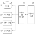
도 1은 본 발명의 일 실시예에 따른 차량의 주행모드 전환 제어 장치가 적용된 차량 시스템을 도시한 도면이다.1 is a diagram illustrating a vehicle system to which a driving mode switching control device of a vehicle according to an embodiment of the present invention is applied.
도 1에 도시된 바와 같이, 본 발명에 따른 차량 시스템은 주행모드 전환 제어 장치(100) 및 주행 제어 시스템(200)을 포함한다.As shown in FIG. 1 , the vehicle system according to the present invention includes a driving mode
주행모드 전환 제어 장치(100)는 차량 내에 구비된 지도 DB(10), 측위 시스템(20), 카메라 시스템(30) 및 센서 시스템(40) 등과 같이 차량 주변의 정보를 취득하는 시스템들로부터 데이터를 수집한다. The driving mode
여기서, 지도 DB(10)는 정밀 지도 및 센서 지도 등이 저장된다. 정밀 지도는 사전에 도로의 형상 및 지형 정보를 이용하여 구축한 것으로서, 정밀 측위를 통해 위치 정확도가 확보된 경우에 활용 가능하다. 또한, 정밀 지도는 고속도로 자율주행모드로 동작 시에 활용될 수 있다.Here, the map DB 10 stores precision maps and sensor maps. A precise map is constructed using road shape and topographical information in advance, and can be used when location accuracy is secured through precise positioning. In addition, the precise map can be utilized when operating in the highway autonomous driving mode.
측위 시스템(20)은 차량의 정밀 위치를 측위하는 시스템으로서, 차량의 위치 정확도를 향상시키는데 활용된다.The positioning system 20 is a system for positioning a precise position of a vehicle, and is used to improve positioning accuracy of the vehicle.
카메라 시스템(30)은 하나 이상의 카메라를 포함하며, 카메라에 의해 실시간으로 촬영되는 영상을 처리하여 차선, 차량 주변의 다른 차량 및/또는 장애물과 같은 특징물의 정보를 취득한다. 여기서, 카메라 시스템(30)에 의해 취득된 차선 정보는 차로추종 지원모드로 동작 시에 활용될 수 있다.The camera system 30 includes one or more cameras, and processes images captured by the cameras in real time to obtain information on features such as lanes, other vehicles around the vehicle, and/or obstacles. Here, the lane information acquired by the camera system 30 may be utilized when operating in the lane following assistance mode.
센서 시스템(40)은 라이다(LIDAR)와 같은 센서를 포함하며, 센서에 의해 차량 주변의 특징물에 대한 정보를 취득하고, 취득한 정보를 제공한다. 여기서, 라이다는 차량 주변에서 검출한 포인트 클라우드(point cloud) 데이터를 처리하여 전방의 장애물 및/또는 지형 지물에 대한 정보를 취득한다. 센서 시스템(40)에 의해 취득된 장애물 정보는 고속도로 주행지원모드로 동작 시에 활용될 수 있다.The sensor system 40 includes a sensor such as a LIDAR, obtains information about features around the vehicle by the sensor, and provides the acquired information. Here, LIDAR processes point cloud data detected around the vehicle to obtain information about obstacles and/or terrain features ahead. Obstacle information acquired by the sensor system 40 may be utilized when operating in the highway driving support mode.
물론, 센서 시스템(40)은 라이다 외에도 차량 주변에 위치한 특징물을 검출하는 센서가 더 포함될 수 있다.Of course, the sensor system 40 may further include a sensor for detecting a feature located around the vehicle in addition to the LIDAR.
또한, 주행모드 전환 제어 장치(100)는 수집된 데이터들을 분석하여 각 데이터의 신뢰도를 판단한다. 이때, 주행모드 전환 제어 장치(100)는 각 데이터의 신뢰도 판단 결과에 기초하여 차량의 주행 전략을 설계하고 주행 전략에 따른 주행모드 전환 데이터를 생성하여 주행 제어 시스템(200)으로 제공한다.In addition, the driving mode
따라서, 주행 제어 시스템(200)은 주행모드 전환 제어 장치(100)로부터 제공된 모드 전환 데이터에 기초하여 차량의 주행모드를 전환한다.Accordingly, the
본 발명에 따른 주행모드 전환 제어 장치(100)는 차량의 내부에 구현될 수 있다. 이때, 주행모드 전환 제어 장치(100)는 차량의 내부 제어 유닛들과 일체로 형성될 수 있으며, 별도의 장치로 구현되어 별도의 연결 수단에 의해 차량의 제어 유닛들과 연결될 수도 있다. The driving mode
도 2는 본 발명의 일 실시예에 따른 차량의 주행모드 전환 제어 장치의 구성을 도시한 도면이다.2 is a diagram showing the configuration of a driving mode switching control device for a vehicle according to an embodiment of the present invention.
도 2를 참조하면, 주행모드 전환 제어 장치(100)는 제어부(110), 통신부(120), 저장부(130), 데이터 수집부(140), 데이터 전처리부(150), 신뢰도 판단부(160) 및 모드 전환 제어부(170)를 포함할 수 있다. 여기서, 본 실시예에 따른 주행모드 전환 제어 장치(100)의 제어부(110), 데이터 수집부(140), 데이터 전처리부(150), 신뢰도 판단부(160) 및 모드 전환 제어부(170)는 적어도 하나 이상의 프로세서(processor)로서 구현될 수 있다.Referring to FIG. 2 , the driving mode
제어부(110)는 주행모드 전환 제어 장치(100)의 각 구성요소들 간에 전달되는 신호를 처리할 수 있다.The
통신부(120)는 차량에 구비된 전장품 및/또는 제어유닛들과의 통신 인터페이스를 지원하는 통신모듈을 포함할 수 있다. 일 예로서, 통신모듈은 차량에 구비된 지도 DB(10), 측위 시스템(20), 카메라 시스템(30) 및 센서 시스템(40) 등과 통신 연결되어, 각 시스템들에 의해 취득된 데이터를 수신할 수 있다. 또한, 통신모듈은 차량에 구비된 주행 제어 시스템(200)과 통신 연결되어 모드 전환 데이터를 주행 제어 시스템(200)으로 송신할 수 있다.The
여기서, 통신모듈은 CAN(Controller Area Network) 통신, LIN(Local Interconnect Network) 통신, 플렉스레이(Flex-Ray) 통신 등의 차량 네트워크 통신을 지원하는 모듈을 포함할 수 있다. Here, the communication module may include a module supporting vehicle network communication such as CAN (Controller Area Network) communication, LIN (Local Interconnect Network) communication, and Flex-Ray communication.
또한, 통신모듈은 무선 인터넷 접속을 위한 모듈 또는 근거리 통신(Short Range Communication)을 위한 모듈을 포함할 수도 있다. 여기서, 무선 인터넷 기술로는 무선랜(Wireless LAN, WLAN), 와이브로(Wireless Broadband, Wibro), 와이파이(Wi-Fi), 와이맥스(World Interoperability for Microwave Access, Wimax) 등이 포함될 수 있으며, 근거리 통신 기술로는 블루투스(Bluetooth), 지그비(ZigBee), UWB(Ultra Wideband), RFID(Radio Frequency Identification), 적외선통신(Infrared Data Association, IrDA) 등이 포함될 수 있다.Also, the communication module may include a module for wireless Internet access or a module for short range communication. Here, the wireless Internet technology may include wireless LAN (WLAN), wireless broadband (Wibro), Wi-Fi, WiMAX (World Interoperability for Microwave Access, Wimax), etc., and short-range communication technology Examples may include Bluetooth, ZigBee, Ultra Wideband (UWB), Radio Frequency Identification (RFID), Infrared Data Association (IrDA), and the like.
저장부(130)는 주행모드 전환 제어 장치(100)가 동작하는데 필요한 데이터 및/또는 알고리즘 등을 저장할 수 있다. The
저장부(130)는 데이터 수집부(140)에 의해 지도 DB(10), 측위 시스템(20), 카메라 시스템(30) 및 센서 시스템(40) 등으로부터 수집된 데이터가 저장될 수 있다. 또한, 저장부(130)는 주행모드 전환 제어 장치(100)가 수집된 데이터들의 신뢰도를 판단하기 위한 조건 정보가 저장될 수 있으며, 수집된 데이터들의 신뢰도를 판단하고, 신뢰도를 기반으로 주행 전략을 설계하고, 주행 전략에 따라 모드 전환 데이터를 생성하기 위한 명령 및/또는 알고리즘이 저장될 수 있다.The
여기서, 저장부(130)는 램(Random Access Memory, RAM), SRAM(Static Random Access Memory), 롬(Read-Only Memory, ROM), PROM(Programmable Read-Only Memory), EEPROM(Electrically Erasable Programmable Read-Only Memory)와 같은 저장매체를 포함할 수 있다.Here, the
데이터 수집부(140)는 통신부(120)와 연결된 지도 DB(10), 측위 시스템(20), 카메라 시스템(30) 및 센서 시스템(40) 등으로 데이터를 요청하고, 지도 DB(10), 측위 시스템(20), 카메라 시스템(30) 및 센서 시스템(40) 등으로부터 취득된 데이터를 수집한다.The
일 예로서, 데이터 수집부(140)는 지도 DB(10)로부터 정밀 지도 및 센서 지도 등의 지도 데이터를 수집할 수 있다. 또한, 데이터 수집부(140)는 측위 시스템(20)으로부터 측위 데이터를 수집할 수 있다. 또한, 데이터 수집부(140)는 카메라 시스템(30)으로부터 차선 데이터를 수집할 수 있다. 또한, 데이터 수집부(140)는 센서 시스템(40)으로부터 라이다 등의 센서들에 의해 취득된 장애물 데이터를 수집할 수 있다.As an example, the
데이터 수집부(140)에 의해 수집된 데이터들은 저장부에 저장될 수 있으며, 제어부를 통해 데이터 전처리부(150)로 전달될 수 있다. 이에, 데이터 전처리부(150)는 데이터 수집부(140)에 의해 수집된 데이터들을 전처리하여 신뢰도 판단부(160)로 전달한다.Data collected by the
신뢰도 판단부(160)는 데이터 전처리부(150)에 의해 전처리된 데이터들, 즉, 지도 DB(10)로부터의 지도 데이터, 측위 시스템(20)으로부터의 측위 데이터, 카메라 시스템(30)으로부터의 차선 데이터 및 센서 시스템(40)으로부터의 장애물 데이터를 분석하여 각 데이터의 신뢰도를 판단한다.The
먼저, 신뢰도 판단부(160)는 도 3a에 도시된 바와 같이, 센서 데이터 및 지도 데이터의 오차량(311), 오차 누적 지속 시간(313) 및 지역정보(315)를 분석하고, 분석 결과에 기초하여 정밀 지도 및 센서 지도에 대한 신뢰도를 판단한다.First, as shown in FIG. 3A, the
여기서, 신뢰도 판단부(160)는 센서 데이터 및 지도 데이터의 오차량(311)이 클수록, 오차 누적 지속 시간(313)이 길수록 정밀 지도 및 센서 지도의 신뢰도가 낮은 것으로 판단할 수 있다. 또한, 신뢰도 판단부(160)는 사전에 각 지역의 맵 매칭 정도를 수치화하여 레벨을 부여하고, 입력된 지역 정보에 대응하는 맵 매칭 레벨이 낮은 경우 정밀 지도 및 센서 지도의 신뢰도가 낮은 것으로 판단할 수 있다.Here, the
이와 같은 방식으로, 신뢰도 판단부(160)는 정밀 지도 및 센서 지도의 신뢰도를 결정하고, 결정된 신뢰도가 기준치 이상이면 신뢰도를 확보한 것으로 판단하고 그렇지 않으면 미달인 것으로 판단한다.In this way, the
또한, 신뢰도 판단부(160)는 도 3b에 도시된 바와 같이, 트래킹(Tracking) 로직 내부의 오차 공분산 크기 변화량(321), 센서 데이터의 업데이트 주기(323), 추정치 및 센서 데이터의 오차 누적량(325)을 분석하고, 분석 결과에 기초하여 측위 데이터의 신뢰도를 판단한다.In addition, as shown in FIG. 3B, the
여기서, 신뢰도 판단부(160)는 트래킹 로직 내부의 오차 공분산 크기 변화량(321)이 클수록, 센서 신호 업데이트 주기(323)가 길수록, 그리고 추정치 및 센서 데이터의 오차 누적량(325)이 클수록 측위 데이터의 신뢰도가 낮은 것으로 판단할 수 있다. Here, the
이와 같은 방식으로, 신뢰도 판단부(160)는 측위 데이터의 신뢰도를 결정하고, 결정된 신뢰도가 기준치 이상이면 신뢰도를 확보한 것으로 판단하고 그렇지 않으면 미달인 것으로 판단한다.In this way, the
또한, 신뢰도 판단부(160)는 도 3c에 도시된 바와 같이, 차선 정보의 신뢰도 레벨(331) 및 동일 차로의 전방차량 이동경로 및 자차량 이동경로 간 오차(333)를 분석하고, 분석 결과에 기초하여 차선 데이터의 신뢰도를 판단한다.In addition, as shown in FIG. 3C, the
여기서, 신뢰도 판단부(160)는 차선 정보의 신뢰도 레벨(331)이 낮을수록, 전방차량 이동경로 및 자차량 이동경로 간 오차(333)가 클수록 차선 데이터의 신뢰도가 낮은 것으로 판단할 수 있다.Here, the
이와 같은 방식으로, 신뢰도 판단부(160)는 차선 데이터의 신뢰도를 결정하고, 결정된 신뢰도가 기준치 이상이면 신뢰도를 확보한 것으로 판단하고 그렇지 않으면 미달인 것으로 판단한다.In this way, the
또한, 신뢰도 판단부(160)는 도 3d에 도시된 바와 같이, 센서 시스템(40)의 각 센서들의 감지 중복영역의 장애물 출력정보에 대한 오차량(341) 및 날씨 정보(343)에 기초하여 장애물 데이터의 신뢰도를 판단한다.Also, as shown in FIG. 3D , the
여기서, 신뢰도 판단부(160)는 라이다와 다른 센서 간 감지 중복영역의 장애물 출력정보에 대한 오차량(341)이 클수록 장애물 데이터의 신뢰도가 낮은 것으로 판단할 수 있다. 또한, 신뢰도 판단부(160)는 사전에 날씨 정도를 수치화하여 레벨을 부여하고, 입력된 날씨 정보에 대응하는 레벨이 낮은 경우 장애물 데이터의 신뢰도가 낮은 것으로 판단할 수 있다.Here, the
이와 같은 방식으로, 신뢰도 판단부(160)는 장애물 데이터의 신뢰도를 결정하고, 결정된 신뢰도가 기준치 이상이면 신뢰도를 확보한 것으로 판단하고 그렇지 않으면 미달인 것으로 판단한다.In this way, the
신뢰도 판단부(160)는 각 데이터들의 신뢰도 판단 결과를 모드 전환 제어부(170)로 전달한다.The
이에, 모드 전환 제어부(170)는 각 데이터들의 신뢰도 판단 결과에 기초하여 주행 전략을 설계하고, 설계된 주행 전략에 따라 모드 전환 데이터를 생성한다. Accordingly, the mode
주행모드 전환 제어 장치(100)의 주행 전략의 설계 동작에 대한 실시예는 도 4를 참조하도록 한다.An embodiment of the design operation of the driving strategy of the driving mode
도 4를 참조하면, 본 발명의 일 실시예에 따른 주행 전략은 운전자 주행모드(401), 고속도로 자율주행모드(403), 차로추종 지원모드(405) 및 고속도로 주행지원모드(407) 간 모드 전환을 위한 전략인 것으로 가정하여 설명한다.Referring to FIG. 4 , the driving strategy according to an embodiment of the present invention is mode switching among
모드 전환 제어부(170)는 신뢰도 판단부(160)로부터 제공된 지도 데이터, 측위 데이터, 차선 데이터 및 장애물 데이터의 신뢰도에 기초하여 고속도로 자율주행모드(403), 차로추종 지원모드(405), 고속도로 주행지원모드(407) 및 운전자 주행모드(401) 간 모드 전환 전략을 설계할 수 있다.The mode
여기서, 고속도로 자율주행모드(403)는 고속도로, 자동차 전용도로의 본선, IC/JC/TG 전구간에서 동작하는 모드로, 차간거리 및 차로유지 제어 기능, 차로 변경 기능, 회피 기능 및 내비게이션에 설정된 경로에 의한 IC/JC/TG의 자동 진출입 판단 및 제어 기능 등을 수행한다. 이때, 고속도로 자율주행모드(403)는 정밀 지도 및 측위 데이터를 활용하여 동작할 수 있다.Here, the highway self-driving
따라서, 모드 전환 제어부(170)는 운전자 주행모드(401) 또는 고속도로 주행지원모드(407)에서 측위 데이터 및 정밀 지도의 신뢰도를 확보한 것으로 확인되면, 도면부호 411 또는 도면부호 441과 같이 차량의 주행모드를 고속도로 자율주행모드(403)로 전환하는 주행 전략을 설계할 수 있다.Therefore, when it is confirmed that the reliability of the positioning data and the precise map is secured in the
한편, 모드 전환 제어부(170)는 고속도로 자율주행모드(403)에서 측위 데이터 또는 정밀 지도의 신뢰도가 미달된 것으로 확인되면, 도면부호 445와 같이 차량의 주행모드를 고속도로 주행지원모드(407)로 전환하는 주행 전략을 설계할 수 있다.On the other hand, if it is confirmed that the reliability of the positioning data or the precision map is insufficient in the highway
또한, 모드 전환 제어부(170)는 고속도로 자율주행모드(403)에서 지도 데이터, 측위 데이터, 차선 데이터 및 장애물 데이터의 신뢰도가 모두 미달된 것으로 확인되면, 도면부호 415와 같이 차량의 주행모드를 운전자 주행모드(401)로 전환하는 주행 전략을 설계할 수 있다.In addition, if it is confirmed that the reliability of map data, positioning data, lane data, and obstacle data are all insufficient in the highway
고속도로 주행지원모드(407)는 고속도로, 자동차전용도로 본선 및 IC/JC 구간에서 동작하는 모드로, 차간거리 및 차로유지 제어 기능, 차로 변경 기능, 회피 기능, 설정속도 자동변경 기능 및 과속단속구간 감속제어 기능 등을 수행한다. 이때, 고속도로 주행지원모드(407)는 센서 지도 및 장애물 데이터를 활용하여 동작할 수 있다.Highway driving support mode (407) is a mode that operates on highways, car-only roads and IC/JC sections, and provides inter-vehicle distance and lane maintenance control functions, lane change functions, avoidance functions, automatic setting speed change functions, and deceleration in overspeed enforcement sections. control functions, etc. At this time, the highway driving
따라서, 모드 전환 제어부(170)는 운전자 주행모드(401) 또는 차로추종 지원모드(405)에서 센서 지도 및 장애물 데이터의 신뢰도를 확보한 것으로 확인되면, 도면부호 431 또는 도면부호 451과 같이 차량의 주행모드를 고속도로 주행지원모드(407)로 전환하는 주행 전략을 설계할 수 있다. 앞서 언급한 바와 같이, 모드 전환 제어부(170)는 고속도로 자율주행모드(403)에서 측위 데이터 또는 정밀 지도의 신뢰도가 미달된 것으로 확인된 경우에도 도면부호 445와 같이 차량의 주행모드를 고속도로 주행지원모드(407)로 전환하는 주행 전략을 설계할 수 있다.Accordingly, the mode
한편, 모드 전환 제어부(170)는 고속도로 주행지원모드(407)에서 센서 지도 또는 장애물 데이터의 신뢰도가 미달된 것으로 확인되면, 도면부호 455와 같이 차량의 주행모드를 차로추종 지원모드(405)로 전환하는 주행 전략을 설계할 수 있다.Meanwhile, if it is determined that the reliability of the sensor map or obstacle data is insufficient in the highway driving
또한, 모드 전환 제어부(170)는 고속도로 주행지원모드(407)에서 지도 데이터, 측위 데이터, 차선 데이터 및 장애물 데이터의 신뢰도가 모두 미달된 것으로 확인되면, 도면부호 435와 같이 차량의 주행모드를 운전자 주행모드(401)로 전환하는 주행 전략을 설계할 수 있다.In addition, if it is confirmed that the reliability of the map data, positioning data, lane data, and obstacle data are all insufficient in the highway driving
차로추종 지원모드(405)는 고속도로 및 자동차전용도로 본선 구간에서 동작하는 모드로, 차간거리 및 차로유지 제어 기능 등을 수행한다. 이때, 차선추종 지원모드는 차선 데이터를 활용하여 동작할 수 있다.The lane-following
따라서, 모드 전환 제어부(170)는 운전자 주행모드(401)에서 차선 데이터의 신뢰도를 확보한 것으로 확인되면, 도면부호 421과 같이 차량의 주행모드를 차선추종 지원모드로 전환하는 주행 전략을 설계할 수 있다. 앞서 언급한 바와 같이, 모드 전환 제어부(170)는 고속도로 주행지원모드(407)에서 센서 지도 또는 장애물 데이터의 신뢰도가 미달된 것으로 확인된 경우에도 도면부호 455와 같이 차량의 주행모드를 차선추종 지원모드로 전환하는 주행 전략을 설계할 수 있다.Accordingly, when it is confirmed that the reliability of the lane data is secured in the
한편, 모드 전환 제어부(170)는 차선추종 지원모드에서 차선 데이터의 신뢰도가 미달되거나 혹은 지도 데이터, 측위 데이터, 차선 데이터 및 장애물 데이터의 신뢰도가 모두 미달된 것으로 확인되면, 도면부호 425와 같이 차량의 주행모드를 운전자 주행모드(401)로 전환하는 주행 전략을 설계할 수 있다.Meanwhile, the mode
만일, 지도 데이터, 측위 데이터, 차선 데이터 및 장애물 데이터의 신뢰도가 모두 확보된 것으로 확인되면, 모드 전환 제어부(170)는 차량의 주행모드를 고속도로 자율주행모드(403)로 전환하는 주행 전략을 설계할 수 있다.If it is confirmed that the reliability of the map data, positioning data, lane data, and obstacle data are all secured, the mode
상기와 같은 방식으로, 모드 전환 제어부(170)는 차량의 주행모드 전환을 위한 주행 전략이 설계되면, 설계된 주행 전략을 포함하는 모드 전환 데이터를 생성한다. 이때, 모드 전환 제어부(170)는 생성된 모드 전환 데이터를 통신부를 통해 차량 내 주행 제어 시스템(200)으로 송신한다.In the above manner, when a driving strategy for switching the driving mode of the vehicle is designed, the mode
따라서, 주행 제어 시스템(200)은 모드 전환 데이터에 포함된 주행 전략에 따라 차량의 주행모드를 전환할 수 있다.Accordingly, the driving
상기에서와 같이 동작하는 본 실시예에 따른 주행모드 전환 제어 장치(100)는 메모리와 각 동작을 처리하는 프로세서를 포함하는 독립적인 하드웨어 장치 형태로 구현될 수 있으며, 마이크로프로세서나 범용 컴퓨터 시스템과 같은 다른 하드웨어 장치에 포함된 형태로 구동될 수 있다.The driving mode
상기와 같이 구성되는 본 발명에 따른 차량의 주행모드 전환 제어 장치의 동작 흐름을 보다 상세히 설명하면 다음과 같다.The operation flow of the driving mode switching control device for a vehicle according to the present invention configured as described above will be described in more detail.
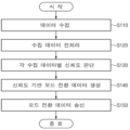
도 5는 본 발명의 일 실시예에 따른 차량의 주행모드 전환 제어 방법에 대한 동작 흐름을 도시한 도면이다.FIG. 5 is a diagram illustrating an operational flow of a method for controlling switching of a driving mode of a vehicle according to an embodiment of the present invention.
도 5를 참조하면, 주행모드 전환 제어 장치(100)는 차량 내 지도 DB(10), 측위 시스템(20), 카메라 시스템(30) 및 센서 시스템(40) 등과 같이 차량 주변의 정보를 취득하는 시스템들로부터 데이터를 수집한다(S110). 'S110' 과정에서, 주행모드 전환 제어 장치(100)는 지도 DB(10)로부터 정밀 지도 및 센서 지도 등의 지도 데이터, 측위 시스템(20)으로부터 측위 데이터, 카메라 시스템(30)으로부터 차선 데이터, 그리고 센서 시스템(40)으로부터 장애물 데이터를 수집할 수 있다.Referring to FIG. 5 , the driving mode
주행모드 전환 제어 장치(100)는 'S110' 과정에서 수집된 데이터들을 전처리하고(S120), 전처리 된 데이터들을 분석하여 각 데이터 별로 신뢰도를 판단한다(S130).The driving mode
이후, 주행모드 전환 제어 장치(100)는 'S130' 과정의 신뢰도 판단 결과를 기반으로 모드 전환을 위한 주행 전략을 설계하고 설계된 주행 전략을 포함하는 모드 전환 데이터를 생성하여(S140), 차량 내 주행 제어 시스템(200)으로 송신한다(S150).Thereafter, the driving mode
도 6은 본 발명의 일 실시예에 따른 방법이 실행되는 컴퓨팅 시스템을 도시한 도면이다.6 is a diagram illustrating a computing system on which a method according to an embodiment of the present invention is executed.
도 6을 참조하면, 컴퓨팅 시스템(1000)은 버스(1200)를 통해 연결되는 적어도 하나의 프로세서(1100), 메모리(1300), 사용자 인터페이스 입력 장치(1400), 사용자 인터페이스 출력 장치(1500), 스토리지(1600), 및 네트워크 인터페이스(1700)를 포함할 수 있다. Referring to FIG. 6 , a
프로세서(1100)는 중앙 처리 장치(CPU) 또는 메모리(1300) 및/또는 스토리지(1600)에 저장된 명령어들에 대해 처리를 실행하는 반도체 장치일 수 있다. 메모리(1300) 및 스토리지(1600)는 다양한 종류의 휘발성 또는 불휘발성 저장 매체를 포함할 수 있다. 예를 들어, 메모리(1300)는 ROM(Read Only Memory)(1310) 및 RAM(Random Access Memory)(1320)을 포함할 수 있다. The
따라서, 본 명세서에 개시된 실시예들과 관련하여 설명된 방법 또는 알고리즘의 단계는 프로세서(1100)에 의해 실행되는 하드웨어, 소프트웨어 모듈, 또는 그 2 개의 결합으로 직접 구현될 수 있다. 소프트웨어 모듈은 RAM 메모리, 플래시 메모리, ROM 메모리, EPROM 메모리, EEPROM 메모리, 레지스터, 하드 디스크, 착탈형 디스크, CD-ROM과 같은 저장 매체(즉, 메모리(1300) 및/또는 스토리지(1600))에 상주할 수도 있다. 예시적인 저장 매체는 프로세서(1100)에 커플링되며, 그 프로세서(1100)는 저장 매체로부터 정보를 판독할 수 있고 저장 매체에 정보를 기입할 수 있다. 다른 방법으로, 저장 매체는 프로세서(1100)와 일체형일 수도 있다. 프로세서 및 저장 매체는 주문형 집적회로(ASIC) 내에 상주할 수도 있다. ASIC는 사용자 단말기 내에 상주할 수도 있다. 다른 방법으로, 프로세서 및 저장 매체는 사용자 단말기 내에 개별 컴포넌트로서 상주할 수도 있다.Accordingly, the steps of a method or algorithm described in connection with the embodiments disclosed herein may be directly implemented as hardware executed by the
이상의 설명은 본 발명의 기술 사상을 예시적으로 설명한 것에 불과한 것으로서, 본 발명이 속하는 기술 분야에서 통상의 지식을 가진 자라면 본 발명의 본질적인 특성에서 벗어나지 않는 범위에서 다양한 수정 및 변형이 가능할 것이다. The above description is merely an example of the technical idea of the present invention, and various modifications and variations can be made to those skilled in the art without departing from the essential characteristics of the present invention.
따라서, 본 발명에 개시된 실시예들은 본 발명의 기술 사상을 한정하기 위한 것이 아니라 설명하기 위한 것이고, 이러한 실시예에 의하여 본 발명의 기술 사상의 범위가 한정되는 것은 아니다. 본 발명의 보호 범위는 아래의 청구범위에 의하여 해석되어야 하며, 그와 동등한 범위 내에 있는 모든 기술 사상은 본 발명의 권리범위에 포함되는 것으로 해석되어야 할 것이다.Therefore, the embodiments disclosed in the present invention are not intended to limit the technical idea of the present invention, but to explain, and the scope of the technical idea of the present invention is not limited by these embodiments. The protection scope of the present invention should be construed according to the claims below, and all technical ideas within the equivalent range should be construed as being included in the scope of the present invention.
10: 지도 DB 20: 측위 시스템
30: 카메라 시스템 40: 센서 시스템
100: 주행모드 전환 제어 장치 110: 제어부
120: 통신부 130: 저장부
140: 데이터 수집부 150: 데이터 전처리부
160: 신뢰도 판단부 170: 모드 전환 제어부
200: 주행 제어 시스템10: map DB 20: positioning system
30: camera system 40: sensor system
100: drive mode switching control device 110: control unit
120: communication unit 130: storage unit
140: data collection unit 150: data pre-processing unit
160: reliability determination unit 170: mode conversion control unit
200: driving control system
Claims (20)
상기 수집된 데이터들을 분석하여 각 데이터의 신뢰도를 판단하는 신뢰도 판단부; 및
상기 각 데이터의 신뢰도 판단 결과에 기초하여 차량의 주행모드를 고속도로 자율주행모드, 고속도로 주행지원모드, 차로추종 지원모드, 또는 운전자 주행모드 중 하나로 전환하도록 하는 모드 전환 데이터를 생성하는 모드 전환 제어부
를 포함하고,
상기 고속도로 자율주행모드는 고속도로, 자동차 전용도로의 본선, 또는 IC/JC/TG 전구간에서 상기 정밀 지도 및 상기 측위 데이터를 통해 동작하는 모드를 포함하고,
상기 고속도로 주행지원모드는, 상기 고속도로, 상기 자동차 전용도로의 본선, 또는 상기 IC/JC 구간에서 상기 센서 지도 및 상기 장애물 데이터를 통해 동작하는 모드를 포함하고,
상기 차로추종 지원모드는, 상기 고속도로 및 상기 자동차 전용도로 본선 구간에서 상기 차선 데이터를 통해 동작하는 모드를 포함하는 것을 특징으로 하는 차량의 주행모드 전환 제어 장치.
A data collection unit that collects data including map data including precise maps and sensor maps, positioning data, lane data, and obstacle data from an in-vehicle map DB, positioning system, camera system, and sensor system;
a reliability determination unit analyzing the collected data and determining reliability of each data; and
Mode switching control unit for generating mode switching data for switching the driving mode of the vehicle to one of highway autonomous driving mode, highway driving assistance mode, lane following assistance mode, and driver driving mode based on the reliability determination result of each data.
including,
The highway autonomous driving mode includes a mode operating through the precise map and the positioning data on a highway, a main line of an automobile road, or an entire IC / JC / TG section,
The highway driving support mode includes a mode operating through the sensor map and the obstacle data in the highway, the main line of the automobile road, or the IC / JC section,
The driving mode switching control device of a vehicle, characterized in that, the lane following support mode includes a mode operating through the lane data in the main road section of the highway and the automobile-only road.
상기 신뢰도 판단부는,
센서 데이터 및 상기 지도 데이터의 오차량, 오차 누적 지속 시간 및 지역정보를 분석하고 상기 분석 결과에 기초하여 상기 정밀 지도 및 상기 센서 지도에 대한 신뢰도를 판단하는 것을 특징으로 하는 차량의 주행모드 전환 제어 장치.The method of claim 1,
The reliability determination unit,
A driving mode switching control device for a vehicle, characterized in that for analyzing sensor data and the error amount of the map data, accumulated error duration, and local information, and determining reliability of the precise map and the sensor map based on the analysis result. .
상기 신뢰도 판단부는,
트래킹(Tracking) 로직 내부의 오차 공분산 크기 변화량, 센서 데이터의 업데이트 주기, 추정치 및 센서 데이터의 오차 누적량을 분석하고 상기 분석 결과에 기초하여 상기 측위 데이터의 신뢰도를 판단하는 것을 특징으로 하는 차량의 주행모드 전환 제어 장치.The method of claim 1,
The reliability determination unit,
A driving mode of a vehicle characterized in that a change in the size of the error covariance in a tracking logic, an update cycle of sensor data, an estimation value, and an error accumulation amount of sensor data are analyzed, and reliability of the positioning data is determined based on the analysis result. conversion control device.
상기 신뢰도 판단부는,
차선 정보의 신뢰도 레벨 및 동일 차로의 전방차량 이동경로 및 자차량 이동경로 간 오차를 분석하고 상기 분석 결과에 기초하여 상기 차선 데이터의 신뢰도를 판단하는 것을 특징으로 하는 차량의 주행모드 전환 제어 장치.The method of claim 1,
The reliability determination unit,
A driving mode switching control device for a vehicle, characterized in that it analyzes the reliability level of the lane information and the error between the movement path of the preceding vehicle and the movement path of the host vehicle in the same lane, and determines the reliability of the lane data based on the analysis result.
상기 신뢰도 판단부는,
상기 센서 시스템의 각 센서들의 감지 중복영역의 장애물 출력정보에 대한 오차량 및 날씨 정보에 기초하여 상기 장애물 데이터의 신뢰도를 판단하는 것을 특징으로 하는 차량의 주행모드 전환 제어 장치.
The method of claim 1,
The reliability determination unit,
The driving mode switching control device of the vehicle, characterized in that the reliability of the obstacle data is determined based on the error amount and weather information for the obstacle output information of the detection overlapping area of each sensor of the sensor system.
상기 모드 전환 제어부는,
상기 각 데이터의 신뢰도가 모두 기준치 이상이면 상기 차량의 주행모드를 상기 고속도로 자율주행모드로 전환하는 상기 모드 전환 데이터를 생성하는 것을 특징으로 하는 차량의 주행모드 전환 제어 장치.The method of claim 1,
The mode switching control unit,
and generating the mode switching data for switching the driving mode of the vehicle to the highway autonomous driving mode when the reliability of each data is equal to or higher than a reference value.
상기 모드 전환 제어부는,
상기 각 데이터의 신뢰도가 모두 기준치 미만이면 상기 차량의 주행모드를 상기 운전자 주행모드로 전환하는 상기 모드 전환 데이터를 생성하는 것을 특징으로 하는 차량의 주행모드 전환 제어 장치.The method of claim 1,
The mode switching control unit,
and generating the mode switching data for switching the driving mode of the vehicle to the driver driving mode when the reliability of each data is less than a reference value.
상기 수집된 데이터들을 전처리하는 데이터 전처리부를 더 포함하는 것을 특징으로 하는 차량의 주행모드 전환 제어 장치.The method of claim 1,
The driving mode switching control device for a vehicle, characterized in that it further comprises a data pre-processing unit for pre-processing the collected data.
상기 수집된 데이터들을 분석하여 각 데이터의 신뢰도를 판단하는 단계; 및
상기 각 데이터의 신뢰도 판단 결과에 기초하여 차량의 주행모드를 고속도로 자율주행모드, 고속도로 주행지원모드, 차로추종 지원모드, 또는 운전자 주행모드 중 하나로 전환하도록 하는 모드 전환 데이터를 생성하는 단계; 를 포함하고,
TG 전구간에서 상기 정밀 지도 및 상기 측위 데이터를 통해 동작하는 모드를 포함하고,
상기 고속도로 주행지원모드는, 상기 고속도로, 상기 자동차 전용도로의 본선, 또는 상기 IC/JC 구간에서 상기 센서 지도 및 상기 장애물 데이터를 통해 동작하는 모드를 포함하고,
상기 차로추종 지원모드는, 상기 고속도로 및 상기 자동차 전용도로 본선 구간에서 상기 차선 데이터를 통해 동작하는 모드를 포함하는 것을 특징으로 하는 차량의 주행모드 전환 제어 방법.
Collecting data including map data including precise maps and sensor maps, positioning data, lane data, and obstacle data from an in-vehicle map DB, positioning system, camera system, and sensor system;
analyzing the collected data to determine reliability of each data; and
generating mode switching data for switching the driving mode of the vehicle to one of a highway autonomous driving mode, a highway driving assistance mode, a lane following assistance mode, and a driver driving mode, based on a reliability determination result of each data; including,
Including a mode operating through the precise map and the positioning data in the entire TG section,
The highway driving support mode includes a mode operating through the sensor map and the obstacle data in the highway, the main line of the automobile road, or the IC / JC section,
The driving mode switching control method of a vehicle, characterized in that the lane following support mode includes a mode operating through the lane data in the main road section of the highway and the automobile-only road.
상기 신뢰도를 판단하는 단계는,
센서 데이터 및 상기 지도 데이터의 오차량, 오차 누적 지속 시간 및 지역정보를 분석하고 상기 분석 결과에 기초하여 상기 정밀 지도 및 상기 센서 지도에 대한 신뢰도를 판단하는 단계를 포함하는 것을 특징으로 하는 차량의 주행모드 전환 제어 방법.The method of claim 11,
The step of determining the reliability is,
and analyzing sensor data and an error amount of the map data, accumulated error duration, and local information, and determining reliability of the precise map and the sensor map based on the analysis result. Mode switching control method.
상기 신뢰도를 판단하는 단계는,
트래킹(Tracking) 로직 내부의 오차 공분산 크기 변화량, 센서 데이터의 업데이트 주기, 추정치 및 센서 데이터의 오차 누적량을 분석하고 상기 분석 결과에 기초하여 상기 측위 데이터의 신뢰도를 판단하는 단계를 포함하는 것을 특징으로 하는 차량의 주행모드 전환 제어 방법.The method of claim 11,
The step of determining the reliability is,
Analyzing the amount of change in the size of the error covariance in the tracking logic, the update period of the sensor data, the estimated value, and the amount of error accumulation of the sensor data, and determining the reliability of the positioning data based on the analysis result. A method for controlling the switching of driving modes of a vehicle.
상기 신뢰도를 판단하는 단계는,
차선 정보의 신뢰도 레벨 및 동일 차로의 전방차량 이동경로 및 자차량 이동경로 간 오차를 분석하고 상기 분석 결과에 기초하여 상기 차선 데이터의 신뢰도를 판단하는 단계를 포함하는 것을 특징으로 하는 차량의 주행모드 전환 제어 방법.The method of claim 11,
The step of determining the reliability is,
and analyzing a reliability level of the lane information and an error between a movement path of the preceding vehicle and the movement path of the host vehicle in the same lane, and determining reliability of the lane data based on the analysis result. control method.
상기 신뢰도를 판단하는 단계는,
상기 센서 시스템의 각 센서들의 감지 중복영역의 장애물 출력정보에 대한 오차량 및 날씨 정보에 기초하여 상기 장애물 데이터의 신뢰도를 판단하는 단계를 포함하는 것을 특징으로 하는 차량의 주행모드 전환 제어 방법.
The method of claim 11,
The step of determining the reliability is,
and determining reliability of the obstacle data based on weather information and an error amount of obstacle output information of an overlapping detection area of each sensor of the sensor system.
상기 모드 전환 데이터를 생성하는 단계는,
상기 각 데이터의 신뢰도가 모두 기준치 이상이면 상기 차량의 주행모드를 고속도로 자율주행모드로 전환하는 상기 모드 전환 데이터를 생성하는 단계를 포함하는 것을 특징으로 하는 차량의 주행모드 전환 제어 방법.The method of claim 11,
The step of generating the mode change data,
and generating the mode switching data for switching the driving mode of the vehicle to the highway autonomous driving mode when the reliability of each data is equal to or higher than a reference value.
상기 모드 전환 데이터를 생성하는 단계는,
상기 각 데이터의 신뢰도가 모두 기준치 미만이면 상기 차량의 주행모드를 상기 운전자 주행모드로 전환하는 상기 모드 전환 데이터를 생성하는 단계를 포함하는 것을 특징으로 하는 차량의 주행모드 전환 제어 방법.The method of claim 11,
The step of generating the mode change data,
and generating the mode switching data for switching the driving mode of the vehicle to the driver driving mode when the reliability of each data is less than a reference value.
상기 주행모드 전환 제어 장치로부터 제공된 상기 모드 전환 데이터에 기초하여 상기 차량의 주행모드를 전환하는 주행 제어 시스템; 을 포함하고,
상기 고속도로 자율주행모드는 고속도로, 자동차 전용도로의 본선, 또는 IC/JC/TG 전구간에서 상기 정밀 지도 및 상기 측위 데이터를 통해 동작하는 모드를 포함하고,
상기 고속도로 주행지원모드는, 상기 고속도로, 상기 자동차 전용도로의 본선, 또는 상기 IC/JC 구간에서 상기 센서 지도 및 상기 장애물 데이터를 통해 동작하는 모드를 포함하고,
상기 차로추종 지원모드는, 상기 고속도로 및 상기 자동차 전용도로 본선 구간에서 상기 차선 데이터를 통해 동작하는 모드를 포함하는 것을 특징으로 하는 차량 시스템.
Map data, positioning data, lane data, and obstacle data are collected from the in-vehicle map DB, positioning system, camera system, and sensor system, and each collected data is analyzed to determine reliability for each data. a driving mode switching control device generating mode switching data for switching a driving mode of a vehicle to one of a highway autonomous driving mode, a highway driving assistance mode, a lane following assistance mode, and a driver driving mode; and
a driving control system that switches a driving mode of the vehicle based on the mode switching data provided from the driving mode switching control device; including,
The highway autonomous driving mode includes a mode operating through the precise map and the positioning data on a highway, a main line of an automobile road, or an entire IC / JC / TG section,
The highway driving support mode includes a mode operating through the sensor map and the obstacle data in the highway, the main line of the automobile road, or the IC / JC section,
The vehicle system of claim 1 , wherein the lane-following support mode includes a mode operating through the lane data in the main road section of the highway and the automobile-only road.
Priority Applications (4)
| Application Number | Priority Date | Filing Date | Title |
|---|---|---|---|
| KR1020180020341A KR102496654B1 (en) | 2018-02-21 | 2018-02-21 | Apparatus and method for controlling driving mode change of vehicle, vehicle system |
| US16/022,359 US20190258249A1 (en) | 2018-02-21 | 2018-06-28 | Apparatus and method for controlling driving mode switch of vehicle and vehicle system |
| CN201810737383.9A CN110174856B (en) | 2018-02-21 | 2018-07-06 | Vehicle driving mode switching control device and method, and vehicle system |
| DE102018116633.8A DE102018116633B4 (en) | 2018-02-21 | 2018-07-10 | Apparatus and method for controlling a driving mode change of a vehicle and vehicle system |
Applications Claiming Priority (1)
| Application Number | Priority Date | Filing Date | Title |
|---|---|---|---|
| KR1020180020341A KR102496654B1 (en) | 2018-02-21 | 2018-02-21 | Apparatus and method for controlling driving mode change of vehicle, vehicle system |
Publications (2)
| Publication Number | Publication Date |
|---|---|
| KR20190105160A KR20190105160A (en) | 2019-09-16 |
| KR102496654B1 true KR102496654B1 (en) | 2023-02-07 |
Family
ID=67482047
Family Applications (1)
| Application Number | Title | Priority Date | Filing Date |
|---|---|---|---|
| KR1020180020341A Active KR102496654B1 (en) | 2018-02-21 | 2018-02-21 | Apparatus and method for controlling driving mode change of vehicle, vehicle system |
Country Status (4)
| Country | Link |
|---|---|
| US (1) | US20190258249A1 (en) |
| KR (1) | KR102496654B1 (en) |
| CN (1) | CN110174856B (en) |
| DE (1) | DE102018116633B4 (en) |
Families Citing this family (18)
| Publication number | Priority date | Publication date | Assignee | Title |
|---|---|---|---|---|
| US11126197B2 (en) * | 2018-11-19 | 2021-09-21 | Waymo Llc | Verification of iterative closest point alignments for autonomous vehicles |
| KR102792003B1 (en) * | 2019-09-27 | 2025-04-09 | 현대모비스 주식회사 | Autonomous driving apparatus and method |
| KR102778760B1 (en) * | 2019-09-27 | 2025-03-12 | 현대모비스 주식회사 | Autonomous driving apparatus and method |
| CN113428168B (en) * | 2020-03-19 | 2022-11-15 | 上海擎感智能科技有限公司 | Control method, system and medium for automatically driving vehicle and automobile |
| JP7191065B2 (en) * | 2020-07-06 | 2022-12-16 | 本田技研工業株式会社 | Processing device, processing method, and program |
| JP7194224B2 (en) * | 2021-03-31 | 2022-12-21 | 本田技研工業株式会社 | VEHICLE CONTROL DEVICE, VEHICLE CONTROL METHOD, AND PROGRAM |
| JP7203884B2 (en) * | 2021-03-31 | 2023-01-13 | 本田技研工業株式会社 | VEHICLE CONTROL DEVICE, VEHICLE CONTROL METHOD, AND PROGRAM |
| CN113247014B (en) * | 2021-06-09 | 2021-11-09 | 智己汽车科技有限公司 | Confidence identification method and system for automatic driving system |
| CN113467412B (en) * | 2021-06-11 | 2023-03-14 | 重庆长安汽车股份有限公司 | System and method for vehicle driving mode integrated linkage |
| US20230115240A1 (en) * | 2021-10-13 | 2023-04-13 | Arriver Software Llc | Advanced driver-assistance systems feature activation control using digital map and on-board sensing to confirm safe vehicle operation |
| JP7632236B2 (en) * | 2021-11-04 | 2025-02-19 | トヨタ自動車株式会社 | Vehicle control system and vehicle control method |
| KR20230071555A (en) * | 2021-11-16 | 2023-05-23 | 현대자동차주식회사 | Apparatus for generating virtual traffic line and method thereof |
| CN114384900B (en) * | 2021-12-09 | 2023-12-12 | 武汉理工大学 | Autonomous ship navigation and driving methods, devices and storage media on inland water surfaces |
| JP7376634B2 (en) * | 2022-03-22 | 2023-11-08 | 本田技研工業株式会社 | Vehicle control device, vehicle control method, and program |
| US20230322259A1 (en) * | 2022-04-06 | 2023-10-12 | Qualcomm Incorporated | Inclusion And Use Of Safety and Confidence Information Associated With Objects In Autonomous Driving Maps |
| CN117549898B (en) * | 2022-08-03 | 2026-01-06 | 比亚迪股份有限公司 | Methods for switching terrain modes, in-vehicle systems and vehicles |
| DE102022125086A1 (en) * | 2022-09-29 | 2024-04-04 | Bayerische Motoren Werke Aktiengesellschaft | Method and device for blocking an automated driving function of a vehicle |
| CN116872750B (en) * | 2023-07-24 | 2025-09-30 | 奇瑞新能源汽车股份有限公司 | Driving mode switching method, driving mode switching system and vehicle |
Citations (2)
| Publication number | Priority date | Publication date | Assignee | Title |
|---|---|---|---|---|
| JP2015081083A (en) * | 2013-10-22 | 2015-04-27 | ホンダ リサーチ インスティテュート ヨーロッパ ゲーエムベーハーHonda Research Institute Europe GmbH | Reliability estimation based on validity rules for predictive driver assistance systems |
| US20190064799A1 (en) | 2017-08-22 | 2019-02-28 | Elmira Amirloo Abolfathi | System, method, and processor-readable medium for autonomous vehicle reliability assessment |
Family Cites Families (43)
| Publication number | Priority date | Publication date | Assignee | Title |
|---|---|---|---|---|
| JP2961966B2 (en) * | 1991-07-15 | 1999-10-12 | 松下電器産業株式会社 | Vehicle position and orientation calculation device |
| WO2002052225A2 (en) * | 2000-12-22 | 2002-07-04 | The Charles Stark Draper Laboratory, Inc. | Geographical navigation using multipath wireless navigation signals |
| DE10349631A1 (en) * | 2003-10-24 | 2005-05-19 | Robert Bosch Gmbh | Driver assistance method and apparatus based on lane information |
| DE102006004772B4 (en) * | 2006-02-02 | 2022-02-10 | Robert Bosch Gmbh | Driver assistance system and method for its control |
| US8996294B2 (en) * | 2007-12-19 | 2015-03-31 | Nissan Motor Co., Ltd. | Inter-vehicle distance maintenance supporting system and method |
| US9171079B2 (en) * | 2011-01-28 | 2015-10-27 | Cisco Technology, Inc. | Searching sensor data |
| CN102254430A (en) * | 2011-06-03 | 2011-11-23 | 东南大学 | Method for distinguishing accident-prone road section by using traffic conflicts |
| KR101703144B1 (en) * | 2012-02-09 | 2017-02-06 | 한국전자통신연구원 | Apparatus and method for autonomous driving |
| JP2014106854A (en) * | 2012-11-29 | 2014-06-09 | Toyota Infotechnology Center Co Ltd | Automatic driving vehicle control apparatus and method |
| US8825258B2 (en) * | 2012-11-30 | 2014-09-02 | Google Inc. | Engaging and disengaging for autonomous driving |
| US9633576B2 (en) * | 2012-12-13 | 2017-04-25 | Alliance Wireless Technologies, Inc. | Vehicle activity information system |
| DE102014201965A1 (en) * | 2013-02-06 | 2014-08-07 | Gm Global Technology Operations, Llc | Method for automatically controlling operation of vehicle, involves calculating reliability level of driving route, at least partly based on environment around vehicle, and displaying route representation or reliability level to driver |
| US8799036B1 (en) * | 2013-03-10 | 2014-08-05 | State Farm Mutual Automobile Insurance Company | Systems and methods for analyzing vehicle operation data to facilitate insurance policy processing |
| JP5842862B2 (en) * | 2013-05-14 | 2016-01-13 | 株式会社デンソー | Collision mitigation device |
| KR102058897B1 (en) * | 2013-11-12 | 2019-12-24 | 현대모비스 주식회사 | Apparatus and method for controlling automatic driving of vehicle |
| US9919717B2 (en) * | 2014-04-14 | 2018-03-20 | Mitsubishi Electric Corporation | Driving assistance device and driving assistance method |
| JP6172678B2 (en) * | 2014-04-30 | 2017-08-02 | インターナショナル・ビジネス・マシーンズ・コーポレーションInternational Business Machines Corporation | Detection apparatus, detection method, and program |
| EP3109115B1 (en) * | 2015-06-23 | 2018-01-31 | Volvo Car Corporation | Arrangement and method for facilitating handover to and from an automated autonomous driving aid system |
| US10082797B2 (en) * | 2015-09-16 | 2018-09-25 | Ford Global Technologies, Llc | Vehicle radar perception and localization |
| US20170080948A1 (en) * | 2015-09-18 | 2017-03-23 | Faraday&Future Inc. | Vehicle mode adjusting system |
| US9786192B2 (en) * | 2015-10-14 | 2017-10-10 | Toyota Motor Engineering & Manufacturing North America, Inc. | Assessing driver readiness for transition between operational modes of an autonomous vehicle |
| KR101786237B1 (en) * | 2015-12-09 | 2017-10-17 | 현대자동차주식회사 | Apparatus and method for processing failure detection and calibration of sensor in driver assist system |
| KR102113816B1 (en) * | 2016-01-05 | 2020-06-03 | 한국전자통신연구원 | System for autonomous driving service of vehicle, cloud server thereof and method thereof |
| JP6728558B2 (en) * | 2016-01-25 | 2020-07-22 | 日立オートモティブシステムズ株式会社 | Automatic operation control device and automatic operation control method |
| CN107179767B (en) * | 2016-03-10 | 2021-10-08 | 松下电器(美国)知识产权公司 | Driving control device, driving control method, and non-transitory recording medium |
| JP6508095B2 (en) * | 2016-03-11 | 2019-05-08 | トヨタ自動車株式会社 | Automatic operation control system of vehicle |
| US10829129B2 (en) * | 2016-04-18 | 2020-11-10 | Honda Motor Co., Ltd. | Vehicle control system, vehicle control method, and vehicle control program |
| CN105882627A (en) * | 2016-04-26 | 2016-08-24 | 百度在线网络技术(北京)有限公司 | Vehicle and vehicle control method and device |
| CN109074733A (en) * | 2016-04-28 | 2018-12-21 | 本田技研工业株式会社 | Vehicle control system, control method for vehicle and vehicle control program |
| CN105922995A (en) * | 2016-05-13 | 2016-09-07 | 乐视控股(北京)有限公司 | Switching method and device for vehicle driving patterns and vehicle |
| CN107499311B (en) * | 2016-06-14 | 2020-01-31 | 斑马网络技术有限公司 | Driving mode switching method, device and device |
| KR102006147B1 (en) | 2016-08-17 | 2019-08-02 | 기초과학연구원 | Wide range adjustable coupling coefficient rf coupler for coaxial line |
| CN106774291B (en) * | 2016-12-26 | 2020-07-31 | 清华大学苏州汽车研究院(吴江) | Electric control system for automatically driving electric automobile |
| CN107139917B (en) * | 2017-04-27 | 2019-05-31 | 江苏大学 | It is a kind of based on mixing theoretical pilotless automobile crosswise joint system and method |
| CN107225928B (en) * | 2017-05-03 | 2019-05-31 | 江苏大学 | A kind of active/passive suspension modes handover control system and method based on driving behavior |
| CN107200020B (en) * | 2017-05-11 | 2019-05-31 | 江苏大学 | It is a kind of based on mixing theoretical pilotless automobile self-steering control system and method |
| CN107241496A (en) * | 2017-05-26 | 2017-10-10 | 宇龙计算机通信科技(深圳)有限公司 | Mode switching method, mode-changeover device and mobile terminal |
| CN107221222B (en) * | 2017-07-03 | 2020-05-01 | 扬州大学 | Multi-mode driving simulation system for work efficiency evaluation and evaluation method thereof |
| KR102013590B1 (en) * | 2017-07-18 | 2019-08-23 | 엘지전자 주식회사 | Vehicle control device mounted on vehicle and method for controlling the vehicle |
| CN107564363B (en) * | 2017-09-05 | 2019-11-05 | 百度在线网络技术(北京)有限公司 | A kind of method and apparatus for driving mode switching |
| CN107672597A (en) * | 2017-09-25 | 2018-02-09 | 驭势科技(北京)有限公司 | A kind of method and apparatus for being used to control vehicle driving model |
| CN107697072A (en) * | 2017-09-25 | 2018-02-16 | 北京新能源汽车股份有限公司 | Driving mode switching method, vehicle and vehicle control unit |
| CN107650911A (en) * | 2017-09-27 | 2018-02-02 | 戴姆勒股份公司 | A kind of intelligent driving control system and method for vehicle |
-
2018
- 2018-02-21 KR KR1020180020341A patent/KR102496654B1/en active Active
- 2018-06-28 US US16/022,359 patent/US20190258249A1/en not_active Abandoned
- 2018-07-06 CN CN201810737383.9A patent/CN110174856B/en active Active
- 2018-07-10 DE DE102018116633.8A patent/DE102018116633B4/en active Active
Patent Citations (2)
| Publication number | Priority date | Publication date | Assignee | Title |
|---|---|---|---|---|
| JP2015081083A (en) * | 2013-10-22 | 2015-04-27 | ホンダ リサーチ インスティテュート ヨーロッパ ゲーエムベーハーHonda Research Institute Europe GmbH | Reliability estimation based on validity rules for predictive driver assistance systems |
| US20190064799A1 (en) | 2017-08-22 | 2019-02-28 | Elmira Amirloo Abolfathi | System, method, and processor-readable medium for autonomous vehicle reliability assessment |
Also Published As
| Publication number | Publication date |
|---|---|
| US20190258249A1 (en) | 2019-08-22 |
| CN110174856B (en) | 2023-04-28 |
| KR20190105160A (en) | 2019-09-16 |
| DE102018116633B4 (en) | 2025-05-15 |
| DE102018116633A1 (en) | 2019-08-22 |
| CN110174856A (en) | 2019-08-27 |
Similar Documents
| Publication | Publication Date | Title |
|---|---|---|
| KR102496654B1 (en) | Apparatus and method for controlling driving mode change of vehicle, vehicle system | |
| US10339400B1 (en) | Traffic light detection using multiple cameras | |
| US11205342B2 (en) | Traffic information processing device | |
| KR102543525B1 (en) | Vehicle and collision avoidance method for the same | |
| US11124163B2 (en) | Method for controlling travel of vehicle, and device for controlling travel of vehicle | |
| CN112660128B (en) | Apparatus for determining lane change path of autonomous vehicle and method thereof | |
| US10239539B2 (en) | Vehicle travel control method and vehicle travel control device | |
| US11433897B2 (en) | Method and apparatus for determination of optimal cruising lane in an assisted driving system | |
| US10643472B2 (en) | Monitor apparatus and monitor system | |
| US10162357B2 (en) | Distributed computing among vehicles | |
| MX2015001842A (en) | Autonomous control in a dense vehicle environment. | |
| US10839522B2 (en) | Adaptive data collecting and processing system and methods | |
| KR20210026918A (en) | Navigation system and method using drone | |
| JP7233386B2 (en) | Map update device, map update system, and map update method | |
| US11852742B2 (en) | Method for generating a map of the surroundings of a vehicle | |
| WO2020164090A1 (en) | Trajectory prediction for driving strategy | |
| JP2020030200A (en) | System and method for locating a vehicle using accuracy specifications | |
| US12240450B2 (en) | V2X warning system for identifying risk areas within occluded regions | |
| CN113830100A (en) | Vehicle and its control method | |
| CN112241004A (en) | Object recognition device | |
| KR20210044961A (en) | Apparatus for determining lane change strategy of autonomous vehicle and method thereof | |
| US11487293B2 (en) | Map-information obstacle-tracking system and method | |
| CN113933854A (en) | Method for automatically driving vehicle to dynamically acquire drive test data and automatically driving vehicle | |
| US20210048819A1 (en) | Apparatus and method for determining junction | |
| KR102705927B1 (en) | Driver assistance system and driver assistance method |
Legal Events
| Date | Code | Title | Description |
|---|---|---|---|
| PA0109 | Patent application |
St.27 status event code: A-0-1-A10-A12-nap-PA0109 |
|
| PN2301 | Change of applicant |
St.27 status event code: A-3-3-R10-R13-asn-PN2301 St.27 status event code: A-3-3-R10-R11-asn-PN2301 |
|
| R18-X000 | Changes to party contact information recorded |
St.27 status event code: A-3-3-R10-R18-oth-X000 |
|
| R18-X000 | Changes to party contact information recorded |
St.27 status event code: A-3-3-R10-R18-oth-X000 |
|
| P22-X000 | Classification modified |
St.27 status event code: A-2-2-P10-P22-nap-X000 |
|
| PG1501 | Laying open of application |
St.27 status event code: A-1-1-Q10-Q12-nap-PG1501 |
|
| A201 | Request for examination | ||
| PA0201 | Request for examination |
St.27 status event code: A-1-2-D10-D11-exm-PA0201 |
|
| PN2301 | Change of applicant |
St.27 status event code: A-3-3-R10-R13-asn-PN2301 St.27 status event code: A-3-3-R10-R11-asn-PN2301 |
|
| P22-X000 | Classification modified |
St.27 status event code: A-2-2-P10-P22-nap-X000 |
|
| E902 | Notification of reason for refusal | ||
| PE0902 | Notice of grounds for rejection |
St.27 status event code: A-1-2-D10-D21-exm-PE0902 |
|
| E13-X000 | Pre-grant limitation requested |
St.27 status event code: A-2-3-E10-E13-lim-X000 |
|
| P11-X000 | Amendment of application requested |
St.27 status event code: A-2-2-P10-P11-nap-X000 |
|
| P13-X000 | Application amended |
St.27 status event code: A-2-2-P10-P13-nap-X000 |
|
| E701 | Decision to grant or registration of patent right | ||
| PE0701 | Decision of registration |
St.27 status event code: A-1-2-D10-D22-exm-PE0701 |
|
| GRNT | Written decision to grant | ||
| PR0701 | Registration of establishment |
St.27 status event code: A-2-4-F10-F11-exm-PR0701 |
|
| PR1002 | Payment of registration fee |
St.27 status event code: A-2-2-U10-U11-oth-PR1002 Fee payment year number: 1 |
|
| PG1601 | Publication of registration |
St.27 status event code: A-4-4-Q10-Q13-nap-PG1601 |
|
| P22-X000 | Classification modified |
St.27 status event code: A-4-4-P10-P22-nap-X000 |
|
| PR1001 | Payment of annual fee |
St.27 status event code: A-4-4-U10-U11-oth-PR1001 Fee payment year number: 4 |