KR102492139B1 - Bisymmetric comparison of sub-epidermal moisture values - Google Patents
Bisymmetric comparison of sub-epidermal moisture values Download PDFInfo
- Publication number
- KR102492139B1 KR102492139B1 KR1020217042010A KR20217042010A KR102492139B1 KR 102492139 B1 KR102492139 B1 KR 102492139B1 KR 1020217042010 A KR1020217042010 A KR 1020217042010A KR 20217042010 A KR20217042010 A KR 20217042010A KR 102492139 B1 KR102492139 B1 KR 102492139B1
- Authority
- KR
- South Korea
- Prior art keywords
- sensor
- patient
- electrode
- sem
- skin
- Prior art date
- Legal status (The legal status is an assumption and is not a legal conclusion. Google has not performed a legal analysis and makes no representation as to the accuracy of the status listed.)
- Active
Links
Images


Classifications
-
- A—HUMAN NECESSITIES
- A61—MEDICAL OR VETERINARY SCIENCE; HYGIENE
- A61B—DIAGNOSIS; SURGERY; IDENTIFICATION
- A61B5/00—Measuring for diagnostic purposes; Identification of persons
- A61B5/05—Detecting, measuring or recording for diagnosis by means of electric currents or magnetic fields; Measuring using microwaves or radio waves
- A61B5/053—Measuring electrical impedance or conductance of a portion of the body
- A61B5/0537—Measuring body composition by impedance, e.g. tissue hydration or fat content
-
- A—HUMAN NECESSITIES
- A61—MEDICAL OR VETERINARY SCIENCE; HYGIENE
- A61B—DIAGNOSIS; SURGERY; IDENTIFICATION
- A61B5/00—Measuring for diagnostic purposes; Identification of persons
- A61B5/05—Detecting, measuring or recording for diagnosis by means of electric currents or magnetic fields; Measuring using microwaves or radio waves
- A61B5/053—Measuring electrical impedance or conductance of a portion of the body
- A61B5/0531—Measuring skin impedance
-
- A—HUMAN NECESSITIES
- A61—MEDICAL OR VETERINARY SCIENCE; HYGIENE
- A61B—DIAGNOSIS; SURGERY; IDENTIFICATION
- A61B5/00—Measuring for diagnostic purposes; Identification of persons
- A61B5/44—Detecting, measuring or recording for evaluating the integumentary system, e.g. skin, hair or nails
- A61B5/441—Skin evaluation, e.g. for skin disorder diagnosis
- A61B5/445—Evaluating skin irritation or skin trauma, e.g. rash, eczema, wound, bed sore
-
- A—HUMAN NECESSITIES
- A61—MEDICAL OR VETERINARY SCIENCE; HYGIENE
- A61B—DIAGNOSIS; SURGERY; IDENTIFICATION
- A61B5/00—Measuring for diagnostic purposes; Identification of persons
- A61B5/68—Arrangements of detecting, measuring or recording means, e.g. sensors, in relation to patient
- A61B5/6801—Arrangements of detecting, measuring or recording means, e.g. sensors, in relation to patient specially adapted to be attached to or worn on the body surface
- A61B5/6813—Specially adapted to be attached to a specific body part
- A61B5/6823—Trunk, e.g., chest, back, abdomen, hip
-
- A—HUMAN NECESSITIES
- A61—MEDICAL OR VETERINARY SCIENCE; HYGIENE
- A61B—DIAGNOSIS; SURGERY; IDENTIFICATION
- A61B5/00—Measuring for diagnostic purposes; Identification of persons
- A61B5/68—Arrangements of detecting, measuring or recording means, e.g. sensors, in relation to patient
- A61B5/6801—Arrangements of detecting, measuring or recording means, e.g. sensors, in relation to patient specially adapted to be attached to or worn on the body surface
- A61B5/6813—Specially adapted to be attached to a specific body part
- A61B5/6829—Foot or ankle
-
- A—HUMAN NECESSITIES
- A61—MEDICAL OR VETERINARY SCIENCE; HYGIENE
- A61B—DIAGNOSIS; SURGERY; IDENTIFICATION
- A61B5/00—Measuring for diagnostic purposes; Identification of persons
- A61B5/68—Arrangements of detecting, measuring or recording means, e.g. sensors, in relation to patient
- A61B5/6801—Arrangements of detecting, measuring or recording means, e.g. sensors, in relation to patient specially adapted to be attached to or worn on the body surface
- A61B5/6843—Monitoring or controlling sensor contact pressure
-
- A—HUMAN NECESSITIES
- A61—MEDICAL OR VETERINARY SCIENCE; HYGIENE
- A61B—DIAGNOSIS; SURGERY; IDENTIFICATION
- A61B2560/00—Constructional details of operational features of apparatus; Accessories for medical measuring apparatus
- A61B2560/04—Constructional details of apparatus
- A61B2560/0462—Apparatus with built-in sensors
- A61B2560/0468—Built-in electrodes
-
- A—HUMAN NECESSITIES
- A61—MEDICAL OR VETERINARY SCIENCE; HYGIENE
- A61B—DIAGNOSIS; SURGERY; IDENTIFICATION
- A61B2562/00—Details of sensors; Constructional details of sensor housings or probes; Accessories for sensors
- A61B2562/04—Arrangements of multiple sensors of the same type
- A61B2562/046—Arrangements of multiple sensors of the same type in a matrix array
Landscapes
- Health & Medical Sciences (AREA)
- Life Sciences & Earth Sciences (AREA)
- Surgery (AREA)
- Biophysics (AREA)
- Pathology (AREA)
- Engineering & Computer Science (AREA)
- Biomedical Technology (AREA)
- Heart & Thoracic Surgery (AREA)
- Medical Informatics (AREA)
- Molecular Biology (AREA)
- Physics & Mathematics (AREA)
- Animal Behavior & Ethology (AREA)
- General Health & Medical Sciences (AREA)
- Public Health (AREA)
- Veterinary Medicine (AREA)
- Nuclear Medicine, Radiotherapy & Molecular Imaging (AREA)
- Radiology & Medical Imaging (AREA)
- Dermatology (AREA)
- Measuring And Recording Apparatus For Diagnosis (AREA)
- Measurement And Recording Of Electrical Phenomena And Electrical Characteristics Of The Living Body (AREA)
- Investigating Or Analysing Biological Materials (AREA)
- Measurement Of The Respiration, Hearing Ability, Form, And Blood Characteristics Of Living Organisms (AREA)
- Investigating Or Analyzing Materials By The Use Of Electric Means (AREA)
Abstract
본 발명은 임상적 개입을 위해 손상된 조직을 식별하기 위해 환자의 좌우 대칭 위치에서의 표피하 수분을 측정하는 장치 및 방법을 제공한다.The present invention provides a device and method for measuring subepidermal moisture in a left-right symmetrical position of a patient to identify damaged tissue for clinical intervention.
Description
관련 출원들에 대한 상호 참조CROSS REFERENCES TO RELATED APPLICATIONS
본 출원은 2017 년 2 월 3 일자로 출원된 미국 가특허 출원 제 62/454,455 호 및 2017 년 6 월 19 일자로 출원된 미국 가특허 출원 제 62/521,871 호의 우선권을 주장하며, 이들 각각은 그 전체가 본 출원에 참고로 인용된다.This application claims priority to U.S. Provisional Patent Application Serial No. 62/454,455, filed on February 3, 2017, and U.S. Provisional Patent Application No. 62/521,871, filed on June 19, 2017, each of which is in its entirety are incorporated by reference into this application.
본 발명은 임상적 개입을 위해 손상된 조직을 확인하기 위해 환자의 표피하(sub-epidermal) 수분을 측정하기 위한 장치 및 컴퓨터 판독 가능 매체를 제공한다. 본 발명은 또한 손상된 조직을 결정하는 방법을 제공한다.The present invention provides a device and computer readable medium for measuring sub-epidermal moisture in a patient to identify damaged tissue for clinical intervention. The present invention also provides methods for determining damaged tissue.
피부는 인체에서 가장 큰 장기이다. 여러 종류의 손상 및 부상에 쉽게 노출된다. 피부와 그 주변 조직이 외부 압력과 기계적 힘을 재분배 할 수 없으면, 궤양이 형성될 수 있다. 뒤쪽 피부 표면에 있는 앙와위(supine) 환자의 체중에 의해 생성된 압력과 같은 적당한 압력조차도 지속적으로 장기간 노출되면 압력 궤양(pressure ulcer)을 유발할 수 있다. 당뇨병에 의해 유발될 수 있는 신경병증 및 말초 조직 약화와 같은 다른 손상이 있는 경우, 중간 수준의 압력과 스트레스에 주기적으로 노출 되어도 발 궤양과 같은 궤양을 유발할 수 있다.The skin is the largest organ in the human body. It is easily exposed to many kinds of damage and injuries. When the skin and surrounding tissues are unable to redistribute external pressure and mechanical forces, ulcers may form. Even moderate pressure, such as that generated by the body weight of a supine patient on the posterior skin surface, can cause pressure ulcers with sustained and prolonged exposure. In the presence of other damage, such as neuropathy and peripheral tissue weakness that can be caused by diabetes, even periodic exposure to moderate levels of pressure and stress can cause ulcers, such as foot ulcers.
압력 궤양은 한 해에 미국에서는 약 250 만 명의 사람들이, 유럽 연합에서는 동등한 수가 발병된다. 장기 및 중환자 치료 환경에서, 노약자 및 부동 환자의 최대 25%가 압력 궤양을 앓게 된다. 약 60,000 명의 미국 환자가 압력 궤양으로 인한 다른 합병증 및 감염으로 인해 매년 사망한다.Pressure ulcers affect about 2.5 million people in the United States and an equal number in the European Union each year. In long-term and critical care settings, up to 25% of elderly and immobilized patients suffer from pressure ulcers. About 60,000 US patients die each year from infection and other complications of pressure ulcers.
피부가 부서지기 전에 조직 손상을 검출하고 하부 조직의 추가 열화를 피하기 위해 적절한 치료법을 개입시키는 것은 환자뿐만 아니라 사회에 바람직하다. 가장 초기에 보이는 징후(단계 1 궤양) 에서 압력으로 인한 손상을 치료하는 평균 비용은 $2,000 달러에 불과하지만 궤양이 근육이나 뼈에 노출될 만큼 깊을 때(단계 4 궤양) $129,000 달러로 상승한다. 압력 궤양을 감지하는 현재의 표준은 주관적이고, 신뢰할 수 없고, 시기 적절하지 않고, 특이성이 결여된 육안 검사에 의한 것이다.Detecting tissue damage before the skin breaks down and intervening appropriate treatments to avoid further deterioration of the underlying tissue is desirable for the patient as well as for society. The average cost to treat a pressure injury at its earliest sign (
일 측면에서, 본 발명은 손상된 조직을 식별하기 위한 장치를 제공하고, 포함하되, 상기 장치는 : 제 1 센서 및 제 2 센서로서, 상기 센서들 각각은 제 1 전극 및 제 2 전극을 포함하고, 상기 센서의 각각은 환자의 피부에 맞닿게 배치되도록 구성되는, 상기 제 1 센서 및 상기 제 2 센서; 상기 제 1 전극 및 제 2 전극에 전기적으로 결합되고, 상기 센서들의 각각의 제 1 전극과 상기 제 2 전극 사이의 전기적 특성을 측정하고, 상기 전기적 특성에 관한 정보를 제공하도록 구성된 회로; 상기 회로에 전기적으로 결합되고, 상기 회로로부터 정보를 수신하고 상기 정보를 표피하 수분(SEM) 값으로 변환하도록 구성된 프로세서; 및 비-일시적 컴퓨터 판독 가능 매체로서, 상기 프로세서에 전기적으로 결합되고, 상기 프로세서상에서 실행될 때, 상기 제 1 전기적 특성을 제 1 표피하 수분(SEM :sub-epidermal moisture) 값으로 변환하고, 상기 제 2 전기적 특성을 제 2 SEM 값으로 변환하는 단계, 및 상기 제 1 SEM 값과 상기 제 2 SEM 값 사이의 차이를 결정하는 단계를 수행하는 상기 매체 상에 저장된 명령들을 포함하는, 상기 비-일시적 컴퓨터 판독 가능 매체를 포함한다.In one aspect, the present invention provides a device for identifying damaged tissue, comprising: a first sensor and a second sensor, each of the sensors including a first electrode and a second electrode; the first sensor and the second sensor, wherein each of the sensors is configured to be placed in contact with the patient's skin; circuitry electrically coupled to the first electrode and the second electrode and configured to measure an electrical characteristic between the first electrode and the second electrode of each of the sensors and to provide information about the electrical characteristic; a processor electrically coupled to the circuitry, configured to receive information from the circuitry and convert the information to subepidermal moisture (SEM) values; and a non-transitory computer readable medium electrically coupled to the processor and configured to, when executed on the processor, convert the first electrical property to a first sub-epidermal moisture (SEM) value, wherein the second 2 The non-transitory computer comprising instructions stored on the medium for performing the steps of converting an electrical property to a second SEM value and determining a difference between the first and second SEM values. Contains a readable medium.
일 측면에서, 손상된 조직을 식별하기 위한 장치가 본 발명에 의해 제공되고, 상기 장치는 : 환자의 피부의 표면에 맞닿아 배치되도록 구성된 기판; 개별 복수의 위치에서 상기 기판 상에 배치된 복수의 센서로서, 각각의 센서가 한 쌍의 전극을 포함하는, 상기 복수의 센서; 상기 복수의 센서의 각각의 한 쌍의 전극에 전기적으로 결합되고, 상기 복수의 센서의 일부의 전극의 쌍 사이의 전기적 특성을 측정하고 상기 측정된 전기적 특성에 관한 정보를 제공하도록 구성된 회로; 상기 회로에 전기적으로 결합되고, 상기 회로로부터 상기 전기적 특성에 관한 정보를 수신하고 상기 복수의 전기적 특성을 개별 복수의 표피하 수분(SEM) 값으로 변환하도록 구성된 프로세서; 및 비-일시적 컴퓨터 판독 가능 매체로서, 상기 프로세서에 전기적으로 결합되고, 상기 프로세서상에서 실행될 때, 상기 환자의 피부에 대해 좌우 대칭인 제 1 위치 및 제 2 위치에 위치된 제 1 센서 및 제 2 센서를 상기 복수의 SEM 값으로부터 식별하는 단계, 및 상기 제 1 센서와 관련된 제 1 SEM 값을 상기 제 2 센서와 관련된 제 2 SEM 값과 비교하는 단계를 수행하는 상기 매체 상에 저장된 명령들을 포함하는,비-일시적 컴퓨터 판독 가능 매체를 포함한다.In one aspect, a device for identifying damaged tissue is provided by the present invention, the device comprising: a substrate configured to be placed against a surface of skin of a patient; a plurality of sensors disposed on the substrate at a plurality of discrete locations, each sensor including a pair of electrodes; circuitry electrically coupled to a pair of electrodes of each of the plurality of sensors and configured to measure an electrical characteristic between a pair of electrodes of a portion of the plurality of sensors and provide information about the measured electrical characteristic; a processor electrically coupled to the circuitry, configured to receive information about the electrical properties from the circuitry and convert the plurality of electrical properties to a respective plurality of subepidermal moisture (SEM) values; and a non-transitory computer readable medium electrically coupled to the processor and, when executed on the processor, a first sensor and a second sensor positioned in first and second positions symmetrical with respect to the skin of the patient. instructions stored on the medium that perform the steps of identifying from the plurality of SEM values, and comparing a first SEM value associated with the first sensor with a second SEM value associated with the second sensor. It includes a non-transitory computer readable medium.
일 측면에서, 손상된 조직을 식별하기 위한 장치가 본 발명에 의해 제공되고, 상기 장치는 : 장치 본체; 제 1 센서 및 제 2 센서를 포함하는 2 개의 센서로서, 상기 2 개의 센서는 환자의 피부상의 제 1 위치에 상기 제 1 센서를 위치시키고 동시에 상기 제 2 센서를 상기 제 1 위치에 대해 좌우 대칭인 제 2 위치에 위치시키도록 상기 장치 본체상에 배치된, 상기 2 개의 센서; 상기 2 개의 센서 각각에 전기적으로 결합되고, 상기 2 개의 센서 각각으로부터 전기적 특성을 측정하도록 구성된 회로; 상기 회로에 전기적으로 결합되고, 제 1 위치로부터 제 1 전기적 특성 측정치를 수신하고 제 2 위치로부터 제 2 전기적 특성 측정치를 수신하고, 상기 제 1 전기적 특성 측정치를 제 1 SEM 값으로 그리고 상기 제 2 전기적 특성 측정치를 제 2 SEM 값으로 변환하도록 구성된 프로세서; 상기 프로세서에 전기적으로 결합되고, 상기 프로세서상에서 실행될 때, 상기 제 1 SEM 값과 상기 제 2 SEM 값 간의 차이를 결정하는 단계를 수행하는 명령을 포함하는 비-일시적 컴퓨터 판독 가능 매체를 포함한다.In one aspect, a device for identifying damaged tissue is provided by the present invention, the device comprising: a device body; Two sensors comprising a first sensor and a second sensor, the two sensors positioning the first sensor at a first location on the patient's skin and simultaneously placing the second sensor symmetrically with respect to the first location. the two sensors disposed on the device body to be positioned in a second position; circuitry electrically coupled to each of the two sensors and configured to measure an electrical characteristic from each of the two sensors; electrically coupled to the circuit, to receive a first electrical property measurement from a first location and a second electrical property measurement from a second location, the first electrical property measurement to a first SEM value and the second electrical property measurement a processor configured to convert the characteristic measurement into a second SEM value; and a non-transitory computer readable medium electrically coupled to the processor and including instructions that, when executed on the processor, perform the step of determining a difference between the first SEM value and the second SEM value.
일 측면에서, 손상된 조직을 식별하기 위한 방법에 있어서, 상기 방법은 환자의 피부 상의 제 1 위치로부터 제 1 표피하 수분(SEM) 값을 획득하는 단계; 상기 제 1 위치에 대하여 좌우 대칭인 제 2 위치로부터 제 2 SEM 값을 획득하는 단계; 상기 제 1 SEM 값과 상기 제 2 SEM 값 사이의 차이를 결정하는 단계를 포함한다.In one aspect, a method for identifying damaged tissue, the method comprising: obtaining a first subepidermal moisture (SEM) value from a first location on a patient's skin; obtaining a second SEM value from a second position symmetrical with respect to the first position; and determining a difference between the first SEM value and the second SEM value.
본 명세서의 측면들은 첨부된 도면을 참조하여 단지 예시적으로 설명된다. 이제 상세한 도면을 구체적으로 참조하고, 도시된 세부 사항은 예시로서 본 발명의 측면들의 예시적인 설명을 위한 것임을 강조한다. 이와 관련하여, 단독으로 그리고 함께 고려되는 설명 및 도면은 당업자에게 어떻게 본 발명의 측면들이 실시될 수 있는지를 명백히 한다.
도 1a는 토로이드형 센서(toroidal sensor)의 평면도의 예시이다.
도 1b는 도 1a의 토로이드형 센서의 단면을 예시한다.
도 1c는 활성화될 때 도 1a의 토로이드형 센서에 의해 생성된 이상화된 필드 맵(field map)을 예시한다.
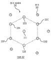
도 2a는 본 발명에 따른 천골 영역(sacral region)상의 한 쌍의 좌우 대칭(bisymmetric) 위치의 예를 제공한다.
도 2b는 본 발명에 따른 양 발의 바닥면 상의 한 쌍의 좌우 대칭 위치의 예를 제공한다.
도 2c는 본 발명에 따른 양측 다리의 측부 및 발바닥상의 한 쌍의 좌우 대칭 위치의 예를 제공한다.
도 3은 하나의 동축 센서를 포함하는 장치의 예시이다.
도 4a는 본 발명에 따른 2 개의 센서를 포함하는 제 1 예시적인 장치이다.
도 4b는 본 발명에 따른 2 개의 센서를 포함하는 제 2 예시적인 장치이며, 좌우 대칭 위치에서 SEM 값을 결정하도록 구성된다.
도 5는 본 발명에 따른 복수의 센서들을 포함하는 예시적인 장치이다.
도 6은 제 1 예시적인 전극 어레이이다.
도 7은 본 발명에 따른 예시적인 전극 어레이이다.
도 8a는 본 발명에 따른 도 7에 개시된 전극 어레이가 센서를 형성하도록 어떻게 구성되는지의 제 1 예를 예시한다.
도 8b는 본 발명에 따른 도 7에 개시된 전극 어레이가 센서를 형성하도록 어떻게 구성되는지의 제 2 예를 예시한다.
도 9a는 본 발명에 따른 전극들의 어레이에 형성된 제 1 센서의 예를 도시한다.
도 9b는 본 발명에 따른 제 2 센서가 도 9a의 제 1 센서와 어떻게 중첩되게 형성되는지의 예를 도시한다.
도 10은 본 발명에 따른 어레이에 맞닿아 위치되는 환자의 피부의 부분보다 더 큰 전극들의 어레이로 도 8a에 도시된 센서들이 어떻게 형성되는지의 예를 도시한다.
도 11a는 본 발명에 따른 SEM 측정을 위한 왼발 및 오른발 위의 위치를 도시한다.
도 11b는 본 발명에 따른 좌우 대칭 위치를 식별하기 위한 알려진 상대적 위치와 관련된 SEM 값의 플롯이다.
도 12a는 본 발명에 따른 환자의 피부상의 알려진 위치에 위치되도록 형성된 기판(substrate)의 예시적인 구성을 도시한다.
도 12b는 본 발명에 따른 도 12a의 예시적인 구성의 정면도를 도시한다.
도 13은 본 발명에 따른 SEM 값의 측정, 평가, 저장 및 전송을 위한 통합 시스템을 도시한다.Aspects of this specification are described by way of example only with reference to the accompanying drawings. DETAILED DESCRIPTION OF THE PREFERRED EMBODIMENTS With particular reference now to the detailed drawings, it is emphasized that the details shown are by way of example and for illustrative purposes of describing aspects of the present invention. In this regard, the description and drawings, taken alone and together, will make clear to those skilled in the art how aspects of the invention may be practiced.
1A is an illustration of a top view of a toroidal sensor.
Figure 1b illustrates a cross-section of the toroidal sensor of Figure 1a.
FIG. 1C illustrates an idealized field map produced by the toroidal sensor of FIG. 1A when activated.
2A provides an example of a pair of bisymmetric positions on the sacral region according to the present invention.
Figure 2b provides an example of a pair of left-right symmetrical positions on the bottom surfaces of both feet according to the present invention.
2C provides an example of a pair of left-right symmetrical positions on the sides and soles of both legs according to the present invention.
3 is an example of a device including one coaxial sensor.
Figure 4a is a first exemplary device comprising two sensors according to the present invention.
Figure 4b is a second exemplary device comprising two sensors according to the present invention, configured to determine SEM values in a left-right symmetrical position.
5 is an exemplary device including a plurality of sensors according to the present invention.
6 is a first exemplary electrode array.
7 is an exemplary electrode array in accordance with the present invention.
8A illustrates a first example of how the electrode array disclosed in FIG. 7 may be configured to form a sensor in accordance with the present invention.
FIG. 8B illustrates a second example of how the electrode array disclosed in FIG. 7 may be configured to form a sensor in accordance with the present invention.
9a shows an example of a first sensor formed on an array of electrodes according to the present invention.
Fig. 9b shows an example of how a second sensor according to the present invention is formed to overlap the first sensor of Fig. 9a.
FIG. 10 shows an example of how the sensors shown in FIG. 8A are formed with an array of electrodes larger than a portion of a patient's skin positioned against an array according to the present invention.
Figure 11a shows the positions on the left and right feet for SEM measurements according to the present invention.
11B is a plot of SEM values associated with known relative positions for identifying left-right symmetry positions in accordance with the present invention.
12A shows an exemplary configuration of a substrate configured to be placed at a known location on a patient's skin in accordance with the present invention.
Figure 12b shows a front view of the exemplary configuration of Figure 12a in accordance with the present invention.
13 shows an integrated system for measurement, evaluation, storage and transmission of SEM values according to the present invention.
본 설명은 본 발명이 구현될 수 있는 모든 상이한 방식의 상세한 카탈로그 또는 본 발명에 추가될 수 있는 모든 특징이 되는 것은 아니다. 예를 들어, 일 실시예와 관련하여 설명된 특징은 다른 실시예에 통합될 수 있고, 특정 실시예와 관련하여 도시된 특징은 해당 실시예에서 삭제될 수 있다. 따라서, 본 발명은 본 발명의 일부 실시예에서, 본 출원에 개시된 특징 또는 특징의 조합이 배제되거나 생략될 수 있음을 고려한다. 추가하여, 본 출원에서 제안된 다양한 실시예에 대한 다수의 변형 및 부가는 본 발명의 관점에서 당업자에게 명백할 것이며, 이는 본 발명 내용을 벗어나지 않는다. 다른 경우에, 주지의 구조, 인터페이스 및 프로세스는 불필요하게 본 발명을 불명료하게 하지 않기 위해 상세하게 설명하지 않았다. 본 명세서의 어떠한 부분도 본 발명의 전체 범위의 일부의 부정을 초래하는 것으로 해석되어서는 안 된다. 따라서, 이하의 설명은 본 발명의 일부 특정 실시예를 설명하기 위한 것이지, 모든 치환, 조합 및 변형을 철저히 기술하지는 않는다.This description is not intended to be a detailed catalog of all the different ways in which the invention can be implemented or all features that can be added to the invention. For example, a feature described in relation to one embodiment may be incorporated into another embodiment, and a feature shown in relation to a particular embodiment may be deleted from that embodiment. Accordingly, the present disclosure contemplates that in some embodiments of the present disclosure, a feature or combination of features disclosed herein may be excluded or omitted. In addition, numerous modifications and additions to the various embodiments proposed in this application will be apparent to those skilled in the art in view of the present invention, which do not depart from the scope of the present invention. In other instances, well-known structures, interfaces and processes have not been described in detail in order not to unnecessarily obscure the present invention. No part of this specification should be construed as a departure from any part of the full scope of this invention. Accordingly, the following description is intended to describe some specific embodiments of the invention, but does not exhaustively describe all permutations, combinations and variations.
달리 정의되지 않는 한, 본 출원에서 사용되는 모든 기술 및 과학 용어는 본 발명 내용이 속하는 기술 분야의 당업자에 의해 일반적으로 이해되는 것과 동일한 의미를 갖는다. 본 명세서의 설명에 사용된 용어는 특정 측면 또는 실시예만을 설명하기 위한 것이며, 본 발명 내용을 한정하려는 것은 아니다.Unless defined otherwise, all technical and scientific terms used in this application have the same meaning as commonly understood by one of ordinary skill in the art to which this subject matter belongs. Terms used in the description herein are for describing only specific aspects or embodiments, and are not intended to limit the scope of the present invention.
본 출원에 인용된 모든 공보, 특허 출원, 특허 및 기타 참고 문헌은 참고 문헌이 제시되는 문장 및/또는 문단에 관련된 교시를 위해 그 전체가 참조로 통합된다. 본 출원에서 사용된 기술에 대한 지칭은 당업자에게 명백할 기술의 변형 또는 균등한 기술의 대체를 포함하여 당해 기술 분야에서 일반적으로 이해되는 기술을 의미하도록 의도된다.All publications, patent applications, patents and other references cited in this application are incorporated by reference in their entirety for the teachings relating to the sentence and/or paragraph to which the reference is made. References to technology used in this application are intended to refer to technology commonly understood in the art, including variations of technology or equivalent replacements of technology that will be apparent to those skilled in the art.
미국 특허 출원 제 14/827,375 호는 도 1에 도시된 센서(90)와 유사한 바이폴라 센서를 사용하여 표피하 정전용량을 측정하기 위해 라디오 주파수(RF) 에너지를 사용하는 장치를 개시하고 있는데, 여기서 표피하 정전용량은 환자의 피부의 타겟 영역의 수분 함량에 대응한다. '375 출원은 또한 다양한 크기의 바이폴라 센서 어레이를 개시한다.US patent application Ser. No. 14/827,375 discloses a device that uses radio frequency (RF) energy to measure subepidermal capacitance using a bipolar sensor similar to
미국 특허 출원 제 15/134,110 호는 도 3에 도시된 디바이스와 유사한 표피하 수분(sub-epidermal moisture)(SEM) 측정 장치를 개시하며, 디바이스는 단일 동축 센서를 통해 32 kHz의 주파수에서 RF 신호를 방출하고 수신하고, 생체 신호를 생성한 다음 이 신호를 SEM 값으로 변환한다.US patent application Ser. No. 15/134,110 discloses a device for measuring sub-epidermal moisture (SEM) similar to the device shown in FIG. It emits and receives, generates biosignals and then converts these signals into SEM values.
미국 특허 출원 일련 번호 제 14/827,375 호 및 제 15/134,110 호는 모두 본 출원에 참고 문헌으로 인용된다.US Patent Application Serial Nos. 14/827,375 and 15/134,110 are both incorporated herein by reference.
문맥이 달리 나타내지 않는 한, 본 출원에 설명된 개시의 다양한 특징이 임의의 조합으로 사용될 수 있는 것을 구체적으로 의도한다. 게다가, 본 발명은 본 발명의 일부 실시예에서, 본 출원에서 설명된 임의의 특징 또는 특징의 조합이 배제되거나 생략될 수 있음을 또한 고려한다.It is specifically intended that the various features of the disclosure described in this application may be used in any combination, unless the context indicates otherwise. Moreover, the present disclosure also contemplates that in some embodiments of the present disclosure, any feature or combination of features described herein may be excluded or omitted.
본 출원에 개시된 방법은 설명된 방법을 달성하기 위한 하나 이상의 단계 또는 동작을 포함하고 그것들로 이루어진다. 방법 단계들 및/또는 동작들은 본 발명의 범위를 벗어나지 않고 상호 교환될 수 있다. 다시 말해서, 특정 순서의 단계 또는 동작이 실시예의 적절한 동작을 위해 요구되지 않는 한, 특정 단계 및/또는 동작의 순서 및/또는 사용은 본 발명의 범위를 벗어나지 않고 수정될 수 있다.The methods disclosed in this application include and consist of one or more steps or actions for achieving the described methods. Method steps and/or actions may be interchanged without departing from the scope of the present invention. In other words, unless a specific order of steps or actions is required for proper operation of an embodiment, the order and/or use of specific steps and/or actions may be modified without departing from the scope of the present invention.
본 명세서 및 첨부된 청구 범위의 설명에 사용되는, 단수 형태 "a", "an” 및 "the"는 문맥상 달리 명시하지 않는 한 복수 형태를 포함하는 것으로 의도된다.As used in the description of this specification and the appended claims, the singular forms “a”, “an” and “the” are intended to include the plural forms unless the context clearly dictates otherwise.
본 출원에 사용되는,“ 및/또는"은 하나 이상의 관련 열거된 항목의 임의 및 모든 가능한 조합뿐만 아니라 대안(“또는")으로 해석될 때는 조합이 없음을 가리키며 포함한다.As used in this application, “and/or” indicates and includes any and all possible combinations of one or more of the related listed items, as well as the absence of combinations when interpreted as alternatives (“or”).
길이, 주파수 또는 SEM 값 등과 같은 측정 가능한 값을 지칭할 때 본 출원에서 사용되는 용어 "약” 및 "대략"은 ± 20%, ± 10%, ± 5%, ± 1%, ± 0.5% 또는 심지어 ± 0.1%의 편차를 포함하는 것을 의미한다.The terms "about" and "approximately" as used in this application when referring to a measurable value such as length, frequency, or SEM value, ± 20%, ± 10%, ± 5%, ± 1%, ± 0.5% or even It is meant to include a deviation of ± 0.1%.
본 출원에서 사용되는 "X와 Y 사이” 및 "약 X와 Y 사이"와 같은 문구는 X 및 Y를 포함하는 것으로 해석되어야 한다. 본 출원에서 사용되는 "약 X와 Y 사이"와 같은 어구는 " 약 X와 약 Y 사이"를 의미하고, 어구 예컨대 "약 X에서 Y까지 "는"약 X에서 약 Y까지 "를 의미한다."As used in this application, phrases such as "between X and Y" and "between about X and Y" should be interpreted to include X and Y. As used in this application, phrases such as "between about X and Y" means "between about X and about Y", and a phrase such as "from about X to Y" means "from about X to about Y".
본 출원에 사용된 바와 같이, 용어 "표피하 수분(sub-epidermal moisture)"또는 "SEM"은 조직에 대한 압력, 세포 사멸, 괴사 및 염증 과정에 계속된 존재하에 손상된 조직의 하부 구조를 변형시키는 혈관 누출 및 다른 변화에 의해 유발되는 조직 유체 및 국소 부종(edema)의 증가를 나타낸다.As used in this application, the term “sub-epidermal moisture” or “SEM” refers to the ability of the tissue to deform the underlying structure of damaged tissue in the continued presence of pressure on the tissue, cell death, necrosis and inflammatory processes. It refers to an increase in tissue fluid and local edema caused by vascular leakage and other changes.
본 출원에 사용되는, "시스템"은 서로 유선 또는 무선 통신하는 디바이스들의 집합일 수 있다.As used herein, a “system” may be a collection of devices that communicate with each other wired or wirelessly.
본 출원에 사용되는, "질의(interrogate)"은 환자의 피부로 침투하기 위한 라디오주파수 에너지의 사용을 지칭한다.As used in this application, “interrogate” refers to the use of radiofrequency energy to penetrate a patient's skin.
본 출원에 사용되는, "환자"는 인간 또는 동물 피험체일 수 있다.As used herein, a “patient” may be a human or animal subject.
본 출원에 사용되는, "좌우 대칭(bisymmetric)"은 대칭 선으로부터 대략 등거리에 있는 한 쌍의 위치를 나타낸다.As used in this application, "bisymmetric" refers to a pair of positions that are approximately equidistant from the line of symmetry.
본 출원에서 사용되는 "델타(delta)"는 2 개의 SEM 값 사이의 계산된 차이를 나타낸다.As used in this application, "delta" refers to the calculated difference between two SEM values.
도 1a는 중심 전극(110) 및 링 전극(120)을 포함하는 토로이드형 센서(toroidal sensor)(90)의 평면도이다. 일 측면에서, 전극(110 및 120)은 도 1b에 도시된 센서(90)의 단면에 도시된 기판(100)의 공통 표면상에 배치된다. 일 측면에서, 기판(100)은 예를 들어 FR4 인쇄 회로 기판(PCB)의 시트와 같이 단단하다. 일 측면에서, 기판(100)은 가요성이며, 예를 들어 폴리이미드의 시트일 수 있다. 일 측면에서, 기판(100)은 강성 요소와 가요성 요소의 조합이다. 일 측면에서, 전극(110 및 120)은 전극(110 및 120)을 서로 및/또는 외부 컨택으로부터 격리시키기 위해 비전도성인 커버 층(130)으로 덮힌다. 일 측면에서, 커버 층(130)의 부분들은 방향성 전도성이어서, 전극(110 및 120)이 커버 층(130) 상에 배치된 물체와 전기적으로 컨택하면서 인접한 전극으로부터 전기적으로 절연되도록 한다. 일 측면에서, 커버 층(130)은 단단하고 평평하며, 이에 의해 평평한 외부 표면을 제공한다. 일 측면에서, 커버 층(130)은 기판(100)과 커버 층(130) 사이에 갭 또는 공기 공간이 존재하지 않도록 하기 위해 하지 전극(110 및 120) 및 기판(100)과 합치한다(conform). 전압이 전극(110 및 120)에 걸쳐 인가된 때, 전극(110 및 120)의 평면으로부터 도 1c에 도시된 바와 같이 피사계 심도를 지칭하는 거리(150)로 외측으로 연장되는 전기장(140)이 전극(110 및 120) 사이에 생성된다. 중심 전극(110)의 직경, 링 전극(120)의 내경 및 외경, 및 전극(110 및 120) 사이의 갭은 필드(140)의 특성, 예를 들어, 피사계 심도(150)를 바꾸기 위해 변화될 수 있다.1A is a plan view of a
도 2a는 환자(10)의 등의 천골 부위(sacral region)를 도시한다. 대칭 선(12)은 좌우 거울 이미지로 등을 나누어 등의 중앙을 따라 그려질 수 있다. 위치(14)는 대칭 선(12)으로부터 대략 동일한 거리이고, 따라서, 환자(10)의 등 위에서 좌우 대칭(bisymmetric)인 위치로 간주된다.2A shows the sacral region of the patient's 10 back. A line of symmetry 12 may be drawn along the center of the back dividing the back in left and right mirror images.
도 2b는 환자(10)가 침대(미도시) 상에 등을 대고 관찰자가 침대 밑에 서 있는 것을 볼 때 환자(10)의 왼발(20L) 및 오른발(20R)을 도시한다. 발들(20L 및 20R)의 발바닥(22L 및 22R)에 대하여, 위치들(24L 및 24R)은 대략 동일한 위치들, 예컨대 후방 표면 즉 발 뒤꿈치로부터 동일한 거리 및 각각의 발들(20L 또는 20R)의 내측으로부터 동일한 거리에 위치되고, 좌우 대칭 위치인 것으로 간주된다.2B shows the
도 2c는 발들(20L 및 20R)의 측면들 상에 위치된 추가적인 예시적인 좌우 대칭 위치들(26L 및 26R) 및 발들(20L 및 20R)의 각각의 발바닥(sole)(22L 및 22R) 상에 위치한 좌우 대칭 위치들(28L 및 28R)을 도시한다. 일 측면에서, 위치(26R 및 30R)는 발(20L)을 참조하지 않고 단독으로 고려될 때 발(20R)에 대해 좌우 대칭인 것으로 간주된다.2C shows additional exemplary left-right
특정한 이론에 한정되지 않고, 좌우 대칭 위치에서 취해진 SEM 측정의 비교는 환자 모집단으로부터의 특정 환자의 판독 값의 오프셋을 보상할 수 있다. 예를 들어, 측정이 이루어질 때 특정 날에 환자가 탈수될 수 있다. 탈수 상태에서 동일한 환자의 건강한 조직의 SEM 값을 비교하면 환자가 완전히 수화(hydrate) 되었을 때 동일한 위치의 동일한 조직의 SEM 값에서 시프트(shift)될 수 있다. 한 위치에 있는 조직이 건강한 상태에서 좌우 대칭 위치에 있는 조직이 손상된 경우, 좌우 대칭 위치에서 취해진 판독 값을 비교하면 양쪽 위치에서 탈수의 "공통 모드(common mode)"효과가 배제되고 조직이 한 위치에서 손상되었다는 보다 확고한 표시를 제공한다.Without being bound by any particular theory, comparison of SEM measurements taken in left-right symmetrical positions can compensate for offsets of a particular patient's readings from a population of patients. For example, a patient may be dehydrated on a particular day when measurements are made. Comparing the SEM values of healthy tissue from the same patient in a dehydrated state may result in a shift in the SEM values of the same tissue in the same location when the patient is fully hydrated. If the tissue in one location is healthy and the tissue in the symmetric location is damaged, comparing readings taken at the symmetric location will rule out the "common mode" effect of dehydration in both locations and the tissue in one location will be provides a more robust indication that it has been compromised.
도 3은 장치 본체의 하부(172) 상에 배치된 하나의 토로이드형 센서(174)를 포함하는 예시적인 SEM 측정 장치(170)를 도시한다. 장치(170)는 예를 들어 제 1 위치에서의 제 1 측정 및 제 1 위치에 대하여 좌우 대칭인 제 2 위치에서의 제 2 측정과 같은 다수의 위치에서 측정을 수행하는데 사용될 수 있다. 일 측면에서, 장치(170)는 비-일시적인 컴퓨터 판독 가능 매체 상에 저장된 명령들에 의해 구성되어, 다수의 위치에서 취해진 측정치의 특성 또는 측정치와 관련된 또는 도출된 파라미터, 예를 들어 복수의 측정치로부터 각각 도출된 SEM 값의 공통 평균치로부터의 평균값 또는 각 값의 차이 중 하나 이상을 결정할 수 있다. 일 측면에서, 장치(170)는 측정과 관련된 하나 이상의 파라미터, 예를 들어 2 개의 좌우 대칭 위치에서 취해진 측정치로부터 도출된 SEM 값 사이의 델타를 표시하도록 구성된 디스플레이를 포함한다.3 shows an exemplary
도 4a는 본 발명에 따른 장치 본체(182)상의 개별 위치에 배치된 2 개의 센서(184A, 184B)를 포함하는 예시적인 SEM 측정 장치(180)를 도시한다. 사용 예는 제 1 센서(184A)를 제 1 위치에 동시에 위치시키고 제 2 센서(184B)를 제 2 위치에 환자 피부의 표면상에 동시에 위치시키도록 환자의 신체(미도시)에 맞닿게 장치(180)를 배치하는 것이다. 일 측면에서, 장치 본체(182)는 단단하고, 센서들(184A 및 184B)을 고정된 이격 거리 및 서로에 대한 고정된 방위에 유지시킨다. 일 측면에서, 센서(184A 및 184B)는 도 4a에 도시된 바와 같이 공통 평면 상에 정렬된다. 일 측면에서, 장치 본체(182)는 가요성이어서 센서(184A 및 184B)가 서로 소정 각도로 배향될 수 있다. 일 측면에서, 센서(184A 및 184B) 중 하나 이상은 이동 가능하고 이동가능한 센서와 다른 하나의 센서 사이의 각도는 가변될 수 있다.4A shows an exemplary
사용시, 장치(180)는 하나 이상의 센서들(184A 및 184B)로 저항, 정전용량, 인덕턴스, 임피던스, 자기저항(reluctance) 및 다른 전기적 특성으로 이루어진 그룹으로부터 선택된 하나 이상의 전기적 특성을 포함하는 전기적 특성 또는 파라미터를 측정할 수 있다. 일 측면에서, 센서(184A 및 184B)는 토로이드형 센서로 예컨대, 도 1a에 도시된 중심 전극(110)과 링 전극(120)을 갖도록 구성된다. 일 측면에서, 센서(184A 및 184B)는 본 출원에서 논의된 다른 구성으로 제공된다. 일 실시예에서, 센서(184A 및 184B)는 전극들(110 및 120)의 일부분에 인접하고 이들로부터 분리된 전기적 접지면(미도시)을 포함한다. 일 측면에서, 접지면은 간섭으로부터 전극들(110 및 120)을 차폐시키거나 또는 센서들(184A 및 184B)의 필드 형상(도 1c의 필드(140)에 개념에 유사한)을 변경한다. 일 실시예에서, 접지면은 전극(110 및 120)이 배치되는 측면에 대향하는 기판의 측면 상에 배치된다. 일 측면에서, 장치(180)는 각 센서(184A 및 184B)의 전극(110 및 120)에 전기적으로 결합되고, 전극(110 및 120) 사이의 전기적 특성을 측정하도록 구성된 회로(미도시)를 포함한다. 일 측면에서, 접지면은 접지 또는 회로의 동등한 플로팅(floating) 기준에 결합된다. 일 측면에서, 회로는 측정된 전기적 특성에 관한 정보를 결정하고 제공하도록 구성된다. 일 측면에서, 장치(180)는 본질적으로 동시에 센서(184A 및 184B)로 측정을 취한다. 일 측면에서, 장치(180)는 0에서 1 초 또는 그 이상의 범위의 측정들 사이의 시간 간격으로 순서대로 측정들을 취한다. 일 측면에서, 장치(180)에 의한 측정은 버튼(도 4a에는 보이지 않음) 또는 액추에이터의 작동에 의해 트리거링된다. 일 측면에서, 장치(180)에 의한 측정은 장치(180)의 일부인 스위칭 소자(도 4a에 미도시), 예를 들어, 컨택 센서, 압력 센서, 광학 센서, 또는 일 측면에서 센서(184A 및 184B) 중 하나 이상에 근접하여 위치된 근접 검출 장치의 센서의 다른 유형의 센서로부터의 입력에 기초하여 자동으로 트리거된다. 일 측면에서, 측정을 수행하기 위한 입력을 제공하기 위해 다중 스위칭 소자가 동시에 활성화되어야 한다.In use,
일 측면에서, 장치(180)는 회로에 결합되고, 회로로부터 측정된 전기적 특성에 관한 정보를 수신하는 프로세서(미도시)를 포함한다. 일 측면에서, 정보는 아날로그 신호, 예를 들어, 전압 또는 디지털 신호의 형태이다. 일 측면에서, 프로세서는 센서(184A 및 184B)에 직접 결합되고, 전기적 특성을 직접 측정하도록 구성된다. 일 측면에서, 프로세서는 수신된 전기적 특성을 SEM 값으로 변환하도록 구성된다. 일 측면에서, 프로세서는 프로세서에 전기적으로 결합된 비-일시적 컴퓨터 판독 가능 매체 상에 저장되는 기계 판독 가능한 명령어에 의해 구성된다. 일 측면에서, 명령들은 장치(180)가 파워 온 될 때 매체로부터 프로세서로 로딩된다.In one aspect,
일 측면에서, 측정된 전기 파라미터는 센서들(184A 및 184B) 및 장치(180)의 다른 동작 특성에 의해 생성되는 도 1c를 참조하여 전기장(140)의 주파수 및 세기, 센서(184A 및 184B)의 전극의 기하학적 구조에 의해 결정되는 깊이에서 환자의 표피의 수분 함량과 관련된다. 일 측면에서, 수분 함량은 미리 결정된 스케일상의 값을 갖는 SEM 함량과 등가이다. 일 측면에서, 미리 결정된 스케일은 0 내지 20, 예컨대 0 내지 1, 0 내지 2, 0 내지 3, 0 내지 4, 0 내지 5, 0 내지 6, 0 내지 7, 0 내지 8, 0 내지 9, 0 내지 10, 0 내지 11, 0 내지 12, 0 내지 13, 0 내지 14, 0 내지 15, 0 내지 16, 0 내지 17 0 내지 18, 0 내지 19 의 범위일 수 있다. 일 측면에서, 미리 결정된 스케일링된 값은 본 출원에서 제공되는 값에 기초하여 인수 또는 배수로 스케일링될 수 있다. 일 측면에서, 판독값 사이의 하나 이상의 동작 특성을 변화시키면서 다수의 측정이 이루어지므로, 피부의 다양한 깊이에서 수분 함량에 관한 정보를 제공한다.In one aspect, the electrical parameters measured are the frequency and strength of the
일 측면에서, 센서(184A 및 184B)가 환자의 피부상의 2 개의 좌우 대칭 위치와 적절하게 컨택하고 있다고 컨택 센서들(도 4a에서 보이지 않음)이 결정할 때, 정전 용량의 측정은 센서(184A 및 184B)로 동시에 취해진다. 일 측면에서, 동시 용량 측정치들은 좌우 대칭 위치들 중 하나의 아래의 조직이 손상되었는지 여부를 결정하기 위해 서로 비교된다. 일 측면에서, 정전용량 측정치는 개별적으로 각각의 센서(184A 및 184B)에 근접한 조직의 수분 함량에 대응하는 SEM 값으로 변환되고 SEM 값들이 비교된다. 일 측면에서, 등가 전압, 정전용량 값 또는 다른 중간 신호를 사용하여 비교가 수행된다.In one aspect, when the contact sensors (not shown in FIG. 4A) determine that the
일 측면에서, SEM 값들 사이의 차이가 결정되며, 여기서, 미리 결정된 임계값을 초과하는 차이는 대응하는 정전용량 측정치들이 취해진 위치들 중 하나에서의 조직 손상을 나타낸다. 일 측면에서, 각각의 좌우 대칭 위치에서 획득된 SEM 값의 평균이 결정되고 비교된다. 일 측면에서, 각각의 좌우 대칭 위치에서 획득된 SEM 값 또는 중앙값 또는 모드가 결정되고 비교된다. 일 측면에서, 손상은 더 큰 SEM 값과 관련된 위치에 있다고 표시된다. 일 측면에서, 손상은 SEM 값 중 더 작은 것과 관련된 위치에 있다고 표시된다. 일 측면에서, 조직 손상이 있는지 여부의 결정은 하나 이상의 미리 결정된 범위 또는 임계값과 개별 SEM 값의 비교 및 하나 이상의 미리 결정된 범위 또는 임계값과의 차이의 비교 중 하나 이상을 포함한다. 일 측면에서, 미리 결정된 범위는 0.1 내지 8.0 예컨대, 0.1 내지 1.0, 1.1 내지 2.0, 2.1 내지 3.0, 3.1 내지 4.0, 4.1 내지 5.0, 5.1 내지 6.0, 6.1 내지 7.0, 7.1 내지 8.0, 0.1 내지 7.5, 0.5 내지 8.0, 1.0 내지 7.0, 1.5 내지 6.5, 2.0 내지 6.0, 3.0 내지 5.5, 3.5 내지 5.0 또는 4.0 내지 4.5일 수 있다. 일 측면에서, 미리 결정된 범위는 0.1 내지 4.0, 예컨대, 0.5 내지 4.0, 0.1 내지 3.5, 1.0 내지 3.5, 1.5 내지 4.0, 1.5 내지 3.5, 2.0 내지 4.0, 2.5 내지 3.5, 2.0 내지 3.0, 2.0 내지 2.5 또는 2.5 내지 3.0일 수 있다. 일 측면에서, 미리 결정된 범위는 4.1 내지 8.0, 예컨대, 4.5 내지 8.0, 4.1 내지 7.5, 5.0 내지 7.5, 5.5 내지 7.0, 5.5 내지 7.5, 6.0 내지 8.0, 6.5 내지 7.5, 6.0 내지 7.0, 6.0 내지 6.5, 또는 6.5 내지 7.0일 수 있다. 일 측면에서, 미리 결정된 임계값은 약 0.3, 0.35, 0.4, 0.45, 0.5, 0.55, 0.6, 0.65, 0.7, 0.75, 0.8, 0.85, 0.9, 0.95, 1.0, 1.1, 1.2, 1.3, 1.4, 1.5, 1.6, 1.7, 1.8, 1.9, 2.0, 2.1, 2.2, 2.3, 2.4, 2.5, 2.6, 2.7, 2.8, 2.9, 3.0, 3.1, 3.2, 3.3, 3.4, 3.5, 3.6, 3.7, 3.8, 3.9, 4.0, 4.1, 4.2, 4.3, 4.4, 4.5, 4.6, 4.7, 4.8, 4.9, 5.0, 5.1, 5.2, 5.3, 5.4, 5.5, 5.6, 5.7, 5.8, 5.9, 6.0, 6.1, 6.2, 6.3, 6.4, 6.5, 6.6, 6.7, 6.8, 6.9, 7.0, 7.1, 7.2, 7.3, 7.4, 또는 7.5 일 수 있다. 일 측면에서, 미리 결정된 임계값은 0.1 내지 8.0 예컨대, 0.1 내지 1.0, 1.1 내지 2.0, 2.1 내지 3.0, 3.1 내지 4.0, 4.1 내지 5.0, 5.1 내지 6.0, 6.1 내지 7.0, 7.1 내지 8.0, 0.1 내지 7.5, 0.5 내지 8.0, 1.0 내지 7.0, 1.5 내지 6.5, 2.0 내지 6.0, 3.0 내지 5.5, 3.5 내지 5.0 또는 4.0 내지 4.5 범위일 수 있다. 일 측면에서, 미리 결정된 범위 또는 임계값은 본 출원에 제공된 값에 기초하여 인수 또는 배수로 스케일링될 수 있다. 미리 결정된 값은 디자인에 의해 제한되지 않고 오히려 당업자는 SEM의 미리 결정된 단위에 기초하여 미리 결정된 값을 선택할 수 있는 것으로 이해될 것이다. 일 측면에서, 본 개시의 범위 및 임계값은 특정 좌우 대칭 위치, 측정이 수행되는 환자의 신체 부분, 또는 하나 이상의 환자의 특성 예컨대, 신장, 체중, 가족력, 인종 그룹 및 기타 신체적 특징 또는 건강 상태에 따라 변화된다.In one aspect, a difference between the SEM values is determined, where a difference that exceeds a predetermined threshold indicates tissue damage at one of the locations at which corresponding capacitance measurements were taken. In one aspect, the average of the SEM values obtained at each left-right symmetric position is determined and compared. In one aspect, the SEM value or median value or mode obtained at each left-right symmetric position is determined and compared. In one aspect, damage is indicated to be at a location associated with a larger SEM value. In one aspect, damage is indicated as being at a location relative to the smaller of the SEM values. In one aspect, determining whether there is tissue damage includes one or more of comparing an individual SEM value to one or more predetermined ranges or thresholds and comparing a difference with one or more predetermined ranges or thresholds. In one aspect, the predetermined range is 0.1 to 8.0, such as 0.1 to 1.0, 1.1 to 2.0, 2.1 to 3.0, 3.1 to 4.0, 4.1 to 5.0, 5.1 to 6.0, 6.1 to 7.0, 7.1 to 8.0, 0.1 to 7.5, 0.5 to 8.0, 1.0 to 7.0, 1.5 to 6.5, 2.0 to 6.0, 3.0 to 5.5, 3.5 to 5.0 or 4.0 to 4.5. In one aspect, the predetermined range is 0.1 to 4.0, such as 0.5 to 4.0, 0.1 to 3.5, 1.0 to 3.5, 1.5 to 4.0, 1.5 to 3.5, 2.0 to 4.0, 2.5 to 3.5, 2.0 to 3.0, 2.0 to 2.5 or It may be 2.5 to 3.0. In one aspect, the predetermined range is 4.1 to 8.0, e.g., 4.5 to 8.0, 4.1 to 7.5, 5.0 to 7.5, 5.5 to 7.0, 5.5 to 7.5, 6.0 to 8.0, 6.5 to 7.5, 6.0 to 7.0, 6.0 to 6.5; or 6.5 to 7.0. In one aspect, the predetermined threshold is about 0.3, 0.35, 0.4, 0.45, 0.5, 0.55, 0.6, 0.65, 0.7, 0.75, 0.8, 0.85, 0.9, 0.95, 1.0, 1.1, 1.2, 1.3, 1.4, 1.5, 1.6, 1.7, 1.8, 1.9, 2.0, 2.1, 2.2, 2.3, 2.4, 2.5, 2.6, 2.7, 2.8, 2.9, 3.0, 3.1, 3.2, 3.3, 3.4, 3.5, 3.6, 3.7, 3.8, 3.9, 4.0, 4.1, 4.2, 4.3, 4.4, 4.5, 4.6, 4.7, 4.8, 4.9, 5.0, 5.1, 5.2, 5.3, 5.4, 5.5, 5.6, 5.7, 5.8, 5.9, 6.0, 6.1, 6.2, 6.3, 6.4, 6.5, 6.6, 6.7, 6.8, 6.9, 7.0, 7.1, 7.2, 7.3, 7.4, or 7.5. In one aspect, the predetermined threshold is from 0.1 to 8.0, such as from 0.1 to 1.0, 1.1 to 2.0, 2.1 to 3.0, 3.1 to 4.0, 4.1 to 5.0, 5.1 to 6.0, 6.1 to 7.0, 7.1 to 8.0, 0.1 to 7.5; 0.5 to 8.0, 1.0 to 7.0, 1.5 to 6.5, 2.0 to 6.0, 3.0 to 5.5, 3.5 to 5.0 or 4.0 to 4.5. In one aspect, the predetermined range or threshold may be scaled by a factor or multiple based on the values provided herein. It will be appreciated that the predetermined value is not limited by design, but rather one skilled in the art can select a predetermined value based on the predetermined units of the SEM. In one aspect, the ranges and thresholds of the present disclosure are specific to a particular bilaterally symmetrical location, the part of the patient's body from which the measurement is being made, or one or more characteristics of the patient, such as height, weight, family history, ethnic group, and other physical characteristics or health conditions. change according to
하나 이상의 영역이 신체 상에서 정의될 수 있다. 일 측면에서, 한 영역 내에서 이루어진 측정은 서로 필적할만한 것으로 간주된다. 영역은 신체의 피부 영역으로서 정의될 수 있으며, 여기서, 측정은 해당 영역 내의 임의의 지점에서 취해질 수 있다. 일 측면에서, 영역은 해부학적 영역(예를 들어, 뒤꿈치, 발목, 등 아래 부분(lower back))에 상응한다. 일 측면에서, 영역은 해부학적 특징에 관련된 2 이상의 특정 지점들의 세트로서 정의될 수 있으며, 여기서 측정은 특정 지점에서만 취해진다. 일 측면에서, 영역은 신체 상에 복수의 비 연접(non-contiguous) 영역을 포함할 수 있다. 일 측면에서, 특정 위치들의 세트는 다수의 비연접 영역들 내의 지점들을 포함할 수 있다.One or more regions may be defined on the body. In one aspect, measurements made within an area are considered comparable to each other. An area can be defined as an area of skin on the body, where measurements can be taken at any point within that area. In one aspect, a region corresponds to an anatomical region (eg, heel, ankle, lower back). In one aspect, a region can be defined as a set of two or more specific points related to an anatomical feature, where measurements are taken only at specific points. In one aspect, an area may include a plurality of non-contiguous areas on the body. In one aspect, the set of particular locations may include points within a number of non-contiguous areas.
일 측면에서, 영역은 표면적에 의해 정의된다. 일 실시 형태에서, 영역은 예를 들어, 5 내지 200 ㎠, 5 내지 100 ㎠, 5 내지 50 ㎠, 또는 10 내지 50 ㎠, 10 내지 25 ㎠, 또는 5 내지 25 ㎠일 수 있다.In one aspect, an area is defined by surface area. In one embodiment, the area can be, for example, 5 to 200
일 측면에서, 측정치는 특정 패턴 또는 그 일부분으로 이루어질 수 있다. 일 측면에서, 판독의 패턴은 중심에서 관심의 타겟 영역을 갖는 패턴으로 이루어진다. 일 측면에서, 측정은 증가하거나 또는 감소하는 크기, T 형상 패턴, 특정 위치의 세트, 또는 조직 또는 영역에 걸쳐 무작위로 하나 이상의 원형 패턴으로 이루어진다. 일 측면에서, 패턴은 해부학적 특징에 대하여 패턴의 제 1 측정 위치를 정의함으로써 신체 상에 위치될 수 있고 해당 패턴의 나머지 측정 위치들은 제 1 측정 위치로부터의 오프셋(offset)들로서 정의된다.In one aspect, measurements may be made in a specific pattern or portion thereof. In one aspect, the pattern of readings consists of a pattern with the target region of interest in the center. In one aspect, measurements are made of increasing or decreasing size, a T-shaped pattern, a set of specific locations, or one or more circular patterns randomly across a tissue or area. In one aspect, a pattern may be positioned on the body by defining a first measurement location of the pattern relative to an anatomical feature and the remaining measurement locations of the pattern defined as offsets from the first measurement location.
일 측면에서, 복수의 측정은 조직 또는 영역에 걸쳐 취해지고, 복수의 측정치 중 가장 낮은 측정치와 가장 높은 측정치 사이의 차이는 해당 복수의 측정치의 델타 값으로서 기록된다. 일 측면에서, 조직 또는 영역에 걸쳐 3 회 이상, 4 회 이상, 5 회 이상, 6 회 이상, 7 회 이상, 8 회 이상, 9 회 이상 또는 10 회 이상의 측정이 수행된다.In one aspect, a plurality of measurements are taken over a tissue or region, and the difference between the lowest and highest of the plurality of measurements is recorded as the delta value of the plurality of measurements. In one aspect, at least 3, at least 4, at least 5, at least 6, at least 7, at least 8, at least 9, or at least 10 measurements are taken across the tissue or area.
일 측면에서, 임계값은 적어도 하나의 영역에 대해 수립될 수 있다. 일 측면에서, 적어도 하나의 영역에 대해 0.2, 0.3, 0.4, 0.5, 0.6, 0.7, 0.8, 0.9 또는 다른 값의 임계값이 수립될 수 있다. 일 측면에서, 델타 값(delta value)은 한 영역 내에서 취해진 복수의 측정치의 델타 값이 해당 영역과 관련된 임계값을 만족하거나 초과할 때 중요한 것으로 식별된다. 일 측면에서, 복수의 영역들의 각각은 상이한 임계값을 갖는다. 일 측면에서, 둘 이상의 영역은 공통 임계값을 가질 수 있다.In one aspect, a threshold may be established for at least one region. In one aspect, a threshold of 0.2, 0.3, 0.4, 0.5, 0.6, 0.7, 0.8, 0.9 or other values may be established for at least one region. In one aspect, a delta value is identified as significant when the delta values of multiple measurements taken within an area meet or exceed a threshold associated with that area. In one aspect, each of the plurality of regions has a different threshold value. In one aspect, two or more regions may have a common threshold.
일 측면에서, 임계값은 델타 값 성분 및 시간순 성분 둘 모두를 가지며, 여기서 델타 값은 델타 값이 시간 간격의 미리 결정된 부분에 대해 미리 결정된 수치보다 클 때 중요한 것으로 식별된다. 일 측면에서, 시간 간격의 미리 결정된 부분은 X 날의 최소값으로서 정의되며, 해당 날에 취해진 복수의 측정치는 총 Y 연속 측정 일 내에서 미리 결정된 수치 값보다 크거나 같은 델타 값을 생성한다. 일 측면에서, 시간 간격의 미리 결정된 부분은 해당 날에 취해진 복수의 측정치가 미리 결정된 수치 값보다 크거나 같은 델타 값을 생성하는 1, 2, 3, 4 또는 5 연속 일로서 정의될 수 있다 값. 일 측면에서, 시간 간격의 미리 결정된 부분은 상이한 특정 시간 기간(주, 월, 시간 등)의 일부로서 정의될 수 있다.In one aspect, a threshold has both a delta value component and a chronological component, wherein a delta value is identified as significant when the delta value is greater than a predetermined number for a predetermined portion of the time interval. In one aspect, the predetermined portion of the time interval is defined as the minimum value of day X, and a plurality of measurements taken on that day produce a delta value greater than or equal to the predetermined numerical value within a total of Y consecutive measurement days. In one aspect, the predetermined portion of the time interval may be defined as 1, 2, 3, 4 or 5 consecutive days for which a plurality of measurements taken on that day result in a delta value greater than or equal to the predetermined numerical value. In one aspect, the predetermined portion of the time interval may be defined as part of a different specific time period (week, month, hour, etc.).
일 측면에서, 임계값은 연속적인 복수 측정치의 델타 값의 변화가 서로 비교되는 추세 양상(trending aspect)을 갖는다. 일 측면에서, 추세 임계값은 미리 결정된 길이의 시간에 대한 델타 값의 미리 결정된 변화로서 정의되며, 임계값이 충족되거나 초과되었다는 결정이 중요하다. 일 측면에서, 중요성의 결정은 경보가 발령되게 할 것이다. 일 측면에서, 추세선(trend line)은 연속적인 복수 측정치의 개별 측정치의 일부로부터 계산될 수 있다. 일 측면에서, 추세선은 연속적인 복수 측정치의 델타 값의 일부로부터 계산될 수 있다.In one aspect, the threshold has a trending aspect in which changes in delta values of multiple successive measurements are compared to each other. In one aspect, a trend threshold is defined as a predetermined change in delta value over a predetermined length of time, and the determination that the threshold has been met or exceeded is significant. In one aspect, determining the importance will cause an alert to be raised. In one aspect, a trend line may be calculated from a portion of individual measurements of a plurality of consecutive measurements. In one aspect, a trend line may be calculated from a portion of the delta values of multiple successive measurements.
일 측면에서, 단일 영역 내에서 취해진 측정의 수는 패턴으로 정의된 측정 위치의 수보다 적을 수 있다. 일 측면에서, 델타 값은 패턴에 정의된 측정 위치의 수보다 적은 미리 결정된 초기 판독 회수가 영역에서 취해진 이후에 그리고 동일한 영역에서의 각각의 추가 판독 이후에 계산될 것이고, 델타 값이 해당 영역과 관련된 임계값을 충족하거나 초과하면 추가 판독 값이 취해지지 않는다.In one aspect, the number of measurements taken within a single area may be less than the number of measurement locations defined by the pattern. In one aspect, a delta value will be calculated after a predetermined initial number of readings less than the number of measurement locations defined in the pattern are taken in an area and after each additional reading in the same area, the delta value being associated with that area. If the threshold is met or exceeded, no additional readings are taken.
일 측면에서, 단일 영역 내에서 취해진 측정의 수는 패턴으로 정의된 측정 위치의 수를 초과할 수 있다. 일 측면에서, 델타 값은 각각의 추가 판독 후에 계산될 것이다.In one aspect, the number of measurements taken within a single area may exceed the number of measurement locations defined by the pattern. In one aspect, a delta value will be calculated after each additional reading.
일 측면에서, 품질 메트릭(quality metric)은 각각의 복수의 측정들에 대해 생성될 수 있다. 일 측면에서, 이 품질 메트릭은 측정의 재현성을 평가하기 위해 선택된다. 일 측면에서, 이 품질 메트릭은 측정을 수행한 임상의 기술을 평가하기 위해 선택된다. 일 측면에서, 품질 메트릭은 하나 이상의 통계적 파라미터, 예를 들어 평균(average), 중간값(mean) 또는 표준 편차(standard deviation)를 포함할 수 있다. 일 측면에서, 품질 메트릭은 개별적인 측정 값들의 미리 정의된 범위에 대한 하나 이상의 비교를 포함할 수 있다. 일 측면에서, 품질 메트릭은 개별 측정치를 값의 패턴과 비교하는 것, 예를 들어 미리 정의된 위치에서 측정 값을 각각의 미리 정의된 위치와 관련된 범위와 비교하는 것을 포함할 수 있다. 일 측면에서, 품질 메트릭은 어떤 측정치가 건강한 조직에 대해 행해진 지의 결정 및 "건강한" 측정의 이 서브 세트 내에서의 일관성의 하나 이상의 평가, 예를 들어 범위, 표준 편차 또는 다른 파라미터를 포함할 수 있다.In one aspect, a quality metric may be generated for each of the plurality of measurements. In one aspect, this quality metric is chosen to evaluate the reproducibility of a measurement. In one aspect, this quality metric is chosen to evaluate the skill of the clinician making the measurement. In one aspect, a quality metric may include one or more statistical parameters, such as an average, mean or standard deviation. In one aspect, a quality metric may include one or more comparisons to a predefined range of individual measurement values. In one aspect, a quality metric may include comparing individual measurements to a pattern of values, eg, comparing measured values at predefined locations to a range associated with each predefined location. In one aspect, a quality metric may include a determination of which measurements were made on healthy tissue and one or more assessments of consistency within this subset of “healthy” measurements, eg, range, standard deviation, or other parameter. .
일 측면에서, 측정치, 예를 들어 임계값은 SEM 스캐너 모델 200(Bruin Biometrics, LLC, Los Angeles, CA)에 의해 결정된다. 다른 측면에서, 다른 SEM 스캐너에 의해 측정이 결정된다.In one aspect, a measurement, eg, a threshold, is determined by the SEM Scanner Model 200 (Bruin Biometrics, LLC, Los Angeles, Calif.). In another aspect, measurements are determined by another SEM scanner.
일 측면에서, 측정 값은 기준 디바이스에 대한 기준에 의한 정전용량 측정에 기초한다. 일 측면에서, 정전용량 측정은 디바이스 내의 임의의 전극의 위치 및 다른 측면에 의존할 수 있다. 이러한 변형은 SEM 스캐너 모델 200(Bruin Biometrics, LLC, Los Angeles, CA)과 같은 기준 SEM 디바이스와 비교될 수 있다. 당업자는 본 출원에서 설명된 측정치가 기준 디바이스에 대한 기준에 의해 차이 정전 용량 범위를 수용하도록 조절될 수 있음을 이해한다.In one aspect, the measurement value is based on capacitance measurement by reference to a reference device. In one aspect, the capacitance measurement may depend on the position of any electrode within the device and other aspects. These variations can be compared to a reference SEM device such as the SEM Scanner Model 200 (Bruin Biometrics, LLC, Los Angeles, Calif.). One skilled in the art understands that the measurements described herein can be adjusted to accommodate the differential capacitance range by reference to a reference device.
일 측면에서, 장치(180)는 다수의 측정 및 계산 결과를 저장할 수 있다. 일 측면에서, 본 발명에 따른 장치는 또한 다른 컴포넌트, 예를 들어 카메라 또는 바코드 스캐너(도 4a에는 보이지 않음)를 포함할 수 있으며, 해당 컴포넌트의 출력을 저장할 수 있다. 일 측면에서, 장치(180)는 도 13에 도시된 바와 같이, 예를 들어 블루투스, WiFi 또는 이더넷 연결을 통해 저장된 데이터를 다른 디바이스, 예를 들어 퍼스널 컴퓨터, 서버, 태블릿 또는 스마트 폰으로 전송하기 위한 컴포넌트(도 4a에는 보이지 않음)를 포함한다.In one aspect,
도 4b는 좌우 대칭 위치에서 SEM 값을 결정하도록 구성된 장치(186)의 다른 측면을 도시한다. 일 측면에서, 장치(186)는 센서(187A 및 187B) 사이의 이격 거리가 변화될 수 있는 힌지(188)를 포함한다. 일 측면에서, 센서(184A 및 184B)는 장치 본체 요소(186A 및 186B)에 대해 정렬되어 예를 들어 미리 결정된 이격 거리에서 서로에 대해 평행한 원하는 상대적인 방위를 달성한다. 일 측면에서, 센서(187A 및 187B) 중 하나 이상은 이동 가능하여, 이동 가능한 센서와 다른 센서 사이의 각도는 예를 들어 도 2c에 도시된 위치(26R 및 3OR) 위에 센서(187A 및 187B)를 위치시키도록 발목 주위에서 장치(185)가 폐쇄될 때 각각의 센서(187A 및 187B)의 아래에 피부의 방위에 일치시키도록 변할 수 있다.4B shows another aspect of a
도 5는 본 발명에 따른 복수의 센서(90)를 포함하는 어레이(92)를 포함하는 예시적인 매트 어셈블리(mat assembly)(190)를 도시한다. 일 측면에서, 매트 어셈블리(192)는 센서(90)가 배치되는 매트(200)를 포함한다. 일 측면에서, 센서(90)는 매트(200)내에 내장된다. 일 측면에서, 센서(90)는 매트(200)의 상부 표면 상에 위치된다. 일 측면에서, 센서(90)는 그것들 위에 커버 층(도 5에서 보이지 않음)을 갖는다. 일 측면에서, 센서(90)는 매트의 상부에 근접한 물체, 예를 들어 매트 상에 서 있는 환자의 발과 전기적 컨택을 생성하도록 상부 표면에 노출된 전도성 전극을 포함한다. 일 측면에서, 센서(90)는 도 1a에 도시된 바와 같은 토로이드형 센서이다. 일 측면에서, 센서(90)는 단일 유형 및 구성을 갖는다. 일 측면에서, 센서(90)는 어레이(92) 내에서 크기 및 유형이 다양하다. 일 측면에서, 센서(90)는 도면들 6, 7, 8a 및 8b와 관련하여 논의된 것과 같은 하나 이상의 대안 구성들을 갖는다. 일 측면에서, 매트 어셈블리(190)는 직접 또는 케이블(194)를 통해 전자 기기 어셈블리(192)에 결합된다. 일 측면에서, 전자 기기 어셈블리(192)는 장치(180)와 관련하여 앞서 논의된 바와 같이, 회로에 연결된 프로세서(도 4a에서는 보이지 않음) 및 센서들(90)의 전극들에 결합된 회로(도 4a에서는 보이지 않음)를 포함할 수 있다.5 shows an
일 측면에서, 매트 어셈블리(190)는 매트(200)를 가로 지르는 하나 이상의 개별 위치에 배치된 하나 이상의 압력 센서, 온도 센서, 광학 센서 및 컨택 센서(도 5에서는 보이지 않음)를 포함한다. 일 측면에서, 센서(90)를 사용하는 하나 이상의 측정은 압력, 온도, 광학 및 컨택 센서 중 하나 이상으로부터의 입력에 의해 트리거링된다.In one aspect,
*일 측면에서, 매트 어셈블리(190)는 플로어 매트로서 구성되어 및 압력, 온도, 광학 및 컨택 센서 중 하나 이상의 작동이 예를 들어 압력 센서에 의해 사람의 체중을 검출함에 의한 매트 어셈블리(190)상에 서 있는 사람의 검출이 하나 이상의 센서들(90)에 의한 측정을 개시한다. 일 실시예에서, 센서(90)는 사람이 매트 어셈블리(190) 상에 발을 들여 놓았을 때를 검출할 수 있는 "검출 모드" 로 작동되어, 사람이 매트 어셈블리(190) 상에 서 있는 것으로 결정되면 "측정 모드"로 전환된다.*In one aspect,
일 측면에서, 매트 어셈블리(190)는 환자가 침대에 누워있는 동안 환자의 피부의 표면에 맞닿아, 예를 들어 환자의 등에 맞닿아 또는 발의 한쪽 또는 양쪽 발바닥에 맞닿아 배치될 수 있는 휴대용 장치로 구성된다. 일 측면에서, 매트 어셈블리(190)는 환자의 피부의 표면에 맞닿아 센서(90)를 배치하는 것을 돕기 위해 지지 트레이, 보강 요소 및 등도포성 패드(conformal pad)(도 5에 미도시) 중 하나 이상을 포함한다.In one aspect,
도 6은 본 발명에 따른 예시적인 전극 어레이(290)를 도시한다. 어레이(290)는 기판(292) 위에 규칙적인 패턴으로 배치된 개별 전극들(300)으로 구성된다. 일 실시예에서, 각각의 전극(300)은(도 6 내지 도 8b에 도시되지 않은 전도성 요소를 통해) 예컨대, 전기적 파라미터를 측정하도록 구성된 도 4a와 관련하여 설명된 회로에 개별적으로 결합된다. 일 측면에서, "가상 센서(virtual sensor)"는 회로의 공통 요소에 전극(300)의 미리 결정된 서브 세트의 선택적 연결에 의해 생성된다. 이 예에서, 특정 전극(310)은 도 1a의 전극(110)과 유사하게 중심 전극으로서 연결되고, 6 개의 전극(320A-320F)은 도 1a의 전극(120)과 유사하게 "가상 링"으로 함께 연결된다. 일 실시예에서, 2 개의 개별 전극은 회로에 개별적으로 연결되어 가상 센서를 형성하며, 예를 들어 전극(310 및 320A)은 센서의 2 개의 전극으로서 각각 연결된다. 일 측면에서, 하나 이상의 전극(300)은 함께 연결되어 2 개의-전극 센서의 전극 중 하나 또는 다른 전극을 형성한다.6 shows an
도 7은 본 발명에 따른 전극(410)의 또 다른 예시적인 어레이(400)를 나타낸다. 이 예에서, 각각의 전극(410)은 주변 전극(410)의 각각으로부터 갭(420)에 의해 분리된 대략 육각형이다. 일 측면에서, 전극(410)은 원, 정사각형, 오각형 또는 다른 규칙적 또는 불규칙적인 형상 중 하나이다. 일 측면에서, 갭(420)은 모든 전극(410) 사이에서 균일하다. 일 측면에서, 갭(420)은 다양한 전극들 사이에서 변화한다. 일 측면에서, 갭(420)은 각각의 전극(410)의 단면보다 좁은 폭을 갖는다. 일 측면에서, 전극(410)은 도 8a 및 도 8b와 관련하여 후술되는 바와 같이 가상 센서를 형성하도록 상호 연결될 수 있다.7 shows another
도 8a는 본 발명에 따른 예시적인 센서(430)를 형성하도록 구성되는, 예를 들어 측정 회로에 연결된 전극(410)의 어레이(400)를 도시한다. 일 측면에서, "1"로 라벨링된 단일 육각정계 전극(410)은 중심 전극을 형성하고, "2"로 표시된 전극들(410)의 링은 링 전극을 형성하도록 상호 연결된다. 일 실시예에서, 중심 전극과 링 전극 사이의 전극(410)은 전기적으로 "플로팅(floating)"된다. 일 측면에서, 중심 전극과 링 전극 사이의 전극(410)은 접지되거나 플로팅 접지에 연결된다. 일 측면에서, 링 전극의 외부에 있는 전극(410)은 전기적으로 "플로팅"된다. 일 측면에서, 가상 링 전극 외부에 있는 전극(410)은 접지되거나 플로팅 접지에 연결된다.8A shows an
도 8b는 전극(410)의 어레이(400)가 본 발명에 따른 가상 센서(440)를 형성하도록 구성되는 대안 측면을 도시한다. 일 측면에서, "1"로 표시된 다수의 전극(410)은 중심 전극을 형성하도록 상호 연결되고, 한편 "2"로 표시된 전극의 이중-폭 링(double-wide ring)은 링 전극을 형성하도록 상호 연결된다. 일 측면에서, 다양한 수 및 위치의 전극(410)은 다양한 크기 및 형상의 가상 전극을 형성하도록 상호 연결된다.8B shows an alternative aspect in which an
도 9a 및 9b는 본 발명에 따른 다수의 중첩 위치에 센서(430)를 형성할 수 있는 전극 어레이(400)의 예시적인 구성을 도시한다. 도 9a에서 가상 센서(430A)는 "1"로 표시된 단일 전극(410)에 의해 형성된 중심 전극(432) 및 "2"로 표시된 복수의 전극(410)에 의해 형성된 링 전극(434)으로 형성된다. 이 동일한 어레이(400)가 도 9b에 도시되어 있으며, 여기서, 새로운 가상 센서(43OB)는 "3"으로 표시된 중심 전극(436) 및 "4"로 표시된 링 전극(438)으로 형성되었다. 가상 센서(430A)의 위치는 어두운 윤곽선으로 도시된다. 가상 센서(43OB)는 가상 센서(43OA)의 위치와 중첩되어, 센서(430)의 직경보다 미세한 해상도로 측정이 수행될 수 있음을 알 수 있다.9A and 9B show an exemplary configuration of an
도 10은 센서(430)가 본 출원에 따른 어레이에 맞닿아 위치되는 환자 피부 일부분보다 더 큰 전극 어레이(400)로 어떻게 형성될 수 있는지를 도시한다. 이 예에서, 도면들 2a-2c를 참조하여 발(20R) 아래에서 보았을 때, 환자(10)의 오른발(20R)의 발바닥(22R)의 컨택 영역(450)의 윤곽선이 어레이(400) 위에 오버레이(overlay)된다. 이 예에서, 센서(430C)는 센서(430C)의 일부가 컨택 영역(450)의 에지를 넘어 연장되는 위치에 형성된다. 이러한 위치에서, 센서(430C)에 의해 측정된 정전용량 또는 다른 전기적 파라미터는 컨택 영역(450) 내에 완전히 위치된 센서(430D)에 의해 측정된 정전용량보다 낮다. 센서(430)는 어레이(400) 내의 임의의 지점에 형성될 수 있고 센서(430)의 위치에 따라 0 내지 100%의 범위 내의 임의의 레벨에서 컨택 영역과 부분적으로 중첩될 수 있음을 알 수 있다.10 shows how a
일 측면에서, 두 개의 센서는 0-50% 예컨대, 0-10%, 5-15%, 10-20%, 15-25%, 20-30%, 25-35%, 30-40%, 35%-45%, 40-50%, 0-25%, 15-35% 또는 25-50% 중첩될 수 있다. 일 측면에서, 두 개의 센서는 25-75% 예컨대, 25-35%, 30-40%, 35-45%, 40-50% 45-55%, 50-60%, 55-65%, 60-70%, 65-75%, 25-50%, 40-55% 또는 50-75% 중첩될 수 있다. 일 측면에서, 두 개의 센서는 50-100% 예컨대, 50-60%, 55-65%, 60-70%, 65-75%, 70-80%, 75-85%, 80-90%, 85-95%, 90-100%, 50-75%, 65-85% 또는 75-100% 중첩될 수 있다.In one aspect, the two sensors are 0-50% eg 0-10%, 5-15%, 10-20%, 15-25%, 20-30%, 25-35%, 30-40%, 35% May overlap %-45%, 40-50%, 0-25%, 15-35% or 25-50%. In one aspect, the two sensors are 25-75% eg 25-35%, 30-40%, 35-45%, 40-50% 45-55%, 50-60%, 55-65%, 60- It can overlap 70%, 65-75%, 25-50%, 40-55% or 50-75%. In one aspect, the two sensors are 50-100% eg 50-60%, 55-65%, 60-70%, 65-75%, 70-80%, 75-85%, 80-90%, 85% -95%, 90-100%, 50-75%, 65-85% or 75-100% overlap.
일 측면에서, 센서 어레이(400)는 피부 표면에 하나 이상의 가상 센서의 완전한 컨택을 보장하기 위해 각각의 전극을 둘러싸는 동일한 평면 상에 복수의 컨택 센서(도 10에 미도시)를 더 포함한다. 복수의 컨택 센서는 복수의 압력 센서, 복수의 광 센서, 복수의 온도 센서, 복수의 pH 센서, 복수의 발한(perspiration) 센서, 복수의 초음파 센서, 복수의 골 성장 자극 센서, 또는 이들 센서의 복수의 조합일 수 있다. 일부 실시예에서, 복수의 컨택 센서는 각 전극을 둘러싸는 4 개, 5 개, 6 개, 7 개, 8 개, 9 개 또는 10 개 이상의 컨택 센서를 포함할 수 있다.In one aspect,
도 11a 및 11b는 본 발명에 따른, 알려진 상대 위치에서 센서와 관련된 SEM 값의 비교가 어떻게 좌우 대칭 위치를 식별할 수 있는지의 예를 도시한다. 이 예에서, 센서(430)는 오른발(20R)의 컨택 영역(450R)을 가로 질러, 도 11a의 "A"에서”H"로 표시된 중첩되지 않는 위치에 형성된다. 각 위치에서 측정된 SEM 값은 도 11b의 그래프에 플롯되었다. 이 예에서, 위치 "A” 및 "H"의 SEM 값은 낮거나 0이며, 해당 위치에서 컨택 영역(450)과 센서(430)의 비 중첩을 반영한다. 위치 "B” 및 "G"와 관련된 SEM 값은 센서(430)가 해당 위치에서 컨택 영역(450)의 일부와 중첩됨에 따라 더 높아진다. 위치(C-D-E-F)에 대한 SEM 값은 더 높고, 이 예에서는 거의 동일하며, 센서(430)가 해당 위치에서 컨택 영역(450) 내에 완전히 있음을 나타낸다. 일 측면에서, 장치(180)와 같은 SEM 측정 장치는 예를 들어, 위치 "C” 및 "F"와 같은 특정 위치가 오른발(20R)의 중심선(452R)에 대해 좌우 대칭임을 결정할 수 있다. 일 측면에서, 유사한 세트의 측정이 왼발(20L)상의 위치 A'-H'에서 이루어지는 경우, 각각의 발(20L 및 20R) 위의 위치, 예를 들어 위치 E 및 E'는 대략 좌우 대칭(bisymmetric)인 것으로 결정될 수 있다.11A and 11B show examples of how comparison of SEM values associated with sensors at known relative positions can identify left-right symmetric positions in accordance with the present invention. In this example,
도 12a 및 12b는 본 발명에 따른 환자의 피부상의 알려진 위치에 배치되도록 구성된 센서 어셈블리(500)의 예시적인 측면을 도시한다. 이 예에서, 센서 어셈블리(500)는 발(20)의 뒤꿈치의 후방 및 바닥 표면에 일치하도록 구성된 모양의 기판(510)을 갖는다. 일 측면에서, 형상화된 기판(510)은 왼발(20L) 및 오른발(20R) 양쪽과 함께 사용하기에 적절할 수 있다. 일 측면에서, 센서 어셈블리(500)는 성형 기판(510)의 내부 표면 상에 배치된 하나 이상의 센서(520)를 포함한다. 이 예에서, 센서(520)는 도 1a에 도시된 바와 같은 토로이드형 센서로서 구성된다. 일 측면에서, 형상화된 기판(510)의 내부 표면은 도 7을 참조하여 전극(410)의 어레이(400)로 라이닝(line)되어 가상 센서가 임의의 위치에 형성될 수 있다. 일 측면에서, 형상화된 기판(510)의 내부 표면 상에 다른 형상 및 구성의 센서가 제공된다. 일 측면에서, 형상화된 기판(510)은 환자의 피부에 합치할 수 있는 예를 들어, 발목 뒤쪽을 감쌀 수 있는 가요성 패널(도 12a에 미도시)이다. 일 측면에서, 센서 어셈블리(500)는 센서들(520)을 하나 이상의 전원, 하나 이상의 정전용량 또는 다른 전기적 특성을 측정하도록 구성된 회로, 프로세서, 통신 서브 시스템, 또는 다른 유형의 전자 어셈블리(도 12a에 미도시)에 연결하기 위한 케이블(530)을 포함한다.12A and 12B show an exemplary aspect of a
도 12b는 예를 들어 센서 어셈블리(500)가 오른발 뒤꿈치 및 바닥 주위의 환자 피부에 맞닿아 배치될 때, 센서들(520)은 뒤꿈치의 중앙 뒤쪽뿐만 아니라 도 2c를 참조하여 발 위치(26R, 28R 및 30R)에 위치되도록 다수의 센서(520)가 형상화된 기판(510) 상에 배치되는 센서 어셈블리(500)의 예시적인 구성을 도시한다. 이것은 단일 위치에서 센서 어셈블리(500)로 발 뒤꿈치상의 반복 가능한 위치에서 다수의 SEM 측정을 취할 수 있게 한다. 일 측면에서(도 12a 및 12b에 미도시), 센서 어셈블리(500)는 환자의 등의 일부분 상에 배치되도록 구성되어서, 등의 좌우 대칭 위치에서 측정을 수행하는 능력을 제공한다. 일 측면에서, 형상화된 기판(510)은 환자의 타겟 영역의 해부학적 특징에 매칭되도록 구성된다. 일 측면에서, 형상화된 기판(510)은 수 십시간 내지 수 주의 전체적인 범위에서의 시간 기간에 걸친 시간 간격에서 동일한 위치에서 측정을 수행할 수 있게 하도록 환자의 신체의 피쳐와 정렬될 수 있는 마킹 또는 다른 표시자를 포함한다. 일 측면에서, 센서 어셈블리(500)는 의복 또는 신발 또는 다른 의류 물품의 라이닝에 통합된다. 일 측면에서, 센서 어셈블리(500)는 시트, 블랭킷, 라이너 또는 다른 유형의 침대 의류에 통합된다. 일 측면에서, 센서 어셈블리(500)는 센서 어셈블리(500)에 물리적으로 연결하지 않고 센서(520)의 작동을 허용하는 수동 라디오 주파수 식별(RFID) 또는 유도성 커플링과 같은 무선 통신 기능을 포함한다.FIG. 12B shows, for example, that when
도 13은 본 발명에 따른 SEM 값의 측정, 평가, 저장 및 전달을 위한 통합 시스템(600)의 개략도를 도시한다. 이 예에서, 시스템(600)은 도 4a와 관련하여 논의된 바와 같이, WiFi 액세스 지점(610)과 무선 통신하는 능력을 포함하는 SEM 측정 장치(180)를 포함한다. 장치(180)는 서버상에서 실행되는 하나 이상의 SEM 애플리케이션 (640), 랩탑 컴퓨터(620), 스마트 폰(630) 또는 다른 디지털 디바이스상에서 실행되는 애플리케이션과 통신한다. 일 측면에서, 랩탑 컴퓨터(620) 및 스마트 폰(630)은 장치(180)의 사용자, 예를 들어 간호사에 의해 휴대되며, 애플리케이션은 피드백 및 정보를 사용자에게 제공한다. 일 측면에서, 환자에 대해 장치(180)로부터 수신된 정보는 데이터베이스(650)에 저장된다. 일 측면에 있어서, 장치(180)로부터 수신된 정보는 네트워크(645)를 통해 환자의 전자 의료 기록(EMR)(670)에 정보의 일부를 저장하는 다른 서버(660)로 전송된다. 일 측면에서, 장치(180)로부터의 정보 또는 데이터베이스(650) 또는 EMR(670)으로부터 검색된 정보는 외부 서버(680)로 전송된 다음 컴퓨터(685), 예를 들어 환자를 돌보는 의사의 사무실에 컴퓨터로 전송된다.13 shows a schematic diagram of an
전술한 내용으로부터, 본 발명은 이하를 포함하지만 이에 한정되지 않는 다양한 방식으로 구체화될 수 있다는 것을 알 수 있을 것이다 :From the foregoing, it will be seen that the present invention may be embodied in a variety of ways, including but not limited to:
실시예 1. 손상된 조직을 식별하기 위한 장치에 있어서, 상기 장치는 : 제 1 센서 및 제 2 센서로서, 상기 제 1 센서 및 상기 제 2 센서의 각각은 제 1 전극 및 제 2 전극을 포함하고, 상기 센서의 각각은 환자의 피부에 맞닿게 배치되도록 구성되는, 상기 제 1 센서 및 상기 제 2 센서,상기 제 1 전극 및 제 2 전극에 전기적으로 결합되고, 상기 센서들의 각각의 제 1 전극과 상기 제 2 전극 사이의 전기적 특성을 측정하고, 상기 전기적 특성에 관한 정보를 제공하도록 구성된 회로, 상기 회로에 전기적으로 결합되고, 상기 회로로부터 정보를 수신하고 상기 정보를 표피하 수분(SEM) 값으로 변환하도록 구성된 프로세서, 및 비-일시적 컴퓨터 판독 가능 매체로서, 상기 프로세서에 전기적으로 결합되고, 상기 프로세서상에서 실행될 때, 상기 제 1 전기적 특성을 제 1 표피하 수분(SEM :sub-epidermal moisture) 값으로 변환하고, 상기 제 2 전기적 특성을 제 2 SEM 값으로 변환하는 단계, 및 상기 제 1 SEM 값과 상기 제 2 SEM 값 사이의 차이를 결정하는 단계를 수행하는 상기 매체 상에 저장된 명령들을 포함하는, 상기 비-일시적 컴퓨터 판독 가능 매체를 포함한다.Example 1. A device for identifying damaged tissue, the device comprising: a first sensor and a second sensor, each of the first sensor and the second sensor comprising a first electrode and a second electrode; Each of the sensors is electrically coupled to the first sensor and the second sensor, the first electrode and the second electrode, configured to be disposed in contact with the patient's skin, and the first electrode of each of the sensors and the second sensor. A circuit configured to measure an electrical property between the second electrodes and provide information regarding the electrical property, electrically coupled to the circuit, receive information from the circuit and convert the information into a subepidermal moisture (SEM) value. a processor configured to, and a non-transitory computer readable medium, electrically coupled to the processor and, when executed on the processor, convert the first electrical property to a first sub-epidermal moisture (SEM) value. and instructions stored on the medium that perform the steps of converting the second electrical characteristic to a second SEM value, and determining a difference between the first and second SEM values. It includes a non-transitory computer readable medium.
실시예 2. 실시예 1에 따른 장치에 있어서, 상기 차이가 미리 결정된 임계값보다 큰 경우, 상기 제 1 위치 및 상기 제 2 위치 중 하나에서의 손상된 조직을 나타낸다.Example 2. The device according to example 1, wherein the difference is greater than a predetermined threshold, indicating damaged tissue at one of the first location and the second location.
실시예 3. 실시예 1에 따른 장치에 있어서, 상기 회로는 상기 제 1 센서 및 제 2 센서 각각의 제 1 전극 및 제 2 전극에 전기적으로 결합되고, 상기 회로는 상기 제 1 센서로 측정된 제 1 전기적 특성을 제 1 SEM 값으로 변환하고, 제 2 센서로 측정된 제 2 전기적 특성을 제 2 SEM 값으로 변환하도록 구성된다.Embodiment 3. The device according to
실시예 4. 실시예 2에 따른 장치에 있어서, 환자의 피부상의 알려진 위치에 배치되도록 구성된 기판을 더 포함하고, 제 1 센서 및 제 2 센서는 기판 상에 배치되어 기판이 환자의 피부상의 알려진 위치에 배치될 때 제 1 센서 및 제 2 센서는 환자의 피부상의 좌우 대칭 위치에 위치된다.Example 4. The device according to example 2, further comprising a substrate configured to be disposed at a known location on the patient's skin, wherein the first sensor and the second sensor are disposed on the substrate such that the substrate is at a known location on the patient's skin. When placed on the first sensor and the second sensor are located in left-right symmetrical positions on the skin of the patient.
실시예 5. 실시예 1에 따른 장치에 있어서, 상기 제 1 전극 및 제 2 전극 사이에 갭을 더 포함한다.Embodiment 5. The device according to
실시예 6. 실시예 1에 따른 장치에 있어서, 상기 전기적 특성은 저항, 정전용량, 인덕턴스, 임피던스 및 자기저항으로 구성된 그룹으로부터 선택된 하나 이상의 전기적 성분을 포함한다.Embodiment 6. The device according to
실시예 7. 손상된 조직을 식별하기 위한 장치에 있어서, 상기 장치는 : 환자의 피부의 표면에 맞닿게 배치되도록 구성된 기판, 개별 복수의 위치에서 상기 기판 상에 배치된 복수의 센서로서, 각각의 센서가 한 쌍의 전극을 포함하는, 상기 복수의 센서, 상기 복수의 센서의 각각의 한 쌍의 전극에 전기적으로 결합되고, 상기 복수의 센서의 일부의 전극의 쌍 사이의 전기적 특성을 측정하고 상기 측정된 전기적 특성에 관한 정보를 제공하도록 구성된 회로,상기 회로에 전기적으로 결합되고, 상기 회로로부터 상기 전기적 특성에 관한 정보를 수신하고 상기 복수의 전기적 특성을 개별 복수의 표피하 수분(SEM) 값으로 변환하도록 구성된 프로세서, 및 비-일시적 컴퓨터 판독 가능 매체로서, 상기 프로세서에 전기적으로 결합되고, 상기 프로세서상에서 실행될 때, 상기 환자의 피부에 대해 좌우 대칭인 제 1 위치 및 제 2 위치에 위치된 제 1 센서 및 제 2 센서를 상기 복수의 SEM 값으로부터 식별하는 단계, 및 상기 제 1 센서와 관련된 제 1 SEM 값을 상기 제 2 센서와 관련된 제 2 SEM 값과 비교하는 단계를 수행하는 상기 매체 상에 저장된 명령들을 포함하는,비-일시적 컴퓨터 판독 가능 매체를 포함한다.Example 7. A device for identifying damaged tissue, the device comprising: a substrate configured to be placed against a surface of a patient's skin, a plurality of sensors disposed on the substrate at a plurality of discrete locations, each sensor The plurality of sensors, including a pair of electrodes, are electrically coupled to each pair of electrodes of the plurality of sensors, measure electrical characteristics between pairs of electrodes of some of the plurality of sensors, and measure the measurement a circuit configured to provide information about an electrical property of the skin, electrically coupled to the circuit, receiving information about the electrical property from the circuit and converting the plurality of electrical properties into a plurality of individual subepidermal moisture (SEM) values; a processor configured to: and a non-transitory computer readable medium electrically coupled to the processor and, when running on the processor, a first sensor positioned in first and second positions symmetrically relative to the skin of the patient. and instructions stored on the medium that perform the steps of identifying a second sensor from the plurality of SEM values, and comparing a first SEM value associated with the first sensor with a second SEM value associated with the second sensor. A non-transitory computer readable medium comprising:
실시예 8. 실시예 7에 따른 장치에 있어서, 상기 명령들은, 상기 제 1 SEM 값과 상기 제 2 SEM 값 사이의 차이를 결정하는 단계, 및 상기 차이가 미리 결정된 임계값보다 큰 경우, 상기 제 1 위치 및 제 2 위치 중 하나에서 조직이 손상되었다는 표시를 제공하는 단계를 더 포함한다.
실시예 9. 실시예 7에 따른 장치에 있어서, 상기 명령들은, 상기 제 1 SEM 값과 상기 제 2 SEM 값 사이의 차이를 결정하는 단계, 상기 제1 SEM 값과 상기 제2 SEM 값 중 어느 것이 다른 것보다 더 큰 지를 결정하는 단계, 및 상기 차이가 미리 결정된 임계값보다 더 큰 경우 더 큰 SEM 값과 관련된 위치에서 조직이 손상되었다는 표시를 제공하는 단계를 더 포함한다.Embodiment 9 The apparatus according to embodiment 7, wherein the instructions further comprise determining a difference between the first SEM value and the second SEM value, which of the first SEM value and the second SEM value is greater than another, and providing an indication that tissue is damaged at the location associated with the greater SEM value if the difference is greater than a predetermined threshold.
실시예 10. 실시예 7에 따른 장치에 있어서, 상기 전기적 특성은 저항, 정전용량, 인덕턴스, 임피던스 및 자기저항으로 구성된 그룹으로부터 선택된 하나 이상의 전기적 성분을 포함한다.
실시예 11. 손상된 조직을 식별하기 위한 장치에 있어서, 상기 장치는 : 장치 본체; 제 1 센서 및 제 2 센서를 포함하는 2 개의 센서로서, 상기 2 개의 센서는 환자의 피부상의 제 1 위치에 상기 제 1 센서를 위치시키고 동시에 상기 제 2 센서를 상기 제 1 위치에 대해 좌우 대칭인 제 2 위치에 위치시키도록 상기 장치 본체상에 배치된, 상기 2 개의 센서; 상기 2 개의 센서 각각에 전기적으로 결합되고, 상기 2 개의 센서 각각으로부터 전기적 특성을 측정하도록 구성된 회로; 상기 회로에 전기적으로 결합되고, 제 1 위치로부터 제 1 전기적 특성 측정치를 수신하고 제 2 위치로부터 제 2 전기적 특성 측정치를 수신하고, 상기 제 1 전기적 특성 측정치를 제 1 표피하 수분(SEM) 값으로 그리고 상기 제 2 전기적 특성 측정치를 제 2 SEM 값으로 변환하도록 구성된 프로세서;상기 프로세서에 전기적으로 결합되고, 상기 프로세서상에서 실행될 때, 상기 제 1 SEM 값과 상기 제 2 SEM 값 간의 차이를 결정하는 단계를 수행하는 명령을 포함하는 비-일시적 컴퓨터 판독 가능 매체를 포함한다.Example 11. A device for identifying damaged tissue, the device comprising: a device body; Two sensors comprising a first sensor and a second sensor, the two sensors positioning the first sensor at a first location on the patient's skin and simultaneously placing the second sensor symmetrically with respect to the first location. the two sensors disposed on the device body to be positioned in a second position; circuitry electrically coupled to each of the two sensors and configured to measure an electrical characteristic from each of the two sensors; electrically coupled to the circuit to receive a first electrical property measurement from a first location and a second electrical property measurement from a second location, the first electrical property measurement as a first subepidermal moisture (SEM) value and a processor configured to convert the second electrical characteristic measurement to a second SEM value; electrically coupled to the processor and, when running on the processor, determining a difference between the first SEM value and the second SEM value. a non-transitory computer readable medium containing instructions to perform
실시예 12. 실시예 11에 따른 장치에 있어서, 상기 2 개의 센서의 각각은 공통 평면 상에 정렬되어 있으면서 상기 장치 본체의 2 개의 단부 상에 배치된다.Embodiment 12. The device according to embodiment 11, wherein each of the two sensors are disposed on two ends of the device body while being aligned on a common plane.
실시예 13. 실시예 11에 따른 장치에 있어서, 상기 장치 본체는 단단하고, 상기 2 개의 센서를 서로에 대해 고정 이격 거리 및 고정된 방위에서 유지된다.Embodiment 13. The device according to embodiment 11, wherein the device body is rigid and holds the two sensors at a fixed separation distance and fixed orientation relative to each other.
실시예 14. 실시예 11에 따른 장치에 있어서, 상기 장치 본체는 가요성이고, 상기 2 개의 센서가 서로 소정 각도에서 배향되는 것을 허용한다.
실시예 15. 실시예 14에 따른 장치에 있어서, 상기 장치 본체는 힌지를 포함한다. Embodiment 15. The device according to
실시예 16. 실시예 11에 따른 장치에 있어서, 2 개의 센서의 각각은 갭에 의해 분리된 제 1 전극 및 제 2 전극을 포함한다.Embodiment 16. The device according to embodiment 11, wherein each of the two sensors includes a first electrode and a second electrode separated by a gap.
실시예 17. 실시예 16에 따른 장치에 있어서, 상기 전기적 특성은 제 1 전극과 제 2 전극 사이에서 측정된다.Example 17. The device according to example 16, wherein the electrical property is measured between the first electrode and the second electrode.
실시예 18. 실시예 11에 따른 장치에 있어서, 상기 2 개의 센서의 각각은 갭에 의해 분리된 복수의 전극을 포함한다.Embodiment 18 The device according to embodiment 11, wherein each of the two sensors includes a plurality of electrodes separated by a gap.
실시예 19. 실시예 18에 따른 장치에 있어서, 복수의 전극은 가상 링 전극 및 가상 중심 전극을 형성하도록 선택적으로 활성화된다.Example 19. The device according to example 18, wherein the plurality of electrodes are selectively activated to form a virtual ring electrode and a virtual center electrode.
실시예 20. 실시예 11에 따른 장치에 있어서, 상기 전기적 특성은 저항, 정전용량, 인덕턴스, 임피던스 및 자기저항으로 구성된 그룹으로부터 선택된 하나 이상의 전기적 특성을 포함한다.
실시예 21. 실시예 11에 따른 장치에 있어서, 상기 제 1 전기적 특성 측정 및 제 2 전기적 특성 측정은 동시에 측정된다.Embodiment 21. The apparatus according to embodiment 11, wherein the first electrical characteristic measurement and the second electrical characteristic measurement are measured simultaneously.
실시예 22. 실시예 21에 따른 장치에 있어서, 상기 장치 는 2 개의 센서 중 하나에 근접하게 위치된 컨택 센서를 더 포함하고, 동시 측정은 컨택 센서의 작동에 의해 트리거링된다.Embodiment 22 The apparatus according to embodiment 21, wherein the apparatus further comprises a contact sensor positioned proximate to one of the two sensors, wherein simultaneous measurement is triggered by actuation of the contact sensor.
실시예 23. 실시예 22에 따른 장치에 있어서, 상기 컨택 센서는 압력 센서 또는 광학 센서이다.Embodiment 23. The device according to embodiment 22, wherein the contact sensor is a pressure sensor or an optical sensor.
실시예 24. 실시예 11에 따른 장치에 있어서, 상기 차이가 미리 결정된 임계값보다 큰 경우 조직이 제 1 위치 및 제 2 위치 중 하나에서 손상되었다는 표시를 제공하는 단계를 더 포함한다.Embodiment 24 The device according to embodiment 11, further comprising providing an indication that the tissue has been damaged in one of the first location and the second location if the difference is greater than a predetermined threshold.
실시예 25. 실시예 11에 따른 장치에 있어서, 상기 명령들은, 상기 제 1 SEM 값과 상기 제 2 SEM 값 중 더 큰 것을 결정하는 단계, 및 상기 차이가 미리 결정된 임계값을 초과하는 경우 더 큰 SEM 값과 관련된 위치에서 조직이 손상되었다는 표시를 제공하는 단계를 더 포함한다.Embodiment 25 The apparatus according to embodiment 11, wherein the instructions further comprise determining the greater of the first SEM value and the second SEM value, and if the difference exceeds a predetermined threshold, the greater Further comprising providing an indication that the tissue has been damaged at the location relative to the SEM value.
실시예 26. 손상된 조직을 식별하기 위한 방법에 있어서, 상기 방법은 환자의 피부 상의 제 1 위치로부터 제 1 표피하 수분(SEM) 값을 획득하는 단계; 상기 제 1 위치에 대하여 좌우 대칭인 제 2 위치로부터 제 2 SEM 값을 획득하는 단계; 상기 제 1 SEM 값과 상기 제 2 SEM 값 사이의 차이를 결정하는 단계를 포함한다.Example 26. A method for identifying damaged tissue, the method comprising: obtaining a first subepidermal moisture (SEM) value from a first location on a patient's skin; obtaining a second SEM value from a second position symmetrical with respect to the first position; and determining a difference between the first SEM value and the second SEM value.
실시예 27. 실시예 26에 따른 방법에 있어서, 상기 차이가 미리 결정된 임계값보다 큰 경우, 상기 제 1 위치 및 상기 제 2 위치 중 하나에서 조직이 손상되었다는 표시를 제공하는 단계를 더 포함한다.Embodiment 27 The method according to embodiment 26, further comprising providing an indication that tissue has been damaged at one of the first location and the second location if the difference is greater than a predetermined threshold.
실시예 28. 실시예 26에 따른 방법에 있어서, 상기 제 1 SEM 값과 제 2 SEM 값 중 큰 것을 결정하는 단계, 및 차이가 미리 결정된 임계값을 초과하는 경우 더 큰 SEM 값과 관련된 위치에서 조직이 손상되었다는 표시를 제공하는 단계를 더 포함한다.Embodiment 28 The method according to embodiment 26, further comprising determining the greater of the first SEM value and the second SEM value, and if the difference exceeds a predetermined threshold, the tissue at the location associated with the greater SEM value and providing an indication that the data has been compromised.
본 발명은 특정 측면을 참조하여 기술되었지만, 당업자는 본 발명의 범위를 벗어나지 않으면서 다양한 변형이 이루어질 수 있고 균등물이 그것의 요소로 치환될 수 있음을 이해할 것이다. 추가하여, 본 발명의 범위를 벗어나지 않으면서 본 발명의 교시에 대한 특정 상황 또는 재료에 대한 많은 변형이 이루어질 수 있다. 따라서, 본 발명은 개시된 특정 측면에 한정되지 않으며, 본 발명은 첨부된 청구항들의 사상 및 범위 내에 있는 모든 측면을 포함할 것이다.Although the invention has been described with reference to specific aspects, those skilled in the art will understand that various changes may be made and equivalents may be substituted for elements thereof without departing from the scope of the invention. In addition, many modifications may be made to a particular situation or material to the teachings of this invention without departing from its scope. Thus, the invention is not limited to the specific aspects disclosed, but the invention will include all aspects falling within the spirit and scope of the appended claims.
Claims (21)
제 1 센서 및 제 2 센서로서, 각각은 제 1 전극 및 제 2 전극을 포함하고, 상기 제 1 센서는 환자의 피부상의 제 1 위치에 맞닿아 배치되도록 구성되고, 상기 제 2 센서는 동시에 상기 환자의 피부상의 제 2 위치에 맞닿게 배치되도록 구성되고, 상기 제 2 위치는 상기 제 1 위치에 대하여 좌우 대칭(bisymmetric)인, 상기 제 1 센서 및 상기 제 2 센서,
상기 제 1 전극 및 상기 제 2 전극에 전기적으로 결합되고, 상기 제 1 센서의 제 1 전극과 제 2 전극 사이의 제 1 전기적 특성을 측정하고, 상기 제 2 센서의 제 1 전극과 제 2 전극 사이의 제 2 전기적 특성을 측정하고, 상기 제 1 전기적 특성과 상기 제 2 전기적 특성에 관한 정보를 제공하도록 구성된 회로,
상기 회로에 전기적으로 결합되고, 상기 정보를 수신하도록 구성된 프로세서, 및
비-일시적 컴퓨터 판독 가능 매체로서, 상기 프로세서에 전기적으로 결합되고, 상기 프로세서상에서 실행될 때,
상기 제 1 전기적 특성을 제 1 표피하 수분(SEM :sub-epidermal moisture) 값으로 변환하고, 상기 제 2 전기적 특성을 제 2 SEM 값으로 변환하는 단계, 및
상기 제 1 SEM 값과 상기 제 2 SEM 값 사이의 차이를 결정하는 단계를 수행하는 상기 매체 상에 저장된 명령들을 포함하는, 상기 비-일시적 컴퓨터 판독 가능 매체를 포함하는, 장치.A device for identifying damaged tissue, the device comprising:
A first sensor and a second sensor, each comprising a first electrode and a second electrode, the first sensor being configured to be disposed against a first location on the patient's skin, the second sensor being simultaneously disposed on the patient's skin. the first sensor and the second sensor configured to be disposed against a second location on the skin of the person, the second location being bisymmetric with respect to the first location;
electrically coupled to the first electrode and the second electrode, measuring a first electrical characteristic between the first electrode and the second electrode of the first sensor, and between the first electrode and the second electrode of the second sensor circuitry configured to measure a second electrical characteristic of and provide information about the first electrical characteristic and the second electrical characteristic;
a processor electrically coupled to the circuitry and configured to receive the information; and
A non-transitory computer readable medium electrically coupled to the processor and when executed on the processor;
converting the first electrical property into a first sub-epidermal moisture (SEM) value and converting the second electrical property into a second SEM value; and
and the non-transitory computer readable medium comprising instructions stored on the medium to perform the step of determining a difference between the first SEM value and the second SEM value.
상기 회로는 상기 스위칭 소자에 전기적으로 결합되고, 상기 제 1 센서 및 상기 제 2 센서가 상기 환자의 피부와 적절한 컨택 상태에 있을 때 상기 제 1 전기적 특성 및 상기 제 2 전기적 특성을 측정하도록 구성되는, 장치.The method of claim 1 , further comprising a switching element configured to detect when the first sensor and the second sensor are properly contacting the patient's skin;
wherein the circuit is electrically coupled to the switching element and configured to measure the first electrical characteristic and the second electrical characteristic when the first sensor and the second sensor are in proper contact with the patient's skin. Device.
상기 환자의 피부상의 알려진 위치에 배치되도록 구성된 기판을 더 포함하고, 상기 제 1 센서 및 상기 제 2 센서가 상기 기판 상에 배치되어 상기 기판이 상기 환자의 피부 위의 알려진 위치에 배치될 때 상기 제 1 센서 및 상기 제 2 센서가 상기 환자의 피부상의 좌우 대칭 위치에 위치되는, 장치.The method of claim 2,
further comprising a substrate configured to be disposed at a known location on the skin of the patient, wherein the first sensor and the second sensor are disposed on the substrate so that the substrate is disposed at a known location on the skin of the patient; wherein the first sensor and the second sensor are positioned at symmetrical positions on the patient's skin.
환자의 피부의 표면에 맞닿아 배치되도록 구성된 기판,
개별 복수의 위치에서 상기 기판 상에 배치된 복수의 센서로서, 각각의 센서가 한 쌍의 전극을 포함하는, 상기 복수의 센서,
상기 복수의 센서의 각각의 한 쌍의 전극에 전기적으로 결합되고, 상기 복수의 센서의 일부의 전극의 쌍 사이의 전기적 특성을 측정하고 상기 측정된 전기적 특성에 관한 정보를 제공하도록 구성된 회로,
상기 회로에 전기적으로 결합되고, 상기 회로로부터 상기 전기적 특성에 관한 정보를 수신하고 상기 복수의 전기적 특성을 개별 복수의 표피하 수분(SEM) 값으로 변환하도록 구성된 프로세서, 및
비-일시적 컴퓨터 판독 가능 매체로서, 상기 프로세서에 전기적으로 결합되고, 상기 프로세서상에서 실행될 때,
상기 환자의 피부에 대해 좌우 대칭인 제 1 위치 및 제 2 위치에 위치된 제 1 센서 및 제 2 센서를 상기 복수의 SEM 값으로부터 식별하는 단계, 및
상기 제 1 센서와 관련된 제 1 SEM 값을 상기 제 2 센서와 관련된 제 2 SEM 값과 비교하는 단계를 수행하는 상기 매체 상에 저장된 명령들을 포함하는,비-일시적 컴퓨터 판독 가능 매체를 포함하는, 장치.A device for identifying damaged tissue, comprising:
a substrate configured to be placed against the surface of the patient's skin;
a plurality of sensors disposed on the substrate at a plurality of discrete locations, each sensor comprising a pair of electrodes;
circuitry electrically coupled to a pair of electrodes of each of the plurality of sensors and configured to measure electrical characteristics between pairs of electrodes of some of the plurality of sensors and provide information about the measured electrical characteristics;
a processor electrically coupled to the circuitry and configured to receive information regarding the electrical properties from the circuitry and convert the plurality of electrical properties to a respective plurality of subepidermal moisture (SEM) values; and
A non-transitory computer readable medium electrically coupled to the processor and when executed on the processor;
identifying from the plurality of SEM values a first sensor and a second sensor located at first and second positions that are symmetrical with respect to the patient's skin; and
A non-transitory computer readable medium comprising instructions stored on the medium that perform the step of comparing a first SEM value associated with the first sensor with a second SEM value associated with the second sensor. .
상기 제 1 SEM 값과 상기 제 2 SEM 값 사이의 차이를 결정하는 단계, 및
상기 차이가 미리 결정된 임계값보다 큰 경우, 상기 제 1 위치 및 제 2 위치 중 하나에서 조직이 손상되었다는 표시를 제공하는 단계를 더 포함하는, 장치.The method of claim 7, wherein the commands,
determining a difference between the first SEM value and the second SEM value; and
providing an indication that tissue has been damaged at one of the first and second locations if the difference is greater than a predetermined threshold.
상기 제 1 SEM 값과 상기 제 2 SEM 값 사이의 차이를 결정하는 단계,
상기 제 1 SEM 값과 제 2 SEM 값 중 어느 것이 다른 것보다 큰지를 결정하는 단계, 및 상기 차이가 미리 결정된 임계값보다 큰 경우 더 큰 SEM 값과 관련된 위치에서 조직이 손상되었다는 표시를 제공하는 단계를 더 포함하는, 장치.The method of claim 7, wherein the commands,
determining a difference between the first SEM value and the second SEM value;
determining which of the first and second SEM values is greater than the other, and providing an indication of tissue damage at the location associated with the greater SEM value if the difference is greater than a predetermined threshold. Further comprising a device.
상기 전기적 특성은 정전용량인 장치.According to claim 7,
The device of claim 1, wherein the electrical property is capacitance.
상기 제 1 센서 및 상기 제 2 센서는 토로이드형(toroidal) 센서인 장치.According to claim 1,
wherein the first sensor and the second sensor are toroidal sensors.
상기 제 1 전극 및 상기 제 2 전극은 링 전극인 장치.According to claim 1,
wherein the first electrode and the second electrode are ring electrodes.
상기 스위칭 소자는 컨택 센서, 압력 센서, 온도 센서, 광학 센서, 근접-검출 센서로 구성된 그룹으로부터 선택되는 장치.According to claim 3,
wherein the switching element is selected from the group consisting of a contact sensor, a pressure sensor, a temperature sensor, an optical sensor, and a proximity-detection sensor.
상기 환자의 피부 상의 좌우 대칭인 위치는 상기 환자의 등의 천골 부위(sacral region)에 위치하는 장치.According to claim 4,
The left-right symmetrical position on the skin of the patient is located in the sacral region of the patient's back.
상기 환자의 피부 상의 좌우 대칭인 위치는 상기 환자의 왼발 및 오른발에 위치하는 장치.According to claim 4,
The left and right symmetric positions on the skin of the patient are located on the left and right feet of the patient.
상기 환자의 피부 상의 좌우 대칭 위치는 상기 환자의 왼발 뒤꿈치 및 오른발 뒤꿈치에 위치하는 장치.According to claim 4,
The left and right symmetric positions on the skin of the patient are located on the left heel and the right heel of the patient.
상기 전기적 특성은 정전용량인 장치.
According to claim 6,
The device of claim 1, wherein the electrical property is capacitance.
Applications Claiming Priority (6)
| Application Number | Priority Date | Filing Date | Title |
|---|---|---|---|
| US201762454455P | 2017-02-03 | 2017-02-03 | |
| US62/454,455 | 2017-02-03 | ||
| US201762521871P | 2017-06-19 | 2017-06-19 | |
| US62/521,871 | 2017-06-19 | ||
| PCT/US2018/016731 WO2018144938A1 (en) | 2017-02-03 | 2018-02-02 | Bisymmetric comparison of sub-epidermal moisture values |
| KR1020197012119A KR102343909B1 (en) | 2017-02-03 | 2018-02-02 | Symmetrical comparison of sub-epidermal moisture values |
Related Parent Applications (1)
| Application Number | Title | Priority Date | Filing Date |
|---|---|---|---|
| KR1020197012119A Division KR102343909B1 (en) | 2017-02-03 | 2018-02-02 | Symmetrical comparison of sub-epidermal moisture values |
Publications (2)
| Publication Number | Publication Date |
|---|---|
| KR20210158868A KR20210158868A (en) | 2021-12-31 |
| KR102492139B1 true KR102492139B1 (en) | 2023-01-27 |
Family
ID=63038433
Family Applications (2)
| Application Number | Title | Priority Date | Filing Date |
|---|---|---|---|
| KR1020217042010A Active KR102492139B1 (en) | 2017-02-03 | 2018-02-02 | Bisymmetric comparison of sub-epidermal moisture values |
| KR1020197012119A Active KR102343909B1 (en) | 2017-02-03 | 2018-02-02 | Symmetrical comparison of sub-epidermal moisture values |
Family Applications After (1)
| Application Number | Title | Priority Date | Filing Date |
|---|---|---|---|
| KR1020197012119A Active KR102343909B1 (en) | 2017-02-03 | 2018-02-02 | Symmetrical comparison of sub-epidermal moisture values |
Country Status (17)
| Country | Link |
|---|---|
| US (2) | US20180220924A1 (en) |
| EP (3) | EP4523617A3 (en) |
| JP (4) | JP2020503081A (en) |
| KR (2) | KR102492139B1 (en) |
| CN (2) | CN115553725B (en) |
| AU (3) | AU2018217182B2 (en) |
| CA (1) | CA3042092C (en) |
| DK (1) | DK3515297T3 (en) |
| ES (1) | ES2927252T3 (en) |
| GB (3) | GB2601274B (en) |
| HU (1) | HUE060045T2 (en) |
| LT (1) | LT3515297T (en) |
| MX (1) | MX2019004931A (en) |
| PL (1) | PL3515297T3 (en) |
| PT (1) | PT3515297T (en) |
| SI (1) | SI3515297T1 (en) |
| WO (1) | WO2018144938A1 (en) |
Families Citing this family (45)
| Publication number | Priority date | Publication date | Assignee | Title |
|---|---|---|---|---|
| FI4122383T3 (en) | 2010-05-08 | 2025-05-19 | Univ California | Sem scanner sensing apparatus for early detection of ulcers |
| NZ736278A (en) | 2015-04-24 | 2022-05-27 | Bruin Biometrics Llc | Apparatus and methods for determining damaged tissue using sub-epidermal moisture measurements |
| US11717447B2 (en) | 2016-05-13 | 2023-08-08 | Smith & Nephew Plc | Sensor enabled wound monitoring and therapy apparatus |
| MX2019004926A (en) | 2017-02-03 | 2019-06-20 | Bruin Biometrics Llc | Measurement of edema. |
| CN118177725A (en) | 2017-02-03 | 2024-06-14 | 布鲁恩医疗创新有限责任公司 | Measurement of susceptibility to diabetic foot ulcers |
| US11304652B2 (en) | 2017-02-03 | 2022-04-19 | Bbi Medical Innovations, Llc | Measurement of tissue viability |
| JP7091356B2 (en) | 2017-03-09 | 2022-06-27 | スミス アンド ネフュー ピーエルシー | Devices, devices, and methods for determining skin perfusion pressure |
| US11690570B2 (en) | 2017-03-09 | 2023-07-04 | Smith & Nephew Plc | Wound dressing, patch member and method of sensing one or more wound parameters |
| US11324424B2 (en) | 2017-03-09 | 2022-05-10 | Smith & Nephew Plc | Apparatus and method for imaging blood in a target region of tissue |
| EP3609449A1 (en) | 2017-04-11 | 2020-02-19 | Smith & Nephew PLC | Component positioning and stress relief for sensor enabled wound dressings |
| CN110832598B (en) | 2017-05-15 | 2024-03-15 | 史密夫及内修公开有限公司 | Wound analysis devices and methods |
| EP3635733A1 (en) | 2017-05-15 | 2020-04-15 | Smith & Nephew plc | Negative pressure wound therapy system using eulerian video magnification |
| WO2018234443A1 (en) | 2017-06-23 | 2018-12-27 | Smith & Nephew Plc | POSITIONING SENSORS FOR MONITORING OR PROCESSING SENSOR ACTIVATED WAFER |
| GB201809007D0 (en) | 2018-06-01 | 2018-07-18 | Smith & Nephew | Restriction of sensor-monitored region for sensor-enabled wound dressings |
| GB201804502D0 (en) | 2018-03-21 | 2018-05-02 | Smith & Nephew | Biocompatible encapsulation and component stress relief for sensor enabled negative pressure wound therapy dressings |
| JP7511468B2 (en) | 2017-08-10 | 2024-07-05 | スミス アンド ネフュー ピーエルシー | Sensor Placement for Sensor-Enabled Wound Monitoring or Treatment |
| GB201804971D0 (en) | 2018-03-28 | 2018-05-09 | Smith & Nephew | Electrostatic discharge protection for sensors in wound therapy |
| GB201718870D0 (en) | 2017-11-15 | 2017-12-27 | Smith & Nephew Inc | Sensor enabled wound therapy dressings and systems |
| EP3681376A1 (en) | 2017-09-10 | 2020-07-22 | Smith & Nephew PLC | Systems and methods for inspection of encapsulation and components in sensor equipped wound dressings |
| GB201718859D0 (en) | 2017-11-15 | 2017-12-27 | Smith & Nephew | Sensor positioning for sensor enabled wound therapy dressings and systems |
| WO2019063481A1 (en) | 2017-09-27 | 2019-04-04 | Smith & Nephew Plc | Ph sensing for sensor enabled negative pressure wound monitoring and therapy apparatuses |
| WO2019072531A1 (en) | 2017-09-28 | 2019-04-18 | Smith & Nephew Plc | Neurostimulation and monitoring using sensor enabled wound monitoring and therapy apparatus |
| EP3709943B1 (en) | 2017-11-15 | 2024-07-24 | Smith & Nephew PLC | Integrated sensor enabled wound monitoring and/or therapy dressings and systems |
| GB2574945A (en) | 2017-11-16 | 2019-12-25 | Bruin Biometrics Llc | Providing a continuity of care across multiple care settings |
| EP4331480B1 (en) | 2018-02-09 | 2025-07-30 | Bruin Biometrics, LLC | Detection of tissue damage |
| GB201814011D0 (en) | 2018-08-29 | 2018-10-10 | Smith & Nephew | Componet positioning and encapsulation for sensor enabled wound dressings |
| GB2592508B (en) | 2018-09-12 | 2022-08-31 | Smith & Nephew | Device, apparatus and method of determining skin perfusion pressure |
| GB2592502B (en) | 2018-09-28 | 2023-03-22 | Smith & Nephew | Optical fibers for optically sensing through wound dressings |
| KR102903190B1 (en) | 2018-10-11 | 2025-12-23 | 브루인 바이오메트릭스, 엘엘씨 | Devices with disposable elements |
| GB201816838D0 (en) | 2018-10-16 | 2018-11-28 | Smith & Nephew | Systems and method for applying biocompatible encapsulation to sensor enabled wound monitoring and therapy dressings |
| GB201820927D0 (en) | 2018-12-21 | 2019-02-06 | Smith & Nephew | Wound therapy systems and methods with supercapacitors |
| GB2611914B (en) | 2019-01-30 | 2023-09-20 | Smith & Nephew | Sensor integrated dressings and systems |
| GB2616370B (en) | 2019-03-18 | 2023-12-06 | Smith & Nephew | Design rules for sensor integrated substrates |
| US12478279B2 (en) | 2019-03-19 | 2025-11-25 | Smith & Nephew Plc | Systems and methods for measuring tissue impedance |
| US20210076974A1 (en) * | 2019-09-17 | 2021-03-18 | Bruin Biometrics, Llc | System for Strategic Monitoring and Treatment of Pressure Ulcer Using Sub-Epidermal Moisture Values |
| GB201914443D0 (en) | 2019-10-07 | 2019-11-20 | Smith & Nephew | Sensor enabled negative pressure wound monitoring apparatus with different impedances inks |
| GB201918856D0 (en) | 2019-12-19 | 2020-02-05 | Smith & Nephew | Sensor integrated dressings and systems |
| GB202003203D0 (en) | 2020-03-05 | 2020-04-22 | Smith & Nephew | Sensor integrated dressings and systems |
| GB2634169B (en) * | 2020-04-03 | 2025-07-16 | Bruin Biometrics Llc | Biocapacitance sensor |
| JP7798783B2 (en) | 2020-04-21 | 2026-01-14 | ティージェイ スミス アンド ネフュー リミテッド | Wound Care Management Using Augmented Reality Overlays |
| GB202007391D0 (en) | 2020-05-19 | 2020-07-01 | Smith & Nephew | Patient protection from unsafe electric current in sensor integrated dressings and systems |
| CN112107791A (en) * | 2020-09-27 | 2020-12-22 | 长沙海润生物技术有限公司 | Center electrode for electric field treatment device |
| US11642075B2 (en) * | 2021-02-03 | 2023-05-09 | Bruin Biometrics, Llc | Methods of treating deep and early-stage pressure induced tissue damage |
| WO2022226043A2 (en) * | 2021-04-20 | 2022-10-27 | Bruin Biometrics, Llc | Detection of tissue damage from personal protective equipment |
| US20220378376A1 (en) * | 2021-05-26 | 2022-12-01 | Pixart Imaging Inc. | Wearable electronic device and biological information measuring system capable of sensing motion or calibrating biological information corresponding to motion |
Citations (2)
| Publication number | Priority date | Publication date | Assignee | Title |
|---|---|---|---|---|
| JP2003290166A (en) * | 2002-03-29 | 2003-10-14 | Art Heaven Nine:Kk | Standing body composition measuring device |
| US20170014044A1 (en) * | 2015-04-24 | 2017-01-19 | Bruin Biometrics Llc | Apparatus and Methods for Determining Damaged Tissue Using Sub-Epidermal Moisture Measurements |
Family Cites Families (29)
| Publication number | Priority date | Publication date | Assignee | Title |
|---|---|---|---|---|
| SE466987B (en) * | 1990-10-18 | 1992-05-11 | Stiftelsen Ct Foer Dentaltekni | DEVICE FOR DEEP-SELECTIVE NON-INVASIVE, LOCAL SEATING OF ELECTRICAL IMPEDANCE IN ORGANIC AND BIOLOGICAL MATERIALS AND PROBE FOR SEATING ELECTRICAL IMPEDANCE |
| US5388587A (en) * | 1990-12-04 | 1995-02-14 | Dorsograf Ab | Method and apparatus for measuring the transport time of nerve signals excited in different dermatoms of a patient |
| JPH10201726A (en) * | 1997-01-17 | 1998-08-04 | Omron Corp | Electrodermal phenomena measuring electrode, electrodermal phenomena measuring device, game machine and automobile |
| US20040054298A1 (en) * | 2000-12-14 | 2004-03-18 | Yoshihisa Masuo | Body impedance measuring instrument |
| US7051022B1 (en) * | 2000-12-19 | 2006-05-23 | Oracle International Corporation | Automated extension for generation of cross references in a knowledge base |
| FI109651B (en) * | 2001-03-23 | 2002-09-30 | Delfin Technologies Ltd | Procedure for measuring edema in tissues |
| WO2005018432A2 (en) * | 2003-08-20 | 2005-03-03 | Philometron, Inc. | Hydration monitoring |
| US8971984B2 (en) * | 2005-04-04 | 2015-03-03 | Hypermed Imaging, Inc. | Hyperspectral technology for assessing and treating diabetic foot and tissue disease |
| RU2422081C2 (en) * | 2007-01-05 | 2011-06-27 | Майскин, Инк. | System, device and method of skin image |
| GB0801264D0 (en) * | 2008-01-24 | 2008-02-27 | Univ Ulster | Electrically enhances wound healing system and method |
| WO2009104266A1 (en) * | 2008-02-21 | 2009-08-27 | 帝國製薬株式会社 | Apparatus for environmental simulation measurement of wound coating material on the skin and measurement method therefor |
| EP2223650A1 (en) * | 2009-02-25 | 2010-09-01 | The Provost, Fellows and Scholars of the College of the Holy and Undivided Trinity of Queen Elizabeth near Dublin | Method and apparatus for imaging tissue topography |
| EP3207904B1 (en) * | 2009-08-11 | 2020-12-30 | Neodyne Biosciences, Inc. | Devices and methods for dressing applicators |
| JP5774590B2 (en) * | 2009-08-17 | 2015-09-09 | ザ リージェンツ オブ ザ ユニバーシティ オブ カリフォルニア | Distributed internal / external wireless sensor system for assessing surface and subsurface biomedical structures and conditions |
| WO2011106792A2 (en) * | 2010-02-26 | 2011-09-01 | Myskin, Inc. | Analytic methods of tissue evaluation |
| JP6192032B2 (en) * | 2010-04-22 | 2017-09-06 | リーフ ヘルスケア インコーポレイテッド | A system for monitoring a patient's physiological status |
| FI4122383T3 (en) * | 2010-05-08 | 2025-05-19 | Univ California | Sem scanner sensing apparatus for early detection of ulcers |
| PT2603138T (en) * | 2010-08-13 | 2018-02-26 | Respiratory Motion Inc | DEVICES AND METHODS FOR THE MONITORING OF RESPIRATORY VARIATION BY MEASURING RESPIRATORY VOLUMES, MOVEMENT AND VARIABILITY |
| US8684928B2 (en) * | 2010-09-26 | 2014-04-01 | Zhiqiang Cui | Vitalimetrics-based methods, devices and systems for health/lifestyle maintenance and improvement |
| WO2013110021A1 (en) * | 2012-01-20 | 2013-07-25 | Harvard Bioscience, Inc. | Method for evaluating tissue injuries |
| JP5922457B2 (en) * | 2012-03-26 | 2016-05-24 | テルモ株式会社 | Pressure ulcer detection device and its operating method |
| US20150157435A1 (en) * | 2013-12-06 | 2015-06-11 | PegaSense, Inc. | Equine fitness monitor |
| JP2015134074A (en) * | 2014-01-17 | 2015-07-27 | 株式会社タニタ | Biometric device |
| EP3108392A1 (en) * | 2014-02-18 | 2016-12-28 | Tria Beauty, Inc. | Internet connected dermatological devices and systems |
| US10314638B2 (en) * | 2015-04-07 | 2019-06-11 | Ethicon Llc | Articulating radio frequency (RF) tissue seal with articulating state sensing |
| WO2016172264A1 (en) * | 2015-04-24 | 2016-10-27 | Bruin Biometrics Llc | Apparatus and methods for determining damaged tissue using sub-epidermal moisture measurements |
| CN205144878U (en) * | 2015-10-10 | 2016-04-13 | 邓攀 | Urine is not wet with temperature and humidity alarm function |
| EP3463053A1 (en) * | 2016-06-06 | 2019-04-10 | University of Massachusetts | Systems and methods for prevention of pressure ulcers |
| KR102035642B1 (en) * | 2016-10-06 | 2019-10-23 | 주식회사 인바디 | Body composition mesurement using clamp electrode |
-
2018
- 2018-02-02 KR KR1020217042010A patent/KR102492139B1/en active Active
- 2018-02-02 CN CN202211189042.5A patent/CN115553725B/en active Active
- 2018-02-02 CA CA3042092A patent/CA3042092C/en active Active
- 2018-02-02 EP EP25154882.2A patent/EP4523617A3/en active Pending
- 2018-02-02 SI SI201830763T patent/SI3515297T1/en unknown
- 2018-02-02 ES ES18748025T patent/ES2927252T3/en active Active
- 2018-02-02 KR KR1020197012119A patent/KR102343909B1/en active Active
- 2018-02-02 JP JP2019523030A patent/JP2020503081A/en active Pending
- 2018-02-02 LT LTEPPCT/US2018/016731T patent/LT3515297T/en unknown
- 2018-02-02 DK DK18748025.6T patent/DK3515297T3/en active
- 2018-02-02 US US15/887,831 patent/US20180220924A1/en not_active Abandoned
- 2018-02-02 EP EP22172017.0A patent/EP4091537A1/en not_active Withdrawn
- 2018-02-02 GB GB2202874.0A patent/GB2601274B/en active Active
- 2018-02-02 AU AU2018217182A patent/AU2018217182B2/en active Active
- 2018-02-02 MX MX2019004931A patent/MX2019004931A/en unknown
- 2018-02-02 PT PT187480256T patent/PT3515297T/en unknown
- 2018-02-02 CN CN201880004142.1A patent/CN109890271B/en active Active
- 2018-02-02 GB GB1905837.9A patent/GB2569921B/en active Active
- 2018-02-02 PL PL18748025.6T patent/PL3515297T3/en unknown
- 2018-02-02 WO PCT/US2018/016731 patent/WO2018144938A1/en not_active Ceased
- 2018-02-02 HU HUE18748025A patent/HUE060045T2/en unknown
- 2018-02-02 GB GB2202871.6A patent/GB2601273B/en active Active
- 2018-02-02 EP EP18748025.6A patent/EP3515297B1/en active Active
-
2020
- 2020-03-11 AU AU2020201790A patent/AU2020201790B2/en active Active
-
2021
- 2021-04-14 AU AU2021202263A patent/AU2021202263B2/en active Active
- 2021-05-10 JP JP2021079925A patent/JP2021118921A/en active Pending
-
2022
- 2022-03-02 JP JP2022032153A patent/JP7378524B2/en active Active
-
2023
- 2023-01-05 US US18/150,650 patent/US20230148893A1/en active Pending
- 2023-10-30 JP JP2023185982A patent/JP7614294B2/en active Active
Patent Citations (2)
| Publication number | Priority date | Publication date | Assignee | Title |
|---|---|---|---|---|
| JP2003290166A (en) * | 2002-03-29 | 2003-10-14 | Art Heaven Nine:Kk | Standing body composition measuring device |
| US20170014044A1 (en) * | 2015-04-24 | 2017-01-19 | Bruin Biometrics Llc | Apparatus and Methods for Determining Damaged Tissue Using Sub-Epidermal Moisture Measurements |
Also Published As
Similar Documents
| Publication | Publication Date | Title |
|---|---|---|
| KR102492139B1 (en) | Bisymmetric comparison of sub-epidermal moisture values | |
| KR102481926B1 (en) | Measurement of susceptibility to diabetic foot ulcers | |
| HK40122423A (en) | Bisymmetric comparison of sub-epidermal moisture values | |
| HK40084236A (en) | Bisymmetric comparison of sub-epidermal moisture values | |
| HK40074903A (en) | Bisymmetric comparison of sub-epidermal moisture values | |
| NZ752935B2 (en) | Bisymmetric comparison of sub-epidermal moisture values | |
| HK40011822A (en) | Bisymmetric comparison of sub-epidermal moisture values | |
| HK40011822B (en) | Bisymmetric comparison of sub-epidermal moisture values | |
| HK40010170B (en) | Bisymmetric comparison of sub-epidermal moisture values | |
| HK40086696B (en) | Two-sided symmetric comparison of subcutaneous humidity values | |
| HK40086696A (en) | Two-sided symmetric comparison of subcutaneous humidity values | |
| HK40010170A (en) | Bisymmetric comparison of sub-epidermal moisture values | |
| HK40075248A (en) | Bisymmetric comparison of sub-epidermal moisture values | |
| BR112019008567B1 (en) | APPARATUS FOR IDENTIFYING INJURED TISSUE, USE OF A FIRST SENSOR, A SECOND SENSOR, A CIRCUIT, A PROCESSOR AND A COMPUTER-READABLE NON-TRANSITIVE MEDIUM, AND USE OF A SUBSTRATE, A PLURALITY OF SENSORS, A CIRCUIT, A PROCESSOR AND A COMPUTER-READABLE NON-TRANSITIVE MEDIUM | |
| NZ752927B2 (en) | Measurement of susceptibility to diabetic foot ulcers |
Legal Events
| Date | Code | Title | Description |
|---|---|---|---|
| A107 | Divisional application of patent | ||
| PA0104 | Divisional application for international application |
St.27 status event code: A-0-1-A10-A16-div-PA0104 St.27 status event code: A-0-1-A10-A18-div-PA0104 |
|
| PG1501 | Laying open of application |
St.27 status event code: A-1-1-Q10-Q12-nap-PG1501 |
|
| PA0201 | Request for examination |
St.27 status event code: A-1-2-D10-D11-exm-PA0201 |
|
| E902 | Notification of reason for refusal | ||
| PE0902 | Notice of grounds for rejection |
St.27 status event code: A-1-2-D10-D21-exm-PE0902 |
|
| E13-X000 | Pre-grant limitation requested |
St.27 status event code: A-2-3-E10-E13-lim-X000 |
|
| P11-X000 | Amendment of application requested |
St.27 status event code: A-2-2-P10-P11-nap-X000 |
|
| P13-X000 | Application amended |
St.27 status event code: A-2-2-P10-P13-nap-X000 |
|
| E701 | Decision to grant or registration of patent right | ||
| PE0701 | Decision of registration |
St.27 status event code: A-1-2-D10-D22-exm-PE0701 |
|
| PR0701 | Registration of establishment |
St.27 status event code: A-2-4-F10-F11-exm-PR0701 |
|
| PR1002 | Payment of registration fee |
Fee payment year number: 1 St.27 status event code: A-2-2-U10-U12-oth-PR1002 |
|
| PG1601 | Publication of registration |
St.27 status event code: A-4-4-Q10-Q13-nap-PG1601 |
|
| R18-X000 | Changes to party contact information recorded |
St.27 status event code: A-5-5-R10-R18-oth-X000 |
|
| PR1001 | Payment of annual fee |
St.27 status event code: A-4-4-U10-U11-oth-PR1001 Fee payment year number: 4 |
|
| U11 | Full renewal or maintenance fee paid |
Free format text: ST27 STATUS EVENT CODE: A-4-4-U10-U11-OTH-PR1001 (AS PROVIDED BY THE NATIONAL OFFICE) Year of fee payment: 4 |