KR102479120B1 - A method and apparatus for 3D tensor-based 3-dimension image acquisition with variable focus - Google Patents
A method and apparatus for 3D tensor-based 3-dimension image acquisition with variable focus Download PDFInfo
- Publication number
- KR102479120B1 KR102479120B1 KR1020200178689A KR20200178689A KR102479120B1 KR 102479120 B1 KR102479120 B1 KR 102479120B1 KR 1020200178689 A KR1020200178689 A KR 1020200178689A KR 20200178689 A KR20200178689 A KR 20200178689A KR 102479120 B1 KR102479120 B1 KR 102479120B1
- Authority
- KR
- South Korea
- Prior art keywords
- value
- tensor
- image
- subject
- focus
- Prior art date
- Legal status (The legal status is an assumption and is not a legal conclusion. Google has not performed a legal analysis and makes no representation as to the accuracy of the status listed.)
- Active
Links
Images


Classifications
-
- G—PHYSICS
- G06—COMPUTING OR CALCULATING; COUNTING
- G06T—IMAGE DATA PROCESSING OR GENERATION, IN GENERAL
- G06T17/00—Three dimensional [3D] modelling, e.g. data description of 3D objects
- G06T17/20—Finite element generation, e.g. wire-frame surface description, tesselation
-
- G—PHYSICS
- G06—COMPUTING OR CALCULATING; COUNTING
- G06T—IMAGE DATA PROCESSING OR GENERATION, IN GENERAL
- G06T7/00—Image analysis
- G06T7/50—Depth or shape recovery
- G06T7/55—Depth or shape recovery from multiple images
- G06T7/571—Depth or shape recovery from multiple images from focus
-
- G—PHYSICS
- G06—COMPUTING OR CALCULATING; COUNTING
- G06T—IMAGE DATA PROCESSING OR GENERATION, IN GENERAL
- G06T2207/00—Indexing scheme for image analysis or image enhancement
- G06T2207/10—Image acquisition modality
- G06T2207/10141—Special mode during image acquisition
- G06T2207/10148—Varying focus
-
- G—PHYSICS
- G06—COMPUTING OR CALCULATING; COUNTING
- G06T—IMAGE DATA PROCESSING OR GENERATION, IN GENERAL
- G06T2207/00—Indexing scheme for image analysis or image enhancement
- G06T2207/20—Special algorithmic details
- G06T2207/20088—Trinocular vision calculations; trifocal tensor
Landscapes
- Engineering & Computer Science (AREA)
- Physics & Mathematics (AREA)
- General Physics & Mathematics (AREA)
- Theoretical Computer Science (AREA)
- Computer Vision & Pattern Recognition (AREA)
- Computer Graphics (AREA)
- Geometry (AREA)
- Software Systems (AREA)
- Image Analysis (AREA)
Abstract
본 발명은 가변 초점 방식의 3D 텐서 기반 영상 획득 방법 및 장치에 관한 것이다. 본 발명의 일 실시예에 따른 가변 초점 방식의 3D 텐서 기반 영상 획득 방법은 (a) 피사체에 대한 이미지 시퀀스를 획득하는 단계; (b) 상기 이미지 시퀀스에 대한 3D(3-dimension) 텐서 기반 표면 정보를 산출하는 단계; (c) 상기 3D 텐서 기반 표면 정보를 이용하여 초점 값을 결정하는 단계; 및 (d) 상기 초점 값에 기반하여 상기 피사체에 대한 3D 이미지를 디스플레이하는 단계;를 포함할 수 있다. The present invention relates to a variable focus type 3D tensor-based image acquisition method and apparatus. A method for obtaining a 3D tensor-based image of a variable focus method according to an embodiment of the present invention includes the steps of (a) obtaining an image sequence of a subject; (b) calculating 3-dimension (3D) tensor-based surface information for the image sequence; (c) determining a focus value using the 3D tensor-based surface information; and (d) displaying a 3D image of the subject based on the focus value.
Description
본 발명은 가변 초점 방식의 3D 텐서 기반 영상 획득 방법 및 장치에 관한 것으로, 더욱 상세하게는 가변 초점 방식의 3D 텐서의 표면 정보를 이용하는 영상 획득 방법 및 장치에 관한 것이다.The present invention relates to a method and apparatus for obtaining a 3D tensor-based image of a variable focus method and, more particularly, to a method and apparatus for obtaining an image using surface information of a 3D tensor of a variable focus method.
다양한 깊이맵(depth map, 거리정보) 및 삼차원(3D) 형상 복원 기술중에서, 초점기반 방법(DFF: depth from focus, SFF: shape from focus)은 초점을 가변하여 획득한 이차원(2D) 영상으로부터 피사체의 3차원 구조나 깊이정보를 추정하는 방법이다. 지난 10녀연동안, 초점기반 방법은 기술 구현이 비교적 심플하나, 정확도가 높고, 빠른 처리속도로 인하여 상당한 관심을 받아왔다.Among various depth map (distance information) and three-dimensional (3D) shape restoration techniques, the focus-based method (DFF: depth from focus, SFF: shape from focus) is a method that converts a two-dimensional (2D) image obtained by changing the focus to a subject. It is a method of estimating the 3D structure or depth information of Over the past decade, focus-based methods have received considerable attention due to their relatively simple technical implementation, high accuracy, and fast processing speed.
다만, 기존 방법은 2D 영상에서 계산을 하는데, 각 장마다 3x3, 5x5 등 비교적 작은 2D 마스크를 이용하여, 같은 2D 마스크를 이용하여 연산량이 크며, 노이즈에 약하다는 문제점이 있다. However, the existing method uses a relatively small 2D mask, such as 3x3 or 5x5, for each chapter to calculate in 2D images, and has a problem in that the amount of calculation is large and weak against noise by using the same 2D mask.
또한, 기존 방법에서 2D 마스크는 2D 영상에서만 처리하므로, 진동 발생시 위/아래 2D 영상에 의한 연산 오류 발생 가능이 존재한다. In addition, since the 2D mask is processed only in the 2D image in the existing method, calculation errors may occur due to the upper/lower 2D image when vibration occurs.
본 발명은 전술한 문제점을 해결하기 위하여 창출된 것으로, 가변 초점 방식의 3D 텐서 기반 영상 획득 방법 및 장치를 제공하는 것을 그 목적으로 한다.The present invention has been created to solve the above problems, and an object of the present invention is to provide a method and apparatus for obtaining a 3D tensor-based image of a variable focus method.
또한, 본 발명은, 3D 텐서의 표면(surfaceness) 정보를 이용하는 가변 초점 방식의 3D 텐서 기반 영상 획득 방법 및 장치를 제공하는 것을 그 목적으로 한다.Another object of the present invention is to provide a method and apparatus for obtaining a 3D tensor-based image of a variable focus method using surfaceness information of a 3D tensor.
본 발명의 목적들은 이상에서 언급한 목적들로 제한되지 않으며, 언급되지 않은 또 다른 목적들은 아래의 기재로부터 명확하게 이해될 수 있을 것이다.The objects of the present invention are not limited to the objects mentioned above, and other objects not mentioned will be clearly understood from the description below.
상기한 목적들을 달성하기 위하여, 본 발명의 일 실시예에 따른 가변 초점 방식의 3D 텐서 기반 영상 획득 방법은, (a) 피사체에 대한 이미지 시퀀스를 획득하는 단계; (b) 상기 이미지 시퀀스에 대한 3D(3-dimension) 텐서 기반 표면 정보를 산출하는 단계; (c) 상기 3D 텐서 기반 표면 정보를 이용하여 초점 값을 결정하는 단계; 및 (d) 상기 초점 값에 기반하여 상기 피사체에 대한 3D 이미지를 디스플레이하는 단계;를 포함할 수 있다. In order to achieve the above objects, a method for obtaining a 3D tensor-based image of a variable focus method according to an embodiment of the present invention includes the steps of (a) obtaining an image sequence of a subject; (b) calculating 3-dimension (3D) tensor-based surface information for the image sequence; (c) determining a focus value using the 3D tensor-based surface information; and (d) displaying a 3D image of the subject based on the focus value.
실시예에서, 상기 (b) 단계는, 상기 이미지 시퀀스로부터 상기 3D 텐서 기반 표면 정보에 대한 돌출 값(saliency value)을 산출하는 단계;를 포함할 수 있다. In an embodiment, the step (b) may include calculating a saliency value for the 3D tensor-based surface information from the image sequence.
실시예에서, 상기 (c) 단계는, 상기 3D 텐서 기반 표면 정보를 이용하여 상기 이미지 시퀀스의 각 픽셀에 대한 초점 값(focus value)을 결정하는 단계;를 포함할 수 있다. In an embodiment, the step (c) may include determining a focus value for each pixel of the image sequence using the 3D tensor-based surface information.
실시예에서, 상기 (d) 단계는, 상기 초점 값을 이용하여 상기 이미지 시퀀스의 각 픽셀에 대한 깊이 값(depth value)을 결정하는 단계; 및 상기 깊이 값에 기반하여 상기 피사체에 대한 3D 이미지를 생성하는 단계;를 포함할 수 있다. In an embodiment, the step (d) may include determining a depth value for each pixel of the image sequence using the focus value; and generating a 3D image of the subject based on the depth value.
실시예에서, 상기 깊이 값을 결정하는 단계는, 상기 이미지 시퀀스의 각 픽셀에 대한 초점 값을 미리 결정된 방향으로 최대화하여 상기 깊이 값을 결정하는 단계;를 포함할 수 있다. In an embodiment, the determining of the depth value may include determining the depth value by maximizing a focus value of each pixel of the image sequence in a predetermined direction.
실시예에서, 가변 초점 방식의 3D 텐서 기반 영상 획득 장치는, 피사체에 대한 이미지 시퀀스를 획득하는 촬영부; 및 상기 이미지 시퀀스에 대한 3D(3-dimension) 텐서 기반 표면 정보를 산출하고, 상기 3D 텐서 기반 표면 정보를 이용하여 초점 값을 결정하는 제어부; 및 상기 초점 값에 기반하여 상기 피사체에 대한 3D 이미지를 디스플레이하는 표시부;를 포함할 수 있다. In an embodiment, an apparatus for obtaining a 3D tensor-based image of a variable focus method includes a photographing unit acquiring an image sequence of a subject; and a control unit calculating 3-dimension (3D) tensor-based surface information for the image sequence and determining a focus value using the 3-dimensional tensor-based surface information. and a display unit displaying a 3D image of the subject based on the focus value.
실시예에서, 상기 제어부는, 상기 이미지 시퀀스로부터 상기 3D 텐서 기반 표면 정보에 대한 돌출 값(saliency value)을 산출할 수 있다. In an embodiment, the controller may calculate a saliency value for the 3D tensor-based surface information from the image sequence.
실시예에서, 상기 제어부는, 상기 3D 텐서 기반 표면 정보를 이용하여 상기 이미지 시퀀스의 각 픽셀에 대한 초점 값(focus value)을 결정할 수 있다. In an embodiment, the control unit may determine a focus value for each pixel of the image sequence using the 3D tensor-based surface information.
실시예에서, 상기 제어부는, 상기 초점 값을 이용하여 상기 이미지 시퀀스의 각 픽셀에 대한 깊이 값(depth value)을 결정하고, 상기 표시부는, 상기 깊이 값에 기반하여 상기 피사체에 대한 3D 이미지를 생성할 수 있다. In an embodiment, the control unit determines a depth value for each pixel of the image sequence using the focus value, and the display unit generates a 3D image of the subject based on the depth value. can do.
실시예에서, 상기 제어부는, 상기 이미지 시퀀스의 각 픽셀에 대한 초점 값을 미리 결정된 방향으로 최대화하여 상기 깊이 값을 결정할 수 있다. In an embodiment, the controller may determine the depth value by maximizing a focus value for each pixel of the image sequence in a predetermined direction.
상기한 목적들을 달성하기 위한 구체적인 사항들은 첨부된 도면과 함께 상세하게 후술될 실시예들을 참조하면 명확해질 것이다.Specific details for achieving the above objects will become clear with reference to embodiments to be described later in detail in conjunction with the accompanying drawings.
그러나, 본 발명은 이하에서 개시되는 실시예들에 한정되는 것이 아니라, 서로 다른 다양한 형태로 구성될 수 있으며, 본 발명의 개시가 완전하도록 하고 본 발명이 속하는 기술 분야에서 통상의 지식을 가진 자(이하, "통상의 기술자")에게 발명의 범주를 완전하게 알려주기 위해서 제공되는 것이다.However, the present invention is not limited to the embodiments disclosed below, and may be configured in a variety of different forms, so that the disclosure of the present invention is complete and those of ordinary skill in the art to which the present invention belongs ( It is provided hereafter to fully inform the "ordinary skilled person") of the scope of the invention.
본 발명의 일 실시예에 의하면, 3D 텐서 기반 표면 정보를 이용하여 결정된 초점 값에 기반하여 피사체에 대한 3D 이미지를 디스플레이함으로써, 연산량이 감소하고, 노이즈에 강하며, 연산 오류 발생 가능성이 감소할 수 있다. According to an embodiment of the present invention, by displaying a 3D image of a subject based on a focus value determined using 3D tensor-based surface information, the amount of computation is reduced, the noise is strong, and the possibility of occurrence of computation errors can be reduced. there is.
본 발명의 효과들은 상술된 효과들로 제한되지 않으며, 본 발명의 기술적 특징들에 의하여 기대되는 잠정적인 효과들은 아래의 기재로부터 명확하게 이해될 수 있을 것이다.The effects of the present invention are not limited to the above-mentioned effects, and the potential effects expected by the technical features of the present invention will be clearly understood from the description below.
도 1a는 본 발명의 일 실시예에 따른 가변 초점 방식의 3D 텐서 기반 영상 획득 장치를 도시한 도면이다.
도 1b 및 1c는 본 발명의 일 실시예에 따른 가변 초점 방식의 3D 텐서 기반 영상 획득 과정을 도시한 도면이다.
도 2는 본 발명의 일 실시예에 따른 가변 초점 방식의 3D 텐서 기반 영상 획득 방법을 도시한 도면이다.
도 3a 내지 3e는 본 발명의 일 실시예에 따른 2D 및 3D 초점 측정 성능 비교 그래프를 도시한 도면이다.
도 4는 본 발명의 일 실시예에 따른 RMSE 성능 비교 그래프를 도시한 도면이다.
도 5a 내지 5e는 본 발명의 일 실시예에 따른 이미지 생성 성능 비교 그래프를 도시한 도면이다.
도 6은 본 발명의 일 실시예에 따른 가변 초점 방식의 3D 텐서 기반 영상 획득 장치의 기능적 구성을 도시한 도면이다.1A is a diagram illustrating a 3D tensor-based image acquisition device of a variable focus method according to an embodiment of the present invention.
1b and 1c are diagrams illustrating a process of acquiring a 3D tensor-based image of a variable focus method according to an embodiment of the present invention.
2 is a diagram illustrating a method for obtaining a 3D tensor-based image of a variable focus method according to an embodiment of the present invention.
3A to 3E are diagrams illustrating 2D and 3D focus measurement performance comparison graphs according to an embodiment of the present invention.
4 is a diagram showing a RMSE performance comparison graph according to an embodiment of the present invention.
5A to 5E are diagrams illustrating image generation performance comparison graphs according to an embodiment of the present invention.
6 is a diagram showing a functional configuration of a 3D tensor-based image capture device of a variable focus method according to an embodiment of the present invention.
본 발명은 다양한 변경을 가할 수 있고, 여러 가지 실시예들을 가질 수 있는 바, 특정 실시예들을 도면에 예시하고 이를 상세히 설명하고자 한다. Since the present invention can make various changes and have various embodiments, specific embodiments will be illustrated in the drawings and described in detail.
청구범위에 개시된 발명의 다양한 특징들은 도면 및 상세한 설명을 고려하여 더 잘 이해될 수 있을 것이다. 명세서에 개시된 장치, 방법, 제법 및 다양한 실시예들은 예시를 위해서 제공되는 것이다. 개시된 구조 및 기능상의 특징들은 통상의 기술자로 하여금 다양한 실시예들을 구체적으로 실시할 수 있도록 하기 위한 것이고, 발명의 범위를 제한하기 위한 것이 아니다. 개시된 용어 및 문장들은 개시된 발명의 다양한 특징들을 이해하기 쉽게 설명하기 위한 것이고, 발명의 범위를 제한하기 위한 것이 아니다.Various features of the invention disclosed in the claims may be better understood in consideration of the drawings and detailed description. Devices, methods, manufacturing methods, and various embodiments disclosed in the specification are provided for illustrative purposes. The disclosed structural and functional features are intended to enable a person skilled in the art to specifically implement various embodiments, and are not intended to limit the scope of the invention. The disclosed terms and phrases are intended to provide an easy-to-understand description of the various features of the disclosed invention, and are not intended to limit the scope of the invention.
본 발명을 설명함에 있어서, 관련된 공지기술에 대한 구체적인 설명이 본 발명의 요지를 불필요하게 흐릴 수 있다고 판단되는 경우, 그 상세한 설명을 생략한다.In describing the present invention, if it is determined that a detailed description of related known technologies may unnecessarily obscure the subject matter of the present invention, the detailed description will be omitted.
이하, 본 발명의 일 실시예에 따른 가변 초점 방식의 3D 텐서 기반 영상 획득 방법 및 장치를 설명한다.Hereinafter, a
도 1a는 본 발명의 일 실시예에 따른 가변 초점 방식의 3D 텐서 기반 영상 획득 장치(110)를 도시한 도면이다. 도 1b 및 1c는 본 발명의 일 실시예에 따른 가변 초점 방식의 3D 텐서 기반 영상 획득 과정을 도시한 도면이다.1A is a diagram illustrating a 3D tensor-based
도 1a 내지 1c를 참고하면, 본 발명에 따른 영상 획득 장치(110)는 카메라와 렌즈를 포함할 수 있다. 이 경우, 영상 획득 장치(110)는 이동하며 3차원 피사체를 촬영하여 이미지를 획득할 수 있다. 일 실시예에서, 피사체의 기준면을 이동시키며 영상 획득 장치(110)는 피사체를 촬영하여 이미지를 획득할 수 있다. Referring to FIGS. 1A to 1C , the
이 경우, 이동에 따라 획득된 3D 이미지 영상에서 텐서(tensor)를 이용하여 3D로 계산할 수 있다. 이를 통해, 본 발명에 따르면, 종래의 2D 영상에서 2D 마스크를 이용하여 연산을 수행하는 경우에 비하여, 각 이미지 장마다 계산할 필요가 없기 때문에 연산량이 감소하며, 노이즈에 강하고, 진동 발생 시 3D 영상에 의한 처리 방식으로 연산 오류 발생 가능성이 감소할 수 있다. In this case, it can be calculated in 3D using tensors from 3D image images acquired according to movement. Through this, according to the present invention, compared to the case of performing calculation using a 2D mask in a conventional 2D image, since there is no need to calculate for each image, the amount of calculation is reduced, it is resistant to noise, and when vibration occurs, the 3D image The possibility of occurrence of calculation error can be reduced by the processing method by
일 실시예에서, 본 발명에 따른 가변 초점 방식의 3D 텐서 기반 영상 획득 과정은 자율주행 차량용 3D(depth map) 카메라 기술, 반도체, 디스플레이, PCT 검사 기술, 의료(병리학 등) 분야의 세포 측정, 전체 슬라이드 이미지(whole slide image)와 같은 다양한 분야에 적용될 수 있다. In one embodiment, the 3D tensor-based image acquisition process of the variable focus method according to the present invention is a 3D (depth map) camera technology for autonomous vehicles, semiconductor, display, PCT inspection technology, cell measurement in the medical (pathology, etc.) field, overall It can be applied to various fields such as whole slide images.
영상 획득 장치(110)는 3D 구조 텐서 분석을 기반으로 피사체에 대한 정확한 3D 형상 추정을 위한 새로운 초점 측정을 사용할 수 있다. The
먼저, 영상 획득 장치(110)는 각 픽셀에 대한 입력 이미지 시퀀스로부터 3D 텐서를 계산할 수 있다. First, the
그런 다음, 영상 획득 장치(110)는 각 텐서를 고유 값(eigen value)과 고유 벡터(eigen vector)로 분해하여 포인트(pointness), 커브(curveness) 및 표면(surfaceness) 텐서로 분해할 수 있다. Then, the
또한, 영상 획득 장치(110)는 표면 정보를 선명도의 품질을 측정하는데 사용할 수 있다. Also, the
본 발명에 따른 영상 획득 장치(110)의 초점 측정은 정확한 초점 값과 노이즈에 대한 더 나은 저항을 제공할 수 있다. Focus measurement of the
영상 획득 장치(110)는 본 발명에 따른 초점 결상(Shape From Focus, SFF) 과정을 수행할 수 있다. The
영상 획득 장치(110)는 3D ST(structure tensor)를 얻기 위해 먼저 이미지 볼륨의 그라디언트(gradient)를 하기 <수학식 1>과 같이 계산할 수 있다. The
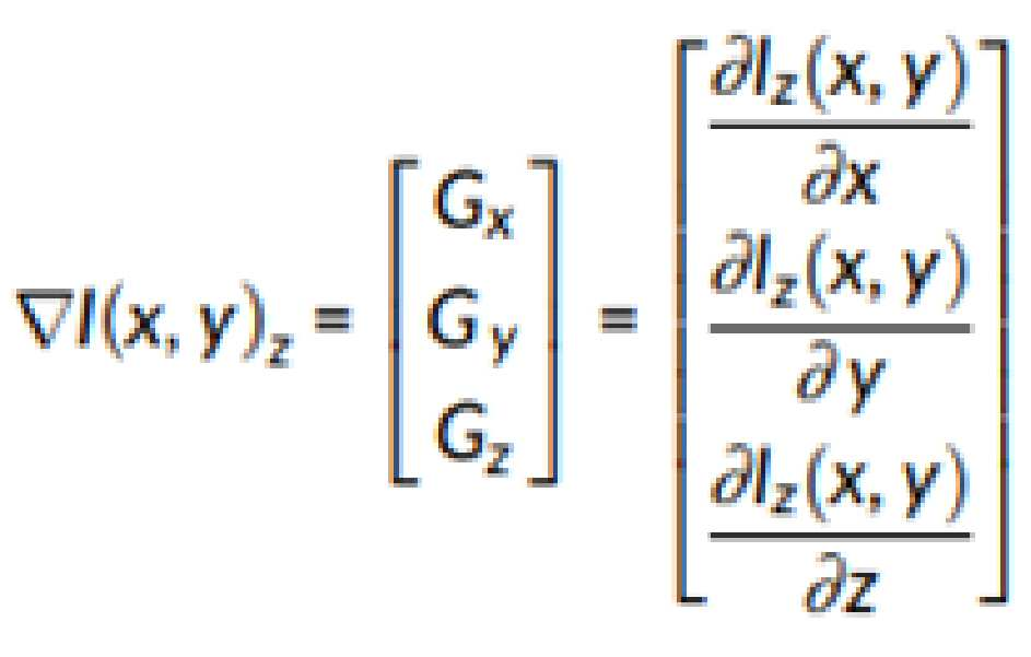
여기서 Gx, Gy 및 Gz는 각각 x, y 및 z 방향의 1차 도함수(first-order derivatives)를 나타낸다. where G x , G y and G z denote the first-order derivatives in the x, y and z directions, respectively.
일 실시예에서, 3D ST T는 하기 <수학식 2>와 같이 계산될 수 있다. In one embodiment, 3D ST T may be calculated as in Equation 2 below.

여기서 ![]()
![]()
![]()
![]()
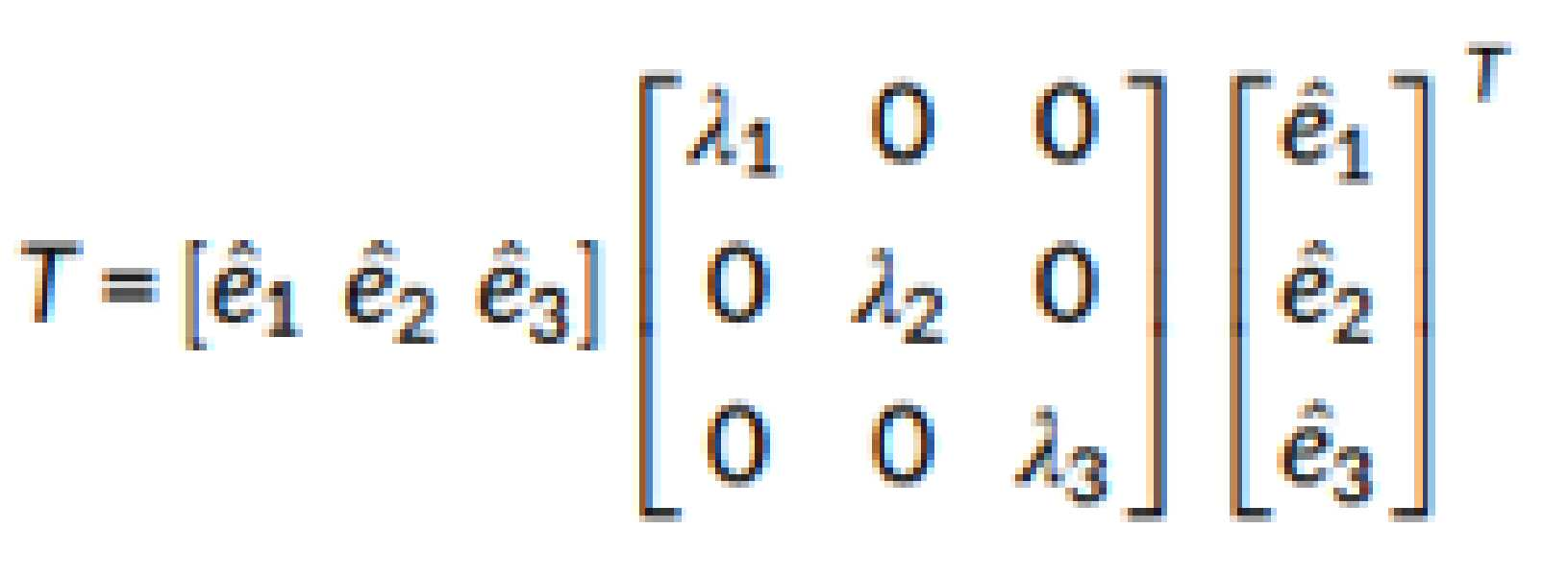
일 실시예에서, 고유 값(eigen value)과 고유 벡터(eigen vector)를 기반으로 하는 3D ST의 2차 형식(quadratic form) T은 하기 <수학식 3>과 같이 계산될 수 있다. In an embodiment, a quadratic form T of a 3D ST based on an eigen value and an eigen vector may be calculated as in Equation 3 below.
여기서 ![]()
![]()
![]()
![]()
![]()
![]()
![]()
![]()
![]()
![]()
![]()
![]()
일 실시예에서, 3D ST의 압축 형식(compact form) T은 하기 <수학식 4>와 같이 계산될 수 있다. In one embodiment, the compact form T of the 3D ST may be calculated as in Equation 4 below.
![]()
![]()
이러한 텐서는 3D에서 시각화될 수 있다. 예를 들어, 연관된 시각화된 텐서는 볼(ball), 플레이트(plate) 및 스틱(stick)일 수 있다. These tensors can be visualized in 3D. For example, the associated visualized tensors can be balls, plates, and sticks.
이 세 가지 단수 텐서(볼, 플레이트 및 스틱)는 점(pointness,), 곡선(curveness) 및 표면(surfaceness)과 관련된 정보를 제공할 수 있다. These three singular tensors (ball, plate, and stick) can provide information related to pointness, curveness, and surfaceness.
일 실시예에서, 텐서 T는 하기 <수학식 5>와 같이 세 가지 요소의 선형 조합으로 표현할 수 있다. In one embodiment, the tensor T can be expressed as a linear combination of three elements as shown in
![]()
![]()
일 실시예에서, 각 텐서 요소는 하기 <표 1>과 같이 나타낼 수 있다. In one embodiment, each tensor element can be represented as shown in Table 1 below.
![]()
![]()
![]()
![]()
![]()
![]()
![]()
![]()
![]()
![]()
![]()
![]()
![]()
![]()
![]()
![]()
본 발명에 따르면, 영상 획득 장치(110)는 초점 측정을 계산하기 위해 표면 정보를 사용할 수 있다. 여기서, 표면 정보는 표면 텐서(surfaceness tensor)에 대한 돌출 측정 값(saliency measure)을 포함할 수 있다. 이 경우, 표면 정보는 가장 큰 고유 값과 두 번째로 큰 고유 값의 차이(즉, ![]()
![]()
![]()
![]()
일 실시예에서, 각 픽셀 (x,y)z에 대한 초점(focus) 값 F(x,y)z은 하기 <수학식 6>과 같이 계산될 수 있다. In an embodiment, a focus value F(x,y) z for each pixel (x,y) z may be calculated as in Equation 6 below.
![]()
![]()
일 실시예에서, 텐서 분해(tensor decomposition)를 사용하여 추정된 깊이(depth) 값 D(x, y)은 z 방향으로 초점 측정 값을 최대화하여 하기 <수학식 7>과 같이 계산될 수 있다. In an embodiment, a depth value D(x, y) estimated using tensor decomposition may be calculated as shown in Equation 7 below by maximizing a focus measurement value in the z direction.
![]()
![]()
도 2는 본 발명의 일 실시예에 따른 가변 초점 방식의 3D 텐서 기반 영상 획득 방법을 도시한 도면이다.2 is a diagram illustrating a method for obtaining a 3D tensor-based image of a variable focus method according to an embodiment of the present invention.
도 2를 참고하면, S201 단계는, 피사체에 대한 이미지 시퀀스를 획득하는 단계이다. Referring to FIG. 2 , step S201 is a step of obtaining an image sequence of a subject.
S203 단계는, 이미지 시퀀스에 대한 3D(3-dimension) 텐서 기반 표면 정보를 산출하는 단계이다. 일 실시예에서, 이미지 시퀀스로부터 3D 텐서 기반 표면 정보에 대한 돌출 값(saliency value)을 산출할 수 있다. Step S203 is a step of calculating 3-dimension (3D) tensor-based surface information for the image sequence. In one embodiment, a saliency value for 3D tensor-based surface information may be calculated from an image sequence.
일 실시예에서, 이미지 시퀀스에 대한 3D 텐서 기반 포인트 정보, 커브 정보 및 표면 정보를 산출할 수 있다. In one embodiment, 3D tensor-based point information, curve information, and surface information for an image sequence may be calculated.
S205 단계는, 3D 텐서 기반 표면 정보를 이용하여 초점 값을 결정하는 단계이다. 일 실시예에서, 3D 텐서 기반 표면 정보를 이용하여 이미지 시퀀스의 각 픽셀에 대한 초점 값(focus value)을 결정할 수 있다. Step S205 is a step of determining a focus value using 3D tensor-based surface information. In one embodiment, a focus value for each pixel of an image sequence may be determined using 3D tensor-based surface information.
일 실시예에서, 피사체의 형태(예: 구형, 원기둥형, 직육면체 등)에 따라 표면 정보뿐만 아니라, 포인트 정보 및 커브 정보를 이용하여 초점 값을 결정할 수 있다. 예를 들어, 피사체의 형태에 따라 3D 텐서 기반 표면 정보에 대한 돌출 값, 포인트 정보에 대한 돌출 값, 커브 정보에 대한 돌출 값을 이용하여 이미지 시퀀스의 각 픽셀에 대한 초점 값을 결정하고, 초점 값을 미리 결정된 방향으로 최대화하여 깊이 값을 결정할 수 있다. In an embodiment, a focus value may be determined using not only surface information but also point information and curve information according to the shape of a subject (eg, sphere, cylinder, rectangular parallelepiped, etc.). For example, according to the shape of the subject, a focus value for each pixel of the image sequence is determined using a 3D tensor-based protrusion value for surface information, a protrusion value for point information, and a protrusion value for curve information. A depth value may be determined by maximizing ? in a predetermined direction.
일 실시예에서, 미리 결정된 방향은, 각 픽셀에 대한 2차원 좌표(x, y)에 대한 방향과 수직인 방향(z)을 포함할 수 있다. In one embodiment, the predetermined direction may include a direction (z) perpendicular to the direction of the two-dimensional coordinates (x, y) for each pixel.
다른 실시예에서, 초점 값을 포인트 정보, 커브 정보 및 표면 정보에 대해 각각 결정할 수 있으며, 이 경우, 포인트 정보에 대한 돌출 값, 커브 정보에 대한 돌출 값 및 표면 정보에 대한 돌출 값에 대하여, 서로 다른 방향으로 초점 값을 최대화하여 최종적인 깊이 값을 결정할 수 있다. In another embodiment, focus values may be determined for the point information, the curve information, and the surface information, respectively. In this case, the protrusion value for the point information, the protrusion value for the curve information, and the protrusion value for the surface information may be mutually determined. The final depth value can be determined by maximizing the focus value in the other direction.
일 실시예에서, 영상 획득 장치(110) 또는 피사체가 이동함에 따라 이미지 시퀀스를 획득할 때, 영상 획득 장치(110) 또는 피사체에 진동이 발생하는 경우, 영상 획득 장치(110) 또는 피사체의 진동 정보를 산출하고, 산출된 진동 정보를 깊이 값에 가중치로 피드백하여 깊이 값을 보정할 수 있다. 이를 통해, 이미지 촬영 시 진동이 발생하더라도 보다 정확하게 3D 이미지를 구현할 수 있다. In one embodiment, when an image sequence is obtained as the
S207 단계는, 초점 값에 기반하여 피사체에 대한 3D 이미지를 디스플레이하는 단계이다. 일 실시예에서, 초점 값을 이용하여 이미지 시퀀스의 각 픽셀에 대한 깊이 값(depth value)을 결정하고, 깊이 값에 기반하여 피사체에 대한 3D 이미지를 생성할 수 있다. Step S207 is a step of displaying a 3D image of a subject based on the focus value. In an embodiment, a depth value for each pixel of the image sequence may be determined using the focus value, and a 3D image of the subject may be generated based on the depth value.
일 실시예에서, 이미지 시퀀스의 각 픽셀에 대한 초점 값을 미리 결정된 방향으로 최대화하여 깊이 값을 결정할 수 있다. In one embodiment, the depth value may be determined by maximizing the focus value of each pixel of the image sequence in a predetermined direction.
도 3a 내지 3e는 본 발명의 일 실시예에 따른 2D 및 3D 초점 측정 성능 비교 그래프를 도시한 도면이다.3A to 3E are diagrams illustrating 2D and 3D focus measurement performance comparison graphs according to an embodiment of the present invention.
도 3a 내지 3e를 참고하면, 본 발명에 따른 초점 측정의 효과는 시뮬레이션된 개체와 실제 개체의 이미지 시퀀스를 사용하여 실험을 수행하여 평가될 수 있다. Referring to FIGS. 3A to 3E , the effect of the focus measurement according to the present invention can be evaluated by conducting experiments using image sequences of simulated objects and real objects.
예를 들어, 제곱 평균 오차(root mean square error, RMSE), 상관 관계(correlation, C2), 피크 신호 대 잡음비(peak signal-to-noise ratio, PSNR) 및 구조적 유사성 지수 측정(structural similarity index measure, SSIM)과 같은 품질 측정이 사용될 수 있다. For example, root mean square error (RMSE), correlation (C2), peak signal-to-noise ratio (PSNR), and structural similarity index measure (C2). SSIM) can be used.
이 경우, ML이라 지칭되는 이미지 라플라시안(image Laplacian)의 에너지, SML이라 지칭되는 스몰 윈도우(small window) 내 이미지 라플라시안의 에너지 합, 이미지 통계 기반의 초점 측정 그레이 레벨 분산(gray-level variance, GLV), TEN(Tenenbaum) 초점 측정이라는 이미지 그라디언트의 에너지와 같은 종래의 기법을 4개의 초점 측정 연산자로 사용될 수 있다. In this case, the energy of the image Laplacian, referred to as ML, the energy sum of the image Laplacian within a small window, referred to as SML, and focus measurement gray-level variance (GLV) based on image statistics , conventional techniques such as the energy of image gradients, called TEN (Tenenbaum) focus measurement, can be used as four focus measurement operators.
기존 방법(ML, SML, GLV, TEN)과 본 발명에 따른 ST 기반 방법의 2D 및 3D 사례 결과의 비교는 하기 <표 2>와 같이 나타낼 수 있다. A comparison of the 2D and 3D case results of the existing methods (ML, SML, GLV, TEN) and the ST-based method according to the present invention can be shown in Table 2 below.
상기 <표 2>에서 본 발명에 따른 초점 측정이 다른 모든 종래의 2D 및 3D 초점 측정에 대해 RMSE, C2, PSNR 및 SSIM과 같은 정량 측정에 대해 더 정확한 값을 제공했음을 확인할 수 있다. 또한, 3D 초점 측정 중 본 발명에 따른 초점 측정은 정확한 깊이 추정에서 더 나은 성능을 보임을 확인할 수 있다. It can be seen from Table 2 that the focus measurement according to the present invention provided more accurate values for quantitative measurements such as RMSE, C2, PSNR and SSIM than all other conventional 2D and 3D focus measurements. In addition, among 3D focus measurements, it can be seen that the focus measurement according to the present invention shows better performance in accurate depth estimation.
기존 방법(ML, SML, GLV, TEN)과 본 발명에 따른 ST 기반 방법을 사용하여 얻은 깊이 맵(Depth map)을 확인할 수 있다. 본 발명에 따른 ST 기반 방법을 사용하여 재구성한 3D 형상은 정확하고, 종래의 ML과 TEN을 사용하여 재구성된 형상은 초점 측정 계산의 부정확성으로 인해 스파이크가 있음을 알 수 있다.Depth maps obtained using existing methods (ML, SML, GLV, TEN) and the ST-based method according to the present invention can be checked. It can be seen that the 3D shape reconstructed using the ST-based method according to the present invention is accurate, and the shape reconstructed using conventional ML and TEN has spikes due to inaccuracies in focus measurement calculations.
도 4는 본 발명의 일 실시예에 따른 RMSE 성능 비교 그래프를 도시한 도면이다.4 is a diagram showing a RMSE performance comparison graph according to an embodiment of the present invention.
도 4를 참고하면, 소음 환경에서 본 발명에 따른 초점 측정의 성능을 평가하기 위해 시뮬레이션된 이미지 시퀀스에 다양한 유형의 노이즈를 추가하여 성능평가가 수행될 수 있다. Referring to FIG. 4 , in order to evaluate the performance of the focus measurement according to the present invention in a noisy environment, performance evaluation may be performed by adding various types of noise to a simulated image sequence.
일 실시예에서, 이미지 시퀀스는 평균이 0이고 분산이 0.005 인 가우스 노이즈로 손상될 수 있다.In one embodiment, the image sequence may be corrupted with Gaussian noise with zero mean and 0.005 variance.
기존 방법(ML, SML, GLV, TEN)과 본 발명에 따른 ST 기반 방법에 대한 노이즈 이미지 시퀀스에서 얻은 결과를 2D 및 3D 사례에 대해 비교한 내용은 하기 <표 3>과 같이 나타낼 수 있다. 즉, 결과로부터 본 발명에 따른 ST 기반 방법이 종래의 방법보다 더 나은 성과를 나타냄을 확인할 수 있다. Table 3 shows the comparison of the results obtained from the noise image sequence for the existing methods (ML, SML, GLV, TEN) and the ST-based method according to the present invention for 2D and 3D cases. That is, it can be confirmed from the results that the ST-based method according to the present invention exhibits better performance than the conventional method.
본 발명에 따른 ST 기반 방법은 노이즈에 대해 상당한 저항을 보였지만 ML 초점 측정은 다른 초점 측정에 비해 성능이 떨어짐을 확인할 수 있다.Although the ST-based method according to the present invention showed considerable resistance to noise, it can be seen that ML focus measurement has poor performance compared to other focus measurements.
본 발명에 따른 초점 측정의 견고성은 노이즈 및 노이즈 없는 이미지 시퀀스에 대한 RMSE를 비교하여 시각화할 수 있다. ML 및 SML 초점 측정은 TEN 및 GLV 초점 측정에 비해 노이즈에 더 민감하다는 것을 알 수 있다. 본 발명에 따르면, 소음에 대한 강도를 보여주는 두 경우 모두 거의 동일한 결과를 제공함을 확인할 수 있다.The robustness of the focus measurement according to the present invention can be visualized by comparing the RMSE for noisy and noise-free image sequences. It can be seen that ML and SML focus measurements are more sensitive to noise than TEN and GLV focus measurements. According to the present invention, it can be seen that almost the same results are provided in both cases showing the intensity of noise.
일 실시예에서, 노이즈 밀도가 0.1인 쏠트 앤 페퍼 노이즈(salt-and-pepper noise)로 손상된 이미지 시퀀스를 사용하여 결과를 계산할 수 있다.In one embodiment, the result can be calculated using an image sequence corrupted with salt-and-pepper noise with a noise density of 0.1.
기존 방법(ML, SML, GLV, TEN)과 제안된 ST 기반 방법에 대해 2D 및 3D 사례에 대해 노이즈 이미지 시퀀스에서 얻은 결과를 비교한 내용은 하기 <표 4>와 같이 나타낼 수 있다.The comparison of the results obtained from the noisy image sequence for 2D and 3D cases for the existing methods (ML, SML, GLV, TEN) and the proposed ST-based method can be shown in Table 4 below.
<표 4>에서 본 발명에 따른 ST 초점 측정은 ML이 저조한 성능을 발휘하는 동안 노이즈에 대해 상당한 저항을 나타냄을 알 수 있습니다. 또한, 본 발명에 따른 ST 초점 측정은 노이즈가 있는 경우와 없는 경우의 차이가 가장 낮아 견고함을 확인할 수 있다.It can be seen from Table 4 that the ST focus measurement according to the present invention exhibits significant resistance to noise while ML performs poorly. In addition, it can be confirmed that the ST focus measurement according to the present invention is robust with the lowest difference between the case with noise and the case without noise.
기존의 방법(ML, SML, GLV, TEN)과 본 발명에 따른 ST 초점 측정을 사용하여 얻은 깊이 맵을 확인할 수 있다. 즉, 본 발명에 따른 ST 초점 측정이 최상의 3D 형상을 제공하며, 노이즈에 대한 강점을 보여줌을 확인할 수 있다. Depth maps obtained using existing methods (ML, SML, GLV, TEN) and the ST focus measurement according to the present invention can be confirmed. That is, it can be confirmed that the ST focus measurement according to the present invention provides the best 3D shape and shows strength against noise.
도 5a 내지 5e는 본 발명의 일 실시예에 따른 이미지 생성 성능 비교 그래프를 도시한 도면이다.5A to 5E are diagrams illustrating image generation performance comparison graphs according to an embodiment of the present invention.
도 5a 내지 5e를 참고하면, 본 발명에 따른 방법의 성능은 실제 물체 그루브(groove)의 이미지 시퀀스를 사용하여 평가될 수 있다. 기존 방법(ML, SML, GLV, TEN)과 본 발명에 따른 ST 기반 방법에서 얻은 깊이 맵을 확인할 수 있다. Referring to Figures 5a to 5e, the performance of the method according to the present invention can be evaluated using image sequences of real object grooves. Depth maps obtained from the existing methods (ML, SML, GLV, TEN) and the ST-based method according to the present invention can be confirmed.
본 발명에 따른 ST 기반 방법이 종래의 다른 방법에 비해보다 정확한 3D 형상을 제공함을 알 수 있다. It can be seen that the ST-based method according to the present invention provides a more accurate 3D shape than other conventional methods.
도 5e의 (a)와 (b)를 참고하면, 각각 3D GLV 및 ST 방법을 사용하여 재구성의 단면을 확인할 수 있다. 본 발명에 따른 ST 방법은 정확한 깊이를 제공하는 반면, 3D GLV 기반 깊이는 스파이크로 볼 수 있는 부정확성을 가지고 있음을 알 수 있다. Referring to (a) and (b) of FIG. 5e , the cross section of the reconstruction can be confirmed using the 3D GLV and ST methods, respectively. It can be seen that the ST method according to the present invention provides accurate depth, whereas the 3D GLV-based depth has inaccuracies that can be seen as spikes.
즉, 본 발명에 따른 초점 측정이 더 나은 성과를 보이며, 이는, 로컬 이미지 볼륨의 변형 또는 고주파 콘텐츠를 활용하기 때문일 수 있다. That is, the focus measurement according to the present invention shows better performance, which may be due to utilization of high-frequency content or deformation of the local image volume.
수학적으로 고유 값의 합이 로컬 이미지 볼륨의 총 분산과 같으므로 본 발명에 따른 초점 측정은 분산을 추가로 활용할 수 있다. 즉, 제안된 측정 값이 분산의 변동을 계산한다는 결론을 내릴 수 있다.Since mathematically the sum of the eigenvalues equals the total variance of the local image volume, the focus measurement according to the present invention can additionally utilize the variance. That is, it can be concluded that the proposed measure calculates the variation in variance.
본 발명에 따르면, 3D ST 분석을 기반으로 정확한 깊이 맵 추정을 위한 새로운 초점 측정이 사용될 수 있다. 3D ST의 표면 요소(surfaceness element)는 선명도의 품질을 측정하는데 사용될 수 있다.According to the present invention, a new focus measurement for accurate depth map estimation based on 3D ST analysis can be used. The surfaceness element of 3D ST can be used to measure the quality of sharpness.
도 6은 본 발명의 일 실시예에 따른 가변 초점 방식의 3D 텐서 기반 영상 획득 장치(110)의 기능적 구성을 도시한 도면이다.6 is a diagram showing a functional configuration of a
도 6을 참고하면, 영상 획득 장치(110)는 촬영부(610), 제어부(620) 및 표시부(630)를 포함할 수 있다.Referring to FIG. 6 , the
촬영부(610)는 피사체에 대한 이미지 시퀀스를 획득할 수 있다. 일 실시예에서, 촬영부(610)는 광학 현미경 또는 카메라로 구현될 수 있다. 예를 들어, 촬영부(610)는 카메라와 렌즈를 포함할 수 있다. The photographing
제어부(620)는 이미지 시퀀스에 대한 3D 텐서 기반 표면 정보를 산출하고, 3D 텐서 기반 표면 정보를 이용하여 초점 값을 결정할 수 있다. The
일 실시예에서, 제어부(620)는 적어도 하나의 프로세서 또는 마이크로(micro) 프로세서를 포함하거나, 또는, 프로세서의 일부일 수 있다. 또한, 제어부(620)는 CP(communication processor)라 지칭될 수 있다. 제어부(620)는 본 발명의 다양한 실시예에 따른 영상 획득 장치(110)의 동작을 제어할 수 있다. In one embodiment, the
표시부(630)는 초점 값에 기반하여 피사체에 대한 3D 이미지를 디스플레이할 수 있다. The
일 실시예에서, 표시부(630)는 영상 획득 장치(110)에서 처리되는 정보를 나타낼 수 있다. 예를 들면, 표시부(630)는 액정 디스플레이(LCD; Liquid Crystal Display), 발광 다이오드(LED; Light Emitting Diode) 디스플레이, 유기 발광 다이오드(OLED; Organic LED) 디스플레이, 마이크로 전자기계 시스템(MEMS; Micro Electro Mechanical Systems) 디스플레이 및 전자 종이(electronic paper) 디스플레이 중 적어도 어느 하나를 포함할 수 있다.In one embodiment, the
도 6을 참고하면, 영상 획득 장치(110)는 촬영부(610), 제어부(620) 및 표시부(630)를 포함할 수 있다. 본 발명의 다양한 실시 예들에서 영상 획득 장치(110)는 도 6에 설명된 구성들이 필수적인 것은 아니어서, 도 6에 설명된 구성들보다 많은 구성들을 가지거나, 또는 그보다 적은 구성들을 가지는 것으로 구현될 수 있다.Referring to FIG. 6 , the
이상의 설명은 본 발명의 기술적 사상을 예시적으로 설명한 것에 불과한 것으로, 통상의 기술자라면 본 발명의 본질적인 특성이 벗어나지 않는 범위에서 다양한 변경 및 수정이 가능할 것이다.The above description is only illustrative of the technical idea of the present invention, and various changes and modifications may be made by those skilled in the art without departing from the essential characteristics of the present invention.
따라서, 본 명세서에 개시된 실시예들은 본 발명의 기술적 사상을 한정하기 위한 것이 아니라, 설명하기 위한 것이고, 이러한 실시예들에 의하여 본 발명의 범위가 한정되는 것은 아니다.Therefore, the embodiments disclosed in this specification are not intended to limit the technical spirit of the present invention, but to explain, and the scope of the present invention is not limited by these embodiments.
본 발명의 보호범위는 청구범위에 의하여 해석되어야 하며, 그와 동등한 범위 내에 있는 모든 기술 사상은 본 발명의 권리범위에 포함되는 것으로 이해되어야 한다.The protection scope of the present invention should be interpreted by the claims, and all technical ideas within the equivalent range should be understood to be included in the scope of the present invention.
110: 영상 획득 장치
610: 촬영부
620: 제어부
630: 표시부110: image acquisition device
610: shooting unit
620: control unit
630: display unit
Claims (10)
상기 이동에 따라 획득된 상기 이미지 시퀀스로부터 상기 이미지 시퀀스에 대한 3D(3-dimension) 텐서를 계산하는 단계;
상기 피사체의 형태에 따라 상기 이미지 시퀀스에 대한 3D 텐서 기반 표면 정보에 대한 돌출 값(saliency value), 포인트 정보에 대한 돌출 값 및 커브 정보에 대한 돌출 값을 산출하는 단계;
상기 3D 텐서 기반 표면 정보에 대한 돌출 값, 포인트 정보에 대한 돌출 값 및 커브 정보에 대한 돌출 값을 이용하여 상기 이미지 시퀀스의 각 픽셀에 대한 초점 값을 결정하는 단계;
상기 결정된 초점 값을 미리 결정된 방향으로 최대화하여 깊이 값(depth value)을 결정하는 단계; 및
상기 최대화된 깊이 값에 기반하여 상기 피사체에 대한 3D 이미지를 디스플레이하는 단계;
를 포함하는,
가변 초점 방식의 3D 텐서 기반 영상 획득 방법.
acquiring an image sequence of the subject by photographing the subject while moving a reference plane of the subject;
calculating a 3-dimension (3D) tensor for the image sequence from the image sequence obtained according to the movement;
calculating a saliency value for 3D tensor-based surface information, a saliency value for point information, and a saliency value for curve information of the image sequence according to the shape of the subject;
determining a focus value for each pixel of the image sequence using the 3D tensor-based surface information protrusion value, point information protrusion value, and curve information protrusion value;
determining a depth value by maximizing the determined focus value in a predetermined direction; and
displaying a 3D image of the subject based on the maximized depth value;
including,
3D tensor-based image acquisition method of variable focus method.
상기 이동에 따라 획득된 상기 이미지 시퀀스로부터 상기 이미지 시퀀스에 대한 3D(3-dimension) 텐서를 계산하고,
상기 피사체의 형태에 따라 상기 이미지 시퀀스에 대한 3D(3-dimension) 텐서 기반 표면 정보에 대한 돌출 값(saliency value), 포인트 정보에 대한 돌출 값 및 커브 정보에 대한 돌출 값을 산출하고,
상기 3D 텐서 기반 표면 정보에 대한 돌출 값, 포인트 정보에 대한 돌출 값 및 커브 정보에 대한 돌출 값을 이용하여 상기 이미지 시퀀스의 각 픽셀에 대한 초점 값을 결정하고,
상기 결정된 초점 값을 미리 결정된 방향으로 최대화하여 깊이 값(depth value)을 결정하는 제어부; 및
상기 최대화된 깊이 값에 기반하여 상기 피사체에 대한 3D 이미지를 디스플레이하는 표시부;
를 포함하는,
가변 초점 방식의 3D 텐서 기반 영상 획득 장치.
a photographing unit which acquires an image sequence of the subject by photographing the subject while moving a reference plane of the subject; and
Calculate a 3-dimension (3D) tensor for the image sequence from the image sequence obtained according to the movement;
Calculate a saliency value for 3-dimension (3D) tensor-based surface information of the image sequence, a saliency value for point information, and a saliency value for curve information of the image sequence according to the shape of the subject,
Determining a focus value for each pixel of the image sequence using the 3D tensor-based protrusion value for surface information, the protrusion value for point information, and the protrusion value for curve information;
a controller that determines a depth value by maximizing the determined focus value in a predetermined direction; and
a display unit displaying a 3D image of the subject based on the maximized depth value;
including,
Variable focus type 3D tensor based image capture device.
Priority Applications (1)
| Application Number | Priority Date | Filing Date | Title |
|---|---|---|---|
| KR1020200178689A KR102479120B1 (en) | 2020-12-18 | 2020-12-18 | A method and apparatus for 3D tensor-based 3-dimension image acquisition with variable focus |
Applications Claiming Priority (1)
| Application Number | Priority Date | Filing Date | Title |
|---|---|---|---|
| KR1020200178689A KR102479120B1 (en) | 2020-12-18 | 2020-12-18 | A method and apparatus for 3D tensor-based 3-dimension image acquisition with variable focus |
Publications (2)
| Publication Number | Publication Date |
|---|---|
| KR20220088050A KR20220088050A (en) | 2022-06-27 |
| KR102479120B1 true KR102479120B1 (en) | 2022-12-16 |
Family
ID=82247027
Family Applications (1)
| Application Number | Title | Priority Date | Filing Date |
|---|---|---|---|
| KR1020200178689A Active KR102479120B1 (en) | 2020-12-18 | 2020-12-18 | A method and apparatus for 3D tensor-based 3-dimension image acquisition with variable focus |
Country Status (1)
| Country | Link |
|---|---|
| KR (1) | KR102479120B1 (en) |
Family Cites Families (3)
| Publication number | Priority date | Publication date | Assignee | Title |
|---|---|---|---|---|
| JP5773323B2 (en) | 2011-08-09 | 2015-09-02 | インテル・コーポレーション | Multi-view 3D face generation based on images |
| WO2013102790A2 (en) * | 2012-01-04 | 2013-07-11 | Thomson Licensing | Processing 3d image sequences cross reference to related applications |
| WO2017220598A1 (en) * | 2016-06-20 | 2017-12-28 | Cognex Corporation | Method for the three dimensional measurement of moving objects during a known movement |
-
2020
- 2020-12-18 KR KR1020200178689A patent/KR102479120B1/en active Active
Non-Patent Citations (1)
| Title |
|---|
| Muhammad T. Mahmood et al., "Shape from focus based on 3D structure tensor using optical microscopy", 2019.10.21. 1부.* |
Also Published As
| Publication number | Publication date |
|---|---|
| KR20220088050A (en) | 2022-06-27 |
Similar Documents
| Publication | Publication Date | Title |
|---|---|---|
| Ferstl et al. | Image guided depth upsampling using anisotropic total generalized variation | |
| Jeon et al. | Accurate depth map estimation from a lenslet light field camera | |
| US8355564B2 (en) | Corresponding point searching method and three-dimensional position measuring method | |
| CN103528571B (en) | Single eye stereo vision relative pose measuring method | |
| Chen et al. | Transforming a 3-d lidar point cloud into a 2-d dense depth map through a parameter self-adaptive framework | |
| CN113470002A (en) | Method and device for evaluating reconstruction quality of chromatographic SAR three-dimensional point cloud | |
| Shedligeri et al. | Data driven coded aperture design for depth recovery | |
| CN109961092B (en) | Binocular vision stereo matching method and system based on parallax anchor point | |
| Paramanand et al. | Depth from motion and optical blur with an unscented Kalman filter | |
| Kim et al. | Cost-aware depth map estimation for lytro camera | |
| KR102479120B1 (en) | A method and apparatus for 3D tensor-based 3-dimension image acquisition with variable focus | |
| CN116630423A (en) | A multi-target binocular positioning method and system for micro-robots based on ORB features | |
| KR20150119770A (en) | Method for measuring 3-dimensional cordinates with a camera and apparatus thereof | |
| CN109741389A (en) | One kind being based on the matched sectional perspective matching process of region base | |
| Zheng et al. | Depth from Focus in 3D Measurement: An Overview | |
| KR102171203B1 (en) | A method of matching a stereo image and an apparatus therefor | |
| Wang et al. | Close-range photogrammetry for accurate deformation distribution measurement | |
| Di Martino et al. | One-shot 3D gradient field scanning | |
| Scharr | Towards a multi-camera generalization of brightness constancy | |
| Xian et al. | Depth-from-defocus: Blur equalization technique | |
| Duan et al. | GSNet: A defocused camera calibration method integrating gradient and spectrum for single image defocus deblurring | |
| Madjidi et al. | On robustness and localization accuracy of optical flow computation from color imagery | |
| US20240296577A1 (en) | Large depth-of-field microscopic structured-light 3d imaging | |
| Jonscher et al. | Reconstruction of images taken by a pair of non-regular sampling sensors using correlation based matching | |
| Shi et al. | Practical Method of Low-Light-Level Binocular Ranging Based on Triangulation and Error Correction |
Legal Events
| Date | Code | Title | Description |
|---|---|---|---|
| PA0109 | Patent application |
St.27 status event code: A-0-1-A10-A12-nap-PA0109 |
|
| PA0201 | Request for examination |
St.27 status event code: A-1-2-D10-D11-exm-PA0201 |
|
| P11-X000 | Amendment of application requested |
St.27 status event code: A-2-2-P10-P11-nap-X000 |
|
| P13-X000 | Application amended |
St.27 status event code: A-2-2-P10-P13-nap-X000 |
|
| D13-X000 | Search requested |
St.27 status event code: A-1-2-D10-D13-srh-X000 |
|
| D14-X000 | Search report completed |
St.27 status event code: A-1-2-D10-D14-srh-X000 |
|
| PE0902 | Notice of grounds for rejection |
St.27 status event code: A-1-2-D10-D21-exm-PE0902 |
|
| AMND | Amendment | ||
| E13-X000 | Pre-grant limitation requested |
St.27 status event code: A-2-3-E10-E13-lim-X000 |
|
| P11-X000 | Amendment of application requested |
St.27 status event code: A-2-2-P10-P11-nap-X000 |
|
| P13-X000 | Application amended |
St.27 status event code: A-2-2-P10-P13-nap-X000 |
|
| PN2301 | Change of applicant |
St.27 status event code: A-3-3-R10-R13-asn-PN2301 St.27 status event code: A-3-3-R10-R11-asn-PN2301 |
|
| PN2301 | Change of applicant |
St.27 status event code: A-3-3-R10-R13-asn-PN2301 St.27 status event code: A-3-3-R10-R11-asn-PN2301 |
|
| E601 | Decision to refuse application | ||
| PE0601 | Decision on rejection of patent |
St.27 status event code: N-2-6-B10-B15-exm-PE0601 |
|
| X091 | Application refused [patent] | ||
| PG1501 | Laying open of application |
St.27 status event code: A-1-1-Q10-Q12-nap-PG1501 |
|
| AMND | Amendment | ||
| E13-X000 | Pre-grant limitation requested |
St.27 status event code: A-2-3-E10-E13-lim-X000 |
|
| P11-X000 | Amendment of application requested |
St.27 status event code: A-2-2-P10-P11-nap-X000 |
|
| P13-X000 | Application amended |
St.27 status event code: A-2-2-P10-P13-nap-X000 |
|
| PX0901 | Re-examination |
St.27 status event code: A-2-3-E10-E12-rex-PX0901 |
|
| PX0701 | Decision of registration after re-examination |
St.27 status event code: A-3-4-F10-F13-rex-PX0701 |
|
| X701 | Decision to grant (after re-examination) | ||
| GRNT | Written decision to grant | ||
| PR0701 | Registration of establishment |
St.27 status event code: A-2-4-F10-F11-exm-PR0701 |
|
| PR1002 | Payment of registration fee |
St.27 status event code: A-2-2-U10-U11-oth-PR1002 Fee payment year number: 1 |
|
| PG1601 | Publication of registration |
St.27 status event code: A-4-4-Q10-Q13-nap-PG1601 |
|
| PR1001 | Payment of annual fee |
St.27 status event code: A-4-4-U10-U11-oth-PR1001 Fee payment year number: 4 |
|
| U11 | Full renewal or maintenance fee paid |
Free format text: ST27 STATUS EVENT CODE: A-4-4-U10-U11-OTH-PR1001 (AS PROVIDED BY THE NATIONAL OFFICE) Year of fee payment: 4 |
|
| R18 | Changes to party contact information recorded |
Free format text: ST27 STATUS EVENT CODE: A-5-5-R10-R18-OTH-X000 (AS PROVIDED BY THE NATIONAL OFFICE) |
|
| R18-X000 | Changes to party contact information recorded |
St.27 status event code: A-5-5-R10-R18-oth-X000 |