KR102421067B1 - Simultaneous estimation apparatus and method for simultaneously estimating the camera pose and 3d coordinates of the target object - Google Patents
Simultaneous estimation apparatus and method for simultaneously estimating the camera pose and 3d coordinates of the target object Download PDFInfo
- Publication number
- KR102421067B1 KR102421067B1 KR1020200166956A KR20200166956A KR102421067B1 KR 102421067 B1 KR102421067 B1 KR 102421067B1 KR 1020200166956 A KR1020200166956 A KR 1020200166956A KR 20200166956 A KR20200166956 A KR 20200166956A KR 102421067 B1 KR102421067 B1 KR 102421067B1
- Authority
- KR
- South Korea
- Prior art keywords
- point
- coordinates
- camera
- projected
- estimated
- Prior art date
- Legal status (The legal status is an assumption and is not a legal conclusion. Google has not performed a legal analysis and makes no representation as to the accuracy of the status listed.)
- Active
Links
Images


Classifications
-
- G—PHYSICS
- G06—COMPUTING OR CALCULATING; COUNTING
- G06T—IMAGE DATA PROCESSING OR GENERATION, IN GENERAL
- G06T7/00—Image analysis
- G06T7/70—Determining position or orientation of objects or cameras
- G06T7/73—Determining position or orientation of objects or cameras using feature-based methods
-
- G—PHYSICS
- G06—COMPUTING OR CALCULATING; COUNTING
- G06T—IMAGE DATA PROCESSING OR GENERATION, IN GENERAL
- G06T15/00—3D [Three Dimensional] image rendering
- G06T15/10—Geometric effects
-
- G—PHYSICS
- G06—COMPUTING OR CALCULATING; COUNTING
- G06T—IMAGE DATA PROCESSING OR GENERATION, IN GENERAL
- G06T7/00—Image analysis
- G06T7/30—Determination of transform parameters for the alignment of images, i.e. image registration
- G06T7/33—Determination of transform parameters for the alignment of images, i.e. image registration using feature-based methods
-
- G—PHYSICS
- G06—COMPUTING OR CALCULATING; COUNTING
- G06T—IMAGE DATA PROCESSING OR GENERATION, IN GENERAL
- G06T2207/00—Indexing scheme for image analysis or image enhancement
- G06T2207/30—Subject of image; Context of image processing
- G06T2207/30244—Camera pose
Landscapes
- Engineering & Computer Science (AREA)
- Physics & Mathematics (AREA)
- General Physics & Mathematics (AREA)
- Theoretical Computer Science (AREA)
- Computer Vision & Pattern Recognition (AREA)
- Geometry (AREA)
- Computer Graphics (AREA)
- Length Measuring Devices By Optical Means (AREA)
Abstract
카메라 자세와 대상 물체의 3D 좌표를 동시에 추정하는 동시 추정 방법에 관한 것으로서, 카메라 자세와 대상 물체의 3D 좌표를 동시에 추정하는 동시 추정 방법은, (a) 기준 물체의 알려진 3D 기준점의 좌표를 입력받는 단계; (b) 상기 알려진 3D 기준점과 관련하여, 카메라를 통해 제1 시간 에포크에서 획득된 제1 이미지 상에 투영된 제1 투영된 2D 포인트를 설정하고, 상기 카메라의 자세 변경에 의해 상기 제1 시간 에포크와는 다른 제2 시간 에포크에서 제2 이미지가 획득되는 경우, 상기 제2 이미지 상에 투영되는 제2 투영된 2D 포인트를 설정하는 단계; 및 (c) 상기 카메라의 자세 변경에 응답하여, 상기 (b) 단계에서 설정된 정보를 기초로 획득되는 이미지 상의 투영된 2D 포인트와 3D 포인트 간의 관계 정보 및 상기 카메라의 자세 변경이 고려된 두 이미지 상에서의 상기 알려진 3D 기준점에 대한 상대적인 위치 관계에 관한 정보를 고려하여 정의된 비용 함수를 이용하여, 상기 제2 시간 에포크에 대응하는 카메라의 변경된 자세인 추정 대상 카메라 자세와 상기 제2 시간 에포크에 대응하는 상기 제2 이미지 내 상기 대상 물체의 알려지지 않은 3D 포인트의 좌표인 추정 대상 3D 좌표의 동시 추정을 수행하는 단계를 포함하고, 상기 상대적인 위치 관계에 관한 정보는, 상기 제2 투영된 2D 포인트와 상기 제1 투영된 2D 포인트 간의 관계 정보를 포함할 수 있다.A simultaneous estimation method for simultaneously estimating a camera posture and 3D coordinates of a target object, the simultaneous estimation method for estimating a camera posture and 3D coordinates of a target object simultaneously, (a) receiving coordinates of a known 3D reference point of a reference object step; (b) with respect to the known 3D reference point, setting a first projected 2D point projected on a first image acquired at a first time epoch through a camera, and by changing the attitude of the camera to the first time epoch setting a second projected 2D point projected on the second image when a second image is acquired at a second time epoch different from ; and (c) in response to the change in the posture of the camera, relation information between the projected 2D point and the 3D point on the image obtained based on the information set in step (b), and on the two images in which the change in the posture of the camera is considered. Using a cost function defined in consideration of information on the relative positional relationship with respect to the known 3D reference point of performing simultaneous estimation of estimated target 3D coordinates that are coordinates of an unknown 3D point of the target object in the second image, wherein the information about the relative positional relationship includes: the second projected 2D point and the second 1 may include relationship information between the projected 2D points.
Description
본원은 카메라 자세와 대상 물체의 3D 좌표를 동시에 추정하는 동시 추정 장치 및 방법에 관한 것이다.The present application relates to a simultaneous estimation apparatus and method for simultaneously estimating a camera posture and 3D coordinates of a target object.
카메라에서 물체까지의 거리를 계산하려면 삼각 측량(triangulation)이 필요하다. 이는 측량(surveying), 계측(metrology), 천문학(astrometry), 내비게이션(navigation) 및 타겟 추적(target tracking)과 같은 다양한 엔지니어링에서 중요합니다. 특히, 컴퓨터 비전 사회의 삼각 측량은 SfM (Structure-from-Motion), 스테레오 비전(stereo vision), SLAM (Simultaneous Localization And Mapping), 시각 측위(visual localization) 등 다양한 유용한 방법론을 제공해 왔다.Triangulation is needed to calculate the distance from the camera to the object. This is important in a variety of engineering applications such as surveying, metrology, astronomy, navigation, and target tracking. In particular, triangulation in the computer vision society has provided various useful methodologies such as SfM (Structure-from-Motion), stereo vision, SLAM (Simultaneous Localization And Mapping), and visual localization.
삼각 측량은 실제 세계의 3D 포인트(3D point)가 다른 카메라 영상(camera images)에 의해 관찰된 해당 이미지 포인트(image points)와 일치한다고 가정한다. 이미지 포인트는 일예로 종래에 공지된 특징(feature) 감지 및 추출 알고리즘에 의해 획득될 수 있다. 이러한 2D 포인트(2D 점)는 일반적으로 특징점(feature point)이라 지칭되는데, 본원에서는 특징점 대신 단순히 포인트(point, 점)로 달리 지칭될 수 있다.Triangulation assumes that 3D points in the real world coincide with corresponding image points observed by other camera images. The image point may be obtained by, for example, a feature detection and extraction algorithm known in the art. Such a 2D point (2D point) is generally referred to as a feature point, but may be simply referred to as a point instead of a feature point in the present application.
노이즈(noise)가 없는 상황에서 삼각 측량 문제를 푸는 것은 간단하다고 볼 수 있다. 그러나, 실제로 이 가정은, 다른 이미지에서 측정된 2D 포인트가 노이즈로 인해 정확히 일치하지 않기 때문에 비현실적이라 할 수 있다. Solving triangulation problems in the absence of noise can be seen as simple. However, in practice this assumption is unrealistic because the 2D points measured in different images do not exactly match due to noise.
노이즈가 있는 상황에서 삼각 측량 문제는 3D 포인트 좌표의 최상의 솔루션(best solution)을 추정한다. 좌표 추정(coordinate estimation)의 정확도는 카메라 움직임, 보정 파라미터(calibration parameters) 또는 픽셀 노이즈(pixel noise)의 불확실성(uncertainties)으로 인해 감소할 수 있다.In the presence of noise, the triangulation problem estimates the best solution of the 3D point coordinates. The accuracy of coordinate estimation may decrease due to uncertainties in camera movement, calibration parameters, or pixel noise.
대부분의 기존(종래) 방법에서 카메라의 자세(즉, 위치 및 방향)는 삼각 측량 이전에 알 수 있는 것으로 가정(즉, 미리 알려져 있는 것으로 가정)한다. 이전에 재구성된 3D 기준점(3D reference points)과 그들의 투영된 이미지 포인트의 조합은 2D-3D 대응(correspondence)이라고 불리며, 카메라 자세(camera pose)를 추정하는 데 사용될 수 있다. 이 방법은 PnP (Perspective-n-Point) 방법으로 널리 알려져 있다.In most existing (conventional) methods, the pose (ie position and orientation) of the camera is assumed to be known (ie known in advance) prior to triangulation. The combination of previously reconstructed 3D reference points and their projected image points is called the 2D-3D correspondence, and can be used to estimate the camera pose. This method is widely known as a PnP (Perspective-n-Point) method.
3D 기준점의 정확한 좌표가 주어진다고 가정할 때, 정확한 카메라 자세 추정(estimates)을 위한 방법에는 다양한 버전(diverse versions)이 있다. 그러나, 현실적으로 3D 기준점의 정확한 좌표를 일관되게 제공하는 것은 어렵다고 할 수 있다. 따라서, 3D 기준점의 좌표에 오차(error, 에러, 오류)가 존재하는 상황(즉, 3D 기준점의 좌표가 부정확한 상황)에서도 정확한 카메라의 자세를 추정할 수 있도록 하는 기술에 대한 개발이 요구된다.Assuming that the exact coordinates of the 3D reference point are given, there are various versions of a method for accurate camera pose estimations. However, in reality, it can be said that it is difficult to consistently provide accurate coordinates of a 3D reference point. Therefore, it is required to develop a technique for estimating the correct camera posture even in a situation in which an error exists in the coordinates of the 3D reference point (that is, in a situation in which the coordinates of the 3D reference point are inaccurate).
본원의 배경이 되는 기술은 한국등록특허공보 제10-1645568호에 개시되어 있다.The technology that is the background of the present application is disclosed in Korean Patent Publication No. 10-1645568.
본원은 전술한 종래 기술의 문제점을 해결하기 위한 것으로서, 3D 기준점의 좌표에 오차(error, 에러, 오류)가 존재하는 상황(즉, 3D 기준점의 좌표가 부정확한 상황)에서도 정확한 카메라의 자세를 추정하고, 뿐만 아니라 알려지지 않은 대상 물체의 3D 좌표를 동시에 추정할 수 있도록 하는 카메라 자세와 대상 물체의 3D 좌표를 동시에 추정하는 동시 추정 장치 및 방법을 제공하려는 것을 목적으로 한다.The present application is to solve the problems of the prior art described above, and even in a situation in which an error (error, error) exists in the coordinates of the 3D reference point (that is, the situation in which the coordinates of the 3D reference point is inaccurate), the correct camera posture is estimated In addition, it is an object of the present invention to provide a simultaneous estimation apparatus and method for simultaneously estimating a camera posture and 3D coordinates of a target object, enabling simultaneous estimation of 3D coordinates of an unknown target object.
다만, 본원의 실시예가 이루고자 하는 기술적 과제는 상기된 바와 같은 기술적 과제들로 한정되지 않으며, 또 다른 기술적 과제들이 존재할 수 있다.However, the technical problems to be achieved by the embodiments of the present application are not limited to the technical problems as described above, and other technical problems may exist.
상기한 기술적 과제를 달성하기 위한 기술적 수단으로서, 본원의 일 실시예에 따른 카메라 자세와 대상 물체의 3D 좌표를 동시에 추정하는 동시 추정 방법은, (a) 기준 물체의 알려진 3D 기준점의 좌표를 입력받는 단계; (b) 상기 알려진 3D 기준점과 관련하여, 카메라를 통해 제1 시간 에포크에서 획득된 제1 이미지 상에 투영된 제1 투영된 2D 포인트를 설정하고, 상기 카메라의 자세 변경에 의해 상기 제1 시간 에포크와는 다른 제2 시간 에포크에서 제2 이미지가 획득되는 경우, 상기 제2 이미지 상에 투영되는 제2 투영된 2D 포인트를 설정하는 단계; 및 (c) 상기 카메라의 자세 변경에 응답하여, 상기 (b) 단계에서 설정된 정보를 기초로 획득되는 이미지 상의 투영된 2D 포인트와 3D 포인트 간의 관계 정보 및 상기 카메라의 자세 변경이 고려된 두 이미지 상에서의 상기 알려진 3D 기준점에 대한 상대적인 위치 관계에 관한 정보를 고려하여 정의된 비용 함수를 이용하여, 상기 제2 시간 에포크에 대응하는 카메라의 변경된 자세인 추정 대상 카메라 자세와 상기 제2 시간 에포크에 대응하는 상기 제2 이미지 내 상기 대상 물체의 알려지지 않은 3D 포인트의 좌표인 추정 대상 3D 좌표의 동시 추정을 수행하는 단계를 포함하고, 상기 상대적인 위치 관계에 관한 정보는, 상기 제2 투영된 2D 포인트와 상기 제1 투영된 2D 포인트 간의 관계 정보를 포함할 수 있다.As a technical means for achieving the above technical problem, the simultaneous estimation method for simultaneously estimating the camera posture and the 3D coordinates of the target object according to an embodiment of the present application, (a) receiving the coordinates of the known 3D reference point of the reference object step; (b) with respect to the known 3D reference point, setting a first projected 2D point projected on a first image acquired at a first time epoch through a camera, and by changing the attitude of the camera to the first time epoch setting a second projected 2D point projected on the second image when a second image is acquired at a second time epoch different from ; and (c) in response to the change in the posture of the camera, relation information between the projected 2D point and the 3D point on the image obtained based on the information set in step (b), and on the two images in which the change in the posture of the camera is considered. Using a cost function defined in consideration of information on the relative positional relationship with respect to the known 3D reference point of performing simultaneous estimation of estimated
또한, 상기 (c) 단계에서 상기 비용 함수는, 상기 추정 대상 카메라 자세 관련 상태 파라미터와 상기 추정 대상 3D 좌표 관련 3D 좌표 추정 오차를 포함하도록 정의되는 전체 상태 벡터, 깊이 관련 스케일 인수가 고려된 간접 측정치와 관련되도록 정의되는 전체 간접 측정 벡터, 및 간접 측정치와 상기 전체 상태 벡터 간의 연결 관계를 나타내는 전체 관측 행렬 간의 관계로 정의될 수 있다.In addition, in the step (c), the cost function is an indirect measurement value in which a depth-related scale factor is taken into consideration, and a full state vector defined to include the estimated target camera posture-related state parameter and the estimated
또한, 상기 (c) 단계는, 상기 비용 함수의 최소화를 통해 상기 동시 추정을 수행하되, 상기 전체 간접 측정 벡터와 상기 전체 관측 행렬을 곱하여 산출되는 비용 함수의 값인 전체 상태 벡터의 오차 값들 중 최소 오차 값을 산출하는 전체 상태 벡터를 기반으로 하여, 상기 추정 대상 카메라 자세와 상기 추정 대상 3D 좌표를 동시에 추정할 수 있다.Also, in step (c), the simultaneous estimation is performed through the minimization of the cost function, and the minimum error among the error values of the entire state vector that is a value of the cost function calculated by multiplying the entire indirect measurement vector and the entire observation matrix. Based on the overall state vector for calculating the value, the estimated camera posture and the estimated
또한, 상기 (c) 단계에서 상기 비용 함수는, 하기 수학식 1을 만족하도록 설정되고, [수학식 1]은 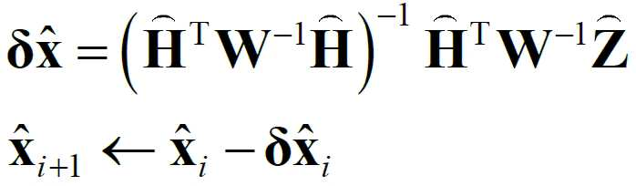
![]()
![]()
![]()
![]()
![]()
![]()
![]()
![]()
![]()
![]()
또한, 상기 (a) 단계에서 상기 알려진 3D 기준점의 좌표는, 상기 기준 물체의 실제 3D 포인트의 추정 오차가 고려되어 있는 오차가 존재하는 추정된 3D 기준점의 좌표를 포함할 수 있다.In addition, the coordinates of the known 3D reference point in the step (a) may include the coordinates of the estimated 3D reference point in which an error in which an estimation error of the actual 3D point of the reference object exists.
또한, 상기 (c) 단계에서 상기 관계 정보 및 상기 위치 관계에 관한 정보는, 유클리드 기하학(Euclidean geometry)을 기반으로 설정되는 정보일 수 있다.In addition, in the step (c), the information about the relationship information and the location relationship may be information set based on Euclidean geometry.
한편, 본원의 일 실시예에 따른 카메라 자세와 대상 물체의 3D 좌표를 동시에 추정하는 동시 추정 장치는, 기준 물체의 알려진 3D 기준점의 좌표를 입력받는 입력부; 상기 알려진 3D 기준점과 관련하여, 카메라를 통해 제1 시간 에포크에서 획득된 제1 이미지 상에 투영된 제1 투영된 2D 포인트를 설정하고, 상기 카메라의 자세 변경에 의해 상기 제1 시간 에포크와는 다른 제2 시간 에포크에서 제2 이미지가 획득되는 경우, 상기 제2 이미지 상에 투영되는 제2 투영된 2D 포인트를 설정하는 설정부; 및 상기 카메라의 자세 변경에 응답하여, 상기 설정부에서 설정된 정보를 기초로 획득되는 이미지 상의 투영된 2D 포인트와 3D 포인트 간의 관계 정보 및 상기 카메라의 자세 변경이 고려된 두 이미지 상에서의 상기 알려진 3D 기준점에 대한 상대적인 위치 관계에 관한 정보를 고려하여 정의된 비용 함수를 이용하여, 상기 제2 시간 에포크에 대응하는 카메라의 변경된 자세인 추정 대상 카메라 자세와 상기 제2 시간 에포크에 대응하는 상기 제2 이미지 내 상기 대상 물체의 알려지지 않은 3D 포인트의 좌표인 추정 대상 3D 좌표의 동시 추정을 수행하는 추정부를 포함하고, 상기 상대적인 위치 관계에 관한 정보는, 상기 제2 이미지 상에 투영된 상기 알려진 2D 기준점에 대응하는 제2 투영된 2D 포인트와 상기 제1 이미지 상에 투영된 상기 제1 투영된 2D 포인트 간의 관계 정보를 포함할 수 있다.Meanwhile, a simultaneous estimation apparatus for simultaneously estimating a camera posture and 3D coordinates of a target object according to an embodiment of the present application includes: an input unit for receiving coordinates of a known 3D reference point of a reference object; With respect to the known 3D reference point, set a first projected 2D point projected on a first image acquired at a first time epoch through a camera, and different from the first time epoch by changing the attitude of the camera a setting unit configured to set a second projected 2D point projected on the second image when a second image is obtained in a second time epoch; and relation information between a projected 2D point and a 3D point on an image obtained based on the information set in the setting unit in response to the change in the posture of the camera, and the known 3D reference point on the two images in which the change in the posture of the camera is considered Using a cost function defined in consideration of information on the relative positional relationship with and an estimator configured to simultaneously estimate the estimated
또한, 상기 비용 함수는, 상기 추정 대상 카메라 자세 관련 상태 파라미터와 상기 추정 대상 3D 좌표 관련 3D 좌표 추정 오차를 포함하도록 정의되는 전체 상태 벡터, 깊이 관련 스케일 인수가 고려된 간접 측정치와 관련되도록 정의되는 전체 간접 측정 벡터, 및 간접 측정치와 상기 전체 상태 벡터 간의 연결 관계를 나타내는 전체 관측 행렬 간의 관계로 정의될 수 있다.In addition, the cost function includes a global state vector defined to include the estimated target camera posture-related state parameter and the estimated
또한, 상기 추정부는, 상기 비용 함수의 최소화를 통해 상기 동시 추정을 수행하되, 상기 전체 간접 측정 벡터와 상기 전체 관측 행렬을 곱하여 산출되는 비용 함수의 값인 전체 상태 벡터의 오차 값들 중 최소 오차 값을 산출하는 전체 상태 벡터를 기반으로 하여, 상기 추정 대상 카메라 자세와 상기 추정 대상 3D 좌표를 동시에 추정할 수 있다.In addition, the estimator performs the simultaneous estimation through the minimization of the cost function, and calculates a minimum error value among the error values of the entire state vector, which is a value of the cost function calculated by multiplying the entire indirect measurement vector and the entire observation matrix. Based on the overall state vector, the estimated camera posture and the estimated 3D coordinates may be simultaneously estimated.
또한, 상기 비용 함수는, 하기 수학식 2를 만족하도록 설정되고, [수학식 2]는 
![]()
![]()
![]()
![]()
![]()
![]()
![]()
![]()
![]()
![]()
또한, 상기 알려진 3D 기준점의 좌표는, 상기 기준 물체의 실제 3D 포인트의 추정 오차가 고려되어 있는 오차가 존재하는 추정된 3D 기준점의 좌표를 포함할 수 있다.Also, the known coordinates of the 3D reference point may include the coordinates of the estimated 3D reference point in which an error in which an estimation error of the actual 3D point of the reference object exists.
또한, 상기 관계 정보 및 상기 위치 관계에 관한 정보는, 유클리드 기하학(Euclidean geometry)을 기반으로 설정되는 정보일 수 있다.In addition, the relationship information and the information about the positional relationship may be information set based on Euclidean geometry.
상술한 과제 해결 수단은 단지 예시적인 것으로서, 본원을 제한하려는 의도로 해석되지 않아야 한다. 상술한 예시적인 실시예 외에도, 도면 및 발명의 상세한 설명에 추가적인 실시예가 존재할 수 있다.The above-described problem solving means are merely exemplary, and should not be construed as limiting the present application. In addition to the exemplary embodiments described above, additional embodiments may exist in the drawings and detailed description.
전술한 본원의 과제 해결 수단에 의하면, 카메라 자세와 대상 물체의 3D 좌표를 동시에 추정하는 동시 추정 장치 및 방법을 제공함으로써, 3D 기준점의 좌표에 오차(error, 에러, 오류)가 존재하는 상황(즉, 3D 기준점의 좌표가 부정확한 상황)에서도 정확한 카메라의 자세를 추정하고, 뿐만 아니라 알려지지 않은 대상 물체의 3D 좌표를 동시에 추정할 수 있는 효과를 제공할 수 있다.According to the above-described problem solving means of the present application, by providing a simultaneous estimation apparatus and method for estimating the camera posture and the 3D coordinates of the target object at the same time, there is an error (error, error) in the coordinates of the 3D reference point (that is, , it is possible to provide the effect of estimating the correct camera posture even when the coordinates of the 3D reference point are inaccurate) and simultaneously estimating the 3D coordinates of an unknown target object.
다만, 본원에서 얻을 수 있는 효과는 상기된 바와 같은 효과들로 한정되지 않으며, 또 다른 효과들이 존재할 수 있다.However, the effects obtainable herein are not limited to the above-described effects, and other effects may exist.
도 1은 종래의 삼각 측량(상) 방법 및 종래의 PnP 방법(하)의 다이어그램을 개략적으로 나타낸 도면이다.
도 2는 본원의 일 실시예에 따른 카메라 자세와 대상 물체의 3D 좌표를 동시에 추정하는 동시 추정 장치에 의한 동시 추정 방법의 다이어그램을 개략적으로 나타낸 도면이다.
도 3은 본원의 일 실시예에 따른 카메라 자세와 대상 물체의 3D 좌표를 동시에 추정하는 동시 추정 장치의 개략적인 구성을 나타낸 도면이다.
도 4는 본원의 일 실험 결과로서, 픽셀 노이즈의 표준 편차를 증가시키는 모든 실험의 RMSEs를 나타낸 도면이다.
도 5는 본원의 일 실험 결과로서, 카메라 자세, 카메라 회전 및 알려지지 않은 3D 포인트의 좌표 각각의 RMSEs의 비교 결과를 나타낸 도면이다.
도 6은 본원의 일 실험 결과로서, 일정한 가우스 픽셀 노이즈와 일정한 3D 기준 좌표의 불확실성에서, 서로 다른 기준선과 깊이를 따르는 다른 방법에 의해, 카메라 자세, 카메라 회전 및 알려지지 않은 3D 포인트의 좌표에 대한 추정 오차를 비교한 도면이다.
도 7은 본원의 일 실험 결과로서, 일치된 2D 포인트가 두 개의 연속적인 영상에 표시된 실험 환경을 묘사한 도면이다.
도 8은 본원의 일 실험 결과로서, 카메라 위치, 카메라 회전 및 알려지지 않은 3D 포인트의 RMSEs의 비교 예를 나타낸 도면이다.
도 9는 본원의 일 실시예에 따른 카메라 자세와 대상 물체의 3D 좌표를 동시에 추정하는 동시 추정 장치의 구성을 개략적으로 나타낸 도면이다.
도 10은 본원의 일 실시예에 따른 카메라 자세와 대상 물체의 3D 좌표를 동시에 추정하는 동시 추정 방에 대한 동작 흐름도이다.1 is a diagram schematically showing a diagram of a conventional triangulation (top) method and a conventional PnP method (bottom).
2 is a diagram schematically illustrating a simultaneous estimation method by a simultaneous estimation apparatus for simultaneously estimating a camera posture and 3D coordinates of a target object according to an embodiment of the present application.
3 is a diagram illustrating a schematic configuration of a simultaneous estimation apparatus for simultaneously estimating a camera posture and 3D coordinates of a target object according to an embodiment of the present application.
4 is a diagram showing RMSEs of all experiments that increase the standard deviation of pixel noise as a result of an experiment of the present application.
5 is a view showing comparison results of RMSEs of each of the coordinates of a camera posture, a camera rotation, and an unknown 3D point as an experimental result of the present application.
6 is an experimental result of the present application, in constant Gaussian pixel noise and constant uncertainty of 3D reference coordinates, estimation of camera posture, camera rotation, and coordinates of unknown 3D points by different methods along different reference lines and depths It is a diagram comparing errors.
7 is a diagram depicting an experimental environment in which a matched 2D point is displayed on two consecutive images as an experimental result of the present application.
8 is a diagram illustrating a comparative example of RMSEs of a camera position, a camera rotation, and an unknown 3D point as an experimental result of the present application.
9 is a diagram schematically illustrating a configuration of a simultaneous estimation apparatus for simultaneously estimating a camera posture and 3D coordinates of a target object according to an exemplary embodiment of the present disclosure.
10 is a flowchart illustrating a simultaneous estimation room for simultaneously estimating a camera posture and 3D coordinates of a target object according to an exemplary embodiment of the present disclosure.
아래에서는 첨부한 도면을 참조하여 본원이 속하는 기술 분야에서 통상의 지식을 가진 자가 용이하게 실시할 수 있도록 본원의 실시예를 상세히 설명한다. 그러나 본원은 여러 가지 상이한 형태로 구현될 수 있으며 여기에서 설명하는 실시예에 한정되지 않는다. 그리고 도면에서 본원을 명확하게 설명하기 위해서 설명과 관계없는 부분은 생략하였으며, 명세서 전체를 통하여 유사한 부분에 대해서는 유사한 도면 부호를 붙였다.Hereinafter, embodiments of the present application will be described in detail with reference to the accompanying drawings so that those of ordinary skill in the art to which the present application pertains can easily implement them. However, the present application may be implemented in several different forms and is not limited to the embodiments described herein. And in order to clearly explain the present application in the drawings, parts irrelevant to the description are omitted, and similar reference numerals are attached to similar parts throughout the specification.
본원 명세서 전체에서, 어떤 부분이 다른 부분과 "연결"되어 있다고 할 때, 이는 "직접적으로 연결"되어 있는 경우뿐 아니라, 그 중간에 다른 소자를 사이에 두고 "전기적으로 연결" 또는 "간접적으로 연결"되어 있는 경우도 포함한다. Throughout this specification, when a part is said to be “connected” to another part, it is not only “directly connected” but also “electrically connected” or “indirectly connected” with another element interposed therebetween. "Including cases where
본원 명세서 전체에서, 어떤 부재가 다른 부재 "상에", "상부에", "상단에", "하에", "하부에", "하단에" 위치하고 있다고 할 때, 이는 어떤 부재가 다른 부재에 접해 있는 경우뿐 아니라 두 부재 사이에 또 다른 부재가 존재하는 경우도 포함한다.Throughout this specification, when it is said that a member is positioned "on", "on", "on", "under", "under", or "under" another member, this means that a member is located on the other member. It includes not only the case where they are in contact, but also the case where another member exists between two members.
본원 명세서 전체에서, 어떤 부분이 어떤 구성 요소를 "포함"한다고 할 때, 이는 특별히 반대되는 기재가 없는 한 다른 구성 요소를 제외하는 것이 아니라 다른 구성 요소를 더 포함할 수 있는 것을 의미한다.Throughout this specification, when a part "includes" a component, it means that other components may be further included, rather than excluding other components, unless otherwise stated.
본원은 하이브리드 대응(hybrid correspondences)(즉, 2D-2D 대응 및 2D-3D 대응)을 활용하여 카메라 자세(즉, 위치 및 방향)와 물체의 알려지지 않은(알 수 없는, 미지의) 3D 좌표를 동시에 추정할 수 있는 기술에 대하여 제안한다. 이때, 본원에서의 하이브리드 대응으로는 단일 카메라로 서로 다른 시간 에포크(time epochs, 시간 기점)에서 본 일치하는 2D-2D 및 2D-3D 포인트가 고려될 수 있다. 또한, 본원에서 이미지 재투영 오차(image reprojection error)를 최소화하기 위해 반복 최소 제곱법(Iterative Least Square Method)이 적용될 수 있다. 본원에서 최소 제곱법은 최소 자승법 등으로 달리 지칭될 수 있다. We utilize hybrid correspondences (i.e., 2D-2D correspondence and 2D-3D correspondence) to simultaneously record camera pose (i.e. position and orientation) and unknown (unknown, unknown) 3D coordinates of an object. We propose techniques that can be estimated. In this case, as a hybrid correspondence herein, coincident 2D-2D and 2D-3D points viewed at different time epochs (time base) with a single camera may be considered. In addition, an iterative least square method may be applied herein to minimize an image reprojection error. The least squares method may be otherwise referred to herein as the least squares method or the like.
도 1은 종래의 삼각 측량(상) 방법 및 종래의 PnP 방법(하)의 다이어그램(diagram)을 개략적으로 나타낸 도면이다. 도 2는 본원의 일 실시예에 따른 카메라 자세와 대상 물체의 3D 좌표를 동시에 추정하는 동시 추정 장치(10)에 의한 동시 추정 방법의 다이어그램을 개략적으로 나타낸 도면이다. 도 3은 본원의 일 실시예에 따른 카메라 자세와 대상 물체의 3D 좌표를 동시에 추정하는 동시 추정 장치(10)의 개략적인 구성을 나타낸 도면이다. 1 is a diagram schematically showing a diagram of a conventional triangulation (top) method and a conventional PnP method (bottom). 2 is a diagram schematically illustrating a simultaneous estimation method by the
도 1 및 도 2에서 물음표 '?' 표시는, 추정할(추정하고자 하는, 추정 대상이 되는, 추정될) 알려지지 않은 파라미터(parameters)를 의미할 수 있다. 1 and 2, the question mark '?' The indication may mean unknown parameters to be estimated (to be estimated, to be estimated, to be estimated).
즉, 도 2은 본 장치(10)의 기하학적 모형의 예를 나타낸다. 도 2를 참조하여 설명하면, 본 장치(10)에서 2D-3D 대응에 해당하는 포인트들(파란색 포인트들)과 2D-2D 대응에 해당하는 포인트들(노란색 포인트들)은 본 장치(10)에서의 측정치(즉, 본 장치에 의해 측정이 이루어지는 측정치)를 의미할 수 있다. 또한, 도 2에서 빨간색으로 표시된 3D 좌표(즉, P4 와 P5)와 R, t는 본 장치(10)의 추정부(13)에 의해 추정되는 추정 대상(추정 항목, 추정 파라미터)을 의미할 수 있다. 이때, 추정 대상은 측정치와의 구별을 위해 물음표(?)로 표시되어 있다. 또한, 도 2에서, 대문자 P는 물체의 3차원 좌표(3D 포인트의 좌표)를 나타내며, 소문자 p는 이미지 상으로 투영된 물체의 2차원 좌표(즉, 이미지 상에 투영된 투영 2D 포인트의 좌표)를 나타낼 수 있다.That is, FIG. 2 shows an example of a geometrical model of the
이하에서는 본원의 일 실시예에 따른 카메라 자세와 대상 물체의 3D 좌표를 동시에 추정하는 동시 추정 장치(10)를 설명의 편의상 본 장치(10)라 하기로 한다. 또한, 본 장치(10)에 의해 수행되는 카메라 자세와 대상 물체의 3D 좌표를 동시에 추정하는 동시 추정 방법은 이하 설명의 편의상 제안된 방법이라 하기로 한다. 또한, 본원에서 본 장치(10)에 대하여 설명된 내용은 이하 생략된 내용이라 하더라도 제안된 방법에 대한 설명에도 동일하게 적용될 수 있으며, 그 반대로도 적용 가능하다.Hereinafter, the
도 1 내지 도 3을 참조하면, 본 장치(10)는 획득한 이미지에서 카메라 자세(즉, 카메라의 위치와 방향)과 알려지지 않은 포인트의 3D 좌표(unknown 3D coordinates of the points)를 동시에 추정할 수 있는 기술에 관한 것이다.1 to 3 , the
본 장치(10)에 의한 제안된 방법은, 2D-2D 대응과 관련된 도 1의 상측 그림과 같은 삼각 측량 방법 및 2D-3D 대응과 관련된 도 1의 하측 그림과 같은 PnP (Perspective-n-Point) 방법과 모두 밀접하게 연관(융합)되어 있다고 할 수 있다. 이러한 본 장치(10)는 하이브리드 대응(즉, 2D-2D 대응 및 2D-3D 대응)을 기반으로 하는 단일 추정기(10)라 지칭될 수 있다.The proposed method by the
제안된 방법은 다중 기준(multi-baseline) 기술의 뚜렷한 장점을 가지고 있으며, 이 장점은 카메라 간의 기준선(multi-baseline)에 비례하는 깊이 정확도(depth accuracy)를 향상시킬 수 있다.The proposed method has a distinct advantage of the multi-baseline technique, which can improve the depth accuracy proportional to the multi-baseline between cameras.
또한, 제안된 방법은, 일예로 문헌 [R. Hartley and A. Zisserman, Multiple View Geometry in Computer Vision. Cambridge university press, 2003.]와 같이 2D 매칭 포인트만을 사용(즉, 2D-2D 대응만 사용)하는 기본 행렬 기반의 종래 방법들과 비교(대비)하여, 2D-3D 대응을 함께 이용함으로써 3D 포인트에 대한 길이 스케일(length scale) 파라미터를 직접적으로(directly) 추정할 수 있다.In addition, the proposed method, for example, [R. Hartley and A. Zisserman, Multiple View Geometry in Computer Vision. Cambridge university press, 2003.] by using only 2D matching points (that is, using only 2D-2D correspondence) with the basic matrix-based conventional methods such as It is possible to directly estimate a length scale parameter for .
제안된 방법은 2D-2D 대응과 2D-3D 대응을 혼합하여 사용(즉, 하이브리드 대응을 사용)함으로 인해, 3D 기준점(3D reference points)의 노이즈 불확실성(uncertainties)에 대해 더욱 견고해질 수 있다. 구체적으로, 제안된 방법과 비교했을 때, 대부분의 종래 PnP 방법들은 카메라 자세 추정을 위해 2D-3D 대응에만 의존한다. 이러한 종래의 방법들은 3D 기준점 좌표가 정확하게 주어진다고 가정한 상태에서, 단지 2D 포인트에 대한 불확실성만을 고려한다. 따라서, 제안된 방법은 3D 기준점의 좌표에 오차(error, 에러, 오류)가 존재하는 상황(즉, 3D 기준점의 좌표가 부정확한 상황)에서도 보다 상당히 정확한 카메라 자세를 획득할 수 있도록, 상술한 이러한 가정을 완화시킬 수 있다. 즉, 제안된 방법은 부정확한 3D 기준점 좌표가 주어지는 상황에서도 보다 정확한 카메라 자세를 추정할 수 있다.The proposed method can be more robust against noise uncertainties of 3D reference points by using a mixture of 2D-2D correspondence and 2D-3D correspondence (ie, using hybrid correspondence). Specifically, compared with the proposed method, most conventional PnP methods rely only on 2D-3D correspondence for camera pose estimation. These conventional methods only consider the uncertainty of the 2D point, assuming that the 3D reference point coordinates are accurately given. Therefore, the proposed method is such that it is possible to obtain a more accurate camera posture even in a situation in which an error (error, error) exists in the coordinates of the 3D reference point (that is, a situation in which the coordinates of the 3D reference point are inaccurate). assumptions can be alleviated. That is, the proposed method can estimate a more accurate camera posture even when inaccurate 3D reference point coordinates are given.
또한, 제안된 방법은 측정의 가용성(availability, 유용성)에 따라 삼각 측량 방법 또는 PnP 방법(즉, 카메라 자세 추정 방법)으로 전환(converted)될 수 있다. 만약, 2D-2D 대응만 가능한 경우 제안된 방법은 삼각 측량 방법과 동일할 수 있다. 반면 2D-3D 대응만 가능한 경우 제안된 방법은 PnP 방법과 동일할 수 있다.In addition, the proposed method can be converted to a triangulation method or a PnP method (ie, a camera posture estimation method) according to the availability of measurements. If only 2D-2D correspondence is possible, the proposed method may be the same as the triangulation method. On the other hand, if only 2D-3D correspondence is possible, the proposed method may be the same as the PnP method.
이하에서는 본 장치(10)에 대한 구체적인 설명을 수행하기에 앞서, 본 장치(10)의 기반이 되는 기술(삼각 측량 기술 및 PnP를 이용한 카메라 자세 추정 기술)에 대하여 보다 상세히 설명하기로 한다.Hereinafter, prior to performing a detailed description of the
삼각 측량(triangulation) 기술에 대한 보다 구체적인 설명은 다음과 같다.A more detailed description of the triangulation technique follows.
2-뷰 삼각 측량(two-view triangulation, 두가지 관점의 삼각 측량)을 위한 가장 광범위한 접근 방식은, 이미지 재투영 오차(image reprojection errors)의 L 2 노름(norm)을 최소화하는 3D 포인트의 좌표(coordinates)를 찾는 것이라 할 수 있다. 이 접근 방식은 일반적으로 비 반복 다항식 방법(non-iterative polynomial methods)에 의해 구현될 수 있다. 알려지지 않은(알 수 없는) 좌표의 최대 우도 추정치(maximum likelihood estimate, MLE)는 이미지 포인트(image points)가 가우스 픽셀 노이즈(gaussian pixel noise)에 의해 섭동(perturbed)된다는 가정 하에 구해질 수 있다. 다른 2-뷰(2가지 관점) 방법은 동일한 가정을 기반으로 하지만 반복적인 방법에 의해 연구되었다. 또한, 종래에는 이미지 재투영 오차의 L 2 노름을 최소화하는 대신, 각도 재투영 오차(angular Eigenreprojection errors)를 최소화하기 위해 L 1 및 ![]()
![]()
앞서 언급한 다항식 방법 외에, 선형 최소 제곱법(linear least-square, LLS) 및 선형 고유법(linear-eigen, LE)과 같은 선형 삼각 측량 방법(linear triangulation methods)도 존재한다. 하지만, 이러한 선형 삼각 측량 방법들은 기하학적 의미(geometric meaning)를 가지고 있지 않고, 이미지 재투영 오차의 L 2 노름을 최소화(minimizes)하는 비용 함수(cost function)에 대응하지 않는다. In addition to the polynomial methods mentioned above, there are also linear triangulation methods such as linear least-square (LLS) and linear-eigen (LE). However, these linear triangulation methods have no geometric meaning and do not correspond to a cost function that minimizes the L 2 norm of the image reprojection error.
따라서, 비용 함수가 동일한 오차(same errors)를 최소화할 수 있도록 하고자, LLS와 LE에 반복 선형 방법(iterative linear methods)을 적용한 기술이 종래에 제안된 바 있다. 이러한 개선된 LLS 및 LE 방법은 각각 반복-LS 방법(Iterative-LS method)과 반복-아이겐 방법(Iterative-Eigen method)으로 불리운다. 이 두 가지 방법은 소프트웨어 구현의 단순성에 유리하다. 그러나, 이 두 가지 방법은 가끔 어떤 점이 에피폴(epipoles)에 가까울 때 불안정한 상황(unstable situations)에서 수렴(converge)하지 못하는 경우가 있다.Therefore, in order to minimize the same errors of the cost function, a technique in which iterative linear methods are applied to LLS and LE has been previously proposed. These improved LLS and LE methods are called Iterative-LS method and Iterative-Eigen method, respectively. Both of these methods favor the simplicity of software implementation. However, these two methods sometimes fail to converge in unstable situations when some points are close to epipoles.
또한, 종래에는 알려지지 않은 3D 좌표(unknown 3D coordinate) 추정의 정확성을 개선하기 위해, 3개 이상의 뷰(views)에 기초한 새로운 삼각 측량 접근법들이 제시된 바 있다. 이 중 어느 한 종래 문헌에서는 이미지 재투영 오차의 L 2 노름의 최소화에 기초한 다항식 방법을 도입하였고, 이와는 대조적으로, 반복 비선형 최소 제곱법(iterative nonlinear least square method)은 다른 어느 한 종래 문헌에서 제안되었다.In addition, in order to improve the accuracy of estimating unknown 3D coordinates in the prior art, new triangulation approaches based on three or more views have been proposed. One of these prior documents introduced a polynomial method based on the minimization of the L 2 norm of the image reprojection error, and in contrast to this, an iterative nonlinear least square method was proposed in any other prior document. .
그런데, 상술한 종래의 모든 삼각 측량 방법은 카메라 자세(camera pose)를 사전에 정확히 알고 있어야 한다는 가정을 따르고 있으며, 카메라 자세가 부정확할 때 3D 포인트의 알려지지 않은 좌표를 찾는 것에 대한 세부적인 고려는 이루어지고 있지 않은 문제가 있다.However, all of the above-described conventional triangulation methods follow the assumption that the camera pose should be accurately known in advance, and detailed consideration of finding the unknown coordinates of the 3D point when the camera pose is incorrect is made. There is a problem that is not being lost.
한편, 카메라 자세 추정(camera pose estimation) 기술에 대한 보다 구체적인 설명은 다음과 같다.Meanwhile, a more detailed description of the camera pose estimation technique is as follows.
1970년대 초에는 차량 에고 모션 추정(vehicle ego-motion estimation)에서 위성항법시스템(Global Positioning System, GPS)과 관성항법시스템(Inertial Navigation System, INS)의 통합이 메인 스트림(main stream)이었다. 최근, 비전 기반 접근법(vision-based approaches)이 더 정확하고, 저렴하며, 다용도인 것으로 입증되었다.In the early 1970s, the integration of a global positioning system (GPS) and an inertial navigation system (INS) was the main stream in vehicle ego-motion estimation. Recently, vision-based approaches have proven to be more accurate, cheaper and more versatile.
전통적인 접근 방식(Traditional approaches)은 구조 기반 자세 추정(structure-based pose estimation)으로 알려진 2D-3D 대응 또는 구조물 없는 자세 추정(structure-less pose estimation)으로 알려진 2D-2D 대응 중 어느 하나를 사용하는 데에 초점을 맞추고 있다. 이들 각각은 사진 측량(photogrammetry)과 컴퓨터 비전(computer vision) 분야에서 가장 오래되고 중요한 주제 중 하나이다. 널리 사용되는 PnP 방법은 2D-3D 대응을 기반으로 한다. P3P (Perspective-Three-Points) 방법은 PnP 문제의 최소 사례(minimal case)에 해당하며, 기본 P3P 방법의 많은 변형 방법들이 그 이후로 연구되어 왔다.Traditional approaches involve using either a 2D-3D counterpart, known as structure-based pose estimation, or a 2D-2D counterpart, known as structure-less pose estimation. is focused on Each of these is one of the oldest and most important subjects in the fields of photogrammetry and computer vision. A widely used PnP method is based on 2D-3D correspondence. The P3P (Perspective-Three-Points) method corresponds to the minimal case of the PnP problem, and many variants of the basic P3P method have been studied since then.
PnP 문제를 해결하기 위해 2D-3D와 2D-2D 대응을 모두 사용하는 다른 종래 문헌들도 있다. 이러한 하이브리드 방법(hybrid methods)은 가능한 모든 매치(matches, 일치)를 충분히 활용한다. 다양한 가능한 조합(various possible combinations)에 대한 최소 사례(minimal case)에 대하여 설명하면 다음과 같다. 예시적으로, 종래 문헌에는 1 개의 3D-3D 대응과 2 개의 2D-3D 대응에 기초한 자세 추정의 결합 공식(joint formulation)이 제안되어 있다. 여기서, 다른 비 하이브리드 PnP 방법(non-hybrid PnP methods)과 비교했을 때, 3개의 2D-3D 매치(matches) 중 하나는 하나의 3D-3D 매치로 대체(replaced)된다. 대체된 3D-3D 매치에는 좌표를 미리 삼각 측량해야 하는 3D 포인트가 포함되어 있다. 그러나, 이 비 하이브리드 방법(non-hybrid method)은 로컬 프레임(local frame)에서 삼각 측량된 포인트(triangulated points)의 품질(quality)에 크게 의존하는 문제가 있다.There are other prior literatures using both 2D-3D and 2D-2D correspondence to solve the PnP problem. These hybrid methods make full use of all possible matches. The minimum case for various possible combinations will be described as follows. Illustratively, a joint formulation of posture estimation based on one 3D-3D correspondence and two 2D-3D correspondences has been proposed in the prior art. Here, compared with other non-hybrid PnP methods, one of three 2D-3D matches is replaced with one 3D-3D match. The superseded 3D-3D match contains 3D points whose coordinates need to be triangulated beforehand. However, this non-hybrid method has a problem in that it largely depends on the quality of triangulated points in a local frame.
이러한 점을 고려해, 제안된 방법 내지 해당 제안된 방법을 제공하는 본 장치(10)는 PnP 방법(즉, 카메라 자세 추정 방법)과 삼각 측량법(triangulation method)을 조합(combining)하여, 물체의 알려지지 않은 3D 포인트(unknown 3D points)(알 수 없는 3D 포인트, 미지의 3D 포인트)와 카메라 자세(camera pose)의 좌표를 동시에(simultaneously) 추정할 수 있다. 이를 위해, 본 장치(10)는 비용 함수(cost function)와 관련하여 이미지 재투영 오차(image reprojection error)의 L 2 노름을 최소화(minimized)할 수 있다. 이때, 최소화(minimization)는 반복 최소 제곱법(iterative least square scheme)에 기초하여 단일 추정기(10, 본 장치)에 의해 구현될 수 있다. 본 장치(10)에서는 표준 투시 투영 모델(standard perspective projection model)이 사용될 수 있으며, 두 가지 관점(two-view)의 사례(cases)가 고려될 수 있다.In consideration of this, the proposed method or the
이하에서는 본 장치(10)에서 고려(적용)되는 좌표 프레임(coordinate frames) 및 표기법(notations)에 대하여 설명한다.Hereinafter, coordinate frames and notations considered (applied) in the
투시 투영(perspective projection)(투시도법, 원근 투영)은 컴퓨터 비전(computer visio) 사회에서 흔히 사용되는 균일한 좌표(homogeneous coordinates)보다는 유클리드 좌표(Euclidean coordinates)로 표현된다. 이를 통해 포인트 사이의 거리(distance between points), 즉 유클리드 거리에 대한 의미 있는 정의(meaningful definition)를 할 수 있다. 이 때문에, 본 장치(10)에서는 전반적으로 유클리드 좌표가 사용될 수 있다.Perspective projection (perspective projection) is expressed in Euclidean coordinates rather than homogeneous coordinates commonly used in computer vision society. This allows a meaningful definition of the distance between points, that is, the Euclidean distance. For this reason, in the
본 장치(10)에서 고려되는 여러 좌표 프레임(several coordinate frames)과 수학적 표기법(mathematical notations)에 대한 설명은 다음과 같다. A description of several coordinate frames and mathematical notations considered in the
V-프레임(V-frame)은 일반적으로 이미지 평면(image plane, 영상 평면)이라고도 하는 비전 프레임(vision frame)을 나타낸다. P-프레임(P-frame)은 시각적 측정(visual measurements)을 나타내는 픽셀 프레임(pixel frame)을 나타낸다. C-프레임(C-frame)은 카메라 프레임(camera frame)을 나타낸다. N-프레임(N-frame)은 항법 프레임(navigation frame)을 나타낸다.A V-frame represents a vision frame, also commonly referred to as an image plane (image plane). A P-frame represents a pixel frame representing visual measurements. C-frame represents a camera frame. N-frame (N-frame) represents a navigation frame (navigation frame).
C-프레임의 원점(origin)은 카메라의 광학 중심(optical center)에 있으며, XYZ 축(axes)은 전방-우측-하향 규칙(forward-right-down convention)을 따를 수 있다. N-프레임은 지역 북쪽(local north), 동쪽(east) 및 아래쪽(downward) 방향(directions)에 정렬되어 있을 수 있다.The origin of the C-frame is at the optical center of the camera, and the XYZ axes may follow a forward-right-down convention. N-frames may be aligned in local north, east, and downward directions.
본 장치(10)에서는, N-프레임을 기준 프레임(reference frame)으로 설정하고, C-프레임이 시간에 따라 다를지라도 초기 시간(initial time)을 임의로(arbitrarily) 할당할 수 있기 때문에 일반성(generality)을 잃지 않고 C-프레임의 초기 위치(initial position)와 방향(orientation)이 N-프레임의 초기 위치와 방향과 일치한다고 가정할 수 있다.In the
본 장치(10)를 설명함에 있어서, 작은 굵은 글자(Small bold letters)는 벡터(vectors)를 나타내기 위해 사용될 수 있다. 보통 글자(Ordinary letters)는 좌표 원소(coordinate elements)를 나타내기 위해 사용될 수 있다. 작은 글자에 부착된 윗첨자(Superscripts)와 아래첨자(subscripts)는 각각 기준 프레임(reference frames)과 물체 ID(object identities)를 나타낼 수 있다.In describing the
예를 들어, ![]()
![]()
![]()
![]()
![]()
![]()
![]()
![]()
![]()
![]()
![]()
![]()
![]()
![]()
굵은 대문자(Bold capital letters)는 행렬(matrices)을 나타내기 위해 사용될 수 있다. ![]()
![]()
![]()
![]()
이하에서는 본 장치(10)에서 고려(적용)될 수 있는 오차 모델(error models)에 대하여 설명한다.Hereinafter, error models that can be considered (applied) in the
추정치(estimates), 추정오차(estimation errors), 측정치(measurements), 측정오차(measurements errors), 3D 포인트(3D points)와 그의 투영된 이미지 포인트(projected image points) 간의 관계는 아래 식 1과 같이 설정될 수 있다. 여기서, 투영된 이미지 포인트는 투영된 2D 포인트라 달리 지칭될 수 있다.The relationships between estimates, estimation errors, measurements, measurements errors, and 3D points and their projected image points are set as shown in
[식 1][Equation 1]
여기서, ![]()
![]()
![]()
![]()
![]()
![]()
![]()
![]()
추정된 회전 행렬(estimated rotation matrix)인 ![]()
![]()
![]()
![]()
![]()
![]()
[식 2][Equation 2]

회전 오차(rotation erro)가 작다고 가정하면, ![]()
![]()
[식 3][Equation 3]
![]()
![]()
여기서, ![]()
![]()
![]()
![]()
![]()
![]()
![]()
![]()
상기 식 2 및 식 3을 사용하여, 회전 행렬 오차(rotation matrix error)를 아래 식 4와 같이 도출(유도)할 수 있다. Using
[식 4][Equation 4]
![]()
![]()
비슷한 절차에 의해, 상기 식 4를 치환(transpose)하면 아래 식 5와 같이 표현될 수 있다.By a similar procedure, if
[식 5][Equation 5]
![]()
![]()
이하에서는 본 장치(10)에 의한 제안된 방법에 대하여 보다 상세히 설명한다. 특히나, 이하에서는 카메라 자세(camera pose)와 알려지지 않은 3D 포인트(unknown 3D points)의 좌표(coordinates)를 동시에(simultaneously) 추정하기 위해 제안된 방법의 공식화(formulation)에 대하여 보다 상세히 설명한다.Hereinafter, the proposed method by the
제안된 방법에서는 단일 3D 기준점(single 3D reference point)과 그것의 투영된 2D 포인트(projected 2D point)의 좌표를 실현 가능한 오류(feasible errors)로 알고 있도록 요구될 수 있다. 달리 표현해, 제안된 방법은 단일 3D 기준점(single 3D reference point)과 그것의 투영된 2D 포인트(projected 2D point)의 좌표를 오차가 있는 부정확한 것으로 알고 있을 수 있다(부정확한 것으로 알고 있는 것을 조건으로 할 수 있다). 또한, 제안된 방법은 적어도 3개의 새로운 포인트(three new points)이 2개의 연속된 이미지(two consecutive images) 사이에서 관찰(observed)되어야 함이 요구될 수 있다(즉, 관찰되어야 함을 조건으로 할 수 있다). 여기서, 전자의 조건(former condition)은 2D-3D 대응(2D-3D correspondence)과 관련되고, 후자의 조건(latter condition)은 2D-2D 대응(2D-2D correspondence)과 관련이 있을 수 있다.In the proposed method, it may be required to know the coordinates of a single 3D reference point and its projected 2D point with feasible errors. In other words, the proposed method may know the coordinates of a single 3D reference point and its projected 2D point to be inaccurate with an error (provided that it is known to be inaccurate). can do). In addition, the proposed method may require that at least three new points be observed between two consecutive images (that is, subject to can). Here, the former condition may be related to 2D-3D correspondence, and the latter condition may be related to 2D-2D correspondence.
이러한 조건(conditions) 하에서, 본 장치(10)는 업데이트된 카메라 자세(updated camera pose)를 가지고 새로운 포인트(new points)의 알려지지 않은 3D 좌표(unknown 3D coordinates)를 추정할 수 있다.Under these conditions, the
이하에서는 본 장치(10)(혹은 본 장치의 제안된 방법)에 의해 개발된 오차 모델(error models)에 대하여 설명한다. 제안된 방법으로 개발된 오차 모델은 그 기하학적 관계(geometric relations)에 의해 다음과 같은 순서대로 각각 설명될 수 있다. 즉, 제안된 방법으로 개발된 오차 모델은, 알려지지 않은 3D 포인트(unknown 3D points)에 대한 2D-3D, 두개의 뷰(two views, 투 뷰) 사이의 3D-3D, 알려진 3D 포인트(known 3D points)에 대한 2D-3D 및 전체 공식(full formulation)의 순서대로 각각 설명될 수 있다. 이들 각각은 후술하는 설명에서 제1 파트 내지 제4 파트 관련 오류 모델이라 지칭하기로 한다. Hereinafter, error models developed by the apparatus 10 (or the proposed method of the apparatus) will be described. The error model developed by the proposed method can be explained in the following order by its geometric relations. That is, the error model developed by the proposed method is 2D-3D for unknown 3D points, 3D-3D between two views, and known 3D points ) can be described respectively in the order of the 2D-3D and full formulations. Each of these will be referred to as an error model related to the first to fourth parts in the following description.
첫번째로, 제1 파트 관련 오류 모델과 관련하여, 알려지지 않은 3D 포인트(unknown 3D points)에 대한 2D-3D의 오류 모델(error model)에 대한 설명은 다음과 같다.First, with respect to the first part-related error model, a description of a 2D-3D error model for unknown 3D points is as follows.
종래에 잘 알려진 핀홀 카메라 모델(Pinhole camera model)을 사용하여 ![]()
![]()
[식 6][Equation 6]

여기서, ![]()
![]()
![]()
![]()
![]()
![]()
![]()
![]()
![]()
![]()
![]()
![]()
선형화 된 오차 모델(linearized error model)은 식 6을 1차로(up to the first order) 섭동(perturbing)함으로써 아래 식 7과 같이 도출할 수 있다.A linearized error model can be derived as shown in
[식 7][Equation 7]

여기서, ![]()
![]()
![]()
![]()
![]()
![]()
![]()
![]()
이러한 식 7은 비용 함수(cost function)를 나타내며, 식 7에서 물결로 표시된 후측 부분에 대해 최소화가 이루어질 수 있다.
야코비 행렬 ![]()
![]()
![]()

![]()
![]()
![]()
여기서, ![]()
![]()
![]()
![]()
![]()
![]()
아래 식 8의 방정식(equation)은 스케일 인수(scale factor)에 곱해지더라도 이미지 재투영 오차를 최소화(minimizes)할 수 있다. 따라서, 아래 식 8의 방정식은 상기 식 7과 동일한 추정 문제를 다룰 수 있다.The equation of Equation 8 below can minimize the image re-projection error even when multiplied by a scale factor. Therefore, the equation of Equation 8 below can handle the same estimation problem as
[식 8][Equation 8]

여기서, ![]()
![]()
![]()
![]()
![]()
![]()
상기 식 8을 기반으로, 제안된 방법에서는(즉, 본 장치(10)는) 후술하는 바와 같이 두 개의 연속된 에포크(two consecutive epochs)에서 볼 수 있는(바라본) 동일한 3D 포인트(same 3D point)의 2개의 새로운 오류 모델을 도출할 수 있다.Based on Equation 8, in the proposed method (that is, the device 10) is the same 3D point (same 3D point) that can be seen (viewed) in two consecutive epochs as described below We can derive two new error models of
두번째로, 제2 파트 관련 오류 모델과 관련하여, 두개의 뷰(two views, 투 뷰) 사이의 3D-3D의 오류 모델에 대한 설명은 다음과 같다.Second, with respect to the error model related to the second part, a description of the error model of 3D-3D between two views is as follows.
일예로, 두 개의 연속적인 에포크(two consecutive epochs)에서 동일한 카메라(same camera)에 포착된(captured, 캡처된) 하나의 공통 3D 포인트(single common 3D point)가 알려져 있지 않다(unknown)고 가정(즉, 하나의 공통 3D 포인트를 알 수 없다고 가정)해 보자. 이는 현재의 에포크(current epoch)에서 C-프레임과 관련하여 추정될 수 있다.As an example, it is assumed that a single common 3D point captured by the same camera in two consecutive epochs is unknown ( That is, suppose that one common 3D point is unknown). This can be estimated in relation to the C -frame in the current epoch.
이하에서는 설명의 편의상, 두 개의 다른 시간 에포크(two different time epochs)에서 정의된 C-프레임을 C(k-1) 과 C(k) 로 표시(denoted)할 수 있다. 시간 에포크는 앞서 말한 바와 같이 시간 기점, 시점 등을 의미할 수 있다. 즉, 두 개의 연속적인 에포크(혹은 두 개의 다른 시간 에포크)라 함은 연속된 서로 다른 시점(연속된 서로 다른 시간에서의 시점)을 의미할 수 있다.Hereinafter, for convenience of description, C -frames defined in two different time epochs may be denoted as C ( k −1 ) and C ( k ). As described above, the time epoch may mean a time base, a time point, or the like. That is, two consecutive epochs (or two different time epochs) may mean different consecutive time points (time points at different consecutive times).
두 개의 연속적인 에포크에서 바라본 동일한 3D 포인트(same 3D point)의 좌표(coordinates)는 아래 식 9와 같이 표현될 수 있다.Coordinates of the same 3D point viewed from two consecutive epochs can be expressed as Equation 9 below.
[식 9][Equation 9]
![]()
![]()
실제 벡터(true vectors) 간의 관계로 표현되는 상기 식 9를 기반으로, 이 방정식은 또한 추정된 벡터(estimated vectors) 간의 관계로 표현되는 아래 식 10과 같이 표현될 수 있다.Based on Equation 9, which is expressed as a relation between true vectors, this equation can also be expressed as
[식 10][Equation 10]
![]()
![]()
이때, 식 10에서, ![]()
![]()
![]()
![]()
![]()
![]()
1 차 테일러 급수(Taylor series) 확장(expansion)에 의해 상기 식 10을 섭동(perturbing)하고 후술하는 식 28을 이용함으로써, 추정된 좌표(estimated coordinate) ![]()
![]()
![]()
![]()
[식 11][Equation 11]

여기서, ![]()
![]()
식 11에서, ![]()
![]()
![]()
![]()
![]()
![]()
[식 12][Equation 12]
![]()
![]()
여기서, ![]()
![]()
![]()
![]()
식 11을 식 8에 대입(Substituting)하면, 이전 (k-1) 번째 시간 에포크에서 ![]()
![]()
![]()
![]()
![]()
![]()
![]()
![]()
[식 13][Equation 13]

이와 유사하게, 현재 (k) 번째 시간 에포크에서 ![]()
![]()
![]()
![]()
[식 14][Equation 14]
![]()
![]()
상기 식 13과 식 14를 조합(Combining)하면, 누적 관측 행렬(stacked observation matrix) ![]()
![]()
![]()
![]()
[식 15][Equation 15]

식 15에서, 

![]()
![]()
![]()
![]()
상기 식 12에서 식 15까지, 아래 첨자(subscript) U 는 알려진 3D 포인트(known 3D points)의 오차 모델과 알려지지 않은 3D 포인트(unknown 3D points)의 오차 모델 사이를 구분(discriminate)하기 위해, '알 수 없음(unknown)'이라는 단어의 첫 글자(first letter)에서 인용된 것이라 할 수 있다.From
세번째로, 제3 파트 관련 오류 모델과 관련하여, 알려진 3D 포인트(known 3D points)에 대한 2D-3D의 오류 모델에 대한 설명은 다음과 같다. 즉, 이하에서는 알려진 3D 포인트와 두 연속적인 카메라 프레임(two consecutive camera frames) 사이의 관계를 고려한 오차 모델에 대하여 설명한다.Third, with respect to the third part-related error model, a description of the error model of 2D-3D with respect to known 3D points is as follows. That is, hereinafter, an error model considering a relationship between a known 3D point and two consecutive camera frames will be described.
이전 (k-1) 번째 시간 에포크에서 C-프레임에 관한 3D 포인트를 미리 알고 있다고 하자. 이때, 현재 (k) 번째 시간 에포크에서 보이는 그 동일한 3D 포인트(same 3D point)는 상기 식 1 및 상기 식 2를 이용하여 아래 식 16과 같이 추정될 수 있다.Assume that the 3D point of the C -frame is known in advance at the previous ( k −1) th time epoch. In this case, the same 3D point seen in the current ( k )-th time epoch can be estimated as in Equation 16 below using
[식 16][Equation 16]
![]()
![]()
![]()
![]()
![]()
![]()
[식 17][Equation 17]

이러한 식 17을 상술한 식 11의 알 수 없는 3D 포인트에 대한 오차 모델과 비교하면, 식 17에서는 ![]()
![]()
![]()
![]()
상기 식 17을 식 8에 대입(Substituting)하면, 상태 ![]()
![]()
![]()
![]()
![]()
![]()
[식 18][Equation 18]

상기 식 18에 의해, 누적 관측 행렬(stacked observation matrix) ![]()
![]()
![]()
![]()
[식 19][Equation 19]

식 19에서, 
![]()
![]()
상기 식 18 및 식 19에서, 아래 첨자(subscript) K 는 '알려진(known, 알고 있는)'이라는 단어의 첫 글자(first letter)에서 인용된 것이라 할 수 있다.In Equations 18 and 19, the subscript K may be cited from the first letter of the word 'known (known)'.
이때, 식 15에서의 HU의 행렬(매트릭스) 중 앞쪽 요소가 JM 값으로 표시된 것과 대비하여, 그와 대응하는 식 19에서의 Hk 의 행렬(매트릭스) 중 앞쪽 요소가 0으로 표시된 것은, 해당 제3 파트에서는 알려진 포인트에 대한 오류 모델을 설명한 것임에 따라 해당 값을 알 필요가 없어서 0으로 표시한 것일 수 있다.At this time, in contrast to the case in which the front element of the matrix (matrix) of H U in
상술한 설명에서, 제1 파트는 두 시간 에포크(시점) 중 어느 한 시간 에포크에서의 2D-3D 관계를 설명한 것이라 할 수 있다. 제2 파트는 3D-3D 간(혹은 2D-2D 간)의 관계로서, 특히 알려지지 않은 3D 포인트를 기준으로 했을 때, 시점에 따라 달라지는 시점이 고려된 3D 포인트의 상대적 위치 관계를 설명(즉, 알려지지 않은 정보와 2D-2D 대응 간의 관계를 설명)한 것이라 할 수 있다. 제3 파트는 알려진 3D 포인트를 기준으로 했을 때, 알려진 3D 포인트를 어떻게 표현하고, 해당 포인트가 본 장치(10)에서 추정하고자 하는 정보(즉, 추정 대상 카메라 자세, 추정 대상 3D 좌표)와 어떠한 관련이 있는지를 설명한 것이라 할 수 있다. 즉, 제3 파트는 2D-3D 관계 중 본 장치(10)에서 추정하고자 하는 정보(알지 못하는 정보, 알려지지 않은 정보)와 알려진 3D 포인트 간의 관계를 설명한 것이라 할 수 있다. In the above description, the first part can be said to describe a 2D-3D relationship in one time epoch among two time epochs (viewpoints). The second part is a relationship between 3D-3D (or between 2D-2D), and in particular, based on an unknown 3D point, describes the relative positional relationship of 3D points in which viewpoints that vary depending on viewpoints are considered (ie, unknown 3D points). It can be said that it describes the relationship between non-information and 2D-2D correspondence). The third part represents how the known 3D point is expressed based on the known 3D point, and what kind of relation does the point have with the information to be estimated by the device 10 (ie, the estimated target camera posture, the estimated
네번째로, 제4 파트 관련 오류 모델과 관련하여, 전체 공식(full formulation)의 오류 모델에 대한 설명은 다음과 같다. 즉, 전체 2D-3D와 3D-3D의 오류 모델에 대한 설명은 다음과 같다. 다시 말해, 이하에서는 본 장치(10)에서 고려되는 전체 공식(제안된 방법의 전체 공식)에 대하여 설명한다.Fourth, with respect to the error model related to the fourth part, the description of the error model of the full formulation is as follows. That is, the description of the error models of the entire 2D-3D and 3D-3D is as follows. In other words, the entire formulation (the overall formulation of the proposed method) considered in the
상기 식 15와 식 19를 이용하여, 전체 간접 측정 벡터(full indirect measurement vector) ![]()
![]()
![]()
![]()
![]()
![]()
[식 20][Equation 20]

이에 상응하여(Correspondingly), 그들의 추정치(estimates)는 C-프레임에서 아래 식 21과 같이 표현될 수 있다. 식 20에서 Z 는 측정치 조합이 어떻게 되어있는지를 나타낸 것일 수 있다. Correspondingly, their estimates can be expressed as Equation 21 below in the C -frame. In
[식 21][Equation 21]

가우스-뉴턴법(Gauss-Newton method)이라고도 하는 반복 가중 최소 제곱법(iterative weighted least square method)은 아래 식 22에 기초하여 적용될 수 있다.An iterative weighted least squares method, also called a Gauss-Newton method, may be applied based on
[식 22][Equation 22]

여기서, 
![]()
![]()
![]()
![]()
![]()
![]()
![]()
![]()
식 22에서, ![]()
![]()
![]()
![]()
![]()
![]()
![]()
![]()
![]()
![]()
위 식 22는 본 장치(10)에 의해 정의(설정, 생성)되는 비용 함수(cost function)를 의미할 수 있다. 이러한 비용 함수는 상술한 식 7을 기반으로 하여 정의될 수 있다. 본 장치(10)의 추정부(13)는 식 22를 최소화시킴으로써 카메라 자세와 알려지지 않은 물체의 3D 좌표(3D 포인트 좌표)를 동시에 추정할 수 있다.
이러한 본 장치(10)는 상술한 첫번째 내지 네번째의 순서로 설명이 이루어진 제안된 방법으로 개발된 오차 모델을 기반으로 하여, 카메라의 자세와 알려지지 않은 3D 좌표를 동시에 추정할 수 있다. The
이하에서는 본 장치(10)의 제안된 방법이 측정의 가용성(availability, 유용성)에 따라 삼각 측량 방법 또는 PnP 방법(즉, 카메라 자세 추정 방법)으로 전환(converted)될 수 있음에 대하여 설명하기로 한다. 즉, 본 장치(10)는 측정의 가용상에 따라 삼각 측량 모드 또는 PnP 모드인 카메라 자세 추정 모드로 전환될 수 있다.Hereinafter, it will be described that the proposed method of the
먼저, 본 장치(10)의 삼각 측량(triangulation) 방법(모드)으로의 전환에 대해 설명하면 다음과 같다.First, the conversion to the triangulation method (mode) of the
만약 2D-2D 대응(2D-2D correspondences)만 가능하다면, 본 장치(10)의 제안된 방법은 반복 최소 제곱법(Iterative Least Square) 기반의 삼각 측량(triangulation) 알고리즘으로 변환될 수 있다.If only 2D-2D correspondences are possible, the proposed method of the
삼각 측량 모드를 위해서는, 카메라 자세를 미리 알고 있어야 한다. 관측 행렬(observation matrix) ![]()
![]()
![]()
![]()
![]()
![]()
![]()
![]()
이 경우, 상태 벡터(state vector) ![]()
![]()
[식 23][Equation 23]

여기서, 
![]()
![]()
상기 식 23을 기반으로, (k) 번째 시간 에포크에서 C-프레임에 대한 알려지지 않은 3D 좌표는 최소 제곱법(least square scheme)을 적용함으로써 추정될 수 있다.Based on Equation 23 above, the unknown 3D coordinates for the C -frame at the ( k )-th time epoch can be estimated by applying the least squares scheme.
다음으로, 본 장치(10)의 PnP 방법(즉, 카메라 자세 추정 방법, 모드)으로 전환에 대해 설명하면 다음과 같다.Next, switching to the PnP method (ie, the camera posture estimation method and mode) of the
만약 2D-3D 대응(2D-3D correspondences)만 가능하다면, 본 장치(10)의 제안된 방법은 종래의 PnP 알고리즘과 같이 카메라 자세 추정 알고리즘(camera pose estimation algorithm)으로 변환될 수 있다. 이 모드에서는 3D 포인트 좌표를 이미 알고 있기 때문에 추정할 필요가 없다.If only 2D-3D correspondences are possible, the proposed method of the
이 경우, 관측 행렬(observation matrix) ![]()
![]()
![]()
![]()
![]()
![]()
![]()
![]()
![]()
![]()
[식 24][Equation 24]

여기서, 
![]()
![]()
(k-1) 번째 시간 에포크에서 C-프레임에 대한 카메라 자세(즉, 카메라의 자세와 방향)은 상기 식 24에 최소 제곱법(least square scheme)을 적용함으로써 추정될 수 있다.The camera pose (ie, the camera pose and orientation) for the C -frame at the ( k −1) th time epoch can be estimated by applying the least squares scheme to Equation 24 above.
한편, 상술한 설명에서, 식 25 내지 식 28을 통해 도출 가능한 회전 오차 행렬에 대한 설명은 다음과 같다. 즉, 항법 프레임(navigation frame)을 사용한 카메라 프레임(camera frames) 사이의 회전 오차 행렬에 대해 간단히 설명하면 다음과 같다.Meanwhile, in the above description, a description of the rotation error matrix derivable through
상술한 식 2에 따르면, 두 개의 연속적인 에포크에서 카메라 프레임 사이의 회전 행렬의 추정치(estimate)는 아래 식 25와 같이 묘사(described)될 수 있다.According to
[식 25][Equation 25]

여기서, ![]()
![]()
상기 식 2와 달리 상기 식 25에는 ![]()
![]()
[식 26][Equation 26]

두 개의 연속된 에포크에서 카메라 위치(camera positions) 사이의 거리(distance)가 지구의 반지름(radius of the earth)에 비해 훨씬 작다는 가정 하에, 두 N-프레임 사이에는 큰 차이가 없다고 볼 수 있다. 이와 같은 경우, 다음의 관계는 아래 식 27을 유지할 수 있다.It can be seen that there is no significant difference between the two N -frames, assuming that the distance between the camera positions in two consecutive epochs is much smaller than the radius of the earth. In this case, the following relationship can be maintained by Equation 27 below.
[식 27][Equation 27]

이후, 식 4와 식 5를 상기 식 27에 대입(Substituting)하면, ![]()
![]()
[식 28][Equation 28]

여기서, ![]()
![]()
이하에서는 상술한 설명을 기반으로, 본 장치(10)의 블록도에 대하여 도 3을 참조하여 설명한다.Hereinafter, a block diagram of the
도 2 및 도 3을 참조하면, 본 장치(10)는 카메라 자세와 대상 물체의 3D 좌표를 동시에 추정하는 동시 추정 장치에 관한 것이다. 여기서, 대상 물체는 알려지지 않은 3D 포인트의 좌표를 갖는 물체(객체)를 의미할 수 있다. 즉, 본 장치(10)에 의해 추정되는 대상 물체의 3D 좌표에 해당하는 알려지지 않은 3D 포인트는 일예로 도 2에서 대문자 P와 관련하여 P4, P5로 표시된 3D 포인트를 의미할 수 있다. 또한, 본 장치(10)에 의해 추정되는 카메라 자세는 도 2에서 R로 표시된 회전 행렬(rotation matrix)와 t로 표시된 변환 벡터(translation vector)를 의미할 수 있다.2 and 3 , the
본 장치(10)는 입력부(11), 설정부(12) 및 추정부(13)를 포함할 수 있다.The
입력부(11)는 기준 물체의 알려진 3D 기준점(기준이 되는 3D 포인트)의 좌표를 입력받을 수 있다. 여기서, 알려진 3D 기준점은 이미 알려져 있는(known, 알고 있는) 3D 기준점(3D reference points)을 의미할 수 있다. 입력부(11)가 입력받는 알려진 3D 기준점은, 일예로 도 2에서 대문자 P와 관련하여 P1, P2, P3로 표시된 3D 포인트를 의미할 수 있다.The
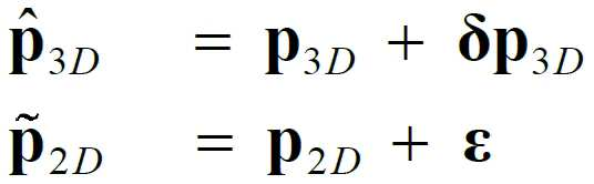
입력부(11)가 입력받는 알려진 3D 기준점의 좌표는, 기준 물체의 실제 3D 포인트의 추정 오차(즉, 상술한 식 1의 ![]()
![]()
![]()
![]()
설정부(12)는 입력부(11)에서 입력된 알려진 3D 기준점과 관련하여, 카메라를 통해 제1 시간 에포크에서 획득된 제1 이미지 상에 투영된 제1 투영된 2D 포인트(즉, 제1 이미지 상에 투영된 알려진 3D 기준점에 대응하는 제1 투영된 2D 포인트)를 설정할 수 있다. 또한, 설정부(12)는 카메라의 자세 변경(업데이트)에 의해 제1 시간 에포크와는 다른 제2 시간 에포크에서 제2 이미지가 획득되는 경우, 제2 이미지 상에 투영되는 제2 투영된 2D 포인트(즉, 제2 이미지 상에 투영된 알려진 3D 기준점에 대응하는 제2 투영된 2D 포인트)를 설정할 수 있다.The setting
본원에서 설정부(12)는 일예로 연산부 등으로 달리 지칭될 수 있다. 이에 따르면, 일예로 설정부(12, 연산부)는 카메라의 자세 변경(업데이트)에 의해 제1 시간 에포크와는 다른 제2 시간 에포크에서 제2 이미지가 획득되는 경우, 제2 이미지 상에 투영되는 제2 투영된 2D 포인트(즉, 제2 이미지 상에 투영된 알려진 3D 기준점에 대응하는 제2 투영된 2D 포인트)를 연산할 수 있다. 즉, 설정부(12, 연산부)는 획득된 제2 이미지 상에서, 알려진 3D 기준점에 대응하는 이미지 상 투영된 2D 포인트(제2 투영된 2D 포인트)의 위치가 어디인지 연산할 수 있다. 본원에서는 이하 생략된 내용이라 하더라도, 제2 이미지에 대하여 설명된 내용은 제1 이미지에 대한 설명에도 동일 내지 유사하게 적용될 수 있다. In the present specification, the setting
여기서, 제1 시간 에포크와 제2 시간 에포크는 두 개의 연속하는 시간 에포크(즉, 연속하는 두 시간 에포크)일 수 있다. 제1 시간 에포크는 일예로 상술한 이전 (k-1) 번째 시간 에포크를 의미하고, 제2 시간 에포크는 상술한 이전 (k) 번째 시간 에포크를 의미할 수 있다. 시간 에포크는 앞서 말한 바와 같이 시간 기점, 시점(바라보는 뷰 방향의 지점) 등으로 달리 지칭될 수 있다.Here, the first time epoch and the second time epoch may be two consecutive time epochs (ie, two consecutive time epochs). The first time epoch may mean, for example, the previous ( k −1)-th time epoch described above, and the second time epoch may mean the previous ( k )-th time epoch described above. As mentioned above, the temporal epoch may be referred to as a time base, a viewpoint (a point in a viewing direction), and the like.
이에 따르면, 제1 시간 에포크에서의 제1 이미지는 일예로 (k-1) 번째 시간 에포크에서 정의된 C-프레임을 의미하는 것으로서, 이는 상술한 C(k-1)와 같이 표시될 수 있다. 제2 시간 에포크에서의 제2 이미지는 일예로 (k) 번째 시간 에포크에서 정의된 C-프레임을 의미하는 것으로서, 이는 상술한 C(k)와 같이 표시될 수 있다.Accordingly, the first image in the first time epoch means, for example, a C -frame defined in the ( k −1) th time epoch, which may be displayed as C ( k −1) described above. The second image in the second time epoch means, for example, a C -frame defined in the ( k )-th time epoch, which may be displayed as above-described C ( k ).
제1 투영된 2D 포인트는 일예로 도 2에 도시되어 있지 않고 생략되어 있다. 다만, 제1 투영된 2D 포인트는 제1 이미지(이미지 평면, 평면 이미지) 상에 표시되는 2D 포인트를 의미하는 것으로서, 일예로 도 1의 상단 도면을 기준으로 예를 들면, 소문자 p와 관련하여 ![]()
![]()
![]()
![]()
이러한 제1 투영된 2D 포인트와 제2 투영된 2D 포인트는, 상술한 바와 같이 일예로 핀홀 카메라 모델을 이용함으로써 설정될 수 있으며, 특히 상술한 공지된 코너 검출기(corner detector)와 같은 어떠한 특징의 검출(feature detection) 또는 추출 알고리즘(extraction algorithms)을 이용해 획득함으로써 설정될 수 있다.The first projected 2D point and the second projected 2D point can be set by using a pinhole camera model as an example as described above, and in particular, detection of any feature, such as the known corner detector described above. (feature detection) or by obtaining using extraction algorithms.
추정부(13)는 카메라의 자세 변경(업데이트)에 의해 제1 시간 에포크와는 다른 제2 시간 에포크에서 제2 이미지가 획득되는 경우, 카메라의 자세 변경에 응답하여, 설정부(12)에서 설정된 정보를 기초로 획득되는 이미지 상의 투영된 2D 포인트와 3D 포인트 간의 관계 정보 및 카메라의 자세 변경(즉, 도 2에서의 R, t)이 고려된 두 이미지(즉, 제1 이미지와 제2 이미지) 상에서의 알려진 3D 기준점에 대한 상대적인 위치 관계에 관한 정보를 고려하여 정의된 비용 함수(단일 비용 함수)를 이용하여, 제2 시간 에포크에 대응하는 카메라의 변경된 자세인 추정 대상 카메라 자세와 제2 시간 에포크에 대응하는 제2 이미지 내 대상 물체의 알려지지 않은 3D 포인트의 좌표인 추정 대상 3D 좌표(즉, 알려지지 않은 물체의 3D 포인트의 좌표)의 동시 추정을 수행할 수 있다.When a second image is acquired at a second time epoch different from the first time epoch by changing (updating) the camera's posture, the
여기서, 설정부(12)에서 설정된 정보를 기초로 획득되는 이미지 상의 투영된 2D 포인트와 3D 포인트 간의 관계 정보(이하, 단순히 관계 정보라 함)는, 두 이미지(즉, 제1 이미지와 제2 이미지) 중 어느 한 이미지를 기준으로 하여, 해당 어느 한 이미지 상에 투영된 2D 포인트와 3D 포인트 간의 관계 정보를 의미할 수 있다. 이러한 관계 정보는 상술한 설명에서 2D-3D 대응(2D-3D correspondence)으로 지칭되는 것에 관련된 관계 정보라 지칭될 수 있다.Here, the relationship information (hereinafter simply referred to as relationship information) between the projected 2D point and the 3D point on the image obtained based on the information set in the
이때, 관계 정보에서 고려되는 3D 포인트로는 알려진 3D 포인트 및 알려지지 않은 3D 포인트가 고려될 수 있다. 알려진 3D 포인트는 기준 물체의 3D 포인트(즉, 기준 물체의 알려진 3D 기준점)을 의미하고, 알려지지 않은 3D 포인트는 대상 물체의 3D 포인트(즉, 대상 물체의 알려지지 않은 3D 포인트)를 의미할 수 있다.In this case, a known 3D point and an unknown 3D point may be considered as 3D points considered in the relationship information. The known 3D point may mean a 3D point of the reference object (ie, a known 3D reference point of the reference object), and the unknown 3D point may mean a 3D point of the target object (ie, an unknown 3D point of the target object).
여기서, 3D 포인트로서 알려지지 않은 3D 포인트가 고려되는 경우, 관계 정보는 상술한 제1 파트 관련 오류 모델에 대하여 설명된 내용을 기반으로 도출된 관계 정보를 의미할 수 있다. 이에 따르면, 관계 정보는 상술한 식 6 내지 식 8을 포함하는 정보를 의미할 수 있으며, 결과적으로는 상기 식 8과 같이 설정(정의)되는 정보를 의미할 수 있다. 예시적으로, 관계 정보는 도 2에서 소문자 p 에 관한 p4, p5와 대문자 P에 관한 P4, P5 간의 관계 정보를 의미할 수 있다. 이러한 관계 정보는 알려지지 않은 3D 포인트(unknown 3D points)에 대한 2D-3D의 오류 모델(error model)에 관한 관계 정보(즉, 2D-3D 대응에 관한 관계 정보)를 의미할 수 있다.Here, when an unknown 3D point is considered as the 3D point, the relationship information may refer to relationship information derived based on the description of the above-described first part-related error model. Accordingly, the relationship information may mean information including the above-described
만약, 3D 포인트로서 알려진 3D 포인트가 고려되는 경우, 관계 정보는 상술한 제3 파트 관련 오류 모델에 대하여 설명된 내용을 기반으로 도출된 관계 정보를 의미할 수 있다. 이에 따르면, 관계 정보는 상술한 식 16 내지 식 19를 포함하는 정보를 의미할 수 있으며, 결과적으로는 상기 식 19와 같이 설정(정의)되는 정보를 의미할 수 있다. 예시적으로, 관계 정보는 도 2에서 소문자 p 에 관한 p1, p2, p3와 대문자 P에 관한 P1, P2, P3 간의 관계 정보를 의미할 수 있다. 이러한 관계 정보는 알려진 3D 포인트(known 3D points)에 대한 2D-3D의 오류 모델에 관한 관계 정보(즉, 2D-3D 대응에 관한 관계 정보)를 의미할 수 있다.If a 3D point known as a 3D point is considered, the relationship information may mean relationship information derived based on the description of the third part-related error model. Accordingly, the relationship information may mean information including the above-described Equations 16 to 19, and consequently may mean information set (defined) as in Equation 19 above. Exemplarily, the relationship information may refer to relationship information between p 1 , p 2 , and p 3 for a lowercase p in FIG. 2 and P 1 , P 2 , and P 3 for a capital P in FIG. 2 . Such relationship information may refer to relationship information about a 2D-3D error model with respect to known 3D points (ie, relationship information about a 2D-3D correspondence).
또한, 추정부(13)에서 고려되는 상대적인 위치 관계에 관한 정보(이하 단순히 위치 관계에 관한 정보라 함)는, 제2 이미지 상에 투영된 알려진 2D 기준점에 대응하는 제2 투영된 2D 포인트와 제1 이미지 상에 투영된 제1 투영된 2D 포인트 간의 관계 정보를 포함할 수 있다. In addition, the information on the relative positional relationship considered by the estimator 13 (hereinafter simply referred to as information on the positional relationship) includes the second projected 2D point corresponding to the known 2D reference point projected on the second image and the second projected 2D point. It may include relationship information between the first projected 2D points projected on one image.
이때, 위치 관계에 관한 정보는 상술한 설명에서 2D-2D 대응(2D-3D correspondence) 혹은 3D-3D로 지칭되는 것에 관련된 관계 정보라 지칭될 수 있다.In this case, the information on the positional relationship may be referred to as relationship information related to what is referred to as 2D-2D correspondence or 3D-3D in the above description.
이러한 위치 관계에 관한 정보는, 상술한 제2 파트 관련 오류 모델에 대하여 설명된 내용을 기반으로 도출된 관계 정보를 의미할 수 있다. 이에 따르면, 위치 관계에 관한 정보는 상술한 식 9 내지 식 15를 포함하는 정보를 의미할 수 있으며, 결과적으로는 상기 식 15와 같이 설정(정의)되는 정보를 의미할 수 있다. 예시적으로, 위치 관계에 관한 정보는 도 2에서 두 이미지 상에 각각 표시되어 있는 소문자 p 에 관한 p4, p5 간의 관계 정보를 의미할 수 있다.The information on the positional relationship may refer to relationship information derived based on the description of the second part-related error model. Accordingly, the information on the positional relationship may mean information including Equations 9 to 15 described above, and consequently may mean information set (defined) as in
추정부(13)에서 고려되는 관계 정보 및 위치 관계에 관한 정보는, 유클리드 기하학(Euclidean geometry)을 기반으로 설정되는 정보(관계 정보)일 수 있다. 뿐만 아니라, 본 장치(10)에서 고려되는 모든 수식은 유클리드 기하학을 기반으로 설정된 것일 수 있다(즉, 유클리드 좌표에 기반하여 표현되는 수식일 수 있다). The relationship information and the positional relationship information considered by the
추정부(13)는 이러한 관계 정보와 위치 관계에 관한 정보를 고려하여 정의된 비용 함수를 이용하여, 제2 시간 에포크에 대응하는 카메라의 변경된 자세인 추정 대상 카메라 자세와 제2 시간 에포크에 대응하는 제2 이미지 내 대상 물체의 알려지지 않은 3D 포인트의 좌표인 추정 대상 3D 좌표를 동시에 추정할 수 있다. 추정부(13)는 추정 대상 카메라 자세와 추정 대상 3D 좌표를 단일하게 하나로 마련된 비용 함수(즉, 단일 비용 함수)를 이용하여 동시에 추정할 수 있다.The
비용 함수는 상기 식 22를 만족하도록 설정될 수 있다. 추정부(13)는 비용 함수를 기 정의해둘 수 있으며, 이를 위해 상술한 식 20 내지 식 22의 전개 과정을 수행할 수 있다.The cost function may be set to satisfy
상술한 식 20 내지 식 22를 참조하면, 비용 함수는 추정 대상 카메라 자세 관련 상태 파라미터와 추정 대상 3D 좌표 관련 3D 좌표 추정 오차를 포함하도록 정의되는 전체 상태 벡터, 깊이 관련 스케일 인수가 고려된 간접 측정치(이는 상술한 식 8에서의 Z를 의미할 수 있음)와 관련되도록 정의되는 전체 간접 측정 벡터, 및 간접 측정치와 전체 상태 벡터 간의 연결 관계를 나타내는 전체 관측 행렬 간의 관계로 정의될 수 있다.Referring to
이때, 추정 대상 카메라 자세 관련 상태 파라미터에는 변환 벡터(즉, 도 2에서 추정하고자 하는 값들 중 t 로 표시된 값)와 관련된 ![]()
![]()
![]()
![]()
![]()
![]()
추정부(13)는 상기 식 22와 같이 표현되는 비용 함수의 최소화를 통해 동시 추정을 수행할 수 있다. 특히, 추정부(13)는 전체 간접 측정 벡터와 전체 관측 행렬을 곱하여 산출되는 비용 함수의 값인 전체 상태 벡터의 오차 값들 중 최소 오차 값을 산출하는 전체 상태 벡터를 기반으로 하여, 추정 대상 카메라 자세와 추정 대상 3D 좌표를 동시에 추정할 수 있다.The
즉, 추정부(13)는 최소 오차 값을 산출하는 전체 상태 벡터에 대응하는 추정 대상 카메라 자세 관련 상태 파라미터의 값을, 추정 대상 카메라 자세인 것으로 최종적으로 추정(최적의 추정값인 것으로 도출)할 수 있다. 또한, 추정부(13)는 최소 오차 값을 산출하는 전체 상태 벡터에 대응하는 추정 대상 3D 좌표 관련 3D 좌표 추정 오차 값을, 추정 대상 3D 좌표인 것으로 최종적으로 추정(최적의 추정값인 것으로 도출)할 수 있다. 비용 함수와 관련된 식 설명은 앞서 자세히 설명했으므로, 이하 생략하기로 한다.That is, the
추정부(13)는 동시 추정의 수행을 통해, 추정 대상 카메라 자세로서 카메라의 위치와 방향을 추정할 수 있다. 특히, 추정부(13)는 추정 대상 카메라 자세로서, 도 2에서 R로 표시되는 회전 행렬(rotation matrix)과 t로 표시되는 변환 벡터(translation vector)를 추정할 수 있다. 또한, 추정부(13)는 동시 추정의 수행을 통해, 추정 대상 3D 좌표로서, 알려지지 않은 물체의 3D 포인트의 좌표를 추정할 수 있다.The
이러한 본 장치(10)는 추정 대상 카메라 자세와 추정 대상 3D 좌표의 동시 추정을 통해, 후술하는 실험 결과에서 볼 수 있는 바와 같이 종래에 카메라 자세만 추정하거나 혹은 3D 좌표만 추정하던 종래 기술과 대비하여 보다 높은 정확도를 가지면서 동시 추정을 수행할 수 있다. 또한, 본 장치(10)는 동시 추정의 수행을 통해, 종래 기술들 대비 보다 빠른 연산 속도로 카메라 자세의 추정값과 알려지지 않은 3D 포인트의 좌표 추정값을 보다 정확한 값으로 도출할 수 있다.As can be seen from the experimental results to be described later, through the simultaneous estimation of the estimated camera posture and the estimated
이하에서는 본 장치(10)의 성능 평가 결과(즉, 제안된 방법의 성능 평가 결과)에 대하여 설명한다. 이하에서는 본 장치(10)의 성능 평가를 위한 실험을 본 실험이라 지칭하기로 한다. Hereinafter, the performance evaluation result of the apparatus 10 (ie, the performance evaluation result of the proposed method) will be described. Hereinafter, an experiment for evaluating the performance of the
제안된 방법의 성능을 평가하기 위해, 합성 데이터 세트(synthetic dataset)와 실제 데이터 세트(real dataset) 각각을 활용함으로써, 두 가지 유형의 실험을 수행하였다. 이러한 실험은 측정 노이즈(measurement noise)에 대한 민감도(sensitivities), 좌표 불확실성(coordinate uncertainty), 및 기준선(baseline)과 깊이(depth)에 대한 의존도(dependence)를 정량적으로(quantitatively) 평가하기 위한 것이라 할 수 있다.In order to evaluate the performance of the proposed method, two types of experiments were performed by utilizing a synthetic dataset and a real dataset, respectively. This experiment is intended to quantitatively evaluate sensitivity to measurement noise, coordinate uncertainty, and dependence on baseline and depth. can
본 실험에서, 제안된 방법은 최근의 SfM 소프트웨어에서 자주 사용되는 다음과 같은 접근법과 비교되었다. 카메라 자세 추정을 위해, MSAC-P3P, 가우스 버전(gaussian version)의 EPnP와 강력한 버전(robust version)의 DLS가 비교되었다. 이러한 방법은 PnP 알고리즘으로 분류될 수 있다. MSAC-P3P는 MSAC와 P3P의 조합으로서, 최근 매트랩 비전 툴박스(MATALB Vision toolbox)에 제공된 노이즈와 아웃라이어(outliers)에 대해 강력한 추정(robust estimation)을 위한 것이다.In this experiment, the proposed method was compared with the following approaches frequently used in recent SfM software. For camera pose estimation, MSAC-P3P, a Gaussian version of EPnP, and a robust version of DLS were compared. This method can be classified as a PnP algorithm. MSAC-P3P is a combination of MSAC and P3P for robust estimation of noise and outliers recently provided in the MATLAB Vision toolbox.
삼각 측량을 위해 DLT가, 앞서 언급 한 PnP 알고리즘에 의해 카메라 자세가 획득된 후 알려지지 않은 3D 좌표를 추정하는 데에 사용되었다. 본 실험 전반에 걸쳐, 본 실험에서는 카메라 보정 파라미터(calibration parameters)가 사전에 미리 주어진다고 가정한다. 이하에서는 합성 데이터 평가(synthetic data evaluation) 결과에 대해 먼저 설명하고, 이후 실제 데이터 평가(real data evaluation) 결과에 대해 설명한다.For triangulation, DLT was used to estimate unknown 3D coordinates after the camera pose was acquired by the aforementioned PnP algorithm. Throughout this experiment, it is assumed that camera calibration parameters are given in advance in this experiment. Hereinafter, the results of synthetic data evaluation will be described first, and then the results of real data evaluation will be described.
합성 데이터 평가 결과에 대한 설명은 다음과 같다.The description of the synthetic data evaluation results is as follows.
합성 데이터 실험에서는, 처음으로 실제 카메라 궤적(true camera trajectory)을 생성하였다. 이후, 초기 시간 에포크(initial time epoch)에서 C-프레임에 대한 3D 포인트를 볼륨(volume) [3 m, 7 m] × [-1 m, 1 m] × [-1 m, 1 m] 로부터 무작위로(randomly, 랜덤하게) 샘플링했다. 본 실험에서 고려되는 카메라는, 1280 ×960 픽셀의 이미지 사이즈(image size)를 갖고, 초점 길이(focal length)가 1013이고, 이미지 중심(image center)이 주점(principal point)인 가상 카메라(virtual camera)인 것으로 가정했다.In the synthetic data experiment, a true camera trajectory was created for the first time. Then, at the initial time epoch, the 3D points for the C -frames are randomized from the volume [3 m, 7 m] × [-1 m, 1 m] × [-1 m, 1 m]. sampled randomly. The camera considered in this experiment has an image size of 1280 × 960 pixels, a focal length of 1013, and a virtual camera whose image center is a principal point. ) was assumed to be
2D-3D 및 2D-2D 대응은 모든 포인트들(all the points)을 두 카메라 이미지 평면(wo camera image planes)에 투영시킴으로써 생성되었다. 각 PnP 방법에는 카메라 자세 추정을 위해 4 개의 2D-3D 대응이 제공되었다. 그러나, DLT에는 다양한 알려지지 않은 3D 좌표를 추정하기 위해 수십 개(several tens)의 2D-2D 대응이 주어졌다.2D-3D and 2D-2D correspondences were created by projecting all the points onto two camera image planes. For each PnP method, four 2D-3D correspondences were provided for camera pose estimation. However, DLT was given several tens of 2D-2D correspondences to estimate various unknown 3D coordinates.
제안된 방법에서는 단 하나의 2D-3D 대응과 DLT 방식에 사용된 동일한 양(same amount)의 2D-2D 대응이 주어질 수 있다.In the proposed method, only one 2D-3D correspondence and the same amount of 2D-2D correspondence used in the DLT scheme can be given.
해당 파트(즉, 합성 데이터 평가 결과에 대한 설명)에서 제시되는 모든 구성(plots, 플롯)은, 다음에 설명하는 다양한 실험 조건(different experiment conditions)에서 의미있는 정확도 통계(meaningful accuracy statistics)를 얻기 위해, 서로 다른 무작위 시드 번호(different random seed numbers)로 100 번의 실험(trials)을 실행함으로써 독립적으로 생성될 수 있다.All plots (plots) presented in that part (i.e., descriptions of synthetic data evaluation results) were used to obtain meaningful accuracy statistics under different experiment conditions described below. , can be independently generated by running 100 trials with different random seed numbers.
측정 노이즈(measurement noise)에 대한 민감도(sensitivities)의 평가 실험 결과는 다음과 같다.The evaluation test results of sensitivity to measurement noise are as follows.
이 실험에서는 측정 노이즈가 있는 상태에서 제안된 방법을 포함하여 4가지 방법의 정확도(accuracy)를 비교하였다. 가우스 픽셀 노이즈(Gaussian pixel noise)는 모든 투영된 2D 포인트에 추가되었다. 그러나, 3D 기준점(3D reference points)의 좌표는 이상적으로 정확하다고 가정했다. 각 방법을 실행한 후에, 회전각(rotational angles), 변환 벡터(translation vectors) 및 알려지지 않은 3D 좌표의 정확도를 지상 실측 정보(ground-truth)와 비교하였다.In this experiment, the accuracy of four methods, including the proposed method, was compared in the presence of measurement noise. Gaussian pixel noise is added to every projected 2D point. However, it was assumed that the coordinates of the 3D reference points were ideally accurate. After running each method, the accuracy of rotational angles, translation vectors and unknown 3D coordinates were compared with ground-truth.
도 4는 본원의 일 실험 결과(즉, 본 장치의 성능 평가를 위한 일 실험 결과)로서, 픽셀 노이즈의 표준 편차(standard deviation)를 증가시키는 모든 실험(trials)의 RMSEs(Root Mean Square Errors)를 나타낸 도면이다.4 is an experimental result of the present application (ie, an experimental result for evaluating the performance of the present device), showing RMSEs (Root Mean Square Errors) of all trials that increase the standard deviation of pixel noise. the drawing shown.
특히, 도 4는 다른 가우스 픽셀 노이즈 값(Gaussian pixel noise values)을 갖는 다른 방법을 사용하여, 카메라 위치, 카메라 회전 및 알 수 없는 3D 좌표의 추정 오차를 비교한 도면이다. 이때, 도 4에서 좌측 도면은 카메라 위치의 RMSE, 가운데 도면은 카메라 회전의 RMSE, 우측 도면은 알 수 없는 3D 좌표의 RMSE를 나타낸다.In particular, FIG. 4 is a diagram comparing camera position, camera rotation, and estimation errors of unknown 3D coordinates using different methods having different Gaussian pixel noise values. At this time, in FIG. 4 , the left figure shows the RMSE of the camera position, the middle figure shows the RMSE of camera rotation, and the right figure shows the RMSE of unknown 3D coordinates.
도 4를 참조하면, 제안된 방법은 MSAC-P3P 및 DLS 방법에 비해 픽셀 노이즈에 대해 회복력(resilient) 있지는 않으나, EPNP 방법에 비해 결과가 좋음을 확인할 수 있다. 그러나, 픽셀 노이즈가 0.5 미만일 경우의 결과는 거의 비슷함을 확인할 수 있다.Referring to FIG. 4 , it can be confirmed that the proposed method is not resilient to pixel noise compared to the MSAC-P3P and DLS methods, but has better results than the EPNP method. However, it can be seen that the results are almost similar when the pixel noise is less than 0.5.
기준선(baseline)과 깊이(depth)에 대한 의존성(dependence)의 평가 실험 결과는 다음과 같다.The evaluation experimental results of the dependence on the baseline and the depth are as follows.
이 실험에서는 제안된 방법의 정확도를 다른 깊이와 기준선이 주어진 기존의 방법(종래 방법, conventional methods)과 비교하였다. 또한, 이 실험에서는 이미지 평면(image plane)에서 투영된 2D 포인트 (![]()
![]()
![]()
![]()
서로 다른 깊이와 기준선에 대한 개별적인 의존도(individual dependence)를 확인하기 위해, 일정한 표준 편차(constant standard deviations)(![]()
![]()
![]()
![]()
도 5는 본원의 일 실험 결과(즉, 본 장치의 성능 평가를 위한 일 실험 결과)로서, 카메라 자세, 카메라 회전 및 알려지지 않은 3D 포인트의 좌표 각각의 RMSEs의 비교 결과를 나타낸 도면이다. 특히, 도 5에서는 오직 ![]()
![]()
다시 말해, 도 5는 일정한 가우스 픽셀 노이즈(constant Gaussian pixel noise)(일예로, 0.5 픽셀)에서, 서로 다른 기준선과 깊이를 따르는 다른 방법에 의해, 카메라 자세, 카메라 회전 및 알려지지 않은 3D 포인트의 좌표에 대한 추정 오차를 비교한 도면이다. 도 5에서 상측 3개의 도면은 깊이가 7m로 고정되고 기준선이 바뀌는 경우를 나타내고, 도 5에서 하측 3개 도면은 기준선이 1.1m로 고정되고 깊이가 바뀌는 경우를 나타낸다.In other words, Figure 5 shows the camera pose, camera rotation, and coordinates of unknown 3D points by different methods along different baselines and depths, at constant Gaussian pixel noise (eg 0.5 pixels). It is a diagram comparing estimation errors for In FIG. 5 , the upper three figures show a case where the depth is fixed at 7 m and the reference line is changed, and the lower three figures in FIG. 5 show a case where the base line is fixed at 1.1 m and the depth is changed.
즉, 도 5를 참조하면, 도 5의 상위 3개의 구성(plot)에서(즉, 상위 3개의 그래프에서), 깊이는 7m로 고정되어 있고, 기준선은 점차(gradually) 변화될 수 있다. 이와는 대조적으로, 도 5의 하위 3개의 구성에서(즉, 하위 3개의 그래프에서), 기준선은 1.1m로 고정되어 있고, 깊이는 변화될 수 있다. That is, referring to FIG. 5 , in the top 3 plots of FIG. 5 (ie, in the top 3 graphs), the depth is fixed to 7 m, and the reference line may be gradually changed. In contrast, in the lower three configurations of FIG. 5 (ie, in the lower three graphs), the baseline is fixed at 1.1 m, and the depth can be varied.
도 5의 모든 구성(모든 그래프)에서 볼 수 있듯이, EPNP의 성능은 일반적으로 좋지 않지만, 깊이(depth)가 짧을 때는 만족스러울 수 있다.As can be seen in all configurations (all graphs) of FIG. 5 , the performance of the EPNP is generally not good, but may be satisfactory when the depth is short.
제안된 방법의 정확도는 DLS 및 MSAC-P3P에 비해 더 우수함을 확인할 수 있다. 특히, DLS의 결과와 제안된 방법의 결과가 거의 유사함을 확인할 수 있다. 이는 일예로 DLS 방법도 최소 제곱 접근 방식을 기반으로 하기 때문이라 할 수 있다.It can be confirmed that the accuracy of the proposed method is better than that of DLS and MSAC-P3P. In particular, it can be seen that the results of DLS and the results of the proposed method are almost similar. This is because, for example, the DLS method is also based on the least squares approach.
반면에, 노이즈에 강하도록 설계된 MSAC-P3P의 정확도는 DLS 및 제안된 방법에 비해 만족스럽지 못한 결과를 제공함을 확인할 수 있다. 도 5에서 볼 수 있듯이, 만약 픽셀 노이즈가 크지 않다면, 제안된 방법과 DLS는 모두, 긴 기준선(long baseline)과 먼 깊이(distant depth)를 고려할 때 MSAC-P3P보다 더 정확한 추정치(accurate estimates)를 제공할 수 있음을 확인할 수 있다.On the other hand, it can be confirmed that the accuracy of MSAC-P3P, which is designed to be resistant to noise, provides unsatisfactory results compared to DLS and the proposed method. As can be seen in Fig. 5, if the pixel noise is not large, both the proposed method and DLS give more accurate estimates than MSAC-P3P when considering the long baseline and distant depth. You can confirm that you can provide it.
도 6는 알려진 3D 기준점에 대한 ![]()
![]()
즉, 도 6은 본원의 일 실험 결과(즉, 본 장치의 성능 평가를 위한 일 실험 결과)로서, 일정한 가우스 픽셀 노이즈(constant Gaussian pixel noise)(일예로, 0.5 픽셀)와 일정한 3D 기준 좌표의 불확실성(0.01m)에서, 서로 다른 기준선과 깊이를 따르는 다른 방법에 의해, 카메라 자세, 카메라 회전 및 알려지지 않은 3D 포인트의 좌표에 대한 추정 오차를 비교한 도면이다. 도 6에서 상측 3개의 도면은 깊이가 7m로 고정되고 기준선이 바뀌는 경우를 나타내고, 도 6에서 하측 3개 도면은 기준선이 1.1m로 고정되고 깊이가 바뀌는 경우를 나타낸다.That is, FIG. 6 is an experimental result of the present application (ie, an experimental result for evaluating the performance of the apparatus), and shows constant Gaussian pixel noise (eg, 0.5 pixel) and uncertainty of constant 3D reference coordinates. (0.01 m), a diagram comparing the estimation errors for the coordinates of the camera pose, camera rotation, and unknown 3D point by different methods along different baselines and depths. In FIG. 6 , the upper three figures show a case where the depth is fixed at 7 m and the reference line is changed, and the lower three figures in FIG. 6 show a case where the base line is fixed at 1.1 m and the depth is changed.
다시 말해, ![]()
![]()
도 6을 참조하면, 전체적인 정확도(overall accuracy)가 도 5와 비교했을 때 4가지 방법 모두 감소함을 확인할 수 있다. 그럼에도 불구하고, 제안된 방법은 카메라 위치, 카메라 회전 및 알려지지 않은 3D 좌표 추정에 있어서, 다른 모든 방법들 보다 더 나은 결과를 보여주고 있음을 확인할 수 있다.Referring to FIG. 6 , it can be seen that the overall accuracy is decreased in all four methods when compared with FIG. 5 . Nevertheless, it can be confirmed that the proposed method shows better results than all other methods in estimating camera position, camera rotation and unknown 3D coordinates.
-그러나, 도 5의 MSAC-P3P 및 DLS 결과와 비교했을 때, MSAC-P3P의 정확도가 도 4의 DLS보다 우수함을 확인할 수 있다. 이 결과는, MSAC-P3P가 후보들(candidates) 사이에서 가장 좋은 3가지의 2D-3D 대응을 찾기 때문에 얻어진 것이라 볼 수 있다. 따라서 MSAC-P3P의 결과는 DLS의 결과보다 더 정확함을 확인할 수 있다.- However, when compared with the MSAC-P3P and DLS results of FIG. 5 , it can be confirmed that the accuracy of the MSAC-P3P is superior to the DLS of FIG. 4 . This result can be considered to be obtained because MSAC-P3P finds the best 3 2D-3D correspondence among the candidates. Therefore, it can be confirmed that the result of MSAC-P3P is more accurate than that of DLS.
도 5 및 도 6에서 보여지는 것과 같이, 모든 방법에 의해 기준선이 증가하거나 깊이가 감소함에 따라 RMSEs가 감소하는 경향을 보임을 확인할 수 있다. 특히, 제안된 방법은, 기준선이 길어질수록 깊이 정확도가 증가하도록 다중 기준선 기술(multi-baseline techniques)의 특성을 물려받기(inherits) 때문에, 기준점의 알려진 3D 좌표에 대한 불확실성을 고려할 때 뚜렷한 견고성(distinguishing robustness.)을 가질 수 있다.As shown in FIGS. 5 and 6 , it can be confirmed that the RMSEs tend to decrease as the baseline increases or the depth decreases by all methods. In particular, since the proposed method inherits the properties of multi-baseline techniques such that the depth accuracy increases as the baseline length increases, it is distinctly robust when considering the uncertainty about the known 3D coordinates of the reference point. robustness.).
시뮬레이션의 전체 결과는 ![]()
![]()
![]()
![]()
![]()
![]()
즉, 아래 표 1은 ![]()
![]()
![]()
![]()
![]()
![]()
이때 표에서, MSAC-P3P 및 2EPnP + GN은 각각 MP3P 및 EPnP로 축약되어 표시될 수 있다.In this case, in the table, MSAC-P3P and 2EPnP + GN may be abbreviated as MP3P and EPnP, respectively.
[표 1][Table 1]

[표 2][Table 2]

이하에서는 실제 데이터 평가(real data evaluation) 결과에 대하여 설명한다.Hereinafter, the results of real data evaluation will be described.
실제 시나리오(real world scenarios)에서 제안된 방법의 성능을 검증(validate)하기 위해, 본 실험에서는 스테레오 카메라(일예로 BumbleXB3)를 사용하여 데이터 세트를 수집하였다. 센서는 기준선(baseline)이 24cm인 15Hz에서 정류된 글로벌 셔터(rectified global shutter) VGA(640 × 80) 스테레오 이미지를 출력할 수 있다. 이 실험은 서로 다른 기준선 및 깊이에서 알려지지 않은 3D 포인트가 주어진 제안된 방법을 평가하는 데에 초점을 맞추어 졌다. 본 실험에서는 스테레오 카메라 API를 이용함으로써 해당 실험 전에 카메라 보정 파라미터(camera calibration parameters)를 파악하였다.In order to validate the performance of the proposed method in real world scenarios, a data set was collected using a stereo camera (eg, BumbleXB3) in this experiment. The sensor may output a rectified global shutter VGA (640×80) stereo image at 15 Hz having a baseline of 24 cm. This experiment was focused on evaluating the proposed method given unknown 3D points at different baselines and depths. In this experiment, camera calibration parameters were identified before the experiment by using the stereo camera API.
데이터 세트(dataset)는 이미지(images)와 카메라 자세의 지상 실측 값(ground- truth values)과 타겟 지점 좌표(target point coordinates)로 구성될 수 있다. 다양한 기준선과 깊이로 카메라를 움직여 이미지를 캡처하였다. 평가를 위해, 일예로 왼쪽 카메라 이미지(left camera images)만을 활용하였다. 실험(experiment)은 4개의 다른 기준선과 4개의 깊이를 고려하여 16번 수행되었다.The data set may be composed of images, ground-truth values of camera poses, and target point coordinates. Images were captured by moving the camera at various baselines and depths. For evaluation, only left camera images were used as an example. Experiments were performed 16 times considering 4 different baselines and 4 depths.
또한, 0.6m의 폭(width)과 0.9m의 높이(height)를 갖는 대형 체스판(big chessboard)을 타겟 물체(target object)로 활용하였다. 이것은 0.1 m × 0.15 m 크기의 작은 블록(small blocks) 36개를 포함하고 있을 수 있다. 타겟 포인트(target points)의 3D 좌표는 24cm 의 기준선을 갖는 스테레오 이미지에 의해 지상 실측(ground- truth)에 대해 계산되었다.In addition, a large chessboard having a width of 0.6 m and a height of 0.9 m was used as a target object. It may contain 36 small blocks measuring 0.1 m × 0.15 m. The 3D coordinates of the target points were calculated for ground-truth by stereo images with a baseline of 24 cm.
깊이 정보(depth information)의 정확도(accuracy)가 좌표 추정(coordinate estimation)에 주요 요소(dominant factor)이므로, 본 실험에서는 정밀 거리 측정기(precise range finder)인 BOSCH GLM 50C로 깊이를 측정하였다. 기준점의 3D 좌표는 초기 시간 에포크(initial time epoch)에서 C-프레임에 대해 계산되었다.Since the accuracy of depth information is a dominant factor in coordinate estimation, in this experiment, depth was measured with a BOSCH GLM 50C, a precision range finder. The 3D coordinates of the reference point were calculated for the C -frame at the initial time epoch.
도 7은 본원의 일 실험 결과(즉, 본 장치의 성능 평가를 위한 일 실험 결과)로서, 일치된 2D 포인트(matched 2D points)가 두 개의 연속적인 영상(two consecutive images)에 표시된 실험 환경을 묘사한 도면이다.7 is an experimental result of the present application (ie, an experimental result for evaluating the performance of the present device), depicting an experimental environment in which matched 2D points are displayed in two consecutive images. it is one drawing
즉, 도 7은 실제 실험 환경의 예를 나타낸다. 해당 실험에서는 BumblebeeXB3의 의 카메라 3대 중 왼쪽 이미지만을 활용하였다. 체스 판(chessboard)은 평면 표면(plane surface)을 갖는다. 도 7에서 (a)는 일정한 깊이(constant depth)의 간격(interval)으로 마련된 스테레오 카메라와 체스판의 예를 나타낸다. 도 7에서 (b) 는 실험의 삽화(illustration)를 나타낸 것으로서, 빨간색 화살표(red arrow)는 카메라와 물체(object)가 그 방향으로 움직이는 것을 나타낸다. 카메라로부터 물체는 일정한 깊이의 일정 간격(regular interval)으로 설정될 수 있다. 도 7에서 (c)는 두 개의 연속적인 이미지(two consecutive images) 사이에 일치하는 2D 포인트(Matched 2D points)의 예를 나타낸다.That is, FIG. 7 shows an example of an actual experimental environment. In this experiment, only the left image was used among the 3 cameras of BumblebeeXB3. A chessboard has a plane surface. 7A shows an example of a stereo camera and a chessboard provided at intervals of a constant depth. 7 (b) shows an illustration of the experiment, and a red arrow indicates that the camera and the object move in that direction. The object from the camera may be set at regular intervals of a constant depth. 7( c ) shows an example of Matched 2D points between two consecutive images.
도 7을 참조하면, 코너 검출기(corner detector)는 SSD(Sum of Squared Difference)를 기반으로 한 두개의 연속된 이미지(two consecutive images)에서 2D 포인트를 추출하는 데 사용될 수 있다. 본 실험에서는 2D- 3D 대응을 만들기 위해, 알려진 3D 기준점과 그들의 투영된 2D 포인트를 무작위로 선택하였다. 그리고, 나머지(rest)는 2D-2D 대응을 얻기 위해 설정되었다.Referring to FIG. 7 , a corner detector may be used to extract a 2D point from two consecutive images based on a sum of squared difference (SSD). In this experiment, known 3D reference points and their projected 2D points were randomly selected to create a 2D–3D correspondence. And, the rest is set to obtain 2D-2D correspondence.
도 8은 본원의 일 실험 결과(즉, 본 장치의 성능 평가를 위한 일 실험 결과)로서, 카메라 위치, 카메라 회전 및 알려지지 않은 3D 포인트의 RMSEs의 비교 예를 나타낸 도면이다. 이러한 도 8은 네 가지 방법으로 생성된 결과를 나타낸다.8 is an experimental result of the present application (ie, an experimental result for evaluating the performance of the present device), and is a diagram illustrating a comparative example of RMSEs of a camera position, a camera rotation, and an unknown 3D point. 8 shows the results generated by the four methods.
즉, 도 8은 다른 기준선과 깊이에 따라 실제 데이터를 기반으로 한 다른 방법에 의해, 카메라 위치, 카메라 회전 및 알려지지 않은 특징 좌표(feature coordinates)의 추정 오차를 비교한 결과를 나타낸다. 도 8에서 상측 3개의 도면은 0.275m에서 1.1m로 기준선이 변경될 때, 깊이가 5m로 고정되는 경우를 나타낸다. 도 8에서 하측 3개의 도면은 2m에서 5m로 깊이가 변경될 때, 기준선이 1.1m로 고정되는 경우를 나타낸다.That is, FIG. 8 shows the results of comparing the estimation errors of the camera position, camera rotation, and unknown feature coordinates by other methods based on actual data according to different reference lines and depths. In FIG. 8 , the upper three diagrams show a case where the depth is fixed to 5 m when the reference line is changed from 0.275 m to 1.1 m. The lower three figures in FIG. 8 show a case in which the reference line is fixed to 1.1 m when the depth is changed from 2 m to 5 m.
도 8을 참조하면, 다른 깊이를 갖는 도 8의 하측 3개의 도면에서 보이는 바와 같이, 카메라 자세의 추정 정확도는 다른 방법들 대비 제안된 방법에 의해 증가됨을 확인할 수 있다. 특히, 제안된 방법은 깊이를 4 또는 5m로 증가시킬 때 최고 정확도(best accuracy)를 보임을 확인할 수 있다.Referring to FIG. 8 , as shown in the three lower drawings of FIG. 8 having different depths, it can be confirmed that the estimation accuracy of the camera posture is increased by the proposed method compared to other methods. In particular, it can be confirmed that the proposed method shows the best accuracy when the depth is increased to 4 or 5 m.
아래 표 3에는 실제 데이터 실험의 전체 결과가 요약되어 있다. 즉, 표 3은 실제 데이터에 기반한 다른 기준선 및 깊이 별로 추정 오차를 비교한 결과를 나타낸다.Table 3 below summarizes the overall results of the actual data experiments. That is, Table 3 shows the results of comparing estimation errors for different baselines and depths based on actual data.
[표 3][Table 3]

표 3을 참조하면, 제안된 방법에 의한 시뮬레이션 결과와 비교하여, 다른 방법들의 정확도는 상당히 저하됨을 확인할 수 있다. 즉, 표 3에 의하면, 제안된 방법이 다른 방법들 대비 더 우수한 정확도를 보임을 확인할 수 있다. Referring to Table 3, it can be seen that the accuracy of the other methods is significantly lowered compared to the simulation results by the proposed method. That is, according to Table 3, it can be confirmed that the proposed method shows better accuracy than other methods.
본 실험에 사용된 타겟 물체는 평면 표면(ane surface)이기 때문에, 평면 물체에 민감한 대부분의 PnP 알고리즘의 정확도에 영향을 미칠 수 있다. 반면에, 제안된 방법은 실제 데이터에 대한 정확도 저하를 비교적 적게 보여준다. 요약하면, 상술한 실험 결과에 따르면, 제안된 방법은 카메라의 위치(position)와 회전(rotation)을 추정할 때, 다른 방법들 보다 훨씬 더 나은 정확도를 보임을 확인할 수 있다.Since the target object used in this experiment is an ane surface, it may affect the accuracy of most PnP algorithms that are sensitive to planar objects. On the other hand, the proposed method shows relatively little degradation of accuracy for real data. In summary, according to the above experimental results, it can be confirmed that the proposed method shows much better accuracy than other methods when estimating the position and rotation of the camera.
상술한 바에 따르면, 본 장치(10)는 2D-2D와 2D-3D 대응을 활용하여 카메라 자세와 알려지지 않은 3D 포인트의 좌표를 동시에 추정할 수 있는 참신하고 다재다능한 접근법에 대하여 제안한다.As described above, the
본 장치(10)의 제안된 방법은 측정의 가용성(availability, 유용성)에 따라 PnP 방법과 삼각 측량법이라는 두 가지의 기존 모드로 축소(reduced)될 수 있기 때문에 매우 다용도로 활용될 수 있는 장점을 가질 수 있다.The proposed method of the
상술한 본원의 일 실험을 통하여, 제안된 방법은 합성 데이터와 실제 데이터 모두에 대해 검증이 이루어졌다. 상술한 실험 결과에 따르면, 최근 SfM 소프트웨어에서 사용된 세 가지 대표 방법(MSAC-P3P, EPnP 및 DLS)과 비교하여, 제안된 방법이 처음에 알려지지 않은 3차원 포인트 좌표와 카메라 자세에 대해 보다 정확한 추정치를 제공할 수 있음이 입증될 수 있다.Through the above-described experiment of the present application, the proposed method was verified for both synthetic data and real data. According to the experimental results described above, compared with the three representative methods (MSAC-P3P, EPnP and DLS) recently used in SfM software, the proposed method provides a more accurate estimate of the initially unknown 3D point coordinates and camera posture. It can be demonstrated that it can provide
또한, 상술한 실험 결과에 따르면, 제안된 방법은 3D 기준점의 좌표에 대한 적정한(moderate) 불확실성(uncertainties)이 주어진 평면 물체(planer objects)나 원격 물체(remote objects)를 관찰할 때에도, 보다 안정적인 추정치를 제공함을 확인할 수 있다.In addition, according to the experimental results described above, the proposed method provides a more stable estimate even when observing planer objects or remote objects given moderate uncertainties about the coordinates of the 3D reference point. It can be confirmed that the .
달리 말해, 제안된 방법은 3D 기준점의 좌표에 오차(error, 에러, 오류)가 존재하는 상황(즉, 3D 기준점의 좌표가 부정확한 상황)에서도, 관찰하고자 하는 대상(관찰 대상)인 물체(평면 물체나 원격 물체)의 3차원 좌표 추정치 및 카메라 자세의 추정치를 보다 정확한 값으로 추정하여 제공할 수 있다.In other words, the proposed method is an object (planar) that is an object to be observed (observation object) even in a situation in which an error exists in the coordinates of the 3D reference point (that is, in a situation in which the coordinates of the 3D reference point are inaccurate). An estimate of the three-dimensional coordinates of an object or a remote object) and an estimate of a camera posture may be estimated and provided as more accurate values.
본 장치(10)는 하이브리드 대응을 사용함으로써 3D 기준점에서 측정 노이즈에 대한 민감도를 감소시키고, 기준선이 길어짐에 따라 깊이 정확도를 향상시킬 수 있다(즉, 기준점이 길어질수록 보다 높은 깊이 정확도를 보일 수 있다). 또한, 제안된 방법은 반복 최소 제곱법(Iterative Least Square Method) 을 적용함으로써 이미지 재투영 오차를 최소화시킬 수 있다.The
또한, 제안된 방법은 측정의 가용성에 따라 가장 최근의 SfM (Structure-from-Motion) 접근 방식에서 활용되는 기존의 PnP (Perspective-n-Point) 방법과 삼각 측량 방법으로 축소될 수 있다.In addition, the proposed method can be reduced to the conventional PnP (Perspective-n-Point) method and triangulation method utilized in the most recent SfM (Structure-from-Motion) approach depending on the availability of measurements.
또한, 본원은 상술한 실험을 통하여, 합성 데이터와 실제 데이터 모두를 통해 제안된 방법이 카메라 자세와 알려지지 않은 3D 좌표를 동시에 추정하는 데에 효과적임을 입증하였다.In addition, the present application has demonstrated that the proposed method is effective in estimating the camera pose and unknown 3D coordinates simultaneously through both synthetic data and real data through the above-described experiments.
상술한 바에 따르면, 본 장치(10)는 3D 기준점의 좌표에 오차(error, 에러, 오류)가 존재하는 상황(즉, 3D 기준점의 좌표가 부정확한 상황)에서도 정확한 카메라의 자세를 추정하고, 뿐만 아니라 알려지지 않은 대상 물체의 3D 좌표를 동시에 추정할 수 있도록 하는 카메라 자세와 대상 물체의 3D 좌표를 동시에 추정할 수 있다.As described above, the
종래에 도 1의 하측 도면과 같은 PnP 방법은 알려진(알려져 있는, 알고 있는) 물체의 3D 좌표(3D 포인트의 좌표)를 기반으로(즉, 물체의 정확한 3D 좌표를 알고 있다는 가정 하에) 카메라의 자세를 추정하는 기술을 의미한다.Conventionally, the PnP method as shown in the lower diagram of FIG. 1 is based on the 3D coordinates (coordinates of the 3D point) of a known (known, known) object (ie, assuming that the exact 3D coordinates of the object are known) the camera's posture technology for estimating
한편, 종래에 도 1의 상측 도면과 같은 삼각 측량 방법(삼각 측량법)은 카메라의 자세가 알려져 있을 때(일예로, PnP 방법 등에 의한 추정을 통해 카메라의 자세를 이미 알고 있을 때), 알려진 카메라의 자세를 기반으로 하여(즉, 카메라의 자세를 알고 있다는 가정 하에), 3D 좌표를 모르는 물체(즉, 알려지지 않은 3D 좌표를 갖는 물체)를 두 시점에서 카메라를 통해 바라보았을 때 두 시점에서 획득된 카메라의 두 이미지 상에 투영된 해당 물체의 이미지 상 좌표(즉, 두 이미지 상에, 해당 물체의 3D 좌표에 대응하여 공통으로 투영되어 있는 해당 물체의 투영된 2D 포인트의 좌표)(즉, 2D-2D 대응)로부터 해당 물체의 3D 좌표를 추정해내는 기술을 의미한다.On the other hand, in the conventional triangulation method (triangulation method) as shown in the upper diagram of FIG. 1, when the posture of the camera is known (for example, when the posture of the camera is already known through estimation by the PnP method, etc.), the known camera Based on the pose (i.e., assuming that the pose of the camera is known), an object with unknown 3D coordinates (i.e., an object with unknown 3D coordinates) is viewed through the camera from two viewpoints. Coordinates on the image of the object projected onto the two images of Correspondence) refers to a technique for estimating the 3D coordinates of the object.
이에 따르면, 종래에는 카메라의 자세를 추정하거나 알려지지 않은 3D 좌표를 추정하고자 할 때, 서로 구분된 별개의 두 기법(즉, PnP 방법과 삼각 측량법) 각각을 독립적으로 이용해야 했다. 즉, 종래에는 단순히 PnP 방법으로 카메라의 자세 추정만 가능하고, 삼각 측량법으로 알려지지 않은 3D 좌표의 추정만 가능했으며, 이들을 하나의 추정기로 동시에 추정하는 기술은 존재하지 않았다.According to this, conventionally, when estimating the camera posture or estimating unknown 3D coordinates, two separate techniques (ie, the PnP method and the triangulation method) had to be independently used. That is, conventionally, only camera posture estimation is possible with the PnP method, and only unknown 3D coordinates can be estimated with the triangulation method, and there is no technology for estimating them simultaneously with one estimator.
예시적으로, 종래에 카메라의 자세와 알려지지 않은 3D 좌표를 함께 추정하는 것은, 일예로 1차적으로 PnP 방법을 이용해 알려진 3D 좌표(알려진 3D 포인트의 좌표)를 기반으로 카메라의 자세를 추정한 다음, 이후 1차 추정된 카메라의 자세를 기반으로 하여 2차적으로 삼각 측량법을 이용해 알려지지 않은 3D 좌표를 추정함(즉, PnP 방법과 삼각 측량법을 순차적으로 수행함)으로써 이루어질 수 있었다.Illustratively, estimating the pose of the camera and the unknown 3D coordinates together in the prior art is, for example, primarily estimating the pose of the camera based on the known 3D coordinates (coordinates of the known 3D point) using the PnP method, Afterwards, it could be done by estimating unknown 3D coordinates using triangulation secondarily (ie, sequentially performing the PnP method and triangulation method) based on the first estimated camera posture.
그런데, 종래의 PnP 방법은, 알려진 3D 좌표(즉, 3D 기준점)가 정확한 좌표인 것으로 가정한 상태로 카메라의 자세를 추정한다. 그런데, 현실적으로 3D 좌표(즉, 3D 기준점의 좌표)가 정확한 좌표로 일관되게 제공되는 것은 어렵다고 할 수 있다. 즉, PnP 방법을 포함하여 카메라 자세를 추정하는 종래의 방법들은 대부분 3D 기준점으로 고려되는 알려진 3D 좌표가 정확하다는 가정 하에(즉, 정확한 3D 좌표인 것임을 가정으로 하여) 카메라 자세를 추정하기 때문에, 3D 기준점으로 고려되는 알려진 3D 좌표에 오차가 존재하는 경우(즉, 알려진 3D 좌표가 부정확한 좌표인 경우)에는 카메라의 자세를 정확히 추정하지 못하는 문제가 있다.However, in the conventional PnP method, a camera posture is estimated under the assumption that known 3D coordinates (ie, 3D reference point) are accurate coordinates. However, in reality, it can be said that it is difficult to consistently provide 3D coordinates (ie, coordinates of a 3D reference point) as accurate coordinates. That is, most conventional methods for estimating the camera posture, including the PnP method, estimate the camera posture under the assumption that the known 3D coordinates considered as the 3D reference point are accurate (that is, assuming that they are accurate 3D coordinates). If there is an error in the known 3D coordinates considered as the reference point (ie, the known 3D coordinates are inaccurate coordinates), there is a problem in that the posture of the camera cannot be accurately estimated.
이에 따르면, 종래의 기술로 카메라의 자세와 알려지지 않은 3D 좌표를 함께 추정하고자 하는 경우에는, 일예로 알려진 3D 좌표에 오차가 존재할 경우, 이를 기반으로 추정되는 카메라의 자세에도 오차가 발생하게 되고(즉, 추정된 카메라 자세가 부정확한 값을 갖게 되고), 나아가 그 추정된 카메라 자세를 기반으로 추정되는 3D 좌표(즉, 알려지지 않은 3D 좌표) 역시 오차가 발생하게 되는 문제가 있다. 즉, 종래 기술로는, 알려진 3D 좌표의 오차가 커질수록 추정되는 카메라 자세의 오차 역시 커지게 되며, 나아가 그를 기반으로 추정되는 3D 좌표(알려지지 않은 3D 좌표)의 오차는 더욱 더 커지게 되는 문제가 있다.According to this, in the case of estimating the camera posture and the unknown 3D coordinates together with the prior art, if there is an error in the known 3D coordinates, an error occurs in the camera posture estimated based on this as an example (i.e. , the estimated camera pose has an inaccurate value), and furthermore, there is a problem that an error occurs in 3D coordinates (ie, unknown 3D coordinates) estimated based on the estimated camera pose. That is, in the prior art, as the error of the known 3D coordinates increases, the error of the estimated camera posture also increases, and further, the error of the 3D coordinates (unknown 3D coordinates) estimated based on it increases. have.
즉, 종래 기술을 통해서는 두 기법이 순차적으로 이루어짐에 따라, 순차적으로 두 기법의 과정을 거치면서 오차가 점점 더 커지게 되어, 추정되는 카메라 자세와 추정되는 알려지지 않은 3D 좌표 모두 정확도가 상당히 떨어지는 문제가 있다. That is, in the prior art, as the two techniques are sequentially performed, the error becomes larger and larger as the two techniques are sequentially performed, and the accuracy of both the estimated camera posture and the unknown 3D coordinates is significantly lowered. there is
이러한 문제를 해소하고자, 본원은 종래에 별개로 이루어졌던 카메라 자세 추정 기술과 3D 좌표 추정 기술을 하나의 단일 프로세스로 결합함으로써 상술한 식 22에 제시된 비용 함수(단일 비용 함수)를 통하여 카메라 자세 추정과 3D 좌표 추정이 동시에(한번에) 이루어질 수 있도록 하는 단일 추정기인 본 장치(10)를 제공할 수 있다. 본원은 이러한 본 장치(10)를 제공함으로써, 3D 기준점의 좌표에 오차가 존재하더라도 카메라 자세와 알려지지 않은 대상 물체의 3D 좌표의 추정이 보다 정확히 이루어지도록 제공할 수 있다.In order to solve this problem, the present application combines the camera posture estimation technique and the 3D coordinate estimation technique, which have been separately performed in the prior art, into one single process, thereby estimating the camera posture and It is possible to provide the
이러한 본 장치(10)는 종래의 두 기술(즉, PnP 기반 카메라 자세 추정 기술과 삼각 측량법 기반 3D 좌표 추정 기술)을 하나의 단일 프로세스로 결합함으로써, 알려진 3D 좌표에 오차(노이즈 포함 등)가 있어 이를 기반으로 추정된 카메라 자세에도 오차가 어느 정도 있다고 하더라도, 이러한 오차가, 3D 좌표 추정시 이용되는 2D-2D 대응 기법(즉, 두 이미지 상에 공통적으로 투영된 2개의 투영된 2D 포인트를 이용하는 픽셀 단위 기반의 기법)에서 어느 정도 상쇄되도록 할 수 있는 바, 이로부터 카메라의 자세와 알려지지 않은 대상 물체의 3D 좌표의 보다 정확한 추정을 가능케 할 수 있다. This
즉, 알려진 3D 좌표(즉, 3D 기준점의 좌표)의 오차와 대비하여, 두 이미지 상에 공통적으로 투영되어 나타난 두 2D 포인트(즉, 2D-2D 대응에 해당하는 포인트, 두 이미지 상의 매칭되는 2D 포인트, 달리 표현해 두 이미지 상에 동일한 2D 점군으로 나타난 그 공통된 점들)은 픽셀 단위이기 때문에(즉, 픽셀 단위로 표현되는 것이기 때문에) 오차가 3D 좌표의 오차보다 상대적으로 훨씬 적다고 할 수 있다. 이러한 점을 고려하여, 본 장치(10)는 상술한 두 기술을 하나의 단일 프로세스로 결합시킴으로써, 알려진 3D 좌표(기준점의 좌표)에 오차가 존재하더라도 이를 상쇄시킬 수 있을 만한 측정치인 2D-2D 대응이 활용되도록 하기 때문에, 종래 기술들과 대비하여 카메라 자세 뿐만 아니라 3D 좌표(특히, 알려지지 않은 3D 포인트의 좌표)까지 보다 정확하게 동시에 추정되도록 제공할 수 있다. 이러한 본 장치(10)가 종래 기술들 대비 더 우수한 효과를 보임(즉, 보다 정확한 카메라 자세와 3D 좌표를 추정함)은 상술한 도 5, 도 6, 도 8 등을 참조하여 설명된 성능 평가 결과를 통해 증명될 수 있다. 즉, 본 장치(10)는 종래 기술들 대비 추정 정확도가 향상될 수 있다. That is, in contrast to the known error of 3D coordinates (that is, the coordinates of the 3D reference point), two 2D points that are commonly projected on two images (ie, a point corresponding to a 2D-2D correspondence, a matching 2D point on the two images) , in other words, the common points represented by the same 2D point cloud on two images) are in pixels (that is, expressed in units of pixels), so the error is relatively much smaller than the error of 3D coordinates. In consideration of this point, the
즉, 본 장치(10)는 알고있는 값(즉, 기준 물체의 알려진 3D 기준점의 좌표)과 오차가 커질 수 있는 값(즉, 오차의 허용오차(tolerance) 범위가 훨씬 클 수 있는 값으로서, 카메라 자세 관련 정보인 R과 t, 및 3차원 포인트 좌표 정보)을 상술한 식 22로 정의(설정)된 단일 비용 함수에 동시에 넣어서 한번에 최적화시키면서 추정하고자 하는 정보(즉, 추정 대상 카메라 자세와 추정 대상 3D 좌표)를 도출해 낼 수 있으며, 이를 통해 종래 기술들 대비 신뢰도 높은 추정 결과를 획득할 수(즉, 보다 정확한 추정값을 도출해낼 수) 있다 .이러한 본 장치(10)는 상술한 성능 평가 결과에서 볼 수 있는 바와 같이, 종래 기술들 대비 더 우수한 효과를 가질 수 있다.That is, the
본 장치(10)는 기 정의된 비용 함수(단일 비용 함수)가 최소화되는 방향으로 추정 대상 카메라 자세와 추정 대상 3D 좌표를 동시에 추정할 수 있다.The
또한, 카메라/영상 등 관련 분야에서, 종래에는 일예로 호모지니어스(homogeneous) 기하학을 기반으로 한 추정이 이루어졌던 반면, 본원은 유클리드 기하학(Euclidean geometry)을 기반으로 한 제안된 방법(동시 추정 방법)을 수행하는 본 장치(10)를 제공할 수 있다.In addition, in related fields such as cameras/images, conventionally, as an example, estimation based on homogeneous geometry has been made, whereas in the present application, a proposed method based on Euclidean geometry (simultaneous estimation method) It is possible to provide the
또한, 일예로 다수의 추정 기법을 제공함에 있어서, 어떠한 기법이 이용되었는지, 어떠한 기하학 혹은 식이 이용되었는지가 중요하게 여겨질 수 있다. 이러한 점에 있어서, 본 장치(10)는 유클리드 기하학을 기반으로 하여 상술한 두 기술을 하나의 단일 프로세스로 결합시킨 동시 추정 방법(이는 제안된 방법을 의미함)을 제공하며, 또한 쓰이는 판 자체도 반복 최소 제곱법(Iterative Least Square Method)로 식 22와 같은 비용 함수(즉, 목적 함수)를 정의함으로써 두 기술을 하나의 단일 프로세스로 결합시킨 동시 추정 방법을 제공할 수 있다.In addition, in providing a plurality of estimation techniques as an example, it may be considered important which technique is used and which geometry or equation is used. In this regard, the
본 장치(10)는 입력이 주어지면(여기서, 입력은 일예로 카메라의 자세 변경의 감지를 의미할 수 있음), 제안된 방법에서의 상술한 식 22로 표현되는 H와 Z와의 관계에 의해서, 최소 제곱법(최소 자승법)을 통해 추정 대상 카메라 자세와 추정 대상 3D 좌표(알려지지 않은 물체의 3D 포인트의 좌표)를 동시에 추정해 낼 수 있다.When an input is given (here, the input may mean detection of a change in the camera's posture, for example), by the relationship between H and Z expressed by
본 장치(10)는 식 22와 같이 정의된 수식에 대하여 오차가 최소가 되는 값이 도출될 때까지 최소 제곱법을 적용함으로써, 추정 대상 카메라 자세와 추정 대상 3D 좌표(알려지지 않은 물체의 3D 포인트의 좌표)를 동시에 추정해 낼 수 있다.The
본 장치(10)는 기준 물체의 알려진 3D 기준점의 좌표가 주어져 있으면, 이후 카메라에 의해 이미지 획득(촬영)이 이루어졌을 때, 획득된 해당 이미지로부터 알려진 3D 기준점의 좌표에 대응하는 획득된 이미지 상의 투영된 2D 포인트의 연산하여 알 수 있으므로, 연산된 투영된 2D 포인트에 대한 정보를 기반으로 하여 추정 대상 카메라 자세와 추정 대상 3D 좌표(알려지지 않은 물체의 3D 포인트의 좌표)를 동시에 추정해 낼 수 있다.When the coordinates of the known 3D reference point of the reference object are given, the
즉, 본 장치(10)는 기준 물체의 알려진 3D 기준점의 좌표를 입력받고, 이후 제1 이미지가 획득되면, 설정부(12)에 의해 제1 이미지 상에 투영된 알려진 3D 기준점에 대응하는 포인트(즉, 제1 이미지 상의 제1 투영된 2D 포인트의 좌표)를 연산하여 설정할 수 있다. 이때, 제1 투영된 2D 포인트 내지 그 좌표는 앞서 말한 바와같이 일예로 종래의 특징 검출/추출 알고리즘을 이용해 연산(획득)될 수 있다. 이후, 본 장치(10)는 카메라의 자세 변경(업데이트)에 의해 제2 이미지가 획득된 경우, 설정부(12)에 의해 제2 이미지 상에 투영된 알려진 3D 기준점에 대응하는 포인트(즉, 제2 이미지 상의 제2 투영된 2D 포인트의 좌표)를 연산하여 설정할 수 있으며, 이러한 투영된 2D 포인트의 좌표 역시 일예로 종래의 특징 검출/추출 알고리즘을 이용해 연산(획득)될 수 있다. 이후, 본 장치(10)는 카메라의 자세 변경에 응답하여, 앞서 설정부(12)에 의해 연산되어 설정된 투영된 2D 포인트의 정보를 식 22와 같이 설정된 비용 함수에 적용하여 최소 제곱법(최소 자승법)을 수행함으로써, 추정 대상 카메라 자세와 추정 대상 3D 좌표(알려지지 않은 물체의 3D 포인트의 좌표)를 동시에 추정(획득)할 수 있다.That is, the
다시 말해, 본 장치(10)는 카메라의 자세(일예로, 위치와 방향) 및 알려지지 않은 물체의 3차원 좌표를 동시에 추정할 수 있는 기술에 관한 것이다. 본 장치(10)는 기존의 Structure-from-Motion (SfM) 시스템에서 Camera Pose Estimation (카메라의 위치/자세 추정) 및 Triangulation (물체의 3차원 좌표 추정) 기법과 연관되며, 기존 방식과 다르게 순차적으로 처리되는 두 개의 기법을 하나의 시스템으로(장치로) 결합한 새로운 방법론(제안된 방법)에 대하여 제안한다.In other words, the
도 9는 본원의 일 실시예에 따른 카메라 자세와 대상 물체의 3D 좌표를 동시에 추정하는 동시 추정 장치(10, 본 장치)의 구성을 개략적으로 나타낸 도면이다.9 is a diagram schematically illustrating a configuration of a simultaneous estimation apparatus 10 (the present apparatus) for simultaneously estimating a camera posture and 3D coordinates of a target object according to an embodiment of the present application.
도 9를 참조하면, 본 장치(10)는 알려진 물체의 3차원 좌표(즉, 기존 물체의 알려진 3D 기준점의 좌표)와 해당 물체가 이미지에 투영된 2차원 좌표를 나타내는 2D-3D 대응점(즉, 2D-3D 대응에 해당하는 포인트), 및 알려지지 않은 물체(즉, 대상 물체)가 각각의 두 시점의 이미지(즉, 제1 이미지와 제2 이미지)에 투영된 2차원 좌표를 나타내는 2D-2D 대응점(즉, 2D-2D 대응에 해당하는 포인트)을 제안된 방법의 입력으로 이용(적용)할 수 있다. 이처럼, 두 종류의 대응점(즉, 2D-3D 대응에 해당하는 포인트와 2D-2D 대응에 해당하는 포인트)을 입력으로 하는 본 장치(10)에 의한 제안된 방법은, 초기 설정된 좌표계를 기준으로 카메라의 상대적인 자세(일예로, 위치와 방향) 및 새롭게 관찰된 물체(대상 물체)의 3차원 좌표를 동시에 추정할 수 있다. 여기서, 초기 설정된 좌표계는 예시적으로 N-프레임을 기준으로 설정되는 좌표계를 의미할 수 있으며, 이에만 한정되는 것은 아니다.Referring to FIG. 9 , the
본 장치(10)는 기존의 Structure-from-Motion (SfM) 알고리즘에서 두 단계로 나누어 처리되던 카메라의 자세 및 물체의 3차원 정보 획득 과정을 하나의 추정기로 설계함으로써, 다음과 같은 4가지의 특징(장점)을 가질 수 있다.The
첫번째로 본 장치(10)는 기존의 Camera Pose Estimation인 Perspective-n-Point (PnP) 기법에서의 특정 가정을 완화하며 기존 알고리즘 대비 개선된 정확도를 가질 수 있다. 여기서, 특정 가정은 알려진 물체의 3차원 정보가 정확하다는 것을 의미할 수 있다.First, the
두번째로 본 장치(10)는 물체의 3차원 정보 중에 깊이 정보의 정확도가 기존 알고리즘 대비 카메라 사이의 거리(baseline, 기준선, 베이스라인)이 길어질수록 높아진다는 특징을 가질 수 있다.Second, the
세번째로, 기존의 2D-2D 대응점만을 활용하여 카메라의 상대 위치 및 자세 추정하는 기법의 경우 스케일 정보가 부재되어 있는 반면, 이에 반해 본 장치(10)는 2D-3D 대응점을 활용함으로써 스케일 정보를 직접적으로 알 수 있다는 특징을 가질 수 있다.Third, scale information is absent in the existing technique of estimating the relative position and posture of a camera by using only 2D-2D corresponding points, whereas the
네번째로, 본 장치(10)는 활용 가능한 대응점의 종류(즉, 2D-2D 대응 혹은 2D-3D 대응)에 따라서 기존 기법인 삼각 측량(Triangulation) 기법 또는 PnP 방법으로 변환이 자유롭게 가능하다는 특징을 가질 수 있다.Fourth, the
이러한 본 장치(10)는 카메라를 활용한 물체 혹은 주변 환경의 3차원 정보 재구성에 관련된 분야인 가상 현실(Virtual Reality, VR) & 증강 현실(Augmented Reality, AR), 로봇 그리고 지도 제작 등의 분야에 효과적으로 적용될 수 있다. 뿐만 아니라, 본 장치(10)는 물체의 위치 및 자세 정보를 연구 및 응용 개발하는 분야인 내비게이션(Navigation), 항법(Positioning) 및 로봇 탐색 등의 분야에 효과적으로 적용될 수 있다.This
기존의 컴퓨터 비전 및 영상 처리 분야에서 카메라 이미지를 활용하여 물체의 3차원 정보를 재구성하는 기법인 Structure-from-Motion (SfM)이 존재한다. SfM 기법은 카메라 이미지 획득, 카메라 위치/자세 추정, 물체의 3차원 정보 추정 그리고 최적화 기법의 순서대로 진행이 이루어지게 된다. 이에 반해, 본 장치(10)는 기존 SfM의 처리 과정 중에서 카메라 위치/자세 추정 및 물체의 3차원 정보 추정 과정을 동시에 처리하는 새로운 방법론을 제시함으로써, 종래 대비 높은 정확도를 보이는 추정 결과를 제공할 수 있다.In the existing computer vision and image processing fields, Structure-from-Motion (SfM), a technique for reconstructing 3D information of an object using a camera image, exists. The SfM technique proceeds in the order of camera image acquisition, camera position/position estimation, 3D information estimation of an object, and optimization technique. On the other hand, the
본 장치(10)는 기존 기법 대비 알려진 물체의 3차원 정보에 오차가 존재하여도 비교적 높은 정확도로 카메라의 위치/자세, 그리고 새로운 물체의 3차원 정보를 동시에 획득(추정)할 수 있으며, 제공된 측정치의 조합에 따라서 기존 PnP 기법 혹은 Triangulation 기법으로 변환 가능한 다목적 특징을 가질 수 있다.The
본 장치(10)에서는 측정치로서 2D-3D 대응점(2D-3D 대응 관련 포인트)과 2D-2D 대응점(2D-2D 대응 관련 포인트)이 활용(이용)될 수 있다. 여기서, 2D-3D 대응점은 알려진 물체의 3차원 좌표와 이미지 평면으로 투영된 물체의 2차원 좌표(투영된 2D 포인트의 좌표)의 조합을 나타낸다. 2D-2D 대응점은 알려지지 않은 물체가 각각의 다른 시점의 이미지(즉, 제1 이미지와 제2 이미지)로 투영되었을 때의 2차원 좌표의 조합을 나타낸다. 본 장치(10)는 이러한 두 조합(2D-3D 대응점과 2D-2D 대응점)의 측정치를 입력으로 하여, 현재 시점(일예로 제2 시간 에포크에 대응하는 시점)의 카메라의 자세(위치, 방향)와 알려지지 않은 물체의 3차원 좌표를 동시에 추정할 수 있다.In the
종래에 2D-2D 대응점만 활용할 경우 스케일 정보를 복원할 수 없다는 단점이 있는 반면, 본 장치(10)는 2D-3D 대응점을 추가적으로 활용하여 이러한 문제를 개선할 수 있다. 또한, 본 장치(10)는 종래에 카메라 자세를 추정하기 위해 일예로 3단계로 나누어 처리되는 방식과는 다르게, 하나의 추정기(단일 추정기) 내에서 카메라의 위치와 자세를 동시에 추정할 수 있으며, 뿐만 아니라 알려지지 않은 3D 좌표도 함께 동시에 추정할 수 있다. 본 장치(10)는 카메라의 위치와 자세만 추정하는 것이 아닌, 알려지지 않은 물체의 3차원 좌표도 동시에 추정하는 복합 기술에 대하여 제공할 수 있다.While there is a disadvantage in that scale information cannot be restored when only 2D-2D corresponding points are used in the related art, the
가상 현실이 아닌 실제 3차원 공간에서 카메라의 위치 및 자세를 표현하기 위해서는 스케일 정보가 필수적으로 요구된다고 할 수 있다. 이에, 본 장치(10)는 기존과 다르게 제안된 방법의 제공을 통해, 스케일이 복원되어 실제 3차원 공간에서 카메라의 경로를 표현할 수 있다.It can be said that scale information is essential in order to express the position and posture of the camera in real 3D space, not virtual reality. Accordingly, the
본 장치(10)는 2D-3D 대응점뿐만 아니라 2D-2D 대응점을 함께 활용함으로써, 종래 기술 대비 카메라의 위치, 자세 및 알려지지 않은 3D 포인트에 대한 추정 정확도를 효과적으로 개선시킬 수 있다. 본 장치(10)는 2D-3D 대응점과 2D-2D 대응점을 함께 활용함으로써, 카메라의 위치, 자세 및 알려지지 않은 3D 포인트를 한번에 동시 추정할 수 있다. 또한, 본 장치(10)는 는 2D-3D 대응점과 2D-2D 대응점을 모두 활용함으로써, 카메라의 위치, 자세, 및 영상의 특징점 정보를 모두 획득할 수 있다. 본 장치(10)는 2D-2D 대응점을 활용하여 영상 특징점의 3차원 위치를 추정함과 동시에 카메라의 위치 및 자세 또한 추정 가능하다.The
본 장치(10)는 Global Positioning System (GPS)과 Inertial Navigation System (INS)를 활용하지 않고 카메라로부터 획득한 이미지(즉, 제1 이미지와 제2 이미지)와 알려진 특징점 좌표(즉, 기준 물체의 알려진 3D 기준점의 좌표)를 활용함으로써, 카메라의 위치 및 자세 그리고 알려지지 않은 특징점 좌표를 모두 제공(추정)할 수 있다. 즉, 본 장치(10)는 카메라만을 활용하여 카메라의 위치 및 자세 그리고 물체의 3차원 좌표를 추정할 수 있는 기술로서, GPS 와 INS 같은 부가적인 센서가 필요 없으며, 이에 따라 본 장치(10)는 해당 센서(GPS, INS 센서)로 인한 추가 비용 및 무게를 절감(감소)시킬 수 있다.The
본 장치(10)는 스테레오 카메라뿐만 아니라 단일 카메라에 적용 가능할 수 있다. 또한, 본 장치(10)는 다양한 투시 투영(perspective projection) 기반의 카메라에서 활용될 수 있다.The
본 장치(10)는 2D-3D 대응점을 활용하여 카메라의 위치, 자세를 추정할 수 있다. 또한 본 장치(10)는2D-2D 대응점 및 알려진 카메라 자세 및 위치 정보를 활용하여 알려지지 않은 물체의 3차원 좌표를 추정할 수 있다. 본 장치(10)는 알려지지 않은 물체의 3차원 좌표뿐만 아니라 카메라의 위치 및 자세 또한 추정 가능할 수 있다.The
이하에서는 상기에 자세히 설명된 내용을 기반으로, 본원의 동작 흐름을 간단히 살펴보기로 한다.Hereinafter, based on the details described above, the operation flow of the present application will be briefly reviewed.
도 10은 본원의 일 실시예에 따른 카메라 자세와 대상 물체의 3D 좌표를 동시에 추정하는 동시 추정 방법에 대한 동작 흐름도이다.10 is a flowchart illustrating a simultaneous estimation method for simultaneously estimating a camera posture and 3D coordinates of a target object according to an exemplary embodiment of the present disclosure.
도 10에 도시된 카메라 자세와 대상 물체의 3D 좌표를 동시에 추정하는 동시 추정 방법은 앞서 설명된 본 장치(10)에 의하여 수행될 수 있다. 따라서, 이하 생략된 내용이라고 하더라도 본 장치(10)에 대하여 설명된 내용은 카메라 자세와 대상 물체의 3D 좌표를 동시에 추정하는 동시 추정 방법에 대한 설명에도 동일하게 적용될 수 있다.The simultaneous estimation method of simultaneously estimating the camera posture and the 3D coordinates of the target object shown in FIG. 10 may be performed by the
도 10을 참조하면, 단계 S11에서 입력부는, 기준 물체의 알려진 3D 기준점의 좌표를 입력받을 수 있다.Referring to FIG. 10 , in step S11 , the input unit may receive coordinates of a known 3D reference point of a reference object.
이때, 알려진 3D 기준점의 좌표는, 기준 물체의 실제 3D 포인트의 추정 오차가 고려되어 있는 오차가 존재하는 추정된 3D 기준점의 좌표를 포함할 수 있다. 즉, 단계S11에서 고려되는 알려진 3D 기준점의 좌표는 일예로 오차가 존재하는 부정확한 3D 기준점의 좌표를 포함할 수 있다.In this case, the known coordinates of the 3D reference point may include the coordinates of the estimated 3D reference point having an error in which the estimation error of the actual 3D point of the reference object is considered. That is, the coordinates of the known 3D reference point considered in step S11 may include, for example, the coordinates of the inaccurate 3D reference point in which an error exists.
다음으로, 단계 S12에서 설정부는, 단계S11에서 입력받은 알려진 3D 기준점과 관련하여, 카메라를 통해 제1 시간 에포크에서 획득된 제1 이미지 상에 투영된 제1 투영된 2D 포인트를 설정하고, 카메라의 자세 변경에 의해 제1 시간 에포크와는 다른 제2 시간 에포크에서 제2 이미지가 획득되는 경우, 제2 이미지 상에 투영되는 제2 투영된 2D 포인트를 설정할 수 있다.Next, in step S12, the setting unit sets the first projected 2D point projected on the first image acquired at the first time epoch through the camera with respect to the known 3D reference point input in step S11, and When the second image is obtained at a second time epoch different from the first time epoch due to the change of posture, a second projected 2D point projected on the second image may be set.
다음으로, 단계S13에서 추정부는, 카메라의 자세 변경에 응답하여, 단계S12에서 설정된 정보를 기초로 획득되는 이미지 상의 투영된 2D 포인트와 3D 포인트 간의 관계 정보 및 카메라의 자세 변경이 고려된 두 이미지 상에서의 알려진 3D 기준점에 대한 상대적인 위치 관계에 관한 정보를 고려하여 정의된 비용 함수를 이용하여, 제2 시간 에포크에 대응하는 카메라의 변경된 자세인 추정 대상 카메라 자세와 제2 시간 에포크에 대응하는 제2 이미지 내 대상 물체의 알려지지 않은 3D 포인트의 좌표인 추정 대상 3D 좌표의 동시 추정을 수행할 수 있다.Next, in step S13, the estimator, in response to the change in the posture of the camera, on the two images in which the relation information between the projected 2D point and the 3D point on the image obtained based on the information set in step S12 and the change in the posture of the camera are considered Using a cost function defined in consideration of information on the relative positional relationship with respect to a known 3D reference point of Simultaneous estimation of the estimated
여기서, 상대적인 위치 관계에 관한 정보는, 상기 제2 투영된 2D 포인트와 상기 제1 투영된 2D 포인트 간의 관계 정보를 포함할 수 있다.Here, the information on the relative positional relationship may include relationship information between the second projected 2D point and the first projected 2D point.
또한, 단계S13에서 비용 함수는, 추정 대상 카메라 자세 관련 상태 파라미터와 추정 대상 3D 좌표 관련 3D 좌표 추정 오차를 포함하도록 정의되는 전체 상태 벡터, 깊이 관련 스케일 인수가 고려된 간접 측정치와 관련되도록 정의되는 전체 간접 측정 벡터, 및 간접 측정치와 전체 상태 벡터 간의 연결 관계를 나타내는 전체 관측 행렬 간의 관계로 정의될 수 있다.In addition, in step S13, the cost function is an overall state vector defined to include the estimation target camera posture-related state parameter and the
또한, 단계S13에서 추정부는, 비용 함수의 최소화를 통해 동시 추정을 수행하되, 전체 간접 측정 벡터와 전체 관측 행렬을 곱하여 산출되는 비용 함수의 값인 전체 상태 벡터의 오차 값들 중 최소 오차 값을 산출하는 전체 상태 벡터를 기반으로 하여, 추정 대상 카메라 자세와 추정 대상 3D 좌표를 동시에 추정할 수 있다.In addition, in step S13, the estimator performs simultaneous estimation through the minimization of the cost function, but calculates the minimum error value among the error values of the entire state vector, which is a value of the cost function calculated by multiplying the entire indirect measurement vector and the entire observation matrix. Based on the state vector, the estimated camera posture and the estimated 3D coordinates may be simultaneously estimated.
또한, 단계 S13에서 비용 함수는, 상술한 식 22를 만족하도록 설정될 수 있으며, 식 22에 대한 설명은 앞서 자세히 설명했으므로, 이하 중복되는 설명은 설명하기로 한다.In addition, in step S13, the cost function may be set to satisfy
또한, 단계 S13에서 고려되는 관계 정보 및 위치 관계에 관한 정보는, 유클리드 기하학(Euclidean geometry)을 기반으로 설정되는 정보일 수 있다.In addition, the relation information and the positional relation information considered in step S13 may be information set based on Euclidean geometry.
상술한 설명에서, 단계 S11 내지 S13은 본원의 구현예에 따라서, 추가적인 단계들로 더 분할되거나, 더 적은 단계들로 조합될 수 있다. 또한, 일부 단계는 필요에 따라 생략될 수도 있고, 단계 간의 순서가 변경될 수도 있다.In the above description, steps S11 to S13 may be further divided into additional steps or combined into fewer steps, according to an embodiment of the present application. In addition, some steps may be omitted if necessary, and the order between the steps may be changed.
본원의 일 실시 예에 따른 카메라 자세와 대상 물체의 3D 좌표를 동시에 추정하는 동시 추정 방법은 다양한 컴퓨터 수단을 통하여 수행될 수 있는 프로그램 명령 형태로 구현되어 컴퓨터 판독 가능 매체에 기록될 수 있다. 상기 컴퓨터 판독 가능 매체는 프로그램 명령, 데이터 파일, 데이터 구조 등을 단독으로 또는 조합하여 포함할 수 있다. 상기 매체에 기록되는 프로그램 명령은 본 발명을 위하여 특별히 설계되고 구성된 것들이거나 컴퓨터 소프트웨어 당업자에게 공지되어 사용 가능한 것일 수도 있다. 컴퓨터 판독 가능 기록 매체의 예에는 하드 디스크, 플로피 디스크 및 자기 테이프와 같은 자기 매체(magnetic media), CD-ROM, DVD와 같은 광기록 매체(optical media), 플롭티컬 디스크(floptical disk)와 같은 자기-광 매체(magneto-optical media), 및 롬(ROM), 램(RAM), 플래시 메모리 등과 같은 프로그램 명령을 저장하고 수행하도록 특별히 구성된 하드웨어 장치가 포함된다. 프로그램 명령의 예에는 컴파일러에 의해 만들어지는 것과 같은 기계어 코드뿐만 아니라 인터프리터 등을 사용해서 컴퓨터에 의해서 실행될 수 있는 고급 언어 코드를 포함한다. 상기된 하드웨어 장치는 본 발명의 동작을 수행하기 위해 하나 이상의 소프트웨어 모듈로서 작동하도록 구성될 수 있으며, 그 역도 마찬가지이다.The simultaneous estimation method for simultaneously estimating the camera posture and the 3D coordinates of the target object according to an embodiment of the present application may be implemented in the form of a program command that can be executed through various computer means and recorded in a computer-readable medium. The computer-readable medium may include program instructions, data files, data structures, etc. alone or in combination. The program instructions recorded on the medium may be specially designed and configured for the present invention, or may be known and available to those skilled in the art of computer software. Examples of the computer-readable recording medium include magnetic media such as hard disks, floppy disks and magnetic tapes, optical media such as CD-ROMs and DVDs, and magnetic such as floppy disks. - includes magneto-optical media, and hardware devices specially configured to store and execute program instructions, such as ROM, RAM, flash memory, and the like. Examples of program instructions include not only machine language codes such as those generated by a compiler, but also high-level language codes that can be executed by a computer using an interpreter or the like. The hardware devices described above may be configured to operate as one or more software modules to perform the operations of the present invention, and vice versa.
또한, 전술한 카메라 자세와 대상 물체의 3D 좌표를 동시에 추정하는 동시 추정 방법은 기록 매체에 저장되는 컴퓨터에 의해 실행되는 컴퓨터 프로그램 또는 애플리케이션의 형태로도 구현될 수 있다.In addition, the simultaneous estimation method of simultaneously estimating the camera posture and the 3D coordinates of the target object may be implemented in the form of a computer program or application executed by a computer stored in a recording medium.
전술한 본원의 설명은 예시를 위한 것이며, 본원이 속하는 기술분야의 통상의 지식을 가진 자는 본원의 기술적 사상이나 필수적인 특징을 변경하지 않고서 다른 구체적인 형태로 쉽게 변형이 가능하다는 것을 이해할 수 있을 것이다. 그러므로 이상에서 기술한 실시예들은 모든 면에서 예시적인 것이며 한정적이 아닌 것으로 이해해야만 한다. 예를 들어, 단일형으로 설명되어 있는 각 구성 요소는 분산되어 실시될 수도 있으며, 마찬가지로 분산된 것으로 설명되어 있는 구성 요소들도 결합된 형태로 실시될 수 있다.The above description of the present application is for illustration, and those of ordinary skill in the art to which the present application pertains will understand that it can be easily modified into other specific forms without changing the technical spirit or essential features of the present application. Therefore, it should be understood that the embodiments described above are illustrative in all respects and not restrictive. For example, each component described as a single type may be implemented in a distributed manner, and likewise components described as distributed may also be implemented in a combined form.
본원의 범위는 상기 상세한 설명보다는 후술하는 특허청구범위에 의하여 나타내어지며, 특허청구범위의 의미 및 범위 그리고 그 균등 개념으로부터 도출되는 모든 변경 또는 변형된 형태가 본원의 범위에 포함되는 것으로 해석되어야 한다.The scope of the present application is indicated by the following claims rather than the above detailed description, and all changes or modifications derived from the meaning and scope of the claims and their equivalents should be construed as being included in the scope of the present application.
10: 카메라 자세와 대상 물체의 3D 좌표를 동시에 추정하는 동시 추정 장치
11: 입력부
12: 설정부
13: 추정부10: Simultaneous estimation device for simultaneously estimating the camera posture and the 3D coordinates of the target object
11: input
12: setting unit
13: estimator
Claims (13)
(a) 기준 물체의 알려진 3D 기준점의 좌표를 입력받는 단계;
(b) 상기 알려진 3D 기준점과 관련하여, 카메라를 통해 제1 시간 에포크에서 획득된 제1 이미지 상에 투영된 제1 투영된 2D 포인트를 설정하고, 상기 카메라의 자세 변경에 의해 상기 제1 시간 에포크와는 다른 제2 시간 에포크에서 제2 이미지가 획득되는 경우, 상기 제2 이미지 상에 투영되는 제2 투영된 2D 포인트를 설정하는 단계; 및
(c) 상기 카메라의 자세 변경에 응답하여, 상기 (b) 단계에서 설정된 정보를 기초로 획득되는 이미지 상의 투영된 2D 포인트와 3D 포인트 간의 관계 정보 및 상기 카메라의 자세 변경이 고려된 두 이미지 상에서의 상기 알려진 3D 기준점에 대한 상대적인 위치 관계에 관한 정보를 고려하여 정의된 비용 함수를 이용하여, 상기 제2 시간 에포크에 대응하는 카메라의 변경된 자세인 추정 대상 카메라 자세와 상기 제2 시간 에포크에 대응하는 상기 제2 이미지 내 상기 대상 물체의 알려지지 않은 3D 포인트의 좌표인 추정 대상 3D 좌표의 동시 추정을 수행하는 단계를 포함하고,
상기 상대적인 위치 관계에 관한 정보는, 상기 제2 투영된 2D 포인트와 상기 제1 투영된 2D 포인트 간의 관계 정보를 포함하는 것인, 동시 추정 방법.A simultaneous estimation method for simultaneously estimating a camera posture and 3D coordinates of a target object, comprising:
(a) receiving the coordinates of a known 3D reference point of the reference object;
(b) with respect to the known 3D reference point, setting a first projected 2D point projected on a first image acquired at a first time epoch through a camera, and by changing the posture of the camera, the first time epoch setting a second projected 2D point projected on the second image when a second image is acquired at a second time epoch different from ; and
(c) in response to the change in the posture of the camera, relation information between the projected 2D point and the 3D point on the image obtained based on the information set in step (b), and the change in the posture of the camera on the two images Using a cost function defined in consideration of information on the relative positional relationship with respect to the known 3D reference point, the estimated target camera attitude, which is the changed attitude of the camera corresponding to the second time epoch, and the position corresponding to the second time epoch performing simultaneous estimation of the estimated target 3D coordinates that are the coordinates of the unknown 3D point of the target object in the second image,
The information on the relative positional relationship will include relationship information between the second projected 2D point and the first projected 2D point.
상기 (c) 단계에서 상기 비용 함수는,
상기 추정 대상 카메라 자세 관련 상태 파라미터와 상기 추정 대상 3D 좌표 관련 3D 좌표 추정 오차를 포함하도록 정의되는 전체 상태 벡터, 깊이 관련 스케일 인수가 고려된 간접 측정치와 관련되도록 정의되는 전체 간접 측정 벡터, 및 간접 측정치와 상기 전체 상태 벡터 간의 연결 관계를 나타내는 전체 관측 행렬 간의 관계로 정의된 것인, 동시 추정 방법.According to claim 1,
In step (c), the cost function is
A global state vector defined to include the estimated target camera posture-related state parameter and the estimated target 3D coordinate-related 3D coordinate estimation error, a global indirect measurement vector defined to relate a depth-related scale factor to the considered indirect measurement value, and the indirect measurement value and a relationship between the entire observation matrix representing the connection relationship between the global state vectors and the simultaneous estimation method.
상기 (c) 단계는,
상기 비용 함수의 최소화를 통해 상기 동시 추정을 수행하되,
상기 전체 간접 측정 벡터와 상기 전체 관측 행렬을 곱하여 산출되는 비용 함수의 값인 전체 상태 벡터의 오차 값들 중 최소 오차 값을 산출하는 전체 상태 벡터를 기반으로 하여, 상기 추정 대상 카메라 자세와 상기 추정 대상 3D 좌표를 동시에 추정하는 것인, 동시 추정 방법. 3. The method of claim 2,
Step (c) is,
performing the simultaneous estimation through minimization of the cost function,
Based on a total state vector that calculates a minimum error value among error values of a total state vector that is a value of a cost function calculated by multiplying the entire indirect measurement vector and the entire observation matrix, the estimated camera posture and the estimated target 3D coordinates Simultaneous estimation method for estimating at the same time.
상기 (c) 단계에서 상기 비용 함수는, 하기 수학식 1을 만족하도록 설정되고,
[수학식 1]

여기서,
In step (c), the cost function is set to satisfy Equation 1 below,
[Equation 1]
here,
상기 (a) 단계에서 상기 알려진 3D 기준점의 좌표는,
상기 기준 물체의 실제 3D 포인트의 추정 오차가 고려되어 있는 오차가 존재하는 추정된 3D 기준점의 좌표를 포함하는 것인, 동시 추정 방법.According to claim 1,
The coordinates of the known 3D reference point in step (a) are,
The simultaneous estimation method, wherein the estimation error of the actual 3D point of the reference object includes the coordinates of the estimated 3D reference point in which the error is considered.
상기 (c) 단계에서 상기 관계 정보 및 상기 위치 관계에 관한 정보는, 유클리드 기하학(Euclidean geometry)을 기반으로 설정되는 정보인 것인, 동시 추정 방법.According to claim 1,
In the step (c), the information about the relationship information and the location relationship is information set based on Euclidean geometry.
기준 물체의 알려진 3D 기준점의 좌표를 입력받는 입력부;
상기 알려진 3D 기준점과 관련하여, 카메라를 통해 제1 시간 에포크에서 획득된 제1 이미지 상에 투영된 제1 투영된 2D 포인트를 설정하고, 상기 카메라의 자세 변경에 의해 상기 제1 시간 에포크와는 다른 제2 시간 에포크에서 제2 이미지가 획득되는 경우, 상기 제2 이미지 상에 투영되는 제2 투영된 2D 포인트를 설정하는 설정부; 및
상기 카메라의 자세 변경에 응답하여, 상기 설정부에서 설정된 정보를 기초로 획득되는 이미지 상의 투영된 2D 포인트와 3D 포인트 간의 관계 정보 및 상기 카메라의 자세 변경이 고려된 두 이미지 상에서의 상기 알려진 3D 기준점에 대한 상대적인 위치 관계에 관한 정보를 고려하여 정의된 비용 함수를 이용하여, 상기 제2 시간 에포크에 대응하는 카메라의 변경된 자세인 추정 대상 카메라 자세와 상기 제2 시간 에포크에 대응하는 상기 제2 이미지 내 상기 대상 물체의 알려지지 않은 3D 포인트의 좌표인 추정 대상 3D 좌표의 동시 추정을 수행하는 추정부를 포함하고,
상기 상대적인 위치 관계에 관한 정보는, 상기 제2 이미지 상에 투영된 상기 알려진 3D 기준점에 대응하는 제2 투영된 2D 포인트와 상기 제1 이미지 상에 투영된 상기 제1 투영된 2D 포인트 간의 관계 정보를 포함하는 것인, 동시 추정 장치.A simultaneous estimation device for estimating a camera posture and 3D coordinates of a target object at the same time, comprising:
an input unit for receiving coordinates of a known 3D reference point of a reference object;
With respect to the known 3D reference point, set a first projected 2D point projected on a first image acquired at a first time epoch through a camera, and different from the first time epoch by changing the attitude of the camera a setting unit configured to set a second projected 2D point projected on the second image when a second image is obtained in a second time epoch; and
In response to the change in the posture of the camera, the relationship information between the projected 2D point and the 3D point on the image obtained based on the information set in the setting unit and the known 3D reference point on the two images in which the change in the posture of the camera is considered Using a cost function defined in consideration of information on a relative positional relationship between and an estimator that performs simultaneous estimation of the estimated target 3D coordinates that are coordinates of the unknown 3D point of the target object;
The information about the relative positional relationship includes relation information between a second projected 2D point corresponding to the known 3D reference point projected on the second image and the first projected 2D point projected on the first image which includes, a simultaneous estimation device.
상기 비용 함수는,
상기 추정 대상 카메라 자세 관련 상태 파라미터와 상기 추정 대상 3D 좌표 관련 3D 좌표 추정 오차를 포함하도록 정의되는 전체 상태 벡터, 깊이 관련 스케일 인수가 고려된 간접 측정치와 관련되도록 정의되는 전체 간접 측정 벡터, 및 간접 측정치와 상기 전체 상태 벡터 간의 연결 관계를 나타내는 전체 관측 행렬 간의 관계로 정의된 것인, 동시 추정 장치.8. The method of claim 7,
The cost function is
A global state vector defined to include the estimated target camera posture-related state parameter and the estimated target 3D coordinate-related 3D coordinate estimation error, a global indirect measurement vector defined to relate a depth-related scale factor to the considered indirect measurement value, and the indirect measurement value and a relationship between the entire observation matrix representing the connection relationship between the global state vectors and the simultaneous estimation apparatus.
상기 추정부는,
상기 비용 함수의 최소화를 통해 상기 동시 추정을 수행하되,
상기 전체 간접 측정 벡터와 상기 전체 관측 행렬을 곱하여 산출되는 비용 함수의 값인 전체 상태 벡터의 오차 값들 중 최소 오차 값을 산출하는 전체 상태 벡터를 기반으로 하여, 상기 추정 대상 카메라 자세와 상기 추정 대상 3D 좌표를 동시에 추정하는 것인, 동시 추정 장치. 9. The method of claim 8,
The estimator is
performing the simultaneous estimation through minimization of the cost function,
Based on a total state vector that calculates a minimum error value among error values of a total state vector that is a value of a cost function calculated by multiplying the entire indirect measurement vector and the entire observation matrix, the estimated camera posture and the estimated target 3D coordinates Simultaneous estimation apparatus for estimating at the same time.
상기 비용 함수는, 하기 수학식 2를 만족하도록 설정되고,
[수학식 2]

여기서,
The cost function is set to satisfy Equation 2 below,
[Equation 2]
here,
상기 알려진 3D 기준점의 좌표는,
상기 기준 물체의 실제 3D 포인트의 추정 오차가 고려되어 있는 오차가 존재하는 추정된 3D 기준점의 좌표를 포함하는 것인, 동시 추정 장치.8. The method of claim 7,
The coordinates of the known 3D reference point are,
The simultaneous estimation apparatus of claim 1, wherein the estimation error of the actual 3D point of the reference object includes the coordinates of the estimated 3D reference point in which the error is considered.
상기 관계 정보 및 상기 위치 관계에 관한 정보는, 유클리드 기하학(Euclidean geometry)을 기반으로 설정되는 정보인 것인, 동시 추정 장치.8. The method of claim 7,
The information on the relationship information and the information on the position relationship is information set based on Euclidean geometry.
Priority Applications (1)
| Application Number | Priority Date | Filing Date | Title |
|---|---|---|---|
| KR1020200166956A KR102421067B1 (en) | 2020-12-02 | 2020-12-02 | Simultaneous estimation apparatus and method for simultaneously estimating the camera pose and 3d coordinates of the target object |
Applications Claiming Priority (1)
| Application Number | Priority Date | Filing Date | Title |
|---|---|---|---|
| KR1020200166956A KR102421067B1 (en) | 2020-12-02 | 2020-12-02 | Simultaneous estimation apparatus and method for simultaneously estimating the camera pose and 3d coordinates of the target object |
Publications (2)
| Publication Number | Publication Date |
|---|---|
| KR20220077731A KR20220077731A (en) | 2022-06-09 |
| KR102421067B1 true KR102421067B1 (en) | 2022-07-13 |
Family
ID=81985666
Family Applications (1)
| Application Number | Title | Priority Date | Filing Date |
|---|---|---|---|
| KR1020200166956A Active KR102421067B1 (en) | 2020-12-02 | 2020-12-02 | Simultaneous estimation apparatus and method for simultaneously estimating the camera pose and 3d coordinates of the target object |
Country Status (1)
| Country | Link |
|---|---|
| KR (1) | KR102421067B1 (en) |
Families Citing this family (1)
| Publication number | Priority date | Publication date | Assignee | Title |
|---|---|---|---|---|
| CN119090958B (en) * | 2024-06-18 | 2025-07-08 | 苏州铸正机器人有限公司 | Monocular vision posture estimation method and system based on EPnP algorithm |
Citations (3)
| Publication number | Priority date | Publication date | Assignee | Title |
|---|---|---|---|---|
| JP2014216813A (en) | 2013-04-25 | 2014-11-17 | 日本放送協会 | Camera attitude estimation device and program therefor |
| JP2017130042A (en) | 2016-01-20 | 2017-07-27 | 株式会社リコー | Video processing apparatus, video processing method, and program |
| JP2020122754A (en) | 2019-01-31 | 2020-08-13 | 株式会社豊田中央研究所 | Three-dimensional position estimation device and program |
-
2020
- 2020-12-02 KR KR1020200166956A patent/KR102421067B1/en active Active
Patent Citations (3)
| Publication number | Priority date | Publication date | Assignee | Title |
|---|---|---|---|---|
| JP2014216813A (en) | 2013-04-25 | 2014-11-17 | 日本放送協会 | Camera attitude estimation device and program therefor |
| JP2017130042A (en) | 2016-01-20 | 2017-07-27 | 株式会社リコー | Video processing apparatus, video processing method, and program |
| JP2020122754A (en) | 2019-01-31 | 2020-08-13 | 株式会社豊田中央研究所 | Three-dimensional position estimation device and program |
Non-Patent Citations (1)
| Title |
|---|
| Federico Camposeco et al., "Hybrid Camera Pose Estimation", 2018 IEEE/CVF Conference on Computer Vision and Pattern Recognition, June 2018 |
Also Published As
| Publication number | Publication date |
|---|---|
| KR20220077731A (en) | 2022-06-09 |
Similar Documents
| Publication | Publication Date | Title |
|---|---|---|
| Pathak et al. | Online three‐dimensional SLAM by registration of large planar surface segments and closed‐form pose‐graph relaxation | |
| Jiao et al. | Robust odometry and mapping for multi-lidar systems with online extrinsic calibration | |
| JP5832341B2 (en) | Movie processing apparatus, movie processing method, and movie processing program | |
| Kim et al. | Stereo camera localization in 3d lidar maps | |
| CN105869136A (en) | Collaborative visual SLAM method based on multiple cameras | |
| Beder et al. | Determining an initial image pair for fixing the scale of a 3d reconstruction from an image sequence | |
| Usenko et al. | Reconstructing street-scenes in real-time from a driving car | |
| Tomono | 3-D localization and mapping using a single camera based on structure-from-motion with automatic baseline selection | |
| US10977810B2 (en) | Camera motion estimation | |
| CN113465617A (en) | Map construction method and device and electronic equipment | |
| Li et al. | UAV-based SLAM and 3D reconstruction system | |
| CN106153041A (en) | A kind of visual odometry speed-measuring method based on many depth of view information | |
| Bethmann et al. | Object-based multi-image semi-global matching–concept and first results | |
| KR102421067B1 (en) | Simultaneous estimation apparatus and method for simultaneously estimating the camera pose and 3d coordinates of the target object | |
| Giubilato et al. | A comparison of monocular and stereo visual FastSLAM implementations | |
| Harms et al. | Accuracy analysis of surface normal reconstruction in stereo vision | |
| CN116524014B (en) | Method and device for calibrating external parameters on line | |
| Barath et al. | Relative pose solvers using monocular depth | |
| Ren | An improved binocular LSD_SLAM method for object localization | |
| JP3512919B2 (en) | Apparatus and method for restoring object shape / camera viewpoint movement | |
| Shibata et al. | Refraction-based bundle adjustment for scale reconstructible structure from motion | |
| Haner et al. | Optimal view path planning for visual SLAM | |
| Di et al. | Wide baseline mapping for Mars rovers | |
| Masher | Accurately scaled 3-D scene reconstruction using a moving monocular camera and a single-point depth sensor | |
| Ahmadabadian | Photogrammetric multi-view stereo and imaging network design |
Legal Events
| Date | Code | Title | Description |
|---|---|---|---|
| PA0109 | Patent application |
Patent event code: PA01091R01D Comment text: Patent Application Patent event date: 20201202 |
|
| PA0201 | Request for examination | ||
| PG1501 | Laying open of application | ||
| E902 | Notification of reason for refusal | ||
| PE0902 | Notice of grounds for rejection |
Comment text: Notification of reason for refusal Patent event date: 20220622 Patent event code: PE09021S01D |
|
| E701 | Decision to grant or registration of patent right | ||
| PE0701 | Decision of registration |
Patent event code: PE07011S01D Comment text: Decision to Grant Registration Patent event date: 20220707 |
|
| GRNT | Written decision to grant | ||
| PR0701 | Registration of establishment |
Comment text: Registration of Establishment Patent event date: 20220711 Patent event code: PR07011E01D |
|
| PR1002 | Payment of registration fee |
Payment date: 20220711 End annual number: 3 Start annual number: 1 |
|
| PG1601 | Publication of registration |