KR102417622B1 - Tertiary amine derivatives and organic electroluminescent device including the same - Google Patents
Tertiary amine derivatives and organic electroluminescent device including the same Download PDFInfo
- Publication number
- KR102417622B1 KR102417622B1 KR1020200065216A KR20200065216A KR102417622B1 KR 102417622 B1 KR102417622 B1 KR 102417622B1 KR 1020200065216 A KR1020200065216 A KR 1020200065216A KR 20200065216 A KR20200065216 A KR 20200065216A KR 102417622 B1 KR102417622 B1 KR 102417622B1
- Authority
- KR
- South Korea
- Prior art keywords
- group
- mmol
- layer
- electrode
- organic
- Prior art date
- Legal status (The legal status is an assumption and is not a legal conclusion. Google has not performed a legal analysis and makes no representation as to the accuracy of the status listed.)
- Active
Links
Images


Classifications
-
- C—CHEMISTRY; METALLURGY
- C07—ORGANIC CHEMISTRY
- C07D—HETEROCYCLIC COMPOUNDS
- C07D307/00—Heterocyclic compounds containing five-membered rings having one oxygen atom as the only ring hetero atom
- C07D307/77—Heterocyclic compounds containing five-membered rings having one oxygen atom as the only ring hetero atom ortho- or peri-condensed with carbocyclic rings or ring systems
- C07D307/91—Dibenzofurans; Hydrogenated dibenzofurans
-
- C—CHEMISTRY; METALLURGY
- C07—ORGANIC CHEMISTRY
- C07D—HETEROCYCLIC COMPOUNDS
- C07D333/00—Heterocyclic compounds containing five-membered rings having one sulfur atom as the only ring hetero atom
- C07D333/50—Heterocyclic compounds containing five-membered rings having one sulfur atom as the only ring hetero atom condensed with carbocyclic rings or ring systems
- C07D333/76—Dibenzothiophenes
-
- C—CHEMISTRY; METALLURGY
- C07—ORGANIC CHEMISTRY
- C07D—HETEROCYCLIC COMPOUNDS
- C07D409/00—Heterocyclic compounds containing two or more hetero rings, at least one ring having sulfur atoms as the only ring hetero atoms
- C07D409/02—Heterocyclic compounds containing two or more hetero rings, at least one ring having sulfur atoms as the only ring hetero atoms containing two hetero rings
- C07D409/12—Heterocyclic compounds containing two or more hetero rings, at least one ring having sulfur atoms as the only ring hetero atoms containing two hetero rings linked by a chain containing hetero atoms as chain links
-
- C—CHEMISTRY; METALLURGY
- C07—ORGANIC CHEMISTRY
- C07D—HETEROCYCLIC COMPOUNDS
- C07D413/00—Heterocyclic compounds containing two or more hetero rings, at least one ring having nitrogen and oxygen atoms as the only ring hetero atoms
- C07D413/02—Heterocyclic compounds containing two or more hetero rings, at least one ring having nitrogen and oxygen atoms as the only ring hetero atoms containing two hetero rings
- C07D413/12—Heterocyclic compounds containing two or more hetero rings, at least one ring having nitrogen and oxygen atoms as the only ring hetero atoms containing two hetero rings linked by a chain containing hetero atoms as chain links
-
- C—CHEMISTRY; METALLURGY
- C07—ORGANIC CHEMISTRY
- C07D—HETEROCYCLIC COMPOUNDS
- C07D417/00—Heterocyclic compounds containing two or more hetero rings, at least one ring having nitrogen and sulfur atoms as the only ring hetero atoms, not provided for by group C07D415/00
- C07D417/02—Heterocyclic compounds containing two or more hetero rings, at least one ring having nitrogen and sulfur atoms as the only ring hetero atoms, not provided for by group C07D415/00 containing two hetero rings
- C07D417/12—Heterocyclic compounds containing two or more hetero rings, at least one ring having nitrogen and sulfur atoms as the only ring hetero atoms, not provided for by group C07D415/00 containing two hetero rings linked by a chain containing hetero atoms as chain links
-
- C—CHEMISTRY; METALLURGY
- C09—DYES; PAINTS; POLISHES; NATURAL RESINS; ADHESIVES; COMPOSITIONS NOT OTHERWISE PROVIDED FOR; APPLICATIONS OF MATERIALS NOT OTHERWISE PROVIDED FOR
- C09K—MATERIALS FOR MISCELLANEOUS APPLICATIONS, NOT PROVIDED FOR ELSEWHERE
- C09K11/00—Luminescent, e.g. electroluminescent, chemiluminescent materials
- C09K11/06—Luminescent, e.g. electroluminescent, chemiluminescent materials containing organic luminescent materials
-
- H01L51/0071—
-
- H01L51/0073—
-
- H01L51/5012—
-
- H—ELECTRICITY
- H10—SEMICONDUCTOR DEVICES; ELECTRIC SOLID-STATE DEVICES NOT OTHERWISE PROVIDED FOR
- H10K—ORGANIC ELECTRIC SOLID-STATE DEVICES
- H10K50/00—Organic light-emitting devices
- H10K50/10—OLEDs or polymer light-emitting diodes [PLED]
- H10K50/11—OLEDs or polymer light-emitting diodes [PLED] characterised by the electroluminescent [EL] layers
-
- H—ELECTRICITY
- H10—SEMICONDUCTOR DEVICES; ELECTRIC SOLID-STATE DEVICES NOT OTHERWISE PROVIDED FOR
- H10K—ORGANIC ELECTRIC SOLID-STATE DEVICES
- H10K85/00—Organic materials used in the body or electrodes of devices covered by this subclass
- H10K85/60—Organic compounds having low molecular weight
- H10K85/649—Aromatic compounds comprising a hetero atom
- H10K85/657—Polycyclic condensed heteroaromatic hydrocarbons
- H10K85/6574—Polycyclic condensed heteroaromatic hydrocarbons comprising only oxygen in the heteroaromatic polycondensed ring system, e.g. cumarine dyes
-
- C—CHEMISTRY; METALLURGY
- C09—DYES; PAINTS; POLISHES; NATURAL RESINS; ADHESIVES; COMPOSITIONS NOT OTHERWISE PROVIDED FOR; APPLICATIONS OF MATERIALS NOT OTHERWISE PROVIDED FOR
- C09K—MATERIALS FOR MISCELLANEOUS APPLICATIONS, NOT PROVIDED FOR ELSEWHERE
- C09K2211/00—Chemical nature of organic luminescent or tenebrescent compounds
- C09K2211/10—Non-macromolecular compounds
- C09K2211/1018—Heterocyclic compounds
- C09K2211/1025—Heterocyclic compounds characterised by ligands
- C09K2211/1088—Heterocyclic compounds characterised by ligands containing oxygen as the only heteroatom
Landscapes
- Chemical & Material Sciences (AREA)
- Organic Chemistry (AREA)
- Engineering & Computer Science (AREA)
- Materials Engineering (AREA)
- Physics & Mathematics (AREA)
- Spectroscopy & Molecular Physics (AREA)
- Optics & Photonics (AREA)
- Electroluminescent Light Sources (AREA)
Abstract
UV영역의 고에너지 외부광원을 효과적으로 흡수하여 유기 전계 발광 소자 내부의 유기물들의 손상을 최소화함으로써 유기 전계 발광 소자의 실질적인 수명 향상에 기여하는 3차 아민 유도체를 제공한다.
본 발명에 따른 유기 전계 발광 소자는, 제1 전극; 제2 전극; 상기 제1 전극과 제2 전극 사이에 배치된 1층 이상의 유기물층; 및 캡핑층을 포함하고, 상기 캡핑층은 하기 화학식 1로 표시되는 3차 아민 유도체를 포함한다.
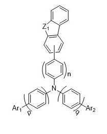
[화학식 1]

(상기 화학식 1에서 각 치환기들은 발명의 상세한 설명에서 정의한 바와 같다.)Provided is a tertiary amine derivative that effectively absorbs a high-energy external light source in the UV region to minimize damage to organic materials inside the organic EL device, thereby contributing to the improvement of the practical lifespan of the organic EL device.
An organic electroluminescent device according to the present invention, a first electrode; a second electrode; one or more organic material layers disposed between the first electrode and the second electrode; and a capping layer, wherein the capping layer includes a tertiary amine derivative represented by Formula 1 below.
[Formula 1]
(Each substituent in Formula 1 is as defined in the detailed description of the invention.)
Description
본 발명은 3차 아민 유도체 및 이를 포함하는 유기 전계 발광 소자에 관한 것으로, 3차 아민 유도체에 의해 캡핑층을 포함한 유기 전계 발광 소자가 고굴절률 특성과 자외선 흡수특성을 동시에 갖도록 하는 것이다. The present invention relates to a tertiary amine derivative and to an organic electroluminescent device including the same, wherein the organic electroluminescent device including a capping layer by the tertiary amine derivative has both high refractive index and ultraviolet absorption characteristics.
디스플레이 산업에서 자기 발광 현상을 이용한 디스플레이로서 OLED(유기발광다이오드, Organic Light Emitting Diodes)가 주목받고 있다.OLED (Organic Light Emitting Diodes) is attracting attention as a display using self-luminescence in the display industry.
OLED에 있어, 1963년 Pope 등에 의하여 안트라센(Anthracene) 방향족 탄화수소의 단결정을 이용한 캐리어 주입형 전계발광(Electroluminescence; EL)의 연구가 최초로 시도되었다. 이러한 연구로부터 유기물에서 전하주입, 재결합, 여기자 생성, 발광 등의 기초적 메커니즘과 전기발광 특성 등이 이해되고 연구되어왔다. In OLED, a study of carrier injection electroluminescence (EL) using a single crystal of an anthracene aromatic hydrocarbon was first attempted by Pope et al. in 1963. From these studies, basic mechanisms such as charge injection, recombination, exciton generation, and light emission in organic materials and electroluminescence characteristics have been understood and studied.
특히 발광 효율을 높이기 위해 소자의 구조 변화 및 물질 개발 등 다양한 접근이 이루어지고 있다[Sun, S., Forrest, S. R., Appl. Phys. Lett. 91, 263503 (2007)/Ken-Tsung Wong, Org. Lett., 7, 2005, 5361-5364]. In particular, in order to increase the luminous efficiency, various approaches are being made, such as changing the structure of the device and developing materials [Sun, S., Forrest, S. R., Appl. Phys. Lett. 91, 263503 (2007)/Ken-Tsung Wong, Org. Lett., 7, 2005, 5361-5364].
OLED 디스플레이의 기본적 구조는, 일반적으로 양극(Anode), 정공주입층(Hole Injection Layer, HIL), 정공수송층(Hole Transporting Layer, HTL), 발광층 (Emission Layer, EML), 전자수송층(Electron Transporting Layer, ETL), 그리고 음극(Cathode)의 다층 구조로 구성되며, 전자 유기 다층막이 두 전극 사이에 형성된 샌드위치 구조로 되어 있다. The basic structure of an OLED display is, in general, an anode, a hole injection layer (HIL), a hole transporting layer (HTL), a light emitting layer (Emission Layer, EML), an electron transporting layer (Electron Transporting Layer, ETL), and a multilayer structure of a cathode, and a sandwich structure in which an electron organic multilayer film is formed between two electrodes.
일반적으로 유기 발광 현상이란 유기 물질을 이용하여 전기에너지를 빛에너지로 전환해주는 현상을 말한다. 유기 발광 현상을 이용하는 유기 발광 소자는 통상 양극과 음극 및 이들 사이에 유기물층을 포함하는 구조를 가진다. 여기서 유기물층은 유기 발광 소자의 효율과 안정성을 높이기 위하여 각기 다른 물질로 구성된 다층의 구조로 이루어진 경우가 많으며, 예컨대 정공 주입층, 정공 수송층, 발광층, 전자 수송층, 전자 주입층 등을 포함할 수 있다. In general, the organic light emitting phenomenon refers to a phenomenon in which electric energy is converted into light energy using an organic material. An organic light emitting device using an organic light emitting phenomenon typically has a structure including an anode and a cathode and an organic material layer therebetween. Here, the organic material layer is often formed of a multilayer structure made of different materials in order to increase the efficiency and stability of the organic light emitting device, and may include, for example, a hole injection layer, a hole transport layer, a light emitting layer, an electron transport layer, an electron injection layer, and the like.
이러한 유기 발광 소자의 구조에서 두 전극 사이에 전압을 걸어주게 되면, 양극에서는 정공이, 음극에서는 전자가 유기물층으로 주입되고, 주입된 정공과 전자가 만났을 때 엑시톤(exciton)이 형성되며, 이 엑시톤이 바닥상태로 떨어질 때 빛이 나게 된다. 이러한 유기 발광 소자는 자발광, 고휘도, 고효율, 낮은 구동전압, 넓은 시야각, 높은 콘트라스트, 고속 응답성 등의 특성을 갖는 것으로 알려져 있다.When a voltage is applied between the two electrodes in the structure of the organic light emitting device, holes are injected into the organic material layer from the anode and electrons from the cathode are injected into the organic material layer, and excitons are formed when the injected holes and electrons meet. It lights up when it falls to the ground state. Such an organic light emitting device is known to have characteristics such as self-luminescence, high luminance, high efficiency, low driving voltage, wide viewing angle, high contrast, and high-speed response.
유기 발광 소자에서 유기물층으로 사용되는 재료는 기능에 따라, 발광 재료와 전하 수송 재료, 예컨대 정공 주입 재료, 정공 수송 재료, 전자 수송 재료, 전자 주입 재료 등으로 분류될 수 있다. A material used as an organic material layer in an organic light emitting device may be classified into a light emitting material and a charge transporting material, for example, a hole injection material, a hole transport material, an electron transport material, an electron injection material, and the like, according to functions.
발광 재료는 발광색에 따라 청색, 녹색, 적색 발광 재료와 좀 더 나은 천연색을 구현하기 위해 필요한 노란색 및 주황색 발광 재료가 있다. 또한, 색순도의 증가와 에너지 전이를 통한 발광 효율을 증가시키기 위하여, 발광 재료로서 호스트/도판트 계를 사용할 수 있다. 그 원리는 발광층을 주로 구성하는 호스트보다 에너지 대역 간극이 작고 발광 효율이 우수한 도판트를 발광층에 소량 혼합하면, 호스트에서 발생한 엑시톤이 도판트로 수송되어 효율이 높게 빛을 내는 것이다. 이때 호스트의 파장이 도판트의 파장대로 이동하므로, 이용하는 도판트의 종류에 따라 원하는 파장의 빛을 얻을 수 있다.The light-emitting material includes blue, green, and red light-emitting materials depending on the light-emitting color, and yellow and orange light-emitting materials required to realize a better natural color. In addition, in order to increase color purity and increase luminous efficiency through energy transfer, a host/dopant system may be used as a light emitting material. The principle is that when a small amount of a dopant having a smaller energy band gap and superior luminous efficiency than the host constituting the light emitting layer is mixed in the light emitting layer in a small amount, excitons generated from the host are transported to the dopant to emit light with high efficiency. At this time, since the wavelength of the host moves to the wavelength band of the dopant, light having a desired wavelength can be obtained according to the type of dopant used.
전술한 유기 발광 소자가 갖는 우수한 특징들을 충분히 발현하기 위해, 소자 내 유기물층을 이루는 물질, 예컨대 정공 주입 물질, 정공 수송 물질, 발광 물질, 전자 수송 물질, 전자 주입 물질 등이 개발되었고, 이로 인해 상용화된 제품들에 의해 유기 발광 소자의 성능을 인정받고 있다. In order to sufficiently express the excellent characteristics of the above-described organic light emitting device, materials constituting an organic material layer in the device, such as a hole injection material, a hole transport material, a light emitting material, an electron transport material, an electron injection material, etc. The performance of the organic light emitting device is recognized by the products.
그러나 유기 발광 소자의 상용화가 이루어지고 시간이 지남에 따라 유기 발광 소자 자체의 발광 특성 이외에 다른 특성들의 필요성이 대두되고 있다. However, as the commercialization of the organic light emitting device is made and time passes, the need for other characteristics in addition to the light emitting characteristic of the organic light emitting device itself is emerging.
유기 발광 소자는 외부 광원에 노출되는 시간이 많은 경우가 대부분이므로 고에너지를 갖는 자외선에 노출되는 환경에 있게 된다. 이에 따라 유기 발광 소자를 구성하는 유기물이 지속적인 영향을 받게 되는 문제가 있다. 이러한 고에너지 광원에 노출을 막기 위해 자외선 흡수특성을 갖는 캡핑층을 유기 발광 소자에 적용함으로써 문제를 해결할 수 있다. Since the organic light emitting diode is exposed to an external light source for a large amount of time, it is in an environment exposed to ultraviolet rays having high energy. Accordingly, there is a problem in that the organic material constituting the organic light emitting device is continuously affected. In order to prevent exposure to such a high energy light source, the problem can be solved by applying a capping layer having ultraviolet absorption characteristics to the organic light emitting diode.
일반적으로 유기 발광 소자의 시야각 특성은 넓다고 알려져 있지만 광원 스펙트럼 관점에서는 시야각에 따라 상당한 편차가 발생하게 되며 이는 유기 발광 소자를 이루는 유리 기판, 유기물, 전극재료 등의 전체 굴절률과 유기 발광 소자의 발광파장에 따른 적절한 굴절률 사이에서 편차가 발생하는 것에 기인한다. In general, it is known that the viewing angle characteristics of an organic light emitting device are wide, but from the viewpoint of the light source spectrum, a significant deviation occurs depending on the viewing angle. This is due to the occurrence of a deviation between the appropriate refractive indices.
일반적으로 청색에 필요한 굴절률 값이 크고 파장이 길어질수록 필요 굴절률의 값은 작아진다. 이에 따라 상기 언급된 자외선 흡수특성과 적정 굴절률을 동시에 만족하는 캡핑층을 이루는 재료의 개발이 필요하다.In general, the larger the value of the refractive index required for blue and the longer the wavelength, the smaller the value of the required refractive index. Accordingly, it is necessary to develop a material for forming a capping layer that simultaneously satisfies the above-mentioned ultraviolet absorption characteristics and an appropriate refractive index.
유기 발광 소자의 효율은 일반적으로 내부 발광 효율 (internal luminescent efficiency)과 외부 발광 효율로 나눌 수 있다. 내부 발광 효율은 광변환이 이루어지기 위해 유기층에서 엑시톤의 형성의 효율성에 관련된다. The efficiency of the organic light emitting diode can be generally divided into internal luminescent efficiency and external luminescent efficiency. The internal luminous efficiency is related to the efficiency of the formation of excitons in the organic layer for light conversion to take place.
외부 발광 효율은 유기층에서 생성된 광이 유기 발광 소자 외부로 방출되는 효율을 말한다.The external luminous efficiency refers to the efficiency at which light generated in the organic layer is emitted to the outside of the organic light emitting device.
전체적으로 효율을 제고하기 위해서는 내부 발광 효율뿐만 아니라 외부 발광 효율을 높여야 한다. 외부 발광 효율을 높이고 오랜 시간 주광하에 노출할 때에 야기될 수도 있는 여러 문제점을 방지하기 위하여, 새로운 기능의 캡핑층(CPL) 화합물의 개발이 요구되고 있다. 특히 CPL 기능 중에서 UV 파장대의 빛을 흡수하는 능력이 우수한 캡핑층(CPL) 물질 개발이 요구되고 있다. In order to improve the overall efficiency, it is necessary to increase the external luminous efficiency as well as the internal luminous efficiency. In order to increase external luminous efficiency and prevent various problems that may be caused when exposed to daylight for a long time, the development of a new functional capping layer (CPL) compound is required. In particular, there is a demand for the development of a capping layer (CPL) material having excellent ability to absorb light in the UV wavelength band among CPL functions.
본 발명의 목적은, 발광 효율과 수명을 개선할 수 있고 동시에 시야각 특성을 개선할 수 있는, 유기 발광 소자용 캡핑층 재료를 제공하는 것이다.SUMMARY OF THE INVENTION It is an object of the present invention to provide a capping layer material for an organic light emitting device, which can improve luminous efficiency and lifespan, and at the same time improve viewing angle characteristics.
본 발명의 목적은 특히 유기 전계 발광 소자의 광 추출율을 개선하기 위하여 굴절률과 내열성이 높은 캡핑층을 포함하는 고효율 및 장수명의 유기 전계 발광 소자를 제공하는 것에 있다.An object of the present invention is to provide an organic electroluminescent device with high efficiency and long life, including a capping layer having high refractive index and heat resistance, in particular to improve the light extraction rate of the organic electroluminescent device.
본 발명은 제1 전극; 상기 제1 전극 상에 배치된 유기물층; 상기 유기물층 상에 배치된 제2전극; 및 상기 제2 전극 상에 배치된 캡핑층을 포함하며, 상기 유기물층 또는 캡핑층은 하기 화학식 1로 표시되는 3차 아민 유도체를 포함하는 유기 전계 발광 소자를 제공한다.The present invention is a first electrode; an organic material layer disposed on the first electrode; a second electrode disposed on the organic material layer; and a capping layer disposed on the second electrode, wherein the organic material layer or the capping layer provides an organic electroluminescent device including a tertiary amine derivative represented by
[화학식 1][Formula 1]

상기 화학식 1에 있어서, In
Z1는 O 또는 S이며,Z 1 is O or S;
n, p 및 q는 각각 독립적으로 0 또는 1이고,n, p and q are each independently 0 or 1,
Ar1 및 Ar2는 서로 동일하며, 시아노기; 시아노기가 치환된 아릴기; 치환 또는 비치환된 디벤조퓨란기; 치환 또는 비치환된 디벤조티오펜기; 치환 또는 비치환된 벤즈옥사졸기; 및 치환 또는 비치환된 벤즈티아졸기; 중에서 선택되는 어느 하나이다. Ar 1 and Ar 2 are the same as each other, and a cyano group; an aryl group substituted with a cyano group; A substituted or unsubstituted dibenzofuran group; a substituted or unsubstituted dibenzothiophene group; a substituted or unsubstituted benzoxazole group; and a substituted or unsubstituted benzthiazole group; any one selected from
본 명세서에 기재된 화합물은 유기 발광 소자의 유기물층 또는 캡핑층의 재료로 사용될 수 있다. The compound described herein may be used as a material for an organic material layer or a capping layer of an organic light emitting device.
본 발명에 따른 화합물은 자외선 흡수특성을 나타내어 외부 광원에 의한 유기 발광 소자 내 유기물 손상을 최소화할 수 있고, 유기 발광 소자에서 효율의 향상, 낮은 구동전압 및/또는 수명 특성을 향상시킬 수 있다. The compound according to the present invention can minimize damage to organic materials in the organic light-emitting device by an external light source by exhibiting ultraviolet absorption characteristics, and can improve efficiency, low driving voltage, and/or lifespan characteristics in the organic light-emitting device.
또한, 본 명세서에 기재된 화합물을 캡핑층으로 이용한 유기 발광 소자에서 발광효율 향상, 발광 스펙트럼 반치폭 감소에 따른 색순도를 현저히 개선시킬 수 있다. In addition, in an organic light-emitting device using the compound described in the present specification as a capping layer, it is possible to significantly improve luminous efficiency and color purity according to a decrease in the emission spectrum half width.
도 1은 본 발명의 일 실시예에 따른 기판(100) 위에 제1 전극(110), 정공주입층(210), 정공수송층(215), 발광층(220), 전자수송층(230), 전자주입층(235), 제2 전극(120) 및 캡핑층(300)이 순차적으로 적층된 유기 발광 소자의 예를 도시한 것이다.
도 2는 본 발명의 일 실시예에 따른 3차 아민 유도체를 이용할 경우에 나타나는 빛의 굴절과 흡수 특성의 그래프이다. 1 illustrates a
Figure 2 is a graph of the refraction and absorption characteristics of light appearing when using a tertiary amine derivative according to an embodiment of the present invention.
이하 본 발명에 대하여 더욱 상세히 설명한다.Hereinafter, the present invention will be described in more detail.
본 발명은 다양한 변경을 가할 수 있고 여러 가지 형태를 가질 수 있는 바, 특정 실시예들을 도면에 예시하고 본문에 상세하게 설명하고자 한다. 그러나 이는 본 발명을 특정한 개시 형태에 대해 한정하려는 것이 아니며, 본 발명의 사상 및 기술 범위에 포함되는 모든 변경, 균등물 내지 대체물을 포함하는 것으로 이해되어야 한다. Since the present invention can have various changes and can have various forms, specific embodiments are illustrated in the drawings and described in detail in the text. However, this is not intended to limit the present invention to the specific disclosed form, it should be understood to include all modifications, equivalents and substitutes included in the spirit and scope of the present invention.
각 도면을 설명하면서 유사한 참조부호를 유사한 구성요소에 대해 사용하였다. 첨부된 도면에 있어서, 구조물들의 치수는 본 발명의 명확성을 위하여 실제보다 확대하여 도시한 것이다. 제1, 제2 등의 용어는 다양한 구성요소들을 설명하는데 사용될 수 있지만, 상기 구성요소들은 상기 용어들에 의해 한정되어서는 안 된다. 상기 용어들은 하나의 구성요소를 다른 구성요소로부터 구별하는 목적으로만 사용된다. 예를 들어, 본 발명의 권리 범위를 벗어나지 않으면서 제1 구성요소는 제2 구성요소로 명명될 수 있고, 유사하게 제2 구성요소도 제1 구성요소로 명명될 수 있다. 단수의 표현은 문맥상 명백하게 다르게 뜻하지 않는 한, 복수의 표현을 포함한다.In describing each figure, like reference numerals have been used for like elements. In the accompanying drawings, the dimensions of the structures are enlarged than the actual size for clarity of the present invention. Terms such as first, second, etc. may be used to describe various elements, but the elements should not be limited by the terms. The above terms are used only for the purpose of distinguishing one component from another. For example, without departing from the scope of the present invention, a first component may be referred to as a second component, and similarly, a second component may also be referred to as a first component. The singular expression includes the plural expression unless the context clearly dictates otherwise.
본 출원에서, "포함하다" 또는 "가지다" 등의 용어는 명세서 상에 기재된 특징, 숫자, 단계, 동작, 구성요소, 부품 또는 이들을 조합한 것이 존재함을 지정하려는 것이지, 하나 또는 그 이상의 다른 특징들이나 숫자, 단계, 동작, 구성요소, 부분품 또는 이들을 조합한 것들의 존재 또는 부가 가능성을 미리 배제하지 않는 것으로 이해되어야 한다. 또한, 층, 막, 영역, 판 등의 부분이 다른 부분 "상에" 있다고 할 경우, 이는 다른 부분 "바로 위에" 있는 경우뿐만 아니라 그 중간에 또 다른 부분이 있는 경우도 포함한다. In the present application, terms such as "comprise" or "have" are intended to designate that a feature, number, step, operation, component, part, or a combination thereof described in the specification exists, but one or more other features It is to be understood that it does not preclude the possibility of the presence or addition of numbers, steps, operations, components, parts, or combinations thereof. Also, when a part of a layer, film, region, plate, etc. is said to be “on” another part, it includes not only the case where the other part is “directly on” but also the case where there is another part in between.
본 명세서에서, “치환 또는 비치환된”은 중수소 원자, 할로겐 원자, 시아노기, 니트로기, 아미노기, 히드록시기, 실릴기, 붕소기, 포스핀 옥사이드기, 포스핀 설파이드기, 알킬기, 알콕시기, 알케닐기, 아릴기, 헤테로 아릴기 및 헤테로 고리기로 이루어진 군에서 선택되는 1개 이상의 치환기로 치환 또는 비치환된 것을 의미할 수 있다. 또한, 상기 예시된 치환기 각각은 치환 또는 비치환된 것일 수 있다. 예를 들어, 바이페닐기는 아릴기로 해석될 수도 있고, 페닐기로 치환된 페닐기로 해석될 수도 있다.As used herein, "substituted or unsubstituted" is a deuterium atom, a halogen atom, a cyano group, a nitro group, an amino group, a hydroxy group, a silyl group, a boron group, a phosphine oxide group, a phosphine sulfide group, an alkyl group, an alkoxy group, an alke group It may mean unsubstituted or substituted with one or more substituents selected from the group consisting of a nyl group, an aryl group, a heteroaryl group, and a heterocyclic group. In addition, each of the substituents exemplified above may be substituted or unsubstituted. For example, a biphenyl group may be interpreted as an aryl group or a phenyl group substituted with a phenyl group.
본 명세서에서, 할로겐 원자의 예로는 불소 원자, 염소 원자, 브롬 원자 또는 요오드 원자가 있다.In the present specification, examples of the halogen atom include a fluorine atom, a chlorine atom, a bromine atom or an iodine atom.
본 명세서에서, 알킬기는 직쇄, 분지쇄 또는 고리형일 수 있다. 알킬기의 탄소수는 1 이상 50 이하, 1 이상 30 이하, 1 이상 20 이하, 1 이상 10 이하 또는 1 이상 6 이하이다. 알킬기의 예로는 메틸기, 에틸기, n-프로필기, 이소프로필기, n-부틸기, s-부틸기, t-부틸기, i-부틸기, 2- 에틸부틸기, 3, 3-디메틸부틸기, n-펜틸기, i-펜틸기, 네오펜틸기, t-펜틸기, 시클로펜틸기, 1-메틸펜틸기, 3-메틸펜틸기, 2-에틸펜틸기, 4-메틸-2-펜틸기, n-헥실기, 1-메틸헥실기, 2-에틸헥실기, 2-부틸헥실기, 시클로헥실기, 4-메틸시클로헥실기, 4-t-부틸시클로헥실기, n-헵틸기, 1-메틸헵틸기, 2,2-디메틸헵틸기, 2-에틸헵틸기, 2-부틸헵틸기, n-옥틸기, t-옥틸기, 2-에틸옥틸기, 2-부틸옥틸기, 2-헥실옥틸기, 3,7-디메틸옥틸기, 시클로옥틸기, n-노닐기, n-데실기, 아다만틸기, 2-에틸데실기, 2-부틸데실기, 2-헥실데실기, 2-옥틸데실기, n-운데실기, n-도데실기, 2-에틸도데실기, 2-부틸도데실기, 2-헥실도데실기, 2-옥틸도데실기, n-트리데실기, n-테트라데실기, n-펜타데실기, n-헥사데실기, 2-에틸헥사데실기, 2-부틸헥사데실기, 2-헥실헥사데실기, 2-옥틸헥사데실기, n-헵타데실기, n-옥타데실기, n-노나데실기, n-이코실기, 2-에틸이코실기, 2-부틸이코실기, 2-헥실이코실기, 2-옥틸이코실기, n-헨이코실기, n-도코실기, n-트리코실기, n-테트라코실기, n-펜타코실기, n-헥사코실기, n-헵타코실기, n-옥타코실기, n-노나코실기, 및 n-트리아콘틸기 등을 들 수 있지만, 이들에 한정되지 않는다.In the present specification, the alkyl group may be linear, branched or cyclic. Carbon number of an alkyl group is 1 or more and 50 or less, 1 or more and 30 or less, 1 or more and 20 or less, 1 or more and 10 or less, or 1 or more and 6 or less. Examples of the alkyl group include methyl group, ethyl group, n-propyl group, isopropyl group, n-butyl group, s-butyl group, t-butyl group, i-butyl group, 2-ethylbutyl group, 3, 3-dimethylbutyl group , n-pentyl group, i-pentyl group, neopentyl group, t-pentyl group, cyclopentyl group, 1-methylpentyl group, 3-methylpentyl group, 2-ethylpentyl group, 4-methyl-2-pentyl group , n-hexyl group, 1-methylhexyl group, 2-ethylhexyl group, 2-butylhexyl group, cyclohexyl group, 4-methylcyclohexyl group, 4-t-butylcyclohexyl group, n-heptyl group, 1 -Methylheptyl group, 2,2-dimethylheptyl group, 2-ethylheptyl group, 2-butylheptyl group, n-octyl group, t-octyl group, 2-ethyloctyl group, 2-butyloctyl group, 2-hexyl group Siloctyl group, 3,7-dimethyloctyl group, cyclooctyl group, n-nonyl group, n-decyl group, adamantyl group, 2-ethyldecyl group, 2-butyldecyl group, 2-hexyldecyl group, 2-ox Tyldecyl group, n-undecyl group, n-dodecyl group, 2-ethyldodecyl group, 2-butyldodecyl group, 2-hexyldodecyl group, 2-octyldodecyl group, n-tridecyl group, n-tetradecyl group, n -Pentadecyl group, n-hexadecyl group, 2-ethylhexadecyl group, 2-butylhexadecyl group, 2-hexylhexadecyl group, 2-octylhexadecyl group, n-heptadecyl group, n-octadecyl group , n-nonadecyl group, n-icosyl group, 2-ethyl icosyl group, 2-butyl icosyl group, 2-hexyl icosyl group, 2-octyl icosyl group, n-henicosyl group, n-docosyl group, n-tricho Sil group, n-tetracosyl group, n-pentacosyl group, n-hexacosyl group, n-heptacosyl group, n-octacosyl group, n-nonacosyl group, and n-triacontyl group etc. are mentioned, It is not limited to these.
본 명세서에서, 탄화수소 고리기는 지방족 탄화수소 고리로부터 유도된 임의의 작용기 또는 치환기를 의미한다. 탄화수소 고리기는 고리 형성 탄소수 5 이상 20 이하의 포화 탄화수소 고리기일 수 있다.As used herein, the hydrocarbon ring group means any functional group or substituent derived from an aliphatic hydrocarbon ring. The hydrocarbon ring group may be a saturated hydrocarbon ring group having 5 to 20 ring carbon atoms.
본 명세서에서, 아릴기는 방향족 탄화수소 고리로부터 유도된 임의의 작용기 또는 치환기를 의미한다. 아릴기는 단환식 아릴기 또는 다환식 아릴기일 수 있다. 아릴기의 고리 형성 탄소수는 6 이상 30 이하, 6 이상 20 이하, 또는 6 이상 15 이하일 수 있다. 아릴기의 예로는 페닐기, 나프틸기, 플루오레닐기, 안트라세닐기, 페난트릴기, 바이페닐기, 터페닐기, 쿼터페닐기, 퀸크페닐기, 섹시페닐기, 트리페닐에닐기, 피레닐기, 페릴렌일기, 나프타세닐기, 파이레닐기, 벤조 플루오란테닐기, 크리세닐기 등을 예시할 수 있지만, 이들에 한정되지 않는다.As used herein, the aryl group means any functional group or substituent derived from an aromatic hydrocarbon ring. The aryl group may be a monocyclic aryl group or a polycyclic aryl group. The number of ring carbon atoms of the aryl group may be 6 or more and 30 or less, 6 or more and 20 or less, or 6 or more and 15 or less. Examples of the aryl group include a phenyl group, a naphthyl group, a fluorenyl group, an anthracenyl group, a phenanthryl group, a biphenyl group, a terphenyl group, a quarterphenyl group, a quinkphenyl group, a sexyphenyl group, a triphenylenyl group, a pyrenyl group, a peryleneyl group, a naphtha group Although a cenyl group, a pyrenyl group, a benzo fluoranthenyl group, a chrysenyl group, etc. can be illustrated, it is not limited to these.
본 명세서에서, 플루오레닐기는 치환될 수 있고, 치환기 2개가 서로 결합하여 스피로 구조를 형성할 수도 있다. In the present specification, the fluorenyl group may be substituted, and two substituents may be bonded to each other to form a spiro structure.
본 명세서에서, 헤테로아릴기는 이종 원소로 O, N, P, Si 및 S 중 1개 이상을 포함하는 헤테로아릴기일 수 있다. N 및 S 원자는 경우에 따라 산화될 수 있고, N 원자(들)은 경우에 따라 4차화될 수 있다. 헤테로아릴기의 고리 형성 탄소수는 2 이상 30 이하 또는 2 이상 20 이하이다. 헤테로아릴기는 단환식 헤테로아릴기 또는 다환식 헤테로아릴기일 수 있다. 다환식 헤테로아릴기는 예를 들어, 2환 또는 3환 구조를 갖는 것일 수 있다. In the present specification, the heteroaryl group may be a heteroaryl group including at least one of O, N, P, Si and S as a heterogeneous element. The N and S atoms may optionally be oxidized and the N atom(s) may optionally be quaternized. The number of ring carbon atoms in the heteroaryl group is 2 or more and 30 or less, or 2 or more and 20 or less. The heteroaryl group may be a monocyclic heteroaryl group or a polycyclic heteroaryl group. The polycyclic heteroaryl group may have, for example, a bicyclic or tricyclic structure.
헤테로아릴기의 예로는 티오펜기, 퓨란기, 피롤기, 이미다졸기, 피라졸릴기, 티아졸기, 옥사졸기, 옥사디아졸기, 트리아졸기, 피리딘기, 비피리딘기, 피리미딘기, 트리아진기, 테트라진기, 트리아졸기, 테트라졸기, 아크리딜기, 피리다진기, 피라지닐기, 퀴놀린기, 퀴나졸린기, 퀴녹살린기, 페녹사진기, 프탈라진기, 피리도 피리미딘기, 피리도 피라지노 피라진기, 이소퀴놀린기, 신놀리기, 인돌기, 이소인돌기, 인다졸기, 카바졸기, N-아릴카바졸기, N-헤테로아릴카바졸기, N-알킬카바졸기, 벤조옥사졸기, 벤조이미다졸기, 벤조티아졸기, 벤조카바졸기, 벤조티오펜기, 벤조티오펜기, 벤조이소티아졸릴, 벤조이속사졸릴, 디벤조티오펜기, 티에노티오펜기, 벤조퓨란기, 페난트롤린기, 페난트리딘기, 티아졸기, 이소옥사졸기, 옥사디아졸기, 티아디아졸기, 이소티아졸기, 이속사졸기, 페노티아진기, 벤조디옥솔기, 디벤조실롤기 및 디벤조퓨란기, 이소벤조퓨란기 등이 있으나, 이들에 한정되지 않는다. 또한, 상기 단환식 헤테로 아릴기 또는 다환식 헤테로 아릴기에 상응하는 N-옥사이드 아릴기, 예를 들어, 피리딜 N-옥사이드기, 퀴놀릴 N-옥사이드기 등의 4차 염 등이 있으나, 이들에 한정되지 않는다. Examples of the heteroaryl group include a thiophene group, a furan group, a pyrrole group, an imidazole group, a pyrazolyl group, a thiazole group, an oxazole group, an oxadiazole group, a triazole group, a pyridine group, a bipyridine group, a pyrimidine group, a triazine group , tetrazine group, triazole group, tetrazole group, acridyl group, pyridazine group, pyrazinyl group, quinoline group, quinazoline group, quinoxaline group, phenoxazine group, phthalazine group, pyridopyrimidine group, pyridopyrazino group Pyrazine group, isoquinoline group, cinnol group, indole group, isoindole group, indazole group, carbazole group, N-arylcarbazole group, N-heteroarylcarbazole group, N-alkylcarbazole group, benzoxazole group, benzoimidazole group , benzothiazole group, benzocarbazole group, benzothiophene group, benzothiophene group, benzoisothiazolyl, benzoisoxazolyl, dibenzothiophene group, thienothiophene group, benzofuran group, phenanthroline group, phenanthridine group , thiazole group, isoxazole group, oxadiazole group, thiadiazole group, isothiazole group, isoxazole group, phenothiazine group, benzodioxol group, dibenzosilol group and dibenzofuran group, isobenzofuran group, etc., It is not limited to these. In addition, there are N-oxide aryl groups corresponding to the monocyclic heteroaryl group or polycyclic heteroaryl group, for example, quaternary salts such as pyridyl N-oxide group, quinolyl N-oxide group, etc., but these not limited
본 명세서에서, 실릴기는 알킬 실릴기 및 아릴 실릴기를 포함한다. 실릴기의 예로는 트리메틸실릴기, 트리에틸실릴기, t-부틸디메틸실릴기, 비닐디메틸실릴기, 프로필디메틸실릴기, 트리페닐실릴기, 디페닐실릴기, 페닐실릴기 등이 있으나, 이들에 한정되지 않는다.In the present specification, the silyl group includes an alkyl silyl group and an aryl silyl group. Examples of the silyl group include a trimethylsilyl group, a triethylsilyl group, a t-butyldimethylsilyl group, a vinyldimethylsilyl group, a propyldimethylsilyl group, a triphenylsilyl group, a diphenylsilyl group, a phenylsilyl group, and the like. not limited
본 명세서에서, 붕소기는 알킬 붕소기 및 아릴 붕소기를 포함한다. 붕소기의 예로는 트리메틸붕소기, 트리에틸붕소기, t-부틸디메틸붕소기, 트리페닐붕소기, 디페닐붕소기, 페닐붕소기 등이 있으나, 이들에 한정되지 않는다.In the present specification, the boron group includes an alkyl boron group and an aryl boron group. Examples of the boron group include, but are not limited to, a trimethylboron group, a triethylboron group, a t-butyldimethylboron group, a triphenylboron group, a diphenylboron group, and a phenylboron group.
본 명세서에서, 알케닐기는 직쇄 또는 분지쇄일 수 있다. 탄소수는 특별히 한정되지 않으나, 2 이상 30 이하, 2 이상 20 이하 또는 2 이상 10 이하이다. 알케닐기의 예로는 비닐기, 1-부테닐기, 1-펜테닐기, 1,3-부타디에닐 아릴기, 스티레닐기, 스티릴비닐기 등이 있으나, 이들에 한정되지 않는다.In the present specification, the alkenyl group may be straight-chain or branched. Although carbon number is not specifically limited, 2 or more and 30 or less, 2 or more and 20 or less, or 2 or more and 10 or less. Examples of the alkenyl group include, but are not limited to, a vinyl group, a 1-butenyl group, a 1-pentenyl group, a 1,3-butadienyl aryl group, a styrenyl group, a styryl vinyl group, and the like.
본 명세서에 있어서, 아릴아민기의 예로는 치환 또는 비치환된 모노아릴아민기, 치환 또는 비치환된 디아릴아민기, 또는 치환 또는 비치환된 트리아릴아민기가 있다. 상기 아릴아민기 중의 아릴기는 단환식 아릴기일 수 있고, 다환식 아릴기, 또는 단환식아릴기와 다환식 아릴기를 동시에 포함할 수 있다. In the present specification, examples of the arylamine group include a substituted or unsubstituted monoarylamine group, a substituted or unsubstituted diarylamine group, or a substituted or unsubstituted triarylamine group. The aryl group in the arylamine group may be a monocyclic aryl group, and may include a polycyclic aryl group or a monocyclic aryl group and a polycyclic aryl group at the same time.
아릴 아민기의 구체적인 예로는 페닐아민기, 나프틸아민기, 비페닐아민기, 안트라세닐아민기, 3-메틸-페닐아민기, 4-메틸-나프틸아민기, 2-메틸-비페닐아민기, 9-메틸-안트라세닐아민기, 디페닐 아민기, 페닐 나프틸아민기, 디톨릴 아민기, 페닐 톨릴 아민기, 카바졸 및 트리페닐 아민기 등이 있으나, 이에 한정되는 것은 아니다.Specific examples of the arylamine group include a phenylamine group, a naphthylamine group, a biphenylamine group, an anthracenylamine group, a 3-methyl-phenylamine group, a 4-methyl-naphthylamine group, and a 2-methyl-biphenylamine group. group, 9-methyl-anthracenylamine group, diphenyl amine group, phenyl naphthylamine group, ditolyl amine group, phenyl tolyl amine group, carbazole and triphenyl amine group, and the like, but are not limited thereto.
본 명세서에 있어서, 헤테로아릴아민기의 예로는 치환 또는 비치환된 모노헤테로아릴아민기, 치환 또는 비치환된 디헤테로아릴아민기, 또는 치환 또는 비치환된 트리헤테로아릴아민기가 있다. 상기 헤테로아릴아민기 중의 헤테로아릴기는 단환식 헤테로 고리기일 수 있고, 다환식 헤테로 고리기일 수 있다. 상기 2이상의 헤테로 고리기를 포함하는 헤테로아릴아민기는 단환식 헤테로 고리기, 다환식 헤테로 고리기, 또는 단환식 헤테로 고리기와 다환식 헤테로 고리기를 동시에 포함할 수 있다. In the present specification, examples of the heteroarylamine group include a substituted or unsubstituted monoheteroarylamine group, a substituted or unsubstituted diheteroarylamine group, or a substituted or unsubstituted triheteroarylamine group. The heteroaryl group in the heteroarylamine group may be a monocyclic heterocyclic group or a polycyclic heterocyclic group. The heteroarylamine group including two or more heterocyclic groups may include a monocyclic heterocyclic group, a polycyclic heterocyclic group, or a monocyclic heterocyclic group and a polycyclic heterocyclic group at the same time.
본 명세서에 있어서, 아릴헤테로아릴아민기는 아릴기 및 헤테로 고리기로 치환된 아민기를 의미한다.In the present specification, the aryl heteroarylamine group refers to an amine group substituted with an aryl group and a heterocyclic group.
본 명세서에서, “인접하는 기”는 해당 치환기가 치환된 원자와 직접 연결된 원자에 치환된 치환기, 해당 치환기가 치환된 원자에 치환된 다른 치환기 또는 해당 치환기와 입체구조적으로 가장 인접한 치환기를 의미할 수 있다. 예컨대, 1,2-디메틸벤젠(1,2-dimethylbenzene)에서 2개의 메틸기는 서로 “인접하는 기”로 해석될 수 있고, 1,1-디에틸시클로펜테인(1,1-diethylcyclopentene)에서 2개의 에틸기는 서로 “인접하는 기”로 해석될 수 있다.As used herein, “adjacent group” may mean a substituent substituted on an atom directly connected to the atom in which the substituent is substituted, another substituent substituted on the atom in which the substituent is substituted, or a substituent most sterically adjacent to the substituent. have. For example, in 1,2-dimethylbenzene, two methyl groups can be interpreted as “adjacent groups” to each other, and in 1,1-diethylcyclopentene, 2 methyl groups The two ethyl groups can be interpreted as “adjacent groups” to each other.
이하에서는 상기 유기물층 및/또는 캡핑층에 사용되는 3차 아민 유도체 화합물에 대해 설명한다. Hereinafter, the tertiary amine derivative compound used in the organic material layer and/or the capping layer will be described.
본 발명의 일 실시예에 따른 3차 아민 유도체 화합물은 하기 화학식 1로 표시된다.The tertiary amine derivative compound according to an embodiment of the present invention is represented by the following formula (1).
[화학식 1][Formula 1]
상기 화학식 1에 있어서, In
Z1는 O 또는 S이며,Z 1 is O or S;
n, p 및 q는 각각 독립적으로 0 또는 1이고,n, p and q are each independently 0 or 1,
Ar1 및 Ar2는 서로 동일하며, 시아노기; 시아노기가 치환된 아릴기; 치환 또는 비치환된 디벤조퓨란기; 치환 또는 비치환된 디벤조티오펜기; 치환 또는 비치환된 벤즈옥사졸기; 및 치환 또는 비치환된 벤즈티아졸기; 중에서 선택되는 어느 하나이다. Ar 1 and Ar 2 are the same as each other, and a cyano group; an aryl group substituted with a cyano group; A substituted or unsubstituted dibenzofuran group; a substituted or unsubstituted dibenzothiophene group; a substituted or unsubstituted benzoxazole group; and a substituted or unsubstituted benzthiazole group; any one selected from
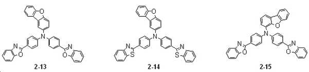
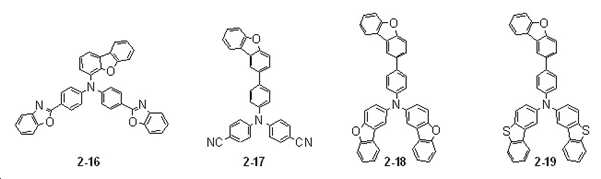
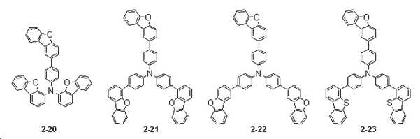
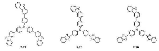
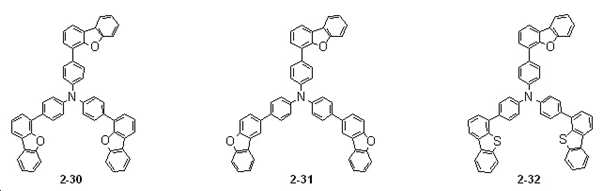
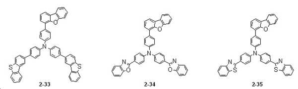
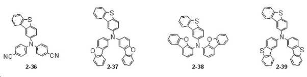
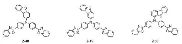
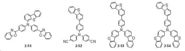
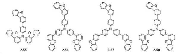
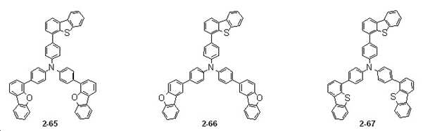
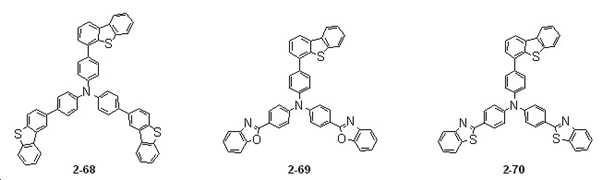
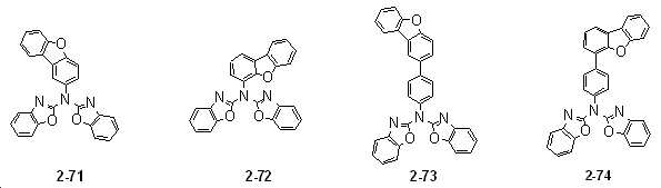
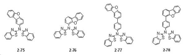
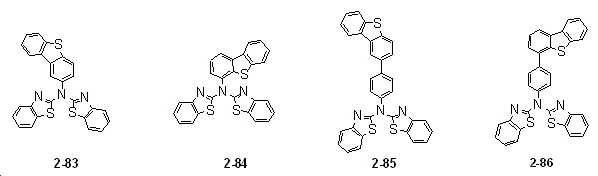
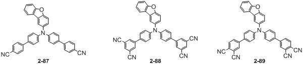
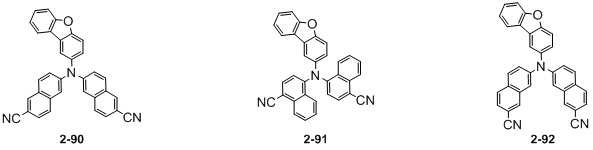
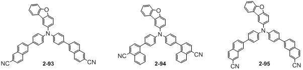
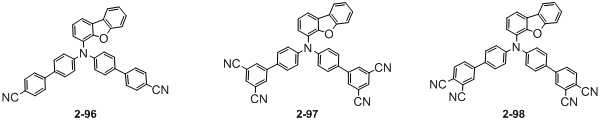
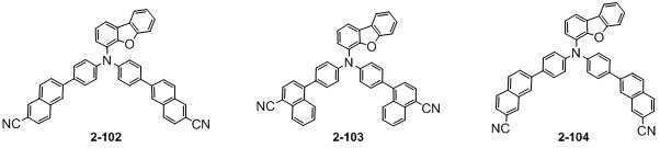
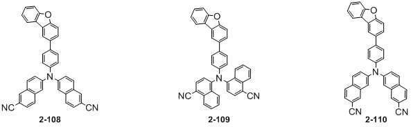
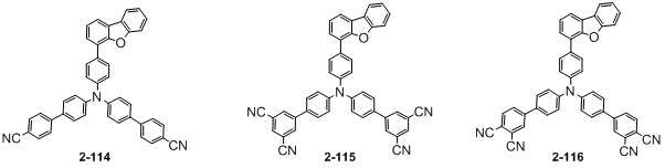
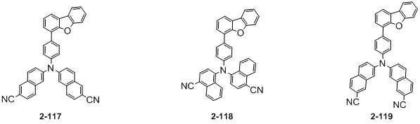
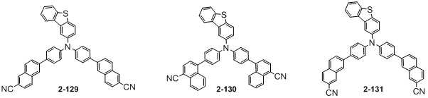
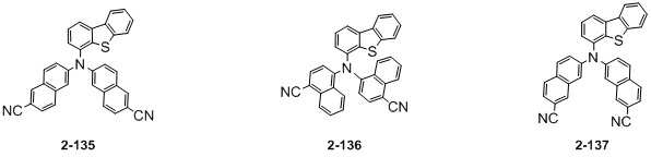
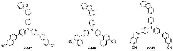
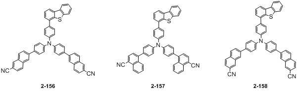
본 발명의 일 실시예에 있어서, 상기 화학식 1로 표시되는 3차 아민 유도체는 하기 화학식 2 표시된 화합물들 중에서 선택된 어느 하나일 수 있고, 하기 화합물들은 추가로 치환될 수 있다. In one embodiment of the present invention, the tertiary amine derivative represented by
[화학식 2] [Formula 2]


이하, 도 1 및 2를 참조하여 본 발명의 실시예를 설명한다.Hereinafter, an embodiment of the present invention will be described with reference to FIGS. 1 and 2 .
도 1은 본 발명의 일 실시예에 따른 유기 발광 소자를 개략적으로 나타낸 단면도이다. 도 1을 참조하면, 일 실시예에 따른 유기 발광 소자는 기판(100)위에 순차적으로 적층된 제1 전극(110), 정공주입층(210), 정공수송층(215), 발광층(220), 전자수송층(230), 전자주입층(235), 제2 전극(120), 캡핑층(300)을 포함할 수 있다.1 is a cross-sectional view schematically illustrating an organic light emitting diode according to an embodiment of the present invention. Referring to FIG. 1 , in an organic light emitting diode according to an exemplary embodiment, a
제1 전극(110)과 제2 전극(120)은 서로 마주하고 배치되며, 제1 전극(110)과 제2 전극(120) 사이에는 유기물층(200)이 배치될 수 있다. 유기물층(200)은 정공주입층(210), 정공수송층(215), 발광층(220), 전자수송층(230), 전자주입층(235)을 포함할 수 있다.The
한편, 본 발명에서 제시되는 캡핑층(300)은 제2 전극(120) 위에 증착되는 기능층으로서, 본 발명의 화학식 1에 따른 유기물을 포함한다.Meanwhile, the
도 1에 도시된 일 실시예의 유기 발광 소자에서 제1 전극(110)은 도전성을 갖는다. 제1 전극(110)은 금속 합금 또는 도전성 화합물로 형성될 수 있다. 제1 전극(110)은 일반적으로 양극(anode)이지만 전극으로의 기능은 제한하지 않는다.In the organic light emitting diode according to the exemplary embodiment shown in FIG. 1 , the
제1 전극(110)은 기판(100) 상부에 전극 물질을 증착법, 전자빔 증발 또는 스퍼터링법 등을 이용하여 형성할 수 있다. 제1 전극(110)의 재료는 유기 발광 소자 내부로 정공의 주입이 용이하도록 높은 일함수를 갖는 물질 중에서 선택될 수 있다. The
본 발명에서 제안되는 캡핑층(300)은 유기 발광 소자의 발광방향이 전면발광일 경우에 적용되며, 따라서 제1 전극(110)은 반사형 전극을 사용한다. 이들의 재료로는 산화물이 아닌 Mg(마그네슘), Al(알루미늄), Al-Li(알루미늄-리튬), Ca(칼슘), Mg-In(마그네슘-인듐), Mg-Ag(마그네슘-은)과 같은 금속을 사용하여 제작할 수도 있다. 최근에 와서는 CNT(탄소나노튜브), Graphene(그래핀) 등 탄소기판 유연 전극 재료가 사용될 수도 있다. The
상기 유기물층(200)은 복수의 층으로 형성될 수 있다. 상기 유기물층 (200)이 복수의 층인 경우, 유기물층(200)은 제1 전극(110) 상에 배치된 정공수송영역(210~215), 상기 정공 수송영역 상에 배치된 발광층(220), 상기 발광층(220) 상에 배치된 전자 수송 영역(230~235)를 포함할 수 있다.The organic material layer 200 may be formed of a plurality of layers. When the organic material layer 200 is a plurality of layers, the organic material layer 200 includes the
일 실시예의 상기 캡핑층(300)은 후술하는 화학식 1로 표시되는 유기화합물을 포함한다. The
정공 수송 영역(210~215)은 제1 전극(110) 상에 제공된다. 정공 수송 영역(210~215)은 정공 주입층(210), 정공 수송층(215), 정공 버퍼층 및 전자 저지층(EBL) 중 적어도 하나를 포함할 수 있고, 유기 발광 소자 내로 원활한 정공 주입과 수송의 역할을 맡고 있으며 일반적으로 정공이동도가 전자이동도 보다 빠르기 때문에 전자 수송영역보다 두꺼운 두께를 갖는다.The
정공 수송 영역(210~215)은 단일 물질로 이루어진 단일층, 복수의 서로 다른 물질로 이루어진 단일층 또는 복수의 서로 다른 물질로 이루어진 복수의 층을 갖는 다층 구조를 가질 수 있다. The
예를 들어, 정공 수송 영역(210~215)은 정공 주입층(210) 또는 정공 수송층(215)의 단일층의 구조를 가질 수도 있고, 정공 주입 물질과 정공 수송 물질로 이루어진 단일층 구조를 가질 수도 있다. 또한, 정공 수송 영역(210~215)은, 복수의 서로 다른 물질로 이루어진 단일층의 구조를 갖거나, 제1 전극(110)으로부터 차례로 적층된 정공 주입층(210)/정공 수송층(215), 정공 주입층(210)/정공 수송층(215)/정공 버퍼층, 정공 주입층(210)/정공 버퍼층, 정공 수송층(215)/정공 버퍼층, 또는 정공 주입층(210)/정공 수송층(215)/전자 저지층(EBL)의 구조를 가질 수 있으나, 실시예가 이에 한정되는 것은 아니다. For example, the
상기 정공 수송 영역(210~215) 중 정공 주입층(210)은 양극 위로 진공증착법, 스핀코팅법, 캐스트법, LB법 등 다양한 방법으로 형성될 수 있다. 진공 증착법에 의하여 정공 주입층(210)을 형성하는 경우, 그 증착 조건은 정공주입층(210) 재료로 사용하는 화합물, 목적으로 하는 정공주입층(210)의 구조 및 열적 특성 등에 따라 100 내지 500℃에서 증착 속도를 1Å/s 전후로 하여 자유롭게 조절할 수 있으며, 특정한 조건에 한정되는 것은 아니다. 스핀 코팅법에 의하여 정공주입층(210)을 형성하는 경우 코팅 조건은 정공주입층(210) 재료로 사용하는 화합물과 계면으로 형성되는 층들 간의 특성에 따라 상이하지만 고른 막형성을 위해 코팅속도, 코팅 후 용매 제거를 위한 열처리 등이 필요하다.The

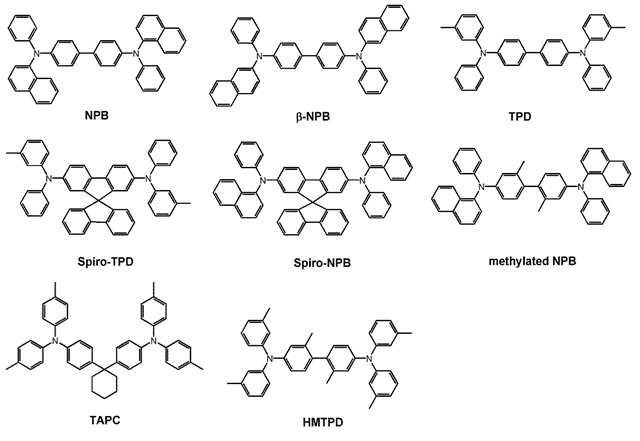
상기 정공 수송 영역(210~215)은, 예를 들면, m-MTDATA, TDATA, 2-TNATA, NPB, β-NPB, TPD, Spiro-TPD, Spiro-NPB, methylated-NPB, TAPC, HMTPD, TCTA(4,4',4"-트리스(N-카바졸일)트리페닐아민(4,4',4"-tris(Ncarbazolyl) triphenylamine)), Pani/DBSA(Polyaniline/Dodecylbenzenesulfonic acid:폴리아닐린/도데실벤젠술폰산), PEDOT/PSS(Poly(3,4-ethylenedioxythiophene) /Poly(4-styrene sulfonate):폴리(3,4-에틸렌디옥시티오펜) /폴리(4-스티렌술포네이트)), Pani/CSA(Polyaniline/Camphor sulfonicacid : 폴리아닐린/캠퍼술폰산), PANI/PSS(Polyaniline)/Poly(4-styrenesulfonate):폴리아닐린)/폴리(4-스티렌술포네이트)) 등을 포함할 수 있다.The
상기 정공 수송 영역(210~215)의 두께는 약 100 내지 약 10,000Å으로 형성될 수 있으며, 각 정공 수송영역(210~215)의 해당 유기물층들은 같은 두께로 한정되는 것은 아니다. 예를 들면, 정공주입층(210)의 두께가 50Å이면 정공수송층(215)의 두께는 1000Å, 전자저지층의 두께는 500Å을 형성할 수 있다. 정공 수송영역(210~215)의 두께 조건은 유기 발광 소자의 구동전압 상승이 커지지 않는 범위 내에서 효율과 수명을 만족하는 정도로 정할 수 있다. 상기 유기물층(200)은 정공주입층(210), 정공수송층(215), 정공주입 기능과 정공수송 기능을 동시에 갖는 기능층, 버퍼층, 전자저지층, 발광층(220), 정공저지층, 전자수송층(230), 전자주입층(235) 및 전자수송 기능과 전자주입 기능을 동시에 갖는 기능층으로 이루어진 군 중에서 선택되는 1층 이상을 포함할 수 있다.The
정공 수송 영역(210~215)은 발광층(220)과 마찬가지로 특성 향상을 위해 도핑을 사용할 수 있으며 이러한 정공 수송 영역(210~215) 내로 전하-생성 물질의 도핑은 유기 발광 소자의 전기적 특성을 향상시킬 수 있다.The
전하-생성 물질은 일반적으로 HOMO와 LUMO가 굉장히 낮은 물질로 이루어지며 예를 들어, 전하-생성 물질의 LUMO는 정공수송층(215) 물질의 HOMO와 유사한 값을 갖는다. 이러한 낮은 LUMO로 인하여 LUMO의 전자가 비어 있는 특성을 이용하여 인접한 정공수송층(215)에 쉽게 정공을 전달하여 전기적 특성을 향상시킨다.The charge-generating material is generally made of a material having a very low HOMO and LUMO. For example, the LUMO of the charge-generating material has a value similar to the HOMO of the
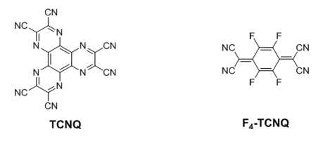
상기 전하-생성 물질은 예를 들면, p-도펀트일 수 있다. 상기 p-도펀트는 퀴논 유도체, 금속 산화물 및 시아노기-함유 화합물 중 하나일 수 있으나, 이에 한정되는 것은 아니다. 예를 들어, 상기 p-도펀트의 비제한적인 예로는, 테트라사이아노퀴논다이메테인(TCNQ) 및 2,3,5,6-테트라플루오로-테트라사이아노-1,4-벤조퀴논다이메테인(F4-TCNQ) 등과 같은 퀴논 유도체; 텅스텐 산화물 및 몰리브덴 산화물 등과 같은 금속 산화물; 시아노기-함유 화합물; 등을 들 수 있으나, 이에 한정되는 것은 아니다.The charge-generating material may be, for example, a p-dopant. The p-dopant may be one of a quinone derivative, a metal oxide, and a cyano group-containing compound, but is not limited thereto. For example, non-limiting examples of the p-dopant include tetracyanoquinonedimethane (TCNQ) and 2,3,5,6-tetrafluoro-tetracyano-1,4-benzoquinonedimethane quinone derivatives such as phosphorus (F4-TCNQ) and the like; metal oxides such as tungsten oxide and molybdenum oxide; cyano group-containing compounds; and the like, but is not limited thereto.
정공 수송 영역(210~215)은 앞서 언급한 물질 외에, 도전성 향상을 위하여 전하 생성 물질을 더 포함할 수 있다. The
전하 생성 물질은 정공 수송 영역(210~215) 내에 균일하게 또는 불균일하게 분산되어 있을 수 있다. 전하 생성 물질은 예를 들어, p-도펀트(dopant)일 수 있다. p-도펀트는 퀴논(quinone) 유도체, 금속 산화물 및 시아노(cyano)기 함유 화합물 중 하나일 수 있으나, 이에 한정되는 것은 아니다. 예를 들어, p-도펀트의 비제한적인 예로는, TCNQ(Tetracyanoquinodimethane) 및 F4-TCNQ(2,3,5,6-tetrafluoro-tetracyanoquinodimethane) 등과 같은 퀴논 유도체, 텅스텐 산화물 및 몰리브덴 산화물 등과 같은 금속 산화물 등을 들 수 있으나, 이에 한정되는 것은 아니다.The charge generating material may be uniformly or non-uniformly dispersed in the
전술한 바와 같이, 정공 수송 영역(210~215)은 정공주입층(210) 및 정공수송층(215) 외에, 정공 버퍼층 및 전자 저지층 중 적어도 하나를 더 포함할 수 있다. 정공 버퍼층은 발광층(220)에서 방출되는 광의 파장에 따른 공진 거리를 보상하여 광 방출 효율을 증가시킬 수 있다. 정공 버퍼층에 포함되는 물질로는 정공 수송 영역(210~215)에 포함될 수 있는 물질을 사용할 수 있다. As described above, the
전자 저지층은 전자 수송 영역(230~235)으로부터 정공 수송 영역(210~215)으로의 전자 주입을 방지하는 역할을 하는 층이다. 전자 저지층은 정공 수송영역으로 이동하는 전자를 저지할 뿐 아니라 발광층(220)에서 형성된 엑시톤이 정공수송영역(210~215)으로 확산되지 않도록 높은 T1 값을 갖는 재료를 사용할 수 있다. 예를 들면 일반적으로 높은 T1값을 갖는 발광층(220)의 호스트 등을 전자저지층 재료로 사용할 수 있다.The electron blocking layer serves to prevent electron injection from the
발광층(220)은 정공 수송 영역(210~215) 상에 제공된다. 발광층(220)은 예를 들어 약 100Å 내지 약 1000Å 또는, 약 100Å 내지 약 300Å의 두께를 갖는 것일 수 있다. 발광층(220)은 단일 물질로 이루어진 단일층, 복수의 서로 다른 물질로 이루어진 단일층 또는 복수의 서로 다른 물질로 이루어진 복수의 층을 갖는 다층 구조를 가질 수 있다. The
발광층(220)은 정공과 전자가 만나 엑시톤을 형성하는 영역으로 발광층(220)을 이루는 재료는 높은 발광 특성 및 원하는 발광색을 나타내도록 적절한 에너지밴드갭을 가져야 하며 일반적으로 호스트와 도판트 두 가지 역할을 가지는 두 재료로 이루어지나, 이에 한정된 것은 아니다.The
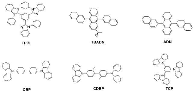
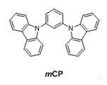
상기 호스트는 하기 TPBi, TBADN, ADN("DNA"라고도 함), CBP, CDBP, TCP, mCP, 중 적어도 하나를 포함할 수 있고, 특성이 적절하다면 재료는 이에 한정된 것은 아니다. The host may include at least one of the following TPBi, TBADN, ADN (also referred to as “DNA”), CBP, CDBP, TCP, and mCP, and if the properties are appropriate, the material is not limited thereto.
일 실시예의 발광층(220)의 도판트는 유기 금속 착물일 수 있다. 일반적인 도판트의 함량은 0.01 내지 20%로 선택될 수 있으며, 경우에 따라 이에 한정되는 것은 아니다.The dopant of the
전자 수송 영역(230~235)은 발광층(220) 상에 제공된다. 전자 수송 영역(230~235)은, 정공 저지층, 전자 수송층(230) 및 전자 주입층(235) 중 적어도 하나를 포함할 수 있으나, 이에 한정되는 것은 아니다.The
전자 수송 영역(230~235)은 단일 물질로 이루어진 단일층, 복수의 서로 다른 물질로 이루어진 단일층 또는 복수의 서로 다른 물질로 이루어진 복수의 층을 갖는 다층 구조를 가질 수 있다. The
예를 들어, 전자 수송 영역(230~235)은 전자 주입층(235) 또는 전자 수송층(230)의 단일층의 구조를 가질 수도 있고, 전자 주입 물질과 전자 수송 물질로 이루어진 단일층 구조를 가질 수도 있다. 또한, 전자 수송 영역(230~235)은, 복수의 서로 다른 물질로 이루어진 단일층의 구조를 갖거나, 발광층(220)으로부터 차례로 적층된 전자 수송층(230)/전자 주입층(235), 정공 저지층/전자 수송층(230)/전자 주입층(235) 구조를 가질 수 있으나, 이에 한정되는 것은 아니다. 전자 수송 영역(230~235)의 두께는 예를 들어, 약 1000Å 내지 약 1500Å인 것일 수 있다.For example, the
전자 수송 영역(230~235)은, 진공 증착법, 스핀 코팅법, 캐스트법, LB법(Langmuir-Blodgett), 잉크젯 프린팅법, 레이저 프린팅법, 레이저 열전사법(Laser Induced Thermal Imaging, LITI) 등과 같은 다양한 방법을 이용하여 형성될 수 있다.The
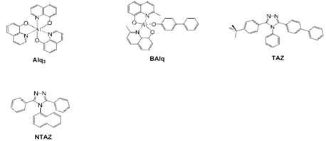
전자 수송 영역(230~235)이 전자 수송층(230)을 포함할 경우, 전자 수송 영역(230)은 안트라센계 화합물을 포함하는 것일 수 있다. 다만, 이에 한정되는 것은 아니며, 전자 수송 영역은 예를 들어, Alq3(Tris(8-hydroxyquinolinato)aluminum),1,3,5-tri[(3-pyridyl)-phen-3-yl]benzene,2,4,6-tris(3'-(pyridin-3-yl)biphenyl-3-yl)-1,3,5-triazine,2-(4-(N-phenylbenzoimidazolyl-1-ylphenyl)-9,10-dinaphthylanthracene,TPBi(1,3,5-Tri(1-phenyl-1H-benzo[d]imidazol-2-yl)phenyl),BCP(2,9-Dimethyl-4,7-diphenyl-1,10-phenanthroline),Bphen(4,7-Diphenyl-1,10-phenanthroline),TAZ(3-(4-Biphenylyl)-4-phenyl-5-tert-butylphenyl-1,2,4-triazole),NTAZ(4-(Naphthalen-1-yl)-3,5-diphenyl-4H-1,2,4-triazole),tBu-PBD(2-(4-Biphenylyl)-5-(4-tert-butylphenyl)-1,3,4-oxadiazole),BAlq(Bis(2-methyl-8-quinolinolato-N1,O8)-(1,1'-Biphenyl-4-olato)aluminum),Bebq2(berylliumbis(benzoquinolin-10-olate),ADN(9,10-di(naphthalene-2-yl)anthracene)및 이들의 혼합물을 포함하는 것일 수 있다.When the
전자수송층(230)은 유기 발광 소자 구조에 따라 빠른 전자이동도 혹은 느린 전자이동도의 재료로 선택되므로 다양한 재료의 선택이 필요하며, 경우에 따라서 하기 Liq나 Li이 도핑되기도 한다.Since the
전자수송층(230)들의 두께는 약 100Å 내지 약 1000Å, 예를 들어 약 150Å 내지 약 500Å일 수 있다. 전자수송층(230)들의 두께가 전술한 바와 같은 범위를 만족할 경우, 실질적인 구동 전압 상승이 없이 만족스러운 정도의 전자 수송 특성을 얻을 수 있다.The thickness of the
전자 수송 영역(230~235)이 전자주입층(235)을 포함할 경우, 전자 수송 영역(230~235)은 전자의 주입을 용이하게 하는 금속재료를 선택하며, LiF, LiQ(Lithium quinolate), Li2O, BaO, NaCl, CsF, Yb와 같은 란타넘족 금속, 또는 RbCl, RbI와 같은 할로겐화 금속 등이 사용될 수 있으나 이에 한정되는 것은 아니다. When the
전자주입층(235)은 또한, 전자 수송 물질과 절연성의 유기 금속염(organo metal salt)이 혼합된 물질로 이루어질 수 있다. 유기 금속염은 에너지 밴드 갭(energy band gap)이 대략 4eV 이상의 물질이 될 수 있다. 구체적으로 예를 들어, 유기 금속염은 금속 아세테이트(metal acetate), 금속 벤조에이트(metal benzoate), 금속 아세토아세테이트(metal acetoacetate), 금속 아세틸아세토네이트(metal acetylacetonate) 또는 금속 스테아레이트(stearate)를 포함할 수 있다. 전자주입층(235)들의 두께는 약 1Å 내지 약 100Å, 약 3Å 내지 약 90Å일 수 있다. 전자 주입층(235)들의 두께가 전술한 바와 같은 범위를 만족할 경우, 실질적인 구동 전압 상승 없이 만족스러운 정도의 전자 주입 특성을 얻을 수 있다.The
전자 수송 영역(230~235)은 앞서 언급한 바와 같이, 정공 저지층을 포함할 수 있다. 정공 저지층은 예를 들어, BCP(2,9-dimethyl-4,7-diphenyl-1,10-phenanthroline), Bphen(4,7-diphenyl-1,10-phenanthroline) 및 Balq 중 적어도 하나를 포함할 수 있으나, 이에 한정되는 것은 아니다.As described above, the
제2 전극(120)은 전자 수송 영역(230~235) 상에 제공된다. 제2 전극(120)은 공통 전극 또는 음극일 수 있다. 제2 전극(120)은 투과형 전극 또는 반투과형 전극 전극일 수 있다. 제2 전극(120)은 제1 전극(110)과 다르게 상대적으로 낮은 일함수를 갖는 금속, 전기전도성 화합물, 합금 등을 조합하여 사용할 수 있다.The
제2 전극(120)은 반투과형 전극 또는 반사형 전극이다. 제2 전극(120)은 Li(리튬), Mg(마그네슘), Al(알루미늄), Al-Li(알루미늄-리튬), Ca(칼슘), Mg-In(마그네슘-인듐), Mg-Ag(마그네슘-은) 또는 이들을 포함하는 화합물이나 혼합물(예를 들어, Ag와 Mg의 혼합물)을 포함할 수 있다. 또는 상기 물질로 형성된 반사막이나 반투과막 및 ITO(indium tin oxide), IZO(indium zinc oxide), ZnO(zinc oxide), ITZO(indium tin zinc oxide) 등으로 형성된 투명 도전막을 포함하는 복수의 층 구조일 수 있다.The
도시하지는 않았으나, 제2 전극(120)은 보조 전극과 연결될 수 있다. 제2 전극(120)가 보조 전극과 연결되면, 제2 전극(120)의 저항을 감소시킬 수 있다.Although not shown, the
도시된 기판(100) 상에 전극 및 유기물층을 형성하며, 이때 기판(100) 재료는 경성 또는 연성 재료를 사용할 수 있으며, 예를 들어 경성 재료로는 소다라임 글래스, 무알칼리 글래스, 알루미노 실리케이트 글래스 등을 사용할 수 있으며, 연성 재료로는 PC(폴리카보네이트), PES(폴리에테르술폰), COC(싸이클릭올리펜코폴리머), PET(폴리에틸렌테레프탈레이트), PEN(폴리에틸렌나프탈레이트) 등을 사용할 수 있다.An electrode and an organic material layer are formed on the illustrated
유기 발광 소자에서, 제1 전극(110)과 제2 전극(120)에 각각 전압이 인가됨에 따라 제1 전극(110)으로부터 주입된 정공(hole)은 정공 수송 영역(210~215)을 거쳐 발광층(220)으로 이동되고, 제2 전극(120)로부터 주입된 전자가 전자 수송 영역(230~235)을 거쳐 발광층(220)으로 이동된다. 전자와 정공은 발광층(220)에서 재결합하여 여기자(exciton)를 생성하며, 여기자가 여기 상태에서 바닥 상태로 떨어지면서 발광하게 된다.In the organic light emitting device, as a voltage is applied to each of the
발광층(220)에서 발생된 광경로는 유기 발광 소자를 구성하는 유무기물들의 굴절률에 따라 매우 다른 경향을 나타낼 수 있다. 제2 전극(120)을 통과하는 빛은 제2 전극(120)의 임계각보다 작은 각도로 투과되는 빛들만 통과할 수 있다. 그 외 임계각보다 크게 제2 전극(120)에 접촉하는 빛들은 전반사 또는 반사되어 유기 발광 소자 외부로 방출되지 못한다.The light path generated by the
캡핑층(300)의 굴절률이 높으면 이러한 전반사 또는 반사 현상을 줄여서 발광효율 향상에 기여하고 또한 적절한 두께를 갖게 되면 미소공동현상(Micro-cavity)현상의 극대화로 높은 효율 향상과 색순도 향상에도 기여하게 된다.When the refractive index of the
캡핑층(300)은 유기 발광 소자의 가장 바깥에 위치하게 되며, 소자의 구동에 전혀 영향을 주지 않으면서 소자특성에는 지대한 영향을 미친다. 따라서 캡핑층(300)은 유기 발광 소자의 내부 보호역할과 동시에 소자특성 향상 두 가지 관점에서 모두 중요하다. 유기물질들은 특정 파장영역의 광에너지를 흡수하며 이는 에너지밴드갭에 의존한다. 이 에너지밴드갭을 유기 발광 소자 내부의 유기물질들에 영향을 줄 수 있는 UV영역의 흡수를 목적으로 조정하면 캡핑층(300)이 광학특성 개선을 포함하여 유기 발광 소자 보호의 목적으로도 사용될 수 있다.The
본 명세서에 따른 유기 발광 소자는 사용되는 재료에 따라 전면 발광형, 후면 발광형 또는 양면 발광형일 수 있다.The organic light emitting device according to the present specification may be a top emission type, a back emission type, or a double side emission type depending on the material used.
이하 본 명세서를 구체적으로 설명하기 위해 실시예를 들어 상세하게 설명하기로 한다. 그러나 본 명세서에 따른 실시예들은 여러가지 다른 형태로 변형될 수 있으며, 본 출원의 범위가 아래에서 상술하는 실시예들에 한정되는 것으로 해석되지 않는다. 본 출원의 실시예들은 당 업계에서 평균적인 지식을 가진 자에게 본 명세서를 보다 완전하게 설명하기 위해 제공되는 것이다.Hereinafter, examples will be given to describe the present specification in detail. However, the embodiments according to the present specification may be modified in various other forms, and the scope of the present application is not to be construed as being limited to the embodiments described below. The embodiments of the present application are provided to more completely explain the present specification to those of ordinary skill in the art.
[실시예] [Example]
중간체 intermediate 합성예Synthesis example 1: 중간체(1)의 합성 1: Synthesis of Intermediate (1)
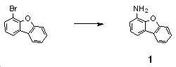
4-브로모디벤조[b,d]퓨란(4-bromodibenzo[b,d]furan) 10.0 g(40.5 mmol), 벤조페논 이민(Benzophenone imine) 8.1 g(44.7 mmol), Pd(dba)2 0.7 g(1.2 mmol), BINAP 1.5 g(2.5 mmol), tert-부톡시나트륨 11.7 g(121.7 mmol) 및 톨루엔 200 mL의 혼합물을 110 ℃에서 하루 종일 교반하였다. 반응 혼합물을 상온으로 냉각하여 셀라이트 패드에 통과시킨 후 감압 증류하여 용매를 제거하였다. 얻어진 화합물을 테트라하이드로퓨란 100 mL에 용해한 후 4N 염산용액으로 천천히 산성화(pH<2)하여 50 ℃에서 4 시간 동안 교반하였다. 상온으로 냉각한 후 테트라하이드로퓨란을 감압 증류하여 제거한 후 디에틸에테르를 가하여 교반하였다. 생성된 고체를 감압 여과하고, 여과한 습체를 물 200 mL에 부유시키고 포화 탄산나트륨 용액으로 산도를 8 이상으로 조정하여 1시간 동안 교반하였다. 생성된 고체를 여과하고 물로 세척한 후 감압 건조하였다. 얻어진 화합물은 컬럼 크로마토그래피로 정제하여 화합물(중간체(1)) 5.0 g(수율: 67%)을 얻었다.4-bromodibenzo [b, d] furan (4-bromodibenzo [b, d] furan) 10.0 g (40.5 mmol), benzophenone imine (Benzophenone imine) 8.1 g (44.7 mmol), Pd (dba) 2 0.7 g (1.2 mmol), BINAP 1.5 g (2.5 mmol), tert -butoxysodium 11.7 g (121.7 mmol) and toluene 200 mL were stirred at 110 °C all day. The reaction mixture was cooled to room temperature, passed through a celite pad, and distilled under reduced pressure to remove the solvent. The obtained compound was dissolved in 100 mL of tetrahydrofuran, and then slowly acidified (pH<2) with 4N hydrochloric acid, followed by stirring at 50 °C for 4 hours. After cooling to room temperature, tetrahydrofuran was distilled off under reduced pressure, and diethyl ether was added thereto and stirred. The resulting solid was filtered under reduced pressure, the filtered wet body was suspended in 200 mL of water, the acidity was adjusted to 8 or more with saturated sodium carbonate solution, and the mixture was stirred for 1 hour. The resulting solid was filtered, washed with water, and dried under reduced pressure. The obtained compound was purified by column chromatography to obtain 5.0 g (yield: 67%) of the compound (intermediate (1)).
중간체 intermediate 합성예Synthesis example 2: 중간체(3)의 합성 2: Synthesis of intermediate (3)
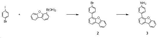
(중간체(2)의 합성)(Synthesis of Intermediate (2))
4-브로모-1-요오드벤젠(4-bromo-1-iodobenzene) 10.0 g(35.3 mmol), 디벤조퓨란-4-일보론산(dibenzofuran-4-ylboronic acid) 8.2 g(38.9 mmol), Pd(PPh3)4 0.2 g(1.1 mmol), 2M 탄산나트륨 용액 36.0 mL(72.0 mmol), 톨루엔 90 mL 및 에탄올 36 mL의 혼합물을 12 시간 동안 환류 교반하였다. 반응 혼합물을 상온으로 냉각한 후 톨루엔 100 mL로 희석하고 물로 세척하였다. 유기층을 분리하여 무수 황산마그네슘으로 건조, 여과, 농축하여 고체의 화합물(중간체(2)) 10.7 g(수율: 93%)을 얻었다.4-bromo-1-iodobenzene (4-bromo-1-iodobenzene) 10.0 g (35.3 mmol), dibenzofuran-4-ylboronic acid (dibenzofuran-4-ylboronic acid) 8.2 g (38.9 mmol), Pd ( A mixture of 0.2 g (1.1 mmol) of PPh 3 ) 4 , 36.0 mL (72.0 mmol) of 2M sodium carbonate solution, 90 mL of toluene and 36 mL of ethanol was stirred under reflux for 12 hours. The reaction mixture was cooled to room temperature, diluted with 100 mL of toluene, and washed with water. The organic layer was separated, dried over anhydrous magnesium sulfate, filtered, and concentrated to obtain 10.7 g (yield: 93%) of a solid compound (intermediate (2)).
(중간체(3)의 합성)(Synthesis of Intermediate (3))
중간체(2) 60.0 g(185.7 mmol), 벤조페논 이민(Benzophenone imine) 37.0 g(204.2 mmol), Pd(dba)2 5.3 g(9.3 mmol), BINAP 11.5 g(18.5 mmol), tert-부톡시나트륨 44.6 g(464.1 mmol), 톨루엔 600 mL의 혼합물을 12시간 동안 환류 교반하였다. 반응혼합물을 상온으로 냉각한 후 클로로포름으로 용해하였다. 이 용액을 셀라이트 패드에 통과시킨 후 감압 농축하였다. 얻어진 화합물을 테트라하이드로퓨란 500 mL에 용해시킨 후 6N 염산 80 mL를 천천히 가하여 상온에서 하룻밤 교반하였다. 생성된 침전을 감압 여과한 후 클로로포름으로 세척하였다. 여과한 습체를 600 mL의 물에 부유시키고, 포화 탄산나트륨 용액으로 pH를 8 이상으로 조정한 후 클로로포름으로 추출하여 층분리하였다. 분리한 클로로포름층을 무수황산나트륨으로 건조, 여과하고 감압 농축하였다. 농축 잔류물을 디클로로메탄과 노말헥산으로 슬러리화하여 노란색 고체의 화합물(중간체(3)) 28.0 g(수율: 58%)을 얻었다.Intermediate (2) 60.0 g (185.7 mmol), Benzophenone imine 37.0 g (204.2 mmol), Pd (dba) 2 5.3 g (9.3 mmol), BINAP 11.5 g (18.5 mmol), tert -butoxysodium A mixture of 44.6 g (464.1 mmol) and 600 mL of toluene was stirred at reflux for 12 hours. The reaction mixture was cooled to room temperature and dissolved in chloroform. The solution was passed through a celite pad and concentrated under reduced pressure. After dissolving the obtained compound in 500 mL of tetrahydrofuran, 80 mL of 6N hydrochloric acid was slowly added thereto, followed by stirring at room temperature overnight. The resulting precipitate was filtered under reduced pressure and washed with chloroform. The filtered wet body was suspended in 600 mL of water, the pH was adjusted to 8 or higher with a saturated sodium carbonate solution, and the layers were separated by extraction with chloroform. The separated chloroform layer was dried over anhydrous sodium sulfate, filtered, and concentrated under reduced pressure. The concentrated residue was slurried with dichloromethane and n-hexane to obtain 28.0 g (yield: 58%) of the compound (intermediate (3)) as a yellow solid.
중간체 intermediate 합성예Synthesis example 3: 중간체(4)의 합성 3: Synthesis of intermediate (4)
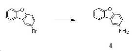
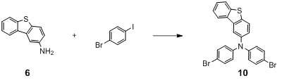
1-(2-브로모디벤조[b,d]퓨란)(1-(2-bromodibenzo[b,d]furan)) 10.0 g(40.5 mmol), 벤조페논 이민(Benzophenone imine) 8.07 g(44.5 mmol), Pd(dba)2 0.70 g(1.22 mmol), BINAP 1.51 g(2.43 mmol), tert-부톡시나트륨 7.78 g(81.0 mmol) 및 톨루엔 100 mL의 혼합물을 12시간 동안 환류 교반하였다. 반응혼합물을 상온으로 냉각한 후 톨루엔 100 mL로 희석하고 물 200 mL로 2회 세척하였다. 유기층을 분리하여 무수황산나트륨으로 건조하고 여과, 농축하였다. 농축 잔류물을 테트라하이드로퓨란 100 mL에 용해한 후 6N 염산 5 mL를 천천히 첨가하여 50 ℃에서 1 시간 동안 교반하였다. 상온으로 냉각한 후 얻어진 고체를 감압 여과한 후 아세톤으로 세척하였다. 여과한 습체를 물 200 mL에 부유시키고 포화 탄산나트륨 용액으로 산도를 8 이상으로 조정한 후 1시간 동안 교반하였다. 생성된 침전을 여과하고 물로 세척, 감압 건조하여 중간체(4) 4.09 g(수율: 55%)을 얻었다.1- (2-bromodibenzo [b, d] furan) (1- (2-bromodibenzo [b, d] furan)) 10.0 g (40.5 mmol), Benzophenone imine 8.07 g (44.5 mmol) , Pd(dba) 2 0.70 g (1.22 mmol), BINAP 1.51 g (2.43 mmol), tert -butoxysodium 7.78 g (81.0 mmol) and 100 mL of toluene were stirred at reflux for 12 hours. The reaction mixture was cooled to room temperature, diluted with 100 mL of toluene, and washed twice with 200 mL of water. The organic layer was separated, dried over anhydrous sodium sulfate, filtered and concentrated. The concentrated residue was dissolved in 100 mL of tetrahydrofuran, 5 mL of 6N hydrochloric acid was slowly added thereto, and the mixture was stirred at 50 °C for 1 hour. After cooling to room temperature, the obtained solid was filtered under reduced pressure and washed with acetone. The filtered wet body was suspended in 200 mL of water, and the acidity was adjusted to 8 or higher with saturated sodium carbonate solution, followed by stirring for 1 hour. The resulting precipitate was filtered, washed with water, and dried under reduced pressure to obtain 4.09 g (yield: 55%) of intermediate (4).
중간체 intermediate 합성예Synthesis example 4: 중간체(5)의 합성 4: Synthesis of intermediate (5)

4-브로모디벤조[b,d]티오펜(4-bromodibenzo[b,d]thiophene) 10.0 g(38.0 mmol), 벤조페논 이민(benzophenone imine) 6.9 g(38.0 mmol), Pd(dba)2 1.1 g(1.9 mmol), BINAP 2.4 g(3.8 mmol), tert-부톡시나트륨 7.3 g(76.0 mmol), 톨루엔 190 mL의 혼합물을 3시간 동안 환류 교반하였다. 반응혼합물을 상온으로 냉각한 후 증류수 190 mL를 가하고 추출하였다. 유기층에 6 N HCl 100 mL를 가하고 3시간 동안 상온에서 교반한 후 생성된 고체를 감압 여과하였다. 여과된 습체를 포화 탄산나트륨 용액으로 염기성화(pH>8)시키고 디클로로메탄 190 mL로 추출하였다. 분리한 유기층을 무수 황산나트륨으로 건조, 여과하고 농축한 후 컬럼 크로마토그래피로 정제하여 옅은 주황색 고체의 화합물(중간체(5)) 3.6 g(수율: 47.6 %)을 얻었다.4-bromodibenzo[b,d]thiophene (4-bromodibenzo[b,d]thiophene) 10.0 g (38.0 mmol), benzophenone imine 6.9 g (38.0 mmol), Pd (dba) 2 1.1 g (1.9 mmol), BINAP 2.4 g (3.8 mmol), tert -butoxysodium 7.3 g (76.0 mmol), and a mixture of 190 mL toluene was stirred under reflux for 3 hours. After the reaction mixture was cooled to room temperature, 190 mL of distilled water was added, followed by extraction. After adding 100 mL of 6 N HCl to the organic layer and stirring at room temperature for 3 hours, the resulting solid was filtered under reduced pressure. The filtered wet body was basified (pH>8) with saturated sodium carbonate solution and extracted with 190 mL of dichloromethane. The separated organic layer was dried over anhydrous sodium sulfate, filtered, concentrated, and purified by column chromatography to obtain 3.6 g (yield: 47.6 %) of the compound as a pale orange solid (Intermediate (5)).
중간체 intermediate 합성예Synthesis example 5: 중간체(6)의 합성 5: Synthesis of intermediate (6)

2-브로모디벤조[b,d]티오펜(2-bromodibenzo[b,d]thiophene) 6.0 g(22.8 mmol), 벤조페논 이민(Benzophenone imine) 4.6 mL(27.4 mmol), Pd2(dba)3 1.04 g(1.14 mmol), BINAP 1.42 g(2.28 mmol), 탄산세슘 22.3 g(68.4 mmol) 및 톨루엔 110 mL의 혼합물을 12시간 동안 환류 교반하였다. 반응혼합물을 상온으로 냉각하고 셀라이트 패드로 여과한 후, 여과액을 감압 농축하였다. 여과한 습체를 테트라하이드로퓨란 70 mL에 용해시킨 후 6N 염산 30 mL를 가하여 1시간 동안 교반하였다. 혼합물을 포화 탄산나트륨 용액으로 염기성화(pH 7-8)시킨 후 디클로로메탄으로 추출하였다. 분리한 유기층을 무수 황산나트륨으로 건조, 여과하고 농축한 후 컬럼 크로마토그래피로 정제하여 갈색 고체의 화합물(중간체(6)) 2.72 g(수율: 59.9%)을 얻었다. 2-bromodibenzo[b,d]thiophene (2-bromodibenzo[b,d]thiophene) 6.0 g (22.8 mmol), benzophenone imine 4.6 mL (27.4 mmol), Pd 2 (dba) 3 A mixture of 1.04 g (1.14 mmol), 1.42 g (2.28 mmol) of BINAP, 22.3 g (68.4 mmol) of cesium carbonate and 110 mL of toluene was stirred at reflux for 12 hours. The reaction mixture was cooled to room temperature, filtered through a pad of Celite, and the filtrate was concentrated under reduced pressure. After dissolving the filtered wet body in 70 mL of tetrahydrofuran, 30 mL of 6N hydrochloric acid was added, followed by stirring for 1 hour. The mixture was basified (pH 7-8) with saturated sodium carbonate solution and then extracted with dichloromethane. The separated organic layer was dried over anhydrous sodium sulfate, filtered, concentrated, and purified by column chromatography to obtain 2.72 g (yield: 59.9%) of the compound (intermediate (6)) as a brown solid.
중간체 intermediate 합성예Synthesis example 6: 중간체(8)의 합성 6: Synthesis of intermediate (8)

(중간체(7)의 합성)(Synthesis of Intermediate (7))
4-브로모-1-요오드벤젠(4-bromo-1-iodobenzene) 10.0 g(35.3 mmol), 디벤조퓨란-4-일보론산(dibenzofuran-4-ylboronic acid) 8.2 g(38.9 mmol), Pd(PPh3)4 0.2 g(1.1 mmol), 2M 탄산나트륨 용액 36.0 mL(72.0 mmol), 톨루엔 90 mL 및 에탄올 36 mL의 혼합물을 12시간 동안 환류 교반하였다. 반응 혼합물을 상온으로 냉각한 후 톨루엔 100 mL로 희석하고 물로 세척하였다. 유기층을 분리하여 무수 황산마그네슘으로 건조, 여과, 농축하여 고체의 화합물(중간체(7)) 10.7 g(수율: 93%)을 얻었다.4-bromo-1-iodobenzene (4-bromo-1-iodobenzene) 10.0 g (35.3 mmol), dibenzofuran-4-ylboronic acid (dibenzofuran-4-ylboronic acid) 8.2 g (38.9 mmol), Pd ( A mixture of 0.2 g (1.1 mmol) of PPh 3 ) 4 , 36.0 mL (72.0 mmol) of 2M sodium carbonate solution, 90 mL of toluene and 36 mL of ethanol was stirred under reflux for 12 hours. The reaction mixture was cooled to room temperature, diluted with 100 mL of toluene, and washed with water. The organic layer was separated, dried over anhydrous magnesium sulfate, filtered, and concentrated to obtain 10.7 g (yield: 93%) of a solid compound (intermediate (7)).
(중간체(8)의 합성)(Synthesis of Intermediate (8))
중간체(7) 60.0 g(185.7 mmol), 벤조페논 이민(Benzophenone imine) 37.0 g(204.2 mmol), Pd(dba)2 5.3 g(9.3 mmol), BINAP 11.5 g(18.5 mmol), tert-부톡시나트륨 44.6 g(464.1 mmol), 톨루엔 600 mL의 혼합물을 12시간 동안 환류 교반하였다. 반응혼합물을 상온으로 냉각한 후 클로로포름으로 용해하였다. 이 용액을 셀라이트 패드에 통과시킨 후 감압 농축하였다. 얻어진 화합물을 테트라하이드로퓨란 500 mL에 용해시킨 후 6N 염산 80 mL를 천천히 가하여 상온에서 하룻밤 교반하였다. 생성된 침전을 감압 여과한 후 클로로포름으로 세척하였다. 여과한 습체를 600 mL의 물에 부유시키고, 포화 탄산나트륨 용액으로 pH를 8 이상으로 조정한 후 클로로포름으로 추출하여 층분리하였다. 분리한 클로로포름층을 무수황산나트륨으로 건조, 여과하고 감압 농축하였다. 농축 잔류물을 디클로로메탄과 노말헥산으로 슬러리화하여 노란색 고체의 화합물(중간체(8)) 28.0 g(수율: 58%)을 얻었다.Intermediate (7) 60.0 g (185.7 mmol), Benzophenone imine 37.0 g (204.2 mmol), Pd (dba) 2 5.3 g (9.3 mmol), BINAP 11.5 g (18.5 mmol), tert -butoxysodium A mixture of 44.6 g (464.1 mmol) and 600 mL of toluene was stirred at reflux for 12 hours. The reaction mixture was cooled to room temperature and dissolved in chloroform. The solution was passed through a celite pad and concentrated under reduced pressure. After dissolving the obtained compound in 500 mL of tetrahydrofuran, 80 mL of 6N hydrochloric acid was slowly added thereto, followed by stirring at room temperature overnight. The resulting precipitate was filtered under reduced pressure and washed with chloroform. The filtered wet body was suspended in 600 mL of water, the pH was adjusted to 8 or higher with a saturated sodium carbonate solution, and the layers were separated by extraction with chloroform. The separated chloroform layer was dried over anhydrous sodium sulfate, filtered, and concentrated under reduced pressure. The concentrated residue was slurried with dichloromethane and n-hexane to obtain 28.0 g (yield: 58%) of the compound (intermediate (8)) as a yellow solid.
중간체 intermediate 합성예Synthesis example 7: 중간체(9)의 합성 7: Synthesis of intermediate (9)

1구 250 mL 플라스크에 중간체(3) 4.6 g(17.7 mmol), 1-브로모-4-아이오도벤젠(1-Bromo-4-iodobenzene) 11.0 g(39.0 mmol), Pd(dba)2 0.5 g(0.9 mmol), DPPF 1.0 g(1.8 mmol), NaOtBu 5.1 g(53.2 mmol) 및 톨루엔 90 mL를 넣고 4시간 동안 환류 및 교반하였다. 상온에서 식힌 후 셀라이트 여과를 통해 불순물을 제거하였다. 용매를 제거한 후 디클로로메탄에 녹여 실리카겔 컬럼 크로마토그래피(DCM:HEX)로 정제하였다. 얻어진 고체를 혼합용액(디클로로메탄/아세톤)으로 여과하여 흰색 고체의 화합물(중간체(9)) 6.9 g(수율: 68.6%)을 얻었다.In a 1-neck 250 mL flask, 4.6 g (17.7 mmol) of Intermediate (3), 11.0 g (39.0 mmol) of 1-Bromo-4-iodobenzene, 0.5 g of Pd (dba) 2 (0.9 mmol), DPPF 1.0 g (1.8 mmol), NaOtBu 5.1 g (53.2 mmol) and toluene 90 mL were added and refluxed and stirred for 4 hours. After cooling to room temperature, impurities were removed through celite filtration. After removing the solvent, it was dissolved in dichloromethane and purified by silica gel column chromatography (DCM:HEX). The obtained solid was filtered with a mixed solution (dichloromethane/acetone) to obtain 6.9 g (yield: 68.6%) of the compound as a white solid (intermediate (9)).
중간체 intermediate 합성예Synthesis example 8: 중간체(10)의 합성 8: Synthesis of intermediate (10)
1구 500 mL 플라스크에 중간체(6) 4.0 g(20.1 mmol), 1-브로모-4-아이오도벤젠(1-Bromo-4-iodobenzene) 12.5 g(44.2 mmol), Pd(dba)2 0.6 g(1.0 mmol), DPPF 1.1 g(2.0 mmol), NaOtBu 5.8 g(60.2 mmol) 및 톨루엔 100 mL를 넣고 4시간 동안 환류 및 교반하였다. 상온에서 식힌 후 셀라이트 여과를 통해 불순물을 제거하였다. 용매를 제거한 후 디클로로메탄에 녹여 실리카겔 컬럼 크로마토그래피(DCM:HEX)로 정제하였다. 얻어진 고체를 혼합용액(아세톤/메탄올)으로 여과하여 노란색 고체의 화합물(중간체(10)) 8.8 g(수율: 86.2%)을 얻었다.In a 1-
중간체 intermediate 합성예Synthesis example 8: 중간체(11)의 합성 8: Synthesis of intermediate (11)
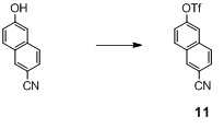
6-하이드록시-2-나프토니트릴(6-Hydroxy-2-naphthonitrile) 10.0 g(59.1 mmol)을 다이클로로메탄(DCM) 300 mL에 녹이고 피리딘(Pyridine) 14.0 g(177.3 mmol)을 적가한 후 0℃로 온도를 낮췄다. Tf2O 20.0 g(70.9 mmol)를 천천히 적가한 후 상온으로 온도를 올린 후 12시간 동안 반응시켰다. 반응물을 물(500 mL)에 세척한 후, 분리한 유기층을 무수 황산나트륨으로 건조, 여과하고 농축한 후 컬럼 크로마토그래피(CHCl3)로 정제하여 노란색 고체의 화합물(중간체(11)) 15.8 g(수율: 88.7%)을 얻었다.10.0 g (59.1 mmol) of 6-hydroxy-2-naphthonitrile was dissolved in 300 mL of dichloromethane (DCM), and 14.0 g (177.3 mmol) of pyridine was added dropwise. The temperature was lowered to 0 °C. 20.0 g (70.9 mmol) of Tf 2 O was slowly added dropwise, and the temperature was raised to room temperature, followed by reaction for 12 hours. After the reaction was washed with water (500 mL), the separated organic layer was dried over anhydrous sodium sulfate, filtered, concentrated, and purified by column chromatography (CHCl 3 ) to obtain 15.8 g of a yellow solid compound (intermediate (11)) (yield) : 88.7%) was obtained.
중간체 intermediate 합성예Synthesis example 9: 중간체(13)의 합성 9: Synthesis of intermediate (13)
(중간체(12)의 합성)(Synthesis of Intermediate (12))
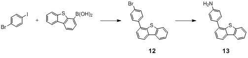
1구 1000 mL 플라스크에 1-브로모-4-아이오도벤젠(1-bromo-4-iodobenzene) 37.2 g(131.5 mmol), 다이벤조[b,d]싸이오펜-4-일보론산(dibenzo[b,d]thiophen-4-ylboronic acid) 30.0 g(131.5 mmol), Pd(PPh3)4 4.6 g(3.9 mmol) 및 톨루엔 400 mL를 넣고 교반하다가 에탄올 200 mL, K2CO3 27.3 g(197.3 mmol)/물 200mL를 첨가하고, 가열 환류하에 8시간 동안 교반하였다. 반응이 종결되면 상온으로 냉각하고 용매를 제거하고 물을 첨가한 후 디클로로메탄으로 추출하고 유기상을 무수 MgSO4로 건조하고, 컬럼 크로마토그래피(DCM)로 정제하여 약간의 노란색 고체의 화합물(중간체(12)) 29.1 g(수율: 65.3%)을 얻었다. In a 1-neck 1000 mL flask, 1-bromo-4-iodobenzene (1-bromo-4-iodobenzene) 37.2 g (131.5 mmol), dibenzo [b, d] thiophen-4-ylboronic acid (dibenzo [b ,d]thiophen-4-ylboronic acid) 30.0 g (131.5 mmol), Pd(PPh 3 ) 4 4.6 g (3.9 mmol), and
(중간체(13)의 합성)(Synthesis of Intermediate (13))
1구 1000 mL 플라스크에 중간체(12) 29.1 g(85.8 mmol), 벤조페논 이민(Benzophenone imine) 17.1 g(94.4 mmol), NaOtBu 16.5 g(171.6 mmol), 톨루엔 500 mL를 넣고 교반하다가 Pd(dba)2 1.5 g(2.6 mmol), BINAP 3.2 g(5.2 mmol)를 첨가하고 가열 환류하에 하루종일 교반하였다. 반응이 종결되면 상온으로 냉각하고 용매를 제거하고 물을 첨가한 후 디클로로메탄으로 추출하고 유기상을 무수 MgSO4로 건조하고, 클로로포름 1000 mL로 셀라이트를 깐 패드에 통과시킨 후 감압 증류를 이용해 용매를 제거하였다. 약간 갈색 액체의 화합물를 테트라하이드로퓨란 500mL를 같이 넣고 교반하다가 4N HCl로 pH 2 이상으로 맞추고 50℃에서 4시간 교반하였다. 반응이 종결되면 용매를 날리고 얻어진 고체에 아세톤을 첨가하고 30분간 교반 후 여과하여 붉은색 고체를 얻었다. 이 고체를 NaOH로 pH 8 이상으로 맞추고 30분간 교반한 후 디클로로메탄 추출하고 용매를 제거하고 컬럼 크로마토그래피(Hex:CHCl3)로 정제하여 약간 붉은색 고체의 화합물(중간체(13)) 12.6 g(수율: 53.4%)을 얻었다.29.1 g (85.8 mmol) of intermediate (12), 17.1 g (94.4 mmol) of benzophenone imine, 16.5 g (171.6 mmol) of NaOtBu, and 500 mL of toluene were added to a 1-neck 1000 mL flask and stirred, followed by Pd (dba) 2 1.5 g (2.6 mmol), 3.2 g (5.2 mmol) of BINAP were added, and the mixture was stirred under reflux under heating all day. Upon completion of the reaction, the reaction was cooled to room temperature, the solvent was removed, water was added, and the mixture was extracted with dichloromethane, the organic phase was dried over anhydrous MgSO 4 , passed through a pad covered with celite with 1000 mL of chloroform, and the solvent was distilled off under reduced pressure. removed. A slightly brown liquid compound was added with 500 mL of tetrahydrofuran and stirred, then adjusted to
상기 합성된 중간체 화합물을 이용하여 이하와 같이 다양한 3차 아민 유도체를 합성하였다. Using the synthesized intermediate compound, various tertiary amine derivatives were synthesized as follows.
실시예Example 1: 화합물 2-4(LT19-35-308)의 합성 1: Synthesis of compound 2-4 (LT19-35-308)
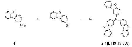
중간체(4) 2.8 g(15.4 mmol), 2-브로모디벤조[b,d]티오펜(2-bromodibenzo[b,d]thiophene) 8.9 g(33.9 mmol), Pd(dba)2 1.8 g(3.1 mmol), tert-부톡시나트륨 7.4 g(77.1 mmol), 트리-tert-부틸포스핀 1.3 g(3.0 mmol, 50wt% 톨루엔 용액), 자일렌 100 mL의 혼합물을 110 ℃에서 8시간 동안 교반하였다. 반응혼합물을 상온으로 냉각하여 물을 가한 후 클로로포름 300 mL로 2회 추출하였다. 유기층을 무수 황산마그네슘으로 건조, 여과하고 감압 농축하였다. 얻어진 혼합물을 컬럼 크로마토그래피로 정제하여 화합물 2-4(LT19-35-308) 4.9 g(수율: 58.1%)을 얻었다. Intermediate (4) 2.8 g (15.4 mmol), 2-bromodibenzo [b, d] thiophene (2-bromodibenzo [b, d] thiophene) 8.9 g (33.9 mmol), Pd (dba) 2 1.8 g (3.1 mmol), tert -butoxysodium 7.4 g (77.1 mmol), tri- tert -butylphosphine 1.3 g (3.0 mmol, 50wt% toluene solution), and 100 mL of xylene were stirred at 110° C. for 8 hours. The reaction mixture was cooled to room temperature, water was added, and then extracted twice with 300 mL of chloroform. The organic layer was dried over anhydrous magnesium sulfate, filtered, and concentrated under reduced pressure. The obtained mixture was purified by column chromatography to obtain 4.9 g (yield: 58.1%) of compound 2-4 (LT19-35-308).
실시예Example 2: 화합물 2-5(LT19-30-224)의 합성 2: Synthesis of compound 2-5 (LT19-30-224)

중간체(4) 1.5 g(8.2 mmol), 중간체(2) 5.3 g(16.4 mmol), Pd(dba)2 0.2 g(0.4 mmol), tert-부톡시나트륨 2.4 g(24.6 mmol), 트리-tert-부틸포스핀 0.3 g(0.6 mmol, 50wt% 톨루엔 용액), 톨루엔 23 mL의 혼합물을 3시간 동안 환류 교반하였다. 반응 혼합물을 상온으로 냉각한 후 메탄올 115 mL를 가하였다. 생성된 반고체 상태의 침전을 분리한 후 컬럼 크로마토그래피로 정제하여 노란색 고체 화합물 2-5(LT19-30-224) 3.4 g(수율: 62.1%)을 얻었다.Intermediate (4) 1.5 g (8.2 mmol), intermediate (2) 5.3 g (16.4 mmol), Pd(dba) 2 0.2 g (0.4 mmol), tert - butoxysodium 2.4 g (24.6 mmol), tri-tert- A mixture of 0.3 g (0.6 mmol, 50wt% toluene solution) of butylphosphine and 23 mL of toluene was stirred under reflux for 3 hours. After the reaction mixture was cooled to room temperature, 115 mL of methanol was added thereto. The resulting semi-solid precipitate was separated and purified by column chromatography to obtain 3.4 g (yield: 62.1%) of yellow solid compound 2-5 (LT19-30-224).
실시예Example 3: 화합물 2-9(LT19-30-192)의 합성 3: Synthesis of compound 2-9 (LT19-30-192)

중간체(1) 1.5 g(8.2 mmol), 중간체(2) 5.3 g(16.4 mmol), Pd(dba)2 0.2 g(1.2 mmol), 트리-tert-부틸포스핀 0.3 g(0.8 mmol, 50wt% 톨루엔 용액), tert-부톡시나트륨 1.6 g(16.4 mmol) 및 톨루엔 82 mL의 혼합물을 8시간 동안 환류 교반하였다. 반응혼합물을 상온으로 냉각한 후 물로 세척하고 유기층을 분리하여 무수 황산나트륨으로 건조하고 여과, 농축하였다. 농축된 혼합물을 컬럼 크로마토그래피로 정제한 후 디클로로메탄과 에틸아세테이트로 재결정하여 흰색의 고체 화합물 2-9(LT19-30-192) 3.9 g(수율: 71.2%)을 얻었다.Intermediate (1) 1.5 g (8.2 mmol), Intermediate (2) 5.3 g (16.4 mmol), Pd(dba) 2 0.2 g (1.2 mmol), tri- tert -butylphosphine 0.3 g (0.8 mmol, 50 wt% toluene) solution), 1.6 g (16.4 mmol) of sodium tert -butoxy and 82 mL of toluene was stirred at reflux for 8 hours. The reaction mixture was cooled to room temperature, washed with water, the organic layer was separated, dried over anhydrous sodium sulfate, filtered, and concentrated. The concentrated mixture was purified by column chromatography and recrystallized from dichloromethane and ethyl acetate to obtain 3.9 g (yield: 71.2%) of a white solid compound 2-9 (LT19-30-192).
실시예Example 4: 화합물 2-13(LT18-30-239)의 합성 4: Synthesis of compound 2-13 (LT18-30-239)
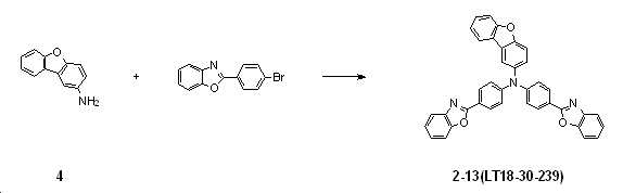
중간체(4) 1.5 g(8.2 mmol), 2-(4-브로모페닐)벤조[d]옥사졸(2-(4-bromophenyl)benzo[d]oxazole) 5.3 g(19.3mmol), Pd(dba)2 483 mg(840.6 μ㏖), 트리-tert-부틸포스핀 680 mg(1.7 mmol, 50wt% 톨루엔 용액), tert-부톡시나트륨 4.9 g(50.4mmol) 및 자일렌 56 mL의 혼합물을 120 ℃에서 12시간 동안 교반 하였다. 반응혼합물을 상온으로 냉각하여 클로로포름으로 희석한 후 물로 세척하였다. 유기층을 분리하여 무수 황산나트륨으로 건조하고 여과, 농축하였다. 얻어진 혼합물을 컬럼 크로마토그래피로 정제하여, 노란색 고체의 화합물 2-13(LT18-30-239 1.8 g(수율: 38.5%)을 얻었다.Intermediate (4) 1.5 g (8.2 mmol), 2- (4-bromophenyl) benzo [d] oxazole (2- (4-bromophenyl) benzo [d] oxazole) 5.3 g (19.3 mmol), Pd (dba) ) 2 483 mg (840.6 μmol), tri- tert -
실시예Example 5: 화합물 2-14(LT19-30-305)의 합성 5: Synthesis of compound 2-14 (LT19-30-305)

1구 250 mL 플라스크에 중간체(4) 1.3 g(7.0 mmol), 2-(4-브로모페닐)벤조티아졸(2-(4-bromophenyl)benzo[d]thiazole) 5.1 g(14.7 mmol) 및 Xylene 100 mL를 첨가한 후 50 ℃에서 교반한 후 Pd(dba)2 403.0 mg(0.7 mmol), Sodium tert-butoxide 2.0 g(21.0 mmol) 및 tri-tert-butylphospine(50wt% in Toluene) 567.2 mg(1.4 mmol)을 첨가한 후 125~130 ℃에서 하루 종일 교반하였다. 반응이 종결된 후 상온으로 냉각하고 반응물을 CHCl3으로 셀라이트 패드에 통과시킨 후 감압 증류하여 용매를 제거하였다. 얻어진 화합물을 Hexane으로 고체화하여 노란색의 고체를 수득한 후 CHCl3 800 mL에 가열하여 녹인 후 charcoal을 첨가하여 30분간 교반하였다. 뜨거운 혼합 용매(Hot CHCl3:EA=20:1)를 사용하여 셀라이트와 SiO2 패드에 통과시킨 후 감압증류를 이용해 용매를 제거하였다. 얻어진 화합물은 SiO2 컬럼 크로마토그래피(EA:CHCl3:HEX=1:1:5)로 정제하였다. DCM과 Hexane으로 slurry화하여 노란색 고체의 화합물 2-14(LT19-35-305) 3.1 g(수율: 73.5%)을 얻었다.In a one-necked 250 mL flask, 1.3 g (7.0 mmol) of intermediate (4), 5.1 g (14.7 mmol) of 2-(4-bromophenyl)benzo[d]thiazole, and After adding 100 mL of xylene and stirring at 50 ℃, Pd(dba) 2 403.0 mg (0.7 mmol), Sodium tert -butoxide 2.0 g (21.0 mmol) and tri- tert -butylphospine (50wt% in Toluene) 567.2 mg ( 1.4 mmol) was added, and the mixture was stirred at 125-130 °C all day. After completion of the reaction, it was cooled to room temperature, and the reactant was passed through a celite pad with CHCl 3 and distilled under reduced pressure to remove the solvent. The obtained compound was solidified with hexane to obtain a yellow solid, dissolved by heating in 800 mL of CHCl 3 , and then charcoal was added and stirred for 30 minutes. Using a hot mixed solvent (Hot CHCl 3 :EA=20:1), it was passed through a pad of Celite and SiO 2 , and then the solvent was removed by distillation under reduced pressure. The obtained compound was purified by SiO 2 column chromatography (EA:CHCl 3 :HEX=1:1:5). It was slurryed with DCM and Hexane to obtain 3.1 g (yield: 73.5%) of compound 2-14 (LT19-35-305) as a yellow solid.
실시예Example 6: 화합물 2-21(LT19-30-312)의 합성 6: Synthesis of compound 2-21 (LT19-30-312)
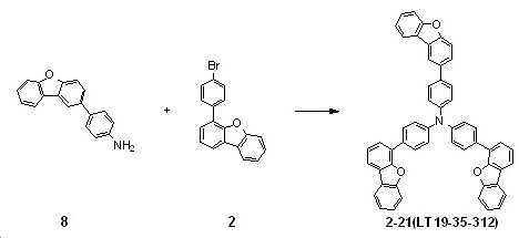
중간체(8) 1.7 g(6.5 mmol), 중간체(2) 4.6 g(14.4 mmol), tert-부톡시나트륨 1.9 g(19.6 mmol), Pd(dba)2 0.2 g(0.4 mmol), 트리-tert-부틸포스핀 0.2 g(0.5 mmol, 50wt % 톨루엔 용액) 및 자일렌 150 mL의 혼합물을 하루 종일 환류 교반하였다. 반응 혼합물을 상온으로 냉각하여 클로로포름 500 mL로 희석한 후 셀라이트 패드로 여과하였다. 여과액을 농축한 후 잔류물을 컬럼 크로마토그래피로 정제하여 노란색 고체의 화합물 2-21(LT19-35-312) 2.9 g(수율: 60.7%)을 얻었다.1.7 g (6.5 mmol) of intermediate (8), 4.6 g (14.4 mmol) of intermediate (2), sodium tert -butoxy 1.9 g (19.6 mmol), Pd(dba) 2 0.2 g (0.4 mmol), tri- tert -butylphosphine A mixture of 0.2 g (0.5 mmol, 50wt % toluene solution) and 150 mL of xylene was stirred under reflux throughout the day. The reaction mixture was cooled to room temperature, diluted with 500 mL of chloroform, and filtered through a pad of Celite. After the filtrate was concentrated, the residue was purified by column chromatography to obtain 2.9 g (yield: 60.7%) of compound 2-21 (LT19-35-312) as a yellow solid.
실시예Example 7: 화합물 2-27(LT19-30-286)의 합성 7: Synthesis of compound 2-27 (LT19-30-286)
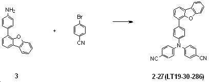
중간체(3) 4.0 g(15.4 mmol), 4-브로모벤조니트릴(4-bromobenzonitrile) 8.4 g(46.3 mmol), Pd(dba)2 1.8 g(3.1 mmol), 트리-tert-부틸포스핀 3.0 mL(6.2 mmol, 50wt% 톨루엔 용액), tert-부톡시나트륨 5.9 g(61.7 mmol) 및 톨루엔 154 mL의 혼합물을 16시간 동안 환류 교반하였다. 반응혼합물을 상온으로 냉각한 후 물로 세척하고 유기층을 분리하여 무수황산나트륨으로 건조하고 여과, 농축하였다. 농축된 혼합물을 컬럼 크로마토그래피로 정제 후 에틸아세테이트로 재결정하여 아이보리색의 고체 화합물 2-27(LT19-30-286) 1.3 g(수율: 18.3%)을 얻었다. Intermediate (3) 4.0 g (15.4 mmol), 4-bromobenzonitrile (4-bromobenzonitrile) 8.4 g (46.3 mmol), Pd (dba) 2 1.8 g (3.1 mmol), tri- tert -butylphosphine 3.0 mL A mixture of (6.2 mmol, 50wt% toluene solution), 5.9 g (61.7 mmol) of tert -butoxysodium and 154 mL of toluene was stirred under reflux for 16 hours. The reaction mixture was cooled to room temperature, washed with water, the organic layer was separated, dried over anhydrous sodium sulfate, filtered, and concentrated. The concentrated mixture was purified by column chromatography and recrystallized from ethyl acetate to obtain 1.3 g (yield: 18.3%) of compound 2-27 (LT19-30-286) of ivory color.
실시예Example 8: 화합물 2-29(LT19-30-259)의 합성 8: Synthesis of compound 2-29 (LT19-30-259)
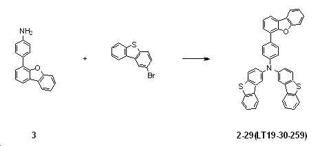
중간체(3) 4.0 g(15.4 mmol), 2-브로모디벤조[b,d]티오펜(2-bromodibenzo[b,d]thiophene) 8.9 g(33.9 mmol), Pd(dba)2 1.8 g(3.1 mmol), tert-부톡시나트륨 7.4 g(77.1 mmol), 트리-tert-부틸포스핀 1.3 g(3.0 mmol, 50wt% 톨루엔 용액), 자일렌 100 mL의 혼합물을 110 ℃에서 8시간 동안 교반하였다. 반응혼합물을 상온으로 냉각하여 물을 가한 후 클로로포름 300 mL로 2회 추출하였다. 유기층을 무수 황산마그네슘으로 건조, 여과하고 감압 농축하였다. 얻어진 혼합물을 컬럼 크로마토그래피로 정제하여 화합물 2-29(LT19-30-259) 1.7 g(수율: 17.7%)을 얻었다. Intermediate (3) 4.0 g (15.4 mmol), 2-bromodibenzo [b, d] thiophene (2-bromodibenzo [b, d] thiophene) 8.9 g (33.9 mmol), Pd (dba) 2 1.8 g (3.1 mmol), tert -butoxysodium 7.4 g (77.1 mmol), tri- tert -butylphosphine 1.3 g (3.0 mmol, 50wt% toluene solution), and 100 mL of xylene were stirred at 110° C. for 8 hours. The reaction mixture was cooled to room temperature, water was added, and then extracted twice with 300 mL of chloroform. The organic layer was dried over anhydrous magnesium sulfate, filtered, and concentrated under reduced pressure. The obtained mixture was purified by column chromatography to obtain 1.7 g (yield: 17.7%) of compound 2-29 (LT19-30-259).
실시예Example 9: 화합물 2-36(LT19-30-278)의 합성 9: Synthesis of compound 2-36 (LT19-30-278)
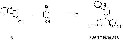
중간체(6) 2.5 g(12.5 mmol), 4-브로모벤조니트릴(4-bromobenzonitrile) 4.8 g(26.3 mmol), Pd(dba)2 1.4 g(2.5 mmol), tert-부톡시나트륨 6.0 g(62.7 mmol), 트리-tert-부틸포스핀 1.0 g(2.5 mmol, 50wt% 톨루엔 용액), 자일렌 100 mL의 혼합물을 110 ℃에서 8시간 동안 교반하였다. 반응혼합물을 상온으로 냉각하여 물을 가한 후 클로로포름 300 mL로 2회 추출하였다. 유기층을 무수 황산마그네슘으로 건조, 여과하고 감압 농축하였다. 얻어진 화합물을 컬럼 크로마토그래피로 정제하여 화합물 2-36(LT19-30-278) 1.4 g(수율: 27.9%)을 얻었다. Intermediate (6) 2.5 g (12.5 mmol), 4-bromobenzonitrile (4-bromobenzonitrile) 4.8 g (26.3 mmol), Pd (dba) 2 1.4 g (2.5 mmol), tert -butoxysodium 6.0 g (62.7) mmol), tri- tert -butylphosphine 1.0 g (2.5 mmol, 50wt% toluene solution), and 100 mL of xylene were stirred at 110° C. for 8 hours. The reaction mixture was cooled to room temperature, water was added, and then extracted twice with 300 mL of chloroform. The organic layer was dried over anhydrous magnesium sulfate, filtered, and concentrated under reduced pressure. The obtained compound was purified by column chromatography to obtain 1.4 g (yield: 27.9%) of compound 2-36 (LT19-30-278).
실시예Example 10: 화합물 2-40(LT19-30-218)의 합성 10: Synthesis of compound 2-40 (LT19-30-218)
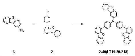
중간체(6) 1.3 g(6.5 mmol), 중간체(2) 4.6 g(14.4 mmol), tert-부톡시나트륨 1.9 g(19.6 mmol), Pd(dba)2 0.2 g(0.4 mmol), 트리-tert-부틸포스핀 0.2 g(0.5 mmol, 50wt% 톨루엔 용액) 및 자일렌 150 mL의 혼합물을 하루 종일 환류 교반하였다. 반응 혼합물을 상온으로 냉각하여 클로로포름 500 mL로 희석한 후 셀라이트 패드로 여과하였다. 여과액을 농축한 후 잔류물을 컬럼 크로마토그래피로 정제하여 노란색 고체의 화합물 2-40(LT19-30-218) 2.7 g(수율: 60.7%)을 얻었다.1.3 g (6.5 mmol) of intermediate (6), 4.6 g (14.4 mmol) of intermediate (2), sodium tert -butoxy 1.9 g (19.6 mmol), Pd(dba) 2 0.2 g (0.4 mmol), tri- tert -butylphosphine A mixture of 0.2 g (0.5 mmol, 50wt% toluene solution) and 150 mL of xylene was stirred at reflux throughout the day. The reaction mixture was cooled to room temperature, diluted with 500 mL of chloroform, and filtered through a pad of Celite. After the filtrate was concentrated, the residue was purified by column chromatography to obtain 2.7 g (yield: 60.7%) of compound 2-40 (LT19-30-218) as a yellow solid.
실시예Example 11: 화합물 2-44(LT19-30-199)의 합성 11: Synthesis of compound 2-44 (LT19-30-199)

중간체(5) 2.0 g(10.0 mmol), 중간체(2) 6.5 g(20.1 mmol), Pd(dba)2 0.6 g (1.0 mmol), 트리-tert-부틸포스핀 1.0 mL(2.0 mmol, 50wt% 톨루엔 용액), tert-부톡시나트륨 3.9 g(40.2 mmol) 및 톨루엔 100 mL의 혼합물을 8시간 동안 환류 교반하였다. 반응혼합물을 상온으로 냉각한 후 물로 세척하고 유기층을 분리하여 Na2SO4으로 건조하고 여과, 농축하였다. 농축된 혼합물을 컬럼 크로마토그래피로 정제 후 디클로로메탄과 MeOH로 재결정하여 흰색의 고체 화합물 2-44(LT19-30-199) 1.5 g(수율: 21.9 %)을 얻었다. Intermediate (5) 2.0 g (10.0 mmol), Intermediate (2) 6.5 g (20.1 mmol), Pd(dba) 2 0.6 g (1.0 mmol), tri- tert -butylphosphine 1.0 mL (2.0 mmol, 50 wt% toluene) solution), 3.9 g (40.2 mmol) of sodium tert -butoxy and 100 mL of toluene were stirred under reflux for 8 hours. The reaction mixture was cooled to room temperature, washed with water, the organic layer was separated, dried over Na 2 SO 4 , filtered, and concentrated. The concentrated mixture was purified by column chromatography and recrystallized from dichloromethane and MeOH to obtain 1.5 g (yield: 21.9%) of white solid compound 2-44 (LT19-30-199).
실시예Example 12: 화합물 2-48(LT18-30-263)의 합성 12: Synthesis of compound 2-48 (LT18-30-263)
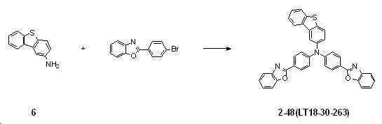
중간체(6) 1.6 g(8.0 mmol), 2-(4-브로모페닐)벤조[d]옥사졸(2-(4-bromophenyl)benzo[d]oxazole) 5.5 g(20.1 mmol), Pd(dba)2 0.92 g(1.61 mmol), 트리-tert-부틸포스핀 1.3 g(3.2 mmol, 50wt% 톨루엔 용액), tert-부톡시나트륨 3.1 g(32.1 mmol) 및 자일렌 54 mL의 혼합물을 하루 종일 환류 교반하였다. 반응 혼합물을 상온으로 냉각하여 셀라이트 패드로 여과한 후 감압 증류하여 용매를 제거하였다. 얻어진 혼합물을 컬럼 크로마토그래피로 정제하여 갈색 고체의 화합물 2-48(LT18-30-263) 3.1 g(수율: 66.2%)을 얻었다.Intermediate (6) 1.6 g (8.0 mmol), 2- (4-bromophenyl) benzo [d] oxazole (2- (4-bromophenyl) benzo [d] oxazole) 5.5 g (20.1 mmol), Pd (dba) ) 2 0.92 g (1.61 mmol), tri- tert -butylphosphine 1.3 g (3.2 mmol, 50wt% toluene solution), tert -butoxysodium 3.1 g (32.1 mmol), and a mixture of 54 mL of xylene were refluxed throughout the day. stirred. The reaction mixture was cooled to room temperature, filtered through a pad of Celite, and distilled under reduced pressure to remove the solvent. The obtained mixture was purified by column chromatography to obtain 3.1 g (yield: 66.2%) of compound 2-48 (LT18-30-263) as a brown solid.
실시예Example 13: 화합물 2-87(LT20-30-070)의 합성 13: Synthesis of compound 2-87 (LT20-30-070)
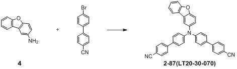
1구 250 mL 플라스크에 중간체(4) 2.8 g(15.3 mmol), 4'-브로모-[1.1'-비페닐]-4-카보니트릴(4'-bromo-[1.1'-biphenyl]-4-carbonitrile) 8.7 g(33.6 mmol), NaOtBu 4.4 g(45.8 mmol) 및 자일렌 150 mL를 넣고 교반하다가 Pd(dba)2 0.5 g(0.9 mmol), P(t-Bu)3 0.3 mL(1.2 mmol)를 첨가하고 가열 환류하에 하루종일 교반하였다. 반응이 종결되면 상온으로 냉각하고 용매를 날리고 클로로포름 500 mL로 셀라이트 패드에 통과시킨 후 감압 증류를 이용해 용매를 제거한다. 컬럼 크로마토그래피(Hex:CHCl3)로 정제하여 노란색 고체의 화합물 2-87(LT20-30-070) 2.5 g(수율: 30.4%)을 얻었다.In a 1-neck 250 mL flask, 2.8 g (15.3 mmol) of intermediate (4), 4'-bromo-[1.1'-biphenyl]-4-carbonitrile (4'-bromo-[1.1'-biphenyl]-4- carbonitrile) 8.7 g (33.6 mmol), NaO t Bu 4.4 g (45.8 mmol), and xylene 150 mL were added, stirred, and then Pd(dba) 2 0.5 g (0.9 mmol), P( t -Bu) 3 0.3 mL (1.2) mmol) and stirred under reflux under heating all day. Upon completion of the reaction, the reaction is cooled to room temperature, the solvent is blown off, and 500 mL of chloroform is passed through a celite pad, and then the solvent is removed by distillation under reduced pressure. It was purified by column chromatography (Hex:CHCl 3 ) to obtain 2.5 g (yield: 30.4%) of compound 2-87 (LT20-30-070) as a yellow solid.
실시예Example 14: 화합물 2-114(LT20-30-068)의 합성 14: Synthesis of compound 2-114 (LT20-30-068)

1구 250 mL 플라스크에 중간체(9) 4.7 g(8.3 mmol), 4-사이안화페닐보론산(4-Cyanophenylboronic acid) 3.6 g(24.8 mmol), Pd(dba)2 0.5 g(0.8 mmol), XPhos 0.8 g(1.7 mmol), 2M K3PO4 16 mL(33.0 mmol) 및 1,4-디옥산 40 mL를 넣고 85℃에서 2시간 동안 교반하였다. 상온에서 식힌 후 생성된 고체를 여과하였으며, 에탄올로 씻어주었다. 고체를 클로로포름(200 mL)으로 끓인 후 실리카겔 컬럼 크로마토그래피(CHCl3:HEX)를 통해 정제하였다. 얻어진 고체를 디클로로메탄으로 여과 및 아세톤으로 씻어주어 노란색 고체의 화합물 2-114(LT20-30-068) 2.9 g(수율: 58.3%)을 얻었다.In a 1-neck 250 mL flask, 4.7 g (8.3 mmol) of Intermediate (9), 3.6 g (24.8 mmol) of 4-Cyanophenylboronic acid, 0.5 g (0.8 mmol) of Pd(dba) 2 , XPhos 0.8 g (1.7 mmol), 2M K 3 PO 4 16 mL (33.0 mmol) and 1,4-dioxane 40 mL were added and stirred at 85° C. for 2 hours. After cooling to room temperature, the resulting solid was filtered and washed with ethanol. The solid was boiled with chloroform (200 mL) and purified through silica gel column chromatography (CHCl 3 :HEX). The obtained solid was filtered with dichloromethane and washed with acetone to obtain 2.9 g (yield: 58.3%) of compound 2-114 (LT20-30-068) as a yellow solid.
실시예Example 15: 화합물 2-117(LT20-30-260)의 합성 15: Synthesis of compound 2-117 (LT20-30-260)
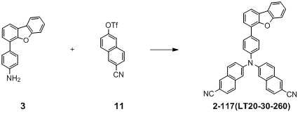
1구 250 mL 플라스크에 중간체(3) 5.0 g(19.3 mmol), 중간체(11) 12.2 g(40.5 mmol), Pd(dba)2 1.1 mg(1.9 mmol), 50% t-Bu3P 1.6 g(3.9 mmol), NaOtBu 5.6 g(57.9 mmol) 및 Xylene 80 mL를 넣고 혼합한 다음, 120℃에서 12시간 동안 반응하였다. 반응이 종결된 후 상온으로 냉각하고, 물을 넣고 클로로포름으로 추출한 후 감압 하에 용매를 제거하였다. 얻어진 화합물을 실리카겔 컬럼 크로마토그래피(Hex:EA)로 정제하고 아세톤에 녹인 후 메탄올을 천천히 적가하면서 고체화하여, 노란색 고체의 화합물 2-117(LT20-30-260) 1.5 g(수율: 13.8%)을 얻었다.In a one-necked 250 mL flask, 5.0 g (19.3 mmol) of Intermediate (3), 12.2 g (40.5 mmol) of Intermediate (11), 1.1 mg (1.9 mmol) of Pd(dba) 2 , 1.6 g of 50% t-Bu 3 P ( 3.9 mmol), NaOtBu 5.6 g (57.9 mmol), and 80 mL of Xylene were added and mixed, followed by reaction at 120° C. for 12 hours. After completion of the reaction, the mixture was cooled to room temperature, added with water, extracted with chloroform, and the solvent was removed under reduced pressure. The obtained compound was purified by silica gel column chromatography (Hex:EA), dissolved in acetone, and then solidified while slowly adding methanol dropwise to obtain 1.5 g (yield: 13.8%) of compound 2-117 (LT20-30-260) as a yellow solid. got it
실시예Example 16: 화합물 2-123(LT20-30-051)의 합성 16: Synthesis of compound 2-123 (LT20-30-051)
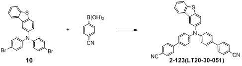
1구 250 mL 플라스크에 중간체(10) 4.6 g(9.0 mmol), 4-사이안화페닐보론산(4-Cyanophenylboronic acid) 4.0 g(27.1 mmol), Pd(dba)2 0.5 g(0.9 mmol), XPhos 0.9 g(1.8 mmol), 2M K3PO4 18 mL(36.1 mmol) 및 1,4-디옥산 45 mL를 넣고 85℃에서 2시간 동안 교반하였다. 상온에서 식힌 후 생성된 고체를 여과하였으며, 에탄올로 씻어주었다. 고체를 클로로포름으로 끓인 후 실리카겔 컬럼 크로마토그래피(CHCl3:HEX)를 통해 정제하였다. 얻어진 고체를 디클로로메탄으로 끓인 후 식혀서 여과 및 아세톤으로 씻어주어 노란색 고체의 화합물 2-123(LT20-30-051) 3.4 g(수율: 68.7%)을 얻었다.Intermediate (10) 4.6 g (9.0 mmol), 4-Cyanophenylboronic acid 4.0 g (27.1 mmol), Pd(dba) 2 0.5 g (0.9 mmol), XPhos in a 1-neck 250 mL flask 0.9 g (1.8 mmol), 2M K 3 PO 4 18 mL (36.1 mmol) and 1,4-dioxane 45 mL were added and stirred at 85° C. for 2 hours. After cooling to room temperature, the resulting solid was filtered and washed with ethanol. After boiling the solid with chloroform, it was purified by silica gel column chromatography (CHCl 3 :HEX). The obtained solid was boiled with dichloromethane, cooled, filtered and washed with acetone to obtain 3.4 g (yield: 68.7%) of compound 2-123 (LT20-30-051) as a yellow solid.
실시예Example 17: 화합물 2-153(LT20-35-365)의 합성 17: Synthesis of compound 2-153 (LT20-35-365)
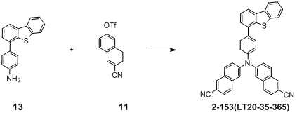
1구 250 mL 플라스크에 중간체(13) 5.0 g(18.2 mmol), 중간체(11) 11.5 g(38.1 mmol), Pd(dba)2 1.0 mg(1.8 mmol), 50% t-Bu3P 1.5 g(3.6 mmol), NaOtBu 5.2 g(54.5 mmol) 및 Xylene 80 mL를 넣고 혼합한 다음, 120℃에서 12시간 동안 반응하였다. 반응이 종결된 후 상온으로 냉각하고, 물을 넣고 클로로포름으로 추출한 후 감압 하에 용매를 제거하였다. 얻어진 화합물을 실리카겔 컬럼 크로마토그래피(Hex:EA)로 정제하고 아세톤에 녹인 후 메탄올을 천천히 적가하면서 고체화하여, 노란색 고체의 화합물 2-153(LT20-35-365) 1.1 g(수율: 10.5%)을 얻었다.In a one-necked 250 mL flask, 5.0 g (18.2 mmol) of Intermediate (13), 11.5 g (38.1 mmol) of Intermediate (11), 1.0 mg (1.8 mmol) of Pd(dba) 2 , 1.5 g of 50% t-Bu 3 P ( 3.6 mmol), NaOtBu 5.2 g (54.5 mmol) and Xylene 80 mL were added and mixed, followed by reaction at 120° C. for 12 hours. After completion of the reaction, the mixture was cooled to room temperature, added with water, extracted with chloroform, and the solvent was removed under reduced pressure. The obtained compound was purified by silica gel column chromatography (Hex:EA), dissolved in acetone, and then solidified while slowly adding methanol dropwise to obtain 1.1 g of compound 2-153 (LT20-35-365) as a yellow solid (yield: 10.5%) got it
<시험예><Test Example>
본 발명의 화합물에 대하여 J.A. WOOLLAM社 Ellipsometer 기기를 이용하여 광학 특성 평가용 단막의 n(refractive index)와 k(extinction coefficient)을 측정한다.For the compounds of the present invention J.A. Measure n (refractive index) and k (extinction coefficient) of a single film for optical property evaluation using WOOLLAM's Ellipsometer device.
광학 특성 평가용 단막 제작 : Fabrication of single film for evaluation of optical properties:
화합물의 광학 특성 측정을 위해, 유리기판(0.7T)을 Ethanol, DI Water, Acetone에 각각 10분씩 세척한 후, 2×10- 2Torr에서 125 W로 2분간 유리기판 위에 산소 플라즈마 처리하고 9×10- 7Torr의 진공도에서 1Å/sec의 속도로 유리기판 위에 화합물을 800Å 증착하여 단막을 제작한다. To measure the optical properties of the compound, the glass substrate (0.7T) was washed with Ethanol, DI Water, and Acetone for 10 minutes each, and then treated with oxygen plasma on the glass substrate at 2×10 - 2 Torr at 125 W for 2 minutes and then with 9× A single film is fabricated by depositing 800 Å of the compound on a glass substrate at a rate of 1 Å/sec in a vacuum of 10 - 7 Torr.
비교시험예 : Comparative test example:
상기 광학 특성 평가용 단막 제작에서 화합물로 REF01을 사용하였다. REF01 was used as a compound in the production of the single film for evaluation of optical properties.
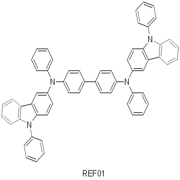
< 시험예 1 내지 17 >< Test Examples 1 to 17 >
상기 비교시험예에서, REF01을 이용하는 대신에 하기 표 1에 나타낸 각각의 화합물을 사용한 것을 제외하고는 상기 비교 시험예와 동일한 방법으로 단막을 제작하였다.In the comparative test example, a single membrane was manufactured in the same manner as in the comparative test example, except that each compound shown in Table 1 was used instead of using REF01.
상기 비교시험예 및 시험예 1 내지 17에 의한 화합물의 광학 특성을 표 1에 나타냈다.Table 1 shows the optical properties of the compounds according to the Comparative Test Examples and Test Examples 1 to 17.
광학 특성은 450nm 및 620nm 파장에서 굴절률 상수와 380nm 파장에서의 흡수율 상수이다.The optical properties are the refractive index constants at 450 nm and 620 nm wavelengths and the absorption coefficient constants at 380 nm wavelengths.
(LT19-35-308)2-4
(LT19-35-308)
(LT19-30-224)2-5
(LT19-30-224)
(LT19-30-192)2-9
(LT19-30-192)
(LT18-30-239)2-13
(LT18-30-239)
(LT19-35-305)2-14
(LT19-35-305)
(LT19-35-312)2-21
(LT19-35-312)
(LT19-30-286)2-27
(LT19-30-286)
(LT19-30-259)2-29
(LT19-30-259)
(LT19-30-278)2-36
(LT19-30-278)
(LT19-30-218)2-40
(LT19-30-218)
(LT19-30-199)2-44
(LT19-30-199)
(LT18-30-263)2-48
(LT18-30-263)
(LT20-30-070)2-87
(LT20-30-070)
(LT20-30-068)2-114
(LT20-30-068)
(LT20-30-260)2-117
(LT20-30-260)
(LT20-30-051)2-123
(LT20-30-051)
(LT20-35-365)2-153
(LT20-35-365)
상기 표 1에서 알 수 있는 바와 같이, 비교시험예(REF01)의 청색영역(450nm)과 적색영역(620nm)에서의 n값이 각각 2.000, 1.846 이었고, 이에 반해 대부분의 본 발명에 따른 화합물들은 대체적으로 청색영역, 녹색영역 및 적색영역에서 비교시험예 화합물(REF01) 보다 높은 굴절률을 갖는 것으로 확인되었다. 이것은 청색영역에서의 높은 시야각을 확보하기 위해 필요한 높은 굴절률 값에 만족한다. As can be seen from Table 1, n values in the blue region (450 nm) and the red region (620 nm) of Comparative Test Example (REF01) were 2.000 and 1.846, respectively, whereas most of the compounds according to the present invention were generally As a result, it was confirmed to have a higher refractive index than that of Comparative Test Example compound (REF01) in the blue region, the green region and the red region. This satisfies the high refractive index value required to secure a high viewing angle in the blue region.
또한 UV영역의 시작단계에 해당하는 380nm에서의 k값 또한 대부분의 실시예 화합물들이 높은 것으로 확인되었다. 이는, UV영역의 고에너지 외부광원을 효과적으로 흡수하여 유기 발광 소자 내부의 유기물들의 손상을 최소화시킴으로써 유기 전계 발광 소자의 실질적인 수명 향상에 기여할 수 있을 것이다.In addition, it was confirmed that the k value at 380 nm corresponding to the starting stage of the UV region was also high for most of the example compounds. This will effectively absorb a high energy external light source in the UV region to minimize damage to organic materials inside the organic light emitting device, thereby contributing to the substantial improvement of the lifespan of the organic light emitting device.
<실시예><Example>
소자 제작device fabrication
소자 제작을 위해 투명 전극인 ITO는 양극 층으로 사용하였고, 2-TNATA는 정공 주입층, NPB는 정공 수송층, αβ-ADN은 발광층의 호스트, Pyene-CN은 청색 형광 도판트, Liq는 전자 주입층, Mg:Ag은 음극으로 사용하였다. 이 화합물들의 구조는 하기의 화학식과 같다.For device fabrication, ITO, a transparent electrode, was used as the anode layer, 2-TNATA for the hole injection layer, NPB for the hole transport layer, αβ-ADN for the host of the emission layer, Pyene-CN for the blue fluorescent dopant, and Liq for the electron injection layer. , Mg:Ag was used as the negative electrode. The structures of these compounds are as follows.

비교실시예 : ITO / 2-TNATA(60 nm) / NPB(20 nm) / αβ-ADN:10% Pyrene-CN(30 nm) / Alq3(30 nm) / Liq(2 nm) / Mg:Ag(1:9, 10 nm) / REF01(60nm)Comparative Example: ITO / 2-TNATA (60 nm) / NPB (20 nm) / αβ-ADN: 10% Pyrene-CN (30 nm) / Alq 3 (30 nm) / Liq (2 nm) / Mg: Ag (1:9, 10 nm) / REF01 (60 nm)
청색 형광 유기발광소자는 ITO(180 nm) / 2-TNATA (60 nm) / NPB (20 nm) / αβ-ADN:Pyrene-CN 10% (30 nm) / Alq3 (30 nm) / Liq (2 nm) / Mg:Ag (1:9, 10 nm) / REF(60nm) 순으로 증착하여 소자를 제작하였다. 유기물을 증착하기 전에 ITO 전극은 2 × 10- 2Torr에서 125W로 2분간 산소 플라즈마 처리를 하였다. 유기물은 9 × 10- 7Torr의 진공도에서 증착하였으며, Liq는 0.1 Å/sec, αβ-ADN은 0.18 Å/sec의 기준으로 Pyrene-CN는 0.02 Å/sec으로 동시 증착하였고, 나머지 유기물들은 모두 1 Å/sec의 속도로 증착하였다. 실험에 사용된 캡핑층 물질은 REF01로 선택하였다. 소자 제작이 끝난 후 소자의 공기 및 수분의 접촉을 막기 위하여 질소 기체로 채워져 있는 글러브 박스 안에서 봉지를 하였다. 3M사의 접착용 테이프로 격벽을 형성 후 수분 등을 제거할 수 있는 흡습제인 바륨산화물(Barium Oxide)을 넣고 유리판을 붙였다.Blue fluorescence organic light emitting diode ITO (180 nm) / 2-TNATA (60 nm) / NPB (20 nm) / αβ-ADN:Pyrene-CN 10% (30 nm) / Alq 3 (30 nm) / Liq (2 nm) / Mg:Ag (1:9, 10 nm) / REF (60 nm) by deposition in the order to fabricate a device. Before depositing the organic material, the ITO electrode was subjected to oxygen plasma treatment at 2 × 10 - 2 Torr at 125 W for 2 minutes. Organic materials were deposited at a vacuum degree of 9 × 10 - 7 Torr, Liq was 0.1 Å/sec, αβ-ADN was 0.18 Å/sec, and Pyrene-CN was simultaneously deposited at 0.02 Å/sec, and the remaining organic materials were all 1 Deposited at a rate of Å/sec. The capping layer material used in the experiment was selected as REF01. After the device was manufactured, it was encapsulated in a glove box filled with nitrogen gas to prevent the device from contacting air and moisture. After forming the barrier with 3M's adhesive tape, barium oxide, a moisture absorbent that can remove moisture, was added and a glass plate was attached.

< 실시예 1 내지 17 >< Examples 1 to 17 >
상기 비교실시예에서, REF01을 이용하는 대신에 하기 표 2에 나타낸 각각의 화합물을 사용한 것을 제외하고는 상기 비교실시예와 동일한 방법으로 소자를 제작하였다.In the comparative example, a device was manufactured in the same manner as in the comparative example, except that each compound shown in Table 2 was used instead of REF01.
상기 비교실시예 및 실시예 1 내지 17에서 제조된 유기 발광 소자에 대한 전기적 발광특성을 표 2에 나타냈다. Table 2 shows the electroluminescence characteristics of the organic light emitting devices prepared in Comparative Examples and Examples 1 to 17.
(LT19-35-308)2-4
(LT19-35-308)
(LT19-30-224)2-5
(LT19-30-224)
(LT19-30-192)2-9
(LT19-30-192)
(LT18-30-239)2-13
(LT18-30-239)
(LT19-35-305)2-14
(LT19-35-305)
(LT19-35-312)2-21
(LT19-35-312)
(LT19-30-286)2-27
(LT19-30-286)
(LT19-30-259)2-29
(LT19-30-259)
(LT19-30-278)2-36
(LT19-30-278)
(LT19-30-218)2-40
(LT19-30-218)
(LT19-30-199)2-44
(LT19-30-199)
(LT18-30-263)2-48
(LT18-30-263)
(LT20-30-070)2-87
(LT20-30-070)
(LT20-30-068)2-114
(LT20-30-068)
(LT20-30-260)2-117
(LT20-30-260)
(LT20-30-051)2-123
(LT20-30-051)
(LT20-35-365)2-153
(LT20-35-365)
상기 표 2의 결과로부터, 본 발명에 따른 특정의 3차 아민 유도체 화합물은 유기 발광 소자를 비롯한 유기 전자 소자의 캡핑층의 재료로서 사용될 수 있고, 이를 이용한 유기 발광 소자를 비롯한 유기 전자 소자는 효율, 구동전압, 안정성 등에서 우수한 특성을 나타냄을 알 수 있다. 특히, 본 발명에 따른 화합물은 미소공동현상(Micro-cavity)의 능력이 우수하여 높은 효율 특성을 나타냈다.From the results of Table 2 above, a specific tertiary amine derivative compound according to the present invention can be used as a material for a capping layer of an organic electronic device including an organic light emitting device, and an organic electronic device including an organic light emitting device using the same has efficiency, It can be seen that it exhibits excellent characteristics such as driving voltage and stability. In particular, the compound according to the present invention exhibited high efficiency characteristics due to excellent micro-cavity ability.
화학식 1의 화합물은 OLED에서 캡핑층으로 사용하기 위한 의외의 바람직한 특성을 가지고 있다. The compound of
본 발명의 화합물이 이러한 특성에 의해 산업용 유기 전자 소자 제품에 적용될 수 있다.The compound of the present invention can be applied to industrial organic electronic device products due to these properties.
다만, 전술한 합성예는 일 예시이며, 반응 조건은 필요에 따라 변경될 수 있다. 또한, 본 발명의 일 실시예에 따른 화합물은 당 기술분야에 알려진 방법 및 재료를 이용하여 다양한 치환기를 가지도록 합성될 수 있다. 화학식 1로 표시되는 코어 구조에 다양한 치환체를 도입함으로써 유기 전계 발광 소자에 사용되기에 적합한 특성을 가질 수 있다. However, the above-described synthesis example is an example, and the reaction conditions may be changed as needed. In addition, the compound according to an embodiment of the present invention may be synthesized to have various substituents using methods and materials known in the art. By introducing various substituents into the core structure represented by
100: 기판, 110: 제1 전극, 120: 제2 전극, 200: 유기물층, 210: 정공주입층, 215: 정공수송층, 220: 발광층, 230: 전자수송층, 235: 전자주입층, 300: 캡핑층 100: substrate, 110: first electrode, 120: second electrode, 200: organic material layer, 210: hole injection layer, 215: hole transport layer, 220: light emitting layer, 230: electron transport layer, 235: electron injection layer, 300: capping layer
Claims (3)
[화학식 1]

Z1는 O 또는 S이며,
n, p 및 q는 각각 독립적으로 0 또는 1이고,
Ar1 및 Ar2는 서로 동일하며, 시아노기; 시아노기가 치환된 아릴기; 치환 또는 비치환된 벤즈옥사졸기; 및 치환 또는 비치환된 벤즈티아졸기; 중에서 선택되는 어느 하나이다. A tertiary amine derivative for a capping layer of an organic electroluminescent device, represented by the following formula (1).
[Formula 1]
Z 1 is O or S;
n, p and q are each independently 0 or 1,
Ar 1 and Ar 2 are the same as each other, and a cyano group; an aryl group substituted with a cyano group; a substituted or unsubstituted benzoxazole group; and a substituted or unsubstituted benzthiazole group; any one selected from
상기 화학식 1은 하기 화학식 2로 표시되는 화합물들 중에서 선택되는 유기 전계 발광 소자의 캡핑층 용 3차 아민 유도체.
[화학식 2]
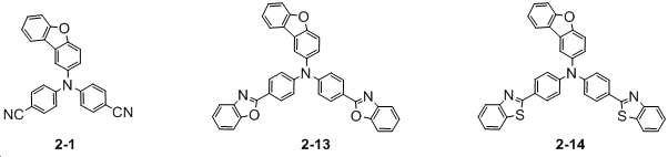
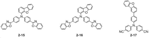


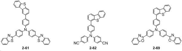

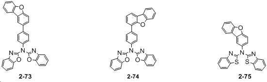

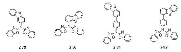


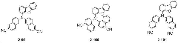


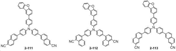
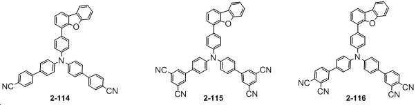
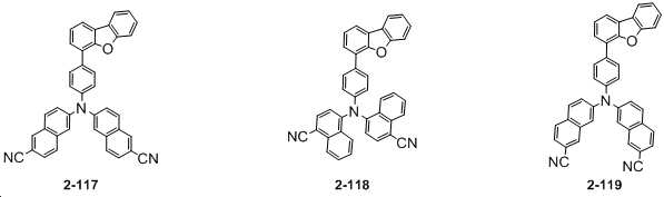

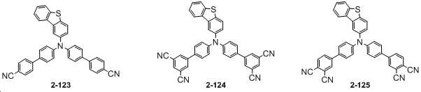
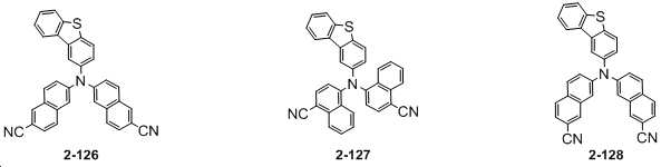

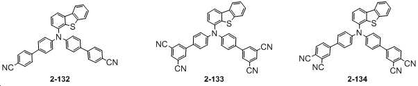


The method of claim 1,
Formula 1 is a tertiary amine derivative for a capping layer of an organic electroluminescent device selected from compounds represented by Formula 2 below.
[Formula 2]
상기 제1 전극 상에 배치된, 복수의 유기물층으로 구성된 유기물층;
상기 유기물층 상에 배치된 제2 전극; 및
상기 제2 전극 상에 배치된 캡핑층;을 포함하고,
상기 캡핑층은 상기 제 1항 또는 제 2항의 3차 아민 유도체를 포함하는 유기 전계 발광 소자. a first electrode;
an organic material layer formed of a plurality of organic material layers disposed on the first electrode;
a second electrode disposed on the organic material layer; and
a capping layer disposed on the second electrode; and
The capping layer is an organic electroluminescent device comprising the tertiary amine derivative of claim 1 or 2.
Priority Applications (2)
| Application Number | Priority Date | Filing Date | Title |
|---|---|---|---|
| CN202080076161.2A CN114641469A (en) | 2019-10-31 | 2020-08-18 | Tertiary amine derivative and organic electroluminescent element comprising same |
| PCT/KR2020/010960 WO2021085817A2 (en) | 2019-10-31 | 2020-08-18 | Tertiary amine derivative and organic electroluminescent device comprising same |
Applications Claiming Priority (2)
| Application Number | Priority Date | Filing Date | Title |
|---|---|---|---|
| KR20190137084 | 2019-10-31 | ||
| KR1020190137084 | 2019-10-31 |
Publications (2)
| Publication Number | Publication Date |
|---|---|
| KR20210052171A KR20210052171A (en) | 2021-05-10 |
| KR102417622B1 true KR102417622B1 (en) | 2022-07-06 |
Family
ID=75918555
Family Applications (1)
| Application Number | Title | Priority Date | Filing Date |
|---|---|---|---|
| KR1020200065216A Active KR102417622B1 (en) | 2019-10-31 | 2020-05-29 | Tertiary amine derivatives and organic electroluminescent device including the same |
Country Status (1)
| Country | Link |
|---|---|
| KR (1) | KR102417622B1 (en) |
Families Citing this family (1)
| Publication number | Priority date | Publication date | Assignee | Title |
|---|---|---|---|---|
| JP7732986B2 (en) * | 2020-07-03 | 2025-09-02 | 保土谷化学工業株式会社 | organic electroluminescence element |
Family Cites Families (4)
| Publication number | Priority date | Publication date | Assignee | Title |
|---|---|---|---|---|
| CN104884444B (en) * | 2012-12-26 | 2018-07-03 | 出光兴产株式会社 | Oxygen-containing fused ring amine compound, sulfur-containing fused ring amine compound, and organic electroluminescent element |
| KR101788366B1 (en) | 2014-11-24 | 2017-10-20 | 삼성디스플레이 주식회사 | Organic light emitting diode display compring capping layer having high refractive index |
| KR102851400B1 (en) * | 2016-03-03 | 2025-08-29 | 메르크 파텐트 게엠베하 | Materials for organic electroluminescent devices |
| KR102528355B1 (en) * | 2016-05-11 | 2023-05-03 | 삼성디스플레이 주식회사 | Organic light emitting diode and light emitting device including the same |
-
2020
- 2020-05-29 KR KR1020200065216A patent/KR102417622B1/en active Active
Also Published As
| Publication number | Publication date |
|---|---|
| KR20210052171A (en) | 2021-05-10 |
Similar Documents
| Publication | Publication Date | Title |
|---|---|---|
| KR102060645B1 (en) | Tertiary amine derivatives and organic electroluminescent device including the same | |
| KR102099171B1 (en) | Aryl amine derivatieves and organic electroluminescent device including the same | |
| KR102059550B1 (en) | Tribenzazole amine derivatives and organic electroluminescent device including the same | |
| KR102517278B1 (en) | Triazine or Pyrimidine derivatives, and organic electroluminescent device including the same | |
| KR102838927B1 (en) | Benzazole derivatives and organic electroluminescent device including the same | |
| KR102612519B1 (en) | Organic compounds and organic electroluminescent device including the same | |
| KR102517277B1 (en) | Cyano-group substituted aryl or heteroaryl derivatives and organic electroluminescent device including the same | |
| KR102554038B1 (en) | Organic compounds and organic electroluminescent device including the same | |
| KR102748733B1 (en) | Benzazole derivatives and organic electroluminescent device including the same | |
| KR102252493B1 (en) | Benzazole derivatives and organic electroluminescent device including the same | |
| KR20230028821A (en) | Heteroaryl amine derivatives substituted with cyano group and organic electroluminescent device including the same | |
| KR20220030385A (en) | Anthracene, Triphenylene derivatives and organic electroluminescent device including the same | |
| KR102443601B1 (en) | Tertiary amine derivatives and organic electroluminescent device including the same | |
| KR20250084996A (en) | Heteroaryl amine derivatives and organic electroluminescent device including the same | |
| KR20230025723A (en) | cyano group-substituted carbazole derivatives and organic electroluminescent device including the same | |
| CN114641469A (en) | Tertiary amine derivative and organic electroluminescent element comprising same | |
| KR102460493B1 (en) | Dibenzo five-membered ring compounds and organic electroluminescent device including the same | |
| KR102470622B1 (en) | Tertiary amine derivatives and organic electroluminescent device including the same | |
| KR102417622B1 (en) | Tertiary amine derivatives and organic electroluminescent device including the same | |
| KR102274482B1 (en) | Heteroaryl derivatives and organic electroluminescent device including the same | |
| KR102261704B1 (en) | Tertiary amine derivatives and organic electroluminescent device including the same | |
| KR20190082052A (en) | Aryl amine derivatieves and organic electroluminescent device including the same | |
| KR20220050764A (en) | High refractive benzazole derivatives and organic electroluminescent device including the same | |
| KR20230020069A (en) | Tertiary amine derivatives and organic electroluminescent device including the same | |
| KR20230028648A (en) | Tertiary amine derivatives and organic electroluminescent device including the same |
Legal Events
| Date | Code | Title | Description |
|---|---|---|---|
| PA0109 | Patent application |
Patent event code: PA01091R01D Comment text: Patent Application Patent event date: 20200529 |
|
| PA0201 | Request for examination | ||
| PG1501 | Laying open of application | ||
| E902 | Notification of reason for refusal | ||
| PE0902 | Notice of grounds for rejection |
Comment text: Notification of reason for refusal Patent event date: 20211129 Patent event code: PE09021S01D |
|
| E701 | Decision to grant or registration of patent right | ||
| PE0701 | Decision of registration |
Patent event code: PE07011S01D Comment text: Decision to Grant Registration Patent event date: 20220628 |
|
| PR0701 | Registration of establishment |
Comment text: Registration of Establishment Patent event date: 20220701 Patent event code: PR07011E01D |
|
| PR1002 | Payment of registration fee |
Payment date: 20220701 End annual number: 3 Start annual number: 1 |
|
| PG1601 | Publication of registration | ||
| PR1001 | Payment of annual fee |
Payment date: 20250616 Start annual number: 4 End annual number: 4 |