KR102405432B1 - Adaptive timing synchronization for reception of bursty and continuous signals - Google Patents
Adaptive timing synchronization for reception of bursty and continuous signals Download PDFInfo
- Publication number
- KR102405432B1 KR102405432B1 KR1020207011132A KR20207011132A KR102405432B1 KR 102405432 B1 KR102405432 B1 KR 102405432B1 KR 1020207011132 A KR1020207011132 A KR 1020207011132A KR 20207011132 A KR20207011132 A KR 20207011132A KR 102405432 B1 KR102405432 B1 KR 102405432B1
- Authority
- KR
- South Korea
- Prior art keywords
- power
- information
- sample
- signal
- derived
- Prior art date
- Legal status (The legal status is an assumption and is not a legal conclusion. Google has not performed a legal analysis and makes no representation as to the accuracy of the status listed.)
- Active
Links
- 230000003044 adaptive effect Effects 0.000 title description 5
- 238000000034 method Methods 0.000 claims abstract description 196
- 230000006978 adaptation Effects 0.000 claims abstract description 28
- 230000005540 biological transmission Effects 0.000 claims description 107
- 238000001514 detection method Methods 0.000 claims description 68
- 238000012935 Averaging Methods 0.000 claims description 50
- 238000012545 processing Methods 0.000 claims description 47
- 230000008569 process Effects 0.000 claims description 35
- 230000002123 temporal effect Effects 0.000 claims description 22
- 230000011664 signaling Effects 0.000 claims description 21
- 238000001914 filtration Methods 0.000 claims description 18
- 238000012937 correction Methods 0.000 claims description 11
- 230000007704 transition Effects 0.000 claims description 11
- 238000005516 engineering process Methods 0.000 claims description 9
- 230000004913 activation Effects 0.000 claims description 8
- 238000004458 analytical method Methods 0.000 claims description 8
- 238000011156 evaluation Methods 0.000 claims description 5
- 230000008093 supporting effect Effects 0.000 claims description 5
- 238000009795 derivation Methods 0.000 claims description 3
- 238000009499 grossing Methods 0.000 claims description 2
- 239000000523 sample Substances 0.000 description 269
- 238000005286 illumination Methods 0.000 description 56
- 238000007710 freezing Methods 0.000 description 38
- 230000008014 freezing Effects 0.000 description 38
- 238000009432 framing Methods 0.000 description 29
- 238000005070 sampling Methods 0.000 description 27
- 238000004891 communication Methods 0.000 description 17
- 238000013459 approach Methods 0.000 description 13
- 238000004590 computer program Methods 0.000 description 11
- 230000004044 response Effects 0.000 description 11
- 230000006870 function Effects 0.000 description 10
- 230000000630 rising effect Effects 0.000 description 9
- 238000004422 calculation algorithm Methods 0.000 description 7
- 238000004364 calculation method Methods 0.000 description 7
- 230000000875 corresponding effect Effects 0.000 description 7
- 235000019580 granularity Nutrition 0.000 description 7
- 230000001965 increasing effect Effects 0.000 description 6
- 238000012795 verification Methods 0.000 description 6
- 238000005259 measurement Methods 0.000 description 5
- 238000005457 optimization Methods 0.000 description 5
- 230000008901 benefit Effects 0.000 description 4
- 230000008859 change Effects 0.000 description 4
- 238000010295 mobile communication Methods 0.000 description 4
- 238000010200 validation analysis Methods 0.000 description 4
- 238000003708 edge detection Methods 0.000 description 3
- 230000000694 effects Effects 0.000 description 3
- 238000013213 extrapolation Methods 0.000 description 3
- 238000012986 modification Methods 0.000 description 3
- 230000004048 modification Effects 0.000 description 3
- 238000007493 shaping process Methods 0.000 description 3
- 238000012360 testing method Methods 0.000 description 3
- 239000000872 buffer Substances 0.000 description 2
- 230000002596 correlated effect Effects 0.000 description 2
- 230000003111 delayed effect Effects 0.000 description 2
- 230000001976 improved effect Effects 0.000 description 2
- 230000006872 improvement Effects 0.000 description 2
- 238000011835 investigation Methods 0.000 description 2
- 238000012797 qualification Methods 0.000 description 2
- 230000001360 synchronised effect Effects 0.000 description 2
- 238000012546 transfer Methods 0.000 description 2
- 238000012952 Resampling Methods 0.000 description 1
- 230000003213 activating effect Effects 0.000 description 1
- 230000003321 amplification Effects 0.000 description 1
- 238000003491 array Methods 0.000 description 1
- 238000006243 chemical reaction Methods 0.000 description 1
- 230000000295 complement effect Effects 0.000 description 1
- 230000001143 conditioned effect Effects 0.000 description 1
- 230000001276 controlling effect Effects 0.000 description 1
- 238000002790 cross-validation Methods 0.000 description 1
- 230000009849 deactivation Effects 0.000 description 1
- 230000003247 decreasing effect Effects 0.000 description 1
- 238000012217 deletion Methods 0.000 description 1
- 230000037430 deletion Effects 0.000 description 1
- 238000010586 diagram Methods 0.000 description 1
- 230000002708 enhancing effect Effects 0.000 description 1
- 230000037433 frameshift Effects 0.000 description 1
- 230000007274 generation of a signal involved in cell-cell signaling Effects 0.000 description 1
- PCHJSUWPFVWCPO-UHFFFAOYSA-N gold Chemical compound [Au] PCHJSUWPFVWCPO-UHFFFAOYSA-N 0.000 description 1
- 239000010931 gold Substances 0.000 description 1
- 229910052737 gold Inorganic materials 0.000 description 1
- 238000003780 insertion Methods 0.000 description 1
- 230000037431 insertion Effects 0.000 description 1
- 239000012464 large buffer Substances 0.000 description 1
- 230000007246 mechanism Effects 0.000 description 1
- 230000006855 networking Effects 0.000 description 1
- 238000003199 nucleic acid amplification method Methods 0.000 description 1
- 230000000737 periodic effect Effects 0.000 description 1
- 230000007420 reactivation Effects 0.000 description 1
- 230000003252 repetitive effect Effects 0.000 description 1
- 238000004088 simulation Methods 0.000 description 1
- 230000001960 triggered effect Effects 0.000 description 1
Images


Classifications
-
- H—ELECTRICITY
- H04—ELECTRIC COMMUNICATION TECHNIQUE
- H04L—TRANSMISSION OF DIGITAL INFORMATION, e.g. TELEGRAPHIC COMMUNICATION
- H04L7/00—Arrangements for synchronising receiver with transmitter
- H04L7/0079—Receiver details
- H04L7/0083—Receiver details taking measures against momentary loss of synchronisation, e.g. inhibiting the synchronisation, using idle words or using redundant clocks
-
- H—ELECTRICITY
- H03—ELECTRONIC CIRCUITRY
- H03L—AUTOMATIC CONTROL, STARTING, SYNCHRONISATION OR STABILISATION OF GENERATORS OF ELECTRONIC OSCILLATIONS OR PULSES
- H03L7/00—Automatic control of frequency or phase; Synchronisation
- H03L7/06—Automatic control of frequency or phase; Synchronisation using a reference signal applied to a frequency- or phase-locked loop
- H03L7/08—Details of the phase-locked loop
- H03L7/10—Details of the phase-locked loop for assuring initial synchronisation or for broadening the capture range
- H03L7/107—Details of the phase-locked loop for assuring initial synchronisation or for broadening the capture range using a variable transfer function for the loop, e.g. low pass filter having a variable bandwidth
- H03L7/1075—Details of the phase-locked loop for assuring initial synchronisation or for broadening the capture range using a variable transfer function for the loop, e.g. low pass filter having a variable bandwidth by changing characteristics of the loop filter, e.g. changing the gain, changing the bandwidth
-
- H—ELECTRICITY
- H04—ELECTRIC COMMUNICATION TECHNIQUE
- H04B—TRANSMISSION
- H04B1/00—Details of transmission systems, not covered by a single one of groups H04B3/00 - H04B13/00; Details of transmission systems not characterised by the medium used for transmission
- H04B1/06—Receivers
- H04B1/10—Means associated with receiver for limiting or suppressing noise or interference
- H04B1/1027—Means associated with receiver for limiting or suppressing noise or interference assessing signal quality or detecting noise/interference for the received signal
-
- H—ELECTRICITY
- H04—ELECTRIC COMMUNICATION TECHNIQUE
- H04B—TRANSMISSION
- H04B7/00—Radio transmission systems, i.e. using radiation field
- H04B7/14—Relay systems
- H04B7/15—Active relay systems
- H04B7/204—Multiple access
- H04B7/2041—Spot beam multiple access
-
- H—ELECTRICITY
- H04—ELECTRIC COMMUNICATION TECHNIQUE
- H04L—TRANSMISSION OF DIGITAL INFORMATION, e.g. TELEGRAPHIC COMMUNICATION
- H04L25/00—Baseband systems
- H04L25/02—Details ; arrangements for supplying electrical power along data transmission lines
- H04L25/03—Shaping networks in transmitter or receiver, e.g. adaptive shaping networks
- H04L25/03006—Arrangements for removing intersymbol interference
- H04L25/03012—Arrangements for removing intersymbol interference operating in the time domain
- H04L25/03019—Arrangements for removing intersymbol interference operating in the time domain adaptive, i.e. capable of adjustment during data reception
- H04L25/03057—Arrangements for removing intersymbol interference operating in the time domain adaptive, i.e. capable of adjustment during data reception with a recursive structure
-
- H—ELECTRICITY
- H04—ELECTRIC COMMUNICATION TECHNIQUE
- H04L—TRANSMISSION OF DIGITAL INFORMATION, e.g. TELEGRAPHIC COMMUNICATION
- H04L7/00—Arrangements for synchronising receiver with transmitter
- H04L7/0004—Initialisation of the receiver
-
- H—ELECTRICITY
- H04—ELECTRIC COMMUNICATION TECHNIQUE
- H04L—TRANSMISSION OF DIGITAL INFORMATION, e.g. TELEGRAPHIC COMMUNICATION
- H04L7/00—Arrangements for synchronising receiver with transmitter
- H04L7/0016—Arrangements for synchronising receiver with transmitter correction of synchronization errors
- H04L7/002—Arrangements for synchronising receiver with transmitter correction of synchronization errors correction by interpolation
- H04L7/0029—Arrangements for synchronising receiver with transmitter correction of synchronization errors correction by interpolation interpolation of received data signal
-
- H—ELECTRICITY
- H04—ELECTRIC COMMUNICATION TECHNIQUE
- H04L—TRANSMISSION OF DIGITAL INFORMATION, e.g. TELEGRAPHIC COMMUNICATION
- H04L7/00—Arrangements for synchronising receiver with transmitter
- H04L7/0054—Detection of the synchronisation error by features other than the received signal transition
- H04L7/0062—Detection of the synchronisation error by features other than the received signal transition detection of error based on data decision error, e.g. Mueller type detection
-
- H—ELECTRICITY
- H04—ELECTRIC COMMUNICATION TECHNIQUE
- H04L—TRANSMISSION OF DIGITAL INFORMATION, e.g. TELEGRAPHIC COMMUNICATION
- H04L7/00—Arrangements for synchronising receiver with transmitter
- H04L7/0079—Receiver details
-
- H—ELECTRICITY
- H04—ELECTRIC COMMUNICATION TECHNIQUE
- H04W—WIRELESS COMMUNICATION NETWORKS
- H04W52/00—Power management, e.g. Transmission Power Control [TPC] or power classes
- H04W52/02—Power saving arrangements
- H04W52/0209—Power saving arrangements in terminal devices
- H04W52/0225—Power saving arrangements in terminal devices using monitoring of external events, e.g. the presence of a signal
- H04W52/0245—Power saving arrangements in terminal devices using monitoring of external events, e.g. the presence of a signal according to signal strength
-
- H—ELECTRICITY
- H04—ELECTRIC COMMUNICATION TECHNIQUE
- H04B—TRANSMISSION
- H04B7/00—Radio transmission systems, i.e. using radiation field
- H04B7/14—Relay systems
- H04B7/15—Active relay systems
- H04B7/204—Multiple access
-
- Y—GENERAL TAGGING OF NEW TECHNOLOGICAL DEVELOPMENTS; GENERAL TAGGING OF CROSS-SECTIONAL TECHNOLOGIES SPANNING OVER SEVERAL SECTIONS OF THE IPC; TECHNICAL SUBJECTS COVERED BY FORMER USPC CROSS-REFERENCE ART COLLECTIONS [XRACs] AND DIGESTS
- Y02—TECHNOLOGIES OR APPLICATIONS FOR MITIGATION OR ADAPTATION AGAINST CLIMATE CHANGE
- Y02D—CLIMATE CHANGE MITIGATION TECHNOLOGIES IN INFORMATION AND COMMUNICATION TECHNOLOGIES [ICT], I.E. INFORMATION AND COMMUNICATION TECHNOLOGIES AIMING AT THE REDUCTION OF THEIR OWN ENERGY USE
- Y02D30/00—Reducing energy consumption in communication networks
- Y02D30/70—Reducing energy consumption in communication networks in wireless communication networks
Landscapes
- Engineering & Computer Science (AREA)
- Computer Networks & Wireless Communication (AREA)
- Signal Processing (AREA)
- Power Engineering (AREA)
- Mobile Radio Communication Systems (AREA)
- Synchronisation In Digital Transmission Systems (AREA)
Abstract
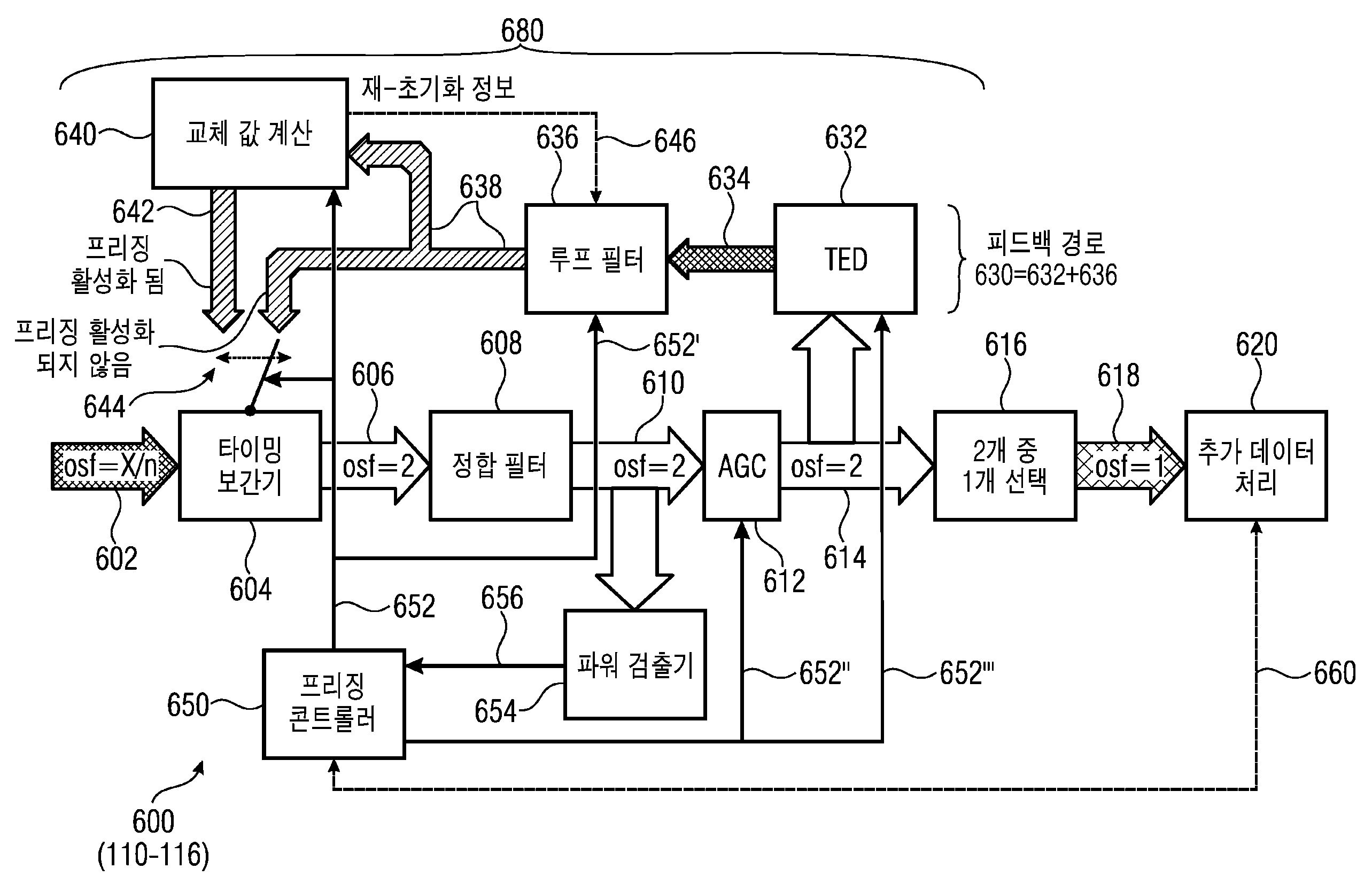
수신기들, 콘트롤러 유닛들(예를 들어, 수신기들을 위한) 및 관련 방법(예를 들어, 수신기들을 위한)의 예가 제공된다. 다음을 포함하는 하나의 수신기가 제공된다: 조정가능 샘플 타이밍을 사용하는 입력 신호의 샘플들을 제공하도록 구성된 조정가능 샘플 제공자(adjustable sample provider)(604); 타이밍 에러 정보(634)에 기초하여 상기 조정가능 샘플 제공자(604)에 피드백 신호(feedback signal)를 제공하도록 구성된 피드백 경로(feedback path)(630) - 상기 피드백 경로(630)는 상기 조정가능 샘플 제공자(604)에 샘플 타이밍 정보(638)를 제공하도록 구성되는 루프 필터(636)을 포함함 -; 및 입력 신호가 피드백 기반 샘플 타이밍 적응(feedback-based sample timing adaptation)을 위한 미리 결정된 요구사항을 달성하지 않을 때 피드백 경로(630)에 의해 제공된 상기 샘플 타이밍 정보(638)를 교체하는 교체 샘플 타이밍 정보(replacement sample timing information)(642)를 제공하도록 구성된 교체 값 제공자(replacement value provider)(640)를 포함하고, 상기 교체 값 제공자(640)는 상기 샘플 타이밍 정보(638)의 제공을 위한 상기 루프 필터(636)에 의해 고려되는 시간 주기와 비교할 때 더 긴 시간 주기에 걸쳐, 상기 타이밍 에러 정보(634)로부터 도출된 양(quantity), 또는 타이밍 에러 정보(timing error information)(634)를 고려하는 상기 교체 샘플 타이밍 정보(642)를 제공하도록 구성된다.An example of receivers, controller units (eg, for receivers) and a related method (eg, for receivers) is provided. One receiver is provided comprising: an adjustable sample provider 604 configured to provide samples of an input signal using adjustable sample timing; a feedback path 630 configured to provide a feedback signal to the tunable sample provider 604 based on timing error information 634 - the feedback path 630 comprising the tunable sample provider 604 including a loop filter 636 configured to provide sample timing information 638 to 604; and replacement sample timing information that replaces the sample timing information 638 provided by the feedback path 630 when the input signal does not achieve a predetermined requirement for feedback-based sample timing adaptation. a replacement value provider (640) configured to provide replacement sample timing information (642), wherein the replacement value provider (640) is configured to provide the sample timing information (638). The quantity derived from the timing error information 634, or timing error information 634, is taken into account over a longer period of time as compared to the period of time considered by 636. and provide replacement sample timing information 642 .
Description
본 발명은 버스티 및 연속적인 신호들의 수신을 위한 적응적 타이밍 동기화에 관한 것이다.The present invention relates to adaptive timing synchronization for the reception of bursty and continuous signals.
전송 및 신호 수신 시나리오들
전 세계에서 보다 빠르고 유연한 통신을 하는 것이 세계적인 추세이다. 지상파 네트워크(Terrestrial networks)는 인구 밀집 지역에 적합하다. 그러나, 이 추세는 바다, 하늘, 다양하고 인구 밀도가 낮은(sparsely populated) 지역들뿐만 아니라 - 그것의 요구 사항들에 포함될 수 있는 위성 통신 시나리오를 포함할 것이다. 시간 및 위치에 따라 변화하는 트래픽 요구에 맞게 기술을 최적으로 맞추기 위해 새로운 빔 호핑 개념(beam-hopping concept)이 도입되었다. 종래의 다중 빔 위성 시스템(multi-beam satellite system)에서의 준 정적 조명(quasi-static illumination)과 달리, 상기 위성은 사용자 단말 위치와 트래픽 요구로부터 도출된 특정 스케줄에 따라 위성의 빔들을 켜고 끈다. 시스템 용량 최적화 및 트래픽 요구를 보다 잘 매칭하는 점에서의 이점들이 [1] 및 [2]에 도시된다.
곧 있을 유텔셋 퀀텀 클래스 위성(Eutelsat Quantum-Class Satellite)은 서비스 영역 정의, 주파수 계획 및 파워 할당을 포함하여 페이로드(payload)의 모든 동작 파라미터들(operational parameters)에서 궤도 내 유연성을 제공하는 소프트웨어 정의 Ku 대역(Ku-band) 위성이다[3]. 또한 그것은 용량 할당 내 뛰어난 유연성을 갖는 위성에 의해 볼 수 있듯이 가시적인 지구 너머의 존재를 제공할 것인 빔 호핑 기능을 지원한다. 그것은 최초의 개방형 표준 빔 호핑 시스템으로 여겨지며, 독립적인 빔 호핑 네트워크들을 지원할 것이다[4]. 2019년 서비스 예정인 시스템은, 유동성(mobility), 분산 지리학적 영역들(disperse geographical areas) 및 비상 및 정보 서비스와 같은 다양한 애플리케이션에 적용할 수 있는 빠르고 매끄러운 빔 포밍 재구성을 활용한다.
예를 들어, 이러한 시스템을 실행하기 위해서는, 적합한 웨이브 파형이 중요한 역할을 한다. 적합한 것은 최근에 출시된 DVB-S2표준의 슈퍼 프레이밍 사양(super-framing specification)이다. 대응하는 어플리케이션 예는 도1에 도시되어 있고, 위성(102)(전송기)은 빔 전환 시간 계획(beam-switching time plan)(BSTP)(121)에 따라 3개의 서비스 영역(104, 106, 108)(예컨대, 지리적으로 구별되는 지상 영역들)을 서비스한다.
BSTP의 개념은 스케줄링 계획의 일반화로서 이해될 수 있다. 시간은 각각의 특정 커버리지 영역 당 개별 지속 시간의 주기적 시간 슬롯들로 세분화되고, 각각의 시간 슬롯은 차례로 복수의 슈퍼-프레임들(super-frames)로 세분화된다. 각각의 타임 슬롯은 조명된(illuminated) 타임 슬롯(또는 주기) 또는 비 조명된(non-illuminated) 타임 슬롯일 수 있다. 커버리지 영역의 각 수신기는 조명된 시간 슬롯 동안 전송기로부터 빔 신호를 수신하는 것을 의미한다. 커버리지 영역의 각 수신기는 일반적으로 비 조명된 시간 슬롯 동안 전송기로부터 빔을 수신하는 것을 의미하지는 않는다. BSTP의 정의는 일반적으로 시간 및 위치에 따라 변하는 데이터 트래픽 요구들을 충족시키도록 전송기로부터 수신기들로의 전송을 최적화하기 위해 수행된다.
특정 BSTP들(121)의 정의는 서비스 영역(104, 106, 108) 당 상이한 양의 원격 단말들(수신기들)(110, 112, 108) 및 상이한 트래픽 요구에 기인할 수 있다. 결과적으로, 상이한 수의 슈퍼-프레임들이 상이한 서비스 영역들로 전송된다(예컨대, 위성(102)에 의해 수행되는 전환 활동(switching activity)에 기초하여). 상기 요구들은 시간 및 위치에 따라 변화하기 때문에, 게이트웨이(116)에서의 스케줄러는 새로운 BSTP들(121)을 계산하고, 획득된 전환 스케줄(switching schedule)(예를 들어, BTSP들)을 위성(102)(또는 전송기가 될 다른 디바이스)으로 전달(예를 들어, 신호를 보냄으로써)한다. [6]에서 볼 수 있듯이, 소위 슈퍼 프레이밍 포맷들(2, 3 및 4)은 빔 호핑 시스템에 사용될 수 있다.(일부 예들에서, 상기 게이트 웨이는 전송기에 통합될 수 있다.)
시스템(100)을 도시하는 도 1에서, 위성(102)(예를 들어, 게이트웨이(gateway)(116)로부터 통신을 수신하고/하거나 선택된 BTSP들을 따르는)은 타임 슬롯들(120`) 동안 커버리지 영역(104)에서 원격 단말(110)을 향해 빔(120)을, 슬롯(122 ') 동안 커버리지 영역(106)에서 원격 단말들(112)을 향해 빔(122)을, 및 타임 슬롯(124 ') 동안 커버리지 영역(108)에서 원격 단말(114)를 향해 빔(124)을 지향 시킨다. 각 원격 터미널들에 대해 상기 전송기로부터 상기 빔을 수신하는 시간 슬롯들은 조명된 시간 슬롯들이다. 단말들(110)에 대해서, 타임 슬롯들(122` 및 124`)이 단말들(110)에 대해 비 조명된 타임 슬롯들인 반면, 타임 슬롯들(120`)은 조명된 타임 슬롯들이다. 일부 예들에서, 타임 슬롯들(120', 122 ', 124')은 서로 중첩되지 않고 시간 다중화(time multiplex)를 실현한다. 따라서, 단말들(110)은 조명된 타임 슬롯(120 ')을 비 조명 타임 슬롯(122'및 124 ')과 확실하게(reliably) 구별할 수 있는 것이 일반적으로 바람직하다.
위성(102)과 같은 위성은 몇몇 빔 호핑 네트워크, 즉 시스템(100)과 같은 몇몇 시스템을 지원할 수 있다.
도1의 상기 전송 예는 다수의 가능한 시스템 구성 중 하나의 가능한 예 만을 나타낸다는 것을 주목해야한다. 상기 개념의 중요한 특징은 상기 트래픽 요구들을 가장 잘 충족시키기 위해 거의 임의로 재-구성할 수 있는 능력에 있다. 다행스럽게도, 조명 지속시간의 입도를 슈퍼-프레임들 지속시간의 배수로 간주(Count on)할 수 있다. 상기 위성은 시간 슬롯을 기반으로 작동하며 자유롭게 구성할 수 있고 다양한 심볼 레이트의 지원을 제공하기 위해 예컨대 1 μs의 지원되는 입도를 가질 수 있다. 그러나, 데이터 전송에 사용되는 파형은 기술된 베이스 라인(baseline) 슈퍼-프레임 지속시간 또는 슈퍼-프레임 지속시간에 기초한 입도를 제공한다. 상기 단말은 상기 파형 특징들을 이용한다. 상기 슈퍼 프레이밍 이외의 다른 프레이밍 개념들 및 규약들(conventions)은 또한 적용될 수 있다는 점을 주목해야한다. 예컨대, 캐스케이드 연결된(cascaded) 슈퍼-프레임 지속 시간을 지정할 수 있는데, 여기서 짧은 베이스 라인 슈퍼-프레임 지속 시간이 있고 다른 슈퍼-프레임 지속 시간은 이 베이스 라인 슈퍼-프레임 지속 시간의 배수이다.
원격 단말(110, 112, 114) 관점에서, 4가지 수신 시나리오는 하나의 캐리어 주파수와 관련하여 빔 호핑 위성 시스템 내에 발생할 수 있다:
ㆍ도 1에 도시된 경우에 대응하는 하나의 빔(하나의 서비스 영역 또는 커버리지(coverage)에 대한)의 신호를 수신하는 반복적인 조명. 도1에 도시된 바와 같이, 상기 조명들의 시작(120a)(또는 122a, 124a) 및 끝(120b)(또는 122b, 124b)는 수신의 시작과 끝에 대응한다. 수신기(110)은, 예를 들어, 다른 영역을 향하는 빔(122 또는 124)를 수신하지 않는다. 특히, 상기 수신기가 조명되지 않을 때 상기 수신기의 타이밍에 문제가 있을 수 있다.
ㆍ다중 빔들의 신호를 수신하는 반복적인 조명(상이한 서비스 영역 또는 커버리지에 대한). 단말들의 매끄러운 핸드 오버(handover)를 위해, 인접 커버리지들은 약간 오버랩 될 수 있다. 결과적으로, 커버리지의 가장자리에 있는 단발은 도2a에 도시된 바와 같이 적어도 2개의 빔의 조명을 수신할 수 있다. 예를 들어, 빔(C)(정확하게는, 수퍼 프레임(SF7 및 SF8)에 의해 형성된 조명된 슬롯(220) 동안 특정 수신기에 의해 수신되도록 의도됨)은 최대 파워(P2)에서 수신된다. 그러나, 빔(D)(실제로 수퍼 프레임(SF9 및 SF10)에 의해 형성된 슬롯(222) 동안 상이한 이웃 서비스 영역에 의해 수신되도록 의도됨)은 P2 보다 작은 파워 레벨(P1)에서도 수신된다. 빔(D)에 의한 조명의 시작(222a)에 또한 대응하는 빔(C)에 의한 조명의 종료(220b)에서, 파워 P2 - P1의 근소한 감소만이 발생한다는 점에 유의한다. 이 현상은 원하지 않는 효과를 초래할 수 있다. 수신기는 중복된(redundant) 전송들을 수신하는 것을 피하기를 원할 수 있다. 예를 들어, 원하지 않는 전송의 복호화를 피함으로써 파워 소비가 감소될 수 있다. 한편, 예를 들어, 높은 신호 대 잡음 비(SNR)를 가질 수 있는 의도하지 않은 전송들을 이용하는 단말 동기화를 향상시키기 위해 수신이 바람직할 수 있다. 그러나, 상기 의도되지 않은 전송들을 이용하는 것은 이 도전에 대처하기 위해 또한 더 복잡한 동기화 절차들을 요구한다는 점에 유의한다. 상기 단말 동기화 절차들이 이 시나리오를 인식하지 못하면 그들은 혼란스러울 수 있고 단말 동기화는 실패할 것이다.
ㆍ하나의 신호로 연속 조명하는 것이 또다른 극단이다. 모든 사용자들은 예컨대, 함대(a fleet of ships) 와 같은 하나의 서비스 영역(커버리지 영역)에 있고, 빔 포밍만이 빔 스티어링을 맞추기 위해 사용된다. 따라서, 최적의 구성은 서비스 영역을 영구적으로 조명하는 것이다.
ㆍ조명 없음. 이는 모든 단말이 꺼져 있고 요구가 없을 때 발생한다. 그러나 일단, 서비스 지역의 제1 단말이 켜진다. 그리고, 예컨대, 상기 전송기(예컨대, 위성(102))에 요청 신호를 보냄으로써, 조명을 요구하기 위해 이차 시스템 제어 채널(secondary system control channel)이 상기 단말에 의해 사용될 수 있다. 그 후, 게이트웨이(116)(예컨대, 위성(102)에 의해 알려짐)는 제1 단말과의 통신에 맞는 슈퍼-프레임들을 정의할 것이고 상기 새로운 커버리지 영역을 포함하는 BSTP 업데이트를 발행할 것이다. 그런 다음, 상기 제1단말은 따라서 상기 시나리오들 중 하나에 따라 동작할 것이다.
각 조명의 길이는 BSTP 업데이트 및 조명의 듀티 사이클(duty cycle)에 따라 변경될 수 있다.
문제들 및 도전들
단말(110-114)의 관점에서, 주요한 문제는 전술한 모든 시나리오를 처리하기에 충분히 강건하도록(robust) 정확한 타이밍(재) 동기화((re-) synchronization)를 달성하는 것이다. 초기의 대략적인(Coarse) 획득 또한 매우 간단하다(straight forward). 조명 종료 시(예를 들어, 120b, 122b, 124b, 220b) 모든 동기화 알고리즘이 수렴되고 오프셋이 보상됐을 수 있다. 그러나, 도전은 잠재적으로 존재하는 프리앰블 시퀀스(preamble sequence) 이후에 페이로드 데이터 복조를 계속하기 위해, 조명이 다시 시작될 때(예컨대, 120a, 122a, 124a에서) 즉시 재 동기화하는 데 있다. 필요한 정확도는 심볼 지속시간의 부분의 순서, 즉 타이밍 또는 샘플링 페이즈(sampling phase)에 있다. 샘플링 페이즈 오프셋은 데이터 복조 에러들을 유발할 수 있는 자기 간섭(self-interference)을 생성한다.
즉각적인 재동기화를 살펴보면, 또다른 문제가 확인된다. 조명의 시작 시 타이밍 재 동기화 동안, 상기 프리앰블 시퀀스 검출은 버스트의 시작을 마크(marks)하고 데이터 프레이밍 트래커(data framing tracker)를(재)초기화((re-)initialize) 한다. 이 트래커는 버스트 구조(burst structure)에 따라 서로 다른 데이터 필드와 페이로드 데이터 프레임을 마크한다. 타이밍 재동기화와 프리앰블 시퀀스 검출은 병렬로 실행될 수 있기 때문에, 프레이밍 그리드(framing grid)(시그널링 또는 히스토리 및/또는 공통 버스트 구조에 의해 이전 버스트로부터 예상됨)와 관련하여 매우 적은 심볼의 불확실성이 존재한다. 잡음과 같은 장애들 때문에, 타이밍 재-동기화(timing re-synchronization)가 예상된 심볼-정확한 데이터 프레이밍 그리드(symbol-precise data framing grid)로부터 +/- 1 또는 +/- 2 심볼 떨어진 정상 상태 심볼 그리드로 수렴할 가능성/확률이 존재한다. 이는 수렴 시간이 버스트의 시작 프리앰블 시퀀스의 검출 및 버스트의 시작 프리앰블 시퀀스의 지속시간보다 더 길거나 동일할 수 있기 때문에 발생할 수 있다. 보상되지 않으면, 이 심볼 오프셋은 데이터 복조 및 복호화 에러를 발생시킨다.
추가 문제점은 조명의 시작 및 종료를 결정하기 위해 적절하고(suitable) 신뢰할 수 있는(dependable) 검출 전략을 갖는 것이다. 후자의 정보는 타이밍 동기화를 관리하는 것과 같은 다른 기능 및/또는 장비에 확실하게 추정되고 시그널링 되어야한다. 조명의 시작이 너무 일찍 잘못 결정되면, 데이터 대신 노이즈 샘플들만 처리되고 동기화가 방해된다. 조명 시작이 늦게 결정되면, 가치 있는 동기화 데이터가 손실되고 재 동기화에 이용되지 않기 때문에 시간이 낭비된다. 다시, 데이터 복조 에러들 및 데이터 손실로 귀결된다.
다른 양상은 광대역 통신(wideband communication), 즉 고속 데이터 전송에 대한 요구이다. 이것은 데이터 전송의 시간 다중 접근 방식(ime-multiplex approach of the data transmission)에서 비롯된다. 기존 시스템이 예컨대 30MHz의 심볼 레이트로 영구적으로 10개의 서비스 영역 각각의 서비스를 제공(serves)하는 경우, 빔 호핑된 시스템은 동일한 처리량을 달성하기 위해 10개의 조명 타임 슬롯에 공유되는 300MHz의 광대역 캐리어를 필요로 한다. 결과적으로, 단말은 조명 동안 높은 데이터 처리량에 대처하기 위해 상당한 처리 능력을 지원해야한다.
종래 기술의 솔루션들 및 그 단점들
위에서 언급한 주요 문제를 다루는 두 가지 기존 개념이 있다. 그러나, 둘은 모두 본 발명의 측면에 따른 예에 의해 극복되는 약간의 단점을 보여준다.
1. 검출 및 버퍼:
이 개념은 먼저 조명의 시작과 끝이 검출되는 검출 단계에 적용된다. 비 데이터 보조(Non-data-aided; NDA) 파워 검출 기반 알고리즘은 이를 위해 및/또는 데이터 보조(data-aided; DA) 알려진 시퀀스 검출(known-sequence detection)(예를 들어, 상관에 의해)에 사용될 수 있다. 이 검출 및 결정에 기초하여 수신된 데이터 샘플은 버퍼에 저장된다. 대략적인 동기화 및 미세 동기화(타이밍 및 주파수에 관한) 및 모든 추가 처리는 버퍼링 된 데이터를 기반으로 수행된다. 이 스토리지 덕분에, 상기 동기화 처리는 버퍼링 된 데이터에 대해 반복적으로/재귀적으로 작동하여 오프셋 보상을 개선할(refine) 수 있다.
2. 조명이 없는 동안 프리징 타이밍 루프(Freezing timing loop during absent illumination):
도 3의 신호 처리(300)에 도시된 타이밍 루프 개념은 재귀적인 방식으로 샘플링 오프셋을 동기화하기 위한 표준 접근법이다. 모듈 "타이밍 보간기(timing interpolator)"(304), "자동 이득 제어(automated gain control; AGC)"(312), "타이밍 에러 검출기(timing error detector; TED)"(332) 및 "루프 필터"(336)에 관한 상이한 구성들 및 처리 규칙은 [7] 및 [8]과 같은 표준 문헌에서 찾을 수 있다. 정합 필터(matched filter)(308)도 사용된다.
타이밍 보간기(332)는 루프 필터(336)로부터 피드백 경로(330)의 제어 신호에 따라 입력 데이터(302)의 리샘플링(resampling)을 수행한다. 루프 필터(336)를 사용하면 전체 루프의 적응 레이트 및 동적 특성들이 영향을 받을 수 있다. 이 필터(336)는 일반적으로 TED(332)에서 계산된 순간적 타이밍 에러/오프셋을 매끄럽게 하기 위해 저역 통과 및 평균화 특성을 갖는다. 이 원리는 지속적인 신호 수신에 적합(works fine)하다. 이 제어 루프의 초기 수렴 후, 그것은 피드백 경로(330)를 통한 영구적인 재-조정(re-adjustment)에 의해 타이밍 오프셋(샘플링 페이즈 및 샘플링 주파수)을 보상하기 위해 정확한 재-샘플링(re-sampling)을 제공한다.
프리징 콘트롤러(350)는 일단 프리징이 켜지면 적응 프로세스들(adaptation processes)을 일정하게 유지한다. 조명이 없거나 너무 약한 조명이 있는 경우 필요할 수 있다.
개념 1은이 문제에 대한 실용적인 솔루션인 것으로 보인다. 그러나 긴 조명들을 처리하기 위해 매우 큰 버퍼들이 잠재적으로 필요할 수 있다. 또한 다양한 시나리오 지원과 연속 신호 수신과 같은 최악의 시스템 구성과 관련하여 처리량 제한을 겪을 수 있다. 따라서 이 방법은 중간에서 낮은 심볼 속도 및 차라리 낮은 듀티 사이클에 더 적합하다. 이러한 낮은 듀티 사이클은 조명 당 하나 또는 몇 개의 슈퍼-프레임과 결합한 충분히 긴 조명 부재 지속 시간(illumination absence duration), 또는 자체 데이터 프레임(own data frame)만 수신되고 다른 사용자 데이터를 갖는 완전한 슈퍼-프레임(complete super-frame)은 수신되지 않도록 하는 기존의 버스트 모드 수신 시나리오 중 어느 하나를 나타낸다.
개념 2는 원칙적으로 이미 달성된 오프셋 보상을 손상시키지(compromise) 않기 위해 프리징 콘트롤러가 정확하게 작동하는 조건 하에서 적용할 수 있다. 그러나 심층 조사에서 타이밍 루프의 피드백 경로의 제어 신호가 너무 많은 지터(jitter)를 보이는 것으로 나타났다. 이것은 마지막 값이 프리즈 되고 조명이 없는 동안 계속 일정하게 유지되기 때문에 문제이다. 따라서 루프를 업데이트 할 수 없으므로 값의 실제 에러가 누적된다. 결과적으로, 조명 시작 시 재 동기화는 예상 그리드로부터 임의의 양의 심벌만큼 떨어져 시작하여 프리앰블/알려진 시퀀스가 추정된 샘플링과 관련하여 예상하지 않은 시점에 위치하게 된다.
파워 검출 방법들은 쉬워 보인다. 그리고 검출이라는 용어는 검출된 것을 명확하게 명시하지 않는다. 직관적으로,(잠재적으로 평균화 된) 수신 파워의 상승 에지 및 하강 에지를 검출하는 것을 목표로 할 것이다. 두 가지 고전적 접근방식은 다음과 같이 분석된다:
ㆍ임계치-기반 파워 검출기:
평균 수신 파워 신호로부터 관측 시간에 걸쳐 최소 및 최대 파워가 결정된다. 임계치들은 상승 에지 검출 및 하강 에지 검출을 위해 이러한 최소/최대 파워 값에서 계산된다. 시간이 지남에 따라 약간의 변경 수신 파워를 추적하기 위해 이 절차를 반복할 수 있다.
ㆍ기울기 기반 파워 검출기:
기울기는 차동 신호, 즉 시간 거리 Δ의 파워 값을 빼는 수단들에 의해 평균화 된 수신 파워 신호로부터 계산된다. 파워가 크게 변경되면, 상기 차동 신호에 피크가 발생하여 임계치에 대비하여 확인할 수 있다.
아래 두 가지 타입의 시뮬레이션 결과는 SNR = -3dB(최악의 SNR이 예상되는 것으로 가정)에서 단일 조명에 제공된다. 도 4 및 도 5에서, 임계치 기반 검출기 및 기울기 기반 검출기가 각각 고려된다. 두 경우 모두, 순시 파워(instantaneous power) 값의 변동(fluctuation)이 너무 높기 때문에 우선 순시 파워 값의 평균화가 이루어진다. 여기서 평균화는 무한 임펄스 응답(infinite impulse response; IIR) 필터들에 의해 구현되며, 여기서 평균화 심도에 관한 두 가지 구성, 즉 IIR1 및 IIR2가 비교된다. 도4 및 5는 파워 고/저의 검출을 나타낸다. 그러나, 선형 평균화와 같은 다른 방법들도 원칙적으로 가능하다.
도 4에서, 최대 및 최소 평균 파워 값은 강한 평균화("PW 최대(IIR2)", "PW 최소(IIR2)")로 인해 더 정밀하기 때문에 IIR2로부터 결정된다. 이로부터 임계 값들은 "임계치(IIR1)"및 "임계치(IIR2)"로 계산된다. 이 검출은 단일 빔만 수신하는 시나리오를 고려했기 때문에 평가된 IIR 구성 모두에서 성공적이었다. 그러나, 도 2a에 도시 된 바와 같이 상이한 시나리오에서의 테스트는 상이한 빔 신호가 적절히 구별될 수 없고, 이는 상승 또는 하강 검출들 누락을 초래한다는 것을 나타낸다. 결과적으로, 사례 처리(case handling) 및 에러 검출을 위한 막대한 노력이 필요할 것이다.
도 5에서, 차동 신호(differential signal)는 Δ = 2048 샘플들을 사용하여 IIR1에 기초하여 계산된다. 0 주위에서 변동하는 것이 도시되어 있다. 상기 차동 신호에서 피크(502 및 504)는 적어도 이론적으로 관찰 및 검출될 수 있지만, 검출이 성공적이지 않을 가능성이 있다(예를 들어, 낮은 SNR 하에서). 이는 차동 신호 계산의 노이즈 향상 본성(noise enhancing nature) 때문이다. 이 신뢰할 수 없는 검출 성능은 도 2a에 도시된 바와 같이 다중 빔 시나리오(multiple beam scenarios)에서 훨씬 더 심각해진다. 220에서 222(220b)로 전이할 때, 피크(504)의 크기는 매우 크지 않은 양만큼 감소될 것이며, 피크(504)가 노이즈와 혼동되는 바람직하지 않은 가능성이 발생한다.
타이밍 재 동기화 수렴 후 예상치 못한 심볼 오프셋 문제의 경우, 두 가지 전통적인 접근 방식이 다르게 수행된다. 개념1은 동기화의 반복적/재귀적 개선이 자동으로 보상하기 때문에 이 문제를 전혀 나타내지 않을 것이다. 이는 심벌 오프셋의 검출을 생성하는 각각의 개선 반복 후에 동기화 품질이 측정되기 때문이다. 간단한 구현의 개념 2는 프리앰블 시퀀스의 검출의 수단들에 의한 프레이밍 그리드 검출만들 제공할 것이다. 따라서 개념2에는 예기치 않은 심볼 오프셋 문제를 적절히 다루기 위한 대책(counter-measures)이 없다.
결론적으로, 상기 간단한 또는 기존 접근 방식은 문제를 적절하게 해결하지 못한다.
종래 기술 문헌의 인용
US 2002/0186802 A1은 타이밍 루프의 파라미터들을 적응적으로 조정하는 방법을 개시한다. 루프 필터는 페이즈 검출기에서 페이즈 에러를 얻는다. 상기 루프 필터는 제1 이득 또는 스케일링 단계(초기 이득 α를 가짐) 및 제2 이득 단계(초기 이득 β를 가짐)를 포함한다. 상기 타이밍 루프 파라미터들(α 및 β은 평균 주파수 에러와 현재 주파수 에러 간 차이가 미리 결정된 임계치 이하이거나 또는 초과하는 것에 기초하여 수정될 수 있다.
US 2014/0312943 A1은 페이즈 고정 루프(phase locked loop; PLL)를 개시한다.
US 2015/0002198 A1은 정상 모드(normal mode) 또는 속도 모드(speed mode)에서 동작할 수 있는 PLL을 개시한다. 상기 속도 모드는, 예를 들어 현재 페이즈 에러 값과 메모리에 저장된 값 간의 차이의 크기가 임계치보다 작은 경우에 활성화된다.
그러나, 종래 기술은 위에서 논의된 문제를 해결하지 못한다. 예를 들어, 종래 기술은 올바르게 조명 시나리오와 잘못된 조명 시나리오를 구별하는 것을 허용하지 않는다. 또한, 종래 기술은 비 조명 주기들(non-illumination periods) 동안 타이밍 값의 프리징을 피할 수 없다. Transmit and signal reception scenarios
Faster and more flexible communication around the world is a global trend. Terrestrial networks are suitable for densely populated areas. However, this trend will include satellite communications scenarios that may be included in its requirements - as well as sea, sky, and diverse and sparsely populated areas. A new beam-hopping concept has been introduced to optimally adapt the technology to the changing traffic needs over time and location. Unlike quasi-static illumination in a conventional multi-beam satellite system, the satellite turns the satellite's beams on and off according to a specific schedule derived from user terminal location and traffic requirements. Advantages in optimizing system capacity and better matching traffic needs are shown in [1] and [2].
The upcoming Eutelsat Quantum-Class Satellite is a software-defined software-defined satellite that provides in-orbit flexibility in all operational parameters of the payload, including service area definition, frequency planning and power allocation. It is a Ku-band satellite [3]. It also supports a beam-hopping function that will provide a visible beyond-Earth presence as seen by satellites with great flexibility in capacity allocation. It is considered the first open standard beam hopping system and will support independent beam hopping networks [4]. The system, scheduled for service in 2019, utilizes fast and smooth beamforming reconstruction, which can be applied to various applications such as mobility, distributed geographical areas and emergency and information services.
For example, to implement such a system, a suitable wave waveform plays an important role. Appropriate is the super-framing specification of the recently released DVB-S2 standard. A corresponding application example is shown in FIG. 1 , wherein the satellite 102 (transmitter) has three
The concept of BSTP can be understood as a generalization of a scheduling scheme. Time is subdivided into periodic time slots of individual duration per each specific coverage area, each time slot being subdivided in turn into a plurality of super-frames. Each time slot may be an illuminated time slot (or period) or a non-illuminated time slot. It means that each receiver in the coverage area receives a beam signal from the transmitter during an illuminated time slot. Each receiver in the coverage area does not generally mean receiving a beam from the transmitter during an unilluminated time slot. The definition of BSTP is generally done to optimize transmission from transmitters to receivers to meet data traffic needs that vary with time and location.
The definition of
In FIG. 1 illustrating
A satellite, such as
It should be noted that the above transmission example of Figure 1 represents only one possible example of a number of possible system configurations. An important feature of the concept is its ability to be almost arbitrarily reconfigurable to best meet the traffic needs. Fortunately, it is possible to count on the granularity of the lighting duration as a multiple of the super-frames duration. The satellites operate on a time-slot basis, are freely configurable, and have a supported granularity of, for example, 1 μs to provide support for various symbol rates. However, the waveform used for data transmission provides a granularity based on the described baseline super-frame duration or super-frame duration. The terminal uses the waveform characteristics. It should be noted that other framing concepts and conventions other than the super framing above may also apply. For example, one can specify a cascaded super-frame duration, where there is a short baseline super-frame duration and another super-frame duration is a multiple of this baseline super-frame duration.
From the
ㆍRepetitive illumination receiving a signal of one beam (for one service area or coverage) corresponding to the case shown in FIG. 1 . As shown in Figure 1, the
• Repetitive illumination (for different service areas or coverage) receiving a signal of multiple beams. For smooth handover of terminals, adjacent coverages may slightly overlap. As a result, a single shot at the edge of coverage can receive illumination of at least two beams as shown in FIG. 2A . For example, beam C (to be precise, intended to be received by a particular receiver during
ㆍContinuous lighting with one signal is another extreme. All users are in one service area (coverage area), for example a fleet of ships, and only beam forming is used to align the beam steering. Therefore, the optimal configuration is to permanently illuminate the service area.
ㆍNo lighting. This occurs when all terminals are off and there is no demand. However, once, the first terminal in the service area is turned on. And, for example, by sending a request signal to the transmitter (eg, satellite 102), a secondary system control channel can be used by the terminal to request illumination. Gateway 116 (eg, known by satellite 102 ) will then define super-frames suitable for communication with the first terminal and issue a BSTP update containing the new coverage area. The first terminal will then operate according to one of the scenarios accordingly.
The length of each light can be changed according to the BSTP update and the duty cycle of the light.
problems and challenges
From the perspective of terminals 110 - 114 , the main problem is to achieve accurate timing (re-) synchronization to be robust enough to handle all of the scenarios described above. The initial coarse acquisition is also very simple (straight forward). At the end of the lighting (eg, 120b, 122b, 124b, 220b) all synchronization algorithms have converged and offsets may have been compensated. However, the challenge lies in resynchronizing immediately when lighting is restarted (eg at 120a, 122a, 124a) to continue demodulating the payload data after a potentially present preamble sequence. The required precision is in the order of the parts of the symbol duration, i.e. the timing or sampling phase. The sampling phase offset creates self-interference that can cause data demodulation errors.
Looking at the immediate resynchronization, another problem is identified. During timing resynchronization at start of illumination, the preamble sequence detection marks the start of a burst and (re-)initializes the data framing tracker. This tracker marks different data fields and payload data frames according to the burst structure. Since timing resynchronization and preamble sequence detection can be run in parallel, there is very little symbol uncertainty with respect to the framing grid (as expected from previous bursts by signaling or history and/or common burst structure). . Steady-state symbol grids +/- 1 or +/- 2 symbols away from the expected symbol-precise data framing grid, where timing re-synchronization is expected due to disturbances such as noise. There is a possibility/probability of convergence to . This may occur because the convergence time may be longer or equal to the detection of the burst's start preamble sequence and the duration of the burst's start preamble sequence. If not compensated, this symbol offset introduces data demodulation and decoding errors.
A further problem is to have a suitable and dependable detection strategy for determining the start and end of illumination. The latter information must be reliably estimated and signaled to other functions and/or equipment, such as managing timing synchronization. If the onset of lighting is erroneously determined too early, only noise samples are processed instead of data and synchronization is disturbed. If the lighting start is decided late, valuable synchronization data is lost and time is wasted because it is not used for resynchronization. Again, this results in data demodulation errors and data loss.
Another aspect is the need for wideband communication, ie, high-speed data transmission. This stems from the time-multiplex approach of the data transmission. If the existing system serves each of 10 service areas permanently at a symbol rate of, for example, 30 MHz, the beam-hopped system uses a 300 MHz broadband carrier shared in 10 lighting time slots to achieve the same throughput. in need. Consequently, the terminal must support significant processing power to cope with high data throughput during lighting.
Prior art solutions and their disadvantages
There are two existing concepts that address the main issues mentioned above. However, both show some disadvantages that are overcome by examples according to aspects of the present invention.
1. Detection and Buffer:
This concept is first applied to the detection phase, where the start and end of illumination are detected. Non-data-aided (NDA) power detection based algorithms for this purpose and/or data-aided (DA) known-sequence detection (eg by correlation) can be used Data samples received based on this detection and determination are stored in a buffer. Coarse synchronization and fine synchronization (with respect to timing and frequency) and all further processing are performed based on the buffered data. Thanks to this storage, the synchronization process can operate iteratively/recursively on the buffered data to refine offset compensation.
2. Freezing timing loop during absent illumination:
The timing loop concept illustrated in
The
Freezing
Power detection methods seem easy. And the term detection does not explicitly specify what has been detected. Intuitively, we would aim to detect the rising and falling edges of the (potentially averaged) receive power. Two classical approaches are analyzed as follows:
ㆍThreshold-based power detector:
The minimum and maximum powers over the observation time are determined from the average received power signal. Thresholds are calculated at these minimum/maximum power values for rising edge detection and falling edge detection. You can repeat this procedure to keep track of slightly changing received power over time.
ㆍSlope-based Power Detector:
The slope is calculated from the differential signal, i.e. the received power signal averaged by means of subtracting the power value over the time distance Δ. When the power is greatly changed, a peak is generated in the differential signal, which can be checked against a threshold value.
The two types of simulation results below are given for a single light at SNR = -3dB (assuming the worst-case SNR is expected). 4 and 5, a threshold-based detector and a slope-based detector are respectively considered. In both cases, since the fluctuation of the instantaneous power value is too high, the instantaneous power value is first averaged. Here the averaging is implemented by infinite impulse response (IIR) filters, where two constructs regarding the averaging depth are compared: IIR1 and IIR2. 4 and 5 show the detection of high/low power. However, other methods such as linear averaging are also possible in principle.
In FIG. 4 , the maximum and minimum average power values are determined from IIR2 as they are more precise due to the strong averaging (“PW max(IIR2)”, “PW min(IIR2)”). From this the threshold values are calculated as "threshold (IIR1)" and "threshold (IIR2)". This detection was successful in all of the evaluated IIR configurations because we considered the scenario of receiving only a single beam. However, testing in different scenarios as shown in Fig. 2a shows that different beam signals cannot be properly distinguished, which results in missing rising or falling detections. As a result, enormous effort will be required for case handling and error detection.
5 , a differential signal is calculated based on IIR1 using Δ=2048 samples. Variation around zero is shown.
For the unexpected symbol offset problem after timing resynchronization convergence, the two traditional approaches are performed differently.
In conclusion, the above simple or conventional approaches do not adequately solve the problem.
Citation of prior art literature
US 2002/0186802 A1 discloses a method for adaptively adjusting parameters of a timing loop. The loop filter gets the phase error in the phase detector. The loop filter comprises a first gain or scaling stage (with an initial gain α) and a second gain stage (with an initial gain β). The timing loop parameters α and β may be modified based on the difference between the average frequency error and the current frequency error being below or exceeding a predetermined threshold.
US 2014/0312943 A1 discloses a phase locked loop (PLL).
US 2015/0002198 A1 discloses a PLL capable of operating in either normal mode or speed mode. The speed mode is activated, for example, when the magnitude of the difference between the current phase error value and the value stored in the memory is less than a threshold value.
However, the prior art does not solve the problem discussed above. For example, the prior art does not allow to correctly distinguish between lighting scenarios and false lighting scenarios. Furthermore, the prior art cannot avoid freezing of the timing value during non-illumination periods.
본 발명의 개요(Summary of the invention)
측면들에 따르면, 조정가능 샘플 타이밍(adjustable sample timing)을 사용하는 입력 신호의 샘플들을 제공하도록 구성된 조정가능 샘플 제공자(adjustable sample provider);
타이밍 에러에 기초하여 상기 조정가능 샘플 제공자에 피드백 신호(feedback signal)를 제공하도록 구성된 피드백 경로(feedback path) - 상기 피드백 경로는 상기 조정가능 샘플 제공자에 샘플 타이밍 정보를 제공하도록 구성되는 루프 필터를 포함함 -; 및
입력 신호가 피드백 기반 샘플 타이밍 적응(feedback-based sample timing adaptation)을 위한 미리 결정된 요구사항을 달성하지 않을 때 피드백 경로에 의해 제공된 상기 샘플 타이밍 정보를 교체하는 교체 샘플 타이밍 정보(replacement sample timing information)를 제공하도록 구성된 교체 값 제공자(replacement value provider)를 포함하고,
상기 교체 값 제공자는 상기 샘플 타이밍 정보의 제공을 위한 상기 루프 필터에 의해 고려되는 시간 주기와 비교할 때 더 긴 시간 주기에 걸쳐, 상기 타이밍 에러 정보로부터 도출된 양(quantity), 또는 타이밍 에러 정보(timing error information)를 고려하는 상기 교체 샘플 타이밍 정보를 제공하도록 구성된, 수신기가 제공된다.
측면들에 따르면, 조정가능 샘플 타이밍을 사용하는 입력 신호의 샘플들을 제공하도록 구성된 조정가능 샘플 제공자;
타이밍 에러에 기초하여 상기 조정가능 샘플 제공자에 피드백 신호(feedback signal)를 제공하도록 구성된 피드백 경로(feedback path) - 상기 피드백 경로는 상기 조정가능 샘플 제공자에 샘플 타이밍 정보를 제공하도록 구성되는 루프 필터를 포함함 -; 및
입력 신호가 피드백 기반 샘플 타이밍 적응(feedback-based sample timing adaptation)을 위한 미리 결정된 요구사항을 달성하지 않을 때 피드백 경로에 의해 제공된 샘플 타이밍 정보를 교체하는 교체 샘플 타이밍 정보(replacement sample timing information)를 제공하도록 구성된 교체 값 제공자(replacement value provider)를 포함하고,
상기 교체 값 제공자는 상기 교체 샘플 타이밍 정보를 얻기 위해, 상기 루프 필터 및/또는 루프 필터 내부 타이밍 정보(loop filter-internal timing information)에 의해 제공된 샘플 타이밍 정보를 일시적으로 매끄럽게 하도록(temporally smoothen) 구성된, 수신기가 제공된다.
상기 교체 값 제공자는 현재 샘플 타이밍 정보를 제공하기 위해 상기 루프 필터에 의해 고려되는 타이밍 에러 정보를 위한 시간의 주기보다 더 긴 시간의 주기에 걸쳐 상기 타이밍 에러 정보로부터 도출된 양 및/또는 타이밍 에러 정보 및/또는 상기 루프 필터에 의해 제공된 샘플 타이밍 정보를 평균화하도록 구성될 수 있다.
상기 교체 값 제공자는 상기 교체 샘플 타이밍 정보를 제공하기 위해, 루프 필터와 비교할 때 더 긴 시간주기에 걸쳐 평균화하거나 필터링 하도록 구성될 수 있다.
상기 루프 필터는 저역 통과 필터(low pass filter)이고 현재 입력 값들과 비교할 때 과거 입력 값들에 더 작은 가중치를 주는 평균 또는 동일 가중 평균화(equally weighted averaging)를 수행하도록 구성될 수 있다.
상기 교체 값 제공자는 상기 타이밍 에러 정보로부터 도출된 양, 및/또는 타이밍 에러 정보 및/또는 상기 루프 필터에 의해 제공된 샘플 타이밍 정보의 상기 입력 값들에 대한 동일한 또는 다른 가중치의 수단들에 의해 선형 평균화를 수행하도록 구성될 수 있다.
상기 교체 값 제공자는 선택된 샘플들에 대해 필터링 또는 평균화를 수행하기 위해 상기 샘플 타이밍 정보의 샘플들을 선택하도록 구성될 수 있다.
상기 교체 값 제공자는 상기 선택된 샘플들에 대해 필터링(filtering) 또는 평균화를 수행하도록 상기 타이밍 에러 정보 로부터 도출된 양의, 또는 상기 타이밍 에러 정보의 샘플들을 적응적으로(adaptively) 선택하기 위해 상기 신호의 분석을 수행하도록 구성되고,
상기 수신기는 상대적으로 적은 노이즈를 가지는 신호들과 비교할 때 상대적으로 높은 노이즈를 가지는 신호들에 대한 선택된 샘플들의 수를 증가시키도록 및/또는 상기 선택된 샘플들 간 거리를 줄이도록 구성된다.
상기 교체 값 제공자는 평균 길이(averaging length) 또는 필터 길이(filter length)에 대한 상기 평균 이득(averaging gain)을 증가시키도록, 상기 선택된 샘플들에 대한 필터링 또는 평균화를 수행하기 위해 적응적으로 샘플들을 선택하도록 구성될 수 있다.
상기 교체 값 제공자는 다운 샘플 버전(downsample version)에 대한 필터링 또는 평균화를 수행하기 위해 다운 샘플링된 버전(downsampled version)을 사용하도록 구성될 수 있다.
상기 교체 값 제공자는 상기 다운 샘플 버전(downsample version)에 대해 필터링 또는 평균화를 수행하기 위해 상기 타이밍 에러 정보로부터 도출된 양 또는 상기 타이밍 에러 정보의 다운 샘플링된 버전을 사용하도록 구성될 수 있고,
상기 다운 샘플링된 버전의 상기 샘플링 레이트(sampling rate)는 상기 타이밍 에러 정보로부터 도출된 양 또는 상기 타이밍 에러 정보의 샘플링 레이트보다 느린 100번과 10000번 사이 또는 500번과 2000번 사이인 제1 샘플링 레이트이다.
상기 교체 값 제공자는 상기 교체 타이밍 정보의 제공을 위한 상기 타이밍 에러 정보로부터 도출된 양의, 또는 상기 타이밍 에러 정보의 샘플들을 선택적으로 고려하도록 구성될 수 있고,
현재 교체 타이밍 정보는 상기 입력 신호가 미리 결정된 조건을 만족하는 동안 적어도 2개의 상이한 고려된 입력 신호의 시간 주기들의 샘플들에 기초하여 얻어진다.
상기 교체 값 제공자는 통신 시나리오(communication scenario)에 따른 또는 구성(configuration)에 따른 룩업 테이블(lookup table) 및/또는 구성 데이터에 기초하여, 상기 타이밍 에러 정보로부터 도출된 양 또는 상기 타이밍 에러 정보의 샘플들을 선택하도록 구성될 수 있다.
상기 교체 값 제공자는 상기 타이밍 에러 정보로부터 도출된 양 또는 상기 타이밍 에러 정보의 분석에 기초하여 상기 교체 샘플 타이밍 정보의 상기 도출(derivation)을 위해 상기 타이밍 에러 정보로부터 도출된 양, 또는 상기 타이밍 에러 정보의 샘플들을 적응적으로 선택하도록 구성될 수 있다.
상기 수신기는 초기 일시적 인터벌(initial transitory interval)에 대한 루프 필터 특성 및/또는 상기 루프 이득을 증가시키도록 구성될 수 있다.
상기 수신기는 변경된 수신 조건들(reception conditions)에 기초하여 동작하는 동안 상기 루프 이득/루프 필터 특성을 재-구성(re-configure)하도록 구성된, 수신기.
상기 수신기는 상대적으로 낮은 신호 대 잡음 비(signal to noise ratio; SNR)을 갖는 신호와 관련하여, 상대적으로 높은 SNR을 갖는 신호에 대해 상기 루프 필터의 루프 필터 특성 및/또는 상기 루프 이득을 증가시키도록 및/또는 상대적으로 높은 SNR을 갖는 신호와 관련하여 상대적으로 낮은 SNR을 갖는 신호에 대해 상기 루프 필터의 루프 필터 특성 및/또는 상기 루프 이득을 감소시키도록 구성될 수 있다.
상기 수신기는 상기 피드백 경로로부터의 상기 피드백 신호가 상기 조정가능 샘플 제공자에 제공되는 피드백 모드(feedback mode)와 상기 교체 샘플 타이밍 정보가 상기 조정가능 샘플 제공자에 제공되는 교체 값 제공 모드(replacement value provision mode) 간 전환(switch)하도록 구성될 수 있다.
상기 수신기는 중간 값들(intermediate values)이 상기 조정가능 샘플 제공자로 제공되는 중간 모드(intermediate mode)로 전환하도록 구성되고 - 상기 중간 값들은 상기 피드백 신호의 상기 값들과 상기 교체 샘플 타이밍 정보 사이의 값들로서 얻어 짐 -,
상기 전환은 상기 피드백 모드로부터 상기 중간 모드로 및 상기 중간 모드로부터 상기 교체 값 제공 모드로, 및/또는
상기 전환은 상기 교체 값 제공 모드로부터 상기 중간 모드로 및 상기 중간 모드로부터 상기 피드백 모드로의 전환이다.
상기 수신기는 상기 중간 모드에서, 상기 피드백 모드에서 상기 교체 값 제공 모드로의 전이 혹은 그 반대로의 전이를 매끄럽게 하기 위해 중간 교체 샘플 타이밍 정보를 제공하도록 구성될 수 있다.
상기 수신기는 상기 교체 값 제공자(640)로부터 상기 루프 필터로 재구성 정보 및/또는 데이터를 제공하도록 구성될 수 있다.
측면들에 따르면, 수신될 전송(transmission to be received)을 인식하기 위한 콘트롤러 유닛이 제공되고,
상기 콘트롤러 유닛은 수신 신호의 파워 또는 상기 파워로부터의 양(quantity)이 제한된 간격(limited interval)에 놓여 있는지 여부를 결정하는 것을 수행하고, 및
상기 결정에 기초하여, 수신될 전송을 인식하도록 구성될 수 있다.
상기 콘트롤러 유닛은 상기 수신 신호가 이전에 결정된 파워 레벨(power level)을 포함하는지 여부를 식별하도록 구성될 수 있다.
상기 콘트롤러 유닛은 상기 수신 신호가 파워 레벨을 포함하는 동안의 적어도 하나의 제한된 시간 주기의 길이를 인식하기 위해, 상기 수신 신호로부터 도출된 양, 또는 상기 수신 신호의 상기 파워가 상기 제한된 간격 내에 얼마나 오래 놓여 있는지를 결정하도록 구성될 수 있다.
상기 콘트롤러 유닛은 수신될 전송의 인식을 지원하기 위해, 상기 수신 신호가 상기 파워 레벨을 포함하는 동안의 상기 제한된 시간 주기의 상기 인식된 길이가 미리 결정된 조건을 만족하는지 여부를 체크하도록 구성될 수 있다.
상기 콘트롤러 유닛은 상기 수신 신호, 또는 상기 파워로부터 도출된 상기 양의 상이한 파워 레벨들을 인식하도록 구성될 수 있다.
상기 콘트롤러 유닛은 파워 레벨 스케줄링 정보를 도출하기 위해, 상기 상이한 파워 레벨들이 나타나는 지속 시간을 추적하도록 구성될 수 있다.
상기 콘트롤러 유닛은 현재 파워 레벨이 제한된 간격에 놓여 있는지 여부 및 상기 이전에 도출된 파워 레벨 스케줄링 정보에 기초하여 결정되는 간격 경계들(interval boundaries)을 체크하도록 구성될 수 있다.
상기 콘트롤러 유닛은 상기 도출된 파워 레벨 스케줄링 정보에 기초하여 상기 처리(processing)의 또는 상기 수신기의 구성요소들 또는 처리 또는 수신기를 선택적으로 감소된 파워 소비 모드(reduced-power-consumption mode)로 전환하도록 구성될 수 있다.
상기 콘트롤러 유닛은 상이한 시간 주기들에 대해 상이하게 상기 수신기를 재-구성(re-configure)하도록 및/또는 수신될 상기 전송에 대한 상기 시간 주기들을 인식하도록 상기 상이한 시간 주기들의 순위를 매기기 위해 상기 수신 신호의, 또는 상기 파워로부터 도출된 상기 양의 상이한 파워 레벨들 및 상기 상이한 파워 레벨들이 나타나는 동안의 시간의 주기들을 인식하도록 구성될 수 있다.
상기 콘트롤러 유닛은 상대적으로 적은 파워 레벨을 갖는 시간 주기와 관련하여 상대적으로 높은 파워 레벨을 갖는 시간 주기를 선택하기 위해, 상기 수신 신호의, 또는 상기 파워로부터 도출된 상기 양의 상이한 파워 레벨들을 인식하도록 구성될 수 있다.
상기 콘트롤러 유닛은 상기 수신 신호의 상이한 레벨들의 시간 부분들의 특징을 묘사하는 시간 정보를 저장하도록 및 상기 파워로부터 도출된 상기 양 또는 상기 수신 신호의 상기 파워 레벨들에 대한 정보를 저장하도록 구성될 수 있고,
다음 순간들에서, 적어도 상기 저장된 시간 정보에 기초하여 수신될 상기 전송과 관련된 시간 주기들을 인식하도록 구성된다.
상기 콘트롤러 유닛은 상기 다른 조명(들)의 자격 증명(qualification) 및 상이한 조명 파워 레벨들의 상기 검출에 기초하여, 특별한 활성화 모드인 “다른 조명 이용(exploit other illumination)”을 포함할 수 있다.
상기 콘트롤러 유닛은 상기 파워 레벨에 기초하여 수신될 전송의 주기의 시작 및/또는 끝을 결정하도록 구성될 수 있다.
상기 콘트롤러 유닛은 수신될 전송의 주기의 상기 시작 및/또는 상기 끝을 결정하기 위해 상기 수신 신호 내 인코딩된 적어도 하나의 정보를 복호화(decode) 및/또는 검출하도록 구성될 수 있다.
상기 콘트롤러 유닛은 미리 결정된 임계치를 넘는 또는 미만인 상기 파워의 기울기를 검출하는 것,
이전의 파워 레벨 결정들과 함께 얻어진 시간 정보를 사용하는 것,
수신된 신호에서 인코딩된 특정(particular) 정보를 복호화 하는 것, 및/또는
품질 정보를 검출하거나 다른 모듈들로부터 그것을 추정하는(deducing) 것,
전송기(transmitter)로부터 시그널링된(signalled) 데이터들 및/또는 커맨드들을 사용하는 것
중 적어도 하나를 포함하는 중복된(redundant) 또는 지원하는(supporting) 기술에 의해 수신될 상기 전송의 상기 주기의 상기 시작 및/또는 상기 끝을 인식하도록 구성될 수 있다.
상기 콘트롤러 유닛은 구체적 파워 레벨과 관련된 제한된 간격들 내에 적어도 2개의 연속적인 파워 샘플들(consecutive power samples)이 놓여 있다는 상기 결정에 기초하여 적어도 하나의 파워 레벨을 인식 및/또는 동적으로 정의하도록 구성될 수 있다.
상기 콘트롤러 유닛은
제1 조건으로서, 상기 파워로부터 도출된 양의, 또는 수신 신호의 파워의 현재 샘플이 상기 파워로부터 도출된 상기 양의, 또는 수신 신호의 상기 파워의 제1 앞선 샘플에 의해 결정된 간격 내에 놓여 있는지 결정하고, 및
제2 조건으로서, 상기 파워로부터 도출된 상기 양의, 또는 수신 신호의 상기 파워의 상기 현재 샘플이 또한 상기 파워로부터 도출된 상기 양의, 또는 수신 신호의 상기 파워의 제2 앞선 샘플에 의해 결정된 간격 내에 놓여 있는지 결정하도록 구성될 수 있고,
상기 콘트롤러 유닛은 상기 제1 조건 및 상기 제2 조건이 모두 만족된 경우 파워 레벨의 연속을 인식하도록 구성될 수 있다.
상기 콘트롤러 유닛은 파워 레벨의 끝을 인식하는 것 없이 상기 제1 조건 및/또는 상기 제2 조건을 만족하지 않는 상기 파워로부터 도출된 상기 양의, 또는 상기 수신 신호의 상기 파워의 미리 결정된 수의 연속적인 샘플들을 용인(tolerate)하도록 구성될 수 있고,
미리 결정된 것보다 많은 수의 상기 파워로부터 도출된 상기 양의, 또는 상기 수신 신호의 상기 파워의 연속적인 샘플들이 상기 제1 조건 또는 상기 제2 조건을 만족하지 않는 경우 파워 레벨의 끝을 인식하도록 구성될 수 있다.
상기 콘트롤러 유닛은 상기 파워로부터 도출된 상기 양의, 또는 상기 수신 신호의 상기 파워의 현재 샘플이 상기 파워로부터 도출된 상기 양의, 또는 상기 수신 신호의 상기 파워의 직전 샘플에 의해 결정된 간격보다 더 큰 허용 간격(tolerance interval)의 바깥에 놓이는지 여부를 또한 결정하도록 구성될 수 있고,
상기 콘트롤러 유닛은 상기 파워로부터 도출된 상기 양의, 또는 상기 수신 신호의 상기 파워의 현재 샘플이 처음으로 상기 허용 간격의 바깥에 놓일 때 파워 레벨의 끝을 인식하도록 구성될 수 있다.
상기 콘트롤러 유닛은 적어도 제1 및 제2 동작 모드를 따라 동작하도록 더 구성될 수 있고, 상기 제1 및 제2 동작 모드들 중 적어도 하나에서 상기 파워로부터 도출된 상기 양, 또는 수신 신호의 파워가 제한된 간격 내에 놓여 있는지 결정하는 기술,
파워가 예상된 시간 주기에 결정되는지 확인하는 기술,
수신될 상기 신호 내에서 인코딩된 특정 정보를 복호화 또는 검출하는 기술,
품질 정보를 체크하는 기술,
전송기로부터 시그널링된(signalled) 정보에 따른 기준의 만족을 체크하는 기술,
상기 파워 내 기울기(slope)가 미리 결정된 임계치를 넘는지 또는 미만인지 여부를 검출하는 기술 중 적어도 하나를 수행하도록 구성될 수 있고,
상기 콘트롤러 유닛은 상기 제2 동작 모드와 관련하여 상기 제1 동작 모드에서 적어도 하나의 상이한 기술을 사용하도록 구성된다.
상기 콘트롤러 유닛은 상기 신호에서 인코딩된 정보를 고려하는 것 없이, 상기 파워로부터 도출된 상기 양, 또는 상기 수신 신호의 파워가 제한된 간격 내에 놓여 있는지를 결정하는 제1 모드; 및
상기 파워로부터 도출된 상기 양, 또는 상기 수신 신호의 파워가 제한된 간격 내에 놓여 있는지 결정하고, 및
상기 수신된 신호 내 인코딩된 정보가 상기 파워에 기초한 수신될 전송의 인식에 순응하는지 여부에 기초하여 결정의 상기 정확성을 확인(verifies)하는
제2모드
중 적어도 2개의 동작 모드들을 따라 동작하도록 구성될 수 있다.
상기 콘트롤러 유닛은 자동 이득 제어(automatic gain control; AGC), 및/또는 정합 필터(matched filter, 608)로부터 상기 파워로부터 도출된 양을 도출 또는 얻도록 구성될 수 있다.
상기 파워와 관련된 상기 양은 파워 정보의 무한 임펄스 응답(infinite impulse response; IIR) 필터링된 버전(IIR-filtered version)인, 상기 콘트롤러 유닛.
상기 콘트롤러 유닛은 수신될 전송을 인식하기 위해 차후에 사용되는 적어도 하나의 파워 레벨을 결정하기 위한 파워;
시간 정보;
품질 정보
중 적어도 하나 또는 이들의 조합과 관련된 파라미터들을 얻기 위한 초기화 과정을 수행하도록 구성될 수 있고,
상기 콘트롤러 유닛은 상기 초기화를 수행하기 위해 시그널링된 정보(signalled information)를 수신하기 위해, 또는 상기 초기화를 수행하기 위해 상기 수신 신호의 주기에 걸쳐 상기 파워로부터 도출된 상기 양의, 또는 상기 파워의 시간 진전(temporal evolution)을 분석하도록 구성될 수 있다.
상기 콘트롤러 유닛은 상기 파워의 히스토리컬(historical) 값들에 기초한 상기 파워에 대한 상한 간격 경계 값(upper interval boundary value) 및 하한 간격 경계 값(lower interval boundary value)을 적응적으로 수정하도록 구성될 수 있다.
상기 콘트롤러 유닛은 상기 수신기를 제어하도록 구성될 수 있다.
상기 콘트롤러 유닛은 상기 피드백 경로가 상기 조정가능 샘플 제공자에 대해 상기 피드백 경로를 제공하는 제1 상태; 및
상기 교체 값 제공자가 상기 조정가능 샘플 제공자에 대해 상기 교체 샘플 타이밍 정보를 제공하는 제2 상태
중에서 선택하기 위해 적어도 하나의 상기 또는 하기의 수신기를 제어하도록 구성될 수 있다.
상기 콘트롤러 유닛은 상기 입력 신호에 의해 만족될 상기 미리 결정된 요구사항을 결정하기 위해 적어도 하나의 상기 또는 하기의 수신기를 제어하도록 구성될 수 있다.
상기 콘트롤러 유닛은 상기 피드백 경로(630)가 상기 콘트롤러 유닛(650, 654)이 상기 전송이 수신될 것을 인식할 때 상기 피드백 신호(638)를 상기 조정가능 샘플 제공자(604)에 제공하는 것; 및/또는
상기 교체 값 제공자(640)가 상기 콘트롤러 유닛(650, 654)이 상기 전송이 수신될 전송이 아니라는 것 또는 전송이 없다는 것을 인식할 때 상기 교체 샘플 타이밍 정보(642)를 상기 조정가능 샘플 제공자(604)에 제공하는 것
을 선택하기 위해 적어도 하나의 상기 또는 하기의 수신기를 제어하도록 구성될 수 있다.
상기 수신기는 상기 및/또는 하기의 어느 콘트롤러 유닛을 더 포함할 수 있다.
측면들에 따르면, 시스템은 전송기 및 수신기를 포함할 수 있고, 상기 수신기는 상기 또는 하기의 어느 수신기이고, 상기 전송기는 상기 수신기에 신호를 전송하도록 구성된다.
측면들에 따르면, 상기 전송기는 위성일 수 있는 시스템이 있다.
상기 전송기는 빔 전환 시간 계획(beam-switching time plan; BSTP)에 따라 및/또는 스케줄링 전송(scheduling transmission)에 따라 전송을 수행하도록 구성될 수 있고,
상기 BSTP 및/또는 상기 스케줄링은 적어도 하나의 제1 간격에 대해 상기 신호가 상기 수신기로 전송되게 의도되도록, 및 적어도 하나의 제2간격에 대해 상기 신호가 상기 수신기로 전송되지 않게 의도되도록 정의될 수 있는, 시스템.
상기 시스템은 복수의 수신기들을 포함할 수 있고, 상기 전송기는 신호 파워(signal power)가 상기 의도된 수신기의 방향으로 일시적으로 향상되도록 BSTP 및/또는 스케줄링에 따라 일시적으로 특정 빔이 의도된 수신기를 향하도록 구성될 수 있다.
상기 수신기는 상기 전송기가 상기 수신기를 향하게 된다는 결정에서 상기 피드백 신호(638)를 사용하도록 및 상기 전송기가 상기 수신기를 위한 것이 아니라는 결정에서 및/또는 상기 전송기로부터의 전송의 비 결정(non-determination)에서 상기 교체 샘플 타이밍 정보(642)를 사용하도록 구성될 수 있다.
상기 전송기는 적어도 하나의 빔이 연속적으로 하나의 수신기를 향하는 연속 신호 조건(continuous signal condition), 및 상이한 빔들이 상이한 수신기들을 향하는 버스티 신호 조건(bursty signal condition)에 따라 동작하도록 구성될 수 있다.
입력 신호를 수신하기 위한 방법은 조정가능 샘플 타이밍을 사용하는 상기 입력 신호의 샘플들(samples)을 처리하는 단계;
타이밍 에러에 기초한 피드백 신호에 기초하여 상기 샘플 타이밍을 맞추는 단계 - 상기 피드백 신호는 샘플 타이밍 정보를 제공하는 루프 필터를 사용하여 얻어 짐 -; 및
상기 입력 신호가 피드백 기반 샘플 타이밍 적응을 위한 미리 결정된 요구사항을 만족하지 않을 때 상기 피드백 신호와 함께 제공된 상기 샘플 타이밍 정보를 교체하는 교체 샘플 타이밍 정보를 제공하는 단계를 포함할 수 있고,
상기 교체 샘플 타이밍 정보는 상기 샘플 타이밍 정보의 제공을 위해 상기 루프 필터에 의해 고려된 시간 주기와 비교할 때 더 긴 시간 주기에 걸쳐, 상기 타이밍 에러 정보로부터 도출된 양, 또는 타이밍 에러 정보를 고려하여 얻어진다.
입력 신호를 수신하기 위한 방법은 조정가능 샘플 타이밍을 사용하여 상기 입력 신호의 샘플들을 처리하는 단계;
타이밍 에러에 기초한 피드백 신호에 기초하여 상기 샘플 타이밍을 맞추는 단계 - 상기 피드백 신호는 샘플 타이밍 정보를 제공하는 루프 필터를 사용하여 얻어 짐 -; 및
상기 입력 신호가 피드백 기반 샘플 타이밍 적응을 위한 미리 결정된 요구사항을 만족하지 않을 때 상기 피드백 신호와 함께 제공된 상기 샘플 타이밍 정보를 교체하는 교체 샘플 타이밍 정보를 제공하는 단계를 포함할 수 있고,
상기 교체 샘플 타이밍 정보는 상기 교체 샘플 타이밍 정보를 얻기 위해 상기 루프 필터에 의해 제공된 샘플 타이밍 정보를 일시적으로 매끄럽게 하는 것에 의해 얻어진다.
상기 파워(656)로부터 도출된 양, 또는 수신 신호의 파워가 제한된 간격 내에 놓여 있는지 여부를 결정하는 단계, 및
상기 결정에 기초하여 수신될 전송을 인식하는 단계
를 포함할 수 있는, 수신될 전송을 인식하기위한 방법.
방법은 상기 및/또는 하기의 방법을 포함할 수 있고,
상기 및/또는 하기의 방법의 상기 교체 샘플 타이밍 정보의 상기 제공 및 상기 피드백 신호의 상기 제공은 상기 및/또는 하기의 방법에 의해 제어될 수 있다.
프로세서에 의해 실행될 때, 상기 및/또는 하기의 방법들 중 적어도 하나를 수행할 수 있는 컴퓨터 프로그램.
측면들에 따르면, 예상된 위치에서 제1 프레임 후보 및 미리 결정된 오프셋(offset)에 대해 상기 제1 프레임 후보로부터 시프트 된 적어도 하나의 제2 프레임 후보를 찾고,
상기 적어도 하나의 제2 프레임 후보의 및 상기 제1 프레임 후보의 특성을 평가하고,
상기 평가에 기초하여 상기 코렉트 프레임을 식별
하도록 구성된 데이터 프로세서를 포함하는, 수신기가 제공된다.
상기 수신기는 상호 상관(cross correlation) 프로세스들에 기초하여 상기 코렉트 프레임을 식별하기 위해
각 프레임 후보 및
심볼들의 알려진 시퀀스
간 상호 상관 프로세스들을 수행하도록 구성될 수 있다.
상기 수신기는 상기 상호 상관 프로세스들에 기초하여 상기 코렉트 프레임을 식별하기 위해,
제1 및 제2 프레임 후보들의 프레임 헤더를 복조(demodulate) 및/또는 복호화하고,
심볼들의 상기 시퀀스를 재 변조(re-modulate) 및/또는 재 인코딩하고, 및
각 프레임 후보 프레임 헤더 및 상기 프레임 후보 프레임 헤더의 상기 재 변조 및/또는 재 인코딩된 버전 간 상기 상호 상관 프로세스들을 수행
하도록 구성될 수 있다.
상기 수신기는 상기 프레임 시그널링(frame signalling)(806) 및 상기 프레임 심볼들(804) 간 상기 검출된 시간 오프셋(temporal offset)을 보상하기 위해 프레임 시그널링(806)의 시작/끝 및/또는 프레임 심볼들(804)에 대해 정정 절차(correction procedure)를 수행하도록 구성될 수 있다.
상기 수신기는 상기 코렉트 프레임(correct frame)을 입증하기 위해 상기 상관 프로세스들의 상기 결과들에 대한 평가 동작을 수행하도록 구성될 수 있다.
상기 수신기는 상기 코렉트 프레임이 상기 제1 미리 결정된 임계치보다 더 큰 상관 값과 관련된 상기 유일한 프레임 후보(unique frame candidate)인 경우 상기 코렉트 프레임을 입증하기 위해 제1 임계치(first threshold)(902)와 각 프레임 후보에 관련된 각각의 상기 상호 상관 결과들을 비교하도록 구성될 수 있다.
상기 수신기는 적어도 미리 결정된 수의 프레임 후보들이 상기 더 작은 미리 결정된 임계치 및 상기 더 큰 미리 결정된 임계치 내의 상호 상관 값들과 연관된 경우 상기 코렉트 프레임을 입증하는 것을 억제하기 위해 각 프레임 후보와 연관된 각각의 상기 상호 상관 결과들을 더 큰 임계치 및 더 작은 미리 결정된 임계치와 비교하도록 구성될 수 있고,
상기 미리 결정된 수의 프레임 후보들이 상기 미리 결정된 임계치보다 더 큰 상호 상관 값들과 연관되고 적어도 미리 결정된 수의 프레임 후보들이 상기 더 작은 미리 결정된 임계치 보다 더 작은 상호 상관 값과 연관된다는 상기 입증에서의 에러를 알리도록 구성될 수 있다.
상기 수신기는 적어도 미리 결정된 수의 프레임 후보들이 상기 미리 결정된 임계치보다 더 큰 상호 상관 값들과 연관되고 적어도 미리 결정된 수의 프레임 후보들이 상기 더 작은 미리 결정된 임계치보다 더 작은 상호 상관 값들과 연관된 경우, 상기 코렉트 프레임을 입증하는 것을 억제하기 위해 각 프레임 후보와 연관된 각각의 상기 상호 상관 결과들을 더 큰 미리 결정된 임계치 및 더 작은 미리 결정된 임계치와 비교하도록 구성될 수 있고, 및
상기 미리 결정된 수의 프레임 후보들이 상기 미리 결정된 임계치보다 더 큰 상호 상관 값들과 연관되고 적어도 미리 결정된 수의 프레임 후보들이 상기 더 작은 미리 결정된 임계치 보다 더 작은 상호 상관 값과 연관된다는 상기 입증에서의 에러를 알리도록 구성될 수 있다.
측면들에 따르면, 조정가능 샘플 타이밍을 사용하여[예를 들어, 상기 샘플 타이밍 정보에 의해] 입력 신호의 샘플들을 제공하도록 구성된 조정가능 샘플 제공자 [예를 들어, 타이밍 보간기];
타이밍 에러 [예를 들어, 타이밍 에러 검출기에 의해 결정되는]에 기초하여 상기 조정가능 샘플 제공자 [예를 들어, 타이밍 보간기]에 피드백 신호(feedback signal)를 제공하도록 구성된 피드백 경로(feedback path) [예를 들어, TED, 루프 필터] - 상기 피드백 경로는 상기 조정가능 샘플 제공자에 샘플 타이밍 정보를 제공하도록 구성되는 루프 필터를 포함함 [상기 루프 필터는 예를 들어, 상기 타이밍 에러 검출기에 의해 제공된 타이밍 에러 값들을 필터링 하거나 평균을 냄] -;
입력 신호가 피드백 기반 샘플 타이밍 적응(feedback-based sample timing adaptation)을 위한 미리 결정된 요구사항 [예를 들어, 상기 입력 신호 내 인코딩된 특정 시퀀스에 기초하여 및/또는 상기 입력 신호와 관련된 파워 레벨 및/또는 파워에 기초하여, 콘트롤러에 의해 발휘되는 제어에 기초하여 및/또는 조명의 상기 부재와 관련된 요구사항]을 달성하지 않을 때 상기 피드백 경로에 의해 제공된 상기 샘플 타이밍 정보를 교체하는 교체 샘플 타이밍 정보(replacement sample timing information)를 제공하도록 구성된 교체 값 제공자(replacement value provider)를 포함하고,
상기 교체 값 제공자는 상기 샘플 타이밍 정보의 제공을 위한 상기 루프 필터에 의해 고려되는 시간 주기와 비교할 때 더 긴 시간 주기에 걸쳐, 상기 타이밍 에러 정보로부터 도출된 양(quantity), 또는 타이밍 에러 정보(timing error information)를 고려하는 상기 교체 샘플 타이밍 정보를 제공하도록 구성된, 수신기가 제공된다.
예들에 따르면, 조정가능 샘플 타이밍을 사용하여[예를 들어, 상기 샘플 타이밍 정보에 의해] 입력 신호의 샘플들을 제공하도록 구성된 조정가능 샘플 제공자 [예를 들어, 타이밍 보간기];
타이밍 에러 [예를 들어, 타이밍 에러 검출기(TED)에 의해 결정되는]에 기초하여 상기 조정가능 샘플 제공자 [예를 들어, 타이밍 보간기]에 피드백 신호(feedback signal)를 제공하도록 구성된 피드백 경로(feedback path) [예를 들어, TED, 루프 필터] - 상기 피드백 경로는 상기 조정가능 샘플 제공자에 샘플 타이밍 정보를 제공하도록 구성되는 루프 필터를 포함함 [상기 루프 필터는 예를 들어, 상기 타이밍 에러 검출기에 의해 제공된 타이밍 에러 값들을 필터링 하거나 평균을 냄] -;
입력 신호가 피드백 기반 샘플 타이밍 적응(feedback-based sample timing adaptation)을 위한 미리 결정된 요구사항 [예를 들어, 상기 입력 신호 내 인코딩된 특정 시퀀스에 기초하여 및/또는 상기 입력 신호와 관련된 파워 레벨 및/또는 파워에 기초하여, 콘트롤러에 의해 발휘되는 제어에 기초하여 및/또는 조명의 상기 부재와 관련된 요구사항]을 달성하지 않을 때 상기 피드백 경로에 의해 제공된 상기 샘플 타이밍 정보를 교체하는 교체 샘플 타이밍 정보(replacement sample timing information)를 제공하도록 구성된 교체 값 제공자(replacement value provider)를 포함하고,
상기 교체 값 제공자는 상기 교체 샘플 타이밍 정보를 얻기 위해, 상기 루프 필터 및/또는 루프 필터 내부 타이밍 정보(loop filter-internal timing information)에 의해 제공된 샘플 타이밍 정보를 일시적으로 매끄럽게 하도록(temporally smoothen) [예를 들어, 저역 통과 필터 차수 시간 평균(low-pass-filter order time average)]구성된
상기 교체 값 제공자는 현재 샘플 타이밍 정보[상기 샘플 타이밍 정보의 제공을 위한 상기 루프 필터에 의해 고려되는 시간 주기][예를 들어, 상기 루프 필터로서 사용되는 FIR 필터의 필터 길이]를 제공하기 위해 상기 루프 필터에 의해 고려되는 타이밍 에러 정보를 위한 시간의 주기보다 더 긴 시간의 주기에 걸쳐 상기 타이밍 에러 정보로부터 도출된 양 및/또는 타이밍 에러 정보 및/또는 상기 루프 필터에 의해 제공된 샘플 타이밍 정보를 평균화 하도록 구성될 수 있다.
상기 교체 값 제공자는 상기 교체 샘플 타이밍 정보를 제공하기 위해 [예를 들어, 타이밍 에러 정보의 값에 대한 교체 값 제공자의 임펄스 응답이 타이밍 에러 정보의 값에 대한 루프 필터의 임펄스 응답보다 길다는 점에서; 또는 교체 값 제공자는 현재 교체 샘플 시간 정보를 제공하기 위해 시간의 제1주기에 걸쳐 상기 타이밍 에러 정보의 값들을 고려하는 반면, 상기 루프 필터는 현재 샘플 시간 정보를 제공하기 위해 시간의 제1주기보다 짧은 시간의 제2주기에 걸쳐 상기 타이밍 에러 정보의 값들을 고려한다는 점에서][상기 루프 필터는 예를 들어 저역 통과 필터일 수 있고, 결과적으로 현재 입력 값과 비교할 때 과거의 입력 값에 대해 동일한 가중 평균화 또는 비교적 작은 가중치를 가하는 평균화를 수행할 수도 있다] 루프 필터와 비교할 때 더 긴 시간주기에 걸쳐 평균을 내거나 필터링 하도록 구성될 수 있다.
상기 교체 값 제공자는 상기 타이밍 에러 정보로부터 도출된 양[예를 들어, 상기 루프 필터 내에서 사용 가능한 중간 내부의 또는 중간 양 또는 상기 루프 필터에 의해 제공되는 상기 샘플 타이밍 정보와 같은 상기 루프 필터의 상기 출력], 및/또는 타이밍 에러 정보 및/또는 상기 루프 필터에 의해 제공된 샘플 타이밍 정보의 상기 입력 값들에 대한 동일한 또는 다른 가중치의 수단들에 의해 선형 평균화를 수행하도록 구성될 수 있다.
상기 교체 값 제공자는 상기 타이밍 에러 정보로부터 도출된 양의, 또는 타이밍 에러 정보의 동일 가중치들을 갖는 평균화를 수행하도록 구성될 수 있다.
상기 교체 값 제공자는 [상기 교체 값 제공자가 상기 루프 필터보다 단위 시간 당 더 적은 샘플들을 평가하도록]선택된 샘플들에 대해 필터링 또는 평균화를 수행하기 위해 상기 타이밍 에러 정보로부터 도출된 양[예를 들어, 상기 루프 필터 내에서 사용 가능한 중간 내부의 또는 중간 양 또는 상기 루프 필터에 의해 제공되는 상기 샘플 타이밍 정보와 같은 상기 루프 필터의 상기 출력]의, 또는 상기 타이밍 에러 정보의 상기 샘플들보다 더 큰 시간 간격(temporal spacing)을 갖는 상기 타이밍 에러 정보로부터 도출된 양의, 또는 상기 타이밍 에러 정보의 샘플들[특정 스냅 샷들과 관련된] 을 선택하도록 구성될 수 있다.
상기 교체 값 제공자는 상기 선택된 샘플들에 대해 필터링(filtering) 또는 평균화를 수행하도록 상기 타이밍 에러 정보 [예를 들어, 상기 루프 필터 내에서 사용 가능한 중간 내부의 또는 중간 양 또는 상기 루프 필터에 의해 제공되는 상기 샘플 타이밍 정보와 같은 상기 루프 필터의 상기 출력]로부터 도출된 양의, 또는 상기 타이밍 에러 정보의 샘플들[예를 들어, 특정 스냅 샷들과 관련된]을 적응적으로(adaptively) 선택하기 위해 상기 신호[예를 들어, 상기 입력 신호로부터 도출된 신호 또는 상기 입력 신호의]의 분석을 수행하도록 구성되고,
상기 수신기는 상대적으로 적은 노이즈를 가지는 신호들과 비교할 때 상대적으로 높은 노이즈를 가지는 신호들에 대한 선택된 샘플들의 수를 증가시키도록 및/또는 상기 선택된 샘플들 간 거리를 줄이도록 구성된다.
상기 교체 값 제공자는 평균 심도(averaging depth) 또는 필터 길이(filter length)에 대한 상기 평균 이득(averaging gain)을 증가시키도록, 상기 선택된 샘플들에 대한 필터링 또는 평균화를 수행하기 위해 상기 타이밍 에러 정보[예를 들어, 상기 루프 필터 내에서 사용 가능한 중간 내부의 또는 중간 양 또는 상기 루프 필터에 의해 제공되는 상기 샘플 타이밍 정보와 같은 상기 루프 필터의 상기 출력]로부터 도출된 양의, 또는 상기 타이밍 에러 정보의 샘플들[예를 들어, 특정 스냅 샷들과 관련된]을 적응적으로 선택하도록 구성될 수 있다.
상기 교체 값 제공자는 상기 다운 샘플 버전(downsample version)에 대한 필터링 또는 평균화를 수행하기 위해 상기 타이밍 에러 정보 [예를 들어, 특정 스냅 샷들과 관련된, 예를 들어, 적응적으로][예를 들어, 상기 루프 필터 내에서 사용 가능한 중간 내부의 또는 중간 양 또는 상기 루프 필터에 의해 제공되는 상기 샘플 타이밍 정보와 같은 상기 루프 필터의 상기 출력]로부터 도출된 양의, 또는 상기 타이밍 에러 정보의 다운 샘플링된 버전[예를 들어, 하위 샘플링된 버전]을 사용하도록 구성될 수 있다.
상기 교체 값 제공자는 상기 다운 샘플 버전(downsample version)에 대한 필터링 또는 평균화를 수행하기 위해 상기 타이밍 에러 정보 [예를 들어, 상기 루프 필터 내에서 사용 가능한 중간 내부의 또는 중간 양 또는 상기 루프 필터에 의해 제공되는 상기 샘플 타이밍 정보와 같은 상기 루프 필터의 상기 출력]로부터 도출된 양의, 또는 상기 타이밍 에러 정보[예컨대, 상기 TED의 상기 출력]의 다운 샘플링된 버전[예를 들어, 하위 샘플링된 버전] [예를 들어, 특정 스냅 샷들과 관련된, 예를 들어, 적응적으로]을 사용하도록 구성되고,
이로써, 상기 다운 샘플링된 버전의 상기 샘플링 레이트(sampling rate) [또는 샘플 레이트(sample rate)]는 상기 타이밍 에러 정보 [예를 들어, 상기 루프 필터 내에서 사용 가능한 중간 내부의 또는 중간 양 또는 상기 루프 필터에 의해 제공되는 상기 샘플 타이밍 정보와 같은 상기 루프 필터의 상기 출력]로부터 도출된 양 또는 상기 타이밍 에러 정보의 샘플링 레이트 [또는 샘플 레이트]보다 느린 100번과 10000번 사이 또는 500번과 2000번 사이인 제1 샘플링 레이트이다.
상기 교체 값 제공자는 적어도 2배 또는 8배 또는 적어도 16배 또는 적어도 32배 또는 적어도 64배 및/또는 적어도 제곱의 배수(factor of a power of 2)로 필터링 또는 평균화를 수행하기 위해 상기 교체 값 제공자에 의해 처리되는 상기 타이밍 에러 정보 [예를 들어, 상기 루프 필터 내에서 사용 가능한 중간 내부의 또는 중간 양 또는 상기 루프 필터에 의해 제공되는 상기 샘플 타이밍 정보와 같은 상기 루프 필터의 상기 출력]로부터 도출된 양의, 또는 상기 타이밍 에러 정보의 샘플들[예를 들어, 특정 스냅 샷들과 관련된, 예를 들어, 적응적으로]의 레이트에 변화를 주도록 구성될 수 있다[예를 들어, 다른 기준과 독립적으로 또는 상기 입력 신호의 신호 대 잡음 비와 독립적으로][예를 들어, 현재 교체 샘플 타이밍 정보를 제공하기 위해 상기 교체 값 제공자에 의해 사용되는 샘플들의 전체 수는 일정할 수 있다].
상기 교체 값 제공자는 낮은 샘플링 레이트와 높은 샘플링 레이트 [상기 샘플링 레이트는 구성 가능하고 및/또는 제어 되고, 예를 들어, 최대 조명 시간과 같은 적어도 하나의 조건을 고려하여 그것의 하단이 구성된다]사이 상기 선택된 샘플들에 대해 필터링(filtering) 또는 평균화를 수행하도록 상기 타이밍 에러 정보 [예를 들어, 상기 루프 필터 내에서 사용 가능한 중간 내부의 또는 중간 양 또는 상기 루프 필터에 의해 제공되는 상기 샘플 타이밍 정보와 같은 상기 루프 필터의 상기 출력]로부터 도출된 양의, 또는 상기 타이밍 에러 정보의 샘플들[예를 들어, 특정 스냅 샷들과 관련된]을 적응적으로(adaptively) 선택하도록 구성될 수 있다.
상기 교체 값 제공자는 상기 교체 타이밍 정보의 제공을 위해 상기 타이밍 에러 정보 [예를 들어, 상기 루프 필터 내에서 사용 가능한 중간 내부의 또는 중간 양 또는 상기 루프 필터에 의해 제공되는 상기 샘플 타이밍 정보와 같은 상기 루프 필터의 상기 출력]로부터 도출된 양의, 또는 상기 타이밍 에러 정보의 샘플들[예를 들어, 특정 스냅 샷들과 관련된]을 선택적으로 고려 [예를 들어, 처리, 또는 평균, 또는 선택] 하도록 구성될 수 있고,
이로써, 현재 교체 타이밍 정보는 상기 입력 신호가 상기 미리 결정된 조건[예를 들어, 상이한 시간 주기들과 관련된 필터 출력들 또는 평균과 같은 상이한 시간 주기들과 관련된 상이한 값들 및/또는 상이한 시간 주기들]을 달성하지 않는 동안의 및 2개의 상이한 고려된 시간 주기들 사이에 놓여 있는 시간 주기를 스킵(skipping)하는 반면, 상기 입력 신호가 미리 결정된 조건[예를 들어, 상기 미리 결정된 요구사항 또는 다른 요구사항]을 만족하는 동안의 상기 입력 신호의 적어도 2개의 상이한 고려된 시간 주기들의 샘플들에 기초하여 얻어질 수 있다.
상기 교체 값 제공자는 통신 시나리오에 따라 구성에 따른 룩업 테이블 및/또는 구성 데이터에 기초하여, 상기 타이밍 에러 정보 [예를 들어, 상기 루프 필터 내에서 사용 가능한 중간 내부의 또는 중간 양 또는 상기 루프 필터에 의해 제공되는 상기 샘플 타이밍 정보와 같은 상기 루프 필터의 상기 출력]로부터 도출된 양의, 또는 상기 타이밍 에러 정보의 샘플들[예를 들어, 특정 스냅 샷들과 관련된]을 선택하도록[예를 들어, 적응적으로] 구성될 수 있다.
상기 교체 값 제공자는 [예를 들어, 상관 및/또는 자기 상관에 의해]상기 타이밍 에러 정보로부터 도출된 양의, 또는 상기 타이밍 에러 정보의 분석에 기초하여 상기 교체 샘플 타이밍 정보의 상기 도출을 위해, 상기 타이밍 에러 정보 [예를 들어, 상기 루프 필터 내에서 사용 가능한 중간 내부의 또는 중간 양 또는 상기 루프 필터에 의해 제공되는 상기 샘플 타이밍 정보와 같은 상기 루프 필터의 상기 출력]로부터 도출된 양의, 또는 상기 타이밍 에러 정보의 샘플들[예를 들어, 특정 스냅 샷들과 관련된]을 적응적으로 선택하도록 구성될 수 있다.
상기 교체 값 제공자는
목표 신호 대 잡음, SNR, 비율;
지원된 타이밍 오프셋 범위;
지원된 캐리어 주파수 오프셋 범위;
수렴 속도 요구사항들;
상기 시간 에러 검출을 위해 사용된 상기 스킴(scheme);
데이터 신호 특징들;
수신기 측 정합 필터의 사용된 롤-오프 및/또는 전송기 측 펄스-정형 필터의 사용된 롤-오프 중 적어도 하나 또는 조합에 기초하여 선택된 샘플들에 대해 필터링 또는 평균화를 수행하기 위해 상기 타이밍 에러 정보 [예를 들어, 상기 루프 필터 내에서 사용 가능한 중간 내부의 또는 중간 양 또는 상기 루프 필터에 의해 제공되는 상기 샘플 타이밍 정보와 같은 상기 루프 필터의 상기 출력]로부터 도출된 양의, 또는 상기 타이밍 에러 정보의 샘플들[예를 들어, 특정 스냅 샷들과 관련된]을 적응적으로 선택하도록 구성될 수 있다.
상기 수신기는 초기 일시적 인터벌(initial transitory interval)에 대한 루프 필터 특성 및/또는 상기 루프 이득을 증가시키도록 구성될 수 있다.
상기 수신기는 변경된 수신 조건들(reception conditions)[예를 들어, 이전보다 낮은 SNR]에 기초하여 동작하는 동안 상기 루프 이득/루프 필터 특성을 재-구성(re-configure)하도록 구성된, 수신기.
상기 수신기는 상대적으로 낮은 신호 대 잡음 비(signal to noise ratio; SNR)을 갖는 신호와 관련하여, 상대적으로 높은 SNR을 갖는 신호에 대해 상기 루프 필터의 루프 필터 특성 및/또는 상기 루프 이득을 증가시키도록 및/또는 상대적으로 높은 SNR을 갖는 신호와 관련하여 상대적으로 낮은 SNR을 갖는 신호에 대해 상기 루프 필터의 루프 필터 특성 및/또는 상기 루프 이득을 감소시키도록 구성될 수 있다.
상기 수신기는 상기 피드백 경로로부터 상기 피드백 신호가 상기 조정가능 샘플 제공자에 제공되는 피드백 모드, 및 상기 교체 샘플 타이밍 정보가 상기 조정가능 샘플 제공자에 제공되는 교체 값 제공 모드, 및
중간 값들(intermediate values)이 상기 조정가능 샘플 제공자로 제공되는 중간 모드(intermediate mode) 사이 전환하도록 구성되고 - 상기 중간 값들은 상기 피드백 신호의 상기 값들과 상기 교체 샘플 타이밍 정보[예를 들어, 평균 값들] 사이의 값들로서 얻어짐 -,
상기 전환은 상기 피드백 모드로부터 상기 중간 모드로 및 상기 중간 모드로부터 상기 교체 값 제공 모드로, 및/또는
상기 전환은 상기 교체 값 제공 모드로부터 상기 중간 모드로 및 상기 중간 모드로부터 상기 피드백 모드로의 전환이다.
상기 수신기는 상기 중간 모드에서, 상기 피드백 모드에서 상기 교체 값 제공 모드로의 전이 혹은 그 반대로의 전이를 매끄럽게 하기 위해 중간 교체 샘플 타이밍 정보를 제공하도록 구성될 수 있다.
상기 수신기는 상기 교체 값 제공자(640)로부터 상기 루프 필터로 재구성 정보 및/또는 데이터를 제공하도록 구성될 수 있다[예를 들어, 제어 신호 점프(control signal jump)를 회피하기 위해 및 기준선으로서 상기 교체 값을 갖는 적응 및/또는 보간을 계속하기 위해].
수신될 전송을 인식하기 위한 콘트롤러(예를 들어, 콘트롤러 유닛)에 있어서,
상기 콘트롤러는 상기 파워[예를 들어, 파워 레벨 정보의 저역 통과 필터링된 버전]로부터 도출된 양, 또는 수신 신호의 파워가 제한된 간격[예를 들어, 하한 간격 경계 값 및 상한 간격 경계 값에 의해 제한되는; 이는 예를 들어 “파워 범위”의 또는 “파워 레벨”의 식별을 구성할 수 있다] 내에 놓여 있는지 여부의 결정을 수행하고, 및 상기 결정[상기 파워로부터 도출된 양, 또는 수신 신호의 파워가 제한된 간격 내에 놓여 있는지 여부]에 기초하여 수신될 전송을 인식하도록 구성될 수 있다[상기 제한된 간격은, 예를 들어, 동적으로 정의될 수 있다][예를 들어, 적어도 하나의 파워 레벨은 적어도 2개의 연속적인 파워 샘플들이 특정 파워 레벨과 관련하여 제한된 간격들 내에 놓여 있다는 결정에 기초하여 동적으로 정의될 수 있다].
상기 콘트롤러는 상기 수신 신호가 이전에 결정된 파워 레벨 [예를 들어, 파워 니베(power niveau)] [예를 들어, 구별될 두개 이상의 파워 레벨들 중에서 - 상기 적어도 2개 이상의 파워 레벨들 또는 니베들은 다른 신호 내용들, 다른 빔들, 다른 수신기들과 연관될 수 있음-]을 포함하는지 여부를 식별하도록 구성될 수 있다.
상기 콘트롤러는 상기 수신 신호가 파워 레벨[예를 들어, 동일한 파워 레벨에서 연속 샘플의 수를 카운팅하거나 및 / 또는 미리 결정된 탐색 시간 주기 내에서 샘플들 사이 시간 거리를 분석함으로써]을 포함하는 동안의 적어도 하나의 제한된 시간 주기[예를 들어, 신호 버스트의 길이, 또는 특정 공간 영역의 조명의 길이]의 길이를 인식하기 위해, 상기 수신 신호[예를 들어, 파워 레벨 정보의 저역 통과 필터링된 버전]로부터 도출된 양, 또는 상기 수신 신호의 상기 파워가 상기 제한된 간격 내에 얼마나 오래 놓여 있는지를 결정하도록 더 구성될 수 있다[상기 제한된 간격은 예를 들어, 동적으로 정의될 수 있다][ 예를 들어, 적어도 하나의 파워 레벨은 적어도 2개의 연속적인 파워 샘플들이 특정 파워 레벨과 관련하여 제한된 간격들 내에 놓여 있다는 결정에 기초하여 동적으로 정의될 수 있다].
상기 콘트롤러는 수신될 전송의 인식을 지원하기 위해[예를 들어, 잘못된 결정을 인식하는 것을 허용함으로써], 상기 수신 신호가 상기 파워 레벨을 포함하는 동안의 상기 제한된 시간 주기의 상기 인식된 길이가 미리 결정된 조건[예를 들어, 적어도 대략 다수의 스케줄링 입도이거나, 복수의 상이한 전송들 중 주어진 전송의 시간 스케줄을 따르는 것]을 만족하는지 여부를 체크하도록 구성될 수 있다.
상기 콘트롤러는 상기 파워[예를 들어, 파워 정보의 저역 통과 필터링된 버전]로부터 도출된 양의, 또는 상기 수신 신호의 상이한 파워 레벨들[예를 들어, 2개 이상의 상이한 파워 레벨들 중 하나는 잡음 파워 레벨일 수 있고 2개 이상의 파워 레벨들은 다른 빔들 또는 다른 전송들과 관련이 있을 수 있다]을 인식[예를 들어, 구별(distinguish)]하도록 더 구성될 수 있다.
상기 콘트롤러는 스케줄링 정보를 도출하기 위해, 상기 상이한 파워 레벨들이 나타나는 지속 시간을 추적하도록 구성될 수 있다[예를 들어, 특정 파워 레벨을 인식하기 위해 미리 결정된 탐색 시간 주기 내에 복수의 샘플들이 특정 파워 범위 내에 있음을 인식하도록 구성되는 것].
상기 콘트롤러는 현재 파워 레벨이 제한된 간격에 놓여 있는지 여부 및 상기 이전에 도출된 파워 레벨 스케줄링 정보에 기초하여 결정되는 간격 경계들(interval boundaries)을 체크하도록 구성될 수 있다.
상기 콘트롤러는 도출된 스케줄링 정보에 기초하여 수신기 또는 그것의 구성 요소들을 감소된 파워 소비 모드로 선택적으로 전환하도록 구성될 수 있다[예를 들어, 도출된 스케줄링 정보에 기초하여, 상기 수신기에 의해 수신될 전송이 없는 것으로 추정되는 시간의 주기들에 대해] [수신될 전송이 상기 도출된 스케줄링 정보에 기초하여 예상될 때 상기 수신기는 또한 상기 감소된 파워 소비 모드로부터 “정상” 수신 모드로 다시 전환될 수 있다].
상기 콘트롤러는 수신될 상기 전송에 대한 상기 시간 주기들을 인식하도록 상기 상이한 시간 주기들[예를 들어, 어느 시간의 주기들 동안에 최고 파워 레벨, 두 번째로 높은 파워 레벨 등이 있는지 결정]의 순위를 매기기 위해 상기 수신 신호의, 또는 상기 파워[예를 들어, 파워 정보의 저역 통과 필터링된 버전]로부터 도출된 상기 양의 상이한 파워 레벨들 및 상기 상이한 파워 레벨들이 나타나는 동안의 시간의 주기들을 인식하도록 구성될 수 있다[예를 들어, 최고 파워 레벨이 있는 동안의 시간 주기를 선택함으로써].
상기 콘트롤러는 상대적으로 낮은 파워 레벨을 갖는 시간 주기와 관련하여 상대적으로 높은 파워 레벨[또는 상대적으로 최고 파워 레벨]을 갖는 시간 주기를 선택하기 위해, 상기 수신 신호의, 또는 상기 파워[예를 들어, 파워 정보의 저역 통과 필터링된 버전]로부터 도출된 상기 양의 상이한 파워 레벨들을 인식하도록 구성될 수 있다.
상기 콘트롤러는 상기 수신 신호의 상이한 레벨들의 시간 부분들의 특징을 묘사하는(characterizing)[또는 설명하는(describing)] 시간 정보를 저장하도록 및 상기 파워[예를 들어, 파워 정보의 저역 통과 필터링된 버전]로부터 도출된 상기 양 또는 상기 수신 신호의 상기 파워 레벨들에 대한 정보를 저장하도록 구성될 수 있고,
다음 순간들에서, 적어도 상기 저장된 시간 정보에 기초하여 수신될 상기 전송과 관련된 시간 주기들을 인식하도록 구성된다.
상기 콘트롤러는 [예를 들어, 간격 경계들을 설정하기 위해]수신될 상기 전송과 관련된 상기 시간 주기들의 상기 인식을 위해 상이한 시간 부분들 동안 상기 수신 신호의 상기 파워 레벨에 대해 상기 저장된 정보를 또한 사용하도록 구성될 수 있다.
상기 콘트롤러는 상기 파워 레벨[예를 들어, 파워 정보의 저역 통과 필터링된 버전]에 기초하여 수신될 전송의 주기의 시작 및/또는 끝을 결정하도록 구성될 수 있다.
상기 콘트롤러는 수신될 전송의 주기의 상기 시작 및/또는 상기 끝을 결정하기 위해 상기 수신 신호 내 인코딩된 적어도 하나의 정보[예를 들어, 시퀀스 및/또는 프리앰블 및/또는 특정 비트 스트림]를 복호화(decode) 및/또는 검출하도록 구성될 수 있다[예를 들어,상기 파워 레벨 및 상기 복호화 모두 사용될 수 있고, 및 수신될 전송은 특성 정보가 복호화 된 때 상기 파워가 여전히 상기 제한된 간격 내에 있지 않더라도 이미 인식될 수 있다.].
상기 콘트롤러는 적어도 하나의 파워 레벨 [예를 들어, 범위]와 관련된 상한 간격 경계 값 및/또는 하한 간격 경계 값 및/또는 시간 정보 [예를 들어, 스케줄링 관련 및/또는 BTSP 관련 정보 및/또는 수정]에 관해 전송기로부터 시그널링 전송들(signalling transmissions)을 수신하도록 더 구성될 수 있다. [예를 들어, 적어도 부분적으로 상기 시그널링 전송들에 의해 제어되거나 부가-정보를 획득하기 위해 시그널링 전송들을 획득하도록 구성되는 상기 콘트롤러].
상기 콘트롤러는 다음 중 적어도 하나[또는 적어도 둘의 조합]를 포함하는 중복된(redundant) 또는 지원하는(supporting) 기술에 의해 수신될 상기 전송의 상기 주기의 상기 시작 및/또는 상기 끝을 인식하도록 구성될 수 있다:
상기 파워 내 기울기(slope)가 미리 결정된 임계치를 넘는지 또는 미만인지 검출하는 것[예를 들어, 시간에 관한 상기 수신된 신호의 상기 검출된 파워 내 증가(increment)가 하한(the lower)의 빠른 증가를 나타내는 상한 임계치(upper threshold)보다 크다고 결정하는 것에 의해 및/또는 시간에 관한 상기 수신된 신호의 상기 검출된 파워 내 음의 증가(negative increment)가 상기 검출된 파워의 빠른 감소를 나타내는 음의 낮은 임계치(negative lower threshold)보다 낮다고 결정하는 것에 의해];
이전의 파워 레벨 결정들로 얻어진 시간 정보를 사용하는 것 [예를 들어, 수신될 전송이 시간 외삽(extrapolation)을 사용하여 시작될 것으로 예상되는 시간을 예측하기 위해];
o 수신된 신호 내 인코딩된 특정 정보[예를 들어, 시퀀스 및/또는 프리앰블 및/또는 특정 비트 스트림]를 복호화[또는 검출]하는 것; 및/또는
o 품질 정보 [예를 들어, 신호 대 잡음 비]를 검출하거나 다른 모듈들[예를 들어, 신호 대 잡음 비 추정기(signal to noise ratio estimator)]에서 그것을 추론하는 것; 및/또는
o 전송기로부터의 명령들 및/또는 시그널링된 데이터를 사용하는 것.
[상기 중복된/지원하는 기술에 기초하여 파워 레벨에 기초한 결정의 정확성을 확인하기 위해].
상기 콘트롤러는 적어도 2개의 연속적인 파워 샘플들이 특정 파워 레벨과 관련된 제한된 간격들 내에 놓여 있다는 결정에 기초하여 적어도 하나의 파워 레벨을 동적으로 정의 및/또는 인식하도록 더 구성될 수 있다.
상기 콘트롤러는 제1 조건으로서, 상기 파워로부터 도출된 양의, 또는 수신 신호의 파워의 현재 샘플이 상기 파워로부터 도출된 상기 양의, 또는 수신 신호의 상기 파워의 제1 앞선 샘플에 의해 결정된 간격 내에 놓여 있는지 결정하도록[예를 들어, 제1 앞선 샘플 값으로부터 상하로 확장되는 간격], 및 제2 조건으로서, 상기 파워로부터 도출된 상기 양의, 또는 수신 신호의 상기 파워의 상기 현재 샘플이 또한 상기 파워로부터 도출된 상기 양의, 또는 수신 신호의 상기 파워의 제2 앞선 샘플에 의해 결정된 간격 내에 놓여 있는지 결정하도록[예를 들어, 상기 제2 앞선 샘플 값으로부터 상하로 확장되는 간격] 구성될 수 있고[예를 들어, ![]()
상기 콘트롤러는 상기 제1 조건 및 상기 제2 조건이 모두 만족된 경우 파워 레벨의 연속을 인식하도록 구성될 수 있다.
상기 콘트롤러는 파워 레벨의 끝을 인식하는 것 없이 상기 제1 조건 및/또는 상기 제2 조건을 만족하지 않는 상기 파워로부터 도출된 상기 양의, 또는 상기 수신 신호의 상기 파워의 미리 결정된 수의 연속적인 샘플들[예를 들어, 1 샘플]을 용인(tolerate)하도록 구성될 수 있고,
미리 결정된 것보다 많은 수의 상기 파워로부터 도출된 상기 양의, 또는 상기 수신 신호의 상기 파워의 연속적인 샘플들이 상기 제1 조건 또는 상기 제2 조건을 만족하지 않는 경우 파워 레벨의 끝을 인식하도록 구성될 수 있다.
상기 콘트롤러는 상기 파워[예를 들어, 파워 레벨 정보의 저역 통과 필터링된 버전]로부터 도출된 상기 양의, 또는 상기 수신 신호의 상기 파워의 현재 샘플이 상기 파워로부터 도출된 상기 양의, 또는 상기 수신 신호의 상기 파워의 직전 샘플에 의해 결정된 간격보다 더 큰 허용 간격(tolerance interval)[“추가적 임계치(additional thresholds)”에 의해 설명되는]의 바깥에 놓이는지 여부를 또한 결정하도록 구성될 수 있고,
상기 콘트롤러는 [상기 현재 샘플이 파워 레벨의 끝을 인식하는 것 없이 상기 직전 샘플에 의해 결정된 상기 간격의 바깥에 놓이는 것이 적어도 한번은 허용되는 반면]상기 파워로부터 도출된 상기 양의, 또는 상기 수신 신호의 상기 파워의 현재 샘플이 처음으로 상기 허용 간격의 바깥에 놓일 때 파워 레벨의 끝을 [즉시]인식하도록 구성될 수 있다.
상기 콘트롤러는 제1 및 제2 동작 모드[예를 들어, 제2 모드는 제1 모드의 종료에 대응하여 개시됨]에 따라 동작하도록 더 구성될 수 있고, 제1 및 제2 모드들 중 적어도 하나에서 상기 콘트롤러는 다음 기술들 중 적어도 2개의 조합[선택적으로 다른 기술과 조합하여] 또는 다음 기술들 중 적어도 하나[다른 기술과 함께 사용 가능]를 수행하도록 구성될 수 있다:
- 상기 파워[예를 들어, 파워 정보의 저역 통과 필터링된 버전]로부터 도출된 양, 또는 수신 신호의 파워가 제한된 간격 내에 놓여 있는지 결정하는 기술;
- 파워가 예상된 시간 주기에 결정되는지 확인하는 기술[예를 들어, 이전 측정들로부터 추론된(extrapolated) 바와 같이];
- 수신될 상기 신호 내에서 인코딩된 특정 정보[예를 들어, 시퀀스 및/또는 프리앰블 및/또는 특정 비트 스트림]를 복호화 또는 검출하는 기술;
- 품질 정보[예를 들어, 신호 대 잡음 비]를 체크하는 기술;
- 전송기로부터 시그널링된 정보에 따른 기준의 만족을 체크하는 기술;
- 상기 파워 내 기울기(slope)가 미리 결정된 임계치를 넘는지 또는 미만인지 여부를 검출하는 기술[예를 들어, 시간에 관한 상기 수신된 신호의 상기 검출된 파워 내 증가(increment)가 하한(the lower)의 빠른 증가를 나타내는 상한 임계치(upper threshold)보다 크다고 결정하는 것에 의해 및/또는 시간에 관한 상기 수신된 신호의 상기 검출된 파워 내 음의 증가(negative increment)가 상기 검출된 파워의 빠른 감소를 나타내는 음의 낮은 임계치(negative lower threshold)보다 낮다고 결정하는 것에 의해];
상기 콘트롤러는 상기 제2 모드와 관련하여 상기 제1 모드에서 적어도 하나의 상이한 기술을 사용하도록 구성될 수 있다.
상기 콘트롤러는 적어도 2개의 동작 모드들에 따라 동작하도록 더 구성될 수 있다:
상기 콘트롤러가 상기 신호에서 인코딩된 정보를 고려하는 것 없이, 상기 파워[예를 들어, 파워 정보의 저역 통과 필터링된 버전]로부터 도출된 상기 양, 또는 상기 수신 신호의 파워가 제한된 간격[예를 들어, 파워 측정들에 기초하여] 내에 놓여 있는지를 결정하는 제1 모드; 및
상기 콘트롤러가 상기 파워[예를 들어, 파워 정보의 저역 통과 필터링된 버전]로부터 도출된 상기 양, 또는 상기 수신 신호의 파워가 제한된 간격 내에 놓여 있는지 결정하고, 및
상기 수신된 신호 내 인코딩된 정보가 상기 파워에 기초한 수신될 전송의 인식에 순응하는지 여부에 기초하여 결정의 상기 정확성을 확인(verifies)하는 제2모드[예를 들어, 제1 모드의 종료에 대응하여 개시되는].
상기 콘트롤러는 자동 이득 제어(automatic gain control; AGC)로부터 상기 파워[예를 들어, 파워 정보의 저역 통과 필터링된 버전]로부터 도출된 양을 도출 또는 얻도록 더 구성될 수 있다.
상기 콘트롤러는 정합 필터로부터 상기 파워[또는 상기 파워로부터 도출된][예를 들어, 파워 정보의 저역 통과 필터링된 버전]와 관련된 양을 도출하도록 더 구성될 수 있다.
상기 및/또는 하기의 콘트롤러에 있어서, 상기 파워와[또는 상기 파워로부터 도출된] 관련된 상기 양은 파워 정보의 무한 임펄스 응답(infinite impulse response; IIR) 필터링된 버전일 수 있다.
상기 콘트롤러는 다음의 적어도 하나 또는 조합과 관련된 파라미터들을 얻기 위해 초기화 절차를 수행하도록 더 구성될 수 있다:
수신될 전송을 인식하기 위해 차후에 사용되는 적어도 하나의 파워 레벨을 결정하기 위한 파워[예를 들어, 하한 경계 값과 상한 경계 값에 의해 제한되는];
시간 정보[예를 들어, 상이한 파워 레벨들이 검출된 시간 순간들 및/또는 스케줄링 정보];
품질 정보[예를 들어, 신호 대 잡음 비];
상기 콘트롤러는 상기 초기화를 수행하기 위해 시그널링된 정보(signalled information)를 수신하기 위해, 또는 상기 초기화를 수행하기 위해 상기 수신 신호의 주기에 걸쳐 상기 파워로부터 도출된 상기 양의, 또는 상기 파워의 시간 진전(temporal evolution)을 분석하도록 구성된다.
[예를 들어, 상기 파라미터들은 수신기로부터 시그널링된 정보를 수신 및/또는 측정하는 것에 의해 얻어질 수 있다].
상기 콘트롤러는 상기 파워의 히스토리컬(historical) 값들에 기초한 상기 파워[및/또는 수신될 상기 전송과 관련된 다른 파라미터들]에 대한 상한 간격 경계 값(upper interval boundary value) 및 하한 간격 경계 값(lower interval boundary value)을 적응적으로 수정하도록 구성될 수 있다.
상기 콘트롤러는 임의의 상기 및/또는 하기의 적어도 하나의 상기 수신기를 제어하도록 구성될 수 있다.
상기 콘트롤러는 상기 피드백 경로가 상기 조정가능 샘플 제공자에 대해 상기 피드백 경로를 제공하는 제1 상태[예를 들어, 피드백 상태]; 및
상기 교체 값 제공자가 상기 조정가능 샘플 제공자에 대해 상기 교체 샘플 타이밍 정보를 제공하는 제2 상태[예를 들어, 프리즈 상태]
중에서 선택하기 위해 적어도 하나의 상기 또는 하기의 수신기를 제어하도록 구성될 수 있다.
상기 콘트롤러는 상기 입력 신호에 의해 만족될 상기 미리 결정된 요구사항[예를 들어, 입력 신호와 관련된 파워 및/또는 파워 레벨 및/또는 입력 신호에 인코딩된 특정 시퀀스에 기초한, 예를 들어, 조명 부재와 관련된 요구사항]을 결정하기 위해 적어도 하나의 상기 또는 하기의 수신기를 제어하도록 구성될 수 있다.
상기 콘트롤러는 상기 피드백 경로(630)가 상기 콘트롤러 유닛(650, 654)이 상기 전송이 수신될 것을 인식할 때 상기 피드백 신호(638)를 상기 조정가능 샘플 제공자(604)에 제공하는 것; 및/또는
상기 교체 값 제공자(640)가 상기 콘트롤러 유닛(650, 654)이 상기 전송이 수신될 전송이 아니라는 것 또는 전송이 없다는 것을 인식할 때 상기 교체 샘플 타이밍 정보(642)를 상기 조정가능 샘플 제공자(604)에 제공하는 것
을 선택하기 위해 적어도 하나의 상기 또는 하기의 수신기를 제어하도록 구성될 수 있다.
상기 콘트롤러는 상기 및/또는 하기의 콘트롤러를 더 포함할 수 있다.
전송기 및 수신기를 포함하고, 상기 수신기[예를 들어, 복수의 수신하는 안테나들을 갖는]는 상기 또는 하기와 같은 상기 수신기이고, 상기 전송기는 상기 수신기에 신호[예를 들어, 빔 포밍 된(beam-formed) 또는 빔 전환 신호(beam-switched signal)]를 전송하도록 구성된 것인, 시스템.
상기 전송기는 위성[예를 들어, 증폭 및 포워드 모드인 또는 신호 처리 및 포워드 모드인 또는 신호 생성 모드인]일 수 있다.
상기 전송기는 빔 전환 시간 계획(beam-switching time plan; BSTP) 전송에 따라 및/또는 스케줄링 전송(scheduling transmission)에 따라 전송을 수행하도록 구성될 수 있고,
상기 BSTP 및/또는 상기 스케줄링은 적어도 하나의 제1 간격에 대해 상기 신호가 상기 수신기로 전송되게 의도되도록, 및 적어도 하나의 제2간격에 대해 상기 신호가 상기 수신기로 전송되지 않게 의도되도록 정의될 수 있다.
상기 시스템은 복수의 수신기들을 더 포함하고, 상기 전송기는 상기 신호 파워가 상기 의도된 수신기의 상기 방향으로 일시적으로 향상되도록 BSTP 및/또는 스케줄링에 따라 일시적으로 특정 빔이 의도된 수신기를 향하도록 구성될 수 있다.
상기 수신기는 상기 전송기가 상기 수신기를 향하게 된다는 결정에서 상기 피드백 신호를 사용하도록 및 상기 전송기가 상기 수신기를 위한 것이 아니라는 결정에서 및/또는 상기 전송기로부터의 전송의 상기 비 결정(non-determination)에서 상기 교체 샘플 타이밍 정보를 사용하도록 구성될 수 있다.
상기 전송기는 적어도 빔이 연속적으로 수신기를 향하는 연속 신호 조건(continuous signal condition), 및 상이한 빔들이 상이한 수신기들을 향하는[예를 들어, 스케줄링 또는 BSTP에 따라] 버스티 신호 조건(bursty signal condition)에 따라 동작하도록 구성될 수 있다.
입력 신호를 수신하기 위한 방법은,
조정가능 샘플 타이밍[예를 들어, 샘플 타이밍 정보에 의해 결정된]을 사용하는 상기 입력 신호의 샘플들(samples)을 처리[예를 들어, 타이밍 보간에 의해]하는 단계;
타이밍 에러[예를 들어, 타이밍 에러 검출기에 의해 결정된]에 기초한 피드백 신호[예를 들어, TED, 루프 필터]에 기초하여 상기 샘플 타이밍을 맞추는 단계 - 상기 피드백 신호는 샘플 타이밍 정보를 제공하는 루프 필터를 사용하여 얻어짐 -; 및
상기 입력 신호가 피드백 기반 샘플 타이밍 적응을 위한 미리 결정된 요구사항[예를 들어, 상기 입력 신호 내 인코딩된 특정 시퀀스에 기초하여 및/또는 상기 입력 신호와 관련된 파워 레벨 및/또는 파워에 기초하여, 콘트롤러에 의해 발휘되는 제어에 기초하여 및/또는 조명의 상기 부재와 관련된 요구사항]을 만족하지 않을 때 상기 피드백 신호와 함께 제공된 상기 샘플 타이밍 정보를 교체하는 교체 샘플 타이밍 정보를 제공하는 단계를 포함할 수 있고,
상기 교체 샘플 타이밍 정보는 상기 샘플 타이밍 정보의 제공을 위해 상기 루프 필터에 의해 고려된 시간 주기와 비교할 때 더 긴 시간 주기에 걸쳐, 상기 타이밍 에러 정보로부터 도출된 양, 또는 타이밍 에러 정보를 고려하여 얻어진다.
입력 신호를 수신하기 위한 방법은,
조정가능 샘플 타이밍[예를 들어, 샘플 타이밍 정보에 의해 결정된]을 사용하는 상기 입력 신호의 샘플들(samples)을 처리[예를 들어, 타이밍 보간에 의해]하는 단계;
타이밍 에러[예를 들어, 타이밍 에러 검출기에 의해 결정된]에 기초한 피드백 신호[예를 들어, TED, 루프 필터]에 기초하여 상기 샘플 타이밍을 맞추는 단계 - 상기 피드백 신호는 샘플 타이밍 정보를 제공하는 루프 필터를 사용하여 얻어짐 -; 및
상기 입력 신호가 피드백 기반 샘플 타이밍 적응을 위한 미리 결정된 요구사항[예를 들어, 상기 입력 신호 내 인코딩된 특정 시퀀스에 기초하여 및/또는 상기 입력 신호와 관련된 파워 레벨 및/또는 파워에 기초하여, 콘트롤러에 의해 발휘되는 제어에 기초하여 및/또는 조명의 상기 부재와 관련된 요구사항]을 만족하지 않을 때 상기 피드백 신호와 함께 제공된 상기 샘플 타이밍 정보를 교체하는 교체 샘플 타이밍 정보를 제공하는 단계를 포함할 수 있고,
상기 교체 샘플 타이밍 정보는 상기 교체 샘플 타이밍 정보를 얻기 위해 상기 루프 필터에 의해 제공된 샘플 타이밍 정보를 일시적으로 매끄럽게 하는[예를 들어, 저역 통과 필터 차수 시간 평균(low-pass-filter order time average)] 것에 의해 얻어진다.
수신될 전송을 인식하기 위한 방법은:
상기 파워[예를 들어, 파워 정보의 저역 통과 필터링된 버전]로부터 도출된 양, 또는 수신 신호의 파워가 제한된 간격[예를 들어, 하한 간격 경계 값 및 상한 간격 경계 값에 의해 제한되는; 이는 예를 들어 “파워 범위”의 또는 “파워 레벨”의 식별을 구성할 수 있다] 내에 놓여 있는지 여부를 결정하는 단계, 및
상기 결정에 기초하여 수신될 전송을 인식하는 단계를 포함할 수 있다.
방법은:
임의의 상기 및/또는 하기의 방법을 포함할 수 있고,
상기 및/또는 하기의 방법의 상기 교체 샘플 타이밍 정보의 상기 제공 및 상기 피드백 신호의 상기 제공은 상기 및/또는 하기의 방법에 의해 제어될 수 있다.
프로세서에 의해 실행될 때, 상기 및/또는 하기의 방법들 중 적어도 하나를 수행하는 컴퓨터 프로그램. Summary of the invention
According to aspects, there is provided an adjustable sample provider comprising: an adjustable sample provider configured to provide samples of an input signal using adjustable sample timing;
a feedback path configured to provide a feedback signal to the tunable sample provider based on a timing error, the feedback path comprising a loop filter configured to provide sample timing information to the tunable sample provider Ham -; and
replacement sample timing information that replaces the sample timing information provided by a feedback path when the input signal does not achieve a predetermined requirement for feedback-based sample timing adaptation a replacement value provider configured to provide;
The replacement value provider provides a quantity derived from the timing error information, or timing error information, over a longer period of time compared to the period of time considered by the loop filter for providing the sample timing information. A receiver is provided, configured to provide the replacement sample timing information taking into account error information.
According to aspects, there is provided an tunable sample provider configured to provide samples of an input signal using adjustable sample timing;
a feedback path configured to provide a feedback signal to the tunable sample provider based on a timing error, the feedback path comprising a loop filter configured to provide sample timing information to the tunable sample provider Ham -; and
Provides replacement sample timing information that replaces the sample timing information provided by the feedback path when the input signal does not achieve a predetermined requirement for feedback-based sample timing adaptation a replacement value provider configured to
wherein the replacement value provider is configured to temporarily smoothen sample timing information provided by the loop filter and/or loop filter-internal timing information to obtain the replacement sample timing information; A receiver is provided.
The replacement value provider provides an amount and/or timing error information derived from the timing error information over a period of time longer than the period of time for timing error information considered by the loop filter to provide current sample timing information. and/or average the sample timing information provided by the loop filter.
The replacement value provider may be configured to average or filter over a longer period of time as compared to a loop filter to provide the replacement sample timing information.
The loop filter is a low pass filter and may be configured to perform averaging or equally weighted averaging giving a smaller weight to past input values when compared to current input values.
The replacement value provider may perform a linear averaging by means of equal or different weights for the input values of a quantity derived from the timing error information, and/or the timing error information and/or the sample timing information provided by the loop filter. may be configured to perform.
The replacement value provider may be configured to select samples of the sample timing information to perform filtering or averaging on the selected samples.
The replacement value provider provides a positive value derived from the timing error information to perform filtering or averaging on the selected samples, or of the signal to adaptively select samples of the timing error information. configured to perform an analysis;
The receiver is configured to increase the number of selected samples and/or decrease the distance between the selected samples for signals having relatively high noise when compared to signals having relatively low noise.
The replacement value provider adaptively selects samples to perform filtering or averaging on the selected samples to increase the averaging gain over an averaging length or filter length. can be configured to select.
The replacement value provider may be configured to use the downsampled version to perform filtering or averaging over the downsampled version.
the replacement value provider may be configured to use an amount derived from the timing error information or a down-sampled version of the timing error information to perform filtering or averaging over the downsampled version;
The sampling rate of the down-sampled version is an amount derived from the timing error information or a first sampling rate that is between 100 and 10000 or between 500 and 2000 that is slower than the sampling rate of the timing error information. to be.
the replacement value provider may be configured to selectively consider samples of the timing error information or a quantity derived from the timing error information for providing the replacement timing information;
Current replacement timing information is obtained based on samples of at least two different considered time periods of the input signal while the input signal satisfies a predetermined condition.
The replacement value provider provides an amount derived from the timing error information or a sample of the timing error information based on a lookup table and/or configuration data according to a communication scenario or according to a configuration. can be configured to select
The replacement value provider provides an amount derived from the timing error information or an amount derived from the timing error information for the derivation of the replacement sample timing information based on an analysis of the timing error information, or the amount derived from the timing error information. may be configured to adaptively select samples of
The receiver may be configured to increase the loop gain and/or the loop filter characteristic for an initial transitory interval.
and the receiver is configured to re-configure the loop gain/loop filter characteristic while operating based on changed reception conditions.
The receiver is configured to increase a loop filter characteristic and/or the loop gain of the loop filter for a signal having a relatively high SNR with respect to a signal having a relatively low signal to noise ratio (SNR). and/or reduce the loop gain and/or a loop filter characteristic of the loop filter for a signal having a relatively low SNR in relation to a signal having a relatively high SNR.
The receiver is configured in a feedback mode in which the feedback signal from the feedback path is provided to the tunable sample provider and a replacement value provision mode in which the replacement sample timing information is provided to the tunable sample provider. ) may be configured to switch between
the receiver is configured to switch to an intermediate mode in which intermediate values are provided to the tunable sample provider, the intermediate values being values between the values of the feedback signal and the replacement sample timing information obtained -,
the transition from the feedback mode to the intermediate mode and from the intermediate mode to the replacement value providing mode; and/or
The transition is from the replacement value providing mode to the intermediate mode and from the intermediate mode to the feedback mode.
The receiver may be configured to provide, in the intermediate mode, intermediate replacement sample timing information to smooth a transition from the feedback mode to the replacement value providing mode or vice versa.
The receiver may be configured to provide reconstruction information and/or data from the
According to aspects, there is provided a controller unit for recognizing a transmission to be received,
the controller unit performs determining whether a power of a received signal or a quantity from the power lies in a limited interval, and
Based on the determination, it may be configured to recognize a transmission to be received.
The controller unit may be configured to identify whether the received signal comprises a previously determined power level.
The controller unit is configured to recognize a length of at least one limited time period during which the received signal comprises a power level, the amount derived from the received signal, or how long the power of the received signal is within the limited interval. may be configured to determine whether the
The controller unit may be configured to check whether the recognized length of the limited time period during which the received signal comprises the power level satisfies a predetermined condition, to support recognition of a transmission to be received. .
The controller unit may be configured to recognize different power levels of the received signal, or the amount derived from the power.
The controller unit may be configured to track the duration at which the different power levels appear, to derive power level scheduling information.
The controller unit may be configured to check whether a current power level lies in a limited interval and interval boundaries determined based on the previously derived power level scheduling information.
The controller unit is configured to selectively switch components of the processing or receiver or processing or receiver to a reduced-power-consumption mode based on the derived power level scheduling information. can be configured.
The controller unit is configured to re-configure the receiver differently for different time periods and/or to rank the different time periods to recognize the time periods for the transmission to be received. It may be configured to recognize different power levels of the signal, or of the amount derived from the power, and periods of time during which the different power levels appear.
The controller unit recognizes different power levels of the received signal, or of the amount derived from the power, for selecting a time period having a relatively high power level relative to a time period having a relatively low power level. can be configured.
the controller unit may be configured to store temporal information characterizing temporal portions of different levels of the received signal and to store information about the power levels of the received signal or the quantity derived from the power; ,
at the following instants, recognize time periods associated with the transmission to be received based at least on the stored time information.
The controller unit may include a special activation mode “exploit other illumination”, based on the qualification of the other illumination(s) and the detection of different illumination power levels.
The controller unit may be configured to determine the start and/or end of a period of transmission to be received based on the power level.
The controller unit may be configured to decode and/or detect at least one information encoded in the received signal to determine the start and/or the end of a period of transmission to be received.
wherein the controller unit detects a slope of the power that is above or below a predetermined threshold;
using the time information obtained with previous power level determinations;
Decoding specific information encoded in the received signal, and/or
detecting quality information or deducing it from other modules;
Using data and/or commands signaled from a transmitter
and recognize the start and/or the end of the period of the transmission to be received by a redundant or supporting technology comprising at least one of.
wherein the controller unit is configured to recognize and/or dynamically define at least one power level based on the determination that at least two consecutive power samples lie within limited intervals associated with a specific power level. can
The controller unit is
Determine, as a first condition, whether a current sample of the power of the positive, or received signal derived from the power lies within an interval determined by a first preceding sample of the positive, or received signal, of the power derived from the power; and
As a second condition, an interval determined by a second preceding sample of the positive, or received signal, wherein the current sample of the power of the received signal, or the positive, derived from the power is also derived from the power can be configured to determine whether
The controller unit may be configured to recognize a continuation of the power level when both the first condition and the second condition are satisfied.
The controller unit is configured to: a sequence of the positive or predetermined number of the power of the received signal derived from the power that does not satisfy the first condition and/or the second condition without recognizing the end of the power level. can be configured to tolerate negative samples,
and recognize an end of a power level when successive samples of the power of the received signal, or the amount derived from a greater than predetermined number of the powers, do not satisfy the first condition or the second condition. can be
The controller unit determines that the amount derived from the power, or a current sample of the power of the received signal, is greater than an interval determined by the positive, or immediately preceding sample of the power of the received signal, derived from the power. also be configured to determine whether it lies outside a tolerance interval,
The controller unit may be configured to recognize the end of a power level when a current sample of the power of the received signal, or of the amount derived from the power, first lies outside the tolerance interval.
The controller unit may be further configured to operate according to at least a first and a second mode of operation, wherein the amount derived from the power in at least one of the first and second modes of operation, or the power of a received signal, is limited. the technique of determining whether it lies within the gap,
techniques to ensure that the power is determined in the expected time period;
techniques for decoding or detecting specific information encoded within the signal to be received;
technology to check quality information,
A technique for checking the satisfaction of a criterion according to information signaled from a transmitter,
be configured to perform at least one of a technique of detecting whether a slope in the power is above or below a predetermined threshold,
The controller unit is configured to use at least one different technique in the first mode of operation with respect to the second mode of operation.
The controller unit is configured to: a first mode for determining whether the power of the received signal, or the amount derived from the power, lies within a limited interval, without taking into account information encoded in the signal; and
determine whether the amount derived from the power, or the power of the received signal, lies within a limited interval, and
verifies the correctness of a determination based on whether encoded information in the received signal is compliant with a recognition of a to-be-received transmission based on the power;
2nd mode
It may be configured to operate according to at least two of the modes of operation.
The controller unit may be configured to derive or obtain a quantity derived from the power from an automatic gain control (AGC), and/or a matched filter (608).
and the quantity related to the power is an infinite impulse response (IIR) filtered version of power information.
The controller unit includes: power for determining at least one power level to be used subsequently to recognize a transmission to be received;
time information;
quality information
may be configured to perform an initialization process to obtain parameters related to at least one of or a combination thereof,
The controller unit is configured to receive information signaled to perform the initialization, or to perform the initialization, the time of the power, or the amount derived from the power over a period of the received signal. may be configured to analyze temporal evolution.
The controller unit may be configured to adaptively modify an upper interval boundary value and a lower interval boundary value for the power based on historical values of the power. .
The controller unit may be configured to control the receiver.
The controller unit may be configured to: a first state in which the feedback path provides the feedback path to the tunable sample provider; and
a second state in which the replacement value provider provides the replacement sample timing information for the tunable sample provider
and may be configured to control at least one of the above or below receivers to select among.
The controller unit may be configured to control at least one of the or following receivers to determine the predetermined requirement to be satisfied by the input signal.
the controller unit provides the feedback signal (638) to the tunable sample provider (604) when the feedback path (630) recognizes that the controller unit (650, 654) is to receive the transmission; and/or
The
may be configured to control at least one of the above or below receivers to select
The receiver may further include any of the above and/or the following controller units.
According to aspects, a system may include a transmitter and a receiver, the receiver being any of the above or the following, the transmitter being configured to transmit a signal to the receiver.
According to aspects, there is a system wherein the transmitter may be a satellite.
The transmitter may be configured to perform transmission according to a beam-switching time plan (BSTP) and/or according to a scheduling transmission,
The BSTP and/or the scheduling may be defined such that for at least one first interval the signal is intended to be transmitted to the receiver and for at least one second interval the signal is not intended to be transmitted to the receiver. there, the system.
The system may include a plurality of receivers, wherein the transmitter temporarily directs a specific beam to an intended receiver according to BSTP and/or scheduling such that signal power is temporarily enhanced in the direction of the intended receiver. can be configured to
The receiver is configured to use the
The transmitter may be configured to operate according to a continuous signal condition in which at least one beam is continuously directed to one receiver, and a bursty signal condition in which different beams are directed to different receivers.
A method for receiving an input signal comprises: processing samples of the input signal using adjustable sample timing;
adjusting the sample timing based on a feedback signal based on a timing error, wherein the feedback signal is obtained using a loop filter that provides sample timing information; and
providing replacement sample timing information that replaces the sample timing information provided with the feedback signal when the input signal does not satisfy a predetermined requirement for feedback-based sample timing adaptation;
The replacement sample timing information is obtained taking into account timing error information, or an amount derived from the timing error information, over a longer period of time as compared to the period of time considered by the loop filter for providing the sample timing information. lose
A method for receiving an input signal comprises: processing samples of the input signal using adjustable sample timing;
adjusting the sample timing based on a feedback signal based on a timing error, wherein the feedback signal is obtained using a loop filter that provides sample timing information; and
providing replacement sample timing information that replaces the sample timing information provided with the feedback signal when the input signal does not satisfy a predetermined requirement for feedback-based sample timing adaptation;
The replacement sample timing information is obtained by temporarily smoothing the sample timing information provided by the loop filter to obtain the replacement sample timing information.
determining whether a quantity derived from the power (656), or the power of a received signal, lies within a limited interval; and
recognizing a transmission to be received based on the determination;
A method for recognizing a transmission to be received, which may include
The method may include the above and/or the following method,
The provision of the replacement sample timing information and the provision of the feedback signal of the method above and/or below may be controlled by the method above and/or below.
A computer program capable of performing at least one of the above and/or following methods when executed by a processor.
According to aspects, finding a first frame candidate at an expected position and at least one second frame candidate shifted from the first frame candidate with respect to a predetermined offset,
evaluating characteristics of the at least one second frame candidate and of the first frame candidate;
identify the correct frame based on the evaluation
A receiver is provided, comprising a data processor configured to:
The receiver is configured to identify the correct frame based on cross correlation processes.
each frame candidate and
known sequence of symbols
and may be configured to perform cross-correlation processes.
The receiver is configured to identify the correct frame based on the cross-correlation processes,
demodulate and/or decode a frame header of the first and second frame candidates;
re-modulate and/or re-encode the sequence of symbols, and
performing the cross-correlation processes between each frame candidate frame header and the re-modulated and/or re-encoded version of the frame candidate frame header
can be configured to
The receiver sends the start/end of frame signaling 806 and/or frame symbols to compensate for the detected temporal offset between the frame signaling 806 and the
The receiver may be configured to perform an evaluation operation on the results of the correlation processes to verify the correct frame.
The receiver validates the correct frame if the correct frame is the unique frame candidate associated with a correlation value greater than the first predetermined threshold. and compare each of the cross-correlation results related to a frame candidate.
The receiver is configured to refrain from validating the correct frame when at least a predetermined number of frame candidates are associated with cross-correlation values within the smaller predetermined threshold and the larger predetermined threshold. and compare the correlation results to a larger threshold and a smaller predetermined threshold;
error in the proof that the predetermined number of frame candidates are associated with cross-correlation values greater than the predetermined threshold and that at least a predetermined number of frame candidates are associated with cross-correlation values less than the smaller predetermined threshold. may be configured to notify.
The receiver corrects if at least a predetermined number of frame candidates are associated with cross-correlation values greater than the predetermined threshold and at least a predetermined number of frame candidates are associated with cross-correlation values less than the smaller predetermined threshold. compare each of the cross-correlation results associated with each frame candidate to a larger predetermined threshold and a smaller predetermined threshold to refrain from validating a frame, and
error in the proof that the predetermined number of frame candidates are associated with cross-correlation values greater than the predetermined threshold and that at least a predetermined number of frame candidates are associated with cross-correlation values less than the smaller predetermined threshold. may be configured to notify.
According to aspects, there is provided an tunable sample provider [eg, a timing interpolator] configured to provide samples of an input signal using [eg, with the sample timing information] adjustable sample timing;
a feedback path configured to provide a feedback signal to the tunable sample provider [eg, a timing interpolator] based on a timing error [eg, determined by a timing error detector] [ eg, TED, loop filter] - the feedback path comprises a loop filter configured to provide sample timing information to the tunable sample provider [the loop filter may include, for example, the timing provided by the timing error detector Filter or average error values] -;
The input signal has predetermined requirements for feedback-based sample timing adaptation [eg, based on a specific sequence encoded in the input signal and/or a power level associated with the input signal and/or or replacement sample timing information that replaces the sample timing information provided by the feedback path when not meeting a requirement related to the absence of illumination and/or based on control exerted by a controller, based on power; a replacement value provider configured to provide replacement sample timing information;
The replacement value provider provides a quantity derived from the timing error information, or timing error information, over a longer period of time compared to the period of time considered by the loop filter for providing the sample timing information. A receiver is provided, configured to provide the replacement sample timing information taking into account error information.
According to examples, a tunable sample provider [eg, a timing interpolator] configured to provide samples of an input signal using [eg, with the sample timing information] adjustable sample timing;
a feedback path configured to provide a feedback signal to the tunable sample provider (eg, a timing interpolator) based on a timing error (eg, as determined by a timing error detector (TED)) path) [e.g., TED, loop filter] - the feedback path comprises a loop filter configured to provide sample timing information to the tunable sample provider [the loop filter is e.g. to the timing error detector filter or average the timing error values provided by] -;
The input signal has predetermined requirements for feedback-based sample timing adaptation [eg, based on a specific sequence encoded in the input signal and/or a power level associated with the input signal and/or or replacement sample timing information that replaces the sample timing information provided by the feedback path when not meeting a requirement related to the absence of illumination and/or based on control exerted by a controller, based on power; a replacement value provider configured to provide replacement sample timing information;
The replacement value provider may temporarily smoothen sample timing information provided by the loop filter and/or loop filter-internal timing information to obtain the replacement sample timing information [e.g. For example, low-pass-filter order time average] configured
The replacement value provider provides the current sample timing information [period of time considered by the loop filter for providing the sample timing information] [e.g., the filter length of the FIR filter used as the loop filter]. Averaging the amount and/or timing error information derived from the timing error information and/or the sample timing information provided by the loop filter over a period of time longer than the period of time for the timing error information considered by the loop filter can be configured to
The replacement value provider is configured to provide the replacement sample timing information, [eg, in that the impulse response of the replacement value provider to the value of the timing error information is longer than the impulse response of the loop filter to the value of the timing error information. ; or the replacement value provider considers values of the timing error information over a first period of time to provide current replacement sample time information, while the loop filter considers the values of the timing error information over a first period of time to provide current sample time information. in that it takes into account the values of the timing error information over a second period of short time] [the loop filter may for example be a low-pass filter, resulting in the same for past input values when compared to current input values Weighted averaging or averaging with relatively small weights may be performed] can be configured to average or filter over a longer period of time when compared to a loop filter.
The replacement value provider provides an amount derived from the timing error information [eg, an intermediate internal or intermediate amount available within the loop filter or the sample timing information provided by the loop filter. output], and/or timing error information and/or sample timing information provided by the loop filter by means of equal or different weights on the input values.
The replacement value provider may be configured to perform averaging with equal weights of positive or timing error information derived from the timing error information.
The replacement value provider determines an amount derived from the timing error information to perform filtering or averaging on selected samples [such that the replacement value provider evaluates fewer samples per unit time than the loop filter]. A time interval greater than the samples of the loop filter, or of the intermediate amount available within the loop filter, or the output of the loop filter such as the sample timing information provided by the loop filter. and select samples of the timing error information (related to specific snapshots), or a quantity derived from the timing error information with temporal spacing.
The replacement value provider provides the timing error information [e.g., an intermediate internal or intermediate amount available within the loop filter or provided by the loop filter to perform filtering or averaging on the selected samples. the signal to adaptively select positively derived from the output of the loop filter as the sample timing information, or samples of the timing error information (eg, associated with specific snapshots). configured to perform analysis [e.g., of a signal derived from or of the input signal];
The receiver is configured to increase the number of selected samples and/or decrease the distance between the selected samples for signals having relatively high noise when compared to signals having relatively low noise.
The replacement value provider provides the timing error information [ For example, an intermediate internal or intermediate amount available within the loop filter or an amount derived from the output of the loop filter, such as the sample timing information provided by the loop filter, or of the timing error information. It may be configured to adaptively select samples (eg, associated with particular snapshots).
The replacement value provider provides the timing error information [e.g. related to specific snapshots, e.g. adaptively] [e.g., an intermediate internal or intermediate amount available within the loop filter or the output of the loop filter such as the sample timing information provided by the loop filter], or a down-sampled version of the timing error information It may be configured to use [e.g., a sub-sampled version].
The replacement value provider provides the timing error information [e.g., an intermediate internal or intermediate amount available within the loop filter or by the loop filter to perform filtering or averaging on the downsample version. A positive, or down-sampled version (eg, sub-sampled version) of the timing error information (eg, the output of the TED) derived from the output of the loop filter, such as the sample timing information provided configured to use [e.g., related to, e.g. adaptively, certain snapshots];
As such, the sampling rate (or sample rate) of the down-sampled version is based on the timing error information [e.g., an intermediate internal or intermediate amount available within the loop filter or the loop An amount derived from the output of the loop filter, such as the sample timing information provided by the filter, or between 100 and 10000 or between 500 and 2000 slower than the sampling rate [or sample rate] of the timing error information. is the first sampling rate.
The replacement value provider is configured to perform filtering or averaging by at least a factor of 2 or 8 or at least 16 or at least 32 or at least 64 and/or at least a factor of a power of 2. derived from the timing error information processed by positive, or may be configured to vary (eg, independently of other criteria) the rate of samples of the timing error information (eg, associated with particular snapshots, eg, adaptively) or independently of the signal-to-noise ratio of the input signal] [eg, the total number of samples used by the replacement value provider to provide the current replacement sample timing information may be constant].
The replacement value provider may be configured between a low sampling rate and a high sampling rate, wherein the sampling rate is configurable and/or controlled, and the lower end thereof is configured taking into account at least one condition such as, for example, maximum illumination time. The timing error information [e.g., an intermediate internal or intermediate amount usable within the loop filter or the sample timing information provided by the loop filter and and adaptively select samples of the timing error information (eg, related to specific snapshots), or positive samples derived from the same output of the loop filter.
The replacement value provider provides the replacement timing information with the timing error information [eg, an intermediate internal or intermediate amount available within the loop filter or the sample timing information provided by the loop filter. configured to selectively consider [e.g., process, or average, or select] samples of the timing error information (e.g., related to specific snapshots) derived from the output of the loop filter can be,
As such, the current replacement timing information indicates that the input signal conforms to the predetermined condition (eg, different values and/or different time periods associated with different time periods, such as average or filter outputs associated with different time periods). skipping a time period that lies between two different considered time periods while not achieving a predetermined condition (e.g., the predetermined requirement or other requirement) while the input signal can be obtained based on samples of at least two different considered time periods of the input signal while satisfying
The replacement value provider provides the timing error information [e.g., an intermediate internal or intermediate amount available in the loop filter or in the loop filter based on a lookup table and/or configuration data according to configuration according to a communication scenario. To select [e.g., adapt] samples [e.g., associated with specific snapshots] of the amount, or the timing error information, derived from the output of the loop filter, such as the sample timing information provided by can be configured.
The replacement value provider provides for the derivation of the replacement sample timing information based on a quantity derived from the timing error information (eg, by correlation and/or autocorrelation), or based on an analysis of the timing error information; an amount derived from the timing error information [e.g., the output of the loop filter such as an intermediate internal or intermediate amount available within the loop filter or the sample timing information provided by the loop filter]; or It may be configured to adaptively select samples of the timing error information (eg, related to specific snapshots).
The replacement value provider is
target signal-to-noise, SNR, ratio;
supported timing offset ranges;
supported carrier frequency offset range;
convergence speed requirements;
the scheme used for the temporal error detection;
data signal characteristics;
the timing error information [ For example, an intermediate internal or intermediate amount available within the loop filter or an amount derived from the output of the loop filter, such as the sample timing information provided by the loop filter, or of the timing error information. It may be configured to adaptively select samples (eg, associated with particular snapshots).
The receiver may be configured to increase the loop gain and/or the loop filter characteristic for an initial transitory interval.
wherein the receiver is configured to re-configure the loop gain/loop filter characteristic while operating based on changed reception conditions (eg, lower SNR than before).
The receiver is configured to increase a loop filter characteristic and/or the loop gain of the loop filter for a signal having a relatively high SNR with respect to a signal having a relatively low signal to noise ratio (SNR). and/or reduce the loop gain and/or a loop filter characteristic of the loop filter for a signal having a relatively low SNR in relation to a signal having a relatively high SNR.
wherein the receiver is configured in a feedback mode in which the feedback signal from the feedback path is provided to the tunable sample provider, and a replacement value providing mode in which the replacement sample timing information is provided to the tunable sample provider; and
intermediate values are configured to switch between an intermediate mode provided to the tunable sample provider - the intermediate values being the values of the feedback signal and the replacement sample timing information (eg, average values) ] obtained as values between -,
the transition from the feedback mode to the intermediate mode and from the intermediate mode to the replacement value providing mode; and/or
The transition is from the replacement value providing mode to the intermediate mode and from the intermediate mode to the feedback mode.
The receiver may be configured to provide, in the intermediate mode, intermediate replacement sample timing information to smooth a transition from the feedback mode to the replacement value providing mode or vice versa.
The receiver may be configured to provide reconstruction information and/or data from the
A controller (eg a controller unit) for recognizing a transmission to be received, comprising:
The controller determines that the amount derived from the power (eg, a low-pass filtered version of the power level information), or the power of the received signal, is limited by a limited interval (eg, by a lower interval boundary value and an upper interval boundary value). felled; This may constitute, for example, an identification of a "power range" or a "power level"), and makes a determination whether it lies within the determination (amount derived from the power, or the power of the received signal is limited); may be configured to recognize a transmission to be received based on whether it lies within an interval] [the limited interval may, for example, be defined dynamically] [eg, the at least one power level is at least two Successive power samples may be defined dynamically based on a determination that they lie within limited intervals with respect to a particular power level].
The controller determines that the received signal is at a previously determined power level [eg, a power niveau] [eg, among the two or more power levels to be distinguished - wherein the at least two or more power levels or nives are different signal contents, other beams, may be associated with other receivers-].
at least while the received signal comprises a power level (eg, by counting the number of consecutive samples at the same power level and/or analyzing the time distance between samples within a predetermined search time period) To recognize the length of one limited time period (eg, the length of a signal burst, or the length of illumination of a particular spatial region), from the received signal (eg, a low-pass filtered version of the power level information) may be further configured to determine how long a derived amount, or the power of the received signal, lies within the constrained interval [the constrained interval may e.g. be dynamically defined] [eg at least A power level may be dynamically defined based on a determination that at least two consecutive power samples lie within limited intervals with respect to a particular power level].
The controller determines that the recognized length of the limited period of time during which the received signal contains the power level is previously and check whether a determined condition (eg, at least approximately a plurality of scheduling granularities, or conforming to a time schedule of a given one of a plurality of different transmissions) is satisfied.
The controller determines whether a quantity derived from the power (eg, a low-pass filtered version of power information), or at different power levels of the received signal (eg, one of two or more different power levels is noisy) may be a power level and two or more power levels may be associated with different beams or other transmissions].
The controller may be configured to track the duration at which the different power levels appear (eg, a plurality of samples within a predetermined search time period to recognize a particular power level within a particular power range to derive scheduling information). which is configured to recognize that it is within].
The controller may be configured to check whether a current power level lies in a limited interval and interval boundaries determined based on the previously derived power level scheduling information.
The controller may be configured to selectively switch a receiver or components thereof to a reduced power consumption mode based on derived scheduling information [eg, based on derived scheduling information, to be received by the receiver For periods of time in which there is assumed to be no transmission] [the receiver may also switch back to the “normal” reception mode from the reduced power consumption mode when a transmission to be received is expected based on the derived scheduling information. have].
The controller ranks the different time periods (eg, determining during which periods of time there is a highest power level, a second highest power level, etc.) to recognize the time periods for the transmission to be received. to recognize different power levels of the received signal, or the amount derived from the power (eg, a low-pass filtered version of power information), and periods of time during which the different power levels appear. (eg, by selecting a time period during which there is a peak power level).
The controller controls the power [eg, low-pass filtered version of the power information].
The controller is configured to store temporal information characterizing (or describing) temporal portions of different levels of the received signal and the power (eg, a low-pass filtered version of the power information). be configured to store information about the power levels of the received signal or the quantity derived from
at the following instants, recognize time periods associated with the transmission to be received based at least on the stored time information.
The controller is further configured to use the stored information about the power level of the received signal during different time portions for the recognition of the time periods associated with the transmission to be received [eg, to set interval boundaries]. can be configured.
The controller may be configured to determine the start and/or end of a period of transmission to be received based on the power level (eg, a low pass filtered version of the power information).
The controller decodes at least one piece of information encoded in the received signal (eg, a sequence and/or a preamble and/or a specific bit stream) to determine the start and/or the end of the period of transmission to be received ( decode) and/or detect [eg, both the power level and the decoding may be used, and the transmission to be received is already recognized even if the power is still not within the limited interval when the characteristic information is decoded) can be.].
The controller is configured to configure upper interval boundary values and/or lower interval boundary values and/or time information [eg, scheduling related and/or BTSP related information and/or modification related to at least one power level [eg range]) ] may be further configured to receive signaling transmissions from the transmitter. [eg, the controller being at least partially controlled by the signaling transmissions or configured to obtain signaling transmissions to obtain side-information].
wherein the controller is configured to recognize the start and/or the end of the period of the transmission to be received by a redundant or supporting technology comprising at least one (or a combination of at least two) of the following: can be:
Detecting whether a slope in the power is above or below a predetermined threshold (eg, an increment in the detected power of the received signal with respect to time is faster than the lower limit). by determining that it is greater than an upper threshold indicative of an increase and/or a negative increment in the detected power of the received signal with respect to time is indicative of a rapid decrease in the detected power. by determining that it is lower than a negative lower threshold];
using time information obtained from previous power level determinations (eg, to predict when a to-be-received transmission is expected to begin using time extrapolation);
o decoding [or detecting] encoded specific information [eg sequence and/or preamble and/or specific bit stream] in the received signal; and/or
o Detecting quality information [eg signal to noise ratio] or inferring it in other modules (eg signal to noise ratio estimator); and/or
o Using commands and/or signaled data from the transmitter.
[To verify correctness of decision based on power level based on the overlapping/supporting technology].
The controller may be further configured to dynamically define and/or recognize at least one power level based on a determination that at least two consecutive power samples lie within limited intervals associated with a particular power level.
The controller determines that, as a first condition, a current sample of the power of the positive, or received signal, derived from the power is within an interval determined by the positive, or a first preceding sample of the power of the received signal, derived from the power. to determine whether it lies [eg, an interval extending up and down from a first preceding sample value], and as a second condition, the current sample of the power of the received signal, or of the quantity derived from the power, is also be configured to determine whether the amount derived from power, or lies within an interval determined by a second preceding sample of the power of the received signal [eg, an interval extending up and down from the second preceding sample value], and [for example,![]()
The controller may be configured to recognize a continuation of the power level when both the first condition and the second condition are satisfied.
The controller is configured to continuously perform a predetermined number of consecutive numbers of the amount of the power of the received signal, or the amount derived from the power that do not satisfy the first condition and/or the second condition, without recognizing the end of the power level. can be configured to tolerate samples (eg, 1 sample),
and recognize an end of a power level when successive samples of the power of the received signal, or the amount derived from a greater than predetermined number of the powers, do not satisfy the first condition or the second condition. can be
The controller determines that the amount derived from the power [eg, a low-pass filtered version of power level information], or the amount of which a current sample of the power of the received signal is derived from the power, or the received signal and determine whether it lies outside a tolerance interval (described by “additional thresholds”) greater than an interval determined by the immediately preceding sample of said power of the signal;
The controller determines that the amount derived from the power, or of the received signal, [while at least once the current sample is allowed to lie outside the interval determined by the previous sample without recognizing the end of the power level] and recognize [immediately] the end of the power level when the current sample of the power first lies outside the tolerance interval.
The controller may be further configured to operate according to a first and a second mode of operation (eg, the second mode is initiated in response to termination of the first mode), wherein the controller is further configured to operate according to at least one of the first and second modes. wherein the controller may be configured to perform a combination of at least two of the following techniques (optionally in combination with another technique) or at least one of the following techniques (usable in conjunction with another technique):
a technique for determining whether a quantity derived from the power (eg a low-pass filtered version of the power information), or the power of the received signal, lies within a limited interval;
- techniques to ensure that the power is determined in the expected time period (eg as extrapolated from previous measurements);
- techniques for decoding or detecting specific information encoded within said signal to be received (eg sequence and/or preamble and/or specific bit stream);
- techniques for checking quality information [eg signal-to-noise ratio];
- a technique for checking the satisfaction of criteria according to information signaled from the transmitter;
- a technique for detecting whether the slope in the power is above or below a predetermined threshold (e.g. the increment in the detected power of the received signal with respect to time is the lower limit) by determining that a negative increment in the detected power of the received signal with respect to time is greater than an upper threshold indicating a rapid increase in by determining that it is lower than an indicated negative lower threshold];
The controller may be configured to use at least one different technique in the first mode with respect to the second mode.
The controller may be further configured to operate according to at least two modes of operation:
The amount derived from the power (e.g., a low-pass filtered version of power information), or the power of the received signal at a limited interval [e.g. , based on the power measurements]; and
the controller determines whether the amount derived from the power (eg, a low-pass filtered version of power information), or the power of the received signal, lies within a limited interval, and
a second mode (e.g., corresponding to the end of the first mode) that verifies the correctness of a determination based on whether the encoded information in the received signal conforms to the recognition of the to-be-received transmission based on the power disclosed by].
The controller may be further configured to derive or obtain a quantity derived from the power (eg, a low pass filtered version of power information) from an automatic gain control (AGC).
The controller may be further configured to derive, from a matched filter, a quantity related to the power (or derived from the power) [eg, a low pass filtered version of the power information].
In the above and/or below controller, the quantity related to (or derived from) the power may be an infinite impulse response (IIR) filtered version of the power information.
The controller may be further configured to perform an initialization procedure to obtain parameters related to at least one or a combination of the following:
power (eg, limited by a lower bound and an upper bound) to determine at least one power level subsequently used to recognize a transmission to be received;
time information (eg, time instants at which different power levels were detected and/or scheduling information);
quality information [eg, signal-to-noise ratio];
The controller is configured to receive information signaled to perform the initialization, or to perform the initialization, the positive, or time evolution of the power derived from the power over a period of the received signal to perform the initialization. (temporal evolution) is configured to analyze.
[For example, the parameters may be obtained by receiving and/or measuring signaled information from a receiver].
The controller determines an upper interval boundary value and a lower interval boundary value for the power (and/or other parameters related to the transmission to be received) based on historical values of the power. boundary value) may be adaptively modified.
The controller may be configured to control any of the above and/or below at least one of the receivers.
The controller may be configured to: a first state (eg, a feedback state) in which the feedback path provides the feedback path to the tunable sample provider; and
a second state (eg, a freeze state) in which the replacement value provider provides the replacement sample timing information to the tunable sample provider
and may be configured to control at least one of the above or below receivers to select among.
The controller is configured to configure a lighting element and/or a lighting element based on the predetermined requirements to be satisfied by the input signal (eg a power and/or a power level associated with the input signal and/or a specific sequence encoded in the input signal). related requirements].
the controller provides the feedback signal (638) to the tunable sample provider (604) when the feedback path (630) recognizes that the controller unit (650, 654) is to receive the transmission; and/or
The
may be configured to control at least one of the above or below receivers to select
The controller may further include the above and/or the following controller.
a transmitter and a receiver, wherein the receiver (eg, having a plurality of receiving antennas) is the receiver as above or formed or a beam-switched signal.
The transmitter may be a satellite (eg, in amplification and forward mode or in signal processing and forward mode or in signal generation mode).
The transmitter may be configured to perform transmission according to a beam-switching time plan (BSTP) transmission and/or according to a scheduling transmission,
The BSTP and/or the scheduling may be defined such that for at least one first interval the signal is intended to be transmitted to the receiver and for at least one second interval the signal is not intended to be transmitted to the receiver. have.
The system further comprises a plurality of receivers, wherein the transmitter is configured to temporarily direct a particular beam towards the intended receiver according to BSTP and/or scheduling such that the signal power is temporarily enhanced in the direction of the intended receiver. can
The receiver is configured to use the feedback signal in determining that the transmitter is directed towards the receiver and in determining that the transmitter is not for the receiver and/or in the non-determination of transmission from the transmitter. may be configured to use replacement sample timing information.
The transmitter depends on at least a continuous signal condition in which beams are continuously directed towards the receiver, and a bursty signal condition in which different beams are directed at different receivers (eg, according to scheduling or BSTP). may be configured to operate.
A method for receiving an input signal is:
processing (eg, by timing interpolation) samples of the input signal using adjustable sample timing (eg, as determined by sample timing information);
timing the sample based on a feedback signal (eg, TED, loop filter) based on a timing error (eg, determined by a timing error detector), the feedback signal providing sample timing information Obtained using -; and
If the input signal is subjected to predetermined requirements for feedback-based sample timing adaptation [eg, based on a specific sequence encoded within the input signal and/or based on a power level and/or power associated with the input signal, the controller providing replacement sample timing information that replaces the sample timing information provided with the feedback signal based on a control exerted by there is,
The replacement sample timing information is obtained taking into account timing error information, or an amount derived from the timing error information, over a longer period of time as compared to the period of time considered by the loop filter for providing the sample timing information. lose
A method for receiving an input signal is:
processing (eg, by timing interpolation) samples of the input signal using adjustable sample timing (eg, as determined by sample timing information);
timing the sample based on a feedback signal (eg, TED, loop filter) based on a timing error (eg, determined by a timing error detector), the feedback signal providing sample timing information Obtained using -; and
If the input signal is subjected to predetermined requirements for feedback-based sample timing adaptation [eg, based on a specific sequence encoded within the input signal and/or based on a power level and/or power associated with the input signal, the controller providing replacement sample timing information that replaces the sample timing information provided with the feedback signal based on a control exerted by there is,
The replacement sample timing information temporarily smoothes (eg, low-pass-filter order time average) sample timing information provided by the loop filter to obtain the replacement sample timing information. obtained by
The method for recognizing a transmission to be received is:
A quantity derived from the power (eg, a low-pass filtered version of the power information), or the power of the received signal, is limited by a limited interval (eg, by a lower interval boundary value and an upper interval boundary value; this may constitute, for example, an identification of a “power range” or a “power level”]; and
recognizing a transmission to be received based on the determination.
Way:
may include any of the above and/or the following methods,
The provision of the replacement sample timing information and the provision of the feedback signal of the method above and/or below may be controlled by the method above and/or below.
A computer program that, when executed by a processor, performs at least one of the above and/or the following methods.
도1: 전송기 및 수신기들을 갖는 시스템의 예. 타임 슬롯들(Time slots)은 빔 호핑 위성 시스템(beam-hopping satellite system)을 통해 상이한 서비스 영역들로 분배된다.
도 2a 및 2b: 다수의 조명들(illuminations)을 갖는 단말 측 수신 신호(Terminal-side receive signal) 시나리오(Terminal-side receive signal scenarios).
도 3: 종래 기술에 따른 프리징 콘트롤러가 추가된 타이밍 루프
도 4: 최소/최대 파워를 평가하는 임계치 기반 검출기를 사용한 파워 검출.
도 5: 슬로프 기반 검출기를 사용한 파워 검출.
도 6: 특히 교체 값 계산을 하는 타이밍 루프 및 파워 검출 데이터를 평가하는 프리징 컨트롤러를 도시하는 수신기의 수신기 신호 처리(signal processing)의 블록 스킴(Block scheme).
도 6a: 타이밍 루프의 플로우 차트
도 6b: 일 예에 따른 필터링 및/또는 평균화
도 6c: 일 예에 따른 구성요소들을 도시한다.
도 6d: 도 6의 예의 변형을 도시한다.
도 6e: 수신기의 예를 도시한다.
도 7: 파워 레벨 검출을 사용한 파워 검출기.
도 7a: 파워의 중요한 변화를 식별하기 위해 추가적인 임계치 체크의 수단들에 의해 향상된 파워 검출 및 분석.
도 7b: 파워 레벨의 예
도 7c: 일 예에 따른 방법
도 7d: 일 예에 따른 메모리 부에 저장된 테이블
도 8: 수신기의 수신기 신호 처리의 구성요소의 블록 스킴. 상기 구성요소는 “추가 데이터 처리(Further data processing)”블록 내 “프리앰블 검출기(Preamble Detector)”모듈 다음에 “프레이밍 확인 및 정정(Framing Verification and Correction)” 블록을 포함한다.
도 9 및 10: 코렉트 프레임의 상이한 검출 경우들.Figure 1: Example of a system with a transmitter and receivers. Time slots are distributed to different service areas via a beam-hopping satellite system.
Figures 2a and 2b: Terminal-side receive signal scenarios with multiple illuminations (Terminal-side receive signal scenarios).
Figure 3: Timing loop to which a freezing controller according to the prior art is added;
Figure 4: Power detection using a threshold-based detector to evaluate min/max power.
Figure 5: Power detection using a slope-based detector.
Fig. 6: Block scheme of receiver signal processing of the receiver, showing in particular the timing loop for calculating the replacement value and the freezing controller for evaluating the power detection data.
Figure 6a: Flow chart of the timing loop
6B: Filtering and/or averaging according to an example
6C: shows components according to an example.
Fig. 6d: shows a variant of the example of Fig. 6;
Fig. 6e: shows an example of a receiver.
Figure 7: Power detector using power level detection.
7A: Enhanced power detection and analysis by means of additional threshold checks to identify significant changes in power.
Figure 7b: Example of power level
7C: A method according to an example
7D: A table stored in a memory unit according to an example
Fig. 8: Block scheme of the components of the receiver signal processing of the receiver. The component includes a “Framing Verification and Correction” block after the “Preamble Detector” module in the “Further data processing” block.
9 and 10: Different detection cases of a correct frame.
설명
이하에서, 상이한 독창적인 실시예들, 예들 및 측면들이 설명될 것이다.
또한, 추가적인 실시예들은 첨부된 청구 범위에 의해 정의될 것이다.
청구 범위에 의해 정의된 실시예는 다음 장에서 설명된 임의의 세부 사항(특징들 및 기능들)에 의해 보충될 수 있다.
다음 장에서 설명된 실시예들은 개별적으로 사용될 수 있으며, 임의의 다른 장의 특징들 중 어느 하나 또는 청구 범위에 포함된 임의의 특징에 의해 보충될 수 있다.
여기에 개시된 개별적 측면들은 개별적으로 또는 조합하여 사용될 수 있다. 따라서, 세부 사항들은 다른 언급된 측면들 중 하나에 대한 세부 사항을 추가하는 것 없이 언급된 개별적 측면들 각각에 추가될 수 있다.
본 개시는 이동 통신 시스템의 및 수신기의 및 이동 통신 디바이스의 특징들을 명시적 또는 암시적으로 설명한다. 따라서, 여기에 설명된 임의의 특징들은 이동 통신 시스템(예컨대, 위성을 포함하는)과 관련하여 및 이동 통신 디바이스와 관련하여 사용될 수 있다. 따라서, 개시된 기술들은 모든 고정된 위성 서비스들(fixed satellite services)(FSS) 및 이동 위성 서비스들(mobile satellite services)(MSS)에 적합하다.
나아가, 방법과 관련하여 여기에 개시된 기능들 및 특징들은 장치에서 사용될 수 있다. 더욱이, 장치와 관련하여 여기에 개시된 임의의 기능들 및 특징들은 또한 대응하는 방법에 사용될 수 있다. 다시 말해서, 여기에 개시된 상기 방법들은 상기 장치들과 관련하여 개시된 임의의 상기 특징들 및 기능들에 의해 보충될 수 있다.
또한, 여기에 개시된 임의의 상기 특징들 및 기능들은 하드웨어 또는 소프트웨어에 또는 “구현 대안들(implementation alternatives)”섹션에서 설명될 바와 같이, 하드웨어와 소프트웨어의 조합을 사용하여 구현될 수 있다.
이하, 본 발명의 실시예들은 예들로서 언급될 수 있다.
개요(Introduction)
무선 수신기(wireless receiver)는 복호화 하기 위해 수신 신호(receive signal)와 동기화되어야 한다. 타이밍 루프(timing loop)는 연속 신호들(continuous signals)과 동기화하기 위한 방법이다. 그러나 버스티 신호들(bursty signals)의 경우 신호가 없을 때 루프 피드백(loop-feedback)을 프리즈(freeze)할 수 있다.
본 발명의 제1 부분(제1 측면) 은, 예컨대, 오프셋 결과가 거의없이 빠른 재 동기화를 하도록 개방 루프 정확도를 향상시키기 위한 피드백 루프에 대한 추가수단에 관한 것이다. 이러한 추가 수단은 수치 제어 발진기(numerically controlled oscillator)(NCO) 입력에서 정확한 교체 값(accurate replacement value)의 계산 및 프리징에 따른 루프 피드백 경로의 제어가 ON 또는 OFF로 설정되었음을 의미할 수 있다. 낮은 복잡성 실시예(low complexity embodiment)는 대안적인 큰 복잡성 실시예(large complexity embodiment)와 동일한 정확도를 달성하도록 제안되고 증명된다.
본 발명의 제2 부분(제2 측면)은 예를 들어 프리징 신호(freezing signal)가 어떻게 생성되는지에 관한 것이다. 상기 프리징 신호의 생성은 상기 제1 측면과 독립적으로 또는 제1측면과 조합하여 사용될 수 있다. 본 발명에 따르면, 프리징 콘트롤러(freezing controller)는 파워 레벨 검출 방법(power-level detection method) 및/또는 알려진 시퀀스 검출기(known-sequence detector)(예컨대, 상관(correlation)을 통해)로부터 정보를 평가할 수 있다. 두 가지 모두와 버스트 크기 입도(burst-size granularity)에 대한 지식을 갖춘 상기 프리징 콘트롤러는 연속 신호 수신 모드 또는 버스트 신호 수신 모드 사이에서 적응 적으로 전환할 수 있다. 후자의 경우, 2개의 검출 방법은 프리즈 되지 않는 또는 프리즈로의 전환을 위한 적절한 구성을 식별하고 스케줄링 하기 위해 사용될 수 있다.
제3 부분(제3 측면)은 데이터 프레임 동기화에 대한 보조 모듈에 관한 것이다. 각 버스티 신호 수신의 시작 시 빠른 타이밍 루프 재 동기화로 인한 문제를 보상(compensate)하고 태클(tackle)할 수 있다. 상기 타이밍 루프의 재 수렴(re-convergence)후 예상된 데이터 프레이밍 그리드(expected data framing grid)에 관한 불확실성 매우 적은 심볼들의 불확실성이 있다. 따라서, 이 모듈 “프레이밍 확인 및 정정(Framing Verification and Correction)”은 이 오프셋을 추정하고 보상할 수 있다.
실시예들:
혁신적 측면1: 적응 프리징 동안 샘플링 정확도 유지
도 1 및 도 2는 종래 기술을 논의하기 위해 사용되었지만, 이들은 또한 본 발명에 따른 시스템(100)을 설명하기 위해 사용될 수 있다. 따라서, 시스템(100)은 전송기(예를 들어, 위성(102)), 게이트웨이(116)에 의해 정의된 슈퍼-프레임에 따라 조명된 타임 슬롯(120'-124 ')에서 빔들(120-124)을 수신하기 위해 상이한 커버리지 영역들(104-108)에 배치된 수신기들(예를 들어, 단말들)을 포함할 수 있다. 도 2a의 시나리오는 또한 일어날 수 있다. 수신기는 파워(P2)에서 의도된 빔(intended beam)(C) 외에 BSTP에 따라 상이한 수신기에 의해 수신되도록 의도된 비 의도적 빔(non-intended beam)(D)도 수신할 수 있다.
도 6e는 수신기(예를 들어, 단말들(110, 112, 114) 중 하나)을 도시한다. 상기 수신기는 전송 및/또는 수신을 수행하기위한 안테나 어레이(127)를 포함할 수 있다. 상기 안테나 어레이(127)는 수신기 신호 처리(receiver signal processing)(600) 및/또는 전송 신호 처리(transmit signal processing)(600e)에 연결될 수 있다. 수신기 신호 처리(600) 및/또는 전송 신호 처리(600e)는 외부 장치 및/또는 애플리케이션-실행 장비(application-running equipment)에 연결될 수 있는 입력/출력 포트(129)에 연결될 수 있다(일부 경우, 애플리케이션 실행 장비는 상기 수신기 및/또는 상기 처리들(600 또는 600 e)에 통합될 수 있다).
각각의 수신기는 처리(600)를 수행하기 위한 하드웨어 및 기능적 수단(예를 들어, 안테나들 및/또는 안테나 어레이들, 통신 콘트롤러들, 디지털 신호 프로세서들 등)을 포함할 수 있다.
(본 발명의 원격 단말들(110-114) 중 임의의 것으로 구현될 수 있는) 상기 신호 처리(600)는 신호(602)(임의의 빔(120-124)으로부터 얻어질 수 있음)와 함께 입력된다. 신호(602)는 데이터 처리 블록(620)에 제공되도록 처리된다. 처리 블록은 예를 들어 조정가능 샘플 제공자(604) [예를 들어, 타이밍 보간기(timing interpolator)], 정합 필터(608), 자동 이득 제어 블록(612), 선택기(selector)(616)이다(대안적인 실시예에서, 이들 블록 중 하나 또는 일부는 회피 될 수 있음). 정합 필터(608)는 전송-측 펄스 정형 필터(transmit-side pulse-shaping filter)와 정합하는 저역 통과 필터(예를 들어, 선형 저역 통과 필터) 일 수 있다. 따라서, 통신 이론에 따라 신호 대 잡음 비(Signal to noise ratio; SNR)가 최대화될 수 있다. 자동 이득 제어(AGC)(612)는(예를 들어, 정합 필터(610)에 의한 출력으로서) 입력 신호(602)의 버전(610)의 신호 파워를 분석할 수 있다. AGC(612)는 그 출력(입력 신호(602)의 버전(614))에서 목표 파워 레벨을 달성하도록 상기 신호를 스케일링 할 수 있다. 선택적인 선택기(616)는 입력 신호(602)의 버전(614)의 샘플을 매초 드롭(drop)할 수 있다(다른 종류의 선택기들은 대안적인 실시예들에서 정의될 수 있다).
또한, 피드백 경로(630)(타이밍 에러 검출기, TED(632), 및 루프 필터(636)을 구비함) 및 교체 값 제공자(640)가 제공된다.
TED(632)는 예를 들어 샘플들로부터 순간 타이밍 오프셋을 얻을 수 있다. TED(632)는 예를 들어, 초기-후기 검출기(early-late detector), 제로 크로싱 검출기(zero-crossing detector) 및/또는 뮐러&뮐러 검출기(M![]()
![]()
루프 필터(636)는 평균화, 스케일링 및/또는 통합과 같은 동작들을 수행할 수 있다. 저역 통과 필터의 설정이 그것의 루프 수렴(loop convergence) 및 트래킹 특성(tracking characteristic)을 제어하는 저역 통과 필터일 수 있다. 루프 필터(636)는 예를 들어 타이밍 에러 정보(634)에 기초한 타이밍 에러들을 고려하는 피드백 기반 정보(638)를 제공할 수 있다.
루프 필터(636)는 현재 입력 값들과 비교할 때 과거의 입력 값들에 대해 상대적으로 작은 가중치를 주는 평균화 또는 동일 또는 지수적으로(equally or exponentially) 가중된 평균화를 수행할 수 있다. 루프 필터(636)의 출력(638)(여기서는 "샘플 타이밍 정보"라고 함)은 타이밍 에러 정보(634)의 매끄럽게 되고(smoothened) 통합된(integrated) 버전을 나타낼 수 있다. 샘플 타이밍 정보(638)는 조정가능 샘플 제공자(604)에 의해 동기화 에러들을 보상하기 위해 사용되는 상기 피드백-기반 정보일 수 있다. 샘플 타이밍 정보(638)는 필터링된 값 또는 특정 기간(예를 들어, 최종 K 개의 샘플 수와 관련된 결정된 기간) 동안 계산된 평균값을 고려할 수 있다.
제1 발명의 측면에 따르면, 비 조명 시간 주기 동안, 상기 타이밍 보간은 도 3(종래 기술)에서와 같이 피드백 값들을 사용하지 않고 교체 값(642)을 사용하여 수행된다. 조명이 종료되면(예를 들어, 120b, 122b, 124b에서), 신호 처리(600)는 피드백 경로(630)로부터 신뢰할 수 있는 타이밍 에러 정보를 얻을 가능성이 없다(따라서 노이즈에 기초할 것이다). 종래 기술의 교시를 따라야 한다면, 마지막 타이밍은 전체 비-조명 주기 동안 사용되고 프리즈 될 것이다. 그러나, 상기 마지막 타이밍이 충분히 정확하거나 올바르다는 보장이 없다는 점에 유의한다. 마지막 타이밍을 프리징함으로써, 전체 비-조명 주기 전체에 걸쳐 큰 타이밍 에러가 축적될 가능성이 발생한다. 그러나, 본 발명의 측면에서, 조명의 종료 시(예를 들어, 120b, 122b, 124b에서) 마지막 타이밍은 프리즈 되지 않고, 대신에 교체 값(642)(일반적으로 더 긴 시간 주기에 걸쳐 계산되고 따라서 원칙적으로 정확함)이 사용되므로, 잘못된 타이밍의 가능성이 줄어든다.
기본적으로, 본 발명의 이러한 측면에서, 가장 편리한 경우(조명된 시간 주기 동안) 피드백 전략이 활성화되는 반면, 피드 포워드 전략은 가장 편리한 경우(조명되지 않은 시간 동안) 활성화된다.
조정가능 샘플 제공자(604)(타이밍 보간기)는 조정가능 샘플 타이밍을 사용하여 입력 신호(602)의 샘플들을 제공할 수 있다. 조정가능 샘플 제공자(604)는 입력 신호(602)에서 인코딩된 데이터의 복호화, 복조 및 동기화를 허용하기 위해 수신된 입력 신호(602)를 리샘플링 할 수 있다. 따라서, 타이밍 오프셋(샘플링 페이즈 및 샘플링 주파수)을 보상할 수 있다.
따라서, 조정가능 샘플 제공자(604)는 피드백 경로(630)에 의존할 수 있으며, 피드백 경로(630)는 실시간으로 이전에 발생한 타이밍 에러(샘플 타이밍 정보)에 대한 피드백 기반 정보(638)를 제공할 수 있다.
피드백 경로(630)는 예를 들어 입력 신호(602)의 이전 부분들(이전 샘플들 등)에 기초하여 타이밍 에러 값을 도출하는 타이밍 에러 검출기(timing error detector; TED)(632)를 포함할 수 있다. 그러므로 타이밍 에러 정보(634)는 TED(632)에 의해 제공될 수 있다.
그러나, 본 발명의 측면에 따르면 신호 처리(600)는 피드백 경로(630)를 고유하게 사용하지 않는다.
신호 처리(600)는 교체 샘플 타이밍 정보(642)를 제공할 수 있는 교체 값 제공자(640)를 포함할 수 있다(예를 들어, 비 조명 주기 동안 샘플 타이밍 정보(638)를 교체할 목적으로). 따라서, 일부 순간들에서, 교체 값 제공자(640)가 활성화되는 동안, 피드백 경로(630)는 비활성화 될 수 있고, 그 반대도 마찬가지이다. 타이밍 보간기(604)는 대안적으로:
- 예를 들어, 피드백 기술에 따라(이전 샘플들을 손상시키는 에러 정보에 기초하여 및 피드백 경로(630)로부터 획득되는) 샘플 타이밍 정보(638)를, 및
- 예를 들어, 피드포워드 기술에 따라(교체 값 제공자(640)로부터 획득된) 교체 샘플 타이밍 정보(642)를 사용할 수 있다.
2 개의 대안적인 타이밍들 사이의 이러한 선택은 도 6에서 선택기(644)에 의해 표현된다.
버스티 신호 수신(bursty signal receptions)(예를 들어, 도 1 및 2와 같은 비 연속 조명 환경에서)을 위해, 비 조명 주기 동안, 교체 샘플 타이밍 정보(642)는 타이밍 보간기(604)에 제공될 수 있는 반면, 샘플 타이밍 정보(638)는 조명된 시간주기 동안 타이밍 보간기(604)에 제공될 수 있다.
보다 일반적으로, 교체 샘플 타이밍 정보(642)는 미리 정해진 요구 사항이 달성되지 않을 때(입력 신호의 수신 여부를 결정하기위한 요구 사항일 수 있음) 타이밍 보간기(604)에 제공될 수 있다. 상기 요구사항은, 예를 들어, 조명의 존재와 관련될 수 있고/있거나 콘트롤러에 의해 발휘되는 제어, 예를 들면, 입력 신호(602)에서(예를 들어, 입력 신호와 관련된 프레임의 초기 부분에서) 인코딩된 특정 시퀀스(예를 들어, 파일럿 시퀀스(pilot sequence) 및/또는 프리앰블(preamble)) 및/또는 입력 신호와 관련된 파워 레벨 및/또는 파워의 결정에 기초할 수 있다.
따라서, 수신기의 처리(600)는 적어도 2 개의 모드(일부 선택적인 예에서 3 개의 모드)를 가질 수 있다:
- 피드백 경로(630)가 활성화되고, 샘플 타이밍 정보(638)를 타이밍 보간기(604)에 제공하는 피드백 모드(예를 들어, 피드백 모드는 예를 들어 조명의 존재와 같은 미리 정해진 요구 사항의 달성과 관련됨);
- 샘플 타이밍 정보(638)가 비활성화되고 교체 샘플 타이밍 정보(642)는 교체 샘플 타이밍 정보(642)를 타이밍 보간기(604)에 능동적으로(actively) 제공하는(예를 들어, 피드포워드 기술에 따라 동작하는) 교체 값 제공 모드(replacement value provision mode)(상기 교체 값 제공 모드는, 예를 들어, 미리 결정된 요구사항의 비-달성(non-fulfilment)와 관련이 있고, 따라서 조명의 부재와 관련이 있을 수 있다);
-(선택적으로) 중간 모드(intermediate mode)(아래 참조).
교체 타이밍 정보(642)는 중간 정보(intermediate information)(예를 들어, 루프 필터(636) 내부의) 또는 루프 필터(636)에 의해 제공되는 샘플 타이밍 정보(638)과 같은 타이밍 에러 정보(634)로부터 얻어진 양 또는 타이밍 에러 정보(634)에 기초하여 교체 값 제공자(640)에 의해 생성될 수 있다.
그러나, 교체 샘플 타이밍 정보(642)는 샘플 타이밍 정보(638)를 제공할 때 루프 필터(636)에 의해 고려된 시간 주기보다 긴 시간 주기에 걸쳐 그로부터 도출된 양 또는 타이밍 에러 정보(634)를 고려함으로써 생성될 수 있다.
추가 또는 대안적으로, 상기 교체 값 제공자(640)는 교체 샘플 타이밍 정보(642)를 제공하기 위해, 루프 필터-내부의 타이밍 정보 및/또는 루프 필터(646)에 의해 제공된 샘플 타이밍 정보(638)를 일시적으로 매끄럽게 하도록(temporally smoothen)(예를 들어, 저역 통과 필터 또는 시간 평균) 구성될 수 있다.
비 조명 주기 동안 보다 정확한 교체 샘플 타이밍 정보(642)를 사용함으로써, 조명이 재시작 될 때 지터(jitter)가 감소된다는 것이 주목되었다. 비 조명 주기 동안, 실제로 출력(634 또는 638)의 마지막 값은 더 이상 사용되지 않는다(프리즈 된 이후). 반대로, 비 조명 주기 동안, 히스토리컬(historical) 데이터를 고려하여, 더 긴 시간에 기초한 평균화 또는 필터링의 결과인 값(642)이 사용될 수 있다. 예를 들어, 비 조명 주기 동안, 잘못된 타이밍 정보가 축적될 가능성이 적다. 그렇지 않으면, 종래 기술에서와 같이 최종 값(634 또는 638)을 프리징함으로써, 타이밍 보간 기(604)에 더 큰 지터가 축적될 것이다.
교체 값 제공자(640)는 현재 교체 샘플 시간 정보를 제공하기 위해 제1 기간에 걸친 타이밍 에러 정보(634)(또는 638)의 값들을 고려할 수 있다. 루프 필터(636)는 현재 샘플 시간 정보(638)를 제공하기 위해 제1 기간보다 짧은 제2 기간에 걸친 타이밍 에러 정보(634)의 값들을 고려할 수 있다. 따라서, 교체 샘플 타이밍 정보(642)는 일반적으로 더 큰 시간 주기에 기초하므로 랜덤 에러가 덜 발생하고 일반적으로 더 신뢰할 수 있다.
교체 샘플 타이밍 정보(642)는 현재 샘플 타이밍 정보(638)를 제공하기 위해 루프 필터(636)에 의해 타이밍 에러 정보(634)가 고려되는 기간보다 더 긴 기간에 걸쳐 도출될 수 있다[예를 들어, 샘플 타이밍 정보의 제공을 위한 루프 필터에 의해 고려되는 시간 주기][예를 들어, 루프 필터로 사용되는 FIR필터의 필터 길이].
일부 예들에서, 정보(634)(또는 638)의 값에 대한 교체 값 제공자(640)의 임펄스 응답은 타이밍 에러 정보(634)(또는 638)의 값에 대한 루프 필터(636)의 임펄스 응답보다 길다.
교체 값 제공자(640)는 동일 또는 상이한 가중치에 의해 선형 평균화를 수행할 수 있다.
교체 샘플 타이밍 정보(642)를 얻기 위한 기술의 예가 여기에 제공된다.
교체 값 제공자(640)는 극도로 연장된 시간 주기(및 매우 많은 수의 샘플들)에 관한 값들(634(또는 638))을 대규모로 평균화함으로써 교체 샘플 정보(642)를 생성한다고 상상할 수 있다. 그러나, 교체 값 제공자(640)가 단위 시간 당 선택된 수의 샘플들만을 고려함으로써 복잡성 및 메모리 요구사항을 줄이는 것이 유리하다는 것이 알려졌다. 상기 선택된 샘플들이 교체 값 제공자(640)에 의해 평균화 또는 필터링 될 것이지만, 선택되지 않은 샘플들은 교체 값 제공자(640)에 의해 사용되지 않을 것이다.
예를 들어, 교체 값 제공자(640)는 정보(634 또는 638)의 샘플들보다 더 큰 시간 간격(temporal spacing)을 갖는 샘플들을 선택할 수 있다. 교체 값 제공자(640)는 루프 필터보다 시간 단위당 더 적은 샘플들을 평가할 수 있다. 따라서, 교체 샘플 타이밍 정보(642)의 생성에 필요한 계산 노력은 과도하지 않지만, 교체 샘플 타이밍 정보(642)는 루프 필터에 의해 제공된 값들과 비교하여 여전히 히스토리컬 정보를 제공한다.
예를 들어, 교체 값 제공자(640)는 정보(634)(또는 638)의 모든 샘플 대신에 정보(634)(또는 638)의 다운 샘플링된 버전(예를 들어, 서브 샘플링된 버전(sub-sampled version))만을 고려함으로써 교체 샘플 타이밍 정보(642)를 생성할 수 있다. 예를 들어, 교체 값 제공자(640)는 다른 샘플들을 폐기하면서 정보(634)(또는 638)의 샘플의 특정 비율만을 평균화(또는 고려하여 필터링 수행) 할 수 있다. 다운 샘플링된 버전의 정보(634(또는 638))는 정보(634 또는 638)의 샘플링 레이트보다 느린 100 번 내지 10000 번, 또는 500 번 내지 2000 번의 제 1 샘플링 속도를 가질 수 있다. 예를 들어, 교체 값 제공자(640)는 정보(634 또는 638)의 샘플들의 레이트를 2배(factor of 2)만큼 변화(다운 샘플링) 할 수 있고, 따라서 교체 샘플 타이밍 정보(642)를 생성하고 따라서 2 개의 샘플들 중 하나를 폐기한다. 다른 예들에서, 샘플들의 레이트는 8배 또는 적어도 16배 또는 적어도 32배 또는 적어도 64배 및/또는 적어도 제곱의 배수(factor of a power of 2)로 변할 수 있다.
교체 값 제공자(640)는 타이밍 에러 정보(634)의 샘플을 적응적으로 선택하여 더 낮은 샘플링 레이트와 더 높은 샘플링 레이트 사이에서 선택된 샘플에 대해 필터링 또는 평균화를 수행할 수 있다.
또한, 교체 값 제공자(640)가 정보(634)(또는 638)의 샘플 수를 적응적으로 선택할 수 있다는 것이 주목되었다. 따라서, 정보(634(또는 638))의 2 개의 연속적인 선택된 샘플 사이의 거리는 입력 신호(602)에 대해(또는 예를 들어, 정보(606, 610, 634, 638)중 어느 것에 대해) 수행된 결정에 기초하여 증가 또는 감소될 수 있다. 예를 들어:
- 입력 신호가 잡음이 있는 경우, 샘플 타이밍 정보(642)를 계산하기 위해 선택된 정보 샘플들(634)(또는 638) 사이의 거리가 감소될 것이고(예를 들어, 잡음이 높으면 다운 샘플링 계수는 작다, 예를 들어 2 또는 4);
- 입력 신호가 잡음이 없는 경우, 샘플 타이밍 정보(642)를 계산하기 위해 선택된 정보 샘플들(634)(또는 638) 사이의 거리가 증가될 것이다(예를 들어, 잡음이 낮으면 다운 샘플링 계수가 크다, 예를 들어, 32 또는 64).
따라서, 수신된 신호의 SNR의 플라이(fly)에 대한 측정이 있을 수 있다. SNR이 높을수록 다운 샘플링 레이트는 낮아진다. 따라서, 입력에 노이즈가 많을수록 사용된 샘플들 사이 거리가 더 줄어든다.
입력 신호(602)가 잡음이 있는 경우, 획득될 수 있는 정보(642)는 원칙적으로 비-특이적으로 신뢰할 수 있는(non-particularly reliable) 것으로 가정될 수 있다. 이 문제에 대처하기 위해, 교체 값 제공자(640)는 평균화 될 시간 단위당 샘플들 수를 증가시켜 결과 정보(resulting information)(642)가 더 많은 샘플들에 기초하도록 한다. 따라서, 노이즈가 있는 신호들에 대해, 교체 값 제공자(640)는 시간 단위마다 노이즈가 적은 신호들에 대해서 보다 증가된 수의 정보의 샘플들을 고려할 수 있다.
일반적으로, 입력 신호의 신호 대 잡음비에 의존하거나 다른 기준에 의존하여, 정보(642)를 얻기 위한 상이한 다운 샘플링 기술을 수행하는 것이 가능하다. 예를 들어, 신호 대 잡음이 낮을수록 비율이 높을수록 다운 샘플링이 높아진다.
예들에서, 선택된 샘플들에 대한 필터링 또는 평균화는 타겟 신호 대 잡음, SNR, 비율, 지원되는 타이밍 오프셋 범위, 지원되는 캐리어 주파수 오프셋 범위, 수렴 속도 요구사항들, 시간 에러 검출에 사용된 스킴(scheme), 데이터 신호 특성들, 전송-측 펄스-정형 필터(transmit-side pulse-shaping filter)의 사용된 롤-오프(roll-off) 및/또는 수신기-측 정합 필터(608)의 사용된 롤-오프 중 어느 하나 또는 조합에 기초하여 교체 값 제공자(640)에 의해 수행될 수 있다.
교체 값 제공자(640)는 예를 들어 신호 처리 능력(capabilities)을 가질 수 있고/있거나 다운 샘플링을 최적화하기 위해, 예를 들어 상관(correlation) 및/또는 자기 상관(autocorrelation)에 의해 정보(634 또는 638)의 분석을 처리할 수 있고, 신호 대 잡음 비를 계산할 수 있다.
특히, 그러나, 일반적으로 정보(634 또는 638)의 연속적인 2개의 선택된 샘플 사이의 거리를 무한정(indefinitely) 업 스케일(up-scale) 하지 않는 것이(또는 정보(634 또는 638)의 샘플링 레이트를 무한정 감소시키지 않는 것이) 바람직하다. 실제로, 교체 값 제공자(640)가 평균화 또는 필터링 해야 하는 샘플들은 조명 시간 동안 획득되어야 한다. 따라서 최대 거리가 정의된다. 따라서, 정보(634 또는 638)의 샘플링 레이트(교체 값 제공자(640)에 대한 입력으로서)는 그것의 하단이 최대 및 최소 조명 시간(다른 조건들이 정의될 수 있음)을 고려하여 구성되도록 구성 및/또는 제어 가능할 수 있다. 따라서, 교체 값 제공자(640)는 비 조명 주기 동안에만 정보(634 또는 638)의 샘플들을 획득하려고 시도하지 않는 것이 보장된다.
교체 값 제공자(640)는 입력 신호가 미리 결정된 조건(예를 들어, 조명의 존재와 같은 미리 결정된 조건)을 충족시키는 입력 신호(602)의 적어도 2 개의 상이한 시간 주기의 샘플들을 평균화하거나 필터링 할 수 있다. 교체 값 제공자(640)에 의해 고려된 정보(634 또는 638)의 샘플들 중 적어도 일부는 상이한 조명 기간으로부터 취해질 수 있다. 교체 값 제공자(640)는 비 조명된 시간 주기의 샘플들을 고려하지 않는다.
예들에서, 정보(634 또는 638)의 샘플들은 통신 시나리오에 따라 또는 구성에 따라 룩업 테이블 및/또는 구성 데이터에 기초하여 선택될 수 있다.
전술한 바와 같이, 수신기 신호 처리(600)는 적어도 2개 또는 3개의 모드들을 가질 수 있다:
- 피드백 경로(630)의 샘플 타이밍 정보(638)가 활성화되는 상기 피드백 모드,
- 샘플 타이밍 정보(638)가 비활성화되는 상기 교체 값 제공 모드(차례로 교체 정보(642)가 제공될 수 있음),
-(선택적으로) 상기 중간 모드.
상기 교체 값 제공 모드로부터 피드백 모드로 전이할 때 하드-스위칭(hard-switching)을 피하기 위해 중간 모드가 제공될 수 있다. 처리(600)는 다음과 같이 동작할 수 있다:
- 상기 피드백 모드에서 상기 교체 값 제공 모드로 전이(transitioning)하기 위해(예를 들어, 조명이 종료된 경우):
o 상기 피드백 모드에서 상기 중간 모드로 전이하는 단계; 및, 다음에,
o 상기 중간 모드에서 상기 교체 값 제공 모드로 전이하는 단계, 및/또는
- 상기 교체 값 제공 모드에서 상기 피드백 모드로 전이하기 위해(예를 들어, 조명이 결정된 경우):
o 상기 교체 값 제공 모드에서 상기 중간 모드로 전이하는 단계, 및, 다음에,
o 상기 중간 모드에서 상기 피드백 모드로 전이하는 단계.
프로세싱(600)은, 예를 들어, "점프"를 회피함으로써, 또는 기준선으로서 교체 값으로 보간 및/또는 적응을 수행함으로써 전이를 매끄럽게 하도록 구성될 수 있다. 도 6에 도시된 바와 같이, 중간 모드에서, 값(646)(교체 샘플 타이밍 정보(642)의 한 버전 일 수 있음)이 루프 필터(636)에 제공될 수 있고, 따라서 교체 값(646)(또는 교체 값(646)과 값(634)의 중간 값)을 필터링하고 상기 필터링된 값을 샘플 타이밍 정보로서 타이밍 보간기(604)에 제공할 수 있다. 값(646)은 교체 값 계산기(replacement value calculator)(640)에 의해 중간 모드에 대한 루프 필터(646)에 제공되는 재구성 정보의 예일 수 있다.
추가로 또는 대안적으로, 루프 필터(636)와 관련된 루프 이득이 증가될 수 있고/있거나 루프 필터 특성이 루프 필터(636)가 수정되는 초기 일시적 간격 동안 수정될 수 있다. 일부 경우, SNR이 이전의 SNR에 비해 감소된 것으로 검출되면, 루프 이득이 증가되거나 루프 필터 특성이 수정될 수 있다. 예를 들어, 상대적으로 더 낮은 signal to noise ratio, SNR을 갖는 신호와 관련하여 상대적으로 더 높은 SNR을 갖는 입력 신호에 대해 루프 필터(636)의 루프 필터 특성(예를 들어, 더 넓은 저역 통과 대역폭)을 변경하고/변경하거나 상기 루프 이득을 증가시키는 것이 가능하고, 및/또는 상대적으로 더 높은 SNR을 갖는 신호와 관련하여 상대적으로 더 낮은 SNR을 갖는 입력 신호에 대해 루프 필터의 루프 필터 특성(예를 들어, 더 작은 저역 통과 대역폭)을 변경하고/변경하거나 상기 루프 이득을 감소시키는 것이 가능하다.
예들에서, 피드백 모드 및 교체 값 제공 모드의 활성화(및/또는 일부 예에서, 중간 모드를 통한 전이)는 파워 정보(656)에 기초하여 동작할 수 있는 프리징 콘트롤러(650)에 의해 수행된다(예를 들어, 조명 또는 비 조명 상태를 인식함으로써).
도 6a는 측면 1에 따른 동작을 도시하는 도면(690)을 도시한다. 프리징 콘트롤러(650)는 예를 들어 조명의 시작이 발생했는지를 검출함으로써 조명이 존재하는지 여부(예를 들어, 미리 결정된 요구 사항일 수 있음)를 검사한다. 조명이 시작되면, 피드백 모드(698)의 단계(692-696)이 호출(invoked)된다. 이들 단계(692-696)에서 피드백 처리가 활성화된다. 692에서, 입력 신호(602)가 획득된다. 그 후, 693에서, 샘플 타이밍 정보(638)는 피드백 경로(630)에 의해 업데이트된다. 병행하여(또는 다른 예들에서 직렬로), 694에서, 교체 샘플 정보(642)는 현재 출력되지 않는 경우에도 교체 값 제공자(640)에 의해 업데이트된다(모든 경우에 업데이트가 활성화되는 것은 아니며; 예를 들어, 단계(694)는 예를 들어, 결정된 SNR에 기초하여 1000 스냅 샷의 거리, 또는 예를 들어, 위에서 논의된 다른 거리에서 실제로 활성화된다). 695에서, 상기 타이밍은 순간 피드백에 기초하여 타이밍을 보간하기 위해 조정가능 샘플 제공자(604)에 의해 적용된다. 696에서, 상기 신호는 블록(620)에서 복호화 된다. 단계 691b에서, 조명이 없는 것으로 확인되면(예를 들어, 조명의 종료를 결정함으로써), 교체 샘플 타이밍 제공 모드(699)(블록 697)로 들어가고, 교체 샘플 타이밍 정보(642)는 교체 샘플 타이밍 정보(642)에 기초하여 타이밍 보간을 수행하기 위해 계속적으로 출력된다.
특히, 구성요소들(604, 608, 612, 616, 620)이 피드백 경로(630)에 의해 조절된(conditioned) 타이밍 하에서 신호(602)로부터 데이터의 복호화를 허용하도록 동작하는 동안, 피드백 모드(698)는 또한 정상 수신 모드로 간주될 수 있다. 반대로, 교체 샘플 타이밍 제공 모드(699)는 비 조명 주기들 동안 파워 소모를 줄이기 위해 구성요소들(612, 616, 620) 및/또는 피드백 경로(630)가 비활성화되는 감소된 파워 소비 모드(reduced-power-consumption mode)일 수 있다.
도 6b는 1 차원 그래프에서 제1 측면에 따른 동작을 재개한다. 시간 축은 샘플 i의 이산적인 연속으로 표현되며, 타이밍 에러 정보(634)의 샘플과 관련된 각각은 샘플 타이밍 정보(638)를 생성하기 위해 사용된다. 피드백 모드(698)(조명 중) 및 교체 샘플 모드(699)(조명 부재)가 도시되어 있다. 일반적인 순간이 피드백 모드(695)에 있을 때, 루프 필터(636)는 작은 시간 주기(tsmall)(예를 들어,62로 표시되는 타이밍 에러 정보(634)의 마지막 32샘플들에 의해 형성됨)의 샘플들에 비례하여 타이밍 에러 정보(634)를 처리하여, 상기 조정가능 샘플 제공자 또는 타이밍 보간기(604)에 제공될 샘플 타이밍 정보(638)의 샘플을 획득한다(단계 693 참조). 순간에서는 또한 교체 값 제공자(640)는 교체 샘플 타이밍 정보(642)를 업데이트하기 위해 타이밍 오류 정보(634)를 처리한다. 교체 값 제공자(640)에 의해 평균화 되는(예를 들어, 단계 694에서) 타이밍 에러 정보(634)의 샘플들은 큰 시간 주기(tlarge)(large> tsmall)에서 취해진다. 그러나, 그러나, 위에서 설명된 바와 같이, 큰 시간 주기(large time period)에 있는 모든 샘플이 교체 값 제공자(640)에 의해 처리되는 것은 아니다. 예를 들어, 상대적 거리(tsnapshot)(스냅 샷 거리)를 갖는 샘플들(60)만이 선택될 수 있다. 특히, 그러나, 피드백 모드(698)에서, 샘플 타이밍 정보(638)의 샘플들은 타이밍 보간기(604)에 제공되는 반면, 교체 샘플 타이밍 정보(642)의 업데이트는 교체 값 제공자(640)에 의해 출력되지 않는다. 교체 샘플 모드(699)에서, 교체 값 제공자(640) 및 루프 필터(636)는 어느 평균화 또는 필터링도 수행하지 않는다. 그러나, 교체 샘플 모드(699)에서, 교체 값 제공자(640)는 교체 샘플 타이밍 정보(642)의 일정한 값을 타이밍 보간기(604)에 지속적으로 제공할 수 있는 반면, 루프 필터(636)로부터 타이밍 보간기(604)에 타이밍 정보는 제공되지 않는다.
예들에서, 루프 필터(636) 및/또는 교체 값 제공자(640)에 의해 수행된 평균화 또는 필터링 동작은 가중될 수 있다. 예들 들어, 더 가까운 샘플들은 더 멀리 떨어진 샘플들보다 더 높은 가중치를 부여받을 수 있다. 다른 경우에, 상기 가중치들은 샘플들 간 단일 및/또는 동일할 수 있다.
위에서 설명된 바와 같이, tsnapshot의 길이는 수신 신호(602)에 적응될 수 있다. 노이즈가 있는 신호들(Noisy signals)은 더 작은tsnapshot의 길이를 요구할 수 있다. 예를 들어, 따라서, SNR이 높을수록 tsnapshot이 더 작다.
교체 값 제공자(640)는 또한 루프 타이밍(636)에 의해 제공된 샘플 타이밍 정보(638)를 일시적으로 매끄럽게 하여 샘플 타이밍 정보(638)보다 더 정확한 교체 샘플 타이밍 정보(642)를 얻을 수 있다.
위에서 설명한 동작들에 대한 논의가 여기서 수행된다.
도 3의 종래의 접근법과 비교하여, 피드백 경로(630)는 상기 루프 필터 출력(및/또는 다른 실시예에서 TED 출력(634))을 사용하는 교체 값 계산을 위한 모듈(640) 및 더 큰 비트-폭에 의해 정확도가 향상된다. 프리징이 활성화된 경우, 도시된 스위치(644)(또는 임의의 다른 데이터 경로 제어 메커니즘)는 루프 필터 출력(638) 대신 타이밍 보간기(604)에 정확한 교체 값을 전달하기 위해 사용된다. 프리징이 비활성화 될 때, 스위치(644)는 루프 필터 출력(638)을 타이밍 보간기(604)로 전달하기 위해 뒤로 이동한다. 이 경우에 대비하여, 교체 값 계산 모듈(640)은 선택적으로 재 초기화 정보(re-initialization information) 및 데이터(646)를 루프 필터(636)에 제공한다. 이는 전환(switching)할 때 제어 신호 점프(control signal jump)를 회피는 것 및 기준선으로서 상기 교체 값을 갖는 적응 프로세스와 보간을 계속하는 것의 두 가지 이점들을 가진다.
하드 스위칭 대신에,(선택적으로) 다른 실시예에서 소프트 스위칭을 사용할 수도 있다(상기 참조). 이는 교체 값(642)과 새로운 루프 필터 값(638) 사이의 원활한 전이를 위한 일부 중간 값들을 제공하는 것 및 계산을 의미한다.
다른 실시예는 모듈 내부 신호들/변수들/값들에 적용되는 루프 필터 모듈 내에 위치된 제안된 스킴(scheme)(= 교체 값 계산 및 교체 값과 루프 필터 값 사이의 전환)을 가질 수 있다는 점에 유의한다.
상기 교체 값 계산의 접근 방식은 루프 필터 값들에 대해 대규모 평균화(massive averaging)를 수행하는 것일 수 있다. 그러나 이것은 메모리 비용과 복잡성을 증가시킬 수 있다. 대신에, 일부 실시예들은 상기 루프 필터의 평균화 특성 및 저역 통과에 관한 지식을(선택적으로) 이용한다. 따라서, 루프 필터(363)의 연속적인 출력 샘플들(368)은 상관될(correlated) 것으로 예상된다. 다른 루프 필터 구성들 및 최적화들은 수렴 속도 요구사항들, 지원되는 캐리어 주파수 오프셋 범위, 지원되는 타이밍 오프셋 범위, 및 목표 SNR 범위에 따른 [7] 및[8]을 참조하여 가능하다. 이 모든 것이 루프 필터 출력 신호의 상관 특성에 영향을 미친다. 더 나아가, 이는 또한 사용된 TED 스킴(TED scheme) 및 현재 데이터 신호 특성들, 예를 들어 상기 전송-측 펄스-정형 필터(transmit-side pulse-shaping filter)의 롤-오프(roll-off) 및 상기 수신기-측 정합 필터(receiver-side matched filter)의 롤-오프(roll-off)에 의존한다. 따라서, 혁신적인 교체 값 계산기(640)는 다음 기능들 중 하나 이상을 선택적으로 수행할 수 있다:
ㆍ상기 스냅 샷 거리가 신호 특성들(예를 들어, SNR에 의해 표현되는 포함된 노이즈의 레벨) 및 상이한 타이밍 루프 모듈에 따라 선택적으로 구성될 수 있는 루프 필터 신호(638)의 스냅 샷들에 대한 평균화
→주어진 평균화 심도(averaging depth)/필터 길이(filter length)에 대한 최대 평균화 이득(Maximum averaging gain)은 달성될 수 있을 수 있다.
ㆍ선형 평균화는 다른 방법들(예를 들어, IIR)보다 바람직하지만 필요하지 않다
→모든 값들의 동일한 가중치로 인해 최대 평균화 이득이 달성된다.
타이밍 루프 구성의 경우, 조사들은 1000의 스냅 샷 거리가 모든 값들에 대한 평균화와 동일한 평균화 이득을 가져온다는 것을 보여준다. 따라서 메모리 요구 사항은 1000으로 줄어들고, 예를 들어, 500,000값들에서 500값들에 대한 평균화로 줄어든다. TED(632) 및 루프 필터(636)가 정적으로 구성되더라도, 수신된 신호 내 노이즈 레벨 및 정합 필터에 사용되는 상이한 롤-오프들은 상기 스냅 샷 거리를 최대 20배까지 스케일링 하는 것을 정당화한다(선택적). 일부 경우들에서, 상기 스냅 샷 거리는 주어진 최소 조명 시간(최악의 경우)이 있어 임의로 업 스케일 될 수 없다. 상기 타이밍 오프셋이 일정하게 유지된다고 가정할 때 하나의 조명 보다 더 많은 조명에 걸쳐 스냅 샷들의 평균화를 하거나 각 조명 동안 충분한 통계들을 얻을 수 있다.
최적의 스냅 샷 거리를 달성하기 위해(예를 들어) 서로 다른 구성 및 시나리오에 대해 오프라인 최적화를 수행하고 수신기의 테이블 룩업(table look up)을 저장할 수 있다. 또는 예를 들어, 상관에 의해 상기 루프 필터 신호를 분석함으로써 온라인 최적화가 수행될 수 있다. 물론, 제1 접근법은 바람직한 낮은 복잡도 솔루션을 나타난다. 다른 솔루션들 또한 가능하다.
전체 최적화의 최종 목표는 조명 부재 지속 시간 이후에 누적된 타이밍 오프셋이 예를 들어, 0.1과 같은 심볼 지속시간의 일부에만 있는 것이다. 상기 교체 값에 기초한 프리-러닝 타이밍 보간기 때문에 부정확성이 시간이 지남에 따라 통합(integrated)된다. 이는 타이밍 루프가 성공적으로 언프리즈되고 트랙에서 재동기화 될 때까지 다른 모듈에 대한 신호 왜곡을 제한하기 위한 것이다.
혁신적 측면2: 파워 레벨 분석기로 구동되는 프리즈 제어(독립적으로 또는 측면 1과 함께 사용 가능)
여기서는 예들에 따라 수신된 신호의 결정을 수행하는 방법을 설명한다. 콘트롤러(650)는 예를 들어, 신호(예를 들어, 신호(602))의 수신을 결정하기 위해 사용될 수 있다.
위에서 설명한 바와 같이, 다음을 구별하는 것의 필요성이 발생한다.
- 수신기가 위치된 특정 커버리지 영역으로 향하는 신호
- 다른 커버리지 영역으로 향하는 신호
상기 다른 커버리지 영역이 상기 수신기가 위치된 커버리지 영역과 가까우면,(BSTP에 따라, 상이한 커버리지 영역으로 전송되도록 의도된) 빔이 검출되고 복호화 될 신호(602)의 부분으로 잘못 가정될 가능성이 발생한다.
콘트롤러 유닛은 도 2a를 참조하여, 빔(C)의 파워 레벨(P2)에서의 더 높은 조명과 빔(D)의 파워(P1)에서의 더 낮은 조명을 구별하기 위해 사용될 수 있다.
콘트롤러 유닛은, 예를 들어, 파워 검출기(654)와 협동 및/또는 다운 스트림(downstream)하는 프리징 콘트롤러(650)를 포함할 수 있다. 파워 검출기(654)는 예를 들어 신호의 파워가 특정 간격 내에 있는지 여부를 확인할 수 있다. 예를 들어, 파워 검출기(654)는 또한 다음에 사용될 특정 파워 간격(하기 참조)을 결정할 수 있다. 특히, 예를 들어, 콘트롤러(650)의 적어도 일부 기능들은 파워 검출기(654)에 의해 수행될 수 있거나 그 반대일 수 있다. 예를 들어, 파워 검출기(654)는 콘트롤러(650)에 통합될 수 있다. 이하에서, 용어 “콘트롤러 유닛(650, 654)”는 파워 검출기(654) 및 콘트롤러(650) 중 적어도 하나를 표시하기 위해 사용될 수 있다.
특히, 콘트롤러 유닛(650, 654)은 위에서 논의된 상기 교체 값 제공(예를 들어, 선택기(644)를 명령하는(commands) 제어 신호 라인(control signal line)(652)에 의해 식별됨)을 활성화 또는 비활성화 할 수 있다. 콘트롤러 유닛(650, 654)은 파워와 관련된 다른 양 또는 파워 정보에 기초하여 입력 신호(602)가 수신될 전송인지 아닌지 여부를 결정할 수 있다. 일부 경우에, 파워 정보 또는 파워와 관련된 양 외에 다른 조건들도 또한 고려될 수 있다. 그러나, 유닛(650, 654)의 동작들은 상이하거나 독립적인 목적들로 또한 사용될 수 있다. (명령들(652 ', 652”, 652”')로 콘트롤러 유닛은, 예를 들어 루프 필터(636), AGC(612) 및 TED(632)를 프리즈 할 수도 있다.)
예들에서, 콘트롤러 유닛(650, 654)은 파워로부터 도출된 양(656)(예를 들어, 파워 레벨 정보의 저역-통과-필터링된 버전(low-pass-filtered version)), 또는 수신 신호(602)의 파워가 제한된 간격 내에 놓여있는지 여부의 결정을 수행하고 상기 결정에 기초하여 수신될 전송(602)을 인식하도록 구성될 수 있다. 상기 결정에 기초하여, 콘트롤러 유닛(650, 654)은 스위치(644)의 활성/비활성을 제어할 수 있다.
예들에서, 콘트롤러 유닛(650, 654)은 동기화를 향상시키기 위해 상기 수신기에 의해 이용 가능(exploitable)할 적절한 파워 레벨 범위에 있을 다른 조명(들)의 자격 증명(qualification) 및 상이한 조명 파워 레벨들의 검출에 기초하여, 특별한 활성화 모드인 “다른 조명 이용(exploit other illumination)”을 지원한다. 또한, 수신된 신호로부터 복호화 된 커버리지 ID와 같은 부가 정보(side information)가 자격 증명을 위해 고려될 수 있다. 이 특별한 활성화 모드는 종래 기술에 따른 활성화 모드와 비교하여 모듈을 다르게 제어할 수 있다. 예를 들어, AGC(612)의 스케일링 적응은 파워 차이에 의해 프리즈 되거나 의도적으로 바이어스(biased) 될 수 있지만, 피드백 경로(630)는 활성화될 것이다.
예들에서, 콘트롤러 유닛(650, 654)이:
- 입력 신호(602)는 피드백 모드를 활성화(이로써 타이밍 보간기(604)는 상기 신호의 상기 현재 샘플들의 타이밍 에러 정보(634)에 기초하여 샘플 타이밍 정보(638)를 공급받는다)하기 위해 선택기(644)를 전환하기 위해 수신될 전송이라는 점(따라서 상기 현재 조명과 같은 미리 결정된 요구사항이 달성되었음 확인)을 인식하는 경우, 및/또는
- 입력 신호(602)는 교체 값 제공 모드를 활성화(따라서 타이밍 보간기(604)는 교체 샘플 타이밍 정보(642)를 공급받는다) 하도록 선택기(selector)(644)를 전환하기 위해 수신되지 않는 전송이라는 점(따라서 현재 조명과 같은 미리 결정된 요구 사항이 충족되지 않았음을 확인함)을 인식하는 경우.
상기 경우들 중 적어도 하나의 경우에 전술한 바와 같이 상기 중간 모드는 또한 콘트롤러 유닛(650, 654)에 의해 트리거 될 수 있다.
콘트롤러 유닛(650, 654)은 콘트롤러 유닛(650, 654)이 파워 레벨이 특정 간격 내에 있다고 결정할 때(예를 들어, 이 동작은 파워 검출기(654)에 의해 수행도리 수 있다) 신호(602)가 수신 및 복호화 되는 신호임을 이해할 수 있다. 도 7b를 참조하면, 간격(702)는 하한 간격 경계 값(lower interval boundary value)(704) 및 상한 간격 경계 값(upper interval boundary value)에 의해 제한될(bounded) 수 있다. 이것은 예를 들어 "파워 레벨"또는 "파워 범위"의 식별을 구성할 수 있다. 따라서, 콘트롤러 유닛(650, 654)은 수신된 신호가 미리 결정된 파워 레벨 [예를 들어, 파워 니베(power niveau)][예를 들어, 구별될 두개 이상의 파워 레벨들 중에서 - 상기 적어도 2개 이상의 파워 레벨들 또는 니베들은 다른 신호 내용들, 다른 빔들, 다른 수신기들과 연관될 수 있음-]을 나타내는지 여부를 식별할 수 있다. 예를 들어, 도 7b에서, 샘플(708)은 파워 범위(702) 내에 있고, 샘플(710)은 파워 범위(702) 밖에 있다.
콘트롤러 유닛(650, 654)은, 예를 들어, 수신 신호(602)의 파워(및/또는 예를 들어, 파워 레벨 정보의 저역-통과-필터링된 버전과 같은 상기 수신 신호로부터 도출된 양)이 제한된 간격 내에 얼마나 오래 있는지를 추가적으로 결정할 수 있다. 따라서, 콘트롤러 유닛(650, 654)은 상기 간격의 상기 시간 길이를 결정할 수 있다. 따라서, 콘트롤러 유닛(650, 654)은 수신 신호(602)가 파워 레벨을 포함하는 동안(예를 들어, 동일한 파워 레벨에서 연속적인 샘플들의 수를 카운팅 함으로써 및/또는 미리 결정된 탐색 시간 주기(predetermined search time period) 내에서 샘플들 사이 시간 거리를 분석함으로써) 적어도 하나의 제한된 시간 주기의 길이(예를 들어, 신호 버스트((signal burst))의 길이 또는 특정 공간 영역(certain spatial region)의 조명의 길이(712))를 인식할 수 있다.
예들에서, 제한된 간격(702)은 고정될 수 있고 그것의 상한 및 하한 간격 값들(704, 706)은 고정 및 미리 결정될 수 있다(예를 들어, 오프라인으로 정의됨).
다른 예들에서, 상기 제한된 간격들(및 값들(704, 706))은 동적으로 정의될 수 있다. 예를 들어, 적어도 하나의 파워 레벨은 미리 결정된 수의(예를 들어, 적어도 2 개의) 연속적인 파워 샘플들이 특정 파워 레벨과 연관된 제한된 간격 내에 있다는 결정에 기초하여 동적으로 정의될 수 있다. 콘트롤러 유닛(650, 654)은 상기 수신 신호로부터 도출된 양, 또는 수신 신호(602)의 파워가 상기 제한된 간격 내에 놓여 있는 시간을 결정할 수 있다. 따라서, 수신된 신호(602)가 특정 파워 레벨(예를 들어, 702)을 포함하는 적어도 하나의 제한된 시간 주기의 시간 길이(712) [예를 들어, 신호 버스트의 길이, 또는 수신기(110-114)가 위치된 특정 공간 영역(커버리지 영역(104-108))의 조명의 길이]를 인식하는 것이 가능하다. 예를 들어, 동일한 파워 레벨에서 연속적인 샘플들의 수를 카운팅(counting) 함으로써 및/또는 미리 결정된 탐색 시간 주기(predetermined search time period) 내 샘플들 간 시간 거리를 분석함으로써 파워 레벨(702)의 시간 길이(712)를 인식할 수 있다. 예들에서, 파워 레벨(702)은 적어도 2 개의 연속적인 파워 샘플들이 특정 파워 레벨과 관련된 제한된 간격 내에 있다는 결정에 기초하여 동적으로 정의될 수 있다.
예들에서, 콘트롤러 유닛(650, 654)은 수신된 신호가 파워 레벨(702)을 포함하는 제한된 기간(712)의 인식된 길이가 미리 결정된 조건을 충족시키는 지 여부를 체크할 수 있다. 예를 들어, 상기 미리 결정된 조건은 "제한된 시간 주기(수신된 신호가 파워 레벨을 포함하는 동안)의 인식된 길이가 적어도 대략적으로 스케줄링 입도(scheduling granularity)의 배수인가?” 또는 "제한된 시간 주기(수신된 신호가 파워 레벨을 포함하는 동안)의 인식된 길이가 복수의 상이한 전송들 중 주어진 전송의 시간 스케줄을 준수하는가?"일 수 있다. 적어도 하나의 조건을 확인함("예")으로써, 입력 신호(602)가 수신될 전송과 관련되어 있다는 인식을 지원하는 것이 가능하다. 둘 이상의 기준을 평가하는 것은 잘못된 결정을 인식하게 한다. 적어도 하나의 조건이 확인되지 않았음("아니오")을 확인함으로써, 상기 신호의 잘못된 결정을 인식하는 것이 가능하다. 따라서, 에러 감지 능력이 향상된다.
콘트롤러 유닛(650, 654)(및 예에서, 파워 검출기(654)에 의해)에 의해 결정될 수 있는 파워 레벨들의 수는 적어도 2개일 수 있다(도 2a에서, 예를 들어 3 개의 파워 레벨 P1, P2, P0은 인식됨, 도 2b에서 4 개의 파워 레벨 P1, P2, P3, P0이 인식됨). (간단하게 하기 위해, 도 2a 및 2b는도 7b에서 704, 706으로 표시되는 상한 및 하한 간격 값을 나타내지 않는다.) 따라서 다른 파워 수준을 구별하는 것이 가능하다. 특히, 일부 경우에, 파워 레벨들 중 적어도 하나는 노이즈 파워 레벨(noise power level)(예를 들어, P0)일 수 있는 반면, 최고 파워 레벨(예를 들어,도 2a의 P2 및 도 2b의 P3과 같은 더 높은 것)은 수신기에 의해 수신되고 복호화 되도록 의도된 전송과 관련된 것으로 이해될 수 있다. 다른 파워 레벨들은 상이한 수신기들에 대해 의도된 빔들과 관련된 파워 레벨들일 수 있고 또한 노이즈 또는 2차 파워 레벨들(secondary power levels)(아래 참조)로 간주될 수 있다.
따라서, 프로세싱(600)은 상기 후자가 잡음 파워 레벨과 관련될 때 입력 신호(602)의 복호화를 억제할 수 있다. 예를 들어, 콘트롤러 유닛(650, 654)는 데이터 프로세서(620)에 들어오는 신호가 복호화 되지 않는다는 통보(660)을 전송할 수 있다. 추가로 또는 대안적으로, 콘트롤러 유닛(650, 654)은 체 샘플 타이밍 제공자(640)를 활성화(예를 들어, 명령(command)(652) 및 선택기(644)를 통해)하여, 상기 후자가 교체 샘플 타이밍 정보(640)를 타이밍 보간기(604)에 제공하기 시작한다.
예들에서, 콘트롤러 유닛(650, 654)은 상이한 파워 레벨들이 존재하는 지속시간을 추적하여 스케줄링 정보를 도출할 수 있다. 예를 들어, 콘트롤러 유닛(650, 654)은 미리 결정된 탐색 시간 주기 내에서, 특정 파워 레벨을 인식하기 위해 복수의 샘플들이 특정 파워 범위 내에 있음을 인식하도록 구성될 수 있다. 이 기술은, 예를 들어, 전송기(예를 들어, 위성(120)) 로부터 상기 스케줄링 정보를 명시적으로 시그널링 할 필요 없이 수신기가 상기 스케줄링을 학습하게 할 수 있고, 특정 초기화 세션에서 수행될 수 있다.
예들에서, 수신될 전송, 시간 정보, 및/또는 품질 정보를 인식하기 위해 다음에 사용될 적어도 하나의 파워 레벨을 결정하기 위해 파워의 적어도 하나 또는 조합과 관련된 파라미터들을 얻도록 초기화가 수행된다. 콘트롤러 유닛(650, 654)은 초기화를 수행하기 위해 시그널링된 정보(signalled information)를 수신하기 위해 또는 초기화를 수행하기 위해 상기 수신 신호의 주기에 걸쳐 파워로부터 도출된 양의, 또는 파워의 시간 진전(temporal evolution)을 분석할 수 있다.
전송기(예를 들어, 위성(102))가 또한 스케줄링 계획(예를 들어, BSTP)을 시그널링 하는 예들에서, 수신되는 전송의 정확성(correctness)을 확인하기 위해 및/또는 스케줄링 정보의 정확성을 확인하기 위해 수신을 위한 시간 주기(time period)의 지속 시간(duration)은 그럼에도 불구하고 콘트롤러 유닛(650, 654)에 의해 체크될 수 있다. 여기서, 콘트롤러 유닛(650, 654)은 현재 파워 레벨이 제한된 간격에 놓여 있는지 여부 및 상기 이전에 도출된 파워 레벨 스케줄링 정보에 기초하여 결정되는 간격 경계들(interval boundaries)을 체크한다.
콘트롤러 유닛(650, 654)은 수신 신호(602)의 상이한 레벨들의 시간 부분들을 특성화(characterizing) [및/또는 기술(describing)]하는 시간 정보를 저장할 수 있고, 파워로부터 도출된 양, 또는 상기 수신 신호의 파워 레벨들에 대한 정보를 저장할 수 있다. 콘트롤러 유닛(650, 654)은 또한 다음 순간들에서, 적어도 저장된 시간 정보(예를 들어, 스케줄링)에 기초하여 수신될 전송과 관련된 시간 주기들을 인식하도록 구성될 수 있다.
콘트롤러 유닛(650, 654)은 [예를 들어, 간격 경계들(704, 706)을 설정하기 위해] 수신될 전송과 관련된 파워 레벨들 및 시간 주기들의 인식을 위해 상이한 시간 부분들 동안 상기 수신 신호의 파워 레벨들에 대한 저장된 정보를 사용할 수 있다.
예들에서, 처리(600)(및 상기 수신기 또한)는 두개의 모드들 중 적어도 하나에 있을 수 있다:
- 도출된 스케줄링 정보에 기초한 감소된-파워-소비 모드(예를 들어, 699)[예를 들어, 도출된 스케쥴링 정보에 기초하여, 수신기에 의해 수신될 전송이 없다는 것이 추정되는 시간의 주기들에 대해],
- 도출된 스케줄링 정보에 기초하여 수신될 전송이 예상될 때 정상 수신 모드(예를 들어, 698).
감소된 파워 소비 모드(699)에서, 처리(600)는 교체 샘플 타이밍 제공 모드에 있을 수 있다(이로써 루프 필터(636) 및/또는 TED(632)가 비활성화되는 동안 타이밍 보간기(604)는 교체 샘플 타이밍 정보(642)를 공급받는다). 또한, 감소된 파워 소비 모드(699)에서, 수신된 신호(602)는 복호화 되지 않을 수 있다. 정상 수신 모드(695)에서, 처리(600)는 피드백 모드에 있을 수 있다(이로써 타이밍 보간기(604)에는 샘플 타이밍 정보(638)가 공급되고, 및/또는 루프 필터(636) 및/또는 TED(632)가 활성화되고, 및/또는 교체 샘플 값 제공자(640)는 평균화를 계속 수행할 수 있더라도 교체 샘플 타이밍 정보(642)를 제공하지 않는다). 또한, 정상 모드에서, 입력 신호(602)는 실제로 복호화 될 수 있다.
콘트롤러 유닛(650, 654)은 상이한 파워 레벨들이 존재하는 기간을 인식하여, 수신될 전송을 위한 시간 주기들을 인식하기 위해 상이한 시간 주기들을 순위 매길 수 있다. 예를 들어, 콘트롤러 유닛(650, 654)은 어느 기간 동안에 최고 파워 레벨이 있었는지, 제2 최고 파워 레벨이 있었는지 등을 결정할 수 있다. 예를 들어, 가장 높은 파워 레벨이 존재하는 기간이 조명 주기로서 선택될 수 있다. 낮은 파워 레벨은 노이즈와 연관될 수 있다. 나머지 파워 레벨들은 2차 파워 레벨들로 간주될 수 있다. 따라서, 최저 측정된 파워 레벨(예를 들어, 도 2a 및 2b에서 P0)이 노이즈로 해석될 수 있지만, 상기 나머지 비 최고 랭크된 파워 레벨들(non-highest-ranked power levels)(예를 들어, 도 2a에서 P1 및 도 2b에서 P1 및 P2)은 2차 파워 레벨들로 해석될 수 있다. 상기 2차 파워 레벨들은 가능한 핸드-오버(hand-over)(예를 들어, 더 이상 최고 파워 레벨에서 신호를 획득할 수 없는 경우)를 위해 및/또는 핸드-오버를 위해 적절한 빔을 식별하기 위해 시간이 지남에 따라 파워 레벨 차이들을 추적하기 위해 사용될 수 있다. 핸드-오버는 수신기가 이동하고 하나의 커버리지 영역에서 다음 커버리지 영역으로 갈 때(예를 들어, 그것이 영역(104)에서 영역(106)으로 이동) 때 필요하다. 이 경우, 사용자 데이터는 더 이상 하나의 커버리지 영역의 빔에 의해 제공되지 않고 다음 커버리지 영역의 빔에 의해 제공된다. 파워 레벨들 및/또는 파워 레벨 차이들의 이러한 관찰 및 추적은 또한 2 차 파워 레벨의 신호가 수신기 동기화를 향상시키는데 사용될 수 있는지 여부를 결정하는 것을 허용한다. 예를 들어, 2 차 파워 레벨이 주 파워 레벨(main power level)에 매우 근접한 경우, 즉 주어진 임계치보다 높은 경우, 2 차 파워 레벨의 신호로부터 양호한 신호 품질이 기대될 수 있다. 따라서 이를 활용하면 동기화 성능/정확도/안정성이 향상된다.
도 7c는 콘트롤러 유닛(650, 654)에 의해 수행될 수 있는 방법(720)의 예를 도시한다. 단계(722)에서, 입력 신호의 파워 레벨 및 그들의 시간 길이가 결정된다. 도 2a를 참조하면, 콘트롤러 유닛(650, 654)은 파워 레벨들에 관한 시간 주기들 및 파워 레벨에 대한 지식(예를 들어, P0, P1 및 P2 각각을 그의 경계(704, 706)에 의해 기술하기 위해 기술하기 위해)을 얻을 수 있다. 검색된(retrieved) 파워 레벨들은 최고 파워 레벨(highest power level)(예를 들어, 도 2a의 P2)에서 낮은 파워 레벨(lower power level)(예를 들어, P0)로 순위가 매겨진다. 단계(724)에서, 최고 파워를 갖는 파워 레벨(예를 들어, 도 2a의 P2와 같은 최고 파워 레벨)이 결정된다(예를 들어, 최고 순위를 갖는 시간주기를 결정함). 도 2a를 참조하면, 콘트롤러 유닛(650, 654)은, 따라서, 조명된 주기가 파워 레벨 P2(가장 높은 순위)와 연관된 간격의 길이와 일치한다고 결정할 수 있고, 따라서 슈퍼-프레임(SF7 및 SF8)을 조명된 주기(illuminated period)로 이해할 수 있다. 유사하게, 콘트롤러 유닛(650, 654)은 다른 시간 주기들(예를 들어, 슈퍼-프레임들(SF1-SF6) 및 슈퍼-프레임들(SF9-SF12))을 노이즈 주기들로 이해할 수 있다. 특히, 슈퍼-프레임(SF9 및 SF10)과 관련된 주기들은 상이한 커버리지 영역으로 향하는 빔이 잡음으로 간주되는 의도하지 않은 조명을 발생시키는 기간으로 이해될 것이다. 단계(726)에서, 최고 파워 레벨(예를 들어, P2)을 갖는 조명의 주기가 코렉트 조명 주기(correct illumination period)로 선택된다. 따라서, 다음 슈퍼-프레임들에 대해, 입력 신호(602)는 그것이 코렉트 조명 주기(예를 들어, 슈퍼-프레임들(SF9 및 SF10))에 있을 때에만 복호화 될 것이다.
도 7d는 도 2a의 시나리오에 적용된 방법(720)의 가능한 결과를 도시한다. 테이블(750)은 메모리 유닛에 획득되어 저장될 수 있다. 각 행은 다른 간격(P0, P1 및 P2)과 연관될 수 있다. 컬럼(column)(752)은 파워 간격들 간격(P0, P1 및 P2)에 각각 관련된 특정 시간 주기에 관련된다. 이 경우에, 컬럼(752)은 2 개의 서브-컬럼들(sub-columns), 즉 주기가 시작되는 프레임을 나타내는 시작 서브-컬럼(752a) 및 주기가 종료되는 프레임을 나타내는 종료 서브-컬럼(752b)으로 세분된다. 컬럼(754)은 검색된 파워 레벨(P0, P1 및 P2)을 나타낼 수 있다. 이 경우, 컬럼(754)은 2 개의 서브-컬럼, 즉, 주기가 시작되는 높은 파워 경계 서브-컬럼(higher power boundary sub-column)(754b) 및 파워 간격(예를 들어, 도 7b의 704)의 하한(lower boundary)(예를 들어, P_x-ε_1)을 나타내는 낮은 파워 경계 서브-컬럼(lower power boundary sub-column)(754a) 및 파워 간격(예를 들어, 도 7b의 706)의 상한(예를 들어, P_x + ε_2)을 나타내는 종료 서브 컬럼(752b)으로 세분화된다. 컬럼(756)은 특정 파워 레벨의 등급을 나타낸다. 상기 노이즈는 낮은-순위-간격으로서의 P0인 것으로 가정한다. 상기 조명 주기는 최고-순위-간격으로서의 슈퍼-프레임들(SF7-SF8)(파워 레벨P2)로 선택된다. 2차 파워 레벨은 P1이다.
처리(600)는 상기 수신될 전송의 주기의 시작(예를 들어, 120a, 122a, 124a) 및/또는 끝(예를 들어, 120b, 122b, 124b)을 결정하기 위해, 수신 신호(602) 내 인코딩된 적어도 하나의 정보[예를 들어, 시퀀스 및/또는 프리앰블 및/또는 특정 비트 스트림(bitstream)]를 복호화 및/또는 검출할 수 있다. 일부 예들에서, 파워 레벨 및 복호화 모두가 사용될 수 있고, 파워가 여전히 제한된 간격 내에 있지 않더라도 특성 정보가 복호화 및/또는 검출될 때 수신될 전송이 이미 인식될 수 있다.
처리(600)는 적어도 하나의 파워 레벨 [예를 들어, 범위]와 관련된 상한 간격 경계 값 및/또는 하한 간격 경계 값 및/또는 시간 정보 [예를 들어, 스케줄링 관련 및/또는 BTSP 관련 정보 및/또는 수정]에 관해 전송기(예를 들어, 위성(102))로부터 시그널링 전송들(signalling transmissions)을 수신할 수 있다. 콘트롤러 유닛(650, 654)은 시그널링 전송들을 획득할 수 있고, 이로써 콘트롤러 유닛(650, 654)이 적어도 부분적으로 상기 시그널링 전송들에 의해 제어되거나 부가-정보를 획득할 수 있다.
일부 예들에서, 파워 레벨의 결정의 정확성(correctness)을 확인(verify)하기 위해 리던던시 전략(redundancy strategy)이 사용될 수 있다. 예를 들어:
- 수신 신호(602)의 파워가 간격(702) 내에 있는지 여부의 결정을 수행하고; 및
- 다음 전략들 중 적어도 하나에 기초하여 상기 결정의 정확성을 확인하는 것이 가능하다:
o 같이 미리 결정된 임계치를 넘는 또는 미만인 파워 내 기울기(slope)를 검출하는 것. 예를 들어:
■ 시간에 대한 수신된 신호의 검출된 파워에서 양의 증가(positive increment)가 상한 임계치보다 큰 경우, 검출된 파워의 빠른 증가가 결정된다, 및/또는
■ 시간에 대한 수신된 신호의 검출된 파워에서 음의 증가(negative increment)가 음의 낮은 임계치(negative lower threshold)보다 낮은 경우, 검출된 파워의 빠른 감소가 결정된다; 및/또는
o 이전의 파워 레벨 결정들로 얻어진 시간 정보를 사용하는 것 [예를 들어, 수신될 전송이 시간 외삽(extrapolation)을 사용하여 시작될 것으로 예상되는 시간을 예측하기 위해]; 및/또는
o 수신된 신호 내 인코딩된 특정 정보[예를 들어, 시퀀스 및/또는 프리앰블 및/또는 특정 비트 스트림]를 복호화[또는 검출]하는 것; 및/또는
o 품질 정보 [예를 들어, 신호 대 잡음 비]를 검출하거나 다른 모듈들[예를 들어, 신호 대 잡음 비 추정기(signal to noise ratio estimator)]에서 그것을 추론하는 것; 및/또는
o 전송기로부터의 명령들 및/또는 시그널링된 데이터를 사용하는 것.
예를 들어, 상기 검출된 파워의 빠른 증가 또는 빠른 감소는 수신된 신호(602)가 이제 다른 파워 레벨에 있다는 사실과 관련될 수 있다(이는 상기 신호가 빠른 양의 증가의 경우 실제로 수신되는 신호라는 정보와 빠른 감소의 경우 상기 신호가 더 이상 수신되지 않는다는 정보로 이어질 수 있다). 추가로 또는 대안적으로, 상기 파워 레벨은 상기 열거된 다른 전략 중 하나를 사용하여 입증(validated)될 수 있다.
예들에서, 콘트롤러 유닛(650, 654)은 파워 레벨의 값을 동적으로 결정할 수 있다(예를 들어, 방법(720)은 실시간으로 수행될 수 있다). 예를 들어, 상기 파워 레벨은 일정한 수(예를 들어, 2)의 연속적인 파워 샘플들(예를 들어, 706, 708)이 특정 범위 내에 있는 것으로 인식될 때 동적으로 결정되는 것으로 고려될 수 있다.
콘트롤러 유닛(650, 654)은, 예를 들어,
- 제1 조건으로서, 현재 파워 샘플이 수신 신호의 상기 파워의 제1 앞선 샘플(first preceding sample)에 의해 결정된 간격[예를 들어, 상기 제1 앞선 샘플 값(first preceding sample value)으로부터 위아래로 연장되는 간격] 내에 놓여 있는지 결정하고, 및
- 제2 조건으로서, 상기 현재 샘플이 또한 상기 파워로부터 도출된 상기 양의, 또는 수신 신호의 상기 파워의 제2 앞선 샘플(second preceding sample)에 의해 결정된 간격 내에 놓여 있는지 결정하도록 구성될 수 있다.
제1 조건 및 제2 조건이 모두 달성되는 경우 파워 레벨의 연속.
도 7을 참조하여, 파워 간격(732) 및 시간 길이(730)를 결정하는 방법이 이제 논의된다. pACT [i]가 이전 파워 샘플 pACT [i-1]에 의해 정의된 간격 내에 있기 때문에, 파워 샘플 pACT [i]는 제1 조건을 확인한다. 사실, 조건
![]()
은 pmargin이 마진(margin)을 나타내는 곳에서 확인된다. 또한, pACT [i]는
![]()
로서의 제2조건을 확인한다.
따라서, 파워 간격(730)이 식별된다. 다음 파워 샘플 pACT [i + 1]에 대해, pACT [i] 및 pACT [i-1]과 관련하여 동일한 두 조건이 또한 확인된다. 따라서, pACT [i + 1]은 pACT [i]의 동일한 시간 간격에 있다. 동일한 것은 다음 파워 샘플(subsequent power sample) pACT [i + 2] 등에도 적용된다. 특정 시간 순간 pACT [i + N]에서, 상기 조건들은 더 이상 달성되지 않는다. 따라서, 상기 간격의 시간 길이(730)는 N + 2 인 것으로 이해된다. 특히, 순간 pACT [i + N + 2]에서, 파워 간격(734)이 식별된다.
따라서, 조건
![]()
은 새로운 간격이 발견되는지 체크하고 간격의 시간 길이를 재귀적으로 얻기 위해 사용될 수 있다.
특히, 간격 ![]()
콘트롤러 유닛(650, 654)은:
- 파워 레벨의 끝을 인식하는 것 없이 상기 제1 조건 및/또는 상기 제2 조건을 만족하지 않는 미리 결정된 수의 연속적인 파워 샘플들을 용인(tolerate)하도록 구성되고,
- 미리 결정된 것보다 많은 수의 연속적인 파워 샘플들이 상기 제1 조건 또는 상기 제2 조건을 만족하지 않는 경우 파워 레벨의 끝을 인식하도록 구성된다.
도 7a를 참조하면, 콘트롤러 유닛(650, 654)은 수신 신호의 파워의 현재 샘플이 [도 7a의 "추가 임계치(additional thresholds)"에 의해 설명된] 허용 간격(tolerance interval)(742) 밖에 있는지 여부를 결정할 수 있다. 허용 간격(742)은 수신 신호의 파워의 직전(directly preceding) 샘플에 의해 결정된 구간(744)(예를 들어, 위의 p_act [i-1] ± p_margin)보다 크다. 샘플(746)은 샘플(749)의 허용 간격(742) 외부에 있는 반면, 샘플(748)은 공차 구간(742)(샘플(749)의 구간(744) 외부에 있음) 내에 있다. 콘트롤러 유닛(650, 654)은 상기 수신 신호의 파워의 샘플이 처음으로 허용 구간(742) 밖에 있을 때 샘플(746)에서 파워 레벨의 종료를 [예를 들어, 즉시] 인식하도록 구성될 수 있다. 더욱이, 샘플(748)은 직전 샘플(749)에 의해 결정된 간격(744) 외부에 놓이는 것이(적어도 한번) 허용된다. 이 경우, 파워 레벨의 끝이 인식되지 않는다.
예들에서, 콘트롤러 유닛(650, 654)은:
- 제1 및 제2 동작 모드[예를 들어, 제2 모드는 제1 모드의 종료에 대응하여 개시됨]에 따라 동작할 수 있고, 제1 및 제2 모드들 중 적어도 하나에서 상기 콘트롤러는 다음 기술들 중 적어도 2개의 조합 또는 다음 기술들 중 적어도 하나를 수행하도록 구성된다:
o 수신 신호의 파워가 제한된 간격 내에 놓여 있는지 결정하는 기술;
o 파워가 예상된 시간 주기에 결정되는지 확인하는 기술[예를 들어, 이전 측정들로부터 추론된(extrapolated) 바와 같이];
o 수신될 상기 신호 내에서 인코딩된 특정 정보[예를 들어, 시퀀스 및/또는 프리앰블 및/또는 특정 비트 스트림]를 복호화 또는 검출하는 기술;
o 품질 정보(예를 들어, 신호 대 잡음 비)를 체크하는 기술;
o 전송기로부터 시그널링된 정보에 따른 기준의 만족을 체크하는 기술;
o 상기 파워 내 기울기(slope)가 미리 결정된 임계치를 넘는지 또는 미만인지 여부를 검출하는 기술[예를 들어, 시간에 관한 상기 수신된 신호의 상기 검출된 파워 내 증가(increment)가 하한(the lower)의 빠른 증가를 나타내는 상한 임계치(upper threshold)보다 크다고 결정하는 것에 의해 및/또는 시간에 관한 상기 수신된 신호의 상기 검출된 파워 내 음의 증가(negative increment)가 상기 검출된 파워의 빠른 감소를 나타내는 음의 낮은 임계치(negative lower threshold)보다 낮다고 결정하는 것에 의해].
제1 모드에서, 콘트롤러 유닛(650, 654)은 상기 신호 내 인코딩된 신호를 고려하는 것 없이 [예를 들어, 파워 측정들(power measurements)에 기초하여] 제한된 간격 내 샘플 파워가 놓여 있는지 결정할 수 있다. 제2 모드에서, [예를 들어, 제1 모드의 종료에 대응하여 개시되는] 콘트롤러 유닛(650, 654)은:
파워 샘플이 제한된 간격 내에 있는지 결정하고[예를 들어, 파워 측정들에 기초하여]; 및
그것은 상기 수신된 신호 내 인코딩된 정보가 상기 파워에 기초한 수신될 전송의 인식에 순응하는지(compliant) 여부에 기초하여 결정의 상기 정확성을 확인(verifies)한다.
상기 예들에서, 종종 파워(예를 들어, pact [i]와 같은 값)이 언급된다. 그러나, 상기 파워 값들은 일부 예에서, 파워의 무한 임펄스 응답(infinite impulse response; IIR) 필터링된 버전과 같은 상기 파워와 관련된 양의 값들로 교체될 수 있다.
일부 예들에서, 제2 측면의 기술들은 상기 제1 측면의 기술들과 독립적일 수 있다. 예를 들어, 콘트롤러 유닛(650, 654)은 교체 타이밍 제공자(640) 없이도 사용될 수 있다. 도 6d는 조명 없음(no-illumination)이 검출될 때 교체 타이밍 정보(642)가 제공되지 않는 처리(600`)의 예를 도시한다. 그 경우, 루프 필터(636)에 의해 제공되는 최종 샘플 타이밍 정보(638)는 프리징 될 수 있다.
위에서 설명한 기술들에 대한 논의가 여기에서 수행된다.
일 실시예에서, 콘트롤러 유닛(650, 654)은 분석기(656) 및 파워 레벨 검출기의 피드백에만 의존한다. 이는 그것이 비-데이터 지원(non-data aided)되고 타이밍 또는 주파수와 관련하여 동기화 오프셋들에 민감하지 않기 때문에 강건한(robust) 구성이다. 따라서, 이는 다른 더 정확한(precise) 방법들이 실패할 때 대비 솔루션(fallback solution)이고 기준선(baseline)이다. 예를 들어, 상기 파워 레벨 검출기 및 분석기는 파워 레벨 종료 또는 시작에 대한 통보(notification) 뿐만 아니라 상이한 검출된 파워 레벨들에 관한 모든 정보를 추적하고 제공한다.
다른 실시예들에서, 상기 프리즈 제어(선택적으로)는 도 6에 도시된 바와 같이 블록 "추가 데이터 처리(further data processing)"와도 교환된 데이터를 평가한다. 예를 들어, 프리앰블/알려진 시퀀스 검출 알고리즘은 검출 이벤트들에 관한 정보를 제공한다. 상기 프리앰블은 적어도 각각의 조명의 시작에서 신호에 포함될 것이기 때문에, 파워 레벨 검출 신호를 기다리는 것보다 일찍 프리징 오프(freezing OFF) 신호를 보내는데 도움이 될 수 있으며, 이는 약간의 결정 지연(decision delay)을 가질 수 있다.
상기 프리앰블 검출은(선택적으로) 파워 레벨 검출로부터 "낮은 파워 레벨의 종료"정보의 확인으로서 또는 조합에 사용될 수 있다.
다른 한편으로, 상기 프리즈 제어(freeze control)는 그것의 프리즈 신호들(freeze signals)을 또한 블록 "추가 데이터 처리"(620)로 전달할 수 있으며, 여기서 모듈들은 버스티 입력 데이터에 대처하기 위해 그것이 필요할 수 있다. 이 경우는 상기 단말이 켜질 때(switched ON) 획득하는 동안 발생할 수 있다:
예를 들어, 처음에는 상기 프리즈 제어는 예를 들어 타이밍 및 주파수 오프셋들이 충분히 보상될 때까지 상기 파워 검출에만 의존할 수 있다. 상기 프리즈 신호는 또한(선택적으로) 블록 "추가 데이터 처리"의 상기 프리앰블 검출 알고리즘에 제공될 수 있고, 이로써 그것은 그것의 프리앰블 검출 임계치를 맞출(adapt) 수 있다. 상기 검출기 임계치가 수렴되면, 상기 프리앰블 검출 이벤트들은 선택적으로 상기 프리즈 신호에 피드백 될 수 있다.
추가 실시예들에서, 또한 빔 -ID/커버리지 -ID/BSTP 상태 및 업데이트 등에 관한 위성 신호를 통해 시그널링된 정보 및/또는 측정된 SNR에 관한 정보는 상기 블록 "추가 데이터 처리"로부터 수신된다. 그것은 재구성을 위한 교체 값 계산과 같은 다른 모듈들로 전달될 수 있다. 또한, 상기 프리즈 제어는 조명의 부재 동안 다른 모듈들에 대한 슬립 모드 시그널링(sleep mode signaling) 및/또는 프리징 예측을 위해 이를 사용하기 위해 및 상기 BSTP의 재귀적 본성(recurring nature)의 식별을 하기 위해 이 데이터를 히스토리 테이블(history table)에 유지할 수 있다.
위에서 언급한 바와 같이, 상기 파워 레벨 검출기 및 분석기는 프리즈 제어를 공급하는 기본 알고리즘(baseline algorithm)이다. 도 6에 도시된 바와 같이 AGC이전에 상기 수신 신호를 사용할 수 있다. 이는 AGC가 제어 목표에 따라 신호를 업 또는 다운 스케일 할 때 상기 파워 레벨 검출기와 분석기가 혼동되지 않기 때문에 이치에 맞는다. 매우 느린 AGC 적응 또는 AGC 파워 스케일링 효과를 보상하기위한 다른 수단들의 경우, 상기 파워 레벨 분석기는 상기 AGC 이후에도 배치될 수 있다. 또한, 상기 파워 레벨 검출기로 들어오는 노이즈 파워를 제한하기 위해 선택적으로 정합 필터 뒤에 배치될 수 있다. AGC는 어쨌든 수신 신호의 파워를 계산하고 평균화하기 때문에 파워 레벨 분석기는 리소스들을 절약하기 위해 선택적으로 AGC내에 배치될 수 있다.
위에서 논의된 2가지 접근법은 조명의 시작 및 종료를 직접적으로 식별하기 하는 것을(상승/하강 에지의 검출) 검색(search for)하지만, 본 발명의 접근법은 파워 레벨들을 검색한다. 구성 가능한 스냅 샷 거리에 따라, 이러한 스냅 샷들은 연속적인 스냅 샷이 구성 가능한 마진 내에 있는지 비교된다. 도 7에 도시된 바와 같이, 평균들 IIR1과 IIR2를 분석하는 데 효과적이다. 스냅 샷들의(예를 들어, 반드시는 아니지만, 최소 2개) 짧은 히스토리가 파워 레벨 검출에 도움이 될 수 있기 때문에, 파워 레벨의 끝이 즉시 식별될 수 있는 반면, 파워 레벨 결정의 시작은 사용된 히스토리 길이에 따라 지연될 수 있다. 도 7의 예에 대해, 2개의 스냅 샷의 히스토리가 고려되고 실제 스냅 샷과 비교된다. 하나(또는 그 이상)의 스냅 샷(들)이 우연히 마진에서 벗어나면, 더 긴 히스토리가 에러에 대한 내성이 생기게(error tolerant) 된다는 것에 유의해야한다.
보다 구체적으로, 2 개의 IIR 필터들의 매끄럽게 된 파워 엔벨로프로부터의 스냅 샷들은 고려되고, 즉, 실제 스냅 샷 p_act [i] = p_IIR1 [k = iΔk] 또는 p_IIR2 [k = iΔk] 이고, Δk는 두 스냅 샷들 사이 구성 가능한 시간 간격이다. 일정한 파워 레벨들(얼마간의 마진 내) 및 이러한 파워 레벨들의 지속시간을 식별하는 것은 다음과 같이 작동한다.
ㆍ스냅 샷 카운터 i
ㆍ예를 들어, 두 개의 스냅 샷들의 슬라이딩 히스토리(sliding history)를 고려하는 일정한 파워 레벨들과 관련하여 스냅 샷들 p_act [i]를 분석한다. 각 i에 대해 간격 체크 기준을 평가한다
![]()
o 기준이 충족되면, 이 세 지수를 "파워 레벨 발견"으로 마크한다.
처음으로 충족한다면, 지수들을 i_first=i로 설정한다.
o 방정식이 더 이상 유지되지 않으면 = “파워 레벨 끝(power level end)”
그 후 i_last=i
ㆍ각 파워 레벨의 끝에서, 리스트에 데이터를 저장한다:
o N개의 검출된 파워 레벨들에 대해 평균: ![]()
o i_first and i_last 로부터 파워 레벨 지속시간 계산한다.
ㆍ리스트 분석기(List analyser)는 매 업데이트마다
o 다중 슈퍼-프레임들과 관련하여 파워 레벨의 지속시간을 체크 및 계산하고
→예를 들어, 동일 레벨 ![]()
o 패턴 분석을 수행하여 BSTP주기 및 검출된 여러 조명들/빔들의 수를 식별하고
o 각 조명마다 SNR 및 커버리지-ID와 같은 다른 모듈로부터 사용 가능한 추가 정보 잠재적 수집
o 파워 레벨 당 하나의 커버리지-ID와 같은 일관성 체크도 할 수 있다.
도 7의 결과를 위해, 2%의 파워 레벨 검출을 위한 상대적 마진이 사용될 수 있다.
→즉, x = 1, 2일 때 마진 p_margin [x]=p_act [i-x]2% 이다.
파워 레벨들의 순수한 검출 및 그들의 시작과 끝에 대한 선택적인 확장으로, 파워 레벨 분석기는 식별된 파워 레벨들(대표적인 스냅 샷 값들 또는 스냅 샷들의 평균 파워)을 저장하고 새니티 체크(sanity checks)를 한다. 예를 들어, 파워 레벨의 길이는 조명 지속 시간의 입도와 비교된다. 예를 들어, 상기 분석기는 파워 레벨 패턴들 및 반복되어 발생하는 파워 레벨들의 식별을 또한 할 수 있다. 이 정보로 프리즈 제어는 BSTP 정보에 대해 선택적으로 교차 검증(cross-check)할 수 있다. 나아가, 이 식별은 조명의 종료(높은 파워 레벨이 확인된 후 하강하는 파워) 및/또는 조명의 시작(낮은 파워 레벨이 확인된 후 상승하는 파워) 이벤트들뿐만 아니라 파워 레벨의 시작과 끝의 시그널링을 확인하기 위해 선택적으로 사용될 수 있다. 따라서, 따라서, 도 2a에 도시된 바와 같이, 상이한 빔들의 상이한 파워 레벨들이 구별되고 추적될 수 있다.
물론, 이 접근법은 상기 언급된 임계치 기반 검출기와 결합될 수 있다. 예를 들어, 파워 레벨의 끝 이벤트는 임계치들에 대해 상호 점검될 수 있고, 예를 들어, 임계치들은 상기 분석기에 저장된 다른 스냅 샷 파워 값들 또는 최대/최소 파워들로부터 계산될 수 있다. 상기 파워 레벨 검출기 및 분석기는 검출들을 확인하기 위해 또한 선택적으로 기울기-기반 검출기(slope-based detector)와 함께 사용될 수 있다. 가능한 파워 검출 지연(상승 에지의 검출과 파워의 실제 상승 에지(real rising edge of power) 사이)은 상기 교체 값에 의한 매우 정확한 타이밍 외삽(extrapolation) 때문에 크리티컬(critical)하지 않다는 것에 유의한다. 전술한 바와 같이, 프리징 ON/OFF트리거는 또한 선택적으로 가능한 빨리 알려진 시퀀스 검출 피드백과 관련될 수 있다.
상기 파워 레벨 검출기 및 분석기의 추가 선택적 확장은 평균화로 인한 상기 언급한 결정 지연을 향상시키기(enhance) 위해 다른 임계치/간격 비교를 채용한다. 그것은 “파워 레벨의 이탈/끝(leaving/end of a power level)”을 검출한다. “실제 파워 값이 최근에 추적된 파워 레벨로부터 상당히 멀어짐(actual power value is significantly away from recently tracked power level)”이벤트는 “새로운 파워 레벨의 시작(start of new power level)”으로 해석되며, 종종 음의 표시(negative indication)라고 한다. 추가적 임계치 없이 상기 파워 레벨 검출기에만 기초한 “새로운 파워 레벨의 시작”으로의 “파워 레벨의 이탈/끝”의 순수한 해석은 신뢰할 만한 결정을 제공하지 않고 계속 진행하는 크게 변화하는 파워가 있는지 아닌지 여부를 체크한다.
그리고 중요한 것을 결정하기 위해, 추가적인 임계치/간격이 사용된다(이전 파워 값들 또는 최근 파워 레벨과 관련됨). 이 임계치/간격은 물론 파워 레벨 검출기에 사용된 마진보다 크다. 상기 결정 지연 향상이 반영된 이 접근 방식은 아래 도면에 도시된다. 도면에서 알 수 있듯이, “상승 파워” 및 “하강 파워”의 경우들은 어떤 임계치에 도달했는지에 따라 구별될 수 있다.
도 6c는 콘트롤러 유닛(650, 654)의 예를 도시한다. 파워 검출기(654)는 예를 들어 정합 필터(608)로부터 입력을 수신하여 입력 신호(602)의 버전(610)을 얻을 수 있다(상기 입력 신호들의 다른 버전은 다른 예들, 예를 들어 정합 필터(606) 전에 취해진 신호에서 사용될 수 있다). 파워 검출기(654)는 예를 들어 신호(602)의 버전(610)의 현재 샘플과 관련된 샘플(6542)(예를 들어, pact [i])을 얻을 수 있는 파워 샘플 측정기(power sample measurer)(6540)를 포함할 수 있다. 파워 샘플 측정기(6540)는 추가적으로 또는 대안적으로 파워의 필터링된 또는 평균화 된 버전을 제공할 수 있다. 파워 샘플 측정기(6540)는 샘플 카운터(6544)를 포함할 수 있고, 이는 신호(602)의 버전(610)의 현재 샘플의 현재 인덱스(index)(6546)를 제공할 수 있다. 샘플 카운터(6544)는 예를 들어 간격(744) 내에 얼마나 많은 연속적인 파워 샘플들이 있는지 및/또는 얼마나 많은 샘플들(748)이 현재 간격(744)에서 벗어나 있는지를 셀 수 있다. 파워 검출기(654)는 현재 인덱스(current index)(6546) 및 샘플들(6542)로부터 현재 파워 레벨을 결정하는 파워 레벨 정의기(power level definer)를 포함할 수 있다. 파워 레벨 정의기(6548)는 따라서 프리징 콘트롤러(650)에 제공될 파워 정보(656)을 제공할 수 있다. 프리징 컨트롤러(650)은 파워 정보(656)로부터 스케줄링 정보(6552)를 얻을 수 있는 스케줄러(6550)를 포함할 수 있다.(스케줄러(6550)은 또한, 일부 예들에서, 시그널링과 같은 다른 구성요소들로부터 정보를 얻을 수 있다) 스위치 콘트롤러(6554)는 스케줄링 정보(6552) 및 파워 정보(656)를 얻을 수 있다. 일부 예들에서, 스위치 콘트롤러(6554)는 현재 파워 레벨이 스케줄링 정보(6552)를 따르는지 여부를 체크할 수 있다. 파워 정보(656) 또는 상기 스케줄링 정보에 기초하여, 스위치 콘트롤러(6554)는 상기 수신기가 현재 조명되고 있는지 아닌지(및/또는 상기 미리 결정된 조건을 달성하는지) 여부를 결정할 수 있다. 파워 정보(656) 및/또는 상기 스케줄링 정보에 기초하여, 스위치 콘트롤러(6554)는 타이밍 보간기(604)에 피드백 신호(638)의 제공과 타이밍 보간기(604)에 교체 샘플 타이밍 정보(642)의 제공 사이 선택을 수행하기 위해 스위치(644)를 작동시킬 수 있다.
혁신적 측면3: 산발적 심볼 오프셋들을 태클하기 위한 프레이밍 확인 및 정정(Framing Verification and Correction to Tackle Sporadic Symbol Offsets)
수신기(예를 들어, 110, 112, 114)의 신호 처리(600)는 도 8에 상세히 나타난 추가 데이터 처리 블록(a further data processing block)(620)을 포함할 수 있다. 프로세싱(600)의 타이밍 루프 구성요소들은 도 6(또는 “버스트 모드 가능한 타이밍 루프(burst-mode capable timing loop)”를 참조하여 블록(680)에 포함되는 것으로 이해될 수 있다.
이제 심볼들의 시퀀스들로부터 프레임들이 어떻게 인식될 수 있는지에 대한 예이다.
데이터(618)는 예를 들어 연속적인 심볼들의 형태로 블록(680)으로부터 블록(620)으로 제공된다. 블록(620)은 예를 들어 프리앰블 검출기(preamble detector)(802) 및/또는 프레이밍 확인 및 정정 블록(framing verification and correction block)(808)(프레이밍 확인 및 정정)을 포함할 수 있다. 블록들(802 및 808)은 프레임 시퀀스들에서 프레임들의 시작 및 끝을 식별하는 데이터 프로세서(820)를 형성할 수 있다. 블록(802)은 예를 들어, 프레임 후보들(frame candidates)일 수 있는 순서화 된 시퀀스들(symbols in ordered sequences)(804)에서 심볼들을 블록(808)에 제공할 수 있다. (프리앰블 검출기 일 수 있는) 블록(802)은 예를 들어 프레임들의 고정 필드들(fixed fields)에 고유하게 위치되는(예를 들어, 특정 표준, 프로토콜 등에 따라) 것으로 가정되는 특정 시퀀스들(예를 들어, 프레임의 헤더의 프리앰블)를 인식하는 것과 같은 알려진 전략들을 수행할 수 있다. 추가적으로 또는 대안적으로, 블록(802)은 새로운 프레임이 예상되는 시간 순간(time instant)을 비교할 수 있다.
프레임 내의 데이터 필드 또는 각 프레임의 시작은 예를 들어 신호(806)를 사용하여 블록(802)에 의해 시그널링 될 수 있다. 신호(806)는 상기 심볼들에 동기화될 수 있는 이진 시그널링 정보 플래그들(binary signaling information flags)(프레이밍 데이터 플래그(framing data flag))일 수 있다. 각 플래그/비트는 다른 필드를 표시할 수 있다. 예를 들어, 상기 플래그는 파일럿 심볼들(pilot symbols)이 존재하는 경우(예를 들어, 파일럿 시퀀스가 결정될 때) 1일 수 있는 반면, 플래그는 파일럿 심볼이 없는 경우(예를 들어, 파일럿 시퀀스가 더 이상 결정되지 않을 때, 예를 들어, 페이로드(payload)가 존재하는 경우) 0일 수 있다. 프레임의 시작(start-of-frame)에서, 상기 플래그는 따라서, 1 일 수 있고 프레임의 모든 초기 심볼들에 대해 1로 유지될 수 있는 반면, 파일럿 시퀀스가 종료될 때 플래그는 0으로 리턴 될 수 있다.
도 10에 의해 예가 제공된다. 여기서, 심볼들의 시퀀스 S0, S1,…, SM, S(M + 1), S(M + 2)…는 블록(802)으로부터 블록(808)에 의해 순차적으로 획득된다. 블록(802)은 심볼(S1)에서(예를 들어, 프리앰블을 분석하거나 또는 제1 심볼이 예상 시간 순간(time instant)과 관련되어 있다는 사실에 의해) 프레임의 시작을 인식한다. 따라서, 블록(808)은:
- 시퀀스 S1… SM으로 구성되는(및 신호(806)와 연관된) 제1 프레임 후보(1000),
- 시퀀스 S0… S(M-1)로 구성되는(및 신호(806)를 통한 시그널링과 제1 프레임 후보(1000)의 제1 심볼에 앞서 하나의 심볼에 대해 시프트 된)제2 프레임 후보(1002),
- 시퀀스 S2… S(M+1)로 구성되는(및 신호(806)를 통한 시그널링과 제1 프레임 후보(1000)의 제1 심볼 이후에 하나의 심볼에 대해 시프트 된)다른 제2 프레임 후보(1004)를 평가할 수 있다.
블록(808)은 프레임 후보들(1000 내지 1004)에 대한 신호(804)의 특성들을 평가하여 후보 중 프레임의 코렉트 시작(correct start)을 식별할 수 있다. 블록(808)은 가설 테스트(hypothesis testing)를 수행할 수 있다.
예를 들어, 블록(808)은 가장 적합한 것을 인식하기 위해 후보들에 관하여 신호(804)에 대한 상관 프로세스들을 수행할 수 있다.
예를 들어, 블록(808)은 상호 상관 프로세스들(cross correlation processes)에 기초하여 코렉트 프레임을 식별하기 위해, 심볼들의 알려진 시퀀스(예를 들어, 예상되는 프리앰블)와 각 프레임 후보 간 상호 상관 프로세스들을 수행할 수 있다. 상기 상관 프로세스를 사용하면 어떤 프레임 후보가 가장 높은 확률의 코렉트 프레임인지 이해할 수 있다.
예들에서, 블록(808)은 상기 상호 상관 프로세스들에 기초하여 상기 코렉트 프레임을 식별하기 위해, 심볼들의 재-인코딩 및/또는 재-변조된 시퀀스, 제1 및 제2 프레임 후보들의 프레임 헤더를 복조 및/또는 복호화 할 수 있고, 프레임 후보 프레임 헤더의 재-인코딩 및/또는 재-변조된 버전과 각 프레임 후보 프레임 헤더 간 상기 상호 상관 프로세스들을 수행할 수 있다. 이는 확인에 이용할 수 있는 알려진 시퀀스가 없는 경우 특히 관련이 있다. 일반적으로 프레임 헤더 복호화는 프레임 데이터 복호화(훨씬 더 긴 코드 워드들(code words)을 사용하는)보다 훨씬 덜 복잡하다.
일부 예들에서, 예를 들어 진폭 및/또는 페이즈(예를 들어, 복소 페이즈)을 예상 진폭 및/또는 페이즈와 비교할 수 있다. 후보가 코렉트 페이즈 또는 코렉트 진폭(또는 미리 결정된 범위 내의 진폭 또는 페이즈)을 갖지 않으면, 상기 프레임 후보는 폐기될 수 있다. 따라서, 예상 페이즈 및/또는 진폭과 가장 유사한 페이즈 및/또는 진폭을 갖는 프레임 후보는 코렉트한 것으로 식별될 수 있다.
제2 프레임 후보들(1002 및 1004) 중 하나가 코렉트 프레임으로 식별되면, 프레이밍 시그널링(806)은 예상 시간 순간에 대응하는 코렉트 위치에 있도록 시프트 된다. 그 후 이 업데이트 되고 확인된 시그널링은(코렉트 프레이밍 데이터 플래그(correct framing data flag)) 812로 나타난다.
상호 상관 프로세스들이 수행되는 방법과 관련하여, 도 9는 식별된 코렉트 프레임을 입증할 수 있는 일부 입증 전략들을 도시한다.
예를 들어, 상호 상관 진폭에서 비교를 수행하여 코렉트 프레임을 입증할 수 있다.
입증의 예들은 도 10의 예들을 참조하여 도 9에 제공된다. 가로 좌표(abscissa)에는 획득된 상호 상관 값이 제공된다. 도 9a에서, 프레임의 검출된 시작은 제2 프레임 후보들(1002) 중 첫 번째이다(이것은 하나의 심볼 이전, 즉 "-1"로 시프트 된다). 도 9b에서, 프레임의 검출된 시작은(블록(802)에 의해 정확하게 나타난 바와 같이) 제1 프레임 후보(1000)이다. 도 9c에서, 검출된 프레임의 시작은 프레임 후보(1004)(하나의 심볼 이후, 즉 "+1"로 시프트 됨)이다. 세 가지 경우에, 코렉트 프레임이 임계치(902)보다 큰 상호 상관 값을 갖는 유일한 프레임인 반면, 인코렉트(incorrect) 후보는 임계치(902) 미만의 상호 상관을 가지므로, 식별된 프레임 시프트가 입증(validated)된다. 상기 코렉트 후보가 입증되면, 상기 프레임은 복호화 될 수 있다.
도 9d는 모든 후보들의 상호 상관 값들이 더 작은 미리 결정된 임계치(904) 및 더 큰 미리 결정된 임계치(906)에 의해 정의된 범위 내에 있는 에러 상태(error state)를 도시한다. 이 경우 코렉트 프레임을 식별할 수 없으므로 에러 통보가 전송된다.
도 9e는 2 개의 후보들(1002, 1000)이 더 큰 미리 결정된 임계치(910)(예에서, 임계치(906 또는 902)와 동일할 수 있음)보다 큰 상호 상관을 갖는 중간 타이밍 동기화 상태(intermediate timing synchronization state)를 도시하지만, 하나의 후보(1004)는 미리 결정된 임계치(908)(예를 들어, 임계치(904)와 동일 할 수 있음)보다 작은 상호 상관을 갖는다.
(입증되고 정정된 프레임 시그널링(812)과 함께) 입증된 프레임(810)은 수신된(및 복호화 된) 데이터에 포함된 정보를 사용할 수 있는 추가 데이터 처리 모듈(814)에 제공될 수 있다.
일부 예들에서, 시그널링(806)에 관한 코렉트 프레임 정렬(correct frame alignment)의 입증은 통보(840)(통신(660) 또는 그 일부로 이해될 수 있음)의 프리징 콘트롤러(650)로의 전송을 트리거 할 수 있고, 이는 따라서 처리(600)의 다른 구성요소들을 제어하기 위한 목적으로 이 정보를 사용할 수 있다. 특히, 프리징 콘트롤러(650)는 파워 검출기(654)에 의해 검출된 바와 같이 파워 레벨(656)을 확인하기 위해 통보(840)(660)를 사용할 수 있다. 통보(840(660)) 및/또는 검출된 파워(656)에 기초하여, 프리징 콘트롤러(650)는 또한 피드백 모드와 교체 값 제공 모드(및/또는 중간 모드) 사이에서 전환할 수 있다.
특히, 그러나, 블록(620)은 예를 들어 비 조명 상태가 식별될 때 프리징 콘트롤러(650)에 의해 전송될 수 있는 또한 명령(842(660))에 의해 비활성화 될 수 있다. 따라서, 블록(620)은 콘트롤러 유닛(650, 654)이 수신기의 비 조명(예를 들어, 110-114)을 결정할 때 쓸모 없는 데이터를 복호화 하지 않을 것이다.
상기 제3 혁신적 측면에 대한 논의가 이제 제공된다.
도 에 도시된 추가 모듈 "프레임 확인 및 정정"(808)은 프리앰블 시퀀스 검출(802) 바로 뒤에 위치된다. 그것은 프리앰블 검출기(802)에서 생성된 대응하는 프레이밍 정보(806)뿐만 아니라 데이터 심볼들(804)을 수신한다. 이 정보가 이미 설명된 바와 같이 부정확할 수 있기 때문에, 모듈 "프레임 확인 및 정정"(808)은 프레이밍 정보(806)를 체크한다.
상이한 타입들의 프레이밍 체크 방법들은:
ㆍ상기 프리앰블 시퀀스 이후에(수신기에게 알려진) 다른 데이터 시퀀스의 검출(한 번 또는 반복적으로):
예를 들어, 상호 상관이 적용될 수 있다. 여기서, 다른 데이터 시퀀스가 상기 프레이밍 정보에 의해 시그널링 되는 명목상(nominally) 예상된 시간 순간 주위에 +/- 1 심볼의 범위에서만 나타날 것으로 예상된다는 점을 이용함으로써 낮은 복잡도 구현이 달성될 수 있다. 이 경우, 3 개의 상관 결과들이 진폭에서 비교된다. 심볼 오프셋 검출 결정은 상기 3 개의 상관 진폭 중 가장 큰 것에 기초하여 이루어진다.
ㆍ비교할 다른 데이터 시퀀스 생성:
예를 들어, 수신된 코드 워드의 복조 및 복호화 및 각각의 심볼 오프셋 -1, 0, +1을 갖는 상이한 프레이밍 가설에서 이 코드 워드의 재 인코딩 및 변조에 의해. 그리고, 상기 언급된 상호 상관 방법이 사용되며, 각각의 수신된 코드 워드 가설은 대응하는 재 인코딩 및 변조된 코드 워드 버전과 상관된다. 그리고, 상기 3 개의 상관 진폭들 중 가장 큰 것에 기초하여 심볼 오프셋 검출 결정이 다시 이루어진다.
ㆍ데이터 특성 변화 검출:
예를 들어, 상기 수신된 신호의 진폭 또는 복소 페이즈는 검출기가 변경의 코렉트 시간 순간을 결정하고 상기 심볼 오프셋을 결정하기 위해 이를 프레임 정보와 비교하는 예상할 수 있는 방식으로 변한다.
0이 아닌 심볼 오프셋을 식별한 후에, 정정은 데이터 심볼들의 삽입/삭제(변형 804![]()
![]()
물론, 최대 진폭 가설을 결정하는 것뿐만 아니라 추가 체크 및 분석을 수행할 수 있다. 이는 상이한 검출 경우들 및 적용된 임계치들이 도시된 도 9에 도시되어 있다. 다음의 분석들의 설명은 실제 가설 상관 진폭을 고려하지만, 그들의 히스토리 또한 고려될 수 있다.
ㆍ낮은 두개의 상관 진폭들이 현재(및 잠재적으로 또한 이전의) 최대 상관 진폭으로부터 도출된 임계치 미만인지 테스트하는 것에 의한 “피크 입증(Peak Validation)” 따라서, 도 9a, b 및 c의 3가지 검출 사례들은 대시-닷 임계치 선(dash-dotted threshold line) 아래이기 때문에 입증된다.
ㆍ “타이밍 수렴 진행(Timing Convergence Ongoing)”
도 9e에 도시된 바와 같이 최대 상관 진폭에 매우 가까운 제2 상관 진폭이 있다면, 그것은 상기 코렉트 샘플링 시간 순간이 두 개의 높은 상관 진폭 사이에 있어야 함을 반영한다. 이는 타이밍 동기화가 아직 안정되지(settled) 않았고 수렴이 진행중임을 의미한다. 제1 임계치는 제2 높은 상관 진폭을 식별하기 위해 필요하고, 제2 임계치는 이 경우를 도 9d의 에러 경우와 구별하기 위해 필요하다.
ㆍ “에러(Error)” 세 개의 진폭이 모두 신뢰 구간(confidence interval) 내에서 매우 유사한 값을 나타내는 경우(즉, 높은 및 낮은 임계치(upper and lower threshold)). 이것은 가설들의 양(amount of hypotheses)에 의해 커버되는(covered) 것보다 더 큰 심볼 오프셋 때문에 또는 신호가 존재하지 않기 때문에 발생할 수 있다.
또한, 타당해 보이지 않는 진폭 값들은 낮은 값이 0에 있는 동안의 심볼 오프셋 +1 및 -1에서의 두개의 매우 높은 상관 진폭들과 같은 “에러”로 이어진다.
물론, 결정이 가능하고 정정이 적용될 수 있을 때까지 데이터 흐름이 버퍼링 되어야(buffered) 한다.
가능한 측면들(선택적으로 본 발명의 실시예들에서 개별적으로 또는 조합하여 사용 가능):
ㆍ타이밍 루프 개념들, [7] 및 [8] 참조
o DA- 또는 NDA-타이밍 에러 검출기들 사용, 및/또는
o 루프 필터들 및 타이밍 에러 신호의 평균화 사용, 및/또는
o 상기 보간기가 최신 피드백 값에 따라 계속 실행되도록 상기 타이밍 루프 피드백을 프리징
ㆍ상기 AGC 스케일링 적응(AGC scaling adaptation) 프리징
ㆍ상승/하강 에지 검출에 중점을 둔 파워 검출, 예를 들어, 임계치-기반 또는 기울기-기반
ㆍ프리앰블/알려진 시퀀스 검출을 위한 알고리즘들, 예[9] 참조
혁신적 측면들(개별적으로 또는 여기에 설명된 임의의 실시예와 조합하여 사용 가능):
ㆍ주요 측면: 상기 프리즈 신호가 ON으로 설정될 때 루프 필터 출력 신호 및/또는 루프 필터 내부 신호로부터 교체 값을 계산하고 순시 루프 필터 출력 대신 이 값을 적용한다. 선택적으로 루프 필터 재-활성화(re-activation)를 위해 재-초기화 정보(re-initialization information)를 선택적으로 준비한다. 선택적으로 프리즈 신호가 OFF이고 루프 필터가 상기 재-초기화 정보에 기초하여 다시 시작할 때 다시 전환(switch back)한다.
o 예를 들어, 사용된 롤-오프에 따른 스냅 샷 거리와 관련하여 선택적으로 구성 가능
o 선택적으로 표준 접근 방식(standard approach)과 비교하여 NCO입력에 대해 향상된 비트-폭(enhanced bit-width)을 사용
ㆍ프리징 제어(하위-측면, 주요 측면과 함께 사용 가능하지만 개별적으로 사용 가능)는 파워 레벨 검출기에 더해(선택적으로) 아래 다른 방법들의 임의의 조합에 의해 구동될 수 있다. “조합”은 접합(joint)/동시(simultaneous) 사용 또는 연속적인 사용 또는 심지어 둘 다일 수도 있다.
o 정확한 조명의 시작과 종료보다는 파워 레벨들(강건하기 때문에 그러나 지연되는 획득(acquisition)을 위한 기준선)을 식별하는 파워 검출
→선택적으로 실제 검출들을 평가(rate)하기 위해 이전에 식별된 파워 레벨들의 히스토리를 추적
→선택적으로 적응적 임계치 계산들 및 업데이트들
→선택적으로 유효한 프리징 ON/OFF의 교차 검증을 또한 위해 파워 검출을 사용
→새로운 파워 레벨의 시작 시에 조기에 표시되도록 상당한 파워 변화를 식별하기 위해 추가 임계치/간격 체크를 적용함으로써 선택적으로 향상된 검출 지연
o 프리앰블/알려진 시퀀스 검출(추적 모드(tracking mode)에서)
→프리징 제어는 선택적으로 또한 파워 검출 정보에 기초하여 상기 프리앰블/알려진 시퀀스 검출 알고리즘의 적응적 임계치 계산 프리즈를 구동할 수 있다!
o 카운터들과 같은 프리징 신호 ON/OFF를 위한 내부 트리거(슈퍼-프레임의 3/4)
o 프리징 신호 ON/OFF를 위한 외부 표시기들(indicators)/트리거들(triggers)
ㆍ프리징 제어 추가적 선택적 특징들(features)(하나 이상의 특징들이 선택적으로 사용될 수 있음)
o 콘트롤러는 상기 수신기의 다른 모듈들에 슬립 모드(sleep mode)를 신호하는데 또한 사용될 수 있다.
이를 위해, 히스토리 및/또는 시그널링된 부가 정보의 조명 통계는 조명을 놓치지 않도록 선택적으로 사용될 수 있다.
o 버스티 또는 연속적인 신호 수신 간 구별 및 검출하는 능력:
■ 버스티 신호 수신:
검출된 파워 레벨들의 히스토리를 평가하는 것에 의해 하나 또는 상이한 커버리지들의 하나 또는 다수의 조명들의 수신은 선택적으로 식별된다. 예를 들어 이 통계를 통해 가장 강한 파워 레벨들이 인식될 수 있고 언-프리즈(un-freeze)하고 적응하기 위해 사용된다. 커버리지-ID와 같은 시그널링된 정보 또는 피크 진폭 및 상관 피크 검출들 또는 측정된 SNR에 관한 보충 정보(Complementary information)는 공동 평가(joint evaluation) 및 차이의 미세한 추적(fine tracking)을 위해 고려될 수 있다.
■ 연속적인 신호 수신(Continuous signal reception):
상기 파워 레벨 검출이 파워 레벨의 변화 또는 상당히 상이한 파워 레벨들을 검출하지 않는 경우, 예를 들어, 먼저 연속적인 신호가 수신될 것이라는 가정이 테스트된다. 따라서 프리징은 상기 타이밍 루프를 시작하기 위해 OFF로 설정되고 예를 들어, 프리앰블/알려진 시퀀스 검출 알고리즘은 상기 가설을 확인(confirm)하기 위해 적용된다. 음수인 경우, 노이즈만 수신되고 신호는 수신되지 않는다.
ㆍ타이밍 루프 구성이 수정되고/조정될 수 있는 위의 개념들:
o 루프 필터 구성: 초기 시간 지속시간 동안 더 빠른 수렴을 위한 높은 루프 이득; 및/또는
o 루프 필터 구성: 더 높은 SNR의 경우 더 빠른 수렴을 위한 더 높은 루프 이득 및 더 낮은 SNR의 경우 더 적은 루프 이득; 및/또는
o 타이밍 에러 검출기: 스위칭 계산 모드/원칙, 예를 들어, NDA- 및 DA- 모드 간
ㆍ코렉트 프레이밍 동기화를 보장하기 위한 지원 모듈(Supporting module)
o 매우 적은 심볼 오프셋 가설만이 체크되어야 한다는 점을 활용한 구현, 예를 들어, 타이밍 루프 수렴(timing loop convergence) 후에 예상된 프레이밍에 관하여 -1, 0, 1의 심볼 오프셋들을 체크하는 3가지 경우
o 새니티 체크(sanity checks)에 의해 도출된 가설의 결정의 레이팅(Rating): “피크 입증” 및/또는 “타이밍 수렴 진행” 및/또는 “에러”
구현 대안들
특정 구현 요구사항들에 따라 하드웨어에서 예들을 구현할 수 있다. 상기 구현은 전자적으로 판독 가능한 제어 신호가 저장된 디지털 저장 매체, 예를 들어, 플로피 디스크, 디지털 다기능 디스크(Digital Versatile Disc; DVD), 블루레이 디스크, 컴팩트 디스크(CD), 읽기 전용 메모리(ROM), 프로그램 가능 읽기 전용 메모리(Programmable Read-Only Memory; PROM), 제거 가능 및 프로그램 가능 읽기 전용 메모리(Erasable and Programmable Read-only Memory; EPROM), 전기적으로 제거 가능 프로그램 가능 읽기 전용 메모리(Electrically Erasable Programmable Read-Only Memory; EEPROM) 또는 플래시 메모리를 사용하여 수행될 수 있으며, 각각의 방법이 수행되도록 프로그램 가능한 컴퓨터 시스템과 협력(또는 협력할 수 있음)한다. 따라서, 디지털 저장 매체는 컴퓨터 판독 가능할 수 있다.
일반적으로, 예들은 프로그램 명령들을 갖는 컴퓨터 프로그램 제품으로서 구현될 수 있으며, 상기 프로그램 명령들은 상기 컴퓨터 프로그램 제품이 컴퓨터 상에서 실행될 때 상기 방법들 중 하나를 수행하도록 동작한다. 상기 프로그램 명령들은 예를 들어 기계 판독 가능 매체에 저장될 수 있다.
다른 예들은 기계 판독 가능 캐리어에 저장된, 여기에 설명된 방법들 중 하나를 수행하는 것을 위한 컴퓨터 프로그램을 포함한다. 다시 말해서, 방법의 예는, 따라서, 컴퓨터 프로그램이 컴퓨터에서 실행될 때, 여기에 설명된 방법 중 하나를 수행하기위한 프로그램 명령을 갖는 컴퓨터 프로그램이다.
상기 방법들의 추가 예는, 따라서, 여기에 설명된 방법들 중 하나를 수행하기 위한 데이터 캐리어 매체에 기록된 컴퓨터 프로그램을 포함하는, 데이터 캐리어 매체(또는 디지털 저장 매체, 또는 컴퓨터 판독 가능 매체)이다. 데이터 캐리어 매체, 디지털 저장 매체 또는 기록 매체는 무형의(intangible) 및 일시적인(transitory) 신호들보다는 유형의(tangible) 및 /또는 비 일시적(non-transitionary)이다.
추가 예는 처리 유닛(processing unit), 예를 들어 컴퓨터, 또는 여기에 설명된 방법들 중 하나를 수행하는 프로그램 가능 논리 디바이스(programmable logic device)를 포함한다.
추가 예는 여기에 설명된 방법들 중 하나를 수행하기위한 컴퓨터 프로그램이 설치된 컴퓨터를 포함한다.
추가 예는 여기에 설명된 방법들 중 하나를 행하기위한 컴퓨터 프로그램을 수신기로(예를 들어, 전자적으로 또는 광학적으로) 전송하는 디바이스 또는 시스템을 포함한다. 상기 수신기는 예를 들어 컴퓨터, 모바일 디바이스, 메모리 디바이스 등일 수 있다. 디바이스 또는 시스템은 예를 들어 상기 컴퓨터 프로그램을 상기 수신기로 전송하기 위한 파일 서버를 포함할 수 있다.
일부 예들에서, 프로그램 가능 논리 디바이스(예를 들어, 필드 프로그램 가능 게이트 어레이)는 여기에 설명된 방법들의 기능들 중 일부 또는 전부를 수행하기 위해 사용될 수 있다. 일부 예들에서, 필드 프로그램 가능 게이트 어레이는 여기에 설명된 방법들 중 하나를 수행하기 위해 마이크로 프로세서와 협력할 수 있다. 일반적으로, 방법은 임의의 적절한 하드웨어 장치(apparatus)에 의해 수행될 수 있다.
상기 예들은 무선 주파수(예를 들어, RF) 전송과 같은 무선 전송을 지칭할 수 있다.
전술한 예는 상기 논의된 원리에 대한 예시이다. 본 명세서에 설명된 배열들 및 세부 사항들의 수정들 및 변형들이 명백할 것으로 이해된다. 따라서, 임박한(impending) 특허 청구 범위의 범위에 의해 제한되는 것이지, 여기의 실시예의 설명 및 설명에 의해 제시된 특정 세부 사항에 의해 제한되는 것은 아니다.
참조들:
[1] J. Anzalchi, A. Couchman, C. Topping, P. Gabellini, G. Gallinaro, L. D'Agristina,P. Angeletti, N. Alagha, A. Vernucci, “Hopping in Multi-Beam Broadband Satellite Systems(다중 빔 광대역 위성 시스템의 빔 호핑),” 2010 5회 ASMS(Advanced Satellite Multimedia Systems) 컨퍼런스 및 11 차 SPSC(Signal Processing for Space Communications) 워크숍, Cagliari, 2010, pp. 248-255.
[2] X. Alberti and J. M. Cebrian and A. Del Bianco and Z. Katona and J. Lei and M. A. Vazquez-Castro and A. Zanus and L. Gilbert and N. Alagha, "System capacity optimization in time and frequency for multibeam multi-media satellite systems(멀티미디어 위성 시스템들을 위한 시간 및 주파수의 시스템 용량 최적화)," 2010 5회 ASMS(Advanced Satellite Multimedia Systems) 컨퍼런스 및 11 차 SPSC(Signal Processing for Space Communications) 워크숍, Cagliari, 2010, pp. 226-233.
[3] H. Fenech; S. Amos, Eutelsat Quantum-a Game Changer(유텔셋 퀀텀 게임 체인저), 33 차 AIAA 국제 통신 위성 시스템 회의(International Communications Satellite Systems Conference ; ICSSC), QT 서퍼스 파라다이스, 골드 코스트 QLD 오스트레일리아, 2015 년 9 월 7-10 일.
[4] E. Feltrin, S. Amos, H. Fenech, E. Weller, “Quantum-Class Satellite: Beam Hopping(유텔셋 퀀텀 클래스 위성: 빔 호핑)”유연한 고급 통신 페이로드(Advanced Flexible Telecom Payloads)에 관한 3 차 ESA 워크샵. 2016 년 3 월.
[5] ETSI EN 302 307-2 V1.1.1(2014-10), Digital Video Broadcasting(디지털 비디오 브로드캐스팅)(DVB); Second generation framing structure(제2 세대 프레이밍 구조), channel coding and modulation systems(채널 코딩 및 변조 시스템들)(...); Part 2: DVB-S2 Extension(DVB-S2X).
[6] C. Rohde, R. Wansch, G. Mocker, S. Amos, E. Feltrin, H. Fenech, “of DVB-S2X Super-Framing for Beam-hopping Systems(빔 호핑 시스템들을 위한 DVB-S2X 수퍼 프레임 적용),”제23회 카 및 브로드밴드 통신 회의, 2017년 10월, 에스테, 이탈리아.
[7] Mengali, D'Andrea, “Techniques for Digital Receivers(디지털 수신기들을 위한 동기화 기법)”Plenum Press, 뉴욕, 미국, 1997.(Chapter 7 + 8, pp. 353―476)
[8] Meyr, Moeneclaey, Fechtel, “Communication Receivers: Synchronization, Channel Estimation, and Signal Processing(디지털 통신 수신기들: 동기화, 채널 추정 및 신호 처리)”Wiley Series in Telecommunications and Signal Processing(통신 및 신호처리 분야의 Wiley Series), John Wiley & Sons, Inc., 뉴욕, 미국, 1998(pp. 79―147, 229―232)
[9] C. Rohde, N. Alagha, R. De Gaudenzi, H. Stadali, G. Mocker, "Super-Framing: A Powerful Physical Layer Frame Structure for Next Generation Satellite Broadband Systems(슈퍼 프레임 : 차세대 위성 광대역 시스템을위한 강력한 물리 계층 프레임 구조),“국제 위성 통신 네트워킹 저널(Int. Journal of Satellite Communications and Networking; IJSCN), Wiley Press, vol. 34, no. 3, pp. 413-438, 2015년 11월, SAT-15-0037.R1. 이용 가능: http://dx.doi.org/10.1002/sat.1153 Explanation
In the following, different inventive embodiments, examples and aspects will be described.
Further embodiments will be defined by the appended claims.
The embodiment defined by the claims may be supplemented by any details (features and functions) set forth in the following chapters.
The embodiments described in the following chapters may be used individually, and may be supplemented by any one of the features of any other chapter or any feature included in the claims.
Individual aspects disclosed herein may be used individually or in combination. Accordingly, details may be added to each of the individual recited aspects without adding details to one of the other recited aspects.
This disclosure explicitly or implicitly describes features of a mobile communication system and of a receiver and of a mobile communication device. Accordingly, any of the features described herein may be used in connection with a mobile communication system (eg, including a satellite) and in connection with a mobile communication device. Accordingly, the disclosed techniques are suitable for all fixed satellite services (FSS) and mobile satellite services (MSS).
Furthermore, the functions and features disclosed herein with respect to a method may be used in an apparatus. Moreover, any functions and features disclosed herein in connection with the apparatus may also be used in the corresponding method. In other words, the methods disclosed herein may be supplemented by any of the features and functions disclosed in connection with the apparatuses.
Further, any of the above features and functions disclosed herein may be implemented in hardware or software or using a combination of hardware and software, as described in the “implementation alternatives” section.
Hereinafter, embodiments of the present invention may be referred to as examples.
Introduction
A wireless receiver must be synchronized with a receive signal for decoding. A timing loop is a method for synchronizing with continuous signals. However, in the case of bursty signals, loop-feedback may be frozen when there is no signal.
A first part (first aspect) of the present invention relates to additional means to a feedback loop, for example, for improving the open loop accuracy for fast resynchronization with little offset result. This additional means may mean that the control of the loop feedback path according to the calculation and freezing of an accurate replacement value in a numerically controlled oscillator (NCO) input is set to ON or OFF. A low complexity embodiment is proposed and demonstrated to achieve the same accuracy as an alternative large complexity embodiment.
A second part (second aspect) of the invention relates to, for example, how a freezing signal is generated. The generation of the freezing signal may be used independently of the first aspect or in combination with the first aspect. According to the present invention, a freezing controller can evaluate information from a power-level detection method and/or a known-sequence detector (eg via correlation). can With knowledge of both and burst-size granularity, the freezing controller can adaptively switch between continuous signal reception mode or burst signal reception mode. In the latter case, the two detection methods can be used to identify and schedule suitable configurations for non-freeze or transition to freeze.
The third part (third aspect) relates to an auxiliary module for data frame synchronization. Problems caused by fast timing loop resynchronization at the start of each bursty signal reception can be compensated for and tackled. Uncertainty about the expected data framing grid after re-convergence of the timing loop There is very little uncertainty of symbols. Thus, this module “Framing Verification and Correction” can estimate and compensate for this offset.
Examples:
Innovative Aspect 1: Maintaining Sampling Accuracy During Adaptive Freezing
1 and 2 have been used to discuss the prior art, they may also be used to illustrate the
6E shows a receiver (eg, one of
Each receiver may include hardware and functional means (eg, antennas and/or antenna arrays, communication controllers, digital signal processors, etc.) for performing
The signal processing 600 (which may be implemented with any of the remote terminals 110-114 of the present invention) is input with a signal 602 (which may be obtained from any beam 120-124). do.
A feedback path 630 (with a timing error detector,
The ![]()
![]()
The
According to a first aspect of the invention, during the non-illumination time period, the timing interpolation is performed using the
Basically, in this aspect of the invention, the feedback strategy is activated when it is most convenient (during the illuminated time period), while the feed forward strategy is activated when it is most convenient (during the unilluminated time period).
A tunable sample provider 604 (timing interpolator) may provide samples of the
Thus, the
The feedback path 630 may include, for example, a timing error detector (TED) 632 that derives a timing error value based on previous portions (such as previous samples) of the
However, in accordance with aspects of the present invention,
- sample timing information 638 (obtained from feedback path 630 and based on error information corrupting previous samples, for example) according to a feedback technique, and
- Can use replacement sample timing information 642 (obtained from replacement value provider 640) according to, for example, a feedforward technique.
This choice between two alternative timings is represented by
For bursty signal receptions (eg, in non-continuous lighting environments such as FIGS. 1 and 2 ), during a non-illumination period, alternate
More generally, replacement
Thus, the receiver's
- a feedback mode in which the feedback path 630 is activated and provides
- the
- (optionally) intermediate mode (see below).
However, the replacement
Additionally or alternatively, the
It has been noted that by using more accurate replacement
The
The replacement
In some examples, the impulse response of the
The
An example of a technique for obtaining replacement
It is envisioned that the
For example,
For example, the
The
It has also been noted that the
- if the input signal is noisy, the distance between the selected information samples 634 (or 638) will be reduced to compute the sample timing information 642 (e.g. if the noise is high the downsampling coefficient is small , for example 2 or 4);
- if the input signal is noise-free, the distance between the selected information samples 634 (or 638) will be increased to compute the sample timing information 642 (e.g., if the noise is low, the downsampling coefficient large, eg 32 or 64).
Thus, there may be a measure of the fly of the SNR of the received signal. The higher the SNR, the lower the downsampling rate. Thus, the more noisy the input, the smaller the distance between the samples used.
When the
In general, depending on the signal-to-noise ratio of the input signal or depending on other criteria, it is possible to perform different downsampling techniques to obtain the
In examples, filtering or averaging over selected samples may be based on the target signal-to-noise, SNR, ratio, supported timing offset range, supported carrier frequency offset range, convergence rate requirements, scheme used for temporal error detection. , data signal characteristics, the used roll-off of the transmit-side pulse-shaping filter and/or the used roll-off of the receiver-side matched
The
In particular, however, in general, not up-scaling the distance between two consecutive selected samples of
The
In examples, samples of
As noted above,
- the feedback mode in which the
- said replacement value provision mode in which
- (optionally) said intermediate mode.
An intermediate mode may be provided to avoid hard-switching when transitioning from the replacement value providing mode to the feedback mode.
- for transitioning from the feedback mode to the replacement value provision mode (eg when lighting is terminated):
o transitioning from the feedback mode to the intermediate mode; and, next,
o transitioning from the intermediate mode to the replacement value providing mode, and/or
- to transition from the replacement value provision mode to the feedback mode (eg when lighting is determined):
o transitioning from the replacement value providing mode to the intermediate mode, and then
o Transitioning from the intermediate mode to the feedback mode.
Processing 600 may be configured to smooth the transition, for example, by avoiding “jumps” or by performing interpolation and/or adaptation with replacement values as baselines. As shown in Figure 6, in the intermediate mode, a value 646 (which may be a version of the replacement sample timing information 642) may be provided to the
Additionally or alternatively, a loop gain associated with
In examples, activation of the feedback mode and the replacement value providing mode (and/or in some examples, transitioning through the intermediate mode) is performed by the freezing
FIG. 6A shows a diagram 690 illustrating operation according to
In particular,
6b resumes the operation according to the first aspect in the one-dimensional graph. The time axis is represented by a discrete sequence of samples i, each associated with a sample of
In examples, the averaging or filtering operation performed by
As described above, the length of the tsnapshot may be adapted to the received
The
A discussion of the operations described above is performed herein.
Compared to the conventional approach of FIG. 3 , the feedback path 630 includes a
Instead of hard switching, it is also possible (optionally) to use soft switching in another embodiment (see above). This means providing and calculating some intermediate values for a smooth transition between the
Note that another embodiment may have a proposed scheme (= calculation of replacement value and conversion between replacement value and loop filter value) located within the loop filter module applied to the module internal signals/variables/values. Take note.
The approach of calculating the replacement value may be to perform massive averaging on the loop filter values. However, this can increase memory cost and complexity. Instead, some embodiments use (optionally) knowledge of the low pass and averaging characteristics of the loop filter. Accordingly, successive output samples 368 of loop filter 363 are expected to be correlated. Other loop filter configurations and optimizations are possible with reference to [7] and [8] depending on convergence rate requirements, supported carrier frequency offset range, supported timing offset range, and target SNR range. All of this affects the correlation characteristics of the loop filter output signal. Furthermore, it also depends on the TED scheme used and the current data signal characteristics, for example the roll-off of the transmit-side pulse-shaping filter and It depends on the roll-off of the receiver-side matched filter. Accordingly, the innovative
Averaging over snapshots of
→ Maximum averaging gain for a given averaging depth/filter length can be achieved.
Linear averaging is preferred over other methods (eg IIR) but is not necessary
→ The maximum averaging gain is achieved due to equal weighting of all values.
For the timing loop configuration, investigations show that a snapshot distance of 1000 yields the same averaging gain as averaging over all values. Thus the memory requirement is reduced to 1000, for example from 500,000 values to averaging over 500 values. Although the
Offline optimizations can be performed for different configurations and scenarios to achieve the optimal snapshot distance (for example) and a table lookup of the receiver can be saved. Alternatively, online optimization may be performed, for example, by analyzing the loop filter signal by correlation. Of course, the first approach represents a desirable low complexity solution. Other solutions are also possible.
The end goal of the overall optimization is that the timing offset accumulated after the light element duration is only a fraction of the symbol duration, eg 0.1. Inaccuracies are integrated over time because of the free-running timing interpolator based on the replacement value. This is to limit signal distortion to other modules until the timing loop has been successfully unfreeze and resynchronized on the track.
Innovative aspect 2: Freeze control driven by power level analyzer (can be used independently or in combination with aspect 1)
A method for performing determination of a received signal according to examples is described herein.
As explained above, the need arises to distinguish between:
- Signals destined for a specific coverage area in which the receiver is located
- Signals destined for other coverage areas
If the other coverage area is close to the coverage area in which the receiver is located, then the possibility arises that a beam (which is intended to be transmitted to a different coverage area, according to BSTP) is erroneously assumed to be part of the
A controller unit can be used to distinguish higher illumination at power level P2 of beam C and lower illumination at power P1 of beam D, with reference to FIG. 2A .
The controller unit may include, for example, a freezing
In particular,
In examples, the
In examples,
In examples,
- the
- the
In at least one of the above cases the intermediate mode may also be triggered by the
When the
The
In examples, constrained interval 702 may be fixed and its upper and lower interval values 704 , 706 may be fixed and predetermined (eg, defined offline).
In other examples, the constrained intervals (and values 704 , 706 ) may be defined dynamically. For example, the at least one power level may be dynamically defined based on a determination that a predetermined number (eg, at least two) consecutive power samples are within a limited interval associated with a particular power level. The
In examples, the
The number of power levels that may be determined by the
Accordingly, processing 600 may suppress decoding of
In examples, the
In examples, initialization is performed to obtain parameters related to at least one or combination of powers to determine at least one power level to be used next to recognize transmission, time information, and/or quality information to be received. The
In examples where the transmitter (eg, satellite 102) also signals a scheduling plan (eg, BSTP), to verify the correctness of a received transmission and/or to verify the correctness of scheduling information The duration of the time period for reception can nevertheless be checked by the
The
The
In examples, processing 600 (and the receiver as well) may be in at least one of two modes:
- a reduced-power-consumption mode based on the derived scheduling information (eg 699) [eg, based on the derived scheduling information, in periods of time in which it is estimated that there is no transmission to be received by the receiver. about],
- Normal reception mode (eg 698) when a transmission to be received is expected based on the derived scheduling information.
In the reduced power consumption mode 699 , the
The
7C shows an example of a
7D shows a possible outcome of the
In some examples, a redundancy strategy may be used to verify the correctness of the determination of the power level. for example:
- perform a determination as to whether the power of the received
- it is possible to check the correctness of said determination based on at least one of the following strategies:
o to detect a slope in the power that is above or below a predetermined threshold, such as for example:
n if the positive increment in the detected power of the received signal over time is greater than the upper threshold, a fast increase in the detected power is determined, and/or
■ If the negative increment in the detected power of the received signal over time is lower than the negative lower threshold, a fast decrease in the detected power is determined; and/or
o using time information obtained from previous power level determinations (eg to predict when a to-be-received transmission is expected to begin using time extrapolation); and/or
o decoding [or detecting] encoded specific information [eg sequence and/or preamble and/or specific bit stream] in the received signal; and/or
o Detecting quality information [eg signal to noise ratio] or inferring it in other modules (eg signal to noise ratio estimator); and/or
o Using commands and/or signaled data from the transmitter.
For example, the fast increase or fast decrease in the detected power may be related to the fact that the received
In examples, the
The
- as a first condition, the current power sample extends up and down from the interval determined by the first preceding sample of the power of the received signal (eg, up and down from the first preceding sample value) to determine whether it lies within the interval between
- as a second condition, determine whether the current sample also lies within an interval determined by a second preceding sample of the power of the received signal, or of the positive, derived from the power.
A continuation of power levels when both the first condition and the second condition are met.
Referring to FIG. 7 , a method of determining a
![]()
is identified where pmargin represents the margin. In addition, pACT [i] is
![]()
Confirm the second condition as
Accordingly, a
Therefore, the condition
![]()
can be used to check if a new interval is found and recursively get the time length of the interval.
In particular, the gap![]()
The
- tolerate a predetermined number of consecutive power samples which do not satisfy the first condition and/or the second condition without recognizing the end of the power level,
- recognizing an end of a power level if a greater number of consecutive power samples than a predetermined number do not satisfy the first condition or the second condition.
Referring to FIG. 7A , the
In examples,
- be able to operate according to first and second modes of operation (eg, the second mode is initiated in response to termination of the first mode), wherein in at least one of the first and second modes the controller is configured to: and perform a combination of at least two of the techniques or at least one of the following techniques:
o Techniques for determining whether the power of a received signal lies within a limited interval;
o Techniques (eg, as extrapolated from previous measurements) to ensure that power is determined in an expected period of time;
o techniques for decoding or detecting specific information encoded within the signal to be received (eg sequences and/or preambles and/or specific bit streams);
o Techniques for checking quality information (eg signal-to-noise ratio);
o A technique for checking the satisfaction of criteria according to information signaled from the transmitter;
o Techniques for detecting whether a slope in the power is above or below a predetermined threshold (e.g., the increment in the detected power of the received signal with respect to time is the lower by determining that a negative increment in the detected power of the received signal with respect to time is greater than an upper threshold indicating a rapid increase in by determining that it is lower than the negative lower threshold it represents].
In a first mode, the
determine whether a power sample is within a limited interval (eg, based on power measurements); and
It verifies the correctness of a decision based on whether the encoded information in the received signal is compliant with the recognition of the to-be-received transmission based on the power.
In the examples above, power (eg, a value equal to pact [i]) is often referred to. However, the power values may, in some examples, be replaced with positive values related to the power, such as an infinite impulse response (IIR) filtered version of the power.
In some examples, the techniques of the second aspect may be independent of the techniques of the first aspect. For example, the
A discussion of the techniques described above is conducted herein.
In one embodiment, the
In other embodiments, the freeze control (optionally) also evaluates the exchanged data with a block "further data processing" as shown in FIG. For example, a preamble/known sequence detection algorithm provides information about detection events. Since the preamble will be included in the signal at least at the start of each light, it can help to signal a freezing OFF earlier than waiting for a power level detection signal, which incurs some decision delay. can have
The preamble detection may (optionally) be used as a check or in combination with the "end of low power level" information from the power level detection.
On the other hand, the freeze control may also pass its freeze signals to block “additional data processing” 620 , where modules need it to cope with bursty input data. can This case may occur during acquisition when the terminal is switched ON:
For example, the freeze control may initially rely solely on the power detection until, for example, timing and frequency offsets are sufficiently compensated. The freeze signal may also (optionally) be provided to the preamble detection algorithm of a block "additional data processing", whereby it may adapt its preamble detection threshold. When the detector threshold converges, the preamble detection events may optionally be fed back to the freeze signal.
In further embodiments, also information signaled via satellite signals regarding beam-ID/coverage-ID/BSTP status and updates, etc. and/or information about measured SNR is received from said block “additional data processing”. It can be passed to other modules, such as calculating replacement values for reconstruction. In addition, the freeze control can be used for sleep mode signaling and/or freezing prediction for other modules during absence of illumination and identification of the recurring nature of the BSTP. For this purpose, you can keep this data in a history table.
As mentioned above, the power level detector and analyzer are the baseline algorithms that provide freeze control. As shown in FIG. 6, the received signal can be used before AGC. This makes sense because the power level detector and analyzer are not confused when the AGC is scaling the signal up or down depending on the control target. In the case of very slow AGC adaptation or other means to compensate for the effect of AGC power scaling, the power level analyzer can also be deployed after the AGC. It may also optionally be placed after a matched filter to limit the noise power entering the power level detector. A power level analyzer can optionally be placed in the AGC to save resources since the AGC anyway calculates and averages the power of the received signal.
While the two approaches discussed above search for directly identifying the start and end of lighting (detection of rising/falling edges), the approach of the present invention searches for power levels. According to the configurable snapshot distance, these snapshots are compared whether successive snapshots are within a configurable margin. As shown in FIG. 7 , it is effective to analyze the averages IIR1 and IIR2. Because a short history of (eg, not necessarily, at least two) snapshots can aid in power level detection, the end of the power level can be immediately identified, whereas the beginning of the power level determination is It may be delayed depending on the history length. For the example of FIG. 7 , the history of the two snapshots is considered and compared with the actual snapshots. It should be noted that if one (or more) snapshot(s) accidentally go off margin, the longer history becomes error tolerant.
More specifically, the snapshots from the smoothed power envelope of the two IIR filters are considered, ie the actual snapshot p_act [i] = p_IIR1 [k = iΔk] or p_IIR2 [k = iΔk], Δk is the two snaps Configurable time interval between shots. Identifying constant power levels (within some margin) and duration of these power levels works as follows.
ㆍSnapshot counter i
• Analyze, for example, the snapshots p_act[i] with respect to certain power levels considering the sliding history of two snapshots. Evaluate the interval check criteria for each i
![]()
o If the criteria are met, mark these three indices as “Power Level Found”.
If first met, set the exponents to i_first=i.
o If the equation no longer holds = “power level end”
After that i_last=i
• At the end of each power level, store data in a list:
o Average over N detected power levels:![]()
o Calculate the power level duration from i_first and i_last.
ㆍList analyzer for every update
o Check and calculate the duration of the power level in relation to multiple super-frames and
→ For example, the same level![]()
o Perform pattern analysis to identify the BSTP period and number of detected multiple lights/beams
o Potential gathering of additional information available from other modules such as SNR and Coverage-ID for each light
o Consistency checks such as one coverage-ID per power level are also possible.
For the results of Figure 7, a relative margin for power level detection of 2% may be used.
→ That is, when x = 1, 2, the margin p_margin [x]=p_act [i-x]2%.
With pure detection of power levels and optional extension to their start and end, the power level analyzer stores the identified power levels (representative snapshot values or average power of snapshots) and does sanity checks. For example, the length of the power level is compared to the granularity of the lighting duration. For example, the analyzer may also identify power level patterns and recurring power levels. With this information, the freeze control can selectively cross-check the BSTP information. Furthermore, this identification may include signaling of the start and end of the power level as well as end of light (power falling after a high power level is identified) and/or start of light (power rising after a low power level is identified) events. can be optionally used to confirm Accordingly, different power levels of different beams can be distinguished and tracked, as shown in FIG. 2A .
Of course, this approach can be combined with the threshold-based detector mentioned above. For example, an end-of-power level event may be cross-checked against thresholds, eg thresholds may be calculated from other snapshot power values or maximum/minimum powers stored in the analyzer. The power level detector and analyzer may also be used to confirm detections and optionally with a slope-based detector. Note that the possible power detection delay (between the detection of the rising edge and the real rising edge of power) is not critical because of the very precise timing extrapolation by the replacement value. As mentioned above, the freezing ON/OFF trigger may also optionally be associated with a known sequence detection feedback as soon as possible.
A further optional extension of the power level detector and analyzer employs different threshold/interval comparisons to enhance the aforementioned decision delay due to averaging. It detects “leaving/end of a power level”. An “actual power value is significantly away from recently tracked power level” event is interpreted as “start of new power level”, often negative is called a negative indication of The pure interpretation of “exit/end of power level” to “beginning of a new power level” based solely on the power level detector without any additional thresholds does not provide a reliable decision to check whether or not there is a large varying power going on or not. do.
And to determine what is important, an additional threshold/interval is used (relative to previous power values or recent power level). This threshold/interval is of course greater than the margin used for the power level detector. This approach, reflecting the decision delay enhancement, is illustrated in the figure below. As can be seen from the figure, cases of “rising power” and “falling power” can be distinguished depending on which threshold is reached.
6C shows an example of a
Innovative Aspect 3: Framing Verification and Correction to Tackle Sporadic Symbol Offsets
The
Now an example of how frames can be recognized from sequences of symbols.
The start of each frame or data field within a frame may be signaled by
An example is provided by FIG. 10 . Here, the sequence of symbols S0, S1, ... , SM, S(M + 1), S(M + 2)… is obtained sequentially by
- Sequence S1... a
- Sequence S0... a second frame candidate 1002 (and shifted for one symbol prior to the first symbol of the
- Sequence S2... Evaluate another
For example, block 808 may perform correlation processes on
For example, block 808 performs cross-correlation processes between each frame candidate and a known sequence of symbols (eg, expected preamble) to identify a correct frame based on cross correlation processes. can be done Using the correlation process, it is possible to understand which frame candidate is a correct frame with the highest probability.
In examples, block 808 demodulates a re-encoded and/or re-modulated sequence of symbols, a frame header of first and second frame candidates, to identify the correct frame based on the cross-correlation processes. and/or decode, and perform the cross-correlation processes between the re-encoding and/or re-modulated version of the frame candidate frame header and each frame candidate frame header. This is particularly relevant when no known sequences are available for identification. In general, frame header decoding is much less complicated than frame data decoding (which uses much longer code words).
In some examples, for example, an amplitude and/or phase (eg, a complex phase) may be compared to an expected amplitude and/or phase. If a candidate does not have a correct phase or correct amplitude (or an amplitude or phase within a predetermined range), the frame candidate may be discarded. Accordingly, a frame candidate having a phase and/or amplitude most similar to the expected phase and/or amplitude may be identified as correct.
If one of the
Regarding how the cross-correlation processes are performed, Figure 9 shows some validation strategies that can validate an identified correct frame.
For example, a comparison can be performed on the cross-correlation amplitude to verify a correct frame.
Examples of validation are provided in FIG. 9 with reference to the examples of FIG. 10 . The abscissa is given the obtained cross-correlation value. In FIG. 9A , the detected start of the frame is the first of the second frame candidates 1002 (it is shifted one symbol before, ie “-1”). In FIG. 9B , the detected start of the frame (as precisely indicated by block 802 ) is the
9D illustrates an error state in which the cross-correlation values of all candidates are within a range defined by a smaller predetermined threshold 904 and a larger
9E shows an intermediate timing synchronization state in which two
The verified frame 810 (along with the verified and corrected frame signaling 812 ) may be provided to a further
In some examples, verification of correct frame alignment with respect to signaling 806 will trigger transmission of notification 840 (which may be understood as
In particular, however, block 620 may also be deactivated by command 842 ( 660 ), which may be sent by freezing
A discussion of the third innovative aspect is now provided.
An additional module "frame check and correction" 808 shown in FIG. is located immediately after the
Different types of framing check methods are:
• Detection (once or repeatedly) of another data sequence after the preamble sequence (known to the receiver):
For example, cross-correlation may be applied. Here, a low complexity implementation can be achieved by taking advantage of the fact that other data sequences are only expected to appear in the range of +/- 1 symbol around the nominally expected time instant signaled by the framing information. In this case, the three correlation results are compared in amplitude. A symbol offset detection decision is made based on the largest of the three correlation amplitudes.
ㆍCreate another data sequence to compare:
For example, by demodulating and decoding a received code word and re-encoding and modulating this code word in different framing hypotheses with respective symbol offsets -1, 0, +1. Then, the above-mentioned cross-correlation method is used, wherein each received code word hypothesis is correlated with a corresponding re-encoded and modulated code word version. Then, a symbol offset detection decision is made again based on the largest of the three correlation amplitudes.
ㆍDetect data characteristic change:
For example, the amplitude or complex phase of the received signal varies in a predictable way where a detector determines the correct time instant of change and compares it with frame information to determine the symbol offset.
After identifying a non-zero symbol offset, the correction is an insertion/deletion of data symbols (variant 804).![]()
![]()
Of course, further checks and analyzes can be performed as well as determining the maximum amplitude hypothesis. This is illustrated in Fig. 9 where the different detection cases and applied thresholds are shown. The description of the analyzes that follow takes into account the actual hypothetical correlation amplitude, but their history can also be considered.
“Peak Validation” by testing if the lower two correlation amplitudes are below a threshold derived from the current (and potentially also previous) maximum correlation amplitude. They are verified because they are below the dash-dotted threshold line.
ㆍ “Timing Convergence Ongoing”
If there is a second correlation amplitude very close to the maximum correlation amplitude as shown in Fig. 9e, it reflects that the correct sampling time instant should be between the two high correlation amplitudes. This means that the timing synchronization has not yet been settling and convergence is in progress. A first threshold is needed to identify a second high correlation amplitude, and a second threshold is needed to distinguish this case from the error case of FIG. 9D .
• “Error” when all three amplitudes exhibit very similar values within a confidence interval (ie, upper and lower thresholds). This may occur because of a larger symbol offset than covered by the amount of hypotheses or because the signal is not present.
Also, amplitude values that don't seem reasonable lead to "errors" such as the two very high correlation amplitudes at symbol offsets +1 and -1 while the low value is at zero.
Of course, the data flow must be buffered until a decision can be made and a correction can be applied.
Possible aspects (optionally usable individually or in combination in embodiments of the present invention):
ㆍTiming loop concepts, see [7] and [8]
o using DA- or NDA-timing error detectors, and/or
o use of loop filters and averaging of the timing error signal, and/or
o Freezing the timing loop feedback so that the interpolator continues to run according to the latest feedback value
ㆍThe AGC scaling adaptation freezing
ㆍPower detection with emphasis on rising/falling edge detection, e.g. threshold-based or slope-based
ㆍAlgorithms for preamble/known sequence detection, see example [9]
Innovative Aspects (usable individually or in combination with any embodiment described herein):
ㆍMain Aspect: When the freeze signal is set to ON, a replacement value is calculated from the loop filter output signal and/or the loop filter internal signal and this value is applied instead of the instantaneous loop filter output. Optionally, re-initialization information is optionally prepared for loop filter re-activation. Optionally switch back when the freeze signal is OFF and the loop filter restarts based on the re-initialization information.
o Optionally configurable with respect to the snapshot distance, e.g. depending on the roll-off used
o Optionally use an enhanced bit-width for the NCO input compared to the standard approach
The freezing control (sub-side, available with the main side but separately) can be driven by any combination of the other methods below (optionally) in addition to the power level detector. “Combination” may be a joint/simultaneous use or a sequential use or even both.
o Power detection to identify power levels (baseline for acquisition that are robust but delayed) rather than the exact start and end of illumination
→ optionally traces the history of previously identified power levels to rate actual detections
→ Optionally adaptive threshold calculations and updates
→ optionally also use power detection for cross-validation of valid freezing ON/OFF
→ Optionally enhanced detection delay by applying additional threshold/interval checks to identify significant power changes to be indicated early at the onset of a new power level
o Preamble/known sequence detection (in tracking mode)
→ Freezing control may optionally also drive an adaptive threshold calculation freeze of the preamble/known sequence detection algorithm based on the power detection information!
o Internal trigger for ON/OFF of freezing signal such as counters (3/4 of super-frame)
o External indicators/triggers for freezing signal ON/OFF
- Freezing control additional optional features (one or more features may optionally be used)
o The controller can also be used to signal a sleep mode to other modules of the receiver.
To this end, the lighting statistics of the history and/or the signaled side information can be selectively used so as not to miss the lighting.
o Ability to distinguish and detect between bursty or continuous signal reception:
■ Receiving bursty signals:
Reception of one or multiple lights of one or different coverages is optionally identified by evaluating the history of detected power levels. For example with this statistic the strongest power levels can be recognized and used to un-freeze and adapt. Signaled information such as coverage-ID or complementary information about peak amplitude and correlation peak detections or measured SNR can be considered for joint evaluation and fine tracking of difference .
■ Continuous signal reception:
If the power level detection does not detect a change in power level or significantly different power levels, for example, first the assumption that a continuous signal will be received is tested. Freezing is thus set to OFF to start the timing loop and eg a preamble/known sequence detection algorithm is applied to confirm the hypothesis. If negative, only noise is received and no signal is received.
ㆍThe above concepts in which the timing loop configuration can be modified/adjusted:
o Loop filter configuration: high loop gain for faster convergence during initial time duration; and/or
o Loop filter configuration: higher loop gain for faster convergence for higher SNR and less loop gain for lower SNR; and/or
o Timing error detector: switching calculation modes/principles, e.g. between NDA- and DA- modes
ㆍSupporting module to ensure correct framing synchronization
o An implementation that takes advantage of the fact that only very few symbol offset hypotheses have to be checked, e.g. three cases of checking symbol offsets of -1, 0, 1 with respect to the expected framing after timing loop convergence
o Rating of the determination of hypotheses derived by sanity checks: “Peak validation” and/or “Timing convergence in progress” and/or “Error”
Implementation alternatives
The examples may be implemented in hardware according to specific implementation requirements. The implementation may include a digital storage medium having electronically readable control signals stored therein, for example, a floppy disk, a digital versatile disk (DVD), a Blu-ray disk, a compact disk (CD), a read-only memory (ROM), Programmable Read-Only Memory (PROM), Erasable and Programmable Read-only Memory (EPROM), Electrically Erasable Programmable Read-only Memory (EPROM) Only Memory (EEPROM) or flash memory, cooperating with (or cooperating with) a programmable computer system for each method to be performed. Accordingly, the digital storage medium may be computer readable.
Generally, the examples may be implemented as a computer program product having program instructions, the program instructions operative to perform one of the methods when the computer program product is executed on a computer. The program instructions may be stored in a machine-readable medium, for example.
Other examples include a computer program for performing one of the methods described herein, stored on a machine-readable carrier. In other words, an example of a method is, therefore, a computer program having program instructions for performing one of the methods described herein when the computer program is run on a computer.
A further example of the methods is a data carrier medium (or digital storage medium, or computer readable medium), thus comprising a computer program recorded on the data carrier medium for performing one of the methods described herein. Data carrier media, digital storage media or recording media are tangible and/or non-transitionary rather than intangible and transitory signals.
A further example includes a processing unit, such as a computer, or a programmable logic device for performing one of the methods described herein.
A further example includes a computer installed with a computer program for performing one of the methods described herein.
A further example includes a device or system that transmits (eg, electronically or optically) a computer program to a receiver for performing one of the methods described herein. The receiver may be, for example, a computer, a mobile device, a memory device, or the like. The device or system may include, for example, a file server for transmitting the computer program to the receiver.
In some examples, a programmable logic device (eg, a field programmable gate array) may be used to perform some or all of the functions of the methods described herein. In some examples, the field programmable gate array can cooperate with a microprocessor to perform one of the methods described herein. In general, the method may be performed by any suitable hardware application.
The above examples may refer to wireless transmission, such as radio frequency (eg, RF) transmission.
The foregoing examples are illustrative of the principles discussed above. It is understood that modifications and variations of the arrangements and details described herein will be apparent. Accordingly, it is intended to be limited by the scope of the impending claims, not by the specific details set forth by the description and description of the embodiments herein.
References:
[1] J. Anzalchi, A. Couchman, C. Topping, P. Gabellini, G. Gallinaro, L. D'Agristina, P. Angeletti, N. Alagha, A. Vernucci, “Hopping in Multi-Beam Broadband Satellite Systems,” 2010 5th Advanced Satellite Multimedia Systems (ASMS) Conference and 11th SPSC (Signal Processing for) Conference Space Communications) Workshop, Cagliari, 2010, pp. 248-255.
[2] X. Alberti and J. M. Cebrian and A. Del Bianco and Z. Katona and J. Lei and M. A. Vazquez-Castro and A. Zanus and L. Gilbert and N. Alagha, “System capacity optimization in time and frequency for multibeam multi-media satellite systems (optimizing system capacity in time and frequency for multimedia satellite systems)," 2010 5th ASMS (Advanced Satellite Multimedia Systems) Conference and 11th SPSC (Signal Processing for Space Communications) Workshop, Cagliari, 2010, pp. . 226-233.
[3] H. Fenech; S. Amos, Eutelsat Quantum-a Game Changer, 33rd AIAA International Communications Satellite Systems Conference (ICSSC), QT Surfers Paradise, Gold Coast QLD Australia, 7 September 2015 -10 days.
[4] E. Feltrin, S. Amos, H. Fenech, E. Weller, “Quantum-Class Satellite: Beam Hopping” on Advanced Flexible Telecom Payloads 3rd ESA Workshop on the subject. March 2016.
[5]
[6] C. Rohde, R. Wansch, G. Mocker, S. Amos, E. Feltrin, H. Fenech, “of DVB-S2X Super-Framing for Beam-hopping Systems. Frame application),” 23rd Car and Broadband Communication Conference, October 2017, Este, Italy.
[7] Mengali, D'Andrea, “Techniques for Digital Receivers” Plenum Press, New York, USA, 1997. (Chapter 7 + 8, pp. 353–476)
[8] Meyr, Moeneclaey, Fechtel, “Communication Receivers: Synchronization, Channel Estimation, and Signal Processing” Wiley Series in Telecommunications and Signal Processing Wiley Series), John Wiley & Sons, Inc., New York, USA, 1998 (pp. 79-147, 229-232)
[9] C. Rohde, N. Alagha, R. De Gaudenzi, H. Stadali, G. Mocker, "Super-Framing: A Powerful Physical Layer Frame Structure for Next Generation Satellite Broadband Systems. (Strong Physical Layer Frame Structures for ), “Int. Journal of Satellite Communications and Networking (IJSCN), Wiley Press, vol. 34, no. 3, pp. 413-438, November 2015, SAT. -15-0037.R1.Available at: http://dx.doi.org/10.1002/sat.1153
Claims (71)
콘트롤러 유닛(650, 654);
조정가능 샘플 타이밍을 사용하는 입력 신호(602)의 샘플들을 제공하도록 구성된 조정가능 샘플 제공자(604);
타이밍 에러 정보(634)에 기초하여 상기 조정가능 샘플 제공자(604)에 피드백 신호를 제공하도록 구성된 피드백 경로(630) - 상기 피드백 경로(630)는, 상기 입력 신호가 피드백 기반 샘플 타이밍 적응을 위해 미리 결정된 요구사항을 달성( fulfill)하는 경우, 상기 조정가능 샘플 제공자(604)에 샘플 타이밍 정보(638)를 제공하도록 구성되는 루프 필터(636)을 포함하고, 상기 미리 결정된 요구사항은, 상기 콘트롤러 유닛(650, 654)에 의한, 상기 입력 신호(602)와 관련된 파워 레벨의 결정 및/또는 상기 입력 신호(602) 내 특정 시퀀스의 결정과 관련됨 -; 및
상기 입력 신호(602)가 상기 피드백 기반 샘플 타이밍 적응을 위한 상기 미리 결정된 요구사항을 달성하지 않은 경우, 상기 피드백 경로(630)에 의해 제공된 상기 샘플 타이밍 정보(638)를 교체하는 교체 샘플 타이밍 정보(642)를 상기 조정 가능 샘플 제공자(604)에 제공하도록 구성된 교체 값 제공자(640)
를 포함하고,
상기 교체 값 제공자(640)는,
상기 입력 신호(602)가 상기 피드백 기반 샘플 타이밍 적응을 위해 상기 미리 결정된 요구사항을 만족하는 경우, 상기 교체 샘플 타이밍 정보(642)를 상기 조정 가능 샘플 제공자(604)에 제공하는 것을 억제하도록 구성되고,
상기 교체 값 제공자(640)는,
상기 입력 신호가 상기 피드백 기반 샘플 타이밍 적응을 위한 상기 미리 결정된 요구사항을 만족하는 경우, 상기 샘플 타이밍 정보(638)의 제공을 위한 상기 루프 필터(636)에 의해 고려되는 시간 주기와 비교할 때 더 긴 시간 주기에 걸쳐, 상기 타이밍 에러 정보(634)로부터 도출된 양(quantity), 또는 타이밍 에러 정보(634)를 고려하는 것에 의해 상기 교체 샘플 타이밍 정보(642)를 얻도록 구성된,
무선 수신기.
In the wireless receiver (110-114),
controller units 650 and 654;
an adjustable sample provider 604 configured to provide samples of the input signal 602 using adjustable sample timing;
A feedback path 630 configured to provide a feedback signal to the tunable sample provider 604 based on timing error information 634, wherein the feedback path 630 includes: a loop filter (636) configured to provide sample timing information (638) to the tunable sample provider (604) upon fulfillment of a predetermined requirement, wherein the predetermined requirement is: related to the determination of a power level associated with the input signal 602 and/or the determination of a particular sequence within the input signal 602 by (650, 654); and
replacement sample timing information to replace the sample timing information 638 provided by the feedback path 630 when the input signal 602 does not achieve the predetermined requirement for the feedback-based sample timing adaptation; 642 ) to the tunable sample provider 604 , the replacement value provider 640 .
including,
The replacement value provider 640 includes:
and refrain from providing the replacement sample timing information (642) to the tunable sample provider (604) when the input signal (602) meets the predetermined requirement for the feedback-based sample timing adaptation; ,
The replacement value provider 640 includes:
longer when compared to the period of time considered by the loop filter 636 for providing the sample timing information 638 when the input signal meets the predetermined requirement for the feedback-based sample timing adaptation configured to obtain the replacement sample timing information (642) by considering a quantity derived from the timing error information (634), or timing error information (634) over a period of time;
wireless receiver.
콘트롤러 유닛(650, 654);
조정가능 샘플 타이밍을 사용하는 입력 신호의 샘플들을 제공하도록 구성된 조정가능 샘플 제공자(604);
상기 입력 신호가 피드백 기반 샘플 타이밍 적응을 위해 미리 결정된 요구사항을 달성할 때, -상기 미리 결정된 요구사항은 상기 입력 신호(602) 내 특정 시퀀스의 상기 결정 및/또는 상기 입력 신호(602)와 관련된 파워 레벨의, 상기 콘트롤러 유닛(650, 654)에 의한, 상기 결정과 관련됨 - 타이밍 에러 정보(634)에 기초하여 상기 조정가능 샘플 제공자(604)에 피드백 신호(638)를 제공하도록 구성된 피드백 경로(630) - 상기 피드백 경로(630)는 상기 조정가능 샘플 제공자(604)에 샘플 타이밍 정보(638)를 제공하도록 구성되는 루프 필터(636)를 포함함 -; 및
상기 입력 신호가 상기 피드백 기반 샘플 타이밍 적응을 위한 상기 미리 결정된 요구사항을 달성하지 않을 때 피드백 경로(630)에 의해 제공된 샘플 타이밍 정보(638)를 교체하는 교체 샘플 타이밍 정(642)를 제공하도록 구성된 교체 값 제공자(640)를 포함하고,
상기 입력 신호가 상기 피드백 기반 샘플 타이밍 적응을 위한 상기 미리 결정된 요구사항을 만족하지 못할 때에 대해 상기 교체 값 제공자(640)는 상기 교체 샘플 타이밍 정보를 얻기 위해, 상기 루프 필터(636)에 의해 제공된 샘플 타이밍 정보(638)를 일시적으로 매끄럽게 하도록(temporally smoothen) 구성된,
무선 수신기.
In the wireless receiver (110-114),
controller units 650 and 654;
an adjustable sample provider 604 configured to provide samples of the input signal using adjustable sample timing;
When the input signal achieves a predetermined requirement for feedback-based sample timing adaptation, the predetermined requirement is related to the determination of a particular sequence in the input signal 602 and/or the input signal 602 associated with the determination, by the controller unit (650, 654) of a power level - a feedback path configured to provide a feedback signal (638) to the tunable sample provider (604) based on timing error information (634); 630 , the feedback path 630 including a loop filter 636 configured to provide sample timing information 638 to the tunable sample provider 604 ; and
configured to provide a replacement sample timing information 642 that replaces the sample timing information 638 provided by a feedback path 630 when the input signal does not achieve the predetermined requirement for the feedback-based sample timing adaptation. a replacement value provider (640);
The replacement value provider 640 provides the sample provided by the loop filter 636 to obtain the replacement sample timing information for when the input signal does not satisfy the predetermined requirement for the feedback-based sample timing adaptation. configured to temporarily smoothen timing information 638 ,
wireless receiver.
상기 교체 값 제공자(640)는,
상기 타이밍 에러 정보(634)로부터 도출된 양, 및/또는 타이밍 에러 정보(634) 및/또는 상기 루프 필터(636)에 의해 제공된 샘플 타이밍 정보(638)의 입력 값들에 대한 동일한 또는 다른 가중치의 수단들에 의해 선형 평균화를 수행하도록 구성된,
무선 수신기.
3. The method of claim 1 or 2,
The replacement value provider 640 includes:
A quantity derived from the timing error information 634 and/or means of equal or different weighting for the input values of the timing error information 634 and/or the sample timing information 638 provided by the loop filter 636 configured to perform linear averaging by
wireless receiver.
상기 교체 값 제공자(640)는,
선택된 샘플들에 대해 필터링 하거나 또는 평균을 내도록, 상기 타이밍 에러 정보(634)로부터 도출된 양의, 또는 상기 타이밍 에러 정보(634)의 샘플들을 적응적으로 선택하기 위해 상기 신호의 분석을 수행하도록 구성되고,
상기 수신기는,
상대적으로 적은 노이즈를 가지는 신호들과 비교할 때 상대적으로 높은 노이즈를 가지는 신호들에 대한 선택된 샘플들의 수를 증가시키도록 및/또는 상기 선택된 샘플들 간 거리를 줄이도록 구성된,
무선 수신기.
3. The method of claim 1 or 2,
The replacement value provider 640 includes:
configure to perform analysis of the signal to adaptively select samples of the positive or timing error information 634 derived from the timing error information 634, to filter or average over the selected samples become,
The receiver is
configured to increase the number of selected samples and/or decrease the distance between the selected samples for signals with relatively high noise when compared to signals with relatively low noise;
wireless receiver.
상기 교체 값 제공자(640)는,
평균 길이 또는 필터 길이에 대한 평균 이득을 증가시키도록, 선택된 샘플들에 대해 필터링 하고 또는 평균을 내기 위해 적응적으로 샘플들을 선택하도록 구성된,
무선 수신기.
3. The method of claim 1 or 2,
The replacement value provider 640 includes:
configured to adaptively select samples for averaging or filtering over selected samples to increase average length or average gain over filter length;
wireless receiver.
상기 교체 값 제공자(640)는,
다운 샘플링된 버전에 대한 필터링 또는 평균화를 수행하기 위해 상기 타이밍 에러 정보(634)로부터 도출된 양, 또는 상기 타이밍 에러 정보(634)의 다운 샘플링된 버전을 사용하도록 구성된,
무선 수신기.
3. The method of claim 1 or 2,
The replacement value provider 640 includes:
configured to use a quantity derived from the timing error information (634), or a down-sampled version of the timing error information (634), to perform filtering or averaging on the down-sampled version;
wireless receiver.
상기 교체 값 제공자(640)는,
상기 교체 샘플 타이밍 정보(642)의 상기 제공을 위한 상기 타이밍 에러 정보(634)로부터 도출된 양의, 또는 상기 타이밍 에러 정보(634)의 샘플들을 선택적으로 고려하도록 구성되고,
현재 교체 샘플 타이밍 정보(642)는 상기 입력 신호가 상기 미리 결정된 요구사항을 만족하는 동안 적어도 2개의 상이한 고려된 상기 입력 신호(602)의 시간 주기들의 샘플들에 기초하여 얻어지는,
무선 수신기.
3. The method of claim 1 or 2,
The replacement value provider 640 includes:
and selectively consider samples of the timing error information (634), or positive amounts derived from the timing error information (634) for the provision of the replacement sample timing information (642);
the current replacement sample timing information (642) is obtained based on samples of at least two different considered time periods of the input signal (602) while the input signal satisfies the predetermined requirement;
wireless receiver.
상기 교체 값 제공자(640)는,
상기 타이밍 에러 정보(634)로부터 도출된 양 또는 상기 타이밍 에러 정보(634)의 분석에 기초하여 상기 교체 샘플 타이밍 정보(642)의 도출을 위해 상기 타이밍 에러 정보(634)로부터 도출된 양, 또는 상기 타이밍 에러 정보(634)의 샘플들을 적응적으로 선택하도록 구성된,
무선 수신기.
3. The method of claim 1 or 2,
The replacement value provider 640 includes:
an amount derived from the timing error information 634 or an amount derived from the timing error information 634 for derivation of the replacement sample timing information 642 based on an analysis of the timing error information 634, or the configured to adaptively select samples of timing error information (634);
wireless receiver.
변경된 수신 조건들에 기초하여 동작하는 동안 루프 이득/루프 필터 특성을 재-구성하도록 구성된,
무선 수신기.
3. The method of claim 1 or 2,
configured to re-configure a loop gain/loop filter characteristic while operating based on changed receive conditions;
wireless receiver.
상기 피드백 경로(630)로부터의 상기 피드백 신호가 상기 조정가능 샘플 제공자(604)에 제공되는 피드백 모드와 상기 교체 샘플 타이밍 정보(642)가 상기 조정가능 샘플 제공자(604)에 제공되는 교체 값 제공 모드 간 전환하도록 구성된,
무선 수신기.
3. The method of claim 1 or 2,
A feedback mode in which the feedback signal from the feedback path 630 is provided to the tunable sample provider 604 and a replacement value providing mode in which the replacement sample timing information 642 is provided to the tunable sample provider 604 configured to switch between
wireless receiver.
중간 값들(intermediate values)이 상기 조정가능 샘플 제공자(604)로 제공되는 중간 모드로 전환하도록 구성되고 - 상기 중간 값들은, 상기 피드백 신호의 상기 값들과 상기 교체 샘플 타이밍 정보(642) 사이의 값들로서 얻어짐 -,
전환(switching)(644)은 상기 피드백 모드로부터 상기 중간 모드로 및 상기 중간 모드로부터 상기 교체 값 제공 모드로, 및/또는 상기 전환(644)은 상기 교체 값 제공 모드로부터 상기 중간 모드로 및 상기 중간 모드로부터 상기 피드백 모드로의 전환인,
무선 수신기.
11. The method of claim 10,
intermediate values are configured to switch to an intermediate mode provided to the tunable sample provider 604 - the intermediate values as values between the values of the feedback signal and the replacement sample timing information 642 obtained -,
switching 644 from the feedback mode to the intermediate mode and from the intermediate mode to the replacement value providing mode, and/or the switching 644 from the replacement value providing mode to the intermediate mode and the intermediate mode a transition from the mode to the feedback mode,
wireless receiver.
상기 교체 값 제공자(640)로부터 상기 루프 필터(636)로 재구성 정보(646) 및/또는 데이터(646)를 제공하도록 구성된,
무선 수신기.
3. The method of claim 1 or 2,
configured to provide reconstruction information (646) and/or data (646) from the replacement value provider (640) to the loop filter (636);
wireless receiver.
수신 신호의 파워 또는 상기 파워로부터의 양(quantity)(656)이 제한된 간격(limited interval)(702, 744)에 놓여 있는지 여부를 결정하는 것을 수행하고,
상기 결정에 기초하여, 수신될 전송을 인식하도록 구성된,
콘트롤러 유닛(650, 654).
3. A controller unit (650, 654) configured to control the radio receiver of claim 1 or 2 and configured to recognize a transmission to be received, comprising:
determining whether the power of the received signal or a quantity 656 from the power lies in a limited interval 702, 744;
configured to recognize a transmission to be received based on the determination;
controller units (650, 654).
파워로부터 도출된 양(656), 또는 수신 신호(602)의 파워가 제한된 간격(702, 744) 내에 놓여 있는지 여부의 결정을 수행하고, 및
상기 파워로부터 도출된 상기 양(656), 또는 상기 수신 신호(602)의 상기 파워가 상기 제한된 간격(702, 744) 내에 놓여 있다는 상기 결정에 기초하여 수신될 전송을 인식하고, 및
상이한 시간 주기들에 대해 상이하게 수신기(600)를 재-구성하도록 및/또는 수신될 상기 전송에 대한 상기 시간 주기들을 인식하도록 상기 상이한 시간 주기들의 순위를 매기기 위해 상기 상이한 파워 레벨들이 나타나는 동안의 시간의 주기들, 및 상기 파워로부터 도출된 상기 양, 또는 상기 수신 신호(602)의 상이한 파워 레벨들(P0, P1, P2)을 인식하도록 구성된,
콘트롤러 유닛(650, 654).
A controller unit (650,654) for recognizing a transmission to be received, comprising:
perform a determination of whether the amount 656 derived from the power, or the power of the received signal 602, lies within a limited interval 702, 744, and
recognize a transmission to be received based on the determination that the amount (656) derived from the power, or the power of the received signal (602), lies within the limited interval (702, 744), and
The time during which the different power levels appear to re-configure the receiver 600 differently for different time periods and/or to rank the different time periods to recognize the time periods for the transmission to be received. configured to recognize different power levels (P0, P1, P2) of the received signal (602), or the amounts derived from the periods of
controller units (650, 654).
상기 수신 신호(602)가 이전에 결정된 파워 간격(702, 744)과 관련된 파워 레벨을 포함하는지 여부를 식별하도록 구성된,
콘트롤러 유닛(650, 654).
14. The method of claim 13,
configured to identify whether the received signal (602) includes a power level associated with a previously determined power interval (702, 744);
controller units (650, 654).
상기 수신 신호(602)가 상기 제한된 간격(702, 744)과 관련된 파워 레벨(P0, P1, P2)에 있는 동안의 적어도 하나의 제한된 시간 주기의 길이(712)를 인식하기 위해, 상기 수신 신호로부터 도출된 양, 또는 상기 수신 신호(602)의 상기 파워가 상기 제한된 간격(702, 744) 내에 얼마나 오래 놓여 있는지를 결정하도록 구성된,
콘트롤러 유닛(650, 654).
14. The method of claim 13,
to recognize a length 712 of at least one limited period of time during which the received signal 602 is at a power level P0, P1, P2 associated with the limited interval 702, 744; configured to determine how long a derived amount, or the power of the received signal (602), lies within the limited interval (702, 744);
controller units (650, 654).
상기 수신 신호(602), 또는 상기 파워로부터 도출된 양(quantity)의 상이한 파워 레벨들을 인식하도록 구성된,
콘트롤러 유닛(650, 654).
14. The method of claim 13,
configured to recognize different power levels of the received signal (602), or a quantity derived from the power;
controller units (650, 654).
상기 도출된 스케줄링 정보에 기초하여, 처리(600) 또는 상기 수신기(110-114)의 구성요소들(604, 608, 612, 620) 또는 처리(600) 또는 수신기(110-114)를 선택적으로 감소된 파워 소비 모드(699)로 전환하도록 구성된,
콘트롤러 유닛(650, 654).
14. The method of claim 13,
Selectively reduce process 600 or components 604 , 608 , 612 , 620 of process 600 or receiver 110-114 or process 600 or receiver 110-114 based on the derived scheduling information configured to switch to the current power consumption mode 699;
controller units (650, 654).
상기 수신 신호의 상이한 레벨들의 시간 부분들의 특징을 묘사하는 시간 정보를 저장하도록 및 상기 파워로부터 도출된 상기 양, 또는 상기 수신 신호의 상기 파워 레벨들에 대한 정보를 저장하도록 구성되고,
다음 순간들에서, 적어도 상기 저장된 시간 정보에 기초하여 수신될 상기 전송과 관련된 시간 주기들을 인식하도록 구성된,
콘트롤러 유닛(650, 654).
14. The method of claim 13,
configured to store temporal information characterizing temporal portions of different levels of the received signal and to store information about the quantity derived from the power, or the power levels of the received signal,
configured to recognize time periods associated with the transmission to be received based on at least the stored time information, in the following instances:
controller units (650, 654).
수신되지 않을 전송들의 자격 증명 및 수신되지 않을 전송들의 파워 레벨들의 검출에 기초하여, 특별한 활성화 모드를 더 포함하는,
콘트롤러 유닛(650, 654).
14. The method of claim 13,
based on the credential of transmissions not to be received and detection of power levels of transmissions not to be received, further comprising a special activation mode;
controller units (650, 654).
미리 결정된 임계치를 넘는 또는 미만인 상기 파워의 기울기를 검출하는 것,
이전의 파워 레벨 결정들과 함께 얻어진 시간 정보를 사용하는 것,
수신된 신호에서 인코딩된 특정 정보를 복호화 하는 것, 및/또는
품질 정보를 검출하거나 다른 모듈들로부터 그것을 추정하는 것, 전송기로부터 시그널링된 데이터들 및/또는 커맨드들을 사용하는 것
중 적어도 하나를 포함하는 중복된 또는 지원하는 기술에 의해 수신될 상기 전송의 상기 주기의 시작 및/또는 끝을 인식하도록 구성된,
콘트롤러 유닛(650, 654).
14. The method of claim 13,
detecting a slope of the power above or below a predetermined threshold;
using the time information obtained with previous power level determinations;
decoding specific information encoded in the received signal, and/or
Detecting quality information or estimating it from other modules, using data and/or commands signaled from the transmitter
configured to recognize the start and/or end of the period of the transmission to be received by a redundant or supporting technology comprising at least one of
controller units (650, 654).
구체적 파워 레벨과 관련된 제한된 간격들 내에 적어도 2개의 연속적인 파워 샘플들이 놓여 있다는 상기 결정에 기초하여 적어도 하나의 파워 레벨을 인식 및/또는 동적으로 정의하도록 구성된,
콘트롤러 유닛(650, 654).
14. The method of claim 13,
configured to recognize and/or dynamically define at least one power level based on the determination that at least two consecutive power samples lie within limited intervals associated with a specific power level;
controller units (650, 654).
상기 파워로부터 도출된 양의, 또는 수신 신호(602)의 파워의 현재 샘플이 상기 파워로부터 도출된 상기 양의, 또는 상기 수신 신호(602)의 상기 파워의 제1 앞선 샘플에 의해 결정된 간격 내에 놓여 있는 제1 조건, 및
상기 파워로부터 도출된 상기 양의, 또는 상기 수신 신호(602)의 상기 파워의 상기 현재 샘플이 또한 상기 파워로부터 도출된 상기 양의, 또는 수신 신호(602)의 상기 파워의 제2 앞선 샘플에 의해 결정된 간격 내에 놓여 있는 제2 조건
이 모두 만족되는 것을 인식하는 것에 의해 파워 레벨의 연속을 인식하도록 구성된,
콘트롤러 유닛(650, 654).
14. The method of claim 13,
a current sample of the power of the positive, or received signal 602, derived from the power lies within an interval determined by the positive, or first preceding sample of the power of the received signal 602, derived from the power a first condition, and
The current sample of the power of the positive, or received signal 602 derived from the power is also derived from the power by a second preceding sample of the positive, or the power of the received signal 602 a second condition that lies within the determined interval
configured to recognize a continuum of power levels by recognizing that all of these are satisfied,
controller units (650, 654).
상기 파워로부터 도출된 양(quantity)의, 또는 상기 수신 신호의 상기 파워의 현재 샘플이 상기 파워로부터 도출된 양의, 또는 상기 수신 신호의 상기 파워의 직전 샘플에 의해 결정된 간격(744)보다 더 큰 허용 간격(tolerance interval)(742)의 바깥에 놓이는지 여부를 또한 결정하도록 구성되고,
상기 파워로부터 도출된 상기 양의, 또는 상기 수신 신호의 상기 파워의 현재 샘플(746)이 처음으로 상기 허용 간격(742)의 바깥에 놓일 때 파워 레벨의 끝을 인식하도록 구성된,
콘트롤러 유닛(650, 654).
14. The method of claim 13,
A quantity derived from the power, or a current sample of the power of the received signal, is greater than an interval 744 determined by a quantity derived from the power, or an immediately preceding sample of the power of the received signal. and determine whether it lies outside a tolerance interval (742);
configured to recognize an end of a power level when a current sample (746) of the positive, or power, derived from the power first lies outside the tolerance interval (742);
controller units (650, 654).
적어도 제1 및 제2 동작 모드를 따라 동작하도록 더 구성되고, 상기 제1 및 제2 동작 모드들 중 적어도 하나에서
상기 파워로부터 도출된 상기 양, 또는 수신 신호의 파워가 제한된 간격 내에 놓여 있는지 결정하는 기술,
파워가 예상된 시간 주기에 결정되는지 확인하는 기술,
수신될 상기 신호 내에서 인코딩된 특정 정보를 복호화 또는 검출하는 기술,
품질 정보를 체크하는 기술,
전송기로부터 시그널링된 정보에 따른 기준의 만족을 체크하는 기술,
상기 파워 내 기울기(slope)가 미리 결정된 임계치를 넘는지 또는 미만인지 여부를 검출하는 기술
중 적어도 하나를 수행하도록 구성되고,
상기 콘트롤러 유닛(650, 654)은,
상기 제2 동작 모드와 관련하여 상기 제1 동작 모드에서 적어도 하나의 상이한 기술을 사용하도록 구성된,
콘트롤러 유닛(650, 654).
14. The method of claim 13,
further configured to operate according to at least first and second modes of operation, wherein in at least one of the first and second modes of operation
a technique for determining whether the amount derived from the power, or the power of a received signal, lies within a limited interval;
techniques to ensure that power is determined in the expected time period;
techniques for decoding or detecting specific information encoded within the signal to be received;
technology to check quality information,
A technique for checking the satisfaction of a criterion according to information signaled from a transmitter;
A technique for detecting whether a slope in the power is above or below a predetermined threshold
configured to perform at least one of
The controller unit (650, 654),
configured to use at least one different technique in the first mode of operation with respect to the second mode of operation;
controller units (650, 654).
수신될 전송을 인식하기 위해 차후에 사용되는 적어도 하나의 파워 레벨을 결정하기 위한 파워;
시간 정보;
품질 정보
중 적어도 하나 또는 이들의 조합과 관련된 파라미터들을 얻기 위한 초기화 과정을 수행하도록 구성되고,
상기 콘트롤러 유닛(650, 654)은,
상기 초기화를 수행하기 위해 시그널링된 정보를 수신하기 위해, 또는 상기 초기화를 수행하기 위해 상기 수신 신호의 주기에 걸쳐 상기 파워로부터 도출된 양(quantity)의, 또는 상기 파워의 시간 진전(temporal evolution)을 분석하도록 구성된,
콘트롤러 유닛(650, 654).
14. The method of claim 13,
power for determining at least one power level that is subsequently used to recognize a transmission to be received;
time information;
quality information
configured to perform an initialization process to obtain parameters related to at least one of or a combination thereof,
The controller unit (650, 654),
To receive information signaled to perform the initialization, or to perform the initialization, a quantity derived from the power over a period of the received signal, or a temporal evolution of the power configured to analyze;
controller units (650, 654).
상기 파워의 히스토리컬(historical) 값들에 기초한 상기 파워에 대한 상한 간격 경계 값 및 하한 간격 경계 값을 적응적으로 수정하도록 구성된,
콘트롤러 유닛(650, 654).
14. The method of claim 13,
configured to adaptively modify an upper interval boundary value and a lower interval boundary value for the power based on historical values of the power;
controller units (650, 654).
조정가능 샘플 타이밍을 사용하는 입력 신호(602)의 샘플들(604)을 처리하는 단계;
타이밍 에러 정보(634)에 기초한 피드백 신호(638)에 기초하여 상기 샘플 타이밍을 조정(adapt)하는 단계 - 상기 피드백 신호(638)는, 상기 입력 신호(602)가 피드백 기반 샘플 타이밍 적응을 위해 미리 결정된 요구사항을 달성하는 경우, 샘플 타이밍 정보(638)를 제공하는 루프 필터(636)를 사용하여 얻어지고, 상기 미리 결정된 요구사항은, 상기 미리 결정된 요구사항은, 콘트롤러 유닛(650, 654)에 의한, 상기 입력 신호(602)와 관련된 파워 레벨의 결정 및/또는 상기 입력 신호(602) 내 특정 시퀀스의 결정과 관련됨 -; 및
상기 입력 신호(602)가 상기 피드백 기반 샘플 타이밍 적응을 위한 상기 미리 결정된 요구사항을 만족하지 않을 때만 상기 피드백 신호(638)와 함께 제공된 상기 샘플 타이밍 정보를 교체하는 교체 샘플 타이밍 정보(642)를 제공하는 단계
를 포함하고,
상기 교체 샘플 타이밍 정보(642)는,
상기 입력 신호(602)가 상기 피드백 기반 샘플 타이밍 적응을 위한 상기 미리 결정된 요구사항을 달성할 때, 상기 샘플 타이밍 정보의 제공을 위해 상기 루프 필터(636)에 의해 고려된 시간 주기와 비교할 때 더 긴 시간 주기에 걸쳐, 상기 타이밍 에러 정보(634)로부터 도출된 양, 또는 타이밍 에러 정보(634)를 고려하는 것에 의해 얻어지는,
방법.
A method for receiving a wireless input signal (602), comprising:
processing samples (604) of the input signal (602) using adjustable sample timing;
adapting the sample timing based on a feedback signal (638) based on timing error information (634), wherein the feedback signal (638) is such that the input signal (602) is preset for feedback-based sample timing adaptation. When a predetermined requirement is achieved, it is obtained using a loop filter 636 that provides sample timing information 638, the predetermined requirement being sent to a controller unit 650, 654. related to the determination of a power level associated with the input signal 602 and/or the determination of a particular sequence in the input signal 602 by and
providing replacement sample timing information 642 that replaces the sample timing information provided with the feedback signal 638 only when the input signal 602 does not satisfy the predetermined requirement for the feedback-based sample timing adaptation step to do
including,
The replacement sample timing information 642 includes:
When the input signal 602 achieves the predetermined requirement for the feedback-based sample timing adaptation, a longer period of time as compared to the period of time considered by the loop filter 636 for providing the sample timing information. obtained by considering a quantity derived from the timing error information (634), or timing error information (634), over a period of time,
Way.
조정가능 샘플 타이밍을 사용하여 입력 신호(602)의 샘플들을 처리하는 단계;
타이밍 에러에 기초한 피드백 신호에 기초하여 상기 샘플 타이밍을 조정(adapt)하는 단계 - 상기 피드백 신호(638)는, 상기 입력 신호(602)가 피드백 기반 샘플 타이밍 적응을 위해 미리 결정된 요구사항을 달성하는 경우, 샘플 타이밍 정보(638)를 제공하는 루프 필터(636)를 사용하여 얻어짐 -; 및
상기 입력 신호(602)가 피드백 기반 샘플 타이밍 적응을 위한 미리 결정된 요구사항을 만족하지 않을 때만 상기 피드백 신호와 함께 제공된 상기 샘플 타이밍 정보를 교체하는 교체 샘플 타이밍 정보(642)를 제공하는 단계
를 포함하고,
상기 교체 샘플 타이밍 정보(642)는,
상기 교체 샘플 타이밍 정보(642)를 얻기 위해 상기 루프 필터(636)에 의해 제공된 샘플 타이밍 정보를 일시적으로 매끄럽게 하는(smoothening) 것에 의해 얻어지는,
방법.
A method for receiving a wireless input signal (602), comprising:
processing samples of the input signal (602) using adjustable sample timing;
adapting the sample timing based on a feedback signal based on a timing error, wherein the feedback signal 638 is such that the input signal 602 achieves a predetermined requirement for feedback-based sample timing adaptation. , obtained using a loop filter 636 providing sample timing information 638; and
providing replacement sample timing information (642) that replaces the sample timing information provided with the feedback signal only when the input signal (602) does not satisfy a predetermined requirement for feedback-based sample timing adaptation;
including,
The replacement sample timing information 642 includes:
obtained by temporarily smoothing the sample timing information provided by the loop filter (636) to obtain the replacement sample timing information (642);
Way.
파워(656)로부터 도출된 양, 또는 수신 신호(602)의 파워가 제한된 간격 내에 놓여 있는지 여부를 결정하는 단계, 및
상기 파워로부터 도출된 상기 양, 또는 상기 수신 신호(602)의 상기 파워가 상기 제한된 간격 내에 놓여 있다는 상기 결정에 기초하여 수신될 전송을 인식하는 단계,
상이한 시간 주기들에 대해 상이하게 수신기(600)를 재-구성하도록 및/또는 수신될 상기 전송에 대한 상기 시간 주기들을 인식하도록 상기 상이한 시간 주기들의 순위를 매기기 위해 상기 상이한 파워 레벨들이 나타나는 동안의 시간의 주기들, 및 상기 파워로부터 도출된 상기 양, 또는 상기 수신 신호(602)의 상이한 파워 레벨들(P0, P1, P2)을 인식하는 단계
를 포함하는 방법.
A method for recognizing a transmission to be received, comprising:
determining whether the amount derived from the power 656, or the power of the received signal 602, lies within a limited interval, and
recognizing a transmission to be received based on the determination that the amount derived from the power or the power of the received signal (602) lies within the limited interval;
The time during which the different power levels appear to re-configure the receiver 600 differently for different time periods and/or to rank the different time periods to recognize the time periods for the transmission to be received. recognizing different power levels (P0, P1, P2) of the received signal (602), or the amounts derived from the periods of
How to include.
제28항 또는 제29항의 방법
을 포함하고,
제28항 또는 제29항의 방법의 교체 샘플 타이밍 정보(642)의 제공 및 상기 피드백 신호(638)의 제공은 제30항의 방법에 의해 제어되는,
방법.
31. The method of claim 30; and
30. The method of claim 28 or 29
including,
31. The method of claim 28 or 29, wherein the provision of replacement sample timing information (642) and the provision of the feedback signal (638) are controlled by the method of claim 30.
Way.
예상된 위치에서 제1 프레임 후보(1000) 및
미리 결정된 오프셋에 대해 상기 제1 프레임 후보로부터 시프트 된 적어도 하나의 제2 프레임 후보(1002, 1004)를 찾는 단계,
상기 적어도 하나의 제2 프레임 후보의 및 상기 제1 프레임 후보의 특성들을 평가하는 단계,
상기 평가에 기초하여 코렉트 프레임(correct frame)을 식별하는 단계
를 포함하는, 방법.
30. The method of claim 28 or 29,
The first frame candidate 1000 at the expected position and
finding at least one second frame candidate (1002, 1004) shifted from the first frame candidate for a predetermined offset;
evaluating characteristics of the at least one second frame candidate and of the first frame candidate;
identifying a correct frame based on the evaluation;
A method comprising
A non-transitory computer-readable storage medium storing instructions that, when executed by a processor, perform the method of any one of claims 28-30.
데이터 프로세서(820)를 포함하고,
상기 데이터 프로세서(820)는,
예상된 위치에서 제1 프레임 후보(1000) 및
미리 결정된 오프셋(offset)에 대해 상기 제1 프레임 후보(1000)로부터 시프트 된 적어도 하나의 제2 프레임 후보(1002, 1004)를 찾고,
상기 적어도 하나의 제2 프레임 후보의 및 상기 제1 프레임 후보의 특성들을 평가하고,
상기 평가에 기초하여 코렉트 프레임을 식별하도록 구성된
무선 수신기.
3. The method of claim 1 or 2,
comprising a data processor (820);
The data processor 820 is
The first frame candidate 1000 at the expected position and
finding at least one second frame candidate (1002, 1004) shifted from the first frame candidate (1000) with respect to a predetermined offset;
evaluate characteristics of the at least one second frame candidate and of the first frame candidate;
configured to identify a correct frame based on the evaluation
wireless receiver.
상호 상관 프로세스들에 기초하여 상기 코렉트 프레임을 식별하기 위해 각 프레임 후보 및 심볼들의 알려진 시퀀스 간 상호 상관 프로세스들을 수행하도록 구성된,
무선 수신기.
35. The method of claim 34,
configured to perform cross-correlation processes between each frame candidate and a known sequence of symbols to identify the correct frame based on cross-correlation processes;
wireless receiver.
프레임 시그널링(806) 및 프레임 심볼들(804) 간 검출된 시간 오프셋(temporal offset)을 보상하기 위해 프레임 시그널링(806)의 시작/끝 및/또는 프레임 심볼들(804)에 대해 정정 절차(correction procedure)를 수행하도록 구성된,
무선 수신기.
35. The method of claim 34,
A correction procedure for the start/end of frame signaling 806 and/or frame symbols 804 to compensate for a detected temporal offset between frame signaling 806 and frame symbols 804 ) configured to perform
wireless receiver.
전송기(102), 및
무선 수신기(110-114)
를 포함하고,
상기 무선 수신기는 제1항 또는 제2항에 따른 무선 수신기이고,
상기 전송기는 상기 무선 수신기에 신호를 전송하도록 구성된 것인,
시스템.
In the system 100,
transmitter 102, and
Wireless Receivers (110-114)
including,
The radio receiver is a radio receiver according to claim 1 or 2,
wherein the transmitter is configured to transmit a signal to the wireless receiver;
system.
상기 전송기는 위성인,
시스템.
38. The method of claim 37,
The transmitter is a satellite,
system.
상기 전송기는 빔 전환 시간 계획(BSTP) 전송에 따라 및/또는 스케줄링 전송에 따라 전송을 수행하도록 구성되고,
상기 BSTP 및/또는 상기 스케줄링은 적어도 하나의 제1 간격에 대해 상기 신호가 상기 무선 수신기로 전송되게 의도되도록, 및 적어도 하나의 제2간격에 대해 상기 신호가 상기 무선 수신기로 전송되게 의도되지 않도록 정의되는,
시스템.
38. The method of claim 37,
the transmitter is configured to perform transmission according to a beam switching time plan (BSTP) transmission and/or according to a scheduled transmission;
wherein the BSTP and/or the scheduling is defined such that for at least one first interval the signal is intended to be transmitted to the radio receiver and for at least one second interval the signal is not intended to be transmitted to the radio receiver. felled,
system.
복수의 무선 수신기들을 포함하고, 상기 전송기는 신호 파워가 상기 의도된 무선 수신기의 방향으로 일시적으로 향상되도록 BSTP 및/또는 스케줄링에 따라 일시적으로 특정 빔이 의도된 무선 수신기를 향하도록 구성된,
시스템.
40. The method of claim 39,
a plurality of radio receivers, wherein the transmitter is configured to temporarily direct a specific beam toward the intended radio receiver according to BSTP and/or scheduling such that signal power is temporarily enhanced in the direction of the intended radio receiver;
system.
상기 무선 수신기는,
상기 전송기가 상기 무선 수신기를 향하게 된다는 상기 결정에서 피드백 신호(638)를 사용하고, 및
상기 전송기가 상기 무선 수신기를 위한 것이 아니라는 상기 결정에서 및/또는 상기 전송기로부터의 전송의 비 결정(non-determination)에서 상기 교체 샘플 타이밍 정보(642)를 사용하도록
구성된, 시스템.
38. The method of claim 37,
The wireless receiver is
using a feedback signal (638) in the determination that the transmitter is directed towards the wireless receiver, and
to use the replacement sample timing information 642 in the determination that the transmitter is not for the wireless receiver and/or in non-determination of transmissions from the transmitter.
configured, system.
상기 전송기는,
적어도 빔이 연속적으로 무선 수신기를 향하는 연속 신호 조건, 및 상이한 빔들이 상이한 수신기들을 향하는 버스티 신호 조건에 따라 동작하도록 구성된,
시스템.
38. The method of claim 37,
The transmitter is
configured to operate at least according to a continuous signal condition in which beams are continuously directed toward a wireless receiver, and a bursty signal condition in which different beams are directed to different receivers.
system.
상기 수신 신호(602)가 이전에 결정된 파워 간격(702, 744)과 관련된 파워 레벨을 포함하는지 여부를 식별하도록 구성된,
콘트롤러 유닛(650, 654).
15. The method of claim 14,
configured to identify whether the received signal (602) includes a power level associated with a previously determined power interval (702, 744);
controller units (650, 654).
상기 수신 신호(602)가 상기 제한된 간격(702, 744)과 관련된 파워 레벨(P0, P1, P2)에 있는 동안의 적어도 하나의 제한된 시간 주기의 길이(712)를 인식하기 위해, 상기 수신 신호로부터 도출된 양, 또는 상기 수신 신호(602)의 상기 파워가 상기 제한된 간격(702, 744) 내에 얼마나 오래 놓여 있는지를 결정하도록 구성된,
콘트롤러 유닛(650, 654).
15. The method of claim 14,
to recognize a length 712 of at least one limited period of time during which the received signal 602 is at a power level P0, P1, P2 associated with the limited interval 702, 744; configured to determine how long a derived amount, or the power of the received signal (602), lies within the limited interval (702, 744);
controller units (650, 654).
상기 수신 신호(602), 또는 상기 파워로부터 도출된 양(quantity)의 상이한 파워 레벨들을 인식하도록 구성된,
콘트롤러 유닛(650, 654).
15. The method of claim 14,
configured to recognize different power levels of the received signal (602), or a quantity derived from the power;
controller units (650, 654).
도출된 스케줄링 정보에 기초하여 처리(600)의 또는 수신기(110-114)의 구성요소들(604, 608, 612, 620) 또는 처리(600) 또는 수신기(110-114)를 선택적으로 감소된 파워 소비 모드(699)로 전환하도록 구성된,
콘트롤러 유닛(650, 654).
15. The method of claim 14,
Selectively reduced power to components 604 , 608 , 612 , 620 of process 600 or receiver 110-114 or process 600 or receiver 110-114 based on the derived scheduling information configured to switch to consumption mode 699;
controller units (650, 654).
수신될 상기 전송을 위한 상기 시간 주기로서, 상대적으로 낮은 파워 레벨을 갖는 시간 주기와 관련하여 상대적으로 높은 파워 레벨을 갖는 시간 주기를 선택하기 위해, 상기 파워로부터 도출된 상기 양, 또는 상기 수신 신호(602)의 상이한 파워 레벨들을 인식하도록 구성된,
콘트롤러 유닛(650, 654).
15. The method of claim 14,
the amount derived from the power, or the received signal ( 602) configured to recognize different power levels,
controller units (650, 654).
상기 수신 신호의 상이한 레벨들의 시간 부분들의 특징을 묘사하는 시간 정보를 저장하도록 및 상기 파워로부터 도출된 상기 양, 또는 상기 수신 신호의 상기 파워 레벨들에 대한 정보를 저장하도록 구성되고,
다음 순간들에서, 적어도 상기 저장된 시간 정보에 기초하여 수신될 상기 전송과 관련된 시간 주기들을 인식하도록 구성된,
콘트롤러 유닛(650, 654).
15. The method of claim 14,
configured to store temporal information characterizing temporal portions of different levels of the received signal and to store information about the quantity derived from the power, or the power levels of the received signal,
configured to recognize time periods associated with the transmission to be received based on at least the stored time information, in the following instances:
controller units (650, 654).
수신되지 않을 전송들의 자격 증명 및 수신되지 않을 전송들의 파워 레벨들의 검출에 기초하여, 특별한 활성화 모드를 더 포함하는,
콘트롤러 유닛(650, 654).
15. The method of claim 14,
based on the credential of transmissions not to be received and detection of power levels of transmissions not to be received, further comprising a special activation mode;
controller units (650, 654).
상기 파워 레벨에 기초하여 수신될 전송의 주기의 시작 및/또는 끝을 결정하도록 구성된,
콘트롤러 유닛(650, 654).
15. The method of claim 14,
configured to determine a start and/or end of a period of a transmission to be received based on the power level;
controller units (650, 654).
수신될 전송의 주기의 시작 및/또는 끝을 결정하기 위해 상기 수신 신호 내 인코딩된 적어도 하나의 정보를 복호화 및/또는 검출하도록 구성된,
콘트롤러 유닛(650, 654).
15. The method of claim 14,
configured to decode and/or detect at least one information encoded in the received signal to determine a start and/or end of a period of transmission to be received;
controller units (650, 654).
미리 결정된 임계치를 넘는 또는 미만인 상기 파워의 기울기를 검출하는 것,
이전의 파워 레벨 결정들과 함께 얻어진 시간 정보를 사용하는 것,
수신된 신호에서 인코딩된 특정 정보를 복호화 하는 것, 및/또는
품질 정보를 검출하거나 다른 모듈들로부터 그것을 추정하는 것, 전송기로부터 시그널링된 데이터들 및/또는 커맨드들을 사용하는 것
중 적어도 하나를 포함하는 중복된 또는 지원하는 기술에 의해 수신될 상기 전송의 상기 주기의 시작 및/또는 끝을 인식하도록 구성된,
콘트롤러 유닛(650, 654).
15. The method of claim 14,
detecting a slope of the power above or below a predetermined threshold;
using the time information obtained with previous power level determinations;
decoding specific information encoded in the received signal, and/or
Detecting quality information or estimating it from other modules, using data and/or commands signaled from the transmitter
configured to recognize the start and/or end of the period of the transmission to be received by a redundant or supporting technology comprising at least one of
controller units (650, 654).
구체적 파워 레벨과 관련된 제한된 간격들 내에 적어도 2개의 연속적인 파워 샘플들이 놓여 있다는 상기 결정에 기초하여 적어도 하나의 파워 레벨을 인식 및/또는 동적으로 정의하도록 구성된,
콘트롤러 유닛(650, 654).
15. The method of claim 14,
configured to recognize and/or dynamically define at least one power level based on the determination that at least two consecutive power samples lie within limited intervals associated with a specific power level;
controller units (650, 654).
상기 파워로부터 도출된 양의, 또는 수신 신호(602)의 파워의 현재 샘플이 상기 파워로부터 도출된 상기 양의, 또는 상기 수신 신호(602)의 상기 파워의 제1 앞선 샘플에 의해 결정된 간격 내에 놓여 있는 제1 조건, 및
상기 파워로부터 도출된 상기 양의, 또는 상기 수신 신호(602)의 상기 파워의 상기 현재 샘플이 또한 상기 파워로부터 도출된 상기 양의, 또는 수신 신호(602)의 상기 파워의 제2 앞선 샘플에 의해 결정된 간격 내에 놓여 있는 제2 조건
이 모두 만족되는 것을 인식하는 것에 의해 파워 레벨의 연속을 인식하도록 구성된,
콘트롤러 유닛(650, 654).
15. The method of claim 14,
a current sample of the power of the positive, or received signal 602, derived from the power lies within an interval determined by the positive, or first preceding sample of the power of the received signal 602, derived from the power a first condition, and
The current sample of the power of the positive, or received signal 602 derived from the power is also derived from the power by a second preceding sample of the positive, or the power of the received signal 602 a second condition that lies within the determined interval
configured to recognize a continuum of power levels by recognizing that all of these are satisfied,
controller units (650, 654).
상기 파워로부터 도출된 상기 양의, 또는 상기 수신 신호의 상기 파워의 현재 샘플이 상기 파워로부터 도출된 상기 양의, 또는 상기 수신 신호의 상기 파워의 직전 샘플에 의해 결정된 간격(744)보다 더 큰 허용 간격(tolerance interval)(742)의 바깥에 놓이는지 여부를 또한 결정하도록 구성되고,
상기 파워로부터 도출된 상기 양의, 또는 상기 수신 신호의 상기 파워의 현재 샘플(746)이 처음으로 상기 허용 간격(742)의 바깥에 놓일 때 파워 레벨의 끝을 인식하도록 구성된,
콘트롤러 유닛(650, 654).
15. The method of claim 14,
Allowing that the positive, or current sample of the power of the received signal, derived from the power is greater than the interval 744 determined by the immediately preceding sample of the positive, or the power of the received signal, derived from the power. and determine whether it lies outside a tolerance interval (742);
configured to recognize the end of a power level when a current sample (746) of the positive, or power, derived from the power first lies outside the tolerance interval (742);
controller units (650, 654).
적어도 제1 및 제2 동작 모드를 따라 동작하도록 더 구성되고, 상기 제1 및 제2 동작 모드들 중 적어도 하나에서
상기 파워로부터 도출된 상기 양, 또는 수신 신호의 파워가 제한된 간격 내에 놓여 있는지 결정하는 기술,
파워가 예상된 시간 주기에 결정되는지 확인하는 기술,
수신될 상기 신호 내에서 인코딩된 특정 정보를 복호화 또는 검출하는 기술,
품질 정보를 체크하는 기술,
전송기로부터 시그널링된 정보에 따른 기준의 만족을 체크하는 기술,
상기 파워 내 기울기(slope)가 미리 결정된 임계치를 넘는지 또는 미만인지 여부를 검출하는 기술
중 적어도 하나를 수행하도록 구성되고,
상기 콘트롤러 유닛(650, 654)은,
상기 제2 동작 모드와 관련하여 상기 제1 동작 모드에서 적어도 하나의 상이한 기술을 사용하도록 구성된,
콘트롤러 유닛(650, 654).
15. The method of claim 14,
further configured to operate according to at least first and second modes of operation, wherein in at least one of the first and second modes of operation
a technique for determining whether the amount derived from the power, or the power of a received signal, lies within a limited interval;
techniques to ensure that power is determined in the expected time period;
techniques for decoding or detecting specific information encoded within the signal to be received;
technology to check quality information,
A technique for checking the satisfaction of a criterion according to information signaled from a transmitter;
A technique for detecting whether a slope in the power is above or below a predetermined threshold
configured to perform at least one of
The controller unit (650, 654),
configured to use at least one different technique in the first mode of operation with respect to the second mode of operation;
controller units (650, 654).
상기 신호에서 인코딩된 정보를 고려하는 것 없이, 상기 파워로부터 도출된 상기 양, 또는 상기 수신 신호의 파워가 제한된 간격 내에 놓여 있는지를 결정하는 제1 모드; 및
상기 파워로부터 도출된 상기 양, 또는 상기 수신 신호의 파워가 제한된 간격 내에 놓여 있는지 결정하고, 및 상기 수신된 신호 내 인코딩된 정보가 상기 파워에 기초한 수신될 전송의 인식에 순응(compliant)하는지 여부에 기초하여 결정의 정확성을 확인(verify)하는 제2모드
중 적어도 2개의 동작 모드들을 따라 동작하도록 구성된,
콘트롤러 유닛(650, 654).
15. The method of claim 14,
a first mode for determining whether the amount derived from the power, or the power of the received signal, lies within a limited interval, without considering information encoded in the signal; and
determine whether the amount derived from the power, or the power of the received signal, lies within a limited interval, and whether encoded information in the received signal is compliant with a recognition of a to-be-received transmission based on the power; A second mode of verifying the accuracy of the decision based on
configured to operate according to at least two modes of operation of
controller units (650, 654).
수신될 전송을 인식하기 위해 차후에 사용되는 적어도 하나의 파워 레벨을 결정하기 위한 파워;
시간 정보;
품질 정보
중 적어도 하나 또는 이들의 조합과 관련된 파라미터들을 얻기 위한 초기화 과정을 수행하도록 구성되고,
상기 콘트롤러 유닛(650, 654)은,
상기 초기화를 수행하기 위해 시그널링된 정보를 수신하기 위해, 또는 상기 초기화를 수행하기 위해 상기 수신 신호의 주기에 걸쳐 상기 파워로부터 도출된 양(quantity)의, 또는 상기 파워의 시간 진전(temporal evolution)을 분석하도록 구성된,
콘트롤러 유닛(650, 654).
15. The method of claim 14,
power for determining at least one power level that is subsequently used to recognize a transmission to be received;
time information;
quality information
configured to perform an initialization process to obtain parameters related to at least one of or a combination thereof,
The controller unit (650, 654),
To receive information signaled to perform the initialization, or to perform the initialization, a quantity derived from the power over a period of the received signal, or a temporal evolution of the power configured to analyze;
controller units (650, 654).
상기 파워의 히스토리컬(historical) 값들에 기초한 상기 파워에 대한 상한 간격 경계 값 및 하한 간격 경계 값을 적응적으로 수정하도록 구성된,
콘트롤러 유닛(650, 654).
15. The method of claim 14,
configured to adaptively modify an upper interval boundary value and a lower interval boundary value for the power based on historical values of the power;
controller units (650, 654).
31. A non-transitory storage device for storing instructions that, when executed by a processor, perform the method of claim 29 or 30.
제14항의 콘트롤러 유닛(650, 654)을 더 포함하는,
무선 수신기.
3. The method of claim 1 or 2,
15. further comprising the controller unit (650, 654) of claim 14,
wireless receiver.
Applications Claiming Priority (3)
| Application Number | Priority Date | Filing Date | Title |
|---|---|---|---|
| EP17192257 | 2017-09-20 | ||
| EP17192257.8 | 2017-09-20 | ||
| PCT/EP2018/074349 WO2019057537A2 (en) | 2017-09-20 | 2018-09-10 | Adaptive timing synchronization for reception for bursty and continuous signals |
Publications (2)
| Publication Number | Publication Date |
|---|---|
| KR20200067844A KR20200067844A (en) | 2020-06-12 |
| KR102405432B1 true KR102405432B1 (en) | 2022-06-07 |
Family
ID=59997074
Family Applications (1)
| Application Number | Title | Priority Date | Filing Date |
|---|---|---|---|
| KR1020207011132A Active KR102405432B1 (en) | 2017-09-20 | 2018-09-10 | Adaptive timing synchronization for reception of bursty and continuous signals |
Country Status (8)
| Country | Link |
|---|---|
| US (2) | US10958410B2 (en) |
| EP (2) | EP3685544B1 (en) |
| JP (2) | JP7206260B2 (en) |
| KR (1) | KR102405432B1 (en) |
| CN (2) | CN115665845A (en) |
| AU (2) | AU2018336752B2 (en) |
| CA (1) | CA3076552C (en) |
| WO (1) | WO2019057537A2 (en) |
Families Citing this family (6)
| Publication number | Priority date | Publication date | Assignee | Title |
|---|---|---|---|---|
| FR3107151B1 (en) * | 2020-02-06 | 2022-12-16 | Sigfox | Symbol time recovery method by a receiver device |
| US11607927B2 (en) * | 2020-10-19 | 2023-03-21 | Ford Global Technologies, Llc | Enhanced vehicle operation |
| KR102402686B1 (en) * | 2021-02-26 | 2022-05-26 | 인하대학교 산학협력단 | Table-based Adaptive Digital Phase-Locked Loops for GNSS Receivers |
| CN114244431B (en) * | 2021-11-22 | 2023-11-14 | 武汉万集光电技术有限公司 | Transmission parameter calibration method and optical communication equipment |
| US20250349400A1 (en) * | 2022-06-03 | 2025-11-13 | Happy Health, Inc. | Device and method to create a low-powered approximation of completed sets of data |
| WO2024158394A1 (en) * | 2023-01-26 | 2024-08-02 | Rakuten Symphony, Inc. | Pucch format 0 signal processing with reduced complexity and robust noise estimation |
Citations (5)
| Publication number | Priority date | Publication date | Assignee | Title |
|---|---|---|---|---|
| US20020016157A1 (en) | 2000-01-04 | 2002-02-07 | Hughes Electronics Corporation | Method and apparatus for in-line detection of satellite signal lock |
| US20070009074A1 (en) | 2005-07-07 | 2007-01-11 | Ching-Wen Ma | Timing recovery apparatus and method with frequency protection |
| US20070176825A1 (en) | 2004-09-23 | 2007-08-02 | Interdigital Technology Corporation | Undulating transmit patterns to support signal separation at a receiver |
| US20160353372A1 (en) | 2015-05-29 | 2016-12-01 | Exelis Inc. | Low Power Mode In A Satellite-Based Broadcast Data Service |
| US20170227625A1 (en) | 2005-12-15 | 2017-08-10 | Polte Corporation | Partially synchronized multilateration/trilateration method and system for positional finding using rf |
Family Cites Families (32)
| Publication number | Priority date | Publication date | Assignee | Title |
|---|---|---|---|---|
| US5561673A (en) * | 1993-04-16 | 1996-10-01 | Matsushita Electric Industrial Co., Ltd. | Antenna switched diversity reciever |
| US6023477A (en) * | 1996-12-18 | 2000-02-08 | Ericsson Inc. | System and method of time and frequency synchronization in a radiocommunication system |
| US6108538A (en) * | 1997-12-01 | 2000-08-22 | Motorola, Inc. | Method and apparatus for dynamically controlling hand-off thresholds in a satellite cellular communication system |
| JP2000069114A (en) * | 1998-08-20 | 2000-03-03 | Fujitsu Ltd | Instantaneous interruption countermeasure method and data transmission device |
| US6600615B1 (en) | 2000-02-02 | 2003-07-29 | Infineon Technologies North America Corp. | Synchronous timing for interpolated timing recovery |
| US6973145B1 (en) * | 2000-09-01 | 2005-12-06 | Ut-Battelle, Llc | Digital-data receiver synchronization method and apparatus |
| JP2002111768A (en) * | 2000-09-26 | 2002-04-12 | Sony Corp | Digital satellite broadcast demodulation apparatus and method |
| US6985549B1 (en) * | 2000-10-20 | 2006-01-10 | Ati Research, Inc. | Blind cost criterion timing recovery |
| ATE522032T1 (en) * | 2000-12-04 | 2011-09-15 | Atc Tech Llc | INTEGRATED OR INDEPENDENT ARRANGEMENT AND METHOD FOR REUSE OF SATELLITE EARTH FREQUENCIES THROUGH SIGNAL ATTENUATION AND/OR SIGNAL BLOCKING, DYNAMIC FREQUENCY ALLOCATION AND/OR HYSTERESIS |
| US6973150B1 (en) * | 2001-04-24 | 2005-12-06 | Rockwell Collins | Cycle slip detection using low pass filtering |
| US6993104B2 (en) | 2001-04-27 | 2006-01-31 | Adtran, Inc. | Apparatus and method for adaptively adjusting a timing loop |
| FR2830997B1 (en) * | 2001-10-12 | 2004-02-13 | Thomson Licensing Sa | GAIN CONTROL METHOD FOR GUSTED SIGNAL RECEIVER AND RECEIVER USING THE SAME |
| US6714605B2 (en) * | 2002-04-22 | 2004-03-30 | Cognio, Inc. | System and method for real-time spectrum analysis in a communication device |
| JP2004096297A (en) * | 2002-08-30 | 2004-03-25 | Nec Engineering Ltd | Time division multiple accessing demodulator |
| JP4821264B2 (en) * | 2005-10-25 | 2011-11-24 | ソニー株式会社 | Synchronization device, synchronization method, synchronization program, and data reproduction device |
| JP4669521B2 (en) * | 2006-02-02 | 2011-04-13 | 富士通株式会社 | Wireless transmission method, wireless transmitter and wireless receiver |
| EP2174440A2 (en) * | 2007-08-03 | 2010-04-14 | BARTELS, Oliver | Radio device with new cifdm modulation method |
| EP2114012A1 (en) * | 2008-04-28 | 2009-11-04 | Deutsche Thomson OHG | Cycle slip detection for timing recovery |
| US8271014B2 (en) * | 2008-08-11 | 2012-09-18 | Qualcomm Incorporated | Automated parameter adjustment to compensate self adjusting transmit power and sensitivity level at the node B |
| US8238402B2 (en) * | 2008-12-23 | 2012-08-07 | Cornell University | Systems and methods for PCO based UWB impulse radio with localized synchronization detection and retention |
| US8259857B2 (en) * | 2009-12-10 | 2012-09-04 | The Aerospace Corporation | Methods and systems for increased communication throughput |
| US8767815B2 (en) * | 2012-11-30 | 2014-07-01 | Honeywell International Inc. | Parallel-frequency partially-coherent reception of pulse-position modulated ADS-B messages |
| US9264101B2 (en) | 2013-03-28 | 2016-02-16 | Broadcom Corporation | Communication system with proactive network maintenance and methods for use therewith |
| EP2797235B1 (en) | 2013-04-22 | 2015-03-18 | Asahi Kasei Microdevices Corporation | Phase-locked loop device with managed transition to random noise operation mode |
| US8941424B2 (en) | 2013-06-27 | 2015-01-27 | Microsemi Semiconductor Ulc | Digital phase locked loop with reduced convergence time |
| EP2903199B1 (en) * | 2014-01-31 | 2019-03-06 | Stichting IMEC Nederland | Circuit for symbol timing synchronization |
| US10033509B2 (en) * | 2014-05-20 | 2018-07-24 | Satixfy Israel Ltd. | Method and system for satellite communication |
| CN105791179B (en) * | 2014-12-18 | 2019-03-29 | 联芯科技有限公司 | Sampling frequency offset compensation device and method |
| WO2016132173A1 (en) * | 2015-02-16 | 2016-08-25 | Telefonaktiebolaget Lm Ericsson (Publ) | Mimo rank reduction to improve downlink throughput |
| US10009093B2 (en) * | 2015-05-01 | 2018-06-26 | Qualcomm Incorporated | Handoff for satellite communication |
| US10278130B2 (en) * | 2016-04-26 | 2019-04-30 | Qualcomm Incorporated | Search, measurements, and positioning with aid of motion detection information |
| US9832011B1 (en) * | 2016-06-30 | 2017-11-28 | Intel IP Corporation | Performance indicator for phase locked loops |
-
2018
- 2018-09-10 KR KR1020207011132A patent/KR102405432B1/en active Active
- 2018-09-10 EP EP18762553.8A patent/EP3685544B1/en active Active
- 2018-09-10 CN CN202211285277.4A patent/CN115665845A/en active Pending
- 2018-09-10 CN CN201880075137.XA patent/CN111373690B/en active Active
- 2018-09-10 EP EP21170326.9A patent/EP3926886B1/en active Active
- 2018-09-10 CA CA3076552A patent/CA3076552C/en active Active
- 2018-09-10 JP JP2020516845A patent/JP7206260B2/en active Active
- 2018-09-10 WO PCT/EP2018/074349 patent/WO2019057537A2/en not_active Ceased
- 2018-09-10 AU AU2018336752A patent/AU2018336752B2/en active Active
-
2020
- 2020-03-20 US US16/825,661 patent/US10958410B2/en active Active
- 2020-03-20 US US16/825,580 patent/US10965437B2/en active Active
-
2022
- 2022-01-07 JP JP2022001658A patent/JP7318027B2/en active Active
- 2022-01-20 AU AU2022200371A patent/AU2022200371B2/en active Active
Patent Citations (5)
| Publication number | Priority date | Publication date | Assignee | Title |
|---|---|---|---|---|
| US20020016157A1 (en) | 2000-01-04 | 2002-02-07 | Hughes Electronics Corporation | Method and apparatus for in-line detection of satellite signal lock |
| US20070176825A1 (en) | 2004-09-23 | 2007-08-02 | Interdigital Technology Corporation | Undulating transmit patterns to support signal separation at a receiver |
| US20070009074A1 (en) | 2005-07-07 | 2007-01-11 | Ching-Wen Ma | Timing recovery apparatus and method with frequency protection |
| US20170227625A1 (en) | 2005-12-15 | 2017-08-10 | Polte Corporation | Partially synchronized multilateration/trilateration method and system for positional finding using rf |
| US20160353372A1 (en) | 2015-05-29 | 2016-12-01 | Exelis Inc. | Low Power Mode In A Satellite-Based Broadcast Data Service |
Also Published As
| Publication number | Publication date |
|---|---|
| EP3926886B1 (en) | 2024-09-25 |
| CA3076552C (en) | 2023-03-14 |
| CN111373690A (en) | 2020-07-03 |
| JP2022058541A (en) | 2022-04-12 |
| WO2019057537A2 (en) | 2019-03-28 |
| AU2018336752A1 (en) | 2020-04-16 |
| EP3685544A2 (en) | 2020-07-29 |
| AU2022200371B2 (en) | 2023-06-08 |
| US20200220706A1 (en) | 2020-07-09 |
| CN115665845A (en) | 2023-01-31 |
| CA3173393A1 (en) | 2019-03-28 |
| CA3076552A1 (en) | 2019-03-28 |
| JP7206260B2 (en) | 2023-01-17 |
| CN111373690B (en) | 2023-05-23 |
| AU2018336752B2 (en) | 2021-10-21 |
| WO2019057537A3 (en) | 2019-04-25 |
| EP3685544B1 (en) | 2023-10-18 |
| KR20200067844A (en) | 2020-06-12 |
| US10965437B2 (en) | 2021-03-30 |
| AU2022200371A1 (en) | 2022-02-17 |
| US20200274689A1 (en) | 2020-08-27 |
| JP7318027B2 (en) | 2023-07-31 |
| US10958410B2 (en) | 2021-03-23 |
| EP3926886A1 (en) | 2021-12-22 |
| JP2020534764A (en) | 2020-11-26 |
Similar Documents
| Publication | Publication Date | Title |
|---|---|---|
| KR102405432B1 (en) | Adaptive timing synchronization for reception of bursty and continuous signals | |
| US5406593A (en) | Adaptive phase-locked loop employing channel state information estimation from received signal phase angles | |
| CN110121845A (en) | A kind of method and system for satellite communication | |
| EP2451089B1 (en) | Multi-carrier satellite network supporting heterogeneous terminals | |
| WO2021101779A1 (en) | Dynamic resizing of a satellite link outroute or forward channel | |
| US6603349B2 (en) | Doppler learning phase lock loop for burst demodulator | |
| CA3173393C (en) | Adaptive timing synchronization for reception for bursty and continuous signals | |
| KR100346325B1 (en) | Digital TV broadcast receiving apparatus, and transmitting and receiving system | |
| US20260046087A1 (en) | Vsat demodulator architecture for beam hopping satellite systems | |
| US12470341B2 (en) | VSAT demodulator architecture for beam hopping satellite systems | |
| US7254200B2 (en) | System and method for frequency burst detection for GSM/GPRS | |
| KR100493127B1 (en) | Tuning method and system for achieving quick acquisition time for a digital satellite receiver with the provisions to account for independent frequency offsets of satellite transponders | |
| KR100871838B1 (en) | Timing Lock Detection Apparatus and Method for Digital Broadcasting Receiver | |
| JP6472041B2 (en) | Frequency offset estimation apparatus and radio communication apparatus | |
| Aroumont et al. | Snr estimation algorithms for channel quality detection in ka/ehf band satellite systems employing fade mitigation techniques | |
| KR100327413B1 (en) | Lock Detecting Method of symbol synchronization circuit in digital receiver |
Legal Events
| Date | Code | Title | Description |
|---|---|---|---|
| PA0105 | International application |
Patent event date: 20200417 Patent event code: PA01051R01D Comment text: International Patent Application |
|
| PA0201 | Request for examination | ||
| PG1501 | Laying open of application | ||
| E902 | Notification of reason for refusal | ||
| PE0902 | Notice of grounds for rejection |
Comment text: Notification of reason for refusal Patent event date: 20210523 Patent event code: PE09021S01D |
|
| E701 | Decision to grant or registration of patent right | ||
| PE0701 | Decision of registration |
Patent event code: PE07011S01D Comment text: Decision to Grant Registration Patent event date: 20220311 |
|
| GRNT | Written decision to grant | ||
| PR0701 | Registration of establishment |
Comment text: Registration of Establishment Patent event date: 20220531 Patent event code: PR07011E01D |
|
| PR1002 | Payment of registration fee |
Payment date: 20220602 End annual number: 3 Start annual number: 1 |
|
| PG1601 | Publication of registration |