KR102404751B1 - Systems and methods for determining the spin axis of a sports ball - Google Patents
Systems and methods for determining the spin axis of a sports ball Download PDFInfo
- Publication number
- KR102404751B1 KR102404751B1 KR1020207021865A KR20207021865A KR102404751B1 KR 102404751 B1 KR102404751 B1 KR 102404751B1 KR 1020207021865 A KR1020207021865 A KR 1020207021865A KR 20207021865 A KR20207021865 A KR 20207021865A KR 102404751 B1 KR102404751 B1 KR 102404751B1
- Authority
- KR
- South Korea
- Prior art keywords
- radar
- ball
- spin axis
- spin
- receivers
- Prior art date
- Legal status (The legal status is an assumption and is not a legal conclusion. Google has not performed a legal analysis and makes no representation as to the accuracy of the status listed.)
- Active
Links
- 238000000034 method Methods 0.000 title claims description 27
- 238000012545 processing Methods 0.000 claims abstract description 17
- 239000013598 vector Substances 0.000 claims description 38
- 238000009987 spinning Methods 0.000 claims description 26
- 238000001228 spectrum Methods 0.000 claims description 19
- 238000004458 analytical method Methods 0.000 claims description 8
- 230000010363 phase shift Effects 0.000 claims description 6
- 230000000875 corresponding effect Effects 0.000 claims 7
- 230000002596 correlated effect Effects 0.000 claims 1
- 230000033001 locomotion Effects 0.000 description 23
- 230000000694 effects Effects 0.000 description 5
- 238000012935 Averaging Methods 0.000 description 3
- 238000013459 approach Methods 0.000 description 3
- 230000007423 decrease Effects 0.000 description 3
- 238000005259 measurement Methods 0.000 description 3
- 230000001174 ascending effect Effects 0.000 description 2
- 230000033228 biological regulation Effects 0.000 description 2
- 230000008859 change Effects 0.000 description 2
- 239000012141 concentrate Substances 0.000 description 2
- 238000012986 modification Methods 0.000 description 2
- 230000004048 modification Effects 0.000 description 2
- 230000003287 optical effect Effects 0.000 description 2
- 238000004088 simulation Methods 0.000 description 2
- 241000288673 Chiroptera Species 0.000 description 1
- 238000004364 calculation method Methods 0.000 description 1
- 238000004891 communication Methods 0.000 description 1
- 238000013461 design Methods 0.000 description 1
- 238000010586 diagram Methods 0.000 description 1
- 238000005305 interferometry Methods 0.000 description 1
- 235000000396 iron Nutrition 0.000 description 1
- 239000000463 material Substances 0.000 description 1
- 230000007246 mechanism Effects 0.000 description 1
- 230000005855 radiation Effects 0.000 description 1
- 230000009467 reduction Effects 0.000 description 1
- 238000000926 separation method Methods 0.000 description 1
- 238000010561 standard procedure Methods 0.000 description 1
- 238000012360 testing method Methods 0.000 description 1
- 230000009466 transformation Effects 0.000 description 1
- 230000001131 transforming effect Effects 0.000 description 1
- 238000013519 translation Methods 0.000 description 1
- 230000000007 visual effect Effects 0.000 description 1
Images


Classifications
-
- A—HUMAN NECESSITIES
- A63—SPORTS; GAMES; AMUSEMENTS
- A63B—APPARATUS FOR PHYSICAL TRAINING, GYMNASTICS, SWIMMING, CLIMBING, OR FENCING; BALL GAMES; TRAINING EQUIPMENT
- A63B24/00—Electric or electronic controls for exercising apparatus of preceding groups; Controlling or monitoring of exercises, sportive games, training or athletic performances
- A63B24/0021—Tracking a path or terminating locations
-
- G—PHYSICS
- G01—MEASURING; TESTING
- G01S—RADIO DIRECTION-FINDING; RADIO NAVIGATION; DETERMINING DISTANCE OR VELOCITY BY USE OF RADIO WAVES; LOCATING OR PRESENCE-DETECTING BY USE OF THE REFLECTION OR RERADIATION OF RADIO WAVES; ANALOGOUS ARRANGEMENTS USING OTHER WAVES
- G01S13/00—Systems using the reflection or reradiation of radio waves, e.g. radar systems; Analogous systems using reflection or reradiation of waves whose nature or wavelength is irrelevant or unspecified
- G01S13/02—Systems using reflection of radio waves, e.g. primary radar systems; Analogous systems
- G01S13/50—Systems of measurement based on relative movement of target
- G01S13/58—Velocity or trajectory determination systems; Sense-of-movement determination systems
- G01S13/583—Velocity or trajectory determination systems; Sense-of-movement determination systems using transmission of continuous unmodulated waves, amplitude-, frequency-, or phase-modulated waves and based upon the Doppler effect resulting from movement of targets
-
- A—HUMAN NECESSITIES
- A63—SPORTS; GAMES; AMUSEMENTS
- A63B—APPARATUS FOR PHYSICAL TRAINING, GYMNASTICS, SWIMMING, CLIMBING, OR FENCING; BALL GAMES; TRAINING EQUIPMENT
- A63B69/00—Training appliances or apparatus for special sports
- A63B69/36—Training appliances or apparatus for special sports for golf
- A63B69/3658—Means associated with the ball for indicating or measuring, e.g. speed, direction
-
- G—PHYSICS
- G01—MEASURING; TESTING
- G01S—RADIO DIRECTION-FINDING; RADIO NAVIGATION; DETERMINING DISTANCE OR VELOCITY BY USE OF RADIO WAVES; LOCATING OR PRESENCE-DETECTING BY USE OF THE REFLECTION OR RERADIATION OF RADIO WAVES; ANALOGOUS ARRANGEMENTS USING OTHER WAVES
- G01S13/00—Systems using the reflection or reradiation of radio waves, e.g. radar systems; Analogous systems using reflection or reradiation of waves whose nature or wavelength is irrelevant or unspecified
- G01S13/02—Systems using reflection of radio waves, e.g. primary radar systems; Analogous systems
- G01S13/50—Systems of measurement based on relative movement of target
- G01S13/58—Velocity or trajectory determination systems; Sense-of-movement determination systems
-
- G—PHYSICS
- G01—MEASURING; TESTING
- G01S—RADIO DIRECTION-FINDING; RADIO NAVIGATION; DETERMINING DISTANCE OR VELOCITY BY USE OF RADIO WAVES; LOCATING OR PRESENCE-DETECTING BY USE OF THE REFLECTION OR RERADIATION OF RADIO WAVES; ANALOGOUS ARRANGEMENTS USING OTHER WAVES
- G01S13/00—Systems using the reflection or reradiation of radio waves, e.g. radar systems; Analogous systems using reflection or reradiation of waves whose nature or wavelength is irrelevant or unspecified
- G01S13/88—Radar or analogous systems specially adapted for specific applications
-
- G—PHYSICS
- G01—MEASURING; TESTING
- G01S—RADIO DIRECTION-FINDING; RADIO NAVIGATION; DETERMINING DISTANCE OR VELOCITY BY USE OF RADIO WAVES; LOCATING OR PRESENCE-DETECTING BY USE OF THE REFLECTION OR RERADIATION OF RADIO WAVES; ANALOGOUS ARRANGEMENTS USING OTHER WAVES
- G01S7/00—Details of systems according to groups G01S13/00, G01S15/00, G01S17/00
- G01S7/02—Details of systems according to groups G01S13/00, G01S15/00, G01S17/00 of systems according to group G01S13/00
- G01S7/35—Details of non-pulse systems
- G01S7/352—Receivers
- G01S7/356—Receivers involving particularities of FFT processing
-
- A—HUMAN NECESSITIES
- A63—SPORTS; GAMES; AMUSEMENTS
- A63B—APPARATUS FOR PHYSICAL TRAINING, GYMNASTICS, SWIMMING, CLIMBING, OR FENCING; BALL GAMES; TRAINING EQUIPMENT
- A63B24/00—Electric or electronic controls for exercising apparatus of preceding groups; Controlling or monitoring of exercises, sportive games, training or athletic performances
- A63B24/0021—Tracking a path or terminating locations
- A63B2024/0028—Tracking the path of an object, e.g. a ball inside a soccer pitch
- A63B2024/0034—Tracking the path of an object, e.g. a ball inside a soccer pitch during flight
-
- A—HUMAN NECESSITIES
- A63—SPORTS; GAMES; AMUSEMENTS
- A63B—APPARATUS FOR PHYSICAL TRAINING, GYMNASTICS, SWIMMING, CLIMBING, OR FENCING; BALL GAMES; TRAINING EQUIPMENT
- A63B2220/00—Measuring of physical parameters relating to sporting activity
- A63B2220/30—Speed
- A63B2220/34—Angular speed
- A63B2220/35—Spin
Landscapes
- Engineering & Computer Science (AREA)
- Radar, Positioning & Navigation (AREA)
- Remote Sensing (AREA)
- Physics & Mathematics (AREA)
- Computer Networks & Wireless Communication (AREA)
- General Physics & Mathematics (AREA)
- Physical Education & Sports Medicine (AREA)
- Health & Medical Sciences (AREA)
- General Health & Medical Sciences (AREA)
- Electromagnetism (AREA)
- Life Sciences & Earth Sciences (AREA)
- Biophysics (AREA)
- Radar Systems Or Details Thereof (AREA)
Abstract
공의 스핀축을 결정하는 시스템은 신호를 타깃 영역으로 송신하는 레이더를 포함한다. 상기 제1 레이더는 2쌍의 수신기가 동일 선상(co-linear)이 아니도록 배치된 최소 3개의 수신기를 포함한다. 상기 시스템은 또한 레이더로부터 데이터를 수신하고, 공이 스핀할 때 공의 상이한 부분의 레이더에 대한 상이한 속도에 대응하는 시점에 수신한 레이더의 주파수 범위를 결정하는 처리 유닛("PU")을 포함한다. PU는 레이더 주파수 범위를 복수의 주파수 성분으로 분할하고, 각각의 주파수 성분에 대해 연관된 각도 위치를 계산한다. PU는 레이더로부터 공까지의 시선에 수직인 평면에서 스핀축의 투영으로서 상기 결정된 각도 위치에 의해 표시되는 선에 수직한 선을 표시한다.The system for determining the spin axis of the ball includes a radar that transmits a signal to the target area. The first radar includes at least three receivers arranged such that the two pairs of receivers are not co-linear. The system also includes a processing unit (“PU”) that receives data from the radar and determines, as the ball spins, the frequency range of the radar received at points in time corresponding to different velocities for the radar of different parts of the ball. The PU divides the radar frequency range into a plurality of frequency components, and calculates an associated angular position for each frequency component. PU denotes a line perpendicular to the line indicated by the determined angular position as a projection of the spin axis in a plane perpendicular to the line of sight from the radar to the ball.
Description
우선권 주장claim priority
본 출원은 2018년 3월 13일 출원된 미국가특허출원번호 62/642,369의 우선권을 주장한다. 전술한 출원의 상세한 설명이 참조로 본 명세서에 통합된다.This application claims priority to U.S. Provisional Patent Application No. 62/642,369, filed March 13, 2018. The detailed description of the foregoing application is incorporated herein by reference.
스포츠 공의 스핀 비율 및 스핀축의 배향과 같은 스핀 파라미터는 스포츠 공을 추적하고, 스포츠 공의 비행을 시뮬레이션하고 골프 공, 클럽, 아이언, 라켓, 배트 또는 스포츠 공을 발사하는데 사용되는 장비와 같은 스포츠 장비를 개발하는데 모두 매우 유용하다. 골프공에 대해, 그러한 결정은 일반적으로 골프 공에 시각적 마커의 스트립 또는 패턴, 또는 레이더 반사 물질을 부가함으로써 이루어진다. 그러나, 그러한 해결책은 일반적으로 테스트 목적으로만 유용하며, 골퍼가 변경 없이 그들이 선택한 공을 자유롭게 사용하는 응용에는 유용하지 않다.Spin parameters, such as the spin rate and orientation of the spin axis of a sports ball, track the sports ball, simulate the flight of the sports ball, and sports equipment such as golf balls, clubs, irons, racquets, bats or equipment used to launch sports balls. They are all very useful for developing For golf balls, such determination is generally made by adding a strip or pattern of visual markers, or radar reflective material, to the golf ball. However, such a solution is generally useful only for testing purposes, not for applications where the golfer is free to use the ball of their choice without modification.
본 발명은 스포츠 공이 발사되는 타깃 영역으로 신호를 송신하는 제1 레이더를 포함하는 스포츠 공의 스핀축을 결정하기 위한 시스템에 관한 것으로, 상기 제1 레이더는, 2쌍의 수신기가 동일 선상(co-linear)에 있지 않도록 배치된 최소 3개의 수신기를 포함하고, 처리 유닛은 제1 레이더로부터 데이터를 수신하고 공이 스핀할 때 공의 상이한 부분들의 제1 레이더에 대한 상이한 속도들에 대응하는 제1 시점에 수신된 제1 레이더 주파수 범위를 결정하고, 상기 처리 유닛은 제1 레이더 주파수 범위를 복수의 주파수 성분으로 분할하고 각각의 주파수 성분에 대하여 각각의 주파수 성분과 연관된 각도 위치를 계산하고, 상기 처리 유닛은 상기 결정된 각도 위치에 의해 표시되는 라인에 수직인 라인을 제1 레이더로부터 스포츠 공까지의 시선(line of sight)에 수직인 평면에서 스핀축의 제1 투영(first projection)으로서 식별한다.The present invention relates to a system for determining a spin axis of a sports ball comprising a first radar that transmits a signal to a target area where the sports ball is launched, wherein the first radar includes two pairs of receivers co-linear ), wherein the processing unit receives data from the first radar and at a first time point corresponding to different velocities with respect to the first radar of different parts of the ball as the ball spins. determine a first radar frequency range, wherein the processing unit divides the first radar frequency range into a plurality of frequency components and calculates for each frequency component an angular position associated with each frequency component, the processing unit comprising: A line perpendicular to the line indicated by the determined angular position is identified as the first projection of the spin axis in a plane perpendicular to the line of sight from the first radar to the sports ball.
본 발명은 또한 스포츠 공의 스핀축을 결정하기 위한 방법에 관한 것이다. 상기 방법은, 제1 레이더를 통해 신호를 스포츠 공이 발사되는 타깃 영역으로 송신하는 단계로서, 제1 레이더는 최소 3개의 수신기가 동일 선상에 있지 않도록 배치된 3개의 수신기를 포함하고, 상기 신호는 스포츠 공에 의해 상기 수신기로 다시 반사되는 단계; 스포츠 공이 회전할 때 스포츠 공의 상이한 부분의 레이더에 대한 상이다른 속도에 대응하는 제1 레이더의 의해 수신된 주파수 범위를 결정하기 위해 제1 시점에서 제1 레이더에 의해 수신된 반사된 신호에 대한 주파수 분석을 수행하는 단계; 수신된 신호를 복수의 주파수 성분으로 분리하는 단계; 및 각각의 주파수 성분에 대응하는 각도 위치를 결정하고, 제1 레이더로부터 스포츠 공까지의 시선에 수직인 라인에 수직한 평면 상으로의 스포츠 공의 스핀축의 투영으로서 각도 위치에 의해 결정되어 표시되는 라인을 식별하는 단계;를 포함한다.The invention also relates to a method for determining the spin axis of a sports ball. The method comprises transmitting, via a first radar, a signal to a target area where a sports ball is launched, the first radar comprising three receivers arranged such that the at least three receivers are not collinear, the signal comprising: reflected back to the receiver by the ball; Frequency for a reflected signal received by the first radar at a first time to determine a frequency range received by the first radar corresponding to different velocities for the radar of different parts of the sports ball as the sports ball rotates performing an analysis; separating the received signal into a plurality of frequency components; and a line determined and displayed by the angular position as a projection of the spin axis of the sports ball onto a plane perpendicular to the line perpendicular to the line of sight from the first radar to the sports ball, determining the angular position corresponding to each frequency component. Including;
부가적으로, 본 발명은 스포츠 공의 스핀축을 결정하기 위한 방법에 관한 것이다. 본 발명은, 제1 라이더를 통해 신호를 스포츠 공이 발사되는 타깃 영역으로 송신하는 단계로서, 상기 제1 레이더는 최소 3개의 수신기가 동일 선상에 있지 않도록 배치된 3개의 수신기를 포함하고, 상기 신호가 스포츠 공에 의해 수신기로 다시 반사되는, 단계; 반사된 신호를 수신기를 통해 제1 레이더에 의해 수신하는 단계; 제1 레이더에 대하여 스포츠 공의 각도 위치를 결정하는 단계; 및 제1 레이더에 의해 수신된 반사된 신호 상에서 주파수 분석을 수행하고, 주파수 분석에 기초하여, 주파수와 연관하여 수신기에서 관측된 위상 차의 도함수(derivative) 계산하고, 이러한 도함수와 스포츠 공의 각도 위치에 기초하여, 스포츠 공의 회전(rotation)의 주축을 식별하는 단계를 포함한다.Additionally, the present invention relates to a method for determining the spin axis of a sports ball. The present invention provides a step of transmitting a signal through a first lidar to a target area where a sports ball is fired, wherein the first radar comprises three receivers arranged such that at least three receivers are not collinear, and the signal is reflected back to the receiver by the sports ball; receiving the reflected signal by the first radar through the receiver; determining an angular position of the sports ball with respect to the first radar; and performing frequency analysis on the reflected signal received by the first radar, and calculating, based on the frequency analysis, a derivative of the phase difference observed at the receiver in association with the frequency, this derivative and the angular position of the sports ball based on the , identifying a major axis of rotation of the sports ball.
도 1은 본 발명의 예시적인 실시 양태에 따른 스포츠 공의 스핀축을 결정하기 위한 시스템을 도시한다;
도 2는 본 발명의 예시적인 실시 양태에 따른 도 1의 시스템의 레이더와 스핀하는 스포츠 공의 측면도를 도시한다;
도 3은 도 1의 레이더 시스템에서 볼 수 있는 스핀하는 스포츠 공을 도시한다;
도 4는 도 2 및 3의 스핀하는 스포츠 공의 보상된 병진 운동으로부터 수신된 도플러 신호의 스펙트럼을 도시한다;
도 5는 도 1의 시스템 사용 방법의 흐름도를 도시한다;
도 6은 본 발명의 예시적인 실시 양태에 따른 도 1 시스템의 레이더 및 스핀하는 스포츠 공의 측면도를 도시한다;
도 7은 다수의 주파수 성분으로 분리된 도 6의 스포츠 공의 주파수 스펙트럼을 도시한다;
도 8은 도 6의 스포츠 공 상에 매핑된 도 7의 각각의 주파수 성분의 평균 상대 위치를 도시한다;
도 9는 순수한 반대 방향의 스핀을 갖는 공의 상이한 주파수 성분의 평균 상대 위치를 도시한다;
도 10은 도 9의 스핀하는 공의 보상된 병진 운동으로부터 수신된 도플러 신호의 스펙트럼을 도시한다;
도 11은 위상 대 위상 모노펄스(monopulse) 비교로부터 각도를 측정하는 원리를 도시한다.1 illustrates a system for determining the spin axis of a sports ball in accordance with an exemplary embodiment of the present invention;
Figure 2 shows a side view of the radar and spinning sports ball of the system of Figure 1 in accordance with an exemplary embodiment of the present invention;
Fig. 3 shows a spinning sports ball as seen in the radar system of Fig. 1;
Figure 4 shows the spectrum of a Doppler signal received from the compensated translational motion of the spinning sports ball of Figures 2 and 3;
Fig. 5 shows a flow chart of a method of using the system of Fig. 1;
6 shows a side view of the radar and spinning sports ball of the FIG. 1 system in accordance with an exemplary embodiment of the present invention;
Fig. 7 shows the frequency spectrum of the sports ball of Fig. 6 separated into a number of frequency components;
Fig. 8 shows the average relative position of each frequency component of Fig. 7 mapped onto the sports ball of Fig. 6;
9 shows the average relative positions of the different frequency components of a ball with purely opposite spin;
Fig. 10 shows the spectrum of a Doppler signal received from the compensated translational motion of the spinning ball of Fig. 9;
11 shows the principle of measuring the angle from a phase-to-phase monopulse comparison.
예시적인 실시 양태는 아래의 상세한 설명과 관련된 첨부 도면을 참조하여 더 이해될 수 있고, 여기서, 유사한 소자는 동일한 참조 번호로 제공된다. 예시적인 실시 양태는 스포츠 공의 스핀축을 결정하기 위한 시스템 및 방법에 관한 것이다. 스포츠 공은 스핀하는 동안에 정지해 있을 수 있지만, 대부분의 경우 병진 운동을 할 것이다. 비록 본 명세서에서 상술된 예시적인 실시 양태 골프 공 추적을 서술하지만, 통상의 기술자는 임의의 스포츠 공 또는 심지어 스포츠와 연관되지 않은 물체가 동일한 방식에서 상기 시스템으로 추적될 수 있다는 것을 이해할 것이다.BRIEF DESCRIPTION OF THE DRAWINGS An exemplary embodiment may be further understood with reference to the accompanying drawings, taken in conjunction with the detailed description below, wherein like elements are provided with like reference numerals. Exemplary embodiments relate to systems and methods for determining the spin axis of a sports ball. A sports ball may remain stationary while spinning, but in most cases it will have a translational motion. Although the exemplary embodiment described hereinabove golf ball tracking is described above, one of ordinary skill in the art will appreciate that any sports ball or even non-sporting object may be tracked with the system in the same manner.
도 1은 예시적인 실시 양태에 따른 스포츠 공의 스핀축을 결정하기 위한 제1 시스템(100)을 도시한다. 제1 시스템(100)은 스포츠 공이 그 비행의 적어도 일부분 동안 통과하는 타킷 영역을 겨냥하는 레이더 기구(102)를 포함한다. 이러한 실시 양태에서, 레이더(102)는 송신기(104) 및 적어도 3개의 수신기(106)를 포함한다. 이러한 실시 양태에서, 수신기(106)는 수신기 106A, 106B가 서로 수직으로 정렬되고, 수신기 106A, 106C가 서로 수평으로 정렬되도록 분포한다. 그러나, 레이더 기구(102)가 최소 3개의 수신기 안테나는 서로 동일 선상에 있지 않는 3개 이상의 수신기 안테나를 포함하는 한, 수신기(106)가 수직 또는 수평으로 정렬될 필요는 없다는 것을 통상의 기술자는 이해할 것이다. 이러한 실시 양태에서, 수직으로 정렬된 수신기(106A, 106B)는 수신기(106A, 106C)가 수평으로 정렬되는 축에 수직인 축을 따라 정렬된다. 그러나, 수신기 쌍들이 서로 직교할 필요는 없다는 것을 통상의 기술자는 이해할 것이다. 이러한 실시 양태에서, 수신기(106)는 서로에 대해 고정된다. 통상의 기술자에 의해 이해되고, 아래에서 보다 상세하게 논의되는 바와 같이, 분리된 수신기들(106A, 106B, 106C)의 기하학적인 배치는 스포츠 공으로부터 수신기(106A, 106B, 106C)로 반사된 레이더 신호의 분석을 허용하여, 하나 이상의 시점에서 공의 스핀축(공이 그 축을 중심으로 스핀하는 축)의 배향을 이끌어 내도록 한다.1 illustrates a
예를 들어, 상기 레이더(102)는 최대 500 밀리와트 EIRP(동등한 등방성 방사 파워, Equivalent Isotropic Radiated Power)의 파워로 X-대역 주파수(10GHz)에서 마이크로파를 방출하는 연속파 도플러 레이더일 수 있고, 따라서, 단범위 국제 라디에이터(radiator)를 위한 FCC 및 CE 규정을 준수한다. 그러나, 다른 관할 구역에서는, 다른 파워 레벨 및 주파수가 지역적 규정을 준수하기 위하여 사용될 수 있다. 예시적인 실시 양태에서, 마이크로파는 예를 들어, 5 내지 125GHz 사이의 고주파에서 방출된다. 더 낮은 물체 속도에서 보다 정확한 측정을 위해, 20GHz 또는 더 높은 주파수가 사용될 수 있다. 위상 또는 주파수 변조 CW 레이더, 다중 주파수 CW 레이더 또는 단일 주파수 CW 레이더를 포함하여, 임의의 유형의 연속파(CW) 도플러 레이더가 사용될 수 있다. 라이더(lidar)와 같은 다른 추적 기구가 가시 주파수 또는 비-가시 주파수 영역에서의 방사로 사용될 수 있다는 것을 이해할 것이다. 전력 펄스 레이더 시스템은 레이더 기구에 가까운 물체를 추적하는 그 능력이 제한된다. 그러나, 이러한 펄스 레이더 시스템으로부터 물체가 있어야만 하는 거리는 시간이 지남에 따라 줄어들고, 계속 감소할 것으로 예상된다. 따라서, 이러한 유형의 레이더는 곧 이러한 작동에 효과적일 수 있고, 아래에서 서술되는 본 발명의 시스템 내에서의 그 사용이 고려된다. 본 발명 전체에서, 물체의 추적은 도플러 주파수 스펙트럼의 사용에 기초하여 서술된다. 이해되는 바와 같이. 이러한 도플러 주파수 스펙트럼은 사용된 임의의 유형의 레이더 또는 라이더로부터의 도플러 스펙트럼을 나타낸다.For example, the
상기 시스템(100)은 통상의 기술자에 의해 이해되는 바와 같이, 예를 들어, 유선 또는 무선 연결부를 통해 레이더 기구(102)(또는 다수의 레이더 기구)와 통신하는 하나 이상의 프로세서를 포함할 수 있는 처리 유닛(202)을 더 포함한다. 일 실시 양태에서, 상기 처리 유닛(202)은 레이더 기구(102)와 연결된 컴퓨터를 포함한다.The
도 1의 실시 양태에서, 상기 시스템(100)은 주어진 발사 위치로부터 타깃 영역 내에서 또는 타깃 영역으로 타격된 골프 공(110)의 스핀축을 결정하기 위한 시스템이고, 상기 타깃 영역은 레이더(102)의 시야(field of view) 내에 있다. 통상의 기술자에 의해 이해되는 바와 같이, 타깃 영역은 임의의 특별하게 생성된 영역일 필요는 없으며, 상기 발사 위치는 레이더(102)의 시야 내의 또는 시야 밖의 임의의 위치일 수 있다. 레이더에 대해 공 속도 방향(119)으로 타깃 영역으로 발사될 때, 골프 공(110)은 도 1에 도시된 바와 같이 z축을 따라 스핀축 주위로 스핀 방향(112)으로 스핀하면서 비행 경로를 따라 이동한다. 통상의 기술자는, 비록 골프 공(110)의 스핀이 골프 클럽으로 골프 공(110)을 타격함으로써 생성되지만, 치기, 던지기, 발로 차기, 헤딩, 임의의 타격 도구(예를 들어, 야구 배트)에 의해 타격되는지 등의 여부에 관계 없이 동일한 분석이 임의의 스포츠 공에 적용될 수 있다는 것을 이해할 것이다. 본 실시 양태에서, 레이더에 대한 병진 운동에 더하여 골프 공(110)은 백스핀(back spin)을 포함하여, 백 스핀시 공의 최상위(114)는 레이더쪽으로 이동하는 반면에 공의 최하위(116)는 레이더로부터 멀어지도록 이동한다. 그러나, 골프 공(110)은 임의의 방향으로 배향된 스핀축 상에서 스핀할 수 있다. 레이더(102)는 (발사 위치가 레이더(102)의 시야 내에 있는 경우) 발사 위치로부터 발사될 때 또는 골프 공(110)이 레이더(102)의 시야에 들어왔을 때 골프 공(110)을 추적하고, 비행 경로를 따라 이동한다. 골프 공(110)이 움직일 때, 레이더(102)에 의해 생성된 레이더 신호가 골프 공(110)에 의해 반사되고, 레이더 수신기(106)에 의해 수신된다.1 , the
반사된 신호의 주파수와 송신된 주파수 사이의 차이를 도플러 시프트(Fd)라 한다. 도플러 시프트(Fd)는 볼 상의 반사지점의 반경 반향 속도(스피드)(Vr) 및 레이더에 대한 병진 운동에 비례한다. 따라서, Fd = 2/λ*Vr이고, 여기서, λ는 송신된 주파수의 파장이다. 스핀하지 않는 공에 대해서, 공의 모든 부분은 레이더(102)에 대해 동일한 속도로 이동하고, 동일한 도플러 시프트를 생성한다. 그러나, 스핀하는 골프 공(110)에 대해서, 레이더(102)에 대한 공의 병진 운동과 조합된 공의 회전 운동으로 인해 공의 여러 부분들은 레이더(102)에 대해 상이한 속도로 이동한다. 도 2 내지 3에서 도시된 바와 같이, 레이더(102)에 대해 동일한 속도를 갖는 공의 부분들은 공의 표면 주위로 연장된 등고선(contour line)(118) 상에서 발견된다. 전술한 바와 같이, 이러한 실시 양태의 공(110)은 레이더(102)의 시선에 대하여 순수한 백스핀을 갖기 때문에, 각각의 등고선과 연관된 상대 속도는 (1.0*ω*r의 상대 속도를 갖는) 공의 최하위에서부터 (-1.0*ω*r의 상대 속도를 갖는) 공의 최상위로 감소하고, 여기서, ω는 공의 스핀 주파수 fspin의 2π배와 같은 각도 주파수이고, r은 공의 반경이다. 따라서, 레이더 신호가 골프 공(110)으로부터 수신기(106)로 반사될 때, 도플러 레이더는, 스핀하는 공(110)으로부터의 단일 속도가 아니라 공의 스핀에 의해 결정되는 공 위의 상이한 지점에 대한 상대 속도의 범위에 걸친 속도 스펙트럼을 검출한다. 결과적으로, 스핀하는 골프 공(110)으로부터 반사된 신호는, 공의 병진 속도(즉, 레이더에 대한 공의 질량 중심의 속도)에 일반적으로 대응하는, 레이더로부터 가장 빠르게 멀어지도록 회전하는 등고선에서의 최대 속도(공의 최하위)로부터 레이더 쪽으로 가장 빠르게 회전하는 등고선에서의 최소 속도(공의 최상위)로의, 도플러 시프트 주위로의 도플러 신호의 확산을 나타낸다. 반사된 신호로부터 수신된 상기 대응하는 도플러 스펙트럼은 주파수 성분(120)의 원하는 개수(적어도 2개)로 분리될 수 있고, 이후 각각의 성분은 도 4에서 각각의 성분(120)에 대응하는 상대 속도를 도시하는 공 위에서의 한 그룹의 반사지점으로 매핑될 수 있다. 각각의 주파수 성분(120)에 대해, 수신기 쌍에서의 수신된 신호의 대응하는 위상 차이가 결정될 수 있다. 수신기 쌍에 대해 수신된 신호의 위상 차이, ΔΦ,는 다음의 수식을 통해 반사지점들의 각도 위치와 관련되고,The difference between the frequency of the reflected signal and the transmitted frequency is called the Doppler shift (F d ). The Doppler shift (F d ) is proportional to the radial echo velocity (speed) (V r ) of the point of reflection on the ball and its translational motion relative to the radar. Thus, F d = 2/λ*V r , where λ is the wavelength of the transmitted frequency. For a ball that does not spin, all parts of the ball travel at the same speed relative to the
![]()
![]()
여기서, α는 수신기 쌍을 통과하는 라인에 수직인 평면과 수신기로부터 반사지점으로의 라인 사이의 각도이고, D는 수신기 쌍들 사이의 간격(도 11에 도시)이고, λ는 송신된 신호의 파장이다. 각도 위치를 결정하는 이러한 방식은 또한 위상 대 위상 모노펄스 비교 원리 또는 간섭법(interferometry)이라 부른다. 도 11에서 2개의 수신기(106A, 106B)만이 도시되었지만, 물론 동일한 원리가 수신기(106A, 106C) 또는 임의의 다른 수신기에 사용될 수 있다. 이와 같이, 한 세트의 각도 위치가 수신기 쌍 내의 상기 위상 차이로부터 획득될 수 있다. 이러한 각도 위치는 공 상에서 상이한 반사지점에 대응하며, 스핀하는 공의 주축을 규정하고, 이는 3D 스핀축을 포함하는 평면에 직교한다. 이러한 평면은 레이더로부터 공으로의 시선에 의해 2개의 반평면(half plane)으로 분할되고, (아래에서 설명된 바와 같이 식별된) 3D 스핀축을 포함하는 상기 반평면은 스핀축 반평면이라 한다. 주축 및 스핀축 반평면은 공의 3D 스핀축 및 레이더로부터 공으로의 방향에만 의존한다. 이들은 이하에서 더 상세히 서술될 것이다.where α is the angle between the plane perpendicular to the line passing through the receiver pair and the line from the receiver to the point of reflection, D is the distance between the receiver pairs (shown in Figure 11), and λ is the wavelength of the transmitted signal . This method of determining angular position is also called phase-to-phase monopulse comparison principle or interferometry. Although only two
α의 각도 결정의 정확도(dα)는 서로로부터 공(110) 위에서의 각도 위치들을 분해할 수 있도록 충분해야 한다. 레이더까지의 거리(R) 일 때 반경 r을 갖는 볼(110)의 각도 연장 αball은: αball = asin(2r/R)이다. 신호들 사이의 위상 차이(ΔΦ)는 단일 노이즈 비율에 의존하는 제한된 정확도(dΦ)로만 결정될 수 있고, α의 각도 결정의 충분히 높은 분해도(resolution)를 제공하기 위해 수신기들(106A 내지 106C) 사이의 거리가 파장에 비해 충분히 커야 하고, 그래서 dα < αball 이다. 수식[1]에 삽입된 바와 같이, 이는 일반적으로 D가 수식[2]를 만족시켜야 한다는 것을 의미한다.The accuracy dα of the angular determination of α must be sufficient to be able to resolve the angular positions on the
![]()
![]()
본 발명의 전형적인 실시 양태는 수신기(106A 내지 106C)로부터 대략 4.2m 떨어진 거리에서 약 21mm의 반경을 갖는 골프 공의 스핀축을 측정한다. 이러한 실시 양태에서, 위상 차이 결정의 2π/50의 위상 차이 정확도는 수식[2]에 따른 수신기(106A 내지 106C) 사이의 거리(D)가 파장(λ)의 2배보다 클 것을 요구할 것이고, 이는 상당히 실현 가능한 레이더 디자인이다. 시간에 따른 평균화와 같은 다른 수단이 각도 정확도를 증가시키기 위해 사용될 수 있기 때문에, 수식[2]는 절대적인 요구사항이 아님을 유의해야한다.A typical embodiment of the present invention measures the spin axis of a golf ball having a radius of about 21 mm at a distance of approximately 4.2 m from
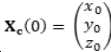
예를 들어, 도 2 및 도 3에서 도시된 구성을 고려한다. 상기 시스템은 레이더(102)와 상기 레이더(102)의 시선에 수직인 스핀축(130) 주위로 스핀하는 공(110)을 도시한다(스핀축 벡터의 배향은 이후에 생성된다). 본 실시 양태에서, 스핀으로 인한 공의 표면의 상대적인 운동만이 고려되고, 따라서, 레이더(102)에 대한 공 중심의 운동은 포함되지 않는다는 것에 유의해야한다. 이러한 예에서, 직교 좌표계(Cartesian coordinate system)는 시선에 평행한 x-축, 스핀축(130)에 평행한 z-축 및 공(110)의 중심으로서의 원점으로 정의되며, y-축은 오른손 배향된(right-hand) 직교좌표계 시스템을 완성한다. 도 3에서 도시된 바와 같이, 임의의 시간에 스핀축(130) 주위로 볼이 회전할 때 볼(110) 표면 상에서 반사지점(122)의 위치는 다음의 좌표 벡터에 의해 주어지고,For example, consider the configuration shown in FIGS. 2 and 3 . The system shows the
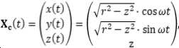
여기서, Xc는 좌표 벡터이고, r이 공의 반경이며, ω는 스핀으로 인한 각도 주파수이다. 골프 공(110)의 표면 상에서 상기 지점(122)의 상대 속도(124, Vc)를 얻기 위해, t에 대하여 좌표 벡터(Xc)를 미분할 필요가 있다:where X c is the coordinate vector, r is the radius of the ball, and ω is the angular frequency due to spin. To obtain the
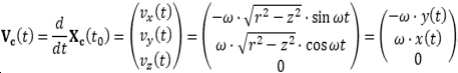
레이더(102)로부터 관측된 속도 성분은 레이더(102)의 시선에 평행한 성분이고, 이 경우 Vc의 x 성분이다. 성분이 -ω*y(t)와 같기 때문에, 속도 등고선(118)은 도 2에 도시된 바와 같이 xz 평면에 평행한 평면, 즉, 시선 벡터(x축)와 스핀축 벡터(130)(이 예에서 z축에 평행한)에 의해 스팬되는(spanned) 평면 내에 모두 위치한다.The velocity component observed from the
그러나, 일부 상황에서, 스핀축(130)은 z축에 평행하지 않을 것이다. 스핀축 벡터(u)가 z축에 평행한 것을 요구하지 않는 경우에, 정규화된(normalized) 스핀 축 벡터는 ![]()
![]()

이러한 일반적인 경우에 공이 시간 t에서 대략 ![]()
![]()

여기서, here,
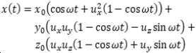
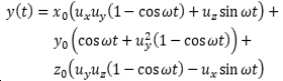
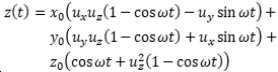
및and
전술한 바와 같이, 시선을 따르는 속도 성분(즉, 속도 벡터의 x 성분)만이 도플러 시프트를 생성하고, 이 예에서는 상기 속도 성분이 관심대상이다:As mentioned above, only the velocity component along the line of sight (i.e. the x component of the velocity vector) produces a Doppler shift, and in this example the velocity component is of interest:

제곱된 괄호들 사이의 식은 uy*z(t)-uz*y(t)와 같고, 따라서:The expression between squared parentheses is equal to u y *z(t)-u z *y(t), so:
![]()
![]()

결과적으로, 속도 등고선에 속하는 지점들의 각각의 위치(Xc), 즉, 일정한 vx(t)는, 스핀하는 공의 주축 벡터라 불리고, 다음과 같이 주어지는 법선 벡터(n)를 갖는 평면에 놓인다:Consequently, each position (X c ) of the points belonging to the velocity contour, i.e. constant v x (t), lies in the plane with the normal vector n, called the principal axis vector of the spinning ball, given by :

n은 3D 스핀축과 레이더에서 공까지의 방향에 의존한다는 것을 주목하여야 한다. 각각의 속도 등고선에 대해, 대응하는 위치들의 평균은 평균지점(averaged point)을 규정하고, 다른 속도 등고선에 대한 평균지점들과 조합될 때 상기 평균지점은 스핀하는 공의 주축 벡터(n)를 규정한다. 주축 벡터(n)의 방향은, 속도 등고선들의 상대 주파수의 오름차순에서의 속도 등고선들에 대한 평균지점들의 배열에 의해 규정된다.It should be noted that n depends on the 3D spin axis and the direction from the radar to the ball. For each velocity contour, the average of the corresponding positions defines an averaged point, which when combined with the averaged points for other velocity contours defines the principal axis vector n of the spinning ball. do. The direction of the principal axis vector n is defined by the arrangement of the mean points for the velocity contours in ascending order of the relative frequencies of the velocity contours.
얻어진 각각의 속도 등고선들은 수신된 도플러 신호의 주파수 성분들과 연관된다. 구체적으로, 아래에서 추가적으로 서술될 바와 같이, 수신된 도플러 신호는 예시적으로 도 4에 도시된 바와 같이 임의의 개수의 주파수 성분(120)(적어도 2개)으로 분리될 수 있다. 도플러 신호의 분리는 예를 들어, 국소 푸리에 변환(Short Time Fourier Transformation, STFT)과 같은 임의의 알려진 방법에 의해 수행될 수 있다. 이러한 각각의 주파수 성분(120)은 속도 등고선들의 평균 위치에 효과적으로 대응한다고 여겨진다. 이러한 각각의 주파수 성분과 연관된 각도 위치는 신호 부분에 대응하는 모든 반사지점들의 가중 평균 위치(weighted average position)이다. 이러한 각도 위치는 전술한 바와 같이 수신기 쌍들 사이의 위상 차이로부터 획득되고, 이러한 위치들은 스핀하는 공의 주축(n)에 가까운 선을 형성할 것이다. 스핀하는 공의 주축(n)은 3D 스핀축을 포함하는 평면에 수직이다. 예를 들어, 탑-스핀(top-spin) 또는 백-스핀(back-spin)에 대응하는 스핀하는 공의 주축 방향이 알려졌기 때문에, n에 수직인 반평면만이 3D 스핀축을 포함할 수 있고, 이러한 반평면을 스핀축 반평면이라 부른다.The respective velocity contours obtained are associated with frequency components of the received Doppler signal. Specifically, as will be described further below, the received Doppler signal may be separated into any number of frequency components 120 (at least two), illustratively as shown in FIG. 4 . Separation of the Doppler signal may be performed by any known method, for example, Short Time Fourier Transformation (STFT). It is believed that each of these
결정된 n이 또한 레이더로부터 시선에 수직인 평면 상으로 스핀축의 투영을 제공하므로, 이 시점에서 아직 알려지지 않은 것은 스핀축의 ux 성분이다. 3D 스핀축을 결정하기 위해 아래에 주어진 몇가지 예의 다양한 접근법이 수행될 수 있다.What is not yet known at this point is the u x component of the spin axis, as the determined n also provides a projection of the spin axis from the radar onto a plane perpendicular to the line of sight. A variety of approaches can be performed, in some examples given below, to determine the 3D spin axis.
1. u가 비행하는 공의 속도 벡터(V)에 수직하도록 ux를 결정한다. 이 경우에, 결정된 스핀축은 라이플 스핀(rifle-spin)이나 자이로 스핀(gyro-spin)이 없다. 예를 들어, 골프 샷과 같은 많은 경우에 있어서 이는 상당히 유효한 가정이며, 이러한 가정이 유효하지 않더라도, 이러한 가정하의 3D 스핀의 효과는 정확한 3D 스핀축으로 획득된 공기역학과 실질적으로 동등한 거동(behavior)을 갖는 공기역학을 초래할 것이다. 따라서, 공의 비행에 대한 3D 스핀축 배향의 영향을 결정하기 위해 실제적으로 사용하기에 이는 매우 유용하다.1. Determine u x so that u is perpendicular to the velocity vector (V) of the flying ball. In this case, the determined spin axis has neither rifle-spin nor gyro-spin. For many cases, such as golf shots, for example, this is a fairly valid assumption, and even if this assumption is not valid, the effect of 3D spin under this assumption will behave substantially equivalent to the aerodynamics obtained with an accurate 3D spin axis. will result in aerodynamics with Therefore, it is very useful for practical use to determine the effect of 3D spin axis orientation on ball flight.
2. 다른 수단에 의해 라이플 스핀의 양 또는 백분율을 추정한다. 라이플 스핀은, 공의 공기 역학적 거동을 공의 미리 결정된 스핀 비율과 상관 시키거나(correlating), 프레임마다 공 위의 패턴들을 인식하는 공의 광학 추적을 사용함으로써 추정될 수 있다. 대안으로, 라이플 스핀의 라이플 백분율은 전체 주파수 대역폭(BW)(도 7에서, fd,F-fd,A와 같은), 공의 미리 결정된 스핀 비율과 반경에 기초한 제로 라이플 스핀을 갖는 예상 대역폭(BWnoRifle = 2*ω*r)과 비교함으로써 추정될 수 있고, 여기서 BW = cos(θ)* BWnoRifle이고, θ는 라이플 스핀 각도이다. 또 다른 대안은 라이플 스핀 비율 또는 백분율을 미리 결정하거나 가정하는 것이다.2. Estimate the amount or percentage of rifle spins by other means. Rifle spin can be estimated by correlating the aerodynamic behavior of the ball with a predetermined spin rate of the ball, or by using optical tracking of the ball to recognize patterns on the ball from frame to frame. Alternatively, the rifle percentage of the rifle spin is the total frequency bandwidth (BW) (in FIG. 7, such as f d,F -f d,A ), the expected bandwidth with zero rifle spin based on the ball's predetermined spin ratio and radius It can be estimated by comparing with (BW noRifle = 2*ω*r), where BW = cos(θ)*BW noRifle and θ is the rifle spin angle. Another alternative is to predetermine or assume a rifle spin rate or percentage.
3. 3D 스핀축 벡터가 주어진 시간 간격에서 일정하다는 가정하에서, 주축(n)은 비행 중 적어도 2개의 상이한 시점에서 결정되고, 여기서 적어도 2개의 이러한 주축(n)은 평행하지 않은 반-스핀 평면들(half-spin plane)을 규정한다. 3D 스핀축은 스핀축 반 평면들의 교차부이고, 각각의 스핀축 반평면은 결정된 주축(n)에 수직한다. 이러한 접근은 상기 스핀축이 시간에 따른 유사-상수(quasi-constant)라고 가정하고, 이는 대부분의 응용 분야에서 유효한 가정이다.3. Under the assumption that the 3D spin axis vector is constant in a given time interval, the principal axis n is determined at at least two different time points in flight, wherein at least two such principal axes n are non-parallel anti-spin planes (half-spin plane) is defined. The 3D spin axis is the intersection of the spin axis half planes, and each spin axis half plane is perpendicular to the determined principal axis n. This approach assumes that the spin axis is quasi-constant with time, which is a valid assumption for most applications.
4. 동일한 시점에 적어도 2개의 상이한 위치로부터 주축(n)을 결정하고, 적어도 2개의 이러한 주축은 평행하지 않고, 3D 스핀축 벡터에 평행한 선을 따르는 대응하는 반-평면의 교차부를 야기한다. 상기 2개의 상이한 위치는 처리 유닛(202)에 연결된 2개의 레이더 시스템(102)을 구비하는 것에 의하여, 혹은 수신기들(106)의 개수를 증가시키고 평행하지 않은 스핀축 반 평면 결정을 달성하기 위해 상기 수신기들이 충분히 분리되도록 함에 의하여 획득될 수 있다.4. Determine the principal axes n from at least two different positions at the same point in time, resulting in the intersection of corresponding anti-planes along lines parallel to at least two such principal axes which are not parallel and parallel to the 3D spin axis vector. The two different locations can be located either by having two
스핀하는 골프 공의 스핀축을 결정하기 위한 예시적인 제1의 방법의 흐름도가 도 5에 도시된다. 이러한 실시 양태에서, 일 평면 내에 장착된 3개의 수신기 안테나(106A, 106B, 106C)를 포함하는 다중 수신기 레이더 구성이 이용된다. 선택적으로, 결정된 위치의 정확도를 증가시키고 3차원(3D) 스핀축을 얻기 위해 추가적인 수신기 안테나가 사용될 수 있다. 처음의 200 단계에서, 레이더(102)는 신호를 생성하며, 상기 신호는 타깃 영역으로 송신되고 스핀하는 골프 공(110)으로부터 반사 후 수신기(106A, 106B, 106C)에 의해 수신되고, 상기 수신기들은 도플러 주파수 스펙트럼을 나타내는 대응하는 신호를 발생시킨다. 이러한 실시 양태에서, 공은 레이더로부터 멀어지도록 이동한다. 그러나, 상기 공은 레이더(102)에 대해 정지되어 있거나, 임의의 방향으로 움직일 수 있다는 것을 이해할 것이다. 공의 스핀 운동으로 인해, 수신된 도플러 신호는 레이더(102)에 대한 공의 병진 운동과 연관된 도플러 시프트 값 부근으로 확장된다. 즉, 공이 레이더(102)에 대해 스핀하고 이동할 때, 공의 상이한 부분들의 상대 속도의 범위를 반영하는 주파수 범위에 걸쳐 상기 반사된 신호는 확산될 것이다. A flow diagram of a first exemplary method for determining the spin axis of a spinning golf ball is shown in FIG. 5 . In this embodiment, a multi-receiver radar configuration is used comprising three
205 단계에서, 신호가 수신기(106A, 106B, 106C)에 의해 수신된 후, 수신된 신호에 대해 주파수 분석이 수행된다. 예시적인 실시 양태에서, 고속 푸리에 변환(Fast Fourier Transform, FFT)이 사용될 수 있다. 전술한 바와 같이, 공의 스핀으로 인해, 수신된 신호의 주파수는 이후 원하는 주파수 성분의 개수로 분리될 수 있는 범위에 걸쳐 확산된다. 도 10은 순수한 백스핀을 나타내는 레이더로부터 멀어지게 이동하는 골프 공으로부터 수신된 주파수의 스펙트럼을 도시한다. 도 10에서 상기 스펙트럼에서의 수신된 주파수는 (병진 운동하는) 공의 속도에 대응하는 주파수에 대해 도시된다. 이러한 예에서, 도 6에 도시된 바와 같이, 공의 최하위(F 지점)는 레이더로부터 멀어지도록 스핀하고, 이는 공의 최하위 부분으로부터의 반사가 공의 속도에 대해 가장 큰 양의 도플러 시프트를 갖는 반면에, 레이더 쪽으로 스핀하는 공의 최상위(A 지점)로부터의 반사는 공의 속도에 대해 가장 큰 음의 도플러 시프트를 갖는다는 것을 의미한다.In
선택적인 210 단계에서, 수신된 도플러 신호의 움직임 보상(motion compensation)은 신호로부터 (레이더에 대한 공의 병진 운동, 즉, 공의 속도에 대응하는) 공(110)의 평균 움직임을 차감하여 수행된다. 이러한 움직임 보상은 공(110)의 도플러 신호를 0Hz 근처로 집중시키고, 상기 보상은 본 발명이 속하는 기술 분야에서 통상의 기술자에 의해 알려진 표준 기술을 통해 임의의 다양한 방식으로 수행될 수 있다. 도 10은 움직임 보상이 수행된 후 스펙트럼 사진을 도시하며, 따라서, 공으로부터의 신호 중심 주파수가 현재 0Hz이다. 스핀하고 이동하는 공으로부터 확장된 도플러 스펙트럼 내부의 상대적인 도플러 시프트가 중요하기 때문에, 이러한 움직임 보상 단계는 선택적이다. 그러나, 움직임 보상을 수행하는 단계는 일부 실용적인 구현상의 이점을 제공할 수 있다.In an
215 단계에서, 수신된 신호는 주파수 성분(120)의 원하는 개수로 분리된다. 전술한 바와 같이, 수신된 신호의 주파수 확장은 공이 스핀하는 동안 레이더에 의해 관측된 공의 표면 상의 상이한 지점에서의 상이한 속도로부터 야기된다. 동일한 속도 등고선 상의 반사지점은 도플러 시프트의 동일한 주파수 성분에 연관된다. 즉, 각각의 속도 등고선은 주파수 스펙트럼의 상이한 부분과 연관된다. 예를 들어, 도 6을 보면, 복수의 반사지점(A, B, C, D, E, F)이 공의 외부면 상의 상이한 위치에 도시된다. 공의 스핀에 따라, 이러한 반사지점 각각은 레이더에 대해 상이한 속도를 가질 것이다. 도 6에 도시된 바와 같이, 공의 백스핀 때문에, 공의 병진 운동에 대한 보상 후, 공이 레이더로부터 멀어지게 스핀하는 F 지점에서 공은 최대 양(positive)의 속도를 갖고, 공이 레이더 쪽으로 스핀하는 A 지점에서 최대 음(negative)의 속도를 갖는다. 공의 중간 선 바로 위에 있는 C 지점은 가장 작은 음의 속도를 나타내고, 반면에 공의 중간 선 바로 아래에 있는 D 지점은 가장 작은 양의 속도를 나타낸다. 더욱이, 공의 스핀으로 인해, 각각의 반사지점(A, B, C, D, E, F)은 별개의 속도 등고선(142)에 대응한다. 예를 들어, B 지점은 등고선(142B)에 대응하여, B 지점이 등고선(142B)을 따라 공의 표면 상의 모든 다른 지점과 동일한 상대 속도를 갖는다. 유사하게, C 지점은 등고선(142C)에 대응하여, C 지점이 등고선(142C)을 따라 모든 다른 지점과 레이더(102)에 대해 동일한 속도를 갖고, 반면에 D 및 E 지점은 각각 등고선 142D 및 142E에 대응하여, 등고선(142D)을 따라 위치한 모든 지점이 D 지점과 레이더(102)에 대해 동일한 속도를 나타내고, 등고선(142E) 상에 위치한 모든 지점은 E 지점과 레이더(102)에 대해 동일한 속도를 나타낸다. 각각의 주파수 성분(144)에 대해, 일정한 속도의 각각의 성분과 연관된 속도 등고선의 레이더에 대한 3D 각도 위치는, 각각의 수신기 쌍(106)에 의해 수신된 신호와의 비교에 기초한 대응하는 속도를 나타내는 신호와 연관된 위상 시프트를 분석함으로써 결정되고, 이러한 각도 위치는 도 8에 도시된 바와 같이 공(110) 상으로 매핑될 수 있다. 특히, 이러한 위상 시프트는 다양한 주파수 성분(144) 각각을 공(110) 상의 상이한 각도 위치(126)로 할당하는데 사용된다. 위상 시프트는 주파수 성분(144)에 대응하는 공(110) 상에서의 위치를 결정하기 위하여 사용될 수 있다. 각각의 주파수 성분(144)이 속도 등고선(142)의 대응하는 범위를 스팬하기 때문에, 각각의 주파수 성분(144)에 대해 결정된 각도 위치는 효과적으로 이러한 범위 내의 속도 등고선 각각에 속하는 지점들의 평균이 될 것이다. 레이더의 시야에 수직인 평면 내에서, 각각의 등고선(142) 상의 상기 지점들의 평균은 스핀축(130)에 직교하고 스핀하는 공의 주축인 선(125)에 속하는 위치(126)를 규정한다. 이러한 실시 양태에서, 신호가 5개의 주파수 성분(144)으로 분리되는 동안, 통상의 기술자라면 신호가 주파수 성분(144)의 임의의 개수(적어도 2개)로 분리되어, 상기 부분들이 공의 스핀으로 인해 확장된 도플러 스펙트럼 내에 분포한다는 것을 이해할 것이라는 점에 유의한다.In
220 단계에서, 215 단계로부터의 상대적인 각도 위치는 일반적으로 yz 평면 내의 하나의 선을 따라 그룹화된다. 이 선은 스핀하는 공의 주축(n)이라 불리며, 3D 스핀축 벡터를 포함하는 평면에 직교하고, 상기 각도 위치는 yz 평면 내의 선에 맞춰진다. yz 평면 내에서 주축의 선의 배향만이 주측(n)을 결정하는데 필요하기 때문에, 각도 위치로부터 y,z 좌표로의 스케일링은 중요하지 않으며, 생략될 수 있다. 측정의 노이즈로 인해(예를 들어, 대역 통과 필터 또는 저역 통과 필터의 적용에 의해 알려진 노이즈 감소 기술을 사용하여 감소될 수 있다), 이러한 위치들은 일반적으로 이상적인 선으로부터 벗어날 것이다. 그러나, 예를 들어, 도 8 및 도 9에서 도시된 바와 같이 라인은 상기 위치의 선형 맞춤(linear fit)을 이용하여 결정될 수 있다. 일부 경우에, 선택된 시간 간격 동안 여러 시간 단계로부터의 각도 위치를 사용하는 것이 유용할 수 있으며, 따라서 이 시간 간격동안 시선의 임의의 변화는 미미하게 된다. 주축 벡터(n)의 방향은 상대 주파수의 오름 차순에서의 대응하는 주파수 성분의 각도 위치에 의해 결정된다.At
주축 벡터(n)로부터, 스핀축 반평면은 n에 수직인 평면으로서 식별될 수 있고, 상기 평면은 레이더로부터의 시선(x축)에 의해 절반으로 절단되고, 스핀 반평면은 n과 x축 단위 벡터(unity vector)의 벡터 곱을 포함하는 측이다. 스핀축 반평면은 결과적으로 주축 벡터(n)와 x축 단위 벡터, 즉, 시선에 의해 완전하게 기술된다From the principal axis vector n, the spin axis half-plane can be identified as a plane perpendicular to n, which plane is cut in half by the line of sight (x-axis) from the radar, and the spin half-plane is n and the x-axis unit vector ( The side containing the vector product of the unity vector). The spin-axis half-plane is consequently completely described by the principal-axis vector (n) and the x-axis unit vector, i.e., the line of sight.
레이더(102)로부터 공(110)으로의 시선은 x축에 평행하게 규정된다. 그러나, 이동하는 공을 갖는 대부분의 경우에서, 레이더로부터의 시선은 공이 이동함에 따라 세계 좌표(world coordinate)에 대하여 그 배향을 변경할 것이다. 225 단계에서, 스핀축 반평면은 실제 세계 좌표로 변환된 좌표이다. 이는 주축(n)과 공에 대한 레이더의 시선 방향(x축)이 원하는 좌표 시스템으로 전환된다는 것을 의미한다. 실제 세계 좌표는 공의 움직임에 의해 규정될 수 있지만, 반드시 그렇지는 않다. 그러한 좌표는 스핀축 배향이 공의 움직임과 관련하여 주로 주목될 때 종종 사용된다. 즉, 공이 그 축 주위로 스핀하는 해당 축을 결정함으로써, 상기 시스템은 검출된 스핀 비율과 함께 이러한 축을 사용하여 스핀이 공의 이동 경로 상에서 갖는 효과를 계산할 수 있다. 사실 단순히 공의 속도 벡터(119)에 수직인 평면 상으로의 상기 스핀축의 투영을 아는 것으로써, 상기 시스템은 공의 초기 비행 경로의 오른쪽 또는 왼쪽 및 위 또는 아래의 공 편차에 대한 스핀의 공기 역학적인 효과를 근사할 수 있고, 예를 들어, 스핀축이 결정된 후 상기 시스템은 공의 연속적인 비행의 시뮬레이션 투영의 정확도를 향상시키는데 사용될 수 있다. 통상의 기술자는 이 시스템이 공의 비행의 짧은 부분만이 연속적인 공의 비행에서 검출되고, 이후 시뮬레이션 환경으로 투영되는 골프 시뮬레이션 게임에 유용할 수 있다는 것을 인식할 것이다. 예를 들어, 자동화된 카메라에 의해 또는 카메라 조작자에게 공의 예측된 경로를 표시함으로써, 이러한 시스템은 또한 골프 공의 추적을 향상시키는데 유용할 수 있으며, 상기 시스템은 수동 조작되는 카메라가 보다 정확하게 공을 추적하는 것을 가능하게 하고, 또한 자동화된 카메라 추적 시스템에 의한 공의 추적을 지원할 수 있다. 또한 3차원적으로 공을 추적하는 동안 스핀축 및 스핀 비율을 측정함으로써, 바람, 온도, 공의 공기 역학적 속성 등과 같은 공의 궤적에 영향을 미치는 상이한 성분들에 대한 상세한 통찰력을 얻을 수 있다.The line of sight from the
230 단계에서, 식별된 스핀축 반평면은 3D 스핀축을 결정하는데 사용된다. 이러한 단계는 적어도 4개의 대안적인 방식으로 수행될 수 있다. 제1의 대안적인 방식에서는, 3D 스핀축이 공의 속도 벡터에 수직할 것이 요구되고, 이로 인해 라이플 스핀 또는 자이로 스핀은 0이라 가정한다. 이러한 제1 방법은 공의 속도 벡터의 방향이 결정될 것을 더 필요로 한다.In
230 단계의 제2의 대안적인 방식에서, 라이플 스핀 또는 자이로 스핀의 양은 다른 수단에 의해 결정된다. 라이플 스핀은 공의 공기 역학적 거동을 미리 결정된 공의 스핀 비율과 상관시킴으로써 또는 프레임마다 공 상의 패턴을 인식하는 공의 광학 추적을 사용함으로써 추정될 수 있다. 대안적으로, 라이플 스핀 비율 또는 백분율은 어떤 합리적으로 기대되는 값으로 미리 결정되거나 가정될 수 있다.In a second alternative manner of
230 단계의 제3의 대안적인 방식에서, 상이한 스핀축 반평면은 하나 이상의 시간 단계에 걸쳐 획득되어져, 상기 3D 스핀축 배향이 결정될 수 있다. 제3의 대안적인 방식에 의해 3D 스핀축 배향을 이끌어 내는 것은 실제 세계 좌표에서의 스핀축 벡터의 배향은 자이로스코프 효과로 인해 시간에 따라 실질적으로 일정하다는 가정에 의존한다. 추가로 스핀축 반평면들은 적어도 2개의 시간 단계에서 평행하지 않아야 한다. 3D 스핀축은 결정된 스핀축 반평면의 교차부로서 식별된다.In a third alternative manner of
제4의 대안적인 방식에서, 단일 레이더 유닛 내에서 다수의 레이더 또는 3개 초과의 수신기가 사용되는 경우, 다수의 스핀축 반평면들이 동시에 결정될 수 있다. 3D 스핀축은 결정된 스핀축 반평면의 교차부로서 결정될 수 있다. 스핀축 반평면들이 서로 평행하지 않은 한, 이는 명백하게 수행될 수 있다.In a fourth alternative scheme, when multiple radars or more than three receivers are used within a single radar unit, multiple spin axis half planes can be determined simultaneously. The 3D spin axis may be determined as the intersection of the determined spin axis antiplanes. As long as the spin axis antiplanes are not parallel to each other, this can be done explicitly.
스핀하는 공의 주축은, 상기 공으로부터 수신된 도플러 신호의 주파수에 대한 각도 위치의 미분 벡터의 방향에서의 단위 벡터인 것으로 관측된다. 본 발명의 다른 실시 형태에서, 수신된 신호의 주파수 분석에 기초하여 주파수에 대해 수신 안테나에서 관측된 위상차의 도함수를 계산하고, 이로부터 공의 각도 위치의 지식에 기초하여 공의 주축을 계산함으로써 주축이 결정된다.The principal axis of a spinning ball is observed to be a unit vector in the direction of the differential vector of angular position with respect to the frequency of the Doppler signal received from the ball. In another embodiment of the present invention, the principal axis is calculated by calculating the derivative of the phase difference observed at the receiving antenna with respect to the frequency based on the frequency analysis of the received signal, and calculating the principal axis of the ball based on the knowledge of the angular position of the ball therefrom. this is decided
후자의 계산에 사용되는 각도 위치는 전술한 바와 같이 바람직하게는 수신된 도플러 대역의 중심 주파수에서 관측된 위상차를 이용하여 또는 도플러 대역에 걸쳐 수신된 위상차를 평균함으로써 상기 수신된 신호로부터 결정될 수 있다. 전술한 방법과 대조적으로, 이 방법은 단일 각도 위치만이 결정되는 것을 요구한다는 점에 유의하라.The angular position used in the latter calculation may be determined from the received signal, preferably using the observed phase difference at the center frequency of the received Doppler band, as described above, or by averaging the received phase difference over the Doppler band. Note that, in contrast to the method described above, this method requires only a single angular position to be determined.
본 발명의 또 다른 실시 형태에서, 공의 각도 위치는 레이더 신호로부터 결정되지 않지만, 다른 수단에 의해 충족될 수 있다. 일 실시 양태에서, 각도 위치는 레이더 유닛에 내장된 카메라로부터 또는 레이더 외부에 카메라를 구비하여 결정될 수 있고, 외부 카메라는 레이더에 입력으로서 각도 위치의 측정값 또는 각도 위치가 결정될 수 있는 비디오 신호를 제공한다. 3D 스핀축을 결정하기 위해 전술한 다중 레이더 구성이 이용되는 다른 실시 양태에서, 공의 위치는 제1 레이더에 의해 결정되고, 입력으로서 상기 공의 위치가 제2 레이더에 공급될 수 있고, 상기 제2 레이더는 공의 위치에 기초하여 공의 각도 위치를 계산한다.In another embodiment of the invention, the angular position of the ball is not determined from the radar signal, but may be satisfied by other means. In an embodiment, the angular position can be determined from a camera built into the radar unit or with a camera external to the radar, which provides as input to the radar a measurement of the angular position or a video signal from which the angular position can be determined. do. In another embodiment, wherein the multiple radar configuration described above is used to determine the 3D spin axis, the position of the ball may be determined by a first radar, and the position of the ball may be supplied to a second radar as an input, wherein the second radar The radar calculates the angular position of the ball based on the position of the ball.
또 다른 실시 양태에서, 각도 위치는 레이더 배치와 타깃 영역의 지식으로부터 가정될 수 있고, 주축을 결정하기 위해 계산되거나 입력될 필요는 없다. 이는 공의 궤적이 주로 레이더로부터 잘 알려진 반경 방향에 있는 방식으로 레이더가 배치되는 경우이거나, 공이 일 시점에 일정의 위치에 있는 것으로 알려지거나 결정되는 경우일 수 있다.In another embodiment, the angular position may be assumed from knowledge of the radar placement and target area and need not be calculated or entered to determine the principal axis. This may be a case in which the radar is disposed in such a way that the trajectory of the ball is mainly in a well-known radial direction from the radar, or it may be a case in which the ball is known or determined to be at a certain position at a point in time.
본 발명의 실시 양태에 따른 시스템에서, 스핀축은 레이더의 시선과 평행한 제1 정규화 벡터에 의해 규정된 좌표 시스템 내에서 식별되고, 제2 및 제3 벡터는 제1 정규화 벡터가 법선 벡터인 평면을 스팬한다. 상기 수신된 신호는 국소 푸리에 변환을 사용해 주파수 성분들로 분리된다.In a system according to an embodiment of the present invention, the spin axis is identified within a coordinate system defined by a first normalized vector parallel to the radar's line of sight, and the second and third vectors define a plane in which the first normalized vector is a normal vector. span The received signal is separated into frequency components using a local Fourier transform.
본 발명의 일 실시 양태에 따르면, 상기 방법은 상기 신호로부터 스포츠 공의 평균 움직임을 빼서 수신된 신호의 움직임 보상을 수행하는 단계를 포함한다. 움직임 보상은 수신된 신호를 0Hz부근으로 집중시킨다. 주파수 성분 각각은 공 표면 상의 속도 등고선과 연관되고, 속도 등고선은 동일한 상대 속도를 갖는 스핀하는 공의 표면 상의 복수의 반사지점에 대응하고, 각각의 주파수 성분과 연관된 각도 위치는 제1 레이더의 제1 수신기 쌍에 의해 수신된 신호들과 제1 레이더의 제2 수신기 쌍에 의해 수신된 신호들 사이에서 검출된 위상 시프트에 기초하여 결정된다. 또한, 상기 방법은 대응하는 평면 내에 하나의 지점을 규정하기 위해 각각의 등고선 위에 있는 위치들을 평균하는 단계를 포함할 수 있고, 각각의 속도 등고선으로부터의 지점들의 세트는 스핀축에 수직인 선에 대응한다.According to an embodiment of the present invention, the method includes performing motion compensation of the received signal by subtracting the average motion of the sports ball from the signal. Motion compensation concentrates the received signal around 0Hz. Each of the frequency components is associated with a velocity contour on the ball surface, the velocity contour corresponds to a plurality of reflection points on the surface of the spinning ball having the same relative velocity, and the angular position associated with each frequency component is a first of the first radar. determined based on a detected phase shift between signals received by the receiver pair and signals received by a second receiver pair of the first radar. The method may also include averaging positions on each contour to define a point in a corresponding plane, wherein the set of points from each velocity contour corresponds to a line perpendicular to the spin axis. do.
상기 방법은 또한 스포츠 공에 대한 3차원 스핀축을 계산하지 않고 스핀축의 제1 투영에 기초하여 스포츠 공의 궤적의 특성을 추정하는 단계를 포함한다. 상기 방법은 식별된 스핀축을 실제 세계 좌표로 변환하는 단계를 더 포함할 수 있다. 부가적으로, 상기 방법은 스포츠 공의 3차원 스핀축을 결정하기 위해 제1 시점에서 스핀축의 제1 투영을 결정하고, 이후 제2 시점에서 스핀축의 추가적인 제1 투영을 계산하고, 제1 및 제2 투영을 조합함으로써 3차원 스핀축을 계산하는 단계를 더 포함할 수 있다. 더불어, 상기 방법은 동일한 시점에 다수의 레이더로부터 주축을 결정함으로써 3차원 스핀축 배향을 식별하는 단계를 더 포함할 수 있다. 수신된 신호는 국소 푸리에 변환을 이용하여 주파수 성분들로 분리된다.The method also includes estimating a characteristic of the trajectory of the sports ball based on a first projection of the spin axis without calculating a three-dimensional spin axis for the sports ball. The method may further comprise transforming the identified spin axis into real world coordinates. Additionally, the method determines a first projection of the spin axis at a first time point to determine a three-dimensional spin axis of the sports ball, and then calculates an additional first projection of the spin axis at a second time point, first and second The method may further include calculating the three-dimensional spin axis by combining the projections. In addition, the method may further include identifying the three-dimensional spin axis orientation by determining the principal axis from a plurality of radars at the same time. The received signal is separated into frequency components using a local Fourier transform.
통상의 기술자는 본 발명의 기술적 사상으로부터 벗어나지 않고 전술한 실시 양태를 변화시킬 수 있다는 것을 인식할 것이다. 실시 양태들 중 하나와 연관된 구조적인 특징 및 방법은 다른 실시 양태에 통합될 수 있다는 것 또한 인식할 것이다. 따라서, 본 발명은 개시된 특정한 실시 양태에 구속되지 않지만, 오히려 일부 변경이 첨부된 청구항에 의해 규정된 본 발명의 범위 내에서 또한 보호된다.Those skilled in the art will recognize that changes can be made to the above-described embodiments without departing from the spirit of the present invention. It will also be appreciated that structural features and methods associated with one of the embodiments may be incorporated in other embodiments. Accordingly, the present invention is not intended to be limited to the particular embodiments disclosed, but rather some modifications are also protected within the scope of the present invention as defined by the appended claims.
Claims (15)
신호를 스포츠 공이 발사되는 타깃 영역으로 송신하는 제1 레이더로서, 2쌍의 수신기가 동일 선상(co-linear)에 있지 않도록 배열된 최소 3개의 수신기를 포함하는, 상기 제1 레이더; 및
상기 제1 레이더로부터 데이터를 수신하고, 상기 공이 스핀할 때 상기 공의 상이한 부분들의 상기 제1 레이더에 대한 상이한 속도들에 대응하는 제1 시점에 수신된 제1 레이더 주파수 범위를 포함하는 주파수 스펙트럼을 결정하는 처리 유닛으로서, 상기 처리 유닛은 상기 주파수 스펙트럼을 복수의 주파수 성분으로 분리하고 각각의 상기 주파수 성분에 대해, 각각의 상기 주파수 성분과 연관된 각도 위치를 계산하고, 상기 처리 유닛은 상기 결정된 각도 위치에 의해 표시되는 라인에 의해 규정되는 상기 스포츠 공의 주축에 수직인 라인을, 상기 제1 레이더로부터 상기 스포츠 공으로의 시선(line of sight)에 수직인 평면 내의 상기 스핀축의 제1 2차원 투영(two-dimensional projection)으로서 식별하는, 상기 처리 유닛;을 포함하는,
시스템.A system for determining a spin axis of a sports ball, comprising:
a first radar for transmitting a signal to a target area where a sports ball is launched, the first radar comprising at least three receivers arranged such that the two pairs of receivers are not co-linear; and
receive data from the first radar and generate a frequency spectrum comprising a first radar frequency range received at a first time point corresponding to different velocities with respect to the first radar of different parts of the ball as the ball spins a processing unit for determining, the processing unit dividing the frequency spectrum into a plurality of frequency components and calculating, for each of the frequency components, an angular position associated with each of the frequency components, the processing unit comprising: a line perpendicular to the major axis of the sports ball defined by the line denoted by the processing unit, which identifies it as a -dimensional projection; including,
system.
각각의 상기 주파수 성분과 연관된 상기 각도 위치가 상기 제1 레이더의 수신기의 제1 쌍에 의해 수신된 신호들과 상기 제1 레이더의 수신기의 제2 쌍에 의해 수신된 신호들 사이에서 검출된 위상 시프트에 기초하여 결정되는,
시스템.According to claim 1,
The angular position associated with each of the frequency components is a detected phase shift between signals received by a first pair of receivers of the first radar and signals received by a second pair of receivers of the first radar. determined on the basis of
system.
상기 위상 시프트가 각각의 다양한 주파수 성분을 상기 제1 레이더에 대응하는 제1 레이더 좌표 시스템에 대한 각도 위치로 할당하기 위하여 사용되는,
시스템.3. The method of claim 2,
wherein the phase shift is used to assign each of the various frequency components to an angular position relative to a first radar coordinate system corresponding to the first radar;
system.
신호를 상기 타깃 영역으로 송신하는 제2 레이더로서, 2쌍의 수신기가 동일 선상에 있지 않도록 배열된 최소 3개의 수신기를 포함하는, 상기 제2 레이더; 및
상기 제2 레이더로부터 데이터를 수신하고, 상기 공이 스핀할 때 상기 공의 상이한 부분들의 상기 제2 레이더에 대한 상이한 속도들에 대응하는 제1 시점에 수신된 제2 레이더 주파수 범위를 결정하는 처리 유닛으로서, 상기 처리 유닛은 상기 제2 레이더 주파수 범위를 복수의 주파수 성분으로 분할하고 각각의 상기 주파수 성분에 대해, 각각의 상기 주파수 성분과 연관된 각도 위치를 계산하고, 상기 처리 유닛은 상기 결정된 각도 위치에 의해 표시되는 라인에 의해 규정되는 상기 스포츠 공의 주축에 수직인 라인을, 상기 제2 레이더로부터 상기 스포츠 공으로의 시선에 수직인 평면 내의 상기 스핀축의 제2 2차원 투영으로서 식별하고, 상기 스핀축의 상기 제1 및 제2 투영에 기초하여, 상기 스포츠 공의 3차원 스핀축을 계산하는, 상기 처리 유닛;을 더 포함하는,
시스템.According to claim 1,
a second radar for transmitting a signal to the target area, the second radar comprising at least three receivers arranged such that the two pairs of receivers are not collinear; and
a processing unit receiving data from the second radar and determining a second radar frequency range received at a first point in time corresponding to different velocities with respect to the second radar of different parts of the ball as the ball spins; , the processing unit divides the second radar frequency range into a plurality of frequency components and calculates, for each of the frequency components, an angular position associated with each of the frequency components, the processing unit being configured to: identify a line perpendicular to the major axis of the sports ball defined by the displayed line as a second two-dimensional projection of the spin axis in a plane perpendicular to the line of sight from the second radar to the sports ball, based on the first and second projections, the processing unit for calculating the three-dimensional spin axis of the sports ball;
system.
상기 시스템은 상기 스포츠 공에 대한 3차원 스핀축을 계산하지 않고 상기 스포츠 공의 속도 벡터에 수직인 평면 상으로의 상기 스핀축의 투영에 기초하여 상기 스포츠 공의 궤적 특성을 추정하는,
시스템.According to claim 1,
wherein the system estimates the trajectory characteristic of the sports ball based on a projection of the spin axis onto a plane perpendicular to the velocity vector of the sports ball without calculating a three-dimensional spin axis for the sports ball;
system.
상기 공의 3차원 스핀축을 추정하기 위해 상기 제1 투영 및 상기 공의 비행에 대응하는 궤적 데이터에 기초하여 3차원 스핀 벡터가 계산되는,
시스템.According to claim 1,
a three-dimensional spin vector is calculated based on the first projection and trajectory data corresponding to the flight of the ball to estimate the three-dimensional spin axis of the ball;
system.
상기 제1 투영 및 라이플 스핀(rifle spin)의 결정된 백분율에 기초하여 3차원 스핀 벡터가 계산되는,
시스템.According to claim 1,
a three-dimensional spin vector is calculated based on the first projection and the determined percentage of rifle spin;
system.
제로 라이플 스핀 시나리오(zero rifle spin scenario)로부터 예상되는 주파수 대역폭과 상관되는(correlated) 상기 스핀하는 공으로부터 반사 후에 수신되는 레이더 신호의 주파수 대역폭에 기초하여 라이플 스핀의 상기 백분율이 결정되는,
시스템.8. The method of claim 7,
wherein the percentage of rifle spin is determined based on a frequency bandwidth of a radar signal received after reflection from the spinning ball that is correlated with a frequency bandwidth expected from a zero rifle spin scenario;
system.
미리 결정된 값이 라이플 스핀의 상기 백분율로서 사용되는,
시스템.8. The method of claim 7,
a predetermined value is used as said percentage of rifle spin,
system.
상기 레이더는 상기 공에 대하여 제1 각도에 있는 제1 세트의 수신기 및 상기 공에 대하여 제2 각도에 있는 제2 세트의 수신기를 포함하고, 상기 처리 유닛은 상기 제1 세트의 수신기 및 제2 세트의 수신기로부터의 스핀축의 투영들의 조합에 기초하여 3차원 스핀축을 결정하는,
시스템.According to claim 1,
The radar comprises a first set of receivers at a first angle with respect to the ball and a second set of receivers at a second angle with respect to the ball, the processing unit comprising the first set of receivers and a second set of receivers determining the three-dimensional spin axis based on a combination of projections of the spin axis from the receiver of
system.
프로세서는 제1 시점에서 상기 스핀축의 제1 투영을 결정함으로써 3차원 스핀축을 계산하고, 이후 제2 시점에서 상기 스핀축의 추가적인 제1 투영을 계산하고, 상기 스포츠 공의 3차원 스핀축을 결정하기 위해 제1 투영 및 제2 투영을 조합하는,
시스템.According to claim 1,
The processor calculates a three-dimensional spin axis by determining a first projection of the spin axis at a first time point, then calculates an additional first projection of the spin axis at a second time point, and a second to determine the three-dimensional spin axis of the sports ball combining a first projection and a second projection,
system.
제1 레이더를 통해 신호를 상기 스포츠 공이 발사되는 타깃 영역으로 송신하는 단계로서, 상기 제1 레이더는 최소 3개의 수신기가 동일 선상에 있지 않도록 배열된 3개의 수신기를 포함하고, 상기 신호는 상기 스포츠 공에 의해 상기 수신기로 다시 반사되는, 상기 단계;
상기 제1 레이더에 의해, 수신기를 통해 반사된 신호를 수신하는 단계;
상기 스포츠 공이 스핀할 때 상기 스포츠 공의 상이한 부분들의 상기 레이더에 대한 상이한 속도들에 대응하는 상기 제1 레이더에 의해 수신된 주파수 범위를 포함하는 주파수 스펙트럼을 결정하기 위해 제1 시점에서 상기 제1 레이더에 의해 수신된 상기 반사된 신호에 관하여 주파수 분석을 수행하는 단계;
상기 결정된 주파수 스펙트럼을 복수의 주파수 성분으로 분리하는 단계;
각각의 주파수 성분에 대응하는 각도 위치를 결정하고, 상기 결정된 각도 위치에 의해 표시되는 라인에 의해 규정되는 상기 스포츠 공의 주축에 수직인 라인을, 상기 제1 레이더로부터 상기 스포츠 공으로의 시선에 수직인 라인에 수직인 평면 상으로의 상기 스포츠 공의 스핀축의 2차원 투영으로서 식별하는 단계;를 포함하는,
방법.A method for determining a spin axis of a sports ball, comprising:
transmitting a signal via a first radar to a target area where the sports ball is launched, wherein the first radar comprises three receivers arranged such that the at least three receivers are not collinear, the signal comprising: reflected back to the receiver by
receiving, by the first radar, a signal reflected through a receiver;
the first radar at a first time point to determine a frequency spectrum comprising a frequency range received by the first radar corresponding to different velocities for the radar of different parts of the sports ball as the sports ball spins performing frequency analysis on the reflected signal received by
separating the determined frequency spectrum into a plurality of frequency components;
determine an angular position corresponding to each frequency component, and draw a line perpendicular to the main axis of the sports ball defined by a line indicated by the determined angular position, perpendicular to the line of sight from the first radar to the sports ball identifying as a two-dimensional projection of the spin axis of the sports ball onto a plane perpendicular to the line;
Way.
2쌍의 수신기가 동일 선상에 있지 않도록 배열된 최소 3개의 수신기를 포함하는 제2 레이더를 통해 신호를 상기 타깃 영역으로 송신하는 단계; 및
상기 제2 레이더로부터 데이터를 수신하고, 상기 공이 스핀할 때 상기 공의 상이한 위치들의 상기 제2 레이더에 대한 상이한 속도들에 대응하는 제1 시점에 수신된 제2 레이더 주파수 범위를 결정하는 단계로서, 처리 유닛은 상기 제2 레이더 주파수 범위를 복수의 주파수 성분으로 분할하고 각각의 상기 주파수 성분에 대해, 각각의 상기 주파수 성분과 연관된 각도 위치를 계산하고, 상기 처리 유닛은 상기 결정된 각도 위치에 의해 표시되는 라인에 수직인 라인을, 상기 제2 레이더로부터 상기 스포츠 공으로의 시선에 수직인 평면 내의 스핀축의 제2 투영으로서 식별하며, 상기 스핀축의 상기 제1 및 제2 투영에 기초하여 상기 스포츠 공의 3차원 스핀축을 계산하는, 단계;를 더 포함하는,
방법.13. The method of claim 12,
transmitting a signal to the target area via a second radar comprising at least three receivers arranged such that the two pairs of receivers are not collinear; and
receiving data from the second radar and determining a second radar frequency range received at a first point in time corresponding to different velocities for the second radar at different positions of the ball as the ball spins; a processing unit divides the second radar frequency range into a plurality of frequency components and calculates, for each of the frequency components, an angular position associated with each of the frequency components, the processing unit being indicated by the determined angular position identify a line perpendicular to the line as a second projection of a spin axis in a plane perpendicular to the line of sight from the second radar to the sports ball, the three dimensions of the sports ball based on the first and second projections of the spin axis Calculating the spin axis; further comprising
Way.
분리된 소스로부터 라이플 스핀의 미리 결정된 양과 조합하여 스핀축 반평면(half plane)으로부터의 3차원 스핀축 배향(orientation)을 식별하는 단계를 더 포함하는,
방법.13. The method of claim 12,
identifying a three-dimensional spin axis orientation from a spin axis half plane in combination with a predetermined amount of rifle spin from a separate source;
Way.
Priority Applications (1)
| Application Number | Priority Date | Filing Date | Title |
|---|---|---|---|
| KR1020227018131A KR102527155B1 (en) | 2018-03-13 | 2018-12-11 | System and method for determining a spin axis of a sports ball |
Applications Claiming Priority (3)
| Application Number | Priority Date | Filing Date | Title |
|---|---|---|---|
| US201862642369P | 2018-03-13 | 2018-03-13 | |
| US62/642,369 | 2018-03-13 | ||
| PCT/IB2018/059879 WO2019175650A1 (en) | 2018-03-13 | 2018-12-11 | System and method for determining a spin axis of a sports ball |
Related Child Applications (1)
| Application Number | Title | Priority Date | Filing Date |
|---|---|---|---|
| KR1020227018131A Division KR102527155B1 (en) | 2018-03-13 | 2018-12-11 | System and method for determining a spin axis of a sports ball |
Publications (2)
| Publication Number | Publication Date |
|---|---|
| KR20200123098A KR20200123098A (en) | 2020-10-28 |
| KR102404751B1 true KR102404751B1 (en) | 2022-06-02 |
Family
ID=65036851
Family Applications (2)
| Application Number | Title | Priority Date | Filing Date |
|---|---|---|---|
| KR1020207021865A Active KR102404751B1 (en) | 2018-03-13 | 2018-12-11 | Systems and methods for determining the spin axis of a sports ball |
| KR1020227018131A Active KR102527155B1 (en) | 2018-03-13 | 2018-12-11 | System and method for determining a spin axis of a sports ball |
Family Applications After (1)
| Application Number | Title | Priority Date | Filing Date |
|---|---|---|---|
| KR1020227018131A Active KR102527155B1 (en) | 2018-03-13 | 2018-12-11 | System and method for determining a spin axis of a sports ball |
Country Status (6)
| Country | Link |
|---|---|
| US (6) | US10850179B2 (en) |
| EP (2) | EP3737965A1 (en) |
| JP (2) | JP7152493B2 (en) |
| KR (2) | KR102404751B1 (en) |
| CN (1) | CN111542764B (en) |
| WO (2) | WO2019175650A1 (en) |
Families Citing this family (12)
| Publication number | Priority date | Publication date | Assignee | Title |
|---|---|---|---|---|
| WO2019175650A1 (en) * | 2018-03-13 | 2019-09-19 | Trackman A/S | System and method for determining a spin axis of a sports ball |
| WO2020097494A1 (en) | 2018-11-08 | 2020-05-14 | Full-Swing Golf, Inc. | Launch monitor |
| US10835803B2 (en) * | 2019-03-18 | 2020-11-17 | Rapsodo Pte. Ltd. | Object trajectory simulation |
| CN113518931A (en) | 2019-07-11 | 2021-10-19 | 轨迹人有限责任公司 | System and method for determining spin measurements using ball markers |
| EP4009069A4 (en) * | 2019-08-01 | 2023-08-09 | Furuno Electric Co., Ltd. | Target detection device and target detection method |
| SE544234C2 (en) | 2020-06-03 | 2022-03-08 | Topgolf Sweden Ab | Method for determing spin of a projectile |
| CN116210103A (en) | 2020-09-23 | 2023-06-02 | 株式会社Lg新能源 | Solid-state battery negative electrode including high-molecular polymer layer for preventing micro-short circuit and solid-state battery including the same |
| US11352079B1 (en) | 2020-12-22 | 2022-06-07 | Tc Global Holdings Llc | Mobile golf simulation system |
| EP4270045A4 (en) | 2020-12-23 | 2024-12-04 | Furuno Electric Co., Ltd. | TARGET DETECTION DEVICE AND TARGET DETECTION METHOD |
| KR102603088B1 (en) * | 2021-03-30 | 2023-11-16 | 주식회사 골프존 | Device and method for calculating spin of golf ball moved by hitting |
| US12508485B1 (en) | 2021-10-20 | 2025-12-30 | Airborne Athletics, Inc. | Basketball training system |
| US12194357B1 (en) | 2022-01-24 | 2025-01-14 | Airborne Athletics, Inc. | Basketball training system with computer vision functionality |
Citations (3)
| Publication number | Priority date | Publication date | Assignee | Title |
|---|---|---|---|---|
| US20070293331A1 (en) | 2004-05-26 | 2007-12-20 | Fredrik Tuxen | Method of and an Apparatus for Determining Information Relating to a Projectile, Such as a Golf Ball |
| US20140191896A1 (en) | 2013-01-10 | 2014-07-10 | Edh Us Llc | Ball spin rate measurement |
| US20160306035A1 (en) | 2013-12-03 | 2016-10-20 | Henri Johnson | Golf ball spin axis measurement |
Family Cites Families (23)
| Publication number | Priority date | Publication date | Assignee | Title |
|---|---|---|---|---|
| US5926780A (en) * | 1997-10-09 | 1999-07-20 | Tweed Fox | System for measuring the initial velocity vector of a ball and method of use |
| US6244971B1 (en) * | 1999-01-28 | 2001-06-12 | The Distancecaddy Company, Llc | Spin determination for a rotating object |
| GB2380682A (en) * | 2001-10-08 | 2003-04-16 | Edh | Golf ball tracking device and method |
| JP3870233B2 (en) | 2002-03-29 | 2007-01-17 | 国立大学法人 香川大学 | Rotational speed detection apparatus, object measurement system, and rotational speed detection method |
| IES20020934A2 (en) * | 2002-12-03 | 2004-06-16 | Montague Kenyon Ltd | Golf drive measurement and practice device |
| DE102004054466A1 (en) * | 2004-11-11 | 2006-06-08 | Robert Bosch Gmbh | Radar system, in particular for distance and / or speed measurement |
| US10393870B2 (en) | 2005-03-03 | 2019-08-27 | Trackman A/S | Determination of spin parameters of a sports ball |
| US9645235B2 (en) * | 2005-03-03 | 2017-05-09 | Trackman A/S | Determination of spin parameters of a sports ball |
| CN101384308B (en) * | 2005-03-03 | 2011-07-27 | 竞技者公司 | Determination of spin parameters of a sports ball |
| JP2007130071A (en) * | 2005-11-08 | 2007-05-31 | Bridgestone Sports Co Ltd | Golf ball performance evaluation system |
| US20080021651A1 (en) | 2006-07-18 | 2008-01-24 | John Richard Seeley | Performance Assessment and Information System Based on Sports Ball Motion |
| CN100561250C (en) * | 2006-09-29 | 2009-11-18 | 清华大学 | Method of generating clutter baseband analog signal for spaceborne bistatic radar |
| US8172722B2 (en) * | 2008-12-05 | 2012-05-08 | Nike, Inc. | Athletic performance monitoring systems and methods in a team sports environment |
| US8628453B2 (en) * | 2008-12-05 | 2014-01-14 | Nike, Inc. | Athletic performance monitoring systems and methods in a team sports environment |
| KR102267575B1 (en) | 2009-01-29 | 2021-06-22 | 트랙맨 에이/에스 | An assembly comprising a radar and an imaging element |
| WO2011074247A1 (en) * | 2009-12-14 | 2011-06-23 | 横浜ゴム株式会社 | Ball for ball game and method for manufacturing same |
| JP5617480B2 (en) | 2010-09-24 | 2014-11-05 | 横浜ゴム株式会社 | Ball measuring device and ball measuring method |
| US9592427B2 (en) * | 2012-05-16 | 2017-03-14 | The Yokohama Rubber Co., Ltd. | Ball for ball game |
| JP2014182032A (en) * | 2013-03-19 | 2014-09-29 | Tokyo Denki Univ | Rotation estimation system of rotary flying body, rotation estimation method, and rotation estimation program |
| CN103913736A (en) | 2014-04-11 | 2014-07-09 | 四川大学 | Laser micro Doppler parameter estimation method based on spectrogram rearrangement |
| US9955126B2 (en) * | 2015-08-19 | 2018-04-24 | Rapsodo Pte. Ltd. | Systems and methods of analyzing moving objects |
| CN106872980B (en) * | 2017-04-12 | 2019-10-18 | 中国科学院电子学研究所 | Method for Determining Transceiver Separation Slant Distance Based on Uniform Acceleration Curve Motion Model |
| WO2019175650A1 (en) * | 2018-03-13 | 2019-09-19 | Trackman A/S | System and method for determining a spin axis of a sports ball |
-
2018
- 2018-12-11 WO PCT/IB2018/059879 patent/WO2019175650A1/en not_active Ceased
- 2018-12-11 KR KR1020207021865A patent/KR102404751B1/en active Active
- 2018-12-11 EP EP18836510.0A patent/EP3737965A1/en active Pending
- 2018-12-11 KR KR1020227018131A patent/KR102527155B1/en active Active
- 2018-12-11 JP JP2020544532A patent/JP7152493B2/en active Active
- 2018-12-11 US US16/215,793 patent/US10850179B2/en active Active
- 2018-12-11 CN CN201880085196.5A patent/CN111542764B/en active Active
-
2019
- 2019-03-05 WO PCT/IB2019/051781 patent/WO2019175711A1/en not_active Ceased
- 2019-03-05 US US16/293,366 patent/US12042698B2/en active Active
- 2019-03-05 EP EP19715218.4A patent/EP3737967A1/en active Pending
-
2020
- 2020-10-21 US US16/949,250 patent/US11446546B2/en active Active
-
2022
- 2022-06-30 JP JP2022106737A patent/JP7510464B2/en active Active
- 2022-08-11 US US17/819,098 patent/US11938375B2/en active Active
-
2024
- 2024-03-25 US US18/615,232 patent/US20240316402A1/en active Pending
- 2024-07-22 US US18/779,686 patent/US20240374959A1/en active Pending
Patent Citations (3)
| Publication number | Priority date | Publication date | Assignee | Title |
|---|---|---|---|---|
| US20070293331A1 (en) | 2004-05-26 | 2007-12-20 | Fredrik Tuxen | Method of and an Apparatus for Determining Information Relating to a Projectile, Such as a Golf Ball |
| US20140191896A1 (en) | 2013-01-10 | 2014-07-10 | Edh Us Llc | Ball spin rate measurement |
| US20160306035A1 (en) | 2013-12-03 | 2016-10-20 | Henri Johnson | Golf ball spin axis measurement |
Also Published As
| Publication number | Publication date |
|---|---|
| KR20220080009A (en) | 2022-06-14 |
| EP3737965A1 (en) | 2020-11-18 |
| US20240316402A1 (en) | 2024-09-26 |
| CN111542764B (en) | 2023-09-19 |
| JP7510464B2 (en) | 2024-07-03 |
| US20190282881A1 (en) | 2019-09-19 |
| US20210052940A1 (en) | 2021-02-25 |
| US11446546B2 (en) | 2022-09-20 |
| EP3737967A1 (en) | 2020-11-18 |
| WO2019175711A1 (en) | 2019-09-19 |
| JP2021515200A (en) | 2021-06-17 |
| US20190282854A1 (en) | 2019-09-19 |
| CN111542764A (en) | 2020-08-14 |
| KR102527155B1 (en) | 2023-04-28 |
| US10850179B2 (en) | 2020-12-01 |
| US20220387851A1 (en) | 2022-12-08 |
| US11938375B2 (en) | 2024-03-26 |
| KR20200123098A (en) | 2020-10-28 |
| JP7152493B2 (en) | 2022-10-12 |
| US12042698B2 (en) | 2024-07-23 |
| JP2022133365A (en) | 2022-09-13 |
| WO2019175650A1 (en) | 2019-09-19 |
| US20240374959A1 (en) | 2024-11-14 |
Similar Documents
| Publication | Publication Date | Title |
|---|---|---|
| KR102404751B1 (en) | Systems and methods for determining the spin axis of a sports ball | |
| CN101384308B (en) | Determination of spin parameters of a sports ball | |
| KR102571076B1 (en) | Device, system, and method for tracking an object using radar data and imager data | |
| US11143754B2 (en) | Determination of spin parameters of a sports ball | |
| US7321330B2 (en) | Ball measuring apparatus | |
| US9645235B2 (en) | Determination of spin parameters of a sports ball | |
| JP6018766B2 (en) | Run simulation method | |
| KR20150139494A (en) | Ball spin rate measurement | |
| Martin | Evaluation of Doppler radar ball tracking and its experimental uses | |
| Xin et al. | Investigation on spatial resolving capability of bistatic SAR |
Legal Events
| Date | Code | Title | Description |
|---|---|---|---|
| PA0105 | International application |
Patent event date: 20200727 Patent event code: PA01051R01D Comment text: International Patent Application |
|
| PA0201 | Request for examination | ||
| PG1501 | Laying open of application | ||
| E902 | Notification of reason for refusal | ||
| PE0902 | Notice of grounds for rejection |
Comment text: Notification of reason for refusal Patent event date: 20211105 Patent event code: PE09021S01D |
|
| E701 | Decision to grant or registration of patent right | ||
| PE0701 | Decision of registration |
Patent event code: PE07011S01D Comment text: Decision to Grant Registration Patent event date: 20220308 |
|
| PA0104 | Divisional application for international application |
Comment text: Divisional Application for International Patent Patent event code: PA01041R01D Patent event date: 20220527 |
|
| PR0701 | Registration of establishment |
Comment text: Registration of Establishment Patent event date: 20220527 Patent event code: PR07011E01D |
|
| PR1002 | Payment of registration fee |
Payment date: 20220530 End annual number: 3 Start annual number: 1 |
|
| PG1601 | Publication of registration |