KR102401851B1 - Method of compressing image and display apparatus for performing the same - Google Patents
Method of compressing image and display apparatus for performing the same Download PDFInfo
- Publication number
- KR102401851B1 KR102401851B1 KR1020170075133A KR20170075133A KR102401851B1 KR 102401851 B1 KR102401851 B1 KR 102401851B1 KR 1020170075133 A KR1020170075133 A KR 1020170075133A KR 20170075133 A KR20170075133 A KR 20170075133A KR 102401851 B1 KR102401851 B1 KR 102401851B1
- Authority
- KR
- South Korea
- Prior art keywords
- image data
- blocks
- pixels
- block
- dct
- Prior art date
- Legal status (The legal status is an assumption and is not a legal conclusion. Google has not performed a legal analysis and makes no representation as to the accuracy of the status listed.)
- Active
Links
- 238000000034 method Methods 0.000 title claims abstract description 47
- 230000006835 compression Effects 0.000 claims abstract description 129
- 238000007906 compression Methods 0.000 claims abstract description 129
- 230000003247 decreasing effect Effects 0.000 claims 1
- 238000013139 quantization Methods 0.000 description 72
- 238000010586 diagram Methods 0.000 description 25
- 230000008859 change Effects 0.000 description 12
- 238000006243 chemical reaction Methods 0.000 description 5
- 239000004973 liquid crystal related substance Substances 0.000 description 5
- 230000008569 process Effects 0.000 description 5
- 238000012937 correction Methods 0.000 description 3
- 230000002093 peripheral effect Effects 0.000 description 3
- 230000004044 response Effects 0.000 description 3
- 230000009466 transformation Effects 0.000 description 3
- 239000003990 capacitor Substances 0.000 description 2
- 230000001934 delay Effects 0.000 description 2
- 230000003044 adaptive effect Effects 0.000 description 1
- 238000013459 approach Methods 0.000 description 1
- 238000004519 manufacturing process Methods 0.000 description 1
- 239000011159 matrix material Substances 0.000 description 1
- 238000012986 modification Methods 0.000 description 1
- 230000004048 modification Effects 0.000 description 1
Images


Classifications
-
- H—ELECTRICITY
- H04—ELECTRIC COMMUNICATION TECHNIQUE
- H04N—PICTORIAL COMMUNICATION, e.g. TELEVISION
- H04N19/00—Methods or arrangements for coding, decoding, compressing or decompressing digital video signals
- H04N19/10—Methods or arrangements for coding, decoding, compressing or decompressing digital video signals using adaptive coding
- H04N19/102—Methods or arrangements for coding, decoding, compressing or decompressing digital video signals using adaptive coding characterised by the element, parameter or selection affected or controlled by the adaptive coding
- H04N19/12—Selection from among a plurality of transforms or standards, e.g. selection between discrete cosine transform [DCT] and sub-band transform or selection between H.263 and H.264
-
- G—PHYSICS
- G09—EDUCATION; CRYPTOGRAPHY; DISPLAY; ADVERTISING; SEALS
- G09G—ARRANGEMENTS OR CIRCUITS FOR CONTROL OF INDICATING DEVICES USING STATIC MEANS TO PRESENT VARIABLE INFORMATION
- G09G3/00—Control arrangements or circuits, of interest only in connection with visual indicators other than cathode-ray tubes
- G09G3/20—Control arrangements or circuits, of interest only in connection with visual indicators other than cathode-ray tubes for presentation of an assembly of a number of characters, e.g. a page, by composing the assembly by combination of individual elements arranged in a matrix no fixed position being assigned to or needed to be assigned to the individual characters or partial characters
- G09G3/2092—Details of a display terminals using a flat panel, the details relating to the control arrangement of the display terminal and to the interfaces thereto
- G09G3/2096—Details of the interface to the display terminal specific for a flat panel
-
- H—ELECTRICITY
- H04—ELECTRIC COMMUNICATION TECHNIQUE
- H04N—PICTORIAL COMMUNICATION, e.g. TELEVISION
- H04N19/00—Methods or arrangements for coding, decoding, compressing or decompressing digital video signals
- H04N19/10—Methods or arrangements for coding, decoding, compressing or decompressing digital video signals using adaptive coding
- H04N19/102—Methods or arrangements for coding, decoding, compressing or decompressing digital video signals using adaptive coding characterised by the element, parameter or selection affected or controlled by the adaptive coding
- H04N19/103—Selection of coding mode or of prediction mode
- H04N19/105—Selection of the reference unit for prediction within a chosen coding or prediction mode, e.g. adaptive choice of position and number of pixels used for prediction
-
- H—ELECTRICITY
- H04—ELECTRIC COMMUNICATION TECHNIQUE
- H04N—PICTORIAL COMMUNICATION, e.g. TELEVISION
- H04N19/00—Methods or arrangements for coding, decoding, compressing or decompressing digital video signals
- H04N19/10—Methods or arrangements for coding, decoding, compressing or decompressing digital video signals using adaptive coding
- H04N19/134—Methods or arrangements for coding, decoding, compressing or decompressing digital video signals using adaptive coding characterised by the element, parameter or criterion affecting or controlling the adaptive coding
- H04N19/136—Incoming video signal characteristics or properties
-
- H—ELECTRICITY
- H04—ELECTRIC COMMUNICATION TECHNIQUE
- H04N—PICTORIAL COMMUNICATION, e.g. TELEVISION
- H04N19/00—Methods or arrangements for coding, decoding, compressing or decompressing digital video signals
- H04N19/10—Methods or arrangements for coding, decoding, compressing or decompressing digital video signals using adaptive coding
- H04N19/169—Methods or arrangements for coding, decoding, compressing or decompressing digital video signals using adaptive coding characterised by the coding unit, i.e. the structural portion or semantic portion of the video signal being the object or the subject of the adaptive coding
- H04N19/17—Methods or arrangements for coding, decoding, compressing or decompressing digital video signals using adaptive coding characterised by the coding unit, i.e. the structural portion or semantic portion of the video signal being the object or the subject of the adaptive coding the unit being an image region, e.g. an object
- H04N19/176—Methods or arrangements for coding, decoding, compressing or decompressing digital video signals using adaptive coding characterised by the coding unit, i.e. the structural portion or semantic portion of the video signal being the object or the subject of the adaptive coding the unit being an image region, e.g. an object the region being a block, e.g. a macroblock
-
- H—ELECTRICITY
- H04—ELECTRIC COMMUNICATION TECHNIQUE
- H04N—PICTORIAL COMMUNICATION, e.g. TELEVISION
- H04N19/00—Methods or arrangements for coding, decoding, compressing or decompressing digital video signals
- H04N19/50—Methods or arrangements for coding, decoding, compressing or decompressing digital video signals using predictive coding
- H04N19/593—Methods or arrangements for coding, decoding, compressing or decompressing digital video signals using predictive coding involving spatial prediction techniques
-
- G—PHYSICS
- G09—EDUCATION; CRYPTOGRAPHY; DISPLAY; ADVERTISING; SEALS
- G09G—ARRANGEMENTS OR CIRCUITS FOR CONTROL OF INDICATING DEVICES USING STATIC MEANS TO PRESENT VARIABLE INFORMATION
- G09G2320/00—Control of display operating conditions
- G09G2320/02—Improving the quality of display appearance
- G09G2320/0252—Improving the response speed
-
- G—PHYSICS
- G09—EDUCATION; CRYPTOGRAPHY; DISPLAY; ADVERTISING; SEALS
- G09G—ARRANGEMENTS OR CIRCUITS FOR CONTROL OF INDICATING DEVICES USING STATIC MEANS TO PRESENT VARIABLE INFORMATION
- G09G2340/00—Aspects of display data processing
- G09G2340/02—Handling of images in compressed format, e.g. JPEG, MPEG
-
- G—PHYSICS
- G09—EDUCATION; CRYPTOGRAPHY; DISPLAY; ADVERTISING; SEALS
- G09G—ARRANGEMENTS OR CIRCUITS FOR CONTROL OF INDICATING DEVICES USING STATIC MEANS TO PRESENT VARIABLE INFORMATION
- G09G2340/00—Aspects of display data processing
- G09G2340/06—Colour space transformation
-
- G—PHYSICS
- G09—EDUCATION; CRYPTOGRAPHY; DISPLAY; ADVERTISING; SEALS
- G09G—ARRANGEMENTS OR CIRCUITS FOR CONTROL OF INDICATING DEVICES USING STATIC MEANS TO PRESENT VARIABLE INFORMATION
- G09G2340/00—Aspects of display data processing
- G09G2340/16—Determination of a pixel data signal depending on the signal applied in the previous frame
-
- G—PHYSICS
- G09—EDUCATION; CRYPTOGRAPHY; DISPLAY; ADVERTISING; SEALS
- G09G—ARRANGEMENTS OR CIRCUITS FOR CONTROL OF INDICATING DEVICES USING STATIC MEANS TO PRESENT VARIABLE INFORMATION
- G09G2360/00—Aspects of the architecture of display systems
- G09G2360/16—Calculation or use of calculated indices related to luminance levels in display data
-
- G—PHYSICS
- G09—EDUCATION; CRYPTOGRAPHY; DISPLAY; ADVERTISING; SEALS
- G09G—ARRANGEMENTS OR CIRCUITS FOR CONTROL OF INDICATING DEVICES USING STATIC MEANS TO PRESENT VARIABLE INFORMATION
- G09G3/00—Control arrangements or circuits, of interest only in connection with visual indicators other than cathode-ray tubes
- G09G3/20—Control arrangements or circuits, of interest only in connection with visual indicators other than cathode-ray tubes for presentation of an assembly of a number of characters, e.g. a page, by composing the assembly by combination of individual elements arranged in a matrix no fixed position being assigned to or needed to be assigned to the individual characters or partial characters
- G09G3/34—Control arrangements or circuits, of interest only in connection with visual indicators other than cathode-ray tubes for presentation of an assembly of a number of characters, e.g. a page, by composing the assembly by combination of individual elements arranged in a matrix no fixed position being assigned to or needed to be assigned to the individual characters or partial characters by control of light from an independent source
- G09G3/36—Control arrangements or circuits, of interest only in connection with visual indicators other than cathode-ray tubes for presentation of an assembly of a number of characters, e.g. a page, by composing the assembly by combination of individual elements arranged in a matrix no fixed position being assigned to or needed to be assigned to the individual characters or partial characters by control of light from an independent source using liquid crystals
- G09G3/3611—Control of matrices with row and column drivers
-
- H—ELECTRICITY
- H04—ELECTRIC COMMUNICATION TECHNIQUE
- H04N—PICTORIAL COMMUNICATION, e.g. TELEVISION
- H04N19/00—Methods or arrangements for coding, decoding, compressing or decompressing digital video signals
- H04N19/60—Methods or arrangements for coding, decoding, compressing or decompressing digital video signals using transform coding
- H04N19/625—Methods or arrangements for coding, decoding, compressing or decompressing digital video signals using transform coding using discrete cosine transform [DCT]
Landscapes
- Engineering & Computer Science (AREA)
- Multimedia (AREA)
- Signal Processing (AREA)
- Physics & Mathematics (AREA)
- General Physics & Mathematics (AREA)
- Discrete Mathematics (AREA)
- Computer Hardware Design (AREA)
- Theoretical Computer Science (AREA)
- Control Of Indicators Other Than Cathode Ray Tubes (AREA)
Abstract
영상 압축 방법은, 각각 복수의 픽셀들로 이루어진 블록별로 영상 데이터의 압축을 수행하는 표시 장치의 영상 압축 방법에서, 제1 수평 라인에 위치하는 제1 블록들의 영상 데이터를 기초로 상기 제1 수평 라인의 하단에 위치하는 제2 수평 라인에 위치하는 제2 블록들의 영상 데이터를 예측하여, 잔차 신호를 생성하는 단계, 입력 영상에 따라 상기 잔차 신호의 이산 코사인 변환(Discrete Cosine Transform) 여부를 결정하는 단계, 상기 제2 블록들의 영상 데이터를 압축하는 단계, 및 상기 제2 블록들의 영상 데이터의 압축률에 따라 상기 제2 수평 라인의 하단에 위치하는 제3 수평 라인에 위치하는 제3 블록들의 영상 데이터의 압축률을 결정하는 단계를 포함한다.The image compression method is an image compression method of a display device in which image data is compressed for each block composed of a plurality of pixels, wherein the first horizontal line is based on image data of first blocks positioned on a first horizontal line. generating a residual signal by predicting image data of second blocks positioned on a second horizontal line positioned at the bottom of , compressing the image data of the second blocks, and compressing the image data of the third blocks positioned on a third horizontal line positioned below the second horizontal line according to the compression ratio of the image data of the second blocks including the step of determining
Description
본 발명은 표시 장치에 관한 것으로, 보다 상세하게는 표시 장치에서 수행되는 영상 압축 방법 및 이를 수행하는 표시 장치에 관한 것이다.The present invention relates to a display device, and more particularly, to an image compression method performed in a display device and a display device performing the same.
액정 표시 장치(Liquid Crystal Display; LCD), 유기 발광 다이오드(Organic Light Emitting Diode; OLED) 표시 장치 등과 같은 표시 장치는 표시 패널 및 패널 구동부를 포함한다. 상기 표시 패널은 복수의 게이트 라인들, 복수의 데이터 라인들 및 상기 게이트 라인들 및 상기 데이터 라인들에 연결되는 복수의 픽셀들을 포함한다. 상기 패널 구동부는 상기 게이트 라인들 각각에 게이트 신호를 제공하는 게이트 구동부 및 상기 데이터 라인들 각각에 데이터 전압을 제공하는 데이터 구동부를 포함한다.A display device such as a liquid crystal display (LCD) or an organic light emitting diode (OLED) display includes a display panel and a panel driver. The display panel includes a plurality of gate lines, a plurality of data lines, and a plurality of pixels connected to the gate lines and the data lines. The panel driver includes a gate driver providing a gate signal to each of the gate lines and a data driver providing a data voltage to each of the data lines.
한편, 액정 표시 장치의 응답 속도를 개선하기 위한 능동 커패시턴스 보상(Dynamic Capacitance Compensation; 이하, DCC라 칭함)이 적용되고 있다. 상기 DCC는 이전 프레임 영상의 데이터와 현재 프레임 영상의 데이터에 기초하여 상기 현재 프레임 영상의 데이터의 계조를 보정하는 방식이다. 상기 DCC를 수행하기 위해, 액정 표시 장치는 상기 이전 프레임 영상의 데이터를 저장하는 메모리를 포함하며, 이로 인해 액정 표시 장치의 크기 및 제조 비용이 증가할 수 있다.Meanwhile, dynamic capacitance compensation (hereinafter, referred to as DCC) has been applied to improve the response speed of the liquid crystal display. The DCC is a method of correcting a grayscale of data of the current frame image based on data of a previous frame image and data of a current frame image. In order to perform the DCC, the liquid crystal display includes a memory for storing data of the previous frame image, which may increase the size and manufacturing cost of the liquid crystal display.
영상 압축(Image Compression)은 영상을 더욱 효율적으로 전송 및 저장하기 위하여 영상 데이터의 크기를 줄이기 위한 기술이다. 예를 들어, 영상 데이터의 필요 없는 부분 및 중복되는 부분들을 감소시킴으로써, 영상 데이터의 크기는 작아질 수 있다.Image compression is a technique for reducing the size of image data in order to more efficiently transmit and store images. For example, by reducing unnecessary portions and overlapping portions of the image data, the size of the image data may be reduced.
이에 본 발명의 기술적 과제는 이러한 점에서 착안된 것으로, 본 발명의 목적은 표시 품질을 향상시키는 영상 압축 방법을제공하는 것이다.Accordingly, it is an object of the present invention to provide an image compression method for improving display quality.
본 발명의 다른 목적은 상기 영상 압축 방법을 수행하는 표시 장치를 제공하는 것이다.Another object of the present invention is to provide a display device that performs the image compression method.
상기한 본 발명의 목적을 실현하기 위한 실시예들에 따른 영상 압축 방법은, 각각 복수의 픽셀들로 이루어진 블록별로 영상 데이터의 압축을 수행하는 표시 장치의 영상 압축 방법에서, 제1 수평 라인에 위치하는 제1 블록들의 영상 데이터를 기초로 상기 제1 수평 라인의 하단에 위치하는 제2 수평 라인에 위치하는 제2 블록들의 영상 데이터를 예측하여, 잔차 신호를 생성하는 단계, 입력 영상에 따라 상기 잔차 신호의 이산 코사인 변환(Discrete Cosine Transform) 여부를 결정하는 단계, 상기 제2 블록들의 영상 데이터를 압축하는 단계, 및 상기 제2 블록들의 영상 데이터의 압축률에 따라 상기 제2 수평 라인의 하단에 위치하는 제3 수평 라인에 위치하는 제3 블록들의 영상 데이터의 압축률을 결정하는 단계를 포함한다.An image compression method according to embodiments for realizing the object of the present invention is located on a first horizontal line in an image compression method of a display device that compresses image data for each block composed of a plurality of pixels generating a residual signal by predicting image data of second blocks positioned on a second horizontal line positioned below the first horizontal line on the basis of image data of the first blocks to generate a residual signal; Determining whether to perform a discrete cosine transform of a signal, compressing the image data of the second blocks, and located at the bottom of the second horizontal line according to the compression ratio of the image data of the second blocks and determining a compression rate of image data of third blocks positioned on a third horizontal line.
본 발명의 일 실시예에 있어서, 상기 잔차 신호를 생성하는 단계는 상기 제1 블록들의 최하단 라인에 위치하는 참조 픽셀들의 영상 데이터를 이용하여 상기 제2 블록들 각각의 영상 데이터를 예측하는 단계, 및 상기 예측된 제2 블록들 각각의 영상 데이터와 실제 제2 블록들 각각의 영상 데이터의 차에 해당하는 상기 잔차 신호를 생성하는 단계를 포함할 수 있다.In an embodiment of the present invention, the generating of the residual signal comprises: predicting image data of each of the second blocks using image data of reference pixels located in the lowest line of the first blocks; The method may include generating the residual signal corresponding to a difference between the predicted image data of each of the second blocks and the actual image data of each of the second blocks.
본 발명의 일 실시예에 있어서, 상기 참조 픽셀들은 상기 제1 블록들 중, 상기 제2 블록들 각각의 상단에 접하는 제1 상단 블록 및 상기 제1 상단 블록의 좌측에 위치하는 제1 좌상단 블록의, 최하단 라인에 위치하는 픽셀들일 수 있다.In an embodiment of the present invention, the reference pixels are a first upper block in contact with an upper end of each of the second blocks among the first blocks and a first upper left block located to the left of the first upper block. , may be pixels located on the lowest line.
본 발명의 일 실시예에 있어서, 상기 제2 블록들 각각의 영상 데이터를 예측하는 단계는 상기 참조 픽셀들의 영상 데이터의 평균값을 상기 제2 블록들 각각의 영상 데이터로 예측하는 단계를 포함할 수 있다.In an embodiment of the present invention, predicting the image data of each of the second blocks may include predicting an average value of the image data of the reference pixels as the image data of each of the second blocks. .
본 발명의 일 실시예에 있어서, 상기 제2 블록들 각각의 영상 데이터를 예측하는 단계는 상기 참조 픽셀들 각각의 영상 데이터를, 상기 제2 블록들의 픽셀들 중 각 참조 픽셀의 우측 하단 대각선 방향으로 위치하는 픽셀들의 영상 데이터로 예측하는 단계를 포함할 수 있다.In one embodiment of the present invention, the predicting of the image data of each of the second blocks includes the image data of each of the reference pixels in a diagonal direction at the lower right of each reference pixel among the pixels of the second blocks. The method may include predicting with image data of pixels located therein.
본 발명의 일 실시예에 있어서, 상기 참조 픽셀들은 상기 제1 블록들 중, 상기 제2 블록들 각각의 상단에 접하는 제1 상단 블록 및 상기 제1 상단 블록의 우측에 위치하는 제1 우상단 블록의, 최하단 라인에 위치하는 픽셀들이고, 상기 제2 블록들 각각의 영상 데이터를 예측하는 단계는 상기 참조 픽셀들 각각의 영상 데이터를, 상기 제2 블록들의 픽셀들 중 각 참조 픽셀의 좌측 하단 대각선 방향으로 위치하는 픽셀들의 영상 데이터로 예측하는 단계를 포함할 수 있다.In an embodiment of the present invention, the reference pixels are selected from among the first blocks, a first upper block that is in contact with an upper end of each of the second blocks and a first upper right block located to the right of the first upper block. , pixels located in the lowermost line, and the predicting of the image data of each of the second blocks includes the image data of each of the reference pixels in the diagonal direction of the lower left of each reference pixel among the pixels of the second blocks. The method may include predicting with image data of pixels located therein.
본 발명의 일 실시예에 있어서, 상기 참조 픽셀들은 상기 제1 블록들 중, 상기 제2 블록들 각각의 상단에 접하는 제1 상단 블록의, 최하단 라인에 위치하는 픽셀들이고, 상기 제2 블록들 각각의 영상 데이터를 예측하는 단계는 상기 참조 픽셀들 각각의 영상 데이터를, 상기 제2 블록들의 픽셀들 중 각 참조 픽셀의 아래 방향으로 위치하는 픽셀들의 영상 데이터로 예측하는 단계를 포함할 수 있다.In one embodiment of the present invention, the reference pixels are pixels located on the lowest line of the first upper block in contact with the upper end of each of the second blocks among the first blocks, and each of the second blocks Predicting the image data of may include predicting the image data of each of the reference pixels as image data of pixels located below each reference pixel among the pixels of the second blocks.
본 발명의 일 실시예에 있어서, 상기 입력 영상에 따라 상기 잔차 신호의 DCT 여부를 결정하는 단계는 상기 입력 영상에 특정 패턴이 포함되어 있으면 상기 DCT를 수행하지 않고, 상기 입력 영상에 상기 특정 패턴이 포함되어 있지 않으면 상기 DCT를 수행하는 단계를 포함할 수 있다.In an embodiment of the present invention, in the step of determining whether DCT of the residual signal is based on the input image, the DCT is not performed if the input image includes a specific pattern, and the input image contains the specific pattern. If not included, the step of performing the DCT may be included.
본 발명의 일 실시예에 있어서, 상기 제2 블록들의 영상 데이터를 압축하는 단계는 상기 DCT를 수행하는 경우 상기 잔차 신호를 주파수 영역에서 양자화하고, 상기 DCT를 수행하지 않는 경우 상기 잔차 신호를 시간 영역에서 양자화하는 단계를 포함할 수 있다.In an embodiment of the present invention, in the step of compressing the image data of the second blocks, the residual signal is quantized in the frequency domain when the DCT is performed, and the residual signal is converted into the time domain when the DCT is not performed. It may include the step of quantizing in.
본 발명의 일 실시예에 있어서, 상기 제3 수평 라인에 위치하는 제3 블록들의 영상 데이터의 압축률을 결정하는 단계는 상기 제2 블록들의 영상 데이터의 압축률을 목표 압축률과 비교하는 단계, 및 상기 비교 결과에 따라 상기 제3 블록들의 영상 데이터의 압축률을 결정하는 단계를 포함할 수 있다.In an embodiment of the present invention, the determining of the compression ratio of the image data of the third blocks positioned on the third horizontal line includes comparing the compression ratio of the image data of the second blocks with a target compression ratio, and the comparison The method may include determining a compression rate of the image data of the third blocks according to the result.
본 발명의 일 실시예에 있어서, 상기 비교 결과에 따라 상기 제3 블록들의 영상 데이터의 압축률을 결정하는 단계는 상기 제2 블록들의 영상 데이터의 압축률이 상기 목표 압축률보다 높으면 상기 제3 블록들의 영상 데이터의 압축률이 감소하도록 하고, 상기 제2 블록들의 영상 데이터의 압축률이 상기 목표 압축률보다 낮으면 상기 제3 블록들의 영상 데이터의 압축률이 증가하도록 하는 단계를 포함할 수 있다.In an embodiment of the present invention, in the determining of the compression ratio of the image data of the third blocks according to the comparison result, when the compression ratio of the image data of the second blocks is higher than the target compression ratio, the image data of the third blocks reducing the compression ratio of , and when the compression ratio of the image data of the second blocks is lower than the target compression ratio, increasing the compression ratio of the image data of the third blocks.
본 발명의 일 실시예에 있어서, 상기 결정된 제3 블록들의 영상 데이터의 압축률 및 상기 압축된 제2 블록들의 영상 데이터에 관한 정보를 메모리에 저장하는 단계를 더 포함할 수 있다.In one embodiment of the present invention, the method may further include storing information about the determined compression ratio of the image data of the third blocks and the compressed image data of the second blocks in a memory.
본 발명의 일 실시예에 있어서, 상기 제2 블록들의 영상 데이터를 압축하는 단계는 상기 제2 블록들의 영상 데이터를 제1 양자화 계수로 양자화하는 단계를 포함하고, 상기 결정된 제3 블록들의 영상 데이터의 압축률에 관한 정보는 상기 제1 양자화 계수와 상기 결정된 제3 블록들의 영상 데이터의 압축률을 달성하기 위한 제2 양자화 계수의 차이며, 상기 제3 블록들의 영상 데이터를 상기 제2 양자화 계수로 양자화하여 압축하는 단계를 더 포함할 수 있다.In an embodiment of the present invention, compressing the image data of the second blocks includes quantizing the image data of the second blocks with a first quantization coefficient, and The information about the compression ratio is a difference between the first quantization coefficient and a second quantization coefficient for achieving the determined compression ratio of the image data of the third blocks, and the image data of the third blocks is quantized with the second quantization coefficient and compressed. It may further include the step of
본 발명의 일 실시예에 있어서, 각 블록은 4행 4열의 픽셀들로 이루어질 수 있다.In one embodiment of the present invention, each block may include pixels in 4 rows and 4 columns.
상기한 본 발명의 다른 목적을 실현하기 위한 실시예들에 따른 표시 장치는 수평 방향으로 연장되는 게이트 라인들, 상기 수평 방향과 교차하는 수직 방향으로 연장되는 데이터 라인들, 및 각각 복수의 픽셀들로 이루어진 복수의 블록들을 포함하고, 영상을 표시하는 표시 패널, 및 제1 수평 라인에 위치하는 제1 블록들의 영상 데이터를 기초로 상기 제1 수평 라인의 하단에 위치하는 제2 수평 라인에 위치하는 제2 블록들의 영상 데이터를 예측하여 잔차 신호를 생성하고, 입력 영상에 따라 상기 잔차 신호의 이산 코사인 변환(Discrete Cosine Transform; 이하, DCT라 칭함) 여부를 결정하며, 상기 제2 블록들의 영상 데이터를 압축하고, 상기 제2 블록들의 영상 데이터의 압축률에 따라 상기 제2 수평 라인의 하단에 위치하는 제3 수평 라인에 위치하는 제3 블록들의 영상 데이터의 압축률을 결정하는 구동부를 포함한다.A display device according to an embodiment of the present invention includes gate lines extending in a horizontal direction, data lines extending in a vertical direction crossing the horizontal direction, and a plurality of pixels, respectively. a display panel including a plurality of blocks made up of blocks, the display panel displaying an image, and a second horizontal line positioned at a lower end of the first horizontal line based on image data of the first blocks positioned on the first horizontal line. A residual signal is generated by predicting image data of two blocks, a discrete cosine transform (hereinafter referred to as DCT) of the residual signal is determined according to an input image, and the image data of the second blocks is compressed and a driving unit that determines a compression ratio of image data of third blocks positioned on a third horizontal line positioned below the second horizontal line according to a compression ratio of the image data of the second blocks.
본 발명의 일 실시예에 있어서, 상기 구동부는 압축된 이전 프레임의 영상 데이터 및 현재 프레임의 영상 데이터를 기초로 능동 커패시턴스 보상(Dynamic Capacitance Compensation)을 수행하여, 상기 현재 프레임의 데이터 신호를 생성하고, 상기 표시 패널은 상기 데이터 신호에 기초하여 상기 현재 프레임의 영상을 표시할 수 있다.In one embodiment of the present invention, the driving unit generates a data signal of the current frame by performing active capacitance compensation (Dynamic Capacitance Compensation) based on the compressed image data of the previous frame and the image data of the current frame, The display panel may display the image of the current frame based on the data signal.
본 발명의 일 실시예에 있어서, 상기 구동부는 상기 제1 블록들의 최하단 라인에 위치하는 참조 픽셀들의 영상 데이터를 이용하여 상기 제2 블록들 각각의 영상 데이터를 예측하고, 상기 예측된 제2 블록들 각각의 영상 데이터와 실제 제2 블록들 각각의 영상 데이터의 차에 해당하는 상기 잔차 신호를 생성할 수 있다.In an embodiment of the present invention, the driver predicts the image data of each of the second blocks by using image data of reference pixels located in the lowest line of the first blocks, and predicts the image data of the predicted second blocks. The residual signal corresponding to a difference between the respective image data and the actual image data of each of the second blocks may be generated.
본 발명의 일 실시예에 있어서, 상기 구동부는 상기 입력 영상에 특정 패턴이 포함되어 있으면 상기 DCT를 수행하지 않고, 상기 입력 영상에 상기 특정 패턴이 포함되어 있지 않으면 상기 DCT를 수행할 수 있다.In an embodiment of the present invention, the driver may not perform the DCT if the input image includes a specific pattern, and may perform the DCT if the input image does not include the specific pattern.
본 발명의 일 실시예에 있어서, 상기 구동부는 상기 제2 블록들의 영상 데이터의 압축률을 목표 압축률과 비교하고, 상기 비교 결과에 따라 상기 제3 블록들의 영상 데이터의 압축률을 결정할 수 있다.In an embodiment of the present invention, the driving unit may compare the compression ratio of the image data of the second blocks with a target compression ratio, and determine the compression ratio of the image data of the third blocks according to the comparison result.
본 발명의 일 실시예에 있어서, 각 블록은 4행 4열의 픽셀들로 이루어질 수 있다.In one embodiment of the present invention, each block may include pixels in 4 rows and 4 columns.
본 발명의 실시예들에 따른 영상 압축 방법 및 이를 수행하는 표시 장치에 따르면, 이미 부호화 및 압축이 수행된 이전 블록의 영상 데이터만을 이용하여 현재 블록의 영상 데이터를 예측하여, 제한된 하드웨어 영역에서 높은 압축 효율을 구현할 수 있다. 또한, 입력 영상에 이산 코사인 변환(Discrete Cosine Transform; 이하, DCT라 칭함)에 적당하지 않은 패턴이 포함된 경우, 상기 DCT를 생략하여 압축률을 증가시킨다. 뿐만 아니라, 현재 블록의 압축률을 기초로 다음 블록의 압축률을 제어하여, 실제 압축률이 목표 압축률에 근접하도록 한다. 이에 따라, 표시 장치의 표시 품질을 향상시킬 수 있다.According to an image compression method and a display device performing the same according to embodiments of the present invention, image data of a current block is predicted using only image data of a previous block on which encoding and compression have been performed, and thus high compression is performed in a limited hardware area. efficiency can be realized. Also, when the input image includes a pattern that is not suitable for discrete cosine transform (hereinafter, referred to as DCT), the DCT is omitted to increase the compression ratio. In addition, the compression ratio of the next block is controlled based on the compression ratio of the current block so that the actual compression ratio approaches the target compression ratio. Accordingly, the display quality of the display device may be improved.
도 1은 본 발명의 실시예들에 따른 표시 장치를 나타내는 블록도이다.
도 2는 도 1의 표시 장치에 포함되는 타이밍 컨트롤러를 나타내는 블록도이다.
도 3은 도 1의 표시 장치에서 표시되는 영상의 프레임들을 나타내는 도면이다.
도 4는 도 3의 프레임들 중 한 프레임에서의 픽셀들 및 블록들의 배치를 나타내는 도면이다.
도 5는 도 2의 타이밍 컨트롤러에 포함되는 데이터 신호 생성부를 나타내는 블록도이다.
도 6은 도 5의 데이터 신호 생성부에 포함되는 부호화부를 나타내는 블록도이다.
도 7a 내지 7d는 도 6의 부호화부에 포함되는 예측부의 예측 방법들을 나타내는 도면들이다.
도 8a는 도 6의 부호화부에 포함되는 변환부 및 양자화부를 나타내는 블록도이다.
도 8b는 도 6의 부호화부에 포함되는 역양자화부 및 역변환부를 나타내는 블록도이다.
도 9a 내지 9c는 도 6의 부호화부에 포함되는 압축률 제어부의 압축률 제어 방법들을 나타내는 도면들이다.
도 10은 도 5의 데이터 신호 생성부에 포함되는 복호화부의 일 예를 나타내는 블록도이다.
도 11은 도 5의 데이터 신호 생성부에 포함되는 복호화부의 다른 예를 나타내는 블록도이다.1 is a block diagram illustrating a display device according to example embodiments.
FIG. 2 is a block diagram illustrating a timing controller included in the display device of FIG. 1 .
3 is a diagram illustrating frames of an image displayed on the display device of FIG. 1 .
FIG. 4 is a diagram illustrating the arrangement of pixels and blocks in one of the frames of FIG. 3 .
5 is a block diagram illustrating a data signal generator included in the timing controller of FIG. 2 .
6 is a block diagram illustrating an encoder included in the data signal generator of FIG. 5 .
7A to 7D are diagrams illustrating prediction methods of a predictor included in the encoder of FIG. 6 .
8A is a block diagram illustrating a transform unit and a quantizer included in the encoder of FIG. 6 .
8B is a block diagram illustrating an inverse quantizer and an inverse transform unit included in the encoder of FIG. 6 .
9A to 9C are diagrams illustrating compression rate control methods of a compression rate controller included in the encoder of FIG. 6 .
10 is a block diagram illustrating an example of a decoder included in the data signal generator of FIG. 5 .
11 is a block diagram illustrating another example of a decoder included in the data signal generator of FIG. 5 .
이하, 첨부한 도면들을 참조하여, 본 발명을 보다 상세하게 설명하고자 한다.Hereinafter, the present invention will be described in more detail with reference to the accompanying drawings.
도 1은 본 발명의 실시예들에 따른 표시 장치를 나타내는 블록도이다.1 is a block diagram illustrating a display device according to example embodiments.
도 1을 참조하면, 표시 장치는 표시 패널(100) 및 구동부를 포함한다. 상기 구동부는 타이밍 컨트롤러(200), 게이트 구동부(300), 감마 기준 전압 생성부(400) 및 데이터 구동부(500)를 포함한다.Referring to FIG. 1 , a display device includes a
상기 표시 패널(100)은 영상을 표시하는 표시부 및 상기 표시부에 이웃하여 배치되는 주변부를 포함한다.The
상기 표시 패널(100)은 복수의 게이트 라인들(GL), 복수의 데이터 라인들(DL) 및 상기 게이트 라인들(GL) 및 상기 데이터 라인들(DL) 각각에 전기적으로 연결된 복수의 픽셀들을 포함한다. 상기 게이트 라인들(GL)은 제1 방향(D1)으로 연장되고, 상기 데이터 라인들(DL)은 상기 제1 방향(D1)과 교차하는 제2 방향(D2)으로 연장된다.The
상기 픽셀들 각각은 상기 픽셀 전극에 연결되는 스위칭 소자(미도시), 상기 스위칭 소자에 전기적으로 연결된 액정 캐패시터(미도시) 및 스토리지 캐패시터(미도시)를 포함할 수 있다. 상기 픽셀들은 매트릭스 형태로 배치될 수 있다.Each of the pixels may include a switching element (not shown) connected to the pixel electrode, a liquid crystal capacitor (not shown) and a storage capacitor (not shown) electrically connected to the switching element. The pixels may be arranged in a matrix form.
상기 타이밍 컨트롤러(200)는 외부의 장치(미도시)로부터 입력 영상 데이터(RGB) 및 입력 제어 신호(CONT)를 수신한다. 상기 입력 영상 데이터(RGB)는 입력 영상 신호와 실질적으로 동일한 의미로 사용될 수 있다. 상기 입력 영상 데이터(RGB)는 적색 영상 데이터(R), 녹색 영상 데이터(G) 및 청색 영상 데이터(B)를 포함할 수 있다. 상기 입력 제어 신호(CONT)는 마스터 클럭 신호 및 데이터 인에이블 신호를 포함할 수 있다. 상기 입력 제어 신호(CONT)는 수직 동기 신호 및 수평 동기 신호를 더 포함할 수 있다.The
상기 타이밍 컨트롤러(200)는 상기 입력 영상 데이터(RGB) 및 상기 입력 제어 신호(CONT)를 근거로 제1 제어 신호(CONT1), 제2 제어 신호(CONT2), 제3 제어 신호(CONT3) 및 데이터 신호(DAT)를 생성한다.The
상기 타이밍 컨트롤러(200)는 상기 입력 제어 신호(CONT)를 근거로 상기 게이트 구동부(300)의 동작을 제어하기 위한 상기 제1 제어 신호(CONT1)를 생성한다. 상기 타이밍 컨트롤러(200)는 상기 제1 제어 신호(CONT1)를 상기 게이트 구동부(300)에 출력한다. 상기 제1 제어 신호(CONT1)는 수직 개시 신호 및 게이트 클럭 신호를 포함할 수 있다.The
상기 타이밍 컨트롤러(200)는 상기 입력 제어 신호(CONT)를 근거로 상기 데이터 구동부(500)의 동작을 제어하기 위한 상기 제2 제어 신호(CONT2)를 생성한다. 상기 타이밍 컨트롤러(200)는 상기 제2 제어 신호(CONT2)를 상기 데이터 구동부(500)에 출력한다. 상기 제2 제어 신호(CONT2)는 수평 개시 신호 및 로드 신호를 포함할 수 있다.The
상기 타이밍 컨트롤러(200)는 상기 입력 영상 데이터(RGB)를 근거로 상기 데이터 신호(DAT)를 생성한다. 상기 타이밍 컨트롤러(200)는 상기 데이터 신호(DAT)를 상기 데이터 구동부(500)에 출력한다. 상기 데이터 신호(DAT)는 상기 입력 영상 데이터(RGB)와 실질적으로 동일한 영상 데이터일 수도 있고, 상기 입력 영상 데이터(RGB)를 보정하여 발생된 보정 영상 데이터일 수도 있다. 예를 들어, 상기 타이밍 컨트롤러(200)는 상기 입력 영상 데이터(RGB)에 대한 화질 보정, 얼룩 보정, 색 특성 보상(Adaptive Color Correction 이하, ACC라 칭함) 및/또는 능동 커패시턴스 보상(Dynamic Capacitance Compensation 이하, DCC라 칭함) 등을 선택적으로 수행하여 상기 데이터 신호(DAT)를 발생할 수 있다.The
상기 타이밍 컨트롤러(200)는 상기 입력 제어 신호(CONT)를 근거로 상기 감마 기준 전압 생성부(400)의 동작을 제어하기 위한 상기 제3 제어 신호(CONT3)를 생성한다. 상기 타이밍 컨트롤러(200)는 상기 제3 제어 신호(CONT3)를 상기 감마 기준 전압 생성부(400)에 출력한다.The
상기 타이밍 컨트롤러(200)에 대해서는 도 2를 참조하여 상세히 후술한다.The
상기 게이트 구동부(300)는 상기 타이밍 컨트롤러(200)로부터 입력 받은 상기 제1 제어 신호(CONT1)에 응답하여 상기 게이트 라인들(GL)을 구동하기 위한 게이트 신호들을 생성한다. 상기 게이트 구동부(300)는 상기 게이트 신호들을 상기 게이트 라인들(GL)에 순차적으로 출력한다.The
상기 게이트 구동부(300)는 상기 표시 패널(100)에 직접 실장(mounted)되거나, 테이프 캐리어 패키지(tape carrier package: TCP) 형태로 상기 표시 패널(100)에 연결될 수 있다. 한편, 상기 게이트 구동부(300)는 상기 표시 패널(100)의 상기 주변부에 집적(integrated)될 수 있다.The
상기 감마 기준 전압 생성부(400)는 상기 타이밍 컨트롤러(200)로부터 입력 받은 상기 제3 제어 신호(CONT3)에 응답하여 감마 기준 전압(VGREF)을 생성한다. 상기 감마 기준 전압 생성부(400)는 상기 감마 기준 전압(VGREF)을 상기 데이터 구동부(500)에 제공한다. 상기 감마 기준 전압(VGREF)은 각각의 데이터 신호(DAT)에 대응하는 값을 갖는다.The gamma reference voltage generator 400 generates a gamma reference voltage VGREF in response to the third control signal CONT3 received from the
본 발명의 일 실시예에서, 상기 감마 기준 전압 생성부(400)는 상기 타이밍 컨트롤러(200) 내에 배치되거나 상기 데이터 구동부(500) 내에 배치될 수 있다.In an embodiment of the present invention, the gamma reference voltage generator 400 may be disposed in the
상기 데이터 구동부(500)는 상기 타이밍 컨트롤러(200)로부터 상기 제2 제어 신호(CONT2) 및 상기 데이터 신호(DAT)를 입력 받고, 상기 감마 기준 전압 생성부(400)로부터 상기 감마 기준 전압(VGREF)을 입력 받는다. 상기 데이터 구동부(500)는 상기 데이터 신호(DAT)를 상기 감마 기준 전압(VGREF)을 이용하여 아날로그 형태의 데이터 전압들로 변환한다. 상기 데이터 구동부(500)는 상기 데이터 전압들을 상기 데이터 라인들(DL)에 출력한다.The
상기 데이터 구동부(500)는 상기 표시 패널(100)에 직접 실장되거나, 테이프 캐리어 패키지(tape carrier package: TCP) 형태로 상기 표시 패널(100)에 연결될 수 있다. 한편, 상기 데이터 구동부(500)는 상기 표시 패널(100)의 상기 주변부에 집적될 수도 있다.The
도 2는 도 1의 표시 장치에 포함되는 타이밍 컨트롤러를 나타내는 블록도이다.FIG. 2 is a block diagram illustrating a timing controller included in the display device of FIG. 1 .
도 1 및 2를 참조하면, 상기 타이밍 컨트롤러(200)는 데이터 신호 생성부(1000) 및 제어 신호 생성부(2000)를 포함한다.1 and 2 , the
상기 데이터 신호 생성부(1000)는 상기 입력 영상 데이터(RGB)를 근거로 상기 데이터 신호(DAT)를 생성한다. 상기 데이터 신호 생성부(1000)는 상기 데이터 신호(DAT)를 상기 데이터 구동부(500)에 출력한다. 상기 데이터 신호 생성부(1000)는 상기 입력 영상 데이터(RGB)를 보정하여 상기 데이터 신호(DAT)를 생성할 수 있다. 예를 들어, 상기 데이터 신호 생성부(1000)는 상기 입력 영상 데이터(RGB)에 대한 화질 보정, 얼룩 보정, ACC 및/또는 DCC 등을 선택적으로 수행하여 상기 데이터 신호(DAT)를 발생할 수 있다.The
상기 DCC는 이전 프레임 영상의 데이터와 현재 프레임 영상의 데이터에 기초하여 상기 현재 프레임 영상의 데이터의 계조를 보정하는 방식이다. 즉, 상기 데이터 신호 생성부(1000)는 이전 프레임의 입력 영상 데이터(RGB)와 현재 프레임의 입력 영상 데이터(RGB)에 기초하여, 상기 현재 프레임의 입력 영상 데이터(RGB)를 보정하여 상기 데이터 신호(DAT)를 생성할 수 있다. 상기 DCC를 수행하기 위해 상기 데이터 신호 생성부(1000)는 상기 이전 프레임의 입력 영상 데이터(RGB)를 저장할 수 있다.The DCC is a method of correcting a grayscale of data of the current frame image based on data of a previous frame image and data of a current frame image. That is, the
상기 데이터 신호 생성부(1000)에 대해서는 도 5를 참조하여 상세히 후술한다.The
상기 제어 신호 생성부(2000)는 상기 입력 제어 신호(CONT)를 기초로 상기 제1 제어 신호(CONT1), 상기 제2 제어 신호(CONT2) 및 상기 제3 제어 신호(CONT3)를 생성한다. 상기 제어 신호 생성부(2000)는 상기 제1 제어 신호(CONT1)를 상기 게이트 구동부(300)에 출력한다. 상기 제어 신호 생성부(2000)는 상기 제2 제어 신호(CONT2)를 상기 데이터 구동부(500)에 출력한다. 상기 제어 신호 생성부(2000)는 상기 제3 제어 신호(CONT3)를 상기 감마 기준 전압 생성부(400)에 출력한다.The
도 3은 도 1의 표시 장치에서 표시되는 영상의 프레임들을 나타내는 도면이다.3 is a diagram illustrating frames of an image displayed on the display device of FIG. 1 .
도 1 및 3을 참조하면, 상기 표시 장치는 프레임별로 영상을 표시한다. 예를 들어, 상기 표시 장치는 제(n-1) 프레임(Fn-1)의 영상 및 제n 프레임(Fn)의 영상을 표시한다. 본 명세서에서, 상기 제n 프레임(Fn)은 현재 프레임, 상기 제(n-1) 프레임(Fn-1)은 상기 현재 프레임 이전의 이전 프레임으로 나타낸다.1 and 3 , the display device displays an image for each frame. For example, the display device displays an image of an (n-1)th frame Fn-1 and an image of an nth frame Fn. In the present specification, the nth frame Fn is referred to as a current frame, and the (n-1)th frame Fn-1 is referred to as a previous frame before the current frame.
도 4는 도 3의 프레임들 중 한 프레임에서의 픽셀들 및 블록들의 배치를 나타내는 도면이다. 구체적으로, 도 4는 도 3의 이전 프레임(Fn-1)에서의 픽셀들 및 블록들 일부의 배치를 나타내는 도면이다.FIG. 4 is a diagram illustrating the arrangement of pixels and blocks in one of the frames of FIG. 3 . Specifically, FIG. 4 is a diagram illustrating the arrangement of some pixels and blocks in the previous frame Fn-1 of FIG. 3 .
도 1, 3 및 4를 참조하면, 매 프레임에서 각 블록은 4 * 4 개의 픽셀들(P)을 포함할 수 있다. 예를 들어, 상기 이전 프레임(Fn-1)에서 각 블록은 4 * 4 개의 픽셀들(P)을 포함할 수 있다. 즉, 각 블록은 4행 4열의 픽셀들(P)을 포함할 수 있다. 예를 들어, 제(m-1) 블록들 각각(Bm-1) 및 제m 블록들 각각(Bm)은 4 * 4 개의 픽셀들을 포함할 수 있다. 상기 제(m-1) 블록들은 상기 표시 패널(100)의 블록들 중 (m-1)번째 라인에 위치한 블록들이고, 상기 제m 블록들은 상기 표시 패널(100)의 블록들 중 m번째 라인에 위치한 블록들일 수 있다. 본 명세서에서, 상기 제m 블록들 각각(Bm)은 현재 블록, 상기 제(m-1) 블록들 각각(Bm-1)은 상기 현재 블록 이전의 이전 블록으로 나타낸다.1, 3, and 4, each block in every frame may include 4 * 4 pixels (P). For example, each block in the previous frame Fn-1 may include 4 * 4 pixels P. That is, each block may include pixels P in 4 rows and 4 columns. For example, each of the (m−1)th blocks Bm−1 and each of the mth blocks Bm may include 4 * 4 pixels. The (m-1)-th blocks are blocks located on the (m-1)-th line among the blocks of the
도 5는 도 2의 타이밍 컨트롤러에 포함되는 데이터 신호 생성부를 나타내는 블록도이다.5 is a block diagram illustrating a data signal generator included in the timing controller of FIG. 2 .
도 1 내지 5를 참조하면, 상기 데이터 신호 생성부(1000)는 색공간 변환부(1100), 라인 버퍼(1200), 부호화부(1300), 메모리(1400), 복호화부(1500), 색공간 역변환부(1600) 및 영상 데이터 보상부(1700)를 포함한다.1 to 5 , the
상기 색공간 변환부(1100)는 매 프레임의 프레임 입력 영상 데이터(RGB(F))를 수신한다. 상기 프레임 입력 영상 데이터(RGB(F))는 적색(R), 녹색(G) 및 청색(B)으로 이루어진 RGB 색공간에 기초한 영상 데이터일 수 있다. 예를 들어, 상기 색공간 변환부(1100)는 상기 이전 프레임(Fn-1)의 이전 프레임 입력 영상 데이터(RGB(Fn-1))를 수신한다. 상기 이전 프레임 입력 영상 데이터(RGB(Fn-1))는 상기 RGB 색공간에 기초한 영상 데이터일 수 있다.The
상기 색공간 변환부(1100)는 상기 프레임 입력 영상 데이터(RGB(F))의 색공간을 변환할 수 있다. 예를 들어, 상기 색공간 변환부(1100)는 상기 이전 프레임 입력 영상 데이터(RGB(Fn-1))의 색공간을 변환할 수 있다.The color
예를 들어, 상기 색공간 변환부(1100)는 상기 프레임 입력 영상 데이터(RGB(F))의 색공간을 YUV 색공간으로 변환할 수 있다. 상기 YUV 색공간은 휘도 성분(Y)과 색차 성분(U, V)으로 이루어진 색공간이다. 상기 색차 성분 중 U는 상기 휘도 성분(Y)과 청색 성분(B)의 차를 의미하고, 상기 색차 성분 중 V는 상기 휘도 성분(Y)과 적색 성분(R)의 차를 의미한다. 상기 YUV 색공간은 영상의 압축 효율을 높이는 데 주로 사용되는 색공간이다.For example, the
이와는 달리, 상기 색공간 변환부(1100)는 상기 프레임 입력 영상 데이터(RGB(F))의 색공간을 YCbCr 색공간으로 변환할 수 있다. 상기 YCbCr 색공간은 휘도 성분(Y)과 색차 성분(Cb, Cr)으로 이루어진 색공간이다. 상기 YCbCr 색공간은 상기 RGB 색공간의 정보를 인코딩하는 데에 주로 사용되는 색공간이다.Alternatively, the
상기 색공간 변환부(1100)는 매 프레임의 변환된 프레임 영상 데이터(ABC(F))를 상기 라인 버퍼(1200)에 출력한다. 예를 들어, 상기 색공간 변환부(1100)는 변환된 이전 프레임 영상 데이터(ABC(Fn-1))를 상기 라인 버퍼(1200)에 출력한다.The
상기 라인 버퍼(1200)는 상기 변환된 프레임 영상 데이터(ABC(F))를 블록 라인 하나씩 지연시켜 상기 부호화부(1300)에 매 블록의 블록 영상 데이터를 출력한다. 예를 들어, 상기 라인 버퍼(1200)는 상기 변환된 이전 프레임 영상 데이터(ABC(Fn-1))를 블록 라인 하나씩 지연시켜 상기 부호화부(1300)에 매 블록의 블록 영상 데이터(ABC(B))를 출력한다. 예를 들어, 상기 라인 버퍼(1200)는 현재 블록 라인의 현재 블록 영상 데이터들(ABC(Bm))을 상기 부호화부(1300)에 출력한다. 상기 라인 버퍼(1200)는 프레임의 모든 블록 라인들에 대해 상기 동작을 수행한다. 예를 들어, 상기 라인 버퍼(1200)는 상기 이전 프레임(Fn-1)의 모든 블록 라인들에 대해 상기 동작을 수행한다.The
상기 부호화부(1300)는 상기 블록 영상 데이터(ABC(B))를 부호화 및 압축하여 상기 메모리(1400)에 매 블록의 블록 부호화 데이터(BS(B))를 출력한다. 예를 들어, 상기 부호화부(1300)는 상기 현재 블록 영상 데이터(ABC(Bm))를 부호화 및 압축하여 상기 메모리(1400)에 현재 블록 부호화 데이터(BS(Bm))를 출력한다. 상기 현재 블록 부호화 데이터(BS(Bm))는 비트스트림일 수 있다.The
상기 부호화부(1300)의 구체적인 동작은 도 6을 참조하여 상세히 후술한다.A detailed operation of the
상기 메모리(1400)는 상기 블록 부호화 데이터(BS(B))를 저장한다. 예를 들어, 상기 메모리(1400)는 현재 블록 부호화 데이터(BS(Bm))를 저장한다. 상기 메모리(1400)는 프레임의 모든 블록 라인들에 대해 상기 동작을 수행한다. 예를 들어, 상기 메모리(1400)는 상기 이전 프레임(Fn-1)의 모든 블록 라인들에 대해 상기 동작을 수행한다. 상기 메모리(1400)는 상기 이전 프레임(Fn-1)의 모든 블록 라인들의 블록 부호화 데이터(BS(B))를 저장한다.The
상기 메모리(1400)는 매 프레임의 모든 블록 라인들의 블록 부호화 데이터를 기초로 프레임 부호화 데이터(BS(F))를 상기 복호화부(1500)에 제공한다. 예를 들어, 상기 메모리(1400)는 상기 이전 프레임(Fn-1)의 모든 블록 라인들의 블록 부호화 데이터(BS(B))를 기초로 상기 이전 프레임(Fn-1)의 이전 프레임 부호화 데이터(BS(Fn-1))를 상기 복호화부(1500)에 제공한다.The
상기 복호화부(1500)는 상기 프레임 부호화 데이터(BS(F))를 복호화하여, 프레임 복호화 데이터(ABC'(F))를 생성한다. 예를 들어, 상기 복호화부(1500)는 상기 이전 프레임 부호화 데이터(BS(Fn-1))를 복호화하여, 이전 프레임 복호화 데이터(ABC'(Fn-1))를 생성한다. 상기 복호화부(1500)는 상기 이전 프레임 복호화 데이터(ABC'(Fn-1))를 상기 색공간 역변환부(1600)에 출력한다.The
상기 색공간 역변환부(1600)는 상기 프레임 복호화 데이터(ABC'(F))의 색공간을 역변환한다. 즉, 상기 색공간 역변환부(1600)는 상기 색공간 변환부(1100)에서 변환된 색공간의 역변환을 수행한다. 예를 들어, 상기 색공간 역변환부(1600)는 상기 프레임 복호화 데이터(ABC'(F))의 색공간을 상기 YUV 색공간 또는 상기 YCbCr 색공간에서 상기 RGB 색공간으로 변환시킬 수 있다. 상기 색공간 역변환부(1600)는 상기 프레임 복호화 데이터(ABC'(F))의 색공간을 역변환하여 프레임 복원 영상 데이터(RGB'(F))를 생성한다. 예를 들어, 상기 이전 프레임 복호화 데이터(ABC'(Fn-1))의 색공간을 역변환하여 이전 프레임 복원 영상 데이터(RGB'(Fn-1))를 생성한다. 상기 이전 프레임 복원 영상 데이터(RGB'(Fn-1))는 상기 RGB 색공간에 기초한 영상 데이터일 수 있다. 상기 색공간 역변환부(1600)는 상기 이전 프레임 복원 영상 데이터(RGB'(Fn-1))를 상기 영상 데이터 보상부(1700)에 출력한다.The color space
상기 영상 데이터 보상부(1700)는 현재 프레임(Fn)의 현재 프레임 입력 영상 데이터(RGB(Fn)) 및 상기 이전 프레임 복원 영상 데이터(RGB'(Fn-1))를 수신한다. 상기 영상 데이터 보상부(1700)는 상기 현재 프레임 입력 영상 데이터(RGB(Fn)) 및 상기 이전 프레임 복원 영상 데이터(RGB'(Fn-1))를 기초로 상기 현재 프레임 입력 영상 데이터(RGB(Fn))를 보상하여, 상기 현재 프레임(Fn-1)에 대응하는 데이터 신호(DAT)를 생성한다. 상기 영상 데이터 보상부(1700)는 매 프레임마다 상기 동작을 반복할 수 있다. 상기 보상은 상기 DCC 보상일 수 있다. 상기 영상 데이터 보상부(1700)는 상기 데이터 신호(DAT)를 상기 데이터 구동부(500)에 출력한다.The
도 6은 도 5의 데이터 신호 생성부에 포함되는 부호화부를 나타내는 블록도이다.6 is a block diagram illustrating an encoder included in the data signal generator of FIG. 5 .
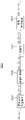
도 1 내지 6을 참조하면, 상기 부호화부(1300)는 예측부(1301), 예측 부호화부(1302), 변환부(1303), 양자화부(1304), 역양자화부(1305), 역변환부(1306), 예측 복호화부(1307), 엔트로피 부호화부(1308), 모드 결정부(1309), 참조 갱신부(1310), 참조 버퍼(1311), 비트스트림 생성부(1312) 및 압축률 제어부(1313)를 포함한다.1 to 6 , the
상기 예측부(1301)는 상기 참조 버퍼(1311)로부터 이전 블록(Bm-1)의 이전 블록 복호화 영상 데이터(ABC'(Bm-1))를 수신하고, 상기 라인 버퍼(1200)로부터 현재 블록 영상 데이터(ABC(Bm))를 수신한다. 상기 예측부(1301)는 상기 이전 블록 복호화 영상 데이터(ABC'(Bm-1)) 및 상기 현재 블록 영상 데이터(ABC(Bm))를 기초로 현재 블록 예측 잔차 신호(P_RS(Bm))를 생성하여 상기 예측 부호화부(1302)에 출력한다. 상기 현재 블록 예측 잔차 신호(P_RS(Bm))는 상기 현재 블록 영상 데이터(ABC(Bm))와 상기 이전 블록 복호화 영상 데이터(ABC'(Bm-1))의 차일 수 있다. 상기 현재 블록 예측 잔차 신호(P_RS(Bm))는 복수일 수 있다.The
상기 예측부(1301)가 상기 이전 블록 복호화 영상 데이터(ABC'(Bm-1)) 및 상기 현재 블록 영상 데이터(ABC(Bm))를 기초로 상기 현재 블록 예측 잔차 신호(P_RS(Bm))를 생성하는 방법은 도 7a 내지 7d를 참조하여 상세히 후술한다.The
상기 예측 부호화부(1302)는 상기 현재 블록 예측 잔차 신호(P_RS(Bm))를 부호화하여 현재 블록 잔차 신호(RS(Bm))를 생성한다. 상기 현재 블록 잔차 신호(RS(Bm))는 복수일 수 있다. 상기 예측 부호화부(1302)는 상기 현재 블록 잔차 신호(RS(Bm))를 상기 변환부(1303)에 출력한다.The
상기 변환부(1303)는 상기 현재 블록 잔차 신호(RS(Bm))를 이산 코사인 변환(Discrete Cosine Transform; 이하, DCT라 칭함)하여 현재 블록 DCT 신호(DCT(Bm))를 생성한다. 상기 현재 블록 DCT 신호(DCT(Bm))는 복수일 수 있다. 상기 DCT를 통해, 시간 영역의 상기 현재 블록 잔차 신호(RS(Bm))는 주파수 영역의 상기 현재 블록 DCT 신호(DCT(Bm))로 변환된다. 즉, 상기 DCT를 통해, 블록당 4 * 4의 잔차 신호 데이터들을 갖는 상기 현재 블록 잔차 신호(RS(Bm))는 블록당 4 * 4의 DCT 계수들을 갖는 상기 현재 블록 DCT 신호(DCT(Bm))로 변환된다. 상기 변환부(1303)는 입력 영상에 따라 상기 DCT를 생략할 수 있다. 예를 들어, 상기 변환부(1303)는 상기 입력 영상에 특수한 패턴이 포함될 경우 상기 DCT를 생략할 수 있다. 상기 변환부(1303)는 갖는 상기 현재 블록 DCT 신호(DCT(Bm))를 상기 양자화부(1304)에 출력한다.The
상기 양자화부(1304)는 상기 현재 블록 DCT 신호(DCT(Bm))를 양자화하여 현재 블록 양자화 신호(Q(Bm))를 생성한다. 상기 양자화는 상기 DCT 계수들을 양자화 계수로 나눈 뒤 반올림하는 과정이다. 상기 양자화 계수는 0 ~ 51 사이의 값을 가질 수 있다. 상기 현재 블록 양자화 신호(Q(Bm))는 복수일 수 있다. 상기 양자화부(1304)는 상기 현재 블록 양자화 신호(Q(Bm))를 상기 엔트로피 부호화부(1308) 및 상기 역양자화부(1305)에 출력한다.The
상기 역양자화부(1305)는 상기 현재 블록 양자화 신호(Q(Bm))를 역양자화하여 현재 블록 역양자화 신호(DCT'(Bm))를 생성한다. 상기 역양자화는 상기 양자화의 반대 과정일 수 있다. 상기 현재 블록 역양자화 신호(DCT'(Bm))는 복수일 수 있다. 상기 역양자화부(1305)는 상기 현재 블록 역양자화 신호(DCT'(Bm))를 상기 역변환부(1306)에 출력한다.The
상기 역변환부(1306)는 상기 현재 블록 역양자화 신호(DCT'(Bm))를 역변환하여 현재 블록 역변환 신호(RS'(Bm))를 생성한다. 상기 역변환은 상기 DCT의 반대 과정일 수 있다. 상기 역변환을 통해, 주파수 영역의 상기 현재 블록 역양자화 신호(DCT'(Bm))는 시간 영역의 상기 현재 블록 역변환 신호(RS'(Bm))로 변환된다. 상기 현재 블록 역변환 신호(RS'(Bm))는 복수일 수 있다. 상기 역변환부(1306)는 상기 입력 영상에 따라 상기 역변환을 생략할 수 있다. 예를 들어, 상기 역변환부(1306)는 상기 변환부(1303)가 상기 DCT를 생략한 경우 상기 역변환을 생략할 수 있다. 상기 역변환부(1306)는 상기 현재 블록 역변환 신호(RS'(Bm))를 상기 예측 부호화부(1307)에 출력한다.The
상기 변환부(1303), 상기 양자화부(1304), 상기 역양자화부(1305) 및 상기 역변환부(1306)의 DCT 생략 여부에 따른 구체적인 동작은 도 8a 및 8b를 참조하여 상세히 후술한다.Specific operations of the
상기 예측 복호화부(1307)는 상기 현재 블록 역변환 신호(RS'(Bm))를 복호화하여 현재 블록 복호화 영상 데이터(ABC'(Bm))를 생성한다. 상기 복호화는 상기 예측 부호화부(1302)에서 수행된 부호화의 반대 과정일 수 있다. 상기 현재 블록 복호화 영상 데이터(ABC'(Bm))는 복수일 수 있다. 상기 예측 복호화부(1307)는 상기 현재 블록 복호화 영상 데이터(ABC'(Bm))를 상기 모드 결정부(1309) 및 상기 참조 갱신부(1310)에 출력한다.The
상기 엔트로피 부호화부(1308)는 상기 현재 블록 양자화 신호(Q(Bm))를 엔트로피 부호화(Entropy Encoding)하여 현재 블록 엔트로피 부호화 신호(E(Bm))를 생성한다. 상기 현재 블록 엔트로피 부호화 신호(E(Bm))는 복수일 수 있다. 상기 엔트로피 부호화부(1308)는 상기 현재 블록 엔트로피 부호화 신호(E(Bm))를 상기 모드 결정부(1309)에 출력한다.The
상기 모드 결정부(1309)는 복수의 상기 현재 블록 복호화 영상 데이터들(ABC'(Bm))을 기초로 복수의 상기 현재 블록 엔트로피 부호화 신호들(E(Bm)) 중 하나를 선택하여 상기 비트스트림 생성부(1312)에 출력한다. 상기 모드 결정부(1309)는 상기 현재 블록 복호화 영상 데이터들(ABC'(Bm)) 중 상기 현재 블록 영상 데이터(ABC(Bm))에 가장 근접하는 데이터에 해당하는 모드의 현재 블록 엔트로피 부호화 신호(E(Bm))를 선택할 수 있다.The
상기 참조 갱신부(1310)는 상기 현재 블록 복호화 영상 데이터(ABC'(Bm))를 수신하여 상기 참조 버퍼(1311)에 저장된 이전 블록의 복호화 영상 데이터를 갱신한다. 상기 참조 버퍼(1311)는 상기 현재 블록 복호화 영상 데이터(ABC'(Bm))를 이전 블록 복호화 영상 데이터(ABC'(Bm-1))로서 상기 예측부(1301)에 제공한다. 즉, 상기 예측부(1301)가 상기 라인 버퍼(1200)로부터 상기 현재 블록 영상 데이터(ABC(Bm))를 수신할 때, 상기 참조 버퍼(1311)는 상기 이전 블록 복호화 영상 데이터(ABC'(Bm-1))를 제공한다.The
상기 비트스트림 생성부(1312)는 상기 모드 결정부(1309)가 선택한 상기 현재 블록 엔트로피 부호화 신호(E(Bm))의 비트스트림을 생성하여 압축률 제어부(1313)에 출력한다.The
상기 압축률 제어부(1313)는 상기 현재 블록 엔트로피 부호화 신호(E(Bm))를 기초로 다음 블록의 압축률을 결정한다. 상기 압축률 제어부(1313)는 상기 결정된 다음 블록의 압축률에 관한 정보를 상기 비트스트림과 함께 상기 현재 블록 부호화 데이터(BS(Bm))로서 상기 메모리(1400)에 제공할 수 있다.The compression
상기 압축률 제어부(1313)가 상기 다음 블록의 압축률을 결정하는 방법은 도 9a 내지 9b를 참조하여 상세히 후술한다.A method for the compression
도 7a 내지 7d는 도 6의 부호화부에 포함되는 예측부의 예측 방법들을 나타내는 도면들이다.7A to 7D are diagrams illustrating prediction methods of a predictor included in the encoder of FIG. 6 .
도 1 내지 6 및 7a 내지 7d를 참조하면, 현재 블록(Bm)은 4 * 4 픽셀들(P0 ~ P15)로 이루어진다. 이전 블록들(Bm-1)의 마지막 수평 라인에는 제1 내지 제12 참조 픽셀들(R1 ~ R12)이 위치한다.1 to 6 and 7A to 7D , the current block Bm includes 4 * 4 pixels P0 to P15. The first to twelfth reference pixels R1 to R12 are positioned on the last horizontal line of the previous blocks Bm-1.
상기 예측부(1301)는 상기 제1 내지 제12 참조 픽셀들(R1 ~ R12)을 참조하여 상기 현재 블록(Bm)의 픽셀들(P0 ~ P15)의 영상 데이터를 예측한다. 즉, 상기 이전 블록 복호화 영상 데이터(ABC'(Bm-1))에 포함된 상기 제1 내지 제12 참조 픽셀들(R1 ~ R12)의 영상 데이터 정보를 참조하여 상기 현재 블록(Bm)의 픽셀들(P0 ~ P15)의 영상 데이터를 예측한다. 상기 예측 방법은 도 7a 내지 7d의 4 가지가 있을 수 있다. 다만, 본 발명에서 상기 예측 방법은 상기 4 가지에 한정되지는 않는다.The
도 7a를 참조하면, 상기 예측부(1301)는 상기 제1 내지 제12 참조 픽셀들(R1 ~ R12) 중 일부 픽셀들의 이전 블록 복호화 영상 데이터(ABC'(Bm-1))의 평균값을 이용하여 상기 현재 블록(Bm)의 픽셀들(P0 ~ P15)의 영상 데이터를 예측할 수 있다. 예를 들어, 상기 예측부(1301)는 상기 제1 내지 제8 참조 픽셀들(R1 ~ R8)의 이전 블록 복호화 영상 데이터(ABC'(Bm-1))의 평균값을 이용하여 상기 현재 블록(Bm)의 픽셀들(P0 ~ P15)의 영상 데이터를 예측할 수 있다. 구체적으로, 상기 예측부(1301)는 상기 현재 블록(Bm)의 픽셀들(P0 ~ P15) 각각의 현재 블록 영상 데이터(ABC(Bm))와 상기 평균값의 차를 계산하여, 상기 현재 블록 예측 잔차 신호(P_RS(Bm))를 생성할 수 있다.Referring to FIG. 7A , the
도 7b를 참조하면, 상기 예측부(1301)는 상기 제1 내지 제12 참조 픽셀들(R1 ~ R12) 중 상기 현재 블록(Bm)과 접하는 픽셀들의 이전 블록 복호화 영상 데이터(ABC'(Bm-1))를 이용하여 상기 현재 블록(Bm)의 픽셀들(P0 ~ P15)의 영상 데이터를 예측할 수 있다. 예를 들어, 상기 예측부(1301)는 상기 제5 내지 제8 참조 픽셀들(R5 ~ R8)의 이전 블록 복호화 영상 데이터(ABC'(Bm-1))를 이용하여 도면상 아래 방향으로 상기 현재 블록(Bm)의 픽셀들(P0 ~ P15)의 영상 데이터를 예측할 수 있다. 구체적으로, 상기 예측부(1301)는 상기 현재 블록(Bm)의 픽셀들(P0 ~ P15) 중 첫번째 열에 위치한 픽셀들(P0, P4, P8, P12) 각각의 현재 블록 영상 데이터(ABC(Bm))와 상기 제5 참조 픽셀(R5)의 이전 블록 복호화 영상 데이터(ABC'(Bm-1))의 차, 상기 현재 블록(Bm)의 픽셀들(P0 ~ P15) 중 두번째 열에 위치한 픽셀들(P1, P5, P9, P13) 각각의 현재 블록 영상 데이터(ABC(Bm))와 상기 제6 참조 픽셀(R6)의 이전 블록 복호화 영상 데이터(ABC'(Bm-1))의 차, 상기 현재 블록(Bm)의 픽셀들(P0 ~ P15) 중 세번째 열에 위치한 픽셀들(P2, P6, P10, P14) 각각의 현재 블록 영상 데이터(ABC(Bm))와 상기 제7 참조 픽셀(R7)의 이전 블록 복호화 영상 데이터(ABC'(Bm-1))의 차, 및 상기 현재 블록(Bm)의 픽셀들(P0 ~ P15) 중 네번째 열에 위치한 픽셀들(P3, P7, P11, P15) 각각의 현재 블록 영상 데이터(ABC(Bm))와 상기 제8 참조 픽셀(R8)의 이전 블록 복호화 영상 데이터(ABC'(Bm-1))의 차를 계산하여, 상기 현재 블록 예측 잔차 신호(P_RS(Bm))를 생성할 수 있다.Referring to FIG. 7B , the
도 7c를 참조하면, 상기 예측부(1301)는 상기 제1 내지 제12 참조 픽셀들(R1 ~ R12) 중 상기 현재 블록(Bm)과 접하는 픽셀들 및 상기 현재 블록(Bm)의 도면상 오른쪽 위에 위치한 픽셀들의 이전 블록 복호화 영상 데이터(ABC'(Bm-1))를 이용하여 상기 현재 블록(Bm)의 픽셀들(P0 ~ P15)의 영상 데이터를 예측할 수 있다. 예를 들어, 상기 예측부(1301)는 상기 제5 내지 제12 참조 픽셀들(R5 ~ R12)의 이전 블록 복호화 영상 데이터(ABC'(Bm-1))를 이용하여 도면상 왼쪽 아래를 향하는 대각선 방향으로 상기 현재 블록(Bm)의 픽셀들(P0 ~ P15)의 영상 데이터를 예측할 수 있다. 구체적으로, 상기 예측부(1301)는 상기 현재 블록(Bm)의 픽셀들(P0 ~ P15) 중 첫번째 대각선 상에 위치한 픽셀(P0)의 현재 블록 영상 데이터(ABC(Bm))와 상기 제6 참조 픽셀(R6)의 이전 블록 복호화 영상 데이터(ABC'(Bm-1))의 차, 상기 현재 블록(Bm)의 픽셀들(P0 ~ P15) 중 두번째 대각선 상에 위치한 픽셀들(P1, P4)의 현재 블록 영상 데이터(ABC(Bm))와 상기 제7 참조 픽셀(R7)의 이전 블록 복호화 영상 데이터(ABC'(Bm-1))의 차, 상기 현재 블록(Bm)의 픽셀들(P0 ~ P15) 중 세번째 대각선 상에 위치한 픽셀들(P2, P5, P8)의 현재 블록 영상 데이터(ABC(Bm))와 상기 제8 참조 픽셀(R8)의 이전 블록 복호화 영상 데이터(ABC'(Bm-1))의 차, 상기 현재 블록(Bm)의 픽셀들(P0 ~ P15) 중 네번째 대각선 상에 위치한 픽셀들(P3, P6, P9, P12)의 현재 블록 영상 데이터(ABC(Bm))와 상기 제9 참조 픽셀(R9)의 이전 블록 복호화 영상 데이터(ABC'(Bm-1))의 차, 상기 현재 블록(Bm)의 픽셀들(P0 ~ P15) 중 다섯번째 대각선 상에 위치한 픽셀들(P7, P10, P13)의 현재 블록 영상 데이터(ABC(Bm))와 상기 제10 참조 픽셀(R10)의 이전 블록 복호화 영상 데이터(ABC'(Bm-1))의 차, 상기 현재 블록(Bm)의 픽셀들(P0 ~ P15) 중 여섯번째 대각선 상에 위치한 픽셀들(P11, P14)의 현재 블록 영상 데이터(ABC(Bm))와 상기 제11 참조 픽셀(R11)의 이전 블록 복호화 영상 데이터(ABC'(Bm-1))의 차, 및 상기 현재 블록(Bm)의 픽셀들(P0 ~ P15) 중 일곱번째 대각선 상에 위치한 픽셀(P15)의 현재 블록 영상 데이터(ABC(Bm))와 상기 제12 참조 픽셀(R12)의 이전 블록 복호화 영상 데이터(ABC'(Bm-1))의 차를 계산하여, 상기 현재 블록 예측 잔차 신호(P_RS(Bm))를 생성할 수 있다.Referring to FIG. 7C , the
도 7d를 참조하면, 상기 예측부(1301)는 상기 제1 내지 제12 참조 픽셀들(R1 ~ R12) 중 상기 현재 블록(Bm)과 접하는 픽셀들 및 상기 현재 블록(Bm)의 도면상 왼쪽 위에 위치한 픽셀들의 이전 블록 복호화 영상 데이터(ABC'(Bm-1))를 이용하여 상기 현재 블록(Bm)의 픽셀들(P0 ~ P15)의 영상 데이터를 예측할 수 있다. 예를 들어, 상기 예측부(1301)는 상기 제1 내지 제8 참조 픽셀들(R1 ~ R8)의 이전 블록 복호화 영상 데이터(ABC'(Bm-1))를 이용하여 도면상 오른쪽 아래를 향하는 대각선 방향으로 상기 현재 블록(Bm)의 픽셀들(P0 ~ P15)의 영상 데이터를 예측할 수 있다. 구체적으로, 상기 예측부(1301)는 상기 현재 블록(Bm)의 픽셀들(P0 ~ P15) 중 첫번째 대각선 상에 위치한 픽셀(P12)의 현재 블록 영상 데이터(ABC(Bm))와 상기 제1 참조 픽셀(R1)의 이전 블록 복호화 영상 데이터(ABC'(Bm-1))의 차, 상기 현재 블록(Bm)의 픽셀들(P0 ~ P15) 중 두번째 대각선 상에 위치한 픽셀들(P8, P13)의 현재 블록 영상 데이터(ABC(Bm))와 상기 제2 참조 픽셀(R2)의 이전 블록 복호화 영상 데이터(ABC'(Bm-1))의 차, 상기 현재 블록(Bm)의 픽셀들(P0 ~ P15) 중 세번째 대각선 상에 위치한 픽셀들(P4, P9, P14)의 현재 블록 영상 데이터(ABC(Bm))와 상기 제3 참조 픽셀(R3)의 이전 블록 복호화 영상 데이터(ABC'(Bm-1))의 차, 상기 현재 블록(Bm)의 픽셀들(P0 ~ P15) 중 네번째 대각선 상에 위치한 픽셀들(P0, P5, P10, P15)의 현재 블록 영상 데이터(ABC(Bm))와 상기 제4 참조 픽셀(R4)의 이전 블록 복호화 영상 데이터(ABC'(Bm-1))의 차, 상기 현재 블록(Bm)의 픽셀들(P0 ~ P15) 중 다섯번째 대각선 상에 위치한 픽셀들(P1, P6, P11)의 현재 블록 영상 데이터(ABC(Bm))와 상기 제5 참조 픽셀(R5)의 이전 블록 복호화 영상 데이터(ABC'(Bm-1))의 차, 상기 현재 블록(Bm)의 픽셀들(P0 ~ P15) 중 여섯번째 대각선 상에 위치한 픽셀들(P2, P7)의 현재 블록 영상 데이터(ABC(Bm))와 상기 제6 참조 픽셀(R6)의 이전 블록 복호화 영상 데이터(ABC'(Bm-1))의 차, 및 상기 현재 블록(Bm)의 픽셀들(P0 ~ P15) 중 일곱번째 대각선 상에 위치한 픽셀(P3)의 현재 블록 영상 데이터(ABC(Bm))와 상기 제7 참조 픽셀(R7)의 이전 블록 복호화 영상 데이터(ABC'(Bm-1))의 차를 계산하여, 상기 현재 블록 예측 잔차 신호(P_RS(Bm))를 생성할 수 있다.Referring to FIG. 7D , the
도 7a 내지 7d의 실시예에 따르면, 이미 부호화, 압축 및 복호화가 완료된 이전 블록의 영상 데이터만을 이용하여 현재 블록의 영상 데이터를 예측할 수 있다.7A to 7D , the image data of the current block may be predicted using only the image data of the previous block that has already been encoded, compressed, and decoded.
도 8a는 도 6의 부호화부에 포함되는 변환부 및 양자화부를 나타내는 블록도이다. 도 8b는 도 6의 부호화부에 포함되는 역양자화부 및 역변환부를 나타내는 블록도이다.8A is a block diagram illustrating a transform unit and a quantizer included in the encoder of FIG. 6 . 8B is a block diagram illustrating an inverse quantizer and an inverse transform unit included in the encoder of FIG. 6 .
도 1 내지 6, 8a 및 8b를 참조하면, 상기 변환부(1303)는 상기 입력 영상에 따라 상기 DCT를 수행하거나 생략할 수 있다. 예를 들어, 상기 변환부(1303)는 상기 입력 영상에 특수한 패턴이 포함될 경우 상기 DCT를 생략하고, 그렇지 않으면 상기 DCT를 수행할 수 있다. 상기 특수한 패턴은 상기 DCT가 수행될 경우 압축에 불리하게 바뀌는 패턴일 수 있다.1 to 6 , 8A and 8B , the
상기 변환부(1303)는 변환 수행부(1303a) 및 변환 생략부(1303b)를 포함할 수 있다. 상기 양자화부(1304)는 변환 양자화부(1304a) 및 비변환 양자화부(1304b)를 포함할 수 있다.The
상기 변환부(1303)가 상기 DCT를 수행하는 경우, 상기 변환 수행부(1303a)는 상기 현재 블록 잔차 신호(RS(Bm))를 기초로 상기 DCT를 수행하여 상기 현재 블록 DCT 신호(DCT(Bm))를 생성한다. 이 경우, 상기 변환 양자화부(1304a)는 상기 현재 블록 DCT 신호(DCT(Bm))를 양자화하여 상기 현재 블록 양자화 신호(Qa(Bm))를 생성한다. 상기 양자화는 주파수 영역에서의 양자화일 수 있다.When the
상기 변환부(1303)가 상기 DCT를 생략하는 경우, 상기 변환 생략부(1303b)는 상기 현재 블록 잔차 신호(RS(Bm))를 그대로 상기 비변환 양자화부(1304b)에 전달한다. 이 경우, 상기 비변환 양자화부(1304b)는 상기 현재 블록 잔차 신호(RS(Bm))를 양자화하여 상기 현재 블록 양자화 신호(Qb(Bm))를 생성한다. 상기 양자화는 시간 영역에서의 양자화일 수 있다.When the
상기 역변환부(1306)는 역변환 수행부(1306a) 및 역변환 생략부(1306b)를 포함할 수 있다.The
역양자화부(1325)는 상기 현재 블록 양자화 신호(Q(Bm))를 역양자화한다. 예를 들어, 상기 역양자화부(1325)는 상기 주파수 영역의 현재 블록 양자화 신호(Qa(Bm))를 주파수 영역에서 역양자화하여, 주파수 영역의 현재 블록 역양자화 신호(DCT'(Bm))를 생성하여, 상기 역변환 수행부(1306a)에 출력한다. 이와는 달리, 상기 역양자화부(1325)는 상기 시간 영역의 현재 블록 양자화 신호(Qb(Bm))를 시간 영역에서 역양자화하여, 시간 영역의 현재 블록 역양자화 신호(RS'(Bm))를 생성하여, 상기 역변환 생략부(1306b)에 출력한다. 상기 시간 영역의 현재 블록 역양자화 신호(RS'(Bm))는 상기 현재 블록 역변환 신호(RS'(Bm))와 실질적으로 동일할 수 있다.The
상기 역변환 수행부(1306a)는 상기 주파수 영역의 현재 블록 역양자화 신호(DCT'(Bm))를 역변환하여 상기 현재 블록 역변환 신호(RS'(Bm))를 생성한다. 상기 역변환 수행부(1306a)는 상기 현재 블록 역변환 신호(RS'(Bm))를 상기 예측 부호화부(1307)에 출력한다. 상기 역변환 생략부(1306b)는 상기 시간 영역의 현재 블록 역양자화 신호(RS'(Bm))를 그대로 상기 예측 부호화부(1307)에 전달한다.The inverse
도 8a 및 8b의 실시예에 따르면, DCT가 수행될 경우 압축 효율이 낮아지는 입력 영상에 대해서는 상기 DCT를 생략함으로써, 영상의 압축 효율을 높일 수 있다.According to the embodiments of FIGS. 8A and 8B , when DCT is performed, the compression efficiency of an image can be increased by omitting the DCT for an input image whose compression efficiency is low.
도 9a 내지 9c는 도 6의 부호화부에 포함되는 압축률 제어부의 압축률 제어 방법들을 나타내는 도면들이다.9A to 9C are diagrams illustrating compression rate control methods of a compression rate controller included in the encoder of FIG. 6 .
도 1 내지 6 및 9a를 참조하면, 상기 압축률 제어부(1313)는 현재 블록 라인의 블록들의 현재 블록 엔트로피 부호화 신호(E(Bm))를 기초로 다음 블록 라인의 압축률을 결정한다. 예를 들어, 상기 압축률 제어부(1313)는 상기 현재 블록 엔트로피 부호화 신호(E(Bm))를 기초로 목표 압축률과 상기 현재 블록 라인까지의 실제 압축률을 비교하여, 상기 다음 블록 라인의 압축률을 결정할 수 있다. 상기 압축률 제어부(1313)는 상기 결정된 다음 블록 라인의 압축률에 상응하도록 하는, 현재 블록 라인의 양자화 계수와 다음 블록 라인의 양자화 계수의 차에 대응하는 양자화 계수 변화값(DQPa)을 생성한다. 상기 다음 블록 라인의 양자화 계수는 상기 결정된 다음 블록 라인의 압축률을 달성하도록 하는 값이다. 상기 압축률 제어부(1313)는 상기 양자화 계수 변화값(DQPa)을 상기 비트스트림과 함께 상기 현재 블록 부호화 데이터(BS(Bm))로서 상기 메모리(1400)에 제공한다.1 to 6 and 9A , the compression
예를 들어, 상기 압축률 제어부(1313)는 첫번째 블록 라인의 블록들의 블록 엔트로피 부호화 신호를 기초로 목표 압축률과 상기 첫번째 블록 라인까지의 실제 압축률을 비교하여, 두번째 블록 라인의 압축률을 결정할 수 있다. 상기 압축률 제어부(1313)는 상기 결정된 두번째 블록 라인의 압축률에 상응하도록 하는, 제1 양자화 계수 변화값(DQP1a)을 생성할 수 있다. 상기 제1 양자화 계수 변화값(DQP1a)은 상기 첫번째 블록 라인의 양자화 계수와 상기 결정된 두번째 블록 라인의 압축률을 달성하도록 하는 상기 두번째 블록 라인의 양자화 계수의 차이다.For example, the
상기 압축률 제어부(1313)는 상기 두번째 블록 라인의 블록들의 블록 엔트로피 부호화 신호를 기초로 목표 압축률과 상기 두번째 블록 라인까지의 실제 압축률을 비교하여, 세번째 블록 라인의 압축률을 결정할 수 있다. 상기 압축률 제어부(1313)는 상기 결정된 세번째 블록 라인의 압축률에 상응하도록 하는, 제2 양자화 계수 변화값(DQP2a)을 생성할 수 있다. 상기 제2 양자화 계수 변화값(DQP2a)은 상기 두번째 블록 라인의 양자화 계수와 상기 결정된 세번째 블록 라인의 압축률을 달성하도록 하는 상기 세번째 블록 라인의 양자화 계수의 차이다.The compression
도 9b 및 9c를 참조하면, 상기 압축률 제어의 단위를 복수의 블록 라인들로 설정할 수 있다.9B and 9C , the compression rate control unit may be set to a plurality of block lines.
예를 들어, 도 9b를 참조하면, 상기 압축률 제어부(1313)는 첫번째 및 두번째 블록 라인들의 블록들의 블록 엔트로피 부호화 신호들을 기초로 목표 압축률과 상기 두번째 블록 라인까지의 실제 압축률을 비교하여, 세번째 및 네번째 블록 라인들의 압축률을 결정할 수 있다. 상기 압축률 제어부(1313)는 상기 결정된 세번째 및 네번째 블록 라인들의 압축률에 상응하도록 하는, 제1 양자화 계수 변화값(DQP1b)을 생성할 수 있다. 상기 제1 양자화 계수 변화값(DQP1b)은 상기 첫번째 및 두번째 블록 라인들의 양자화 계수와 상기 결정된 세번째 및 네번째 블록 라인들의 압축률을 달성하도록 하는 상기 세번째 및 네번째 블록 라인들의 양자화 계수의 차이다.For example, referring to FIG. 9B , the compression
예를 들어, 도 9c를 참조하면, 상기 압축률 제어부(1313)는 첫번째 내지 세번째 블록 라인들의 블록들의 블록 엔트로피 부호화 신호들을 기초로 목표 압축률과 상기 세번째 블록 라인까지의 실제 압축률을 비교하여, 네번째 내지 여섯번째 블록 라인들의 압축률을 결정할 수 있다. 상기 압축률 제어부(1313)는 상기 결정된 네번째 내지 여섯번째 블록 라인들의 압축률에 상응하도록 하는, 제1 양자화 계수 변화값(DQP1c)을 생성할 수 있다. 상기 제1 양자화 계수 변화값(DQP1c)은 상기 첫번째 내지 세번째 블록 라인들의 양자화 계수와 상기 결정된 네번째 내지 여섯번째 블록 라인들의 압축률을 달성하도록 하는 상기 네번째 내지 여섯번째 블록 라인들의 양자화 계수의 차이다.For example, referring to FIG. 9C , the compression
도 9a 내지 9c의 실시예에 따르면, 일정 단위의 블록별로 목표 압축률의 달성 여부를 판단하여, 다음 블록의 압축률을 조절할 수 있다. 뿐만 아니라, 상기 압축률 조절에 있어서 현재 블록과 다음 블록의 양자화 계수의 차이에 해당하는 정보만 필요하다.According to the embodiment of FIGS. 9A to 9C , it is possible to determine whether a target compression ratio is achieved for each block of a predetermined unit, and adjust the compression ratio of the next block. In addition, only information corresponding to the difference between the quantization coefficients of the current block and the next block is required in adjusting the compression ratio.
도 10은 도 5의 데이터 신호 생성부에 포함되는 복호화부의 일 예를 나타내는 블록도이다.10 is a block diagram illustrating an example of a decoder included in the data signal generator of FIG. 5 .
도 1 내지 6 및 10을 참조하면, 상기 복호화부(1500)는 엔트로피 복호화부(1501), 역양자화부(1502), 역변환부(1503) 및 예측 복호화부(1504)를 포함한다.1 to 6 and 10 , the
상기 엔트로피 복호화부(1501)는 상기 이전 프레임 부호화 데이터(BS(Fn-1))를 엔트로피 복호화(Entropy Decoding)하여, 이전 프레임 엔트로피 복호화 신호(Q'(Fn-1))를 생성한다. 상기 엔트로피 복호화는 상기 엔트로피 부호화부(1308)가 수행하는 상기 엔트로피 부호화의 반대 과정일 수 있다. 상기 엔트로피 복호화부(1501)는 상기 이전 프레임 엔트로피 복호화 신호(Q'(Fn-1))를 상기 역양자화부(1502)에 출력한다.The
상기 역양자화부(1502)는 상기 이전 프레임 엔트로피 복호화 신호(Q'(Fn-1))를 역양자화하여 이전 프레임 역양자화 신호(DCT'(Fn-1))를 생성한다. 상기 역양자화부(1502)는 상기 이전 프레임 역양자화 신호(DCT'(Fn-1))를 상기 역변환부(1503)에 출력한다.The
상기 역변환부(1503)는 상기 이전 프레임 역양자화 신호(DCT'(Fn-1))를 역변환하여 이전 프레임 역변환 신호(RS'(Fn-1))를 생성한다. 상기 역변환부(1503)는 상기 이전 프레임 역변환 신호(RS'(Fn-1))를 상기 예측 복호화부(1504)에 출력한다.The
상기 예측 복호화부(1504)는 상기 이전 프레임 역변환 신호(RS'(Fn-1))를 복호화하여 상기 이전 프레임 복호화 데이터(ABC'(Fn-1))를 생성한다. 상기 예측 복호화부(1504)는 상기 이전 프레임 복호화 데이터(ABC'(Fn-1))를 상기 색공간 역변환부(1600)에 출력한다.The
도 11은 도 5의 데이터 신호 생성부에 포함되는 복호화부의 다른 예를 나타내는 블록도이다. 도 10과 중복되는 설명은 생략한다.11 is a block diagram illustrating another example of a decoder included in the data signal generator of FIG. 5 . A description overlapping with FIG. 10 will be omitted.
도 1 내지 6 및 11을 참조하면, 상기 복호화부(1500)는 엔트로피 복호화부(1501), 역양자화부(1502), 역변환부(1503) 및 예측 복호화부(1504)를 포함한다. 상기 복호화부(1500)는 압축률 제어부(1505)를 더 포함할 수 있다.1 to 6 and 11 , the
도 6의 부호화부(1300)에 포함되는 압축률 제어부(1313)는 상기 현재 블록 엔트로피 부호화 신호(E(Bm))를 기초로 다음 블록의 압축률을 결정한다.The
상기 압축률 제어부(1505)는 도 6의 부호화부(1300)에 포함되는 압축률 제어부(1313)와 실질적으로 동일한 동작을 수행할 수 있다. 상기 압축률 제어부(1505)는 상기 이전 프레임 부호화 데이터(BS(Fn-1))를 기초로 각 블록의 압축률을 판단하여, 상기 역양자화부(1502)에 양자화 계수 변화값(DQP)을 제공한다.The compression
상기 역양자화부(1502)는 상기 양자화 계수 변화값(DQP)을 기초로 각 블록의 양자화 계수를 판단하고 상기 이전 프레임 엔트로피 복호화 신호(Q'(Fn-1))를 역양자화하여, 이전 프레임 역양자화 신호(DCT'(Fn-1))를 생성한다.The
도 11의 실시예에 따르면, 복호화부에도 압축률 제어부가 포함되어 있으므로, 부호화부에서 복호화부에 다음 블록의 압축률에 관한 정보를 제공하지 않아도 된다.According to the embodiment of FIG. 11 , since the decoder also includes the compression rate control unit, the encoder does not need to provide information on the compression rate of the next block to the decoder.
본 발명은 표시 장치 및 이를 포함하는 다양한 장치 및 시스템에 적용될 수 있다. 따라서 본 발명은 휴대폰, 스마트 폰, PDA, PMP, 디지털 카메라, 캠코더, PC, 서버 컴퓨터, 워크스테이션, 노트북, 디지털 TV, 셋-탑 박스, 음악 재생기, 휴대용 게임 콘솔, 네비게이션 시스템, 스마트 카드, 프린터 등과 같은 다양한 전자기기에 유용하게 이용될 수 있다.The present invention can be applied to a display device and various devices and systems including the same. Accordingly, the present invention is a mobile phone, a smart phone, a PDA, a PMP, a digital camera, a camcorder, a PC, a server computer, a workstation, a notebook computer, a digital TV, a set-top box, a music player, a portable game console, a navigation system, a smart card, a printer It can be usefully used in various electronic devices, such as.
이상 실시예들을 참조하여 설명하였지만, 해당 기술분야의 숙련된 당업자는 하기의 특허 청구의 범위에 기재된 본 발명의 사상 및 영역으로부터 벗어나지 않는 범위 내에서 본 발명을 다양하게 수정 및 변경시킬 수 있음을 이해할 수 있을 것이다.Although it has been described with reference to the above embodiments, it will be understood by those skilled in the art that various modifications and changes can be made to the present invention without departing from the spirit and scope of the present invention as set forth in the claims below. will be able
100: 표시 패널 200: 타이밍 컨트롤러
300: 게이트 구동부 400: 감마 기준 전압 생성부
500: 데이터 구동부100: display panel 200: timing controller
300: gate driver 400: gamma reference voltage generator
500: data driving unit
Claims (20)
제1 수평 라인에 위치하는 제1 블록들의 영상 데이터를 기초로 상기 제1 수평 라인의 하단에 위치하는 제2 수평 라인에 위치하는 제2 블록들의 영상 데이터를 예측하여, 잔차 신호를 생성하는 단계;
입력 영상에 따라 상기 잔차 신호의 이산 코사인 변환(Discrete Cosine Transform; 이하, DCT라 칭함) 여부를 결정하는 단계;
상기 제2 블록들의 영상 데이터를 압축하는 단계; 및
상기 제2 블록들의 영상 데이터의 압축률에 따라 상기 제2 수평 라인의 하단에 위치하는 제3 수평 라인에 위치하는 제3 블록들의 영상 데이터의 압축률을 결정하는 단계를 포함하며,
상기 입력 영상에 따라 상기 잔차 신호의 DCT 여부를 결정하는 단계는
상기 입력 영상에 특수한 패턴이 포함되어 있으면 상기 DCT를 수행하지 않고, 상기 입력 영상에 상기 특수한 패턴이 포함되어 있지 않으면 상기 DCT를 수행하는 단계를 포함하고,
상기 제2 블록들의 영상 데이터를 압축하는 단계는
상기 DCT를 수행하는 경우 상기 잔차 신호를 주파수 영역에서 양자화하고, 상기 DCT를 수행하지 않는 경우 상기 잔차 신호를 시간 영역에서 양자화하는 단계를 포함하며,
상기 특수한 패턴은 상기 DCT가 수행될 경우 압축에 불리하게 바뀌는 패턴인 것을 특징으로 하는 영상 압축 방법.In an image compression method of a display device for compressing image data for each block composed of a plurality of pixels, the method comprising:
generating a residual signal by predicting image data of second blocks positioned on a second horizontal line positioned below the first horizontal line based on image data of the first blocks positioned on the first horizontal line;
determining whether to perform discrete cosine transform (DCT) of the residual signal according to an input image;
compressing the image data of the second blocks; and
determining the compression ratio of the image data of third blocks positioned on a third horizontal line positioned below the second horizontal line according to the compression ratio of the image data of the second blocks;
The step of determining whether DCT of the residual signal according to the input image is
not performing the DCT if the input image includes a special pattern, and performing the DCT if the input image does not include the special pattern;
Compressing the image data of the second blocks includes:
quantizing the residual signal in the frequency domain when the DCT is performed, and quantizing the residual signal in the time domain when the DCT is not performed,
The special pattern is an image compression method, characterized in that the pattern is changed unfavorably to compression when the DCT is performed.
상기 잔차 신호를 생성하는 단계는
상기 제1 블록들의 최하단 라인에 위치하는 참조 픽셀들의 영상 데이터를 이용하여 상기 제2 블록들 각각의 영상 데이터를 예측하는 단계; 및
상기 예측된 제2 블록들 각각의 영상 데이터와 실제 제2 블록들 각각의 영상 데이터의 차에 해당하는 상기 잔차 신호를 생성하는 단계를 포함하는 것을 특징으로 하는 영상 압축 방법.According to claim 1,
generating the residual signal
predicting the image data of each of the second blocks by using image data of reference pixels located in the lowermost line of the first blocks; and
and generating the residual signal corresponding to a difference between the predicted image data of each of the second blocks and the actual image data of each of the second blocks.
상기 참조 픽셀들은
상기 제1 블록들 중, 상기 제2 블록들 각각의 상단에 접하는 제1 상단 블록 및 상기 제1 상단 블록의 좌측에 위치하는 제1 좌상단 블록의, 최하단 라인에 위치하는 픽셀들인 것을 특징으로 하는 영상 압축 방법.3. The method of claim 2,
The reference pixels are
of the first blocks, pixels positioned on the lowermost line of a first upper block in contact with an upper end of each of the second blocks and a first upper left block positioned to the left of the first upper block compression method.
상기 제2 블록들 각각의 영상 데이터를 예측하는 단계는
상기 참조 픽셀들의 영상 데이터의 평균값을 상기 제2 블록들 각각의 영상 데이터로 예측하는 단계를 포함하는 것을 특징으로 하는 영상 압축 방법.4. The method of claim 3,
Predicting the image data of each of the second blocks includes:
and predicting an average value of the image data of the reference pixels as the image data of each of the second blocks.
상기 제2 블록들 각각의 영상 데이터를 예측하는 단계는
상기 참조 픽셀들 각각의 영상 데이터를, 상기 제2 블록들의 픽셀들 중 각 참조 픽셀의 우측 하단 대각선 방향으로 위치하는 픽셀들의 영상 데이터로 예측하는 단계를 포함하는 것을 특징으로 하는 영상 압축 방법.4. The method of claim 3,
Predicting the image data of each of the second blocks includes:
and predicting the image data of each of the reference pixels as image data of pixels located in a diagonal direction at the lower right of each reference pixel among the pixels of the second blocks.
상기 참조 픽셀들은
상기 제1 블록들 중, 상기 제2 블록들 각각의 상단에 접하는 제1 상단 블록 및 상기 제1 상단 블록의 우측에 위치하는 제1 우상단 블록의, 최하단 라인에 위치하는 픽셀들이고,
상기 제2 블록들 각각의 영상 데이터를 예측하는 단계는
상기 참조 픽셀들 각각의 영상 데이터를, 상기 제2 블록들의 픽셀들 중 각 참조 픽셀의 좌측 하단 대각선 방향으로 위치하는 픽셀들의 영상 데이터로 예측하는 단계를 포함하는 것을 특징으로 하는 영상 압축 방법.3. The method of claim 2,
The reference pixels are
Among the first blocks, the pixels are positioned on the lowermost line of the first upper block in contact with the upper end of each of the second blocks and the first upper right block positioned to the right of the first upper block,
Predicting the image data of each of the second blocks includes:
and predicting the image data of each of the reference pixels as image data of pixels located diagonally to the lower left of each reference pixel among the pixels of the second blocks.
상기 참조 픽셀들은
상기 제1 블록들 중, 상기 제2 블록들 각각의 상단에 접하는 제1 상단 블록의, 최하단 라인에 위치하는 픽셀들이고,
상기 제2 블록들 각각의 영상 데이터를 예측하는 단계는
상기 참조 픽셀들 각각의 영상 데이터를, 상기 제2 블록들의 픽셀들 중 각 참조 픽셀의 아래 방향으로 위치하는 픽셀들의 영상 데이터로 예측하는 단계를 포함하는 것을 특징으로 하는 영상 압축 방법.3. The method of claim 2,
The reference pixels are
Among the first blocks, the pixels are located on the lowermost line of the first upper block in contact with the upper end of each of the second blocks,
Predicting the image data of each of the second blocks includes:
and predicting the image data of each of the reference pixels as image data of pixels located below each reference pixel among the pixels of the second blocks.
상기 제3 수평 라인에 위치하는 제3 블록들의 영상 데이터의 압축률을 결정하는 단계는
상기 제2 블록들의 영상 데이터의 압축률을 목표 압축률과 비교하는 단계; 및
상기 비교 결과에 따라 상기 제3 블록들의 영상 데이터의 압축률을 결정하는 단계를 포함하는 것을 특징으로 하는 영상 압축 방법.According to claim 1,
The step of determining the compression ratio of the image data of the third blocks positioned on the third horizontal line includes:
comparing the compression ratio of the image data of the second blocks with a target compression ratio; and
and determining a compression rate of the image data of the third blocks according to the comparison result.
상기 비교 결과에 따라 상기 제3 블록들의 영상 데이터의 압축률을 결정하는 단계는
상기 제2 블록들의 영상 데이터의 압축률이 상기 목표 압축률보다 높으면 상기 제3 블록들의 영상 데이터의 압축률이 감소하도록 하고, 상기 제2 블록들의 영상 데이터의 압축률이 상기 목표 압축률보다 낮으면 상기 제3 블록들의 영상 데이터의 압축률이 증가하도록 하는 단계를 포함하는 것을 특징으로 하는 영상 압축 방법.11. The method of claim 10,
The step of determining the compression ratio of the image data of the third blocks according to the comparison result includes:
When the compression ratio of the image data of the second blocks is higher than the target compression ratio, the compression ratio of the image data of the third blocks is decreased, and when the compression ratio of the image data of the second blocks is lower than the target compression ratio, the compression ratio of the third blocks An image compression method comprising the step of increasing the compression rate of image data.
각 블록은 4행 4열의 픽셀들로 이루어지는 것을 특징으로 하는 영상 압축 방법.According to claim 1,
Each block is an image compression method, characterized in that it consists of pixels in 4 rows and 4 columns.
제1 수평 라인에 위치하는 제1 블록들의 영상 데이터를 기초로 상기 제1 수평 라인의 하단에 위치하는 제2 수평 라인에 위치하는 제2 블록들의 영상 데이터를 예측하여 잔차 신호를 생성하고, 입력 영상에 따라 상기 잔차 신호의 이산 코사인 변환(Discrete Cosine Transform; 이하, DCT라 칭함) 여부를 결정하며, 상기 제2 블록들의 영상 데이터를 압축하고, 상기 제2 블록들의 영상 데이터의 압축률에 따라 상기 제2 수평 라인의 하단에 위치하는 제3 수평 라인에 위치하는 제3 블록들의 영상 데이터의 압축률을 결정하는 구동부를 포함하포함하며,
상기 구동부는
상기 입력 영상에 특수한 패턴이 포함되어 있으면 상기 DCT를 수행하지 않고, 상기 입력 영상에 상기 특수한 패턴이 포함되어 있지 않으면 상기 DCT를 수행하고,
상기 DCT를 수행하는 경우 상기 잔차 신호를 주파수 영역에서 양자화하고, 상기 DCT를 수행하지 않는 경우 상기 잔차 신호를 시간 영역에서 양자화하며,
상기 특수한 패턴은 상기 DCT가 수행될 경우 압축에 불리하게 바뀌는 패턴인 것을 특징으로 하는 표시 장치.a display panel including gate lines extending in a horizontal direction, data lines extending in a vertical direction crossing the horizontal direction, and a plurality of blocks each including a plurality of pixels, the display panel displaying an image; and
A residual signal is generated by predicting image data of second blocks positioned on a second horizontal line positioned below the first horizontal line based on image data of the first blocks positioned on the first horizontal line, and the input image determines whether to perform discrete cosine transform (DCT) of the residual signal according to It includes a driving unit that determines the compression ratio of the image data of the third blocks positioned on the third horizontal line positioned at the lower end of the horizontal line,
the driving unit
If the input image includes a special pattern, the DCT is not performed, and if the input image does not include the special pattern, the DCT is performed,
When the DCT is performed, the residual signal is quantized in the frequency domain, and when the DCT is not performed, the residual signal is quantized in the time domain,
The special pattern is a pattern that is changed unfavorably to compression when the DCT is performed.
상기 구동부는 압축된 이전 프레임의 영상 데이터 및 현재 프레임의 영상 데이터를 기초로 능동 커패시턴스 보상(Dynamic Capacitance Compensation)을 수행하여, 상기 현재 프레임의 데이터 신호를 생성하고,
상기 표시 패널은 상기 데이터 신호에 기초하여 상기 현재 프레임의 영상을 표시하는 것을 특징으로 하는 표시 장치.16. The method of claim 15,
The driving unit generates a data signal of the current frame by performing active capacitance compensation based on the compressed image data of the previous frame and the image data of the current frame,
and the display panel displays the image of the current frame based on the data signal.
상기 구동부는
상기 제1 블록들의 최하단 라인에 위치하는 참조 픽셀들의 영상 데이터를 이용하여 상기 제2 블록들 각각의 영상 데이터를 예측하고, 상기 예측된 제2 블록들 각각의 영상 데이터와 실제 제2 블록들 각각의 영상 데이터의 차에 해당하는 상기 잔차 신호를 생성하는 것을 특징으로 하는 표시 장치.16. The method of claim 15,
the driving unit
The image data of each of the second blocks is predicted by using the image data of reference pixels located in the lowermost line of the first blocks, and the image data of each of the predicted second blocks and the actual image data of each of the second blocks and generating the residual signal corresponding to a difference between image data.
상기 구동부는
상기 제2 블록들의 영상 데이터의 압축률을 목표 압축률과 비교하고, 상기 비교 결과에 따라 상기 제3 블록들의 영상 데이터의 압축률을 결정하는 것을 특징으로 하는 표시 장치.16. The method of claim 15,
the driving unit
and comparing a compression ratio of the image data of the second blocks with a target compression ratio, and determining a compression ratio of the image data of the third blocks according to a result of the comparison.
각 블록은 4행 4열의 픽셀들로 이루어지는 것을 특징으로 하는 표시 장치.
16. The method of claim 15,
A display device, characterized in that each block is composed of pixels in 4 rows and 4 columns.
Priority Applications (2)
| Application Number | Priority Date | Filing Date | Title |
|---|---|---|---|
| KR1020170075133A KR102401851B1 (en) | 2017-06-14 | 2017-06-14 | Method of compressing image and display apparatus for performing the same |
| US15/939,728 US20180366055A1 (en) | 2017-06-14 | 2018-03-29 | Method of compressing image and display apparatus for performing the same |
Applications Claiming Priority (1)
| Application Number | Priority Date | Filing Date | Title |
|---|---|---|---|
| KR1020170075133A KR102401851B1 (en) | 2017-06-14 | 2017-06-14 | Method of compressing image and display apparatus for performing the same |
Publications (2)
| Publication Number | Publication Date |
|---|---|
| KR20180136618A KR20180136618A (en) | 2018-12-26 |
| KR102401851B1 true KR102401851B1 (en) | 2022-05-26 |
Family
ID=64658166
Family Applications (1)
| Application Number | Title | Priority Date | Filing Date |
|---|---|---|---|
| KR1020170075133A Active KR102401851B1 (en) | 2017-06-14 | 2017-06-14 | Method of compressing image and display apparatus for performing the same |
Country Status (2)
| Country | Link |
|---|---|
| US (1) | US20180366055A1 (en) |
| KR (1) | KR102401851B1 (en) |
Cited By (2)
| Publication number | Priority date | Publication date | Assignee | Title |
|---|---|---|---|---|
| US12182981B2 (en) | 2021-03-04 | 2024-12-31 | Samsung Electronics Co., Ltd. | Image processing apparatus and operating method of the same |
| KR20250061907A (en) | 2023-10-30 | 2025-05-08 | 한화비전 주식회사 | Apparatus and method for processing image |
Families Citing this family (3)
| Publication number | Priority date | Publication date | Assignee | Title |
|---|---|---|---|---|
| CN110021256B (en) * | 2019-04-02 | 2021-11-23 | Oppo广东移动通信有限公司 | Display brightness adjusting method and related product |
| KR102809085B1 (en) * | 2021-04-13 | 2025-05-20 | 삼성디스플레이 주식회사 | Display apparatus and method of driving display panel using the same |
| KR102860860B1 (en) * | 2021-09-30 | 2025-09-16 | 엘지디스플레이 주식회사 | Display device and method for processing compensation data thereof |
Citations (1)
| Publication number | Priority date | Publication date | Assignee | Title |
|---|---|---|---|---|
| US20030138150A1 (en) * | 2001-12-17 | 2003-07-24 | Microsoft Corporation | Spatial extrapolation of pixel values in intraframe video coding and decoding |
Family Cites Families (21)
| Publication number | Priority date | Publication date | Assignee | Title |
|---|---|---|---|---|
| US5590064A (en) * | 1994-10-26 | 1996-12-31 | Intel Corporation | Post-filtering for decoded video signals |
| KR100481067B1 (en) * | 2001-09-28 | 2005-04-07 | 브이케이 주식회사 | Apparatus for 2-D Discrete Cosine Transform using Distributed Arithmetic Module |
| KR100833228B1 (en) * | 2002-02-21 | 2008-05-28 | 삼성전자주식회사 | Video encoding method and apparatus therefor with fixed amount of computation |
| HUP0301368A3 (en) * | 2003-05-20 | 2005-09-28 | Amt Advanced Multimedia Techno | Method and equipment for compressing motion picture data |
| US20090022229A1 (en) * | 2007-07-17 | 2009-01-22 | Chih-Ta Star Sung | Efficient image transmission between TV chipset and display device |
| US8861879B2 (en) * | 2009-09-17 | 2014-10-14 | Samsung Electronics Co., Ltd. | Method and apparatus for encoding and decoding image based on skip mode |
| US9288495B2 (en) * | 2009-11-24 | 2016-03-15 | Sk Telecom Co., Ltd. | Adaptive secondary prediction-based image encoding/decoding method, device and recording medium |
| JP2011259246A (en) * | 2010-06-09 | 2011-12-22 | Canon Inc | Image processing device, image processing method, and program |
| JP5717465B2 (en) * | 2011-02-25 | 2015-05-13 | 株式会社日立国際電気 | Moving picture coding apparatus and moving picture coding method |
| WO2013003823A1 (en) * | 2011-06-30 | 2013-01-03 | Huawei Technologies, Co., Ltd. | Lossless coding and associated signaling methods for compound video |
| US9008179B2 (en) * | 2011-06-30 | 2015-04-14 | Futurewei Technologies, Inc. | Encoding of prediction residuals for lossless video coding |
| EP2611156A1 (en) * | 2011-12-30 | 2013-07-03 | Samsung Electronics Co., Ltd | Apparatus and method for encoding depth image by skipping discrete cosine transform (dct), and apparatus and method for decoding depth image by skipping dct |
| US9426466B2 (en) * | 2012-06-22 | 2016-08-23 | Qualcomm Incorporated | Transform skip mode |
| CN110392257A (en) * | 2012-07-02 | 2019-10-29 | 韩国电子通信研究院 | Video decoding/encoding method and computer-readable recording medium |
| US9277212B2 (en) * | 2012-07-09 | 2016-03-01 | Qualcomm Incorporated | Intra mode extensions for difference domain intra prediction |
| US11323747B2 (en) * | 2013-06-05 | 2022-05-03 | Qualcomm Incorporated | Residual differential pulse code modulation (DPCM) extensions and harmonization with transform skip, rotation, and scans |
| US9451254B2 (en) * | 2013-07-19 | 2016-09-20 | Qualcomm Incorporated | Disabling intra prediction filtering |
| US9264724B2 (en) * | 2013-10-11 | 2016-02-16 | Blackberry Limited | Sign coding for blocks with transform skipped |
| US9456210B2 (en) * | 2013-10-11 | 2016-09-27 | Blackberry Limited | Sign coding for blocks with transform skipped |
| KR102338980B1 (en) * | 2015-03-23 | 2021-12-13 | 삼성전자주식회사 | Encoder for adjusting quantization coefficient to remove flicker and device including the same |
| US20180288420A1 (en) * | 2017-03-30 | 2018-10-04 | Qualcomm Incorporated | Zero block detection using adaptive rate model |
-
2017
- 2017-06-14 KR KR1020170075133A patent/KR102401851B1/en active Active
-
2018
- 2018-03-29 US US15/939,728 patent/US20180366055A1/en not_active Abandoned
Patent Citations (1)
| Publication number | Priority date | Publication date | Assignee | Title |
|---|---|---|---|---|
| US20030138150A1 (en) * | 2001-12-17 | 2003-07-24 | Microsoft Corporation | Spatial extrapolation of pixel values in intraframe video coding and decoding |
Cited By (2)
| Publication number | Priority date | Publication date | Assignee | Title |
|---|---|---|---|---|
| US12182981B2 (en) | 2021-03-04 | 2024-12-31 | Samsung Electronics Co., Ltd. | Image processing apparatus and operating method of the same |
| KR20250061907A (en) | 2023-10-30 | 2025-05-08 | 한화비전 주식회사 | Apparatus and method for processing image |
Also Published As
| Publication number | Publication date |
|---|---|
| KR20180136618A (en) | 2018-12-26 |
| US20180366055A1 (en) | 2018-12-20 |
Similar Documents
| Publication | Publication Date | Title |
|---|---|---|
| KR102401851B1 (en) | Method of compressing image and display apparatus for performing the same | |
| US8699803B2 (en) | Display driving circuit | |
| CN101193301B (en) | Method and system for visually compressing image data | |
| US8363965B2 (en) | Image encoder and decoder using unidirectional prediction | |
| US12177453B2 (en) | Image encoder and decoder using unidirectional prediction | |
| US7929602B2 (en) | Apparatus and method for performing dynamic capacitance compensation (DCC) in liquid crystal display (LCD) | |
| US8675732B2 (en) | Method and apparatus of compressing image data | |
| US8270747B2 (en) | Image encoding device, image decoding device, and integrated circuit | |
| JP2014078860A (en) | Compressor, driving device, display device, and compression method | |
| KR102304892B1 (en) | Method for coding sequence of image frames | |
| US7860322B2 (en) | Display driving apparatus and method and medium for implementing the display driving method | |
| US9967562B2 (en) | Method, device and system for changing quantization parameter for coding unit in HEVC | |
| KR102763185B1 (en) | Method of encoding data and encoder | |
| JP2009071472A (en) | Image encoding method, image decoding method, image encoding device, image decoding device, and semiconductor integrated circuit | |
| KR100543611B1 (en) | Intra compression method | |
| US11343512B1 (en) | Systems and methods for compression with constraint on maximum absolute error | |
| KR20160061172A (en) | A decoder, a decoding system including the decoder, and a method of operating the decoder |
Legal Events
| Date | Code | Title | Description |
|---|---|---|---|
| PA0109 | Patent application |
Patent event code: PA01091R01D Comment text: Patent Application Patent event date: 20170614 |
|
| PG1501 | Laying open of application | ||
| PA0201 | Request for examination |
Patent event code: PA02012R01D Patent event date: 20200612 Comment text: Request for Examination of Application Patent event code: PA02011R01I Patent event date: 20170614 Comment text: Patent Application |
|
| E902 | Notification of reason for refusal | ||
| PE0902 | Notice of grounds for rejection |
Comment text: Notification of reason for refusal Patent event date: 20210812 Patent event code: PE09021S01D |
|
| E701 | Decision to grant or registration of patent right | ||
| PE0701 | Decision of registration |
Patent event code: PE07011S01D Comment text: Decision to Grant Registration Patent event date: 20220221 |
|
| PR0701 | Registration of establishment |
Comment text: Registration of Establishment Patent event date: 20220520 Patent event code: PR07011E01D |
|
| PR1002 | Payment of registration fee |
Payment date: 20220523 End annual number: 3 Start annual number: 1 |
|
| PG1601 | Publication of registration |