KR102346066B1 - Exporting a selected group of micro-objects from a micro-fluidic device - Google Patents
Exporting a selected group of micro-objects from a micro-fluidic device Download PDFInfo
- Publication number
- KR102346066B1 KR102346066B1 KR1020167013485A KR20167013485A KR102346066B1 KR 102346066 B1 KR102346066 B1 KR 102346066B1 KR 1020167013485 A KR1020167013485 A KR 1020167013485A KR 20167013485 A KR20167013485 A KR 20167013485A KR 102346066 B1 KR102346066 B1 KR 102346066B1
- Authority
- KR
- South Korea
- Prior art keywords
- micro
- objects
- enclosure
- outlet
- passageway
- Prior art date
- Legal status (The legal status is an assumption and is not a legal conclusion. Google has not performed a legal analysis and makes no representation as to the accuracy of the status listed.)
- Active
Links
- 230000014759 maintenance of location Effects 0.000 claims abstract description 54
- 238000000034 method Methods 0.000 claims description 115
- 230000008569 process Effects 0.000 claims description 71
- 210000004027 cell Anatomy 0.000 claims description 56
- 239000007788 liquid Substances 0.000 claims description 49
- 239000000758 substrate Substances 0.000 claims description 30
- 239000000463 material Substances 0.000 claims description 23
- 230000004913 activation Effects 0.000 claims description 17
- 238000000926 separation method Methods 0.000 claims description 14
- 230000004888 barrier function Effects 0.000 claims description 11
- 238000009792 diffusion process Methods 0.000 claims description 8
- 230000003472 neutralizing effect Effects 0.000 claims description 7
- 239000004065 semiconductor Substances 0.000 claims description 7
- 239000002699 waste material Substances 0.000 claims description 7
- 230000000694 effects Effects 0.000 claims description 5
- 206010028980 Neoplasm Diseases 0.000 claims description 4
- 201000011510 cancer Diseases 0.000 claims description 4
- 235000015097 nutrients Nutrition 0.000 claims description 4
- 230000032258 transport Effects 0.000 claims description 4
- 239000004020 conductor Substances 0.000 claims description 3
- 238000003825 pressing Methods 0.000 claims description 3
- 230000008878 coupling Effects 0.000 claims description 2
- 238000010168 coupling process Methods 0.000 claims description 2
- 238000005859 coupling reaction Methods 0.000 claims description 2
- 210000002865 immune cell Anatomy 0.000 claims description 2
- 210000000287 oocyte Anatomy 0.000 claims description 2
- 230000004044 response Effects 0.000 claims description 2
- 210000000130 stem cell Anatomy 0.000 claims description 2
- BQCADISMDOOEFD-UHFFFAOYSA-N Silver Chemical compound [Ag] BQCADISMDOOEFD-UHFFFAOYSA-N 0.000 claims 1
- 210000001161 mammalian embryo Anatomy 0.000 claims 1
- 229910052709 silver Inorganic materials 0.000 claims 1
- 239000004332 silver Substances 0.000 claims 1
- 230000001131 transforming effect Effects 0.000 claims 1
- 239000002609 medium Substances 0.000 description 98
- 239000012530 fluid Substances 0.000 description 27
- 239000000243 solution Substances 0.000 description 20
- 238000011010 flushing procedure Methods 0.000 description 10
- 238000002156 mixing Methods 0.000 description 7
- 230000005670 electromagnetic radiation Effects 0.000 description 5
- 230000007246 mechanism Effects 0.000 description 5
- 238000012545 processing Methods 0.000 description 5
- 230000001954 sterilising effect Effects 0.000 description 5
- 239000011324 bead Substances 0.000 description 4
- 210000001728 clone cell Anatomy 0.000 description 4
- 230000005484 gravity Effects 0.000 description 4
- 239000003570 air Substances 0.000 description 3
- 230000008901 benefit Effects 0.000 description 3
- LOKCTEFSRHRXRJ-UHFFFAOYSA-I dipotassium trisodium dihydrogen phosphate hydrogen phosphate dichloride Chemical compound P(=O)(O)(O)[O-].[K+].P(=O)(O)([O-])[O-].[Na+].[Na+].[Cl-].[K+].[Cl-].[Na+] LOKCTEFSRHRXRJ-UHFFFAOYSA-I 0.000 description 3
- 238000006073 displacement reaction Methods 0.000 description 3
- 230000006870 function Effects 0.000 description 3
- 238000005286 illumination Methods 0.000 description 3
- 238000003780 insertion Methods 0.000 description 3
- 230000037431 insertion Effects 0.000 description 3
- 238000002955 isolation Methods 0.000 description 3
- 239000002502 liposome Substances 0.000 description 3
- 239000011325 microbead Substances 0.000 description 3
- 230000000737 periodic effect Effects 0.000 description 3
- 239000002953 phosphate buffered saline Substances 0.000 description 3
- 238000012360 testing method Methods 0.000 description 3
- 239000004793 Polystyrene Substances 0.000 description 2
- XUIMIQQOPSSXEZ-UHFFFAOYSA-N Silicon Chemical compound [Si] XUIMIQQOPSSXEZ-UHFFFAOYSA-N 0.000 description 2
- 230000010261 cell growth Effects 0.000 description 2
- 238000004891 communication Methods 0.000 description 2
- 239000004205 dimethyl polysiloxane Substances 0.000 description 2
- 235000013870 dimethyl polysiloxane Nutrition 0.000 description 2
- 229920001971 elastomer Polymers 0.000 description 2
- 230000005684 electric field Effects 0.000 description 2
- 239000001963 growth medium Substances 0.000 description 2
- 238000003384 imaging method Methods 0.000 description 2
- 231100000518 lethal Toxicity 0.000 description 2
- 230000001665 lethal effect Effects 0.000 description 2
- 150000002632 lipids Chemical class 0.000 description 2
- 239000000203 mixture Substances 0.000 description 2
- 230000000704 physical effect Effects 0.000 description 2
- 229920000435 poly(dimethylsiloxane) Polymers 0.000 description 2
- 229920001296 polysiloxane Polymers 0.000 description 2
- 229920002223 polystyrene Polymers 0.000 description 2
- 230000003362 replicative effect Effects 0.000 description 2
- 229910052710 silicon Inorganic materials 0.000 description 2
- 239000010703 silicon Substances 0.000 description 2
- XLYOFNOQVPJJNP-UHFFFAOYSA-N water Chemical compound O XLYOFNOQVPJJNP-UHFFFAOYSA-N 0.000 description 2
- JKMHFZQWWAIEOD-UHFFFAOYSA-N 2-[4-(2-hydroxyethyl)piperazin-1-yl]ethanesulfonic acid Chemical compound OCC[NH+]1CCN(CCS([O-])(=O)=O)CC1 JKMHFZQWWAIEOD-UHFFFAOYSA-N 0.000 description 1
- 102000004127 Cytokines Human genes 0.000 description 1
- 108090000695 Cytokines Proteins 0.000 description 1
- 239000007995 HEPES buffer Substances 0.000 description 1
- 108010052285 Membrane Proteins Proteins 0.000 description 1
- 230000003213 activating effect Effects 0.000 description 1
- 239000012080 ambient air Substances 0.000 description 1
- 229910021417 amorphous silicon Inorganic materials 0.000 description 1
- 239000012491 analyte Substances 0.000 description 1
- 238000004458 analytical method Methods 0.000 description 1
- 239000000427 antigen Substances 0.000 description 1
- 102000036639 antigens Human genes 0.000 description 1
- 108091007433 antigens Proteins 0.000 description 1
- 238000003556 assay Methods 0.000 description 1
- 239000012911 assay medium Substances 0.000 description 1
- 230000004071 biological effect Effects 0.000 description 1
- 210000000601 blood cell Anatomy 0.000 description 1
- 150000001720 carbohydrates Chemical class 0.000 description 1
- 235000014633 carbohydrates Nutrition 0.000 description 1
- 238000011965 cell line development Methods 0.000 description 1
- 239000008004 cell lysis buffer Substances 0.000 description 1
- 239000002771 cell marker Substances 0.000 description 1
- 239000013043 chemical agent Substances 0.000 description 1
- 230000000295 complement effect Effects 0.000 description 1
- 210000004748 cultured cell Anatomy 0.000 description 1
- 238000005520 cutting process Methods 0.000 description 1
- 230000000254 damaging effect Effects 0.000 description 1
- 239000008367 deionised water Substances 0.000 description 1
- 229910021641 deionized water Inorganic materials 0.000 description 1
- 238000010790 dilution Methods 0.000 description 1
- 239000012895 dilution Substances 0.000 description 1
- 238000007599 discharging Methods 0.000 description 1
- 238000004090 dissolution Methods 0.000 description 1
- 239000013013 elastic material Substances 0.000 description 1
- 239000000806 elastomer Substances 0.000 description 1
- 230000005611 electricity Effects 0.000 description 1
- 210000002257 embryonic structure Anatomy 0.000 description 1
- 238000005516 engineering process Methods 0.000 description 1
- 238000001704 evaporation Methods 0.000 description 1
- 230000008020 evaporation Effects 0.000 description 1
- 239000011521 glass Substances 0.000 description 1
- 230000012010 growth Effects 0.000 description 1
- 239000003102 growth factor Substances 0.000 description 1
- 210000004408 hybridoma Anatomy 0.000 description 1
- 230000003993 interaction Effects 0.000 description 1
- 230000002452 interceptive effect Effects 0.000 description 1
- 150000002500 ions Chemical class 0.000 description 1
- 230000001678 irradiating effect Effects 0.000 description 1
- 239000010410 layer Substances 0.000 description 1
- 238000004519 manufacturing process Methods 0.000 description 1
- 238000005259 measurement Methods 0.000 description 1
- 239000002207 metabolite Substances 0.000 description 1
- 229910044991 metal oxide Inorganic materials 0.000 description 1
- 150000004706 metal oxides Chemical class 0.000 description 1
- 239000011859 microparticle Substances 0.000 description 1
- 239000002480 mineral oil Substances 0.000 description 1
- 235000010446 mineral oil Nutrition 0.000 description 1
- 230000000116 mitigating effect Effects 0.000 description 1
- 239000002107 nanodisc Substances 0.000 description 1
- 238000006386 neutralization reaction Methods 0.000 description 1
- CXQXSVUQTKDNFP-UHFFFAOYSA-N octamethyltrisiloxane Chemical compound C[Si](C)(C)O[Si](C)(C)O[Si](C)(C)C CXQXSVUQTKDNFP-UHFFFAOYSA-N 0.000 description 1
- 239000003921 oil Substances 0.000 description 1
- 230000003287 optical effect Effects 0.000 description 1
- 230000005693 optoelectronics Effects 0.000 description 1
- 230000002572 peristaltic effect Effects 0.000 description 1
- 150000003904 phospholipids Chemical class 0.000 description 1
- 238000004987 plasma desorption mass spectroscopy Methods 0.000 description 1
- 239000004033 plastic Substances 0.000 description 1
- 229920003023 plastic Polymers 0.000 description 1
- -1 polydimethylsiloxane Polymers 0.000 description 1
- 238000002360 preparation method Methods 0.000 description 1
- 108090000623 proteins and genes Proteins 0.000 description 1
- 102000004169 proteins and genes Human genes 0.000 description 1
- 239000005060 rubber Substances 0.000 description 1
- 239000002210 silicon-based material Substances 0.000 description 1
- 238000001228 spectrum Methods 0.000 description 1
- 239000000126 substance Substances 0.000 description 1
- 230000000153 supplemental effect Effects 0.000 description 1
- 210000001519 tissue Anatomy 0.000 description 1
- 238000001890 transfection Methods 0.000 description 1
- 238000005406 washing Methods 0.000 description 1
Images


Classifications
-
- B—PERFORMING OPERATIONS; TRANSPORTING
- B01—PHYSICAL OR CHEMICAL PROCESSES OR APPARATUS IN GENERAL
- B01L—CHEMICAL OR PHYSICAL LABORATORY APPARATUS FOR GENERAL USE
- B01L3/00—Containers or dishes for laboratory use, e.g. laboratory glassware; Droppers
- B01L3/50—Containers for the purpose of retaining a material to be analysed, e.g. test tubes
- B01L3/502—Containers for the purpose of retaining a material to be analysed, e.g. test tubes with fluid transport, e.g. in multi-compartment structures
- B01L3/5027—Containers for the purpose of retaining a material to be analysed, e.g. test tubes with fluid transport, e.g. in multi-compartment structures by integrated microfluidic structures, i.e. dimensions of channels and chambers are such that surface tension forces are important, e.g. lab-on-a-chip
- B01L3/502761—Containers for the purpose of retaining a material to be analysed, e.g. test tubes with fluid transport, e.g. in multi-compartment structures by integrated microfluidic structures, i.e. dimensions of channels and chambers are such that surface tension forces are important, e.g. lab-on-a-chip specially adapted for handling suspended solids or molecules independently from the bulk fluid flow, e.g. for trapping or sorting beads, for physically stretching molecules
-
- B—PERFORMING OPERATIONS; TRANSPORTING
- B81—MICROSTRUCTURAL TECHNOLOGY
- B81B—MICROSTRUCTURAL DEVICES OR SYSTEMS, e.g. MICROMECHANICAL DEVICES
- B81B7/00—Microstructural systems; Auxiliary parts of microstructural devices or systems
- B81B7/02—Microstructural systems; Auxiliary parts of microstructural devices or systems containing distinct electrical or optical devices of particular relevance for their function, e.g. microelectro-mechanical systems [MEMS]
-
- B—PERFORMING OPERATIONS; TRANSPORTING
- B03—SEPARATION OF SOLID MATERIALS USING LIQUIDS OR USING PNEUMATIC TABLES OR JIGS; MAGNETIC OR ELECTROSTATIC SEPARATION OF SOLID MATERIALS FROM SOLID MATERIALS OR FLUIDS; SEPARATION BY HIGH-VOLTAGE ELECTRIC FIELDS
- B03C—MAGNETIC OR ELECTROSTATIC SEPARATION OF SOLID MATERIALS FROM SOLID MATERIALS OR FLUIDS; SEPARATION BY HIGH-VOLTAGE ELECTRIC FIELDS
- B03C5/00—Separating dispersed particles from liquids by electrostatic effect
- B03C5/005—Dielectrophoresis, i.e. dielectric particles migrating towards the region of highest field strength
-
- B—PERFORMING OPERATIONS; TRANSPORTING
- B03—SEPARATION OF SOLID MATERIALS USING LIQUIDS OR USING PNEUMATIC TABLES OR JIGS; MAGNETIC OR ELECTROSTATIC SEPARATION OF SOLID MATERIALS FROM SOLID MATERIALS OR FLUIDS; SEPARATION BY HIGH-VOLTAGE ELECTRIC FIELDS
- B03C—MAGNETIC OR ELECTROSTATIC SEPARATION OF SOLID MATERIALS FROM SOLID MATERIALS OR FLUIDS; SEPARATION BY HIGH-VOLTAGE ELECTRIC FIELDS
- B03C5/00—Separating dispersed particles from liquids by electrostatic effect
- B03C5/02—Separators
- B03C5/022—Non-uniform field separators
- B03C5/026—Non-uniform field separators using open-gradient differential dielectric separation, i.e. using electrodes of special shapes for non-uniform field creation, e.g. Fluid Integrated Circuit [FIC]
-
- B—PERFORMING OPERATIONS; TRANSPORTING
- B03—SEPARATION OF SOLID MATERIALS USING LIQUIDS OR USING PNEUMATIC TABLES OR JIGS; MAGNETIC OR ELECTROSTATIC SEPARATION OF SOLID MATERIALS FROM SOLID MATERIALS OR FLUIDS; SEPARATION BY HIGH-VOLTAGE ELECTRIC FIELDS
- B03C—MAGNETIC OR ELECTROSTATIC SEPARATION OF SOLID MATERIALS FROM SOLID MATERIALS OR FLUIDS; SEPARATION BY HIGH-VOLTAGE ELECTRIC FIELDS
- B03C7/00—Separating solids from solids by electrostatic effect
- B03C7/02—Separators
- B03C7/023—Non-uniform field separators
-
- C—CHEMISTRY; METALLURGY
- C12—BIOCHEMISTRY; BEER; SPIRITS; WINE; VINEGAR; MICROBIOLOGY; ENZYMOLOGY; MUTATION OR GENETIC ENGINEERING
- C12M—APPARATUS FOR ENZYMOLOGY OR MICROBIOLOGY; APPARATUS FOR CULTURING MICROORGANISMS FOR PRODUCING BIOMASS, FOR GROWING CELLS OR FOR OBTAINING FERMENTATION OR METABOLIC PRODUCTS, i.e. BIOREACTORS OR FERMENTERS
- C12M23/00—Constructional details, e.g. recesses, hinges
- C12M23/02—Form or structure of the vessel
- C12M23/16—Microfluidic devices; Capillary tubes
-
- C—CHEMISTRY; METALLURGY
- C12—BIOCHEMISTRY; BEER; SPIRITS; WINE; VINEGAR; MICROBIOLOGY; ENZYMOLOGY; MUTATION OR GENETIC ENGINEERING
- C12M—APPARATUS FOR ENZYMOLOGY OR MICROBIOLOGY; APPARATUS FOR CULTURING MICROORGANISMS FOR PRODUCING BIOMASS, FOR GROWING CELLS OR FOR OBTAINING FERMENTATION OR METABOLIC PRODUCTS, i.e. BIOREACTORS OR FERMENTERS
- C12M47/00—Means for after-treatment of the produced biomass or of the fermentation or metabolic products, e.g. storage of biomass
- C12M47/02—Separating microorganisms from the culture medium; Concentration of biomass
-
- G—PHYSICS
- G01—MEASURING; TESTING
- G01N—INVESTIGATING OR ANALYSING MATERIALS BY DETERMINING THEIR CHEMICAL OR PHYSICAL PROPERTIES
- G01N33/00—Investigating or analysing materials by specific methods not covered by groups G01N1/00 - G01N31/00
- G01N33/48—Biological material, e.g. blood, urine; Haemocytometers
- G01N33/50—Chemical analysis of biological material, e.g. blood, urine; Testing involving biospecific ligand binding methods; Immunological testing
- G01N33/53—Immunoassay; Biospecific binding assay; Materials therefor
- G01N33/543—Immunoassay; Biospecific binding assay; Materials therefor with an insoluble carrier for immobilising immunochemicals
- G01N33/54313—Immunoassay; Biospecific binding assay; Materials therefor with an insoluble carrier for immobilising immunochemicals the carrier being characterised by its particulate form
- G01N33/54326—Magnetic particles
-
- B—PERFORMING OPERATIONS; TRANSPORTING
- B01—PHYSICAL OR CHEMICAL PROCESSES OR APPARATUS IN GENERAL
- B01L—CHEMICAL OR PHYSICAL LABORATORY APPARATUS FOR GENERAL USE
- B01L2200/00—Solutions for specific problems relating to chemical or physical laboratory apparatus
- B01L2200/02—Adapting objects or devices to another
- B01L2200/026—Fluid interfacing between devices or objects, e.g. connectors, inlet details
- B01L2200/027—Fluid interfacing between devices or objects, e.g. connectors, inlet details for microfluidic devices
-
- B—PERFORMING OPERATIONS; TRANSPORTING
- B01—PHYSICAL OR CHEMICAL PROCESSES OR APPARATUS IN GENERAL
- B01L—CHEMICAL OR PHYSICAL LABORATORY APPARATUS FOR GENERAL USE
- B01L2200/00—Solutions for specific problems relating to chemical or physical laboratory apparatus
- B01L2200/06—Fluid handling related problems
- B01L2200/0647—Handling flowable solids, e.g. microscopic beads, cells, particles
- B01L2200/0652—Sorting or classification of particles or molecules
-
- B—PERFORMING OPERATIONS; TRANSPORTING
- B01—PHYSICAL OR CHEMICAL PROCESSES OR APPARATUS IN GENERAL
- B01L—CHEMICAL OR PHYSICAL LABORATORY APPARATUS FOR GENERAL USE
- B01L2200/00—Solutions for specific problems relating to chemical or physical laboratory apparatus
- B01L2200/06—Fluid handling related problems
- B01L2200/0647—Handling flowable solids, e.g. microscopic beads, cells, particles
- B01L2200/0668—Trapping microscopic beads
-
- B—PERFORMING OPERATIONS; TRANSPORTING
- B01—PHYSICAL OR CHEMICAL PROCESSES OR APPARATUS IN GENERAL
- B01L—CHEMICAL OR PHYSICAL LABORATORY APPARATUS FOR GENERAL USE
- B01L2300/00—Additional constructional details
- B01L2300/04—Closures and closing means
- B01L2300/041—Connecting closures to device or container
- B01L2300/044—Connecting closures to device or container pierceable, e.g. films, membranes
-
- B—PERFORMING OPERATIONS; TRANSPORTING
- B01—PHYSICAL OR CHEMICAL PROCESSES OR APPARATUS IN GENERAL
- B01L—CHEMICAL OR PHYSICAL LABORATORY APPARATUS FOR GENERAL USE
- B01L2300/00—Additional constructional details
- B01L2300/06—Auxiliary integrated devices, integrated components
- B01L2300/0627—Sensor or part of a sensor is integrated
- B01L2300/0636—Integrated biosensor, microarrays
-
- B—PERFORMING OPERATIONS; TRANSPORTING
- B01—PHYSICAL OR CHEMICAL PROCESSES OR APPARATUS IN GENERAL
- B01L—CHEMICAL OR PHYSICAL LABORATORY APPARATUS FOR GENERAL USE
- B01L2300/00—Additional constructional details
- B01L2300/06—Auxiliary integrated devices, integrated components
- B01L2300/0627—Sensor or part of a sensor is integrated
- B01L2300/0645—Electrodes
-
- B—PERFORMING OPERATIONS; TRANSPORTING
- B01—PHYSICAL OR CHEMICAL PROCESSES OR APPARATUS IN GENERAL
- B01L—CHEMICAL OR PHYSICAL LABORATORY APPARATUS FOR GENERAL USE
- B01L2300/00—Additional constructional details
- B01L2300/08—Geometry, shape and general structure
- B01L2300/0809—Geometry, shape and general structure rectangular shaped
- B01L2300/0816—Cards, e.g. flat sample carriers usually with flow in two horizontal directions
-
- B—PERFORMING OPERATIONS; TRANSPORTING
- B01—PHYSICAL OR CHEMICAL PROCESSES OR APPARATUS IN GENERAL
- B01L—CHEMICAL OR PHYSICAL LABORATORY APPARATUS FOR GENERAL USE
- B01L2300/00—Additional constructional details
- B01L2300/08—Geometry, shape and general structure
- B01L2300/0809—Geometry, shape and general structure rectangular shaped
- B01L2300/0819—Microarrays; Biochips
-
- B—PERFORMING OPERATIONS; TRANSPORTING
- B01—PHYSICAL OR CHEMICAL PROCESSES OR APPARATUS IN GENERAL
- B01L—CHEMICAL OR PHYSICAL LABORATORY APPARATUS FOR GENERAL USE
- B01L2300/00—Additional constructional details
- B01L2300/08—Geometry, shape and general structure
- B01L2300/0809—Geometry, shape and general structure rectangular shaped
- B01L2300/0829—Multi-well plates; Microtitration plates
-
- B—PERFORMING OPERATIONS; TRANSPORTING
- B01—PHYSICAL OR CHEMICAL PROCESSES OR APPARATUS IN GENERAL
- B01L—CHEMICAL OR PHYSICAL LABORATORY APPARATUS FOR GENERAL USE
- B01L2300/00—Additional constructional details
- B01L2300/08—Geometry, shape and general structure
- B01L2300/0848—Specific forms of parts of containers
- B01L2300/0851—Bottom walls
-
- B—PERFORMING OPERATIONS; TRANSPORTING
- B01—PHYSICAL OR CHEMICAL PROCESSES OR APPARATUS IN GENERAL
- B01L—CHEMICAL OR PHYSICAL LABORATORY APPARATUS FOR GENERAL USE
- B01L2300/00—Additional constructional details
- B01L2300/08—Geometry, shape and general structure
- B01L2300/0861—Configuration of multiple channels and/or chambers in a single devices
- B01L2300/0864—Configuration of multiple channels and/or chambers in a single devices comprising only one inlet and multiple receiving wells, e.g. for separation, splitting
-
- B—PERFORMING OPERATIONS; TRANSPORTING
- B01—PHYSICAL OR CHEMICAL PROCESSES OR APPARATUS IN GENERAL
- B01L—CHEMICAL OR PHYSICAL LABORATORY APPARATUS FOR GENERAL USE
- B01L2300/00—Additional constructional details
- B01L2300/08—Geometry, shape and general structure
- B01L2300/0861—Configuration of multiple channels and/or chambers in a single devices
- B01L2300/087—Multiple sequential chambers
-
- B—PERFORMING OPERATIONS; TRANSPORTING
- B01—PHYSICAL OR CHEMICAL PROCESSES OR APPARATUS IN GENERAL
- B01L—CHEMICAL OR PHYSICAL LABORATORY APPARATUS FOR GENERAL USE
- B01L2300/00—Additional constructional details
- B01L2300/08—Geometry, shape and general structure
- B01L2300/0861—Configuration of multiple channels and/or chambers in a single devices
- B01L2300/0877—Flow chambers
-
- B—PERFORMING OPERATIONS; TRANSPORTING
- B01—PHYSICAL OR CHEMICAL PROCESSES OR APPARATUS IN GENERAL
- B01L—CHEMICAL OR PHYSICAL LABORATORY APPARATUS FOR GENERAL USE
- B01L2400/00—Moving or stopping fluids
- B01L2400/04—Moving fluids with specific forces or mechanical means
- B01L2400/0403—Moving fluids with specific forces or mechanical means specific forces
- B01L2400/0415—Moving fluids with specific forces or mechanical means specific forces electrical forces, e.g. electrokinetic
- B01L2400/0424—Dielectrophoretic forces
-
- B—PERFORMING OPERATIONS; TRANSPORTING
- B01—PHYSICAL OR CHEMICAL PROCESSES OR APPARATUS IN GENERAL
- B01L—CHEMICAL OR PHYSICAL LABORATORY APPARATUS FOR GENERAL USE
- B01L2400/00—Moving or stopping fluids
- B01L2400/04—Moving fluids with specific forces or mechanical means
- B01L2400/0403—Moving fluids with specific forces or mechanical means specific forces
- B01L2400/0433—Moving fluids with specific forces or mechanical means specific forces vibrational forces
-
- B—PERFORMING OPERATIONS; TRANSPORTING
- B01—PHYSICAL OR CHEMICAL PROCESSES OR APPARATUS IN GENERAL
- B01L—CHEMICAL OR PHYSICAL LABORATORY APPARATUS FOR GENERAL USE
- B01L2400/00—Moving or stopping fluids
- B01L2400/04—Moving fluids with specific forces or mechanical means
- B01L2400/0403—Moving fluids with specific forces or mechanical means specific forces
- B01L2400/0454—Moving fluids with specific forces or mechanical means specific forces radiation pressure, optical tweezers
-
- B—PERFORMING OPERATIONS; TRANSPORTING
- B01—PHYSICAL OR CHEMICAL PROCESSES OR APPARATUS IN GENERAL
- B01L—CHEMICAL OR PHYSICAL LABORATORY APPARATUS FOR GENERAL USE
- B01L2400/00—Moving or stopping fluids
- B01L2400/08—Regulating or influencing the flow resistance
- B01L2400/084—Passive control of flow resistance
- B01L2400/086—Passive control of flow resistance using baffles or other fixed flow obstructions
-
- B—PERFORMING OPERATIONS; TRANSPORTING
- B03—SEPARATION OF SOLID MATERIALS USING LIQUIDS OR USING PNEUMATIC TABLES OR JIGS; MAGNETIC OR ELECTROSTATIC SEPARATION OF SOLID MATERIALS FROM SOLID MATERIALS OR FLUIDS; SEPARATION BY HIGH-VOLTAGE ELECTRIC FIELDS
- B03C—MAGNETIC OR ELECTROSTATIC SEPARATION OF SOLID MATERIALS FROM SOLID MATERIALS OR FLUIDS; SEPARATION BY HIGH-VOLTAGE ELECTRIC FIELDS
- B03C2201/00—Details of magnetic or electrostatic separation
- B03C2201/26—Details of magnetic or electrostatic separation for use in medical or biological applications
-
- C—CHEMISTRY; METALLURGY
- C12—BIOCHEMISTRY; BEER; SPIRITS; WINE; VINEGAR; MICROBIOLOGY; ENZYMOLOGY; MUTATION OR GENETIC ENGINEERING
- C12M—APPARATUS FOR ENZYMOLOGY OR MICROBIOLOGY; APPARATUS FOR CULTURING MICROORGANISMS FOR PRODUCING BIOMASS, FOR GROWING CELLS OR FOR OBTAINING FERMENTATION OR METABOLIC PRODUCTS, i.e. BIOREACTORS OR FERMENTERS
- C12M41/00—Means for regulation, monitoring, measurement or control, e.g. flow regulation
- C12M41/46—Means for regulation, monitoring, measurement or control, e.g. flow regulation of cellular or enzymatic activity or functionality, e.g. cell viability
-
- G—PHYSICS
- G01—MEASURING; TESTING
- G01N—INVESTIGATING OR ANALYSING MATERIALS BY DETERMINING THEIR CHEMICAL OR PHYSICAL PROPERTIES
- G01N27/00—Investigating or analysing materials by the use of electric, electrochemical, or magnetic means
- G01N27/26—Investigating or analysing materials by the use of electric, electrochemical, or magnetic means by investigating electrochemical variables; by using electrolysis or electrophoresis
- G01N27/416—Systems
- G01N27/447—Systems using electrophoresis
- G01N27/44756—Apparatus specially adapted therefor
- G01N27/44791—Microapparatus
-
- G—PHYSICS
- G01—MEASURING; TESTING
- G01N—INVESTIGATING OR ANALYSING MATERIALS BY DETERMINING THEIR CHEMICAL OR PHYSICAL PROPERTIES
- G01N33/00—Investigating or analysing materials by specific methods not covered by groups G01N1/00 - G01N31/00
- G01N33/48—Biological material, e.g. blood, urine; Haemocytometers
- G01N33/50—Chemical analysis of biological material, e.g. blood, urine; Testing involving biospecific ligand binding methods; Immunological testing
- G01N33/5005—Chemical analysis of biological material, e.g. blood, urine; Testing involving biospecific ligand binding methods; Immunological testing involving human or animal cells
- G01N33/5008—Chemical analysis of biological material, e.g. blood, urine; Testing involving biospecific ligand binding methods; Immunological testing involving human or animal cells for testing or evaluating the effect of chemical or biological compounds, e.g. drugs, cosmetics
- G01N33/502—Chemical analysis of biological material, e.g. blood, urine; Testing involving biospecific ligand binding methods; Immunological testing involving human or animal cells for testing or evaluating the effect of chemical or biological compounds, e.g. drugs, cosmetics for testing non-proliferative effects
- G01N33/5023—Chemical analysis of biological material, e.g. blood, urine; Testing involving biospecific ligand binding methods; Immunological testing involving human or animal cells for testing or evaluating the effect of chemical or biological compounds, e.g. drugs, cosmetics for testing non-proliferative effects on expression patterns
-
- G—PHYSICS
- G01—MEASURING; TESTING
- G01N—INVESTIGATING OR ANALYSING MATERIALS BY DETERMINING THEIR CHEMICAL OR PHYSICAL PROPERTIES
- G01N35/00—Automatic analysis not limited to methods or materials provided for in any single one of groups G01N1/00 - G01N33/00; Handling materials therefor
- G01N35/10—Devices for transferring samples or any liquids to, in, or from, the analysis apparatus, e.g. suction devices, injection devices
Landscapes
- Health & Medical Sciences (AREA)
- Chemical & Material Sciences (AREA)
- Life Sciences & Earth Sciences (AREA)
- Engineering & Computer Science (AREA)
- Zoology (AREA)
- Bioinformatics & Cheminformatics (AREA)
- Wood Science & Technology (AREA)
- Organic Chemistry (AREA)
- General Health & Medical Sciences (AREA)
- Biotechnology (AREA)
- Biomedical Technology (AREA)
- Microbiology (AREA)
- Biochemistry (AREA)
- Immunology (AREA)
- Hematology (AREA)
- Dispersion Chemistry (AREA)
- General Engineering & Computer Science (AREA)
- Sustainable Development (AREA)
- Genetics & Genomics (AREA)
- Clinical Laboratory Science (AREA)
- Physics & Mathematics (AREA)
- Analytical Chemistry (AREA)
- Molecular Biology (AREA)
- Chemical Kinetics & Catalysis (AREA)
- Urology & Nephrology (AREA)
- Fluid Mechanics (AREA)
- Food Science & Technology (AREA)
- Pathology (AREA)
- General Physics & Mathematics (AREA)
- Microelectronics & Electronic Packaging (AREA)
- Medicinal Chemistry (AREA)
- Cell Biology (AREA)
- Computer Hardware Design (AREA)
- Electrochemistry (AREA)
- Apparatus Associated With Microorganisms And Enzymes (AREA)
- Sampling And Sample Adjustment (AREA)
- Measuring Or Testing Involving Enzymes Or Micro-Organisms (AREA)
- Micro-Organisms Or Cultivation Processes Thereof (AREA)
- Physical Or Chemical Processes And Apparatus (AREA)
Abstract
미세-유체 디바이스에서 유지 펜에서의 미세-객체들의 그룹이 선택되어 대기 영역으로 이동될 수 있으며, 그 대기 영역으로부터 미세-객체들이 미세-유체 디바이스로부터 유출될 수 있다. 미세-유체 디바이스는 복수의 유지 펜들을 가질 수 있으며, 각각의 유지 펜은 다른 유지 펜들에 또는 미세-유체 디바이스에서의 다른 어딘가에 위치된 미세-객체들로부터 유지 펜에 위치된 미세-객체들을 분리할 수 있다. 미세-객체들의 선택된 그룹은 세포들의 클론 개체군과 같은, 하나 이상의 생물학적 세포들을 포함할 수 있다. 본 발명의 실시형태들은 따라서 미세-유체 디바이스에서 클론 세포들의 특정의 그룹을 선택하고, 클론 세포들을 대기 영역으로 이동시키고, 그리고 유출되는 그룹의 클론 성질을 유지하면서 미세-유체 디바이스로부터 클론 세포들을 유출할 수 있다.A group of micro-objects in the holding pen in the micro-fluidic device can be selected and moved to an atmospheric area from which micro-objects can flow out of the micro-fluidic device. The micro-fluidic device may have a plurality of retention pens, each retention pen being capable of separating micro-objects located on the retention pen from micro-objects positioned on other retention pens or elsewhere in the micro-fluidic device. can The selected group of micro-objects may comprise one or more biological cells, such as a clonal population of cells. Embodiments of the present invention thus select a specific group of clonal cells in the micro-fluidic device, move the clonal cells to a standby area, and export clonal cells from the micro-fluidic device while maintaining the clonal nature of the effluent group. can do.
Description
생명과학 및 관련된 분야들에서는, 선택된 엘리먼트들을 미세-유체 디바이스로부터 유출하는 것이 유용할 수 있다. 일부 본 발명의 실시형태들은 미세-유체 디바이스에서의 특정의 유지 펜에서 미세-객체들의 그룹을 선택하고 선택된 그룹을 미세-유체 디바이스로부터 유출하는 장치들 및 프로세스들을 포함한다. 아울러, 본 발명의 배경이 되는 기술은 미국공개공보 제2011/0117634호 (2011.05.19.) 및 미국공개공보 제2009/0170186호 (2009.07.02.) 에 개시되어 있다.In the life sciences and related fields, it may be useful to extract selected elements from a micro-fluidic device. Some embodiments of the present invention include apparatuses and processes for selecting a group of micro-objects in a particular holding pen in a micro-fluidic device and draining the selected group from the micro-fluidic device. In addition, the technology underlying the present invention is disclosed in US Publication No. 2011/0117634 (2011.05.19.) and US Publication No. 2009/0170186 (2009.07.02.).
일부 실시형태들에서, 본 발명은 미세-유체 디바이스로부터 미세-객체들을 유출하는 프로세스를 제공한다. 프로세스는 미세-유체 디바이스의 인클로저 내부에 위치되는 유지 펜 (holding pen) 에 위치된 미세-객체들의 그룹을 선택하는 단계를 포함할 수 있다. 유지 펜은 인클로저 내부에 위치되는 복수의 유지 펜들 중 하나일 수 있다. 프로세스는 미세-객체들의 선택된 그룹을 인클로저 내부의 대기 영역 (staging area) 으로 이동시키는 단계; 및 미세-객체들의 선택된 그룹을 상기 대기 영역으로부터, 인클로저에서의 통로를 통해서, 상기 인클로저의 외부에 있는 위치로 유출하는 단계를 더 포함할 수 있다. 어떤 실시형태들에서, 인클로저에서의 각각의 유지 펜은 복수의 미세-객체들을 유지하도록 구성된 분리 영역을 포함한다. 어떤 실시형태들에서, 미세-객체들의 그룹을 이동시키는 단계는 미세-유체 디바이스 내에 배치된 모든 다른 미세-객체들로부터 미세-객체들의 그룹을 분리시키는 단계를 포함한다.In some embodiments, the present invention provides a process for extracting micro-objects from a micro-fluidic device. The process may include selecting a group of micro-objects located in a holding pen that is located inside an enclosure of the micro-fluidic device. The retention pen may be one of a plurality of retention pens positioned inside the enclosure. The process includes moving the selected group of micro-objects to a staging area inside the enclosure; and egressing the selected group of micro-objects from the waiting area, through a passageway in the enclosure, to a location external to the enclosure. In some embodiments, each holding pen in the enclosure includes a separation area configured to hold a plurality of micro-objects. In some embodiments, moving the group of micro-objects comprises separating the group of micro-objects from all other micro-objects disposed within the micro-fluidic device.
어떤 실시형태들에서, 선택된 그룹에서의 미세-객체의 하나 이상의 (또는, 모두) 은 생물학적 세포이다. 어떤 실시형태들에서, 미세-객체들의 선택된 그룹은 면역 세포, 암 세포, 형질전환 세포, 줄기 세포, 또는 기타 등등과 같은, 단일 생물학적 세포이다. 다른 실시형태들에서, 미세-객체들의 선택된 그룹은 생물학적 세포들의 클론 개체군과 같은, 복수의 세포들이다.In some embodiments, one or more (or all) of the micro-objects in the selected group are biological cells. In some embodiments, the selected group of micro-objects is a single biological cell, such as an immune cell, cancer cell, transformed cell, stem cell, or the like. In other embodiments, the selected group of micro-objects is a plurality of cells, such as a clonal population of biological cells.
어떤 실시형태들에서, 미세-객체들의 그룹을 선택하는 단계는 상기 미세-객체들의 그룹이 특정의 활동 또는 물리적인 특성을 갖는다고 결정하는 단계를 포함한다.In some embodiments, selecting the group of micro-objects comprises determining that the group of micro-objects has a particular activity or physical characteristic.
어떤 실시형태들에서, 미세-객체들의 그룹을 선택하는 단계는 광의 패턴이 선택된 그룹의 미세-객체들을 둘러싸서 선택된 그룹의 미세-객체들을 가두는 DEP 힘들을 활성화하도록 광의 패턴을 미세-유체 디바이스로 안내하는 단계를 포함한다. 어떤 관련된 실시형태들에서, 미세-객체들의 선택된 그룹을 이동시키는 단계는 광의 패턴이 대기 영역으로 이동함에 따라서, 선택된 그룹의 미세-객체들이 광의 패턴에 의해 활성화되는 DEP 힘들에 의해 가두어져 유지하도록, 그룹을 둘러싸는 광의 패턴을 대기 영역으로 이동시키는 단계를 포함한다.In some embodiments, selecting the group of micro-objects comprises transferring the pattern of light into the micro-fluidic device such that the pattern of light surrounds the selected group of micro-objects to activate DEP forces that confine the selected group of micro-objects. including guiding. In certain related embodiments, moving the selected group of micro-objects comprises: as the pattern of light moves into the atmospheric region, the micro-objects of the selected group remain confined by DEP forces activated by the pattern of light; moving the pattern of light surrounding the group to an atmospheric region.
어떤 실시형태들에서, 대기 영역은 미세-유체 디바이스의 인클로저에 의해 정의되는 채널에 위치된다. 예를 들어, 대기 영역은 미세-객체들의 선택된 그룹을 포함하는 유지 펜으로부터 채널까지의 개구에 인접할 수 있다. 다른 실시형태들에서, 대기 영역은 미세-객체들의 선택된 그룹을 포함하는 유지 펜 내에 위치된다. 어떤 관련된 실시형태들에서, 미세-객체들의 선택된 그룹을 대기 영역으로 이동시키는 단계는 중력으로 하여금 미세-객체들의 그룹을 대기 영역으로 끌어당기도록 하는 단계를 포함한다.In some embodiments, the atmospheric region is located in a channel defined by the enclosure of the micro-fluidic device. For example, the atmospheric region may be adjacent to an opening from the holding pen to the channel containing the selected group of micro-objects. In other embodiments, the waiting area is located within a holding pen comprising a selected group of micro-objects. In certain related embodiments, moving the selected group of micro-objects to the atmospheric region comprises causing gravity to attract the group of micro-objects to the atmospheric region.
어떤 실시형태들에서, 미세-객체들의 선택된 그룹을 유출시키는 단계는 선택된 그룹의 미세-객체들을 대기 영역으로부터, 인클로저에서의 통로를 통해서 빼내는 단계를 포함한다. 어떤 실시형태들에서, 유출 디바이스는 선택된 그룹의 미세-객체들을 유출 디바이스의 근위단을 통해서, 이에 따라서 인클로저에서의 통로를 통해서 빼내기 위해 사용된다. 어떤 실시형태들에서, 인클로저에서의 통로를 통해서 선택된 그룹의 미세-객체들을 빼내는 단계는 그룹의 미세-객체들을 유출 디바이스의 근위단에서의 개구로 빼내는 압력 차이를 발생시키는 단계를 포함한다. 어떤 실시형태들에서, 유출 디바이스는 미세-객체들의 선택된 그룹이 유출되기 전에 인클로저에서의 통로 위에 배치된 유출 인터페이스에 삽입된다. 어떤 실시형태들에서, 유출 디바이스를 유출 인터페이스에 삽입하는 것은 유출 디바이스의 근위단에서의 개구를 인클로저에서의 통로에 인접하게 위치시킨다.In some embodiments, draining the selected group of micro-objects comprises draining the selected group of micro-objects from the atmospheric area through a passageway in the enclosure. In some embodiments, the outlet device is used to extract a selected group of micro-objects through the proximal end of the outlet device and thus through a passageway in the enclosure. In some embodiments, withdrawing the selected group of micro-objects through the passageway in the enclosure comprises generating a pressure differential that withdraws the group of micro-objects into an opening at the proximal end of the outlet device. In some embodiments, the egress device is inserted into an egress interface disposed over a passageway in the enclosure before the selected group of micro-objects is evicted. In some embodiments, inserting the outlet device into the outlet interface positions the opening at the proximal end of the outlet device adjacent the passageway in the enclosure.
어떤 실시형태들에서, 미세-유체 디바이스는 인클로저에서의 통로 위에 배치되어 통로를 덮는 자기-폐쇄 커버를 가지는 유출 인터페이스를 포함한다. 어떤 실시형태들에서, 유출 디바이스는 유출 디바이스의 근위단을 자기-폐쇄 커버에서의 간극에 압박하여 유출 디바이스의 근위단을 인클로저에서의 통로에 인접한 위치로 이동시킴으로써, 이러한 유출 인터페이스에 삽입될 수 있다.In some embodiments, the micro-fluidic device includes an outlet interface having a self-closing cover disposed over and covering the passageway in the enclosure. In some embodiments, the outlet device can be inserted into the outlet interface by pressing the proximal end of the outlet device against a gap in the self-closing cover to move the proximal end of the outlet device to a position adjacent the passageway in the enclosure. .
어떤 실시형태들에서, 미세-유체 디바이스는 인클로저에서의 통로 위에 배치되어 그를 덮는 자기-회복 커버를 가지는 유출 인터페이스를 포함한다. 어떤 실시형태들에서, 유출 디바이스는 유출 디바이스의 근위단으로 자기-회복 커버를 천공하여 유출 디바이스의 근위단을 인클로저에서의 통로에 인접하게 위치시킴으로써, 이러한 유출 인터페이스에 삽입될 수 있다.In some embodiments, the micro-fluidic device includes an outlet interface having a self-healing cover disposed over and covering the passageway in the enclosure. In some embodiments, the outlet device may be inserted into the outlet interface by puncturing a self-healing cover into the proximal end of the outlet device to position the proximal end of the outlet device adjacent the passageway in the enclosure.
어떤 실시형태들에서, 미세-객체들의 선택된 그룹은 1 μL 이하의 용적을 가지는 매체 또는 다른 솔루션으로 유출된다. 다른 실시형태들에서, 미세-객체들의 선택된 그룹은 5 μL, 10 μL, 25 μL, 50 μL, 이상의 용적을 가지는 매체 또는 다른 솔루션으로 유출된다.In some embodiments, the selected group of micro-objects is drained into a medium or other solution having a volume of 1 μL or less. In other embodiments, the selected group of micro-objects is poured into a medium or other solution having a volume of 5 μL, 10 μL, 25 μL, 50 μL, or more.
어떤 실시형태들에서, 미세-객체들의 선택된 그룹이 미세-유체 디바이스로부터 유출된 후, 대기 영역, 유출 인터페이스, 유출 디바이스, 또는 이들의 임의의 조합이 유출되는데 실패한 선택된 그룹의 미세-객체들에 대해 검사된다. 어떤 실시형태들에서, 유출되는데 실패한 미세-객체들은 대기 영역, 유출 인터페이스, 및/또는 유출 디바이스로부터 제거된다. 유출되는데 실패한 미세-객체들은 예를 들어, 대기 영역, 유출 인터페이스, 및/또는 유출 디바이스를 플러싱하고 및/또는 중화시킴으로써, 제거될 수 있다.In some embodiments, after the selected group of micro-objects has been evacuated from the micro-fluidic device, the atmospheric region, the effluent interface, the effluent device, or any combination thereof, fails to evacuate for the selected group of micro-objects. are inspected In some embodiments, micro-objects that fail to egress are removed from the atmospheric area, egress interface, and/or egress device. Micro-objects that fail to leak can be removed, for example, by flushing and/or neutralizing the atmospheric area, the outflow interface, and/or the outflow device.
어떤 실시형태들에서, 미세-유체 디바이스의 인클로저는 제 1 통로 및 제 2 통로를 포함한다. 어떤 실시형태들에서, 제 1 통로는 대기 영역의 제 1 단부에 인접하게 위치되며, 제 2 통로는 대기 영역의 제 2 단부에 인접하게 위치된다. 일부 실시형태들에서, 대기 영역은 연장된 형태를 갖는다. 어떤 관련된 실시형태들에서, 미세-객체들의 선택된 그룹을 이동시키는 단계는 그 그룹을 제 1 단부에, 제 2 단부에, 또는 대기 영역의 제 1 단부와 제 2 단부 사이에 위치되는 대기 영역에서의 위치로 이동시키는 단계를 포함한다. 어떤 관련된 실시형태들에서, 미세-객체들의 선택된 그룹을 유출하는 단계는 액체를 제 1 유출 디바이스로부터 인클로저에서의 제 1 통로를 통해서 대기 영역의 제 1 단부 방향으로 흘리고, 이에 의해 대기 영역의 제 1 단부로부터 대기 영역의 제 2 단부로 흐름을 발생시키는 단계를 포함한다. 다른 관련된 실시형태들에서, 미세-객체들의 선택된 그룹을 유출하는 단계는 선택된 그룹의 미세-객체들을 대기 영역의 제 2 단부로부터 인클로저에서의 제 2 통로를 통해서, 제 2 통로에 인접하게 위치된 제 2 유출 디바이스의 근위단에서의 개구로 빼내는 단계를 포함한다.In some embodiments, the enclosure of the micro-fluidic device includes a first passageway and a second passageway. In some embodiments, the first passageway is located adjacent a first end of the atmospheric area and the second passageway is located adjacent a second end of the atmospheric area. In some embodiments, the atmospheric region has an elongated shape. In certain related embodiments, moving the selected group of micro-objects comprises moving the group at a first end, at a second end, or in an atmospheric region located between the first and second ends of the atmospheric region. moving it into position. In certain related embodiments, draining the selected group of micro-objects flows liquid from the first outlet device through a first passageway in the enclosure toward a first end of the atmospheric region, thereby causing a first and generating a flow from the end to a second end of the atmospheric region. In other related embodiments, exiting the selected group of micro-objects comprises transferring the selected group of micro-objects from a second end of the atmospheric area, through a second passage in the enclosure, to a second passage positioned adjacent to the second passage. 2 withdrawing into the opening at the proximal end of the outlet device.
일부 실시형태들에서, 미세-유체 디바이스로부터 미세-객체들을 유출하는 프로세스는 액체 매체의 흐름을 미세-유체 디바이스의 인클로저에서 매체에 대한 인클로저로부터의 출구로 직접 생성하는 단계를 포함할 수 있다. 어떤 실시형태들에서, 액체 매체의 흐름이 인클로저 내에 위치된 채널에 존재한다. 프로세스는 또한 인클로저 내부의 유지 펜에서 미세-객체들의 그룹을 선택하는 단계, 및 선택된 그룹을 유지 펜으로부터 액체 매체의 흐름 통로로 이동시키는 단계를 포함할 수 있다. 어떤 실시형태들에서, 액체 매체의 흐름은 그 흐름이 선택된 그룹을 출구로, 그리고 출구를 통해서 인클로저로부터 스윕 (sweep) 하기에 충분하게 유지된다. 어떤 실시형태들에서, 선택된 그룹이 유지 펜으로부터 흐름 통로로 이동되는 동안 액체 매체의 흐름이 감속되거나 또는 중지된다.In some embodiments, the process of extracting micro-objects from a micro-fluidic device can include creating a flow of liquid medium directly from an enclosure of the micro-fluidic device to an outlet from the enclosure to the medium. In some embodiments, the flow of liquid medium is in a channel located within the enclosure. The process may also include selecting a group of micro-objects at a holding pen inside the enclosure, and moving the selected group from the holding pen to a flow passageway of the liquid medium. In some embodiments, the flow of the liquid medium is maintained sufficient for the flow to sweep the selected group to and from the enclosure through the outlet. In some embodiments, the flow of liquid medium is slowed or stopped while the selected group is moved from the holding pen to the flow passage.
일부 실시형태들에서, 본 발명은 미세-유체 장치를 제공한다. 미세-유체 장치는 액체 매체를 포함하도록 구성된 인클로저 및 그 인클로저를 통하는 통로를 포함할 수 있다. 미세-유체 장치는 인클로저 내부에 배치된 채널 및 그 채널에 바로 연결된 적어도 하나의 유지 펜을 더 포함할 수 있다. 어떤 실시형태들에서, 미세-유체 디바이스는 그 채널에 바로 연결된 복수의 유지 펜들을 포함한다. 각각의 유지 펜은 미세-객체들의 그룹을 유지하도록 구성될 수 있다. 어떤 실시형태들에서, 각각의 유지 펜은 미세-유체 디바이스에서 다른 유지 펜들에서의 미세-객체들로부터 미세-객체들의 그룹을 분리하도록 구성된다. 어떤 실시형태들에서, 각각의 유지 펜은 분리 영역을 포함한다.In some embodiments, the present invention provides a micro-fluidic device. A micro-fluidic device can include an enclosure configured to contain a liquid medium and a passageway therethrough. The micro-fluidic device may further include a channel disposed within the enclosure and at least one retention pen directly coupled to the channel. In some embodiments, the micro-fluidic device includes a plurality of retention pens directly coupled to the channel. Each holding pen may be configured to hold a group of micro-objects. In some embodiments, each retention pen is configured to separate a group of micro-objects from micro-objects in other retention pens in the micro-fluidic device. In some embodiments, each retention pen includes a separate area.
어떤 실시형태들에서, 미세-유체 장치는 유출 인터페이스를 포함한다. 예를 들어, 유출 인터페이스는 인클로저를 통한 통로에 인접한 인클로저 상에 배치될 수 있다. 어떤 실시형태들에서, 유출 인터페이스는 인클로저를 관통하는 통로를 전체적으로 덮는 커버를 포함한다. 어떤 실시형태들에서, 유출 인터페이스는 유출 디바이스의 제 1 (또는, 근위의) 단부에서의 개구가 인클로저를 관통하는 통로에 인접하게 위치되도록 유출 디바이스와 인터페이스하도록 구성된다.In some embodiments, the micro-fluidic device includes an outlet interface. For example, the outlet interface may be disposed on an enclosure adjacent a passageway through the enclosure. In some embodiments, the outlet interface includes a cover that entirely covers the passageway through the enclosure. In some embodiments, the outlet interface is configured to interface with the outlet device such that an opening at the first (or proximal) end of the outlet device is positioned adjacent a passageway through the enclosure.
어떤 실시형태들에서, 유출 인터페이스의 커버는 커버를 인접한 플랩들로 분리하는 간극을 포함한다. 어떤 실시형태들에서, 플랩들은 서로 접촉하도록 바이어스되며 이에 의해 인클로저를 관통하는 통로를 전체적으로 덮는다. 어떤 실시형태들에서, 커버의 플랩들은 서로 분리되기에, 그리고 유출 디바이스의 제 1 단부가 커버를 인접한 플랩들로 분리하는 간극에 대해 압박될 때 유출 디바이스의 제 1 단부를 수용할 수 있는 개수를 형성하기에 충분히 가요성이다. 다른 실시형태들에서, 유출 인터페이스의 커버는 유출 디바이스에 천공될 수 있는 자기-회복 재료를 포함한다. 어떤 실시형태들에서, 이러한 천공은 상기 유출 디바이스를 수용하는 홀을 형성하며, 그러나 홀은 자기-회복하고 이에 의해 유출 디바이스가 커버로부터 제거될 때 폐쇄될 수 있다.In some embodiments, the cover of the outlet interface includes a gap separating the cover into adjacent flaps. In some embodiments, the flaps are biased into contact with each other, thereby completely covering the passageway through the enclosure. In some embodiments, there is a number that can accommodate the first end of the outlet device as the flaps of the cover are separated from each other and when the first end of the outlet device is pressed against the gap separating the cover into adjacent flaps. flexible enough to form. In other embodiments, the cover of the outlet interface comprises a self-healing material that can be perforated to the outlet device. In some embodiments, this perforation forms a hole to receive the outlet device, but the hole is self-healing and thereby can be closed when the outlet device is removed from the cover.
어떤 실시형태들에서, 미세-유체 디바이스의 인클로저는 적어도 하나의 대기 영역을 포함한다. 어떤 실시형태들에서, 적어도 하나의 대기 영역은 상기 인클로저를 관통하는 통로에 인접하게 위치된다. 어떤 실시형태들에서, 대기 영역은 채널에 위치된다. 어떤 실시형태들에서, 인클로저는 복수의 대기 영역들을 포함한다. 어떤 실시형태들에서, 미세-유체 디바이스에서의 각각의 유지 펜은 대기 영역을 포함한다.In some embodiments, the enclosure of the micro-fluidic device includes at least one atmospheric region. In some embodiments, at least one atmospheric area is located adjacent a passageway through the enclosure. In some embodiments, the waiting area is located in the channel. In some embodiments, the enclosure includes a plurality of atmospheric areas. In some embodiments, each holding pen in the micro-fluidic device includes an atmospheric area.
일부 실시형태들에서, 본 발명은 시스템을 제공한다. 시스템은 미세-유체 디바이스; 및 미세-유체 디바이스 내에 위치되는 미세-객체들의 그룹을 가두어 이동시키는 수단을 포함할 수 있다. 미세-유체 디바이스는 본원에서 설명되는 임의의 디바이스일 수 있다. 어떤 실시형태들에서, 미세-객체들의 그룹을 가두어 이동시키는 수단은 미세-유체 디바이스 내 유지 펜에 위치되는 미세-객체들의 그룹을 가두고 가두어진 미세-객체들의 그룹을 대기 영역으로 이동시키기에 적합하다.In some embodiments, the present invention provides a system. The system may include a micro-fluidic device; and means for trapping and moving a group of micro-objects located within the micro-fluidic device. The micro-fluidic device can be any device described herein. In some embodiments, the means for trapping and moving the group of micro-objects is suitable for trapping the group of micro-objects and moving the group of confined micro-objects to a waiting area located on a holding pen in the micro-fluidic device. do.
본 발명의 방법들, 시스템들, 및 디바이스들의 이들 및 다른 양태들 및 이점들은 뒤따르는 설명에서 그리고 첨부된 청구항들에서 좀더 충분히 개시되거나 또는 명백하게 될 것이다. 특징들 및 이점들은 특히, 첨부된 예들 및 청구항들에서 언급된 기구들 및 조합들에 의해 실현되어 획득될 수도 있다. 더욱이, 설명된 시스템들, 디바이스들, 및 방법들의 양태들 및 이점들은 실시에 의해 습득될 수도 있거나 또는 이하에 개시된 바와 같은 설명으로부터 자명할 것이다.These and other aspects and advantages of the methods, systems, and devices of the present invention will be more fully disclosed or will become apparent in the description that follows and in the appended claims. The features and advantages may be realized and obtained by means of the instruments and combinations particularly pointed out in the appended examples and claims. Moreover, aspects and advantages of the described systems, devices, and methods may be learned by practice or will become apparent from the description as set forth below.
도 1a 는 미세-유체 디바이스의 사시도이다.
도 1b 는 도 1a 의 미세-유체 디바이스의 상부 단면도이다.
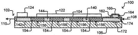
도 1c 는 도 1a 의 미세-유체 디바이스의 측 단면도이다.
도 1c 는 유출 인터페이스에의 유출 디바이스의 삽입을 예시하는 도 1a 의 미세-유체 디바이스의 부분 측 단면도이다.
도 2a 는 (예시의 용이를 위해) 선택기가 유전영동 (DEP) 디바이스로서 구성되는 유지 펜들 없이 도 1a 내지 도 1c 의 미세-유체 디바이스의 부분 측 단면도이다.
도 2b 는 도 2a 의 부분 상부 단면도이다.
도 3 은 미세-유체 디바이스로부터 미세-객체들의 그룹을 유출하는 프로세스의 일 예이다.
도 4 는 도 1a 내지 도 1c 의 미세-유체 디바이스에서의 유지 펜들에서의 미세-객체들의 그룹들의 일 예를 나타낸다.
도 5 는 유지 펜들 중 하나에서 미세-객체들의 그룹을 선택하여 트랙하는 일 예를 예시한다.
도 6 은 가두어진 미세-객체들의 그룹을 유지 펜으로부터 미세-유체 디바이스에서의 대기 영역 방향으로 이동시키는 일 예를 나타낸다.
도 7 은 대기 영역에서의 미세-객체들의 그룹을 나타낸다.
도 8 은 도 1a 내지 도 1c 의 미세-유체 디바이스의 유출 인터페이스에 삽입된 유출 디바이스의 일 예를 예시한다.
도 9 는 대기 영역을 유출 디바이스로 빼내어 지고 있는 미세-객체들의 일 예를 나타낸다.
도 10 은 대기 영역으로부터 미세-객체들의 그룹을 유출하는 프로세스의 일 예를 예시한다.
도 11 은 미-유출된 미세-객체들의 대기 영역 및 유출 인터페이스를 중화시키는 예시적인 프로세스이다.
도 12a 는 자기-폐쇄 커버를 포함하는 유출 인터페이스의 일 실시형태를 가지는 도 1a 내지 도 1c 의 미세-유체 디바이스의 부분 사시도이다.
도 12b 는 도 12a 의 부분 측 단면도이다.
도 12c 는 도 12a 및 도 12b 의 유출 인터페이스에 삽입된 유출 디바이스를 나타낸다.
도 13a 는 자기-회복 커버를 포함하는 유출 인터페이스의 일 실시형태를 가지는 도 1a 내지 도 1c 의 미세-유체 디바이스의 부분 측 단면도이다.
도 13b 는 유출 디바이스를 도 13a 의 유출 인터페이스에 삽입된 피하 주사바늘의 형태로 예시한다.
도 13c 는 도 13a 의 유출 인터페이스의 상이한 부분에 삽입된 피하 주사바늘을 나타낸다.
도 14 는 부착된 관상의 유출 디바이스를 포함하는 유출 인터페이스의 일 실시형태를 가지는 도 1a 내지 도 1c 의 미세-유체 디바이스의 부분 측 단면도이다.
도 15a 는 복수의 유출 인터페이스들을 포함하는 미세-유체 디바이스의 부분 사시도이다.
도 15b 는 반대 단부들 사이에 중간 부분을 포함하는 대기 영역을 예시하는 도 15a 의 상부 단면도이다.
도 15c 는 도 15a 의 측 단면도이다.
도 16 은 유출 인터페이스들에 삽입된 유출 디바이스들을 예시하는 도 15a 의 미세-유체 디바이스의 측 단면도이다.
도 17 은 디바이스에서의 흐름 통로에서 유지 펜들 및 다수의 대기 영역들을 포함하는 미세-유체 디바이스의 상부 단면도이다.
도 18 은 유지 펜들이 대기 영역이 위치되는 흐름 통로로부터 연속적인 배리어에 의해 분리되는 채널로부터 개방되는 유지 펜들 및 대기 영역을 포함하는 미세-유체 디바이스의 상부 단면도이다.
도 19a 는 유지 펜들이 개방되는 채널에, 각각의 유지 펜으로의 개구에 인접하게 위치되는 대기 영역들을 가지는 유지 펜들을 포함하는 미세-유체 디바이스의 상부 단면도이다.
도 19b 는 도 19a 의 미세유체 디바이스의 측 단면도이다.
도 20 은 도 19a 내지 도 19b 의 디바이스로부터 미세-객체들을 유출하는 프로세스의 일 예를 예시한다.
도 21a 는 유출 인터페이스들이 바로 인접한 유지 펜들에 위치될 수 있는 미세-유체 디바이스의 부분 측 단면도이다.
도 21b 는 유지 펜이 일부가 대기 영역인 분리 영역을 포함하는 미세-유체 디바이스의 부분 상부 단면도이다.
도 21c 는 유지 펜이 분리 영역 및 접속된 대기 영역을 포함하는 미세유체 디바이스에서의 유지 펜의 부분 상부 단면도이다.1A is a perspective view of a micro-fluidic device.
FIG. 1B is a top cross-sectional view of the micro-fluidic device of FIG. 1A .
1C is a cross-sectional side view of the micro-fluidic device of FIG. 1A .
1C is a partial side cross-sectional view of the micro-fluidic device of FIG. 1A illustrating insertion of an outlet device into an outlet interface.
FIG. 2A is a partial side cross-sectional view of the micro-fluidic device of FIGS. 1A-1C without holding pens where the selector is configured as a dielectrophoretic (DEP) device (for ease of illustration).
FIG. 2B is a partial top cross-sectional view of FIG. 2A ;
3 is an example of a process for extracting a group of micro-objects from a micro-fluidic device.
4 shows an example of groups of micro-objects in holding pens in the micro-fluidic device of FIGS. 1A-1C ;
5 illustrates an example of selecting and tracking a group of micro-objects in one of the holding pens.
6 shows an example of moving a group of confined micro-objects from a holding pen toward a waiting area in a micro-fluidic device.
7 shows a group of micro-objects in the atmospheric area.
8 illustrates an example of an outflow device inserted into the outflow interface of the micro-fluidic device of FIGS. 1A-1C .
9 shows an example of micro-objects being evacuated to an outflow device in the atmospheric region.
10 illustrates an example of a process for egressing a group of micro-objects from an atmospheric area.
11 is an exemplary process for neutralizing an outflow interface and an atmospheric region of non-spilled micro-objects.
12A is a fragmentary perspective view of the micro-fluidic device of FIGS. 1A-1C having one embodiment of an outlet interface including a self-closing cover;
12B is a partial side cross-sectional view of FIG. 12A ;
Fig. 12c shows the egress device inserted into the egress interface of Figs. 12a and 12b;
13A is a partial side cross-sectional view of the micro-fluidic device of FIGS. 1A-1C having one embodiment of an outlet interface including a self-healing cover;
13B illustrates an outflow device in the form of a hypodermic needle inserted into the outflow interface of FIG. 13A .
13C shows a hypodermic needle inserted in a different portion of the outflow interface of FIG. 13A .
14 is a partial side cross-sectional view of the micro-fluidic device of FIGS. 1A-1C having one embodiment of an outlet interface comprising an attached tubular outlet device;
15A is a partial perspective view of a micro-fluidic device including a plurality of outflow interfaces.
15B is a cross-sectional top view of FIG. 15A illustrating an atmospheric region including a middle portion between opposite ends;
FIG. 15C is a side cross-sectional view of FIG. 15A .
FIG. 16 is a cross-sectional side view of the micro-fluidic device of FIG. 15A illustrating outlet devices inserted into outlet interfaces;
17 is a top cross-sectional view of a micro-fluidic device including retention pens and multiple atmospheric regions in a flow passageway in the device.
18 is a top cross-sectional view of a micro-fluidic device comprising an atmospheric region and retention pens open from a channel in which the retention pens are separated by a continuous barrier from a flow passageway in which the atmospheric region is located.
19A is a top cross-sectional view of a micro-fluidic device including retention pens having atmospheric regions located adjacent an opening to each retention pen, in a channel into which the retention pens are opened.
19B is a cross-sectional side view of the microfluidic device of FIG. 19A .
20 illustrates an example of a process for exporting micro-objects from the device of FIGS. 19A-19B .
21A is a partial side cross-sectional view of a micro-fluidic device in which outflow interfaces may be positioned in immediate adjacent retention pens.
21B is a partial top cross-sectional view of a micro-fluidic device in which the retention pen includes an isolation region, in part, an atmospheric region.
21C is a partial top cross-sectional view of a holding pen in a microfluidic device in which the holding pen includes an isolation region and an attached atmospheric region.
본 명세서는 본 발명의 예시적인 실시형태들 및 애플리케이션들을 설명한다. 본 발명은, 그러나, 이들 예시적인 실시형태들 및 애플리케이션들에, 또는 예시적인 실시형태들 및 애플리케이션들이 동작하거나 또는 본원에서 설명되는 방법에 한정되지 않는다. 더욱이, 도면들은 단순화된 또는 부분 도들을 나타낼 수도 있으며, 도면들에서의 엘리먼트들의 치수들은 명료성을 위해 확대되거나 또는 아니면 비율대로 확대되지 않을 수도 있다. 게다가, 용어들 "상에 (on)", "에 부착된", 또는 "에 커플링된 " 이 본원에서 사용될 때, 하나의 엘리먼트 (예컨대, 재료, 층, 기판, 등) 는 하나의 엘리먼트가 바로 다른 엘리먼트 상에 있거나, 부착되거나, 또는 커플링되든지 또는 하나의 엘리먼트와 다른 엘리먼트 사이에 하나 이상의 간섭하는 엘리먼트들이 존재하든지에 관계없이 다른 엘리먼트 "상에", "그에 부착되거나" 또는 "그에 커플링될" 수 있다. 또한, 방향들 (예컨대, 위에 (above), 아래에 (below), 상부 (top), 저부 (bottom), 측면 (side), 위로 (up), 아래로 (down), 아래에 (under), 가로질러 (over), 상부의 (upper), 하부의 (lower), 수평, 수직, "x", "y", "z", 등) 은, 제공되는 경우, 상대적이며, 단지 일 예로서, 예시 및 설명의 용이를 위해 비한정적으로 제공된다. 게다가, 엘리먼트들 (예컨대, 엘리먼트들 a, b, c) 의 리스트에 대해 참조가 이루어지는 경우, 이러한 참조는 리스트된 엘리먼트들 단독, 모든 리스트된 엘리먼트들 미만의 임의의 조합, 및/또는 리스트된 엘리먼트들의 모두의 조합 중 하나를 포함하도록 의도된다.This specification describes exemplary embodiments and applications of the present invention. The present invention, however, is not limited to these exemplary embodiments and applications, or to the manner in which the exemplary embodiments and applications operate or described herein. Moreover, the drawings may represent simplified or partial views, and dimensions of elements in the drawings may be enlarged for clarity or otherwise not to scale. Moreover, when the terms “on,” “attached to,” or “coupled to,” are used herein, an element (eg, material, layer, substrate, etc.) means that one element is “On,” “attached to,” or “coupled to” another element, whether directly on, attached to, or coupled to, or whether there are one or more interfering elements between one element and the other element. can be "ringed". Also, directions (e.g., above, below, top, bottom, side, up, down, under, Across, upper, lower, horizontal, vertical, "x", "y", "z", etc.), when provided, are relative, by way of example only, It is provided without limitation for ease of illustration and description. Moreover, when a reference is made to a list of elements (eg, elements a, b, c), such reference is made to the listed elements alone, any combination of less than all listed elements, and/or the listed element. It is intended to include any one of the combinations of all of them.
본원에서 사용될 때, "실질적으로" 는 의도된 목적에 따라 작용하기에 충분하다는 것을 의미한다. 용어 "실질적으로" 는 따라서 예컨대, 당업자에 의해 예상되지만 전체 성능에 눈에 띄게 영향을 미치지 않을, 절대적 또는 완전한 상태, 치수, 측정치, 결과, 또는 기타 등등으로부터의 작은, 중요하지 않은 변경들을 허용한다. 용어 "하나들 (ones)" 는 하나 보다 많은 것을 의미한다.As used herein, “substantially” means sufficient to function for its intended purpose. The term "substantially" thus allows for small, insignificant changes from absolute or perfect condition, dimensions, measurements, results, or the like, such as would be expected by one of ordinary skill in the art but would not appreciably affect overall performance. . The term “ones” means more than one.
미세-객체에 대해 사용될 때 용어 "흡인 (aspirate) " 은 미세-객체를 압력 차이를 이용하여 이동시키는 것을 의미하며, "흡인기" 는 압력 차이 발생 디바이스이다.The term “aspirate” when used for a micro-object means to move the micro-object using a pressure difference, and “aspirate” is a pressure difference generating device.
본원에서 사용될 때, 용어 "미세-객체" 는, 극미립자들, 마이크로비드들 (예컨대, 폴리스티렌 비드들, Luminex™ 비드들, 또는 기타 등등), 자기 비드들, 마이크로로드들, 마이크로와이어들, 양자 도트들, 및 기타 등등과 같은, 무생물의 미세-객체들; 세포들 (예컨대, 배아들, 난모세포들, 정자들, 조직으로부터 분리된 세포들, 혈액 세포들, 하이브리도마스, 배양 세포들, 세포계로부터의 세포들, 암 세포들, 감염 세포들, 형질감염 (transfected) 및/또는 형질전환 세포들, 리포터 세포들, 및 기타 등등), (예컨대, 합성 또는 멤버레인 조제용 물질들 (preparations) 로부터 유도된) 리포솜들, 지질 나노래프트들, 및 기타 등등과 같은, 생물학적 미세-객체들; 또는 무생물의 미세-객체들과 생물학적 미세-객체들 (예컨대, 세포들에 부착된 마이크로비드들, 리포솜-코팅된 마이크로-비드들, 리포솜-코팅된 자기 비드들, 또는 기타 등등) 의 조합 중 하나 이상을 포괄할 수 있다. 지질 나노래프트들은 예컨대, Methods Enzymol., (2009), 464:211-231, Ritchie 등, "Reconstitution of Membrane Proteins in Phospholipid Bilayer Nanodiscs" 에 설명되어 있다.As used herein, the term “micro-object” refers to microparticles, microbeads (eg, polystyrene beads, Luminex™ beads, or the like), magnetic beads, microrods, microwires, quantum inanimate micro-objects, such as dots, and the like; cells (e.g., embryos, oocytes, sperm, cells isolated from tissue, blood cells, hybridomas, cultured cells, cells from a cell line, cancer cells, infected cells, transfection (transfected) and/or transformed cells, reporter cells, and the like), liposomes (eg, derived from synthetic or memberaine preparations), lipid nanorafts, and the like; such, biological micro-objects; or a combination of inanimate micro-objects and biological micro-objects (eg, microbeads attached to cells, liposome-coated micro-beads, liposome-coated magnetic beads, or the like). can encompass more than that. Lipid nanorafts are described, for example, in Methods Enzymol., (2009), 464:211-231, Ritchie et al., "Reconstitution of Membrane Proteins in Phospholipid Bilayer Nanodiscs".
용어 "흐름" 은, 액체에 대해 본원에서 사용될 때, 주로 확산 이외의 임의의 메커니즘으로 인한 액체의 벌크 이동을 지칭한다. 예를 들어, 매체의 흐름은 지점들 사이의 압력 차이로 인한 하나의 지점으로부터 다른 지점으로의 유체 매체의 이동을 수반할 수 있다. 이러한 흐름은 액체의 연속적, 펄스적, 주기적, 무작위적, 간헐적, 또는 왕복하는 흐름, 또는 이들의 임의의 조합을 포함할 수 있다. 하나의 유체 매체가 다른 유체 매체로 흐를 때, 매체들의 난류 (turbulence) 및 혼합이 일어날 수 있다.The term “flow,” as used herein with respect to a liquid, refers primarily to the bulk movement of a liquid due to any mechanism other than diffusion. For example, flow of a medium may involve movement of a fluid medium from one point to another due to a pressure difference between the points. Such flow may include a continuous, pulsed, periodic, random, intermittent, or reciprocating flow of liquid, or any combination thereof. When one fluid medium flows into another fluid medium, turbulence and mixing of the media may occur.
어구 "실질적으로 어떤 흐름도 없는" 은 액체로의 또는 내에서의 재료 (예컨대, 관심 분석물질) 의 구성요소들의 확산의 레이트보다 작은 액체의 흐름의 레이트를 지칭한다. 이러한 재료의 구성요소들의 확산의 레이트는 예를 들어, 온도, 구성요소들의 사이즈, 및 구성요소들과 유체 매체 사이의 상호작용들의 강도에 의존할 수 있다.The phrase “substantially free of any flow” refers to a rate of flow of a liquid that is less than the rate of diffusion of components of a material (eg, an analyte of interest) into or within the liquid. The rate of diffusion of the components of such a material may depend, for example, on the temperature, the size of the components, and the strength of interactions between the components and the fluid medium.
유체 매체와 관련하여 본원에서 사용될 때, "확산하다 (diffuse)" 및 "확산 (diffusion)" 은 농도 기울기 아래로의 유체 매체의 구성요소의 열역학적 이동을 지칭한다.As used herein in reference to a fluid medium, “diffuse” and “diffusion” refer to the thermodynamic movement of components of a fluid medium down a concentration gradient.
미세유체 디바이스 내 상이한 영역들과 관련하여 본원에서 사용될 때, 어구 "유체 접속된" 은 상이한 영역들이 유체 매체들과 같은 유체로 실질적으로 충진될 때, 영역들 각각에서의 유체가 유체의 단일 본체를 형성하도록 접속된다는 것을 의미한다. 이것은 상이한 영역들에서의 유체들 (또는, 유체 매체들) 이 조성에서 반드시 동일하다는 것을 의미하지 않는다. 대신, 미세유체 디바이스의 상이한 유체 접속된 영역들에서의 유체들은 용질들이 그들의 개개의 농도 기울기들 아래로 이동하고 및/또는 유체들이 디바이스를 통과하여 흐름에 따라서 유입하는 상이한 조성들 (예컨대, 단백질들, 탄수화물들, 이온들, 또는 다른 분자들과 같은, 용질들의 상이한 농도들) 을 가질 수 있다.As used herein in reference to different regions within a microfluidic device, the phrase “fluidically connected” means that when the different regions are substantially filled with a fluid, such as fluid media, the fluid in each of the regions passes through a single body of fluid. means to be connected to form. This does not mean that the fluids (or fluid media) in different regions are necessarily identical in composition. Instead, fluids in different fluidically connected regions of a microfluidic device are of different compositions (e.g., proteins) in which solutes move down their respective concentration gradients and/or fluids enter as they flow through the device. , different concentrations of solutes, such as carbohydrates, ions, or other molecules).
본 발명의 미세유체 디바이스 또는 장치는 "스윕된 (swept)" 영역들 및 "미스윕된 (unswept)" 영역들을 포함할 수 있다. 유체 접속들이 스윕된 영역과 미스윕된 영역 사이에 확산이 가능하지만 어떤 실질적인 매체들의 흐름도 불가능하도록 구조화된다고 가정하면, 미스윕된 영역은 스윕된 영역에 유체 접속될 수 있다. 따라서, 미세유체 장치는 단지 스윕된 영역과 미스윕된 영역 사이에 확산 유체 소통을 실질적으로 가능하게 하면서도, 스윕된 영역에서의 매체의 흐름으로부터 미스윕된 영역을 실질적으로 분리하도록 구조화될 수 있다.A microfluidic device or apparatus of the present invention may include “swept” regions and “unswept” regions. A misswept region can be fluidly connected to the swept region, assuming the fluid connections are structured such that diffusion is possible between the swept region and the misswept region, but no substantial flow of media is possible. Accordingly, a microfluidic device may be structured to substantially separate the misswept region from the flow of media in the swept region, while only substantially enabling diffusive fluid communication between the swept region and the misswept region.
생물학적 세포를 "살균하는" 은 세포를 복제하기에 불가능하게 만드는 것을 의미한다.By “sterilizing” a biological cell is meant making it impossible to replicate.
본원에서 사용될 때, 미세-객체들의 "그룹" 은 단일 미세-객체 또는 복수의 미세-객체들일 수 있다. 미세-객체들의 그룹은 생물학적 세포들 (예컨대, 하나의 세포, 복수의 세포들, 또는 클론 콜로니로부터의 세포들의 모두) 의 클론 그룹일 수 있다. 복제하는 것이 가능한 콜로니에서 생 세포들의 모두가 단일 부모 세포로부터 유도된 딸 세포들이면, 생물학적 세포들의 콜로니는 "클론" 이다. "클론 세포들" 은 동일한 클론 콜로니의 세포들이다.As used herein, a “group” of micro-objects may be a single micro-object or a plurality of micro-objects. The group of micro-objects can be a clonal group of biological cells (eg, a single cell, a plurality of cells, or all of the cells from a clonal colony). A colony of biological cells is a "clonal" if all of the living cells in a replicating colony are daughter cells derived from a single parent cell. “Clone cells” are cells of the same clonal colony.
본 발명의 일부 실시형태들에서, 미세-객체들의 그룹은 미세-유체 디바이스에서의 선택된 유지 펜으로부터 캡쳐되어, 유지 펜으로부터, 그룹의 미세-객체들이 미세-유체 디바이스로부터 유출될 수 있는, 대기 영역으로 이동될 수 있다. 미세-객체들은 생물학적 세포들일 수 있다. 각각의 유지 펜은 (예컨대, 생물학적 세포들을 유지 펜의 분리 영역에 위치시킴으로써) 유지 펜들의 나머지들에서의 생물학적 세포들로부터 유지 펜에서의 생물학적 세포들을 분리할 수 있다. 선택된 유지 펜으로부터 캡쳐된 미세-객체들은 클론 세포들일 수 있으며, 본 발명의 실시형태들은 미세-유체 디바이스에서 클론 세포들의 특정의 그룹을 선택하고, 클론 세포들을 대기 영역으로 이동시키고, 그리고 그룹의 클론 성질을 유지하면서 미세-유체 디바이스로부터 클론 세포들을 유출할 수 있다.In some embodiments of the invention, a group of micro-objects is captured from a selected holding pen in the micro-fluidic device, from which the group of micro-objects can flow out of the micro-fluidic device, the atmospheric region. can be moved to Micro-objects may be biological cells. Each retention pen may separate the biological cells in the retention pen from the biological cells in the remainder of the retention pens (eg, by placing the biological cells in a separation region of the retention pen). The micro-objects captured from the selected retention pen may be clone cells, embodiments of the present invention select a specific group of clone cells in the micro-fluidic device, move the clone cells to a waiting area, and clone the group Clonal cells can be ejected from the micro-fluidic device while maintaining properties.
도 1a 내지 도 1d 는 유지 펜들 (156), 선택기 (122), 및 유출 인터페이스 (162) 를 포함하는 미세-유체 디바이스 (100) 의 일 예를 예시한다. 나타낸 바와 같이, 선택기 (122) 는 미세-객체들 (미도시) 을 선택하여 펜들 (156) 중 임의의 펜으로부터 디바이스 (100) 의 인클로저 (102) 내부의 대기 영역 (172) 으로 이동시키고, 유출 인터페이스 (162) 는 대기 영역 (172) 으로부터 미세-객체들 (미도시) 을 유출할 수 있는 외부 유출 디바이스 (182) 를 위한 인클로저 (102) 에 인터페이스를 제공한다.1A-1D illustrate an example of a
도 1a 내지 도 1d 에 나타낸 바와 같이, 미세-유체 디바이스 (100) 는 인클로저 (102), 선택기 (122), 흐름 제어기 (124), 및 외부 유출 디바이스 (182) 를 위한 유출 인터페이스 (162) 를 포함할 수 있다. 또한 나타낸 바와 같이, 미세-유체 디바이스 (100) 는 제어 모듈 (130), 전자기 방사 (136) 의 소스 (이하, EM 소스 (136)), 검출기 (138), 및/또는 기타 등등과 같은 보조 엘리먼트들을 포함할 수 있다.1A-1D , the
인클로저 (102) 는 흐름 영역 (140) 을 정의하고 액체 매체 (144) 를 유지할 수 있다. 인클로저 (102) 는 예를 들어, 베이스 (예컨대, 기판) (106) 상에 배치된 미세-유체 구조 (104) 를 포함할 수 있다. 미세-유체 구조 (104) 는 고무, 플라스틱, 탄성체, 실리콘 (예컨대, 패턴형성가능한 실리콘), 폴리디메틸실록산 ("PDMS"), 또는 기타 등등과 같은, 가스 투과성인, 가요성 재료를 포함할 수 있다. 미세유체 구조 (104) 를 구성할 수 있는 재료들의 다른 예들은 몰드된 유리, 에칭가능한 재료, 예컨대 실리콘, 광-레지스트 (예컨대, SU8), 또는 기타 등등을 포함한다. 일부 실시형태들에서, 이러한 재료들, 즉, 미세유체 구조 (104) 는 강성이며 및/또는 가스에 실질적으로 불투과성일 수 있다. 여하튼, 미세유체 구조 (104) 는 베이스 (106) 상에 배치될 수 있다. 베이스 (106) 는 하나 이상의 기판들을 포함할 수 있다. 단일 구조로 예시되지만, 베이스 (106) 는 다수의 기판들과 같은 다수의 상호접속된 구조들을 포함할 수 있다. 미세-유체 구조 (104) 는 상호접속될 수 있는 다수의 구조들을 또한 포함할 수 있다. 예를 들어, 미세-유체 구조 (104) 는 그 구조에서의 다른 재료와 동일하거나 또는 상이한 재료로 제조된 커버 (미도시) 를 더 포함할 수 있다.
미세-유체 구조 (104) 및 베이스 (106) 는 미세-유체 흐름 영역 (140) 을 정의할 수 있다. 하나의 흐름 영역 (140) 이 도 1a 내지 도 1c 에 도시되지만, 미세-유체 구조 (104) 및 베이스 (106) 는 매체 (144) 에 대해 다수의 흐름 영역들을 정의할 수 있다. 흐름 영역 (140) 은 미세-유체 회로들을 형성하도록 상호접속될 수 있는 채널들 (도 1b 에서 152, 153) 및 챔버들을 포함할 수 있다. 도 1b 및 도 1c 는 매체 (144) 가 평탄하고 (예컨대, 편평하고) 피쳐 (feature) 없이 배치될 수 있는 흐름 영역 (140) 의 내측 표면 (142) 을 예시한다. 내측 표면 (142) 은, 그러나, 대안적으로 비평탄할 (예컨대, 편평하지 않을) 수 있으며 전기 단자들 (미도시) 과 같은 피쳐들을 포함한다.The
나타낸 바와 같이, 인클로저 (102) 는 매체 (144) 가 흐름 영역 (140) 으로 통과하여 입력될 수 있는 하나 이상의 입구들 (108) 을 포함할 수 있다. 입구 (108) 는 예를 들어, 입력 포트, 개구, 밸브, 다른 채널, 유체 커넥터들, 튜브, 유체 펌프 (예컨대, 양 변위 주사기 펌프), 또는 기타 등등일 수 있다. 인클로저 (102) 는 또한 매체 (144) 가 흐름 영역 (140) 으로부터 통과해서 제거될 수 있는 하나 이상의 출구들 (110) 을 포함할 수 있다. 출구 (110) 는 예를 들어, 출력 포트, 개구, 밸브, 채널, 유체 커넥터들, 튜브, 펌프, 또는 기타 등등일 수 있다. 다른 예로서, 출구 (110) 는 2013년 4월 4일에 출원된 미국 특허 출원 번호 제 13/856,781호 (대리인 접수번호 BL1-US) 에 개시된 출력 메커니즘들 중 임의의 메커니즘과 같은 액적 출력 메커니즘을 포함할 수 있다. 인클로저 (102) 의 모두 또는 일부는 가스 (예컨대, 주변 공기) 가 흐름 영역 (140) 에 유입하고 유출가능하게 하도록 가스 투과성일 수 있다. 하나 보다 많은 흐름 영역 (140) 을 포함하는 인클로저들에 대해, 각각의 흐름 영역 (140) 은 흐름 영역 (140) 으로부터 매체 (144) 를 각각 입력하고 제거하는 하나 이상의 입구들 (108) 및 하나 이상의 출구들 (110) 과 연관될 수 있다.As shown,
도 1b 및 도 1c 에 나타낸 바와 같이, 유지 펜들 (156) 은 흐름 영역 (140) 에 배치될 수 있다. 예를 들어, 각각의 유지 펜 (156) 은 인클로저 (102) 의 내부 표면 (142) 상에 배치된 배리어 (154) 를 포함할 수 있다. 임의의 패턴으로 배치된 흐름 영역 (140) 에 많은 이러한 유지 펜들 (156) 이 존재할 수 있으며, 유지 펜들 (156) 은 많은 상이한 사이즈들 및 형태들 중 임의의 것일 수 있다. 예를 들어, 유지 펜들 (156) 은 2014년 10월 1일에 출원된 미국 가출원 제 62/058,658호에서 설명된 바와 같은 구조를 포함할 수 있다. 따라서, 예를 들어, 유지 펜들 (156) 은 접속 영역 (미도시) 및 분리 영역 (미도시) 을 포함할 수 있다. 도 1b 에 나타낸 바와 같이, 유지 펜들 (156) 의 개구들은 매체 (144) 가 하나 보다 많은 펜 (156) 의 개구들을 지나서 흐르는 도관일 수 있는 채널 (152, 153) 에 인접하게 배치될 수 있다. 각각의 유지 펜 (156) 의 개구는 채널 (152, 153) 에 흐르는 액체 매체 (144) 의 자연스러운 교환을 가능하게 할 수 있지만, 각각의 유지 펜 (156) 은 임의의 하나 펜 (156) 에서의, 생물학적 세포들과 같은, 미세-객체들 (미도시) 이, 임의의 다른 펜 (156) 에서의 미세-객체들과 혼합되는 것을 방지하도록 충분히 밀폐될 수 있다. 8개의 펜들 (156) 및 2개의 채널들 (152, 153) 이 도시되지만, 더 많거나 또는 더 적을 수 있다. 예를 들어, 100, 250, 500, 1000, 2500, 5000, 10,000, 25,000, 50,000, 100,000 이상의 유지 펜들과 유체 접속된 단일 채널일 수도 있다.1B and 1C , retention pens 156 may be disposed in
매체 (144) 는 채널들 (152, 153) 에서 유지 펜들 (156) 에서의 개구들을 지나서 흘려질 수 있다. 채널들 (152, 153) 에서의 매체 (144) 의 흐름은 예를 들어, 유지 펜들 (156) 에서의 생물학적 미세-객체들 (미도시) 에 영양소들을 제공할 수 있다. 채널들 (152, 153) 에서의 매체 (144) 의 흐름은 또한 유지 펜들 (156) 로부터의 폐기물의 제거를 위해 제공할 수 있다. 분리 영역을 포함하는 유지 펜들 (156) 에 대해, 분리 영역들과 채널들 (152, 153) 사이의 영양소들 및 폐기물의 교환이 단지 확산에 의해 실질적으로 발생할 수 있다.
또한 나타낸 바와 같이, 흐름 영역 (140) 에, 따라서, 인클로저 (102) 내부에 대기 영역 (172) 이 존재할 수 있다. 대기 영역 (172) 은 단순히, 마크되거나 또는 마크되지 않을 수 있는 인클로저 (102) 의 내부 표면 (142) 상의 영역일 수 있다. 대안적으로, 대기 영역 (172) 은 (도 1b - 도 1d 에 나타낸 바와 같은) 표면 (142) 에의 함몰부, 표면 (142) 으로부터 연장하는 플랫폼 (미도시), (예컨대, 배리어들 (154) 과 유사한) 배리어들 (미도시), 챔버들, 또는 기타 등등과 같은 흐름 영역 (140) 에서의 구조를 포함할 수 있다. 여하튼, 도 1d 에 나타낸 바와 같이, 대기 영역 (172) 은 인클로저 (102) 를 통하여 흐름 영역 (140) 으로의 통로 (174) 에 (예컨대, 그로부터 흐름 영역 (140) 을 가로질러) 인접하게 배치될 수 있다. 통로 (174) 는 인클로저 (102) 외부로부터 인클로저 (102) 내부까지 일 수 있다. 통로 (174) 는 예를 들어, 인클로저 (102) 에서의 홀일 수 있다.As also shown, there may be an
유출 인터페이스 (162) 는 인클로저 (102) 외부에 있는 디바이스일 수 있는 외부 유출 디바이스 (182) 를 위한 인클로저 (102) 로의 통로 (174) 에 인터페이스를 제공할 수 있다. 도 1c 에 나타낸 바와 같이, 유출 인터페이스 (162) 는 통로 (174) 에 (예컨대, 걸쳐서 및/또는 내에) 인접한 인클로저 (102) 상에 배치될 수 있다. 유출 인터페이스 (162) 는 통로 (174) 로의 개구 (164) 를 포함할 수 있다. 유출 인터페이스 (162) 는 개구 (164) 에 걸쳐서 커버 (166) 를 더 포함할 수 있다. 커버 (166) 는 착탈식이거나 또는 아니면 통로 (174) 를 인클로저 (102) 에 결합하기 위해 유출 인터페이스 (162) 에서의 개구 (164) 에 삽입될 수 있는 유출 디바이스 (182) 에 의해 돌파가능할 수 있다. 별개의 엔터티들로서 나타내지만, 유출 인터페이스 (162) 및 미세-유체 구조 (104) 는 동일한 재료로 일체로 형성되며 따라서 하나의 물리적인 엔터티의 부분들일 수 있다.The
유출 인터페이스 (162) 는 예를 들어, 폴리스티렌과 같은 가요성 재료 또는 미세-유체 구조 (104) 에 대해 위에서 설명된 재료들 중 임의의 재료를 포함할 수 있다. 대안적으로, 유출 인터페이스 (162) 는 단단하거나 또는 딱딱한 재료, 또는 가요성 재료와 단단한 또는 딱딱한 재료의 조합을 포함할 수 있다. 커버 (166) 의 예들은 인클로저 (102) 로부터 탈부착될 수 있는 커버, 개구 (164) 에 삽입될 수 있지만 통로 (174) 보다 더 작은 코르크 (cork) 형 구조 (미도시), 또는 기타 등등을 포함한다. 도 12a 내지 도 13b 에서 볼 수 있는 바와 같이, 커버 (166) 의 다른 예들은 유출 디바이스 (182) 및 유출 인터페이스 (1302) 에 의해 밀어져서 개방될 수 있는, 천공가능한 자기-회복 구조의 형태인, 자기-폐쇄 커버 (1206) 를 포함한다.The
도 1d 에 나타낸 바와 같이, 유출 디바이스 (182) 는 중공 튜브-유사한 구조일 수 있다. 예를 들어, 유출 디바이스 (182) 는 제 1 단부 (188) 로부터 반대 제 2 단부 (192) 까지의 내부 통로 (186) 를 정의하는 관상의 하우징 (184) 을 포함할 수 있다. 유출 인터페이스 (162) 의 커버 (166) 가 제거됨과 동시에, 유출 디바이스 (182) 는 제 1 단부 (188) 가 인클로저 통로 (174) 에 근접하거나 또는 접촉하게 되도록, 인터페이스 (162) 에서의 개구 (164) 에 삽입될 수 있다. 유출 디바이스 (182) 의 제 1 단부 (188) 에서의 개구 (190) 가 따라서 인클로저 (102) 로의 통로 (174) 에 인접하게 위치될 수 있다.As shown in FIG. 1D , the
일부 실시형태들에서, 유출 디바이스 (182) 는 압력 차이 발생 디바이스 (예컨대, 흡인기, 양 변위 주사기 펌프, 공기 변위 펌프, 연동 펌프, 또는 기타 등등) 일 수 있다. 예를 들어, 유출 디바이스 (182) 는 유출 디바이스 (182) 의 제 1 단부 (188) 로부터 제 2 단부 (192) 까지 압력 차이를 발생시킬 수 있는, 압력 차이 (미도시) 를 발생시키는 것이 가능한 소스에 접속가능할 수 있다. 유출 디바이스 (182) 는 따라서 미세-객체들 (미도시) 을 대기 영역 (172) 으로부터 통로 (174) 를 통해서 그의 제 1 단부 (188) 에서의 개구 (190) 로, 내부 통로 (186) 를 통해서, 미세-객체들 (미도시) 이 수집되거나 또는 아니면 처분될 수 있는 제 2 단부 (192) 로, 빼내도록 구성될 수 있다. 유출 디바이스 (182) 의 예들은 피펫, 튜브, 피하 주사바늘과 같은 중공 주사바늘, 이들의 조합 또는 기타 등등을 포함한다. 유출 디바이스의 내부 통로 (186) 는 약 5 μm 내지 300 μm (예컨대, 약 25 내지 300 μm, 약 50 내지 300 μm, 약 75 내지 300 μm, 약 100 내지 300 μm, 약 100 내지 250 μm, 약 100 내지 200 μm, 약 100 내지 150 μm, 약 150 내지 200 μm, 또는 전술한 종점들 (endpoints) 중 하나 이상에 의해 정의되는 임의의 다른 직경 또는 범위) 의 직경을 가질 수 있다.In some embodiments, the
유출 디바이스 (182) 는 유출 디바이스를 통과하는 미세-객체들을 검출하는 것이 가능한 센서 (미도시) 를 더 포함할 수 있다. 센서는 유출 인터페이스 (162) 의 근위에 위치될 수 있다. 대안적으로, 센서는 유출 인터페이스 (162) 의 원위에 (예컨대, 유출 디바이스 (182) 의 말단부에) 위치될 수 있다. 센서는 예를 들어, 카메라 (예컨대, 디지털 카메라) 또는 광센서 (예컨대, 전하 결합 디바이스 또는 상보형 금속 산화물 반도체 이미저) 와 같은, 이미징 디바이스일 수 있다. 대안적으로, 센서는 미세-객체들이 통과할 때 복합 임피던스에서의 변화들을 검출하는 디바이스와 같은, 전기 디바이스일 수 있다.The
선택기 (122) 는 매체 (144) 에서의 미세-객체들 (미도시) 상에 동전기 힘들 (electrokinetic forces) 을 선택적으로 생성하도록 구성될 수 있다. 예를 들어, 선택기 (122) 는 흐름 영역 (140) 의 내측 표면 (142) 에서의 전극들을 선택적으로 활성화하고 (예컨대, 턴온하고) 그리고 비활성화하도록 (예컨대, 턴오프하도록) 구성될 수 있다. 전극들은 매체 (144) 에서의 미세-객체들 (미도시) 을 끌어당기거나 또는 반발하는 매체 (144) 에서 힘들을 생성할 수 있으며, 선택기 (122) 는 따라서 매체 (144) 에서 하나 이상의 미세-객체들을 선택하여 이동시킬 수 있다. 전극들은 예를 들어, 유전영동 (DEP) 전극들일 수 있다.
예를 들어, 선택기 (122) 는 (예컨대, (본원에 전체적으로 참조로 포함되는) 미국 특허 번호 제 7,612,355호 또는 (또한, 본원에 전체적으로 참조로 포함되는) 미국 특허 출원 번호 제 14/051,004 호 (대리인 접수 번호 BL9-US) 에 개시된 바와 같은) 하나 이상의 유전영동 전극 디바이스들, 광학적 (예컨대, 레이저) 트위저들 디바이스들, 및/또는 하나 이상의 광전자 트위저들 (OET) 디바이스들을 포함할 수 있다. 또한, 다른 예로서, 선택기 (122) 는 미세-객체들 중 하나 이상이 부유되는 매체 (144) 의 액적을 이동시키기 위한 하나 이상의 디바이스들 (미도시) 을 포함할 수 있다. 이러한 디바이스들 (미도시) 은 광전자 습윤 (OEW) 디바이스들 (예컨대, 미국 특허 번호 제 6,958,132호에 개시된 바와 같은) 또는 다른 전기습윤 디바이스들과 같은, 전기습윤 디바이스들을 포함할 수 있다. 선택기 (122) 는 따라서 일부 실시형태들에서 DEP 디바이스로서 특징화될 수 있다.For example, selector 122 (eg, U.S. Patent No. 7,612,355 (which is incorporated herein by reference in its entirety) or U.S. Patent Application Serial No. 14/051,004 (which is also incorporated herein by reference in its entirety) (attorney's (as disclosed in accession number BL9-US)), optical (eg, laser) tweezers devices, and/or one or more optoelectronic tweezers (OET) devices. Also, as another example,
도 2a 및 도 2b 는 선택기 (122) 가 DEP 디바이스 (200) 를 포함하는 예를 예시한다. 나타낸 바와 같이, DEP 디바이스 (200) 는 제 1 전극 (204), 제 2 전극 (210), 전극 활성화 기판 (208), 전원 (212) (예컨대, 교류 (AC) 전원), 및 (EM 소스 (136) 와 동일하거나 또는 상이할 수 있는) 광원 (220) 을 포함할 수 있다. 흐름 영역 (140) 에서의 매체 (144) 및 전극 활성화 기판 (208) 은 전극들 (204, 210) 을 분리시킬 수 있다. 광원 (220) 으로부터의 광 (222) 의 패턴들을 변경하는 것은 흐름 영역 (140) 의 내측 표면 (142) 의 영역들 (214) 에서의 DEP 전극들의 패턴들을 변경하는 것을 선택적으로 활성화하고 비활성화할 수 있다. (이하, 영역들 (214) 은 "전극 영역들" 으로서 지칭된다.) 2A and 2B illustrate an example in which the
도 2b 에 예시된 예에서, 내측 표면 (142) 상으로 안내된 광 패턴 (222') 은 나타낸 정사각형 패턴으로, 크로스-해칭된 전극 영역들 (214a) 을 조사한다. 다른 전극 영역들 (214) 은 조사되지 않으며 이하에 "어두운" 전극 영역들 (214) 로서 지칭된다. 전극 활성화 기판 (208) 을 가로질러 각각의 어두운 전극 영역 (214) 로부터 제 2 전극 (210) 까지의 상대적인 전기 임피던스는 제 1 전극 (204) 으로부터 흐름 영역 (140) 에서의 매체 (144) 를 가로질러 어두운 전극 영역 (214) 까지의 상대적인 임피던스보다 더 크다. 전극 영역 (214a) 을 조사하는 것은, 그러나, 전극 활성화 기판 (208) 을 가로질러 그 조사된 전극 영역 (214a) 으로부터 제 2 전극 (210) 까지의 상대적인 임피던스를 제 1 전극 (204) 으로부터 흐름 영역 (140) 에서의 매체 (144) 를 가로질러 그 조사된 전극 영역 (214a) 까지의 상대적인 임피던스 미만까지 감소시킨다.In the example illustrated in FIG. 2B , the
전원 (212) 이 활성화되면서, 전술한 것은 매체 (144) 에서, 조사된 전극 영역들 (214a) 과 인접한 어두운 전극 영역들 (214) 사이에 전기장 기울기를 생성하고, 이것은 결국 매체 (144) 에서의 인접한 미세-객체들 (미도시) 을 끌어당기거나 또는 미는 로컬 DEP 힘들을 생성한다. 매체 (144) 에서의 미세-객체들을 당기거나 또는 미는 DEP 전극들이 따라서 광원 (220) (예컨대, 레이저 소스 또는 다른 유형의 광원) 으로부터 미세-유체 디바이스 (200) 로 투사되는 광 패턴들 (222) 을 변경함으로써 흐름 영역 (140) 의 내측 표면 (142) 에서의 많은 상이한 이러한 전극 영역들 (214) 에서 선택적으로 활성화되고 비활성화될 수 있다. DEP 힘들이 인접한 미세-객체들을 당기거나 또는 미는 지 여부는 전원 (212) 의 주파수 및 매체 (144) 및/또는 미세-객체들 (미도시) 의 유전체 성질들과 같은 파라미터들에 의존할 수 있다.As
도 2b 에 예시된 조사된 전극 영역들 (214a) 의 예시된 정사각형 패턴 (222') 은 단지 예이다. 전극 영역들 (214) 의 임의의 패턴은 디바이스 (100) 에 투사된 광 (222) 의 패턴으로 조사될 수 있으며, 조사된 전극 영역들 (222') 의 패턴은 광 패턴 (222) 을 변경함으로써 반복적으로 변경될 수 있다.The illustrated square pattern 222' of the irradiated
일부 실시형태들에서, 전극 활성화 기판 (208) 은 광 전도 재료일 수 있으며, 내측 표면 (142) 은 피쳐가 없을 수 있다. 이러한 실시형태들에서, DEP 전극들 (214) 은 광 패턴 (222) (도 2a 참조) 에 따라서 흐름 영역 (140) 의 내측 표면 (142) 상에 어느 곳에서 그리고 임의의 패턴으로 생성될 수 있다. 전극 영역들 (214) 의 개수 및 패턴은 따라서 고정되지 않고 광 패턴 (222) 에 대응한다. 예들이 전술한 미국 특허 번호 제 7,612,355호에 예시되는데, 전술한 특허의 도면들에 나타낸 미도핑된 비정질 실리콘 재료 24 가 전극 활성화 기판 (208) 을 형성할 수 있는 광 전도 재료의 일 예일 수 있다.In some embodiments, the
다른 실시형태들에서, 전극 활성화 기판 (208) 은 반도체 분야들에서 알려져 있는 바와 같은 반도체 집적 회로들을 형성하는, 복수의 도핑된 층들, 전기 절연층들, 및 전기 전도성 층들을 포함하는 반도체 재료와 같은 회로 기판을 포함할 수 있다. 이러한 실시형태들에서, 전기 회로 엘리먼트들은 흐름 영역 (140) 의 내측 표면 (142) 에서의 전극 영역들 (214) 과 광 패턴 (222) 에 의해 선택적으로 활성화되고 비활성화될 수 있는 제 2 전극 (210) 사이에 전기 접속들을 형성할 수 있다. 활성화되지 않을 때, 각각의 전기 접속은 대응하는 전극 영역 (214) 로부터 제 2 전극 (210) 까지의 상대적인 임피던스가 제 1 전극 (204) 으로부터 매체 (144) 를 통해서 대응하는 전극 영역 (214) 까지의 상대적인 임피던스보다 더 크도록, 높은 임피던스를 가질 수 있다. 광 패턴 (222) 에서의 광에 의해 활성화될 때, 그러나, 각각의 전기 접속은 대응하는 전극 영역 (214) 로부터 제 2 전극 (210) 까지의 상대적인 임피던스가 위에서 설명한 바와 같이, 대응하는 전극 영역 (214) 에서의 DEP 전극을 활성화하는, 제 1 전극 (204) 으로부터 매체 (144) 를 통해서 대응하는 전극 영역 (214) 까지의 상대적인 임피던스 미만이 되도록, 낮은 임피던스를 가질 수 있다. 매체 (144) 에서의 미세-객체들 (미도시) 을 당기거나 또는 미는 DEP 전극들은 따라서 흐름 영역 (140) 의 내측 표면 (142) 에서의 많은 상이한 전극 영역들 (214) 에서 광 패턴 (222) 에 의해 선택적으로 활성화되고 비활성화될 수 있다. 전극 활성화 기판 (208) 의 이러한 구성들의 비한정적인 예들은 미국 특허 번호 제 7,956,339호의 도 21 및 도 22 에 예시된 포토트랜지스터-기반의 디바이스 및 2013년 10월 10일에 출원된 전술한 미국 특허 출원 번호 제 14/051,004호에서의 도면들 전반에 걸쳐서 예시된 디바이스들 (200, 400, 500, 및 600) 을 포함한다.In other embodiments, the
일부 실시형태들에서, 일반적으로 도 2a 에 예시된 바와 같이, 제 1 전극 (204) 은 인클로저 (102) 의 제 1 벽 (202) (또는, 커버) 의 부분일 수 있으며, 전극 활성화 기판 (208) 및 제 2 전극 (210) 은 인클로저 (102) 의 제 2 벽 (206) (또는, 베이스) 의 부분일 수 있다. 나타낸 바와 같이, 흐름 영역 (140) 은 제 1 벽 (202) 과 제 2 벽 (206) 사이에 있을 수 있다. 전술한 것은, 그러나, 단지 예이다. 다른 실시형태들에서, 제 1 전극 (204) 은 제 2 벽 (206) 의 부분일 수 있으며, 전극 활성화 기판 (208) 및/또는 제 2 전극 (210) 중 하나 (또는, 양쪽) 는 제 1 벽 (202) 의 부분일 수 있다. 다른 예로서, 제 1 전극 (204) 은 전극 활성화 기판 (208) 및 제 2 전극 (210) 과 동일한 벽 (202 또는 206) 의 부분일 수 있다. 예를 들어, 전극 활성화 기판 (208) 은 제 1 전극 (204) 및/또는 제 2 전극 (210) 을 포함할 수 있다. 더욱이, 광원 (220) 은 대안적으로 인클로저 (102) 아래에 위치될 수 있다.In some embodiments, as generally illustrated in FIG. 2A , the
도 2a 및 도 2b 의 DEP 디바이스 (200) 로 구성되면, 선택기 (122) 는 따라서 미세-객체를 둘러싸서 캡쳐하는 패턴에서 흐름 영역 (140) 의 내측 표면 (142) 의 전극 영역들 (214) 에서 하나 이상의 DEP 전극들을 활성화시키기 위해 광 패턴 (222) 을 디바이스 (200) 에 투사함으로써 흐름 영역 (140) 에서의 매체 (144) 에서 미세-객체 (미도시) 를 선택할 수 있다. 선택기 (122) 는 따라서 디바이스 (200) 에 대해 광 패턴 (222) 을 이동시킴으로써 캡쳐된 미세-객체를 이동시킬 수 있다. 대안적으로, 디바이스 (200) 가 광 패턴 (222) 에 대해서 이동될 수 있다.When configured with the
유지 펜들 (156) 을 한정하는 배리어들 (154) 이 물리적인 배리어들로서 도 1b 및 도 1c 에 예시되고 위에서 설명되지만, 배리어들 (154) 은 대안적으로, 광 패턴 (222) 에 의해 활성화되는 DEP 힘들을 포함하는 가상 배리어들일 수 있다.Although the
흐름 제어기 (124) 는 흐름 영역 (140) 에서의 매체 (144) 의 흐름을 제어하도록 구성될 수 있다. 예를 들어, 흐름 제어기 (124) 는 흐름의 방향 및/또는 속도를 제어할 수 있다. 흐름 제어기 (124) 의 비한정적인 예들은 하나 이상의 펌프들 또는 유체 엑츄에이터들을 포함한다. 일부 실시형태들에서, 흐름 제어기 (124) 는 예를 들어, 흐름 영역 (140) 에서의 매체 (144) 의 흐름의 속도를 감지하기 위한 하나 이상의 센서들 (미도시) 과 같은, 추가적인 엘리먼트들을 포함할 수 있다.The
제어 모듈 (130) 은 선택기 (122), EM 소스 (136), 검출기 (138), 및/또는 흐름 제어기 (124) 로부터 신호를 수신하고 그들을 제어하도록 구성될 수 있다. 나타낸 바와 같이, 제어 모듈 (130) 은 제어기 (132) 및 메모리 (134) 를 포함할 수 있다. 일부 실시형태들에서, 제어기 (132) 는 예를 들어, 디지털 전자, 광학적, 또는 자기 메모리 디바이스일 수 있는 메모리 (134) 에 비일시성 신호들로서 저장된 머신 판독가능 명령들 (예컨대, 소프트웨어, 펌웨어, 마이크로코드, 또는 기타 등등) 에 따라서 동작하도록 구성된 디지털 전자 제어기 (예컨대, 마이크로프로세서, 마이크로제어기, 컴퓨터, 또는 기타 등등) 일 수 있다. 대안적으로, 제어기 (132) 는 하드와이어드 디지털 회로 및/또는 아날로그 회로, 또는 머신 판독가능 명령들에 따라서 동작하는 디지털 전자 제어기와 하드와이어드 디지털 회로 및/또는 아날로그 회로의 조합을 포함할 수 있다. 제어 모듈 (130) 은 본원에서 개시되는 임의의 프로세스, 기능, 단계, 또는 기타 등등의 모두 또는 임의의 부분을 수행하도록 구성될 수 있다.The
EM 소스 (136) 는 전자기 방사선을 인클로저 (102) 로 선택적으로 안내할 수 있다. 전자기 방사는 발색단 (예컨대, 형광단) 과 같은 라벨에 의해 흡수되고 및/또는 여기시키는 파장을 포함할 수 있다. 전자기 방사는 전자기 스펙트럼의 가시선 또는 자외선 영역들에서의 파장을 포함할 수 있다. EM 소스 (136) 는 흐름 영역 (140) 내부의 특정의 목표 영역들에 광 빔들을 안내하도록 제어 모듈 (130) 에 의해 제어될 수 있는, 예를 들어, 레이저 광원, 발광 다이오드 (LED), 높은 강도 분비물 램프, 또는 기타 등등일 수 있다. 검출기 (138) 는 예를 들어, 펜들 (156), 매체 (144) 에서의 미세-객체들 (미도시), 및 대기 영역 (172) 을 포함하는 흐름 영역 (140) 의 이미지들 (예컨대, 디지털 이미지들) 을 캡쳐하는 메커니즘일 수 있다. 검출기 (138) 는 또한 유출 인터페이스 (162) 의 이미지들을 캡쳐할 수 있다. 검출기 (138) 가 포함할 수 있는 적합한 이미징 디바이스들의 예들은 디지털 카메라들 또는 광센서들, 예컨대 전하 결합 디바이스들 및 보충적인 금속-산화물-반도체 이미저들을 포함한다. 이미지들은 이러한 디바이스들로 캡쳐되어 (예컨대, 제어 모듈 (130) 및/또는 인간 조작자에 의해) 분석될 수 있다.The
일부 실시형태들에서, 펜들 (156) 은 (예컨대, 선택기 (122), EM 소스, 및/또는 검출기 (138) 에 의해) 조명으로부터 차단될 수 있거나 또는 짧은 시간 기간들 동안 단지 선택적으로 조사될 수 있다. 생물학적 미세-객체들 (402) (도 4 참조) 이 따라서 조명으로부터 보호될 수 있거나 또는 생물학적 미세-객체들 (402) 의 조명이 생물학적 미세-객체들 (502) (도 5 및 도 6 참조) 이 유출되기 전에 최소화될 수 있다.In some embodiments, pens 156 may be blocked from illumination (eg, by
도 3 은 일부 실시형태들에 따른, 미세-유체 디바이스로부터 미세-객체들의 그룹을 유출하는 예시적인 프로세스 (300) 를 예시한다. 프로세스 (300) 는 도 1a 내지 도 1d 의 미세-유체 디바이스 (100) 로 수행될 수 있다. 선택기 (122) 는 도 2a 및 도 2b 에 나타낸 바와 같은 DEP 디바이스로서 구성될 수 있다. 프로세스 (300) 는 이에 한정되지 않고, 그러나, 다른 미세-유체 디바이스들로 수행될 수 있다.3 illustrates an
단계 302 에서, 프로세스 (300) 는 미세-객체들의 그룹을 미세-유체 디바이스에서의 유지 펜으로부터 대기 영역으로 이동시킬 수 있다. 그룹은 유지 펜에서의 미세-객체들 중 특정의 하나 이상으로 이루어질 수 있다. 도 4 내지 도 7 은 예를 예시한다.At
도 4 에 나타낸 바와 같이, 복수의 유지 펜들 (156) 에 미세-객체들의 그룹들 (402) 이 존재할 수 있다. 예를 들어, 미세-객체들은 생물학적 세포들일 수 있으며, 유지 펜들 (156) 중 하나에서의 각각의 그룹 (402) 은 세포들의 클론 콜로니일 수 있다. 또한 나타낸 바와 같이, 매체 (144) 의 흐름 (404) 은 예를 들어, 입구 (108) 로부터 출구 (110) 까지 제공될 수 있다.As shown in FIG. 4 , there may be
도 5 에 예시된 바와 같이, 유지 펜들 (156) 중 하나에서의 그룹들 (402) 중 하나가 선택될 수 있다. 특정의 그룹 (402) 및/또는 유지 펜 (156) 은 예를 들어, 검출기 (138) 에 의해 캡쳐되는 흐름 영역 (140) 의 이미지들 (도 1a 참조) 과 식별될 수 있다. 선택은 유지 펜 (156) 에서의 미세-객체들의 물리적인 특성들 또는 그 미세-객체들과 연관된 활동에 기초할 수 있다. 이러한 물리적인 특성들은 예컨대, 미세-객체들의 개수, 그들의 사이즈, 그들의 모폴로지, 또는 기타 등등을 포함할 수 있다. 미세-객체들과 연관되는 활동은 예컨대, (항체, 시토카인, 성장 인자, 대사물질, 암 세포 마커, 또는 기타 등등과 같은) 관심 항원의 생산 또는 프리젠테이션, 성장의 레이트, 또는 이들의 임의의 조합을 포함할 수 있다. 도 5 에서, 선택된 그룹 (402) 은 502 로 라벨링된다. 선택된 그룹 (502) 이 펜 (156) 에서의 미세-객체들의 모두를 포함하는 것으로 예시되지만, 선택된 그룹 (502) 은 대신에, 펜 (156) 에서 그룹 (402) 에서의 미세-객체들의 모두 (예컨대, 1, 2, 3, 4, 5 등) 미만을 포함할 수 있다.As illustrated in FIG. 5 , one of the
도 5 에 나타낸 예에서, 미세-객체들의 선택된 그룹 (502) 은 도 2a 및 도 2b 의 DEP 디바이스 (200) 로서 구성된 선택기 (122) 에 의해 발생될 수 있는 광 트랩 (504; light trap) 으로 가두어진다. 예를 들어, 광 트랩 (504) 은 선택된 그룹 (502) 을 둘러싸는 활성화된 DEP 전극들 (214) 의 인접한 패턴을 포함할 수 있다. 위에서 설명한 바와 같이, DEP 전극들 (214) 은 전극 활성화 기판 (208) (도 2a 및 도 2b 참조) 상으로 안내된 광의 패턴 (222) 에 의해 선택적으로 활성화될 수 있다.In the example shown in FIG. 5 , a selected group of
도 6 에 나타낸 바와 같이, 광 트랩 (504) 은 유지 펜 (156) 으로부터, 대기 영역 (172) 으로 이동될 수 있으며, 그 대기 영역은 또한 미세-객체들의 선택된 그룹 (502) 을 이동시킨다. 광 트랩 (504) 은 그후 대기 영역 (172) 으로 이동될 수 있다. 위에서 설명한 바와 같이, 광 트랩 (504) 은 전극 활성화 기판 (208) 으로 안내되는 광 패턴 (222) 을 변경함으로써 이동될 수 있다. 검출기 (138) 에 의해 캡쳐되는 흐름 영역 (140) 의 이미지들은 그룹 (502) 을 선택하고, 가두어, 대기 영역 (172) 으로 이동시키는 것을 촉진할 수 있다.As shown in FIG. 6 , the
광 트랩 (504) 은 예를 들어, 매체 (144) 에서의 미세-객체들을 밀도록 구성될 수 있다. 광 트랩 (504) 은 따라서 선택된 그룹 (502) 의 미세-객체들을 트랩 (504) 내에 유지하고 하나 거른 그룹 (402) 중 모든 다른 미세-객체들을 트랩 (504) 의 외부에 유지할 수 있다. 광 트랩 (504) 은 따라서 도 3 의 단계 302 동안 선택된 그룹 (502) 에서의 미세-객체들이 디바이스 (100) 에서의 미세-객체들의 임의의 다른 그룹 (402) 과 혼합하는 것 및 선택된 그룹 (502) 이 아닌 임의의 미세-객체가 그룹 (502) 과 혼합하는 것 양쪽을 방지할 수 있다.The
도 7 에 나타낸 바와 같이, 선택된 그룹 (502) 이 대기 영역 (172) 에 존재하면, 광 트랩 (504) 은 턴오프될 수 있다. 도 7 에 나타낸 바와 같이, 매체 (144) 의 흐름 (404) (도 4 참조) 은 선택된 그룹 (502) 의 미세-객체들이 대기 영역 (172) 으로부터 플러시되지 않도록 턴오프될 수 있다. 대안적으로, 광 트랩 (504) 은 그룹 (502) 을 흐름 영역 (140) 에서의 매체 (144) 의 흐름에 대해 대기 영역 (172) 에 제자리에 유지하기 위해 대기 영역 (172) 에 유지될 수 있다. 또한, 다른 대안으로서, 대기 영역 (172) 은 그룹 (502) 을 흐름 영역 (140) 에서의 매체 (144) 의 흐름에 대해 제자리에 유지할 수 있는 물리적인 배리어들 (미도시) 을 포함할 수 있다.As shown in FIG. 7 , if the selected
도 3 의 단계 304 에서, 프로세스 (300) 는 대기 영역 (172) 으로부터 미세-객체들의 그룹 (502) 을 유출할 수 있다. 도 8 및 도 9 는 예를 예시한다.In
도 8 에 나타낸 바와 같이, 유출 인터페이스 (162) 의 커버 (166) 는 제거될 수 있으며, 유출 디바이스 (182) 는 유출 디바이스 (182) 의 제 1 단부 (188) 에서의 개구 (190) 가 인클로저 (102) 로의 통로 (174) 와 근접하거나 또는 접촉하도록 인터페이스 (162) 에 삽입될 수 있다. 도 8 에 나타낸 바와 같이, 유출 디바이스 (182) 의 제 1 단부 (188) 에서의 개구 (190) 는 따라서 대기 영역 (172) 에서의 미세-객체들의 그룹 (502) 과 인접할 수 있다.As shown in FIG. 8 , the
도 9 에 나타낸 바와 같이, 압력 차이가 유출 디바이스 (182) 에서 생성될 수 있다. 대기 영역 (172) 에 위치된 그룹 (502) 에서의 미세-객체들이 따라서 인클로저 (102) 로, 그리고 유출 디바이스 (182) 의 내부 (186) 로의 통로 (174) 를 통해서 빼내질 수 있다. 그룹 (502) 의 미세-객체들이 따라서 유출 디바이스 (182) 의 제 2 단부 (192) 에 수집되거나 또는 아니면 그로부터 처분될 수 있다. 대안적으로, 유출 디바이스 (182) 는 압력 차이 발생 디바이스가 아니거나 또는 압력 차이가 생성되지 않으며, 그러나 다른 메커니즘이 그룹 (502) 에서의 미세-객체들을 유출 디바이스 (182) 로 빼낸다. 예를 들어, 그룹 (502) 에서의 미세-객체들을 대기 영역 (172) 으로부터 유출 디바이스 (182) 로 씻어내는 매체 (140) 의 흐름 (미도시) 이 발생될 수 있다. 미세-객체들을 유출하기 위해 채용될 수 있는 다른 힘들은 중력 및 자기력을 포함할 수 있다. 또한, 다른 대안으로서, 매체 (140) 의 흐름 및 유출 디바이스 (182) 에 의해 발생되는 압력 차이와 같은, 힘들의 조합이 그룹 (502) 에서의 미세-객체들을 유출 디바이스 (182) 로 빼내기 위해 사용될 수 있다.As shown in FIG. 9 , a pressure differential can be created in the
도 10 은 도 3 의 단계 304 가 수행될 수 있는 예시적인 프로세스 (1000) 이다. 나타낸 바와 같이, 유체 흐름은 그룹 (502) 의 미세-객체들을 대기 영역 (172) 으로부터 유출 디바이스 (182) 로 이동시킬 수도 있다. 이러한 유체 흐름은 디바이스 (100) 에서의 매체 (144) 의 흐름, 유출 디바이스 (182) 에 의한 압력 차이, 유출 디바이스 (182) 에 의한 모세관 힘들, 및 기타 등등을 포함할 수 있다.10 is an
단계 1002 에서, 흐름 영역 (140) 에서의 매체 (144) 의 흐름 (404) (도 4 참조) 이 실질적으로 중지될 수 있다. 예를 들어, 제어 모듈 (130) 이 흐름 제어기 (124) 로 하여금 흐름 (404) 을 실질적으로 중지하도록 할 수 있다. 대안적으로, 흐름 (404) 은 단계 1002 에서 감속될 수 있다. 단계 1004 에서, 유출 디바이스 (182) 는 예를 들어, 도 8 에 나타낸 바와 같이, 유출 인터페이스 (162) 로 삽입될 수 있다. 단계 1006 에서, 미세-유체 디바이스 (100) (도 1a 내지 도 1c 참조) 의 출구 (110) 가 폐쇄될 수 있다. 유출 인터페이스 (162) 이외의 인클로저 (102) 로부터의 임의의 다른 출구들 (미도시) 은 또한 폐쇄될 수 있다.At
단계 1008 에서, 흐름 영역 (140) 에서의 매체 (144) 의 흐름 (404) 이 재개될 수 있다. 유출 인터페이스 (162) 가 단지 인클로저 (102) 로부터의 개방된 출구이기 때문에, 흐름 (404) 의 방향은 유출 인터페이스 (162) 로 향할 것이며, 흐름 (404) 은 따라서 그룹 (502) 의 미세-객체들을 대기 영역 (172) 으로부터 유출 디바이스 (182) 방향으로 스윕시킬 수 있다.At
단계 1010 에서, 그룹 (502) 의 미세-객체들을 유출 디바이스 (182) 의 제 2 단부 (192) 방향으로 그리고 그 내부 (186) 로 빼낼 수 있는, 유출 디바이스 (182) 에서 압력 차이가 생성될 수 있다. 대안적으로, 어떤 압력 차이도 단계 1010 에서 생성되지 않으며, 단계 1008 에서 단독으로 (옵션적으로는, 중력 또는 자기력과 같은 다른 힘들과 커플링하여) 발생된 흐름은 그룹 (502) 의 미세-객체들을 대기 영역 (172) 으로부터 유출 디바이스 (182) 로 빼낸다. 유출 디바이스 (182) 의 일부 실시형태들은 따라서 압력 차이 능력을 가지지 않는다.In
일단 미세-객체들의 그룹 (502) 이 유출 디바이스 (182) 로 빼내어지면, 매체 (144) 의 흐름 (404) 이 다시 실질적으로 단계 1012 에서 중지되거나 또는 감속될 수 있으며, 유출 디바이스 (182) 가 옵션적으로 단계 1014 에서 유출 인터페이스 (162) 로부터 제거될 수 있다. 유출 디바이스 (182) 에 의한 압력 차이가 또한 단계 1012 또는 1014 에서 턴오프될 수 있다. 단계 1016 에서, 미세-유체 디바이스 (100) 의 출구 (110) 가 개방될 수 있으며, 흐름 영역 (140) 에서의 매체 (144) 의 흐름 (404) 이 단계 1018 에서 다시 재개될 수 있다.Once the
프로세스 (1000) 은 단지 예이며, 변형예들이 가능하다. 예를 들어, 스텝들의 순서 1002-1018 는 일부 경우, 나타낸 것과는 상이할 수 있다. 게다가, 모든 단계들이 수행되도록 요구되지는 않는다. 예를 들어, 유출 디바이스 (182) 는 유출 인터페이스 (162) 에 실질적으로 영구적으로 접속될 수 있으며, 이것은 단계들 1004 및 1014 을 스킵하는 것을 가능하게 한다. 이와 유사하게, 상이한 유지 펜들 (156) 로부터의 미세-객체들의 직렬 유출을 위해, 출구 (110) 는 제 1 유출 동안 폐쇄될 수 있지만, 그후 후속 유출 단계들 동안 폐쇄된 채 유지할 수 있다. 따라서, 프로세스 (1000) 의 단계 1016 가 스킵될 수 있거나, 프로세스 (1000) 의 단계들 1006 및 1016 이 스킵될 수 있거나, 프로세스 (1000) 의 단계들 1014 및 1016 이 스킵될 수 있거나, 프로세스 (1000) 의 단계들 1004, 1006, 1014, 및 1006 이 스킵될 수 있거나, 또는 프로세스 (1000) 의 단계들 1004, 1006, 및 1014 이 스킵될 수 있다.
다시 도 3 을 참조하면, 단계 306 에서, 프로세스 (300) 는 대기 영역 및 유출 인터페이스에서 임의의 미-유출된 미세-객체들을 중화시킬 수 있다. 다양한 이유들로, 그룹 (502) 의 미세-객체들 중 하나 이상이 단계 (304) 의 부분으로서 유출되지 않을지도 모른다. 예를 들어, 미세-객체가 의도치 않게 대기 영역 (172) 에 유지할지도 모른다. 다른 예로서, 미세-객체가 유출 인터페이스 (162) 에 갇히게 될지도 모른다.Referring again to FIG. 3 , at
다양한 이유들로, 대기 영역 (172) 및 유출 인터페이스 (162) 에서의 이러한 미-유출된 미세-객체들은 중화되도록 요구할지도 모른다. 예를 들어, 일부 애플리케이션들에서, 그룹들 (402) 중 하나에서의 미세-객체들이 그룹들 (402) 에서의 다른 그룹에서의 미세-객체들과 혼합하는 것을 방지하는 것이 중요할 수 있다 (도 4 참조). 예를 들어, 언급한 바와 같이, 펜들 (156) 에서의 미세-객체들의 각각의 그룹 (402) 은 생물학적 세포들의 클론 콜로니일 수 있으며, 이 경우, 세포가 혼합되는 콜로니가 더 이상 클론이 아닐 것이기 때문에 하나의 그룹 (402) 에서 복제할 수 있는 생 세포가 다른 그룹과 혼합하는 것을 방지하는 것이 중요할 수 있다. 그룹 (502) 으로부터의 미세-객체가 대기 영역 (172) 또는 유출 인터페이스 (162) 에 남겨져 있으면, 미-유출된 미세-객체는 미세-객체들의 다음 그룹 (402) 과 혼합되어, 유지 펜 (156) 으로부터 제거되고 대기 영역 (172) 으로 이동되고 그리고 유출 인터페이스 (162) 를 통해서 유출될 수 있다.For a variety of reasons, these non-effluent micro-objects in
단계 306 은 다양한 방법들 중 임의의 방법으로 수행될 수 있다. 예를 들어, 검출기 (138) 는 대기 영역 (172) 및 유출 인터페이스 (162) 의 이미지들을 캡쳐할 수 있으며, 그들 이미지들은 그룹 (502) 중에서 미-유출된 미세-객체들에 대해 검사될 수 있다. 이미지들은 인간 조작자에 의해, 및/또는 제어 모듈 (130) 에 의해 실행되는 이미지 프로세싱 알고리즘들을 이용하여, 검사될 수 있다. 임의의 검출된 미세-객체들은 다양한 가능한 방법들 중 임의의 방법으로 중화될 수 있다.Step 306 may be performed in any of a variety of ways. For example, the
예를 들어, 대기 영역 (172) 및/또는 유출 인터페이스 (162) 에서의 미-유출된 미세-객체들은 대기 영역 (172) 및/또는 유출 인터페이스 (162), 또는 기타 등등으로부터 미-유출된 미세-객체들을 플러시함으로써 (예컨대, 도 2a 및 도 2b 의 DEP 디바이스 (200) 로서 구성된) 선택기 (122) 를 이용하여 제거될 수 있다. 다른 예로서, 단계 306 은 먼저 단계 302 에서 새로운 미세-객체들의 그룹을 대기 영역 (172) 으로 이동시키지 않고, 단계 304 를 한번 이상 반복함으로써, 수행될 수 있다.For example, micro-objects that have not been evacuated from
다른 예로서, 미-유출된 미세-객체들이 생물학적 세포들이면, 미-유출된 생물학적 세포들은 미-유출된 세포들을 살균하거나 또는 죽임으로써 중화될 수 있다. 도 11 은 미세-객체들이 세포들과 같은 생물학적 미세-객체들일 때 도 3 의 단계 306 를 수행하는 예시적인 프로세스 (1100) 를 예시한다. 단계 1102 에서, 처리가 대기 영역 (172) 및 유출 인터페이스 (162) 에 적용될 수 있다. 처리는 생물학적 미세-객체들을 죽이거나 또는 살균할 수 있다. 예를 들어, 처리는 대기 영역 (172) 및 유출 인터페이스 (162) 를 통해서 생물학적 미세-객체들에 치명적이거나 또는 살균하는 화학적 에이전트를 플러시할 수 있다. 다른 예로서, 처리는 생물학적 미세-객체들에 치명적이거나 또는 살균하는 전자기 방사선을 대기 영역 (172) 및 유출 인터페이스 (162) 상으로 안내하는 것을 포함할 수 있다. 예를 들어, EM 소스 (136) 는 레이저 빔들을 대기 영역 (172) 및 유출 인터페이스 (162) 상으로 안내할 수 있다. 일부 실시형태들에서, 검출기 (138) 는 대기 영역 (172) 및/또는 유출 인터페이스 (162) 의 이미지들을 캡쳐할 수 있으며, 이러한 레이저 빔들은 구체적으로 말하면 이미지들에서 검출된 임의의 생물학적 미세-객체들에 안내될 수 있다. 대기 영역 (172) 또는 유출 인터페이스 (162) 에서 미-유출된 세포들을 죽이거나 또는 살균하는 다른 예들은 전기, 열 또는 냉기, (예컨대, 기계적 절삭 마이크로-기구에 의한) 용해, 초음파 진동들, 또는 기타 등등의 사용을 포함한다.As another example, if the non-shed micro-objects are biological cells, the non-shed biological cells may be neutralized by killing or sterilizing the non-shed cells. FIG. 11 illustrates an
단계 1104 에서, 프로세스 (300) 는 대기 영역 (172) 및 유출 인터페이스 (162) 를 플러시하여, 대기 영역 (172) 또는 유출 인터페이스 (162) 에서의 임의의 생물학적 미세-객체들을 씻어낼 수 있다. 예를 들어, 대기 영역 (172) 및 유출 인터페이스 (162) 는 매체 (144) 로 플러시될 수 있다. 다른 예로서, 대기 영역 (172) 및 유출 인터페이스 (162) 는 탈이온수로 플러시될 수 있다.At
단계 1106 에서, 대기 영역 (172) 및 유출 인터페이스 (162) 는 미-유출된 생물학적 미세-객체들에 대해 검사될 수 있다. 예를 들어, 검출기 (138) 는 위에서 설명한 바와 같이, 미-유출된 생물학적 미세-객체들에 대해 검사될 수 있는 대기 영역 (172) 및 유출 인터페이스 (162) 의 이미지들을 캡쳐할 수 있다. 미-유출된 생물학적 미세-객체들이 검출되면, 단계 1106 에서 어떤 미-유출된 미세-객체들도 검출되지 않을 때까지, 처리 (1102) 및 플러시 (1104) 를 적용하는 단계들이 반복될 수 있다.At
도 11 의 프로세스 (1100) 은 단지 예이며, 변형예들이 고려된다. 예를 들어, 검사하는 단계 1106 가 처리 (1102) 및 플러시 (1104) 단계들에 선행할 수 있으며, 이 단계들은 일부 실시형태들에서, 단지 미-유출된 미세-객체들이 검출되는 경우에만 그후 수행된다. 다른 예로서, 프로세스 (1100) 은 플러시하는 단계 (1104) 또는 검사하는 단계 (1106) 중 하나 (또는, 양쪽) 없이 수행될 수 있다. 또한, 다른 예로서, 프로세스 (1100) 는 단계 1102 없이, 예컨대, 미-유출된 생물학적 미세-객체들을 폐기물 리셉터클로 플러시함으로써, 수행될 수 있다. The
사실대로 말하자면, 도 1a 내지 도 11 에 예시된 디바이스들 및 프로세스들은 예들이며, 변형예들이 고려된다. 도 12a 내지 도 16 은 이러한 변형예들의 예들을 예시한다.To tell the truth, the devices and processes illustrated in FIGS. 1A-11 are examples, and variations are contemplated. 12a to 16 illustrate examples of such variations.
도 12a 내지 도 12c 는 본원에서의 도면들 또는 설명들 중 임의의 것에서의 유출 인터페이스 (162) 를 이후에 대체할 수 있는 유출 인터페이스 (1202) 의 다른 예를 예시한다. 나타낸 바와 같이, 유출 인터페이스 (1202) 는 통로 (174) 를 가로질러 인클로저 (102) 상에 배치될 수 있다. 유출 인터페이스 (1202) 는 통로 (174) 로의 개구 (1204), 간극 (1208) (예컨대, 슬릿) 및 플랩들 (1210) 을 포함하는 커버 (1206), 및 입구 개구 (1222) 를 포함할 수 있다.12A-12C illustrate another example of an
도 12b 에 나타낸 바와 같이, 간극 (1208) 은 플랩들 (1210) 을 정의하며 따라서 분리할 수 있다. 예를 들어, 간극 (1208) 은 커버 (1206) 에서의 하나 이상의 슬릿들을 포함할 수 있다. 커버 (1206) 가 하나의 간극 (1208) 및 2개의 플랩들 (1210) 을 포함하는 것으로 예시되지만, 커버 (1206) 는 더 많은 간극들 (1208) 및 플랩들 (1210) 을 포함할 수 있다. 여하튼, 커버 (1206) 는 유연한 탄성 재료를 포함할 수 있으며, 커버 (1206) 는 커버 (1206) 가 인클로저 (102) 를 관통하는 통로 (174) 를 전체적으로 또는 실질적으로 전체적으로 덮게, 내부 탄성력들이 플랩들 (1210) 을 근접부 (proximity) 또는 접촉부 (contact) 에 바이어스 (bias) 하도록, 구성될 수 있다. 플랩들 (1210) 의 가요성은, 그러나, 유출 디바이스 (182) 의 제 1 단부 (188) 의 힘이 간극 (1208) 근처에서 커버 (1206) 에 대해 눌러지는 것에 응답하여 플랩들 (1210) 을 분리시키는 것을 가능하게 한다. 도 12c 에 예시된 바와 같이, 플랩들 (1210) 은 분리될 수 있으며, 이에 의해 유출 디바이스 (182) 의 제 1 단부 (188) 가 인클로저 (102) 로의 통로 (174) 와의 근접부 또는 접촉부로 이동되도록 할 수 있다. 도시되지는 않았지만, 플랩들 (1210) 의 복원력은 유출 디바이스 (182) 가 유출 인터페이스 (1202) 로부터 제거됨에 따라서 커버 (1206) 가 도 12b 에 나타낸 바와 같이 통로 (174) 를 전체적으로 또는 실질적으로 전체적으로 덮도록, 플랩들 (1210) 을 접촉부로 다시 이동시킬 수 있다.As shown in FIG. 12B , the
커버 (1206) 는 따라서, 커버 (1206) 가 유출 디바이스 (182) 를 수용하도록 개방되는, 유출 디바이스 (182) 의 단부 (188) 가 커버 (1206) 에 대해 또는 통해서 눌려질 때를 제외하고는, 폐쇄될 수 있다. 유출 디바이스 (182) 가 커버 (1206) 로부터 제거됨에 따라, 커버 (1206) 는 스스로 폐쇄된다.The
유출 인터페이스 (1202) 의 입구 (1222) 부분은 유출 인터페이스 (1202) 에의 유출 디바이스 (182) 의 삽입을 촉진하는 가이드로서 기능할 수 있다. 예시된 바와 같이, 입구 (1222) 는 경사진 측벽들 (1224) 을 포함할 수 있다.The
도 13a 내지 도 13c 는 본원에서의 도면들 또는 설명들 중 임의의 것에서의 유출 인터페이스 (162) 를 대체할 수 있는 유출 인터페이스 (1302) 의 다른 예를 예시한다. 나타낸 바와 같이, 유출 인터페이스 (1302) 는 통로 (174) 를 가로질러 인클로저 (102) 상에 배치될 수 있다. 유출 인터페이스 (1302) 는 도 13a 에 나타낸 바와 같이 통로 (174) 를 전체적으로 덮는 (따라서, 커버 (166) 인) 재료의 블록을 포함할 수 있다. 재료는, 그러나, 도 13b 에 나타낸 바와 같은 유출 디바이스 (1304) 에 의해 용이하게 천공되기에 충분히 잘 휘어질 수 있다. 도 13b 에서, 예를 들어, 피하 주사바늘 또는 기타 등등일 수 있는 유출 디바이스 (1304) 의 제 1 단부 (1388) 를, 유출 인터페이스 (1302) 를 통해서 압박함으로써 유출 인터페이스 (1302) 가 천공되며, 이것은 따라서 유출 인터페이스 (1302) 에서 홀 (1306) 을 형성한다. 유출 디바이스 (1304) 는 특히 얇지만, 아니면 일반적으로 유출 디바이스 (182) 와 유사할 수 있다. 따라서, 도 13b 에 나타낸 바와 같이 유출 인터페이스 (1302) 를 통해서 삽입되면서, 유출 디바이스 (1304) 의 제 1 단부 (1388) 는 인클로저 (102) 로의 통로 (174) 에 근접하거나 또는 접촉할 수 있으며, 미세-객체들 (도 13b 에 미도시) 은 유출 디바이스 (182) 와 관련하여 일반적으로 위에서 설명된 바와 같은 유출 디바이스 (1304) 의 제 1 단부 (1388) 에서의 개구로 빼내질 수 있다. 유출 디바이스 (1304) 는 따라서 유출 디바이스 (182) 의 일 예이며, 따라서 본원에서의 도면들 또는 설명들 중 임의의 것에서의 유출 디바이스 (182) 를 대체할 수 있다. 유출 인터페이스 (1302) 의 재료는 유출 디바이스 (1304) 가 유출 인터페이스 (1302) 로부터 제거됨에 따라서 유출 디바이스 (182) 에 의해 형성되는 홀 (1306) 이 폐쇄되도록, 자기-회복할 수 있다. 유출 인터페이스 (1302) 에 대한 자기-회복 재료의 예들은 실리콘을 포함한다. 도 13c 에 예시된 바와 같이, 유출 디바이스 (1302) 는 유출 디바이스 (1304) 에 의해 다수의 장소들에서 다수회 천공될 수 있다. 미세-유체 구조 (104) 로부터 분리되는 구조이기 보다는, 유출 인터페이스 (1302) 는 대신에 대기 영역 (172) 에 바로 인접한 미세-유체 구조 (104) 의 부분일 수 있다. 이러한 경우, 구조 (104) 는 통로 (174) 를 포함할 필요가 없다.13A-13C illustrate another example of an
도 14 는 본원에서의 도면들 또는 설명들 중 임의의 것에서의 유출 인터페이스 (162) 를 대체할 수 있는 유출 인터페이스 (1406) 의 또 다른 예를 나타낸다. 도 14 에서, 유출 인터페이스 (1406) 는 튜브 (1402) 의 제 1 단부 (1488) 가 인클로저 (102) 로의 통로 (174) 에 근접하거나 또는 접촉하도록, 액세스 튜브 (1402) 를 인클로저 (102) 에 영구적으로 고정하는 고정된 부착 메커니즘일 수 있다. 미세-객체들 (도 14 에 미도시) 은 유출 디바이스 (182) 와 관련하여 일반적으로 위에서 설명된 바와 같은 액세스 튜브 (1402) 의 제 1 단부 (1488) 에서의 개구로 빼내질 수 있다. 액세스 튜브 (1402) 는 따라서 유출 디바이스 (182) 의 일 예이며 본원에서의 도면들 또는 설명들 중 임의의 것에서의 유출 디바이스 (182) 를 대체할 수 있다. 나타낸 바와 같이, 액세스 튜브 (1402) 는 튜브 (1402) 에서의 내부 통로를 제 1 단부 (1488) 로부터 제 2 단부 (1492) 까지 개방하고 폐쇄할 수 있는 밸브 (1408) 를 포함할 수 있다. 밸브 (1408) 는 예를 들어, 대기 영역 (172) 으로부터 미세-객체들을 유출하는 동안을 제외하고는, 폐쇄될 수 있다. 그러나, 액세스 튜브 (1402) 는 모세관 힘들 및 흐름 영역 (140) 을 통한 유체 흐름의 레이트를 조정하는 것이 밸브 (1408) 를 대체할 수 있기 때문에, 밸브 (1408) 를 포함할 필요가 없다.14 shows another example of an
도 15a 는 도 1a 내지 도 1d 의 디바이스 (100) 의 변형예의 일 예일 수 있는 미세-유체 디바이스 (1500) 의 부분 사시도를 나타낸다. 몇 개의 예외들과 함께, 미세-유체 디바이스 (1500) 는 디바이스 (100) 와 유사할 수 있으며, 도 15a 내지 도 15c 에서 유사하게 넘버링된 엘리먼트들은 도 1a 내지 도 1d 에서의 엘리먼트들과 동일할 수 있다.FIG. 15A shows a fragmentary perspective view of a
도 15a 내지 도 15c 에 나타낸 바와 같이, 유출 인터페이스 (162) 는 미세-유체 디바이스 (1500) 의 제 1 유출 인터페이스를 포함할 수 있으며, 또한 제 2 통로 (1574) 를 가로질러 인클로저 (102) 를 통해서 흐름 영역 (140) 으로 배치된 제 2 유출 인터페이스 (1562) 를 포함할 수 있다. 그렇지 않으면, 제 2 유출 인터페이스 (1562) 는 제 1 유출 인터페이스 (162) 와 유사할 수 있다. 예를 들어, 제 2 유출 인터페이스 (1562) 는 위에서 설명한 바와 같은 제 1 유출 인터페이스 (162) 의 개구 (164) 및 커버 (166) 와 유사할 수 있는, 통로 (1574) 로의 개구 (1564) 및 커버 (1566) 를 포함할 수 있다. 또한 나타낸 바와 같이, 인클로저 (102) 로의 통로들 (174, 1574), 따라서 유출 인터페이스들 (162, 1562) 은 인클로저 (102) 의 반대 측면들 상에 있을 수 있으며, 하나가 다른 것과 정렬될 필요가 없다.As shown in FIGS. 15A-15C , the
미세-유체 디바이스 (1500) 는 또한 디바이스 (100) 의 대기 영역 (172) 과 다른 대기 영역 (1512) 을 가질 수 있다. 예를 들어, 도 15b 및 도 15c 에 나타낸 바와 같이, 대기 영역 (1512) 은 일반적으로 통로 (174), 따라서 제 1 유출 인터페이스 (162) 와 정렬될 수 있는 제 1 단부 (1518); 일반적으로 통로 (1574), 따라서 제 2 유출 인터페이스 (1562) 와 정렬될 수 있는 제 2 단부 (1514); 및 단부들 (1514, 1518) 사이의 중간 부분 (1516) 을 포함할 수 있다. 그렇지 않으면, 대기 영역 (1512) 은 위에서 설명한 바와 같은 디바이스 (100) 의 대기 영역 (172) 과 유사할 수 있다. 디바이스 (100) 는 대안적으로 유사한 대기 영역 (1512) 을 가질 수 있으며, 이 영역은 따라서 도 1a 내지 도 11 및 상기 설명들에서의 대기 영역 (172) 을 대체할 수 있다.The
도 3 의 프로세스 (300) 는 다음과 같이 미세-유체 디바이스 (1500) 로 수행될 수 있다. 단계 302 는 일반적으로 위에서 설명한 바와 같이 수행될 수 있다. 예를 들어, 도 15a 내지 도 15c 에 나타낸 도면들에서 볼 수 없지만, 디바이스 (1500) 는 예를 들어, 도 5 에 나타낸 바와 같이, 미세-객체들의 그룹 (402) 을 각각 유지할 수 있는 유지 펜들 (156) 을 포함할 수 있다. 유지 펜들 (156) 은 미세-객체들의 그룹들 (402) 이 위치되는 분리 공간들을 포함할 수 있다. 미세-객체들의 그룹은 일반적으로 도 4 내지 도 7 에 예시된 바와 같이, 유지 펜 (156) 으로부터 대기 영역 또는 그의 부분 (예컨대, 중간 부분 (1516)) 으로 이동될 수 있다.The
단계 304 는 도 16 에 예시된 바와 같이 수행될 수 있다. 유출 인터페이스들 (162, 1562) 의 커버들 (166, 1566) 이 제거될 수 있으며, 제 1 유출 디바이스 (182) 는 제 1 단부 (188) 에서의 개구 (190) 가 인클로저 (102) 를 통해서 제 1 통로 (174) 에 근접하거나 또는 접촉하도록 제 1 인터페이스 (162) 에 삽입될 수 있다. 제 1 유출 디바이스 (182) 는 위에서 설명된 유출 디바이스 (182) 와 동일할 수 있으며, 전술한 것은 위에서 설명한 바와 같이 동일할 수 있다.Step 304 may be performed as illustrated in FIG. 16 . The
제 2 유출 디바이스 (1682) 는 유사하게 제 2 인터페이스 (1562) 에 삽입될 수 있다. 제 2 유출 디바이스 (1682) 는 제 1 유출 디바이스 (182) 와 동일하거나 또는 유사할 수 있다. 제 2 유출 디바이스 (1682) 는 따라서 내부 통로 (1686) 를 제 1 단부 (1688) 로부터 마주보는 제 2 단부 (1692) 까지 정의하는 관상의 하우징 (1684) 을 포함하는 중공 튜브-형 구조를 포함할 수 있다. 제 2 유출 인터페이스 (1562) 의 커버 (1566) 가 제거되면서, 제 2 유출 디바이스 (1682) 는 제 1 단부 (1688) 가 인클로저 (102) 로의 제 2 통로 (1574) 에 근접하거나 또는 접촉하게 되도록, 제 2 유출 인터페이스 (1562) 에서의 개구 (1564) 에 삽입될 수 있다.The
유출 디바이스들 (182, 1682) 이 도 16 에 예시된 바와 같이 유출 인터페이스들 (162, 1562) 에 삽입되면서, 액체 (예컨대, 매체 (144)) 의 흐름이 제 1 유출 디바이스 (182) 의 개구 (190) 와 제 2 유출 디바이스 (1682) 의 개구 (1690) 사이에 발생될 수 있으며, 동시에 액체의 흐름이 대기 영역 (1512) 에 인접한 흐름 영역 (140) 의 부분을 통과할 수 있다. 이러한 액체의 흐름을 촉진하기 위해, 압력 차이가 제 1 유출 디바이스 (182) 의 개구 (190) 와 제 2 유출 디바이스 (1682) 의 개구 (1690) 사이에 발생될 수 있다.As the
예를 들어, 도 16 에 나타낸 바와 같이, 액체 (예컨대, 매체 (144)) 의 흐름이 제 1 유출 디바이스 (182) 의 제 2 단부 (192) 로부터 제 1 단부 (188) 까지 발생될 수 있다. 이것은 인클로저 (102) 에서 대기 영역 (1512) 의 제 1 단부 (1518) 로부터 제 2 단부 (1514) 까지 흐름 (1604) 을 생성할 수 있다. 흐름 (1604) 은 미세-객체들의 선택된 그룹 (502) 을 대기 영역 (1512) 의 중간 부분 (1516) 으로부터 제 2 단부 (1514), 따라서 제 2 유출 디바이스 (1682) 의 제 1 단부 (1688) 에서의 개구 (1690) 방향으로 스윕할 수 있다. 동시에, 압력 차이가 제 2 유출 디바이스 (1682) 의 제 1 단부 (1688) 로부터 제 2 단부 (1692) 까지 발생될 수 있다. 이러한 압력 차이는 미세-객체들의 선택된 그룹 (502) 을 인클로저 (102) 에서의 제 2 통로 (1574) 를 통해서 그리고 제 2 유출 디바이스 (1682) 로 빼낼 수 있다. 선택된 그룹 (502) 의 미세-객체들이 따라서 제 2 유출 디바이스 (1682) 의 제 2 단부 (1692) 에서 수집될 수 있다.For example, as shown in FIG. 16 , a flow of liquid (eg, medium 144 ) can occur from the
도 3 의 단계 302 에서 대기 영역 (1512) 으로 이동된 미세-객체들의 선택된 그룹 (502) 이 따라서 단계 304 에서 유출될 수 있다. 그후, 일반적으로 위에서 설명한 바와 같이, 단계 306 에서, 대기 영역 (1512), 제 1 유출 인터페이스 (162), 및/또는 제 2 유출 인터페이스 (1562) 가 플러시되고 및/또는 미-유출된 미세-객체들을 중화시킬 수 있다.The selected
도 17 은 도 1a 내지 도 1d 의 디바이스 (100) 의 다른 변형예를 예시한다. 나타낸 바와 같이, 도 17 의 디바이스 (1700) 는 위에서 설명한 바와 같은 대기 영역 (172) 와 각각 유사할 수 있는 복수의 대기 영역들 (1772) 을 포함할 수 있으며, 디바이스 (1700) 는 (위에서 설명된 바와 같은 출구들 (110) 일 수 있는) 복수의 출구들 (110a, 110b) 을 포함할 수 있다. 일부 실시형태들에서, 각각의 대기 영역 (1772) 은 단일 유지 펜 (156) 과 연관될 수 있다. 그렇지 않으면, 디바이스 (1700) 는 도 1a 내지 도 1d 의 디바이스 (100) 와 유사할 수 있으며, 유사하게 넘버링된 엘리먼트들은 동일할 수 있다.17 illustrates another variant of the
도 17 에 예시된 바와 같이, 매체의 흐름 (1704) 이 대기 영역들 (1772) 로 안내될 수 있다. 예를 들어, 출구 (110a) 를 제외한 출구들 (110) 의 모두가 폐쇄되어, 채널 (152) 로부터의 유체 흐름을 전환하여 단일 흐름 통로 (1752) 를 일반적으로 입구 (108) 로부터 대기 영역들 (1772) 까지 그리고 단지 개방된 출구 (110a) 까지 생성할 수 있다. 미세-객체들 (도 17 에 미도시) 이 미세-객체들을 펜들 (156) 중 하나로부터 흐름 (1704) 으로 간단히 이동시킴으로써 대기 영역 (1772) 으로 이동될 수 있으며, 그 흐름은 그후 미세-객체들을 대기 영역들 (1772) 로 운반할 수 있으며, 그 영역들에서 미세-객체들 (미도시) 이 위에서 설명한 바와 같이, 인접한 유출 인터페이스 (미도시) 를 통해서 제거될 수 있다. 대안적으로, 일부 실시형태들에서, 미세-객체들 (도 17 에 미도시) 은 펜들 (156) 중 하나로부터 대기 영역 (1772) 으로 이동될 수 있으며, 흐름 (1704) 은 출구 (110a) 로 그리고 출구 (110a) 로부터 미세-객체들을 운반할 수 있다. 출구 (110a) 는 따라서 유출 인터페이스로서 기능할 수 있다. 출구 (110a) 는 인클로저 (102) 를 관통하는 간단한 홀을 포함한, 위에서 설명된 출구 (110) 의 유사한 예들 중 임의의 예일 수 있다.As illustrated in FIG. 17 , a
도 18 은 도 17 의 디바이스 (1700) 의 변형예를 예시한다. 나타낸 바와 같이, 도 18 의 디바이스 (1800) 는 디바이스 (1800) 가 유지 펜들 (156) 을 정의하며 흐름 통로 (1752) 로부터 채널 (152) 을 분리하는 단일 배리어 (1854) 를 포함한다는 점을 제외하고는 디바이스 (1700) 와 일반적으로 동일할 수 있다 (그리고 유사하게 넘버링된 엘리먼트들은 동일할 수 있다). 게다가, 디바이스 (1800) 는 흐름 통로 (1752) 에 위치된 단일 대기 영역 (1772) 을 포함한다 (또는, 하나도 포함하지 않는다). 도 17 과 관련하여 위에서 설명한 바와 같이, 매체 (144) 의 흐름 (1704) 이 출구 (110a) 를 제외한 출구들 (110) 의 모두를 폐쇄함으로써 흐름 통로 (1752) 에서 생성될 수 있다. 미세-객체들 (도 18 에 미도시) 은 미세-객체들을 펜들 (156) 중 하나로부터 대기 영역 (1772) 으로 이동시킴으로써 디바이스 (1800) 로부터 유출될 수 있으며, 그 영역에서 미세-객체들 (미도시) 이 위에서 설명한 바와 같이, 인접한 유출 인터페이스 (미도시) 를 통해서 제거될 수 있다. 대안적으로, 미세-객체들 (도 18 에 미도시) 은 미세-객체들을 펜들 (156) 중 하나로부터 대기 영역 (1772) 으로 또는 (어떤 대기 영역도 존재하지 않으면) 흐름 (1704) 으로 이동시킴으로써 디바이스 (1800) 로부터 유출될 수 있으며, 흐름 (1704) 은 따라서 출구 (110a) 로 그리고 출구 (110a) 로부터 미세-객체들을 운반할 수 있다. 출구 (110a) 는 인클로저 (102) 를 관통하는 간단한 홀을 포함한, 위에서 설명된 출구 (110) 의 유사한 예들 중 임의의 예일 수 있다.18 illustrates a variant of the
도 19a 내지 도 19b 는 도 17 의 디바이스 (1700) 의 다른 변형예를 예시한다. 나타낸 바와 같이, 도 19a 내지 도 19b 의 디바이스 (1900) 는 디바이스 (1900) 가 흐름 통로 (1752) 로서 또한 기능하는 채널 (152) 을 포함한다는 점을 제외하고는, 디바이스 (1700) 와 일반적으로 동일할 수 있다 (그리고 유사하게 넘버링된 엘리먼트들은 동일할 수 있다). 나타낸 실시형태에서, 각각의 대기 영역 (1772) 은 유지 펜 (156) 으로의 개구에 인접하게, 채널 (152) 에 위치된다. 그러나, 디바이스 (1900) 에서의 대기 영역들의 개수는 유지 펜들 (156) 의 개수 미만일 수 있으며 및/또는 대기 영역들은 채널 (152) 에서 특정의 유출들을 가지도록 요구하지 않는다 (즉, 채널 (152) 에서의 임의의 위치가 대기 영역 (1772) 으로 간주될 수 있다). 도 19b 에 나타낸 바와 같이 (디바이스 (1900) 의 측면 단면적), 흐름 영역 (140) 으로의 입구 (108) 및/또는 그로부터의 출구 (110) 는 흐름 영역 (140) 위에 위치될 수 있으며, 출구는 통로 (174) 를 가지는 유출 인터페이스로서 기능할 수 있다. 출구 (110) 는 유출 디바이스 (미도시)에, 일반적으로 위에서 설명한 방법으로 접속될 수 있다. 더욱이, 유지 펜들 (156) 은 분리 영역들 (1960) 및 접속 영역들 (1958) 을 가질 수 있으며, 동시에 분리 영역들 (1960) 이 접속 영역들 (1958) 을 통해서 채널 (152) 에 유체 접속될 수 있다. 미세-객체들 (도 19a 내지 도 19b 에 미도시) 은 미세-객체들을 펜들 (156) 중 하나로부터 채널 (152) 에서의 대기 영역 (1772) 으로 이동시킴으로써 디바이스 (1900) 로부터 유출될 수 있으며, 흐름 (1904) 은 따라서 미세-객체들을 출구 (110) 로, 그리고 유출 디바이스로 운반할 수 있다.19A-19B illustrate another variation of
도 20 은 도 19a 내지 도 19b 의 디바이스 (1900) 로부터 미세-객체들을 유출하는 프로세스 (2000) 의 일 예를 예시한다. 나타낸 바와 같이, 단계 2002 에서, 프로세스 (2000) 는 디바이스 (1900) 의 인클로저 (102) 에서 출구 (110) 로 직접 매체 (144) 의 흐름 (1904) 을 생성할 수 있다. 예를 들어, 흐름 (1904) 은 매체 (144) 를 채널 (152) 를 통해서 그리고 출구 (110) 로 플러시할 수 있다. 단계 2002 에서의 플러시는 채널 (152) 에, 출구 (110) (즉, 유출 인터페이스) 주변에, 및/또는 유출 디바이스 (미도시) 에 존재할 수 있는 미세-객체들의 디바이스 (1900) 를 제거할 수 있다. 어떤 실시형태들에서, 단계 2002 에서 디바이스 (1900) 를 통해서 플러시된 매체 (144) 의 양은 디바이스 (1900) 및 유출 디바이스가 유지하는 것이 가능한 유체의 결합된 용적의 적어도 2 배 (예컨대, 적어도 3, 4, 5, 10, 15, 20, 25 배, 또는 이상) 이다. 매체를 플러시하는 것은 약 0.05 내지 5.0 μL/sec (예컨대, 약 0.1 내지 2.0, 0.2 내지 1.5, 0.5 내지 1.0 μL/sec, 또는 약 1.0 내지 2.0 μL/sec) 의 레이트로 채널로 흘려진다. 단계 2002 에서의 매체의 흐름 (1904) 은 액체의 연속적, 펄스적, 주기적, 무작위적, 간헐적, 또는 왕복하는 흐름, 또는 이들의 임의의 조합일 수 있다.20 illustrates an example of a
단계 2004 에서, 프로세스 (2000) 는 채널 (152) 에서의 매체 (144) 의 흐름 (1904) 을 감속하거나 또는 실질적으로 중지하는 것을 포함할 수 있다. 예를 들어, 채널 (152) 에서의 매체 (144) 의 흐름 (1904) 은 약 0.05 μL/sec 이하의 레이트까지 감속될 수 있다.At
단계 2006 에서, 프로세스 (2000) 는 유지 펜들 (156) 중 하나에서 미세-객체들의 그룹을 선택하고, 단계 2008 에서, 선택된 그룹을 채널 (152) 로 (예컨대, 펜 (156) 의 개구에 인접하게 위치된 대기 영역 (1772) 또는 채널 (152) 의 일부 다른 영역으로) 이동시킬 수 있다. 도 19a 내지 도 19b 에 나타내지는 않지만, 유지 펜들 (156) 은 도 5 에 예시된 바와 같이 미세-객체들 (402) 의 그룹들을 포함할 수 있다. 단계들 2006 및 2008 은 예를 들어, 선택된 그룹 (502) 이 도 5 내지 도 7 의 대기 영역 (172) 대신 도 19a 내지 도 19b 의 채널 (152) 로 이동될 수 있다는 점을 제외하고는, 도 5 내지 도 7 에 예시된 바와 같이 수행될 수 있다. (예컨대, 도 5 내지 도 7 에서의 광 트랩 (504) 과 유사한) 광 트랩이 미세-객체들 (502) 의 그룹을 이동시키기 위해 사용되는 경우, 일단 미세-객체들 (502) 이 채널 (152) 에 위치되면 광 트랩이 턴오프될 수 있다.At
단계 2010 에서, 채널 (152) 에서의 매체 (144) 의 흐름 (1904) 이 재개될 수 있으며 미세-객체들 (502) 의 선택된 그룹이 흐름 (1904) 으로 운반되고 출구 (110) 를 통해서, 유출 디바이스 (미도시) 로, 그리고 유출 디바이스의 말단부를 통해서 유출될 수 있다. 단계 2010 에서, 채널 (152) 에서의 매체 (144) 의 흐름 (1904) 이 예를 들어, 약 0.05 내지 0.25 μL/sec (예컨대, 약 0.1 내지 0.2 μL/sec 또는 약 0.14 내지 0.15 μL/sec) 의 레이트로 재개될 수 있다. 매체의 흐름 (1904) 은 액체의 연속적, 펄스적, 주기적, 무작위적, 간헐적, 또는 왕복하는 흐름, 또는 이들의 임의의 조합일 수 있다.In
(프로세스들 (300 및 1000) 뿐만아니라) 프로세스 (2000) 에 대해, 유출 디바이스는 매체 (144) (또는, 다른 솔루션) 을 리셉터클, 예컨대 테스트 튜브, 미세정량 플레이트에서의 우물 (well), 또는 기타 등등으로 유출하도록 구성될 수 있다. 유출 디바이스의 말단부 (예컨대, 도 1d 에서의 제 2 단부 (192) 또는 도 16 에서의 제 2 단부 (1692)) 는 리셉터클에 포함된 액체의 표면과 접촉하고, 이에 의해 유출된 매체 (144) 의 용적을 리셉터클에서의 액체에 직접 접촉시킬 수 있다. 대안적으로, 유출 디바이스의 말단부가 리셉터클의 저부 또는 측면 벽과 접촉할 수 있다. 리셉터클이든 또는 리셉터클에 포함된 액체이든 이들과의 이러한 직접 접촉은, 그렇지 않으면 유출 디바이스와 연관된 유출된 매체 (144) 의 용적 (또는, 그의 일부 작은 부분) 을 유지하는 경향이 있을지도 모르는 표면 인장을 감소시키는 것을 도울 수 있다.For process 2000 (as well as
프로세스 (2000) 의 단계 2010 은 미세-객체들 (502) 의 선택된 그룹을 유출하기 전에 원치않는 매체 (144) 를 폐기하는 단계를 포함할 수 있다. 일단 미세-객체들 (502) 의 그룹이 대기 영역 (1772) (예컨대, 미세-객체들 (502) 의 선택된 그룹이 제거된 유지 펜 (156) 의 개구에 인접하게 위치된 채널 (140) 의 영역 (도 19a 참조)) 으로 이동되었으면, (i) 대기 영역 (1772) 과 출구 (110) 사이에 위치된 채널 (140) 의 부분, 및 (ii) 근위단 (예컨대, 유출 디바이스 (182) 의 제 1 단부 (188)) 과 말단부 (예컨대, 유출 디바이스 (182) 의 제 2 단부 (192)) 사이의 유출 디바이스의 내부 통로 (미도시) 를 점유하는 액체 매체 (144) 의 "선두 용적" 이 존재할 것이다. 이 액체 매체 (144) 의 선두 용적이 임의의 미세-객체들을 포함하지 않아야 하므로, 예를 들어, 그것을 유출 디바이스의 제 2 단부에 액세스가능한 폐기물 리셉터클에 폐기하는 것이 바람직할 수 있다. 따라서, 단계 2010 은 선두 용적이 폐기되도록 선두 용적과 동등한 액체 매체 (144) 의 용적을 디바이스 (1900) 를 통해서 흘리고, 그후 미세-객체들 (502) 의 선택된 그룹의 유출을 완료하는 단계를 포함할 수 있다. 액체 매체 (144) 의 선두 용적을 폐기한 후, 그러나 미세-객체들 (502) 의 그룹의 유출을 완료하기 전에, 채널 (140) 에서의 액체 매체 (144) 의 흐름 (1904) 이 유출 디바이스의 말단부를 미세-객체들 (502) 의 그룹이 유출될 수 있는 리셉터클로 이동시키기에 충분한 어떤 시간 기간 동안 감속되거나 또는 실질적으로 중지될 수 있다.
일단 미세-객체들 (502) 의 선택된 그룹이 유출되었으면, 단계 2010 은 채널 (140), 출구 (110), 및/또는 유출 디바이스에 갇힐 수도 있는 임의의 미-유출된 미세-객체들을 중화시키는 단계를 더 포함할 수 있다. 위에서 설명한 중화시키는 기법들 중 임의의 기법이 이용될 수 있다. 예를 들어, 중화시키는 기법은 유출 디바이스를 포함한, 디바이스 (1900) 를 플러시하는 것을 포함하거나 또는 그것으로 이루어질 수 있다. 이러한 플러시는 유출의 새로운 순환 (round) 의 단계 2002 를 구성할 수 있다.Once the selected group of
프로세스 (2000) 에 대한 하나의 변형예에서, 단계 2002 에서 채널 (140), 출구 (110), 및/또는 유출 디바이스 (미도시) 를 플러시하기 위해 그리고 단계 2010 에서 미세-객체들 (502) 의 선택된 그룹을 유출하기 위해 사용되는 액체 매체 (144) 는 대안적인 솔루션으로 대체될 수 있다. 대안적인 솔루션은 그들이 유출된 후 미세-객체들 (502) 의 그룹의 프로세싱에 적합할 수 있다. 솔루션은 예를 들어, 세포 성장을 지원하지 않는 솔루션, 세포들이 긴 시간 기간들 동안 잘 견딜 수 없는 솔루션, 또는 생물학적 활동과 양립가능하거나 또는 생물학적 활동을 시험하는데 유용한 솔루션일 수 있다. 예를 들어, 솔루션은 HEPES 버퍼, 인산염 버퍼된 염류 (PBS), 삼투-천칭된 (osmotically-balanced) 당 물, 또는 기타 등등일 수 있다. 프로세스 (2000) 에 대한 이 변형예에서, 단계 2010 은 대안적인 솔루션이 디바이스 (1900) 로부터 씻겨나가도록, 액체 매체 (144) 에 의한 플러시 단계를 포함할 수 있다. 단계들 2002 내지 2010 이 빨리 수행된다고 가정하면, 대안적인 솔루션에의, 유지 펜들 (156) 의 분리 영역들에 위치된 미세-객체들 (402) 의 그룹들 (미도시) 의 노출이 제한될 수 있으며, 이에 의해 그렇지 않으면 대안적인 솔루션이 미세-객체들 (402) 의 그룹들에 미칠지도 모르는 임의의 손상 효과를 실질적으로 경감할 수 있다.In one variant of the
액체 매체 (144) 의 선두 용적을 폐기하는 것, 또는 액체 매체 (144) 와는 상이한 솔루션, 및 특정의 조건들 중 임의의 조건, 예컨대 유량들 및 기타 등등에서 플러시하고 유출하는 것과 같은, 프로세스 (2000) 의 전술한 단계들 중 임의의 단계가 적합한 경우, 프로세스들 (300 또는 1000) 에서 유사하게 적용될 수 있다.
프로세스들 300, 1000, 또는 2000 중 임의의 단계에 있어, 유출되는 미세-객체들 (502) 의 선택된 그룹은 매체 (144) (또는, 다른 솔루션) 의 미리 결정된 용적으로 유출될 수 있다. 매체 (144) 의 용적은 그룹에서의 미세-객체들의 개수 및 미세-객체들 (502) 의 그룹이 유출 이후 프로세싱될 양에 의존할 수 있다. 따라서, 예를 들어, 미세-객체들 (502) 의 그룹은 5 μL 미만 (예컨대, 4 μL 미만, 3 μL, 2 μL, 1 μL, 750 nL, 500 nL, 250 nL, 200 nL, 150 nL, 100 nL, 75 nL, 50 nL 이하) 인 매체 (144) 의 용적으로 유출될 수 있다. 대안적으로, 미세-객체들 (502) 의 그룹은 약 1 내지 10 μL, 5 내지 15 μL, 10 내지 20 μL, 15 내지 25 μL, 20 내지 30 μL, 25 내지 35 μL, 30 내지 40 μL, 35 내지 45 μL, 40 내지 50 μL, 또는 전술한 종점들 (endpoints) 중 2개에 의해 정의되는 임의의 범위인 용적으로 유출될 수 있다. 단일 세포 유전체학 애플리케이션들 또는 기타 등등에 있어, 미세-객체들 (502) 의 그룹은 단일 세포로 이루어질 수 있으며, 단일 세포를 포함하는 유출된 매체 (144) 의 용적은 상대적으로 작을 (예컨대, 5 μL 미만일) 수 있다. 세포들의 세포계 발달 또는 클론 확장에 있어, 미세-객체들의 그룹은 복수의 세포들을 포함할 수 있으며, 복수의 세포들을 포함하는 유출된 매체 (144) 의 용적은 상대적으로 클 (예컨대, 5 μL, 10 μL, 25 μL, 50 μL 이상일) 일 수 있다. 미세-객체들과 연관된 활동을 시험하기 위해, 미세-객체들 (502) 의 그룹은 하나 또는 복수의 미세-객체들을 포함할 수 있으며, 미세-객체들 (502) 의 그룹을 포함하는 유출된 매체 (144) 의 용적은 특정의 분석에 적합한 경우 상대적으로 작거나 또는 상대적으로 클 수 있다.In any of
특히 유출된 매체 (144) 의 용적이 작을 (예컨대, 1 μL 이하일) 때 매체 (144) 의 유출된 용적의 희석 및/또는 증발을 방지하기 위해, (미세-객체들의 그룹을 포함하는) 유출된 매체 (144) 의 용적은 비-수성 액체, 예컨대 오일 (예컨대, 무기질 오일) 로 유출될 수 있다. 대안적으로, 유출된 매체 (144) 의 용적은 배양 매체 (예컨대, 신선한 세포 성장 매체), (예컨대, 적합한 분석 구성요소들을 포함하는) 분석 매체, 또는 유출된 매체 (144) 의 용적 내에 포함된 미세-객체들의 후속 프로세싱에 적합한 일부 다른 솔루션 (예컨대, PBS, 세포 용해 버퍼, 및 기타 등등) 으로 유출될 수 있다.To prevent dilution and/or evaporation of the spilled volume of the medium 144 especially when the volume of the spilled
프로세스들 300, 1000, 또는 2000 중 임의의 프로세스에 있어, 미세-객체들 (502) 의 선택된 그룹은 선택된 미세-객체들의 다른 그룹들과는 개별적으로 또는 직렬로 유출될 수 있다 (즉, 프로세스들 300, 1000, 및 2000 이 반복될 수 있다). 일부 실시형태들에서, 미세-객체들의 그룹들을 직렬로 유출하는 것은, 프로세스의 특정의 단계들을 반복하는 것을 수반하는 반면, 프로세스에서의 다른 단계들은 반복되지 않는다. 예를 들어, 프로세스 2000 에서, 미세-객체들 (502) 의 복수의 선택된 그룹들이 채널 (140) 에 존재하도록 초래하는 단계들 2002, 2004, 및 2010 을 반복하지 않고 단계들 206 및 208 이 복수회 반복될 수 있다. 단계 2010 에서의 유출 동안, 액체 매체 (144) 의 미리 결정된 용적들은 상이한 리셉터클들로 직렬로 유출될 수 있다. 용적이 단지 선택된 미세-객체들의 단일 그룹만을 포함하도록 액체 매체 (144) 의 미리 결정된 용적을 조정함으로써, 미세-객체들의 복수의 선택된 그룹들 사이의 혼합이 회피될 수 있다. 도 21a 내지 도 21c 는 본원에서 개시된 디바이스들 (예컨대, 도 1a 내지 도 1d 의 디바이스 (100) 또는 도 19a 및 도 19b 의 디바이스 (1900)) 의 추가적인 변형예들을 예시한다. 나타낸 바와 같이, 도 21a 의 디바이스 (2100) 는 피하 주사바늘 (1304) 또는 다른 이러한 유출 디바이스가 인터페이스 (1302) 를 천공하여 펜 (156) 으로부터 직접 미세-객체들 (도 21a 에 미도시) 을 제거할 수 있도록, 유지 펜들 (156) 의 각각에 인접한 천공가능한 커버의 형태로, 미세-유체 구조 (104) 및 유출 인터페이스 (1302) 를 관통하는 통로 (174) 를 포함할 수 있다. 각각의 통로 (174), 각각의 유출 인터페이스 (1302), 및 피하 주사바늘 (1304) 은 그렇지 않으면 도 13a 내지 도 13c 에서의 유사하게 넘버링된 엘리먼트들과 동일할 수 있다. 더욱이, 디바이스 (2100) 는 그렇지 않으면 도 1a 내지 도 1d 의 디바이스 (100) 또는 도 19a 및 도 19b 의 디바이스 (1900) 와 유사할 수 있으며, 유사하게 넘버링된 엘리먼트들은 동일할 수 있다. 도 21b 및 도 21c 는 유출 인터페이스 (1302) 가 유지 펜 (156) 에 인접할 수 있는 상이한 방법들을 나타낸다. 도 21b 에서, 유지 펜 (156) 은 분리 영역 (1960) 을 포함하며, 그 영역의 부분은 유출 인터페이스 (1302) 가 위에 위치되는 대기 영역 (2172) 을 형성한다. 유지 펜 (156) 의 대기 영역 (2172) 부분에 위치된 미세-객체들 (204) (미도시) 은 따라서 유지 펜 (156) 으로부터의 직접 유출을 위해 액세스가능하다. 도 21c 에서, 유지 펜 (156) 은 유출 인터페이스 (1302) 가 위에 위치될 수 있는 대기 영역 (2172) 에 (이 경우, 통로에 의해) 접속되는 분리 영역 (1960) 을 포함한다. 세포들의 팝퓰레이션과 같은, 미세-객체들 (402) 의 그룹 (미도시) 이 도 21c 의 유지 펜 (156) 의 분리 영역 (1960) 에서 증식함에 따라서, 세포들은 대기 영역으로 이동하기 시작할 것이다. 이러한 이동은 예를 들어, 중력을 포함하는 힘에 의해 달성될 수 있다. 또, 일단 미세-객체들이 대기 영역 (2172) 에 존재하면, 그들은 유지 펜 (156) 으로부터의 직접 유출을 위해 액세스가능하다.For any of
도 21a 에 나타낸 바와 같이 천공가능한 커버 (1302) 형태의 유출 인터페이스 (1302) 및 피하 주사바늘 (1304) 의 형태인 유출 디바이스 대신, 디바이스 (2100) 는 본원에서 예시되고 설명되는 임의의 유출 인터페이스 및 유출 디바이스를 이용할 수 있다. 예를 들어, 도 1a 내지 도 1d 의 유출 인터페이스 (162) 는 도 21a 에서의 유출 인터페이스들 (1302) 의 임의의 것 또는 모두를 대체할 수 있으며, 유출 디바이스 (182) 는 피하 주사바늘 (1304) 을 대체할 수 있다. 디바이스 (2100) 의 변형예의 다른 예로서, 미세-유체 구조 (104) 로부터 분리되는 구조인 대신, 유출 인터페이스 (1302) 는 대신 펜에 바로 인접한 미세-유체 구조 (104) 의 부분일 수 있다. 이러한 경우, 구조 (104) 는 통로들 (174) 을 포함할 필요가 없다.Instead of an
유지 펜 (156) 으로부터의 직접 유출을 포함하는 유출의 방법들이 매우 소용량의 유체 매체 (144) (또는, 다른 솔루션) 에서 미세-객체들 (502) 의 선택된 그룹을 유출하는데 사용될 수 있다. 예를 들어, (피하 주사바늘 (1304) 과 같은) 유출 디바이스는 유출 인터페이스 (1302) 를 통해서 삽입되기 전에, 근위단 (즉, 유출 인터페이스 (1302) 에/통해서 삽입되어지는 제 1 단부 (1388)) 내에 위치되는 소용량의 공기를 가질 수 있다. 삽입하자 마자, 유출 디바이스는 미세-객체들 (502) 의 선택된 그룹을 포함하는 액체 매체 (144) 의 미리 결정된 용적을 취해 올릴 (예컨대, 흡입해 올릴) 수 있다. 유출 디바이스는 그후 유출 인터페이스 (1302) 로부터 제거되어 적합한 리셉터클로 이동될 수 있으며, 그 결과, 유출 디바이스에 의해 취해 올려진 (미세-객체들 (502) 의 그룹과 함께) 액체 매체 (144) 의 용적이 리셉터클로 배출된다. 유출 디바이스의 근위단 내에 위치된 공기는 따라서 액체 매체 (144) 의 유출된 용적이 그렇지 않으면 유출 디바이스에 존재할 유체와 혼합하는 것을 방지할 수 있다. 게다가, 채널 (152) 을 거치는 유출 경로, 유출 인터페이스 (162), 및/또는 유출 디바이스 (182) 의 내부 통로의 길이를 회피함으로써, 미세-객체들 (502) 의 선택된 그룹이 횡단함에 따라서 확산하는 것에 기인한 유출된 용적에서의 증가 및/또는 유출 경로를 따른 미세-객체들의 손실이 회피될 수 있다. 더욱이, 유출 디바이스, 이 실시형태에서, (예컨대, 피하 주사바늘 (1304)) 가 용이하게 세척될 수 있으며 및/또는 미-유출된 미세-객체들이 유출 디바이스를 솔루션으로 플러시함으로써, 예컨대 솔루션을 씻어내고 중화시킴으로써 추가적인 사용을 위해 준비될 수 있다. 솔루션을 유출 디바이스를 통해서 그리고 외부 폐기물 리셉터클로 플러시함으로써, 미세유체 디바이스 (예컨대, 디바이스 100, 1700, 1800, 1900, 또는 기타 등등) 에의 잠재적으로 유해한 화학물질들의 도입이 회피될 수 있다.Methods of outflow, including direct outflow from the holding
도들 3, 10, 11, 및 20 의 프로세스 (300, 1000, 1100, 2000) 의 단계들 중 임의의 단계가 도 1a 내지 도 11 및 15a-16 에서의 유출 인터페이스 (162) 및/또는 유출 인터페이스 (1562) 대신, 도 12a 내지 도 12c, 13a 및 13b, 및 1406 에서의 유출 인터페이스들 (1202, 1302, 1406) 또는 도 17 또는 18 의 출구 (110a) 로 수행될 수 있다. 이와 유사하게, 도들 3, 10, 11, 및 20 의 프로세스 (300, 1000, 1100, 2000) 의 단계들 중 임의의 단계가 도 1a 내지 도 11 및 16 에서의 유출 디바이스들 (182, 1682) 대신, 도 13a 내지 도 14 의 유출 디바이스들 (1304, 1402) 로 수행될 수 있다. 이와 유사하게, 도들 3, 10, 11, 및 20 의 프로세스 (300, 1000, 1100, 2000) 가 디바이스 (100) 보다는, 도 15a 내지 도 19b 및 21a-21c 의 미세-유체 디바이스들 (1500, 1700, 1800, 1900, 2100) 로 수행될 수 있다.Any of the steps of the
본 발명의 특정의 실시형태들 및 애플리케이션들이 본 명세서에서 설명되었지만, 이들 실시형태들 및 애플리케이션들은 예시적인 단지 예시적이며, 많은 변형예들이 가능하다. 예를 들어, 통로들 (174) 이 도면들에서 인클로저 (102) 의 상부를 관통하는 것으로 예시되지만, 통로들 (174) 은 대안적으로, 인클로저 (102) 의 측면 또는 저부를 통과할 수 있으며, 유출 인터페이스들 (162, 1202, 1302, 1406) (또는, 출구들 (110, 110a)) 은 그에 따라서 인클로저 (102) 의 측면 또는 저부 상에 있을 수 있다.Although specific embodiments and applications of the invention have been described herein, these embodiments and applications are exemplary only, and many variations are possible. For example, although
Claims (40)
상기 미세-유체 디바이스는 기판 및 상기 기판 상에 배치된 미세-유체 구조를 포함하는 인클로저 (enclosure) 를 포함하고, 상기 인클로저는 액체 매체를 포함하도록 구성된 흐름 영역을 정의하고, 상기 인클로저는 상기 흐름 영역으로부터 상기 액체 매체를 각각 입력하고 제거하기 위해, 각각이 상기 흐름 영역과 연관된 입구 및 출구를 포함하고, 상기 출구는 상기 인클로저를 관통하는 통로를 제공하고;
상기 흐름 영역은 상기 인클로저 내부에 배치되는 채널을 포함하고, 상기 채널은 상기 채널에 바로 연결된 복수의 유지 펜들을 가지고, 상기 복수의 유지 펜들의 각각은 은 접속 영역 및 분리 영역을 포함하고, 상기 분리 영역은:
미세-객체들의 그룹을 유지하고;
상기 복수의 유지 펜들의 나머지들에서의 미세-객체들로부터 상기 미세-객체들의 그룹을 분리하고;
확산에 의해 발생하는 상기 유지 펜과 상기 채널 사이의 영양소들 및 폐기물의 교환을 제한하도록 구성되고;
상기 프로세스는:
상기 미세-유체 디바이스의 인클로저 내의 채널을 통해서 액체 매체를 흘리는 단계;
상기 채널에서의 상기 액체 매체의 흐름을 중지하는 단계;
상기 복수의 유지 펜들 중 하나인 유지 펜에 위치된 미세-객체들의 그룹을 선택하는 단계로서, 상기 복수의 유지 펜들의 각각은 상기 미세-유체 디바이스의 상기 인클로저 내부의 상기 채널에 개방되는, 상기 미세-객체들의 그룹을 선택하는 단계;
상기 선택된 미세-객체들의 그룹을 상기 채널로 이동시키는 단계; 및
상기 채널에서의 상기 액체 매체의 흐름을 재개함으로써 상기 미세-객체들의 선택된 그룹을 유출하는 단계로서, 상기 액체 매체의 흐름은 상기 미세-객체들의 선택된 그룹을 상기 인클로저에서의 통로를 통해서 상기 출구로 그리고 유출 디바이스로 운반하는, 상기 미세-객체들의 선택된 그룹을 유출하는 단계를 포함하는, 미세-유체 디바이스로부터 미세-객체들을 유출하는 프로세스.A process for extracting micro-objects from a micro-fluidic device, comprising:
The micro-fluidic device includes an enclosure comprising a substrate and a micro-fluidic structure disposed on the substrate, the enclosure defining a flow region configured to contain a liquid medium, the enclosure comprising the flow region each comprising an inlet and an outlet associated with said flow region, said outlet providing a passageway through said enclosure for respectively inputting and removing said liquid medium from said enclosure;
wherein the flow area comprises a channel disposed within the enclosure, the channel having a plurality of retention pens directly coupled to the channel, each of the plurality of retention pens comprising a silver connection area and a separation area, the separation The area is:
maintain groups of micro-objects;
separate the group of micro-objects from micro-objects in the remainders of the plurality of holding pens;
configured to limit exchange of nutrients and wastes between the channel and the retention pen caused by diffusion;
The process is:
flowing a liquid medium through a channel in the enclosure of the micro-fluidic device;
stopping the flow of the liquid medium in the channel;
selecting a group of micro-objects located in a holding pen that is one of the plurality of holding pens, each of the plurality of holding pens open to the channel inside the enclosure of the micro-fluidic device - selecting a group of objects;
moving the selected group of micro-objects to the channel; and
draining the selected group of micro-objects by resuming flow of the liquid medium in the channel, wherein the flow of liquid medium directs the selected group of micro-objects through a passageway in the enclosure to the outlet and A process for extracting micro-objects from a micro-fluidic device, comprising the step of exporting the selected group of micro-objects for transport to an outflow device.
상기 선택된 미세-객체들의 그룹의 각각의 미세-객체는 생물학적 세포인, 미세-유체 디바이스로부터 미세-객체들을 유출하는 프로세스.The method of claim 1,
The process of extracting micro-objects from a micro-fluidic device, wherein each micro-object of the selected group of micro-objects is a biological cell.
상기 선택된 미세-객체들의 그룹은 단일 생물학적 세포인, 미세-유체 디바이스로부터 미세-객체들을 유출하는 프로세스.3. The method of claim 2,
The process of extracting micro-objects from a micro-fluidic device, wherein the selected group of micro-objects is a single biological cell.
상기 선택된 미세-객체들의 그룹은 생물학적 세포들의 클론 개체군인, 미세-유체 디바이스로부터 미세-객체들을 유출하는 프로세스.3. The method of claim 2,
The process of extracting micro-objects from a micro-fluidic device, wherein the selected group of micro-objects is a clonal population of biological cells.
상기 선택하는 단계는 상기 미세-객체들의 그룹이 특정의 활동 또는 물리적인 특성을 갖는다고 결정하는 단계를 포함하는, 미세-유체 디바이스로부터 미세-객체들을 유출하는 프로세스.5. The method according to any one of claims 1 to 4,
wherein the selecting comprises determining that the group of micro-objects has a particular activity or physical characteristic.
상기 인클로저는 제 1 전극, 제 2 전극, 및 상기 흐름 영역의 내측 표면에서의 유전영동 (DEP) 전극들을 포함하는 전극 활성화 기판을 포함하는, 미세-유체 디바이스로부터 미세-객체들을 유출하는 프로세스.5. The method according to any one of claims 1 to 4,
wherein the enclosure comprises a first electrode, a second electrode, and an electrode activation substrate comprising dielectrophoretic (DEP) electrodes at an inner surface of the flow region.
상기 선택하는 단계는 광의 패턴을 상기 미세-유체 디바이스로 안내하는 단계를 포함하며, 상기 광의 패턴은 상기 선택된 그룹의 상기 미세-객체들을 둘러싸고 상기 선택된 그룹의 상기 미세-객체들을 가두는 DEP 힘들을 활성화하며;
상기 이동시키는 단계는 상기 광의 패턴을 상기 채널로 이동시키는 단계를 포함하며, 상기 선택된 그룹의 상기 미세-객체들은 상기 광의 패턴이 상기 채널로 이동함에 따라서 상기 광의 패턴에 의해 활성화된 상기 DEP 힘들에 의해 가두어진 채 유지하는, 미세-유체 디바이스로부터 미세-객체들을 유출하는 프로세스.5. The method according to any one of claims 1 to 4,
wherein the selecting comprises directing a pattern of light to the micro-fluidic device, wherein the pattern of light surrounds the micro-objects of the selected group and activates DEP forces that confine the micro-objects of the selected group. and;
wherein the moving comprises moving the pattern of light into the channel, wherein the micro-objects of the selected group are activated by the DEP forces activated by the pattern of light as the pattern of light travels into the channel. The process of extracting micro-objects from a micro-fluidic device that remains confined.
상기 선택된 미세-객체들의 그룹을 이동시키는 단계는 상기 미세-객체들의 선택된 그룹을 상기 채널에 위치된 대기 영역으로 이동시키는 단계를 더 포함하는, 미세-유체 디바이스로부터 미세-객체들을 유출하는 프로세스.5. The method according to any one of claims 1 to 4,
wherein moving the selected group of micro-objects further comprises moving the selected group of micro-objects to an atmospheric area located in the channel.
상기 유출하는 단계는 상기 유출 디바이스의 근위단의 개구를 상기 인클로저에서의 상기 통로에 걸쳐서 배치된 유출 인터페이스에 삽입하여, 상기 개구를 상기 통로에 결합하기 위해 상기 유출 디바이스의 상기 근위단에 위치시키는 단계를 더 포함하는, 미세-유체 디바이스로부터 미세-객체들을 유출하는 프로세스.The method of claim 1,
The pouring step includes inserting an opening at the proximal end of the outlet device into an outlet interface disposed over the passageway in the enclosure, positioning the opening at the proximal end of the outlet device for coupling to the passageway. The process of extracting micro-objects from the micro-fluidic device, further comprising:
상기 유출 인터페이스는 상기 통로에 걸쳐서 배치되고 상기 통로를 덮는 자기-폐쇄 커버를 포함하며;
상기 삽입하는 것은 상기 자기-폐쇄 커버에서 간극에 대해 상기 유출 디바이스의 상기 근위단을 압박하고 상기 유출 디바이스의 상기 근위단을 상기 통로와 결합하도록 이동시킴으로써 상기 자기-폐쇄 커버를 개방하는 것을 포함하는, 미세-유체 디바이스로부터 미세-객체들을 유출하는 프로세스.10. The method of claim 9,
the outlet interface includes a self-closing cover disposed over the passageway and covering the passageway;
the inserting comprises opening the self-closing cover by pressing the proximal end of the outlet device against a gap in the self-closing cover and moving the proximal end of the outlet device into engagement with the passageway; The process of extracting micro-objects from a micro-fluidic device.
상기 유출 인터페이스는 상기 통로에 걸쳐서 배치되고 상기 통로를 덮는 자기-회복 커버를 포함하며;
상기 삽입하는 것은 상기 유출 디바이스의 상기 근위단으로 상기 자기-회복 커버를 천공하고 상기 유출 디바이스의 상기 근위단을 상기 통로와 결합하도록 위치시키는 것을 포함하는, 미세-유체 디바이스로부터 미세-객체들을 유출하는 프로세스.10. The method of claim 9,
the outlet interface includes a self-healing cover disposed over the passageway and covering the passageway;
wherein the inserting comprises puncturing the self-healing cover into the proximal end of the outlet device and positioning the proximal end of the outlet device to engage the passageway. process.
상기 미세-객체들의 선택된 그룹은 1 μL 이하의 용적을 가지는 매체 또는 다른 솔루션에서 유출되는, 미세-유체 디바이스로부터 미세-객체들을 유출하는 프로세스.5. The method according to any one of claims 1 to 4,
The process of extracting micro-objects from a micro-fluidic device, wherein the selected group of micro-objects is drained in a medium or other solution having a volume of 1 μL or less.
상기 유출 후, 상기 선택된 그룹의 임의의 미-유출된 미세-객체들에 대해 상기 대기 영역 및 상기 유출 디바이스 중 적어도 하나를 검사하는 단계를 더 포함하는, 미세-유체 디바이스로부터 미세-객체들을 유출하는 프로세스.9. The method of claim 8,
after the spill, examining at least one of the waiting area and the outflow device for any non-breached micro-objects of the selected group. process.
상기 유출 후, 상기 선택된 그룹의 임의의 미-유출된 미세-객체들에 대해 상기 유출 인터페이스를 검사하는 단계를 더 포함하는, 미세-유체 디바이스로부터 미세-객체들을 유출하는 프로세스.10. The method of claim 9,
the process of exporting micro-objects from a micro-fluidic device, further comprising, after the evacuation, examining the effluent interface for any non-exfiltrated micro-objects of the selected group.
상기 대기 영역 및 상기 유출 디바이스 중 적어도 하나로부터 상기 미세-객체들 중 임의의 미-유출된 미세-객체들을 제거하는 단계를 더 포함하는, 미세-유체 디바이스로부터 미세-객체들을 유출하는 프로세스.14. The method of claim 13,
The process of extracting micro-objects from a micro-fluidic device, further comprising removing any of the non-exfiltrated micro-objects from at least one of the atmospheric region and the outflow device.
상기 인클로저에서의 상기 통로는 상기 인클로저에서의 제 2 통로이며 상기 대기 영역의 제 2 단부에 인접하게 배치되며,
상기 이동시키는 단계는 상기 선택된 그룹을 상기 대기 영역의 상기 제 2 단부와 대응하는 (opposite) 제 1 단부 사이의 상기 대기 영역의 중간 부분으로 이동시키는 단계를 포함하며,
상기 유출하는 단계는,
액체를 제 1 유출 디바이스로부터 상기 인클로저에서의 제 1 통로를 통해서 상기 대기 영역의 상기 제 1 단부 방향으로 흘리고 이에 의해 상기 대기 영역의 상기 제 1 단부로부터 상기 대기 영역의 상기 제 2 단부로 흐름을 발생시키는 단계, 및
상기 선택된 그룹의 상기 미세-객체들을 상기 대기 영역의 상기 제 2 단부로부터 상기 인클로저에서의 상기 제 2 통로를 통해서 상기 제 2 통로에 인접하게 배치된 제 2 유출 디바이스의 근위단에서 개구로 빼내는 단계를 포함하는, 미세-유체 디바이스로부터 미세-객체들을 유출하는 프로세스.9. The method of claim 8,
wherein said passageway in said enclosure is a second passageway in said enclosure and is disposed adjacent a second end of said atmospheric area;
wherein said moving comprises moving said selected group to a middle portion of said atmospheric region between said second end of said atmospheric region and an opposite first end;
The outflow step is
flowing liquid from a first outlet device in a direction to the first end of the atmospheric region through a first passageway in the enclosure thereby generating a flow from the first end of the atmospheric region to the second end of the atmospheric region making step, and
withdrawing the micro-objects of the selected group from the second end of the atmospheric area through the second passageway in the enclosure to an opening at a proximal end of a second outlet device disposed adjacent the second passageway; A process for extracting micro-objects from a micro-fluidic device, comprising:
기판 및 상기 기판 상에 배치된 미세-유체 구조를 포함하는 인클로저로서, 상기 인클로저는 액체 매체를 포함하도록 구성된 흐름 영역을 정의하고, 상기 인클로저는 상기 흐름 영역으로부터 상기 액체 매체를 각각 입력하고 제거하기 위해, 각각이 상기 흐름 영역과 연관된 입구 및 출구를 포함하고, 상기 출구는 상기 인클로저를 관통하는 통로를 제공하는, 상기 인클로저;
상기 흐름 영역은 상기 인클로저 내부에 배치되는 채널을 포함하고, 상기 채널은 상기 채널에 바로 연결된 복수의 유지 펜들을 가지고, 상기 복수의 유지 펜들 각각은 접속 영역 및 분리 영역을 포함하고, 상기 분리 영역은:
미세-객체들의 그룹을 유지하고;
상기 복수의 유지 펜들의 나머지들에서의 미세-객체들로부터 상기 미세-객체들의 그룹을 분리하고;
확산에 의해 발생하는 상기 유지 펜과 상기 채널 사이의 영양소들 및 폐기물의 교환을 제한하도록 구성되고;
상기 통로에 개구를 포함하는 상기 인클로저 상에 배치된 유출 인터페이스로서, 상기 유출 인터페이스는 유출 디바이스의 제 1 단부에서의 개구가 상기 인클로저를 관통하는 상기 통로에 결합하여 배치되도록, 상기 유출 디바이스를 인터페이스하도록 구성되고, 상기 유출 인터페이스는 상기 인클로저를 관통하는 상기 통로 전체를 덮는 커버를 포함하는, 상기 유출 인터페이스를 포함하는, 미세-유체 장치.A micro-fluidic device comprising:
An enclosure comprising a substrate and a micro-fluidic structure disposed on the substrate, the enclosure defining a flow region configured to contain a liquid medium, the enclosure for respectively inputting and removing the liquid medium from the flow region , the enclosure each comprising an inlet and an outlet associated with the flow region, the outlet providing a passageway therethrough;
wherein the flow area comprises a channel disposed within the enclosure, the channel having a plurality of retention pens directly coupled to the channel, each of the plurality of retention pens comprising a connection area and a separation area, the separation area comprising: :
maintain groups of micro-objects;
separate the group of micro-objects from micro-objects in the remainders of the plurality of holding pens;
configured to limit exchange of nutrients and wastes between the channel and the retention pen caused by diffusion;
an outlet interface disposed on the enclosure including an opening in the passageway, the outlet interface to interface the outlet device such that an opening at a first end of the outlet device is disposed in engagement with the passageway through the enclosure wherein the outlet interface comprises a cover covering the entirety of the passageway through the enclosure.
상기 인클로저는 상기 흐름 영역의 구조 또는 상기 인클로저의 내부 표면 상의 영역을 포함하는 적어도 하나의 대기 영역을 포함하는, 미세-유체 장치.18. The method of claim 17,
wherein the enclosure comprises at least one atmospheric zone comprising a structure of the flow zone or an area on an interior surface of the enclosure.
상기 적어도 하나의 대기 영역은 상기 인클로저를 관통하는 상기 통로에 인접하게 위치되는, 미세-유체 장치.19. The method of claim 18,
wherein the at least one atmospheric region is located adjacent the passageway through the enclosure.
상기 적어도 하나의 대기 영역은 상기 채널에 위치되는, 미세-유체 장치.19. The method of claim 18,
wherein the at least one atmospheric region is located in the channel.
상기 인클로저는 복수의 대기 영역들을 포함하는, 미세-유체 장치.19. The method of claim 18,
wherein the enclosure comprises a plurality of atmospheric regions.
상기 커버는 상기 커버를 인접한 플랩들로 분리하는 간극을 포함하며,
상기 플랩들은 서로 접촉하여 상기 인클로저를 관통하는 상기 통로를 전체적으로 덮도록 바이어스되며,
상기 플랩들은 상기 유출 디바이스의 상기 제 1 단부의 힘이 상기 간극에 대해 압박되는 것에 응답하여 상기 유출 디바이스의 상기 제 1 단부를 수용하도록 분리 이동되어 개구를 형성하도록 가요성인, 미세-유체 장치.18. The method of claim 17,
the cover includes a gap separating the cover into adjacent flaps;
wherein the flaps are biased to contact each other and completely cover the passageway through the enclosure;
wherein the flaps are flexible to move apart to receive the first end of the outlet device in response to a force of the first end of the outlet device being biased against the gap to form an opening.
상기 커버는 천공되어 상기 유출 디바이스를 수용하기 위한 홀을 형성할 수 있지만 상기 유출 디바이스가 자기-회복 재료로부터 제거될 때 자기-회복하여 상기 홀을 폐쇄할 수 있는 상기 자기-회복 재료를 포함하는, 미세-유체 장치.18. The method of claim 17,
the cover comprising the self-healing material capable of being perforated to form a hole for receiving the outlet device but capable of self-healing and closing the hole when the outlet device is removed from the self-healing material; Micro-fluidic devices.
상기 DEP 전극들은 상기 흐름 영역의 상기 내측 표면 상으로 광의 패턴을 안내하는 것에 의해 활성화되는, 미세-유체 디바이스로부터 미세-객체들을 유출하는 프로세스.7. The method of claim 6,
wherein the DEP electrodes are activated by directing a pattern of light onto the inner surface of the flow region.
상기 생물학적 세포는 면역 세포, 암 세포, 형질 전환 세포, 또는 줄기 세포인, 미세-유체 디바이스로부터 미세-객체들을 유출하는 프로세스.3. The method of claim 2,
The process of extracting micro-objects from a micro-fluidic device, wherein the biological cell is an immune cell, a cancer cell, a transforming cell, or a stem cell.
상기 생물학적 세포는 배아, 난모 세포, 또는 정자인, 미세-유체 디바이스로부터 미세-객체들을 유출하는 프로세스.3. The method of claim 2,
The process of extracting micro-objects from a micro-fluidic device, wherein the biological cell is an embryo, an oocyte, or a sperm.
상기 미세-객체들의 선택된 그룹은 1 μL 내지 5 μL 의 액체 매체의 용적으로 유출되는, 미세-유체 디바이스로부터 미세-객체들을 유출하는 프로세스.3. The method of claim 2,
The process of extracting micro-objects from a micro-fluidic device, wherein the selected group of micro-objects is drained with a volume of liquid medium between 1 μL and 5 μL.
상기 인클로저, 상기 유출 인터페이스, 및 상기 유출 디바이스 중 적어도 하나에 위치한 상기 미세-객체들 중 임의의 미-유출된 미세-객체들을 중화시키는 단계를 더 포함하는, 미세-유체 디바이스로부터 미세-객체들을 유출하는 프로세스.10. The method of claim 9,
draining micro-objects from a micro-fluidic device, further comprising neutralizing any of the micro-objects located in at least one of the enclosure, the outflow interface, and the outflow device. process to do.
상기 유출하는 단계는 상기 액체 매체의 선두 용적을 폐기하는 단계를 포함하는, 미세-유체 디바이스로부터 미세-객체들을 유출하는 프로세스.The method of claim 1,
wherein said draining comprises discarding a leading volume of said liquid medium.
각각의 유지 펜은 상기 복수의 대기 영역들 중 하나의 대기 영역을 포함하는, 미세-유체 장치. 22. The method of claim 21,
and each holding pen comprises one of said plurality of atmospheric regions.
상기 유출 인터페이스는 착탈식이거나, 또는 상기 유출 디바이스에 의해 돌파가능할 수 있는 커버를 포함하는, 미세-유체 장치. 18. The method of claim 17,
wherein the outlet interface comprises a cover that may be removable or pierceable by the outlet device.
상기 유출 디바이스는 50 μm 내지 300 μm 의 직경을 가지는 내부 통로를 정의하는 관상의 하우징을 포함하는, 미세-유체 장치.18. The method of claim 17,
wherein the outlet device comprises a tubular housing defining an inner passage having a diameter of between 50 μm and 300 μm.
상기 인클로저는 제 1 전극, 제 2 전극, 및 상기 흐름 영역의 내측 표면에서의 유전영동 (DEP) 전극들을 포함하는 전극 활성화 기판을 포함하는, 미세-유체 장치.18. The method of claim 17,
wherein the enclosure comprises a first electrode, a second electrode, and an electrode activation substrate comprising dielectrophoretic (DEP) electrodes at an inner surface of the flow region.
상기 미세-유체 구조는 커버를 포함하는, 미세-유체 장치.34. The method of claim 33,
wherein the micro-fluidic structure comprises a cover.
상기 제 1 전극은 상기 커버의 일부이고, 상기 제 2 전극 및 상기 전극 활성화 기판은 상기 기판의 일부이고, 그리고 상기 흐름 영역은 상기 커버 및 상기 기판 사이에 있는, 미세-유체 장치.35. The method of claim 34,
wherein the first electrode is part of the cover, the second electrode and the electrode activation substrate are part of the substrate, and the flow region is between the cover and the substrate.
상기 전극 활성화 기판은 광 전도 재료의 층을 포함하는, 미세-유체 장치.34. The method of claim 33,
wherein the electrode-activated substrate comprises a layer of light-conducting material.
상기 전극 활성화 기판은, 반도체 집적 회로들을 형성하는, 복수의 도핑된 층들, 전기 절연층들, 및 전기 전도성 층들을 포함하는 반도체 재료를 포함하는, 미세-유체 장치.34. The method of claim 33,
wherein the electrode activation substrate comprises a semiconductor material comprising a plurality of doped layers, electrically insulating layers, and electrically conductive layers forming semiconductor integrated circuits.
상기 전극 활성화 기판은 포토트랜지스터들의 배열을 포함하는, 미세-유체 장치.34. The method of claim 33,
wherein the electrode activation substrate comprises an array of phototransistors.
상기 흐름 영역은 복수의 상호접속된 채널 및 챔버들을 포함하는, 미세-유체 장치.18. The method of claim 17,
wherein the flow region comprises a plurality of interconnected channels and chambers.
상기 복수의 유지 펜들 각각은 물리적인 배리어에 의해 정의되는, 미세-유체 장치.18. The method of claim 17,
wherein each of the plurality of retention pens is defined by a physical barrier.
Priority Applications (1)
| Application Number | Priority Date | Filing Date | Title |
|---|---|---|---|
| KR1020217042819A KR102546375B1 (en) | 2013-10-22 | 2014-10-22 | Exporting a selected group of micro-objects from a micro-fluidic device |
Applications Claiming Priority (9)
| Application Number | Priority Date | Filing Date | Title |
|---|---|---|---|
| US201361996962P | 2013-10-22 | 2013-10-22 | |
| US201361996969P | 2013-10-22 | 2013-10-22 | |
| US61/996,969 | 2013-10-22 | ||
| US61/996,962 | 2013-10-22 | ||
| US201462058658P | 2014-10-01 | 2014-10-01 | |
| US62/058,658 | 2014-10-01 | ||
| US14/520,510 US9617145B2 (en) | 2013-10-22 | 2014-10-22 | Exporting a selected group of micro-objects from a micro-fluidic device |
| PCT/US2014/061787 WO2015061462A1 (en) | 2013-10-22 | 2014-10-22 | Exporting a selected group of micro-objects from a micro-fluidic device |
| US14/520,510 | 2014-10-22 |
Related Child Applications (1)
| Application Number | Title | Priority Date | Filing Date |
|---|---|---|---|
| KR1020217042819A Division KR102546375B1 (en) | 2013-10-22 | 2014-10-22 | Exporting a selected group of micro-objects from a micro-fluidic device |
Publications (2)
| Publication Number | Publication Date |
|---|---|
| KR20160075641A KR20160075641A (en) | 2016-06-29 |
| KR102346066B1 true KR102346066B1 (en) | 2021-12-31 |
Family
ID=56080195
Family Applications (2)
| Application Number | Title | Priority Date | Filing Date |
|---|---|---|---|
| KR1020167013485A Active KR102346066B1 (en) | 2013-10-22 | 2014-10-22 | Exporting a selected group of micro-objects from a micro-fluidic device |
| KR1020217042819A Active KR102546375B1 (en) | 2013-10-22 | 2014-10-22 | Exporting a selected group of micro-objects from a micro-fluidic device |
Family Applications After (1)
| Application Number | Title | Priority Date | Filing Date |
|---|---|---|---|
| KR1020217042819A Active KR102546375B1 (en) | 2013-10-22 | 2014-10-22 | Exporting a selected group of micro-objects from a micro-fluidic device |
Country Status (4)
| Country | Link |
|---|---|
| JP (2) | JP6563914B2 (en) |
| KR (2) | KR102346066B1 (en) |
| DK (2) | DK3060926T3 (en) |
| SG (1) | SG11201602340TA (en) |
Families Citing this family (2)
| Publication number | Priority date | Publication date | Assignee | Title |
|---|---|---|---|---|
| DK3501658T3 (en) * | 2019-03-19 | 2021-07-26 | Ace Medical Tech Co Ltd | Device for sorting bioparticles using a force generated from light-induced dielectrophoresis and method for operating it |
| WO2020247533A1 (en) | 2019-06-03 | 2020-12-10 | Abbott Laboratories | Devices and methods for sample analysis |
Citations (4)
| Publication number | Priority date | Publication date | Assignee | Title |
|---|---|---|---|---|
| JP2007537729A (en) * | 2004-04-12 | 2007-12-27 | ザ・レジェンツ・オブ・ザ・ユニバーシティ・オブ・カリフォルニア | Optoelectronic tweezers for manipulation of microparticles and cells |
| JP2010060567A (en) | 2004-12-03 | 2010-03-18 | Orion Diagnostica Oy | Particle based binding assay |
| US20110117634A1 (en) * | 2008-04-21 | 2011-05-19 | Asaf Halamish | Flat cell carriers with cell traps |
| WO2017188124A1 (en) | 2016-04-28 | 2017-11-02 | 大研医器株式会社 | Cuffed tube |
Family Cites Families (5)
| Publication number | Priority date | Publication date | Assignee | Title |
|---|---|---|---|---|
| US5765559A (en) * | 1996-04-25 | 1998-06-16 | Higher Dimension Research, Inc. | Multi-cuffed endotracheal tube and method of its use |
| CA2480728A1 (en) * | 2002-04-01 | 2003-10-16 | Fluidigm Corporation | Microfluidic particle-analysis systems |
| US7312085B2 (en) * | 2002-04-01 | 2007-12-25 | Fluidigm Corporation | Microfluidic particle-analysis systems |
| GB2464300A (en) * | 2008-10-10 | 2010-04-14 | Univ Dublin City | Microfluidic multiplexed cellular and molecular analysis device and method |
| EP2616551B1 (en) * | 2010-09-14 | 2020-08-19 | The Regents of The University of California | Method for isolating cells from heterogeneous solution using microfluidic trapping vortices |
-
2014
- 2014-10-22 KR KR1020167013485A patent/KR102346066B1/en active Active
- 2014-10-22 DK DK14855225.0T patent/DK3060926T3/en active
- 2014-10-22 KR KR1020217042819A patent/KR102546375B1/en active Active
- 2014-10-22 JP JP2016525534A patent/JP6563914B2/en active Active
- 2014-10-22 SG SG11201602340TA patent/SG11201602340TA/en unknown
- 2014-10-22 DK DK18205286.0T patent/DK3473699T3/en active
-
2019
- 2019-07-25 JP JP2019136979A patent/JP6940558B2/en active Active
Patent Citations (4)
| Publication number | Priority date | Publication date | Assignee | Title |
|---|---|---|---|---|
| JP2007537729A (en) * | 2004-04-12 | 2007-12-27 | ザ・レジェンツ・オブ・ザ・ユニバーシティ・オブ・カリフォルニア | Optoelectronic tweezers for manipulation of microparticles and cells |
| JP2010060567A (en) | 2004-12-03 | 2010-03-18 | Orion Diagnostica Oy | Particle based binding assay |
| US20110117634A1 (en) * | 2008-04-21 | 2011-05-19 | Asaf Halamish | Flat cell carriers with cell traps |
| WO2017188124A1 (en) | 2016-04-28 | 2017-11-02 | 大研医器株式会社 | Cuffed tube |
Also Published As
| Publication number | Publication date |
|---|---|
| JP6940558B2 (en) | 2021-09-29 |
| SG11201602340TA (en) | 2016-05-30 |
| KR20160075641A (en) | 2016-06-29 |
| KR20220002737A (en) | 2022-01-06 |
| JP2019187448A (en) | 2019-10-31 |
| KR102546375B1 (en) | 2023-06-21 |
| DK3060926T3 (en) | 2019-03-25 |
| DK3473699T3 (en) | 2020-10-12 |
| JP6563914B2 (en) | 2019-08-21 |
| JP2016539631A (en) | 2016-12-22 |
Similar Documents
| Publication | Publication Date | Title |
|---|---|---|
| US10800652B2 (en) | Exporting a selected group of micro-objects from a micro-fluidic device | |
| EP3473699B1 (en) | Exporting a selected group of micro-objects from a micro-fluidic device | |
| KR102237846B1 (en) | Dep force control and electrowetting control in different sections of the same microfluidic apparatus | |
| JP7333365B2 (en) | Microfluidic device with isolation enclosure and method for testing biological microobjects therewith | |
| US10376886B2 (en) | Micro-fluidic devices for assaying biological activity | |
| US11192107B2 (en) | DEP force control and electrowetting control in different sections of the same microfluidic apparatus | |
| KR101998918B1 (en) | Pens for biological micro-objects | |
| JP2021035398A (en) | Culture station for microfluidic device | |
| KR20170139048A (en) | Freezing and archiving cells on a microfluidic device | |
| CN110437975B (en) | Microfluidic device with isolated pens and method of testing biological micro-objects using same | |
| KR102346066B1 (en) | Exporting a selected group of micro-objects from a micro-fluidic device | |
| HK40005414B (en) | Exporting a selected group of micro-objects from a micro-fluidic device | |
| HK40005414A (en) | Exporting a selected group of micro-objects from a micro-fluidic device | |
| HK1228500B (en) | Exporting a selected group of micro-objects from a micro-fluidic device | |
| HK1228500A1 (en) | Exporting a selected group of micro-objects from a micro-fluidic device | |
| HK1225407B (en) | Microfluidic devices having isolation pens and methods of testing biological micro-objects with same |
Legal Events
| Date | Code | Title | Description |
|---|---|---|---|
| PA0105 | International application |
Patent event date: 20160520 Patent event code: PA01051R01D Comment text: International Patent Application |
|
| PG1501 | Laying open of application | ||
| A201 | Request for examination | ||
| A302 | Request for accelerated examination | ||
| PA0201 | Request for examination |
Patent event code: PA02012R01D Patent event date: 20191022 Comment text: Request for Examination of Application |
|
| PA0302 | Request for accelerated examination |
Patent event date: 20191022 Patent event code: PA03022R01D Comment text: Request for Accelerated Examination |
|
| E902 | Notification of reason for refusal | ||
| PE0902 | Notice of grounds for rejection |
Comment text: Notification of reason for refusal Patent event date: 20191219 Patent event code: PE09021S01D |
|
| E902 | Notification of reason for refusal | ||
| PE0902 | Notice of grounds for rejection |
Comment text: Notification of reason for refusal Patent event date: 20200831 Patent event code: PE09021S01D |
|
| E90F | Notification of reason for final refusal | ||
| PE0902 | Notice of grounds for rejection |
Comment text: Final Notice of Reason for Refusal Patent event date: 20210525 Patent event code: PE09021S02D |
|
| E701 | Decision to grant or registration of patent right | ||
| PE0701 | Decision of registration |
Patent event code: PE07011S01D Comment text: Decision to Grant Registration Patent event date: 20210928 |
|
| GRNT | Written decision to grant | ||
| PA0104 | Divisional application for international application |
Comment text: Divisional Application for International Patent Patent event code: PA01041R01D Patent event date: 20211228 |
|
| PR0701 | Registration of establishment |
Comment text: Registration of Establishment Patent event date: 20211228 Patent event code: PR07011E01D |
|
| PR1002 | Payment of registration fee |
Payment date: 20211229 End annual number: 3 Start annual number: 1 |
|
| PG1601 | Publication of registration |