KR102322000B1 - Method and system for tracking trajectory based on visual localizaion and odometry - Google Patents
Method and system for tracking trajectory based on visual localizaion and odometry Download PDFInfo
- Publication number
- KR102322000B1 KR102322000B1 KR1020190144126A KR20190144126A KR102322000B1 KR 102322000 B1 KR102322000 B1 KR 102322000B1 KR 1020190144126 A KR1020190144126 A KR 1020190144126A KR 20190144126 A KR20190144126 A KR 20190144126A KR 102322000 B1 KR102322000 B1 KR 102322000B1
- Authority
- KR
- South Korea
- Prior art keywords
- pose
- estimated
- odometry
- processor
- graph
- Prior art date
- Legal status (The legal status is an assumption and is not a legal conclusion. Google has not performed a legal analysis and makes no representation as to the accuracy of the status listed.)
- Active
Links
Images


Classifications
-
- G—PHYSICS
- G05—CONTROLLING; REGULATING
- G05D—SYSTEMS FOR CONTROLLING OR REGULATING NON-ELECTRIC VARIABLES
- G05D1/00—Control of position, course, altitude or attitude of land, water, air or space vehicles, e.g. using automatic pilots
- G05D1/02—Control of position or course in two dimensions
- G05D1/021—Control of position or course in two dimensions specially adapted to land vehicles
- G05D1/0212—Control of position or course in two dimensions specially adapted to land vehicles with means for defining a desired trajectory
-
- G—PHYSICS
- G05—CONTROLLING; REGULATING
- G05D—SYSTEMS FOR CONTROLLING OR REGULATING NON-ELECTRIC VARIABLES
- G05D1/00—Control of position, course, altitude or attitude of land, water, air or space vehicles, e.g. using automatic pilots
- G05D1/20—Control system inputs
- G05D1/24—Arrangements for determining position or orientation
- G05D1/243—Means capturing signals occurring naturally from the environment, e.g. ambient optical, acoustic, gravitational or magnetic signals
- G05D1/2437—Extracting relative motion information
-
- G—PHYSICS
- G06—COMPUTING OR CALCULATING; COUNTING
- G06T—IMAGE DATA PROCESSING OR GENERATION, IN GENERAL
- G06T7/00—Image analysis
- G06T7/20—Analysis of motion
-
- G—PHYSICS
- G05—CONTROLLING; REGULATING
- G05D—SYSTEMS FOR CONTROLLING OR REGULATING NON-ELECTRIC VARIABLES
- G05D1/00—Control of position, course, altitude or attitude of land, water, air or space vehicles, e.g. using automatic pilots
- G05D1/02—Control of position or course in two dimensions
- G05D1/021—Control of position or course in two dimensions specially adapted to land vehicles
- G05D1/0231—Control of position or course in two dimensions specially adapted to land vehicles using optical position detecting means
- G05D1/0246—Control of position or course in two dimensions specially adapted to land vehicles using optical position detecting means using a video camera in combination with image processing means
-
- G—PHYSICS
- G05—CONTROLLING; REGULATING
- G05D—SYSTEMS FOR CONTROLLING OR REGULATING NON-ELECTRIC VARIABLES
- G05D1/00—Control of position, course, altitude or attitude of land, water, air or space vehicles, e.g. using automatic pilots
- G05D1/02—Control of position or course in two dimensions
- G05D1/021—Control of position or course in two dimensions specially adapted to land vehicles
- G05D1/0268—Control of position or course in two dimensions specially adapted to land vehicles using internal positioning means
- G05D1/027—Control of position or course in two dimensions specially adapted to land vehicles using internal positioning means comprising intertial navigation means, e.g. azimuth detector
-
- G—PHYSICS
- G05—CONTROLLING; REGULATING
- G05D—SYSTEMS FOR CONTROLLING OR REGULATING NON-ELECTRIC VARIABLES
- G05D1/00—Control of position, course, altitude or attitude of land, water, air or space vehicles, e.g. using automatic pilots
- G05D1/02—Control of position or course in two dimensions
- G05D1/021—Control of position or course in two dimensions specially adapted to land vehicles
- G05D1/0268—Control of position or course in two dimensions specially adapted to land vehicles using internal positioning means
- G05D1/0274—Control of position or course in two dimensions specially adapted to land vehicles using internal positioning means using mapping information stored in a memory device
-
- G—PHYSICS
- G05—CONTROLLING; REGULATING
- G05D—SYSTEMS FOR CONTROLLING OR REGULATING NON-ELECTRIC VARIABLES
- G05D1/00—Control of position, course, altitude or attitude of land, water, air or space vehicles, e.g. using automatic pilots
- G05D1/20—Control system inputs
- G05D1/24—Arrangements for determining position or orientation
- G05D1/246—Arrangements for determining position or orientation using environment maps, e.g. simultaneous localisation and mapping [SLAM]
-
- G—PHYSICS
- G06—COMPUTING OR CALCULATING; COUNTING
- G06F—ELECTRIC DIGITAL DATA PROCESSING
- G06F17/00—Digital computing or data processing equipment or methods, specially adapted for specific functions
- G06F17/10—Complex mathematical operations
- G06F17/11—Complex mathematical operations for solving equations, e.g. nonlinear equations, general mathematical optimization problems
-
- G—PHYSICS
- G06—COMPUTING OR CALCULATING; COUNTING
- G06F—ELECTRIC DIGITAL DATA PROCESSING
- G06F17/00—Digital computing or data processing equipment or methods, specially adapted for specific functions
- G06F17/10—Complex mathematical operations
- G06F17/17—Function evaluation by approximation methods, e.g. inter- or extrapolation, smoothing, least mean square method
-
- G—PHYSICS
- G06—COMPUTING OR CALCULATING; COUNTING
- G06T—IMAGE DATA PROCESSING OR GENERATION, IN GENERAL
- G06T5/00—Image enhancement or restoration
- G06T5/40—Image enhancement or restoration using histogram techniques
-
- G—PHYSICS
- G06—COMPUTING OR CALCULATING; COUNTING
- G06T—IMAGE DATA PROCESSING OR GENERATION, IN GENERAL
- G06T7/00—Image analysis
- G06T7/20—Analysis of motion
- G06T7/246—Analysis of motion using feature-based methods, e.g. the tracking of corners or segments
-
- G—PHYSICS
- G06—COMPUTING OR CALCULATING; COUNTING
- G06T—IMAGE DATA PROCESSING OR GENERATION, IN GENERAL
- G06T7/00—Image analysis
- G06T7/70—Determining position or orientation of objects or cameras
-
- G—PHYSICS
- G06—COMPUTING OR CALCULATING; COUNTING
- G06T—IMAGE DATA PROCESSING OR GENERATION, IN GENERAL
- G06T7/00—Image analysis
- G06T7/70—Determining position or orientation of objects or cameras
- G06T7/73—Determining position or orientation of objects or cameras using feature-based methods
- G06T7/74—Determining position or orientation of objects or cameras using feature-based methods involving reference images or patches
-
- G—PHYSICS
- G06—COMPUTING OR CALCULATING; COUNTING
- G06T—IMAGE DATA PROCESSING OR GENERATION, IN GENERAL
- G06T2207/00—Indexing scheme for image analysis or image enhancement
- G06T2207/20—Special algorithmic details
- G06T2207/20072—Graph-based image processing
-
- G—PHYSICS
- G06—COMPUTING OR CALCULATING; COUNTING
- G06T—IMAGE DATA PROCESSING OR GENERATION, IN GENERAL
- G06T2207/00—Indexing scheme for image analysis or image enhancement
- G06T2207/20—Special algorithmic details
- G06T2207/20084—Artificial neural networks [ANN]
-
- G—PHYSICS
- G06—COMPUTING OR CALCULATING; COUNTING
- G06T—IMAGE DATA PROCESSING OR GENERATION, IN GENERAL
- G06T2207/00—Indexing scheme for image analysis or image enhancement
- G06T2207/30—Subject of image; Context of image processing
- G06T2207/30241—Trajectory
-
- G—PHYSICS
- G06—COMPUTING OR CALCULATING; COUNTING
- G06T—IMAGE DATA PROCESSING OR GENERATION, IN GENERAL
- G06T2207/00—Indexing scheme for image analysis or image enhancement
- G06T2207/30—Subject of image; Context of image processing
- G06T2207/30244—Camera pose
-
- G—PHYSICS
- G06—COMPUTING OR CALCULATING; COUNTING
- G06T—IMAGE DATA PROCESSING OR GENERATION, IN GENERAL
- G06T2207/00—Indexing scheme for image analysis or image enhancement
- G06T2207/30—Subject of image; Context of image processing
- G06T2207/30248—Vehicle exterior or interior
- G06T2207/30252—Vehicle exterior; Vicinity of vehicle
- G06T2207/30261—Obstacle
Landscapes
- Engineering & Computer Science (AREA)
- Physics & Mathematics (AREA)
- General Physics & Mathematics (AREA)
- Theoretical Computer Science (AREA)
- Mathematical Physics (AREA)
- Pure & Applied Mathematics (AREA)
- Mathematical Optimization (AREA)
- Data Mining & Analysis (AREA)
- Mathematical Analysis (AREA)
- Computational Mathematics (AREA)
- Radar, Positioning & Navigation (AREA)
- Computer Vision & Pattern Recognition (AREA)
- Remote Sensing (AREA)
- Automation & Control Theory (AREA)
- Aviation & Aerospace Engineering (AREA)
- General Engineering & Computer Science (AREA)
- Software Systems (AREA)
- Databases & Information Systems (AREA)
- Algebra (AREA)
- Multimedia (AREA)
- Operations Research (AREA)
- Electromagnetism (AREA)
- Control Of Position, Course, Altitude, Or Attitude Of Moving Bodies (AREA)
- Navigation (AREA)
- Closed-Circuit Television Systems (AREA)
Abstract
비주얼 로컬리제이션과 오도메트리를 기반으로 한 경로 추적 방법 및 시스템이 개시된다. 경로 추적 방법은, 카메라 포즈 정보로서 오도메트리(odometry)에 의한 포즈 추정 결과와 VL(visual localization)에 의한 포즈 추정 결과를 이용하여 경로(trajectory)를 추적하는 단계를 포함할 수 있다.A path tracking method and system based on visual localization and odometry are disclosed. The path tracking method may include tracking a trajectory using a pose estimation result by odometry and a pose estimation result by VL (visual localization) as camera pose information.
Description
아래의 설명은 실내 내비게이션을 위한 경로 추적 기술에 관한 것이다.The description below relates to route tracking technology for indoor navigation.
이동로봇은 주어진 환경 내에서 자신의 위치를 파악할 수 있어야 할 뿐만 아니라, 이전에 경험하지 못한 새로운 환경에 놓이는 경우 스스로 그 주변 화면에 대한 지도를 작성할 수 있어야 한다.The mobile robot should not only be able to determine its location within a given environment, but also be able to create a map of its surroundings when it is placed in a new environment that it has not experienced before.
이동로봇의 지도 작성이란, 주변의 장애물이나 물체가 놓인 위치, 그리고 자유롭게 이동 가능한 열린 공간 등을 알아내어 적절한 방법으로 기억하는 작업을 의미한다.Creating a map of a mobile robot means finding out the location of nearby obstacles or objects, and an open space that can move freely and remembering it in an appropriate way.
이동로봇의 지도 작성 기술의 일례로, 한국 공개특허공보 제10-2010-0070922호(공개일 2010년 06월 28일)에는 주변 물체까지의 거리 정보를 이용하여 격자 지도를 작성한 후 랜드마크의 위치 정보와 연동 시킴으로써 이동로봇의 위치 인식을 위한 최종 격자 지도를 작성할 수 있는 기술이 개시되어 있다.As an example of mapping technology of mobile robots, Korean Patent Application Laid-Open No. 10-2010-0070922 (published on June 28, 2010) describes the location of landmarks after creating a grid map using distance information to nearby objects. A technology that can create a final grid map for location recognition of a mobile robot by interworking with information is disclosed.
VL(visual localization) 기술과 오도메트리(odometry) 기술이 결합된 측위 기술을 제공한다.It provides a positioning technology that combines VL (visual localization) technology and odometry technology.
VL의 포즈와 오도메트리의 포즈를 이용하여 최적화된 경로를 생성할 수 있는 방법과 시스템을 제공한다.A method and system for generating an optimized path using the pose of VL and pose of odometry are provided.
컴퓨터 시스템에서 실행되는 경로 추적 방법에 있어서, 상기 컴퓨터 시스템은 메모리에 포함된 컴퓨터 판독가능한 명령들을 실행하도록 구성된 적어도 하나의 프로세서를 포함하고, 상기 경로 추적 방법은, 상기 적어도 하나의 프로세서에 의해, 카메라 포즈 정보로서 오도메트리(odometry)에 의한 포즈 추정 결과와 VL(visual localization)에 의한 포즈 추정 결과를 이용하여 경로(trajectory)를 추적하는 단계를 포함하는 경로 추적 방법을 제공한다.A method for tracking a path executed in a computer system, the computer system comprising at least one processor configured to execute computer readable instructions contained in a memory, the method comprising: by the at least one processor, a camera Provided is a path tracing method comprising tracing a trajectory using a pose estimation result by odometry and a pose estimation result by VL (visual localization) as pose information.
일 측면에 따르면, 상기 추적하는 단계는, 상기 오도메트리를 통해 추정된 상대 포즈를 상기 VL를 통해 추정된 절대 포즈를 이용하여 보정하는 단계를 포함할 수 있다.According to an aspect, the tracking may include correcting the relative pose estimated through the odometry using the absolute pose estimated through the VL.
다른 측면에 따르면, 상기 추적하는 단계는, 상기 오도메트리에 의한 포즈 추정 시에 발생되는 누적 오차를 상기 VL을 통해 추정된 포즈 값을 이용하여 보정하는 단계를 포함할 수 있다.According to another aspect, the tracking may include correcting an accumulated error generated during pose estimation by the odometry using the pose value estimated through the VL.
또 다른 측면에 따르면, 상기 추적하는 단계는, 상기 오도메트리를 통해 추정된 상대 포즈와 상기 VL를 통해 추정된 절대 포즈를 노드(node)로 정의하고 노드 간의 포즈 차이를 엣지(edge)로 정의한 포즈 그래프를 최적화하는 단계를 포함할 수 있다.According to another aspect, in the tracking step, the relative pose estimated through the odometry and the absolute pose estimated through the VL are defined as nodes, and the pose difference between nodes is defined as edges. optimizing the pose graph.
또 다른 측면에 따르면, 상기 최적화하는 단계는, 상기 포즈 그래프에서 임의 시점 혹은 사전에 정해진 일정 주기로 일 시점에 추정된 상대 포즈 값을 해당 시점에 추정된 절대 포즈 값을 이용하여 보정하는 단계를 포함할 수 있다.According to another aspect, the optimizing may include correcting a relative pose value estimated at a point in the pose graph at an arbitrary point in time or at a predetermined period using an absolute pose value estimated at that point in time. can
또 다른 측면에 따르면, 상기 최적화하는 단계는, 상기 포즈 그래프에서 임의 시점 혹은 사전에 정해진 일정 주기로 일 시점에 추정된 상대 포즈 값을 해당 시점에 추정된 절대 포즈 값과의 오차를 최소화하는 방향으로 최적화하는 단계를 포함할 수 있다.According to another aspect, the optimizing may include optimizing the relative pose value estimated at a point in the pose graph at a certain point in time or at a predetermined period in a direction to minimize an error with the absolute pose value estimated at the point in time. may include the step of
또 다른 측면에 따르면, 상기 최적화하는 단계는, 상기 포즈 그래프에 포함된 모든 엣지에 대해 오차를 합산하여 포즈 그래프 오차 함수(pose-graph error function)를 정의하는 단계; 및 상기 포즈 그래프 오차 함수를 기초로 각 노드의 포즈 값을 가우스-뉴턴(Gauss-Newton) 방식을 통해 추정하는 단계를 포함할 수 있다.According to another aspect, the optimizing may include: defining a pose-graph error function by summing errors for all edges included in the pose graph; and estimating the pose value of each node based on the pose graph error function through a Gauss-Newton method.
또 다른 측면에 따르면, 상기 경로 추적 방법은, 상기 적어도 하나의 프로세서에 의해, 상기 VL의 동작 여부 또는 상기 VL의 포즈 추정 결과에 따라 VOT(visual object tracking) 기술을 추가로 이용하여 포즈를 추정하는 단계를 포함할 수 있다.According to another aspect, in the path tracking method, the pose is estimated by additionally using a visual object tracking (VOT) technique according to whether the VL is operating or a result of estimating the pose of the VL by the at least one processor. may include steps.
상기 경로 추적 방법을 상기 컴퓨터 시스템에 실행시키기 위해 비-일시적인 컴퓨터 판독가능한 기록 매체에 저장되는 컴퓨터 프로그램을 제공한다.There is provided a computer program stored in a non-transitory computer-readable recording medium for executing the path tracking method in the computer system.
상기 경로 추적 방법을 컴퓨터에 실행시키기 위한 프로그램이 기록되어 있는 비-일시적인 컴퓨터 판독 가능한 기록 매체를 제공한다.There is provided a non-transitory computer-readable recording medium in which a program for executing the path tracing method in a computer is recorded.
컴퓨터 시스템에 있어서, 메모리에 포함된 컴퓨터 판독가능한 명령들을 실행하도록 구성된 적어도 하나의 프로세서를 포함하고, 상기 적어도 하나의 프로세서는, 카메라 포즈 정보로서 오도메트리에 의한 포즈 추정 결과와 VL에 의한 포즈 추정 결과를 이용하여 경로를 추적하는 것을 특징으로 하는 컴퓨터 시스템을 제공한다.A computer system comprising: at least one processor configured to execute computer readable instructions contained in a memory, the at least one processor comprising: a pose estimation result by odometry and a pose estimation result by VL as camera pose information It provides a computer system, characterized in that for tracing the path using
본 발명의 실시예들에 따르면, VL의 포즈와 오도메트리의 포즈를 이용하여 경로 최적화를 수행함으로써 적정한 연산량으로 높은 정확도의 측위 결과를 제공할 수 있다.According to embodiments of the present invention, by performing path optimization using the pose of the VL and the pose of the odometry, it is possible to provide a high-accuracy positioning result with an appropriate amount of computation.
본 발명의 실시예들에 따르면, VL 기술과 오도메트리 기술이 융합된 측위를 통해 최소한의 네트워크와 저사양 카메라로 이동 상황에서 끊김 없는 실시간 측위가 가능하다.According to embodiments of the present invention, seamless real-time positioning is possible in a moving situation with a minimum network and a low-spec camera through positioning in which VL technology and odometry technology are fused.
도 1은 본 발명의 일실시예에 따른 네트워크 환경의 예를 도시한 도면이다.
도 2는 본 발명의 일실시예에 있어서 전자 기기 및 서버의 내부 구성을 설명하기 위한 블록도이다.
도 3 내지 도 4는 본 발명의 일실시예에 있어서 VL(visual localization)을 수행하는 과정을 설명하기 위한 예시 도면이다.
도 5는 본 발명의 일실시예에 따른 서버의 프로세서가 포함할 수 있는 구성요소의 예를 도시한 블록도이다.
도 6은 본 발명의 일실시예에 따른 서버가 수행할 수 있는 방법의 예를 도시한 흐름도이다.
도 7은 본 발명의 일실시예에 있어서 VL의 포즈와 오도메트리의 포즈를 표현한 포즈 그래프 예시를 도시한 것이다.
도 8 내지 도 10은 본 발명의 일실시예에 있어서 그래프 기반의 포즈 최적화 과정을 설명하기 위한 예시 도면이다.
도 11은 본 발명의 일실시예에 있어서 최적화 포즈(optimized pose)에 대한 실험 결과를 도시한 것이다.1 is a diagram illustrating an example of a network environment according to an embodiment of the present invention.
2 is a block diagram for explaining the internal configuration of an electronic device and a server according to an embodiment of the present invention.
3 to 4 are exemplary views for explaining a process of performing VL (visual localization) according to an embodiment of the present invention.
5 is a block diagram illustrating an example of components that a processor of a server may include according to an embodiment of the present invention.
6 is a flowchart illustrating an example of a method that a server may perform according to an embodiment of the present invention.
7 shows an example of a pose graph expressing a pose of a VL and a pose of an odometry according to an embodiment of the present invention.
8 to 10 are exemplary diagrams for explaining a graph-based pose optimization process according to an embodiment of the present invention.
11 shows experimental results for an optimized pose according to an embodiment of the present invention.
이하, 본 발명의 실시예를 첨부된 도면을 참조하여 상세하게 설명한다.Hereinafter, embodiments of the present invention will be described in detail with reference to the accompanying drawings.
본 발명의 실시예들은 카메라 기반 측위 기술에 관한 것이다.Embodiments of the present invention relate to camera-based positioning technology.
본 명세서에서 구체적으로 개시되는 것들을 포함하는 실시예들은 VL 기술과 오도메트리 기술이 결합된 측위 기술을 제공할 수 있고, 이를 통해 기존 측위 기술의 한계를 극복하여 측위 연산량과 측위 정확도를 향상시킬 수 있고 보다 다양한 디바이스에서 활용 가능하다.Embodiments including those specifically disclosed herein may provide a positioning technology in which VL technology and odometry technology are combined, thereby overcoming the limitations of existing positioning technology to improve the amount of positioning calculation and positioning accuracy. and can be used on a variety of devices.
도 1은 본 발명의 일실시예에 따른 네트워크 환경의 예를 도시한 도면이다. 도 1의 네트워크 환경은 복수의 전자 기기들(110, 120, 130, 140), 복수의 서버들(150, 160) 및 네트워크(170)를 포함하는 예를 나타내고 있다. 이러한 도 1은 발명의 설명을 위한 일례로 전자 기기의 수나 서버의 수가 도 1과 같이 한정되는 것은 아니다.1 is a diagram illustrating an example of a network environment according to an embodiment of the present invention. The network environment of FIG. 1 shows an example including a plurality of
복수의 전자 기기들(110, 120, 130, 140)은 컴퓨터 시스템으로 구현되는 고정형 단말이거나 이동형 단말일 수 있다. 복수의 전자 기기들(110, 120, 130, 140)의 예를 들면, 스마트폰(smart phone), 휴대폰, 내비게이션, 컴퓨터, 노트북, 디지털방송용 단말, PDA(Personal Digital Assistants), PMP(Portable Multimedia Player), 태블릿 PC, 게임 콘솔(game console), 웨어러블 디바이스(wearable device), IoT(internet of things) 디바이스, VR(virtual reality) 디바이스, AR(augmented reality) 디바이스 등이 있다. 일례로 도 1에서는 전자 기기(110)의 예로 스마트폰의 형상을 나타내고 있으나, 본 발명의 실시예들에서 전자 기기(110)는 실질적으로 무선 또는 유선 통신 방식을 이용하여 네트워크(170)를 통해 다른 전자 기기들(120, 130, 140) 및/또는 서버(150, 160)와 통신할 수 있는 다양한 물리적인 컴퓨터 시스템들 중 하나를 의미할 수 있다.The plurality of
통신 방식은 제한되지 않으며, 네트워크(170)가 포함할 수 있는 통신망(일례로, 이동통신망, 유선 인터넷, 무선 인터넷, 방송망, 위성망 등)을 활용하는 통신 방식뿐만 아니라 기기들간의 근거리 무선 통신 역시 포함될 수 있다. 예를 들어, 네트워크(170)는, PAN(personal area network), LAN(local area network), CAN(campus area network), MAN(metropolitan area network), WAN(wide area network), BBN(broadband network), 인터넷 등의 네트워크 중 하나 이상의 임의의 네트워크를 포함할 수 있다. 또한, 네트워크(170)는 버스 네트워크, 스타 네트워크, 링 네트워크, 메쉬 네트워크, 스타-버스 네트워크, 트리 또는 계층적(hierarchical) 네트워크 등을 포함하는 네트워크 토폴로지 중 임의의 하나 이상을 포함할 수 있으나, 이에 제한되지 않는다.The communication method is not limited, and a communication method using a communication network (eg, a mobile communication network, a wired Internet, a wireless Internet, a broadcasting network, a satellite network, etc.) that the
서버(150, 160) 각각은 복수의 전자 기기들(110, 120, 130, 140)과 네트워크(170)를 통해 통신하여 명령, 코드, 파일, 컨텐츠, 서비스 등을 제공하는 컴퓨터 장치 또는 복수의 컴퓨터 장치들로 구현될 수 있다. 예를 들어, 서버(150)는 네트워크(170)를 통해 접속한 복수의 전자 기기들(110, 120, 130, 140)로 제1 서비스를 제공하는 시스템일 수 있으며, 서버(160) 역시 네트워크(170)를 통해 접속한 복수의 전자 기기들(110, 120, 130, 140)로 제2 서비스를 제공하는 시스템일 수 있다. 보다 구체적인 예로, 서버(150)는 복수의 전자 기기들(110, 120, 130, 140)에 설치되어 구동되는 컴퓨터 프로그램으로서의 어플리케이션을 통해, 해당 어플리케이션이 목적하는 서비스(일례로, 위치 기반 서비스 등)를 제1 서비스로서 복수의 전자 기기들(110, 120, 130, 140)로 제공할 수 있다. 다른 예로, 서버(160)는 상술한 어플리케이션의 설치 및 구동을 위한 파일을 복수의 전자 기기들(110, 120, 130, 140)로 배포하는 서비스를 제2 서비스로서 제공할 수 있다.Each of the
도 2는 본 발명의 일실시예에 있어서 전자 기기 및 서버의 내부 구성을 설명하기 위한 블록도이다. 도 2에서는 전자 기기에 대한 예로서 전자 기기(110), 그리고 서버(150)의 내부 구성을 설명한다. 또한, 다른 전자 기기들(120, 130, 140)이나 서버(160) 역시 상술한 전자 기기(110) 또는 서버(150)와 동일한 또는 유사한 내부 구성을 가질 수 있다.2 is a block diagram for explaining the internal configuration of an electronic device and a server according to an embodiment of the present invention. In FIG. 2 , the internal configuration of the
전자 기기(110)와 서버(150)는 메모리(211, 221), 프로세서(212, 222), 통신 모듈(213, 223) 그리고 입출력 인터페이스(214, 224)를 포함할 수 있다. 메모리(211, 221)는 비-일시적인 컴퓨터 판독 가능한 기록매체로서, RAM(random access memory), ROM(read only memory), 디스크 드라이브, SSD(solid state drive), 플래시 메모리(flash memory) 등과 같은 비소멸성 대용량 저장 장치(permanent mass storage device)를 포함할 수 있다. 여기서 ROM, SSD, 플래시 메모리, 디스크 드라이브 등과 같은 비소멸성 대용량 저장 장치는 메모리(211, 221)와는 구분되는 별도의 영구 저장 장치로서 전자 기기(110)나 서버(150)에 포함될 수도 있다. 또한, 메모리(211, 221)에는 운영체제와 적어도 하나의 프로그램 코드(일례로 전자 기기(110)에 설치되어 구동되는 브라우저나 특정 서비스의 제공을 위해 전자 기기(110)에 설치된 어플리케이션 등을 위한 코드)가 저장될 수 있다. 이러한 소프트웨어 구성요소들은 메모리(211, 221)와는 별도의 컴퓨터에서 판독 가능한 기록매체로부터 로딩될 수 있다. 이러한 별도의 컴퓨터에서 판독 가능한 기록매체는 플로피 드라이브, 디스크, 테이프, DVD/CD-ROM 드라이브, 메모리 카드 등의 컴퓨터에서 판독 가능한 기록매체를 포함할 수 있다. 다른 실시예에서 소프트웨어 구성요소들은 컴퓨터에서 판독 가능한 기록매체가 아닌 통신 모듈(213, 223)을 통해 메모리(211, 221)에 로딩될 수도 있다. 예를 들어, 적어도 하나의 프로그램은 개발자들 또는 어플리케이션의 설치 파일을 배포하는 파일 배포 시스템(일례로, 상술한 서버(160))이 네트워크(170)를 통해 제공하는 파일들에 의해 설치되는 컴퓨터 프로그램(일례로 상술한 어플리케이션)에 기반하여 메모리(211, 221)에 로딩될 수 있다.The
프로세서(212, 222)는 기본적인 산술, 로직 및 입출력 연산을 수행함으로써, 컴퓨터 프로그램의 명령을 처리하도록 구성될 수 있다. 명령은 메모리(211, 221) 또는 통신 모듈(213, 223)에 의해 프로세서(212, 222)로 제공될 수 있다. 예를 들어 프로세서(212, 222)는 메모리(211, 221)와 같은 기록 장치에 저장된 프로그램 코드에 따라 수신되는 명령을 실행하도록 구성될 수 있다.The
통신 모듈(213, 223)은 네트워크(170)를 통해 전자 기기(110)와 서버(150)가 서로 통신하기 위한 기능을 제공할 수 있으며, 전자 기기(110) 및/또는 서버(150)가 다른 전자 기기(일례로 전자 기기(120)) 또는 다른 서버(일례로 서버(160))와 통신하기 위한 기능을 제공할 수 있다. 일례로, 전자 기기(110)의 프로세서(212)가 메모리(211)와 같은 기록 장치에 저장된 프로그램 코드에 따라 생성한 요청이 통신 모듈(213)의 제어에 따라 네트워크(170)를 통해 서버(150)로 전달될 수 있다. 역으로, 서버(150)의 프로세서(222)의 제어에 따라 제공되는 제어 신호나 명령, 컨텐츠, 파일 등이 통신 모듈(223)과 네트워크(170)를 거쳐 전자 기기(110)의 통신 모듈(213)을 통해 전자 기기(110)로 수신될 수 있다. 예를 들어 통신 모듈(213)을 통해 수신된 서버(150)의 제어 신호나 명령, 컨텐츠, 파일 등은 프로세서(212)나 메모리(211)로 전달될 수 있고, 컨텐츠나 파일 등은 전자 기기(110)가 더 포함할 수 있는 저장 매체(상술한 영구 저장 장치)로 저장될 수 있다.The
입출력 인터페이스(214)는 입출력 장치(215)와의 인터페이스를 위한 수단일 수 있다. 예를 들어, 입력 장치는 키보드, 마우스, 마이크로폰, 카메라 등의 장치를, 그리고 출력 장치는 디스플레이, 스피커, 햅틱 피드백 디바이스(haptic feedback device) 등과 같은 장치를 포함할 수 있다. 다른 예로 입출력 인터페이스(214)는 터치스크린과 같이 입력과 출력을 위한 기능이 하나로 통합된 장치와의 인터페이스를 위한 수단일 수도 있다. 입출력 장치(215)는 전자 기기(110)와 하나의 장치로 구성될 수도 있다. 또한, 서버(150)의 입출력 인터페이스(224)는 서버(150)와 연결되거나 서버(150)가 포함할 수 있는 입력 또는 출력을 위한 장치(미도시)와의 인터페이스를 위한 수단일 수 있다. 보다 구체적인 예로, 전자 기기(110)의 프로세서(212)가 메모리(211)에 로딩된 컴퓨터 프로그램의 명령을 처리함에 있어서 서버(150)나 전자 기기(120)가 제공하는 데이터를 이용하여 구성되는 서비스 화면이나 컨텐츠가 입출력 인터페이스(214)를 통해 디스플레이에 표시될 수 있다.The input/
또한, 다른 실시예들에서 전자 기기(110) 및 서버(150)는 도 2의 구성요소들보다 더 많은 구성요소들을 포함할 수도 있다. 그러나, 대부분의 종래기술적 구성요소들을 명확하게 도시할 필요성은 없다. 예를 들어, 전자 기기(110)는 상술한 입출력 장치(215) 중 적어도 일부를 포함하도록 구현되거나 또는 트랜시버(transceiver), GPS(Global Positioning System) 모듈, 카메라, 각종 센서, 데이터베이스 등과 같은 다른 구성요소들을 더 포함할 수도 있다. 보다 구체적인 예로, 전자 기기(110)가 스마트폰인 경우, 일반적으로 스마트폰이 포함하고 있는 가속도 센서나 자이로 센서, 카메라 모듈, 각종 물리적인 버튼, 터치패널을 이용한 버튼, 입출력 포트, 진동을 위한 진동기 등의 다양한 구성요소들이 전자 기기(110)에 더 포함되도록 구현될 수 있다.In addition, in other embodiments, the
먼저, 이미지를 기반으로 포즈(3축 위치 값과 3축 방향 값을 포함함)를 계산하는, 즉 VL을 수행하는 과정을 설명한다.First, the process of calculating poses (including 3-axis position values and 3-axis direction values) based on an image, that is, performing VL will be described.
도 3 내지 도 4는 VL 과정의 일례를 설명하기 위한 예시 도면이다.3 to 4 are exemplary views for explaining an example of the VL process.
VL은 한 장 혹은 여러 장의 이미지로 절대 위치를 찾는 기술이다.VL is a technology that finds the absolute position of one or several images.
서버(150)는 대상 공간에 대한 지리적 태그 이미지(geo-tagged images)를 이용하여 3D 모델에 해당되는 VL용 지도(400)를 사전에 구성하여 유지할 수 있다.The
도 3에 도시한 바와 같이, 서버(150)는 전자 기기(예컨대, 모바일 단말이나 이동 로봇 등)(110)에서 촬영된 이미지를 쿼리 이미지(301)로 수신하는 경우 VL용 지도 데이터베이스(일례로, 메모리(221))로부터 쿼리 이미지(301)와 유사한 참조 이미지(302)를 추출할 수 있다. 이때, 서버(150)는 딥러닝(deep learning) 모델을 통해 쿼리 이미지(301)에서 글로벌한 피처를 추출한 후 추출된 피처를 이용하여 참조 이미지(302)를 검색할 수 있다.As shown in FIG. 3 , the
도 4에 도시한 바와 같이, 서버(150)는 참조 이미지(302)와 대응되는 3D 모델(303)과 함께 쿼리 이미지(301)를 이용한 로컬리제이션을 통해 쿼리 이미지(301)의 6자유도 포즈(위치 및 방향)를 추정할 수 있다. 다시 말해, 서버(150)는 포즈가 태깅된 데이터를 이용하여 VL을 수행함으로써 VL용 지도(400) 상에서 쿼리 이미지(301)에 대응되는 지점으로 절대 좌표를 확인할 수 있다.As shown in FIG. 4 , the
이와 같이, 이미지를 기반으로 카메라 포즈(3축 위치 값과 3축 방향 값을 포함함)를 계산하기 위해서, 즉 VL을 수행하기 위해서는 사전에 데이터 수집 장비를 이용하여 대상 공간을 스캐닝 한 후 스캐닝을 통해 얻은 (포즈가 태깅된) 데이터를 가공하여 VL용 지도(400)를 생성할 수 있다.In this way, in order to calculate the camera pose (including the 3-axis position value and 3-axis direction value) based on the image, that is, to perform the VL, the target space is scanned using the data acquisition equipment in advance, and then the scanning is performed. The
다시 말해, 이미지 기반 측위 기술인 VL은 VL용 지도(400)를 사전에 구축하고 구축된 VL용 지도(400) 안에서 위치를 추정하는 방법으로 측위를 한다.In other words, VL, which is an image-based positioning technology, performs positioning by constructing a
이러한 VL 기술은 절대 위치를 알 수 있으며 시간이 경과함에 따라 오차가 누적되는 드리프트(drift) 현상이 발생하지 않는 반면에, 이동 상황에서는 정밀한 측위가 어렵고 다양한 환경 변화에 대응해야 하기 때문에 연산량이 많아 계산 시간이 오래 걸리는 단점이 있다.This VL technology can know the absolute position and does not cause a drift phenomenon that accumulates errors over time. On the other hand, precise positioning is difficult in a moving situation and it has to respond to various environmental changes. The disadvantage is that it takes a long time.
이동 상황에서 정밀한 측위를 위해 실시간 위치 추적이 가능한 오도메트리 기술을 사용할 수 있다. 오도메트리 기술은 VIO(visual-inertial odometry), WO(Wheel odometry) 등을 포함할 수 있으며, 이미지 혹은 바퀴의 회전 정보로 상대적인 위치를 계산하는 방법으로 측위를 한다.For precise positioning in moving situations, odometry technology that enables real-time location tracking can be used. The odometry technology may include visual-inertial odometry (VIO), wheel odometry (WO), etc., and positioning is performed by calculating a relative position based on image or wheel rotation information.
이러한 오도메트리 기술은 상대적인 포즈를 매끄럽게(smoothly) 추정 가능하고 연산량이 비교적 적어서 저사양의 컴퓨터 시스템, 예컨대 스마트폰과 같은 전자 기기(110, 120, 130, 140)에서 수행 가능한 반면에, 상대적인 위치 변화량만을 추정 가능하고 드리프트 현상이 발생하는 단점이 있다.This odometry technique can smoothly estimate a relative pose and has a relatively small amount of computation, so it can be performed in a low-spec computer system, for example, an
이하에서는 VL 기술과 오도메트리 기술이 결합된 측위 기술로서 VL과 오도메트리 기반 경로 추적 방법 및 시스템의 구체적인 실시예를 설명하기로 한다.Hereinafter, a specific embodiment of a VL and odometry-based path tracking method and system as a positioning technology in which VL technology and odometry technology are combined will be described.
도 5은 본 발명의 일실시예에 따른 서버의 프로세서가 포함할 수 있는 구성요소의 예를 도시한 블록도이고, 도 6는 본 발명의 일실시예에 따른 서버가 수행할 수 있는 방법의 예를 도시한 흐름도이다.5 is a block diagram illustrating an example of components that a processor of a server may include according to an embodiment of the present invention, and FIG. 6 is an example of a method that the server may perform according to an embodiment of the present invention. is a flowchart showing
본 실시예에 따른 서버(150)는 위치 기반 서비스를 제공할 수 있으며, 특히 VL 기술과 오도메트리 기술이 결합된 측위 기술을 바탕으로 위치 기반 서비스를 제공할 수 있다.The
서버(150)의 프로세서(222)는 도 6에 따른 경로 추적 방법을 수행하기 위한 구성요소로서 도 5에 도시된 바와 같이, 상대 포즈 추정부(510), 절대 포즈 추정부(520), 및 경로 최적화부(530)를 포함할 수 있다. 실시예에 따라 프로세서(222)의 구성요소들은 선택적으로 프로세서(222)에 포함되거나 제외될 수도 있다. 또한, 실시예에 따라 프로세서(222)의 구성요소들은 프로세서(222)의 기능의 표현을 위해 분리 또는 병합될 수도 있다.The
이러한 프로세서(222) 및 프로세서(222)의 구성요소들은 도 6의 경로 추적 방법이 포함하는 단계들(S610 내지 S630)을 수행하도록 서버(150)를 제어할 수 있다. 예를 들어, 프로세서(222) 및 프로세서(222)의 구성요소들은 메모리(221)가 포함하는 운영체제의 코드와 적어도 하나의 프로그램의 코드에 따른 명령(instruction)을 실행하도록 구현될 수 있다.The
여기서, 프로세서(222)의 구성요소들은 서버(150)에 저장된 프로그램 코드가 제공하는 명령에 따라 프로세서(222)에 의해 수행되는 프로세서(222)의 서로 다른 기능들(different functions)의 표현들일 수 있다. 예를 들어, 서버(150)가 상대 포즈를 추정하도록 상술한 명령에 따라 서버(150)를 제어하는 프로세서(222)의 기능적 표현으로서 상대 포즈 추정부(510)가 이용될 수 있다.Here, the components of the
프로세서(222)는 서버(150)의 제어와 관련된 명령이 로딩된 메모리(221)로부터 필요한 명령을 읽어들일 수 있다. 이 경우, 상기 읽어들인 명령은 프로세서(222)가 이후 설명될 단계들(S610 내지 S630)을 실행하도록 제어하기 위한 명령을 포함할 수 있다.The
단계(S610)에서 상대 포즈 추정부(510)는 VIO나 WO와 같은 오도메트리 기술을 이용하여 카메라 포즈 정보(3축 위치 값과 3축 방향 값을 포함함)로서 상대 포즈를 추정할 수 있다. 상대 포즈 추정부(510)는 전자 기기(110)에서 발생되는 쿼리 정보로서 연속적인 센서 정보(예를 들어, 연속된 이미지들, 바퀴의 회전 정보 등)를 수신할 수 있으며, 연속적인 센서 정보 사이에서의 상대적인 포즈 관계를 계산할 수 있다.In step S610, the
단계(S620)에서 절대 포즈 추정부(520)는 이미지를 이용한 로컬리제이션, 즉 VL을 통해 카메라 포즈 정보로서 절대 포즈를 추정할 수 있다. 절대 포즈 추정부(520)는 전자 기기(110)에서 발생되는 쿼리 정보로서 쿼리 이미지를 수신할 수 있으며, VL을 통해 수신된 쿼리 이미지의 6자유도 포즈(위치 및 방향)를 추정할 수 있다. 절대 포즈 추정부(520)는 포즈가 태깅된 데이터를 이용하여 VL을 수행함으로써 사전에 구축해 놓은 VL용 지도(400) 상에서 쿼리 이미지에 대응되는 지점, 즉 절대 포즈를 추정할 수 있다.In step S620 , the
단계(S630)에서 경로 최적화부(530)는 단계(S610)에서 추정된 상대 포즈와 단계(S620)에서 추정된 절대 포즈를 이용하여 그래프 기반의 포즈 최적화를 통해 최적화된 경로를 생성함으로써 오차가 보정된 최종 포즈로 경로를 추적할 수 있다. 오도메트리 기술만을 이용하여 포즈를 추정하는 경우 드리프트 현상에 의해 누적 오차가 발생할 수 있고, VL로 추정된 포즈의 경우 오도메트리에 비해 오차 범위가 커서 추정 값에 대한 신뢰도가 떨어질 수 있다. 오도메트리 기술과 VL 기술이 가진 단점을 극복하기 위해, 경로 최적화부(530)는 오도메트리로 추정된 연속적인 로컬 포즈 정보와 VL을 통해 추정된 글로벌 포즈 정보를 융합한 최적화 알고리즘을 적용하여 정확한 포즈를 추정할 수 있다.In step S630, the path optimizer 530 uses the relative pose estimated in step S610 and the absolute pose estimated in step S620 to generate an optimized path through graph-based pose optimization, thereby correcting the error. The path can be traced to the final pose. In the case of estimating a pose using only the odometry technique, a cumulative error may occur due to a drift phenomenon, and in the case of a pose estimated by the VL, the error range is larger than that of the odometry, and the reliability of the estimated value may be lowered. In order to overcome the shortcomings of the odometry technology and the VL technology, the
경로 최적화부(530)는 오도메트리에 의한 포즈 추정 결과와 VL에 의한 포즈 추정 결과를 이용하여 그래프 기반의 포즈 최적화를 통해 최적화된 경로를 생성할 수 있다. 도 7은 포즈 그래프(700)의 예시를 나타내고 있다. 도 7에 도시한 바와 같이, 포즈 그래프(700)는 오도메트리로 추정된 상대 포즈를 나타내는 노드(이하, '오도메트리 노드'라 칭함)(701)와 VL로 추정된 절대 포즈를 나타내는 노드(이하, 'VL 노드'라 칭함)(702)로 구성될 수 있고, 상대 포즈 간의 차이와 상대 포즈와 절대 포즈 간의 차이는 해당 노드들을 연결하는 엣지(703)로 표현할 수 있다.The path optimizer 530 may generate an optimized path through graph-based pose optimization using the pose estimation result by odometry and the pose estimation result by VL. 7 shows an example of a
오도메트리 노드(701)와 오도메트리 노드(701)의 포즈 차이, 또는 VL 노드(702)와 오도메트리 노드(701)의 포즈 차이를 나타내는 엣지(703)에 대한 오차는 수학식 1과 같이 정의될 수 있다.The error with respect to the
[수학식 1][Equation 1]
![]()
![]()
여기서, ![]()
![]()
![]()
![]()
![]()
![]()
스크류 변위 기법은 수학식 2와 같이 정의할 수 있다.The screw displacement technique can be defined as in Equation (2).
[수학식 2][Equation 2]
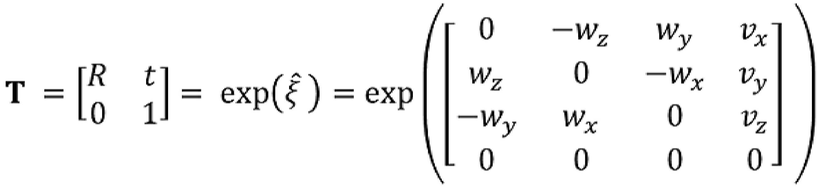
![]()
![]()
여기서, ![]()
![]()
![]()
![]()
![]()
![]()
![]()
![]()
![]()
![]()
포즈 그래프(700)에 포함된 모든 엣지(703)에 대해 오차를 합산하면 수학식 3과 같이 포즈 그래프 오차 함수(pose-graph error function)(![]()
![]()
[수학식 3][Equation 3]
![]()
![]()
여기서, ![]()
![]()
경로 최적화부(530)는 수학식 4와 같이 포즈 그래프 오차 함수의 오차가 줄어드는 방향으로 노드(701, 702)의 포즈 값(![]()
![]()
![]()
![]()
[수학식 4][Equation 4]
![]()
![]()
최적화된 포즈 그래프는 상대 포즈 값(![]()
![]()
![]()
![]()
![]()
![]()
![]()
![]()
도 8 내지 도 10은 상대 포즈(![]()
![]()
![]()
![]()
도 8을 참조하면, 경로 최적화부(530)는 t=0 시점에 추정된 상대 포즈 값(x0)을 바탕으로 t=1 시점에 추정된 상대 포즈 값(x1)에 대해 t=1 시점에 추정된 절대 포즈 값(l1)을 요청하여 t=1 시점의 상대 포즈 값(x1)을 보정할 수 있다. 이때, 경로 최적화부(530)는 t=1 시점의 상대 포즈 값(x1)을 t=1 시점에 획득한 절대 포즈 값(l1)과의 오차를 최소화 하는 방향으로 최적화할 수 있다.Referring to FIG. 8 , the
도 9를 참조하면, 경로 최적화부(530)는 t=1 시점의 최적화된 포즈 값을 바탕으로 t=2 시점에 추정된 상대 포즈 값(x2)에 이어 t=3 시점에 추정된 상대 포즈 값(x3)에 대해 t=3 시점에 추정된 절대 포즈 값(l2)을 요청하여 t=3 시점의 상대 포즈 값(x3)을 보정할 수 있다. 이때, 경로 최적화부(530)는 t=3 시점의 상대 포즈 값(x3)을 t=3 시점에 획득한 절대 포즈 값(l2)과의 오차를 최소화 하는 방향으로 최적화할 수 있다.Referring to FIG. 9 , the
도 10을 참조하면, 경로 최적화부(530)는 t=3 시점의 최적화된 포즈 값을 바탕으로 t=4 시점에 추정된 상대 포즈 값(x4) 이후 상기와 동일한 포즈 최적화 과정을 반복할 수 있다.Referring to FIG. 10 , the
경로 최적화부(530)는 오도메트리로부터 추정된 상대 포즈(![]()
![]()
![]()
![]()
경로 최적화부(530)는 상대 포즈(![]()
![]()
![]()
![]()
포즈 그래프 최적화를 통해 포즈 추정 정확도를 향상시킬 수 있다. 오도메트리로부터 추정된 포즈인 상대 포즈(![]()
![]()
![]()
![]()
VL로부터 추정된 포즈 값(![]()
![]()
![]()
![]()
![]()
![]()
도 11에 도시한 포즈 추정 결과 그래프를 살펴보면, 본 실시예에서는 VL과 오도메트리를 융합하여 최적화한 포즈 결과(optimized pose)가 검증 데이터(ground truth)에 가까워지는 결과를 얻을 수 있다.Looking at the pose estimation result graph shown in FIG. 11 , in the present embodiment, it is possible to obtain a result in which the optimized pose is close to the ground truth by fusion of VL and odometry.
본 실시예에서는 VL 기술과 오도메트리 기술, 그리고 최적화 알고리즘을 융합하여 측위 정확도를 향상시킬 수 있다. 더 나아가, 이동 상황을 고려한 측위 기술 중 하나로 VOT(visual object tracking) 기술을 추가 활용할 수 있으며, 이때 VOT는 이미지 인식 기술을 기반으로 물체의 위치나 방향을 6자유도로 추정할 수 있는 기술이다. VL의 동작 여부 또는 VL의 포즈 추정 결과에 따라 VOT 기술을 추가로 이용하여 6자유도 포즈를 추정할 수 있다. 예를 들어, VL이 제대로 동작하지 않거나 VL의 포즈 결과가 부정확한 환경일 때 VOT 기술을 활용하여 사전에 포즈를 파악한 물체나 마커를 이용하여 측위를 할 수 있다.In this embodiment, the positioning accuracy can be improved by fusing the VL technique, the odometry technique, and the optimization algorithm. Furthermore, VOT (visual object tracking) technology can be additionally used as one of the positioning technologies considering the movement situation, and VOT is a technology that can estimate the position or direction of an object with 6 degrees of freedom based on image recognition technology. According to whether the VL operates or the result of estimating the pose of the VL, the 6DOF pose may be estimated by additionally using the VOT technique. For example, when the VL does not operate properly or the pose result of the VL is in an inaccurate environment, VOT technology can be used to position the position using an object or marker whose pose has been identified in advance.
상기에서는 본 실시예에 따른 경로 추적 방법이 서버(150)에서 수행되는 것으로 설명하고 있으나, 이에 한정되는 것은 아니다. 도 6의 경로 추적 방법이 서버(150)와의 연동을 통해 전자 기기(110)에서 수행되는 것은 물론이고, 상호 연동 환경에서 일부 과정은 서버(150)에서 수행되고 나머지 과정은 전자 기기(110)에서 수행되는 것 또한 가능하다. 예를 들어, VL를 이용한 포즈 추정은 서버(150)에서 수행될 수 있고, 오도메트리를 이용한 포즈 추정은 전자 기기(110)에서 수행될 수 있다. 이때, 경로 최적화 과정은 서버(150)와 전자 기기(110) 중 어느 한쪽에서 수행될 수 있다.In the above description, the path tracking method according to the present embodiment is described as being performed by the
이처럼 본 발명의 실시예들에 따르면, VL의 포즈 결과와 오도메트리의 포즈 결과를 이용하여 경로 최적화를 수행함으로써 적정한 연산량으로 높은 정확도의 측위 결과를 제공할 수 있다. 그리고, 본 발명의 실시예들에 따르면, VL 기술과 오도메트리 기술이 융합된 측위 기술의 경우 최소한의 네트워크와 저사양 카메라만으로 이동 상황에서 끊김 없는 실시간 측위가 가능함에 따라 스마트폰과 같은 모바일 기기는 물론이고, 이동 로봇이나 보행 로봇, 자동차 등 다양한 디바이스에 적용할 수 있다.As described above, according to embodiments of the present invention, by performing path optimization using the pose result of VL and the pose result of odometry, it is possible to provide a high-accuracy positioning result with an appropriate amount of computation. And, according to the embodiments of the present invention, in the case of the positioning technology in which the VL technology and the odometry technology are fused, real-time positioning without interruption in a moving situation is possible only with a minimum network and a low-spec camera, so a mobile device such as a smartphone is Of course, it can be applied to various devices such as mobile robots, walking robots, and automobiles.
이상에서 설명된 장치는 하드웨어 구성요소, 소프트웨어 구성요소, 및/또는 하드웨어 구성요소 및 소프트웨어 구성요소의 조합으로 구현될 수 있다. 예를 들어, 실시예들에서 설명된 장치 및 구성요소는, 프로세서, 콘트롤러, ALU(arithmetic logic unit), 디지털 신호 프로세서(digital signal processor), 마이크로컴퓨터, FPGA(field programmable gate array), PLU(programmable logic unit), 마이크로프로세서, 또는 명령(instruction)을 실행하고 응답할 수 있는 다른 어떠한 장치와 같이, 하나 이상의 범용 컴퓨터 또는 특수 목적 컴퓨터를 이용하여 구현될 수 있다. 처리 장치는 운영 체제(OS) 및 상기 운영 체제 상에서 수행되는 하나 이상의 소프트웨어 어플리케이션을 수행할 수 있다. 또한, 처리 장치는 소프트웨어의 실행에 응답하여, 데이터를 접근, 저장, 조작, 처리 및 생성할 수도 있다. 이해의 편의를 위하여, 처리 장치는 하나가 사용되는 것으로 설명된 경우도 있지만, 해당 기술분야에서 통상의 지식을 가진 자는, 처리 장치가 복수 개의 처리 요소(processing element) 및/또는 복수 유형의 처리 요소를 포함할 수 있음을 알 수 있다. 예를 들어, 처리 장치는 복수 개의 프로세서 또는 하나의 프로세서 및 하나의 콘트롤러를 포함할 수 있다. 또한, 병렬 프로세서(parallel processor)와 같은, 다른 처리 구성(processing configuration)도 가능하다.The device described above may be implemented as a hardware component, a software component, and/or a combination of the hardware component and the software component. For example, the apparatus and components described in the embodiments may include a processor, a controller, an arithmetic logic unit (ALU), a digital signal processor, a microcomputer, a field programmable gate array (FPGA), and a programmable logic unit (PLU). It may be implemented using one or more general purpose or special purpose computers, such as a logic unit, microprocessor, or any other device capable of executing and responding to instructions. The processing device may execute an operating system (OS) and one or more software applications executed on the operating system. The processing device may also access, store, manipulate, process, and generate data in response to execution of the software. For convenience of understanding, although one processing device is sometimes described as being used, one of ordinary skill in the art will recognize that the processing device includes a plurality of processing elements and/or a plurality of types of processing elements. It can be seen that can include For example, the processing device may include a plurality of processors or one processor and one controller. Other processing configurations are also possible, such as parallel processors.
소프트웨어는 컴퓨터 프로그램(computer program), 코드(code), 명령(instruction), 또는 이들 중 하나 이상의 조합을 포함할 수 있으며, 원하는 대로 동작하도록 처리 장치를 구성하거나 독립적으로 또는 결합적으로(collectively) 처리 장치를 명령할 수 있다. 소프트웨어 및/또는 데이터는, 처리 장치에 의하여 해석되거나 처리 장치에 명령 또는 데이터를 제공하기 위하여, 어떤 유형의 기계, 구성요소(component), 물리적 장치, 컴퓨터 저장 매체 또는 장치에 구체화(embody)될 수 있다. 소프트웨어는 네트워크로 연결된 컴퓨터 시스템 상에 분산되어서, 분산된 방법으로 저장되거나 실행될 수도 있다. 소프트웨어 및 데이터는 하나 이상의 컴퓨터 판독 가능 기록 매체에 저장될 수 있다.The software may comprise a computer program, code, instructions, or a combination of one or more thereof, which configures a processing device to operate as desired or is independently or collectively processed You can command the device. The software and/or data may be embodied in any type of machine, component, physical device, computer storage medium or device for interpretation by or providing instructions or data to the processing device. have. The software may be distributed over networked computer systems, and stored or executed in a distributed manner. Software and data may be stored in one or more computer-readable recording media.
실시예에 따른 방법은 다양한 컴퓨터 수단을 통하여 수행될 수 있는 프로그램 명령 형태로 구현되어 컴퓨터 판독 가능 매체에 기록될 수 있다. 이때, 매체는 컴퓨터로 실행 가능한 프로그램을 계속 저장하거나, 실행 또는 다운로드를 위해 임시 저장하는 것일 수도 있다. 또한, 매체는 단일 또는 수 개의 하드웨어가 결합된 형태의 다양한 기록수단 또는 저장수단일 수 있는데, 어떤 컴퓨터 시스템에 직접 접속되는 매체에 한정되지 않고, 네트워크 상에 분산 존재하는 것일 수도 있다. 매체의 예시로는, 하드 디스크, 플로피 디스크 및 자기 테이프와 같은 자기 매체, CD-ROM 및 DVD와 같은 광기록 매체, 플롭티컬 디스크(floptical disk)와 같은 자기-광 매체(magneto-optical medium), 및 ROM, RAM, 플래시 메모리 등을 포함하여 프로그램 명령어가 저장되도록 구성된 것이 있을 수 있다. 또한, 다른 매체의 예시로, 어플리케이션을 유통하는 앱 스토어나 기타 다양한 소프트웨어를 공급 내지 유통하는 사이트, 서버 등에서 관리하는 기록매체 내지 저장매체도 들 수 있다.The method according to the embodiment may be implemented in the form of program instructions that can be executed through various computer means and recorded in a computer-readable medium. In this case, the medium may be to continuously store a program executable by a computer, or to temporarily store it for execution or download. In addition, the medium may be a variety of recording means or storage means in the form of a single or several hardware combined, it is not limited to a medium directly connected to any computer system, and may exist distributed on a network. Examples of the medium include a hard disk, a magnetic medium such as a floppy disk and a magnetic tape, an optical recording medium such as CD-ROM and DVD, a magneto-optical medium such as a floppy disk, and those configured to store program instructions, including ROM, RAM, flash memory, and the like. In addition, examples of other media include recording media or storage media managed by an app store that distributes applications, sites that supply or distribute various other software, and servers.
이상과 같이 실시예들이 비록 한정된 실시예와 도면에 의해 설명되었으나, 해당 기술분야에서 통상의 지식을 가진 자라면 상기의 기재로부터 다양한 수정 및 변형이 가능하다. 예를 들어, 설명된 기술들이 설명된 방법과 다른 순서로 수행되거나, 및/또는 설명된 시스템, 구조, 장치, 회로 등의 구성요소들이 설명된 방법과 다른 형태로 결합 또는 조합되거나, 다른 구성요소 또는 균등물에 의하여 대치되거나 치환되더라도 적절한 결과가 달성될 수 있다.As described above, although the embodiments have been described with reference to the limited embodiments and drawings, various modifications and variations are possible from the above description by those skilled in the art. For example, the described techniques are performed in a different order than the described method, and/or the described components of the system, structure, apparatus, circuit, etc. are combined or combined in a different form than the described method, or other components Or substituted or substituted by equivalents may achieve an appropriate result.
그러므로, 다른 구현들, 다른 실시예들 및 특허청구범위와 균등한 것들도 후술하는 특허청구범위의 범위에 속한다.Therefore, other implementations, other embodiments, and equivalents to the claims are also within the scope of the following claims.
Claims (18)
상기 컴퓨터 시스템은 메모리에 포함된 컴퓨터 판독가능한 명령들을 실행하도록 구성된 적어도 하나의 프로세서를 포함하고,
상기 경로 추적 방법은,
상기 적어도 하나의 프로세서에 의해, 카메라 포즈 정보로서 오도메트리(odometry)에 의한 포즈 추정 결과와 VL(visual localization)에 의한 포즈 추정 결과를 이용하여 경로(trajectory)를 추적하는 단계
를 포함하고,
상기 추적하는 단계는,
상기 오도메트리를 통해 추정된 상대 포즈와 상기 VL를 통해 추정된 절대 포즈를 노드(node)로 정의하고 노드 간의 포즈 차이를 엣지(edge)로 정의한 포즈 그래프를 최적화하는 단계
를 포함하는 경로 추적 방법.A path tracing method executed in a computer system, comprising:
the computer system comprising at least one processor configured to execute computer readable instructions contained in a memory;
The path tracking method is
tracking a trajectory by using the pose estimation result by odometry and the pose estimation result by VL (visual localization) as camera pose information by the at least one processor
including,
The tracking step is
optimizing the pose graph in which the relative pose estimated through the odometry and the absolute pose estimated through the VL are defined as nodes and the pose difference between nodes is defined as edges
Path tracing method including .
상기 추적하는 단계는,
상기 오도메트리를 통해 추정된 상대 포즈를 상기 VL를 통해 추정된 절대 포즈를 이용하여 보정하는 단계
를 포함하는 경로 추적 방법.According to claim 1,
The tracking step is
Correcting the relative pose estimated through the odometry using the absolute pose estimated through the VL
Path tracing method including .
상기 추적하는 단계는,
상기 오도메트리에 의한 포즈 추정 시에 발생되는 누적 오차를 상기 VL을 통해 추정된 포즈 값을 이용하여 보정하는 단계
를 포함하는 경로 추적 방법.According to claim 1,
The tracking step is
correcting the accumulated error generated during the pose estimation by the odometry using the pose value estimated through the VL;
Path tracing method including .
상기 최적화하는 단계는,
상기 포즈 그래프에서 임의 시점 혹은 사전에 정해진 일정 주기로 일 시점에 추정된 상대 포즈 값을 해당 시점에 추정된 절대 포즈 값을 이용하여 보정하는 단계
를 포함하는 경로 추적 방법.According to claim 1,
The optimizing step is
Correcting the relative pose value estimated at a point in the pose graph at an arbitrary point in time or at a predetermined period using the absolute pose value estimated at the point in time
Path tracing method including .
상기 최적화하는 단계는,
상기 포즈 그래프에서 임의 시점 혹은 사전에 정해진 일정 주기로 일 시점에 추정된 상대 포즈 값을 해당 시점에 추정된 절대 포즈 값과의 오차를 최소화하는 방향으로 최적화하는 단계
를 포함하는 경로 추적 방법.According to claim 1,
The optimizing step is
optimizing the relative pose value estimated at a point in the pose graph at a certain point in time or at a predetermined period in advance in a direction to minimize the error with the absolute pose value estimated at the point in time;
Path tracing method including .
상기 최적화하는 단계는,
상기 포즈 그래프에 포함된 모든 엣지에 대해 오차를 합산하여 포즈 그래프 오차 함수(pose-graph error function)를 정의하는 단계; 및
상기 포즈 그래프 오차 함수를 기초로 각 노드의 포즈 값을 가우스-뉴턴(Gauss-Newton) 방식을 통해 추정하는 단계
를 포함하는 경로 추적 방법.According to claim 1,
The optimizing step is
defining a pose-graph error function by summing errors for all edges included in the pose graph; and
estimating the pose value of each node based on the pose graph error function through a Gauss-Newton method
Path tracing method including .
상기 경로 추적 방법은,
상기 적어도 하나의 프로세서에 의해, 상기 VL의 동작 여부 또는 상기 VL의 포즈 추정 결과에 따라 VOT(visual object tracking) 기술을 추가로 이용하여 포즈를 추정하는 단계
를 포함하는 경로 추적 방법.According to claim 1,
The path tracking method is
estimating, by the at least one processor, a pose by additionally using a VOT (visual object tracking) technique according to whether the VL is operating or a result of estimating the pose of the VL;
Path tracing method including .
메모리에 포함된 컴퓨터 판독가능한 명령들을 실행하도록 구성된 적어도 하나의 프로세서
를 포함하고,
상기 적어도 하나의 프로세서는,
카메라 포즈 정보로서 오도메트리에 의한 포즈 추정 결과와 VL에 의한 포즈 추정 결과를 이용하여 경로를 추적하고,
상기 오도메트리를 통해 추정된 상대 포즈와 상기 VL를 통해 추정된 절대 포즈를 노드로 정의하고 노드 간의 포즈 차이를 엣지로 정의한 포즈 그래프를 최적화하는 것
을 특징으로 하는 컴퓨터 시스템.In a computer system,
at least one processor configured to execute computer readable instructions contained in memory
including,
the at least one processor,
The path is traced using the pose estimation result by odometry and the pose estimation result by VL as camera pose information,
Optimizing the pose graph in which the relative pose estimated through the odometry and the absolute pose estimated through the VL are defined as nodes and the pose difference between nodes is defined as the edge
A computer system characterized by a.
상기 적어도 하나의 프로세서는,
상기 오도메트리를 통해 추정된 상대 포즈를 상기 VL를 통해 추정된 절대 포즈를 이용하여 보정하는 것
을 특징으로 하는 컴퓨터 시스템.12. The method of claim 11,
the at least one processor,
Correcting the relative pose estimated through the odometry using the absolute pose estimated through the VL
A computer system characterized by a.
상기 적어도 하나의 프로세서는,
상기 오도메트리에 의한 포즈 추정 시에 발생되는 누적 오차를 상기 VL을 통해 추정된 포즈 값을 이용하여 보정하는 것
을 특징으로 하는 컴퓨터 시스템.12. The method of claim 11,
the at least one processor,
Correcting the accumulated error generated in the pose estimation by the odometry using the pose value estimated through the VL
A computer system characterized by a.
상기 적어도 하나의 프로세서는,
상기 포즈 그래프에서 임의 시점 혹은 사전에 정해진 일정 주기로 일 시점에 추정된 상대 포즈 값을 해당 시점에 추정된 절대 포즈 값을 이용하여 보정하는 것
을 특징으로 하는 컴퓨터 시스템.12. The method of claim 11,
the at least one processor,
Correcting the relative pose value estimated at a point in the pose graph at an arbitrary point in time or at a predetermined period using the absolute pose value estimated at that point in time
A computer system characterized by a.
상기 적어도 하나의 프로세서는,
상기 포즈 그래프에서 임의 시점 혹은 사전에 정해진 일정 주기로 일 시점에 추정된 상대 포즈 값을 해당 시점에 추정된 절대 포즈 값과의 오차를 최소화하는 방향으로 최적화하는 것
을 특징으로 하는 컴퓨터 시스템.12. The method of claim 11,
the at least one processor,
Optimizing the relative pose value estimated at a point in the pose graph at an arbitrary point in time or at a predetermined period in a way that minimizes the error with the absolute pose value estimated at that point in time
A computer system characterized by a.
상기 적어도 하나의 프로세서는,
상기 포즈 그래프에 포함된 모든 엣지에 대해 오차를 합산하여 포즈 그래프 오차 함수를 정의한 후, 상기 포즈 그래프 오차 함수를 기초로 각 노드의 포즈 값을 가우스-뉴턴 방식을 통해 추정하는 것
을 특징으로 하는 컴퓨터 시스템.12. The method of claim 11,
the at least one processor,
After defining a pose graph error function by summing errors for all edges included in the pose graph, estimating the pose value of each node based on the pose graph error function through a Gaussian-Newton method
A computer system characterized by a.
상기 적어도 하나의 프로세서는,
상기 VL의 동작 여부 또는 상기 VL의 포즈 추정 결과에 따라 VOT 기술을 추가로 이용하여 포즈를 추정하는 것
을 특징으로 하는 컴퓨터 시스템.12. The method of claim 11,
the at least one processor,
Estimating a pose by additionally using a VOT technique according to whether the VL operates or a result of estimating the pose of the VL
A computer system characterized by a.
Priority Applications (3)
| Application Number | Priority Date | Filing Date | Title |
|---|---|---|---|
| KR1020190144126A KR102322000B1 (en) | 2019-11-12 | 2019-11-12 | Method and system for tracking trajectory based on visual localizaion and odometry |
| JP2020187752A JP7197550B2 (en) | 2019-11-12 | 2020-11-11 | Route tracking method and system based on visual localization and odometry |
| US17/095,909 US11620755B2 (en) | 2019-11-12 | 2020-11-12 | Method and system for tracking trajectory based on visual localization and odometry |
Applications Claiming Priority (1)
| Application Number | Priority Date | Filing Date | Title |
|---|---|---|---|
| KR1020190144126A KR102322000B1 (en) | 2019-11-12 | 2019-11-12 | Method and system for tracking trajectory based on visual localizaion and odometry |
Publications (2)
| Publication Number | Publication Date |
|---|---|
| KR20210057402A KR20210057402A (en) | 2021-05-21 |
| KR102322000B1 true KR102322000B1 (en) | 2021-11-04 |
Family
ID=75847014
Family Applications (1)
| Application Number | Title | Priority Date | Filing Date |
|---|---|---|---|
| KR1020190144126A Active KR102322000B1 (en) | 2019-11-12 | 2019-11-12 | Method and system for tracking trajectory based on visual localizaion and odometry |
Country Status (3)
| Country | Link |
|---|---|
| US (1) | US11620755B2 (en) |
| JP (1) | JP7197550B2 (en) |
| KR (1) | KR102322000B1 (en) |
Families Citing this family (7)
| Publication number | Priority date | Publication date | Assignee | Title |
|---|---|---|---|---|
| US10859713B2 (en) * | 2017-01-04 | 2020-12-08 | Qualcomm Incorporated | Position-window extension for GNSS and visual-inertial-odometry (VIO) fusion |
| KR102639524B1 (en) | 2021-10-05 | 2024-02-22 | 국방과학연구소 | Map merging method of electronic apparatus |
| CN113936120B (en) * | 2021-10-12 | 2024-07-12 | 北京邮电大学 | Label-free lightweight Web AR method and system |
| CN114593735B (en) * | 2022-01-26 | 2024-05-31 | 奥比中光科技集团股份有限公司 | A posture prediction method and device |
| KR102854324B1 (en) * | 2022-11-15 | 2025-09-03 | 주식회사 벰로보틱스 | A Method for Generating A Characteristic Map of a Driving Robot and A Computer-Readable Recording Medium On Which A Program Performing The Same Is Recorded |
| CN116051637A (en) * | 2023-01-03 | 2023-05-02 | 阿里巴巴(中国)有限公司 | VO reliability evaluation method, model training method, device, equipment and product |
| KR102615412B1 (en) * | 2023-01-19 | 2023-12-19 | 주식회사 브이알크루 | Apparatus and method for performing visual localization |
Citations (1)
| Publication number | Priority date | Publication date | Assignee | Title |
|---|---|---|---|---|
| US20190304105A1 (en) * | 2018-04-03 | 2019-10-03 | Altumview Systems Inc. | High-performance visual object tracking for embedded vision systems |
Family Cites Families (9)
| Publication number | Priority date | Publication date | Assignee | Title |
|---|---|---|---|---|
| US7145478B2 (en) | 2002-12-17 | 2006-12-05 | Evolution Robotics, Inc. | Systems and methods for controlling a density of visual landmarks in a visual simultaneous localization and mapping system |
| KR100855469B1 (en) | 2006-09-13 | 2008-09-01 | 삼성전자주식회사 | Apparatus and method for attitude estimation of mobile robot |
| KR20100070922A (en) | 2008-12-18 | 2010-06-28 | 한국전자통신연구원 | Building apparatus of occupancy grid map and its method for a location recognition |
| AU2011305154B2 (en) * | 2010-09-24 | 2015-02-05 | Irobot Corporation | Systems and methods for VSLAM optimization |
| US9709404B2 (en) * | 2015-04-17 | 2017-07-18 | Regents Of The University Of Minnesota | Iterative Kalman Smoother for robust 3D localization for vision-aided inertial navigation |
| US9507346B1 (en) * | 2015-11-04 | 2016-11-29 | Zoox, Inc. | Teleoperation system and method for trajectory modification of autonomous vehicles |
| CN110062871B (en) * | 2016-12-09 | 2024-01-19 | 通腾全球信息公司 | Methods and systems for video-based positioning and mapping |
| JP2019079171A (en) | 2017-10-23 | 2019-05-23 | 日本電産シンポ株式会社 | Movable body |
| JP2019190994A (en) | 2018-04-25 | 2019-10-31 | 日産自動車株式会社 | Method and device for estimating self-position |
-
2019
- 2019-11-12 KR KR1020190144126A patent/KR102322000B1/en active Active
-
2020
- 2020-11-11 JP JP2020187752A patent/JP7197550B2/en active Active
- 2020-11-12 US US17/095,909 patent/US11620755B2/en active Active
Patent Citations (1)
| Publication number | Priority date | Publication date | Assignee | Title |
|---|---|---|---|---|
| US20190304105A1 (en) * | 2018-04-03 | 2019-10-03 | Altumview Systems Inc. | High-performance visual object tracking for embedded vision systems |
Also Published As
| Publication number | Publication date |
|---|---|
| US20210142488A1 (en) | 2021-05-13 |
| JP7197550B2 (en) | 2022-12-27 |
| JP2021076605A (en) | 2021-05-20 |
| US11620755B2 (en) | 2023-04-04 |
| KR20210057402A (en) | 2021-05-21 |
Similar Documents
| Publication | Publication Date | Title |
|---|---|---|
| KR102322000B1 (en) | Method and system for tracking trajectory based on visual localizaion and odometry | |
| KR102212825B1 (en) | Method and system for updating map for pose estimation based on images | |
| JP7131994B2 (en) | Self-position estimation device, self-position estimation method, self-position estimation program, learning device, learning method and learning program | |
| KR20220004607A (en) | Target detection method, electronic device, roadside device and cloud control platform | |
| KR102132675B1 (en) | Method and system for providing navigation function through aerial view | |
| KR20210022016A (en) | Method and system for improving depth information of feature points using camera and lidar | |
| CN111338383A (en) | Autonomous flight method and system based on GAAS and storage medium | |
| KR20220123901A (en) | Method and system for generating HD maps based on aerial images taken by unmanned aerial vehicles or aircraft | |
| US12254041B2 (en) | Position recognition method and system based on visual information processing | |
| US20250329116A1 (en) | Positioning method and apparatus, electronic device, computer-readable storage medium, and computer program product | |
| KR20210015516A (en) | Method and system for improving depth information of feature points using camera and lidar | |
| CN116358525A (en) | Mapping and positioning method, system and engineering vehicle based on lidar | |
| KR102589296B1 (en) | Apparatus and method for generating three dimensional map using aerial images | |
| Li et al. | A novel edge-enabled SLAM solution using projected depth image information | |
| CN117870650B (en) | AR positioning map updating method and device | |
| KR20210057586A (en) | Method and system for camera-based visual localization using blind watermarking | |
| CN118068355A (en) | Laser radar data merging method, electronic device and storage medium | |
| JP2024165836A (en) | CONTROL DEVICE, MOBILE BODY, ROUTE PLANNING DEVICE, PROGRAM, AND METHOD FOR GENERATING TRAINED MODEL | |
| KR20240155417A (en) | Apparatus and method of localizing user pose in three-dimensional space | |
| KR102803033B1 (en) | Method and apparatus for registration of target point cloud data and source point cloud data using registration algorithm selected based on the number of matching points between target point cloud data and source point cloud data | |
| Demim et al. | Simultaneous localization and mapping algorithm based on 3D laser for unmanned aerial vehicle | |
| KR20220078519A (en) | Apparatus and method of estimating vehicle location for autonomous driving | |
| US20150092985A1 (en) | Updating filter parameters of a system | |
| US20250334968A1 (en) | Method and apparatus for producing high-precision indoor maps through loop closing optimization | |
| Hashimoto et al. | Self-localization from a 360-Degree Camera Based on the Deep Neural Network |
Legal Events
| Date | Code | Title | Description |
|---|---|---|---|
| PA0109 | Patent application |
St.27 status event code: A-0-1-A10-A12-nap-PA0109 |
|
| PA0201 | Request for examination |
St.27 status event code: A-1-2-D10-D11-exm-PA0201 |
|
| D13-X000 | Search requested |
St.27 status event code: A-1-2-D10-D13-srh-X000 |
|
| D14-X000 | Search report completed |
St.27 status event code: A-1-2-D10-D14-srh-X000 |
|
| PE0902 | Notice of grounds for rejection |
St.27 status event code: A-1-2-D10-D21-exm-PE0902 |
|
| E13-X000 | Pre-grant limitation requested |
St.27 status event code: A-2-3-E10-E13-lim-X000 |
|
| P11-X000 | Amendment of application requested |
St.27 status event code: A-2-2-P10-P11-nap-X000 |
|
| P13-X000 | Application amended |
St.27 status event code: A-2-2-P10-P13-nap-X000 |
|
| PG1501 | Laying open of application |
St.27 status event code: A-1-1-Q10-Q12-nap-PG1501 |
|
| E701 | Decision to grant or registration of patent right | ||
| PE0701 | Decision of registration |
St.27 status event code: A-1-2-D10-D22-exm-PE0701 |
|
| PR0701 | Registration of establishment |
St.27 status event code: A-2-4-F10-F11-exm-PR0701 |
|
| PR1002 | Payment of registration fee |
St.27 status event code: A-2-2-U10-U11-oth-PR1002 Fee payment year number: 1 |
|
| PG1601 | Publication of registration |
St.27 status event code: A-4-4-Q10-Q13-nap-PG1601 |
|
| R18-X000 | Changes to party contact information recorded |
St.27 status event code: A-5-5-R10-R18-oth-X000 |
|
| P22-X000 | Classification modified |
St.27 status event code: A-4-4-P10-P22-nap-X000 |
|
| PR1001 | Payment of annual fee |
St.27 status event code: A-4-4-U10-U11-oth-PR1001 Fee payment year number: 4 |
|
| P22-X000 | Classification modified |
St.27 status event code: A-4-4-P10-P22-nap-X000 |