KR102318444B1 - Control system for distributed power supply device using non-contact type coupler - Google Patents
Control system for distributed power supply device using non-contact type coupler Download PDFInfo
- Publication number
- KR102318444B1 KR102318444B1 KR1020190162034A KR20190162034A KR102318444B1 KR 102318444 B1 KR102318444 B1 KR 102318444B1 KR 1020190162034 A KR1020190162034 A KR 1020190162034A KR 20190162034 A KR20190162034 A KR 20190162034A KR 102318444 B1 KR102318444 B1 KR 102318444B1
- Authority
- KR
- South Korea
- Prior art keywords
- power supply
- distributed power
- communication
- line
- distribution line
- Prior art date
- Legal status (The legal status is an assumption and is not a legal conclusion. Google has not performed a legal analysis and makes no representation as to the accuracy of the status listed.)
- Active
Links
- 238000004891 communication Methods 0.000 claims abstract description 125
- 238000000034 method Methods 0.000 claims description 17
- 230000008878 coupling Effects 0.000 claims description 4
- 238000010168 coupling process Methods 0.000 claims description 4
- 238000005859 coupling reaction Methods 0.000 claims description 4
- 239000000284 extract Substances 0.000 claims description 4
- 238000005516 engineering process Methods 0.000 claims description 2
- 238000010248 power generation Methods 0.000 description 10
- 238000010586 diagram Methods 0.000 description 5
- 230000005540 biological transmission Effects 0.000 description 3
- 238000009434 installation Methods 0.000 description 3
- 238000004804 winding Methods 0.000 description 3
- 238000013461 design Methods 0.000 description 2
- 230000005674 electromagnetic induction Effects 0.000 description 2
- 239000002184 metal Substances 0.000 description 2
- 230000003287 optical effect Effects 0.000 description 2
- 238000012546 transfer Methods 0.000 description 2
- 230000000903 blocking effect Effects 0.000 description 1
- 238000010276 construction Methods 0.000 description 1
- 238000012937 correction Methods 0.000 description 1
- 238000001514 detection method Methods 0.000 description 1
- 230000000694 effects Effects 0.000 description 1
- 230000005611 electricity Effects 0.000 description 1
- 230000006870 function Effects 0.000 description 1
- 238000004519 manufacturing process Methods 0.000 description 1
- 239000000463 material Substances 0.000 description 1
- 238000012986 modification Methods 0.000 description 1
- 230000004048 modification Effects 0.000 description 1
- 238000012544 monitoring process Methods 0.000 description 1
- 230000007935 neutral effect Effects 0.000 description 1
- 230000010363 phase shift Effects 0.000 description 1
- 230000008054 signal transmission Effects 0.000 description 1
Images


Classifications
-
- H—ELECTRICITY
- H04—ELECTRIC COMMUNICATION TECHNIQUE
- H04B—TRANSMISSION
- H04B3/00—Line transmission systems
- H04B3/54—Systems for transmission via power distribution lines
-
- H—ELECTRICITY
- H02—GENERATION; CONVERSION OR DISTRIBUTION OF ELECTRIC POWER
- H02J—CIRCUIT ARRANGEMENTS OR SYSTEMS FOR SUPPLYING OR DISTRIBUTING ELECTRIC POWER; SYSTEMS FOR STORING ELECTRIC ENERGY
- H02J3/00—Circuit arrangements for AC mains or AC distribution networks
- H02J3/38—Arrangements for parallely feeding a single network by two or more generators, converters or transformers
- H02J3/381—Dispersed generators
-
- H—ELECTRICITY
- H04—ELECTRIC COMMUNICATION TECHNIQUE
- H04B—TRANSMISSION
- H04B3/00—Line transmission systems
- H04B3/54—Systems for transmission via power distribution lines
- H04B3/56—Circuits for coupling, blocking, or by-passing of signals
-
- H—ELECTRICITY
- H04—ELECTRIC COMMUNICATION TECHNIQUE
- H04B—TRANSMISSION
- H04B2203/00—Indexing scheme relating to line transmission systems
- H04B2203/54—Aspects of powerline communications not already covered by H04B3/54 and its subgroups
- H04B2203/5462—Systems for power line communications
- H04B2203/5466—Systems for power line communications using three phases conductors
-
- H—ELECTRICITY
- H04—ELECTRIC COMMUNICATION TECHNIQUE
- H04B—TRANSMISSION
- H04B2203/00—Indexing scheme relating to line transmission systems
- H04B2203/54—Aspects of powerline communications not already covered by H04B3/54 and its subgroups
- H04B2203/5462—Systems for power line communications
- H04B2203/5483—Systems for power line communications using coupling circuits
Landscapes
- Engineering & Computer Science (AREA)
- Power Engineering (AREA)
- Computer Networks & Wireless Communication (AREA)
- Signal Processing (AREA)
- Cable Transmission Systems, Equalization Of Radio And Reduction Of Echo (AREA)
Abstract
본 발명은 비접촉 커플러를 이용하여 분산형 전원장치를 제어하기 위한 분산형 전원장치 제어 시스템에 관한 것이다.
본 발명의 분산형 전원장치 제어 시스템은, 분산형 전원장치 제어신호에 대응하는 제1주파수신호를 출력하는 제1통신모뎀, 배전선로에 연결된 접지선에 비접촉으로 결합되며 제1통신모뎀에서 출력되는 제1주파수신호를 접지선에 전달하는 제1비접촉커플러, 1상의 배전선로에 비접촉식으로 결합되며 접지선으로부터 1상의 배전선로를 통해 전달되는 제1주파수신호를 수집하는 제2비접촉커플러, 제2비접촉커플러로부터 수신된 제1주파수신호로부터 제어신호를 추출하는 제2통신모뎀, 그리고 제2통신모뎀으로부터 출력되는 제어신호를 이용하여 분산형 전원장치를 제어하는 제어부를 포함한다.The present invention relates to a distributed power supply control system for controlling a distributed power supply using a contactless coupler.
The distributed power supply control system of the present invention includes a first communication modem that outputs a first frequency signal corresponding to a distributed power supply control signal, a first communication modem that is non-contactly coupled to a ground line connected to a distribution line and is output from the first communication modem. A first non-contact coupler that transmits one frequency signal to a ground line, a second non-contact coupler that is non-contactly coupled to a one-phase distribution line and collects a first frequency signal transmitted from a ground line through a one-phase distribution line, a second non-contact coupler receives from A second communication modem for extracting a control signal from the first frequency signal, and a control unit for controlling the distributed power supply using the control signal output from the second communication modem.

Description
본 발명은 분산형 전원장치 제어용 전력선 통신 시스템에 관한 것으로서, 특히 비접촉 커플러를 이용하여 분산형 전원장치를 제어하기 위한 제어 시스템에 관한 것이다.The present invention relates to a power line communication system for controlling a distributed power supply, and more particularly, to a control system for controlling a distributed power supply using a contactless coupler.
분산형 전원장치는 자체적으로 전압을 생산하여 배전설비로 공급할 수 있다. 이를 위해 배전설비와 분산형 전원장치 간에 배전선로와 통신선로가 설치된다. 배전설비는 공급받은 전압을 다른 곳으로 배전할 수 있다.The distributed power supply can generate its own voltage and supply it to the power distribution facility. For this purpose, a distribution line and a communication line are installed between the distribution facility and the distributed power supply device. The power distribution facility can distribute the supplied voltage to other places.
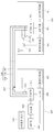
도 1은 종래의 분산형 전원장치 제어 시스템의 구성도이다. 1 is a block diagram of a conventional distributed power supply control system.
배전설비(10)의 통신부(12)는 배전센터 서버(11)로부터 분산형 발전유닛(20)의 분산형 전원장치(25)의 제어를 위한 제어신호를 수신하여 분산형 발전유닛(20)의 제어부(21)로 전달한다. The
이러한 제어신호의 전달을 위해 배전설비(10)의 통신부(12)와 분산형 발전유닛(20)의 제어부(21) 간에는 RS485 통신선로(1)가 연결된다.An
제어부(21)는 RS485 통신선로(1)를 통해 수신되는 제어신호를 기초로 후술하는 인버터(24)의 동작을 제어한다.The
분산형 전원장치(25)는 복수 개로 설치될 수 있으며 각각 전압을 생성한다.A plurality of distributed
인버터(24)는 제어부(21)의 제어신호에 따라 분산형 전원장치(25)에서 생성되는 직류전압을 교류전압으로 변환한다. The
변압기(23)는 배전설비(10)에서 요구하는 전압으로 변환한다.The
변압기(23)에서 변환된 전압은 배전선로(2)를 이용하여 배전설비(10)로 전달된다. 배전선로(2)는 고전압용 3상 배전선로이며, 예컨대 22.9㎸의 고전압이 3상 배전선로를 통해 전달된다.The voltage converted by the
배전설비(10)와 분산형 발전유닛(20) 간에 연결된 3상 배전선로(2)에는 각각 고전압 제1차단기(13) 및 제2차단기(22)가 설치되어 비상시 각각 독립적으로 회로를 차단할 수 있다. A high-voltage
그리고, 가스절연부하개폐기(13)의 전단에서 3상 배전선로(2)는 접지선을 통해 접지와 연결되어 있다.In addition, at the front end of the gas insulated
이와 같은 종래의 분산형 전원장치 제어시스템에서는 배전센터 서버(11)에서 출력되는 제어신호를 RS485 통신선로(1)를 통해 통신부(12)에서 제어부(21)로 전달되고 분산형 전원장치(25)에서 발전된 고전압은 3상 배전선로(2)를 통하여 배전설비(10)로 전달된다.In such a conventional distributed power supply control system, the control signal output from the
하지만, 위 종래의 시스템에는 배전설비(10)와 분산형 발전유닛(20) 간의 통신을 위해 RS485 통신선로(1)를 별도로 구축해야 하는 번거로움이 있고, 이를 위해 지하의 관로를 확보해야 하는 어려움이 있고, 활선작업을 위한 시간과 비용이 증가하는 문제점이 있다. RS485 통신선로(1)를 지상으로 설치하는 경우 낙뢰 등으로 인해 통신장비에 손상을 줄 수 있다.However, in the above conventional system, there is a hassle of separately constructing an
최근 RS485 통신선로 대신 TRS, LTE 등의 무선통신 방식을 적용하는 시도가 있었으나, 보안문제와 장거리 통신의 안정성 문제로 인해 적용하기가 어려우며 통신불능 구간이 존재하여 통신의 안정성에 문제가 제기되었다.Recently, there have been attempts to apply wireless communication methods such as TRS and LTE instead of RS485 communication lines, but it is difficult to apply due to security problems and stability problems of long-distance communication.
한편, 등록특허공보 제10-0657873호에는 전력선 통신방식을 이용한 분산발전용 원격 감시 제어시스템이 개시되어 있다. 상기 선행문헌은 분산형 전원을 제어하기 위해 전력선 통신을 이용하며, 제어부가 원격감시기와 통신 연계되도록 하기 위해 저압전력선을 연결하고 저압배전선로에 접속되는 커플러를 연결한다.Meanwhile, Korean Patent Publication No. 10-0657873 discloses a remote monitoring and control system for distributed power generation using a power line communication method. The prior document uses power line communication to control distributed power, and connects a low voltage power line and a coupler connected to a low voltage distribution line so that the control unit communicates with a remote monitor.
하지만, 상기 선행문헌은 저압배전선로에 접촉식 커플러를 연결하여 사용하고 있다. 저압배전선로의 접촉식 커플러 연결은 다음과 같은 문제점이 있다.However, the prior literature uses a contact coupler connected to a low voltage distribution line. The contact coupler connection of the low voltage distribution line has the following problems.
첫째, 접촉식 커플러는 배전선과 중심선에 모두 연결해야 하는데 고압의 3상 배전선로에는 중심선이 없으므로 연결이 불가능하다.First, the contact coupler should be connected to both the distribution line and the center line, but since there is no center line in the high-voltage three-phase distribution line, connection is impossible.
둘째, 접촉식 커플러는 활선을 개방하여 활선에 커플러의 코일과 직접 연결해야 하므로 회로를 차단한 후 공사를 해야 하고, 고압용 배전선로의 경우 활선에 직접 연결하는 것은 작업자에게 매우 위험하다.Second, the contact-type coupler has to open the live wire and directly connect the coupler's coil to the live wire, so the circuit must be blocked before construction.
셋째, 접촉식 커플러는 대부분 저압용이고 고압용으로 제조하기 위해서는 비용이 많이 들고 내전압 용량을 위해서는 부피가 증가하는 문제점이 있다.Third, most of the contact coupler is for a low voltage, and it is expensive to manufacture for a high voltage, and there is a problem in that a volume increases for a withstand voltage capacity.
넷째, 접촉식 커플러를 고압용으로 제조하더라도 3상 배전선로에서 같은 상의 배전선로를 확인하여 양단에 커플러를 직접 연결 설치해야 하므로 작업의 번거로움이 발생한다.Fourth, even if the contact coupler is manufactured for high voltage, it is necessary to directly connect and install the coupler at both ends by checking the distribution line of the same phase in the three-phase distribution line.
다섯째, 분산형 전원장치의 주변에 설치된 다수의 전자기 장치로 인해 통신신호에 노이즈신호가 삽입되어 통신의 신뢰성이 감소되는 문제점이 있다.Fifth, there is a problem in that a noise signal is inserted into a communication signal due to a number of electromagnetic devices installed around the distributed power supply device, thereby reducing communication reliability.
따라서, 해당 기술분야에서는 고압용 3상 배전선로에 연결된 분산형 전원장치를 원격지에서 안전하고 신뢰성 있게 제어할 수 있도록 하는 시스템의 개발이 요구되고 있다.Accordingly, there is a need in the art to develop a system capable of safely and reliably controlling a distributed power supply connected to a three-phase distribution line for high voltage from a remote location.
본 발명은 종래의 분산형 전원장치 제어시스템에서 RS485 통신선로를 제거하고 비접촉 커플러를 통해 제어신호를 전달하는 분산형 전원장치 제어시스템을 제공하는데 목적이 있다.An object of the present invention is to provide a distributed power supply control system that removes the RS485 communication line from the conventional distributed power supply control system and transmits a control signal through a contactless coupler.
본 발명은 비접촉 커플러를 고전압용 3상 배전선로에 설치하여 배전센터 서버와 분산형 전원장치 간에 전력선 통신이 가능하도록 하는 분산형 전원장치 제어시스템을 제공하는데 목적이 있다.An object of the present invention is to provide a distributed power supply control system that enables power line communication between a distribution center server and a distributed power supply by installing a contactless coupler on a three-phase distribution line for high voltage.
본 발명은 RS-232 또는 RS-485 시리얼 통신 데이터를 동축케이블을 통해 비접촉커플러로 송수신할 수 있는 최적으로 통신모뎀을 구비하여 전력선 통신이 가능하도록 하는 분산형 전원장치 제어시스템을 제공하는데 목적이 있다.An object of the present invention is to provide a distributed power supply control system that enables power line communication with an optimal communication modem capable of transmitting and receiving RS-232 or RS-485 serial communication data to and from a contactless coupler through a coaxial cable. .
본 발명에 따른 분산형 전원장치 제어 시스템은, 전압을 생성하여 3상 고전압 배전선로를 통해 생성된 전압을 배전설비로 공급하는 분산형 전원장치에서, 상기 분산형 전원장치의 제어를 위한 제어신호가 수신되면 상기 제어신호에 대응하는 제1주파수신호를 발생하여 출력하는 제1통신모뎀; 상기 3상 고전압 배전선로에 연결된 접지선에 비접촉으로 결합되며 상기 제1통신모뎀에서 출력되는 제1주파수신호를 상기 접지선에 전달하는 제1비접촉커플러; 상기 3상 고전압 배전선로 중 선택된 1상의 배전선로에 비접촉식으로 결합되며 상기 접지선으로부터 상기 1상의 배전선로를 통해 전달되는 상기 제1주파수신호를 커플링하여 수집하는 제2비접촉커플러; 상기 제2비접촉커플러로부터 상기 제1주파수신호를 수신하고 상기 수신된 주파수신호로부터 상기 제어신호를 추출하는 제2통신모뎀; 및 상기 제2통신모뎀으로부터 출력되는 제어신호를 이용하여 상기 분산형 전원장치를 제어하는 제어부를 포함한다.A distributed power supply control system according to the present invention is a distributed power supply that generates a voltage and supplies the voltage generated through a three-phase high voltage distribution line to a distribution facility, wherein a control signal for controlling the distributed power supply is provided. a first communication modem for generating and outputting a first frequency signal corresponding to the control signal when received; a first contactless coupler that is non-contactly coupled to a ground line connected to the three-phase high voltage distribution line and transmits a first frequency signal output from the first communication modem to the ground line; a second non-contact coupler which is non-contactably coupled to a distribution line of one phase selected from among the three-phase high voltage distribution line and couples and collects the first frequency signal transmitted from the ground line through the one-phase distribution line; a second communication modem receiving the first frequency signal from the second non-contact coupler and extracting the control signal from the received frequency signal; and a control unit for controlling the distributed power supply device using a control signal output from the second communication modem.
본 발명에서, 상기 접지선은, 각각의 일단이 상기 3상 고전압 배전선로에 각각 하나씩 연결되고 타단은 서로 공통(common)으로 연결되는 3개의 제1접지지선; 및 일단이 상기 공통으로 연결된 상기 제1접지선의 타단과 연결되며 타단은 접지와 연결되는 1개의 제2접지지선을 포함한다.In the present invention, the ground line includes: three first ground lines each having one end connected to the three-phase high voltage distribution line and the other end connected in common to each other; and one second grounding line having one end connected to the other end of the commonly connected first grounding line and the other end connected to the ground.
본 발명에서, 상기 제1비접촉커플러는 상기 제2접지지선에 비접촉식으로 결합된다In the present invention, the first non-contact coupler is coupled to the second ground line in a non-contact manner.
본 발명에서, 상기 제어부는, 상기 분산형 전원장치에서 생성되는 전압을 이용하여 상기 분산형 전원장치에서 상기 3상 고전압 배전선로를 통해 전달하는 전력량을 산출한다.In the present invention, the controller calculates the amount of power transmitted from the distributed power supply device through the three-phase high voltage distribution line by using the voltage generated by the distributed power supply device.
이때, 상기 제2통신모뎀은 상기 제어부로부터 상기 전력량 정보를 수신하고 상기 수신된 전력량 정보에 대응하는 제2주파수신호를 발생하여 출력한다.In this case, the second communication modem receives the power amount information from the control unit, and generates and outputs a second frequency signal corresponding to the received power amount information.
이때, 상기 제2비접촉커플러는 상기 제2주파수신호를 수신하여 상기 결합된 1상의 배전선로로 전달한다.At this time, the second non-contact coupler receives the second frequency signal and transmits it to the combined one-phase distribution line.
이때, 상기 제1비접촉커플러는 상기 1상의 배전선로로부터 상기 접지선을 통해 전달되는 상기 제2주파수신호를 커플링하여 수집한다.In this case, the first non-contact coupler couples and collects the second frequency signal transmitted from the one-phase distribution line through the ground line.
이때 상기 제1통신모뎀은 상기 제1비접촉커플러로부터 상기 제2주파수신호를 수신하고 상기 수신된 제2주파수신호로부터 상기 전력량 정보를 추출한다.In this case, the first communication modem receives the second frequency signal from the first contactless coupler and extracts the amount of power information from the received second frequency signal.
본 발명에서, 상기 분산형 전원장치에서 생성된 전압을 교류전압으로 변환하는 인버터를 더 포함할 수 있다.In the present invention, the inverter may further include an inverter that converts the voltage generated by the distributed power supply device into an AC voltage.
이때, 상기 제어부는 상기 수신된 제어신호를 기초로 상기 인버터의 구동을 제어한다.In this case, the control unit controls the driving of the inverter based on the received control signal.
이때, 상기 인버터에 의해 변환된 교류전압을 기설정된 크기의 전압으로 변환하는 변압기를 더 포함할 수 있다.In this case, the inverter may further include a transformer that converts the AC voltage converted by the inverter into a voltage of a preset size.
본 발명에서, 상기 3상 고전압 배전선로의 양단에는 제1차단기 및 제2차단기가 각각 설치된다.In the present invention, a first circuit breaker and a second circuit breaker are respectively installed at both ends of the three-phase high voltage distribution line.
이때, 상기 제1비접촉커플러는 상기 제1차단기로부터 기설정된 거리 이내에 상기 3상 고전압 배전선로에 연결된 접지선에 비접촉식으로 결합되고 상기 제2비접촉커플러는 상기 제2차단기로부터 기설정된 거리 이내에 상기 3상 고전압 배전선로 중 선택된 1상의 배전선로에 비접촉식으로 결합된다.In this case, the first non-contact coupler is non-contactly coupled to the ground line connected to the three-phase high voltage distribution line within a preset distance from the first breaker, and the second non-contact coupler is the three-phase high voltage within a preset distance from the second breaker It is connected to a distribution line of one phase selected among distribution lines in a non-contact manner.
본 발명에서, 상기 제2차단기 및 제2비접촉커플러 사이의 상기 1상의 배전선로에 비접촉식으로 결합되며 상기 1상의 배전선로로 전달되는 노이즈신호를 제거하는 필터부를 더 포함할 수 있다.In the present invention, it may further include a filter unit coupled to the one-phase distribution line between the second circuit breaker and the second non-contact coupler in a non-contact manner to remove a noise signal transmitted to the one-phase distribution line.
본 발명에서, 상기 제1,2통신모뎀은 RS-232 또는 RS-485 시리얼 데이터 통신을 수행하고 입력전원은 DC 9~35V 무극성 전압이고 S-FSK 변조 기술을 사용해 장거리 통신을 제공하며, 내부에 CUSTOM CODE 부여하여 상기 CUSTOM CODE가 부여된 모뎀간에 통신을 수행한다.In the present invention, the first and second communication modems perform RS-232 or RS-485 serial data communication, the input power is DC 9~35V non-polar voltage, and provides long-distance communication using S-FSK modulation technology. By assigning a CUSTOM CODE, communication is performed between the modems to which the CUSTOM CODE is assigned.
본 발명은 종래의 분산형 전원장치 제어시스템에서 통신을 위한 RS485 통신선로를 제거할 수 있으므로 장거리 통신에서 통신선로의 설치를 위한 관로확보의 어려움을 해결할 수 있고 설치비용을 절감할 수 있다.The present invention can eliminate the RS485 communication line for communication in the conventional distributed power supply control system, so it is possible to solve the difficulty of securing a conduit for the installation of the communication line in long-distance communication and to reduce the installation cost.
본 발명은 비접촉식 커플러를 사용하여 전력선 통신을 수행하므로 접촉식 커플러를 사용시 활선 연결에 따른 안전사고를 방지할 수 있다.Since the present invention performs power line communication using a non-contact coupler, it is possible to prevent a safety accident due to a live wire connection when using the contact coupler.
본 발명은 분산형 전원장치의 주변에 설치된 다수의 전자기장치로 인해 통신신호에 삽입된 노이즈신호를 필터를 통해 제거할 수 있으므로 신뢰성 있는 통신을 보장할 수 있다.The present invention can ensure reliable communication because a noise signal inserted into a communication signal can be removed through a filter due to a plurality of electromagnetic devices installed around the distributed power supply device.
본 발명은 비접촉 커플러를 사용하므로 배전선로에 연결이 간편하고 설치시간을 훨씬 단축할 수 있다.Since the present invention uses a non-contact coupler, it is easy to connect to the distribution line and the installation time can be significantly shortened.
본 발명은 고전압 3상 배전선로에 공통(common)으로 연결된 하나의 접지선에 비접촉 커플러를 연결하므로 3상 배전선로의 종류에 무관하게 통신이 가능하다.In the present invention, since the contactless coupler is connected to one ground line commonly connected to the high voltage three-phase distribution line, communication is possible regardless of the type of the three-phase distribution line.
본 발명은 상대적으로 외경이 작은 접지선에 비접촉 커플러를 연결하므로 커플러의 소형화가 가능하다. In the present invention, since the non-contact coupler is connected to a ground wire having a relatively small outer diameter, the coupler can be miniaturized.
본 발명은 RS-232 또는 RS-485 시리얼 통신 데이터를 동축케이블을 통해 전력 통신을 수행하므로 신뢰성 있는 통신이 가능하다.Since the present invention performs power communication of RS-232 or RS-485 serial communication data through a coaxial cable, reliable communication is possible.
도 1은 종래의 분산형 전원장치 제어 시스템의 구성도이다.
도 2는 본 발명의 실시예에 따른 비접촉 커플러를 이용한 분산형 전원장치 제어 시스템의 구성도이다.
도 3은 본 발명의 실시예에 따른 비접촉 커플러의 구성도이다.1 is a block diagram of a conventional distributed power supply control system.
2 is a block diagram of a distributed power supply control system using a non-contact coupler according to an embodiment of the present invention.
3 is a configuration diagram of a non-contact coupler according to an embodiment of the present invention.
이하, 본 발명의 일부 실시 예들을 예시적인 도면을 통해 상세히 설명한다. 각 도면의 구성요소들에 참조부호를 부가함에 있어서, 동일한 구성요소들에 대해서는 비록 다른 도면상에 표시되더라도 가능한 한 동일한 부호를 가지도록 하고 있음에 유의해야 한다. 또한, 본 발명의 실시 예를 설명함에 있어, 관련된 공지 구성 또는 기능에 대한 구체적인 설명이 본 발명의 실시 예에 대한 이해를 방해한다고 판단되는 경우에는 그 상세한 설명은 생략한다.Hereinafter, some embodiments of the present invention will be described in detail with reference to exemplary drawings. In adding reference numerals to the components of each drawing, it should be noted that the same components are given the same reference numerals as much as possible even though they are indicated on different drawings. In addition, in describing the embodiment of the present invention, if it is determined that a detailed description of a related known configuration or function interferes with the understanding of the embodiment of the present invention, the detailed description thereof will be omitted.
또한, 본 발명의 실시 예의 구성요소를 설명하는 데 있어서, 제 1, 제 2, A, B, (a), (b) 등의 용어를 사용할 수 있다. 이러한 용어는 그 구성요소를 다른 구성 요소와 구별하기 위한 것일 뿐, 그 용어에 의해 해당 구성요소의 본질이나 차례 또는 순서 등이 한정되지 않는다. 어떤 구성요소가 다른 구성요소에 "연결", "결합" 또는 "접속"된다고 기재된 경우, 그 구성요소는 그 다른 구성요소에 직접적으로 연결되거나 접속될 수 있지만, 각 구성요소 사이에 또 다른 구성요소가 "연결", "결합" 또는 "접속"될 수도 있다고 이해되어야 할 것이다.In addition, in describing the components of the embodiment of the present invention, terms such as first, second, A, B, (a), (b), etc. may be used. These terms are only for distinguishing the elements from other elements, and the essence, order, or order of the elements are not limited by the terms. When it is described that a component is “connected”, “coupled” or “connected” to another component, the component may be directly connected or connected to the other component, but between each component another component It will be understood that may also be "connected", "coupled" or "connected".
도 2는 본 발명의 실시예에 따른 비접촉 커플러를 이용한 분산형 전원장치 제어 시스템의 구성도이다.2 is a block diagram of a distributed power supply control system using a non-contact coupler according to an embodiment of the present invention.
도 2를 참조하면, 본 발명에 따른 분산형 전원장치 제어시스템은, 제1통신모뎀(140), 제1비접촉커플러(150), 제2비접촉커플러(210), 제2통신모뎀(220) 및 제어부(230)를 포함하여 구성될 수 있다. 상기 분산형 전원장치 제어시스템은 선택적으로 필터부(280)를 더 포함하여 구성될 수도 있다.Referring to FIG. 2 , the distributed power supply control system according to the present invention includes a
도시된 바와 같이, 본 발명에 따른 분산형 전원장치 제어시스템은 배전설비(100)와 원격지의 분산형 발전유닛(200) 사이에 배치될 수 있다.As shown, the distributed power supply control system according to the present invention may be disposed between the
배전설비(100)는 수전설비로 공급받은 전기를 수요 장소에 공급하기 위한 설비로서 배전센터 서버(110), 통신장치(120), 제1차단기(130), 제1통신모뎀(140), 제1비접촉커플러(150)가 구비될 수 있다. The
분산형 발전유닛(200)은 배전설비(100)와 일정거리로 떨어져 있고 자체적으로 전력을 생성하여 배전설비(100)로 공급할 수 있다. The distributed
이러한 분산형 발전유닛(200)은 제2비접촉커플러(210), 제2통신모뎀(220), 제어부(230), 인버터(240), 변압기(250), 분산형 전원장치(260), 제2차단기(270)가 구비될 수 있다. 또한, 분산형 발전유닛(200)에는 선택적으로 필터부(280)가 더 구비될 수 있다.The distributed
배전센터 서버(110)는 분산형 전원장치(260)를 제어하기 위한 제어신호를 생성하여 출력할 수 있다. 이러한 제어신호는 인버터(240)의 구동을 위한 구동신호, 분산형 전원장치(260)에서의 요구전력량, 제1,2차단기(130,220)의 동작신호 등을 포함할 수 있다.The
통신장치(120)는 배전센터 서버(110)로부터 전달되는 제어신호를 수신하여 제1차단기(130) 및 제1통신모뎀(140)으로 전달할 수 있다.The
본 실시예에서 통신장치(120)는 다기능 광 전송시스템(MOTS:Mutiple Optical Transfer System) 및 배전자동화용 단말장치(FRTU:Feeder Remote Terminal Unit)를 포함할 수 있다.In this embodiment, the
이러한 다기능 광 전송시스템(MOTS)은 배전센터 서버(1)로부터 분산형 전원장치(260)의 제어를 위한 제어신호를 수신하여 배전자동화용 단말장치(FRTU)로 전달할 수 있다.Such a multifunctional optical transmission system (MOTS) may receive a control signal for controlling the distributed
배전자동화용 단말장치(FRTU)는 제어신호를 제1통신모뎀(140)으로 전달한다.The distribution automation terminal unit (FRTU) transmits a control signal to the
제1차단기(130)로 전달되는 제어신호는 제1차단기(130)의 동작신호로서 비상시 제1차단기(130)를 동작시켜 회로를 차단하도록 할 수 있다.The control signal transmitted to the
제1차단기(130)는 예컨대 고전압 가스절연개폐기를 포함할 수 있다. 고전압 가스절연개폐기는 3상 고전압 배전선로(300)에 과전류가 흐를 경우 배전설비(100) 내의 각종 장치들을 과전류로부터 보호하기 위해 3상 고전압 배전선로(300)를 통해 흐르는 과전류를 차단하기 위한 장치이다.The
제1통신모뎀(140)은 통신장치(120)로부터 제어신호가 수신되면, 제어신호에 대응하는 제1주파수신호를 발생하여 출력한다. 제1통신모뎀(140)에서 출력된 제1주파수신호는 제1비접촉커플러(150)로 전달된다.When a control signal is received from the
제1비접촉커플러(150)는 3상 고전압 배전선로(300)에 연결된 접지선(160)에 비접촉으로 결합되며 제1통신모뎀(140)에서 출력되는 제1주파수신호를 접지선(160)에 전달한다.The first
접지선(160)으로 전달된 제1주파수신호는 접지선(160)에 연결된 3상 고전압 배전선로(300)를 통해 전달된다. 이때, 제1주파수신호는 접지선(160)에서 3개의 고전압 배전선로(301,302,303)에 각각 전달될 수 있다. 따라서, 제1주파수신호는 각각의 고전압 배전선로(301,302,303)를 통해 전달될 수 있다.The first frequency signal transmitted to the
또한, 제1비접촉커플러(150)는 3상 고전압 배전선로(300)를 통해 접지선(160)으로 전달되는 주파수신호를 커플링하여 수집할 수도 있다. Also, the first
이러한 제1비접촉커플러(150)는 전자기 유도원리를 이용하여 접지선(160)으로 주파수신호를 전달하거나 접지선(160)을 통해 전달되는 주파수신호를 커플링하여 수집할 수 있다. The first
접지선(160)은 3개의 제1접지지선(161)과 1개의 제2접지지선(162)으로 구성될 수 있다. The
3개의 제1접지지선(161)은 각각의 일단이 3상 고전압 배전선로(301,302,303)에 각각 하나씩 연결되고 각각의 타단은 서로 공통(common)으로 연결된다.Each of the three
1개의 제2접지지선(162)은 일단이 상기 공통으로 연결된 제1접지선(161)의 타단과 연결되며 타단은 접지(GND)와 연결된다.One
이때, 제1비접촉커플러(150)는 1개의 제2접지지선(162)에 비접촉식으로 결합된다.At this time, the first
한편, 제1비접촉커플러(150)는 제1차단기(130)로부터 기설정된 거리 이내에 3상 고전압 배전선로(300)에 연결된 접지선(160), 상세히는 제2접지지선(162)에 비접촉식으로 결합될 수 있다.On the other hand, the first
3상 고전압 배전선로(300)는 각 상별로 3개의 고전압 배전선로(301,302,303)로 구성될 수 있다. 구체적으로, 분산형 전원장치(260)는 고전압을 생산하여 배전설비(100)로 전달하기 위해 3상 3선식 고전압 배전선로(301,302,303)를 이용한다.The three-phase high
3상 3선식 배전선로는 세 줄의 전선을 사용하여 3상 전력을 공급하기 위한 것으로서, 이 방식은 최대 선간 전압, 전력 손실을 일정하게 하여 전선의 무게를 다른 방식에 비해 유리하고 통상의 송전 및 동력선의 배전에 사용될 수 있다.The three-phase three-wire distribution line is for supplying three-phase power using three lines of wires. This method makes the maximum line voltage and power loss constant so that the weight of the wire is advantageous compared to other methods, and It can be used for power distribution of power lines.
3상 전류에서 각 상의 전류의 크기가 같은 경우 전류의 합은 0(zero)이 될 수 있다. 특히 본 실시예에서는 상기와 같이 3상 배전전로(300)에 접지선(160)을 연결할 때 각 상의 전류의 위상과 전류의 크기를 고려할 때 접지선(160)으로 흐르는 전류는 0이 될 수 있다.In a three-phase current, if the magnitude of the currents of each phase is the same, the sum of the currents may be 0 (zero). In particular, in the present embodiment, when the
만약, 분산형 전원장치(260)의 특성에 따라 생산되는 전압에 의한 각 상의 전류의 크기가 서로 다른 경우에는 전류의 합이 0가 되지 않는다. 이에, 한 줄의 귀전선을 추가하여 송전을 위한 선로 3개와 귀선을 위한 선로 1개를 사용하는 3상 4선식 배전선로를 적용할 수도 있다.If, according to the characteristics of the distributed
이는 4개의 도선으로 3상의 전력을 공급하는 것으로서 도선 1개는 중성점에, 다른 3개는 각각 3개의 상에 접속하는 것이다.This is to supply power to three phases with four wires, and one wire is connected to the neutral point and the other three wires are connected to each of three phases.
본 발명에 따른 3상 고전압 배전선로(300)는 기본적으로 3상 3선식을 적용할 수 있으나, 필요에 따라 3상 4선식도 가능하다. 이하에서는 3상 3선식에 대하여 설명하기로 한다.The three-phase high
제2비접촉커플러(210)는 3상 고전압 배전선로(300) 중 선택된 1상의 고전압 배전선로(301,302 또는 303)에 비접속식으로 결합된다.The second
또한, 제2비접촉커플러(210)는 상기 1상의 고전압 배전선로를 통해 전달되는 제1주파수신호를 커플링하여 수집할 수 있다. 이러한 커플링을 통한 주파수신호의 수집은 전자기 유도 원리를 이용할 수 있다.In addition, the second
제2통신모뎀(220)은 제2비접촉커플러(210)로부터 전달되는 제1주파수신호를 수신하고, 수신된 제1주파수신호로부터 제어신호를 추출한다. 이러한 제어신호는 배전센터 서버(110)에서 분산형 전원장치(260)를 제어하기 위해 출력되었던 것이다.The
제2통신모뎀(220)은 추출된 제어신호를 제어부(230)로 전달한다.The
제어부(230)는 수신된 제어신호를 기초로 분산형 전원장치(260)를 제어한다. 예컨대, 분산형 전원장치(260)의 전력량을 제어할 수 있다. 또한, 제어부(230)는 인버터(240)를 구동시켜 분산형 전원장치(260)에서 생산한 직류전압을 교류전압으로 전환할 수 있다.The
변압기(250)는 전압을 배전설비(100)에서 요구된 크기의 전압으로 변환한다.The
변압기(250)에 의해 변환된 전압은 3상 고전압 배전선로(300)를 통하여 배전설비(100)로 전달된다.The voltage converted by the
제2차단기(260)는 3상 고전압 배전선로(300)에 설치되어 전압이 전달되는 과정에서 3상 고전압 배전선로(300)에 과전류, 과전압 등 이상이 발생할 경우 선로를 차단하는 기능을 수행한다.The
제2차단기(260)는 예컨대 진공회로차단기(VCB:Vacuum Circuit Breaker)를 포함할 수 있다.The
한편, 제2비접촉커플러(210)는 차단기(260)로부터 기설정된 거리 이내에 3상 고전압 배전선로(300) 중 선택된 1상의 고전압 배전선로에 비접촉식으로 결합될 수 있다. 이때, 기설정된 거리는 1m 이내 인 것이 바람직하지만, 본 발명은 이에 한정되지 않으면 5m 이내가 될 수도 있다.Meanwhile, the second
또한, 제2차단기(260)는 변압기(250)에서 변환된 전압을 제어부(230)로 전달한다. In addition, the
이에, 제어부(230)는 제2차단기(260)에서 전달되는 분산형 전원장치(260)에서 생산된 전압을 이용하여 분산형 전원장치(260)에서 3상 고전압 배전선로(300)를 통해 전달하는 전력량을 산출한다.Accordingly, the
이에, 제2통신모뎀(220)은 제어부(230)로부터 전력량 정보를 수신하고, 수신된 전력량 정보에 대응하는 제2주파수신호를 발생하여 출력한다.Accordingly, the
제2비접촉커플러(210)는 제2주파수신호를 수신하여 자신이 결합된 1상의 배전선로로 전달한다.The second
그러면, 제2주파수신호는 1상의 배전선로를 통해 접지선(160)으로 전달된다.Then, the second frequency signal is transmitted to the
이에, 제1비접촉커플러(150)는 1상의 배전선로로부터 접지선(160)을 통해 전달되는 제2주파수신호를 커플링하여 수집한다.Accordingly, the first
제1통신모뎀(140)은 제1비접촉커플러(150)로부터 제2주파수신호를 수신하고, 수신된 제2주파수신호로부터 전력량 정보를 추출한 후, 이를 배전센터 서버(110)로 전달한다.The
이로써, 배전센터 서버(110)는 분산형 전원장치(260)에서 얼마만큼의 전력량이 공급되는지를 확인할 수 있고, 이를 통해 전력수급에 따른 비용 등을 처리할 수 있다.Accordingly, the
본 발명의 다른 실시예에서 제2비접촉커플러(210)가 비접촉식으로 결합되는 1상의 고전압 배전선로에 필터부(280)가 추가로 비접촉식으로 결합될 수도 있다.In another embodiment of the present invention, the
필터부(280)는 자신이 결합된 1상의 고전압 배전선로를 통해 입력되는 노이즈신호를 제거함으로써 1상의 고전압 배선전호를 따라 전달되는 제1주파수신호 및 제2주파수신호에 노이즈신호가 추가되는 것을 방지할 수 있다.The
이로써 더 깨끗한 제1,2주파수신호가 전달될 수 있어 통신의 신뢰성이 향상될 수 있다.As a result, clearer first and second frequency signals can be transmitted, so that communication reliability can be improved.
한편, 본 발명의 실시예에 따른 제1,2통신모뎀(140,220)은 RS-232 또는 RS-485 시리얼 통신을 수행할 수 있다. 즉, 제1,2비접촉커플러(150,210)와 RS-232 또는 RS-485 시리얼 통신 데이터를 송수신할 수 있다. 이때, 제1,2통신모뎀(140,220)과 제1,2비접촉커플러(150,210)는 각각 동축케이블을 통해 연결될 수 있다. Meanwhile, the first and
그리고, 본 실시예에서 이들 간의 통신주파수 대역은 307.2㎑가 될 수 있다. 물론 이러한 통신주파수 대역은 변경이 가능하다.And, in this embodiment, the communication frequency band between them may be 307.2 kHz. Of course, these communication frequency bands can be changed.
본 실시예에 따른 제1,2통신모뎀(140,220)의 경우 입력전원은 DC 9~35V의 무극성 전압이며, 2핀 터미널 블록 커넥터로 입력전원이 연결된다. 이로써 실제 현장에서 연결작업이 용이하다.In the case of the first and
또한, 제1,2통신모뎀(140,220)의 외관을 구성하는 케이스는 상부 케이스와 하부 케이스로 분리될 수 있다. 상부 및 하부 케이스가 서로 결합되면서 내부에 공간이 형성되고 그 내부 공간에 제1,2통신모뎀(140,220)의 주요 부품이 내장될 수 있다. 이때, 하부 케이스의 외면에는 다수의 자석이 부착되어 있다. 이는 제1,2통신모뎀(140,220)을 다른 금속 함체에 고정할 때 유리하도록 하기 위한 것이다. 즉, 이러한 자석을 이용하면 금속 함체에 탈부착이 가능하고 용이하다.In addition, the case constituting the exterior of the first and
제1,2통신모뎀(140,220)의 동작온도는 주변온도 -25~55℃에서 정상적으로 동작할 수 있으므로 외부의 온도변화에도 강인하다.Since the operating temperature of the first and
통신 사양으로는 Spread FSK 통신방식을 사용하고 Half Duplex의 신호전송방식을 사용하며 주파수대역은 상술한 바와 같이 307.2㎑가 될 수 있다.As the communication specification, spread FSK communication method is used and half duplex signal transmission method is used, and the frequency band can be 307.2 kHz as described above.
인터페이스 사양으로는 F female connect의 동축케이블을 사용할 수 있고, RS-232 통신시 DB-9핀의 핀 중 2번 Rx, 3번 Tx, 5번 GND로 사용할 수 있다. RS-485 통신시 3핀 터미널 블록으로서 각 핀을 B, A, GND(터미널 저항 내장)로 사용할 수 있다. 다만, RS-232 통신과 RS-485 통신을 동시에 사용하는 것은 불가하다.As an interface specification, a coaxial cable of F female connect can be used, and during RS-232 communication, it can be used as No. 2 Rx, No. 3 Tx, No. 5 GND among the pins of DB-9 pin. As a 3-pin terminal block in RS-485 communication, each pin can be used as B, A, GND (with built-in terminal resistor). However, it is impossible to use RS-232 communication and RS-485 communication at the same time.
그리고, 시리얼 통신 속도는 9,600~57,600bps이고, 입력전원은 DC 전압으로서 9~35V 무극성이다. And, the serial communication speed is 9,600~57,600bps, and the input power is a DC voltage of 9~35V non-polar.
또한, 본 실시예에 따른 제1,2통신모뎀(140,210)의 경우 애쉴론 등과 같은 전력선 통신 전용 칩셋이 아닌 마이크로 컨트롤러(이하 마이컴)를 사용하여 C 언어로 통신 시스템 설계함으로써 전용 칩에 비해 단가 비용을 절감할 수 있다. 예를 들어, Digikey 1개 기준으로 볼 때 애쉬론 전용칩 PL3120보다 마이컴 atmega88pa가 훨씬 저렴하다. 그리고, 마이컴의 성능 내에서 전용 칩셋보다 개발자가 원하는 방식으로 설계가 쉽고 설계내용에 대해서 수용 및 활용성이 높다는 장덤이 있다.In addition, in the case of the first and
또한, 시리얼 통신 간 출력되는 9,600bps보다 높은 19,200bps가 출력되도록 설계하여 에러 발생 시 에러 bit 검출과 보정 작업을 진행할 수 있다. 이로써 시리얼 통신 성공률이 증가하고 통신거리가 증가한다. 예를 들어, 입력통신데이터 4bit 이면 출력통신데이터는 8 bit이기 때문에 4bit에 에러가 발생하면 나머지 4bit에서 에러를 보정하는 작업을 진행할 수 있다. 19,200bps 초과되는 속도는 마이컴에서 처리할 수 없다.In addition, it is designed to output 19,200 bps, which is higher than the 9,600 bps output between serial communication, so that when an error occurs, error bit detection and correction can be performed. This increases the serial communication success rate and increases the communication distance. For example, if the input communication data is 4 bits, the output communication data is 8 bits, so if an error occurs in 4 bits, the error can be corrected in the remaining 4 bits. The speed exceeding 19,200bps cannot be processed by the microcomputer.
또한, 마이컴 전원(5V)과 통신전원(4Vpp)으로 단일 전원 5V를 사용하여 제1,2통신모뎀(140,210)의 구동이 가능하다. 이로써, 전원부를 최소화화하여 소모전력을 줄일 수 있다. 본 실시예에서 제1,2통신모뎀(140,210)은 DC 24V to 5V 컨버터 1개를 내장한다.In addition, it is possible to drive the first and
또한, 통신단에 3단 대역 필터(BPF Band-pass filter)을 설치하여 노이즈에 강하다. 이러한 BPF는 통신주파수대역의 신호외 나머지 주파수 대역 신호를 감쇄시키는 역할을 한다. 4단 BPF이상은 통신 주파수 대역에서 신호 감쇄가 발생하므로 3단 BPF가 바람직하다.In addition, a 3-stage band-pass filter (BPF Band-pass filter) is installed in the communication terminal, so it is strong against noise. This BPF serves to attenuate signals of the remaining frequency bands in addition to the signals of the communication frequency band. Above 4-stage BPF, signal attenuation occurs in the communication frequency band, so 3-stage BPF is preferable.
또한, 본 실시예에 따른 제1,2통신모뎀(140,210)은 S-FSK(Spread Frequency Shift Keying) 변조 기술을 사용해 장거리 통신을 제공하도록 한다. 주파수에 정보를 담기 때문에 선로 상태가 열악한 댁내 통신, 홈네트워크 계열 환경에서 이용될 수 있다. 이러한 S-FSK 변조방식은 다른 변조방식, 예컨대 ASK 진폭 편이 변조, PSK 위상 편이 변조에 비해 잡음의 영향이 적고 장거리 통신이 가능하다. In addition, the first and
뿐만아니라, 제1,2통신모뎀(140,210)은 내부에 미리 설정된 제품코드(CUSTOM CODE)를 부여하여 혼선방지와 데이터 보안에 우수하다. 즉, 제품코드(CUSTOM CODE)를 부여함으로써 CUSTOM CODE가 동일하게 부여된 장비끼리만 통신 가능하고 CUSTOM CODE가 부여되지 않은 장비로는 통신 데이터 확인이 불가하므로 데이터 보안이 우수하고 다른 모뎀과의 혼선방지의 장점이 있다. In addition, the first and
도 3은 본 발명의 실시예에 따른 비접촉커플러의 외관 사시도이다.3 is an external perspective view of a non-contact coupler according to an embodiment of the present invention.
본 발명에 따른 제1,2비접촉커플러(150,210)는 동일한 형상과 구조를 가지므로, 이하에서 설명되는 비접촉커플러는 제1,2비접촉커플러(150,210)에 공통으로 적용된다.Since the first and second
도 3의 (a)를 참조하면, 본 발명에 따른 비접촉커플러는 제1하우징(151) 및 제2하우징(152)로 구성된다. 제1,2하우징(151,152)는 반원통 형상으로 구현되며, 둘은 서로 동일한 모양을 갖는다. Referring to FIG. 3A , the non-contact coupler according to the present invention includes a
비접촉식커플러을 고전압 배전선로(300) 및 접지선(160)에 비접촉식으로 결합하기 위해서는 제1하우징(151)과 제2하우징(152)을 서로 대응하도록 결합한다.In order to connect the non-contact coupler to the high
즉, 도 3의 (b)와 같이 중앙부에 길이방향으로 형성된 중공부(153)가 형성되도록 제1하우징(151)과 제2하우징(152)를 결합하는 것이다. 도면부호 154는 제1,2하우징(151,152)의 결합시 결합면을 나타낸다.That is, the
이와 같이 제1하우징(151)과 제2하우징(152)를 결합하면 원통형상으로 구현되어 중앙부에 길이방향으로 중공부(153)가 형성되고, 이러한 중공부(153)에 3상 고전압 배전선로(300) 및 접지선(160)이 관통하도록 하여 3상 고전압 배전선로(300) 및 접지선(160)을 비접촉식으로 감싸도록 한다.In this way, when the
도 4는 본 발명의 실시 예에 따른 비접촉식커플러의 코어를 도시한 도면이다. 4 is a view showing a core of a non-contact coupler according to an embodiment of the present invention.
도 4를 참조하면, 본 발명에 따른 제1,2하우징(151,152)의 내부에는 제1,2하우징(151,152)의 형상에 대응하는 반원통 형상의 코어(155)가 삽입되어 있다. 즉, 제1하우징(151)에는 제1코어가 삽입되고 제2하우징(152)에는 제2코어가 삽입된다.Referring to FIG. 4 , a
이러한 제1,2코어(155)는 각각 하나의 모듈로 일체형으로 구성될 수 있다.Each of the first and
도 4의 (a)는 일례로 복수의 서브코더(155a)가 적층되어 구성을 도시한다. 이때, 제1,2코어(155)는 서로 동일한 개수의 서브코어(155a)가 적층됨이 바람직하다.4A illustrates a configuration in which a plurality of
제1,2하우징(151,152)이 서로 결합되면 도 4의 (b)와 같이 제1하우징(151)의 서브코어(155a)의 끝단부와 제2하우징(152)의 서브코어(155a)의 끝단부가 서로 대향하도록 하여 전체적으로 제1,2코어(155)도 원통형상이 된다.When the first and
도 5는 본 발명의 실시 예에 따른 코어에 코일을 권선한 예시도이다.5 is an exemplary view in which a coil is wound around a core according to an embodiment of the present invention.
도 5를 참조하면, 본 발명에 따른 코어(155)에는 적어도 하나의 코일(158)이 권선된다. 도면에는 일례로 1개의 코일(158)이 코어(155)에 권선된 것으로 도시되어 있으나, 코일의 개수는 변경이 가능하다.Referring to FIG. 5 , at least one
본 발명에서 코일(158)의 권선은 매우 중요하다. 왜냐하면, 서브코어(155a)에 코일(158)이 몇 회 권선되어 있으냐에 따라 입,출력되는 주파수신호가 다르기 때문이다.The winding of the
구체적으로, 코일(158)의 직경, 권선수, 재질 등에 따라 비접촉커플러를 통해 전달 및 수집되는 주파수신호가 달라질 수 있다. Specifically, the frequency signal transmitted and collected through the non-contact coupler may vary according to the diameter, number of windings, material, etc. of the
그리고, 코일(158)의 양 끝단부를 통해 주파수신호가 입력 및 출력된다. 예를 들어, 코일(158)의 끝단부를 통해 제1,2주파수신호가 입력 및 출력될 수 있다.Then, a frequency signal is input and output through both ends of the
본 발명에서는 제1비접촉커플러(150)의 코일(158)은 제1통신모뎀(140)의 단자에 연결되고 제2비접촉식커플러(210)의 코일(158)은 제2통신모뎀(220)의 단자와 연결될 수 있다.In the present invention, the
주파수신호가 비접촉커플러를 통해 전달 및 수집되기 위해서는 코일(158)의 권선시 코일(158)의 임피던스가 비접촉커플러가 결합되는 3상 고전압 배전선로(300) 및 접지선(160)의 임피던스가 서로 매칭이 되도록 한다.In order for the frequency signal to be transmitted and collected through the non-contact coupler, the impedance of the
즉, 3상 고전압 배전선로(300) 및 접지선(160)의 각 임피던스와 비접촉으로 결합된 비접촉커플러의 코일(158)의 임피던스가 서로 매칭됨으로써 비접촉커플러를 통해 주파수신호의 전달 및 수집이 효과적으로 이루어질 수 있는 것이다.That is, each impedance of the three-phase high
이상에서 설명한 바와 같이, 본 발명에서는 배전센서 서버(110)에서 원격지의 분산형 전원장치(260)를 제어하는 경우 제1,2통신모뎀(140,220) 및 제1,2비접촉커플러(150,210)를 이용함으로써 종래기술에 비해 안정성, 신뢰성, 비용 측면에서 훨씬 큰 효과를 얻을 수 있다.As described above, in the present invention, when the power
특히, 제1비접촉커플러(150)는 3상 고전압 배전선로(300)에 연결된 하나의 접지선(162)에 비접촉식으로 연결되므로 제1비접촉커플러(150)의 크기 및 용량을 줄일 수 있고, 제2비접촉커플러(210)를 3개의 고전압 배전선로(330) 중 어느 한 상의 배전선로를 임의로 선택하여 비접촉식으로 결합하더라도 통신이 가능하다.In particular, since the first
나아가, 본 발명에서는 제2비접촉커플러(210)가 비접촉식으로 결합되는 1상의 고전압 배전선로에 노이즈신호를 제거하는 필터부(280)를 비접촉식으로 설치하기 때문에 배전선로(300)를 통해 전달되는 주파수신호에 노이즈신호가 제거되므로 통신의 신뢰성이 향상될 수 있다.Furthermore, in the present invention, since the
이상에서, 본 발명의 실시 예를 구성하는 모든 구성 요소들이 하나로 결합하거나 결합하여 동작하는 것으로 설명되었다고 해서, 본 발명이 반드시 이러한 실시 예에 한정되는 것은 아니다. 즉, 본 발명의 목적 범위 안에서라면, 그 모든 구성 요소들이 하나 이상으로 선택적으로 결합하여 동작할 수도 있다. 또한, 이상에서 기재된 "포함하다", "구성하다" 또는 "가지다" 등의 용어는, 특별히 반대되는 기재가 없는 한, 해당 구성 요소가 내재할 수 있음을 의미하는 것이므로, 다른 구성 요소를 제외하는 것이 아니라 다른 구성 요소를 더 포함할 수 있는 것으로 해석되어야 한다. 기술적이거나 과학적인 용어를 포함한 모든 용어들은, 다르게 정의되지 않는 한, 본 발명이 속하는 기술 분야에서 통상의 지식을 가진 자에 의해 일반적으로 이해되는 것과 동일한 의미가 있다. 사전에 정의된 용어와 같이 일반적으로 사용되는 용어들은 관련 기술의 문맥상의 의미와 일치하는 것으로 해석되어야 하며, 본 발명에서 명백하게 정의하지 않는 한, 이상적이거나 과도하게 형식적인 의미로 해석되지 않는다.In the above, even though it has been described that all components constituting the embodiment of the present invention are combined or operated in combination, the present invention is not necessarily limited to this embodiment. That is, within the scope of the object of the present invention, all the components may operate by selectively combining one or more. In addition, terms such as "comprises", "comprises" or "have" described above mean that the corresponding component may be inherent, unless otherwise stated, excluding other components. Rather, it should be construed as being able to further include other components. All terms including technical and scientific terms have the same meaning as commonly understood by one of ordinary skill in the art to which the present invention belongs, unless otherwise defined. Commonly used terms such as terms defined in the dictionary should be interpreted as being consistent with the contextual meaning of the related art, and are not interpreted in an ideal or excessively formal meaning unless explicitly defined in the present invention.
이상의 설명은 본 발명의 기술 사상을 예시적으로 설명한 것에 불과한 것으로서, 본 발명이 속하는 기술 분야에서 통상의 지식을 가진 자라면 본 발명의 본질적인 특성에서 벗어나지 않는 범위에서 다양한 수정 및 변형이 가능할 것이다. 따라서, 본 발명에 개시된 실시 예들은 본 발명의 기술 사상을 한정하기 위한 것이 아니라 설명하기 위한 것이고, 이러한 실시 예에 의하여 본 발명의 기술 사상의 범위가 한정되는 것은 아니다. 본 발명의 보호 범위는 아래의 청구범위에 의하여 해석되어야 하며, 그와 동등한 범위 내에 있는 모든 기술 사상은 본 발명의 권리범위에 포함되는 것으로 해석되어야 할 것이다.The above description is merely illustrative of the technical spirit of the present invention, and various modifications and variations will be possible without departing from the essential characteristics of the present invention by those skilled in the art to which the present invention pertains. Therefore, the embodiments disclosed in the present invention are not intended to limit the technical spirit of the present invention, but to explain, and the scope of the technical spirit of the present invention is not limited by these embodiments. The protection scope of the present invention should be construed by the following claims, and all technical ideas within the equivalent range should be construed as being included in the scope of the present invention.
100 : 배전설비 110 : 배전센터 서버
120 : 통신장치 130 : 제1차단기
140 : 제1통신모뎀 150 : 제1비접촉커플러
200 : 분산형 발전유닛 210 : 제2비접촉커플러
220 : 제2통신모뎀 230 : 제어부
240 : 인버터 250 : 변압기
260 : 분산형 전원장치 270 : 제2차단기
280 : 필터부100: distribution facility 110: distribution center server
120: communication device 130: first breaker
140: first communication modem 150: first contactless coupler
200: distributed power generation unit 210: second non-contact coupler
220: second communication modem 230: control unit
240: inverter 250: transformer
260: distributed power supply 270: second breaker
280: filter unit
Claims (15)
상기 분산형 전원장치의 제어를 위한 제어신호가 수신되면 상기 제어신호에 대응하는 제1주파수신호를 발생하여 출력하는 제1통신모뎀;
상기 3상 배전선로에 연결된 접지선에 비접촉으로 결합되며 상기 제1통신모뎀에서 출력되는 제1주파수신호를 상기 접지선에 전달하는 제1비접촉커플러;
상기 3상 배전선로 중 선택된 1상의 배전선로에 비접촉식으로 결합되며 상기 접지선으로부터 상기 1상의 배전선로를 통해 전달되는 상기 제1주파수신호를 커플링하여 수집하는 제2비접촉커플러;
상기 제2비접촉커플러로부터 상기 제1주파수신호를 수신하고 상기 수신된 주파수신호로부터 상기 제어신호를 추출하는 제2통신모뎀;
상기 제2통신모뎀으로부터 출력되는 제어신호를 이용하여 상기 분산형 전원장치를 제어하는 제어부; 를 포함하고,
상기 접지선은 각각의 일단이 상기 3상 배전선로에 각각 하나씩 연결되고 타단은 서로 공통(common)으로 연결되는 3개의 제1접지지선 및 일단이 상기 공통으로 연결된 상기 제1접지지선의 타단과 연결되며 타단은 접지와 연결되는 1개의 제2접지지선을 포함하며, 상기 제1비접촉커플러는 상기 제2접지지선에 비접촉식으로 결합되는 분산형 전원장치 제어 시스템.In a distributed power supply device that generates a voltage and supplies the generated voltage to a distribution facility through a three-phase distribution line,
a first communication modem for generating and outputting a first frequency signal corresponding to the control signal when a control signal for controlling the distributed power supply is received;
a first contactless coupler coupled to a ground line connected to the three-phase distribution line in a non-contact manner and transmitting a first frequency signal output from the first communication modem to the ground line;
a second non-contact coupler which is non-contactly coupled to a distribution line of one phase selected among the three-phase distribution lines and couples and collects the first frequency signal transmitted from the ground line through the distribution line of the single phase;
a second communication modem receiving the first frequency signal from the second non-contact coupler and extracting the control signal from the received frequency signal;
a control unit for controlling the distributed power supply device using a control signal output from the second communication modem; including,
Each of the ground lines is connected to three first ground lines having one end connected to the three-phase distribution line, the other end being commonly connected to each other, and the other end of the first ground line having one end connected in common, and The other end includes a second grounding line connected to the ground, and the first non-contact coupler is non-contactingly coupled to the second grounding line.
상기 분산형 전원장치에서 생성되는 전압을 이용하여 상기 분산형 전원장치에서 상기 3상 배전선로를 통해 전달되는 전력량을 산출하는 분산형 전원장치 제어 시스템.According to claim 1, wherein the control unit,
A distributed power supply control system for calculating the amount of power transmitted from the distributed power supply through the three-phase distribution line by using the voltage generated by the distributed power supply.
상기 제2통신모뎀은 상기 제어부로부터 상기 전력량 정보를 수신하고 상기 수신된 전력량 정보에 대응하는 제2주파수신호를 발생하여 출력하는 분산형 전원장치 제어 시스템.5. The method of claim 4,
The second communication modem receives the power amount information from the control unit and generates and outputs a second frequency signal corresponding to the received power amount information.
상기 제2비접촉커플러는 상기 제2주파수신호를 수신하여 상기 결합된 1상의 배전선로로 전달하는 분산형 전원장치 제어 시스템.6. The method of claim 5,
The second non-contact coupler receives the second frequency signal and transmits the second frequency signal to the combined one-phase distribution line.
상기 제1비접촉커플러는 상기 1상의 배전선로로부터 상기 접지선을 통해 전달되는 상기 제2주파수신호를 커플링하여 수집하는 분산형 전원장치 제어 시스템.7. The method of claim 6,
The first non-contact coupler is a distributed power supply control system for coupling and collecting the second frequency signal transmitted from the one-phase distribution line through the ground line.
상기 제1통신모뎀은 상기 제1비접촉커플러로부터 상기 제2주파수신호를 수신하고 상기 수신된 제2주파수신호로부터 상기 전력량 정보를 추출하는 분산형 전원장치 제어 시스템.8. The method of claim 7,
The first communication modem receives the second frequency signal from the first contactless coupler and extracts the amount of power information from the received second frequency signal.
상기 분산형 전원장치에서 생성된 전압을 교류전압으로 변환하는 인버터를 더 포함하는 분산형 전원장치 제어 시스템.According to claim 1,
The distributed power supply control system further comprising an inverter for converting the voltage generated by the distributed power supply into an AC voltage.
상기 제어부는 상기 수신된 제어신호를 기초로 상기 인버터의 구동을 제어하는 분산형 전원장치 제어 시스템.10. The method of claim 9,
The control unit is a distributed power supply control system for controlling the driving of the inverter based on the received control signal.
상기 인버터에 의해 변환된 교류전압을 기설정된 크기의 전압으로 변환하는 변압기를 더 포함하는 분산형 전원장치 제어 시스템. 10. The method of claim 9,
Distributed power supply control system further comprising a transformer for converting the AC voltage converted by the inverter into a voltage of a predetermined size.
상기 3상 배전선로의 양단에는 제1차단기 및 제2차단기가 각각 설치되는 분산형 전원장치 제어 시스템. According to claim 1,
A distributed power supply control system in which a first circuit breaker and a second circuit breaker are respectively installed at both ends of the three-phase distribution line.
상기 제1비접촉커플러는 상기 제1차단기로부터 기설정된 거리 이내에 상기 3상 배전선로에 연결된 접지선에 비접촉식으로 결합되고 상기 제2비접촉커플러는 상기 제2차단기로부터 기설정된 거리 이내에 상기 3상 배전선로 중 선택된 1상의 배전선로에 비접촉식으로 결합되는 분산형 전원장치 제어 시스템. 13. The method of claim 12,
The first non-contact coupler is non-contactly coupled to a ground line connected to the three-phase distribution line within a preset distance from the first breaker, and the second non-contact coupler is selected from among the three-phase distribution lines within a preset distance from the second breaker A distributed power supply control system that is non-contactly coupled to a single-phase distribution line.
상기 제2차단기 및 제2비접촉커플러 사이의 상기 1상의 배전선로에 비접촉식으로 결합되며 상기 1상의 배전선로로 전달되는 노이즈신호를 제거하는 필터부를 더 포함하는 분산형 전원장치 제어 시스템.14. The method of claim 13,
The distributed power supply control system further comprising a filter unit coupled to the one-phase distribution line between the second breaker and the second non-contact coupler in a non-contact manner and removing a noise signal transmitted to the one-phase distribution line.
상기 제1,2통신모뎀은 RS-232 또는 RS-485 시리얼 데이터 통신을 수행하고 입력전원은 DC 9~35V 무극성 전압이고 S-FSK 변조 기술을 사용해 장거리 통신을 제공하며, 내부에 미리 설정된 제품코드(CUSTOM CODE)를 부여하여 상기 제품코드가 부여된 모뎀간에 통신을 수행하는 분산형 전원장치 제어 시스템.According to claim 1,
The first and second communication modems perform RS-232 or RS-485 serial data communication, and the input power is DC 9~35V non-polar voltage, and provides long-distance communication using S-FSK modulation technology, and a product code preset inside A distributed power supply control system that performs communication between the modems to which the product code is assigned by giving (CUSTOM CODE).
Priority Applications (1)
| Application Number | Priority Date | Filing Date | Title |
|---|---|---|---|
| KR1020190162034A KR102318444B1 (en) | 2019-12-06 | 2019-12-06 | Control system for distributed power supply device using non-contact type coupler |
Applications Claiming Priority (1)
| Application Number | Priority Date | Filing Date | Title |
|---|---|---|---|
| KR1020190162034A KR102318444B1 (en) | 2019-12-06 | 2019-12-06 | Control system for distributed power supply device using non-contact type coupler |
Publications (2)
| Publication Number | Publication Date |
|---|---|
| KR20210071645A KR20210071645A (en) | 2021-06-16 |
| KR102318444B1 true KR102318444B1 (en) | 2021-11-01 |
Family
ID=76602975
Family Applications (1)
| Application Number | Title | Priority Date | Filing Date |
|---|---|---|---|
| KR1020190162034A Active KR102318444B1 (en) | 2019-12-06 | 2019-12-06 | Control system for distributed power supply device using non-contact type coupler |
Country Status (1)
| Country | Link |
|---|---|
| KR (1) | KR102318444B1 (en) |
Cited By (1)
| Publication number | Priority date | Publication date | Assignee | Title |
|---|---|---|---|---|
| KR20240175829A (en) * | 2023-06-14 | 2024-12-23 | (주)매트론 | Wired drone system |
Families Citing this family (1)
| Publication number | Priority date | Publication date | Assignee | Title |
|---|---|---|---|---|
| KR102908647B1 (en) * | 2022-12-16 | 2026-01-09 | 한국전력공사 | System and method for detecting of distribution line using power line communication |
Citations (5)
| Publication number | Priority date | Publication date | Assignee | Title |
|---|---|---|---|---|
| JP2001258149A (en) | 2000-03-13 | 2001-09-21 | Toenec Corp | Transmission and distribution apparatus |
| KR100784303B1 (en) | 2006-10-31 | 2007-12-13 | 한국전력공사 | Coupler for Power Line Communication |
| KR101006905B1 (en) | 2010-04-20 | 2011-01-13 | 한국전력공사 | Integrated modem and remote metering method for telemetering system |
| KR101104319B1 (en) | 2011-01-04 | 2012-01-13 | 한전케이디엔주식회사 | Remote metering data collection device including phase classification function of power meter distribution inlet and phase classification method of power meter distribution inlet |
| KR101620932B1 (en) | 2015-12-29 | 2016-05-13 | (주)대광기술 | Power control unit distribution of the distribution line |
Family Cites Families (5)
| Publication number | Priority date | Publication date | Assignee | Title |
|---|---|---|---|---|
| US6452482B1 (en) * | 1999-12-30 | 2002-09-17 | Ambient Corporation | Inductive coupling of a data signal to a power transmission cable |
| KR100627189B1 (en) * | 1999-06-28 | 2006-09-22 | 에스케이 텔레콤주식회사 | Relay system using power line in wireless communication network |
| KR100657873B1 (en) | 2005-12-21 | 2006-12-15 | 한국전기연구원 | Remote monitoring control system for distributed generation using power line communication method |
| KR100817137B1 (en) * | 2006-04-20 | 2008-03-27 | 한국전기연구원 | Power conversion device of distributed generation system and transfer method using same |
| KR101523086B1 (en) * | 2013-04-25 | 2015-05-28 | 주식회사 씨앤유글로벌 | Powerline Communication Device and power supply of non-direct contact type |
-
2019
- 2019-12-06 KR KR1020190162034A patent/KR102318444B1/en active Active
Patent Citations (5)
| Publication number | Priority date | Publication date | Assignee | Title |
|---|---|---|---|---|
| JP2001258149A (en) | 2000-03-13 | 2001-09-21 | Toenec Corp | Transmission and distribution apparatus |
| KR100784303B1 (en) | 2006-10-31 | 2007-12-13 | 한국전력공사 | Coupler for Power Line Communication |
| KR101006905B1 (en) | 2010-04-20 | 2011-01-13 | 한국전력공사 | Integrated modem and remote metering method for telemetering system |
| KR101104319B1 (en) | 2011-01-04 | 2012-01-13 | 한전케이디엔주식회사 | Remote metering data collection device including phase classification function of power meter distribution inlet and phase classification method of power meter distribution inlet |
| KR101620932B1 (en) | 2015-12-29 | 2016-05-13 | (주)대광기술 | Power control unit distribution of the distribution line |
Cited By (2)
| Publication number | Priority date | Publication date | Assignee | Title |
|---|---|---|---|---|
| KR20240175829A (en) * | 2023-06-14 | 2024-12-23 | (주)매트론 | Wired drone system |
| KR102895013B1 (en) * | 2023-06-14 | 2025-12-04 | (주)매트론 | Wired drone system |
Also Published As
| Publication number | Publication date |
|---|---|
| KR20210071645A (en) | 2021-06-16 |
Similar Documents
| Publication | Publication Date | Title |
|---|---|---|
| JP3137341B2 (en) | Plug and socket connection | |
| CN100477539C (en) | Coupler for coupling data signal to power transmission cable | |
| HUT76947A (en) | Coupling of telecommunications signals to a balanced power distribution network | |
| KR20170110648A (en) | Smart devices, including addressable electrical outlets, | |
| JPS5829013B2 (en) | Signal coupling circuit device for distribution line carrier communication system | |
| RU2547856C2 (en) | Spark-proof connecting block with network interface, respective spark-proof device and network interface | |
| EP3050213B1 (en) | System for transmitting and receiving a power line communication signal over the power bus of a power electronic converter | |
| KR102318444B1 (en) | Control system for distributed power supply device using non-contact type coupler | |
| JP2007527146A (en) | Inductive coupling circuit and method for transmitting messages over shielded energy cables of an electrical energy distribution network | |
| JP4757123B2 (en) | Transmission equipment for power line carrier communication, outlet plug, outlet plug box, table tap, coupling device, communication device, and communication system | |
| US20070297425A1 (en) | Systems and methods for establishing a network over a substation dc/ac circuit | |
| KR101523086B1 (en) | Powerline Communication Device and power supply of non-direct contact type | |
| EP2869475B1 (en) | Transformer for power line communication | |
| JP2018129760A (en) | Power distribution system | |
| JP7138272B2 (en) | PLC adapter and power line communication system using the same | |
| US10001008B2 (en) | System and method for providing broadband communications over power cabling | |
| CN211045250U (en) | Current transformer based on wireless communication technology networking | |
| JP2008160490A (en) | AC adapter for power line communication and information terminal | |
| EP2328246B1 (en) | Electricity distribution system and method for adapting a TT electricity distribution network | |
| CN108291928A (en) | Induction type current mutual inductor | |
| US5943202A (en) | Two way packet radio including smart data buffer and packet rate conversion | |
| JP6600781B2 (en) | Remote meter reading system | |
| KR100614896B1 (en) | Signal connector for power line communication of transmission / distribution system | |
| JPH10510115A (en) | Power line signal transmission system | |
| KR101264253B1 (en) | Three phase PLC coupler for low voltage power line |
Legal Events
| Date | Code | Title | Description |
|---|---|---|---|
| PA0109 | Patent application |
Patent event code: PA01091R01D Comment text: Patent Application Patent event date: 20191206 |
|
| PA0201 | Request for examination | ||
| PE0902 | Notice of grounds for rejection |
Comment text: Notification of reason for refusal Patent event date: 20210127 Patent event code: PE09021S01D |
|
| PG1501 | Laying open of application | ||
| E701 | Decision to grant or registration of patent right | ||
| PE0701 | Decision of registration |
Patent event code: PE07011S01D Comment text: Decision to Grant Registration Patent event date: 20210730 |
|
| GRNT | Written decision to grant | ||
| PR0701 | Registration of establishment |
Comment text: Registration of Establishment Patent event date: 20211026 Patent event code: PR07011E01D |
|
| PR1002 | Payment of registration fee |
Payment date: 20211026 End annual number: 6 Start annual number: 1 |
|
| PG1601 | Publication of registration |