KR102290325B1 - Fluorescent microscope comprising condensing lens module - Google Patents
Fluorescent microscope comprising condensing lens module Download PDFInfo
- Publication number
- KR102290325B1 KR102290325B1 KR1020190172678A KR20190172678A KR102290325B1 KR 102290325 B1 KR102290325 B1 KR 102290325B1 KR 1020190172678 A KR1020190172678 A KR 1020190172678A KR 20190172678 A KR20190172678 A KR 20190172678A KR 102290325 B1 KR102290325 B1 KR 102290325B1
- Authority
- KR
- South Korea
- Prior art keywords
- lens
- condensing lens
- light
- filter
- hollow part
- Prior art date
Links
- 238000010521 absorption reaction Methods 0.000 claims abstract description 22
- 230000008878 coupling Effects 0.000 claims abstract description 17
- 238000010168 coupling process Methods 0.000 claims abstract description 17
- 238000005859 coupling reaction Methods 0.000 claims abstract description 17
- QSHDDOUJBYECFT-UHFFFAOYSA-N mercury Chemical compound [Hg] QSHDDOUJBYECFT-UHFFFAOYSA-N 0.000 claims description 10
- 229910052753 mercury Inorganic materials 0.000 claims description 10
- VYPSYNLAJGMNEJ-UHFFFAOYSA-N Silicium dioxide Chemical compound O=[Si]=O VYPSYNLAJGMNEJ-UHFFFAOYSA-N 0.000 claims description 8
- 239000000463 material Substances 0.000 claims description 6
- 239000000377 silicon dioxide Substances 0.000 claims description 4
- 230000005540 biological transmission Effects 0.000 claims description 3
- 230000001678 irradiating effect Effects 0.000 claims description 3
- 230000000694 effects Effects 0.000 abstract description 3
- 230000000903 blocking effect Effects 0.000 abstract description 2
- 230000004075 alteration Effects 0.000 description 6
- OAICVXFJPJFONN-UHFFFAOYSA-N Phosphorus Chemical compound [P] OAICVXFJPJFONN-UHFFFAOYSA-N 0.000 description 4
- PEDCQBHIVMGVHV-UHFFFAOYSA-N Glycerine Chemical compound OCC(O)CO PEDCQBHIVMGVHV-UHFFFAOYSA-N 0.000 description 3
- 238000001514 detection method Methods 0.000 description 2
- 238000010586 diagram Methods 0.000 description 2
- 238000003384 imaging method Methods 0.000 description 2
- 238000000034 method Methods 0.000 description 2
- 230000003287 optical effect Effects 0.000 description 2
- 235000007173 Abies balsamea Nutrition 0.000 description 1
- 241000894006 Bacteria Species 0.000 description 1
- 239000004857 Balsam Substances 0.000 description 1
- 244000018716 Impatiens biflora Species 0.000 description 1
- 206010047571 Visual impairment Diseases 0.000 description 1
- 239000008393 encapsulating agent Substances 0.000 description 1
- 238000005516 engineering process Methods 0.000 description 1
- 239000007850 fluorescent dye Substances 0.000 description 1
- 230000031700 light absorption Effects 0.000 description 1
- 229940057995 liquid paraffin Drugs 0.000 description 1
- 238000012986 modification Methods 0.000 description 1
- 230000004048 modification Effects 0.000 description 1
- 102000004169 proteins and genes Human genes 0.000 description 1
- 108090000623 proteins and genes Proteins 0.000 description 1
- 230000035945 sensitivity Effects 0.000 description 1
- 239000000126 substance Substances 0.000 description 1
- 238000002198 surface plasmon resonance spectroscopy Methods 0.000 description 1
- XLYOFNOQVPJJNP-UHFFFAOYSA-N water Substances O XLYOFNOQVPJJNP-UHFFFAOYSA-N 0.000 description 1
Images


Classifications
-
- G—PHYSICS
- G02—OPTICS
- G02B—OPTICAL ELEMENTS, SYSTEMS OR APPARATUS
- G02B21/00—Microscopes
- G02B21/36—Microscopes arranged for photographic purposes or projection purposes or digital imaging or video purposes including associated control and data processing arrangements
- G02B21/361—Optical details, e.g. image relay to the camera or image sensor
-
- G—PHYSICS
- G02—OPTICS
- G02B—OPTICAL ELEMENTS, SYSTEMS OR APPARATUS
- G02B21/00—Microscopes
- G02B21/06—Means for illuminating specimens
-
- G—PHYSICS
- G02—OPTICS
- G02B—OPTICAL ELEMENTS, SYSTEMS OR APPARATUS
- G02B3/00—Simple or compound lenses
- G02B3/02—Simple or compound lenses with non-spherical faces
-
- G—PHYSICS
- G02—OPTICS
- G02B—OPTICAL ELEMENTS, SYSTEMS OR APPARATUS
- G02B5/00—Optical elements other than lenses
- G02B5/20—Filters
- G02B5/208—Filters for use with infrared or ultraviolet radiation, e.g. for separating visible light from infrared and/or ultraviolet radiation
-
- G—PHYSICS
- G02—OPTICS
- G02B—OPTICAL ELEMENTS, SYSTEMS OR APPARATUS
- G02B7/00—Mountings, adjusting means, or light-tight connections, for optical elements
- G02B7/02—Mountings, adjusting means, or light-tight connections, for optical elements for lenses
- G02B7/021—Mountings, adjusting means, or light-tight connections, for optical elements for lenses for more than one lens
Landscapes
- Physics & Mathematics (AREA)
- General Physics & Mathematics (AREA)
- Optics & Photonics (AREA)
- Chemical & Material Sciences (AREA)
- Analytical Chemistry (AREA)
- Health & Medical Sciences (AREA)
- Toxicology (AREA)
- Engineering & Computer Science (AREA)
- Multimedia (AREA)
- Microscoopes, Condenser (AREA)
Abstract
본 발명은 형광현미경에 관한 것으로, 이러한 형광현미경에는 집광렌즈 모듈이 포함되어 구성된다.
상기 집광렌즈 모듈은 중공부가 형성되는 본체와; 상기 본체에 내부의 공간에 장착되는 집광렌즈; 및 상기 집광렌즈와 일정거리 이격되며 상기 본체 내부에 장착되는 열흡수필터로 구성되며, 상기 집광렌즈 모듈은 결합홈과 결합돌기에 의하여 안착부재에서 탈부착되는 구성이다.
이와 같은 구성에 의하여 본 발명의 집광렌즈 모듈이 포함된 형광현미경은 집광과 동시에 열을 차단하여서 선명한 이미지를 얻을 수 있는 효과가 발생하게 된다. 특히 집광렌즈 모듈은 간단하게 장착할 수 있고 또한 분리가 용이하게 된다.The present invention relates to a fluorescence microscope, and the fluorescence microscope includes a condensing lens module.
The condensing lens module includes: a body in which a hollow part is formed; a condensing lens mounted in the space inside the body; and a heat absorption filter spaced apart from the condensing lens by a predetermined distance and mounted inside the body, wherein the condensing lens module is detachably attached to and detached from the mounting member by means of a coupling groove and a coupling protrusion.
According to such a configuration, the fluorescence microscope including the condensing lens module of the present invention has the effect of obtaining a clear image by blocking heat at the same time as condensing. In particular, the condensing lens module can be easily mounted and detached easily.

Description
본 발명은 형광현미경에 관한 것으로, 더욱 상세하게는 집광렌즈 모듈이 장착되어 광원강도를 증대시키고 광원에서 발생하는 열에 의하여 이미지가 왜곡되는 잔상을 제거하는 집광렌즈 모듈을 포함하는 형광현미경에 관한 것이다.The present invention relates to a fluorescence microscope, and more particularly, to a fluorescence microscope including a condensing lens module equipped with a condensing lens module to increase light source intensity and to remove an afterimage distorted by heat generated from the light source.
일반적으로, 형광현미경(fluorescent microscope, 螢光顯微鏡)은, 형광체가 특정 파장의 빛을 흡수하면 형광을 발하는 원리를 이용한 것으로, 시료에 형광 물질(형광색소)을 처리한 후, 시료에 상기 형광 물질의 흡수 파장의 광을 조사하여, 상기 빛을 발하는 형광 물질을 통해 상기 시료를 관찰하는 장치를 말한다.
이러한 형광현미경은 생물학적 물질의 검사에 많이 이용되는데, 박테리아나 단백질과 같은 시료 자체가 형광성을 가지거나, 형광물질을 흡착할 수 있는 시료에 유효하게 사용될 수 있으며, 개개의 시료에 따라서 적합한 형광색소를 선택한다.
그리고 시료의 봉입제로는 발삼 대신에 유동 파라핀 물 글리세롤 등 그 자체가 형광을 갖지 않은 것이 주로 사용된다.
형광현미경에서는, 제1필터를 통하여, 백색광 중에서 플레이트 위에 놓인 시료에 부착된 형광체의 흡수 파장과 일치하는 단색광을 선별하고, 상기 선별된 흡수 파장의 단색 광의 경로를 색 선별 거울을 통해 조정하여, 대물렌즈를 통해 시료에 조사하고, 그리고 제2필터를 통하여 상기 대물렌즈 및 색 선별 거울을 통과한 상기 시료의 형광체에 의해 발생한 광에서 상기 시료의 형광체의 발색 파장과 일치하는 광을 선별하여 수광부로 제공한다.
상기 수광부는 대안렌즈 또는 CCD와 같은 촬상소자로 구현되는 것으로서, 상기와 같이 입사되는 상기 시료에 부착된 형광체의 발색 파장을 검출하여 보임으로써, 상기 시료의 형상을 관찰할 수 있게 된다.In general, a fluorescent microscope (螢光顯微鏡) uses the principle that a phosphor emits fluorescence when it absorbs light of a specific wavelength. After treating a sample with a fluorescent material (fluorescent dye), the fluorescent material It refers to a device for observing the sample through a fluorescent material emitting the light by irradiating light with an absorption wavelength of .
Such a fluorescence microscope is widely used for the examination of biological substances, and it can be effectively used for samples such as bacteria or proteins that have fluorescence or can adsorb fluorescence. choose
And as an encapsulating agent for the sample, liquid paraffin, water, glycerol, etc., which does not have fluorescence, is mainly used instead of balsam.
In a fluorescence microscope, a monochromatic light matching the absorption wavelength of a phosphor attached to a sample placed on a plate is selected from white light through a first filter, and the path of the monochromatic light of the selected absorption wavelength is adjusted through a color selection mirror, The sample is irradiated through the lens, and the light generated by the phosphor of the sample passing through the objective lens and the color sorting mirror through the second filter is selected and provided to the light receiving unit do.
The light receiving unit is implemented as an image pickup device such as an alternative lens or CCD, and by detecting and showing the color wavelength of the phosphor attached to the sample incident as described above, the shape of the sample can be observed.
이러한 형광현미경은 특수 광원을 필터에 여기하여 형광 염색된 파장대의 이미지를 관찰하게 되는데, 이러한 형광현미경은 보통의 광학 현미경과 다르게 광원을 집광하는 기술에 의하여 이미지의 선명성이 좌우된다.
그러나 일반적으로 사용되고 있는 형광현미경은 광원을 집광하는 것이 불비하여 선명한 이미지를 얻을 수 없다는 문제점이 있다. 또한 광원(머큐리 램프)에서 발생하는 열의 차단이 미미하여 선명한 이미지를 얻을 수 없다는 문제점이 있다.
따라서 본 발명은 상술한 바와 같은 문제점들을 해결하기 위하여 창안한 것으로서, 본 발명의 목적은 선명한 이미지를 얻을 수 있는 집광렌즈 모듈을 포함하는 형광현미경을 제공하는데 있다.Such a fluorescence microscope excites a special light source to a filter to observe an image of a fluorescence-dyed wavelength band, and unlike a normal optical microscope, the clarity of an image is influenced by a technology of condensing the light source differently from the fluorescence microscope.
However, a fluorescence microscope generally used has a problem in that it is not possible to obtain a clear image because it is insufficient to condense a light source. In addition, there is a problem that a clear image cannot be obtained because the heat generated from the light source (mercury lamp) is insignificant.
Accordingly, the present invention has been devised to solve the above-described problems, and an object of the present invention is to provide a fluorescence microscope including a condensing lens module capable of obtaining a clear image.
이러한 상기 목적은 본 발명에 의하여 달성되며, 본 발명의 일면에 따라, 형광현미경은, 머큐리 램프와; 상기 머큐리 램프에서 조사되는 빛이 관통하고 중공부가 형성되며 내주면에 형성되는 결합홈에 결합되는 결합돌기가 형성되는 안착부재와; 상기 안착부재를 통과한 평행 광선을 굴절시키는 제1굴절렌즈와; 상기 제1굴절렌즈를 통과한 빛의 량을 조절하는 제1조리개와; 상기 제1조리개를 통과한 빛을 굴절시켜 평행광선으로 굴절시키는 제2굴절렌즈와; 상기 제2굴절렌즈를 통과한 빛을 조절하는 제2조리개와; 상기 제2조리개를 통과한 빛을 굴절시키는 제3굴절렌즈와; 상기 제3굴절렌즈를 통과한 빛에서 특정한 영역의 파장만 투과하는 대물필터와; 상기 대물필터를 통과한 빛을 시료에 조사하는 반사판과; 시료에서 반사되는 빛에서 오염된 파장의 빛을 제거하는 대안필터와; 상기 대안필터를 통과한 빛을 굴절시키는 대안렌즈 및 상기 안착부재에서 탈부착되는 집광렌즈 모듈로 구성되고, 상기 집광렌즈 모듈은, 중공부가 형성되는 본체와; 상기 본체에 내부의 공간에 장착되는 집광렌즈; 및 상기 집광렌즈와 일정거리 이격되며 상기 본체 내부에 장착되는 열흡수필터로 구성되고, 상기 집광렌즈는 비구면렌즈로 이루어지고, 광원과의 최소거리(BFL)는 8~10mm이고, 광원에서 조사되는 빛이 통과한 후의 초점거리(EFL)는 17~18.5mm이고, 상기 집광렌즈의 재질은 UV Fuzed Silica 이고, 상기 본체는 원통관 형상으로 내부에 제1중공부가 형성되는 제1본체; 및 원통관 형상이고 상기 제1본체의 제1중공부와 연통되는 제2중공부가 형성되는 제2본체로 구성되고, 상기 제2중공부는 직경이 서로 다른 제1격실과 제2격실로 구분되며, 상기 제1중공부에는 상기 집광렌즈가 안착되고, 상기 제2격실에는 상기 열흡수필터가 장착된 열흡수부재가 안착되고, 상기 집광렌즈는 한 쌍의 고정링으로 상기 제1본체에 지지되며, 상기 열흡수부재는 원통관 형상의 지지구와; 상기 지지구에 안착되는 상기 열흡수필터; 및 상기 열흡수필터를 상기 지지구에 견고하게 지지하는 한 쌍의 상기 고정링으로 구성되고, 상기 열흡수필터는 적외선이 투과되는 것을 억제하고, 상기 제2본체의 외부면에는 상기 결합홈이 형성되며, 상기 대물필터는 최소한 하나 이상으로 장착되는 구성으로 이루어져서, 상기 집광렌즈 모듈은 상기 결합홈과 상기 결합돌기에 의하여 상기 안착부재에서 탈부착되는 것을 특징으로 한다.The above object is achieved by the present invention, and according to an aspect of the present invention, a fluorescence microscope, a Mercury lamp; a seating member through which light irradiated from the mercury lamp penetrates, a hollow part is formed, and a coupling protrusion coupled to a coupling groove formed on an inner circumferential surface is formed; a first refractive lens for refracting the parallel rays passing through the seating member; a first iris for controlling the amount of light passing through the first refractive lens; a second refractive lens refracting the light passing through the first iris into parallel rays; a second iris for controlling the light passing through the second refractive lens; a third refractive lens for refracting the light passing through the second iris; an objective filter that transmits only a wavelength of a specific region in the light passing through the third refractive lens; a reflector for irradiating the light passing through the objective filter to the sample; an alternative filter that removes light of a polluted wavelength from the light reflected from the sample; It consists of an alternative lens for refracting the light passing through the alternative filter and a condensing lens module detachably attached to the mounting member, the condensing lens module comprising: a body in which a hollow part is formed; a condensing lens mounted in the space inside the body; and a heat absorption filter spaced apart from the condensing lens by a certain distance and mounted inside the body, the condensing lens is made of an aspherical lens, and the minimum distance (BFL) from the light source is 8 to 10 mm, and is irradiated from the light source The focal length (EFL) after the light has passed is 17 to 18.5 mm, the material of the condensing lens is UV Fuzed Silica, and the main body is a first body having a cylindrical tube shape and a first hollow part formed therein; and a second body having a cylindrical tube shape and having a second hollow part communicating with the first hollow part of the first body, the second hollow part being divided into a first compartment and a second compartment having different diameters, The light collecting lens is seated in the first hollow part, the heat absorption member equipped with the heat absorption filter is seated in the second compartment, and the light collecting lens is supported on the first body by a pair of fixing rings, The heat absorbing member includes a cylindrical tube-shaped support; the heat absorption filter seated on the support; and a pair of fixing rings that firmly support the heat absorption filter to the support, wherein the heat absorption filter suppresses transmission of infrared rays, and the coupling groove is formed on the outer surface of the second body and the objective filter is configured to be mounted with at least one, and the condensing lens module is detachable from the mounting member by the coupling groove and the coupling protrusion.
본 발명의 상기와 같은 구성에 따라, 본 발명의 집광렌즈 모듈을 포함하는 형광현미경은 집광과 동시에 열을 차단하여서 선명한 이미지를 얻을 수 있는 효과가 발생하게 된다.According to the above configuration of the present invention, the fluorescence microscope including the condensing lens module of the present invention has the effect of obtaining a clear image by blocking heat at the same time as condensing.
도 1은 본 발명의 일실시예에 따른 형광현미경의 구성도.
도 2는 도 1에 도시된 집광렌즈 모듈의 사시도.
도 3은 도 1에 도시된 집광렌즈 모듈의 단면도.
도 4는 도 1에 도시된 집광렌즈 모듈의 분리 사시도.
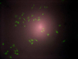
도 5는 종래기술의 형광현미경의 이미지.
도 6은 본 발명의 집광렌즈 모듈이 장착된 형광현미경의 이미지.
도 7은 종래기술의 형광현미경의 이미지.
도 8은 본 발명의 집광렌즈 모듈의 열흡수부재가 장착된 형광현미경의 이미지.1 is a block diagram of a fluorescence microscope according to an embodiment of the present invention.
Figure 2 is a perspective view of the condensing lens module shown in Figure 1;
3 is a cross-sectional view of the condensing lens module shown in FIG. 1 ;
Figure 4 is an exploded perspective view of the condensing lens module shown in Figure 1;
5 is an image of a prior art fluorescence microscope.
6 is an image of a fluorescence microscope equipped with a condensing lens module of the present invention.
7 is an image of a prior art fluorescence microscope.
8 is an image of a fluorescence microscope equipped with a heat absorbing member of the condensing lens module of the present invention.
이하, 첨부한 도면을 참조하여 본 발명의 바람직한 실시예를 상술하며, 도면 전체를 통하여 동일한 부분에는 동일한 도면부호를 사용하기로 한다.
도 1은 본 발명의 일실시예에 따른 형광현미경의 구성도이다.
도면에 도시된 바와 같이, 도면부호 100으로 도시한 상기 형광현미경은 광원을 이루는 머큐리 램프(110)와 상기 머큐리 램프(110)에서 조사되는 빛이 관통하고 중공부가 형성되며 내주면에 상기 결합홈(7)에 결합되는 결합돌기(127)가 형성되는 안착부재(120)가 구성되어 있다.
그리고 상기 안착부재(120)를 통과하여 평행하게 조사되는 광선을 굴절시키는 제1굴절렌즈(131)와, 상기 제1굴절렌즈(131)를 통과한 빛의 량을 조절하는 제1조리개(141), 상기 제1조리개(141)를 통과한 빛을 굴절시켜 평행 광선으로 굴절시키는 제2굴절렌즈(132), 상기 제2굴절렌즈(132)를 통과한 빛을 조절하는 제2조리개(142), 상기 제2조리개(142)를 통과한 빛을 굴절시키는 제3굴절렌즈(133)가 구성되다.
도면에 도시된 바와 같이, 상기 제3굴절렌즈(133)를 통과한 빛에서 특정한 영역의 파장만 투과하는 대물필터(150)와 상기 대물필터(150)를 통과한 빛을 시료에 조사하는 반사판(160)과, 시료에서 반사되는 빛에서 오염된 파장의 빛을 제거하는 대안필터(170) 및 상기 대안필터(170)를 통과한 빛을 굴절시키는 대안렌즈(180)를 포함하게 된다.
그리고 상기 대물필터(150)는 최소한 하나 이상으로 장착되는 것이 바람직하다.
도 2는 도 1에 도시된 집광렌즈 모듈(10)의 사시도이고, 도 3과 도 4는 상기 집광렌즈 모듈(10)의 단면도와 분리 사시도이다.
도면에 도시된 바와 같이, 상기 집광렌즈 모듈(10)은 본체(20), 집광렌즈(30), 열흡수필터(45) 등으로 구성된다.
상기 본체(20)는 원통관 형상으로 내부에 제1중공부(210)가 형성되는 제1본체(21)와, 원통관 형상이고 상기 제1본체(21)의 제1중공부(210)와 연통되는 제2중공부(220)가 형성되는 제2본체(22)로 구성되어 있다.
그리고 상기 본체(20)의 내부의 공간에는 상기 집광렌즈(30)와 상기 열흡수필터(45)가 장착된다.
상기 집광렌즈(30)는 비구면렌즈로 이루어진다.
일반적으로 렌즈는 필름 혹은 이미징 센서에 빛을 모아주는 역할을 한다. 보통 볼록렌즈와 오목렌즈의 조합에 의해 렌즈가 제조된다.
볼록렌즈의 광축과 평행하게 렌즈를 통과한 빛은 어느 한 점에 모이는데, 이를 렌즈의 초점이라고 하고, 대다수의 렌즈는 초점이 잘 맺히지 않는데 그 정도를 렌즈의 수차라고 한다.
렌즈의 수차는 크게 색수차와 구면 수차로 구분한다. 렌즈의 수차를 완전히 제거하기란 거의 불가능하다. 다만, 여러 개의 렌즈를 포개 놓거나, 렌즈에 특수한 성분들을 첨가하는 방법 등 으로 수차를 어느 정도까지 줄일 수는 있다.
비구면렌즈는 렌즈의 곡면에 의해 나타나는 수차를 줄이기 위해 채용되는 렌즈이다. 단순한 구면으로 가공된 렌즈는 이론적으로 빛을 완전하게 한곳으로 모아주지 못하기 때문에 화질이 저하되거나 왜곡이 발생하는데, 정밀한 계산을 통해 렌즈의 표면을 단순한 구면이 아닌 곡선의 형태로 가공해서 빛이 정확하게 촬상면에 맺히도록 하는 렌즈이다.
상기 집광렌즈(30)는 UV Fuzed Silica 재질로 이루어진다. 상기 UV Fuzed Silica는 머큐리 램프(110, 광원)에서 조사된 광에서 일부의 파장의 빛만 투과시키게 된다.
그리고 광원(머큐리 램프, 110)과의 최소거리(BFL)는 8~10mm이고, 광원에서 조사되는 빛이 통과한 후의 초점거리(EFL)는 17~18.5mm 인 것이 바람직하다.
상기 열흡수필터(45)는 상기 집광렌즈(30)를 투과한 빛에서 적외선 영역에서의 광흡수율이 높아져 열차단을 할 수 있게 된다. 즉 상기 열흡수필터(45)는 적외선이 투과되는 것을 억제하여 도 7과 도 8에 도시된 바와 같이 선명한 이미지를 얻을 수 있게 된다.
그리고 도 3과 도 4에 도시된 바와 같이, 상기 본체(20)의 상기 제2중공부(220)는 직경이 서로 다른 제1격실(221)과 제2격실(222)로 구분된다.
상기 제1중공부(210)에는 상기 집광렌즈(30)가 안착되고, 제2격실(222)에는 상기 열흡수필터(45)가 장착된 열흡수부재(40)가 안착되게 된다.
도면에 도시된 바와 같이, 상기 집광렌즈(30)는 한 쌍의 고정링(5)으로 상기 제1본체(21)에 지지되게 된다.
상기 열흡수부재(40)는 원통관 형상의 지지구(41)와 상기 열흡수부재(40)에 안착되는 상기 열흡수필터(45) 및 상기 열흡수필터(45)를 상기 지지구(41)에 견고하게 지지하는 한 쌍의 상기 고정링(5)으로 구성된다.
상기 열흡수필터(45)가 상기 지지구(41)에 견고하게 지지된 상태에서 상기 제2격실(222)에 장착되게 되므로, 집광렌즈 모듈(10)의 조립과 분해가 용이하게 이루어지는 효과가 발생하게 된다.
그리고 상기 제2본체(22)의 외부면에는 결합홈(7)이 형성되어 있고, 형광현미경(100)의 안착부재(120)에는 결합돌기(127)가 형성되어 있어있다. 따라서 상기 집광렌즈(10)가 형광현미경(100)의 상기 안착부재(120)에 견고하게 안착할 수 있게 된다.
이와 같은 구성에 의하여 상기 집광렌즈 모듈(10)이 장착된 형광현미경(100)은 집광과 동시에 열을 차단하여서 선명한 이미지를 얻을 수 있는 효과가 발생하게 된다.
도 5와 도 6의 이미지와 같이, 종래기술의 형광현미경(100)의 이미지와 본 발명의 집광렌즈 모듈(10)이 장착된 형광현미경(100)의 이미지는 확실한 해상도에서 차이가 발생하게 된다.
또한, 상기 열흡수부재(40)에 의하여, 본 발명의 집광렌즈 모듈(10)이 포함된 형광현미경(100)은 선명한 이미지를 얻을 수 있게 된다.(도 7과 도 8 참조)
이상에서 설명한 것은 본 발명에 따른 집광렌즈 모듈(10)을 포함한 형광현미경(100)을 실시하기 위한 하나의 실시예에 불과한 것으로서, 본 발명은 상기한 실시예에 한정되지 아니하고 이하의 특허청구범위에서 청구하는 바와 같이 본 발명의 요지를 벗어남이 없이 당해 발명이 속하는 분야에서 통상의 지식을 가진 자라면 누구든지 다양한 변경 실시가 가능한 범위까지 본 발명의 기술적 사상이 있다고 할 것이다.Hereinafter, preferred embodiments of the present invention will be described in detail with reference to the accompanying drawings, and the same reference numerals will be used for the same parts throughout the drawings.
1 is a block diagram of a fluorescence microscope according to an embodiment of the present invention.
As shown in the drawing, in the fluorescence microscope indicated by
And a first
As shown in the drawing, an
And it is preferable that at least one
2 is a perspective view of the
As shown in the drawing, the
The
And the
The condensing
In general, a lens serves to collect light on a film or imaging sensor. Usually, a lens is manufactured by a combination of a convex lens and a concave lens.
The light passing through the lens parallel to the optical axis of the convex lens converges to a certain point, which is called the focal point of the lens.
Lens aberration is largely divided into chromatic aberration and spherical aberration. It is almost impossible to completely eliminate lens aberrations. However, it is possible to reduce the aberration to some extent by stacking several lenses or adding special components to the lenses.
An aspherical lens is a lens employed to reduce aberrations caused by a curved surface of the lens. A lens processed with a simple spherical surface does not theoretically collect light completely in one place, so image quality deteriorates or distortion occurs. It is a lens that focuses on the imaging surface.
The
And it is preferable that the minimum distance (BFL) with the light source (mercury lamp, 110) is 8 to 10 mm, and the focal length (EFL) after the light irradiated from the light source passes is 17 to 18.5 mm.
The
And as shown in FIGS. 3 and 4 , the second
The
As shown in the drawing, the
The
Since the
In addition, a
According to this configuration, the
5 and 6, the image of the
In addition, by the
What has been described above is only one embodiment for implementing the
10: 집광렌즈 모듈 20: 본체
21: 제1본체 22: 제2본체
30: 집광렌즈 40: 열흡수부재
41: 지지구 45: 열흡수필터
100: 현미경 110: 머큐리램프
120: 안착부재 127: 결합돌기
131: 제1굴절렌즈 132: 제2굴절렌즈
133: 제3굴절렌즈 141: 제1조리개
142: 제2조리개 150: 대물필터
160: 반사판 170: 대안필터
180: 대안렌즈10: condensing lens module 20: body
21: first body 22: second body
30: condensing lens 40: heat absorbing member
41: support 45: heat absorption filter
100: microscope 110: mercury lamp
120: seating member 127: coupling projection
131: first refractive lens 132: second refractive lens
133: third refractive lens 141: first aperture
142: second aperture 150: objective filter
160: reflector 170: alternative filter
180: alternative lens
Claims (10)
상기 집광렌즈 모듈은, 중공부가 형성되는 본체와; 상기 본체에 내부의 공간에 장착되는 집광렌즈; 및 상기 집광렌즈와 일정거리 이격되며 상기 본체 내부에 장착되는 열흡수필터로 구성되고, 상기 집광렌즈는 비구면렌즈로 이루어지고, 광원과의 최소거리(BFL)는 8~10mm이고, 광원에서 조사되는 빛이 통과한 후의 초점거리(EFL)는 17~18.5mm이고, 상기 집광렌즈의 재질은 UV Fuzed Silica 이고, 상기 본체는 원통관 형상으로 내부에 제1중공부가 형성되는 제1본체; 및 원통관 형상이고 상기 제1본체의 제1중공부와 연통되는 제2중공부가 형성되는 제2본체로 구성되고, 상기 제2중공부는 직경이 서로 다른 제1격실과 제2격실로 구분되며, 상기 제1중공부에는 상기 집광렌즈가 안착되고, 상기 제2격실에는 상기 열흡수필터가 장착된 열흡수부재가 안착되고, 상기 집광렌즈는 한 쌍의 고정링으로 상기 제1본체에 지지되며, 상기 열흡수부재는 원통관 형상의 지지구와; 상기 지지구에 안착되는 상기 열흡수필터; 및 상기 열흡수필터를 상기 지지구에 견고하게 지지하는 한 쌍의 상기 고정링으로 구성되고, 상기 열흡수필터는 적외선이 투과되는 것을 억제하고, 상기 제2본체의 외부면에는 상기 결합홈이 형성되며, 상기 대물필터는 최소한 하나 이상으로 장착되는 구성으로 이루어져서, 상기 집광렌즈 모듈은 상기 결합홈과 상기 결합돌기에 의하여 상기 안착부재에서 탈부착되는 것을 특징으로 하는 집광렌즈 모듈을 포함하는 형광현미경.Mercury lamp; a seating member through which light irradiated from the mercury lamp penetrates, a hollow part is formed, and a coupling protrusion coupled to a coupling groove formed on an inner circumferential surface is formed; a first refractive lens for refracting the parallel rays passing through the seating member; a first iris for controlling the amount of light passing through the first refractive lens; a second refractive lens refracting the light passing through the first iris into parallel rays; a second iris for controlling the light passing through the second refractive lens; a third refractive lens for refracting the light passing through the second iris; an objective filter that transmits only a wavelength of a specific region in the light passing through the third refractive lens; a reflector for irradiating the light passing through the objective filter to the sample; an alternative filter that removes light of a polluted wavelength from the light reflected from the sample; In the fluorescence microscope consisting of an alternative lens for refracting the light passing through the alternative filter, and a condensing lens module detachably attached to the mounting member,
The condensing lens module includes: a body in which a hollow part is formed; a condensing lens mounted in the space inside the body; and a heat absorption filter spaced apart from the condensing lens by a certain distance and mounted inside the body, the condensing lens is made of an aspherical lens, and the minimum distance (BFL) from the light source is 8 to 10 mm, and is irradiated from the light source The focal length (EFL) after the light has passed is 17 to 18.5 mm, the material of the condensing lens is UV Fuzed Silica, and the main body is a first body having a cylindrical tube shape and a first hollow part formed therein; and a second body having a cylindrical tube shape and having a second hollow part communicating with the first hollow part of the first body, the second hollow part being divided into a first compartment and a second compartment having different diameters, The light collecting lens is seated in the first hollow part, the heat absorption member equipped with the heat absorption filter is seated in the second compartment, and the light collecting lens is supported on the first body by a pair of fixing rings, The heat absorbing member includes a cylindrical tube-shaped support; the heat absorption filter seated on the support; and a pair of fixing rings that firmly support the heat absorption filter to the support, wherein the heat absorption filter suppresses transmission of infrared rays, and the coupling groove is formed on the outer surface of the second body and the objective filter is configured to be mounted with at least one or more, and the condensing lens module is detachably attached to and detached from the mounting member by the coupling groove and the coupling protrusion.
Priority Applications (1)
| Application Number | Priority Date | Filing Date | Title |
|---|---|---|---|
| KR1020190172678A KR102290325B1 (en) | 2019-12-23 | 2019-12-23 | Fluorescent microscope comprising condensing lens module |
Applications Claiming Priority (1)
| Application Number | Priority Date | Filing Date | Title |
|---|---|---|---|
| KR1020190172678A KR102290325B1 (en) | 2019-12-23 | 2019-12-23 | Fluorescent microscope comprising condensing lens module |
Publications (2)
| Publication Number | Publication Date |
|---|---|
| KR20210081470A KR20210081470A (en) | 2021-07-02 |
| KR102290325B1 true KR102290325B1 (en) | 2021-08-18 |
Family
ID=76896937
Family Applications (1)
| Application Number | Title | Priority Date | Filing Date |
|---|---|---|---|
| KR1020190172678A KR102290325B1 (en) | 2019-12-23 | 2019-12-23 | Fluorescent microscope comprising condensing lens module |
Country Status (1)
| Country | Link |
|---|---|
| KR (1) | KR102290325B1 (en) |
Cited By (4)
| Publication number | Priority date | Publication date | Assignee | Title |
|---|---|---|---|---|
| KR102450912B1 (en) | 2022-02-25 | 2022-10-06 | 주식회사 제이엘메디랩스 | Fluorescence microscope for identifying biomarker and biomarker identification method using the same |
| KR20230139684A (en) | 2022-03-28 | 2023-10-05 | 주식회사 스타노스 | Autofocus device for optical microscopy and autofocus maintenance method |
| KR20240028903A (en) | 2022-08-25 | 2024-03-05 | 주식회사 이지다이아텍 | Image acquisition device for target material signal detection and acquisition method using thereof |
| KR20240079551A (en) | 2022-11-29 | 2024-06-05 | 주식회사 스타노스 | Automatic excitation light control device for optical microscope and automatic excitation light control method |
Citations (7)
| Publication number | Priority date | Publication date | Assignee | Title |
|---|---|---|---|---|
| WO2006067846A1 (en) * | 2004-12-22 | 2006-06-29 | Takashi Yoshimine | Lighting apparatus for microscope and lighting system for microscope |
| US20080198448A1 (en) * | 2007-02-16 | 2008-08-21 | Leica Microsystems Cms Gmbh | Fluorescence microscope having an illumination device |
| JP2010181601A (en) | 2009-02-05 | 2010-08-19 | Toray Ind Inc | Filter for display |
| US20120133756A1 (en) * | 2010-11-30 | 2012-05-31 | Robert Levin | Compact, high-resolution fluorescence and brightfield microscope and methods of use |
| JP2013221956A (en) | 2012-04-12 | 2013-10-28 | Olympus Corp | Microscope |
| KR101821637B1 (en) | 2016-07-19 | 2018-03-09 | 한국광기술원 | Luminescence microscope |
| JP2018529125A (en) | 2015-09-02 | 2018-10-04 | インスコピックス, インコーポレイテッド | System and method for color imaging |
Family Cites Families (8)
| Publication number | Priority date | Publication date | Assignee | Title |
|---|---|---|---|---|
| KR0118787Y1 (en) * | 1993-08-18 | 1998-07-15 | 김광호 | Water level sensor of dishwasher |
| JPH10260343A (en) * | 1997-03-18 | 1998-09-29 | Olympus Optical Co Ltd | Replacing mechanism for optical lens barrel |
| KR100500610B1 (en) | 2003-10-29 | 2005-07-11 | 한국전기연구원 | Fluorescent microscope and method for measurement using the same |
| KR101084018B1 (en) | 2009-12-22 | 2011-11-16 | 연세대학교 산학협력단 | Detection module for ultra-high resolution total reflection fluorescence microscopy and total reflection fluorescence microscopy based on localized surface plasmon resonance |
| KR101393514B1 (en) | 2011-09-06 | 2014-05-13 | 서울대학교산학협력단 | High-sensitivity and video-rate confocal fluorescence microscope |
| KR101478881B1 (en) | 2012-11-28 | 2015-01-06 | 한양대학교 산학협력단 | Dual detection confocal fluorescence microscopy apparatus and method of capturing image |
| KR20140110293A (en) * | 2013-03-07 | 2014-09-17 | 삼성전기주식회사 | Camera module |
| KR101766064B1 (en) | 2015-11-30 | 2017-08-08 | 연세대학교 산학협력단 | Total internal reflection fluorescence microscopy |
-
2019
- 2019-12-23 KR KR1020190172678A patent/KR102290325B1/en active IP Right Grant
Patent Citations (7)
| Publication number | Priority date | Publication date | Assignee | Title |
|---|---|---|---|---|
| WO2006067846A1 (en) * | 2004-12-22 | 2006-06-29 | Takashi Yoshimine | Lighting apparatus for microscope and lighting system for microscope |
| US20080198448A1 (en) * | 2007-02-16 | 2008-08-21 | Leica Microsystems Cms Gmbh | Fluorescence microscope having an illumination device |
| JP2010181601A (en) | 2009-02-05 | 2010-08-19 | Toray Ind Inc | Filter for display |
| US20120133756A1 (en) * | 2010-11-30 | 2012-05-31 | Robert Levin | Compact, high-resolution fluorescence and brightfield microscope and methods of use |
| JP2013221956A (en) | 2012-04-12 | 2013-10-28 | Olympus Corp | Microscope |
| JP2018529125A (en) | 2015-09-02 | 2018-10-04 | インスコピックス, インコーポレイテッド | System and method for color imaging |
| KR101821637B1 (en) | 2016-07-19 | 2018-03-09 | 한국광기술원 | Luminescence microscope |
Cited By (5)
| Publication number | Priority date | Publication date | Assignee | Title |
|---|---|---|---|---|
| KR102450912B1 (en) | 2022-02-25 | 2022-10-06 | 주식회사 제이엘메디랩스 | Fluorescence microscope for identifying biomarker and biomarker identification method using the same |
| EP4235154A1 (en) | 2022-02-25 | 2023-08-30 | JL Medilabs, Inc. | Fluorescence microscope for identifying biomarker and biomarker identification method using the same |
| KR20230139684A (en) | 2022-03-28 | 2023-10-05 | 주식회사 스타노스 | Autofocus device for optical microscopy and autofocus maintenance method |
| KR20240028903A (en) | 2022-08-25 | 2024-03-05 | 주식회사 이지다이아텍 | Image acquisition device for target material signal detection and acquisition method using thereof |
| KR20240079551A (en) | 2022-11-29 | 2024-06-05 | 주식회사 스타노스 | Automatic excitation light control device for optical microscope and automatic excitation light control method |
Also Published As
| Publication number | Publication date |
|---|---|
| KR20210081470A (en) | 2021-07-02 |
Similar Documents
| Publication | Publication Date | Title |
|---|---|---|
| KR102290325B1 (en) | Fluorescent microscope comprising condensing lens module | |
| US10877256B2 (en) | Observation device | |
| WO2016158780A1 (en) | Observation device and observation method | |
| US8625195B2 (en) | Objective-type dark-field illumination device for microfluidic channel | |
| WO1997028439A1 (en) | Fluorescence imaging system compatible with macro and micro scanning objectives | |
| US20060157637A1 (en) | Focus detection device and fluorescent observation device using the same | |
| JP2019002906A5 (en) | ||
| JP2009510539A (en) | Fluorescence microscope | |
| CN109791275B (en) | Observation device | |
| JP2013535687A (en) | Cytometry system with a solid numerical aperture increasing lens | |
| CN107924051A (en) | Headshape microscope | |
| WO2017098657A1 (en) | Observation device | |
| US20090177043A1 (en) | Objective Optical System for Endoscopes and Endoscope System Using the Same | |
| KR101801087B1 (en) | Particle measuring apparatus using light scattering | |
| US10948703B2 (en) | Imaging system and method with scattering to reduce source auto-fluorescence and improve uniformity | |
| JP2019109302A (en) | Illumination optical system, optical inspection device, and optical microscope | |
| EP3074807B1 (en) | Optical arrangement for imaging a sample | |
| JP5992913B2 (en) | Method for observing light emission from a sample by dynamic optical microscopy | |
| US6940641B2 (en) | Fluorescence observation apparatus | |
| JP2016095408A (en) | Scanning microscope | |
| JP2011118265A (en) | Microscope device | |
| JP2007293210A (en) | Imaging device | |
| JP2013054146A (en) | Objective lens unit, and scanning microscope including the objective lens unit | |
| JP3908022B2 (en) | Fluorescence observation equipment | |
| US20200201014A1 (en) | Microscope and microscope illumination method |
Legal Events
| Date | Code | Title | Description |
|---|---|---|---|
| PA0109 | Patent application |
Patent event code: PA01091R01D Comment text: Patent Application Patent event date: 20191223 |
|
| PA0201 | Request for examination | ||
| PE0902 | Notice of grounds for rejection |
Comment text: Notification of reason for refusal Patent event date: 20210115 Patent event code: PE09021S01D |
|
| E701 | Decision to grant or registration of patent right | ||
| PE0701 | Decision of registration |
Patent event code: PE07011S01D Comment text: Decision to Grant Registration Patent event date: 20210510 |
|
| PG1501 | Laying open of application | ||
| GRNT | Written decision to grant | ||
| PR0701 | Registration of establishment |
Comment text: Registration of Establishment Patent event date: 20210810 Patent event code: PR07011E01D |
|
| PR1002 | Payment of registration fee |
Payment date: 20210810 End annual number: 3 Start annual number: 1 |
|
| PG1601 | Publication of registration | ||
| PR1001 | Payment of annual fee |
Payment date: 20240519 Start annual number: 4 End annual number: 4 |