KR102267171B1 - Apparatus and Method for treating substrate - Google Patents
Apparatus and Method for treating substrate Download PDFInfo
- Publication number
- KR102267171B1 KR102267171B1 KR1020200066834A KR20200066834A KR102267171B1 KR 102267171 B1 KR102267171 B1 KR 102267171B1 KR 1020200066834 A KR1020200066834 A KR 1020200066834A KR 20200066834 A KR20200066834 A KR 20200066834A KR 102267171 B1 KR102267171 B1 KR 102267171B1
- Authority
- KR
- South Korea
- Prior art keywords
- substrate
- clamp
- processing
- processing space
- pressure
- Prior art date
- Legal status (The legal status is an assumption and is not a legal conclusion. Google has not performed a legal analysis and makes no representation as to the accuracy of the status listed.)
- Active
Links
Images


Classifications
-
- H—ELECTRICITY
- H01—ELECTRIC ELEMENTS
- H01L—SEMICONDUCTOR DEVICES NOT COVERED BY CLASS H10
- H01L21/00—Processes or apparatus adapted for the manufacture or treatment of semiconductor or solid state devices or of parts thereof
- H01L21/67—Apparatus specially adapted for handling semiconductor or electric solid state devices during manufacture or treatment thereof; Apparatus specially adapted for handling wafers during manufacture or treatment of semiconductor or electric solid state devices or components ; Apparatus not specifically provided for elsewhere
- H01L21/67005—Apparatus not specifically provided for elsewhere
- H01L21/67011—Apparatus for manufacture or treatment
- H01L21/67017—Apparatus for fluid treatment
- H01L21/67028—Apparatus for fluid treatment for cleaning followed by drying, rinsing, stripping, blasting or the like
-
- H10P72/0406—
-
- H—ELECTRICITY
- H01—ELECTRIC ELEMENTS
- H01L—SEMICONDUCTOR DEVICES NOT COVERED BY CLASS H10
- H01L21/00—Processes or apparatus adapted for the manufacture or treatment of semiconductor or solid state devices or of parts thereof
- H01L21/02—Manufacture or treatment of semiconductor devices or of parts thereof
- H01L21/02041—Cleaning
- H01L21/02043—Cleaning before device manufacture, i.e. Begin-Of-Line process
-
- H—ELECTRICITY
- H01—ELECTRIC ELEMENTS
- H01L—SEMICONDUCTOR DEVICES NOT COVERED BY CLASS H10
- H01L21/00—Processes or apparatus adapted for the manufacture or treatment of semiconductor or solid state devices or of parts thereof
- H01L21/02—Manufacture or treatment of semiconductor devices or of parts thereof
- H01L21/02041—Cleaning
- H01L21/02057—Cleaning during device manufacture
-
- H—ELECTRICITY
- H01—ELECTRIC ELEMENTS
- H01L—SEMICONDUCTOR DEVICES NOT COVERED BY CLASS H10
- H01L21/00—Processes or apparatus adapted for the manufacture or treatment of semiconductor or solid state devices or of parts thereof
- H01L21/67—Apparatus specially adapted for handling semiconductor or electric solid state devices during manufacture or treatment thereof; Apparatus specially adapted for handling wafers during manufacture or treatment of semiconductor or electric solid state devices or components ; Apparatus not specifically provided for elsewhere
- H01L21/67005—Apparatus not specifically provided for elsewhere
- H01L21/67011—Apparatus for manufacture or treatment
- H01L21/6715—Apparatus for applying a liquid, a resin, an ink or the like
-
- H10P70/10—
-
- H10P70/20—
-
- H10P72/0448—
Landscapes
- Engineering & Computer Science (AREA)
- Physics & Mathematics (AREA)
- Condensed Matter Physics & Semiconductors (AREA)
- General Physics & Mathematics (AREA)
- Manufacturing & Machinery (AREA)
- Computer Hardware Design (AREA)
- Microelectronics & Electronic Packaging (AREA)
- Power Engineering (AREA)
- Cleaning Or Drying Semiconductors (AREA)
Abstract
본 발명은 고압 분위기에서 기판을 처리하는 장치 및 방법을 제공한다. 기판을 처리하는 장치는 서로 조합되어 내부에 처리 공간을 형성하는 제1바디 및 제2바디를 가지는 챔버, 상기 처리 공간을 외부로부터 밀폐하는 밀폐 위치 및 상기 처리 공간을 외부로부터 개방하는 개방 위치 간에 위치 변경이 가능하도록 상기 제1바디와 상기 제2바디 간의 상대 위치를 이동시키는 구동기, 상기 처리 공간 내에서 기판을 지지하는 기판 지지 유닛, 상기 처리 공간 내에 기판을 처리하는 가스를 공급하는 가스 공급 유닛, 그리고 상기 구동기를 제어하는 제어기를 포함하되, 상기 제어기는 상기 개방 위치에서 상기 밀폐 위치로 위치 변경 시 상기 제1바디 또는 상기 제2바디를 제1속도로 이동시키는 고속 밀폐 단계와 상기 제1속도보다 느린 제2속도로 이동시키는 저속 밀폐 단계가 순차적으로 수행되도록 상기 구동기를 제어한다. 이로 인해 제1바디와 제2바디 간에 충격을 완화시킬 수 있다.The present invention provides an apparatus and method for processing a substrate in a high pressure atmosphere. An apparatus for processing a substrate includes a chamber having first and second bodies combined with each other to form a processing space therein, a closed position for sealing the processing space from the outside, and an open position for opening the processing space from the outside a driver for moving a relative position between the first body and the second body so as to be changeable, a substrate support unit for supporting a substrate in the processing space, a gas supply unit for supplying a gas for processing a substrate into the processing space; and a controller for controlling the actuator, wherein the controller comprises a high-speed sealing step of moving the first body or the second body at a first speed when the position is changed from the open position to the closed position and higher than the first speed. The actuator is controlled so that the low-speed sealing step of moving the second slow speed is sequentially performed. Due to this, the impact between the first body and the second body can be alleviated.
Description
본 발명은 기판을 처리하는 장치 및 방법에 관한 것으로 더 상세하게는 고압 분위기에서 기판을 처리하는 장치 및 방법에 관한 것이다.The present invention relates to an apparatus and method for processing a substrate, and more particularly, to an apparatus and method for processing a substrate in a high pressure atmosphere.
반도체소자를 제조하기 위해서, 기판에 사진, 식각, 애싱, 이온주입, 그리고 박막 증착등의 다양한 공정들을 통해 원하는 패턴을 기판에 형성한다. 각각의 공정에는 다양한 처리액들이 사용되며, 공정 진행 중에는 오염물 및 파티클이 생성된다. 이를 제거하기 위해 각각의 공정 전후에는 오염물 및 파티클을 세정 처리하기 위한 세정 공정이 필수적으로 수행된다.In order to manufacture a semiconductor device, a desired pattern is formed on the substrate through various processes such as photography, etching, ashing, ion implantation, and thin film deposition. Various treatment liquids are used in each process, and contaminants and particles are generated during the process. In order to remove this, a cleaning process for cleaning contaminants and particles is essentially performed before and after each process.
일반적으로 세정 공정은 기판을 케미칼 및 린스액으로 처리한 후에 건조 처리한다. 건조 처리 단계는 기판 상에 잔류된 린스액을 건조하기 위한 공정으로, 이소프로필알코올(IPA)과 같이 표면 장력이 린스액보다 낮은 유기 용제로 기판 상의 린스액을 치환하고, 이후에 유기 용제를 제거한다. 그러나 기판에 형성된 패턴과 패턴과의 거리(CD:Critical Dimension)가 미세화됨에 따라, 그 패턴들의 사이 공간에 잔류하는 유기 용제의 제거가 용이하지 않다.In general, in the cleaning process, the substrate is treated with chemicals and a rinse solution and then dried. The drying treatment step is a process for drying the rinse solution remaining on the substrate, replacing the rinse solution on the substrate with an organic solvent having a lower surface tension than the rinse solution, such as isopropyl alcohol (IPA), and then removing the organic solvent do. However, as the distance between the patterns formed on the substrate (CD: Critical Dimension) is reduced, it is not easy to remove the organic solvent remaining in the space between the patterns.
최근에는 초임계 유체를 이용하여 기판 상에 잔류된 유기 용제를 제거하는 공정을 수행한다. 초임계 처리 공정은 초임계 유체의 특정 조건을 만족하기 위해 외부로부터 밀폐된 고압의 공간에서 진행된다. Recently, a process of removing the organic solvent remaining on the substrate is performed using a supercritical fluid. The supercritical treatment process is performed in a high-pressure space sealed from the outside in order to satisfy the specific conditions of the supercritical fluid.
도 1은 일반적인 초임계 처리 장치를 보여주는 단면도이다. 도 1을 참조하면, 초임계 처리 공정을 수행하는 공정 챔버는 제1바디(2) 및 제2바디(4)를 가진다. 제1바디(2) 및 제2바디(4)는 서로 조합되어 내부에 처리 공간을 형성한다. 제1바디(2)와 제2바디(4)는 서로의 상대 위치가 이동되어 처리 공간을 개방 또는 밀폐한다. 제1바디(2)와 제2바디(4)는 서로 가까워지는 방향 또는 서로 멀어지는 방향으로 이동되어 처리 공간을 개방 또는 밀폐되며, 바디는 일정 속도로 이동된다.1 is a cross-sectional view showing a general supercritical processing apparatus. Referring to FIG. 1 , a process chamber for performing a supercritical treatment process has a
고압의 조건에서 처리 공간을 밀폐하게 위해, 실린더는 제1바디(2)와 제2바디(4)를 가까워지는 방향을 향해 강한 힘이 제공되어야 한다. 또한 기판의 처리량을 높이기 위해서는 처리 공간의 개폐에 소요되는 시간을 줄어야한다. 이로 인해 처리 공간이 개방 또는 밀폐되는 과정에서 바디는 고속으로 이동된다.In order to seal the processing space under the high pressure condition, a strong force must be provided to the cylinder in a direction in which the
그러나 처리 공간이 밀폐되는 중에 제1바디(2)와 제2바디(4)는 서로 강한 힘으로 충돌되며, 이는 제1바디(2)와 제2바디(4)를 손상시키고, 처리 공간의 기밀성을 떨어뜨린다.However, while the processing space is sealed, the
또한 처리 공간의 개방 초기에는 처리 공간이 팽창됨에 따라 처리 공간의 압력이 일시적으로 외부보다 낮은 압력을 가지며, 외부의 파티클이 유입되는 문제를 가진다.Also, at the initial stage of opening of the processing space, as the processing space is expanded, the pressure of the processing space is temporarily lower than that of the outside, and external particles are introduced.
본 발명은 바디들에 의해 형성된 처리 공간을 개폐하는 과정에서 바디들이 손상되는 것을 방지할 수 있는 장치 및 방법을 제공하는 것을 일 목적으로 한다.An object of the present invention is to provide an apparatus and method capable of preventing the bodies from being damaged in the process of opening and closing a processing space formed by the bodies.
또한 본 발명은 처리 공간을 개방하는 과정에서 처리 공간 내에 외부의 파티클이 유입되는 것을 방지할 수 있는 장치 및 방법을 제공하는 것을 일 목적으로 한다.Another object of the present invention is to provide an apparatus and method capable of preventing external particles from being introduced into the processing space during the process of opening the processing space.
본 발명의 실시예는 고압 분위기에서 기판을 처리하는 장치 및 방법을 제공한다. 기판을 처리하는 장치는 서로 조합되어 내부에 처리 공간을 형성하는 제1바디 및 제2바디를 가지는 챔버, 상기 처리 공간을 외부로부터 밀폐하는 밀폐 위치 및 상기 처리 공간을 외부로부터 개방하는 개방 위치 간에 위치 변경이 가능하도록 상기 제1바디와 상기 제2바디 간의 상대 위치를 이동시키는 구동기, 상기 처리 공간 내에서 기판을 지지하는 기판 지지 유닛, 상기 처리 공간 내에 기판을 처리하는 가스를 공급하는 가스 공급 유닛, 그리고 상기 구동기를 제어하는 제어기를 포함하되, 상기 제어기는 상기 개방 위치에서 상기 밀폐 위치로 위치 변경 시 상기 제1바디 또는 상기 제2바디를 제1속도로 이동시키는 고속 밀폐 단계와 상기 제1속도보다 느린 제2속도로 이동시키는 저속 밀폐 단계가 순차적으로 수행되도록 상기 구동기를 제어한다. Embodiments of the present invention provide an apparatus and method for processing a substrate in a high pressure atmosphere. An apparatus for processing a substrate includes a chamber having first and second bodies combined with each other to form a processing space therein, a closed position for sealing the processing space from the outside, and an open position for opening the processing space from the outside a driver for moving a relative position between the first body and the second body so as to be changeable, a substrate support unit for supporting a substrate in the processing space, a gas supply unit for supplying a gas for processing a substrate into the processing space; and a controller for controlling the actuator, wherein the controller comprises a high-speed sealing step of moving the first body or the second body at a first speed when the position is changed from the open position to the closed position and higher than the first speed. The actuator is controlled so that the low-speed sealing step of moving the second slow speed is sequentially performed.
상기 제어기는 상기 밀폐 위치에서 상기 개방 위치로 위치 변경 시 상기 제1바디 또는 상기 제2바디를 제3속도로 이동시키는 저속 개방 단계와 상기 제3속도보다 빠른 제4속도로 이동시키는 고속 개방 단계가 순차적으로 수행되도록 상기 구동기를 제어할 수 있다.The controller includes a low-speed opening step of moving the first body or the second body at a third speed when the position is changed from the closed position to the open position, and a high-speed opening step of moving the first body or the second body at a fourth speed faster than the third speed. The driver may be controlled to be sequentially performed.
상기 장치는 상기 밀폐 위치의 챔버를 클램핑하는 클램핑 부재 및 상기 클램핑 부재가 상기 제1바디와 상기 제2바디를 클램핑하는 잠금 위치 또는 상기 클램핑 부재가 제2바디와 상기 제2바디로부터 이격되는 상기 해제 위치로 이동시키는 이동 부재를 더 포함하되, 상기 제어기는 상기 저속 밀폐 단계와 상기 저속개방단계 사이에, 상기 클램핑 부재가 상기 잠금 위치로 이동되는 잠금 단계, 상기 밀폐 위치에서 상기 처리 공간에 가스를 공급하여 기판을 처리하는 공정 처리 단계, 그리고 상기 클램핑 부재가 상기 해제 위치로 이동되는 해제 단계가 수행되도록 상기 가스 공급 유닛 및 이동 부재를 제어할 수 있다. The device comprises a clamping member for clamping the chamber in the closed position and a locked position in which the clamping member clamps the first body and the second body or the unlocking wherein the clamping member is spaced apart from the second body and the second body. a moving member for moving to a position, wherein the controller is configured to: between the low speed closing step and the low speed opening step, a locking step in which the clamping member is moved to the locked position, and supplying gas to the processing space in the closed position to control the gas supply unit and the moving member to perform a process processing step of processing the substrate and a release step of moving the clamping member to the release position.
상기 제어기는 상기 공정 처리 단계에서 상기 제1바디와 상기 제2바디는 서로 가까워지는 방향으로 제1압력이 가해지도록 상기 구동기를 제어하고, 상기 처리 공간에 공급된 가스에 의해 제2압력이 가해지도록 상기 가스 공급 유닛을 제어하되, 상기 제2압력은 상기 제1압력보다 크게 제공될 수 있다. The controller controls the actuator so that a first pressure is applied in a direction in which the first body and the second body approach each other in the process step, and a second pressure is applied by the gas supplied to the processing space. In controlling the gas supply unit, the second pressure may be greater than the first pressure.
상기 장치는 상기 처리 공간을 배기하는 배기하는 배기 유닛을 더 포함하되, 상기 제어기는 상기 공정 처리 단계에서 상기 처리 공간을 상기 제2압력으로 가한 후에, 상기 처리 공간이 상기 제1압력보다 낮아지도록 상기 배기 유닛을 제어할 수 있다. The apparatus further includes an exhaust unit evacuating the processing space, wherein the controller causes the processing space to be lower than the first pressure after applying the processing space to the second pressure in the processing step. The exhaust unit can be controlled.
상기 제2압력은 가스의 임계 압력보다 높은 압력으로 제공될 수 있다. The second pressure may be provided as a pressure higher than a critical pressure of the gas.
기판을 처리하는 방법은 제1바디와 제2바디가 서로 가까워지는 방향을 향해 제1속도로 이동되는 고속 밀폐 단계, 상기 제1바디와 상기 제2바디가 상기 제1속도보다 느린 제2속도로 이동되어 서로 밀착되는 저속 밀폐 단계, 그리고 상기 제1바디와 상기 제2바디가 조합되어 내부에 형성된 처리 공간에서 기판을 가스 처리하는 공정 처리 단계를 포함한다. A method of processing a substrate includes a high-speed sealing step in which a first body and a second body are moved at a first speed in a direction toward which they approach each other, and the first body and the second body are moved at a second speed slower than the first speed. and a low-speed sealing step of moving and closely contacting each other, and a process treatment step of gas-treating the substrate in a processing space formed therein by combining the first body and the second body.
상기 방법은 상기 공정 처리 단계 이후에 상기 제1바디와 상기 제2바디가 서로 멀어지는 방향을 향해 제3속도로 이동되는 저속 개방 단계 및 상기 제1바디와 상기 제2바디가 서로 멀어지는 방향을 향해 상기 제3속도보다 빠른 제4속도로 이동되는 고속 개방 단계를 더 포함할 수 있다. The method includes a low-speed opening step in which the first body and the second body are moved at a third speed in a direction away from each other after the processing step, and a direction in which the first body and the second body are moved away from each other. It may further include a high-speed opening step of moving at a fourth speed faster than the third speed.
상기 방법은 상기 저속 밀폐 단계와 상기 공정 처리 단계 사이에는, 클램핑 부재에 의해 서로 밀착된 상기 제1바디와 상기 제2바디를 클램핑하는 잠금 단계 및 상기 공정 처리 단계와 상기 저속 개방 단계 사이에는, 상기 클램핑을 해제하는 해제 단계를 더 포함할 수 있다. The method includes a locking step of clamping the first body and the second body in close contact with each other by a clamping member between the low speed sealing step and the processing step, and between the processing step and the low speed opening step, It may further include a releasing step of releasing the clamping.
상기 공정 처리 단계에서 상기 제1바디와 상기 제2바디는 서로 가까워지는 방향을 향해 제1압력이 가해지고, 상기 처리 공간은 그 내부에 공급되는 상기 가스에 의해 제2압력이 가해지되, 상기 제2압력은 상기 제1압력보다 클 수 있다. In the process step, a first pressure is applied to the first body and the second body toward each other, and a second pressure is applied to the processing space by the gas supplied therein, The second pressure may be greater than the first pressure.
상기 공정 처리 단계에서 상기 처리 공간이 상기 제1압력보다 커지면, 상기 제1바디와 상기 제2바디 각각은 서로 멀어지는 방향으로 이동되어 상기 클램핑 부재에 밀착될 수 있다. 상기 공정 처리 단계에는 상기 제2압력에서 상기 기판의 가스 처리가 완료되면, 상기 처리 공간을 상기 제1압렵보다 작은 압력으로 배기하되, 상기 처리 공간이 상기 제1압력보다 작아지면, 상기 제1바디와 상기 제2바디 각각은 서로 가까워지는 방향으로 이동되어 상기 클램핑 부재로부터 이격될 수 있다. When the processing space becomes greater than the first pressure in the processing step, each of the first body and the second body may be moved away from each other to be in close contact with the clamping member. In the process step, when the gas treatment of the substrate at the second pressure is completed, the processing space is exhausted to a pressure smaller than the first pressure, and when the processing space is smaller than the first pressure, the first body and the second body may be moved in a direction closer to each other to be spaced apart from the clamping member.
상기 공정 처리 단계에서 상기 가스는 초임계 상태로 제공될 수 있다.In the process step, the gas may be provided in a supercritical state.
본 발명의 실시예에 의하면, 처리 공간을 밀폐하는 과정에서 제1바디 또는 제2바디를 고속으로 이동시키고, 이후에 저속으로 이동시킨다. 이로 인해 제1바디와 제2바디 간에 충격을 완화시킬 수 있다.According to an embodiment of the present invention, the first body or the second body is moved at a high speed in the process of sealing the processing space, and then moves at a low speed. Due to this, the impact between the first body and the second body can be alleviated.
또한 본 발명의 실시예에 의하면, 처리 공간을 개방하는 과정에서 제1바디 또는 제2바디를 저속으로 이동시키고, 이후에 고속으로 이동시킨다. 이로 인해 처리 공간 내에 일시적으로 음압이 발생되는 것을 방지할 수 있다.In addition, according to the embodiment of the present invention, the first body or the second body is moved at a low speed in the process of opening the processing space, and then moves at a high speed. As a result, it is possible to prevent temporary negative pressure from being generated in the processing space.
또한 본 발명의 실시예에 의하면, 제1바디와 제2바디는 서로 밀착된 상태에서 클램핑 또는 이를 해제한다. 이로 인해 각 바디와 클램핑 부재 간에 충돌을 최소화할 수 있다.In addition, according to an embodiment of the present invention, the first body and the second body are clamped or released while in close contact with each other. This makes it possible to minimize the collision between each body and the clamping member.
도 1은 종래의 초임계 처리 장치를 보여주는 단면도이다.
도 2는 본 발명의 실시예에 따른 기판 처리 설비를 보여주는 평면도이다.
도 3은 도 2의 제1공정 유닛에서 기판을 세정 처리하는 장치를 보여주는 단면도이다.
도 4는 도 2의 제2공정 유닛에서 기판을 건조 처리하는 장치를 보여주는 단면도이다.
도 5는 도 4의 하우징을 보여주는 사시도이다.
도 6은 도 4의 기판 지지 유닛을 보여주는 사시도이다.
도 7은 도 4의 클램핑 부재를 보여주는 사시도이다.
도 8은 도 4의 장치를 이용하여 기판을 처리하는 과정을 보여주는 플로우 차트이다.
도 9는 도 8의 플로우 차트에서 제2바디의 위치를 보여주는 그래프이다.
도 10 내지 도 17을 도 4의 장치를 이용하여 기판을 처리하는 과정을 보여주는 도면들이다.1 is a cross-sectional view showing a conventional supercritical processing apparatus.
2 is a plan view illustrating a substrate processing facility according to an embodiment of the present invention.
FIG. 3 is a cross-sectional view illustrating an apparatus for cleaning a substrate in the first process unit of FIG. 2 .
FIG. 4 is a cross-sectional view illustrating an apparatus for drying and processing a substrate in the second process unit of FIG. 2 .
5 is a perspective view illustrating the housing of FIG. 4 ;
6 is a perspective view illustrating the substrate support unit of FIG. 4 .
FIG. 7 is a perspective view showing the clamping member of FIG. 4 .
8 is a flowchart illustrating a process of processing a substrate using the apparatus of FIG. 4 .
9 is a graph showing the position of the second body in the flowchart of FIG. 8 .
10 to 17 are views illustrating a process of processing a substrate using the apparatus of FIG. 4 .
본 발명의 실시예는 여러 가지 형태로 변형될 수 있으며, 본 발명의 범위가 아래에서 서술하는 실시예로 인해 한정되어지는 것으로 해석되어서는 안된다. 본 실시예는 당업계에서 평균적인 지식을 가진 자에게 본 발명을 보다 완전하게 설명하기 위해서 제공되는 것이다. 따라서 도면에서의 구성 요소의 형상 등은 보다 명확한 설명을 강조하기 위해서 과장된 것이다.Embodiments of the present invention may be modified in various forms, and the scope of the present invention should not be construed as being limited by the embodiments described below. This example is provided to more completely explain the present invention to those of ordinary skill in the art. Accordingly, the shapes of the components in the drawings are exaggerated in order to emphasize a clearer description.
본 발명은 도 2 내지 도 17을 참조하여 본 발명의 일 예를 상세히 설명한다.An example of the present invention will be described in detail with reference to FIGS. 2 to 17 .
도 2는 본 발명의 실시예에 따른 기판 처리 설비를 보여주는 평면도이다.2 is a plan view illustrating a substrate processing facility according to an embodiment of the present invention.
도 2를 참조하면, 기판 처리 설비(1)는 인덱스 모듈(10)과 공정 처리 모듈(20)을 가지고, 인덱스 모듈(10)은 로드 포트(120) 및 이송 프레임(140)을 가진다. 로드 포트(120), 이송 프레임(140), 그리고 공정 처리 모듈(20)은 순차적으로 일렬로 배열된다. 이하, 로드 포트(120), 이송 프레임(140), 그리고 공정 처리 모듈(20)이 배열된 방향을 제1방향(12)이라 하고, 상부에서 바라볼 때, 제1방향(12)과 수직한 방향을 제2방향(14)이라 하며, 제1방향(12)과 제2방향(14)을 포함한 평면에 수직인 방향을 제3방향(16)이라 칭한다. Referring to FIG. 2 , the
로드 포트(120)에는 기판(W)이 수납된 캐리어(18)가 안착된다. 로드 포트(120)는 복수 개가 제공되며 이들은 제2방향(14)을 따라 일렬로 배치된다. 도 1에서는 네 개의 로드 포트(120)가 제공된 것으로 도시하였다. 그러나 로드 포트(120)의 개수는 공정 처리 모듈(20)의 공정효율 및 풋 프린트 등의 조건에 따라 증가하거나 감소할 수도 있다. 캐리어(18)에는 기판의 가장자리를 지지하도록 제공된 슬롯(도시되지 않음)이 형성된다. 슬롯은 제3방향(16)을 따라 복수 개가 제공되고, 기판은 제3방향(16)을 따라 서로 이격된 상태로 적층되게 캐리어(18) 내에 위치된다. 캐리어(18)로는 전면 개방 일체형 포드(Front Opening Unified Pod;FOUP)가 사용될 수 있다. The
공정 처리 모듈(20)은 버퍼 유닛(220), 이송 챔버(240), 제1공정 유닛(260), 그리고 제2공정 유닛(280)를 가진다. 이송 챔버(240)는 그 길이 방향이 제1방향(12)과 평행하게 배치된다. 이송 챔버(240)의 일측에는 제2방향(14)를 따라 제1공정 유닛들(260)이 배치되고, 이송 챔버(240)의 타측에는 제2방향(14)를 따라 제2공정 유닛들(280)이 배치된다. 제1공정 유닛들(260)과 제2공정 유닛들(280)은 이송 챔버(240)를 기준으로 서로 대칭이 되도록 제공될 수 있다. 제1공정 유닛들(260) 중 일부는 이송 챔버(240)의 길이 방향을 따라 배치된다. 또한, 제1공정 유닛들(260) 중 일부는 서로 적층되게 배치된다. 즉, 이송 챔버(240)의 일측에는 제1공정 유닛들(260)이 A X B(A와 B는 각각 1이상의 자연수)의 배열로 배치될 수 있다. 여기서 A는 제1방향(12)을 따라 일렬로 제공된 제1공정 유닛(260)의 수이고, B는 제3방향(16)을 따라 일렬로 제공된 제2공정 유닛(260)의 수이다. 이송 챔버(240)의 일측에 제1공정 유닛(260)이 4개 또는 6개 제공되는 경우, 제1공정 유닛들(260)은 2 X 2 또는 3 X 2의 배열로 배치될 수 있다. 제1공정 유닛(260)의 개수는 증가하거나 감소할 수도 있다. 제2공정 유닛들(280)도 제1공정 유닛들(260)과 유사하게 M X N(M과 N은 각각 1 이상의 자연수)의 배열로 배치될 수 있다. 여기에서 M, N은 각각 A, B와 동일한 수일 수 있다. 상술한 바와 달리, 제1공정 유닛(260)과 제2공정 유닛(280)은 모두 이송 챔버(240)의 일측에만 제공될 수 있다. 또한, 상술한 바와 달리, 제1공정 유닛(260)과 제2공정 유닛(280)은 각각 이송 챔버(240)의 일측 및 타측에 단층으로 제공될 수 있다. 또한, 제1공정 유닛(260)과 제2공정 유닛(280)은 상술한 바와 달리 다양한 배치로 제공될 수 있다. The process module 20 includes a
버퍼 유닛(220)은 이송 프레임(140)과 이송 챔버(240) 사이에 배치된다. 버퍼 유닛(220)은 이송 챔버(240)와 이송 프레임(140) 간에 기판(W)이 반송되기 전에 기판(W)이 머무르는 공간을 제공한다. 버퍼 유닛(220)은 그 내부에 기판(W)이 놓이는 슬롯(미도시)이 제공되며, 슬롯(미도시)들은 서로 간에 제3방향(16)을 따라 이격되도록 복수 개 제공된다. 버퍼 유닛(220)에서 이송 프레임(140)과 마주보는 면과 이송 챔버(240)와 마주보는 면 각각이 개방된다.The
이송 프레임(140)은 로드 포트(120)에 안착된 캐리어(18)와 버퍼 유닛(220) 간에 기판(W)을 반송한다. 이송 프레임(140)에는 인덱스레일(142)과 인덱스로봇(144)이 제공된다. 인덱스레일(142)은 그 길이 방향이 제2방향(14)과 나란하게 제공된다. 인덱스로봇(144)은 인덱스레일(142) 상에 설치되며, 인덱스레일(142)을 따라 제2방향(14)으로 직선 이동된다. 인덱스로봇(144)은 베이스(144a), 몸체(144b), 그리고 인덱스암(144c)을 가진다. 베이스(144a)는 인덱스레일(142)을 따라 이동 가능하도록 설치된다. 몸체(144b)는 베이스(144a)에 결합된다. 몸체(144b)는 베이스(144a) 상에서 제3방향(16)을 따라 이동 가능하도록 제공된다. 또한, 몸체(144b)는 베이스(144a) 상에서 회전 가능하도록 제공된다. 인덱스암(144c)은 몸체(144b)에 결합되고, 몸체(144b)에 대해 전진 및 후진 이동 가능하도록 제공된다. 인덱스암(144c)은 복수 개 제공되어 각각 개별 구동되도록 제공된다. 인덱스암(144c)들은 제3방향(16)을 따라 서로 이격된 상태로 적층되게 배치된다. 인덱스암(144c)들 중 일부는 공정 처리 모듈(20)에서 캐리어(18)로 기판(W)을 반송할 때 사용되고, 다른 일부는 캐리어(18)에서 공정 처리 모듈(20)로 기판(W)을 반송할 때 사용될 수 있다. 이는 인덱스로봇(144)이 기판(W)을 반입 및 반출하는 과정에서 공정 처리 전의 기판(W)으로부터 발생된 파티클이 공정 처리 후의 기판(W)에 부착되는 것을 방지할 수 있다. The
이송 챔버(240)는 버퍼 유닛(220), 제1공정 유닛(260), 그리고 제2공정 유닛(280) 간에 기판(W)을 반송한다. 이송 챔버(240)에는 가이드 레일(242)과 메인 로봇(244)이 제공된다. 가이드 레일(242)은 그 길이 방향이 제1방향(12)과 나란하도록 배치된다. 메인 로봇(244)은 가이드 레일(242) 상에 설치되고, 가이드 레일(242) 상에서 제1방향(12)을 따라 직선 이동된다. The
제1공정 유닛(260)과 제2공정 유닛(280)은 하나의 기판(W)에 대해 순차적으로 공정을 수행하도록 제공될 수 있다. 예컨대, 기판(W)은 제1공정 유닛(260)에서 케미칼 공정, 린스 공정, 그리고 1차 건조 공정이 수행되고, 제2공정 유닛(260)에서 2차 건조 공정이 수행될 수 있다. 이 경우, 1차 건조 공정은 유기 용제에 의해 이루어지고, 2차 건조 공정은 초임계 유체에 의해 이루어질 수 있다. 유기 용제로는 이소프로필 알코올(IPA) 액이 사용되고, 초임계 유체로는 이산화탄소(CO2)가 사용될 수 있다. 이와 달리 제1공정 유닛(260)에서 1차 건조 공정은 생략될 수 있다.The
아래에서는 제1공정 유닛(260)에 제공된 기판 처리 장치(300)에 대해 설명한다. 도 3은 도 2의 제1공정 유닛에서 기판을 세정 처리하는 장치를 보여주는 단면도이다. 도 3을 참조하면, 기판 처리 장치(300)는 처리 용기(320), 스핀 헤드(340), 승강 유닛(360), 그리고 분사 부재(380)를 가진다. 처리 용기(320)는 기판처리공정이 수행되는 공간을 제공하며, 그 상부는 개방된다. 처리 용기(320)는 내부 회수통(322) 및 외부 회수통(326)을 가진다. 각각의 회수통(322,326)은 공정에 사용된 처리액 중 서로 상이한 처리액을 회수한다. 내부 회수통(322)은 스핀 헤드(340)를 감싸는 환형의 링 형상으로 제공되고, 외부 회수통(326)은 내부 회수통(322)을 감싸는 환형의 링 형상으로 제공된다. 내부 회수통(322)의 내측공간(322a) 및 외부 회수통(326)과 내부 회수통(322)의 사이 공간(326a)은 각각 내부 회수통(322) 및 외부 회수통(326)으로 처리액이 유입되는 유입구로서 기능한다. 각각의 회수통(322,326)에는 그 저면 아래 방향으로 수직하게 연장되는 회수라인(322b,326b)이 연결된다. 각각의 회수라인(322b,326b)은 각각의 회수통(322,326)을 통해 유입된 처리액을 배출한다. 배출된 처리액은 외부의 처리액 재생 시스템(미도시)을 통해 재사용될 수 있다.Hereinafter, the
스핀 헤드(340)는 처리 용기(320) 내에 배치된다. 스핀 헤드(340)은 공정 진행 중 기판(W)을 지지하고 기판(W)을 회전시킨다. 스핀 헤드(340)는 몸체(342), 지지핀(334), 척핀(346), 그리고 지지축(348)을 가진다. 몸체(342)는 상부에서 바라볼 때 대체로 원형으로 제공되는 상부면을 가진다. 몸체(342)의 저면에는 모터(349)에 의해 회전가능한 지지축(348)이 고정결합된다. 지지핀(334)은 복수 개 제공된다. 지지핀(334)은 몸체(342)의 상부면의 가장자리부에 소정 간격으로 이격되게 배치되고 몸체(342)에서 상부로 돌출된다. 지지핀들(334)은 서로 간에 조합에 의해 전체적으로 환형의 링 형상을 가지도록 배치된다. 지지핀(334)은 몸체(342)의 상부면으로부터 기판(W)이 일정거리 이격되도록 기판의 후면 가장자리를 지지한다. 척핀(346)은 복수 개 제공된다. 척핀(346)은 몸체(342)의 중심에서 지지핀(334)보다 멀리 떨어지게 배치된다. 척핀(346)은 몸체(342)에서 상부로 돌출되도록 제공된다. 척핀(346)은 스핀 헤드(340)가 회전될 때 기판(W)이 정 위치에서 측 방향으로 이탈되지 않도록 기판(W)의 측부를 지지한다. 척핀(346)은 몸체(342)의 반경 방향을 따라 대기위치와 지지위치 간에 직선 이동 가능하도록 제공된다. 대기위치는 지지위치에 비해 몸체(342)의 중심으로부터 멀리 떨어진 위치이다. 기판(W)이 스핀 헤드(340)에 로딩 또는 언 로딩시에는 척핀(346)은 대기위치에 위치되고, 기판(W)에 대해 공정 수행시에는 척핀(346)은 지지위치에 위치된다. 지지위치에서 척핀(346)은 기판(W)의 측부와 접촉된다.The
승강 유닛(360)은 처리 용기(320)를 상하 방향으로 직선 이동시킨다. 처리 용기(320)가 상하로 이동됨에 따라 스핀 헤드(340)에 대한 처리 용기(320)의 상대 높이가 변경된다. 승강 유닛(360)은 브라켓(362), 이동축(364), 그리고 구동기(366)를 가진다. 브라켓(362)은 처리 용기(320)의 외벽에 고정설치되고, 브라켓(362)에는 구동기(366)에 의해 상하 방향으로 이동되는 이동축(364)이 고정결합된다. 기판(W)이 스핀 헤드(340)에 놓이거나, 스핀 헤드(340)로부터 들어올려 질 때 스핀 헤드(340)가 처리 용기(320)의 상부로 돌출되도록 처리 용기(320)는 하강된다. 또한, 공정이 진행될 시에는 기판(W)에 공급된 처리액의 종류에 따라 처리액이 기설정된 회수통(360)으로 유입될 수 있도록 처리 용기(320)의 높이가 조절한다. The
상술한 바와 달리 승강 유닛(360)은 처리 용기(320) 대신 스핀 헤드(340)를 상하 방향으로 이동시킬 수 있다.Unlike the above, the elevating
분사 부재(380)는 기판(W) 상에 처리액을 공급한다. 분사 부재(380)는 노즐 지지대(382), 노즐(384), 지지축(386), 그리고 구동기(388)를 가진다. 지지축(386)은 그 길이 방향이 제3방향(16)을 따라 제공되고, 지지축(386)의 하단에는 구동기(388)가 결합된다. 구동기(388)는 지지축(386)을 회전 및 승강 운동한다. 노즐지지대(382)는 구동기(388)와 결합된 지지축(386)의 끝단 반대편과 수직하게 결합된다. 노즐(384)은 노즐지지대(382)의 끝단 저면에 설치된다. 노즐(384)은 구동기(388)에 의해 공정 위치와 대기 위치로 이동된다. 공정 위치는 노즐(384)이 처리 용기(320)의 수직 상부에 배치된 위치이고, 대기 위치는 노즐(384)이 처리 용기(320)의 수직 상부로부터 벗어난 위치로 정의한다. 분사 부재(380)는 하나 또는 복수 개가 제공될 수 있다. 분사 부재(380)가 복수 개 제공되는 경우, 케미칼, 린스액, 그리고 유기 용제 각각은 서로 상이한 분사 부재(380)를 통해 제공될 수 있다. 케미칼은 강산 또는 강염기의 성질을 가지는 액일 수 있다. 린스액은 순수일 수 있다. 유기 용제는 이소프로필 알코올 증기와 비활성 가스의 혼합물이거나 이소프로필 알코올 액일 수 있다.The
제2공정 유닛(280)에는 기판(W)의 2차 건조 공정이 수행하는 기판 처리 장치(400)가 제공된다. 기판 처리 장치(400)는 제1공정 유닛(260)에서 1차 건조 처리된 기판(W)을 2차 건조 처리한다. 기판 처리 장치(400)는 유기 용제가 잔류된 기판(W)을 건조 처리한다. 기판 처리 장치(400)는 초임계 유체를 이용하여 기판(W)을 건조 처리할 수 있다. 도 4는 도 2의 제2공정 유닛에서 기판을 건조 처리하는 장치를 보여주는 단면도이고, 도 5는 도 4의 하우징을 보여주는 사시도이다. 도 4 및 도 5를 참조하면, 기판 처리 장치(400)는 하우징(402), 공정 챔버(410), 기판 지지 유닛(440), 승강 부재(450), 가열 부재(460), 차단 부재(480), 배기 유닛(470), 유체 공급 유닛(490), 클램핑 부재(500), 이동 부재(550), 그리고 제어기(600)를 포함한다.The
하우징(402)은 몸체(404) 및 중간판(406)을 포함한다. 몸체(404)는 내부에 공간을 가지는 통 형상으로 제공된다. 예컨대, 몸체(404)는 직육면체 형상으로 제공될 수 있다. 몸체(404)의 상면에는 슬릿 형상의 관통홀(405)들이 형성된다. 관통홀(405)들은 서로 상이한 위치에서 서로 동일한 길이 방향을 가지도록 제공된다. 일 예에 의하면, 관통홀(405)은 4 개이며, 어느 2 개는 일측에 위치되고, 다른 2 개는 타측에 위치될 수 있다. 선택적으로, 관통홀(405)은 짝수 개로 제공되며, 2 개 또는 6 개 이상일 수 있다. 관통홀(405)은 이동 부재(550)와 클램핑 부재(500)를 연결시키는 통로로 기능한다. The
중간판(406)은 몸체(404) 내에 위치된다. 중간판(406)은 몸체(404)의 내부를 상부 공간(408a)과 하부 공간(408b)으로 구획한다. 중간판(406)은 중공(404a)을 가지는 판 형상으로 제공된다. 중공(404a)에는 제2바디(420)가 삽입 가능하도록 제공된다. 중공(404a)은 제2바디(420)의 하단보다 큰 직경을 가지도록 제공될 수 있다. 상부 공간(408a)에는 공정 챔버(410) 및 클램핑 부재(500)가 위치되고, 하부 공간(408b)에는 승강 부재(450)가 위치될 수 있다. 이동 부재(550)는 하우징(402)의 외벽에 위치될 수 있다. An
공정 챔버(410)는 내부에 기판(W)을 처리하는 처리 공간(412)을 가진다. 공정 챔버(410)는 기판(W)을 처리하는 동안에 그 처리 공간(412)을 외부로부터 밀폐한다. 공정 챔버(410)는 제2바디(420), 제1바디(430), 그리고 실링 부재(414)를 포함한다. 제2바디(420)의 저면은 단차지게 제공된다. 제2바디(420)는 저면 중앙부가 가장자리부에 비해 낮게 위치되는 형상으로 제공된다. 제2바디(420)는 승강 부재(450)에 의해 몸체(404)의 상부 공간(408a) 및 하부 공간(408b)으로 승하강 이동이 가능하다. 제2바디(420)의 저면에는 하부 공급 포트(422) 및 배기 포트(426)가 형성된다. 상부에서 바라볼 때 하부 공급 포트(422)는 제2바디(420)의 중심축을 벗어나게 위치될 수 있다. 하부 공급 포트(422)는 처리 공간(412)에 초임계 유체를 공급하는 유로로 기능한다.The
제1바디(430)는 제2바디(420)와 조합되어 내부에 처리 공간(412)을 형성한다. 제1바디(430)는 제2바디(420)의 위에 위치되는 상부 바디(430)로 제공되고, 제2바디(420)는 제1바디(430)의 아래에 위치되는 하부 바디(420)로 제공된다. 제1바디(430)는 하우징(402)의 상부 공간(408a)에 위치된다. 제1바디(430)는 완충 부재(435)에 의해 몸체(404)의 천장면에 결합된다. 완충 부재(435)는 탄성 재질로 제공될 수 있다. 완충 부재(435)는 판 스프링 또는 코일 스프링일 수 있다. 예컨대, 완충 부재(435)는 스프링일 수 있다. 제1바디(430)의 상면은 단차지게 제공된다. 제1바디(430)는 상면의 중앙부가 가장자리부보다 높게 위치되는 형상으로 제공된다. 제1바디(430)에는 상부 공급 포트(432)가 형성된다. 상부 공급 포트(432)는 처리 공간(412)에 초임계 유체가 공급되는 유로로 기능한다. 상부 공급 포트(432)는 제1바디(430)의 중심에 일치되게 위치될 수 있다. 일 예에 의하면, 제1바디(430) 및 제2바디(420) 각각은 금속 재질로 제공될 수 있다.The
실링 부재(414)는 제1바디(430)와 제2바디(420) 간에 틈을 실링한다. 실링 부재(414)는 제1바디(430) 및 제2바디(420)의 사이에 위치된다. 실링 부재(414)는 환형의 링 형상을 가진다. 예컨대, 실링 부재(414)는 오링(O-ring, 414)으로 제공될 수 있다. 실링 부재(414)는 제1바디(430)의 하단면 또는 제2바디(420)의 상단면에 제공된다. 본 실시예에는 실링 부재(414)가 제2바디(420)의 상단면에 제공되는 것으로 설명한다. 제2바디의 상단면에는 실링 부재(414)가 삽입되는 실링홈이 형성된다. 실링 부재(414)의 일부는 실링홈에 삽입되게 위치되고, 다른 일부는 실링홈으로부터 돌출되게 위치된다. 실링 부재(414)는 탄성을 포함하는 재질로 제공될 수 있다.The sealing
기판 지지 유닛(440)은 처리 공간(412)에서 기판(W)을 지지한다. 도 6은 도 4의 기판 지지 유닛을 보여주는 사시도이다. 도 6을 참조하면, 기판 지지 유닛(440)은 기판(W)의 처리면이 위를 향하도록 기판(W)을 지지한다. 기판 지지 유닛(440)은 지지대(442) 및 기판 유지대(444)를 포함한다. 지지대(442)는 제1바디(430)의 저면으로부터 아래로 연장된 바 형상으로 제공된다. 지지대(442)는 복수 개로 제공된다. 예컨대, 지지대(442)는 4 개일 수 있다. 기판 유지대(444)는 기판(W)의 저면 가장자리 영역을 지지한다. 기판 유지대(444)는 복수 개로 제공되며, 각각은 기판(W)의 서로 상이한 영역을 지지한다. 예컨대, 기판 유지대(444)는 2 개일 수 있다. 상부에서 바라볼 때 기판 유지대(444)는 라운드진 플레이트 형상으로 제공된다. 상부에서 바라볼 때 기판 유지대(444)는 지지대의 내측에 위치된다. 각각의 기판 유지대(444)는 서로 조합되어 링 형상을 가지도록 제공된다. 각각의 기판 유지대(444)는 서로 이격되게 위치된다.The
다시 도 4 및 도 5를 참조하면, 승강 부재(450)는 제1바디(430) 및 제2바디(420) 간에 상대 위치를 조절한다. 승강 부재(450)는 제1바디(430) 및 제2바디(420) 중 어느 하나가 다른 하나에 대해 이격 또는 밀착되도록 승하강시킨다. 승강 부재(450)는 공정 챔버(410)가 개방 위치 또는 밀폐 위치로 이동되도록 제1바디(430) 및 제2바디(420) 중 어느 하나를 승하강시킨다. 여기서 개방 위치는 제1바디(430) 및 제2바디(420)가 서로 이격되는 위치이고, 밀폐 위치는 제1바디(430) 및 제2바디(420)가 서로 밀착되어 접촉되는 위치이다. 즉 개방 위치에서 처리 공간(412)은 외부로부터 개방되고, 밀폐 위치에서 처리 공간(412)이 외부로부터 밀폐된다. 본 실시예에는 승강 부재(450)가 하부 공간(408b)에서 제2바디(420)를 승하강시키고, 제1바디(430)는 위치가 고정되는 것으로 설명한다. 선택적으로, 제2바디(420)는 고정되고, 제1바디(430)가 제2바디(420)에 대해 승하강 이동될 수 있다. 이 경우, 승강 부재(450)는 상부 공간(408a)에 위치될 수 있다.Referring back to FIGS. 4 and 5 , the lifting
승강 부재(450)는 지지판(452), 승강축(454), 그리고 구동기(456)를 포함한다. 지지판(452)은 하부 공간(408b)에서 제2바디(420)를 지지한다. 지지판(452)에는 제2바디(420)가 고정 결합된다. 지지판(452)은 원형의 판 형상으로 제공된다. 지지판(452)은 중공(404a)보다 큰 직경을 가지도록 제공된다. 이에 따라 제2바디(420)의 하단은 밀폐 위치에서도 하부 공간(408b)에 위치된다. 승강축(454)은 하부 공간(408b)에서 지지판(452)의 저면을 지지한다. 승강축(454)은 지지판(452)에 고정 결합된다. 승강축(454)은 복수 개로 제공된다. 승강축(454)들은 원주 방향을 따라 배열되게 위치된다. 구동기(456)는 각각의 승강축(454)을 승하강시킨다. 구동기(456)는 복수 개로 제공되며, 승강축(454)과 일대일 대응되게 결합된다. 구동기(456)에 구동력이 제공되면, 제2바디(420) 및 승강축(454)은 승강 이동되고, 제1바디(430) 및 제2바디(420)는 처리 공간이 밀폐되는 밀폐 위치로 이동된다. 각각의 구동기(456)는 동일하게 구동력이 제공되거나, 구동력이 동일하게 해제된다. 이에 따라 복수의 승강축(454)들은 승하강 중에 동일 높이에 위치되며, 지지판(452) 및 제2바디(420)는 수평을 유지한 채로 승하강이 가능하다. 예컨대, 구동기(456)은 실린더 또는 모터일 수 있다.The lifting
가열 부재(460)는 처리 공간(412)을 가열한다. 가열 부재(460)는 처리 공간(412)에 공급된 초임계 유체를 임계온도 이상으로 가열하여 초임계 유체 상으로 유지한다. 가열 부재(460)는 복수 개의 히터들(460)을 포함한다. 히터들(460)은 서로 평행한 길이 방향을 가지는 바 또는 봉 형상으로 제공된다. 히터들(460)은 클램프들(510,520)이 이동되는 방향과 수직한 길이 방향을 가진다. 예컨대, 히터들(460)은 각 바디(420,430)가 이동되는 방향과 평행한 길이 방향을 가진다. 이는 각 바디(420,430)의 측부가 클램핑되므로, 히터(460)를 각 바디(420,430)의 측면에서부터 삽입시키는 것이 불가능하다. 제1바디(430) 및 제2바디(420) 중 적어도 하나의 벽 내에 매설되어 설치될 수 있다. 예를 들어, 히터는 외부로부터 전원을 받아 열을 발생시킬 수 있다. 본 실시예에는 히터(460)가 제1바디(430)에 제공되는 것으로 설명하였으나, 제1바디(430) 및 제2바디(420) 각각에 제공될 수 있다. 또한 히터(460)는 제1바디(430)에 미제공되고, 제2바디(420)에 제공될 수 있다.The
차단 부재(480)는 하부 공급 포트(474)로부터 공급되는 초임계 유체가 기판(W)의 비처리면에 직접적으로 공급되는 것을 방지한다. 차단 부재(480)는 차단 플레이트(482) 및 지지대(484)를 포함한다. 차단 플레이트(482)는 하부 공급 포트(474)와 기판 지지 유닛(440) 사이에 위치된다. 차단 플레이트(482)는 원형의 판 형상을 가지도록 제공된다. 차단 플레이트(482)는 제2바디(420)의 내경보다 작은 직경을 가진다. 상부에서 바라볼 때 차단 플레이트(482)는 하부 공급 포트(474) 및 배기 포트(426)를 모두 가리는 직경을 가진다. 예컨대, 차단 플레이트(482)는 기판(W)의 직경과 대응되거나, 이보다 큰 직경을 가지도록 제공될 수 있다. 지지대(484)는 차단 플레이트(482)를 지지한다. 지지대(484)는 복수 개로 제공되며, 차단 플레이트(482)의 원주 방향을 따라 배열된다. 각각의 지지대(484)는 서로 일정 간격으로 이격되게 배열된다. The blocking
배기 유닛(470)은 처리 공간(412)의 분위기를 배기한다. 처리 공간(412)에 발생된 공정 부산물은 배기 유닛(470)을 통해 배기된다. 배기는 자연 배기 또는 강제 배기일 수 있다. 또한 배기 유닛(470)은 공정 부산물을 배기하는 동시에, 처리 공간(412)의 압력을 조절 가능하다. 배기 유닛(470)은 배기 라인(472) 및 압력 측정 부재(474)를 포함한다. 배기 라인(472)은 배기 포트(426)에 연결된다. 배기 라인(472)에 설치된 배기 밸브(476)는 처리 공간(412)의 배기량을 조절 가능하다. 압력 측정 부재(474)는 배기 라인(472)에 설치되며, 배기 라인(472)의 압력을 측정한다. 압력 측정 부재(474)는 배기 방향에 대해 배기 밸브(476)보다 상류에 위치된다. 배기 유닛(470)에 의해 처리 공간(412)은 상압 또는 공정 챔버(410)의 외부에 대응되는 압력으로 감압될 수 있다.The exhaust unit 470 exhausts the atmosphere of the
유체 공급 유닛(490)은 처리 공간(412)에 처리 유체를 공급한다. 처리 유체는 임계 온도 및 임계 압력에 의해 초임계 상태로 공급된다. 유체 공급 유닛(490)은 상부 공급 라인(492) 및 하부 공급 라인(494)을 포함한다. 상부 공급 라인(492)은 상부 공급 포트(432)에 연결된다. 처리 유체는 상부 공급 라인(492) 및 상부 공급 포트(432)를 순차적으로 거쳐 처리 공간(412)에 공급된다. 상부 공급 라인(492)에는 상부 밸브(493)가 설치된다. 상부 밸브(493)는 상부 공급 라인(492)을 개폐한다. 하부 공급 라인(494)은 상부 공급 라인(492)과 하부 공급 포트(422)를 서로 연결한다. 하부 공급 라인(494)은 상부 공급 라인(492)으로부터 분기되어 하부 공급 포트(422)에 연결된다. 즉, 상부 공급 라인(492) 및 하부 공급 라인(494) 각각으로부터 공급되는 처리 유체는 동일한 종류의 유체일 수 있다. 처리 유체는 하부 공급 라인(494) 및 하부 공급 포트(422)를 순차적으로 거쳐 처리 공간(412)에 공급된다. 하부 공급 라인(494)에는 하부 밸브(495)가 설치된다. 하부 밸브(495)는 하부 공급 라인(494)을 개폐한다.The
일 예에 의하면, 기판(W)의 비 처리면과 대향되는 하부 공급 포트(422)로부터 처리 유체가 공급되고, 이후에 기판(W)의 처리면과 대향되는 상부 공급 포트(432)로부터 처리 유체가 공급될 수 있다. 따라서 처리 유체는 하부 공급 라인(494)을 통해 처리 공간(412)으로 공급되고, 이후에 상부 공급 라인(492)을 통해 처리 공간(412)으로 공급될 수 있다. 이는 초기에 공급되는 처리 유체가 임계 압력 또는 임계 온도에 미도달된 상태에서 기판(W)에 공급되는 것을 방지하기 위함이다. According to an example, the processing fluid is supplied from the
클램핑 부재(500)는 밀폐 위치에 위치되는 제1바디(430)와 제2바디(420)를 클램핑한다. 이로 인해 공정 진행 시 처리 공간 내 압력이 상승하더라도, 제1바디(430)와 제2바디(420) 간에 틈이 발생되는 것을 방지할 수 있다. The clamping
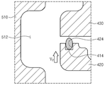
도 7은 도 4의 클램핑 부재를 보여주는 사시도이다. 도 7을 참조하면, 클램핑 부재(500)는 제1클램프(510), 제2클램프(520), 그리고 잠금핀(530)을 포함한다. 제1클램프(510) 및 제2클램프(520)는 공정 챔버(410)의 측부에 위치된다. 일 예에 의하면, 제1클램프(510) 및 제2클램프(520) 각각은 공정 챔버(410)를 사이에 두고 서로 마주도보록 위치된다. 제1클램프(510) 및 제2클램프(520) 각각은 공정 챔버(410)를 감싸는 형상으로 제공된다. 제1클램프(510) 및 제2클램프(520) 각각은 공정 챔버(410)를 바라보는 내측면에 클램프 홈(512)이 형성된다. 클램프 홈(512)에는 밀폐 위치에 위치된 제1바디(430)의 가장자리부 및 제2바디(420)의 가장자리부가 삽입 가능하다. 즉 제1바디(430)의 가장자리부 및 제2바디(420)의 가장자리부 각각은 클램핑되는 영역으로 제공된다. 상하 방향을 향하는 클램프 홈의 길이(P2)는 밀폐 위치에 위치된 제1바디(430)의 가장자리부 상단과 제2바디(420)의 가장자리부 하단을 연장하는 길이(P1)보다 길게 제공된다. 즉 클램프 홈의 상하 길이(P2)는 밀폐 위치에 위치되는 제1바디 및 제2바디의 클램핑 영역의 상하 길이(P1)보다 길게 제공된다.FIG. 7 is a perspective view showing the clamping member of FIG. 4 . Referring to FIG. 7 , the clamping
클램핑 부재(500)는 잠금 위치 또는 해제 위치로 이동 가능하다. 여기서 잠금 위치는 제1클램프(510) 및 제2클램프(520)가 서로 가까워져 제1바디(430) 및 제2바디(420)를 클램핑하는 위치이고, 해제 위치는 제1클램프(510) 및 제2클램프(520)가 제1바디(430) 및 제2바디(420)로부터 이격되는 위치로 정의한다. 제1클램프(510) 및 제2클램프(520)는 잠금 위치에서 서로 조합되어 환형의 링 형상을 가지도록 제공된다. 예컨대, 제1클램프(510) 및 제2클램프(520) 중 어느 하나의 수직 단면은 "C" 또는 "ㄷ" 자 형상을 가지고, 다른 하나의 수직 단면은 수직축을 기준으로 어느 하나의 수직 단면과 대칭되게 제공될 수 있다.The clamping
제1클램프(510)는 제2클램프(520)와 접촉되는 일측면이 단차지도록 제공된다. 제2클램프(520)는 제1클램프(510)와 접촉되는 타측면이 단차지도록 제공된다. 제1클램프(510)의 일측면과 제2클램프(520)의 타측면은 서로 엇갈린 형상으로 제공된다. 일 예에 의하면, 제1클램프(510)의 일측면은 상단이 하단에 비해 길게 단차지고, 제2클램프(520)의 타측면은 상단이 하단에 비해 짧게 단차지도록 제공될 수 있다. 제1클램프(510)의 단차진 영역에는 잠금핀(530)이 위치되는 제1핀홈(514)이 형성되고, 제2클램프(520)의 단차진 영역에는 제2핀홈(524)이 형성된다. 제1핀홈(514) 및 제2핀홈(524) 각각은 클램핑 부재(500)의 이동 방향과 수직한 방향을 향하도록 제공된다. 잠금 위치에서 제1핀홈(514)과 제2핀홈(524)은 서로 대향되게 위치된다. 일 예에 의하면, 잠금 위치에는 잠금핀(530)이 제1핀홈(514)으로부터 돌출되어 제2핀홈(524)에 삽입될 수 있다. 또한 제1핀홈(514)은 제2클램프(520)에 더 형성되고, 제2핀홈(524)은 제1클램프(510)에 더 형성될 수 있다.The
다시 도 4 및 도 5를 참조하면, 이동 부재(550)는 클램핑 부재(500)를 잠금 위치 및 해제 위치로 이동시킨다. 이동 부재(550)는 클램핑 부재(500)를 공정 챔버(410)의 이동 방향과 수직한 방향으로 이동시킨다. 이동 부재(550)는 가이드 레일(560), 브라켓(570), 그리고 구동 부재(580)를 포함한다. 가이드 레일(560)은 하우징(402)의 외부에 위치된다. 가이드 레일(560)은 제1바디(430)가 위치되는 상부 공간(408a)과 인접하게 위치된다. 가이드 레일(560)은 하우징(402)의 상면에 설치된다. 가이드 레일(560)은 공정 챔버(410)의 이동 방향과 수직한 길이 방향을 가진다. 가이드 레일(560)은 복수 개로 제공되며, 각각은 동일한 길이 방향을 가진다. 일 예에 의하면, 가이드 레일(560)은 관통홀(405)과 동일한 개수로 제공된다. 가이드 레일(560)은 관통홀(405)과 평행한 길이 방향을 가진다. 상부에서 바라볼 때 가이드 레일(560)은 관통홀(405)과 중첩되게 위치된다. 브라켓(570)은 가이드 레일(560)과 클램핑 부재(500)를 서로 고정 결합시킨다. 브라켓(570)은 가이드 레일(560)과 동일한 개수로 제공된다 일 예에 의하면, 상부에서 바라볼 때 일측에 위치되는 가이드 레일(560)에는 제1클램프(510)에 연결되고, 타측에 위치되는 가이드 레일에는 제2클램프(520)가 연결될 수 있다. 구동 부재(580)는 클램핑 부재(500)가 가이드 레일(560)의 길이 방향을 따라 잠금 위치 또는 해제 위치로 이동되도록 가이드 레일(560)을 구동시킨다. Referring again to FIGS. 4 and 5 , the moving
제어기(600)는 승강 부재(450) 및 이동 부재(550)를 제어한다. 제어기(600)는 공정 챔버(410)가 밀폐 위치 또는 개방 위치로 이동되도록 승강 부재(450)를 제어하고, 클램핑 부재(500)가 잠금 위치 또는 해제 위치로 이동되도록 이동 부재(550)를 제어한다. 또한 제어기(600)는 처리 공간(412)의 압력이 밀폐 위치에서 제2바디(420)에 가해지는 압력보다 크도록 유체 공급 유닛(490)을 제어할 수 있다. 일 예에 의하면, 제어기(600)는 공정 챔버(410)가 개방 위치에서 밀폐 위치로 이동되면, 클램핑 부재(500)는 해제 위치에서 잠금 위치로 이동될 수 있다. 제어기(600)는 제2바디(420)의 승강 속도를 제1속도(V1) 및 제2속도(V2)로 조절하고, 하강 속도를 제3속도(V3) 및 제4속도(V4)로 조절할 수 있다.The
다음은 상술한 기판 처리 장치(400)를 이용하여 기판을 처리하는 방법을 설명한다. 도 8은 도 4의 장치를 이용하여 기판을 처리하는 과정을 보여주는 플로우 차트이고, 도 9는 도 8의 플로우 차트에서 제2바디(420)의 위치를 보여주는 그래프이며, 도 10 내지 도 17은 도 4의 장치를 이용하여 기판을 처리하는 과정을 보여주는 도면들이다. 도 8 내지 도 17을 참조하면, 기판(W)을 처리하는 과정에 있어서, 공정 챔버(410)는 고속 밀폐 단계(S10), 저속 밀폐 단계(S20), 잠금 단계(S30), 공정 처리 단계(S40), 해제 단계(S50), 저속 개방 단계(S60), 그리고 고속 개방 단계(S70)가 순차적으로 이루어지도록 이동된다. 다음은 공정 챔버(410)가 개방 위치, 그리고 클램핑 부재(500)가 해제 위치에 위치된 상태에서 고속 밀폐 단계(S10)가 수행되는 것으로 설명한다.Next, a method of processing a substrate using the above-described
고속 밀폐 단계(S10)에는 클램핑 부재(500)가 해제 위치에 위치되고, 공정 챔버(410)는 서로 가까워지는 방향을 향해 제1속도(V1)로 승강 이동된다. 고속 밀폐 단계(S10)에는 제1바디(430)와 제2바디(420)가 서로 이격된 위치를 가진다. 제1바디(430)와 제2바디(420)가 서로 인접한 위치로 이동되면, 저속 밀폐 단계(S20)가 수행된다.In the high-speed sealing step ( S10 ), the clamping
저속 밀폐 단계(S20)에는 제1바디(430)와 제2바디(420)가 서로 가까워지는 방향을 향해 제2속도(V2)로 이동된다. 제2바디(420)는 제2속도(V2)로 승강 이동되어 제1바디(430)에 밀착되는 밀폐 위치로 이동된다. 여기서 제2속도(V2)는 제1속도(V1)에 비해 느린 속도로 제공된다. 이에 따라 제1바디(430)와 제2바디(420)가 충돌 시 각 바디에 가해지는 충격을 제1속도(V1)로 충돌시키는 것에 비해 완화시킬 수 있다. 제1바디(430)와 제2바디(420)가 서로 밀착되면, 처리 공간(412)은 외부로부터 밀폐된다. 이때 구동기(454)는 제2바디(420)를 제1압력으로 가압한다. 예컨대, 구동기(454)는 제2바디(420)를 저속 밀폐 단계(S20)에서 해제 단계(S50)까지 제1압력으로 가압할 수 있다.In the low-speed sealing step (S20), the
잠금 단계(S30)에는 클램핑 부재(500)가 해제 위치에서 잠금 위치로 이동된다. 클램핑 부재(500)는 잠금 위치로 이동되어 공정 챔버(410)를 클램핑한다. 이때 제1바디(430)와 제2바디(420)는 서로 밀착된 위치를 가지며, 클램프 홈의 길이(P2)는 제1바디(430)의 가장자리부 상단과 제2바디(420)의 가장자리부 하단을 연장하는 길이(P1)보다 길게 제공되므로, 클램핑 부재(500)가 이동되는 과정에서 클램핑 부재(500)와 공정 챔버(410) 간에 충돌을 방지할 수 있다. 공정 챔버(410)가 클램핑되면, 공정 처리 단계(S40)가 수행된다.In the locking step S30, the clamping
공정 처리 단계(S40)에는 처리 공간(412)에 초임계 유체를 공급한다. 처리 공간(412)에 초임계 유체가 공급됨에 따라 처리 공간(412)의 압력은 점진적으로 높아진다. 처리 공간(412)은 처리 유체에 의해 제2압력으로 가압된다. 여기서 제2압력은 제1압력보다 높은 압력으로 제공된다. 제2압력은 처리 유체의 임계 압력보다 큰 압력으로 제공된다. 기판(W)의 건조 처리는 제2압력 상태에서 이루어진다. 이에 따라 제1바디(430)와 제2바디(420)는 서로 멀이지는 방향으로 이동되어 클램핑 부재(500)에 밀착된다. 이때 처리 공간(412)은 실링 부재(414)에 의해 외부로부터 밀폐된 상태를 유지한다. 기판(W)의 건조 처리가 완료되면, 처리 유체의 공급을 중지하고, 배기 유닛에 의해 처리 공간(412)을 배기한다. 처리 공간(412)은 제1압력보다 작은 제3압력까지 배기된다. 예컨대, 제3압력은 상압 또는 이와 인접한 압력일 수 있다. 처리 공간(412)이 제3압력으로 감압되면, 구동기(454)가 제1바디(430)에 가하는 제1압력에 의해 제1바디(430)와 제2바디(420)는 다시 서로 밀착된다. 해제 단계(S50)가 수행된다.In the process step S40 , a supercritical fluid is supplied to the
해제 단계(S50)가 진행되면, 클램핑 부재(500)는 잠금 위치에서 해제 위치로 이동된다. 클램핑 부재(500)가 이동되는 과정에서 제1바디(430)와 제2바디(420)는 서로 밀착된 위치를 가지므로, 클램핑 부재(500)와 공정 챔버(410)가 충돌되는 것을 방지할 수 있다. 클램핑 부재(500)가 해제 위치로 이동되면, 저속 개방 단계(S60)가 수행된다.When the unlocking step S50 proceeds, the clamping
저속 개방 단계(S60)에는 제1바디(430)와 제2바디(420)가 서로 멀어지는 방향을 향해 제3속도(V3)로 이동된다. 제2바디(420)는 제3속도(V3)로 하강 이동된다. 이에 따라 처리 공간(412)이 급격하게 팽창되는 것을 방지하고, 처리 공간(412)에 음압이 발생되는 것을 방지할 수 있다. 제1바디(430)와 제2바디(420)가 서로 이격되면, 고속 개방 단계(S70)를 수행한다. In the low-speed opening step S60, the
고속 개방 단계(S70)에는 제2바디(420)가 제4속도(V4)로 하강 이동되어 개방 위치로 이동된다. 여기서 제4속도(V4)는 제3속도(V3)에 비해 빠른 속도로 제공된다. 이로 인해 처리 공간(412)의 팽창을 방지함과 동시에 공정 챔버(410)의 개방 속도를 신속히 수행할 수 있다. 예컨대, 제1속도(V1)는 제4속도(V4)와 동일하고, 제2속도(V2)는 제3속도(V3)와 동일할 수 있다. In the high-speed opening step (S70), the
410: 공정 챔버 420: 제2바디
430: 제1바디 456: 구동기
490: 유체 공급 유닛 500: 클램핑 부재
600: 제어기410: process chamber 420: second body
430: first body 456: actuator
490: fluid supply unit 500: clamping member
600: controller
Claims (19)
서로 조합되어 내부에 처리 공간을 형성하는 제1바디 및 제2바디를 가지는 챔버와;
상기 제1바디와 상기 제2바디 간의 상대 위치를 이동시켜 상기 처리 공간을 밀폐 또는 개방하는 구동기와;
상기 처리 공간 내에서 기판을 지지하는 기판 지지 유닛과;
상기 처리 공간에 놓인 기판을 처리하는 가스를 공급하는 가스 공급 유닛과;
상기 구동기와 상기 가스 공급 유닛을 제어하는 제어기와;
밀폐된 상기 챔버를 클램핑하는 클램핑 부재; 그리고,
상기 클램핑 부재를 이동시키는 이동 부재를 더 포함하되,
상기 제어기는,
상기 기판이 상기 처리 공간 내부에서 처리되는 동안,
상기 제1바디와 상기 제2바디가 밀착되는 방향으로 상기 제1바디 또는 상기 제2바디에 제1압력을 가하도록 상기 구동기를 제어하고, 상기 처리 공간 내부의 압력이 제2압력이 되도록 상기 가스 공급 유닛을 제어하고,
상기 제2압력은 상기 제1압력보다 크게 제공되고,
상기 처리 공간이 밀폐된 이후에 상기 클램핑 부재가 상기 제1바디와 상기 제2바디를 클램핑 하도록 이동되는 잠금 단계, 상기 처리 공간으로 가스를 공급하여 상기 기판을 처리하는 공정 처리 단계, 그리고 상기 클램핑 부재가 상기 제1바디와 상기 제2바디로부터 이격되는 해제 단계가 순차적으로 수행되고,
상기 해제 단계 이후에 상기 처리 공간이 개방되도록 상기 구동기를 제어하되;
상기 클램핑 부재는,
상기 챔버의 일측에 위치되는 제1클램프와;
상기 챔버를 사이에 두고, 상기 제1클램프와 마주보도록 위치되는 제2클램프를 포함하고,
상기 제1바디와 상기 제2바디의 외측면은,
상기 잠금 단계에서 상기 제1클램프와 상기 제2클램프가 상기 챔버의 측면을 감싸도록 상기 제1클램프 및 상기 제2클램프의 내측면과 대응되는 형상으로 제공되는 기판 처리 장치.An apparatus for processing a substrate, comprising:
a chamber having a first body and a second body combined with each other to form a processing space therein;
a actuator for closing or opening the processing space by moving a relative position between the first body and the second body;
a substrate support unit for supporting a substrate in the processing space;
a gas supply unit supplying a gas for processing a substrate placed in the processing space;
a controller controlling the driver and the gas supply unit;
a clamping member for clamping the sealed chamber; And,
Further comprising a moving member for moving the clamping member,
The controller is
while the substrate is processed inside the processing space;
The actuator is controlled to apply a first pressure to the first body or the second body in a direction in which the first body and the second body are in close contact, and the gas inside the processing space becomes a second pressure. control the supply unit,
The second pressure is provided greater than the first pressure,
A locking step in which the clamping member is moved to clamp the first body and the second body after the processing space is closed, a process processing step of supplying a gas to the processing space to process the substrate, and the clamping member The releasing step of being spaced apart from the first body and the second body is sequentially performed,
controlling the actuator to open the processing space after the releasing step;
The clamping member is
a first clamp positioned at one side of the chamber;
A second clamp positioned to face the first clamp with the chamber interposed therebetween,
The first body and the outer surface of the second body,
In the locking step, the substrate processing apparatus is provided in a shape corresponding to inner surfaces of the first clamp and the second clamp so that the first clamp and the second clamp surround a side surface of the chamber.
상기 제1클램프 및 상기 제2클램프는 상기 챔버를 바라보는 내측면에 클램프 홈이 형성되고,
상기 잠금 단계에서,
서로 밀착된 상기 제1바디와 상기 제2바디의 가장자리부 및 제2바디의 가장자리부가 삽입되고,
상하 방향을 향하는 상기 클램프 홈의 길이는 서로 밀착된 제1바디의 가장자리부 상단으로부터 제2바디의 가장자리부 하단까지의 길이보다 길게 제공되는 기판 처리 장치.7. The method of claim 6,
The first clamp and the second clamp have a clamp groove formed on the inner surface facing the chamber,
In the locking step,
The edges of the first body and the second body in close contact with each other and the edge of the second body are inserted,
The length of the clamp groove in the vertical direction is longer than the length from the upper end of the edge of the first body to the lower end of the edge of the second body in close contact with each other.
상기 제2압력은 가스의 임계 압력보다 높은 압력으로 제공되는 기판 처리 장치.8. The method of claim 6 or 7,
The second pressure is provided as a pressure higher than a critical pressure of the gas.
서로 조합되어 내부에 처리 공간을 형성하는 제1바디 및 제2바디를 가지는 챔버와;
상기 제1바디와 상기 제2바디 간의 상대 위치를 이동시켜 상기 처리 공간을 밀폐 또는 개방하는 구동기와;
밀폐된 상기 챔버를 클램핑하는 클램핑 부재; 그리고,
상기 클램핑 부재를 이동시키는 이동 부재를 포함하고,
상기 처리 공간 내에서 기판을 지지하는 기판 지지 유닛과;
상기 처리 공간에 놓인 기판을 처리하는 가스를 공급하는 가스 공급 유닛과;
상기 구동기, 상기 가스 공급 유닛 그리고 상기 이동 부재를 제어하는 제어기를 포함하되,
상기 클램핑 부재는,
상기 챔버의 일측에 위치되는 제1클램프와;
상기 챔버를 사이에 두고, 상기 제1클램프와 마주보도록 위치되는 제2클램프를 포함하며,
상기 제1바디와 상기 제2바디의 외측면은,
상기 제1클램프와 상기 제2클램프가 밀폐된 상기 챔버의 측면을 감싸도록 상기 제1클램프 및 상기 제2클램프의 내측면과 대응되는 형상으로 제공되고,
상기 제1클램프 및 상기 제2클램프는 상기 챔버를 바라보는 내측면에 클램프 홈이 형성되며,
상하 방향을 향하는 상기 클램프 홈의 길이는 서로 밀착된 제1바디의 가장자리부 상단으로부터 제2바디의 가장자리부 하단까지의 길이보다 길게 제공되되;
상기 제어기는,
상기 기판이 상기 처리 공간 내부에서 처리되는 동안,
상기 제1바디와 상기 제2바디가 밀착되는 방향으로 상기 제1바디 또는 상기 제2바디에 제1압력을 가하도록 상기 구동기를 제어하고, 상기 처리 공간 내부의 압력이 제2압력이 되도록 상기 가스 공급 유닛을 제어하고,
상기 제2압력은 상기 제1압력보다 크게 제공되는 기판 처리 장치.An apparatus for processing a substrate, comprising:
a chamber having a first body and a second body combined with each other to form a processing space therein;
a actuator for closing or opening the processing space by moving a relative position between the first body and the second body;
a clamping member for clamping the sealed chamber; And,
a moving member for moving the clamping member;
a substrate support unit for supporting a substrate in the processing space;
a gas supply unit supplying a gas for processing a substrate placed in the processing space;
a controller for controlling the actuator, the gas supply unit, and the moving member;
The clamping member is
a first clamp positioned at one side of the chamber;
and a second clamp positioned to face the first clamp with the chamber interposed therebetween,
The first body and the outer surface of the second body,
The first clamp and the second clamp are provided in a shape corresponding to the inner surface of the first clamp and the second clamp so as to surround the sealed side of the chamber,
The first clamp and the second clamp has a clamp groove formed on the inner surface facing the chamber,
The length of the clamp groove in the vertical direction is provided to be longer than the length from the upper edge of the first body in close contact to the lower edge of the second body;
The controller is
while the substrate is processed inside the processing space;
The actuator is controlled to apply a first pressure to the first body or the second body in a direction in which the first body and the second body are in close contact, and the gas inside the processing space becomes a second pressure. control the supply unit,
The second pressure is greater than the first pressure is provided in the substrate processing apparatus.
상기 제어기는,
상기 처리 공간이 밀폐된 이후에 상기 클램핑 부재가 상기 제1바디와 상기 제2바디를 클램핑 하도록 이동되는 잠금 단계, 상기 처리 공간으로 가스를 공급하여 상기 기판을 처리하는 공정 처리 단계, 그리고 상기 클램핑 부재가 상기 제1바디와 상기 제2바디로부터 이격되는 해제 단계가 순차적으로 수행되고,
상기 해제 단계 이후에 상기 처리 공간이 개방되도록 상기 구동기를 제어하는 기판 처리 장치.11. The method of claim 10,
The controller is
A locking step in which the clamping member is moved to clamp the first body and the second body after the processing space is closed, a process processing step of supplying a gas to the processing space to process the substrate, and the clamping member The releasing step of being spaced apart from the first body and the second body is sequentially performed,
and controlling the driver so that the processing space is opened after the releasing step.
상기 처리 공간을 배기하는 배기하는 배기 유닛을 더 포함하되,
상기 제어기는,
상기 배기 유닛이 상기 공정 처리 단계 이후에 상기 처리 공간을 배기하여 상기 처리 공간의 내부 압력이 상기 제1압력보다 낮아진 이후에 상기 클램핑 부재가 상기 제1바디와 상기 제2바디로부터 이격되도록 상기 배기 유닛 및 상기 이동 부재를 제어하는 기판 처리 장치.12. The method of claim 11,
Further comprising an exhaust unit for exhausting the processing space,
The controller is
the exhaust unit so that the clamping member is spaced apart from the first body and the second body after the exhaust unit exhausts the processing space after the processing step so that the internal pressure of the processing space becomes lower than the first pressure and a substrate processing apparatus controlling the moving member.
상기 제2압력은 가스의 임계 압력보다 높은 압력으로 제공되는 기판 처리 장치.13. The method according to any one of claims 10 to 12,
The second pressure is provided as a pressure higher than a critical pressure of the gas.
Priority Applications (2)
| Application Number | Priority Date | Filing Date | Title |
|---|---|---|---|
| KR1020200066834A KR102267171B1 (en) | 2018-04-30 | 2020-06-03 | Apparatus and Method for treating substrate |
| KR1020210065792A KR102391253B1 (en) | 2020-06-03 | 2021-05-21 | Apparatus and Method for treating substrate |
Applications Claiming Priority (2)
| Application Number | Priority Date | Filing Date | Title |
|---|---|---|---|
| KR1020180049778A KR102126180B1 (en) | 2018-04-30 | 2018-04-30 | Apparatus and Method for treating substrate |
| KR1020200066834A KR102267171B1 (en) | 2018-04-30 | 2020-06-03 | Apparatus and Method for treating substrate |
Related Parent Applications (1)
| Application Number | Title | Priority Date | Filing Date |
|---|---|---|---|
| KR1020180049778A Division KR102126180B1 (en) | 2018-04-30 | 2018-04-30 | Apparatus and Method for treating substrate |
Related Child Applications (1)
| Application Number | Title | Priority Date | Filing Date |
|---|---|---|---|
| KR1020210065792A Division KR102391253B1 (en) | 2020-06-03 | 2021-05-21 | Apparatus and Method for treating substrate |
Publications (2)
| Publication Number | Publication Date |
|---|---|
| KR20200070172A KR20200070172A (en) | 2020-06-17 |
| KR102267171B1 true KR102267171B1 (en) | 2021-06-22 |
Family
ID=71406076
Family Applications (2)
| Application Number | Title | Priority Date | Filing Date |
|---|---|---|---|
| KR1020200066834A Active KR102267171B1 (en) | 2018-04-30 | 2020-06-03 | Apparatus and Method for treating substrate |
| KR1020210065792A Active KR102391253B1 (en) | 2020-06-03 | 2021-05-21 | Apparatus and Method for treating substrate |
Family Applications After (1)
| Application Number | Title | Priority Date | Filing Date |
|---|---|---|---|
| KR1020210065792A Active KR102391253B1 (en) | 2020-06-03 | 2021-05-21 | Apparatus and Method for treating substrate |
Country Status (1)
| Country | Link |
|---|---|
| KR (2) | KR102267171B1 (en) |
Families Citing this family (3)
| Publication number | Priority date | Publication date | Assignee | Title |
|---|---|---|---|---|
| KR102537676B1 (en) * | 2020-12-31 | 2023-06-01 | 세메스 주식회사 | Apparatus for treating substrate |
| KR102622985B1 (en) | 2020-12-31 | 2024-01-11 | 세메스 주식회사 | Apparatus for treatng a substrate |
| CN118073241B (en) * | 2024-02-29 | 2024-09-10 | 哈尔滨工业大学 | A multi-layer flip chip high-flexibility stacking and integrated bonding device and method |
Citations (3)
| Publication number | Priority date | Publication date | Assignee | Title |
|---|---|---|---|---|
| JP2011009299A (en) * | 2009-06-23 | 2011-01-13 | Tokyo Electron Ltd | High-pressure treatment apparatus |
| JP2011097101A (en) * | 2003-10-06 | 2011-05-12 | Tokyo Electron Ltd | High-pressure processing chamber for semiconductor wafer |
| KR101853377B1 (en) | 2016-12-30 | 2018-06-20 | 세메스 주식회사 | Apparatus and Method for treating substrate |
Family Cites Families (3)
| Publication number | Priority date | Publication date | Assignee | Title |
|---|---|---|---|---|
| JP3442948B2 (en) * | 1996-12-09 | 2003-09-02 | 大日本スクリーン製造株式会社 | Substrate processing equipment |
| KR101099592B1 (en) | 2010-01-07 | 2011-12-28 | 세메스 주식회사 | Substrate Processing Equipment Using Supercritical Fluid |
| KR102157837B1 (en) * | 2013-12-31 | 2020-09-18 | 세메스 주식회사 | Substrate treating apparatus and substrate treating method |
-
2020
- 2020-06-03 KR KR1020200066834A patent/KR102267171B1/en active Active
-
2021
- 2021-05-21 KR KR1020210065792A patent/KR102391253B1/en active Active
Patent Citations (3)
| Publication number | Priority date | Publication date | Assignee | Title |
|---|---|---|---|---|
| JP2011097101A (en) * | 2003-10-06 | 2011-05-12 | Tokyo Electron Ltd | High-pressure processing chamber for semiconductor wafer |
| JP2011009299A (en) * | 2009-06-23 | 2011-01-13 | Tokyo Electron Ltd | High-pressure treatment apparatus |
| KR101853377B1 (en) | 2016-12-30 | 2018-06-20 | 세메스 주식회사 | Apparatus and Method for treating substrate |
Also Published As
| Publication number | Publication date |
|---|---|
| KR20210063296A (en) | 2021-06-01 |
| KR20200070172A (en) | 2020-06-17 |
| KR102391253B1 (en) | 2022-04-29 |
Similar Documents
| Publication | Publication Date | Title |
|---|---|---|
| KR102126180B1 (en) | Apparatus and Method for treating substrate | |
| CN109560022B (en) | Apparatus and methods for processing substrates | |
| KR101910801B1 (en) | Apparatus and method for treating substrate | |
| KR101949408B1 (en) | Apparatus for treating substrate | |
| KR101856606B1 (en) | Apparatus and Method for treating substrate | |
| KR101935951B1 (en) | Apparatus and Method for treating substrate | |
| KR102030056B1 (en) | Method for cleaning a chamber, Method for treating a substrate, and Apparatus for treating a substrate | |
| KR101987959B1 (en) | Apparatus and Method for treating substrate | |
| KR101935953B1 (en) | Apparatus and Method for treating substrate | |
| KR101964655B1 (en) | Apparatus and Method for treating substrate | |
| KR102391253B1 (en) | Apparatus and Method for treating substrate | |
| KR101853377B1 (en) | Apparatus and Method for treating substrate | |
| KR102143139B1 (en) | Apparatus for tretinf substrate | |
| KR101654627B1 (en) | Apparatus and method for treating substrate | |
| KR102316240B1 (en) | Method for treating substrate | |
| KR102649716B1 (en) | Apparatus for treating a substrate | |
| KR102537676B1 (en) | Apparatus for treating substrate | |
| KR20210036454A (en) | Apparatus for treating substrate | |
| KR102616133B1 (en) | Apparatus and method for treating substrate | |
| JP7318066B1 (en) | Substrate processing equipment | |
| KR102392490B1 (en) | Apparatus for treating substrate | |
| CN117198919A (en) | Apparatus for treating substrate |
Legal Events
| Date | Code | Title | Description |
|---|---|---|---|
| A107 | Divisional application of patent | ||
| PA0107 | Divisional application |
St.27 status event code: A-0-1-A10-A18-div-PA0107 St.27 status event code: A-0-1-A10-A16-div-PA0107 |
|
| PA0201 | Request for examination |
St.27 status event code: A-1-2-D10-D11-exm-PA0201 |
|
| PG1501 | Laying open of application |
St.27 status event code: A-1-1-Q10-Q12-nap-PG1501 |
|
| E902 | Notification of reason for refusal | ||
| PE0902 | Notice of grounds for rejection |
St.27 status event code: A-1-2-D10-D21-exm-PE0902 |
|
| T11-X000 | Administrative time limit extension requested |
St.27 status event code: U-3-3-T10-T11-oth-X000 |
|
| T11-X000 | Administrative time limit extension requested |
St.27 status event code: U-3-3-T10-T11-oth-X000 |
|
| T11-X000 | Administrative time limit extension requested |
St.27 status event code: U-3-3-T10-T11-oth-X000 |
|
| T11-X000 | Administrative time limit extension requested |
St.27 status event code: U-3-3-T10-T11-oth-X000 |
|
| AMND | Amendment | ||
| P11-X000 | Amendment of application requested |
St.27 status event code: A-2-2-P10-P11-nap-X000 |
|
| P13-X000 | Application amended |
St.27 status event code: A-2-2-P10-P13-nap-X000 |
|
| E601 | Decision to refuse application | ||
| PE0601 | Decision on rejection of patent |
St.27 status event code: N-2-6-B10-B15-exm-PE0601 |
|
| T11-X000 | Administrative time limit extension requested |
St.27 status event code: U-3-3-T10-T11-oth-X000 |
|
| T13-X000 | Administrative time limit extension granted |
St.27 status event code: U-3-3-T10-T13-oth-X000 |
|
| AMND | Amendment | ||
| E13-X000 | Pre-grant limitation requested |
St.27 status event code: A-2-3-E10-E13-lim-X000 |
|
| P11-X000 | Amendment of application requested |
St.27 status event code: A-2-2-P10-P11-nap-X000 |
|
| P13-X000 | Application amended |
St.27 status event code: A-2-2-P10-P13-nap-X000 |
|
| PA0107 | Divisional application |
St.27 status event code: A-0-1-A10-A18-div-PA0107 St.27 status event code: A-0-1-A10-A16-div-PA0107 |
|
| PX0901 | Re-examination |
St.27 status event code: A-2-3-E10-E12-rex-PX0901 |
|
| PX0701 | Decision of registration after re-examination |
St.27 status event code: A-3-4-F10-F13-rex-PX0701 |
|
| X701 | Decision to grant (after re-examination) | ||
| GRNT | Written decision to grant | ||
| PR0701 | Registration of establishment |
St.27 status event code: A-2-4-F10-F11-exm-PR0701 |
|
| PR1002 | Payment of registration fee |
St.27 status event code: A-2-2-U10-U11-oth-PR1002 Fee payment year number: 1 |
|
| PG1601 | Publication of registration |
St.27 status event code: A-4-4-Q10-Q13-nap-PG1601 |
|
| PN2301 | Change of applicant |
St.27 status event code: A-5-5-R10-R13-asn-PN2301 St.27 status event code: A-5-5-R10-R11-asn-PN2301 |
|
| R18-X000 | Changes to party contact information recorded |
St.27 status event code: A-5-5-R10-R18-oth-X000 |
|
| PR1001 | Payment of annual fee |
St.27 status event code: A-4-4-U10-U11-oth-PR1001 Fee payment year number: 4 |
|
| PN2301 | Change of applicant |
St.27 status event code: A-5-5-R10-R13-asn-PN2301 St.27 status event code: A-5-5-R10-R11-asn-PN2301 |
|
| PR1001 | Payment of annual fee |
St.27 status event code: A-4-4-U10-U11-oth-PR1001 Fee payment year number: 5 |
|
| P22-X000 | Classification modified |
St.27 status event code: A-4-4-P10-P22-nap-X000 |