KR102260475B1 - blind ram unit for continuous circulation process - Google Patents
blind ram unit for continuous circulation process Download PDFInfo
- Publication number
- KR102260475B1 KR102260475B1 KR1020210043306A KR20210043306A KR102260475B1 KR 102260475 B1 KR102260475 B1 KR 102260475B1 KR 1020210043306 A KR1020210043306 A KR 1020210043306A KR 20210043306 A KR20210043306 A KR 20210043306A KR 102260475 B1 KR102260475 B1 KR 102260475B1
- Authority
- KR
- South Korea
- Prior art keywords
- blind ram
- packer
- blind
- ram
- block
- Prior art date
- Legal status (The legal status is an assumption and is not a legal conclusion. Google has not performed a legal analysis and makes no representation as to the accuracy of the status listed.)
- Active
Links
- 238000000034 method Methods 0.000 title claims description 7
- 239000012530 fluid Substances 0.000 claims abstract description 11
- XLYOFNOQVPJJNP-UHFFFAOYSA-N water Substances O XLYOFNOQVPJJNP-UHFFFAOYSA-N 0.000 claims description 25
- 238000007789 sealing Methods 0.000 claims description 19
- 230000008878 coupling Effects 0.000 claims description 16
- 238000010168 coupling process Methods 0.000 claims description 16
- 238000005859 coupling reaction Methods 0.000 claims description 16
- 238000003780 insertion Methods 0.000 claims description 9
- 230000037431 insertion Effects 0.000 claims description 9
- 239000000314 lubricant Substances 0.000 claims description 5
- 238000009434 installation Methods 0.000 claims description 4
- 238000007373 indentation Methods 0.000 claims 1
- 238000005553 drilling Methods 0.000 description 10
- 238000011084 recovery Methods 0.000 description 2
- 239000011435 rock Substances 0.000 description 2
- 239000004820 Pressure-sensitive adhesive Substances 0.000 description 1
- 230000005540 biological transmission Effects 0.000 description 1
- 238000010586 diagram Methods 0.000 description 1
- 239000007789 gas Substances 0.000 description 1
- 239000004519 grease Substances 0.000 description 1
- 238000005192 partition Methods 0.000 description 1
- 239000002861 polymer material Substances 0.000 description 1
- 239000011148 porous material Substances 0.000 description 1
- 239000004576 sand Substances 0.000 description 1
Images


Classifications
-
- E—FIXED CONSTRUCTIONS
- E21—EARTH OR ROCK DRILLING; MINING
- E21B—EARTH OR ROCK DRILLING; OBTAINING OIL, GAS, WATER, SOLUBLE OR MELTABLE MATERIALS OR A SLURRY OF MINERALS FROM WELLS
- E21B33/00—Sealing or packing boreholes or wells
- E21B33/02—Surface sealing or packing
- E21B33/03—Well heads; Setting-up thereof
- E21B33/068—Well heads; Setting-up thereof having provision for introducing objects or fluids into, or removing objects from, wells
-
- E—FIXED CONSTRUCTIONS
- E21—EARTH OR ROCK DRILLING; MINING
- E21B—EARTH OR ROCK DRILLING; OBTAINING OIL, GAS, WATER, SOLUBLE OR MELTABLE MATERIALS OR A SLURRY OF MINERALS FROM WELLS
- E21B33/00—Sealing or packing boreholes or wells
- E21B33/02—Surface sealing or packing
- E21B33/03—Well heads; Setting-up thereof
- E21B33/06—Blow-out preventers, i.e. apparatus closing around a drill pipe, e.g. annular blow-out preventers
- E21B33/061—Ram-type blow-out preventers, e.g. with pivoting rams
-
- E—FIXED CONSTRUCTIONS
- E21—EARTH OR ROCK DRILLING; MINING
- E21B—EARTH OR ROCK DRILLING; OBTAINING OIL, GAS, WATER, SOLUBLE OR MELTABLE MATERIALS OR A SLURRY OF MINERALS FROM WELLS
- E21B33/00—Sealing or packing boreholes or wells
- E21B33/10—Sealing or packing boreholes or wells in the borehole
- E21B33/12—Packers; Plugs
- E21B33/1208—Packers; Plugs characterised by the construction of the sealing or packing means
- E21B33/1216—Anti-extrusion means, e.g. means to prevent cold flow of rubber packing
Landscapes
- Life Sciences & Earth Sciences (AREA)
- Engineering & Computer Science (AREA)
- Geology (AREA)
- Mining & Mineral Resources (AREA)
- Physics & Mathematics (AREA)
- Environmental & Geological Engineering (AREA)
- Fluid Mechanics (AREA)
- General Life Sciences & Earth Sciences (AREA)
- Geochemistry & Mineralogy (AREA)
- Piles And Underground Anchors (AREA)
Abstract
Description
본 발명은 시추용 머드의 압력을 유지하면서 순환시키기 위한 연속이수순환시스템에 적용되는 블라인드 램 유닛에 관한 것이다.The present invention relates to a blind ram unit applied to a continuous water circulation system for circulating while maintaining the pressure of the drilling mud.
해저 또는 육지의 지하자원을 탐사하거나 지층의 구조, 상태를 조사하기 위하여 암석이자 모래를 굴착하는 경우 드릴 부분 내 머드의 압력을 일정 조건 내로 유지하는 것이 요구된다. In the case of excavating rocks and sand to explore underground resources on the seabed or land or to investigate the structure and condition of strata, it is required to maintain the pressure of the mud in the drilling part within a certain condition.
상기 머드의 압력이 너무 낮을 경우에는 지하 유체 및 가스들의 힘(pore pressure)에 의해 시추공 벽면이 눌려 붕괴되고, 너무 높을 경우에는 팽창으로 인한 주변 암석 내 균열을 발생시켜 머드가 이와 같은 균열 사이로 빠져나가 순환 과정에서 유실이 발생하게 된다.When the pressure of the mud is too low, the borehole wall is compressed and collapsed by the force of underground fluids and gases (pore pressure). When the pressure of the mud is too high, cracks are generated in the surrounding rock due to expansion and the mud escapes through these cracks. Loss occurs during the cycle.
따라서, 제한된 압력 조건(pressure window) 내에 시추용 머드의 압력을 유지하는 것이 중요하며, 이를 위해 연속이수순환시스템(CCS:Continuous Circulation System)이 사용되고 있다.Therefore, it is important to maintain the pressure of the drilling mud within a limited pressure window, and for this purpose, a Continuous Circulation System (CCS) is used.
즉, 상기 연속이수순환시스템은 드릴 파이프의 연결, 해제 작업을 비롯한 드릴링 작업공정 전반에 걸쳐 머드펌프의 연속 구동을 유도하여 머드가 시추장치 내에서 연속순환되도록 한다.That is, the continuous water circulation system induces continuous operation of the mud pump throughout the drilling operation process, including connection and disconnection of the drill pipe, so that the mud is continuously circulated in the drilling apparatus.
이를 위해 상기 연속 이수 순환시스템은 챔버 어셈블리/로터리 슬립 어셈블리/스누빙 디바이스 어셈블리/파이프 가이드 어셈블리, 실린더, 파이프 램, 블라인드 램, 램 블록, 밸브, 머드 펌프 등의 구성을 포함하며, 드릴링 머드의 순환경로를 단계적으로 가변시키면서 드릴 파이프의 연결 또는 연결해제가 이루어진다. To this end, the continuous water circulation system includes a chamber assembly / rotary slip assembly / snubbing device assembly / pipe guide assembly, cylinder, pipe ram, blind ram, ram block, valve, mud pump, etc., and the circulation of drilling mud The connection or disconnection of the drill pipe is made by varying the path stepwise.
관련하여, 대한민국 등록특허공보 등록번호 제10-1959829호 "연속 이수 순환시스템", 대한민국 등록특허공보 등록번호 제10-2115513호 "개량형 연속 이수 순환시스템" 등이 공지되어 있다.In this regard, Republic of Korea Patent Registration No. 10-1959829 "continuous water circulation system", Republic of Korea Patent Registration No. 10-2115513 "improved continuous water circulation system" and the like are known.
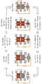
한편, 도 1 에는 연속 이수 순환시스템의 순환 프로세스 일 실시 예가 도시된다. On the other hand, Figure 1 shows an embodiment of the circulation process of the continuous water circulation system.
도면을 참조하면, 드릴 파이프를 통해 추출되는 드릴링 머드는 순환 배관을 통해 챔버 내부로 공급되며, 이와 같은 챔버는 상/하부 파이프 램과 중앙 블라인드 램에 의해 다단의 구획된 공간으로 가변된다. Referring to the drawings, the drilling mud extracted through the drill pipe is supplied into the chamber through the circulation pipe, and such a chamber is changed into a multi-stage partitioned space by an upper/lower pipe ram and a central blind ram.
상기와 같은 공간 구획 구조는 드릴 파이프의 추가 연결이나 해제를 위해 드릴링 머드의 순환 경로를 가변시키기 위한 것으로, 도시된 바와 같이 상/하부 파이프 램과 블라인드 램의 차폐와 개방 순서에 따라 유체의 순환경로를 가변시키면서 드릴링 유체 압력이 유지될 수 있도록 한다. The space partition structure as described above is for changing the circulation path of the drilling mud for additional connection or release of the drill pipe. As shown, the circulation path of the fluid according to the shielding and opening order of the upper/lower pipe ram and the blind ram while varying the drilling fluid pressure.
따라서, 상기와 같은 연속 이수 순환시스템에서는 챔버 내부의 공간 구획 시 압력 유지와 이를 위한 누설방지가 중요하며, 이를 위해 파이프 램과 블라인드 램에는 밀폐를 위한 램 패커가 설치된다.Therefore, in the continuous water circulation system as described above, it is important to maintain pressure and prevent leakage when dividing the space inside the chamber, and for this, a ram packer for sealing is installed in the pipe ram and the blind ram.
한편, 파이프 램 또는 블라인드 램에 설치되는 램 패커는 직접 밀폐대상과 맞닿아 밀폐구조를 형성하는 구성으로 보다 램 챔버 및 램 블록과 함께 유기적인 결합구조를 형성함으로써 유동을 줄여 기밀성능을 향상시키기 위한 노력이 이루어지고 있다.On the other hand, the ram packer installed in the pipe ram or blind ram directly contacts the sealing object to form a sealed structure, and forms an organic coupling structure with the ram chamber and ram block to reduce flow and improve airtight performance. Efforts are being made
본 발명의 목적은 연속이수 순환시스템에 장착되어 기밀성을 향상시킬 수 있는 연속이수순환시스템용 블라인드 램 유닛을 제공하는 것이다.It is an object of the present invention to provide a blind ram unit for a continuous water circulation system that can improve airtightness by being mounted on the continuous water circulation system.
상술한 과제를 해결하기 위한 기술 수단으로서, 본 발명의 일 실시예에 따른 연속이수순환시스템용 블라인드 램 유닛은, 연속이수순환시스템에서 드릴 파이프와 함께 유체가 수용되는 공간을 선택적으로 차폐하기 위한 블라인드 램 유닛으로, 육면체 형상으로 중앙에 상하 방향으로 개구되는 드릴 파이프 수용부가 형성되고, 실린더를 통해 진출입되는 블라인드 램 블록의 진출입 경로를 제공하는 블라인드 램 삽입부가 서로 마주보는 양측면에 형성되는 블라인드 램 챔버, 일단이 실린더와 연결되어 상기 블라인드 램 삽입부를 통해 진출입되며, 내부에 수용되는 드릴 파이프가 간섭되지 않는 위치에서 서로 접하여 기밀구조를 형성하기 위한 2개의 블라인드 램 패커의 설치 공간을 제공하는 2개의 블라인드 램 블록;을 포함하고, 상기 블라인드 램 패커는, 반원 형상의 차폐 실링부와, 상기 차폐 실링부를 중앙에 두고 상측과 하측으로 소정 길이 연장형성되어 차폐 실링부와 직교하는 형상의 소정 두께를 가지는 반원 형상의 블록 장착부를 포함하도록 구성되며, 상기 블라인드 램 패커의 블록 장착부 측면에는, 상기 블라인드 램 블록 바디의 전면에 요입 형성되는 단턱홈과 대응되는 형상의 단턱이 형성되고, 상기 블라인드 램 블록은, 후측에 실린더 헤드와 연결되도록 요홈부와 돌출부로 이루어지는 실린더 연결부가 마련되는 블라인드 램 블록 바디와, 상기 블라인드 램 블록 바디의 전측에서 상기 블라인드 램 패커의 장착을 위한 설치공간을 제공하는 블라인드 램 패커 체결부를 포함하며, 상기 블라인드 램 패커 체결부는, 상기 블라인드 램 블록 바디의 전측 상부에 형성되는 탑 패커 체결부와, 미들 패커 체결부 및 바텀 패커 체결부를 포함하고, 상기 미들 패커 체결부는 상기 탑 패커 체결부 및 바텀 패커 체결부 보다 후측에 위치되어 상기 탑 패커 체결부와 바텀 패커 체결부 사이에 블라인드 램 패커의 차폐 실링부가 위치되며, 상기 블라인드 램 삽입부는, 상기 드릴 파이프 수용부를 향해 수평 방향으로 형성되는 수평면과, 상기 블라인드 램 블록이 진입되는 시작단으로 상기 수평면의 가장자리에서 외측으로 경사지게 형성되어 진입공간을 확장시키는 테이퍼면을 포함하도록 형성되며, 상기 블라인드 램 챔버에는, 상기 드릴 파이프 수용부와 상기 블라인드 램 삽입부가 교차하는 영역에서 일정 깊이 삽입되는 블라인드 램 블록의 삽입 위치를 제한하면서 블라인드 램 블록에 장착된 블라인드 램 패커를 가압하여 고정시키기 위한 패커 고정 그루브가 형성될 수 있다.As a technical means for solving the above-mentioned problems, the blind ram unit for a continuous water circulation system according to an embodiment of the present invention selectively shields a space in which a fluid is accommodated together with a drill pipe in a continuous water circulation system. A blind ram unit for a blind ram unit, in which a drill pipe accommodating part opened in the vertical direction is formed in the center in a hexahedral shape, and blind ram insertion parts providing an entry and exit path for the blind ram block entering and exiting through a cylinder are formed on both sides facing each other. The chamber, one end of which is connected to the cylinder, enters and exits through the blind ram insert, and is in contact with each other at a position where the drill pipe accommodated therein does not interfere with each other to form an airtight structure. Two blind ram packers providing an installation space and a blind ram block, wherein the blind ram packer has a semicircular shielding sealing part, and the shielding sealing part is formed to extend a predetermined length upward and downward with the shielding sealing part in the center, and has a predetermined thickness in a shape orthogonal to the shielding sealing part. It is configured to include a block mounting part having a semicircular shape, and on the side of the block mounting part of the blind ram packer, a step having a shape corresponding to a stepped groove formed in a concave shape on the front surface of the blind ram block body is formed, and the blind ram block, A blind ram block body provided with a cylinder connection part including a recess and a protrusion to be connected to the cylinder head on the rear side, and a blind ram packer fastening part providing an installation space for mounting the blind ram packer on the front side of the blind ram block body The blind ram packer fastening part includes a top packer fastening part formed on a front upper portion of the blind ram block body, a middle packer fastening part and a bottom packer fastening part, and the middle packer fastening part includes the top packer fastening part and The shield sealing part of the blind ram packer is positioned at a rear side of the bottom packer fastening part between the top packer fastening part and the bottom packer fastening part, and the blind ram insertion part includes a horizontal surface formed in a horizontal direction toward the drill pipe receiving part; , the blind The ram block is formed to include a tapered surface that is inclined outwardly from the edge of the horizontal plane to expand the entry space as the starting end at which the ram block enters, and in the blind ram chamber, the drill pipe receiving part and the blind ram inserting part intersect A packer fixing groove may be formed for pressing and fixing the blind ram packer mounted on the blind ram block while limiting the insertion position of the blind ram block inserted to a certain depth in the region.
또한, 본 발명의 일 실시예에 따른 연속이수순환시스템용 블라인드 램 유닛은, 상기 블라인드 램 블록의 실린더 연결부에는 상기 실린더 헤드가 장착된 뒤 상하 방향으로 소정거리 이동 가능하도록 결합여유가 형성될 수 있다.In addition, in the blind ram unit for a continuous water circulation system according to an embodiment of the present invention, a coupling allowance may be formed in the cylinder connection part of the blind ram block to be movable a predetermined distance in the vertical direction after the cylinder head is mounted. have.
또한, 본 발명의 일 실시예에 따른 연속이수순환시스템용 블라인드 램 유닛은, 상기 블라인드 램 패커에는 윤활제가 주입되는 가공홀이 하나 이상 형성될 수 있다.In addition, in the blind ram unit for a continuous water circulation system according to an embodiment of the present invention, one or more processing holes into which a lubricant is injected may be formed in the blind ram packer.
또한, 본 발명의 일 실시예에 따른 연속이수순환시스템용 블라인드 램 유닛은, 상기 블라인드 램 패커 체결부의 측면에는 윤활제의 주입이 가능한 가공홀이 하나 이상 형성될 수 있다.In addition, in the blind ram unit for a continuous water circulation system according to an embodiment of the present invention, one or more processing holes through which a lubricant can be injected may be formed on a side surface of the blind ram packer fastening part.
본 발명에 따르면, 블라인드 램 챔버와 블라인드 램 블록 및 블라인드 램 패커의 결합관계가 보다 견고히 이루어져 기밀 성능을 보다 향상시킬 수 있다.According to the present invention, the bonding relationship between the blind ram chamber, the blind ram block, and the blind ram packer is made stronger, so that the airtight performance can be further improved.
도 1은 연속이수 순환 시스템 순환 프로세스의 일 실시 예를 보인 도면이다.
도 2는 연속이수 순환시스템용 램 유닛 테스트 베드의 일 실시 예를 보인 도면이다.
도 3은 본 발명에 따른 블라인드 램 유닛의 상세 구성을 보인 도면이다.
도 4는 본 발명의 요부구성인 블라인드 램 챔버의 상세 구조를 보이기 위한 도면이다.
도 5는 본 발명의 요부구성인 블라인드 램 블록의 상세 구조를 보이기 위한 도면이다.
도 6은 본 발명의 요부구성인 블라인드 램 블록의 단턱홈을 보이기 위한 확대 정면도이다.
도 7은 본 발명의 요부구성인 블라인드 램 패커의 상세 구조를 보이기 위한 도면이다.
도 8은 본 발명에 따른 블라인드 램 유닛의 결합 구조를 보이기 위한 도면이다.1 is a view showing an embodiment of a continuous water circulation system circulation process.
2 is a view showing an embodiment of a ram unit test bed for a continuous water circulation system.
3 is a view showing a detailed configuration of a blind ram unit according to the present invention.
4 is a view for showing a detailed structure of a blind ram chamber, which is a main part of the present invention.
5 is a view for showing a detailed structure of a blind ram block, which is a main part of the present invention.
6 is an enlarged front view for showing the stepped groove of the blind ram block, which is the main part of the present invention.
7 is a view for showing a detailed structure of a blind ram packer, which is a main part of the present invention.
8 is a view for showing the coupling structure of the blind ram unit according to the present invention.
이하, 본 발명의 일부 실시 예들을 예시적인 도면을 통해 상세히 설명한다. 각 도면의 구성요소들에 참조부호를 부가함에 있어서, 동일한 구성요소들에 대해서는 비록 다른 도면상에 표시되더라도 가능한 한 동일한 부호로 기재된다. 또한, 실시 예의 설명에 있어 드릴 파이프나 실린더와 같이 관련된 공지 구성 또는 기능에 대한 구체적인 설명이 본 발명의 실시 예에 대한 이해를 방해한다고 판단되는 경우에는 그 설명을 간략히 하거나 생략하였으며, 어떤 구성요소가 다른 구성요소의 일측에 “구비”,“연결”되거나, 어떤 구성요소가 다른 구성요소와 함께“형성”한다고 기재된 경우, 그 구성요소는 그 다른 구성요소의 일측에 직접적으로 구비 또는 연결되거나 언급된 구성으로 형성할 수 있지만, 각 구성요소 사이에 또 다른 구성 요소가 “구비”또는“연결”되거나, 또 다른 구성과 함께“형성”할 수도 있다고 이해되어야 할 것이다. Hereinafter, some embodiments of the present invention will be described in detail with reference to exemplary drawings. In adding reference numerals to components in each drawing, the same components are denoted by the same reference numerals as much as possible even though they are indicated in different drawings. In addition, in the description of the embodiment, if it is determined that a detailed description of a related known configuration or function, such as a drill pipe or a cylinder, interferes with the understanding of the embodiment of the present invention, the description is simplified or omitted, and what component is When it is described as “included” or “connected” to one side of another component, or that a component is “formed” together with another component, the component is directly provided, connected, or referred to one side of the other component. Although it may be formed by a composition, it should be understood that another element may be "comprised" or "connected" between each element, or may be "formed" together with another element.
한편, 이하에서는 본 발명이 연속이수 순환시스템용 램 유닛 테스트 베드에 장착된 형태로 설명되나, 실제 연속이수 순환시스템의 챔버 일측에서 유체 이동경로를 차폐하기 위해 적용될 수 있다. On the other hand, below, the present invention is described in a form mounted on a ram unit test bed for a continuous water circulation system, but it can be applied to shield the fluid movement path at one side of the chamber of the actual continuous water circulation system.
도 2 에는 연속이수 순환시스템용 램 유닛 테스트 베드의 일 실시 예를 보인 도면이 도시된다.2 is a view showing an embodiment of a ram unit test bed for a continuous water circulation system is shown.
도면을 참조하면, 본 발명의 설명을 위한 연속이수 순환시스템용 램 유닛 테스트 베드(이하“테스트 베드(100)”라 함)는 드릴 파이프가 수용되는 테스트 챔버(600)에 테스트 유체가 일정 시간 동안 순환시키면서 누설이나 테스트 챔버(600) 내부의 압력 저하가 발생되는지를 확인하도록 구성된다.Referring to the drawings, the ram unit test bed for the continuous water circulation system (hereinafter referred to as the “
이를 위해 상기 테스트 베드(100)는 상기 테스트 챔버(600)를 중심으로 하측을 차폐하는 블라인드 램 유닛(400)과 상측을 차폐하는 파이프 램 유닛(200)이 포함되며, 상기 파이프 램 유닛(200)과 블라인드 램 유닛(400)은 지주(130)에 의해 테스트 챔버(600)와 대응되는 높이만큼 이격 설치된다.To this end, the
그리고, 상기 블라인드 램 유닛(400)의 하측에는 안정적인 지지를 위한 베이스 플레이트(120)가 형성되고, 상기 파이프 램 유닛(200)에는 드릴 파이프(P)가 수용되며, 수용된 드릴 파이프(P)를 고정하기 위한 드릴 파이프 베이스 플렌지(160)가 체결된다. In addition, a
또한, 상기 파이프 램 유닛(200)에는 드릴 파이프(P)를 향해 가압력을 제공하기 위한 파이프 램 실린더(280)가 더 구비되고, 상기 블라인드 램 유닛(400)에는 공간 차폐를 위한 가압력 제공을 위해 블라인드 램 실린더(480)가 더 구비된다. In addition, the
상기 각 실린더(280, 480)는 아래에서 설명할 램 블록의 개수와 대응되며, 가이드바(180)에 의해 실린더(280, 480)의 조립 편의성이 향상될 수 있다.Each of the
한편, 상기와 같이 상측과 하측이 각각 파이프 램 유닛(200)과 블라인드 램 유닛(400)에 의해 차폐된 테스트 챔버(600)에는 복수의 테스트홀(140)이 마련된다. Meanwhile, a plurality of
상기 테스트홀(140)은 테스트 유체의 공급 및 회수를 위한 유체공급홀과 유체회수홀 및 센서의 설치를 위한 센서홀이 포함되며, 상기 센서홀은 실시간으로 변화되는 테스트챔버(600) 내부 압력을 디지털 값으로 측정하여 전송하는 압력센서홀을 기본으로 테스트 현장에서 실시간 변화되는 압력을 확인하기 위한 압력게이지홀이 더 포함될 수 있다. The
이하에서는 상기 테스트 챔버(600)의 하측에서 밀폐구조를 형성하는 블라인드 램 유닛(400)에 대해서 설명한다. Hereinafter, the
도 3 에는 본 발명에 따른 블라인드 램 유닛의 상세 구성을 보인 도면이 도시되고, 도 4 에는 본 발명의 요부구성인 블라인드 램 챔버의 상세 구조를 보이기 위한 도면이 도시되며, 도 5 에는 본 발명의 요부구성인 블라인드 램 블록의 상세 구조를 보이기 위한 도면이 도시되고, 도 6 에는 본 발명의 요부구성인 블라인드 램 블록의 단턱홈을 보이기 위한 확대 정면도가 도시되고, 도 7 에는 본 발명의 요부구성인 블라인드 램 패커의 상세 구조를 보이기 위한 도면이 도시된다. 3 is a view showing the detailed configuration of the blind ram unit according to the present invention, FIG. 4 is a diagram showing the detailed structure of the blind ram chamber, which is the main part of the present invention, and FIG. 5 is the main part of the present invention A drawing is shown to show the detailed structure of the blind ram block, which is a component, and FIG. 6 is an enlarged front view for showing the stepped groove of the blind ram block, which is the main component of the present invention, and FIG. 7 is the blind which is the main component of the present invention. A drawing is shown to show the detailed structure of the ram packer.
이들 도면을 참조하면, 상기 블라인드 램 유닛(400)은 육면체 형상의 블라인드 램 챔버(420)와 상기 블라인드 램 챔버(420) 내부에 선택적으로 장착되는 블라인드 램 블록(440) 및 상기 블라인드 램 블록(440)에 구비되어 기밀 성능을 형성하는 블라인드 램 패커(460)를 포함하여 구성된다. Referring to these drawings, the
본 실시 예에서 상기 블라인드 램 챔버(420)는 사각 통상의 블라인드 램 챔버 바디(422)에 상하 방향으로 형성되는 드릴 파이프 수용부(424)와 상기 블라인드 램 챔버(420)의 측면에서 서로 마주보는 두 개의 측면에 형성되는 블라인드 램 삽입부(421)를 포함한다. In this embodiment, the
그리고, 상기 블라인드 램 챔버 바디(422)의 상면에는 테스트 챔버 체결홀(424a)이 형성되어 상기 테스트 챔버(600)의 하단이 체결되고, 상기 블라인드 램 삽입부(421)가 형성된 측면에는 상기 블라인드 램 실린더(480)가 설치될 수 있도록 블라인드 램 실린더 체결홀(422a)이 더 형성된다. In addition, a test
상기 드릴 파이프 수용부(424)는 블라인드 램 챔버 바디(422)의 중앙 부분에 형성되는 개구된 공간으로 상기 블라인드 램 블록(440)과 이에 결합되는 블라인드 램 패커(460)가 수용될 수 있도록 상하 대응되는 깊이로 형성된다.The drill
또한, 상기 드릴 파이프 수용부(424)와 인접한 상기 블라인드 램 챔버 바디(422)의 내면 상측 및 하측 가장자리에는 패커 고정 그루브(426)가 더 형성된다.In addition,
상기 패커 고정 그루브(426)는 상기 블라인드 램 삽입부(421)를 통해 삽입되는 블라인드 램 패커(460)가 쉽게 탈거되지 않도록 가압하는 구성으로 블라인드 램 패커(460)의 상면 및 하면을 향해 소정 크기 돌출 형성된다. The
그리고, 상기 블라인드 램 삽입부(421)에는 블라인드 램 블록(440)이 삽입되는 부분이 수평면(421a)과 테이퍼면(421b)으로 형성된다. In addition, a portion into which the
상기 수평면(421a)은 상기 드릴 파이프 수용부(424)를 향해 직선 이동을 가이드 하면서 블라인드 램 블록(440)의 하중을 일정 부분 지지하게 되며, 상기 테이퍼면(421b)은 상기 블라인드 램 블록(440)의 진입 시 진입 입구를 확장시켜 보다 용이하게 삽입될 수 있도록 한다. The
한편, 상기 블라인드 램 블록(440)은 실린더 연결부(446)가 마련되어 실린더와 결합되는 블라인드 램 블록 바디(441)와, 상기 블라인드 램 패커(460)가 장착되는 블라인드 램 패커 체결부(442)를 포함하여 구성된다. On the other hand, the
상기 블라인드 램 블록 바디(441)는 상기 블라인드 램 챔버(420)의 서로 마주보는 측면에 형성된 블라인드 램 삽입부(421)를 통해 진출입 되는 구성으로, 2개가 180°간격으로 각각 배치되는 한편, 진출입을 위한 동력이 전달되도록 후측에 실린더 연결부(446)가 형성된다. The blind
상기 실린더 연결부(446)는 실린더 헤드(482, 도 8의 (a) 참조)가 끼워질 수 있도록 요홈과 돌출부를 포함하는 형상으로 형성되며, 실린더 헤드(482)와 실린더 연결부(446)의 결합구조는 아래에서 보다 상세히 설명하기로 한다.The
한편, 상기 블라인드 램 패커 체결부(442)는 블라인드 램 블록 바디(441)의 전측에 상하 소정 간격 이격 형성되며, 후단부가 상기 블라인드 램 블록 바디(441)의 전측과 대응되는 반원 곡률 형상으로 형성된다. On the other hand, the blind ram
상세히, 상기 블라인드 램 블록 바디(441)의 전측 상부에는 탑 패커 체결부(442a)가 형성된다.In detail, a top
상기 탑 패커 체결부(442a)는 소정 넓이를 가지는 반원 형상으로 형성된다.The top
그리고, 탑 패커 체결부(442a)의 상면은 상기 블라인드 램 블록 바디(441)의 상면보다 낮은 높이는 물론, 상기 패커 고정 그루브(426)의 돌출 높이보다 더 낮게 형성되어 블라인드 램 블록(440)이 드릴 파이프 수용부(424)를 향해 진입하는 경우 간섭이 발생되지 않는다.In addition, the upper surface of the top
또한, 상기 탑 패커 체결부(442a)의 후단은 블라인드 램 블록 바디(441)와 일정거리 이격되며, 상기 탑 패커 체결부(442a)의 하면에 미들 패커 체결부(442b)가 블라인드 램 블록 바디(441)의 전면과 접하도록 형성됨으로써 탑 패커 체결부(442a)와 미들 패커 체결부(442b) 및 블라인드 램 블록 바디(441)에 의해 소정 깊이의 탑 패커 장착홈(443a)이 형성된다. In addition, the rear end of the top
상기 미들 패커 체결부(442b)는 상기 탑 패커 체결부(442a)와 대응되는 형상으로 형성되되, 좌우 양측부가 상대적으로 짧게 형성되며, 상기 탑 패커 체결부(442a)보다 후측에 위치됨에 따라 탑 패커 체결부(442a)의 하측으로 소정 공간이 형성되어 블라인드 램 패커(460)의 중앙 부분이 장착될 수 있는 미들 패커 장착홈(423b)이 형성된다. The middle
그리고, 상기 미들 패커 체결부(442b)의 하측에는 상기 탑 패커 체결부(442a)과 동일한 형상 및 크기로 상기 미들 패커 체결부(442b)의 두께만큼 이격된 위치에 바텀 패커 체결부(442c)가 형성되어 전술한 상기 탑 패커 장착홈(443a)과 마찬가지로 바텀 패커 장착홈(443c)이 형성된다. And, on the lower side of the middle
또한, 상기 바텀 패커 체결부(442c)의 경우에도 바텀 패커 체결부(442c)의 하면은 상기 블라인드 램 블록 바디(441)의 하면보다 높은 위치는 물론 상기 패커 고정 그루브(426)의 돌출 높이보다 더 높은 위치에 형성됨으로써 블라인드 램 블록(440)이 드릴 파이프 수용부(424)를 향해 진입하는 경우 간섭이 발생되지 않는다.In addition, in the case of the bottom
한편, 상기와 같이 형성되는 블라인드 램 패커 체결부(442)의 측면에는 각각 하나 이상의 가공홀(444)이 더 형성되며, 상기 가공홀(444)에는 상기 블라인드 램 패커(460)를 용이 결합시키며 향후 분리 가능한 구조를 형성하기 위한 점착제가 주입될 수 있다. On the other hand, at least one
상기와 같은 형상의 블라인드 램 블록(440)에는 전술한 바와 같이 블라인드 램 패커(460)가 장착된다. As described above, the
상기 블라인드 램 패커(460)는 고분자 폴리머 재질로 형성되어 상기 블라인드 램 블록(440) 보다 상대적으로 연질이며, 외압에 의해 탄성 변형이 가능하여 블라인드 램 챔버(420) 내부에서 서로 맞대어져 밀착될 수 있다. The
상세히, 상기 블라인드 램 패커(460)는 차폐 실링부(462)와 블록 장착부(464)로 구분될 수 있으며, 상기 차폐 실링부(462)는 드릴 파이프 수용부(424) 내부에서 서로 직접 접촉하여 드릴 파이프 수용부(424)를 차폐한다. In detail, the
또한, 블라인드 램 패커(460)가 블라인드 램 블록(440)에 장착되는 경우 블라인드 램 패커(460)의 차폐 실링부(462)는, 블라인드 램 블록(440)의 탑, 바텀 패커 체결부(442a)(442c)보다 돌출되게 형성됨으로써 드릴 파이프 수용부(424)를 보다 안정적으로 차폐할 수 있다.In addition, when the
그리고, 상기 블라인드 램 패커(460)의 후측에는 상기 미들 패커 체결부(442b)와 대응되는 면적으로 개구된 미들 패커 체결부 수용홈(464a)이 형성된다. In addition, a middle packer fastening
상기 블록 장착부(464)는 상기 차폐 실링부(462)를 중앙에 두고 상측과 하측으로 소정 길이 연장형성되어 차폐 실링부(462)와 직교하는 형상의 소정 두께를 가지는 반원 형상으로 형성된다. The
그리고, 상기 블록 장착부(464)의 측면에는 상기 블라인드 램 블록 바디(441)의 전면에 요입 형성되는 단턱홈(441a)에 끼워지는 단턱(464b)이 더 형성되어 블라인드 램 패커(460)의 끼움 장착 시 보다 견고한 결합력이 형성될 수 있다. In addition, a
또한, 상기 차폐 실링부(462) 및 블록 장착부(464)에는 복수의 가공홀(462a, 462b)이 더 형성된다. In addition, a plurality of
상기 각 가공홀(462b, 464a)에는 그리스(grease)와 같은 윤활제가 주입되어 블라인드 램 챔버(420) 내부로 진/출입이 보다 용이하게 이루어질 수 있다. A lubricant, such as grease, is injected into each of the processing holes 462b and 464a to facilitate entry/exit into the
한편, 도 8 에는 본 발명에 따른 블라인드 램 유닛의 결합 구조를 보이기 위한 도면이 도시 된다. Meanwhile, FIG. 8 is a view showing the coupling structure of the blind ram unit according to the present invention.
도면을 참조하면, 상기 블라인드 램 블록(440)에 장착된 블라인드 램 패커(460)는 블라인드 램 챔버 바디(422) 내부로 블라인드 램 실린더(480)에 의해 진/출입 될 수 있으며, 이를 위해 상기 블라인드 램 실린더(480)의 실린더 헤드(482)는 실린더 연결부(446)와 대응되는 형상으로 형성되어 결합된다.Referring to the drawings, the
이때, 상기 실린더 연결부(446)는 상기 실린더 헤드(482)보다 소정 크기 크게 형성되어 결합여유(446a)를 가지며, 상기와 같이 형성되는 결합여유(446a)는 상기 실린더 헤드(482)를 가압할 경우 상기 블라인드 램 블록(440)을 상하로 흔들어주면서 밀어 넣을 수 있도록 한다. At this time, the
따라서, 상기 블라인드 램 삽입부(421)에 형성된 테이퍼면(421b)과 상기 결합여유(446a)에 의해 상기 블라인드 램 블록(440)이 블라인드 램 챔버(420) 내부로 보다 용이하고 안정적으로 진입될 수 있다. Accordingly, the
한편, 도 8의 (a)를 참조하면 상기 블라인드 램 챔버 바디(422) 내부에 수용되는 블라인드 램 블록(440)과 이에 장착된 블라인드 램 패커(460)는 소정 깊이 진입하게 되면 상기 블록 장착부(464)가 상기 패커 고정 그루브(426)와 접하게 되는데(도 8의 (b)참조) 이때, 상기 패커 고정 그루브(426)와 접하는 블록 장착부(464)는 가압에 의해 탄성변형되면서 블라인드 램 블록(440)의 진입 깊이를 제한함은 물론 블라인드 램 패커(460)를 보다 견고히 고정시킬 수 있다. Meanwhile, referring to FIG. 8A , when the
그리고, 상기 차폐 실링부(462)는 탑 패커 체결부(442a)와 바텀 패커 체결부(442c) 및 미들 패커 체결부(442b)에 의해 3면이 고정된 지지구조로 장착됨에 따라 가압력의 전달이 보다 안정적으로 이루어질 수 있다. And, as the
상기와 같이 장착되는 블라인드 램 패커(460)는 180°간격으로 2개가 서로 마주보도록 배치되어 블라인드 램 챔버(420) 내부에서 드릴 파이프 수용부(424)를 향해 가압되면서 서로 밀착됨으로써, 상기 테스트 챔버(600) 하측에서 안정적인 밀폐구조를 형성할 수 있다. The two
100.......... 테스트 베드 200.......... 파이프 램 유닛
280.......... 파이프 램 실린더 400.......... 블라인드 램 유닛
420.......... 블라인드 램 챔버 440.......... 블라인드 램 블록
460.......... 블라인드 램 패커 480.......... 블라인드 램 실린더
600.......... 테스트 챔버100..........
280........
420.............
460.........
600........Test chamber
Claims (4)
육면체 형상으로 중앙에 상하 방향으로 개구되는 드릴 파이프 수용부가 형성되고, 실린더를 통해 진출입되는 블라인드 램 블록의 진출입 경로를 제공하는 블라인드 램 삽입부가 서로 마주보는 양측면에 형성되는 블라인드 램 챔버;
일단이 실린더와 연결되어 상기 블라인드 램 삽입부를 통해 진출입되며, 내부에 수용되는 드릴 파이프가 간섭되지 않는 위치에서 서로 접하여 기밀구조를 형성하기 위한 2개의 블라인드 램 패커의 설치 공간을 제공하는 2개의 블라인드 램 블록;을 포함하고,
상기 블라인드 램 패커는,
반원 형상의 차폐 실링부와, 상기 차폐 실링부를 중앙에 두고 상측과 하측으로 소정 길이 연장형성되어 차폐 실링부와 직교하는 형상의 소정 두께를 가지는 반원 형상의 블록 장착부를 포함하도록 구성되며,
상기 블라인드 램 패커의 블록 장착부 측면에는,
상기 블라인드 램 블록 바디의 전면에 요입 형성되는 단턱홈과 대응되는 형상의 단턱이 형성되고,
상기 블라인드 램 블록은,
후측에 실린더 헤드와 연결되도록 요홈부와 돌출부로 이루어지는 실린더 연결부가 마련되는 블라인드 램 블록 바디와, 상기 블라인드 램 블록 바디의 전측에서 상기 블라인드 램 패커의 장착을 위한 설치공간을 제공하는 블라인드 램 패커 체결부를 포함하며,
상기 블라인드 램 패커 체결부는,
상기 블라인드 램 블록 바디의 전측 상부에 형성되는 탑 패커 체결부와, 미들 패커 체결부 및 바텀 패커 체결부를 포함하고,
상기 미들 패커 체결부는 상기 탑 패커 체결부 및 바텀 패커 체결부 보다 후측에 위치되어 상기 탑 패커 체결부와 바텀 패커 체결부 사이에 블라인드 램 패커의 차폐 실링부가 위치되며,
상기 블라인드 램 삽입부는,
상기 드릴 파이프 수용부를 향해 수평 방향으로 형성되는 수평면과, 상기 블라인드 램 블록이 진입되는 시작단으로 상기 수평면의 가장자리에서 외측으로 경사지게 형성되어 진입공간을 확장시키는 테이퍼면을 포함하도록 형성되며,
상기 블라인드 램 챔버에는,
상기 드릴 파이프 수용부와 상기 블라인드 램 삽입부가 교차하는 영역에서 일정 깊이 삽입되는 블라인드 램 블록의 삽입 위치를 제한하면서 블라인드 램 블록에 장착된 블라인드 램 패커를 가압하여 고정시키기 위한 패커 고정 그루브가 형성되는 것을 특징으로 하는 연속이수순환시스템용 블라인드 램 유닛.A blind ram unit for selectively shielding the space where the fluid is accommodated together with the drill pipe in the continuous water circulation system.
a blind ram chamber having a hexahedral shape, a drill pipe receiving part opening vertically in the center, and blind ram inserting parts providing an entry/exit path for a blind ram block that enters and exits through a cylinder is formed on both sides facing each other;
Two blind rams having one end connected to the cylinder and entering and exiting through the blind ram insert, providing an installation space for two blind ram packers to contact each other at a position where the drill pipe accommodated therein does not interfere to form an airtight structure block; including;
The blind ram packer,
It is configured to include a semicircular shielding sealing part, and a semicircular block mounting part having a predetermined thickness in a shape orthogonal to the shielding sealing part by extending a predetermined length upward and downward with the shielding sealing part in the center,
On the side of the block mounting part of the blind ram packer,
A stepped groove having a shape corresponding to a stepped groove formed with a concave indentation is formed on the front surface of the blind ram block body,
The blind ram block,
A blind ram block body provided with a cylinder connection part including a recess and a protrusion to be connected to the cylinder head on the rear side, and a blind ram packer fastening part providing an installation space for mounting the blind ram packer on the front side of the blind ram block body includes,
The blind ram packer fastening part,
a top packer fastening part, a middle packer fastening part, and a bottom packer fastening part formed on the front upper part of the blind ram block body;
The middle packer fastening part is located behind the top packer fastening part and the bottom packer fastening part so that the shield sealing part of the blind ram packer is positioned between the top packer fastening part and the bottom packer fastening part,
The blind ram insertion unit,
It is formed to include a horizontal surface formed in a horizontal direction toward the drill pipe receiving part, and a tapered surface formed to be inclined outward from the edge of the horizontal surface as a starting end into which the blind ram block enters, thereby expanding the entry space,
In the blind ram chamber,
Forming a packer fixing groove for pressing and fixing the blind ram packer mounted on the blind ram block while limiting the insertion position of the blind ram block to be inserted to a certain depth in the area where the drill pipe receiving part and the blind ram inserting part intersect Blind ram unit for continuous water circulation system.
상기 블라인드 램 블록의 실린더 연결부에는 상기 실린더 헤드가 장착된 뒤 상하 방향으로 소정거리 이동 가능하도록 결합여유가 형성되는 것을 특징으로 하는 연속이수순환시스템용 블라인드 램 유닛.The method of claim 1,
Blind ram unit for continuous water circulation system, characterized in that the coupling allowance is formed in the cylinder connection part of the blind ram block to be movable a predetermined distance in the vertical direction after the cylinder head is mounted.
상기 블라인드 램 패커에는 윤활제가 주입되는 가공홀이 하나 이상 형성되는 것을 특징으로 하는 연속이수순환시스템용 블라인드 램 유닛.The method of claim 1,
The blind ram unit for a continuous water circulation system, characterized in that the blind ram packer is formed with one or more processing holes into which lubricant is injected.
상기 블라인드 램 패커 체결부의 측면에는 윤활제의 주입이 가능한 가공홀이 하나 이상 형성되는 것을 특징으로 하는 연속이수순환시스템용 블라인드 램 유닛.The method of claim 1,
The blind ram unit for a continuous water circulation system, characterized in that at least one processing hole through which a lubricant can be injected is formed on a side surface of the blind ram packer fastening part.
Priority Applications (1)
| Application Number | Priority Date | Filing Date | Title |
|---|---|---|---|
| KR1020210043306A KR102260475B1 (en) | 2021-04-02 | 2021-04-02 | blind ram unit for continuous circulation process |
Applications Claiming Priority (1)
| Application Number | Priority Date | Filing Date | Title |
|---|---|---|---|
| KR1020210043306A KR102260475B1 (en) | 2021-04-02 | 2021-04-02 | blind ram unit for continuous circulation process |
Publications (1)
| Publication Number | Publication Date |
|---|---|
| KR102260475B1 true KR102260475B1 (en) | 2021-06-03 |
Family
ID=76396807
Family Applications (1)
| Application Number | Title | Priority Date | Filing Date |
|---|---|---|---|
| KR1020210043306A Active KR102260475B1 (en) | 2021-04-02 | 2021-04-02 | blind ram unit for continuous circulation process |
Country Status (1)
| Country | Link |
|---|---|
| KR (1) | KR102260475B1 (en) |
Citations (9)
| Publication number | Priority date | Publication date | Assignee | Title |
|---|---|---|---|---|
| KR100215513B1 (en) | 1995-04-18 | 1999-08-16 | 뷜렘 쟝-끌로드, 꼴롬 끌로드 | Means for a machine for cutting sheet elements and associated arrangements |
| US20020134555A1 (en) * | 2000-03-14 | 2002-09-26 | Weatherford/Lamb, Inc. | Tong for wellbore operations |
| US20030111271A1 (en) * | 2001-12-19 | 2003-06-19 | Dallas L. Murray | Slip spool and method of using same |
| US20040159465A1 (en) * | 1998-10-14 | 2004-08-19 | Ayling Laurence John | Drilling method |
| US20130097836A1 (en) * | 2011-10-20 | 2013-04-25 | Cameron International Corporation | Ram packer extraction tool |
| KR20130076770A (en) * | 2011-12-28 | 2013-07-08 | 하이드릴 유에스에이 메뉴팩춰링 엘엘씨 | Shear blade and method of attachment to shear rams |
| KR101959829B1 (en) | 2018-10-25 | 2019-03-19 | 주식회사 칸정공 | Continuous Circulation System |
| US20200072013A1 (en) * | 2018-08-31 | 2020-03-05 | Nexus Energy Technologies Inc. | Ram block inner seal assembly and seal therefore |
| KR102115513B1 (en) * | 2019-10-21 | 2020-06-02 | 주식회사 칸정공 | Continuous Circulation System |
-
2021
- 2021-04-02 KR KR1020210043306A patent/KR102260475B1/en active Active
Patent Citations (9)
| Publication number | Priority date | Publication date | Assignee | Title |
|---|---|---|---|---|
| KR100215513B1 (en) | 1995-04-18 | 1999-08-16 | 뷜렘 쟝-끌로드, 꼴롬 끌로드 | Means for a machine for cutting sheet elements and associated arrangements |
| US20040159465A1 (en) * | 1998-10-14 | 2004-08-19 | Ayling Laurence John | Drilling method |
| US20020134555A1 (en) * | 2000-03-14 | 2002-09-26 | Weatherford/Lamb, Inc. | Tong for wellbore operations |
| US20030111271A1 (en) * | 2001-12-19 | 2003-06-19 | Dallas L. Murray | Slip spool and method of using same |
| US20130097836A1 (en) * | 2011-10-20 | 2013-04-25 | Cameron International Corporation | Ram packer extraction tool |
| KR20130076770A (en) * | 2011-12-28 | 2013-07-08 | 하이드릴 유에스에이 메뉴팩춰링 엘엘씨 | Shear blade and method of attachment to shear rams |
| US20200072013A1 (en) * | 2018-08-31 | 2020-03-05 | Nexus Energy Technologies Inc. | Ram block inner seal assembly and seal therefore |
| KR101959829B1 (en) | 2018-10-25 | 2019-03-19 | 주식회사 칸정공 | Continuous Circulation System |
| KR102115513B1 (en) * | 2019-10-21 | 2020-06-02 | 주식회사 칸정공 | Continuous Circulation System |
Non-Patent Citations (1)
| Title |
|---|
| Mehdi Zare Bardaj 등. ‘Continuous Circulation System:A Key to drilling safety increment.’ 3rd RST conference, Berlin Germany.(2016.07.09.) * |
Similar Documents
| Publication | Publication Date | Title |
|---|---|---|
| KR102260474B1 (en) | ram unit test bed for continuous circulation process | |
| US11391145B2 (en) | Dynamic fracture width calculation method for drilling fluid loss in fractured formation | |
| US20220327265A1 (en) | In-situ stress evaluation method based on wellbore mechanical instability collapse | |
| CA2299398A1 (en) | Assembly and process for drilling and completing multiple wells | |
| Karacan et al. | Numerical analysis of the impact of longwall panel width on methane emissions and performance of gob gas ventholes | |
| KR102260475B1 (en) | blind ram unit for continuous circulation process | |
| GB2313610A (en) | Downhole lubricator | |
| CN111535863A (en) | A design method for gas storage caverns in goafs combined with curtains and water curtains | |
| CN113686693A (en) | A kind of deep-ground combined fracturing, geothermal injection-production and seepage simulation test system | |
| US20250207471A1 (en) | Subsea Wellhead Monitoring System | |
| CN213360089U (en) | Device for determining impression direction of dry hole hydraulic fracturing method | |
| CN112302654B (en) | Method for determining rapid coal caving parameter actual measurement of ultra-thick coal seam | |
| CN104265364B (en) | Monitoring determining method for working face goaf lateral coal plastic area width | |
| CN109242364A (en) | A kind of volume displaced evaluating production capacity method of gas well at HTHP simulation wellbore hole | |
| KR102260479B1 (en) | pipe ram unit for continuous circulation process | |
| CN110107343A (en) | Deep high methane high-ground stress constructs coal road outburst elimination method more | |
| CN109098711A (en) | It is a kind of to block the heavily stressed method in ore body top using pressure relief groove | |
| CN105108541A (en) | Automobile exhaust manifold air inlet connector installation hole drilling tool | |
| CN109519210A (en) | A kind of single coal bed working face belly band detection and fixed point outburst elimination method | |
| CN116988785A (en) | Ultra-short radius radial horizontal well mud pulse measurement while drilling tool and its measurement method | |
| CN106032750A (en) | Geological recording instrument based on drilling energy spectrum | |
| OA09994A (en) | Method for assessing the damage to the structure of a rock surrounding a well | |
| CN217606099U (en) | Micro-seismic sensor device for monitoring mine geological disasters | |
| CN119041895A (en) | Directional drilling measurement technology-based water guide fracture zone detection method | |
| CN222949789U (en) | Thin-layer rock identification device for oil field exploration |
Legal Events
| Date | Code | Title | Description |
|---|---|---|---|
| PA0109 | Patent application |
Patent event code: PA01091R01D Comment text: Patent Application Patent event date: 20210402 |
|
| PA0201 | Request for examination | ||
| PA0302 | Request for accelerated examination |
Patent event date: 20210402 Patent event code: PA03022R01D Comment text: Request for Accelerated Examination |
|
| E701 | Decision to grant or registration of patent right | ||
| PE0701 | Decision of registration |
Patent event code: PE07011S01D Comment text: Decision to Grant Registration Patent event date: 20210520 |
|
| GRNT | Written decision to grant | ||
| PR0701 | Registration of establishment |
Comment text: Registration of Establishment Patent event date: 20210528 Patent event code: PR07011E01D |
|
| PR1002 | Payment of registration fee |
Payment date: 20210528 End annual number: 3 Start annual number: 1 |
|
| PG1601 | Publication of registration | ||
| PR1001 | Payment of annual fee |
Payment date: 20240221 Start annual number: 4 End annual number: 4 |
|
| PR1001 | Payment of annual fee |
Payment date: 20250512 Start annual number: 5 End annual number: 5 |