KR102255848B1 - Non-combustible flavor aspirator - Google Patents
Non-combustible flavor aspirator Download PDFInfo
- Publication number
- KR102255848B1 KR102255848B1 KR1020197004983A KR20197004983A KR102255848B1 KR 102255848 B1 KR102255848 B1 KR 102255848B1 KR 1020197004983 A KR1020197004983 A KR 1020197004983A KR 20197004983 A KR20197004983 A KR 20197004983A KR 102255848 B1 KR102255848 B1 KR 102255848B1
- Authority
- KR
- South Korea
- Prior art keywords
- flavor
- flow path
- aerosol
- source
- aspirator
- Prior art date
- Legal status (The legal status is an assumption and is not a legal conclusion. Google has not performed a legal analysis and makes no representation as to the accuracy of the status listed.)
- Expired - Fee Related
Links
Images


Classifications
-
- A—HUMAN NECESSITIES
- A24—TOBACCO; CIGARS; CIGARETTES; SIMULATED SMOKING DEVICES; SMOKERS' REQUISITES
- A24F—SMOKERS' REQUISITES; MATCH BOXES; SIMULATED SMOKING DEVICES
- A24F40/00—Electrically operated smoking devices; Component parts thereof; Manufacture thereof; Maintenance or testing thereof; Charging means specially adapted therefor
- A24F40/40—Constructional details, e.g. connection of cartridges and battery parts
- A24F40/42—Cartridges or containers for inhalable precursors
-
- A24F47/008—
-
- A—HUMAN NECESSITIES
- A24—TOBACCO; CIGARS; CIGARETTES; SIMULATED SMOKING DEVICES; SMOKERS' REQUISITES
- A24F—SMOKERS' REQUISITES; MATCH BOXES; SIMULATED SMOKING DEVICES
- A24F40/00—Electrically operated smoking devices; Component parts thereof; Manufacture thereof; Maintenance or testing thereof; Charging means specially adapted therefor
- A24F40/10—Devices using liquid inhalable precursors
-
- A—HUMAN NECESSITIES
- A24—TOBACCO; CIGARS; CIGARETTES; SIMULATED SMOKING DEVICES; SMOKERS' REQUISITES
- A24F—SMOKERS' REQUISITES; MATCH BOXES; SIMULATED SMOKING DEVICES
- A24F40/00—Electrically operated smoking devices; Component parts thereof; Manufacture thereof; Maintenance or testing thereof; Charging means specially adapted therefor
- A24F40/30—Devices using two or more structurally separated inhalable precursors, e.g. using two liquid precursors in two cartridges
-
- A—HUMAN NECESSITIES
- A24—TOBACCO; CIGARS; CIGARETTES; SIMULATED SMOKING DEVICES; SMOKERS' REQUISITES
- A24F—SMOKERS' REQUISITES; MATCH BOXES; SIMULATED SMOKING DEVICES
- A24F40/00—Electrically operated smoking devices; Component parts thereof; Manufacture thereof; Maintenance or testing thereof; Charging means specially adapted therefor
- A24F40/40—Constructional details, e.g. connection of cartridges and battery parts
- A24F40/48—Fluid transfer means, e.g. pumps
- A24F40/485—Valves; Apertures
-
- A—HUMAN NECESSITIES
- A24—TOBACCO; CIGARS; CIGARETTES; SIMULATED SMOKING DEVICES; SMOKERS' REQUISITES
- A24F—SMOKERS' REQUISITES; MATCH BOXES; SIMULATED SMOKING DEVICES
- A24F40/00—Electrically operated smoking devices; Component parts thereof; Manufacture thereof; Maintenance or testing thereof; Charging means specially adapted therefor
- A24F40/50—Control or monitoring
- A24F40/51—Arrangement of sensors
-
- A—HUMAN NECESSITIES
- A24—TOBACCO; CIGARS; CIGARETTES; SIMULATED SMOKING DEVICES; SMOKERS' REQUISITES
- A24F—SMOKERS' REQUISITES; MATCH BOXES; SIMULATED SMOKING DEVICES
- A24F40/00—Electrically operated smoking devices; Component parts thereof; Manufacture thereof; Maintenance or testing thereof; Charging means specially adapted therefor
- A24F40/50—Control or monitoring
- A24F40/57—Temperature control
-
- A—HUMAN NECESSITIES
- A24—TOBACCO; CIGARS; CIGARETTES; SIMULATED SMOKING DEVICES; SMOKERS' REQUISITES
- A24F—SMOKERS' REQUISITES; MATCH BOXES; SIMULATED SMOKING DEVICES
- A24F47/00—Smokers' requisites not otherwise provided for
-
- A—HUMAN NECESSITIES
- A24—TOBACCO; CIGARS; CIGARETTES; SIMULATED SMOKING DEVICES; SMOKERS' REQUISITES
- A24F—SMOKERS' REQUISITES; MATCH BOXES; SIMULATED SMOKING DEVICES
- A24F7/00—Mouthpieces for pipes; Mouthpieces for cigar or cigarette holders
- A24F7/04—Mouthpieces for pipes; Mouthpieces for cigar or cigarette holders with smoke filters
-
- A—HUMAN NECESSITIES
- A61—MEDICAL OR VETERINARY SCIENCE; HYGIENE
- A61M—DEVICES FOR INTRODUCING MEDIA INTO, OR ONTO, THE BODY; DEVICES FOR TRANSDUCING BODY MEDIA OR FOR TAKING MEDIA FROM THE BODY; DEVICES FOR PRODUCING OR ENDING SLEEP OR STUPOR
- A61M15/00—Inhalators
- A61M15/06—Inhaling appliances shaped like cigars, cigarettes or pipes
-
- H—ELECTRICITY
- H05—ELECTRIC TECHNIQUES NOT OTHERWISE PROVIDED FOR
- H05B—ELECTRIC HEATING; ELECTRIC LIGHT SOURCES NOT OTHERWISE PROVIDED FOR; CIRCUIT ARRANGEMENTS FOR ELECTRIC LIGHT SOURCES, IN GENERAL
- H05B1/00—Details of electric heating devices
- H05B1/02—Automatic switching arrangements specially adapted to apparatus ; Control of heating devices
- H05B1/0227—Applications
- H05B1/0297—Heating of fluids for non specified applications
-
- A—HUMAN NECESSITIES
- A24—TOBACCO; CIGARS; CIGARETTES; SIMULATED SMOKING DEVICES; SMOKERS' REQUISITES
- A24D—CIGARS; CIGARETTES; TOBACCO SMOKE FILTERS; MOUTHPIECES FOR CIGARS OR CIGARETTES; MANUFACTURE OF TOBACCO SMOKE FILTERS OR MOUTHPIECES
- A24D3/00—Tobacco smoke filters, e.g. filter-tips, filtering inserts; Filters specially adapted for simulated smoking devices; Mouthpieces for cigars or cigarettes
- A24D3/17—Filters specially adapted for simulated smoking devices
-
- A—HUMAN NECESSITIES
- A24—TOBACCO; CIGARS; CIGARETTES; SIMULATED SMOKING DEVICES; SMOKERS' REQUISITES
- A24F—SMOKERS' REQUISITES; MATCH BOXES; SIMULATED SMOKING DEVICES
- A24F40/00—Electrically operated smoking devices; Component parts thereof; Manufacture thereof; Maintenance or testing thereof; Charging means specially adapted therefor
- A24F40/20—Devices using solid inhalable precursors
Landscapes
- Health & Medical Sciences (AREA)
- Engineering & Computer Science (AREA)
- Life Sciences & Earth Sciences (AREA)
- Animal Behavior & Ethology (AREA)
- Anesthesiology (AREA)
- Biomedical Technology (AREA)
- Heart & Thoracic Surgery (AREA)
- Hematology (AREA)
- Bioinformatics & Cheminformatics (AREA)
- Pulmonology (AREA)
- General Health & Medical Sciences (AREA)
- Public Health (AREA)
- Veterinary Medicine (AREA)
- Cigarettes, Filters, And Manufacturing Of Filters (AREA)
- Disinfection, Sterilisation Or Deodorisation Of Air (AREA)
- Nozzles (AREA)
Abstract
에어로졸 발생 유닛과, 향미 발생 유닛과, 흡구단을 구비하고, 상기 에어로졸 발생 유닛은, 에어로졸원을 수용하는 에어로졸원 수용부와 해당 에어로졸원으로부터 에어로졸을 발생시키는 에어로졸 발생 기구를 구비하며, 상기 향미 발생 유닛은, 향미원을 수용하는 향미원 수용부를 구비하고, 상기 에어로졸 발생 유닛은, 에어로졸 발생 유닛 내에서부터 흡구단으로 향하는 제1 유로가 마련되며, 상기 향미원 수용부는, 외부와 연통하는 적어도 하나의 구멍으로 이루어지는 제2 유로와, 해당 향미원 수용부 내에서부터 상기 제1 유로를 향하거나, 또는 상기 흡구단으로 향하는 제3 유로가 각각 마련되어 있는 비연소형 향미 흡인기를 제공한다.An aerosol-generating unit, a flavor-generating unit, and an intake end are provided, and the aerosol-generating unit includes an aerosol-source receiving unit for receiving an aerosol source and an aerosol-generating mechanism for generating an aerosol from the aerosol source, and the flavor is generated. The unit includes a flavor source accommodating portion for accommodating a flavor source, the aerosol generating unit is provided with a first flow path from within the aerosol generating unit toward an intake end, and the flavor source accommodating unit includes at least one A non-combustion type flavor aspirator is provided in which a second flow path made of a hole and a third flow path from the inside of the flavor source accommodating portion toward the first flow path or toward the inlet end are respectively provided.
Description
본 발명은, 비연소형 향미 흡인기에 관한 것이다.The present invention relates to a non-combustion type flavor aspirator.
현재, 연소를 수반하지 않고 향미를 발생시켜, 사용자가 그 향미를 흡인하는 비연소형 향미 흡인기(이하, 간단히 향미 흡인기라고도 한다)가 실용화되어 있다.Currently, a non-combustion type flavor aspirator (hereinafter, simply referred to as a flavor aspirator) has been put into practical use in which a flavor is generated without combustion and the user sucks the flavor.
사용자가 향기를 더 명료하게 즐기기 위해서, 향미 흡인기의 외주면에 향 물질 탱크를 배치한 것이 알려져 있다(특허문헌 1).In order for the user to enjoy the fragrance more clearly, it is known that a fragrance substance tank is disposed on the outer circumferential surface of the flavor aspirator (Patent Document 1).
본 발명은, 비(非) 퍼프시에만 사용자의 코에 향미를 감돌게 하여 후각을 자극하고, 퍼프시에 사용자의 구강에 향미를 흡인시켜 미각 및 후각을 자극하는 것이 가능한 비연소형 향미 흡인기를 제공한다.The present invention provides a non-combustion type flavor aspirator capable of stimulating the sense of smell by stimulating the sense of smell by exposing the flavor to the user's nose only when puffing, and stimulating the taste and smell by aspirating the flavor into the mouth of the user during puffing. do.
여기서, 「퍼프시」란, 사용자가 향미 흡인기의 흡구단(吸口端)측을 물고 흡인하고 있을 때를 의미한다. 「비 퍼프시」란, 사용자가 향미 흡인기의 흡구단측을 물고 흡인하고 있지 않을 때를 의미한다.Here, "puffy" means a time when the user bites and sucks the intake end side of the flavor aspirator. "Non-puff sea" means when the user is not sucking by biting the intake end side of the flavor aspirator.
본 발명에 의하면, 에어로졸 발생 유닛과, 향미 발생 유닛과, 흡구단을 구비하고, 에어로졸 발생 유닛은, 에어로졸원을 수용하는 에어로졸원 수용부와 상기 에어로졸원으로부터 에어로졸을 발생시키는 에어로졸 발생 기구를 구비하며, 향미 발생 유닛은, 향미원을 수용하는 향미원 수용부를 구비하고, 상기 에어로졸 발생 유닛에는, 상기 에어로졸 발생 유닛 내에서부터 상기 흡구단으로 향하는 제1 유로가 마련되며, 상기 향미원 수용부에는, 외부와 연통하는 적어도 하나의 구멍으로 이루어지는 제2 유로와, 향미원 수용부 내에서부터 상기 제1 유로를 향하거나, 또는 흡구단으로 향하는 제3 유로가 각각 마련되어 있는 비연소형 향미 흡인기가 제공된다.According to the present invention, an aerosol generating unit, a flavor generating unit, and an inlet end are provided, and the aerosol generating unit includes an aerosol source receiving portion accommodating an aerosol source and an aerosol generating mechanism for generating an aerosol from the aerosol source. , The flavor generating unit includes a flavor source accommodating portion for accommodating a flavor source, the aerosol generating unit is provided with a first flow path from within the aerosol generating unit toward the intake end, and the flavor source accommodating unit includes an external A non-combustion type flavor aspirator is provided in which a second flow path including at least one hole communicating with and a third flow path from the inside of the flavor source accommodating portion toward the first flow path or toward the inlet end is provided.
[도 1] 제1 실시형태에 따른 비연소형 향미 흡인기를 나타내는 개략 단면도.
[도 2] 도 1에 나타내는 아토마이저부(部)를 나타내는 확대 단면도.
[도 3] 제1 실시형태에 따른 향미 흡인기에 있어서의 아토마이저부의 향미 발생 유닛을 나타내는 확대 단면도.
[도 4] 제2 실시형태에 따른 향미 흡인기에 있어서의 아토마이저부의 향미 발생 유닛을 나타내는 확대 단면도.
[도 5] 제3 실시형태에 따른 향미 흡인기에 있어서의 아토마이저부의 향미 발생 유닛을 나타내는 확대 단면도.
[도 6] 제4 실시형태에 따른 향미 흡인기에 있어서의 아토마이저부의 향미 발생 유닛을 나타내는 확대 단면도.
[도 7] 제5 실시형태에 따른 향미 흡인기에 있어서의 아토마이저부의 향미 발생 유닛을 나타내는 확대 단면도.
[도 8] 제6 실시형태에 따른 향미 흡인기에 있어서의 아토마이저부의 향미 발생 유닛을 나타내는 확대 단면도.[Fig. 1] A schematic cross-sectional view showing a non-combustion type flavor aspirator according to a first embodiment.
[Fig. 2] An enlarged cross-sectional view showing an atomizer portion shown in Fig. 1;
[Fig. 3] An enlarged cross-sectional view showing a flavor generating unit of an atomizer in the flavor aspirator according to the first embodiment.
[Fig. 4] An enlarged cross-sectional view showing a flavor generating unit of an atomizer in a flavor aspirator according to a second embodiment.
[Fig. 5] An enlarged cross-sectional view showing a flavor generating unit of an atomizer in a flavor aspirator according to a third embodiment.
[Fig. 6] An enlarged cross-sectional view showing a flavor generating unit of an atomizer in a flavor aspirator according to a fourth embodiment.
[Fig. 7] An enlarged cross-sectional view showing a flavor generating unit of an atomizer in a flavor aspirator according to a fifth embodiment.
[Fig. 8] An enlarged cross-sectional view showing a flavor generating unit of an atomizer in a flavor aspirator according to a sixth embodiment.
이하, 실시형태에 따른 비연소형 향미 흡인기를 상세하게 설명한다.Hereinafter, the non-combustion type flavor aspirator according to the embodiment will be described in detail.
(제1 실시형태)(First embodiment)
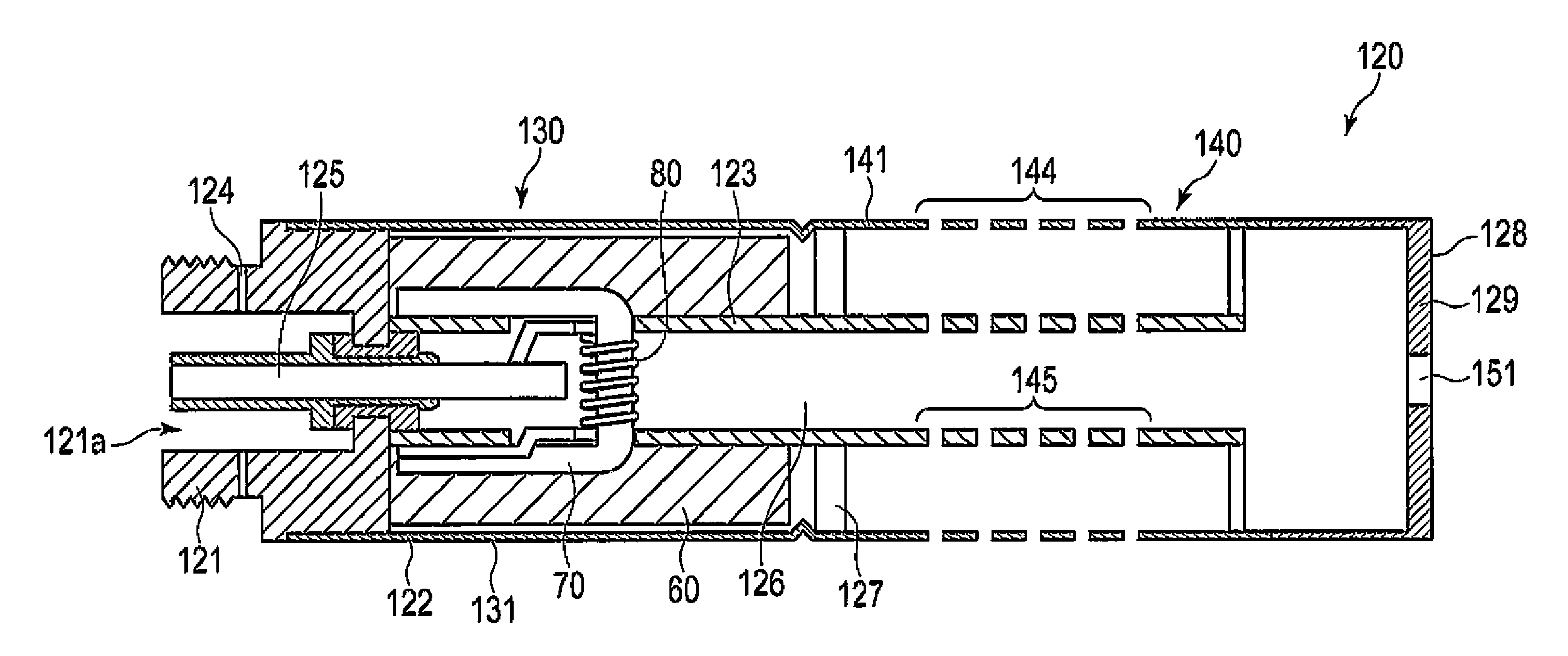
제1 실시형태를 도 1 및 도 2를 참조하여 설명한다. 도 1은, 제1 실시형태에 따른 비연소형 향미 흡인기(100)를 나타내는 개략 단면도이다. 도 2는, 도 1에 나타내는 아토마이저부(120)를 나타내는 확대 단면도이다.A first embodiment will be described with reference to FIGS. 1 and 2. 1 is a schematic cross-sectional view showing a non-combustion
도 1에서, 비연소형 향미 흡인기(100)는 전원부(110)와, 전원부(110)의 예를 들면 흡구단측에 배치되는 아토마이저부(120)를 구비한다. 전원부(110)는, 비(非) 흡구단을 가지며 그 타단에 제1 접속부(111)를 가진다. 아토마이저부(120)는, 흡구단(128)을 가지며, 그 타단에 제2 접속부(121)를 가진다. 제1 접속부(111) 및 제2 접속부(121)에는, 예를 들면, 각각 서로 나사결합 가능한 암나사 및 수나사가 형성되어 있다. 전원부(110)와 아토마이저부(120)는, 제1 접속부(111) 및 제2 접속부(121)를 통하여 서로 착탈 가능한 구조로 되어 있다.In FIG. 1, the non-combustion
아토마이저부(120)는, 도 2에 나타내는 바와 같이, 예를 들면, 원통 모양의 제2 케이스(122)를 구비한다. 원통 모양의 제2 케이스(122)의 일단은, 개구단(開口端)을 예를 들면 제2 케이스(122)와 일체화된 벽부(129)로 봉지(封止)하여 규정되는 흡구단(128)이 형성되고, 타단은 제2 접속부(121)가 형성되어 있다. 제2 케이스(122) 내에는, 에어로졸 발생 유닛(130) 및 향미 발생 유닛(140)이 제1 접속부측으로부터 이 순서로 배치되어 있다.As shown in FIG. 2, the
제2 접속부(121)인 암나사는, 축방향으로 도려내진 오목부(121a)를 가진다. 외기(外氣)를 제1 유로로 취입하기 위한 복수의 공기 취입 구멍(124)은, 제2 접속부(121)에 그 외주면으로부터 오목부(121a)에 이르도록 개구되어 있다. 제2 케이스(122) 내에는, 제2 접속부(121)의 중앙 부분을 관통하여 전원부(110) 내와 연통하는, 관체(管體)로 이루어지는 제4 유로(125)가 마련되어 있다. 제2 케이스(122) 내의 중앙에는, 제2 접속부(121)로부터 흡구단으로 향하여 연출(延出)되고, 제4 유로(125)와 연통하는 원통 모양의 제1 격벽(123)이 설치되어 있다. 제1 격벽(123) 내에는, 제1 유로(126)가 형성된다. 제2 케이스(122)의 흡구단(128)의 벽부(129)의 중앙에는, 사용자가 향미 흡인기(100) 내의 기체를 흡인하기 위한 제1 흡인 구멍(151)이 개구되어 있다. 제1 흡인 구멍(151)은, 제1 유로(126)와 연통하고 있다.The female screw serving as the second connecting
에어로졸 발생 유닛(130)은, 예를 들면, 제2 케이스(122) 내의 제2 접속부(121)측에 배치된다. 해당 제2 케이스(122) 내에는, 에어로졸원 수용부(131), 유지체(60), 흡수체(70) 및 에어로졸 발생 기구(80)가 배치되어 있다. 에어로졸원 수용부(131)는, 예를 들면, 외벽이 제2 케이스(122), 내벽이 제1 격벽(123), 비 흡구단측의 단(端)이 제2 접속부(121), 흡구단측의 단이 제2 격벽(127)으로 규정되는 원통 모양을 이루며, 원통 모양의 유지체(60)를 수납하고 있다. 유지체(60)는, 예를 들면 다공질 수지 또는 발포 수지로 만들어져, 에어로졸원을 유지, 수용하고 있다.The
에어로졸원은, 에어로졸 발생 기구(80)에 의해 에어로졸을 발생하면 특별히 한정되지 않지만, 예를 들면, 글리세린 또는 프로필렌글리콜 등의 에어로졸 형성체, 그 외 물, 용매, 에탄올, 식물 엑기스, 천연 또는 인공의 향미료(예를 들면, 멘톨)를 이용할 수 있다. 에어로졸원은, 담배 풍미 함유 화합물 또는 니코틴 함유재 재료를 함유해도 된다.The aerosol source is not particularly limited as long as the aerosol is generated by the
흡수체(70)는, 예를 들면, U자 모양을 이루며, 양단이 에어로졸원 수용부(131) 내에 유지되며, 또 중앙 부분이 제4 유로(125)인 관체의 선단에 근접해서 배치되어 있다. 흡수체(70)는, 예를 들면, 유리 섬유의 다발로 이루어지며, 유지체(60)에 유지된 액체의 에어로졸원이 모세관 현상에 의해 이동된다.The
에어로졸 발생 기구(80)는, 에어로졸원으로부터 에어로졸을 발생시키는 기구이면 되고, 예를 들면 에어로졸원을 가열하여 에어로졸을 발생하는 기구를 이용할 수 있다. 에어로졸 발생 기구(80)는, 예를 들면, 제1 가열 요소이다. 제1 가열 요소(80)는, 예를 들면, 흡수체(70)에 감긴 코일 히터로 이루어지며, 예를 들면, 스테인리스강, 구리, 구리 합금, 니켈 크롬 합금, 초합금으로 이루어진다. 제1 가열 요소(80)는, 에어로졸원으로부터 에어로졸을 발생할 수 있는 온도, 예를 들면, 150℃~350℃로 가열된다. 제1 가열 요소(80)는, 예를 들면, 향미 흡인기에 부설한 다이얼 조작으로, 제1 가열 요소(80)에 인가하는 전압을 조절하는 구조의 것을 이용할 수 있다.The
향미 발생 유닛(140)은, 예를 들면, 제2 케이스(122) 내의 에어로졸 발생 유닛(130)과 흡구단 사이에 배치되어, 향미원 수용부(141)를 구비한다. 향미원 수용부(141)는, 예를 들면, 외벽이 제2 케이스(122), 내벽이 제1 격벽(123), 제2 접속부측의 단이 제2 격벽(127) 및 흡구단측에 위치하는 격벽으로 둘러싸이며, 향미를 발생하는 향미원이 수용된다. 해당 제2 케이스(122) 부분에는, 외부와 연통하는 적어도 하나의 구멍, 예를 들면 복수의 구멍으로 이루어지는 제2 유로(144)가 마련되어 있다. 해당 원통 모양의 제1 격벽(123) 부분에는, 제1 유로(126)와 연통하는 복수의 구멍으로 이루어지는 제3 유로(145)가 마련되어 있다. 제2 유로(144) 및 제3 유로(145)는, 바람직하게는 향미 투과성 부재(도시하지 않음)를 구비한다. 향미 투과성 부재는, 예를 들면, 다수의 미세 구멍이 개공된 다공질 막이며, 예를 들면 입상(粒狀)의 향미원이 외부로 유출되는 것을 방지한다.The flavor generating
향미원 수용부(141) 내의 향미원은, 물리적 파쇄에 의해 발생하는 향미의 양 또는 종류를 조절할 수 있는 것이어도 된다. 예를 들면, 인공 또는 천연의 향미료를 내포하는 복수의 캡슐이어도 된다. 이 경우, 캡슐을 향미원 수용부(141)에 수용하여, 제2 유로(144)가 마련되는 제2 케이스(122) 부분을 유연성 재료로 형성한다. 이러한 구성에서, 사용자는 제2 유로(144)가 마련되는 제2 케이스(122) 부분을 손가락 등으로 압압(押壓)하는 것에 의해, 향미원 수용부(141) 내의 향미원인 캡슐을 파쇄하여 향미를 발생시킬 수 있다. 사용자는 파쇄하는 캡슐의 종류와 양을 선택하는 것에 의해, 발생하는 향미의 성분과 양을 조절할 수 있다. 캡슐은, 손가락 등으로 압압하는 대신에 초음파 등의 자극에 의해 파쇄하여 내포하는 향미를 발생해도 된다. 향미원은, 예를 들면, 붕괴성이 높은 과립·정제 등의 형상으로 성형하며, 필요에 따라 부형제·코팅 소재를 첨가한 것을 비벼 으깸으로써, 발생하는 향미의 양을 조절해도 된다.The flavor source in the flavor source accommodating
그 외의 향미원은, 향미원 수용부 내를 공기가 투과할 수 있는 고체 모양의 물질로, 예를 들면, 식물 원체(原體), 식물 엑기스, 니코틴, 멘톨, 천연 또는 인공의 향미료를 함유한다. 구체적으로는, 살담배, 담배 원료를 입상으로 한 성형체, 각종 향미료를 입상으로 한 성형체, 담배 원료를 시트 모양으로 성형한 성형체, 담배 이외의 식물 원체(예를 들면, 민트, 허브 등)를 들 수 있다. 성형체 이외에, 예를 들면, 식물 엑기스, 천연 또는 인공의 향미료를 함침시킨 입상의 흡착제를 들 수 있다.Other flavor sources are solid substances that allow air to permeate the interior of the flavor source, for example, plant sources, plant extracts, nicotine, menthol, and natural or artificial flavors. . Specifically, a molded body made of sage tobacco, a tobacco raw material granularly, a molded body made of various flavors into a granular shape, a molded product made of tobacco raw material into a sheet shape, and plant raw materials other than tobacco (e.g., mint, herb, etc.) are exemplified. have. In addition to the molded body, for example, a granular adsorbent impregnated with plant extracts and natural or artificial flavors can be mentioned.
상술한 전원부(110)는, 도 1에 나타내는 바와 같이 예를 들면, 원통 모양의 제1 케이스(112)를 구비한다. 제1 케이스(112) 내에는, 스위치(30), 발광 소자(40), 제어 회로(50), 전원(10) 및 센서(20)가 비 흡구단측으로부터 이 순서로 배치되어 있다.As shown in FIG. 1, the
전원(10)은, 예를 들면, 리튬이온 이차 전지이며, 센서(20), 발광 소자(40), 제어 회로(50) 및 제1 가열 요소(80)에 전기적으로 접속되어 있다. 센서(20)는, 사용자의 흡인 동작에 의해 생기는 향미 흡인기(100) 내의 기류를 검출하는, 예를 들면 흡구단을 향하여 기체가 흡인되는 것에 의해 생기는 부압(負壓)을 검출하는 압전 소자를 이용할 수 있다. 스위치(30)는, 예를 들면, 비 흡구단에 배치되어, 전원부(110)의 길이방향에 대해 압입함으로써 조작하는 누름 버튼이며, 향미 흡인기(100)의 전원(10)을 온 상태 또는 오프 상태로 한다. 발광 소자(40)는, 제1 케이스(112)의 외주면의 비 흡구단측에 매립되는, 예를 들면 발광 다이오드이며, 발광 패턴 또는 발광 색에 의해 향미 흡인기(100)의 상태를 사용자에 대하여 통지한다. 구체적으로는, 전원(10)이 온 상태일 때에 점등하고, 오프 상태일 때에 소등한다. 제어 회로(50)는, 예를 들면, 전원(10), 센서(20), 스위치(30), 발광 소자(40) 및 제1 가열 요소(80)에 접속되며, 예를 들면 센서(20)의 검출에 근거하여 제1 가열 요소(80)를 피드백 제어하거나, 발광 소자(40)의 발광 패턴을 제어하거나 한다.The
다음으로, 상기 구성의 향미 흡인기(100)의 작용을 도 1~3을 참조하여 설명한다. 사용자는, 향미 흡인기(100)의 전원(10)을 스위치(30)로 온 상태로 하고, 흡구단측을 입에 물고 사용한다.Next, the operation of the
도 3의 (a)에 나타내는 바와 같이, 사용자가 향미 흡인기(100) 내의 기체를 흡인하고 있지 않을 때(비 퍼프시), 향미원 수용부(141)에 수용된 향미원으로부터 제2 유로(144)를 통해 향미(161)가 외부로 유출된다. 향미 흡인기(100)를 문 사용자는, 유출된 향미(161)가 코에 감돌기 때문에, 그 향미(161)를 후각으로 맛볼 수 있다.As shown in FIG. 3A, when the user is not sucking gas in the flavor aspirator 100 (when non-puffing), the
도 3의 (b)에 나타내는 바와 같이, 사용자가 향미 흡인기(100) 내의 공기를 흡인할 때(퍼프시), 센서(20)가 흡인 동작을 검출하여, 그 검출 신호가 입력된 제어 회로(50)로부터, 제1 가열 요소(80)에 제어 신호가 출력되어, 해당 제1 가열 요소(80)를 가열한다. 제1 가열 요소(80)의 가열에 의해, 흡수체(70)에 유지되는 에어로졸원으로부터 에어로졸이 발생한다. 또한, 사용자의 흡인 동작에 수반하여, 공기가 에어로졸 발생 유닛의 공기 취입 구멍(124) 및 제4 유로(125)를 통해서, 제1 유로(126)에 유입된다. 이때, 제1 유로(126)에서, 제1 흡인 구멍(151)을 향하는 제1 기류(162)가 발생한다. 에어로졸원으로부터 발생한 에어로졸은, 제1 기류(162)에 동반되어 제1 흡인 구멍(151)으로 유출된다. 동시에, 제1 유로(126) 및 제3 유로(145)를 통해서 연통하는 향미원 수용부(141) 내가 부압으로 되기 때문에, 외부의 공기가 제2 유로(144), 향미원 수용부(141) 및 제3 유로(145)를 통해서 제1 유로(126)로 유입하는 제2 기류(163)가 발생한다. 이에 의해, 향미원 수용부(141) 내의 향미원으로부터 발생한 향미는, 제2 기류(163)에 동반되어, 제1 흡인 구멍(151)으로 유출된다. 그 결과, 에어로졸과 향미의 혼합 기체가 제1 흡인 구멍(151)을 통과하여 사용자의 구강으로 흡인된다.As shown in Fig. 3(b), when the user sucks air in the flavor aspirator 100 (when puffing), the
제1 실시형태에 의하면, 향미 흡인기(100)를 무는 사용자는 비 퍼프시에 있어서, 향미원 수용부(141) 내의 향미원으로부터 향미가 제2 유로(144)를 통한 외부로 유출되어, 코에 감돌기 때문에, 그 향미를 후각으로 맛볼 수 있다. 한편, 사용자는 퍼프시에 있어서, 향미원으로부터 향미가 제2 유로(144)를 통해서 외부로 유출되는 일없이, 구강만으로 향미와 에어로졸원으로부터 발생한 에어로졸의 혼합 기체를 흡인할 수 있다. 그 결과, 사용자는 코로부터의 향미에 의한 후각 자극에 노출되는 일없이, 다시 말해 향미에 의한 자극으로 코의 후각이 둔화하는 일없이, 구강으로부터의 향미와 에어로졸에 의한 미각 및 후각의 자극을 즐길 수 있다.According to the first embodiment, the user who bites the
또한, 제1 실시형태에 따른 향미 흡인기(100)는, 에어로졸 발생 유닛(130)과는 별개로 향미 발생 유닛(140)을 구비하기 때문에, 향미원 수용부(141)에는 제1 가열 요소(80)의 온도에서는 파괴되는 성분의 향미원을 수용할 수 있다. 그 결과, 사용자는 다양한 향미를 흡인할 수 있다.In addition, since the
제1 실시형태는, 상술한 구성 외에, 이하에 설명하는 다양한 형태를 채용할 수 있다.In addition to the above-described configuration, the first embodiment can adopt various forms described below.
에어로졸원에는 맛이나 자극에 기여하는 체성(體性) 감각 기여 성분만을 함유시키고, 향미원에만 향미를 함유하는 구성으로 할 수 있다. 이 구성에서는, 에어로졸에는 향미에 기여하는 성분을 함유하지 않기 때문에, 주위에 향미를 확산시키지 않고 사용자만 향미를 맛볼 수 있다.The aerosol source may contain only somatosensory contributing components that contribute to taste or stimulation, and the aerosol source may be configured to contain flavor only from the flavor source. In this configuration, since the aerosol does not contain components that contribute to the flavor, only the user can taste the flavor without spreading the flavor around it.
제2 유로는, 사용자의 코측에만 마련되는 것이 바람직하다. 이 구성에 의하면, 향미원으로부터 발생하는 향미가 주위로 불필요하게 확산하는 것을 방지할 수 있어, 사용자의 후각만을 효율적으로 자극할 수 있다.It is preferable that the second flow path is provided only on the nose side of the user. According to this configuration, it is possible to prevent unnecessarily spreading of the flavor generated from the flavor source to the surroundings, so that only the user's sense of smell can be efficiently stimulated.
제2 케이스 내에 수납된 에어로졸 발생 유닛 및 향미 발생 유닛은 착탈 가능한 구조로 할 수 있다. 이에 의해, 예를 들면, 향미원이 감소하였을 때에 2개의 유닛을 교환하지 않고 향미 발생 유닛만을 교환하여 대응할 수 있다.The aerosol generating unit and the flavor generating unit accommodated in the second case may have a detachable structure. Thereby, for example, when the flavor source decreases, it is possible to respond by replacing only the flavor generating unit without replacing the two units.
제3 유로는, 제1 격벽(123)측에 한하지 않고, 예를 들면, 향미원 수용부의 흡구단에 대향하는 측벽에 복수의 구멍으로서 개공하고 있어도 된다.The third flow path is not limited to the
아토마이저부에서, 향미 발생 유닛은 에어로졸 발생 유닛보다 흡구단측에 배치되어 있지만, 이것으로 한정되지 않는다. 예를 들면, 아토마이저부에서, 에어로졸 발생 유닛은 향미 발생 유닛보다 흡구단측에 배치해도 된다.In the atomizer portion, the flavor generating unit is disposed on the intake end side than the aerosol generating unit, but is not limited thereto. For example, in the atomizer unit, the aerosol generating unit may be disposed on the intake end side rather than the flavor generating unit.
에어로졸 발생 유닛은, 유지체와, 흡수체와, 제1 가열 요소를 구비하는 구성으로 했지만, 이것으로 한정되지 않는다. 예를 들면, 제1 가열 요소는, 코일 히터 대신에 블레이드 히터를 이용하고, 해당 블레이드 히터인 제1 가열 요소를 삽입한 살담배인 에어로졸원을 가열해도 된다.Although the aerosol generating unit has a structure including a holding body, an absorber, and a first heating element, it is not limited thereto. For example, as the first heating element, a blade heater may be used instead of a coil heater, and an aerosol source, which is an aerosol to which the first heating element, which is the blade heater, is inserted may be heated.
제1 흡인 구멍에 연통하는 제1 유로에 필터를 더 구비하고 있어도 된다. 필터는, 담배의 필터를 이용할 수 있으며, 예를 들면 아세테이트 필터이다. 제1 유로에 이와 같이 필터를 설치하는 것에 의해, 사용자의 입에 이물이 혼입하는 것을 방지할 수 있다.A filter may be further provided in the first flow path communicating with the first suction hole. As the filter, a cigarette filter can be used, for example an acetate filter. By providing the filter in the first flow path in this way, it is possible to prevent foreign matters from entering the user's mouth.
제1 가열 요소는, 사용자가 향미 흡인기를 흡인했을 때에 가열하는 구성으로 했지만, 이것으로 한정되지 않는다. 예를 들면, 제1 가열 요소는, 전원을 온 상태로 한 후 연속하여 가열하는 구성인 경우, 안정적으로 향기를 발생할 수 있다.Although the 1st heating element was made into the structure which heated when the user sucked in the flavor aspirator, it is not limited to this. For example, when the first heating element is configured to continuously heat after turning on the power, it can stably generate a fragrance.
(제2 실시형태)(2nd embodiment)
제2 실시형태에 따른 비연소형 향미 흡인기를 도 4를 참조하여 설명한다. 도 4는 향미 흡인기의 아토마이저부의 향미 발생 유닛을 나타내는 단면도이다. 제2 실시형태에 따른 향미 흡인기는, 아토마이저부의 향미 발생 유닛 이외, 제1 실시형태에서 설명한 도 1 및 도 2와 같다.A non-combustible flavor aspirator according to the second embodiment will be described with reference to FIG. 4. 4 is a cross-sectional view showing a flavor generating unit of an atomizer portion of a flavor aspirator. The flavor aspirator according to the second embodiment is the same as in FIGS. 1 and 2 described in the first embodiment other than the flavor generating unit of the atomizer unit.
향미 발생 유닛(240)은, 원통 모양의 제2 케이스(222) 내에 제2 접속부로부터 흡구단(228)에 이르는 원통 모양의 제1 격벽(223)을 구비하고 있다. 흡구단(228)은, 제2 케이스(222)의 개구단을 예를 들면 제2 케이스(222)와 일체화된 벽부(229)로 봉지하여 규정된다. 원통 모양의 제1 격벽(223) 내는, 제1 유로(226)로서 기능한다. 향미원 수용부(241)는, 예를 들면, 외벽이 제2 케이스(222), 내벽이 제1 격벽(223), 제2 접속부측의 단이 제2 격벽(227), 그 타단이 흡구단(228)으로 둘러싸이며, 향미를 발생하는 향미원이 수용된다.The
향미원 수용부(241)에 대응하는 제2 케이스(222) 부분에는, 외부와 연통하는 복수의 구멍으로 이루어지는 제2 유로(244)가 마련되어 있다. 제2 케이스(222)의 흡구단(228)을 규정하는 벽부(229)의 중앙(제1 유로(226)와 대향하는 개소)은, 사용자가 흡인하기 위한 제1 흡인 구멍(251)이 개구되어 있다. 해당 벽부(229)의 향미원 수용부(241)에 대응하는 개소에는, 향미원 수용부(241)로부터 흡구단(228)을 향하는, 외부와 연통하는 복수의 구멍으로 이루어지는 제3 유로(252)가 마련되어 있다. 제3 유로(252)는, 제2 흡인 구멍을 겸한다.In the portion of the
다음으로, 상기 구성의 향미 흡인기의 작용을 도 4를 참조하여 설명한다. 사용자는, 향미 흡인기의 전원(10)을 스위치(30)로 온 상태로 하고, 흡구단측을 입에 물고 사용한다.Next, the operation of the flavor aspirator of the above configuration will be described with reference to FIG. 4. The user turns on the
비 퍼프시에는, 향미원 수용부(241)에 수용된 향미원으로부터 제2 유로(244)를 통해 향미가 외부로 유출된다. 향미 흡인기를 무는 사용자는, 유출된 향미가 코에 감돌기 때문에, 그 향미를 후각으로 맛볼 수 있다.During the non-puff, flavor is discharged from the flavor source accommodated in the flavor source
한편, 퍼프시에는 사용자의 흡인 동작에 수반하여, 공기가 에어로졸 발생 유닛의 공기 취입 구멍(124) 및 제4 유로(125)를 통해서, 제1 유로(226)에 유입된다. 이때, 제1 유로(226)에서, 제1 흡인 구멍(251)을 향하는 제1 기류(262)가 발생한다. 에어로졸원으로부터 발생한 에어로졸은, 제1 기류(262)에 동반되어 제1 흡인 구멍(251)으로 유출된다. 동시에, 사용자가 제2 흡인 구멍을 겸하는, 제3 유로(252)를 통해 흡입하는 것에 의해, 향미원 수용부(241) 내가 부압이 되기 때문에 외부의 공기가 제2 유로(244)를 통해서 향미원 수용부(241)로 유입되는 제2 기류(263)가 발생한다. 이에 의해, 향미원 수용부(241) 내의 향미원으로부터 발생한 향미는, 제2 기류(263)에 동반되어, 제2 유로(244)를 통해서 제3 유로(제2 흡인 구멍)(252)로 유출된다. 그 결과, 에어로졸 및 향미가, 제1 흡인 구멍(251) 및 제3 유로(제2 흡인 구멍)(252)를 통해 사용자의 구강으로 흡인된다.On the other hand, during puffing, air is introduced into the
따라서, 제2 실시형태에 의하면 제1 실시형태와 마찬가지로, 비 퍼프시에 향미에 의한 사용자의 후각을 자극할 수 있고, 또 퍼프시에 향미에 의한 사용자의 미각 및 후각을 자극할 수 있는 효과를 나타낸다.Therefore, according to the second embodiment, as in the first embodiment, it is possible to stimulate the user's sense of smell by flavor at the time of non-puff, and the effect of stimulating the user's sense of taste and sense of smell by the flavor at the time of puff. Show.
또한, 제2 유로(244) 및 제3 유로(252)에 향미 투과성 부재를 설치하는 것에 의해, 사용자가 향미 흡인기를 흡인할 때 향미원이 구강 내로 유출되는 것을 방지할 수 있다.In addition, by providing the flavor permeable member in the
(제3 실시형태)(3rd embodiment)
제3 실시형태에 따른 비연소형 향미 흡인기를 도 5를 참조하여 설명한다. 도 5는 향미 흡인기의 아토마이저부의 향미 발생 유닛을 나타내는 단면도이다. 제3 실시형태에 따른 향미 흡인기는, 아토마이저부의 향미 발생 유닛 이외, 제2 실시형태에서 설명한 도 1 및 도 2와 같다.A non-combustible flavor aspirator according to a third embodiment will be described with reference to FIG. 5. 5 is a cross-sectional view showing a flavor generating unit of an atomizer portion of a flavor aspirator. The flavor aspirator according to the third embodiment is the same as in FIGS. 1 and 2 described in the second embodiment other than the flavor generating unit of the atomizer unit.
향미 발생 유닛(340)은, 원통 모양의 제2 케이스(322) 내에 제2 접속부로부터 흡구단에 이르는 원통 모양의 제1 격벽(323)을 구비하고 있다. 흡구단(328)은, 제2 케이스(322)의 개구단을 예를 들면 제2 케이스(322)와 일체화된 벽부(329)로 봉지하여 규정된다. 벽부(329)는, 환상(環狀) 구멍(352)이 개구되어 있다. 향미원 수용부(341)는, 예를 들면, 외벽이 제2 케이스(322), 내벽이 제1 격벽(323), 제2 접속부측의 단이 제2 격벽(327), 흡구단(328)으로부터 원하는 거리 떨어져서 규정되는 원통체이며, 향미원이 수납되어 있다. 원하는 두께를 가지는 원통 모양의 필터(343)는, 제2 케이스(322)와 제1 격벽(323) 사이, 및 향미원 수용부(341)와 흡구단(328) 사이에 배치되어 있다. 필터(343)는, 일단이 향미원 수용부(341)에 위치하고, 타단이 벽부(329)의 환상 구멍(352) 내에 위치하며, 향미원 수용부(341) 내로부터 흡구단(328)으로 향하는 제3 유로를 구성하고 있다. 원통 모양의 제1 격벽(323) 내에는, 제1 유로(326)가 형성되어 있다. 제2 케이스(322)의 흡구단(328)을 규정하는 벽부(329)의 환상 구멍(352)으로 둘러싸인 부분(제1 유로(326)와 대향하는 개소)은, 사용자가 흡인하기 위한 제1 흡인 구멍(351)이 개구되어 있다. 또한, 벽부(329)의 환상 구멍(352) 내에 위치하는 필터(343)의 타단은, 제2 흡인 구멍으로서 기능한다.The
필터(343)는, 통기성을 가지는 재료로 이루어지며, 향미원 수용부(341) 내의 향미원이 유출되지 않을 정도의 조밀도를 가지는 것이 바람직하다. 필터(343)는, 담배의 필터와 동일한 것, 예를 들면 아세테이트 필터를 이용할 수 있다.The
다음으로, 상기 구성의 향미 흡인기의 작용을 도 5를 참조하여 설명한다. 사용자는, 향미 흡인기의 전원(10)을 스위치(30)로 온 상태로 하고, 흡구단(328)측을 입에 물고 사용한다.Next, the operation of the flavor aspirator of the above configuration will be described with reference to FIG. 5. The user turns on the
비 퍼프시에는, 향미원 수용부(341)에 수용된 향미원으로부터 제2 유로(344)를 통해 향미가 외부로 유출된다. 향미 흡인기를 무는 사용자는, 유출된 향미가 코에 감돌기 때문에, 그 향미를 후각으로 맛볼 수 있다.During the non-puff, flavor flows out from the flavor source accommodated in the flavor source
퍼프시에는, 사용자의 흡인 동작에 수반하여, 공기가 에어로졸 발생 유닛의 공기 취입 구멍(124) 및 제4 유로(125)를 통해, 제1 유로(326)에 유입된다. 이때, 제1 유로(326)에서, 제1 흡인 구멍(351)으로 향하는 제1 기류(362)가 발생한다. 에어로졸원으로부터 발생한 에어로졸은, 제1 기류(362)에 동반되어 제1 흡인 구멍(351)으로 유출된다. 동시에, 사용자가 제2 흡인 구멍을 겸하는, 필터(제3 유로)(343)를 통해 흡입하는 것에 의해, 향미원 수용부(341) 내가 부압이 되기 때문에, 외부의 공기가 제2 유로(344)를 통해 향미원 수용부(341)로 유입되는 제2 기류(363)가 발생한다. 이에 의해, 향미원 수용부(341) 내의 향미원으로부터 발생한 향미는, 제2 기류(363)에 동반되어, 제3 유로인 필터(343)를 통해 그 타단(제2 흡인 구멍)으로 유출된다. 그 결과, 에어로졸 및 향미가, 제1 흡인 구멍(351) 및 제2 흡인 구멍을 통과하여 사용자의 구강으로 흡인됨과 함께, 제2 기류(363)가 필터(343)를 통해 사용자의 구강에 흡인되기 때문에, 향미원이 사용자의 구강으로 유출되는 것이 방지된다.At the time of puffing, air is introduced into the
따라서, 제3 실시형태에 의하면 제1 실시형태와 마찬가지로, 비 퍼프시에 향미에 의한 사용자의 후각을 자극할 수 있고, 또 퍼프시에 향미에 의한 사용자의 미각 및 후각을 자극할 수 있는 효과를 나타낸다.Therefore, according to the third embodiment, as in the first embodiment, it is possible to stimulate the user's sense of smell by flavor at the time of non-puff, and the effect of stimulating the user's sense of taste and sense of smell by the flavor at the time of puff. Show.
(제4 실시형태)(4th embodiment)
제4 실시형태에 따른 비연소형 향미 흡인기를 도 6을 참조하여 설명한다. 도 6은 향미 흡인기의 아토마이저부의 향미 발생 유닛을 나타내는 단면도이다. 제4 실시형태에 따른 향미 흡인기는, 제2 가열 요소를 더 구비하는 이외, 제3 실시형태에서 설명한 도 5와 같다. 또한, 도 6에서, 도 5와 같은 부재는 동일 부호를 붙이고 설명을 생략한다.A non-combustible flavor aspirator according to the fourth embodiment will be described with reference to FIG. 6. 6 is a cross-sectional view showing a flavor generating unit of an atomizer portion of a flavor aspirator. The flavor aspirator according to the fourth embodiment is the same as in Fig. 5 described in the third embodiment, except that a second heating element is further provided. In addition, in Fig. 6, the same members as in Fig. 5 are denoted by the same reference numerals, and descriptions thereof are omitted.
향미 발생 유닛(340)은, 향미원 수용부(341) 내의 향미원을 가열하기 위한 제2 가열 요소(370)를 구비하고 있다. 제2 가열 요소(370)는, 예를 들면, 원통 모양을 이루며, 향미원 수용부(341)를 구획하는 제1 격벽(323)의 향미원 수용부(341)의 대부분에 대응하는 내주면에 접해서 배치되어 있다. 상술한 전원(10)은, 제2 가열 요소(370)에 접속되어 있다.The
제2 가열 요소(370)는, 향미원 수용부(341) 내의 향미원의 종류에 따른 온도로 가열되고, 예를 들면 제1 가열 요소(80)보다 낮은 온도(실온에서부터 250℃)로 가열된다. 제2 가열 요소(370)는, 예를 들면, 전원(10)이 온 상태에서, 센서(20)가 흡인 동작을 검출하고, 그 검출 신호가 제어부에 출력되었을 때, 해당 제어부로부터 전원(10)에 제어 신호가 출력되면 가열된다.The
제2 가열 요소(370)는, 사용자의 조작에 의해 온 오프 가능하게 구성되는 것이 바람직하다. 제2 가열 요소(370)는, 예를 들면, 향미 흡인기에 더 구비되는 다이얼을 조작함으로써, 인가하는 전압을 조작하여 가열 온도를 조절할 수 있는 구성으로 하는 것이 바람직하다.It is preferable that the
향미원은, 이하에 설명하는 다양한 태양(態樣)을 가진다.Flavor source has various aspects described below.
(1) 향미원은, 제1 실시형태에서 설명한 것과 동일한 것을 이용할 수 있다.(1) As the flavor source, the same ones as described in the first embodiment can be used.
(2) 향미원은, 향미료를 내포하는 열파쇄성(熱破碎性) 소재의 캡슐을 이용할 수 있다. 열파쇄하는 온도가 다른 캡슐을 복수개 조합하여, 캡슐이 내포하는 향미료를 복수 종류 조합하는 것이 가능하다.(2) As the flavor source, a capsule made of a heat crushable material containing a flavor may be used. It is possible to combine a plurality of capsules having different temperatures for thermal crushing, and to combine a plurality of types of flavors contained in the capsules.
(3) 향미원은, 향미료를 내포하는 액체 파쇄성 캡슐과, 가열에 의해 물 등의 액체를 방출하는 흡착체의 혼합물이어도 된다.(3) The flavor source may be a mixture of a liquid crushable capsule containing a flavoring agent and an adsorbent that releases a liquid such as water by heating.
(4) 향미원은, 제2 가열 요소(370)의 가열 온도에 따라 열분해되어 향미가 생성되는 향기 전구체(前驅體)를 함유해도 된다. 향기 전구체로서는, 예를 들면, 식물 원체, 식물 엑기스, 배당체(配糖體), 에스테르, 열에 불안정한 분자량이 큰 화합물(멜라노이딘, 당단백질 등)을 들 수 있다.(4) The flavor source may contain a fragrance precursor that is thermally decomposed according to the heating temperature of the
(5) 향미원은, 향미료를 함침시킨 열탈착(熱脫着) 속도가 다른 흡착제여도 된다. 흡착제로서는, 예를 들면, 폴리스티렌 등의 수지제 흡착제, 활성탄 또는 무기 광물을 이용할 수 있다.(5) The flavor source may be an adsorbent having a different thermal desorption rate impregnated with a flavoring agent. As the adsorbent, for example, a resin adsorbent such as polystyrene, activated carbon or inorganic minerals can be used.
(6) 향미원은, 열분해되어 향미가 되는 관능기를 구비하는 폴리머여도 된다. 폴리머는, 예를 들면 셀룰로오스, 폴리비닐알코올, 아크릴산 폴리머의 알코올에 에스테르 결합·에테르 결합을 통하여 카복실산·알코올을 가지는 향료 성분을 담지시킨 것을 들 수 있다.(6) The flavor source may be a polymer having a functional group that is thermally decomposed to become a flavor. Examples of the polymer include cellulose, polyvinyl alcohol, and a perfume component having a carboxylic acid/alcohol supported on an alcohol of an acrylic acid polymer through an ester bond or an ether bond.
다음으로, 상기 구성의 제4 실시형태에 따른 향미 흡인기의 작용을 도 6을 참조하여 설명한다.Next, the operation of the flavor aspirator according to the fourth embodiment of the configuration will be described with reference to FIG. 6.
사용자는, 향미 흡인기의 전원(10)을 스위치(30)로 온 상태로 하고, 흡구단측을 입에 물고 사용한다. 예를 들면, 스위치가 온 상태일 때, 제어 회로(50)로부터 제2 가열 요소(370)에 제어 신호가 출력되어, 해당 제2 가열 요소(370)를 가열한다.The user turns on the
비 퍼프시에는, 향미원 수용부(341)에 수용된 향미원으로부터 제2 유로(344)를 통해 향미가 외부로 유출된다. 이때, 향미원으로부터 발생하는 향미의 발생량 및 성분은, 제2 가열 요소(370)의 가열 온도에 의해 조절할 수 있다. 향미 흡인기를 무는 사용자는, 유출된 향미가 코에 감돌기 때문에, 그 조절된 향미를 후각으로 맛볼 수 있다.During the non-puff, flavor flows out from the flavor source accommodated in the flavor source
한편, 퍼프시에는 사용자의 흡인 동작에 수반하여, 에어로졸원으로부터 발생한 에어로졸은, 제1 기류(362)에 동반되어 제1 흡인 구멍(351)으로 유출된다. 동시에, 향미원 수용부(341) 내의 향미원으로부터 발생한 향미는, 제2 기류(363)에 동반되어, 제3 유로인 필터(343)를 통해 그 타단(제2 흡인 구멍)으로 유출된다. 그 결과, 에어로졸 및 향미는, 제1 흡인 구멍(351) 및 제2 흡인 구멍을 통과하여 사용자의 구강으로 흡인된다. 이때, 향미원으로부터 발생하는 향미의 발생량 및 성분은, 제2 가열 요소(370)의 가열 온도에 의해 조절할 수 있다. 그 때문에, 향미 흡인기를 무는 사용자는, 에어로졸과 그 조절된 최적량(最適量)의 향미를 후각 및 미각으로 느낄 수 있다.On the other hand, at the time of puffing, the aerosol generated from the aerosol source is accompanied by the
따라서, 제4 실시형태에 의하면 제1 실시형태와 마찬가지로, 비 퍼프시에 향미에 의한 사용자의 후각을 자극할 수 있고, 또 퍼프시에 향미에 의한 사용자의 미각 및 후각을 자극할 수 있는 효과를 나타낸다.Therefore, according to the fourth embodiment, as in the first embodiment, it is possible to stimulate the user's sense of smell by flavor at the time of non-puff, and the effect of stimulating the user's sense of taste and sense of smell by the flavor at the time of puffing. Show.
제2 가열 요소(370)의 가열 온도를 조절하고, 향미원을 상술한 (1)~(6)의 태양과 조합함으로써 향미원 수용부 내의 향미원으로부터의 향미 발생량 및 성분을 조절할 수 있다.By adjusting the heating temperature of the
제2 가열 요소(370)를 제1 유로(326) 내에 배치하고 있기 때문에, 제2 가열 요소(370)는 향미원을 가열함과 함께, 제1 기류(362)에 동반하는 에어로졸을 가열할 수 있다. 제2 가열 요소(370)는, 제1 기류(362)를 가열함으로써, 제1 기류(362)의 온도를 조절할 수 있고, 제1 기류(362)에 동반하는 에어로졸의 입자 지름을 작게 할 수 있다.Since the
향미원의 재치(載置) 안정성을 향상시킬 수 있다. 즉, 향미원으로부터 발생하는 향미가 휘발성이 높은 성분 또는 열화(劣化)되기 쉬운 성분이어도, 제2 가열 요소(370)로 가열할 때까지 누출 또는 열화시키지 않고 유지할 수 있다.It is possible to improve the stability of the flavor source. That is, even if the flavor generated from the flavor source is a highly volatile component or a component that is liable to deteriorate, it can be maintained without leakage or deterioration until heated by the
또한, 제4 실시형태에 따른 향미 흡인기의 향미원 수용부(341)에는, 에어로졸을 발생시키는 제1 가열 요소(80)의 온도에서는 파괴되고, 제2 가열 요소(370)의 가열 온도에서는 파괴되지 않는 성분의 향미원을 수용할 수 있다. 그 결과, 사용자는 다양한 향미를 흡인할 수 있다.In addition, in the flavor
또한, 제2 가열 요소는 제1 격벽의 내주면에 원통 모양으로 설치될 필요는 없고, 향미원을 가열할 수 있으면 된다. 제2 가열 요소는, 예를 들면 향미원 수용부 내에 배치해도 된다.Further, the second heating element does not need to be provided in a cylindrical shape on the inner peripheral surface of the first partition wall, and only needs to be able to heat the flavor source. The 2nd heating element may be arrange|positioned, for example in the flavor source accommodating part.
(제5 실시형태)(Fifth embodiment)
제5 실시형태에 따른 향미 흡인기를 도 7을 참조하여 설명한다. 도 7은 향미 흡인기의 아토마이저부의 향미 발생 유닛을 나타내는 단면도이다. 제5 실시형태에 따른 향미 흡인기는, 셔터를 더 구비하는 이외, 제3 실시형태에서 설명한 도 5와 같다. 또한, 도 7에서, 도 5와 같은 부재는 동일 부호를 붙이고 설명을 생략한다.A flavor aspirator according to a fifth embodiment will be described with reference to FIG. 7. 7 is a cross-sectional view showing a flavor generating unit of an atomizer portion of a flavor aspirator. The flavor aspirator according to the fifth embodiment is the same as in Fig. 5 described in the third embodiment, except that a shutter is further provided. Incidentally, in FIG. 7, the same members as in FIG. 5 are denoted by the same reference numerals and description thereof is omitted.
향미 발생 유닛(340)은, 제2 케이스(322)에 슬라이드 가능하게 설치되고, 해당 제2 케이스(322)에 개구된 제2 유로(344)를 개폐 가능한 원통 모양의 셔터(380)를 구비한다. 셔터(380)는, 예를 들면, 제2 케이스(322)의 외주면을 따른 원통 모양이며, 제2 유로(344)의 전면(全面)을 덮을 수 있는 길이를 가진다.The
셔터(380)는, 이하에 설명하는 도 7의 (a)~(c)에 나타내는 슬라이드 동작에 의해 향미원 수용부(341) 내의 향미원으로부터의 향미 발생량을 조절할 수 있다.The
도 7의 (a)에 나타내는 바와 같이, 셔터(380)를 후퇴시키면, 제2 유로(344)는 셔터(380)로 덮이지 않는다. 즉, 제2 유로(344)의 개구 면적이 최대인 상태가 된다. 그 때문에, 사용자가 향미 흡인기를 물고 있는 비 퍼프시에 있어서, 제2 유로(344)로부터 비교적 많은 양의 향미가 유출되기 때문에, 사용자의 후각을 다대하게 자극한다. 이에 대해, 사용자가 향미 흡인기를 물고 흡인하는 퍼프시에 있어서, 제2 유로(344)가 가장 열린 상태이기 때문에, 흡구단(328)으로부터 구강으로 유입되는 제1 기류(362)와 제2 기류(363a) 중 제2 기류(363a), 다시 말해, 제2 유로(344)로부터 향미원 수용부(341), 필터(제3 유로)(343)를 흐르는 기류의 비율은 최대가 된다.As shown in FIG. 7A, when the
도 7의 (b)에 나타내는 바와 같이 셔터(380)를 제2 유로(344)의 도중까지 전진시키면, 제2 유로(344)는 셔터(380)로 절반 정도 덮인다. 그 때문에, 사용자가 향미 흡인기를 물고 있는 비 퍼프시에 있어서, 제2 유로(344)로부터 유출되어 사용자의 후각을 자극하는 향미는 도 7의 (a)의 상태와 비교하여 반감된다. 또한, 사용자가 향미 흡인기를 물고 흡인하는 퍼프시에 있어서, 흡구단(328)으로부터 유출되는 제1 기류(362) 및 제2 기류(363b) 중, 제2 기류(363b)가 차지하는 비율은 도 7의 (a)의 상태와 비교하여 감소한다.When the
도 7의 (c)에 나타내는 바와 같이 셔터(380)를 더 전진시키면, 제2 유로(344)는 셔터(380)로 완전히 덮인다. 그 때문에, 사용자가 향미 흡인기를 물고 있는 비 퍼프시에 있어서, 제2 유로(344)로부터 향미가 유출되지 않기 때문에, 사용자의 후각을 자극하지 않는다. 사용자가 향미 흡인기를 물고 흡인하는 퍼프시에 있어서, 에어로졸을 동반하는 제1 기류(362)만이 흡구단으로부터 구강으로 유입되기 때문에, 사용자는 에어로졸만을 맛볼 수 있다. 또한, 셔터(380)에 의해 향미 흡인기의 불사용시에는 폐쇄하는 것에 의해, 향미원 수용부(341) 내의 향미원이 불필요하게 주위로 확산되는 것을 방지할 수 있다.When the
따라서, 셔터(380)를 제2 케이스(322)에 슬라이드 가능하게 설치하여 제2 유로(344)를 개폐하는 것에 의해, 비 퍼프시에 향미에 의한 사용자의 후각 자극을 조절할 수 있고, 또 퍼프시에 향미에 의한 사용자의 미각 및 후각의 자극을 조절할 수 있다.Therefore, by installing the
또한, 향미 발생 유닛은 도 6에 나타내는 제4 실시형태에 따른 향미 발생 유닛과 마찬가지로 제2 가열 요소를 구비하고 있어도 된다. 셔터의 개폐 상태, 및 제2 가열 요소의 가열 온도를 제어하는 것에 의해, 향미에 의한 비 퍼프시의 후각을 자극할 수 있고, 또 퍼프시에 미각 및 후각의 자극을 조절할 수 있다.In addition, the flavor generating unit may be provided with a second heating element similarly to the flavor generating unit according to the fourth embodiment shown in FIG. 6. By controlling the opening/closing state of the shutter and the heating temperature of the second heating element, it is possible to stimulate the sense of smell during the non-puff due to flavor, and control the stimulation of the taste and smell during the puff process.
(제6 실시형태)(6th embodiment)
제6 실시형태에 따른 향미 흡인기를 도 8을 참조하여 설명한다. 도 8은 향미 흡인기의 아토마이저부의 향미 발생 유닛을 나타내는 단면도이다. 제6 실시형태에 따른 향미 흡인기는, 아토마이저부의 향미 발생 유닛 이외, 제1 실시형태에서 설명한 도 1 및 도 2와 같다.A flavor aspirator according to a sixth embodiment will be described with reference to FIG. 8. 8 is a cross-sectional view showing a flavor generating unit of an atomizer portion of a flavor aspirator. The flavor aspirator according to the sixth embodiment is the same as in Figs. 1 and 2 described in the first embodiment except for the flavor generating unit of the atomizer unit.
향미 발생 유닛(440)은, 제2 케이스(422)를 구비하고, 해당 제2 케이스(422)는 제2 격벽(427)으로부터 흡구단(428)에 이르는 평판 모양의 제3 격벽(430)에 의해 구획되어 있다. 흡구단(428)은, 제2 케이스(422)의 개구단을 예를 들면 케이스(422)와 일체화된 벽부(429)로 봉지하여 규정된다. 평판 모양의 제3 격벽(430)에 의해 구획된 제2 케이스(422)의 상부측에 위치하는 벽부(429)는, 거의 반원기둥 모양 구멍(452)으로 개구되어 있다. 평판 모양의 제3 격벽(430)에 의해 구획된 제2 케이스(422)의 하부측의 제2 케이스(422) 내는, 제1 격벽(423)의 내측, 제3 격벽(430) 및 제2 케이스(422)로 규정되는 제1 유로(426)가 형성되어 있다. 평판 모양의 제3 격벽(430)에 의해 구획된 제2 케이스(422)의 상부측의 제2 케이스(422)에는, 거의 반원기둥 모양의 향미원 수용부(441) 및 거의 반원기둥 모양의 필터(443)가 이 순서로 흡구단(428)을 향해서 배치되어 있다. 즉, 향미원 수용부(441) 및 반원기둥 모양의 필터(443)는 향미 흡인기를 사용자가 물었을 때, 사용자의 코측에 위치하도록 배치된다. 향미원 수용부(441)는, 예를 들면, 외벽이 제2 케이스(422), 내벽이 제3 격벽(430), 제2 접속부측의 단이 제2 격벽(427), 흡구단측의 단이 필터(443)로 규정되는 반원기둥 모양이며, 향미원이 수용되어 있다. 필터(443)는, 일단이 거의 반원기둥 모양의 향미원 수용부(441)에 위치하고, 타단이 벽부(429)의 거의 반원기둥 모양 구멍(452) 내에 위치하여, 향미원 수용부(441) 내로부터 흡구단(428)으로 향하는 제3 유로를 구성하고 있다.The
외부와 연통하는 복수의 구멍으로 이루어지는 제2 유로(444)는, 향미원 수용부(441)에 대응하는 제2 케이스(422)에 마련되어 있다. 제2 케이스(422)의 흡구단(428)을 규정하는 벽부(429)의 제1 유로(426)와 대향하는 개소에는, 사용자가 흡인하기 위한 제1 흡인 구멍(451)이 개구되어 있다. 또한, 벽부(429)의 거의 반원기둥 모양 구멍 내에 위치하는 필터(443)의 타단은, 제2 흡인 구멍으로서 기능한다.The
제6 실시형태에 의하면, 비 퍼프시에 있어서 향미원 수용부(441) 내의 향미원으로부터 향미가 제2 유로(444)를 통해 외부로 유출되기 때문에, 사용자의 후각만을 자극할 수 있다.According to the sixth embodiment, since flavor flows out from the flavor source in the flavor source
한편, 퍼프시에는, 에어로졸원으로부터 발생한 에어로졸은 에어로졸원으로부터 제1 유로(426)를 유통하는 제1 기류(462)에 동반되어, 제1 흡인 구멍(451)을 통해 사용자의 구강에 흡인된다. 동시에, 향미원으로부터 발생한 향미는, 제2 유로(444)로부터 향미원 수용부(441) 및 필터(443)를 유통하는 제2 기류(463)에 동반되어, 필터(443) 타단의 제2 흡인 구멍을 통해 사용자의 구강에 흡인된다.On the other hand, during puffing, the aerosol generated from the aerosol source is accompanied by the
따라서, 제6 실시형태에 의하면 제1 실시형태와 마찬가지로, 비 퍼프시에 향미에 의한 사용자의 후각을 자극할 수 있고, 또 퍼프시에 향미에 의한 사용자의 미각 및 후각을 자극할 수 있는 효과를 나타낸다.Therefore, according to the sixth embodiment, as in the first embodiment, it is possible to stimulate the user's sense of smell due to flavor at the time of non-puff, and the effect of stimulating the taste and smell of the user by the flavor at the time of puff Show.
또한, 도 1~도 3에 나타내는 제1 실시형태에 따른 비연소형 향미 흡인기에서, 도 6에 나타내는 제4 실시형태에 따른 향미 흡인기와 같이 향미원 수용부 내를 가열하는 제2 가열 요소를 설치하거나, 도 7에 나타내는 제5 실시형태에 따른 향미 흡인기와 같이 슬라이드 가능한 셔터를 설치하거나 해도 된다.In addition, in the non-combustion type flavor aspirator according to the first embodiment shown in FIGS. 1 to 3, a second heating element for heating the inside of the flavor source accommodating portion is provided, such as the flavor aspirator according to the fourth embodiment shown in FIG. In addition, like the flavor suction machine according to the fifth embodiment shown in FIG. 7, a slideable shutter may be provided.
또한, 제1~제6 실시형태에서 유로를 구성하는 복수의 구멍의 지름 및 수는, 향미원 수용부 내에 수용되는 향미원의 성상(性狀), 예를 들면 향미의 강도, 증발성 등에 따라 적절히 선택된다.In addition, in the first to sixth embodiments, the diameter and number of the plurality of holes constituting the flow path are appropriately determined according to the properties of the flavor source accommodated in the flavor source accommodating portion, for example, intensity of flavor, evaporation property, etc. Is selected.
본 발명의 몇 가지 실시형태를 설명했지만, 이들 실시형태는, 예로서 제시한 것이며, 발명의 범위를 한정하는 것은 의도하지 않는다. 이들 실시형태는, 그 밖의 다양한 형태로 실시되는 것이 가능하고, 발명의 요지를 일탈하지 않는 범위에서, 다양한 생략, 치환, 변경을 행할 수 있다. 이들 실시형태나 그 변형은, 발명의 범위나 요지에 포함되는 것과 마찬가지로, 특허청구의 범위에 기재된 발명과 그 균등한 범위에 포함되는 것이다.Although several embodiments of the present invention have been described, these embodiments have been presented as examples and are not intended to limit the scope of the invention. These embodiments can be implemented in various other forms, and various omissions, substitutions, and changes can be made without departing from the gist of the invention. Similar to those included in the scope and summary of the invention, these embodiments and modifications thereof are included in the invention described in the claims and their equivalent ranges.
10…전원
20…센서
30…스위치
40…발광 소자
50…제어 회로
60…유지체
70…흡수체
80…에어로졸 발생 기구(제1 가열 요소)
100…비연소형 향미 흡인기
110…전원부
111…제1 접속부
112…제1 케이스
120, 220, 320, 420…아토마이저부
121…제2 접속부
121a…오목부
122, 222, 322, 422…제2 케이스
123, 223, 323, 423…제1 격벽
124…공기 취입 구멍
125…제4 유로
126, 226, 326, 426…제1 유로
127, 227, 327, 427…제2 격벽
128, 228, 328, 428…흡구단
129, 229, 329, 429…벽부
130…에어로졸 발생 유닛
131…에어로졸원 수용부
140, 240, 340, 440…향미 발생 유닛
141, 241, 341, 441…향미원 수용부
343, 443…필터
144, 244, 344, 444…제2 유로
145…제3 유로
151, 251, 351, 451…제1 흡인 구멍
252…제2 흡인 구멍
161…향미
162, 262, 362, 462…제1 기류
163, 263, 363, 463…제2 기류
370…제2 가열 요소
380…셔터
430…제3 격벽10… power
20… sensor
30... switch
40… Light-emitting element
50… Control circuit
60… Maintenance
70... Absorber
80... Aerosol generating device (first heating element)
100... Non-combustible flavor aspirator
110... Power
111... First connection
112... Case 1
120, 220, 320, 420... Atomizer
121... 2nd connection
121a... Concave
122, 222, 322, 422... Case 2
123, 223, 323, 423... First bulkhead
124... Air intake hole
125... 4th euro
126, 226, 326, 426... 1st euro
127, 227, 327, 427... 2nd bulkhead
128, 228, 328, 428... Intake end
129, 229, 329, 429... Wall
130... Aerosol generating unit
131... Aerosol One Receptacle
140, 240, 340, 440... Flavor generating unit
141, 241, 341, 441... Hyangmiwon Receptacle
343, 443... filter
144, 244, 344, 444... 2nd euro
145... 3rd euro
151, 251, 351, 451... First suction hole
252... 2nd suction hole
161... Flavor
162, 262, 362, 462... 1st air current
163, 263, 363, 463... 2nd air current
370... Second heating element
380... shutter
430... 3rd bulkhead
Claims (13)
상기 케이스 내에 배치되어, 에어로졸원을 수용하는 에어로졸원 수용부와 해당 에어로졸원으로부터 에어로졸을 발생시키는 에어로졸 발생 기구를 구비하는 에어로졸 발생 유닛과,
상기 케이스 내에 배치되어, 향미원을 수용하는 향미원 수용부를 구비하는 향미 발생 유닛과,
상기 케이스의 일단(一端)에 위치하는 흡구단,
을 구비하는 비연소형 향미 흡인기이며,
상기 에어로졸 발생 유닛은, 해당 에어로졸 발생 유닛 내에서부터 흡구단으로 향하는 제1 유로가 마련되며,
상기 향미원 수용부는, 상기 케이스의 외주면에 개구(開口)되어, 상기 향미원 수용부 내로부터 해당 향미 흡인기의 외부에 연통(連通)하는 적어도 하나의 구멍으로 이루어지는 제2 유로와, 해당 향미원 수용부 내로부터 상기 제1 유로를 향하거나, 또는 상기 흡구단으로 향하는 제3 유로가 각각 마련되어 있는 비연소형 향미 흡인기.With the case,
An aerosol-generating unit disposed in the case and having an aerosol-generating unit for receiving an aerosol source and an aerosol-generating mechanism for generating an aerosol from the aerosol source;
A flavor generating unit disposed in the case and having a flavor source receiving portion for accommodating the flavor source;
An inlet end located at one end of the case,
It is a non-combustible flavor aspirator having a,
The aerosol generating unit is provided with a first flow path from within the aerosol generating unit toward the inlet end,
The flavor source accommodating portion is opened in the outer circumferential surface of the case and communicates with the outside of the flavor aspirator from the inside of the flavor source accommodating portion to a second flow path comprising at least one hole, and the flavor source accommodating Non-combustion type flavor aspirator provided with a third flow path from the inside of the unit to the first flow path or the inlet end.
상기 제1 유로를 향하는 상기 제3 유로는, 상기 향미원 수용부 내와 상기 제1 유로를 연통하는 적어도 하나의 구멍인 비연소형 향미 흡인기.The method according to claim 1,
The third flow path toward the first flow path is a non-combustion type flavor aspirator comprising at least one hole communicating the inside of the flavor source accommodating portion and the first flow path.
상기 흡구단으로 향하는 상기 제3 유로는, 상기 제1 유로에 대해 떨어져 있고, 또 상기 향미원 수용부와 상기 흡구단의 외부와 연통하는 적어도 하나의 구멍인 비연소형 향미 흡인기.The method according to claim 1,
The third flow path toward the intake end is at least one hole separated from the first flow path and communicating with the flavor source accommodating portion and the outside of the intake end.
상기 제3 유로는, 상기 제1 유로에 대해 떨어져 있고, 또 상기 향미원 수용부와 상기 흡구단의 사이에 개재된 필터이며, 해당 필터는 상기 향미원 수용부와 상기 흡구단의 외부와 연통하는 비연소형 향미 흡인기.The method according to claim 1,
The third flow path is a filter that is separated from the first flow path and is interposed between the flavor source accommodation part and the intake end, and the filter communicates with the flavor source accommodation part and the outside of the intake end. Non-combustible flavor aspirator.
상기 에어로졸 발생 기구는, 상기 에어로졸원을 가열하는 제1 가열 요소인 비연소형 향미 흡인기.The method according to claim 1,
The aerosol generating mechanism is a non-combustible flavor aspirator that is a first heating element that heats the aerosol source.
상기 제1 가열 요소는, 온도 조절 가능한 비연소형 향미 흡인기.The method of claim 5,
The first heating element is a non-combustible flavor aspirator capable of controlling a temperature.
상기 제1 가열 요소는, 온 오프 가능한 비연소형 향미 흡인기.The method according to claim 5 or 6,
The first heating element is a non-combustible flavor aspirator capable of being turned on and off.
상기 향미 발생 유닛은, 상기 향미원 수용부 내의 상기 향미원을 가열하는 제2 가열 요소를 더 구비하는 비연소형 향미 흡인기.The method of claim 5,
The flavor generating unit further comprises a second heating element for heating the flavor source in the flavor source receiving portion.
상기 제1 가열 요소는, 상기 제2 가열 요소보다 높은 온도로 가열되는 비연소형 향미 흡인기.The method of claim 8,
The first heating element is a non-combustion type flavor aspirator that is heated to a higher temperature than the second heating element.
상기 제2 가열 요소는, 온도 조정 가능한 비연소형 향미 흡인기.The method of claim 8,
The second heating element is a temperature-adjustable non-combustion type flavor aspirator.
상기 제2 가열 요소는, 온 오프 가능한 비연소형 향미 흡인기.The method of claim 8,
The second heating element is a non-combustible flavor aspirator capable of turning on and off.
상기 제2 유로를 구성하는 적어도 하나의 구멍에는, 향미 투과성 부재가 설치되어 있는 비연소형 향미 흡인기.The method according to claim 1,
Non-combustion type flavor aspirator in which at least one hole constituting the second flow path is provided with a flavor permeable member.
상기 제2 유로를 구성하는 적어도 하나의 구멍을 개폐하는 셔터를 더 구비하는 비연소형 향미 흡인기.
The method according to claim 1,
Non-combustible flavor aspirator further comprising a shutter for opening and closing at least one hole constituting the second flow path.
Applications Claiming Priority (1)
| Application Number | Priority Date | Filing Date | Title |
|---|---|---|---|
| PCT/JP2016/075035 WO2018037562A1 (en) | 2016-08-26 | 2016-08-26 | Non-combustion flavor inhaler |
Publications (2)
| Publication Number | Publication Date |
|---|---|
| KR20190026929A KR20190026929A (en) | 2019-03-13 |
| KR102255848B1 true KR102255848B1 (en) | 2021-05-24 |
Family
ID=61245581
Family Applications (1)
| Application Number | Title | Priority Date | Filing Date |
|---|---|---|---|
| KR1020197004983A Expired - Fee Related KR102255848B1 (en) | 2016-08-26 | 2016-08-26 | Non-combustible flavor aspirator |
Country Status (8)
| Country | Link |
|---|---|
| US (1) | US20190183183A1 (en) |
| EP (1) | EP3504988B1 (en) |
| JP (1) | JP6705001B2 (en) |
| KR (1) | KR102255848B1 (en) |
| CN (1) | CN109661182B (en) |
| CA (1) | CA3033621C (en) |
| EA (1) | EA038384B1 (en) |
| WO (1) | WO2018037562A1 (en) |
Families Citing this family (51)
| Publication number | Priority date | Publication date | Assignee | Title |
|---|---|---|---|---|
| US10842193B2 (en) * | 2016-10-04 | 2020-11-24 | Altria Client Services Llc | Non-combustible smoking device and elements thereof |
| US11033051B2 (en) | 2017-12-29 | 2021-06-15 | Altria Client Services Llc | Tip device for electronic vaping device |
| US12102118B2 (en) * | 2018-03-09 | 2024-10-01 | Rai Strategic Holdings, Inc. | Electronically heated heat-not-burn smoking article |
| JP7067204B2 (en) * | 2018-04-02 | 2022-05-16 | 凸版印刷株式会社 | Atomizer |
| RU2757244C1 (en) | 2018-05-31 | 2021-10-12 | Джапан Тобакко Инк. | Device for generating aroma |
| RU2761374C1 (en) * | 2018-09-19 | 2021-12-07 | Джапан Тобакко Инк. | Fragrance generating device, power supply, method for controlling fragrance generating device, and program |
| JP7053876B2 (en) | 2018-10-26 | 2022-04-12 | 日本たばこ産業株式会社 | Flavor generator, power supply control method, program and power supply unit |
| JP7310001B2 (en) * | 2018-10-26 | 2023-07-18 | 日本たばこ産業株式会社 | flavor generator |
| JP7232368B2 (en) * | 2018-10-26 | 2023-03-02 | 日本たばこ産業株式会社 | flavor generator |
| EP3692837A1 (en) * | 2019-02-07 | 2020-08-12 | Nerudia Limited | Flavour delivery article, smoking substitute apparatus and smoke substitute device |
| KR102330302B1 (en) * | 2019-06-24 | 2021-11-24 | 주식회사 케이티앤지 | Method and system for producing aerosol for enhancing transition of nicotine from medium |
| CN112167725B (en) * | 2019-07-03 | 2023-03-14 | 深圳市合元科技有限公司 | Application of organic porous material in aerosol generating device and atomizer using material |
| CN110200333A (en) * | 2019-07-22 | 2019-09-06 | 雷苗苗 | Heat generating device and electronic cigarette |
| KR102365666B1 (en) * | 2019-07-29 | 2022-02-21 | 주식회사 케이티앤지 | Cartridge for aerosol generating device |
| EP3795001A1 (en) * | 2019-09-20 | 2021-03-24 | Nerudia Limited | Smoking substitute apparatus |
| EP3795002A1 (en) * | 2019-09-20 | 2021-03-24 | Nerudia Limited | Smoking substitute apparatus |
| EP4674294A1 (en) | 2019-09-20 | 2026-01-07 | Imperial Tobacco Limited | Smoking substitute apparatus |
| EP3795013A1 (en) * | 2019-09-20 | 2021-03-24 | Nerudia Limited | Smoking substitute apparatus |
| WO2021151192A1 (en) * | 2020-01-27 | 2021-08-05 | Hexo Operations Inc. | Aroma-enhanced electronic vaporizers and related methods |
| US12310422B2 (en) | 2020-02-26 | 2025-05-27 | Philip Morris Products S.A. | Inhaler mouthpiece with separate flavour air channel |
| WO2021171179A1 (en) * | 2020-02-26 | 2021-09-02 | Philip Morris Products S.A. | Inhaler mouthpiece with flavour element |
| CN115484839B (en) * | 2020-05-11 | 2025-11-11 | 菲利普莫里斯生产公司 | Cartridge for an aerosol-generating device |
| KR102797676B1 (en) * | 2020-08-05 | 2025-04-21 | 필립모리스 프로덕츠 에스.에이. | Interchangeable modules for aerosol and flavor generating devices |
| US11707088B2 (en) | 2020-09-25 | 2023-07-25 | Rai Strategic Holdings, Inc. | Aroma delivery system for aerosol delivery device |
| JP6922062B1 (en) * | 2020-11-20 | 2021-08-18 | 日本たばこ産業株式会社 | Power supply unit for aerosol generator |
| JP6915143B1 (en) * | 2020-11-20 | 2021-08-04 | 日本たばこ産業株式会社 | Power supply unit of aerosol generator |
| JP7159410B2 (en) * | 2020-11-20 | 2022-10-24 | 日本たばこ産業株式会社 | aerosol generator |
| JP7019785B1 (en) | 2020-11-20 | 2022-02-15 | 日本たばこ産業株式会社 | Aerosol generator |
| JP6854961B1 (en) * | 2020-11-20 | 2021-04-07 | 日本たばこ産業株式会社 | Power supply unit for aerosol generator |
| JP6915142B1 (en) * | 2020-11-20 | 2021-08-04 | 日本たばこ産業株式会社 | Power supply unit of aerosol generator |
| JP2024501188A (en) * | 2020-12-17 | 2024-01-11 | フィリップ・モーリス・プロダクツ・ソシエテ・アノニム | Aerosol-generating article comprising two aerosol-generating substrates |
| KR20230122056A (en) * | 2020-12-17 | 2023-08-22 | 필립모리스 프로덕츠 에스.에이. | Hybrid aerosol generator |
| WO2022190281A1 (en) * | 2021-03-10 | 2022-09-15 | 日本たばこ産業株式会社 | Inhaling device |
| WO2022201419A1 (en) * | 2021-03-25 | 2022-09-29 | 日本たばこ産業株式会社 | Inhalation device, capsule, information processing system, information processing method, and program |
| KR20240053046A (en) * | 2021-09-01 | 2024-04-23 | 필립모리스 프로덕츠 에스.에이. | Aerosol-generating system having a mouthpiece with sensory medium |
| WO2023044662A1 (en) * | 2021-09-23 | 2023-03-30 | 云南中烟工业有限责任公司 | Aerosol generating product having perfumed cigarette core section |
| DE102021126707B4 (en) | 2021-10-14 | 2025-10-16 | Körber Technologies Gmbh | Vaporizer cartridge and inhaler with such a vaporizer cartridge |
| WO2023112291A1 (en) * | 2021-12-17 | 2023-06-22 | 日本たばこ産業株式会社 | Atomization unit and inhaler |
| WO2023112293A1 (en) * | 2021-12-17 | 2023-06-22 | 日本たばこ産業株式会社 | Atomization unit and inhalation device |
| WO2023188375A1 (en) * | 2022-03-31 | 2023-10-05 | 日本たばこ産業株式会社 | Atomizing unit and method for manufacturing same, and inhaler |
| WO2023188374A1 (en) * | 2022-03-31 | 2023-10-05 | 日本たばこ産業株式会社 | Atomization unit and method for manufacturing same, and inhalation device |
| WO2023188377A1 (en) * | 2022-03-31 | 2023-10-05 | 日本たばこ産業株式会社 | Atomization unit, method for manufacturing same, and inhalation tool |
| WO2023188372A1 (en) * | 2022-03-31 | 2023-10-05 | 日本たばこ産業株式会社 | Atomization unit and method for manufacturing same, and inhalation device |
| WO2023188376A1 (en) * | 2022-03-31 | 2023-10-05 | 日本たばこ産業株式会社 | Atomization unit, method for manufacturing same, and inhalation apparatus |
| WO2023188373A1 (en) * | 2022-03-31 | 2023-10-05 | 日本たばこ産業株式会社 | Atomization unit, production method therefor, and inhalation device |
| WO2023188435A1 (en) * | 2022-04-01 | 2023-10-05 | 日本たばこ産業株式会社 | Atomization unit and method for producing same, and inhalation tool |
| WO2023188436A1 (en) * | 2022-04-01 | 2023-10-05 | 日本たばこ産業株式会社 | Atomization unit, production method therefor, and inhalation device |
| WO2024095398A1 (en) * | 2022-11-02 | 2024-05-10 | 日本たばこ産業株式会社 | Flavor component-adsorbed body, method for producing same, flavor molded body, method for producing same, and non-combustion heating-type flavor inhaler |
| WO2024110579A1 (en) * | 2022-11-25 | 2024-05-30 | Jt International Sa | Aerosol generating device including an air guiding means |
| CN116035271A (en) * | 2023-01-30 | 2023-05-02 | 深圳麦克韦尔科技有限公司 | Atomization components, atomizers and electronic atomization devices |
| GB202315064D0 (en) * | 2023-10-02 | 2023-11-15 | Nicoventures Trading Ltd | Aerosol delivery system |
Citations (4)
| Publication number | Priority date | Publication date | Assignee | Title |
|---|---|---|---|---|
| DE102014114308A1 (en) | 2014-02-27 | 2015-08-27 | Xeo Holding GmbH | smoking device |
| US20160073693A1 (en) | 2013-05-02 | 2016-03-17 | Nicoventures Holdings Limited | Electronic cigarette |
| WO2016062777A1 (en) * | 2014-10-22 | 2016-04-28 | British American Tobacco (Investments) Limited | Inhalator and cartridge thereof |
| WO2016121143A1 (en) * | 2015-01-26 | 2016-08-04 | 日本たばこ産業株式会社 | Non-combustible flavor inhaler, flavor source unit, and method for manufacturing non-combustible flavor inhaler member |
Family Cites Families (11)
| Publication number | Priority date | Publication date | Assignee | Title |
|---|---|---|---|---|
| EP0845220B1 (en) * | 1996-06-17 | 2003-09-03 | Japan Tobacco Inc. | Flavor producing article |
| RU2011138941A (en) * | 2009-02-23 | 2013-11-20 | Джапан Тобакко Инк. | NON-HEATING DEVICE FOR SUCKING TOBACCO FRAGRANCE |
| CN102405074B (en) * | 2009-02-23 | 2014-08-13 | 日本烟草产业株式会社 | Non-heating type flavor inhaler |
| AT508244B1 (en) * | 2010-03-10 | 2010-12-15 | Helmut Dr Buchberger | INHALATORKOMPONENTE |
| CN104254258B (en) * | 2012-04-12 | 2018-11-30 | Jt国际公司 | aerosol generating device |
| WO2014156537A1 (en) * | 2013-03-28 | 2014-10-02 | 日本たばこ産業株式会社 | Non-heating-type flavor inhaler |
| JP6023891B2 (en) * | 2013-09-30 | 2016-11-09 | 日本たばこ産業株式会社 | Non-burning flavor inhaler and capsule unit |
| CN203692552U (en) * | 2014-02-12 | 2014-07-09 | 刘秋明 | Electronic cigarette |
| EP3191162B1 (en) * | 2014-09-10 | 2022-02-23 | Fontem Holdings 1 B.V. | Methods and devices for modulating air flow in delivery devices |
| US10849358B2 (en) * | 2014-10-29 | 2020-12-01 | Altria Client Services Llc | E-vaping cartridge |
| CN105686090A (en) * | 2016-04-20 | 2016-06-22 | 云南中烟工业有限责任公司 | Atomizer with mixed flue gas function |
-
2016
- 2016-08-26 KR KR1020197004983A patent/KR102255848B1/en not_active Expired - Fee Related
- 2016-08-26 CA CA3033621A patent/CA3033621C/en active Active
- 2016-08-26 EP EP16914236.1A patent/EP3504988B1/en active Active
- 2016-08-26 EA EA201990582A patent/EA038384B1/en not_active IP Right Cessation
- 2016-08-26 WO PCT/JP2016/075035 patent/WO2018037562A1/en not_active Ceased
- 2016-08-26 JP JP2018536028A patent/JP6705001B2/en not_active Expired - Fee Related
- 2016-08-26 CN CN201680088776.0A patent/CN109661182B/en not_active Expired - Fee Related
-
2019
- 2019-02-25 US US16/284,353 patent/US20190183183A1/en not_active Abandoned
Patent Citations (4)
| Publication number | Priority date | Publication date | Assignee | Title |
|---|---|---|---|---|
| US20160073693A1 (en) | 2013-05-02 | 2016-03-17 | Nicoventures Holdings Limited | Electronic cigarette |
| DE102014114308A1 (en) | 2014-02-27 | 2015-08-27 | Xeo Holding GmbH | smoking device |
| WO2016062777A1 (en) * | 2014-10-22 | 2016-04-28 | British American Tobacco (Investments) Limited | Inhalator and cartridge thereof |
| WO2016121143A1 (en) * | 2015-01-26 | 2016-08-04 | 日本たばこ産業株式会社 | Non-combustible flavor inhaler, flavor source unit, and method for manufacturing non-combustible flavor inhaler member |
Also Published As
| Publication number | Publication date |
|---|---|
| WO2018037562A1 (en) | 2018-03-01 |
| EP3504988A4 (en) | 2020-04-29 |
| CN109661182B (en) | 2022-01-11 |
| CN109661182A (en) | 2019-04-19 |
| JPWO2018037562A1 (en) | 2019-04-04 |
| US20190183183A1 (en) | 2019-06-20 |
| CA3033621A1 (en) | 2018-03-01 |
| JP6705001B2 (en) | 2020-06-03 |
| EP3504988B1 (en) | 2021-04-07 |
| EA201990582A1 (en) | 2019-07-31 |
| EA038384B1 (en) | 2021-08-19 |
| CA3033621C (en) | 2022-06-21 |
| EP3504988A1 (en) | 2019-07-03 |
| KR20190026929A (en) | 2019-03-13 |
Similar Documents
| Publication | Publication Date | Title |
|---|---|---|
| KR102255848B1 (en) | Non-combustible flavor aspirator | |
| JP6919870B2 (en) | Aerosol supply device | |
| JP6938832B2 (en) | Aerosol supplies | |
| RU2738697C1 (en) | Aerosol generation device component | |
| CN108289510B (en) | Electrically operated aerosol-generating system with liquid pump | |
| RU2729529C1 (en) | Aerosol generation device and aerosol generation article | |
| US9730473B2 (en) | Non-burning type flavor inhaler and capsule unit | |
| US9848635B2 (en) | Apparatus for creating liquid tobacco extract | |
| JP2021509579A (en) | Aerosol generator and system | |
| US20150351456A1 (en) | Electronic cigarette | |
| CN118787146A (en) | Aerosol delivery device providing fragrance control | |
| CN121196230A (en) | Aerosol generating apparatus, aerosol generating system and method for generating aerosols | |
| CN119184369A (en) | Smoking replacement system | |
| CN109744577A (en) | The miniature vaporizer of multi-source | |
| TWI738899B (en) | Vapor generating device and electronic delivery system for providing nicotine to a user | |
| EP3787427B1 (en) | Smoking substitute device having a liquid impermeable filter between the mouthpiece and the liquid tank | |
| TWI609637B (en) | Non-combustible flavor applicator | |
| TWI627911B (en) | Heating-type fragrance inhaler | |
| HK40000501A (en) | Non-combustion flavor inhaler | |
| HK40000501B (en) | Non-combustion flavor inhaler | |
| TW201822654A (en) | Heating-type fragrance inhaler |
Legal Events
| Date | Code | Title | Description |
|---|---|---|---|
| A201 | Request for examination | ||
| PA0105 | International application |
St.27 status event code: A-0-1-A10-A15-nap-PA0105 |
|
| PA0201 | Request for examination |
St.27 status event code: A-1-2-D10-D11-exm-PA0201 |
|
| PG1501 | Laying open of application |
St.27 status event code: A-1-1-Q10-Q12-nap-PG1501 |
|
| E902 | Notification of reason for refusal | ||
| PE0902 | Notice of grounds for rejection |
St.27 status event code: A-1-2-D10-D21-exm-PE0902 |
|
| P11-X000 | Amendment of application requested |
St.27 status event code: A-2-2-P10-P11-nap-X000 |
|
| P13-X000 | Application amended |
St.27 status event code: A-2-2-P10-P13-nap-X000 |
|
| R18-X000 | Changes to party contact information recorded |
St.27 status event code: A-3-3-R10-R18-oth-X000 |
|
| E701 | Decision to grant or registration of patent right | ||
| PE0701 | Decision of registration |
St.27 status event code: A-1-2-D10-D22-exm-PE0701 |
|
| GRNT | Written decision to grant | ||
| PR0701 | Registration of establishment |
St.27 status event code: A-2-4-F10-F11-exm-PR0701 |
|
| PR1002 | Payment of registration fee |
St.27 status event code: A-2-2-U10-U12-oth-PR1002 Fee payment year number: 1 |
|
| PG1601 | Publication of registration |
St.27 status event code: A-4-4-Q10-Q13-nap-PG1601 |
|
| P22-X000 | Classification modified |
St.27 status event code: A-4-4-P10-P22-nap-X000 |
|
| P22-X000 | Classification modified |
St.27 status event code: A-4-4-P10-P22-nap-X000 |
|
| P22-X000 | Classification modified |
St.27 status event code: A-4-4-P10-P22-nap-X000 |
|
| PC1903 | Unpaid annual fee |
St.27 status event code: A-4-4-U10-U13-oth-PC1903 Not in force date: 20240519 Payment event data comment text: Termination Category : DEFAULT_OF_REGISTRATION_FEE |
|
| PC1903 | Unpaid annual fee |
St.27 status event code: N-4-6-H10-H13-oth-PC1903 Ip right cessation event data comment text: Termination Category : DEFAULT_OF_REGISTRATION_FEE Not in force date: 20240519 |