KR102233625B1 - Three dimensional manufacturing apparatus and method for manufacturing three dimensional manufactured product - Google Patents
Three dimensional manufacturing apparatus and method for manufacturing three dimensional manufactured product Download PDFInfo
- Publication number
- KR102233625B1 KR102233625B1 KR1020170102078A KR20170102078A KR102233625B1 KR 102233625 B1 KR102233625 B1 KR 102233625B1 KR 1020170102078 A KR1020170102078 A KR 1020170102078A KR 20170102078 A KR20170102078 A KR 20170102078A KR 102233625 B1 KR102233625 B1 KR 102233625B1
- Authority
- KR
- South Korea
- Prior art keywords
- gas
- light
- photocurable resin
- dimensional
- acrylate
- Prior art date
- Legal status (The legal status is an assumption and is not a legal conclusion. Google has not performed a legal analysis and makes no representation as to the accuracy of the status listed.)
- Active
Links
Images


Classifications
-
- B—PERFORMING OPERATIONS; TRANSPORTING
- B29—WORKING OF PLASTICS; WORKING OF SUBSTANCES IN A PLASTIC STATE IN GENERAL
- B29C—SHAPING OR JOINING OF PLASTICS; SHAPING OF MATERIAL IN A PLASTIC STATE, NOT OTHERWISE PROVIDED FOR; AFTER-TREATMENT OF THE SHAPED PRODUCTS, e.g. REPAIRING
- B29C64/00—Additive manufacturing, i.e. manufacturing of three-dimensional [3D] objects by additive deposition, additive agglomeration or additive layering, e.g. by 3D printing, stereolithography or selective laser sintering
- B29C64/10—Processes of additive manufacturing
- B29C64/106—Processes of additive manufacturing using only liquids or viscous materials, e.g. depositing a continuous bead of viscous material
- B29C64/124—Processes of additive manufacturing using only liquids or viscous materials, e.g. depositing a continuous bead of viscous material using layers of liquid which are selectively solidified
-
- B—PERFORMING OPERATIONS; TRANSPORTING
- B29—WORKING OF PLASTICS; WORKING OF SUBSTANCES IN A PLASTIC STATE IN GENERAL
- B29C—SHAPING OR JOINING OF PLASTICS; SHAPING OF MATERIAL IN A PLASTIC STATE, NOT OTHERWISE PROVIDED FOR; AFTER-TREATMENT OF THE SHAPED PRODUCTS, e.g. REPAIRING
- B29C64/00—Additive manufacturing, i.e. manufacturing of three-dimensional [3D] objects by additive deposition, additive agglomeration or additive layering, e.g. by 3D printing, stereolithography or selective laser sintering
- B29C64/10—Processes of additive manufacturing
- B29C64/188—Processes of additive manufacturing involving additional operations performed on the added layers, e.g. smoothing, grinding or thickness control
-
- B—PERFORMING OPERATIONS; TRANSPORTING
- B29—WORKING OF PLASTICS; WORKING OF SUBSTANCES IN A PLASTIC STATE IN GENERAL
- B29C—SHAPING OR JOINING OF PLASTICS; SHAPING OF MATERIAL IN A PLASTIC STATE, NOT OTHERWISE PROVIDED FOR; AFTER-TREATMENT OF THE SHAPED PRODUCTS, e.g. REPAIRING
- B29C64/00—Additive manufacturing, i.e. manufacturing of three-dimensional [3D] objects by additive deposition, additive agglomeration or additive layering, e.g. by 3D printing, stereolithography or selective laser sintering
- B29C64/20—Apparatus for additive manufacturing; Details thereof or accessories therefor
- B29C64/255—Enclosures for the building material, e.g. powder containers
-
- B—PERFORMING OPERATIONS; TRANSPORTING
- B29—WORKING OF PLASTICS; WORKING OF SUBSTANCES IN A PLASTIC STATE IN GENERAL
- B29C—SHAPING OR JOINING OF PLASTICS; SHAPING OF MATERIAL IN A PLASTIC STATE, NOT OTHERWISE PROVIDED FOR; AFTER-TREATMENT OF THE SHAPED PRODUCTS, e.g. REPAIRING
- B29C64/00—Additive manufacturing, i.e. manufacturing of three-dimensional [3D] objects by additive deposition, additive agglomeration or additive layering, e.g. by 3D printing, stereolithography or selective laser sintering
- B29C64/20—Apparatus for additive manufacturing; Details thereof or accessories therefor
- B29C64/264—Arrangements for irradiation
-
- B—PERFORMING OPERATIONS; TRANSPORTING
- B29—WORKING OF PLASTICS; WORKING OF SUBSTANCES IN A PLASTIC STATE IN GENERAL
- B29C—SHAPING OR JOINING OF PLASTICS; SHAPING OF MATERIAL IN A PLASTIC STATE, NOT OTHERWISE PROVIDED FOR; AFTER-TREATMENT OF THE SHAPED PRODUCTS, e.g. REPAIRING
- B29C64/00—Additive manufacturing, i.e. manufacturing of three-dimensional [3D] objects by additive deposition, additive agglomeration or additive layering, e.g. by 3D printing, stereolithography or selective laser sintering
- B29C64/30—Auxiliary operations or equipment
- B29C64/364—Conditioning of environment
- B29C64/371—Conditioning of environment using an environment other than air, e.g. inert gas
-
- B—PERFORMING OPERATIONS; TRANSPORTING
- B33—ADDITIVE MANUFACTURING TECHNOLOGY
- B33Y—ADDITIVE MANUFACTURING, i.e. MANUFACTURING OF THREE-DIMENSIONAL [3-D] OBJECTS BY ADDITIVE DEPOSITION, ADDITIVE AGGLOMERATION OR ADDITIVE LAYERING, e.g. BY 3-D PRINTING, STEREOLITHOGRAPHY OR SELECTIVE LASER SINTERING
- B33Y10/00—Processes of additive manufacturing
-
- B—PERFORMING OPERATIONS; TRANSPORTING
- B33—ADDITIVE MANUFACTURING TECHNOLOGY
- B33Y—ADDITIVE MANUFACTURING, i.e. MANUFACTURING OF THREE-DIMENSIONAL [3-D] OBJECTS BY ADDITIVE DEPOSITION, ADDITIVE AGGLOMERATION OR ADDITIVE LAYERING, e.g. BY 3-D PRINTING, STEREOLITHOGRAPHY OR SELECTIVE LASER SINTERING
- B33Y30/00—Apparatus for additive manufacturing; Details thereof or accessories therefor
-
- B—PERFORMING OPERATIONS; TRANSPORTING
- B33—ADDITIVE MANUFACTURING TECHNOLOGY
- B33Y—ADDITIVE MANUFACTURING, i.e. MANUFACTURING OF THREE-DIMENSIONAL [3-D] OBJECTS BY ADDITIVE DEPOSITION, ADDITIVE AGGLOMERATION OR ADDITIVE LAYERING, e.g. BY 3-D PRINTING, STEREOLITHOGRAPHY OR SELECTIVE LASER SINTERING
- B33Y40/00—Auxiliary operations or equipment, e.g. for material handling
-
- B—PERFORMING OPERATIONS; TRANSPORTING
- B33—ADDITIVE MANUFACTURING TECHNOLOGY
- B33Y—ADDITIVE MANUFACTURING, i.e. MANUFACTURING OF THREE-DIMENSIONAL [3-D] OBJECTS BY ADDITIVE DEPOSITION, ADDITIVE AGGLOMERATION OR ADDITIVE LAYERING, e.g. BY 3-D PRINTING, STEREOLITHOGRAPHY OR SELECTIVE LASER SINTERING
- B33Y50/00—Data acquisition or data processing for additive manufacturing
- B33Y50/02—Data acquisition or data processing for additive manufacturing for controlling or regulating additive manufacturing processes
-
- C—CHEMISTRY; METALLURGY
- C09—DYES; PAINTS; POLISHES; NATURAL RESINS; ADHESIVES; COMPOSITIONS NOT OTHERWISE PROVIDED FOR; APPLICATIONS OF MATERIALS NOT OTHERWISE PROVIDED FOR
- C09D—COATING COMPOSITIONS, e.g. PAINTS, VARNISHES OR LACQUERS; FILLING PASTES; CHEMICAL PAINT OR INK REMOVERS; INKS; CORRECTING FLUIDS; WOODSTAINS; PASTES OR SOLIDS FOR COLOURING OR PRINTING; USE OF MATERIALS THEREFOR
- C09D4/00—Coating compositions, e.g. paints, varnishes or lacquers, based on organic non-macromolecular compounds having at least one polymerisable carbon-to-carbon unsaturated bond ; Coating compositions, based on monomers of macromolecular compounds of groups C09D183/00 - C09D183/16
Landscapes
- Chemical & Material Sciences (AREA)
- Engineering & Computer Science (AREA)
- Materials Engineering (AREA)
- Manufacturing & Machinery (AREA)
- Physics & Mathematics (AREA)
- Mechanical Engineering (AREA)
- Optics & Photonics (AREA)
- Health & Medical Sciences (AREA)
- Toxicology (AREA)
- Organic Chemistry (AREA)
- Life Sciences & Earth Sciences (AREA)
- Wood Science & Technology (AREA)
- Environmental & Geological Engineering (AREA)
- Chemical Kinetics & Catalysis (AREA)
- Medicinal Chemistry (AREA)
- Polymers & Plastics (AREA)
- Heating, Cooling, Or Curing Plastics Or The Like In General (AREA)
Abstract
3차원 조형물이 제조된다. 다음 층을 위한 공간에 미경화의 광 경화성 수지를 충전하는 속도를 향상시켜, 조형 속도를 향상시킨다. 광 경화성 수지를 수용하는 용기의 한 면은, 광 경화성 수지에 면하고 광 조사 장치의 조사 광을 투과시키는 가스 투과성 시트, 및 가스 투과 부재보다 용기의 외측에 배치된 광 투과판에 의해 구성된다. 가스 투과성 시트 및 광 투과판의 사이에는 압력 제어 장치에 의해 압력 제어 가능한 압력실이 형성된다. 조형 스테이지를 이동시킬 때는, 압력실 내부를 감압하여 가스 투과성 시트를 오목면 변형시키고, 광 조사를 행할 때는, 압력실 내의 가스를 가압에 의해 광 경화성 수지로 투과시킨다.A three-dimensional sculpture is produced. The speed of filling the uncured photocurable resin in the space for the next layer is improved, thereby improving the molding speed. One side of the container containing the photocurable resin is constituted by a gas-permeable sheet that faces the photo-curable resin and transmits irradiation light from the light irradiation device, and a light-transmitting plate disposed outside the container than the gas-permeable member. A pressure chamber capable of controlling pressure by a pressure control device is formed between the gas-permeable sheet and the light-transmitting plate. When the molding stage is moved, the pressure chamber interior is decompressed to deform the gas-permeable sheet in a concave surface. When light irradiation is performed, the gas in the pressure chamber is transmitted through the photocurable resin by pressurization.
Description
본 발명은 용기 중에 수용된 광 경화성 수지에 광 조사를 행하고 3차원 조형물을 제조하는, 3차원 조형 장치 및 3차원 조형물의 제조 방법에 관한 것이다.The present invention relates to a three-dimensional modeling apparatus and a method for producing a three-dimensional sculpture by irradiating light onto a photocurable resin contained in a container to produce a three-dimensional sculpture.
최근 들어, 미경화 상태의 광 경화성 수지를 노광하고, 광 경화성 수지를 고화 (경화)시키는 공정 단계를 반복하여 조형물을 형성하는 3차원 조형 기술의 개발이 진행되어 있다. 이러한 종류의 3차원 조형 장치에서는, 조형 스테이지 또는 고화된 조형물 (워크) 상에 1층씩 도포 롤러 등에 의해 재료로서 광 경화성 수지를 도포하고, 광 조사를 반복하는 구성이 알려져 있다. 또한, 용기에 수용된 광 경화성 수지 중에 조형 스테이지 (또는 조형물의 조형된 부분)을 침지하고, 하방 또는 상방으로부터 광 조사를 행하여 층 조형을 행하고, 다음 층의 조형을 위하여 조형 스테이지를 상방 또는 하방으로 이동시키는 구성도 알려져 있다.In recent years, development of a three-dimensional shaping technique in which a sculpture is formed by repeatedly exposing a photocurable resin in an uncured state and solidifying (curing) the photocurable resin has been developed. In this kind of three-dimensional molding apparatus, a configuration is known in which a photocurable resin is applied as a material by a coating roller or the like on a molding stage or a solidified molding (work) one by one, and light irradiation is repeated. In addition, the molding stage (or the molded part of the molded object) is immersed in the photocurable resin contained in the container, light irradiation is performed from the bottom or the top to perform layer shaping, and the shaping stage is moved upward or downward for shaping the next layer. The configuration to be made is also known.
예를 들어, 후자의 구성은 전자의 구성에서와 같은 도포 기구를 사용하지 않기 때문에 조형 장치의 기계적 구성 및 제어가 간단하다는 이점이 있으나, 적층 방향의 조형 속도가 느리다는 문제가 있다 (미국 특허 출원 공개 제2015/54198호). 조형 속도를 저하시키는 요인 중 하나는, 조형 조건에 따라서는 수지의 용기, 예를 들어 경화 광을 투과시키는 광 투과 부재의 부위에서 광 경화성 수지의 고착 (또는 점도 상승)이 일어나는 문제이다. 이 경우에는, 예를 들어 1층을 조형한 후, 다음 층을 위하여 스테이지를 승강시킬 경우에, 고착 또는 점도 상승이 일어나 있는 부위를 강제적으로 제거하는 공정 단계가 필요하게 되고, 이로 인해 조형 속도가 저하된다. 또한, 조형 스테이지의 이동 장치는 큰 구동력이 필요하다는 문제도 있다. 또한, 조형 속도를 저하시키는 또 다른 요인은, 1층의 조형 후에 조형 스테이지를 이동시켰을 때, 조형 조건에 따라 다르지만, 광 경화성 수지가 다음 조형층이 형성되는 공간으로 신속히 공급되지 않는 문제이다.For example, the latter configuration has the advantage of simple mechanical configuration and control of the molding device because it does not use the same coating mechanism as in the former configuration, but there is a problem that the molding speed in the stacking direction is slow (US patent application Publication No. 2015/54198). One of the factors that lowers the molding speed is a problem in which the photocurable resin adheres (or increases in viscosity) at the portion of the resin container, for example, a light-transmitting member that transmits curing light, depending on the molding conditions. In this case, for example, when the stage is raised or lowered for the next layer after the first floor is formed, a process step of forcibly removing the area where the sticking or viscosity increase occurs is required, and thus the molding speed is increased. It is lowered. In addition, there is a problem that the moving device of the modeling stage requires a large driving force. In addition, another factor that lowers the molding speed is a problem in that the photocurable resin is not quickly supplied to the space in which the next molding layer is formed, although it varies depending on the molding conditions when the molding stage is moved after molding of the first layer.
따라서, 용기의 특정 부위, 예를 들어, 경화 광을 투과시키는 광 투과 부재의 근방의 공간 영역에서, 광 경화성 수지의 경화 (중합)를 저해하는 상태를 형성하는 방법이 제안되어 있다 (미국 특허 제9216546호). 이 구성에서는, 예를 들어, 용기 중의 광 경화성 수지에 면하는 광 투과 부재를 가스 투과 부재로 형성하고, 가스 투과 부재의 외측으로부터 광 경화성 수지 중에 광 경화성 수지의 경화 (중합)를 저해하는 가스(예를 들어 산소 원자를 포함하는 가스)를 투과시킨다. 이 구성에 의하면, 가스 투과 부재를 통해 투과한 가스는 광 투과 부재의 근방 공간에 있어서 광 경화성 수지의 경화 (중합)를 저지한다. 따라서, 광 투과 부재에 대한 고착, 스테이지의 이동 속도의 저하, 및 다음 층을 위한 용융 수지의 공급 속도의 저하가 억제된다. 이와 같은 구성에 의해, 예를 들어, 이동 화상으로서 경화 광을 조사하고 연속적으로 스테이지를 이동시키는 것에 의해, 연속적 및 고속의 적층 조형 동작을 행할 수 있게 될 가능성이 있다.Therefore, a method of forming a state that inhibits curing (polymerization) of a photocurable resin in a specific part of a container, for example, in a spatial region in the vicinity of a light-transmitting member that transmits curing light, has been proposed (U.S. Patent No. 9216546). In this configuration, for example, a light-transmitting member facing the light-curable resin in the container is formed as a gas-permeable member, and a gas that inhibits curing (polymerization) of the photo-curable resin in the photo-curable resin from the outside of the gas-permeable member ( For example, a gas containing an oxygen atom) is allowed to permeate. According to this configuration, the gas transmitted through the gas-permeable member prevents curing (polymerization) of the photocurable resin in the space near the light-transmitting member. Accordingly, adhesion to the light transmitting member, a decrease in the moving speed of the stage, and a decrease in the supply rate of the molten resin for the next layer are suppressed. With such a configuration, for example, by irradiating curing light as a moving image and continuously moving the stage, there is a possibility that continuous and high-speed lamination molding operation can be performed.
여기서, 광 경화성 수지의 광 경화와 조형 스테이지의 이동을 반복하는 조형 방법에 있어서, 각종 조형 조건 및 조형 속도의 관계가 고려된다.Here, in the molding method of repeating the photocuring of the photocurable resin and the movement of the molding stage, the relationship between various molding conditions and molding speed is considered.
예를 들어, 이동 화상 조사와 같은 방법에 의해, 노광 화상을 연속적으로 조사해 고화 층을 연속적으로 적층하는 경우, 고화 층의 두께가 약 0.02 mm 내지 0.2 mm로 매우 얇아진다. 후속적으로, 1개의 프레임 (예를 들어, 1개의 조형층에 상당함)의 조사마다 상기에 기재된 고화 층의 두께에 상당하는 양만큼 스테이지를 이동시킨다. 스테이지 이동에 의해, 예를 들어, 용기의 투과부 근방으로부터의 간극에서 밀도가 저하된 공간에 수지가 공급되지만, 이러한 좁은 (얇은) 공간에 미경화의 광 경화성 수지를 공급하는 데는 시간이 많이 걸린다.For example, when the exposed image is continuously irradiated and the solidified layer is continuously laminated by a method such as moving image irradiation, the thickness of the solidified layer becomes very thin, from about 0.02 mm to 0.2 mm. Subsequently, the stage is moved by an amount corresponding to the thickness of the solidified layer described above for each irradiation of one frame (e.g., equivalent to one shaping layer). By moving the stage, for example, the resin is supplied to the space where the density is decreased in the gap from the vicinity of the transmission portion of the container, but it takes a long time to supply the uncured photocurable resin to such a narrow (thin) space.
따라서, 광 경화성 수지의 공급 속도를 증가시키기 위해서, 조형물의 각 층에서의 단면적을 작게 하는 것, 및 조형물을 복수의 블록으로 분할하여 조형하는 것과 같은 고안이 행해진다. 또한, 광 경화성 수지에 점도가 낮은 재료를 사용하는 대책 등도 행해질 수 있다. 조형물의 각 층에서의 단면적을 작게 하기 위해서, 예를 들어 격자 구조와 같이 조형층을 작게 하거나 격자 구조와 같은 작은 조각으로 분할하면, 조형물의 강도가 낮아지는 문제가 발생한다. 애당초, 격자 형태와 같은 구조는 제조하고 싶은 목적하는 조형물의 구조와 반드시 일치하는 것은 아닐 수 있다.Therefore, in order to increase the supply rate of the photocurable resin, devises such as reducing the cross-sectional area in each layer of the molded object and dividing the molded object into a plurality of blocks to shape are made. In addition, countermeasures such as using a material having a low viscosity for the photocurable resin can also be taken. In order to reduce the cross-sectional area of each layer of the sculpture, for example, if the sculpture layer is made small such as a lattice structure or divided into small pieces such as a lattice structure, a problem arises that the strength of the sculpture is lowered. In the first place, a structure such as a lattice shape may not necessarily match the structure of the desired sculpture to be manufactured.
또한, 광 경화성 수지에 점도가 낮은 재료를 사용한 경우에는, 고화시의 수축이 커져 조형물의 변형이 일어나는 문제, 및 광 경화시의 중합도가 증가하지 않아 강도 저하를 초래하고, 내열성이 낮아지는 문제가 발생할 가능성이 있다.In addition, when a material with a low viscosity is used for the photocurable resin, the shrinkage during solidification increases, resulting in deformation of the sculpture, and the polymerization degree during photocuring does not increase, leading to a decrease in strength, and a problem of lowering heat resistance. It is likely to occur.
따라서, 점도가 낮은 재료를 사용해 고화 층에 대한 재료 공급을 빠르게 하기 위해서, 이동 화상 투영 등에 의해 광 경화를 행하는 조형 페이즈를 급속하게 실행하고, 조형 페이즈 후에 후처리 단계로서 후경화법을 실행하는 방법도 또한 고려되어 있다. 이 후경화법에서는, 수지의 강도를 증가시키기 위해서, 광 및 열을 가함으로써 미경화 부분을 경화하는 공정 단계가 행하여진다. 그러나, 후경화에 의해 2차 경화가 행해지는 경우에는, 경화 시의 치수 변화나 변형 등의 문제가 발생할 가능성이 있다.Therefore, in order to speed up the supply of material to the solidified layer using a material with low viscosity, a method of rapidly performing a shaping phase for photocuring by moving image projection, etc., and performing a post-curing method as a post-treatment step after the shaping phase is also available. It is also considered. In this post-curing method, in order to increase the strength of the resin, a step of curing the uncured portion by applying light and heat is performed. However, when secondary curing is performed by post curing, there is a possibility that problems such as dimensional change or deformation at the time of curing may occur.
조형물 (고화 층)을 작은 조각으로 분할하거나, 광 경화성 수지의 점도를 저하시키거나 하는 것은, 광 경화성 수지의 공급 속도를 고려하여, 본질적인 해결이라고는 할 수 없고, 여러가지의 다른 바람직하지 않은 부작용이 발생하는 문제가 있다. 이로 인해, 광 경화성 수지의 점도를 공연히 저하시키지 않고, 라이트닝홀 부분이 적은 고상의 조형을 행하는 경우에는, 종래에는, 스테이지를 이동시킨 후 다음 층을 위한 좁은 공간에 고정밀도로 미경화의 재료를 충전하는 시간 주기가 증가하는 경향이 있었다.Dividing the sculpture (solidified layer) into small pieces or lowering the viscosity of the photocurable resin is not an essential solution in consideration of the supply rate of the photocurable resin, and has various other undesirable side effects. There is a problem that arises. For this reason, in the case of performing solid-state molding with a small lightening hole portion without significantly lowering the viscosity of the photocurable resin, conventionally, the uncured material is filled with high precision in a narrow space for the next layer after moving the stage. There was a tendency for the time period to increase.
상기의 미국 특허 제9216546호와 같이 경화 저해성의 가스를 투과시키는 방법에 의해서도, 점도가 높은 수지, 및 1층의 조사 (경화) 면적이 큰 형상의 조형물에서는, 예를 들어, 25 내지 35 μm의 두께인 다음 층을 위한 공간에 재료를 충전하는 시간 주기를 단축하는 것은 그다지 용이하지 않다.Even by a method of permeating a curing inhibitory gas as in the above U.S. Patent No. 9216546, in a resin having a high viscosity and a sculpture having a large irradiation (curing) area of one layer, for example, 25 to 35 μm It is not so easy to shorten the time period for filling the material into the space for the next layer of thickness.
상기의 여러 문제를 감안하여, 본 발명의 목적은 광 경화성 수지의 광 경화와 조형 스테이지의 이동을 반복하는 3차원 조형에 있어서, 다음 층을 위한 공간에 미경화의 광 경화성 수지를 충전하는 속도를 향상시키는 것에 있다. 또한, 본 발명의 목적은 경화 저해성을 갖는 가스를 사용하고, 예를 들어, 경화 광 (조형 광)의 투과부의 근방에서의 광 경화성 수지의 고화, 고착 및 점도 저하를 억제하는 데에 있다.In view of the above problems, it is an object of the present invention to speed up the filling of the uncured photocurable resin in the space for the next layer in a three-dimensional molding that repeats the photocuring of the photocurable resin and the movement of the molding stage. It is in improving. It is also an object of the present invention to use a gas having curing inhibiting properties, and to suppress solidification, fixation, and viscosity reduction of the photocurable resin in the vicinity of the transmission portion of the cured light (shaping light), for example.
상기 과제를 해결하기 위해서, 본 발명의 한 측면에 따라, 3차원 조형 장치는, 광 경화성 수지에 접하게 배치된 가스 투과 부재, 및 상기 가스 투과 부재의, 상기 광 경화성 수지와는 반대측에 배치된 광 투과 부재를 포함하고, 상기 광 경화성 수지를 수용하는 용기; 상기 용기에 수용된 상기 광 경화성 수지에 광 조사를 행하는 광 조사 장치; 상기 광 조사 장치의 광 조사에 의해 경화된 부위를 상기 가스 투과 부재로부터 이격하는 방향으로 이동시키는 이동 장치; 상기 가스 투과 부재 및 상기 광 투과 부재에 의해 형성되는 압력실; 상기 압력실 내부의 가스의 압력을 제어하는 압력 제어 장치; 상기 광 조사 장치, 상기 이동 장치 및 상기 압력 제어 장치를 제어하는 제어 유닛을 포함한다.In order to solve the above problem, according to one aspect of the present invention, a three-dimensional molding apparatus includes a gas permeable member disposed in contact with a photocurable resin, and a light disposed on the side opposite to the photocurable resin of the gas permeable member. A container including a transmissive member and accommodating the photocurable resin; A light irradiation device for irradiating light onto the photocurable resin housed in the container; A moving device for moving a portion cured by light irradiation of the light irradiation device in a direction away from the gas transmitting member; A pressure chamber formed by the gas transmitting member and the light transmitting member; A pressure control device for controlling the pressure of the gas inside the pressure chamber; And a control unit that controls the light irradiation device, the moving device, and the pressure control device.
본 발명의 또 다른 측면에 따라, 3차원 조형물의 제조 방법은, 광 경화성 수지에 접하게 배치된 가스 투과 부재, 및 상기 가스 투과 부재의, 상기 광 경화성 수지와는 반대측에 배치된 광 투과 부재를 포함하는 용기에 수용된 광 경화성 수지에 광을 조사하여, 상기 광 경화성 수지를 경화시키고, 상기 가스 투과 부재와 상기 광 투과 부재의 사이에 가스를 주입하는 단계; 및 상기 경화된 광 경화성 수지를 상기 가스 투과 부재로부터 이격하는 방향으로 이동시키고 상기 가스 투과 부재와 상기 광 투과 부재의 사이의 가스를 감압하는 단계를 포함한다.According to another aspect of the present invention, a method of manufacturing a three-dimensional sculpture includes a gas-permeable member disposed in contact with a photocurable resin, and a light-transmitting member disposed on a side opposite to the photocurable resin of the gas-permeable member. Irradiating light to the photocurable resin accommodated in the container to cure the photocurable resin, and injecting a gas between the gas-transmitting member and the light-transmitting member; And moving the cured photocurable resin in a direction spaced apart from the gas-permeable member and depressurizing a gas between the gas-permeable member and the light-transmitting member.
상기 기재된 구성에 의하면, 광 조사 후, 예를 들어, 조형 스테이지 이동을 행할 때, 압력실을 감압함으로써, 가스 투과 부재가 조형된 부위로부터 이격하는 방향으로 변형되어 조형 영역의 용적을 확대한다. 이에 의해, 다음 층을 위한 공간에 미경화의 광 경화성 수지를 충전하는 속도가 향상될 수 있다. 또한, 예를 들어, 조형된 부위의 이동이 종료되고, 광 조사를 행하는 시에는, 압력실 내부의 경화 저해성이 있는 가스를 가압하고, 이에 의해 가스는 가스 투과 부재를 통해 광 경화성 수지로 투과하게 된다. 이에 의해, 예를 들어, 광 투과 부재에 있어서의 광 경화성 수지의 고화, 고착 및 점도 저하를 억제하고, 이에 따라 조사 후 광 경화성 수지의 충전 속도의 향상이 기대되고, 조형 스테이지가 원활하게 이동될 수 있다. 상기의 방법으로, 3차원 조형 속도는 크게 향상될 수 있다.According to the configuration described above, by depressurizing the pressure chamber after light irradiation, for example, when moving the modeling stage, the gas permeable member is deformed in a direction away from the modeled portion to enlarge the volume of the modeling area. Thereby, the speed of filling the uncured photocurable resin in the space for the next layer can be improved. In addition, for example, when the movement of the molded part is finished and light irradiation is performed, a gas having curing inhibiting property inside the pressure chamber is pressurized, whereby the gas is transmitted through the gas permeable member to the photocurable resin. It is done. Thereby, for example, solidification, fixation, and viscosity reduction of the photocurable resin in the light transmitting member is suppressed, and accordingly, an improvement in the filling speed of the photocurable resin after irradiation is expected, and the molding stage can be smoothly moved. I can. With the above method, the speed of 3D sculpting can be greatly improved.
본 발명의 추가의 특징은 첨부된 도면을 참조로 예시적 실시형태의 상세한 설명으로부터 명백해질 것이다.Further features of the invention will become apparent from the detailed description of exemplary embodiments with reference to the accompanying drawings.
도 1은 본 발명의 실시형태 1에 따른 3차원 조형 장치의 구성을 도시하는 설명도이다.
도 2는 도 1의 장치의 주요부를 확대하여 도시하는 설명도이다.
도 3은 본 발명의 실시형태 2에 따른 3차원 조형 장치의 구성을 도시하는 설명도이다.
도 4는 본 발명에 따른 3차원 조형 제어 수순을 도시하는 흐름도이다.
도 5는 본 발명에 따른 3차원 조형 장치의 제어계 구성예를 도시하는 블록도이다.
도 6은 제1 실시형태의 단면도이다.
도 7은 제1 실시형태 1의 블록도이다.
도 8a는 실시예 1에서의 액적 실험의 사진을 도시한다.
도 8b는 비교예 1에서의 액적 실험의 사진을 도시한다.
도 8c는 비교예 2에서의 액적 실험의 사진을 도시한다.
도 9는 제2 실시형태의 단면도이다.1 is an explanatory diagram showing a configuration of a three-dimensional modeling apparatus according to a first embodiment of the present invention.
FIG. 2 is an explanatory view showing an enlarged main part of the device of FIG. 1.
3 is an explanatory diagram showing a configuration of a three-dimensional modeling apparatus according to
4 is a flowchart showing a three-dimensional shaping control procedure according to the present invention.
5 is a block diagram showing a configuration example of a control system of a three-dimensional modeling apparatus according to the present invention.
6 is a cross-sectional view of the first embodiment.
7 is a block diagram of the first embodiment.
8A shows a photograph of the droplet experiment in Example 1.
8B shows a photograph of a droplet experiment in Comparative Example 1. FIG.
8C shows a photograph of a droplet experiment in Comparative Example 2.
9 is a cross-sectional view of a second embodiment.
본 발명의 바람직한 실시형태는 이제 첨부 도면을 참조로 상세하게 기재될 것이다.Preferred embodiments of the present invention will now be described in detail with reference to the accompanying drawings.
이하, 첨부 도면에 도시된 실시형태를 참조하여 본 발명을 실시하기 위한 형태에 대하여 설명한다. 또한, 이하에 나타내는 실시형태는 어디까지나 일례이며, 예를 들어, 세부의 구성에 대해서는 본 발명의 취지를 벗어나지 않는 범위에서 관련 기술분야의 통상의 기술자에 의해 임의적으로 변경될 수 있다. 또한, 본 실시형태에서 다루는 수치는 참고 수치이며, 본 발명을 한정하는 것은 아니다.Hereinafter, an embodiment for carrying out the present invention will be described with reference to embodiments shown in the accompanying drawings. In addition, the embodiment shown below is an example only, and for example, the detailed structure can be arbitrarily changed by a person skilled in the related art within the scope not departing from the spirit of the present invention. In addition, the numerical values dealt with in this embodiment are reference values and do not limit the present invention.
<실시형태 1><
도 1은 실시형태 1에 있어서, 3차원 조형물을 제조하기 위한 3차원 조형 장치의 구성을 단면 구조로 하여 도시한 것이다. 도 1에 있어서, 용기(5) 중에는, 용융 (미경화) 상태의 광 경화성 수지(1)가 수용되어 있다. 본 명세서에 있어서, 용융 (미경화) 상태의 액상 광 경화성 수지를, 광 경화성 수지로 기재한다.FIG. 1 is a diagram showing a configuration of a three-dimensional modeling apparatus for manufacturing a three-dimensional sculpture in the first embodiment as a cross-sectional structure. In FIG. 1, in the
광 경화성 수지(1)로서, 널리 공지된 광 경화성 수지를 사용할 수 있다. 광 경화성 수지는, 단량체 또는 올리고머, 광중합 개시제, 각종 첨가제(안정제, 충전제, 안료 등)을 포함할 수 있다. 또한, 단량체 및 올리고머를 둘 다 포함할 수 있다. 단량체는 중합하여 큰 분자가 되어 플라스틱을 형성하는 유기 재료이다. 올리고머는 일부의 단량체를 미리 반응시켜 수득하고 단량체와 유사하게 중합하여 큰 분자가 되어 플라스틱을 형성하는 재료이다. 광중합 개시제는 광을 흡수하여 활성화 (여기)하고, 라디칼 분자, 수소 이온 등의 반응을 개시하는 물질을 생성한다. 생성된 라디칼 분자나 수소 이온 등이 올리고머나 단량체를 공격하여 중합이나 가교 반응을 일으킨다. 광으로 조사된 부분이 액체 상태로부터 고체 상태로 변화한다. 광 경화성 수지 조성물 중에는 필요에 따라서 안정화 또는 강화 등의 목적을 위해, 안정제, 충전제 등의 각종 첨가제를 첨가할 수 있다.As the
단량체 또는 올리고머로서, 아크릴계 수지, 메타크릴계 수지, 아크릴 아미드, 스티렌계 수지, 올레핀, 할로겐화 올레핀, 환상 알켄, 무수 말레산, 알켄, 알킨, 일산화탄소, 관능성 올리고머, 다관능성 경화 부위 단량체, 관능성 PEG 등, 및 이들 물질의 조합을 들 수 있지만, 단량체 또는 올리고머는 이들의 물질 및 조합으로 한정되지 않는다. 광중합 개시제는 벤조인 이소프로필 에테르, 벤조페논, 미힐러 케톤, 클로로티오크산톤, 이소프로필티오크산톤, 벤질디메틸케탈, 아세토페논 디에틸케탈, α-히드록시시클로헥실 페닐 케톤, 2-히드록시-2-메틸-페닐프로판 등 및 이들의 조합을 들 수 있지만, 광중합 개시제는 이들의 물질 및 조합으로 한정되지 않는다. 예를 들어 라디칼 중합 수지 재료는 아크릴레이트의 재료이다. 특히 그 경우에, 광 경화성 수지(1)의 재료는 우레탄 아크릴레이트, 에폭시 아크릴레이트, 폴리에스테르 아크릴레이트, 아크릴 아크릴레이트 등의 올리고머로부터 선택된다.As monomers or oligomers, acrylic resins, methacrylic resins, acrylamides, styrene resins, olefins, halogenated olefins, cyclic alkenes, maleic anhydride, alkenes, alkynes, carbon monoxide, functional oligomers, polyfunctional curing site monomers, functional properties PEG and the like, and combinations of these substances, but the monomers or oligomers are not limited to these substances and combinations. Photopolymerization initiators are benzoin isopropyl ether, benzophenone, Michler's ketone, chlorothioxanthone, isopropyl thioxanthone, benzyl dimethyl ketal, acetophenone diethyl ketal, α-hydroxycyclohexyl phenyl ketone, 2-hydroxy -2-methyl-phenylpropane and the like, and combinations thereof, and the like, but the photopolymerization initiator is not limited to these substances and combinations. For example, the radical polymerizable resin material is an acrylate material. Particularly in that case, the material of the
본 실시형태에서는, 조형 스테이지(3) (베이스 플레이트)를 광 경화성 수지(1)에 침지 (내지는 적어도 접촉한) 상태로부터, 용기(5)의 저부 방향으로부터 광 조사를 행하고, 1층을 조형한다. 그 후, 다음 층의 조형을 위하여 승강 장치(4)에 의해 도면의 상방 부분에 조형 스테이지(3)를 이동시키고, 조형 스테이지(3) 하면에 생성된 조형물의 하방 부분에 광 경화성 수지(1)를 공급한 후, 다음 층의 조형을 위한 광 조사를 행한다.In this embodiment, light irradiation is performed from the bottom direction of the
도 1에서는 승강 장치(4)의 상세 도시는 생략되어 있지만, 승강 장치(4)는 모터와 같은 회전 구동원, 및 래크 앤드 피니언과 같은 전달 (내지 변속)계를 포함할 수 있다. 승강 장치(4)는 후술하는 제어 장치 (예를 들어 CPU(601))의 제어에 기초하여 조형 스테이지(3)를 도 1의 상하 방향을 따르는 임의의 높이로 이동시킬 수 있다.Although detailed illustration of the
본 실시형태에서는, 광 경화성 수지(1)를 경화시키기 위한 광 조사는 용기(5)의 저부 방향으로부터 행하여, 용기(5)의 저부가 광 투과성의 재료로부터 형성된다. 또한, 용기(5)의 측벽부도 조형의 진행을 시각적으로 인식 (내지 도시하지 않은 카메라 등에 의해 촬영)하는 목적을 위해 광 투과성의 재료로부터 형성될 수 있다. 특히 본 실시형태에서는, 용기(5)의 저부는, 이하에서 상세하게 설명한 바와 같이 광 투과판(6)(광 투과 부재) 및 가스 투과성 시트(7)(가스 투과 부재)를 포함한다.In this embodiment, light irradiation for curing the
경화 광은 예를 들어 광원(8), 미러 유닛(9), 렌즈 유닛(10)을 포함하는 광 조사 유닛에서 조사한다. 광원(8)은 예를 들어 레이저 광원이다. 광 경화성 수지(1)가, 예를 들어, 자외선 경화형일 경우에는, 광원(8)의 조사 광의 파장은, 예를 들어 광 경화성 수지(1)의 재료 등의 조건에 적합한 약 200 내지 450 nm의 범위로 선택된다. 이러한 종류의 수지 경화의 용도에 사용되는 전형적인 자외선 파장으로서는, 254nm, 365nm, 420nm 등이 언급된다. 그러나, 광원(8)의 조사 광의 파장은 반드시 자외선 영역에 한정되는 것은 아니라, 광 경화성 수지(1)의 재료에 따라서는 다른 파장 영역의 조사 광을 사용할 수 있다. 미러 유닛(9)은 갈바노미터 미러 유닛 등을 포함하고, 렌즈 유닛(10)을 통해 XY 방향에 광원(8)의 조사 스폿을 주사한다. 이에 의해, 광 경화성 수지(1)의 조형물(2)이 특정한 높이에 대응하는 1층분의 형상에 상당하는 부위를 경화시킬 수 있다.The cured light is irradiated by a light irradiation unit including the
상기 기재된 바와 같은 레이저 스폿의 평면 주사에 의한 광 조사 방식에 한정되지 않고, 광 경화성 수지(1)의 재료 및 점도와 같은 특성에 따라서 광 조사 유닛은 이동 화상을 면 조사를 행하는 프로젝터로 구성될 수 있다. 그러나, 이동 화상 투영 방식의 경우에는, 후술하는 가스 투과성 시트(7)를 변형시키는 동작을 추종할 수 있는 정도의 프레임 속도를 사용하는 등의 조치가 필요하게 된다. 예를 들어, 후술하는 가스 투과성 시트(7)의 변형 동작의 소요시간이 가령 0.5초 내지 2.0초인 경우, 광원(8)으로 투영하는 이동 화상의 프레임은 이러한 변형 동작의 소요시간에 상당하는 프레임 투영 간격을 채용한다.It is not limited to the light irradiation method by planar scanning of the laser spot as described above, and the light irradiation unit may be configured as a projector that performs surface irradiation of a moving image according to properties such as material and viscosity of the photocurable resin (1). have. However, in the case of the moving image projection method, measures such as using a frame rate that can follow the operation of deforming the gas
용기(5)의 저부의 광 투과부와, 조형 스테이지(3)의 하부의 조형물(2)의 하면과의 사이의 공간은, 조형 스테이지(3)를 상방으로 이동시키면서, 조형물(2)의 각 층에 대응하는 부위의 광 경화성 수지(1)를 차례차례로 경화시켜 가는 조형 영역(14) (조형 공간)에 상당한다.The space between the light transmitting part of the bottom of the
본 실시형태에서는, 용기(5)의 저부에서 광 투과부는, 용기(5)의 최외부를 구성하는 광 투과판(6), 및 용기(5) 내의 광 경화성 수지(1)에 면하고, 광 투과판(6)으로부터 미리 결정된 거리만큼 이격하여 실질적으로 평행하게 배치된 가스 투과성 시트(7)를 포함한다. 가스 투과성 시트(7)는 경화 (중합) 저해재를 포함하는 가스를 용기(5) 내의 광 경화성 수지(1)의 방향으로 투과시키는 성질을 갖는 가스 투과 부재이다. 이러한 가스 투과성 시트(7)를 위한 재료로서는, PFA, PTFE, PP 또는 PE와 같은 재료가 생각된다. 또한, 가스 투과성 시트(7)는 특히 광원(8)의 발광 파장의 광에 대한 광 투과성을 가질 필요가 있다. 일반적으로는, 가스 투과성 시트(7)에는 상기 기재된 바와 같은 재료의 착색되어 있지 않은 투명 재료를 사용한다.In this embodiment, the light-transmitting portion at the bottom of the
또한, 가스 투과성 시트(7)는 후술하는 압력실(11)의 감압 제어에 의해 용이하게 변형시킬 수 있도록 선택된다. 예를 들어, 상기 기재된 바와 같은 재료의 수지인 경우, 가스 투과성 시트(7)의 두께는 약 1.0 mm 내지 10 mm가 생각된다.In addition, the gas
한편, 광 투과판(6)의 재료로는, 유리 또는 석영판이 생각된다. 본 실시형태에서는, 광 투과판(6)은 고강성인 편이 바람직하고, 이로 인해, 광 투과판(6)의 두께는 10 mm 내지 30 mm이 생각된다.On the other hand, as the material of the
또한, 본 실시형태에서는, 미리 결정된 거리 (예를 들어 mm 정도)만큼 이격하여 배치된 광 투과판(6)과 가스 투과성 시트(7)는 광 투과판(6)과 가스 투과성 시트(7)의 양자간에 압력실(11)을 형성한다. 압력실(11)의 내부에는 압력 제어 장치(12)에 의해 경화 (중합) 저해재로서의 가스를 공급할 수 있다. 또한, 압력 제어 장치(12)는 후술하는 바와 같이 조형 처리의 진행에 따라서 압력실(11)에 충전한 가스의 압력을 (가압/감압) 제어를 행할 수 있도록 구성한다.In addition, in this embodiment, the
압력실(11)의 내부로부터 가스 투과성 시트(7)를 통해 용기(5)의 내측 광 경화성 수지(1)를 통해 경화 (중합) 저해재로서의 가스를 투과시키는 것은, 조형 영역(14), 특히 조형 영역(14)의 하방 영역에서, 광 경화성 수지(1)의 경화를 억제하기 위해서이다. 이에 의해, 광 경화성 수지(1)가 용기(5)의 저부, 특히 가스 투과성 시트(7)에 고착하여 조형물(2)의 이동을 곤란하게 하거나, 다음 층을 위한 광 경화성 수지(1)가 원활하게 공급되지 않게 되는 문제를 피할 수 있다.Passing the gas as a curing (polymerization) inhibitor from the inside of the
압력실(11)에 충전하는 가스로서는, 광 경화성 수지(1)의 재료에 따라서도 상이한데 산소, 오존, 공기, 질소, 아르곤 등을 비롯한 가스가 생각된다. 예를 들어, 광 경화성 수지(1)로서 일반적으로 자주 사용되는 라디칼 중합 유형의 재료를 사용할 때에는, 산소 또는 오존 등, 단체로서의 산소를 함유하는 가스가 생각된다. 이 경우, 압력실(11)에 충전하는 가스로서는, 예를 들어 공기 (대기) 등 외에, 순 산소나, 오존발생기 등에서 발생한 오존을 사용하여 오존 농도를 높인 공기를 사용할 수 있다.The gas to be filled in the
압력실(11)에 충전하는 가스가 공기라면, 압력 제어 장치(12)는 가압 및 감압을 위한 컴프레서 및 진공 펌프, 제어 밸브 등을 포함할 수 있다 (상세 도시 생략). 순 산소 등의 가스를 사용하는 경우에는, 압력 제어 장치(12)에는 또한 가스를 저장 및 공급하는 탱크 등이 추가된다. 또한, 오존을 사용하는 경우에는, 압력 제어 장치(12)의 가스 유로에는 오존발생기 등을 추가할 수 있다.If the gas to be filled in the
도 2에 도시한 바와 같이, 압력실(11)의 내부에는 압력실(11)의 내압을 측정하기 위한 압력 센서(31)를 배치할 수 있다. 후술하는 압력 제어 장치(12)에 의한 가압 내지 감압 제어에 있어서, CPU(601) 또는 압력 제어 유닛(606)은 압력 센서(31)의 출력하는 압력 측정값을 사용하여 압력실(11)의 내압을 목표 압력값으로 제어할 수 있다.As shown in FIG. 2, a
도 1에 도시한 바와 같이, 압력 제어 장치(12)와 압력실(11)의 사이는 가스 유로(13)에 의해 연통되어 있고, 압력 제어 장치(12)는 가스 유로(13)을 통해 압력실(11)의 내압을 제어한다. 예를 들어, 후술하는 조형 제어에 있어서, 경화 광을 조사하는 시에는, 압력 제어 장치(12)는 바람직하게는 예를 들어 약 100 내지 150 PSI(내지 약 10 기압)의 양압을 발생시킨다. 이에 의해, 광 경화성 수지(1)의 조형 영역(14)의 가스 투과성 시트(7)에 면하는 부위에 필요량의 경화 (중합) 저해재로서의 가스를 공급하고, 예를 들어 광 투과 부재의 근방에 있어서의 불필요한 광 경화성 수지의 고화, 고착이나 점도 저하를 억제한다.As shown in FIG. 1, the
또한, 본 실시형태에서는, 압력 제어 장치(12)는 압력실(11) 내부를 음압으로 제어하고, 도 2에 도시한 바와 같이 가스 투과성 시트(7)를 조형 영역(14), 또는 조형물(2)의 조형된 부위로부터 퇴각 및 이격하는 방향으로 변형시킨다. 이 감압 동작에 의해, 가스 투과성 시트(7)를 통해 조형 영역(14)의 광 경화성 수지(1)에 음압을 발생시키고, 이 음압을 갖는 부위에 조형물(2)의 조형된 부위의 주위로부터 급속하게 및 원활하게 다음 층을 위한 재료가 되는 광 경화성 수지(1)를 공급할 수 있다.In addition, in this embodiment, the
도 5는 도 1 (후술하는 도 3의 실시형태 2의 구성에 있어서도 마찬가지임)의 조형 장치의 제어계의 구성을 도시하고 있다.FIG. 5 shows the configuration of the control system of the molding apparatus of FIG. 1 (the same applies to the configuration of the second embodiment of FIG. 3 to be described later).
도 5의 구성은, 제어 장치의 주체적 기능을 담당하는 CPU(601)을 중심으로 ROM(602), RAM(603), 인터페이스(604, 608), 네트워크 인터페이스(609) 등을 배치한 것이다.In the configuration of Fig. 5, a
CPU(601)에는, ROM(602), RAM(603) 및 각종 인터페이스(604, 608) 및 (609)가 접속된다. ROM(602)에는, BIOS 등의 기본 프로그램이 저장된다. ROM(602)의 저장 영역에는, 재기입가능한 E(E)PROM과 같은 디바이스가 포함할 수 있다. RAM(603)은 CPU(601)의 산술 연산 처리 결과를 일시적으로 저장하는 작업 영역로서 사용된다. CPU(601)는 ROM(602)에 기록 (저장)된 프로그램을 실행함으로써, 후술하는 조형 제어 수순을 실행한다.To the
후술하는 조형 제어 수순을 실행시키는 프로그램을 ROM(602)에 기록 (저장)할 경우, 기록 매체는 본 발명을 실시하기 위한 제어 수순을 저장한 컴퓨터 판독가능 기록 매체를 구성한다. 또한, 후술하는 제어 수순을 실행시키는 프로그램은 ROM(602)와 같은 고정된 기록 매체에 저장하는 것 외에, 각종 플래시 메모리나 광 (자기) 디스크와 같은 탈착가능한 컴퓨터 판독가능 기록 매체에 저장할 수 있다. 이러한 저장 형태는, 본 발명을 실시하는 제어 수순을 실행시키는 프로그램을 설치 및 갱신할 경우에 사용할 수 있다. 또한, 이러한 제어 프로그램을 설치 및 갱신할 경우, 상기 기재된 바와 같은 탈착가능한 기록 매체를 사용하는 것 외에, 네트워크 인터페이스(609)를 통해 네트워크(611)로부터 프로그램을 다운로드하는 방식을 사용할 수 있다.In the case of recording (storing) a program for executing the molding control procedure described later in the
CPU(601)는 네트워크 인터페이스(609)를 통해, 예를 들어 TCP/IP와 같은 프로토콜을 사용하여 통신을 행하는 네트워크(611) 상의 다른 자원과 통신할 수 있다. 네트워크 인터페이스(609)는 예를 들어 유선 접속 (IEEE802.3 등) 및 무선 접속 (IEEE802.xx 등) 등의 각종의 네트워크 통신 방식에 의해 구성할 수 있다. 또한, 네트워크(611)에 배치된 서버로부터 후술하는 조형 제어 프로그램을 다운로드하고 ROM(602) 등의 프로그램 메모리에 설치하거나, 또는 이미 설치되어 있는 프로그램을 신판으로 갱신할 수 있다.The
조형물(2)을 적층적으로 3차원 조형하기 위한 3차원 (3D) 데이터는, 예를 들어 3D CAD와 같은 데이터 형식에서, 상위의 호스트 장치(610)로부터 인터페이스(608)를 통해 송신된다. 인터페이스(608)는 각종 예를 들어 각종 직렬 내지 병렬 인터페이스 규격에 기초하여 구성할 수 있다. 또한, 호스트 장치(610)는 네트워크 단말기로서 네트워크(611)에 접속된 경우 본 조형 장치에 대하여 조형 데이터를 유사하게 공급할 수 있다.Three-dimensional (3D) data for laminating the
CPU(601)는 광원(8)을 제어하는 광 조사 제어 유닛(605), 압력 센서(31)의 검출값을 입력하고 압력 제어 장치(12)을 제어하는 압력 제어 유닛(606), 및 승강 장치(4)의 승강을 제어하는 스테이지 제어 유닛(607)과 통신한다. CPU(601)는, 이들의 각 유닛을 목적하는 조형 시퀀스에 따라 제어함으로써 전체의 조형 공정을 진행시킨다.The
인터페이스(604)는 예를 들어 각종 직렬 내지 병렬 인터페이스 규격에 기초하여 구성할 수 있다. 도 5에서는 간략화 때문에 인터페이스(604)를 1개의 블록으로 도시하고 있지만, 인터페이스(604)는 인터페이스(604)의 우측에 도시한 각 유닛의 통신 사양 등에 따라서 각각 상이한 통신 방식을 갖는 인터페이스 회로에 의해 구성될 수 있다.The
다음으로 도 1, 도 2 및 도 4를 참조하면서 상기 기재된 구성에 있어서의 동작에 대하여 설명할 것이다. 도 4는 도 1의 장치에 있어서의 조형 제어 수순을 도시한다. 도 4의 수순은 예를 들어 CPU(601)(제어 장치: 컴퓨터)에 의해 판독가능 및 실행가능한 제어 프로그램으로서 기재되고, 예를 들어 ROM(602)(내지 도시하지 않은 외부 저장 장치)에 저장할 수 있다. 또한, 도 4의 좌열의 플로우(S10 내지 S15)는 조형 제어의 주된 제어 수순을 나타낸다.Next, the operation in the above-described configuration will be described with reference to Figs. 1, 2, and 4. Fig. 4 shows a molding control procedure in the apparatus of Fig. 1. The procedure in Fig. 4 is described as, for example, a control program readable and executable by the CPU 601 (control device: computer), and can be stored, for example, in the ROM 602 (or an external storage device not shown). have. In addition, the flows (S10 to S15) of the left row of Fig. 4 show the main control procedure of the molding control.
조형에 앞서, 용기(5) 중에 액상 (미경화) 상태의 광 경화성 수지(1)를 공급한다. 이 수속은 작업자의 수동 조작에 의해 행하거나, 또는 도시하지 않은 수지 공급 장치를 통해 용기(5)에 주입되도록 구성할 수 있다. 수지 공급 장치에 의해 광 경화성 수지(1)를 공급하는 구성에 있어서는, 광 경화성 수지(1)의 액면 수준을 검출하는 적당한 액위 검출 유닛의 출력에 따라, 용기(5) 중의 광 경화성 수지(1)의 양을 자동적으로 적량으로 제어하는 자동 제어를 행할 수 있다. 또한, 수지 공급 장치를 배치하는 경우에는, 용기(5)로부터 광 경화성 수지(1)를 흡입 및 배출시키는 수지 회수 장치를 추가하고, 수지 회수 장치로부터 수지 공급 장치로, 또한 다시 용기(5)로 광 경화성 수지(1)를 순환시키는 것 같은 구성을 채용할 수 있다.Prior to shaping, the
도 4에 스텝 (S10 내지 S15)로서 도시한 공정 단계는, 조형물(2)의 1층분을 조형할 때의 제어 수순에 상당한다. 이 스텝 (S10 내지 S15)를 반복해 실행함으로써, 적층적으로 조형물(2)을 조형할 수 있다.The process steps shown as steps S10 to S15 in FIG. 4 correspond to the control procedure when molding one layer of the
도 4의 스텝 (S10)에 앞서, CPU(601)는 압력 제어 장치(12) 및 압력 센서(31)를 제어하여 압력실(11) 내부의 가스를 가압하는 제어를 행한다. 여기에서는, 압력 센서(31)에 의해 검출한 압력실(11)의 내압에 기초하여, CPU(601)는 압력 제어 장치(12)에 의한 가스 공급을 제어한다. 가압 제어에 의한 압력실(11) 내부의 목표 압력은 바람직하게는 예를 들어 100 내지 150 PSI(약 10 기압)가 생각된다. 압력 센서(31)로 검출한 압력값이 목표 압력에 도달한 경우에는, CPU(601)는 압력 제어 장치(12)에 의한 가스 공급을 정지시키고, 가스 유로(13)의 상류에 배치한 밸브를 폐쇄하여 가압 제어를 완료한다. 이 가압 제어의 완료 처리는, 후술하는 가압 제어에 관한 가압 완료 처리에 상당하다.Prior to step S10 of FIG. 4, the
도 4의 스텝 (S10)에서는, CPU(601)는 광원(8)을 점등시키고, 미러 유닛(9)에 의해 조형층의 형상에 따라서 광원(8)의 조사 광을 주사시킨다. 이에 의해, 광원(8)으로부터의 경화 광은 미러 유닛(9), 렌즈 유닛(10)으로부터 광 투과판(6), 압력실(11), 가스 투과성 시트(7)를 투과하여, 조형 영역(14) 근방의 광 경화성 수지(1)에 조사되고, 조형 영역(14) 근방의 광 경화성 수지(1)의 부위를 경화시킨다. 조형물(2)의 3D 형상 데이터는 미리 호스트 장치(610) 등으로부터 송신되고 있어, 3D 조형 데이터를 예를 들어 복수의 조형층의 (단면) 형상 데이터로 변환함으로써, 각 층의 형상 데이터 (슬라이스 데이터)가 생성된다. 대안적으로, CPU(601)에, 호스트 장치(610)로부터, 3D 형상 데이터를 예를 들어 복수의 조형층의 (단면) 형상 데이터로 변환하여 생성된 각 층의 형상 데이터 (슬라이스 데이터)를 입력한다. 본 명세서에 있어서, 3D 형상 데이터 또는 각 층의 형상 데이터 (슬라이스 데이터)는 형상 데이터로 지칭된다.In step S10 of FIG. 4, the
광 조사 공정 단계 동안, 상기 기재된 바와 같이 압력실(11) 내부의 (경화 저해성의) 가스가 가압되고, 가스 투과성 시트(7)를 통해 조형 영역(14)의 하방 부분에 투과 (침투)하고, 조형 영역(14)의 하방 부분의 부위의 광 경화성 수지(1)가 경화, 또는 바람직하지 않은 점도 상승을 발생하는 것을 억제한다. 압력실(11)을 가압하는 가압 기간에서는, 용기(5) 내의 수지량이 많은 경우에는 압력실(11)의 내부 압력을 높이고, 가스 투과성 시트(7)의 수지 하중에 의한 변형을 방지하는 제어를 행할 수 있다. 예를 들어, 광 경화성 수지(1)의 액면 수준을 검출하는 액위 검출 유닛 (도시하지 않음)이 배치되어 있는 경우에는, 액위 검출 장치의 검출값에 따라서 압력 제어 장치(12)에 의해 압력실(11)의 내압을 증감시키는 제어를 행한다.During the light irradiation process step, the gas (hardening inhibiting property) inside the
1층의 조형층을 경화시키는 조사 광 주사가 종료하면, 스텝 (S11)에 있어서, CPU(601)는 광원(8)의 광 조사를 정지시킨다 (광 조사 정지). 그 후, CPU(601)는 압력 센서(31)의 압력 검출값을 감시하면서, 압력 제어 장치(12)의 감압 기구를 작동시켜 압력실(11)의 내를 감압한다. 본 실시형태에 있어서, 감압은 도 2에 도시한 바와 같이 가스 투과성 시트(7)를 조형 영역(14), 특히 조형물(2)의 조형된 부위로부터 이격하는 방향으로 변형시키기 위하여 행해진다. 이로 인해, 감압 시의 압력실(11) 내부의 압력으로서, 가스 투과성 시트(7)의 재료, 강성, 두께 등에 따라 예를 들어 대기압 이하의 적당한 값이 선택된다. 감압 시의 압력실(11) 내부의 압력값은, 예를 들어 미리 용기(5)에 적량의 광 경화성 수지(1)를 수용한 상태에서 가스 투과성 시트(7)가 목적하는 오목면 변형을 발생시키는 음압값을 수득하는 실험을 행함으로써 수득할 수 있다. 압력 센서(31)를 통해 검출한 압력값이 미리 결정된 음압값이 되었을 때, CPU(601)는 스텝 (S12)에 있어서 압력 제어 장치(12)의 감압 (흡인) 메카니즘을 정지시킨다 (가스 투과성 시트의 위치 이동 완료).When the irradiation light scanning for curing the one-layer shaping layer is finished, in step S11, the
그 후, 스텝 (S13, S14)에 있어서, CPU(601)는 승강 장치(4)를 제어하여 조형 스테이지(3)를 다음 층의 조형에 필요한 높이까지만 상승시킨다 (스테이지 이동 및 스테이지 이동 완료). 이때, 다음 층의 조형을 위하여 조형 스테이지(3)를 이동 (상승)시키는 거리는, 조형물(2)의 형상이나 조형 사양에 따라서도 상이한데 약 15 μm 내지 0.1 mm의 비교적 미량인 거리이다. 스테이지 이동에 의해 발생하는 공간으로의 광 경화성 수지(1)의 공급은, 수지 자신이 갖는 점도 및 대기압, 및 자중 및 인상에 수반하는 음압에 의해 행해진다. 그러나, 상기 기재된 바와 같이 수지가 진입하려고 하는 스페이스는 작아서, 수지가 진입하는 힘은 그다지 크지 않다. 이로 인해, 이와 같은 "얇은" 공간으로 그 공간의 주위나 하방 부분으로부터 용융 상태의 광 경화성 수지(1)를 공급하기 위해서는, 종래에는 10 내지 수십 초 정도의 비교적 장시간을 요하고 있었다.Thereafter, in steps S13 and S14, the
이에 비해 본 실시형태에서는, 조형 스테이지(3)의 이동 제어 공정 단계(S13, S14) 동안, 상기 감압 공정 단계에 의해, 도 2와 같이 가스 투과성 시트(7)를 오목면 변형시킨다. 즉, 가스 투과성 시트(7)를 조형 영역(14), 특히 조형물(2)의 조형된 부위로부터 이격하는 방향으로 변형시킨다. 이에 의해, 조형 스테이지(3)의 이동 제어 공정 단계(S13, S14) 동안, 예를 들어 조형 영역(14)이 실질적인 용적이 확대된다. 즉, 조형 스테이지(3) 또는 조형 스테이지(3)의 하방 부분의 조형물(2)의 조형된 부위의 하방 공간이 확대되고, 상기 공간의 부위의 광 경화성 수지(1)의 압력 (내지 밀도)은 다른 부위의 광 경화성 수지(1)의 압력 (내지 밀도)보다 저하된다. 이에 의해, 조형 스테이지(3)이 상방으로 이동함에 따라, 조형 영역(14), 특히 조형물(2)의 조형된 부위의 하방 공간에, 다음 층의 조형을 위한 용융 상태의 광 경화성 수지(1)를 원활하게 및 급속하게 공급할 수 있다.In contrast, in the present embodiment, during the movement control step (S13, S14) of the shaping
압력실(11)의 감압에 의해 가스 투과성 시트(7)를 오목면 변형시키는 제어를 행하지 않는 종래 구성에서는, 조형물(2)의 이동 (상승)만으로 다음 층의 조형을 위한 수지를 조형 영역(14)로 공급할뿐이기 때문에, 본 실시형태 정도의 수지 공급 속도는 기대할 수 없었다. 본 실시형태에 따르면, 상기 기재된 바와 같이 압력실(11)의 감압에 의해 가스 투과성 시트(7)를 오목면 변형시키고, 조형 영역(14)의 용적을 확대한 것에 의해, 광 경화성 수지(1)가 조형 영역(14)에 진입하기 쉬워지고, 광 경화성 수지(1)는 종래 장치에 비해보다 원활하게 및 급속하게 공급된다. 광 경화성 수지(1)의 공급 속도는 사용되는 수지의 종류, 점도나 조형물(2)의 (하면의) 형상 등에 따라 상이한데, 본 실시형태의 감압 제어에 의해, 약 0.3 ml/초 내지 30 ml/초의 속도를 달성할 수 있다.In the conventional configuration in which the control of deforming the gas-
스텝 (S14)(스테이지 이동 완료)로, 미리 결정된 양만큼, 조형 스테이지(3)를 이동 (본 실시형태의 경우 상승)시킨 후, CPU(601)는, 압력 제어 장치(12) 및 압력 센서(31)를 사용하여 압력실(11) 내부를 가압하는 가압 제어 공정 단계를 실행한다. 이때의 제어 내용은, 상기 기재된 초기 가압에 있어서 설명한 것과 유사하며, 목표 압력의 결정 방법에 대해서도 상기 기재된 것과 유사하다. 이에 의해, 가스 투과성 시트(7)의 위치 이동이 완료되고 (스텝 (S15)), 플로우는 스텝 (S10)에 루프하여 다음 층의 조형으로 이행할 수 있다. 또한, 이때의 가압 압력은, 주로, 압력실(11)로부터 가스 투과성 시트(7)를 통해 용기(5) 내에 불필요한 고착 (내지 점도 상승)을 억제할 수 있는 정도로 한다. 이때의 압력값은 예를 들어 상기 기재된 약 10 기압이 생각될 수 있지만, 동시에, 적어도 가스 투과성 시트(7)를 도 2와 같은 오목면 변형 상태에 비해 보다 상방으로 볼록한 형상으로 변형시킬 수 있는 정도로 선택한다. 이와 같은 양압값 제어는 상기 기재된 바와 같이 가스 투과성 시트(7)를 소위 다이어프램 동작을 행하게 해서, 조형 스테이지(3) 이동 시의 감압을 효과적으로 행하기 위해 필요하다.In step S14 (stage movement complete), after moving the
이상과 같이, 본 실시형태 1에 의하면, 광 조사의 후, 예를 들어 조형 스테이지(3)의 이동을 행할 때, 압력실(11)을 감압함으로써 가스 투과성 시트(7)를 스테이지 내지는 조형된 부위로부터 이격하는 방향으로 변형시키고, 조형 영역(14)의 용적을 확대할 수 있다. 이에 의해, 다음 층을 위한 공간에 미경화의 광 경화성 수지를 충전하는 속도를 향상시킬 수 있다. 또한, 예를 들어 조형 스테이지(3) (조형된 부위)의 이동이 종료하고, 광 조사를 행하는 시에는, 압력실내의 경화 저해성을 갖는 가스를 가압함으로써, 가스 투과 부재를 통해 광 경화성 수지에 투과시킬 수 있다. 이에 의해, 예를 들어 경화 광 (조형 광)의 투과부의 근방 등에 있어서의 광 경화성 수지의 고화, 고착이나 점도 저하를 억제하고, 이에 의해 또한 조사 후의 광 경화성 수지의 충전 속도 향상을 기대할 수 있고, 조형 스테이지를 원활하게 이동시킬 수 있다. 이상과 같이 하여, 본 실시형태 1에 의하면, 조형 층간의 조형 제어에 필요한 소요시간을 단축할 수 있고, 3차원 조형 속도를 크게 향상시킬 수 있다.As described above, according to the first embodiment, after light irradiation, for example, when the
또한, 본 실시형태에 따르면, 가스 투과성 시트(7)의 하면에 압력실(11)을 배치하고, 압력 제어 장치(12)에 의해 압력실(11)의 내압을 가압 및 감압하는 하드웨어 구성을 채용하고 있다. 이로 인해, 가압 기간에서는 가스 투과성 시트(7)의 가스 투과성을 효율적으로 나타낼 수 있어, 예를 들어 장치 전체를 수용한 큰 챔버의 압력을 고압에 제어하는 것 같은 대규모의 장치 구성을 필요로 하지 않는 이점이 제공된다.In addition, according to the present embodiment, the
<실시형태 2><
실시형태 1에서는, 도 1, 도 2 등에 도시한 바와 같이 용기(5)의 하방으로부터 광 경화성 수지(1)를 경화시키기 위한 광 조사를 행하고, 층 형성마다 승강 장치(4)에 의해 조형 스테이지(3)를 상방으로 이동시키는 구성을 예시했다. 그러나, 광 경화성 수지(1)를 경화시키기 위한 광 조사 방향, 및 조형 스테이지(3)의 이동 방향은 반드시 상기 기재된 바와 같은 방향으로 한정되는 것은 아니다.In the first embodiment, light irradiation for curing the
예를 들어, 도 3에 도시한 바와 같이, 용기(5)의 상방으로부터 광 경화성 수지(1)를 경화시키기 위한 광 조사를 행하고, 층 형성마다 승강 장치(4)에 의해 조형 스테이지(3)를 하방으로 이동시키는 구성에 있어서, 실시형태 1의 작용 및 효과에 대해 동등한 작용 및 효과를 나타내는 구성이 생각된다.For example, as shown in Fig. 3, light irradiation for curing the
도 3에 도시한 조형 장치는, 도 1, 도 2의 부재와 동일한 참조 부호를 붙인 각 부재를 포함하고, 조형 동작에 관한 실시형태 1과의 차이는 주로 광 조사 방향, 및 층조형마다 행해지는 조형 스테이지(3)의 이동 방향뿐이다. 도 3의 구성은 도 1의 구성과는 정확히 상하가 반대로 된 구성이라고 생각될 수 있다. 도 3에 있어서, 도 1, 도 2의 부재와 동일한 참조 부호를 붙인 각 부재의 재료는 실시형태 1의 부재와 동일 내지 동등하다.The molding apparatus shown in Fig. 3 includes each member denoted with the same reference numerals as the members of Figs. 1 and 2, and the difference from the first embodiment regarding the molding operation is mainly performed in the light irradiation direction and for each layer molding. It is only the moving direction of the
도 3의 구성에서는, 가스 투과성 시트(7) 및 광 투과판(6)은 광 경화성 수지(1)로 충족된 용기(5)의 상부를 덮도록 배치된다. 가스 투과성 시트(7) 및 광 투과판(6)은 광 경화성 수지(1) 측으로부터 보아 가스 투과성 시트(7) 및 광 투과판(6)의 순서로 배치되고, 가스 투과성 시트(7) 및 광 투과판(6) 사이의 공간이 압력실(11)이 된다. 가스 유로(13)을 통해 압력 제어 장치(12)에 의해 압력실(11)의 내부에 경화 저해성을 갖는 가스를 가압 및 감압하는 기능은 실시형태 1의 기능과 동등하다.In the configuration of Fig. 3, the gas-
도 3의 조형 장치의 제어계는, 실시형태 1의 도 5와 유사하게 구성할 수 있고, 상기 제어계의 조형 제어, 및 조형 제어에 수반하는 가압 및 감압 제어는, CPU(601)에 의해 대략 도 4의 흐름도에 나타낸 바와 같이 실행할 수 있다. 그러나, 그 경우, 실시형태 1에 있어서의 도 4의 설명은, 예를 들어 1층 조형 후의 조형 스테이지(3)의 이동 방향이 실시형태 1의 "상방"이 아니고 "하방"인 점만 바꾸어 읽을 필요가 있는 것은 말할 필요도 없다.The control system of the molding apparatus of Fig. 3 can be configured similarly to Fig. 5 of the first embodiment, and the molding control of the control system and the pressurization and depressurization control accompanying the molding control are substantially performed by the
도 3과 같은 구성에 있어서, 주로 광원(8)으로부터의 경화 광의 조사 기간에 있어서는, 압력실(11)의 내부를 가압하고, 가스 투과성 시트(7)를 통해 용기(5) 상부의 조형 영역(14)의 상부 근방에 경화 저해성을 갖는 가스를 투과 (침투)시킬 수 있다. 또한, 1층 경화 후의 조형 스테이지(3)의 이동 기간에 있어서는, 압력실(11)의 내부를 감압하고, 다음 층을 위한 재료가 되는 광 경화성 수지(1)를 급속하게 및 원활하게 조형 영역(14) 근방에 공급할 수 있다.In the configuration as shown in FIG. 3, mainly during the irradiation period of the curing light from the
이상과 같은 방식에서, 조형시의 경화 광의 조사 방향, 및 조형의 진행에 수반하는 조형 스테이지의 이동 방향이 서로 상이한 구성에 있어서, 상기한 실시형태 1과 마찬가지의 구성을 실현할 수 있고, 실시형태 1의 작용 및 효과와 마찬가지의 작용 및 효과를 기대할 수 있다. 조형시의 경화 광의 조사 방향, 및 조형의 진행에 수반하는 조형 스테이지의 이동 방향이 실시형태 1 및 실시형태 2의 둘 다의 조사 방향 및 이동 방향과 상이한 경우에도, 본 발명은 실시될 수 있다. 예를 들어, 용기(5)의 측방으로부터의 광 조사, 역의 측방으로의 스테이지 이동을 행하는 구성에 있어서도 용기(5)의 일부가 가스 투과성 시트로부터 형성되고, 가스 투과성 시트의 외측에 압력실(11)을 배치하는 구성이 실시될 수 있음은 말할 필요도 없다.In the above-described manner, in a configuration in which the irradiation direction of the curing light at the time of molding and the moving direction of the molding stage accompanying the progress of molding are different from each other, a configuration similar to that of the first embodiment can be realized, and the first embodiment. The same actions and effects as those of can be expected. Even when the irradiation direction of the curing light at the time of molding and the moving direction of the shaping stage accompanying the progress of the molding are different from the irradiation direction and the moving direction of both the first and second embodiments, the present invention can be practiced. For example, in a configuration in which light is irradiated from the side of the
[실시형태 3][Embodiment 3]
도 6은 본 발명의 실시형태 3에 따른 3차원 조형 장치의 구조를 기재하기 위한 장치의 단면을 개략적으로 도시하는 도면이다.6 is a diagram schematically showing a cross section of an apparatus for describing the structure of a three-dimensional shaping apparatus according to
(장치의 구성)(Device configuration)
도 6에서, 참조 부호 201은 용기를 나타내고, 참조 부호 202는 광 경화성 수지를 나타내고, 참조 부호 203은 수지 공급 유닛을 나타내고, 참조 부호 204는 광 투과부를 나타내고, 참조 부호 205는 차광부를 나타내고, 참조 부호 206은 친수성 표면부를 나타내고, 참조 부호 207은 광원을 나타내고, 참조 부호 208은 미러 유닛을 나타내고, 참조 부호 209는 렌즈 유닛을 나타내고, 참조 부호 210은 광원 유닛을 나타내고, 참조 부호 211은 베이스를 나타내고, 참조 부호 212는 승강 암을 나타내고, 참조 부호 213은 승강 유닛을 나타내고, 참조 부호 214는 3차원 조형물을 나타낸다.In Fig. 6,
용기(201)는 광 경화성 수지(202)를 유지하는 용기이고, 광 경화성 수지를 고화시키는 파장 영역에서의 광을 차광하는 재료로부터 형성된다.The
수지 공급 유닛(203)은 광 경화성 수지를 저장하는 탱크 및 펌프를 포함하고, 광 경화성 수지를 공급하여 적당한 양의 광 경화성 수지(202)가 용기(201)에 유지된다.The
광 경화성 수지(202)는 광 경화성 수지(202)가 특정 파장 영역에서의 광에 의해 조사되는 경우 경화 (고화)되는 액체 수지이다. 광 경화성 수지(202)로서, 널리 공지된 광 경화성 수지가 사용될 수 있다. 광 경화성 수지는 단량체, 광중합 개시제, 및 다양한 첨가제 (안정화제, 충전제, 안료 등)를 포함할 수 있다. 추가로, 단량체에 더하여 올리고머가 포함될 수 있다. 단량체는 큰 분자로 중합되어 플라스틱을 형성하는 유기 재료이다. 올리고머는 일부의 단량체를 미리 반응시켜 수득되고, 단량체와 유사하게 큰 분자로 중합되어 플라스틱을 형성하는 재료이다. 광중합 개시제는 광을 흡수하여 활성화 (여기)되고 반응을 개시하는 물질 예컨대 라디칼 분자 및 수소 이온을 생성한다. 생성된 라디칼 분자, 수소 이온 등은 올리고머 및 단량체를 공격하여 중합 및 가교 반응을 일으킨다. 광에 의해 조사된 부분은 액체 상태에서 고체 상태로 변한다. 다양한 첨가제 예컨대 안정화제 및 충전제가 안정화, 강화 등의 목적을 위해 필요에 따라 광 경화성 수지 조성물에 첨가될 수 있다.The
단량체 또는 올리고머로서, 아크릴계 수지, 메타크릴계 수지, 아크릴 아미드, 스티렌계 수지, 올레핀, 할로겐화 올레핀, 환상 알켄, 무수 말레산, 알켄, 알킨, 일산화탄소, 관능성 올리고머, 다관능성 경화 부위 단량체, 관능성 PEG 등, 및 이들 물질의 조합이 언급되지만, 단량체 또는 올리고머는 이들의 물질 및 조합으로 제한되지 않는다. 광중합 개시제로서, 벤조인 이소프로필 에테르, 벤조페논, 미힐러 케톤, 클로로티오크산톤, 이소프로필티오크산톤, 벤질 디메틸 케탈, 아세토페논 디에틸 케탈, α-히드록시시클로헥실 페닐 케톤, 2-히드록시-2-메틸-페닐프로판 등, 및 이들 물질의 조합이 언급되지만, 광중합 개시제는 이들의 물질 및 조합으로 제한되지 않는다. 예를 들어, 라디칼 중합 수지 재료는 아크릴레이트 재료이다. 특히 그 경우에, 올리고머로서, 광 경화성 수지(202)의 재료는 우레탄 아크릴레이트, 에폭시 아크릴레이트, 폴리에스테르 아크릴레이트, 아크릴 아크릴레이트 등의 올리고머로부터 선택된다. 광 경화성 수지(202)는 용기(201) 내에 광 투과부(204) 및 차광부(205)의 하면까지 충전되고, 또한 기포가 광 경화성 수지(202)에 진입하지 못하도록 유지된다. 광 투과부(204) 및 차광부(205)는 용기(201)의 뚜껑으로서 기능하고 개방 및 폐쇄가능이다.As monomers or oligomers, acrylic resins, methacrylic resins, acrylamides, styrene resins, olefins, halogenated olefins, cyclic alkenes, maleic anhydride, alkenes, alkynes, carbon monoxide, functional oligomers, polyfunctional curing site monomers, functional properties PEG and the like, and combinations of these substances are mentioned, but the monomers or oligomers are not limited to these substances and combinations. As a photoinitiator, benzoin isopropyl ether, benzophenone, Michler's ketone, chlorothioxanthone, isopropyl thioxanthone, benzyl dimethyl ketal, acetophenone diethyl ketal, α-hydroxycyclohexyl phenyl ketone, 2-hydroxy Although oxy-2-methyl-phenylpropane and the like, and combinations of these substances are mentioned, the photopolymerization initiator is not limited to these substances and combinations. For example, the radical polymerizable resin material is an acrylate material. In particular in that case, as the oligomer, the material of the
광 투과부(204)는 광 경화성 수지(202)를 고화시키는 파장 영역에서의 광을 투과시키는 윈도우이고, 예를 들어, 유리판이다. 차광부(205)는 광 경화성 수지(202)를 고화시키는 파장 영역에서의 광을 차광하는 부재로 형성된 부분이다. 본 발명의 실시형태에서, 광 투과부(204)는 뚜껑으로서 기능하는 부분의, 광원 유닛(210)과 베이스(211) 사이의 광학 경로인 부분에서 제공되고, 차광부(205)는 광 투과부(204)를 제외한 영역에 형성되지만, 불필요한 광이 장치의 외부로부터 진입하지 않는다면, 전체 뚜껑은 광 투과부의 재료와 동일한 재료로부터 형성될 수 있다.The
이후에 기재된 UV광 투과성 친수성 표면부(206)는 광 투과부(204)의 하면 상에 제공된다. 친수성 표면은 표면이 물에 접촉하게 되는 경우 친수성화를 보여주는 표면 상태를 지칭한다. 즉, 친수성 표면이란 표면의 특징을 표현하는 것이고, 표면이 장치의 사용 상태에서 물에 접촉하는 것을 의미하지는 않는다.The UV light-transmitting
광원(207), 미러 유닛(208) 및 렌즈 유닛(209)은 조형될 3차원 모델의 형상에 상응하는 광에 의해 광 경화성 수지를 조사하기 위한 광원 유닛(210)을 구성한다. 광원(207)은 광 경화성 수지를 고화시키는 파장 영역에서의 광을 방출하는 광원이다. 광 경화성 수지로서 자외선 광에 대한 감도를 갖는 재료를 사용하는 경우, 자외선 광원 예컨대 He-Cd 레이저 및 Ar 레이저가 사용된다. 미러 유닛(208)은 조형될 3차원 모델의 형상에 따른 광원(207)에 의해 방출된 광을 조정하는 유닛이고, 마이크로미러 디바이스가 어레이 형상에 배치되는 디바이스가 사용된다. 렌즈 유닛(209)은 광 투과부(204) 아래에 미리 결정된 위치에 위치된 광 경화성 수지(202) 상으로 조정된 광을 집광하기 위한 렌즈이다. 미리 결정된 위치에 위치된 광 경화성 수지(202)는 광 경화성 수지(202)가 충분한 강도를 갖는 집광된 자외선 광에 의해 조사될 때 경화된다.The
경화된 물체의 형상의 정밀도를 보장하기 위해, 광 투과부의 근방에 집광 렌즈의 초점 위치를 셋팅하는 것이 바람직하지만, 초점 위치가 광 투과부에 지나치게 가까운 경우, 경화된 수지는 광 투과부(204)에 부착될 가능성이 있다. 따라서, 렌즈 유닛(209)의 초점 위치를 광 투과부(204)의 하면의 60 μm 내지 110 μm 아래에 셋팅하는 것이 바람직하다.In order to ensure the precision of the shape of the cured object, it is preferable to set the focal position of the condensing lens in the vicinity of the light-transmitting part, but if the focal position is too close to the light-transmitting part, the cured resin adheres to the light-transmitting
광원 유닛(210)은, 광원 유닛(210)이 조형될 3차원 모델의 형상에 상응하게 광 경화성 수지를 고화시키는 파장 영역에서의 광을 조정하고, 미리 결정된 위치 상에 광을 집광하는 기능을 갖는 한, 상기 기재된 실시예로 제한되지 않는다. 예를 들어, 광원 유닛(210)은 자외선 광원 및 액정 셔터, 반도체 레이저 다이오드 어레이, 스캐닝 미러, 이미지 형성 미러 등의 조합을 사용한 유닛일 수 있다.The
베이스(211)는 베이스(211)의 상부 표면 상에 3차원 조형물(214)을 보유하고 3차원 조형물(214)을 지지하고, 승강 암(212)을 통해 승강 유닛(213)에 연결되는 베이스이다. 승강 유닛(213)은 승강 암(212)을 위 아래로 이동시켜 베이스(211)의 높이를 조정하는 메카니즘이고, 베이스를 이동시키는 이동 유닛이다.The
도 7은 3차원 조형 장치의 블록도이다. 참조 부호 221은 제어 유닛을 나타내고, 참조 부호 222는 외부 장치를 나타내고, 참조 부호 223은 동작 패널을 나타내고, 참조 부호 203은 수지 공급 유닛을 나타내고, 참조 부호 210은 광원 유닛을 나타내고, 참조 부호 213은 승강 유닛을 나타낸다.7 is a block diagram of a 3D modeling apparatus.
제어 유닛(221)은 CPU, 제어 프로그램을 저장하고 수치 표를 제어하는 비휘발성 메모리인 ROM, 산술 연산 등에 사용하기 위한 휘발성 메모리인 RAM, 장치의 각각의 유닛과 통신하기 위한 I/O 포트 등을 포함한다. ROM에서, 3차원 조형 장치의 기본 작동을 제어하기 위한 프로그램이 저장된다. 제어 유닛(221)은 컴퓨터일 수 있다. ROM에 3차원 조형 장치의 기본 작동을 제어하기 위한 프로그램을 기록 (저장)하는 경우, 기록 매체는 본 발명을 수행하기 위한 제어 수순을 저장하는 컴퓨터 판독가능 기록 매체를 구성한다. 3차원 조형 장치의 기본 동작을 제어하기 위한 프로그램은 고정된 기록 매체 예컨대 ROM에 저장하는 것 외에, 탈착가능한 컴퓨터 판독가능 기록 매체 예컨대 각종 플래시 메모리 및 광학 (자성) 디스크에 저장될 수 있다. 이와 같은 저장 형태는 제어 수순으로 본 발명을 수행하여 실행하도록 하는 프로그램이 설치 또는 갱신되는 경우 사용될 수 있다. 이와 같은 제어 프로그램이 설치 또는 갱신되는 경우, 상기 기재된 바와 같은 탈착가능한 기록 매체를 사용하는 것 외에, 네트워크 인터페이스를 통해 네트워크로부터 프로그램을 다운로드하는 방법이 사용할 수 있다.The
외부 장치(222)로부터, 3차원 조형물의 형상 데이터를 I/O 포트를 통해 3차원 조형 장치의 제어 유닛(221)에 입력한다.From the
동작 패널(223)은 3차원 조형 장치의 조작자가 장치에 명령을 제공하기 위한 입력 유닛, 및 조작자에게 정보를 표시하는 표시 유닛을 포함한다. 입력 유닛은 키보드 및 동작 버튼을 포함한다. 표시 유닛은 3차원 조형 장치의 동작 상황 등을 표시하는 표시 패널을 포함한다.The
제어 유닛(221)은 수지 공급 유닛(203), 광원 유닛(210) 및 승강 유닛(213)을 제어하여 이들 유닛이 3차원 조형 공정을 실행하게 한다The
(3차원 조형 공정)(3D molding process)
다음에, 상기 기재된 3차원 조형 장치를 사용한 3차원 조형 공정이 기재된다.Next, a three-dimensional shaping process using the three-dimensional shaping apparatus described above is described.
먼저, 제어 유닛(221)은 도시되지 않은 센서를 사용하여 미리 결정된 양의 광 경화성 수지가 용기(201)에 수용되는지를 확인한다. 광 경화성 수지가 불충분한 경우, 제어 유닛(221)은 수지 공급 유닛(203)을 동작시켜 미리 결정된 양의 광 경화성 수지(202)를 용기(201)의 내부에 충전한다.First, the
다음에, 제어 유닛(221)은 승강 유닛(213)을 동작시켜 베이스(211)의 위치를 베이스(211)의 상부 표면의 높이가 광원 유닛(210)의 초점 위치의 약간 아래가 되도록 셋팅한다. 예를 들어, 적층적 조형에 의해 3차원 조형물을 형성할 때에 1층의 두께를 40 μm로 셋팅하는 경우, 베이스(211)의 위치를 조정하여 베이스(211)의 상부 표면을 초점 위치의 10 μm 내지 30 μm 아래에 위치시킨다.Next, the
제어 유닛(221)은 외부 장치(222)로부터 입력된 3차원 조형 모델 형상 데이터를 기초로 하여, 적층적 조형 공정에 사용되는 각 층의 형상 데이터 (슬라이스 데이터)를 생성한다. 대안적으로, 적층적 조형 공정에 사용되고, 3차원 조형 모델 형상 데이터를 기초로 하여 생성되는 각 층의 형상 데이터 (슬라이스 데이터)를 외부 장치(222)로부터 제어 유닛(221)에 입력한다. 본 명세서에서, 각 층의 3차원 조형 모델 형상 데이터 또는 형상 데이터 (슬라이스 데이터)는 형상 데이터로 지칭된다.The
후속적으로, 광원 유닛(210)을 구동하여 광을 방출시키고, 광 경화성 수지(202)를 자외선 광에 의해 조사하고 3차원 조형물의 제1 층의 형상 데이터를 기초로 하여 조정한다. 조사된 부위에서의 광 경화성 수지(202)가 경화되고, 3차원 조형물의 제1 층 부분이 베이스(211) 상에 형성된다.Subsequently, the
다음에, 제2 층을 형성하기 위한 제조로서, 제어 유닛(221)은 승강 유닛(213)을 동작시켜 제1 층 부분이 형성된 베이스(211)를 40 μm만큼 하강시킨다. 광 경화성 수지(202)는 주위로부터 하강된 베이스(211)와 광 투과부(204) 사이의 공간으로 유동한다.Next, as a manufacture for forming the second layer, the
본 발명에 따라, 친수성 표면 처리를 광 투과부(204)의 하면, 즉 광 경화성 수지(202)에 접촉하는 표면에 적용하여, 광 경화성 수지(202)의 유동 저항이 감소된다. 결과적으로, 광 경화성 수지(202)의 유입 속도는 높고, 제2 층을 형성하기 위한 제조 공정 단계에 필요한 소요시간의 단축이 가능하다. 즉, 3차원 조형물을 조형할 때 광원 유닛은 광을 방출하여 용기 내에 유지된 액체 광 경화성 수지의 부분을 광-경화하고, 이후, 액체 광 경화성 수지는 액체 광 경화성 수지가 광 투과부 상에 제공된 친수성 표면에 접촉하게 되면서 고속으로 보충된다.According to the present invention, the hydrophilic surface treatment is applied to the lower surface of the
유입, 즉 광 경화성 수지(202)의 보충이 완료된 시점에서, 제어 유닛(221)은 광원 유닛(210)을 구동하고 3차원 조형물의 제2 층의 형상 데이터를 기초로 하여 조정된 자외선 광을 조사한다. 광 경화성 수지(202)는 조사된 부위에서 경화하고, 제2층 부분이 3차원 조형물의 제1 층 상에 적층 형성된다.When the inflow, that is, the replenishment of the
이후, 유사한 공정 단계를 반복함으로써, 다수의 층을 적층하고, 목적하는 형상으로 3차원 조형물을 형성하는 것이 가능하다.Thereafter, by repeating similar process steps, it is possible to stack a plurality of layers and form a three-dimensional sculpture in a desired shape.
본 발명에 따라서, UV광 투과성 친수성화 처리는 광 투과부의 하면에 적용되고, 이에 의해, 다음 층의 형성을 위한 광 경화성 수지의 주입이 고속으로 수행될 수 있다. 3차원 조형물을 형성하는데 소요되는 시간은 조형물의 크기 및 형상, 사용되는 광 경화성 수지의 종류, 온도 등에 따라 변화하여, 본 발명에 따른 시간을 단축하는 효과를 보편적인 수치로서 나타내는 것은 어렵다. 따라서, 본 발명 및 본 발명을 수행하지 않는 장치의 상대적 비교를 수행한다.According to the present invention, the UV light-transmitting hydrophilization treatment is applied to the lower surface of the light-transmitting portion, whereby injection of the photo-curable resin for formation of the next layer can be performed at high speed. The time required to form a three-dimensional sculpture varies depending on the size and shape of the sculpture, the type of photocurable resin used, and temperature, and it is difficult to express the effect of shortening the time according to the present invention as a universal number. Thus, a relative comparison of the present invention and the device not carrying out the present invention is performed.
(실시예 1)(Example 1)
인산칼슘 세라믹으로부터 형성된 UV광 투과성 친수성 필름을 UV 투과성 유리 기판 상에 증착시킴으로써 유리 기판 표면을 친수성화 처리에 적용시킨 후, 유리 기판을 광 투과부(204)로서 사용했다.After applying the surface of the glass substrate to the hydrophilization treatment by depositing a UV light-transmitting hydrophilic film formed from calcium phosphate ceramic on the UV-transmitting glass substrate, the glass substrate was used as the
친수성화 처리로서, 광 경화성 수지에 대한 높은 친화도를 갖는 수지 필름을 미리 제공하는 것이 가능하다. 대안적으로, 각각 가시광 파장보다 동등하거나 작은 직경을 갖는 미시적 무기 산화물로부터 형성된 무기 산화물 필름을 제공할 수 있고, 예를 들어, 산화규소 (실리카 SiOx), 산화티타늄, 산화알루미늄, 산화아연 등의 무기 산화물 필름을 제공할 수 있다. 특히, 인산칼슘 세라믹으로부터 형성된 필름은 UV광에 대해 높은 투과도를 가지고 또한 우수한 내구성을 가지므로, 따라서 본 발명을 수행하기에 유리한 재료이다.As the hydrophilization treatment, it is possible to provide a resin film having a high affinity for a photocurable resin in advance. Alternatively, it is possible to provide an inorganic oxide film formed from a microscopic inorganic oxide each having a diameter equal to or smaller than the visible wavelength, for example, silicon oxide (silica SiO x ), titanium oxide, aluminum oxide, zinc oxide, etc. An inorganic oxide film can be provided. In particular, the film formed from calcium phosphate ceramic has a high transmittance to UV light and also has excellent durability, and is therefore an advantageous material for carrying out the present invention.
먼저, 미리 세정된 UV 투과성 유리 기판을 진공 증착 장치에 셋팅하고, 50℃로 가열했다. 이어서, 10 nm 두께의 베이스 층을 2 옹스트롬/초의 증착 속도로 증착시켰다. 다음에, 1.2x10⁻² Pa의 산소를 도입하면서, 인산칼슘 전자 건을 2x10⁻³ Pa 이하의 진공도에서의 총 압력에 의해 구동하고, 100 nm 두께의 인산칼슘 세라믹 층을 2 옹스트롬/초의 증착 속도로 증착시켰다.First, the UV-transmitting glass substrate washed in advance was set in a vacuum evaporation apparatus, and heated to 50°C. Subsequently, a 10 nm thick base layer was deposited at a deposition rate of 2 angstroms/second. Next, while introducing oxygen of 1.2x10 -2 Pa, the calcium phosphate electron gun was driven by a total pressure at a vacuum degree of 2x10 -3 Pa or less, and a 100 nm thick calcium phosphate ceramic layer was deposited at a deposition rate of 2 angstroms/sec. Deposited with.
세라믹 층은 실질적으로 UV광을 약화시키는 것 없이 UV광을 투과시킬 수 있다.The ceramic layer can transmit UV light substantially without attenuating the UV light.
(비교예 1)(Comparative Example 1)
플루오린 코팅 재료의 발수 코팅을 UV 투과성 유리 기판의 표면에 적용하고, 유리 기판을 광 투과부(204)로서 사용했다.A water-repellent coating of a fluorine coating material was applied to the surface of a UV-transmitting glass substrate, and the glass substrate was used as the
(비교예 2)(Comparative Example 2)
표면이 유기 용매 및 순수로 세정된 UV 투과성 유리 기판을 광 투과부(204)로서 사용했다.A UV-transmitting glass substrate whose surface was washed with an organic solvent and pure water was used as the
먼저, 액적 형상 시험을 수행하여 광 경화성 수지를 실시예 1, 비교예 1 및 비교예 2의 유리 기판 상에 적가하고 액적 형상을 관찰했다. 유리 기판은 유리 기판이 광 투과부(204)로서 도 6의 장치에 셋팅될 때에 상부 및 하부 표면이 역전된 이들 표면을 가지고, 100 마이크로리터의 우레탄 아크릴레이트를 21.8℃의 환경 하에 적가하고, 액적이 기판 상에 안정화된 시점에서 형상을 관찰했다.First, a droplet shape test was performed, and the photocurable resin was added dropwise onto the glass substrates of Example 1, Comparative Example 1 and Comparative Example 2, and the droplet shape was observed. The glass substrate has these surfaces in which the upper and lower surfaces are reversed when the glass substrate is set in the device of FIG. 6 as the
도 8a 내지 8c는 각각 측방으로부터 실시예 1, 비교예 1 및 비교예 2의 액적 형상을 관찰하기 위해 수행된 실험의 사진이다. 액적의 형상 측정 결과는 표 1에 제시한다.8A to 8C are photographs of experiments performed to observe the droplet shapes of Example 1, Comparative Example 1, and Comparative Example 2 from the side, respectively. The measurement results of the droplet shape are shown in Table 1.
[표 1][Table 1]

표 1에서, 액적 높이는 각각의 액적의 피크에 대해 각각의 유리 기판 표면의 높이를 지칭한다. 추가로, 액적 직경은 각각의 유리 기판을 위에서 볼 때의 각각의 액적의 직경을 지칭한다.In Table 1, droplet height refers to the height of each glass substrate surface for each droplet's peak. Additionally, droplet diameter refers to the diameter of each droplet as viewed from the top of each glass substrate.
도 8a 내지 8c 및 표 1로부터 명백한 바와 같이, 실시예 1의 유리 기판 상에서, 광 경화성 수지의 액적은 비교예 1 및 비교예 2의 유리 기판 상의 액적과 비교하여 보다 편평하다. 인산칼슘 세라믹으로부터 형성된 친수성 필름을 코팅한 결과로서, 기판 표면과 광 경화성 수지 간의 친화도는 증가하고, 액적 형상은 편평해진다고 말할 수 있다. 즉, 액적 형상 시험의 결과 등으로부터, 액적 형상 시험에서 액적 높이가 550 μm 이하이고 액적 직경이 15.00 mm 이상인 경우, 친수성 표면은 액체 광 경화성 수지를 광 투과부와 고체 조형물 사이로 신속하게 보충하는 것을 가능하게 하는 것으로 나타난다.As is apparent from FIGS. 8A to 8C and Table 1, on the glass substrate of Example 1, the droplets of the photocurable resin are more flat compared to the droplets on the glass substrates of Comparative Examples 1 and 2. As a result of coating the hydrophilic film formed from calcium phosphate ceramic, it can be said that the affinity between the substrate surface and the photocurable resin increases, and the droplet shape becomes flat. That is, from the result of the droplet shape test, etc., when the droplet height in the droplet shape test is 550 μm or less and the droplet diameter is 15.00 mm or more, the hydrophilic surface makes it possible to quickly replenish the liquid photocurable resin between the light transmitting part and the solid sculpture. Appears to be.
다음에, 실시예 1, 비교예 1 및 비교예 2의 유리 기판을 도 6에서 3차원 조형 장치의 광 투과부(204)로서 사용하고, 3차원 조형을 광 투과부가 상이한 점을 제외하고는 동일한 조건 하에 수행하고, 조형에 필요한 시간 주기를 비교했다.Next, the glass substrates of Example 1, Comparative Example 1, and Comparative Example 2 were used as the
실시예 1의 광 투과부를 사용하는 경우에, 광 경화성 수지(202)의 유동 저항은 친수성 표면 처리를 실시예 1의 광 투과부에 적용하고, 베이스가 하강될 때의 광 경화성 수지의 유입 속도가 약 15% 내지 20% 높기 때문에, 실시예 1 및 실시예 2의 유동 저항에 비해 감소된다는 것을 확인했다. 예를 들어, 실시예 1에서, 5 cmx5 cm의 하부 표면, 및 750개의 층수를 갖는 약 30 mm의 높이인 3차원 물체를 형성한 경우에, 광 경화 공정을 포함한 3차원 조형에 필요한 시간 주기를 비교예 1과 비교하여 대략 60% 감소시킬 수 있고, 비교예 2와 비교하여 대략 40% 감소시킬 수 있다.In the case of using the light-transmitting portion of Example 1, the flow resistance of the photo-
[실시형태 4][Embodiment 4]
도 9는 본 발명의 실시형태 4에 따른 3차원 조형 장치의 구조를 기재하기 위한 장치의 단면을 개략적으로 도시하는 도면이다.9 is a diagram schematically showing a cross section of an apparatus for describing the structure of a three-dimensional modeling apparatus according to
(장치의 구성)(Device configuration)
제1 실시형태에서, 광 투과부는 용기의 뚜껑으로서 기능하지만, 제2 실시형태에서, 광 투과부는 용기의 바닥에 제공된다. 추가로, 제1 실시형태 및 제2 실시형태는, 제1 실시형태에서는, 유리판과 같은 높은 기밀성을 갖는 재료가 광 투과부의 재료로서 사용된 반면, 제2 실시형태에서는, 가스 예컨대 산소를 투과시키는 특징을 포함한 재료가 사용되고, 예를 들어, 가스가 광 투과부를 통하여 광 투과부 근방의 광 경화성 수지에 공급되는 점에서 상이하다. 예를 들어, 재료가 가스 예컨대 산소를 포함한 경우 광 경화에 대한 감도가 감소된 라디칼 중합 재료가 광 경화성 수지로서 사용된 경우에, 경화가 억제된 영역이 광 투과부의 근방에 형성되고, 경화된 물체는 광 투과부에 부착하지 않는다는 이점이 제공된다.In the first embodiment, the light-transmitting portion functions as a lid of the container, whereas in the second embodiment, the light-transmitting portion is provided at the bottom of the container. In addition, in the first and second embodiments, in the first embodiment, a material having high airtightness such as a glass plate is used as the material of the light transmitting portion, whereas in the second embodiment, a gas such as oxygen is transmitted. The material containing the characteristic is used, and it differs in that, for example, gas is supplied to the photocurable resin in the vicinity of the light-transmitting portion through the light-transmitting portion. For example, when the material contains gas, such as oxygen, when a radically polymerized material with reduced sensitivity to photocuring is used as the photocurable resin, a cured-inhibited region is formed in the vicinity of the light transmitting part, and the cured object The advantage is that it does not adhere to the light transmitting part.
도 9에서, 참조 부호 201은 용기를 나타내고, 참조 부호 202는 광 경화성 수지를 나타내고, 참조 부호 203은 수지 공급 유닛을 나타내고, 참조 부호 244는 광 투과부를 나타내고, 참조 부호 205는 차광부를 나타내고, 참조 부호 246은 친수성 표면부를 나타내고, 참조 부호 207은 광원을 나타내고, 참조 부호 208은 미러 유닛을 나타내고, 참조 부호 209는 렌즈 유닛을 나타내고, 참조 부호 210은 광원 유닛을 나타내고, 참조 부호 211은 베이스를 나타내고, 참조 부호 212는 승강 암을 나타내고, 참조 부호 213은 승강 유닛을 나타내고, 참조 부호 214는 3차원 조형물을 나타낸다.In Fig. 9,
용기(201)는 광 경화성 수지(202)를 유지하는 용기이고, 광 경화성 수지를 고화시키는 파장 영역에서의 광을 차광하는 재료로부터 형성된다.The
수지 공급 유닛(203)은 광 경화성 수지를 저장하는 탱크 및 펌프를 포함하고, 광 경화성 수지를 공급하여 적합한 양의 광 경화성 수지(202)를 용기(201)에 유지한다.The
광 경화성 수지(202)는 광 경화성 수지(202)를 특정 파장 영역에서의 광에 의해 조사할 때 경화 (고화)되는 액체 수지이다.The
광 투과부(244)는 광 경화성 수지(202)를 고화시키는 파장 영역에서의 광을 투과시키는 부분이고, 또한 광 경화성 수지의 경화를 억제하는 가스가 광 투과부(244)를 통과하게 하고, 예를 들어, 수지 예컨대 PFA, PTFE 및 PE 재료의 판으로 구성된다.The light-transmitting
광 투과부(244) 근방의 광 경화성 수지는 광 투과부(244)를 통과하는 경화 억제 가스의 작용에 의해 광 경화에 대한 감도가 감소된다. 예를 들어, 경화 억제 작용을 나타내는 가스는 산소여서, 통상의 분위기가 광 투과부(244)의 외부에 존재할 수 있다. 가스의 작용을 보다 효과적으로 만들기 위해서, 광 투과부 외부의 공기의 조성 및 압력을 제어하는 메커니즘을 제공할 수 있다.The photocurable resin in the vicinity of the
후술한 UV광 투과성 친수성 표면부(246)는 광 투과부(244)의 상부 표면 상에 제공된다.The UV light-transmitting
차광부(205)는 광 경화성 수지(202)를 고화시키는 파장 영역에서의 광을 차광하는 부재로 형성된 부분이다.The
광원(207), 미러 유닛(208) 및 렌즈 유닛(209)은 조형될 3차원 모델의 형상에 상응하는 광으로 광 경화성 수지를 조사하는 광원 유닛(210)을 구성한다. 광원(207)은 광 경화성 수지를 고화시키는 파장 영역에서의 광을 방출하는 광원이다. 예를 들어, 광 경화성 수지로서 자외선 광에 대해 감도를 갖는 재료를 사용한 경우, 자외선 광원 예컨대 He-Cd 레이저 및 Ar 레이저를 사용한다. 미러 유닛(208)은, 조형될 3차원 모델의 형상에 따른 광원(207)에 의해 방출된 광을 조정하는 유닛이고, 마이크로미러 디바이스가 어레이 형상에 배치된 디바이스가 사용된다. 렌즈 유닛(209)은 광 투과부(244) 아래에 미리 결정된 위치에 위치된 광 경화성 수지(202)에 대해 조정된 광을 집광하는 렌즈이다. 미리 결정된 위치에 위치된 광 경화성 수지(202)를 충분한 강도를 갖는 자외선 광으로 조사함으로써 경화한다.The
경화된 물체의 형상의 정밀도를 보장하기 위해, 광 투과부의 근방에서 집광 렌즈의 초점 위치를 셋팅하는 것이 바람직하지만, 초점 위치가 광 투과부에 대해 지나치게 가까운 경우, 초점 위치는 가스에 의해 경화를 억제한 영역에 중첩될 가능성이 있다. 따라서, 렌즈 유닛(9)의 초점 위치를 광 투과부(244)의 상부 표면의 60 μm 내지 110 μm 위에 셋팅하는 것이 바람직하다.In order to ensure the precision of the shape of the cured object, it is preferable to set the focal position of the condensing lens in the vicinity of the light-transmitting part, but when the focal position is too close to the light-transmitting part, the focal position is suppressed by gas to cure. There is a possibility of overlapping in the area. Therefore, it is preferable to set the focal position of the
광원 유닛(210)은 광원 유닛(10)이 조형될 3차원 모델의 형상에 따라 광 경화성 수지를 고화시키는 파장 영역에서의 광을 조절하고, 미리 결정된 위치 상에 광을 집광하는 기능을 갖는 한 상기 기재된 실시예로 제한되지 않는다. 예를 들어, 광원 유닛(210)은 자외선 광원 및 액정 셔터, 반도체 레이저 다이오드 어레이, 스캐닝 미러, 이미지 형성 미러 등의 조합을 사용할 수 있다.As long as the
베이스(211)는 베이스(211)의 하면에 3차원 조형물(214)을 매달아 3차원 조형물(214)을 지지하는 베이스이고, 승강 암(212)을 통해 승강 유닛(213)에 연결된다. 승강 유닛(213)은 승강 암(212)을 위 아래로 이동시켜 베이스(211)의 높이를 조정하는 메카니즘이고, 베이스를 이동시키는 이동 유닛이다.The
제2 실시형태의 3차원 조형 장치의 블록도는 제1 실시형태에 기재된 도 7에 대해 실질적으로 공통이고, 따라서 블록도의 설명은 생략될 것이다.The block diagram of the three-dimensional shaping apparatus of the second embodiment is substantially common to Fig. 7 described in the first embodiment, and therefore the description of the block diagram will be omitted.
(3차원 조형 공정)(3D molding process)
다음에, 제2 실시형태에서 3차원 조형 장치를 사용하여 3차원 조형 공정을 기재할 것이다.Next, a three-dimensional shaping process using a three-dimensional shaping apparatus in the second embodiment will be described.
먼저, 제어 유닛(221)은 도시되지 않은 센서를 사용하여 미리 결정된 양의 광 경화성 수지가 용기(201)에 수용되는지를 확인한다. 광 경화성 수지가 불충분한 경우, 제어 유닛(221)은 수지 공급 유닛(203)을 동작시켜 미리 결정된 양의 광 경화성 수지(202)를 용기(201)의 내부에 충전한다.First, the
다음에, 제어 유닛(221)은 승강 유닛(213)을 동작시켜 베이스(211)의 위치를 베이스(211)의 하면의 위치가 광원 유닛(210)의 초점보다 약간 위가 되도록 셋팅한다. 예를 들어, 적층적 조형에 의해 3차원 조형물을 형성할 때에 1층의 두께를 40 μm로 셋팅하고, 베이스(211)의 위치를 조정하여 베이스(211)의 하면을 초점 위치의 10 μm 내지 30 μm 위에 위치시킨다.Next, the
제어 유닛(221)은 외부 장치(222)로부터 입력된 3차원 조형 모델 형상 데이터를 기초로 하여, 적층적 조형 공정에 사용되는 각 층의 형상 데이터 (슬라이스 데이터)를 생성한다. 대안적으로, 적층적 조형 공정에 사용되고, 3차원 조형 모델 형상 데이터를 기초로 하여 생성된 각 층의 형상 데이터 (슬라이스 데이터)를 외부 장치(222)로부터 제어 유닛(221)에 입력한다.The
제어 유닛(221)은 광원 유닛(210)을 구동하고, 3차원 조형물의 제1 층의 형상 데이터를 기초로 하여 조정된 자외선 광을 조사한다. 조사된 위치에서의 광 경화성 수지(202)는 경화하고, 3차원 조형물의 제1 층 부분이 베이스(211)의 하면 상에 형성된다.The
다음에, 제2 층을 형성하기 위한 제조로서, 제어 유닛(221)은 승강 유닛(213)을 동작시켜 제1 층 부분이 형성된 베이스(211)를 40 μm만큼 들어올린다. 광 경화성 수지(202)는 주위로부터 상승 베이스(211)와 광 투과부(244)의 사이 공간으로 유입한다.Next, as a manufacture for forming the second layer, the
본 발명에 따라, 친수성 표면 처리를 광 투과부(244)의 상부 표면, 즉, 광 경화성 수지(202)와 접촉하는 표면에 적용하여, 광 경화성 수지(202)의 유동 저항을 감소시킨다. 결과적으로, 광 경화성 수지(202)의 유입 속도가 높고, 제2 층을 형성하기 위한 제조 공정 단계에 필요한 소요시간을 단축시키는 것이 가능하다.According to the present invention, the hydrophilic surface treatment is applied to the upper surface of the
광 경화성 수지(202)의 유입이 완료된 때에, 제어 유닛(221)은 광원 유닛(210)을 구동하고 3차원 조형물의 제2 층의 형상 데이터를 기초로 하여 조정된 자외선 광을 조사한다. 조사된 위치에서의 광 경화성 수지(202)를 경화하고, 제2 층 부분이 3차원 조형물의 제1 층 아래에 적층 형성된다.When the inflow of the
이하, 유사한 공정 단계를 반복함으로써, 다수의 층을 적층하고, 목적하는 형상으로 3차원 조성물을 형성하는 것이 가능하다.Hereinafter, by repeating similar process steps, it is possible to laminate a plurality of layers and form a three-dimensional composition in a desired shape.
본 발명에 따라, 친수성화 처리는 광 투과부의 상부 표면에 적용되고, 그에 의해, 다음 층의 형성을 위한 광 경화성 수지의 주입을 고속으로 만들 수 있다. 3차원 조형물을 형성하는데 필요한 소요시간은 조형물의 크기 및 형상, 사용되는 광 경화성 수지의 종류, 온도 등에 따라 변화하여, 본 발명에 따른 시간에 있어서 감소시키는 효과를 보편적인 수치로서 나타내는 것은 어렵다. 따라서, 본 발명을 실시하지 않는 장치에 의한 상대 비교를 수행했다.According to the present invention, the hydrophilization treatment is applied to the upper surface of the light transmitting portion, thereby making it possible to make injection of the photocurable resin for the formation of the next layer at high speed. The time required to form a three-dimensional sculpture varies depending on the size and shape of the sculpture, the type of photocurable resin used, and the temperature, and it is difficult to express the effect of reducing the time according to the present invention as a universal number. Thus, relative comparisons were made with the device not carrying out the present invention.
(실시예 2)(Example 2)
인산칼슘 세라믹으로부터 형성된 UV광 투과성 친수성 필름을 UV 투과성 및 가스 투과성 PFA 기판에 증착시키고, 친수성화 처리를 표면에 적용하고, 이후 PFA 기판을 광 투과부(244)로서 사용했다.A UV light-transmitting hydrophilic film formed from calcium phosphate ceramic was deposited on a UV-transmitting and gas-permeable PFA substrate, a hydrophilization treatment was applied to the surface, and then the PFA substrate was used as the light-transmitting
먼저, 미리 세정된 PFA 기판을 진공 증착 장치에 셋팅하고, 50℃로 가열했다. 이어서, 10 nm의 두께의 베이스 층을 2 옹스트롬/초로 증착시켰다. 다음에, 1.2x10⁻² Pa의 산소를 도입하면서, 인산칼슘 전자 건을 2x10⁻³ Pa 이하의 진공도에서 총 압력에 의해 구동하고, 100 nm의 두께의 인산칼슘 세라믹 층을 2 옹스트롬/초의 증착 속도로 증착시켰다.First, the previously cleaned PFA substrate was set in a vacuum evaporation apparatus and heated to 50°C. Subsequently, a 10 nm thick base layer was deposited at 2 angstroms/second. Next, while introducing oxygen of 1.2x10 -2 Pa, the calcium phosphate electron gun was driven by the total pressure at a vacuum degree of 2x10 -3 Pa or less, and the calcium phosphate ceramic layer having a thickness of 100 nm was deposited at a deposition rate of 2 angstroms/sec. Deposited with.
세라믹 층은 실질적으로 UV광을 약화시키는 것 없이 UV광을 투과시키고, 또한 가스 예컨대 산소 및 오존이 세라믹 층을 통과하는 것을 가능하게 한다.The ceramic layer transmits UV light substantially without attenuating the UV light, and also allows gases such as oxygen and ozone to pass through the ceramic layer.
(비교예 3)(Comparative Example 3)
UV 투과성 및 가스 투과성 PFA 기판의 표면을 유기 용매 및 순수로 세정하고, PFA 기판을 광 투과부(244)로서 사용했다.The surface of the UV-transmitting and gas-permeable PFA substrate was washed with an organic solvent and pure water, and the PFA substrate was used as the
먼저, 액적 형상 시험을 수행하여, 광 경화성 수지를 실시예 2, 및 비교예 3의 PFA 기판 상으로 적가하고, 액적 형상을 관찰했다. 100 마이크로리터의 우레탄 아크릴레이트를 21.8℃의 환경 하에, PFA 기판의, 친수성 필름이 형성된 친수성 표면 상으로 적가하고, 액적의 형상을 액적이 기판 상에 안정화된 시점에 관찰했다.First, a droplet shape test was performed, and a photocurable resin was added dropwise onto the PFA substrates of Example 2 and Comparative Example 3, and the droplet shape was observed. 100 microliters of urethane acrylate was added dropwise onto the hydrophilic surface on which the hydrophilic film was formed of the PFA substrate in an environment of 21.8° C., and the shape of the droplet was observed when the droplet was stabilized on the substrate.
액적의 형상 측정 결과는 표 2에 제시한다.The measurement results of the droplet shape are shown in Table 2.
[표 2][Table 2]
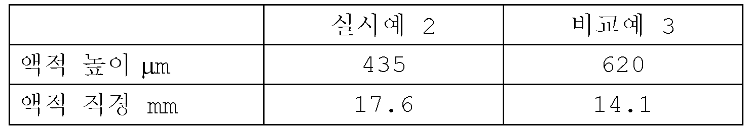
표 2에서, 액적 높이는 각각의 액적의 피크에 대해 각각의 유리 기판 표면으로부터의 높이를 지칭한다. 추가로, 액적 직경은 각각의 PFE 기판을 위에서 볼 때의 각각의 액적의 직경을 지칭한다.In Table 2, droplet height refers to the height from each glass substrate surface for each droplet's peak. Additionally, droplet diameter refers to the diameter of each droplet as viewed from the top of each PFE substrate.
표 2로부터 명백한 바와 같이, 실시예 2에서 PFE 기판 상에, 광 경화성 수지의 액적은 비교예 3의 PFE 기판 상의 액적에 비해 보다 편평하다. 인산칼슘 세라믹으로부터 형성된 친수성 필름을 코팅한 결과로서, 기판 표면과 광 경화성 수지 간의 친화도는 증가하고, 액적 형상은 편평해진다고 말할 수 있다.As is apparent from Table 2, on the PFE substrate in Example 2, the droplets of the photocurable resin are more flat than the droplets on the PFE substrate of Comparative Example 3. As a result of coating the hydrophilic film formed from calcium phosphate ceramic, it can be said that the affinity between the substrate surface and the photocurable resin increases, and the droplet shape becomes flat.
추가로, 광 경화성 수지(202)로서 아크릴 아크릴레이트, 및 폴리에스테르 아크릴레이트, 뿐만 아니라 우레탄 아크릴레이트에 대해 실험을 수행하고, 모든 경우에, 액적은 비교예 3의 PFE 기판보다 실시예 2의 PFE 기판에서 보다 편평해지는 것으로 나타났다.In addition, experiments were conducted on acrylic acrylate, and polyester acrylate, as well as urethane acrylate as the
3종류의 광 경화성 수지에 대해 실시예 2의 PFE 기판 상에서 관찰된 액적 형상은 표 3에 제시한다.The droplet shapes observed on the PFE substrate of Example 2 for the three types of photocurable resins are shown in Table 3.
[표 3][Table 3]

액적 형상 시험 등의 결과로부터, 친수성 표면은 액적 형상 시험의 액적 높이가 550 μm 이하이고 액적 직경이 15.00 mm 이상인 경우, 액체 광 경화성 수지를 광 투과부와 고체 조형물 사이로 신속하게 공급하는 것을 가능하게 하는 것으로 나타난다.From the results of the droplet shape test, etc., the hydrophilic surface is that when the droplet height in the droplet shape test is 550 μm or less and the droplet diameter is 15.00 mm or more, it is possible to quickly supply a liquid photocurable resin between the light transmitting part and the solid sculpture. appear.
다음에, 실시예 2 및 비교예 3에서 PFE 기판을 도 9의 3차원 조형 장치의 광 투과부(244)로서 사용하고, 3-차원 조형을 광 투과부가 상이한 것을 제외하고는 동일한 조건 하에 수행하고, 조형에 필요한 시간 주기를 비교했다.Next, in Example 2 and Comparative Example 3, the PFE substrate was used as the
실시예 2의 광 투과부를 사용한 경우에, 광 경화성 수지(202)의 유동 저항은 친수성 표면 처리를 실시예 2의 광 투과부에 적용하였기 때문에 비교예 3의 유동 저항에 비해 감소하고, 베이스를 들어 올린 때의 광 경화성 수지의 유입 속도가 약 20% 더 높은 것으로 확인되었다. 결과로서, 실시예 2에서, 5 cmx5 cm의 하부 표면, 및 750개의 층수를 갖는 약 30 mm의 높이인 3-차원 물체를 형성하는 경우에, 광 경화 공정을 포함한 3-차원 조형에 필요한 시간 주기는 비교예 3에 비해 대략 55% 단축시킬 수 있다.In the case of using the light transmitting part of Example 2, the flow resistance of the
<다른 실시형태><Other Embodiment>
제1 실시형태에서, 광 투과부는 용기의 상단 부분에 배치되는 반면, 제2 실시형태에서, 광 투과부는 용기의 하부 표면에 배치된다. 본 발명의 친수성 표면 처리가 적용된 광 투과부의 배치는 이들 실시예로 제한되지 않는다. 예를 들어, 광 투과부를 용기의 측면에 배치할 수 있고, 광이 용기의 측방으로 입사할 수 있다. 그 경우에, 광 투과부로부터의 거리를 조정하기 위해 베이스를 수직 방향 대신에 측 방향으로 이동시킬 수 있다.In the first embodiment, the light transmitting part is disposed on the upper portion of the container, whereas in the second embodiment, the light transmitting part is disposed on the lower surface of the container. The arrangement of the light transmitting portion to which the hydrophilic surface treatment of the present invention is applied is not limited to these embodiments. For example, a light transmitting portion may be disposed on the side of the container, and light may enter the side of the container. In that case, the base can be moved laterally instead of vertically to adjust the distance from the light transmitting portion.
임의의 이들 배치에서, 제1 실시형태에서와 같이 높은 기밀성을 갖는 부재, 또는 제2 실시형태에서와 같이 가스 투과성을 갖는 부재를 사용하는 것이 가능하다.In any of these arrangements, it is possible to use a member having high airtightness as in the first embodiment, or a member having gas permeability as in the second embodiment.
추가로, 제1 실시형태 및 제2 실시형태에서, 광 투과부(204) 및 (244)는 광원 유닛(210)과 베이스(211)와의 사이의 광학 경로인 부분에서 제공되고, 친수성 표면 처리는 이 부분에만 적용된다. 그러나, 친수성 표면 처리는 광학 경로인 부분의 둘레 영역에 적용될 수도 있다.Additionally, in the first and second embodiments, the
본 발명은 네트워크 또는 저장 매체를 통한 시스템 또는 장치로의 상기 언급된 실시형태의 1개 이상의 기능을 실현하는 프로그램, 및 상기 프로그램을 판독 또는 실행하는 시스템 또는 장치의 컴퓨터에서의 1개 이상의 프로세서를 공급하는 프로세싱에 의해 실현가능하다. 추가로, 본 발명은 또한 1개 이상의 기능을 실현하는 회로 (예를 들어, ASIC)에 의해 실현가능한다.The present invention provides a program that realizes one or more functions of the above-mentioned embodiments to a system or device via a network or storage medium, and one or more processors in a computer of a system or device that reads or executes the program. It can be realized by processing that is done. In addition, the present invention is also feasible by circuits (eg ASICs) that realize one or more functions.
본 발명의 실시형태는 또한 저장 매체 (이는 또한 '비-일시적 컴퓨터 판독가능 저장 매체'로서 보다 완전히 지칭될 수 있음) 상에 기록된 컴퓨터 실행가능 명령 (예를 들어, 1개 이상의 프로그램)을 판독 및 실행하여 상기-기재된 실시형태의 1개 이상의 기능을 수행하고/거나 상기-기재된 실시형태의 1개 이상의 기능을 수행하기 위한 1개 이상의 회로 (예를 들어, 주문형 집적 회로 (ASIC))를 포함하는 시스템 또는 장치의 컴퓨터, 및 예를 들어, 저장 매체로부터의 컴퓨터 실행가능 명령을 판독 및 실행하여 상기-기재된 실시형태의 1개 이상의 기능을 수행하고/거나 상기-기재된 실시형태의 1개 이상의 기능을 수행하기 위한 1개 이상의 회로를 제어하는 시스템 또는 장치의 컴퓨터에 의해 수행되는 방법에 의해 실현될 수 있다. 컴퓨터는 1개 이상의 프로세서 (예를 들어, 중앙 처리 유닛 (CPU), 마이크로 처리 유닛 (MPU))을 포함하고 컴퓨터 실행가능 명령을 판독 및 실행하기 위한 별개의 컴퓨터 또는 별개의 프로세서의 네트워크를 포함할 수 있다. 컴퓨터 실행가능 명령은 예를 들어 네트워크 또는 저장 매체로부터 컴퓨터에 제공될 수 있다. 저장 매체는, 예를 들어, 1종 이상의 하드 디스크, 임의-접근 메모리 (RAM), 읽기 전용 메모리 (ROM), 분산 컴퓨팅 시스템의 저장, 광학 디스크 (예컨대 콤팩트 디스크 (CD), 디지털 다기능 디스크 (DVD), 또는 블루-레이 디스크 (BD)™), 플래시 메모리 디바이스, 메모리 카드 등을 포함할 수 있다.Embodiments of the present invention also read computer-executable instructions (e.g., one or more programs) recorded on a storage medium (which may also be more fully referred to as a'non-transitory computer-readable storage medium'). And one or more circuits (e.g., application specific integrated circuits (ASICs)) for executing to perform one or more functions of the above-described embodiments and/or for performing one or more functions of the above-described embodiments. Reading and executing computer-executable instructions from a computer, and, for example, a storage medium, to perform one or more functions of the above-described embodiments and/or one or more functions of the above-described embodiments. It can be realized by a computer-implemented method of a system or apparatus that controls one or more circuits for performing the operation. A computer includes one or more processors (e.g., a central processing unit (CPU), a micro processing unit (MPU)) and includes a separate computer or a network of separate processors for reading and executing computer-executable instructions. I can. Computer-executable instructions may be provided to a computer from, for example, a network or a storage medium. The storage medium may be, for example, one or more hard disks, random-access memory (RAM), read-only memory (ROM), storage of distributed computing systems, optical disks (such as compact disks (CD), digital multifunctional disks (DVD)). ), or Blu-ray Disc (BD)™), flash memory devices, memory cards, and the like.
<기타의 실시예><Other Examples>
본 발명은, 상기의 실시형태의 1개 이상의 기능을 실현하는 프로그램을, 네트워크 또는 기억 매체를 개입하여 시스템 혹은 장치에 공급하고, 그 시스템 혹은 장치의 컴퓨터에 있어서 1개 이상의 프로세서가 프로그램을 읽어 실행하는 처리에서도 실현가능하다.In the present invention, a program that realizes one or more functions of the above embodiment is supplied to a system or device via a network or a storage medium, and one or more processors in the computer of the system or device read and execute the program. It is also possible to realize the processing.
또한, 1개 이상의 기능을 실현하는 회로 (예를 들어, ASIC)에 의해서도 실행가능하다.It can also be implemented by a circuit (eg, ASIC) that realizes more than one function.
본 발명은 예시적 실시형태를 참조로 기재되지만, 본 발명은 개시된 예시적 실시형태로 제한되지 않는다고 이해된다. 하기 청구범위의 범위는 가장 넓은 해석을 부여하여 모든 그러한 변경 및 등가의 구조 및 기능을 포괄한다.While the present invention has been described with reference to exemplary embodiments, it is understood that the invention is not limited to the disclosed exemplary embodiments. The scope of the following claims is to be accorded the widest interpretation to cover all such modifications and equivalent structures and functions.
Claims (15)
상기 용기에 수용된 상기 광 경화성 수지에 광 조사를 수행하는 광 조사 장치;
상기 광 조사 장치의 광 조사에 의해 경화된 부위를 상기 가스 투과 부재로부터 이격하는 방향으로 이동시키는 이동 장치;
상기 가스 투과 부재와 상기 광 투과 부재에 의해 형성되는 압력실;
상기 압력실 내부의 가스의 압력을 제어하는 압력 제어 장치; 및
상기 광 조사 장치, 상기 이동 장치 및 상기 압력 제어 장치를 제어하는 제어 유닛을 포함하고,
상기 제어 유닛은, 상기 압력 제어 장치에 의해 상기 압력실 내의 가스의 압력을 감소시켜 상기 가스 투과 부재와 광 투과 부재 사이의 거리가 짧아지도록 상기 광 조사에 의해 경화된 부위로부터 이격하는 방향으로 가스 투과 부재를 변형시키고, 상기 경화된 부위를 상기 이동 장치에 의해 상기 가스 투과 부재로부터 이격하는 방향으로 이동시키는 3차원 조형 장치.A container including a gas-permeable member disposed in contact with the photocurable resin, and a light-transmitting member disposed on a side opposite to the photocurable resin of the gas-permeable member, and containing the photocurable resin;
A light irradiation device for performing light irradiation on the photocurable resin accommodated in the container;
A moving device for moving a portion cured by light irradiation of the light irradiation device in a direction away from the gas permeable member;
A pressure chamber formed by the gas transmitting member and the light transmitting member;
A pressure control device for controlling the pressure of the gas inside the pressure chamber; And
And a control unit for controlling the light irradiation device, the moving device, and the pressure control device,
The control unit transmits gas in a direction away from the cured portion by the light irradiation so that the distance between the gas-transmitting member and the light-transmitting member is shortened by reducing the pressure of the gas in the pressure chamber by the pressure control device. A three-dimensional modeling apparatus for deforming a member and moving the cured portion in a direction away from the gas permeable member by the moving device.
상기 이동 장치에 의한 이동 후, 상기 압력 제어 장치에 의해 상기 압력실 내부의 가스를 가압하는, 3차원 조형 장치.The method of claim 1, wherein the control unit,
After movement by the moving device, the gas inside the pressure chamber is pressurized by the pressure control device.
상기 가스 투과 부재와 광 투과 부재 사이의 거리가 짧아지도록 상기 광 조사에 의해 경화된 부위로부터 이격하는 방향으로 가스 투과 부재를 변형시키기 위해 상기 가스 투과 부재와 상기 광 투과 부재 사이의 가스를 감압하고, 경화된 상기 광 경화성 수지를 상기 가스 투과 부재로부터 이격하는 방향으로 이동시키는 단계를 포함하는, 3차원 조형물의 제조 방법.By irradiating light to a photocurable resin housed in a container including a gas-permeable member disposed in contact with the photocurable resin and a light-transmitting member disposed on the opposite side of the gas-permeable member to the photocurable resin, the photocurable resin Curing and injecting gas between the gas-transmitting member and the light-transmitting member; And
Decompressing the gas between the gas-transmitting member and the light-transmitting member to deform the gas-permeable member in a direction away from the cured portion by the light irradiation so that the distance between the gas-transmitting member and the light-transmitting member is shortened, A method of manufacturing a three-dimensional sculpture comprising the step of moving the cured photocurable resin in a direction spaced apart from the gas permeable member.
상기 광 경화성 수지와 접촉하는 친수성 표면을 갖는 광 투과부를 포함하는, 용기.It is a container that holds a photocurable resin used in a three-dimensional molding apparatus,
A container comprising a light transmitting portion having a hydrophilic surface in contact with the photocurable resin.
Applications Claiming Priority (4)
| Application Number | Priority Date | Filing Date | Title |
|---|---|---|---|
| JP2016163070A JP6783586B2 (en) | 2016-08-23 | 2016-08-23 | Manufacturing method of 3D modeling equipment and 3D modeled objects |
| JPJP-P-2016-163070 | 2016-08-23 | ||
| JP2016164835A JP6896388B2 (en) | 2016-08-25 | 2016-08-25 | Manufacturing method of 3D modeling equipment and 3D modeled objects |
| JPJP-P-2016-164835 | 2016-08-25 |
Publications (2)
| Publication Number | Publication Date |
|---|---|
| KR20180022571A KR20180022571A (en) | 2018-03-06 |
| KR102233625B1 true KR102233625B1 (en) | 2021-03-31 |
Family
ID=61241381
Family Applications (1)
| Application Number | Title | Priority Date | Filing Date |
|---|---|---|---|
| KR1020170102078A Active KR102233625B1 (en) | 2016-08-23 | 2017-08-11 | Three dimensional manufacturing apparatus and method for manufacturing three dimensional manufactured product |
Country Status (3)
| Country | Link |
|---|---|
| US (2) | US20180056587A1 (en) |
| KR (1) | KR102233625B1 (en) |
| CN (1) | CN107756785B (en) |
Families Citing this family (21)
| Publication number | Priority date | Publication date | Assignee | Title |
|---|---|---|---|---|
| JP6849457B2 (en) | 2016-03-09 | 2021-03-24 | キヤノン株式会社 | 3D modeling equipment |
| JP6866152B2 (en) * | 2016-12-22 | 2021-04-28 | キヤノン株式会社 | 3D modeling device and 3D modeling method |
| US11130286B2 (en) * | 2016-09-07 | 2021-09-28 | Canon Kabushiki Kaisha | Three-dimensional manufacturing apparatus, three-dimensional manufactured object producing method, and container for three-dimensional manufacturing apparatus |
| AT521717B1 (en) * | 2018-10-01 | 2021-04-15 | Sirona Dental Systems Gmbh | Device for a system for building up a body in layers |
| WO2020121052A1 (en) | 2018-12-10 | 2020-06-18 | Bmf Precision Technology (Wuxi) Inc. | Methods of controlling dimensions in projection micro stereolithography |
| US11433618B2 (en) * | 2019-03-27 | 2022-09-06 | 3D Systems, Inc. | Large area three-dimensional printer with precision optical path |
| WO2020201943A1 (en) * | 2019-03-29 | 2020-10-08 | 3M Innovative Properties Company | Build platform for use in an additive manufacturing device |
| US11654618B2 (en) * | 2019-04-25 | 2023-05-23 | 3D Systems, Inc. | Three dimensional printing system with partially immersed imaging bar defining build plane below a free surface of photocurable resin |
| US11891465B2 (en) * | 2019-04-29 | 2024-02-06 | Mighty Buildings, Inc. | System for obtaining a photopolymerized prepolymer |
| CN110193933B (en) * | 2019-07-02 | 2024-07-23 | 杭州德迪智能科技有限公司 | A light-curing upper liquid level control device and method |
| CN112265262B (en) * | 2019-07-08 | 2023-08-15 | 上海普利生机电科技有限公司 | A light-curing 3D printing device |
| CN111168995B (en) * | 2020-01-03 | 2022-09-02 | 深圳摩方新材科技有限公司 | Multi-material photocuring 3D printing equipment for film coating and using method thereof |
| WO2021171282A1 (en) * | 2020-02-27 | 2021-09-02 | Nanofabrica Ltd. | System, method and computer readable medium for three-dimensional (3d) printing |
| US20210299952A1 (en) * | 2020-03-25 | 2021-09-30 | Bmf Material Technology Inc. | Roller-membrane layering micro stereolithography |
| CN111469403B (en) * | 2020-06-15 | 2021-12-10 | 广州黑格智造信息科技有限公司 | Photocuring 3D printing method and photocuring 3D printing system |
| CN113895033B (en) * | 2020-06-22 | 2023-04-07 | 上海普利生机电科技有限公司 | Photocuring type 3D printing device and printing method |
| US12420486B2 (en) | 2020-10-23 | 2025-09-23 | Bmf Material Technology Inc. | Multi-scale system for projection micro stereolithography |
| CN112497733B (en) * | 2021-02-07 | 2021-06-25 | 源秩科技(上海)有限公司 | Photosensitive material pulse release method and device |
| CN112497730B (en) * | 2021-02-07 | 2021-06-25 | 源秩科技(上海)有限公司 | Distributed photocuring three-dimensional printing system |
| US12397500B2 (en) | 2021-08-13 | 2025-08-26 | Bmf Nano Material Technology Co., Ltd | System and method of low-waste multi-material resin printing |
| CN115214146B (en) * | 2022-06-23 | 2024-10-22 | 先临三维科技股份有限公司 | 3D printing control method, device, electronic equipment and medium |
Citations (4)
| Publication number | Priority date | Publication date | Assignee | Title |
|---|---|---|---|---|
| JP2001047521A (en) | 1999-08-12 | 2001-02-20 | Teijin Seiki Co Ltd | Optical three-dimensional molding method and apparatus |
| JP2002370286A (en) | 2001-04-23 | 2002-12-24 | Envision Technologies Gmbh | Apparatus and method for separating material layer |
| US20150072293A1 (en) | 2013-08-14 | 2015-03-12 | Eipi Systems, Inc. | Continuous liquid interphase printing |
| US20160200052A1 (en) * | 2015-01-13 | 2016-07-14 | Carbon3D, Inc. | Three-dimensional printing with build plates having surface topologies for increasing permeability and related methods |
Family Cites Families (20)
| Publication number | Priority date | Publication date | Assignee | Title |
|---|---|---|---|---|
| US4873044A (en) * | 1987-12-21 | 1989-10-10 | Shell Oil Company | Method and apparatus for reduction of mold cycle time |
| US5122441A (en) * | 1990-10-29 | 1992-06-16 | E. I. Du Pont De Nemours And Company | Method for fabricating an integral three-dimensional object from layers of a photoformable composition |
| JPH0596632A (en) * | 1991-10-08 | 1993-04-20 | Daikin Ind Ltd | Optical modeling method and apparatus |
| JPH06246838A (en) * | 1993-02-26 | 1994-09-06 | Teijin Seiki Co Ltd | Stereolithography device |
| US5965629A (en) * | 1996-04-19 | 1999-10-12 | Korea Institute Of Science And Technology | Process for modifying surfaces of materials, and materials having surfaces modified thereby |
| US5857358A (en) | 1996-10-23 | 1999-01-12 | Donnelly Corporation | Method and apparatus for bending glass |
| JP3764980B2 (en) * | 1997-05-29 | 2006-04-12 | 学校法人立命館 | Micro stereolithography equipment |
| WO2000053689A1 (en) * | 1999-03-09 | 2000-09-14 | Toto Ltd. | Hydrophilic member, method for preparation thereof, and coating agent and apparatus for preparation thereof |
| KR101284943B1 (en) * | 2006-06-30 | 2013-07-10 | 엘지디스플레이 주식회사 | Method for fabricating mold |
| EP1880832A1 (en) * | 2006-07-18 | 2008-01-23 | Nederlandse Organisatie voor Toegepast-Natuuurwetenschappelijk Onderzoek TNO | Method and system for layerwise production of a tangible object |
| ES2588073T3 (en) * | 2007-09-17 | 2016-10-28 | Synergy Biosurgical Ag | Medical implant |
| US20100092765A1 (en) * | 2008-10-10 | 2010-04-15 | 3M Innovative Properties Company | Silica coating for enhanced hydrophilicity |
| JP2011098484A (en) | 2009-11-05 | 2011-05-19 | Sony Corp | Three-dimensional optical shaping apparatus, three-dimensional optical shaping method, and shaped article |
| IT1397457B1 (en) | 2010-01-12 | 2013-01-10 | Dws Srl | MODELING PLATE FOR A STEREOLITHOGRAPHIC MACHINE, A STEREOLITHOGRAPHIC MACHINE USING SUCH A MODELING AND TOOL PLATE FOR CLEANING SUCH A MODELING PLATE. |
| US8801418B2 (en) * | 2011-01-31 | 2014-08-12 | Global Filtration Systems | Method and apparatus for making three-dimensional objects from multiple solidifiable materials |
| EP2956823B2 (en) | 2013-02-12 | 2019-07-03 | CARBON3D, Inc. | Continuous liquid interphase printing |
| WO2015126461A1 (en) * | 2014-02-20 | 2015-08-27 | Global Filtration Systems, A Dba Of Gulf Filtration Systems Inc. | Apparatus and method for forming three-dimensional objects using a tilting solidification substrate |
| KR101665939B1 (en) * | 2014-07-18 | 2016-10-25 | 한국생산기술연구원 | A material supply apparatus for 3D manufacturing, a rapid 3D printer therewith, and 3D manufacturing method using it. |
| CN105034138B (en) * | 2015-07-06 | 2017-06-06 | 西安交通大学 | A kind of oxygen supply slurry tank systems and the ceramic plane exposure continuous Method of printings of 3D |
| US11130286B2 (en) | 2016-09-07 | 2021-09-28 | Canon Kabushiki Kaisha | Three-dimensional manufacturing apparatus, three-dimensional manufactured object producing method, and container for three-dimensional manufacturing apparatus |
-
2017
- 2017-08-11 KR KR1020170102078A patent/KR102233625B1/en active Active
- 2017-08-15 US US15/677,160 patent/US20180056587A1/en not_active Abandoned
- 2017-08-18 CN CN201710709428.7A patent/CN107756785B/en active Active
-
2021
- 2021-04-28 US US17/242,698 patent/US11951677B2/en active Active
Patent Citations (4)
| Publication number | Priority date | Publication date | Assignee | Title |
|---|---|---|---|---|
| JP2001047521A (en) | 1999-08-12 | 2001-02-20 | Teijin Seiki Co Ltd | Optical three-dimensional molding method and apparatus |
| JP2002370286A (en) | 2001-04-23 | 2002-12-24 | Envision Technologies Gmbh | Apparatus and method for separating material layer |
| US20150072293A1 (en) | 2013-08-14 | 2015-03-12 | Eipi Systems, Inc. | Continuous liquid interphase printing |
| US20160200052A1 (en) * | 2015-01-13 | 2016-07-14 | Carbon3D, Inc. | Three-dimensional printing with build plates having surface topologies for increasing permeability and related methods |
Also Published As
| Publication number | Publication date |
|---|---|
| CN107756785A (en) | 2018-03-06 |
| KR20180022571A (en) | 2018-03-06 |
| US11951677B2 (en) | 2024-04-09 |
| US20210245435A1 (en) | 2021-08-12 |
| US20180056587A1 (en) | 2018-03-01 |
| CN107756785B (en) | 2021-06-15 |
Similar Documents
| Publication | Publication Date | Title |
|---|---|---|
| KR102233625B1 (en) | Three dimensional manufacturing apparatus and method for manufacturing three dimensional manufactured product | |
| CN107791512B (en) | Three-dimensional manufacturing apparatus, three-dimensional manufactured object manufacturing method, and container for three-dimensional manufacturing apparatus | |
| US20130292862A1 (en) | Solid Image Apparatus With Improved Part Separation From The Image Plate | |
| JP6866152B2 (en) | 3D modeling device and 3D modeling method | |
| CN110997282A (en) | Method and system for stereolithography three-dimensional printing | |
| JP2016511713A (en) | 3D object production | |
| WO2012150497A1 (en) | Perfected method for manufacturing three-dimensional objects in layers and perfected stereolithography machine using said method | |
| US20210260819A1 (en) | Systems, apparatuses, and methods for manufacturing three dimensional objects via continuously curing photopolymers, utilising a vessel containing an interface fluid | |
| JP6783586B2 (en) | Manufacturing method of 3D modeling equipment and 3D modeled objects | |
| JP6896388B2 (en) | Manufacturing method of 3D modeling equipment and 3D modeled objects | |
| CN113276408A (en) | Continuous photocuring forming additive manufacturing device in liquid and manufacturing method thereof | |
| JP4828028B2 (en) | 3D modeling apparatus and 3D modeling method | |
| JP6849357B2 (en) | Manufacturing method of 3D modeling equipment and 3D modeled objects | |
| JP2019142197A (en) | Molding apparatus, container, and manufacturing method of molding | |
| CN111168996A (en) | Photosensitive resin dip-forming apparatus and method | |
| CN106976232B (en) | Semipermeable element, application and preparation method thereof and 3D printing equipment | |
| CN215151851U (en) | An additive manufacturing device for continuous light-curing molding in liquid | |
| JP7066459B2 (en) | 3D modeling device and 3D modeling method | |
| KR102515653B1 (en) | 3D Printer | |
| EP4410519B1 (en) | Stereolithography device and method for producing 3d printed object | |
| KR101874791B1 (en) | Method for photo-curable 3D laminated molding and apparatus for photo-curable 3D laminated molding | |
| JP3721477B2 (en) | Stereolithography | |
| JP4072568B2 (en) | High-precision stereolithography with optimal irradiation and lamination conditions | |
| US20240336005A1 (en) | Methods and apparatuses for formation of topographical microstructures and patterning of textured surfaces using photopolymerization | |
| JP2023073111A (en) | Optical shaping device and method for manufacturing shaped article |
Legal Events
| Date | Code | Title | Description |
|---|---|---|---|
| PA0109 | Patent application |
Patent event code: PA01091R01D Comment text: Patent Application Patent event date: 20170811 |
|
| PG1501 | Laying open of application | ||
| AMND | Amendment | ||
| PA0201 | Request for examination |
Patent event code: PA02012R01D Patent event date: 20190211 Comment text: Request for Examination of Application Patent event code: PA02011R01I Patent event date: 20170811 Comment text: Patent Application |
|
| E902 | Notification of reason for refusal | ||
| PE0902 | Notice of grounds for rejection |
Comment text: Notification of reason for refusal Patent event date: 20200424 Patent event code: PE09021S01D |
|
| AMND | Amendment | ||
| E601 | Decision to refuse application | ||
| PE0601 | Decision on rejection of patent |
Patent event date: 20201028 Comment text: Decision to Refuse Application Patent event code: PE06012S01D Patent event date: 20200424 Comment text: Notification of reason for refusal Patent event code: PE06011S01I |
|
| X091 | Application refused [patent] | ||
| AMND | Amendment | ||
| PX0901 | Re-examination |
Patent event code: PX09011S01I Patent event date: 20201028 Comment text: Decision to Refuse Application Patent event code: PX09012R01I Patent event date: 20200624 Comment text: Amendment to Specification, etc. Patent event code: PX09012R01I Patent event date: 20190211 Comment text: Amendment to Specification, etc. |
|
| PX0701 | Decision of registration after re-examination |
Patent event date: 20210107 Comment text: Decision to Grant Registration Patent event code: PX07013S01D Patent event date: 20201228 Comment text: Amendment to Specification, etc. Patent event code: PX07012R01I Patent event date: 20201028 Comment text: Decision to Refuse Application Patent event code: PX07011S01I Patent event date: 20200624 Comment text: Amendment to Specification, etc. Patent event code: PX07012R01I Patent event date: 20190211 Comment text: Amendment to Specification, etc. Patent event code: PX07012R01I |
|
| X701 | Decision to grant (after re-examination) | ||
| GRNT | Written decision to grant | ||
| PR0701 | Registration of establishment |
Comment text: Registration of Establishment Patent event date: 20210324 Patent event code: PR07011E01D |
|
| PR1002 | Payment of registration fee |
Payment date: 20210325 End annual number: 3 Start annual number: 1 |
|
| PG1601 | Publication of registration | ||
| PR1001 | Payment of annual fee |
Payment date: 20240226 Start annual number: 4 End annual number: 4 |