KR102225617B1 - Method of setting algorithm for image registration - Google Patents
Method of setting algorithm for image registration Download PDFInfo
- Publication number
- KR102225617B1 KR102225617B1 KR1020140151584A KR20140151584A KR102225617B1 KR 102225617 B1 KR102225617 B1 KR 102225617B1 KR 1020140151584 A KR1020140151584 A KR 1020140151584A KR 20140151584 A KR20140151584 A KR 20140151584A KR 102225617 B1 KR102225617 B1 KR 102225617B1
- Authority
- KR
- South Korea
- Prior art keywords
- image
- camera
- images
- matching algorithm
- setting
- Prior art date
- Legal status (The legal status is an assumption and is not a legal conclusion. Google has not performed a legal analysis and makes no representation as to the accuracy of the status listed.)
- Active
Links
Images


Classifications
-
- H—ELECTRICITY
- H04—ELECTRIC COMMUNICATION TECHNIQUE
- H04N—PICTORIAL COMMUNICATION, e.g. TELEVISION
- H04N13/00—Stereoscopic video systems; Multi-view video systems; Details thereof
- H04N13/20—Image signal generators
- H04N13/296—Synchronisation thereof; Control thereof
-
- H—ELECTRICITY
- H04—ELECTRIC COMMUNICATION TECHNIQUE
- H04N—PICTORIAL COMMUNICATION, e.g. TELEVISION
- H04N23/00—Cameras or camera modules comprising electronic image sensors; Control thereof
- H04N23/60—Control of cameras or camera modules
- H04N23/617—Upgrading or updating of programs or applications for camera control
-
- G—PHYSICS
- G06—COMPUTING OR CALCULATING; COUNTING
- G06T—IMAGE DATA PROCESSING OR GENERATION, IN GENERAL
- G06T7/00—Image analysis
- G06T7/30—Determination of transform parameters for the alignment of images, i.e. image registration
- G06T7/33—Determination of transform parameters for the alignment of images, i.e. image registration using feature-based methods
- G06T7/337—Determination of transform parameters for the alignment of images, i.e. image registration using feature-based methods involving reference images or patches
-
- H—ELECTRICITY
- H04—ELECTRIC COMMUNICATION TECHNIQUE
- H04N—PICTORIAL COMMUNICATION, e.g. TELEVISION
- H04N13/00—Stereoscopic video systems; Multi-view video systems; Details thereof
- H04N13/10—Processing, recording or transmission of stereoscopic or multi-view image signals
- H04N13/106—Processing image signals
- H04N13/133—Equalising the characteristics of different image components, e.g. their average brightness or colour balance
-
- H—ELECTRICITY
- H04—ELECTRIC COMMUNICATION TECHNIQUE
- H04N—PICTORIAL COMMUNICATION, e.g. TELEVISION
- H04N13/00—Stereoscopic video systems; Multi-view video systems; Details thereof
- H04N13/20—Image signal generators
- H04N13/204—Image signal generators using stereoscopic image cameras
- H04N13/239—Image signal generators using stereoscopic image cameras using two 2D image sensors having a relative position equal to or related to the interocular distance
-
- H—ELECTRICITY
- H04—ELECTRIC COMMUNICATION TECHNIQUE
- H04N—PICTORIAL COMMUNICATION, e.g. TELEVISION
- H04N21/00—Selective content distribution, e.g. interactive television or video on demand [VOD]
- H04N21/40—Client devices specifically adapted for the reception of or interaction with content, e.g. set-top-box [STB]; Operations thereof
- H04N21/45—Management operations performed by the client for facilitating the reception of or the interaction with the content or administrating data related to the end-user or to the client device itself, e.g. learning user preferences for recommending movies, resolving scheduling conflicts
- H04N21/454—Content or additional data filtering, e.g. blocking advertisements
- H04N21/4545—Input to filtering algorithms, e.g. filtering a region of the image
-
- H—ELECTRICITY
- H04—ELECTRIC COMMUNICATION TECHNIQUE
- H04N—PICTORIAL COMMUNICATION, e.g. TELEVISION
- H04N23/00—Cameras or camera modules comprising electronic image sensors; Control thereof
- H04N23/45—Cameras or camera modules comprising electronic image sensors; Control thereof for generating image signals from two or more image sensors being of different type or operating in different modes, e.g. with a CMOS sensor for moving images in combination with a charge-coupled device [CCD] for still images
-
- H—ELECTRICITY
- H04—ELECTRIC COMMUNICATION TECHNIQUE
- H04N—PICTORIAL COMMUNICATION, e.g. TELEVISION
- H04N23/00—Cameras or camera modules comprising electronic image sensors; Control thereof
- H04N23/60—Control of cameras or camera modules
- H04N23/665—Control of cameras or camera modules involving internal camera communication with the image sensor, e.g. synchronising or multiplexing SSIS control signals
-
- H—ELECTRICITY
- H04—ELECTRIC COMMUNICATION TECHNIQUE
- H04N—PICTORIAL COMMUNICATION, e.g. TELEVISION
- H04N23/00—Cameras or camera modules comprising electronic image sensors; Control thereof
- H04N23/60—Control of cameras or camera modules
- H04N23/69—Control of means for changing angle of the field of view, e.g. optical zoom objectives or electronic zooming
-
- H—ELECTRICITY
- H04—ELECTRIC COMMUNICATION TECHNIQUE
- H04N—PICTORIAL COMMUNICATION, e.g. TELEVISION
- H04N23/00—Cameras or camera modules comprising electronic image sensors; Control thereof
- H04N23/60—Control of cameras or camera modules
- H04N23/695—Control of camera direction for changing a field of view, e.g. pan, tilt or based on tracking of objects
-
- G—PHYSICS
- G06—COMPUTING OR CALCULATING; COUNTING
- G06T—IMAGE DATA PROCESSING OR GENERATION, IN GENERAL
- G06T2207/00—Indexing scheme for image analysis or image enhancement
- G06T2207/10—Image acquisition modality
- G06T2207/10004—Still image; Photographic image
- G06T2207/10012—Stereo images
-
- G—PHYSICS
- G06—COMPUTING OR CALCULATING; COUNTING
- G06T—IMAGE DATA PROCESSING OR GENERATION, IN GENERAL
- G06T2207/00—Indexing scheme for image analysis or image enhancement
- G06T2207/10—Image acquisition modality
- G06T2207/10016—Video; Image sequence
-
- G—PHYSICS
- G06—COMPUTING OR CALCULATING; COUNTING
- G06T—IMAGE DATA PROCESSING OR GENERATION, IN GENERAL
- G06T2207/00—Indexing scheme for image analysis or image enhancement
- G06T2207/10—Image acquisition modality
- G06T2207/10048—Infrared image
-
- G—PHYSICS
- G06—COMPUTING OR CALCULATING; COUNTING
- G06T—IMAGE DATA PROCESSING OR GENERATION, IN GENERAL
- G06T2207/00—Indexing scheme for image analysis or image enhancement
- G06T2207/30—Subject of image; Context of image processing
- G06T2207/30244—Camera pose
-
- H—ELECTRICITY
- H04—ELECTRIC COMMUNICATION TECHNIQUE
- H04N—PICTORIAL COMMUNICATION, e.g. TELEVISION
- H04N23/00—Cameras or camera modules comprising electronic image sensors; Control thereof
- H04N23/10—Cameras or camera modules comprising electronic image sensors; Control thereof for generating image signals from different wavelengths
- H04N23/11—Cameras or camera modules comprising electronic image sensors; Control thereof for generating image signals from different wavelengths for generating image signals from visible and infrared light wavelengths
Landscapes
- Engineering & Computer Science (AREA)
- Multimedia (AREA)
- Signal Processing (AREA)
- Theoretical Computer Science (AREA)
- Computer Vision & Pattern Recognition (AREA)
- Physics & Mathematics (AREA)
- General Physics & Mathematics (AREA)
- Human Computer Interaction (AREA)
- Software Systems (AREA)
- Databases & Information Systems (AREA)
- Studio Devices (AREA)
- Image Processing (AREA)
- Image Analysis (AREA)
- Length Measuring Devices By Optical Means (AREA)
Abstract
제1 카메라와 제2 카메라가 일체식으로 설치된 스테레오 카메라 시스템에서, 제1 카메라와 제2 카메라로부터의 영상들을 정합시키기 위한 영상 정합 알고리즘을 설정하는 방법에 있어서, 단계들 (a) 및 (b)를 포함한다. 단계 (a)에서는, 제1 카메라와 제2 카메라가 일체식으로 패닝 및 틸팅을 수행하면서 단일 기준 피사체를 촬영함에 의하여, 단일 기준 피사체의 영상이 서로 다른 위치에 있는 복수의 영상들이 구해진다. 단계 (b)에서는, 구해진 복수의 영상들이 사용되어 영상 정합 알고리즘이 설정된다.In a method of setting an image matching algorithm for matching images from a first camera and a second camera in a stereo camera system in which a first camera and a second camera are integrally installed, the steps (a) and (b) Includes. In step (a), a single reference object is photographed while the first camera and the second camera integrally perform panning and tilting, thereby obtaining a plurality of images in which images of the single reference object are at different positions. In step (b), the obtained plurality of images are used to establish an image matching algorithm.
Description
본 발명은, 영상 정합 알고리즘을 설정하는 방법에 관한 것으로서, 보다 상세하게는, 제1 카메라와 제2 카메라가 일체식으로 설치된 스테레오 카메라 시스템에서, 상기 제1 카메라와 상기 제2 카메라로부터의 영상들을 정합시키기 위한 영상 정합 알고리즘을 설정하는 방법에 관한 것이다.The present invention relates to a method of setting an image matching algorithm, and more particularly, in a stereo camera system in which a first camera and a second camera are integrally installed, images from the first camera and the second camera are It relates to a method of setting an image matching algorithm for matching.
일반적으로, 동일한 촬영 대상으로부터의 두 영상들을 한 영상으로 변화시키기 위해서는 정합(registration)과 융합(fusion)이 필요하다. 정합은 두 영상들의 위치를 일치시키는 처리 과정이다. 즉, 정합은, 제2 카메라로부터의 제2 영상의 위치를 제1 카메라로부터의 제1 영상의 위치에 일치시키는 처리 과정이다. 융합은 정합 결과의 영상에 대하여 원래의 두 영상들의 계조를 조정하는 처리 과정이다. 본 명세서에서는 영상 정합(registration) 알고리즘을 설정하는 방법이 기술된다. In general, registration and fusion are required in order to change two images from the same photographing object into one image. Matching is a process of matching the positions of two images. That is, matching is a process of matching the position of the second image from the second camera to the position of the first image from the first camera. Fusion is a process of adjusting the gradation of two original images with respect to the image as a result of matching. In this specification, a method of setting an image registration algorithm is described.
일반적으로 감시를 위하여 패닝(panning) 및 틸팅(tilting)을 수행하는 스테레오 카메라에서는 제1 카메라와 제2 카메라가 일체식으로 설치된다. 여기에서, 제1 카메라로서 가시(可視) 영상 카메라가 사용되고, 제2 카메라로서 열(熱)-영상 카메라가 사용된다. 대부분의 경우, 가시(可視) 영상 카메라는 줌 렌즈를 구비하지만, 제조 비용을 줄이기 위하여 열(熱)-영상 카메라는 고정 초점 렌즈를 구비한다. 따라서, 열(熱)-영상 카메라는 고정된 화각을 가진다. 또한, 제조 비용을 줄이기 위하여 열(熱)-영상 카메라의 화소 수는 가시(可視) 영상 카메라의 화소 수보다 적다.In general, in a stereo camera that pans and tilts for monitoring, a first camera and a second camera are integrally installed. Here, a visible image camera is used as the first camera, and a thermal-image camera is used as the second camera. In most cases, visible imaging cameras are equipped with zoom lenses, but in order to reduce manufacturing costs, thermal-imaging cameras are equipped with fixed focus lenses. Thus, the thermal-imaging camera has a fixed angle of view. In addition, in order to reduce manufacturing cost, the number of pixels of a thermal-imaging camera is smaller than that of a visible imaging camera.
가시(可視) 영상 카메라의 줌 배율의 범위별로 영상 정합 알고리즘을 설정함에 있어서, 종래에는 "체크 보드(check board)"라 불리우는 특정 패턴의 기준 피사체가 사용되었다. 여기에서, 열(熱)-영상 카메라로부터의 열(熱)-영상의 경우, 열(熱)-영상 데이터 자체를 처리하는 디지털 주밍이 수행된다. "체크 보드(check board)"는 가장 낮은 줌 배율(즉, 가장 넓은 화각)에 대응하도록 방대한 크기를 가진다.In setting an image matching algorithm for each range of a zoom magnification of a visible image camera, a reference object of a specific pattern called a "check board" has been conventionally used. Here, in the case of a heat-image from a heat-image camera, digital zooming is performed that processes the heat-image data itself. The "check board" has a massive size to correspond to the lowest zoom magnification (ie, the widest angle of view).
따라서, 상대적으로 높은 줌 배율에서 영상 정합 알고리즘을 설정할 경우, 즉, 상대적으로 좁은 화각에서 영상 정합 알고리즘을 설정할 경우, 열(熱)-영상의 해상도가 더욱 낮아지게 된다. 그럼에도 불구하고 종래에는 "체크 보드(check board)"와 같은 고정적인 기준 피사체가 사용되므로, 열(熱)-영상에서 특징점들을 정확하게 찾을 수 없는 어려움이 있다. Accordingly, when the image matching algorithm is set at a relatively high zoom magnification, that is, when the image matching algorithm is set at a relatively narrow angle of view, the resolution of the column-image is further lowered. Nevertheless, conventionally, since a fixed reference object such as a "check board" is used, there is a difficulty in accurately finding feature points in a column-image.
상기 배경 기술의 문제점은, 발명자가 본 발명의 도출을 위해 보유하고 있었거나, 본 발명의 도출 과정에서 습득한 내용으로서, 반드시 본 발명의 출원 전에 일반 공중에게 공지된 내용이라 할 수는 없다.The problem of the background art is that the inventor possessed for derivation of the present invention or learned in the derivation process of the present invention, and is not necessarily known to the general public prior to filing the present invention.
본 발명의 실시예는, 제1 카메라와 제2 카메라가 일체식으로 설치된 스테레오 카메라 시스템에서 보다 용이하고 정확하게 영상 정합 알고리즘을 설정할 수 있게 해주는 방법을 제공하고자 한다.An embodiment of the present invention is to provide a method for enabling an image matching algorithm to be more easily and accurately set in a stereo camera system in which a first camera and a second camera are integrally installed.
본 발명의 일 측면에 의하면, 제1 카메라와 제2 카메라가 일체식으로 설치된 스테레오 카메라 시스템에서, 상기 제1 카메라와 상기 제2 카메라로부터의 영상들을 정합시키기 위한 영상 정합 알고리즘을 설정하는 방법에 있어서, 단계들 (a) 및 (b)를 포함한다. According to an aspect of the present invention, in a stereo camera system in which a first camera and a second camera are integrally installed, in a method of setting an image matching algorithm for matching images from the first camera and the second camera, , Steps (a) and (b).
상기 단계 (a)에서는, 상기 제1 카메라와 상기 제2 카메라가 일체식으로 패닝 및 틸팅을 수행하면서 단일 기준 피사체를 촬영함에 의하여, 상기 단일 기준 피사체의 영상이 서로 다른 위치에 있는 복수의 영상들이 구해진다.In the step (a), by capturing a single reference subject while the first camera and the second camera integrally perform panning and tilting, a plurality of images in which the images of the single reference subject are different from each other are displayed. Is obtained.
상기 단계 (b)에서는, 구해진 상기 복수의 영상들이 사용되어 상기 영상 정합 알고리즘이 설정된다.In the step (b), the obtained images are used to set the image matching algorithm.
바람직하게는, 상기 단일 기준 피사체의 영상이 서로 다른 위치에 있는 상기 복수의 영상들 각각에서, 상기 단일 기준 피사체의 영상을 제외한 나머지 영상의 화소들의 계조가 영(0)이 된다.Preferably, in each of the plurality of images in which the image of the single reference object is at different positions, gray scales of pixels of the remaining images except for the image of the single reference object become zero.
또한, 상기 단계 (b)에서 상기 영상 정합 알고리즘을 설정함에 있어서, 서로 다른 위치에 있는 상기 단일 기준 피사체의 영상의 중심 좌표들이 특징점들의 좌표들로서 사용될 수 있다.In addition, in setting the image matching algorithm in step (b), center coordinates of the image of the single reference object at different locations may be used as coordinates of feature points.
또한, 상기 단계 (b)는 단계들 (b1) 내지 (b3)을 포함할 수 있다.In addition, step (b) may include steps (b1) to (b3).
상기 단계 (b1)에서는, 상기 제1 카메라로부터의 상기 복수의 영상들이 합성되어 제1 기준 영상이 구해진다.In the step (b1), the plurality of images from the first camera are synthesized to obtain a first reference image.
상기 단계 (b2)에서는, 상기 제2 카메라로부터의 상기 복수의 영상들이 합성되어 제2 기준 영상이 구해진다.In the step (b2), the plurality of images from the second camera are synthesized to obtain a second reference image.
상기 단계 (b3)에서는, 상기 제1 기준 영상과 상기 제2 기준 영상이 사용되어, 상기 영상 정합 알고리즘이 설정된다.In the step (b3), the first reference image and the second reference image are used, and the image matching algorithm is set.
또한, 상기 단계 (b3)은 단계들 (b31) 내지 (b33)을 포함할 수 있다.In addition, step (b3) may include steps (b31) to (b33).
상기 단계 (b31)에서는, 상기 제1 기준 영상의 3차원적 성분이 2차원적 성분으로 변환되도록 상기 제1 기준 영상에 대하여 투영(projection)이 수행되어, 투영된 결과의 제1 기준 영상이 구해진다.In the step (b31), projection is performed on the first reference image so that the three-dimensional component of the first reference image is converted into a two-dimensional component, and a first reference image of the projected result is obtained. It becomes.
상기 단계 (b32)에서는, 상기 제2 기준 영상의 3차원적 성분이 2차원적 성분으로 변환되도록 상기 제2 기준 영상에 대하여 투영(projection)이 수행되어, 투영된 결과의 제2 기준 영상이 구해진다.In the step (b32), projection is performed on the second reference image so that the three-dimensional component of the second reference image is converted into a two-dimensional component, and a second reference image of the projected result is obtained. It becomes.
상기 단계 (b33)에서는, 상기 투영된 결과의 제1 및 제2 기준 영상들이 사용되어, 상기 제2 기준 영상의 각 화소의 위치 변환을 위한 상기 영상 정합 알고리즘으로서의 2차원 호모그래피(homography) 행렬이 구해진다.In the step (b33), the first and second reference images of the projected result are used, and a two-dimensional homography matrix as the image matching algorithm for position transformation of each pixel of the second reference image is Is obtained.
또한, 상기 단계 (b33)은 단계들 (b331) 내지 (b333)을 포함할 수 있다.In addition, step (b33) may include steps (b331) to (b333).
상기 단계 (b331)에서는, 상기 투영된 결과의 제1 기준 영상에서, 특징점들의 좌표들에 의한 직선 방정식들이 구해진다.In the step (b331), linear equations based on coordinates of feature points are obtained from the first reference image of the projected result.
상기 단계 (b332)에서는, 상기 투영된 결과의 제2 기준 영상에서, 특징점들의 좌표들에 의한 직선 방정식들이 구해진다.In the step (b332), linear equations based on coordinates of feature points are obtained from the second reference image of the projected result.
상기 단계 (b333)에서는, 상기 투영된 결과의 제1 기준 영상 및 제2 기준 영상의 상기 직선 방정식들이 사용되어, 상기 영상 정합 알고리즘으로서의 2차원 호모그래피(homography) 행렬이 구해진다.In the step (b333), the linear equations of the first reference image and the second reference image of the projected result are used to obtain a two-dimensional homography matrix as the image matching algorithm.
본 발명의 일 측면의 상기 영상 정합 알고리즘을 설정하는 방법에 의하면, 상기 제1 카메라와 상기 제2 카메라가 일체식으로 패닝 및 틸팅을 수행하면서 단일 기준 피사체를 촬영함에 의하여, 상기 단일 기준 피사체의 영상이 서로 다른 위치에 있는 복수의 영상들이 구해진다. 또한, 구해진 상기 복수의 영상들이 사용되어 상기 영상 정합 알고리즘이 설정된다.According to the method of setting the image matching algorithm of one aspect of the present invention, the first camera and the second camera are integrally panned and tilted while photographing a single reference subject, thereby providing an image of the single reference subject. A plurality of images in these different locations are obtained. In addition, the obtained images are used to set the image matching algorithm.
따라서, 다음과 같은 효과들이 있다.Therefore, there are the following effects.
첫째, 영상 정합에 적합한 개수의 기준 피사체 영상들이 자유롭게 배치될 수 있다.First, a number of reference subject images suitable for image matching may be freely arranged.
둘째, 기준 피사체 영상들이 영상 정합에 적합한 위치들에 자유롭게 배치될 수 있다.Second, images of the reference subject may be freely disposed at positions suitable for image registration.
셋째, 영상 정합에 적합한 단일 기준 피사체가 다양하게 선정될 수 있다.Third, a single reference subject suitable for image matching may be variously selected.
그리고 넷째, 가장 낮은 줌 배율(즉, 가장 넓은 화각)에 대응하기 위하여 방대한 크기의 기준 피사체를 설치할 필요가 없다.And fourth, it is not necessary to install a reference subject of a large size in order to respond to the lowest zoom magnification (ie, the widest angle of view).
따라서, 보다 용이하고 정확하게 영상 정합 알고리즘이 설정될 수 있다. 예를 들어, 상대적으로 높은 줌 배율에서 영상 정합 알고리즘을 설정할 경우, 즉, 상대적으로 좁은 화각에서 영상 정합 알고리즘을 설정할 경우, 열(熱)-영상의 해상도가 더욱 낮아지게 된다. 하지만, 기준 피사체 영상들이 자유롭고 적절하게 생성될 수 있으므로, 열(熱)-영상에서 특징점들을 정확하게 찾을 수 있다.Therefore, an image matching algorithm can be more easily and accurately set. For example, when an image matching algorithm is set at a relatively high zoom magnification, that is, when an image matching algorithm is set at a relatively narrow angle of view, the resolution of the column-image is further lowered. However, since the reference subject images can be freely and appropriately generated, feature points can be accurately found in the column-image.
도 1은 본 발명의 실시예의 영상 정합 알고리즘을 설정하는 방법이 수행되는 스테레오 카메라 시스템을 보여주는 도면이다.
도 2는 본 발명의 실시예의 영상 정합 알고리즘을 설정하는 방법을 보여주는 흐름도이다.
도 3은 스테레오 카메라가 도 2의 단계 (a)를 수행하는 예를 보여주는 도면이다.
도 4는 도 2의 단계 (a)를 수행한 결과의 예를 보여주는 도면이다.
도 5는 도 2의 단계 (b)의 상세 과정의 예를 보여주는 흐름도이다.
도 6은 도 5의 단계들 (b1) 및 (b2)를 수행한 결과의 예를 보여주는 도면이다.
도 7은 도 2의 영상 정합 알고리즘을 총괄적으로 설명하기 위한 도면이다.
도 8은 도 5의 단계 (b3)의 상세 과정의 예를 보여주는 흐름도이다.
도 9는 도 8의 단계들 (b31) 및 (b33)을 설명하기 위한 도면이다.
도 10은 도 8의 단계 (b33)의 상세 과정의 예를 보여주는 흐름도이다.1 is a diagram showing a stereo camera system in which a method of setting an image matching algorithm according to an embodiment of the present invention is performed.
2 is a flowchart showing a method of setting an image matching algorithm according to an embodiment of the present invention.
3 is a diagram illustrating an example in which a stereo camera performs step (a) of FIG. 2.
4 is a diagram showing an example of a result of performing step (a) of FIG. 2.
5 is a flowchart showing an example of a detailed process of step (b) of FIG. 2.
6 is a diagram showing an example of a result of performing steps (b1) and (b2) of FIG. 5.
7 is a diagram for collectively explaining the image matching algorithm of FIG. 2.
8 is a flowchart showing an example of a detailed process of step (b3) of FIG. 5.
9 is a diagram for explaining steps (b31) and (b33) of FIG. 8.
10 is a flowchart showing an example of a detailed process of step (b33) of FIG. 8.
하기의 설명 및 첨부된 도면은 본 발명에 따른 동작을 이해하기 위한 것이며, 본 기술 분야의 통상의 기술자가 용이하게 구현할 수 있는 부분은 생략될 수 있다. The following description and accompanying drawings are for understanding the operation according to the present invention, and parts that can be easily implemented by a person skilled in the art may be omitted.
또한 본 명세서 및 도면은 본 발명을 제한하기 위한 목적으로 제공된 것은 아니고, 본 발명의 범위는 청구의 범위에 의하여 정해져야 한다. 본 명세서에서 사용된 용어들은 본 발명을 가장 적절하게 표현할 수 있도록 본 발명의 기술적 사상에 부합하는 의미와 개념으로 해석되어야 한다.In addition, the specification and drawings are not provided for the purpose of limiting the present invention, and the scope of the present invention should be determined by the claims. Terms used in the present specification should be interpreted as meanings and concepts consistent with the technical idea of the present invention so that the present invention can be most appropriately expressed.
이하 첨부된 도면들을 참조하여 본 발명의 실시예가 상세히 설명된다.Hereinafter, embodiments of the present invention will be described in detail with reference to the accompanying drawings.
도 1은 본 발명의 실시예의 영상 정합 알고리즘을 설정하는 방법이 수행되는 스테레오 카메라 시스템을 보여준다.1 shows a stereo camera system in which a method of setting an image matching algorithm according to an embodiment of the present invention is performed.
도 1의 스테레오 카메라 시스템을 참조하면, 제2 카메라(102)로서의 열(熱)-영상 카메라는 피사체의 온도에 따른 열(熱) 영상으로서의 제2 영상(Ithe)을 출력한다. 제1 카메라(101)로서의 가시(可視) 영상 카메라는 피사체의 가시(可視) 영상으로서의 제1 영상(Ivis)을 출력한다. Referring to the stereo camera system of FIG. 1, a thermal-image camera as the
제어 장치(103)는, 제1 카메라(101)로부터의 제1 영상(Ivis)과 제2 카메라(102)로부터의 제2 영상(Ithe)에 대하여 정합(registration) 및 융합(fusion)을 수행한다. 정합은 두 영상들의 위치를 일치시키는 처리 과정이다. 융합은 정합 결과의 영상에 대하여 원래의 두 영상들의 계조를 조정하는 처리 과정이다. The
제어 장치(103)는 정합 및 융합 결과의 영상(Imix)을 디스플레이 장치(104) 또는 클라이언트 단말기들(도시되지 않음)에게 제공한다. 물론, 제어 장치(103)는 제1 영상(Ivis), 제2 영상(Ithe), 또는 융합 결과의 영상(Imix)을 기록기에 저장할 수도 있다. The
상기 정합 동작을 위하여, 도 1의 제어 장치(103)에는 영상 정합 알고리즘이 설정되어야 한다. 이하, 본 실시예의 영상 정합 알고리즘을 설정하는 방법이 상세히 설명된다.For the matching operation, an image matching algorithm must be set in the
도 2는 본 발명의 실시예의 영상 정합 알고리즘을 설정하는 방법을 보여준다. 2 shows a method of setting an image matching algorithm according to an embodiment of the present invention.
도 3은 스테레오 카메라(301)가 도 2의 단계 (a)를 수행하는 예를 보여준다. 도 3에서 패닝(panning) 및 틸팅(tilting)을 수행하는 스테레오 카메라(301) 내에는 제1 카메라(도 1의 101)로서의 가시(可視) 영상 카메라와 제2 카메라(도 1의 102)로서의 열(熱)-영상 카메라가 일체식으로 설치되어 있다.3 shows an example in which the
도 3에서 참조 부호 302는 단일 기준 피사체(304)의 배경 영역을, 303은 촬영 대상 영역을, 그리고 304는 단일 기준 피사체로서의 카메라 교정용 흑체원(black body source)을 각각 가리킨다. 도 3을 참조하면, 스테레오 카메라(301)는, 단일 기준 피사체(304)가 중앙에 위치하도록 촬영한 후, 하향 틸팅 및 우향 패닝에 의하여 단일 기준 피사체(304)가 좌상단에 위치하도록 촬영하고 있다.In FIG. 3,
도 4는 도 2의 단계 (a)를 수행한 결과의 예를 보여준다. 도 4에서 참조 부호 401a 내지 401e는 제1 카메라(도 1의 101)로부터의 복수의 영상들, 402a 내지 402e는 제2 카메라(도 1의 102)로부터의 복수의 영상들을, 그리고 403은 단일 기준 피사체의 영상을 각각 가리킨다. 4 shows an example of the result of performing step (a) of FIG. 2. In Fig. 4,
도 1 내지 4를 참조하여 본 실시예의 영상 정합 알고리즘을 설정하는 방법을 설명하면 다음과 같다.A method of setting an image matching algorithm according to the present embodiment will be described with reference to FIGS. 1 to 4 as follows.
스테레오 카메라(301)는 제어 장치(103)의 제어에 의하여 다음과 같이 동작한다.The
스테레오 카메라(301) 내의 제1 카메라(101)와 제2 카메라(102)는, 일체식으로 패닝 및 틸팅을 수행하면서 단일 기준 피사체(304)를 촬영함에 의하여, 단일 기준 피사체의 영상(403)이 서로 다른 위치에 있는 복수의 영상들(401a 내지 401e, 402a 내지 402e)을 구한다(단계 (a)).The
여기에서, 보다 정밀한 정합 알고리즘을 설정하기 위하여, 제어 장치(103)는 복수의 영상들(401a 내지 401e, 402a 내지 402e) 각각에서 단일 기준 피사체의 영상(403)을 제외한 나머지 영상의 화소들의 계조가 영(0)이 되게 할 수 있다. 즉, 제어 장치(103)는 마스킹 처리를 할 수 있다. Here, in order to set a more precise matching algorithm, the
그리고, 제어 장치(103)는 구해진 복수의 영상들(401a 내지 401e, 402a 내지 402e)을 사용하여 영상 정합 알고리즘을 설정한다(단계 (b)). 여기에서, 서로 다른 위치에 있는 단일 기준 피사체의 영상(403)의 중심 좌표들이 특징점들의 좌표들로서 사용된다.Then, the
따라서, 상기와 같은 본 실시예의 영상 정합 알고리즘을 설정하는 방법에 의하면, 다음과 같은 효과들이 있다.Accordingly, according to the method of setting the image matching algorithm of the present embodiment as described above, the following effects are provided.
첫째, 영상 정합에 적합한 개수의 기준 피사체 영상들(403)이 자유롭게 배치될 수 있다.First, the number of reference
둘째, 기준 피사체 영상들(403)이 영상 정합에 적합한 위치들에 자유롭게 배치될 수 있다.Second, the reference
셋째, 영상 정합에 적합한 단일 기준 피사체(304)가 다양하게 선정될 수 있다.Third, a
그리고 넷째, 가장 낮은 줌 배율(즉, 가장 넓은 화각)에 대응하기 위하여 방대한 크기의 기준 피사체를 설치할 필요가 없다.And fourth, it is not necessary to install a reference subject of a large size to respond to the lowest zoom magnification (ie, the widest angle of view).
따라서, 보다 용이하고 정확하게 영상 정합 알고리즘이 설정될 수 있다. 예를 들어, 상대적으로 높은 줌 배율에서 영상 정합 알고리즘을 설정할 경우, 즉, 상대적으로 좁은 화각에서 영상 정합 알고리즘을 설정할 경우, 열(熱)-영상의 해상도가 더욱 낮아지게 된다. 하지만, 기준 피사체 영상들(403)이 자유롭고 적절하게 생성될 수 있으므로, 열(熱)-영상(402a 내지 402e)에서 특징점들을 정확하게 찾을 수 있다.Therefore, an image matching algorithm can be more easily and accurately set. For example, when an image matching algorithm is set at a relatively high zoom magnification, that is, when an image matching algorithm is set at a relatively narrow angle of view, the resolution of the column-image is further lowered. However, since the reference
도 5는 도 2의 단계 (b)의 상세 과정의 예를 보여준다.5 shows an example of a detailed process of step (b) of FIG. 2.
도 6은 도 5의 단계들 (b1) 및 (b2)를 수행한 결과의 예를 보여준다. 도 6에서 참조 부호 403은 단일 기준 피사체의 영상을, 601은 제1 기준 영상을, 그리고 602는 제2 기준 영상을 각각 가리킨다.6 shows an example of a result of performing steps (b1) and (b2) of FIG. 5. In FIG. 6,
도 1 및 도 4 내지 6을 참조하여 도 2의 단계 (b)의 상세 과정의 예를 설명하면 다음과 같다.An example of the detailed process of step (b) of FIG. 2 will be described with reference to FIGS. 1 and 4 to 6.
제어 장치(103)는 제1 카메라(101)로부터의 상기 복수의 영상들(401a 내지 401e)을 합성하여 제1 기준 영상(601)을 구한다(단계 (b1)).The
또한, 제어 장치(103)는 제2 카메라(102)로부터의 상기 복수의 영상들(402a 내지 402e)을 합성하여 제2 기준 영상(602)을 구한다(단계 (b2)).Further, the
그리고, 제어 장치(103)는 제1 기준 영상(601)과 제2 기준 영상(602)을 사용하여, 영상 정합 알고리즘을 설정한다(단계 (b3)).Then, the
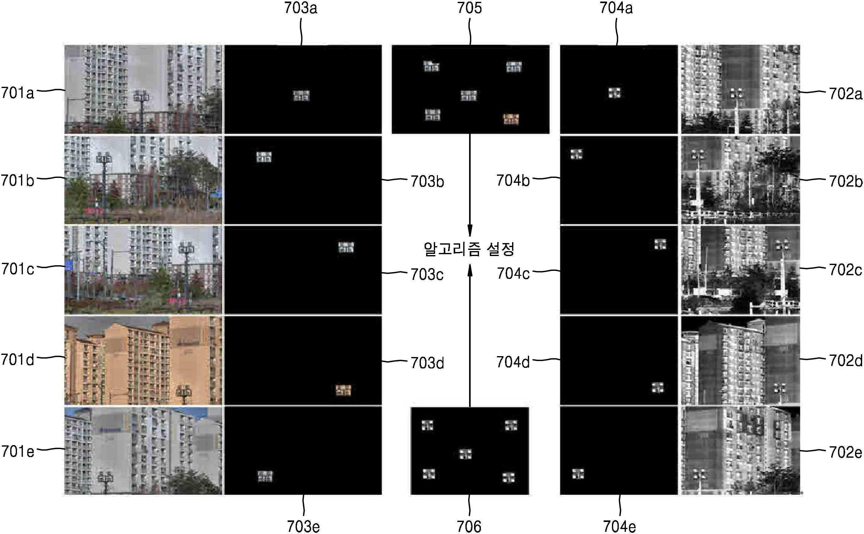
도 7은 도 2의 영상 정합 알고리즘을 총괄적으로 설명하기 위한 도면이다.7 is a diagram for collectively explaining the image matching algorithm of FIG. 2.
도 1 및 7을 참조하면, 보다 정밀한 정합 알고리즘의 설정을 위하여, 제1 카메라(101)로부터의 복수의 영상들(701a 내지 701e)은 마스킹 처리된 복수의 영상들(703a 내지 703e)로 변환된다. 즉, 복수의 영상들(701a 내지 701e) 각각에서 단일 기준 피사체의 영상을 제외한 나머지 영상의 화소들의 계조가 영(0)이 된다.1 and 7, in order to set a more precise matching algorithm, a plurality of
이와 마찬가지로, 보다 정밀한 정합 알고리즘의 설정을 위하여, 제2 카메라(102)로부터의 복수의 영상들(702a 내지 702e)은 마스킹 처리된 복수의 영상들(704a 내지 704e)로 변환된다. 즉, 복수의 영상들(702a 내지 702e) 각각에서 단일 기준 피사체의 영상을 제외한 나머지 영상의 화소들의 계조가 영(0)이 된다.Likewise, in order to set a more precise matching algorithm, the plurality of
다음에, 마스킹 처리된 제1 복수의 영상들(703a 내지 703e)이 서로 합성됨에 의하여 제1 기준 영상(705)이 구해진다.Next, a
이와 마찬가지로, 마스킹 처리된 제2 복수의 영상들(704a 내지 704e)이 서로 합성됨에 의하여 제2 기준 영상(706)이 구해진다.Likewise, a
그래서, 제1 기준 영상(705)과 제2 기준 영상(706)이 사용되어, 영상 정합 알고리즘이 설정된다.Thus, the
도 8은 도 5의 단계 (b3)의 상세 과정의 예를 보여준다. 8 shows an example of a detailed process of step (b3) of FIG. 5.
도 9는 도 8의 단계들 (b31) 및 (b33)을 설명하기 위한 도면이다. 도 9에서, 참조 부호 901은 2차원 투영(projection) 평면을, 902는 투영된 결과의 제1 기준 영상을, 그리고 903은 투영된 결과의 제2 기준 영상을 가리킨다.9 is a diagram for explaining steps (b31) and (b33) of FIG. 8. In FIG. 9,
도 1 및 도 7 내지 9를 참조하여 도 5의 단계 (b3)의 상세 과정의 예를 설명하면 다음과 같다.An example of the detailed process of step (b3) of FIG. 5 will be described with reference to FIGS. 1 and 7 to 9.
제어 장치(103)는, 제1 기준 영상(705)의 3차원적 성분이 2차원적 성분으로 변환되도록 제1 기준 영상(705)에 대하여 투영(projection)을 수행하여, 투영된 결과의 제1 기준 영상(902)을 구한다(단계 (b31)). 영상에서의 3차원적 성분을 2차원적 성분으로 변환하기 위한 투영(projection) 방법은, 이미 잘 알려져 있으므로, 그 설명이 생략된다.The
이와 마찬가지로, 제어 장치(103)는, 제2 기준 영상(706)의 3차원적 성분이 2차원적 성분으로 변환되도록 제1 기준 영상(706)에 대하여 투영(projection)을 수행하여, 투영된 결과의 제2 기준 영상(903)을 구한다(단계 (b32)).Likewise, the
그리고, 제어 장치(103)는, 투영된 결과의 제1 및 제2 기준 영상들(902, 903)을 사용하여, 투영된 결과의 제2 기준 영상(902)의 각 화소의 위치 변환을 위한 상기 영상 정합 알고리즘으로서의 2차원 호모그래피(homography) 행렬을 구한다(단계 (b33)).In addition, the
도 9에서 특징점 A1은 A2에 대응하고, 특징점 B1은 B2에 대응하며, 특징점 C1은 C2에 대응하고, 특징점 D1은 D2에 대응하며, 특징점 E1은 E2에 대응한다. 여기에서, 서로 다른 위치에 있는 단일 기준 피사체의 영상의 중심 좌표들이 특징점들의 좌표들로서 사용된다. 도 9에 도시된 바와 같이 대응 특징점들의 위치가 서로 다른 이유는, 3차원적 성분이 2차원적 성분으로 변환되는 과정에서 거리(depth) 성분이 반영되기 때문이다.In FIG. 9, the feature point A1 corresponds to A2, the feature point B1 corresponds to B2, the feature point C1 corresponds to C2, the feature point D1 corresponds to D2, and the feature point E1 corresponds to E2. Here, center coordinates of an image of a single reference object at different locations are used as coordinates of feature points. The reason why the positions of the corresponding feature points are different as shown in FIG. 9 is that the depth component is reflected in the process of converting the 3D component to the 2D component.
도 10은 도 8의 단계 (b33)의 상세 과정의 예를 보여준다.10 shows an example of a detailed process of step (b33) of FIG. 8.
도 1, 9 및 10을 참조하여 도 8의 단계 (b33)의 상세 과정의 예를 상세히 설명하면 다음과 같다.An example of the detailed process of step (b33) of FIG. 8 will be described in detail with reference to FIGS. 1, 9 and 10 as follows.
제어 장치(103)는, 투영된 결과의 제1 기준 영상(902)에서, 특징점들(A1 내지 E1)의 좌표들에 의한 직선 방정식들을 구한다(단계 (b331)). 상기한 바와 같이, 서로 다른 위치에 있는 단일 기준 피사체의 영상의 중심 좌표들이 특징점들의 좌표들로서 사용된다.The
이와 마찬가지로, 제어 장치(103)는, 투영된 결과의 제2 기준 영상(903)에서, 특징점들(A2 내지 E2)의 좌표들에 의한 직선 방정식들을 구한다(단계 (b332)).Similarly, the
그리고, 제어 장치(103)는, 투영된 결과의 제1 기준 영상(902) 및 제2 기준 영상(902)의 상기 직선 방정식들을 사용하여, 상기 영상 정합 알고리즘으로서의 2차원 호모그래피(homography) 행렬을 구한다(단계 (b333)). And, the
영상 정합을 위한 2차원 호모그래피 행렬의 설정 방법은, 이미 잘 알려져 있으므로, 그 상세한 설명이 생략된다.A method of setting a two-dimensional homography matrix for image matching is already well known, and a detailed description thereof is omitted.
예를 들어, 스테레오 카메라의 경우, 투영된 결과의 제2 기준 영상(403)의 각 화소의 위치 변환을 위한 2차원 호모그래피(homography) 행렬 H는 아래의 수학식 1과 같이 구해질 수 있다.For example, in the case of a stereo camera, a 2D homography matrix H for position transformation of each pixel of the

상기 수학식 1에서 변수 원소 h13은 대상 화소의 x-좌표 차이 값을, 그리고 h23은 대상 화소의 y-좌표 차이 값을 각각 가리킨다. 즉, 상기 수학식 1을 사용하여, 제2 영상(도 1의 Ithe)의 모든 화소들 각각에 대한 정합 결과로서의 x-좌표 값 및 y-좌표 값이 구해질 수 있다. In Equation 1, the variable element h13 denotes the x-coordinate difference value of the target pixel, and h23 denotes the y-coordinate difference value of the target pixel, respectively. That is, using Equation 1, an x-coordinate value and a y-coordinate value as a result of matching for each of all pixels of the second image (Ithe in FIG. 1) may be obtained.
이상 설명된 바와 같이, 본 발명의 실시예의 영상 정합 알고리즘을 설정하는 방법에 의하면, 제1 카메라와 제2 카메라가 일체식으로 패닝 및 틸팅을 수행하면서 단일 기준 피사체를 촬영함에 의하여, 단일 기준 피사체의 영상이 서로 다른 위치에 있는 복수의 영상들이 구해진다. 또한, 구해진 복수의 영상들이 사용되어 영상 정합 알고리즘이 설정된다.As described above, according to the method of setting the image matching algorithm according to the embodiment of the present invention, the first camera and the second camera integrally perform panning and tilting while photographing a single reference subject. A plurality of images in which images are located at different locations are obtained. In addition, the obtained plurality of images are used to establish an image matching algorithm.
따라서, 다음과 같은 효과들이 있다.Therefore, there are the following effects.
첫째, 영상 정합에 적합한 개수의 기준 피사체 영상들이 자유롭게 배치될 수 있다.First, a number of reference subject images suitable for image matching may be freely arranged.
둘째, 기준 피사체 영상들이 영상 정합에 적합한 위치들에 자유롭게 배치될 수 있다.Second, images of the reference subject may be freely disposed at positions suitable for image registration.
셋째, 영상 정합에 적합한 단일 기준 피사체가 다양하게 선정될 수 있다.Third, a single reference subject suitable for image matching may be variously selected.
그리고 넷째, 가장 낮은 줌 배율(즉, 가장 넓은 화각)에 대응하기 위하여 방대한 크기의 기준 피사체를 설치할 필요가 없다.And fourth, it is not necessary to install a reference subject of a large size in order to respond to the lowest zoom magnification (ie, the widest angle of view).
따라서, 보다 용이하고 정확하게 영상 정합 알고리즘이 설정될 수 있다. 예를 들어, 상대적으로 높은 줌 배율에서 영상 정합 알고리즘을 설정할 경우, 즉, 상대적으로 좁은 화각에서 영상 정합 알고리즘을 설정할 경우, 열(熱)-영상의 해상도가 더욱 낮아지게 된다. 하지만, 기준 피사체 영상들이 자유롭고 적절하게 생성될 수 있으므로, 열(熱)-영상에서 특징점들을 정확하게 찾을 수 있다.Therefore, an image matching algorithm can be more easily and accurately set. For example, when an image matching algorithm is set at a relatively high zoom magnification, that is, when an image matching algorithm is set at a relatively narrow angle of view, the resolution of the column-image is further lowered. However, since the reference subject images can be freely and appropriately generated, feature points can be accurately found in the column-image.
이제까지 본 발명에 대하여 바람직한 실시예를 중심으로 살펴보았다. 본 발명이 속하는 기술 분야에서 통상의 지식을 가진 자는 본 발명의 본질적인 특성에서 벗어나지 않는 범위에서 변형된 형태로 본 발명을 구현할 수 있음을 이해할 것이다. So far, we have looked at the center of the preferred embodiment for the present invention. Those of ordinary skill in the art to which the present invention pertains will understand that the present invention can be implemented in a modified form without departing from the essential characteristics of the present invention.
그러므로 상기 개시된 실시예는 한정적인 관점이 아니라 설명적인 관점에서 고려되어야 한다. 본 발명의 범위는 전술한 설명이 아니라 특허청구범위에 나타나 있으며, 특허청구범위에 의해 청구된 발명 및 청구된 발명과 균등한 발명들은 본 발명에 포함된 것으로 해석되어야 한다.Therefore, the disclosed embodiments should be considered from an explanatory point of view rather than a limiting point of view. The scope of the present invention is shown in the claims rather than the above description, and the invention claimed by the claims and the inventions equivalent to the claimed invention should be construed as being included in the invention.
두 영상들의 정합 뿐만 아니라, 세 개 이상의 영상들의 정합에도 이용될 가능성이 있다.It may be used not only for matching two images, but also for matching three or more images.
101 : 제1 카메라, Ivis : 제1 영상,
102 : 제2 카메라, Ithe : 제2 영상,
103 : 제어 장치,
Imix : 정합 및 융합 결과의 영상, 301 : 스테레오 카메라,
302 : 단일 기준 피사체의 배경 영역, 303 : 촬영 대상 영역,
304 : 카메라 교정용 흑체원(black body source),
401a 내지 401e : 제1 카메라로부터의 복수의 영상들,
402a 내지 402e : 제2 카메라로부터의 복수의 영상들,
403 : 단일 기준 피사체의 영상, 601 : 제1 기준 영상,
602 : 제2 기준 영상,
701a 내지 701e : 제1 카메라로부터의 복수의 영상들,
702a 내지 702e : 제2 카메라로부터의 복수의 영상들,
703a 내지 703e : 마스킹 처리된 복수의 영상들,
704a 내지 704e : 마스킹 처리된 복수의 영상들,
705 : 제1 기준 영상, 706 : 제2 기준 영상,
901 : 2차원 투영(projection) 평면,
902 : 투영된 결과의 제1 기준 영상,
903 : 투영된 결과의 제2 기준 영상.101: first camera, Ivis: first image,
102: second camera, Ithe: second image,
103: control device,
Imix: video of matching and fusion results, 301: stereo camera,
302: background area of a single reference subject, 303: shooting target area,
304: black body source for camera calibration,
401a to 401e: a plurality of images from the first camera,
402a to 402e: a plurality of images from the second camera,
403: image of a single reference subject, 601: first reference image,
602: second reference image,
701a to 701e: a plurality of images from the first camera,
702a to 702e: a plurality of images from the second camera,
703a to 703e: a plurality of masked images,
704a to 704e: a plurality of masked images,
705: first reference image, 706: second reference image,
901: two-dimensional projection plane,
902: the first reference image of the projected result,
903: The second reference image of the projected result.
Claims (6)
(a) 상기 제1 카메라와 상기 제2 카메라가 일체식으로 패닝 및 틸팅을 수행하면서 단일 기준 피사체를 촬영함에 의하여, 상기 단일 기준 피사체의 영상이 서로 다른 위치에 있는 복수의 영상들을 구함; 및
(b) 구해진 상기 복수의 영상들을 사용하여 상기 영상 정합 알고리즘을 설정함;을 포함하고,
상기 단계 (b)는,
(b1) 상기 제1 카메라로부터의 상기 복수의 영상들을 합성하여 제1 기준 영상을 구함;
(b2) 상기 제2 카메라로부터의 상기 복수의 영상들을 합성하여 제2 기준 영상을 구함; 및
(b3) 상기 제1 기준 영상과 상기 제2 기준 영상을 사용하여, 상기 영상 정합 알고리즘을 설정함;을 포함한, 영상 정합 알고리즘을 설정하는 방법. In a stereo camera system in which a first camera and a second camera are integrally installed, in the method of setting an image matching algorithm for matching images from the first camera and the second camera,
(a) obtaining a plurality of images in which the images of the single reference subject are different from each other by photographing a single reference subject while the first camera and the second camera integrally perform panning and tilting; And
(b) setting the image matching algorithm using the obtained plurality of images; Including,
The step (b),
(b1) obtaining a first reference image by synthesizing the plurality of images from the first camera;
(b2) obtaining a second reference image by synthesizing the plurality of images from the second camera; And
(b3) setting the image matching algorithm by using the first reference image and the second reference image.
(a) 상기 제1 카메라와 상기 제2 카메라가 일체식으로 패닝 및 틸팅을 수행하면서 단일 기준 피사체를 촬영함에 의하여, 상기 단일 기준 피사체의 영상이 서로 다른 위치에 있는 복수의 영상들을 구함; 및
(b) 구해진 상기 복수의 영상들을 사용하여 상기 영상 정합 알고리즘을 설정함;을 포함하고,
상기 단일 기준 피사체의 영상이 서로 다른 위치에 있는 상기 복수의 영상들 각각에서,
상기 단일 기준 피사체의 영상을 제외한 나머지 영상의 화소들의 계조가 영(0)이 되는, 영상 정합 알고리즘을 설정하는 방법. In a stereo camera system in which a first camera and a second camera are integrally installed, in the method of setting an image matching algorithm for matching images from the first camera and the second camera,
(a) obtaining a plurality of images in which the images of the single reference subject are different from each other by photographing a single reference subject while the first camera and the second camera integrally perform panning and tilting; And
(b) setting the image matching algorithm using the obtained plurality of images; Including,
In each of the plurality of images in which the image of the single reference subject is at different positions,
A method of setting an image matching algorithm, wherein grayscales of pixels of an image other than the image of the single reference subject are zero.
서로 다른 위치에 있는 상기 단일 기준 피사체의 영상의 중심 좌표들이 특징점들의 좌표들로서 사용되는, 영상 정합 알고리즘을 설정하는 방법. The method of claim 1, wherein in setting the image matching algorithm in step (b),
A method of setting an image matching algorithm, wherein center coordinates of an image of the single reference subject at different positions are used as coordinates of feature points.
(b31) 상기 제1 기준 영상의 3차원적 성분이 2차원적 성분으로 변환되도록 상기 제1 기준 영상에 대하여 투영(projection)을 수행하여, 투영된 결과의 제1 기준 영상을 구함;
(b32) 상기 제2 기준 영상의 3차원적 성분이 2차원적 성분으로 변환되도록 상기 제2 기준 영상에 대하여 투영(projection)을 수행하여, 투영된 결과의 제2 기준 영상을 구함; 및
(b33) 상기 투영된 결과의 제1 및 제2 기준 영상들을 사용하여, 상기 투영된 결과의 제2 기준 영상의 각 화소의 위치 변환을 위한 상기 영상 정합 알고리즘으로서의 2차원 호모그래피(homography) 행렬을 구함;을 포함한, 영상 정합 알고리즘을 설정하는 방법. The method of claim 1, wherein the step (b3),
(b31) performing projection on the first reference image so that the three-dimensional component of the first reference image is converted into a two-dimensional component to obtain a first reference image of the projected result;
(b32) performing projection on the second reference image so that the three-dimensional component of the second reference image is converted into a two-dimensional component to obtain a second reference image of the projected result; And
(b33) Using the first and second reference images of the projected result, a two-dimensional homography matrix as the image matching algorithm for position transformation of each pixel of the second reference image of the projected result is Wanted; Including, how to set the image matching algorithm.
(b331) 상기 투영된 결과의 제1 기준 영상에서, 특징점들의 좌표들에 의한 직선 방정식들을 구함;
(b332) 상기 투영된 결과의 제2 기준 영상에서, 특징점들의 좌표들에 의한 직선 방정식들을 구함; 및
(b333) 상기 투영된 결과의 제1 기준 영상 및 제2 기준 영상의 상기 직선 방정식들을 사용하여, 상기 영상 정합 알고리즘으로서의 2차원 호모그래피(homography) 행렬을 구함;을 포함한, 영상 정합 알고리즘을 설정하는 방법. The method of claim 5, wherein the step (b33),
(b331) obtaining linear equations based on coordinates of feature points from the first reference image of the projected result;
(b332) obtaining linear equations based on coordinates of feature points from the second reference image of the projected result; And
(b333) using the linear equations of the first reference image and the second reference image of the projected result, obtaining a two-dimensional homography matrix as the image matching algorithm; including, setting an image matching algorithm Way.
Priority Applications (3)
| Application Number | Priority Date | Filing Date | Title |
|---|---|---|---|
| KR1020140151584A KR102225617B1 (en) | 2014-11-03 | 2014-11-03 | Method of setting algorithm for image registration |
| US14/882,870 US10078899B2 (en) | 2014-11-03 | 2015-10-14 | Camera system and image registration method thereof |
| CN201510736765.6A CN105574847B (en) | 2014-11-03 | 2015-11-03 | Camera system and image registration method thereof |
Applications Claiming Priority (1)
| Application Number | Priority Date | Filing Date | Title |
|---|---|---|---|
| KR1020140151584A KR102225617B1 (en) | 2014-11-03 | 2014-11-03 | Method of setting algorithm for image registration |
Publications (2)
| Publication Number | Publication Date |
|---|---|
| KR20160051473A KR20160051473A (en) | 2016-05-11 |
| KR102225617B1 true KR102225617B1 (en) | 2021-03-12 |
Family
ID=55853201
Family Applications (1)
| Application Number | Title | Priority Date | Filing Date |
|---|---|---|---|
| KR1020140151584A Active KR102225617B1 (en) | 2014-11-03 | 2014-11-03 | Method of setting algorithm for image registration |
Country Status (3)
| Country | Link |
|---|---|
| US (1) | US10078899B2 (en) |
| KR (1) | KR102225617B1 (en) |
| CN (1) | CN105574847B (en) |
Families Citing this family (13)
| Publication number | Priority date | Publication date | Assignee | Title |
|---|---|---|---|---|
| KR101932547B1 (en) * | 2014-10-23 | 2018-12-27 | 한화테크윈 주식회사 | Camera system and Method of image registration thereof |
| US10580146B2 (en) * | 2016-12-22 | 2020-03-03 | Motorola Solutions, Inc. | Method and system for tracking an object of interest in a talkgroup |
| WO2019130827A1 (en) * | 2017-12-25 | 2019-07-04 | キヤノン株式会社 | Image processing apparatus and control method therefor |
| JP7058585B2 (en) * | 2017-12-25 | 2022-04-22 | キヤノン株式会社 | Image processing device and its control method |
| CN108399631B (en) * | 2018-03-01 | 2022-02-11 | 北京中测智绘科技有限公司 | Scale invariance oblique image multi-view dense matching method |
| GB2572795A (en) * | 2018-04-11 | 2019-10-16 | Nokia Technologies Oy | Camera registration |
| CN111741209A (en) * | 2019-03-25 | 2020-10-02 | 浙江宇视科技有限公司 | An image acquisition method, system, readable storage medium and electronic device |
| CN110322485B (en) * | 2019-06-25 | 2022-08-26 | 南京智谱科技有限公司 | Rapid image registration method of heterogeneous multi-camera imaging system |
| US11270448B2 (en) | 2019-11-26 | 2022-03-08 | Microsoft Technology Licensing, Llc | Using machine learning to selectively overlay image content |
| US11321939B2 (en) | 2019-11-26 | 2022-05-03 | Microsoft Technology Licensing, Llc | Using machine learning to transform image styles |
| CN111429493B (en) * | 2020-03-20 | 2023-05-05 | 青岛联合创智科技有限公司 | Feature point matching method among multiple images |
| CN113971689B (en) * | 2021-09-08 | 2024-12-17 | 浙江大华技术股份有限公司 | Image registration method and related device |
| CN116740152A (en) * | 2023-02-28 | 2023-09-12 | 智洋创新科技股份有限公司 | A registration method and system for zoom visible light images and infrared images |
Citations (4)
| Publication number | Priority date | Publication date | Assignee | Title |
|---|---|---|---|---|
| US20040189674A1 (en) * | 2003-03-31 | 2004-09-30 | Zhengyou Zhang | System and method for whiteboard scanning to obtain a high resolution image |
| US20070014347A1 (en) * | 2005-04-07 | 2007-01-18 | Prechtl Eric F | Stereoscopic wide field of view imaging system |
| US20130004021A1 (en) * | 2010-03-01 | 2013-01-03 | Honda Motor Co., Ltd. | Vehicle perimeter monitoring device |
| US20140036085A1 (en) | 2011-03-22 | 2014-02-06 | Bruno Avignon | Monitoring System |
Family Cites Families (32)
| Publication number | Priority date | Publication date | Assignee | Title |
|---|---|---|---|---|
| CN1213784A (en) * | 1998-08-28 | 1999-04-14 | 清华大学 | A kind of three-dimensional image making method |
| US6856344B2 (en) * | 2002-04-02 | 2005-02-15 | Robert H. Franz | Vehicle undercarriage inspection and imaging method and system |
| JP4075892B2 (en) | 2002-10-22 | 2008-04-16 | トヨタ自動車株式会社 | Image processing method and image processing apparatus |
| CN1229751C (en) * | 2003-08-14 | 2005-11-30 | 中国人民解放军第一军医大学 | Rigid registration method of multi-device medical images based on the framework of the same overlapping area |
| US7103399B2 (en) * | 2003-09-08 | 2006-09-05 | Vanderbilt University | Apparatus and methods of cortical surface registration and deformation tracking for patient-to-image alignment in relation to image-guided surgery |
| US7436429B2 (en) * | 2003-11-24 | 2008-10-14 | The Boeing Company | Virtual pan/tilt camera system and method for vehicles |
| KR20050063991A (en) | 2003-12-23 | 2005-06-29 | 한국전자통신연구원 | Image matching method and apparatus using image pyramid |
| CN101111748B (en) * | 2004-12-03 | 2014-12-17 | 弗卢克公司 | Combined visible and IR image camera with laser pointer |
| JP4817881B2 (en) * | 2006-02-24 | 2011-11-16 | キヤノン株式会社 | Image processing method and image processing apparatus |
| JP5036260B2 (en) * | 2006-09-14 | 2012-09-26 | キヤノン株式会社 | Position and orientation calculation method and apparatus |
| JP2008164367A (en) * | 2006-12-27 | 2008-07-17 | Matsushita Electric Ind Co Ltd | Solid-state imaging device, camera, vehicle, and monitoring device |
| JP4694581B2 (en) * | 2008-01-25 | 2011-06-08 | 富士フイルム株式会社 | File generation apparatus and method, three-dimensional shape reproduction apparatus and method, and program |
| KR100986809B1 (en) | 2008-07-17 | 2010-10-08 | 인하대학교 산학협력단 | Automatic Geometric Compensation Method between Multiple Resolution Satellite Images Using Size Invariant Feature Transformation |
| CN101339658B (en) * | 2008-08-12 | 2010-09-01 | 北京航空航天大学 | Aerial photography traffic video rapid robust registration method |
| US7924312B2 (en) * | 2008-08-22 | 2011-04-12 | Fluke Corporation | Infrared and visible-light image registration |
| CN101388115B (en) * | 2008-10-24 | 2011-07-27 | 北京航空航天大学 | Depth image autoegistration method combined with texture information |
| US8310539B2 (en) * | 2009-05-29 | 2012-11-13 | Mori Seiki Co., Ltd | Calibration method and calibration device |
| US20100328456A1 (en) * | 2009-06-30 | 2010-12-30 | Nokia Corporation | Lenslet camera parallax correction using distance information |
| JP2011043419A (en) * | 2009-08-21 | 2011-03-03 | Sony Corp | Information processor, information processing method, and program |
| JP5364528B2 (en) | 2009-10-05 | 2013-12-11 | 株式会社日立ハイテクノロジーズ | Pattern matching method, pattern matching program, electronic computer, electronic device inspection device |
| US8633810B2 (en) * | 2009-11-19 | 2014-01-21 | Robert Bosch Gmbh | Rear-view multi-functional camera system |
| US20120019614A1 (en) * | 2009-12-11 | 2012-01-26 | Tessera Technologies Ireland Limited | Variable Stereo Base for (3D) Panorama Creation on Handheld Device |
| US8447136B2 (en) * | 2010-01-12 | 2013-05-21 | Microsoft Corporation | Viewing media in the context of street-level images |
| EP2375376B1 (en) * | 2010-03-26 | 2013-09-11 | Alcatel Lucent | Method and arrangement for multi-camera calibration |
| JP5521888B2 (en) * | 2010-08-19 | 2014-06-18 | ソニー株式会社 | Information processing apparatus, information processing method, program, and electronic apparatus |
| CN101937565B (en) * | 2010-09-16 | 2013-04-24 | 上海交通大学 | Dynamic image registration method based on moving target track |
| WO2012064106A2 (en) * | 2010-11-12 | 2012-05-18 | Samsung Electronics Co., Ltd. | Method and apparatus for video stabilization by compensating for view direction of camera |
| US9204062B2 (en) * | 2011-08-24 | 2015-12-01 | Fluke Corporation | Thermal imaging camera with range detection |
| KR101323141B1 (en) | 2011-12-13 | 2013-10-30 | 전자부품연구원 | Apparatus and method for concurrent calibration of visible light sensor and infrared ray sensor |
| TW201329426A (en) * | 2012-01-12 | 2013-07-16 | Hon Hai Prec Ind Co Ltd | Camera testing device and test method thereof |
| CN102801994B (en) * | 2012-06-19 | 2014-08-20 | 西北工业大学 | Physical image information fusion device and method |
| CN103927739B (en) * | 2014-01-10 | 2016-11-23 | 北京航天飞行控制中心 | A kind of rover localization method based on stitching image |
-
2014
- 2014-11-03 KR KR1020140151584A patent/KR102225617B1/en active Active
-
2015
- 2015-10-14 US US14/882,870 patent/US10078899B2/en active Active
- 2015-11-03 CN CN201510736765.6A patent/CN105574847B/en active Active
Patent Citations (4)
| Publication number | Priority date | Publication date | Assignee | Title |
|---|---|---|---|---|
| US20040189674A1 (en) * | 2003-03-31 | 2004-09-30 | Zhengyou Zhang | System and method for whiteboard scanning to obtain a high resolution image |
| US20070014347A1 (en) * | 2005-04-07 | 2007-01-18 | Prechtl Eric F | Stereoscopic wide field of view imaging system |
| US20130004021A1 (en) * | 2010-03-01 | 2013-01-03 | Honda Motor Co., Ltd. | Vehicle perimeter monitoring device |
| US20140036085A1 (en) | 2011-03-22 | 2014-02-06 | Bruno Avignon | Monitoring System |
Also Published As
| Publication number | Publication date |
|---|---|
| KR20160051473A (en) | 2016-05-11 |
| US20160125585A1 (en) | 2016-05-05 |
| US10078899B2 (en) | 2018-09-18 |
| CN105574847B (en) | 2020-11-10 |
| CN105574847A (en) | 2016-05-11 |
Similar Documents
| Publication | Publication Date | Title |
|---|---|---|
| KR102225617B1 (en) | Method of setting algorithm for image registration | |
| JP6395423B2 (en) | Image processing apparatus, control method, and program | |
| US9946955B2 (en) | Image registration method | |
| KR101521008B1 (en) | Correction method of distortion image obtained by using fisheye lens and image display system implementing thereof | |
| KR101932547B1 (en) | Camera system and Method of image registration thereof | |
| KR20130112574A (en) | Apparatus and method for improving quality of enlarged image | |
| CN105530431A (en) | Reflective panoramic imaging system and method | |
| JP2015035658A (en) | Image processing apparatus, image processing method, and imaging apparatus | |
| JP6604908B2 (en) | Image processing apparatus, control method thereof, and control program | |
| JP6552256B2 (en) | Image processing apparatus and image processing apparatus control method | |
| EP3606059B1 (en) | Projector calibration method and projection system using the same | |
| JP2013123123A (en) | Stereo image generation device, stereo image generation method and computer program for stereo image generation | |
| TW201225658A (en) | Imaging device, image-processing device, image-processing method, and image-processing program | |
| JP7204449B2 (en) | Control device, imaging device, control method and program | |
| JP2005258953A (en) | Fisheye camera and calibration method for fisheye camera | |
| JP6700935B2 (en) | Imaging device, control method thereof, and control program | |
| GB2537886A (en) | An image acquisition technique | |
| JP6162971B2 (en) | Image processing apparatus, image processing method, imaging apparatus, and control method thereof | |
| WO2020084894A1 (en) | Multi-camera system, control value calculation method and control device | |
| JP2016021603A (en) | Electronic apparatus, method and program | |
| JP2013192152A (en) | Imaging apparatus, imaging system, and image processing method | |
| KR20220108683A (en) | Multi-camera image synthesis method and multi-camera image synthesis apparatus | |
| US12382171B2 (en) | Image capturing apparatus for capturing and compositing images different in in-focus position, control method, and storage medium | |
| JP2015220662A (en) | Information processing apparatus, method for the same, and program | |
| JP2025064320A (en) | Image capture device and method for controlling image capture device |
Legal Events
| Date | Code | Title | Description |
|---|---|---|---|
| PA0109 | Patent application |
Patent event code: PA01091R01D Comment text: Patent Application Patent event date: 20141103 |
|
| PG1501 | Laying open of application | ||
| N231 | Notification of change of applicant | ||
| PN2301 | Change of applicant |
Patent event date: 20180919 Comment text: Notification of Change of Applicant Patent event code: PN23011R01D |
|
| A201 | Request for examination | ||
| PA0201 | Request for examination |
Patent event code: PA02012R01D Patent event date: 20190924 Comment text: Request for Examination of Application Patent event code: PA02011R01I Patent event date: 20141103 Comment text: Patent Application |
|
| E902 | Notification of reason for refusal | ||
| PE0902 | Notice of grounds for rejection |
Comment text: Notification of reason for refusal Patent event date: 20200730 Patent event code: PE09021S01D |
|
| E701 | Decision to grant or registration of patent right | ||
| PE0701 | Decision of registration |
Patent event code: PE07011S01D Comment text: Decision to Grant Registration Patent event date: 20210127 |
|
| PR0701 | Registration of establishment |
Comment text: Registration of Establishment Patent event date: 20210303 Patent event code: PR07011E01D |
|
| PR1002 | Payment of registration fee |
Payment date: 20210304 End annual number: 3 Start annual number: 1 |
|
| PG1601 | Publication of registration | ||
| PR1001 | Payment of annual fee |
Payment date: 20240222 Start annual number: 4 End annual number: 4 |
|
| PR1001 | Payment of annual fee |
Payment date: 20250225 Start annual number: 5 End annual number: 5 |