KR102223094B1 - Direction detecting antenna using horn antenna and radome attached antenna - Google Patents
Direction detecting antenna using horn antenna and radome attached antenna Download PDFInfo
- Publication number
- KR102223094B1 KR102223094B1 KR1020190135708A KR20190135708A KR102223094B1 KR 102223094 B1 KR102223094 B1 KR 102223094B1 KR 1020190135708 A KR1020190135708 A KR 1020190135708A KR 20190135708 A KR20190135708 A KR 20190135708A KR 102223094 B1 KR102223094 B1 KR 102223094B1
- Authority
- KR
- South Korea
- Prior art keywords
- radome
- antenna
- antennas
- disposed
- mounted antennas
- Prior art date
- Legal status (The legal status is an assumption and is not a legal conclusion. Google has not performed a legal analysis and makes no representation as to the accuracy of the status listed.)
- Active
Links
Images


Classifications
-
- H—ELECTRICITY
- H01—ELECTRIC ELEMENTS
- H01Q—ANTENNAS, i.e. RADIO AERIALS
- H01Q1/00—Details of, or arrangements associated with, antennas
- H01Q1/42—Housings not intimately mechanically associated with radiating elements, e.g. radome
-
- G—PHYSICS
- G01—MEASURING; TESTING
- G01S—RADIO DIRECTION-FINDING; RADIO NAVIGATION; DETERMINING DISTANCE OR VELOCITY BY USE OF RADIO WAVES; LOCATING OR PRESENCE-DETECTING BY USE OF THE REFLECTION OR RERADIATION OF RADIO WAVES; ANALOGOUS ARRANGEMENTS USING OTHER WAVES
- G01S3/00—Direction-finders for determining the direction from which infrasonic, sonic, ultrasonic, or electromagnetic waves, or particle emission, not having a directional significance, are being received
- G01S3/02—Direction-finders for determining the direction from which infrasonic, sonic, ultrasonic, or electromagnetic waves, or particle emission, not having a directional significance, are being received using radio waves
- G01S3/04—Details
- G01S3/043—Receivers
-
- H—ELECTRICITY
- H01—ELECTRIC ELEMENTS
- H01Q—ANTENNAS, i.e. RADIO AERIALS
- H01Q13/00—Waveguide horns or mouths; Slot antennas; Leaky-waveguide antennas; Equivalent structures causing radiation along the transmission path of a guided wave
- H01Q13/02—Waveguide horns
Landscapes
- Physics & Mathematics (AREA)
- Engineering & Computer Science (AREA)
- General Physics & Mathematics (AREA)
- Radar, Positioning & Navigation (AREA)
- Remote Sensing (AREA)
- Details Of Aerials (AREA)
- Aerials With Secondary Devices (AREA)
Abstract
본 발명의 실시예에 따르면, 방향 탐지 안테나는 레이돔 내 상하좌우에 배치된 레이돔 장착형 안테나들 및 상기 레이돔 장착형 안테나들에 의해 둘러싸이도록 상기 레이돔의 중앙부에 배치되는 혼 안테나를 포함하며, 상기 혼 안테나의 적어도 일부 표면에는 인공 자기 도체가 적용되고, 상기 레이돔 장착형 안테나들 및 상기 혼 안테나는 편파가 서로 일치하도록 배치된 것을 특징으로 한다. According to an embodiment of the present invention, the direction detection antenna includes radome-mounted antennas disposed at the top, bottom, left and right in the radome, and a horn antenna disposed at the center of the radome so as to be surrounded by the radome-mounted antennas. Artificial magnetic conductors are applied to at least some surfaces, and the radome-mounted antennas and the horn antenna are arranged so that polarizations coincide with each other.
Description
본 발명은 방향 탐지 안테나에 관한 것으로, 보다 자세하게는 혼 안테나 및 레이돔 장착형 안테나를 이용한 방향 탐지 안테나에 관한 것이다.The present invention relates to a direction finding antenna, and more particularly, to a direction finding antenna using a horn antenna and a radome-mounted antenna.
방향 탐지 안테나는 표적의 위치를 탐지하는 역할을 수행한다.The direction finding antenna serves to detect the location of the target.
합차 모노펄스 방식은 대표적인 방향 탐지 방식으로, 모노펄스 배열 안테나를 구성하는 다수의 안테나에 입사된 표적 신호의 크기 및 위상 정보를 이용하여 표적 위치를 계산한다.The summation monopulse method is a representative direction detection method, and calculates a target position by using the magnitude and phase information of a target signal incident on a plurality of antennas constituting a monopulse array antenna.
한편, 방향 탐지 시스템 내 안테나가 차지할 수 있는 공간이 한정적인 경우, 모노펄스 배열 안테나를 구성하는 각각의 안테나는 소형화되어야 하며, 안테나 간 상호 결합을 고려하여 최적 배치되어야 한다. On the other hand, when the space occupied by the antennas in the direction detection system is limited, each antenna constituting the monopulse array antenna should be miniaturized, and should be optimally arranged in consideration of mutual coupling between antennas.
예를 들어, 고각 및 방위각에서의 방향 탐지를 위해 각각의 안테나는 상하 및 좌우에 배치될 수 있다. 이 때, 상하에 배치된 안테나들은 고각 방향, 좌우에 배치된 안테나들은 방위각 방향에서의 방향 탐지를 수행할 수 있다.For example, each antenna may be placed up and down and left and right for direction detection at elevation and azimuth. In this case, antennas disposed above and below may perform direction detection in an elevation direction, and antennas disposed at left and right may perform direction detection in an azimuth direction.
또한, 모노펄스 배열 안테나의 탐지거리 확보를 위해 모노펄스 배열 안테나를 구성하는 각각의 안테나들은 서로 일치하는 편파를 갖는 것이 유리하며, 상하 및 좌우에 배치된 안테나 외에 추가적으로 안테나를 배치할 필요가 있다. In addition, in order to secure the detection distance of the monopulse array antenna, it is advantageous for each of the antennas constituting the monopulse array antenna to have polarizations coincident with each other, and it is necessary to additionally arrange an antenna in addition to the antennas disposed above and below and to the left and right.
이 때, 추가적으로 배치되는 안테나가 높은 견고성 등의 이유로 도체로 구성되는 경우, 전자기적 경계 조건으로 인해 주변에 위치한 안테나 중 일부 안테나의 정면 방향 이득을 감소시켜 정면 방향에서의 탐지거리 증가 효과가 미비할 수 있다.At this time, if the additionally disposed antenna is composed of a conductor for reasons such as high robustness, the effect of increasing the detection distance in the front direction is insufficient by reducing the gain in the front direction of some of the antennas located in the vicinity due to the electromagnetic boundary condition. I can.
본 발명은 레이돔 내 상하좌우에 배치된 레이돔 장착형 안테나 및 레이돔 중심에 배치된 혼 안테나로 구성된 방향 탐지 안테나를 제공하는 것을 목적으로 하며, 나아가 일부 표면에 인공 자기 도체가 적용된 혼 안테나를 포함하는 방향 탐지 안테나를 제공하는 것을 목적으로 한다.An object of the present invention is to provide a direction detection antenna consisting of a radome-mounted antenna disposed in the upper, lower, left, and right sides of a radome and a horn antenna disposed at the center of the radome, and furthermore, a direction detection including a horn antenna to which an artificial magnetic conductor is applied to some surfaces. It aims to provide an antenna.
본 발명의 실시예에 따르면, 방향 탐지 안테나는 축 방향으로 연장된 유선형의 레이돔; 상기 레이돔의 축을 기준으로 상하좌우에 배치되는 복수의 레이돔 장착형 안테나들; 및 상기 레이돔 장착형 안테나들에 의해 둘러싸이도록 상기 레이돔의 중앙부에 배치되며, 단면 형상이 사각형인 혼 안테나를 포함하고, 상기 혼 안테나는, 각각의 면이 상기 레이돔 장착형 안테나들 중 어느 하나를 향하도록 배치된 것을 특징으로 한다.According to an embodiment of the present invention, the direction detection antenna includes a streamlined radome extending in the axial direction; A plurality of radome-mounted antennas disposed in the upper, lower, left, and right sides with respect to the axis of the radome; And a horn antenna disposed at the center of the radome so as to be surrounded by the radome-mounted antennas and having a quadrangular cross-sectional shape, wherein each side of the horn antenna faces any one of the radome-mounted antennas. It is characterized by being.
본 실시예에 있어서, 상기 혼 안테나는, 각각의 면이 상기 레이돔 장착형 안테나들 중 어느 하나와 접하도록 배치되는 것을 특징으로 한다.In this embodiment, the horn antenna is characterized in that each surface is arranged to contact any one of the radome-mounted antennas.
본 실시예에 있어서, 상기 복수의 레이돔 장착형 안테나들은, 상기 레이돔의 중심을 기준으로 90°간격으로 배치되는 것을 특징으로 한다.In this embodiment, the plurality of radome-mounted antennas are arranged at intervals of 90° with respect to the center of the radome.
본 실시예에 있어서, 상기 혼 안테나는, 상기 레이돔 장착형 안테나와 접하는 표면들 중 적어도 일부 표면에 인공 자기 도체가 적용된 것을 특징으로 한다.In this embodiment, the horn antenna is characterized in that an artificial magnetic conductor is applied to at least some of the surfaces in contact with the radome-mounted antenna.
본 실시예에 있어서, 상기 인공 자기 도체가 적용된 상기 혼 안테나의 표면은, 상기 레이돔의 축 방향을 기준으로 좌우에 배치된 상기 레이돔 장착형 안테나들과 접하는 표면을 포함하는 것을 특징으로 한다.In the present embodiment, the surface of the horn antenna to which the artificial magnetic conductor is applied includes a surface in contact with the radome-mounted antennas disposed on the left and right based on the axial direction of the radome.
본 실시예에 있어서, 상기 혼 안테나의 적어도 일부 표면에는, 임의의 형상을 갖는 상기 인공 자기 도체가 주기적으로 배열된 것을 특징으로 한다. In this embodiment, the artificial magnetic conductor having an arbitrary shape is periodically arranged on at least a part of the surface of the horn antenna.
본 실시예에 있어서, 상기 레이돔 장착형 안테나들 및 상기 혼 안테나는, 모두 동일한 방향의 선형 편파를 구현하는 것을 특징으로 한다.In the present embodiment, the radome-mounted antennas and the horn antenna are all characterized by implementing linear polarization in the same direction.
본 실시예에 있어서, 상기 복수의 레이돔 장착형 안테나들은, 상기 레이돔의 축을 기준으로 각각 상하로 배치되어 표적의 고각을 탐지하도록 구성되는 제1 레이돔 장착형 안테나 및 제2 레이돔 장착형 안테나; 및 상기 레이돔의 축을 기준으로 각각 좌우로 배치되어 표적의 방위각을 탐지하도록 구성되는 제3 레이돔 장착형 안테나 및 제4 레이돔 장착형 안테나를 포함하는 것을 특징으로 한다. In this embodiment, the plurality of radome-mounted antennas may include: a first radome-mounted antenna and a second radome-mounted antenna configured to detect an elevation of a target by being disposed vertically with respect to the axis of the radome; And a third radome-mounted antenna and a fourth radome-mounted antenna configured to detect an azimuth angle of the target by being disposed to the left and right with respect to the axis of the radome.
본 실시예에 있어서, 상기 레이돔의 축 방향을 기준으로 상하로 배치된 제1 및 제2 레이돔 장착형 안테나들과 좌우로 배치된 제3 및 제4 레이돔 장착형 안테나들은 상기 방사부가 서로 교차되도록 배치되는 것을 특징으로 한다. In this embodiment, the first and second radome-mounted antennas arranged vertically with respect to the axial direction of the radome and the third and fourth radome-mounted antennas arranged left and right are arranged such that the radiating portions cross each other. It is characterized.
본 발명의 실시예에 따른 방향 탐지 안테나는 레이돔 내 상하좌우에 레이돔 장착형 안테나가 배치되고, 레이돔 중심에 혼 안테나가 배치된 구조를 통해 소형화할 수 있고, 안테나 이득을 향상시켜 충분한 탐지 거리를 확보할 수 있는 효과가 있다. The direction detection antenna according to an embodiment of the present invention can be miniaturized through a structure in which a radome-mounted antenna is arranged in the upper, lower, left, and right sides of the radome, and a horn antenna is arranged at the center of the radome, and the antenna gain is improved to secure a sufficient detection distance There is an effect that can be.
또한, 레이돔 중심에 배치된 혼 안테나의 적어도 일부 표면에 인공 자기 도체를 적용하여 레이돔의 축 방향에 대한 안테나의 전체 합 이득을 증가시킬 수 있으며, 최대 탐지거리를 증가시킬 수 있는 효과가 있다.In addition, by applying an artificial magnetic conductor to at least a portion of the surface of the horn antenna disposed in the center of the radome, the total sum gain of the antenna in the axial direction of the radome can be increased, and the maximum detection distance can be increased.
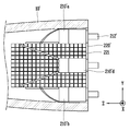
도 1은 본 발명의 일 실시예에 따른 방향 탐지 안테나의 사시도이다.
도 2는 도 1에 따른 방향 탐지 안테나의 배열 구조를 나타낸 도면이다.
도 3은 도 1에 따른 방향 탐지 안테나의 측단면도이다.
도 4는 본 발명의 다른 실시예에 따른 방향 탐지 안테나의 사시도이다.
도 5는 도 4에 따른 방향 탐지 안테나의 배열 구조를 나타낸 도면이다.
도 6은 도 4에 따른 방향 탐지 안테나의 측단면도이다.
도 7은 도 1 및 도 4에 따른 방향 탐지 안테나에 있어, 제4 레이돔 장착형 안테나의 XY 평면 방사패턴을 나타낸 그래프이다. 1 is a perspective view of a direction finding antenna according to an embodiment of the present invention.
FIG. 2 is a diagram illustrating an arrangement structure of a direction finding antenna according to FIG. 1.
3 is a side cross-sectional view of the direction finding antenna according to FIG. 1.
4 is a perspective view of a direction finding antenna according to another embodiment of the present invention.
5 is a diagram illustrating an arrangement structure of a direction finding antenna according to FIG. 4.
6 is a side cross-sectional view of the direction finding antenna according to FIG. 4.
7 is a graph showing an XY plane radiation pattern of a fourth radome-mounted antenna in the direction finding antennas according to FIGS. 1 and 4.
이하에서는, 첨부한 도면들을 참조하여 본 발명의 실시예에 따른 방향 탐지 안테나(100, 100′)에 대해 설명한다.Hereinafter, the
방향 탐지 안테나(100, 100′)는 방향 탐지 안테나(100, 100′)를 구성하는 각각의 안테나들(200, 200′)을 통해 표적의 위치를 탐지하는 역할을 수행할 수 있다.The
본 발명의 실시예에 따른 방향 탐지 안테나(100, 100′)는 작은 직경을 갖는 레이돔(10) 내부에 복수의 소형 안테나들(200, 200′)이 배치된 구조일 수 있다.The
여기서, 레이돔(10)이란 기상용 레이더, 도프 레이더, 적탐색용 레이더 등의 안테나를 보호하도록 하는 하우징 역할을 하는 것으로, 안테나가 외부에 직접 노출되는 것을 방지할 수 있다.Here, the
레이돔(10)은 유전체로 이루어질 수 있으며, 일체로 형성되어 공기와의 마찰 등과 같은 외부 충격에 견딜 수 있는 강도를 가질 수 있다.The
본 발명의 실시예에 따르면, 방향 탐지 안테나(100, 100′)는 전술한 레이돔(10)에 장착되어 배치되는 복수의 레이돔 장착형 안테나들(210, 210′)과 레이돔 장착형 안테나들(210, 210′)에 의해 둘러싸이도록 레이돔(10)의 중앙부에 배치되는 혼 안테나(220, 220′)로 구성될 수 있다.According to an embodiment of the present invention, the
본 발명의 실시예에 따른 방향 탐지 안테나(100, 100′)는 혼 안테나 (220, 220′) 일부 표면에 인공 자기 도체(221) 적용 여부에 따라 서로 다른 실시예를 가질 수 있다.The
먼저, 본 발명의 일 실시예에 따른 표면에 인공 자기 도체가 적용되지 않은 혼 안테나(220)를 포함하는 방향 탐지 안테나(100)에 대해 설명한다. First, a description will be given of a
도 1은 본 발명의 일 실시예에 따른 방향 탐지 안테나의 사시도이고, 도 2는 도 1에 따른 방향 탐지 안테나의 배열 구조를 나타낸 도면이고, 도 3은 도 1에 따른 방향 탐지 안테나의 측단면도이다.1 is a perspective view of a direction finding antenna according to an embodiment of the present invention, FIG. 2 is a diagram showing an arrangement structure of the direction finding antenna according to FIG. 1, and FIG. 3 is a side cross-sectional view of the direction finding antenna according to FIG. 1. .
본 발명의 일 실시예에 따르면, 방향 탐지 안테나(100)는 레이돔(10)에 장착되어 배치되는 복수의 레이돔 장착형 안테나들(210a, 210b, 210c, 210d)과 레이돔 장착형 안테나들(210a, 210b, 210c, 210d)에 의해 둘러싸이도록 레이돔 (10)의 중앙부에 배치되는 혼 안테나(220)를 포함하여 이루어질 수 있다. According to an embodiment of the present invention, the
레이돔(10)은 임의의 형상일 수 있으나, 첨부한 도면과 같이 레이돔 (10)의 축 방향(z축 방향)으로 연장된 유선형 형상일 수 있다. 또한, 전술한 것과 같이 유전체로 이루어질 수 있다.The
레이돔 장착형 안테나들(210a, 210b, 210c, 210d)은 레이돔(10)의 축을 기준으로 상하좌우에 배치될 수 있다.The radome-mounted
레이돔 장착형 안테나들(210a, 210b, 210c, 210d)은 레이돔(10)의 내측 둘레를 따라 동일한 간격으로 배치될 수 있다. 예를 들어, 레이돔 장착형 안테나들(210a, 210b, 210c, 210d)은 레이돔(10)의 중심을 기준으로 90° 간격으로 배치될 수 있다. The radome-mounted
레이돔 장착형 안테나들(210a, 210b, 210c, 210d)은 일측이 레이돔(10)의 개구된 후방을 덮는 후면 덮개(110)에 고정 설치될 수 있다. 자세하게는, 레이돔 장착형 안테나들(210a, 210b, 210c, 210d)의 커넥터부(212)가 레이돔 (10)의 후면 덮개(110)를 관통하도록 설치되어, 레이돔(10)의 후방으로부터 무선 신호(이하, 전자기파)를 전송받을 수 있다. The radome-mounted
레이돔 장착형 안테나들(210a, 210b, 210c, 210d)은 일측이 커넥터부 (212)와 연결되는 급전부(미도시)를 포함할 수 있다. 예를 들어, 급전부는 다단형의 구조로 형성되어 커넥터부(212)로부터 전송받은 전자기파의 임피던스를 변화시킬 수 있다. The radome-mounted
예를 들어, 급전부의 다단형 구조가 xz 평면에 대하여 수직하도록 형성되는 경우, 레이돔 장착형 안테나(210)는 y축 방향의 편파를 구현할 수 있다.For example, when the multi-stage structure of the power supply unit is formed to be perpendicular to the xz plane, the radome-mounted
본 실시예에 따르면, 방향 탐지 안테나(100)를 구성하는 레이돔 장착형 안테나들(210a, 210b, 210c, 210d)은 모두 y축 방향의 선형 편파를 갖도록 배치 및 설계됨으로써 안테나의 이득을 향상시킬 수 있다.According to the present embodiment, the radome-mounted
방사부(211)는 급전부의 타측에서 연장 형성되며, 임피던스가 변화된 전자기파를 레이돔(10) 내부, 자세하게는, 레이돔(10)의 축 방향을 향해 방사할 수 있다.The
방사부(211)는 레이돔(10)의 내측면 형상과 대응되도록 형성된 부분을 포함하여, 레이돔(10)의 내측면에 밀착되도록 배치될 수 있다. 즉, 방사부 (211)는 레이돔(10)과 동일한 유선형의 형상으로 형성된 부분을 포함할 수 있다. The
또한, 방사부(211)는 급전부의 타측으로부터 멀어질수록 확장되는 개구면을 가질 수 있다. 이러한 구조를 통해 레이돔(10)의 축 방향에 대한 안테나 이득을 향상시킬 수 있다. In addition, the
한편, 레이돔 장착형 안테나들(210a, 210b, 210c, 210d)은 배치된 위치에 따라 서로 다른 역할을 수행할 수 있다. Meanwhile, the radome-mounted
구체적으로, 레이돔 장착형 안테나들(210a, 210b, 210c, 210d)은 레이돔 (10)의 축을 기준으로 각각 상하로 배치되어 표적의 고각을 탐지하는 제1 레이돔 장착형 안테나(210a) 및 제2 레이돔 장착형 안테나(210b)를 포함할 수 있다.Specifically, the radome-mounted
또한, 레이돔(10)의 축을 기준으로 각각 좌우로 배치되어 표적의 방위각을 탐지하는 제3 레이돔 장착형 안테나(210c) 및 제4 레이돔 장착형 안테나(210d)를 포함할 수 있다.In addition, a third radome-mounted
이 때, 레이돔(10)의 축 방향을 기준으로 상하로 배치된 제1 및 제2 레이돔 장착형 안테나들(210a, 210b)과 좌우로 배치된 제3 및 제4 레이돔 장착형 안테나들(210c, 210d)은 방사부(211)가 서로 교차되도록 배치될 수 있다. At this time, the first and second radome-mounted
레이돔 장착형 안테나들(210a, 210b, 210c, 210d)은 레이돔(10)의 내측 표면에 장착되므로, 레이돔(10) 내 중앙부에는 빈 공간이 형성될 수 있다.Since the radome-mounted
본 발명의 실시예에 따르면, 레이돔(10) 내 중앙부에 형성된 빈 공간에는 표적을 탐지하기 위한 혼 안테나(220)가 배치될 수 있다. 즉, 혼 안테나(220)는 레이돔 장착형 안테나들(210a, 210b, 210c, 210d)에 의해 형성되는 레이돔(10)의 내측 반경 내 배치될 수 있다. According to an embodiment of the present invention, a
이와 같은 배치 구조, 즉, 레이돔(10)의 내측 둘레를 따라 레이돔 장착형 안테나들(210a, 210b, 210c, 210d)이 배치되며, 중앙부의 빈 공간에 혼 안테나(220)가 배치되는 배치 구조를 통해 공간을 효율적으로 활용할 수 있으며, 방향 탐지 안테나(100)를 소형화할 수 있는 효과가 있다.Through such an arrangement structure, that is, the radome-mounted
한편, 혼 안테나(220)는 단면 형상이 사각형일 수 있으며, 혼 안테나 (220)를 형성하는 면은 도체(conductor)로 형성될 수 있다. 즉, 혼 안테나(220)는 도체로 형성된 4개의 면으로 이루어질 수 있다.Meanwhile, the
혼 안테나(220)는 각각의 면이 레이돔(10)의 내측 둘레를 따라 상하좌우로 배치된 레이돔 장착형 안테나들(210a, 210b, 210c, 210d) 중 어느 하나를 향하도록 배치될 수 있다. The
나아가, 혼 안테나(220)는 각각의 면이 레이돔 장착형 안테나들 (210a, 210b, 210c, 210d) 중 어느 하나와 접하도록 배치될 수 있다. Further, the
한편, 레이돔(10) 내 중앙부에 배치된 혼 안테나(220)의 표면으로 레이돔 (10)의 내측 둘레를 따라 배치된 레이돔 장착형 안테나들(210a, 210b, 210c, 210d)로부터 방사된 무선 신호가 입사될 수 있다.Meanwhile, a radio signal radiated from the radome-mounted
구체적으로, 제1 레이돔 장착형 안테나(210a) 및 제2 레이돔 장착형 안테나(210b)에서 방사된 전자기파는 혼 안테나(220)의 상면 및 하면의 표면에 수직 편파로 입사할 수 있으며, 제3 레이돔 장착형 안테나(210c) 및 제4 레이돔 장착형 안테나(210d)에서 방사된 전자기파는 혼 안테나(220)의 좌측면 및 우측면의 표면에 수평 편파로 입사할 수 있다. Specifically, electromagnetic waves radiated from the first radome-mounted
본 발명의 일 실시예에 따른 방향 탐지 안테나(100)는 레이돔 장착형 안테나들(210a, 210b, 210c, 210d)과 이들의 중앙부에 혼 안테나(220)를 추가 배치하여, 안테나 이득을 향상시킬 수 있는 효과가 있다. The
다음으로, 본 발명의 다른 실시예에 따른 표면에 인공 자기 도체가 적용된 혼 안테나(220′)를 포함하는 방향 탐지 안테나(100′)에 대해 설명한다. Next, a description will be given of a direction finding antenna 100' including a horn antenna 220' to which an artificial magnetic conductor is applied to a surface according to another embodiment of the present invention.
도 4는 본 발명의 다른 실시예에 따른 방향 탐지 안테나의 사시도이고, 도 5는 도 4에 따른 방향 탐지 안테나의 배열 구조를 나타낸 도면이고, 도 6은 도 4에 따른 방향 탐지 안테나의 측단면도이다.4 is a perspective view of a direction finding antenna according to another embodiment of the present invention, FIG. 5 is a view showing an arrangement structure of the direction finding antenna according to FIG. 4, and FIG. 6 is a side cross-sectional view of the direction finding antenna according to FIG. 4 .
본 발명의 다른 실시예에 따르면, 방향 탐지 안테나(100′)는 레이돔 (10′)에 장착되어 배치되는 복수의 레이돔 장착형 안테나들(210′a, 210′b, 210′c, 210′d)과 레이돔 장착형 안테나들(210′a, 210′b, 210′c, 210′d)에 의해 둘러싸이도록 레이돔(10′)의 중앙부에 배치되는 혼 안테나(220′)를 포함하여 이루어질 수 있다. 이하에서는 각각의 구성들과 관련하여 전술한 실시예와 동일한 사항들에 대한 설명은 생략한다.According to another embodiment of the present invention, the
본 발명의 다른 실시예에 따르면, 레이돔 장착형 안테나들(210′a, 210′b, 210′c, 210′d)과 접하는 혼 안테나(220′)의 표면들 중 적어도 일부 표면에는 인공 자기 도체(221, Artificial Magnetic Conductor)가 적용될 수 있다. 혼 안테나(220′)는 도체로 형성될 수 있으며, 인공 자기 도체(221)가 적용되는 면에는 유전체를 더 구비할 수 있다. According to another embodiment of the present invention, at least some of the surfaces of the
바람직하게, 인공 자기 도체(221)가 적용된 혼 안테나(220′)의 표면은 레이돔(10)의 축 방향을 기준으로 좌우에 배치된 제3 및 제4 레이돔 장착형 안테나들(210′c, 210′d)과 접하는 표면을 포함할 수 있다. Preferably, the surface of the
구체적으로, 전술한 것과 같이 제3 레이돔 장착형 안테나(210′c) 및 제4 레이돔 장착형 안테나 (210′d)로부터 방사된 전자기파는 혼 안테나(220′)의 도체 표면에 수평 편파로 입사하게 된다.Specifically, as described above, the electromagnetic waves radiated from the third radome-mounted
이와 같이 전자기파가 도체로 형성된 혼 안테나(220′)의 표면에 수평 편파로 입사하는 경우, 전자기적 경계 조건에 따라 전기장과 이미지 성분이 혼 안테나(220′) 표면의 정면 방향에서 상쇄 간섭을 일으키게 되어, 레이돔 장착형 안테나들(210′)의 정면 방향 이득 저하를 유발할 수 있다. 여기서, 정면 방향은 레이돔(10) 축 방향(z축 방향)을 의미한다. When the electromagnetic wave is incident on the surface of the
따라서 본 발명의 다른 실시예에 따른 방향 탐지 안테나(100′)는 전자기파가 수평 편파로 입사하게 되는 혼 안테나(220′)의 좌측 표면 및 우측 표면에 인공 자기 도체(221)를 적용함으로써, 레이돔 장착형 안테나들(210)의 정면 방향 이득 저하를 최소화할 수 있는 효과가 있다.Therefore, the
혼 안테나(220′) 표면에 적용되는 인공 자기 도체(221)의 크기, 재질, 형상 등은 레이돔(10′) 축 방향(z축 방향)에서 레이돔 장착형 안테나(210′)의 이득이 최대가 되도록 선정될 수 있다.The size, material, shape, etc. of the artificial
인공 자기 도체(221)는 혼 안테나(220′) 표면 상에 사각 패치 또는 기타 임의의 형상이 주기적으로 배열된 구조를 갖도록 적용될 수 있으며, 자세하게는, 인공 자기 도체(221)는 혼 안테나(220′) 표면에 구비된 유전체 상에 적용될 수 있다. 유전체는 인공 자기 도체(221)가 적용되는 혼 안테나 (220′) 표면에 선택적으로 구비될 수 있다. 이 때, 혼 안테나(220′)의 타면은 금속으로 접지된 상태일 수 있으며, 배열 간격은 유전체의 유전율에 따라 상이할 수 있다. The artificial
도 7은 도 1 및 도 4에 따른 방향 탐지 안테나에 있어, 제4 레이돔 장착형 안테나의 xz 평면 방사패턴을 나타낸 그래프이다. 7 is a graph showing an xz plane radiation pattern of a fourth radome-mounted antenna in the direction finding antennas according to FIGS. 1 and 4.
그래프에서 x축에 나타난 theta(degree)는 레이돔 축을 0도로 선정했을 경우의 xz 평면에서의 관찰 각도를 의미하고, y축에 나타난 realized gain은 관찰 각도에서 나타난 안테나의 방사 전력을 dB 단위로 도시한 것이다. In the graph, theta(degree) shown on the x-axis means the observation angle in the xz plane when the radome axis is selected at 0 degrees, and the realized gain shown on the y-axis shows the radiated power of the antenna shown in the observation angle in dB. will be.
도 7을 참조하면, 혼 안테나(220′)의 좌측 및 우측 표면에 인공 자기 도체(221)를 적용한 경우, 레이돔(10′) 정면 방향에서의 이득은 약 5 dB만큼 향상되는 것을 확인할 수 있다. Referring to FIG. 7, when the artificial
이는 인공 자기 도체(221)를 적용함으로써 혼 안테나(220′) 표면에 수평 편파로 입사하는 제3 및 제4 레이돔 장착형 안테나(210′c, 210′d)의 이득 저하가 최소화되고, 이에 따라 방향 탐지 안테나(100′)의 전체 합 이득이 향상되어 최대 탐지 거리가 증가함을 의미한다.This is achieved by applying the artificial
본 발명의 실시예에 따른 방향 탐지 안테나(100, 100′)는 레이돔(10, 10′) 내 상하좌우에 레이돔 장착형 안테나(210, 210′)가 배치되고, 레이돔(10, 10′) 중심에 혼 안테나(220, 220′)가 배치된 구조를 통해 소형화할 수 있고, 안테나 이득을 향상시켜 충분한 탐지 거리를 확보할 수 있는 효과가 있다. In the
또한, 레이돔(10′) 중심에 배치된 혼 안테나(220′)의 적어도 일부 표면에 인공 자기 도체(221)를 적용하여 레이돔(10′)의 축 방향에 대한 안테나의 전체 합 이득을 증가시킬 수 있으며, 최대 탐지거리를 증가시킬 수 있는 효과가 있다.In addition, by applying the artificial
이상 본 발명의 바람직한 실시예에 대해서 설명하였으나, 당업계에서 통상의 지식을 가진 자라면 이하의 청구범위에 기재된 본 발명의 사상 및 영역을 벗어나지 않는 범위 내에서 본 발명을 다양하게 수정 및 변형시킬 수 있음을 이해할 수 있을 것이다. Although the preferred embodiments of the present invention have been described above, those of ordinary skill in the art can variously modify and modify the present invention without departing from the spirit and scope of the present invention described in the following claims. You will understand that there is.
100, 100′: 방향 탐지 안테나
210, 210′: 레이돔 장착형 안테나
220, 220′: 혼 안테나
221: 인공 자기 도체100, 100′: direction finding antenna
210, 210′: Radome-mounted antenna
220, 220′: horn antenna
221: artificial magnetic conductor
Claims (9)
상기 레이돔의 축을 기준으로 상하좌우에 배치되는 복수의 레이돔 장착형 안테나들; 및
상기 레이돔 장착형 안테나들에 의해 둘러싸이도록 상기 레이돔의 중앙부에 배치되며, 단면 형상이 사각형인 혼 안테나를 포함하고,
상기 혼 안테나는, 각각의 면이 상기 레이돔 장착형 안테나들 중 어느 하나를 향하도록 배치되고, 각각의 면이 상기 레이돔 장착형 안테나들 중 어느 하나와 접하는 것을 특징으로 하는, 방향 탐지 안테나. A streamlined radome extending in the axial direction;
A plurality of radome-mounted antennas disposed on the top, bottom, left, and right based on the axis of the radome; And
It is disposed in the central portion of the radome so as to be surrounded by the radome-mounted antennas, and includes a horn antenna having a rectangular cross-sectional shape,
The horn antenna, wherein each surface is disposed to face one of the radome-mounted antennas, and each surface is in contact with any one of the radome-mounted antennas.
상기 복수의 레이돔 장착형 안테나들은, 상기 레이돔의 중심을 기준으로 90°간격으로 배치되는 것을 특징으로 하는, 방향 탐지 안테나.The method of claim 1,
The plurality of radome-mounted antennas are arranged at intervals of 90° with respect to the center of the radome.
상기 혼 안테나는, 상기 레이돔 장착형 안테나와 접하는 표면들 중 적어도 일부 표면에 인공 자기 도체가 적용된 것을 특징으로 하는, 방향 탐지 안테나. The method of claim 1,
The horn antenna, characterized in that an artificial magnetic conductor is applied to at least some of the surfaces in contact with the radome-mounted antenna.
상기 인공 자기 도체가 적용된 상기 혼 안테나의 표면은,
상기 레이돔의 축 방향을 기준으로 좌우에 배치된 상기 레이돔 장착형 안테나들과 접하는 표면을 포함하는 것을 특징으로 하는, 방향 탐지 안테나.The method of claim 4,
The surface of the horn antenna to which the artificial magnetic conductor is applied,
And a surface in contact with the radome-mounted antennas disposed on the left and right based on the axial direction of the radome.
상기 혼 안테나의 적어도 일부 표면에는, 임의의 형상을 갖는 상기 인공 자기 도체가 주기적으로 배열된 것을 특징으로 하는, 방향 탐지 안테나. The method of claim 4,
The artificial magnetic conductor having an arbitrary shape is periodically arranged on at least a portion of the surface of the horn antenna.
상기 레이돔 장착형 안테나들 및 상기 혼 안테나는, 모두 동일한 방향의 선형 편파를 구현하는 것을 특징으로 하는, 방향 탐지 안테나.The method of claim 1,
The radome-mounted antennas and the horn antenna, characterized in that both implement linear polarization in the same direction, a direction finding antenna.
상기 복수의 레이돔 장착형 안테나들은,
상기 레이돔의 축을 기준으로 각각 상하로 배치되어 표적의 고각을 탐지하도록 구성되는 제1 레이돔 장착형 안테나 및 제2 레이돔 장착형 안테나; 및
상기 레이돔의 축을 기준으로 각각 좌우로 배치되어 표적의 방위각을 탐지하도록 구성되는 제3 레이돔 장착형 안테나 및 제4 레이돔 장착형 안테나를 포함하는 것을 특징으로 하는, 방향 탐지 안테나.The method of claim 1,
The plurality of radome-mounted antennas,
A first radome-mounted antenna and a second radome-mounted antenna configured to detect elevation of a target by being disposed vertically with respect to the axis of the radome; And
And a third radome-mounted antenna and a fourth radome-mounted antenna, which are disposed to the left and right with respect to the axis of the radome and configured to detect an azimuth angle of the target.
상기 복수의 레이돔 장착형 안테나들은 일측이 커넥터부와 연결되는 급전부 및 상기 급전부의 타측에서 연장 형성되어 전자기파를 레이돔의 축 방향을 향해 방사하도록 하는 방사부를 포함하고,
상기 레이돔의 축 방향을 기준으로 상하로 배치된 제1 및 제2 레이돔 장착형 안테나들과 좌우로 배치된 제3 및 제4 레이돔 장착형 안테나들은 상기 방사부가 서로 교차되도록 배치되는 것을 특징으로 하는, 방향 탐지 안테나. The method of claim 8,
The plurality of radome-mounted antennas include a feeding part having one side connected to the connector part and a radiating part extending from the other side of the feeding part to radiate electromagnetic waves in the axial direction of the radome,
Direction detection, characterized in that the first and second radome-mounted antennas arranged vertically with respect to the axial direction of the radome and the third and fourth radome-mounted antennas arranged left and right are arranged such that the radiating portions cross each other. antenna.
Priority Applications (1)
| Application Number | Priority Date | Filing Date | Title |
|---|---|---|---|
| KR1020190135708A KR102223094B1 (en) | 2019-10-29 | 2019-10-29 | Direction detecting antenna using horn antenna and radome attached antenna |
Applications Claiming Priority (1)
| Application Number | Priority Date | Filing Date | Title |
|---|---|---|---|
| KR1020190135708A KR102223094B1 (en) | 2019-10-29 | 2019-10-29 | Direction detecting antenna using horn antenna and radome attached antenna |
Publications (1)
| Publication Number | Publication Date |
|---|---|
| KR102223094B1 true KR102223094B1 (en) | 2021-03-04 |
Family
ID=75174836
Family Applications (1)
| Application Number | Title | Priority Date | Filing Date |
|---|---|---|---|
| KR1020190135708A Active KR102223094B1 (en) | 2019-10-29 | 2019-10-29 | Direction detecting antenna using horn antenna and radome attached antenna |
Country Status (1)
| Country | Link |
|---|---|
| KR (1) | KR102223094B1 (en) |
Citations (3)
| Publication number | Priority date | Publication date | Assignee | Title |
|---|---|---|---|---|
| JP2007264680A (en) * | 2005-03-11 | 2007-10-11 | Rcs:Kk | Radio marker |
| US20180123229A1 (en) * | 2016-11-03 | 2018-05-03 | Raytheon Company | Systems and Techniques for Radome-Antenna Configuration |
| KR101972347B1 (en) * | 2018-08-22 | 2019-04-25 | 국방과학연구소 | An Array Antenna Inserted on a Surface of Cylinder Conductor for Direction Finding Applications |
-
2019
- 2019-10-29 KR KR1020190135708A patent/KR102223094B1/en active Active
Patent Citations (3)
| Publication number | Priority date | Publication date | Assignee | Title |
|---|---|---|---|---|
| JP2007264680A (en) * | 2005-03-11 | 2007-10-11 | Rcs:Kk | Radio marker |
| US20180123229A1 (en) * | 2016-11-03 | 2018-05-03 | Raytheon Company | Systems and Techniques for Radome-Antenna Configuration |
| KR101972347B1 (en) * | 2018-08-22 | 2019-04-25 | 국방과학연구소 | An Array Antenna Inserted on a Surface of Cylinder Conductor for Direction Finding Applications |
Similar Documents
| Publication | Publication Date | Title |
|---|---|---|
| US7298333B2 (en) | Patch antenna element and application thereof in a phased array antenna | |
| EP2369677B1 (en) | Planar bi-directional radiation antenna | |
| US6501965B1 (en) | Radio communication base station antenna | |
| US9851436B2 (en) | Radar antenna assembly with panoramic detection | |
| US6819291B1 (en) | Reduced-size GPS antennas for anti-jam adaptive processing | |
| KR100871432B1 (en) | Low altitude radar antenna | |
| US20170040702A1 (en) | Low-Profile Blanket Antenna | |
| WO2013055272A1 (en) | Short range radar system | |
| US8179328B2 (en) | Direction finding antenna | |
| Kim et al. | A compact dual-polarized (CP, LP) with dual-feed microstrip patch array for target detection | |
| CN108173002A (en) | A Composite Polarization Sensitive Array Device Based on Conformal Vivaldi Antenna | |
| US10756446B2 (en) | Planar antenna structure with reduced coupling between antenna arrays | |
| US6211839B1 (en) | Polarized planar log periodic antenna | |
| US11558987B2 (en) | Radar apparatus | |
| KR100529709B1 (en) | Beam variable antenna | |
| KR102223094B1 (en) | Direction detecting antenna using horn antenna and radome attached antenna | |
| CN103872453B (en) | Lightning protection system and associated assemble method for antenna house | |
| US20200381813A1 (en) | Antenna device | |
| US11600918B2 (en) | Integrated antenna arrangement | |
| Jeong et al. | Printed dipole antenna array with reconfigurable feeding network for wide elevation angle of U2X communications | |
| CN111585020B (en) | An omnidirectional scanning monopole end-fired array antenna with horizontal beam | |
| JP2000201014A (en) | Microstrip antenna | |
| KR101775516B1 (en) | Crpa array antenna | |
| JP3045522B2 (en) | Flush mount antenna | |
| KR102067399B1 (en) | A compact radome mounted antenna for direction finding appication and antenna system having the same |
Legal Events
| Date | Code | Title | Description |
|---|---|---|---|
| PA0109 | Patent application |
St.27 status event code: A-0-1-A10-A12-nap-PA0109 |
|
| PA0201 | Request for examination |
St.27 status event code: A-1-2-D10-D11-exm-PA0201 |
|
| D13-X000 | Search requested |
St.27 status event code: A-1-2-D10-D13-srh-X000 |
|
| R17-X000 | Change to representative recorded |
St.27 status event code: A-3-3-R10-R17-oth-X000 |
|
| D14-X000 | Search report completed |
St.27 status event code: A-1-2-D10-D14-srh-X000 |
|
| PE0902 | Notice of grounds for rejection |
St.27 status event code: A-1-2-D10-D21-exm-PE0902 |
|
| E13-X000 | Pre-grant limitation requested |
St.27 status event code: A-2-3-E10-E13-lim-X000 |
|
| P11-X000 | Amendment of application requested |
St.27 status event code: A-2-2-P10-P11-nap-X000 |
|
| P13-X000 | Application amended |
St.27 status event code: A-2-2-P10-P13-nap-X000 |
|
| PE0902 | Notice of grounds for rejection |
St.27 status event code: A-1-2-D10-D21-exm-PE0902 |
|
| P11-X000 | Amendment of application requested |
St.27 status event code: A-2-2-P10-P11-nap-X000 |
|
| P13-X000 | Application amended |
St.27 status event code: A-2-2-P10-P13-nap-X000 |
|
| E701 | Decision to grant or registration of patent right | ||
| PE0701 | Decision of registration |
St.27 status event code: A-1-2-D10-D22-exm-PE0701 |
|
| GRNT | Written decision to grant | ||
| PR0701 | Registration of establishment |
St.27 status event code: A-2-4-F10-F11-exm-PR0701 |
|
| PR1002 | Payment of registration fee |
St.27 status event code: A-2-2-U10-U11-oth-PR1002 Fee payment year number: 1 |
|
| PG1601 | Publication of registration |
St.27 status event code: A-4-4-Q10-Q13-nap-PG1601 |
|
| PR1001 | Payment of annual fee |
St.27 status event code: A-4-4-U10-U11-oth-PR1001 Fee payment year number: 4 |
|
| PR1001 | Payment of annual fee |
St.27 status event code: A-4-4-U10-U11-oth-PR1001 Fee payment year number: 5 |
|
| PR1001 | Payment of annual fee |
St.27 status event code: A-4-4-U10-U11-oth-PR1001 Fee payment year number: 6 |