KR102213720B1 - vending machine - Google Patents
vending machine Download PDFInfo
- Publication number
- KR102213720B1 KR102213720B1 KR1020190129235A KR20190129235A KR102213720B1 KR 102213720 B1 KR102213720 B1 KR 102213720B1 KR 1020190129235 A KR1020190129235 A KR 1020190129235A KR 20190129235 A KR20190129235 A KR 20190129235A KR 102213720 B1 KR102213720 B1 KR 102213720B1
- Authority
- KR
- South Korea
- Prior art keywords
- main body
- frame
- product
- collecting
- vending machine
- Prior art date
Links
- 230000000903 blocking effect Effects 0.000 description 2
- 235000013305 food Nutrition 0.000 description 2
- 238000012986 modification Methods 0.000 description 2
- 230000004048 modification Effects 0.000 description 2
- 238000013459 approach Methods 0.000 description 1
- 235000013361 beverage Nutrition 0.000 description 1
- 235000013365 dairy product Nutrition 0.000 description 1
- 238000001514 detection method Methods 0.000 description 1
- 238000010586 diagram Methods 0.000 description 1
- 230000000694 effects Effects 0.000 description 1
- 210000004392 genitalia Anatomy 0.000 description 1
- 238000004519 manufacturing process Methods 0.000 description 1
- 238000005057 refrigeration Methods 0.000 description 1
Images


Classifications
-
- G—PHYSICS
- G07—CHECKING-DEVICES
- G07F—COIN-FREED OR LIKE APPARATUS
- G07F11/00—Coin-freed apparatus for dispensing, or the like, discrete articles
- G07F11/02—Coin-freed apparatus for dispensing, or the like, discrete articles from non-movable magazines
- G07F11/04—Coin-freed apparatus for dispensing, or the like, discrete articles from non-movable magazines in which magazines the articles are stored one vertically above the other
- G07F11/16—Delivery means
-
- G—PHYSICS
- G07—CHECKING-DEVICES
- G07F—COIN-FREED OR LIKE APPARATUS
- G07F11/00—Coin-freed apparatus for dispensing, or the like, discrete articles
- G07F11/02—Coin-freed apparatus for dispensing, or the like, discrete articles from non-movable magazines
- G07F11/38—Coin-freed apparatus for dispensing, or the like, discrete articles from non-movable magazines in which the magazines are horizontal
- G07F11/42—Coin-freed apparatus for dispensing, or the like, discrete articles from non-movable magazines in which the magazines are horizontal the articles being delivered by motor-driven means
Landscapes
- Physics & Mathematics (AREA)
- General Physics & Mathematics (AREA)
- Control Of Vending Devices And Auxiliary Devices For Vending Devices (AREA)
Abstract
본 발명은, 구조적으로 간단하고 사용상 간편하도록 된 취출수단을 구비하여 생산성 및 경제성을 구현할 수 있도록;
본체와; 상기 본체의 내부에 상하좌우로 배열되며 상품이 적재된 다수의 진열대와; 상기 진열대에 진열된 상품을 선택적으로 취출하도록 된 취출수단;을 포함하여 이루어지는 자판기에 있어서; 상기 취출수단은, 상기 본체에 수직상으로 길이를 가지면서 배치된 수직레일과, 상기 수직레일에 수평상으로 갈이를 가지면서 배치된 수평레일과, 상기 수평레일의 길이 방향으로 이동되면서 안내되도록 결합되며 상기 본체의 전후방향으로 길이를 가지는 안내공이 형성된 운동체를 가지는 안내부재와; 상기 운동체의 안내공을 관통하면서 결합되어 상기 본체의 전후방향으로 이동운동하도록 된 안내프레임과, 상기 안내프레임의 전단 및 후단에서 하측 방향으로 길이를 가지면서 각각 구비되는 전단프레임 및 후단프레임을 가지는 작동부재와; 상기 후단프레임의 하단에 구비되며 상기 전단프레임에 구비된 조작버튼의 구동에 따라 전원공급부의 전원을 인가받아 제어하도록 된 제어수단의 제어를 통해 구동되어 상기 진열대에 진열된 최전방의 상품의 포집하도록 된 포집부재;를 포함하여 이루어지는 자판기를 제공한다.The present invention is provided with a take-out means that is structurally simple and easy to use, so that productivity and economy can be realized;
Main body; A plurality of display racks arranged in the upper, lower, left, and right directions inside the main body and loaded with products; A vending machine comprising: taking out means configured to selectively take out the products displayed on the display rack; The take-out means is coupled to a vertical rail disposed while having a length vertically on the main body, a horizontal rail disposed while having a horizontal grind on the vertical rail, and guided while moving in the longitudinal direction of the horizontal rail. And a guide member having a moving body having a guide hole having a length in the front and rear direction of the main body; Operation having a guide frame that is coupled while passing through the guide hole of the moving body to move in the front-rear direction of the main body, and a front end frame and a rear end frame each having a length in a downward direction from the front and rear ends of the guide frame Absent; It is provided at the lower end of the rear frame and is driven through the control of a control means configured to receive and control the power of the power supply unit according to the operation of the operation button provided on the front frame to collect the frontmost product displayed on the display stand. It provides a vending machine comprising a; collecting member.
Description
본 발명은, 상하좌우로 진열된 다양한 상품을 선택적으로 취출하여 판매하도록 된 자판기에 관한 것으로, 더욱 상세하게는, 구조적으로 간단하고 사용상 간편하도록 된 취출수단을 구비하여 생산성 및 경제성을 구현할 수 있도록 된 자판기에 관한 것이다.The present invention relates to a vending machine configured to selectively take out and sell a variety of products displayed vertically and horizontally, and more specifically, it is possible to realize productivity and economy by providing a takeout means that is structurally simple and easy to use. It's about vending machines.
일반적으로, 자판기(자동판매기)는 정형화된 공산품은 물론 비정형 식품의 판매 가능하며, 식품 중에서 냉장을 요하는 음료와 유제품으로 영역을 확대하고 있다.In general, vending machines (vending machines) are capable of selling non-standard foods as well as standardized industrial products, and are expanding into beverages and dairy products that require refrigeration among foods.
이러한 자판기는, 다품종의 상품을 수납하는 구조상 선택된 상품의 위치 검출에 대한 작동신뢰성과 내구성이 중요하다.In such a vending machine, operation reliability and durability in detecting the location of a selected product are important because of a structure for storing a variety of products.
한국특허출원번호 제10-2015-0174665호(명칭: 멀티자판기의 상품위치 검출장치/2015.12.09.)에서는, 공보에 공지된 바와 같이, 멀티자판기에 수납된 상품의 위치를 검출하는 장치에 있어서: 종횡으로 수납선반을 지닌 본체; 상기 본체의 내부에 설치되어 반송대의 상하이동을 유발하는 수직반송부; 상기 반송대 상에 트레이를 수평이동 가능하게 탑재하고, 횡으로 인접한 수납선반에 인식레일을 구비하는 수평반송부; 및 상기 수직반송부와 수평반송부에 연결되어 트레이를 선택된 수납선반으로 이동시키는 제어기;를 포함하여 이루어지는 자판기가 구비되어 있다.In Korean Patent Application No. 10-2015-0174665 (name: product position detection device for a multi-vending machine/2015.12.09.), as known in the publication, in an apparatus for detecting the position of a product stored in a multi-vending machine. : Main body with storage shelf vertically and horizontally; A vertical transfer unit installed inside the main body to cause an upward movement of the transfer table; A horizontal transfer unit having a tray mounted on the transfer table so as to be horizontally movable, and having a recognition rail on a horizontally adjacent storage shelf; And a controller connected to the vertical transfer unit and the horizontal transfer unit to move the tray to the selected storage shelf.
그러나 상기와 같은 종래의 자판기는, 다양한 센서 및 모터 등과 같은 구성품들이 필수적으로 구비되어야 함에 따라, 구조적으로 복잡하여 생산성 및 사용상의 오류에 의한 비안전성을 가지어 제조 및 사용이 불편한 문제점들이 있었다.However, the conventional vending machine as described above has a problem in that it is inconvenient to manufacture and use because it is structurally complex and has non-safety due to errors in productivity and use as components such as various sensors and motors must be provided.
본 발명은, 상기와 같은 종래의 문제점들을 해결하기 위하여 제안된 것으로, 본 발명의 목적은, 구조적으로 간단하고 사용상 간편하도록 된 취출수단을 구비하여 생산성 및 경제성을 구현할 수 있도록 된 자판기를 제공하는 것에 있다.The present invention has been proposed to solve the conventional problems as described above, and an object of the present invention is to provide a vending machine capable of realizing productivity and economy by having a take-out means that is structurally simple and easy to use. have.
상기와 같은 본 발명의 목적을 달성하기 위한 본 발명에 의한 자판기는, 본체와; 상기 본체의 내부에 상하좌우로 배열되며 상품이 적재된 다수의 진열대와; 상기 진열대에 진열된 상품을 선택적으로 취출하도록 된 취출수단;을 포함하여 이루어지는 자판기에 있어서; 상기 취출수단은, 상기 본체에 수직상으로 길이를 가지면서 배치된 수직레일과, 상기 수직레일에 수평상으로 갈이를 가지면서 배치된 수평레일과, 상기 수평레일의 길이 방향으로 이동되면서 안내되도록 결합되며 상기 본체의 전후방향으로 길이를 가지는 안내공이 형성된 운동체를 가지는 안내부재와; 상기 운동체의 안내공을 관통하면서 결합되어 상기 본체의 전후방향으로 이동운동하도록 된 안내프레임과, 상기 안내프레임의 전단 및 후단에서 하측 방향으로 길이를 가지면서 각각 구비되는 전단프레임 및 후단프레임을 가지는 작동부재와; 상기 후단프레임의 하단에 구비되며 상기 전단프레임에 구비된 조작버튼의 구동에 따라 전원공급부의 전원을 인가받아 제어하도록 된 제어수단의 제어를 통해 구동되어 상기 진열대에 진열된 최전방의 상품의 포집하도록 된 포집부재;를 포함하여 이루어지는 것을 특징으로 한다.The vending machine according to the present invention for achieving the object of the present invention as described above, the main body; A plurality of display racks arranged in the upper, lower, left, and right directions inside the main body and loaded with products; A vending machine comprising: taking out means configured to selectively take out the products displayed on the display rack; The take-out means is coupled to a vertical rail disposed while having a length vertically on the main body, a horizontal rail disposed while having a horizontal grind on the vertical rail, and guided while moving in the longitudinal direction of the horizontal rail. And a guide member having a moving body having a guide hole having a length in the front and rear direction of the main body; Operation having a guide frame that is coupled while passing through the guide hole of the moving body to move in the front-rear direction of the main body, and a front end frame and a rear end frame each having a length in a downward direction from the front and rear ends of the guide frame Absent; It is provided at the lower end of the rear frame and is driven through the control of a control means configured to receive and control the power of the power supply unit according to the operation of the operation button provided on the front frame to collect the frontmost product displayed on the display stand. It characterized in that it comprises a; collecting member.
이와 같이 이루어지는 본 발명에 의한 자판기는, 사용자의 수동에 의하여 작동부재를 상하좌우전후 방향으로 선택적인 이동운동을 수행하여 상품을 포집하도록 된 포집부재를 선택된 상품의 전면에 배치한 상태에서 조작버튼을 통해 포집부재의 가동을 조작하여 상품을 포집하여 취출하도록 됨에 따라, 구조적으로 간단하고 사용상 간편하도록 된 취출수단을 구비하여 생산성 및 경제성을 구현하는 효과를 가진다.In the vending machine according to the present invention made as described above, the operation button is placed on the front side of the selected product by selectively moving the operating member in the vertical, left, right, forward and backward directions by the user. As the product is collected and taken out by manipulating the operation of the collecting member through the operation, it has the effect of realizing productivity and economy by providing a take-out means that is structurally simple and easy to use.
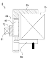
도 1은, 본 발명에 따른 일 실시 예에 의한 자판기를 보인 개략 측단면 예시도.
도 2는, 본 실시 예에 의한 자판기를 보인 개략 정면 예시도.
도 3 내지 도 6은, 본 실시 예에 의한 자판기를 구성하는 취출수단을 보인 개략 예시도.
도 7 내지 도 12는, 본 실시 예에 의한 자판기의 작용상태를 보인 개략 예시도.
도 13 내지 도 15는, 본 실시 예에 의한 자판기를 구성하는 취출수단에 적용되는 포집부재의 일 예를 보인 개략 예시도.
도 16 내지 도 18은, 본 실시 예에 의한 자판기를 구성하는 취출수단에 적용되는 포집부재의 다른 예를 보인 개략 예시도.
도 19는, 본 실시 예에 의한 자판기의 제어상태를 보인 개략 예시도.1 is a schematic side cross-sectional view showing a vending machine according to an embodiment of the present invention.
Figure 2 is a schematic front view showing the vending machine according to the present embodiment.
3 to 6 are schematic exemplified views showing take-out means constituting the vending machine according to the present embodiment.
7 to 12 are schematic diagrams showing an operating state of the vending machine according to the present embodiment.
13 to 15 are schematic exemplary views showing an example of a collecting member applied to a take-out means constituting a vending machine according to the present embodiment.
16 to 18 are schematic exemplified views showing another example of a collecting member applied to a take-out means constituting the vending machine according to the present embodiment.
19 is a schematic illustration showing a control state of the vending machine according to the present embodiment.
이하, 첨부된 도면을 참조하여, 본 발명에 따른 바람직한 실시 예에 의한 자판기를 상세히 설명하면 다음과 같다.Hereinafter, a vending machine according to a preferred embodiment of the present invention will be described in detail with reference to the accompanying drawings.
본 발명의 실시 예는 여러 가지 형태로 변형될 수 있으며, 본 발명의 범위가 아래에서 상세히 설명하는 실시 예로 한정되는 것으로 해석되어서는 안 된다. 본 실시예는 당 업계에서 평균적인 지식을 가진 자에게 본 발명을 더욱 완전하게 설명하기 위해서 제공되는 것이다. 따라서 도면에서의 요소의 형상 등은 보다 명확한 설명을 강조하기 위해서 과장되어 표현될 수 있다. 각 도면에서 동일한 부재는 동일한 참조부호로 도시한 경우가 있음을 유의하여야 한다. 본 발명의 요지를 불필요하게 흐릴 수 있다고 판단되는 공지 기능 및 구성에 대한 상세한 기술은 생략된다.The embodiments of the present invention may be modified in various forms, and the scope of the present invention should not be construed as being limited to the embodiments described in detail below. This embodiment is provided to more completely explain the present invention to those of ordinary skill in the art. Accordingly, the shape of the element in the drawings may be exaggerated to emphasize a clearer description. It should be noted that in each drawing, the same member may be indicated by the same reference numeral. Detailed descriptions of known functions and configurations that are determined to unnecessarily obscure the subject matter of the present invention will be omitted.
도 1 내지 도 6은, 본 발명에 따른 일 실시 예에 의한 자판기(1)를 보인 도면으로, 본 실시 예에 의한 자판기(1)는, 상하좌우로 진열된 자양한 상품(10)을 선택적으로 취출하여 판매하도록 된 자판기(1)로써, 본체(2)와; 상기 본체(2)의 내부에 상하좌우로 배열되며 상품(10)이 적재된 다수의 진열대(11)와; 상기 진열대(11)에 진열된 상품(10)을 선택적으로 취출하도록 된 취출수단(3);을 포함하여 이루어진다.1 to 6 are views showing a
즉, 실내외에 설치된 상기 본체(2)의 내부에 진열된 상품(10)을 상기 취출수단(3)을 통해 선택적으로 취출하여 판매하도록 된 것이다.That is, the
상기에서 본체(2)는, 내부에 상기 진열대(11)가 구비된 공간부를 가지며, 전면에는 상기 상품(10)이 외부로 투영되어 인지하도록 된 투시창(21)이 구비될 수 있다.In the above, the
상기 본체(21)에는, 상기 진열대(11)의 전방하부에 외부와 공간적으로 연결된 배출공간(A)이 구비되며, 상기 배출공간(A)에는, 외부에 대하여 개폐하도록 된 개폐문(22)이 구비되어 외부에서 상기 배출공간(A)에 수용된 취출되는 상품(10)을 꺼낼 수 있도록 될 수 있다.The
즉, 상기 취출수단(3)을 통해 상기 진열대(11)의 전방에 위치된 취출공간(B)으로 취출한 후, 자유낙하시켜 상기 배출공간(A)으로 저장되는 상품(10)을 안정적으로 꺼낼 수 있게 된다.That is, after being taken out to the take-out space (B) located in front of the display rack (11) through the take-out means (3), free fall to stably take out the product (10) stored in the discharge space (A). You will be able to.
한편, 상기 본체(2)에는, 전원공급부(41)의 전원을 제어하도록 된 제어수단(4)의 제어를 통해 공급되는 화폐(지폐/동전)를 연산하면서 수납하고 외부로 표시하도록 된 표시부재(51)가 구비될 수 있다.Meanwhile, in the
즉, 사용자가 상기 본체(2)에 구비된 화폐투입구(52) 및 동전투입구(52)를 통해 화폐를 주입하면, 상기 화폐투입구(52) 및 상기 동전투입구(52)와 전기제어적으로 연결된 상기 제어수단(4)을 통해 주입된 화폐량을 연산하여 계산하고 계산된 화폐량 또는 주입된 화폐량에 따라 설정된 상기 취출수단(3)의 사용횟수를 상기 표시부재(51)에 카운터표시하도록 되어 사용상의 편의를 향상시킬 수 있게 된다.That is, when the user injects money through the
아울러, 상기 본체(2)의 내부에서, 상기 취출공간(B)과 상기 배출공간(A)의 사이에는, 상기 상품(10)이 자유낙하하도록 된 경로공간을 형성하면서 하향경사진 '판(板:plate)' 형상의 '경사판'으로 이루어진 차단판(23)이 구비되어, 상기 배출공간(B)을 통해 상기 취출공간(A)을 무단으로 침입하지 않도록 되어 보안성을 확보하도록 될 수 있다.In addition, inside the
상기에서 진열대(11)는, 상면에 상기 상품(10)이 수평적으로 배열되면서 배치되는 '판(板:plate)' 형상의 '판체'로 이루어지며, 전방측 방향으로 하향 경사진 경사각도를 가지면서 구비되어 상품(10)이 순차적으로 전방축 방향으로 자체하중에 의해 이동운동하도록 될 수 있다.In the above, the
즉, 최전방에 위치된 상품(10)이 상기 취출수단(3)을 통해 취출되면 차기의 상품(10)이 순차적으로 전방측으로 이동하여 위치됨으로써, 차후의 취출작업이 안정적으로 이루어질 수 있다.That is, when the
상기에서 진열대(11)의 전방에는, 최전방에 위치된 상품(10)의 무단이탈을 방지하도록 된 '제한부재(12)'가 구비될 수 있으며; 상기 제한부재(12)는, 상기 진열대(11)의 전면에 상부로 돌출된 '돌출편'으로 이루어질 수 있고, 상기 상품(10)의 전면을 탄성적으로 지지하면서 상품의 취출시 자체 탄성을 통해 절곡되어 상품(10)의 취출이 안정적으로 이루어지도록 된 '탄성편'으로 이루어질 수 있는 것으로, 사용자의 선택에 따라 적용할 수 있다.In the front of the display stand 11, a'limiting member 12' may be provided to prevent unauthorized departure of the
이러한, 본 실시 예에 의한 자판기(1)에서, 상기 취출수단(3)은, 상기 본체(2)에 수직상으로 길이를 가지면서 배치된 수직레일(61)과, 상기 수직레일(61)에 수평상으로 갈이를 가지면서 배치된 수평레일(62)과, 상기 수평레일(62)의 길이 방향으로 이동되면서 안내되도록 결합되며 상기 본체(2)의 전후방향으로 길이를 가지는 안내공(63)이 형성된 운동체(64)를 가지는 안내부재(6)와; 상기 운동체(64)의 안내공(61)을 관통하면서 결합되어 상기 본체(2)의 전후방향으로 이동운동하도록 된 안내프레임(71)과, 상기 안내프레임(71)의 전단 및 후단에서 하측 방향으로 길이를 가지면서 각각 구비되는 전단프레임(72) 및 후단프레임(73)을 가지는 작동부재(7);를 가진다.In this, in the
상기에서 전단프레임(72)은, 상기 본체(2)의 전면에 위치하게 되며; 상기 후단프레임(73)은, 상기 본체(2)의 취출공간(B)에 위치되며; 상기 안내프레임(71)은, 상기 본체(2)에서 상기 취출공간(B)의 상부에 위치되는 상기 운동체(64)에 결속되어; 상기 작동부재(7)의 전체형상이 '![]()
![]()
즉, 상기 작동부재(7)가 상기 안내부재(6)의 운동체(64)에 고정되어 상기 본체(2)에서 상하좌우전후측 방향으로 이동가능하게 된다.That is, the
이에 따라, 상기 작동부재(7)에서 상기 전단프레임(72)은, 상기 본체(2)의 전면에 노출되도록 배치되며, 상기 후단프레임(73)은, 상기 취출공간(B)에서 상기 전단프레임(72)의 이동운동에 따라 동일방향으로 이동운동하도록 배치된다.Accordingly, the
이때, 상기 전단프레임(72)을 사용자가 손으로 잡고 상하좌우전후측 방향으로 선택적인 운동을 하게 되면 상기 운동체(64)가 상기 수평프레임(62) 및 상기 수직프레임(61)을 통해 사용자가 선택적으로 운동시키는 상하좌우측 방향으로 이동운동하면서 상기 후단프레임(73)이 동일한 방향으로 이동운동하게 된다.At this time, when the user holds the
이에 따라, 사용자의 선택에 따라 상기 본체(2)의 내부에 위치되는 상기 후단프레임(73)의 위치를 조절하게 된다.Accordingly, the position of the
상기에서 전단프레임(72)에는, 사용자가 손으로 잡을 수 있도록 된 손잡이(74)가 구비되어 간편하게 손으로 취부할 수 있도록 될 수 있다.In the above, the
이와 같이 이루어지는 본 실시 예에 의한 자판기(1)에서, 상기 취출수단(3)은, 상기 후단프레임(73)의 하단에 구비되며 상기 전단프레임(72)에 구비된 조작버튼(42)의 구동에 따라 성기 전원공급부(41)의 전원을 인가받아 제어하도록 된 상기 제어수단(4)의 제어를 통해 구동되어 상기 진열대(11)에 진열된 최전방의 상품(10)의 포집하도록 된 포집부재(8);를 더 가진다.In the
즉, 사용자에 의한 상기 작동부재(7)의 위치조작에 따라, 선택된 상품(10)의 전면에서, 상기 포집부재(8)를 구동하여 상품(10)을 포집하게 된다.That is, according to the user's positioning of the
이때, 상기 조작버튼(42)은, 상기 제어수단(4)과 전기제어적으로 연결되어, 상기 표기부재(51)에서 카운터가 남아 있는 상태에서만 구동되도록 됨에 따라, 무단으로 조작되는 것이 방지하여, 상품이 무단취출이 이루어지지 않도록 되는 것이 바람직하다.At this time, the
상기에서 조작버튼(42)은, 상기 손잡이(74)에 구비되어 조작이 간편하게 이루어지도록 될 수 있다.In the above, the
한편, 사용자에 의한 상기 작동부재(7)의 위치조작에 따라 선택된 상품(10)의 전면에 상기 포집부재(8)가 위치되면, 사용자에 의해 상기 작동부재(7)의 전단프레임(72)을 상기 본체(2)측 방향으로 전진시키면 상기 안내프레임(71)이 상기 운동체(64)의 안내공(63)을 통해 안내되면서 전진운동하게 됨에 따라, 상기 후단프레임(73) 및 상기 포집부재(8)가 상품(10)측방향으로 전진하여 상품(10)의 전면에 위치된 후, 상기 포집부재(8)의 구동에 따라, 상기 진열대(11)의 최전방에 위치된 상품(10)이 포집된다.On the other hand, when the collecting
그리고, 상품(10)이 상기 포집부재(8)에 의해 포집이 완료되면, 사용자에 의한 상기 작동부재(7)의 전단프레임(72)이 상기 본체(2)에서 후퇴운동시키면 상기 안내프레임(71)이 상기 운동체(64)의 안내공(63)을 통해 안내되면서 후퇴운동하게 됨에 따라, 상기 후단프레임(73) 및 상기 포집부재(8)가 상기 진열대(11)에서 후퇴하면서 상기 취출공간(B)으로 상품(10)이 이동하여 위치된다.And, when the
상기와 같이 이루어지는 본 실시 예에 의한 자판기(1)에서, 상기 취출수단(3)은, 상기 후단프레임(73)에서 상기 본체(2)의 투시창(21)측 방향으로 돌출되면서 구비되며 상기 투시창(21)과의 밀착에 따라 구동되는 개폐스위치(81);를 가진다.In the
즉, 사용자에 의한 상기 전단프레임(72)이 상기 본체(2)에서 후퇴운동에 따라, 상기 후단프레임(73)이 상기 진열대(11)에서 후퇴하면서 상기 투시창(21)측 방향으로 근접되어, 상기 개폐스위치(81)가 상기 투시창(21)과의 접촉에 따른 구동되며; 상기 개폐스위치(81)의 구동동작에 따른 전기적신호를 상기 제어수단(4)에서 인가받아 설정된 데이터를 기반으로 연산하여 상기 포집부재(8)를 역구동하여 상기 포집부재(8)에 포집된 상품(10)의 포집상태를 해제하게 된다.That is, as the
이에 따라, 상기 포집부재(8)에서 분리된 상품(10)은 상기 취출공간(B)에서 자유낙하한 후, 상기 배출공간(A)으로 저장되며; 사용자가 상기 배출공간(A)의 개폐문(22)을 통해 외부로 꺼내면 상품(10)의 인출이 완료된다.Accordingly, the
상술한 바와 같이, 본 실시 예에 의한 자판기(1)는, 사용자의 수동조작에 의하여 상기 작동부재(7)가 상하좌우전후 측방향으로 선택적인 이동운동을 수행하면서 사용자에의 선택된 상품(10)을 상기 포집부재(10)를 통해 포집하고, 상품(10)이 상기 취출공간으(B)로 위치되는 과정에서 상기 개폐스위치(81)가 지동적으로 구동되면서 상품이 상기 포집부재(8)에서 분리된 후, 자유낙하하여 배출공간(A)으로 저장되도록 되는 것을 기술적 구성의 특징으로 한다.As described above, in the
이에 따라, 상기 취출수단(3)이 구조적으로 간단하고 사용자에 의한 수동동작으로 구동되도록 됨에 따라, 최소한의 전기적인 요소의 구성과 동작제어을 구현하도록 되어, 생산성 및 경제성을 구현하게 된다.Accordingly, as the take-out means 3 is structurally simple and is driven by a manual operation by a user, a minimum electrical element configuration and operation control are implemented, thereby realizing productivity and economy.
이와 같이 이루어지는 본 실시 예에 의한 자판기(1)은, 상기 취출수단(3)에서 상기 포집부재(8)는, 도 13 내지 도 15에서 도시된 바와 같이, 상기 제어수단(4)의 제어를 통해 선택적으로 구동(상기 조작버튼(42)의 조작에 따라 구동되도록 된 진공펌프(82)와; 상기 후단프레임(73)의 하단에 구비되며 상기 진공펌프(82)에서 발생된 진공흡입력을 형성하도록 된 진공패드(83);를 포함하여 이루어질 수 있다.In the
즉, 상기 진공패드(83)의 전면에서 형성된 진공흡입력을 통해 상기 상품(10)을 진공흡착하여 포집하며; 상기 상품(10)이 상기 취출공간(B)에 위치된 후, 상기 개폐스위치(81)의 구동신호에 따라, 해제되는 진공흡입력을 통해 상기 상품(10)이 상기 진공패드(83)에서 분리된 후, 상기 배출공간(A)으로 자유낙하하여 배출공간(A)에 수용되도록 될 수 있다.That is, the
상기와 같이 이루어지는 본 실시 예에 의한 자판기(1)은, 상기 취출수단(3)에서 상기 포집부재(8)는, 도 16 내지 도 18에서 도시된 바와 같이, 상기 후단프레임(73)의 하단에 구비되며 상기 상품(10)의 수평방향으로 길이를 가지는 포집본체(84)와; 상기 포집본체(84)의 일단에서 상기 상품(10)측 방향으로 길이를 가지면서 연장되되 상기 상품(10)의 두께보다 작은 길이를 가지는 지지편(85)과; 상기 포집본체(84)에서 상기 지지편(85)과 대응되는 단부에서 상기 포집본체(84)의 길이방향으로 이동가능하게 구비되며 상기 상품(10)의 두께보다 작은 길이를 가지는 포집편(86)과; 상기 제어수단(4)의 제어를 통해 선택적으로 구동(상기 조작버튼(42)의 조작에 따라 조작되는)하여 상기 포집편(86)을 상기 지지편(85)측 방향으로 근접 및 이격운동시키도록 된 전자밸브(87);를 포함하여 이루어질 수 있다.In the
즉, 상기 전자밸브(87)의 선택적 구동에 따라, 상기 포집편(86)이 상기 지지편(85)측 방향으로 근접되면서 상기 진열대(11)의 최전방에 위치된 상품(10)의 양단을 포집한 후, 상기 취출공간(B)에서 상기 개폐스위치(81)의 구동신호에 따라 상기 전자밸브(87)의 역구동을 통해 상기 포집편(86)이 상기 지지편(85)에서 이격운동하면서 상기 상품(10)의 포집상태를 해제하여 상품(10)이 상기 취출공간(B)에서 자유낙하하여 배출공간(B)에 수용되도록 될 수 있다.That is, according to the selective driving of the
이상에서 설명된 본 발명의 일 실시 예는 예시적인 것에 불과하며, 본 발명이 속한 기술분야의 통상의 지식을 가진 자라면 이로부터 다양한 변형 및 균등한 타 실시 예가 가능하다는 점을 잘 알 수 있을 것이다. 그러므로 본 발명은 상기의 상세한 설명에서 언급되는 형태로만 한정되는 것은 아님을 잘 이해할 수 있을 것이다. 따라서 본 발명의 진정한 기술적 보호 범위는 첨부된 특허청구범위의 기술적 사상에 의해 정해져야 할 것이다. 또한, 본 발명은 첨부된 청구범위에 의해 정의되는 본 발명의 정신과 그 범위 내에 있는 모든 변형물과 균등물 및 대체물을 포함하는 것으로 이해되어야 한다.One embodiment of the present invention described above is merely exemplary, and those of ordinary skill in the technical field to which the present invention belongs will appreciate that various modifications and other equivalent embodiments are possible. . Therefore, it will be appreciated that the present invention is not limited to the form mentioned in the detailed description above. Therefore, the true technical protection scope of the present invention should be determined by the technical spirit of the appended claims. In addition, the present invention is to be understood as including the spirit of the present invention as defined by the appended claims and all modifications, equivalents and substitutes within the scope thereof.
1 : 자판기 10 : 상품
11 : 진열대 12 : 제한부재
2 : 본체 21 : 투시창
22 : 개폐문 23 : 차단판
3 : 취출수단 4 : 제어수단
41 : 전원공급부 42 : 조작버튼
51 : 표시부재 52 : 화폐투입구
53 : 동전투입구 6 : 안내부재
61 : 수직레일 62 : 수평레일
63 : 안내공 64 : 운동체
7 : 작동부재 71 : 안내프레임
72 : 전단프레임 73 : 후단프레임
74 ; 손잡이 8 : 포집부재
81 : 개폐스위치 82 : 진공펌프
83 : 진공패드 84 : 포집본체
85 : 지지편 86 : 포집편
87 : 전자밸브 A : 배출공간
B : 취출공간1: vending machine 10: product
11: display stand 12: limiting member
2: main body 21: viewing window
22: opening and closing door 23: blocking plate
3: take-out means 4: control means
41: power supply 42: operation button
51: display member 52: money inlet
53: coin input port 6: guide member
61: vertical rail 62: horizontal rail
63: guide hole 64: moving body
7: operation member 71: guide frame
72: front frame 73: rear frame
74; Handle 8: collecting member
81: open/close switch 82: vacuum pump
83: vacuum pad 84: collecting body
85: support piece 86: collection piece
87: solenoid valve A: discharge space
B: take-out space
Claims (1)
상기 포집부재(8)는,
상기 후단프레임(73)의 하단에 구비되며 상기 상품(10)의 수평방향으로 길이를 가지는 포집본체(84)와; 상기 포집본체(84)의 일단에서 상기 상품(10)측 방향으로 길이를 가지면서 연장되되 상기 상품(10)의 두께보다 작은 길이를 가지는 지지편(85)과; 상기 포집본체(84)에서 상기 지지편(85)과 대응되는 단부에서 상기 포집본체(84)의 길이방향으로 이동가능하게 구비되며 상기 상품(10)의 두께보다 작은 길이를 가지는 포집편(86)과; 상기 제어수단(4)의 제어를 통해 선택적으로 구동하여 상기 포집편(86)을 상기 지지편(85)측 방향으로 근접 및 이격운동시키도록 된 전자밸브(87);를 포함하여 이루어지는 것을 특징으로 하는 자판기.A main body 2; A plurality of display stands 11 arranged in the main body 2 vertically, left and right, and loaded with products 10; A vertical rail 61 disposed while having a length vertically on the main body 2, a horizontal rail 62 disposed while having a horizontal grinding on the vertical rail 61, and the horizontal rail 62 A guide member 6 having a moving body 64 formed with a guide hole 63 having a length in the front and rear direction of the main body 2 and coupled to be guided while moving in the longitudinal direction of the body 2, and the guide of the moving body 64 A guide frame 71 that is coupled while passing through the ball 63 to move in the front and rear direction of the main body 2, and each provided having a length in a downward direction from the front and rear ends of the guide frame 71 Power by driving the operation member 7 having the front frame 72 and the rear frame 73, and the operation button 42 provided at the lower end of the rear frame 73 and provided on the front frame 72 It has a collecting member 8 that is driven through the control of the control means 4 to be controlled by receiving power from the supply unit 41 to collect the foremost product 10 displayed on the display stand 11. In the vending machine (1) comprising a; take-out means (3) for selectively taking out the product (10) displayed on the display stand (11);
The collecting member 8,
A collection body 84 provided at the lower end of the rear frame 73 and having a length in the horizontal direction of the product 10; A support piece 85 extending from one end of the collecting body 84 in a direction toward the product 10 and having a length smaller than the thickness of the product 10; A collecting piece 86 provided to be movable in the longitudinal direction of the collecting body 84 at an end corresponding to the support piece 85 in the collecting body 84 and having a length smaller than the thickness of the product 10 and; And a solenoid valve 87 configured to selectively drive the collecting piece 86 through the control of the control means 4 to move the collecting piece 86 closer and apart in the direction of the support piece 85 side. Vending machine.
Priority Applications (1)
| Application Number | Priority Date | Filing Date | Title |
|---|---|---|---|
| KR1020190129235A KR102213720B1 (en) | 2019-10-17 | 2019-10-17 | vending machine |
Applications Claiming Priority (1)
| Application Number | Priority Date | Filing Date | Title |
|---|---|---|---|
| KR1020190129235A KR102213720B1 (en) | 2019-10-17 | 2019-10-17 | vending machine |
Publications (1)
| Publication Number | Publication Date |
|---|---|
| KR102213720B1 true KR102213720B1 (en) | 2021-02-05 |
Family
ID=74558903
Family Applications (1)
| Application Number | Title | Priority Date | Filing Date |
|---|---|---|---|
| KR1020190129235A KR102213720B1 (en) | 2019-10-17 | 2019-10-17 | vending machine |
Country Status (1)
| Country | Link |
|---|---|
| KR (1) | KR102213720B1 (en) |
Citations (4)
| Publication number | Priority date | Publication date | Assignee | Title |
|---|---|---|---|---|
| KR930014220A (en) * | 1991-12-05 | 1993-07-22 | 이희종 | Uptake device of can vending machine |
| KR20040068050A (en) * | 2004-06-14 | 2004-07-30 | 하봉호 | A commodity take out lifter install display a stand |
| KR20160046432A (en) * | 2014-10-21 | 2016-04-29 | 남남기 | An goods extracting game apparatus with improved constitution |
| KR20170068003A (en) * | 2015-12-09 | 2017-06-19 | 롯데알미늄 주식회사 | Apparatus for detecting merchandise position on automatic vending machine |
-
2019
- 2019-10-17 KR KR1020190129235A patent/KR102213720B1/en active IP Right Grant
Patent Citations (4)
| Publication number | Priority date | Publication date | Assignee | Title |
|---|---|---|---|---|
| KR930014220A (en) * | 1991-12-05 | 1993-07-22 | 이희종 | Uptake device of can vending machine |
| KR20040068050A (en) * | 2004-06-14 | 2004-07-30 | 하봉호 | A commodity take out lifter install display a stand |
| KR20160046432A (en) * | 2014-10-21 | 2016-04-29 | 남남기 | An goods extracting game apparatus with improved constitution |
| KR20170068003A (en) * | 2015-12-09 | 2017-06-19 | 롯데알미늄 주식회사 | Apparatus for detecting merchandise position on automatic vending machine |
Similar Documents
| Publication | Publication Date | Title |
|---|---|---|
| ES2313970T3 (en) | METHOD AND APPLIANCE FOR STORAGE OF HOSE IN AN ARTICLE HANDLING DEVICE. | |
| US7086560B2 (en) | Vending machine | |
| ES2979186T3 (en) | Efficient vending machine | |
| US9038852B2 (en) | Automatic vending machine | |
| CN204833471U (en) | Self -service vending machine cargo discharging device | |
| US6513677B1 (en) | Apparatus and method for vending products | |
| US6328180B1 (en) | Apparatus and method for vending products | |
| US20160292953A1 (en) | Packaged ice vending machine | |
| US8104767B2 (en) | Automatic poker shuffling machine | |
| JP2017167751A (en) | Vending machine product unloading device | |
| KR102213720B1 (en) | vending machine | |
| US10043336B2 (en) | Product storage device | |
| JP5668545B2 (en) | Product storage device | |
| JP5251739B2 (en) | vending machine | |
| US9501889B2 (en) | Product storage device | |
| KR200478593Y1 (en) | Goods display device for game machine | |
| KR20150001545U (en) | Gift game apparatus | |
| KR20180001812A (en) | Vending machine for delivery boxes | |
| KR101478580B1 (en) | Cassette for drawing stuff and drawing method for stuff using the same | |
| JP5691963B2 (en) | vending machine | |
| CN211237017U (en) | Automatic vending machine | |
| JP3509986B2 (en) | Column setting device for vending machines | |
| CN213987664U (en) | Novel automatic vending machine | |
| RU13715U1 (en) | DEVICE FOR STORING AND DISPOSING ITEMS | |
| JP5742328B2 (en) | Product storage device |
Legal Events
| Date | Code | Title | Description |
|---|---|---|---|
| PA0109 | Patent application |
Patent event code: PA01091R01D Comment text: Patent Application Patent event date: 20191017 |
|
| PA0201 | Request for examination | ||
| PE0902 | Notice of grounds for rejection |
Comment text: Notification of reason for refusal Patent event date: 20201106 Patent event code: PE09021S01D |
|
| E701 | Decision to grant or registration of patent right | ||
| PE0701 | Decision of registration |
Patent event code: PE07011S01D Comment text: Decision to Grant Registration Patent event date: 20210201 |
|
| GRNT | Written decision to grant | ||
| PR0701 | Registration of establishment |
Comment text: Registration of Establishment Patent event date: 20210202 Patent event code: PR07011E01D |
|
| PR1002 | Payment of registration fee |
Payment date: 20210202 End annual number: 3 Start annual number: 1 |
|
| PG1601 | Publication of registration | ||
| PR1001 | Payment of annual fee |
Payment date: 20240215 Start annual number: 4 End annual number: 4 |