KR102212032B1 - Wireless power transfer apparatus and system - Google Patents
Wireless power transfer apparatus and system Download PDFInfo
- Publication number
- KR102212032B1 KR102212032B1 KR1020140103851A KR20140103851A KR102212032B1 KR 102212032 B1 KR102212032 B1 KR 102212032B1 KR 1020140103851 A KR1020140103851 A KR 1020140103851A KR 20140103851 A KR20140103851 A KR 20140103851A KR 102212032 B1 KR102212032 B1 KR 102212032B1
- Authority
- KR
- South Korea
- Prior art keywords
- power
- wireless power
- battery
- output
- receiver
- Prior art date
- Legal status (The legal status is an assumption and is not a legal conclusion. Google has not performed a legal analysis and makes no representation as to the accuracy of the status listed.)
- Active
Links
- 238000012546 transfer Methods 0.000 title description 32
- 230000005540 biological transmission Effects 0.000 claims description 158
- 238000000034 method Methods 0.000 claims description 89
- 230000008859 change Effects 0.000 claims description 28
- 230000004044 response Effects 0.000 abstract description 13
- 238000010168 coupling process Methods 0.000 description 59
- 238000006243 chemical reaction Methods 0.000 description 38
- 238000001514 detection method Methods 0.000 description 38
- 230000001939 inductive effect Effects 0.000 description 33
- 230000008569 process Effects 0.000 description 20
- 238000004891 communication Methods 0.000 description 19
- 230000006854 communication Effects 0.000 description 19
- 238000010586 diagram Methods 0.000 description 18
- 230000008878 coupling Effects 0.000 description 7
- 238000005859 coupling reaction Methods 0.000 description 7
- 230000005672 electromagnetic field Effects 0.000 description 7
- 238000005516 engineering process Methods 0.000 description 7
- 230000001965 increasing effect Effects 0.000 description 7
- 230000006698 induction Effects 0.000 description 7
- 239000003990 capacitor Substances 0.000 description 4
- 238000009499 grossing Methods 0.000 description 4
- 238000012544 monitoring process Methods 0.000 description 4
- 230000008093 supporting effect Effects 0.000 description 4
- 230000007704 transition Effects 0.000 description 4
- 239000000470 constituent Substances 0.000 description 3
- 238000009774 resonance method Methods 0.000 description 3
- 230000007175 bidirectional communication Effects 0.000 description 2
- 230000001413 cellular effect Effects 0.000 description 2
- 230000007423 decrease Effects 0.000 description 2
- 230000014509 gene expression Effects 0.000 description 2
- 230000020169 heat generation Effects 0.000 description 2
- 239000000696 magnetic material Substances 0.000 description 2
- 230000002265 prevention Effects 0.000 description 2
- 230000000630 rising effect Effects 0.000 description 2
- 208000032953 Device battery issue Diseases 0.000 description 1
- 238000012790 confirmation Methods 0.000 description 1
- 230000003247 decreasing effect Effects 0.000 description 1
- 230000000694 effects Effects 0.000 description 1
- 230000001976 improved effect Effects 0.000 description 1
- 230000007246 mechanism Effects 0.000 description 1
- 238000010295 mobile communication Methods 0.000 description 1
- 238000003032 molecular docking Methods 0.000 description 1
- 230000010355 oscillation Effects 0.000 description 1
Images


Classifications
-
- H—ELECTRICITY
- H02—GENERATION; CONVERSION OR DISTRIBUTION OF ELECTRIC POWER
- H02J—CIRCUIT ARRANGEMENTS OR SYSTEMS FOR SUPPLYING OR DISTRIBUTING ELECTRIC POWER; SYSTEMS FOR STORING ELECTRIC ENERGY
- H02J7/00—Circuit arrangements for charging or depolarising batteries or for supplying loads from batteries
- H02J7/00032—Circuit arrangements for charging or depolarising batteries or for supplying loads from batteries characterised by data exchange
- H02J7/00034—Charger exchanging data with an electronic device, i.e. telephone, whose internal battery is under charge
-
- H—ELECTRICITY
- H02—GENERATION; CONVERSION OR DISTRIBUTION OF ELECTRIC POWER
- H02J—CIRCUIT ARRANGEMENTS OR SYSTEMS FOR SUPPLYING OR DISTRIBUTING ELECTRIC POWER; SYSTEMS FOR STORING ELECTRIC ENERGY
- H02J50/00—Circuit arrangements or systems for wireless supply or distribution of electric power
- H02J50/10—Circuit arrangements or systems for wireless supply or distribution of electric power using inductive coupling
- H02J50/12—Circuit arrangements or systems for wireless supply or distribution of electric power using inductive coupling of the resonant type
-
- H—ELECTRICITY
- H02—GENERATION; CONVERSION OR DISTRIBUTION OF ELECTRIC POWER
- H02J—CIRCUIT ARRANGEMENTS OR SYSTEMS FOR SUPPLYING OR DISTRIBUTING ELECTRIC POWER; SYSTEMS FOR STORING ELECTRIC ENERGY
- H02J50/00—Circuit arrangements or systems for wireless supply or distribution of electric power
- H02J50/40—Circuit arrangements or systems for wireless supply or distribution of electric power using two or more transmitting or receiving devices
- H02J50/402—Circuit arrangements or systems for wireless supply or distribution of electric power using two or more transmitting or receiving devices the two or more transmitting or the two or more receiving devices being integrated in the same unit, e.g. power mats with several coils or antennas with several sub-antennas
-
- H—ELECTRICITY
- H02—GENERATION; CONVERSION OR DISTRIBUTION OF ELECTRIC POWER
- H02J—CIRCUIT ARRANGEMENTS OR SYSTEMS FOR SUPPLYING OR DISTRIBUTING ELECTRIC POWER; SYSTEMS FOR STORING ELECTRIC ENERGY
- H02J50/00—Circuit arrangements or systems for wireless supply or distribution of electric power
- H02J50/80—Circuit arrangements or systems for wireless supply or distribution of electric power involving the exchange of data, concerning supply or distribution of electric power, between transmitting devices and receiving devices
-
- H—ELECTRICITY
- H04—ELECTRIC COMMUNICATION TECHNIQUE
- H04B—TRANSMISSION
- H04B5/00—Near-field transmission systems, e.g. inductive or capacitive transmission systems
- H04B5/70—Near-field transmission systems, e.g. inductive or capacitive transmission systems specially adapted for specific purposes
- H04B5/79—Near-field transmission systems, e.g. inductive or capacitive transmission systems specially adapted for specific purposes for data transfer in combination with power transfer
-
- H—ELECTRICITY
- H02—GENERATION; CONVERSION OR DISTRIBUTION OF ELECTRIC POWER
- H02J—CIRCUIT ARRANGEMENTS OR SYSTEMS FOR SUPPLYING OR DISTRIBUTING ELECTRIC POWER; SYSTEMS FOR STORING ELECTRIC ENERGY
- H02J2207/00—Indexing scheme relating to details of circuit arrangements for charging or depolarising batteries or for supplying loads from batteries
- H02J2207/10—Control circuit supply, e.g. means for supplying power to the control circuit
Landscapes
- Engineering & Computer Science (AREA)
- Power Engineering (AREA)
- Computer Networks & Wireless Communication (AREA)
- Signal Processing (AREA)
- Charge And Discharge Circuits For Batteries Or The Like (AREA)
Abstract
본 발명은, 무선으로 전력의 수신이 가능한 무선 전력 수신장치에 있어서, 무선으로 전력을 수신하는 전력 수신부와 상기 전력 수신부로부터 전력을 수신하여, 배터리에 공급하는 충전부 및 상기 전력 수신부에서 출력되는 출력 용량에 따라, 상기 배터리에 공급되는 전력의 충전 효율이 최대가 되는 출력 전압을 결정하고, 상기 출력 전압으로 배터리가 충전되도록 상기 전력 수신부를 제어하는 제어부를 포함하는 것을 특징으로 한다. The present invention is a wireless power receiver capable of receiving power wirelessly, a power receiver for wirelessly receiving power, a charging section for receiving power from the power receiver and supplying it to a battery, and an output capacity output from the power receiver In response, a control unit for determining an output voltage at which charging efficiency of the power supplied to the battery is maximized, and controlling the power receiving unit to charge the battery with the output voltage.
Description
본 발명은 무선 전력 전송분야에서, 무선 전력 전송장치 및 무선 충전 시스템에 관한 것이다.The present invention relates to a wireless power transmission device and a wireless charging system in the field of wireless power transmission.
전통적으로 무선 전력 수신장치들에게 유선으로 전기 에너지를 공급하는 방법 대신에, 최근에는 접촉 없이 무선으로 전기 에너지를 공급하는 방법이 사용된다. 무선으로 에너지를 수신하는 무선 전력 수신장치는 상기 수신된 무선 전력에 의하여 직접 구동되거나, 상기 수신된 무선 전력을 이용하여 배터리를 충전하고 상기 충전된 전력에 의하여 구동될 수 있다.Instead of traditionally supplying electric energy to wireless power receivers by wire, recently, a method of supplying electric energy wirelessly without contact is used. The wireless power receiver for wirelessly receiving energy may be directly driven by the received wireless power, or may charge a battery using the received wireless power and driven by the charged power.
자기 유도 방식의 무선 전력 전송에 대한 기술을 다루는 무선 전력 협의체(Wireless Power Consortium)는 2010년 4월 12일에 무선 전력 전송에서의 호환성(interoperability)에 대한 "무선 전력 전송 시스템 설명서, 제1권, 저전력, 파트 1: 인터페이스 정의, 버전 1.00 RC1(System Description Wireless Power Transfer, Volume 1, Low Power, Part 1: Interface Definition, Version 1.00 Release Candidate 1)" 표준 문서를 공개하였다. On April 12, 2010, the Wireless Power Consortium, which deals with the technology for magnetic induction wireless power transmission, published the "Wireless Power Transmission System Manual,
또 다른 기술표준협의체인 파워매터스얼라이언스(Power Matters Alliance)는 2012년 3월 설립되어, 인터페이스 표준의 제품군을 발전시키고, 유도 공진 전력을 제공하기 위하여 유도 결합 기술을 기반으로 한 표준 문서를 공개하였다. The Power Matters Alliance, another technical standards consultative, was established in March 2012, and developed a product family of interface standards and published a standard document based on inductive coupling technology to provide inductive resonance power.
한편, 상기의 방식을 사용하는 무선 충전에 있어서, 전력의 전송에 있어 충전 효율을 높이기 위한 필요성이 증대되고 있다. 또한, 디바이스의 크기가 커짐에 따라 저전력 이외에도 중전력 및 고전력으로 충전의 수행이 가능한 충전기에 대한 필요성이 대두되고 있다. On the other hand, in wireless charging using the above method, the need to increase charging efficiency in power transmission is increasing. In addition, as the size of the device increases, there is a need for a charger capable of charging at medium and high power in addition to low power.
이에, 본 발명은 충전 효율을 높임과 함께, 저전력뿐만 아니라, 중전력 및 고전력에서도 충전의 수행이 가능한 무선 충전 수신장치를 제공한다. Accordingly, the present invention provides a wireless charging receiving device capable of performing charging not only at low power but also at medium power and high power while increasing charging efficiency.
본 발명의 일 목적은 무선 전력 전송장치 및 무선 충전 시스템에서 충전 효율을 높이는 메커니즘을 제공하기 위한 것이다.An object of the present invention is to provide a mechanism for increasing charging efficiency in a wireless power transmission device and a wireless charging system.
본 발명의 다른 일 목적은 저전력뿐만 아니라, 중전력 및 고전력에서도 사용 가능한 무선 전력 전송장치 및 무선 충전 시스템을 제공하는 것에 있다.Another object of the present invention is to provide a wireless power transmission device and a wireless charging system that can be used in low power as well as medium power and high power.
상기와 같은 목적을 달성하기 위하여, 무선으로 전력의 수신이 가능한 무선 전력 수신장치에 있어서, 무선으로 전력을 수신하는 전력 수신부와 상기 전력 수신부로부터 전력을 수신하여, 배터리에 공급하는 충전부 및 상기 전력 수신부에서 출력되는 출력 용량에 따라, 상기 배터리에 공급되는 전력의 충전 효율이 최대가 되는 출력 전압을 결정하고, 상기 출력 전압으로 배터리가 충전되도록 상기 전력 수신부를 제어하는 제어부를 포함한다. In order to achieve the above object, in a wireless power receiving device capable of receiving power wirelessly, a power receiving unit receiving power wirelessly, a charging unit receiving power from the power receiving unit and supplying it to a battery, and the power receiving unit And a controller configured to determine an output voltage at which the charging efficiency of the power supplied to the battery is maximized according to the output capacity output from, and to control the power receiver to charge the battery with the output voltage.
일 실시 예에 있어서, 상기 제어부는 상기 전력 수신부에서 출력되는 출력 용량의 변경을 실시간 또는 기 설정된 시간 간격으로 감지하여, 상기 출력용량의 변경에 따라, 상기 배터리에 공급될 출력전압을 실시간으로 변경하는 것을 특징으로 한다. In one embodiment, the control unit detects a change in the output capacity output from the power receiving unit in real time or at a preset time interval, and changes the output voltage to be supplied to the battery in real time according to the change in the output capacity. It features.
일 실시 예에 있어서, 상기 제어부는 상기 전력 수신부에서 출력되는 출력용량이 제1출력용량인 경우, 상기 배터리에 공급될 출력 전압을 제1출력전압으로 결정하고, 상기 전력 수신부에서 출력되는 출력용량이 제2출력용량인 경우, 상기 배터리에 공급될 출력 전압을 제2출력전압으로 결정하며, 상기 결정된 출력전압으로 상기 배터리에 전력을 공급하도록 상기 전력 수신부를 제어하는 것을 특징으로 한다. In one embodiment, the controller determines the output voltage to be supplied to the battery as the first output voltage when the output capacity output from the power receiver is the first output capacity, and the output capacity output from the power receiver is In the case of the second output capacity, an output voltage to be supplied to the battery is determined as a second output voltage, and the power receiver is controlled to supply power to the battery using the determined output voltage.
일 실시 예에 있어서, 상기 제어부는 제1출력용량에서 제1출력전압으로 상기 배터리에 전력이 공급 중인 상태에서, 상기 출력 용량이 제2출력용량으로 변경되면, 상기 제1출력전압을 제2출력전압으로 변경하는 것을 특징으로 한다. In one embodiment, the control unit outputs the first output voltage to a second output capacity when the output capacity is changed to a second output capacity while power is being supplied to the battery from a first output capacity to a first output voltage. It is characterized by changing to voltage.
일 실시 예에 있어서, 상기 제어부는 상기 출력 용량이 기 설정된 출력 용량 이하인 경우, 상기 배터리에 공급되는 전력의 공급을 중단하도록 상기 충전부를 제어하는 것을 특징으로 한다.In an embodiment, the controller controls the charging unit to stop supply of power supplied to the battery when the output capacity is less than or equal to a preset output capacity.
일 실시 예에 있어서, 상기 제어부는 충전 효율이 최대가 되도록 상기 전력 수신부에서 출력되는 전력을 기 설정된 간격으로 검출하여, 상기 배터리에 공급될 출력 전압을 실시간으로 변경하고, 상기 변경된 출력 전압으로 전력을 공급하도록 상기 전력 수신부를 제어하는 것을 특징으로 한다.In an embodiment, the control unit detects power output from the power receiver at preset intervals so that charging efficiency is maximized, changes the output voltage to be supplied to the battery in real time, and converts power to the changed output voltage. It characterized in that it controls the power receiver to supply.
일 실시 예에 있어서, 상기 제어부는 상기 전력 수신부에서 출력되는 전류와 미리 설정된 초기 전압을 이용하여, 상기 전력 수신부에서 출력되는 출력 전력을 결정하고, 상기 결정된 출력 전력에 따라 상기 미리 설정된 초기 전압을 다른 전압으로 변경하여, 상기 배터리에 전력을 공급하도록 상기 전력 수신부를 제어하는 것을 특징으로 한다. In an embodiment, the control unit determines the output power output from the power reception unit using the current output from the power reception unit and a preset initial voltage, and determines the preset initial voltage according to the determined output power. By changing to a voltage, the power receiver is controlled to supply power to the battery.
일 실시 예에 있어서, 상기 제어부는 상기 충전부에서 상기 배터리로 공급되는 전류를 검출하고, 상기 검출된 전류와 미리 설정된 초기 전압을 이용하여, 상기 배터리에 공급되는 공급 전력을 결정하고, 상기 공급 전력에 따라 상기 초기 전압을 다른 전압으로 변경하도록 상기 전력 수신부를 제어하는 것을 특징으로 한다. In an embodiment, the control unit detects a current supplied from the charging unit to the battery, determines supply power supplied to the battery using the detected current and a preset initial voltage, and determines the supply power supplied to the battery. Accordingly, the power receiver is controlled to change the initial voltage to another voltage.
일 실시 예에 있어서, 상기 제어부는 상기 배터리로 공급되는 전류가 기 설정된 값 이하인 경우, 상기 배터리에 공급되는 전력을 중단하도록 상기 충전부를 제어하는 것을 특징으로 한다.In an embodiment, the controller controls the charging unit to stop power supplied to the battery when the current supplied to the battery is less than or equal to a preset value.
본 발명의 또 다른 예에 따른 무선 전력 수신장치의 전력 공급 방법에 있어서, 무선으로 전력의 수신이 가능한 무선 전력 수신장치에 있어서, 무선으로 전력을 수신하는 단계와 상기 수신된 전력 중 배터리에 공급되는 출력 용량을 검출하는 단계와 상기 검출된 출력 용량에 기초하여, 배터리의 충전 효율이 최대가 되도록 배터리에 공급될 출력 전압을 결정하는 단계 및 상기 결정된 출력 전압으로 배터리에 전력을 공급하는 단계를 포함하고, 상기 결정된 출력 전압은 상기 배터리에 전력을 공급 중, 상기 배터리에 공급되는 출력 용량이 변경되면,상기 변경된 출력 용량에 대응되는 출력 전압으로 변경되는 것을 특징으로 한다.In the power supply method of a wireless power receiver according to another example of the present invention, in a wireless power receiver capable of receiving power wirelessly, receiving power wirelessly and among the received power supplied to a battery Determining an output voltage to be supplied to the battery such that the charging efficiency of the battery is maximized based on the detected output capacity and the detected output capacity, and supplying power to the battery with the determined output voltage, When the output capacity supplied to the battery is changed while supplying power to the battery, the determined output voltage is changed to an output voltage corresponding to the changed output capacity.
일 실시 예에 있어서, 상기 배터리에 공급되는 출력 용량을 검출하는 단계에서는 기 설정된 간격 또는 실시간으로 상기 배터리에 공급되는 전류를 감지하여, 출력 용량을 검출하고, 상기 출력 용량이 변경되는 것이 감지되면, 상기 배터리에 공급될 출력 전압을 실시간으로 변경하는 것을 특징으로 한다.In one embodiment, in the step of detecting the output capacity supplied to the battery, the current supplied to the battery is sensed at a preset interval or in real time to detect the output capacity, and when it is detected that the output capacity is changed, It characterized in that the output voltage to be supplied to the battery is changed in real time.
일 실시 예에 있어서, 서로 다른 출력 용량에는 서로 다른 출력 전압이 매핑되어 있고, 상기 출력 전압을 결정하는 단계에서는 현재 설정된 출력 전압이 현재 검출된 출력 용량에 매핑된 출력 전압과 다른 경우, 상기 현재 설정된 출력 전압을 상기 검출된 출력 용량에 매핑된 출력 전압으로 변경하는 것을 특징으로 한다. In one embodiment, different output voltages are mapped to different output capacities, and in the determining of the output voltage, if the currently set output voltage is different from the output voltage mapped to the currently detected output capacities, the currently set It is characterized in that the output voltage is changed to an output voltage mapped to the detected output capacity.
일 실시 예에 있어서, 상기 출력 전압을 결정하는 단계에서는 상기 현재 설정된 출력 전압이 현재 검출된 출력 용량에 매핑된 출력 전압과 일치하는 경우, 상기 현재 설정된 출력 전압을 유지하는 것을 특징으로 한다.In an embodiment, in the determining of the output voltage, if the currently set output voltage matches an output voltage mapped to a currently detected output capacity, the currently set output voltage is maintained.
일 실시 예에 있어서, 상기 출력 전압을 결정하는 단계에서는 상기 검출된 출력 용량이 제1출력용량인 경우, 상기 출력 전압을 제1출력 전압으로 결정하고, 상기 검출된 출력 용량이 제2출력용량인 경우, 상기 출력 전압을 제2출력 전압으로 결정하는 것을 특징으로 한다.In one embodiment, in the determining of the output voltage, when the detected output capacity is the first output capacity, the output voltage is determined as the first output voltage, and the detected output capacity is the second output capacity. In case, the output voltage is determined as the second output voltage.
일 실시 예에 있어서, 상기 배터리에 전력을 공급하는 단계에서는 상기 출력 전력이 기 설정된 값 이하인 경우, 상기 전력의 공급을 중단하는 것을 특징으로 한다. In one embodiment, in the step of supplying power to the battery, when the output power is less than a preset value, supply of the power is stopped.
본 발명의 무선 충전 시스템에 있어서, 무선으로 전력을 송신하도록 형성된 전송장치 및 상기 전송장치로부터 무선 전력을 수신하도록 형성되는 수신장치를 포함하고, 상기 수신장치는 무선으로 전력을 수신하는 전력 수신부와 상기 전력 수신부로부터 전력을 수신하여, 배터리에 공급하는 충전부 및 상기 전력 수신부에서 출력되는 출력 용량에 따라, 상기 배터리에 공급될 출력 전압을 결정하고, 상기 출력 전압을 출력하도록 상기 전력 수신부를 제어하는 제어부를 포함하는 것을 특징으로 한다. In the wireless charging system of the present invention, a transmission device configured to transmit power wirelessly and a reception device configured to receive wireless power from the transmission device, wherein the reception device includes a power receiver for wirelessly receiving power, and the A control unit configured to control the power receiving unit to determine an output voltage to be supplied to the battery and to output the output voltage according to a charging unit that receives power from a power receiving unit and supplies it to the battery and an output capacity output from the power receiving unit. It characterized in that it includes.
일 실시 예에 있어서, 상기 제어부는 상기 전력 수신부에서 출력되는 상기 출력 용량의 변경을 실시간 또는 기 설정된 시간 간격으로 감지하여, 상기 출력용량의 변경에 따라 상기 배터리에 공급될 출력전압을 실시간으로 변경하는 것을 특징으로 한다. In one embodiment, the control unit detects a change in the output capacity output from the power receiving unit in real time or at a preset time interval, and changes the output voltage to be supplied to the battery in real time according to the change in the output capacity. It features.
일 실시 예에 있어서, 상기 제어부는 상기 전력 수신부에서 출력되는 상기 출력 용량의 변경을 실시간 또는 기 설정된 시간 간격으로 감지하여, 상기 출력용량의 변경에 따라 상기 배터리에 공급될 출력전압을 실시간으로 변경하는 것을 특징으로 한다. In one embodiment, the control unit detects a change in the output capacity output from the power receiving unit in real time or at a preset time interval, and changes the output voltage to be supplied to the battery in real time according to the change in the output capacity. It features.
일 실시 예에 있어서, 상기 제어부는 상기 전력 수신부에서 출력되는 출력용량이 제1출력용량인 경우, 상기 배터리에 공급될 출력 전압을 제1출력전압으로 결정하고, 상기 전력 수신부에서 출력되는 출력용량이 제2출력용량인 경우, 상기 배터리에 공급될 출력 전압을 제2출력전압으로 결정하며, 상기 결정된 출력전압으로 상기 배터리에 전력을 공급하도록 상기 전력 수신부를 제어하는 것을 특징으로 한다. In one embodiment, the controller determines the output voltage to be supplied to the battery as the first output voltage when the output capacity output from the power receiver is the first output capacity, and the output capacity output from the power receiver is In the case of the second output capacity, an output voltage to be supplied to the battery is determined as a second output voltage, and the power receiver is controlled to supply power to the battery using the determined output voltage.
일 실시 예에 있어서, 상기 제어부는 제1출력용량에서 제1출력전압으로 상기 배터리에 전력이 공급 중인 상태에서, 상기 출력 용량이 제2출력용량으로 변경되면, 상기 제1출력전압을 제2출력전압으로 변경하는 것을 특징으로 한다. In one embodiment, the control unit outputs the first output voltage to a second output capacity when the output capacity is changed to a second output capacity while power is being supplied to the battery from a first output capacity to a first output voltage. It is characterized by changing to voltage.
본 발명은 무선 전력을 수신하는 무선 전력 수신장치에 있어서, 배터리에 충전의 수행 중, 출력 전압을 가변함으로써, 배터리에 공급되는 출력 효율이 최대가 되게 할 수 있다. In the wireless power receiver for receiving wireless power, the output efficiency supplied to the battery can be maximized by varying the output voltage while charging the battery.
또한, 본 발명은 충전 효율이 높은 무선 전력 수신장치를 제공함으로써, 충전 시간을 단축할 수 있다. In addition, the present invention can shorten the charging time by providing a wireless power receiver with high charging efficiency.
또한, 본 발명은 충전 중, 무선 전력 수신장치의 발열을 감소시킬 수 있으며, 배터리에 공급되는 전력을 증가시킬 수 있다. In addition, the present invention can reduce heat generation of the wireless power receiver during charging, and can increase power supplied to the battery.
또한, 본 발명은, 무선 전력을 수신하는 무선 전력 수신장치에 있어서, 가변하는 출력 전압을 제어하는 방법을 제공함으로써, 저전력, 중전력 및 고전력에서 사용 가능한 수신장치를 제공할 수 있다. In addition, the present invention provides a method for controlling a variable output voltage in a wireless power receiver for receiving wireless power, thereby providing a receiver that can be used in low power, medium power and high power.
도 1은 본 발명의 실시 예들에 따른 무선 전력 전송장치 및 무선 전력 수신장치를 개념적으로 나타낸 예시도이다.
도 2A 및 2B는 본 명세서에 개시된 실시 예들에서 채용 가능한 무선 전력 전송장치 및 무선 전력 수신장치의 구성을 예시적으로 나타낸 블록도이다.
도 3은 유도 결합 방식에 따라 무선 전력 전송장치로부터 무선 전력 수신장치에 무선으로 전력이 전달되는 개념을 도시한다.
도 4A 및 도 4B는 본 명세서에 개시된 실시 예들에서 채용 가능한 자기 유도 방식의 무선 전력 전송장치 및 무선 전력 수신장치의 구성의 일부를 예시적으로 나타낸 블록도이다.
도 5는 본 명세서에 개시된 실시 예들에서 채용 가능한 유도 결합 방식에 따라 전력을 수신하는 하나 이상의 전송 코일들을 가지도록 구성된 무선 전력 전송장치의 블록도이다.
도 6은 공진 결합 방식에 따라 무선 전력 전송장치로부터 무선 전력 수신장치에 무선으로 전력이 전달되는 개념을 도시한다.
도 7A 및 도 7B는 본 명세서에 개시된 실시 예들에서 채용 가능한 공진 방식의 무선 전력 전송장치 및 무선 전력 수신장치의 구성의 일부를 예시적으로 나타낸 블록도이다.
도 8은 본 명세서에 개시된 실시 예들에서 채용 가능한 공진 결합 방식에 따라 전력을 수신하는 하나 이상의 전송 코일들을 가지도록 구성된 무선 전력 전송장치의 블록도이다.
도 9는 본 명세서에 개시된 실시 예들을 따르는 무선 전력 전달에 있어서 무선 전력 신호의 변조 및 복조를 통하여 무선 전력 전송장치와 전자 기기 사이에 패킷을 송수신하는 개념을 도시한다.
도 10은 본 명세서에 개시된 실시 예들을 따르는 무선 전력 전송에서 전력 제어 메시지를 송수신하기 위한 구성을 도시한다.
도 11은 본 명세서에 개시된 실시 예들을 따르는 무선 전력 전송에서 수행되는 변조 및 복조에서의 신호의 형태를 도시한다.
도 12는 본 명세서에 개시된 실시 예들을 따르는 무선 전력 전달방법에 사용되는 전력 제어 메시지를 포함하는 패킷을 도시한다.
도 13은 본 명세서에 개시된 실시 예들을 따르는 무선 전력 전송장치 및 무선 전력 수신장치의 동작 상태들을 도시한다.
도 14 내지 도 18은 상기 무선 전력 전송장치(100) 및 무선 전력 수신장치 간의 전력 제어 메시지를 포함하는 패킷들의 구조를 도시한다.
도 19는 무선 전력 전송장치가 하나 이상의 무선 전력 수신장치들에게 전력을 전달하는 방법을 도시한 개념도이다.
도 20은 본 발명의 일 실시 예에 따른 무선 충전 시스템을 나타낸 블록도이다.
도 21은 도 20의 무선 충전 시스템에 있어서, 무선 충전 수신기가 배터리에 전력을 공급하는 방법을 나타낸 흐름도이다.
도 22는 출력 용량에 기초하여, 배터리에 공급될 출력 전압을 결정하는 방법을 나타낸 흐름도이다.
도 23은 각 출력 용량에서의 충전 효율을 출력 전력에 따라 나타낸 그래프이다.
도 24는 배터리에 충전 계속 중 가변되는 출력 전압에 따른 충전 전류를 나타낸 그래프이다. 1 is an exemplary diagram conceptually showing a wireless power transmitter and a wireless power receiver according to embodiments of the present invention.
2A and 2B are block diagrams illustrating exemplary configurations of a wireless power transmitter and a wireless power receiver that can be employed in the embodiments disclosed herein.
3 shows a concept in which power is wirelessly transmitted from a wireless power transmitter to a wireless power receiver according to an inductive coupling method.
4A and 4B are block diagrams illustrating a part of the configuration of a magnetic induction wireless power transmitter and a wireless power receiver that can be employed in the embodiments disclosed herein.
5 is a block diagram of a wireless power transmitter configured to have one or more transmission coils for receiving power according to an inductive coupling method employable in the embodiments disclosed herein.
6 shows a concept in which power is wirelessly transmitted from a wireless power transmitter to a wireless power receiver according to a resonance coupling method.
7A and 7B are block diagrams illustrating a part of the configuration of a resonance type wireless power transmitter and wireless power receiver that can be employed in the embodiments disclosed in the present specification.
8 is a block diagram of a wireless power transmitter configured to have one or more transmission coils for receiving power according to a resonance coupling method employable in the embodiments disclosed herein.
9 illustrates a concept of transmitting and receiving packets between a wireless power transmitter and an electronic device through modulation and demodulation of a wireless power signal in wireless power transmission according to embodiments disclosed herein.
10 illustrates a configuration for transmitting and receiving a power control message in wireless power transmission according to embodiments disclosed in the present specification.
11 is a diagram illustrating a shape of a signal in modulation and demodulation performed in wireless power transmission according to embodiments disclosed herein.
12 illustrates a packet including a power control message used in a wireless power transfer method according to embodiments disclosed herein.
13 illustrates operating states of a wireless power transmitter and a wireless power receiver according to embodiments disclosed herein.
14 to 18 illustrate the structure of packets including a power control message between the
19 is a conceptual diagram illustrating a method for a wireless power transmitter to transmit power to one or more wireless power receivers.
20 is a block diagram showing a wireless charging system according to an embodiment of the present invention.
21 is a flowchart illustrating a method of supplying power to a battery by a wireless charging receiver in the wireless charging system of FIG. 20.
22 is a flowchart illustrating a method of determining an output voltage to be supplied to a battery based on an output capacity.
23 is a graph showing charging efficiency at each output capacity according to output power.
24 is a graph showing a charging current according to an output voltage that varies while charging a battery is continued.
본 명세서에 개시된 기술은 무선 전력 전송(wireless power transmission)에 적용된다. 그러나 본 명세서에 개시된 기술은 이에 한정되지 않고, 상기 기술의 기술적 사상이 적용될 수 있는 모든 전력 전송 시스템 및 방법, 무선 충전회로 및 방법, 그 외 무선으로 전송되는 전력을 이용하는 방법 및 장치에도 적용될 수 있다.The technology disclosed in this specification is applied to wireless power transmission. However, the technology disclosed in this specification is not limited thereto, and may be applied to all power transmission systems and methods, wireless charging circuits and methods, and other methods and apparatuses using wirelessly transmitted power to which the technical idea of the technology can be applied. .
본 명세서에서 사용되는 기술적 용어는 단지 특정한 실시 예를 설명하기 위해 사용된 것으로, 본 발명을 한정하려는 의도가 아님을 유의해야 한다. 또한, 본 명세서에서 사용되는 기술적 용어는 본 명세서에서 특별히 다른 의미로 정의되지 않는 한, 본 발명이 속하는 기술 분야에서 통상의 지식을 가진 자에 의해 일반적으로 이해되는 의미로 해석되어야 하며, 과도하게 포괄적인 의미로 해석되거나, 과도하게 축소된 의미로 해석되지 않아야 한다. 또한, 본 명세서에서 사용되는 기술적인 용어가 본 발명의 사상을 정확하게 표현하지 못하는 잘못된 기술적 용어일 때에는, 당업자가 올바르게 이해할 수 있는 기술적 용어로 대체되어 이해되어야 할 것이다. 또한, 본 발명에서 사용되는 일반적인 용어는 사전에 정의되어 있는 바에 따라, 또는 전후 문맥상에 따라 해석되어야 하며, 과도하게 축소된 의미로 해석되지 않아야 한다.It should be noted that the technical terms used in the present specification are only used to describe specific embodiments, and are not intended to limit the present invention. In addition, the technical terms used in the present specification should be interpreted as generally understood by those of ordinary skill in the technical field to which the present invention belongs, unless otherwise defined in the present specification, and excessively comprehensive It should not be construed as a human meaning or an excessively reduced meaning. In addition, when a technical term used in the present specification is an incorrect technical term that does not accurately express the spirit of the present invention, it will be replaced with a technical term that can be correctly understood by those skilled in the art to be understood. In addition, general terms used in the present invention should be interpreted as defined in the dictionary or according to the context before and after, and should not be interpreted as an excessively reduced meaning.
또한, 본 명세서에서 사용되는 단수의 표현은 문맥상 명백하게 다르게 뜻하지 않는 한, 복수의 표현을 포함한다. 본 출원에서, "구성된다" 또는 "포함한다" 등의 용어는 명세서 상에 기재된 여러 구성 요소들, 또는 여러 단계들을 반드시 모두 포함하는 것으로 해석되지 않아야 하며, 그 중 일부 구성 요소들 또는 일부 단계들은 포함되지 않을 수도 있고, 또는 추가적인 구성 요소 또는 단계들을 더 포함할 수 있는 것으로 해석되어야 한다.In addition, the singular expression used in the present specification includes a plurality of expressions unless the context clearly indicates otherwise. In the present application, terms such as "consist of" or "include" should not be construed as necessarily including all of the various elements or various steps described in the specification, and some of the elements or some steps It may not be included, or it should be interpreted that it may further include additional elements or steps.
또한, 또한, 본 명세서에서 사용되는 구성요소에 대한 접미사 "모듈" 및 "부"는 명세서 작성의 용이함만이 고려되어 부여되거나 혼용되는 것으로서, 그 자체로 서로 구별되는 의미 또는 역할을 갖는 것은 아니다.
In addition, the suffixes "module" and "unit" for the constituent elements used in the present specification are given or used interchangeably in consideration of only the ease of writing the specification, and do not themselves have distinct meanings or roles.
또한, 본 명세서에서 사용되는 제1, 제2 등과 같이 서수를 포함하는 용어는 다양한 구성 요소들을 설명하는데 사용될 수 있지만, 상기 구성 요소들은 상기 용어들에 의해 한정되어서는 안 된다. 상기 용어들은 하나의 구성요소를 다른 구성요소로부터 구별하는 목적으로만 사용된다. 예를 들어, 본 발명의 권리 범위를 벗어나지 않으면서 제1 구성요소는 제2 구성 요소로 명명될 수 있고, 유사하게 제2 구성 요소도 제1 구성 요소로 명명될 수 있다. In addition, terms including ordinal numbers such as first and second used herein may be used to describe various elements, but the elements should not be limited by the terms. These terms are used only for the purpose of distinguishing one component from another component. For example, without departing from the scope of the present invention, a first component may be referred to as a second component, and similarly, a second component may be referred to as a first component.
이하, 첨부된 도면을 참조하여 본 발명에 따른 바람직한 실시 예를 상세히 설명하되, 도면 부호에 관계없이 동일하거나 유사한 구성 요소는 동일한 참조 번호를 부여하고 이에 대한 중복되는 설명은 생략하기로 한다. Hereinafter, exemplary embodiments of the present invention will be described in detail with reference to the accompanying drawings, but the same or similar components are assigned the same reference numerals regardless of the reference numerals, and redundant descriptions thereof will be omitted.
또한, 본 발명을 설명함에 있어서 관련된 공지 기술에 대한 구체적인 설명이 본 발명의 요지를 흐릴 수 있다고 판단되는 경우 그 상세한 설명을 생략한다. 또한, 첨부된 도면은 본 발명의 사상을 쉽게 이해할 수 있도록 하기 위한 것일 뿐, 첨부된 도면에 의해 본 발명의 사상이 제한되는 것으로 해석되어서는 아니 됨을 유의해야 한다.
In addition, in describing the present invention, if it is determined that a detailed description of a related known technology may obscure the subject matter of the present invention, a detailed description thereof will be omitted. In addition, it should be noted that the accompanying drawings are only for easily understanding the spirit of the present invention and should not be construed as limiting the spirit of the present invention by the accompanying drawings.
정의Justice
다대일 통신 방법: 송신기 (Tx) 하나가 다수의 수신기 (Rx)와 통신하는 방법Many-to-one communication method: One transmitter (Tx) communicates with multiple receivers (Rx)
단방향 통신: 단지 수신기가 송신기 쪽으로만 필요한 메세지를 전송하는 통신 방법One-way communication: A communication method in which the receiver transmits the necessary messages only toward the transmitter.
양방향 통신: 송신기는 수신기로, 수신기는 송신기로, 즉 양쪽에서 메시지 전송이 가능한 통신 방법Two-way communication: Transmitter to receiver, receiver to transmitter, that is, a communication method in which messages can be transmitted by both
여기서, 송신기 및 수신기는 각각 송신장치 및 수신장치와 동일한 의미이며, 이하, 이들 용어는 혼용될 수 있다.
Here, the transmitter and the receiver have the same meaning as the transmitting device and the receiving device, respectively, and hereinafter, these terms may be used interchangeably.
무선 전력 전송장치 및 무선 전력 수신장치 개념도Concept of wireless power transmitter and wireless power receiver
도 1은 본 발명의 실시 예들에 따른 무선 전력 전송장치 및 무선 전력 수신장치를 개념적으로 나타낸 예시도이다.1 is an exemplary diagram conceptually showing a wireless power transmitter and a wireless power receiver according to embodiments of the present invention.
도 1을 참조하여 알 수 있는 바와 같이, 상기 무선 전력 전송장치(100)는 상기 무선 전력 수신장치(200)가 필요로 하는 무선으로 전력을 전달하는 전력 전달 장치일 수 있다 .As can be seen with reference to FIG. 1, the
또한, 상기 무선 전력 전송장치(100)는 무선으로 전력을 전달함으로써 상기 무선 전력 수신장치(200)의 배터리를 충전하는 무선 충전 장치일 수 있다.In addition, the
그 밖에도, 상기 무선 전력 전송장치(100)는 접촉되지 않은 상태에서 전원이 필요한 무선 전력 수신장치(200)에게 전력을 전달하는 여러 가지 형태의 장치로 구현될 수 있다.In addition, the
상기 무선 전력 수신장치(200)는 상기 무선 전력 전송장치(100)로부터 무선으로 전력을 수신하여 동작이 가능한 기기이다. 또한, 상기 무선 전력 수신장치(200)는 상기 수신된 무선 전력을 이용하여 배터리를 충전할 수 있다.The
한편, 본 명세서에서 설명되는 무선으로 전력을 수신하는 무선 전력 수신장치는 휴대가 가능한 모든 전자 기기, 예컨대 키보드, 마우스, 영상 또는 음성의 보조 출력장치 등의 입출력장치를 비롯하여, 휴대폰, 셀룰러폰, 스마트 폰(smart phone), PDA(Personal Digital Assistants), PMP(Portable Multimedia Player)와, 태블릿, 혹은 멀티미디어 기기 등을 포괄하는 의미로 해석되어야 한다.On the other hand, the wireless power receiving device for wirelessly receiving power described in this specification includes input/output devices such as a keyboard, a mouse, an auxiliary output device for video or audio, as well as a mobile phone, a cellular phone, a smart It should be interpreted as encompassing smart phones, personal digital assistants (PDAs), portable multimedia players (PMPs), tablets, or multimedia devices.
상기 무선 전력 수신장치(200)는, 후술하는 바와 같이, 이동 통신 단말기(예컨대 휴대폰, 셀룰러폰, 태블릿) 또는 멀티미디어 기기일 수 있다.
The
한편, 상기 무선 전력 전송장치(100)는 하나 이상의 무선 전력 전달 방법을 이용하여 상기 무선 전력 수신장치(200)로 상호간 접촉이 없이 무선으로 전력을 전달할 수 있다. 즉, 상기 무선 전력 전송장치(100)는 상기 무선 전력 신호에 의한 자기 유도 현상에 기초한 유도 결합(Inductive Coupling) 방식과 특정한 주파수의 무선 전력 신호에 의한 전자기적 공진 현상에 기초한 공진 결합(Magnetic Resonance Coupling) 방식 중 하나 이상을 이용하여 전력을 전달할 수 있다.Meanwhile, the
상기 유도 결합 방식에 의한 무선 전력 송신은 1차 코일 및 2차 코일을 이용하여 전력을 무선으로 전송하는 기술로, 자기 유도 현상에 의하여 하나의 코일에서 변화하는 자기장 통해 다른 코일 쪽에 전류가 유도됨으로써 전력이 전달되는 것을 말한다.The wireless power transmission by the inductive coupling method is a technology that transmits power wirelessly using a primary coil and a secondary coil, and a current is induced to the other coil through a magnetic field that changes in one coil by magnetic induction. It says what is being conveyed.
상기 공진 결합 방식에 의한 무선 전력 송신은 상기 무선 전력 전송장치(100)에서 전송한 무선 전력 신호에 의하여 상기 무선 전력 수신장치(200)에서 공진이 발생하고, 상기 공진 현상에 의하여 상기 무선 전력 전송장치(100)로부터 상기 무선 전력 수신장치(200)로 전력이 전달되는 것을 말한다.
In the wireless power transmission by the resonance coupling method, resonance is generated in the
이하에서는 본 명세서에 개시된 무선 전력 전송장치(100) 및 무선 전력 수신장치(200)에 관한 실시 예들을 구체적으로 설명한다. 하기의 각 도면의 구성 요소들에 참조 부호를 부가함에 있어서, 동일한 구성 요소들에 한해서는 비록 다른 도면상에 표시되더라도 가능한 한 동일한 부호를 사용한다.
Hereinafter, embodiments of the
도 2A 및 2B는 본 명세서에 개시된 실시 예들에서 채용 가능한 무선 전력 전송장치(100) 및 무선 전력 수신장치(200)의 구성을 예시적으로 나타낸 블록도이다.
2A and 2B are block diagrams showing exemplary configurations of the
무선 전력 전송장치Wireless power transmitter
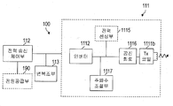
도 2A를 참조하면, 상기 무선 전력 전송장치(100)는 전력 전달부(Power Transmission Unit)(110)를 포함하도록 구성된다. 상기 전력 전달부(110)는 전력 변환부(Power Conversion Unit)(111) 및 전력 송신 제어부(Power Transmission Control Unit)(112)를 포함하여 구성될 수 있다.
Referring to FIG. 2A, the
상기 전력 변환부(111)는 송신측 전원 공급부(190)로부터 공급된 전력을 무선 전력 신호(wireless power signal)로 변환하여 상기 무선 전력 수신장치(200)로 전달한다. 상기 전력 변환부(111)에 의하여 전달되는 무선 전력 신호는 진동(oscillation)하는 특성을 가진 자기장(magnetic field) 또는 전자기장(electro-magnetic field)의 형태로 형성된다. 이를 위하여 상기 전력 변환부(111)는 상기 무선 전력 신호가 발생하는 코일을 포함하도록 구성될 수 있다.The
상기 전력 변환부(111)는 각 전력 전달 방식에 따라 다른 형태의 무선 전력 신호를 형성하기 위한 구성 요소를 포함할 수 있다. 예를 들어, 상기 전력 변환부(111)는 유도 결합 방식에 따라 상기 무선 전력 수신장치(200)의 2차 코일에 전류를 유도시키기 위하여 변화하는 자기장을 형성시키는 1차 코일을 포함하도록 구성될 수 있다. 또한, 상기 전력 변환부(111)는 공진 결합 방식에 따라 상기 무선 전력 수신장치(200)에 공진 현상을 발생시키기 위하여 특정 공진 주파수를 가진 자기장을 형성시키는 코일(또는 안테나)를 포함하도록 구성될 수 있다.The
또한, 상기 전력 변환부(111)는 전술된 유도 결합 방식과 공진 결합 방식 중 하나 이상의 방법을 이용하여 전력을 전달할 수 있다.In addition, the
상기 전력 변환부(111)에 포함되는 구성 요소들 중 유도 결합 방식을 따르는 것들에 대하여는 도 4 및 도 5를 참조하여, 공진 결합 방식을 따르는 것들에 대하여는 도 7 및 도 8을 참조하여 후술된다.Among the constituent elements included in the
한편, 상기 전력 변환부(111)는 상기 무선 전력 신호를 형성시키기 위해 사용되는 주파수, 인가되는 전압, 전류 등의 특성을 조절할 수 있는 회로를 더 포함하도록 구성될 수 있다.
Meanwhile, the
상기 전력 송신 제어부(112)는 상기 전력 전달부(110)에 포함되는 각 구성요소를 제어한다. 상기 전력 송신 제어부(112)는 상기 무선 전력 공급 장치(100)를 제어하는 다른 제어부(미도시)와 통합되도록 구현될 수 있다.
The power
한편, 상기 무선 전력 신호가 도달할 수 있는 영역은 두 가지로 구분될 수 있다. 먼저, 활동 영역(active area)은 상기 무선 전력 수신장치(200)로 전력을 전달하는 무선 전력 신호가 통과하는 영역을 말한다. 다음으로, 감지 영역(semi-active area)은 상기 무선 전력 전송장치(100)가 상기 무선 전력 수신장치(200)의 존재를 감지할 수 있는 관심 영역을 말한다. 여기서, 상기 전력 송신 제어부(112)는 상기 무선 전력 수신장치(200)가 상기 활동 영역 또는 감지 영역에 배치(placement)되거나 제거(removal)되었는지 여부에 대하여 감지할 수 있다. 구체적으로, 상기 전력 송신 제어부(112)는 상기 전력 변환부(111)에서 형성되는 무선 전력 신호를 이용하거나, 별도로 구비된 센서에 의하여 상기 무선 전력 수신장치(200)가 상기 활동 영역 또는 감지 영역에 배치되었는지 여부를 검출할 수 있다. 예컨대, 상기 전력 송신 제어부(112)는 상기 감지 영역에 존재하는 상기 무선 전력 수신장치(200)로 인하여 상기 무선 전력 신호가 영향을 받아, 상기 전력 변환부(111)의 상기 무선 전력 신호를 형성하기 위한 전력의 특성이 변화하는지 여부를 모니터링함으로써 상기 무선 전력 수신장치(200)의 존재를 검출할 수 있다. 다만, 상기 활동 영역 및 감지 영역은 유도 결합 방식 및 공진 결합 방식 등의 무선 전력 전달방식에 따라 다를 수 있다.
Meanwhile, the area to which the wireless power signal can reach may be divided into two types. First, an active area refers to an area through which a wireless power signal transmitting power to the
상기 전력 송신 제어부(112)는 상기 무선 전력 수신장치(200)의 존재를 검출한 결과에 따라 상기 무선 전력 수신장치(200)를 식별하는 과정을 수행하거나, 무선 전력 전송을 시작할 것인지 여부를 결정할 수 있다.The power
또한, 상기 전력 송신 제어부(112)는 상기 무선 전력 신호를 형성하기 위한 상기 전력 변환부(111)의 주파수, 전압, 전류 중 하나 이상의 특성을 결정할 수 있다. 상기 특성의 결정은 상기 무선 전력 전송장치(100) 측의 조건에 의하여 또는 상기 무선 전력 수신장치(200) 측의 조건에 의하여 이루어질 수 있다.
In addition, the power
상기 전력 송신 제어부(112)는 상기 무선 전력 수신장치(200)로부터 전력 제어 메시지를 수신할 수 있다. 상기 전력 송신 제어부(112)는 상기 수신된 전력 제어 메시지를 기초로 상기 전력 변환부(111)의 주파수, 전압, 전류 중 하나 이상의 특성을 결정할 수 있으며, 그 밖에 상기 전력 제어 메시지를 기초로 다른 제어 동작을 수행할 수 있다. The power
예를 들어, 상기 전력 송신 제어부(112)는 상기 무선 전력 수신장치(200)의 정류된 전력량 정보, 충전 상태 정보 및 식별 정보 중 하나 이상을 포함하는 전력 제어 메시지에 따라 상기 무선 전력 신호를 형성시키기 위해 사용되는 주파수, 전류, 전압 중 하나 이상의 특성을 결정할 수 있다.
For example, the power
또한, 상기 전력 제어 메시지를 이용하는 그 밖의 다른 제어 동작으로서, 상기 무선 전력 전송장치(100)는 무선 전력 전달과 관련된 일반적인 제어 동작을 상기 전력 제어 메시지를 기초로 수행할 수 있다. 예를 들어, 상기 무선 전력 전송장치(100)는 상기 전력 제어 메시지를 통하여 상기 무선 전력 수신장치(200)와 관련된 청각적 또는 시각적으로 출력할 정보를 수신하거나, 기기간의 인증 등에 필요한 정보를 수신할 수도 있다.In addition, as another control operation using the power control message, the
이와 같은 상기 전력 제어 메시지를 수신하기 위하여, 상기 전력 송신 제어부(112)는 상기 무선 전력 신호를 통하여 수신하는 방법 및 그 외의 사용자 데이터를 수신하는 방법 중 적어도 하나를 이용할 수 있다.In order to receive the power control message as described above, the power
상기 전력 제어 메시지를 수신하기 위하여, 상기 무선 전력 전송장치(100)는 상기 전력 변환부(111)와 전기적으로 연결된 변복조부(Power Communications Modulation/Demodulation Unit)(113)를 더 포함하도록 구성될 수 있다. 상기 변복조부(113)는 상기 무선 전력 수신장치(200)에 의하여 변조된 무선 전력 신호를 복조하여 상기 전력 제어 메시지를 수신하기 위하여 사용될 수 있다. In order to receive the power control message, the
그 밖에, 어떤 실시 예에서는 상기 전력 송신 제어부(112)가 상기 무선 전력 전송장치(100)에 포함되어 있는 통신 수단(미도시)에 의하여 전력 제어 메시지가 포함되어 있는 사용자 데이터를 수신함으로써 전력 제어 메시지를 획득할 수도 있다.In addition, in some embodiments, the power
[In-band two-way communication을 지원 하는 경우][In case of supporting In-band two-way communication]
또한, 본 명세서에 개시된 실시 예들을 따르는 양방향 통신이 가능한 무선 전력 전송환경에서는, 상기 전력 송신 제어부(112)가 상기 무선 전력 수신장치(200)로 데이터를 전송할 수 있다. 상기 전력 송신 제어부(112)가 전송하는 데이터는 상기 무선 전력 수신장치(200)가 전력 제어 메시지를 보내도록 요청하는 것일 수 있다.
In addition, in a wireless power transmission environment capable of bi-directional communication according to the embodiments disclosed herein, the power
무선 전력 수신장치Wireless power receiver
도 2B를 참조하면, 상기 무선 전력 수신장치는(200)는 전원 공급부(290)를 포함하도록 구성된다. 상기 전원 공급부(290)는 상기 무선 전력 수신장치(200)의 작동에 필요한 전력을 공급한다. 상기 전원 공급부(290)는 전력 수신부(291) 및 전력 수신 제어부(292)를 포함하여 구성될 수 있다.
Referring to FIG. 2B, the
상기 전력 수신부(291)는 상기 무선 전력 전송장치(100)로부터 무선으로 전달되는 전력을 수신한다.The
상기 전력 수신부(291)는 무선 전력 전달 방식에 따라 상기 무선 전력 신호를 수신하기 위해 필요한 구성 요소를 포함할 수 있다. 또한, 상기 전력 수신부(291)는 하나 이상의 무선 전력 전달 방식에 따라 전력을 수신할 수 있으며, 이 경우 상기 전력 수신부(291)는 각 방식에 따라 필요한 서로 구성 요소들을 함께 포함할 수 있다.The
먼저, 상기 전력 수신부(291)는 진동하는 특성을 가진 자기장 또는 전자기장의 형태로 전달되는 무선 전력 신호를 수신하기 위한 코일을 포함하도록 구성될 수 있다. First, the
예컨대, 유도 결합 방식에 따른 구성 요소로서, 상기 전력 수신부(291)는 변화되는 자기장에 의하여 전류가 유도되는 2차 코일을 포함할 수 있다. 또한, 상기 전력 수신부(291)는 공진 결합 방식에 따른 구성 요소로서 특정 공진 주파수를 가진 자기장에 의하여 공진 현상이 발생되는 코일 및 공진 회로를 포함할 수 있다.For example, as a component according to an inductive coupling method, the
다만, 상기 전력 수신부(291)가 하나 이상의 무선 전력 전달 방식에 따라 전력을 수신하는 경우, 상기 전력 수신부(291)는 하나의 코일을 이용하여 수신하도록 구현되거나, 또는 각 전력 전달 방식에 따라 다르게 형성된 코일을 이용하여 수신하도록 구현될 수 있다.However, when the
상기 전력 수신부(291)에 포함되는 구성 요소들 중 유도 결합 방식을 따르는 것들에 대하여는 도 4를 참조하여, 공진 결합 방식을 따르는 것들에 대하여는 도 7을 참조하여 후술된다.
Among the constituent elements included in the
한편, 상기 전력 수신부(291)는 상기 무선 전력 신호를 직류로 변환하기 위한 정류 회로(rectifier) 및 평활 회로(regulator)를 더 포함할 수 있다. 또한, 상기 전력 수신부(291)는 수신된 전력 신호에 의하여 과전압 또는 과전류가 발생하지 않도록 방지하는 회로를 더 포함할 수 있다.
Meanwhile, the
상기 전력 수신 제어부(292)는 상기 전원 공급부(290)에 포함되는 각 구성요소를 제어한다.The power
구체적으로, 상기 전력 수신 제어부(292)는 상기 무선 전력 전송장치(100)로 전력 제어 메시지를 전달할 수 있다. 상기 전력 제어 메시지는 상기 무선 전력 전송장치(100)에게 무선 전력 신호의 전달을 개시하거나 종료하도록 지시하는 것일 수 있다. 또한 상기 전력 제어 메시지는 상기 무선 전력 전송장치(100)에게 상기 무선 전력 신호의 특성을 조절하도록 지시하는 것일 수 있다.Specifically, the power
이와 갈은 상기 전력 제어 메시지를 전송하기 위하여, 상기 전력 수신 제어부(292)는 상기 무선 전력 신호를 통하여 전송하는 방법 및 그 외의 사용자 데이터를 통하여 전송하는 방법 중 적어도 하나를 이용할 수 있다.In order to transmit the alternate power control message, the power
상기 전력 제어 메시지를 전송하기 위하여, 상기 무선 전력 수신장치(200)는 상기 전력 수신부(291)와 전기적으로 연결된 변복조부(Power Communications Modulation/Demodulation Unit)(293)를 더 포함하도록 구성될 수 있다. 상기 변복조부(293)는, 전술된 상기 무선 전력 전송장치(100)의 경우와 마찬가지로, 상기 무선 전력 신호를 통하여 상기 전력 제어 메시지를 전송하기 위하여 사용될 수 있다. 상기 변복조부(293)는 상기 무선 전력 송신장치(100)의 전력 변환부(111)를 흐르는 전류 및/또는 전압을 조절하는 수단으로 사용될 수 있다. 이하, 상기 무선 전력 전송장치(100) 측과 상기 무선 전력 수신장치(200) 측의 각각의 변복조부(113 및 293)가 무선 전력 신호를 통한 전력 제어 메시지의 송수신을 위하여 사용되는 방법에 대하여 설명된다.In order to transmit the power control message, the
상기 전력 변환부(111)에 의하여 형성된 무선 전력 신호는 상기 전력 수신부(291)에 의하여 수신된다. 이때, 상기 전력 수신 제어부(292)는 상기 무선 전력 신호를 변조(modulation)하도록 상기 무선 전력 수신장치(200) 측의 변복조부(293)를 제어한다. 예컨대, 상기 전력 수신 제어부(292)는 상기 전력 수신부(291)과 연결된 변복조부(293)의 리액턴스(reactance)를 변경시킴으로써 상기 무선 전력 신호로부터 수신하는 전력량이 그에 따라 변하도록 변조 과정을 수행할 수 있다. 상기 무선 전력 신호로부터 수신되는 전력량의 변경은 상기 무선 전력 신호를 형성시키는 상기 전력 변환부(111)의 전류 및/또는 전압의 변경을 가져온다. 이 때, 상기 무선 전력 전송장치(100) 측의 변복조부(113)는 상기 전력 변환부(111)의 전류 및/또는 전압의 변경을 감지하여 복조(demodulation) 과정을 수행한다.The wireless power signal formed by the
즉, 상기 전력 수신 제어부(292)는 상기 무선 전력 전송장치(100)에게 전달하고자 하는 전력 제어 메시지를 포함하는 패킷(packet)을 생성하여 상기 패킷이 포함되도록 상기 무선 전력 신호를 변조하고, 상기 전력 송신 제어부(112)는 상기 변복조부(113)의 복조 과정 수행 결과를 기초로 상기 패킷을 디코드함으로써, 상기 패킷에 포함되어 있는 상기 전력 제어 메시지를 획득할 수 있다. That is, the power
그 밖에, 어떤 실시 예들에서는 상기 전력 수신 제어부(292)가 상기 무선 전력 수신장치(200)에 포함되어 있는 통신 수단(미도시)에 의하여 전력 제어 메시지가 포함되어 있는 사용자 데이터를 전송함으로써 전력 제어 메시지를 상기 무선 전력 전송장치(100)로 전송할 수도 있다.
In addition, in some embodiments, the power
[In-band two-way communication을 지원 하는 경우][In case of supporting In-band two-way communication]
또한, 본 명세서에 개시된 실시 예들을 따르는 양방향 통신이 가능한 무선 전력 전송환경에서는, 상기 전력 수신 제어부(292)가 상기 무선 전력 전송장치(100)로부터 전송되는 데이터를 수신할 수 있다. 상기 무선 전력 전송장치(100)로부터 전송되는 데이터는 전력 제어 메시지를 전송할 것을 요청하는 것일 수 있다.
In addition, in a wireless power transmission environment capable of bidirectional communication according to the embodiments disclosed in the present specification, the power
그 밖에, 상기 전원 공급부(290)는 충전부(298) 및 배터리(299)를 더 포함하도록 구성될 수 있다.In addition, the
상기 전원 공급부(290)로부터 동작을 위한 전원을 공급받는 상기 무선 전력 수신장치(200)는 상기 무선 전력 전송장치(100)로부터 전달된 전력에 의하여 동작하거나, 또는 상기 전달된 전력을 이용하여 상기 배터리(299)를 충전한 후 상기 배터리(299)에 충전된 전력에 의하여 동작할 수 있다. 이때, 상기 전력 수신 제어부(292)는 상기 전달된 전력을 이용하여 충전을 수행하도록 상기 충전부(298)를 제어할 수 있다.
The
이하에서, 본 명세서에 개시된 실시 예들에 적용 가능한 무선 전력 전송장치 및 무선 전력 수신장치에 대하여 설명된다. 먼저, 도 3 내지 도 5를 참조하여 상기 무선 전력 전송장치가 상기 무선 전력 수신장치로 유도 결합 방식에 따라 전력을 전달하는 방법이 개시된다.
Hereinafter, a wireless power transmitter and a wireless power receiver applicable to the embodiments disclosed in the present specification will be described. First, a method of transmitting power by the wireless power transmitter to the wireless power receiver according to an inductive coupling method is disclosed with reference to FIGS. 3 to 5.
유도 결합 방식Inductive coupling method
도 3은 유도 결합 방식에 따라 무선 전력 전송장치로부터 무선 전력 수신장치에 무선으로 전력이 전달되는 개념을 도시한다.3 shows a concept in which power is wirelessly transmitted from a wireless power transmitter to a wireless power receiver according to an inductive coupling method.
무선 전력 전송장치(100) 의 전력 전달이 유도 결합 방식을 따르는 경우, 상기 전력 전달부(110) 내의 1차 코일(primary coil)에 흐르는 전류의 세기가 변화되면, 그 전류에 의해 1차 코일을 통과하는 자기장이 변화한다. 이와 같이 변화된 자기장은 상기 무선 전력 수신장치(200) 내의 2차 코일(secondary coil) 측에 유도 기전력을 발생시킨다.When the power transmission of the wireless
이 방식에 따르면, 상기 무선 전력 전송장치(100)의 상기 전력 변환부(111)는 자기 유도에서의 1차 코일로 동작하는 전송 코일(Tx coil)(1111a)를 포함하도록 구성된다. 또한 상기 무선 전력 수신장치(200)의 상기 전력 수신부(291)는 자기 유도에서의 2차 코일로 동작하는 수신 코일(Rx coil)(2911a)을 포함하도록 구성된다.According to this method, the
먼저 상기 무선 전력 전송장치(100) 측의 상기 전송 코일(1111a)과 상기 무선 전력 수신장치(200) 측의 수신 코일이 근접하도록 상기 무선 전력 전송장치(100) 및 상기 무선 전력 수신장치(200)를 배치한다. 그 후 상기 전력 송신 제어부(112)가 상기 전송 코일(1111a)의 전류가 변화되도록 제어하면, 상기 전력 수신부(291)는 상기 수신 코일(2911a)에 유도된 기전력을 이용하여 상기 무선 전력 수신장치(200)에 전원을 공급하도록 제어한다.First, the
상기 유도 결합 방식에 의한 무선 전력 전달의 효율은, 주파수 특성에 따른 영향은 적으나, 각 코일을 포함하는 상기 무선 전력 전송장치(100) 및 상기 무선 전력 수신장치(200) 사이의 배열(alignment) 및 거리(distance)의 영향을 받게 된다.
The efficiency of wireless power transmission by the inductive coupling method is less affected by frequency characteristics, but an alignment between the
한편, 유도 결합 방식에 의한 무선 전력 전달을 위하여 상기 무선 전력 전송장치(100)는 평평한 표면(flat surface) 형태의 인터페이스 표면(interface surface)(미도시)을 포함하도록 구성될 수 있다. 상기 인터페이스 표면의 상부에는 하나 이상의 무선 전력 수신장치가 놓일 수 있으며, 상기 인터페이스 표면의 하부에는 상기 전송 코일(1111a)가 장착될 수 있다. 그 경우, 상기 인터페이스 표면의 하부에는 장착된 상기 전송 코일(1111a)과 상기 인터페이스 표면의 상부에 위치한 무선 전력 수신장치(200)의 수신 코일(2911a) 사이의 수직 공간(vertical spacing)이 작게 형성됨으로써 상기 코일들 간의 거리는 유도 결합 방식에 의한 무선 전력 전달이 효율적으로 이루어질 수 있도록 충분히 작게 된다.
Meanwhile, for wireless power transfer by an inductive coupling method, the
또한, 상기 인터페이스 표면의 상부에는 상기 무선 전력 수신장치(200)가 놓일 위치를 지시하는 배열 지시부(미도시)가 형성될 수 있다. 상기 배열 지시부는 상기 인터페이스 표면의 하부에 장착된 전송 코일(1111a)과 상기 수신 코일(2911a) 사이의 배열이 적합하게 이루어질 수 있는 상기 무선 전력 수신장치(200)의 위치를 지시한다. 상기 배열 지시부는 단순한 표시(marks)이거나, 상기 무선 전력 수신장치(200)의 위치를 가이드하는 돌출 구조의 형태로 형성될 수 있다. 또는 상기 배열 지시부는 상기 인터페이스 표면의 하부에 장착되는 자석과 같은 자성체의 형태로 형성되어, 상기 무선 전력 수신장치(200) 내부에 장착된 다른 극의 자성체와의 상호간 인력에 의하여 상기 코일들이 적합한 배열을 이루도록 가이드할 수도 있다.
In addition, an arrangement indicating unit (not shown) indicating a position where the
한편, 상기 무선 전력 전송장치(100)는 하나 이상의 전송 코일을 포함하도록 형성될 수 있다. 상기 무선 전력 전송장치(100)는 상기 하나 이상의 전송 코일 중에서 상기 무선 전력 수신장치(200)의 수신 코일(2911a)과 적합하게 배열된 일부의 코일을 선택적으로 이용하여 전력 전송 효율을 높일 수 있다. 상기 하나 이상의 전송 코일을 포함하는 무선 전력 전송장치(100)에 관하여 도 5를 참조하여 후술된다.
Meanwhile, the
이하에서는, 본 명세서에 개시된 실시 예들에 적용 가능한 유도 결합 방식의 무선 전력 전송장치 및 무선 전력 수신장치의 구성에 대하여 구체적으로 설명된다.
Hereinafter, configurations of an inductively coupled wireless power transmitter and a wireless power receiver applicable to the embodiments disclosed in the present specification will be described in detail.
유도 결합 방식의 무선 전력 전송장치 및 무선 전력 수신장치Inductively coupled wireless power transmitter and wireless power receiver
도 4는 본 명세서에 개시된 실시 예들에서 채용 가능한 자기 유도 방식의 무선 전력 전송장치(100) 및 무선 전력 수신장치(200)의 구성의 일부를 예시적으로 나타낸 블록도이다. 도 4A를 참조하여 상기 무선 전력 전송장치(100)에 포함된 상기 전력 전달부(110)의 구성에 대하여 설명하고, 도 4B를 참조하여 상기 무선 전력 수신장치(200)에 포함된 상기 전원 공급부(290)의 구성에 대하여 설명한다.
4 is a block diagram illustrating a part of the configuration of the magnetic induction
도 4A를 참조하면, 상기 무선 전력 전송장치(100)의 상기 전력 변환부(111)는 전송 코일(Tx coil)(1111a) 및 인버터(1112)를 포함하도록 구성될 수 있다.Referring to FIG. 4A, the
상기 전송 코일(1111a)는, 전술된 바와 같이, 전류의 변화에 따라 무선 전력 신호에 해당하는 자기장을 형성한다. 상기 전송 코일(1111a)은 평판 나선형태(Planar Spiral type) 또는 원통형 솔레노이드 형태(Cylindrical Solenoid type)로 구현될 수 있다.As described above, the
상기 인버터(1112)는 상기 전원 공급부(190)로부터 얻은 직류 입력(DC input)을 교류 파형(AC waveform)으로 변형시킨다. 상기 인버터(1112)에 의해 변형된 교류 전류는 상기 전송 코일(1111a) 및 커패시터(capacitor)(미도시)를 포함하는 진동 회로(resonant circuit)를 구동시킴으로써 자기장이 상기 전송 코일(1111a)에서 형성된다.
The
그 밖에, 상기 전력 변환부(111)는 위치 결정부(Positioning Unit)(1114)를 더 포함하도록 구성될 수 있다. In addition, the
상기 위치 결정부(1114)는 상기 유도 결합 방식에 의한 무선 전력 전달의 효율을 높이기 위하여 상기 전송 코일(1111a)을 이동 또는 회전시킬 수 있다. 이는, 전술된 바와 같이, 유도 결합 방식에 의한 전력 전달은 1차 및 2차 코일을 포함하는 상기 무선 전력 전송장치(100) 및 상기 무선 전력 수신장치(200) 사이의 배열(alignment) 및 거리(distance)의 영향을 받기 때문이다. 특히, 상기 위치 결정부(1114)는 상기 무선 전력 수신장치(200)가 상기 무선 전력 전송장치(100)의 활동 영역 내에 존재하지 않는 경우에 사용될 수 있다.The
따라서, 상기 위치 결정부(1114)는 상기 무선 전력 전송장치(100)의 상기 전송 코일(1111a)과 및 상기 무선 전력 수신장치(200)의 상기 수신 코일(2911a)의 중심간 거리(distance)가 일정 범위 이내가 되도록 상기 전송 코일(1111a)을 이동시키거나, 상기 전송 코일(1111a)과 상기 수신 코일(2911a)의 중심이 중첩되도록 상기 전송 코일(1111a)를 회전시키는 구동부(미도시)를 포함하도록 구성될 수 있다.Accordingly, the
이를 위하여, 상기 무선 전력 전송장치(100)는 상기 무선 전력 수신장치(200)의 위치를 감지하는 센서로 이루어진 위치 감지부(detection unit)(미도시)를 더 구비할 수 있고, 상기 전력 송신 제어부(112)는 상기 위치 감지 센서로부터 수신한 상기 무선 전력 수신장치(200)의 위치 정보를 기초로 상기 위치 결정부(1114)를 제어할 수 있다.To this end, the
또한, 이를 위하여 상기 전력 송신 제어부(112)는 상기 변복조부(113)를 통하여 상기 무선 전력 수신장치(200)와의 배열 또는 거리에 대한 제어 정보를 수신하고, 상기 수신된 배열 또는 거리에 대한 제어 정보를 기초로 상기 위치 결정부(1114)를 제어할 수 있다.In addition, for this purpose, the power
만약, 상기 전력 변환부(111)가 복수의 전송 코일을 포함하도록 구성되었다면, 상기 위치 결정부(1114)는 상기 복수의 전송 코일 중에서 어느 것이 전력 전달을 위하여 사용될 것인지 결정할 수 있다. 상기 복수의 전송 코일을 포함한 무선 전력 전송장치(100)의 구성에 대해서는 도 5를 참조하여 후술된다.
If the
한편, 상기 전력 변환부(111)는 전력 센싱부(1115)를 더 포함하도록 구성될 수 있다. 상기 무선 전력 전송장치(100) 측의 전력 센싱부(1115)는 상기 전송 코일(1111a)에 흐르는 전류 또는 전압을 모니터링한다. 상기 전력 센싱부(1115)는 무선 전력 전송장치(100)의 정상동작 여부를 확인하기 위한 것으로, 외부로부터 공급되는 전원의 전압 또는 전류를 검출하고, 상기 검출된 전압 또는 전류가 임계값을 초과하는지를 확인할 수 있다. 상기 전력 센싱부(1115)는, 도시되지 않았으나, 외부로부터 공급되는 전원의 전압 또는 전류를 검출하기 위한 저항과 상기 검출된 전원의 전압값 또는 전류값과 임계값을 비교하여 그 비교 결과를 출력하는 비교기를 포함할 수 있다. 상기 전력 센싱부(1115)의 상기 확인 결과를 기초로, 상기 전력 송신 제어부(112)는 스위칭부(미도시)를 제어하여 상기 전송 코일(1111a)로 인가되는 전원을 차단할 수 있다.
Meanwhile, the
도 4B를 참조하면, 상기 무선 전력 수신장치(200)의 상기 전원 공급부(290)는 수신 코일(Rx 코일)(2911a) 및 정류 회로(2913)를 포함하도록 구성될 수 있다.Referring to FIG. 4B, the
상기 전송 코일(1111a)로부터 형성된 자기장에 변화에 의하여 상기 수신 코일(2911a)에서 전류가 유도된다. 상기 수신 코일(2911a)의 구현 형태는, 상기 전송 코일(1111a)의 경우와 마찬가지로, 평판 나선 형태 또는 원통형 솔레노이드 형태일 수 있다.A current is induced in the receiving
또한, 무선 전력의 수신 효율을 높이거나 공진 감지(resonant detection)를 위해 직/병렬 커패시터들(series and parallel capacitors)이 상기 수신 코일(2911a)과 연결되도록 구성될 수 있다.In addition, series and parallel capacitors may be configured to be connected to the receiving
상기 수신 코일(2911a)은 단일 코일 또는 복수의 코일 형태일 수 있다.The receiving
상기 정류 회로(2913)는 교류를 직류로 변환시키기 위하여 전류에 대하여 전파 정류(full-wave rectification)를 수행한다. 상기 정류 회로(2913)는, 예컨대, 4개의 다이오드로 이루어진 브릿지(full bridge) 정류 회로, 또는 능동 소자(active components)를 이용한 회로로 구현될 수 있다.The
그 밖에, 상기 정류 회로(2913)는 정류된 전류를 보다 평탄하고 안정적인 직류로 만들어 주는 평활 회로(regulator)를 더 포함할 수 있다. 또한, 상기 정류 회로(2913)의 출력 전원은 상기 전원 공급부(290)의 각 구성 요소들에게 공급된다. 또한, 상기 정류 회로(2913)은 출력되는 직류 전원을 상기 전원 공급부(290)의 각 구성 요소(예컨대, 충전부(298)와 같은 회로)에 필요한 전원에 맞추기 위하여 적정한 전압으로 변환하는 직류-직류 변환기(DC-DC converter)를 더 포함할 수 있다.In addition, the
상기 변복조부(293)는 상기 전력 수신부(291)과 연결되고, 직류 전류에 대해서는 저항(resistance)이 변하는 저항성 소자로 구성될 수 있고, 교류 전류에 대해서는 리액턴스(reactance)가 변하는 용량성 소자로 구성될 수 있다. 상기 전력 수신 제어부(292)는 상기 변복조부(293)의 저항 또는 리액턴스를 변경시킴으로써 상기 전력 수신부(291)에 수신되는 무선 전력 신호를 변조할 수 있다.The
한편, 상기 전원 공급부(290)는 전력 센싱부(2914)를 더 포함하도록 구성될 수 있다. 상기 무선 전력 수신장치(200) 측의 전력 센싱부(2914)는 상기 정류 회로(2913)에 의하여 정류된 전원의 전압 및/또는 전류를 모니터링하고, 상기 모니터링 결과 상기 정류된 전원의 전압 및/또는 전류가 임계값을 초과하는 경우 상기 전력 수신 제어부(292)는 적절한 전력을 전달하도록 상기 무선 전력 전송장치(100)에게 전력 제어 메시지를 송신한다.
Meanwhile, the
하나 이상의 전송 코일을 포함하여 구성된 무선 전력 전송장치Wireless power transmitter configured including one or more transmission coils
도 5는 본 명세서에 개시된 실시 예들에서 채용 가능한 유도 결합 방식에 따라 전력을 수신하는 하나 이상의 전송 코일들을 가지도록 구성된 무선 전력 전송장치의 블록도이다.5 is a block diagram of a wireless power transmitter configured to have one or more transmission coils for receiving power according to an inductive coupling method employable in the embodiments disclosed herein.
도 5를 참조하면, 본 명세서에 개시된 실시 예들을 따르는 무선 전력 전송장치(100) 의 전력 변환부(111)는 하나 이상의 전송 코일들(1111a-1 내지 1111a-n)로 구성될 수 있다. 상기 하나 이상의 전송 코일들(1111a-1 내지 1111a-n)은 부분적으로 겹치는 1차 코일들의 배열(an array of partly overlapping primary coils)일 수 있다. 상기 하나 이상의 전송 코일들 중 일부에 의하여 활동 영역이 결정될 수 있다.Referring to FIG. 5, the
상기 하나 이상의 전송 코일들(1111a-1 내지 1111a-n)은 상기 인터페이스 표면의 하부에 장착될 수 있다. 또한, 상기 전력 변환부(111)는 상기 하나 이상의 전송 코일들(1111a-1 내지 1111a-n) 중 일부의 코일들의 연결을 수립하고 해제하는 다중화기(Multiplexer)(1113)를 더 포함할 수 있다. The one or
상기 인터페이스 표면의 상부에 놓인 무선 전력 수신장치(200)의 위치가 감지되면, 상기 전력 송신 제어부(112)는 상기 무선 전력 수신장치(200)의 감지된 위치를 고려하여 상기 하나 이상의 전송 코일들(1111a-1 내지 1111a-n) 중 상기 무선 전력 수신장치(200)의 수신 코일(2911a)과 유도 결합 관계에 놓일 수 있는 코일들이 연결될 수 있도록 상기 다중화기(1113)를 제어할 수 있다. When the position of the
이를 위하여 상기 전력 송신 제어부(112)가 상기 무선 전력 수신장치(200)의 위치 정보를 획득할 수 있다. 예를 들어, 상기 전력 송신 제어부(112)는 상기 무선 전력 전송장치(100)에 구비된 상기 위치 감지부(미도시)에 의하여 상기 인터페이스 표면 상의 상기 무선 전력 수신장치(200)의 위치를 획득할 수 있다. 또 다른 예를 들어, 상기 전력 송신 제어부(112)는 상기 하나 이상의 전송 코일들(1111a-1 내지 1111a-n)을 각각 이용하여 상기 인터페이스 표면 상의 물체로부터 무선 전력 신호의 강도를 나타내는 전력 제어 메시지 또는 상기 물체의 식별 정보를 나타내는 전력 제어 메시지를 수신하고, 상기 수신된 결과를 기초로 상기 하나 이상의 전송 코일들 중 어느 코일의 위치와 근접한지를 판단함으로써 상기 무선 전력 수신장치(200)의 위치 정보를 획득할 수도 있다.To this end, the power
한편, 상기 활동 영역은 상기 인터페이스 표면의 일부로서, 상기 무선 전력 전송장치(100)가 상기 무선 전력 수신장치(200)에 무선으로 전력을 전달할 때 높은 효율의 자기장이 통과할 수 있는 부분을 의미할 수 있다. 이 때, 상기 활동 영역을 통과하는 자기장을 형성시키는 단일 전송 코일 또는 하나 이상의 전송 코일들의 조합을 주요 셀(primary cell)로 지칭할 수 있다. 따라서, 상기 전력 송신 제어부(112)는 상기 무선 전력 수신장치(200)의 감지된 위치를 기초로 활동 영역을 결정하고, 상기 활동 영역에 대응되는 주요 셀의 연결을 수립하여 상기 무선 전력 수신장치(200)의 수신 코일(2911a)와 상기 주요 셀에 속한 코일들이 유도 결합 관계에 놓일 수 있도록 상기 다중화기(1113)을 제어할 수 있다.Meanwhile, the active area is a part of the interface surface, and refers to a portion through which a high-efficiency magnetic field can pass when the
또한, 상기 전력 변환부(111)는 연결된 코일들과 진동 회로(resonant circuit)를 형성하도록 임피던스를 조절하는 임피던스 매칭부(impedance matching unit)(미도시)를 더 포함할 수 있다.
In addition, the
이하에서, 도 6 내지 도 8을 참조하여 무선 전력 전송장치가 공진 결합 방식에 따라 전력을 전달하는 방법이 개시된다.
Hereinafter, a method of transmitting power by a wireless power transmitter according to a resonance coupling method is disclosed with reference to FIGS. 6 to 8.
공진 결합 방식Resonant coupling method
도 6은 공진 결합 방식에 따라 무선 전력 전송장치로부터 무선 전력 수신장치에 무선으로 전력이 전달되는 개념을 도시한다.6 shows a concept in which power is wirelessly transmitted from a wireless power transmitter to a wireless power receiver according to a resonance coupling method.
먼저, 공진(resonance)(또는 공명)에 대해 간략하게 설명하면 다음과 같다. 공진(resonance)이란, 진동계가 그 고유 진동수와 같은 진동수를 가진 외력을 주기적으로 받아 진폭이 뚜렷하게 증가하는 현상을 말한다. 공진은 역학적 진동 및 전기적 진동 등 모든 진동에서 일어나는 현상이다. 일반적으로 외부에서 진동계에 진동시킬 수 있는 힘을 가했을 때 그 진동계의 고유 진동수와 외부에서 가해주는 힘의 진동수가 같으면 그 진동은 심해지고 진폭도 커진다.First, a brief description of resonance (or resonance) is as follows. Resonance refers to a phenomenon in which the vibration system periodically receives an external force having the same frequency as its natural frequency, and the amplitude increases significantly. Resonance is a phenomenon that occurs in all vibrations such as mechanical vibration and electrical vibration. In general, when a force capable of vibrating a vibration system is applied from the outside, if the natural frequency of the vibration system and the frequency of the external force applied are the same, the vibration becomes severe and the amplitude increases.
같은 원리로, 일정 거리 내에서 떨어져 있는 복수의 진동체들이 서로 동일한 주파수로 진동하는 경우, 상기 복수의 진동체들은 상호 공진하며, 이 경우 상기 복수의 진동체들 간에는 저항이 감소하게 된다. 전기 회로에서는 인덕터과 커패시터를 사용하여 공진 회로를 만들 수 있다. According to the same principle, when a plurality of vibrating bodies that are separated within a certain distance vibrate at the same frequency with each other, the plurality of vibrating bodies resonate with each other, and in this case, resistance between the plurality of vibrating bodies decreases. In electric circuits, inductors and capacitors can be used to make resonant circuits.
무선 전력 전송장치(100)의 전력 전달이 공진 결합 방식을 따르는 경우, 상기 전력 전달부(110)에서 교류 전원에 의하여 특정한 진동 주파수를 가진 자기장이 형성된다. 상기 형성된 자기장에 의하여 상기 무선 전력 수신장치(200)에서 공진 현상이 일어나는 경우 상기 무선 전력 수신장치(200) 내에서는 상기 공진 현상에 의하여 전력이 발생된다.When the power transmission of the
공진 주파수는, 예를 들어, 다음 수학식 1과 같은 수식에 의하여 결정될 수 있다. The resonant frequency may be determined by, for example, an equation such as

여기서, 공진 주파수(f)는 회로 내의 인덕턴스(L) 및 커패시턴스(C)에 의하여 결정된다. 코일을 사용하여 자기장을 형성하는 회로에 있어서 상기 인덕턴스는 상기 코일의 회전 수 등에 의하여 결정되고, 상기 커패시턴스는 상기 코일 사이의 간격, 면적 등에 의하여 결정될 수 있다. 상기 공진 주파수를 결정하기 위하여 상기 코일 외에 용량성 공진 회로가 연결되도록 구성될 수도 있다.
Here, the resonance frequency f is determined by the inductance L and the capacitance C in the circuit. In a circuit in which a magnetic field is formed using a coil, the inductance may be determined by the number of rotations of the coil, and the capacitance may be determined by a distance or area between the coils. In order to determine the resonance frequency, a capacitive resonance circuit may be connected in addition to the coil.
도 6을 참조하면, 공진 결합 방식에 따라 무선으로 전력이 전송되는 경우, 상기 무선 전력 전송장치(100)의 상기 전력 변환부(111)는 자기장이 형성되는 전송 코일(Tx coil)(1111b) 및 상기 전송 코일(1111b)와 연결되고 특정한 진동 주파수를 결정하기 위한 공진 회로(1116)를 포함하도록 구성될 수 있다. 상기 공진 회로(1116)는 용량성 회로(capacitors)를 이용하여 구현될 수 있으며, 상기 전송 코일(1111b)의 인덕턴스 및 상기 공진 회로(1116)의 커패시턴스를 기초로 상기 특정한 진동 주파수가 결정된다.Referring to FIG. 6, when power is wirelessly transmitted according to a resonance coupling method, the
상기 공진 회로(1116)의 회로 소자의 구성은 상기 전력 변환부(111)가 자기장을 형성할 수 있도록 다양한 형태로 이루어질 수 있으며, 도 6과 같이 상기 전송 코일(1111b)과 병렬로 연결되는 형태로 제한되지 아니한다.The configuration of the circuit element of the
또한, 상기 무선 전력 수신장치(200)의 상기 전력 수신부(291)는 상기 무선 전력 전송장치(100)에서 형성된 자기장에 의하여 공진 현상이 일어날 수 있도록 구성된 공진 회로(2912) 및 수신 코일(Rx coil)(2911b)을 포함한다. 즉, 상기 공진 회로(2912)는 역시 용량성 회로를 이용하여 구현될 수 있으며, 상기 공진 회로(2912)는 상기 수신 코일(2911b)의 인덕턴스와 상기 공진 회로(2912)의 커패시턴스를 기초로 결정되는 공진 주파수가 상기 형성된 자기장의 공진 주파수와 동일하도록 구성된다.In addition, the
상기 공진 회로(2912)의 회로 소자의 구성은 상기 전력 수신부(291)가 상기 자기장에 의하여 공진이 일어날 수 있도록 다양한 형태로 이루어질 수 있으며, 도 6과 같이 상기 수신 코일(2911b)과 직렬로 연결되는 형태로 제한되지 아니한다. The configuration of the circuit elements of the
상기 무선 전력 전송장치(100)에서의 상기 특정한 진동 주파수는 LTx, CTx를 가지고 상기 수학식 1을 이용하여 획득될 수 있다. 여기서, 상기 무선 전력 수신장치(200)의 LRX 및 CRX를 상기 수학식 1에 대입한 결과가 상기 특정한 진동 주파수와 동일한 경우에 상기 무선 전력 수신장치(200)에서는 공진이 일어난다.The specific vibration frequency in the
공진 결합에 의한 무선 전력 전송 방식에 따르면, 상기 무선 전력 전송장치(100) 및 상기 무선 전력 수신장치(200)가 각각 동일 주파수로 공진하는 경우 전자파가 근거리 전자장을 통해 전달되게 되므로, 주파수가 다르면 상기 기기간 에너지 전달이 없게 된다.According to the wireless power transmission method by resonance coupling, when the
따라서, 상기 공진 결합 방식에 의한 무선 전력 전달의 효율은, 주파수 특성에 따른 영향이 큰 반면, 각 코일을 포함하는 상기 무선 전력 전송장치(100) 및 상기 무선 전력 수신장치(200) 사이의 배열 및 거리에 따른 영향은 유도 결합 방식에 비해 상대적으로 작다.
Therefore, while the efficiency of wireless power transfer by the resonance coupling method has a large influence on the frequency characteristics, the arrangement between the
이하에서는, 본 명세서에 개시된 실시 예들에 적용 가능한 공진 결합 방식의 무선 전력 전송장치 및 무선 전력 수신장치의 구성에 대하여 구체적으로 설명된다.
Hereinafter, configurations of a wireless power transmitter and a wireless power receiver of a resonance coupling method applicable to the embodiments disclosed in the present specification will be described in detail.
공진 결합 방식의 무선 전력 전송장치Resonant coupling type wireless power transmitter
도 7은 본 명세서에 개시된 실시 예들에서 채용 가능한 공진 방식의 무선 전력 전송장치(100) 및 무선 전력 수신장치(200)의 구성의 일부를 예시적으로 나타낸 블록도이다.7 is a block diagram illustrating a part of the configuration of the
도 7A를 참조하여 상기 무선 전력 전송장치(100)에 포함된 상기 전력 전달부(110)의 구성에 대하여 설명된다.The configuration of the
상기 무선 전력 전송장치(100)의 상기 전력 변환부(111)는 전송 코일(Tx coil)(1111b), 인버터(1112) 및 공진 회로(1116)를 포함하도록 구성될 수 있다. 상기 인버터(1112)는 상기 전송 코일(1111b) 및 상기 공진 회로(1116)와 연결되도록 구성될 수 있다.The
상기 전송 코일(1111b)은 유도 결합 방식에 따라 전력을 전달하기 위한 전송 코일(1111a)과 별도로 장착될 수 있으나, 하나의 단일 코일을 이용하여 유도 결합 방식 및 공진 결합 방식으로 전력을 전달할 수도 있다.The
상기 전송 코일(1111b)은, 전술된 바와 같이, 전력을 전달하기 위한 자기장을 형성한다. 상기 전송 코일(1111b) 및 상기 공진 회로(1116)는 교류 전원이 인가되면 진동이 발생할 수 있으며, 이 때 상기 전송 코일(1111b)의 인덕턴스 및 상기 공진 회로(1116)의 커패시턴스를 기초로 진동 주파수가 결정될 수 있다. The
이를 위하여 상기 인버터(1112)는 상기 전원 공급부(190) 로부터 얻은 직류 입력을 교류 파형으로 변형시키고, 상기 변형된 교류 전류가 상기 전송 코일(1111b) 및 상기 공진 회로(1116)에 인가된다.To this end, the
그 밖에, 상기 전력 변환부(111)는 상기 전력 변환부(111)의 공진 주파수 값을 변경시키기 위한 주파수 조절부(1117)를 더 포함하도록 구성될 수 있다. 상기 전력 변환부(111)의 공진 주파수는 수학식 1에 의하여 상기 전력 변환부(111)를 구성하는 회로내의 인덕턴스 및 커패시턴스를 기초로 결정되므로, 상기 전력 송신 제어부(112)는 상기 인덕턴스 및/또는 커패시턴스가 변경되도록 상기 주파수 조절부(1117)를 제어함으로써 상기 전력 변환부(111)의 공진 주파수를 결정할 수 있다.In addition, the
상기 주파수 조절부(1117)는, 예를 들어, 상기 공진 회로(1116)에 포함된 커패시터 간의 거리를 조절하여 커패시턴스를 변경시킬 수 있는 모터를 포함하거나, 또는 상기 전송 코일(1111b)의 회전 수(number of turns) 또는 직경을 조절하여 인덕턴스를 변경시킬 수 있는 모터를 포함하거나, 또는 상기 커패시턴스 및/또는 인덕턴스를 결정하는 능동 소자들을 포함하도록 구성될 수 있다.The
한편, 상기 전력 변환부(111)는 전력 센싱부(1115)를 더 포함하도록 구성될 수 있다. 상기 전력 센싱부(1115)의 동작에 대해서는 전술된 바와 동일하다.
Meanwhile, the
도 7B를 참조하여 상기 무선 전력 수신장치(200)에 포함된 상기 전원 공급부(290)의 구성에 대하여 설명된다. 상기 전원 공급부(290)는, 전술된 바와 같이, 상기 수신 코일(Rx coil)(2911b) 및 공진 회로(2912)를 포함하도록 구성될 수 있다.The configuration of the
그 외에도, 상기 전원 공급부(290)의 전력 수신부(291)는 공진 현상에 의하여 생성된 교류 전류를 직류로 변환시키는 정류 회로(2913)를 더 포함하도록 구성될 수 있다. 상기 정류 회로(2913)는 전술된 바와 동일하게 구성될 수 있다.In addition, the
또한, 상기 전력 수신부(291)는 정류된 전원의 전압 및/또는 전류를 모니터링하는 전력 센싱부(2914)를 더 포함하도록 구성될 수 있다. 상기 전력 센싱부(2914)는 전술된 바와 동일하게 구성될 수 있다.
In addition, the
하나 이상의 전송 코일을 포함하여 구성된 무선 전력 전송장치Wireless power transmitter configured including one or more transmission coils
도 8은 본 명세서에 개시된 실시 예들에서 채용 가능한 공진 결합 방식에 따라 전력을 수신하는 하나 이상의 전송 코일들을 가지도록 구성된 무선 전력 전송장치의 블록도이다.8 is a block diagram of a wireless power transmitter configured to have one or more transmission coils for receiving power according to a resonance coupling method employable in the embodiments disclosed herein.
도 8을 참조하면, 본 명세서에 개시된 실시 예들을 따르는 무선 전력 전송장치(100)의 전력 변환부(111)는 하나 이상의 전송 코일들(1111b-1 내지 1111b-n) 및 각 전송 코일들과 연결된 공진 회로(1116-1 내지 1116-n)를 포함하도록 구성될 수 있다. 또한, 상기 전력 변환부(111)는 상기 하나 이상의 전송 코일들(1111b-1 내지 1111b-n) 중 일부의 코일들의 연결을 수립하고 해제하는 다중화기(Multiplexer)(1113)를 더 포함할 수 있다. Referring to FIG. 8, the
상기 하나 이상의 전송 코일들(1111b-1 내지 1111b-n)은 동일한 공진 주파수를 갖도록 설정되거나, 일부가 서로 다른 공진 주파수를 갖도록 설정될 수 있다. 이는 상기 하나 이상의 전송 코일들(1111b-1 내지 1111b-n)과 각각 연결된 상기 공진 회로(1116-1 내지 1116-n)들이 어떠한 인덕턴스 및/또는 커패시턴스를 갖는지에 따라 결정된다.The one or more transmission coils 1111b-1 to 1111b-n may be set to have the same resonance frequency, or some may be set to have different resonance frequencies. This is determined according to the inductance and/or capacitance of the resonance circuits 1116-1 to 1116-n respectively connected to the one or more transmission coils 1111b-1 to 1111b-n.
이를 위하여, 상기 주파수 조절부(1117)는 상기 하나 이상의 전송 코일들(1111b-1 내지 1111b-n)과 각각 연결된 상기 공진 회로(1116-1 내지 1116-n)들의 인덕턴스 및/또는 커패시턴스를 변경시킬 수 있도록 구성될 수 있다.
To this end, the
In-band communicationIn-band communication
도 9는 본 명세서에 개시된 실시 예들을 따르는 무선 전력 전달에 있어서 무선 전력 신호의 변조 및 복조를 통하여 무선 전력 전송장치와 전자 기기 사이에 패킷을 송수신하는 개념을 도시한다.9 illustrates a concept of transmitting and receiving packets between a wireless power transmitter and an electronic device through modulation and demodulation of a wireless power signal in wireless power transmission according to embodiments disclosed herein.
도 9를 참조하면, 무선 전력 전송장치(100)에 포함된 상기 전력 변환부(111)는 무선 전력 신호를 형성한다. 상기 무선 전력 신호는 상기 전력 변환부(111)에 포함된 전송 코일(1111)을 통하여 형성된다.Referring to FIG. 9, the
상기 전력 변환부(111)에 의하여 형성된 무선 전력 신호(10a)는 전자 기기(200)에 도달하여, 상기 전자 기기(200)에 포함된 전력 수신부(291)를 통하여 수신된다. 상기 형성된 무선 전력 신호는 상기 전력 수신부(291)에 포함된 수신 코일(2911)을 통하여 수신된다.The
상기 전력 수신 제어부(292)는 상기 전력 수신부(291)와 연결된 상기 변복조부(293)을 제어하여 상기 전자 기기(200)가 상기 무선 전력 신호를 수신하는 중에 상기 무선 전력 신호를 변조(modulation)한다. 상기 수신되는 무선 전력 신호가 변조되는 경우에 상기 무선 전력 신호는 자기장(magnetic field) 또는 전자기장(electro-magnetic field) 내에서 폐루프(closed-loop)를 형성하므로 상기 전자 기기(200)가 상기 무선 전력 신호를 수신하는 중에 상기 무선 전력 신호를 변조(modulation)하는 경우 상기 무선 전력 전송장치(100)는 변조된 무선 전력 신호(10b)를 감지할 수 있다. 상기 변복조부(113)는 상기 감지된 무선 전력 신호를 복조(demodulation)하고, 복조된 무선 전력 신호로부터 상기 패킷을 디코드할 수 있다.The power
한편, 상기 무선 전력 전송장치(100)와 상기 전자 기기(200) 간의 통신에 사용되는 변조 방법은 진폭 변조(Amplitude Modulation)일 수 있다. 전술된 바와 같이, 상기 진폭 변조 방식은 상기 전력 변환부(111)가 형성한 무선 전력 신호(10a)의 진폭을 상기 전자 기기(200) 측의 변복조부(293)가 변경시켜 상기 무선 전력 전송장치(100) 측의 변복조부(293)가 상기 변조된 무선 전력 신호(10b)의 진폭을 검출하는 백스캐터 변조(backscatter modulation) 방식일 수 있다.
Meanwhile, a modulation method used for communication between the
무선 전력 신호의 변조 및 복조Modulation and demodulation of wireless power signals
이하, 도 10 및 도 11을 참조하여 상기 무선 전력 전송장치(100) 및 상기 전자 기기(200) 사이에서 송수신되는 패킷의 변조 및 복조에 대하여 설명된다.Hereinafter, modulation and demodulation of packets transmitted and received between the
도 10은 본 명세서에 개시된 실시 예들을 따르는 무선 전력 전송에서 전력 제어 메시지를 송수신하기 위한 구성을 도시한다. 도 11은 본 명세서에 개시된 실시 예들을 따르는 무선 전력 전송에서 수행되는 변조 및 복조에서의 신호의 형태를 도시한다.10 illustrates a configuration for transmitting and receiving a power control message in wireless power transmission according to embodiments disclosed in the present specification. 11 is a diagram illustrating a shape of a signal in modulation and demodulation performed in wireless power transmission according to embodiments disclosed herein.
도 10을 참조하면, 상기 전자 기기(200) 측의 상기 전력 수신부(291)를 통하여 수신되는 무선 전력 신호는 도 11의 (a)에 도시된 바와 같이 변조되지 않은 무선 전력 신호(51)이다. 상기 전력 수신부(291) 내의 공진 형성 회로(2912)에 의하여 설정된 공진 주파수에 따라 상기 전자 기기(200) 및 상기 무선 전력 전송장치(100) 사이에 공진 결합이 이루어지고, 상기 수신 코일(2911b)을 통하여 상기 무선 전력 신호(51)가 수신된다.Referring to FIG. 10, a wireless power signal received through the
전력 수신 제어부(292)는 상기 전력 수신부(291)을 통하여 수신되는 무선 전력 신호(51)를 상기 변복조부(293) 내의 부하 임피던스(Impedance)를 변경시킴으로써 변조한다. 상기 변복조부(293)는 상기 무선 전력 신호(51)를 변조하기 위한 수동 소자(2931) 및 능동 소자(2932)를 포함하도록 구성될 수 있다. 상기 변복조부(293)는 상기 무선 전력 전송장치(100)로 전송하고자 하는 패킷이 포함되도록 상기 무선 전력 신호(51)를 변조한다. 이때, 상기 패킷은 상기 변복조부(293) 내의 상기 능동 소자(2932)에 입력될 수 있다.The power
그 후, 상기 무선 전력 전송장치(100) 측의 전력 송신 제어부(112)는 상기 변조된 무선 전력 신호(52)를 포락선 검출(Envelop Detection) 과정을 통하여 복조하고, 상기 검출된 신호(53)를 디지털 데이터(54)로 디코드한다. 상기 복조 과정은 변조된 무선 전력 신호에 의하여 상기 전력 변환부(111)를 흐르는 전류 또는 전압이 HI 상태(HI state) 및 LO 상태(state)로 두 가지 상태로 구분되는 것을 감지하고, 상기 상태들에 따라 구분되는 디지털 데이터를 기초로 상기 전자 기기(200)가 전송하고자 하는 패킷을 획득하는 것이다.Thereafter, the power
이하에서는, 상기 무선 전력 전송장치(100)가 복조된 디지털 데이터로부터 상기 전자 기기(200)가 전송하고자 하는 전력 제어 메시지를 획득하는 과정을 설명한다. Hereinafter, a process of obtaining a power control message to be transmitted by the
도 11의 (b)를 참조하면, 상기 전력 송신 제어부(112)는 포락선 검출된 신호로부터 클럭 신호(CLK)를 이용하여 인코딩된 비트를 검출한다. 상기 검출되는 인코딩된 비트는 상기 전자 기기(200) 측의 변조 과정에서 사용된 비트 인코딩 방법에 따라 인코딩 된 것이다. 어떤 실시 예들에서, 상기 비트 인코딩 방법은 NRZ(non-return to zero)일 수 있다. 어떤 실시 예들에서는, 상기 비트 인코딩 방법이 2-위상(bi-phase) 인코딩일 수 있다.Referring to FIG. 11B, the power
예컨대, 어떤 실시 예들에서, 상기 검출되는 비트는 차동 2-위상(differential bi-phase; DBP) 인코딩된 것일 수 있다. 상기 DBP 인코딩에 의하면, 상기 전자 기기(200) 측의 전력 수신 제어부(292)는 데이터 비트 1을 인코딩하기 위하여 두 번의 상태 전이(transitions)를 갖도록 하고, 데이터 비트 0을 인코딩하기 위하여 한 번의 상태 전이를 갖도록 한다. 즉, 데이터 비트 1은 상기 클럭 신호의 상승 에지(rising edge) 및 하강 에지(falling edge)에서 HI 상태 및 LO 상태간의 전이가 발생하도록 인코딩된 것이고, 데이터 비트 0은 상기 클럭 신호의 상승 에지에서 HI 상태 및 LO 상태간의 전이가 발생하도록 인코딩된 것일 수 있다.For example, in some embodiments, the detected bit may be differential bi-phase (DBP) encoded. According to the DBP encoding, the power
한편, 상기 전력 송신 제어부(112)는 비트 인코딩 방법에 따라 검출된 비트열로부터 패킷을 구성하는 바이트 포맷(byte format)을 이용하여 바이트 단위의 데이터를 획득할 수 있다. 어떤 실시 예들에서, 상기 검출된 비트열은 도 11의 (c)에 도시된 바와 같은 11 비트 비동기 직렬 포맷(11-bit asynchronous serial format)을 이용하여 전송된 것일 수 있다. 즉, 바이트의 시작을 알리는 시작 비트(start bit)와 종료를 알리는 종료 비트(stop)를 포함하고, 시작 비트와 종료 비트 사이에 데이터 비트들(b0 내지 b7)을 포함할 수 있다. 또한, 데이터의 오류를 검사하기 위한 패러티 비트(parity bit)가 추가될 수 있다. 상기 바이트 단위의 데이터는 전력 제어 메시지를 포함하는 패킷을 구성한다.
Meanwhile, the power
[in-band two-way communication을 지원하는 경우][In case of supporting in-band two-way communication]
이상, 도 9에는 상기 무선 전력 전송 장치(100)가 형성한 반송파 신호(carrier signal)(10a)를 이용하여 상기 무선 전력 수신장치(200)가 패킷을 송신하는 것에 대하여 도시되었으나, 상기 무선 전력 전송 장치(100)도 위와 유사한 방식으로 상기 무선 전력 수신장치(200)에 데이터를 전송할 수 있다.As described above, FIG. 9 shows that the
즉, 상기 전력 송신 제어부(112)는 상기 변복조부(113)를 제어하여 상기 무선 전력 수신장치(200)에 보낼 데이터가 상기 반송파 신호(10a)에 실리도록 변조할 수 있다. 이와 같은 경우 상기 무선 전력 수신장치(200) 측의 상기 전력 수신 제어부(292)가 상기 변조된 상기 반송파 신호(10a)로부터 데이터를 획득할 수 있도록 상기 변복조부(293)를 제어하여 복조를 수행할 수 있다.
That is, the power
패킷 포맷Packet format
이하에서는, 본 명세서에 개시된 실시 예들을 따르는 무선 전력 신호를 이용한 통신에서 사용되는 패킷의 구조가 설명된다.Hereinafter, a structure of a packet used in communication using a wireless power signal according to embodiments disclosed in the present specification will be described.
도 12는 본 명세서에 개시된 실시 예들을 따르는 무선 전력 전달방법에 사용되는 전력 제어 메시지를 포함하는 패킷을 도시한다.12 illustrates a packet including a power control message used in a wireless power transfer method according to embodiments disclosed in the present specification.
도 12의 (a)를 참조하면, 상기 무선 전력 전송장치(100) 및 상기 전자 기기(200)는 전송하고자 하는 데이터를 명령 패킷(command_packet)(510)의 형태로 송수신할 수 있다. 상기 명령 패킷(510)은 헤더(511) 및 메시지(512)를 포함하도록 구성될 수 있다.Referring to FIG. 12A, the
상기 헤더(511)는 상기 메시지(512)에 포함되는 데이터의 종류를 지시하는 필드를 포함할 수 있다. 상기 데이터의 종류를 지시하는 필드가 나타내는 값을 기초로 상기 메시지의 크기 및 그 종류가 결정될 수 있다. The
또한, 상기 헤더(511)는 상기 패킷의 발신자를 식별할 수 있는 주소 필드를 포함할 수 있다. 예컨대, 상기 주소 필드는 상기 전자 기기(200)의 식별자 또는 상기 전자 기기(200)가 속한 그룹의 식별자를 나타낼 수 있다. 상기 전자 기기(200)가 상기 패킷(510)을 전송하고자 하는 경우에, 상기 전자 기기(200)는 상기 패킷(510)의 상기 주소 필드가 자신의 식별 정보를 나타내도록 상기 패킷(510)을 생성할 수 있다.In addition, the
상기 메시지(512)는 상기 패킷(510)의 발신자가 전송하고자 하는 데이터를 포함한다. 상기 메시지(512)에 포함되는 데이터는 상대방에 대한 보고 사항(report), 요청 사항(request) 또는 응답 사항(response)일 수 있다.The
한편, 어떤 실시 예에 있어서, 상기 명령 패킷(510)은 도 12의 (b)에 도시된 바와 같이 구성될 수 있다. 상기 명령 패킷(510)에 포함된 상기 헤더(511)는 일정한 크기로 표현될 수 있다. 예컨대, 상기 헤더(511)는 두 바이트의 크기일 수 있다.Meanwhile, in some embodiments, the
상기 헤더(511)는 수신 주소 필드를 포함하도록 구성될 수 있다. 예컨대, 상기 수신 주소 필드는 6 비트의 크기일 수 있다.The
상기 헤더(511)는 OCF(Operation command field) 또는 OGF(Operation group field)를 포함하도록 구성될 수 있다. OGF는 상기 전자 기기(200)를 위한 커맨드의 그룹별로 부여되는 값이며, OCF는 상기 전자 기기(200)가 포함된 각 그룹 내에 존재하는 커맨드 별로 부여되는 값이다.The
상기 메시지(512)는 파라미터의 길이(length) 필드(5121)와 파라미터의 값(value) 필드(5122)로 구분하여 표현될 수 있다. 즉, 상기 패킷(510)의 발신자는 상기 메시지를 상기 전송하고자 하는 데이터를 표현하기 위해 필요한 하나 이상의 파라미터의 길이-값 쌍(5121a-5122a 등)의 형태로 구성할 수 있다.The
도 12의 (c)를 참조하면, 상기 무선 전력 전송장치(100) 및 상기 전자 기기(200)는 상기 명령 패킷(510)에 전송을 위한 프리앰블(520) 및 체크섬(530)을 부가한 패킷의 형태로 상기 데이터를 송수신 할 수 있다.Referring to (c) of FIG. 12, the wireless
상기 프리앰블(520)은 상기 무선 전력 전송장치(100)가 수신되는 데이터와 동기화를 수행하고 상기 명령 패킷(510)의 시작 비트를 정확히 검출하기 위해 사용된다. 상기 프리앰블(520)은 동일한 비트가 반복되도록 구성될 수 있다. 예컨대, 상기 프리앰블(520)은 상기 DBP 인코딩에 따른 데이터 비트 1이 11번 내지 25번 반복되도록 구성될 수 있다.The
상기 체크섬(530)은 전력 제어 메시지가 전송되는 도중에 상기 명령 패킷(510)에 발생할 수 있는 오류를 감지하기 위하여 사용된다.
The
동작 상태(Phases) Phases
이하에서, 상기 무선 전력 전송장치(100) 및 상기 무선 전력 수신장치(200)의 동작 상태들에 대하여 설명된다.Hereinafter, operation states of the
도 13은 본 명세서에 개시된 실시 예들을 따르는 무선 전력 전송장치(100) 및 무선 전력 수신장치(200)의 동작 상태들을 도시한다. 또한, 도 14 내지 도 18은 상기 무선 전력 전송장치(100) 및 무선 전력 수신장치(200)간의 전력 제어 메시지를 포함하는 패킷들의 구조를 도시한다.13 illustrates operating states of the
도 13을 참조하면, 무선 전력 전송을 위한 상기 무선 전력 전송장치(100) 및 무선 전력 수신장치(200)의 동작 상태는 선택 상태(Selection Phase) (610), 검출 상태(Ping Phase)(620), 식별 및 설정 상태(Identification and Configuration Phase)(630), 그리고 전력 전송 상태(Power Transfer Phase)(640)로 구분될 수 있다.Referring to FIG. 13, operating states of the
상기 선택 상태(610)에서는 상기 무선 전력 전송장치(100)가 무선으로 전력을 전송할 수 있는 범위 내에 물체(object)들이 존재하는지 여부를 감지하고, 상기 검출 상태(620)에서는 상기 무선 전력 전송장치(100)가 상기 감지된 물체로 검출 신호를 보내고, 상기 무선 전력 수신장치(200)는 상기 검출 신호에 대한 응답을 보낸다.In the
또한, 상기 식별 및 설정 상태(630)에서는 상기 무선 전력 전송장치(100)가 이전 상태들을 통하여 선택된 무선 전력 수신장치(200)를 식별하고 전력 전달을 위한 설정 정보를 획득한다. 상기 전력 전송 상태(640)에서는 상기 무선 전력 전송장치(100)가, 상기 무선 전력 수신장치(200)로부터 수신한 제어 메시지에 대응하여 전송하는 전력을 조절하면서, 상기 무선 전력 수신장치(200)로 전력을 전송한다.In addition, in the identification and setting state 630, the
이하에서는, 상기 각 동작 상태를 구체적으로 설명한다.Hereinafter, each operation state will be described in detail.
1) 선택 상태 (Selection Phase) 1) Selection Phase
상기 선택 상태(610)에 있는 무선 전력 전송장치(100)는 감지 영역 내에 존재하는 무선 전력 수신장치(200)를 선택하기 위하여 검출 과정을 수행한다. 상기 감지 영역은, 전술된 바와 같이, 해당 영역 내의 물체가 상기 전력 변환부(111)의 전력의 특성에 영향을 미칠 수 있는 영역을 말한다. 상기 검출 상태(620)와 비교하여, 상기 선택 상태(610)에서 무선 전력 수신장치(200)의 선택을 위한 검출 과정은 전력 제어 메시지를 이용하여 상기 무선 전력 수신장치(200)로부터 응답을 수신하는 방식 대신에, 상기 무선 전력 전송장치(100) 측의 전력 변환부에서 무선 전력 신호를 형성하기 위한 전력량이 변화하는 것을 감지하여 일정 범위 내에 물체가 존재하는지 확인하는 과정이다. 상기 선택 상태(610)에서의 검출 과정은 후술될 검출 상태(620)에서 디지털 형식의 패킷을 이용하지 아니하고 무선 전력 신호를 이용하여 물체를 검출하는 점에서 아날로그 검출 과정(analog ping)으로 불릴 수 있다.The
상기 선택 상태(610)의 무선 전력 전송장치(100)는 상기 감지 영역 내에 물체가 들어오고 나가는 것을 감지할 수 있다. 또한, 상기 무선 전력 전송장치(100)는 상기 감지 영역 내에 있는 물체들 중에서 무선으로 전력을 전달할 수 있는 무선 전력 수신장치(200)와 그 밖의 물체들(예를 들어, 열쇠, 동전 등)을 구분할 수 있다.The
전술된 바와 같이, 유도 결합 방식 및 공진 결합 방식에 따라 무선으로 전력을 전송할 수 있는 거리가 다르므로 상기 선택 상태(610)에서 물체가 검출되는 감지 영역은 서로 다를 수 있다.As described above, since the distance at which power can be transmitted wirelessly is different according to the inductive coupling method and the resonance coupling method, the sensing regions in which an object is detected in the selected
먼저, 유도 결합 방식에 따라 전력이 전송되는 경우에 상기 선택 상태(610)의 무선 전력 전송장치(100)는 물체들의 배치 및 제거를 감지하기 위하여 인터페이스 표면(미도시)을 모니터링할 수 있다.First, when power is transmitted according to the inductive coupling method, the
또한, 상기 무선 전력 전송장치(100)는 상기 인터페이스 표면의 상부에 놓인 무선 전력 수신장치(200)의 위치를 감지할 수도 있다. 전술된 바와 같이, 하나 이상의 전송 코일을 포함하도록 형성된 무선 전력 전송장치(100)는 상기 선택 상태(610)에서 상기 검출 상태(620)로 진입하고, 상기 검출 상태(620)에서 각각의 코일을 이용하여 상기 물체로부터 검출 신호에 대한 응답이 전송되는지 여부를 확인하거나 또는 그 후 상기 식별 상태(630)로 진입하여 상기 물체로부터 식별 정보가 전송되는지 여부를 확인하는 방법을 수행할 수 있다. 상기 무선 전력 전송장치(100)는 이와 같은 과정을 통하여 획득한 상기 감지된 무선 전력 수신장치(200)의 위치에 기초하여 무선 전력 전송에 사용될 코일을 결정할 수 있다.In addition, the
또한, 공진 결합 방식에 따라 전력이 전송되는 경우에 상기 선택 상태(610)의 무선 전력 전송장치(100)는 상기 감지 영역 내의 물체로 인한 상기 전력 변환부의 주파수, 전류, 전압 중 하나 이상이 변경되는 것을 감지함으로 써 상기 물체를 검출할 수 있다.In addition, when power is transmitted according to the resonance coupling method, the
한편, 상기 선택 상태(610)의 무선 전력 전송장치(100)는 상기 유도 결합 방식 및 공진 결합 방식에 따른 검출 방법 중 적어도 하나의 방법에 의하여 물체를 검출할 수 있다. 상기 무선 전력 전송장치(100)는 각 전력 전송 방식에 따른 물체 검출 과정을 수행하고, 이후에 다른 상태들(620, 630, 640)로 진행하기 위하여 무선 전력 전달을 위한 결합 방식 중에서 상기 물체를 검출한 방식을 선택할 수 있다.Meanwhile, the
한편, 상기 선택 상태(610)의 무선 전력 전송장치(100)는 물체를 검출하기 위하여 형성하는 무선 전력 신호와 이후 상태들(620, 630, 640)에서의 디지털 검출, 식별, 설정 및 전력 전송을 위하여 형성하는 무선 전력 신호는 그 주파수, 세기 등의 특성이 다를 수 있다. 이는 상기 무선 전력 전송장치(100)의 선택 상태(610)는 물체를 검출하기 위한 대기 상태(idle phase)에 해당하여, 상기 무선 전력 전송장치(100)가 대기 중의 소비 전력을 줄이거나, 또는 효율적인 물체 검출을 위하여 특화된 신호를 생성시킬 수 있도록 하기 위함이다.
Meanwhile, the
2) 검출 상태 (Ping Phase) 2) Detection status (Ping Phase)
상기 검출 상태(620)에 있는 상기 무선 전력 전송장치(100)가 전력 제어 메시지를 통해 상기 감지 영역 내에 존재하는 무선 전력 수신장치(200)를 검출하는 과정을 수행한다. 상기 선택 상태(610)에서 무선 전력 신호의 특성 등을 이용한 무선 전력 수신장치(200)의 검출 과정과 비교하여, 상기 검출 상태(620)에서의 검출 과정은 디지털 검출 과정(digital ping)이라 불릴 수 있다.The
상기 검출 상태(620)에서 상기 무선 전력 전송장치(100)는 상기 무선 전력 수신장치(200)를 검출하기 위한 무선 전력 신호를 형성하고, 상기 무선 전력 수신장치(200)에 의하여 변조된 무선 전력 신호를 복조하고, 상기 복조된 무선 전력 신호로부터 상기 검출 신호에 대한 응답에 해당하는 디지털 데이터 형태의 전력 제어 메시지를 획득한다. 상기 무선 전력 전송장치(100)는 상기 검출 신호에 대한 응답에 해당하는 전력 제어 메시지를 수신함으로써 전력 전송의 대상이 되는 상기 무선 전력 수신장치(200)를 인지 할 수 있다.In the
상기 검출 상태(620)에 있는 상기 무선 전력 전송장치(100)가 디지털 검출 과정을 수행하기 위하여 형성하는 검출 신호는 특정 동작 포인트(operating point)의 전력 신호를 일정한 시간 동안 인가함으로써 형성되는 무선 전력 신호일 수 있다. 상기 동작 포인트는 전송 코일(Tx coil)에 인가되는 전압의 주파수, 듀티 사이클(duty cycle) 및 진폭을 의미할 수 있다. 상기 무선 전력 전송장치(100)는 상기 특정 동작 포인트의 전력 신호를 인가함으로써 생성된 상기 검출 신호를 일정한 시간 동안 생성하고, 상기 무선 전력 수신장치(200)로부터 전력 제어 메시지를 수신할 것을 시도할 수 있다.The detection signal formed by the
한편, 상기 검출 신호에 대한 응답에 해당하는 전력 제어 메시지는 상기 무선 전력 수신장치(200)가 수신한 무선 전력 신호의 강도(strength)를 나타내는 메시지일 수 있다. 예를 들어, 상기 무선 전력 수신장치(200)는 도 14에 도시된 바와 같은 상기 검출 신호에 대한 응답으로서 수신된 무선 전력 신호의 강도를 나타내는 메시지가 포함된 신호 강도 패킷(Signal Strength Packet)( 5100)을 전송할 수 있다. 상기 패킷(5100)은 신호 강도를 나타내는 패킷임을 알리는 헤더(5120) 및 상기 무선 전력 수신장치(200)가 수신한 전력 신호의 강도를 나타내는 메시지(5130)를 포함하도록 구성될 수 있다. 상기 메시지(5130) 내의 전력 신호의 강도는 상기 무선 전력 전송장치(100)와 상기 무선 전력 수신장치(200) 사이의 전력 전송을 위한 유도 결합 또는 공진 결합의 정도(degree of coupling)를 나타내는 값일 수 있다.Meanwhile, the power control message corresponding to the response to the detection signal may be a message indicating the strength of the wireless power signal received by the
상기 무선 전력 전송장치(100)는 상기 검출 신호에 대한 응답 메시지를 수신하여 상기 무선 전력 수신장치(200)를 발견한 후에, 상기 디지털 검출 과정을 연장하여 식별 및 검출 상태(630)로 진입할 수 있다. 즉, 상기 무선 전력 전송장치(100)는 상기 무선 전력 수신장치(200)를 발견한 후에 상기 특정 동작 포인트의 전력 신호를 유지하여 상기 식별 및 검출 상태(630)에서 필요한 전력 제어 메시지를 수신할 수 있다.After receiving the response message to the detection signal and discovering the
다만, 상기 무선 전력 전송장치(100)가 전력을 전달할 수 있는 무선 전력 수신장치(200)를 발견하지 못한 경우, 상기 무선 전력 전송장치(100)의 동작 상태는 상기 선택 상태(610)로 되돌아갈 수 있다.
However, when the
3) 식별 및 설정 상태 (Identification and Configuration Phase)3) Identification and Configuration Phase
상기 식별 및 설정 상태(630)의 무선 전력 전송장치(100)는 상기 무선 전력 수신장치(200)가 전송하는 식별 정보 및/또는 설정 정보를 수신하여 전력 전달이 효율적으로 이루어지도록 제어할 수 있다.The
상기 식별 및 설정 상태(630)에서 상기 무선 전력 수신장치(200)는 자신의 식별 정보를 포함하는 전력 제어 메시지를 전송할 수 있다. 이를 위하여, 상기 무선 전력 수신장치(200)는, 예컨대, 도 15A에 도시된 바와 같은 무선 전력 수신장치(200)의 식별 정보를 나타내는 메시지가 포함된 식별 패킷(Identification Packet)(5200) 을 전송할 수 있다. 상기 패킷(5200)은 식별 정보를 나타내는 패킷임을 알리는 헤더(5220) 및 상기 무선 전력 수신장치의 식별 정보를 포함하는 메시지(5230)를 포함하도록 구성될 수 있다. 상기 메시지(5230)는 무선 전력 전송을 위한 규약의 버전을 나타내는 정보(2531 및 5232), 상기 무선 전력 수신장치(200)의 제조 업체를 식별하는 정보(5233), 확장 장치 식별자의 유무를 나타내는 정보(5234) 및 기본 장치 식별자(5235)를 포함하도록 구성될 수 있다. 또한, 상기 확장 장치 식별자의 유무를 나타내는 정보(5234)에 확장 장치 식별자가 존재하는 것으로 표시되는 경우, 도 15B에 도시된 바와 같은 확장 장치 식별자를 포함한 확장 식별 패킷(Extended Identification Packet)(5300) 이 별도로 전송될 수 있다. 상기 패킷(5300)은 확장 장치 식별자를 나타내는 패킷임을 알리는 헤더(5320) 및 확장 장치 식별자를 포함하는 메시지(5330)를 포함하도록 구성될 수 있다. 이와 같이 확장 장치 식별자가 사용되는 경우에, 상기 무선 전력 수신장치(200)를 식별하기 위하여 상기 제조 업체의 식별 정보(5233), 상기 기본 장치 식별자(5235) 및 상기 확장 장치 식별자(5330)에 기초한 정보가 사용될 수 있다.In the identification and setting state 630, the
상기 식별 및 설정 상태(630)에서 상기 무선 전력 수신장치(200)는 예상 최대 전력에 대한 정보를 포함하는 전력 제어 메시지를 전송할 수 있다. 이를 위하여, 상기 무선 전력 수신장치(200)는, 예컨대, 도 16에 도시된 바와 같은 설정 패킷(Configuration Packet)(5400) 을 전송할 수 있다. 상기 패킷은 설정 패킷임을 알리는 헤더(5420) 및 상기 예상 최대 전력에 대한 정보를 포함하는 메시지(5430)를 포함하도록 구성될 수 있다. 상기 메시지(5430)는 전력 클래스(5431), 예상 최대 전력에 대한 정보(5432), 무선 전력 전송장치 측의 주요 셀의 전류를 결정하는 방법을 나타내는 지시자(5433), 선택적인 설정 패킷들의 수(5434)를 포함하도록 구성될 수 있다. 상기 지시자(5433)는 무선 전력 전송을 위한 규약에 명시된 대로 상기 무선 전력 전송장치 측의 주요 셀의 전류가 결정될 것인지 여부를 나타내는 것일 수 있다.In the identification and setting state 630, the
한편, 상기 무선 전력 전송장치(100)는 상기 식별 정보 및/또는 설정 정보를 기초로 상기 무선 전력 수신장치(200)와 전력 충전에 사용되는 전력 전달 규약(power transfer contract)을 생성할 수 있다. 상기 전력 전달 규약은 상기 전력 전달 상태(640)에서의 전력 전달 특성을 결정하는 파라미터들의 한정 사항들(limits)을 포함할 수 있다.Meanwhile, the
상기 무선 전력 전송장치(100)는 상기 전력 전달 상태(640)로 진입하기 전에 상기 식별 및 설정 상태(630)를 종료하고, 상기 선택 상태(610)로 되돌아 갈 수 있다. 예컨대, 상기 무선 전력 전송장치(100)는 무선으로 전력을 수신할 수 있는 다른 무선 전력 수신장치를 찾기 위하여 상기 식별 및 설정 상태(630)를 종료할 수 있다.
The
4) 전력 전송 상태 (Power Transfer Phase) 4) Power Transfer Phase
상기 전력 전송 상태(640)에서의 상기 무선 전력 전송장치(100)는 상기 무선 전력 수신장치(200)로 전력을 전송한다. The
상기 무선 전력 전송장치(100)는 전력을 전송하는 도중에 상기 무선 전력 수신장치(200)로부터 전력 제어 메시지를 수신하고, 상기 수신한 전력 제어 메시지에 대응하여 상기 전송 코일에 인가되는 전력의 특성을 조절할 수 있다. 예를 들어, 상기 전송 코일의 전력 특성을 조절하기 위해 사용되는 전력 제어 메시지는 도 17에 도시된 바와 같은 제어 오류 패킷(Control Error Packet)( 5500)에 포함될 수 있다. 상기 패킷(5500)은 제어 오류 패킷임을 알리는 헤더(5520)와 제어 오류 값을 포함하는 메시지(5530)를 포함하도록 구성될 수 있다. 상기 무선 전력 전송장치(100)는 상기 제어 오류 값에 따라 상기 전송 코일에 인가되는 전력을 조절할 수 있다. 즉, 상기 전송 코일에 인가되는 전류는 상기 제어 오류 값이 0인 경우에 유지되고, 음수(negative value)인 경우에 감소되고, 양수(positive value)인 경우에 증가하도록 조절될 수 있다.The
상기 전력 전송 상태(640)에서 상기 무선 전력 전송장치(100)는 상기 식별 정보 및/또는 설정 정보를 기초로 생성된 전력 전달 규약(power transfer contract) 내의 파라미터들을 모니터링할 수 있다. 상기 파라미터들을 모니터링한 결과, 상기 무선 전력 수신장치(200)와의 전력 전송이 상기 전력 전달 규약 내에 포함되어 있는 한정 사항들을 위반하게 되는 경우에는 상기 무선 전력 전송장치(100)는 상기 전력 전송을 취소하고 상기 선택 상태(610)로 되돌아갈 수 있다.In the
상기 무선 전력 전송장치(100)는 상기 무선 전력 수신장치(200)로부터 전달된 전력 제어 메시지를 기초로 상기 전력 전송 상태(640)를 종료할 수 있다. The
예를 들어, 상기 무선 전력 수신장치(200)가 전달된 전력을 이용하여 배터리를 충전하는 도중에 상기 배터리의 충전이 완료된 경우 상기 무선 전력 전송장치(100)로 무선 전력 전송을 중지할 것을 요청하는 전력 제어 메시지를 전달할 수 있다. 이 경우, 상기 무선 전력 전송장치(100)는 상기 전력 전송의 중지를 요청하는 메시지를 수신한 후, 무선 전력 전송을 종료하고 상기 선택 상태(610)로 되돌아 갈 수 있다.For example, when the charging of the battery is completed while the
또 다른 예를 들어, 상기 무선 전력 수신장치(200)는 이미 생성된 전력 전달 규약을 갱신하기 위하여 재협상(renegotiation) 또는 재설정(reconfigure)을 요청하는 전력 제어 메시지를 전달할 수 있다. 상기 무선 전력 수신장치(200)는 현재 전송되는 전력량보다 많거나 적은 양의 전력이 필요한 경우에 상기 전력 전달 규약의 재협상을 요청하는 메시지를 전달할 수 있다. 이 경우, 상기 무선 전력 전송장치(100)는 상기 전력 전달 규약의 재협상을 요청하는 메시지를 수신한 후, 무선 전력 전송을 종료하고 상기 식별 및 설정 상태(630)로 되돌아 갈 수 있다.For another example, the
이를 위하여, 상기 무선 전력 수신장치(200)가 전송하는 메시지는, 예컨대, 도 18에 도시된 바와 같은 전력 전송 중단 패킷(End Power Transfer Packet)(5600)일 수 있다. 상기 패킷(5600)은 전력 전송 중단 패킷임을 알리는 헤더(5620) 및 중단의 이유를 나타내는 전력 전송 중단 코드를 포함하는 메시지(5630)를 포함하도록 구성될 수 있다. 상기 전력 전송 중단 코드는 충전 완료(Charge Complete), 내부 오류(Internal Fault), 과열(Over Temperature), 과전압(Over Voltage), 과전류(Over Current), 배터리 오류(Battery Failure), 재설정(Reconfigure), 무응답(No Response), 알려지지 않은 오류(Unknown) 중 어느 하나를 나타낼 수 있다.
To this end, the message transmitted by the
다수의 전자 기기의 통신 방법Communication method of multiple electronic devices
이하, 하나의 무선 전력 송신장치로부터 하나 이상의 전자 기기들이 무선 전력 신호를 이용하여 통신을 수행하는 방법이 설명된다.Hereinafter, a method of performing communication by one or more electronic devices from a single wireless power transmitter using a wireless power signal will be described.
도 19는 무선 전력 전송장치가 하나 이상의 무선 전력 수신장치들에게 전력을 전달하는 방법을 도시한 개념도이다.19 is a conceptual diagram illustrating a method for a wireless power transmitter to transmit power to one or more wireless power receivers.
상기 무선 전력 전송장치(100)는 하나 이상의 무선 전력 수신 장치(200, 200')들을 위하여 전력을 전송할 수 있다. 도 19에는 두 개의 전자 기기들(200, 200')이 도시되어 있으나, 본 명세서에 개시된 실시 예들을 따르는 방법은 도시된 전자 기기들의 숫자로 제한되지 아니한다. The
상기 무선 전력 전송장치(100)의 무선 전력 전달 방식에 따라 상기 활동 영역 및 감지 영역은 차이가 있다. 따라서, 상기 무선 전력 전송장치(100)는 공진 결합 방식의 활동 영역 또는 감지 영역에 배치된 무선 전력 수신장치가 존재하는지 여부, 또는 유도 결합 방식의 활동 영역 또는 감지 영역에 배치된 무선 전력 수신 장치가 존재하는지 여부를 판단할 수 있다. 상기 판단 결과에 따라 각 무선 전력 전달 방식을 지원 하는 상기 무선 전력 전송 장치(100)는 각 무선 전력 수신장치에 대하여 전력 전달 방식을 변경할 수 있다.The active area and the sensing area are different according to the wireless power transfer method of the
본 명세서에 개시된 실시 예들에 따른 무선 전력 전송에서는, 상기 무선 전력 전송장치(100)가 동일한 무선 전력 전달 방식으로 하나 이상의 전자 기기들(200, 200')을 위하여 전력을 전송하는 경우에 상기 전자 기기들(200, 200')이 서로간 충돌 없이 상기 무선 전력 신호를 통하여 통신을 수행할 수 있다. In the wireless power transmission according to the embodiments disclosed herein, when the
도 19에 도시된 바와 같이, 상기 무선 전력 전송장치(100)에 의하여 형성된 무선 전력 신호(10a)는 제 1 전자 기기(200') 및 제 2 전자 기기(200)에 도달한다. 상기 제 1 전자 기기(200') 및 제 2 전자 기기(200)는 상기 형성된 무선 전력 신호를 이용하여 전력 제어 메시지를 전송할 수 있다.As shown in FIG. 19, the
상기 제 1 전자 기기(200') 및 제 2 전자 기기(200)는 무선 전력 신호를 수신하는 전력 수신장치로 동작한다. 본 명세서에 개시된 실시 예들에 따른 상기 전력 수신장치는 상기 형성된 무선 전력 신호를 수신하는 전력 수신부(291', 291); 상기 수신된 무선 전력 신호에 대하여 변조 및 복조를 수행하는 변복조부(293', 293); 및 전력 수신장치의 각 구성요소들을 제어하는 제어부(292', 292)를 포함하도록 구성될 수 있다.
The first
이상에서는 WPC 규격을 중심으로 본 발명의 무선 전력 송수신 방법에 대하여 설명하였다. 나아가, 본 발명에서는 WPC 규격에 따라 무선 전력이 무선 전력 수신장치에 전송시, 배터리에 공급되는 출력 전압을 제어하여, 충전 효율을 높이는 방법을 제시한다. 이하에서는 상기 충전 효율을 높이는 방법에 대하여 보다 구체적으로 살펴본다. In the above, the wireless power transmission/reception method of the present invention has been described based on the WPC standard. Further, the present invention proposes a method of increasing charging efficiency by controlling an output voltage supplied to a battery when wireless power is transmitted to a wireless power receiver according to the WPC standard. Hereinafter, a method of increasing the charging efficiency will be described in more detail.
도 20은 본 발명의 일 실시 예에 따른 무선 충전 시스템을 나타낸 블록도이고, 도 21은 도 20의 무선 충전 시스템에 있어서, 무선 충전 수신기가 배터리에 전력을 공급하는 방법을 나타낸 흐름도이다. 20 is a block diagram showing a wireless charging system according to an embodiment of the present invention, and FIG. 21 is a flowchart illustrating a method of supplying power to a battery by a wireless charging receiver in the wireless charging system of FIG. 20.
무선 전력 전송장치(100)는 적어도 하나의 통신 규격에 따라 무선 전력 수신장치(200)에 무선으로 전력을 전송할 수 있다. 예를 들어, 무선 전력 전송장치와 무선 전력 수신장치는 WPC 규격에 따라 무선으로 전력을 송수신할 수 있다. The
또한, 상기 무선 전력 수신장치(200)는 유도결합 방식 및 공진방식 중 적어도 하나의 방식으로 무선 전력을 수신할 수 있다. 즉, 본 발명은, 어떠한 방법으로 무선으로 전력을 수신하든지 모두 적용 가능하다. In addition, the
상기 무선 전력 수신장치(200)는 상기 무선 전력 전송장치로부터 전력을 수신받기 위하여, 전력 수신부(291)를 포함할 수 있다. 상기 전력 수신부(291)는 표준 규격을 따르는 코일, 정류 회로, 평활 회로 및 방지 회로 중 적어도 하나를 포함할 수 있다. 여기에서, 상기 표준 규격은 WPC 표준 규격 및 PMA 표준 규격 중 적어도 하나의 표준 규격을 따를 수 있다. The
상기 코일은, 유도 전류를 이용하여 무선 전력을 수신할 수 있다. 예를 들어, 상기 코일은 유도 결합 방식에 따라 자기장 또는 전자기장 형태로 무선 전력을 수신하는 코일일 수 있다. 또한, 상기 코일은 공진 방식에 따라 자기장 또는 전자기장 형태로 무선 전력을 수신할 수도 있다. The coil may receive wireless power using an induced current. For example, the coil may be a coil that receives wireless power in the form of a magnetic field or an electromagnetic field according to an inductive coupling method. In addition, the coil may receive wireless power in the form of a magnetic field or an electromagnetic field according to a resonance method.
또한, 상기 정류 회로 및 평활 회로는 상기 코일에 수신된 무선 전력 신호를 직류로 변환하는 역할을 하며, 상기 방지회로는 과전압 또는 과전류의 발생을 방지하는 역할일 수 있다. In addition, the rectifying circuit and the smoothing circuit serve to convert the wireless power signal received by the coil into DC, and the prevention circuit may serve to prevent the occurrence of overvoltage or overcurrent.
상기 무선 전력 수신장치(200)는 상기 전력 수신부(291)에서 수신된 전력으로 배터리(299)에 충전을 수행하도록 충전부(298)를 더 포함할 수 있다. 상기 충전부(298)는 배터리(299)에 전력의 공급이 가능하도록 상기 코일에서 수신된 교류전류를 직류로 변경시키는 역할을 수행할 수 있다. 또한, 상기 충전부(298)는 상기 코일에서 직류가 수신되는 경우에도, 배터리(299)에 적합한 전력의 공급이 가능하도록 전류를 변환하는 역할을 수행할 수 있다. The wireless
또한, 상기 무선 전력 수신장치(200)는 무선 전력 전송장치로부터 수신한 전력의 충전 대상인 배터리(299)를 더 포함할 수 있다. 배터리(299)는 무선 전력 수신장치(200)에 구비되어, 무선 전력 수신장치(200)의 동작에 필요한 전류를 공급할 수 있다. In addition, the
또한, 상기 무선 전력 수신장치(200)는 무선 전력 수신장치를 구성하는 구성요소를 제어하는 전력 수신 제어부(292)를 더 포함할 수 있다. 보다 구체적으로, 상기 전력 수신 제어부(292)는 배터리에 공급되는 전력의 출력 전압을 제어하도록 상기 전력 수신부(291) 및 충전부(298)를 제어할 수 있다. 나아가, 앞서 도 2B에서 서술한 바와 같이, 무선 전력 수신장치(200) 각 구성요소들을 제어할 수 있다. In addition, the
본 발명에 따른 무선 전력 수신장치(200)는 상기 살펴본 구성요소 중 적어도 일부를 포함할 수 있으며, 나아가, 상기 살펴본 구성요소 이외에 추가적인 구성요소도 필요에 따라 포함될 수 있다. The
이하에서는 무선 전력 수신장치(200)에서 충전 효율을 높여 배터리(299)를 충전하는 방법을 보다 구체적으로 살펴본다. 우선, 본 발명의 일 실시 예에 따른 무선 전력 수신장치는 무선 전력 전송장치로부터 무선으로 전력을 수신하는 단계를 진행할 수 있다(S2110).Hereinafter, a method of charging the
무선 전력 수신장치(200)는 적어도 하나 이상의 방식으로 무선 전력을 수신할 수 있다. 예를 들어, 상기 무선 전력 수신장치(200)는 WPC 규격에 따라 무선 전력을 수신할 수 있다. The
이때, 상기 무선 전력은 무선 전력 수신장치(200)에 구비된 전력 수신부(291)를 통하여 수신될 수 있다. 보다 구체적으로, 상기 무선 전력 전송장치(100)의 제1차코일로부터 상기 전력 수신부(291)에 구비된 제2차코일로 자기장 또는 전자기장을 통하여 무선 전력이 전송될 수 있다. 여기에서, 제1차코일 및 제2차코일은 동일한 표준 규격을 따르는 코일일 수 있다. In this case, the wireless power may be received through the
상기 무선 전력이 수신되면, 본 발명의 일 실시 예에 따른 무선 전력 수신장치는 상기 수신된 전력에 대하여, 배터리에 공급되는 출력 용량을 검출하는 단계를 진행할 수 있다(S2120). When the wireless power is received, the wireless power receiver according to an embodiment of the present invention may proceed with the step of detecting an output capacity supplied to the battery with respect to the received power (S2120).
전력 수신부(291)는 무선 전력 전송장치(100)로부터 전력이 수신되면, 배터리(299)에 전력을 충전하도록 상기 수신된 전력을 충전부(298)에 전달할 수 있다.When power is received from the
이때, 전력 수신 제어부(292)는 상기 전력 수신부(291) 및 상기 충전부(298) 중 적어도 하나에서 출력되는 출력 용량을 검출할 수 있다. 즉, 전력 수신 제어부(292)는 배터리에 공급되는 전력 정보를 획득할 수 있다. 여기에서, 출력 용량은 전력 수신부(291)가 무선 전력을 수신받아 충전부(298)에 전달하는 전력을 의미할 수 있다. In this case, the power
상기 출력 용량을 검출하기 위하여, 상기 전력 수신 제어부(292)는 상기 전력 수신부(291) 및 충전부(298) 중 적어도 하나로부터 출력되는 전류를 검출할 수 있다. In order to detect the output capacity, the power
예를 들어, 도 20을 참조하면, 상기 전력 수신 제어부(292)는 상기 전력 수신부(291)로부터 출력되는 전류를 감지(①)하여, 배터리에 공급되는 출력 용량을 검출할 수 있다. 이를 위하여, 상기 무선 전력 수신장치(200)는 전류를 감지하는 감지부를 더 포함할 수 있다. For example, referring to FIG. 20, the power
보다 구체적으로, 상기 전력 수신 제어부(292)는 출력부(298)에 입력되는 전류(①)를 감지할 수 있다. 여기에서, 상기 전류의 감지는 Iusb 센싱을 통해 이루어질 수 있다. More specifically, the power
또 다른 예로, 도 20을 참조하면, 상기 전력 수신 제어부(292)는 상기 충전부(298)에서 출력되는 전류(②)를 검출하여, 상기 전력 수신부(291)에서 출력되는 출력 용량을 검출할 수 있다. 이 경우, 상기 전력 수신 제어부(292)는 상기 충전부(298)에서 출력되는 전류(②)를 무선 전력 수신장치(200)의 충전효율을 이용하여, 상기 전력 수신부(291)에서 출력되는 출력 용량을 산출할 수 있다. 여기에서도, 상기 충전부(298)에서 출력되는 전류는 Iusb를 센싱하여 이루어질 수 있다. As another example, referring to FIG. 20, the power
상기 전력 수신 제어부(292)는 상기 검출된 전류를 이용하여, 상기 전력 수신부(291)의 출력 용량을 산출할 수 있다. 보다 구체적으로, 상기 전력 수신 제어부(292)는 현재 무선 전력 수신장치(200)에 설정된 전압 및 상기 전류를 통하여, 출력 용량을 산출할 수 있다.The power
이때, 상기 무선 전력 수신장치(200)에 설정된 전압은, 기 설정된 전압으로, 무선 전력 수신장치(200)의 기본 전압이거나, WPC 표준 규격을 따르는 전압이거나, 배터리에 공급되는 출력 용량에 따른 전압일 수 있다.At this time, the voltage set in the
즉, 상기 무선 전력 수신장치(200)에는 상기 전력의 수신 전, 배터리에 공급될 기본 전압이 미리 설정되어 있을 수 있다. 예를 들어, 상기 기본 전압은 출력 전력이 3W 이하인 경우를 기준으로 5V로 설정될 수 있다. That is, before receiving the power, a basic voltage to be supplied to the battery may be preset in the
이때, 상기 전력 수신 제어부(292)는 무선 전력의 수신이 시작되면, 상기 기본 전압을 기준으로 출력 용량을 산출할 수 있다. 그 후, 상기 전력 수신 제어부(292)에 의하여 상기 전압이 변경되는 경우, 상기 전력 수신 제어부(292)는 상기 가변된 전압을 기준으로 출력 용량을 산출할 수 있다. In this case, when reception of wireless power starts, the power
상기 출력 용량이 검출되면, 본 발명의 일 실시 예에 따른 무선 전력 수신장치는 상기 검출된 출력 용량에 기초하여, 배터리에 공급될 출력 전압을 결정하는 단계를 진행할 수 있다(S2130). When the output capacity is detected, the wireless power receiver according to an embodiment of the present invention may proceed with the step of determining an output voltage to be supplied to the battery based on the detected output capacity (S2130).
본 발명의 일 실시 예에 따른 무선 전력 수신장치(200)는 복수의 출력 전압 중 어느 하나의 출력 전압으로 배터리에 전력을 공급할 수 있다. 즉, 상기 무선 전력 수신장치(200)는 복수의 출력 전압 중 어느 하나의 출력 전압을 가질 수 있다. 또한, 상기 무선 전력 수신장치(200)는 상기 어느 하나의 출력 전압으로 배터리의 공급 중, 상기 복수의 출력 전압 중 상기 어느 하나와 다른 하나의 출력 전압으로 변경하여 전력을 공급할 수 있다. The
따라서, 전력 수신 제어부(292)는 복수의 출력 전압 중 배터리에 공급될 출력 전압을 결정하여야 한다. 즉, 상기 출력 전압은 상기 전력 수신 제어부(292)에 의하여 변경될 수 있다. 예를 들어, 상기 전력 수신 제어부(292)는 전력 수신부(291)로부터 수신된 전력에 적합하도록 상기 출력 전압을 변경시킬 수 있다. Accordingly, the power
상기 배터리에 공급될 출력 전압은 출력 용량에 따라 달라질 수 있다. 즉, 상기 전력 수신 제어부(292)는 상기 검출된 출력 용량에 기초하여, 배터리에 공급될 출력 전압을 결정할 수 있다. The output voltage to be supplied to the battery may vary according to the output capacity. That is, the power
이는, 상기 배터리에 공급되는 전력의 충전 효율을 높이기 위함이다. 즉, 상기 충전 효율은 출력 용량 및 출력 전압에 따라 달라질 수 있다. 보다 구체적으로, 상기 충전 효율은 특정 출력 용량에서 특정 출력 전압일 때 최대가 될 수 있다. 예를 들어, 7W 급 출력 용량에서는 7V일 때 충전 효율이 최대가 될 수 있다. 여기에서, 상기 충전 효율은 배터리에 공급되는 전력 대비 배터리가 실제로 충전되는 전력을 의미할 수 있다.This is to increase the charging efficiency of the power supplied to the battery. That is, the charging efficiency may vary depending on the output capacity and the output voltage. More specifically, the charging efficiency may be maximized at a specific output voltage at a specific output capacity. For example, in a 7W class output capacity, charging efficiency can be maximized at 7V. Here, the charging efficiency may mean power at which the battery is actually charged compared to power supplied to the battery.
이때, 본 발명의 일 실시 예에 따른 무선 전력 수신장치(200)는 서로 다른 출력 용량에서 충전 효율이 최대가 되게 하는 출력 전압에 대한 정보를 메모리부(미도시 됨)에 저장할 수 있다. 상기 메모리부에는 하기의 [표 1]과 같이 서로 다른 출력 용량에 따라 서로 다른 출력 전압이 대응되어 있는 대응 정보가 저장될 수 있다. In this case, the

상기 [표 1]에서 RX IC는 전력 수신부(291)를 의미할 수 있다. 또한, 상기 [표 1]에서 알 수 있는 바와 같이, 배터리는 충전 계속 중 충전되는 전류가 변경될 수 있다. In [Table 1], RX IC may mean the
상기 전력 수신 제어부(292)는 상기 메모리부를 참조하여, 상기 출력 용량에 따라 상기 출력 전압을 결정할 수 있다. 예를 들어, 상기 출력 용량이 4.5W인 경우, 상기 전력 수신 제어부(292)는 상기 전압을 6V로 결정할 수 있다. The power
상기 메모리부에 저장된 출력 용량에 따른 출력 전압의 값은 실험적으로 또는 수식적으로 얻어질 수 있다. The value of the output voltage according to the output capacity stored in the memory unit may be obtained experimentally or mathematically.
한편, 본 발명은 상기의 [표 1]에 저장된 값들 이외에도 사용자의 선택에 의하여, 또는 수신장치의 초기 설정 시에 다양한 출력 용량에 대하여 출력 전압을 설정해놓을 수 있다.On the other hand, in the present invention, in addition to the values stored in the above [Table 1], the output voltage may be set for various output capacities by the user's selection or upon initial setting of the receiving device.
이를 통하여, 본 발명은 무선 전력 수신장치(200)의 충전 효율을 높일 뿐만 아니라, 저전력, 중전력 및 고전력에서도 충전의 수행이 가능한 무선 전력 수신장치(200)를 제공할 수 있다. 보다 구체적으로, 본 발명은, 출력 전압 및 출력 전류를 가변함으로써, 배터리에 다양한 출력 용량을 공급할 수 있다. 여기에서, 저전력은 5W 이하의 전력을 의미하고, 중전력은 5W초과에서 15W이하의 전력을 의미하며, 고전력은 15W 초과의 전력을 의미한다.Through this, the present invention not only increases the charging efficiency of the
본 발명에서는 저전력을 기준으로 설명하나, 이에 한정되는 것은 아니며, 출력 전압에 따라 중전력 및 고전력에서도 동일한 방식으로 활용 가능할 수 있다. In the present invention, the description is based on low power, but the present invention is not limited thereto, and it may be utilized in the same manner even for medium power and high power according to an output voltage.
이상에서는, 무선으로 전력을 수신한 무선 전력 수신장치가 배터리를 충전하기 위한 출력 전압을 결정하는 방법을 설명하였다. 이를 통하여, 무선 전력 수신장치는 각 출력 용량에서 충전 효율이 최대가 되는 출력 전압으로, 배터리에 전력을 공급할 수 있다. In the above, a method of determining an output voltage for charging a battery by a wireless power receiver receiving power wirelessly has been described. Through this, the wireless power receiver can supply power to the battery with an output voltage at which charging efficiency is maximized at each output capacity.
이하에서는, 무선 전력 수신장치에 있어서, 출력 용량에 기초하여, 배터리에 공급될 출력 전압을 결정하는 방법을 도면과 함께 보다 구체적으로 살펴본다. 도 22는 출력 용량에 기초하여, 배터리에 공급될 출력 전압을 결정하는 방법을 나타낸 흐름도이고, 도 23은 각 출력 용량에서의 충전 효율을 출력 전력에 따라 나타낸 그래프이다. 또한, 도 24는 배터리에 충전 계속 중 가변되는 출력 전압에 따른 충전 전류를 나타낸 그래프이다. Hereinafter, a method of determining an output voltage to be supplied to a battery based on an output capacity in a wireless power receiver will be described in more detail with reference to the drawings. 22 is a flowchart illustrating a method of determining an output voltage to be supplied to a battery based on an output capacity, and FIG. 23 is a graph showing charging efficiency at each output capacity according to output power. Also, FIG. 24 is a graph showing a charging current according to an output voltage that varies while charging the battery.
우선, 본 발명의 일 실시 예에 따른 무선 전력 수신장치는 무선으로 전력을 수신받아 배터리에 충전 계속 중 전력 수신부 또는 충전부에서 출력되는 출력 용량을 검출하는 단계를 진행할 수 있다(S2131).First, the wireless power receiver according to an embodiment of the present invention may receive power wirelessly and perform a step of detecting an output capacity output from the power receiver or the charger while charging the battery is continued (S2131).
본 발명의 무선 전력 수신장치(200)는 무선으로 전력을 수신받아, 배터리를 충전하는 상태에서, 상기 배터리에 충전 효율을 높이기 위하여, 무선 전력 수신장치(200)의 출력 용량을 검출할 수 있다. In a state in which the
상기 출력 용량은 상기 전력 수신부(291) 또는 충전부(298)에서 출력되는 전류를 측정하여, 상기 출력 용량을 검출할 수 있다. The output capacity may be measured by measuring the current output from the
보다 구체적으로, 전력 수신 제어부(292)는 상기 전력 수신부(291) 또는 충전부(298)에서 출력되는 출력 전류를 측정하여, 현재 설정된 출력 전압과 곱하여, 출력 용량을 검출할 수 있다. More specifically, the power
이때, 상기 전력 수신 제어부(292)는 상기 출력 용량을 기 설정된 시간 간격 또는 실시간으로 검출할 수 있다. 즉, 상기 전력 수신 제어부(292)는 상기 출력 용량의 변화를 충전 계속 중 기 설정된 간격으로 또는 실시간으로 감지할 수 있다. In this case, the power
그 후, 본 발명의 일 실시 예에 따른 무선 전력 수신장치는 상기 출력 용량을 현재 설정된 출력 용량 값과 비교하는 단계를 진행할 수 있다(S2132).Thereafter, the wireless power receiver according to an embodiment of the present invention may perform a step of comparing the output capacity with a currently set output capacity value (S2132).
본 발명의 일 실시 예에 따른 무선 전력 수신장치(200)는 무선 전력의 수신 전, 즉, 초기 상태에서 초기 출력 용량 및 초기 출력 전압이 미리 설정되어 있을 수 있다. 이때, 상기 무선 전력 수신장치(200)는 무선 전력의 수신 초기에는 초기 출력 용량으로 배터리에 전력을 공급하고, 이후에는 전력 수신 제어부(292)에서 설정한 출력 용량으로 배터리에 전력을 공급할 수 있다. In the
한편, 상기 전력 수신 제어부(292)는 현재 설정된 초기 출력 용량과 상기 검출된 출력 용량을 비교할 수 있다. 이때, 현재 설정된 출력 용량과 상기 검출된 출력 용량이 동일한 범위 내에 포함된 경우, 상기 전력 수신 제어부(292)는 현재 설정된 출력 용량으로 배터리에 전력을 공급할 수 있다. 여기에서, 출력 용량의 범위란, 기 설정된 범위로, 동일한 출력 전압을 가지는 출력 용량의 범위일 수 있다. Meanwhile, the power
그러나, 상기 출력 용량과 상기 검출된 출력 용량이 다른 범위에 포함된 경우, 상기 전력 수신 제어부(292)는 검출된 출력 용량에 기초하여, 현재 설정된 출력 전압을 변경할 수 있다. 즉, 상기 전력 수신 제어부(292)는 상기 검출된 출력 용량에서, 배터리의 충전 효율이 최대가 되는 출력 전압으로 현재 설정된 출력 전압을 변경할 수 있다.However, when the output capacity and the detected output capacity are included in different ranges, the power
이때, 상기 무선 전력 수신장치(200)의 메모리부에는 출력 용량에 따라 배터리의 충전 효율이 최대가 되는 출력 전압이 기 대응되어 있을 수 있다. 이를 이용하여, 상기 전력 수신 제어부(292)는 배터리에 공급될 출력 전압을 변경할 수 있다. 예를 들어, 도 23에 도시된 그래프를 참조하면, 출력 용량에 따라 충전 효율이 달라지는 것을 알 수 있다. 이때, 상기 충전효율은 출력 전압에 따라 서로 달라지는 것을 알 수 있다. In this case, an output voltage at which the charging efficiency of the battery is maximum may be previously corresponding to the memory unit of the
이때, 본 발명은, 상기 각 출력 용량에서 출력 전압에 따라 충전 효율이 달라지는 것을 이용하여, 출력 용량에 따라 충전 효율이 최대가 되는 출력 전압으로 변경시킬 수 있다. In this case, according to the present invention, the charging efficiency varies according to the output voltage at each of the output capacities, and the charging efficiency may be changed to an output voltage at which the charging efficiency is maximum according to the output capacity.
또한, 상기 전력 수신 제어부(292)는 배터리의 충전 계속 중, 상기 출력 용량이 달라지는 것이 감지되면, 상기 출력 전압을 변경할 수 있다. 보다 구체적으로, 상기 전력 수신 제어부(292)는 기 설정된 시간 간격 또는 실시간으로 출력 용량이 검출되면, 상기 검출된 출력 용량을 현재 설정된 출력 용량과 비교하고, 다른 범위에 포함된 경우, 출력 전압을 변경할 수 있다. 즉, 상기 출력 전압은 배터리 충전 계속 중에도 실시간으로 변경될 수 있다. In addition, the power
상기 출력 전압이 변경되는 경우, 본 발명의 일 실시 예에 따른 무선 전력 수신장치는 상기 변경된 출력 전압으로 배터리에 전력을 공급하는 단계를 진행할 수 있다(S2134).When the output voltage is changed, the wireless power receiver according to an embodiment of the present invention may proceed with the step of supplying power to the battery with the changed output voltage (S2134).
상기 전력 수신 제어부(292)는 상기 변경된 출력 전압으로 배터리에 전력을 공급할 수 있다. 이를 통하여, 무선 전력 수신장치(200)는 종래의 출력 전압이 고정되어 있을 때보다 충전 효율을 높일 수 있다. The power
예를 들어, 도 24에 도시된 그래프를 참조하면, 상기 무선 전력 수신장치(200)는 충전 시간에 따라 배터리에 공급될 출력 전압을 변경하여, 충전을 수행하는 것을 볼 수 있다. 이때, 상기 배터리에 충전되는 전류는 충전 시간에 따라 점차적으로 전류 값이 작아질 수 있다. 여기에서, 배터리에 충전되는 전류는 충전부(298)에서 출력되는 전류를 이용하여 산출할 수 있다. 따라서, 이하에서는 충전부(298)에서 출력되는 전류를 기준으로 출력 전압을 결정하는 것으로 설명한다.For example, referring to the graph shown in FIG. 24, it can be seen that the
보다 구체적으로, 도 24를 참조하면, 상기 전력 수신 제어부(292)는 충전부(298)에서 출력되는 전류가 1.2A인 경우, 7V로 충전을 수행하도록 전력 수신부(291) 및 충전부(298)을 제어할 수 있다. 그 후, 상기 전력 수신 제어부(292)는 충전부(298)에서 출력되는 전류가 1A 이하인 경우, 상기 7V로 설정된 출력 전압을 6V로 변경하여 충전을 수행하도록 전력 수신부(291) 및 충전부(298)을 제어할 수 있다. More specifically, referring to FIG. 24, the power
나아가, 상기 전력 수신 제어부(292)는 충전부(298)에서 출력되는 전류가 580mA이하인 경우, 출력 전압을 5V로 변경하여 충전을 수행하도록 전력 수신부(291) 및 충전부(298)을 제어할 수 있다. Further, when the current output from the charging
즉, 상기 전력 수신 제어부(292)는 충전 수행 중, 출력 용량을 검출하고, 현재 출력 용량에서 충전 효율이 최대가 되는 출력 전압으로 충전을 수행하도록 출력 전압을 제어할 수 있다. That is, the power
그리고, 상기 전력 수신 제어부(292)는 충전부(298)에서 출력되는 전류가 기 설정된 값에 도달하는 경우, 충전을 중지할 수 있다. 예를 들어, 상기 전력 수신 제어부(292)는 충전부(298)에서 출력되는 전류가 200mA 이하인 경우, 배터리의 충전이 완료되었다고 판단하여, 충전을 중지하도록 전력 수신부(291) 및 충전부(298)을 제어할 수 있다. In addition, the power
상기 설명한 바와 같이, 본 발명은 배터리의 충전 계속 중, 출력 전압을 변경함으로써, 배터리의 충전 효율을 보다 높일 수 있다. 이를 통하여, 본 발명은 종래의 출력 전압이 고정된 무선 충전 수신장치보다 높은 충전 효율을 갖는 무선 충전 수신장치를 제공할 수 있다. As described above, according to the present invention, the charging efficiency of the battery can be further increased by changing the output voltage while charging the battery is continued. Through this, the present invention can provide a wireless charging receiver having a higher charging efficiency than a conventional wireless charging receiver having a fixed output voltage.
본 발명은 무선 전력을 수신하는 무선 전력 수신장치에 있어서, 배터리에 충전의 수행 중, 출력 전압을 가변함으로써, 배터리에 공급되는 출력 효율이 최대가 되게 할 수 있다. In the wireless power receiver for receiving wireless power, the output efficiency supplied to the battery can be maximized by varying the output voltage while charging the battery.
또한, 본 발명은 충전 효율이 높은 무선 전력 수신장치를 제공함으로써, 충전 시간을 단축할 수 있다. In addition, the present invention can shorten the charging time by providing a wireless power receiver with high charging efficiency.
또한, 본 발명은 충전 중, 무선 전력 수신장치의 발열을 감소시킬 수 있으며, 배터리에 공급되는 전력을 증가시킬 수 있다. In addition, the present invention can reduce heat generation of the wireless power receiver during charging, and can increase power supplied to the battery.
또한, 본 발명은, 무선 전력을 수신하는 무선 전력 수신장치에 있어서, 가변하는 출력 전압을 제어하는 방법을 제공함으로써, 보다 다양한 사용환경에서 무선 전력을 수신하는 무선 전력 수신장치를 제공할 수 있다. In addition, the present invention provides a method for controlling a variable output voltage in a wireless power receiver for receiving wireless power, thereby providing a wireless power receiver for receiving wireless power in a wider variety of usage environments.
이상 개시된 본 명세서에 기재된 실시 예에 따른 무선 전력 전송장치의 구성은 무선 충전기에만 적용 가능한 경우를 제외하면, 도킹 스테이션(docking station), 단말기 크래들 장치(cradle device), 기타 전자 장치 등과 같은 장치에도 적용될 수도 있음을 본 기술분야의 당업자라면 쉽게 알 수 있을 것이다.The configuration of the wireless power transmission device according to the embodiment described in the present specification disclosed above is applied to devices such as a docking station, a terminal cradle device, and other electronic devices, except when applicable only to a wireless charger. It will be readily apparent to those skilled in the art that it may be possible.
본 발명의 범위는 본 명세서에 개시된 실시 예들로 한정되지 아니하고, 본 발명은 본 발명의 사상 및 특허청구범위에 기재된 범주 내에서 다양한 형태로 수정, 변경, 또는 개선될 수 있다.The scope of the present invention is not limited to the embodiments disclosed herein, and the present invention can be modified, changed, or improved in various forms within the scope of the spirit and claims of the present invention.
Claims (20)
무선으로 전력을 수신하는 전력 수신부;
상기 전력 수신부로부터 전력을 수신하여, 배터리에 공급하는 충전부; 및
수신된 무선 전력을 상기 전력 수신부가 상기 충전부에 전달하는 전력인 출력 용량을 소정 간격으로 검출하고, 상기 검출된 출력 용량에 근거하여 실시간으로 상기 배터리에 공급되는 전력의 출력 전압을 변경하며, 상기 변경된 출력 전압에 따라 상기 충전부를 통해 배터리를 충전함으로써, 충전 효율을 최대로 유지하는 제어부를 포함하는 것을 특징으로 하는 무선 전력 수신장치. In the wireless power receiver capable of receiving power wirelessly,
A power receiver for wirelessly receiving power;
A charging unit receiving power from the power receiving unit and supplying it to a battery; And
The power receiver detects an output capacity, which is the power delivered to the charging unit, of the received wireless power at predetermined intervals, changes the output voltage of the power supplied to the battery in real time based on the detected output capacity, and the changed And a control unit for maintaining the maximum charging efficiency by charging the battery through the charging unit according to the output voltage.
상기 제어부는
상기 전력 수신부에서 출력되는 출력 용량의 변경을 실시간 또는 기 설정된 시간 간격으로 감지하여, 상기 출력 용량의 변경에 따라, 상기 배터리에 공급될 출력전압을 실시간으로 변경하는 것을 특징으로 하는 무선 전력 수신장치.The method of claim 1,
The control unit
And detecting a change in output capacity output from the power receiving unit in real time or at preset time intervals, and changing an output voltage to be supplied to the battery in real time according to the change in output capacity.
상기 출력 용량이 제1 범위 이내인 경우 상기 변경된 출력 전압은 제1 전압이고
상기 출력 용량이 제2 범위 이내인 경우 상기 변경된 출력 전압은 제2 전압이며,
상기 제어부는,
상기 출력 용량이 상기 제1 범위 이내에 있을 때 상기 제1 전압의 출력 전압으로 상기 배터리에 전력을 공급하고, 상기 출력 용량이 상기 제2 범위 이내에 있을 때 상기 제2 전압의 출력 전압으로 상기 배터리에 전력을 공급하도록 상기 전력 수신부를 제어하는 것을 특징으로 하는 무선 전력 수신장치. The method of claim 2,
When the output capacity is within the first range, the changed output voltage is the first voltage
When the output capacity is within the second range, the changed output voltage is a second voltage,
The control unit,
Power to the battery with an output voltage of the first voltage when the output capacity is within the first range, and power to the battery with an output voltage of the second voltage when the output capacity is within the second range Wireless power receiver, characterized in that controlling the power receiver to supply a.
상기 제어부는
제1출력용량에서, 제1출력전압으로 상기 배터리에 전력이 공급 중인 상태에서, 상기 출력 용량이 제2출력용량으로 변경되면, 상기 제1출력전압을 제2출력전압으로 변경하는 것을 특징으로 하는 무선 전력 수신장치. The method of claim 3,
The control unit
In a state in which power is being supplied to the battery with the first output voltage in the first output capacity, when the output capacity is changed to the second output capacity, the first output voltage is changed to a second output voltage. Wireless power receiver.
상기 제어부는
상기 출력 용량이 기 설정된 출력 용량 이하인 경우, 상기 배터리에 공급되는 전력의 공급을 중단하도록 상기 충전부를 제어하는 것을 특징으로 하는 무선 전력 수신장치.The method of claim 4,
The control unit
When the output capacity is less than or equal to a preset output capacity, the charging unit is controlled to stop supply of power supplied to the battery.
상기 제어부는
상기 전력 수신부에서 출력되는 전류와 현재 설정된 전압을 이용하여, 상기 전력 수신부에서 출력되는 출력 용량을 결정하고,
상기 결정된 출력 용량에 따라 상기 현재 설정된 전압을 다른 전압으로 변경하여, 상기 배터리에 전력을 공급하도록 상기 전력 수신부를 제어하는 것을 특징으로 하는 무선 전력 수신장치. The method of claim 1,
The control unit
Using the current output from the power receiver and a currently set voltage, determine an output capacity output from the power receiver,
And controlling the power receiver to supply power to the battery by changing the currently set voltage to another voltage according to the determined output capacity.
상기 제어부는
상기 충전부에서 상기 배터리로 공급되는 전류를 검출하고, 상기 검출된 전류, 현재 설정된 전압 및 충전부의 충전 효율을 이용하여, 상기 배터리에 공급될 출력 용량을 결정하고,
상기 출력 용량에 따라 상기 현재 설정된 전압을 다른 전압으로 변경하도록 상기 전력 수신부를 제어하는 것을 특징으로 하는 무선 전력 수신장치. The method of claim 1,
The control unit
The charging unit detects a current supplied to the battery, and using the detected current, a currently set voltage, and a charging efficiency of the charging unit, determines an output capacity to be supplied to the battery,
And controlling the power receiver to change the currently set voltage to another voltage according to the output capacity.
상기 제어부는
상기 배터리로 공급되는 전류가 기 설정된 값 이하인 경우, 상기 배터리에 공급되는 전력을 중단하도록 상기 충전부를 제어하는 것을 특징으로 하는 무선 전력 수신장치.The method of claim 8,
The control unit
When the current supplied to the battery is less than or equal to a preset value, the charging unit is controlled to stop power supplied to the battery.
무선 전력을 수신하는 전력 수신부가, 배터리에 전력을 공급하는 충전부에 전달하는 전력인 출력 용량을 소정 간격으로 검출하는 단계;
충전 효율이 최대로 유지되도록, 상기 소정 간격으로 검출되는 출력 용량들 각각에 근거하여 실시간으로 상기 배터리에 공급되는 전력의 출력 전압을 변경하는 단계;
상기 변경된 출력 전압에 따라 상기 배터리를 충전하는 단계를 포함하는 것을 특징으로 하는 무선 전력 수신장치의 전력 공급 방법.In the wireless power receiver capable of receiving wireless power,
Detecting, by a power receiver for receiving wireless power, an output capacity that is power delivered to a charging unit that supplies power to the battery at predetermined intervals;
Changing an output voltage of power supplied to the battery in real time based on each of the output capacities detected at the predetermined intervals so that charging efficiency is maintained at the maximum;
And charging the battery according to the changed output voltage.
상기 전송장치로부터 무선 전력을 수신하도록 형성되는 수신장치를 포함하고,
상기 수신장치는
무선으로 전력을 수신하는 전력 수신부;
상기 전력 수신부로부터 전력을 수신하여, 배터리에 공급하는 충전부; 및
상기 무선으로 수신된 전력을 상기 전력 수신부가 상기 충전부에 전달하는 전력인 출력 용량을 소정 간격으로 검출하고, 상기 검출된 출력 용량에 근거하여 실시간으로 상기 배터리에 공급되는 전력의 출력 전압을 변경하며, 상기 변경된 출력 전압에 따라 상기 충전부를 통해 배터리를 충전함으로써, 충전 효율을 최대로 유지하는 제어부를 포함하는 것을 특징으로 하는 무선충전 시스템. A transmission device configured to transmit power wirelessly; And
And a receiving device configured to receive wireless power from the transmitting device,
The receiving device
A power receiver for wirelessly receiving power;
A charging unit receiving power from the power receiving unit and supplying it to a battery; And
Detects an output capacity, which is the power delivered to the charging unit by the power receiver for the wirelessly received power, at predetermined intervals, and changes the output voltage of the power supplied to the battery in real time based on the detected output capacity, And a controller configured to maximize charging efficiency by charging the battery through the charging unit according to the changed output voltage.
Priority Applications (3)
| Application Number | Priority Date | Filing Date | Title |
|---|---|---|---|
| KR1020140103851A KR102212032B1 (en) | 2014-08-11 | 2014-08-11 | Wireless power transfer apparatus and system |
| PCT/KR2015/004933 WO2016024700A1 (en) | 2014-08-11 | 2015-05-18 | Wireless power transfer system and wireless charging system |
| US14/724,342 US9742214B2 (en) | 2014-08-11 | 2015-05-28 | Wireless power transfer system and wireless charging system |
Applications Claiming Priority (1)
| Application Number | Priority Date | Filing Date | Title |
|---|---|---|---|
| KR1020140103851A KR102212032B1 (en) | 2014-08-11 | 2014-08-11 | Wireless power transfer apparatus and system |
Publications (2)
| Publication Number | Publication Date |
|---|---|
| KR20160019281A KR20160019281A (en) | 2016-02-19 |
| KR102212032B1 true KR102212032B1 (en) | 2021-02-04 |
Family
ID=55268169
Family Applications (1)
| Application Number | Title | Priority Date | Filing Date |
|---|---|---|---|
| KR1020140103851A Active KR102212032B1 (en) | 2014-08-11 | 2014-08-11 | Wireless power transfer apparatus and system |
Country Status (3)
| Country | Link |
|---|---|
| US (1) | US9742214B2 (en) |
| KR (1) | KR102212032B1 (en) |
| WO (1) | WO2016024700A1 (en) |
Families Citing this family (29)
| Publication number | Priority date | Publication date | Assignee | Title |
|---|---|---|---|---|
| KR101983172B1 (en) * | 2014-08-20 | 2019-08-28 | 주식회사 위츠 | Non-contact type power receiving apparatus |
| KR101673353B1 (en) | 2015-05-22 | 2016-11-17 | 현대자동차 주식회사 | Wireless charging device and its receiving circuit |
| US10498160B2 (en) * | 2015-08-03 | 2019-12-03 | Massachusetts Institute Of Technology | Efficiency maximization for device-to-device wireless charging |
| US20170077734A1 (en) * | 2015-09-15 | 2017-03-16 | Intel Corporation | Power transmission with wireless transceiver |
| US9693196B2 (en) * | 2015-09-22 | 2017-06-27 | Intel IP Corporation | Detection of wireless power transmitters |
| CN110073574B (en) * | 2016-11-15 | 2023-12-05 | Lg 电子株式会社 | Wireless power transfer method and apparatus thereof |
| KR101951808B1 (en) * | 2017-05-16 | 2019-02-25 | (주)성진아이엘 | Wireless charging power receiving apparatus having plurality of receiving antennas |
| CN107817835A (en) * | 2017-10-12 | 2018-03-20 | 复旦大学 | A kind of intelligent temperature control container based on wireless charging |
| US10651687B2 (en) | 2018-02-08 | 2020-05-12 | Massachusetts Institute Of Technology | Detuning for a resonant wireless power transfer system including cryptography |
| US11018526B2 (en) | 2018-02-08 | 2021-05-25 | Massachusetts Institute Of Technology | Detuning for a resonant wireless power transfer system including cooperative power sharing |
| US11527909B2 (en) | 2018-05-11 | 2022-12-13 | Assembled Products Corporation | Magnetic charging device |
| KR102818311B1 (en) * | 2019-09-11 | 2025-06-10 | 주식회사 엘지에너지솔루션 | Wireless charging receiver integrated battery management system and method |
| US11476722B2 (en) | 2020-04-30 | 2022-10-18 | Nucurrent, Inc. | Precision power level control for extended range wireless power transfer |
| US11482890B2 (en) | 2020-04-30 | 2022-10-25 | Nucurrent, Inc. | Surface mountable wireless power transmitter for transmission at extended range |
| US11239709B2 (en) | 2020-04-30 | 2022-02-01 | Nucurrent, Inc. | Operating frequency based power level altering in extended range wireless power transmitters |
| US11387684B1 (en) | 2020-12-23 | 2022-07-12 | Nucurrent, Inc. | Wireless power transmitters and associated base stations for transmitting power at extended separation distances |
| US11637459B2 (en) | 2020-12-23 | 2023-04-25 | Nucurrent, Inc. | Wireless power transmitters for transmitting power at extended separation distances utilizing T-Core shielding |
| US11387674B1 (en) | 2020-12-23 | 2022-07-12 | Nucurrent, Inc. | Wireless power transmitters for transmitting power at extended separation distances utilizing concave shielding |
| US11476711B2 (en) | 2020-12-23 | 2022-10-18 | Nucurrent, Inc. | Wireless power transmitters and associated base stations for through-structure charging |
| US12081046B2 (en) | 2021-01-19 | 2024-09-03 | Datalogic IP Tech, S.r.l. | Apparatus for dynamic control of wireless power transfer |
| US11482891B1 (en) | 2021-04-20 | 2022-10-25 | Nucurrent, Inc. | Timing verification in precision power level control systems for wireless power transmission |
| US11539247B2 (en) | 2021-04-30 | 2022-12-27 | Nucurrent, Inc. | Power capability detection in precision power level control systems for wireless power transmission |
| US11942799B2 (en) | 2021-04-30 | 2024-03-26 | Nucurrent, Inc. | False notification suppression in wireless power transfer system |
| EP4327433A4 (en) * | 2021-04-20 | 2025-04-30 | NuCurrent, Inc. | Precision power level control systems for wireless power transmission |
| US11532956B2 (en) | 2021-04-30 | 2022-12-20 | Nucurrent, Inc. | Power capability detection with verification load in power level control systems for wireless power transmission |
| US11791667B2 (en) * | 2021-04-30 | 2023-10-17 | Nucurrent, Inc. | Power capability detection for wireless power transmission based on receiver power request |
| US12132325B2 (en) | 2021-10-12 | 2024-10-29 | Nucurrent, Inc. | Wireless power transmitter with removable magnetic connector panel |
| US11967830B2 (en) | 2021-10-12 | 2024-04-23 | Nucurrent, Inc. | Wireless power transmitters for transmitting power at extended separation distances with magnetic connectors |
| US11637448B1 (en) | 2021-10-12 | 2023-04-25 | Nucurrent, Inc. | Wireless power transmitter with removable magnetic connector panel for vehicular use |
Citations (2)
| Publication number | Priority date | Publication date | Assignee | Title |
|---|---|---|---|---|
| JP2009038924A (en) | 2007-08-02 | 2009-02-19 | Kyoto Univ | Wireless power receiving adapter |
| WO2013114522A1 (en) | 2012-01-30 | 2013-08-08 | トヨタ自動車株式会社 | Vehicle power receiving device, power supply equipment and electrical power transmission system |
Family Cites Families (14)
| Publication number | Priority date | Publication date | Assignee | Title |
|---|---|---|---|---|
| US6060864A (en) * | 1994-08-08 | 2000-05-09 | Kabushiki Kaisha Toshiba | Battery set structure and charge/discharge control apparatus for lithium-ion battery |
| JP3111405B2 (en) * | 1996-05-09 | 2000-11-20 | 本田技研工業株式会社 | Battery remaining capacity estimation method |
| US6993367B2 (en) * | 2002-09-04 | 2006-01-31 | Fujitsu Ten Limited | In-car telephone system, hands-free unit and portable telephone unit |
| WO2004036717A1 (en) * | 2002-10-14 | 2004-04-29 | Chungpa Emt Co., Ltd. | Non-contact type battery pack charging apparatus |
| JP4479768B2 (en) * | 2007-09-10 | 2010-06-09 | トヨタ自動車株式会社 | Automobile and auto charging method |
| US9457791B2 (en) * | 2009-01-06 | 2016-10-04 | GM Global Technology Operations LLC | Charging cable with controller |
| US9219378B2 (en) * | 2010-11-01 | 2015-12-22 | Qualcomm Incorporated | Wireless charging of devices |
| US9178369B2 (en) * | 2011-01-18 | 2015-11-03 | Mojo Mobility, Inc. | Systems and methods for providing positioning freedom, and support of different voltages, protocols, and power levels in a wireless power system |
| US20130058379A1 (en) * | 2011-09-05 | 2013-03-07 | Samsung Electronics Co., Ltd. | Communication apparatus and communication method in wireless power transmission system |
| WO2013112609A1 (en) * | 2012-01-23 | 2013-08-01 | Utah State University | Switch wear leveling |
| KR20130098546A (en) * | 2012-02-28 | 2013-09-05 | 삼성전자주식회사 | Method and devices for transmitting signal from a plurality of wireless power receivers to wireless power provider |
| US9859955B2 (en) * | 2012-08-24 | 2018-01-02 | Qualcomm Incorporated | System and method for power output control in wireless power transfer systems |
| JP6185228B2 (en) * | 2012-10-16 | 2017-08-23 | ローム株式会社 | Power reception control circuit, wireless power receiving device control method, electronic device |
| JP6230324B2 (en) * | 2013-08-05 | 2017-11-15 | キヤノン株式会社 | Power receiving device, power receiving device control method and program |
-
2014
- 2014-08-11 KR KR1020140103851A patent/KR102212032B1/en active Active
-
2015
- 2015-05-18 WO PCT/KR2015/004933 patent/WO2016024700A1/en active Application Filing
- 2015-05-28 US US14/724,342 patent/US9742214B2/en active Active
Patent Citations (2)
| Publication number | Priority date | Publication date | Assignee | Title |
|---|---|---|---|---|
| JP2009038924A (en) | 2007-08-02 | 2009-02-19 | Kyoto Univ | Wireless power receiving adapter |
| WO2013114522A1 (en) | 2012-01-30 | 2013-08-08 | トヨタ自動車株式会社 | Vehicle power receiving device, power supply equipment and electrical power transmission system |
Also Published As
| Publication number | Publication date |
|---|---|
| WO2016024700A1 (en) | 2016-02-18 |
| KR20160019281A (en) | 2016-02-19 |
| US9742214B2 (en) | 2017-08-22 |
| US20160043590A1 (en) | 2016-02-11 |
Similar Documents
| Publication | Publication Date | Title |
|---|---|---|
| KR102212032B1 (en) | Wireless power transfer apparatus and system | |
| KR102198782B1 (en) | Wireless power transfer and receive method, apparatus and system | |
| US11108280B2 (en) | Wireless power transfer method, apparatus and system | |
| US11228205B2 (en) | Wireless power transfer method, apparatus and system | |
| KR102099819B1 (en) | Wireless power transfer method, apparatus and system | |
| KR101604310B1 (en) | Wireless power transfer method, apparatus and system | |
| US10097041B2 (en) | Wireless power transmission device and control method therefor | |
| US20160308397A1 (en) | Wireless power transfer method, apparatus and system | |
| KR101750870B1 (en) | Wireless power transfer method, apparatus and system | |
| US10547209B2 (en) | Wireless power transfer method, apparatus and system | |
| KR101649655B1 (en) | Wireless power transmitter and method for controlling the same | |
| EP2953271A1 (en) | Wireless power transfer method, apparatus and system | |
| KR102312096B1 (en) | Wireless power transfer method, apparatus and system | |
| KR101731447B1 (en) | Wireless power transmitter and method for controlling the same | |
| KR20160086685A (en) | Wireless power transfer method, apparatus and system | |
| KR20140144656A (en) | Wireless power transmitter,wireless power receiver, and wireless charging system | |
| EP2955813A1 (en) | Wireless power transfer method, apparatus and system |
Legal Events
| Date | Code | Title | Description |
|---|---|---|---|
| PA0109 | Patent application |
Patent event code: PA01091R01D Comment text: Patent Application Patent event date: 20140811 |
|
| PG1501 | Laying open of application | ||
| PA0201 | Request for examination |
Patent event code: PA02012R01D Patent event date: 20190530 Comment text: Request for Examination of Application Patent event code: PA02011R01I Patent event date: 20140811 Comment text: Patent Application |
|
| E902 | Notification of reason for refusal | ||
| PE0902 | Notice of grounds for rejection |
Comment text: Notification of reason for refusal Patent event date: 20200721 Patent event code: PE09021S01D |
|
| E701 | Decision to grant or registration of patent right | ||
| PE0701 | Decision of registration |
Patent event code: PE07011S01D Comment text: Decision to Grant Registration Patent event date: 20210125 |
|
| PR0701 | Registration of establishment |
Comment text: Registration of Establishment Patent event date: 20210129 Patent event code: PR07011E01D |
|
| PR1002 | Payment of registration fee |
Payment date: 20210201 End annual number: 3 Start annual number: 1 |
|
| PG1601 | Publication of registration |