KR102207463B1 - Oven and method for controlling the same - Google Patents
Oven and method for controlling the same Download PDFInfo
- Publication number
- KR102207463B1 KR102207463B1 KR1020140044306A KR20140044306A KR102207463B1 KR 102207463 B1 KR102207463 B1 KR 102207463B1 KR 1020140044306 A KR1020140044306 A KR 1020140044306A KR 20140044306 A KR20140044306 A KR 20140044306A KR 102207463 B1 KR102207463 B1 KR 102207463B1
- Authority
- KR
- South Korea
- Prior art keywords
- time
- temperature
- heater
- period
- oven
- Prior art date
- Legal status (The legal status is an assumption and is not a legal conclusion. Google has not performed a legal analysis and makes no representation as to the accuracy of the status listed.)
- Active
Links
Images


Classifications
-
- F—MECHANICAL ENGINEERING; LIGHTING; HEATING; WEAPONS; BLASTING
- F24—HEATING; RANGES; VENTILATING
- F24C—DOMESTIC STOVES OR RANGES ; DETAILS OF DOMESTIC STOVES OR RANGES, OF GENERAL APPLICATION
- F24C7/00—Stoves or ranges heated by electric energy
- F24C7/08—Arrangement or mounting of control or safety devices
- F24C7/087—Arrangement or mounting of control or safety devices of electric circuits regulating heat
-
- F—MECHANICAL ENGINEERING; LIGHTING; HEATING; WEAPONS; BLASTING
- F24—HEATING; RANGES; VENTILATING
- F24C—DOMESTIC STOVES OR RANGES ; DETAILS OF DOMESTIC STOVES OR RANGES, OF GENERAL APPLICATION
- F24C7/00—Stoves or ranges heated by electric energy
- F24C7/08—Arrangement or mounting of control or safety devices
- F24C7/082—Arrangement or mounting of control or safety devices on ranges, e.g. control panels, illumination
- F24C7/085—Arrangement or mounting of control or safety devices on ranges, e.g. control panels, illumination on baking ovens
-
- A—HUMAN NECESSITIES
- A23—FOODS OR FOODSTUFFS; TREATMENT THEREOF, NOT COVERED BY OTHER CLASSES
- A23L—FOODS, FOODSTUFFS OR NON-ALCOHOLIC BEVERAGES, NOT OTHERWISE PROVIDED FOR; PREPARATION OR TREATMENT THEREOF
- A23L5/00—Preparation or treatment of foods or foodstuffs, in general; Food or foodstuffs obtained thereby; Materials therefor
- A23L5/10—General methods of cooking foods, e.g. by roasting or frying
-
- F—MECHANICAL ENGINEERING; LIGHTING; HEATING; WEAPONS; BLASTING
- F24—HEATING; RANGES; VENTILATING
- F24C—DOMESTIC STOVES OR RANGES ; DETAILS OF DOMESTIC STOVES OR RANGES, OF GENERAL APPLICATION
- F24C7/00—Stoves or ranges heated by electric energy
- F24C7/08—Arrangement or mounting of control or safety devices
- F24C7/081—Arrangement or mounting of control or safety devices on stoves
-
- A—HUMAN NECESSITIES
- A23—FOODS OR FOODSTUFFS; TREATMENT THEREOF, NOT COVERED BY OTHER CLASSES
- A23V—INDEXING SCHEME RELATING TO FOODS, FOODSTUFFS OR NON-ALCOHOLIC BEVERAGES AND LACTIC OR PROPIONIC ACID BACTERIA USED IN FOODSTUFFS OR FOOD PREPARATION
- A23V2002/00—Food compositions, function of food ingredients or processes for food or foodstuffs
Landscapes
- Engineering & Computer Science (AREA)
- Chemical & Material Sciences (AREA)
- Combustion & Propulsion (AREA)
- Mechanical Engineering (AREA)
- General Engineering & Computer Science (AREA)
- Health & Medical Sciences (AREA)
- Nutrition Science (AREA)
- Life Sciences & Earth Sciences (AREA)
- Food Science & Technology (AREA)
- Polymers & Plastics (AREA)
- Electric Stoves And Ranges (AREA)
Abstract
오븐은, 조리실 내부에 마련되는 적어도 하나의 히터; 미리 설정된 주기로 상기 조리실의 온도를 감지하는 온도센서; 및 미리 설정된 타겟온도와 상기 온도센서로부터 감지되는 상기 조리실의 현재온도 및 이전온도에 기초하여, 각 주기에 대한 상기 히터의 온/오프 시간을 재설정하고, 상기 재설정된 온/오프 시간에 따라 상기 히터의 구동을 제어하는 제어부; 를 포함할 수 있다.
이와 같은 오븐 및 그 제어방법을 통해 히터의 온/오프를 조절함으로써, 타겟온도를 유지하지 못하고 발생하는 리플 현상을 감소시킬 수 있다. 따라서, 음식물의 조리 시 온도의 변화폭을 감소킬 수 있으며, 이에 따라 조리 능력을 향상시킬 수 있다. The oven may include at least one heater provided in the cooking chamber; A temperature sensor that senses the temperature of the cooking compartment at a preset cycle; And reset the on/off time of the heater for each period based on a preset target temperature and the current temperature and previous temperature of the cooking compartment sensed by the temperature sensor, and the heater according to the reset on/off time. A control unit for controlling the driving of the vehicle; It may include.
By controlling the on/off of the heater through the oven and its control method, it is possible to reduce the ripple phenomenon that occurs without maintaining the target temperature. Therefore, it is possible to reduce the range of changes in temperature when cooking food, thereby improving the cooking ability.
Description
히터의 온/오프를 제어하는 오븐 및 오븐의 제어 방법에 관한 것이다. It relates to an oven for controlling the on/off of a heater and a control method of the oven.
현대인의 생활을 더욱 윤택하고 편리하게 하는 보조 수단으로 텔레비젼, 세탁기, 냉장고, 에어컨 등의 수많은 각종 전자제품들이 생산되고 있다. 그 중에서도 특히, 조리기기는 다양한 음식물을 간단하게 조리할 수 있도록 하여 점점 바빠지는 직장인이나 사회 활동에 참여하는 주부들에게 편리함을 더해주고 있으며, 때문에 현대인의 필수 전자 제품 중 하나로 자리잡고 있다. A number of various electronic products such as TVs, washing machines, refrigerators, and air conditioners are being produced as auxiliary means to make the lives of modern people more enriched and convenient. Among them, cooking appliances, in particular, are adding convenience to office workers who are getting busy or housewives participating in social activities by allowing simple cooking of various foods, and therefore, they are becoming one of the essential electronic products of modern people.
오븐은 조리기기의 하나로서, 고온의 열기를 이용하여 음식물을 요리한다. 오븐은 열원의 종류에 따라 가스오븐과 전기오븐으로 나누어지며, 가스오븐은 가스를 열원으로 하여 다수개의 버너에 점화된 불꽃으로 음식물을 가열하여 요리하고, 전기오븐은 전기를 열원으로 히터에서 발산되는 열로 음식물을 가열하여 요리한다. 즉, 전기오븐은 전기를 열원으로 하여 복사열과 대류열 및 전도열을 이용하여 음식물을 요리하게 된다. 전기오븐은 요리할 음식물의 겉과 속을 동시에 가열하여 가스오븐보다 요리 속도가 빠르고, 열효율과 안정성이 높아 그 이용이 늘어나는 추세이다.An oven is one of the cooking appliances, and uses high-temperature heat to cook food. Ovens are divided into gas ovens and electric ovens according to the type of heat source, and gas ovens use gas as a heat source to cook food by heating food with flames ignited in multiple burners, and electric ovens use electricity as heat sources. Cook by heating food with heat. That is, the electric oven uses electricity as a heat source to cook food using radiant heat, convective heat, and conductive heat. Electric ovens heat the outside and inside of the food to be cooked at the same time, so they cook faster than gas ovens, and have higher thermal efficiency and stability, so their use is increasing.
일반적으로, 전기오븐은 외관을 이루며 전면이 개방되어 내부에 조리될 음식물이 투입되는 조리실이 형성된 본체와, 본체의 전방에 설치되어 조리실을 선택적으로 개폐하는 도어를 포함한다. 전기오븐의 도어는 조리실 내부의 열이 외부로 방출되는 것을 방지하기 위해 복수의 글래스로 구성되고, 복수의 글래스 중 일부에는 열반사 코팅면이 형성된다. In general, an electric oven includes a main body that forms an exterior and has a cooking chamber into which food to be cooked is input, and a door installed in front of the main body to selectively open and close the cooking chamber. The door of the electric oven is composed of a plurality of glasses to prevent heat inside the cooking compartment from being radiated to the outside, and a heat reflection coating surface is formed on some of the plurality of glasses.
히터의 온/오프(on/off)를 제어하는 오븐 및 오븐의 제어방법을 제공한다. Provides an oven that controls on/off of a heater and a control method of the oven.
오븐은, 조리실 내부에 마련되는 적어도 하나의 히터; 미리 설정된 주기로 상기 조리실의 온도를 감지하는 온도센서; 및 미리 설정된 타겟온도와 상기 온도센서로부터 감지되는 상기 조리실의 현재온도 및 이전온도에 기초하여, 각 주기에 대한 상기 히터의 온/오프 시간을 재설정하고, 상기 재설정된 온/오프 시간에 따라 상기 히터의 구동을 제어하는 제어부; 를 포함할 수 있다. The oven may include at least one heater provided in the cooking chamber; A temperature sensor that senses the temperature of the cooking compartment at a preset cycle; And reset the on/off time of the heater for each period based on a preset target temperature and the current temperature and previous temperature of the cooking compartment sensed by the temperature sensor, and the heater according to the reset on/off time. A control unit for controlling the driving of the vehicle; It may include.
상기 제어부는, 예열 완료 시점 이전까지 상기 히터가 온되도록 상기 히터의 구동을 제어하고, 상기 예열 완료 시점 이후의 주기에 대한 상기 히터의 온/오프 시간을 재설정할 수 있다. The controller may control driving of the heater so that the heater is turned on until a time when preheating is completed, and may reset an on/off time of the heater for a period after the time when preheating is completed.
상기 현재시간은, 해당 주기가 시작되는 시점의 상기 조리실의 온도일 수 있다. The current time may be the temperature of the cooking compartment at the start of the period.
상기 이전온도는, 이전 주기가 시작되는 시점의 상기 조리실의 온도일 수 있다. The transfer temperature may be the temperature of the cooking compartment at the start of the previous cycle.
오븐은, 온도차에 따라 미리 설정된 상기 히터의 온/오프 시간을 저장하는 저장부; 를 더 포함할 수 있다. The oven may include a storage unit for storing a preset on/off time of the heater according to a temperature difference; It may further include.
상기 제어부는, 상기 타겟온도와 예열 완료 시점의 상기 조리실의 온도차에 기초하여, 상기 저장부에 저장된 상기 히터의 온/오프 시간을 추출할 수 있다. The controller may extract an on/off time of the heater stored in the storage unit based on a temperature difference between the target temperature and the cooking compartment at a time when preheating is completed.
상기 제어부는, 상기 타겟온도, 현재온도 및 이전온도에 기초하여 상기 히터의 온/오프 증감 시간 산출할 수 있다. The controller may calculate an on/off increase/decrease time of the heater based on the target temperature, the current temperature, and the previous temperature.
상기 제어부는, 상기 타겟온도 및 현재온도를 비교하여, 상기 히터의 제 1온/오프 증감 시간을 산출할 수 있다. The control unit may compare the target temperature and the current temperature to calculate a first on/off increase/decrease time of the heater.
상기 제어부는, 상기 현재온도가 상기 타겟온도보다 높은 주기에 대해, 상기 히터의 온 시간이 감소하고 오프 시간이 증가하도록 상기 제 1온/오프 증감 시간을 산출할 수 있다. For a period in which the current temperature is higher than the target temperature, the controller may calculate the first on/off increase/decrease time so that the on time of the heater decreases and the off time increases.
상기 제어부는, 상기 현재온도가 상기 타겟온도보다 낮은 주기에 대해, 상기 히터의 온 시간이 증가하고 오프 시간이 감소하도록 상기 제 1온/오프 증감 시간을 산출할 수도 있다. The controller may calculate the first on/off increase/decrease time so that the on time of the heater increases and the off time decreases for a period in which the current temperature is lower than the target temperature.
상기 제어부는, 상기 현재온도 및 이전온도를 비교하여, 상기 히터의 제 2온/오프 증감 시간을 산출할 수 있다. The control unit may compare the current temperature and the previous temperature to calculate a second on/off increase/decrease time of the heater.
상기 제어부는, 상기 현재온도가 이전온도와 동일한 주기에 대해, 상기 타겟온도 및 현재온도를 비교하여 상기 제 2온/오프 증감 시간을 산출할 수 있다. The control unit may calculate the second on/off increase/decrease time by comparing the target temperature and the current temperature for a period in which the current temperature is the same as the previous temperature.
상기 제어부는, 상기 현재온도가 이전온도보다 높은 주기에 대해, 상기 히터의 온 시간이 감소하고 오프 시간이 증가하도록 상기 제 2온/오프 증감 시간을 산출할 수 있다. The controller may calculate the second on/off increase/decrease time so that the on time of the heater decreases and the off time increases for a period in which the current temperature is higher than the previous temperature.
상기 제어부는, 상기 현재온도가 이전온도보다 낮은 주기에 대해, 상기 히터의 온 시간이 증가하고 오프 시간이 감소하도록 상기 제 2온/오프 증감 시간을 산출할 수도 있다. The controller may calculate the second on/off increase/decrease time so that the on time of the heater increases and the off time decreases for a period in which the current temperature is lower than the previous temperature.
상기 제어부는, 상기 추출된 온/오프 시간에 상기 산출된 상기 히터의 온/오프 증감 시간을 누적하여, 상기 히터의 온/오프 시간을 재설정할 수 있다.The controller may reset the on/off time of the heater by accumulating the calculated on/off increase/decrease time of the heater to the extracted on/off time.
상기 제어부는, 상기 주기의 간격(interval) 또는 주파수(frequency)를 조절하는 오븐일 수 있다.The control unit may be an oven that adjusts an interval or frequency of the period.
오븐은, 조리실 내부에 마련되는 적어도 하나의 히터; 상기 조리실의 온도를 감지하는 온도센서; 사용자로부터 상기 조리실의 타겟온도를 입력받는 입력부; 및 상기 타겟온도가 입력되면, 상기 조리실의 온도가 예열온도에 도달하기까지 상기 히터가 온되도록 제어하고, 상기 조리실의 온도가 상기 예열온도에 도달한 이후에는 상기 타겟온도 및 상기 조리실의 온도에 기초하여 상기 히터가 온/오프되도록 제어하는 제어부; 를 포함할 수 있다.The oven may include at least one heater provided in the cooking chamber; A temperature sensor sensing the temperature of the cooking compartment; An input unit for receiving a target temperature of the cooking chamber from a user; And when the target temperature is input, the heater is controlled to be turned on until the temperature of the cooking compartment reaches the preheating temperature, and after the temperature of the cooking compartment reaches the preheating temperature, the target temperature and the temperature of the cooking compartment are A control unit controlling the heater to be turned on/off; It may include.
제어부는, 상기 조리실의 온도가 상기 타겟온도에 수렴하도록 상기 히터의 온/오프를 제어할 수 있다.The controller may control on/off of the heater so that the temperature of the cooking chamber converges to the target temperature.
상기 제어부는, 주기적으로 상기 히터의 온/오프 시간을 설정하고, 상기 설정된 시간에 따라 상기 히터의 구동을 제어할 수 있다.The control unit may periodically set an on/off time of the heater and control driving of the heater according to the set time.
오븐의 제어 방법은, 온도센서에 의해 미리 설정된 주기로 상기 조리실의 온도를 감지하고; 미리 설정된 타겟온도와 상기 온도센서로부터 감지되는 상기 조리실의 현재온도 및 이전온도에 기초하여, 각 주기에 대한 상기 히터의 온/오프 시간을 재설정하고; 및 상기 재설정된 온/오프 시간에 따라 상기 히터의 구동을 제어하는; 것을 포함할 수 있다. The oven control method includes: sensing the temperature of the cooking compartment at a predetermined cycle by a temperature sensor; Resetting the on/off time of the heater for each cycle based on a preset target temperature and a current temperature and a previous temperature of the cooking compartment sensed by the temperature sensor; And controlling driving of the heater according to the reset on/off time. May include.
상기 각 주기에 대한 상기 히터의 온/오프 시간을 재설정하는 것은, 예열 완료 시점 이전까지 상기 히터가 온되도록 상기 히터의 구동을 제어하고, 상기 예열 완료 시점 이후의 주기에 대한 상기 히터의 온/오프 시간을 재설정하는 것일 수 있다. Resetting the on/off time of the heater for each period includes controlling the driving of the heater so that the heater is turned on before the completion of preheating, and turning on/off of the heater for a period after the completion of preheating. It could be resetting the time.
온도차에 따라 미리 설정된 상기 히터의 온/오프 시간을 저장하는; 것을 더 포함하는 오븐의 제어 방법일 수도 있다. Storing a preset on/off time of the heater according to a temperature difference; It may be a control method of the oven further comprising.
상기 타겟온도와 예열 완료 시점의 상기 조리실의 온도차에 기초하여, 상기 저장부에 저장된 상기 히터의 온/오프 시간을 추출하는; 것을 더 포함하는 오븐의 제어 방법인 것도 가능하다.Extracting an on/off time of the heater stored in the storage unit based on a temperature difference between the target temperature and the cooking compartment at a time when preheating is completed; It is also possible that the control method of the oven further includes.
상기 각 주기에 대한 상기 히터의 온/오프 시간을 재설정하는 것은, 상기 타겟온도, 현재온도 및 이전온도에 기초하여 상기 히터의 온/오프 증감 시간을 산출하는 것을 포함할 수 있다. Resetting the on/off time of the heater for each period may include calculating an on/off increase/decrease time of the heater based on the target temperature, the current temperature, and the previous temperature.
상기 각 주기에 대한 상기 히터의 온/오프 시간을 재설정하는 것은, 상기 타겟온도 및 현재온도를 비교하여, 상기 히터의 제 1온/오프 증감 시간을 산출하는 것을 포함할 수 있다. Resetting the on/off time of the heater for each period may include calculating a first on/off increase/decrease time of the heater by comparing the target temperature and the current temperature.
상기 히터의 제 1온/오프 증감 시간을 산출하는 것은, 상기 현재온도가 상기 타겟온도보다 높은 주기에 대해, 상기 히터의 온 시간이 감소하고 오프 시간이 증가하도록 상기 제 1온/오프 증감 시간을 산출하는 것을 포함할 수 있다. Calculating the first on/off increase/decrease time of the heater includes, for a period in which the current temperature is higher than the target temperature, the first on/off increase/decrease time so that the on time of the heater decreases and the off time increases. It may include calculating.
제 21 항에 있어서, 상기 히터의 제 1온 증감 시간을 산출하는 것은, 상기 현재온도가 상기 타겟온도보다 낮은 주기에 대해, 상기 히터의 온 시간이 증가하도록 상기 제 1온 증감 시간 산출하는 것을 포함할 수 있다. The method of
상기 각 주기에 대한 상기 히터의 온/오프 시간을 재설정하는 것은, 상기 현재온도 및 이전온도를 비교하여, 상기 히터의 제 2온/오프 증감 시간을 산출하는 것을 포함할 수 있다. Resetting the on/off time of the heater for each period may include calculating a second on/off increase/decrease time of the heater by comparing the current temperature and the previous temperature.
상기 히터의 제 2온 증감 시간을 산출하는 것은, 상기 현재온도가 이전온도와 동일한 주기에 대해, 상기 타겟온도 및 현재온도를 비교하여 상기 제 2온/오프 증감 시간을 산출하는 것을 포함할 수 있다. Calculating the second temperature increase/decrease time of the heater may include calculating the second on/off increase/decrease time by comparing the target temperature and the current temperature for a period in which the current temperature is the same as the previous temperature. .
상기 히터의 제 2온 증감 시간을 산출하는 것은, 상기 현재온도가 이전온도보다 높은 주기에 대해, 상기 히터의 온 시간이 감소고 오프 시간이 증가하도록 상기 제 2온/오프 증감 시간을 산출하는 것을 포함할 수 있다. Calculating the second temperature increase/decrease time of the heater includes calculating the second on/off increase/decrease time so that the on time of the heater decreases and the off time increases for a period in which the current temperature is higher than the previous temperature. Can include.
상기 히터의 제 2온 증감 시간을 산출하는 것은, 상기 현재온도가 이전온도보다 낮은 주기에 대해, 상기 히터의 온 시간이 증가하고 오프 시간이 감소하도록 상기 제 2온/오프 증감을 시간 산출하는 것을 포함할 수 있다. Calculating the second temperature increase/decrease time of the heater includes calculating the second on/off increase/decrease time so that the on time of the heater increases and the off time decreases for a period in which the current temperature is lower than the previous temperature. Can include.
상기 각 주기에 대한 상기 히터의 온/오프 시간을 재설정하는 것은, 상기 추출된 온/오프 시간에 상기 산출된 상기 히터의 온/오프 증감 시간을 누적하여, 상기 히터의 온/오프 시간을 재설정하는 것을 포함하는 오븐의 제어 방법일 수도 있다. Resetting the on/off time of the heater for each period is to reset the on/off time of the heater by accumulating the calculated on/off increase/decrease time of the heater to the extracted on/off time. It may be a control method of the oven including that.
상기 주기의 간격(interval) 또는 주파수(frequency)를 조절하는; 것을 더 포함하는 오븐의 제어 방법인 것도 가능하다. Adjusting the interval or frequency of the period; It is also possible that the control method of the oven further includes.
이와 같은 오븐 및 그 제어방법을 통해 히터의 온/오프를 조절함으로써, 타겟온도를 유지하지 못하고 발생하는 리플 현상을 감소시킬 수 있다. 따라서, 음식물의 조리 시 온도의 변화폭을 감소킬 수 있으며, 이에 따라 조리 능력을 향상시킬 수 있게 된다. By controlling the on/off of the heater through the oven and its control method, it is possible to reduce the ripple phenomenon that occurs without maintaining the target temperature. Therefore, it is possible to reduce the range of changes in temperature when cooking food, thereby improving the cooking ability.
도 1 및 도 2는 오븐의 일 실시예에 따른 사시도를 나타내는 도면이다.
도 3은 히터 모듈의 온/오프에 따라 발생되는 온도의 리플 현상을 설명하기 위한 도면이다.
도 4는 오븐(1)의 일 실시예에 따른 제어 블럭도를 도시한 도면이다.
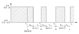
도 5는 히터 모듈의 온/오프 제어를 시간적인 측면에서 도시한 도면이다.
도 6a 및 도 6b는 히터 모듈을 구성하는 히터별로 온/오프가 제어되는 것을 설명하기 위한 도면이다.
도 7a 및 도 7b는 비례 제어를 설명하기 위한 도면이다.
도 8a 및 도 8b는 적분 제어를 설명하기 위한 도면이다.
도 9는 미분 제어를 설명하기 위한 도면이다.
도 10은 타겟온도에 대한 조리실 내부의 온도를 나타내는 도면이다.
도 11은 오븐의 제어 방법의 일 실시예에 따른 흐름도이다.1 and 2 are views showing a perspective view of an oven according to an embodiment.
3 is a diagram for explaining a ripple phenomenon of a temperature generated according to on/off of a heater module.
4 is a view showing a control block diagram according to an embodiment of the oven (1).
5 is a diagram illustrating on/off control of a heater module in terms of time.
6A and 6B are diagrams for explaining that on/off is controlled for each heater constituting the heater module.
7A and 7B are diagrams for explaining proportional control.
8A and 8B are diagrams for explaining integral control.
9 is a diagram for explaining differential control.
10 is a diagram showing a temperature inside a cooking chamber relative to a target temperature.
11 is a flowchart of an oven control method according to an embodiment.
이하, 첨부된 도면을 참조하여 오븐 및 오븐의 제어 방법을 후술된 실시예들에 따라 구체적으로 설명하도록 한다.Hereinafter, an oven and a control method of the oven will be described in detail according to exemplary embodiments described below with reference to the accompanying drawings.
도 1 및 도 2는 오븐의 일 실시예에 따른 사시도를 나타내는 도면으로, 도 1은 오븐의 도어가 닫힌 상태를 도시한 사시도이고, 도 2는 오븐의 도어가 열린 상태를 도시한 사시도이다. 1 and 2 are views illustrating a perspective view of an oven according to an exemplary embodiment, and FIG. 1 is a perspective view illustrating a closed state of the oven door, and FIG. 2 is a perspective view illustrating an open state of the oven door.
도 1 내지 도 2를 참조하면, 오븐(1)은 본체(10), 본체(10) 내부에 마련되는 조리실(20) 및 조리실(20)을 가열하는 가열장치를 포함한다. Referring to FIGS. 1 to 2, the
본체(10)의 상부에는 사용자로부터 조리를 위한 각종 명령을 입력받는 입력부(12) 및 사용자에게 각종 조리 정보를 표시하는 디스플레이부(11)가 마련될 수 있다. 예를 들어, 사용자는 조리 시작/종료 명령, 조리 메뉴의 선택, 조리 시간(time) 및 온도의 세팅 등을 입력부(12)를 통해 입력할 수 있으며, 현재 시간, 메뉴 선택 화면, 동작 상태, 조리 진행/잔여 시간, 현재 온도 및 세팅 온도 등을 디스플레이부(11)를 통해 확인할 수 있다.An
입력부(12)는 버튼이나 회전 가능한 노브(knob) 형태로 구비될 수도 있으며, 터치 스크린(touch screen)과 같이 소프트웨어적으로 구비될 수도 있다. 디스플레이부(11)는 액정 표시 장치(Liquid Crystal Display; LCD), 유기 발광다이오드 표시장치(Light Emitting Diode; LED) 등으로 구현될 수 있으나, 이에 한정되지는 않는다.The
도 1에는 입력부(12) 및 디스플레이부(11)가 본체(10)의 상부 후단에 마련되어 있으나, 이와 달리 사용자 편의에 따라 본체(10)의 상부 전단에 마련되거나 상부가 아닌 다른 곳에 마련될 수도 있는 것으로, 그 위치에는 제한이 없다. In FIG. 1, the
본체(10)에는 음식물을 조리하는 공간인 조리실(20) 및 조리실(20)의 하측에 구비되어 각종 조리 부자재를 수납하는 수납장(14)을 포함할 수 있다. The
수납장(14)은, 전면에 장착된 손잡이(15) 및 양단에 장착된 롤러(미도시)를 이용하여, 가이드레일(미도시)나 가이드홈(미도시) 등을 따라 인출 및 인입 가능하게 마련될 수 있다. The
조리실(20)은 일면이 개폐 가능한 육면체 형상으로 마련될 수 있다. 구체적으로, 조리실(2)은 상면(21), 하면(22), 후면(23), 좌측면(24) 및 우측면(25)을 가지고, 도어(90)에 의해 전면(前面)이 개폐 가능하게 마련될 수 있다. 도어(90)는 흰지장치(30)를 구비하여 상하방향으로 회전 가능하며, 사용자는 도어(90)의 상단에 장착된 손잡이(15)를 잡고 도어를 회전시킴으로써 조리실(20)을 개폐시킬 수 있다. 흰지장치(30) 및 손잡이의 장착 위치는 도 2에 도시된 바와 달라질 수 있으며, 그에 따라 도어(20)의 회전방향이 달라질 수 있음은 물론이다. The
한편, 조리실(20)의 개방 시, 그 내부로 음식물을 출납할 수 있게 된다. 조리실(20) 폐쇄 시, 세팅된 값들에 따라 조리실 내부를 가열시켜 음식물을 조리할 수 있게 된다. 음식물의 출납 상태 및 음식물의 조리 상태 등을 확인할 수 있도록, 도어(90)에는 조리실(20)의 내부를 투시하기 위한 투시창(91)이 마련될 수 있다. On the other hand, when the
조리실(20)이 외부와 단열되도록, 조리실(20)의 상면(21), 하면(22), 후면(23), 좌측면(24) 및 우측면(25)이 단열부재로 형성되거나, 각각의 외측에 단열부재들이 배치될 수 있다. 마찬가지로, 투시창(91)을 비롯한 도어(90) 전체 또는 도어(90)의 일부가 단열부재로 형성될 수 있다. To insulate the
조리실(20)에는 조리될 음식물을 얹을 수 있도록 격자 형상의 그릴선반(50)이 착탈 가능하게 마련되며, 조리실(20)의 양 측면(24, 25)에는 그릴선반(50)의 양단을 지지할 수 있도록 지지대(40)가 설치된다. 그릴선반(50)은 도 2에 도시된 바와 달리 복수개로 구성될 수 있다. 또한, 지지대(40)는 적어도 한 쌍으로 구성될 수 있으며, 특히, 그릴선반(50)의 설치높이를 다양하게 조절할 수 있도록 다양한 높이에 복수의 쌍으로 구성될 수도 있다.A grid-shaped grill shelf 50 is detachably provided in the
조리실(20) 내부에는 음식물의 조리가 이루어지도록 가열장치가 마련되며, 가열장치는 직접 복사열을 가하여 음식물의 조리가 이루어지도록 하는 히터 모듈(60) 및 가열된 공기를 순환시켜 음식물의 조리가 이루어지도록 하는 컨벡션 모듈(70)을 포함할 수 있다. A heating device is provided in the
히터 모듈(60)는 조리실(20)의 상면(21)에 마련되는 상부 히터(61), 조리실(20)의 하면(22)에 마련되는 하부 히터(62)로 구성될 수 있으며, 컨벡션 모듈(70)은 조리실(20)의 후면(23)에 마련되는 두개의 컨벡션 팬(71,72)로 구성될 수 있다. 히터 모듈(60)을 구성하는 히터의 개수나, 컨벡션 모듈(70)을 구성하는 컨벡션 팬의 개수는 도 2에 제한되지 않는다. The heater module 60 may include an
예를 들어, 히터 모듈(60)은 컨벡션 팬(21,72)과 결합된 후면 히터(미도시)를 더 포함할 수 있고, 컨벡션 모듈(70)은 단일의 컨벡션 팬으로 구성될 수 있다. 다만, 설명의 편의를 위해 이하에서는 상면 히터(61) 및 하면 히터(62)로 구성된 히터 모듈(60)과 두개의 컨벡션 팬(71, 72)으로 구성된 컨벡션 모듈(70)을 기준으로 설명하기로 한다. For example, the heater module 60 may further include a rear heater (not shown) coupled with the
히터 모듈(60)은 복사열을 통해 조리실(20) 내의 음식물을 직접 가열하도록 한다. 상부 히터(61)는 조리실(20)의 상면(21)에 노출되도록 마련되어, 음식물의 상측을 가열시킬 수 있다. 하부 히터(62)는, 음식물 또는 음식물에서 발생되는 기름 등으로부터 보호되도록, 조리실(20)의 하면(22)에 노출되지 않고 마련되어 음식물의 하측을 가열시킬 수 있다.The heater module 60 directly heats food in the
컨벡션 모듈(70)은 히터 모듈(60)에 의해 가열된 공기를 순환시킴으로써, 음식물의 조리 시간을 단축시킨다. 다시 말하면, 가열된 공기는 컨벡션 팬(71, 72)이 회전함에 따라 조리실(20) 내부에서 순환하게 되고, 순환열은 히터 모듈(60)의 복사열에 더해져 음식물의 조리 속도를 향상시킨다. The convection module 70 circulates air heated by the heater module 60 to shorten the cooking time of food. In other words, the heated air circulates inside the
컨벡션 모듈(70)은 컨벡션 팬(71,72)을 수용하는 컨벡션 팬 수용부(미도시) 및 조리실(20)과 컨벡션 팬(71, 72)을 구획하는 또는 조리실(20)과 컨벡션 팬 수용부를 구획하는 구획판(75)을 더 포함할 수 있다. 구획판(75)에는 조리실(20)의 공기를 컨벡션 팬 수용부로 흡입시키고, 컨벡션 팬(71, 72)에 의해 순환된 공기를 조리실(20)로 토출시키기 위한 다수의 홀이 마련될 수 있다. The convection module 70 is a convection pan receiving unit (not shown) accommodating the convection pans 71 and 72, and a
일반적인 모드에서는 히터 모듈(60)만이 구동하여 음식물을 조리하는 반면, 사용자에 의해 빠른 조리 또는 컨벡션 모드가 선택되는 경우, 컨벡션 모듈(70)이 함께 구동하게 된다. 즉, 오븐(1)은 히터 모듈(60)에서 발생되는 복사열을 통해 음식물을 조리하고, 컨벡션 모드에서는 컨벡션 팬(71, 72)의 회전으로 음식물의 조리를 보조하게 된다. In the general mode, only the heater module 60 is driven to cook food, whereas when the fast cooking or convection mode is selected by the user, the convection module 70 is driven together. That is, the
일반 모드에서든 컨벡션 모드에서든, 음식물의 조리를 위해 기본적으로 히터 모듈(60)이 구동하게 되며, 세팅된 온도에서 음식물이 조리되도록, 히터 모듈(60)은 온(on) 상태와 오프(off) 상태를 반복하게 된다. Whether in the normal mode or the convection mode, the heater module 60 is basically driven to cook food, and the heater module 60 is in an on state and an off state so that food is cooked at a set temperature. Is repeated.
다만, 히터 모듈(60)의 온/오프(on/off) 상태가 반복됨에 따라, 조리실(20) 내부의 온도는 소정의 범위에서 진동하는 "온도의 리플 현상"이 발생하기도 한다. 히터 모듈(60)이 온상태로 전환되거나 오프 상태로 전환된다고 하여 조리실(20) 내부의 온도에 즉각적으로 영향을 주는 것이 아니며, 히터 모듈(60)의 상태 전환이 조리실(20) 내부에 영향을 미치지까지 일정 시간이 소요된다. 따라서, 사용자로부터 세팅된 온도 즉, 타겟온도로부터 +/-델타 온도가 되는 시점에 히터 모듈(60)를 단순히 온/오프 제어하는 경우, 타겟온도를 기준을 오버슈트(overshoot) 및 언더슈트(overshoot)가 반복적으로 나타나게 되고, 이에 따라 온도의 리플 현상이 발생하게 되는 것이다. 이에 대한 구체적 설명은 도 3을 참조하여 설명하기로 한다. However, as the on/off state of the heater module 60 is repeated, a "temperature ripple phenomenon" in which the temperature inside the
도 3은 히터 모듈의 온/오프에 따라 발생되는 온도의 리플 현상을 설명하기 위한 도면이다. 도 3을 비롯하여 이하에서는, 입력부(12)를 통해 세팅된 온도를 타겟온도(A)라 칭하는 것으로 한다. 3 is a diagram for explaining a ripple phenomenon of a temperature generated according to on/off of a heater module. In the following, including FIG. 3, the temperature set through the
도 3에 도시된 바와 같이, 예열이 완료되는 시점인 T1까지 히터 모듈(60)은 온 상태를 유지하며 조리실(20) 내부의 온도를 높이게 된다. 예열 완료 시의 온도(이하, 예열온도라 칭함)가 타겟온도(A)에 도달하지 못한 경우, 히터 모듈(60)은 온 상태를 소정 시간동안 더 유지하며, 현재온도가 타겟온도(A)에 근접하도록 한다. 현재온도가 타겟온도(A)에 도달하는 시점 Tx 또는 그 직전에 히터 모듈(60)은 오프 상태로 전환한다. 다만, 히터 모듈(60)의 잔열에 의해 조리실(20) 내부의 온도는 타겟온도(A)를 초과하게 되고, 타겟온도(A)에 이르기까지 소정의 시간이 필요하게 된다. 즉, 타겟온도(A)를 기준으로 오버슈트가 나타나게 된다. As shown in FIG. 3, the heater module 60 maintains the on state until T1, when preheating is completed, and increases the temperature inside the
한편, 타겟온도(A)를 유지하기 위해, 현재온도가 타겟온도(A)와 같아지는 시점 Ty 또는 그 직전에 히터 모듈(60)은 다시 온 상태로 전환한다. 히터 모듈(60) 자체의 가열시간이 요구되므로, 조리실(20) 내부의 온도는 타겟온도(A) 이하로 떨어지고, 떨어진 온도가 타겟온도(A)에 도달하는데 소정의 시간이 필요하게 된다. 즉, 타겟온도(A)를 기준으로 언더슈트가 나타나게 된다. On the other hand, in order to maintain the target temperature (A), the heater module 60 is switched to the ON state again at the time point Ty or immediately before the current temperature equals the target temperature (A). Since the heating time of the heater module 60 itself is required, the temperature inside the
이와 같이 히터 모듈(60)의 온/오프가 반복되면서, 조리실(20) 내부의 온도는 타겟온도(A)를 조리 완료 시까지 동일하게 유지하지 못하고, 타겟온도(A)를 초과하거나 타겟온도(A) 이하로 떨어지는 등 소정의 범위(R)로 진동하게 된다. 즉, 조리실(20) 내부 온도에 리플 현상이 발생할 수 있는 것이다. 온도의 리플 현상은 히터 모듈(1)의 온/오프 시점 또는 온/오프의 전환 시점에 따라 더욱 증가할 수도 있고, 감소할 수도 있다. 바꾸어 말하면, 히터 모듈(1)의 온/오프 시점을 어떻게 제어하느냐에 따라 조리실(20) 내부의 온도가 더욱 큰 폭으로 진동할 수도 있고, 그 반대가 될 수도 있다. As the heater module 60 is repeatedly turned on/off in this way, the temperature inside the
이하에서는 히터 모듈(60)의 온/오프 시점의 제어를 통해, 온도의 리플 현상을 감소시키는 오븐(1)의 구성 및 각 구성의 역할에 대해 상술하기로 한다. Hereinafter, the configuration of the
도 4는 오븐(1)의 일 실시예에 따른 제어 블럭도를 도시한 도면이다. 4 is a view showing a control block diagram according to an embodiment of the oven (1).
도 4를 참조하면, 오븐(1)은 입력부(12), 디스플레이부(11), 온도센서(100), 제어부(200), 히터 구동부(300) 및 저장부(400)를 포함한다. Referring to FIG. 4, the
전술한 바 있듯이, 입력부(12)는 사용자로부터 조리를 위한 각종 명령을 입력받으며, 디스플레이부(11)는 사용자에게 각종 조리 정보를 표시한다. 사용자는 조리에 필요한 타겟온도(A)를 입력부(12)를 통해 세팅하고, 디스플레이부(11)를 통해 세팅된 타겟온도(A)가 확인할 수 있다. As described above, the
온도센서(100)는 조리실(20) 내부에 설치되어, 히터 모듈(60)의 온/오프에 따라 변화하는 조리실(20) 내부의 온도를 감지한다. 구체적으로, 온도센서(100)는 조리실(20)의 상면(21), 하면(22), 후면(23), 좌측면(24) 및 우측면(25) 중 적어도 한면에 설치될 수 있으며, 조리 완료 시까지 주기적으로 조리실(20) 내부의 온도를 감지한다. 온도센서(100)에 의해 감지된 온도는 제어부(200)에 전달되고, 제어부(200)는 이와 같은 온도에 기초하여 히터 모듈(60)의 온/오프 시점을 제어하게 된다. 온도센서(100)의 온도 감지와 이에 기초한 제어부(200)의 역할에 대해서는 후술하기로 한다. The
온도센서(100)는 접촉식 온도센서로 구현될 수도 있고, 비접촉식 온도센서로 구현될 수도 있다. 구체적으로, 온도센서(100)는 온도 변화에 따른 금속의 저항변화를 이용하는 측온 저항체(RTD) 온도센서, 온도 변화에 따른 반도체의 저항변화를 이용하는 서미스터 온도센서, 재질이 다른 2종류의 금속선의 접합점 양단에서 발생하는 기전력을 이용하는 열전대 온도센서, 온도에 따라 변화하는 트랜지스터의 양단전압 또는 P-N접합부의 전류전압특성을 이용하는 IC 온도센서 중 적어도 하나로 구현될 수 있다. 다만, 이에 한정되는 것은 아니며 조리실(20) 내부의 온도를 감지할 수만 있다면, 온도센서(100)는 상술한 것 외에 다른 형태의 센서로 구현되는 것도 가능할 것이다. The
제어부(200)는 조리실(20) 내부의 온도에 기초하여, 히터 모듈(60)의 온/오프 시점 또는 온/오프 상태가 지속되는 시간을 제어한다. The
도 5는 히터 모듈의 온/오프 제어를 시간적인 측면에서 도시한 도면이고, 도 6a 및 도 6b는 히터 모듈을 구성하는 히터별로 온/오프가 제어되는 것을 설명하기 위한 도면이다. 5 is a diagram illustrating on/off control of a heater module in terms of time, and FIGS. 6A and 6B are diagrams for explaining that on/off is controlled for each heater constituting the heater module.
도 5를 참조하면, 제어부(200)는 음식물의 조리를 위해, 히터 모듈(60)을 온시키고 예열을 시작한다. 그리고 제어부(200)는 히터 모듈(60)의 온 상태 지속 시간이 예열 완료 시점 T1에 도달하는지 판단하거나, 조리실(20) 내부의 온도가 예열온도에 도달하는지 판단한다. 이를 위해, 예열 완료 시점 또는 예열온도는 미리 설정되어 저장부(400)에 저장되어 있는 것으로 한다. 설명의 편의를 위해, 이하에서는 예열 완료 시점(T1)이 미리 저장부(400)에 저장되어 있고, 제어부(200)는 이를 이용하여 예열 완료 여부를 판단하는 것으로 한다. Referring to FIG. 5, the
예열 완료 시점 T1에 이른 것으로 판단되면, 제어부(200)는 각 주기별로 히터 모듈(60)의 온/오프 시간을 설정하고, 설정된 시간에 따라 온/오프 동작하도록 히터 모듈(60)을 제어한다. 이 때, 히터 모듈(60)의 온 시간은 히터 모듈(60)의 온 상태가 지속되는 시간을 의미하며, 히터 모듈(60)의 오프 시간은 히터 모듈(60)의 오프 상태가 지속되는 시간을 의미한다.When it is determined that the preheating completion point T1 has been reached, the
전술한 바 있듯이, 온도센서(100)는, 예열 시작 시점부터 음식물의 조리가 완료되는 시점까지, 주기적으로 조리실(20) 내부의 온도를 감지하여 제어부(200)에 전달한다. 이 때, 온도센서(100)의 감지 주기는 미리 설정되어 저장부(400)에 저장되어 있는 것으로, 항상 일정할 필요는 없으며, 예열 완료 시점 이전과 예열 완료 시점 이후의 주기가 다르게 설정되는 것도 가능하다. As described above, the
예를 들어, 온도센서(100)는 시점 T1, T2, T3 및 T4에 조리실(20)의 온도를 감지하는데, 시점 T1 내지 T2 사이의 간격, 시점 T2 내지 T3 사이의 간격, 시점 T3 내지 T4 사이의 간격은 일정할 수도 있으나, 서로 다르게 설정될 수도 있는 것이다. 이 때, 시점 T1 내지 T2 사이의 간격을 제 1주기라 정의하고, 시점 T2 내지 T3 사이의 간격을 제 2주기라 정의하며, 시점 T3 내지 T4 사이의 간격을 제 3 주기라 정의할 수 있다. 물론, 온도센서(100)는 예열 완료 전 즉, 시점 T1 이전에도 조리실(20) 내부의 온도를 감지하게 된다. For example, the
제어부(200)는 온도센서(100)로부터 감지된 온도에 기초하여, 주기별로 히터 모듈(60)의 온/오프 시간을 설정하게 된다. The
구체적으로, 제어부(200)는 예열 완료 시점 T1에서, 사용자에 의해 입력된 타겟온도(A), 시점 T1에서 온도센서(100)가 감지한 현재온도, 시점 T1 이전에 온도센서가 감지한 이전온도를 비교하여, 제 1주기의 히터 모듈(60)의 온/오프 시간을 설정한다. 그리고 제어부(200)는 제 1주기의 완료 시점 T2에서, 타겟온도(A), 시점 T2에서 온도센서(100)가 감지한 현재온도, 시점 T2 이전에 온도센서(100)가 감지한 이전온도 즉, 시점 T1에서 온도센서(100)가 감지한 온도를 비교하여, 제 2주기의 히터 모듈(60)의 온/오프 시간을 설정한다. Specifically, the
마찬가지로, 제어부(200)는 제 2주기의 완료 시점 T3에서, 타겟온도(A), 시점 T3에서 온도센서(100)가 감지한 현재온도, 시점 T3 이전에 온도센서(100)가 감지한 이전온도, 즉, 시점 T2에서 온도센서(100)가 감지한 온도를 비교하여, 제 3주기의 히터 모듈(60)의 온/오프 시간을 설정한다. Similarly, the
상술한 바와 같이, 제어부(200)는 각 주기별로 타겟온도(A), 현재온도 및 이전온도를 비교하고, 그에 따라 해당 주기에서 히터 모듈(60)이 동작하기 위한 온/오프 시간을 설정할 수 있다. 제어부(200)가 각 주기별로 타겟온도(A), 현재온도 및 이전온도를 비교하는 방법, 그리고 그에 따라 온/오프 시간을 설정하는 방법에 대한더욱 구체적 설명은 후술하기로 한다.As described above, the
제어부(200)는 설정된 시간에 따라 구동되도록 히터 모듈(60)을 제어한다. 구체적으로, 제 1주기에 대해 히터 모듈(60)의 온 시간은 N1, 오프 시간은 F1으로 설정된 경우, 제어부(200)는 시점 T1에서부터 N1 시간 동안 온 상태를 지속하다가, N1시간이 지난 후 오프 상태로 전환하여 F1 시간을 유지하도록 히터 모듈(60)을 제어한다. 제 2주기에 대해 히터 모듈(60)의 온 시간은 N2, 오프 시간은 F2로 설정된 경우, 제어부(200)는 시점 T2에서 온 상태로 전환하여 N2 시간 지속한 후, 다시 오프 상태로 전환하여 F2 시간을 유지하도록 히터 모듈(60)을 제어한다. The
마찬가지로, 제 3주기에 대해 히터 모듈(60)의 온, 오프 시간이 각각 N3, F3으로 설정된 경우, 제어부(200)는 시점 T3에서 온 상태로 전환하여 N3 시간 지속 후, 다시 F3 시간 오프 상태를 유지하도록 히터 모듈(60)을 제어한다. 이와 같이 제어부(200)가 각 주기의 시초에 온/오프 시간을 재설정하므로, 주기별로 온/오프 시간은 달라질 수 있다. 예를 들어, 히터 모듈(60)의 제 1주기의 온 시간 N1, 제 2 주기의 온 시간 N2 및 제 3주기의 온 시간은 각각 다르게 설정될 수 있는 것이다. Likewise, when the on and off times of the heater module 60 for the third cycle are set to N3 and F3, respectively, the
제어부(200)는 도 6a 및 도 6b에 도시된 바와 같이, 히터 모듈(60)을 구성하는 히터별로 온/오프 시간을 설정하고, 그에 따라 구동하도록 제어할 수도 있다. 다시 말하면, 제어부(200)는 예열 완료 시점 T1에서, 상부 히터(61)의 제 1주기 온, 오프 시간을 N11, F11으로 각각 설정하고, 하부 히터(62)의 제 1주기 온, 오프 시간을 N21, F21으로 각각 설정할 수 있다. 그리고 제어부(200)는 제 1주기 완료 시점 T2에서, 상부 히터(61)의 제 2주기 온, 오프 시간을 N12, F12로 각각 설정하고, 하부 히터(62)의 제 2주기 온, 오프 시간을 N22, F22로 각각 설정할 수 있다. As shown in FIGS. 6A and 6B, the
마찬가지로, 제어부(200)는 제 2주기 완료 시점 T3에서, 상부 히터(61)의 제 3주기 온, 오프 시간을 N13, F13로 각각 설정하고, 하부 히터(62)의 제 3주기 온, 오프 시간을 N23, F23로 각각 설정할 수 있다. 따라서, 동일한 주기라도 히터의 위치에 따라 또는 히터별로 온/오프 시간은 달라질 수 있다. 예를 들어, 제 1주기에 대해 상부 히터(61)의 온 시간 N11과 하부 히터(62)의 온 시간 N21은 서로 다르게 설정될 수 있는 것이다. Similarly, the
상술한 바와 같이 히터별로 온/오프 시간을 설정하는 경우에도, 제어부(200)는 타겟온도(A), 현재온도 및 이전온도를 비교함으로써 각 주기에 대한 온/오프 시간을 설정하게 된다. 이하에서는, 타겟온도(A), 현재온도 및 이전온도를 비교하여 각 주기에 대한 온/오프 시간을 설정하는 방법에 대해 구체적으로 설명하되, 설명의 편의를 위해 히터별로 온/오프 시간을 설정하는 것이 아닌 모든 히터에 대해 동일한 온/오프 시간의 설정을 적용하는 것으로 한다. Even when the on/off time is set for each heater as described above, the
제어부(200)는 타겟온도(A)에 따라 미리 설정되어 저장된 히터 모듈(60)의 온/오프 시간을 저장부(400)로부터 추출한다. 예를 들어, 온도차 x에 대해 저장부(400)에 온 시간은 Nx으로, 오프 시간은 Fx로 기설정되어 저장되어 있고, 입력된 타겟온도(A)가 예열 완료 시점의 온도를 x만큼 초과하는 경우, 제어부(200)는 저장부(400)에서 온, 오프 시간 Nx, Fx를 각각 추출한다. The
제어부(200)는 각 주기의 시초에 타겟온도(A)와 현재온도를 비교하고, 타겟온도와 현재온도의 대소에 따라 1차적으로 온, 오프 시간의 증감 여부를 판단한다. 이를 간단히, "비례 제어"라 칭할 수 있으며, 비례 제어에 의해 증감되는 온/오프 시간을 ±Z1j (단, j는 주기)로 정의할 수 있다. The
그리고 제어부(200)는 각 주기의 시초에 현재온도와 이전온도를 비교한다. 현재온도와 이전온도가 동일한 경우 즉, 온도가 스테이블(stable)한 경우, 제어부(200)는 타겟온도(A)와 현재온도의 대소에 따라 2차적으로 온, 오프 시간의 증감 여부를 판단한다. 이를 "적분 제어"라 칭할 수 있으며, 적분 제어에 의해 증감되는 온/오프 시간을 ±Z2j (단, j는 주기)로 정의할 수 있다. And the
현재온도와 이전온도가 동일하지 않은 경우, 제어부(200)는 현재온도와 이전온도의 대소에 따라 2차적으로 온, 오프 시간의 증감 여부를 판단한다. 이를 "미분 제어"라 칭할 수 있으며, 미분 제어에 의해 증감되는 온/오프 시간을 ±Z3j (단, j는 주기)로 정의할 수 있다. 제어부(200)의 비례 제어, 적분 제어 및 미분 제어에 대해서는 도 7a 내지 도 9를 참조하여 더욱 구체적으로 설명하는 것으로 한다. If the current temperature and the previous temperature are not the same, the
도 7a 및 도 7b는 비례 제어를 설명하기 위한 도면이다. 7A and 7B are diagrams for explaining proportional control.
전술한 바 있듯이, 제어부(200)는 각 주기의 시초에 타겟온도(A)와 현재온도를 비교하고, 타겟온도와 현재온도의 대소에 따라 1차적으로 온, 오프 시간의 증감 여부를 판단하는 "비례 제어"를 수행한다. As described above, the
구체적으로, 제 1주기(P1)의 시초 즉, 예열 완료 시점 T1에, 제어부(200)는 타겟온도(A)와 현재온도(즉, 시점 T1에서의 온도)가 동일한지 또는 현재온도가 타겟온도(A)를 초과하는지 판단한다. 도 7a에 도시된 바와 같이, 현재온도가 타겟온도(A)를 A1만큼 초과하는 경우, 제어부(200)는 히터 모듈(60)의 온 시간을 A1에 대응하는 시간 Z11만큼 감소하도록 제어한다. 반면, 도 7b에 도시된 바와 같이, 현재온도가 타겟온도(A)보다 A1만큼 작은 경우, 제어부(200)는 히터 모듈(60)의 온 시간을 A1에 대응하는 시간 Z11만큼 증가하도록 제어한다.Specifically, at the beginning of the first period P1, that is, at the time point T1 of completion of preheating, the
다시 말하면, 제어부(200)는 현재온도가 타겟온도(A)를 초과하는 경우에는 히터 모듈(60)의 온 시간을 감소시키고, 현재온도가 타겟온도(A)에 이르지 못한 경우에는 히터 모듈(60)의 온 시간을 증가시킴으로써, 현재온도가 타겟온도(A)에 근접할 수 있도록 하는 것이다. In other words, when the current temperature exceeds the target temperature (A), the
이와 같은 비례 제어는 매 주기의 시초에서 이루어진다. 제 2주기(P2)의 시초 T2에서도, 제어부(200)는 타겟온도(A)와 현재온도(즉, 시점 T2에서의 온도)를 비교하고, 현재온도가 도 7a에 도시된 바와 같이 타겟온도(A)를 A2만큼 초과하는 경우에는, 히터 모듈(60)의 온 시간을 A2에 대응하는 시간 Z12만큼 감소시키는 제어를 수행한다. 반면, 도 7b에 도시된 바와 같이 현재온도가 타겟온도(A)보다 A2만큼 작은 경우에는, 히터 모듈(60)의 온 시간을 A2에 대응하는 시간 Z12만큼 증가시키는 제어를 수행하는 것이다. This proportional control takes place at the beginning of every cycle. Even at the beginning T2 of the second period P2, the
도 8a 및 도 8b는 적분 제어를 설명하기 위한 도면이다. 8A and 8B are diagrams for explaining integral control.
제어부(200)는 각 주기의 시초에 현재온도와 이전온도를 비교하고, 현재온도와 이전온도가 동일한 경우, 제어부(200)는 타겟온도(A)와 현재온도의 대소에 따라 2차적으로 온, 오프 시간의 증감 여부를 판단하는 "적분 제어"를 수행한다. 전술한 바 있듯이, 현재온도와 이전온도가 동일한 상태를 스테이블(stable)한 상태라 칭할 수 있다.The
예를 들어, 제 4주기의 시점 T4에, 제어부(200)는 현재온도(즉, 시점 T4에서의 온도)와 이전온도(즉, 시점 T3에서의 온도)가 동일한지를 판단한다. 현재온도와 이전온도가 동일한 경우, 제어부(200)는 현재온도가 타겟온도(A)를 초과하는지 판단한다. For example, at the time point T4 of the fourth cycle, the
도 8a에 도시된 바와 같이, 현재온도와 이전온도가 동일하고, 현재온도가 타겟온도(A)보다 A4만큼 작은 경우, 제어부(200)는 히터 모듈(60)의 온 시간을 A4에 대응하는 시간 Z24만큼 증가하도록 제어한다. 즉, 시점 T4의 조리실(20) 온도가 타겟온도(A)보다 작은 지점에서 스테이블한 상태를 이루는 경우, 제어부(200)는 히터 모듈(60)의 온 시간을 증가시킴으로써, 스테이블한 상태의 온도를 상승시키고 타겟온도(A)로 수렴할 수 있도록 하는 것이다. As shown in FIG. 8A, when the current temperature and the previous temperature are the same, and the current temperature is less than the target temperature A4 by A4, the
도 8b에 도시된 바와 같이, 현재온도와 이전온도가 동일하고, 현재온도가 타겟온도(A)를 A4만큼 초과하는 경우, 제어부(200)는 히터 모듈(60)의 온 시간을 A4에 대응하는 시간 Z24만큼 감소하도록 제어한다. 즉, 시점 T4의 조리실(20) 온도가 타겟온도(A)보다 큰 지점에서 스테이블한 상태를 이루는 경우, 제어부(200)는 히터 모듈(60)의 온 시간을 감소시킴으로써, 스테이블한 상태의 온도를 하락시키고 타겟온도(A)로 수렴할 수 있도록 하는 것이다. As shown in FIG. 8B, when the current temperature and the previous temperature are the same, and the current temperature exceeds the target temperature A by A4, the
도 9는 미분 제어를 설명하기 위한 도면이다.9 is a diagram for explaining differential control.
각 주기의 시초에서 현재온도와 이전온도를 비교할 때, 현재온도와 이전온도가 동일하지 않은 경우 즉, 스테이블한 상태가 아닌 경우, 제어부(200)는 현재온도와 이전온도의 대소에 따라 2차적으로 온, 오프 시간의 증감 여부를 판단하는 "미분 제어"를 수행한다. When comparing the current temperature and the previous temperature at the beginning of each cycle, when the current temperature and the previous temperature are not the same, that is, when they are not in a stable state, the
도 9에 도시된 바와 같이, 제 2주기(P2)의 시점 T2에서 스테이블한 상태가 아닌 경우, 제어부(200)는 현재온도(즉, 시점 T2에서의 온도)가 이전온도(즉, 시점 T1에서의 온도)를 초과하는지 판단한다. 현재온도가 이전온도를 B2만큼 초과하는 경우, 제어부(200)는 히터 모듈(60)의 온 시간을 B2에 대응하는 시간 Z32만큼 감소하도록 제어한다. 바꾸어 말하면, 시점 T2에서의 평균 기울기 S2가 (+)값을 갖는 경우, 제어부(200)는 S2에 대응하는 시간 Z32만큼 히터 모듈(60)의 온 시간이 감소하도록 제어한다고 볼 수도 있다. As shown in FIG. 9, when the state is not in a stable state at the time point T2 of the second period P2, the
마찬가지로, 제 3주기(P3)의 시점 T3에서 스테이블한 상태가 아닌 경우, 제어부(200)는 현재온도(즉, 시점 T3에서의 온도)가 이전온도(즉, 시점 T2에서의 온도)를 초과하는지 판단한다. 현재온도가 이전온도보다 B3만큼 작은 경우, 제어부(200)는 히터 모듈(60)의 온 시간을 B3에 대응하는 시간 Z33만큼 증가하도록 제어한다. 바꾸어 말하면, 시점 T3에서의 평균 기울기 S3가 (-)값을 갖는 경우, 제어부(200)는 S3에 대응하는 시간 Z33만큼 히터 모듈(60)의 온 시간이 증가하도록 제어한다고 볼 수도 있다.Likewise, if the state is not in a stable state at the time point T3 of the third period P3, the
제어부(200)는 평균 기울기가 (+)가 되는 경우에는 히터 모듈(60)의 온 시간을 감소시키고, 평균 기울기가 (-)가 되는 경우에는 히터 모듈(60)의 온 시간을 증가시킴으로써, 평균 기울기가 수평한 상태가 되도록 즉, 스테이블한 상태가 되도록 제어하는 것이다. The
상술한 바와 같은 적분 제어 또는 미분 제어는, 비례 제어와 마찬가지로 매 주기의 시초에서 이루어진다. 따라서, 매 주기의 시초에, 제어부(200)는 1차적으로 현재온도와 타겟온도의 비교하여, 현재온도가 타겟온도(A)에 근접하도록 비례 제어를 수행하고, 2차적으로 현재온도와 이전온도를 비교하여, 스태이블한 상태의 온도가 타겟온도(A)에 수렴하도록 적분 제어를 수행하거나 스테이블하지 않은 상태가 스테이블한 상태로 전환되도록 미분 제어를 수행하게 된다. Integral control or differential control as described above, like proportional control, is performed at the beginning of every cycle. Therefore, at the beginning of each cycle, the
제어부(200)는 타겟온도(A)에 대해 저장부(400)에서 추출된 온/오프 시간 및 비례 제어, 적분 제어 또는 미분 제어를 위해 산출한 시간들을 누적하여 각 주기의 온/오프 시간을 재설정한다.The
예를 들어, 타겟온도(A)에 대해 추출된 온, 오프 시간이 Nx, Fx이고, 제 1주기(P1)에 대해 1차적으로 비례 제어 시간 +Z11 및 2차적으로 적분 제어 시간 +Z12가 산출되고, 제 2주기(P2)에 대해 1차적으로 비례 제어 시간 +Z21 및 2차적으로 미분 제어 시간 -Z31가 산출된다고 할 때, 제어부(200)는 제 1주기의 온 시간 N1=Nx+Z11+Z21 및 오프 시간 F1=Fx-Z11-Z21으로 재설정하고, 제2주기의 온 시간 N2=N1+Z21-Z31 및 오프 시간 F2=F1-Z21+Z31으로 재설정할 수 있다. For example, the extracted on and off times for the target temperature (A) are Nx and Fx, and the proportional control time +Z11 and the integral control time +Z12 are calculated primarily for the first period (P1). When it is assumed that the proportional control time +Z21 and the differential control time -Z31 are calculated primarily for the second period P2, the
이 때, 제어부(200)는 제 1주기(P1)의 온 시간 N1=Nx+Z11+Z21 으로 재설정하고, 제 1주기(P1)의 전체시간 및 온 시간 N1의 차이에 기초하여 오프 시간 F1을 재설정할 수 있다. 즉, 제 1주기(P1)의 오프 시간 F1=(제 1주기의 전체시간)-N1으로 재설정할 수도 있는 것이다. 마찬가지로, 제어부(200)는 제 2주기(P2)의 온 시간 N2=N1+Z21-Z31으로 재설정하고, 이를 이용하여 오프 시간 F2=(제 2주기(P2)의 전체시간)-N2로 재설정할 수도 있다. At this time, the
제어부(200)는 설정된 온/오프 시간에 따라 히터 모듈(60)이 구동하도록 히터 구동부(300)에 제어신호를 출력한다. The
히터 구동부(300)는 제어부(200)의 제어신호에 따라 히터 모듈(60)가 가열하도록 또는 가열을 중지되도록 히터모듈(60)의 온 또는 오프 동작을 제어한다. 예를 들어, 제어부(200)에서 제 1주기(P1)에 대한 히터 모듈(60)의 온, 오프 시간이 N1, F1로 각각 설정되면, 히터 구동부(300)는 그에 대응하여 시점 T1에서부터 N1 시간 동안 온 상태로 동작하다가, N1시간이 지난 후 오프 상태로 전환 동작하여 F1 시간을 유지하도록 히터 모듈(60)의 온/오프 동작을 제어한다. 그리고 제어부(200)에서 제 2주기(P2)에 대한 히터 모듈(60)의 온, 오프 시간이 N2, F2로 설정되면, 히터 구동부(300)는 시점 T2에서 온 상태로 전환 동작하여 N2 시간 유지한 후, 다시 오프 상태로 전환 동작하여 F2 시간을 유지하도록 히터 모듈(60)의 온/오프 동작을 제어한다. The
이와 같은 히터 구동부(300)의 온/오프 동작 제어는 조리 완료시까지 계속된다. This control of the on/off operation of the
한편, 제어부(200)는 히터 모듈(60)의 온/오프 상태가 반복되는 주기를 제어할 수도 있다. 제어부(200)는 히터 모듈(60)의 온/오프 상태가 반복되는 간격(interval) 또는 주파수(frequency)를 제어할 수도 있는 것이다. 이 때, 히터 모듈(60)의 온/오프 상태가 반복되는 주기는 간단히 히터 모듈(60)의 온/오프 주기라 칭할 수도 있다. Meanwhile, the
도 5를 다시 참조하면, 일 예로, 제어부(200)는 제 1 주기인 시점 T1 내지 T2 사이의 간격, 제 2 주기인 시점 T2 내지 T3 사이의 간격 및 제 3 주기인 시점 T3 내지 T4 사이의 간격을 1분으로 설정하고, 그에 대응하여 히터 구동부(300)에 제어신호를 출력할 수도 있다. 다른 예로, 제어부(200)는 제 1 주제, 제 2 주기 및 제 3 주기의 간격을 0.5분으로 설정하고, 그에 대응하여 히터 구동부(200)에 제어신호를 출력할 수도 있다. 상술한 바와 같이, 제어부(200)가 히터 모듈(60)의 온/오프 주기를 짧게 제어함으로써 레졸루션(resolution)을 높일 수 있고, 제어부(200)의 정밀 제어가 가능하게 한다. Referring again to FIG. 5, as an example, the
저장부(400)는 오븐(1)의 조작을 위한 데이터나 알고리즘을 저장할 수 있다. The
데이터 저장의 예들로, 저장부(400)는 온도센서(100)의 감지 주기, 예열 완료 시점, 타겟온도(A), 온도차에 따라 기설정된 히터 모듈(60)의 온/오프 시간를 저장할 수 있다. 데이터 저장의 다른 예들로, 저장부(400)는 비례 제어, 적분 제어 또는 미분 제어에 의해 산출된 각 주기의 온/오프의 증감 시간 및 이를 누적하여 설정된 각 주기의 최종 온/오프 시간을 저장할 수 있다. As examples of data storage, the
알고리즘 저장의 예들로, 저장부(400)는 비례 제어, 적분 제어 또는 미분 제어를 통해 각 주기의 온/오프 증감 시간을 산출하기 위한 알고리즘 및 이를 누적하여 각 주기의 최종 온/오프 시간을 설정하기 위한 알고리즘을 저장할 수 있다. As examples of algorithm storage, the
이러한 저장부(400)는 롬(Read Only Memory: ROM), 피롬(Programmable Read Only Memory: PROM), 이피롬(Erasable Programmable Read Only Memory: EPROM), 플레시 메모리와 같은 비휘발성 메모리 소자, 또는 램(Random Access Memory: RAM)과 같은 휘발성 메모리 소자, 또는 하드 디스크, 광 디스크와 같은 저장 장치로 구현될 수 있다. 다만, 이에 한정되는 것은 아니며, 당업계에 알려져 있는 임의의 다른 형태로 구현될 수도 있다.The
도 10은 타겟온도에 대한 조리실 내부의 온도를 나타내는 도면이다. 10 is a diagram showing a temperature inside a cooking chamber relative to a target temperature.
도 10에 도시된 바와 같이, 초기에는 타겟온도가 A1으로 세팅되었다가, 시점 Tx 이후에 타겟온도가 A2로 세팅되고, 시점 Ty 이후에는 타겟온도가 A3로 다시 세팅되게 된다.As shown in FIG. 10, the target temperature is initially set to A1, the target temperature is set to A2 after the time point Tx, and the target temperature is set to A3 again after the time point Ty.
초기 타겟온도 A1에 대해, 조리실(20) 내부의 온도는 예열이 완료된 후 타겟온도 A1와 거의 동일하게 유지되고 있으며, 타겟온도를 A2로 높인 이후에도, 빠르게 증가하다 타겟온도 A2와 거의 동일하게 유지되고 있다. 마찬가지로 타겟온도를 A3로 더 높인 경우에도, 조리실(20) 내부의 온도는 빠르게 증가하여 타겟온도 A3와 거의 동일하게 유지되는 것을 볼 수 있다. With respect to the initial target temperature A1, the temperature inside the
도 10을 통해 확인할 수 있듯이, 오븐(1)은 비례 제어, 적분 제어 또는 미분 제어를 통해 히터 모듈(60)의 온/오프 시간을 주기별로 재설정함으로써, 온도의 리플 현상을 현저히 감소시킨다. 또한, 오븐(1)은 비례 제어, 적분 제어 또는 미분 제어 시, 히터 모듈(60)의 온/오프 주기가 짧아지도록 설정함으로써, 정밀 제어가 가능하게 한다.As can be seen from FIG. 10, the
이상으로 오븐(1)의 구성 및 각 구성의 역할을 실시예들을 바탕으로 설명하였으며, 이하에서는 주어진 흐름도를 참조하여 오븐의 제어 방법을 살펴보기로 한다. The configuration of the
도 11은 오븐의 제어 방법의 일 실시예에 따른 흐름도이다. 11 is a flowchart of an oven control method according to an embodiment.
도 11을 참조하면, 사용자의 입력에 기초하여 타겟온도(A)가 세팅된다(810).Referring to FIG. 11, a target temperature A is set based on a user input (810).
타겟온도가 세팅된 후, 제어부(200)는 예열을 위한 히터 모듈의 온 동작을 실행한다(811).After the target temperature is set, the
제어부(200)는 예열이 완료되었는지 주기적으로 판단한다(812). The
예열 완료 시점 또는 예열온도는 미리 설정되어 저장부(400)에 저장되어 있으며, 제어부(200)는 예열 시간이 저장된 예열 완료 시점에 도달하였는지 또는 조리실(20)의 현재온도가 저장된 예열온도에 도달하였는지를 판단하여, 예열 완료 여부를 결정한다. The preheating completion time or preheating temperature is set in advance and stored in the
예열이 완료되지 않은 경우, 제어부(200)은 히터 모듈(60)의 온 동작을 계속 실행기킨다. When preheating is not completed, the
예열이 완료된 경우, 제어부(200)은 타겟온도에 대해 기설정된 히터 모듈(60)의 온/오프 시간을 저장부(400)에서 추출한다(813). When preheating is completed, the
다시 말하면, 온도차에 따라 히터 모듈(60)의 온/오프 시간릉 기설정되어 저장부(400)에 저장되어 있으며, 제어부(200)는 세팅된 타겟온도(A)와 예열 완료 시점의 온도차에 해당하는 온/오프 시간을 저장부(400)에서 추출하는 것이다. In other words, according to the temperature difference, the on/off time of the heater module 60 is preset and stored in the
제어부(200)는 히터 모듈(60)의 온/오프 시간을 주기별로 재설정하고, 그에 따라 히터 모듈(60)이 동작하도록 제어한다.The
구체적으로, 제어부(200)는 먼저 타겟온도(A)와 현재온도가 동일한지 판단한다(814). 이 때, 현재온도는 해당 주기의 시초 온도를 의미한다.Specifically, the
타겟온도(A)와 현재온도가 동일한 경우, 제어부(200)는 해당 주기에 대해 온/오프 시간의 재설정 없이, 저장부(400)에서 추출된 온/오프 시간 또는 이전 주기의 온/오프 시간과 동일하게 히터 모듈(60)이 동작하도록 제어한다(820).When the target temperature A and the current temperature are the same, the
타겟온도(A)와 현재온도가 동일하지 않은 경우, 제어부(200)은 타겟온도 및 현재온도의 대소에 따라 히터 모듈(60)의 온 증감 시간을 산출한다(815). 즉, 1차적으로 타겟온도와 현재온도를 비교하여, 현재온도가 타겟온도(A)에 근접하도록 하는 "비례 제어"를 위한 온 증감 시간을 산출한다. If the target temperature A and the current temperature are not the same, the
다음으로, 제어부(200)는 현재온도가 이전온도와 동일한지 판단한다(816). 이 때, 이전온도는 이전 주기의 시초 온도를 의미한다. Next, the
현재온도와 이전온도가 동일한 경우, 제어부(200)는 타겟온도 및 현재온도의 대소에 따라 히터 모듈(60)의 온 증감 시간을 산출한다(817). 즉, 2차적으로 현재온도와 이전온도를 비교하여, 스태이블한 상태의 온도가 타겟온도(A)에 수렴하도록 하는 "적분 제어"를 위한 온 증감 시간을 산출한다. When the current temperature and the previous temperature are the same, the
현재온도와 이전온도가 동일하지 않은 경우, 제어부(200)는 현재온도와 이전온도의 대소에 따라 히터 모듈(60)의 온 증감 시간을 산출한다(818). 즉, 스테이블하지 않은 상태가 스테이블한 상태로 전환되도록 하는 "미분 제어"를 위한 온 증감 시간을 산출한다. If the current temperature and the previous temperature are not the same, the
제어부(200)는 타겟온도(A)에 대해 저장부(400)에서 추출된 온/오프 시간 및 비례 제어, 적분 제어 또는 미분 제어를 위해 산출된 온 증감 시간을 누적하여, 히터 모듈(60)의 온/오프 시간을 재설정한다(819). The
예를 들어, 타겟온도(A)에 대해 추출된 온, 오프 시간이 Nx, Fx이고, 제 1주기에 대해 1차적으로 비례 제어 시간 +Z11 및 2차적으로 적분 제어 시간 +Z12가 획득되고, 제 2주기에 대해 1차적으로 비례 제어 시간 +Z21 및 2차적으로 미분 제어 시간 -Z31가 획득된다고 할 때, 제어부(200)는 제 1주기의 온 시간 N1=Nx+Z11+Z21 및 오프 시간 F1=Fx-Z11-Z21으로 재설정하고, 제2주기의 온 시간 N2=N1+Z21-Z31 및 오프 시간 F2=F1-Z21+Z31으로 재설정할 수 있다. For example, the on and off times extracted for the target temperature (A) are Nx and Fx, and the proportional control time +Z11 and the integral control time +Z12 are obtained primarily for the first cycle, and the second Assuming that the proportional control time +Z21 and the differential control time -Z31 are obtained primarily for two cycles, the
이 때, 제어부(200)는 제 1주기의 온 시간 N1=Nx+Z11+Z21 으로 재설정하고, 제 1주기의 전체시간 및 온 시간 N1의 차이에 기초하여 오프 시간 F1을 재설정할 수 있다. 즉, 제 1주기의 오프 시간 F1=(제 1주기의 전체시간)-N1으로 재설정할 수도 있는 것이다. 마찬가지로, 제어부(200)는 제 2주기의 온 시간 N2=N1+Z21-Z31으로 재설정하고, 이를 이용하여 오프 시간 F2=(제 2주기의 전체시간)-N2로 재설정할 수도 있다. In this case, the
그리고 해당 주기에 대해, 제어부(200)은 설정된 온/오프 시간에 따라 동작하도록 히터 모듈(60)의 구동을 제어한다(820).In addition, for a corresponding period, the
해당 주기가 종료되는 시점에, 제어부(200)는 조리 완료 여부를 판단한다(821).At the end of the period, the
조리가 완료된 경우, 히터 모듈(60)의 구동을 종료시키고, 아직 조리가 완료되지 않은 경우, 다음 주기 시작을 위해 814로 돌아가 타겟온도와 현재온도의 동일 여부를 판단한다.When cooking is completed, the driving of the heater module 60 is terminated, and when cooking is not yet completed, it returns to 814 to start the next cycle and determines whether the target temperature and the current temperature are the same.
이와 같이 제어부(200)는 비례 제어, 적분 제어 또는 미분 제어를 통해 히터 모듈(60)의 온/오프 시간을 주기별로 재설정함으로써, 오븐(1)에서 발생되는 온도의 리플 현상을 현저히 감소시킬 수 있다. 한편, 제어부(200)는 비례 제어, 적분 제어 또는 미분 제어 시, 히터 모듈(60)의 온/오프 주기가 짧아지도록 설정함으로써, 정밀 제어가 가능하도록 할 수 있다.In this way, the
이상으로 예시된 도면을 참조로 하여, 오븐 및 오븐의 제어 방법의 실시예들을 설명하였지만, 본 발명이 속하는 기술분야에서 통상의 지식을 가진 자는 본 발명이 그 기술적 사상이나 필수적인 특징을 변경하지 않고서 다른 구체적인 형태로 실시 될 수 있다는 것을 이해할 수 있을 것이다. 그러므로 이상에서 기술한 실시예들은 모든 면에서 예시적인 것이며, 한정적이 아닌 것으로 이해해야만 한다.With reference to the drawings exemplified above, embodiments of the oven and the control method of the oven have been described, but those of ordinary skill in the art to which the present invention pertains, the present invention is different without changing the technical idea or essential features. It will be appreciated that it can be implemented in a specific form. Therefore, the embodiments described above are illustrative in all respects, and should be understood as non-limiting.
1: 오븐 11: 디스플레이부
12: 입력부 20: 조리실
60: 히터 모듈 61: 상부 히터
62: 하부 히터 70: 컨벡션 모듈
100: 온도센서 200: 제어부
300: 히터 구동부 400: 저장부1: oven 11: display
12: input unit 20: cooking chamber
60: heater module 61: upper heater
62: lower heater 70: convection module
100: temperature sensor 200: control unit
300: heater driving unit 400: storage unit
Claims (20)
미리 설정된 주기로 상기 조리실의 온도를 감지하는 온도센서; 및
미리 설정된 타겟온도와 상기 온도센서로부터 감지되는 상기 조리실의 현재온도 및 이전온도에 기초하여 상기 히터의 온/오프 시간을 추출하고, 상기 타겟온도, 현재온도 및 이전온도에 기초하여 상기 히터의 온/오프 증감 시간을 산출하고, 상기 추출된 온/오프 시간에 상기 산출된 상기 히터의 온/오프 증감 시간을 누적하여, 각 주기에 대한 상기 히터의 온/오프 시간을 재설정하고, 상기 재설정된 온/오프 시간에 따라 상기 히터의 구동을 제어하는 제어부;
를 포함하는 오븐.At least one heater provided inside the cooking chamber;
A temperature sensor that senses the temperature of the cooking compartment at a preset cycle; And
Extracts the on/off time of the heater based on a preset target temperature and the current temperature and previous temperature of the cooking compartment sensed by the temperature sensor, and the on/off time of the heater based on the target temperature, the current temperature, and the previous temperature. An off increase/decrease time is calculated, and the calculated on/off increase/decrease time of the heater is accumulated in the extracted on/off time to reset the on/off time of the heater for each period, and the reset on/off time A control unit controlling driving of the heater according to an off time;
Oven containing a.
상기 제어부는,
예열 완료 시점 이전까지 상기 히터가 온되도록 상기 히터의 구동을 제어하고, 상기 예열 완료 시점 이후의 주기에 대한 상기 히터의 온/오프 시간을 재설정하는 오븐. The method of claim 1,
The control unit,
An oven for controlling driving of the heater so that the heater is turned on until a time when preheating is completed, and resetting an on/off time of the heater for a period after the time when preheating is completed.
상기 현재온도는,
해당 주기가 시작되는 시점의 상기 조리실의 온도인 오븐.The method of claim 1,
The current temperature is,
Oven that is the temperature of the cooking compartment at the start of the cycle.
상기 이전온도는,
이전 주기가 시작되는 시점의 상기 조리실의 온도인 오븐.The method of claim 1,
The transfer temperature is,
Oven which is the temperature of the cooking compartment at the start of the previous cycle.
온도차에 따라 미리 설정된 상기 히터의 온/오프 시간을 저장하는 저장부;
를 더 포함하는 오븐. The method of claim 1,
A storage unit for storing a preset on/off time of the heater according to a temperature difference;
Oven further comprising a.
상기 제어부는,
상기 타겟온도와 예열 완료 시점의 상기 조리실의 온도차에 기초하여, 상기 저장부에 저장된 상기 히터의 온/오프 시간을 추출하는 오븐. The method of claim 5,
The control unit,
An oven for extracting an on/off time of the heater stored in the storage unit based on a temperature difference between the target temperature and the cooking chamber at the time of completion of preheating.
상기 제어부는,
상기 타겟온도 및 현재온도를 비교하여, 상기 히터의 제 1온/오프 증감 시간을 산출하는 오븐. The method of claim 6,
The control unit,
An oven for calculating a first on/off increase/decrease time of the heater by comparing the target temperature and the current temperature.
상기 제어부는,
상기 현재온도가 상기 타겟온도보다 높은 주기에 대해, 상기 히터의 온 시간이 감소하고 오프 시간이 증가하도록 상기 제 1온/오프 증감 시간을 산출하는 오븐. The method of claim 8,
The control unit,
For a period in which the current temperature is higher than the target temperature, the first on/off increase/decrease time is calculated so that the on time of the heater decreases and the off time increases.
상기 제어부는,
상기 현재온도가 상기 타겟온도보다 낮은 주기에 대해, 상기 히터의 온 시간이 증가하고 오프 시간이 감소하도록 상기 제 1온/오프 증감 시간을 산출하는 오븐. The method of claim 8,
The control unit,
For a period in which the current temperature is lower than the target temperature, the first on/off increase/decrease time is calculated so that the on time of the heater increases and the off time decreases.
상기 제어부는,
상기 현재온도 및 이전온도를 비교하여, 상기 히터의 제 2온/오프 증감 시간을 산출하는 오븐. The method of claim 8,
The control unit,
An oven for calculating a second on/off increase/decrease time of the heater by comparing the current temperature and the previous temperature.
상기 제어부는,
상기 현재온도가 이전온도와 동일한 주기에 대해, 상기 타겟온도 및 현재온도를 비교하여 상기 제 2온/오프 증감 시간을 산출하는 오븐. The method of claim 11,
The control unit,
An oven for calculating the second on/off increase/decrease time by comparing the target temperature and the current temperature for a period in which the current temperature is the same as the previous temperature.
상기 제어부는,
상기 현재온도가 이전온도보다 높은 주기에 대해, 상기 히터의 온 시간이 감소하고 오프 시간이 증가하도록 상기 제 2온/오프 증감 시간을 산출하는 오븐. The method of claim 11,
The control unit,
For a period in which the current temperature is higher than the previous temperature, the second on/off increase/decrease time is calculated so that the on time of the heater decreases and the off time increases.
상기 제어부는,
상기 현재온도가 이전온도보다 낮은 주기에 대해, 상기 히터의 온 시간이 증가하고 오프 시간이 감소하도록 상기 제 2온/오프 증감 시간을 산출하는 오븐. The method of claim 11,
The control unit,
For a period in which the current temperature is lower than the previous temperature, the second on/off increase/decrease time is calculated so that the on time of the heater increases and the off time decreases.
상기 제어부는,
상기 주기의 간격(interval) 또는 주파수(frequency)를 조절하는 오븐.The method of claim 1,
The control unit,
An oven for adjusting the interval or frequency of the period.
미리 설정된 타겟온도와 상기 온도센서로부터 감지되는 상기 조리실의 현재온도 및 이전온도에 기초하여 히터의 온/오프 증감 시간을 추출하고;
상기 타겟온도, 현재온도 및 이전온도에 기초하여 상기 히터의 온/오프 증감 시간을 산출하고,
상기 추출된 온/오프 시간에 상기 산출된 상기 히터의 온/오프 증감 시간을 누적하여 각 주기에 대한 히터의 온/오프 시간을 재설정하고; 및
상기 재설정된 온/오프 시간에 따라 상기 히터의 구동을 제어하는;
것을 포함하는 오븐의 제어 방법.Sensing the temperature of the cooking compartment at a preset cycle by the temperature sensor;
Extracting an on/off increase/decrease time of a heater based on a preset target temperature and a current temperature and a previous temperature of the cooking compartment sensed by the temperature sensor;
Calculate the on/off increase/decrease time of the heater based on the target temperature, the current temperature, and the previous temperature,
Accumulating the calculated on/off increase/decrease time of the heater to the extracted on/off time to reset the on/off time of the heater for each period; And
Controlling driving of the heater according to the reset on/off time;
Control method of the oven comprising that.
Priority Applications (3)
| Application Number | Priority Date | Filing Date | Title |
|---|---|---|---|
| KR1020140044306A KR102207463B1 (en) | 2014-04-14 | 2014-04-14 | Oven and method for controlling the same |
| US14/661,463 US10082297B2 (en) | 2014-04-14 | 2015-03-18 | Oven and method for controlling the same |
| EP15163408.6A EP2933566B1 (en) | 2014-04-14 | 2015-04-13 | Oven and method for controlling the same |
Applications Claiming Priority (1)
| Application Number | Priority Date | Filing Date | Title |
|---|---|---|---|
| KR1020140044306A KR102207463B1 (en) | 2014-04-14 | 2014-04-14 | Oven and method for controlling the same |
Publications (2)
| Publication Number | Publication Date |
|---|---|
| KR20150118430A KR20150118430A (en) | 2015-10-22 |
| KR102207463B1 true KR102207463B1 (en) | 2021-01-26 |
Family
ID=52823555
Family Applications (1)
| Application Number | Title | Priority Date | Filing Date |
|---|---|---|---|
| KR1020140044306A Active KR102207463B1 (en) | 2014-04-14 | 2014-04-14 | Oven and method for controlling the same |
Country Status (3)
| Country | Link |
|---|---|
| US (1) | US10082297B2 (en) |
| EP (1) | EP2933566B1 (en) |
| KR (1) | KR102207463B1 (en) |
Families Citing this family (25)
| Publication number | Priority date | Publication date | Assignee | Title |
|---|---|---|---|---|
| US20190234617A1 (en) * | 2015-05-05 | 2019-08-01 | June Life, Inc. | Connected food preparation system and method of use |
| EP3292738B1 (en) | 2015-05-05 | 2020-12-30 | June Life, Inc. | A connected oven |
| CN105011779A (en) * | 2015-07-28 | 2015-11-04 | 中山市马迅电器有限公司 | Baking working method of electric oven |
| US11766151B2 (en) | 2016-02-18 | 2023-09-26 | Meyer Intellectual Properties Ltd. | Cooking system with error detection |
| WO2017143224A1 (en) | 2016-02-18 | 2017-08-24 | Meyer Intellectual Properties Limited | Auxiliary button for a cooking system |
| US20170332676A1 (en) * | 2016-05-23 | 2017-11-23 | Innit International S.C.A. | Dynamic Power Management System, Method And Temperature Control For Conditioners |
| US10721948B1 (en) * | 2017-02-08 | 2020-07-28 | Electrolux Home Products, Inc. | Air sous-vide |
| KR102017041B1 (en) * | 2019-01-22 | 2019-09-02 | (주) 피큐아이넷 | Temperature Control System and Method of Grill |
| CN212346260U (en) | 2019-02-26 | 2021-01-15 | 沙克忍者运营有限责任公司 | Cooking system capable of being positioned on a support surface and mountable cooking system |
| EP4061187B8 (en) | 2019-11-20 | 2025-06-18 | June Life, LLC | Method for estimating foodstuff completion time |
| CN113491454A (en) | 2020-04-06 | 2021-10-12 | 沙克忍者运营有限责任公司 | Cooking system positionable on a support surface |
| CN111616167B (en) * | 2020-05-27 | 2021-09-03 | 广东智源机器人科技有限公司 | Oven temperature control method and system, oven and storage medium |
| KR20220004356A (en) * | 2020-07-03 | 2022-01-11 | 엘지전자 주식회사 | Method for controling cooking appliance |
| CN112656214B (en) * | 2020-12-17 | 2023-02-21 | 华帝股份有限公司 | Drinking water integrated cooking system and preheating control method |
| EP4019848B1 (en) * | 2020-12-22 | 2024-05-15 | Electrolux Appliances Aktiebolag | Method for operating a cooking oven |
| US11578873B2 (en) | 2021-03-29 | 2023-02-14 | Haier Us Appliance Solutions, Inc. | Oven appliance and method for preheating high-heat cooking surface |
| US12383097B2 (en) | 2021-06-14 | 2025-08-12 | Sharkninja Operating Llc | Temperature controlled accessory for countertop cooking system |
| US12117180B2 (en) | 2021-09-23 | 2024-10-15 | Haier Us Appliance Solutions, Inc. | Oven appliance having a modular trim assembly for collecting debris |
| US12298013B2 (en) | 2021-11-04 | 2025-05-13 | Haier Us Appliance Solutions, Inc. | Oven appliance and methods of state-contingent operation |
| CN118119794A (en) * | 2021-12-16 | 2024-05-31 | 三星电子株式会社 | Apparatus and method for constant temperature cooking in an oven using convection heat |
| US12516821B2 (en) * | 2022-01-05 | 2026-01-06 | Lg Electronics Inc. | Cooking appliance and method for controlling the same |
| US12352452B2 (en) | 2022-02-28 | 2025-07-08 | Haier Us Appliance Solutions, Inc. | Oven appliance and methods for adaptive cooking |
| US12111061B2 (en) | 2022-02-28 | 2024-10-08 | Haier Us Appliance Solutions, Inc. | Oven appliances and methods for displaying pre-cooking progress |
| US12372247B2 (en) | 2023-04-26 | 2025-07-29 | Sharkninja Operating Llc | Systems and methods for cooking pizza |
| US12035845B1 (en) * | 2023-04-26 | 2024-07-16 | Sharkninja Operating Llc | Systems and methods for cooking pizza |
Citations (4)
| Publication number | Priority date | Publication date | Assignee | Title |
|---|---|---|---|---|
| US4230731A (en) | 1978-05-25 | 1980-10-28 | Robertshaw Controls Company | Microwave cooking method and control means |
| US20030218002A1 (en) | 2002-02-13 | 2003-11-27 | Fulton Steven J. | Oven temperature control |
| KR100662481B1 (en) * | 2006-01-24 | 2007-01-02 | 엘지전자 주식회사 | Heater control method of electric oven |
| US20070084849A1 (en) | 2005-10-05 | 2007-04-19 | General Electric Company | Systems and methods for controlling oven cooking |
Family Cites Families (115)
| Publication number | Priority date | Publication date | Assignee | Title |
|---|---|---|---|---|
| US3699307A (en) * | 1970-08-26 | 1972-10-17 | Mass Feeding Corp | Oven control |
| US3886539A (en) * | 1972-12-26 | 1975-05-27 | Gen Motors Corp | Domestic appliance control and display systems |
| US3819906A (en) * | 1972-12-26 | 1974-06-25 | Gen Motors Corp | Domestic range control and display system |
| US3974472A (en) * | 1974-04-04 | 1976-08-10 | General Motors Corporation | Domestic appliance control and display panel |
| US4054778A (en) * | 1975-06-30 | 1977-10-18 | M & M Enterprises, Inc. | Solid state electronic oven control system |
| US4217482A (en) * | 1977-05-16 | 1980-08-12 | Mcgraw-Edison Company | Electric cooking apparatus with safety control |
| US4234783A (en) * | 1978-06-16 | 1980-11-18 | Tokyo Shibaura Denki Kabushiki Kaisha | Electric rice cookers |
| US4320285A (en) * | 1979-05-10 | 1982-03-16 | Koether Bernard G | Primary thermostat using cooking computer temperature probe with control transfer upon probe failure |
| US4345145A (en) * | 1980-05-19 | 1982-08-17 | General Electric Company | User programmable control system for toaster oven appliance |
| JPS5875629A (en) * | 1981-10-30 | 1983-05-07 | Matsushita Electric Ind Co Ltd | Automatic heating device with sensor |
| JPS58105728A (en) * | 1981-12-18 | 1983-06-23 | 株式会社東芝 | Rice cooker |
| US4443690A (en) * | 1981-12-23 | 1984-04-17 | General Electric Company | Power control for cooking appliance with transient operating modes |
| US4492336A (en) * | 1982-03-17 | 1985-01-08 | Matsushita Electric Industrial Co., Ltd. | Cooker with heating control system |
| US4510376A (en) * | 1982-07-22 | 1985-04-09 | Alco Foodservice Equipment Company | Variable timing system for toasters and similar appliances |
| US4454803A (en) * | 1982-07-22 | 1984-06-19 | Alco Foodservice Equipment Company | Toaster |
| US4467184A (en) * | 1982-09-27 | 1984-08-21 | Whirlpool Corporation | Thermal range control |
| JPS60143589A (en) * | 1983-12-29 | 1985-07-29 | 三洋電機株式会社 | Electronic range |
| US4636949A (en) * | 1984-03-07 | 1987-01-13 | Amf Incorporated | Method and apparatus for controlling cooking cycles in a cooking system |
| US4615014A (en) * | 1984-04-16 | 1986-09-30 | Lincoln Manufacturing Company, Inc. | Bake time display for cooking oven |
| US4554437A (en) * | 1984-05-17 | 1985-11-19 | Pet Incorporated | Tunnel oven |
| US4604518A (en) * | 1984-11-16 | 1986-08-05 | General Electric Company | Display arrangement for cooking appliance with power control using heater energy counter |
| DE3505232C1 (en) * | 1985-02-15 | 1986-09-04 | Kurt Wolf & Co Kg, 7547 Wildbad | Arrangement for controlling and regulating the heating power in the heating phase of a pressure cooker |
| US5589211A (en) * | 1985-06-24 | 1996-12-31 | Cox; James P. | Methods for processing poultry shell eggs |
| DE3529699A1 (en) * | 1985-08-20 | 1987-03-05 | Wolf & Co Kg Kurt | ARRANGEMENT FOR FRYING WITH A FRYING JAR |
| US4665292A (en) * | 1986-01-06 | 1987-05-12 | General Electric Company | Boil point prediction arrangement for cooking appliance |
| US4692596A (en) * | 1986-01-06 | 1987-09-08 | General Electric Company | Power control arrangement for automatic surface unit |
| US4740664A (en) * | 1987-01-05 | 1988-04-26 | General Electric Company | Temperature limiting arrangement for a glass-ceramic cooktop appliance |
| KR900008978B1 (en) | 1987-01-22 | 1990-12-15 | 마쯔시다덴기산교 가부시기가이샤 | Heating apparatus |
| US4812963A (en) * | 1987-03-31 | 1989-03-14 | Food Automation-Service Techniques, Inc. | Plural cooking computer communication system |
| US4920948A (en) * | 1987-10-29 | 1990-05-01 | Micro-Technology Licensing Corporation | Parameter control system for an oven |
| US5171974A (en) * | 1987-10-29 | 1992-12-15 | Technology Licensing Corporation | Heating system for oven zone location |
| US4913038A (en) * | 1988-08-03 | 1990-04-03 | Henny Penny Corporation | Deep fat fryer with computerized control system |
| US4930488A (en) * | 1988-08-18 | 1990-06-05 | Gas Research Institute | Processor-controlled gas appliances and microprocessor-actuated valves for use therein |
| US4968515A (en) * | 1988-09-01 | 1990-11-06 | Henny Penny Corporation | Rotisserie control device |
| US5044262A (en) * | 1988-09-01 | 1991-09-03 | Henny Penny Corporation | Rotisserie control device |
| US5096725A (en) * | 1989-01-11 | 1992-03-17 | Kim Kyung H | Automatic cooking method |
| US5193439A (en) * | 1989-01-13 | 1993-03-16 | Sanyei Corporation Of Nagoya | Programmable electric toaster |
| US4990749A (en) * | 1989-05-05 | 1991-02-05 | Hussmann Corporation | Temperature controller for a food merchandiser |
| US5029244A (en) * | 1989-07-06 | 1991-07-02 | Robertshaw Controls Company | Control system and methods of making and operating the same |
| US5111027A (en) * | 1989-07-06 | 1992-05-05 | Robertshaw Controls Company | Control system and methods of making and operating the same |
| JP3077150B2 (en) * | 1990-02-09 | 2000-08-14 | 松下電器産業株式会社 | Cooking device |
| JP2848015B2 (en) * | 1991-05-17 | 1999-01-20 | 松下電器産業株式会社 | Cooking device |
| US5528018A (en) * | 1991-08-19 | 1996-06-18 | Henny Penny Corporation | Programmable load compensation method and apparatus for use in a food |
| US5197375A (en) * | 1991-08-30 | 1993-03-30 | The Middleby Corporation | Conveyor oven control |
| US5253564A (en) * | 1991-08-30 | 1993-10-19 | The Middleby Corporation | Conveyor oven control |
| US5471911A (en) * | 1992-03-09 | 1995-12-05 | Hoshizaki Denki Kabushiki Kaisha | Cooking apparatus such as fryer or the like for frying food |
| US5186097A (en) * | 1992-03-23 | 1993-02-16 | Prince Castle | Fryer controller |
| US5426580A (en) * | 1992-05-25 | 1995-06-20 | Funai Electric Co., Ltd. | Time changeable device for an automatic baking machine |
| JPH05332550A (en) * | 1992-05-29 | 1993-12-14 | Toshiba Corp | Heating cooker |
| JPH0666426A (en) * | 1992-08-17 | 1994-03-08 | Toshiba Corp | Heating cooker |
| US5868195A (en) * | 1992-11-23 | 1999-02-09 | Standex International Corporation | Rethermalization system |
| EP0619567A1 (en) * | 1993-04-05 | 1994-10-12 | Whirlpool Corporation | Oven temperature condition sensing method and apparatus for a domestic appliance |
| US5321229A (en) * | 1993-04-05 | 1994-06-14 | Whirlpool Corporation | Remote control for a domestic appliance |
| US5477032A (en) * | 1993-09-30 | 1995-12-19 | Robertshaw Controls Company | Temperature regulating control system for an oven of a cooking apparatus and methods of making and operating the same |
| JPH07229626A (en) * | 1994-02-16 | 1995-08-29 | Sanyo Electric Co Ltd | Temperature control in heating cooker |
| DE4435100A1 (en) * | 1994-09-30 | 1996-04-04 | Braun Ag | Process for controlling the water temperature in a brewed beverage machine |
| US6080972A (en) * | 1995-02-16 | 2000-06-27 | May; Leonhard | Remotely operated universal programmable oven controller |
| US5786568A (en) * | 1995-02-16 | 1998-07-28 | Leonhard May | Programmable oven for cooking holding and proofing comestibles |
| GB2300102B (en) * | 1995-03-28 | 1998-07-08 | United Biscuits Ltd | Improvements in and relating to ovens |
| US5688422A (en) * | 1995-04-28 | 1997-11-18 | Henny Penny Corporation | Programmable fan control method and apparatus for use in a food oven |
| AU1081297A (en) * | 1995-11-22 | 1997-06-11 | Arthur D. Little, Inc. | Boiling point detection and control device |
| US5628242A (en) * | 1996-09-05 | 1997-05-13 | Higley; John E. | Gas grill with automatic shut off controlled by dynamic activity sensor |
| US20040081729A1 (en) * | 1997-03-13 | 2004-04-29 | Garwood Anthony J.M. | Continuous production and packaging of perishable goods in low oxygen environments |
| US20030175392A1 (en) * | 1997-03-13 | 2003-09-18 | Garwood Anthony J.M. | Grinding meat into low-oxygen atmosphere |
| US7205016B2 (en) * | 1997-03-13 | 2007-04-17 | Safefresh Technologies, Llc | Packages and methods for processing food products |
| US6459919B1 (en) * | 1997-08-26 | 2002-10-01 | Color Kinetics, Incorporated | Precision illumination methods and systems |
| JP4037962B2 (en) * | 1998-06-24 | 2008-01-23 | 株式会社アドバンテスト | Parts testing equipment |
| US6063421A (en) * | 1998-07-15 | 2000-05-16 | Barravecchio; Joseph | Method and apparatus for rethermalizing pre-cooked food portions |
| US6252209B1 (en) * | 1999-01-21 | 2001-06-26 | Andigilog, Inc. | Adaptive temperature control circuit with PWM output |
| US6449534B1 (en) * | 1999-03-16 | 2002-09-10 | Sigma Systems Corporation | Method and apparatus for optimizing environmental temperature for a device under test |
| US6993418B2 (en) * | 1999-03-16 | 2006-01-31 | Sigma Systems Corporation | Method and apparatus for latent temperature control for a device under test |
| US6355914B1 (en) * | 1999-03-30 | 2002-03-12 | Edward E. Stockley | Programmable oven with menu selection |
| US6777652B2 (en) * | 1999-03-30 | 2004-08-17 | Edward E. Stockley | Programmable oven with broiler temperature interlock |
| US6140619A (en) * | 1999-05-28 | 2000-10-31 | The Garland Group | Temperature control apparatus, method and memory medium for an oven |
| DE60040158D1 (en) * | 1999-10-18 | 2008-10-16 | Pierre Repper | ELECTRONIC GAS COOKING CONTROL WITH GROUNDING SYSTEM |
| US6784404B2 (en) * | 2000-07-12 | 2004-08-31 | Whirlpool Corporation | System for controlling the duration of a self-clean cycle in an oven |
| US6481433B1 (en) * | 2000-11-17 | 2002-11-19 | Middleby Marshall Incorporated | Conveyor oven having an energy management system for a modulated gas flow |
| US6684875B1 (en) * | 2000-11-17 | 2004-02-03 | Middleby Corporation | Conveyor oven with modulated gas flow |
| US6707014B1 (en) * | 2001-01-05 | 2004-03-16 | Dave O. Corey | Oven apparatus for efficiently cooking food |
| US6624396B2 (en) * | 2001-08-28 | 2003-09-23 | Hatco Corporation | Conveyor speed control system for a conveyor oven |
| KR100471147B1 (en) * | 2002-02-05 | 2005-03-08 | 삼성전자주식회사 | Semiconductor integrated circuit with security function |
| US20030179653A1 (en) * | 2002-02-25 | 2003-09-25 | Mclemore John D. | Cooking facilitator |
| US6817757B1 (en) * | 2002-05-10 | 2004-11-16 | A La Cart, Inc. | Food information monitoring system |
| JP3451554B1 (en) * | 2002-06-12 | 2003-09-29 | オムロン株式会社 | Error detection method, error detection device and temperature controller |
| US6866417B2 (en) * | 2002-08-05 | 2005-03-15 | Fmc Technologies, Inc. | Automatically measuring the temperature of food |
| EP1431667B1 (en) * | 2002-12-16 | 2015-07-08 | LG Electronics, Inc. | Electric oven |
| US7516692B2 (en) * | 2003-02-18 | 2009-04-14 | Therm-Omega-Tech, Inc. | Method and apparatus for slow cooking |
| AU2004255018B8 (en) | 2003-07-18 | 2008-09-18 | Lg Electronics, Inc. | Controlling apparatus of an electric oven and controlling method of the same |
| US8087407B2 (en) * | 2004-03-23 | 2012-01-03 | Middleby Corporation | Conveyor oven apparatus and method |
| US7573005B2 (en) * | 2004-04-22 | 2009-08-11 | Thermal Solutions, Inc. | Boil detection method and computer program |
| US7196293B2 (en) * | 2004-04-30 | 2007-03-27 | The First Years Inc. | Timed accessory adapter |
| US6979804B1 (en) * | 2004-05-27 | 2005-12-27 | Maytag Corporation | Automated oven calibration system |
| US7235762B2 (en) * | 2004-06-14 | 2007-06-26 | Western Industries, Inc. | Factory preset temperature warming appliance |
| US7488919B2 (en) * | 2004-09-01 | 2009-02-10 | Western Industries, Inc. | Warming apparatus |
| US7279659B2 (en) * | 2004-09-01 | 2007-10-09 | Western Industries, Inc. | Non-food warmer appliance |
| US7126088B2 (en) * | 2004-09-30 | 2006-10-24 | Maytag Corporation | Cooking appliance control system |
| DE102005017617A1 (en) * | 2005-04-15 | 2006-10-26 | Electrolux Home Products Corporation N.V. | Method for temperature control and temperature control unit of a furnace |
| US7921767B2 (en) * | 2005-05-13 | 2011-04-12 | Burger King Corporation | Automatic broiler for variable batch cooking |
| US7798139B2 (en) * | 2005-08-03 | 2010-09-21 | Western Industries, Inc. | Modular portable grill |
| US20070045277A1 (en) * | 2005-08-25 | 2007-03-01 | Smarda Valdislav K | Active control of heating systems for food service applications |
| US8058588B2 (en) * | 2005-08-31 | 2011-11-15 | Western Industries, Inc. | Electronically controlled warmer drawer |
| US7420140B2 (en) * | 2006-06-30 | 2008-09-02 | General Electric Company | Method and apparatus for controlling the energization of a cooking appliance |
| US20090017404A1 (en) * | 2007-07-10 | 2009-01-15 | Innovent, Llc | Stovetop/range warning and control fire safety system |
| US9289096B2 (en) * | 2007-11-16 | 2016-03-22 | Wolfedale Engineering Limited | Temperature control device and method |
| CA2884436C (en) * | 2007-11-16 | 2018-04-03 | Wolfedale Engineering Limited | Temperature control apparatus for a barbeque grill |
| US8258437B2 (en) * | 2009-08-27 | 2012-09-04 | Whirlpool Corporation | Non-concentric surface heating element switch |
| US8869679B2 (en) * | 2009-10-08 | 2014-10-28 | Gold Medal Products Company | Automatic power shut-off to at least a portion of a cooking apparatus |
| US8426777B2 (en) * | 2010-05-19 | 2013-04-23 | Whirlpool Corporation | Oven control utilizing data-driven logic |
| US8921743B2 (en) * | 2010-10-22 | 2014-12-30 | Stovminder, Llc | Device and method for monitoring a heating appliance |
| US8610036B2 (en) * | 2010-10-22 | 2013-12-17 | Robert C. Ewell, Jr. | Device and method for monitoring a heating appliance |
| US9389020B2 (en) * | 2010-10-22 | 2016-07-12 | Stovminder, Llc | Device and method for monitoring a heating appliance |
| US8859941B2 (en) * | 2010-10-28 | 2014-10-14 | General Electric Company | Surface temperature cooking control |
| US11168894B2 (en) * | 2011-05-20 | 2021-11-09 | Premark Feg L.L.C. | Combination cooking oven with operator friendly humidity control |
| US20130269539A1 (en) * | 2011-09-17 | 2013-10-17 | B. Robert Polt | Variable Temperature Cooking Method and Apparatus |
| KR101931364B1 (en) * | 2012-08-30 | 2018-12-21 | 삼성전자주식회사 | Steam generator and cooker having the same |
-
2014
- 2014-04-14 KR KR1020140044306A patent/KR102207463B1/en active Active
-
2015
- 2015-03-18 US US14/661,463 patent/US10082297B2/en active Active
- 2015-04-13 EP EP15163408.6A patent/EP2933566B1/en active Active
Patent Citations (4)
| Publication number | Priority date | Publication date | Assignee | Title |
|---|---|---|---|---|
| US4230731A (en) | 1978-05-25 | 1980-10-28 | Robertshaw Controls Company | Microwave cooking method and control means |
| US20030218002A1 (en) | 2002-02-13 | 2003-11-27 | Fulton Steven J. | Oven temperature control |
| US20070084849A1 (en) | 2005-10-05 | 2007-04-19 | General Electric Company | Systems and methods for controlling oven cooking |
| KR100662481B1 (en) * | 2006-01-24 | 2007-01-02 | 엘지전자 주식회사 | Heater control method of electric oven |
Also Published As
| Publication number | Publication date |
|---|---|
| US20150292749A1 (en) | 2015-10-15 |
| US10082297B2 (en) | 2018-09-25 |
| KR20150118430A (en) | 2015-10-22 |
| EP2933566A1 (en) | 2015-10-21 |
| EP2933566B1 (en) | 2021-08-18 |
Similar Documents
| Publication | Publication Date | Title |
|---|---|---|
| KR102207463B1 (en) | Oven and method for controlling the same | |
| US9775461B2 (en) | Cooking device and method of controlling the same | |
| US9089005B2 (en) | Cooking oven control system | |
| US7420140B2 (en) | Method and apparatus for controlling the energization of a cooking appliance | |
| US11818811B2 (en) | System and method for individual heating element control | |
| US9777928B2 (en) | Double oven cycle sync | |
| US10677472B2 (en) | Control method for oven broiling | |
| US9927128B2 (en) | Method for operating an oven appliance and a control system for an oven appliance | |
| CA3153754C (en) | Oven cooking cycle with post-preheat and/or two stage preheat phases | |
| EP3874907B1 (en) | Heating cooker and heating cooking method | |
| US20160116171A1 (en) | Oven airflow control | |
| US11009238B2 (en) | Staged oven self-clean preheat temperature control | |
| EP1646828B1 (en) | Electric oven and method for controlling such an oven | |
| US9482435B2 (en) | Method for light emitting device protection and performance in an appliance | |
| JP6467645B2 (en) | High frequency heating device | |
| US20180051410A1 (en) | An ironing appliance with means for controlling the heating power | |
| JP5959369B2 (en) | Cooker | |
| JP4862710B2 (en) | Cooker | |
| JP4760771B2 (en) | Cooker | |
| JP5892888B2 (en) | Cooking device and cooking program | |
| KR101130389B1 (en) | Method for controlling the heater for a warming drawer | |
| JP2016189245A (en) | Induction heating cooker | |
| US20250374392A1 (en) | Heat molding mode for an oven appliance | |
| US20240361002A1 (en) | Cooking appliance and method of operating the same to synchronize cooking times for multiple zones | |
| EP3264900A1 (en) | A cooking device wherein the heater is controlled |
Legal Events
| Date | Code | Title | Description |
|---|---|---|---|
| PA0109 | Patent application |
Patent event code: PA01091R01D Comment text: Patent Application Patent event date: 20140414 |
|
| PG1501 | Laying open of application | ||
| A201 | Request for examination | ||
| PA0201 | Request for examination |
Patent event code: PA02012R01D Patent event date: 20190318 Comment text: Request for Examination of Application Patent event code: PA02011R01I Patent event date: 20140414 Comment text: Patent Application |
|
| E902 | Notification of reason for refusal | ||
| PE0902 | Notice of grounds for rejection |
Comment text: Notification of reason for refusal Patent event date: 20200227 Patent event code: PE09021S01D |
|
| E701 | Decision to grant or registration of patent right | ||
| PE0701 | Decision of registration |
Patent event code: PE07011S01D Comment text: Decision to Grant Registration Patent event date: 20201020 |
|
| GRNT | Written decision to grant | ||
| PR0701 | Registration of establishment |
Comment text: Registration of Establishment Patent event date: 20210120 Patent event code: PR07011E01D |
|
| PR1002 | Payment of registration fee |
Payment date: 20210121 End annual number: 3 Start annual number: 1 |
|
| PG1601 | Publication of registration | ||
| PR1001 | Payment of annual fee |
Payment date: 20231228 Start annual number: 4 End annual number: 4 |