KR102196733B1 - Ultra-Light, Compact Unmanned Mobile Antenna Gimbal and Synthetic Aperture Radar System including the same - Google Patents
Ultra-Light, Compact Unmanned Mobile Antenna Gimbal and Synthetic Aperture Radar System including the same Download PDFInfo
- Publication number
- KR102196733B1 KR102196733B1 KR1020200083678A KR20200083678A KR102196733B1 KR 102196733 B1 KR102196733 B1 KR 102196733B1 KR 1020200083678 A KR1020200083678 A KR 1020200083678A KR 20200083678 A KR20200083678 A KR 20200083678A KR 102196733 B1 KR102196733 B1 KR 102196733B1
- Authority
- KR
- South Korea
- Prior art keywords
- antenna
- azimuth
- vibration
- elevation
- fixing flange
- Prior art date
- Legal status (The legal status is an assumption and is not a legal conclusion. Google has not performed a legal analysis and makes no representation as to the accuracy of the status listed.)
- Active
Links
Images


Classifications
-
- G—PHYSICS
- G01—MEASURING; TESTING
- G01S—RADIO DIRECTION-FINDING; RADIO NAVIGATION; DETERMINING DISTANCE OR VELOCITY BY USE OF RADIO WAVES; LOCATING OR PRESENCE-DETECTING BY USE OF THE REFLECTION OR RERADIATION OF RADIO WAVES; ANALOGOUS ARRANGEMENTS USING OTHER WAVES
- G01S13/00—Systems using the reflection or reradiation of radio waves, e.g. radar systems; Analogous systems using reflection or reradiation of waves whose nature or wavelength is irrelevant or unspecified
- G01S13/88—Radar or analogous systems specially adapted for specific applications
- G01S13/89—Radar or analogous systems specially adapted for specific applications for mapping or imaging
- G01S13/90—Radar or analogous systems specially adapted for specific applications for mapping or imaging using synthetic aperture techniques, e.g. synthetic aperture radar [SAR] techniques
- G01S13/9021—SAR image post-processing techniques
-
- G—PHYSICS
- G01—MEASURING; TESTING
- G01S—RADIO DIRECTION-FINDING; RADIO NAVIGATION; DETERMINING DISTANCE OR VELOCITY BY USE OF RADIO WAVES; LOCATING OR PRESENCE-DETECTING BY USE OF THE REFLECTION OR RERADIATION OF RADIO WAVES; ANALOGOUS ARRANGEMENTS USING OTHER WAVES
- G01S13/00—Systems using the reflection or reradiation of radio waves, e.g. radar systems; Analogous systems using reflection or reradiation of waves whose nature or wavelength is irrelevant or unspecified
- G01S13/88—Radar or analogous systems specially adapted for specific applications
- G01S13/89—Radar or analogous systems specially adapted for specific applications for mapping or imaging
- G01S13/90—Radar or analogous systems specially adapted for specific applications for mapping or imaging using synthetic aperture techniques, e.g. synthetic aperture radar [SAR] techniques
-
- B—PERFORMING OPERATIONS; TRANSPORTING
- B64—AIRCRAFT; AVIATION; COSMONAUTICS
- B64C—AEROPLANES; HELICOPTERS
- B64C39/00—Aircraft not otherwise provided for
- B64C39/02—Aircraft not otherwise provided for characterised by special use
- B64C39/024—Aircraft not otherwise provided for characterised by special use of the remote controlled vehicle type, i.e. RPV
-
- B—PERFORMING OPERATIONS; TRANSPORTING
- B64—AIRCRAFT; AVIATION; COSMONAUTICS
- B64D—EQUIPMENT FOR FITTING IN OR TO AIRCRAFT; FLIGHT SUITS; PARACHUTES; ARRANGEMENT OR MOUNTING OF POWER PLANTS OR PROPULSION TRANSMISSIONS IN AIRCRAFT
- B64D47/00—Equipment not otherwise provided for
-
- F—MECHANICAL ENGINEERING; LIGHTING; HEATING; WEAPONS; BLASTING
- F16—ENGINEERING ELEMENTS AND UNITS; GENERAL MEASURES FOR PRODUCING AND MAINTAINING EFFECTIVE FUNCTIONING OF MACHINES OR INSTALLATIONS; THERMAL INSULATION IN GENERAL
- F16M—FRAMES, CASINGS OR BEDS OF ENGINES, MACHINES OR APPARATUS, NOT SPECIFIC TO ENGINES, MACHINES OR APPARATUS PROVIDED FOR ELSEWHERE; STANDS; SUPPORTS
- F16M11/00—Stands or trestles as supports for apparatus or articles placed thereon ; Stands for scientific apparatus such as gravitational force meters
- F16M11/02—Heads
- F16M11/04—Means for attachment of apparatus; Means allowing adjustment of the apparatus relatively to the stand
- F16M11/06—Means for attachment of apparatus; Means allowing adjustment of the apparatus relatively to the stand allowing pivoting
- F16M11/12—Means for attachment of apparatus; Means allowing adjustment of the apparatus relatively to the stand allowing pivoting in more than one direction
- F16M11/121—Means for attachment of apparatus; Means allowing adjustment of the apparatus relatively to the stand allowing pivoting in more than one direction constituted of several dependent joints
- F16M11/123—Means for attachment of apparatus; Means allowing adjustment of the apparatus relatively to the stand allowing pivoting in more than one direction constituted of several dependent joints the axis of rotation intersecting in a single point, e.g. by using gimbals
-
- F—MECHANICAL ENGINEERING; LIGHTING; HEATING; WEAPONS; BLASTING
- F16—ENGINEERING ELEMENTS AND UNITS; GENERAL MEASURES FOR PRODUCING AND MAINTAINING EFFECTIVE FUNCTIONING OF MACHINES OR INSTALLATIONS; THERMAL INSULATION IN GENERAL
- F16M—FRAMES, CASINGS OR BEDS OF ENGINES, MACHINES OR APPARATUS, NOT SPECIFIC TO ENGINES, MACHINES OR APPARATUS PROVIDED FOR ELSEWHERE; STANDS; SUPPORTS
- F16M13/00—Other supports for positioning apparatus or articles; Means for steadying hand-held apparatus or articles
- F16M13/02—Other supports for positioning apparatus or articles; Means for steadying hand-held apparatus or articles for supporting on, or attaching to, an object, e.g. tree, gate, window-frame, cycle
-
- G—PHYSICS
- G01—MEASURING; TESTING
- G01S—RADIO DIRECTION-FINDING; RADIO NAVIGATION; DETERMINING DISTANCE OR VELOCITY BY USE OF RADIO WAVES; LOCATING OR PRESENCE-DETECTING BY USE OF THE REFLECTION OR RERADIATION OF RADIO WAVES; ANALOGOUS ARRANGEMENTS USING OTHER WAVES
- G01S7/00—Details of systems according to groups G01S13/00, G01S15/00, G01S17/00
- G01S7/02—Details of systems according to groups G01S13/00, G01S15/00, G01S17/00 of systems according to group G01S13/00
- G01S7/28—Details of pulse systems
- G01S7/285—Receivers
- G01S7/288—Coherent receivers
- G01S7/2883—Coherent receivers using FFT processing
-
- G—PHYSICS
- G05—CONTROLLING; REGULATING
- G05D—SYSTEMS FOR CONTROLLING OR REGULATING NON-ELECTRIC VARIABLES
- G05D1/00—Control of position, course, altitude or attitude of land, water, air or space vehicles, e.g. using automatic pilots
- G05D1/02—Control of position or course in two dimensions
- G05D1/021—Control of position or course in two dimensions specially adapted to land vehicles
-
- H—ELECTRICITY
- H01—ELECTRIC ELEMENTS
- H01Q—ANTENNAS, i.e. RADIO AERIALS
- H01Q1/00—Details of, or arrangements associated with, antennas
- H01Q1/12—Supports; Mounting means
-
- B64C2201/12—
-
- B—PERFORMING OPERATIONS; TRANSPORTING
- B64—AIRCRAFT; AVIATION; COSMONAUTICS
- B64U—UNMANNED AERIAL VEHICLES [UAV]; EQUIPMENT THEREFOR
- B64U2101/00—UAVs specially adapted for particular uses or applications
- B64U2101/30—UAVs specially adapted for particular uses or applications for imaging, photography or videography
Landscapes
- Engineering & Computer Science (AREA)
- Remote Sensing (AREA)
- Radar, Positioning & Navigation (AREA)
- Physics & Mathematics (AREA)
- General Engineering & Computer Science (AREA)
- Aviation & Aerospace Engineering (AREA)
- General Physics & Mathematics (AREA)
- Computer Networks & Wireless Communication (AREA)
- Mechanical Engineering (AREA)
- Electromagnetism (AREA)
- Automation & Control Theory (AREA)
- Radar Systems Or Details Thereof (AREA)
- Variable-Direction Aerials And Aerial Arrays (AREA)
- Details Of Aerials (AREA)
- Waveguide Aerials (AREA)
Abstract
본 발명에 따르면, 무인 이동체의 하단에 결합하며, 상기 안테나가 방위각 방향으로 회전하도록 구동하는 방위각 구동부 및 상기 방위각 구동부의 하단에 조립되고, 일측에 상기 안테나 조립부를 결합하며, 안테나가 고각 방향으로 회전하도록 구동하는 고각 구동부를 포함하여 무인 이동체에 탑재되어 이용할 수 있도록 초경량 소형으로 제작되는 초경량 소형의 무인 이동체용 안테나 김발 장치 및 이를 포함하는 영상 레이더 시스템이 개시된다.According to the present invention, the azimuth driving unit is coupled to the lower end of the unmanned moving body and is assembled at the lower end of the azimuth driving unit and the azimuth driving unit for driving the antenna to rotate in an azimuth direction, and the antenna assembly unit is coupled to one side, and the antenna rotates in the elevation direction Disclosed are an ultra-lightweight and small-sized antenna gimbal device for an unmanned aerial vehicle and an image radar system including the same, which is manufactured in an ultra-lightweight and compact manner so that it can be mounted and used on an unmanned vehicle including a high-angle driving unit that is driven to be used.

Description
본 발명은 안테나 김발 장치에 관한 것으로, 특히 초경량 소형의 무인 이동체용 안테나 김발 장치 및 이를 포함하는 영상 레이더 시스템에 관한 것이다.The present invention relates to an antenna gimbaling device, and in particular, to an antenna gimbaling device for an ultra-lightweight and small unmanned mobile body, and an image radar system including the same.
합성 개구 레이더(Synthetic Aperture Radar, 이하 SAR)는 일반적으로 비행기 또는 인공 위성 등에 탑재되어 이동하는 동안, 여러 차례 지표로 빔을 방사하고 반사되어 수신된 신호에서 감지되는 도플러 주파수의 상대적 변화 특성을 이용하여 지표의 고분해능 정밀 이미지를 획득할 수 있는 레이더를 의미한다.Synthetic Aperture Radar (SAR) is generally mounted on airplanes or satellites and radiates beams to the ground several times while moving, using the characteristics of relative changes in Doppler frequency detected in the received signals. It refers to a radar that can acquire high-resolution, precise images of the surface.
SAR은 극초단파 영역의 초고주파를 활용하기 때문에 아지랑이, 가랑비, 눈, 구름, 연기 등의 기후 환경에 영향을 받지 않고, 육상 지형이나 바다를 관측할 수 있으며, 스스로 관측에 사용하는 에너지원을 전파하는 능동시스템이기 때문에 밤과 낮에 상관없이 이미지를 얻을 수 있다.Since SAR utilizes ultra-high frequencies in the microwave range, it is not affected by the climatic environment such as haze, drizzle, snow, clouds, and smoke, and can observe terrestrial topography or sea, and is an active propagating energy source used for self-observation. Because it is a system, images can be obtained regardless of night or day.
현재 SAR은 비행기 또는 인공 위성 등에 탑재되어 이용되므로, 무인 이동체에 탑재되어 이용할 수 있도록 초경량 소형으로 제작할 수 있는 영상 레이더 시스템이 필요하며, 무인 이동체에 탑재되는 SAR 시스템을 위한 김발의 진동 억제 마운트 장치가 필요하다.Currently, SAR is mounted and used in airplanes or satellites, so an image radar system that can be manufactured in an ultra-lightweight and compact size for use by being mounted on an unmanned vehicle is required, and Kimbal's vibration suppression mount device for the SAR system mounted on an unmanned vehicle is installed. need.
본 발명은 초경량 소형의 무인 이동체용 안테나 김발 장치 및 이를 포함하는 영상 레이더 시스템에 관한 것으로, 무인 이동체의 하단에 결합하며, 상기 안테나가 방위각 방향으로 회전하도록 구동하는 방위각 구동부 및 상기 방위각 구동부의 하단에 조립되고, 일측에 상기 안테나 조립부를 결합하며, 안테나가 고각 방향으로 회전하도록 구동하는 고각 구동부를 포함하여 무인 이동체에 탑재되어 이용할 수 있도록 초경량 소형으로 제작하는데 그 목적이 있다.The present invention relates to an ultra-lightweight and small-sized antenna gimbaling device for an unmanned moving object and an image radar system including the same, and coupled to the lower end of the unmanned moving object, and an azimuth driving unit for driving the antenna to rotate in an azimuth direction, and a lower end of the azimuth driving unit It is assembled and coupled to one side of the antenna assembly unit, including a high angle driving unit that drives the antenna to rotate in the elevation direction, and is mounted on an unmanned moving body and manufactured in a compact and lightweight so that it can be used.
또한, 상부 고정 플랜지와 상기 하부 고정 플랜지를 연결하는 방진 마운트를 포함하여 무인 이동체에 탑재되는 SAR 시스템을 위한 김발의 진동을 억제하는데 또 다른 목적이 있다.In addition, there is another object to suppress the vibration of the gimbal for the SAR system mounted on the unmanned moving body, including a vibration-proof mount connecting the upper fixing flange and the lower fixing flange.
본 발명의 명시되지 않은 또 다른 목적들은 하기의 상세한 설명 및 그 효과로부터 용이하게 추론할 수 있는 범위 내에서 추가적으로 고려될 수 있다.Still other objects, not specified, of the present invention may be additionally considered within the range that can be easily deduced from the following detailed description and effects thereof.
상기 과제를 해결하기 위해, 본 발명의 일 실시예에 따른 초경량 소형의 무인 이동체용 안테나 김발 장치는 안테나를 조립하도록 마련되는 안테나 조립부, 상기 무인 이동체의 하단에 결합하며, 상기 안테나가 방위각 방향으로 회전하도록 구동하는 방위각 구동부 및 상기 방위각 구동부의 하단에 조립되고, 일측에 상기 안테나 조립부를 결합하며, 상기 안테나가 고각 방향으로 회전하도록 구동하는 고각 구동부를 포함한다.In order to solve the above problems, the ultra-lightweight and small-sized antenna gimbal device for an unmanned mobile body according to an embodiment of the present invention is coupled to an antenna assembly unit provided to assemble an antenna, and is coupled to the lower end of the unmanned mobile body, and the antenna is in an azimuth direction. It includes an azimuth driving unit for driving to rotate and an azimuth driving unit assembled at a lower end of the azimuth driving unit, coupled to the antenna assembly unit to one side, and driving the antenna to rotate in an elevation direction.
여기서, 상기 방위각 구동부는, 상기 무인 이동체의 하단에 밀착되는 상부 고정 플랜지, 상기 상부 고정 플랜지의 하부에 이격되어 위치하는 하부 고정 플랜지 및 상기 하부 고정 플랜지의 내측에 위치하는 방위각 모터를 포함한다.Here, the azimuth driving unit includes an upper fixing flange in close contact with the lower end of the unmanned moving body, a lower fixing flange spaced apart from the upper fixing flange, and an azimuth motor located inside the lower fixing flange.
여기서, 상기 방위각 구동부는, 상기 상부 고정 플랜지와 상기 하부 고정 플랜지를 연결하는 방진 마운트를 더 포함한다.Here, the azimuth driving unit further includes a vibration-proof mount connecting the upper fixing flange and the lower fixing flange.
여기서, 상기 방위각 구동부는, 적어도 일부가 상기 무인 이동체의 하단에 삽입되어 상기 방위각 구동부를 결합시키는 고정 지주를 더 포함하며, 상기 고정 지주는, 일측이 상기 하부 고정 플랜지에 결합되고, 상기 상부 고정 플랜지를 통과하여 상기 무인 이동체에 삽입된다.Here, the azimuth driving unit further includes a fixed post, at least a part of which is inserted into a lower end of the unmanned moving body to couple the azimuth driving unit, wherein one side of the fixed post is coupled to the lower fixed flange, and the upper fixed flange It passes through and is inserted into the unmanned moving body.
여기서, 상기 상부 고정 플랜지는, 상기 방진 마운트를 끼워서 조립할 수 있는 방진 마운트 장착홀들을 다수개 포함하며, 상기 방진 마운트는 상기 방진 마운트 장착홀들에 선택적으로 조립된다.Here, the upper fixing flange includes a plurality of anti-vibration mount mounting holes that can be assembled by inserting the anti-vibration mount, and the anti-vibration mount is selectively assembled to the anti-vibration mount mounting holes.
여기서, 외부의 항법 제어 장치로부터 구동 제어 신호를 전송 받아 상기 방위각 구동부와 상기 고각 구동부의 구동을 제어하는 구동 제어부를 더 포함한다.Here, it further includes a driving control unit receiving a driving control signal from an external navigation control device to control driving of the azimuth driving unit and the elevation driving unit.
여기서, 상기 고각 구동부는, 상기 방위각 모터의 하단에 연결되는 고각 프레임, 상기 고각 프레임의 내측에 위치하는 고각 모터 및 상기 고각 모터의 양측에 연결되어, 상기 고각 모터의 회전 시 일체로 회전하는 회전 프레임을 포함한다.Here, the elevation drive unit includes an elevation frame connected to the lower end of the azimuth motor, an elevation motor positioned inside the elevation frame, and a rotation frame connected to both sides of the elevation motor and integrally rotates when the elevation motor rotates Includes.
여기서, 상기 고각 구동부는, 상기 안테나 조립부의 일면을 장착하기 위한 안테나 프레임을 더 포함하며, 상기 회전 프레임은, 상기 안테나 조립부와 연결되어 상기 고각 모터의 회전에 따라 상기 안테나가 회전한다.Here, the elevation drive unit further includes an antenna frame for mounting one surface of the antenna assembly unit, and the rotation frame is connected to the antenna assembly unit to rotate the antenna according to the rotation of the elevation motor.
본 발명의 또 다른 실시예에 따른 초경량 소형의 무인 이동체용 안테나 김발 장치를 포함하는 영상 레이더 시스템은 상기 무인 이동체에 탑재되도록 마련되는 안테나 김발 장치, 상기 안테나 김발 장치에 조립되며, 전파의 빔을 방사하여 대상물로부터의 반사를 수신하는 안테나 장치, 상기 안테나 장치로 송신 신호를 전송하고, 상기 안테나 장치로부터 수신 신호를 수신 받는 송수신 장치 및 상기 송수신 장치의 RF 송수신을 제어하며 타이밍 신호와 전원을 제어하는 항법 제어 장치를 포함하며, 상기 안테나 김발 장치는, 상기 안테나 장치를 조립하도록 마련되는 안테나 조립부, 상기 무인 이동체의 하단에 결합하며, 상기 안테나가 방위각 방향으로 회전하도록 구동하는 방위각 구동부 및 상기 방위각 구동부의 하단에 조립되고, 일측에 상기 안테나 조립부를 결합하며, 상기 안테나가 고각 방향으로 회전하도록 구동하는 고각 구동부를 포함한다.An image radar system including an antenna gimbal device for an ultra-lightweight and small unmanned mobile vehicle according to another embodiment of the present invention is an antenna gimbal device provided to be mounted on the unmanned mobile body, and is assembled to the antenna gimbal device, and radiates a beam of radio waves. An antenna device for receiving reflections from the target object, transmitting a transmission signal to the antenna device, a transceiver for receiving a received signal from the antenna device, and a navigation method for controlling RF transmission and reception of the transceiver and timing signals and power Including a control device, wherein the antenna gimbal device, an antenna assembly unit provided to assemble the antenna device, an azimuth driving unit coupled to the lower end of the unmanned moving body and driving the antenna to rotate in an azimuth direction, and the azimuth driving unit It is assembled at the bottom, coupled to the antenna assembly on one side, and includes an elevation driving unit for driving the antenna to rotate in the elevation direction.
여기서, 상기 방위각 구동부는, 상기 무인 이동체의 하단에 밀착되는 상부 고정 플랜지, 상기 상부 고정 플랜지의 하부에 이격되어 위치하는 하부 고정 플랜지, 상기 하부 고정 플랜지의 내측에 위치하는 방위각 모터 및 상기 상부 고정 플랜지와 상기 하부 고정 플랜지를 연결하는 방진 마운트를 포함한다.Here, the azimuth driving unit includes an upper fixing flange in close contact with a lower end of the unmanned moving body, a lower fixing flange spaced apart from the lower fixing flange, an azimuth motor located inside the lower fixing flange, and the upper fixing flange And a vibration-proof mount connecting the lower fixing flange.
여기서, 상기 상부 고정 플랜지는, 상기 방진 마운트를 끼워서 조립할 수 있는 방진 마운트 장착홀들을 다수개 포함하며, 상기 방진 마운트는 상기 방진 마운트 장착홀들에 선택적으로 조립된다.Here, the upper fixing flange includes a plurality of anti-vibration mount mounting holes that can be assembled by inserting the anti-vibration mount, and the anti-vibration mount is selectively assembled to the anti-vibration mount mounting holes.
여기서, 상기 항법 제어 장치로부터 구동 제어 신호를 전송 받아 상기 방위각 구동부와 상기 고각 구동부의 구동을 제어하는 구동 제어부를 더 포함한다.Here, it further includes a driving control unit for receiving a driving control signal from the navigation control device to control driving of the azimuth driving unit and the elevation driving unit.
여기서, 상기 고각 구동부는, 상기 방위각 모터의 하단에 연결되는 고각 프레임, 상기 고각 프레임의 내측에 위치하는 고각 모터, 상기 고각 모터의 양측에 연결되어, 상기 고각 모터의 회전 시 일체로 회전하는 회전 프레임 및 상기 안테나 조립부의 일면을 장착하기 위한 안테나 프레임을 포함하며, 상기 회전 프레임은, 상기 안테나 조립부와 연결되어 상기 고각 모터의 회전에 따라 상기 안테나가 회전한다.Here, the elevation drive unit includes an elevation frame connected to a lower end of the azimuth motor, an elevation motor positioned inside the elevation frame, a rotation frame connected to both sides of the elevation motor, and integrally rotating when the elevation motor rotates And an antenna frame for mounting one surface of the antenna assembly unit, wherein the rotation frame is connected to the antenna assembly unit so that the antenna rotates according to the rotation of the elevation motor.
이상에서 설명한 바와 같이 본 발명의 실시예들에 의하면, 무인 이동체의 하단에 결합하며, 상기 안테나가 방위각 방향으로 회전하도록 구동하는 방위각 구동부 및 상기 방위각 구동부의 하단에 조립되고, 일측에 상기 안테나 조립부를 결합하며, 안테나가 고각 방향으로 회전하도록 구동하는 고각 구동부를 포함하여 무인 이동체에 탑재되어 이용할 수 있도록 초경량 소형으로 제작할 수 있다.As described above, according to the embodiments of the present invention, the azimuth driving unit is coupled to the lower end of the unmanned moving body and is assembled at the lower end of the azimuth driving unit and the azimuth driving unit for driving the antenna to rotate in an azimuth direction, and the antenna assembly unit on one side It is combined and can be manufactured to be ultra-lightweight and compact so that it can be mounted and used on an unmanned moving body including a high angle driving unit that drives the antenna to rotate in the elevation direction.
또한, 상부 고정 플랜지와 상기 하부 고정 플랜지를 연결하는 방진 마운트를 포함하여 무인 이동체에 탑재되는 SAR 시스템을 위한 김발의 진동을 억제할 수 있다.In addition, it is possible to suppress the vibration of the gimbal for the SAR system mounted on the unmanned moving body, including a vibration-proof mount connecting the upper fixing flange and the lower fixing flange.
여기에서 명시적으로 언급되지 않은 효과라 하더라도, 본 발명의 기술적 특징에 의해 기대되는 이하의 명세서에서 기재된 효과 및 그 잠정적인 효과는 본 발명의 명세서에 기재된 것과 같이 취급된다.Even if it is an effect not explicitly mentioned herein, the effect described in the following specification expected by the technical features of the present invention and the provisional effect thereof are treated as described in the specification of the present invention.
도 1 및 도 2는 본 발명의 일 실시예에 따른 초경량 소형의 무인 이동체용 안테나 김발 장치를 나타낸 도면이다.
도 3 내지 도 5는 본 발명의 일 실시예에 따른 초경량 소형의 무인 이동체용 안테나 김발 장치의 방위각 구동부를 설명하기 위한 도면이다.
도 6은 본 발명의 일 실시예에 따른 초경량 소형의 무인 이동체용 안테나 김발 장치를 포함하는 영상 레이더 시스템을 나타낸 도면이다.
도 7은 본 발명의 일 실시예에 따른 초경량 소형의 무인 이동체용 안테나 김발 장치의 구동 범위를 나타낸 도면이다.1 and 2 are views showing an antenna gimbal device for an ultra-lightweight and compact unmanned moving body according to an embodiment of the present invention.
3 to 5 are views for explaining an azimuth driving unit of an antenna gimbal device for an ultra-lightweight and compact unmanned moving body according to an embodiment of the present invention.
6 is a diagram illustrating an image radar system including an antenna gimbal device for an ultra-lightweight and small unmanned mobile vehicle according to an embodiment of the present invention.
7 is a view showing a driving range of an ultra-lightweight and small-sized unmanned aerial vehicle antenna gimbal apparatus according to an embodiment of the present invention.
이하, 본 발명에 관련된 초경량 소형의 무인 이동체용 안테나 김발 장치 및 이를 포함하는 영상 레이더 시스템에 대하여 도면을 참조하여 보다 상세하게 설명한다. 그러나, 본 발명은 여러 가지 상이한 형태로 구현될 수 있으며, 설명하는 실시예에 한정되는 것이 아니다. 그리고, 본 발명을 명확하게 설명하기 위하여 설명과 관계없는 부분은 생략되며, 도면의 동일한 참조부호는 동일한 부재임을 나타낸다.Hereinafter, an ultra-lightweight and small-sized unmanned aerial vehicle antenna gimbaling device and an image radar system including the same according to the present invention will be described in more detail with reference to the drawings. However, the present invention may be implemented in various different forms, and is not limited to the described embodiments. In addition, in order to clearly describe the present invention, parts irrelevant to the description are omitted, and the same reference numerals in the drawings indicate the same members.
어떤 구성요소가 다른 구성요소에 "연결되어" 있다거나 "접속되어" 있다고 언급된 때에는, 그 다른 구성요소에 직접적으로 연결되어 있거나 또는 접속되어 있을 수도 있지만, 중간에 다른 구성요소가 존재할 수도 있다고 이해되어야 할 것이다. When a component is referred to as being "connected" or "connected" to another component, it is understood that it may be directly connected or connected to the other component, but other components may exist in the middle. Should be.
이하의 설명에서 사용되는 구성요소에 대한 접미사 “모듈” 및 “부”는 명세서 작성의 용이함만이 고려되어 부여되거나 혼용되는 것으로서, 그 자체로 서로 구별되는 의미 또는 역할을 갖는 것은 아니다.The suffixes “module” and “unit” for components used in the following description are given or used interchangeably in consideration of only the ease of preparation of the specification, and do not have distinct meanings or roles by themselves.
제1, 제2 등의 용어는 다양한 구성요소들을 설명하는데 사용될 수 있지만, 구성요소들은 용어들에 의해 한정되어서는 안 된다. 상기 용어들은 하나의 구성요소를 다른 구성요소로부터 구별하는 목적으로만 사용된다.Terms such as first and second may be used to describe various components, but the components should not be limited by terms. These terms are used only for the purpose of distinguishing one component from another component.
본 발명은 초경량 소형의 무인 이동체용 안테나 김발 장치 및 이를 포함하는 영상 레이더 시스템에 관한 것이다.The present invention relates to an ultra-lightweight and small-sized unmanned aerial vehicle gimbal device and an image radar system including the same.
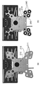
도 1 및 도 2는 본 발명의 일 실시예에 따른 초경량 소형의 무인 이동체용 안테나 김발 장치를 나타낸 도면이다.1 and 2 are views showing an antenna gimbal device for an ultra-lightweight and compact unmanned moving body according to an embodiment of the present invention.
도 1을 참조하면, 본 발명의 일 실시예에 따른 초경량 소형의 무인 이동체용 안테나 김발 장치(10)는 안테나 조립부(100), 방위각 구동부(200), 고각 구동부(300), 구동 제어부(400)를 포함하며, 무인 이동체에 장착 가능하도록 설계된다.Referring to FIG. 1, an
본 발명의 일 실시예에 따른 본 발명의 일 실시예에 따른 초경량 소형의 무인 이동체용 안테나 김발 장치(10)는 무인 이동체에 탑재되도록 마련되어 안테나를 장착하기 위한 김발 장치에 관한 것으로 소형 드론용 SAR 시스템을 위한 김발의 진동 억제 마운트 장치를 이용한다.According to an embodiment of the present invention, the
본 발명에 따르면 진동의 주파수 대역 및 하부 구조물의 하중에 따라 방진 마운트를 병렬로 추가하여 특정주파수 진동을 감쇠할 수 있다.According to the present invention, a specific frequency vibration can be attenuated by adding vibration-proof mounts in parallel according to the frequency band of vibration and the load of the lower structure.
김발시스템을 포함하는 SAR 센서 시스템은 다양한 플랫폼에 장착되어 운용될 수 있다. 각 플랫폼마다 진동 주파수 특성이 다르게 나타나므로 본 발명에 따르면 성능에 영향을 줄 수 있는 고주파를 억제하여 다양한 플랫폼에 적용이 가능하도록 하여 보다 넓은 분야에서 활용이 가능해진다.The SAR sensor system including the gimbal system can be installed and operated on various platforms. Since the vibration frequency characteristics are different for each platform, according to the present invention, high frequencies that may affect performance are suppressed to enable application to various platforms, thereby enabling wider application.
안테나 김발 장치는 크게 방위각부와 고각부로 구분되며, 안테나 장치가 결합된다. 방위각부에 상부 고정플랜지와 하부 고정플랜지가 있으며, 두 고정플랜지는 방진마운트로 연결된다.The antenna gimbal device is largely divided into an azimuth part and an elevation part, and an antenna device is combined. The azimuth part has an upper fixing flange and a lower fixing flange, and the two fixing flanges are connected by a vibration-proof mount.
안테나 조립부(100)는 안테나를 조립하도록 마련된다.The
본 발명에 따른 안테나 조립부에 결합하는 안테나 장치는 소정 두께를 갖는 플레이트 형상으로 형성될 수 있으므로, 안테나 조립부는 플레이트 형상을 조립할 수 있는 평면형으로 설계되는 것이 바람직하다.Since the antenna device coupled to the antenna assembly unit according to the present invention may be formed in a plate shape having a predetermined thickness, it is preferable that the antenna assembly unit is designed in a flat shape capable of assembling a plate shape.
방위각 구동부(200)는 상기 무인 이동체의 하단에 결합하며, 상기 안테나가 방위각 방향으로 회전하도록 구동한다.The
도 2를 참조하면, 방위각 구동부(200)는 상부 고정 플랜지(210), 하부 고정 플랜지(220), 방위각 모터(230), 방진 마운트(240), 고정 지주(250)를 포함한다.Referring to FIG. 2, the
상부 고정 플랜지(210)는 상기 무인 이동체의 하단에 밀착된다.The
상부 고정 플랜지(210)는 상기 방진 마운트를 끼워서 조립할 수 있는 방진 마운트 장착홀(211)들을 다수개 포함하며, 상기 방진 마운트는 상기 방진 마운트 장착홀들에 선택적으로 조립된다.The
고주파 진동을 감쇄할 수 있는 방진마운트 장착홀은 진동 특성 및 구조의 하중에 따라 종류와 개수를 12개까지 장착이 가능하도록 설계된다.The anti-vibration mount mounting holes capable of attenuating high-frequency vibrations are designed to be able to mount up to 12 types and numbers depending on the vibration characteristics and structural load.
또한, 상부 고정 플랜지의 중앙부에 방위각 모터의 일측을 조립할 수 있는 모터 조립홀(213)을 포함한다.In addition, it includes a
상부 고정 플랜지(210)는 무인 이동체의 결합에 적합하도록 경량 소재로 구현되는 것이 바람직하다.It is preferable that the
하부 고정 플랜지(220)는 상기 상부 고정 플랜지의 하부에 이격되어 위치한다.The
방위각 모터(230)는 상기 하부 고정 플랜지의 내측에 위치한다.The
SAR센서를 이용한 촬영 영역인 좌측방, 우측방의 지향이 가능한 경량 고정밀 모터가 방위각/고각부에 각각 장착되며, 케이블 간섭으로 각도는 방위각 최대 -140 ~ 140deg, 고각 최대 0 ~ 85deg로 제한된다. 안테나로 송/수신되는 RF신호선에 대한 경로 또한 김발 장치에서 제공한다.Lightweight high-precision motors capable of directing the left and right sides of the shooting area using the SAR sensor are mounted on the azimuth/elevation, respectively, and the angle is limited to -140 ~ 140deg in azimuth and 0 ~ 85deg in the azimuth due to cable interference. The path to the RF signal line transmitted/received by the antenna is also provided by the Gimbal device.
방진 마운트(240)는 상기 상부 고정 플랜지와 상기 하부 고정 플랜지를 연결한다.The
구체적으로, 방진 마운트가 상부 고정 플랜지와 하부 고정 플랜지의 조립홀에 결합하여 상/하부 고정 플랜지를 연결한다.Specifically, the anti-vibration mount is coupled to the assembly hole of the upper and lower fixing flanges to connect the upper and lower fixing flanges.
고주파 진동을 감쇄하는 방진 마운트를 적용하여 고주파 진동에 의한 빔포인팅 오차가 감소로 성능저하를 억제할 수 있다.By applying a vibration-proof mount that attenuates high-frequency vibration, it is possible to suppress performance degradation by reducing the beam pointing error caused by high-frequency vibration.
고정 지주(250)는 적어도 일부가 상기 무인 이동체의 하단에 삽입되어 상기 방위각 구동부를 결합시킨다.At least a portion of the fixed
고정 지주(250)는, 일측이 상기 하부 고정 플랜지에 결합되고, 상기 상부 고정 플랜지를 통과하여 상기 무인 이동체에 삽입된다.The fixed
따라서, 고정 지주를 이용하여 무인 이동체의 플랫폼과 하부 고정플랜지는 높은 강성을 갖도록 체결이 되므로 진동이 하부 고정 플랜지까지는 전달되지만 상부 고정 플랜지와 김발 구조물은 하부 고정플랜지와 방진 마운트로만 체결되어 김발구조물까지 고주파 진동은 억제되고, 저주파 진동만 전달이 가능하다.Therefore, since the platform of the unmanned moving body and the lower fixed flange are fastened to have high rigidity using the fixed posts, vibration is transmitted to the lower fixed flange, but the upper fixed flange and the gimbal structure are only fastened with the lower fixed flange and the anti-vibration mount to reach the gimbal structure. High-frequency vibrations are suppressed, and only low-frequency vibrations can be transmitted.
고각 구동부(300)는 상기 방위각 구동부의 하단에 조립되고, 일측에 상기 안테나 조립부를 결합하며, 상기 안테나가 고각 방향으로 회전하도록 구동한다.The
여기서, 방위각과 고각은 안테나의 구동 방향을 의미하는 것으로, 방위각 모터에 의해 안테나 김발 장치에 연결된 안테나가 방위각 방향으로 회전하고, 고각 모터에 의해 안테나 김발 장치에 연결된 안테나가 고각 방향으로 회전하게 된다.Here, the azimuth angle and the elevation angle refer to the driving direction of the antenna, and the antenna connected to the antenna gimbal device by the azimuth motor rotates in the azimuth direction, and the antenna connected to the antenna gimbal device by the elevation motor rotates in the elevation direction.
도 2를 참조하면, 고각 구동부(300)는 고각 프레임(310), 고각 모터(320), 회전 프레임(330), 안테나 프레임(340)을 포함한다.Referring to FIG. 2, the
고각 프레임(310)은 상기 방위각 모터의 하단에 연결된다.The
고각 모터(320)는 상기 고각 프레임의 내측에 위치한다.The
구체적으로, 고각 프레임(310)은 하부 고정 플랜지의 양측에 수직으로 결합하는 구조이며, 양측의 내부에 고각모터가 위치하게 된다.Specifically, the
회전 프레임(330)은 상기 고각 모터의 양측에 연결되어, 상기 고각 모터의 회전 시 일체로 회전한다.The
안테나 프레임(340)은 상기 안테나 조립부의 일면을 장착한다. The
상기 회전 프레임은, 상기 안테나 조립부와 연결되어 상기 고각 모터의 회전에 따라 상기 안테나가 회전한다.The rotating frame is connected to the antenna assembly unit so that the antenna rotates according to the rotation of the elevation motor.
구동 제어부(400)는 외부의 항법 제어 장치로부터 구동 제어 신호를 전송 받아 상기 방위각 구동부와 상기 고각 구동부의 구동을 제어한다.The driving
또한, 케이블을 연결할 수 있는 케이블 클램프(350)를 포함할 수 있다.In addition, it may include a
SAR(영상레이더) 센서로 촬영 시 저주파 진동이나 플랫폼의 요동 특성은 시스템 내부에 장착된 자세 센서 등으로 감지가 가능하며, 이러한 특성을 반영하여 신호처리를 수행하여야 한다. 그러나 자세 센서 데이터 획득주기보다 빠른 고주파 진동 특성은 측정할 수 없는 Unknown 요소이며, 촬영지역의 중심을 지향하고 있는 빔 포인팅이 진동에 의해 지향 오차가 발생되어 성능저하가 발생될 수 있다.When shooting with an SAR (Image Radar) sensor, low-frequency vibration or swing characteristics of the platform can be detected with a posture sensor installed inside the system, and signal processing must be performed by reflecting these characteristics. However, the high-frequency vibration characteristics faster than the posture sensor data acquisition period is an unknown factor that cannot be measured, and the beam pointing toward the center of the photographing area may generate a directional error due to the vibration, resulting in performance degradation.
본 발명의 일 실시예에 따른 초경량 소형의 무인 이동체용 안테나 김발 장치는, 고주파 진동을 감쇄하는 방진 마운트를 적용하여 고주파 진동에 의한 빔포인팅 오차가 감소로 성능저하를 억제할 수 있다.The ultra-lightweight and compact antenna gimbal apparatus for an unmanned moving object according to an embodiment of the present invention may suppress performance degradation by reducing a beam pointing error due to high frequency vibration by applying a vibration-proof mount that attenuates high frequency vibration.
도 3 내지 도 5는 본 발명의 일 실시예에 따른 초경량 소형의 무인 이동체용 안테나 김발 장치의 방위각 구동부를 설명하기 위한 도면이다.3 to 5 are views for explaining an azimuth driving unit of an antenna gimbal device for an ultra-lightweight and compact unmanned moving body according to an embodiment of the present invention.
도 3에 나타난 바와 같이, 본 발명의 일 실시예에 따르면 상부 고정플랜지와 하부 고정플랜지가 있으며, 두 고정플랜지는 방진마운트로 연결된다.As shown in FIG. 3, according to an embodiment of the present invention, there are an upper fixing flange and a lower fixing flange, and the two fixing flanges are connected by a vibration-proof mount.
도 3을 참조하면, 상부 고정 플랜지(210)는 상기 방진 마운트를 끼워서 조립할 수 있는 방진 마운트 장착홀(211)들을 다수개 포함하며, 상기 방진 마운트는 상기 방진 마운트 장착홀들에 선택적으로 조립된다.Referring to FIG. 3, the
하부 고정 플랜지(220)는 상기 상부 고정 플랜지의 하부에 이격되어 위치한다.The
방진 마운트(240)는 상기 상부 고정 플랜지와 상기 하부 고정 플랜지를 연결한다.The
구체적으로, 상부 고정 플랜지와 하부 고정 플랜지는 중앙부와 사방으로 연장된 부분을 포함하는 구조이며, 사방으로 연장된 부분에 방진 마운트를 결합시키게 된다.Specifically, the upper fixing flange and the lower fixing flange have a structure including a central portion and a portion extending in all directions, and the anti-vibration mount is coupled to the portion extending in all directions.
이에 따라, 제1 부분에서의 방진 마운트(240a), 제2 부분에서의 방진 마운트(240b), 제3 부분에서의 방진 마운트(240c), 제4 부분에서의 방진 마운트(240d)가 결합되며, 이 때 방진 마운트의 체결 개수는 조정이 가능하다.Accordingly, the
중앙부에는 방위각 모터(230)가 결합된다.An
또한, 상부 고정 플랜지는 고정 지주(250)를 통과시킬 수 있는 홀들을 포함하여 고정 지주가 상부 고정 플랜지를 투과하여 무인 이동체에 결합하게 된다.In addition, the upper fixing flange includes holes through which the fixing
도 4를 참조하면, 상부 고정 플랜지(210)는 안테나 김발 장치에 유입되는 고주파 진동 감쇠를 위한 방진 마운트 장착홀(211)을 다수개 보유한다. 또한, 고정 지주가 통과되는 통과 홀(215)을 포함한다.Referring to FIG. 4, the
도 4의 (a)는 방진 마운트 미체결 시를 나타낸 것이고, 도 4의 (b)는 방진 마운트 체결 시를 나타낸 것이다.FIG. 4(a) shows the case when the anti-vibration mount is not fastened, and FIG. 4(b) shows the case when the anti-vibration mount is fastened.
본 발명의 실시예에서는 방진 마운트 장착홀을 12개로 예로 들어 도시하였으나, 크기와 개수는 이에 한정되는 것은 아니고 장치의 크기에 따라 변경이 가능하다.In the embodiment of the present invention, as an example, 12 anti-vibration mount mounting holes are illustrated, but the size and number are not limited thereto, and may be changed according to the size of the device.
이에 따라, 무인 이동체와 연결되는 플랫폼의 고주파 진동 특성 및 하부 구조물의 중량에 따라 그에 맞는 방진 마운트 종류 및 알맞은 개수를 선택적으로 장착할 수 있도록 설계되어 있다.Accordingly, it is designed to selectively mount the type and number of anti-vibration mounts according to the high-frequency vibration characteristics of the platform connected to the unmanned moving body and the weight of the lower structure.
상부 고정 플랜지는 방진 마운트를 이용하여 하부 고정 플랜지와 결합한다.The upper fixing flange is coupled with the lower fixing flange using a vibration-proof mount.
상부 고정 플랜지는 높은 강성과 경량성을 확보하도록 카본 복합소재를 사용하였으며, 하부 고정 플랜지와 방진마운트로 결합된다.The upper fixing flange is made of carbon composite material to ensure high rigidity and light weight, and it is combined with the lower fixing flange with a dustproof mount.
따라서, 플랫폼과 하부 고정플랜지는 높은 강성을 갖도록 체결이 되므로 진동이 하부 플랜지까지는 전달되지만 상부 고정플랜지와 김발 구조물은 하부 고정플랜지와 방진 마운트로만 체결되어 김발구조물까지 고주파 진동은 억제되고, 저주파 진동만 전달되는 구조이다. Therefore, since the platform and the lower fixed flange are fastened to have high rigidity, vibration is transmitted to the lower flange, but the upper fixed flange and the gimbal structure are only fastened with the lower fixed flange and the anti-vibration mount to suppress high-frequency vibration to the gimbal structure, and only low-frequency vibration. It is a structure that is transmitted.
도 5를 참조하면, 하부 고정 플랜지(220)는 안테나 김발 장치에 유입되는 고주파 진동 감쇠를 위한 방진 마운트 장착홀(223)을 다수개 보유하여 방진 마운트(240)를 장착할 수 있으며, 고정 지주를 고정할 수 있는 고정 지주 체결부(225)를 포함한다.Referring to FIG. 5, the
또한, 하부 고정 플랜지(220)는 육면체 형태의 방위각 모터를 내측에 결합할 수 있도록 사각형의 공간부(221)를 포함한다.In addition, the
고정 지주(250)의 하단은 하부 고정플랜지와 연결되며, 상단은 플랫폼에 장착되고 강성을 유지할 수 있도록 서스 재질로 설계되는 것이 바람직하다.The lower end of the fixed
고정 지주(250)를 이용하여 하부 고정플랜지와 무인 비행체의 플랫폼이 결합되며, 체결성이 높은 강성을 갖도록 서스로 설계한다.The lower fixed flange and the platform of the unmanned aerial vehicle are coupled using the fixed
즉, 하부 고정 플랜지에 결합한 고정 지주가 상부 고정 플랜지의 홀을 통과하여 무인 비행체에 결합하게 되는 것이다.In other words, the fixed post coupled to the lower fixed flange passes through the hole of the upper fixed flange and is coupled to the unmanned aerial vehicle.
SAR(영상레이더)센서가 장착될 수 있는 다양한 플랫폼은 구동방식(엔진, 모터)이나 플랫폼 형상(고정익, 회전익 등), 속도 등에 따라 진동 특성이 다르게 나타나며, 이러한 진동 특성 중 자세/가속도 측정 센서로 측정할 수 없는 고주파 진동 특성은 SAR센서 성능 저하를 발생 시킬 수 있다.Various platforms on which SAR (image radar) sensors can be installed have different vibration characteristics depending on the driving method (engine, motor), platform shape (fixed wing, rotor, etc.), speed, etc., among these vibration characteristics, the attitude/acceleration measurement sensor is used. High-frequency vibration characteristics that cannot be measured can cause degradation of SAR sensor performance.
고주파 진동을 감쇄할 수 있는 방진마운트 장착홀은 진동 특성 및 구조의 하중에 따라 종류와 개수를 12개까지 장착이 가능하도록 설계된다.The anti-vibration mount mounting holes capable of attenuating high-frequency vibrations are designed to be able to mount up to 12 types and numbers depending on the vibration characteristics and structural load.
도 6은 본 발명의 일 실시예에 따른 초경량 소형의 무인 이동체용 안테나 김발 장치를 포함하는 영상 레이더 시스템을 나타낸 도면이다.6 is a diagram illustrating an image radar system including an antenna gimbal device for an ultra-lightweight and small unmanned mobile vehicle according to an embodiment of the present invention.
도 6을 참조하면, 본 발명의 일 실시예에 따른 초경량 소형의 무인 이동체용 안테나 김발 장치를 포함하는 영상 레이더 시스템(1)는 안테나 김발 장치(10), 안테나 장치(20), 항법 제어 장치(30), 송수신 장치(40)를 포함하며, 무인 이동체에 장착 가능하도록 설계된다.Referring to FIG. 6, an
본 발명의 일 실시예에 따른 초경량 소형의 무인 이동체용 영상 레이더 시스템은 무인 이동체에 탑재되어 이미지를 획득하는 장치이다.An ultra-lightweight and compact image radar system for an unmanned moving object according to an embodiment of the present invention is a device mounted on an unmanned moving object to acquire an image.
합성 개구 레이더(Synthetic Aperture Radar, 이하 SAR)는 일반적으로 비행기 또는 인공 위성 등에 탑재되어 이동하는 동안, 여러 차례 지표로 빔을 방사하고 반사되어 수신된 신호에서 감지되는 도플러 주파수의 상대적 변화 특성을 이용하여 지표의 고분해능 정밀 이미지를 획득할 수 있는 레이더를 의미한다.Synthetic Aperture Radar (SAR) is generally mounted on airplanes or satellites and radiates beams to the ground several times while moving, using the characteristics of relative changes in Doppler frequency detected in the received signals. It refers to a radar that can acquire high-resolution, precise images of the surface.
SAR은 극초단파 영역의 초고주파를 활용하기 때문에 아지랑이, 가랑비, 눈, 구름, 연기 등의 기후 환경에 영향을 받지 않고, 육상 지형이나 바다를 관측할 수 있으며, 스스로 관측에 사용하는 에너지원을 전파하는 능동시스템이기 때문에 밤과 낮에 상관없이 이미지를 얻을 수 있다.Since SAR utilizes ultra-high frequencies in the microwave range, it is not affected by the climatic environment such as haze, drizzle, snow, clouds, and smoke, and can observe terrestrial topography or sea, and is an active propagating energy source used for self-observation. Because it is a system, images can be obtained regardless of night or day.
무인 이동체는 조종사 없이 무선전파의 유도에 의해서 비행 및 조종이 가능한 비행기나 헬리콥터 모양의 이동체이다.An unmanned vehicle is an airplane or helicopter-shaped vehicle that can fly and manipulate by induction of radio waves without a pilot.
본 발명의 일 실시예에서는 카메라, 센서, 통신시스템 등이 탑재되어 구현되는 드론을 예로 들어 도시하였으나 이에 한정되는 것은 아니고, 무인으로 이동하는 이동체에 모두 탑재 가능하도록 설계되는 것이 가능하다.In an embodiment of the present invention, a drone implemented with a camera, a sensor, a communication system, etc. mounted thereon is illustrated as an example, but the present invention is not limited thereto, and it may be designed to be mounted on a moving object that moves unmanned.
본 발명의 일 실시예에 따른 초경량 소형의 무인 이동체용 영상 레이더 시스템은 탑재체에 해당하며, IMU를 제외한 무게는 2.0 내지 3.0 kg인 것이 바람직하다.The ultra-lightweight and compact image radar system for an unmanned mobile vehicle according to an embodiment of the present invention corresponds to a payload, and the weight excluding the IMU is preferably 2.0 to 3.0 kg.
종래의 레이더 탑재체 보다 무게를 가볍게 하여 무인 이동체의 탑재가 가능하도록 하며, 지상체와의 통신을 수행하도록 설계하여 무인 이동체에서 비행하는 경우에도 정보를 전달하고 임무를 수행하는 것이 가능하도록 한다.It is possible to mount an unmanned moving object by making the weight lighter than that of a conventional radar mount, and it is designed to communicate with the ground object, so that it is possible to transmit information and perform a mission even when flying in an unmanned mobile object.
영상 해상도는 0.3, 0.5, 1 [m], 운용 고도는 1400 내지 1600 ft (400 내지 500[m])인 것이 바람직하다.The image resolution is preferably 0.3, 0.5, 1 [m], and the operating altitude is 1400 to 1600 ft (400 to 500 [m]).
중심 주파수는 X-band 이며, 소비 전력은 40 내지 60 W인 것이 바람직하다. The center frequency is X-band, and the power consumption is preferably 40 to 60 W.
거리방향 영상폭은 200 내지 400 (@ 해상도 0.3) [m], 방위방향 영상폭은 무제한 (전원용량), 크기는 (15 내지 20) X (20 내지 25) X (25 내지 30) [cm]으로 설계되는 것이 바람직하다.Distance direction image width is 200 to 400 (@ resolution 0.3) [m], azimuth direction image width is unlimited (power capacity), size is (15 to 20) X (20 to 25) X (25 to 30) [cm] It is desirable to be designed as.
본 발명의 일 실시예에 따른 초경량 소형의 무인 이동체용 영상 레이더 시스템(1)의 체계요구조건검토(SRR)/체계기능검토(SFR) 목적은 사용자 요구조건(임무중심)으로부터 도출된 체계 요구조건(기능/성능 중심)의 타당성 (외부 인터페이스 포함)과 체계 요구조건으로부터 하위 구성품으로의 요구조건 할당 및 이에 대한 적절성을 구현하는데 있다.The purpose of the system requirements review (SRR)/system function review (SFR) of the ultra-lightweight and compact unmanned aerial vehicle
본 발명의 일 실시예에 따른 초경량 소형의 무인 이동체용 영상 레이더 시스템(1)은 운용모드는 SAR 모드 (Stripmap)으로 구현되는 것이 바람직하다.In the
거리 방향 해상도는 0.3, 0.5, 1 [m], 거리 방향 영상폭은 0.3, 0.5, 1 [km] 이상인 것이 바람직하며, 최대 탐지 거리는 1km 이하로 설계되는 것이 바람직하다.The distance direction resolution is preferably 0.3, 0.5, 1 [m], the distance direction image width is preferably 0.3, 0.5, 1 [km] or more, and the maximum detection distance is preferably designed to be 1 km or less.
기본설계검토(PDR) 목적은 CI(HW 및 SW) 사양에서 하위 레벨로 할당된 기능 및 사양들의 적절성을 구현하고자 하는 것이다. 또한, HW 및 S/W 설계의 효율성 및 타당성을 검증하고 인터페이스와 관련된 문서들의 적절성과 상세설계 단계로의 추진여부 결정하고자 하는 것이다.The purpose of the basic design review (PDR) is to implement the appropriateness of the functions and specifications assigned to the lower level in the CI (HW and SW) specifications. In addition, it is to verify the efficiency and validity of HW and S/W design, and to determine the appropriateness of interface-related documents and whether to proceed to the detailed design stage.
상세설계검토(CDR) 목적은 상위 요구조건들이 구성품 설계에 적절히 반영되어 있는지 여부를 확인하고 할당 하드웨어 규격의 제작 가능 여부 및 도면 준비 상태와 할당 소프트웨어 규격에 근거한 CSCI 코딩 가능 여부와 상세설계를 통한 기술적 위험 경감 및 대안 수립 여부를 확인하고자 하는데 있다.The purpose of the detailed design review (CDR) is to check whether the higher requirements are properly reflected in the component design, whether or not the allocation hardware specification can be produced, whether CSCI coding is possible based on the drawing preparation status and the allocation software specification, and technical through detailed design. It is to check whether risk reduction and alternatives are established.
안테나 김발 장치(10)는 상기 무인 이동체에 탑재되도록 마련된다.The
안테나 김발 장치(10)는 안테나 조립부(100), 방위각 구동부(200), 고각 구동부(300), 구동 제어부(400)를 포함한다.The
본 발명의 일 실시예에 따른 본 발명의 일 실시예에 따른 초경량 소형의 무인 이동체용 안테나 김발 장치(10)는 무인 이동체에 탑재되도록 마련되어 안테나를 장착하기 위한 김발 장치에 관한 것으로 소형 드론용 SAR 시스템을 위한 김발의 진동 억제 마운트 장치를 이용한다.According to an embodiment of the present invention, the
본 발명에 따르면 진동의 주파수 대역 및 하부 구조물의 하중에 따라 방진 마운트를 병렬로 추가하여 특정주파수 진동을 감쇠할 수 있다.According to the present invention, a specific frequency vibration can be attenuated by adding vibration-proof mounts in parallel according to the frequency band of vibration and the load of the lower structure.
안테나 김발 장치(10)의 요구규격은 PDR 기준으로 중량은 0.5kg 이하, 구동 방식은 2축 구동, 방위각은 -130 내지 130도 이내, 고각은 0 내지 85도 이내인 것이 바람직하며, 자체 고장 진단을 수행할 수 있도록 모니터링부와 제어부를 포함할 수 있다.The required standard of the
안테나 김발 장치(10)는 속도 센서, 가속도 센서, 자이로 센서, 지면과 차체 사이의 거리 측정 센서 등 다양한 센서를 포함할 수 있으며 센서를 통해, 현재 속도, 진행 방향, 가속 및 감속 정보를 감지 및 측정하여 항법 제어 장치에 전송할 수 있다.The
안테나 장치(20)는 상기 안테나 김발 장치에 조립되며, 전파의 빔을 방사하여 대상물로부터의 반사를 수신한다.The
안테나 장치(20)는 급전부, 방사부 패치, 기생패치, 차폐벽을 포함한다.The
안테나 장치(20)의 요구규격은 SRR/SFR 기준으로 중량은 0.3Kg 이하, 운용 주파수는 X-band (X-band 는 6.2~10.9GHz의 주파수대를 말한다.), 편파는 HH, VV, HV, VH, 안테나 이득은 15 dBi 이상, 부엽 준위는 -20 dB 이하로 설계되는 것이 바람직하나, 이에 한정되는 것은 아니다.The required specifications of the
안테나 장치(20)는 송신 안테나와 수신 안테나를 포함한다.The
송신 안테나는 마이크로스트립 패치형 안테나 구조인 것이 바람직하다.The transmission antenna is preferably a microstrip patch type antenna structure.
또한, 송신 안테나와 수신 안테나 사이에 차폐벽을 포함하며, 급전 구조 V-pol을 형성한다.In addition, a shielding wall is included between the transmitting antenna and the receiving antenna, and a power supply structure V-pol is formed.
안테나 장치는 소정 두께를 갖는 플레이트 형상으로 형성될 수 있다. 다중대역 주파수를 모두 수신하는 특성을 갖도록 급전부에 발룬 또는 광대역 매칭 기법을 이용할 수 있다. 안테나 장치는 그 평면 형상이나 종류가 한정되는 것은 아니며, 다중대역의 특성을 갖는 플레이트 형상의 안테나라면 모두 가능하다.The antenna device may be formed in a plate shape having a predetermined thickness. A balun or broadband matching technique may be used in the feeder to have a characteristic of receiving all multi-band frequencies. The antenna device is not limited in its planar shape or type, and any plate-shaped antenna having multi-band characteristics can be used.
안테나 장치의 요구 규격은 CDR 기준으로 중량 0.2kg 이하, 운용 주파수 X-band, 안테나 이득 15 dBi 이상, 안테나 빔폭 거리 방향 25도 이상, 방위 방향 10도 이상으로 설계되는 것이 바람직하며 이에 한정되는 것은 아니다.The required standard of the antenna device is preferably designed to have a weight of 0.2 kg or less, operating frequency X-band, antenna gain 15 dBi or more, antenna beam width distance direction 25 degrees or more,
항법 제어 장치(30)는 송수신 장치의 RF 송수신을 제어하며 타이밍 신호와 전원을 제어한다. 또한, 항법 제어 장치(30)는 안테나 김발 장치의 지향각을 제어하며, 상태 정보를 전송하고 전원을 공급한다.The
항법 제어 장치는 외부의 GNSS 안테나로부터 GPS 신호를 전달 받고, 외장 배터리로부터 전원을 공급받는다.The navigation control device receives GPS signals from an external GNSS antenna and receives power from an external battery.
항법 제어 장치(30)는 제어모듈, GPS 모듈, IMU 모듈, 하우징을 포함한다.The
항법 제어 장치(30)의 요구규격은 CDR 기준으로 중량 500g 이하 (IMU 제외), 소모전력 입력전원 5V 이하 소모전류 5A 이하 소모전력 25W 이하인 것이 바람직하며 운용 상태를 제어할 수 있도록 운용 제어부를 포함할 수 있다.The required standard of the
항법 제어 장치는 지상체의 외부 연동 모의 장비로 항법 및 상태 정보를 전송하고, 제어, MDF 정보, EGI 모의 정보를 전달 받는다. 항법 제어 장치는 지상체의 비행 시험 장비로 항법 정보를 전송한다.The navigation control device transmits navigation and status information to the external interlocking simulation equipment of the ground body, and receives control, MDF information, and EGI simulation information. The navigation control device transmits navigation information to the flight test equipment of the ground body.
송수신 장치(40)는 상기 안테나 장치로 송신 신호를 전송하고, 상기 안테나 장치로부터 수신 신호를 수신 받는다.The transmission/
송수신 장치(40)는 RF 송수신 장치이며 RF 모듈, 디지털 모듈, 전원 모듈, 하우징을 포함한다.The
송수신 장치는 지상체의 표적 모의 장비로 송신 신호와 타이밍 신호를 전송하고, 표적 모의 신호를 수신한다. 송수신 장치는 지상체의 지상 신호 처리 장비로 SAR Raw 데이터를 전송한다.The transmitting and receiving device transmits a transmission signal and a timing signal to the target simulation equipment of the ground body, and receives the target simulation signal. The transmitting and receiving device transmits SAR raw data to the ground signal processing equipment of the ground body.
송수신 장치(40)의 요구규격은 SRR/SFR 기준으로 중량 1.5kg 이하, 운용 주파수 X-band, 송신 출력 1W 이상, 펄스폭 45us 이상, 수신 IF 중심주파수 1.25 Mhz 이상, 수신 IF 대역폭 200 Mhz 이상, 수신 동적범위 60 dB 이상로 설계되는 것이 바람직하며, 이에 한정되는 것은 아니다.The requirements of the transmitting and receiving
이외에도, 신호 처리 장비, 외부 연동 모의 장비, 표적 모의 장비를 포함할 수 있다.In addition, signal processing equipment, external interlocking simulation equipment, and target simulation equipment may be included.
신호 처리 장비는 워크 스테이션을 포함한다.Signal processing equipment includes work stations.
외부 연동 모의 장비는 제어 노트북을 포함한다.External interlocking simulation equipment includes a control notebook.
표적 모의 장비는 제어 모듈, 표적 발생 모듈, IF 수신 모듈, 표적 IF 모듈, 송수신 RF 모듈, 국부 발생 모듈, 전원 모듈, 하우징을 포함한다.The target simulation equipment includes a control module, a target generation module, an IF receiving module, a target IF module, a transmission/reception RF module, a local generation module, a power supply module, and a housing.
도 7은 본 발명의 일 실시예에 따른 초경량 소형의 무인 이동체용 안테나 김발 장치의 구동 범위를 나타낸 도면이다.7 is a view showing a driving range of an ultra-lightweight and small-sized unmanned aerial vehicle antenna gimbal apparatus according to an embodiment of the present invention.
김발 장치의 요구 규격은 CDR 기준으로 중량 0.5kg 이하, 구동 방식 2축 구동인 것이 바람직하며, 도 7에 나타난 바와 같이 방위각 구동 범위는 -130 내지 130도 이내, 고각 구동 범위는 0 내지 85도 이내인 것이 바람직하다.The required standard of the gimbal device is 0.5kg or less in weight based on the CDR, and it is preferable to be a two-axis drive with a drive method, and as shown in FIG. It is preferable to be.
이상의 설명은 본 발명의 일 실시예에 불과할 뿐, 본 발명이 속하는 기술 분야에서 통상의 지식을 가진 자는 본 발명의 본질적 특성에서 벗어나지 않는 범위에서 변형된 형태로 구현할 수 있을 것이다. 따라서 본 발명의 범위는 전술한 실시예에 한정되지 않고 특허 청구 범위에 기재된 내용과 동등한 범위 내에 있는 다양한 실시 형태가 포함되도록 해석되어야 할 것이다.The above description is only an embodiment of the present invention, and those of ordinary skill in the technical field to which the present invention pertains may be implemented in a modified form without departing from the essential characteristics of the present invention. Therefore, the scope of the present invention is not limited to the above-described embodiments, and should be construed to include various embodiments within the scope equivalent to those described in the claims.
10: 초경량 소형의 무인 이동체용 안테나 김발 장치
100: 안테나 조립부
200: 방위각 구동부
300: 고각 구동부10: Ultra-lightweight and compact antenna gimbal device for unmanned moving objects
100: antenna assembly
200: azimuth driving unit
300: high angle drive unit
Claims (13)
안테나를 조립하도록 마련되는 안테나 조립부;
상기 무인 이동체의 하단에 결합하며, 상기 안테나가 방위각 방향으로 회전하도록 구동하는 방위각 구동부; 및
상기 방위각 구동부의 하단에 조립되고, 일측에 상기 안테나 조립부를 결합하며, 상기 안테나가 고각 방향으로 회전하도록 구동하는 고각 구동부;를 포함하고,
상기 방위각 구동부는,
카본 복합소재로 이루어지고 상기 무인 이동체의 하단에 밀착되는 상부 고정 플랜지; 상기 상부 고정 플랜지의 하부에 이격되어 위치하는 하부 고정 플랜지; 상기 하부 고정 플랜지의 내측에 위치하는 방위각 모터; 상기 상부 고정 플랜지와 상기 하부 고정 플랜지를 연결하는 방진 마운트; 및 적어도 일부가 상기 무인 이동체의 하단에 삽입되어 상기 방위각 구동부를 결합시키는 고정 지주;를 포함하며,
상기 상부 고정 플랜지는, 상기 방진 마운트를 끼워서 조립할 수 있는 방진 마운트 장착홀들을 다수개 포함하고, 상기 고정 지주를 통과시킬 수 있는 통과 홀들을 더 포함하며,
상기 방진 마운트는, 상기 방진 마운트 장착홀들에 선택적으로 조립되고,
상기 상부 고정 플랜지와 상기 하부 고정 플랜지는, 중앙부와 사방으로 연장된 부분을 포함하는 구조이며, 사방으로 연장된 부분에 상기 방진 마운트가 결합되고,
상기 고정 지주는, 서스 재질로 이루어지며 일측이 상기 하부 고정 플랜지에 고정 지주 체결부를 통해 고정되게 결합되며, 상기 상부 고정 플랜지를 통과하여 상기 무인 이동체에 삽입되는 것을 특징으로 하는 안테나 김발 장치.In the antenna gimbal device designed to selectively mount the type and number of anti-vibration mounts corresponding to the high-frequency vibration characteristics of the platform connected to the unmanned moving body and the weight of the lower structure, and mountable to the unmanned moving body,
An antenna assembly unit provided to assemble the antenna;
An azimuth driving unit coupled to a lower end of the unmanned moving body and driving the antenna to rotate in an azimuth direction; And
Including; a high angle driving unit assembled at the lower end of the azimuth driving unit, coupled to the antenna assembly unit to one side, and driving the antenna to rotate in an elevation direction,
The azimuth driving unit,
An upper fixing flange made of a carbon composite material and in close contact with the lower end of the unmanned moving body; A lower fixing flange spaced apart from the lower part of the upper fixing flange; An azimuth motor positioned inside the lower fixing flange; A vibration-proof mount connecting the upper fixing flange and the lower fixing flange; And at least a portion is inserted into the lower end of the unmanned moving body, a fixed support for coupling the azimuth driving unit; includes,
The upper fixing flange includes a plurality of anti-vibration mount mounting holes that can be assembled by inserting the anti-vibration mount, and further includes passage holes that can pass the fixed post,
The vibration-proof mount is selectively assembled to the vibration-proof mount mounting holes,
The upper fixing flange and the lower fixing flange have a structure including a central portion and a portion extending in all directions, and the anti-vibration mount is coupled to the portion extending in all directions,
The fixed post is made of a sus material, one side is fixedly coupled to the lower fixed flange through a fixed post fastening part, and the antenna gimbal device, characterized in that inserted into the unmanned moving body through the upper fixed flange.
외부의 항법 제어 장치로부터 구동 제어 신호를 전송 받아 상기 방위각 구동부와 상기 고각 구동부의 구동을 제어하는 구동 제어부;를 더 포함하는 것을 특징으로 하는 안테나 김발 장치.The method of claim 1,
An antenna gimbal apparatus further comprising: a driving control unit receiving a driving control signal from an external navigation control device and controlling driving of the azimuth driving unit and the elevation driving unit.
상기 고각 구동부는,
상기 방위각 모터의 하단에 연결되는 고각 프레임;
상기 고각 프레임의 내측에 위치하는 고각 모터; 및
상기 고각 모터의 양측에 연결되어, 상기 고각 모터의 회전 시 일체로 회전하는 회전 프레임;을 포함하는 것을 특징으로 하는 안테나 김발 장치.The method of claim 1,
The elevation drive unit,
An elevation frame connected to the lower end of the azimuth motor;
An elevation motor located inside the elevation frame; And
An antenna gimbal device comprising: a rotating frame connected to both sides of the elevation motor and integrally rotating when the elevation motor rotates.
상기 고각 구동부는,
상기 안테나 조립부의 일면을 장착하기 위한 안테나 프레임;을 더 포함하며,
상기 회전 프레임은, 상기 안테나 조립부와 연결되어 상기 고각 모터의 회전에 따라 상기 안테나가 회전하는 것을 특징으로 하는 안테나 김발 장치.The method of claim 7,
The elevation drive unit,
Further comprising; an antenna frame for mounting one surface of the antenna assembly unit,
The rotating frame is connected to the antenna assembly unit, wherein the antenna gimbal apparatus, characterized in that the antenna rotates according to the rotation of the elevation motor.
상기 무인 이동체에 탑재되도록 마련되는 안테나 김발 장치;
상기 안테나 김발 장치에 조립되며, 전파의 빔을 방사하여 대상물로부터의 반사를 수신하는 안테나 장치;
상기 안테나 장치로 송신 신호를 전송하고, 상기 안테나 장치로부터 수신 신호를 수신 받는 송수신 장치; 및
상기 송수신 장치의 RF 송수신을 제어하며 타이밍 신호와 전원을 제어하는 항법 제어 장치;를 포함하며,
상기 안테나 김발 장치는,
상기 안테나 장치를 조립하도록 마련되는 안테나 조립부;
상기 무인 이동체의 하단에 결합하며, 상기 안테나가 방위각 방향으로 회전하도록 구동하는 방위각 구동부; 및
상기 방위각 구동부의 하단에 조립되고, 일측에 상기 안테나 조립부를 결합하며, 상기 안테나가 고각 방향으로 회전하도록 구동하는 고각 구동부;를 포함하고,
상기 방위각 구동부는,
카본 복합소재로 이루어지고 상기 무인 이동체의 하단에 밀착되는 상부 고정 플랜지; 상기 상부 고정 플랜지의 하부에 이격되어 위치하는 하부 고정 플랜지; 상기 하부 고정 플랜지의 내측에 위치하는 방위각 모터; 상기 상부 고정 플랜지와 상기 하부 고정 플랜지를 연결하는 방진 마운트; 및 적어도 일부가 상기 무인 이동체의 하단에 삽입되어 상기 방위각 구동부를 결합시키는 고정 지주;를 포함하며,
상기 상부 고정 플랜지는, 상기 방진 마운트를 끼워서 조립할 수 있는 방진 마운트 장착홀들을 다수개 포함하고, 상기 고정 지주를 통과시킬 수 있는 통과 홀들을 더 포함하며,
상기 방진 마운트는, 상기 방진 마운트 장착홀들에 선택적으로 조립되고,
상기 상부 고정 플랜지와 상기 하부 고정 플랜지는, 중앙부와 사방으로 연장된 부분을 포함하는 구조이며, 사방으로 연장된 부분에 상기 방진 마운트가 결합되고,
상기 고정 지주는, 서스 재질로 이루어지며 일측이 상기 하부 고정 플랜지에 고정 지주 체결부를 통해 고정되게 결합되며, 상기 상부 고정 플랜지를 통과하여 상기 무인 이동체에 삽입되는 것을 특징으로 하는 영상 레이더 시스템.In the image radar system designed to selectively mount the type and number of anti-vibration mounts corresponding to the high-frequency vibration characteristics of the platform connected to the unmanned moving object and the weight of the lower structure, and mountable to the unmanned moving object,
An antenna gimbal device provided to be mounted on the unmanned moving body;
An antenna device assembled to the antenna gimbal device and configured to receive a reflection from an object by emitting a beam of radio waves;
A transmission/reception device that transmits a transmission signal to the antenna device and receives a reception signal from the antenna device; And
Includes; a navigation control device for controlling the RF transmission and reception of the transceiver and controlling timing signals and power,
The antenna gimbal device,
An antenna assembly unit provided to assemble the antenna device;
An azimuth driving unit coupled to a lower end of the unmanned moving body and driving the antenna to rotate in an azimuth direction; And
Including; a high angle driving unit assembled at the lower end of the azimuth driving unit, coupled to the antenna assembly unit to one side, and driving the antenna to rotate in an elevation direction,
The azimuth driving unit,
An upper fixing flange made of a carbon composite material and in close contact with the lower end of the unmanned moving body; A lower fixing flange spaced apart from the lower part of the upper fixing flange; An azimuth motor positioned inside the lower fixing flange; A vibration-proof mount connecting the upper fixing flange and the lower fixing flange; And at least a portion is inserted into the lower end of the unmanned moving body, the fixed support for coupling the azimuth driving unit; includes,
The upper fixing flange includes a plurality of anti-vibration mount mounting holes that can be assembled by inserting the anti-vibration mount, and further includes passage holes that can pass the fixed post,
The vibration-proof mount is selectively assembled to the vibration-proof mount mounting holes,
The upper fixing flange and the lower fixing flange have a structure including a central portion and a portion extending in all directions, and the anti-vibration mount is coupled to the portion extending in all directions,
The fixed post is made of a sus material, one side is fixedly coupled to the lower fixed flange through a fixed post fastening part, and is inserted into the unmanned moving body through the upper fixed flange.
상기 항법 제어 장치로부터 구동 제어 신호를 전송 받아 상기 방위각 구동부와 상기 고각 구동부의 구동을 제어하는 구동 제어부;를 더 포함하는 것을 특징으로 하는 영상 레이더 시스템.The method of claim 9,
And a driving control unit for receiving a driving control signal from the navigation control device and controlling driving of the azimuth driving unit and the elevation driving unit.
상기 고각 구동부는,
상기 방위각 모터의 하단에 연결되는 고각 프레임;
상기 고각 프레임의 내측에 위치하는 고각 모터;
상기 고각 모터의 양측에 연결되어, 상기 고각 모터의 회전 시 일체로 회전하는 회전 프레임; 및
상기 안테나 조립부의 일면을 장착하기 위한 안테나 프레임;을 포함하며,
상기 회전 프레임은, 상기 안테나 조립부와 연결되어 상기 고각 모터의 회전에 따라 상기 안테나가 회전하는 것을 특징으로 하는 영상 레이더 시스템.The method of claim 9,
The elevation drive unit,
An elevation frame connected to the lower end of the azimuth motor;
An elevation motor located inside the elevation frame;
A rotating frame connected to both sides of the elevation motor and integrally rotating when the elevation motor rotates; And
Includes; an antenna frame for mounting one surface of the antenna assembly unit,
The rotating frame is connected to the antenna assembly unit, the image radar system, characterized in that the antenna rotates according to the rotation of the elevation motor.
Applications Claiming Priority (2)
| Application Number | Priority Date | Filing Date | Title |
|---|---|---|---|
| KR20190121624 | 2019-10-01 | ||
| KR1020190121624 | 2019-10-01 |
Publications (1)
| Publication Number | Publication Date |
|---|---|
| KR102196733B1 true KR102196733B1 (en) | 2020-12-30 |
Family
ID=72450626
Family Applications (9)
| Application Number | Title | Priority Date | Filing Date |
|---|---|---|---|
| KR1020190163417A Active KR102296961B1 (en) | 2019-10-01 | 2019-12-10 | GPU based SAR Image Restoration Device and Image Radar System for Small Unmanned Mobile |
| KR1020200081114A Active KR102211580B1 (en) | 2019-10-01 | 2020-07-01 | Method and system for estimating moving target speed using SAR mounted on multi unmanned aerial vehicles |
| KR1020200081056A Active KR102156253B1 (en) | 2019-10-01 | 2020-07-01 | Method and system for estimating precise altitude information using SAR mounted on multi unmanned aerial vehicles |
| KR1020200081472A Active KR102256612B1 (en) | 2019-10-01 | 2020-07-02 | Super light Antenna Apparatus having low Permittivity and, Super Small Synthetic Aperture Radar System for Drone Mounting therewith |
| KR1020200083678A Active KR102196733B1 (en) | 2019-10-01 | 2020-07-07 | Ultra-Light, Compact Unmanned Mobile Antenna Gimbal and Synthetic Aperture Radar System including the same |
| KR1020200083677A Active KR102171196B1 (en) | 2019-10-01 | 2020-07-07 | Radio frequency signal transceiver for unmanned aircraft mounted synthetic aperture radar and method thereof |
| KR1020200084569A Active KR102174058B1 (en) | 2019-10-01 | 2020-07-09 | Target simulator for unmanned aircraft mounted synthetic aperture radar |
| KR1020200084924A Active KR102196734B1 (en) | 2019-10-01 | 2020-07-09 | Apparatus and Method for Jamming in Synthetic Aperture Radar |
| KR1020200125931A Active KR102202626B1 (en) | 2019-10-01 | 2020-09-28 | Super light and small synthetic aperture radar apparatus and system for unmanned mobile |
Family Applications Before (4)
| Application Number | Title | Priority Date | Filing Date |
|---|---|---|---|
| KR1020190163417A Active KR102296961B1 (en) | 2019-10-01 | 2019-12-10 | GPU based SAR Image Restoration Device and Image Radar System for Small Unmanned Mobile |
| KR1020200081114A Active KR102211580B1 (en) | 2019-10-01 | 2020-07-01 | Method and system for estimating moving target speed using SAR mounted on multi unmanned aerial vehicles |
| KR1020200081056A Active KR102156253B1 (en) | 2019-10-01 | 2020-07-01 | Method and system for estimating precise altitude information using SAR mounted on multi unmanned aerial vehicles |
| KR1020200081472A Active KR102256612B1 (en) | 2019-10-01 | 2020-07-02 | Super light Antenna Apparatus having low Permittivity and, Super Small Synthetic Aperture Radar System for Drone Mounting therewith |
Family Applications After (4)
| Application Number | Title | Priority Date | Filing Date |
|---|---|---|---|
| KR1020200083677A Active KR102171196B1 (en) | 2019-10-01 | 2020-07-07 | Radio frequency signal transceiver for unmanned aircraft mounted synthetic aperture radar and method thereof |
| KR1020200084569A Active KR102174058B1 (en) | 2019-10-01 | 2020-07-09 | Target simulator for unmanned aircraft mounted synthetic aperture radar |
| KR1020200084924A Active KR102196734B1 (en) | 2019-10-01 | 2020-07-09 | Apparatus and Method for Jamming in Synthetic Aperture Radar |
| KR1020200125931A Active KR102202626B1 (en) | 2019-10-01 | 2020-09-28 | Super light and small synthetic aperture radar apparatus and system for unmanned mobile |
Country Status (1)
| Country | Link |
|---|---|
| KR (9) | KR102296961B1 (en) |
Cited By (4)
| Publication number | Priority date | Publication date | Assignee | Title |
|---|---|---|---|---|
| CN113104223A (en) * | 2021-05-18 | 2021-07-13 | 袁鹏杰 | Unmanned aerial vehicle carries flow monitoring devices |
| CN114245688A (en) * | 2021-12-28 | 2022-03-25 | 南京迈动科技有限公司 | With unmanned aerial vehicle interconnection type image communication equipment |
| US20230243965A1 (en) * | 2022-01-31 | 2023-08-03 | Alphacore, Inc. | Systems and methods for obstacle avoidance for unmanned autonomous vehicles |
| KR102665845B1 (en) | 2023-02-28 | 2024-05-14 | 엘아이지넥스원 주식회사 | Apparatus for compensating axis alignment of gimbal and radar system including the same |
Families Citing this family (16)
| Publication number | Priority date | Publication date | Assignee | Title |
|---|---|---|---|---|
| JP7351280B2 (en) * | 2020-09-30 | 2023-09-27 | トヨタ自動車株式会社 | Information processing device and method |
| KR102269751B1 (en) * | 2020-11-27 | 2021-06-30 | (주)신한항업 | Drone with L-Band SAR Sensor for Displacement Observation |
| KR102596416B1 (en) * | 2021-04-08 | 2023-10-31 | 엘아이지넥스원 주식회사 | Simulated target signal generating apparatus and radar test system having the same |
| CN113189588B (en) * | 2021-04-30 | 2022-05-03 | 电子科技大学 | High frame rate imaging method for cluster unmanned aerial vehicle synthetic aperture radar |
| KR102512910B1 (en) * | 2021-09-07 | 2023-03-22 | 엘아이지넥스원 주식회사 | Synthetic aperture radar system and method of generating synthetic aperture image using first unmanned air vehicle and second unmanned air vehicle |
| KR102558544B1 (en) * | 2021-10-14 | 2023-07-24 | 국방과학연구소 | Range-doppler algorithm based sar imaging apparatus and method thereof |
| KR102588625B1 (en) * | 2021-11-19 | 2023-10-11 | 알에프코어 주식회사 | Method for accelerating phase gradient autofocus of synthetic aperture radar for unmanned aerial vehicle |
| KR102627925B1 (en) * | 2021-12-14 | 2024-01-23 | 연세대학교 산학협력단 | Multistatic synthetic aperture radar(SAR) system and method of generating 3-dimensional SAR image using the same |
| KR102718908B1 (en) * | 2021-12-27 | 2024-10-16 | 국방과학연구소 | Apparatus and method for acquiring target coordinate of airborne electro-optical infrared system |
| KR102750684B1 (en) * | 2022-03-29 | 2025-01-09 | 엘아이지넥스원 주식회사 | Multiple false target jamming signals generating method in response to synthetic aperture radar |
| CN115327543B (en) * | 2022-08-15 | 2023-07-07 | 中国科学院空天信息创新研究院 | Multi-node time-frequency synchronization method for unmanned aerial vehicle bee colony SAR |
| CN115494465B (en) * | 2022-09-07 | 2024-06-21 | 中国人民解放军陆军炮兵防空兵学院 | Multifunctional electronic load for radar anti-interference performance test |
| KR102729019B1 (en) * | 2022-12-20 | 2024-11-11 | 서울대학교산학협력단 | Synthetic aperture radar image decoding apparatus based on back projection and method of decoding image using the same |
| KR102531068B1 (en) * | 2023-01-05 | 2023-05-10 | 국방과학연구소 | System and method for simulating synthetic aperture radar |
| KR102546292B1 (en) * | 2023-01-12 | 2023-06-21 | 국방과학연구소 | Method and system for analyzing jamming effect |
| CN116299463B (en) * | 2023-05-16 | 2023-08-08 | 四川天府新区北理工创新装备研究院 | A small SAR imaging system and method based on the back end of general computing equipment |
Citations (2)
| Publication number | Priority date | Publication date | Assignee | Title |
|---|---|---|---|---|
| KR101165218B1 (en) * | 2012-03-16 | 2012-07-16 | 국방과학연구소 | Stabilization systems for payloads and platform having the same |
| KR101320508B1 (en) * | 2012-09-13 | 2013-10-23 | 국방과학연구소 | Device for efficiency test of synthetic aperture radar |
Family Cites Families (23)
| Publication number | Priority date | Publication date | Assignee | Title |
|---|---|---|---|---|
| US6147648A (en) * | 1996-04-03 | 2000-11-14 | Granholm; Johan | Dual polarization antenna array with very low cross polarization and low side lobes |
| JP3837923B2 (en) * | 1998-07-10 | 2006-10-25 | トヨタ自動車株式会社 | Planar polarization antenna system |
| US8509335B2 (en) * | 2009-03-10 | 2013-08-13 | Kabushiki Kaisha Toshiba | Array antenna apparatus and micro wave transceiver module |
| KR101135070B1 (en) * | 2009-11-30 | 2012-04-13 | 서울시립대학교 산학협력단 | The method for measurign object's velocity using synthetic aperture radar image and the apparatus thereof |
| US8274422B1 (en) * | 2010-07-13 | 2012-09-25 | The Boeing Company | Interactive synthetic aperture radar processor and system and method for generating images |
| KR20120009186A (en) * | 2010-07-23 | 2012-02-01 | (주) 충청에스엔지 | How to create a numerical model using SAR data |
| KR101209567B1 (en) * | 2011-03-02 | 2012-12-07 | 국방과학연구소 | Ultra wide band antenna using a parasitic element to enhance radiation pattern and gain |
| KR101074205B1 (en) * | 2011-07-07 | 2011-10-14 | (주)미래시스템 | Chip to generate target signal for 3D radar test |
| KR101427009B1 (en) * | 2012-12-17 | 2014-08-05 | 한국항공우주연구원 | Apparatus and method for generating jamming signal using synthetic aperture radar active transponder |
| KR101490181B1 (en) * | 2013-11-11 | 2015-02-05 | 국방과학연구소 | Device and method for estimating doppler frequency difference for fdoa |
| KR101605450B1 (en) * | 2014-08-04 | 2016-03-22 | 서울시립대학교산학협력단 | Method of stacking multi-temporal MAI interferogram and Apparatus Thereof |
| KR20160050121A (en) * | 2014-10-28 | 2016-05-11 | 한남대학교 산학협력단 | High Resolution Target simulator with Dual Sampling Clock Rates. |
| KR101627612B1 (en) * | 2014-11-05 | 2016-06-07 | 국방과학연구소 | Efficient Method and Apparatus of Generating Inverse Synthetic Aperture Radar Image of Multiple Targets Using Flight Trajectory and Morphological Processing |
| KR101683242B1 (en) * | 2015-10-15 | 2016-12-07 | 주식회사 카이즈 | System for diagnosing vehicle and providing vehicle information for driver |
| KR101601152B1 (en) * | 2015-11-24 | 2016-03-08 | 엘아이지넥스원 주식회사 | Method for processing image signal of radar and apparatus therefor |
| KR101713767B1 (en) * | 2015-12-09 | 2017-03-08 | 국방과학연구소 | Selective synchronization processing Method and Apparatus for bistatic radar |
| JP6227169B1 (en) * | 2016-05-19 | 2017-11-08 | 三菱電機株式会社 | Parallel processing apparatus and parallel processing method |
| KR101754235B1 (en) * | 2016-10-27 | 2017-07-05 | 엘아이지넥스원 주식회사 | Self-test method of millimeter-wave seeker |
| KR101757885B1 (en) * | 2017-02-22 | 2017-07-13 | 엘아이지넥스원 주식회사 | Apparatus and method for compensating SAR image |
| KR101839046B1 (en) | 2017-10-11 | 2018-03-15 | 엘아이지넥스원 주식회사 | Apparatus and method for obtaining SAR image can miniaturize |
| KR101839041B1 (en) * | 2017-10-18 | 2018-03-15 | 엘아이지넥스원 주식회사 | FMCW-SAR system using correction continuous motion effect and method for reconstructing SAR image using FMCW-SAR system |
| IL257010B (en) * | 2018-01-18 | 2021-10-31 | Israel Aerospace Ind Ltd | Camera-based automatic aircraft control for radar operation |
| KR101920379B1 (en) * | 2018-08-01 | 2018-11-20 | 엘아이지넥스원 주식회사 | Bistatic synthetic aperture radar system based on global navigation satellite system |
-
2019
- 2019-12-10 KR KR1020190163417A patent/KR102296961B1/en active Active
-
2020
- 2020-07-01 KR KR1020200081114A patent/KR102211580B1/en active Active
- 2020-07-01 KR KR1020200081056A patent/KR102156253B1/en active Active
- 2020-07-02 KR KR1020200081472A patent/KR102256612B1/en active Active
- 2020-07-07 KR KR1020200083678A patent/KR102196733B1/en active Active
- 2020-07-07 KR KR1020200083677A patent/KR102171196B1/en active Active
- 2020-07-09 KR KR1020200084569A patent/KR102174058B1/en active Active
- 2020-07-09 KR KR1020200084924A patent/KR102196734B1/en active Active
- 2020-09-28 KR KR1020200125931A patent/KR102202626B1/en active Active
Patent Citations (2)
| Publication number | Priority date | Publication date | Assignee | Title |
|---|---|---|---|---|
| KR101165218B1 (en) * | 2012-03-16 | 2012-07-16 | 국방과학연구소 | Stabilization systems for payloads and platform having the same |
| KR101320508B1 (en) * | 2012-09-13 | 2013-10-23 | 국방과학연구소 | Device for efficiency test of synthetic aperture radar |
Cited By (6)
| Publication number | Priority date | Publication date | Assignee | Title |
|---|---|---|---|---|
| CN113104223A (en) * | 2021-05-18 | 2021-07-13 | 袁鹏杰 | Unmanned aerial vehicle carries flow monitoring devices |
| CN114245688A (en) * | 2021-12-28 | 2022-03-25 | 南京迈动科技有限公司 | With unmanned aerial vehicle interconnection type image communication equipment |
| US20230243965A1 (en) * | 2022-01-31 | 2023-08-03 | Alphacore, Inc. | Systems and methods for obstacle avoidance for unmanned autonomous vehicles |
| US12105195B2 (en) * | 2022-01-31 | 2024-10-01 | Alphacore, Inc. | Systems and methods for obstacle avoidance for unmanned autonomous vehicles |
| KR102665845B1 (en) | 2023-02-28 | 2024-05-14 | 엘아이지넥스원 주식회사 | Apparatus for compensating axis alignment of gimbal and radar system including the same |
| KR102665846B1 (en) | 2023-02-28 | 2024-05-14 | 엘아이지넥스원 주식회사 | Gimbal and radar system including the same |
Also Published As
| Publication number | Publication date |
|---|---|
| KR102196734B1 (en) | 2020-12-30 |
| KR102156253B1 (en) | 2020-09-15 |
| KR20210039264A (en) | 2021-04-09 |
| KR102296961B1 (en) | 2021-09-01 |
| KR102174058B1 (en) | 2020-11-04 |
| KR102171196B1 (en) | 2020-10-28 |
| KR20210039277A (en) | 2021-04-09 |
| KR102256612B1 (en) | 2021-05-26 |
| KR102202626B1 (en) | 2021-01-13 |
| KR102211580B1 (en) | 2021-02-03 |
Similar Documents
| Publication | Publication Date | Title |
|---|---|---|
| KR102196733B1 (en) | Ultra-Light, Compact Unmanned Mobile Antenna Gimbal and Synthetic Aperture Radar System including the same | |
| AU2005308393B2 (en) | Phased array planar antenna for tracking a moving target and tracking method | |
| US9213097B2 (en) | Aircraft comprising an onboard weather radar antenna provided with inclined panels | |
| US7071879B2 (en) | Dielectric-resonator array antenna system | |
| KR101779900B1 (en) | Active electronically scanned array radar | |
| Edrich | Ultra-lightweight synthetic aperture radar based on a 35 GHz FMCW sensor concept and online raw data transmission | |
| US11316261B1 (en) | System and method for an aircraft communicating with multiple satellite constellations | |
| JPS63266378A (en) | Radar system for primary and secondary aeronautical monitor | |
| EP3968456A1 (en) | Terminal antenna architecture | |
| AU2019201954A1 (en) | System and method to reflect radar using aircraft | |
| KR102665846B1 (en) | Gimbal and radar system including the same | |
| EP4196858B1 (en) | Gimbal stabilisation system | |
| Edrich | Design overview and flight test results of the miniaturised SAR sensor MISAR | |
| CN117784017A (en) | Multimode multifunctional millimeter wave radar system | |
| EP3896786A1 (en) | Antenna array | |
| Otten et al. | Circular micro-SAR for mini-UAV | |
| CN106876985B (en) | Stabilized platform system for airborne dual-band antenna | |
| Jenvey et al. | A portable monopulse tracking antenna for UAV communications | |
| CN119224769B (en) | UAV-borne microwave vision 3D SAR system | |
| Salazar-Cerreno et al. | An UAV-based polarimetric antenna measurements for radar and communication systems from 3 GHz to 32 GHz | |
| Paonessa et al. | UAV-mounted corner reflector for in-situ radar verification and calibration | |
| CN206461095U (en) | The Stable Platform System of airborne dual-band antenna | |
| JP7341549B1 (en) | Ground station antenna device | |
| KR20250153129A (en) | Ultra-light multi-polarization SAR system for drones | |
| Wheeler et al. | An L-band SAR for repeat pass deformation measurements on a UAV platform |
Legal Events
| Date | Code | Title | Description |
|---|---|---|---|
| PA0109 | Patent application |
Patent event code: PA01091R01D Comment text: Patent Application Patent event date: 20200707 |
|
| PA0201 | Request for examination | ||
| PA0302 | Request for accelerated examination |
Patent event date: 20200803 Patent event code: PA03022R01D Comment text: Request for Accelerated Examination Patent event date: 20200707 Patent event code: PA03021R01I Comment text: Patent Application |
|
| PE0902 | Notice of grounds for rejection |
Comment text: Notification of reason for refusal Patent event date: 20200918 Patent event code: PE09021S01D |
|
| E701 | Decision to grant or registration of patent right | ||
| PE0701 | Decision of registration |
Patent event code: PE07011S01D Comment text: Decision to Grant Registration Patent event date: 20201210 |
|
| GRNT | Written decision to grant | ||
| PR0701 | Registration of establishment |
Comment text: Registration of Establishment Patent event date: 20201223 Patent event code: PR07011E01D |
|
| PR1002 | Payment of registration fee |
Payment date: 20201223 End annual number: 3 Start annual number: 1 |
|
| PG1601 | Publication of registration | ||
| PR1001 | Payment of annual fee |
Payment date: 20250519 Start annual number: 6 End annual number: 6 |