KR102191096B1 - Near-Eye Display with Extended Field of View for Augmented Reality - Google Patents
Near-Eye Display with Extended Field of View for Augmented Reality Download PDFInfo
- Publication number
- KR102191096B1 KR102191096B1 KR1020180156627A KR20180156627A KR102191096B1 KR 102191096 B1 KR102191096 B1 KR 102191096B1 KR 1020180156627 A KR1020180156627 A KR 1020180156627A KR 20180156627 A KR20180156627 A KR 20180156627A KR 102191096 B1 KR102191096 B1 KR 102191096B1
- Authority
- KR
- South Korea
- Prior art keywords
- mirror
- display
- transparent box
- rod
- movement
- Prior art date
- Legal status (The legal status is an assumption and is not a legal conclusion. Google has not performed a legal analysis and makes no representation as to the accuracy of the status listed.)
- Active
Links
Images


Classifications
-
- G—PHYSICS
- G02—OPTICS
- G02B—OPTICAL ELEMENTS, SYSTEMS OR APPARATUS
- G02B27/00—Optical systems or apparatus not provided for by any of the groups G02B1/00 - G02B26/00, G02B30/00
- G02B27/01—Head-up displays
- G02B27/017—Head mounted
- G02B27/0172—Head mounted characterised by optical features
-
- G—PHYSICS
- G02—OPTICS
- G02B—OPTICAL ELEMENTS, SYSTEMS OR APPARATUS
- G02B27/00—Optical systems or apparatus not provided for by any of the groups G02B1/00 - G02B26/00, G02B30/00
-
- G—PHYSICS
- G02—OPTICS
- G02B—OPTICAL ELEMENTS, SYSTEMS OR APPARATUS
- G02B27/00—Optical systems or apparatus not provided for by any of the groups G02B1/00 - G02B26/00, G02B30/00
- G02B27/02—Viewing or reading apparatus
-
- G06K9/00597—
-
- G—PHYSICS
- G06—COMPUTING OR CALCULATING; COUNTING
- G06V—IMAGE OR VIDEO RECOGNITION OR UNDERSTANDING
- G06V40/00—Recognition of biometric, human-related or animal-related patterns in image or video data
- G06V40/10—Human or animal bodies, e.g. vehicle occupants or pedestrians; Body parts, e.g. hands
- G06V40/18—Eye characteristics, e.g. of the iris
Landscapes
- Physics & Mathematics (AREA)
- General Physics & Mathematics (AREA)
- Optics & Photonics (AREA)
- Engineering & Computer Science (AREA)
- Health & Medical Sciences (AREA)
- General Health & Medical Sciences (AREA)
- Ophthalmology & Optometry (AREA)
- Human Computer Interaction (AREA)
- Multimedia (AREA)
- Theoretical Computer Science (AREA)
- Lenses (AREA)
Abstract
작은 거울을 이용하는 NED에서는 근본적으로 제한될 수 밖에 없는 화각을 확장하기 위한 방안으로, 시스템을 구성하는 핵심 요소인 작은 거울을 관찰자의 동공의 움직임에 맞추어 움직여 주는 NED가 제공된다. 본 발명의 실시예에 따른 디스플레이 시스템은 투명 상자; 투명 상자의 일 면에 대향하는 상태로 이동 가능하며, 영상이 표시되는 디스플레이; 및 투명 상자 내에서 이동 가능하며, 디스플레이에 표시된 영상을 반사하는 거울;을 포함한다.
이에 의해, NED를 구성하는 작은 거울을 관찰자의 동공의 움직임에 맞추어 움직여 줌으로써, NED를 통해 제공되는 영상의 화각을 확장할 수 있게 된다.In NED, which uses a small mirror, a NED is provided that moves a small mirror, which is a key element of the system, according to the movement of the observer's pupil, as a way to expand the angle of view that cannot but be limited. A display system according to an embodiment of the present invention includes a transparent box; A display capable of moving in a state opposite to one side of the transparent box and displaying an image; And a mirror that is movable within the transparent box and reflects an image displayed on the display.
Accordingly, by moving the small mirror constituting the NED according to the movement of the pupil of the observer, it is possible to expand the angle of view of the image provided through the NED.
Description
본 발명은 증강현실 기술에 관한 것으로, 더욱 상세하게는 증강현실을 위한 NED(Near-Eye Display : 근안 디스플레이)에 관한 것이다.The present invention relates to augmented reality technology, and more particularly, to a NED (Near-Eye Display: near-eye display) for augmented reality.
기존의 작은 거울을 이용한 NED는 도 1에 도시된 바와 같이 간단한 구조를 통해 디스플레이의 영상을 관찰자의 눈에 전달할 수 있다.The conventional NED using a small mirror can transmit the image of the display to the viewer's eyes through a simple structure as shown in FIG. 1.
또한, 도 2에 도시된 바와 같이, 전체면적에서 거울이 차지하는 면적이 매우 작아 see-through 특성이 매우 좋아 증강현실에 활용하기 좋다. 특히 거울의 면적이 작아 디스플레이의 영상이 관찰자에게 보여질 때 눈의 수정체 초점거리 변화에 따른 영상의 blur가 거의 없어 증강현실에서 정보를 보여주는데 있어 큰 장점을 갖는다.In addition, as shown in FIG. 2, the area occupied by the mirror in the total area is very small, and the see-through characteristic is very good, so it is good for use in augmented reality. In particular, when the area of the mirror is small, when the image of the display is viewed by the observer, there is little blur in the image due to the change in the focal length of the lens of the eye, which has a great advantage in showing information in augmented reality.
하지만, 이러한 방식의 NED는 eye pupil과 거울 사이의 거리가 영상의 FOV(Field of View : 시야창)를 결정하게 되고, 그 FOV가 근본적으로 매우 작게 될 수 밖에 없다는 문제가 있다.However, this NED has a problem that the distance between the eye pupil and the mirror determines the field of view (FOV) of the image, and the FOV is essentially very small.
본 발명은 상기와 같은 문제점을 해결하기 위하여 안출된 것으로서, 본 발명의 목적은, 작은 거울을 이용하는 NED에서는 근본적으로 제한될 수 밖에 없는 화각을 확장하기 위한 방안으로, 시스템을 구성하는 핵심 요소인 작은 거울을 관찰자의 동공의 움직임에 맞추어 움직여 주는 NED를 제공함에 있다.The present invention has been conceived to solve the above problems, and an object of the present invention is to expand the angle of view that can only be fundamentally limited in the NED using a small mirror. It is to provide NED that moves the mirror according to the movement of the observer's pupil.
상기 목적을 달성하기 위한 본 발명의 일 실시예에 따른, 디스플레이 시스템은 투명 상자; 투명 상자의 일 면에 대향하는 상태로 이동 가능하며, 영상이 표시되는 디스플레이; 및 투명 상자 내에서 이동 가능하며, 디스플레이에 표시된 영상을 반사하는 거울;을 포함한다. According to an embodiment of the present invention for achieving the above object, the display system includes a transparent box; A display capable of moving in a state opposite to one side of the transparent box and displaying an image; And a mirror that is movable within the transparent box and reflects an image displayed on the display.
본 발명에 따른 디스플레이 시스템은 사용자 동공의 움직임을 추적하는 추적기;를 더 포함하고, 거울과 디스플레이는, 사용자 동공의 움직임에 연동하여 이동하는 것일 수 있다. The display system according to the present invention further includes a tracker for tracking the movement of the user's pupil, and the mirror and the display may move in association with the movement of the user's pupil.
거울의 위치는, 사용자 동공이 바라보는 방향에 위치할 수 있다. The position of the mirror may be located in a direction in which the user pupil looks.
디스플레이가 이동하는 평면과 거울이 이동하는 평면은, 수직한 것일 수 있다. The plane in which the display moves and the plane in which the mirror moves may be vertical.
거울은, 리니어 스테이지에 의해 움직여지는 막대의 끝에 부착되어, 막대의 움직임에 연동하여 이동할 수 있다. The mirror is attached to the end of the rod that is moved by the linear stage, and can move in conjunction with the movement of the rod.
거울은, 막대의 끝을 특정 각도로 절단한 단면에 부착될 수 있다. The mirror can be attached to a section of the rod cut at a specific angle.
막대는, 투명 상자와 동일한 물질로 제작된 것일 수 있다.The rod may be made of the same material as the transparent box.
투명 상자 안에는, 투명 액체가 채워져 있을 수 있다. Inside the transparent box, it may be filled with a transparent liquid.
투명 액체는, 막대 및 투명 상자와 동일한 굴절률을 갖는 액체일 수 있다. The transparent liquid may be a liquid having the same refractive index as the rod and the transparent box.
본 발명의 다른 측면에 따르면, 투명 상자의 일 면에 대향하는 디스플레이를 이동 시키는 단계; 투명 상자 내에서 마련되어 디스플레이에 표시된 영상을 반사하는 거울을 이동시키는 단계;를 포함하는 것을 특징으로 하는 영상 디스플레이 방법이 제공된다. According to another aspect of the present invention, moving the display opposite to one side of the transparent box; An image display method comprising: moving a mirror provided in a transparent box and reflecting an image displayed on the display.
본 발명의 또다른 측면에 따르면, 투명 상자; 투명 상자 내에서 이동 가능하며, 디스플레이에 표시된 영상을 반사하는 거울;을 포함하는 것을 특징으로 하는 디스플레이 시스템이 제공된다.According to another aspect of the present invention, a transparent box; A display system comprising: a mirror that is movable within a transparent box and reflects an image displayed on the display.
본 발명의 또다른 측면에 따르면, 투명 상자 내에서 마련된 거울을 이동시키는 단계; 이동되는 거울이 디스플레이에 표시된 영상을 반사시키는 단계;를 포함하는 것을 특징으로 하는 영상 디스플레이 방법이 제공된다.According to another aspect of the present invention, the step of moving the mirror provided in the transparent box; There is provided an image display method comprising a; step of reflecting an image displayed on the display by the moving mirror.
이상 설명한 바와 같이, 본 발명의 실시예들에 따르면, NED를 구성하는 작은 거울을 관찰자의 동공의 움직임에 맞추어 움직여 줌으로써, NED를 통해 제공되는 영상의 화각을 확장할 수 있게 된다.As described above, according to embodiments of the present invention, by moving the small mirror constituting the NED according to the movement of the pupil of the observer, it is possible to expand the angle of view of the image provided through the NED.
도 1은 기존의 작은 거울을 이용한 NED의 측면 모습,
도 2는 기존의 작은 거울을 이용한 NED의 정면 모습,
도 3은 본 발명의 일 실시예에 따른 NED에 적용가능한 Mirror tip,
도 4는 본 발명의 일 실시예에 따른 NED에 적용가능한 transparent box의 제작 방법,
도 5는 본 발명의 일 실시예에 따른 NED의 구성도, 그리고,
도 6은 Mirror tip과 display 이동을 계산하기 위한 geometry이다.1 is a side view of an NED using a conventional small mirror,
2 is a front view of the NED using a conventional small mirror,
3 is a mirror tip applicable to the NED according to an embodiment of the present invention,
Figure 4 is a method of manufacturing a transparent box applicable to the NED according to an embodiment of the present invention,
5 is a configuration diagram of an NED according to an embodiment of the present invention, and,
6 is a geometry for calculating mirror tip and display movement.
이하에서는 도면을 참조하여 본 발명을 보다 상세하게 설명한다.Hereinafter, the present invention will be described in more detail with reference to the drawings.
본 발명의 실시예에서는 기존 기술의 좁은 화각을, 시스템을 구성하는 핵심 요소인 작은 거울을 관찰자의 동공의 움직임에 맞추어 움직여줌으로써 NED(Near-Eye Display : 근안 디스플레이)가 영상을 보여주는 영역을 확장할 수 있는 방안을 제시한다.In an embodiment of the present invention, the NED (Near-Eye Display) expands the area in which the image is displayed by moving the narrow angle of view of the existing technology and a small mirror, which is a key element of the system, according to the movement of the pupil of the observer We present a way to do it.
도 3은 본 발명의 일 실시예에 따른 NED를 구성하기 위해 사용되는 mirror tip(110)을 보여준다. 본 발명의 실시예에 따른 NED에서는 작은 거울(112)을 이동이 용이하게 하기 위해 투명한 물질로 된 막대기(111)의 끝을 원하는 각도로 절단하고 그 단면에 작은 거울(112)을 부착하여 mirror tip(110)으로 사용한다.3 shows a
도 4는 이러한 mirror tip(110)을 이용하여 도 1과 도 2의 기능을 할 수 있도록 glass 부분을 만드는 방법을 보여준다. 도 4에서 구현하고자 하는 기능은 mirror tip(110)이 자유롭게 이동할 수 있으면서도 mirror tip(110)의 형태가 눈에 띄지 않고 see-through 특성을 유지하도록 하는 것이다.FIG. 4 shows a method of making a glass part to perform the functions of FIGS. 1 and 2 using the
이를 위해서 도 4의 (a)와 같이 mirror tip(110)과 동일한 투명한 물질로 만든 transparent box(120)를 준비하고, 그 안에 mirror tip(110)을 넣은 후, 도 4의 (b)와 같이 mirror tip(110)에 사용된 투명 물질과 같은 굴절률(refractive index)를 갖는 index matching liquid(125)를 transparent box(120) 안에 채워넣는다.For this, a
그러면 최종적으로 도 4의 (c)와 같이 전체적인 형태는 도 1 및 도 2와 같이 투명 물질 안에 작은 거울(112) 만이 떠있는 것 같이 관찰자에게 인지되며, mirror tip(110)은 액체 안에서 자유롭게 움직일 수 있게 된다.Then, as shown in FIG. 4(c), the overall shape is perceived by the observer as if only a
도 4에 도시된 방법으로 구현된 mirror tip(110)과 transparent box(120)를 이용한 전체 시스템의 구성을 도 5에 도시하였다. 도 5는 본 발명의 일 실시예에 따른 NED의 구성도이다.The configuration of the entire system using the
도 4에 의해 구성된 transparent box(120)의 아래에 display(130)가 놓여 있으며, eye tracker(140)가 관찰자 동공의 움직임을 추적한다. 즉, display(130)는 transparent box(120)의 하부 면에 대향하는 상태로 배치된다.A
이 때, mirror tip(110)은 xy 방향으로 움직일 수 있는 linear stage(미도시)에 부착되어 구동되며, display는 xz 방향으로 움직일 수 있는 linear stage(미도시)에 부착되어 구동된다.At this time, the
Mirror tip(110)과 display(130)는 eye tracker(140)에 의해 알려지는 사용자 동공의 움직임에 연동하여 linear stage에 의해 적절한 위치로 움직이게 되며, display(130)는 사용자 동공이 바라보는 방향에 맞는 영상을 동기화하여 보여주게 된다. The
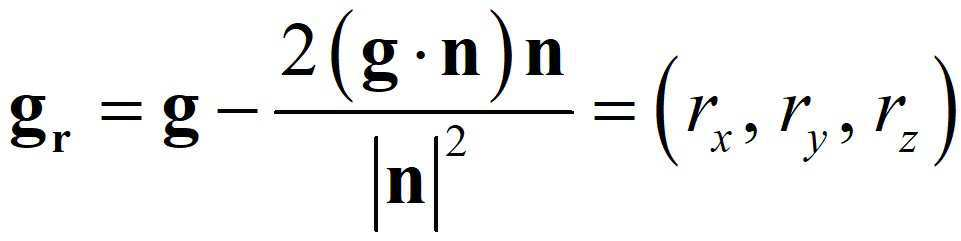
도 6은 mirror tip(110)과 display(130)가 이동하여야 하는 좌표를 계산하기 위한 geometry를 보여주는 도면이다. Transparent box(120)에 수직한 방향에 z축이 있다고 하고, mirror tip(110)의 거울의 중심이 존재하는 평면을 xy 평면으로 정한다.6 is a diagram showing geometry for calculating coordinates to which the
이 때 관찰자의 시선(gaze direction)이 z축 방향일 때 관찰자의 시선을 z축으로 정한다. 사전에 적절한 calibration을 통해 관찰자 동공의 궤적의 반경 R과, 관찰자 동공의 회전 중심 (0, 0, d E)를 정하고, 동공의 움직임을 (![]()
![]()
![]()
![]()
이 때, 도 6의 아래쪽에 정의되어 있듯이 ![]()
![]()
![]()
![]()
![]()
![]()
Mirror tip(110)의 거울의 중심은 항상 관찰자 시선 상에 있어야 하므로 거울 중심의 좌표는 아래와 같이 결정된다.Since the center of the mirror of the
![]()
![]()
이 때 거울면의 법선벡터를 n이라 하면, g벡터가 거울에서 반사된 ray의 벡터는 아래와 같이 결정된다.At this time, if the normal vector of the mirror surface is n, the vector of ray reflected from the mirror g vector is determined as follows.
이 벡터의 연장선 상에 display(130)의 중심이 있어야 하므로, display(130) 중심의 y좌표가 -d D 일 때, x좌표 및 z좌표는 아래와 같이 결정된다.Since the center of the

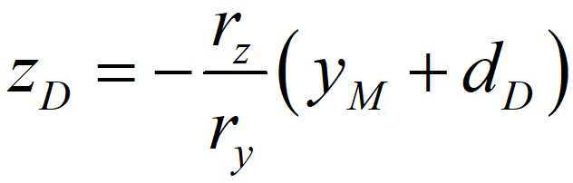
위 좌표의 계산에 따라서 mirror tip(110) 및 display(130)를 이동시켜주면 된다.The
지금까지, 시야창이 확장된 증강현실 근안 디스플레이에 대해 바람직한 실시예를 들어 상세히 설명하였다.So far, a preferred embodiment has been described in detail for the augmented reality near-eye display in which the viewing window is extended.
본 발명의 실시예에서는, 작은 거울을 이용하는 NED에서는 근본적으로 제한될 수 밖에 없는 화각을 확장하기 위한 방안으로, 시스템을 구성하는 핵심 요소인 작은 거울을 관찰자의 동공의 움직임에 맞추어 움직여 주는 NED를 제시하였다.In the embodiment of the present invention, as a plan to expand the angle of view, which is fundamentally limited in NED using small mirrors, the NED that moves the small mirror, which is a core element of the system, according to the movement of the pupil of the observer is presented. I did.
이에 의해, NED를 구성하는 작은 거울을 관찰자의 동공의 움직임에 맞추어 움직여 줌으로써, NED를 통해 제공되는 영상의 화각을 확장할 수 있게 된다.Accordingly, by moving the small mirror constituting the NED according to the movement of the pupil of the observer, it is possible to expand the angle of view of the image provided through the NED.
한편, 위 실시예에서 제시한 NED 전부는 물론이고, NED의 구성들 중 일부만을 부분적으로 구현하는 것이 가능한데, 이 경우도 본 발명의 범주에 포함될 수 있다.On the other hand, it is possible to partially implement not only all of the NEDs presented in the above embodiments, but also some of the configurations of the NED, and this case may also be included in the scope of the present invention.
이를 테면, mirror tip(110)과 transparent box(120)로 구성되는 디스플레이 시스템을 구현하는 경우에도, 본 발명의 기술적 사상이 적용될 수 있음은 물론이다.For example, even when implementing a display system composed of a
나아가, transparent box(120)과 display(130)로 구성되는 디스플레이 시스템이나 mirror tip(110)과 display(130)로 구성되는 디스플레이 시스템의 경우에도, 본 발명의 기술적 사상이 적용될 수 있음은 물론이다.Further, in the case of a display system composed of a
또한, 이상에서는 본 발명의 바람직한 실시예에 대하여 도시하고 설명하였지만, 본 발명은 상술한 특정의 실시예에 한정되지 아니하며, 청구범위에서 청구하는 본 발명의 요지를 벗어남이 없이 당해 발명이 속하는 기술분야에서 통상의 지식을 가진자에 의해 다양한 변형실시가 가능한 것은 물론이고, 이러한 변형실시들은 본 발명의 기술적 사상이나 전망으로부터 개별적으로 이해되어져서는 안될 것이다.In addition, although the preferred embodiments of the present invention have been illustrated and described above, the present invention is not limited to the specific embodiments described above, and the technical field to which the present invention belongs without departing from the gist of the present invention claimed in the claims. In addition, various modifications are possible by those of ordinary skill in the art, and these modifications should not be individually understood from the technical spirit or prospect of the present invention.
110 : mirror tip
120 : transparent box
130 : display
140 : eye tracker110: mirror tip
120: transparent box
130: display
140: eye tracker
Claims (12)
투명 상자의 일 면에 대향하는 상태로 이동 가능하며, 영상이 표시되는 디스플레이; 및
투명 상자 내에서 이동 가능하며, 디스플레이에 표시된 영상을 반사하는 거울;을 포함하고,
거울은,
리니어 스테이지에 의해 움직여지는 막대의 끝에 부착되어, 막대의 움직임에 연동하여 이동하며,
막대는,
투명 상자와 동일한 물질로 제작되는 것을 특징으로 하는 디스플레이 시스템.
Transparent box;
A display capable of moving in a state opposite to one side of the transparent box and displaying an image; And
Including; a mirror that is movable within the transparent box and reflects the image displayed on the display,
The mirror,
Attached to the end of the rod that is moved by the linear stage, it moves in conjunction with the movement of the rod,
The rod is,
Display system, characterized in that made of the same material as the transparent box.
사용자 동공의 움직임을 추적하는 추적기;를 더 포함하고,
거울과 디스플레이는,
사용자 동공의 움직임에 연동하여 이동하는 것을 특징으로 하는 디스플레이 시스템.
The method according to claim 1,
Further comprising; a tracker for tracking the movement of the user's pupil,
Mirrors and displays,
A display system, characterized in that it moves in conjunction with the movement of the user's pupil.
거울의 위치는,
사용자 동공이 바라보는 방향에 위치하는 것을 특징으로 하는 디스플레이 시스템.
The method according to claim 2,
The position of the mirror is,
A display system, characterized in that located in a direction in which the user's pupils look.
디스플레이가 이동하는 평면과 거울이 이동하는 평면은,
수직한 것을 특징으로 하는 디스플레이 시스템.
The method according to claim 1,
The plane the display moves and the plane the mirror moves are,
Display system, characterized in that vertical.
거울은,
막대의 끝을 특정 각도로 절단한 단면에 부착되는 것을 특징으로 하는 디스플레이 시스템.
The method according to claim 1,
The mirror,
Display system, characterized in that attached to the end of the rod is cut at a specific angle.
투명 상자 안에는,
투명 액체가 채워져 있는 것을 특징으로 하는 디스플레이 시스템.
The method according to claim 1,
In the transparent box,
Display system, characterized in that filled with a transparent liquid.
투명 액체는,
막대 및 투명 상자와 동일한 굴절률을 갖는 액체인 것을 특징으로 하는 디스플레이 시스템.
The method of claim 8,
Transparent liquid,
Display system, characterized in that the liquid having the same refractive index as the rod and the transparent box.
투명 상자 내에서 마련되어 디스플레이에 표시된 영상을 반사하는 거울을 이동시키는 단계;를 포함하고,
거울은,
리니어 스테이지에 의해 움직여지는 막대의 끝에 부착되어, 막대의 움직임에 연동하여 이동하며,
막대는,
투명 상자와 동일한 물질로 제작되는 것을 특징으로 하는 영상 디스플레이 방법.
Moving the display opposite to one side of the transparent box;
Including; and moving a mirror that is provided in a transparent box and reflects an image displayed on the display,
The mirror,
Attached to the end of the rod that is moved by the linear stage, it moves in conjunction with the movement of the rod,
The rod is,
Image display method, characterized in that made of the same material as the transparent box.
투명 상자 내에서 이동 가능하며, 디스플레이에 표시된 영상을 반사하는 거울;을 포함하고,
거울은,
리니어 스테이지에 의해 움직여지는 막대의 끝에 부착되어, 막대의 움직임에 연동하여 이동하며,
막대는,
투명 상자와 동일한 물질로 제작되는 것을 특징으로 하는 디스플레이 시스템.
Transparent box;
Including; a mirror that is movable within the transparent box and reflects the image displayed on the display,
The mirror,
Attached to the end of the rod that is moved by the linear stage, it moves in conjunction with the movement of the rod,
The rod is,
Display system, characterized in that made of the same material as the transparent box.
이동되는 거울이 디스플레이에 표시된 영상을 반사시키는 단계;를 포함하고,
거울은,
리니어 스테이지에 의해 움직여지는 막대의 끝에 부착되어, 막대의 움직임에 연동하여 이동하며,
막대는,
투명 상자와 동일한 물질로 제작되는 것을 특징으로 하는 영상 디스플레이 방법.
Moving the mirror provided in the transparent box;
Including, the moving mirror reflects the image displayed on the display,
The mirror,
It is attached to the end of the rod that is moved by the linear stage, and moves in conjunction with the movement of the rod,
The rod is,
Image display method, characterized in that made of the same material as the transparent box.
Priority Applications (2)
| Application Number | Priority Date | Filing Date | Title |
|---|---|---|---|
| PCT/KR2018/015486 WO2020116693A1 (en) | 2018-12-07 | 2018-12-07 | Augmented reality near-eye display having expanded sight window |
| KR1020180156627A KR102191096B1 (en) | 2018-12-07 | 2018-12-07 | Near-Eye Display with Extended Field of View for Augmented Reality |
Applications Claiming Priority (1)
| Application Number | Priority Date | Filing Date | Title |
|---|---|---|---|
| KR1020180156627A KR102191096B1 (en) | 2018-12-07 | 2018-12-07 | Near-Eye Display with Extended Field of View for Augmented Reality |
Publications (2)
| Publication Number | Publication Date |
|---|---|
| KR20200069512A KR20200069512A (en) | 2020-06-17 |
| KR102191096B1 true KR102191096B1 (en) | 2020-12-15 |
Family
ID=70974934
Family Applications (1)
| Application Number | Title | Priority Date | Filing Date |
|---|---|---|---|
| KR1020180156627A Active KR102191096B1 (en) | 2018-12-07 | 2018-12-07 | Near-Eye Display with Extended Field of View for Augmented Reality |
Country Status (2)
| Country | Link |
|---|---|
| KR (1) | KR102191096B1 (en) |
| WO (1) | WO2020116693A1 (en) |
Citations (3)
| Publication number | Priority date | Publication date | Assignee | Title |
|---|---|---|---|---|
| JP2005500728A (en) * | 2001-07-06 | 2005-01-06 | カール−ツアイス−スチフツング | Head-mounted optical fluoroscopy system |
| JP2010262232A (en) | 2009-05-11 | 2010-11-18 | Konica Minolta Opto Inc | Apparatus for displaying video image and head-mounted display |
| JP2016090689A (en) * | 2014-10-31 | 2016-05-23 | セイコーエプソン株式会社 | Image display apparatus and drawing method |
Family Cites Families (5)
| Publication number | Priority date | Publication date | Assignee | Title |
|---|---|---|---|---|
| KR101383235B1 (en) * | 2010-06-17 | 2014-04-17 | 한국전자통신연구원 | Apparatus for inputting coordinate using eye tracking and method thereof |
| US9292973B2 (en) * | 2010-11-08 | 2016-03-22 | Microsoft Technology Licensing, Llc | Automatic variable virtual focus for augmented reality displays |
| IL313175A (en) * | 2013-03-11 | 2024-07-01 | Magic Leap Inc | System and method for augmentation and virtual reality |
| KR20170008430A (en) * | 2015-07-14 | 2017-01-24 | 엘지전자 주식회사 | Head up display |
| KR102293579B1 (en) * | 2015-12-10 | 2021-08-26 | 현대모비스 주식회사 | Rotating drive apparatus |
-
2018
- 2018-12-07 KR KR1020180156627A patent/KR102191096B1/en active Active
- 2018-12-07 WO PCT/KR2018/015486 patent/WO2020116693A1/en not_active Ceased
Patent Citations (3)
| Publication number | Priority date | Publication date | Assignee | Title |
|---|---|---|---|---|
| JP2005500728A (en) * | 2001-07-06 | 2005-01-06 | カール−ツアイス−スチフツング | Head-mounted optical fluoroscopy system |
| JP2010262232A (en) | 2009-05-11 | 2010-11-18 | Konica Minolta Opto Inc | Apparatus for displaying video image and head-mounted display |
| JP2016090689A (en) * | 2014-10-31 | 2016-05-23 | セイコーエプソン株式会社 | Image display apparatus and drawing method |
Also Published As
| Publication number | Publication date |
|---|---|
| WO2020116693A1 (en) | 2020-06-11 |
| KR20200069512A (en) | 2020-06-17 |
Similar Documents
| Publication | Publication Date | Title |
|---|---|---|
| US10409065B2 (en) | Near-eye display | |
| CN106662745B (en) | A compact architecture for near-eye display systems | |
| CN102566049B (en) | Automatic variable virtual focus for augmented reality displays | |
| JP6369017B2 (en) | Virtual image display device | |
| US9851562B2 (en) | Embedded grating structure | |
| US20170336634A1 (en) | Augmented reality eyewear and methods for using same | |
| US20120188148A1 (en) | Head Mounted Meta-Display System | |
| CN107209390A (en) | The display of combination high-resolution narrow and intermediate-resolution wide field are shown | |
| US10962782B2 (en) | Exit pupil expansion via curved waveguide | |
| CN107076998B (en) | Wearables and Unmanned Aerial Systems | |
| JPS5834814B2 (en) | Display using optical collimation | |
| CN107783289B (en) | Multimode head-mounted visual device | |
| CN107966821A (en) | Augmented reality glasses | |
| WO2022142565A1 (en) | Optical assembly and ar device | |
| CN107783291B (en) | Real three-dimensional holographic display head-mounted visual equipment | |
| US20190137775A1 (en) | Vision system and film viewing device | |
| WO2022017445A1 (en) | Augmented reality display apparatus and augmented reality display device comprising same | |
| KR102191096B1 (en) | Near-Eye Display with Extended Field of View for Augmented Reality | |
| CN105659147B (en) | Light guiding prism and image display device | |
| US20180017800A1 (en) | Virtual image display apparatus | |
| US9857592B2 (en) | Display device | |
| KR100403079B1 (en) | The apparatus of the see-through type head mounted display | |
| KR101875293B1 (en) | Optical device for virtual image projection display | |
| US20180234670A1 (en) | Display device | |
| JPH10111470A (en) | Picture display device |
Legal Events
| Date | Code | Title | Description |
|---|---|---|---|
| PA0109 | Patent application |
Patent event code: PA01091R01D Comment text: Patent Application Patent event date: 20181207 |
|
| PA0201 | Request for examination |
Patent event code: PA02012R01D Patent event date: 20190213 Comment text: Request for Examination of Application Patent event code: PA02011R01I Patent event date: 20181207 Comment text: Patent Application |
|
| E902 | Notification of reason for refusal | ||
| PE0902 | Notice of grounds for rejection |
Comment text: Notification of reason for refusal Patent event date: 20200603 Patent event code: PE09021S01D |
|
| PG1501 | Laying open of application | ||
| E701 | Decision to grant or registration of patent right | ||
| PE0701 | Decision of registration |
Patent event code: PE07011S01D Comment text: Decision to Grant Registration Patent event date: 20201207 |
|
| GRNT | Written decision to grant | ||
| PR0701 | Registration of establishment |
Comment text: Registration of Establishment Patent event date: 20201209 Patent event code: PR07011E01D |
|
| PR1002 | Payment of registration fee |
Payment date: 20201209 End annual number: 3 Start annual number: 1 |
|
| PG1601 | Publication of registration | ||
| PR1001 | Payment of annual fee |
Payment date: 20230921 Start annual number: 4 End annual number: 4 |
|
| PR1001 | Payment of annual fee |