KR102185372B1 - Electronic vehicle charging apparatus for mechanical parking station - Google Patents
Electronic vehicle charging apparatus for mechanical parking station Download PDFInfo
- Publication number
- KR102185372B1 KR102185372B1 KR1020200106317A KR20200106317A KR102185372B1 KR 102185372 B1 KR102185372 B1 KR 102185372B1 KR 1020200106317 A KR1020200106317 A KR 1020200106317A KR 20200106317 A KR20200106317 A KR 20200106317A KR 102185372 B1 KR102185372 B1 KR 102185372B1
- Authority
- KR
- South Korea
- Prior art keywords
- connection terminal
- pallet
- terminal
- charging
- electric vehicle
- Prior art date
- Legal status (The legal status is an assumption and is not a legal conclusion. Google has not performed a legal analysis and makes no representation as to the accuracy of the status listed.)
- Active
Links
Images


Classifications
-
- B—PERFORMING OPERATIONS; TRANSPORTING
- B60—VEHICLES IN GENERAL
- B60L—PROPULSION OF ELECTRICALLY-PROPELLED VEHICLES; SUPPLYING ELECTRIC POWER FOR AUXILIARY EQUIPMENT OF ELECTRICALLY-PROPELLED VEHICLES; ELECTRODYNAMIC BRAKE SYSTEMS FOR VEHICLES IN GENERAL; MAGNETIC SUSPENSION OR LEVITATION FOR VEHICLES; MONITORING OPERATING VARIABLES OF ELECTRICALLY-PROPELLED VEHICLES; ELECTRIC SAFETY DEVICES FOR ELECTRICALLY-PROPELLED VEHICLES
- B60L53/00—Methods of charging batteries, specially adapted for electric vehicles; Charging stations or on-board charging equipment therefor; Exchange of energy storage elements in electric vehicles
- B60L53/30—Constructional details of charging stations
- B60L53/35—Means for automatic or assisted adjustment of the relative position of charging devices and vehicles
-
- B—PERFORMING OPERATIONS; TRANSPORTING
- B60—VEHICLES IN GENERAL
- B60L—PROPULSION OF ELECTRICALLY-PROPELLED VEHICLES; SUPPLYING ELECTRIC POWER FOR AUXILIARY EQUIPMENT OF ELECTRICALLY-PROPELLED VEHICLES; ELECTRODYNAMIC BRAKE SYSTEMS FOR VEHICLES IN GENERAL; MAGNETIC SUSPENSION OR LEVITATION FOR VEHICLES; MONITORING OPERATING VARIABLES OF ELECTRICALLY-PROPELLED VEHICLES; ELECTRIC SAFETY DEVICES FOR ELECTRICALLY-PROPELLED VEHICLES
- B60L53/00—Methods of charging batteries, specially adapted for electric vehicles; Charging stations or on-board charging equipment therefor; Exchange of energy storage elements in electric vehicles
- B60L53/30—Constructional details of charging stations
- B60L53/31—Charging columns specially adapted for electric vehicles
-
- E—FIXED CONSTRUCTIONS
- E04—BUILDING
- E04H—BUILDINGS OR LIKE STRUCTURES FOR PARTICULAR PURPOSES; SWIMMING OR SPLASH BATHS OR POOLS; MASTS; FENCING; TENTS OR CANOPIES, IN GENERAL
- E04H6/00—Buildings for parking cars, rolling-stock, aircraft, vessels or like vehicles, e.g. garages
- E04H6/08—Garages for many vehicles
- E04H6/12—Garages for many vehicles with mechanical means for shifting or lifting vehicles
-
- E—FIXED CONSTRUCTIONS
- E04—BUILDING
- E04H—BUILDINGS OR LIKE STRUCTURES FOR PARTICULAR PURPOSES; SWIMMING OR SPLASH BATHS OR POOLS; MASTS; FENCING; TENTS OR CANOPIES, IN GENERAL
- E04H6/00—Buildings for parking cars, rolling-stock, aircraft, vessels or like vehicles, e.g. garages
- E04H6/42—Devices or arrangements peculiar to garages, not covered elsewhere, e.g. securing devices, safety devices, monitoring and operating schemes; centering devices
-
- B—PERFORMING OPERATIONS; TRANSPORTING
- B60—VEHICLES IN GENERAL
- B60Y—INDEXING SCHEME RELATING TO ASPECTS CROSS-CUTTING VEHICLE TECHNOLOGY
- B60Y2200/00—Type of vehicle
- B60Y2200/90—Vehicles comprising electric prime movers
- B60Y2200/91—Electric vehicles
-
- Y—GENERAL TAGGING OF NEW TECHNOLOGICAL DEVELOPMENTS; GENERAL TAGGING OF CROSS-SECTIONAL TECHNOLOGIES SPANNING OVER SEVERAL SECTIONS OF THE IPC; TECHNICAL SUBJECTS COVERED BY FORMER USPC CROSS-REFERENCE ART COLLECTIONS [XRACs] AND DIGESTS
- Y02—TECHNOLOGIES OR APPLICATIONS FOR MITIGATION OR ADAPTATION AGAINST CLIMATE CHANGE
- Y02T—CLIMATE CHANGE MITIGATION TECHNOLOGIES RELATED TO TRANSPORTATION
- Y02T10/00—Road transport of goods or passengers
- Y02T10/60—Other road transportation technologies with climate change mitigation effect
- Y02T10/70—Energy storage systems for electromobility, e.g. batteries
-
- Y—GENERAL TAGGING OF NEW TECHNOLOGICAL DEVELOPMENTS; GENERAL TAGGING OF CROSS-SECTIONAL TECHNOLOGIES SPANNING OVER SEVERAL SECTIONS OF THE IPC; TECHNICAL SUBJECTS COVERED BY FORMER USPC CROSS-REFERENCE ART COLLECTIONS [XRACs] AND DIGESTS
- Y02—TECHNOLOGIES OR APPLICATIONS FOR MITIGATION OR ADAPTATION AGAINST CLIMATE CHANGE
- Y02T—CLIMATE CHANGE MITIGATION TECHNOLOGIES RELATED TO TRANSPORTATION
- Y02T10/00—Road transport of goods or passengers
- Y02T10/60—Other road transportation technologies with climate change mitigation effect
- Y02T10/7072—Electromobility specific charging systems or methods for batteries, ultracapacitors, supercapacitors or double-layer capacitors
-
- Y—GENERAL TAGGING OF NEW TECHNOLOGICAL DEVELOPMENTS; GENERAL TAGGING OF CROSS-SECTIONAL TECHNOLOGIES SPANNING OVER SEVERAL SECTIONS OF THE IPC; TECHNICAL SUBJECTS COVERED BY FORMER USPC CROSS-REFERENCE ART COLLECTIONS [XRACs] AND DIGESTS
- Y02—TECHNOLOGIES OR APPLICATIONS FOR MITIGATION OR ADAPTATION AGAINST CLIMATE CHANGE
- Y02T—CLIMATE CHANGE MITIGATION TECHNOLOGIES RELATED TO TRANSPORTATION
- Y02T90/00—Enabling technologies or technologies with a potential or indirect contribution to GHG emissions mitigation
- Y02T90/10—Technologies relating to charging of electric vehicles
- Y02T90/12—Electric charging stations
Landscapes
- Engineering & Computer Science (AREA)
- Architecture (AREA)
- Mechanical Engineering (AREA)
- Power Engineering (AREA)
- Transportation (AREA)
- Civil Engineering (AREA)
- Structural Engineering (AREA)
- Charge And Discharge Circuits For Batteries Or The Like (AREA)
Abstract
본 발명은 전기차가 적재되도록 형성되는 팔레트, 상기 팔레트를 승하강시키는 승강 리프트, 상기 팔레트가 승하강되는 승강로와 복수개의 주차 격납실을 갖도록 형성되는 골조 프레임과, 상기 승강 리프트를 제어하여 팔레트를 이동시키는 제어기와, 상기 주차 격납실에 마련된 충전 전력 중계 포트 및, 상기 팔레트의 측면에 형성되는 측면 연결 단자를 포함하며, 상기 팔레트가 승강 리프트에 의해 이동되어 전기차를 주차 격납실에 위치시키면 제어기는 충전 전력 중계 포트를 이동시켜 측면 연결 단자와 연결시키는 것을 특징으로 하는 기계식 주차장용 전기차 충전 시스템에 관한 것이다.The present invention is a pallet formed to be loaded with an electric vehicle, a lift lift for raising and lowering the pallet, a frame frame formed to have a hoistway for raising and lowering the pallet and a plurality of parking storage rooms, and a pallet moving by controlling the lift lift It includes a controller, a charging power relay port provided in the parking compartment, and a side connection terminal formed on the side of the pallet, and when the pallet is moved by an elevator lift to place the electric vehicle in the parking compartment, the controller charges It relates to an electric vehicle charging system for a mechanical parking lot, characterized in that the power relay port is moved and connected to the side connection terminal.
Description
본 발명은 기계식 주차장용 전기차 충전 시스템으로서, 기계식 주차장에서 주차와 동시에 충전이 이루어질 수 있는 기계식 주차장용 전기차 충전 시스템에 관한 것이다.The present invention relates to an electric vehicle charging system for a mechanical parking lot, which can be charged simultaneously with parking in a mechanical parking lot.
경제 발전에 따라 자동차에 대한 수요가 폭발적으로 증가세를 보이고 있고, 자동차 수요가 늘어남에 따라 자동차에서 배출되는 배기가스가 환경오염의 주요 원인이 되고 있다. 이는 현재까지의 자동차의 주된 원료가 휘발유, 경우, 가스 등과 같은 화석 연료를 사용하고 있는데 기인하고 있다.Demand for automobiles is showing an explosive increase in accordance with economic development, and exhaust gas emitted from automobiles is a major cause of environmental pollution as demand for automobiles increases. This is due to the fact that fossil fuels such as gasoline, gas and gas are used as the main raw materials for automobiles to date.
이에 자동차의 배출가스를 감소시키기 위한 요구가 이어지고 있으며, 배출가스를 줄일 수 있는 자동차의 연구 및 개발이 진행되고 있다. 더 나아가 배출가스를 발생하지 않는 전기 자동차의 상용화가 부분적으로 시도되고 있다.Accordingly, there is a demand for reducing exhaust gas of automobiles, and research and development of automobiles capable of reducing exhaust gas are in progress. Furthermore, commercialization of electric vehicles that do not generate exhaust gas has been partially attempted.
전기 자동차는 전기를 구동력의 공급원으로 하여 운행하는 차량을 의미하며, 차량 자체에 전력공급원으로 충전이 가능한 배터리를 탑재하고, 탑재된 배터리에서 공급되는 전력을 이용하여 운행하는 차량을 의미한다. 이에 전기 자동차는 크게 전기에 의해 구동되어 전기 자동차를 운행시키는 전기 모터와, 그 전기 모터에 전기를 공급하는 배터리를 필수적인 구성요소로 하고 있다.An electric vehicle refers to a vehicle that operates using electricity as a source of driving power, and refers to a vehicle that mounts a battery that can be charged as a power supply source in the vehicle itself, and operates using power supplied from the mounted battery. Accordingly, an electric vehicle is largely driven by electricity to operate an electric vehicle, and a battery that supplies electricity to the electric motor is used as essential components.
이와 같은 무공해의 전기 자동차가 기존의 화석 연료를 사용하는 자동차를 대체하기 위해서는 아직 많은 기술 분야에서의 발전이 요구되고 있는게 현실이다. 예를 들어, 배터리의 사용 시간, 즉 용량의 증가, 전기 모터의 용량 증가와 같이, 기존의 자동차를 대체할 수 있는 능력이 전기 자동차에도 요구되고 있는게 현실이다.In order for such a non-polluting electric vehicle to replace an existing fossil fuel-based vehicle, development in many technical fields is still required. For example, it is a reality that an electric vehicle is also required to have the ability to replace existing automobiles, such as an increase in battery usage time, that is, capacity, and capacity of an electric motor.
이와 같은 기술적인 문제 외에도 전기 자동차의 보급을 저해하는 요인으로는 전기 자동차를 충전시키기 위한 충전 시스템이 아직 널리 보급되지 않아 전기 자동차를 구입하더라도 이를 충전하기 위한 충전소와 같은 시설을 쉽게 찾기 어려운 실정이다.In addition to such technical problems, as a factor that hinders the spread of electric vehicles, charging systems for charging electric vehicles have not yet been widely distributed, so even when electric vehicles are purchased, it is difficult to find facilities such as charging stations for charging them.
이에, 휘발유 등과는 달리 전기는 일반 가정이나 건물에서도 공급할 수 있다는 점에서 일반 가정이나 건물의 주차장에 충전 시스템을 설치하여 주차 중에 충전을 가능하게 함으로써, 이를 활용하는 경우 충전소와 같은 기반 시설의 미비를 일정 부분 대체할 수 있을 것이다.Therefore, unlike gasoline, electricity can also be supplied by ordinary homes or buildings, so charging during parking is possible by installing a charging system in the parking lot of ordinary homes or buildings, and in the case of utilizing this, the lack of infrastructure such as a charging station is eliminated. It will be able to replace some parts.
특히, 최근에는 도심의 차량 증가로 인한 주차 문제를 해결하기 위해 다양한 방식의 주차 설비가 설치되어 운영되고 있으므로, 이러한 주차 설비에 전기차 충전을 위한 충전 시스템을 구비하면, 전기차 충전을 위한 별도의 기반 시설 부족을 만회함은 물론 전기차 이용의 편의성을 향상시켜 전기차의 보급을 더욱 확대시킬 수 있을 것이다.In particular, in recent years, various types of parking facilities have been installed and operated to solve the parking problem caused by the increase in vehicles in the city, so if a charging system for charging electric vehicles is provided in these parking facilities, a separate infrastructure for charging electric vehicles In addition to making up for the shortage, it will be possible to further expand the spread of electric vehicles by improving the convenience of using electric vehicles.
그런데 지금까지 일반적으로 보급된 전기차 충전 시설은 지상에서 전기 충전이 이루어지는 일반적인 충전기가 공급되고 있을 뿐이지, 승강기 형태의 기계식 주차장에서 주차된 전기차를 손쉽게 충전할 수 있는 기계식 주차장용 전기차 충전 장치는 마련되지 않는 문제가 있다.However, electric vehicle charging facilities that have been generally distributed so far only supply general chargers that charge electricity from the ground, but there is no electric vehicle charging device for mechanical parking lots that can easily charge electric vehicles parked in an elevator-type mechanical parking lot. there is a problem.
본 발명은 기계식 주차장에서 주차된 전기차를 손쉽게 충전할 수 있는 전기차 충전 수단을 제공하는 것을 목적으로 한다.An object of the present invention is to provide an electric vehicle charging means that can easily charge an electric vehicle parked in a mechanical parking lot.
본 발명은 전기차가 적재되도록 형성되는 팔레트, 상기 팔레트를 승하강시키는 승강 리프트, 상기 팔레트가 승하강되는 승강로와 복수개의 주차 격납실을 갖도록 형성되는 골조 프레임과, 상기 승강 리프트를 제어하여 팔레트를 이동시키는 제어기와, 상기 주차 격납실에 마련된 충전 전력 중계 포트 및, 상기 팔레트의 측면에 형성되는 측면 연결 단자를 포함하며, 상기 팔레트가 승강 리프트에 의해 이동되어 전기차를 주차 격납실에 위치시키면 제어기는 충전 전력 중계 포트를 이동시켜 측면 연결 단자와 연결시키는 것을 특징으로 하는 기계식 주차장용 전기차 충전 시스템을 제공한다.The present invention is a pallet formed to be loaded with an electric vehicle, a lift lift for raising and lowering the pallet, a frame frame formed to have a hoistway for raising and lowering the pallet and a plurality of parking storage rooms, and a pallet moving by controlling the lift lift It includes a controller, a charging power relay port provided in the parking compartment, and a side connection terminal formed on the side of the pallet, and when the pallet is moved by an elevator lift to place the electric vehicle in the parking compartment, the controller charges It provides an electric vehicle charging system for a mechanical parking lot, characterized in that the power relay port is moved and connected to the side connection terminal.
상기 팔레트에는 전기차의 하부에 형성된 배터리 충전 단자에 접속되는 접속 단자가 형성되며, 상기 접속 단자는 상기 측면 연결 단자와 연결될 수 있다.A connection terminal connected to a battery charging terminal formed under the electric vehicle may be formed on the pallet, and the connection terminal may be connected to the side connection terminal.
상기 접속 단자가 형성된 접속 단자부는 접속 단자부 몸체와, 상기 접속 단자부 몸체의 내측에 형성되는 접속 단자 프레임부를 포함하고, 상기 접속 단자 프레임부는 내측센서가 형성되는 센서 프레임부분과, 상기 내측센서에서 감지된 충전 단자의 위치로 접속 단자 프레임부를 접속 단자부 몸체 내부에서 이동시키는 하부 프레임부분을 포함할 수 있다.The connection terminal portion on which the connection terminal is formed includes a connection terminal portion body, and a connection terminal frame portion formed inside the connection terminal portion body, and the connection terminal frame portion includes a sensor frame portion on which an inner sensor is formed, and detected by the inner sensor. It may include a lower frame portion for moving the connection terminal frame portion inside the connection terminal body to the position of the charging terminal.
상기 팔레트에 팔레트 길이 방향으로 형성되는 중앙 홈과, 상기 중앙 홈에서 측방향으로 형성되는 측면 홈이 형성되고, 상기 접속 단자부 몸체에는 전기차의 충전 단자 위치를 감지하는 외측 센서와, 상기 중앙 홈과 측면 홈을 따라서 접속 단자부 몸체를 충전 단자 위치로 이동시키는 몸체 이동부가 형성될 수 있다.A central groove formed in the pallet length direction and a side groove formed laterally from the central groove are formed on the pallet, and an outer sensor for sensing the position of a charging terminal of an electric vehicle in the body of the connection terminal portion, and the central groove and side surfaces A body moving part for moving the connection terminal body to the charging terminal position may be formed along the groove.
상기 하부 프레임부분은 구동 바퀴 및, 상기 구동 바퀴를 전후 좌후로 이동시키는 바퀴구동부를 포함할 수 있다.The lower frame portion may include a driving wheel and a wheel driving unit that moves the driving wheel forward, backward, left and rear.
상기 접속 단자부 몸체에는 상단에 형성되는 덮개와, 상기 덮개를 이동시키도록 형성되는 덮개 이동부가 포함될 수 있다.The connection terminal body may include a cover formed at an upper end, and a cover moving part formed to move the cover.
상기 접속 단자 프레임부에는 상기 접속 단자를 승하강시키는 승하강부재가 형성될 수 있다.An elevating member for raising and lowering the connection terminal may be formed in the connection terminal frame portion.
상기 충전 전력 중계 포트는 수직 가이드 레일과, 상기 수직 가이드 레일을 따라서 이동되는 롤러부와, 상기 롤러부를 구동하는 제1 구동부와, 상기 롤러부에 고정되어 롤러부를 따라서 이동되도록 형성되는 충전 전력 중계 단자를 포함하며, 상기 팔레트가 주차 격납실에 위치되면, 제1 구동부가 작동되어 롤러부가 수직 가이드 레일을 따라서 하방으로 이동되면서 상기 충전 전력 중계 단자가 상기 측면 연결 단자에 접속될 수 있다.The charging power relay port includes a vertical guide rail, a roller part moving along the vertical guide rail, a first driving part driving the roller part, and a charging power relay terminal fixed to the roller part and formed to move along the roller part. Including, and when the pallet is located in the parking compartment, the first driving unit is operated and the roller unit is moved downward along the vertical guide rail, the charging power relay terminal may be connected to the side connection terminal.
상기 충전 전력 중계 포트는 전력을 공급하도록 형성된 수직 전력 공급 로드와, 상기 수직 전력 공급 로드에 접하고 중계 포트 단자가 형성된 중계 포트 단자부와, 상기 수직 전력 공급 로드와 평행하게 형성되는 가이드 로드와, 상기 가이드 로드를 따라서 이동되는 가이드롤러부와, 상기 가이드롤러부가 이동될 수 있는 구동력을 제공하는 제2 구동부 및, 상기 가이드롤러부와 중계 포트 단자부 사이를 연결하는 링크부재를 포함하고, 상기 팔레트가 주차 격납실에 위치되면, 제2 구동부가 작동되어 가이드롤러부가 가이드 로드를 따라서 내려오면서 중계 포트 단자부의 중계 포트 단자가 연결 단자 부분에 접촉될 수 있다.The charging power relay port includes a vertical power supply rod formed to supply power, a relay port terminal portion in contact with the vertical power supply rod and having a relay port terminal, a guide rod formed parallel to the vertical power supply rod, and the guide A guide roller unit that is moved along the rod, a second driving unit that provides a driving force to move the guide roller unit, and a link member connecting between the guide roller unit and the relay port terminal unit, and the pallet is parking and stored When positioned in the seal, the second driving unit is operated so that the guide roller unit descends along the guide rod so that the relay port terminal of the relay port terminal unit may contact the connection terminal portion.
상기 덮개에는 피동부재가 형성되고, 상기 덮개 이동부에는 상기 피동부재에 맞물리는 구동부재와, 상기 구동부재를 구동시키는 제3 구동부가 형성될 수 있다.A driven member may be formed on the cover, and a driving member engaged with the driven member and a third driving unit for driving the driving member may be formed on the cover moving part.
상기 승하강부재는 상기 하부 프레임부분에 형성되는 나사선부재와, 상기 나사선부재를 구동시키는 나사선 구동부와, 상기 나사선부재에 접하여 나사선부재가 회전됨에 따라서 높이가 신축되는 신장부재와, 상기 신장부재의 상부에 형성되는 접속 단자판을 포함할 수 있다.The elevating member includes a screw wire member formed in the lower frame portion, a screw wire driver for driving the screw wire member, an elongate member that is in contact with the screw wire member and expands and contracts in height as the screw wire member rotates, and an upper portion of the elongate member It may include a connection terminal plate formed in.
상기 측면 연결 단자는 단자 몸체와, 상기 단자 몸체에 형성되며 절연 소재로 형성되는 단자 기대 및, 상기 단자 기대의 상부에 형성되는 연결 단자 부분을 포함하며, 상기 측면 연결 단자는 단자 기대의 하부와 단자 몸체 사이에 탄성 부재가 형성될 수 있다.The side connection terminal includes a terminal body, a terminal base formed on the terminal body and formed of an insulating material, and a connection terminal portion formed on an upper portion of the terminal base, and the side connection terminal includes a lower portion of the terminal base and a terminal An elastic member may be formed between the bodies.
본 발명은 상기 중계 포트 단자부의 상부에 형성된 제4 구동부와, 상기 제4 구동부에 의해 회전되는 포트 단자 회전팬과, 상기 포트 단자 회전팬에서 발생되는 공기의 흐름을 전달하도록 중계 포트 단자부의 내측에 형성된 연결 덕트부 및, 상기 연결 덕트부의 하단에 형성되는 포트 단자 노즐부를 더 포함하고, 상기 포트 단자 노즐부는 포트 단자 회전팬에서 전달되는 공기를 분사할 수 있다.The present invention provides a fourth driving part formed on the relay port terminal part, a port terminal rotating fan rotated by the fourth driving part, and an inside of the relay port terminal part to transmit the flow of air generated from the port terminal rotating fan. The formed connection duct portion and a port terminal nozzle portion formed at a lower end of the connection duct portion may be further included, and the port terminal nozzle portion may spray air transmitted from the port terminal rotating fan.
상기 접속 단자판에 공기를 분사하는 공기 분사부는 접속 단자부 몸체 외측에 고정되는 제5 구동부와, 상기 제5 구동부에 의해 회전되는 접속 단자 회전팬과, 상기 접속 단자 회전팬에서 발생되는 공기의 흐름을 전달하도록 형성되는 접속 단자 노즐부를 포함할 수 있다.The air injection unit for injecting air to the connection terminal plate transmits the flow of air generated from the fifth driving unit fixed to the outside of the connection terminal unit body, the connection terminal rotating fan rotated by the fifth driving unit, and the connection terminal rotating fan It may include a connection terminal nozzle portion formed to be.
본 발명은 자동차의 주차 위치가 사전에 결정되어진 개소를 이용하는 형태의 기계식 주차장에서 주차된 전기차를 손쉽게 충전할 수 있는 전기차 충전 수단을 제공하는 효과가 발생된다.The present invention has an effect of providing an electric vehicle charging means that can easily charge an electric vehicle parked in a mechanical parking lot using a location in which the parking position of the vehicle is determined in advance.
또한, 본 발명은 전기차의 하부에 형성된 충전 단자의 다양한 위치에 접속 단자부 몸체가 이동되는 1단계와, 상기 1단계를 거친 후에 접속 단자부 몸체 내부에서 접속 단자판이 충전 단자의 정확한 하부에 위치되도록 조정하는 과정을 거치는 2단계를 통하여 정밀한 충전 과정이 진행되는 효과가 발생된다.In addition, the present invention adjusts the first step in which the connection terminal body is moved to various positions of the charging terminal formed under the electric vehicle, and the connection terminal plate is positioned in the correct lower part of the charging terminal inside the connection terminal body after the first step. The effect of a precise charging process is generated through the two steps through the process.
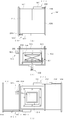
도 1은 본 발명인 기계식 주차장용 전기차 충전 시스템을 나타내는 개략 정면도이다.
도 2의 (a)는 도 1의 전기차에 팔레트의 접속단자부가 접속되기 전의 상태를 나타내는 개략 정면도이고, 도 2의 (b)는 도 2의 (a) 상태에서 전기차의 충전 단자와 팔레트의 접속단자부가 접근한 상태를 나타내는 개략 정면도이며, 도 2의 (c)는 도 2의 (b) 상태에서 전기차의 충전 단자와 팔레트의 접속단자부가 접촉된 상태를 나타내는 개략 정면도이다.
도 3의 (a)는 본 발명에서 전기차가 주차 격납실 측으로 횡행 이동하는 것을 나타내는 개략 정면도이고, 도 3의 (b)는 도 3의 (a)에서 전기차가 주차 격납실 측으로 횡행 이동된 것을 나타내는 개략 정면도이다.
도 4의 (a)는 본 발명에서 충전 전력 중계 포트의 제1 형태를 나타내는 개략 사시도이고, 도 4의 (b)는 도 4의 (a)에서 제1 충전 전력 중계 포트가 제1 측면 연결 단자에 접촉된 상태를 나타내는 개략 사시도이다.
도 5의 (a)는 본 발명에서 충전 전력 중계 포트의 제2 형태를 나타내는 개략 사시도이고, 도 5의 (b)는 도 5의 (a)에서 제2 충전 전력 중계 포트가 제2 측면 연결 단자에 접촉된 상태를 나타내는 개략 사시도이다.
도 6은 본 발명에서 충전 전력 중계 포트의 제2 형태에 대한 변형례를 나타내는 개략 확대 단면도이다.
도 7은 팔레트의 변형례를 나타내는 개략 사시도이다.
도 8의 (a)는 팔레트의 접속단자부 제1 변형례를 나타내는 개략 평면도이고, 도 8의 (b)는 팔레트의 접속단자부 제1 변형례를 나타내는 개략 측단면도이다.
도 9의 (a)는 팔레트의 접속 단자부 제2 변형례에서 덮개가 닫힌 상태를 나타내는 개략 평면도이고, 도 9의 (b)는 팔레트의 접속 단자부 제2 변형례에서 덮개가 닫힌 상태를 나타내는 개략 측단면도이며, 도 9의 (c)는 팔레트의 접속 단자부 제2 변형례에서 덮개가 열린 상태를 나타내는 개략 평면도이다.
도 10은 접속 단자부와 충전 단자의 접속 과정을 나타내는 개략 요부 사시도이다.1 is a schematic front view showing an electric vehicle charging system for a mechanical parking lot according to the present invention.
Figure 2 (a) is a schematic front view showing a state before the connection terminal of the pallet is connected to the electric vehicle of Figure 1, and Figure 2 (b) is the connection of the charging terminal of the electric vehicle and the pallet in the state (a) of Figure 2 It is a schematic front view showing a state in which the terminal portion is approached, and FIG. 2C is a schematic front view showing a state in which the charging terminal of the electric vehicle and the connection terminal portion of the pallet are in contact in the state of FIG. 2B.
Figure 3 (a) is a schematic front view showing that the electric vehicle moves horizontally toward the parking compartment in the present invention, and Figure 3 (b) shows that the electric vehicle is moved horizontally toward the parking compartment in Figure 3 (a) It is a schematic front view.
Figure 4 (a) is a schematic perspective view showing a first form of the charging power relay port in the present invention, Figure 4 (b) is the first charging power relay port in Figure 4 (a) is a first side connection terminal It is a schematic perspective view showing a state in contact with.
Figure 5 (a) is a schematic perspective view showing a second form of the charging power relay port in the present invention, Figure 5 (b) is the second charging power relay port in Figure 5 (a) is a second side connection terminal It is a schematic perspective view showing a state in contact with.
6 is a schematic enlarged cross-sectional view showing a modified example of a second form of a charging power relay port in the present invention.
7 is a schematic perspective view showing a modified example of a pallet.
FIG. 8A is a schematic plan view showing a first modification example of the connection terminal portion of the pallet, and FIG. 8B is a schematic side cross-sectional view showing a first modification example of the connection terminal portion of the pallet.
Fig. 9(a) is a schematic plan view showing the closed state of the lid in the second modified example of the connection terminal part of the pallet, and Fig.9(b) is a schematic side showing the closed state in the second modified example of the connection terminal part of the pallet It is a cross-sectional view, and FIG. 9(c) is a schematic plan view showing a state in which the lid is opened in the second modification example of the connection terminal portion of the pallet.
10 is a schematic perspective view of a main part showing a connection process between a connection terminal part and a charging terminal.
이하, 본 발명의 장점 및 특징, 그리고 그것들을 달성하는 방법은 첨부되는 도면과 함께 상세하게 후술되어 있는 실시예들을 참조하면 명확해질 것이다. 그러나 본 발명은, 이하에서 개시되는 실시예들에 한정되는 것이 아니라 서로 다른 다양한 형태로 구현될 것이며, 본 발명이 속하는 기술분야에서 통상의 지식을 가진 자에게 발명의 범주를 완전하게 알려주기 위해 제공되는 것으로, 본 발명은 청구항의 범주에 의해 정의될 뿐이다. 또한, 본 발명을 설명함에 있어 관련된 공지 기술 등이 본 발명의 요지를 흐리게 할 수 있다고 판단되는 경우 그에 관한 자세한 설명은 생략하기로 한다.Hereinafter, advantages and features of the present invention, and a method of achieving them will become apparent with reference to the embodiments described below in detail together with the accompanying drawings. However, the present invention is not limited to the embodiments disclosed below, but will be implemented in various different forms, and is provided to completely inform the scope of the invention to those of ordinary skill in the art to which the present invention belongs. As such, the invention is only defined by the scope of the claims. In addition, in describing the present invention, when it is determined that related known technologies may obscure the subject matter of the present invention, a detailed description thereof will be omitted.
도 1은 본 발명인 기계식 주차장용 전기차 충전 시스템을 나타내는 개략 정면도이며, 도 2의 (a)는 도 1의 전기차에 팔레트의 접속단자부가 접속되기 전의 상태를 나타내는 개략 정면도이고, 도 2의 (b)는 도 2의 (a) 상태에서 전기차의 충전 단자와 팔레트의 접속단자부가 접근한 상태를 나타내는 개략 정면도이며, 도 2의 (c)는 도 2의 (b) 상태에서 전기차의 충전 단자와 팔레트의 접속단자부가 접촉된 상태를 나타내는 개략 정면도이다.1 is a schematic front view showing an electric vehicle charging system for a mechanical parking lot according to the present invention, FIG. 2 (a) is a schematic front view showing a state before the connection terminal of the pallet is connected to the electric vehicle of FIG. 1, and FIG. 2 (b) Is a schematic front view showing a state in which the charging terminal of the electric vehicle and the connection terminal of the pallet are approached in the state (a) of FIG. 2, and (c) of FIG. 2 is a view of the charging terminal and the pallet of the electric vehicle in the state of (b) of FIG. It is a schematic front view showing a state in which the connection terminal is in contact.
본 명세서에서 "전기차"라는 용어는 전기 자동차, 전기 버스, 전기 승합차, 전기 오토바이 등과 같이 전기 충전에 의해 주행될 수 있는 모든 다양한 형태의 탑승 수단을 포함하는 개념으로 사용된다.In the present specification, the term "electric vehicle" is used as a concept including all various types of boarding means that can be driven by electric charging, such as an electric vehicle, an electric bus, an electric van, and an electric motorcycle.
또한, 본 명세서에서 기계식 주차장은, 엘리베이터 기계식 주차장, 평면 왕복기계식 주차장, 승강기 슬라이드 기계식 주차장을 모두 포함할 수 있다. 이하 본 발명의 실시예에서는 엘리베이터 기계식 주차장에 주차된 전기차를 충전하는 예를 설명하겠으나, 엘리베이터 기계식 주차장뿐만 아니라 평면 왕복기계식 주차장, 승강기 슬라이드 기계식 주차장 등과 같이 팔레트의 이동에 의해 주차되는 다양한 기계식 주차장에도 모두 적용될 수 있을 것이다. 이하 상술한다.In addition, in the present specification, the mechanical parking lot may include all of an elevator mechanical parking lot, a flat reciprocating mechanical parking lot, and an elevator slide mechanical parking lot. Hereinafter, an example of charging an electric vehicle parked in an elevator mechanical parking lot will be described in the embodiment of the present invention. Will be applicable. It will be described in detail below.
엘리베이터 방식의 기계식 주차장(100)은, 전기차(101)가 적재될 수 있는 팔레트(10), 팔레트(10)를 승하강 및 횡행 이동시키는 승강 리프트(20), 승강로(130)와 복수개의 주차 격납실(140)을 수직으로 갖도록 형성되는 골조 프레임(110)과, 승강 리프트(20)를 제어하여 팔레트(10)를 승하강 및 횡행 이동시키는 제어기(120)를 구비한다. The elevator-type
상기 승강로(130)는 승강 리프트(20)가 상하 이동할 수 있도록 골조 프레임(110)의 중심부에 수직 방향으로 형성되고, 주차 격납실(140)은 승강로(130)의 일측 또는 양측에 상하 적층되는 방식으로 다수개 형성되며, 팔레트(10)가 횡행 이동하여 안착지지될 수 있도록 형성된다. The
상기 승강 리프트(20)는 골조 프레임(110)의 상부에 구비된 별도의 구동부에 의해 승강로(130)를 따라 상하 이동하며, 승강 리프트(20)에는 별도의 횡행 구동 장치(30)가 구비되어 팔레트(10)를 횡행 이동시킨다. 즉, 상기 승강 리프트(20)는 팔레트(10)를 승강 리프트(20)로부터 주차 격납실(140)로 횡행 이동시키거나 또는 주차 격납실(140)로부터 승강 리프트(20)로 횡행이동시킨다.The elevating
이러한 구조를 통해 전기차(101)가 출입구로 입고되어 팔레트(10)에 적재되면, 제어기(120)는 승강 리프트(20)를 제어하여 전기차(101)가 적재된 팔레트(10)를 주차 대상의 주차 격납실(140) 높이까지 상측으로 이동시키고, 해당 높이에서 정지한 후, 횡행 구동 장치(30)를 통해 팔레트(10)를 해당 주차 대상의 주차 격납실(140) 측으로 횡행 이동시키며, 이 상태로 전기차(101)는 팔레트(10)에 적재되어 특정 주차 격납실(140)에 격납 주차된다. 이후, 승강 리프트(20)는 또 다른 주차 격납실(140-1)의 빈 팔레트(10-1)를 싣고 하강 이동하여 출입구 측으로 하강 이동한다. 차량 출고 작업은 이와 반대 순서로 진행된다.Through this structure, when the
본 발명은 이러한 팔레트(10), 승강 리프트(20), 골조 프레임(110)을 구비한 기계식 주차장(100)에서 전기차(101)을 충전할 수 있는 기계식 주차장용 전기차 충전 시스템(200)을 제공한다.The present invention provides an electric
본 발명의 기계식 주차장용 전기차 충전 시스템(200)은 분산 충전 관리기(300), 충전 전력 중계 포트(500), 팔레트(10)에 형성된 접속 단자(12)를 포함할 수 있다. 이하 상술하기로 한다.The electric
상기 분산 충전 관리기(300)는, 골조 프레임(110)에 마련된 단일의 충전 관리 격납실(310)에 위치되어 각 주차 격납실(140)에 마련된 충전 전력 중계 포트(500)와 전력 중계 케이블(400)로 연결되어 있으며, 분산 제어되는 충전 전력을 전력 중계 케이블(400)을 통해 각 주차 격납실(140)에 마련된 충전 전력 중계 포트(500)에 각각 공급하는 기능을 수행한다. 즉, 분산 충전 관리기(300)는, 할당된 복수의 충전 전력 중계 포트(500)와 연결되어, 충전 전력을 전력 중계 케이블(400)을 통해 각 주차 격납실(140)에 마련된 충전 전력 중계 포트(500)에 각각 공급한다.The distributed
또한, 분산 충전 관리기(300)는 수직으로 형성된 격납실의 중간에 위치된다. 따라서, 상기 골조 프레임(110)에는 충전 관리 격납실(310)의 상측에 위치하는 주차 격납실(140)의 개수와, 충전 관리 격납실(310)의 하측에 위치하는 주차 격납실(140)의 개수가 동일하게 형성될 수 있다. 이는 분산 충전 관리기(300)를 수직으로 형성된 격납실의 중간에 위치하도록 함으로써, 각 주차 격납실(140)의 충전 전력 중계 포트(500)에 연결되는 전력 중계 케이블(400)의 길이를 최소로 할 수 있기 때문이다.In addition, the distributed
상기 충전 전력 중계 포트(500)는, 골조 프레임(110)에 마련된 각 주차 격납실(140)의 측벽마다 마련되어, 분산 충전 관리기(300)에 연결된 전력 중계 케이블(400)을 통하여 제공되는 충전 전력을 출력하는 포트이다. 즉, 분산 충전 관리기(300)와 각 주차 격납실(140)의 측벽에 마련된 충전 전력 중계 포트(500)는 각각의 전력 중계 케이블(400)을 통해 연결되어 있으며, 이러한 전력 중계 케이블(400)을 통하여 분산 충전 관리기(300)에서 제공하는 충전 전력이 충전 전력 중계 포트(500)로 제공된다.The charging
본 발명에서는 전기차(101)의 배터리 충전 단자(103)가 전기차(101)의 하부에 형성된다.In the present invention, the
전기차(101)가 팔레트(10)에 주차되면 도 2의 (a)와 같이 팔레트(10)에 형성된 접속 단자(12)가 전기차(101)의 배터리 충전 단자(103)의 하부에 위치된다.When the
상기 팔레트(10)에는 접속 단자(12)를 승하강시키도록 접속 승하강 부재(12-1)가 형성되고, 전기차(101)에는 충전 단자(103)를 승하강시키도록 충전 승하강 부재(103-1)가 형성된다.A connection elevating member 12-1 is formed on the
도 2의 (b)와 같이 상기 접속 승하강 부재(12-1)에 의해 접속 단자(12)가 상승하고, 충전 승하강 부재(103-1)에 의해 충전 단자(103)가 하강하여 접속 단자(12)와 충전 단자(103)가 서로 인접한다.As shown in Fig. 2B, the
이 상태에서 충전 단자(103)와 접속 단자(12)가 좀 더 접근하면 도 2의 (c)와 같이 접촉하게 된다.In this state, when the charging
도 3의 (a)는 본 발명에서 전기차가 주차 격납실 측으로 횡행 이동하는 것을 나타내는 개략 정면도이고, 도 3의 (b)는 도 3의 (a)에서 전기차가 주차 격납실 측으로 횡행 이동된 것을 나타내는 개략 정면도이다.Figure 3 (a) is a schematic front view showing that the electric vehicle moves horizontally toward the parking compartment in the present invention, and Figure 3 (b) shows that the electric vehicle has moved horizontally toward the parking compartment in Figure 3 (a) It is a schematic front view.
상기 충전 단자(103)와 접속 단자(12)가 접촉된 상태에서 팔레트(10)가 상승하여 주차 격납실(140)의 높이에 위치되면 횡행 구동 장치를 통하여 횡 방향으로 이동되어 주차된다.When the
상기 팔레트(10)의 측면에는 상기 접속 단자(12)와 전선으로 연결된 측면 연결 단자(510)가 형성되어 팔레트(10)가 횡 방향으로 이동되어 주차될 때 충전 전력 중계 포트(500)와 연결된다.A
상기 충전 전력 중계 포트(500)는 분산 충전 관리기(300)에서 제공하는 충전 전력을 측면 연결 단자(510)에 전달하고, 상기 측면 연결 단자(510)는 접속 단자(12)에 전달하며, 상기 접속 단자(12)는 충전 단자(103)에 전달하여 주차중인 전기차(101)가 충전되도록 작용한다.The charging
도 4의 (a)는 본 발명에서 충전 전력 중계 포트의 제1 형태를 나타내는 개략 사시도이고, 도 4의 (b)는 도 4의 (a)에서 제1 충전 전력 중계 포트가 제1 측면 연결 단자에 접촉된 상태를 나타내는 개략 사시도이다.Figure 4 (a) is a schematic perspective view showing a first form of the charging power relay port in the present invention, Figure 4 (b) is the first charging power relay port in Figure 4 (a) is a first side connection terminal It is a schematic perspective view showing a state in contact with.
본 발명에서 충전 전력 중계 포트(500)의 제1 형태는 팔레트(10)의 제1 측면 연결 단자(510-1)에 접속되는 제1 충전 전력 중계 포트(500-1)이다.In the present invention, the first form of the charging
상기 제1 충전 전력 중계 포트(500-1)는 수직선 방향으로 형성된 수직 가이드 레일(600)과, 상기 수직 가이드 레일(600)을 따라서 이동되는 한쌍의 롤러부(610)와, 상기 롤러부(610)를 구동하는 모터 등의 구동부(620)와, 상기 롤러부(610)에 고정되어 롤러부(610)를 따라서 이동되도록 형성되는 제1 충전 전력 중계 단자(630)를 포함한다.The first charging power relay port 500-1 includes a
상기 제1 충전 전력 중계 단자(630)는 분산 충전 관리기(300)와 전선으로 연결된다.The first charging
도 4의 (a)와 같이 팔레트(10)가 주차 격납실(140)에 위치되면, 제어기(120)에 의해 구동부(620)가 작동되어 롤러부(610)가 수직 가이드 레일(600)을 따라서 하방으로 이동되면서 도 4의 (b)와 같이 상기 제1 충전 전력 중계 단자(630)가 상기 제1 측면 연결 단자(510-1)에 접속된다.When the
도 5의 (a)는 본 발명에서 충전 전력 중계 포트의 제2 형태를 나타내는 개략 사시도이고, 도 5의 (b)는 도 5의 (a)에서 제2 충전 전력 중계 포트가 제2 측면 연결 단자에 접촉된 상태를 나타내는 개략 사시도이다.Figure 5 (a) is a schematic perspective view showing a second form of the charging power relay port in the present invention, Figure 5 (b) is the second charging power relay port in Figure 5 (a) is a second side connection terminal It is a schematic perspective view showing a state in contact with.
본 발명에서 충전 전력 중계 포트(500)의 제2 형태는 팔레트(10)의 측면에 형성되는 제2 측면 연결 단자(510-2)와, 제2 측면 연결 단자(510-2)에 접촉될 수 있는 형태로 형성되는 제2 충전 전력 중계 포트(500-2)를 포함한다.In the present invention, the second form of the charging
상기 제2 측면 연결 단자(510-2)는 단자 몸체(545)와, 상기 단자 몸체(545)의 일부에 단차지게 형성되며 베크라이트 등의 절연 소재로 형성되는 단자 기대(546)와, 상기 단자 기대(546)의 상부에 일정 간격으로 복수개 형성되는 연결 단자 부분(548)을 포함한다.The second side connection terminal 510-2 includes a
상기 제2 충전 전력 중계 포트(500-2)는 분산 충전 관리기(300)에서 전달되는 전력을 공급하도록 트로리바(Trolley-bar)와 같이 내측에 전선이 형성된 수직 전력 공급 로드(552)와, 상기 수직 전력 공급 로드(552)에 일측 접하고 타측에는 연결 단자 부분(548)의 개수와 동일한 개수의 중계 포트 단자(554)가 하부에 형성된 브러쉬 형상의 중계 포트 단자부(556)와, 상기 수직 전력 공급 로드(552)와 평행하게 수직으로 형성되는 가이드 로드(558)와, 상기 가이드 로드(558)를 따라서 이동되는 가이드롤러부(562)와, 상기 가이드롤러부(562)가 이동될 수 있는 구동력을 제공하는 모터 등의 구동부(564) 및, 상기 가이드롤러부(562)와 중계 포트 단자부(556) 사이를 연결하는 링크부재(566)를 포함한다.The second charging power relay port 500-2 includes a vertical
도 5의 (a)와 같이 팔레트(10)가 주차 격납실(140)에 위치되면, 팔레트(10)가 주차 격납실(140)에 위치된 정보가 제어기(120)에 전달되고, 제어기(120)에 의해 구동부(564)가 작동되어 가이드롤러부(562)가 가이드 로드(558)를 따라서 내려오면서 도 5의 (b)와 같이 중계 포트 단자부(556)의 중계 포트 단자(554)가 연결 단자 부분(548)에 접촉된다.When the
본 발명에서 제2 충전 전력 중계 포트(500-2)는 분산 충전 관리기(300)에서 전달되는 전력을 공급하도록 트로리바(Trolley-bar)와 같이 내측에 전선이 형성된 수직 전력 공급 로드(552)가 사용되어 전선이 합선되거나 전선이 엉키는 문제가 발생하지 않는 장점이 있다.In the present invention, the second charging power relay port 500-2 includes a vertical
또한, 복수개의 중계 포트 단자(554)가 복수개의 연결 단자 부분(548)에 연결되어 전력 전송 면적이 증가함으로 안정적으로 전력 전송이 진행되는 효과가 발생된다.In addition, since the plurality of
도 6은 본 발명에서 충전 전력 중계 포트의 제2 형태에 대한 변형례를 나타내는 개략 확대 단면도이다.6 is a schematic enlarged cross-sectional view showing a modified example of a second form of a charging power relay port in the present invention.
본 발명에서 충전 전력 중계 포트(500)의 제2 형태에 대한 변형례는 중계 포트 단자부(556)의 상부에 형성된 모터 등의 구동부(764)와, 상기 구동부(764)에 의해 회전되는 포트 단자 회전팬(766)과, 상기 포트 단자 회전팬(766)에서 발생되는 공기의 흐름을 전달하도록 중계 포트 단자부(556)의 내측에 형성된 연결 덕트부(767)와, 상기 연결 덕트부(767)의 하단에 형성되는 포트 단자 노즐부(768)를 포함한다.In the present invention, a modification of the second form of the charging
상기 포트 단자 노즐부(768)는 중계 포트 단자부(556)의 하단에 중계 포트 단자(554)에 인접하게 형성되어 포트 단자 회전팬(766)에서 전달되는 공기를 하방으로 분사한다.The port
상기 포트 단자 노즐부(768)에서 분사된 공기는 중계 포트 단자(554)가 연결 단자 부분(548)에 접촉되기 전에 중계 포트 단자(554)와 연결 단자 부분(548)에 누적될 수 있는 먼지나 오물을 제거하는 작용을 한다.Air sprayed from the port
상기 제2 측면 연결 단자(510-2)는 단자 기대(546)의 하부와 단자 몸체(545) 사이에 스프링 등의 탄성 부재(772)가 형성된다.In the second side connection terminal 510-2, an
상기 탄성 부재(772)는 중계 포트 단자부(556)가 하방으로 이동되면서 중계 포트 단자(554)가 연결 단자 부분(548)에 접촉될 때, 중계 포트 단자(554)가 연결 단자 부분(548)을 누르면서 좀 더 밀착될 수 있도록 하방으로 탄성 압축된다.The
본 발명은 탄성 부재(772)가 탄성 변형되면서 중계 포트 단자(554)가 연결 단자 부분(548)에 접촉 불량되는 것을 방지할 수 있도록 작용한다.The present invention acts to prevent the
도 7은 팔레트의 변형례를 나타내는 개략 사시도이다.7 is a schematic perspective view showing a modified example of a pallet.
본 발명은 도 7에서 팔레트(10)는 실선으로 도시하고, 팔레트(10)에 주차된 전기차(101)는 점선으로 도시한다.In FIG. 7, the
본 발명에서 팔레트(10)의 변형례는 팔레트(10)에 주차된 전기차(101)의 하부에 형성된 충전 단자(103)의 위치가 전기차(101)마다 다양하기 때문에 주차된 전기차(101)의 충전 단자(103) 위치로 접속 단자부 몸체(802)가 이동될 수 있는 것이 특징이다.In the present invention, a modification of the
즉, 팔레트(10)의 중앙에 팔레트(10)의 길이 방향으로 중앙 홈(852)이 형성되고, 상기 중앙 홈(852)에 일정 간격마다 양측 방향으로 측면 홈(854)이 형성된다.That is, a
상기 접속 단자부 몸체(802)의 상부에는 복수개의 초음파 센서, 이미지 센서, 또는 송수신 센서 등의 외측 센서(862)가 형성되어 전기차(101)에 형성된 충전 단자(103)의 위치를 감지한다.An
전기차(101)에도 충전 단자(103)에 복수개의 송수신 센서(864)가 형성되어 상기 외측 센서(862)와 통신을 통하여 충전 단자(103)의 위치 정보를 전달할 수 있다.In the
상기 접속 단자부 몸체(802)에는 몸체 이동부(806)가 형성되어 중앙 홈(852)과 측면 홈(854)을 통하여 상기 전기차(101)의 충전 단자(103) 위치로 접속 단자부 몸체(802)를 이동시킨다.A
도 8의 (a)는 팔레트의 접속단자부 제1 변형례를 나타내는 개략 평면도이고, 도 8의 (b)는 팔레트의 접속단자부 제1 변형례를 나타내는 개략 측단면도이다.FIG. 8A is a schematic plan view showing a first modification example of the connection terminal portion of the pallet, and FIG. 8B is a schematic side cross-sectional view showing a first modification example of the connection terminal portion of the pallet.
본 발명에서 팔레트(10)의 접속 단자부(841) 제1 변형례는 개략적으로 직육면체 형태로 형성된 접속 단자부 몸체(802)와, 상기 접속 단자부 몸체(802)의 내측에 형성되는 접속 단자 프레임부(804)와, 상기 접속 단자부 몸체(802)의 하부에 형성되는 몸체 이동부(806)를 포함한다.In the present invention, a first modification of the
상기 접속 단자부 몸체(802)에는 상단에 형성되는 일측 절반 덮개(808)와, 상기 일측 절반 덮개(808)와 대향되게 형성되는 타측 절반 덮개(810)와, 상기 일측 절반 덮개(808)를 일측으로 이동시키도록 형성되는 제1 일측 덮개 이동부(812)와, 상기 타측 절반 덮개(810)를 타측으로 이동시키도록 형성되는 제1 타측 덮개 이동부(814)를 포함한다.The
상기 일측 절반 덮개(808)의 하부에는 래크 기어 등의 피동부재(816)가 형성되고, 상기 제1 일측 덮개 이동부(812)에는 상기 래크 기어 등의 피동부재(816)에 맞물리는 피니언 기어 등의 구동부재(818)와, 상기 피니언 기어 등의 구동부재(818)를 구동시키는 구동부(820)가 형성된다.A driven
상기 구동부(820)가 작동되면 피니언 기어 등의 구동부재(818)가 회전되면서 래크 기어 등의 피동부재(816)를 이동시켜 일측 절반 덮개(808)를 개방하거나 폐쇄한다.When the
상기 타측 절반 덮개(810)의 하부에도 래크 기어 등의 피동부재(816-1)가 형성되고, 상기 제1 타측 덮개 이동부(814)에는 상기 래크 기어 등의 피동부재(816-1)에 맞물리는 피니언 기어 등의 구동부재(818-1)와, 상기 피니언 기어 등의 구동부재(818-1)를 구동시키는 구동부(820-1)가 형성된다.A driven member 816-1 such as a rack gear is also formed under the
상기 구동부(820-1)가 작동되면 피니언 기어 등의 구동부재(818-1)가 회전되면서 래크 기어 등의 피동부재(816-1)를 이동시켜 타측 절반 덮개(810)를 개방하거나 폐쇄한다.When the driving unit 820-1 is operated, the driving member 818-1 such as a pinion gear is rotated to move the driven member 816-1 such as a rack gear to open or close the
상기 접속 단자 프레임부(804)는 상부에 형성되는 센서 프레임부분(822)과, 상기 센서 프레임부분(822)에 형성되는 복수개의 내측센서(824)와, 상기 센서 프레임부분(822)의 하부에 형성되는 수직 프레임부분(826)과, 상기 수직 프레임부분(826)의 하부에 형성되는 하부 프레임부분(828)을 포함한다.The connection
상기 센서 프레임부분(822)은 내측센서(824)를 지지하는 작용을 한다. The
상기 내측센서(824)는 송수신부가 형성되는 포토센서이며, 필요한 경우에는 초음파 센서 등을 이용하는 것도 가능하다.The
상기 수직 프레임부분(826)은 센서 프레임부분(822)과 하부 프레임부분(828)을 연결해주는 역할을 하며 4개가 형성된다.The
상기 하부 프레임부분(828)은 하부에 복수개의 피동 바퀴(832)와, 1개의 구동 바퀴(834) 및, 상기 구동 바퀴(834)를 전후 좌후로 이동시키는 바퀴구동부(835)를 포함한다.The
상기 바퀴구동부(835)는 구동 바퀴(834)의 방향을 전환시키는 바퀴 전환 구동부(835-1)과 구동 바퀴(834)의 이동 거리를 조절하는 바퀴 이동 구동부(835-2)를 포함한다.The
구동 바퀴(834)에는 원형 래크 기어 등의 피동부재(835-3)가 형성되고, 바퀴 전환 구동부(835-1)에는 원형 래크 기어 등의 피동부재(835-3)를 회전시키는 피니언 기어 등의 구동부재(835-4)가 형성된다.A driven member 835-3 such as a circular rack gear is formed in the
상기 구동부재(835-4)가 피동부재(835-3)를 회전시켜 구동 바퀴(834)의 방향을 전환시킨다.The driving member 835-4 rotates the driven member 835-3 to change the direction of the
그리고 구동 바퀴(834)의 회전축과 바퀴 이동 구동부(835-2)의 모터축 사이에는 무한 궤도형 벨트부(836)가 형성된다.And between the rotation shaft of the
상기 바퀴 이동 구동부(835-2)가 작동되면 무한 궤도형 벨트부(836)가 회전되면서 구동 바퀴(834)를 이동시킨다.When the wheel movement driving unit 835-2 is operated, the endless track
상기 접속 단자 프레임부(804)에는 접속 단자판(844)을 승하강시키는 유압식이나 기타 다른 승하강 수단을 이용하는 승하강부재가 형성되는 것도 가능하며, 아래에는 상기 승하강부재의 유형 중 하나를 설명한다.The connection
상기 접속 단자 프레임부(804)는 상기 하부 프레임부분(828)의 상면에 형성되는 나사선부재(838)와, 상기 나사선부재(838)를 구동시키는 나사선 구동부(840)와, 상기 나사선부재(838)에 하부가 접하여 나사선부재(838)가 회전됨에 따라서 높이가 증가하거나 감소되는 자바라 형상의 신장부재(842)와, 상기 신장부재(842)의 상부에 형성되는 접속 단자판(844)을 더 포함한다.The connection
상기 나사선부재(838)에는 중심을 기준으로 양측에 서로 대향되는 나사선이 형성되고, 상기 신장부재(842)의 하부는 나사선부재(838)의 양측에 맞물려 이동되어 나사선 구동부(840)가 나사선부재(838)를 일측 방향으로 회전시키면 신장부재(842)가 상부로 높게 신장되고, 나사선부재(838)를 타측 방향으로 회전시키면 신장부재(842)가 하부로 낮게 축소된다.The
상기 접속 단자판(844)에는 복수개의 접속 단자(846)가 상면에 형성된다.A plurality of
상기 몸체 이동부(806)는, 몸체 구동부(806-1)와, 상기 몸체 구동부(806-1)에 의해 회전과 이동을 하는 몸체 바퀴(848)를 포함하고, 필요한 경우에 상기 바퀴구동부(835)와 동일한 구조로 형성되어 몸체 바퀴(848)를 회전 및 이동시킬 수 있다.The
도 9의 (a)는 팔레트의 접속 단자부 제2 변형례에서 덮개가 닫힌 상태를 나타내는 개략 평면도이고, 도 9의 (b)는 팔레트의 접속 단자부 제2 변형례에서 덮개가 닫힌 상태를 나타내는 개략 측단면도이며, 도 9의 (c)는 팔레트의 접속 단자부 제2 변형례에서 덮개가 열린 상태를 나타내는 개략 평면도이다.Fig. 9(a) is a schematic plan view showing the closed state of the lid in the second modification example of the connection terminal part of the pallet, and Fig.9(b) is a schematic side showing the closed state of the connection terminal part of the pallet It is a cross-sectional view, and FIG. 9(c) is a schematic plan view showing a state in which the lid is opened in the second modification example of the connection terminal portion of the pallet.
팔레트(10)의 접속 단자부(841) 제2 변형례는 상기 접속 단자부(841) 제1 변형례에 비교할 때 덮개를 개방하는 방식이 기어를 이용하는 접속 단자부(841) 제1 변형례와 달리 유압실린더(880)를 이용한다는 점에서 상이하다.In the second modification of the
또한, 팔레트(10)의 접속 단자부(841) 제2 변형례는 상기 접속 단자부(841) 제1 변형례에 기재되지 않은 접속 단자판(844)에 공기를 분사하는 공기 분사부(870)가 마련된다는 점에서 상이하다.In addition, the second modification of the
따라서, 이하에서는 팔레트(10)의 접속 단자부(841) 제2 변형례가 접속 단자부(841) 제1 변형례와 상이한 부분을 중심으로 설명한다.Therefore, hereinafter, a second modification example of the
팔레트(10)의 접속 단자부(841) 제2 변형례는 개략적으로 직육면체 형태로 형성된 접속 단자부 몸체(802)와, 상기 접속 단자부 몸체(802)의 내측에 형성되는 접속 단자 프레임부(804)와, 상기 접속 단자부 몸체(802)의 하부에 형성되는 몸체 이동부(806)를 포함한다.The second modification example of the
상기 접속 단자부 몸체(802)에는 상단에 형성되는 일측 절반 덮개(808)와, 상기 일측 절반 덮개(808)와 대향되게 형성되는 타측 절반 덮개(810)와, 상기 일측 절반 덮개(808)를 일측으로 이동시키도록 형성되는 제2 일측 덮개 이동부(812-1)와, 상기 타측 절반 덮개(810)를 타측으로 이동시키도록 형성되는 제2 타측 덮개 이동부(814-1)를 포함한다.The
상기 제2 일측 덮개 이동부(812-1)는 접속 단자부 몸체(802) 외측에 고정되는 유압실린더(880)와, 상기 유압실린더(880)에 의해 신장되는 피스톤 로드(882)와, 상기 피스톤 로드(882)의 끝단과 연결된 일측 절반 덮개(808)의 후단부(884)를 포함한다.The second one side cover moving part 812-1 includes a
상기 유압실린더(880)가 작동되면 피스톤 로드(882)가 신장되면서 접속 단자부 몸체(802)의 상부에서 일측 절반 덮개(808)를 이동시킨다.When the
상기 제2 타측 덮개 이동부(814-1)도 접속 단자부 몸체(802) 외측에 고정되는 유압실린더(880-1)와, 상기 유압실린더(880-1)에 의해 신장되는 피스톤 로드(882-1)와, 상기 피스톤 로드(882-1)의 끝단과 연결된 타측 절반 덮개(810)의 후단부(884-1)를 포함한다.The second cover moving part 814-1 is also a hydraulic cylinder 880-1 fixed outside the
상기 유압실린더(880-1)가 작동되면 피스톤 로드(882-1)가 신장되면서 접속 단자부 몸체(802)의 상부에서 타측 절반 덮개(810)를 이동시킨다.When the hydraulic cylinder 880-1 is operated, the piston rod 882-1 is elongated and the other half cover 810 is moved from the top of the
상기 접속 단자판(844)에 공기를 분사하는 공기 분사부(870)는 접속 단자부 몸체(802) 외측에 고정되는 모터 등의 구동부(886)와, 상기 구동부(886)에 의해 회전되는 접속 단자 회전팬(888)과, 상기 접속 단자 회전팬(888)에서 발생되는 공기의 흐름을 전달하도록 형성되는 접속 단자 노즐부(889)를 포함한다.The
상기 구동부(886)가 접속 단자 회전팬(888)을 작동시키면 접속 단자 회전팬(888)에 의해 이동되는 공기가 노즐을 통해 접속 단자판(844)의 상부 표면에 전달되어 접속 단자판(844) 표면에 붙어 있는 이물질을 제거하는 작용을 한다.When the driving
이를 통하여 접속 단자판(844)에 이물질이 붙어 있는 경우에도 용이하게 제거되는 효과가 발생된다.Through this, even when foreign substances are attached to the
도 10은 접속 단자부와 충전 단자의 접속 과정을 나타내는 개략 요부 사시도이다.10 is a schematic perspective view of a main part showing a connection process between a connection terminal part and a charging terminal.
도 10에서는 이해를 돕기 위해서 전기차(101)를 생략하고 전기차(101)의 충전 단자(103)만 도시하고, 팔레트(10)를 생략하고 팔레트(10)의 접속 단자부 몸체(802)만 도시한다.In FIG. 10, the
본 발명은 도 10의 (a)와 같이 주차 완료된 상태에서 도 7의 외측 센서(862)가 단독으로 작동하여 충전 단자(103)의 위치를 감지하거나, 외측 센서(862)와 충전 단자(103)의 송수신 센서(864)가 작동되어 충전 단자(103)의 위치를 감지하고, 몸체 이동부(806)가 작동하여 접속 단자부 몸체(802)가 충전 단자(103)의 하부로 이동되면 충전 단자(103)의 하부에 팔레트(10)의 접속 단자부 몸체(802)가 위치된다.In the present invention, as shown in (a) of FIG. 10, the
이 상태에서 도 10의 (b)와 같이 덮개 개방 단계는 충전 단자(103)의 하부 덮개(866)를 하방으로 개방하고, 접속 단자부 몸체(802)의 일측 덮개(867)와 타측 덮개(868)를 양측으로 개방한다.In this state, the cover opening step as shown in (b) of FIG. 10 is to open the
도 10의 (b)와 같은 상태에서 도 10의 (c)와 같은 단자위치 보정 단계는 도 8과 같이 상기 복수개의 내측센서(824)를 이용하여 접속 단자부 몸체(802) 내부에서 바퀴구동부(835)를 작동시켜 접속 단자판(844)이 충전 단자(103)의 정확한 하부에 위치되도록 조정한다.In the state as in (b) of FIG. 10, the step of correcting the position of the terminal as in (c) of FIG. 10 is performed using the plurality of
그리고 도 10의 (d)와 같은 충전개시 단계는 신장부재(842)를 신장시켜서 접속 단자판(844)가 충전 단자(103)에 밀착되도록 한다.In addition, the charging start step as shown in FIG. 10D extends the
본 발명은 전기차(101)의 하부에 형성된 충전 단자(103)의 다양한 위치에 접속 단자부 몸체(802)가 이동되는 1단계와, 상기 1단계를 거친 후에 접속 단자부 몸체(802) 내부에서 접속 단자판(844)이 충전 단자(103)의 정확한 하부에 위치되도록 조정하는 과정을 거치는 2단계를 통하여 정밀한 충전 과정이 진행되는 효과가 발생된다.The present invention relates to a first step in which the
상술한 본 발명의 설명에서의 실시예는 여러가지 실시가능한 예중에서 당업자의 이해를 돕기 위하여 가장 바람직한 예를 선정하여 제시한 것으로, 이 발명의 기술적 사상이 반드시 이 실시예만 의해서 한정되거나 제한되는 것은 아니고, 본 발명의 기술적 사상을 벗어나지 않는 범위내에서 다양한 변화와 변경 및 균등한 타의 실시예가 가능한 것이다.The embodiments in the description of the present invention described above are presented by selecting the most preferable examples to aid the understanding of those skilled in the art from among various possible examples, and the technical idea of the present invention is not necessarily limited or limited only by this embodiment. , Various changes and modifications, and other equivalent embodiments are possible within the scope of the technical spirit of the present invention.
10: 팔레트 20: 승강 리프트
100: 엘리베이터 방식의 기계식 주차장 101: 전기차
103: 충전 단자 120: 제어기
140: 주차 격납실 300: 분산 충전 관리기
500: 충전 전력 중계 포트 510: 측면 연결 단자
556: 중계 포트 단자부 802: 접속 단자부 몸체10: pallet 20: lifting lift
100: elevator type mechanical parking lot 101: electric car
103: charging terminal 120: controller
140: parking compartment 300: distributed charge manager
500: charging power relay port 510: side connection terminal
556: relay port terminal portion 802: connection terminal body
Claims (8)
상기 팔레트를 승하강시키는 승강 리프트,
상기 팔레트가 승하강되는 승강로와 복수개의 주차 격납실을 갖도록 형성되는 골조 프레임과,
상기 승강 리프트를 제어하여 팔레트를 이동시키는 제어기와,
상기 주차 격납실에 마련된 충전 전력 중계 포트 및,
상기 팔레트의 측면에 형성되는 측면 연결 단자를 포함하며,
상기 팔레트가 승강 리프트에 의해 이동되어 전기차를 주차 격납실에 위치시키면 제어기는 충전 전력 중계 포트를 이동시켜 측면 연결 단자와 연결시키고,
상기 팔레트에는 전기차의 하부에 형성된 배터리 충전 단자에 접속되는 접속 단자가 형성되며,
상기 접속 단자는 상기 측면 연결 단자와 연결되고,
상기 접속 단자가 형성된 접속 단자부는
접속 단자부 몸체와,
상기 접속 단자부 몸체의 내측에 형성되는 접속 단자 프레임부를 포함하고,
상기 접속 단자 프레임부는
내측센서가 형성되는 센서 프레임부분과,
상기 내측센서에서 감지된 충전 단자의 위치로 접속 단자 프레임부를 접속 단자부 몸체 내부에서 이동시키는 하부 프레임부분을 포함하며,
상기 팔레트에는
팔레트 길이 방향으로 형성되는 중앙 홈과,
상기 중앙 홈에서 측방향으로 형성되는 측면 홈이 형성되고,
상기 접속 단자부 몸체에는
전기차의 충전 단자 위치를 감지하는 외측 센서와,
상기 중앙 홈과 측면 홈을 따라서 접속 단자부 몸체를 충전 단자 위치로 이동시키는 몸체 이동부와,
상단에 형성되는 덮개 및,
상기 덮개를 이동시키도록 형성되는 덮개 이동부가 포함되는 것을 특징으로 하는 기계식 주차장용 전기차 충전 시스템.
A pallet formed to load electric vehicles,
An elevating lift for raising and lowering the pallet,
A frame frame formed to have a hoistway through which the pallet is elevated and a plurality of parking storage rooms,
A controller for moving the pallet by controlling the lifting lift,
A charging power relay port provided in the parking compartment, and
It includes a side connection terminal formed on the side of the pallet,
When the pallet is moved by an elevator lift to place the electric vehicle in the parking compartment, the controller moves the charging power relay port to connect it to the side connection terminal,
The pallet has a connection terminal connected to the battery charging terminal formed under the electric vehicle,
The connection terminal is connected to the side connection terminal,
The connection terminal portion in which the connection terminal is formed
A connection terminal body,
It includes a connection terminal frame portion formed on the inner side of the connection terminal body,
The connection terminal frame portion
A sensor frame portion in which an inner sensor is formed,
And a lower frame part for moving the connection terminal frame part inside the connection terminal body to the position of the charging terminal detected by the inner sensor,
On the pallet
A central groove formed in the longitudinal direction of the pallet,
A side groove formed laterally from the central groove is formed,
In the body of the connection terminal part
An external sensor that detects the position of the charging terminal of the electric vehicle,
A body moving part for moving the connection terminal body to the charging terminal position along the central groove and side groove,
A cover formed on the top and,
Electric vehicle charging system for a mechanical parking lot, characterized in that it comprises a cover moving portion formed to move the cover.
상기 하부 프레임부분은
구동 바퀴 및,
상기 구동 바퀴를 전후 좌후로 이동시키는 바퀴구동부를 포함하는 것을 특징으로 하는 기계식 주차장용 전기차 충전 시스템.
The method according to claim 1,
The lower frame part
Drive wheels and,
Electric vehicle charging system for a mechanical parking lot comprising a wheel drive unit for moving the driving wheel back and forth, left and right.
상기 접속 단자 프레임부에는
상기 접속 단자를 승하강시키는 승하강부재가 형성되는 것을 특징으로 하는 기계식 주차장용 전기차 충전 시스템.
The method according to claim 1,
In the connection terminal frame part
Electric vehicle charging system for a mechanical parking lot, characterized in that the elevating member for elevating the connection terminal is formed.
상기 충전 전력 중계 포트는
수직 가이드 레일과,
상기 수직 가이드 레일을 따라서 이동되는 롤러부와,
상기 롤러부를 구동하는 제1 구동부와,
상기 롤러부에 고정되어 롤러부를 따라서 이동되도록 형성되는 충전 전력 중계 단자를 포함하며,
상기 팔레트가 주차 격납실에 위치되면, 제1 구동부가 작동되어 롤러부가 수직 가이드 레일을 따라서 하방으로 이동되면서 상기 충전 전력 중계 단자가 상기 측면 연결 단자에 접속되는 것을 특징으로 하는 기계식 주차장용 전기차 충전 시스템.
The method according to claim 1,
The charging power relay port
With vertical guide rails,
A roller part that moves along the vertical guide rail,
A first driving unit for driving the roller unit,
It includes a charging power relay terminal fixed to the roller portion and formed to move along the roller portion,
When the pallet is located in the parking compartment, the first driving unit is operated and the roller unit is moved downward along the vertical guide rail, and the charging power relay terminal is connected to the side connection terminal. .
상기 측면 연결 단자는
단자 몸체와,
상기 단자 몸체에 형성되며 절연 소재로 형성되는 단자 기대 및,
상기 단자 기대의 상부에 형성되는 연결 단자 부분을 포함하며,
상기 측면 연결 단자는 단자 기대의 하부와 단자 몸체 사이에 탄성 부재가 형성되는 것을 특징으로 하는 기계식 주차장용 전기차 충전 시스템.
The method of claim 7,
The side connection terminal is
Terminal body,
A terminal base formed on the terminal body and formed of an insulating material, and
It includes a connection terminal portion formed on the upper portion of the terminal base,
The side connection terminal is an electric vehicle charging system for a mechanical parking lot, characterized in that the elastic member is formed between the lower portion of the terminal base and the terminal body.
Priority Applications (1)
| Application Number | Priority Date | Filing Date | Title |
|---|---|---|---|
| KR1020200106317A KR102185372B1 (en) | 2020-08-24 | 2020-08-24 | Electronic vehicle charging apparatus for mechanical parking station |
Applications Claiming Priority (1)
| Application Number | Priority Date | Filing Date | Title |
|---|---|---|---|
| KR1020200106317A KR102185372B1 (en) | 2020-08-24 | 2020-08-24 | Electronic vehicle charging apparatus for mechanical parking station |
Publications (1)
| Publication Number | Publication Date |
|---|---|
| KR102185372B1 true KR102185372B1 (en) | 2020-12-01 |
Family
ID=73790629
Family Applications (1)
| Application Number | Title | Priority Date | Filing Date |
|---|---|---|---|
| KR1020200106317A Active KR102185372B1 (en) | 2020-08-24 | 2020-08-24 | Electronic vehicle charging apparatus for mechanical parking station |
Country Status (1)
| Country | Link |
|---|---|
| KR (1) | KR102185372B1 (en) |
Cited By (7)
| Publication number | Priority date | Publication date | Assignee | Title |
|---|---|---|---|---|
| CN114572041A (en) * | 2022-03-24 | 2022-06-03 | 合肥巍华智能停车设备有限公司 | Movable stereo garage fills electric pile |
| KR20220099264A (en) | 2021-01-06 | 2022-07-13 | 한전케이디엔주식회사 | Ev parking tower management system and method for parking management |
| WO2022211439A1 (en) * | 2021-03-30 | 2022-10-06 | 김다영 | Automatic charging method and system using mechanical parking apparatus |
| KR20230018623A (en) | 2021-07-30 | 2023-02-07 | 주식회사 디엠아이씨코리아 | Carrier assembly, puzzle-type parking system and control method using the same |
| CN116653668A (en) * | 2023-06-13 | 2023-08-29 | 中国南方电网有限责任公司 | Parking charging device and parking lot |
| KR20240039930A (en) | 2022-09-20 | 2024-03-27 | 주식회사 셈페르엠 | Electric vehicle charging system |
| KR102900216B1 (en) * | 2025-02-12 | 2025-12-15 | 대주이엔티 주식회사 | Electric vehicle charging mechanical parking facilities with fire protection |
Citations (5)
| Publication number | Priority date | Publication date | Assignee | Title |
|---|---|---|---|---|
| JP2002004620A (en) * | 2000-06-23 | 2002-01-09 | Ishikawajima Transport Machinery Co Ltd | Pallet with charging contacts and mechanical parking device using it |
| JP2011254593A (en) * | 2010-05-31 | 2011-12-15 | Toyota Motor Corp | Charger |
| JP2013076316A (en) * | 2011-09-16 | 2013-04-25 | Furukawa Electric Co Ltd:The | Mechanical parking device |
| KR20180115191A (en) * | 2017-04-12 | 2018-10-22 | (주)시그넷이브이 | Electric vehicle charging apparatus for parking tower |
| KR20200008520A (en) | 2018-07-16 | 2020-01-28 | 샴 웰렌 | Electric vehicle charging parking structure |
-
2020
- 2020-08-24 KR KR1020200106317A patent/KR102185372B1/en active Active
Patent Citations (5)
| Publication number | Priority date | Publication date | Assignee | Title |
|---|---|---|---|---|
| JP2002004620A (en) * | 2000-06-23 | 2002-01-09 | Ishikawajima Transport Machinery Co Ltd | Pallet with charging contacts and mechanical parking device using it |
| JP2011254593A (en) * | 2010-05-31 | 2011-12-15 | Toyota Motor Corp | Charger |
| JP2013076316A (en) * | 2011-09-16 | 2013-04-25 | Furukawa Electric Co Ltd:The | Mechanical parking device |
| KR20180115191A (en) * | 2017-04-12 | 2018-10-22 | (주)시그넷이브이 | Electric vehicle charging apparatus for parking tower |
| KR20200008520A (en) | 2018-07-16 | 2020-01-28 | 샴 웰렌 | Electric vehicle charging parking structure |
Cited By (8)
| Publication number | Priority date | Publication date | Assignee | Title |
|---|---|---|---|---|
| KR20220099264A (en) | 2021-01-06 | 2022-07-13 | 한전케이디엔주식회사 | Ev parking tower management system and method for parking management |
| WO2022211439A1 (en) * | 2021-03-30 | 2022-10-06 | 김다영 | Automatic charging method and system using mechanical parking apparatus |
| KR20230018623A (en) | 2021-07-30 | 2023-02-07 | 주식회사 디엠아이씨코리아 | Carrier assembly, puzzle-type parking system and control method using the same |
| CN114572041A (en) * | 2022-03-24 | 2022-06-03 | 合肥巍华智能停车设备有限公司 | Movable stereo garage fills electric pile |
| CN114572041B (en) * | 2022-03-24 | 2024-05-10 | 合肥巍华智能停车设备有限公司 | Movable type stereo garage charging pile |
| KR20240039930A (en) | 2022-09-20 | 2024-03-27 | 주식회사 셈페르엠 | Electric vehicle charging system |
| CN116653668A (en) * | 2023-06-13 | 2023-08-29 | 中国南方电网有限责任公司 | Parking charging device and parking lot |
| KR102900216B1 (en) * | 2025-02-12 | 2025-12-15 | 대주이엔티 주식회사 | Electric vehicle charging mechanical parking facilities with fire protection |
Similar Documents
| Publication | Publication Date | Title |
|---|---|---|
| KR102185372B1 (en) | Electronic vehicle charging apparatus for mechanical parking station | |
| CN109501755B (en) | Automatic battery replacing platform and battery replacing station of electric automobile | |
| US6149366A (en) | Cellular depot with hydropneumatically-driven conveyor cars | |
| CN109334628B (en) | Automobile power exchanging station | |
| JP5688888B2 (en) | Mechanical parking equipment | |
| CN207535878U (en) | Automatic battery replacing platform and battery replacing station of electric automobile | |
| WO2019105458A1 (en) | Battery swapping station and control method therefor | |
| KR102015211B1 (en) | Electric Vehicle Charging System for Elevator Type Parking Facilities | |
| CN114590165B (en) | Battery buffer device for power exchange station and power exchange station | |
| CN118124528B (en) | A battery pack storage device, an electrical connection device and a battery pack transfer method in a battery compartment | |
| KR102180875B1 (en) | Electronic vehicle charging apparatus for mechanical parking station | |
| CN115285078B (en) | A battery swap station | |
| CN115009088A (en) | Battery replacing equipment and battery replacing station comprising same | |
| CN113602139B (en) | Battery transfer system | |
| CN115214403A (en) | Energy storage type charging pile system and working method thereof | |
| CN216033885U (en) | Battery replacing equipment and battery replacing station comprising same | |
| CN119705144B (en) | Battery charging frame, charging bin and power exchange station or energy storage station with charging bin | |
| CN211776230U (en) | Novel rechargeable intelligent mechanical parking garage | |
| CN105298191A (en) | Chargeable vertical lifting three-dimensional garage | |
| CN114590164B (en) | Battery circulation method of power exchange station | |
| CN112937357A (en) | Power exchange type electric vehicle power exchange system with driving assisting function and power exchange method | |
| CN215204521U (en) | Battery charging bays, charging racks, charging rooms and swapping stations | |
| CN118876914A (en) | Battery swap station | |
| CN114955442B (en) | Vehicle maintenance mobile device | |
| CN109017416B (en) | High-rise tower garage with independent charging piles |
Legal Events
| Date | Code | Title | Description |
|---|---|---|---|
| PA0109 | Patent application |
Patent event code: PA01091R01D Comment text: Patent Application Patent event date: 20200824 |
|
| PA0201 | Request for examination | ||
| PA0302 | Request for accelerated examination |
Patent event date: 20200824 Patent event code: PA03022R01D Comment text: Request for Accelerated Examination |
|
| E902 | Notification of reason for refusal | ||
| PE0902 | Notice of grounds for rejection |
Comment text: Notification of reason for refusal Patent event date: 20201013 Patent event code: PE09021S01D |
|
| E701 | Decision to grant or registration of patent right | ||
| PE0701 | Decision of registration |
Patent event code: PE07011S01D Comment text: Decision to Grant Registration Patent event date: 20201118 |
|
| GRNT | Written decision to grant | ||
| PR0701 | Registration of establishment |
Comment text: Registration of Establishment Patent event date: 20201125 Patent event code: PR07011E01D |
|
| PR1002 | Payment of registration fee |
Payment date: 20201126 End annual number: 3 Start annual number: 1 |
|
| PG1601 | Publication of registration | ||
| PR1001 | Payment of annual fee |
Payment date: 20231114 Start annual number: 4 End annual number: 4 |
|
| PR1001 | Payment of annual fee |
Payment date: 20241126 Start annual number: 5 End annual number: 5 |