KR102178641B1 - Pneumatic test apparatus for propulsion simulation having variable simulated combustor volume and pneumatic test system comprising the same - Google Patents
Pneumatic test apparatus for propulsion simulation having variable simulated combustor volume and pneumatic test system comprising the same Download PDFInfo
- Publication number
- KR102178641B1 KR102178641B1 KR1020190087419A KR20190087419A KR102178641B1 KR 102178641 B1 KR102178641 B1 KR 102178641B1 KR 1020190087419 A KR1020190087419 A KR 1020190087419A KR 20190087419 A KR20190087419 A KR 20190087419A KR 102178641 B1 KR102178641 B1 KR 102178641B1
- Authority
- KR
- South Korea
- Prior art keywords
- pneumatic test
- control unit
- pneumatic
- moving chamber
- chamber
- Prior art date
- Legal status (The legal status is an assumption and is not a legal conclusion. Google has not performed a legal analysis and makes no representation as to the accuracy of the status listed.)
- Active
Links
Images


Classifications
-
- G—PHYSICS
- G01—MEASURING; TESTING
- G01M—TESTING STATIC OR DYNAMIC BALANCE OF MACHINES OR STRUCTURES; TESTING OF STRUCTURES OR APPARATUS, NOT OTHERWISE PROVIDED FOR
- G01M99/00—Subject matter not provided for in other groups of this subclass
- G01M99/008—Subject matter not provided for in other groups of this subclass by doing functionality tests
-
- F—MECHANICAL ENGINEERING; LIGHTING; HEATING; WEAPONS; BLASTING
- F15—FLUID-PRESSURE ACTUATORS; HYDRAULICS OR PNEUMATICS IN GENERAL
- F15B—SYSTEMS ACTING BY MEANS OF FLUIDS IN GENERAL; FLUID-PRESSURE ACTUATORS, e.g. SERVOMOTORS; DETAILS OF FLUID-PRESSURE SYSTEMS, NOT OTHERWISE PROVIDED FOR
- F15B13/00—Details of servomotor systems ; Valves for servomotor systems
- F15B13/02—Fluid distribution or supply devices characterised by their adaptation to the control of servomotors
Landscapes
- Physics & Mathematics (AREA)
- Engineering & Computer Science (AREA)
- General Physics & Mathematics (AREA)
- Fluid Mechanics (AREA)
- Mechanical Engineering (AREA)
- General Engineering & Computer Science (AREA)
- Testing Of Engines (AREA)
Abstract
일 실시 예에 따른 가변형 모의 연소 공간을 갖는 공압 시험 장치는, 공기 공급 포트를 지지하기 위한 포트 지지부; 내부에 상기 공기 공급 포트로부터 유입되는 공기를 수용하기 위한 내부 공간을 구비하고, 상기 포트 지지부에 대해 상대적으로 이동 가능한 이동 챔버; 상기 이동 챔버의 단부에 형성되고, 상기 이동 챔버의 내부 공간을 외부로 연통하는 노즐; 상기 이동 챔버에 형성되고, 상기 노즐의 출구 면적을 조절 가능한 핀틀; 및 상기 이동 챔버의 내부 공간의 압력을 측정하는 압력 센서를 포함할 수 있다.A pneumatic test apparatus having a variable simulated combustion space according to an embodiment includes: a port support portion for supporting an air supply port; A moving chamber having an inner space for receiving air introduced from the air supply port therein, and relatively movable with respect to the port support portion; A nozzle formed at an end of the moving chamber and communicating the inner space of the moving chamber to the outside; A pintle formed in the moving chamber and capable of adjusting an outlet area of the nozzle; And a pressure sensor measuring the pressure in the inner space of the moving chamber.
Description
아래의 설명은 가변형 연소 공간을 갖는 추진기관 모의 공압 시험 장치 및 이를 포함하는 공압 시험 시스템에 관한 것이다.The following description relates to a propulsion engine simulation pneumatic test apparatus having a variable combustion space and a pneumatic test system including the same.
도 1 및 도 2는 종래의 추진기관을 개략적으로 도시하는 도면이다. 종래의 추진기관은 연소가 한번 시작되면 연소를 멈출 수 없고, 연소기 내부의 온도가 매우 높다. 또한, 종래의 추진기관은 그 형상에 따라 정해진 성능으로 국한되어 있어, 핀틀(pintle)을 장착한 추진기관과 같이 노즐 출구의 연소가스 경로 면적을 조절함으로써 연소실의 압력과 추력을 동시에 제어하고, 이를 통하여 효율적인 시스템을 운용하는 개념으로 발전하였다.1 and 2 are views schematically showing a conventional propulsion engine. Conventional propulsion engines cannot stop combustion once combustion starts, and the temperature inside the combustor is very high. In addition, the conventional propulsion engine is limited to the performance determined according to its shape, and the pressure and thrust of the combustion chamber are simultaneously controlled by controlling the area of the combustion gas path at the outlet of the nozzle like a propulsion engine equipped with a pintle. It developed into the concept of operating an efficient system.
종래의 추진기관은 연소실(91), 노즐(92) 및 핀틀(93)을 포함한다. 연소실(91) 내부에는 고체 연료(F)가 구비될 수 있다. 핀틀(93)은 연소실(91)의 내벽에 형성되는 지지 파트(931)와, 지지 파트(931)에 의해 지지되는 베이스(932)와, 베이스(932)에 대해 상대적으로 슬라이딩 가능한 슬라이더(933)를 포함한다. 슬라이더(933)는 베이스(932)에 대해 슬라이딩 하는 방식으로 노즐(92)의 구멍의 크기를 조절할 수 잇고, 이를 통해 연소실(91)의 압력과 추력을 동시에 제어한다.The conventional propulsion engine includes a
핀틀(93)은 연소가 진행되는 동안 고온 가스에 노출되기 때문에, 내열 및 내삭마특성이 유지되도록 설계 및 제작할 필요가 있다. 아울러, 핀틀(93)을 이용하여 연소실(91)의 압력과 추력을 제어하기 위해서는 고온의 환경 조건에서 많은 시험을 수행해야 한다. 결국 한 번의 시험에 추진기관, 특히 핀틀(93)과 같이 소모적 특성을 가진 고가의 부품을 사용하게 되어 많은 비용이 요구된다.Since the
한편, 시험 방법에 따라서 고체 연료(F)의 연소 속도와 연소실(91) 압력 특성으로 인해서, 동일한 환경을 유지하는 것이 매우 어렵다. 이는 고체 연료(F)가 연소됨에 따라 연소실(91) 내부 공간의 크기가 지속적으로 변하게 되어 핀틀(93)에 의해 동일한 속도로 노즐 출구를 개폐하더라도, 연소실(91) 내부의 압력 상승 속도가 달라지는 고유 특성을 가지고 있기 때문이다. 따라서 시험 비용을 줄이고, 연소실(91) 내부의 반복적인 고유특성을 유지할 수 있는 시험 장치의 필요성이 제기되는 실정이다.On the other hand, according to the test method, it is very difficult to maintain the same environment due to the combustion rate of the solid fuel F and the pressure characteristics of the
이러한 필요성은 고체 연료(F)를 사용하는 추진기관에 국한되지 않고, 액체나 젤 연료를 사용하는 추진기관에도 적용된다. 왜냐하면, 액체나 젤 연료를 사용하는 추진기관의 개발 기간 중에 다양한 크기의 연소기를 사용해야 하는 경우가 있기 때문이다.This need is not limited to propulsion engines using solid fuel (F), but also applies to propulsion engines using liquid or gel fuel. This is because there are cases in which combustors of various sizes must be used during the development period of propulsion engines using liquid or gel fuel.
일 실시 예의 목적은 가변형 모의 연소 공간을 갖는 공압 시험 장치 및 이를 포함하는 공압 시험 시스템을 제공하는 것이다.An object of an embodiment is to provide a pneumatic test apparatus having a variable simulated combustion space and a pneumatic test system including the same.
일 실시 예에 따른 가변형 모의 연소 공간을 갖는 공압 시험 장치는, 공기 공급 포트를 지지하기 위한 포트 지지부; 내부에 상기 공기 공급 포트로부터 유입되는 공기를 수용하기 위한 내부 공간을 구비하고, 상기 포트 지지부에 대해 상대적으로 이동 가능한 이동 챔버; 상기 이동 챔버의 단부에 형성되고, 상기 이동 챔버의 내부 공간을 외부로 연통하는 노즐; 상기 이동 챔버에 형성되고, 상기 노즐의 출구 면적을 조절 가능한 핀틀; 및 상기 이동 챔버의 내부 공간의 압력을 측정하는 압력 센서를 포함할 수 있다.A pneumatic test apparatus having a variable simulated combustion space according to an embodiment includes: a port support portion for supporting an air supply port; A moving chamber having an inner space for receiving air introduced from the air supply port therein, and relatively movable with respect to the port support portion; A nozzle formed at an end of the moving chamber and communicating the inner space of the moving chamber to the outside; A pintle formed in the moving chamber and capable of adjusting an outlet area of the nozzle; And a pressure sensor measuring the pressure in the inner space of the moving chamber.
상기 가변형 모의 연소 공간을 갖는 공압 시험 장치는, 상기 포트 지지부에 대해 상기 이동 챔버를 이동시키기 위한 선형 액츄에이터를 더 포함할 수 있다.The pneumatic test apparatus having the variable simulated combustion space may further include a linear actuator for moving the moving chamber with respect to the port support.
상기 가변형 모의 연소 공간을 갖는 공압 시험 장치는, 상기 압력 센서에서 측정된 압력 정보에 기초하여, 상기 선형 액츄에이터를 제어하는 제어부를 더 포함할 수 있다.The pneumatic test apparatus having the variable simulated combustion space may further include a controller configured to control the linear actuator based on pressure information measured by the pressure sensor.
상기 제어부는, 온도 및 부피 정보를 포함하는 목표 연소 조건 데이터를 입력 받고, 상기 목표 연소 조건의 시정수를 모의하도록, 상기 선형 액츄에이터를 제어할 수 있다.The controller may control the linear actuator to receive target combustion condition data including temperature and volume information and simulate a time constant of the target combustion condition.
상기 제어부는, 상기 목표 연소 조건의 데이터의 온도에 반비례하고, 상기 목표 연소 조건 데이터의 부피에 비례하도록, 상기 선형 액츄에이터를 제어할 수 있다.The controller may control the linear actuator to be inversely proportional to the temperature of the target combustion condition data and to be proportional to the volume of the target combustion condition data.
상기 핀틀은, 상기 이동 챔버로부터 돌출 형성되는 지지 파트; 상기 지지 파트에 의해 지지되는 베이스; 및 상기 베이스에 대해 상대적으로 슬라이딩 가능한 슬라이더를 포함할 수 있다.The pintle may include a support part protruding from the moving chamber; A base supported by the support part; And a slider that is relatively slidable with respect to the base.
상기 가변형 모의 연소 공간을 갖는 공압 시험 장치는, 상기 압력 센서에서 측정된 압력 정보에 기초하여, 상기 슬라이더를 제어하는 제어부를 더 포함할 수 있다.The pneumatic test apparatus having the variable simulated combustion space may further include a controller configured to control the slider based on pressure information measured by the pressure sensor.
상기 가변형 모의 연소 공간을 갖는 공압 시험 장치는, 상기 포트 지지부의 외면과 상기 이동 챔버의 내면 사이에 구비되는 밀봉부를 더 포함할 수 있다.The pneumatic test apparatus having the variable simulated combustion space may further include a sealing portion provided between an outer surface of the port support portion and an inner surface of the moving chamber.
일 실시 예에 따른 공압 시험 시스템은, 공기의 유량을 조절하는 유량 조절부; 상기 유량 조절부로부터 전달된 공기를 토출하는 공기 공급 포트; 및 상기 공기 공급 포트를 지지하는 포트 지지부와, 상기 포트 지지부에 대해 상대적으로 이동 가능한 이동 챔버와, 상기 이동 챔버의 내부 공간을 외부로 연통하는 노즐과, 상기 이동 챔버의 내부 공간의 압력을 측정하는 압력 센서를 포함하는, 가변형 모의 연소 공간을 갖는 공압 시험 장치를 포함할 수 있다.A pneumatic test system according to an embodiment includes a flow rate control unit for adjusting a flow rate of air; An air supply port for discharging the air delivered from the flow rate control unit; And a port support part supporting the air supply port, a movable chamber relatively movable with respect to the port support part, a nozzle communicating an inner space of the movable chamber to the outside, and a pressure of the inner space of the movable chamber. It may include a pneumatic test apparatus having a variable simulated combustion space, including a pressure sensor.
상기 공기 공급 포트는, 상기 이동 챔버가 상기 포트 지지부에 대해 상대적으로 이동하는 것과 무관하게, 상기 유량 조절부에 고정된 상태를 유지할 수 있다.The air supply port may maintain a state fixed to the flow rate control unit, regardless of the movement of the moving chamber relative to the port support unit.
상기 유량 조절부와 상기 공기 공급 포트를 연통하는 연통 호스; 및 상기 이동 챔버를 둘러싸고, 상기 연통 호스를 고정시키는 하우징을 더 포함할 수 있다.A communication hose communicating the flow rate control unit and the air supply port; And a housing surrounding the moving chamber and fixing the communication hose.
상기 하우징 내부의 압력은 조절 가능하다.The pressure inside the housing is adjustable.
상기 가변형 모의 연소 공간을 갖는 공압 시험 장치는, 상기 이동 챔버에 구비되고, 상기 노즐의 출구 면적을 조절 가능한 핀틀을 더 포함할 수 있다.The pneumatic test apparatus having the variable simulated combustion space may further include a pintle provided in the moving chamber and capable of adjusting an outlet area of the nozzle.
상기 가변형 모의 연소 공간을 갖는 공압 시험 장치는, 상기 포트 지지부에 대해 상기 이동 챔버를 이동시키는 선형 액츄에이터를 더 포함할 수 있다.The pneumatic test apparatus having the variable simulated combustion space may further include a linear actuator for moving the moving chamber with respect to the port support.
상기 가변형 모의 연소 공간을 갖는 공압 시험 장치는, 상기 유량 조절부, 선형 액츄에이터 및 핀틀을 제어하는 제어부를 더 포함할 수 있다.The pneumatic test apparatus having the variable simulation combustion space may further include a control unit for controlling the flow rate control unit, the linear actuator, and the pintle.
상기 제어부는, 상기 압력 센서에서 측정된 압력 정보에 기초하여, 상기 선형 액츄에이터를 제어할 수 있다.The controller may control the linear actuator based on pressure information measured by the pressure sensor.
상기 핀틀은, 상기 이동 챔버로부터 돌출 형성되는 지지 파트; 상기 지지 파트에 의해 지지되는 베이스; 및 상기 베이스에 대해 상대적으로 슬라이딩 가능한 슬라이더를 포함할 수 있다.The pintle may include a support part protruding from the moving chamber; A base supported by the support part; And a slider that is relatively slidable with respect to the base.
상기 가변형 모의 연소 공간을 갖는 공압 시험 장치는, 상기 압력 센서에서 측정된 압력 정보에 기초하여, 상기 슬라이더를 제어하는 제어부를 더 포함할 수 있다.The pneumatic test apparatus having the variable simulated combustion space may further include a controller configured to control the slider based on pressure information measured by the pressure sensor.
일 실시 예에 따른 가변형 모의 연소 공간을 갖는 공압 시험 장치는 핀틀을 인용한 추진기관의 시험에 있어서, 연소실의 크기를 변화시킴으로써 반복적인 시험 조건을 유지할 수 있다.The pneumatic test apparatus having a variable simulated combustion space according to an embodiment may maintain repetitive test conditions by changing the size of the combustion chamber in the test of a propulsion engine cited with a pintle.
또한, 일 실시 예에 따른 가변형 모의 연소 공간을 갖는 공압 시험 장치는, 핀틀을 무한적으로 사용할 수 있고, 동일한 시험을 수행할 수 있어서, 매우 높은 신뢰도의 시험 데이터를 확보할 수 있으며, 시험 비용을 획기적으로 낮출 수 있다.In addition, the pneumatic test apparatus having a variable simulated combustion space according to an embodiment can use the pintle infinitely and perform the same test, thereby securing test data of very high reliability and reducing the test cost. It can be dramatically lowered.
본 명세서에 첨부되는 다음의 도면들은 본 발명의 바람직한 일 실시예를 예시하는 것이며, 발명의 상세한 설명과 함께 본 발명의 기술적 사상을 더욱 이해시키는 역할을 하는 것이므로, 본 발명은 그러한 도면에 기재된 사항에만 한정되어 해석되어서는 아니 된다.
도 1 및 도 2는 기존 추진장치를 개략적으로 도시한 도면이다.
도 3은 일 실시 예에 따른 가변형 모의 연소 공간을 갖는 공압 시험 장치를 구비한 공압 시험 시스템을 개략적으로 도시하는 도면이다.
도 4는 도 3의 A부분의 부분 확대도이다.
도 5는 도 3에서 이동 챔버가 이동하여, 이동 챔버 내 공간의 크기가 조절된 모습을 개략적으로 도시하는 도면이다.
도 6은 도 4의 절개선 VI-VI을 따라 절개한 단면도이다.
도 7은 도 6에서 슬라이더가 이동된 모습을 도시하는 단면도이다.The following drawings attached to the present specification illustrate a preferred embodiment of the present invention, and serve to further understand the technical idea of the present invention together with the detailed description of the present invention. It is limited and should not be interpreted.
1 and 2 are views schematically showing an existing propulsion device.
3 is a diagram schematically showing a pneumatic test system having a pneumatic test apparatus having a variable simulated combustion space according to an embodiment.
4 is a partially enlarged view of portion A of FIG. 3.
FIG. 5 is a diagram schematically illustrating a state in which the moving chamber moves in FIG. 3 and the size of the space in the moving chamber is adjusted.
6 is a cross-sectional view taken along line VI-VI of FIG. 4.
7 is a cross-sectional view showing a state in which the slider is moved in FIG. 6.
이하, 실시 예들을 예시적인 도면을 통해 상세하게 설명한다. 각 도면의 구성요소들에 참조부호를 부가함에 있어서, 동일한 구성요소들에 대해서는 비록 다른 도면상에 표시되더라도 가능한 한 동일한 부호를 가지도록 하고 있음에 유의해야 한다. 또한, 실시 예를 설명함에 있어, 관련된 공지 구성 또는 기능에 대한 구체적인 설명이 실시 예에 대한 이해를 방해한다고 판단되는 경우에는 그 상세한 설명은 생략한다. Hereinafter, embodiments will be described in detail through exemplary drawings. In adding reference numerals to elements of each drawing, it should be noted that the same elements are assigned the same numerals as possible even if they are indicated on different drawings. In addition, in describing the embodiment, if it is determined that a detailed description of a related known configuration or function interferes with the understanding of the embodiment, a detailed description thereof will be omitted.
또한, 실시 예의 구성 요소를 설명하는 데 있어서, 제 1, 제 2, A, B, (a), (b) 등의 용어를 사용할 수 있다. 이러한 용어는 그 구성 요소를 다른 구성 요소와 구별하기 위한 것일 뿐, 그 용어에 의해 해당 구성 요소의 본질이나 차례 또는 순서 등이 한정되지 않는다. 어떤 구성 요소가 다른 구성요소에 "연결", "결합" 또는 "접속"된다고 기재된 경우, 그 구성 요소는 그 다른 구성요소에 직접적으로 연결되거나 접속될 수 있지만, 각 구성 요소 사이에 또 다른 구성 요소가 "연결", "결합" 또는 "접속"될 수도 있다고 이해되어야 할 것이다. In addition, in describing the constituent elements of the embodiment, terms such as first, second, A, B, (a) and (b) may be used. These terms are only used to distinguish the component from other components, and the nature, order, or order of the component is not limited by the term. When a component is described as being "connected", "coupled" or "connected" to another component, that component may be directly connected or connected to that other component, but another component between each component It should be understood that may be “connected”, “coupled” or “connected”.
어느 하나의 실시 예에 포함된 구성요소와, 공통적인 기능을 포함하는 구성요소는, 다른 실시 예에서 동일한 명칭을 사용하여 설명하기로 한다. 반대되는 기재가 없는 이상, 어느 하나의 실시 예에 기재한 설명은 다른 실시 예에도 적용될 수 있으며, 중복되는 범위에서 구체적인 설명은 생략하기로 한다. Components included in one embodiment and components including common functions will be described using the same name in other embodiments. Unless otherwise stated, descriptions in one embodiment may be applied to other embodiments, and detailed descriptions in the overlapping range will be omitted.
도 3은 일 실시 예에 따른 가변형 모의 연소 공간을 갖는 공압 시험 장치를 구비한 공압 시험 시스템을 개략적으로 도시하는 도면이고, 도 4는 도 3의 A부분의 부분 확대도이고, 도 5는 도 3에서 이동 챔버가 이동하여, 이동 챔버 내 공간의 크기가 조절된 모습을 개략적으로 도시하는 도면이다.3 is a view schematically showing a pneumatic test system having a pneumatic test apparatus having a variable simulated combustion space according to an embodiment, FIG. 4 is a partially enlarged view of part A of FIG. 3, and FIG. 5 is Is a diagram schematically showing a state in which the moving chamber is moved and the size of the space in the moving chamber is adjusted.
도 3 내지 도 5를 참조하면, 공압 시험 시스템은, 고체 또는 액체 연료 추진기관 개발 중에 다양한 크기의 연소실을 시험해야 하는 상황에서 발생하는 가스 유량을, 공기 유량 조절을 통해 모사하고, 연소실 내부의 동적 상사를 연소실 공간의 크기 조절을 통해 모사할 수 있다. 다시 말하면, 공압 시험 시스템은, 공기 유량 조절을 통해 연소로 발생하는 가스를 모사할 수 있다. 공압 시험 시스템은, 연소실 공간의 크기를 조절하여, 연료 소비로 인해 발생하는 연소실 내부 공간의 크기 변화를 모사할 수 있다. 이와 같이 공압 시험 시스템은, 연소를 수행하지 않으면서, 추진기관의 연소실 특성을 시험할 수 있으므로, 열로 인한 부품 손상을 방지하는 것이 가능할 뿐만 아니라, 연소실 내부 공간의 크기 변화를 통해 반복적인 시험 수행이 가능하다. 3 to 5, the pneumatic test system simulates the gas flow rate generated in a situation in which combustion chambers of various sizes must be tested during development of a solid or liquid fuel propulsion engine, through air flow control, and dynamics inside the combustion chamber. The boss can be simulated by adjusting the size of the combustion chamber space. In other words, the pneumatic test system can simulate the gas generated by combustion through air flow control. The pneumatic test system can simulate the change in the size of the internal space of the combustion chamber caused by fuel consumption by adjusting the size of the combustion chamber space. In this way, the pneumatic test system can test the characteristics of the combustion chamber of the propulsion engine without performing combustion, so it is possible not only to prevent damage to parts due to heat, but also to perform repeated tests through a change in the size of the space inside the combustion chamber. It is possible.
공압 시험 시스템은, 공기 저장부(81), 유량 조절부(82), 공기 공급 포트(83), 연결 호스(84), 연통 호스(85), 가변형 모의 연소 공간을 갖는 공압 시험 장치(1, 이하 공압 시험 장치라고 함), 하우징(71) 및 압력 조절부(72)를 포함할 수 있다. The pneumatic test system includes an
공기 저장부(81)는 공기를 공기 공급 포트(83)에 공급할 수 있다. 공기 저장부(81)는 예를 들어, 펌프 또는 팬 등을 이용하여 유동을 생성할 수 있다.The
유량 조절부(82)는 공기 저장부(81)로부터 전달된 공기의 유량을 조절할 수 있다. 예를 들어, 유량 조절부(82)는 공기가 유동하는 홀의 크기를 조절하는 방식 및/또는 공기의 유동 속도를 조절하는 방식 등을 통해 공기의 유량을 조절할 수 있다. 예를 들어, 유량 조절부(82)에서 토출되는 공기의 유량이 증가할 경우, 공압 시험 장치(1)의 내부 공간의 압력은 증가할 수 있다.The flow
공기 공급 포트(83)는 유량 조절부(82)로부터 전달된 공기를 토출할 수 있다. 공기 공급 포트(83)는 공압 시험 장치(1)의 내부 공간으로 공기를 토출할 수 있다. 공기 공급 포트(83)는 예를 들어 복수 개가 구비될 수 있다. 도 3에는 공기 공급 포트(83)가 3개인 것으로 도시되어 있으나, 그 개수는 이에 제한되지 않음을 밝혀 둔다.The air supply port 83 may discharge the air delivered from the
연결 호스(84)는 공기 저장부(81) 및 유량 조절부(82)를 연통시킬 수 있다.The
연통 호스(85)는 유량 조절부(82) 및 공기 공급 포트(83)를 연통시킬 수 있다. 연통 호스(85)는 후술하는 하우징(71)에 고정될 수 있다. 연통 호스(85)가 고정되어 있으므로, 공기 공급 포트(83) 뿐만 아니라 공기 공급 포트(83)를 지지하는 공압 시험 장치(1)의 포트 지지부(11) 역시 고정되어 있을 수 있다.The communication hose 85 may communicate the flow
공압 시험 장치(1)는 연소실의 크기를 변화시킴으로써 반복적인 시험 조건을 유지할 수 있다. 공압 시험 장치(1)는, 핀틀을 무한적으로 사용할 수 있고, 동일한 시험을 수행할 수 있어서, 매우 높은 신뢰도의 시험 데이터를 확보할 수 있으며, 시험 비용을 획기적으로 낮출 수 있다. 공압 시험 장치(1)는 포트 지지부(11), 이동 챔버(12), 노즐(13), 핀틀(14), 압력 센서(P), 선형 액츄에이터(16), 밀봉부(18) 및 제어부(4)를 포함할 수 있다.The
포트 지지부(11)는 공기 공급 포트(83)를 지지할 수 있다. 포트 지지부(11)는 시스템에서 고정되어 있을 수 있다. 예를 들어, 포트 지지부(11)의 일단은 연통 호스(85)에 일단이 연결될 수 있고, 연통 호스(85)는 하우징(71)에 고정될 수 있다. 이와 같은 구조에 따르면, 포트 지지부(11)는 시스템에서 고정되어 있을 수 있다. 이동 챔버(12)가 이동하더라도 포트 지지부(11)가 시스템에서 고정되어 있으므로, 공압 시험 시스템의 구조적 안정성은 향상될 수 있다.The
이동 챔버(12)는 포트 지지부(11)에 대해 상대적으로 이동 가능하다. 이동 챔버(12)의 내벽은 포트 지지부(11)의 외벽과 밀착한 상태로 슬라이딩 가능하다. 이동 챔버(12) 및 포트 지지부(11) 사이에는 밀봉부(18)가 구비될 수 있고, 밀봉부(18)는 이동 챔버(12) 내부의 공간으로부터, 이동 챔버(12) 및 포트 지지부(11) 사이로 공기가 빠져나가는 것을 방지할 수 있다. 예를 들어, 밀봉부(18)는 오링일 수 있다. 이동 챔버(12)는 내부에 공기 공급 포트(83)로부터 유입되는 공기를 수용하기 위한 내부 공간을 구비할 수 있다. 이동 챔버(12)의 내부 공간의 부피는 이동 챔버(12)가 이동함에 따라 증가하거나 감소할 수 있다. 공압 시험 장치(1)는 이동 챔버(12)를 이동시킴으로써, 연소에 따른 연소실의 동적 상사를 모사할 수 있다.The moving
노즐(13)은 이동 챔버(12)의 단부에 형성되고, 이동 챔버(12)의 내부 공간을 외부로 연통할 수 있다.The
핀틀(14)은 이동 챔버(12)에 형성되고, 노즐(13)의 출구 면적을 조절할 수 있다. 핀틀(14)은 이동 챔버(12)로부터 돌출 형성되는 지지 파트(141)와, 지지 파트(141)에 의해 지지되는 베이스(142)와, 노즐(13)의 내측에 구비되고 베이스(142)에 대해 상대적으로 슬라이딩 가능한 슬라이더(143)를 포함할 수 있다. 예를 들어, 지지 파트(141) 및 베이스(142)는 일체로 형성될 수 있다. 슬라이더(143)는 베이스(142)로부터 멀어지는 방향으로 갈수록 폭이 점차 좁아지는 형상을 가질 수 있다. 다시 말하면, 슬라이더(143)는 단부로부터 베이스(142)를 향한 방향으로 갈수록 폭이 점차 커지는 형상을 가질 수 있다. 슬라이더(143)는 베이스(142) 내부에서 구비되고, 베이스(142)에 대해 상대적으로 슬라이딩할 수 있다. 슬라이더(143)가 베이스(142)로부터 멀어지는 방향으로 슬라이딩 할 경우, 노즐(13)의 출구 면적은 감소할 수 있고, 반대로 슬라이더(143)가 베이스(142)에 가까워지는 방향으로 슬라이딩 할 경우, 노즐(13)의 출구 면적은 증가할 수 있다.The
압력 센서(P)는 이동 챔버(12)의 내부 압력을 측정할 수 있다. 압력 센서(P)는 예를 들어 이동 챔버(12)의 내부에 구비될 수 있다.The pressure sensor P may measure the internal pressure of the moving
선형 액츄에이터(16)는 포트 지지부(11)에 대해 이동 챔버(12)를 이동시킬 수 있다. 예를 들어, 선형 액츄에이터(16)는 구동 모터(161) 및 구동 휠(162)을 포함할 수 있다. 선형 액츄에이터(16)는 이동 챔버(12) 및/또는 하우징(71)에 구비될 수 있다.The
밀봉부(18)는 포트 지지부(11) 및 이동 챔버(12) 사이에 구비되어, 포트 지지부(11)의 외벽 및 이동 챔버(12)의 내벽 사이의 기밀을 유지할 수 있다.The sealing
제어부(4)는 압력 센서(P)에서 측정된 압력 정보에 기초하여, 선형 액츄에이터(16)를 제어할 수 있다. 제어부(4)는 선형 액츄에이터(16)를 제어하여 이동 챔버(12) 내부 공간의 부피를 조절할 수 있다. 제어부(4)는 압력 센서(P)에서 측정된 압력 정보에 기초하여, 슬라이더(143)를 제어할 수 있다. 제어부(4)를 슬라이더(143)를 제어하여 노즐(13)의 출구 면적의 크기를 조절할 수 있다. The
하우징(71)은 공압 시험 장치(1)를 감쌀 수 있다. 하우징(71)의 공압 시험 장치(1)의 외부 환경을 조성할 수 있다. 하우징(71)은 공압 시험 시스템에서 고정되어 있는 부품들을 지지할 수 있다. 예를 들어, 하우징(71)은 연통 호스(85)를 고정할 수 있으며, 이로 인해 연통 호스(85)에 연결된 공기 공급 포트(83) 및 유량 조절부(82)는 고정될 수 있다. 이동 챔버(12)는 하우징(71) 내부에서, 포트 지지부(11)를 둘러싼 상태로 1자유도로 슬라이딩 가능하다.The housing 71 may enclose the
압력 조절부(72)은 하우징(71) 내부 압력을 조절할 수 있다. 하우징(71) 내부 압력은 이동 챔버(12)의 외부 압력에 해당한다. 압력 조절부(72)는 센서 또는 공기 주입 펌프 등을 포함할 수 있다.The pressure control unit 72 may adjust the pressure inside the housing 71. The pressure inside the housing 71 corresponds to the pressure outside the moving
공기 공급 포트(83)는, 이동 챔버(12)가 포트 지지부(11)에 대해 상대적으로 이동하는 것과 무관하게, 유량 조절부(82)에 고정된 상태를 유지할 수 있다.The air supply port 83 may remain fixed to the flow
공압 시험 장치(1)의 이동 챔버(12)의 내부 공간은 고체 추진기관의 연소실 내부 공간을 모사할 수 있도록, 크기가 가변적으로 조절될 수 있다. 이하, 공압 시험 장치(1)가 고체 추진기관의 연소실 내부 공간을 모사하는 방법에 대해 설명하기로 한다.The internal space of the moving
고체 추진기관이 가지는 연소실 내부의 연소 압력(Pc)의 시간에 따른 증가 속도를 선형화 하여 간단히 정리하면, 식(1)과 같이 표현할 수 있다.If the increase rate of the combustion pressure (Pc) in the combustion chamber of the solid propulsion engine is linearized over time and simply summarized, it can be expressed as Equation (1).
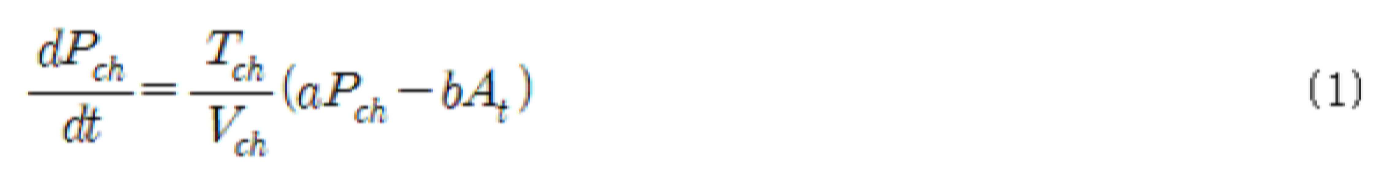
여기서, Tch, Vch, At, a, b는 각각 연소실 연소 가스 온도, 연소실 부피, 핀틀에 의해 조절된 노즐 출구 면적, 그리고 가스 특성과 관련된 상수들이다. 이 수식을 살펴보면 현재의 압력 조건에서 연소 압력 증가 속도(dPch/dt)는 연소 가스 온도(Tch)에 비례하고, 연소실 부피(Vch)에 반비례하며, 노즐 출구 면적(At)이 증가하면 감소하게 되는 특성을 보인다.Here, Tch, Vch, At, a, and b are constants related to the combustion chamber combustion gas temperature, the combustion chamber volume, the nozzle outlet area controlled by the pintle, and gas characteristics, respectively. Looking at this equation, the rate of increase in combustion pressure (dPch/dt) under the current pressure condition is proportional to the combustion gas temperature (Tch), inversely proportional to the combustion chamber volume (Vch), and decreases as the nozzle outlet area (At) increases. Show characteristics.
유사한 방법으로 공압 시험 장치의 내부 압력에 대한 응답속도를 수식으로 전개하면 식(2)과 같이 전개할 수 있다. In a similar way, the response speed to the internal pressure of the pneumatic test apparatus can be developed as an equation (2).

여기서, Pcc, Tcc, Vcc, ![]()
![]()
![]()
![]()
공압을 이용한 시험은 핀틀(14)을 이용하여 노즐(13) 출구의 면적(At)을 조절함으로서 연소실의 압력 조절 성능인 연소실 압력 증가 속도가 추진기관과 공압 시험 장치에서 유사한 응답을 갖도록 환경을 조성할 수 있다. 상기 압력 증가 속도인 시정수(Time constant)를 지배하는 요소를 온도가 다른 조건이라 하더라도, 이동 챔버(12)의 내부 공간의 크기를 조절함으로써 유사한 시정수가 될 수 있도록 다음과 같은 식을 이용한다.In the pneumatic test, by adjusting the area (At) of the outlet of the

따라서 공압 시험 장치와 연소 조건이 유사한 시정수를 갖도록 하기 위해서 조절해야 하는 이동 챔버(12)의 내부 공간의 크기(Vcc)는 다음과 같다.Therefore, the size (Vcc) of the internal space of the moving
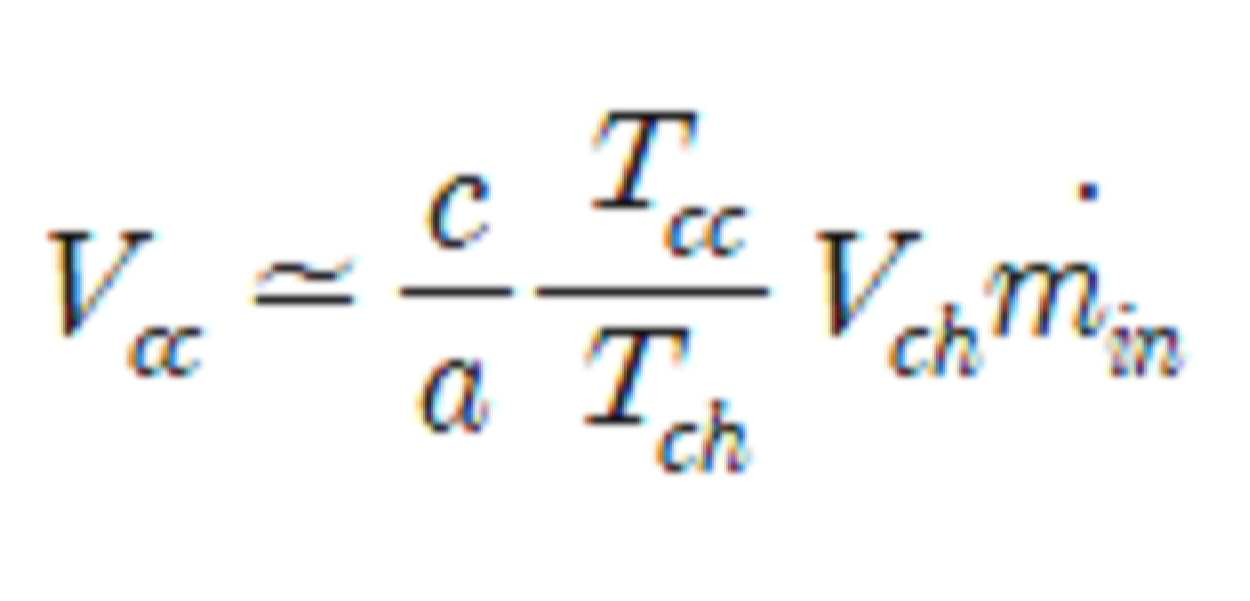
여기서, 공급해야 할 공기(![]()
![]()
제어부는 목표 연소 조건을 모사하기 위해, 연소실 연소 가스 온도의 반비례하고, 연소실 부피에 비례하도록, 선형 액츄에이터를 구동하여, 이동 챔버의 내부 공간의 부피를 조절할 수 있다. 예를 들어, 제어부는 목표 연소 조건 데이터를 입력 받을 수 있다. 예를 들어, 제어부는 목표 연소 조건 데이터는 외부 전자 기기로부터 실시간으로 입력 받거나, 공압 시험을 수행하기 전에 입력받을 수 있다.In order to simulate the target combustion condition, the control unit may control the volume of the internal space of the moving chamber by driving the linear actuator in inverse proportion to the combustion chamber combustion gas temperature and proportional to the combustion chamber volume. For example, the control unit may receive target combustion condition data. For example, the controller may receive target combustion condition data from an external electronic device in real time or before performing a pneumatic test.
목표 연소 조건 데이터는 시간에 따른 연소 공간 내 온도(Tch) 변화와, 시간에 따른 연소 공간 내 부피(Vch) 변화를 포함할 수 있다. 제어부는, 위 식에서와 같이, 목표 연소 조건 데이터의 온도에 반비례하고, 부피에 비례하도록 이동 챔버의 내부 공간의 크기를 조절함으로써, 목표 연소 조건과 공압 시험 장치에서의 시정수가 유사하게 형성되도록 제어할 수 있다.The target combustion condition data may include a change in temperature (Tch) in the combustion space over time and a change in volume (Vch) in the combustion space over time. As in the above equation, the control unit controls the target combustion condition and the time constant in the pneumatic test apparatus to form similarly by adjusting the size of the internal space of the moving chamber in inverse proportion to the temperature of the target combustion condition data and proportional to the volume. I can.
예를 들어, 목표 연소 조건에서 온도는 점차 증가할 수 있고, 부피는 고체 또는 액체 연료가 소모됨에 따라 증가할 수 있다. 제어부는 이러한 목표 연소 조건에서의 변화에 기초하여, 선형 액츄에이터를 제어하여, 이동 챔버 내 부피를 제어할 수 있다.For example, at target combustion conditions, the temperature may gradually increase, and the volume may increase as solid or liquid fuel is consumed. The control unit can control the volume in the moving chamber by controlling the linear actuator based on the change in the target combustion condition.
도 6은 도 4의 절개선 VI-VI을 따라 절개한 단면도이고, 도 7은 도 6에서 슬라이더가 이동된 모습을 도시하는 단면도이다6 is a cross-sectional view taken along the cut line VI-VI of FIG. 4, and FIG. 7 is a cross-sectional view showing a state in which the slider is moved in FIG. 6.
도 6 및 도 7을 참조하면, 슬라이더(143)가 이동함에 따라 노즐(13)의 출구 면적의 크기가 조절될 수 있다. 예를 들어, 도 7은 도 6에 비해 슬라이더(143)가 베이스로부터 멀어지는 방향으로 슬라이딩을 한 모습을 도시하는 도면이다. 도 7에서 노즐(13)의 출구 면적(A2)의 크기는, 도 6에서 노즐(13)의 출구 면적(A1)의 크기 보다 작을 수 있다.6 and 7, as the
이상과 같이 비록 한정된 도면에 의해 실시 예들이 설명되었으나, 해당 기술분야에서 통상의 지식을 가진 자라면 상기의 기재로부터 다양한 수정 및 변형이 가능하다. 예를 들어, 설명된 기술들이 설명된 방법과 다른 순서로 수행되거나, 및/또는 설명된 구조, 장치 등의 구성요소들이 설명된 방법과 다른 형태로 결합 또는 조합되거나, 다른 구성요소 또는 균등물에 의하여 대치되거나 치환되더라도 적절한 결과가 달성될 수 있다.As described above, although the embodiments have been described by the limited drawings, various modifications and variations are possible from the above description by those of ordinary skill in the art. For example, the described techniques are performed in a different order from the described method, and/or components such as the described structure, device, etc. are combined or combined in a form different from the described method, or in other components or equivalents. Even if substituted or substituted by, an appropriate result can be achieved.
Claims (20)
내부에 상기 공기 공급 포트로부터 유입되는 공기를 수용하기 위한 내부 공간을 구비하고, 상기 포트 지지부에 대해 상대적으로 이동 가능한 이동 챔버;
상기 이동 챔버의 단부에 형성되고, 상기 이동 챔버의 내부 공간을 외부로 연통하는 노즐;
상기 이동 챔버에 형성되고, 상기 노즐의 출구 면적을 조절 가능한 핀틀; 및
상기 이동 챔버의 내부 공간의 압력을 측정하는 압력 센서를 포함하는 가변형 모의 연소 공간을 갖는 공압 시험 장치.
Port support for supporting the air supply port;
A moving chamber having an inner space for receiving air introduced from the air supply port therein, and relatively movable with respect to the port support portion;
A nozzle formed at an end of the moving chamber and communicating the inner space of the moving chamber to the outside;
A pintle formed in the moving chamber and capable of adjusting an outlet area of the nozzle; And
A pneumatic testing apparatus having a variable simulated combustion space including a pressure sensor measuring the pressure in the inner space of the moving chamber.
상기 포트 지지부에 대해 상기 이동 챔버를 이동시키기 위한 선형 액츄에이터를 더 포함하는 가변형 모의 연소 공간을 갖는 공압 시험 장치.
The method of claim 1,
Pneumatic testing apparatus having a variable simulated combustion space further comprising a linear actuator for moving the moving chamber relative to the port support.
상기 압력 센서에서 측정된 압력 정보에 기초하여, 상기 선형 액츄에이터를 제어하는 제어부를 더 포함하는 가변형 모의 연소 공간을 갖는 공압 시험 장치.
The method of claim 2,
Based on the pressure information measured by the pressure sensor, the pneumatic test apparatus having a variable simulation combustion space further comprising a control unit for controlling the linear actuator.
상기 제어부는, 온도 및 부피 정보를 포함하는 목표 연소 조건 데이터를 입력 받고, 상기 목표 연소 조건의 시정수를 모의하도록, 상기 선형 액츄에이터를 제어하는 공압 시험 장치.
The method of claim 3,
The control unit receives target combustion condition data including temperature and volume information, and controls the linear actuator to simulate a time constant of the target combustion condition.
상기 제어부는, 상기 목표 연소 조건의 데이터의 온도에 반비례하고, 상기 목표 연소 조건 데이터의 부피에 비례하도록, 상기 선형 액츄에이터를 제어하는 공압 시험 장치.
The method of claim 4,
The control unit controls the linear actuator to be inversely proportional to the temperature of the target combustion condition data and proportional to the volume of the target combustion condition data.
상기 핀틀은,
상기 이동 챔버로부터 돌출 형성되는 지지 파트;
상기 지지 파트에 의해 지지되는 베이스; 및
상기 베이스에 대해 상대적으로 슬라이딩 가능한 슬라이더를 포함하는 가변형 모의 연소 공간을 갖는 공압 시험 장치.
The method of claim 1,
The pintle,
A support part protruding from the moving chamber;
A base supported by the support part; And
Pneumatic test apparatus having a variable simulated combustion space including a slider that is relatively slidable with respect to the base.
상기 압력 센서에서 측정된 압력 정보에 기초하여, 상기 슬라이더를 제어하는 제어부를 더 포함하는 가변형 모의 연소 공간을 갖는 공압 시험 장치.
The method of claim 6,
Based on the pressure information measured by the pressure sensor, the pneumatic test apparatus having a variable simulation combustion space further comprising a control unit for controlling the slider.
상기 포트 지지부의 외면과 상기 이동 챔버의 내면 사이에 구비되는 밀봉부를 더 포함하는 가변형 모의 연소 공간을 갖는 공압 시험 장치.
The method of claim 1,
A pneumatic testing apparatus having a variable simulated combustion space further comprising a sealing portion provided between an outer surface of the port support portion and an inner surface of the moving chamber.
상기 유량 조절부로부터 전달된 공기를 토출하는 공기 공급 포트; 및
상기 공기 공급 포트를 지지하는 포트 지지부와, 상기 포트 지지부에 대해 상대적으로 이동 가능한 이동 챔버와, 상기 이동 챔버의 내부 공간을 외부로 연통하는 노즐과, 상기 이동 챔버의 내부 공간의 압력을 측정하는 압력 센서를 포함하는, 가변형 모의 연소 공간을 갖는 공압 시험 장치;
를 포함하는 공압 시험 시스템.
Flow control unit for adjusting the flow rate of air;
An air supply port for discharging the air delivered from the flow rate control unit; And
A port support part supporting the air supply port, a movable chamber relatively movable with respect to the port support part, a nozzle communicating the inner space of the movable chamber to the outside, and a pressure measuring the pressure of the inner space of the movable chamber A pneumatic testing device having a variable simulated combustion space, including a sensor;
Pneumatic test system comprising a.
상기 공기 공급 포트는, 상기 이동 챔버가 상기 포트 지지부에 대해 상대적으로 이동하는 것과 무관하게, 상기 유량 조절부에 고정된 상태를 유지하는 공압 시험 시스템.
The method of claim 9,
The air supply port is a pneumatic test system that maintains a fixed state in the flow rate control unit, regardless of the movement chamber moving relative to the port support unit.
상기 유량 조절부와 상기 공기 공급 포트를 연통하는 연통 호스; 및
상기 이동 챔버를 둘러싸고, 상기 연통 호스를 고정시키는 하우징을 더 포함하는 공압 시험 시스템.
The method of claim 10,
A communication hose communicating the flow rate control unit and the air supply port; And
A pneumatic test system further comprising a housing surrounding the moving chamber and fixing the communication hose.
상기 하우징 내부의 압력은 조절 가능한 공압 시험 시스템.
The method of claim 11,
Pneumatic test system in which the pressure inside the housing is adjustable.
상기 가변형 모의 연소 공간을 갖는 공압 시험 장치는,
상기 이동 챔버에 구비되고, 상기 노즐의 출구 면적을 조절 가능한 핀틀을 더 포함하는 공압 시험 시스템.
The method of claim 9,
The pneumatic test apparatus having the variable simulated combustion space,
A pneumatic test system further comprising a pintle provided in the moving chamber and capable of adjusting an outlet area of the nozzle.
상기 가변형 모의 연소 공간을 갖는 공압 시험 장치는,
상기 포트 지지부에 대해 상기 이동 챔버를 이동시키는 선형 액츄에이터를 더 포함하는 공압 시험 시스템.
The method of claim 13,
The pneumatic test apparatus having the variable simulated combustion space,
A pneumatic test system further comprising a linear actuator to move the moving chamber relative to the port support.
상기 가변형 모의 연소 공간을 갖는 공압 시험 장치는,
온도 및 부피 정보를 포함하는 목표 연소 조건 데이터를 입력 받고, 상기 목표 연소 조건의 시정수를 모의하도록, 상기 선형 액츄에이터를 제어하는 제어부를 더 포함하는 공압 시험 시스템.
The method of claim 14,
The pneumatic test apparatus having the variable simulated combustion space,
A pneumatic test system further comprising a control unit for receiving target combustion condition data including temperature and volume information and controlling the linear actuator to simulate a time constant of the target combustion condition.
상기 제어부는, 상기 목표 연소 조건 데이터의 온도에 반비례하고 상기 목표 연소 조건 데이터의 부피에 비례하도록, 상기 선형 액츄에이터를 제어하는 공압 시험 시스템.
The method of claim 15,
The control unit controls the linear actuator to be inversely proportional to the temperature of the target combustion condition data and proportional to the volume of the target combustion condition data.
상기 가변형 모의 연소 공간을 갖는 공압 시험 장치는,
상기 유량 조절부, 선형 액츄에이터 및 핀틀을 제어하는 제어부를 더 포함하는 공압 시험 시스템.
The method of claim 14,
The pneumatic test apparatus having the variable simulated combustion space,
A pneumatic test system further comprising a control unit for controlling the flow rate control unit, the linear actuator and the pintle.
상기 제어부는, 상기 압력 센서에서 측정된 압력 정보에 기초하여, 상기 선형 액츄에이터를 제어하는 공압 시험 시스템.
The method of claim 17,
The control unit, based on the pressure information measured by the pressure sensor, a pneumatic test system for controlling the linear actuator.
상기 핀틀은,
상기 이동 챔버로부터 돌출 형성되는 지지 파트;
상기 지지 파트에 의해 지지되는 베이스; 및
상기 베이스에 대해 상대적으로 슬라이딩 가능한 슬라이더를 포함하는 공압 시험 시스템.
The method of claim 13,
The pintle,
A support part protruding from the moving chamber;
A base supported by the support part; And
A pneumatic test system comprising a slider that is slidable relative to the base.
상기 가변형 모의 연소 공간을 갖는 공압 시험 장치는,
상기 압력 센서에서 측정된 압력 정보에 기초하여, 상기 슬라이더를 제어하는 제어부를 더 포함하는 공압 시험 시스템.The method of claim 19,
The pneumatic test apparatus having the variable simulated combustion space,
Pneumatic test system further comprising a control unit for controlling the slider based on the pressure information measured by the pressure sensor.
Priority Applications (1)
| Application Number | Priority Date | Filing Date | Title |
|---|---|---|---|
| KR1020190087419A KR102178641B1 (en) | 2019-07-19 | 2019-07-19 | Pneumatic test apparatus for propulsion simulation having variable simulated combustor volume and pneumatic test system comprising the same |
Applications Claiming Priority (1)
| Application Number | Priority Date | Filing Date | Title |
|---|---|---|---|
| KR1020190087419A KR102178641B1 (en) | 2019-07-19 | 2019-07-19 | Pneumatic test apparatus for propulsion simulation having variable simulated combustor volume and pneumatic test system comprising the same |
Publications (1)
| Publication Number | Publication Date |
|---|---|
| KR102178641B1 true KR102178641B1 (en) | 2020-11-13 |
Family
ID=73399011
Family Applications (1)
| Application Number | Title | Priority Date | Filing Date |
|---|---|---|---|
| KR1020190087419A Active KR102178641B1 (en) | 2019-07-19 | 2019-07-19 | Pneumatic test apparatus for propulsion simulation having variable simulated combustor volume and pneumatic test system comprising the same |
Country Status (1)
| Country | Link |
|---|---|
| KR (1) | KR102178641B1 (en) |
Cited By (3)
| Publication number | Priority date | Publication date | Assignee | Title |
|---|---|---|---|---|
| CN113702058A (en) * | 2021-09-16 | 2021-11-26 | 成立航空股份有限公司 | Combustion test method for pressure reduction simulation of combustion chamber of gas turbine |
| KR20230151738A (en) * | 2022-04-26 | 2023-11-02 | 국방과학연구소 | Performance analysis method of pintle thrust apparatus |
| KR102721957B1 (en) | 2024-09-05 | 2024-10-25 | 국방과학연구소 | pneumatic testing device and method simulating a fuel-rich gas generator for flow control apparatus |
Citations (4)
| Publication number | Priority date | Publication date | Assignee | Title |
|---|---|---|---|---|
| JPH11294714A (en) * | 1998-04-13 | 1999-10-29 | Naotaka Ogawa | Method and device for pulse variable volume combustion |
| JP3016904B2 (en) * | 1991-05-31 | 2000-03-06 | 防衛庁技術研究本部長 | Gas flow controller for gas generator for ram rocket |
| JP2007046843A (en) * | 2005-08-10 | 2007-02-22 | Hitachi Ltd | Gas turbine combustor and gas turbine combustor remodeling method |
| KR100844800B1 (en) * | 2001-11-06 | 2008-07-07 | 주식회사 포스코 | Burner for Combustion Gas Combustion in Steel Mill |
-
2019
- 2019-07-19 KR KR1020190087419A patent/KR102178641B1/en active Active
Patent Citations (4)
| Publication number | Priority date | Publication date | Assignee | Title |
|---|---|---|---|---|
| JP3016904B2 (en) * | 1991-05-31 | 2000-03-06 | 防衛庁技術研究本部長 | Gas flow controller for gas generator for ram rocket |
| JPH11294714A (en) * | 1998-04-13 | 1999-10-29 | Naotaka Ogawa | Method and device for pulse variable volume combustion |
| KR100844800B1 (en) * | 2001-11-06 | 2008-07-07 | 주식회사 포스코 | Burner for Combustion Gas Combustion in Steel Mill |
| JP2007046843A (en) * | 2005-08-10 | 2007-02-22 | Hitachi Ltd | Gas turbine combustor and gas turbine combustor remodeling method |
Cited By (4)
| Publication number | Priority date | Publication date | Assignee | Title |
|---|---|---|---|---|
| CN113702058A (en) * | 2021-09-16 | 2021-11-26 | 成立航空股份有限公司 | Combustion test method for pressure reduction simulation of combustion chamber of gas turbine |
| KR20230151738A (en) * | 2022-04-26 | 2023-11-02 | 국방과학연구소 | Performance analysis method of pintle thrust apparatus |
| KR102785859B1 (en) | 2022-04-26 | 2025-03-25 | 국방과학연구소 | Performance analysis method of pintle thrust apparatus |
| KR102721957B1 (en) | 2024-09-05 | 2024-10-25 | 국방과학연구소 | pneumatic testing device and method simulating a fuel-rich gas generator for flow control apparatus |
Similar Documents
| Publication | Publication Date | Title |
|---|---|---|
| KR102178641B1 (en) | Pneumatic test apparatus for propulsion simulation having variable simulated combustor volume and pneumatic test system comprising the same | |
| JP3720804B2 (en) | CLEARANCE CONTROL METHOD AND DEVICE | |
| EP2150867B1 (en) | Gas mixing pump with variable injection section | |
| JP4585277B2 (en) | Method for controlling at least one actuator in a mass flow conduit | |
| GB2448793A (en) | Controlling operation of a compressor to avoid surge, flutter or stall conditions | |
| JP2022517663A (en) | Flow control methods, systems, and equipment | |
| KR101742030B1 (en) | Generic turbine test system | |
| US6623250B2 (en) | Fuel metering unit | |
| CN107636284A (en) | The operation of gaseous-fuel injector | |
| KR100925914B1 (en) | Turbocharger testing device | |
| CN110940477B (en) | A vibration table | |
| US20170051629A1 (en) | Actuator control | |
| KR20140127647A (en) | Operation Method of Virtual Wind Tunnel | |
| US6311553B1 (en) | Method and device for examining and/or adjusting valves | |
| WO2005101040A1 (en) | Micro thermal chamber having proximity control temperature management for devices under test | |
| KR900005052A (en) | Active Geometric Control System for Gas Turbine Engines | |
| CN111120079A (en) | Valve testing device and method | |
| KR102547447B1 (en) | Back pressure control apparatus for air vehicle intake and air vehicle having the same | |
| CN105201562A (en) | Active clearance control method and system | |
| JP2008241039A (en) | Actuator position controller using fail-freeze servo valve | |
| CN117545996A (en) | Adjusting device for test stand | |
| KR102238150B1 (en) | Performance testing apparatus for axial flow-type rotary fluid machinery | |
| JP2007509273A (en) | Fan with a laminar flow element in front of the suction port | |
| JPH01161116A (en) | Weight/flow rate measuring apparatus | |
| CN107490484B (en) | Plateau air inlet simulation device of engine |
Legal Events
| Date | Code | Title | Description |
|---|---|---|---|
| PA0109 | Patent application |
St.27 status event code: A-0-1-A10-A12-nap-PA0109 |
|
| PA0201 | Request for examination |
St.27 status event code: A-1-2-D10-D11-exm-PA0201 |
|
| D13-X000 | Search requested |
St.27 status event code: A-1-2-D10-D13-srh-X000 |
|
| D14-X000 | Search report completed |
St.27 status event code: A-1-2-D10-D14-srh-X000 |
|
| E902 | Notification of reason for refusal | ||
| PE0902 | Notice of grounds for rejection |
St.27 status event code: A-1-2-D10-D21-exm-PE0902 |
|
| P11-X000 | Amendment of application requested |
St.27 status event code: A-2-2-P10-P11-nap-X000 |
|
| P13-X000 | Application amended |
St.27 status event code: A-2-2-P10-P13-nap-X000 |
|
| E701 | Decision to grant or registration of patent right | ||
| PE0701 | Decision of registration |
St.27 status event code: A-1-2-D10-D22-exm-PE0701 |
|
| GRNT | Written decision to grant | ||
| PR0701 | Registration of establishment |
St.27 status event code: A-2-4-F10-F11-exm-PR0701 |
|
| PR1002 | Payment of registration fee |
St.27 status event code: A-2-2-U10-U11-oth-PR1002 Fee payment year number: 1 |
|
| PG1601 | Publication of registration |
St.27 status event code: A-4-4-Q10-Q13-nap-PG1601 |
|
| PR1001 | Payment of annual fee |
St.27 status event code: A-4-4-U10-U11-oth-PR1001 Fee payment year number: 4 |
|
| PR1001 | Payment of annual fee |
St.27 status event code: A-4-4-U10-U11-oth-PR1001 Fee payment year number: 5 |
|
| PR1001 | Payment of annual fee |
St.27 status event code: A-4-4-U10-U11-oth-PR1001 Fee payment year number: 6 |
|
| U11 | Full renewal or maintenance fee paid |
Free format text: ST27 STATUS EVENT CODE: A-4-4-U10-U11-OTH-PR1001 (AS PROVIDED BY THE NATIONAL OFFICE) Year of fee payment: 6 |