KR102175127B1 - Test kit and staining method using the same - Google Patents
Test kit and staining method using the same Download PDFInfo
- Publication number
- KR102175127B1 KR102175127B1 KR1020170087860A KR20170087860A KR102175127B1 KR 102175127 B1 KR102175127 B1 KR 102175127B1 KR 1020170087860 A KR1020170087860 A KR 1020170087860A KR 20170087860 A KR20170087860 A KR 20170087860A KR 102175127 B1 KR102175127 B1 KR 102175127B1
- Authority
- KR
- South Korea
- Prior art keywords
- specimen
- patch
- plate
- dyeing
- sample
- Prior art date
- Legal status (The legal status is an assumption and is not a legal conclusion. Google has not performed a legal analysis and makes no representation as to the accuracy of the status listed.)
- Active
Links
Images


Classifications
-
- G—PHYSICS
- G01—MEASURING; TESTING
- G01N—INVESTIGATING OR ANALYSING MATERIALS BY DETERMINING THEIR CHEMICAL OR PHYSICAL PROPERTIES
- G01N1/00—Sampling; Preparing specimens for investigation
- G01N1/28—Preparing specimens for investigation including physical details of (bio-)chemical methods covered elsewhere, e.g. G01N33/50, C12Q
- G01N1/30—Staining; Impregnating ; Fixation; Dehydration; Multistep processes for preparing samples of tissue, cell or nucleic acid material and the like for analysis
- G01N1/31—Apparatus therefor
- G01N1/312—Apparatus therefor for samples mounted on planar substrates
-
- C—CHEMISTRY; METALLURGY
- C12—BIOCHEMISTRY; BEER; SPIRITS; WINE; VINEGAR; MICROBIOLOGY; ENZYMOLOGY; MUTATION OR GENETIC ENGINEERING
- C12Q—MEASURING OR TESTING PROCESSES INVOLVING ENZYMES, NUCLEIC ACIDS OR MICROORGANISMS; COMPOSITIONS OR TEST PAPERS THEREFOR; PROCESSES OF PREPARING SUCH COMPOSITIONS; CONDITION-RESPONSIVE CONTROL IN MICROBIOLOGICAL OR ENZYMOLOGICAL PROCESSES
- C12Q1/00—Measuring or testing processes involving enzymes, nucleic acids or microorganisms; Compositions therefor; Processes of preparing such compositions
- C12Q1/02—Measuring or testing processes involving enzymes, nucleic acids or microorganisms; Compositions therefor; Processes of preparing such compositions involving viable microorganisms
- C12Q1/025—Measuring or testing processes involving enzymes, nucleic acids or microorganisms; Compositions therefor; Processes of preparing such compositions involving viable microorganisms for testing or evaluating the effect of chemical or biological compounds, e.g. drugs, cosmetics
-
- B—PERFORMING OPERATIONS; TRANSPORTING
- B01—PHYSICAL OR CHEMICAL PROCESSES OR APPARATUS IN GENERAL
- B01F—MIXING, e.g. DISSOLVING, EMULSIFYING OR DISPERSING
- B01F33/00—Other mixers; Mixing plants; Combinations of mixers
- B01F33/30—Micromixers
- B01F33/3039—Micromixers with mixing achieved by diffusion between layers
-
- B—PERFORMING OPERATIONS; TRANSPORTING
- B01—PHYSICAL OR CHEMICAL PROCESSES OR APPARATUS IN GENERAL
- B01L—CHEMICAL OR PHYSICAL LABORATORY APPARATUS FOR GENERAL USE
- B01L3/00—Containers or dishes for laboratory use, e.g. laboratory glassware; Droppers
-
- C—CHEMISTRY; METALLURGY
- C07—ORGANIC CHEMISTRY
- C07K—PEPTIDES
- C07K16/00—Immunoglobulins [IGs], e.g. monoclonal or polyclonal antibodies
- C07K16/18—Immunoglobulins [IGs], e.g. monoclonal or polyclonal antibodies against material from animals or humans
- C07K16/28—Immunoglobulins [IGs], e.g. monoclonal or polyclonal antibodies against material from animals or humans against receptors, cell surface antigens or cell surface determinants
- C07K16/30—Immunoglobulins [IGs], e.g. monoclonal or polyclonal antibodies against material from animals or humans against receptors, cell surface antigens or cell surface determinants from tumour cells
- C07K16/3061—Blood cells
-
- C—CHEMISTRY; METALLURGY
- C12—BIOCHEMISTRY; BEER; SPIRITS; WINE; VINEGAR; MICROBIOLOGY; ENZYMOLOGY; MUTATION OR GENETIC ENGINEERING
- C12Q—MEASURING OR TESTING PROCESSES INVOLVING ENZYMES, NUCLEIC ACIDS OR MICROORGANISMS; COMPOSITIONS OR TEST PAPERS THEREFOR; PROCESSES OF PREPARING SUCH COMPOSITIONS; CONDITION-RESPONSIVE CONTROL IN MICROBIOLOGICAL OR ENZYMOLOGICAL PROCESSES
- C12Q1/00—Measuring or testing processes involving enzymes, nucleic acids or microorganisms; Compositions therefor; Processes of preparing such compositions
- C12Q1/68—Measuring or testing processes involving enzymes, nucleic acids or microorganisms; Compositions therefor; Processes of preparing such compositions involving nucleic acids
- C12Q1/6844—Nucleic acid amplification reactions
- C12Q1/6848—Nucleic acid amplification reactions characterised by the means for preventing contamination or increasing the specificity or sensitivity of an amplification reaction
-
- C—CHEMISTRY; METALLURGY
- C12—BIOCHEMISTRY; BEER; SPIRITS; WINE; VINEGAR; MICROBIOLOGY; ENZYMOLOGY; MUTATION OR GENETIC ENGINEERING
- C12Q—MEASURING OR TESTING PROCESSES INVOLVING ENZYMES, NUCLEIC ACIDS OR MICROORGANISMS; COMPOSITIONS OR TEST PAPERS THEREFOR; PROCESSES OF PREPARING SUCH COMPOSITIONS; CONDITION-RESPONSIVE CONTROL IN MICROBIOLOGICAL OR ENZYMOLOGICAL PROCESSES
- C12Q1/00—Measuring or testing processes involving enzymes, nucleic acids or microorganisms; Compositions therefor; Processes of preparing such compositions
- C12Q1/68—Measuring or testing processes involving enzymes, nucleic acids or microorganisms; Compositions therefor; Processes of preparing such compositions involving nucleic acids
- C12Q1/6844—Nucleic acid amplification reactions
- C12Q1/686—Polymerase chain reaction [PCR]
-
- C—CHEMISTRY; METALLURGY
- C12—BIOCHEMISTRY; BEER; SPIRITS; WINE; VINEGAR; MICROBIOLOGY; ENZYMOLOGY; MUTATION OR GENETIC ENGINEERING
- C12Q—MEASURING OR TESTING PROCESSES INVOLVING ENZYMES, NUCLEIC ACIDS OR MICROORGANISMS; COMPOSITIONS OR TEST PAPERS THEREFOR; PROCESSES OF PREPARING SUCH COMPOSITIONS; CONDITION-RESPONSIVE CONTROL IN MICROBIOLOGICAL OR ENZYMOLOGICAL PROCESSES
- C12Q1/00—Measuring or testing processes involving enzymes, nucleic acids or microorganisms; Compositions therefor; Processes of preparing such compositions
- C12Q1/70—Measuring or testing processes involving enzymes, nucleic acids or microorganisms; Compositions therefor; Processes of preparing such compositions involving virus or bacteriophage
- C12Q1/701—Specific hybridization probes
-
- G—PHYSICS
- G01—MEASURING; TESTING
- G01N—INVESTIGATING OR ANALYSING MATERIALS BY DETERMINING THEIR CHEMICAL OR PHYSICAL PROPERTIES
- G01N1/00—Sampling; Preparing specimens for investigation
- G01N1/02—Devices for withdrawing samples
- G01N1/10—Devices for withdrawing samples in the liquid or fluent state
- G01N1/14—Suction devices, e.g. pumps; Ejector devices
-
- G—PHYSICS
- G01—MEASURING; TESTING
- G01N—INVESTIGATING OR ANALYSING MATERIALS BY DETERMINING THEIR CHEMICAL OR PHYSICAL PROPERTIES
- G01N1/00—Sampling; Preparing specimens for investigation
- G01N1/28—Preparing specimens for investigation including physical details of (bio-)chemical methods covered elsewhere, e.g. G01N33/50, C12Q
- G01N1/2813—Producing thin layers of samples on a substrate, e.g. smearing, spinning-on
-
- G—PHYSICS
- G01—MEASURING; TESTING
- G01N—INVESTIGATING OR ANALYSING MATERIALS BY DETERMINING THEIR CHEMICAL OR PHYSICAL PROPERTIES
- G01N1/00—Sampling; Preparing specimens for investigation
- G01N1/28—Preparing specimens for investigation including physical details of (bio-)chemical methods covered elsewhere, e.g. G01N33/50, C12Q
- G01N1/30—Staining; Impregnating ; Fixation; Dehydration; Multistep processes for preparing samples of tissue, cell or nucleic acid material and the like for analysis
- G01N1/31—Apparatus therefor
-
- G—PHYSICS
- G01—MEASURING; TESTING
- G01N—INVESTIGATING OR ANALYSING MATERIALS BY DETERMINING THEIR CHEMICAL OR PHYSICAL PROPERTIES
- G01N15/00—Investigating characteristics of particles; Investigating permeability, pore-volume or surface-area of porous materials
- G01N15/06—Investigating concentration of particle suspensions
-
- G—PHYSICS
- G01—MEASURING; TESTING
- G01N—INVESTIGATING OR ANALYSING MATERIALS BY DETERMINING THEIR CHEMICAL OR PHYSICAL PROPERTIES
- G01N15/00—Investigating characteristics of particles; Investigating permeability, pore-volume or surface-area of porous materials
- G01N15/10—Investigating individual particles
- G01N15/14—Optical investigation techniques, e.g. flow cytometry
- G01N15/1429—Signal processing
- G01N15/1433—Signal processing using image recognition
-
- G—PHYSICS
- G01—MEASURING; TESTING
- G01N—INVESTIGATING OR ANALYSING MATERIALS BY DETERMINING THEIR CHEMICAL OR PHYSICAL PROPERTIES
- G01N21/00—Investigating or analysing materials by the use of optical means, i.e. using sub-millimetre waves, infrared, visible or ultraviolet light
- G01N21/75—Systems in which material is subjected to a chemical reaction, the progress or the result of the reaction being investigated
- G01N21/77—Systems in which material is subjected to a chemical reaction, the progress or the result of the reaction being investigated by observing the effect on a chemical indicator
- G01N21/7703—Systems in which material is subjected to a chemical reaction, the progress or the result of the reaction being investigated by observing the effect on a chemical indicator using reagent-clad optical fibres or optical waveguides
-
- G—PHYSICS
- G01—MEASURING; TESTING
- G01N—INVESTIGATING OR ANALYSING MATERIALS BY DETERMINING THEIR CHEMICAL OR PHYSICAL PROPERTIES
- G01N21/00—Investigating or analysing materials by the use of optical means, i.e. using sub-millimetre waves, infrared, visible or ultraviolet light
- G01N21/75—Systems in which material is subjected to a chemical reaction, the progress or the result of the reaction being investigated
- G01N21/77—Systems in which material is subjected to a chemical reaction, the progress or the result of the reaction being investigated by observing the effect on a chemical indicator
- G01N21/78—Systems in which material is subjected to a chemical reaction, the progress or the result of the reaction being investigated by observing the effect on a chemical indicator producing a change of colour
-
- G—PHYSICS
- G01—MEASURING; TESTING
- G01N—INVESTIGATING OR ANALYSING MATERIALS BY DETERMINING THEIR CHEMICAL OR PHYSICAL PROPERTIES
- G01N21/00—Investigating or analysing materials by the use of optical means, i.e. using sub-millimetre waves, infrared, visible or ultraviolet light
- G01N21/84—Systems specially adapted for particular applications
-
- G—PHYSICS
- G01—MEASURING; TESTING
- G01N—INVESTIGATING OR ANALYSING MATERIALS BY DETERMINING THEIR CHEMICAL OR PHYSICAL PROPERTIES
- G01N33/00—Investigating or analysing materials by specific methods not covered by groups G01N1/00 - G01N31/00
- G01N33/48—Biological material, e.g. blood, urine; Haemocytometers
- G01N33/483—Physical analysis of biological material
- G01N33/4833—Physical analysis of biological material of solid biological material, e.g. tissue samples, cell cultures
-
- G—PHYSICS
- G01—MEASURING; TESTING
- G01N—INVESTIGATING OR ANALYSING MATERIALS BY DETERMINING THEIR CHEMICAL OR PHYSICAL PROPERTIES
- G01N33/00—Investigating or analysing materials by specific methods not covered by groups G01N1/00 - G01N31/00
- G01N33/48—Biological material, e.g. blood, urine; Haemocytometers
- G01N33/483—Physical analysis of biological material
- G01N33/487—Physical analysis of biological material of liquid biological material
- G01N33/4875—Details of handling test elements, e.g. dispensing or storage, not specific to a particular test method
- G01N33/48778—Containers specially adapted therefor, e.g. for dry storage
-
- G—PHYSICS
- G01—MEASURING; TESTING
- G01N—INVESTIGATING OR ANALYSING MATERIALS BY DETERMINING THEIR CHEMICAL OR PHYSICAL PROPERTIES
- G01N33/00—Investigating or analysing materials by specific methods not covered by groups G01N1/00 - G01N31/00
- G01N33/48—Biological material, e.g. blood, urine; Haemocytometers
- G01N33/483—Physical analysis of biological material
- G01N33/487—Physical analysis of biological material of liquid biological material
- G01N33/48785—Electrical and electronic details of measuring devices for physical analysis of liquid biological material not specific to a particular test method, e.g. user interface or power supply
- G01N33/48792—Data management, e.g. communication with processing unit
-
- G—PHYSICS
- G01—MEASURING; TESTING
- G01N—INVESTIGATING OR ANALYSING MATERIALS BY DETERMINING THEIR CHEMICAL OR PHYSICAL PROPERTIES
- G01N33/00—Investigating or analysing materials by specific methods not covered by groups G01N1/00 - G01N31/00
- G01N33/48—Biological material, e.g. blood, urine; Haemocytometers
- G01N33/483—Physical analysis of biological material
- G01N33/487—Physical analysis of biological material of liquid biological material
- G01N33/49—Blood
-
- G—PHYSICS
- G01—MEASURING; TESTING
- G01N—INVESTIGATING OR ANALYSING MATERIALS BY DETERMINING THEIR CHEMICAL OR PHYSICAL PROPERTIES
- G01N33/00—Investigating or analysing materials by specific methods not covered by groups G01N1/00 - G01N31/00
- G01N33/48—Biological material, e.g. blood, urine; Haemocytometers
- G01N33/50—Chemical analysis of biological material, e.g. blood, urine; Testing involving biospecific ligand binding methods; Immunological testing
- G01N33/5005—Chemical analysis of biological material, e.g. blood, urine; Testing involving biospecific ligand binding methods; Immunological testing involving human or animal cells
- G01N33/5008—Chemical analysis of biological material, e.g. blood, urine; Testing involving biospecific ligand binding methods; Immunological testing involving human or animal cells for testing or evaluating the effect of chemical or biological compounds, e.g. drugs, cosmetics
- G01N33/5082—Supracellular entities, e.g. tissue, organisms
-
- G—PHYSICS
- G01—MEASURING; TESTING
- G01N—INVESTIGATING OR ANALYSING MATERIALS BY DETERMINING THEIR CHEMICAL OR PHYSICAL PROPERTIES
- G01N33/00—Investigating or analysing materials by specific methods not covered by groups G01N1/00 - G01N31/00
- G01N33/48—Biological material, e.g. blood, urine; Haemocytometers
- G01N33/50—Chemical analysis of biological material, e.g. blood, urine; Testing involving biospecific ligand binding methods; Immunological testing
- G01N33/52—Use of compounds or compositions for colorimetric, spectrophotometric or fluorometric investigation, e.g. use of reagent paper and including single- and multilayer analytical elements
-
- G—PHYSICS
- G01—MEASURING; TESTING
- G01N—INVESTIGATING OR ANALYSING MATERIALS BY DETERMINING THEIR CHEMICAL OR PHYSICAL PROPERTIES
- G01N33/00—Investigating or analysing materials by specific methods not covered by groups G01N1/00 - G01N31/00
- G01N33/48—Biological material, e.g. blood, urine; Haemocytometers
- G01N33/50—Chemical analysis of biological material, e.g. blood, urine; Testing involving biospecific ligand binding methods; Immunological testing
- G01N33/53—Immunoassay; Biospecific binding assay; Materials therefor
- G01N33/5302—Apparatus specially adapted for immunological test procedures
- G01N33/5304—Reaction vessels, e.g. agglutination plates
-
- G—PHYSICS
- G01—MEASURING; TESTING
- G01N—INVESTIGATING OR ANALYSING MATERIALS BY DETERMINING THEIR CHEMICAL OR PHYSICAL PROPERTIES
- G01N33/00—Investigating or analysing materials by specific methods not covered by groups G01N1/00 - G01N31/00
- G01N33/48—Biological material, e.g. blood, urine; Haemocytometers
- G01N33/50—Chemical analysis of biological material, e.g. blood, urine; Testing involving biospecific ligand binding methods; Immunological testing
- G01N33/53—Immunoassay; Biospecific binding assay; Materials therefor
- G01N33/531—Production of immunochemical test materials
- G01N33/532—Production of labelled immunochemicals
- G01N33/533—Production of labelled immunochemicals with fluorescent label
-
- G01N33/575—
-
- G—PHYSICS
- G01—MEASURING; TESTING
- G01N—INVESTIGATING OR ANALYSING MATERIALS BY DETERMINING THEIR CHEMICAL OR PHYSICAL PROPERTIES
- G01N33/00—Investigating or analysing materials by specific methods not covered by groups G01N1/00 - G01N31/00
- G01N33/48—Biological material, e.g. blood, urine; Haemocytometers
- G01N33/50—Chemical analysis of biological material, e.g. blood, urine; Testing involving biospecific ligand binding methods; Immunological testing
- G01N33/58—Chemical analysis of biological material, e.g. blood, urine; Testing involving biospecific ligand binding methods; Immunological testing involving labelled substances
- G01N33/60—Chemical analysis of biological material, e.g. blood, urine; Testing involving biospecific ligand binding methods; Immunological testing involving labelled substances involving radioactive labelled substances
-
- G—PHYSICS
- G01—MEASURING; TESTING
- G01N—INVESTIGATING OR ANALYSING MATERIALS BY DETERMINING THEIR CHEMICAL OR PHYSICAL PROPERTIES
- G01N35/00—Automatic analysis not limited to methods or materials provided for in any single one of groups G01N1/00 - G01N33/00; Handling materials therefor
- G01N35/00029—Automatic analysis not limited to methods or materials provided for in any single one of groups G01N1/00 - G01N33/00; Handling materials therefor provided with flat sample substrates, e.g. slides
-
- G—PHYSICS
- G06—COMPUTING OR CALCULATING; COUNTING
- G06T—IMAGE DATA PROCESSING OR GENERATION, IN GENERAL
- G06T7/00—Image analysis
- G06T7/0002—Inspection of images, e.g. flaw detection
- G06T7/0012—Biomedical image inspection
-
- G—PHYSICS
- G06—COMPUTING OR CALCULATING; COUNTING
- G06T—IMAGE DATA PROCESSING OR GENERATION, IN GENERAL
- G06T7/00—Image analysis
- G06T7/0002—Inspection of images, e.g. flaw detection
- G06T7/0012—Biomedical image inspection
- G06T7/0014—Biomedical image inspection using an image reference approach
-
- B—PERFORMING OPERATIONS; TRANSPORTING
- B01—PHYSICAL OR CHEMICAL PROCESSES OR APPARATUS IN GENERAL
- B01L—CHEMICAL OR PHYSICAL LABORATORY APPARATUS FOR GENERAL USE
- B01L3/00—Containers or dishes for laboratory use, e.g. laboratory glassware; Droppers
- B01L3/50—Containers for the purpose of retaining a material to be analysed, e.g. test tubes
- B01L3/505—Containers for the purpose of retaining a material to be analysed, e.g. test tubes flexible containers not provided for above
-
- B—PERFORMING OPERATIONS; TRANSPORTING
- B01—PHYSICAL OR CHEMICAL PROCESSES OR APPARATUS IN GENERAL
- B01L—CHEMICAL OR PHYSICAL LABORATORY APPARATUS FOR GENERAL USE
- B01L7/00—Heating or cooling apparatus; Heat insulating devices
- B01L7/52—Heating or cooling apparatus; Heat insulating devices with provision for submitting samples to a predetermined sequence of different temperatures, e.g. for treating nucleic acid samples
-
- C—CHEMISTRY; METALLURGY
- C12—BIOCHEMISTRY; BEER; SPIRITS; WINE; VINEGAR; MICROBIOLOGY; ENZYMOLOGY; MUTATION OR GENETIC ENGINEERING
- C12N—MICROORGANISMS OR ENZYMES; COMPOSITIONS THEREOF; PROPAGATING, PRESERVING, OR MAINTAINING MICROORGANISMS; MUTATION OR GENETIC ENGINEERING; CULTURE MEDIA
- C12N2503/00—Use of cells in diagnostics
- C12N2503/02—Drug screening
-
- G—PHYSICS
- G01—MEASURING; TESTING
- G01N—INVESTIGATING OR ANALYSING MATERIALS BY DETERMINING THEIR CHEMICAL OR PHYSICAL PROPERTIES
- G01N15/00—Investigating characteristics of particles; Investigating permeability, pore-volume or surface-area of porous materials
- G01N15/01—Investigating characteristics of particles; Investigating permeability, pore-volume or surface-area of porous materials specially adapted for biological cells, e.g. blood cells
-
- G—PHYSICS
- G01—MEASURING; TESTING
- G01N—INVESTIGATING OR ANALYSING MATERIALS BY DETERMINING THEIR CHEMICAL OR PHYSICAL PROPERTIES
- G01N15/00—Investigating characteristics of particles; Investigating permeability, pore-volume or surface-area of porous materials
- G01N15/06—Investigating concentration of particle suspensions
- G01N15/075—Investigating concentration of particle suspensions by optical means
-
- G—PHYSICS
- G01—MEASURING; TESTING
- G01N—INVESTIGATING OR ANALYSING MATERIALS BY DETERMINING THEIR CHEMICAL OR PHYSICAL PROPERTIES
- G01N1/00—Sampling; Preparing specimens for investigation
- G01N1/02—Devices for withdrawing samples
- G01N1/10—Devices for withdrawing samples in the liquid or fluent state
- G01N1/14—Suction devices, e.g. pumps; Ejector devices
- G01N2001/1472—Devices not actuated by pressure difference
- G01N2001/149—Capillaries; Sponges
-
- G—PHYSICS
- G01—MEASURING; TESTING
- G01N—INVESTIGATING OR ANALYSING MATERIALS BY DETERMINING THEIR CHEMICAL OR PHYSICAL PROPERTIES
- G01N1/00—Sampling; Preparing specimens for investigation
- G01N1/28—Preparing specimens for investigation including physical details of (bio-)chemical methods covered elsewhere, e.g. G01N33/50, C12Q
- G01N1/30—Staining; Impregnating ; Fixation; Dehydration; Multistep processes for preparing samples of tissue, cell or nucleic acid material and the like for analysis
- G01N2001/302—Stain compositions
-
- G—PHYSICS
- G01—MEASURING; TESTING
- G01N—INVESTIGATING OR ANALYSING MATERIALS BY DETERMINING THEIR CHEMICAL OR PHYSICAL PROPERTIES
- G01N21/00—Investigating or analysing materials by the use of optical means, i.e. using sub-millimetre waves, infrared, visible or ultraviolet light
- G01N21/75—Systems in which material is subjected to a chemical reaction, the progress or the result of the reaction being investigated
- G01N21/77—Systems in which material is subjected to a chemical reaction, the progress or the result of the reaction being investigated by observing the effect on a chemical indicator
- G01N21/7703—Systems in which material is subjected to a chemical reaction, the progress or the result of the reaction being investigated by observing the effect on a chemical indicator using reagent-clad optical fibres or optical waveguides
- G01N2021/7706—Reagent provision
- G01N2021/7723—Swelling part, also for adsorption sensor, i.e. without chemical reaction
-
- G—PHYSICS
- G01—MEASURING; TESTING
- G01N—INVESTIGATING OR ANALYSING MATERIALS BY DETERMINING THEIR CHEMICAL OR PHYSICAL PROPERTIES
- G01N21/00—Investigating or analysing materials by the use of optical means, i.e. using sub-millimetre waves, infrared, visible or ultraviolet light
- G01N21/75—Systems in which material is subjected to a chemical reaction, the progress or the result of the reaction being investigated
- G01N21/77—Systems in which material is subjected to a chemical reaction, the progress or the result of the reaction being investigated by observing the effect on a chemical indicator
- G01N2021/7769—Measurement method of reaction-produced change in sensor
- G01N2021/7786—Fluorescence
-
- G—PHYSICS
- G01—MEASURING; TESTING
- G01N—INVESTIGATING OR ANALYSING MATERIALS BY DETERMINING THEIR CHEMICAL OR PHYSICAL PROPERTIES
- G01N35/00—Automatic analysis not limited to methods or materials provided for in any single one of groups G01N1/00 - G01N33/00; Handling materials therefor
- G01N35/00029—Automatic analysis not limited to methods or materials provided for in any single one of groups G01N1/00 - G01N33/00; Handling materials therefor provided with flat sample substrates, e.g. slides
- G01N2035/00039—Transport arrangements specific to flat sample substrates, e.g. pusher blade
-
- G—PHYSICS
- G01—MEASURING; TESTING
- G01N—INVESTIGATING OR ANALYSING MATERIALS BY DETERMINING THEIR CHEMICAL OR PHYSICAL PROPERTIES
- G01N2500/00—Screening for compounds of potential therapeutic value
- G01N2500/10—Screening for compounds of potential therapeutic value involving cells
-
- Y—GENERAL TAGGING OF NEW TECHNOLOGICAL DEVELOPMENTS; GENERAL TAGGING OF CROSS-SECTIONAL TECHNOLOGIES SPANNING OVER SEVERAL SECTIONS OF THE IPC; TECHNICAL SUBJECTS COVERED BY FORMER USPC CROSS-REFERENCE ART COLLECTIONS [XRACs] AND DIGESTS
- Y02—TECHNOLOGIES OR APPLICATIONS FOR MITIGATION OR ADAPTATION AGAINST CLIMATE CHANGE
- Y02A—TECHNOLOGIES FOR ADAPTATION TO CLIMATE CHANGE
- Y02A50/00—TECHNOLOGIES FOR ADAPTATION TO CLIMATE CHANGE in human health protection, e.g. against extreme weather
- Y02A50/30—Against vector-borne diseases, e.g. mosquito-borne, fly-borne, tick-borne or waterborne diseases whose impact is exacerbated by climate change
-
- Y—GENERAL TAGGING OF NEW TECHNOLOGICAL DEVELOPMENTS; GENERAL TAGGING OF CROSS-SECTIONAL TECHNOLOGIES SPANNING OVER SEVERAL SECTIONS OF THE IPC; TECHNICAL SUBJECTS COVERED BY FORMER USPC CROSS-REFERENCE ART COLLECTIONS [XRACs] AND DIGESTS
- Y02—TECHNOLOGIES OR APPLICATIONS FOR MITIGATION OR ADAPTATION AGAINST CLIMATE CHANGE
- Y02P—CLIMATE CHANGE MITIGATION TECHNOLOGIES IN THE PRODUCTION OR PROCESSING OF GOODS
- Y02P20/00—Technologies relating to chemical industry
- Y02P20/50—Improvements relating to the production of bulk chemicals
- Y02P20/582—Recycling of unreacted starting or intermediate materials
Landscapes
- Health & Medical Sciences (AREA)
- Life Sciences & Earth Sciences (AREA)
- Engineering & Computer Science (AREA)
- Chemical & Material Sciences (AREA)
- Immunology (AREA)
- Physics & Mathematics (AREA)
- Biomedical Technology (AREA)
- General Health & Medical Sciences (AREA)
- Biochemistry (AREA)
- Analytical Chemistry (AREA)
- Molecular Biology (AREA)
- General Physics & Mathematics (AREA)
- Pathology (AREA)
- Hematology (AREA)
- Urology & Nephrology (AREA)
- Organic Chemistry (AREA)
- Medicinal Chemistry (AREA)
- Biophysics (AREA)
- Food Science & Technology (AREA)
- Microbiology (AREA)
- Biotechnology (AREA)
- Proteomics, Peptides & Aminoacids (AREA)
- Wood Science & Technology (AREA)
- Zoology (AREA)
- Chemical Kinetics & Catalysis (AREA)
- Cell Biology (AREA)
- Bioinformatics & Cheminformatics (AREA)
- Genetics & Genomics (AREA)
- General Engineering & Computer Science (AREA)
- Medical Informatics (AREA)
- Dispersion Chemistry (AREA)
- Optics & Photonics (AREA)
- Computer Vision & Pattern Recognition (AREA)
- Nuclear Medicine, Radiotherapy & Molecular Imaging (AREA)
- Radiology & Medical Imaging (AREA)
- Quality & Reliability (AREA)
- Theoretical Computer Science (AREA)
- Toxicology (AREA)
- Ecology (AREA)
- Plasma & Fusion (AREA)
Abstract
본 발명은 테스트 키트 및 이를 이용하는 염색 방법에 관한 것으로, 본 발명의 일 양상에 따른 테스트 키트는 검체를 염색시키는 염색 시료를 보관하는 포어를 형성하는 그물 구조의 겔 상으로 제공되고, 상기 검체와 접촉하여 상기 염색 시료로 상기 검체를 염색하는 접촉식 염색 패치를 이용하여 염색을 수행하는 염색용 테스트 키트로, 외부에서 투입되는 검체가 놓이는 제1 플레이트; 상기 접촉식 염색 패치를 수납하고, 상기 제1 플레이트에 상대 이동하도록 마주보며 설치되고, 상기 상대 이동에 의해 상기 제1 플레이트 상에 놓인 검체를 도말하고, 상기 상대 이동에 의해 상기 접촉식 염색 패치와 상기 도말된 검체 간의 접촉 또는 접촉 준비를 수행하는 제2 플레이트;를 포함한다.The present invention relates to a test kit and a dyeing method using the same, and the test kit according to an aspect of the present invention is provided in the form of a gel having a net structure that forms pores for storing a dyed sample for dyeing a sample, and is in contact with the sample. As a dyeing test kit for performing dyeing using a contact dyeing patch for dyeing the sample with the dyed sample, a first plate on which a sample input from the outside is placed; The contact dyeing patch is accommodated, installed facing the first plate so as to move relative to each other, and smears a specimen placed on the first plate by the relative movement, and the contact dyeing patch and And a second plate for contacting or preparing for contact between the smeared specimens.
Description
본 발명은 테스트 키트 및 이를 이용하는 염색 방법에 관한 것으로, 보다 상세하게는 검체와 접촉하여 검체를 염색시키는 접촉식 염색 패치를 수납하는 테스트 키트 및 이를 이용하는 염색 방법에 관한 것이다.The present invention relates to a test kit and a dyeing method using the same, and more particularly, to a test kit for accommodating a contact dyeing patch for dyeing the sample by contacting the sample, and a dyeing method using the same.
혈액 도말 검사는 혈액을 도말하여 염색한 후 현미경으로 혈구 세포들의 형태를 관찰하는 검사 방법이다. 혈액 도말 검사는 주로 말라리아 등의 기생충 질환의 감염, 백혈병을 포함한 혈액 종양이나 선천성 혈구형태 이상 등의 검사에 이용되고 있다. A blood smear test is a test method in which blood is smeared and stained, and then the shape of blood cells is observed under a microscope. Blood smears are mainly used for infections of parasitic diseases such as malaria, blood tumors including leukemia, and congenital blood cell morphology abnormalities.
말라리아 등의 기생충 질환의 검사에는 대개 신속 진단법(RDT: Rapid Diagnostic Test)과 혈액 도말 검사법이 이용된다. RDT의 경우는 비교적 저비용의 진단 키트를 이용하여 간편하고 신속한 검사가 이루어지는 장점이 있으나 그 검사 결과가 다소 부정확한 문제점이 있다. 따라서, 최근에는 보다 정확한 검사를 하기 위하여 혈액 도말 검사법이 권장되고 있다.A rapid diagnostic test (RDT) and a blood smear are usually used to test for parasitic diseases such as malaria. In the case of RDT, a simple and quick test is performed using a relatively low-cost diagnostic kit, but the test result is somewhat inaccurate. Therefore, in recent years, a blood smear test method has been recommended for a more accurate test.
혈액 도말 검사는 환자의 혈액을 슬라이드에 주입하여 이를 도말하여 염색한 뒤, 염색된 혈액을 현미경으로 관찰하여 질환을 검사하는 방법이다. 종래의 혈액 도말 검사에서는 혈액의 도말이나 염색, 현미경 관찰의 프로세스가 검사자의 수작업에 의존하고 있어, 숙련된 검사자가 아닌 경우 혈액의 도말 상태가 불균일하게 되거나 염색 과정에서 반응 조건의 오차로 인해 오염색되는 등에 따라 원활히 검사를 하기 어려운 문제점이 있으며, 이에 따라 아프리카 등과 같이 의료 인력이 부족한 저개발 국가에서는 실질적으로 질환의 검사에 혈액 도말 검사를 운용하기 어려운 실정이다. In the blood smear test, a patient's blood is injected into a slide, smeared and stained, and then the stained blood is observed under a microscope to test for disease. In the conventional blood smear test, the process of smearing, staining, and microscopic observation of blood depends on the manual of the examiner.If you are not an experienced examiner, the staining condition of the blood becomes uneven or the staining color due to an error in reaction conditions during the staining process. There is a problem in that it is difficult to perform a smooth test depending on the problem, and accordingly, it is difficult to operate a blood smear test for the test of a disease in an underdeveloped country, such as Africa, where medical personnel are insufficient.
본 발명의 일 과제는 접촉식 패치를 수납하고 이를 이용하여 간편히 염색을 수행하도록 해주는 테스트 키트 및 이를 이용하는 염색 방법을 제공하는 것이다.An object of the present invention is to provide a test kit for storing a contact patch and performing dyeing using the same, and a dyeing method using the same.
본 발명이 해결하고자 하는 과제가 상술한 과제로 제한되는 것은 아니며, 언급되지 아니한 과제들은 본 명세서 및 첨부된 도면으로부터 본 발명이 속하는 기술분야에서 통상의 지식을 가진 자에게 명확하게 이해될 수 있을 것이다.The problem to be solved by the present invention is not limited to the above-described problems, and problems that are not mentioned will be clearly understood by those of ordinary skill in the art from the present specification and the accompanying drawings. .
본 발명의 일 양상에 따르면, 검체를 염색시키는 염색 시료를 보관하는 포어를 형성하는 그물 구조의 겔 상으로 제공되고, 상기 검체와 접촉하여 상기 염색 시료로 상기 검체를 염색하는 접촉식 염색 패치를 이용하여 염색을 수행하는 염색용 테스트 키트로, 외부에서 투입되는 검체가 놓이는 제1 플레이트; 상기 접촉식 염색 패치를 수납하고, 상기 제1 플레이트에 상대 이동하도록 마주보며 설치되고, 상기 상대 이동에 의해 상기 제1 플레이트 상에 놓인 검체를 도말하고, 상기 상대 이동에 의해 상기 접촉식 염색 패치와 상기 도말된 검체 간의 접촉 또는 접촉 준비를 수행하는 제2 플레이트;를 포함하는 테스트 키트가 제공될 수 있다. According to an aspect of the present invention, a contact-type dyeing patch is used that is provided in a gel form of a net structure that forms pores for storing a dyed sample for dyeing a sample, and contacts the sample to stain the sample with the dyed sample. A test kit for dyeing to perform dyeing, comprising: a first plate on which a sample input from the outside is placed; The contact dyeing patch is accommodated, installed facing the first plate so as to move relative to each other, and smears a specimen placed on the first plate by the relative movement, and the contact dyeing patch and A test kit including a second plate for performing contact or preparation for contact between the smeared specimens may be provided.
본 발명의 다른 양상에 따르면, 검체 염색 프로세스에 이용되는 물질을 보관하는 포어를 형성하는 그물 구조의 겔 상으로 제공되고, 상기 검체와 접촉하여 상기 물질로 상기 검체에 대한 염색 프로세스를 수행하는 접촉식 패치를 이용하여 염색을 수행하는 염색용 테스트 키트로, 그 상면에 상기 검체가 도말되는 검체 영역을 갖는 판상의 제1 플레이트; 상기 제1 플레이트에 대응되는 형태의 판상으로 제공되어 상기 제1 플레이트의 상부에 상기 제1 플레이트에 대하여 상대 이동 가능하도록 배치되고, 그 하면으로 상기 접촉식 패치가 노출되도록 상기 접촉식 패치를 수납하는 수납부, 외부로부터 검체를 투입받아 상기 제1 플레이트의 검체 영역으로 전달하는 투입부 및 상기 검체 영역에 전달된 검체를 도말하는 도말부가 형성되되, 상기 상대 이동에 의해 상기 도말부가 상기 검체 영역을 지나감에 따라 상기 검체의 도말을 수행하고, 상기 상대 이동에 의해 상기 접촉식 패치와 상기 도말된 검체 간의 접촉 또는 접촉 준비를 수행하는 테스트 키트가 제공될 수 있다. According to another aspect of the present invention, it is provided in the form of a gel having a mesh structure that forms pores for storing a material used in a sample staining process, and in contact with the sample to perform a dyeing process on the sample with the material. A dyeing test kit for performing dyeing using a patch, comprising: a plate-shaped first plate having a sample area on an upper surface of the sample to be smeared; It is provided in the shape of a plate corresponding to the first plate, is disposed to be relatively movable with respect to the first plate on an upper portion of the first plate, and accommodates the contact type patch so that the contact type patch is exposed to the lower surface thereof. A receiving unit, an input unit for receiving the sample from the outside and transferring it to the sample area of the first plate, and a smear unit for smearing the sample transferred to the sample area are formed, and the smear passes through the sample area by the relative movement. A test kit may be provided for performing the smearing of the specimen according to the feeling, and performing contact or preparation for contact between the contact patch and the smeared specimen by the relative movement.
본 발명의 또 다른 양상에 따르면, 서로 마주보고 상대 이동 가능하게 결합되는 두 개의 플레이트로, 검체가 도말되는 검체 영역을 갖는 제1 플레이트 및 상기 도말된 검체를 염색시키는 접촉식 패치를 수납하는 제 2 플레이트를 포함하는 테스트 키트에 의해 수행되는 염색 방법으로, 상기 제1 플레이트의 검체 영역이 상기 검체를 획득하는 단계; 상기 제2 플레이트의 상기 제1 플레이트를 마주하는 면으로부터 예각으로 함몰되는 경사면에 부착된 도말 필름이, 상기 상대 이동에 따라 제1 방향으로 이동하여 상기 검체 영역에 놓인 검체와 접촉하여 상기 검체 영역에 상기 상대 이동의 방향에 수직한 방향으로 상기 검체를 퍼뜨리는 단계; 상기 도말 필름이, 상기 상대 이동에 따라 상기 제1 방향의 반대 방향인 제2 방향으로 이동하며 상기 검체 영역에 상기 검체를 도말하는 단계; 상기 접촉식 패치가 상기 검체 영역 상에 배치되는 단계; 및 상기 접촉식 패치가 상기 검체 영역에 도말된 검체와 접촉하여 상기 검체를 염색하는 단계;를 포함하는 염색 방법이 제공될 수 있다.According to another aspect of the present invention, two plates facing each other and coupled to each other so as to be movable relative to each other, a first plate having a sample area on which a sample is smeared, and a second plate containing a contact patch for staining the smeared sample A staining method performed by a test kit including a plate, comprising: obtaining the specimen by a specimen region of the first plate; The smear film attached to the inclined surface of the second plate, which is depressed at an acute angle from the surface facing the first plate, moves in the first direction according to the relative movement, and contacts the specimen placed in the specimen region to the specimen region. Spreading the specimen in a direction perpendicular to the direction of the relative movement; Smearing the specimen on the specimen area while the smear film moves in a second direction opposite to the first direction according to the relative movement; Placing the contact patch on the specimen area; And staining the specimen by contacting the contact-type patch with the specimen smeared on the specimen area.
본 발명의 과제의 해결 수단이 상술한 해결 수단들로 제한되는 것은 아니며, 언급되지 아니한 해결 수단들은 본 명세서 및 첨부된 도면으로부터 본 발명이 속하는 기술분야에서 통상의 지식을 가진 자에게 명확하게 이해될 수 있을 것이다.The solution means of the subject of the present invention is not limited to the above-described solution means, and solutions not mentioned will be clearly understood by those of ordinary skill in the art from the present specification and the accompanying drawings. I will be able to.
본 발명에 의하면, 접촉식 패치를 수납하는 테스트 키트에 검체를 투입하는 것만으로 검체를 염색할 수 있어 염색이 매우 간편해질 수 있다.According to the present invention, a sample can be dyed simply by putting it in a test kit containing a contact patch, so that dyeing can be very simple.
본 발명의 효과가 상술한 효과들로 제한되는 것은 아니며, 언급되지 아니한 효과들은 본 명세서 및 첨부된 도면으로부터 본 발명이 속하는 기술분야에서 통상의 지식을 가진 자에게 명확히 이해될 수 있을 것이다.The effects of the present invention are not limited to the above-described effects, and effects that are not mentioned will be clearly understood by those of ordinary skill in the art from the present specification and the accompanying drawings.
도 1은 본 발명의 실시예에 따른 접촉식 염색 패치의 단면도이다.
도 2는 종래의 혈액 도말 검사 과정을 도시한 도면이다.
도 3은 종래의 혈액 도말 검사 과정 중 염색 용액을 준비하는 과정 및 염색 과정에 관한 도면이다.
도 4는 본 발명의 실시예에 따른 접촉식 염색 패치의 사시도이다.
도 5는 본 발명의 실시예에 따른 접촉식 염색 패치와 검체 슬라이드의 접촉 상태를 도시한 도면이다.
도 6은 본 발명의 실시예에 따른 접촉식 염색 패치를 이용한 염색 과정에 관한 도면이다.
도 7은 표준 김자 염색 프로세스, 즉 기존의 유체 분사 방식에 따른 김자 염색법을 이용한 염색 결과물의 사진이다.
도 8은 표준 김자 염색 프로세스에 따른 김자 염색법을 이용한 염색 결과물의 pH 농도 별 사진이다.
도 9는 본 발명의 실시예에 따른 접촉식 염색 패치를 적용한 김자 염색법을 이용한 염색 결과물의 사진이다.
도 10은 본 발명의 실시예에 따른 접촉식 염색 패치를 적용한 김자 염색법을 이용한 다른 염색 결과물의 사진이다.
도 11은 라이트 염색법에 대하여 각각 표준 염색법과 접촉식 염색 패치를 접목한 염색법에 따른 결과물을 도시한 도면이다.
도 12은 DAPI 염색법에 대하여 접촉식 염색 패치를 접목한 염색법에 따른 결과물을 도시한 도면이다.
도 13은 메틸렌 블루 패치와 에오신 패치를 접촉시킨 뒤, 버퍼 패치를 접촉시키기 이전에 관찰한 염색 결과를 도시한 도면이다.
도 14는 메틸렌 블루 패치와 에오신 패치를 접촉시킨 뒤, 버퍼 패치를 접촉시킨 이후에 관찰한 염색 결과를 도시한 도면이다.
도 15는 본 발명의 실시예에 따른 로테이팅 타입 테스트 키트의 일 예의 분해 사시도이다.
도 16은 본 발명의 실시예에 따른 로테이팅 타입 테스트 키트의 일 예의 사시도이다.
도 17은 본 발명의 실시예에 따른 로테이팅 타입 테스트 키트의 패치 플레이트의 일 예의 사시도이다.
도 18은 본 발명의 실시예에 따른 로테이팅 타입 테스트 키트의 홈 형태의 수납부의 일 예의 단면도이다.
도 19 및 도 20은 본 발명의 실시예에 따른 로테이팅 타입 테스트 키트의 다양한 접촉 유도 수단을 가지는 홈 형태의 수납부의 단면도이다.
도 21은 본 발명의 실시예에 따른 로테이팅 타입 테스트 키트의 검체 플레이트의 일 예의 사시도이다.
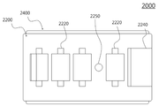
도 22는 본 발명의 실시예에 따른 검체 영역과 비검체 영역 간에 단차가 있는 로테이팅 타입 검체 플레이트의 예의 사시도이다.
도 23은 종래의 혈액 도말 검사 과정에 따른 혈액 도말 방식을 도시한 것이다.
도 24는 본 발명의 실시예에 따른 로테이팅 타입 테스트 키트의 도말부의 단면도이다.
도 25는 본 발명의 실시예에 따른 로테이팅 타입 테스트 키트의 도말부를 이용한 혈액 도말 과정을 도시한 도면이다.
도 26은 본 발명의 실시예에 따른 로테이팅 타입 테스트 키트의 로딩부에 관한 도면이다.
도 27은 본 발명의 실시예에 따른 로테이팅 타입 테스트 키트의 로딩부를 이용한 검체 로딩에 관한 도면이다.
도 28은 본 발명의 실시예에 따른 로테이팅 타입 테스트 키트의 승강 가이드를 가진 패치 플레이트의 사시도이다.
도 29는 본 발명의 실시예에 따른 로테이팅 타입 테스트 키트의 승강 가이드를 가진 검체 플레이트의 사시도이다.
도 30은 본 발명의 실시예에 따른 슬라이딩 타입 테스트 키트의 일 예의 측면도이다.
도 31은 도 30에 따른 슬라이딩 타입 테스트 키트의 패치 플레이트의 일 예에 관한 도면이다.
도 32는 도 30에 따른 슬라이딩 타입 테스트 키트의 검체 플레이트의 일 예에 관한 도면이다.
도 33은 도 30에 따른 슬라이딩 타입 테스트 키트를 이용한 검체 투입 동작도이다.
도 34는 도 30에 따른 슬라이딩 타입 테스트 키트를 이용한 검체 도말 동작도이다.
도 35는 도 30에 따른 슬라이딩 타입 테스트 키트를 이용한 염색 동작도이다.
도 36은 본 발명의 실시예에 따른 슬라이딩 타입 테스트 키트의 다른 예의 측면도이다.
도 37은 도 36에 따른 슬라이딩 타입 테스트 키트의 검체 플레이트의 일 예에 관한 도면이다.
도 38은 본 발명의 실시예에 따른 슬라이딩 타입 테스트 키트의 변형예의 사시도이다.
도 39는 본 발명의 실시예에 따른 슬라이딩 타입 테스트 키트의 변형예의 평면도이다.
도 40은 본 발명의 실시예에 따른 슬라이딩 타입 테스트 키트의 변형예의 측면도이다.
도 41은 본 발명의 실시예에 따른 검체 도말 방식의 일 예이다.
도 42는 본 발명의 실시예에 따른 검체 도말 방식의 다른 예이다.1 is a cross-sectional view of a contact dyeing patch according to an embodiment of the present invention.
2 is a diagram showing a conventional blood smear test process.
3 is a diagram illustrating a process of preparing a dyeing solution and a dyeing process during a conventional blood smear test process.
4 is a perspective view of a contact dyeing patch according to an embodiment of the present invention.
5 is a view showing a contact state between a contact dyeing patch and a specimen slide according to an embodiment of the present invention.
6 is a diagram illustrating a dyeing process using a contact dyeing patch according to an embodiment of the present invention.
7 is a photograph of a dyeing result using a standard Kimja dyeing process, that is, a Kimja dyeing method according to a conventional fluid spraying method.
8 is a photograph of each pH concentration of dyeing results using the Kimja dyeing method according to the standard Kimja dyeing process.
9 is a photograph of a dyeing result using a Kimja dyeing method to which a contact dyeing patch is applied according to an embodiment of the present invention.
10 is a photograph of another dyeing result using the Kimja dyeing method to which the contact dyeing patch is applied according to an embodiment of the present invention.
11 is a view showing the result of the dyeing method in which the standard dyeing method and the contact dyeing patch are grafted, respectively, with respect to the light dyeing method.
12 is a view showing a result of the dyeing method grafting a contact dyeing patch to the DAPI dyeing method.
13 is a view showing the staining results observed before contacting the buffer patch after contacting the methylene blue patch with the eosin patch.
14 is a view showing the staining results observed after contacting the methylene blue patch with the eosin patch and then contacting the buffer patch.
15 is an exploded perspective view of an example of a rotating type test kit according to an embodiment of the present invention.
16 is a perspective view of an example of a rotating type test kit according to an embodiment of the present invention.
17 is a perspective view of an example of a patch plate of a rotating type test kit according to an embodiment of the present invention.
18 is a cross-sectional view of an example of a groove-shaped receiving portion of a rotating type test kit according to an embodiment of the present invention.
19 and 20 are cross-sectional views of a receiving portion having a groove shape having various contact guide means of a rotating type test kit according to an embodiment of the present invention.
21 is a perspective view of an example of a specimen plate of a rotating type test kit according to an embodiment of the present invention.
22 is a perspective view of an example of a rotating type specimen plate having a step difference between a specimen region and a non- specimen region according to an embodiment of the present invention.
23 shows a blood smear method according to a conventional blood smear test process.
24 is a cross-sectional view of a smear of a rotating type test kit according to an embodiment of the present invention.
25 is a view showing a blood smear process using a smear of a rotating type test kit according to an embodiment of the present invention.
26 is a view of a loading unit of a rotating type test kit according to an embodiment of the present invention.
27 is a diagram illustrating sample loading using a loading unit of a rotating type test kit according to an embodiment of the present invention.
28 is a perspective view of a patch plate having an elevating guide of a rotating type test kit according to an embodiment of the present invention.
29 is a perspective view of a specimen plate having an elevating guide of a rotating type test kit according to an embodiment of the present invention.
30 is a side view of an example of a sliding type test kit according to an embodiment of the present invention.
31 is a diagram illustrating an example of a patch plate of the sliding type test kit according to FIG. 30.
32 is a diagram illustrating an example of a specimen plate of the sliding-type test kit according to FIG. 30.
FIG. 33 is a diagram illustrating a sample input operation using the sliding type test kit according to FIG. 30.
34 is an operation diagram of a specimen smear using the sliding type test kit according to FIG. 30.
35 is a diagram illustrating a dyeing operation using the sliding type test kit according to FIG. 30.
36 is a side view of another example of a sliding type test kit according to an embodiment of the present invention.
37 is a diagram of an example of a specimen plate of the sliding type test kit according to FIG. 36.
38 is a perspective view of a modified example of a sliding type test kit according to an embodiment of the present invention.
39 is a plan view of a modified example of a sliding type test kit according to an embodiment of the present invention.
40 is a side view of a modified example of the sliding type test kit according to the embodiment of the present invention.
41 is an example of a specimen smear method according to an embodiment of the present invention.
42 is another example of a specimen smear method according to an embodiment of the present invention.
본 명세서에 기재된 실시예는 본 발명이 속하는 기술 분야에서 통상의 지식을 가진 자에게 본 발명의 사상을 명확히 설명하기 위한 것이므로, 본 발명이 본 명세서에 기재된 실시예에 의해 한정되는 것은 아니며, 본 발명의 범위는 본 발명의 사상을 벗어나지 아니하는 수정예 또는 변형예를 포함하는 것으로 해석되어야 한다.Since the embodiments described in the present specification are intended to clearly explain the spirit of the present invention to those of ordinary skill in the technical field to which the present invention pertains, the present invention is not limited by the embodiments described herein, and the present invention The scope of should be construed as including modifications or variations that do not depart from the spirit of the present invention.
본 명세서에서 사용되는 용어는 본 발명에서의 기능을 고려하여 가능한 현재 널리 사용되고 있는 일반적인 용어를 선택하였으나 이는 본 발명이 속하는 기술 분야에서 통상의 지식을 가진 자의 의도, 관례 또는 새로운 기술의 출현 등에 따라 달라질 수 있다. 다만, 이와 달리 특정한 용어를 임의의 의미로 정의하여 사용하는 경우에는 그 용어의 의미에 관하여 별도로 기재할 것이다. 따라서 본 명세서에서 사용되는 용어는 단순한 용어의 명칭이 아닌 그 용어가 가진 실질적인 의미와 본 명세서의 전반에 걸친 내용을 토대로 해석되어야 한다.The terms used in the present specification have been selected as general terms that are currently widely used in consideration of functions in the present invention, but this varies depending on the intention, custom, or the emergence of new technologies of those of ordinary skill in the technical field to which the present invention belongs. I can. However, if a specific term is defined and used in an arbitrary meaning unlike this, the meaning of the term will be separately described. Therefore, terms used in the present specification should be interpreted based on the actual meaning of the term and the entire contents of the present specification, rather than a simple name of the term.
본 명세서에 첨부된 도면은 본 발명을 용이하게 설명하기 위한 것으로 도면에 도시된 형상은 본 발명의 이해를 돕기 위하여 필요에 따라 과장되어 표시된 것일 수 있으므로 본 발명이 도면에 의해 한정되는 것은 아니다.The drawings attached to the present specification are for easy explanation of the present invention, and the shapes shown in the drawings may be exaggerated and displayed as needed to aid understanding of the present invention, so the present invention is not limited by the drawings.
본 명세서에서 본 발명에 관련된 공지의 구성 또는 기능에 대한 구체적인 설명이 본 발명의 요지를 흐릴 수 있다고 판단되는 경우에 이에 관한 자세한 설명은 필요에 따라 생략하기로 한다.In the present specification, when it is determined that a detailed description of a known configuration or function related to the present invention may obscure the subject matter of the present invention, a detailed description thereof will be omitted as necessary.
본 발명의 일 양상에 따르면, 검체를 염색시키는 염색 시료를 보관하는 포어를 형성하는 그물 구조의 겔 상으로 제공되고, 상기 검체와 접촉하여 상기 염색 시료로 상기 검체를 염색하는 접촉식 염색 패치를 이용하여 염색을 수행하는 염색용 테스트 키트로, 외부에서 투입되는 검체가 놓이는 제1 플레이트; 상기 접촉식 염색 패치를 수납하고, 상기 제1 플레이트에 상대 이동하도록 마주보며 설치되고, 상기 상대 이동에 의해 상기 제1 플레이트 상에 놓인 검체를 도말하고, 상기 상대 이동에 의해 상기 접촉식 염색 패치와 상기 도말된 검체 간의 접촉 또는 접촉 준비를 수행하는 제2 플레이트;를 포함하는 테스트 키트가 제공될 수 있다. According to an aspect of the present invention, a contact-type dyeing patch is used that is provided in a gel form of a net structure that forms pores for storing a dyed sample for dyeing a sample, and contacts the sample to stain the sample with the dyed sample. A test kit for dyeing to perform dyeing, comprising: a first plate on which a sample input from the outside is placed; The contact dyeing patch is accommodated, installed facing the first plate so as to move relative to each other, and smears a specimen placed on the first plate by the relative movement, and the contact dyeing patch and A test kit including a second plate for performing contact or preparation for contact between the smeared specimens may be provided.
본 발명의 다른 양상에 따르면, 검체 염색 프로세스에 이용되는 물질을 보관하는 포어를 형성하는 그물 구조의 겔 상으로 제공되고, 상기 검체와 접촉하여 상기 물질로 상기 검체에 대한 염색 프로세스를 수행하는 접촉식 패치를 이용하여 염색을 수행하는 염색용 테스트 키트로, 그 상면에 상기 검체가 도말되는 검체 영역을 갖는 판상의 제1 플레이트; 상기 제1 플레이트에 대응되는 형태의 판상으로 제공되어 상기 제1 플레이트의 상부에 상기 제1 플레이트에 대하여 상대 이동 가능하도록 배치되고, 그 하면으로 상기 접촉식 패치가 노출되도록 상기 접촉식 패치를 수납하는 수납부, 외부로부터 검체를 투입받아 상기 제1 플레이트의 검체 영역으로 전달하는 투입부 및 상기 검체 영역에 전달된 검체를 도말하는 도말부가 형성되되, 상기 상대 이동에 의해 상기 도말부가 상기 검체 영역을 지나감에 따라 상기 검체의 도말을 수행하고, 상기 상대 이동에 의해 상기 접촉식 패치와 상기 도말된 검체 간의 접촉 또는 접촉 준비를 수행하는 테스트 키트가 제공될 수 있다. According to another aspect of the present invention, it is provided in the form of a gel having a mesh structure that forms pores for storing a material used in a sample staining process, and in contact with the sample to perform a dyeing process on the sample with the material. A dyeing test kit for performing dyeing using a patch, comprising: a plate-shaped first plate having a sample area on an upper surface of the sample to be smeared; It is provided in the shape of a plate corresponding to the first plate, is disposed to be relatively movable with respect to the first plate on an upper portion of the first plate, and accommodates the contact type patch so that the contact type patch is exposed to the lower surface thereof. A receiving unit, an input unit for receiving the sample from the outside and transferring it to the sample area of the first plate, and a smear unit for smearing the sample transferred to the sample area are formed, and the smear passes through the sample area by the relative movement. A test kit may be provided for performing the smearing of the specimen according to the feeling, and performing contact or preparation for contact between the contact patch and the smeared specimen by the relative movement.
또, 상기 도말부는, 상기 제2 플레이트의 하면으로부터 상기 상대 이동의 방향에 대하여 경사를 가지고 절곡되는 경사면 및 그 일부가 상기 경사면으로부터 상기 제1 플레이트 방향으로 돌출되도록 상기 경사면에 설치되는 도말 필름을 포함할 수 있다. In addition, the smear includes an inclined surface that is bent from a lower surface of the second plate with an inclination with respect to the direction of the relative movement, and a smear film installed on the inclined surface so that a part thereof protrudes from the inclined surface toward the first plate. can do.
또, 상기 경사면의 상단은, 상기 검체 투입부로 연결될 수 있다.In addition, the upper end of the inclined surface may be connected to the specimen input unit.
또, 상기 경사면은, 상기 제2 플레이트의 하면과 예각을 이루는 것을 특징으로 할 수 있다.In addition, the inclined surface may be characterized in that it forms an acute angle with the lower surface of the second plate.
또, 상기 도말 필름은, 상기 경사면을 따라 하방으로 연장되어 상기 제1 플레이트의 상면과 접하는 지점에서 굴곡되어 다시 상방으로 연장할 수 있다.In addition, the smear film may extend downward along the inclined surface and be bent at a point in contact with the upper surface of the first plate to extend upward again.
또, 상기 도말 필름은, 친수성인 것을 특징으로 할 수 있다.Moreover, the said smear film can be characterized by being hydrophilic.
또, 상기 도말 필름은, 상기 상대 이동에 의해 상기 검체 영역에 놓인 검체로 이동하여 상기 제1 플레이트 상에 놓인 검체와 접하면 모세관 현상에 따라 상기 상대 이동의 방향에 수직한 방향으로 상기 검체를 퍼뜨릴 수 있다.In addition, when the smear film moves to the specimen placed on the specimen area by the relative movement and comes into contact with the specimen placed on the first plate, it spreads the specimen in a direction perpendicular to the direction of the relative movement according to a capillary phenomenon. I can.
또, 상기 도말 필름은, 상기 상대 이동에 의해 상기 검체와 접한 지점으로부터 후퇴하면 모세관 현상에 따라 상기 후퇴 방향으로 상기 검체를 도말할 수 있다.In addition, when the smear film retreats from a point in contact with the specimen due to the relative movement, the specimen may be smeared in the retraction direction according to a capillary phenomenon.
또, 상기 제1 플레이트 및 상기 제2 플레이트는, 직사각형의 판상으로 제공되고, 상대 슬라이딩 이동할 수 있다.In addition, the first plate and the second plate are provided in a rectangular plate shape, and can be moved relative to each other.
또, 상기 제2 플레이트에는, 상기 슬라이딩 이동의 방향에 따라 상기 투입부, 상기 도말부 및 상기 수납부가 차례로 배치될 수 있다.In addition, on the second plate, the input part, the smear part, and the receiving part may be sequentially disposed in the direction of the sliding movement.
또, 상기 제2 플레이트에는, 상기 투입부와 상기 도말부 사이에 추가적인 상기 수납부가 더 배치될 수 있다.Further, in the second plate, an additional receiving part may be further disposed between the injection part and the smear part.
또, 상기 추가적인 수납부에는, 고정제를 함유하는 고정 패치가 수납될 수 있다.In addition, a fixing patch containing a fixing agent may be accommodated in the additional storage part.
또, 상기 제2 플레이트에는, 상기 투입부와 상기 도말부 사이에 고정제를 수용하는 고정제 수납부가 배치될 수 있다.Further, on the second plate, a fixing agent receiving part for accommodating a fixing agent may be disposed between the injection part and the smear part.
또, 상기 고정제 수납부는, 외부로부터 격리된 내부 공간에 상기 고정제를 수용하고, 특정 동작에 의해 상기 내부 공간이 외부 공간과 연결됨에 따라 상기 고정제가 배출되도록 할 수 있다.In addition, the fixing agent receiving unit may accommodate the fixing agent in an internal space isolated from the outside, and discharge the fixing agent as the internal space is connected to the external space by a specific operation.
또, 상기 제2 플레이트에는, 상기 투입부와 상기 도말부 사이에 고정제 또는 상기 고정제를 함유하는 고정 패치를 수납하는 추가 수납부가 더 배치되고, 상기 검체의 도말 이후 그리고 상기 접촉식 패치를 도말된 검체에 접촉시키기 이전에, 상기 상대 이동에 의해 상기 고정제 또는 상기 고정 패치와 상기 도말된 검체 간의 접촉 또는 접촉 준비를 수행할 수 있다.Further, on the second plate, an additional receiving unit for accommodating a fixing agent or a fixing patch containing the fixing agent is further disposed between the injection part and the smear, and the contact-type patch is smeared after the smear of the specimen. Prior to contacting the specimen, contact or preparation for contact between the fixing agent or the fixing patch and the smeared specimen may be performed by the relative movement.
또, 상기 고정제 또는 상기 고정 패치와 상기 도말된 검체 간의 접촉 또는 접촉 준비를 위한 상기 상대 이동은, 상기 검체의 도말 이후 상기 도말된 검체가 건조하기 위해 필요한 미리 정해진 시간 이후에 수행될 수 있다.In addition, the contact between the fixing agent or the fixed patch and the smeared specimen or the relative movement for preparation for contact may be performed after a predetermined time required for the smeared specimen to dry after the smear of the specimen.
또, 상기 투입부는, 상기 제2 플레이트의 상면으로부터 하면으로 천공되는 투입구 형태로 제공되고, 상기 제1 플레이트는, 상기 투입구를 통해 상기 검체를 투입받는 안착부 및 상기 안착부로부터 상기 검체 영역으로 상기 투입된 검체를 전달하는 채널부를 포함하는 로딩부를 포함할 수 있다.In addition, the injection unit is provided in the form of an injection hole perforated from the upper surface to the lower surface of the second plate, and the first plate includes a receiving unit receiving the sample through the injection port and the sample area from the receiving unit. It may include a loading unit including a channel unit for delivering the injected specimen.
또, 상기 투입부는, 상기 제2 플레이트의 상면으로부터 하면으로 함몰되는 투입홈 형태로 제공되고, 상기 제2 플레이트는, 상기 투입홈의 바닥면에 형성되어 상기 검체를 투입받는 안착부 및 상기 안착부로부터 상기 도말부로 상기 검체를 전달하는 채널부를 포함하는 로딩부를 포함할 수 있다.In addition, the input unit is provided in the form of an input groove that is recessed from the upper surface to the lower surface of the second plate, and the second plate is formed on the bottom surface of the input groove to receive the specimen and the receiving unit It may include a loading part including a channel part for transferring the specimen from the smear to the smear.
또, 상기 제2 플레이트에는, 상기 슬라이딩 이동의 방향에 따라 상기 투입부, 상기 도말부 및 상기 수납부가 차례로 배치될 수 있다.In addition, on the second plate, the input part, the smear part, and the receiving part may be sequentially disposed in the direction of the sliding movement.
또, 상기 제1 플레이트 및 상기 제2 플레이트는, 원판 형상으로 제공되고, 상대 로테이팅 이동할 수 있다.In addition, the first plate and the second plate are provided in a disk shape, and can be rotated relative to each other.
또, 상기 제2 플레이트에는, 상기 투입부, 도말부 및 상기 수납부가 상기 로테이팅 이동의 회전 방향에 따라 차례로 배치될 수 있다.In addition, on the second plate, the injection part, the smear part, and the receiving part may be sequentially disposed according to the rotation direction of the rotating movement.
또, 상기 투입부는, 상기 제2 플레이트에서 상기 제1 플레이트의 검체 영역이 노출되도록 절개되어 형성되는 절개부에 의해 형성될 수 있다.In addition, the injection part may be formed by a cutout formed by cutting the second plate so that the specimen area of the first plate is exposed.
또, 상기 도말부는, 상기 절개부의 모서리면으로 상기 제1 플레이트의 상면과 예각을 이루는 경사면 및 상기 경사면을 따라 상기 경사면에 부착되는 도말 필름을 포함할 수 있다.In addition, the smear may include an inclined surface forming an acute angle with an upper surface of the first plate as a corner surface of the cutout portion, and a smear film attached to the inclined surface along the inclined surface.
본 발명의 또 다른 양상에 따르면, 서로 마주보고 상대 이동 가능하게 결합되는 두 개의 플레이트로, 검체가 도말되는 검체 영역을 갖는 제1 플레이트 및 상기 도말된 검체를 염색시키는 접촉식 패치를 수납하는 제 2 플레이트를 포함하는 테스트 키트에 의해 수행되는 염색 방법으로, 상기 제1 플레이트의 검체 영역이 상기 검체를 획득하는 단계; 상기 제2 플레이트의 상기 제1 플레이트를 마주하는 면으로부터 예각으로 함몰되는 경사면에 부착된 도말 필름이, 상기 상대 이동에 따라 제1 방향으로 이동하여 상기 검체 영역에 놓인 검체와 접촉하여 상기 검체 영역에 상기 상대 이동의 방향에 수직한 방향으로 상기 검체를 퍼뜨리는 단계; 상기 도말 필름이, 상기 상대 이동에 따라 상기 제1 방향의 반대 방향인 제2 방향으로 이동하며 상기 검체 영역에 상기 검체를 도말하는 단계; 상기 접촉식 패치가 상기 검체 영역 상에 배치되는 단계; 및 상기 접촉식 패치가 상기 검체 영역에 도말된 검체와 접촉하여 상기 검체를 염색하는 단계;를 포함하는 염색 방법이 제공될 수 있다.According to another aspect of the present invention, two plates facing each other and coupled to each other so as to be movable relative to each other, a first plate having a sample area on which a sample is smeared, and a second plate containing a contact patch for staining the smeared sample A staining method performed by a test kit including a plate, comprising: obtaining the specimen by a specimen region of the first plate; The smear film attached to the inclined surface of the second plate, which is depressed at an acute angle from the surface facing the first plate, moves in the first direction according to the relative movement, and contacts the specimen placed in the specimen region to the specimen region. Spreading the specimen in a direction perpendicular to the direction of the relative movement; Smearing the specimen on the specimen area while the smear film moves in a second direction opposite to the first direction according to the relative movement; Placing the contact patch on the specimen area; And staining the specimen by contacting the contact-type patch with the specimen smeared on the specimen area.
1. 접촉식 염색 패치1. Contact dye patch
1.1. 겔 상의 접촉식 염색 패치1.1. Contact dye patch on gel
이하에서는 본 발명의 실시예에 따른 접촉식 염색 패치(100)에 관하여 설명한다.Hereinafter, a
본 발명의 실시예에 따른 접촉식 염색 패치(100)는 검체(T)와 접촉하여 이를 염색할 수 있다. The
예를 들어, 접촉식 염색 패치(100)는 1) 염색하고자 하는 대상을 염색 시료(140)를 직접 반응시켜 염색하는 1-1) 말라리아 검진에 이용되는 말초 혈액 도말 검사를 비롯한 혈액 도말 검사에 수반되는 김자 염색법(Giemsa stain)이나 라이트 염색법(Wright stain), 1-2) 세균 검사에 수반되는 단순 염색법(simple stain)이나 그람 염색법(Gram stain), AFB [Ziehl-Neelsen] 염색법은 물론, 2) 자궁경부암을 조사하는데 주로 이용되는 파파니콜라우(Papanicolaou) 도말 검사, 3) DAPI와 같은 형광 염색법, 4) 항원-항체 반응을 이용하여 동위 원소나 형광 물질 또는 효소 등과 결합된 항체를 이용하여 검출하고자 하는 대상이 방사선 검출, 형광 발색, 효소에 의한 간접 발색시키는 4-1) 암 검사 등에 이용되는 특수한 염색법인 면역 화학 염색법(immunohistochemistry)이나 4-2) 인간 면역 결핍 바이러스(HIV: human immunodeficiency syndrome) 검사에 이용되는 효소결합 면역흡착 분석법(ELISA: Enzyme Linked Immunosorbent Assay), 5) DNA 상의 특정 염기 서열을 확인하기 위하여 대상 염기 서열에 상보적인 DNA 프로브에 형광 물질을 결합시켜 이를 검출하는 형광 동소 보합법(FISH: Fluorescence In Situ Hybridization) 및 6) 항원-항체 반응을 이용한 침전법이나 응집법 등에까지 다양하게 이용될 수 있다.For example, the
본 발명에서 접촉식 염색 패치(100)의 "염색"이란, 검체(T)에서 검출하고자 하는 대상을 직접적으로 염색시키는 것에 국한되어 해석되는 것은 아니며, 상술한 바와 같이 검출 대상을 형광 발색시키거나 방사선 검출이 가능케 하거나 효소에 의해 특정 기질에 투입된 경우 반응 발색케 하거나, 응집이나 침전을 유도하여 검출이 가능토록 하는 등 검체(T)로부터 특정 대상 물질을 검출, 확인 가능케 하는 모든 방법을 포괄적으로 아우르는 단어로 해석되어야 한다. In the present invention, the term "dyeing" of the
다시 말해, 본 발명에서 접촉식 염색 패치(100)는 검사하고자 하는 물질을 검체(T)로부터 검출 가능한 상태로 만드는 기능을 하는 것으로, 그 실질적인 기술적 사상에 따르면 접촉식 "검출 유도" 패치가 보다 명확한 표현이겠으나, 본 발명에 대한 설명과 이해의 편의를 돕기 위하여 필요에 따라 접촉식 "염색" 패치라는 용어를 포괄적인 의미로 이용하기로 한다.In other words, in the present invention, the
따라서, 이와 유사하게 본 발명의 명세서 전반에 걸쳐 "염색"이라는 용어 역시 검출 대상에 대한 직접적인 염색이라는 협의의 의미가 아닌 형광 발색, 발색 유도, 방사선 검출 유도, 침전, 응집이나 그 이외의 검출이 가능한 상태로 유도하는 모든 "검출 유도"를 포괄하는 넓은 의미로 해석됨이 마땅할 것이다.Thus, similarly, throughout the specification of the present invention, the term "dyeing" is not a consensus of direct dyeing for a target to be detected, but fluorescence, color development, radiation detection, precipitation, aggregation, or other detection is possible. It should be interpreted in a broad sense encompassing all "induction of detection" leading to a state.
한편, 이와 함께 검체(T)란 검사 대상이 되는 물질로, 혈액이나 세포, 조직, 염색체, DNA, 또는 기생충이나 세균 등 의료 검사의 대상이 되는 모든 바이오 샘플을 아우르는 것으로 해석됨이 타당하다.Meanwhile, it is reasonable to interpret the sample (T) as a substance to be tested and encompass all bio samples subject to medical tests such as blood, cells, tissues, chromosomes, DNA, or parasites or bacteria.
접촉식 염색 패치(100)를 이용한 검체(T)의 염색은 다음과 같이 이루어질 수 있다. The dyeing of the specimen T using the
먼저 접촉식 염색 패치(100)는 겔(gel) 상으로 제공되며, 그 내부의 포어(122)에 염색 시료(140)를 보관한다. 이 상태에서 접촉식 염색 패치(100)를 검체(T)와 접촉시키면, 내부 포어(122)의 염색 시료(140)가 겔 매트릭스의 그물 구조를 거쳐 검체(T)으로 이동하여 염색 대상 물질을 염색시킨다.First, the
1.1.1. 접촉식 염색 패치의 기본 조성1.1.1. Basic composition of contact dyeing patch
도 1은 본 발명의 실시예에 따른 접촉식 염색 패치(100)의 단면도이다.1 is a cross-sectional view of a
도 1을 참조하면, 접촉식 염색 패치(100)는 겔 수용체(120) 및 염색 시료(140)를 포함할 수 있다. Referring to FIG. 1, the
겔 수용체(120)는 그 내부에 포어(122)를 형성하는 다공성의 그물 구조를 가지는 겔 상의 물질로 제공된다. 겔 수용체(120)의 포어(122)는 염색 시료(140)를 수용할 수 있다. The
겔 수용체(120)는 겔 메트릭스를 형성하는 다양한 겔로 제공될 수 있다. 예를 들어, 겔 수용체(120)는 아가로스(agarose)로 만들어진 겔일 수 있다. 여기서, 아가로스 대신 아가(agar)를 사용하는 것도 가능하다. 아가와 아가로스를 비교하면, 아가로부터 폴리락토스(polygalactose) 성분을 정제한 아가로스로 만들어진 겔 수용체(120)가 투명도나 굳기 제어면에서 뛰어난 장점이 있으나, 아가를 사용하는 경우에는 정제 과정 등을 생략할 수 있어 대량 생산 시 코스트 측면에서 장점이 있을 수 있다. The
이외에도 실리콘 겔, 실리카 겔(silica gel), 실리콘 고무, 수지의 주성분으로서 알려진 PDMS(PolyDiMethylSiloxane) 겔, PMMA(polymethylmethacrylate) 겔 및 그 외의 다양한 소재를 이용한 겔이 겔 수용체(120)로 이용될 수 있다.In addition, silicone gel, silica gel, silicone rubber, PDMS (PolyDiMethylSiloxane) gel, PMMA (polymethylmethacrylate) gel, which is known as a main component of resin, and a gel made of various other materials may be used as the
겔 수용체(120)는 주로 수용액 형태인 염색 시료(140)를 잘 머금을 수 있는 하이드로겔(hydrogel)을 이용하는 것이 가능하나, 필요에 따라서는 이와 달리 비수용성(non-hydrogel)을 이용할 수도 있다.As the
염색 시료(140)는 검체(T)와 반응하여 이를 염색하는 물질이다. 여기서, 염색 시료(140)는 직접 검체(T)를 염색하는 염색 시약 뿐만 아니라 염색 물질이나 형광 물질 등이 결합된 항체나 DNA 프로브 등 상술한 접촉식 염색 패치(100)가 이용될 수 있는 염색 방법의 예시들에서 염색 대상 물질과 반응하여 염색 대상을 검출 가능케하는 물질을 모두 아우르는 포괄적인 의미로 해석되어야 한다. The
예를 들어, 염색 시료(140)는 아세트산카민, 멜틸렌블루, 에오신, 산성 훅신, 사프라닌, 야누스그린 B, 헤모톡실린, 김자액, 라이트액, 라이트-김자액 등과 같은 로마노스키 염색법(Romanowsky stain)에 이용되는 염색액, 리슈먼 염색액, 그램 염색액, 카르볼푹신, Ziehl액 등의 다양한 염색액을 포함할 수 있다. For example, the
다른 예를 들어, 염색 시료(140)는 DAPI(4,6-diamidino-2-phenylindole) 형광 색소, 형광 물질과 결합한 DNA 프로브, 효소나 형광 물질, 동위 원소 등과 결합한 항체를 포함할 수도 있다. 물론, 염색 시료(140)가 상술한 예로 한정되는 것은 아니며, 이미 언급한 바와 같이 염색 대상 물질과 반응하여 검출 가능케 유도하는 어떠한 물질이어도 무방하다.For another example, the
포어(122)에는 단일의 염색 시료(140) 또는 둘 이상의 염색 시료(140)가 혼합되어 저장될 수 있다. A
예를 들어, 접촉식 염색 패치(100)를 이용하여 단순 염색(simple stain, 세균 등을 슬라이드(S)에 고정한 후 한가지 염색 시료(140)로 염색하는 방법)을 수행하고자 하는 경우에는, 포어(122)에는 하나의 염색 시료(140)가 저장될 수 있다. 이때, 염색 시료(140)로는 메틸렌블루(Methylene blue), 크리스탈 바이올렛(Crystal violet), 사프라닌(Safranin) 등이 사용될 수 있다. 이와 유사하게 특정 염기 서열만을 검출하기 위해 접촉식 염색 패치(100)를 이용하고자 하는 경우에는 특정 염기 서열에 대응하는 단종의 DNA 프로브에 형광 물질과 같은 검출 유도 물질을 결합시킨 단일의 염색 시료(140)를 이용할 수 있다. For example, in the case of performing simple staining (a method of fixing bacteria, etc. to the slide S and then staining with one staining sample 140) using the
위의 예와 달리, 접촉식 염색 패치(100)를 이용하여 김자 염색을 수행하고자 하는 경우에는, 세포질을 적염시키는 에오신과 핵을 자염시키는 메틸렌 블루의 이종 염색 물질로 구성되는 복합 시료가 염색 시료(140)로 이용될 수 있다. 즉, 포어(122)에는 에오신인 제1 염색 시료(140-1)과 메틸렌 블루인 제2 염색 시료(140-2)가 혼합되어 저장될 수 있다.Unlike the above example, in the case of performing Kimja staining using the
물론, 복합 시료를 염색 시료(140)로 이용하는 염색법에서는 상술한 바와 같이 포어(122)에 복수의 염색 시료(140)를 혼합하여 담는 대신 단일의 염색 시료(140)을 담는 접촉식 염색 패치(100)를 여러 개 이용하는 것도 가능하다. 예를 들어, 김자 염색을 수행하고 하려는 경우에는 에오신 패치(에오신을 제1 염색 시료(140-1)로 저장하는 제1 접촉식 염색 패치(100-1))와 메틸렌 블루 패치(메틸렌 블루를 제2 염색 시료(140-2)로 저장하는 제2 접촉식 염색 패치(100-2))와 같은 식으로, 염색 시료(140)를 각각 별개의 접촉식 염색 패치(100)에 분할 저장하는 것도 가능하다. Of course, in the dyeing method using the complex sample as the
1.1.2. 접촉식 염색 패치의 버퍼액1.1.2. Buffer solution of contact dyeing patch
염색 시료(140)는 필요에 따라 용매에 용해된 형태로 겔 수용체(120)의 포어(122)에 수용될 수 있다. 여기서, 용매로는 염색 시료(140)와 염색 대상 물질 간의 반응 시 반응 조건을 조성하는 버퍼액(B)을 이용할 수 있다. The dyed
버퍼액(B)은 염색 반응 시에 염색 대상과 염색 시료(140) 간의 반응이 잘 일어나도록 반응 환경을 조성하는 역할을 한다. 예를 들어, 김자 염색 등과 같은 염색 반응에서는 염기성의 메틸렌 블루가 음전하를 띄는 세포 핵과 결합하여 이를 염색하고 산성의 에오신은 세포질을 염색하므로 pH 농도가 염색 결과와 밀접하게 관련되며, 이로 인해 염색이 올바르게 되기 위해서는 적절한 pH 농도를 조성하는 것이 매우 중요할 수 있다. 따라서, 이러한 경우 버퍼액(B)은 접촉식 염색 패치(100)의 염색 시료(140)를 이용한 반응에 대한 지적 pH를 유지하는 pH 완충액일 수 있다.The buffer solution (B) serves to create a reaction environment so that the reaction between the dyed object and the dyed
버퍼 패치에 관한 설명에서도 후술하겠지만, 이러한 버퍼액(B)으로는 그 pH 농도가 염색 반응의 지적 pH와 동일한 것을 이용할 수 있다. As will be described later in the description of the buffer patch, a buffer solution (B) having the same pH concentration as the indicated pH of the dyeing reaction can be used.
또는 버퍼액(B)으로는 그 pH 농도가 염색 반응의 지적 pH와 다소 상이한 것을 이용할 수 있다. 기존의 염색 프로세스에서 버퍼 단계에서 버퍼액(B)을 다량으로 염색된 검체(T)에 분사하여 지적 pH를 맞추는 것과는 달리 접촉식 염색 패치(100)에서의 버퍼액(B)은 겔 수용체(120) 내에 함유되며, 접촉식 염색 패치(100)와 검체(T)의 접촉 과정에서 염색 반응의 지적 pH를 맞춰준다. 여기서,겔 수용체(120)에 버퍼액(B)이 함유되는 경우에는 염색 시료(140) 등과 반응하여 그 pH가 다소 조정될 수 있다. 구체적인 예를 들면, 김자 염색약을 염색 시료(140)로 사용하는 접촉식 염색 패치(100)의 경우에는 버퍼액(B)의 pH가 접촉식 염색 패치(100)의 제조되기 전보다 접촉식 염색 패치(100)로 제조된 뒤에 다소 간 상승하게 된다. 이는 버퍼액(B)과 염색 시료(140), 그리고 겔 수용체(100) 간에 상호 작용에 의한 요소와 기존의 액상 분사형 대신 겔 접촉형으로 버퍼 작용을 시킬 때 실질적으로 작용하는 pH가 다소 상이해짐이 그 원인이다. 다시 김자 염색을 위한 접촉식 염색 패치(100)에 대해서는 원료 버퍼액(B)의 pH보다 접촉식 염색 패치(100)에 함유되는 버퍼액(B)의 pH가 약 0.1~0.4 가량 상승할 수 있다. 만약 원하는 반응의 지적 pH 6.8인 경우라면, 버퍼액(B)은 그 pH가 약 6.4~6.7의 pH농도를 가지는 것을 이용할 수 있다. 버퍼액(B)의 pH를 이용하여 접촉식 염색 패치(100)의 지적 pH를 맞추는 것에 대한 설명은 후술되는 버퍼 패치 부분에서 보다 명확히 설명될 것이다.Alternatively, a buffer solution (B) having a pH concentration slightly different from the indicated pH of the dyeing reaction may be used. Unlike the conventional staining process in which the buffer solution (B) is sprayed onto the stained sample (T) in a large amount in the buffer step to adjust the intellectual pH, the buffer solution (B) in the
구체적으로 약 6.5pH를 가진 버퍼액(B)을 이용하여 제조한 김자 염색용 접촉식 염색 패치(100)를 기 염색된 검체(T)에 접촉시킨 뒤 염색된 검체(T)를 관측하면, 실제로는 약 6.6~6.9pH의 버퍼액(B)을 기 염색된 검체(T)에 분사한 것과 유사한 염색 결과가 관측되었다.Specifically, when the dyed sample (T) is observed after contacting the Kimja-dyeing
다시 말해, 특정 pH값을 가지는 버퍼액(B)을 이용하여 제조한 접촉식 염색 패치(100)의 실효 pH는 버퍼액(B) 자체의 pH값과 다소 상이하게 변성될 수 있다. 여기서, 실효 pH란 검체(T)와 패치 간의 반응 시에 느껴지는 pH로서, 이를 테면, 액상의 버퍼액(B)을 검체에 분사하는 경우에 검체(T)에 조성되는 pH일 수 있다.In other words, the effective pH of the
따라서, 접촉식 염색 패치(100) 제조 시에는 그 실효 pH값이 염색법의 지적 pH값과 실질적으로 동일해지도록 버퍼액(B)의 pH를 조정할 필요가 있다. Therefore, when manufacturing the
즉, 버퍼 패치에 이용될 버퍼액(B) 자체의 pH값은 종래의 염색법에서 정의될 수 있는 염색이 잘되도록 하는 지적 pH값에 대하여 겔 매트릭스 내에서 겔과 염색 시료, 그리고 버퍼액(B) 간의 상호 작용에 의해 편향되는 pH를 고려한 보정 pH값만큼을 보정한 값으로 세팅될 수 있다.That is, the pH value of the buffer solution (B) itself to be used for the buffer patch is the gel, the stained sample, and the buffer solution (B) in the gel matrix for the intellectual pH value that enables the staining that can be defined in the conventional staining method. It may be set to a value obtained by correcting the corrected pH value in consideration of the pH biased by the interaction between the two.
이때, 보정 pH값은 겔의 특성, 염색 시료의 종류, 버퍼액(B)에 대한 염색 시료나 겔 물질의 양 등에 따라 결정될 수 있다. In this case, the corrected pH value may be determined according to the characteristics of the gel, the type of the dyed sample, the amount of the dyed sample or the gel material for the buffer solution (B).
여기서, 겔의 특성에 관해서는, 보정 pH값의 크기(즉, 절대값)은 겔 수용체(120)의 겔의 농도, 하드니스, 공극률, 그물 구조의 조밀도 등에 따라 증감될 수 있다. 예를 들어, 겔 수용체(120)의 겔 농도가 커질수록 보정 pH의 크기가 커지고 겔 농도가 낮아질수록 보정 pH의 크기는 작아질 수 있다. 또 예를 들어, 겔 수용체(120)로 아가로스 겔을 이용하는 경우 아가로스의 농도가 높아지면, 보정 pH값의 크기가 커지고 아가로스의 농도가 낮아지면 보정 pH값은 작아질 수 있다. 또 겔 수용체(120)가 단단해질수록 보정 pH의 크기가 커지고 물렁해질수록 보정 pH의 크기가 작아질 수 있다. 또 겔 수용체(120)의 공극률이 커질수록 보정 pH의 크기는 작아지고 공극률이 작아질수록 보정 pH의 크기는 커질 수 있다. 또 겔 수용체(120)의 그물 구조의 조밀도가 커질수록 보정 pH의 크기는 커지고 조밀도가 낮아질수록 보정 pH의 크기는 작아질 수 있다.Here, with respect to the characteristics of the gel, the size of the corrected pH value (ie, the absolute value) may increase or decrease according to the concentration of the gel of the
또, 염색 물질에 대한 상호 작용에 관해서는 버퍼액(B)에 대한 염색 물질의 양이 클수록 ph 쉬프트가 크게 일어날 수 있으며, 산성 방향으로 쉬프티될지 염기성 방향으로 쉬프트될지는 염색 물질의 종류에 따라 정해질 수 있다. 김자 염색 물질의 경우에는 PBS 버퍼액에 대하여 염기성 방향으로 약 pH0.1~0.4 가량의 pH 쉬프트를 초래할 수 있다. 이는 버퍼액 대비 염색 물질의 양이 커질수록 더 크게 쉬프트될 수 있으며, 염색 물질의 종류가 변하면 염기성 방향으로 쉬프트될 수도 있다.In addition, as for the interaction with the dyeing material, the larger the amount of dyeing material in the buffer solution (B), the larger the pH shift may occur, and whether the shift in the acidic direction or the basic direction is shifted depends on the type of dyeing material. Can be set. In the case of Kimja dyeing material, it may cause a pH shift of about pH 0.1 to 0.4 in the basic direction with respect to the PBS buffer solution. This may be shifted larger as the amount of the dyeing material increases compared to the buffer solution, and may be shifted in the basic direction when the type of dyeing material is changed.
이상에서 설명한 본 발명의 실시예에 따른 접촉식 염색 패치(100)에서 겔 수용체(120)는 염색 시료(140)의 보관 기능을 수행한다. 여기서, 보관이란 1) 겔 수용체(120)가 그 내부에 저장되는 염색 시료(140)가 외부에 유출되지 않도록 하고 2) 염색 시료(140)과 외부로부터 오염되지 않도록 하는 것을 의미한다. 이러한 보관 기능은 1) 겔 수용체(120)의 겔 매트릭스의 구조적 성질과 2) 겔 수용체(120) 및 염색 시료(140)의 전기화학적 성질에 의한 것이다. In the
겔 수용체(120)의 구조적 특징에 의한 보관 기능은 겔 수용체(120)의 그물 구조에 의해 포어(122)에 수용된 염색 시료(140)가 겔 수용체(120)의 표면까지 이동하는 것이 억제됨에 따라 이루어질 수 있다. 이에 대하여 구체적으로 설명하면 다음과 같다.The storage function according to the structural features of the
겔 수용체(120)는 그물 구조로써 포어(122)를 형성하여 염색 시료(140)가 겔 수용체(120)의 내부에 수용되도록 할 수 있다. 이때, 포어(122) 내의 염색 시료(140)가 외부로 빠져나가기 위해서는 포어(122)로부터 겔 수용체(120)의 표면까지 이동해야 하는데, 이 과정에서 그물 구조를 거쳐야 하므로 내부 포어(122)에 수용된 염색 시료(140)가 외부로 유출되는 것을 방지할 수 있다. 다시 말해, 겔 수용체(120)의 그물 구조가 포어(122)에 수용된 염색 시료(140)가 겔 수용체(120)의 표면을 통해 증발되거나 유출되기 것을 억제하는 것이다. 또 이와 반대로, 염색 시료(140)가 오염되기 위해서는 외부로부터 오염 물질이 겔 수용체(120)의 표면을 거쳐 겔 수용체(120)의 내부 포어(122)까지 이동해야 하는데, 겔 수용체(120)의 그물 구조는 이 과정에서 이물질이 겔 수용체(120)의 내부로 유입되는 것을 억제하여 겔 수용체(120) 내부의 염색 시료(140)가 오염되는 것을 방지할 수 있다.The
또 겔 수용체(120)의 전기화학적 성질에 의한 보관 기능은 겔 수용체(120)와 염색 시료(140) 사이의 전기화학적 반응성에 의해 이루어질 수 있다. 예를 들어, 겔 수용체(120)의 포어(122)에 저장된 염색 시료(140)가 수용액 형태라면, 겔 수용체(120)를 친수성 겔로 준비함으로써 염색 시료(140)가 겔 수용체(120)로부터 외부로 빠져나가는 것을 억제할 수 있다. 또 이러한 겔 수용체(120)의 성질에 따라 반대 성질의 물질은 외부로부터 겔 수용체(120) 내부로 침입하지 못하게 되므로(예를 들어, 소수성 오염 물질은 친수성 겔 수용체(120) 내부로 침입이 억제된다) 내부에 저장된 염색 시료(140)가 오염으로부터 차단될 수 있다.In addition, the storage function by the electrochemical properties of the
또한, 겔 수용체(120)의 보관 기능은 단순히 염색 시료(140)의 유출이나 오염만을 방지하는 것에 그치는 것은 아니다. 혈액 도말 검사에서 혈액을 원활히 염색하기 위해서는 염색 시의 반응 조건이 매우 중요하다. 예를 들어, 적절한 pH 농도가 갖추어지지 않은 경우에는 염색 시료(140)와 혈액 간의 반응이 제대로 이루어지지 않게 되어 오염색된 혈액을 현미경으로 관찰하게 되고 결과적으로 검사에 오류가 발생할 수 있다. In addition, the storage function of the
이에 대해 본 발명에서는 염색 시료(140)가 적절한 반응 조건을 갖춘 상태로 겔 수용체(120)의 포어(122)에 수용될 수 있으며, 겔 수용체(120)는 반응 조건을 유지하면서 염색 시료(140)를 보관할 수 있다. 예를 들어, 김자(Giemsa) 염색의 경우에는 pH7.2의 조건에서 이루어지는데, 이를 위해 겔 수용체(120)의 포어(122)에는 김자 염색을 위한 염색 시료(140)가 pH7.2인 수용액 상태로 저장될 수 있으며, 겔 수용체(120)의 그물 구조에 의해 염색 시료(140)나 수용액의 외부로 유출과 외부의 물질에 의한 오염 등의 방지되므로, 김자 염색을 위한 염색 시료(140)는 겔 수용체(120) 내부에 pH7.2 상태를 유지하는 수용액 상태로 보관될 수 있다.On the other hand, in the present invention, the dyed
이와 같은 접촉식 염색 패치(100)는 염색 시료(140)를 원하는 반응 조건이 유지된 상태로 장기간 보호할 수 있는 장점이 있다. 이는 기존의 염색법을 이용하는 경우 염색 시료(140)의 반응 조건을 염색 시행 시마다 맞춰주어야 하는 것과 비교하여 큰 장점이다.The
1.1.3. 접촉식 염색 패치의 첨가 조성1.1.3. Additive composition of contact dyeing patch
한편, 접촉식 염색 패치(100)에는 다양한 첨가 조성이 추가로 포함될 수 있다. 이들의 추가적인 첨가 조성은 염색 시료(140)와 유사하게 겔 수용체(120)의 포어(122)에 수용되어 접촉식 염색 패치(100)에 함유될 수 있다.Meanwhile, various additive compositions may be additionally included in the
일 예로, 접촉식 염색 패치(100)에는 증발 방지제가 포함될 수 있다. 증발 방지제는 겔 수용체(120) 내부의 염색 시료(140)가 증발에 의해 외부로 유출되는 것을 방지하는 역할을 할 수 있다. 상술한 바와 같이 수용액 상태 등으로 겔 수용체(120)의 포어(122)에 보관되는 염색 시료(140)는 겔 메트릭스 구조나 겔 수용체(120)의 수용성 성질에 의해 외부 유출이 어느 정도 억제되지만, 겔 수용체(120)에 증발 방지제를 함유시킴으로써 접촉식 염색 패치(100)의 성능을 유지하면서 장기간 보관하는 것이 가능해진다. 이러한 증발 방지제는 5% 이하의 중량비를 가질 수 있으며, 바람직하게는 1% 중량비 이하를 가질 수 있다.For example, the
다른 예로는, 접촉식 염색 패치(100)에는 변질 방지제가 포함될 수 있다. 변질 방지제는 접촉식 염색 패치(100)에서 박테리아가 증식하는 것을 방지하는 방부제나 항생제 등과 같이 접촉식 염색 패치(100) 내부의 염색 시료(140)가 다양한 원인에 의해 변질되는 것을 방지하는 기능을 수행한다. 겔 수용체(120)가 노출되면, 그 내부에서 박테리아나 세균 등이 증식하게 되어 결과적으로 염색 시료(140) 등이 오염되어 성능이 저하될 수 있는데, 접촉식 염색 패치(100)에 변질 방지제를 첨가하면 접촉식 염색 패치(100)의 유통 기간을 늘릴 수 있다.As another example, the
1.2. 접촉식 염색 패치를 이용한 염색 프로세스1.2. Dyeing process using contact dyeing patches
도 2는 종래의 혈액 도말 검사 과정을 도시한 도면이고, 도 3은 종래의 혈액 도말 검사 과정 중 염색 과정에 관한 도면이다.2 is a diagram illustrating a conventional blood smear test process, and FIG. 3 is a diagram illustrating a dyeing process during a conventional blood smear test process.
도 2를 참조하면, 종래의 혈액 도말 검사는 다음과 같이 수행되어 왔다. 먼저 염색 용액 등의 반응 물질을 준비한다. 다음으로는 슬라이드(S) 상에 혈액을 투입하고, 이를 도말한다. 슬라이드(S)에 혈액이 도말되면 이를 고정한 뒤 건조시킨다. 도말 혈액의 고정은 주로 화학적 고정 방식을 이용할 수 있다. 슬라이드(S)에 도말된 혈액이 고정되면 염색 용액을 부어 혈액을 염색한다. 이때, 혈액에 염색 용액을 붓게 되므로 다량의 염색 용액이 혈액에 섞여 있으므로 이를 세척한 뒤 다시 건조시킨다. 이러한 과정을 거치면 슬라이드(S) 상의 염색된 혈액을 현미경 등을 통해 관측하여 혈액 도말 검사를 할 수 있다. Referring to FIG. 2, a conventional blood smear test has been performed as follows. First, a reactive substance such as a dyeing solution is prepared. Next, blood is put on the slide S, and it is smeared. When blood is smeared on the slide (S), it is fixed and dried. The smear blood can be fixed mainly by a chemical fixation method. When the smeared blood is fixed on the slide (S), the blood is stained by pouring a staining solution. At this time, since the dyeing solution is poured into the blood, a large amount of the dyeing solution is mixed with the blood, so it is washed and dried again. Through this process, the stained blood on the slide S can be observed through a microscope or the like to perform a blood smear.
도 3을 참조하면, 종래의 혈액 도말 검사에서는 혈액이 도말된 슬라이드(S)에 염색 용액을 분사하는 형태로 염색을 수행하는데, 이를 위해 분말 형태의 염색 시료(140)를 이용하여 즉석에서 염색 용액을 제조해야 했다. 따라서, 염색 시료(140)와 용매의 비율을 맞추기 위해서는 숙련자의 수작업이 필요하거나 또는 적정 비율의 혼합을 위한 별도의 장비가 필요했다. 뿐만 아니라 염색 용액을 사전 제조한 경우에는 1) 미리 제조한 염색 용액이 공기와 접촉해 반응하거나 또는 2) 염색 용액 내부에서 용매와 염색 시료(140) 간의 반응이 일어나거나 또는 3) 복수의 염색 시료(140)를 혼합해 염색 용액을 제조하여 사용하는 경우에 이종의 염색 시료(140) 간에 반응이 일어날 수 있으며, 이에 따라 염색 용액이 오염되거나 또는 적절한 반응 조건을 유지하지 못하기 때문에 염색 용액을 제조 후 단시간 내에만 사용할 수 있었다.Referring to FIG. 3, in a conventional blood smear test, dyeing is performed in the form of spraying a dyeing solution onto a slide S coated with blood. For this purpose, a dyeing solution is immediately used using a
이에 대해 본 발명의 실시예에 따른 접촉식 염색 패치(100)는 그 겔 수용체(120)에 그물 구조가 형성하는 내부 포어(122)에 염색 시료(140)를 원하는 반응 조건을 유지한 상태로 보관하므로, 검사 현장에서 염색 시료(140)와 용매를 혼합하여 염색 용액을 제조하는 대신 사전에 접촉식 염색 패치(100)를 제작하는 것이 가능하며 또 이를 장기간에 걸쳐 검사에 이용할 수 있게 되는 것이다.On the other hand, the
도 4는 본 발명의 실시예에 따른 접촉식 염색 패치(100)의 사시도이고, 도 5는 본 발명의 실시예에 따른 접촉식 염색 패치(100)와 검체 슬라이드(S)의 접촉 상태를 도시한 도면이다.4 is a perspective view of a
도 4를 참조하면, 접촉식 염색 패치(100)의 형상은 겔 수용체(120)의 형상에 의해 정의될 수 있는데, 적어도 일면에 검체(T)와 접촉하기 위한 접촉면(102)을 가질 수 있다. 여기서, 접촉면(102)은 검체(T)와 직접 접촉하는 면으로, 슬라이드(S) 상에 도말된 검체(T)와의 접촉이 용이하도록 평면인 것이 바람직할 수 있다. 일 예로, 접촉식 염색 패치(100)는 도 4에 도시된 바와 같이 기둥 형태로 제공될 수 있으며, 이러한 원 기둥 형태에서는 기둥의 상면 및 하면 중 일면이 접촉면(102)이 될 수 있다. Referring to FIG. 4, the shape of the
도 5를 살펴보면, 도 4에 도시된 접촉식 염색 패치(100)의 상면에 검체(T)가 도말된 슬라이드(S)를 안착시키거나 반대로 검체(T)가 도말된 슬라이드(S) 상에 염색 패치를 안착시키는 식으로 접촉식 염색 패치(100)와 검체(T)를 접촉시키는 것을 볼 수 있다.Referring to FIG. 5, a slide (S) with a sample (T) smeared on the upper surface of the
한편, 접촉식 염색 패치(100)의 형상이 도 4에 도시된 형태로 한정되는 것은 아니며, 접촉면(100)이 복수인 것도 가능하다. 예를 들어, 접촉식 염색 패치(100)는 육면체 형상으로 제작되고, 각 면들 중 하나 또는 복수의 면이 접촉면(100)을 이용될 수 있다. 다른 예를 들어, 접촉식 염색 패치(100)는 그 바닥면이 접촉면(100)이 되는 반구 형상으로 제조되는 것도 가능하다.Meanwhile, the shape of the
도 6은 본 발명의 실시예에 따른 접촉식 염색 패치(100)를 이용한 염색 과정에 관한 도면이다.6 is a diagram illustrating a dyeing process using the
도 6을 참조하면, 접촉식 염색 패치(100)는 슬라이드(S)에 도말된 검체(T)와 접촉될 수 있다. 다시 말해, 겔 수용체(120)의 접촉면(102)이 검체(T)와 직접적으로 접촉될 수 있다. 접촉이 이루어지면, 검체(T) 또는 염색 시료(140)와 반응하는 검체(T) 내의 특정 성분과 겔 수용체(120) 내부에 저장된, 즉 내부 포어(122)에 수용된 염색 시료(140) 간의 전기화학적 작용에 의해 염색 시료(140)가 그물 구조를 통과하여 접촉면을 통해 검체(T)로 이동하게 된다. 검체(T)로 이동한 염색 시료(140)는 검체(T) 또는 검체(T) 내의 특정 성분과 반응하여 이를 염색시킬 수 있다. Referring to FIG. 6, the
이때, 염색 시료(140)는 겔 수용체(120) 내부에 반응 조건을 유지한 상태로 저장되어 있으므로 별도로 반응 조건을 조정하지 않아도 염색이 원활하게 수행될 수 있다.At this time, since the
한편, 염색 시료(140)와 검체(T) 또는 검체(T) 내의 특정 성분 간에 작용하는 힘에 의해 염색 시료(140)가 겔 수용체(120)의 그물 구조를 통과하여 검체(T)로 이동하기는 하지만, 그물 구조에 의해 다소간 이동에 제약을 받는 상태에서 이동이 이루어지므로 염색 시료(140)나 염색 용액이 과도하게 다량으로 검체(T)에 이동하는 것이 방지될 수 있다. On the other hand, by the force acting between the
여기서, 염색 시료(140)나 염색 용액이 검체(T)로 이동하는 양은 그물 구조의 조밀도나 겔의 유동성, 다공성의 정도 등을 조정하는 것에 의해 제어될 수 있다. 즉, 겔의 단단함(hardness)를 적절히 조절함으로써 접촉식 염색 패치(100)로부터 검체(T)로 적절한 양의 염색 시료(140)만이 전달되도록 할 수 있다. Here, the amount of the
예를 들어, 말초 혈액 도말 검사용으로 아가로스 겔을 이용하여 김자 염색을 위한 접촉식 염색 패치(100)를 제조하는 경우에, 아가로스의 농도는 바람직하게는 1~5%일 수 있다. 아가로스의 농도가 이 범위보다 높은 경우에는 염색 시료(140)의 이동이 지연되어 혈액으로 충분한 약의 염색 시료(140)가 이동하지 못해 염색이 되지 않는 문제가 있을 수 있다. 반대로 아가로스의 농도가 이 범위보다 낮은 경우에는 염색 시료(140)의 이동이 과도하게 일어나 혈액으로 필요 이상의 염색 시료(140)가 전달될 수 있다. 필요 이상의 염색 시료(140)가 전달되는 경우에는 염색은 원활히 이루어질 수 있으나, 염색 시료(140)의 낭비가 발생하며 혈액 상에 잔류물이 남아 이후 잔류물을 제거하기 위한 세척 및 건조 과정이 필요하게 되는 단점이 있을 수 있다. 이를 위해 아가로스의 농도는 보다 바람직하게 1.5~2.5%일 수 있다.For example, in the case of manufacturing the
한편, 다시 도 5를 참조하면, 접촉식 염색 패치(100)를 검체(T)에 접촉시킬 때에는 외부 압력 없이 접촉식 염색 패치(100)와 검체(T)를 단순 접촉(상하방으로 단순 접촉 시에는 중력만 작용하나 이는 실질적으로 압력이 거의 없는 것으로 볼 수 있음)시키거나 또는 둘 사이에 소정의 압력을 인가할 수 있는데, 이는 접촉식 염색 패치(100)의 단단함에 따라 적절히 선택될 수 있다. 예를 들어, 접촉식 염색 패치(100)를 다소 소프트하게 제조한 경우에는 단순 접촉만으로도 충분한 양의 염색 시료(140)가 검체(T)로 전달될 수 있으며, 반대로 접촉식 염색 패치(100)를 다소 하드하게 제조한 경우에는 일정한 압력을 인가하여야 적절한 양의 염색 시료(140)가 검체(T)으로 전달될 것이다. Meanwhile, referring to FIG. 5 again, when the
이와 같은 검체(T)와 직접 접촉하여 검체(T)를 염색하는 접촉식 염색 패치(100)를 이용하면 1) 간단히 검체(T)에 접촉식 염색 패치(100)를 접촉시키는 것만으로도 별도로 반응 조건 조정하지 않고도 올바른 반응 조건 하에서 염색을 할 수 있고, 2) 염색 시료(140)의 낭비를 최소화하며, 3) 염색 전의 검체(T)의 고정(fixation)과 같은 전처리 공정이나 염색 후의 세척 및 건조와 같은 후처리 고정을 생략하여 염색 과정이 간편해 지는 장점이 있다.When using the
다시 도 2 및 도 3을 참조하면, 종래의 혈액 도말 검사에서는 염색을 위해 염색 용액을 즉석에서 제작하여야 하는데, 작업자의 실수에 의해 적절한 반응 조건을 맞추지 못해 염색에 오류가 발생할 가능성이 다분한 문제점이 있었다. 또는 이를 보완하기 위해 염색 시료(140)와 용매를 적절히 혼합해주는 별도의 장비를 사용한다 하더라도, 이에는 혼합 장비를 구매하기 위한 추가 비용이 발생할 뿐 아니라 매 염색 작업 시마다 혼합 작업을 수행해야 하는 불편함이 수반되어 시간과 비용에 손해가 있어왔다.Referring again to FIGS. 2 and 3, in the conventional blood smear test, a dyeing solution must be prepared on-the-fly for dyeing, but there are many problems in that there is a possibility that an error may occur in dyeing due to failure to meet appropriate reaction conditions due to an operator's error. . Alternatively, even if a separate equipment that properly mixes the
이에 반해 본 발명의 실시예에 따른 접촉식 염색 패치(100)는 그 내부에 적절한 반응 조건을 유지한 상태의 염색 시료(140)가 보관되어 있으며, 이를 단순히 검체(T)에 접촉시키는 것만으로도 염색이 올바르게 수행되므로 훨씬 편리한 점이 있어 숙련된 의료진 이외에도 일반인도 염색을 수행할 수 있게 된다.On the other hand, in the
또, 도 2 및 도 3을 참조하면, 종래의 혈액 도말 검사에서는 혈액이 도말된 슬라이드(S)에 염색 용액을 분사하는 형태로 염색을 해왔는데, 이때에 다량의 염색 시료(140)가 낭비되는 문제가 있어왔다. 한번 분사된 염색 시료(140)는 재활용이 어려워 비용 상의 손해가 클 뿐 아니라 그대로 방치 시에는 환경에 악영향을 줄 수 있기 때문에 그 관리 부담까지 가중되는 실정이었다. In addition, referring to FIGS. 2 and 3, in the conventional blood smear test, dyeing was performed in the form of spraying a dyeing solution on the slide S. In this case, a large amount of dyed
이에 반해 본 발명의 실시예에 따른 접촉식 염색 패치(100)는 그 내부에 염색 시료(140) 또는 염색 용액을 보관한 상태에서 검체(T)와의 접촉에 의해 염색이 필요한 양만큼만을 혈액에 전달하므로 염색에 실질적으로 필요한 최소한의 양만으로 염색을 수행할 수 있어 염색 시료(140)를 절감할 수 있으며, 유체 형태로 염색 시료(140)를 분사하는 대신 겔 상을 접촉시키는 방식이어서 사용 후 회수가 훨씬 간편한 장점이 있다.In contrast, the
나아가, 접촉식 염색 패치(100)는 장기간 보관이 가능하므로 1회 사용 후 버려지는 것이 아니라 복수 회의 사용도 가능한데, 복수 회 사용 시에는 비용 절감과 환경 보호에 보다 강점이 뚜렷해진다.Further, since the
또, 도 2 및 도 3을 참조하면, 종래의 혈액 도말 검사에서는 혈액에 염색 용액을 분사하는 형태로 염색이 이루어지므로 혈액이 염색 용액에 쓸려나가는 것을 방지하기 위해 슬라이드(S) 상에 고정시키는 전처리 과정이 요청되었다. In addition, referring to FIGS. 2 and 3, in a conventional blood smear test, since dyeing is performed in the form of spraying a dyeing solution on the blood, pretreatment of fixing on the slide S to prevent the blood from being swept away by the dyeing solution. Course was requested.
이에 반해 본 발명의 실시예에 따른 접촉식 염색 패치(100)는 단순 접촉을 통해 혈액으로 염색 시료(140)를 전달하므로 이 과정에서 검체(T)가 슬라이드(S)로부터 소실되지 않거나 혹은 슬라이드(S)로부터 접촉식 염색 패치(100) 측으로 혈액의 일부가 묻어가더라도 소량에 불과하므로 필요에 따라서는 슬라이드(S) 상에 검체(T) 고정을 하지 않아도 무방할 수 있다. 물론, 보다 최적의 검사 결과를 위해서는 검체(T) 고정이 필요한 경우가 있을 수 있으나, 이는 검사 프로세스의 간략화로 인해 발생하는 이득과 적절히 고려하여 작업자가 선택할 수 있는 정도이다.On the other hand, since the
또, 도 2 및 도 3을 참조하면, 종래의 혈액 도말 검사에서는 혈액을 염색시킨 뒤에 분사된 염색 용액이 슬라이드(S) 상에 잔류하는 것을 제거해야 했으며 이에 따라 세척과 건조의 후처리가 요청되었다.In addition, referring to FIGS. 2 and 3, in the conventional blood smear test, it was necessary to remove the residual staining solution sprayed on the slide S after staining the blood, and accordingly, post-treatment of washing and drying was requested. .
이에 반해 본 발명의 실시예에 따른 접촉식 염색 패치(100)는 염색 시료(140) 또는 염색 용액이 슬라이드(S)에 과도하게 전달되지 않아 슬라이드(S) 상에 잔류물이 잔류하는 것이 방지되므로 이후 이를 세척하는 과정을 생략하여도 좋으며, 세척 과정을 생략함에 따라 건조 과정 역시 생략될 수 있다.On the other hand, in the
특히, 종래의 혈액 도말 검사에서는 세척을 오래하는 경우 탈색이 발생하는 등과 같이 세척 과정으로 인한 오염색 결과가 초래되는 문제점이 있어왔는데, 본 발명의 실시예에 따른 접촉식 염색 패치(100)를 이용하면 세척 과정 자체가 불필요해지므로 세척 과정으로 인한 오염색 자체가 방지될 수 있다. In particular, in the conventional blood smear test, there has been a problem in that staining color results are caused by the washing process, such as discoloration occurs when washing is performed for a long time, but the
1.3. 접촉식 염색 패치의 제조 방법1.3. Manufacturing method of contact dyeing patch
이하에서는 상술한 본 발명의 실시예에 따른 접촉식 염색 패치(100)의 제조 방법에 관하여 설명한다.Hereinafter, a method of manufacturing the
접촉식 염색 패치(100)의 제조 방법의 일 예는, 겔 수용체(120)를 형성하는 단계 및 겔 수용체(120)에 염색 시료(140)를 흡수시키는 단계를 포함할 수 있다. An example of a method of manufacturing the
먼저, 아가로스 분말 등과 같은 겔 형성 물질, 겔화 가능한 물질 등으로 역할하는 겔 원료를 이용하여 겔 수용체(120)를 만든다. 예를 들어, 아가로스 분말과 물을 적절한 비율로 혼합한 뒤 이를 가열한 뒤 냉각시키면 겔 수용체(120)가 제조될 수 있다. 여기서, 가열은 혼합물을 끓이는 방식 내지는 전자 레인지 등으로 베이킹하는 방식 등이 이용될 수 있다. 또 여기서, 냉각은 자연 냉각이나 강제 냉각 등이 있을 수 있으며, 냉각 시에는 필요에 따라 스터링 과정이 포함될 수 있다. First, the
다음으로는 제조된 겔 수용체(120)에 염색 시료(140)를 흡수시킬 수 있다. 염색 시료를 흡수시키기 위해서는 겔 수용체(120)를 염색 시료(140)가 수용된 챔버나 용기 등에 일정 시간 담근 뒤 겔 수용체(120)가 염색 시료(140)를 충분히 흡수한 뒤 건져내는 방법이 이용될 수 있다. Next, the dyed
접촉식 염색 패치(100)의 제조 방법의 다른 예는, 겔 원료, 수용액 및 염색 시료를 혼합하여 겔 수용체를 형성하는 방법이 있을 수 있다. 예를 들어, 아가로스와 수용액(또는 완충액) 그리고 염색 시료(140, 버퍼액과 혼합된 형태일 수 있음)를 적절한 비율로 혼합한 뒤, 이를 가열/냉각시킴으로써 접촉식 염색 패치(100)가 제조될 수 있다. 여기서, 가열/냉각의 방식은 상술한 예와 유사할 수 있다. Another example of a method of manufacturing the
접촉식 염색 패치(100)의 제조 방법의 또 다른 예로는, 겔 원료와 용액을 혼합하여 가열한 뒤, 이를 냉각시키는 과정 중에 염색 시료(140)를 투입하는 방식이 있을 수 있다. 예를 들어, 아가로스와 수용액을 적절한 비율로 혼합한 뒤 가열한 다음, 이를 냉각 시키는 과정 중에 염색 시료(140)를 투입하는 것이다.Another example of a method of manufacturing the
1.4. 접촉식 염색 패치의 실험예1.4. Experimental example of contact dyeing patch
이하에서는 상술한 본 발명의 실시예에 따른 접촉식 염색 패치(100)의 실험예에 관하여 설명한다.Hereinafter, an experimental example of the
본 실험예는 말라리아 검사용으로 전통적인 김자 염색법에 본 발명의 실시예에 따른 접촉식 염색 패치(100)를 접목한 것이다. In this experimental example, a
한편, 본 실험예를 비롯하여 본 명세서에서 후술될 다양한 실험예에 있어서, 김자 염색법은 로마노스키 염색법의 대표로 설명되는 것에 불과하므로, 김자 염색법으로 한정되는 것은 아니며 그 외의 다양한 로마노스키 염색법에도 적용될 수 있다. 첨언하자면, 본 명세서에서 설명되는 접촉식 패치(100)를 활용하여 수행되는 검체 염색법은 기존의 로마노스키 염색법 및 그 외의 다양한 염색법의 효과를 유지하면서도 그 절차가 간편하여 이들을 대체할 것으로 기대되며, 본 발명과 관련하여 출원인들이 작성하고자 하는 논문에서는 “노을 염색법(Noul stain)”으로 이를 지칭할 예정이다.On the other hand, in various experimental examples to be described later in this specification, including this experimental example, since the Kimja dyeing method is only described as a representative of the Romanoski dyeing method, it is not limited to the Kimja dyeing method, and can be applied to various other Romanoskey dyeing methods. . Incidentally, the sample staining method performed using the
이를 위한 접촉식 염색 패치(100)는 다음과 같은 프로토콜에 따라 제조하였다.The
1) 아가로스와 김자 분말, 그리고 버퍼액(B)를 혼합한 후, 그 혼합물을 끊인 뒤 이를 상온에서 냉각시켰다. 아가로스는 2% 농도를 이용하였으며, pH7.2의 버퍼액(B)을 이용하였다. 또 혼합물은 100℃ 이상으로 끓였다. 여기서, 아가로스의 농도는 1~3% 범위 내에서 조절이 가능하다. 또한, 버퍼액(B)의 pH 농도는 pH6.4~7.6 범위에서 조절할 수 있다. 1) After mixing the agarose, laver powder, and the buffer solution (B), the mixture was boiled and cooled at room temperature. Agarose was used at a concentration of 2%, and a buffer solution (B) of pH 7.2 was used. Further, the mixture was boiled at 100°C or higher. Here, the concentration of agarose can be adjusted within the range of 1 to 3%. In addition, the pH concentration of the buffer solution (B) can be adjusted in the range of pH6.4 to 7.6.
이와 같이 제조된 접촉식 염색 패치(100)를 슬라이드(S)에 모노 레이어로 도말된 혈액 상에 약 5분 얹어놓은 뒤, 그 염색 결과를 100X 현미경으로 관측하였다. 혈액으로는 플라스모디움(말라리아 원충, Plasmodium)에 감염된 마우스의 눈에서 채취된 것을 이용하였다.The thus prepared
도 7은 표준 김자 염색 프로세스, 즉 기존의 유체 분사 방식에 따른 김자 염색법을 이용한 염색 결과물의 사진이고, 도 8은 표준 김자 염색 프로세스에 따른 김자 염색법을 이용한 염색 결과물의 pH 농도 별 사진이고, 9는 본 발명의 실시예에 따른 접촉식 염색 패치(100)를 적용한 김자 염색법을 이용한 염색 결과물의 사진이다.7 is a photograph of the dyeing result using the Kimja dyeing method according to the standard Kimja dyeing process, that is, the conventional fluid spraying method, and FIG. 8 is a photograph of the resultant dyeing using the Kimja dyeing method according to the standard Kimja dyeing process by pH concentration, and 9 It is a photograph of the dyeing result using the Kimja dyeing method to which the
도 7은 김자 염색의 적정 pH 농도를 준수한 염색 결과인 반면 도 8은 염색 과정에서 pH 농도가 적정치에서 벗어난 경우의 염색 결과이다. 도 9를 참조하면, 위의 접촉식 염색 패치(100)를 김자 염색법에 적용한 결과물은 적정 pH 농도를 준수한 올바른 염색 결과와 유사한 결과를 보이고 있어, 접촉식 염색 패치(100)를 이용한 염색이 제대로 이루어졌음을 시사하고 있다. FIG. 7 is a result of staining in accordance with an appropriate pH concentration of Kimja dyeing, while FIG. 8 is a result of staining when the pH concentration deviates from an appropriate value during the dyeing process. Referring to FIG. 9, the result of applying the above
특히, 표준 김자 염색 프로세스에서는 도말된 혈액 슬라이드(S)에 염색액을 분사하여 염색하는데 20~30분 이상이 소요되는데 반해 접촉식 염색 패치(100)를 이용한 경우에는 5분 이하로 동일한 결과물을 얻을 수 있었다. 더욱이 기존 표준 프로세스에서는 염색 용액의 준비나 염색 후 세척, 건조 등에 적어도 수십 분의 시간이 소요되는데, 접촉식 염색 패치(100)를 이용한 경우에는 염색 후 수십 초 가량의 자연 건조 이후 곧바로 현미경 관찰이 가능해지므로 시간 단축 효과는 더욱 커진다.In particular, in the standard Kimja staining process, it takes 20 to 30 minutes or more to dye by spraying the staining solution on the smeared blood slide (S), whereas when using the
한편, 위와 동일한 검사를 위한 접촉식 염색 패치(100)는 다음과 같은 프로토콜에 따라 제조될 수도 있다.Meanwhile, the
2) 아가로스 0.4g에 ph 7.2 버퍼액(B)의 혼합 용액 20ml를 혼합한 후, 그 혼합물을 전자레인지에서 30초 가열한 뒤, 스터링하면서 냉각시키고, 여기에 김자 모디파이드(Giemsa modified) 1ml를 섞은 뒤, 마저 냉각시켜 겔 상으로 굳힌다. 2) After mixing 20 ml of the mixed solution of pH 7.2 buffer solution (B) with 0.4 g of agarose, the mixture is heated in a microwave for 30 seconds, then cooled while stirring, and 1 ml of Giemsa modified After mixing, it is cooled and hardened into a gel phase.
이와 같이 제조된 접촉식 염색 패치(100)를 슬라이드(S)에 모노 레이어로 도말된 혈액 상에 약 5분 얹어놓은 뒤, 그 염색 결과를 100X 현미경으로 관측하였다. 혈액으로는 플라스모디움(말라리아 원충, Plasmodium)에 감염된 마우스의 눈에서 채취된 것을 이용하였다.The thus prepared
도 10은 본 발명의 실시예에 따른 접촉식 염색 패치(100)를 적용한 김자 염색법을 이용한 다른 염색 결과물의 사진이다. 도 10을 참조하면, 상술한 전자 레인지 베이킹을 이용하여 제조한 접촉식 염색 패치(100)를 김자 염색법에 적용한 결과물 역시 적정 pH 농도를 준수한 올바른 염색 결과와 유사한 결과를 보이고 있어, 이 경우에도 접촉식 염색 패치(100)를 이용한 염색이 제대로 이루어졌음을 시사하고 있다. 10 is a photograph of another dyeing result using the Kimja dyeing method to which the
이러한 염색 결과물을 고려하면, 본 발명의 실시예에 따른 접촉식 염색 패치(100)는 기존의 표준 프로세스에 따라 수행되던 염색 방법보다 안정적인 염색 성능을 기대할 수 있다. In consideration of such a dyeing result, the
이상의 실험예에서는 김자 염색법에 접촉식 염색 패치(100)를 접목한 것을 설명하였으나, 이외의 다른 염색법에도 접촉식 염색 패치(100)가 적용될 수 있는 것은 자명하다.In the above experimental examples, it has been described that the
도 11은 라이트 염색법에 대하여 각각 표준 염색법과 접촉식 염색 패치(100)를 접목한 염색법에 따른 결과물을 도시한 도면이다. 11 is a view showing the result of the dyeing method in which the standard dyeing method and the
라이트 염색을 위한 접촉식 염색 패치(100)로는 pH6.8 버퍼액(B)에 라이트 염색 시료(140)를 혼합한 염색 용액과 아가로스를 이용하여 겔 상 접촉식 염색 패치(100)를 제조하여 검체(T)에 약 5분 가량 얹어놓은 뒤 400X 현미경으로 관측한 결과이다. 도 11에 도시된 바와 같이 라이트 염색법의 경우에도 역시 표준 프로세스에 따른 결과물과 거의 유사한 결과물이 획득됨을 확인하였다.As the
도 12는 DAPI 염색법에 대하여 접촉식 염색 패치(100)를 접목한 염색법에 따른 결과물을 도시한 도면이다. 12 is a view showing a result of the dyeing method grafting the
DAPI 염색을 위한 접촉식 염색 패치(100)로는 아가로스 0.4g, PBS(Phosphate Buffer Saline, 인산 완충 식염수) 20ml, DAPI 20㎕를 이용하여 겔 상 접촉식 염색 패치(100)를 제조하여 검체(T)에 약 5분 가량 얹어놓은 뒤 각각 Bright 20x와 Fluorescence 20x로 관측한 결과이다. 10에 도시된 바와 같이 DAPI 염색법의 경우에도 안정적으로 형광 발색이 된거을 결과물에서 확인할 수 있었다.As the
이러한 염색 결과물을 고려하면, 본 발명의 실시예에 따른 접촉식 염색 패치(100)가 기존에 수행되던 염색법의 대부분의 표준 프로세스를 간소화하면서도 안정적인 염색 성능을 보장하여 대체할 수 있을 것으로 예상된다.In consideration of such dyeing results, it is expected that the
1.5. 접촉식 염색 패치의 활용1.5. Use of contact dyeing patches
이를 고려하여 대표적인 접촉식 염색 패치(100)의 활용예를 나열하면 다음과 같다.In consideration of this, examples of application of the representative
1.5.1. 스테이닝 패치(Staining patch)1.5.1. Staining patch
혈액학(Hematology)에서 사용되는 전통적인 염색법은 액상의 염색액을 혈액 세포나 조직 위에 분사하였다. 그러나, 이러한 방법은 검체(T) 상에 잔류물이 남아 이를 제거하기 위해 필수적으로 수반되는 세척(washing)과 건조(drying) 과정을 일정하게 제어하기 곤란하며, 사용되는 염색 시약들의 제조방법, 제조시기, 버퍼의 pH 농도 변화 등에 따라 결과물이 민감하게 변형되므로, 안정적인 염색 결과를 얻기 어려웠다. 뿐만 아니라 기존의 표준 프로세스들은 다양한 장비를 필요로 하며, 이를 이용한 프로토콜이 매우 복잡해 숙련되지 않은 작업자가 진행하기에도 매우 어려웠다.In the traditional staining method used in hematology, a liquid staining solution is sprayed onto blood cells or tissues. However, in this method, it is difficult to constantly control the washing and drying processes that are necessary to remove residues remaining on the sample (T), and the preparation method and preparation of the dyeing reagents used It was difficult to obtain a stable staining result because the result was sensitively deformed depending on the timing and the change in the pH concentration of the buffer. In addition, the existing standard processes require a variety of equipment, and the protocol using this is very complex, making it very difficult for an unskilled operator to proceed.
스테이닝 패치는 이러한 기존의 전통적인 염색법을 혁신적으로 개선한 것으로, 기본적으로 하이드로겔(Hydrogel) 상태로 염색 시료(140)를 머금은 겔 상 수용체를 의미한다. 이러한 스테이닝 패치는 염색 파우더, 하이드로겔, 버퍼액(B), 안정제, 물 등을 필요에 따라 적절히 조합하여 제조될 수 있으며, 제조된 염색 패치를 혈액 세포나 조직 위에 비교적 짧은 시간 동안 접촉시켰다 떼어냄으로써 염색이 완료되는 간단한 프로토콜을 가지게 해준다. The staining patch is an innovative improvement of the conventional dyeing method, and basically refers to a gel receptor containing the dyed
이러한 방법은 전체 염색 과정 중 세척과 건조 과정을 생략할 수 있으며, 염색 자체의 시간도 짧고, 검체(T) 상에 얼룩 등의 잔류물이 남지 않으며, 시료 사용을 최소화할 수 있을 뿐 아니라, 기존 방법 대비 결과물이 일정한 안정성을 갖는 장점이 있다.This method can omit washing and drying processes during the entire dyeing process, the time of dyeing itself is short, no residue such as stains remain on the sample (T), and the use of samples can be minimized. Compared to the method, there is an advantage that the resultant has a certain stability.
결과적으로, 스테이닝 패치는 물을 머금고 있으면서, 염색 과정에서의 반응 조건(또는 환경 조건)을 조성함으로써 염색 시료(140)와 반응 대상물 간의 화학반응을 유도하면서도, 동시에 물과 기타 버퍼 물질은 하이드로겔 속에 그대로 남도록 하여, 세척 및 건조 과정이 필요없게 된다.As a result, while the staining patch retains water, it induces a chemical reaction between the
스테이닝 패치의 대표적인 예로는, 김자 패치나 라이트 패치과 같은 로마노스키 염색 패치 내지는 파파니콜라우 염색 패치를 들 수 있다.As a representative example of the staining patch, a Romanoschi dyed patch such as a Kimja patch or a light patch, or a Papanicola dyed patch may be mentioned.
1.5.2. 항체 패치(Antibody patch)1.5.2. Antibody patch
면역 화학 염색법(immunohistochemistry), 혹은 효소결합 면역흡착 분석법(ELISA: Enzyme Linked Immunosorbent Assay)을 수행하는데 있어서, 항체 혹은 형광 물질 같은 리포터들이 결합된 항체를 딜리버리 하기 위하여, 기존의 액체 상태에서가 아닌 하이드로겔 상태에서의 딜리버리를 할 수 있는 패치이다.In performing immunohistochemistry or enzyme-linked immunosorbent assay (ELISA), in order to deliver an antibody to which reporters such as an antibody or a fluorescent substance are bound, a hydrogel, not in a conventional liquid state It is a patch that can be delivered in the state.
이러한 항체 패치는 스테이닝 패치와 유사하게, 혈액이나 조직 위에 소정의 시간 동안 접촉시키는 것을 통해 겔 내부에 저장된 항체들이 항원-항체 반응에 따라 항체 패치로부터 빠져나감에 따라 반응이 종료된다. Similar to the staining patch, the reaction is terminated as the antibodies stored in the gel are released from the antibody patch according to the antigen-antibody reaction through contact with blood or tissue for a predetermined period of time.
항체 패치를 이용하면 기존의 방식보다 신속하게 결과물을 얻을 수 있으며, 세척/건조 과정을 생략할 수 있으며, 백그라운드 노이즈를 최소화할 수 있게 된다.If the antibody patch is used, the result can be obtained more quickly than the conventional method, the washing/drying process can be omitted, and background noise can be minimized.
1.5.3. DNA 패치(DNA patch)1.5.3. DNA patch
FISH 검사 등을 수행함에 있어서, 형광 물질 리포터가 결합된 DNA 프로브를 딜리버리 하기 위한 패치로, 기존의 액체 상태에서가 아닌 하이드로겔 상태에서의 딜리버리를 수행하는 패치이다. In performing a FISH test, etc., a patch for delivering a DNA probe to which a fluorescent substance reporter is bound, and a patch for performing delivery in a hydrogel state, not in a conventional liquid state.
DNA 패치는 스테이닝 패치와 유사하게, 혈액이나 조직 등의 검체(T)와 소정 시간 접촉 후 분리하면, 혼성(hybridization) 결합을 위해 DNA 프로브들이 패치를 빠져나가 반응이 종료된다.Similar to the staining patch, the DNA patch is separated after contacting with a sample (T) such as blood or tissue for a predetermined period of time, and the DNA probes exit the patch for hybridization and the reaction is terminated.
DNA 검사에 있어서도 DNA 패치를 이용하면 기존의 방법보다 신속하고, 정확한 결과를 얻을 수 있으며, 세척 및 건조 과정을 생략할 수 있게 된다. In DNA testing, if a DNA patch is used, faster and more accurate results can be obtained than conventional methods, and washing and drying processes can be omitted.
이상에서는 접촉식 염색 패치(100)의 다양한 활용예에 대하여 살펴보았는데, 접촉식 염색 패치(100)의 활용처가 상술한 예시로 한정되는 것은 아니며, 이외의 다양한 염색(본 명세서에서 정의된 ‘광의의 염색’으로써 검체 검사 시 검출을 유도하는 것)이 접촉식 염색 패치(100)가 활용될 수 있다. 이때에는 그 활용처에 따라 염색 시료(140)를 적절히 선택할 수 있을 것이다. 예를 들어, 스테이닝 패치의 경우에는 염색 시료(140)로 염색 물질을, 항체 패치의 경우에는 염색 시료(140)로 항체를, DNA 패치의 경우에는 DNA 프로브를 사용할 수 있는 식일 것이다.In the above, various examples of application of the
2. 접촉식 염색 보조 패치2. Contact dye auxiliary patch
이상에서는 검체(T)의 반응 대상 물질과 반응하는 염색 시료(140)를 함유하는 접촉식 염색 패치(100)에 관하여 설명하였는데, 이하에서는 염색 프로세스에 걸쳐 이루어지는 다른 과정들, 예를 들어, 검체(T)의 고정이나 완충, 탈색, 매염, 세척 등을 수행하는 본 발명의 실시예에 따른 접촉식 염색 보조 패치(100’)에 관하여 설명한다. In the above, the contact-
2.1. 접촉식 염색 보조 패치의 예2.1. Example of contact dye auxiliary patch
접촉식 염색 보조 패치(100’)의 구성은 기본적으로 접촉식 염색 패치(100)와 대동 소이하다. 구체적으로 접촉식 염색 보조 패치(100’)는 접촉식 염색 패치(100)와 마찬가지로 겔 수용체(120)를 포함하고, 염색 시료(140) 대신 염색 보조제(160)를 포함할 수 있다. The configuration of the contact dyeing auxiliary patch 100' is basically different from that of the
염색 보조제(160)는 접촉식 염색 보조 패치(100’)의 사용처에 따라 선택될 수 있다. The dyeing aid 160 may be selected according to the use of the contact dyeing aiding patch 100'.
2.1.1. 고정 패치2.1.1. Fixed patch
예를 들어, 검체(T)의 고정(fixation)에 이용되는 경우에는 염색 보조제(160)는 슬라이드(S) 등의 상에 검체(T)를 고정시키는 알코올(에탄올(Ethanol)이나 메탄올(Methanol) 등)과 같은 검체 고정제일 수 있다. For example, when used for fixation of a sample (T), the dyeing aid 160 is an alcohol (ethanol or methanol) that fixes the sample (T) on a slide (S), etc. Etc.).
2.1.2. 탈색 패치 및 매염 패치2.1.2. Bleaching patch and mordant patch
다른 예를 들어, 탈색이나 매염에 이용되는 경우에는 탈색제나 매염제가 염색 보조제(160)로 이용될 수 있다. 그람 염색법에서는 본염색제로 크리스탈 바이올렛(Crystal Violet)을 이용하여 그람 양성(Gram positive) 세균과 그람 음성(Gram negative) 세균을 모두 염색한 뒤, 아이오딘(Iodine)을 매염제로 이용하여 그람 양성 세균에 본염색제를 고정시키고, 이후 알코올(에탄올이나 메탄올 등등) 등의 탈색제를 이용하여 그람 음성 세균으로부터 그람 음성 세균에 고정되지 못한 본염색제를 벗겨내고, 사프라닌(Safranin)을 대조염색제로 사용하여 탈색된 그람 음성 세균을 염색하여, 결과적으로는 그람 양성 세균은 본염색제에 의해 염색되고 그람 음성 세균은 대조염색제에 의해 염색되어 서로 상이한 컬러를 띄도록 한다. 이러한 과정에서 실제 염색은 본염색제와 대조염색제로만 이루어지면, 매염제와 탈색제를 염색 자체를 수행하지는 않으나, 염색을 보조하는 역할을 한다. 이러한 그람 염색법에 대해서는, 본 발명의 실시예에 따른 접촉식 염색 패치(100)로서 크리스탈 바이올렛(본염색제)를 염색 시료(140)로 하는 본염색 패치와 사프라닌 O(대조염색제, safranain O)를 염색 시료(140)로 하는 대조염색 패치를 준비하고, 본 발명의 실시예에 따른 접촉식 염색 보조 패치(100’)로서 아이오딘(매염제)를 염색 보조제(160)로 함유하는 매염 패치와 알코올(탈색제)를 염색 보조제(160)로 함유하는 탈색 패치를 준비하여, 본염색 패치, 매염 패치, 탈색 패치, 대조염색 패치 순으로 검체(T)에 접촉시킴으로써 그람 염색법을 수행할 수 있다.For another example, when used for bleaching or mordating, the bleaching agent or mordating agent may be used as the dyeing aid 160. In the Gram staining method, both Gram positive and Gram negative bacteria are stained using Crystal Violet as the main dye, and then Iodine is used as a mordant to prevent Gram-positive bacteria. After fixing the main dye, using a decolorizing agent such as alcohol (ethanol, methanol, etc.), peel off the main dye that was not fixed to the gram-negative bacteria from the gram-negative bacteria, and decolorize by using safranin as a control dyeing agent. The resulting gram-negative bacteria are stained, consequently, the gram-positive bacteria are stained with the main dye, and the gram-negative bacteria are stained with the control dye, so that they have different colors. In this process, if the actual dyeing is made only with the main dyeing agent and the contrast dyeing agent, the mordant and the bleaching agent do not perform dyeing themselves, but they play a role of supporting dyeing. For this Gram dyeing method, as the
상술한 고정제나 탈색제를 이용하여 고정 패치(fixation patch)나 탈색 패치(decolorization patch)와 같은 염색 보조 패치(100’)를 제조할 때에는, 겔 수용체(120)의 소재로 비수용성겔(non-hydrogel)이 주로 이용될 수 있다(물론, 때에 따라서는 하이드로겔을 이용할 수도 있다). 슬라이드(S) 상에 검체(T)를 고정시키기 위해서는 고정제로 높은 농도의 알코올(예를 들어, 99% 이상)를 이용할 필요가 있을 수 있는데, 이때 수용성겔(hydrogel)을 이용하면 겔 수용체(140)와 알코올 간의 상호 작용에 의해 알코올 농도가 낮아질 수 있으며 이에 따라 고정 작용이 저하될 수 있다. 이에 반해 겔 수용체(120)가 비친수성겔(non-hydrogel)인 경우에는 위와 같은 경우 알코올의 농도를 비교적 잘 유지할 수 있기 때문에 고정 성능이나 탈색 성능을 향상될 수 있다. 비친수성겔로는 PDMS 겔이나 PMMA 겔, 실리콘 겔 등이 이용될 수 있다.When manufacturing a dyeing auxiliary patch 100' such as a fixation patch or a decolorization patch using the above-described fixing agent or decolorization agent, a non-hydrogel gel (non-hydrogel) is used as a material for the gel receptor 120. ) Can be mainly used (of course, a hydrogel can also be used in some cases). In order to fix the specimen T on the slide S, it may be necessary to use a high concentration of alcohol (for example, 99% or more) as a fixing agent. In this case, if a water-soluble gel is used, the gel receptor 140 ) And alcohol may lower the alcohol concentration due to the interaction, and thus the fixation action may be lowered. On the other hand, when the
또 고정 패치나 탈색 패치에 대해서는 겔 수용체(120)를 고체화시킨 고정제나 탈색제로 대체하는 것도 가능하다. 예를 들어, 고정 패치 또는 탈색 패치로 고체화된 메탄올(solidified-methanol) 자체를 이용할 수도 있다. In addition, for a fixed patch or a bleaching patch, it is also possible to replace the
2.1.3. 버퍼 패치2.1.3. Buffer patch
또 다른 예로는, 버퍼액(B)을 염색 보조제(160)로 하는 버퍼 패치가 있을 수 있다. 버퍼 패치는 검체(T) 염색의 전이나 후 또는 전후에 검체(T)와 접촉하여 검체(T)에 염색을 위한 반응 조건(환경 조건)을 조성해주는 패치일 수 있다. 김자 염색의 경우에 버퍼 패치는 겔 수용체(120)에 김자 염색에 적절한 pH의 버퍼액(B)을 염색 보조제(160)로서 수용하는 형태로 마련될 수 있을 것이다.As another example, there may be a buffer patch using the buffer solution B as the dyeing aid 160. The buffer patch may be a patch that contacts the sample T before, after, or before and after staining the sample (T) to create reaction conditions (environmental conditions) for staining the sample (T). In the case of Kimja staining, the buffer patch may be provided in a form in which a buffer solution (B) having a pH suitable for Kimja staining is received as a dyeing aid 160 in the
버퍼 패치에 함유될 버퍼액(B)의 pH는 반응 조건에 따른 pH, 즉 지적 pH와 실질적으로 동일할 수 있다.The pH of the buffer solution (B) to be contained in the buffer patch may be substantially the same as the pH according to the reaction conditions, that is, the indicated pH.
또는 이와 달리 버퍼액(B)의 pH는 반응을 위한 최적의 지적 pH와 다소 상이할 수 있다. Alternatively, the pH of the buffer solution (B) may be slightly different from the optimum pointed pH for the reaction.
염색 시에는 염색이 적절하게 이루어지도록 염색 환경, 특히 pH를 적절히 조성해주는 것이 중요한 요소가 될 수 있다. 일반적으로 기존의 염색 절차 중 완충 단계에서는 기 염색된, 또는 염색 중이거나 염색할 검체에 지적 pH를 가지는 버퍼액(B)을 분사하거나 흘리는 식으로 제공하여 pH 조건을 맞춰왔다. 반면, 접촉식 염색 보조 패치(100’)를 이용하는 완충 단계에서는 검체(T)에 버퍼 패치를 접촉시키는 방식으로 검체에 pH 조건을 조성한다. 따라서, 접촉식 염색 보조 패치(100)’는 기존의 액상으로 검체와 접촉하는 방식과는 상이한 기전에 따라 검체(T)에 완충 작용을 일으킨다. When dyeing, it can be an important factor to properly configure the dyeing environment, especially the pH, so that the dyeing is done properly. In general, in the buffering step of the existing staining procedure, the pH condition has been adjusted by spraying or flowing a buffer solution (B) having an indicated pH on the previously stained, stained or stained specimen. On the other hand, in the buffering step using the contact dyeing auxiliary patch 100', a pH condition is created in the sample by contacting the buffer patch with the sample T. Therefore, the contact dyeing auxiliary patch 100' causes a buffering action on the sample T according to a mechanism different from the method of contacting the sample in a conventional liquid phase.
구체적으로 약 6.5pH를 가진 버퍼액(B)을 이용하여 제조한 버퍼 패치를 기 염색된 검체(T)에 접촉시킨 뒤 염색된 검체(T)를 관측하면, 실제로는 약 6.6~6.9pH의 버퍼액(B)을 기 염색된 검체(T)에 분사한 것과 유사한 염색 결과가 관측되었다.Specifically, when the buffer patch prepared using the buffer solution (B) having about 6.5 pH is brought into contact with the pre-stained sample (T) and then the stained sample (T) is observed, the buffer solution is actually about 6.6 to 6.9 pH. A staining result similar to that of spraying the liquid (B) onto the pre-stained specimen (T) was observed.
반대로 약 7.6pH를 가진 버퍼액(B)을 이용하여 제조한 버퍼 패치를 기 염색된 검체(T)에 접촉시킨 뒤 염색된 검체(T)를 관측하면, 실제로는 약 7.2~7.4pH의 버퍼액(B)을 기 염색된 검체(T)에 분사한 것과 유사한 염색 결과가 관측되었다.On the contrary, when the buffer patch prepared using the buffer solution (B) having about 7.6 pH is brought into contact with the pre-stained sample (T) and then the stained sample (T) is observed, the buffer solution is actually about 7.2 to 7.4 pH. A staining result similar to that of spraying (B) onto the previously stained specimen (T) was observed.
이러한 점을 고려할 때, 겔 수용체(S)에 담긴 상태로 버퍼액(B)을 검체(T)에 제공하는 경우에 검체(T)에 조성되는 pH가 검체(T)에 액상으로 직접 버퍼액(B)을 분사하는 경우에 조성되는 pH보다 다소 중성으로 바이어스됨(baised)을 알 수 있다. 이는 직접 버퍼 패치로 제공되는 경우 버퍼액(B)과 검체(T) 간에 이루어지는 산-염기 작용이 겔 메트릭스의 그물 구조를 거쳐 이루어짐에 따라 액상으로 분사되는 버퍼액(B)과 검체 간의 작용보다 다소 지연되기 때문이다.Considering this point, when the buffer solution (B) is provided to the sample (T) in the state of being contained in the gel receptor (S), the pH formed in the sample (T) is directly transferred to the sample (T) as a liquid. In the case of spraying B), it can be seen that the pH is slightly biased to neutrality (baised). When provided as a direct buffer patch, the acid-base action between the buffer solution (B) and the sample (T) is achieved through the mesh structure of the gel matrix, so it is somewhat less than the action between the buffer solution (B) and the sample sprayed in the liquid phase. Because it is delayed.
다시 말해, 특정 pH값을 가지는 버퍼액(B)을 이용하여 제조한 버퍼 패치의 실효 pH는 버퍼액(B) 자체의 pH값보다 다소 중성으로 편향된다. 여기서, 실효 pH란 검체(T) 측에서 느껴지는 pH로서, 이를 테면, 액상의 버퍼액(B)을 검체에 분사하는 경우에 검체(T)에 조성되는 pH일 수 있다.In other words, the effective pH of the buffer patch prepared by using the buffer solution (B) having a specific pH value is slightly biased to neutral than the pH value of the buffer solution (B) itself. Here, the effective pH is a pH felt on the sample T side, for example, may be a pH formed in the sample T when the liquid buffer solution B is sprayed onto the sample.
따라서, 버퍼 패치 제조 시에는 버퍼 패치의 실효 pH값이 버퍼 패치를 이용하여 완충시킬 염색법의 지적 pH값과 실질적으로 동일해지도록 버퍼액(B)의 pH를 조정할 필요가 있다. Therefore, in manufacturing the buffer patch, it is necessary to adjust the pH of the buffer solution B so that the effective pH value of the buffer patch becomes substantially the same as the indicated pH value of the dyeing method to be buffered using the buffer patch.
즉, 버퍼 패치에 이용될 버퍼액(B) 자체의 pH값은 종래의 염색법에서 정의될 수 있는 염색이 잘되도록 하는 지적 pH값에 대하여 겔 매트릭스에 의해 산-염기 작용이 저해되는 정도를 고려한 보정 pH값으로 보정한 값으로 세팅될 수 있다. That is, the pH value of the buffer solution (B) itself to be used for the buffer patch is corrected in consideration of the degree to which acid-base action is inhibited by the gel matrix with respect to the intellectual pH value that allows good staining, which can be defined in the conventional staining method. It can be set to a value corrected by a pH value.
여기서, 보정 pH값은 지적 pH가 산성인 경우에는 음의 값일 수 있다. 예를 들어, 지적 pH가 6.8인 경우에는 보정 pH값은 -0.3일 수 있으며, 이에 따라 실효 pH6.8을 위하여 버퍼 패치 제조 시에 이용되는 버퍼액(B)의 pH값은 pH6.5일 수 있다.Here, the corrected pH value may be a negative value when the intellectual pH is acidic. For example, when the intellectual pH is 6.8, the corrected pH value may be -0.3, and accordingly, the pH value of the buffer solution (B) used in manufacturing the buffer patch for effective pH 6.8 may be pH 6.5. have.
또 여기서, 보정 pH값은 지적 pH가 염기성인 경우에는 양의 값일 수 있다. 예를 들어, 지적 pH가 7.4인 경우에는 보정 pH값은 +0.2일 수 있으며, 이에 따라 실효 pH7.4를 위하여 버퍼 패치 제조 시에 이용되는 버퍼액(B)의 pH값은 pH7.6일 수 있다.In addition, here, the corrected pH value may be a positive value when the intellectual pH is basic. For example, when the intellectual pH is 7.4, the corrected pH value may be +0.2, and accordingly, the pH value of the buffer solution (B) used in manufacturing the buffer patch for effective pH 7.4 may be pH7.6. have.
이러한 보정 pH값의 크기(즉, 절대값)은 겔 수용체(120)의 겔의 농도, 하드니스, 공극률, 그물 구조의 조밀도 등에 따라 증감될 수 있다. The size (ie, absolute value) of the corrected pH value may be increased or decreased depending on the gel concentration, hardness, porosity, and net structure density of the
겔 수용체(120)의 겔 농도가 커질수록 보정 pH의 크기가 커지고 겔 농도가 낮아질수록 보정 pH의 크기는 작아질 수 있다. 예를 들어, 겔 수용체(120)로 아가로스 겔을 이용하는 경우 아가로스의 농도가 높아지면, 보정 pH값의 크기가 커지고 아가로스의 농도가 낮아지면 보정 pH값은 작아질 수 있다.As the gel concentration of the
또 겔 수용체(120)가 단단해질수록 보정 pH의 크기가 커지고 물렁해질수록 보정 pH의 크기가 작아질 수 있다. Further, as the
또 겔 수용체(120)의 공극률이 커질수록 보정 pH의 크기는 작아지고 공극률이 작아질수록 보정 pH의 크기는 커질 수 있다.In addition, as the porosity of the
또 겔 수용체(120)의 그물 구조의 조밀도가 커질수록 보정 pH의 크기는 커지고 조밀도가 낮아질수록 보정 pH의 크기는 작아질 수 있다.In addition, as the density of the mesh structure of the
이러한 버퍼 패치의 pH 쉬프트 현상은 접촉식 염색 패치(100)에서 염색 시료(140)를 버퍼액(B)과 혼합하는 경우 버퍼액(B)의 pH가 쉬프트되는 것과는 다소 상이한 원인에 기인하는 것이다. 즉, 버퍼 패치에 대해서는 바로 위에 설명한 원인에 의해서 pH 쉬프팅이 일어나지만, 접촉식 염색 패치(100)에 대해서는 바로 위에 설명한 원인과 접촉식 염색 패치(100)의 버퍼액(B)에 관하여 설명한 부분에 따른 원인이 복합 작용할 수 있다.The pH shift phenomenon of the buffer patch is due to a slightly different cause than the pH of the buffer solution (B) is shifted when the
한편, 상술한 완충액(B)의 pH 보정에 대한 설명은 버퍼 패치에 포함되는 완충액(B)에만 적용되는 것은 아니며, 버퍼액(B)을 가지는 접촉식 염색 패치(100)나 접촉식 염색 보조 패치(100’)에 전반적으로 적용될 수 있다. 예를 들어, 접촉식 염색 패치(100)에 포함되는 염색 시료(140)이 염색 분말과 버퍼액(B)을 혼합한 용액 형태인 경우에도 그 버퍼액(B)의 pH값을 지적 pH로 맞추는 대신 지적 pH에 보정 pH를 가감한 pH값으로 설정할 수 있을 것이다.On the other hand, the description of the pH correction of the buffer solution (B) described above is not applied only to the buffer solution (B) included in the buffer patch, the
2.1.4. 세척 패치2.1.4. Washing patch
다시 또 다른 예로는, 세척 패치가 있을 수 있다. 세척 패치는 염색 프로세스 중 워싱(washing)을 수행하는 패치로서, 세척 패치는 상술한 접촉식 염색 보조 패치(100’)와는 다소 상이하게 별도의 염색 보조제(160)를 포함하지 않거나 또는 염색 보조제(160)로 소량의 물이나 알코올 등을 이용할 수 있다. Yet another example may be a cleaning patch. The washing patch is a patch that performs washing during the dyeing process, and the washing patch does not contain a separate dyeing aid 160 or a dyeing aid 160 somewhat different from the above-described contact
세척 패치는 검체(T)와 접촉하여 검체(T) 상의 잔류 이물질 등을 제거하는 역할을 수행한다. 예를 들어, 염색 과정 중 검체(T)에 염색약이나 매염제, 탈색제, 고정제 등이 가해지면, 그 일부가 검체(T)에 잔류하게 되어 이를 세척할 필요가 있는데, 이러한 검체(T)에 세척 패치를 접촉시키면, 세척 패치의 겔 메트릭스의 공극에 이물질이 흡수되면서 검체(T)가 세척될 수 있다. 이는 세척 패치가 그 내부에 용액 등을 함유하지 않거나 소량만 함유하고 있으므로 접촉된 이물질을 흡수하는 성질을 가지기 때문이다.The cleaning patch is in contact with the specimen (T) and serves to remove residual foreign matter on the specimen (T). For example, if a dye, mordant, bleaching agent, fixing agent, etc. is added to the sample (T) during the staining process, a part of it remains in the sample (T) and needs to be cleaned. When the patch is brought into contact, the sample (T) may be washed while foreign substances are absorbed into the pores of the gel matrix of the washing patch. This is because the cleaning patch does not contain a solution or the like, or contains only a small amount, and thus has the property of absorbing foreign substances in contact.
세척 패치는 또한 검체(T) 상의 액체를 흡수하는 기능을 하기 때문에 염색 과정에서 세척을 수행함과 동시에 검체(T)를 건조시키는 기능도 함께 하므로 건조 패치로 지칭되어도 무방하다.Since the cleaning patch also has a function of absorbing the liquid on the sample (T), it can also be referred to as a dry patch because it has a function of drying the sample (T) as well as performing washing during the dyeing process.
한편, 세척 패치의 세척 및 건조 기능은 세척 패치 이외의 버퍼 패치에 의해 수행될 수도 있다. 버퍼 패치의 경우에는 세척 패치에 비하여 비교적 다량의 용액을 그 겔 수용체(120) 내부에 포함하고 있기 때문에 검체(T)와 접촉 시 검체(T) 상의 이물질을 흡수하는 성능이 다소 낮을 수는 있지만, 버퍼 패치의 겔 수용체(120) 역시 어느 정도의 공극을 가지고 있기 때문에 검체(T) 상의 잔류물을 흡수하는 기능을 다소 간 수행할 수 있기 때문이다. 결과적으로 버퍼 패치는 검체(T)에 대하여 지적 pH를 설정하는 완충 역할 이외에도 세척과 건조 역할까지도 일부 수행하는 것이 가능한 것이며, 이로 인해 염색 프로세스 상 단순히 버퍼 패치를 검체(T)에 접촉시키는 것만으로 완충/세척/건조가 수행됨에 따라 염색 프로세스가 간단해 질 수 있다. 물론, 과량의 잔류물이 존재하는 경우에는 세척 패치를 이용한 별도의 세척/건조 과정을 수행하는 것이 허용됨은 당연할 것이다.Meanwhile, the washing and drying functions of the washing patch may be performed by buffer patches other than the washing patch. In the case of the buffer patch, compared to the washing patch, since a relatively large amount of solution is contained inside the
한편, 세척 패치의 흡수력을 강화하기 위하여 세척 패치의 겔 수용체(140)에 염색 보조제(160)로서 흡수제를 함유시키는 것도 가능하다. 상술한 바와 같이 겔 수용체(140)에 별도의 용액을 넣지 않거나 또는 소량의 용액만을 넣는 방식으로 겔 수용체(140)의 공극률을 높여서 접촉된 검체(T)로부터 이물질이 잘 흡수되도록 하는 것도 가능하지만, 이보다 더욱 흡수력을 향상시키기 위하여 겔 수용체(140)에 염색 보조제(160)로 흡수제를 넣어주면, 흡수제가 접촉된 검체(T) 상의 이물질을 빨아들여 흡수율이 향상될 수 있다.On the other hand, it is also possible to contain an absorbent as a dyeing aid 160 in the
2.1.5. 복합 패치2.1.5. Composite patch
한편, 이상에서는 접촉식 염색 보조 패치(100’)에 관하여 기능 별로 설명하였으나, 염색 보조 패치는 경우에 따라 둘 이상의 기능을 동시에 지닐 수도 있다. Meanwhile, in the above, the contact dyeing auxiliary patch 100' has been described for each function, but the dyeing auxiliary patch may have two or more functions simultaneously in some cases.
예를 들어, 버퍼 패치는 염색된 검체(T)에 pH 농도 등의 반응 조건을 완충하는 역할을 함과 검체(T) 상에 잔류하는 잔류물을 세척하는 역할을 함께 수행할 수 있다. 본 발명의 실시예에 따른 접촉식 염색 패치(100)를 이용하여 검체(T)를 염색하는 경우에는 실질적으로는 검체(T)에 잔류물이 거의 남지 않지만, 검체(T)로부터 접촉식 염색 패치(100)를 이탈시킨 뒤에 검체(T)에 버퍼 패치를 접촉시키면 검체(T)에 극미량이라도 존재할 수 있는 잔류물을 깨끗하게 제거할 수 있다.For example, the buffer patch may play a role of buffering reaction conditions such as pH concentration in the stained sample T and washing the residue remaining on the sample T. In the case of staining a sample (T) using the
또 한편, 이상에서는 접촉식 염색 보조 패치(100’)는 각 역할 별로 단일의 패치로 구현되는 것으로 설명하였으나, 이와 달리 하나의 접촉식 염색 보조 패치(100’)가 복합 염색 보조제(160)를 함유하도록 하여 둘 이상의 역할을 수행하도록 할 수도 있다.On the other hand, in the above, it has been described that the contact dyeing auxiliary patch 100' is implemented as a single patch for each role, but unlike this, one contact dyeing auxiliary patch 100' contains the complex dyeing aid 160 You can also make them perform more than one role.
예를 들어, 매염 패치와 탈색 패치를 하나의 매염/탈색 패치로 구현하는 것도 가능하다. 겔 수용체(120)에 염색 보조제(160)로서, 매염제와 탈색제를 동시에 저장하게 한 매염/탈색 패치는, 검체(T)와 접촉하면 검체(T)에 대한 매염 및 탈색을 함께 수행할 수 있다. For example, it is also possible to implement a mordant patch and a bleaching patch as a single mordant/bleaching patch. As the dyeing aid 160 in the
더 나아가, 접촉식 염색 패치(100)와 접촉식 염색 보조 패치(100’)를 병합 구현하는 것도 가능하다. 예를 들어, 겔 수용체(120)에 그람 염색법을 위한 본염색제, 매염제, 탈색제, 대조염색제를 수용토록하면 하나의 패치(이하 복합 패치)로 접촉식 염색 패치(100)와 접촉식 염색 보조 패치(100’)를 구현할 수 있다. Furthermore, it is also possible to implement the
이러한 복합 패치는 염색 프로세스를 극단적으로 간소화시켜 사용하기에 편리한 장점이 있으나, 겔 수용체(120) 내부에서 염색 시료(140) 간, 염색 보조제(160) 간 및 염색 시료(140)와 염색 보조제(160) 간의 반응이 일어나는 경우에는 염색에 실패하거나 오염색되는 결과를 얻을 수 있으므로, 장단점을 적절히 고려하여 이용해야 한다.Such a complex patch has the advantage of being convenient to use by greatly simplifying the dyeing process, but the
2.2. 접촉식 염색 보조 패치의 제조 방법2.2. Manufacturing method of contact dyeing auxiliary patch
이하에서는 상술한 본 발명의 실시예에 따른 접촉식 염색 보조 패치(100’)의 제조 방법에 관하여 설명한다.Hereinafter, a method of manufacturing the contact dyeing auxiliary patch 100' according to the embodiment of the present invention will be described.
접촉식 염색 보조 패치(100’)의 제조 방법의 일 예는, 겔 수용체(120)를 형성하는 단계 및 겔 수용체(120)에 염색 보조제(160)를 흡수시키는 단계를 포함할 수 있다. An example of a method of manufacturing the contact dyeing
먼저, 아가로스 분말 등과 같은 겔 형성 물질, 겔화 가능한 물질 등으로 역할하는 겔 원료를 이용하여 겔 수용체(120)를 만든다. 예를 들어, 아가로스 분말과 물을 적절한 비율로 혼합한 뒤 이를 가열한 뒤 냉각시키면 겔 수용체(120)가 제조될 수 있다. 여기서, 가열은 혼합물을 끓이는 방식 내지는 전자 레인지 등으로 베이킹하는 방식 등이 이용될 수 있다. 또 여기서, 냉각은 자연 냉각이나 강제 냉각 등이 있을 수 있으며, 냉각 시에는 필요에 따라 스터링 과정이 포함될 수 있다. First, the
다음으로는 제조된 겔 수용체(120)에 염색보조제(160)를 흡수시킬 수 있다. 염색 보조제(160)를 흡수시키기 위해서는 겔 수용체(120)를 염색 보조제(160)가 수용된 챔버나 용기 등에 일정 시간 담근 뒤 겔 수용체(120)가 염색 보조제(160)를 충분히 흡수한 뒤 건져내는 방법이 이용될 수 있다. Next, the dyeing aid 160 may be absorbed into the
접촉식 염색 보조 패치(100’)의 제조 방법의 다른 예는, 겔 원료, 수용액 및 염색 시료를 혼합하여 겔 수용체를 형성하는 방법이 있을 수 있다. 예를 들어, 아가로스와 수용액(또는 완충액) 그리고 염색 보조제(160)를 적절한 비율로 혼합한 뒤, 이를 가열/냉각시킴으로써 접촉식 염색 보조 패치(100’)가 제조될 수 있다. 여기서, 가열/냉각의 방식은 상술한 예와 유사할 수 있다. Another example of a method of manufacturing the contact dyeing auxiliary patch 100' may be a method of forming a gel receptor by mixing a gel raw material, an aqueous solution, and a dyeing sample. For example, agarose, an aqueous solution (or buffer), and a dyeing aid 160 are mixed in an appropriate ratio, and then heated/cooled to prepare a contact dyeing aid patch 100'. Here, the heating/cooling method may be similar to the above-described example.
접촉식 염색 보조 패치(100’)의 제조 방법의 또 다른 예로는, 겔 원료와 용액을 혼합하여 가열한 뒤, 이를 냉각시키는 과정 중에 염색 보조제(160)를 투입하는 방식이 있을 수 있다. 예를 들어, 아가로스와 수용액을 적절한 비율로 혼합한 뒤 가열한 다음, 이를 냉각 시키는 과정 중에 염색 보조제(160)를 투입하는 것이다.As another example of a method of manufacturing the contact dyeing auxiliary patch 100', there may be a method in which a gel material and a solution are mixed and heated, and then a dyeing aid 160 is added during the cooling process. For example, agarose and an aqueous solution are mixed in an appropriate ratio, heated, and then a dyeing aid 160 is added during the cooling process.
2.3. 접촉식 염색 보조 패치의 실험예2.3. Experimental example of contact dyeing auxiliary patch
이하에서는 상술한 본 발명의 실시예에 따른 접촉식 염색 보조 패치(100’)의 실험예에 관하여 설명한다.Hereinafter, an experimental example of the contact dyeing auxiliary patch 100' according to the embodiment of the present invention will be described.
본 실험예는 말라리아 검사용으로 전통적인 김자 염색법에 본 발명의 실시예에 따른 접촉식 염색 패치(100)와 접촉식 염색 보조 패치(100’)를 접목한 것이다. In this experimental example, a
이를 위한 접촉식 염색 패치(100)는 김자 염색 시료(140)인 메틸렌블루와 에오신에 대하여 이들 각각을 단일 시료로 하도록 두 개로 제작하였다. For this, the
이처럼 각각 단일 시료에 대하여 복수의 패치를 제작하는 것은, 하나의 패치에 두 염색 시료(140)를 혼합하여 패치를 제작하는 경우보다 접촉식 염색 패치(100)의 보관 기간이 장기간으로 유지되는 장점이 있을 수 있다. 구체적인 예를 들어, 단일한 접촉시 염색 패치에 메틸렌블루와 에오신을 혼합 수용하게 되면, 시간이 흐름에 따라 염기성인 메틸렌블루와 산성인 에오신이 서로 반응하여 검체(T)에 대한 반응성이 저하될 수 있는 반면, 각각의 접촉식 염색 패치(100)를 따로 제작하면 이러한 문제가 완화될 수 있기 때문이다.In this way, manufacturing a plurality of patches for each single sample has the advantage that the storage period of the
구체적인 제조 프로토콜을 다음과 같다.The specific manufacturing protocol is as follows.
1) 아가로스와 메틸렌블루, 그리고 버퍼액(B)를 혼합한 후, 그 혼합물을 끊이거나 전자렌지에 베이킹한 뒤 이를 상온에서 냉각시켜 메틸렌블루 염색 패치를 제작하였다.1) After mixing agarose, methylene blue, and buffer solution (B), the mixture was boiled or baked in a microwave oven and then cooled at room temperature to prepare a methylene blue dyed patch.
2) 아가로스와 에오신, 그리고 버퍼액(B)를 혼합한 후, 그 혼합물을 끊이거나 전자렌지에 베이킹한 뒤 이를 상온에서 냉각시켜 에오신 염색 패치를 제작하였다.2) After mixing agarose, eosin, and buffer solution (B), the mixture was boiled or baked in a microwave oven and then cooled at room temperature to prepare an eosin-dyed patch.
1), 2)의 과정에서 아가로스는 농도 1~5%를 사용하였으며, 버퍼액(B) pH 농도는 각각 염색 시료(140)의 지적 pH로 하였다.In the processes of 1) and 2), agarose was used at a concentration of 1 to 5%, and the pH concentration of the buffer solution (B) was set to the indicated pH of the
다음으로는 접촉식 염색 보조 패치(100’)를 다음 프로토콜에 따라 제작하였다.Next, a contact dyeing auxiliary patch (100') was produced according to the following protocol.
3) 아가로스와 염색 시료(140) 없이 버퍼액(B)만을 혼합한 후, 그 혼합물을 끓이거나 전자렌지에 베이킹한 뒤 이를 상온에서 냉각시켜 버퍼 패치를 제작하였다. 이때 버퍼액(B)으로는 pH7.2의 PBS 용액을 이용하였다.3) After mixing only the buffer solution (B) without the agarose and
이처럼 제작한 메틸렌블루 패치와 에오신 패치, 그리고 버퍼 패치를 슬라이드(S)에 도말한 혈액에 순서도로 접촉/이탈시켰다. 이때, 메틸렌블루 패치는 약 30초, 에오신 패치는 약 1분을 접촉시켰다. 이후 버퍼 패치를 약 3분에 걸쳐 혈액에 접촉시켰다.The methylene blue patch, eosin patch, and buffer patch thus produced were contacted/detached to the blood smeared on the slide (S) in a flow chart. At this time, the methylene blue patch was contacted for about 30 seconds and the eosin patch for about 1 minute. The buffer patch was then brought into contact with the blood over about 3 minutes.
도 13은 메틸렌 블루 패치와 에오신 패치를 접촉시킨 뒤, 버퍼 패치를 접촉시키기 이전에 관찰한 염색 결과를 도시한 도면이고, 도 14는 메틸렌 블루 패치와 에오신 패치를 접촉시킨 뒤, 버퍼 패치를 접촉시킨 이후에 관찰한 염색 결과를 도시한 도면이다.13 is a view showing the staining results observed before contacting the buffer patch after contacting the methylene blue patch with the eosin patch, and FIG. 14 is a diagram showing the staining results observed before contacting the methylene blue patch and the eosin patch, and then contacting the buffer patch. It is a figure showing the dyeing result observed later.
도 13과 도 14를 비교해 보면, 도 13이 김자 염색의 표준 염색 프로세스에 따라 정상적으로 염색된 결과와 더 유사한 것을 알 수 있다. 구체적으로 도 13이 도 14에 비하여 청색(메틸렌블루)가 강하게 염색되어 있으며, 상대적으로 에오신에 의한 적염이 잘 관찰되지 않는다. 이는 먼저 혈액에 접촉한 메틸렌블루에 의해 나중에 혈액으로 투입된 에오신의 반응을 방해한 때문이다. 이러한 상태에서 버퍼 패치를 혈액에 접촉시키면, 혈액 상의 반응 조건(pH 농도 등)이 반응에 적절한 지적 pH로 조정되면서 메틸렌블루의 과다 반응이 감소하고, 에오신의 과소 반응이 증가되면서 정상적인 염색이 이루어지는 것이다.Comparing FIG. 13 and FIG. 14, it can be seen that FIG. 13 is more similar to the normal staining result according to the standard staining process of Kimja staining. Specifically, compared to FIG. 14, in FIG. 13, blue (methylene blue) is strongly dyed, and red salting by eosin is relatively less observed. This is because methylene blue, which first contacted the blood, interfered with the reaction of eosin, which was later injected into the blood. In such a state, when the buffer patch is brought into contact with blood, the reaction conditions in the blood (pH concentration, etc.) are adjusted to the appropriate intellectual pH for the reaction, reducing the overreaction of methylene blue and increasing the underreaction of eosin, resulting in normal staining. .
또한, 도 13과 도 14를 세밀하게 살펴보면, 버퍼 패치 접촉 이전에 관찰되던 얼룩 등(도 11의 좌상 측)이 버퍼 패치 접촉 이후에 제거된 것을 알 수 있다.In addition, looking closely at FIGS. 13 and 14, it can be seen that the spots and the like observed before contacting the buffer patch (upper left side of FIG. 11) were removed after contacting the buffer patch.
이러한 점들을 고려하면, 염색 시료(140)를 복합적으로 사용하는 경우, 버퍼 패치는 각각의 염색 시료(140)가 잘 반응하도록 반응 조건을 적절히 조성함과 동시에 이물질 제거의 워싱 기능까지 수행하는 것을 알 수 있다. Considering these points, it is known that when the
추가적으로, 버퍼 패치에 저장된 버퍼액(B)은 혈액, 즉 검체(T) 측으로 과량 이동되지 않으므로 이후 추가적인 드라이 절차가 생략될 수 있거나 최소로 필요하게 된다.In addition, since the buffer solution (B) stored in the buffer patch does not move excessively toward the blood, that is, the specimen (T), an additional drying procedure may be omitted or minimally required.
3. 테스트 키트3. Test Kit
이하에서는 본 발명의 실시예에 따른 테스트 키트에 관하여 설명한다.Hereinafter, a test kit according to an embodiment of the present invention will be described.
본 발명의 실시예에 따른 테스트 키트는 그 내부에 접촉식 염색 패치(100)를 수납하여 검체(T)가 투입되면 이를 염색할 수 있다. In the test kit according to an embodiment of the present invention, the contact-
3.1. 테스트 키트의 형태3.1. Type of test kit
테스트 키트는 두 개의 플레이트를 포함할 수 있다. 여기서, 이 중 하나는 접촉식 염색 패치(100)를 수납하는 플레이트(이하 ‘패치 플레이트’라고 함)이고 다른 하나는 검체(T)가 도말되는 플레이트(이하 ‘검체 플레이트’라고 함)일 수 있다.The test kit may contain two plates. Here, one of these may be a plate for accommodating the contact dyeing patch 100 (hereinafter referred to as a'patch plate'), and the other may be a plate on which the specimen T is smeared (hereinafter referred to as a'sample plate'). .
테스트 키트에서 두 플레이트, 즉 패치 플레이트와 검체 플레이트는 상대적인 이동이 가능하게 결합될 수 있다. 여기서, 이동이란 로테이션 이동이나 슬라이드 이동을 포괄하는 개념이다. In the test kit, two plates, that is, a patch plate and a specimen plate, can be combined to enable relative movement. Here, movement is a concept encompassing rotation movement or slide movement.
테스트 키트는 검체 플레이트에 검체(T)가 도말되면, 패치 플레이트에 수납된 접촉식 염색 패치(100)가 검체(T) 도말 지점 상에 위치하도록 패치 플레이트가 검체 플레이트에 대하여 상대적으로 이동하여 검체(T)와 염색 패치를 접촉시킴으로써 검체(T)를 염색시킬 수 있다. In the test kit, when a specimen (T) is smeared on a specimen plate, the patch plate moves relative to the specimen plate so that the
본 발명에서 테스트 키트는 형태는 다양하게 설계될 수 있다. 테스트 키트의 대표적인 형태로는 로테이팅 타입과 슬라이딩 타입을 들 수 있다. In the present invention, the test kit may be designed in various forms. Representative types of test kits include rotating type and sliding type.
도 16은 본 발명의 실시예에 따른 로테이팅 타입인 테스트 키트(1000)의 일 예의 사시도이고, 도 30은 본 발명의 실시예에 따른 슬라이딩 타입인 테스트 키트(2000)의 일 예의 측면도이다. 16 is a perspective view of an example of a rotating
여기서, 테스트 키트의 구분은 패치 플레이트와 검체 플레이트 간의 상대 이동 방식에 따라 구분된 것으로, 로테이팅 타입 테스트 키트(1000)에서는 두 플레이트가 상대 로테이팅함에 따라 검체(T)의 도말 영역 상에 염색 패치가 위치하게 되고, 슬라이딩 타입 테스트 키트(2000)에서는 두 플레이트가 상대 슬라이딩함에 따라 검체(T)의 도말 영역 상에 염색 패치가 위치하게 된다.Here, the test kit is classified according to the relative movement method between the patch plate and the specimen plate.In the rotating
도 16 및 도 30에 도시된 바와 같이 일반적으로 로테이팅 타입의 테스트 키트(1000)는 주로 원판 형상을 가질 수 있으며, 슬라이딩 타입의 테스트 키트(2000)는 주로 사각 평판 형상을 가질 수 있다. As shown in FIGS. 16 and 30, in general, the rotating
이들 형태의 테스트 키트에서는 주로 패치 플레이트가 검체 플레이트의 상부에 위치할 수 있다. 또 패치 플레이트에는 검체 주입을 위한 개구나 로딩부가 마련될 수 있으며, 이러한 개구나 로딩부를 통해 검체가 검체 플레이트로 이동될 수 있다. 또 패치 플레이트에는 검체 플레이트에 검체 도말을 위한 도말부가 마련되어 있어 패치 플레이트와 검체 플레이트 간의 상대 이동에 따라 검체(T)가 검체 플레이트에 도말될 수 있다. 또 패치 플레이트에는 염색 패치가 검체 플레이트를 마주보도록 수납되며, 검체 플레이트와 패치 플레이트 간의 상대 이동에 따라 검체(T)가 도말된 영역 상에 염색 패치를 위치시킬 수 있다. 또 염색 패치가 검체(T) 도말 영역 상에 위치하면 패치 플레이와 검체 플레이트 간의 간격이 좁혀지거나 또는 염색 패치의 형태나 위치를 검체 플레이트 측으로 변형시킴으로써 검체(T)와 염색 패치가 접촉할 수 있다. In these types of test kits, mainly a patch plate can be placed on top of the specimen plate. In addition, the patch plate may be provided with an opening or a loading portion for injecting a specimen, and the specimen can be moved to the specimen plate through the opening or loading portion. In addition, the patch plate is provided with a smear for smearing the specimen on the specimen plate, so that the specimen T can be smeared on the specimen plate according to the relative movement between the patch plate and the specimen plate. In addition, the dyed patch is accommodated in the patch plate so as to face the sample plate, and the dyed patch may be placed on the area where the sample T is smeared according to the relative movement between the sample plate and the patch plate. In addition, if the stained patch is located on the smear area of the specimen (T), the gap between the patch play and the specimen plate is narrowed, or the shape or location of the stained patch is changed toward the specimen plate, so that the specimen (T) and the stained patch may contact.
이하에서는 두 타입의 테스트 키트에 관하여 보다 상세하게 설명하기로 한다. 다만, 후술되는 로테이팅 타입(1000)과 슬라이딩 타입(2000)에 따른 테스트 키트는 본 발명의 실시예에 따른 테스트의 예시에 불과한 것으로, 로테이팅 타입 테스트 키트(1000)와 슬라이딩 타입 테스트 키트(2000)가 이하의 설명에 의해 한정되는 것은 아니다. 뿐만 아니라 이들 테스트 키트(1000, 2000)의 구분 역시 본 발명의 실시예에 따른 테스트 키트의 형태를 설명하기 위한 예시적인 것에 불과하며, 본 발명의 실시예에 따른 테스트 키트의 형태가 로테이팅 타입(1000)이나 슬라이딩 타입(2000)으로 한정되는 것도 아님에 유의해야 한다.Hereinafter, the two types of test kits will be described in more detail. However, the test kits according to the
3.2. 로테이팅 타입 테스트 키트의 구조3.2. Structure of rotating type test kit
먼저 로테이팅 타입의 테스트 키트(1000)에 관하여 설명한다.First, the rotating
도 15는 본 발명의 실시예에 따른 로테이팅 타입 테스트 키트(1000)의 일 예의 분해 사시도이고, 도 16은 본 발명의 실시예에 따른 로테이팅 타입 테스트 키트(1000)의 일 예의 사시도이다.15 is an exploded perspective view of an example of a rotating
도 15 및 도 16을 참조하면, 테스트 키트(1000)에서 검체 플레이트(1400)는 원판 형상의 몸체(1402)를 가질 수 있다. 또 패치 플레이트(1200)는 원판에서 일부가 절개된 판(예를 들어, 부채꼴판) 형상의 몸체(1202)를 가질 수 있다. 패치 플레이트(1200)와 검체 플레이트(1400)는 서로 마주보도록 제공되며, 원판 또는 부채꼴판의 중심부에서 상대 회전 가능하게 결합될 수 있다. 15 and 16, the
패치 플레이트(1200)와 검체 플레이트(1400)의 몸체(1202, 1402)는 각각 내측면, 외측면 및 측면을 가질 수 있다. 여기서, 내측면은 패치 플레이트(1200)와 검체 플레이트(1400)가 서로 마주보는 면이고, 외측면은 내측면은 반대면이다. 즉, 패치 플레이트(1200)의 내측면(1204)은 검체 플레이트(1400)에 가까운 면이고 패치 플레이트(1200)의 외측면은 검체 플레이트(1400)에 먼 면이며, 검체 플레이트(1400)의 내측면(1404)은 패치 플레이트(1200)에 가까운 면이고 검체 플레이트(1400)의 외측면은 패치 플레이트(1200)에 먼 면이다. The
패치 플레이트(1200)와 검체 플레이트(1400)는 그 중심부에서 결합될 수 있다. 예를 들어, 도 15 및 도 16에 도시된 바와 같이 패치 플레이트(1200) 또는 검체 플레이트(1400) 중 어느 한 쪽의 중앙부에는 내측면으로 돌출되는 결합 돌기(1208)가 형성되고 다른 한쪽의 중앙부에는 결합 홀(1408) 내지는 결합 홈이 형성되어, 결합 홀(1408) 내지 결합 홈에 결합 돌기(1208)가 삽입됨에 따라 패치 플레이트(1200)와 검체 플레이트(1400)가 결합될 수 있다. 이때 두 플레이트 간의 결합이 안정적이 되도록 결합 홀을 관통한 결합 돌기의 단부에 너트를 연결하거나 결합 돌기의 단부에서 직경 방향으로 연장되는 날개를 형성하거나 또는 별도의 핀을 이용하여 두 플레이트 간을 결합시키는 것 등도 가능하다.The
한편, 패치 플레이트(1200) 및/또는 검체 플레이트(1400)는 투명 또는 반(半)투명 재질로 제공될 수 있다. 패치 플레이트(1200) 및/또는 검체 플레이트(1400)가 투명 또는 반투명하면 테스트 키트(1000)를 이용한 염색 과정을 작업자가 육안으로 확인 가능한 장점이 있을 수 있다.Meanwhile, the
3.2.1. 패치 플레이트의 구조3.2.1. Structure of the patch plate
도 17은 본 발명의 실시예에 따른 로테이팅 타입 테스트 키트(1000)의 패치 플레이트(1200)의 일 예의 사시도이다.17 is a perspective view of an example of a
도 17을 참조하면, 패치 플레이트(1200)는 일 부위가 절개된 원판(예를 들어, 부채꼴판) 형상의 몸체를 가질 수 있다. Referring to FIG. 17, the
몸체에는 접촉식 염색 패치(100)나 접촉식 염색 보조 패치(100’) 를 수납하는 수납부(1220)가 형성될 수 있다. 이하에서는 접촉식 염색 패치(100)와 접촉식 염색 보조 패치(100’)를 포괄하여 ‘접촉식 패치’로 지칭하기로 한다.An
수납부(1220)는 패치 플레이트(1200)의 부채꼴 영역 상에 형성될 수 있으며, 보다 구체적으로는 패치 플레이트(1200)의 중심으로부터 반경 방향으로 미리 정해진 거리만큼 이격된 위치에 형성될 수 있다. The
수납부(1220)는 패치 플레이트(1200)에 하나 또는 복수개가 형성될 수 있다. 예를 들어, 김자 염색법에 따라 혈액을 염색하고자 하는 경우에는 패치 플레이트(1200)의 수납부(1220)의 개수는 다음과 같을 수 있다. 패치 플레이트(1200)에는 1) 메틸렌블루-에오신 패치(메틸렌블루와 에오신 두 개의 염색 시료(140)를 동시에 함유하는 접촉식 염색 패치(100)임)만을 수납하기 위한 단일의 수납부(1220)만 형성되거나, 2) 메틸렌블루 패치와 에오신 패치를 각각 수납하기 위한 두 개의 수납부(1220)만 형성되거나 또는 3) 메틸렌블루 패치와 에오신 패치 그리고 버퍼 패치를 수납하기 위한 세 개의 수납부(1220)가 형성될 수 있다. 참고로 도 17는 두 개의 수납부(1220)가 형성된 패치 플레이트(1220)를 도시한 것이다.One or more
수납부(1220)가 복수인 경우에는 패치 플레이트(1200)의 내측면 방향에서 볼 때 패치 플레이트(1200)의 중심에 대하여 각각의 수납부(1220)가 이루는 각도는 균일할 수 있다. 예를 들어, 패치 플레이트(1200)의 중심으로부터 제1 수납부(1220-1)와 제2 수납부(1220-2) 간의 각도, 제2 수납부(1220-2)와 제3 수납부(1220-3) 간의 각도는 45°일 수 있다. 수납부(1220) 간의 각도 간격을 동일하게 설정하면, 동일 각도만큼을 회전시켜 가며 접촉식 패치를 차례로 검체(T)에 접촉시키는 것이 가능하여 후술할 진단 디바이스의 제어가 용이한 장점이 있다.When there are a plurality of receiving
수납부(1220)는 수납하는 접촉식 염색 패치(100)나 접촉식 염색 보조 패치(100’)가 패치 플레이트(1200)의 내측면 방향에서 노출되도록 수납할 수 있다. The
예를 들어, 수납부(1220)는 도 17에 도시된 바와 같이 홈 형태로 형성될 수 있다. 홈은 패치 플레이트(1200)의 내측면 방향이 개방된 형태, 즉 패치 플레이트(1200)의 내측면 방향으로부터 함몰된 형태일 수 있다. 이에 따라 수납부(1220)에 수납된 접촉식 패치가 검체 플레이트(1400) 상에 투입될 검체(T)와 접촉이 가능해질 수 있다. For example, the
여기서, 홈은 수납하고자 하는 접촉식 패치에 대응되는 형태를 가질 수 있다.Here, the groove may have a shape corresponding to a contact patch to be accommodated.
한편, 접촉식 패치는 다양한 형태로 제작될 수 있으나, 설명의 편의를 위하여 접촉식 패치는 원 또는 다각형의 상면과 하면인 주면 및 상면과 하면을 연결하는 측면을 가지는 원통 또는 다각통 형상으로 제작된 것을 기준으로 설명한다. 물론, 접촉식 패치는 이외에도 반구 형상, 상면과 하면의 사이즈가 다른 원 기둥 또는 다각 기둥 형상, 측면이 배불뚝이 형태를 가지는 원 기둥 또는 다각 기둥 형상을 비롯한 다양한 형태로 제작되는 것도 가능하다.On the other hand, the contact type patch can be manufactured in various forms, but for convenience of explanation, the contact type patch is manufactured in a cylindrical or polygonal shape having a main surface that is an upper surface and a lower surface of a circle or polygon, and a side surface connecting the upper surface and the lower surface. Explain based on that. Of course, in addition to the contact-type patch, it is possible to manufacture in various shapes including a hemispherical shape, a circular column or polygonal column shape having different sizes of the upper and lower surfaces, a circular column or a polygonal column shape having a pear shape on the side.
도 18은 본 발명의 실시예에 따른 로테이팅 타입 테스트 키트(1000)의 홈 형태의 수납부(1220)의 일 예의 단면도이다.18 is a cross-sectional view of an example of a groove-shaped
도 17 및 도 18을 참조하면, 홈(1220’)은 개구면(1222), 바닥면(1224) 및 측면(1226)을 가질 수 있다. 17 and 18, the
홈(1220’)을 내측면(1204) 방향에서 볼 때 홈(1220’)의 개구면(1222)과 바닥면(1224)은 접촉식 패치의 주면과 동일한 형태를 가질 수 있다. 이때, 홈(1220’)을 내측면(1204) 방향에서 볼 때 홈(1220)의 개구면(1222) 및 바닥면(1224) 중 적어도 하나는 접촉식 패치의 주면과 동일하거나 접촉식 패치의 주면보다 작은 사이즈를 가질 수 있다. 홈(1220’)의 개구면(1222)이나 바닥면(1224)의 사이즈가 접촉식 패치의 주면보다 작은 경우에는 접촉식 패치가 다소 압축된 상태로 홈에 수납됨으로써 수납부(1220)는 접촉식 패치를 안정적으로 수납할 수 있다.When the
홈(1220’)의 측면(1226)의 깊이는 접촉식 패치의 두께와 동일하거나 접촉식 패치의 두께보다 작은 깊이를 가질 수 있다. 홈(1220’)의 측면(1226)의 깊이가 접촉식 패치의 두께보다 작은 경우에는 홈에 수납된 접촉식 패치의 일부가 패치 플레이트(1200)의 내측면으로부터 일부 돌출되며, 이에 따라 접촉식 패치와 검체 플레이트(1400) 상의 검체(T)의 접촉이 보다 용이할 수 있다.The depth of the
홈(1220’)에는 홈(1220’)에 수납된 접촉식 패치가 이탈되는 것을 방지하는 이탈 방지 수단이 마련될 수 있다. A detachment preventing means may be provided in the
예를 들어, 이탈 방지 수단은 홈(1220’)의 개구면(1222)과 만나는 측면(1226)으로부터 개구면(1222)의 중앙 부위 쪽으로 연장되는 이탈 방지 턱과 같이 구현될 수 있다. 수납부(1220)에 수납된 접촉식 패치는 이탈 방지 턱에 의해 홈의 개구면(1222)에서 걸림에 따라 외부로 이탈되지 않게 된다.For example, the separation prevention means may be implemented as a separation prevention jaw extending from the
다른 예를 들어, 이탈 방지 수단은 홈(1220’)의 측면(1226)으로부터 홈(1220’)의 중앙 부위 쪽으로 연장되는 이탈 방지 돌기와 같이 구현될 수 있다. 접촉식 패치는 이탈 방지 돌기에 의해 수납부(1220)에 압축 수납됨에 따라 수납부(1220)에 안정적으로 고정되어 외부로 이탈되지 않게 된다.For another example, the separation prevention means may be implemented as a separation prevention protrusion extending from the
또다른 예를 들어, 홈(1220’)의 측벽(1226)을바닥면으로부터 개구면으로 가면서 점차 홈(1220’)의 중앙 방면으로 경사지는 형태로 형성하면, 측벽(1226)이 홈(1220’)에 수납되는 접촉식 패치가 외부로 유출되는 것을 방지하는 이탈 방지 수단의 기능을 대신 수행할 수도 있다.As another example, if the
또 홈의 바닥면에는 홈에 수납된 접촉식 패치와 검체 플레이트(1400) 상의 검체(T)가 용이하게 접촉되도록 하는 접촉 유도 수단(1228)이 마련될 수 있다. In addition, a contact guide means 1228 may be provided on the bottom surface of the groove so that the contact patch accommodated in the groove and the specimen T on the
도 19 및 도 20은 본 발명의 실시예에 따른 로테이팅 타입 테스트 키트(1000)의 다양한 접촉 유도 수단(1228)을 가지는 홈 형태의 수납부(1220)의 단면도이다.19 and 20 are cross-sectional views of a receiving
예를 들어, 접촉 유도 수단(1228)은 도 19에 도시된 홈(1220’)의 바닥면(1224)으로부터 볼록하게 돌출되는 접촉 유도 돌기(1228’)와 같이 구현될 수 있다. 수납부(1220)에 수납되는 접촉식 패치는 홈의 바닥면의 접촉 유도 돌기에 의해 그 일부가 패치 플레이트(1200)의 내측면으로부터 돌출되며, 이에 따라 검체 플레이트(1400) 상의 검체(T)와의 접촉이 용이해질 수 있다. 접촉 유도 돌기(1228’)가 반드시 도 19에 도시된 형태를 취해야 하는 것은 아니며, 이외에도 도 20에 도시된 바와 홈(1220’)의 바닥면(1224) 자체가 볼록면(1228’’)으로 형성되어 접촉 유도 수단(1228)으로 기능하는 것도 가능하다. For example, the contact guide means 1228 may be implemented as a contact guide protrusion 1228' that protrudes convexly from the
이상에서는 수납부(1220)가 홈 형태로 구현되는 것으로 설명하였으나, 이와 달리 수납부(1220)는 홀 형태를 취하는 것도 가능하다.In the above, it has been described that the
홀은 패치 플레이트(1200)의 내측면에 형성되는 제1 개구면, 외측면에 형성되는 제2 개구면 및 측면을 가질 수 있다. 이때, 제2 개구면에는 제2 개구면 방향으로 수납된 접촉식 패치가 빠지는 것을 방지하기 위한 이탈 방지 수단이 마련될 수 있다. 예를 들어, 이탈 방지 수단은 이탈 방지 그물과 같이 구현될 수 있다. The hole may have a first opening surface formed on an inner surface of the
한편, 홈 형태의 수납부(1220)에 대한 설명에서 언급된 기술적 특징들(예를 들어, 개구면의 사이즈, 홈의 깊이, 이탈 방지 턱, 이탈 방지 돌기 등)은 홀 형태의 수납부(1220)에도 적합한 방식으로 적용되는 것이 가능하다. 예를 들어, 홀의 직경은 접촉식 패치의 직경 이하일 수 있거나, 홀의 길이는 접촉식 패치의 두께 이하일 수 있거나, 또는 홀의 측면에는 이탈 방지 돌기가 형성될 수 있다.Meanwhile, the technical features mentioned in the description of the groove-shaped storage unit 1220 (for example, the size of the opening surface, the depth of the groove, the separation prevention jaw, the separation prevention protrusion, etc.) are the hole-shaped storage unit 1220 ) It is possible to apply it in a suitable way. For example, the diameter of the hole may be less than or equal to the diameter of the contact patch, the length of the hole may be less than or equal to the thickness of the contact patch, or a release preventing protrusion may be formed on the side of the hole.
3.2.2. 검체 플레이트의 구조3.2.2. Structure of sample plate
도 21은 본 발명의 실시예에 따른 로테이팅 타입 테스트 키트(1000)의 검체 플레이트(1400)의 일 예의 사시도이다. 도 21을 참조하면, 검체 플레이트(1400)는 상술한 바와 같이 내측면(1404), 외측면 및 측면을 가지는 원판 형상의 몸체(1402)를 가질 수 있다. 내측면(1404)은 패치 플레이트(1200)와 마주하는 면으로, 본 실시예에서는 원 형상으로 제공될 수 있다. 21 is a perspective view of an example of a
원 형상의 검체 플레이트(1400)의 내측면에는 검체 영역(1420)이 마련될 수 있다. 여기서, 검체 영역(1420)이란 테스트 키트(1000)에 투입된 검체(T)가 놓이는 영역으로, 단순히 검체(T)가 투입되는 영역일 수도 있지만 혈액 도말 검사와 같이 검체(T)를 도말하는 경우에는 검체(T)가 도말되는 영역까지도 포함하는 영역으로 보아야 할 것이다. 예를 들어, 혈액 도말 검사를 수행하고자 하는 경우에는, 혈액은 검체 영역(1420)에 물방울 형태로 투입된 뒤 도말될 수 있을 것이다.A
검체 영역(1420)은 검체 플레이트(1400)의 몸체 내측면의 특정 영역에 마련될 수 있다. 예를 들어, 검체 영역(1420)은 원판의 중심을 기준으로 미리 정해진 각도 범위만큼 내측면일 수 있다.The
후술하겠지만, 검체 영역(1420)에 놓인 검체(T)는 패치 플레이트(1200)가 수납하는 접촉식 패치와 접촉되고 또 관측홀을 통해 관측되어야 하는데, 이를 위해 검체 영역(1420)은 패치 플레이트(1200)가 검체 플레이트(1400)에 대한 상대 회전에 따라 패치 플레이트(1200)의 각 부위(수납부(1220)나 관측홀 등)와 정합될 필요가 있다. As will be described later, the specimen T placed in the
또한, 테스트 키트(1000)를 이용하여 혈액 도말 검사를 하고자 하는 경우를 고려하면, 검체 영역(1420)은 투입된 혈액이 도말되기 충분한 영역을 제공할 필요가 있다. In addition, considering a case in which a blood smear test is to be performed using the
이러한 점들을 고려할 때, 검체 영역(1420)은 바람직하게는 도 21에 도시된 바와 같이 약 45~90°의 각도 영역으로 내측면에 마련될 수 있다. 이러한 각도 영역은 패치 플레이트(1200)에 수납되는 접촉식 패치의 개수, 혈액 도말의 수행 여부 등을 고려하여 조정될 수 있다. In consideration of these points, the
한편, 검체 영역(1420)으로의 검체 투입 시에는 검체(T)를 검체 영역(1420) 상에 직접 드롭(drop)하는 방식을 취할 수 있는데, 이때 검체 영역(1420)이 외부로 노출되도록 검체 영역(1420) 상에 패치 플레이트(1200)의 절개 부위가 정합될 수 있다. 이를 위해서 검체 영역(1420)의 각도 범위와 패치 플레이트(1200)의 절개 부위의 각도 범위는 서로 동일하게 조정될 수 있다. On the other hand, when the sample is put into the
또 검체 영역(1420)은 그 표면이 특수하게 처리될 수 있다. 예를 들어, 검체 영역(1420)의 표면은 친수성 또는 소수성일 수 있다. 구체적으로는 검체 영역(1420)은 표면은 친수성 또는 소수성으로 코팅되거나 검체 플레이트(1400)의 검체 영역(1420) 부위가 소수성 또는 친수성의 재질로 준비될 수 있다. In addition, the surface of the
이와 같이 검체 영역(1420)이 친수성 또는 소수성을 띄도록 하는 것은 1) 검체 영역(1420)이 투입된 검체(T)를 잘 머금고 및/또는 2) 접촉식 패치로부터 염색 시료(140)나 버퍼액(B) 등을 잘 전달받을 수 있도록 하기 위함이다. 예를 들어, 김자 염색법을 통해 혈액 도말 검사를 하고자 하는 경우에는 검체 영역(1420)은 투입되는 혈액을 잘 머금고 접촉식 염색 패치(100)로부터 김자 염색 시료(140)를 잘 전달받을 수 있도록 친수성으로 마련될 수 있다. In this way, to make the
검체 플레이트(1400)의 내측면에서 검체 영역(1420)을 제외한 나머지 영역은 비검체 영역(1440)이 될 수 있다. 비검체 영역(1440)은 검체(T)가 투입되거나 도말되지 않을 것으로 예상되는 영역일 수 있다. On the inner surface of the
비검체 영역(1440)은 그 표면이 검체 영역(1420)의 표면과 반대되는 특성을 띄도록 처리될 수 있다. 예를 들어, 검체 영역(1420)이 친수성이라면 비검체 영역(1440)은 소수성일 수 있으며, 반대로 검체 영역(1420)이 소수성이라면 비검체 영역(1440)은 친수성일 수 있다. The
이와 같이 비검체 영역(1440)이 친수성 또는 소수성을 띄도록 하는 것은 1) 검체 영역(1420)이 투입된 검체(T)가 비검체 영역(1440)으로 전달되는 것을 억제하고 및/또는 2) 접촉식 패치로부터 염색 시료(140)나 버퍼액(B) 등이 전달되지 않도록 하기 위함이다. 특히, 검체(T)에 접촉식 패치를 접촉시키기 위하여 검체 플레이트(1400)에 대하여 패치 플레이트(1200)를 상대 회전시키는 과정에서 (비록 검체 영역(1420)과 비검체 영역(1440) 간의 단차가 있더라도) 접촉식 패치가 검체 플레이트(1400)의 비검체 영역(1440)을 쓸고 지나갈 수 있는데, 이러한 과정에서 접촉식 패치로부터 비검체 영역(1440)으로 염색 시료(140)나 버퍼액(B)이 전달되어 불필요하게 낭비되거나 또는 비검체 영역(1440) 상의 이물질로 인해 접촉식 패치가 오염될 수 있는데, 비검체 영역(1440)을 친수성 또는 소수성으로 처리하는 것은 이를 방지하기 위함이다. 예를 들어, 김자 염색법을 통해 혈액 도말 검사를 하고자 하는 경우에는 비검체 영역(1440)은 검체 영역(1420)에 투입되는 혈액이 전달되지 않고 및/또는 접촉식 염색 패치(100)로부터 김자 염색 시료(140)가 전달되지 않도록 소수성으로 마련될 수 있다. In this way, making the
도 22는 본 발명의 실시예에 따른 로테이팅 타입 테스트 키트(1000)의 검체 영역(1420)과 비검체 영역(1440) 간에 단차가 있는 검체 플레이트(1400)의 예의 사시도이다. 22 is a perspective view of an example of a
또 도 22를 참조하면, 비검체 영역(1440)은 검체 영역(1420)보다 낮은 높이를 가질 수 있다. 예를 들어, 검체 영역(1420)과 비검체 영역(1440)의 경계에는 단차가 형성되어, 패치 플레이트(1200)의 내측면에 대한 비검체 영역(1440)에 해당하는 검체 플레이트(1400)의 내측면의 거리가 검체 영역(1420)에 해당하는 검체 플레이트(1400)의 내측면의 거리보다 클 수 있다. In addition, referring to FIG. 22, the
검체(T)와 접촉식 패치를 접촉시키는 과정 동안 검체 영역(1420) 상에 접촉식 패치를 정합시키기 위하여 검체 플레이트(1400)에 대하여 패치 플레이트(1200)를 상대 회전시키게 된다. 검체 영역(1420)과 비검체 영역(1440) 사이에 단차를 두면, 접촉식 패치와 검체 영역(1420) 상의 검체(T) 간의 접촉은 용이하게 유지하면서 회전 중 접촉식 패치가 검체 플레이트(1400)의 비검체 영역(1440)을 쓸고 지나가는 것이 방지될 수 있으며, 이에 따라 접촉식 패치의 염색 시료(140)나 버퍼액(B)이 비검체 영역(1440)에 전달되어 낭비되는 것이 방지되고 비검체 영역(1440)과의 접촉으로 인해 접촉식 패치가 오염되는 것을 억제할 수 있다. During the process of contacting the sample T with the contact type patch, the
3.2.3. 도말부3.2.3. Smear
한편, 테스트 키트(1000)는 검체 영역(1420)에 투입된 검체(T)를 도말하는 도말부(1240)를 추가로 더 가질 수 있다. 이하에서는 검체 도말을 수행하는 도말부(1240)에 관하여 설명한다. Meanwhile, the
종래의 염색법에서 검체(T)의 도말은 작업자의 수작업에 의해 이루어져왔다. In the conventional staining method, the smear of the specimen (T) has been done manually by a worker.
도 23은 종래의 혈액 도말 검사 과정에 따른 혈액 도말 방식을 도시한 것이다.23 shows a blood smear method according to a conventional blood smear test process.
도 23을 참조하면, 종래의 혈액 도말 검사 과정에서는 먼저 슬라이드(S)에 검체(T)가 놓인 상태에서 다른 슬라이드를 검체(T)가 놓인 슬라이드(S)와 예각을 이루도록 접촉시킨다. 이후 작업자가 다른 슬라이드의 끝단을 검체(T)에 접촉시킨 상태에서 검체(T)가 놓인 슬라이드 (S) 상을 슬라이딩시키면, 검체(T)가 슬라이드(S) 상에 펴지면서 도말될 수 있다. 검체(T)를 원하는 형태(예를 들어, 모노레이어)로 도말하기 위해서는 슬라이드 간의 각도와슬라이딩 시키는 속도를 적절히 조절할 필요가 있는데 종래에는 이러한 요소들은 전적으로 작업자에 의존하여 안정성이 낮은 문제가 있었다.Referring to FIG. 23, in a conventional blood smear test process, first, while a specimen T is placed on a slide S, another slide is brought into contact with the slide S on which the specimen T is placed to form an acute angle. Thereafter, when the operator slides on the slide (S) on which the specimen (T) is placed in a state in which the end of the other slide is in contact with the specimen (T), the specimen (T) may be spread while spreading on the slide (S). In order to smear the specimen T in a desired shape (for example, a monolayer), it is necessary to appropriately adjust the angle between the slides and the speed at which the slides are made, but in the past, these elements depend entirely on the operator, resulting in low stability.
도 24는 본 발명의 실시예에 따른 로테이팅 타입 테스트 키트(1000)의 도말부(1240)의 단면도이다.24 is a cross-sectional view of a
도 15 내지 도 17와 더불어 도 24를 참조하면, 패치 플레이트(1200)의 절개된 부위 중 어느 한 쪽에는 도말부(1240)가 마련될 수 있다. 도말부(1240)는 검체 영역(1420)에 놓인 검체(T)를 도말하는 기능을 수행할 수 있다. Referring to FIG. 24 in addition to FIGS. 15 to 17, a
도말부(1240)는 측면에서 볼 때 마주하는 검체 플레이트(1400)의 내측면에 대하여 예각을 이루는 경사면(1242)과 경사면(1242)에 부착된 도말 필름(1244)을 포함할 수 있다. The
이하에서는 도말부(1240)를 이용한 검체 도말 과정에 대하여 간략히 설명하기로 한다. 다만, 이에 대해서는 설명의 편의를 위하여 혈액 도말을 기준으로 설명하기로 한다. Hereinafter, the process of smearing a specimen using the
도 25는 본 발명의 실시예에 따른 로테이팅 타입 테스트 키트(1000)의 도말부(1240)를 이용한 혈액 도말 과정을 도시한 도면이다.FIG. 25 is a diagram illustrating a blood smear process using the
먼저 도 25의 (a)와 같이 검체 플레이트(1400)의 검체 영역(1420)에 혈액을 투입한다. 이때 검체 영역(1420)이 외부로 노출되도록 패치 플레이트(1200)의 절개 부위와 검체 플레이트(1400)의 검체 영역(1420)이 서로 정합되어 있는 상태이다.First, blood is injected into the
혈액이 투입되면, 도 25의 (b)와 같이 도말부(1240)가 혈액 투입 지점을 향하여 이동하도록 검체 플레이트(1400)에 대하여 패치 플레이트(1200)를 회전시킨다(본 회전 방향을 ‘역방향’으로 정의함). 결과적으로 도말 필름(1244)과 검체 영역(1420) 상에 놓인 혈액 방울이 서로 접촉하게 된다. When blood is injected, the
도말 필름(1244)과 혈액이 접촉하면 모세관 현상에 의해 도말 필름(1244)을 타고 혈액이 도말 필름(1244)과 검체 영역(1420)의 표면 사이로 패치 플레이트(1200)의 절개 방향을 따라 퍼지게 된다. 패치 플레이트(1200)가 원판을 반경 방향으로 절개한 부채꼴판 형상인 경우라면 혈액은 반경 방향으로 퍼질 것이다.When the
혈액이 퍼진 상태에서 검체 플레이트(1400)에 대하여 패치 플레이트(1200)를 정방향(역방향의 반대 방향)으로 회전시키면, 도 25의 (c)와 같이 혈액이 도말 필름(1244)을 따라 이동하며 도말될 수 있다.When the
여기서, 도말부(1240)의 경사면은 검체 플레이트(1400)의 내측면에 대하여 10~60°가량의 경사각을 가지는 것이 바람직할 수 있다. 경사각의 각도는 검체(T)의 특성에 따라 적절히 조절될 수 있다. Here, it may be preferable that the inclined surface of the
경사각이 너무 크면(예를 들어, 직각), 도말 필름(1244)과 검체(T)가 접촉하는 단계(도 25의 (b)에 도시된 단계)에서 모세관 현상이 발생하기 어려워져 검체(T)가 절개 방향으로 충분히 퍼지지 않게 될 수 있다. 또한 정방향 회전에 의해 검체(T)를 도말시키고자 할 때에도 혈액이 도말 필름(1244)을 추종하지 않게되어 도말이 제대로 수행되지 않을 수 있다. If the inclination angle is too large (for example, a right angle), capillary phenomenon is difficult to occur in the step of contacting the
반면, 경사각이 너무 작으면, 도말 필름(1244)과 검체(T)가 접촉할 때 도말 필름(1244)의 하단부가 아닌 부위에서 접촉하여 모세관 현상이 제대로 발생하지 않고 혈액의 추종 역시 제대로 이루어지지 않아 도말이 안될 수 있다. On the other hand, if the inclination angle is too small, when the
도말 필름(1244)은 검체(T)가 잘 추종할 수 있는 재질의 것을 이용할 수 있다. 예를 들어, 검체(T)가 혈액인 경우에는 도말 필름(1244)으로 친수성 재질을 이용하여야 정방향 회전 시 혈액이 도말 필름(1244)을 추종하여 도말이 이루어질 수 있다. 만약 혈액 검체(T)에 대하여 소수성 도말 필름(1244)을 이용하면 도말이 이루어지지 않을 수 있다.The
상부에서 볼 때는 도말 필름(1244)은 절개 방향을 따라 부착, 설치될 수 있다. 상부에서 볼 때 도말 필름(1244)은 모세관 현상에 따라 검체(T)가 절개 방향으로 충분히 퍼질 수 있을 정도의 길이는 가져야 한다. 예를 들어, 도말 필름(1244)은 반경 방향으로 절개면의 30~100% 정도의 길이를 가질 수 있다.When viewed from the top, the
측면에서 볼 때는 경사면에 그 경사각을 따라 부착, 설치될 수 있다. 이때, 도말 필름(1244)은 검체 플레이트(1400)의 내측면에 닿을 수 있도록 설치된다. 이에 따라 도말 필름(1244)은 검체(T)에 모세관 현상을 일으킬 수 있다. When viewed from the side, it can be attached and installed on an inclined surface along the inclination angle. At this time, the
이론적으로는 도말 필름(1244)의 하단이 검체 플레이트(1400)의 내측면에 정확히 접촉하도록 제작하는 것이 바람직하겠지만, 제조 공차 등을 고려했을 때 이는 사실상 불가능하거나 높은 비용이 필요하다.In theory, it would be desirable to fabricate the lower end of the
따라서, 도말 필름(1244)은 검체 영역(1420)에 접촉하도록 하기 위하여 그 하부가 패치 플레이트(1200)의 내측면으로부터 검체 플레이트(1400)의 내측면 방향으로 돌출되도록 설치될 수 있다. 이에 따르면, 도말 필름(1244)은 어느 정도 유연성을 가지므로 그 하부가 꼬부라지는 형태로 말리면서 검체 영역(1420)과 접촉할 수 있다. 이와 함께, 도말 필름(1244)의 꼬부라지는 부위가 수용되는 공간을 위해 경사면의 하부에는 홈을 형성할 수 있다. Accordingly, the
한편, 이상에서는 검체(T) 투입 시 작업자가 직접 검체 영역(1420)에 검체(T)를 드롭하는 식으로 설명하였으나, 이와 달리 검체(T)가 투입되는 로딩부(1250)를 마련하는 것도 가능하다. On the other hand, in the above description, the operator directly drops the sample (T) into the sample area (1420) when the sample (T) is injected, but unlike this, it is also possible to provide a loading unit (1250) into which the sample (T) is injected. Do.
도 26은 본 발명의 실시예에 따른 로테이팅 타입 테스트 키트(1000)의 로딩부(1250)에 관한 도면이고, 도 27은 본 발명의 실시예에 따른 로테이팅 타입 테스트 키트(1000)의 로딩부(1250)를 이용한 검체(T) 로딩에 관한 도면이다.26 is a view of the
도 26을 참조하면, 로딩부(1250)는 누름판(1252), 채취핀(1254) 및 로딩홀(1256)을 가질 수 있다. Referring to FIG. 26, the
누름판(1252)은 검체(T)를 채취할 피검자의 신체 부위로 눌러지는 부위이다. 예를 들어, 사람의 손가락 끝에서 혈액을 채취하고자 하는 경우라면 누름판(1252)은 사람의 손가락 끝으로 누르기 적당한 크기의 판상 형태로 제공될 수 있다. 누름판(1252)은 채취되는 검체(T)를 검체 플레이트(1400)의 검체 영역(1420)으로 전달할 수 있는 위치에 설치될 수 있다. 예를 들어, 누름판(1252)은 패치 플레이트(1200)의 절개면의 외곽부나 검체 영역(1420)의 외곽부에 배치될 수 있다. The
채취핀(1254)은 누름판(1252)에 돌출되는 형태로 설치되는 핀으로서, 피검자의 신체 부위가 누름판(1252)은 누르는 과정에서 그 신체 부위의 피부를 찔러 피검자로부터 검체(T)가 채취될 수 있도록 한다. 채취핀(1254)은 바람직하게는 누름판(1252)의 중앙부에 위치하여 테스트 키트(1000)의 바깥 방향을 향해 설치될 수 있다. The
로딩홀(1256)은 누름판(1252)을 관통하는 홀 형태로 형성되며, 누름판(1252)의 외측면(피검자의 신체 부위와 접촉하는 면)으로부터 그 반대면까지 관통 형성될 수 있다. 이에 따라 로딩홀(1256)은 누름판(1252)의 외측으로부터 테스트 키트(1000)의 내측, 구체적으로는 검체 플레이트(1400)의 검체 영역(1420) 또는 도말부(1240) 측으로, 검체(T)를 로딩시킬 수 있다. 로딩홀(1256)은 채취핀(1254)의 근방에 형성되어 채취핀(1254)에 의해 피검자의 피부로부터 채취되는 검체(T)를 유입받고, 모세관 현상에 따라 이를 검체 영역(1420)이나 도말부(1240) 측으로 전달 투입할 수 있다.The
검체(T)의 로딩은 다음과 같이 이루어질 수 있다.Loading of the sample T may be performed as follows.
먼저 피검자가 도 27의 (b)와 같이 손가락으로 누름판(1252)을 누르면, 채취핀(1254)에 의해 손가락 피부에서 혈액이 나오게 된다. 혈액은 도 27의 (c)와 같이 로딩홀(1256)을 통해 도말 필름(1244)과 접하는 검체 영역(1420)의 외측으로 전달된다. 전달된 혈액은 도말 필름(1244)과 검체 영역(1420) 간의 모세관 현상에 의해 검체 영역(1420)의 내측으로 전달되어 간다. 이후에는 검체 플레이트(1400)에 대하여 패치 플레이트(1200)를 정방향 회전시켜 혈액이 도말되도록 할 수 있다. First, when the subject presses the
이와 같이 로딩부(1250)를 이용하면 상술한 바와 같이 검체 영역(1420)에 작업자가 직접 검체(T)를 투입하는 대신 단순히 로딩부를 피검자의 신체 부위로 누르는 것만으로 테스트 키트(1000)에 검체(T)가 투입될 수 있게 된다.If the
한편, 상술한 검체(T)의 로딩 과정에서 누름판(1252)에 채취핀(1254)이 생략될 수 있는데, 이 경우에는 도 27의 (a)와 같이 피검자의 신체 부위로 누름판(1252)을 누르기 전에 별도의 핀으로 해당 부위에서 검체(T)가 채취될 수 있는 상태를 만들어주면 된다. Meanwhile, the
3.2.4. 테스트 키트의 회전/승강 동작3.2.4. Rotating/elevating motion of the test kit
이상에서 검체 플레이트(1400)에 대하여 패치 플레이트(1200)가 상대 회전하면서 검체 플레이트(1400)에 투입된 검체(T)에 접촉식 패치를 접촉시킴으로써 검체(T)에 대한 염색 프로세스를 진행할 수 있음은 언급한 바 있다. In the above, it is mentioned that the staining process for the specimen (T) can be performed by contacting the contact-type patch with the specimen (T) injected into the specimen plate (1400) while the patch plate (1200) rotates relative to the specimen plate (1400). I have a bar.
구체적으로 접촉식 패치와 검체(T)를 접촉시키는 과정은 1) 검체 플레이트(1400)에 대하여 패치 플레이트(1200)를 상대 회전시켜 검체(T) 또는 도말된 검체(T) 상에 접촉식 패치를 위치시키고 2) 검체 플레이트(1400)에 대하여 패치 플레이트(1200)를 상대적으로 하강시켜 패치 플레이트(1200)에 수납된 접촉식 패치가 검체(T)와 접촉하도록 함으로써 진행될 수 있다. Specifically, the process of contacting the contact-type patch with the specimen (T) is: 1) The contact-type patch is placed on the specimen (T) or the smeared specimen (T) by rotating the patch plate (1200) relative to the specimen plate (1400). And 2) relatively lowering the
기본적으로 패치 플레이트(1200)와 검체 플레이트(1400)는 그 내측면이 서로 소정의 간격을 가지고 이격되도록 결합되어 있는데, 이는 회전 과정 중에 패치 플레이트(1200)에 수납되어 있는 접촉식 패치가 검체 플레이트(1400)에 쓸리는 것으로 막기 위함이다. 따라서, 접촉식 패치를 검체(T) 상에 위치시킨 이후에는 패치 플레이트(1200)와 검체 플레이트(1400)를 서로 밀착시켜 검체(T)에 접촉식 패치가 접촉되도록 할 필요가 있다.Basically, the
이를 위해 패치 플레이트(1200) 및/또는 검체 플레이트(1400)에는 승강 가이드(1260, 1460)가 형성될 수 있다. 승강 가이드(1260, 1460)는 패치 플레이트(1200)와 검체 플레이트(1400)의 상대 회전에 따라 패치 플레이트(1200)와 검체 플레이트(1400)의 승강이 이루어지도록 할 수 있다.To this end, elevation guides 1260 and 1460 may be formed on the
도 28는 본 발명의 실시예에 따른 로테이팅 타입 테스트 키트(1000)의 승강 가이드(1260, 1460)를 가진 패치 플레이트(1200)의 사시도이고, 도 29는 본 발명의 실시예에 따른 로테이팅 타입 테스트 키트(1000)의 승강 가이드(1260, 1460)를 가진 검체 플레이트(1200)의 사시도이다.28 is a perspective view of a
도 28 및 도 29를 참조하면, 승강 가이드(1260, 1460)는 패치 플레이트(1200) 및 검체 플레이트(1400)의 몸체 외측에 형성될 수 있다. 두 플레이트에 형성되는 승강 가이드(1260, 1460) 각각은 몸체의 원주를 둘러쌓도록 형성되는 베이스판(1262, 1462)과 베이스판(1262, 1462)에 소정의 패턴으로 형성되는 승강 패턴(1264, 1464)을 포함할 수 있다.28 and 29, the elevating
베이스판(1262, 1462)은 패치 플레이트(1200) 및 검체 플레이트(1400)의 몸체보다 작은 두께를 가지고 패치 플레이트(1200) 및 검체 플레이트(1400)의 몸체 외주면을 둘러쌓도록 형성된다. 다시 말해, 베이스판(1262, 1462)은 패치 플레이트(1200) 및 검체 플레이트(1400) 각각의 내측면 원주에서 외측면 방향으로 단차를 가지고 절곡되어 패치 플레이트(1200) 및 검체 플레이트(1400)의 테두리를 형성한다.The
한편, 도 28에서 패치 플레이트(1200)는 절개된 부채꼴판 몸체 대신 원판 몸체를 이용할 수 있다. 이 경우, 검체(T)의 투입은 절개된 부위를 거쳐 드랍되는 대신 검체 투입홀(1230)을 통해 검체 플레이트(1400)로 전달될 수 있다. 또 패치 플레이트(1200)에는 결합 돌기가 있는 것으로 설명했으나, 도 28에는 결합 돌기 대신 결합 홀이 형성되어 있으며, 이 결합 홀은 검체 플레이트(1400)의 결합 홀과 연통되며, 이 연통된 경로로 결합 핀이 끼워져 두 플레이트가 결합될 수 있다. 다만, 부채꼴판 형태나 도 28에 따른 원판 형태의 몸체 모두 본 발명의 사상에서 벗어나지 않은 변형예임을 밝혀둔다.Meanwhile, the
승강 패턴(1264, 1464)은 베이스판에 돌출되거나 함몰되어 형성될 수 있다. 이러한 승강 패턴(1264, 1464)은 두 플레이트가 결합된 상태에서 두 플레이트 간의 상대 각도에 따라 두 플레이트의 내측면 간의 간격을 조정하는 역할을 할 수 있다.The lifting
승강 패턴(1264, 1464)은 고점부(H), 저점부(L), 슬로프부(I) 및 단차부(R)를 포함할 수 있다. 여기서, 고점부(H)는 승강 패턴(1264, 1464) 중 가장 높은 부분이고, 저점부(L)는 승강 패턴 중 가장 낮은 부분이다. 예를 들어, 고점부(H)는 베이스판으로부터 가장 높이 돌출된 부분일 수 있으며, 저점부(L)는 베이스판으로부터 돌출이 없는 부분일 수 있다. 슬로프부(I)는 저점부로부터 고점부를 향해 경사를 가지고 높아지는 부분일 수 있다. 단차부(R)는 고점부(H)에서 수직으로 저점부(L)로 절곡되는 부분일 수 있다. The elevating
패치 플레이트(1200)가 검체 플레이트(1400)에 대하여 회전 운동하면 패치 플레이트(1200)의 승강 패턴이 검체 플레이트(1400)의 승강 패턴 상을 이동하게 되면서 검체 플레이트(1400)에 대한 패치 플레이트(1200)의 승강이 이루어질 수 있다. 여기서, 승강은 두 플레이트 간의 간격이 좁아지거나 멀어지는 것을 의미하며, 검체 플레이트(1400)에 대하여 패치 플레이트(1200)가 멀어지는 것을 상승으로 정의하고 검체 플레이트(1400)에 대하여 패치 플레이트(1200)가 가까워지는 것을 하강으로 정의한다.When the
검체 플레이트(1400)의 고점부가 다른 하나의 플레이트의 저점부와 정합된 상태에서는 패치 플레이트(1200)가 검체 플레이트(1400)에 대하여 최대한 하강한 상태, 즉 두 플레이트 간의 간격이 최소 간격인 상태이다. In a state in which the high point portion of the
검체 플레이트(1400)의 고점부가 패치 플레이트(1200)의 고점부와 정합된 상태에서는 패치 플레이트(1200)가 검체 플레이트(1400)에 대하여 최대한 상승한 상태, 즉 두 플레이트 간의 간격이 최대 간격인 상태이다. In a state in which the high point portion of the
또 검체 플레이트(1400)의 고점부가 패치 플레이트(1200)의 슬로프부를 따라 패치 플레이트(1200)의 저점부로부터 패치 플레이트(1200)의 고점부 방향으로 이동하는 동안에는 패치 플레이트(1200)가 검체 플레이트(1400)에 대하여 서서히 상승하게 된다. 반대로 검체 플레이트(1400)의 고점부가 패치 플레이트(1200)의 슬로프부를 따라 패치 플레이트(1200)의 고점부로부터 패치 플레이트(1200)의 저점부 방향으로 이동하는 동안에는 패치 플레이트(1200)가 검체 플레이트(1400)에 대하여 서서히 하강하게 된다. In addition, while the high point portion of the
또 검체 플레이트(1400)의 고점부가 패치 플레이트(1200)의 고점부로부터 패치 플레이트(1200)의 저점부를 향하는 방향으로 패치 플레이트(1200)의 단차부를 통과하면 검체 플레이트(1400)에 대하여 패치 플레이트(1200)가 수직 하강하게 된다. In addition, when the high point portion of the
반대로 검체 플레이트(1400)의 고점부가 패치 플레이트(1200)의 저점부로부터 패치 플레이트(1200)의 고점부를 향하는 방향으로 이동하려 할 때 패치 플레이트(1200)에 단차부가 형성되어 있다면 단차에 의해 검체 플레이트(1400)에 대한 패치 플레이트(1200)의 상대 회전이 억제될 수 있다. Conversely, when the high point portion of the
테스트 키트(1000)는 검체 플레이트(1400)에 대하여 패치 플레이트(1200)가 최대 하강한 위치에서 패치 플레이트(1200)에 수납된 접촉식 패치가 검체 플레이트(1400)의 내측면의 적어도 일부에 접촉하도록 설계될 수 있으며, 이하에서는 이를 접촉 상태로 정의한다. 예를 들어, 접촉 상태에서는 수납부(1220)에 수납된 접촉식 패치가 검체 영역(1420)에 놓인 검체(T)와 접촉할 수 있다. The
또 테스트 키트(1000)는 검체 플레이트(1400)에 대하여 패치 플레이트(1200)가 최대한 하강한 위치 이외에서는 패치 플레이트(1200)에 수납된 접촉식 패치가 검체 플레이트(1400)의 내측면에 접촉하지 않도록 설계될 수 있으며, 이하에서는 이를 이격 상태로 정의한다. 예를 들어, 이격 상태에서는 수납부(1220)에 수납된 접촉식 패치가 비검체 영역(1440)과 접촉하지 않을 수 있다.In addition, the
이러한 원리를 고려하면 승강 패턴은 다음과 같이 설계될 수 있다. Considering this principle, the lifting pattern can be designed as follows.
승강 패턴은 패치 플레이트(1200)의 수납부(1220)가 검체 플레이트(1400)의 검체 영역(1420)에 정합된 앵글에서는 접촉 상태가 되도록 설계할 수 있다. 이에 따라 수납부(1220)에 수납된 접촉식 패치가 검체(T)와 접촉할 수 있다. The lifting pattern may be designed to be in a contact state at an angle where the receiving
또 승강 패턴은 패치 플레이트(1200)의 수납부(1220)가 검체 플레이트(1400)의 비검체 영역(1440) 상에 있는 앵글에서는 접촉 상태가 되지 않도록 설계할 수 있다. 이에 따라 수납부(1220)에 수납된 접촉식 패치가 비검체 영역(1440)에 접촉하지 않을 수 있다. In addition, the lifting pattern may be designed so that the receiving
다시 도 29를 참조하면, 검체 플레이트(1400)의 승강 패턴은 다음과 같이 형성될 수 있다. Referring back to FIG. 29, the lifting pattern of the
검체 영역(1420)의 테두리 측의 적어도 일부분에 고점부가 위치한다. 여기서, 일 부분은 검체 영역(1420)에서 검체(T)가 놓인 위치의 테두리 측일 수 있으며, 만약 검체(T)가 도말된 경우에는 검체(T)가 도말된 영역의 가운데 지점의 테두리 측일 수 있다. 비검체 영역(1440)의 테두리 측에는 저점부가 위치하도록 승강 패턴이 형성될 수 있다. 고점부와 저점부 사이에는 슬로프부가 배치되거나 또는 단차부가 배치될 수 있다. The high point portion is located at least in part on the edge of the
다시 도 28을 참조하면, 패치 플레이트(1200)의 승강 패턴은 다음과 같이 형성될 수 있다. 도 28은 패치 플레이트(1200)를 외측면 방향에서 도시한 것이다.Referring back to FIG. 28, the lifting pattern of the
수납부(1220)의 테두리 측의 일 부분에는 저점부가 위치한다. 여기서,일 부분은 패치 플레이트(1200)의 중심으로부터 수납부(1220)의 중심을 향하는 방경 방향 측의 테두리일 수 있다. 패치 플레이트(1200)의 나머지 부분의 테두리에는 고점부가 배치된다. 고점부와 저점부 사이에는 슬로프부나 단차부가 배치될 수 있다. A low point portion is positioned in a portion of the
이러한 승강 패턴에 의하면, 테스트 키트(1000)는 다음과 같이 동작할 수 있다. According to this lifting pattern, the
먼저 패치 플레이트(1200)의 절개 부위가 검체 플레이트(1400)의 검체 영역(1420) 상에 배치되어 검체 영역(1420)이 외부로 노출될 수 있다. 노출된 검체 영역(1420)으로 작업자는 검체(T)를 직접 드롭할 수 있다. 검체(T)가 드롭되면 검체 플레이트(1400)에 대하여 패치 플레이트(1200)를 역방향으로 회전시켜 도말부(1240)가 검체(T)에 접촉하도록 하여 검체(T)가 도말부(1240)를 따라 퍼지도록 한다. 검체(T)가 퍼지면 다음으로는 패치 플레이트(1200)를 정방향으로 회전시켜 검체(T)를 도말할 수 있다. 이러한 과정 동안에는 검체 플레이트(1400)의 고점부가 패치 플레이트(1200)의 고점부와 접하고 있으며 이에 따라 수납부(1220)는 검체 플레이트(1400)의 내측면(비검체 영역(1440))과 접촉하지 않는 상태이다.First, a cut portion of the
도말이 완료 후 패치 플레이트(1200)를 정방향으로 더 회전시키면, 검체 플레이트(1400)의 고점부는 수납부(1220)의 테두리 측에 위치하는 패치 플레이트(1200)의 저점부에 접하게 되고 이에 따라 두 플레이트는 접촉 상태가 되어 수납부(1220)에 수납된 접촉식 패치가 검체 영역(1420)의 검체(T)에 접촉하게 된다. When the
이때, 도말부(1240)에 테두리 측의 고점부로부터 수납부(1220)의 저점부 사이에는 단차부가 마련될 수 있으며, 이에 따라 이 단차부를 통과하는 과정에서 패치 플레이트(1200)는 검체 플레이트(1400)에 대하여 수직으로 하강하게 되며, 이로써 접촉식 패치는 검체(T)에 스탬핑 되는 방식으로 접촉할 수 있게 된다. 또 이러한 단차부에 의해 접촉식 패치의 스탬핑 이후에는 역방향 회전이 억제될 수 있다. At this time, a step portion may be provided between the high point portion on the edge side of the
스탬핑 이후 패치 플레이트(1200)를 정방향으로 더 회전시키면, 검체 플레이트(1400)의 고점부는 패치 플레이트(1200)의 슬로프부를 지나게 되고 이에 따라 검체 플레이트(1400)에 대하여 패치 플레이트(1200)가 상승하면서 접촉식 패치가 검체(T)로부터 이격된다. When the
검체 플레이트(1400)의 고점부는 패치 플레이트(1200)의 슬로프부를 지나면 다시 패치 플레이트(1200)의 고점부에 접하게 되어 이격이 완료된다. 이에 따라 패치 플레이트(1200)에 수납된 접촉식 패치가 비검체 영역(1440) 상을 지나갈 때 검체 플레이트(1400)의 내측면과 접하지 않을 수 있다. The high point portion of the
만약 수납부(1220)가 하나 이상이라면 패치 플레이트(1200)를 정방향으로 더 회전시킬 수 있으며, 이때에는 검체 플레이트(1400)의 고점부가 다음 수납부(1220)에 따른 패치 플레이트(1200)의 저점부와 접하게 되어 다음 접촉식 패치가 검체(T)에 접하게 된다. 이러한 과정에서는 상술한 스탬핑 과정과 슬로프부에 의한 검체(T)로부터의 접촉식 패치를 이격시키는 과정이 유사하게 뒤따를 수 있다. If there are more than one
검체(T)를 테스트 키트(1000)에 마련된 모든 접촉식 패치에 접촉시킨 뒤추가적으로 정방향 회전을 시키면, 검체 플레이트(1400)의 고점부는 패치 플레이트(1200)의 관측부의 테두리 측에 형성된 저점부와 접하게 된다. When the specimen (T) is brought into contact with all contact-type patches provided in the
여기서, 관측부는 패치 플레이트(1200)의 일 지점에 형성된 관측홀로 형성될 수 있으며, 작업자는 관측홀(1280)을 통해 염색 등이 완료된 검체(T)를 현미경 등을 이용하여 관측, 검사할 수 있다. Here, the observation unit may be formed as an observation hole formed at a point of the
3.3. 슬라이딩 타입 테스트 키트의 구조3.3. Structure of sliding type test kit
이하에서는 슬라이딩 타입의 테스트 키트(2000)에 관하여 설명한다. Hereinafter, the sliding
다만, 이하의 설명에서는 슬라이딩 타입의 테스트 키트(2000)가 로테이팅 타입의 테스트 키트(1000)와 공유하는 기술적 사항에 대해서는 필요에 따라 자세한 설명은 생략하기로 한다. However, in the following description, detailed descriptions of technical matters shared by the sliding
그러나, 구체적인 설명의 생략이 로테이팅 타입 키트(1000)에서 설명한 기술적 사항이 슬라이딩 타입 키트(2000)에는 적용이 안되는 것을 의미하는 것은 아니다. 다시 말해, 상술한 로테이팅 타입의 테스트 키트(1000)에 관한 설명 중 로테이팅 타입과 슬라이딩 타입에 의해 발생하는 차이점을 제외한 나머지 사항들은 별도의 언급이 없는 한 슬라이딩 타입의 테스트 키트(2000)에도 적용이 가능함을 미리 언급해둔다. However, the omission of the detailed description does not mean that the technical matters described in the
예를 들어, 슬라이딩 타입의 테스트 키트(2000)에도 로테이팅 타입 테스트 키트(1000)의 검체 영역(1420)에 대응되는 검체 영역(2420)이 마련될 수 있는데, 이때 그 검체 영역(2420)은 로테이팅 타입 테스트 키트(1000)의 검체 영역(1420)에서 설명한 바와 유사하게 친수성 또는 소수성 표면 처리가 되어 있을 수 있다. 다른 예를 들어, 슬라이딩 타입의 경우에도 도말부가 있을 수 있는데, 이때 그 도말부의 경사각은 로테이팅 타입에서 상술한 예시와 같이 10~60° 가량의 경사각을 가질 수 있다.For example, a
도 30은 본 발명의 실시예에 따른 슬라이딩 타입 테스트 키트(2000)의 일 예의 측면도이다.30 is a side view of an example of a sliding
도 30을 참조하면, 테스트 키트(2000)에서 패치 플레이트(2200)와 검체 플레이트(2400)은 각각 직사각판 형상의 몸체(2202, 2402)를 가질 수 있다.Referring to FIG. 30, in the
이들 플레이트(2200, 2400)는 서로 마주보도록 배치되며, 상대 선형 이동, 즉 슬라이딩이 가능하게 결합될 수 있다. 여기서, 슬라이딩 방향은 몸체(2202,2402)의 길이 방향에 따를 수 있다. 예를 들어, 둘 중 어느 하나의 플레이트의 외각측에는 그 몸체의 길이 방향을 따라 가이드 돌기가 형성되고, 다른 하나에는 가이드 돌기와 상보적인 형상의 가이드 홈이 마련되어, 가이드 돌기가 가이드 홈에 끼워지는 형태로 두 플레이트(2202,2402)가 체결되고, 이 가이드 돌기와 가이드 홈을 따라 두 플레이트(2202,2402)가 서로 상대적으로 슬라이딩 할 수 있다. These
3.3.1. 패치 플레이트의 구조3.3.1. Structure of the patch plate
도 31은 본 발명의 실시예에 따른 슬라이딩 타입 테스트 키트(2000)의 패치 플레이트(2200)의 일 예의 사시도이다.31 is a perspective view of an example of the
도 31을 참조하면, 패치 플레이트(2200)는 사각형 판상의 몸체(2202)를 가질 수 있다.Referring to FIG. 31, the
몸체(2202)에는 접촉식 염색 패치(100)나 접촉식 염색 보조 패치(100’) 등의 접촉식 패치를 수납하는 수납부(2220), 검체(T)가 투입되는 로딩부(2250) 및 검체(T)를 도말하는 도말부(2240)가 형성될 수 있다.In the
로딩부(2250)는 몸체(T)의 일측에 형성된다. 로딩부(2250)는 검체(T)가 투입되는 투입구(2252)와 투입된 검체(T)가 안착되는 안착부(2254) 및 안착된 검체를 도말부(2240)로 가이드하는 채널부(2256)를 포함할 수 있다. The
투입구(2252)를 통해 검체(T)가 드롭되면, 안착부(2254)는 투입된 검체(T)를 수용할 수 있다. 채널부(2256)는 안착부(2254)로부터 도말부(2240)으로 연결되는 유로로써, 안착부(2254)에 수용된 검체(T)는 도말부(2240)로 이동시킬 수 있다. 구체적으로 채널부(2256)는 모세관 현상을 이용해 안착부(2254)로부터 도말부(2240)로 검체(T)를 이동시킬 수 있다.When the specimen T is dropped through the
여기서, 투입구(2252)와 안착부(2254)는 원 형상으로 제공될 수 있으나, 그 형상이 이로 한정되는 것은 아니다. 또 채널부(2256)는 안착부(2254)로부터 연장되는 직선 유로 형태를 취할 수 있으며, 마이크로 채널의 일종일 수 있으나, 그 형태와 종류가 이로 한정되는 것도 아니다.Here, the
도말부(2240)는 로테이팅 타입의 테스트 키트(1000)에서 설명한 도말부(1240)과 유사한 형태로 제공될 수 있다. 즉, 도말부(2240)는 측면에서 볼 때 마주하는 검체 플레이트(2400)의 내측면에 대하여 예각을 이루는 경사면(2242)과 경사면에 부착된 도말 필름(2244)을 포함할 수 있다. 여기서, 도말 필름(2244)는 채널부(2256)의 말단에 연결되어 있으며, 채널부(2256)에 대하여 수직한 방향으로 연장되도록 경사면(2242)에 부착되어 있을 수 있다. The
이에 따라 테스트 키트(2000)로 투입된 검체(T)가 투입구(2252), 안착부(2254), 채널부(2256)을 거쳐 도말 필름(1244)에 접촉하면 모세관 현상에 의해 도말 필름(2244)을 타고 혈액이 도말 필름(2244)과 검체 영역(2420)의 표면 사이로 도말 필름(2244)의 연장 방향(채널부(2256)의 수직 방향)을 따라 퍼지게 될 수 있다. Accordingly, when the specimen T injected into the
필름(2244)의 재질이나 그 하단이 말린 형태 등에 관해서는 로테이팅 타입의 테스트 키트(1000)에서 설명한 내용이 적용될 수 있음은 물론이다. It goes without saying that the contents described in the rotating-
수납부(2220)는 복수 개일 수 있으며, 복수 개인 경우에는 몸체(2202)의 길이 방향을 따라 배치될 수 있다. 따라서, 결과적으로 몸체(2202)에는 일측으로부터 로딩부(2250)와 각 수납부들(2220)이 몸체(2202)의 길이 방향을 따라 일렬로 배치될 수 있다. 또 로딩부(2250)와 수납부(2220)의 사이에는 도말부(2240)이 배치될 수 있다.There may be a plurality of
복수의 수납부들(2202)은 각각 미리 정해진 거리만큼 이격된 위치에 형성될 수 있다. 참고로 도 31은 세 개의 수납부(2220)가 형성된 패치 플레이트(2200)를 도시한 것이다. 여기서, 수납부(2220)는 차례대로 제1 염색 패치(100-1)와 제2 염색 패치(100-2), 그리고 염색 보조 패치(100’)를 수납하고 있으나, 이는 예시적인 것에 불과하며 수납되는 접촉식 패치의 종류는 필요에 따라 그 배치와 개수를 적절히 변경할 수 있다.Each of the plurality of receiving
수납부(2220)는 수납하는 접촉식 염색 패치(100)나 접촉식 염색 보조 패치(100’)가 패치 플레이트(2200)의 내측면 방향에서 노출되도록 수납할 수 있다. 다시 말해, 접촉식 패치는 그 접촉면이 검체 플레이트(2400)를 향하도록 수납부(2220)에 수납될 수 있다. 이에 따라 수납부(1220)에 수납된 접촉식 패치가 검체 플레이트(1400) 상에 투입될 검체(T)와 접촉이 가능해질 수 있다.The
예를 들어, 수납부(2220)는 도 31에 도시된 바와 같이 홀 형태로 형성될 수 있다. 다른 예를 들어, 수납부(2220)는 홈 형태를 가질 수도 있으며, 이 경우에는 패치 플레이트(2200)의 외측면 방향으로부터 내측면 방향으로 힘이 인가되는 경우, 수납된 접촉식 패치의 적어도 일부가 검체 플레이트(2400)를 향해 이동하도록 수납부(2220)의 바닥면(즉, 패치 플레이트(2200)의 외측면)이 플렉서블한 재질로 제공될 수 있다.For example, the receiving
또 수납부(2200)에는 로테이팅 타입의 테스트 키트(1000)에서 설명한 사항들이 적용되는 것도 가능하다.In addition, the items described in the rotating-
3.3.2. 검체 플레이트의 구조3.3.2. Structure of sample plate
도 32는 도 30에 따른 슬라이딩 타입 테스트 키트(2000)의 검체 플레이트(2400)의 일 예에 관한 도면이다.FIG. 32 is a diagram illustrating an example of the
도 32를 참조하면, 검체 플레이트(2400)는 내측면, 외측면 및 측면을 가지는 사각형(바람직하게는 직사각형)의 판상 몸체(2402)를 가질 수 있다. 내측면은 패치 플레이트(2200)와 마주하는 면이다.Referring to FIG. 32, the
여기서, 검체 플레이트(2400)는 유리 재질일 수 있다. 예를 들어, 검체 플레이트(2400)로 슬라이드 글래스를 이용할 수 있다.Here, the
검체 플레이트(2400)의 내측면에는 검체 영역(2420)이 마련될 수 있다. 검체 영역(2420)은 바람직하게는 직사각형 또는 정사각형의 영역으로 준비될 수 있다. 또 검체 영역(2420)은 그 크기가 수납부(2220)에 수납된 접촉식 패치의 검체 플레이트(2400)와 대향하는 접촉면보다 클 수 있다. A
검체 영역(2420)에는 검체(T)가 도말될 수 있다. 구체적으로 검체 영역(2420)에는, 로딩부(2250)으로 투입된 검체(T)가 도말부(2240)로 이동된 뒤 도말부(2240)가 검체 영역(2420)을 지나가는 과정을 통해, 검체(T)가 도말될 수 있다. 이때, 검체 영역(2420)은 검체(T)가 잘 도말될 수 있도록, 그 표면이 특수하게 처리될 수 있다.The specimen T may be smeared on the
검체 플레이트(2400)의 내측면에서 검체 영역(2420)을 제외한 나머지 영역은 비검체 영역(2440)이 될 수 있다. 로테이팅 타입에서 상술한 바와 같이 비검체 영역(2440)은 검체(T)가 투입되거나 도말되지 않을 것으로 예상되는 영역으로, 그 표면이 검체 영역(2420)의 표면과 반대되는 특성을 띄도록 처리될 수 있다. An area other than the
또 검체 영역(2420)과 비검체 영역(2440) 간에는 단차가 마련되어 있을 수도 있다.In addition, a step may be provided between the
3.3.3. 테스트 키트를 이용한 염색 과정3.3.3. Dyeing process with test kit
이상에서 검체 플레이트(2400)에 대하여 패치 플레이트(2200)가 슬라이딩하면서 검체 플레이트(2400)에 도말된 검체(T)에 접촉식 패치를 접촉시킴으로써 검체(T)에 대한 염색 프로세스를 진행할 수 있음은 언급한 바 있다. In the above, it is mentioned that the staining process for the specimen (T) can be performed by contacting the contact-type patch with the specimen (T) smeared on the specimen plate (2400) while the patch plate (2200) slides against the specimen plate (2400). I have a bar.
이하에서는 구체적으로 테스트 키트(2000)가 접촉식 패치를 검체(T)에 접촉시켜가며 염색을 하는 과정에 관하여 설명하기로 한다. Hereinafter, a description will be given of a process in which the
도 33은 도 30에 따른 슬라이딩 타입 테스트 키트(2000)를 이용한 검체 투입 동작도이다.FIG. 33 is a diagram illustrating a sample input operation using the sliding
먼저 도 33의 첫 도면을 참조하면, 패치 플레이트(2200)의 도말부(2240)가 검체 플레이트(2400)의 검체 영역(2420)의 단부측에 위치되도록 두 플레이트(2200,2400)를 정합시킨다. 이 상태에서, 투입구(2252)가 검체(T)를 주입받는다. First, referring to the first drawing of FIG. 33, the two
다음으로 도 33의 두번째 도면을 참조하면, 주입된 검체(T)는 안착부(2254)로 드롭되며, 다시 채널부(2256)을 통해 유로를 따라 도말부(2240)로 이동한다. Next, referring to the second drawing of FIG. 33, the injected specimen T is dropped to the
이제 도 33의 마지막 도면을 참조하면, 채널부(2256)는 유로를 통해 검체(T)를 도말 필름(2244)까지 이동시키고, 도말 필름(2244)은 유로를 통해 검체(T)를 받으면 이를 도말 필름(2244)의 길이 방향, 즉 테스트 키트(2000)의 길이 방향에 수직한 방향으로 퍼뜨린다. Referring now to the last drawing of FIG. 33, the
도 34는 도 30에 따른 슬라이딩 타입 테스트 키트(2000)를 이용한 검체 도말 동작도이다.34 is an operation diagram of a specimen smear using the sliding
다음으로 도 34의 첫 도면을 참조하면, 도말 필름(2244)에 도달한 검체(T)는 모세관 현상에 의해 도말 필름(2244)을 타고 검체 영역(2420)으로 이동한다. 이때 도말 필름(2244)은 검체 영역(2420)의 단부측 상에 상술한 바와 같이 도말 필름(2244)의 길이 방향에 따라 검체(T)를 퍼뜨린다. Next, referring to the first drawing of FIG. 34, the specimen T reaching the
이 상태에서 도 34의 두번째 도면을 참조하면, 두 플레이트(2200,2400)를 상대 슬라이딩 시킨다. 이때, 슬라이딩 방향은 도말 필름(2244)가 검체 영역(2420)의 일 단부측으로부터 타 단부측으로 이동하도록 하는 방향일 수 있다. 이에 따라 도말 필름(2244)에 의해 검체 영역(2420) 상에 검체(T)가 도말될 수 있다. In this state, referring to the second drawing of FIG. 34, the two
검체(T)가 도말되면, 도 34의 마지막 도면과 같이 검체 영역(2420)의 일부 또는 전부가 외부로 노출되도록 다시 두 플레이트(2200,2400)를 상대 이동시킨다. 검체(T)가 도말된 상태로 검체 영역(2420)이 외부로 노출되면, 검체 영역(T)에 메탄올 등과 같이 검체 고정제를 투여하여 검체(T)를 도말 상태로 고정시킬 수 있다. 물론, 이 단계는 필요에 따라 생략될 수 있다. When the specimen T is smeared, the two
도 35는 도 30에 따른 슬라이딩 타입 테스트 키트(2000)를 이용한 염색 동작도이다.FIG. 35 is a diagram illustrating a dyeing operation using the sliding
도 35의 첫 도면을 참조하면, 검체(T)가 도말된 상태에서 검체 영역(2420)과 수납부(2240)가 서로 대향하게 배치되도록 두 플레이트(2200,2400)를 슬라이딩 시킨다. 여기서, 두 플레이트(2200, 2400)는 검체 영역(2420)과 수납부(2240) 혹은 검체 영역(2420)과 수납부(2240)에 수납된 접촉식 패치가 서로 수직 방향에서 볼 때 그 중앙이 실질적으로 일치하도록 슬라이딩될 수 있다. 이 상태에서 패치 플레이트(2200)의 외측면으로부터 접촉식 패치에 압력 또는 힘을 인가하여 접촉식 패치를 검체(T)와 접촉시킨다. 이로써, 해당 접촉식 패치에 의해 검체(T) 염색이 진행될 수 있다. Referring to the first drawing of FIG. 35, two
만약, 복수의 수납부(2240)에 복수의 접촉식 패치가 수납된 경우에는 도 35의 첫번째부터 세번째 도면까지와 같이 로딩부(2250)에 가까운 측의 수납부(2240)부터 먼 쪽의 수납부(2240)까지 차례로 검체 영역(2420)과 정합시킨 뒤, 접촉식 패치를 도말된 검체(T)에 접촉시켜 염색 과정을 진행할 수 있다. If a plurality of contact-type patches are accommodated in the plurality of
모든 접촉식 패치와 검체(T) 간의 접촉을 수행하면, 도 35의 마지막 도면과 같이 검체 영역(2420)이 외부로 노출되도록 두 플레이트(2200,2400)를 슬라이딩시킨다. 이때 슬라이딩 방향은 도 35에 도시된 바와 같이 검체 영역(2420)이 로딩부(2250)에서 먼 측에서 노출되도록 하거나 또는 도 34의 마지막 도면처럼 가까운 측에서 노출되도록 하는 것이 모두 가능하다. When all the contact-type patches and the specimen T are contacted, the two
한편, 패치 플레이트(2200) 상에는 관측 구멍이 마련되어 있을 수도 있는데, 이때에는 검체 영역(2420)이 관측 구멍과 정합되는 위치에 배치되도록 슬라이딩 시키는 것도 가능할 수 있다. On the other hand, an observation hole may be provided on the
이러한 배치에서 현미경이나 카메라 등의 광학 장치 또는 육안을 통해 검체(T)의 염색 결과를 관측할 수 있다. In this arrangement, the staining result of the specimen T can be observed through optical devices such as a microscope or a camera, or with the naked eye.
3.3.4. 로딩부의 변형예3.3.4. Modification example of loading part
한편, 이상의 슬라이딩 타입 테스트 키트(2000)의 설명에서는 로딩부(2250)가 패치 플레이트(2200)에 있는 것으로 설명하였으나, 이와 달리 검체 플레이트(2400)에 위치하는 것도 가능하다.On the other hand, in the above description of the sliding
도 36은 본 발명의 실시예에 따른 슬라이딩 타입 테스트 키트(2000)의 다른 예의 측면도이고, 도 37은 도 36에 따른 슬라이딩 타입 테스트 키트(2000)의 검체 플레이트(2400)의 일 예에 관한 도면이다.FIG. 36 is a side view of another example of the sliding-
도 36 및 도 37을 참조하면, 로딩부(2250)가 상술한 바와 달리 검체 플레이트(2400)에 위치하는 것을 볼 수 있다. Referring to FIGS. 36 and 37, it can be seen that the
여기서, 패치 플레이트(2200)에는 검체(T)가 투입되는 투입구(2252)가 마련된다. 투입구(2252)의 하부 위치의 검체 플레이트(2400)에는 로딩부(2450)가 마련된다. Here, the
구체적으로 검체 플레이트(2400)의 로딩부(2450)는 수용부(2252)로 구성될 수 있다. 수용부(2252)는 투입구(2252)를 통해 투입된 검체(T)를 수용한다. Specifically, the
수용부(2252)는 안착부(2256)와 채널부(2458)를 포함할 수 있다. 예를 들어, 수용부(2252)는 안착부(2256)와 채널부(2458)이 형성된 필름 형태로 제공될 수 있다. 여기서, 안축부(2256)는 최초 투입된 검체(T)가 안착되는 위치이고, 채널부(2458)는 안착부(2546)로부터 도말부(2240)으로 연결되는 유로일 수 있다. 예로써 유로는 마이크로 채널일 수 있다. 검체(T)는 채널부(2258)를 통해 도말부(2240)에 전달될 수 있다 The
또 로딩부(2450)는 이동 유도부(2454)를 더 포함할 수 있다. 여기서, 이동 유도부(2454)는 채널부(2458)와 상호작용하여 안착부(2456)에 수용된 검체(T)가 유로를 통해 도말부(2240)에 전달되도록 모세관 현상을 유도한다.In addition, the
이동 유도부(2454)는 수용부(2252)의 일부를 덮는 필름으로 제공될 수 있다. 바람직하게 이동 유도부(2454)는 채널부(2458)의 적어도 일부를 덮어 채널부(2458)의 유로 크기를 제한함으로써 검체(T)에 모세관 현상이 유도되기 용이한 환경을 조성한다. The movement inducing part 2454 may be provided as a film covering a part of the receiving
또 이동 유도부(2454)는 그 일부가 수용부(2252)의 외측까지 연장되도록 배치될 수 있다. 바람직하게 이동 유도부(2454)는 채널부(2458)의 말단부, 즉 안착부(2456)의 반대 단부 쪽에서 수용부(2252)의 외측으로 연장되도록 배치될 수 있다. In addition, the movement inducing part 2454 may be disposed so that a part thereof extends to the outside of the receiving
이에 따라 검체(T)는 채널부(2456)를 따라 이동하여 그 말단에서 이동 유도부(2454)에 의해 채널부(2456)에 수직한 방향으로 퍼질 수 있다. 이로써, 검첵(T)가 검체 영역(2420)에 슬라이딩에 수직한 방향으로 퍼져, 이후 슬라이딩 동작에 의해 도말될 수 있게 된다. Accordingly, the specimen T may move along the channel portion 2456 and spread in a direction perpendicular to the channel portion 2456 by the movement inducing portion 2454 at its end. As a result, the check T spreads in the direction perpendicular to the sliding in the
이러한 변형된 슬라이딩 타입을 이용하여도 실질적으로 도 30에 따른 슬라이딩 타입의 테스트 키트(2000)와 유사한 염색 동작을 수행할 수 있음은 자명할 것이다.It will be apparent that a dyeing operation similar to that of the sliding-
3.4. 슬라이딩 타입 테스트 키트의 변형예3.4. Variation of sliding type test kit
이상에서는 슬라이딩 타입의 테스트 키트(2000)의 구조에 관하여 설명하였다. 그러나, 슬라이딩 타입의 테스트 키트(2000)의 구조는 다양하게 변형될 수 있다. 특히, 슬라이딩 동작의 방향이나 횟수를 적절히 조절하기 위하여 로딩부(2250)와 수납부(2200), 도말부(2240)의 배치 순서가 다양하게 변형될 수 있다. In the above, the structure of the sliding
이하에서는 다양한 변형예의 일 예에 관하여 설명하기로 한다. 다만, 이하의 예시가 다양한 변형예를 한정하는 것은 아니며, 슬라이딩 타입의 테스트 키트(2000)는 후술되는 예시 이외에도 다양한 형태로 제공될 수 있을 것이다.Hereinafter, an example of various modifications will be described. However, the following examples do not limit various modified examples, and the sliding
도 38은 본 발명의 실시예에 따른 슬라이딩 타입 테스트 키트(2000)의 변형예의 사시도이고, 도 39는 본 발명의 실시예에 따른 슬라이딩 타입 테스트 키트(2000)의 변형예의 평면도이고, 도 40은 본 발명의 실시예에 따른 슬라이딩 타입 테스트 키트(2000)의 변형예의 측면도이다.38 is a perspective view of a modified example of the sliding
도 38 내지 도 40을 참조하면, 변형예에 따른 슬라이딩 타입 테스트 키트(2000)은 패치 플레이트(2200)와 검체 플레이트(2400)를 가질 수 있으며, 이들의 형상은 상술한 설명에서와 마찬가지로 직사각판 형상의 몸체(2202, 2402)로 제공될 수 있다. 38 to 40, the sliding
도 40을 참조하면, 패치 플레이트(2200)와 검체 플레이트(2400)에는 이들이 서로 결합되도록 돌기(2001)와 홈(2002) 등이 형성되어 있을 수 있다. Referring to FIG. 40, a
패치 플레이트(2200)에는 접촉식 패치를 수납하는 수납부(2220), 검체(T)가 투입되는 로딩부(2250) 및 검체(T)를 도말하는 도말부(2240)가 형성될 수 있다.The
또한, 검체 플레이트에(2400)에는 검체 영역(2420)이 마련되어 있을 수 있다. In addition, a
여기서, 패치 플레이트(2200) 상에는 그 일측으로부터 순서대로 도말부(2240), 수납부(2220), 로딩부(2250) 및 다른 수납부(2220)가 배치될 수 있다.Here, on the
특히, 테스트 키트(2000)에는 적어도 두 개의 수납부(2220)가 배치될 수 있는데, 그 중 하나는 로딩부(2250)와 도말부(2240) 사이에 배치될 수 있으며, 나머지는 로딩부(2250)를 기준으로 도말부(2240)의 반대측에 배치될 수 있다. In particular, at least two
여기서, 도말부(2240)의 반대측에 배치되는 수납부(2220)는 전술한 수납부와 마찬가지로 접촉식 패치가 수납될 수 있다. Here, the
한편, 로딩부(2250)와 도말부(2240)의 사이에 배치되는 수납부(2220)에는 고정 패치, 즉 픽세이션(fixation)에 이용되는 패치가 수납될 수 있다. 이러한 고정 패치 대신에 알코올과 같은 고정제를 머금은 다공성 부재(예를 들어, 스폰지 등)이 대신 사용될수 있는데, 이는 상술한 실시예들에 전부 적용될 수 있다. Meanwhile, a fixed patch, that is, a patch used for fixation, may be accommodated in the
또는 로딩부(2250)와 도말부(2240)의 사이에 배치되는 수납부(2220)에는 고정제, 예를 들어 에탄올이나 메탄올 같은 알코올이 수용될 수 있다. 이때에는 수납부(2220)는 그 내부가 외부와 격리된 공간이 되도록 형성되며, 특히 그 하면은 특정 동작에 의해 내부 공간에 수용된 액상의 고정제가 외부로 배출될 수 있도록 구성되어 있다. 예를 들어, 그 하면은 막으로 형성되어 있으며, 두 플레이트(2200, 2400)를 슬라이딩시키는 동작이나 스탬핑하는 동작에 의해 해당 막이 찢어지도록 (예를 들어, 검체 플레이트(2400)에 돌기가 형성되어 패치 플레이트(2200)를 검체 플레이트(2400) 쪽으로 누르면 돌기에 의해 막이 찢어지면서 액상이 새어나오는 식으로) 구성될 수 있다.Alternatively, a fixing agent, for example, alcohol such as ethanol or methanol, may be accommodated in the receiving
이러한 형태의 테스트 키트(2000)의 동작은 다음과 같다. The operation of the
먼저, 로딩부(2250)를 통해 검체(T)가 투입된다. 검체(T)는 투입구(2252)를 통해 검체 영역(2420)에 안착될 것이다. First, the sample T is injected through the
이 상태에서 두 플레이트(2200, 2400)를 일 방향으로 슬라이딩을 시켜 도말부(2240)의 필름(2244)에 검체(T)를 접촉시킨 뒤, 반대 방향으로 슬라이딩 시켜 검체 영역(2420)에 검체(T)가 도말되도록 한다.In this state, the two
다음으로, 다시 반대 방향으로 슬라이딩 시켜 로딩부(2250)와 도말부(2240) 사이의 수납부(2220)가 검체(T)가 도말된 영역 상에 배치되도록 한다. Next, by sliding in the opposite direction again, the receiving
이 상태에서 만약 수납부(2220)에 고정 패치가 수납된 경우에는 스탬핑을 통해 검체(T)에 고정 패치를 접촉시킴으로써 검체(T)를 고정시킨다.In this state, if the fixed patch is received in the receiving
만약 수납부(2220)에 고정 패치 대신 고정제가 액상으로 수용되어 있는 경우라면, 스탬핑 동작을 통해 액상이 새어 나와 검체(T)에 도포되도록 함으로써 검체(T)를 고정시킬 수 있다. If the fixing agent is accommodated in a liquid form instead of the fixing patch in the receiving
여기서, 고정 패치나 고정제를 이용하여 도말된 혈액을 고정시키는 동작은 도말 후 소정의 시간이 도과된 뒤에 수행될 수 있다. 아직 도말된 검체가 충분히 마르지 않은 상태에서 고정 패치와 접촉되거나 고정제가 가해지면 고정이 제대로 이루어지지 않고 혈액(검체)가 번지는 현상이 발생할 수 있다. 특히, 혈액이 충분히 마르기 전에 고정 패치를 혈액에 접촉시키지 않고 인근에 배치시키는 경우라도 메탄올 등의 고정제의 기화로 인해 혈액이 번지는 현상이 발생할 수 있기 때문이다. 따라서, 검체(T)를 도말한 뒤 소정의 시간 이후에 슬라이딩 동작(또는 로테이팅 동작)을 수행하는 것이 바람직할 수 있다.Here, the operation of fixing the smeared blood using a fixed patch or a fixative may be performed after a predetermined time has elapsed after smearing. If the smeared sample is in contact with the fixation patch or the fixation agent is applied while the smeared sample is not sufficiently dry, the fixation may not be performed properly and blood (sample) bleeding may occur. In particular, even if the fixation patch is placed nearby without contacting the blood before the blood is sufficiently dried, the phenomenon of blood bleeding may occur due to vaporization of a fixative such as methanol. Therefore, it may be desirable to perform the sliding operation (or rotating operation) after a predetermined time after smearing the specimen T.
검체(T)가 고정되면, 다시 도말부(2240)의 반대편에 있는 수납부(2200)가 고정된 검체(T) 상에 배치되도록 한 뒤 각 수납부(2200)에 수납된 패치를 검체(T)가 접촉시켜 가면서 염색을 진행할 수 있다.When the sample T is fixed, the receiving
이러한 변형예에 따른 테스트 키트(2000)는 전술한 다른 테스트 키트(2000)와는 달리 일단 도말부(2240)가 검체(T)에 접촉하게 한 뒤로는 일 방향으로 슬라이딩시키는 것만으로, 고정, 염색 작업을 수행할 수 있어 사용자가 이를 이용하기 편리한 장점을 가지고 있다. In the
한편, 이상에서는 도말 시 일 방향으로 도말부가 이동(슬라이딩 또는 회전)하여 검체와 접촉하여 검체가 퍼지도록 한 뒤 그 역 방향으로 도말부가 이동하면서 검체 영영에 검체가 도말되는 것으로 설명하였다. 그러나 이와 달리 도말이 전동작(검체와 도말부의 접촉 동작)과 후동작(접촉된 검체를 도말시키는 동작)이 동일한 방향으로 이루어질 수도 있다. 이를 위해서는 도말필름의 방향이 상술한 예와 동일 또는 반대 방향으로 설정되는 것이 가능하며, 도말부와 검체 영역의 위치관계가 역으로 설계될 수 있을 것이다.On the other hand, in the above, it has been described that the smear moves in one direction (sliding or rotates) in one direction to make the specimen spread in contact with the specimen, and then the smear moves in the reverse direction to spread the specimen on the specimen. However, unlike this, the smear may be performed in the same direction as the pre-movement (contacting the sample and the smear) and the post-spreading (spreading the contacted sample). To this end, the direction of the smear film may be set in the same or opposite direction as in the above-described example, and the positional relationship between the smear part and the specimen area may be designed in reverse.
3.5. 스미어링 방법3.5. Smearing method
이상의 설명에서는 테스트 키트를 이용한 도말 방식에 대하여 도말 필름이 검체가 드롭된 방향(정방향)으로 이동하여 슬라이드(S)의 길이 방향으로 검체를 퍼뜨린 뒤, 반대 방향(역방향)으로 이동하여 슬라이드(S)의 검체 영역(1420, 2420)에 검체를 도말시키는 것으로 설명하였다. In the above description, for the smear method using the test kit, the smear film moves in the direction in which the specimen was dropped (forward), spreads the specimen in the longitudinal direction of the slide (S), and then moves in the opposite direction (reverse direction) to slide (S). It has been described that the specimen is smeared on the
이를 도시한 것이 도 41이다. 도 41은 본 발명의 실시예에 따른 검체 도말 방식의 일 예이다. 도 41에서는 슬라이딩 타입의 테스트 키트(2000)를 기준으로 설명하였으나, 이는 슬라이딩 타입의 테스트 키트(2000)의 슬라이딩 방향이 회전 방향으로 변경되면 로테이팅 타입의 테스트 키트(1000)에도 적용될 수 있다.Fig. 41 shows this. 41 is an example of a specimen smear method according to an embodiment of the present invention. In FIG. 41, description has been made on the basis of the sliding-
그러나, 이러한 스미어링 방법(도말 방법)은 다양하게 변형될 수 있는데, 이하에서는 이에 대하여 구체적으로 설명한다. However, the smearing method (spraying method) may be variously modified, and this will be described in detail below.
3.5.1. 도말 방식3.5.1. Smear method
도말 필름이 검체(T)까지 정방향 이동한 뒤 검체(T)와 접촉하여 검체가 도말 필름의 폭 방향(즉, 슬라이드(S)의 폭 방향)으로 퍼지도록 한 뒤, 역방향으로 이동하며 검체 영역에 검체(T)를 도말하는 대신, 도말 필름이 검체(T)를 향해 정방향 이동할 때 검체(T)를 지나쳐 소정의 거리(터닝 위치까지)만큼 더 이동한 뒤, 역방향으로 이동될 수 있다. After the smear film moves forward to the specimen (T), it contacts the specimen (T) so that the specimen spreads in the width direction of the smear film (that is, in the width direction of the slide (S)), and then moves in the reverse direction to the specimen area. Instead of smearing the specimen (T), when the smear film moves forward toward the specimen (T), it may pass through the specimen (T) and move further by a predetermined distance (to the turning position), and then move in the reverse direction.
도 42는 본 발명의 실시예에 따른 검체 도말 방식의 다른 예이다.42 is another example of a specimen smear method according to an embodiment of the present invention.
도 42를 살펴보면, 예를 들어 도말 필름은 초기 위치에서 검체 투입 위치까지 이동한 뒤, 검체 투입 위치에서 정지하는 대신 검체 투입 위치를 기준으로 초기 위치의 반대편인 터닝 위치까지 검체(T)를 쓸면서 이동할 수 있다. 도 41의 방식과 달리 터닝 위치가 검체 투입 위치보다 뒷편에 있는 경우에는 검체 투입 위치에서 정지한 상태에서 도말 필름의 폭 방향으로 검체가 모세관 현상에 의해 퍼지는 대신 도말 필름이 검체(T)를 쓸고 지나가면서 검체(T)가 자연스럽게 도말 필름의 폭 방향으로 퍼지게 될 수 있다. Referring to Figure 42, for example, the smear film moves from the initial position to the sample input position, and instead of stopping at the sample input position, while sweeping the sample T to the turning position opposite the initial position based on the sample input position. You can move. Unlike the method of Fig. 41, when the turning position is at the rear of the sample input position, the smear film sweeps the sample (T) instead of spreading in the width direction of the smear film in a state where the sample is stopped at the sample input position. As it goes, the specimen (T) may naturally spread in the width direction of the smear film.
이후 터닝 위치에서 다시 역방향으로 이동함에 따라 검체(T)가 도말될 수 있다. Thereafter, the specimen T may be smeared as it moves in the reverse direction from the turning position.
이때, 검체 투입 위치로부터 터닝 위치까지는 검체 투입 위치로부터 도말 종료 위치까지의 약 1/5 정도의 거리일 수 있다. At this time, the distance from the sample input position to the turning position may be about 1/5 of the distance from the sample input position to the smear end position.
3.5.2. 도말 필름3.5.2. Smear film
이상에서는 검체 친화적인 도말 필름을 중심으로 설명하였으나, 도말 필름은 그 표면의 성질에 따라 검체(T)에 친화적인 것과 비친화적인 것으로 구분될 수 있다. In the above, the description has been made focusing on the specimen-friendly smear film, but the smear film may be classified into a specimen (T)-friendly and non-friendly according to the properties of its surface.
일 예로, 검체(T)가 혈액인 경우 도말 필름은 친수성을 이용할 수 있다. 즉, 도말 필름은 그 표면이 친수성으로 코팅되거나 또는 도말 필름 자체가 친수성 물질인 것으로 제작될 수 있다. For example, when the specimen T is blood, the smear film may be hydrophilic. That is, the surface of the smear film may be coated with hydrophilicity, or the smear film itself may be made of a hydrophilic material.
이와 같이 검체(T)에 친화적인 도말 필름을 이용하면 도말 동작 중 도말 필름이 검체(T)를 쓸고 지나가지 않고 다만 검체와 도말 필름이 접촉하는 것만으로도 검체(T)가 필름의 폭 방향으로 퍼질 수 있다. In this way, if a smear film friendly to the specimen (T) is used, the smear film does not sweep through the specimen (T) during the smearing operation, but the specimen (T) is moved in the width direction of the film just by contacting the specimen and the smear film. It can spread.
또 검체(T)가 도말 필름이 역방향 진행하면 도말 필름을 따라오면서 검체 영역에 잘 도말될 수 있다. In addition, if the specimen (T) proceeds in the reverse direction of the smear film, it can be well smeared on the specimen area while following the smear film.
그러나, 이 경우 검체 투입양의 조절에 실패하면 검체(T)가 싱글 레이어로 도말하기 위해서 도말 필름과 슬라이드가 이루는 각도와 도말 필름의 이동속도를 미세하게 조정해야 할 수 있다. However, in this case, if adjustment of the amount of sample input fails, it may be necessary to finely adjust the angle between the smear film and the slide and the moving speed of the smear film in order to smear the sample T in a single layer.
물론, 반대로 각도와 속도의 조절이 원활하면 싱글 레이어 도말(thin smearing)과 멀티 레이어 도말(thick smearing)을 자유로이 조절할 수 있는 장점이 있다. Of course, if the angle and speed are smoothly adjusted, there is an advantage of being able to freely control single layer smearing and multi-layer smearing.
예를 들어, 말라리아에는 멀티 레이어 도말이 필요한 경우가 있는 반면, 암 검진 등은 주로 싱글 레이어 도말이 필요하므로 이에 적절히 대응할 수 있다. For example, malaria sometimes requires a multi-layer smear, whereas cancer screening, etc., mainly requires a single-layer smear, so it can respond appropriately.
이와 달리 도말 필름의 표면이 비친화적일 수도 있다. Alternatively, the surface of the smear film may be incompatible.
일 예로, 검체(T)가 혈액인 경우 도말 필름은 소수성을 이용할 수 있다. 즉, 도말 필름은 그 표면이 소수성으로 코팅되거나 또는 도말 필름 자체가 소수성 물질인 것으로 제작될 수 있다. For example, when the sample T is blood, the smear film may use hydrophobicity. That is, the surface of the smear film may be hydrophobically coated, or the smear film itself may be made of a hydrophobic material.
이와 같이 검체(T)에 비친화적인 도말 필름을 이용하면 도말 동작 중 도말 필름이 검체(T)를 쓸고 지나가면서 그 힘에 의해 검체(T)가 폭 방향으로 퍼지도록 하는 것이 유리할 수 있다. 물론, 슬라이드의 표면 성질과 도말 필름의 각도 등에 의해 도 41과 같은 방식도 적용가능하다.In this way, if a non-friendly smear film is used for the specimen (T), it may be advantageous to spread the specimen (T) in the width direction by the force while the smear film sweeps the specimen (T) during the smear operation. Of course, the same method as in FIG. 41 may be applied depending on the surface properties of the slide and the angle of the coating film.
한편, 비친화적 도말 필름을 이용하게 되면, 도말 필름에 검체(T)가 달라붙는 힘이 다소 약해지므로 친화적 필름을 이용하는 경우보다 씬 스미어링을 조금더 용이하게 할 수 있는 장점은 있다.On the other hand, when the non-friendly smear film is used, the force that the specimen (T) adheres to the smear film is somewhat weakened, so there is an advantage of making thin smearing a little easier than the case of using the friendly film.
3.5.3. 도말 속도와 도말 각도3.5.3. Smear speed and smear angle
한편, 도말 필름을 이용한 도말 시 도말의 속도와 도말 필름과 슬라이드 간의 각도가 중요할 수 있다. Meanwhile, when smearing using a smear film, the speed of smearing and the angle between the smear film and the slide may be important.
각도가 작으면 작을수록 모세관 현상이 강해져 필름에 검체(T)가 보다 잘 달라붙으려고 하며, 반대로 각도가 크면 클수록 모세관 현상이 약해져 필름에 검체(T)가 달라붙으려는 힘이 약해진다.The smaller the angle, the stronger the capillary effect and the better the specimen (T) sticks to the film. On the contrary, the larger the angle, the weaker the capillary phenomenon and the weaker the force that the specimen (T) sticks to the film.
따라서, 도말 각도가 작으면 도말 속도를 높일수 있고, 반대로 도말 각도가 크면 도말 속도를 낮춰야 한다.Therefore, if the smear angle is small, the smear speed can be increased, and if the smear angle is large, the smear speed must be lowered.
또 씬 스미어링을 하고자 하는 경우에는 각도를 크게 하거나 도말 속도를 빨리할 수 있으며, 틱 스미어링을 하고자 하는 경우에는 각도를 작게하거나 도말 속도를 느리게 할 수 있다 In addition, if you want to do thin smearing, you can increase the angle or speed up the spreading speed, and if you want to do tick smearing, you can decrease the angle or slow the spreading speed.
본 발명에서는 일 예에 따르면, 도말 각도는 약 30~45도가 적절할 수 있다. In the present invention, according to an example, the smear angle may be appropriate to about 30 to 45 degrees.
한편, 상기한 도말 각도에서 도말 속도를 적절히 조절하면, 한번의 도말에 씬 스미어링과 틱 스미어링을 함께 할 수 있다. 즉, 도말 초기에는 속도를 빨리가져가되, 도말 후기에는 속도를 느리게 가져가면, 도말 앞 부분은 씬 시미어링이 되고, 뒷 부분은 틱 스미어링이 될 수 있다. 물론, 그 반대도 가능하다.On the other hand, if the smearing speed is properly adjusted at the smearing angle described above, thin smearing and tick smearing can be performed in one smear. That is, if the speed is increased early in the smear, but slower in the late smear, the front part of the smear becomes thin seaming, and the back part may become tick smearing. Of course, the opposite is also possible.
이상의 설명은 본 발명의 기술 사상을 예시적으로 설명한 것에 불과한 것으로서, 본 발명이 속하는 기술 분야에서 통상의 지식을 가진 자라면 본 발명의 본질적인 특성에서 벗어나지 않는 범위에서 다양한 수정 및 변형이 가능할 것이다. 따라서, 이상에서 설명한 본 발명의 실시예들은 서로 별개로 또는 조합되어 구현되는 것도 가능하다.The above description is merely illustrative of the technical idea of the present invention, and those of ordinary skill in the art to which the present invention pertains will be able to make various modifications and variations without departing from the essential characteristics of the present invention. Accordingly, the embodiments of the present invention described above may be implemented separately or in combination with each other.
따라서, 본 발명에 개시된 실시 예들은 본 발명의 기술 사상을 한정하기 위한 것이 아니라 설명하기 위한 것이고, 이러한 실시 예에 의하여 본 발명의 기술 사상의 범위가 한정되는 것은 아니다. 본 발명의 보호 범위는 아래의 청구범위에 의하여 해석되어야 하며, 그와 동등한 범위 내에 있는 모든 기술 사상은 본 발명의 권리범위에 포함되는 것으로 해석되어야 할 것이다.Accordingly, the embodiments disclosed in the present invention are not intended to limit the technical idea of the present invention, but to explain the technical idea, and the scope of the technical idea of the present invention is not limited by these embodiments. The scope of protection of the present invention should be interpreted by the following claims, and all technical ideas within the scope equivalent thereto should be interpreted as being included in the scope of the present invention.
100: 접촉식 염색 패치
120: 겔 수용체
122: 포어
140: 염색 시료
1000: 테스트 키트
1200: 패치 플레이트
1220: 수납부
1400: 검체 플레이트
1420: 검체 영역
100: contact dyeing patch
120: gel receptor
122: Pore
140: dyeing sample
1000: test kit
1200: patch plate
1220: storage unit
1400: specimen plate
1420: sample area
Claims (25)
그 상면에 상기 검체가 도말되는 검체 영역을 갖는 제1 플레이트; 및
상기 제1 플레이트의 상부에 상기 제1 플레이트와 마주보며 상대 슬라이딩 가능하게 결합되는 제2 플레이트;를 포함하고,
상기 제2 플레이트는,
상기 제2 플레이트 상에 상기 상대 슬라이딩 이동 방향에 수직 방향으로 홀 또는 홈의 형태로 형성되어 그 하면으로 상기 접촉식 패치가 노출되도록 상기 접촉식 패치를 수납하는 수납부;
외부로부터 검체를 투입받아 상기 제1 플레이트의 검체 영역으로 전달하는 투입부; 및
상기 검체 영역에 전달된 검체를 상기 상대 슬라이딩에 의해 도말하는 도말부;를 포함하는
테스트 키트.
It is provided in the form of a gel with a mesh structure that forms pores for storing the material used in the sample dyeing process, and performs dyeing using a contact patch that contacts the sample and performs a dyeing process on the sample with the material. As a test kit for dyeing,
A first plate having a specimen area on its upper surface to which the specimen is smeared; And
Including; a second plate facing the first plate on the top of the first plate so as to be relatively slidably coupled,
The second plate,
An accommodating part formed on the second plate in the form of a hole or groove in a direction perpendicular to the relative sliding movement direction to receive the contact type patch so that the contact type patch is exposed to a lower surface thereof;
An input unit for receiving a sample from the outside and transferring it to the sample area of the first plate; And
Includes; a smear for smearing the specimen delivered to the specimen area by the relative sliding
Test kit.
상기 검체 염색 프로세스에 이용되는 물질은 염색시료 또는 염색 보조제인
테스트 키트.
The method of claim 1,
The material used in the sample dyeing process is a dyeing sample or a dyeing aid.
Test kit.
상기 도말부는, 상기 제2 플레이트의 하면으로부터 상기 상대 슬라이딩의 이동 방향에 대하여 경사를 가지고 절곡되는 경사면 및 그 일부가 상기 경사면으로부터 상기 제1 플레이트 방향으로 돌출되도록 상기 경사면에 설치되는 도말 필름을 포함하는
테스트 키트.
The method of claim 1,
The smear part includes a smear film installed on the inclined surface such that an inclined surface that is bent from a lower surface of the second plate with an inclination with respect to a moving direction of the relative sliding, and a part thereof protrudes from the inclined surface toward the first plate.
Test kit.
상기 경사면의 상단은, 상기 투입부로 연결되는
테스트 키트.
The method of claim 3,
The upper end of the inclined surface is connected to the inlet
Test kit.
상기 경사면은, 상기 제2 플레이트의 하면과 예각을 이루는 것을 특징으로 하는
테스트 키트.
The method of claim 3,
The inclined surface, characterized in that forming an acute angle with the lower surface of the second plate
Test kit.
상기 도말 필름은, 상기 경사면을 따라 하방으로 연장되어 상기 제1 플레이트의 상면과 접하는 지점에서 굴곡되어 다시 상방으로 연장되는
테스트 키트.
The method of claim 3,
The smear film is extended downward along the inclined surface and bent at a point in contact with the upper surface of the first plate to extend upward again.
Test kit.
상기 도말 필름은, 친수성인 것을 특징으로 하는
테스트 키트.
The method of claim 3,
The smear film, characterized in that the hydrophilic
Test kit.
상기 도말 필름은, 상기 상대 슬라이딩에 의해 상기 검체 영역에 놓인 검체로 이동하여 상기 제1 플레이트 상에 놓인 검체와 접하면 모세관 현상에 따라 상기 상대 슬라이딩의 이동 방향에 수직한 방향으로 상기 검체를 퍼뜨리는
테스트 키트.
The method of claim 3,
When the smear film moves to the specimen placed on the specimen area by the relative sliding and contacts the specimen placed on the first plate, the smear film spreads the specimen in a direction perpendicular to the moving direction of the relative sliding according to a capillary phenomenon.
Test kit.
상기 도말 필름은, 상기 상대 슬라이딩에 의해 상기 검체와 접한 지점으로부터 후퇴하면 모세관 현상에 따라 상기 후퇴 방향으로 상기 검체를 도말하는
테스트 키트.
According to claim 8
When the smear film retreats from a point in contact with the specimen by the relative sliding, the specimen is smeared in the retraction direction according to a capillary phenomenon.
Test kit.
상기 제1 플레이트 및 상기 제2 플레이트는 직사각형의 판상으로 제공되는
테스트 키트.
The method of claim 1,
The first plate and the second plate are provided in a rectangular plate shape
Test kit.
상기 제2 플레이트에는, 상기 슬라이딩의 이동 방향에 따라 상기 투입부, 상기 도말부 및 상기 수납부가 차례로 배치되는
테스트 키트.
The method of claim 1,
In the second plate, the input part, the smear part, and the receiving part are sequentially arranged according to the moving direction of the sliding.
Test kit.
상기 제2 플레이트에는, 상기 투입부와 상기 도말부 사이에 추가적인 상기 수납부가 더 배치되는
테스트 키트.
The method of claim 11,
In the second plate, an additional receiving part is further disposed between the injection part and the smear part.
Test kit.
상기 추가적인 수납부에는, 고정제를 함유하는 고정 패치가 수납되는
테스트 키트.
The method of claim 12,
In the additional storage unit, a fixing patch containing a fixing agent is accommodated.
Test kit.
상기 제2 플레이트에는, 상기 투입부와 상기 도말부 사이에 고정제를 수용하는 고정제 수납부가 배치되는
테스트 키트.
The method of claim 11,
In the second plate, a fixing agent receiving part for accommodating a fixing agent is disposed between the injection part and the smear part.
Test kit.
상기 고정제 수납부는, 외부로부터 격리된 내부 공간에 상기 고정제를 수용하고, 특정 동작에 의해 상기 내부 공간이 외부 공간과 연결됨에 따라 상기 고정제가 배출되도록 하는
테스트 키트.
The method of claim 14,
The fixing agent receiving part accommodates the fixing agent in an internal space isolated from the outside, and discharges the fixing agent as the internal space is connected to the external space by a specific operation.
Test kit.
상기 제2 플레이트에는, 상기 투입부와 상기 도말부 사이에 고정제 또는 상기 고정제를 함유하는 고정 패치를 수납하는 추가 수납부가 더 배치되고,
상기 검체의 도말 이후 그리고 상기 접촉식 패치를 도말된 검체에 접촉시키기 이전에, 상기 상대 슬라이딩에 의해 상기 고정제 또는 상기 고정 패치와 상기 도말된 검체 간의 접촉 또는 접촉 준비를 수행하는
테스트 키트.
The method of claim 11,
In the second plate, an additional storage unit for accommodating a fixing agent or a fixing patch containing the fixing agent is further disposed between the injection part and the smear,
After smearing the specimen and before contacting the contact-type patch with the smeared specimen, contacting or preparing for contact between the fixing agent or the fixed patch and the smeared specimen by the relative sliding
Test kit.
상기 고정제 또는 상기 고정 패치와 상기 도말된 검체 간의 접촉 또는 접촉 준비를 위한 상기 상대 슬라이딩은, 상기 검체의 도말 이후 상기 도말된 검체가 건조하기 위해 필요한 미리 정해진 시간 이후에 수행되는
테스트 키트.
The method of claim 16,
The relative sliding for contact or contact preparation between the fixing agent or the fixed patch and the smeared specimen is performed after a predetermined time required for the smeared specimen to dry after the smearing of the specimen.
Test kit.
상기 투입부는, 상기 제2 플레이트의 상면으로부터 하면으로 천공되는 투입구 형태로 제공되고,
상기 제1 플레이트는, 상기 투입구를 통해 상기 검체를 투입받는 안착부 및 상기 안착부로부터 상기 검체 영역으로 상기 투입된 검체를 전달하는 채널부를 포함하는 로딩부를 포함하는
테스트 키트.
The method of claim 1,
The inlet portion is provided in the form of an inlet hole punched from the upper surface to the lower surface of the second plate,
The first plate includes a loading portion including a seating portion for receiving the specimen through the inlet port and a channel portion for transferring the injected specimen from the seating portion to the specimen area.
Test kit.
상기 투입부는, 상기 제2 플레이트의 상면으로부터 하면으로 함몰되는 투입홈 형태로 제공되고,
상기 제2 플레이트는, 상기 투입홈의 바닥면에 형성되어 상기 검체를 투입받는 안착부 및 상기 안착부로부터 상기 도말부로 상기 검체를 전달하는 채널부를 포함하는 로딩부를 포함하는
테스트 키트.
The method of claim 1,
The input portion is provided in the form of an input groove recessed from the upper surface to the lower surface of the second plate,
The second plate includes a loading portion formed on the bottom surface of the input groove and including a seating portion receiving the specimen and a channel portion transferring the specimen from the seating portion to the smear.
Test kit.
상기 제1 플레이트의 검체 영역이 상기 검체를 획득하는 단계;
상기 제2 플레이트의 상기 제1 플레이트를 마주하는 면으로부터 예각으로 함몰되는 경사면에 부착된 도말 필름이, 상기 상대 슬라이딩에 따라 제1 방향으로 이동하여 상기 검체 영역에 놓인 검체와 접촉하여 상기 검체 영역에 상기 상대 슬라이딩의 이동 방향에 수직한 방향으로 상기 검체를 퍼뜨리는 단계;
상기 도말 필름이, 상기 상대 슬라이딩에 따라 상기 제1 방향의 반대 방향인 제2 방향으로 이동하며 상기 검체 영역에 상기 검체를 도말하는 단계;
상기 상대 슬라이딩에 따라 상기 접촉식 패치가 상기 검체 영역 상에 배치되는 단계; 및
상기 접촉식 패치가 상기 검체 영역에 도말된 검체와 접촉하여 상기 검체를 염색하는 단계;를 포함하는
염색 방법.
It is performed by a test kit comprising a first plate having a sample area on which a sample is smeared and a second plate containing a contact patch for staining the smeared sample as two plates facing each other so as to be relatively slidable. Dyeing method,
Obtaining the specimen by the specimen region of the first plate;
The smear film attached to the inclined surface of the second plate, which is depressed at an acute angle from the surface facing the first plate, moves in the first direction according to the relative sliding, and contacts the specimen placed in the specimen region to the specimen region Spreading the specimen in a direction perpendicular to the moving direction of the relative sliding;
Smearing the specimen on the specimen area while the smear film moves in a second direction opposite to the first direction according to the relative sliding;
Placing the contact patch on the specimen area according to the relative sliding; And
Including the step of staining the specimen by contacting the contact-type patch with the specimen smeared on the specimen area.
Dyeing method.
Applications Claiming Priority (2)
| Application Number | Priority Date | Filing Date | Title |
|---|---|---|---|
| US201662298959P | 2016-02-23 | 2016-02-23 | |
| US62/298,959 | 2016-02-23 |
Related Parent Applications (1)
| Application Number | Title | Priority Date | Filing Date |
|---|---|---|---|
| KR1020160118462A Division KR20170099742A (en) | 2016-02-23 | 2016-09-13 | Test kit and staining method using the same |
Publications (2)
| Publication Number | Publication Date |
|---|---|
| KR20170099812A KR20170099812A (en) | 2017-09-01 |
| KR102175127B1 true KR102175127B1 (en) | 2020-11-06 |
Family
ID=59923756
Family Applications (23)
| Application Number | Title | Priority Date | Filing Date |
|---|---|---|---|
| KR1020160069937A Pending KR20170099738A (en) | 2016-02-23 | 2016-06-04 | Contact-type staining patch and manufacturing method thereof |
| KR1020160069938A Pending KR20170099739A (en) | 2016-02-23 | 2016-06-04 | Contact-type staining-assist patch, manufacturing method thereof and staining method using the patch |
| KR1020160069936A Pending KR20170099737A (en) | 2016-02-23 | 2016-06-04 | Contact-type staining patch and staining method using the same |
| KR1020160095739A Pending KR20170099741A (en) | 2016-02-23 | 2016-07-27 | Test kit |
| KR1020160118462A Pending KR20170099742A (en) | 2016-02-23 | 2016-09-13 | Test kit and staining method using the same |
| KR1020160144551A Pending KR20170099745A (en) | 2016-02-23 | 2016-11-01 | Method for diagnosis and device perfoming the same |
| KR1020170024392A Active KR102175128B1 (en) | 2016-02-23 | 2017-02-23 | Culturing patch, culturing method, culture test method, culture test device, drug test method, and drug test device |
| KR1020170024389A Active KR102045070B1 (en) | 2016-02-23 | 2017-02-23 | Antibody providing kit, antibody storing patch, immunological diagnostic method using the patch and device using the same |
| KR1020170024391A Active KR102045071B1 (en) | 2016-02-23 | 2017-02-23 | Blood stainig patch, hematologic diagnostic method using the patch and device using the same |
| KR1020170087857A Ceased KR20170099809A (en) | 2016-02-23 | 2017-07-11 | Contact-type staining patch and manufacturing method thereof |
| KR1020170087856A Active KR102213840B1 (en) | 2016-02-23 | 2017-07-11 | Contact-type staining patch and staining method using the same |
| KR1020170087861A Active KR102045072B1 (en) | 2016-02-23 | 2017-07-11 | Method for diagnosis and device perfoming the same |
| KR1020170087859A Active KR102075702B1 (en) | 2016-02-23 | 2017-07-11 | Test kit |
| KR1020170087858A Ceased KR20170099810A (en) | 2016-02-23 | 2017-07-11 | Contact-type staining-assist patch, manufacturing method thereof and staining method using the patch |
| KR1020170087860A Active KR102175127B1 (en) | 2016-02-23 | 2017-07-11 | Test kit and staining method using the same |
| KR1020190143008A Active KR102478637B1 (en) | 2016-02-23 | 2019-11-08 | Antibody providing kit, antibody storing patch, immunological diagnostic method using the patch and device using the same |
| KR1020190142553A Active KR102406592B1 (en) | 2016-02-23 | 2019-11-08 | Blood stainig patch, hematologic diagnostic method using the patch and device using the same |
| KR1020190143009A Active KR102478638B1 (en) | 2016-02-23 | 2019-11-08 | Method for diagnosis and device perfoming the same |
| KR1020200036988A Active KR102258707B1 (en) | 2016-02-23 | 2020-03-26 | Contact-type staining-assist patch, manufacturing method thereof and staining method using the patch |
| KR1020200037756A Active KR102374704B1 (en) | 2016-02-23 | 2020-03-27 | Contact-type staining patch and manufacturing method thereof |
| KR1020210065715A Active KR102373559B1 (en) | 2016-02-23 | 2021-05-21 | Contact-type staining-assist patch, manufacturing method thereof and staining method using the patch |
| KR1020220029461A Active KR102478640B1 (en) | 2016-02-23 | 2022-03-08 | Contact-type staining patch and manufacturing method thereof |
| KR1020220173046A Active KR102603738B1 (en) | 2016-02-23 | 2022-12-12 | Labeling substance storing patch, tissue diagnostic method using the patch and device using the same |
Family Applications Before (14)
| Application Number | Title | Priority Date | Filing Date |
|---|---|---|---|
| KR1020160069937A Pending KR20170099738A (en) | 2016-02-23 | 2016-06-04 | Contact-type staining patch and manufacturing method thereof |
| KR1020160069938A Pending KR20170099739A (en) | 2016-02-23 | 2016-06-04 | Contact-type staining-assist patch, manufacturing method thereof and staining method using the patch |
| KR1020160069936A Pending KR20170099737A (en) | 2016-02-23 | 2016-06-04 | Contact-type staining patch and staining method using the same |
| KR1020160095739A Pending KR20170099741A (en) | 2016-02-23 | 2016-07-27 | Test kit |
| KR1020160118462A Pending KR20170099742A (en) | 2016-02-23 | 2016-09-13 | Test kit and staining method using the same |
| KR1020160144551A Pending KR20170099745A (en) | 2016-02-23 | 2016-11-01 | Method for diagnosis and device perfoming the same |
| KR1020170024392A Active KR102175128B1 (en) | 2016-02-23 | 2017-02-23 | Culturing patch, culturing method, culture test method, culture test device, drug test method, and drug test device |
| KR1020170024389A Active KR102045070B1 (en) | 2016-02-23 | 2017-02-23 | Antibody providing kit, antibody storing patch, immunological diagnostic method using the patch and device using the same |
| KR1020170024391A Active KR102045071B1 (en) | 2016-02-23 | 2017-02-23 | Blood stainig patch, hematologic diagnostic method using the patch and device using the same |
| KR1020170087857A Ceased KR20170099809A (en) | 2016-02-23 | 2017-07-11 | Contact-type staining patch and manufacturing method thereof |
| KR1020170087856A Active KR102213840B1 (en) | 2016-02-23 | 2017-07-11 | Contact-type staining patch and staining method using the same |
| KR1020170087861A Active KR102045072B1 (en) | 2016-02-23 | 2017-07-11 | Method for diagnosis and device perfoming the same |
| KR1020170087859A Active KR102075702B1 (en) | 2016-02-23 | 2017-07-11 | Test kit |
| KR1020170087858A Ceased KR20170099810A (en) | 2016-02-23 | 2017-07-11 | Contact-type staining-assist patch, manufacturing method thereof and staining method using the patch |
Family Applications After (8)
| Application Number | Title | Priority Date | Filing Date |
|---|---|---|---|
| KR1020190143008A Active KR102478637B1 (en) | 2016-02-23 | 2019-11-08 | Antibody providing kit, antibody storing patch, immunological diagnostic method using the patch and device using the same |
| KR1020190142553A Active KR102406592B1 (en) | 2016-02-23 | 2019-11-08 | Blood stainig patch, hematologic diagnostic method using the patch and device using the same |
| KR1020190143009A Active KR102478638B1 (en) | 2016-02-23 | 2019-11-08 | Method for diagnosis and device perfoming the same |
| KR1020200036988A Active KR102258707B1 (en) | 2016-02-23 | 2020-03-26 | Contact-type staining-assist patch, manufacturing method thereof and staining method using the patch |
| KR1020200037756A Active KR102374704B1 (en) | 2016-02-23 | 2020-03-27 | Contact-type staining patch and manufacturing method thereof |
| KR1020210065715A Active KR102373559B1 (en) | 2016-02-23 | 2021-05-21 | Contact-type staining-assist patch, manufacturing method thereof and staining method using the patch |
| KR1020220029461A Active KR102478640B1 (en) | 2016-02-23 | 2022-03-08 | Contact-type staining patch and manufacturing method thereof |
| KR1020220173046A Active KR102603738B1 (en) | 2016-02-23 | 2022-12-12 | Labeling substance storing patch, tissue diagnostic method using the patch and device using the same |
Country Status (10)
| Country | Link |
|---|---|
| US (14) | US11808677B2 (en) |
| EP (13) | EP3428644B1 (en) |
| JP (7) | JP6828986B2 (en) |
| KR (23) | KR20170099738A (en) |
| CN (8) | CN109073630B (en) |
| AU (1) | AU2017224479B2 (en) |
| CA (4) | CA3015602C (en) |
| DK (1) | DK3421993T3 (en) |
| ES (1) | ES2907868T3 (en) |
| PL (1) | PL3421993T3 (en) |
Cited By (1)
| Publication number | Priority date | Publication date | Assignee | Title |
|---|---|---|---|---|
| KR20190130996A (en) * | 2016-02-23 | 2019-11-25 | 노을 주식회사 | Method for diagnosis and device perfoming the same |
Families Citing this family (18)
| Publication number | Priority date | Publication date | Assignee | Title |
|---|---|---|---|---|
| US10371610B2 (en) | 2016-02-23 | 2019-08-06 | Noul Co., Ltd. | Contact-type patch, staining method using the same, and manufacturing method thereof |
| KR102478639B1 (en) | 2016-02-23 | 2022-12-19 | 노을 주식회사 | Labeling substance storing patch, tissue diagnostic method using the patch and device using the same |
| WO2019069378A1 (en) * | 2017-10-03 | 2019-04-11 | オリンパス株式会社 | Culture information processing device |
| US11326989B2 (en) * | 2017-10-26 | 2022-05-10 | Essenlix Corporation | Devices and methods for tissue and cell staining |
| US20210164871A1 (en) * | 2018-05-03 | 2021-06-03 | Noul Co., Ltd. | Specimen inspecting method |
| KR102140802B1 (en) * | 2018-05-03 | 2020-08-04 | 노을 주식회사 | Method and apparatus for controlling posture of patch |
| KR102074378B1 (en) * | 2018-05-03 | 2020-02-07 | 노을 주식회사 | Medium receiving member, kit including the same and method using the same |
| EP3906526A4 (en) * | 2019-03-13 | 2022-03-02 | Tomocube, Inc. | IDENTIFICATION OF MICROORGANISMS USING THREE-DIMENSIONAL QUANTITATIVE PHASE IMAGING |
| JP2020151270A (en) * | 2019-03-20 | 2020-09-24 | 学校法人慶應義塾 | Joint state value acquisition device, joint state learning device, joint position identification device, joint position learning device, joint state value acquisition method, joint state learning method, joint position identification method, joint position learning method and program |
| CN110320079B (en) * | 2019-07-15 | 2021-10-26 | 黄山学院 | Rhizopus slide specimen and manufacturing method thereof |
| CN115698710A (en) * | 2020-05-20 | 2023-02-03 | 罗氏血液诊断股份有限公司 | Preparation of biomarkers and Romanowski-type stained samples printed on glass slides using an automated platform |
| CN112017790B (en) * | 2020-09-09 | 2023-06-20 | 平安科技(深圳)有限公司 | Electronic medical record screening method, device, equipment and medium based on confrontation network |
| KR102227520B1 (en) * | 2020-11-25 | 2021-03-12 | 주식회사 티맥 | Cdr antibody reaction apparatus |
| CN113390791A (en) * | 2021-07-08 | 2021-09-14 | 湖南晟瞳科技有限公司 | Counting plate and film thereof |
| KR102646529B1 (en) | 2021-10-08 | 2024-03-13 | 서울대학교병원 | Kit for staining tissue for on-site evaluation |
| WO2024155051A1 (en) | 2023-01-16 | 2024-07-25 | 노을 주식회사 | Fixative composition for preparing smear specimens of biological samples |
| KR102700713B1 (en) * | 2023-01-16 | 2024-08-30 | 노을 주식회사 | Fixative Composition for Preparation of Biological Sample Smear |
| KR20250113266A (en) | 2024-01-18 | 2025-07-25 | 부산가톨릭대학교 산학협력단 | Gram stain rod |
Citations (1)
| Publication number | Priority date | Publication date | Assignee | Title |
|---|---|---|---|---|
| US20100047790A1 (en) * | 2006-12-21 | 2010-02-25 | Edwin Southern | Sample analyser |
Family Cites Families (157)
| Publication number | Priority date | Publication date | Assignee | Title |
|---|---|---|---|---|
| US555270A (en) | 1896-02-25 | taylor | ||
| US3870146A (en) * | 1973-12-10 | 1975-03-11 | Sci Med Lab Inc | Wright{3 s stain packet |
| GB1555507A (en) | 1975-08-08 | 1979-11-14 | Gen Electric | Slides |
| US4250257A (en) | 1978-08-24 | 1981-02-10 | Technicon Instruments Corporation | Whole blood analyses in porous media |
| DE3638654A1 (en) | 1986-11-12 | 1988-05-26 | Boehringer Mannheim Gmbh | TEST CARRIER FOR ANALYTICAL DETERMINATION OF A COMPONENT OF A BODY LIQUID |
| US4938593A (en) | 1987-01-30 | 1990-07-03 | The Regents Of The University Of Michigan | Photothermal densitometer for reading electrophoresis gels |
| JPS63281050A (en) | 1987-05-13 | 1988-11-17 | Bio Meito:Kk | Blood smearing device |
| CN1034617A (en) | 1987-10-09 | 1989-08-09 | 奈吉尼股份有限公司 | Identify the method and the device of biochemical species |
| GB8813628D0 (en) | 1988-06-09 | 1988-07-13 | Shandon Southern Prod | Immunostaining |
| US5726064A (en) * | 1990-11-22 | 1998-03-10 | Applied Research Systems Ars Holding Nv | Method of assay having calibration within the assay |
| RU1794088C (en) | 1991-03-18 | 1993-02-07 | Институт Молекулярной Биологии Ан@ Ссср | Method of dna nucleotide sequence determination and a device for its realization |
| US5552279A (en) | 1991-03-22 | 1996-09-03 | Amoco Corporation | Nucleic acid probes for the detection of mycoplasma pneumoniae and mycoplasma genitalium |
| US5468648A (en) * | 1991-05-29 | 1995-11-21 | Smithkline Diagnostics, Inc. | Interrupted-flow assay device |
| JPH0587709A (en) * | 1991-09-26 | 1993-04-06 | Omron Corp | Automatic sample preparation device for inspection |
| JPH0593678A (en) * | 1991-10-02 | 1993-04-16 | Omron Corp | Automatic blood sample preparation device |
| CA2151144A1 (en) * | 1992-12-07 | 1994-06-23 | Masaru Saita | Diagnostic patch and method for diagnosis using the same |
| US5599660A (en) * | 1993-01-19 | 1997-02-04 | Pharmacia Biotech Inc. | Method and preparation for sequential delivery of wax-embedded, inactivated biological and chemical reagents |
| US5364790A (en) | 1993-02-16 | 1994-11-15 | The Perkin-Elmer Corporation | In situ PCR amplification system |
| US5385846A (en) * | 1993-06-03 | 1995-01-31 | Boehringer Mannheim Corporation | Biosensor and method for hematocrit determination |
| US5840338A (en) | 1994-07-18 | 1998-11-24 | Roos; Eric J. | Loading of biologically active solutes into polymer gels |
| JP3976356B2 (en) | 1995-03-31 | 2007-09-19 | シスメックス株式会社 | Automatic specimen preparation device |
| US5676910A (en) * | 1995-06-07 | 1997-10-14 | Alpha Scientific Corporation | Automatic blood film preparation device |
| US5928879A (en) | 1995-08-25 | 1999-07-27 | The Regents Of The University Of Minnesota | Method of diagnosing human granulocytic Ehrlichiosis |
| US20030086927A1 (en) | 1995-11-01 | 2003-05-08 | University Of Southern California | Expression of cyclin G1 in tumors |
| US5776684A (en) | 1995-12-28 | 1998-07-07 | Edvotek | Method for staining biomolecules using a gelled matrix |
| US6541213B1 (en) | 1996-03-29 | 2003-04-01 | University Of Washington | Microscale diffusion immunoassay |
| US20030211507A1 (en) | 1996-03-29 | 2003-11-13 | Anson Hatch | Microscale diffusion immunoassay in hydrogels |
| CN1207171A (en) * | 1996-09-18 | 1999-02-03 | 株式会社千代田制作所 | Liquid processing device for biological samples |
| US5948621A (en) * | 1997-09-30 | 1999-09-07 | The United States Of America As Represented By The Secretary Of The Navy | Direct molecular patterning using a micro-stamp gel |
| WO2000000813A1 (en) * | 1998-06-30 | 2000-01-06 | Lamina, Inc. | Cytological and histological fixative composition and methods of use |
| US6174683B1 (en) | 1999-04-26 | 2001-01-16 | Biocept, Inc. | Method of making biochips and the biochips resulting therefrom |
| US6409774B1 (en) | 1999-06-11 | 2002-06-25 | Resolution Sciences Corporation | Electrophoresis-assisted staining of materials |
| US7346200B1 (en) | 1999-11-18 | 2008-03-18 | Ikonisys, Inc. | Method and apparatus for computer controlled cell based diagnosis |
| AUPQ571400A0 (en) * | 2000-02-18 | 2000-03-16 | Life Therapeutics Limited | Improved electrophoresis gels |
| DE10009503A1 (en) * | 2000-02-29 | 2001-08-30 | Roche Diagnostics Gmbh | Procedure for immobilizing conjugates in diagnostic tests |
| CN100409010C (en) | 2001-02-23 | 2008-08-06 | 清华大学 | Two-dimensional Optical Encoder Made by Micromachining and Its Application |
| DE10111457B4 (en) | 2001-03-09 | 2006-12-14 | Siemens Ag | diagnostic device |
| US6761900B2 (en) | 2001-03-12 | 2004-07-13 | Teikoku Pharma Usa, Inc. | Topical patch preparation containing a delayed-type hypersensitivity inducer and methods for using the same |
| US20040175710A1 (en) | 2001-05-22 | 2004-09-09 | Haushalter Robert C. | Method for in situ, on-chip chemical synthesis |
| EP1401853B1 (en) | 2001-05-25 | 2010-09-22 | Duke University | Modulators of pharmacological agents |
| JPWO2002103007A1 (en) | 2001-06-19 | 2004-09-30 | エーザイ株式会社 | Method for homogenizing the amount of DNA fragment and subtraction method |
| ATE348192T1 (en) | 2001-08-23 | 2007-01-15 | Merck & Co Inc | MULTIPLEX HPV PCR FLUORESCENCE ASSAY USING MULTIPLE FLUOROPHORES |
| US6893431B2 (en) * | 2001-10-15 | 2005-05-17 | Scimed Life Systems, Inc. | Medical device for delivering patches |
| JP4144020B2 (en) | 2001-10-23 | 2008-09-03 | 旭硝子株式会社 | Fluororesin powder coating powder and coating composition using the same |
| JP4235014B2 (en) | 2002-03-19 | 2009-03-04 | ライフケア技研株式会社 | Skin reaction test patch and its test method |
| EP1488232B1 (en) * | 2002-03-24 | 2007-11-14 | McMaster University | Method and device for predicting cardiovascular events |
| AU2003299466A1 (en) | 2002-05-03 | 2004-06-07 | Molecular Probes, Inc. | Compositions and methods for detection and isolation of phosphorylated molecules |
| JP2004077387A (en) * | 2002-08-21 | 2004-03-11 | Mitsubishi Heavy Ind Ltd | Protein detecting method and device |
| US7261800B1 (en) * | 2002-08-26 | 2007-08-28 | Helena Laboratories | Automatic in situ electrophoresis method and apparatus |
| WO2004024955A1 (en) | 2002-09-13 | 2004-03-25 | Lg Chem, Ltd. | Bio-chip prepared by gelation on a chip substrate |
| US7695752B2 (en) * | 2003-01-24 | 2010-04-13 | The Government Of The United States Of America As Represented By The Secretary Of The Department Of Health And Human Services | Target activated microtransfer |
| US7887842B2 (en) | 2003-02-07 | 2011-02-15 | Teikoku Pharma Usa, Inc. | Methods of administering a dermatological agent to a subject |
| US7052652B2 (en) | 2003-03-24 | 2006-05-30 | Rosedale Medical, Inc. | Analyte concentration detection devices and methods |
| JP2004298157A (en) | 2003-04-01 | 2004-10-28 | Asahi Kasei Corp | Cell capture method |
| JP2004298158A (en) | 2003-04-01 | 2004-10-28 | Asahi Kasei Corp | Biological particle detection method |
| SE0301592D0 (en) | 2003-05-28 | 2003-05-28 | Amersham Biosciences Ab | Electrophoretic support |
| JP3895307B2 (en) | 2003-06-12 | 2007-03-22 | ローム株式会社 | Quantitative method and quantitative chip for target substance |
| US7073667B2 (en) | 2003-10-24 | 2006-07-11 | Entegris, Inc. | Photochromic substrate container |
| US20050244976A1 (en) | 2004-02-20 | 2005-11-03 | Gee Kyle R | Methods for detecting anionic and non-anionic compositions using carbocyanine dyes |
| JP2007526772A (en) * | 2004-02-27 | 2007-09-20 | プレジデント・アンド・フェロウズ・オブ・ハーバード・カレッジ | Polony fluorescent beads for in situ sequencing |
| DE102004021822B3 (en) | 2004-04-30 | 2005-11-17 | Siemens Ag | Method and arrangement for DNA amplification by means of PCR using dry reagents |
| GB0414825D0 (en) | 2004-07-02 | 2004-08-04 | Biostatus Ltd | Gel formulations and uses thereof |
| US7358335B2 (en) | 2004-09-15 | 2008-04-15 | The Trustees Of Columbia University In The City Of New York | ARF-BP1 as mediator of p53-dependent and independent tumor suppression and uses thereof |
| US8039258B2 (en) * | 2004-09-28 | 2011-10-18 | Ethicon, Inc. | Tissue-engineering scaffolds containing self-assembled-peptide hydrogels |
| CA2584699C (en) | 2004-10-28 | 2015-12-08 | Sontra Medical Corporation | System and method for analyte sampling and analysis with hydrogel |
| JP5502279B2 (en) | 2004-10-28 | 2014-05-28 | エコー セラピューティクス, インコーポレイテッド | System and method for analyte sampling and analysis using hydrogels |
| EP1704258B1 (en) | 2004-11-18 | 2010-09-22 | Eppendorf Array Technologies | Real-time pcr of targets on a micro-array |
| US20060111331A1 (en) | 2004-11-23 | 2006-05-25 | Aventis Pharmaceuticals Inc. | Gave10 agonists for treating inflammation |
| EP2594631A1 (en) | 2005-04-05 | 2013-05-22 | Cellpoint Diagnostics | Devices and method for detecting circulating tumor cells and other particles |
| US7767414B1 (en) | 2005-04-20 | 2010-08-03 | The Board Of Trustees Of The Leland Stanford Junior University | Optical imaging of molecular characteristics of biological specimen |
| US8486621B2 (en) | 2005-08-11 | 2013-07-16 | Cornell Research Foundation, Inc. | Nucleic acid-based matrixes |
| WO2013183976A1 (en) | 2012-06-08 | 2013-12-12 | 이화여자대학교 산학협력단 | Patch for tissue regeneration, comprising fibrous porous three-dimensional scaffold |
| JP2007097448A (en) | 2005-09-30 | 2007-04-19 | Sysmex Corp | Reagent kit for determining property of tissue |
| US20070128073A1 (en) | 2005-12-07 | 2007-06-07 | Beckman Coulter, Inc. | Device for automatic preparation of blood smears on plates |
| US20070224701A1 (en) | 2006-02-16 | 2007-09-27 | Becton, Dickinson And Company | Combination vertical and lateral flow immunoassay device |
| CA2647382A1 (en) | 2006-03-10 | 2007-09-20 | President And Fellows Of Harvard College | Methods and apparatus for near field irradiation |
| WO2007138568A2 (en) * | 2006-05-25 | 2007-12-06 | Yeda Research And Development Co. Ltd. | A device for microscopy flow-through experiments on non-adherent live cells |
| US20080026366A1 (en) * | 2006-06-07 | 2008-01-31 | Newcomer Supply, Inc. | Biological fixative and method of using the biological fixative |
| KR100819122B1 (en) * | 2006-09-30 | 2008-04-04 | 남명진 | Pancreatic Cancer Diagnostic Kit |
| JP4861788B2 (en) * | 2006-10-11 | 2012-01-25 | キヤノン株式会社 | Biological specimen processing method and analysis method |
| US8305579B2 (en) | 2006-11-16 | 2012-11-06 | Thomas Pirrie Treynor | Sequential analysis of biological samples |
| US20080138842A1 (en) * | 2006-12-11 | 2008-06-12 | Hans Boehringer | Indirect lateral flow sandwich assay |
| JP2008164520A (en) | 2006-12-28 | 2008-07-17 | Aisin Seiki Co Ltd | Detection device using antigen-antibody reaction |
| EP2126587B1 (en) | 2007-01-09 | 2010-09-29 | Cholestech Corporation | Device and method for measuring ldl-associated cholesterol |
| CN100451612C (en) * | 2007-01-24 | 2009-01-14 | 北京望升伟业科技发展有限公司 | Kit for rapid diagnosis of sperm concentration, preparation, and method of application |
| EP3620465B1 (en) * | 2007-07-03 | 2025-02-19 | Dako Denmark A/S | Improved methods for generation, labeling and use of mhc multimers |
| GB0716264D0 (en) | 2007-08-21 | 2007-09-26 | Isis Innovation | Bilayers |
| US7892567B2 (en) | 2007-10-01 | 2011-02-22 | Board Of Regents, The University Of Texas System | Methods and compositions for immunization against chlamydial infection and disease |
| US8911938B2 (en) | 2007-12-10 | 2014-12-16 | The Trustees Of The University Of Pennsylvania | Reaction chamber having pre-stored reagents |
| JP4975599B2 (en) * | 2007-12-17 | 2012-07-11 | シスメックス株式会社 | Specimen preparation apparatus and specimen preparation method |
| CN101225430A (en) | 2008-02-14 | 2008-07-23 | 江苏科技大学 | Isolation and screening method of antibacterial and anti-tuberculosis plant endophytes |
| US9602777B2 (en) * | 2008-04-25 | 2017-03-21 | Roche Diagnostics Hematology, Inc. | Systems and methods for analyzing body fluids |
| WO2012030313A1 (en) | 2008-04-25 | 2012-03-08 | James Winkelman | Method of determining a complete blood count and a white blood cell differential count |
| JP5777510B2 (en) * | 2008-05-09 | 2015-09-09 | エボニック コーポレイションEvonik Corporation | Biocompatible and biodegradable elastomeric polymers |
| CN102171234A (en) | 2008-08-05 | 2011-08-31 | 康奈尔大学 | Photo-crosslinked nucleic acid hydrogels |
| US8586310B2 (en) | 2008-09-05 | 2013-11-19 | Washington University | Method for multiplexed nucleic acid patch polymerase chain reaction |
| EP2342368A2 (en) | 2008-09-30 | 2011-07-13 | 3M Innovative Properties Company | Biodetection articles |
| GB0818609D0 (en) | 2008-10-10 | 2008-11-19 | Univ Hull | apparatus and method |
| CA2740597C (en) | 2008-10-17 | 2017-11-21 | Sofradim Production | Multi-layered surgical patches comprising a first hydrogel precursor and a second hydrogel precursor |
| IT1391619B1 (en) | 2008-11-04 | 2012-01-11 | Silicon Biosystems Spa | METHOD FOR THE IDENTIFICATION, SELECTION AND ANALYSIS OF TUMOR CELLS |
| US10928398B2 (en) * | 2008-12-17 | 2021-02-23 | Cornell University | Method for double staining colocalized nuclear-markers in histological lymphoid or bone marrow tissue sample |
| EP2206462A1 (en) | 2009-01-13 | 2010-07-14 | Nederlandse Organisatie voor toegepast-natuurwetenschappelijk Onderzoek TNO | A non-invasive chemical sensor, a skin patch, a packaging material and a monitoring system using the same |
| CN101474455B (en) * | 2009-01-19 | 2012-07-25 | 北京天地和协科技有限公司 | Nano-scale microporous structure medicine elution apparatus for storing and releasing various medicines and preparation method thereof |
| CN102439717B (en) * | 2009-03-24 | 2015-01-21 | 芝加哥大学 | SlipChip Apparatus and Methods |
| EP3427755B1 (en) | 2009-04-13 | 2020-10-21 | INSERM - Institut National de la Santé et de la Recherche Médicale | Hpv particles and uses thereof |
| US20130058992A1 (en) | 2009-04-21 | 2013-03-07 | Andrew K. Godwin | Gene expression signatures associated with response to imatinib mesylate in gastrointestinal stromal tumors and use thereof for predicting patient response to therapy and identification of agents which have efficacy for the treatment of cancer |
| CN101598731B (en) | 2009-05-07 | 2013-04-24 | 陈志南 | Immune tissue chemical diagnostic kit used for pathological diagnosis of tumour |
| ITPI20090066A1 (en) | 2009-05-26 | 2010-11-27 | Consiglio Nazionale Ricerche | METHOD TO PRODUCE A DEVICE APPLICABLE TO BIOLOGICAL FABRICS, IN PARTICULAR A PATCH TO TREAT DAMAGED FABRICS, AND DEVICE OBTAINED WITH THIS METHOD |
| JP5572016B2 (en) | 2009-08-04 | 2014-08-13 | シスメックス株式会社 | Tissue fluid extraction device, manufacturing method thereof, and tissue fluid analysis method using the device |
| JP5278252B2 (en) * | 2009-08-31 | 2013-09-04 | ソニー株式会社 | Tissue section image acquisition display device, tissue section image acquisition display method, and tissue section image acquisition display program |
| JP5198399B2 (en) | 2009-09-10 | 2013-05-15 | シャープ株式会社 | Surface treatment apparatus for biological sample holding sheet, surface treatment method for biological sample holding sheet, biological sample processing apparatus, and biological sample processing method |
| US8809027B1 (en) | 2009-09-27 | 2014-08-19 | Opx Biotechnologies, Inc. | Genetically modified organisms for increased microbial production of 3-hydroxypropionic acid involving an oxaloacetate alpha-decarboxylase |
| CN107462707A (en) | 2009-11-24 | 2017-12-12 | 赛维登特公司 | For testing and analyzing the device of thing |
| EP2335825A1 (en) * | 2009-12-21 | 2011-06-22 | F. Hoffmann-La Roche AG | Unit and device for the preparation of cells and/or particles in a liquid and method for microscopic analysis |
| BR112012016915A2 (en) * | 2009-12-28 | 2016-04-12 | Achira Labs Pvt Ltd | diagnostic element, and a diagnostic device comprising a diagnostic element |
| KR101546826B1 (en) | 2010-01-18 | 2015-08-24 | 엘지전자 주식회사 | Blood sample assay cartridge and cartridge reader |
| WO2011106693A2 (en) | 2010-02-26 | 2011-09-01 | The Regents Of The University Of Michigan | Microscale western blot |
| US8867803B2 (en) | 2010-04-20 | 2014-10-21 | Eric J. Seibel | Optical projection tomography microscopy (OPTM) for large specimen sizes |
| EP2585578A4 (en) | 2010-05-08 | 2014-01-08 | Univ Twente | SIMPLE AND AFFORDABLE IMMUNOPHENOTYPING METHOD USING SAMPLE PREPARATION ON MICROFLUIDIC CHIP WITH IMAGE CYTOMETRY |
| US8993270B2 (en) | 2010-07-09 | 2015-03-31 | The Governors Of The University Of Alberta | Solid gel amplification method and apparatus for genotyping and pathogen detection |
| US20120064041A1 (en) | 2010-09-03 | 2012-03-15 | Arshak Alexanian | Efficient Generation of Neurally-Induced Mesenchymal Stem Cells and Applications Thereof |
| WO2012048154A1 (en) | 2010-10-06 | 2012-04-12 | Biocare Medical, Llc | Methods and systems for efficient processing of biological samples |
| WO2012063947A1 (en) | 2010-11-12 | 2012-05-18 | 日産化学工業株式会社 | Gel sheet comprising lipidic peptide type gelling agent and polymeric compound |
| GB201020236D0 (en) | 2010-11-30 | 2011-01-12 | Convatec Technologies Inc | A composition for detecting biofilms on viable tissues |
| EP2657346B1 (en) | 2010-12-24 | 2017-08-23 | ARKRAY, Inc. | Method for detecting cancer cell |
| WO2012092542A2 (en) | 2010-12-30 | 2012-07-05 | University Of Massachusetts Lowell | Responsive cell culture hydrogel |
| SG194064A1 (en) | 2011-04-08 | 2013-11-29 | Panasonic Corp | Diagnosis kit and method of using the same |
| US8445284B2 (en) * | 2011-06-17 | 2013-05-21 | Constitution Medical, Inc. | Fixative and staining solutions |
| JP5857334B2 (en) * | 2011-07-26 | 2016-02-10 | 国立研究開発法人産業技術総合研究所 | Antibody for detecting epithelial ovarian cancer marker and method for determining epithelial ovarian cancer |
| US20140273088A1 (en) | 2011-10-17 | 2014-09-18 | Victorious Medical Systems Aps | Method, apparatus and system for staining of biological samples |
| CN109200013A (en) | 2011-12-05 | 2019-01-15 | 因赛普特有限责任公司 | Medical organogel method and composition |
| US8568991B2 (en) | 2011-12-23 | 2013-10-29 | General Electric Company | Photoactivated chemical bleaching of dyes |
| US8293487B1 (en) | 2012-01-06 | 2012-10-23 | Jiandi Zhang | Zestern, a simple, fast, specific and quantifiable improvement of immunodetection process |
| US10254286B2 (en) | 2012-01-24 | 2019-04-09 | Pfizer Inc. | Methods for detecting 5T4-positive circulating tumor cells and methods of diagnosis of 5T4-positive cancer in a mammalian subject |
| US20130338016A1 (en) | 2012-04-17 | 2013-12-19 | Vala Sciences, Inc. | Method For Integrated Pathology Diagnosis And Digital Biomarker Pattern Analysis |
| WO2013169924A1 (en) | 2012-05-08 | 2013-11-14 | Health Line International Corp. | Hydrogel based delivery and sensor |
| US9786850B2 (en) | 2012-09-07 | 2017-10-10 | President And Fellows Of Harvard College | Methods and systems for scaffolds comprising nanoelectronic components |
| WO2014041093A1 (en) | 2012-09-13 | 2014-03-20 | Ge Healthcare Uk Limited | Solid matrix for one step nucleic acid amplification |
| WO2014070727A1 (en) * | 2012-10-29 | 2014-05-08 | Freshair Sensor Corporation | Molecularly imprinted polymer-based passive sensor |
| KR101552138B1 (en) * | 2012-12-26 | 2015-09-10 | 국립암센터 | Novel composition for labelling cancer lesion |
| EP2906947B1 (en) * | 2013-03-07 | 2016-11-23 | Rapid Pathogen Screening Inc. | Multiplanar lateral flow assay with diverting zone |
| US8809551B1 (en) | 2013-03-08 | 2014-08-19 | Illumina Cambridge Limited | Polymethine compounds and their use as fluorescent labels |
| US9857361B2 (en) | 2013-03-15 | 2018-01-02 | Iris International, Inc. | Flowcell, sheath fluid, and autofocus systems and methods for particle analysis in urine samples |
| AU2014315104B2 (en) * | 2013-09-05 | 2020-11-05 | The Jackson Laboratory | Compositions for RNA-chromatin interaction analysis and uses thereof |
| CN103808551A (en) | 2013-10-15 | 2014-05-21 | 深圳市华中生物药械有限公司 | Diagnosis reagent for detecting pathological cells of epithelial tissue and preparation technology thereof as well as cotton swab |
| KR101670232B1 (en) | 2013-10-28 | 2016-10-31 | 한국과학기술연구원 | Porous matrix and method for producing thereof |
| KR102123092B1 (en) | 2013-11-21 | 2020-06-15 | 삼성전자주식회사 | Method for identifying fingerprint and electronic device thereof |
| KR101453796B1 (en) * | 2014-03-14 | 2014-10-27 | 동아대학교 산학협력단 | Nano-micro hybridfiber-based cell culture construct and assay chip comprising the same |
| JP6404587B2 (en) * | 2014-04-02 | 2018-10-10 | カオス.アプライド株式会社 | Immunoassay method and apparatus, and immunoassay kit |
| CN104651473B (en) | 2015-01-29 | 2017-08-11 | 淮南市妇幼保健院 | The method for determining the sub-lethal dose staphylococcus aureus resistance to the action of a drug and drug resistance simultaneously |
| US10473557B2 (en) * | 2015-06-30 | 2019-11-12 | Clarapath, Inc. | Method, system, and device for automating transfer of tape to microtome sections |
| CN105136795B (en) | 2015-07-20 | 2018-12-11 | 爱威科技股份有限公司 | Blood sample detection device, method and system |
| EP3341728B1 (en) * | 2015-09-14 | 2025-02-26 | Essenlix Corp. | Device and system for analyzing a sample, particularly blood, as well as methods of using the same |
| CN105259095A (en) | 2015-10-14 | 2016-01-20 | 南昌西尔戴尔医疗科技有限公司 | Negative-exclusion-method intelligent screening system for cervical cancer cellpathology |
| US10371610B2 (en) | 2016-02-23 | 2019-08-06 | Noul Co., Ltd. | Contact-type patch, staining method using the same, and manufacturing method thereof |
| KR20170099738A (en) | 2016-02-23 | 2017-09-01 | 노을 주식회사 | Contact-type staining patch and manufacturing method thereof |
| US10724647B2 (en) | 2018-04-12 | 2020-07-28 | Carefusion 303, Inc. | Check valves |
-
2016
- 2016-06-04 KR KR1020160069937A patent/KR20170099738A/en active Pending
- 2016-06-04 KR KR1020160069938A patent/KR20170099739A/en active Pending
- 2016-06-04 KR KR1020160069936A patent/KR20170099737A/en active Pending
- 2016-07-27 KR KR1020160095739A patent/KR20170099741A/en active Pending
- 2016-09-13 KR KR1020160118462A patent/KR20170099742A/en active Pending
- 2016-11-01 KR KR1020160144551A patent/KR20170099745A/en active Pending
-
2017
- 2017-02-23 EP EP17756844.1A patent/EP3428644B1/en active Active
- 2017-02-23 EP EP23206371.9A patent/EP4300070A3/en active Pending
- 2017-02-23 PL PL17756846T patent/PL3421993T3/en unknown
- 2017-02-23 US US16/079,360 patent/US11808677B2/en active Active
- 2017-02-23 CN CN201780025321.9A patent/CN109073630B/en active Active
- 2017-02-23 DK DK17756846.6T patent/DK3421993T3/en active
- 2017-02-23 US US16/079,299 patent/US11041842B2/en active Active
- 2017-02-23 CA CA3015602A patent/CA3015602C/en active Active
- 2017-02-23 KR KR1020170024392A patent/KR102175128B1/en active Active
- 2017-02-23 EP EP21207600.4A patent/EP3982120B1/en active Active
- 2017-02-23 CA CA3015598A patent/CA3015598C/en active Active
- 2017-02-23 CN CN201780025111.XA patent/CN109073629B/en active Active
- 2017-02-23 JP JP2018562489A patent/JP6828986B2/en active Active
- 2017-02-23 EP EP17756845.8A patent/EP3421992B1/en active Active
- 2017-02-23 US US16/079,271 patent/US20190056296A1/en not_active Abandoned
- 2017-02-23 KR KR1020170024389A patent/KR102045070B1/en active Active
- 2017-02-23 JP JP2018562490A patent/JP6773370B2/en active Active
- 2017-02-23 EP EP24180166.1A patent/EP4424844A3/en active Pending
- 2017-02-23 US US16/079,236 patent/US20190064140A1/en not_active Abandoned
- 2017-02-23 CA CA3015603A patent/CA3015603C/en active Active
- 2017-02-23 EP EP17756846.6A patent/EP3421993B1/en active Active
- 2017-02-23 KR KR1020170024391A patent/KR102045071B1/en active Active
- 2017-02-23 US US16/079,451 patent/US11385144B2/en active Active
- 2017-02-23 ES ES17756846T patent/ES2907868T3/en active Active
- 2017-02-23 CN CN202110067930.9A patent/CN112795618A/en not_active Withdrawn
- 2017-02-23 EP EP23206369.3A patent/EP4293338A3/en active Pending
- 2017-02-23 EP EP17756843.3A patent/EP3428643B1/en active Active
- 2017-02-23 JP JP2018562491A patent/JP6699879B2/en active Active
- 2017-02-23 CA CA3015599A patent/CA3015599C/en active Active
- 2017-02-23 CN CN201780025355.8A patent/CN109073631B/en active Active
- 2017-02-23 CN CN201780025297.9A patent/CN109477825B/en active Active
- 2017-02-23 EP EP17756842.5A patent/EP3428642B1/en active Active
- 2017-02-23 JP JP2018562492A patent/JP6773304B2/en active Active
- 2017-02-23 CN CN201780025367.0A patent/CN109073632B/en active Active
- 2017-02-23 CN CN201780025078.0A patent/CN109073628B/en active Active
- 2017-02-23 EP EP17756841.7A patent/EP3428641A4/en not_active Withdrawn
- 2017-02-23 US US16/079,485 patent/US11208685B2/en active Active
- 2017-02-23 EP EP23172629.0A patent/EP4235144A3/en active Pending
- 2017-02-23 US US16/079,406 patent/US20190025281A1/en not_active Abandoned
- 2017-02-23 AU AU2017224479A patent/AU2017224479B2/en active Active
- 2017-02-23 CN CN201780025053.0A patent/CN109073627B/en active Active
- 2017-02-23 EP EP23172630.8A patent/EP4239332A3/en active Pending
- 2017-02-23 EP EP17756840.9A patent/EP3421991A4/en not_active Withdrawn
- 2017-07-11 KR KR1020170087857A patent/KR20170099809A/en not_active Ceased
- 2017-07-11 KR KR1020170087856A patent/KR102213840B1/en active Active
- 2017-07-11 KR KR1020170087861A patent/KR102045072B1/en active Active
- 2017-07-11 KR KR1020170087859A patent/KR102075702B1/en active Active
- 2017-07-11 KR KR1020170087858A patent/KR20170099810A/en not_active Ceased
- 2017-07-11 KR KR1020170087860A patent/KR102175127B1/en active Active
-
2019
- 2019-11-08 KR KR1020190143008A patent/KR102478637B1/en active Active
- 2019-11-08 KR KR1020190142553A patent/KR102406592B1/en active Active
- 2019-11-08 KR KR1020190143009A patent/KR102478638B1/en active Active
-
2020
- 2020-03-26 KR KR1020200036988A patent/KR102258707B1/en active Active
- 2020-03-27 KR KR1020200037756A patent/KR102374704B1/en active Active
- 2020-04-23 JP JP2020076739A patent/JP7036453B2/en active Active
- 2020-09-28 JP JP2020161952A patent/JP7120515B2/en active Active
-
2021
- 2021-01-19 JP JP2021006421A patent/JP7173464B2/en active Active
- 2021-05-17 US US17/322,803 patent/US20210340607A1/en active Pending
- 2021-05-21 KR KR1020210065715A patent/KR102373559B1/en active Active
- 2021-10-27 US US17/512,571 patent/US11898947B2/en active Active
-
2022
- 2022-03-08 KR KR1020220029461A patent/KR102478640B1/en active Active
- 2022-06-16 US US17/842,651 patent/US20230009655A1/en active Pending
- 2022-12-12 KR KR1020220173046A patent/KR102603738B1/en active Active
-
2023
- 2023-01-27 US US18/160,985 patent/US20230194398A1/en active Pending
- 2023-07-13 US US18/351,796 patent/US12216033B2/en active Active
-
2024
- 2024-01-03 US US18/403,459 patent/US12487154B2/en active Active
- 2024-12-23 US US19/000,072 patent/US20250130144A1/en active Pending
Patent Citations (1)
| Publication number | Priority date | Publication date | Assignee | Title |
|---|---|---|---|---|
| US20100047790A1 (en) * | 2006-12-21 | 2010-02-25 | Edwin Southern | Sample analyser |
Cited By (2)
| Publication number | Priority date | Publication date | Assignee | Title |
|---|---|---|---|---|
| KR20190130996A (en) * | 2016-02-23 | 2019-11-25 | 노을 주식회사 | Method for diagnosis and device perfoming the same |
| KR102478638B1 (en) * | 2016-02-23 | 2022-12-19 | 노을 주식회사 | Method for diagnosis and device perfoming the same |
Also Published As
Similar Documents
| Publication | Publication Date | Title |
|---|---|---|
| KR102175127B1 (en) | Test kit and staining method using the same | |
| US11740162B2 (en) | Contact-type patch, staining method using the same, and manufacturing method thereof |
Legal Events
| Date | Code | Title | Description |
|---|---|---|---|
| A107 | Divisional application of patent | ||
| PA0107 | Divisional application |
Comment text: Divisional Application of Patent Patent event date: 20170711 Patent event code: PA01071R01D Filing date: 20160913 Application number text: 1020160118462 |
|
| PG1501 | Laying open of application | ||
| PA0201 | Request for examination |
Patent event code: PA02012R01D Patent event date: 20200506 Comment text: Request for Examination of Application Patent event code: PA02011R04I Patent event date: 20170711 Comment text: Divisional Application of Patent |
|
| PA0302 | Request for accelerated examination |
Patent event date: 20200506 Patent event code: PA03022R01D Comment text: Request for Accelerated Examination Patent event date: 20170711 Patent event code: PA03021R04I Comment text: Divisional Application of Patent |
|
| E902 | Notification of reason for refusal | ||
| PE0902 | Notice of grounds for rejection |
Comment text: Notification of reason for refusal Patent event date: 20200618 Patent event code: PE09021S01D |
|
| E701 | Decision to grant or registration of patent right | ||
| PE0701 | Decision of registration |
Patent event code: PE07011S01D Comment text: Decision to Grant Registration Patent event date: 20201012 |
|
| PR0701 | Registration of establishment |
Comment text: Registration of Establishment Patent event date: 20201030 Patent event code: PR07011E01D |
|
| PR1002 | Payment of registration fee |
Payment date: 20201102 End annual number: 3 Start annual number: 1 |
|
| PG1601 | Publication of registration |