KR102149707B1 - 3D shape measurement device, 3D shape measurement method and program - Google Patents
3D shape measurement device, 3D shape measurement method and program Download PDFInfo
- Publication number
- KR102149707B1 KR102149707B1 KR1020197022561A KR20197022561A KR102149707B1 KR 102149707 B1 KR102149707 B1 KR 102149707B1 KR 1020197022561 A KR1020197022561 A KR 1020197022561A KR 20197022561 A KR20197022561 A KR 20197022561A KR 102149707 B1 KR102149707 B1 KR 102149707B1
- Authority
- KR
- South Korea
- Prior art keywords
- light
- phase
- reflected light
- dimensional shape
- observed
- Prior art date
- Legal status (The legal status is an assumption and is not a legal conclusion. Google has not performed a legal analysis and makes no representation as to the accuracy of the status listed.)
- Active
Links
Images


Classifications
-
- G—PHYSICS
- G06—COMPUTING OR CALCULATING; COUNTING
- G06T—IMAGE DATA PROCESSING OR GENERATION, IN GENERAL
- G06T7/00—Image analysis
- G06T7/50—Depth or shape recovery
- G06T7/514—Depth or shape recovery from specularities
-
- G—PHYSICS
- G01—MEASURING; TESTING
- G01B—MEASURING LENGTH, THICKNESS OR SIMILAR LINEAR DIMENSIONS; MEASURING ANGLES; MEASURING AREAS; MEASURING IRREGULARITIES OF SURFACES OR CONTOURS
- G01B11/00—Measuring arrangements characterised by the use of optical techniques
- G01B11/24—Measuring arrangements characterised by the use of optical techniques for measuring contours or curvatures
- G01B11/25—Measuring arrangements characterised by the use of optical techniques for measuring contours or curvatures by projecting a pattern, e.g. one or more lines, moiré fringes on the object
-
- G—PHYSICS
- G06—COMPUTING OR CALCULATING; COUNTING
- G06T—IMAGE DATA PROCESSING OR GENERATION, IN GENERAL
- G06T7/00—Image analysis
- G06T7/50—Depth or shape recovery
- G06T7/521—Depth or shape recovery from laser ranging, e.g. using interferometry; from the projection of structured light
-
- G—PHYSICS
- G01—MEASURING; TESTING
- G01B—MEASURING LENGTH, THICKNESS OR SIMILAR LINEAR DIMENSIONS; MEASURING ANGLES; MEASURING AREAS; MEASURING IRREGULARITIES OF SURFACES OR CONTOURS
- G01B11/00—Measuring arrangements characterised by the use of optical techniques
- G01B11/24—Measuring arrangements characterised by the use of optical techniques for measuring contours or curvatures
- G01B11/25—Measuring arrangements characterised by the use of optical techniques for measuring contours or curvatures by projecting a pattern, e.g. one or more lines, moiré fringes on the object
- G01B11/2518—Projection by scanning of the object
- G01B11/2527—Projection by scanning of the object with phase change by in-plane movement of the patern
-
- G—PHYSICS
- G01—MEASURING; TESTING
- G01B—MEASURING LENGTH, THICKNESS OR SIMILAR LINEAR DIMENSIONS; MEASURING ANGLES; MEASURING AREAS; MEASURING IRREGULARITIES OF SURFACES OR CONTOURS
- G01B11/00—Measuring arrangements characterised by the use of optical techniques
- G01B11/24—Measuring arrangements characterised by the use of optical techniques for measuring contours or curvatures
- G01B11/25—Measuring arrangements characterised by the use of optical techniques for measuring contours or curvatures by projecting a pattern, e.g. one or more lines, moiré fringes on the object
- G01B11/2536—Measuring arrangements characterised by the use of optical techniques for measuring contours or curvatures by projecting a pattern, e.g. one or more lines, moiré fringes on the object using several gratings with variable grating pitch, projected on the object with the same angle of incidence
-
- G—PHYSICS
- G01—MEASURING; TESTING
- G01B—MEASURING LENGTH, THICKNESS OR SIMILAR LINEAR DIMENSIONS; MEASURING ANGLES; MEASURING AREAS; MEASURING IRREGULARITIES OF SURFACES OR CONTOURS
- G01B9/00—Measuring instruments characterised by the use of optical techniques
- G01B9/02—Interferometers
- G01B9/02001—Interferometers characterised by controlling or generating intrinsic radiation properties
- G01B9/0201—Interferometers characterised by controlling or generating intrinsic radiation properties using temporal phase variation
-
- G—PHYSICS
- G01—MEASURING; TESTING
- G01C—MEASURING DISTANCES, LEVELS OR BEARINGS; SURVEYING; NAVIGATION; GYROSCOPIC INSTRUMENTS; PHOTOGRAMMETRY OR VIDEOGRAMMETRY
- G01C11/00—Photogrammetry or videogrammetry, e.g. stereogrammetry; Photographic surveying
- G01C11/02—Picture taking arrangements specially adapted for photogrammetry or photographic surveying, e.g. controlling overlapping of pictures
- G01C11/025—Picture taking arrangements specially adapted for photogrammetry or photographic surveying, e.g. controlling overlapping of pictures by scanning the object
-
- G—PHYSICS
- G06—COMPUTING OR CALCULATING; COUNTING
- G06T—IMAGE DATA PROCESSING OR GENERATION, IN GENERAL
- G06T7/00—Image analysis
- G06T7/50—Depth or shape recovery
- G06T7/55—Depth or shape recovery from multiple images
-
- G—PHYSICS
- G06—COMPUTING OR CALCULATING; COUNTING
- G06T—IMAGE DATA PROCESSING OR GENERATION, IN GENERAL
- G06T2207/00—Indexing scheme for image analysis or image enhancement
- G06T2207/20—Special algorithmic details
- G06T2207/20048—Transform domain processing
- G06T2207/20056—Discrete and fast Fourier transform, [DFT, FFT]
-
- G—PHYSICS
- G06—COMPUTING OR CALCULATING; COUNTING
- G06T—IMAGE DATA PROCESSING OR GENERATION, IN GENERAL
- G06T2207/00—Indexing scheme for image analysis or image enhancement
- G06T2207/20—Special algorithmic details
- G06T2207/20092—Interactive image processing based on input by user
- G06T2207/20104—Interactive definition of region of interest [ROI]
Landscapes
- Engineering & Computer Science (AREA)
- Physics & Mathematics (AREA)
- General Physics & Mathematics (AREA)
- Computer Vision & Pattern Recognition (AREA)
- Theoretical Computer Science (AREA)
- Optics & Photonics (AREA)
- Multimedia (AREA)
- Radar, Positioning & Navigation (AREA)
- Remote Sensing (AREA)
- Length Measuring Devices By Optical Means (AREA)
- Image Analysis (AREA)
Abstract
제어 장치는, 촬상 장치에서 관측되는 관측 광이, 투영 장치로부터 투영된 광이 계측 대상물 상의 계측점에서 반사하여 촬상 장치에 입사하는 1차 반사광과, 투영 장치로부터 투영되어 다른 반사면에서 반사된 광이 계측 대상물 상의 계측점에서 반사하여 촬상 장치에 입사하는 2차 반사광의 합성광이라고 가정한다. 제어 장치는, 관측 광의 휘도 진폭값에 대해서 셋 이상의 샘플을 취득하고, 이들 샘플을 사용해서 2차 반사광에 기인하는 위상 오차를 산출하고, 위상 오차를 사용하여 관측 광의 위상값을 보정함으로써 보정 위상값을 산출하고, 보정 위상값에 기초하여 계측 대상물 상의 계측점의 3차원 위치를 산출한다.In the control device, the observation light observed by the imaging device is reflected by the light projected from the projection device at a measurement point on the measurement object and incident on the imaging device, and the light projected from the projection device and reflected from another reflective surface. It is assumed that it is a composite light of secondary reflected light that is reflected from a measurement point on the measurement object and incident on the imaging device. The control device acquires three or more samples with respect to the luminance amplitude value of the observed light, calculates a phase error due to the secondary reflected light using these samples, and corrects the phase value of the observed light using the phase error to correct the phase value. Is calculated, and the three-dimensional position of the measurement point on the measurement object is calculated based on the corrected phase value.
Description
본 발명은, 계측 대상물에 주기성을 갖는 패턴을 투영하고, 관측되는 화상을 사용하여 당해 계측 대상물의 3차원 형상을 계측하는 기술에 관한 것이다.The present invention relates to a technique for projecting a pattern having periodicity on an object to be measured, and measuring a three-dimensional shape of the object to be measured using an observed image.
화상을 사용하여 물체의 3차원 형상을 계측하는 기술로서, 위상 시프트법이 알려져 있다. 위상 시프트법이란, 프로젝터에 의해 계측 대상물에 주기성을 갖는 패턴을 투영하고, 물체 표면의 요철에 의존하여 발생하는 투영 패턴의 왜곡(위상 어긋남)을 해석함으로써, 물체 표면의 3차원 형상을 복원하는 방법이다. 또한, 위상 시프트법의 개량 방법으로서 MPS(Micro phase shifting)라고 불리는 방법도 알려져 있다(비특허문헌 1 참조).As a technique for measuring a three-dimensional shape of an object using an image, the phase shift method is known. The phase shift method is a method of restoring a three-dimensional shape of an object surface by projecting a pattern having periodicity on a measurement object by a projector and analyzing the distortion (phase shift) of the projection pattern that occurs depending on the irregularities of the object surface. to be. In addition, a method called MPS (Micro phase shifting) is also known as an improvement method of the phase shift method (see Non-Patent Document 1).
이들 방법에 있어서는, 계측 대상물의 주위에 존재하는 다른 물체에서의 반사광이 계측 정밀도를 저하시킨다는 현상이 발생하는 경우가 있다. 이 현상에 대하여 도 6을 참조하여 설명한다. 도 6은, 촬상 장치(200)와 프로젝터(201)를 사용한 계측계를 도시하고 있다. 프로젝터(201)로부터 소정의 패턴을 갖는 광(201L)을 계측 대상물(202)에 투영하고, 계측 대상물(202)의 표면에 비추는 투영 패턴을 촬상 장치(200)로 촬상한다. 이때, 계측 대상물(202)의 표면 요철에 의한 투영 패턴의 왜곡은 화상의 휘도 변화가 되어서 나타난다. 따라서, 화상의 휘도 변화를 기초로, 프로젝터(201)와 계측 대상물(202)의 표면 상의 점과 촬상 장치(200)의 위치 관계를 특정하고, 삼각측량의 원리로부터 계측 대상물(202)의 표면 높이(3차원 위치)를 산출할 수 있다.In these methods, a phenomenon in which the reflected light from other objects existing around the measurement object decreases the measurement accuracy may occur. This phenomenon will be described with reference to FIG. 6. 6 shows a measurement system using the
그러나, 도 6에 도시하는 바와 같이, 계측 대상물(202)의 근방에 경면성이 높은 물체(예를 들어 금속제의 물체)(203)가 존재하면, 프로젝터(201)로부터 투영된 광이 물체(203)의 측면에서 반사하고, 그 반사광(203L)이 계측 대상물(202)의 표면을 비추어 버리는 경우가 있다. 그렇게 하면, 촬상 장치(200)로 관측되는 관측 광 중에, 프로젝터(201)의 광(201L)의 반사광(201R)(1차 반사광이라고 부른다)뿐만 아니라, 물체(203)로부터의 광(203L)의 반사광(203R)(2차 반사광 또는 다중 반사광이라고 부른다)도 포함되게 된다. 이 2차 반사광(203R)은, 계측 대상물(202)의 표면 상의 투영 패턴에 노이즈로서 중첩되기 때문에, 투영 패턴의 해석(즉 관측 광의 위상값의 산출)에 악영향을 주고, 계측 오차를 발생시켜 버리는 것이다. 이러한 현상은 「2차 반사」 또는 「다중 반사」라고 불린다.However, as shown in FIG. 6, when an object (for example, a metal object) 203 with high specularity exists in the vicinity of the
다중 반사의 영향을 저감하는 방법으로서, 특허문헌 1에서는, 다중 반사를 발생시키는 부분을 특정하고, 그 부분에 투영되는 투영 패턴을 감광 또는 소광한 상태에서 촬상을 행한다는 방법이 제안되어 있다. 그러나, 이 방법과 같이 투영 패턴을 감광 또는 소광해 버리면, 3차원 형상을 계측할 수 없는 부분(소위 사각)이 발생할 가능성이 있다. 또한, 이 방법은, 다중 반사를 발생시키는 부분(투영 패턴을 감광 또는 소광해야 할 부분)을 미리 정확하게 특정할 수 없으면 다중 반사를 효과적으로 억제할 수 없기 때문에, 현실의 장치로의 실장이 어렵다는 문제도 있다.As a method of reducing the influence of multiple reflections,
본 발명은 상기 실정을 감안하여 이루어진 것이며, 계측 대상물에 투영한 패턴의 위상을 기초로 3차원 형상을 계측하는 방법에 있어서, 다중 반사의 영향을 저감하고, 계측 정밀도를 향상하기 위한 기술을 제공하는 것을 목적으로 한다.The present invention has been made in view of the above circumstances, and provides a technique for reducing the influence of multiple reflections and improving measurement accuracy in a method for measuring a three-dimensional shape based on the phase of a pattern projected onto a measurement object. It is aimed at.
상기 목적을 달성하기 위해서, 본 발명에서는, 관측광의 휘도 진폭값의 복수 점의 샘플을 기초로, 다중 반사에 기인하는 위상 오차를 추정하고, 그 위상 오차를 사용하여 관측 광의 위상값을 보정한다고 하는 구성을 채용한다.In order to achieve the above object, in the present invention, the phase error due to multiple reflections is estimated based on a plurality of samples of the luminance amplitude value of the observed light, and the phase value of the observed light is corrected using the phase error. Adopt a configuration.
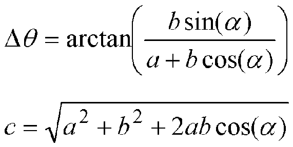
구체적으로는, 본 발명에 관한 3차원 형상 계측 장치는, 계측 대상물에 대하여, 시간 방향과 공간 방향으로 주기성을 갖는 패턴을 투영하는 투영 장치와, 상기 계측 대상물을 촬상하는 촬상 장치와, 상기 투영 장치로부터 투영하는 패턴의 위상을 바꾸면서 상기 촬상 장치에 의해 촬상된 복수의 관측 화상을 사용하여 상기 계측 대상물의 3차원 형상을 계측하는 제어 장치를 갖는다. 상기 제어 장치는, 상기 촬상 장치에서 관측되는 관측 광이, 상기 투영 장치로부터 투영된 광이 상기 계측 대상물 상의 계측점에서 반사하여 상기 촬상 장치에 입사하는 1차 반사광과, 상기 투영 장치로부터 투영되어 다른 반사면에서 반사된 광이 상기 계측 대상물 상의 상기 계측점에서 반사하여 상기 촬상 장치에 입사하는 2차 반사광의 합성광이라고 가정하고, 상기 복수의 관측 화상에 기초하여, 상기 관측광의 휘도 진폭값에 대해서 셋 이상의 샘플을 취득하고, 상기 셋 이상의 샘플을 사용하여 하기 식을 풂으로써, 상기 2차 반사광에 기인하는 위상 오차를 산출하고, 상기 복수의 관측 화상에 기초하여 상기 관측 광의 위상값을 산출하고, 상기 위상 오차를 사용하여 상기 관측광의 위상값을 보정함으로써 보정 위상값을 산출하고, 상기 보정 위상값에 기초하여, 상기 계측 대상물 상의 상기 계측점의 3차원 위치를 산출한다.Specifically, the three-dimensional shape measuring device according to the present invention includes a projection device for projecting a pattern having periodicity in a temporal direction and a spatial direction on a measurement object, an imaging device for imaging the measurement object, and the projection device It has a control device which measures a three-dimensional shape of the measurement object using a plurality of observation images captured by the imaging device while changing the phase of the pattern projected from The control device includes: primary reflected light incident on the imaging device by reflecting the light projected from the projection device at a measurement point on the measurement object and incident on the imaging device, and the other half reflected from the projection device. Assuming that the light reflected from the slope is a composite light of secondary reflected light reflected from the measurement point on the measurement object and incident on the imaging device, based on the plurality of observation images, three or more of the luminance amplitude values of the observation light A sample is obtained, and a phase error caused by the secondary reflected light is calculated by using the three or more samples and the following equation is calculated, a phase value of the observed light is calculated based on the plurality of observed images, and the phase A correction phase value is calculated by correcting the phase value of the observation light using an error, and a three-dimensional position of the measurement point on the measurement object is calculated based on the correction phase value.
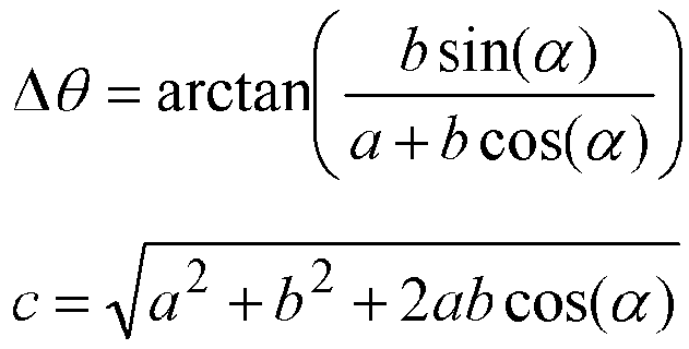
Δθ: 2차 반사광에 기인하는 위상 오차Δθ: phase error due to secondary reflected light
a: 1차 반사광의 휘도 진폭값a: The luminance amplitude value of the primary reflected light
b: 2차 반사광의 휘도 진폭값b: The luminance amplitude value of the secondary reflected light
c: 관측광의 휘도 진폭값c: luminance amplitude value of observation light
α: 1차 반사광과 2차 반사광의 위상차α: Phase difference between the primary and secondary reflected light
이 구성에 의하면, 2차 반사광에 기인하는 위상 오차를 보정한 위상값을 기초로 3차원 형상을 산출하므로, 다중 반사의 영향이 저감된 고정밀도의 3차원 형상 계측을 실현할 수 있다. 게다가 본 발명의 방법은, 종래 방법과 같이 3차원 형상의 계측을 저해하는 것은 없고, 또한 다중 반사가 실제로 발생하고 있는 부분인지 아닌지에 관계없이 적용할 수 있기 때문에, 현실의 장치로의 실장이 용이하다는 이점도 있다.According to this configuration, since the three-dimensional shape is calculated based on the phase value obtained by correcting the phase error caused by the secondary reflected light, it is possible to realize highly accurate three-dimensional shape measurement in which the influence of multiple reflections is reduced. Moreover, the method of the present invention does not impede the measurement of a three-dimensional shape as in the conventional method, and can be applied regardless of whether or not a part where multiple reflections are actually occurring, so it is easy to mount in a real device. There is also the advantage of doing it.
상기 셋 이상의 샘플은, 상기 관측 화상 상의 화소의 위치, 및 상기 패턴의 공간 방향의 주파수 중 적어도 어느 한쪽의 조건이 상이한 샘플이어도 된다.The three or more samples may be samples in which at least one condition of a position of a pixel on the observed image and a frequency in the spatial direction of the pattern is different.
예를 들어, 상기 셋 이상의 샘플은, 상기 관측 화상 상의 셋 이상의 화소에 대해서, 1종류의 주파수 패턴을 사용하여 관측된 휘도 진폭값이고, 상기 셋 이상의 화소는, 상기 패턴의 위상이 서로 상이한 위치에 있는 화소이면 된다. 패턴의 주파수가 1종류면 되기 때문에, 관측 화상의 촬영 횟수가 적어도 되기 때문이다.For example, the three or more samples are luminance amplitude values observed using one type of frequency pattern with respect to three or more pixels on the observed image, and the three or more pixels are at positions having different phases of the pattern. Any pixel that exists. This is because the number of times of photographing of the observed image is minimized because only one frequency of the pattern is required.
상기 셋 이상의 화소는, 상기 관측 화상 상의 국소 영역으로부터 선택되면 된다. 국소 영역(평면으로 근사시킬 수 있는 미소 영역) 내의 화소라면, 계측 대상물 표면의 반사율 등의 조건이 동일하다고 간주할 수 있기 때문이다.The three or more pixels may be selected from local regions on the observation image. This is because if a pixel is in a local region (a minute region that can be approximated by a plane), conditions such as reflectance of the surface of the measurement object can be regarded as the same.
상기 셋 이상의 화소는, 상기 관측 화상 상의 에피택셜 폴라 선에 평행인 방향으로 배열되는 화소이면 된다. 이와 같이 샘플을 선택함으로써, 가능한 한 적은 샘플로부터 고정밀도로 위상 오차를 산출할 수 있기 때문이다.The three or more pixels may be pixels arranged in a direction parallel to an epitaxial polar line on the observed image. This is because, by selecting samples in this way, a phase error can be calculated with high precision from as few samples as possible.
상기 셋 이상의 샘플은, 상기 관측 화상 상의 하나의 화소에 대해서, 3종류 이상의 주파수 패턴을 사용하여 관측된 휘도 진폭값이면 된다. 이 방법의 경우, 동일한 화소(동일한 계측점)에 관한 샘플을 사용하기 때문에, 위상 오차의 추정 정밀도를 보다 향상시킬 수 있다.The three or more samples may be luminance amplitude values observed using three or more frequency patterns for one pixel on the observed image. In this method, since samples for the same pixel (same measurement point) are used, the estimation accuracy of the phase error can be further improved.
상기 제어 장치는, 휘도 진폭값에 관한 제1 지표와, 투영하는 패턴의 공간 방향의 주파수에 관한 제2 지표와, 1차 반사광과 2차 반사광의 위상차에 관한 제3 지표의 관계를 정의하는 레퍼런스 정보를 기억하고 있고, 상기 셋 이상의 샘플과, 각 샘플의 관측 시에 투영한 패턴의 공간 방향의 주파수와, 상기 레퍼런스 정보에 기초하여, 1차 반사광과 2차 반사광의 위상차를 구하면 된다. 이 방법에 의하면, 셋 이상의 샘플의 값으로부터, 1차 반사광과 2차 반사광의 위상차의 값의 간단하고 또한 고정밀도로 계산할 수 있다.The control device is a reference defining a relationship between a first index related to a luminance amplitude value, a second index related to a frequency in a spatial direction of a pattern to be projected, and a third index related to a phase difference between the primary reflected light and the secondary reflected light Information is stored, and the phase difference between the primary reflected light and the secondary reflected light may be calculated based on the frequency of the three or more samples, the spatial direction of the pattern projected at the time of observation of each sample, and the reference information. According to this method, from the values of three or more samples, the value of the phase difference between the primary reflected light and the secondary reflected light can be calculated simply and with high accuracy.
상기 제어 장치는, 위상 시프트법 또는 MPS(Micro Phase Shifting)에 의해, 상기 보정 위상값에 기초하여, 상기 계측 대상물 상의 상기 계측점의 3차원 위치를 산출하면 된다. 상기 다른 반사면은, 경면성 반사면이면 된다.The control device may calculate a three-dimensional position of the measurement point on the measurement object based on the corrected phase value by a phase shift method or MPS (Micro Phase Shifting). The other reflective surface may be a specular reflective surface.
또한, 본 발명은, 상기 구성 내지 기능의 적어도 일부를 갖는 3차원 형상 계측 장치 또는 화상 처리 장치로서 파악할 수 있다. 또한, 본 발명은, 이러한 3차원 형상 계측 장치를 구비하는 검사 장치나 3차원 스캐너나 물체 인식 장치로서 파악할 수도 있다. 또한, 본 발명은, 상기 처리의 적어도 일부를 포함하는, 3차원 형상 계측 방법, 화상 처리 방법, 검사 방법, 물체 인식 방법이나, 이들 방법을 컴퓨터에 실행시키기 위한 프로그램, 또는, 그러한 프로그램을 비일시적으로 기록한 컴퓨터 판독 가능한 기록 매체로서 파악할 수도 있다. 상기 구성 및 처리의 각각은 기술적인 모순이 발생하지 않는 한 서로 조합하여 본 발명을 구성할 수 있다.Further, the present invention can be grasped as a three-dimensional shape measuring device or an image processing device having at least a part of the above configuration or function. Further, the present invention can also be grasped as an inspection device, a three-dimensional scanner, or an object recognition device including such a three-dimensional shape measuring device. In addition, the present invention provides a three-dimensional shape measurement method, an image processing method, an inspection method, an object recognition method, a program for executing these methods on a computer, or a non-transitory program including at least a part of the above processing. It can also be understood as a computer-readable recording medium recorded as a computer. Each of the above configurations and treatments can be combined with each other to constitute the present invention unless technical contradiction occurs.
본 발명에 따르면, 계측 대상물에 투영한 패턴의 위상을 기초로 3차원 형상을 계측하는 방법에 있어서, 다중 반사의 영향을 저감하고, 계측 정밀도를 향상시킬 수 있다.According to the present invention, in a method of measuring a three-dimensional shape based on the phase of a pattern projected onto a measurement object, the influence of multiple reflections can be reduced and measurement accuracy can be improved.
도 1은, 3차원 형상 계측 장치의 하드웨어 구성을 도시하는 모식도이다.
도 2는, 3차원 형상 계측에 관한 기능을 도시하는 블록도이다.
도 3은, 다중 반사와 관측광의 모델을 도시하는 모식도이다.
도 4는, 3차원 형상 계측의 흐름을 나타내는 흐름도이다.
도 5는, 레퍼런스 정보에 있어서의 제1 내지 제3 지표의 값의 관계를 개념적으로 도시하는 도면이다.
도 6은, 다중 반사를 설명하는 도면.1 is a schematic diagram showing a hardware configuration of a three-dimensional shape measuring device.
2 is a block diagram showing functions related to three-dimensional shape measurement.
3 is a schematic diagram showing a model of multiple reflection and observation light.
4 is a flowchart showing a flow of three-dimensional shape measurement.
5 is a diagram conceptually showing the relationship between values of first to third indexes in reference information.
6 is a diagram explaining multiple reflections.
본 발명은, 계측 대상물에 투영한 패턴의 위상의 변화를 기초로 3차원 형상을 계측하는 3차원 형상 계측 기술에 관한 것으로, 특히, 계측 대상물의 주위에 존재하는 반사면에 의한 다중 반사의 영향을 저감하고, 계측 정밀도를 향상시키기 위한 방법에 관한 것이다. 본 발명은, 위상 시프트법이나 그 개량인 MPS(Micro phase shifting)를 이용한 3차원 형상 계측에 바람직하게 적용할 수 있다. 본 발명에 관한 3차원 형상 계측은, 예를 들어 물체의 표면 형상을 계측하는 3차원 스캐너, 계측한 3차원 형상에 기초하여 물체의 검사를 행하는 검사 장치, 계측한 3차원 형상에 기초하여 물체 인식이나 개체 식별을 행하는 장치 등, 다양한 장치에 응용 가능하다. 예를 들어, 표면 실장 기판의 외관 검사 장치에서는, 기판 상의 금속제 부품에 의한 다중 반사가 검사 정밀도의 저하를 초래할 가능성이 있기 때문에, 본 발명에 관한 3차원 형상 계측을 특히 바람직하게 적용할 수 있다.The present invention relates to a three-dimensional shape measurement technology for measuring a three-dimensional shape based on a change in a phase of a pattern projected on a measurement object, and in particular, the influence of multiple reflections by a reflective surface existing around the measurement object. It relates to a method for reducing and improving measurement accuracy. The present invention can be preferably applied to a three-dimensional shape measurement using a phase shift method or MPS (Micro phase shifting) which is an improvement thereof. The three-dimensional shape measurement according to the present invention includes, for example, a three-dimensional scanner that measures the surface shape of an object, an inspection device that inspects an object based on the measured three-dimensional shape, and object recognition based on the measured three-dimensional shape. It can be applied to a variety of devices, such as a device that identifies or identifies an entity. For example, in the appearance inspection apparatus of a surface-mounted substrate, since multiple reflections caused by metal parts on the substrate may cause a decrease in inspection accuracy, the three-dimensional shape measurement according to the present invention can be particularly preferably applied.
이하, 도면을 참조하여 본 발명을 실시하기 위한 바람직한 형태의 일례를 설명한다. 단, 이하의 실시 형태에 기재되어 있는 장치의 구성이나 동작은 일례이고, 본 발명의 범위를 그것들에만 한정하는 취지의 것은 아니다.Hereinafter, an example of a preferred embodiment for carrying out the present invention will be described with reference to the drawings. However, the configuration and operation of the apparatus described in the following embodiments are examples and are not intended to limit the scope of the present invention to them.
(3차원 형상 계측 장치의 구성)(Configuration of 3D shape measuring device)
도 1을 참조하여, 본 실시 형태에 관한 3차원 형상 계측 장치의 전체 구성에 대하여 설명한다. 도 1은 3차원 형상 계측 장치의 하드웨어 구성을 도시하는 모식도이다. 3차원 형상 계측 장치(1)는 계측 대상물 O의 3차원 형상을 계측하기 위한 장치이고, 주된 구성으로서, 투영 장치(프로젝터)(10), 촬상 장치(카메라)(11), 제어 장치(컴퓨터)(12)를 갖고서 구성된다.With reference to FIG. 1, an overall configuration of a three-dimensional shape measuring device according to the present embodiment will be described. 1 is a schematic diagram showing a hardware configuration of a three-dimensional shape measuring device. The three-dimensional
투영 장치(10)는, 계측 대상물 O에 대하여 시간 방향과 공간 방향으로 주기성을 갖는 패턴을 투영하는 투영 수단이다. 투영 장치(10)의 수는 하나여도 되지만, 복수의 방향으로부터 투영 장치(10)에 대하여 패턴을 투영 가능하도록 복수의 투영 장치(10)를 마련해도 된다. 투영 장치(10)로서는, 디지털 미러 디바이스를 사용한 방식의 DLP(Digital Light Processing) 프로젝터를 바람직하게 이용할 수 있다. DLP 프로젝터는 투영 패턴의 변경이 용이하기 때문이다.The
촬상 장치(11)는, 패턴이 투영된 상태의 계측 대상물 O를 촬영하고, 디지털 화상을 출력하는 수단이다. 촬상 장치(11)는, 예를 들어 광학계와 이미지 센서를 갖고서 구성된다. 3차원 형상 계측을 행할 때는, 투영 장치(10)로부터 투영하는 패턴의 위상을 바꾸면서(위상 접속을 행하는 경우에는 추가로 패턴의 주파수를 바꾸면서), 촬상 장치(11)에 의해 복수매의 화상을 도입한다. 이후, 촬상 장치(11)에 의해 촬상되는 계측 대상물 O의 화상을 「관측 화상」이라고 부른다.The
제어 장치(12)는, 투영 장치(10) 및 촬상 장치(11)의 제어, 촬상 장치(11)로부터 도입된 화상에 대한 처리, 3차원 형상의 계측 등의 기능을 갖는 수단이다. 제어 장치(12)는 CPU(프로세서), 메모리, 불휘발성의 기억 장치(예를 들어, 하드 디스크나 플래시 메모리), 입력 장치(예를 들어, 키보드, 마우스, 터치 패널 등), 표시 장치(예를 들어, 액정 디스플레이 등)를 구비하는 컴퓨터에 의해 구성할 수 있다. 후술하는 제어 장치(12)의 기능은, 불휘발성의 기억 장치에 저장된 프로그램을 메모리에 로드하고, CPU가 당해 프로그램을 실행함으로써 실현할 수 있다. 단, 제어 장치(12)의 기능 전부 또는 일부를, ASIC나 FPGA나 전용의 하드웨어로 대체해도 상관없다. 또한, 분산 컴퓨팅이나 클라우드 컴퓨팅의 기술을 이용하여, 제어 장치(12)의 기능을 복수의 컴퓨터의 협동에 의해 실현해도 상관없다.The
도 2는, 제어 장치(12)의 3차원 형상 계측에 영향을 미치는 기능을 도시하는 블록도이다. 제어 장치(12)는, 3차원 형상 계측에 영향을 미치는 기능으로서, 화상 취득부(20), 영역 설정부(21), 위상 산출부(22), 3차원 복원부(23)를 갖고 있다.2 is a block diagram showing a function of the
화상 취득부(20)는, 촬상 장치(11)로부터 3차원 형상 계측에 사용하는 복수의 관측 화상을 도입하는 기능이다. 영역 설정부(21)는, 관측 화상의 시야 중, 후술하는 다중 반사 보정을 실시하는 영역(이후 「보정 영역」이라고 부른다)을 설정하는 기능이다. 위상 산출부(22)는, 관측 화상을 해석함으로써, 관측 화상 상의 각 화소(즉 계측 대상물 O의 표면 상의 각 계측점)에 있어서의 패턴의 위상값을 산출하는 기능이다. 3차원 복원부(23)는, 위상 산출부(22)에서 산출된 위상값에 기초하여, 관측 화상 상의 각 화소(즉 계측 대상물 O의 표면 상의 각 계측점)의 3차원 위치를 산출하는 기능이다. 이들 기능의 상세는 후술한다.The
(관측광의 모델과 다중 반사 보정)(Model of observation light and correction of multiple reflections)
도 3에, 다중 반사와 관측광의 모델을 도시한다.In Fig. 3, a model of multiple reflection and observation light is shown.
계측 대상물 O의 근방에 경면성이 높은 반사면 R(예를 들어 금속제의 물체의 표면)이 존재하는 계를 생각한다. 투영 장치(10)로부터 사인파 형상의 줄무늬 패턴을 투영한 경우에, 계측 대상물 O 상의 계측점 P에, 투영 장치(10)의 패널(100) 상의 점 x1로부터 발해진 광 L1(직접 광)과, 투영 장치(10)의 패널(100) 상의 점 x2로부터 발해진 광 L2의 반사면 R에서의 반사광 L20이 도달한다고 가정한다. 이후의 설명에 있어서, 투영 장치(10)의 패널(100) 상의 점 x를 점 광원으로 간주하고, 「투영 광원 x」라고 부른다.Consider a system in which a reflective surface R with high specularity (for example, the surface of a metal object) exists in the vicinity of the measurement object O. When a sine wave-shaped stripe pattern is projected from the
이때, 촬상 장치(11)에서 관측되는 관측광 IO는, 투영 장치(10)로부터 투영된 광 L1이 계측점 P에서 반사(확산 반사)하고 촬상 장치(11)에 입사한 광(1차 반사광) I1과, 투영 장치(10)로부터 투영되어 반사면 R에서 반사(경면 반사)된 광 L20이 계측점 P에서 반사(확산 반사)하여 촬상 장치(11)에 입사한 광(2차 반사광) I2의 합성광이라고 가정할 수 있고, 다음과 같이 모델화할 수 있다.At this time, the observation light I O observed by the
![]()
![]()

단, c는, 관측광 IO의 휘도 진폭값이고, θM은, 관측광 IO의 위상값이다. a1은, 줄무늬 패턴의 최대 휘도이고, R1은, 계측점 P의 반사율이고, R2는, 반사면 R의 반사율이다. wf는, 줄무늬 패턴의 각속도이고, t는 시간이다. kf는, 줄무늬 패턴의 파수이고, x1은, 광 L1의 투영 광원의 위치이고, x2는, 광 L2의 투영 광원의 위치이다. φ는, 줄무늬 패턴의 초기 위상이다. 또한, 이들의 변수 중 미지의 것은 R1, R2, x1, x2이다.However, c is the luminance amplitude value of the observation light I O , and θ M is the phase value of the observation light I O. a 1 is the maximum luminance of the stripe pattern, R 1 is the reflectance of the measurement point P, and R 2 is the reflectance of the reflective surface R. w f is the angular velocity of the stripe pattern, and t is the time. k f is the wave number of the stripe pattern, x 1 is the position of the projection light source of light L1, and x 2 is the position of the projection light source of light L2. φ is the initial phase of the stripe pattern. Also, unknown of these variables are R 1 , R 2 , x 1 , and x 2 .
여기서, 1차 반사광 I1의 휘도 진폭값 「a1R1」을 「a」, 2차 반사광 I2의 휘도 진폭값 「a1R1R2」를 「b」로 고쳐서, 1차 반사광 I1의 위상값 「wft+kfx1+φ」을 「θtrue」, 1차 반사광 I1과 2차 반사광 I2 사이의 위상차 「kf(x2-x1)」을 「α」로 놓고, 식 (1) 내지 식 (4)를 정리하면, 식 (1)은 하기 식과 같이 나타낼 수 있다.Here, first the brightness amplitude "a 1, R 1 'of the reflected light I 1 and modifies the' a ', second luminance amplitude of the primary reflection light I 2' a 1 R 1 R 2" to "b", the first reflected light I phase value of one "w f t + k f x 1 + φ ", an α to "θ true", the primary reflected light I 1 and the second reflection light phase difference "k f (x 2 -x 1)" between I 2 "', and formula (1) to formula (4) are put together, formula (1) can be expressed as the following formula.
![]()
![]()
단, Δθ는, 2차 반사광 I2에 기인하는 위상 오차이고,However, Δθ is a phase error caused by the secondary reflected light I 2 ,
![]()
![]()
이다.to be.
식 (5)와 합성의 정리로부터 하기 식을 도출할 수 있다.The following equation can be derived from equation (5) and the synthesis theorem.

식 (8)의 미지수는 a, b, α의 셋이기 때문에, 관측광 IO의 휘도 진폭값 c에 대하여 조건이 상이한 셋 이상의 샘플을 실측하면, 식 (8)을 풀 수 있다. 그리고, 식 (8)로부터 구한 a, b, α의 값을 식 (7)에 대입하면, 2차 반사광 I2에 기인하는 위상 오차 Δθ를 도출할 수 있고, 또한 관측 위상값 θM과 식 (6)으로부터 위상의 참값 θtrue를 구할 수 있다. 이상 설명한 모델에 의해, 위상의 참값(2차 반사광 I2의 영향이 없는 경우의 위상값) θtrue를 산출하는 조작을 「다중 반사 보정」이라고 부른다.Since the unknowns of equation (8) are three of a, b, and α, equation (8) can be solved by actually measuring three or more samples with different conditions for the luminance amplitude value c of the observation light I O. And, by substituting the values of a, b, and α obtained from equation (8) into equation (7), the phase error Δθ resulting from the secondary reflected light I 2 can be derived, and the observed phase value θ M and equation ( From 6), the true value θ true of the phase can be obtained. According to the model described above, an operation of calculating the true value of the phase (the phase value when there is no influence of the secondary reflected light I 2 ) θ true is called "multiple reflection correction".
(3차원 형상 계측)(3D shape measurement)
도 4의 흐름도를 따라, 3차원 형상 계측의 처리의 흐름을 설명한다.The flow of the process of three-dimensional shape measurement will be described according to the flow chart of FIG. 4.
스텝 S40에서는, 제어 장치(12)가 투영 장치(10) 및 촬상 장치(11)를 제어하고, 복수의 관측 화상을 촬영한다. 예를 들어, 사인파 형상으로 휘도가 변화하는 줄무늬 패턴(최대 휘도: a1, 파수 kf)을 π/4씩 위상을 바꾸면서 4회 투영하고, 4매의 관측 화상을 촬영해도 된다. 또한, 계측 범위 확대를 위하여 위상 접속을 행하는 경우에는, 줄무늬 패턴의 파수(주파수)를 바꾸고, 관측 화상의 촬영을 반복해도 된다. 예를 들어 일반적인 위상 접속의 경우에는, 계측용의 고주파의 줄무늬 패턴과 접속용의 저주파의 줄무늬 패턴에 의한 촬영을 행하고, MPS의 경우에는, 복수 종류의 고주파의 줄무늬 패턴에 의한 촬영을 행한다. 관측 화상의 데이터는, 화상 취득부(20)에 의해 제어 장치(12)에 도입되어, 메모리 또는 불휘발성의 기억 장치에 저장된다.In step S40, the
스텝 S41에서는, 영역 설정부(21)가, 관측 화상의 시야 중으로부터 보정 영역을 설정한다. 보정 영역의 설정은 어떠한 방법을 사용해도 된다. 예를 들어, 촬상 장치(11)로부터 도입된 화상을 표시 장치에 표시하고, 입력 장치를 사용하여 유저에게 영역을 지정시켜도 된다. 혹은, 영역 설정부(21)가, 관측 화상을 해석하여, 다중 반사가 발생하고 있는 영역을 검출(추정)하여, 보정 영역을 자동으로 설정해도 된다. 혹은, 계측 대상물이 표면 실장 기판과 같은 공업 제품의 경우라면, 설계 데이터(CAD 데이터) 등에 기초하여 반사면 R의 유무 및 다중 반사가 발생할 수 있는 영역을 검출하고, 보정 영역을 자동으로 설정해도 된다.In step S41, the
본 실시 형태에서는, 이와 같이 다중 반사 보정을 행하는 영역을 한정함으로써, 다중 반사 보정에 요하는 처리 부하를 저감하고, 3차원 형상 계측의 처리 시간의 단축을 도모할 수 있다. 또한, 처리 시간의 단축을 도모할 필요가 없으면, 관측 화상의 전체 영역에 다중 반사 보정을 행해도 상관없다. 그 경우에는 스텝 S41의 처리는 생략할 수 있다.In this embodiment, by limiting the region for performing multiple reflection correction in this way, the processing load required for multiple reflection correction can be reduced, and the processing time for three-dimensional shape measurement can be shortened. Further, if it is not necessary to shorten the processing time, multiple reflection correction may be performed on the entire area of the observed image. In that case, the process of step S41 can be omitted.
스텝 S42에서는, 위상 산출부(22)가, 위상을 바꾸어서 촬영한 복수의 관측 화상에 대하여 FFT(고속 푸리에 변환)를 행하여, 관측 화상 상의 각 화소에 있어서의 관측광의 휘도 진폭값 c 및 위상값 θM을 산출한다.In step S42, the
스텝 S43에서는, 위상 산출부(22)가, 스텝 S41에서 설정된 보정 영역 중으로부터 처리 대상으로 하는 화소(이후 「대상 화소 p0」라고 부른다)를 선택한다. 다음으로 스텝 S44에서는, 위상 산출부(22)가, 대상 화소 p0에 대해서, 관측광의 휘도 진폭값 c의 샘플을 셋 이상 취득한다.In step S43, the
관측광의 휘도 진폭값 c의 셋 이상의 샘플은, 「관측 화상 상의 화소의 위치」와 「줄무늬 패턴의 공간 방향의 주파수」 중 적어도 어느 한쪽의 조건이 상이하도록 선택하면 된다.Three or more samples of the luminance amplitude value c of the observed light may be selected so that at least one of the conditions of “the position of the pixel on the observed image” and “the frequency in the spatial direction of the striped pattern” is different.
예를 들어, 파수 kfi의 줄무늬 패턴을 사용하여 관측된 관측 화상에 있어서의 화소 pj의 휘도 진폭값을 cij라고 표기했을 때에, 대상 화소 p0과 그 근방 화소 p1, p2…의 각각에 대하여 파수 kf0의 1종류의 줄무늬 패턴으로 관측된 휘도 진폭값 c00, c01, c02…를 셋 이상의 샘플로서 선택해도 된다. 이 방법의 경우, 줄무늬 패턴의 파수가 1종류면 되기 때문에, 관측 화상의 촬영 횟수가 적어도 된다는 이점이 있다. 여기서, 근방 화소 p1, p2…는 대상 화소 p0 근방의 국소 영역으로부터 선택하면 된다. 국소 영역(평면에서 근사할 수 있는 미소 영역) 내의 화소 p0, p1, p2…이면, 계측 대상물 표면의 반사율 등의 조건이 동일하다고 간주할 수 있기 때문이다. 또한, 화소 p0, p1, p2…는 줄무늬 패턴의 위상이 서로 상이한 위치에서 선택하면 된다. 더욱 바람직하게는, 관측 화상 상의 에피택셜 폴라 선에 평행인 방향으로 배열되는 화소이면 된다. 이와 같이 샘플을 선택함으로써, 가능한 한 적은 샘플로부터 고정밀도로 위상 오차를 산출할 수 있다.For example, when the luminance amplitude value of the pixel p j in the observed image observed using the stripe pattern of wave number k fi is expressed as c ij , the target pixel p 0 and the pixels p 1 , p 2 … For each of the luminance amplitude values c 00 , c 01 , c 02 … observed with one type of stripe pattern of wave number k f0 . May be selected as three or more samples. In the case of this method, there is an advantage that the number of times of photographing an observed image is minimized, since the number of waves of the stripe pattern may be one. Here, the neighboring pixels p 1 , p 2 ... May be selected from a local region near the target pixel p 0 . Pixels p 0 , p 1 , p 2 in a local area (a small area that can be approximated in a plane). This is because conditions such as reflectance of the surface of the measurement object can be regarded as the same. Also, the pixels p 0 , p 1 , p 2 . May be selected at positions where the phases of the stripe patterns are different from each other. More preferably, the pixels may be arranged in a direction parallel to the epitaxial polar line on the observed image. By selecting samples in this way, it is possible to calculate a phase error with high accuracy from as few samples as possible.
혹은, 대상 화소 p0에 대하여 파수 kf0, kf1, kf2…의 3종류 이상의 줄무늬 패턴으로 관측된 휘도 진폭값 c00, c10, c20…를 셋 이상의 샘플로서 선택해도 된다. 이 방법의 경우, 동일 화소(동일 계측점)에 관한 샘플을 사용하기 때문에, 위상 오차의 추정 정밀도를 보다 향상시킬 수 있다. 특히, 계측 대상물 표면의 형상(요철)이나 반사율이 균일하지 않은 경우에는, 이 방법 쪽이 적합하다. 여기서, 파수 kf0, kf1, kf2…는, 어느 파수가 다른 파수의 정수배가 되지 않도록 선택한다. MPS의 경우에는, 3종류 이상의 고주파의 줄무늬 패턴을 사용하여 관측된 대상 화소 p0의 휘도 진폭값을 그대로 셋 이상의 샘플로서 이용할 수 있다.Alternatively, wave numbers k f0 , k f1 , k f2 … for the target pixel p 0 . Luminance amplitude values observed with three or more types of stripe patterns of c 00 , c 10 , c 20 May be selected as three or more samples. In this method, since samples for the same pixel (same measurement point) are used, the estimation accuracy of the phase error can be further improved. In particular, when the shape (corrugation) and reflectance of the surface of the measurement object are not uniform, this method is more suitable. Here, wave numbers k f0 , k f1 , k f2 … Is chosen so that one wave number is not an integer multiple of the other wave number. In the case of MPS, the luminance amplitude value of the target pixel p 0 observed using three or more types of high frequency stripe patterns can be used as three or more samples as it is.
혹은, 화소의 위치와 줄무늬 패턴의 파수의 양쪽 조건이 상이한 휘도 진폭값 c00, c01, c11…이라든가, 휘도 진폭값 c00, c11, c22…를, 셋 이상의 샘플로서 선택해도 된다. 즉, 화소의 위치와 줄무늬 패턴의 공간 방향의 주파수의 양쪽 조건을 바꾼 샘플을 사용해도 된다.Alternatively, the luminance amplitude values c 00 , c 01 , c 11 ... in which both conditions of the pixel position and the wave number of the stripe pattern are different. Like this, the luminance amplitude values c 00 , c 11 , c 22 … May be selected as three or more samples. That is, a sample in which both conditions of the pixel position and the frequency in the spatial direction of the stripe pattern are changed may be used.
스텝 S45에서는, 위상 산출부(22)가, 스텝 S44에서 취득한 휘도 진폭값의 셋 이상의 샘플을 사용하여 식 (7) 및 식 (8)을 풂으로써, 2차 반사광에 기인하는 위상 오차 Δθ를 산출한다. 그리고, 스텝 S46에서는, 위상 산출부(22)가, 위상 오차 Δθ를 사용하여 위상값 θM을 보정함으로써, 대상 화소 p0의 보정 위상값 θtrue를 산출한다. 본 실시 형태에서는, 관측 위상값 θM으로부터 위상 오차 Δθ를 감산한 값을 보정 위상값 θtrue로 한다(θtrue=θM-Δθ).In step S45, the
상술한 스텝 S43 내지 S46의 처리는, 보정 영역 내의 모든 화소에 대하여 행하여진다(스텝 S47).The processing of the above-described steps S43 to S46 is performed for all pixels in the correction area (step S47).
그 후, 스텝 S48에 있어서, 3차원 복원부(23)가, 위상 산출부(22)에서 산출된 각 화소의 위상값(보정 영역 내의 화소에 대해서는 보정 위상값)에 기초하여, 관측 화상 상의 각 화소(즉 계측 대상물의 표면 상의 각 계측점)의 3차원 위치를 산출한다. 이에 의해, 계측 대상물 표면의 3차원 형상을 복원할 수 있다. 위상값으로부터 3차원 형상을 계산하는 방법에는, 예를 들어 위상 시프트법, MPS 등을 사용할 수 있다. 이들의 알고리즘은 공지를 위해 여기에서는 상세한 설명은 생략한다.Thereafter, in step S48, based on the phase value of each pixel (corrected phase value for the pixel in the correction region) calculated by the
이상 설명한 본 실시 형태의 다중 반사 보정에 의하면, 2차 반사광에 기인하는 위상 오차를 보정한 위상값을 기초로 3차원 형상을 산출하므로, 다중 반사의 영향이 저감된 고정밀도의 3차원 형상 계측을 실현할 수 있다. 게다가 본 실시 형태의 다중 반사 보정은, 종래 방법과 같이 3차원 형상의 계측을 저해하는 것은 아니고, 또한 다중 반사가 실제로 발생한 부분인지 아닌지에 구애되지 않고 적용할 수 있기 때문에, 현실의 장치에 대한 실장이 용이하다는 이점도 있다.According to the multiple reflection correction of the present embodiment described above, since a three-dimensional shape is calculated based on a phase value obtained by correcting a phase error caused by secondary reflected light, high-precision three-dimensional shape measurement with reduced effects of multiple reflections is performed. Can be realized. Furthermore, since the multiple reflection correction of this embodiment does not impede the measurement of a three-dimensional shape as in the conventional method, and can be applied regardless of whether or not a part where multiple reflections actually occurred, it can be applied to an actual device. There is also an advantage that this is easy.
(위상 오차의 계산 방법의 예)(Example of phase error calculation method)
이어서, 위상 산출부(22)에 의한 위상 오차의 계산 방법, 즉, 식 (7) 및 식 (8)의 구체적인 해법의 일례를 설명한다.Next, an example of a method of calculating the phase error by the
식 (8)을 변형하면,Transforming Equation (8),
![]()
![]()
가 얻어진다. 여기서, a, b는(미지이지만) 상수이기 때문에, 관측광의 휘도 진폭값 c는, kf와 x2-x1의 함수로서 나타낼 수 있음을 알 수 있다.Is obtained. Here, since a and b are (although unknown) constants, it can be seen that the luminance amplitude value c of the observed light can be expressed as a function of k f and x 2 -x 1 .
그래서 본 예에서는, 휘도 진폭값에 관한 제1의 지표로서 「c2」를, 투영하는 줄무늬 패턴의 공간 방향의 주파수에 관한 제2의 지표로서 「1/kf」를, 1차 반사광과 2차 반사광의 위상차에 관한 제3의 지표로서 「x2-x1」을 각각 선택한다. 그리고, a, b에 적당한 상수를 설정하여, 식 (9)를 충족하는 제1 내지 제3 지표의 값의 조합을 계산함으로써, 제1 내지 제3 지표의 관계를 정의하는 레퍼런스 정보(3차원의 테이블)을 제작하고, 제어 장치(12)의 기억 장치에 미리 저장해 둔다. 도 5는, 레퍼런스 정보에 있어서의 제1 내지 제3 지표의 값의 관계를 개념적으로 도시하는 도면이다. 횡축이 제3 지표 x2-x1의 값이고, 종축이 제2 지표 1/kf의 값이고, 농도가 제1 지표 c2의 값이다.Therefore, in this example, the "1 / k f" as a second indicator relating to "c 2", the frequency of the spatial orientation of the striped pattern to be projected as an indicator of the first of the brightness amplitude values, the first reflected light and the second "X 2 -x 1 "is selected as a third index for the phase difference of the difference reflected light, respectively. Then, by setting appropriate constants for a and b and calculating a combination of values of the first to third indexes that satisfy Equation (9), reference information (three-dimensional Table) and stored in advance in the storage device of the
예를 들어, 대상 화소 p0에 대해서, 파수 kf0, kf1, kf2, kf3의 4종류의 줄무늬 패턴으로 관측된 휘도 진폭값 c00, c10, c20, c30이 샘플로서 취득되었다로 한다. 위상 산출부(22)는, 정규화 상호 상관과 같은 스케일 의존하지 않는 탐색 알고리즘에 의해 레퍼런스 정보를 탐색함으로써, 제2 지표의 값 1/kf0, 1/kf1, 1/kf2, 1/kf3에 대응하는 제1 지표의 값의 비가 c00 2:c10 2:c20 2:c30 2에 가장 근사하는, 제3 지표의 값 x2-x1을 구한다.For example, for the target pixel p 0 , the luminance amplitude values c 00 , c 10 , c 20 , and c 30 observed with four types of stripe patterns of wave numbers k f0 , k f1 , k f2 and k f3 are obtained as samples. It is said that it became. The
이어서, 미지수 a, b를 구하기 위해서, 위상 산출부(22)는, 식 (9)에 의해 다음과 같은 행렬식 (10)을 놓는다.Subsequently, in order to obtain the unknowns a and b, the

위상 산출부(22)는, 행렬식 (10)을 최소 제곱법으로 풂으로써 a2, b2, 2ab의 값을 구하고, 또한 그 값들을 충족하는 a, b의 조합을 구한다.The
그 후, 위상 산출부(22)는, 이상의 계산에서 얻어진 x2-x1의 값과 3차원 형상 계측에 사용하는 파수 kf의 값(예를 들어 kf0)으로부터 위상차 α=kf(x2-x1)을 계산하고, 이 α의 값과 행렬식 (10)으로부터 구한 a, b의 값을 식 (7)에 대입함으로써, 위상 오차 Δθ를 계산한다.After that, the
이상 설명한 계산 방법에 의하면, 휘도 진폭값 c의 복수의 샘플로부터, 위상차 α 및 위상 오차 Δθ의 값을 간단하고 또한 고정밀도로 계산할 수 있다.According to the calculation method described above, from a plurality of samples of the luminance amplitude value c, the values of the phase difference α and the phase error Δθ can be calculated simply and with high accuracy.
또한, 상기의 실시 형태의 설명은, 본 발명을 예시적으로 설명하는 것에 지나지 않는다. 본 발명은 상기의 구체적인 형태에 한정되는 일은 없고, 그 기술적 사상의 범위 내에서 다양한 변형이 가능하다. 예를 들어, 상기 계산 예에서는 네 샘플을 사용하여 탐색 처리 및 행렬 계산을 행하였지만, 셋 또는 다섯 이상의 샘플을 사용하여 동일한 계산을 행해도 된다. 또한, 레퍼런스 정보를 사용하지 않고, 비선형 최적화에 의해 식 (7)을 직접 풀어도 된다.In addition, the description of the above embodiment is only illustrative of the present invention. The present invention is not limited to the specific form described above, and various modifications are possible within the scope of the technical idea. For example, in the above calculation example, search processing and matrix calculation are performed using four samples, but the same calculation may be performed using three or five or more samples. Further, you may directly solve Equation (7) by nonlinear optimization without using reference information.
O: 계측 대상물, P: 계측점, R: 반사면
1: 3차원 형상 계측 장치, 10: 투영 장치, 11: 촬상 장치, 12: 제어 장치
20: 화상 취득부, 21: 영역 설정부, 22: 위상 산출부, 23: 3차원 복원부
100: 패널O: measurement object, P: measurement point, R: reflective surface
1: three-dimensional shape measuring device, 10: projection device, 11: imaging device, 12: control device
20: image acquisition unit, 21: area setting unit, 22: phase calculation unit, 23: 3D restoration unit
100: panel
Claims (11)
상기 계측 대상물을 촬상하는 촬상 장치와,
상기 투영 장치로부터 투영하는 패턴의 위상을 바꾸면서 상기 촬상 장치에 의해 촬상된 복수의 관측 화상을 사용하여 상기 계측 대상물의 3차원 형상을 계측하는 제어 장치를 갖고,
상기 제어 장치는,
상기 촬상 장치에서 관측되는 관측광이, 상기 투영 장치로부터 투영된 광이 상기 계측 대상물 상의 계측점에서 반사하여 상기 촬상 장치에 입사하는 1차 반사광과, 상기 투영 장치로부터 투영되어 다른 반사면에서 반사된 광이 상기 계측 대상물 상의 상기 계측점에서 반사하여 상기 촬상 장치에 입사하는 2차 반사광의 합성광이라고 가정하고,
상기 복수의 관측 화상에 기초하여, 상기 관측광의 휘도 진폭값에 대해서 셋 이상의 샘플을 취득하고,
상기 셋 이상의 샘플을 사용하여 하기 식을 풂으로써, 상기 2차 반사광에 기인하는 위상 오차를 산출하고,
상기 복수의 관측 화상에 기초하여 상기 관측광의 위상값을 산출하고,
상기 위상 오차를 사용하여 상기 관측광의 위상값을 보정함으로써 보정 위상값을 산출하고,
상기 보정 위상값에 기초하여, 상기 계측 대상물 상의 상기 계측점의 3차원 위치를 산출하는 것을 특징으로 하는 3차원 형상 계측 장치.
[수학식 1]
Δθ: 2차 반사광에 기인하는 위상 오차
a: 1차 반사광의 휘도 진폭값
b: 2차 반사광의 휘도 진폭값
c: 관측광의 휘도 진폭값
α: 1차 반사광과 2차 반사광의 위상차A projection device for projecting a pattern having periodicity in the temporal and spatial directions on the measurement object,
An imaging device for imaging the measurement object,
A control device for measuring a three-dimensional shape of the measurement object using a plurality of observation images captured by the imaging device while changing the phase of the pattern projected from the projection device,
The control device,
The observation light observed by the imaging device includes primary reflected light that is incident on the imaging device by reflecting light projected from the projection device at a measurement point on the measurement object, and light that is projected from the projection device and reflected from another reflective surface. Assume that it is a composite light of secondary reflected light reflected from the measurement point on the measurement object and incident on the imaging device,
On the basis of the plurality of observed images, three or more samples are acquired for the luminance amplitude value of the observed light,
The phase error caused by the secondary reflected light is calculated by using the three or more samples and using the following equation,
Calculate a phase value of the observation light based on the plurality of observation images,
A correction phase value is calculated by correcting the phase value of the observation light using the phase error,
A three-dimensional shape measuring device, characterized in that based on the corrected phase value, a three-dimensional position of the measurement point on the measurement object is calculated.
[Equation 1]
Δθ: phase error due to secondary reflected light
a: The luminance amplitude value of the primary reflected light
b: The luminance amplitude value of the secondary reflected light
c: luminance amplitude value of observation light
α: Phase difference between the primary and secondary reflected light
것을 특징으로 하는 3차원 형상 계측 장치.The method according to claim 1, wherein the three or more samples are samples in which at least one condition of a position of a pixel on the observed image and a frequency in the spatial direction of the pattern is different.
A three-dimensional shape measuring device, characterized in that.
상기 셋 이상의 화소는, 상기 패턴의 위상이 서로 상이한 위치에 있는 화소인
것을 특징으로 하는 3차원 형상 계측 장치.The method of claim 1, wherein the three or more samples are luminance amplitude values observed using one type of frequency pattern with respect to three or more pixels on the observation image,
The three or more pixels are pixels having different phases of the pattern.
A three-dimensional shape measuring device, characterized in that.
것을 특징으로 하는 3차원 형상 계측 장치.The method of claim 3, wherein the three or more pixels are selected from local regions on the observed image.
A three-dimensional shape measuring device, characterized in that.
것을 특징으로 하는 3차원 형상 계측 장치.The method of claim 1, wherein the three or more samples are luminance amplitude values observed using three or more frequency patterns for one pixel on the observed image.
A three-dimensional shape measuring device, characterized in that.
휘도 진폭값에 관한 제1 지표와, 투영하는 패턴의 공간 방향의 주파수에 관한 제2 지표와, 1차 반사광과 2차 반사광의 위상차에 관한 제3 지표의 관계를 정의하는 레퍼런스 정보를 기억하고 있고,
상기 셋 이상의 샘플과, 각 샘플의 관측 시에 투영한 패턴의 공간 방향의 주파수와, 상기 레퍼런스 정보에 기초하여, 1차 반사광과 2차 반사광의 위상차를 구하는 것을 특징으로 하는 3차원 형상 계측 장치.The method according to any one of claims 1 to 6, wherein the control device,
Reference information defining a relationship between a first index related to the luminance amplitude value, a second index related to a frequency in the spatial direction of the pattern to be projected, and a third index related to the phase difference between the first reflected light and the second reflected light is stored. ,
A three-dimensional shape measuring apparatus, characterized in that, based on the three or more samples, a frequency in a spatial direction of a pattern projected at the time of observation of each sample, and the reference information, a phase difference between the primary reflected light and the secondary reflected light is calculated.
것을 특징으로 하는 3차원 형상 계측 장치.The method of claim 1, wherein the control device calculates a three-dimensional position of the measurement point on the measurement object based on the correction phase value by a phase shift method or MPS (Micro Phase Shifting).
A three-dimensional shape measuring device, characterized in that.
것을 특징으로 하는 3차원 형상 계측 장치.The method of claim 1, wherein the other reflective surface is a specular reflective surface
A three-dimensional shape measuring device, characterized in that.
상기 패턴은, 시간 방향과 공간 방향으로 주기성을 갖는 패턴이고,
상기 촬상 장치에서 관측되는 관측광이, 상기 투영 장치로부터 투영된 광이 상기 계측 대상물 상의 계측점에서 반사하여 상기 촬상 장치에 입사하는 1차 반사광과, 상기 투영 장치로부터 투영되어 다른 반사면에서 반사된 광이 상기 계측 대상물 상의 상기 계측점에서 반사하여 상기 촬상 장치에 입사하는 2차 반사광의 합성광이라고 가정하고,
상기 3차원 형상 계측 방법이,
상기 복수의 관측 화상에 기초하여, 상기 관측광의 휘도 진폭값에 대해서 셋 이상의 샘플을 취득하는 스텝과,
상기 셋 이상의 샘플을 사용하여 하기 식을 풂으로써, 상기 2차 반사광에 기인하는 위상 오차를 산출하는 스텝과,
상기 복수의 관측 화상에 기초하여 상기 관측광의 위상값을 산출하는 스텝과,
상기 위상 오차를 사용하여 상기 관측광의 위상값을 보정함으로써 보정 위상값을 산출하는 스텝과,
상기 보정 위상값에 기초하여, 상기 계측 대상물 상의 상기 계측점의 3차원 위치를 산출하는 스텝
을 포함하는 것을 특징으로 하는 3차원 형상 계측 방법.
[수학식 2]

Δθ: 2차 반사광에 기인하는 위상 오차
a: 1차 반사광의 휘도 진폭값
b: 2차 반사광의 휘도 진폭값
c: 관측광의 휘도 진폭값
α: 1차 반사광과 2차 반사광의 위상차In a three-dimensional shape measurement method for measuring a three-dimensional shape of a measurement object using a plurality of observation images captured by an imaging device while changing the phase of a pattern projected from a projection device,
The pattern is a pattern having periodicity in time and space directions,
The observation light observed by the imaging device includes primary reflected light that is incident on the imaging device by reflecting light projected from the projection device at a measurement point on the measurement object, and light that is projected from the projection device and reflected from another reflective surface. Assume that it is a composite light of secondary reflected light reflected from the measurement point on the measurement object and incident on the imaging device,
The three-dimensional shape measurement method,
A step of acquiring three or more samples for the luminance amplitude value of the observed light based on the plurality of observed images;
A step of calculating a phase error caused by the secondary reflected light by using the three or more samples and using the following equation,
A step of calculating a phase value of the observation light based on the plurality of observation images,
Calculating a corrected phase value by correcting a phase value of the observed light using the phase error;
A step of calculating a three-dimensional position of the measurement point on the measurement object based on the correction phase value
3D shape measurement method comprising a.
[Equation 2]
Δθ: phase error due to secondary reflected light
a: The luminance amplitude value of the primary reflected light
b: The luminance amplitude value of the secondary reflected light
c: luminance amplitude value of observation light
α: Phase difference between the primary and secondary reflected light
Applications Claiming Priority (3)
| Application Number | Priority Date | Filing Date | Title |
|---|---|---|---|
| JPJP-P-2017-043115 | 2017-03-07 | ||
| JP2017043115A JP2018146449A (en) | 2017-03-07 | 2017-03-07 | 3D shape measuring apparatus and 3D shape measuring method |
| PCT/JP2017/042490 WO2018163530A1 (en) | 2017-03-07 | 2017-11-28 | Three-dimensional shape measurement device, three-dimensional shape measurement method, and program |
Publications (2)
| Publication Number | Publication Date |
|---|---|
| KR20190104367A KR20190104367A (en) | 2019-09-09 |
| KR102149707B1 true KR102149707B1 (en) | 2020-08-31 |
Family
ID=63447483
Family Applications (1)
| Application Number | Title | Priority Date | Filing Date |
|---|---|---|---|
| KR1020197022561A Active KR102149707B1 (en) | 2017-03-07 | 2017-11-28 | 3D shape measurement device, 3D shape measurement method and program |
Country Status (6)
| Country | Link |
|---|---|
| US (1) | US11055863B2 (en) |
| EP (1) | EP3594618B1 (en) |
| JP (1) | JP2018146449A (en) |
| KR (1) | KR102149707B1 (en) |
| CN (1) | CN110268223B (en) |
| WO (1) | WO2018163530A1 (en) |
Families Citing this family (11)
| Publication number | Priority date | Publication date | Assignee | Title |
|---|---|---|---|---|
| JP7186019B2 (en) * | 2017-06-20 | 2022-12-08 | 株式会社ミツトヨ | Three-dimensional shape measuring device and three-dimensional shape measuring method |
| US10656780B2 (en) * | 2018-01-12 | 2020-05-19 | Mitutoyo Corporation | Position specifying method and program |
| JP2021018219A (en) * | 2019-07-24 | 2021-02-15 | 株式会社デンソーアイティーラボラトリ | Three-dimensional shape measurement system, three-dimensional shape measurement method, and three-dimensional shape measurement program |
| WO2021020603A1 (en) * | 2019-07-29 | 2021-02-04 | 한국표준과학연구원 | System and method for measuring three-dimensional shape of freeform surface by using ultrafast deflection measurement method using composite pattern |
| WO2021191991A1 (en) * | 2020-03-24 | 2021-09-30 | 三菱電機株式会社 | Signal processing device, radar device, and signal processing method |
| US11270418B1 (en) | 2020-11-19 | 2022-03-08 | VPIX Medical Incorporation | Method and system for correcting phase of image reconstruction signal |
| WO2022108338A1 (en) * | 2020-11-19 | 2022-05-27 | 주식회사 브이픽스메디칼 | Method and system for correcting phase of image reconstruction signal |
| KR102374439B1 (en) * | 2020-11-19 | 2022-03-15 | (주) 브이픽스메디칼 | Phase of image reconstruction signal calibration method and system |
| CN113960067A (en) * | 2021-10-25 | 2022-01-21 | 慧三维智能科技(苏州)有限公司 | High bright surface defect detection device |
| KR102901195B1 (en) * | 2022-03-09 | 2025-12-17 | 야마하하쓰도키 가부시키가이샤 | Three-dimensional measurement computing device, three-dimensional measurement program, recording medium, three-dimensional measurement device, and three-dimensional measurement computing method |
| JP2024117880A (en) | 2023-02-20 | 2024-08-30 | Juki株式会社 | Three-dimensional measurement device and three-dimensional measurement method |
Citations (4)
| Publication number | Priority date | Publication date | Assignee | Title |
|---|---|---|---|---|
| JP2006023178A (en) * | 2004-07-07 | 2006-01-26 | Olympus Corp | 3-dimensional measuring method and device |
| JP2014106110A (en) * | 2012-11-27 | 2014-06-09 | Canon Inc | Measurement method and measurement device |
| JP2015038474A (en) * | 2013-08-08 | 2015-02-26 | ジェイエスエムエスダブリュー テクノロジー リミテッド・ライアビリティー・カンパニーJSMSW Technology LLC | Phase-controlled model-based overlay measurement system and method |
| JP2015132509A (en) * | 2014-01-10 | 2015-07-23 | 凸版印刷株式会社 | Image data acquiring system, and image data acquiring method |
Family Cites Families (17)
| Publication number | Priority date | Publication date | Assignee | Title |
|---|---|---|---|---|
| JP3996560B2 (en) * | 2003-08-18 | 2007-10-24 | 株式会社リコー | Object shape measuring device |
| JP4644819B2 (en) * | 2004-04-22 | 2011-03-09 | 国立大学法人電気通信大学 | Minute displacement measurement method and apparatus |
| JP3944188B2 (en) * | 2004-05-21 | 2007-07-11 | 株式会社東芝 | Stereo image display method, stereo image imaging method, and stereo image display apparatus |
| JP4611782B2 (en) * | 2005-03-28 | 2011-01-12 | シチズンホールディングス株式会社 | Three-dimensional shape measuring method and measuring apparatus |
| JP2007114071A (en) * | 2005-10-20 | 2007-05-10 | Omron Corp | Three-dimensional shape measuring apparatus, program, computer-readable recording medium, and three-dimensional shape measuring method |
| US20080013090A1 (en) * | 2006-03-29 | 2008-01-17 | Nikon Corporation | Measurement method, measurement unit, processing unit, pattern forming method , and device manufacturing method |
| JP2008309551A (en) * | 2007-06-13 | 2008-12-25 | Nikon Corp | Shape measuring method, storage medium, and shape measuring device |
| JP2009019941A (en) * | 2007-07-11 | 2009-01-29 | Nikon Corp | Shape measurement method |
| JP2011021970A (en) * | 2009-07-15 | 2011-02-03 | Nikon Corp | Three-dimensional shape measuring device and three-dimensional shape measuring method |
| JP2014115109A (en) * | 2012-12-06 | 2014-06-26 | Canon Inc | Device and method for measuring distance |
| JP5633058B1 (en) * | 2013-07-19 | 2014-12-03 | 株式会社三次元メディア | 3D measuring apparatus and 3D measuring method |
| CN103398675B (en) | 2013-08-10 | 2016-06-15 | 南昌航空大学 | A kind of complicated big three-dimensional measurement of objects method based on fringe period correction |
| DE102013017500B3 (en) * | 2013-10-17 | 2015-04-02 | Faro Technologies, Inc. | Method and apparatus for optically scanning and measuring a scene |
| JP2016000139A (en) * | 2014-06-12 | 2016-01-07 | キヤノン株式会社 | Phase information acquisition apparatus and imaging system |
| WO2016076796A1 (en) * | 2014-11-12 | 2016-05-19 | Heptagon Micro Optics Pte. Ltd. | Optoelectronic modules for distance measurements and/or multi-dimensional imaging |
| JP6507653B2 (en) * | 2015-01-13 | 2019-05-08 | オムロン株式会社 | Inspection apparatus and control method of inspection apparatus |
| CN105761243A (en) | 2016-01-28 | 2016-07-13 | 四川川大智胜软件股份有限公司 | Three-dimensional full face photographing system based on structured light projection and photographing method thereof |
-
2017
- 2017-03-07 JP JP2017043115A patent/JP2018146449A/en not_active Ceased
- 2017-11-28 KR KR1020197022561A patent/KR102149707B1/en active Active
- 2017-11-28 EP EP17900273.8A patent/EP3594618B1/en active Active
- 2017-11-28 US US16/484,134 patent/US11055863B2/en active Active
- 2017-11-28 CN CN201780085657.4A patent/CN110268223B/en active Active
- 2017-11-28 WO PCT/JP2017/042490 patent/WO2018163530A1/en not_active Ceased
Patent Citations (4)
| Publication number | Priority date | Publication date | Assignee | Title |
|---|---|---|---|---|
| JP2006023178A (en) * | 2004-07-07 | 2006-01-26 | Olympus Corp | 3-dimensional measuring method and device |
| JP2014106110A (en) * | 2012-11-27 | 2014-06-09 | Canon Inc | Measurement method and measurement device |
| JP2015038474A (en) * | 2013-08-08 | 2015-02-26 | ジェイエスエムエスダブリュー テクノロジー リミテッド・ライアビリティー・カンパニーJSMSW Technology LLC | Phase-controlled model-based overlay measurement system and method |
| JP2015132509A (en) * | 2014-01-10 | 2015-07-23 | 凸版印刷株式会社 | Image data acquiring system, and image data acquiring method |
Also Published As
| Publication number | Publication date |
|---|---|
| JP2018146449A (en) | 2018-09-20 |
| US20200020119A1 (en) | 2020-01-16 |
| US11055863B2 (en) | 2021-07-06 |
| WO2018163530A1 (en) | 2018-09-13 |
| EP3594618A1 (en) | 2020-01-15 |
| CN110268223B (en) | 2021-02-09 |
| EP3594618B1 (en) | 2021-11-17 |
| EP3594618A4 (en) | 2021-01-27 |
| CN110268223A (en) | 2019-09-20 |
| KR20190104367A (en) | 2019-09-09 |
Similar Documents
| Publication | Publication Date | Title |
|---|---|---|
| KR102149707B1 (en) | 3D shape measurement device, 3D shape measurement method and program | |
| KR102170029B1 (en) | 3D shape measurement device, 3D shape measurement method and program | |
| EP1643210A1 (en) | Method and apparatus for measuring shape of an object | |
| CN110692084B (en) | Apparatus and machine-readable storage medium for deriving topology information of a scene | |
| US11803982B2 (en) | Image processing device and three-dimensional measuring system | |
| US11512946B2 (en) | Method and system for automatic focusing for high-resolution structured light 3D imaging | |
| TW201710642A (en) | Structured light generating apparatus, measuring system and method thereof | |
| JP2014186010A (en) | Measuring device, method, and program | |
| Chen et al. | Analysis and reduction of phase errors caused by nonuniform surface reflectivity in a phase-shifting measurement system | |
| KR102218215B1 (en) | Mutual reflection detection device, mutual reflection detection method and program | |
| JP2016102755A (en) | Information processing device, information processing method and program | |
| CN112747686B (en) | Three-dimensional shape measuring device | |
| KR101613829B1 (en) | Method and Apparatus for 3D Shape Measuring By Using Derivative Moire | |
| JP2016109580A (en) | Measuring device and measurement method | |
| CN105008903A (en) | Method and device for analyzing the surface of a substrate | |
| Casavola et al. | Definition of the operational parameters of a structured light system and development of an adaptive lighting algorithm | |
| CN118518028A (en) | 3D measurement device and 3D measurement method |
Legal Events
| Date | Code | Title | Description |
|---|---|---|---|
| A201 | Request for examination | ||
| PA0105 | International application |
Patent event date: 20190731 Patent event code: PA01051R01D Comment text: International Patent Application |
|
| PA0201 | Request for examination | ||
| PG1501 | Laying open of application | ||
| E701 | Decision to grant or registration of patent right | ||
| PE0701 | Decision of registration |
Patent event code: PE07011S01D Comment text: Decision to Grant Registration Patent event date: 20200729 |
|
| GRNT | Written decision to grant | ||
| PR0701 | Registration of establishment |
Comment text: Registration of Establishment Patent event date: 20200825 Patent event code: PR07011E01D |
|
| PR1002 | Payment of registration fee |
Payment date: 20200826 End annual number: 3 Start annual number: 1 |
|
| PG1601 | Publication of registration | ||
| PR1001 | Payment of annual fee |
Payment date: 20230718 Start annual number: 4 End annual number: 4 |
|
| PR1001 | Payment of annual fee |
Payment date: 20240813 Start annual number: 5 End annual number: 5 |