KR102132520B1 - Locomotion system and apparatus - Google Patents
Locomotion system and apparatus Download PDFInfo
- Publication number
- KR102132520B1 KR102132520B1 KR1020177003680A KR20177003680A KR102132520B1 KR 102132520 B1 KR102132520 B1 KR 102132520B1 KR 1020177003680 A KR1020177003680 A KR 1020177003680A KR 20177003680 A KR20177003680 A KR 20177003680A KR 102132520 B1 KR102132520 B1 KR 102132520B1
- Authority
- KR
- South Korea
- Prior art keywords
- platform
- locomotion system
- support
- support halo
- halo
- Prior art date
- Legal status (The legal status is an assumption and is not a legal conclusion. Google has not performed a legal analysis and makes no representation as to the accuracy of the status listed.)
- Active
Links
Images


Classifications
-
- G—PHYSICS
- G06—COMPUTING OR CALCULATING; COUNTING
- G06F—ELECTRIC DIGITAL DATA PROCESSING
- G06F3/00—Input arrangements for transferring data to be processed into a form capable of being handled by the computer; Output arrangements for transferring data from processing unit to output unit, e.g. interface arrangements
- G06F3/01—Input arrangements or combined input and output arrangements for interaction between user and computer
- G06F3/011—Arrangements for interaction with the human body, e.g. for user immersion in virtual reality
-
- A—HUMAN NECESSITIES
- A63—SPORTS; GAMES; AMUSEMENTS
- A63B—APPARATUS FOR PHYSICAL TRAINING, GYMNASTICS, SWIMMING, CLIMBING, OR FENCING; BALL GAMES; TRAINING EQUIPMENT
- A63B69/00—Training appliances or apparatus for special sports
- A63B69/0028—Training appliances or apparatus for special sports for running, jogging or speed-walking
- A63B69/0035—Training appliances or apparatus for special sports for running, jogging or speed-walking on the spot
-
- A—HUMAN NECESSITIES
- A63—SPORTS; GAMES; AMUSEMENTS
- A63B—APPARATUS FOR PHYSICAL TRAINING, GYMNASTICS, SWIMMING, CLIMBING, OR FENCING; BALL GAMES; TRAINING EQUIPMENT
- A63B69/00—Training appliances or apparatus for special sports
- A63B69/0064—Attachments on the trainee preventing falling
-
- A—HUMAN NECESSITIES
- A63—SPORTS; GAMES; AMUSEMENTS
- A63B—APPARATUS FOR PHYSICAL TRAINING, GYMNASTICS, SWIMMING, CLIMBING, OR FENCING; BALL GAMES; TRAINING EQUIPMENT
- A63B71/00—Games or sports accessories not covered in groups A63B1/00 - A63B69/00
- A63B71/06—Indicating or scoring devices for games or players, or for other sports activities
- A63B71/0619—Displays, user interfaces and indicating devices, specially adapted for sport equipment, e.g. display mounted on treadmills
- A63B71/0622—Visual, audio or audio-visual systems for entertaining, instructing or motivating the user
-
- A—HUMAN NECESSITIES
- A63—SPORTS; GAMES; AMUSEMENTS
- A63G—MERRY-GO-ROUNDS; SWINGS; ROCKING-HORSES; CHUTES; SWITCHBACKS; SIMILAR DEVICES FOR PUBLIC AMUSEMENT
- A63G31/00—Amusement arrangements
- A63G31/16—Amusement arrangements creating illusions of travel
-
- A—HUMAN NECESSITIES
- A63—SPORTS; GAMES; AMUSEMENTS
- A63B—APPARATUS FOR PHYSICAL TRAINING, GYMNASTICS, SWIMMING, CLIMBING, OR FENCING; BALL GAMES; TRAINING EQUIPMENT
- A63B24/00—Electric or electronic controls for exercising apparatus of preceding groups; Controlling or monitoring of exercises, sportive games, training or athletic performances
- A63B24/0087—Electric or electronic controls for exercising apparatus of groups A63B21/00 - A63B23/00, e.g. controlling load
- A63B2024/0096—Electric or electronic controls for exercising apparatus of groups A63B21/00 - A63B23/00, e.g. controlling load using performance related parameters for controlling electronic or video games or avatars
-
- A—HUMAN NECESSITIES
- A63—SPORTS; GAMES; AMUSEMENTS
- A63B—APPARATUS FOR PHYSICAL TRAINING, GYMNASTICS, SWIMMING, CLIMBING, OR FENCING; BALL GAMES; TRAINING EQUIPMENT
- A63B69/00—Training appliances or apparatus for special sports
- A63B69/0028—Training appliances or apparatus for special sports for running, jogging or speed-walking
- A63B2069/0037—Training appliances or apparatus for special sports for running, jogging or speed-walking safety devices, e.g. warning bells, rear-view mirrors
-
- A—HUMAN NECESSITIES
- A63—SPORTS; GAMES; AMUSEMENTS
- A63B—APPARATUS FOR PHYSICAL TRAINING, GYMNASTICS, SWIMMING, CLIMBING, OR FENCING; BALL GAMES; TRAINING EQUIPMENT
- A63B71/00—Games or sports accessories not covered in groups A63B1/00 - A63B69/00
- A63B71/06—Indicating or scoring devices for games or players, or for other sports activities
- A63B71/0619—Displays, user interfaces and indicating devices, specially adapted for sport equipment, e.g. display mounted on treadmills
- A63B71/0622—Visual, audio or audio-visual systems for entertaining, instructing or motivating the user
- A63B2071/0638—Displaying moving images of recorded environment, e.g. virtual environment
-
- A—HUMAN NECESSITIES
- A63—SPORTS; GAMES; AMUSEMENTS
- A63B—APPARATUS FOR PHYSICAL TRAINING, GYMNASTICS, SWIMMING, CLIMBING, OR FENCING; BALL GAMES; TRAINING EQUIPMENT
- A63B2210/00—Space saving
- A63B2210/50—Size reducing arrangements for stowing or transport
-
- A—HUMAN NECESSITIES
- A63—SPORTS; GAMES; AMUSEMENTS
- A63B—APPARATUS FOR PHYSICAL TRAINING, GYMNASTICS, SWIMMING, CLIMBING, OR FENCING; BALL GAMES; TRAINING EQUIPMENT
- A63B2220/00—Measuring of physical parameters relating to sporting activity
- A63B2220/10—Positions
-
- A—HUMAN NECESSITIES
- A63—SPORTS; GAMES; AMUSEMENTS
- A63B—APPARATUS FOR PHYSICAL TRAINING, GYMNASTICS, SWIMMING, CLIMBING, OR FENCING; BALL GAMES; TRAINING EQUIPMENT
- A63B2220/00—Measuring of physical parameters relating to sporting activity
- A63B2220/10—Positions
- A63B2220/12—Absolute positions, e.g. by using GPS
-
- A—HUMAN NECESSITIES
- A63—SPORTS; GAMES; AMUSEMENTS
- A63B—APPARATUS FOR PHYSICAL TRAINING, GYMNASTICS, SWIMMING, CLIMBING, OR FENCING; BALL GAMES; TRAINING EQUIPMENT
- A63B2220/00—Measuring of physical parameters relating to sporting activity
- A63B2220/40—Acceleration
-
- A—HUMAN NECESSITIES
- A63—SPORTS; GAMES; AMUSEMENTS
- A63B—APPARATUS FOR PHYSICAL TRAINING, GYMNASTICS, SWIMMING, CLIMBING, OR FENCING; BALL GAMES; TRAINING EQUIPMENT
- A63B2220/00—Measuring of physical parameters relating to sporting activity
- A63B2220/80—Special sensors, transducers or devices therefor
- A63B2220/805—Optical or opto-electronic sensors
-
- A—HUMAN NECESSITIES
- A63—SPORTS; GAMES; AMUSEMENTS
- A63B—APPARATUS FOR PHYSICAL TRAINING, GYMNASTICS, SWIMMING, CLIMBING, OR FENCING; BALL GAMES; TRAINING EQUIPMENT
- A63B2225/00—Miscellaneous features of sport apparatus, devices or equipment
- A63B2225/09—Adjustable dimensions
- A63B2225/093—Height
-
- A—HUMAN NECESSITIES
- A63—SPORTS; GAMES; AMUSEMENTS
- A63B—APPARATUS FOR PHYSICAL TRAINING, GYMNASTICS, SWIMMING, CLIMBING, OR FENCING; BALL GAMES; TRAINING EQUIPMENT
- A63B2225/00—Miscellaneous features of sport apparatus, devices or equipment
- A63B2225/50—Wireless data transmission, e.g. by radio transmitters or telemetry
-
- G—PHYSICS
- G06—COMPUTING OR CALCULATING; COUNTING
- G06F—ELECTRIC DIGITAL DATA PROCESSING
- G06F2203/00—Indexing scheme relating to G06F3/00 - G06F3/048
- G06F2203/01—Indexing scheme relating to G06F3/01
- G06F2203/012—Walk-in-place systems for allowing a user to walk in a virtual environment while constraining him to a given position in the physical environment
Landscapes
- Engineering & Computer Science (AREA)
- General Health & Medical Sciences (AREA)
- Health & Medical Sciences (AREA)
- Physical Education & Sports Medicine (AREA)
- Theoretical Computer Science (AREA)
- General Engineering & Computer Science (AREA)
- Human Computer Interaction (AREA)
- Physics & Mathematics (AREA)
- General Physics & Mathematics (AREA)
- Multimedia (AREA)
- Orthopedics, Nursing, And Contraception (AREA)
- Footwear And Its Accessory, Manufacturing Method And Apparatuses (AREA)
- Toys (AREA)
- User Interface Of Digital Computer (AREA)
- Rehabilitation Tools (AREA)
- Measurement Of The Respiration, Hearing Ability, Form, And Blood Characteristics Of Living Organisms (AREA)
- Business, Economics & Management (AREA)
- Emergency Management (AREA)
- Mechanical Control Devices (AREA)
Abstract
가상환경 기술을 이용하여 사용하기 위한 로코모션 시스템은 사용자를 지지하도록 구성된 플랫폼, 상기 플랫폼에 결합되어 상기 플랫폼으로부터 상방향으로 연장되는 벨트 지지 조립체 및 사용자에 의해 착용되도록 구성된 안전 벨트를 포함한다. 상기 벨트 지지 조립체는 상기 플랫폼 위에 위치되어 수직 중심 축에 대해 연장되는 지지 헤일로를 포함한다. 상기 안전 벨트는 이동 가능하게 상기 지지 헤일로에 대해 결합된 인터페이스 구조체를 포함한다.A locomotion system for use using virtual environment technology includes a platform configured to support a user, a belt support assembly coupled to the platform and extending upward from the platform, and a seat belt configured to be worn by the user. The belt support assembly includes a support halo located above the platform and extending about a vertical central axis. The seat belt includes an interface structure movably coupled to the support halo.
Description
본 출원은 2012년 10월 24일에 발명의 명칭 "로코모션 시스템 및 장치"로 출원된 미국 가특허출원 제61/717,761호의 우선권을 청구하며, 그의 전체 내용은 본 명세서에 참조로 편입되었다. 또한, 본 출원은 2013년 1월 29일에 발명의 명칭 "로코모션 시스템 및 장치"로 출원된 미국 가특허출원 제61/757,986호의 우선권을 청구하며, 그의 전체 내용은 본 명세서에 참조로 편입되었다.This application claims the priority of U.S. Provisional Patent Application No. 61/717,761 filed on October 24, 2012 under the name "RocoMotion System and Apparatus", the entire contents of which are hereby incorporated by reference. In addition, this application claims the priority of U.S. Provisional Patent Application No. 61/757,986 filed on January 29, 2013 under the name "RocoMotion System and Apparatus" of the invention, the entire contents of which are hereby incorporated by reference. .
연방 정부 스폰서 연구 또는 개발에 관한 진술(STATEMENT REGARDING FEDERALLY SPONSORED RESEARCH OR DEVELOPMENT) : 해당 사항 없음STATEMENT REGARDING FEDERALLY SPONSORED RESEARCH OR DEVELOPMENT: N/A
본 발명은 가상현실 시스템들과 조합하여 사용될 수 있는 로코모션 장치들에 관한 것이다. The present invention relates to locomotion devices that can be used in combination with virtual reality systems.
가상 현실 환경에서, 일반적으로 사용자는 자유롭게 걸을 수 있는 능력을 원한다. 특히, 현실 환경에서의 실제 걸음 또는 달리기를 가상 환경으로 전환시키는 능력은 가상 환경에서의 사용자의 몰입 레벨을 상당히 증가시킨다. 그러나, 현실 세계에서의 이동은 물리적 공간 제약(예를 들어, 사용자가 위치하는 내부 공간의 크기)에 의해 종종 제한된다. 따라서, 로코모션 장치(locomotion device)들은 사용자를 특정 위치에 구속하면서, 사용자에게 자유롭게 걷는 느낌을 제공하도록 설계된다. 예를 들어, 대부분의 로코모션 장치들은 사용자가 플랫폼을 벗어나지 않고도 유한 크기(finite size)를 갖는 플랫폼 상에서 360°로 자유롭게 걸을 수 있도록 한다. In a virtual reality environment, users generally want the ability to walk freely. In particular, the ability to convert a real step or run in a real environment into a virtual environment significantly increases the user's immersion level in the virtual environment. However, movement in the real world is often limited by physical space constraints (eg, the size of the internal space in which the user is located). Accordingly, locomotion devices are designed to provide the user a feeling of walking freely while restraining the user to a specific location. For example, most locomotion devices allow the user to freely walk 360° on a finite size platform without leaving the platform.
종래의 로코모션 장치들은 컴퓨터 게임(이에 한정되는 것은 아님)을 포함하는 다수의 애플리케이션에서의 가상현실 환경과 조합하여 사용될 수 있는 전동식 또는 비전동식 디자인을 포함한다. 게임 이외의 애플리케이션들의 예로는 종업원 훈련; 전투 훈련; 물리 치료; 운동; 가상 작업 환경; (전문적이고 개인적인 용도 모두에 대한) 가상 회의실; 스포츠 시뮬레이션 및 훈련; 및 가상 관광, 콘서트, 이벤트 등을 포함한다. Conventional locomotion devices include an electric or non-motorized design that can be used in combination with a virtual reality environment in a number of applications, including but not limited to computer games. Examples of non-game applications include employee training; Combat training; Physiotherapy; Exercise; Virtual working environment; Virtual meeting rooms (for both professional and personal use); Sports simulation and training; And virtual tourism, concerts, events, and the like.
전동식 로코모션 장치들은 사용자의 이동을 검출하고 사용자가 그 위에서 이동하는 벨트 또는 롤러를 구동하는 모터들에 피드백을 보내는 센서들을 일반적으로 사용한다. 벨트 또는 롤러들은 사용자의 이동에 대응하고, 각 단계 이후에 플랫폼의 중심부로 다시 사용자를 이끌도록 작동된다. 이러한 전동식 로코모션 장치에는 많은 단점이 있다. 예를 들어, 전동식 로코모션 장치들은 롤링 및 전동식 구성요소, 센서, 처리 유닛 및 피드백 루프 때문에 일반적으로 복잡하고 비싸다. 또한, 사용자의 이동에 적절하게 대응하기 위해 롤링 및 전동식 구성요소에 대해 복잡한 알고리즘들이 요구된다. 모터로의 부정확한 피드백은 사용자가 균형을 잃거나 또는 플랫폼의 중심에서 떨어져 표류할 수 있는, 벨트 또는 롤러의 잘못된 움직임을 발생시킬 수 있다. 또한, 사용자가 가속할 때, 너무 느린, 잠재적으로 사용자가 플랫폼을 벗어나는 것을 허용하는 부정확한 이동 또는 반응을 일으키는, 피드백 및 반응의 지연에 문제가 있을 수 있다. 또한, 이러한 벨트 또는 롤러들의 대응 이동은 사용자의 이동을 방해하기 때문에, 사용자가 균형을 잃어 넘어질 수 있다.Electric locomotion devices generally use sensors that detect the user's movement and send feedback to the motors driving the belt or roller that the user is moving on. The belts or rollers are operated to respond to the user's movement, and to guide the user back to the center of the platform after each step. There are many disadvantages to such an electric locomotion device. For example, electric locomotion devices are generally complex and expensive due to rolling and electric components, sensors, processing units and feedback loops. In addition, complex algorithms are required for rolling and motorized components to properly respond to the user's movement. Inaccurate feedback to the motor can cause erroneous movements of the belt or roller, which can cause the user to lose balance or drift off the center of the platform. In addition, when the user accelerates, there may be problems with delays in feedback and reaction, which are too slow, potentially causing inaccurate movements or reactions that allow the user to leave the platform. In addition, since the corresponding movement of these belts or rollers interferes with the movement of the user, the user may lose balance and fall over.
전동식 로코모션 장치들의 작동과 관련된 문제들 외에, 그러한 장치들은 통상 대형이고 부피가 커서 평균 크기의 주거 공간(예를 들어, 게임 룸, 거실 또는 침실)에 맞지 않으며, 또한 운송 및 저장을 위한 모듈형 조각으로 분해하기가 어려울 수 있다. 이러한 장치들은 정확한 시스템 응답이 처리되기 전에 사용자가 플랫폼에서 벗어나는 것을 방지하도록 필연적으로 대형으로 되며, 이에 따라 이러한 장치들을 소비자의 집에서의 사용을 부적합하게 한다.In addition to the problems associated with the operation of electric locomotion devices, such devices are usually large and bulky and do not fit into an average-sized residential space (e.g. game room, living room or bedroom), and also modular for transportation and storage. It can be difficult to disassemble into pieces. These devices inevitably become oversized to prevent the user from leaving the platform before the correct system response is processed, thus making these devices unsuitable for use at the consumer's home.
비전동식 로코모션 장치들은 전동식 구성요소들이 부족하고, 각 단계 후에 사용자가 플랫폼의 중심으로 되돌아 가도록 하는 것을 사용자의 이동 및/또는 중력에 의존한다. 예를 들어, 수백개의 볼 베어링을 갖는 전방향(omni-directional) 볼 베어링 플랫폼들은, 사용자의 허리 둘레의 안전 벨트가 사용자를 제 위치에 유지시키면서 사용자가 제 위치에서 걸을 수 있도록 한다. 전방향 볼 베어링 플랫폼들이 갖는 주된 문제는 사용자가 힐-토 충격 이동(heel-toe strike movement)으로 자연스러운 걸음걸이를 체험하지 못하며, 오히려 얼음 위에서 걷는 것과 유사한 불안정성을 체험하는 것이다. 힐과 토 어느 것도 장치에서 들어올리지 않고 발을 끌며 걸을 때의 불안정성은 부자연스러운 걸음걸이를 초래하여 가상환경에서의 사용자의 몰입을 감소시킨다. 더욱이, 이러한 장치들은 복수의 롤링 구성요소로 인해 일반적으로 무겁고 비싸다.Non-motorized locomotion devices lack motorized components and rely on the user's movement and/or gravity to force the user back to the center of the platform after each step. For example, omni-directional ball bearing platforms with hundreds of ball bearings allow the user to walk in place while the seat belt around the user's waist holds the user in place. The main problem with omni-directional ball bearing platforms is that users do not experience natural gait with heel-toe strike movement, but rather experience instability similar to walking on ice. Neither heel nor toe is lifted from the device, and the instability of walking by dragging the foot causes an unnatural gait, reducing the user's immersion in the virtual environment. Moreover, these devices are generally heavy and expensive due to the multiple rolling components.
다른 비전동식 로코모션 장치는 부드러운, 상방향으로 면하는 오목면을 갖는 받침 접시형(saucer-like) 장치이다. 사용자는 일반적으로 특별한 신발을 착용한 후, 사용자 신체를 장치의 중심에서 주로 유지시키면서 사용자의 발을 전후로 반복적으로 슬라이딩시키면서, 매끄러운 오목면 위를 "걷는다". 받침 접시형 장치는 비교적 간단하고, 소형이며, 주거 공간에 적합할 수 있지만, 몇 가지 단점이 있다. 첫 째, 사용자는 힐-토 충격 이동으로 자연스러운 걸음걸이를 체험하지 못하고, 오히려 오목면의 저마찰 특성과 임의의 풋-안정성 요소들이 부족한 특별한 신발로 인해 얼음 위를 걷는 것과 유사한 불안정성을 체험한다. 따라서, 사용자는 자연적인 걸음걸이 동작과는 대조적인, 안정성을 유지하는데 도움을 주는 발을 끌며 걷는 것을 강요받게 된다. 또한, 사용 중에 사용자가 떨어지는 것을 방지하기 위한 안전 메커니즘 또는 장치가 존재하지 않는다. Another non-motorized locomotion device is a saucer-like device having a smooth, upwardly facing concave surface. The user generally "walks" on a smooth concave surface after wearing special shoes and repeatedly sliding the user's foot back and forth while maintaining the user's body mainly at the center of the device. The saucer-type device is relatively simple, compact and may be suitable for a residential space, but has some disadvantages. First, the user does not experience a natural gait due to heel-to-shock movement, but rather experiences instability similar to walking on ice due to special shoes lacking low friction characteristics and random foot-stability elements. Thus, the user is forced to walk with his feet dragged to help maintain stability, as opposed to natural gait motion. Also, there is no safety mechanism or device to prevent the user from falling during use.
또 다른 비전동식 로코모션 장치는 대략 10 피트의 직경을 갖는 대형 중공 구형상 볼을 갖는 장치이다. 사용자는 교체 가능한 패널을 통해 볼로 들어가고, 볼이 주위 환경에 대한 그 중심에 대해 회전할 때 볼 내에서 걷는다. 이러한 볼 장치는 또한 몇 가지 문제가 있다. 첫 째, 볼의 이동을 시작하고 정지시키는 것이 어렵고 부자연스럽기 때문에, 사용자에게 불안정성을 초래할 수 있다. 또한, 공의 크기가 필연적으로 제한되고, 보행 공간도 평면이 아니기 때문에, 덜 자연스러운 보행 체험을 초래하게 된다. 이러한 볼 장치가 주거 공간에 맞지 않게 너무 큰 것에 부가하여, 상업적으로 이용 가능한 볼들은 가계 소비자들에게 과도한 비용을 부가한다.Another non-electric locomotion device is a device with a large hollow spherical ball having a diameter of approximately 10 feet. The user enters the ball through a replaceable panel and walks within the ball as it rotates about its center relative to the surrounding environment. These ball devices also have some problems. First, since it is difficult and unnatural to start and stop the movement of the ball, it may cause instability to the user. In addition, since the size of the ball is inevitably limited and the walking space is not flat, it results in a less natural walking experience. In addition to these ball devices being too large to fit in the living space, commercially available balls add excessive cost to household consumers.
따라서, 사용자에게 더 자연스러운 걸음걸이의 느낌을 제공하면서 사용자가 집에서 편안하게 가상환경들에 안전하게 액세스할 수 있도록 하는 요구가 로코모션 장치들에 남아 있다.Accordingly, there remains a need for locomotion devices to allow the user to safely access virtual environments at home while providing a more natural gait feel to the user.
본 발명의 실시예들은 일반적으로 가상환경 기술을 이용하여 사용하기 위한 로코모션 시스템에 대한 것으로, 상기 로코모션 시스템은 사용자를 지지하도록 구성된 플랫폼, 상기 플랫폼에 결합되어 상기 플랫폼으로부터 상방향으로 연장되며, 상기 플랫폼 위에 위치되어 수직 중심 축에 대해 연장되는 지지 헤일로(support halo)를 포함하는 벨트 지지 조립체(harness support assembly) 및 사용자에 의해 착용되도록 구성된 안전 벨트를 포함한다. 상기 안전 벨트는 이동 가능하게 상기 지지 헤일로에 결합된 인터페이스 구조체를 포함한다.Embodiments of the present invention generally relates to a locomotion system for use using virtual environment technology, wherein the locomotion system is a platform configured to support a user, coupled to the platform, and extended upward from the platform, And a harness support assembly positioned above the platform and including a support halo extending about a vertical central axis and a seat belt configured to be worn by the user. The seat belt includes an interface structure movably coupled to the support halo.
일 실시예에 있어서, 가상환경 기술을 이용하여 사용하기 위한 로코모션 시스템은 사용자를 지지하도록 구성된 플랫폼; 상기 플랫폼에 결합되어 상기 플랫폼으로부터 상방향으로 연장되며, 상기 플랫폼 위에 위치되어 수직 중심 축에 대해 연장되는 지지 헤일로를 포함하는 벨트 지지 조립체; 및 사용자에 의해 착용되도록 구성된 벨트, 상기 벨트에 결합된 인터페이스 구조체 및 상기 벨트에 결합된 수직 부재를 포함하는 안전 벨트를 포함한다. 상기 인터페이스 구조체는 상기 지지 헤일로의 상부면을 슬라이딩 가능하게 맞물며, 상기 수직 부재는 상기 지지 헤일로 내에 배치되며, 상기 지지 헤일로에 대한 상기 인터페이스 구조체의 반경방향 이동을 제한하도록 구성된다.In one embodiment, a locomotion system for use using virtual environment technology includes a platform configured to support a user; A belt support assembly coupled to the platform and extending upwardly from the platform, the belt support assembly including a support halo located above the platform and extending about a vertical central axis; And a seat belt configured to be worn by the user, an interface structure coupled to the belt, and a vertical member coupled to the belt. The interface structure slidably engages an upper surface of the support halo, the vertical member is disposed within the support halo, and is configured to limit radial movement of the interface structure relative to the support halo.
일 실시예에 있어서, 가상환경 시스템은 사용자를 지지하도록 구성된 플랫폼, 상기 플랫폼에 결합된 벨트 지지 조립체 및 사용자에 의해 착용되도록 구성된 안전 벨트를 구비하는 로코모션 시스템을 포함한다. 상기 벨트 지지 조립체는 상기 플랫폼 위에 위치되어 수직 중심 축에 대해 연장되는 지지 헤일로를 포함하며, 상기 안전 벨트는 상기 지지 헤일로에 대해 이동되도록 구성된다. 상기 가상현실 시스템은 처리 유닛; 상기 처리 유닛과 통신하며, 사용자의 동작을 검출하고 추적하도록 구성된 동작 감지 장치; 상기 처리 유닛과 통신하는 영상 표시장치; 및 사용자에 의해 휴대되도록 구성된 컨트롤러를 더 포함한다.In one embodiment, the virtual environment system includes a locomotion system having a platform configured to support a user, a belt support assembly coupled to the platform, and a seat belt configured to be worn by the user. The belt support assembly includes a support halo located above the platform and extending about a vertical central axis, wherein the seat belt is configured to move relative to the support halo. The virtual reality system includes a processing unit; A motion detection device in communication with the processing unit, configured to detect and track a user's motion; An image display device in communication with the processing unit; And a controller configured to be carried by the user.
본 발명의 실시예들은 특정한 종래 장치, 시스템 및 방법들과 관련된 다양한 단점들에 대처하기 위한 특징과 장점들의 조합을 포함한다. 상기의 설명은 본 발명의 특징을 개략적으로 기술한 것이며, 본 발명의 광범위한 특징 및 기술적 이점은 하기의 본 발명의 상세한 설명에서 더 잘 이해될 것이다. 전술한 다양한 특성뿐만 아니라 다른 특징들은 하기의 상세한 설명을 이해하고 첨부하는 도면들을 참조하는 것에 의해 본 발명이 속하는 기술분야의 통상의 기술자들에게 명백할 것이다. 본 발명의 개념 및 특정 실시예들은 본 발명의 동일한 목적을 수행하기 위한 변경 또는 다른 구조체의 설계를 위한 기초로서 이용될 수 있음을 본 발명이 속하는 기술분야의 통상의 기술자들은 인식하여야 한다. 또한, 첨부된 청구항들에서 설정된 바와 같은 본 발명의 사상과 범위를 벗어나지 않는 등가의 구성이 본 발명이 속하는 기술분야의 통상의 기술자들에 의해 실현될 것이다.Embodiments of the present invention include a combination of features and advantages to address various shortcomings associated with certain prior art devices, systems and methods. The above description outlines the features of the present invention, and the broad features and technical advantages of the present invention will be better understood in the following detailed description of the invention. Various features as well as other features described above will be apparent to those skilled in the art to which the present invention pertains by understanding the following detailed description and referring to the accompanying drawings. It should be appreciated by those skilled in the art to which the present invention pertains that the concepts and specific embodiments of the present invention can be used as a basis for designing modifications or other structures to accomplish the same purpose of the present invention. In addition, equivalent configurations that do not depart from the spirit and scope of the present invention as set forth in the appended claims will be realized by those skilled in the art to which the present invention pertains.
도 1은 본 발명의 원리에 따른 로코모션 시스템의 일 실시예의 평면도이다.
도 2는 도 1의 로코모션 플랫폼의 분해사시도이다.
도 3a는 도 1의 로코모션 플랫폼 섹션의 사시도이다.
도 3b는 도 1의 로코모션 플랫폼 섹션의 사시도이다.
도 4a는 도 1의 로코모션 플랫폼 섹션의 측면도이다.
도 4b는 본 발명의 원리에 따른 로코모션 플랫폼 섹션의 대안적인 실시예의 측면도이다.
도 5a는 도 3a의 섹션의 상부면을 따라 연장되는 채널 및 릿지의 단면도이다.
도 5b 내지 도 5d는 본 발명의 원리에 따른 로코모션 플랫폼 섹션의 상부면에 제공될 수 있는 채널 및 릿지의 대안적인 실시예들의 단면도이다.
도 6a는 도 1의 로코모션 플랫폼용의 본 발명의 원리에 따른 안전 장치의 일 실시예의 측면도이다.
도 6b는 도 6a의 안전 장치의 평면도이다.
도 7은 도 1의 로코모션 플랫폼용의 본 발명의 원리에 따른 폿 커버링의 일 실시예의 측면도이다.
도 8은 도 7의 풋 커버링의 저면도이다.
도 9는 도 7의 풋 커버링과 도 1의 로코모션 플랫폼의 일부의 사시도이다.
도 10은 본 발명의 원리에 따른 로코모션 시스템의 일 실시예의 사시도이다.
도 11은 도 31의 로코모션 플랫폼의 중심 구역과 섹션의 사시도이다.
도 12a는 도 31의 로코모션 플랫폼 섹션의 정면 사시도이다.
도 12b는 도 31의 로코모션 플랫폼 섹션의 배면 사시도이다.
도 13a는 도 31의 로코모션 플랫폼 섹션의 측면도이다.
도 13b는 본 발명의 원리에 따른 로코모션 플랫폼 섹션의 대안적인 실시예의 측면도이다.
도 14는 도 31의 로코모션 플랫폼의 플랫폼 연결 구조체 및 베이스의 평면도이다.
도 15는 도 35의 플랫폼 연결 구조체의 일부의 사시도이다.
도 16은 도 35의 플랫폼 연결 구조체의 부분사시도이다.
도 17a는 도 31의 로코모션 플랫폼의 부분사시도이다.
도 17b는 도 35a의 로코모션 플랫폼의 부분확대사시도이다.
도 18은 도 35의 베이스의 일부의 사시도이다.
도 19는 도 31의 시스템의 평면도이다.
도 20은 도 31의 로코모션 시스템의 지지 링의 확대사시도이다.
도 21은 도 41의 지지 링의 부분사시도이다.
도 22는 도 31의 로코모션 시스템의 안전 벨트의 사시도이다.
도 23은 본 발명의 로코모션 플랫폼용의 본 발명의 원리에 따른 풋 커버링의 일 실시예의 사시도이다.
도 24는 도 31의 로코모션 시스템용 가상현실 시스템의 개략도이다.
도 25는 본 발명의 원리에 따른 안전 벨트 지지 구조체와 로코모션 시스템의 일 실시예의 개략도이다.
도 26은 본 발명의 원리에 따른 안전 벨트 지지 구조체와 로코모션 시스템의 일 실시예의 개략도이다.
도 27은 본 발명의 로코모션 시스템용의 본 발명의 원리에 따른 안전 벨트 지지 구조체의 일 실시예의 개략도이다.
도 28은 본 발명의 로코모션 시스템용의 본 발명의 원리에 따른 안전 벨트 지지 구조체의 일 실시예의 개략도이다.
도 29a 내지 도 29q는 본 발명의 로코모션 시스템용의 본 발명의 원리에 따른 안전 벨트와 지지 링의 다른 실시예들의 단면도이다.
도 30은 본 발명의 로코모션 시스템용의 본 발명의 원리에 따른 안전 벨트의 일 실시예의 개략평면도이다.
도 31은 본 발명의 로코모션 시스템용의 본 발명의 원리에 따른 안전 벨트와 지지 링의 일 실시예의 개략 측단면도이다.1 is a plan view of one embodiment of a locomotion system in accordance with the principles of the present invention.
FIG. 2 is an exploded perspective view of the locomotion platform of FIG. 1.
3A is a perspective view of the locomotion platform section of FIG. 1.
3B is a perspective view of the locomotion platform section of FIG. 1.
4A is a side view of the locomotion platform section of FIG. 1.
4B is a side view of an alternative embodiment of a locomotion platform section in accordance with the principles of the present invention.
5A is a cross-sectional view of a channel and ridge extending along the top surface of the section of FIG. 3A.
5B-5D are cross-sectional views of alternative embodiments of channels and ridges that may be provided on the top surface of a locomotion platform section in accordance with the principles of the present invention.
6A is a side view of one embodiment of a safety device in accordance with the principles of the present invention for the locomotion platform of FIG. 1;
6B is a plan view of the safety device of FIG. 6A.
7 is a side view of one embodiment of a pot covering according to the principles of the invention for the locomotion platform of FIG. 1;
8 is a bottom view of the foot covering of FIG. 7.
9 is a perspective view of a portion of the foot covering of FIG. 7 and the locomotion platform of FIG. 1.
10 is a perspective view of one embodiment of a locomotion system in accordance with the principles of the present invention.
11 is a perspective view of the central zone and section of the locomotion platform of FIG. 31;
12A is a front perspective view of the locomotion platform section of FIG. 31.
12B is a rear perspective view of the locomotion platform section of FIG. 31.
13A is a side view of the locomotion platform section of FIG. 31.
13B is a side view of an alternative embodiment of a locomotion platform section in accordance with the principles of the present invention.
14 is a plan view of the platform connecting structure and base of the locomotion platform of FIG. 31.
15 is a perspective view of a portion of the platform connection structure of FIG. 35.
FIG. 16 is a partial perspective view of the platform connection structure of FIG. 35.
FIG. 17A is a partial perspective view of the locomotion platform of FIG. 31.
17B is a partially enlarged perspective view of the locomotion platform of FIG. 35A.
18 is a perspective view of a portion of the base of FIG. 35;
19 is a plan view of the system of FIG. 31.
20 is an enlarged perspective view of the support ring of the locomotion system of FIG. 31;
21 is a partial perspective view of the support ring of FIG. 41;
22 is a perspective view of a seat belt of the locomotion system of FIG. 31.
23 is a perspective view of one embodiment of a foot covering according to the principles of the present invention for a locomotion platform of the present invention.
FIG. 24 is a schematic diagram of the virtual reality system for the locomotion system of FIG. 31.
25 is a schematic diagram of one embodiment of a seat belt support structure and a locomotion system in accordance with the principles of the present invention.
26 is a schematic diagram of one embodiment of a seat belt support structure and a locomotion system in accordance with the principles of the present invention.
27 is a schematic diagram of one embodiment of a seat belt support structure in accordance with the principles of the present invention for a locomotion system of the present invention.
28 is a schematic diagram of one embodiment of a seat belt support structure in accordance with the principles of the present invention for a locomotion system of the present invention.
29A-29Q are cross-sectional views of other embodiments of seat belts and support rings in accordance with the principles of the present invention for a locomotion system of the present invention.
30 is a schematic plan view of one embodiment of a seat belt according to the principles of the present invention for a locomotion system of the present invention.
31 is a schematic side cross-sectional view of one embodiment of a seat belt and support ring according to the principles of the present invention for a locomotion system of the present invention.
본 발명의 바람직한 실시예들의 상세한 설명은 첨부하는 도면들을 참조할 것이다.Detailed description of preferred embodiments of the present invention will be made with reference to the accompanying drawings.
하기의 설명은 본 발명의 다양한 실시예들에 관한 것이다. 그러나, 본 발명이 속하는 기술분야의 통상의 기술자는 본 명세서에 개시된 실시예를 폭넓게 적용할 수 있으며, 임의의 실시예에 대한 설명은 그 실시예의 예시적인 사항만을 의미하는 것으로, 그 실시예가 청구항들을 포함하는 본 발명의 범위를 제한하는 것이 아님을 이해할 것이다.The following description relates to various embodiments of the present invention. However, a person skilled in the art to which the present invention pertains can widely apply the embodiments disclosed in the present specification, and the description of any embodiment means only exemplary matters of the embodiments, and the embodiments are not subject to claims. It will be understood that it is not intended to limit the scope of the invention including.
특정 용어들이 특정 기능이나 구성요소들을 언급하는 하기의 설명 및 청구항들에 사용된다. 본 발명이 속하는 기술분야의 통상의 기술자가 이해하는 바와 같이, 다른 사람들은 다른 명칭으로 동일한 기능 또는 구성요소를 지칭할 수 있다. 본 명세서에서는 명칭은 다르지만 기능은 같은, 구성요소 또는 기능들을 구별하는 것을 의도하지 않는다. 도면들은 일정한 비율로 도시되는 것은 아니다. 본 발명의 특정 기능 및 구성요소는 과장된 형태 또는 다소 개략적인 형태로 표시될 수 있으며, 종래의 요소 중 일부 세부 사항은 명확성과 간결성의 관점에서 도시되지 않을 수 있다.Certain terms are used in the following description and claims that refer to a particular function or component. As will be understood by those skilled in the art to which the present invention pertains, different people may refer to the same function or component by different names. In this specification, although the names are different, the functions are not intended to distinguish the same components or functions. The drawings are not drawn to scale. Certain features and components of the invention may be presented in an exaggerated or rather schematic form, and some details of conventional elements may not be shown in terms of clarity and conciseness.
하기의 설명 및 청구항들에서, "포함하는(including)" 및 "구성되는(comprising)"이란 용어는 개방형 방식으로 사용되며, 이에 따라 "포함하는"이란 의미로 해석되어야 하지만, 이에 한정되는 것은 아니다. 또한, "결합(couple)" 또는 "결합들(couples)"이란 용어는 간접 또는 직접 연결 중 하나를 의미한다. 따라서, 제1 장치가 제2 장치에 결합되는 경우, 연결(connection)은 다른 장치들, 구성요소들 또는 연결부들을 통한 직접 연결 또는 간접 연결일 수 있다. 다른 예로서, 서로 접촉되거나 또는 서로 슬라이딩 가능하게 맞물림되는 2개의 구성요소가 결합될 것이다. 또한, 본 명세서에서 사용된 "축방향(axial)" 및 "축방향으로(axially)"란 용어는, 대체로 중심 축(예를 들어, 본체 또는 포트의 중심 축)을 따르거나 또는 중심 축에 평행한 것을 의미하며, "반경방향(radial)" 및 "반경방향으로(radially)"란 용어는 대체로 중심 축에 수직인 것을 의미한다. 예를 들어, 축방향 거리는 중심 축을 따라 측정된 거리 또는 중심 축에 대해 평행하게 측정된 거리를 의미하며, 반경방향 거리는 중심 축에 대해 수직으로 측정된 거리를 의미한다.In the following description and claims, the terms "including" and "comprising" are used in an open manner, and should therefore be construed as meaning "including," but are not limited to. . Also, the term "couples" or "couples" means either indirect or direct connections. Thus, when the first device is coupled to the second device, the connection may be a direct connection or an indirect connection through other devices, components or connections. As another example, two components that are in contact with each other or slidably engaged with each other will be combined. Also, as used herein, the terms “axial” and “axially” generally follow the central axis (eg, the central axis of the body or port) or are parallel to the central axis. Means one, and the terms "radial" and "radially" mean generally perpendicular to the central axis. For example, an axial distance means a distance measured along the central axis or a distance measured parallel to the central axis, and a radial distance means a distance measured perpendicular to the central axis.
본 발명의 로코모션 장치 및 시스템은, 종래의 로코모션 장치들과 조합된 특정 단점들을 해결하기 위한, 플랫폼, 안전 조립체 및 가변 마찰형 풋 커버링들을 포함한다. 본 발명의 로코모션 장치는 사용자의 자연스러운 걸음걸이를 사용하여 실제 세계에서의 이동이 가상 환경에서의 이동으로 변환되는 자유를 사용자가 체험할 수 있다.The locomotion device and system of the present invention includes a platform, safety assembly and variable friction foot coverings to address certain shortcomings in combination with conventional locomotion devices. The locomotion device of the present invention allows the user to experience the freedom of movement from the real world to movement in a virtual environment using the user's natural gait.
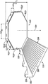
도 1을 참조하면, 본 발명의 원리에 따른 로코모션 시스템(10)의 일 실시예가 도시된다. 이 실시예에 있어서, 로코모션 시스템(10)은 베이스 또는 플랫폼(100), 이 플랫폼(100)에 결합된 안전 조립체(200) 및 가변 마찰형 신발 또는 풋 커버링(300)들을 포함한다. 하기에서 더욱 상세히 설명하는 바와 같이, 시스템(10)의 사용자가 신발(300)들을 사용하여 플랫폼(100) 위에 서서 이동하는 동안 안전 조립체(200)는 시스템(100)을 사용 중인 사용자를 보호하기 위한 수단을 제공한다.1, an embodiment of a
도 2 및 도 3a를 참조하면, 이 실시예에 있어서, 플랫폼(100)은 수직 중심 축(105)을 구비하며, 원주방향으로 인접한 8개의 대체로 삼각형의 섹션(110)을 포함한다. 각각의 플랫폼 섹션(110)은 평면 하부면 또는 저부면(120), 평면 배면(130), 평면 좌측면(140), 평면 우측면(150) 및 상부면 또는 상면(160)을 구비한다. 면(130, 140, 150)들은 하부면(120)으로부터 상방향으로 수직으로 연장되지만, 후술하는 바와 같이, 상부면(160)의 내부는 하부면(120)에 평행하게 배향되고, 상부면(160)의 외부는 하부면(120)에 대해 예각으로 배향되어 있다. 플랫폼 섹션(110)들은 원주방향으로 서로 인접하게 배열되어 있으며, 이에 따라 각각의 좌측면(140)의 전체가 인접한 섹션(110)의 우측면(150)의 전체를 접촉한다. 이 실시예에 있어서, 각각의 플랫폼 섹션(110)은 동일하기 때문에, 플랫폼(100)은 모든 측면들이 공통 중심 지점(common central point)에 대하여 대칭적으로 위치되는 동일한 길이를 갖는 정다각형(regular polygon)이다. 특히, 이 실시예에서 8개의 섹션(110)이 제공되기 때문에, 모든 플랫폼 섹션(110)들이 적절하게 정렬될 때, 플랫폼(100)은 8각형 형상(octagon shape)을 형성한다. 그러나, 다른 실시예들에 있어서, 다른 개수의 플랫폼 섹션(예를 들어, 섹션(110))이 제공될 수 있으며, 이에 따라 다른 기하학적 구조의 플랫폼(100)이 얻어질 수 있다. 예를 들면, 원주방향으로 인접한 6개의 섹션을 구비하는 플랫폼은 6각형 형상(hexagonal shape)을 가질 것이다. 플랫폼(100)은 바람직하게는 3.0 내지 6.0 피트(feet), 더 바람직하게는 3.5 내지 4.5 피트의 직경 또는 최대 수평방향 폭을 갖는다. 2 and 3A, in this embodiment, the
도 3a 및 도 3b를 참조하면, 각각의 플랫폼 섹션(110)은 중심 구역(170), 복수의 채널 또는 홈(180), 관통 구멍(190) 및 결합 메커니즘(135)을 포함한다. 섹션(110)들의 각각은, 바람직하게는 18.0 내지 34.0 인치(inch)의 길이(L110)(축(105)에 있는 내부 가장자리(175)로부터 배면(130)까지 수평방향으로 측정한 길이), 바람직하게는 16.0 내지 30.0 인치의 폭(W110)(좌측면과 우측면(140, 150) 사이에서 배면(130)을 따라 수평방향으로 측정한 폭), 및 바람직하게는 2.0 내지 12.0 인치의 높이(H110)(상부면과 하부면(160, 120) 사이에서 배면(130)을 따라 수직방향으로 각각 측정한 높이)를 갖는다. 각각의 섹션(110)은 고밀도 폴리에틸렌, 저밀도 폴리에틸렌, 폴리염화비닐, 폴리프로필렌과 같은 저마찰계수를 갖는 단일 재료, 또는 저마찰계수를 갖는 임의의 다른 적절한 재료로 구성된다. 3A and 3B, each
하부면(120)은 평면으로 놓여 있으며, 내부 끝점(120c)으로부터 등거리의 외부 끝점(120a, 120b)을 갖는 삼각형이다. 플랫폼(100)의 개개의 섹션(110)들을 설명할 때, "내부(inner)" 및 "외부(outer)"란 용어들은 도 1에 도시된 바와 같이 조립된 플랫폼(100)에 관하여 사용되며, 플랫폼(100)의 외부 가장자리들은 섹션(110)의 배면(130)과 각각 일치하며, 플랫폼(100)의 중심은 중심 축(105)과 동축인 섹션(110)의 내부 가장자리(175)와 각각 일치한다. 내부 가장자리(175)는 상단부(175a)와 하단부(175b)를 포함한다. 하부면(120)의 내부 끝점(120c)은 중심 축(105) 및 내부 가장자리(175)의 하단부(175b)와 일치한다. The
배면(130)은 하부면(120)에 대해 수직으로 배향된 평면에 놓이며, 하부면(120)으로부터 상부면(160)으로 축방향으로 상방향으로 연장되며, 그리고 상부 가장자리(130a), 하부 가장자리(130b), 좌측 가장자리(130c) 및 우측 가장자리(130d)를 구비한다. 좌측면 및 우측면(140, 150)은 또한 하부면(120)에 대해 수직으로 배향되고, 배면(130)의 좌우 가장자리(130c, 130d)로부터 연장되며, 그리고 내부 가장자리(175)에서 종단된다. 이 실시예에 있어서, 좌측면(140)과 우측면(150) 사이의 각도(A145)는 45°이다. 각도(A145)는 플랫폼(100)을 형성하기 위해 사용된 섹션(110)의 개수에 의존한다는 것을 인식하여야 한다. 예를 들면, 전술한 바와 같이, 일 실시예에 있어서, 플랫폼(100)은 6개의 섹션(110)으로 제조될 수 있으며, 이에 따른 각도(A145)는 60°이다. 다른 실시예에 있어서, 플랫폼(100)은 9개의 섹션(110)으로 제조될 수 있으며, 이에 따른 각도(A145)는 40°이다. The
도 3a, 도 3b 및 도 4a를 참조하면, 상부면(160)은 중심 구역(170) 및 각도를 갖는 부분(161)을 포함한다. 중심 구역(170)은 상부면(170a); 배면(130)에 평행한 가장자리(170b); 및 축(105)과 일치하는 내부 가장자리(175)의 상부 끝점(175a)을 포함한다. 삼각형 중심 구역 상부면(170a)은 하부면(120)에 대해 평행하게 배향된 평면에 놓인다. 중심 구역(170)은, 바람직하게는 5.0 내지 10.0 인치의 길이(L170)(가장자리(170b)와 상부 끝점(175a) 사이에서 수평방향으로 측정한 길이), 바람직하게는 4.0 내지 8.0 인치의 폭(W170)(좌측면(140)과 우측면(150) 사이의 가장자리(170b)를 따라 측정한 폭), 및 바람직하게는 0.25 내지 2.0 인치의 높이(H170)(내부 가장자리(175)를 따르는 중심 구역 상부면(170a)과 하부면(120) 사이에서 수직방향으로 측정한 높이)를 갖는다. 이 실시예에서는 하부면(120)에 대해 평행하게 도시하였지만, 삼각형 중심 구역 상부면(170a)은 곡선일 수 있으며, 이에 따라 상부 끝점(175a)은 축(105)을 따라 가장자리(170b)보다 축방향으로 하부에 배치된다. 이 대안적인 실시예에 있어서, 가장자리(170b)는 내부 가장자리(175)를 향하여 반경방향으로 연장되고 상부 끝점(175a)을 향하여 축방향으로 하방향으로 연장되면서 하부면(120)을 향하여 하방향으로 볼록해진다. 3A, 3B and 4A, the
도 3b 및 도 4a에 가장 잘 도시된 바와 같이, 상부면(160)의 각도를 갖는 부분(161)은 상부면(161a); 배면 가장자리(130a)와 일치하는 후방 가장자리(161b); 및 중심 구역 가장자리(170b)와 일치하고 배면(130)에 평행한 전방 가장자리(161c)를 포함한다. 상부면(161a)은 평면으로 놓이며, 외부 가장자리(130a, 161b)들로부터 가장자리(161c, 170b)들을 향하여 반경방향으로 그리고 축방향으로 하방향으로 연장되며, 이에 따라 상부면(161a)에 의해 형성된 평면과 중심 구역 상부면(170a)에 의해 형성된 평면 사이의 각도(A160)는 바람직하게는 5.0°내지 18.0°이다. 도 4b에 도시된 대안적인 실시예에 있어서, 상부면(160)의 각도를 갖는 부분(161)은 상부면(162a), 배면 가장자리(130a)와 일치하는 후방 가장자리(162b); 및 중심 구역 가장자리(170b)와 일치하고 배면(130)에 평행한 전방 가장자리(162c)를 포함한다. 상부면(162a)은 곡면을 형성하며, 외부 가장자리(162b)로부터 내부 가장자리(170b)를 향하여 반경방향으로, 그리고 중심 구역 상부면(170a)을 향하여 축방향으로 하방향으로 연장되면서 하부면(120)을 향하여 하방향으로 볼록해진다. As best seen in FIGS. 3B and 4A, the
도 3a 및 도 3b를 다시 참조하면, 각도를 갖는 부분(161)은 배면(130)으로부터 가장자리(170b)로 반경방향으로 연장되는 복수의 채널 또는 홈(180) 및 릿지(185)들을 또한 포함한다. 도 5a에 가장 잘 도시된 바와 같이, 각각의 채널(180)은 좌측 내부 가장자리(180a), 우측 내부 가장자리(180b) 및 하측 내부 가장자리(180c)를 구비한다. 좌측 가장자리(180a)는 우측 가장자리(180b)에 평행하며, 이 실시예에 있어서, 좌측 및 우측 가장자리(180a, 180b)들 모두는 하측 가장자리(180c)에 대해 직각이다. 각각의 채널(180)은 바람직하게는 0.20 내지 1.0 인치의 폭(W180) 및 바람직하게는 0.05 내지 1 인치의 깊이(D180)를 갖는다.Referring again to FIGS. 3A and 3B, the
도 5a를 다시 참조하면, 각각의 릿지(185)는 좌측 외부 가장자리(185b), 우측 외부 가장자리(185a) 및 상측 외부 가장자리(185c)를 포함한다. 좌측 외부 가장자리(185b)는 채널(180)의 우측 내부 가장자리(180b)와 일치하고, 채널(180)의 좌측 내부 가장자리(180a)와 일치하는 우측 외부 가장자리(185a)에 대해 평행하다. 좌측 및 우측 외부 가장자리(185b, 185a)들 모두는 상측 외부 가장자리(185c)에 대해 직각이다. 각각의 채널(180)은 바람직하게는 0.05 내지 1 인치의 높이(H185)를 갖는다. 그러나, 후술하는 바와 같이, 폭은 채널(180)의 수량 및 크기에 따라 변할 것이다. Referring again to FIG. 5A, each
도 5a에 도시된 실시예에 있어서, 좌측 및 우측 가장자리(180a, 180b)들이 하측 가장자리(180c)에 연결되는 하부 코너(180d)들은 원형이며, 좌측 및 우측 가장자리(180a, 180b)들이 섹션(110)의 상부면(160)에 연결되는 체널(180)의 상부 코너(180e)들은 원형이다. (우측 가장자리(180b)로부터 상부면(160)의 평탄부까지 측정된) 코너(180e)의 곡선부의 수평방향 길이(L180e)는 원하는 바에 따라 증가되거나 감소될 수 있다. In the embodiment shown in FIG. 5A, the
도 5b 및 도 5c를 참조하여, 좌측(181a, 182a), 우측(181b, 182b), 하측 내부 가장자리(181c, 182c) 및 하부(181d, 182d) 및 상부 코너(181e, 182e)에 대해 유사한 명명법(nomenclature)을 사용하면, (좌측 가장자리(181a, 182a)로부터 상부면(160)의 평탄부까지 측정된) 상부 코너(181e, 182e)의 곡선부의 수평방향 길이(L181e, L182e)는 원하는 바에 따라 증가되거나 감소될 수 있다. 예를 들면, 도 5b에 도시된 실시예의 곡선 길이(L181e)는 도 5c에 도시된 실시예의 곡선 길이(L182e) 미만이다. 5B and 5C, similar nomenclature for left 181a, 182a, right 181b, 182b, lower
도 5d를 다시 참조하면, 다른 실시예에 있어서, 하측 내부 가장자리(183c)는 좌측 가장자리(183a)와 우측 가장자리(183b) 사이의 수평방향 거리와 동일한 직경을 갖는 반원형을 형성한다. 따라서, 코너(180d)들은 도 5a에 도시된 바와 같은 원형의 90°인 (좌측 및 우측 가장자리(180a, 180b)와 하측 가장자리(180c) 사이의) 90°각도를 갖는 것으로부터, 90°이상 180°미만의 각도를 갖는 것으로 변할 수 있다. Referring again to FIG. 5D, in another embodiment, the lower
상기 논의는 플랫폼 섹션(110)의 배면(130)에서의 홈(180)과 릿지(185)들의 기하학적 구조에 관한 것이다. 그러나, 릿지(185)들의 높이(H185)는 홈(180)과 릿지들이 중심 구역(170)을 향하여 연장됨에 따라 테이퍼진다(즉, 감소된다). 릿지 높이(H185)는 릿지(185)의 상측 가장자리(185c)가 중심 구역 내부 가장자리(170b)에서 중심 구역 상부면(170a)에 연결될 때까지 점진적으로 낮아진다. 채널 또는 홈(180)들의 기하학적 구조와 치수는 릿지(185)의 높이가 줄어들어도 변경되지 않고 유지된다. The above discussion relates to the geometry of the
바람직하게는, 각각의 섹션(110)은 16개 내지 18개의 채널(180)을 포함하지만; 일반적으로, 채널(180)의 개수는 중심 구역(170)과 각각의 채널(180)의 폭(W180)을 포함하는 각각의 섹션(110)의 크기에 따라 변할 수 있다. 유사하게, 릿지(185)의 수량도 채널(180)의 수량 및 치수뿐만 아니라 각각의 섹션(110)의 크기에 따라 변할 것이다. 도 3a에 도시된 실시예에 있어서, 섹션(110)은 24.0 인치의 길이(L110)를 갖고, 0.20 내지 0.375 인치의 폭 및 대략 0.79 내지 0.97 인치 이격된 공간을 가질 수 있는 17개의 채널(180) 및 이에 따른 0.79 내지 0.97 인치의 폭을 가질 수 있는 16개의 릿지(185)를 구비한다. Preferably, each
다른 실시예에 있어서, 채널(180)의 폭(W180)은 외부 가장자리(130a)와 중심 구역(170) 사이에서 변할 수 있다. 예를 들면, 채널(180)의 폭은 중심 구역 가장자리(170b)에서 보다 외부 가장자리(130a)에서 더 클 수 있다. 또 다른 실시예에 있어서, 채널(180)의 깊이(D180)는 0.5 인치 미만일 수 있고, 채널(180)의 폭(W180)은 0.2 인치 미만일 수 있으며, 이는 각각의 섹션(110)이 18개 이상의 채널(180)을 포함하도록 하며, 이에 따라 릿지(185)들은 섹션(110)의 상부면(160) 상에 부드러운 융기 리브(rib)들을 각각 형성한다.In other embodiments, the width W 180 of the
도 3b를 참조하면, 중심 축(105)에 평행한 중심 축(195)을 갖는 수직 관통 구멍(190)은, 상부면(160)으로부터 하부면(120)으로 하방향으로 연장되는 반원형 형상의 단면을 갖는 관통 구멍을 형성하도록, 단부 지점(190b, 190c)에서 연결된 곡면 측벽(190a)과 평면 측벽(190d)을 포함한다. 관통 구멍(190)은 배면(130)의 좌측 가장자리(130c)에 근접하여 배치되며 - 배면(130)과 좌측면(140)에 대략 등거리로 - 축(105), 배면(130) 및 좌측면(140)에 평행하게 배향된 축(195)을 갖는다. 이 실시예에 있어서, 관통 구멍(190)은 평면 측벽(190d)이 플랫폼 섹션(110)의 좌측면(140)에 직각이 되도록 배향된다. 또한, 관통 구멍(190)은 (단부 지점(190b, 190c)들 사이에서 측정한) 바람직하게는 0.8 내지 1.25 인치의 직경, 즉 배면(130)과 좌측면(140)으로부터 바람직하게는 0.5 내지 2.0 인치 떨어진, 직경(D190)(도 3a 참조)을 갖는다. Referring to FIG. 3B, a vertical through
관통 구멍(190)은 배면(130)을 따라 그리고 배면에 근접한 임의의 위치에 배치될 수 있지만, 이에 한정되는 것은 아니며, 예를 들어, 우측면(150)에 근접하여 배치되거나 또는 좌측면(140)과 우측면(150) 사이에 등거리로 배치될 수 있다. 이 실시예에서는 반원형으로 도시되어 있지만, 관통 구멍(190)은 원형, 타원형, 정사각형, 직사각형 또는 다각형(이들에 한정되는 것은 아님)을 포함하는 임의의 형상일 수 있다. 또한, 관통 구멍(190)은 다양한 방식으로 배향되거나 또는 회전될 수 있으며, 예를 들어 반원형 형상은 곡면 측벽(190a)의 위치를 변경시키도록 제 위치에서 회전될 수 있다. 또한, 관통 보어(190)의 중심 축(195)은 바람직하게는 0.1°내지 45.0°의 각도로 플랫폼(100)의 중심 축(105)을 향하거나 또는 중심 축으로부터 떨어지는 각도로 배향될 수 있다. 또한, 도 1에 도시된 바와 같이, 관통 구멍(190)은 플랫폼(100)의 교대로 위치하는 섹션(110) 상에 배치되며, 이에 따라 섹션(110)의 절반은 관통 구멍(190)을 포함하지 않는다. 그러나, 다른 실시예에 있어서, 관통 구멍(190)은 모든 섹션(110) 상에 배치될 수 있다. The through
도 3a 및 도 3b를 참조하면, 각각의 결합 메커니즘(135)은 4개의 관통 구멍(133)을 갖는 패스너(134) 및 4개의 보어홀(borehole)(138)을 갖는 2개의 리셉터클(receptacle) 또는 절개부(136a, 136b)를 포함한다. 대체로 직사각형의 커넥터 리셉터클 또는 절개부(136a, 136b)는 배면(130) 상에 각각 배치된다. 하나의 리셉터클(136a)은 좌측면(140)에 근접하여 배치되고, 하나의 리셉터클(136b)은 우측면(150)에 근접하여 배치된다. 양쪽 리셉터클 또는 절개부(136a, 136b)들은 상부면(160)과 하부면(120) 사이의 대략 중간에 배치되며, 측면(140, 150)들로부터 내측 절개 가장자리(137b)로 연장되며, 상측 절개 가장자리(137c)로부터 하측 절개 가장자리(137d)로 하방향으로 중심 축(105)을 따라 축방향으로 연장된다. 절개부(136a, 136b)들의 배면(137a)은 섹션의 배면(130)에 의해 형성된 평면에 평행한 평면을 형성한다. 각각의 절개부(136a, 136b)는 바람직하게는 0.5 내지 2.2 인치의 높이, 바람직하게는 1.0 내지 3.7 인치의 길이 및 바람직하게는 0.1 내지 1.0 인치의 깊이를 갖는다. 대안적인 실시예에 있어서, 결합 메커니즘(135)은 절개부(136a, 136b)들을 사용하지 않는 대신에, 보어홀(138)에 대응하고 스크류(132)로 고정되는 관통 구멍(133)들을 갖는 패스너(134)들을 포함한다.3A and 3B, each
도 3b를 참조하면, 각각의 절개부(136a, 136b)는 배면 절개면(137a)에 대해 직각으로 배치되어 이 절개면으로부터 연장되는 2개의 보어홀(138)을 더 포함한다. 이 실시예에 있어서, 보어홀(138)들은 내측 절개 가장자리(137b)와 플랫폼 섹션 측면(140, 150) 사이에 등거리로 이격되며, 뿐만 아니라 상측 및 하측 절개 가장자리(137c, 137d)들 사이에 등거리로 이격되어 있다. 다른 실시예에 있어서, 보어홀(138)들은 대각선 패턴을 형성하도록 상측 및 하측 절개 가장자리(137c, 137d)들 사이에 엇갈려 배치될 수 있다. 각각의 보어홀(138)은 바람직하게는 0.05 내지 0.25 인치의 직경 및 바람직하게는 0.1 내지 1.0 인치의 깊이를 갖는다. Referring to FIG. 3B, each
도 3a를 참조하면, 각각의 커넥터 또는 패스너(134)는 플랫폼 섹션(110)에 해제 가능하게 고정된 제1 직사각형 측면(134a) 및 이 제1 직사각형 측면(134a)과 좌측면(140)으로부터 외측으로 연장되는 제2 직사각형 측면(134b)을 구비하며, 이 제2 측면(134b)은 플랫폼 섹션(110)에 연결되지 않는다. 이 실시예에 있어서, 제2 측면(134b)은 인접한 플랫폼 섹션(110)(도 3a에 도시되지 않음)의 우측면(150)에 근접하여 배치된 절개부(136b)에 연결될 것이다. 제1 및 제2 직사각형 측면(134a, 134b)들은 배면(130)의 좌측 가장자리(130c)에 의해 형성된 축에 대하여 대칭이다. 제1 측면(134a)에 의해 형성된 평면과 제2 측면(134b)에 의해 형성된 평면 사이의 각도는 플랫폼 섹션(110)들의 개수에 따르며, 바람직하게는 120.0°내지 150.0°, 더 바람직하게는 135.0°이다. 각각의 커넥터 측면(134a, 134b)은 바람직하게는 0.25 내지 2.0 인치의 높이, 바람직하게는 0.75 내지 3.5 인치의 길이 및 바람직하게는 0.05 내지 1.0 인치의 두께를 갖는다. Referring to FIG. 3A, each connector or fastener 134 is a first
*각각의 커넥터(134)는, 커넥터(134)가 절개부(136a, 136b)들에 위치될 때 보어홀(138)과 정렬되는 4개의 관통 구멍(133)을 더 포함한다. 커넥터(134)들은 독립형 커넥터로서 사용되거나 또는 브래킷, 래치(latch), 빗장(drawbolt), 힌지(hinge) 또는 클립(clip)(이들에 한정되는 것은 아님)과 같은 본 발명이 속하는 기술분야의 임의의 적절한 표준 패스너와 조합하여 사용될 수 있다. 독립형으로 사용되거나 또는 다른 패스너들과 조합하여 사용되는 것에 관계없이, 커넥터(134)들은 스크류(132) 또는 본 발명이 속하는 기술분야의 다른 적절한 표준 패스너들로 플랫폼 섹션(110)들의 보어홀(138)들에 해제 가능하게 고정되며, 이에 따라 인접한 플랫폼 섹션(110)들이 함께 고정된다. 도 3a 및 도 3b에서는 직사각형으로 도시되었지만, 절개부(136a, 136b)들은 원형, 타원형,정사각형, 반원형 또는 다각형(이들에 한정되는 것은 아님)을 포함하는 임의의 적절한 형상일 수 있다. *Each connector 134 further includes four through
도 6a 및 도 6b를 참조하면, 이 실시예에 있어서, 안전 조립체(200)는 중심 축(205)을 갖는 수직 부재(210), 수직 부재(210)에 피봇식으로 연결된 한 쌍의 수평 바(220, 221), 이 수평 바(220, 221)들에 피봇식으로 연결되고 수직 부재(210)에 슬라이딩 가능하게 연결된 한 쌍의 지지 바(230, 231)를 포함한다. 수직 부재(210)는 상단부(210a)와 하단부(210b)를 갖는 바(bar)이며, 관통 구멍(190)에 합치되어 슬라이딩 가능하게 맞물리도록 구성된 반원형 단면을 갖는다. 수직 부재(210)는 바람직하게는 24.0 내지 48.0 인치, 더 바람직하게는 30.0 내지 42.0 인치의 높이(H210), 및 (비원형 형상의 수직 부재(210)에 대해) 바람직하게는 3/4 내지 1 인치의 직경 또는 폭을 갖는다. 6A and 6B, in this embodiment, the
또한, 수직 부재(210)는 상단부(210a)에 근접하여 배치된 상단부 슬롯(210c)을 갖고, 하단부 슬롯(210d)으로 하방향으로 연장되는 제1 및 제2 슬롯(215a, 215b)을 포함한다. 제1 슬롯(215a)은 제2 슬롯(215b)으로부터 중심 축(205)에 대해 각도 "A215"로 배치되어 있다. 각도 "A215"는 플랫폼 섹션(110)의 개수에 따르며, 바람직하게는 120°내지 150°, 더 바람직하게는 135°이다. 각각의 슬롯(215a, 215b)은 오목 스트립(215a, 215b)의 개구부가 오목 스트립(215a, 215b)의 내부보다 좁도록 립(lip)(도시되지 않음)을 더 포함한다. 수직 부재(210)는 금속 또는 폴리머(이들에 한정되는 것은 아님)를 포함하는 본 발명이 속하는 기술분야에서 알려진 임의의 적절한 재료로 제조될 수 있다. In addition, the
도 6b를 참조하면, 수평 바(220, 221)들은 외측 단부 (220a, 221a), 각각의 내측 단부(220b, 221b) 및 각각의 지지 바 연결 지점(220c, 221c)을 각각 포함한다. 이 실시예에 있어서, 수평 바(220, 221)들은 반원형 단면을 가지며; 바람직하게는 15.0 내지 28.0 인치, 더 바람직하게는 18.0 내지 24.0 인치의 길이(L220, L221); 및 (비원형 형상의 수평 바(220, 221)들에 대해) 바람직하게는 3/4 내지 1 인치의 직경 또는 폭을 갖는다. 수평 바(220, 221)들은 내측 단부(220b, 221b)에서 수직 부재(210)에 피봇식으로 연결된다. 일반적으로, 수평 바(220, 221)들은, 이 수평 바(220, 221)들이 내측 단부(220b, 221b)에서 피봇되도록 하는 힌지, 핀 또는 다른 적절한 커넥터에 의해 수직 부재(210)에 피봇식으로 연결될 수 있다. 수평 바(220, 221)들은 금속 또는 폴리머(이들에 한정되는 것은 아님)를 포함하는 본 발명이 속하는 기술분야에서 알려진 임의의 적절한 재료로 제조될 수 있으며, 바람직하게는 고무와 같은 충격-흡수 폴리머로 덮여진 금속 또는 폴리머 바로 제조된다. Referring to FIG. 6B, the
도 6a 및 도 6b를 다시 참조하면, 지지 바(230, 231)들은 제1 단부(230a, 231a) 및 제2 단부(230b, 231b)를 포함한다. 이 실시예에 있어서, 지지 바(230, 231)들은 각각 바람직하게는 6.0 내지 24.0 인치, 더 바람직하게는 12.0 내지 18.0 인치의 길이(L230, L231); 및 바람직하게는 0.5 내지 1 인치의 직경을 갖는다. 지지 바(230, 231)들은 각각의 제1 단부(230a, 231a)에서 수평 바(220, 221)에 각각 피봇식으로 연결된다. 일반적으로, 지지 바(230, 231)들은, 지지 바(230, 231)들이 제1 단부(230a, 231a)에서 피봇되도록 하는 힌지, 핀 또는 다른 적절한 커넥터에 의해 수평 바(220, 221)들에 피봇식으로 연결될 수 있다. 지지 바(230, 231)들은 슬롯(215a, 215b)의 립에 의해 유지되는 돌출부 또는 핀들에 의해 슬롯(215a, 215b) 내에 각각 유지되는 제2 단부(230b, 231b)들에서 수직 부재(210)에 슬라이딩 가능하게 연결된다. 지지 바(230, 231)들은 금속 또는 폴리머(이들에 한정되는 것은 아님)를 포함하는 본 발명이 속하는 기술분야에서 알려진 임의의 적절한 재료로 제조될 수 있다. Referring back to FIGS. 6A and 6B, support bars 230 and 231 include first ends 230a and 231a and second ends 230b and 231b. In this embodiment, the support bars 230 and 231 are preferably 6.0 to 24.0 inches long, more preferably 12.0 to 18.0 inches long (L 230 , L 231 ); And preferably 0.5 to 1 inch in diameter. The support bars 230 and 231 are pivotally connected to the
해제 버튼(도시되지 않음)은 바람직하게는 수직 부재(210)의 상단부 오목부(210c)에 근접하여 수직 부재(210) 상에 제공된다. 결합 메커니즘(도시되지 않음)은 바람직하게는 해제 버튼과 조합하여 작동되도록 안전 조립체(200) 상에 제공된다. 해제 버튼과 결합 메커니즘은 금속 또는 폴리머(이들에 한정되는 것은 아님)를 포함하는 본 발명이 속하는 기술분야에서 알려진 임의의 적절한 재료로 제조될 수 있다. A release button (not shown) is preferably provided on the
이 실시예에서 안전 시스템(200)이 도시되었지만, 안전 시스템(200)은 사용자가 로코모션 시스템(10)을 사용하는 중에 떨어져 부상을 입는 것을 방지하는 것을 지원하는, 상호연결된 바의 그룹화와 같은, 본 발명이 속하는 기술분야에서 알려진 임의의 적절한 시스템을 포함할 수 있다. 예를 들면, 다른 실시예들에 있어서, 안전 시스템(200)은 사용자가 착용한 벨트 또는 고정식 물체에 장착된 벨트를 포함할 수 있다.Although the
미작동 상태에서, 수평 바(220, 221)와 지지 바(230, 231)들은 수직 부재(210)의 대략 양 측면에서 아래로 접혀져 있거나 또는 굽혀져 있다. 각각의 지지 바(230, 231)의 제2 단부(230b, 231b)는 수직 부재(210)의 하단부 오목부(210d)에 근접하여 배치된다. 수평 바(220, 221)들을 작동시키기 위해, 지지 바(230, 231)의 제2 단부(230b, 231b)들은, 이 제2 단부(230b, 231b)들이 결합 메커니즘을 맞물 때까지 오목 스트립(215a, 215b) 내의 축(205)을 따라 축방향으로 상방향으로 슬라이딩 된다. 제2 단부(230b, 231b)들의 상방향 이동은, 수평 바(220, 221)들을 수평 위치 또는 수평에 가까운 위치로 가져오도록, 수평 바(220, 221)에 대한 지지 바(230, 231) 연결부(제2 단부(230b, 231b)) 및 수직 부재(210)에 대한 수평 바 연결부(내측 단부(220b, 221b)) 양쪽에서 피봇시킴으로써 수평 바(220, 221)들을 수직 또는 거의 수직 위치로부터 상승시킨다. 작동된 상태에서, 수평 바(220, 221)들은 중심 축(205)에 직각으로 배치된다. 다른 실시예에 있어서, 수평 바(220, 221)들은 중심 축(205)으로부터 90°이상 또는 90°미만인 각도로 배치될 수 있다. In the non-operating state, the
수평 바(220, 221)들은 해제 버튼을 작동시킴으로써 하강될 수 있으며; 이에 따라 지지 바(230, 231)들이 중심 축(205)을 따라 오목 스트립(215a, 215b) 내에서 하방향으로 슬라이딩 되도록 한다. 제2 단부(230b, 231b)들의 하방향 이동은, 수평 바(220, 221)들을 수직 위치 또는 수직에 가까운 위치로 가져오도록, 수평 바(220, 221)에 대한 지지 바(230, 231) 연결부(제2 단부(230b, 231b)) 및 수직 부재(210)에 대한 수평 바 연결부(내측 단부(220b, 221b)) 양쪽에서 피봇시킴으로써 수평 바(220, 221)들을 수평 또는 거의 수평 위치로부터 하강시킨다.The
도 7 및 도 8을 참조하면, 본 발명의 플랫폼의 실시예에 사용하기 위한 풋 커버링(foot covering)(300)의 일 실시예가 도시되어 있다. 이 실시예에 있어서, 풋 커버링(300)들은 상부(310), 한 쌍의 클로져 스트랩(closure strap)(320), 솔(sole)(330), 복수의 가변식 마찰 패드(340~360, 380~385) 및 앵커 핀(anchor pin)(390)을 포함한다. 본 명세서에서 사용된 "풋 커버링"이란 용어는 신발 또는 덧신(overshoe)을 의미한다. 덧신은 사람이 착용한 신발을 적어도 부분적으로 덮는 것이며, 솔 및 사용자가 착용한 신발 또는 신체(예를 들어, 발, 발목 또는 다리)에 솔을 부착하기 위한 수단을 포함하는 풋 커버링이다. 또한, 풋 커버링(300)을 설명할 때 사용되는 "상부(top)" 또는 "하부(bottom)"라는 용어는, 토(toe)(301)에 가장 가까운 풋 커버링(300)의 단부를 향하거나 또는 이 단부에 가까운 것을 의미하는 "위로(up)," "위쪽으로(upper)", "위쪽을 향한(upward)" 또는 "위에(above)"를 설명하기 위한 목적으로 사용될 수 있으며, 또한 대체로 힐(heel)(302)에 가장 가까운 풋 커버링(300)의 단부를 향하거나 또는 이 단부에 가까운 것을 의미하는 "아래로(down)", "아래쪽으로(lower)", "아래쪽을 향한(downward)" 또는 "아래에"를 설명하기 위한 목적으로 사용될 수 있다. 풋 커버링(300)의 전체 길이 및 폭은 사용자의 발의 크기에 따라 변할 것이며; 이에 따라 풋 커버링(300)은 임의 크기의 발에 맞추도록 주문제작될 수 있다. 7 and 8, one embodiment of a foot covering 300 for use in embodiments of the platform of the present invention is shown. In this embodiment, the
풋 커버링(300)의 상부(310)는 대체로 사용자의 발의 상부의 일부 또는 전체를 덮는다. 이 실시예에 있어서, 상부(310)는 사용자의 발의 토(301), 힐(302) 및 측면(303, 304)들을 덮는다. 상부(310)는 직물, 가죽 또는 본 발명이 속하는 기술분야에서 알려진 임의의 적절한 재료(이들에 한정되는 것은 아님)를 포함하는 본 발명이 속하는 기술분야에서 알려진 임의의 적절한 재료로 제조될 수 있다. The top 310 of the foot covering 300 generally covers part or all of the top of the user's foot. In this embodiment, the top 310 covers the
도 7을 참조하면, 클로져 스트랩(320)과 리테이너(retainer)(325)들은 상부(310)의 대향 측면들에 배치된다. 클로져 스트랩(320)들은 바람직하게는 0.5 내지 2.0 인치의 폭 및 바람직하게는 6.0 내지 12.0 인치의 길이를 갖는다. 클로져 스트랩(320)들은 사용자의 발의 상부를 지나 클로져 스트랩(320)이 시작되는 대향 상부(310) 측면 상에 배치된 리테이너(325)로 연장된다. 이 실시예에 있어서, 리테이너(325)는 클로져 스트랩(320)이 관통하여 빠져나가는 슬롯을 포함하며, 클로져 스트랩(320)은 자체적으로 접혀 클로져 스트랩(320)이 시작되는 상부(310) 측면을 향하여 되돌아 연장되며; 클로져 스트랩(320)들을 고정하도록 후크 및 루프 클로져(loop closures)가 클로져 스트랩(320)의 인접한 표면들에 사용될 수 있다. 그러나, 일반적으로, 후크 및 루프 패스너, 버클, 버튼, 스냅(snap), 탄성 클로져 또는 끈(shoelace)(이들에 한정되는 것은 아님)을 포함하는 본 발명이 속하는 기술분야에서 알려진 다른 적절한 유지 메커니즘(retention mechanism)이 사용될 수 있다.Referring to FIG. 7, the
도 7 및 도 8을 다시 참조하면, 풋 커버링(300)의 솔(330)은 사용자의 발의 밑부분을 덮고, 사용자의 발의 전체 주변을 따라 상부(310)에 연결된다. 이 실시예에 있어서, 상부(310)와 솔은 하나의 연속적인 조각의 재료를 포함한다.Referring back to FIGS. 7 and 8, the sole 330 of the foot covering 300 covers the bottom of the user's foot and is connected to the top 310 along the entire periphery of the user's foot. In this embodiment, the top 310 and sole comprise one continuous piece of material.
솔(330)은 전족부(forefoot)(335), 중족부(midfoot)(365) 및 후족부(hindfoot)(375)의 3개의 섹션을 포함한다. 전족부 섹션(335)은 토 마찰 패드(340) 및 제1, 제2 및 제3 전족부 패드(350, 355, 360)를 각각 포함한다. 토 마찰 패드(340)는 토(301)에 근접하는 솔(330)의 하부 또는 솔(330)의 "상부"에 배치된다. 토 마찰 패드(340)는 토(301)의 상부로부터 바람직하게는 0.5 내지 1.5 인치로 힐(302)을 향하여 하방향으로 연장되며, 그리고 솔의 일측(303)으로부터 솔(330)의 전체 폭을 가로질러 타측(304)으로 연장된다. 제1 마찰 패드(350)는 토 마찰 패드(340) 아래에 그리고 이 마찰 패드에 근접하여 솔(330)에 배치되며, 바람직하게는 1.0 내지 3.0 인치로 힐(302)을 향하여 하방향으로 연장되며 그리고 일측(303)으로부터 솔(330)의 전체 폭을 가로질러 타측(304)으로 연장된다. 제2 마찰 패드(355)는 제1 마찰 패드(350) 아래에 그리고 이 마찰 패드에 근접하여 솔(330)에 배치되며, 바람직하게는 1.0 내지 3.0 인치로 힐(302)을 향하여 하방향으로 연장되며 그리고 일측(303)으로부터 솔(330)의 전체 폭을 가로질러 타측(304)으로 연장된다. 제3 마찰 패드(360)는 제2 마찰 패드(355) 아래에 그리고 이 마찰 패드에 근접하여 솔(330)에 배치되며, 바람직하게는 1.0 내지 3.0 인치로 힐(302)을 향하여 하방향으로 연장되며 그리고 일측(303)에 근접한 위치로부터 솔(330)의 전체 폭을 가로질러 타측(304)에 근접한 위치로 연장된다. 이 실시예에 있어서는 4개의 마찰 패드(340, 350, 355, 360)를 도시하였지만, 다른 실시예들에 있어서, 전족부 섹션(335)은 크기를 변화시킨 3개 이하의 마찰 패드를 포함할 수 있다. 또 다른 실시예들에 있어서, 전족부 섹션(335)은 크기를 변화시킨 5개 이상의 마찰 패드를 포함할 수 있다. The sole 330 includes three sections: a
*도 8을 다시 참조하면, 중족부 섹션(365)은 사용자의 발의 장심(arch)을 지지하는 풋 커버링(300)의 부분을 포함한다. 도 8에 도시된 바와 같이, 이 실시예에 있어서, 중족부 섹션(365)은 임의의 마찰 패드들을 포함하지 않는다. 그러나, 다른 실시예들에 있어서, 중족부 섹션(365)은 크기를 변화시킨 하나 이상의 마찰 패드를 포함할 수 있다. * Referring back to Figure 8, the
후족부 섹션(375)은 힐 마찰 패드(345) 및 제4 및 제5 후족부 패드(380, 355)를 각각 포함한다. 힐 마찰 패드(345)는 힐(302)에 근접하는 솔(330)의 하부 또는 솔(330)의 하단부에 배치된다. 힐 마찰 패드(345)는 힐(302)의 하부로부터 바람직하게는 0.5 내지 1.5 인치로 토(301)를 향하여 상방향으로 연장되며, 그리고 일측(303)으로부터 솔(330)의 전체 폭을 가로질러 타측(304)으로 연장된다. 제4 마찰 패드(380)는 힐 마찰 패드(345) 위에 그리고 이 마찰 패드에 근접하여 솔(330)에 배치되며, 바람직하게는 1.0 내지 3.0 인치로 토(301)를 향하여 상방향으로 연장되며 그리고 일측(303)으로부터 솔(330)의 전체 폭을 가로질러 타측(304)으로 연장된다. 제5 마찰 패드(385)는 제5 마찰 패드(380) 위에 그리고 이 마찰 패드에 근접하여 솔(330)에 배치되며, 바람직하게는 1.0 내지 3.0 인치로 토(301)를 향하여 상방향으로 연장되며 그리고 일측(303)으로부터 솔(330)의 전체 폭을 가로질러 타측(304)으로 연장된다. 이 실시예에 있어서는 3개의 마찰 패드(345, 380, 385)를 도시하였지만, 다른 실시예들에 있어서, 후족부 섹션(375)은 크기를 변화시킨 2개 이하의 마찰 패드를 포함할 수 있다. 또 다른 실시예들에 있어서, 후족부 섹션(375)은 크기를 변화시킨 4개 이상의 마찰 패드를 포함할 수 있다. The
모든 마찰 패드(340, 345, 350, 355, 360, 380, 385)들은 바람직하게는 0.1 내지 1.0 인치의 두께를 갖는다. 이 실시예에 있어서는 일측(303)으로부터 솔(330)의 전체 폭을 가로질러 타측(304)으로 연장되는 마찰 패드(340~360, 380~385)들이 도시되었지만, 다른 실시예들에 있어서, 마찰 패드(340~360, 380~385)들은 양 측(303, 304) 사이에서 솔(300)의 일부만을 가로질러 연장될 수 있다. 마찰 패드(340~360, 380~385)들은 폴리머, 세라믹, 고무, 직물, 유리섬유 또는 모피(fur)(이들에 한정되는 것은 아님)를 포함하는 본 발명이 속하는 기술분야에서 알려진 임의의 적절한 재료로 제조될 수 있다. 마찰 패드(340~360, 380~385)들은 바람직하게는 폴리에틸렌 또는 폴리테트라플루오로에틸렌으로 제조되며, 더 바람직하게는 고밀도 폴리에틸렌으로 제조된다. 다른 실시예에 있어서, 솔(330)은 마찰 패드들 대신에 모피의 층을 포함할 수 있다. All
도 8 및 도 9를 참조하면, 풋 커버링(300)은 중족부 섹션(365)에 근접하는 제3 마찰 패드(360)의 하부면으로부터 연장되는 앵커 핀(390)을 더 포함한다. 앵커 핀(390)은 바람직하게는 1/2 인치 미만, 더 바람직하게는 1/4 인치 미만의 직경을 갖는다. 앵커 핀(390)은 제3 마찰 패드(360)에 의해 형성된 평면으로부터 직각으로 솔(330)로부터 떨어져 1.0 인치 미만, 더 바람직하게는 1/8 내지 3/4 인치로 제3 마찰 패드(360)로부터 연장된다. 다른 실시예에 있어서, 앵커 핀(390)은 제1 마찰 패드(350) 또는 제2 마찰 패드(355) 상에; 중족부(365) 상에; 제4 마찰 패드(380) 또는 제5 마찰 패드(385) 상에; 또는 마찰 패드(340~360, 380~385)들 사이에 배치될 수 있다. 또 다른 실시예에 있어서, 앵커 핀(390)은 원형 하우징 내에 스프링부하식(spring-loaded)으로 배치될 수 있으며, 이에 따라 미작동 상태에서, 앵커 핀(390)은 하우징 외측으로 돌출하며, 압력이 앵커 핀(390) 상에 부여될 때, 핀(390)은 하우징 내로 수축된다. 또 다른 실시예에 있어서, 솔(330)은 마찰 패드에 의해 형성된 평면으로부터 직각으로 솔(330)로부터 떨어져 다양한 마찰 패드들로부터 또는 이들 마찰 패드들 사이에 연장되며, 바람직하게는 1.0 인치 미만의 복수의 앵커 핀을 포함할 수 있다. 앵커 핀(390)은 폴리머, 금속, 세라믹 또는 고무(이들에 한정되는 것은 아님)를 포함하는 본 발명이 속하는 기술분야에서 알려진 임의의 적절한 재료로 제조될 수 있다.8 and 9, the foot covering 300 further includes an
도 3a, 도 3b, 도 6a 및 도 6b를 참조하면, 안전 조립체(200)는 관통 구멍(190)들에서 플랫폼(100)과 접속된다. 수직 부재(210)의 하단부(210b)는 관통 구멍(190)에 끼워맞춤된다. 이 실시예에 있어서, 수직 부재(210)는 플랫폼 섹션(110)으로부터 절개되는 반원형 형상의 관통 구멍(190)보다 약간 작은 크기의 반원형 단면을 갖는다. 수직 부재(210)와 관통 구멍(190) 양쪽의 반원형 형상은 안전 조립체가 하나의 방향으로만 설치되는 것을 보장하며, 수직 부재(210)가 회전하는 것을 방지한다. 상방향으로 완전히 연장된 경우, 수평 바(220)는 플랫폼 섹션(110)의 배면(130)에 평행하게 배치된다. 상방향으로 완전히 연장된 경우, 수평 바(221)는 인접한 플랫폼 섹션(110)의 배면(130)에 평행하게 배치된다. 3A, 3B, 6A, and 6B, the
도 8 및 도 9를 참조하면, 풋 커버링(300)들은 앵커 핀(390)과 마찰 패드(340~360, 380~385)들을 통해 플랫폼(100)과 접속된다. 앵커 핀(390)들을 채널(180)들에 끼워맞추는 것은, 마찰 패드(340~360, 380~385)들이 플랫폼(100)의 상부면(160)을 접촉하도록 한다. 상부면(160)이 경사져 있기 때문에, 마찰 패드(340~360, 380~385)들은 중력하에서 중심 구역(170)을 향하여 하방향으로 슬라이딩될 것이다. 플랫폼 표면(160) 상의 패드(340~360, 380~385)들의 용이한 슬라이딩 또는 슬라이딩 양은 패드(340~360, 380~385)와 표면(160) 사이의 마찰계수에 따를 것이다. 마찰계수는 플랫폼 표면(160)과 패드(340~360, 380~385) 양쪽에 대해 선택된 재료에 따라 변할 수 있다. 따라서, 마찰 패드용의 재료는 원하는 마찰계수에 기초하여 선택될 수 있다. 8 and 9, the
마찰 패드(340~360, 380~385)들은 바람직하게는 플랫폼 표면(160)과 0.40 이하의 건조 마찰계수, 또는 플랫폼 표면(160)과 0.25 이하의 윤활 마찰계수를 갖는 재료로 제조된다. 더욱이, 각각의 마찰 패드(340~360, 380~385)는 다른 마찰계수들을 가질 수 있지만, 필요한 것은 아니다. 다른 마찰계수들은 각각의 마찰 패드(340~360, 380~385)의 재료를 변경함으로써 덧신 솔(300)의 다른 부분들에 대해 달성될 수 있다. 따라서, 토 및 힐 마찰 패드(340, 345)가 예를 들어, 내부의 제1, 제2, 제3, 제4 및 제5 마찰 패드(350, 355, 360, 380, 385)들 보다 큰 마찰계수를 갖도록, 개개의 마찰 패드(340~360, 380~385)의 마찰계수는 각각의 마찰 패드 사이에서 변할 수 있다. 토 및 힐 마찰 패드(340, 345)와 플랫폼 표면(160) 사이의 마찰계수를 증가시키는 것은, 힐을 때리거나 또는 토를 플랫폼 표면(160)에서 들어올릴 때 슬라이딩 영향을 감소시킴으로써 더 큰 안정성을 제공한다. The friction pads 340-360, 380-385 are preferably made of a material having a
윤활제의 사용은 패드(340~360, 380~385)와 플랫폼 표면(160) 사이의 마찰계수를 더 감소시킬 수 있다. 실리콘 와이프(silicone wipe) 또는 오일계 스프레이(이들에 한정되는 것은 아님)를 포함하는 본 발명이 속하는 기술분야에서의 표준 윤활제들이 사용될 수 있다.The use of lubricant may further reduce the coefficient of friction between the pads 340-360, 380-385 and the
로코모션 시스템(10)를 사용하기 위해, 사용자는 양 발에 풋 커버링(300)을 신고 플랫폼(100) 위를 걷는다. 모든 수평 바(220, 221)들이 완전히 연장된 위치 및 수평 위치로 작동되거나 또는 상승된 경우, 사용자는 2개의 수평 바(220, 221)를 하강시킬 필요가 있으며. 수평 바의 외측 단부(220a, 221a)들은 각각의 대응하는 수직 부재(210) 상의 해제 버튼을 작동시킴으로써 서로 근접하게 된다. 그 후, 사용자는 플랫폼(100) 위를 걸어서 중심 구역(170)으로 걸을 수 있다. 그 후, 사용자는 제2 단부(230b, 231b)들이 결합 메커니즘을 맞물 때까지 각각의 지지 바(230, 231)의 제2 단부(230b, 231b)들을 상방향으로 슬라이딩시키는 것에 의해 완전히 연장되지 않은 그리고 수평 또는 거의 수평인 모든 수평 바(220, 221)들을 작동시킨다. 그 후, 사용자는 사용자 선택의 가상현실 장치를 사용한다. 가상의 환경에서는, 사용자에 의해 이루어진 현실 세계에서의 임의의 이동이 가상 세계에서의 이동으로 전환될 것이다.To use the
사용자는 플랫폼(100) 위를 걷는 중에 이동의 자유를 체험할 것이다. 사용자가 중심 구역(170)에서 제1 다리를 떼고 상부면(160)의 각도를 갖는 부분(161) 위를 걷는 제1 걸음을 취할 때, 풋 커버링(300)의 밑부분에 있는 앵커 핀(390)은 각도를 갖는 부분(161) 상의 채널 또는 홈(180)을 맞문다. 사용자가 그의 제2 다리로 제2 걸음을 취할 때, 각각의 채널(180)보다 직경이 약간 작고 길이가 더 짧은 앵커 핀(390)은 중력에 의해, 중심 구역(170)을 향하여 각도를 갖는 부분(161)의 경사부 아래로 사용자의 제1 발을 안내한다. 풋 커버링 패드(340~360, 380~385)와 플랫폼 표면(160) 사이의 저마찰계수는 풋 커버링이 표면(160) 상을 슬라이딩하도록 한다. 그 후, 사용자의 제2 풋 커버링(300) 상의 앵커 핀(390)은 채널(180)을 맞물려, 이러한 과정을 반복한다. 따라서, 사용자는 플랫폼(100)의 주변 내에서만 이동하면서도 가상 세계에서의 연속적인 걷기 동작을 유지할 수 있다. The user will experience freedom of movement while walking on the
사용자가 로코모션 플랫폼(100)를 걷는 동안, 앵커 핀(390)은 플랫폼(100)과의 초기 접촉시에 채널(180)을 항상 맞물지 않을 수 있다. 이러한 경우가 발생할 때, 각도를 갖는 부분(161)의 경사부 및 중력은 여전히 풋 커버링 패드(340~360, 380~385)를 중심 구역(170)을 향하여 하방향으로 슬라이딩시킬 것이다. 풋 커버링(300)들이 각도를 갖는 부분(161) 아래로 슬라이딩함에 따라, 앵커 핀(390)은 채널(180) 내로 떨어져 풋 커버링을 중심 구역(170)을 향하여 더 안내할 것이다. 채널들(180) 사이의 공간이 각도를 갖는 부분(161)의 후방 가장자리(161b)로부터 중심 구역(170)으로 감소하기 때문에, 앵커 핀(390)은 채널(180) 내로 떨어질 것이다.While the user is walking through the
도 10을 참조하면, 본 발명의 원리에 따른 로코모션 시스템(40)의 다른 실시예가 도시되어 있다. 이 실시예에 있어서, 로코모션 시스템(40)은 플랫폼(400), 플랫폼 연결 구조체(500)(도 14 및 도 17a 참조), 베이스(600), 벨트 지지 조립체(700), 안전 벨트(800), 및 가변 마찰형 신발 또는 풋 커버링(900)(도 22 참조)을 포함한다. 10, another embodiment of a
도 11을 참조하면, 이 실시예에 있어서, 플랫폼(400)은 수직 중심 축(405)을 구비하며, 중심 섹션 또는 구역(470)에 대하여 원주방향으로 인접하여 배치된 8개의 대체로 사다리꼴의 섹션(410)을 포함한다. 각각의 섹션(410)은 평면 하부면 또는 저부면(420), 서로 대향하는 평면 배면(430)과 평면 내부면(475) , 평면 좌측면(440), 평면 우측면(450) 및 상부면 또는 상면(460)을 구비한다. 면(430, 440, 450)들은 하부면(420)으로부터 상방향으로 수직으로 연장되며, 후술하는 바와 같이, 상부면(460)의 외부는 하부면(420)에 대해 예각으로 배향되어 있다. 플랫폼 섹션(410)들은 원주방향으로 서로 인접하게 배열되어 있으며, 이에 따라 각각의 좌측면(440)의 전체가 인접한 섹션(410)의 우측면(450)의 전체를 접촉한다. Referring to FIG. 11, in this embodiment, the
중심 구역(470)은 서로 대향하는 상부면(470a)과 하부면(470c) 및 서로로부터 동등한 내각(internal angle)으로 배치된 8개의 등변(equilateral) 측면(470b)을 포함한다. 중심 구역(470)이 등변이고 등각이기 때문에, 중심 구역(470)은 모든 측면들이 공통 중심 지점에 대하여 대칭적으로 위치되는 동일한 길이를 갖는 정다각형이다. 전술한 바와 같이, 플랫폼 섹션(410)들은 중심 구역(470)에 대하여 배치되어 있으며, 이에 따라 각각의 내부면(475)의 전체가 중심 구역(470)의 측면(470b)의 전체를 접촉한다. 이 실시예에 있어서, 모든 플랫폼 섹션(410)들이 동일하기 때문에, 플랫폼(400)은 또한 정다각형이다. 플랫폼(400)은 바람직하게는 3.0 내지 6.0 피트, 더 바람직하게는 3.5 내지 4.5 피트의 직경 또는 최대 수평방향 폭을 갖는다. The
이 실시예에 있어서, 8개의 섹션(110)이 제공되기 때문에, 모든 플랫폼 섹션(410)들은 적절하게 정렬될 때, 플랫폼(400)은 8각형 형상을 형성한다. 그러나, 다른 실시예들에 있어서, 다른 개수의 플랫폼 섹션(예를 들어, 섹션(410))이 제공될 수 있으며, 이에 따라 다른 기하학적 구조의 플랫폼(400)이 얻어질 수 있다. 예를 들면, 원주방향으로 인접한 6개의 섹션을 구비하는 플랫폼은 6각형 형상을 가질 것이다. In this embodiment, since eight
도 12a, 도 12b, 도 13a 및 도 13b를 참조하면, 각각의 섹션(410)은 상부면(460)에 배치된 복수의 채널 또는 홈(480), 하부면(420)에 배치된 2개의 채널(490, 491), 좌측면(440)에 배치된 3개의 연장 루프(extension loop), 우측면(450)에 배치된 3개의 탭(453), 및 내부면(475)에 배치된 2개의 슬롯(477)을 포함한다. 섹션(410)들의 각각은, 바람직하게는 12.0 내지 18.0 인치의 길이(L410)(내부면(475)으로부터 배면(430)까지 수평방향으로 측정한 길이); 바람직하게는 16.0 내지 21.0 인치의 배면 폭(W410)(좌측과 우측면(440, 450) 사이에서 배면(430)을 따라 수평방향으로 각각 측정한 폭); 바람직하게는 6.0 내지 8.0 인치의 내부 폭(W475)(좌측면과 우측면(440, 450) 사이에서 내부면(475)을 따라 수평방향으로 각각 측정한 폭); 바람직하게는 2.0 내지 12.0 인치의 배면 높이(H410)(배면(430)을 따라 상부면과 하부면(460, 420) 사이에서 수직방향으로 측정한 높이); 및 바람직하게는 0.2 내지 2.0 인치의 내부 높이(H475)(내부면(475)을 따라 상부면과 하부면(460, 420) 사이에서 수직으로 측정한 높이)를 갖는다. 각각의 섹션(410)은 고밀도 폴리에틸렌, 저밀도 폴리에틸렌, 폴리염화비닐, 폴리프로필렌과 같은 저마찰계수를 갖는 단일 재료, 또는 저마찰계수를 갖는 임의의 적절한 재료로 구성된다. 12A, 12B, 13A, and 13B, each
도 12a 및 도 12b를 다시 참조하면, 중심 축(405)에 수직인 평면에 놓인 하부면(420)은 내부면(475)에 평행한 배면(430)과 사다리꼴을 이룬다. 플랫폼(400)의 개개의 섹션(410)들을 설명할 때, "내부" 및 "외부"란 용어들은 도 10에 도시된 바와 같이 조립된 플랫폼(400)에 관하여 사용되며, 플랫폼(400)의 외부 가장자리들은 각각의 섹션(410)의 배면(430)과 일치하며, 플랫폼(400)의 중심은 중심 축(405)과 동축인 중심 구역(470)의 중심과 일치한다. Referring again to FIGS. 12A and 12B, the
배면(430)은 하부면(420)에 대해 수직으로 배향된 평면에 놓이며, 하부면(420)으로부터 상부면(460)으로 축방향으로 상방향으로 연장되며, 그리고 상부 가장자리(430a), 하부 가장자리(430b), 좌측 가장자리(430c) 및 우측 가장자리(430d)를 구비한다. 좌측면 및 우측면(440, 450)은 또한 하부면(420)에 대해 수직으로 배향되고, 배면(430)의 좌측 및 우측 가장자리(430c, 430d)로부터 연장되며, 그리고 내부면(475)에서 각각 종단된다. 내부면(475)은 상부 가장자리(475a)와 하부 가장자리(475b)를 갖는다. 이 실시예에 있어서, 각각의 좌측면(440)과 우측면(450) 사이의 각도(A445)는 45°이다. 각도(A445)는 플랫폼(400)을 형성하기 위해 사용된 섹션(410)의 개수에 의존한다는 것을 인식하여야 한다. 예를 들면, 전술한 바와 같이, 일 실시예에 있어서, 플랫폼(400)은 6개의 섹션(410)으로 제조될 수 있으며, 이에 따른 각도(A445)는 60°이다. 다른 실시예에 있어서, 플랫폼(400)은 9개의 섹션(410)으로 제조될 수 있으며, 이에 따른 각도(A445)는 40°이다. The
도 13a 및 도 13b를 참조하면, 플랫폼 상부면(460)은 배면 가장자리(430a)와 일치하는 후방 가장자리(460b); 및 내측 상부 가장자리(475a)와 일치하고 후방 가장자리(460b)에 평행한 전방 가장자리(460c)를 포함한다. 상부면(460)은 평면으로 놓이며, 외부 가장자리(430a, 460b)로부터 내부 가장자리(460c, 475a)를 항하여 반경방향으로 내측으로 그리고 축방향으로 하방향으로 연장되며, 이에 따라 상부면(460)에 의해 형성된 평면과 중심 구역 상부면(470a)에 의해 형성된 평면 사이의 각도(A460)는 바람직하게는 5.0°내지 18.0°이다. 도 13b에 도시된 대안적인 실시예에 있어서, 상부면(460)은 상부면(462a), 배면 가장자리(430a)와 일치하는 후방 가장자리(462b); 및 내측 상부 가장자리(475a)와 일치하고 후방 가장자리(460b)에 평행한 전방 가장자리(462c)를 포함한다. 상부면(462a)은 외부 가장자리(462b)로부터 내부 가장자리(475a)를 항하여 반경방향으로 내측으로 그리고 축방향으로 하방향으로 연장되면서 하부면(420)을 향하여 볼록해지는, 곡면(curved surface)을 형성한다. 13A and 13B, the platform
도 12a를 참조하면, 상부면(460)은 배면(430)과 내부 가장자리(475) 사이에서 반경방향으로 연장되는 복수의 채널 또는 홈(480) 및 릿지(485)들을 또한 포함한다. 이 실시예의 채널(480)들은 전술한 바와 같은, 또는 도 5a 내지 도 5d에 도시된 임의의 기하학적 구조를 가질 수 있다. 유사한 부분들에는 유사한 참조부호들이 사용된다. 또한, 홈(480)들은 배면(430)과 내부면(475)에 근접하는 단부들에서 더 좁아져 테이퍼질 수 있다. 다른 실시예에 있어서, 상부면(460)은 채널 또는 홈을 포함하는 대신에 부드러운 표면을 가질 수 있다. Referring to FIG. 12A, the
바람직하게는, 각각의 섹션(410)은 16개 내지 18개의 채널(480)을 포함하지만, 채널(480)의 수량은 중심 구역(470)과 각각의 채널(480)의 폭을 포함하는 각각의 섹션(410)의 치수에 따라 변할 것이다. 유사하게, 릿지(485)의 수량도 채널(480)의 수량 및 치수뿐만 아니라 각각의 섹션(410)의 치수에 따라 변할 것이다. Preferably, each
도 12a 및 도 12b를 참조하면, 2개의 채널 또는 절개부의 외측 및 내측 채널(490, 491)의 각각은 하부면(420)에 형성되고 좌측면 및 우측면(440, 450) 사이에서 각각 이 측면들을 통하여 연장된다. 채널(490, 491)들은 서로 평행하게 배치되며, 배면(430)과 내부면(475)에 각각 평행하게 배치된다. 외측 채널(490)은 배면(430)에 근접하여 배치되며, 내측 채널(491)은 내부면(475)에 근접하여 배치되며, 각각의 채널(490, 491)은 하부면(420)으로부터 상부면(460)을 향하여 축방향으로 상방향으로 연장된다. 외측 채널(490)은 서로 대향하는 배면(490a)과 전면(490b) 및 각각의 배면(490a)과 전면(490b) 사이에 배치되어 이들을 연결하는 상부면(490c)을 갖는 대체로 T자 형상이다. 외측 채널(490)의 연장부(490d)는 배면(430) 상에 배치되고, 하부 가장자리(430b)로부터 상부 가장자리(430a)를 향하여 축방향으로 상방향으로 연장되며, 서로 대향하는 좌측면(490e)과 우측면(490f) 및 각각의 좌측면(490e)과 우측면(490f) 사이에 배치되어 이들을 연결하는 상부면(490g)을 포함한다. 연장부(490d)는 하부면(420) 내에 T자 형상 채널을 형성하도록 배면(490a)을 수직으로 교차한다. 12A and 12B, each of the two channels or the outer and
외측 채널(490)은 바람직하게는 5.0 내지 7.0 인치의 폭(W490)(좌측면(490a)과 우측면(490b) 사이에서 하부면(420)을 따라 수평방향으로 측정한 폭); 및 바람직하게는 1.0 내지 6.0 인치의 높이(H490)(좌측면(440)을 따라 하부면(420)과 상부면(490c) 사이에서 수직방향으로 측정한 높이)를 갖는다. 외측 채널(490)의 연장부(490d)는 바람직하게는 2.0 내지 5.0 인치의 폭(W490d)(좌측면(490a)과 우측면(490b) 사이에서 하부면(420)을 따라 수평방향으로 각각 측정한 폭); 및 바람직하게는 1.0 내지 6.0 인치의 높이(H490d)(배면(430)을 따라 하부면(420)과 상부면(490g) 사이에서 수직방향으로 측정한 높이)를 갖는다. 이 실시예에 있어서, 외측 채널(490)의 연장부(490d)는 각각의 좌측면(440)과 우측면(450)으로부터 대략 등거리로 배치되어 있다. 다른 실시예들에 있어서, 연장부(490d)는 좌측면(440)에 더 가깝게 배치되거나 또는 우측면(450)에 더 가깝게 배치될 수 있다. The
도 12a 및 도 12b를 다시 참조하면, 내측 채널(491)은 서로 대향하는 배면(491a)과 전면(491b) 및 각각의 배면(491a)과 전면(491b) 사이에 배치되어 이들을 연결하는 상부면(491c)을 갖는다. 내측 채널(491)은 바람직하게는 2.0 내지 9.0 인치의 폭(W491)(좌측면(491a)과 우측면(491b) 사이에서 하부면(420)을 따라 수평방향으로 각각 측정한 폭); 및 바람직하게는 0.2 내지 2.0 인치의 높이(H491)(좌측면(440)을 따라 하부면(420)과 상부면(491c) 사이에서 수직방향으로 측정한 높이)를 갖는다. 이 실시예에 있어서, 외측 채널(490)은 내측 채널(491)의 폭(W491)보다 작은 폭(W490)을 가지며, 외측 채널(490)은 내측 채널(491)의 높이(H491)보다 큰 높이(H490)를 갖는다. 다른 실시예들에 있어서, 외측 채널(490)은 폭 "W491"보다 큰 폭 "W490"을 가지고 그리고/또는 높이 "H491"보다 작은 높이 "H490"를 가질 수 있다. 또한, 채널(490, 491)들은 각각의 좌측면과 우측면(440, 450)을 따라 대칭적으로 또는 (도시된) 비대칭적으로 분배될 수 있다. 다른 실시예들에 있어서, 1개의 채널만이 사용되거나 또는 2개 이상의 채널이 사용될 수 있다. Referring again to FIGS. 12A and 12B, the
도 12b를 참조하면, 3개의 연장 루프(443)는 하부면(420)에 근접하는 좌측면(440) 상에 배치되어 있다. 각각의 연장 루프(443)는 서로 대향하는 상부면(443a)과 하부면(443b))을 구비하고, 상부면(443a)으로부터 하부면(443b)으로 연장되는 관통 구멍(443c)을 가지며, 좌측면(440)으로부터 반경방향으로 외측으로 연장되는, 대체로 직육면체 형상이다. 이 실시예에 있어서, 하나의 연장 루프(443)는 배면(430)에 근접하여 배치되고, 하나의 연장 루프(443)는 내부면(475)에 근접하여 배치되며, 그리고 하나의 연장 루프(443)는 내측과 외측 채널(491, 490) 사이에 배치된다. 대안적인 실시예에 있어서, 임의의 위치 조합의 2개의 연장 루프가 사용될 수 있다. 다른 실시예들에 있어서, 하나 이상의 연장 루프가 사용될 수 있다. Referring to FIG. 12B, three
도 12a를 참조하면, 3개의 탭(453)이 하부면(420)에 근접하는 우측면(450)에 배치되어 있다. 각각의 탭(453)은 우측면(450)과 공통평면인 본체(453b)의 하부에 배치된 L자 형상부(453a)를 포함하며, 본체(453b)의 측면들은 절개부(453c)들에 의해 형성된다. L자 형상부(453a)는 우측면(450)으로 떨어져 축방향으로 외측으로 연장된다. 이 실시예에 있어서, 하나의 탭(453)은 배면(430)에 근접하여 배치되고, 하나의 탭(453)은 내부면(475)에 근접하여 배치되며, 그리고 하나의 탭(453)은 내측과 외측 채널(491, 490) 사이에 배치된다. 우측면(450) 상의 각각의 탭(453)은, 모든 탭(453)들이 대응하는 모든 측면(450)을 맞물 때까지 인접한 플랫폼 섹션(410)의 좌측면(440) 상의 연장 루프(443)를 상호결합 방식으로 맞문다. 대안적인 실시예에 있어서, 임의의 위치 조합의 2개의 탭이 사용될 수 있다. 다른 실시예들에 있어서, 하나 이상의 탭이 사용될 수 있다. Referring to FIG. 12A, three
도 12a를 다시 참조하면, 2개의 공통평면 슬롯(477)은 상부면(460)과 하부면(420) 사이의 대략 중간에서 내부면(475) 상에 배치되며, 각각의 슬롯(477)은 내부면(475)으로부터 배면(430)을 향하여, 중심 축(405)에 대해 수직으로 축방향으로 외측으로 연장된다. 이 실시예에 있어서, 하나의 슬롯(477)은 좌측면(440)에 근접하여 배치되며, 하나의 슬롯(477)은 우측면(450)에 근접하여 배치된다. 대안적인 실시예에 있어서, 임의의 위치 조합의 하나 이상의 슬롯(477)이 사용될 수 있다.Referring again to FIG. 12A, two
도 11을 참조하면, 중심 구역 상부면(470a)은 하부면(470c)에 평행하며, 양쪽의 상부면 및 하부면(470a, 470c)은 중심 축(405)에 수직으로 배향된 평면에 각각 놓인다. 중심 구역(470)은 바람직하게는 10.0 내지 20.0 인치의 길이(L470)(2개의 대향된 측면(470b) 사이에서 수평방향으로 측정한 길이); 바람직하게는 0.2 내지 2.0 인치의 높이(H470)(상부면(470a)과 하부면(470c) 사이에서 수직방향으로 측정한 높이)를 가지며; 각각의 측면(470b)은 바람직하게는 3.0 내지 8.0 인치의 폭(W470)(좌측과 우측의 인접한 측면(470b)들 사이에 측정한 폭)을 갖는다. 이 실시예에 있어서는, 중심 구역 상부면(470a)이 하부면(420)에 평행한 것을 도시하였지만, 중심 축(405)을 교차하는 상부면(470a)의 부분이 상부면(470a)과 측면(470b)들의 교차점 아래에 축방향으로 배치되도록 곡선일 수 있다. Referring to FIG. 11, the central zone
중심 구역(470)은 각각의 측면(470b) 상에 2개의 탭(473)을 더 포함한다. 각각의 탭(473)은 측면(470b)으로부터 직각으로 외측으로 연장된다. 이 실시예에 있어서, 탭(473)들은 상부면(470a)과 하부면(470c) 사이의 대략 중간에 각각 배치되며, 수평방향으로 이격되어 있다. 탭(473)들은 양쪽 탭(473)들이 플랫폼 섹션(410)의 내부면(475)에 배치된 대응하는 슬롯(477) 내로 슬라이딩 가능하게 맞물리도록 구성되어 있다. 다른 실시예들에 있어서, 탭(473)들은 상부면(470a) 또는 하부면(470c) 중 어느 하나에 더 가깝게 각각 배치될 수 있다. The
도 14 내지 도 16을 참조하면, 플랫폼 연결 구조체(500)는 중심 축(405)에 대하여 원주방향으로 인접하게 배치된 8개의 대체로 사다리꼴의 연결 플레이트(510)를 포함한다. 각각의 플레이트(510)는 서로 대향하는 상부면(560)과 하부면(520), 좌측벽(540) 및 우측벽(550)을 더 포함한다. 플레이트(510)는 상부면(560)을 가로질러 분배되며, 하부면(520)을 통하여 축방향으로 하방향으로 연장되는 6개의 관통 구멍(575)을 더 포함한다. 관통 구멍(575)들은 모두 동일한 직경을 갖거나 또는 다른 직경들을 가질 수 있다. 관통 구멍(575)들은 패스너(585)들이 거기를 통과하도록 한다. 일반적으로, 스크류(도 14 및 도 16 참조), 너트와 볼트, 스탭 끼워맞춤 패스너 및 억지 끼워맞춤 패스너(이들에 한정되는 것은 아님)을 포함하는 본 발명이 속하는 기술분야에서 알려진 임의의 패스너가 사용될 수 있다. 연결 플레이트(510)들은 금속 또는 폴리머(이들에 한정되는 것은 아님)를 포함하는 본 발명이 속하는 기술분야에서 알려진 임의의 적절한 재료로 제조될 수 있다. 14 to 16, the
각각의 플레이트(510)는 내측 채널(491) 내에 끼워맞춤되도록 구성되며, 이에 따라 연결 플레이트(510)의 상부면(560)은 내측 채널 상부면(491c)을 접촉하고, 연결 플레이트(510)의 좌측벽(540)은 플랫폼 섹션(410)의 좌측면(440)에 근접하여 배치되며, 연결 플레이트(510)의 우측벽(550)은 플랫폼 섹션(410)의 우측면(450)에 근접하여 배치된다. 그 후, 패스너(585)들은 플레이트(510)를 플랫폼 섹션 내측 채널(491)에 고정시킨다. Each
도 14 내지 도 16을 다시 참조하면, 좌측벽(540)은 서로 대향하는 상부 가장자리(540a)와 하부 가장자리(540b) 및 서로 대향하는 후방 가장자리(540c)와 내부 가장자리(540d)를 포함한다. 좌측벽(540)은 상부면(560)으로부터 하부 가장자리(540b)로 축방향으로 하방향으로 연장되며, 상부 가장자리(540a)와 하부 가장자리(540b) 사이의 대략 중간에 각각 배치된 2개의 관통 구멍(545)을 구비한다. 이 실시예에 있어서, 관통 구멍(545)들은 좌측벽(540)을 수평방향으로 가로질러 대략 등거리로 분배되어 있다. 다른 실시예들에 있어서, 관통 구멍(545)들은 본 발명이 속하는 기술분야에서 알려진 임의의 적절한 구성으로 위치될 수 있다. 14 to 16 again, the
유사하게, 우측벽(550)은 서로 대향하는 상부 가장자리(550a)와 하부 가장자리(550b) 및 서로 대향하는 후방 가장자리(550c)와 내부 가장자리(550)를 포함한다. 우측벽(550)은 상부면(560)으로부터 하부 가장자리(550b)로 축방향으로 하방향으로 연장되며, 상부 가장자리(550a)와 하부 가장자리(550b) 사이의 대략 중간에 각각 배치된 2개의 관통 구멍(555)을 구비한다. 이 실시예에 있어서, 관통 구멍(555)들은 좌측벽(550)을 수평방향으로 가로질러 대략 등거리로 분배되어 있다. 다른 실시예들에 있어서, 관통 구멍(555)들은 본 발명이 속하는 기술분야에서 알려진 임의의 적절한 구성으로 위치될 수 있다. Similarly, the
도 14 내지 도 16을 다시 참조하면, 관통 구멍(545, 555)들은 좌측벽과 우측벽(540, 550)에 각각 위치되며, 이에 따라 하나의 연결 플레이트(510)의 좌측벽(540)이 다른 연결 플레이트(510)의 우측벽(550)을 접촉할 때, 좌측벽과 우측벽(540, 550) 양쪽의 관통 구멍(545, 555)들은 각각 정렬되어 패스너(565)들이 거기를 통과하도록 한다. 너트와 볼트 패스너(도 16 참조), 스크류, 스탭 끼워맞춤 패스너 및 억지 끼워맞춤 패스너(이들에 한정되는 것은 아님)를 포함하는 본 발명이 속하는 기술분야에서 알려진 임의의 패스너가 사용될 수 있다. 각각의 플레이트(510)가 플랫폼 섹션 내측 채널(491)에 설치되어 패스너(585)들로 고정된 후에, 전술한 바와 같이, 각각의 플레이트 좌측벽(540)은 모든 플랫폼 섹션(410)들이 함께 고정될 때까지 인접한 플랫폼 섹션(410)의 플레이트 우측벽(550)에 고정된다. 14 to 16 again, the through
이 실시예에 있어서, 인접한 연결 플레이트(510)들 사이의 각도(A510)는 135°이다. 각도(A510)는 플랫폼 연결 구조체(500)를 형성하기 위해 사용된 연결 플레이트(510)의 개수에 의존한다는 것을 인식하여야 한다. 예를 들면, 일 실시예에 있어서, 플랫폼 연결 구조체(500)는 6개의 섹션(510)으로 제조될 수 있으며, 이에 따른 각도(A510)는 120°일 것이다. 다른 실시예에 있어서, 플랫폼 연결 구조체(500)는 9개의 섹션(510)으로 제조될 수 있으며, 이에 따른 각도(A510)는 140°일 것이다. In this embodiment, the angle A 510 between adjacent connecting plates 510 is 135°. It should be appreciated that the angle A 510 depends on the number of
도 14 및 도 17a를 참조하면, 베이스(600)는 직사각형 단면을 가지며, 8개의 각이 진 커넥터(angular connector)(620)와 패스너(635)들로 서로 연결된 8개의 관형 부재(610)를 포함한다. 각각의 관형 부재(610)는 서로 대향하는 상부면(610a)과 하부면(610b), 서로 대향하는 좌단부(610c)와 우단부(610d), 및 서로 대향하는 내부면(610e)과 외부면(61Of)을 구비한다. 각각의 관형 부재(610)는 좌단부(610c)에 근접하는 상부면(610a)에 배치된 2개의 보어홀(611) 및 우단부(610d)에 근접하는 상부면(610a)에 배치된 2개의 보어홀(611)을 구비한다. 모든 관형 부재(610)들은 일반적으로 보어홀(611)들을 위치지정하는 치수를 포함하는 동일한 전체 치수를 갖는다. 관형 부재(610)는 금속 또는 폴리머(이들에 한정되는 것은 아님)를 포함하는 본 발명이 속하는 기술분야에서 알려진 임의의 적절한 재료로 제조될 수 있다. 14 and 17A, the
도 18을 참조하면, 각각의 각이 진 커넥터(620)는 중앙의 각이 진 본체(623), 대체로 직육면체의 좌측 인서트(insert)(627), 대체로 직육면체의 우측 인서트(629) 및 풋 패드(630)(도 17a 참조)를 포함한다. 중앙의 각이 진 본체(623)는 서로 대향하는 상부면(621)과 하부면(622), 좌측 절반부(624a)와 우측 절반부(624b)를 갖는 외측의 각이 진 측면(624) 및 좌측 절반부(625a)와 우측 절반부(625b)를 갖는 내측의 각이 진 측면(625)를 구비한다. 본체 상부면(621)은 좌측 가장자리(621a)와 우측 가장자리(621b)를 구비하며; 본체 하부면(622)은 좌측 가장자리(622a)와 우측 가장자리(622b)를 구비한다. 각이 진 커넥터(620)는 금속 또는 폴리머(이들에 한정되는 것은 아님)를 포함하는 본 발명이 속하는 기술분야에서 알려진 임의의 적절한 재료로 제조될 수 있다. 풋 패드(630)는 고무 또는 폴리머(이들에 한정되는 것은 아님)를 포함하는 본 발명이 속하는 기술분야에서 알려진 임의의 적절한 재료로 제조될 수 있다. Referring to FIG. 18, each
도 14 및 도 18을 참조하면, 이 실시예에 있어서, 각각의 각이 진 커넥터(620)의 굽힘부의 각도(A624)(즉, 각이 진 측면(624)의 좌측 절반부(625a)와 우측 절반부(624b) 사이의 각도(A624))는 135°이다. 각도(A624)는 베이스(600)를 형성하기 위해 사용된 관형 부재(610)의 개수에 의존한다는 것을 인식하여야 한다. 예를 들면, 일 실시예에 있어서, 베이스(600)는 6개의 관형 부재(610)로 제조될 수 있으며, 이에 따른 각도(A624)는 120°일 것이다. 다른 실시예에 있어서, 베이스(600) 9개의 관형 부재(610)로 제조될 수 있으며, 이에 따른 각도(A624)는 140°일 것이다. 14 and 18, in this embodiment, the angle A 624 of each bent portion of the angled connector 620 (ie, the
좌측 인서트(627)는 서로 대향하는 상부면(627a)과 하부면(627b), 상부면(627a)과 하부면(627b)에 직각으로 각각 배치되고 이 면들 사이에 연장되는 단부 면(627c), 및 상부면(627a)과 하부면(627b)에 직각으로 각각 배치되고 이 면들 사이에 연장되는, 서로 대향하는 외측면(627d)과 내측면(627e)을 구비한다. 좌측 인서트(627)는 좌측 가장자리(621a)와 단부 면(627c) 사이의 대략 중간에 배치된 상부면(627a) 내의 2개의 보어(615)를 더 포함하며; 이들 보어 중 하나의 보어(615)는 외측면(627d)에 근접하여 배치되고, 하나의 보어는 내측면(627e)에 근접하여 배치된다. 또한, 좌측 인서트(627)는 약간 더 작은 치수를 가지며, 이에 따라 좌측 인서트(627)와 중앙의 각이 진 본체(623) 사이의 전체 계면 둘레에 립(613)이 형성된다(즉, 립(613)은 (1) 상부면(627a)과 좌측 가장자리(621a); (2) 하부면(627b)과 좌측 가장자리(622a); (3) 외측면(627d)과 외측의 각이 진 좌측 절반부(624a); 및 (4) 내측면(627e)과 내측의 각이 진 좌측 절반부(625a)의 계면에 형성된다). The
도 18을 참조하면, 우측 인서트(627)는 서로 대향하는 상부면(629a)과 하부면(629b), 상부면(627a)과 하부면(627b)에 직각으로 각각 배치되고 이 면들 사이에 연장되는 단부 면(629c), 및 상부면(627a)과 하부면(627b)에 직각으로 각각 배치되고 이 면들 사이에 연장되는, 서로 대향하는 외측면(629d)과 내측면(629e)을 구비한다. 우측 인서트(629)는 좌측 가장자리(621b)와 단부 면(629c) 사이의 대략 중간에 배치된 상부면(629a) 내의 2개의 보어(615)를 더 포함하며; 이들 보어 중 하나의 보어(615)는 외측면(629d)에 근접하여 배치되고, 하나의 보어는 내측면(629e)에 근접하여 배치된다. 또한, 우측 인서트(629)는 약간 더 작은 치수를 가지며, 이에 따라 우측 인서트(629)와 중앙의 각이 진 본체(623) 사이의 전체 계면 둘레에 립(613)이 형성된다(즉, 립(613)은 (1) 상부면(629a)과 우측 가장자리(621b); (2) 하부면(629b)과 우측 가장자리(622b); (3) 외측면(629d)과 외측의 각이 진 우측 절반부(624b); 및 (4) 내측면(629e)과 내측의 각이 진 우측 절반부(625b)의 계면에 형성된다). Referring to FIG. 18, the
도 14 및 도 18을 다시 참조하면, 이 실시예에 있어서, 각이 진 커넥터(620)의 좌측 및 우측 인서트(627, 629)의 각각은, 각각의 관형 부재(610)의 좌단부 및 우단부(610d, 610c)의 각각을 슬라이딩 가능하게 맞물며, 이에 따라 8각형 형상이 형성된다. 각각의 좌측 인서트(627)는 관형 부재의 우단부(610d) 내로 슬라이딩 되도록 구성되며, 이에 따라 관형 부재(610)의 보어(611)들은 각이 진 커넥터(620)의 보어(615)들과 정렬된다. 그 후, 패스너(635)는 각이 진 커넥터(620)를 관형 부재(610)에 고정하도록, 정렬된 보어(611, 615) 내로 삽입된다. 우측 인서트(629)들은 유사하게, 관형 부재의 좌단부(610c) 내로 슬라이딩 되도록 구성되며, 이에 따라 관형 부재(610)의 보어(611)들은 각이 진 커넥터(620)의 보어(615)들과 정렬된다. 그 후, 패스너(635)는 각이 진 커넥터(620)를 관형 부재(610)에 고정하도록, 정렬된 보어(611, 615) 내로 삽입된다. 스크류(도 14, 도 17a 및 도 17b 참조), 스탭 끼워맞춤 패스너 및 억지 끼워맞춤 패스너(이들에 한정되는 것은 아님)을 포함하는 본 발명이 속하는 기술분야에서 알려진 임의의 패스너가 사용될 수 있다. 대안적인 실시예에 있어서, 각이 진 커넥터(620)들은 관형 부재(610)에 용접된다. 이 실시예에 있어서, 모든 패스너(635)들이 위치되고 각이 진 커넥터(620)들이 관형 부재(610)의 단부들에 고정된 후에, 플랫폼(400)은 베이스(600) 상에 위치될 수 있으며, 이에 따라 베이스(600)는 플랫폼 채널(490) 내에 배치된다. 14 and 18 again, in this embodiment, each of the left and
이 실시예에 있어서, 인서트(627, 629)와 중앙의 각이 진 본체(623) 사이의 계면은 립(613)을 제공하지만; 다른 실시예들에 있어서, 각이 진 커넥터(620)는 립을 포함할 필요가 없다. 이 실시예에 있어서, 풋 패드(630)들은 각이 진 커넥터들의 하부 상에 배치되지만; 다른 실시예들에 있어서, 풋 패드들은 플랫폼 섹션(410)의 하부, 중심 구역(470) 또는 이들의 임의의 조합된 부분에 배치될 수 있다. In this embodiment, the interface between the
도 17a 및 도 17b를 참조하면, 이 실시예에 있어서, 벨트 지지 조립체 또는 안전 벨트 지지 구조체(700)는 원주방향으로 이격된 한 쌍의 수직 부재(710), 구조체(700)를 베이스(600)에 결합시키는 한 쌍의 베이스 인터페이스(720), 인터페이스(720)와 수직 부재(710) 사이에 연장되는 한 쌍의 연결 빔(730), 수직 부재(710)로부터 신축되는 한 쌍의 높이조정 가능한 빔(740), 및 빔(740)들 사이에 배치된 지지 밴드 또는 헤일로(halo)(750)를 포함한다. 각각의 수직 부재(710)는 직육면체의 관형이며, 서로 대향하는 내측면(710a)과 외측면(710b), 서로 대향하는 좌측면(710c)과 우측면(710d), 및 서로 대향하는 개구 상부면(710e)과 개구 하부면(71Of)을 구비한다. 수직 부재(710)들은 내측면(710a)과 외측면(710b) 사이로 연장하고 이 면들을 각각 관통하는 복수의 관통 구멍(715)을 더 포함한다. 관통 구멍(715)들은 좌측면(710c)과 우측면(710d) 사이의 대략 중간에 수평방향으로 각각 배치되며, 수직으로 균등하게 이격되어 있다. 수직 부재(710)들은 금속 또는 폴리머(이들에 한정되는 것은 아님)를 포함하는 본 발명이 속하는 기술분야에서 알려진 임의의 적절한 재료로 제조될 수 있다. 17A and 17B, in this embodiment, the belt support assembly or the seat
각각의 베이스 인터페이스(720)는 직육면체의 관형이며, 서로 대향하는 내측면(720a)과 외측면(720b), 서로 대향하는 개구 좌측면(720c)과 개구 우측면(720d) 및 서로 대향하는 상부면(720e)과 하부면(72Of)을 구비한다. 베이스 인터페이스(720)들은 상부면(720e)으로부터 축방향으로 하방향으로 연장되는 4개의 보어(725)를 더 포함하며, 각각의 보어(725)는 상부면(720e)의 4개의 코너 중 하나에 근접하여 배치된다. 베이스 인터페이스(720)들의 치수는, 베이스 인터페이스(720)가 관형 부재(610) 위를 슬라이딩하도록 관형 부재(610)의 치수보다 약간 더 크다. 패스너(728)들은 베이스 인터페이스를 베이스 관형 부재(610)에 고정시킨다. 베이스 인터페이스(720)들은 금속 또는 폴리머(이들에 한정되는 것은 아님)를 포함하는 본 발명이 속하는 기술분야에서 알려진 임의의 적절한 재료로 제조될 수 있다. 볼트와 너트 패스너, 스크류(도 17a 및 도 17b 참조), 스탭 끼워맞춤 패스너 및 억지 끼워맞춤 패스너(이들에 한정되는 것은 아님)을 포함하는 본 발명이 속하는 기술분야에서 알려진 임의의 패스너가 사용될 수 있다. 대안적인 실시예에 있어서, 베이스 인터페이스(720)들은 관형 부재(610)에 용접된다. Each
도 17a 및 도 17b를 다시 참조하면, 수직 관형 부재(710)는 연결 빔(730)을 통하여 베이스 인터페이스(720)에 연결된다. 연결 빔(730)은 직육면체이며, 서로 대향하는 내측면(730a)과 외측면(730b), 서로 대향하는 좌측면(730c)과 우측면(730d) 및 서로 대향하는 상부면(730e)과 하부면(730f)을 구비한다. 연결 빔 외측면(730b)은 수직 관형 내측면(710a)에 연결되며, 연결 빔 내측면(730a)은 베이스 인터페이스 외측면(720b)에 연결된다. 연결 빔(730)은 용접, 너트와 볼트 패스너, 스크류, 스탭 끼워맞춤 패스너 및 억지 끼워맞춤 패스너(이들에 한정되는 것은 아님)를 포함하는 본 발명이 속하는 기술분야에서 알려진 임의의 고정 수단을 사용하여 수직 관형 부재(710)와 베이스 인터페이스(720)에 연결될 수 있다. 다른 실시예에 있어서, 수직 관형 부재(710), 연결 빔(730) 및 베이스 인터페이스(720)는 모놀리식(monolithic)이거나 또는 하나의 조각의 재료로 형성될 수 있다. 연결 빔(730)은 중공 관형 또는 중실(solid) 관형일 수 있으며, 금속 또는 폴리머(이들에 한정되는 것은 아님)를 포함하는 본 발명이 속하는 기술분야에서 알려진 임의의 적절한 재료로 제조될 수 있다. 17A and 17B again, the vertical
각각의 높이조정 가능한 빔(740)은 관형이며, 조정부(742), 각도를 갖는 부분(744) 및 링 인터페이스부(746)의 3개의 부분을 포함한다. 조정부(742)는 직육면체의 관형이며, 서로 대향하는 내측면(742a)과 외측면(742b), 서로 대향하는 좌측면(742c)과 우측면(742d) 및 개구 하부면(710f)을 구비한다. 각각의 높이조정 가능한 부분(742)은 내측면(742a)과 외측면(742b) 사이로 연장하고 이 면들을 각각 관통하는 복수의 관통 구멍(745)을 더 포함한다. 관통 구멍(715)들은 좌측면(742c)과 우측면(742d) 사이의 중간에 수평방향으로 각각 배치되며, 수직으로 균등하게 이격되어 있다. 조정부(742)는 수직 관형 부재(710) 내측에 배치되며, 관통 구멍(745)들은 조정부(742) 상에 위치되며, 이에 따라 각각의 관통 구멍(745) 사이의 수직 거리는 관형 부재(710)의 관통 구멍(715)들 사이의 수직 거리와 동등하며, 이에 의해 수직 관형 부재(710) 내에서의 높이조정 가능한 빔(740)의 상승 및 하강은 관통 구멍(715, 745)들이 정렬되도록 한다. 수직 관형 부재(710)와 조정부(742)의 관통 구멍(715, 745)들이 각각 정렬되면, 록킹 메커니즘(718)은 정렬된 관통 구멍(715, 745)들을 통하여 삽입될 수 있다. 각도를 갖는 부분(744)은 관형이며, 조정부(742)로부터 지지 헤일로(750)를 향하여 축방향으로 상방향으로 그리고 반경방향으로 내측으로 연장된다. 링 인터페이스부(746)는 각도를 갖는 부분의 상부로부터 축방향으로 상방향으로 연장되며, 지지 헤일로(750)에 연결된다. 링 인터페이스부(746)는 스크류, 너트와 볼트, 스탭 끼워맞춤 패스너 및 억지 끼워맞춤 패스너(이들에 한정되는 것은 아님)을 포함하는 본 발명이 속하는 기술분야에서 알려진 임의의 고정 수단을 사용하여 지지 헤일로(750)에 연결될 수 있다. 수직 부재(710)들은 금속 또는 폴리머(이들에 한정되는 것은 아님)를 포함하는 본 발명이 속하는 기술분야에서 알려진 임의의 적절한 재료로 제조될 수 있다. 록킹 핀(lock pin), 볼 핀(ball pin) 및 너트와 볼트 패스너(이들에 한정되는 것은 아님)을 포함하는 본 발명이 속하는 기술분야에서 알려진 임의의 록킹 메커니즘(718)이 사용될 수 있다. 대안적인 실시예에 있어서, 2개 이상의 록킹 메커니즘(718)이 2개 이상의 정렬된 관통 구멍(715, 745)을 통하여 삽입될 수 있다. Each height-
도 17a, 도 17b, 도 19 및 도 20을 참조하면, 링 인터페이스부(746)(및 전체 높이조정 가능한 빔(740))들은 지지 헤일로(750)에 연결되고 이 지지 헤일로에 대하여 각도 "A740"로 배치되며, 각도 "A740"은 각각의 수직 부재(710)의 내부면(710a)을 수직방향으로 2등분하는 평면에 의해 형성되며, 바람직하게는 135.0°이다. 다른 실시예들에 있어서, 이 각도 "A740"은 예들 들어, 사용된 플랫폼 섹션(410)의 개수에 따라 180.0°이하일 수 있다. 전체 높이 "H750"(수직 관형 부재의 하부면(710f)과 지지 링(750)의 상부면(750a) 사이에서 수직방향으로 측정한 높이)는 사용자의 다른 높이들을 수용하도록 전술한 바와 같이 조정될 수 있다. 지지 링 높이(H491)의 범위는 바람직하게는 30.0 내지 50.0 인치이다. 이 실시예에 있어서, 지지 헤일로(750)는 사용자 둘레로 완전히 연장되도록 설계된 폐쇄루프 구조체이다. 사용자를 수용하기 위해, 지지 헤일로(750)는 바람직하게는 15 내지 25 인치의 최소 내부 폭(W750)을 갖는다. 이 실시예에서는 지지 헤일로(750)가 사용자 둘레로 완전히 연장되는 폐쇄루프 구조체이지만, 다른 실시예들에 있어서, 지지 헤일로(예를 들어, 지지 헤일로(750))는 사용자 둘레로 부분적으로 연장되는 개방 구조체(예를 들어, C자 형상)일 수 있다. 17A, 17B, 19, and 20, the ring interface 746 (and the full height-adjustable beam 740) are connected to the
*도 17a, 도 17b, 도 20 및 도 21을 참조하면, 지지 헤일로(750)는 수직 중심 축(705)에 대하여 연장되며, 서로 대향하는 상부면(750a)과 하부면(750b) 및 서로 대향하는 내부면(750c)과 외부면(750d)을 구비한다. 이 실시예에 있어서, 지지 헤일로(750)는 환형 링이며, 이에 따라 지지 링(750)으로서 또한 언급될 수 있다. 이 실시예에서 지지 링(750)이 환형이기 때문에, 최소 내부 폭(W750)은 내부 직경(D750)인 것을 인식하여야 한다. 이 실시예에서는 지지 헤일로(750)가 환형이지만, 다른 실시예들에 있어서, 지지 헤일로(예를 들어, 지지 헤일로(750))는 타원형, 계란형, 직사각형, 정사각형과 같은 다른 기하학적 구조를 가질 수 있다. * Referring to FIGS. 17A, 17B, 20 and 21, the
지지 링(750)은 지지 구조체(753), 하부 링(755), 상부 링(757), 래치(760)와 힌지(765)를 갖는 도어(759)를 더 포함한다. 이 실시예에 있어서, 지지 구조체(753)는 강성을 제공할 뿐만 아니라 하부 및 상부 링(755, 757)들이 각각 부착되는 구조체를 제공한다. 도어(759)가 폐쇄될 때, 지지 구조체(753)는 지지 링(750) 내의 지지 구조체(753)에 겹쳐져 지지 링(750)이 하중을 지지하도록 한다. 지지 구조체(753)는 금속 또는 폴리머(이들에 한정되는 것은 아님)를 포함하는 본 발명이 속하는 기술분야에서 알려진 임의의 적절한 재료로 제조될 수 있으며, 바람직하게는 고밀도 폴리에틸렌(HDPE)으로 제조된다. 하부 링(755)은 U자 형상의 단면을 가지며, 하부면(750b) 및 내부면과 외부면(750c, 750d) 양쪽의 하부를 각각 형성하도록 지지 구조체(753)에 부착된다. 상부 링(757)은 역 U자 형상의 단면을 가지며, 상부면(750a) 및 내부면과 외부면(750c, 750d) 양쪽의 상부를 각각 형성하도록 지지 구조체(753)에 부착된다. 하부 및 상부 링(755, 757)들은 각각, 스크류, 스탭 끼워맞춤 패스너 및 억지 끼워맞춤 패스너(이들에 한정되는 것은 아님)를 포함하는 본 발명이 속하는 기술분야에서 알려진 임의의 적절한 고정 장치를 수용하기 위한 절개부(756)를 또한 포함한다. 하부 및 상부 링(755, 757)들은 각각, 폴리머(이에 한정되는 것은 아님)를 포함하는 본 발명이 속하는 기술분야에서 알려진 임의의 적절한 재료로 제조될 수 있다.The
도어(759)는 중심 축(405)에 평행한 축을 따라 힌지(765)에서의 수평방향으로의 피봇에 의해 이동 가능한 지지 링(750)의 일부를 포함한다. 힌지(765)는 핀(766)과 조합되며, 볼 핀, 록킹 핀 및 퀵 릴리스 핀(quick release pin)(이들에 한정되는 것은 아님)을 포함하는 본 발명이 속하는 기술분야에서 알려진 임의의 적절한 수단을 사용할 수 있다. 폐쇄 위치에 있을 때, 래치(760)는 지지 링(750)의 고정부 상에 배치된 록 플레이트(lock plate)(761)를 맞문다. The
도 10 및 도 22를 참조하면, 안전 벨트(800)는 대체로 U자 형상의 바(810), 한 쌍의 장착 부재(820), 한 쌍의 수직 부재(830), 허리 벨트(840) 및 2개의 인터페이스 구조체(850)를 포함한다. U자 형상의 바(810)는 관형이며, 중심 축(405)에 직각인 평면에 놓인다. U자 형상의 바(810)의 각각의 단부에서, 장착 부재(820)는 U자 형상의 바(810)로부터 반경방향으로 외측으로 연장되며; 수직 부재(830)는 장착 부재(820)로부터 축방향으로 하방향으로 연장된다. 이 실시예에 있어서, 장착 부재(820)는 정사각형 관형 바이며, 수직 부재(830)는 수직 접촉 구조체(835)를 더 포함하는 수직 관형 바이다. 장착 부재(820)와 수직 부재(830)는 금속 또는 폴리머(이들에 한정되는 것은 아님)를 포함하는 본 발명이 속하는 기술분야에서 알려진 임의의 적절한 재료로 제조될 수 있다. 이 실시예에 있어서, 수직 접촉 구조체 또는 가이드 패드(835)는 너트와 볼트로 수직 부재(830)의 외측면에 고정된다. 수직 접촉 구조체(835)는 폴리머(이에 한정되는 것은 아님)를 포함하는 본 발명이 속하는 기술분야에서 알려진 임의의 적절한 재료로 제조될 수 있으며, 바람직하게는 HDPE로 제조된다. 허리 벨트(840)는 U자 형상의 단면의 내측면의 각각에서 U자 형상의 바(810)에 고정식으로 부착된다. 허리 벨트(840)는 후크 및 루프 패스너, 버튼, 너트와 볼트, 스크류 및 접착제(이들에 한정되는 것은 아님)를 포함하는 본 발명이 속하는 기술분야에서의 임의의 표준 수단을 사용하여 바(810)에 부착될 수 있다. 허리 벨트(840)는 바(810)에 직접적으로 부착되거나, 또는 브래킷(815)(도 22 참조)에 부착된 후에 바(810)에 부착될 수 있다. 10 and 22, the
도 22를 참조하면, 인터페이스 구조체(850)는 각각의 장착 부재(820) 상에 배치된다. 각각의 인터페이스 구조체(850)는 장착 부재(820)를 슬라이딩 가능하게 맞무는 인터페이스 구조체(850)의 중심부에 배치된 관형 보어(851)를 구비한다. 인터페이스 구조체(850)는 서로 대향하여 설치되는, 하부 수평방향 접촉 구조체 또는 가이드 패드(853) 및 상부 수평방향 접촉 구조체 또는 가이드 패드(857)를 포함하며; 이에 따라, 상부 수평방향 접촉 구조체(857)가 상방향을 면할 때, 하부 수평방향 접촉 구조체(853)는 플랫폼(400)을 향하여 하방향으로 면하며, 그리고 이들에 반대일 수 있다. 관형 보어(851)의 중심으로부터 상부 수평방향 접촉 구조체(857)로의 수직 상방향의 거리(D857)는 관형 보어(851의 중심으로부터 하부 수평방향 접촉 구조체(853)로의 수직 하방향의 거리(D853)보다 크다. 거리 "D853"과 "D857"의 차이는 인터페이스 구조체(850)가 반전될 때 높이 조정의 추가 레벨을 허용한다. 이 실시예에 있어서, 수평방향 가이드 패드(853, 857)들은 너트와 볼트로 인터페이스 구조체(850)의 대향 외측면들에 고정된다. 인터페이스 구조체(850)는 바람직하게는 4.0 내지 10.0 인치의 길이(L850)와 바람직하게는 2.0 내지 8.0 인치의 높이(D853 + D857)를 갖는다. 수평방향 가이드 패드(853, 857)들은 폴리머(이에 한정되는 것은 아님)를 포함하는 본 발명이 속하는 기술분야에서 알려진 임의의 적절한 재료로 제조될 수 있으며, 바람직하게는 HDPE로 제조된다. 인터페이스 구조체(850)는 록킹 메커니즘(865)으로 장착 부재(820)에 고정된다. 록킹 메커니즘(865)은 록킹 핀, 볼 핀 및 너트와 볼트 패스너(이들에 한정되는 것은 아님)을 포함하는 본 발명이 속하는 기술분야에서 알려진 임의의 패스너일 수 있다.Referring to FIG. 22, the
사용 동안, 벨트(800)는 지지 링(750) 내에 위치되며, 이에 따라 인터페이스 구조체(850)들은 지지 링(750)을 슬라이딩 가능하게 맞물며 지지 링(750)에 대해 원주방향으로 반경방향으로 이동할 수 있다. 또한, 수평방향 가이드 패드(853, 857)(각각 하부 또는 상부 중 어느 하나)들은 상부면(750a) 상에 놓여져 이 상부면과 접촉하며, 수직 접촉 구조체(835)는 지지 링(750)의 내부면(750c) 내에 배치되어 사용자의 기동성(maneuverability)을 쉽게 한다. 사용자는 지지 링(750) 위에서 아래위로 움직일 수 있으며, 이에 따라 인터페이스 구조체(850)들은 지지 링(750)을 더 이상 맞물지 않으며, 수직 접촉 구조체(835)는 지지 링(750)의 내부면(750c) 내에 배치되어 유지되거나 또는 유지되지 않을 수 있다. 전술한 바와 같이, 지지 링(750)과 접촉 구조체 모두는 접촉 구조체(835, 853, 857)들이 지지 링(750) 상에서 슬라이딩되도록 하는 폴리머로 제조된다. During use,
도 23을 참조하면, 본 발명의 로코모션 시스템과 플랫폼의 실시예들에 사용하기 위한 풋 커버링(900)의 일 실시예가 도시되어 있다. 이 실시예에 있어서, 풋 커버링(900)들은 상부(910), 솔(930) 및 복수의 가변식 마찰 패드(940~960, 980)를 포함한다. 본 명세서에서 사용된 "풋 커버링"이란 용어는 신발 또는 덧신을 의미한다. 덧신은 사람이 착용한 신발을 적어도 부분적으로 덮는 것이며, 솔 및 사용자가 착용한 신발 또는 신체(예를 들어, 발, 발목 또는 다리)에 솔을 부착하기 위한 수단을 포함하는 풋 커버링이다. 또한, 풋 커버링(900)을 설명할 때 사용되는 "상부" 또는 "하부"라는 용어는, 토(901)에 가장 가까운 풋 커버링(900)의 단부를 향하거나 또는 이 단부에 가까운 것을 의미하는 "위로," "위쪽으로", "위쪽을 향한" 또는 "위에"를 설명하기 위한 목적으로 사용될 수 있으며, 또한 대체로 힐(902)에 가장 가까운 풋 커버링(900)의 단부를 향하거나 또는 이 단부에 가까운 것을 의미하는 "아래로", "아래쪽으로", "아래쪽을 향한" 또는 "아래에"를 설명하기 위한 목적으로 사용될 수 있다. 풋 커버링(900)의 전체 길이 및 폭은 사용자의 발의 크기에 따라 변할 것이며; 이에 따라 풋 커버링(900)은 임의 크기의 발에 맞추도록 주문제작될 수 있다. 이 실시예에 있어서, 풋 커버링(900)은 직물, 가죽 또는 본 발명이 속하는 기술분야에서 알려진 임의의 적절한 재료(이들에 한정되는 것은 아님)를 포함하는 본 발명이 속하는 기술분야에서 알려진 임의의 적절한 재료로 제조될 수 있다. 23, an embodiment of a foot covering 900 for use in embodiments of the locomotion system and platform of the present invention is shown. In this embodiment, the
도 23을 다시 참조하면, 풋 커버링(900)의 솔(930)은 사용자의 발의 밑부분을 덮고, 사용자의 발의 전체 주변을 따라 상부(910)에 연결된다. 이 실시예에 있어서, 상부(310)와 솔은 하나의 연속적인 조각의 재료를 포함한다. Referring again to FIG. 23, the sole 930 of the foot covering 900 covers the bottom of the user's foot and is connected to the top 910 along the entire periphery of the user's foot. In this embodiment, the top 310 and sole comprise one continuous piece of material.
솔(930)은 전족부(935), 중족부(965) 및 후족부(975)의 3개의 섹션을 포함한다. 전족부 섹션(935)은 토 마찰 패드(940) 및 제1, 제2, 제3 및 제4 전족부 패드(945, 950, 955, 960)를 각각 포함한다. 토 마찰 패드(940)는 토(901)에 근접하는 솔(930)의 하부 또는 솔(930)의 "상부"에 배치되며, 마찰 패드(940)의 하단부에 2개의 곡선부 또는 절개부를 갖는다. 토 마찰 패드(940)는 토(901)의 상부로부터 바람직하게는 0.5 내지 2.5 인치로 힐(902)을 향하여 하방향으로 연장되며, 그리고 일측(903)으로부터 솔(930)의 전체 폭을 가로질러 타측(904)으로 연장된다. 마찰 패드(940)는 원형 또는 본 발명이 속하는 기술분야에서 알려진 임의의 적절한 형상일 수 있다. 마찰 패드(940)는 직물, 가죽 또는 폴리머(이들에 한정되는 것은 아님)를 포함하는 임의의 적절한 재료로 제조될 수 있다. 제1 마찰 패드(945)는 대체로 원형이며, 토 마찰 패드(940)의 하부에 설치된 2개의 절개부 중 하나에서 토 마찰 패드(940) 아래에 그리고 이 마찰 패드에 인접하여 배치된다. 제1 마찰 패드(945)는 바람직하게는 0.4 내지 2.0 인치의 직경을 갖는다. 제2 마찰 패드(950)는 대체로 원형이며, 토 마찰 패드(940)의 하부에 설치된 2개의 절개부 중 다른 하나에서 토 마찰 패드(940) 아래에 그리고 이 마찰 패드에 인접하여 배치된다. 제2 마찰 패드(950)는 바람직하게는 0.4 내지 2.0 인치의 직경을 갖는다. 제3 마찰 패드(955)는 대체로 원형이며, 제1 마찰 패드(945) 아래에 그리고 이 마찰 패드에 근접하여 솔(930)에 배치된다. 제3 마찰 패드(955)는 바람직하게는 0.4 내지 2.0 인치의 직경을 갖는다. 제4 마찰 패드(960)는 대체로 원형이며, 제2 마찰 패드(950) 아래에 그리고 이 마찰 패드에 근접하여 솔(930)에 배치된다. 제4 마찰 패드(960)는 바람직하게는 0.4 내지 2.0 인치의 직경을 갖는다. 이 실시예에 있어서는 4개의 마찰 패드(945, 950, 955, 960)를 도시하였지만, 다른 실시예들에 있어서, 전족부 섹션(935)은 크기를 변화시킨 3개 이하의 마찰 패드를 포함할 수 있다. 또 다른 실시예들에 있어서, 전족부 섹션(935)은 크기를 변화시킨 5개 이상의 마찰 패드를 포함할 수 있다.The sole 930 includes three sections: the
도 23을 다시 참조하면, 중족부 섹션(965)은 사용자의 발의 장심을 지지하는 풋 커버링(900)의 부분을 포함한다. 이 실시예에 있어서, 중족부 섹션(965)은 임의의 마찰 패드들을 포함하지 않는다. 그러나, 다른 실시예들에 있어서, 중족부 섹션(965)은 크기를 변화시킨 하나 이상의 마찰 패드를 포함할 수 있다. Referring again to FIG. 23, the
후족부 섹션(975)은 힐 마찰 패드(980)을 포함한다. 제5 마찰 패드(980)는 그의 측면 상에 대체로 도 8과 유사한 형상을 가지며, 양 측면(903, 904)들 사이에서 대략 중심이 맞춰지고 힐(902)에 근접하여 솔(930)에 배치되어 있다. 제5 마찰 패드(385)는 바람직하게는 0.4 내지 2.0 인치의 폭 및 바람직하게는 0.4 내지 2.0 인치의 높이를 갖는다. 이 실시예에 있어서는 1개의 마찰 패드(980)를 도시하였지만, 다른 실시예들에 있어서, 후족부 섹션(975)은 크기 및 형상을 변화시킨 2개 이상의 마찰 패드를 포함할 수 있다.The
모든 마찰 패드(940, 945, 950, 955, 960, 980)들은 바람직하게는 0.1 내지 1.0 인치의 두께를 갖는다. 이 실시예에 있어서는 주 마찰 패드(940~960, 980)들이 원형으로 도시되었지만, 다른 실시예들에서 있어서, 마찰 패드(940~960, 980)들은 일측(903)으로부터 솔(930)의 전체 폭을 가로질러 타측(304)으로 연장될 수 있다. 마찰 패드(940~960, 980)들은 폴리머, 세라믹, 고무, 직물, 유리섬유 또는 모피(이들에 한정되는 것은 아님)를 포함하는 본 발명이 속하는 기술분야에서 알려진 임의의 적절한 재료로 제조될 수 있다. 마찰 패드(940~960, 980)들은 바람직하게는 폴리에틸렌 또는 폴리테트라플루오로에틸렌으로 제조되며, 더 바람직하게는 고밀도 폴리에틸렌으로 제조된다. 다른 실시예에 있어서, 솔(330)은 마찰 패드들 대신에 모피의 층을 포함할 수 있다. 다른 실시예에 있어서, 전체 풋 커버링(900)은 모피 또는 직물을 포함할 수 있다. 다른 실시예에 있어서, 풋 커버링(900)들은 사용자의 신발을 둘러싸는 저마찰 플라스틱 백(plastic low friction bag)을 포함할 수 있다.All
플랫폼 상부면(460)이 경사져 있기 때문에, 마찰 패드(940~960, 980)들은 중력하에서 중심 구역(470)을 향하여 하방향으로 슬라이딩될 것이다. 플랫폼 표면(460) 상의 패드(940~960, 980)들의 용이한 슬라이딩 또는 슬라이딩 양은 패드(940~960, 980)와 표면(160) 사이의 마찰계수에 따를 것이다. 마찰계수는 플랫폼 표면(460)과 패드(940~960, 980) 양쪽에 대해 선택된 재료에 따라 변할 수 있다. 따라서, 마찰 패드용의 재료는 원하는 마찰계수에 기초하여 선택될 수 있다. Because the platform
마찰 패드(940~960, 980)들은 바람직하게는 플랫폼 표면(460)과 0.40 이하의 건조 마찰계수, 또는 플랫폼 표면(460)과 0.25 이하의 윤활 마찰계수를 갖는 재료로 제조된다. 더욱이, 각각의 마찰 패드(940~960, 980)는 다른 마찰계수들을 가질 수 있지만, 필요한 것은 아니다. 다른 마찰계수들은 각각의 마찰 패드(940~960, 980)의 재료를 변경함으로써 덧신 솔(930)의 다른 부분들에 대해 달성될 수 있다. 따라서, 토 마찰 패드(940)가 예를 들어, 내부의 제1, 제2, 제3, 제4 및 제5 마찰 패드(945~960, 980)들 보다 큰 마찰계수를 갖도록, 개개의 마찰 패드(940~960, 980)의 마찰계수는 각각의 마찰 패드 사이에서 변할 수 있다. 토 마찰 패드(940)와 플랫폼 표면(460) 사이의 마찰계수를 증가시키는 것은, 힐을 플랫폼 표면(160)에서 들어올릴 때 슬라이딩 영향을 감소시킴으로써 더 큰 안정성을 제공한다. The friction pads 940-960, 980 are preferably made of a material having a
윤활제의 사용은 패드(940~960, 980)와 플랫폼 표면(460) 사이의 마찰계수를 더 감소시킬 수 있다. 실리콘 와이프 또는 오일계 스프레이(이들에 한정되는 것은 아님)를 포함하는 본 발명이 속하는 기술분야에서의 표준 윤활제들이 사용될 수 있다.The use of lubricant may further reduce the coefficient of friction between the pads 940-960, 980 and the
로코모션 시스템(40)를 사용하기 위해, 사용자는 양 발에 풋 커버링(900)을 신고 플랫폼(400) 위에서 중심 구역(470)으로, 그리고 지지 링(750) 내로 걷는다. 그 후, 사용자는 지지 벨트(800)를 부착한 후 도어(759)를 닫고 걸어 맞춘다. 그 후, 사용자는 사용자 선택의 가상현실 장치를 사용할 수 있다. 가상의 환경에서는, 사용자에 의해 이루어진 현실 세계에서의 임의의 이동이 가상 세계에서의 이동으로 전환될 것이다.To use the
사용자는 플랫폼(400) 위를 걷는 중에 이동의 자유를 체험할 것이다. 사용자가 중심 구역(470)에서 제1 다리를 떼고 각도를 갖는 상부면(460) 위를 걷는 제1 걸음을 취할 수 있다. 사용자가 그의 제2 다리로 제2 걸음을 취할 때, 중력은 중심 구역(470)을 향하여 각도를 갖는 상부면(460)의 경사부 아래로 사용자의 제1 발을 안내한다. 풋 커버링 패드(940~960, 980)와 플랫폼 표면(460) 사이의 저마찰계수는 풋 커버링(900)이 표면(460) 상을 슬라이딩하도록 하며, 이러한 과정을 반복한다. 따라서, 사용자는 플랫폼(400)의 주변 내에서만 이동하면서도 가상 세계에서의 연속적인 걷기 동작을 유지할 수 있다. The user will experience freedom of movement while walking on the
전술한 바와 같이, 각도를 갖는 상부면(460)은 임의의 채널 또는 홈들을 포함할 필요가 없으며, 플랫폼(400) 위를 걷는 중에 사용자는 여전히 이동의 자유를 체험할 수 있다. 그러나, 바람직한 실시예에 있어서, 각도를 갖는 상부면(460)은 플랫폼(400)과 풋 커버링(900) 사이의 접촉 표면적을 감소시키고, 사용자의 발을 중심 구역(470)으로 안내하며, 측방향 슬라이딩을 감소시키면서 미적 만족을 제공하는 홈으로서, 홈(480)들을 포함한다. As described above, the angled
도 24를 참조하면, 본 발명의 로코모션 시스템(40)은, 하나 이상의 동작 감지 장치(1100)와 통신하는 처리 유닛(1200), 표시 장치(1300) 및 컨트롤러(1400)를 포함할 수 있는 가상현실 시스템(1000)과 조합하여 사용될 수 있다. 가상현실 시스템 구성요소들은 개별 장치들 또는 하나 이상의 장치들과 조합될 수 있다. 동작 감지 장치(1100)들은, 사용자의 움직임과 제스처들을 검출하고, 등록하고 그리고 추적하며, 로코모션 시스템(40)의 플랫폼(400)으로부터 분리될 수 있으며(도 24의 구성요소(1100)로서 도시됨), 시스템(40)의 플랫폼(400)에 통합될 수 있으며(도 24의 구성요소(1100')로서 도시됨), 컨트롤러(1400)에 통합될 수 있으며(도 24의 구성요소(1100")로서 도시됨), 표시 장치(1300)에 통합될 수 있으며(도 24의 구성요소(1100"')로서 도시됨), 또는 이들의 임의의 조합일 수 있으며, 이에 따라 가상현실 시스템(1000)은 개별 구성요소(1100)로서, 시스템(40)의 로코모션 플랫폼(400) 내의 구성요소(구성요소(1100'))로서, 컨트롤러(1400) 내의 구성요소(구성요소(1100"))로서, 그리고/또는 표시 장치 내의 구성요소(구성요소(1100"'))로서, 동작 감지 장치를 포함한다. 일반적으로, 광학 제스처 인식 장치들 또는 관성 운동 센서, 가속도계, 자력계, 적외선 또는 광학 추적, 플랫폼(400)의 베이스에 구축된 용량센서, 위성 위치 추적, 자기 추적을 사용하는 장치들, 또는 이들의 조합(이들에 한정되는 것은 아님)을 포함하며, Microsoft® Kinect™, Asus® Wavi Xtion™; Razer® Hydra, Sixense STEM, LEAP MOTION, MYO, INTEL PERCEPTUAL COMPUTING, Sony® PlayStation® Move, and Nintendo® Wii® Remote and Wii® Nunchuck(이들에 한정되는 것은 아님)을 포함하는, 본 발명이 속하는 기술분야에서 알려진 임의의 동작 감지 장치가 사용될 수 있다.Referring to FIG. 24, the
처리 유닛(1200)은 동작 감지 장치(1100)들과 컨트롤러(1400)로부터의 입력 신호를 처리하고, 로코모션 시스템(40)의 플랫폼(400) 상의 사용자의 움직임과 제스처들을 인식하고, 그리고 출력 신호들을 가상환경 프로그램과 표시 장치(1300)로 보내기 위한 모션 인식 소프트웨어를 이용한다. 가상환경 프로그램은 처리 유닛(1200) 및 표시 장치(1300)와 호환될 수 있는 게임 또는 임의의 다른 삼차원 환경 소프트웨어를 포함한다. 처리 유닛(1200)의 출력 신호들은 가상환경 프로그램으로 보내지고, 표시 장치(1300)는 사용자의 물리적 움직임에 기초한 사용자의 가상 표현(즉, 아바타(avatar)의 이동과 동작들을 지시하며, 그리고 투영된 뷰(view)를 사용자에 대해 각각 대응적으로 변경한다. 일반적으로, 그래픽을 처리할 수 있고 동작 감지 장치들로부터의 입력을 처리할 수 있는 소프트웨어를 실행시키고, 그리고 출력 신호들은 가상환경 프로그램 및 표시 장치로 보낼 수 있는, 개인용 컴퓨터, 노트북, 게임 콘솔, 스마트폰 또는 태블릿(이들에 한정되는 것은 아님)을 포함하는 본 발명이 속하는 기술분야에서 알려진 임의의 처리 유닛이 사용될 수 있다. 대안적인 실시예에 있어서, 처리 유닛(1200)은 로코모션 시스템(40)의 통합 구성요소이다.The
표시 장치(1300)는 가상환경의 시각적 이미지를 사용자에게 제공한다. 일반적으로, Oculus Rift, Vuzix® Wrap 920 VR Bundle을 포함하는 가상현실 글라스(glass)들(이들에 한정되는 것은 아님); 또는 처리 유닛과 통합되거나 또는 통합되지 않을 수 있는 프로젝터, 스크린 및 CAVE 환경(이들에 한정되는 것은 아님)을 포함하는 본 발명이 속하는 기술분야에서 알려진 임의의 표시 장치가 사용될 수 있다. The
가상현실 시스템(1000)은, 게임 패드 또는 조이스틱(예를 들어, 호환될 수 있거나 또는 처리 유닛(1200) 및 가상환경 프로그램과 호환되도록 제조된 Xbox 360® 컨트롤러), 키보드 또는 마우스, 태티컬햅틱스 컨트롤러(TacticalHaptics controller), 식센스 STEM 컨트롤러(Sixense STEM controller), 또는 건(gun)(예를 들어, 호환될 수 있거나 또는 처리 유닛(1200) 및 가상환경 프로그램과 호환되도록 제조된 Wii Zapper® with the Wii Remote® and Wii Nunchuk®) 또는 다른 주변 무기와 같은, 가상환경에서의 특정 아바타 동작을 지시하는 것을 추가로 지원하기 위한 유선 또는 무선 컨트롤러(1400)를 더 포함할 수 있다. 전술한 바와 같이, 다른 실시예들에 있어서, 컨트롤러(1400)는 또한 동작 감지 장치(1100)들을 포함할 수 있다. Virtual reality systems (1000), a game pad or joystick (for example, to be compatible, or processing unit (1200) and Virtual Environment Program and manufactured to be compatible with
사용자는 로코모션 시스템(10, 40)을 사용하면서, 웅크림(crouching), 점핑(jumping), 스쿼팅(squatting), 걷기(walking), 달리기(running), 무릎 꿇음(kneeling), 스탠딩(standing), 회전(turning) 및 스트라핑(strafing)(즉, 옆으로 걷기(sideways stepping))(이들에 한정되는 것은 아님)을 포함하는 임의 개수의 이동을 실행할 수 있다는 것을 인식하여야 한다. 따라서, 사용자는 현실 세계에서 방해 없이 이동하고, 이러한 움직임들이 가상환경에서의 움직임으로 변환되는 것에 의해 가상환경에 대해 움직일 수 있다.The user is using the
전술한 바와 같이, 안전 벨트 지지 구조체(700)는 (관형 부재(610)들에 대한 결합을 통해) 베이스(600)에 결합되고, 플랫폼(400)의 평면 배면(430)으로부터 연장되는 수직 부재(710)를 포함한다. 그러나, 다른 실시예들에 있어서, 안전 벨트 지지 구조체(700A)는 예를 들어, 도 25에 도시된 바와 같이, 다른 수단에 의해 플랫폼(400A)에 대안적으로 결합될 수 있으며, 수직 부재(71OA)들은 섹션(41OA)의 반경방향 외측부(499)의 장착 리셉터클(711)에 장착된다.As described above, the seat
전술한 바와 같이, 안전 벨트 지지 구조체(700)는 (베이스(600)의 관형 부재(610)들을 통해) 플랫폼(400)에 결합된 2개의 수직 부재(710)를 포함한다. 그러나, 다른 실시예들에 있어서, 안전 벨트 지지 구조체(700B)는 도 26에 도시된 바와 같이, 단지 1개의 수직 부재(710B)에 의해 플랫폼(400A)에 대안적으로 결합될 수 있다.As described above, the seat
전술한 바와 같이, 도어(759)는 중심 축(405)에 평행한 축을 따라 힌지(765)에서 수평방향으로 피봇됨으로써 이동 가능한 지지 링(750)의 일부를 포함한다. 그러나, 다른 실시예들에 있어서, 도어(759C)는 수평방향으로, 수직방향으로, 또는 이들의 조합된 방향으로 외측으로 피봇됨으로써 힌지(765C)에서 대안적으로 이동될 수 있다. 예를 들면, 도 27에 도시된 바와 같이, 도어(759C)는 힌지(765C)에서 수직방향으로 피봇됨으로써 이동될 수 있다. As described above,
전술한 바와 같이, 사용자가 떨어지는 것을 방지하기 위해 사용자는 사용자의 허리 둘레에 조여질 수 있는 허리 벨트 또는 지지 벨트(840)를 착용한다. 이러한 허리 벨트(840)는 사용자의 다리들을 동그랗게 돌아 벨트를 형성하는 추가의 스트랩으로 이루어질 수 있다. 벨트(840)와 추가의 스트랩들은 가죽, 직물 또는 임의의 다른 재료로 제조될 수 있으며, 후크-앤드 루프-패스너(hook-and loop fastener) 또는 임의의 벨트 조임 및 폐쇄 메커니즘에 의해 조여지고 폐쇄될 수 있다.As described above, to prevent the user from falling, the user wears a waist belt or
전술한 바와 같이, 허리 벨트(840)는 본 발명이 속하는 기술분야의 임의의 표준 패스너(215)에 의해 U자 형상의 단면의 내부면들의 각각에서 U자 형상의 바(810)에 고정식으로 부착된다. 그러나, 다른 실시예들에 있어서, 허리 벨트(840)는 도 28 및 도 29a 내지 도 29q에 도시된 바와 같이, 패스너(815')들을 통해 인터페이스 구조체 또는 플랜지(850)들에 직접적으로 결합될 수 있다. 또한, 안전 벨트(800')는 바(810')에 부착된 3개 이상의 플랜지(850')를 포함할 수 있다. 예를 들어, 그리고 도 28 및 도 30에 도시된 바와 같이, 안전 벨트(800')는 4개의 플랜지(850')를 포함할 수 있다. 또한, 플랜지(850)들은 도 28 및 도 29a 내지 도 29q에 도시된 바와 같이, 서로 다른 구성일 수 있다. 전술한 바와 같이, 인터페이스 구조체 또는 플랜지(850)들은 지지 링(750)을 슬라이딩하는 수평방향 가이드 패드(853, 857)들을 포함한다. As described above, the
도 29a 내지 도 29q를 참조하면, 플랜지(850A~850Q)들은 지지 링(750A~750Q) 위에 위치되어 있으며, 플랜지(850A~850Q)들은 사용자가 플랫폼(400)의 중간에 서 있을 때 지지 링(750A~750Q)을 지나 연장되도록 충분히 길다. 따라서, 플랜지(850A~850Q)들은 지지 링(750A~750Q)들 아래로 내려가지 않을 수 있다. 이와 같이, 플랜지(850A~850Q)들이 사용자의 허리 벨트(840A~840Q)에 부착되기 때문에, 플랜지들 자체가 지지 링(750A~750Q)들에 의해 아래로 내려가는 것이 차단됨에 따라 사용자는 플랜지(850A~850Q)들에 의해 아래로 떨어지는 것이 차단될 것이다. 29A-29Q, the
플랜지(850A~850Q)들은 금속, 플라스틱, 목재 또는 충분한 구조적 강도를 갖는 임의의 다른 재료로 제조될 수 있다. 플랜지들은 단단한 평면, 또는 원형 튜브, 또는 원하는 지지를 제공하는 임의의 다른 형상 또는 형태일 수 있다. 플랜지(850A~850Q)들은 상방향 힘이 그들에게 인가될 때마다 직선 수평방향 위치에서 플랜지들을 유지하는데 충분히 강한 리벳 또는 임의의 다른 부착 메커니즘에 의해 벨트에 부착될 수 있다. 사용자의 허리 벨트(840A~840Q)는 제자리 및 수평방향 위치에서 플랜지들을 유지하는데 충분한 구조적 강도를 제공하도록 추가의 굽힘 가능한 링으로 보강될 수 있다. The
도 29a의 플랜지는, 지지 링(750A)의 외측 상의 단부 플랜지(850A)로부터 수직방향으로 하방향으로 연장되는 후크 형상(751A)을 갖는다. 유사한 부분들에는 유사한 참조부호들이 사용된다. 도 29b의 플랜지(850B)는 지지 링(750B)의 내측 상에 배치된 추가의 제2 후크(752B)를 구비한다. 도 29c의 플랜지(850C)는 지지 링(750C)의 외측 상에 하방향 슬로핑 가장자리(751C)를 구비한다. 도 29d의 플랜지(850D)는 지지 링(750D)의 외측 상에 곡선 가장자리(751D)를 구비한다. 도 29e의 플랜지(850E)는 지지 링(750E)의 내측 상에 배치된 내부 후크(752E)만을 구비한다. 이들 후크 플랜지들은, 이들 후크에 대해 조금 더 이동 유연성을 제공하는 힌지들을 통하여 벨트에 추가로 부착될 수 있다.The flange of FIG. 29A has a
유사하게, 하나 이상의 플랜지들은 지지 링에서 상방향으로 기울어지거나 또는 곡선을 이룰 수 있다. 예를 들면, 도 29f의 플랜지(850F)는 지지 링(750F)의 내측에서 상방향으로 기울어진 후 지지 링(750F)을 수평방향으로 통과하여 연장된다. 도 29g의 플랜지(850G)는 지지 링(750G)의 외측 상에 배치된 후크(751G)를 구비한다. 도 29h의 플랜지(850H)는 지지 링(750H)의 내측 상에서 상방향으로 곡선을 이룬 후 지지 링(750H)을 수평방향으로 통과하여 연장된다. 도 29i의 플랜지(850I)는 지지 링(750I)의 내측 상에서 상방향으로 기울어지고 이 지지 링(750I)을 통과하여 연장된다. 도 29j의 플랜지(850J)는 지지 링(750J)의 내측 상에서 상방향으로 곡선을 이룬다. Similarly, one or more of the flanges may be angled or curved upward in the support ring. For example, the
다른 허리 크기를 허용하고 사용자 조정성을 위해, 플랜지들은 링을 지나 끼워맞춤될 수 있는 다른 가장자리들을 구비할 수 있다. 예를 들면, 도 29k의 플랜지(850K)는 지지 링(750K)을 지나는 볼록한 방식의 곡선을 가질 수 있다. 도 29ℓ의 플랜지(850L)는 지지 링(750L)의 내측 상에서 상방향으로 기울어지고 이 지지 링을 통과하여 연장되며, 지지 링(750L)을 붙잡도록 플랜지(850L)로부터 수직방향으로 하방향으로 연장되는 탭(852L)들을 더 포함한다. 도 29m의 플랜지(850M)는 지지 링(750M)을 지나 볼록한 방식으로 곡선을 이루고 이 지지 링을 통과하여 연장되며, 지지 링(750M)을 붙잡도록 플랜지(850M)로부터 지지 링(750M)을 향하여 연장되는 탭(852M)들을 더 포함한다. 도 29n의 플랜지(850N)는 단부 플랜지(850N)로부터 수직방향으로 하방향으로 연장되는 후크 형상(751N), 및 지지 링(750N) 둘레에 놓여지도록 후크 형상(752N)에 대한 복수의 위치를 허용하기 위한 복수의 추가 후크 형상(752N)을 포함한다. 도 29o의 플랜지(850O)는 도 29n의 플랜지와 실질적으로 유사하지만, 플랜지가 상방향으로 곡선을 이루며 후크 형상(751O, 752O)을 갖는 것이 다르다. To allow for different waist sizes and for user adjustability, the flanges can have different edges that can be fitted past the ring. For example, the
또한, 사용자는 수직 부재(830)의 위치를 조정함으로써, 반경방향 제한의 레벨을 조정할 수 있다. 예를 들어, 도 29p에 도시된 대안적인 실시예에서와 같이, 덜 구속된 사용자에 더 가까이에 핀(830P)을 이동시키는 것은 사용자에 대해 더 제약이 얻어진다. 수직 부재(830P)들은 곡선을 이루고 상방향으로 기울어지는 "범퍼(bumper)"(752Q)들로 대체될 수 있으며, 이 범퍼들은 도 29q에 도시된 바와 같이, 폐쇄 루프를 제공하는 벨트(840Q)에 부착되어 있다. 수직 부재(830P)들과 마찬가지로, 사용자는 제약 조건의 레벨을 조정하도록 범퍼(830Q)의 상부 위치를 조정할 수 있다.In addition, the user can adjust the level of the radial restriction by adjusting the position of the
상기의 임의의 조합은 회전을 허용하면서 그리고 다른 사용자의 허리 크기 및 반경방향 제약의 상이한 레벨을 허용하면서 반경방향 이동 제한을 사용자에게 제공할 수 있다. 전술한 바와 같이, 안전 벨트(840)는 바(810)에 고정식으로 부착되며, 그리고 조정될 수 있다. 도 31에 도시된 일 실시예에 있어서, 바(810")는 플랜지 또는 인터페이스 구조체(850")에 연결되는 연장 가능한 커넥터(899)를 통해 조정될 수 있다. 연장 가능한 커넥터(899)는 사용자의 약간의 전후 유연성을 제공할 수 있다. Any combination of the above can provide the user with radial movement restrictions while allowing rotation and allowing different levels of waist size and radial constraints of other users. As described above, the
바람직한 실시예들이 도시되고 기술되었지만, 그들의 변형은 본 발명의 범위 또는 교시를 벗어나지 않고 본 발명이 속하는 기술분야의 통상의 기술자에 의해 이루어질 수 있다. 본 발명의 실시예들은 단지 예시적인 것이며, 본 발명을 제한하는 것은 아니다. 본 발명의 시스템, 장치 및 공정들의 다양한 변경 및 변형이 가능하며, 이들 변경 및 변형들은 본 발명의 범위 내에 있다. 예를 들면, 다양한 부품의 상대 치수, 다양한 부품들을 제조하는 재료 및 다른 파라미터들은 변경될 수 있다. 따라서, 본 발명의 보호 범위는 본 발명의 실시예들에 한정되지 않고, 단지 하기의 청구항들에 의해서만 제한되며, 본 발명의 범위는 본 발명의 청구항들의 주제의 모든 등가물을 포함한다. 달리 명시적으로 언급되지 않는 한, 방법 청구항에서의 단계들은 임의의 순서로 수행될 수 있다. 방법 청구항에서의 단계들 전의 (a), (b), (c) 또는 (1), (2), (3)과 같은 식별자의 열거는 이들 단계들의 특정 순서를 지정하고 특정하는 것이 아니며, 오히려 이러한 단계들에 대한 후속 참조를 간략화하는데 사용된다.Although preferred embodiments have been shown and described, their modifications can be made by those skilled in the art to which the invention pertains without departing from the scope or teachings of the invention. The embodiments of the present invention are illustrative only, and do not limit the present invention. Various modifications and variations of the systems, devices and processes of the present invention are possible, and these modifications and modifications are within the scope of the present invention. For example, the relative dimensions of the various parts, the materials from which the various parts are made, and other parameters can be changed. Accordingly, the protection scope of the present invention is not limited to the embodiments of the present invention, but is limited only by the following claims, and the scope of the present invention includes all equivalents of the subject matter of the claims of the present invention. Unless explicitly stated otherwise, the steps in a method claim may be performed in any order. The enumeration of identifiers such as (a), (b), (c) or (1), (2), (3) before the steps in the method claims does not specify and specify the specific order of these steps, but rather It is used to simplify subsequent references to these steps.
Claims (40)
플랫폼;
상기 플랫폼에 결합되고, 상기 플랫폼으로부터 상방향으로 연장되는 벨트 지지 조립체 - 상기 벨트 지지 조립체는, 상기 플랫폼 위에 위치되어 수직의 중심축에 대해 연장되고 수직 조정 가능한 지지 헤일로를 포함함 -;
상기 지지 헤일로에 슬라이딩 가능하게 맞물리고 상기 지지 헤일로에 의해 수직으로 지지되는 인터페이스 구조체와 결합된, 안전 벨트; 및
처리 유닛과 통신하고 상기 플랫폼내의 동작을 탐지 및 추적하는 동작 감지 장치;
를 포함하는, 로코모션 시스템.In the locomotion system using virtual environment technology,
platform;
A belt support assembly coupled to the platform and extending upwardly from the platform, the belt support assembly comprising a support halo positioned above the platform and extending relative to a vertical central axis;
A seat belt slidably engaged with the support halo and coupled with an interface structure vertically supported by the support halo; And
A motion detection device in communication with a processing unit and detecting and tracking motion within the platform;
Included, Locomotion system.
상기 지지 헤일로는 상기 플랫폼 위로 30인치 내지 50 인치가 되는 높이(H)에 배치되는, 로코모션 시스템.According to claim 1,
The support halo is disposed at a height (H) of 30 to 50 inches above the platform.
상기 지지 헤일로는 환형인, 로코모션 시스템.According to claim 1,
The support halo is annular, a locomotion system.
상기 지지 헤일로는 사용자 둘레로 완전히 연장되는 폐쇄루프 구조인, 로코모션 시스템.According to claim 1,
The support halo is a closed loop structure that extends completely around the user, the locomotion system.
상기 지지 헤일로는 액세스 도어를 포함하는, 로코모션 시스템.According to claim 1,
The locomotion system, wherein the support halo includes an access door.
상기 플랫폼과 맞물리는 하나 이상의 풋 커버링을 더 포함하고,
상기 풋 커버링은 낮은 마찰 계수를 갖는 가변 마찰재로 구성되는, 로코모션 시스템.According to claim 1,
Further comprising one or more foot coverings engaged with the platform,
The foot covering is composed of a variable friction material having a low coefficient of friction, the locomotion system.
상기 동작 감지 장치는 하나 이상의 풋 커버링 중 제 1 풋 커버링에 연결되는 제 1 관성 동작 센서, 및 하나 이상의 풋 커버링 중 제 2 풋 커버링에 연결되는 제 2 관성 동작 센서를 포함하는, 로코모션 시스템.According to claim 1,
The motion detection device includes a first inertial motion sensor connected to a first foot covering of one or more foot coverings, and a second inertial motion sensor connected to a second foot covering of one or more foot coverings.
상기 벨트 지지 조립체는 상기 지지 헤일로에 결합된 한 쌍의 원주 방향으로 이격된 연결 빔을 포함하는, 로코모션 시스템.According to claim 1,
The belt support assembly includes a pair of circumferentially spaced connecting beams coupled to the support halo, a locomotion system.
상기 안전 벨트에 연결되고 상기 지지 헤일로 내부에 배치되는 수직부재를 더 포함하고,
상기 수직 부재는 상기 지지 헤일로에 대한 상기 인터페이스 구조체의 반경방향 이동을 제한하는, 로코모션 시스템.According to claim 1,
Further comprising a vertical member connected to the seat belt and disposed inside the support halo,
The locomotion system, wherein the vertical member limits radial movement of the interface structure relative to the support halo.
상기 안전 벨트는 상기 지지 헤일로에 대해 수직으로 이동하는, 로코모션 시스템.According to claim 1,
The locomotion system, wherein the seat belt moves perpendicular to the support halo.
상기 안전 벨트는 상기 지지 헤일로에 대해 원주 방향으로 이동하는, 로코모션 시스템.According to claim 1,
The locomotion system, wherein the seat belt moves circumferentially with respect to the support halo.
상기 안전 벨트는 상기 지지 헤일로에 대해 반경 방향으로 이동하는, 로코모션 시스템.According to claim 1,
The locomotion system, wherein the seat belt moves radially with respect to the support halo.
상기 동작 감지 장치는 상기 플랫폼, 컨트롤러, 및 표시 장치 중 하나 이상에 배치되는, 로코모션 시스템.According to claim 1,
The motion detection device is disposed on one or more of the platform, controller, and display device, a locomotion system.
상기 동작 감지 장치는, 관성 동작 센서, 가속도계, 자기력계, 적외선 센서, 광학 센서, 정전 용량 센서, 위성 위치 추적 장치 및 자기력 추적 장치를 포함하는 그룹에서 선택되는, 로코모션 시스템.According to claim 1,
The motion detection device is a locomotion system selected from the group comprising an inertial motion sensor, an accelerometer, a magnetometer, an infrared sensor, an optical sensor, a capacitive sensor, a satellite position tracking device, and a magnetic force tracking device.
컨트롤러를 더 포함하는, 로코모션 시스템.According to claim 1,
The locomotion system further comprising a controller.
상기 동작 감지 장치는 상기 컨트롤러에 연결된, 로코모션 시스템.The method of claim 15,
The motion detection device is connected to the controller, the locomotion system.
영상 표시 장치를 더 포함하는, 로코모션 시스템.According to claim 1,
A locomotion system further comprising a video display device.
상기 동작 감지 장치는 상기 영상 표시 장치에 연결된, 로코모션 시스템.The method of claim 17,
The motion detection device is connected to the video display device, the locomotion system.
플랫폼;
상기 플랫폼에 결합되고, 상기 플랫폼으로부터 상방향으로 연장되며 지지 헤일로와 연결되는 두개 이상의 수직 빔을 포함하는 벨트 지지 조립체 - 상기 지지 헤일로는 수직 조정 가능하며 상기 플랫폼 위에 위치되어 수직의 중심축에 대해 연장됨 -;
상기 지지 헤일로와 슬라이딩 가능하게 맞물린 인터페이스 구조체와, 이동 가능하게 결합된 안전 벨트 - 상기 인터페이스 구조체는, 상기 지지 헤일로에 대해 원주 방향으로 이동 가능하고 상기 지지 헤일로에 의해 수직으로 지지됨 -; 및
처리 유닛과 통신하고 상기 플랫폼 내의 동작을 탐지 및 추적하는 하나 이상의 동작 감지장치;
를 포함하는, 로코모션 시스템.In the locomotion system,
platform;
A belt support assembly comprising two or more vertical beams coupled to the platform, extending upwardly from the platform and connected to the support halo, wherein the support halo is vertically adjustable and positioned above the platform and extending relative to the vertical central axis -;
An interface structure slidably engaged with the support halo and a movably coupled seat belt, the interface structure movable in a circumferential direction with respect to the support halo and supported vertically by the support halo; And
One or more motion detection devices in communication with a processing unit and detecting and tracking motion within the platform;
Included, Locomotion system.
상기 지지 헤일로는 상기 플랫폼 위로 30인치 내지 50 인치가 되는 높이(H)에 배치되는, 로코모션 시스템.The method of claim 19,
The support halo is disposed at a height (H) of 30 to 50 inches above the platform.
상기 지지 헤일로는 환형인, 로코모션 시스템.The method of claim 19,
The support halo is annular, a locomotion system.
상기 지지 헤일로는 사용자 둘레로 완전히 연장되는 폐쇄루프 구조인, 로코모션 시스템.The method of claim 19,
The support halo is a closed loop structure that extends completely around the user, the locomotion system.
상기 지지 헤일로는 액세스 도어를 포함하는, 로코모션 시스템.The method of claim 19,
The locomotion system, wherein the support halo includes an access door.
상기 플랫폼과 맞물리는 하나 이상의 풋 커버링을 더 포함하고,
상기 풋 커버링은 낮은 마찰 계수를 갖는 가변 마찰재로 구성되는, 로코모션 시스템.The method of claim 19,
Further comprising one or more foot coverings engaged with the platform,
The foot covering is composed of a variable friction material having a low coefficient of friction, the locomotion system.
상기 동작 감지 장치는 하나 이상의 풋 커버링 중 제 1 풋 커버링에 연결되는 제 1 관성 동작 센서, 및 하나 이상의 풋 커버링 중 제 2 풋 커버링에 연결되는 제 2 관성 동작 센서를 포함하는, 로코모션 시스템.The method of claim 19,
The motion detection device includes a first inertial motion sensor connected to a first foot covering of one or more foot coverings, and a second inertial motion sensor connected to a second foot covering of one or more foot coverings.
상기 벨트 지지 조립체는 상기 지지 헤일로에 결합된 한 쌍의 원주 방향으로 이격된 연결 빔을 포함하는, 로코모션 시스템.The method of claim 19,
The belt support assembly includes a pair of circumferentially spaced connecting beams coupled to the support halo, a locomotion system.
상기 안전 벨트에 연결되고 상기 지지 헤일로 내부에 배치되는 수직부재를 더 포함하고,
상기 수직 부재는 상기 지지 헤일로에 대한 상기 인터페이스 구조체의 반경방향 이동을 제한하는,
로코모션 시스템.The method of claim 19,
Further comprising a vertical member connected to the seat belt and disposed inside the support halo,
The vertical member limits the radial movement of the interface structure relative to the support halo,
Locomotion system.
상기 안전 벨트는 상기 지지 헤일로에 대해 수직으로 이동하는, 로코모션 시스템.The method of claim 19,
The locomotion system, wherein the seat belt moves perpendicular to the support halo.
상기 안전 벨트는 상기 지지 헤일로에 대해 반경 방향으로 이동하는, 로코모션 시스템.The method of claim 19,
The locomotion system, wherein the seat belt moves radially with respect to the support halo.
상기 동작 감지 장치는 상기 플랫폼, 컨트롤러, 및 표시 장치 중 하나 이상에 배치되는, 로코모션 시스템.The method of claim 19,
The motion detection device is disposed on one or more of the platform, controller, and display device, a locomotion system.
상기 동작 감지 장치는, 관성 동작 센서, 가속도계, 자기력계, 적외선 센서, 광학 센서, 정전 용량 센서, 위성 위치 추적 장치 및 자기력 추적 장치를 포함하는 그룹에서 선택되는, 로코모션 시스템.The method of claim 19,
The motion detection device is a locomotion system selected from the group comprising an inertial motion sensor, an accelerometer, a magnetometer, an infrared sensor, an optical sensor, a capacitive sensor, a satellite position tracking device, and a magnetic force tracking device.
컨트롤러를 더 포함하는, 로코모션 시스템.The method of claim 19,
The locomotion system further comprising a controller.
상기 동작 감지 장치는 상기 컨트롤러에 연결된, 로코모션 시스템.The method of claim 32,
The motion detection device is connected to the controller, the locomotion system.
영상 표시 장치를 더 포함하는, 로코모션 시스템.The method of claim 19,
A locomotion system further comprising a video display device.
상기 동작 감지 장치는 상기 영상 표시 장치에 연결된, 로코모션 시스템.The method of claim 34,
The motion detection device is connected to the video display device, the locomotion system.
플랫폼;
상기 플랫폼에 결합되고, 상기 플랫폼으로부터 상방향으로 연장되며, 지지 헤일로와 연결된 벨트 지지 조립체; 및
인터페이스 구조체 및 수직 부재와 결합된 안전 벨트;를 포함하고,
상기 인터페이스 구조체는 상기 지지 헤일로와 슬라이딩 가능하게 맞물려 이동 가능하게 구성되고,
상기 수직 부재는 상기 지지 헤일로 내에 배치되어 상기 지지 헤일로에 대한 상기 인터페이스 구조체의 반경 방향 이동을 제한하는, 로코모션 시스템. In the locomotion system,
platform;
A belt support assembly coupled to the platform, extending upwardly from the platform, and connected to a support halo; And
And a safety belt combined with the interface structure and the vertical member.
The interface structure is configured to be movable in sliding engagement with the support halo,
The vertical member is disposed within the support halo to limit radial movement of the interface structure relative to the support halo.
상기 플랫폼과 맞물리는 하나 이상의 풋 커버링을 더 포함하고,
상기 풋 커버링은 낮은 마찰 계수를 갖는 가변 마찰재로 구성되는, 로코모션 시스템.The method of claim 36,
Further comprising one or more foot coverings engaged with the platform,
The foot covering is composed of a variable friction material having a low coefficient of friction, the locomotion system.
제 1 풋 커버링에 연결되는 제 1 관성 동작센서 및 제 2 풋 커버링에 연결되는 제 2 관성 동작센서를 더 포함하는, 로코모션 시스템.The method of claim 36,
The locomotion system further comprising a first inertial motion sensor connected to the first foot covering and a second inertial motion sensor connected to the second foot covering.
처리 유닛과 통신하고, 상기 플랫폼 내의 동작을 탐지 및 추적하는 하나 이상의 동작 감지장치를 더 포함하는, 로코모션 시스템.The method of claim 36,
A locomotion system further comprising one or more motion detection devices in communication with a processing unit and detecting and tracking motion within the platform.
상기 하나 이상의 동작 감지 장치는 상기 플랫폼, 컨트롤러, 및 표시 장치 중 하나 이상에 배치되는, 로코모션 시스템.The method of claim 39,
The one or more motion detection device is disposed on one or more of the platform, controller, and display device, Locomotion system.
Applications Claiming Priority (5)
| Application Number | Priority Date | Filing Date | Title |
|---|---|---|---|
| US201261717761P | 2012-10-24 | 2012-10-24 | |
| US61/717,761 | 2012-10-24 | ||
| US201361757986P | 2013-01-29 | 2013-01-29 | |
| US61/757,986 | 2013-01-29 | ||
| PCT/US2013/066662 WO2014066667A1 (en) | 2012-10-24 | 2013-10-24 | Locomotion system and apparatus |
Related Parent Applications (1)
| Application Number | Title | Priority Date | Filing Date |
|---|---|---|---|
| KR1020157012548A Division KR101707757B1 (en) | 2012-10-24 | 2013-10-24 | Locomotion system and apparatus |
Related Child Applications (1)
| Application Number | Title | Priority Date | Filing Date |
|---|---|---|---|
| KR1020207018985A Division KR102216230B1 (en) | 2012-10-24 | 2013-10-24 | Locomotion system and apparatus |
Publications (2)
| Publication Number | Publication Date |
|---|---|
| KR20170018480A KR20170018480A (en) | 2017-02-17 |
| KR102132520B1 true KR102132520B1 (en) | 2020-07-09 |
Family
ID=50484890
Family Applications (3)
| Application Number | Title | Priority Date | Filing Date |
|---|---|---|---|
| KR1020207018985A Active KR102216230B1 (en) | 2012-10-24 | 2013-10-24 | Locomotion system and apparatus |
| KR1020177003680A Active KR102132520B1 (en) | 2012-10-24 | 2013-10-24 | Locomotion system and apparatus |
| KR1020157012548A Active KR101707757B1 (en) | 2012-10-24 | 2013-10-24 | Locomotion system and apparatus |
Family Applications Before (1)
| Application Number | Title | Priority Date | Filing Date |
|---|---|---|---|
| KR1020207018985A Active KR102216230B1 (en) | 2012-10-24 | 2013-10-24 | Locomotion system and apparatus |
Family Applications After (1)
| Application Number | Title | Priority Date | Filing Date |
|---|---|---|---|
| KR1020157012548A Active KR101707757B1 (en) | 2012-10-24 | 2013-10-24 | Locomotion system and apparatus |
Country Status (8)
| Country | Link |
|---|---|
| US (6) | US9329681B2 (en) |
| EP (2) | EP3611599A1 (en) |
| KR (3) | KR102216230B1 (en) |
| CN (2) | CN108686355A (en) |
| AU (2) | AU2013334244B2 (en) |
| BR (1) | BR112015009133B1 (en) |
| RU (2) | RU2769529C2 (en) |
| WO (1) | WO2014066667A1 (en) |
Families Citing this family (50)
| Publication number | Priority date | Publication date | Assignee | Title |
|---|---|---|---|---|
| EP3611599A1 (en) * | 2012-10-24 | 2020-02-19 | Goetgeluk, Jan | Locomotion system and apparatus |
| GB201305534D0 (en) * | 2013-03-26 | 2013-05-08 | King Charles E | Friction surface |
| AT514145B1 (en) * | 2013-04-10 | 2015-10-15 | Cakmak Tuncay | Device for picking up a person and partially limiting their freedom of movement |
| USD766239S1 (en) | 2014-04-24 | 2016-09-13 | Venture Lending & Leasing Vil, Inc. | Omnidirectional locomotion platform |
| GB2523137A (en) * | 2014-02-13 | 2015-08-19 | Charles Edmund King | Acoustic tracking means |
| EP3145600A4 (en) * | 2014-05-21 | 2017-03-29 | Brontman, Yuval | Treadmill system with roratable exercise platform |
| CN104874152B (en) * | 2015-06-11 | 2017-11-14 | 苏州百源软件设计有限公司 | Universal road-work apparatus |
| CN104971469B (en) * | 2015-06-16 | 2017-09-15 | 杭州虚现科技有限公司 | Virtual reality human body Omni-mobile inputs platform |
| EP3804825B1 (en) * | 2015-07-28 | 2023-11-15 | Virtuix Holdings Inc. | System and method of soft decoupling an input |
| CN104984520B (en) * | 2015-07-31 | 2018-05-01 | 任有恒 | Disc type road-work apparatus |
| USD798620S1 (en) * | 2016-04-28 | 2017-10-03 | Bestway Inflatables & Material Corp. | Inflatable animal-shaped rocking chair |
| US10915165B2 (en) | 2016-07-29 | 2021-02-09 | Emmanuel Lusinchi | Methods and systems for controlling a displacement of a virtual point of view in a virtual reality environment |
| US11383062B2 (en) * | 2016-09-01 | 2022-07-12 | Newton Vr Ltd. | Immersive multisensory simulation system |
| CN106310660A (en) * | 2016-09-18 | 2017-01-11 | 三峡大学 | Mechanics-based visual virtual football control system |
| KR20180038629A (en) * | 2016-10-07 | 2018-04-17 | 최해용 | Non-motorized Omni-directional Walking System |
| TR201614631A1 (en) * | 2016-10-18 | 2018-04-24 | Tugra Sahiner | A VIRTUAL REALITY MOVEMENT PLATFORM |
| US10259653B2 (en) | 2016-12-15 | 2019-04-16 | Feedback, LLC | Platforms for omnidirectional movement |
| DE102017102422A1 (en) | 2017-02-08 | 2018-08-09 | Michael Bieglmayer | System for detecting movements of a person using the system and for transforming the movements into a virtual space |
| USD835171S1 (en) * | 2017-02-08 | 2018-12-04 | Mitsubishi Electric Corporation | Reflecting-mirror exchanger for telescope |
| KR102454345B1 (en) | 2017-02-08 | 2022-10-12 | 사이버슈즈 게엠베하 | A device for detecting motions of a person using the device to transform motions into virtual space. |
| DE112017006958B4 (en) | 2017-03-01 | 2021-03-04 | Mitsubishi Electric Corporation | INFORMATION PROCESSING SYSTEM |
| US11112857B2 (en) * | 2017-04-28 | 2021-09-07 | Sony Interactive Entertainment Inc. | Information processing apparatus, information processing method, and program |
| KR102005373B1 (en) * | 2017-08-24 | 2019-07-30 | 주식회사 톨레미시스템 | A method for supporting rehabilitation using omni-directional moving platform |
| KR101986735B1 (en) * | 2017-09-29 | 2019-06-07 | 전자부품연구원 | Apparatus for simulating snowboard |
| KR101847380B1 (en) * | 2017-11-01 | 2018-04-10 | (주)리앤팍스 | Virtual reality fitness system |
| CN108144262A (en) * | 2018-03-12 | 2018-06-12 | 杭州虚现科技有限公司 | A kind of landing formula universal movement platform |
| USD870730S1 (en) * | 2018-03-14 | 2019-12-24 | Hangzhou Virtual And Reality Technology Co., LTD. | Omnidirectional motion simulator |
| CN108499112A (en) * | 2018-07-05 | 2018-09-07 | 池州市若水软件开发有限公司 | A kind of VR game experiencings protective device |
| CN109248415B (en) * | 2018-08-14 | 2020-09-11 | 东南大学 | A roller type human body omnidirectional motion platform and its speed synthesis method |
| CN109605751B (en) * | 2018-12-19 | 2024-05-03 | 上海汉邦联航激光科技有限公司 | Supporting structure of 3D printing platform part |
| US10671154B1 (en) * | 2018-12-19 | 2020-06-02 | Disney Enterprises, Inc. | System and method for providing dynamic virtual reality ground effects |
| AT522019B1 (en) | 2019-01-11 | 2021-01-15 | Cyberith Gmbh | Device for the simulated locomotion of a user |
| CN110013644A (en) * | 2019-04-26 | 2019-07-16 | 赵思俨 | A kind of splice floor board formula omnidirectional's treadmill chassis |
| CN111228721B (en) * | 2020-01-03 | 2021-04-20 | 无限数联网络科技(北京)有限公司 | Omnidirectional movement device based on virtual reality |
| WO2021242486A1 (en) * | 2020-05-25 | 2021-12-02 | Bellippady Akash | System and method for counteracting foot motion relative to a surface |
| USD955486S1 (en) * | 2020-06-24 | 2022-06-21 | Hangzhou Virtual And Reality Technology Co., LTD. | Omnidirectional walking simulator |
| US20230356099A1 (en) | 2020-09-25 | 2023-11-09 | Virtuix Holdings Inc. | Omnidirectional locomotion system with full range of motion in multiple degrees of freedom for walkable or interactive virtual reality |
| USD976344S1 (en) * | 2021-09-09 | 2023-01-24 | Boost Treadmills, LLC | Enclosure of a DAP unweighting system |
| USD976341S1 (en) * | 2021-09-09 | 2023-01-24 | Boost Treadmills, LLC | Handlebar portions of a DAP unweighting system |
| USD976342S1 (en) * | 2021-09-09 | 2023-01-24 | Boost Treadmills, LLC | Portions of an enclosure of a DAP unweighting system |
| USD976340S1 (en) * | 2021-09-09 | 2023-01-24 | Boost Treadmills, LLC | Ovate enclosure of a DAP unweighting system |
| USD976343S1 (en) * | 2021-09-09 | 2023-01-24 | Boost Treadmills, LLC | Portion of an enclosure of a DAP unweighting system |
| US12268921B2 (en) * | 2021-10-21 | 2025-04-08 | Sharon Koifman | System and method for a mobile exercise device |
| USD1000549S1 (en) * | 2021-12-09 | 2023-10-03 | Hangzhou Virutal And Reality Technology Co., LTD. | Omni-directional treadmill |
| CN114522395B (en) * | 2022-02-18 | 2023-02-28 | 东南大学 | A modular omnidirectional motion platform |
| CN114564025A (en) * | 2022-03-15 | 2022-05-31 | 杭州虚现科技股份有限公司 | Virtual walking device and virtual walking method |
| US20230398426A1 (en) * | 2022-06-10 | 2023-12-14 | Mario McKay | Integrated physical therapy and virtual reality display system and methods of use |
| GB2628012A (en) * | 2023-03-09 | 2024-09-11 | Rovr Systems Ltd | Seated virtual reality treadmill |
| CN116617674A (en) * | 2023-05-12 | 2023-08-22 | 杭州虚现科技股份有限公司 | An active omnidirectional mobile device |
| WO2025163551A1 (en) * | 2024-01-30 | 2025-08-07 | Newton Vr Ltd. | Bodyweight support interface apparatus and related methods |
Citations (1)
| Publication number | Priority date | Publication date | Assignee | Title |
|---|---|---|---|---|
| US20010003712A1 (en) * | 1997-12-31 | 2001-06-14 | Gregory Robert Roelofs | Exoskeletal platform for controlling multi-directional avatar kinetics in a virtual environment |
Family Cites Families (55)
| Publication number | Priority date | Publication date | Assignee | Title |
|---|---|---|---|---|
| US196730A (en) | 1877-10-30 | Improvement in baby-walkers | ||
| US2351293A (en) * | 1941-12-27 | 1944-06-13 | Saunders Bertha | Exerciser |
| US4134600A (en) * | 1977-04-25 | 1979-01-16 | Mcdonald Benjamin J | Roller ski apparatus with spring suspension |
| US4279043A (en) * | 1979-10-15 | 1981-07-21 | Saunders Bobbie L | Transfer stand |
| DE9006002U1 (en) * | 1990-05-26 | 1990-08-02 | Grundmann, Ernst H., 4005 Meerbusch | Turntable device |
| USD351026S (en) * | 1991-08-13 | 1994-09-27 | Madera Michael J | Medical aid |
| USD355660S (en) * | 1991-12-20 | 1995-02-21 | W Industries Limited | Support console for virtual reality environments |
| USD363067S (en) * | 1993-09-18 | 1995-10-10 | Virtuality Entertainment Limited | Console |
| USD358436S (en) * | 1993-09-30 | 1995-05-16 | Piaget Gary D | Striding exerciser |
| US5913727A (en) * | 1995-06-02 | 1999-06-22 | Ahdoot; Ned | Interactive movement and contact simulation game |
| RU2109336C1 (en) * | 1995-07-14 | 1998-04-20 | Нурахмед Нурисламович Латыпов | Method and device for immersing user into virtual world |
| JP2917128B2 (en) * | 1996-08-08 | 1999-07-12 | 谷 白糸 | Walking experience device |
| USD433717S (en) * | 1999-05-19 | 2000-11-14 | Konami Co., Ltd. | Operating apparatus for a game machine |
| RU2149667C1 (en) * | 1999-07-05 | 2000-05-27 | Рязанов Анатолий Гаврилович | Apparatus for exercising and competing, particularly, for performing sportive locomotions and games |
| US6598324B1 (en) * | 2000-02-23 | 2003-07-29 | American Bowling Services, Inc. | Bowling shoes having customizable ground engagement |
| USD444573S1 (en) * | 2000-05-01 | 2001-07-03 | Ozark Specialty Outdoors, L.L.C. | Hunting stand |
| DE50209870D1 (en) * | 2001-01-23 | 2007-05-16 | Agentur Manitours Meister & Pe | Reality simulations system (rss) |
| DE10142916A1 (en) * | 2001-01-23 | 2002-08-29 | Peter Wiedenhoeft | Reality Simulation System (RSS) |
| USD479860S1 (en) * | 2002-04-29 | 2003-09-23 | Storm Electronics Company Limited | Controller holder with dust filter for electronic game |
| CA2385832A1 (en) * | 2002-05-10 | 2003-11-10 | Curtis G. Walker | Snow skates |
| US20090111670A1 (en) * | 2003-05-29 | 2009-04-30 | Julian D Williams | Walk simulation apparatus for exercise and virtual reality |
| US7470218B2 (en) | 2003-05-29 | 2008-12-30 | Julian David Williams | Walk simulation apparatus for exercise and virtual reality |
| US7191477B2 (en) * | 2003-09-19 | 2007-03-20 | Pivot Assist Llc | Medical assist device |
| US7369116B2 (en) * | 2003-10-23 | 2008-05-06 | Beckmer Products, Inc | Foot-operated key pad |
| US7554526B2 (en) * | 2003-10-23 | 2009-06-30 | Beckmer Products, Inc. | Foot-operated key pad |
| USD519569S1 (en) * | 2004-08-16 | 2006-04-25 | Namco Inc. | Inputting machine for computer game machine |
| WO2006017926A1 (en) * | 2004-08-20 | 2006-02-23 | UNIVERSITé LAVAL | Locomotion simulation system and method |
| USD517437S1 (en) * | 2004-09-15 | 2006-03-21 | Barmes Gregory P | Scale |
| US20060139317A1 (en) * | 2004-11-23 | 2006-06-29 | The Curators Of The University Of Missouri | Virtual environment navigation device and system |
| US20090021695A1 (en) * | 2005-04-11 | 2009-01-22 | Frank Scarpino | Display of Ocular Movement |
| US20070109259A1 (en) | 2005-11-11 | 2007-05-17 | Xin Liu | Exploring platform for virtual environment |
| US20110105288A1 (en) * | 2006-04-04 | 2011-05-05 | Tony Susnjara | Exercise device |
| USD563813S1 (en) * | 2006-11-06 | 2008-03-11 | Tanita Corporation | Scale |
| WO2008149860A1 (en) * | 2007-06-04 | 2008-12-11 | Shimane Prefectural Government | Information inputting device, and information outputting device and method |
| USD595171S1 (en) * | 2007-12-21 | 2009-06-30 | Royal Consumer Information Products, Inc. | Scale |
| HUP0900067A2 (en) * | 2009-02-05 | 2010-11-29 | Zsolt Szigetlaki | Walking platform preferably for virtual reality system |
| USD614056S1 (en) * | 2009-04-01 | 2010-04-20 | Refco Manufacturing Ltd. | Measuring instrument |
| US9067097B2 (en) * | 2009-04-10 | 2015-06-30 | Sovoz, Inc. | Virtual locomotion controller apparatus and methods |
| USD615436S1 (en) * | 2009-10-31 | 2010-05-11 | Christian Einfalt | Scale |
| US8206267B2 (en) * | 2009-12-04 | 2012-06-26 | Northeastern University | Virtual ankle and balance trainer system |
| US8512142B2 (en) * | 2010-02-25 | 2013-08-20 | William B. Meldeau | Game controller having a stepping exercise platform and a sliding platform |
| USD651258S1 (en) * | 2011-01-04 | 2011-12-27 | Stephane Rivard | Game controller |
| USD660928S1 (en) * | 2011-07-14 | 2012-05-29 | G2 Lifestyles Llc | Training device for balance, agility and proprioception exercises |
| US9056240B2 (en) * | 2012-03-09 | 2015-06-16 | Matthew Carrell | Apparatus for simulating motion in a virtual environment |
| EP3611599A1 (en) * | 2012-10-24 | 2020-02-19 | Goetgeluk, Jan | Locomotion system and apparatus |
| USD713466S1 (en) * | 2013-03-15 | 2014-09-16 | Activision Publishing, Inc. | Video game peripheral detection device |
| AT514145B1 (en) * | 2013-04-10 | 2015-10-15 | Cakmak Tuncay | Device for picking up a person and partially limiting their freedom of movement |
| USD699137S1 (en) * | 2013-07-18 | 2014-02-11 | Fieldpiece Instruments, Inc. | Wired refrigerant scale platform |
| US9729864B2 (en) * | 2013-09-30 | 2017-08-08 | Sony Interactive Entertainment Inc. | Camera based safety mechanisms for users of head mounted displays |
| US10286313B2 (en) * | 2013-10-24 | 2019-05-14 | Virtuix Holdings Inc. | Method of generating an input in an omnidirectional locomotion system |
| USD766239S1 (en) * | 2014-04-24 | 2016-09-13 | Venture Lending & Leasing Vil, Inc. | Omnidirectional locomotion platform |
| EP3145600A4 (en) * | 2014-05-21 | 2017-03-29 | Brontman, Yuval | Treadmill system with roratable exercise platform |
| USD742972S1 (en) * | 2014-08-25 | 2015-11-10 | Activision Publishing, Inc. | Video game portal |
| USD738444S1 (en) * | 2014-09-10 | 2015-09-08 | Escape Fitness Limited | Resistance trainer |
| US9874944B2 (en) * | 2015-05-06 | 2018-01-23 | Pedram Khojasteh | System, method and device for foot-operated motion and movement control in virtual reality and simulated environments |
-
2013
- 2013-10-24 EP EP19193173.2A patent/EP3611599A1/en not_active Withdrawn
- 2013-10-24 EP EP13848424.1A patent/EP2912536B1/en active Active
- 2013-10-24 CN CN201810210565.0A patent/CN108686355A/en active Pending
- 2013-10-24 BR BR112015009133-4A patent/BR112015009133B1/en active IP Right Grant
- 2013-10-24 KR KR1020207018985A patent/KR102216230B1/en active Active
- 2013-10-24 KR KR1020177003680A patent/KR102132520B1/en active Active
- 2013-10-24 KR KR1020157012548A patent/KR101707757B1/en active Active
- 2013-10-24 WO PCT/US2013/066662 patent/WO2014066667A1/en not_active Ceased
- 2013-10-24 CN CN201380067872.3A patent/CN104885035B/en active Active
- 2013-10-24 AU AU2013334244A patent/AU2013334244B2/en active Active
- 2013-10-24 US US14/062,625 patent/US9329681B2/en active Active
- 2013-10-24 RU RU2018102377A patent/RU2769529C2/en active
- 2013-10-24 RU RU2015119521A patent/RU2643667C2/en active
-
2016
- 2016-04-01 US US15/088,568 patent/US9785230B2/en active Active
- 2016-05-03 US US29/563,268 patent/USD789368S1/en active Active
- 2016-08-18 AU AU2016216670A patent/AU2016216670B2/en active Active
-
2017
- 2017-09-26 US US15/716,238 patent/US10635162B2/en active Active
-
2020
- 2020-03-09 US US16/813,428 patent/US11301032B2/en active Active
-
2022
- 2022-03-14 US US17/693,986 patent/US20220197374A1/en active Pending
Patent Citations (1)
| Publication number | Priority date | Publication date | Assignee | Title |
|---|---|---|---|---|
| US20010003712A1 (en) * | 1997-12-31 | 2001-06-14 | Gregory Robert Roelofs | Exoskeletal platform for controlling multi-directional avatar kinetics in a virtual environment |
Also Published As
Similar Documents
| Publication | Publication Date | Title |
|---|---|---|
| KR102132520B1 (en) | Locomotion system and apparatus | |
| US9526983B2 (en) | Virtual reality avatar traveling control system and virtual reality avatar traveling control method | |
| CN107847792B (en) | System and method for soft decoupling of inputs | |
| JP7450335B2 (en) | sports footwear | |
| EP3990133B1 (en) | Postural platform training device | |
| HK1213336B (en) | Locomotion system and apparatus | |
| US20240081479A1 (en) | Anti-slip footwear with rotatable traction element | |
| KR20110032842A (en) | Sole structure of golf shoes | |
| GB2491273A (en) | Leg foot orthopaedic treatment device |
Legal Events
| Date | Code | Title | Description |
|---|---|---|---|
| A107 | Divisional application of patent | ||
| PA0104 | Divisional application for international application |
Comment text: Divisional Application for International Patent Patent event code: PA01041R01D Patent event date: 20170209 Application number text: 1020157012548 Filing date: 20150513 |
|
| PG1501 | Laying open of application | ||
| PA0201 | Request for examination |
Patent event code: PA02012R01D Patent event date: 20181012 Comment text: Request for Examination of Application |
|
| E902 | Notification of reason for refusal | ||
| PE0902 | Notice of grounds for rejection |
Comment text: Notification of reason for refusal Patent event date: 20190308 Patent event code: PE09021S01D |
|
| E90F | Notification of reason for final refusal | ||
| PE0902 | Notice of grounds for rejection |
Comment text: Final Notice of Reason for Refusal Patent event date: 20190919 Patent event code: PE09021S02D |
|
| E701 | Decision to grant or registration of patent right | ||
| PE0701 | Decision of registration |
Patent event code: PE07011S01D Comment text: Decision to Grant Registration Patent event date: 20200407 |
|
| A107 | Divisional application of patent | ||
| PA0104 | Divisional application for international application |
Comment text: Divisional Application for International Patent Patent event code: PA01041R01D Patent event date: 20200701 Application number text: 1020157012548 Filing date: 20150513 |
|
| PR0701 | Registration of establishment |
Comment text: Registration of Establishment Patent event date: 20200703 Patent event code: PR07011E01D |
|
| PR1002 | Payment of registration fee |
Payment date: 20200703 End annual number: 3 Start annual number: 1 |
|
| PG1601 | Publication of registration | ||
| PR1001 | Payment of annual fee |
Payment date: 20240620 Start annual number: 5 End annual number: 5 |
|
| PR1001 | Payment of annual fee |
Payment date: 20250701 Start annual number: 6 End annual number: 6 |