KR102127100B1 - Ycbcr pulsed illumination scheme in a light deficient environment - Google Patents
Ycbcr pulsed illumination scheme in a light deficient environment Download PDFInfo
- Publication number
- KR102127100B1 KR102127100B1 KR1020157002704A KR20157002704A KR102127100B1 KR 102127100 B1 KR102127100 B1 KR 102127100B1 KR 1020157002704 A KR1020157002704 A KR 1020157002704A KR 20157002704 A KR20157002704 A KR 20157002704A KR 102127100 B1 KR102127100 B1 KR 102127100B1
- Authority
- KR
- South Korea
- Prior art keywords
- chrominance
- luminance
- pulses
- blue
- red
- Prior art date
- Legal status (The legal status is an assumption and is not a legal conclusion. Google has not performed a legal analysis and makes no representation as to the accuracy of the status listed.)
- Active
Links
Images


Classifications
-
- H04N5/2354—
-
- A—HUMAN NECESSITIES
- A61—MEDICAL OR VETERINARY SCIENCE; HYGIENE
- A61B—DIAGNOSIS; SURGERY; IDENTIFICATION
- A61B1/00—Instruments for performing medical examinations of the interior of cavities or tubes of the body by visual or photographical inspection, e.g. endoscopes; Illuminating arrangements therefor
- A61B1/04—Instruments for performing medical examinations of the interior of cavities or tubes of the body by visual or photographical inspection, e.g. endoscopes; Illuminating arrangements therefor combined with photographic or television appliances
- A61B1/045—Control thereof
-
- A—HUMAN NECESSITIES
- A61—MEDICAL OR VETERINARY SCIENCE; HYGIENE
- A61B—DIAGNOSIS; SURGERY; IDENTIFICATION
- A61B1/00—Instruments for performing medical examinations of the interior of cavities or tubes of the body by visual or photographical inspection, e.g. endoscopes; Illuminating arrangements therefor
- A61B1/00002—Operational features of endoscopes
- A61B1/00004—Operational features of endoscopes characterised by electronic signal processing
- A61B1/00009—Operational features of endoscopes characterised by electronic signal processing of image signals during a use of endoscope
- A61B1/000095—Operational features of endoscopes characterised by electronic signal processing of image signals during a use of endoscope for image enhancement
-
- A—HUMAN NECESSITIES
- A61—MEDICAL OR VETERINARY SCIENCE; HYGIENE
- A61B—DIAGNOSIS; SURGERY; IDENTIFICATION
- A61B1/00—Instruments for performing medical examinations of the interior of cavities or tubes of the body by visual or photographical inspection, e.g. endoscopes; Illuminating arrangements therefor
- A61B1/04—Instruments for performing medical examinations of the interior of cavities or tubes of the body by visual or photographical inspection, e.g. endoscopes; Illuminating arrangements therefor combined with photographic or television appliances
- A61B1/05—Instruments for performing medical examinations of the interior of cavities or tubes of the body by visual or photographical inspection, e.g. endoscopes; Illuminating arrangements therefor combined with photographic or television appliances characterised by the image sensor, e.g. camera, being in the distal end portion
- A61B1/051—Details of CCD assembly
-
- A—HUMAN NECESSITIES
- A61—MEDICAL OR VETERINARY SCIENCE; HYGIENE
- A61B—DIAGNOSIS; SURGERY; IDENTIFICATION
- A61B1/00—Instruments for performing medical examinations of the interior of cavities or tubes of the body by visual or photographical inspection, e.g. endoscopes; Illuminating arrangements therefor
- A61B1/06—Instruments for performing medical examinations of the interior of cavities or tubes of the body by visual or photographical inspection, e.g. endoscopes; Illuminating arrangements therefor with illuminating arrangements
- A61B1/063—Instruments for performing medical examinations of the interior of cavities or tubes of the body by visual or photographical inspection, e.g. endoscopes; Illuminating arrangements therefor with illuminating arrangements for monochromatic or narrow-band illumination
-
- A—HUMAN NECESSITIES
- A61—MEDICAL OR VETERINARY SCIENCE; HYGIENE
- A61B—DIAGNOSIS; SURGERY; IDENTIFICATION
- A61B1/00—Instruments for performing medical examinations of the interior of cavities or tubes of the body by visual or photographical inspection, e.g. endoscopes; Illuminating arrangements therefor
- A61B1/06—Instruments for performing medical examinations of the interior of cavities or tubes of the body by visual or photographical inspection, e.g. endoscopes; Illuminating arrangements therefor with illuminating arrangements
- A61B1/0638—Instruments for performing medical examinations of the interior of cavities or tubes of the body by visual or photographical inspection, e.g. endoscopes; Illuminating arrangements therefor with illuminating arrangements providing two or more wavelengths
-
- A—HUMAN NECESSITIES
- A61—MEDICAL OR VETERINARY SCIENCE; HYGIENE
- A61B—DIAGNOSIS; SURGERY; IDENTIFICATION
- A61B1/00—Instruments for performing medical examinations of the interior of cavities or tubes of the body by visual or photographical inspection, e.g. endoscopes; Illuminating arrangements therefor
- A61B1/06—Instruments for performing medical examinations of the interior of cavities or tubes of the body by visual or photographical inspection, e.g. endoscopes; Illuminating arrangements therefor with illuminating arrangements
- A61B1/0655—Control therefor
-
- H—ELECTRICITY
- H04—ELECTRIC COMMUNICATION TECHNIQUE
- H04N—PICTORIAL COMMUNICATION, e.g. TELEVISION
- H04N1/00—Scanning, transmission or reproduction of documents or the like, e.g. facsimile transmission; Details thereof
- H04N1/46—Colour picture communication systems
- H04N1/56—Processing of colour picture signals
- H04N1/60—Colour correction or control
- H04N1/6016—Conversion to subtractive colour signals
-
- H—ELECTRICITY
- H04—ELECTRIC COMMUNICATION TECHNIQUE
- H04N—PICTORIAL COMMUNICATION, e.g. TELEVISION
- H04N23/00—Cameras or camera modules comprising electronic image sensors; Control thereof
- H04N23/10—Cameras or camera modules comprising electronic image sensors; Control thereof for generating image signals from different wavelengths
- H04N23/11—Cameras or camera modules comprising electronic image sensors; Control thereof for generating image signals from different wavelengths for generating image signals from visible and infrared light wavelengths
-
- H—ELECTRICITY
- H04—ELECTRIC COMMUNICATION TECHNIQUE
- H04N—PICTORIAL COMMUNICATION, e.g. TELEVISION
- H04N23/00—Cameras or camera modules comprising electronic image sensors; Control thereof
- H04N23/10—Cameras or camera modules comprising electronic image sensors; Control thereof for generating image signals from different wavelengths
- H04N23/12—Cameras or camera modules comprising electronic image sensors; Control thereof for generating image signals from different wavelengths with one sensor only
-
- H—ELECTRICITY
- H04—ELECTRIC COMMUNICATION TECHNIQUE
- H04N—PICTORIAL COMMUNICATION, e.g. TELEVISION
- H04N23/00—Cameras or camera modules comprising electronic image sensors; Control thereof
- H04N23/56—Cameras or camera modules comprising electronic image sensors; Control thereof provided with illuminating means
-
- H—ELECTRICITY
- H04—ELECTRIC COMMUNICATION TECHNIQUE
- H04N—PICTORIAL COMMUNICATION, e.g. TELEVISION
- H04N23/00—Cameras or camera modules comprising electronic image sensors; Control thereof
- H04N23/70—Circuitry for compensating brightness variation in the scene
- H04N23/74—Circuitry for compensating brightness variation in the scene by influencing the scene brightness using illuminating means
-
- H—ELECTRICITY
- H04—ELECTRIC COMMUNICATION TECHNIQUE
- H04N—PICTORIAL COMMUNICATION, e.g. TELEVISION
- H04N23/00—Cameras or camera modules comprising electronic image sensors; Control thereof
- H04N23/80—Camera processing pipelines; Components thereof
- H04N23/84—Camera processing pipelines; Components thereof for processing colour signals
-
- H—ELECTRICITY
- H04—ELECTRIC COMMUNICATION TECHNIQUE
- H04N—PICTORIAL COMMUNICATION, e.g. TELEVISION
- H04N25/00—Circuitry of solid-state image sensors [SSIS]; Control thereof
- H04N25/10—Circuitry of solid-state image sensors [SSIS]; Control thereof for transforming different wavelengths into image signals
- H04N25/11—Arrangement of colour filter arrays [CFA]; Filter mosaics
-
- H—ELECTRICITY
- H04—ELECTRIC COMMUNICATION TECHNIQUE
- H04N—PICTORIAL COMMUNICATION, e.g. TELEVISION
- H04N25/00—Circuitry of solid-state image sensors [SSIS]; Control thereof
- H04N25/50—Control of the SSIS exposure
- H04N25/57—Control of the dynamic range
- H04N25/58—Control of the dynamic range involving two or more exposures
- H04N25/587—Control of the dynamic range involving two or more exposures acquired sequentially, e.g. using the combination of odd and even image fields
- H04N25/589—Control of the dynamic range involving two or more exposures acquired sequentially, e.g. using the combination of odd and even image fields with different integration times, e.g. short and long exposures
-
- H—ELECTRICITY
- H04—ELECTRIC COMMUNICATION TECHNIQUE
- H04N—PICTORIAL COMMUNICATION, e.g. TELEVISION
- H04N25/00—Circuitry of solid-state image sensors [SSIS]; Control thereof
- H04N25/70—SSIS architectures; Circuits associated therewith
-
- H—ELECTRICITY
- H04—ELECTRIC COMMUNICATION TECHNIQUE
- H04N—PICTORIAL COMMUNICATION, e.g. TELEVISION
- H04N5/00—Details of television systems
- H04N5/04—Synchronising
-
- H04N5/369—
-
- H—ELECTRICITY
- H04—ELECTRIC COMMUNICATION TECHNIQUE
- H04N—PICTORIAL COMMUNICATION, e.g. TELEVISION
- H04N9/00—Details of colour television systems
- H04N9/64—Circuits for processing colour signals
- H04N9/646—Circuits for processing colour signals for image enhancement, e.g. vertical detail restoration, cross-colour elimination, contour correction, chrominance trapping filters
-
- H—ELECTRICITY
- H04—ELECTRIC COMMUNICATION TECHNIQUE
- H04N—PICTORIAL COMMUNICATION, e.g. TELEVISION
- H04N9/00—Details of colour television systems
- H04N9/77—Circuits for processing the brightness signal and the chrominance signal relative to each other, e.g. adjusting the phase of the brightness signal relative to the colour signal, correcting differential gain or differential phase
-
- F—MECHANICAL ENGINEERING; LIGHTING; HEATING; WEAPONS; BLASTING
- F04—POSITIVE - DISPLACEMENT MACHINES FOR LIQUIDS; PUMPS FOR LIQUIDS OR ELASTIC FLUIDS
- F04C—ROTARY-PISTON, OR OSCILLATING-PISTON, POSITIVE-DISPLACEMENT MACHINES FOR LIQUIDS; ROTARY-PISTON, OR OSCILLATING-PISTON, POSITIVE-DISPLACEMENT PUMPS
- F04C2270/00—Control; Monitoring or safety arrangements
- F04C2270/04—Force
- F04C2270/041—Controlled or regulated
-
- H04N2005/2255—
-
- H—ELECTRICITY
- H04—ELECTRIC COMMUNICATION TECHNIQUE
- H04N—PICTORIAL COMMUNICATION, e.g. TELEVISION
- H04N23/00—Cameras or camera modules comprising electronic image sensors; Control thereof
- H04N23/50—Constructional details
- H04N23/555—Constructional details for picking-up images in sites, inaccessible due to their dimensions or hazardous conditions, e.g. endoscopes or borescopes
-
- H—ELECTRICITY
- H04—ELECTRIC COMMUNICATION TECHNIQUE
- H04N—PICTORIAL COMMUNICATION, e.g. TELEVISION
- H04N25/00—Circuitry of solid-state image sensors [SSIS]; Control thereof
- H04N25/70—SSIS architectures; Circuits associated therewith
- H04N25/76—Addressed sensors, e.g. MOS or CMOS sensors
Landscapes
- Health & Medical Sciences (AREA)
- Life Sciences & Earth Sciences (AREA)
- Engineering & Computer Science (AREA)
- Surgery (AREA)
- Signal Processing (AREA)
- Multimedia (AREA)
- Pathology (AREA)
- Veterinary Medicine (AREA)
- Physics & Mathematics (AREA)
- Optics & Photonics (AREA)
- Biomedical Technology (AREA)
- Heart & Thoracic Surgery (AREA)
- Medical Informatics (AREA)
- Molecular Biology (AREA)
- Animal Behavior & Ethology (AREA)
- General Health & Medical Sciences (AREA)
- Public Health (AREA)
- Radiology & Medical Imaging (AREA)
- Nuclear Medicine, Radiotherapy & Molecular Imaging (AREA)
- Biophysics (AREA)
- Color Television Image Signal Generators (AREA)
- Endoscopes (AREA)
- Circuit Arrangement For Electric Light Sources In General (AREA)
- Studio Devices (AREA)
- Instruments For Viewing The Inside Of Hollow Bodies (AREA)
- Non-Portable Lighting Devices Or Systems Thereof (AREA)
- Electroluminescent Light Sources (AREA)
Abstract
발명은 광 부족 환경에서 제어된 광원으로부터 방출되는 루미넌스 및 크로미넌스를 가진 이미지를 생성하기 위한 방법, 시스템, 및 컴퓨터 프로그램 제품에 확장한다.The invention extends to methods, systems, and computer program products for generating images with luminance and chrominance emitted from a controlled light source in a light-deficient environment.

Description
관련 출원에 대한 상호참조Cross-reference to related applications
이 출원은 다음 언급되는 출원의 임의의 부분이 이 출원과 일관되지 않는 경우에 이 출원은 다음 언급되는 출원을 대신하는 이러한 예외를 갖고 참조로 포함되는 것으로, 특정하게 이하 나타나는 부분 -이것으로 제한되는 것은 아니다- 을 포함하여, 전체를 참조로 본원에 포함시키는 2012년 7월 26일에 출원된 미국 가 특허 출원번호 61/676,289, 2013년 3월 15일에 출원된 미국 가 특허 출원번호 61/790,487, 2013년 3월 15일에 출원된 미국 가 특허 출원번호 61/790,719 및 2013년 3월 15일에 출원된 미국 가 특허 출원번호 61/791,473의 우선권을 주장한다.This application is hereby incorporated by reference with this exception in lieu of the application referred to in the following, if any part of the application referred to below is not consistent with this application, and is specifically limited to the following: U.S. Provisional Patent Application No. 61/676,289 filed on July 26, 2012, and U.S. Provisional Patent Application No. 61/790,487 filed on March 15, 2013, the entire contents of which are hereby incorporated by reference. In other words, the United States filed on March 15, 2013 claims the priority of patent application number 61/790,719 and the United States filed on March 15, 2013 patent application number 61/791,473.
기술에서 진보는 의료 용도를 위한 이미징 능력에서 진보를 제공하였다. 가장 이익이 되는 진보 중 일부를 향유하였던 한 영역은 내시경을 구성하는 성분들에서의 진보 때문에 내시경 수술 절차의 영역이다.Advances in technology have provided advances in imaging capabilities for medical applications. One area that has enjoyed some of the most beneficial advances is the area of endoscopic surgical procedures due to advances in the components that make up the endoscope.
발명은 일반적으로 제어된 광원으로부터 크로미넌스 및 루미넌스 펄스를 갖는 비디오 스트림을 생성하는 것에 관련하여 전자기 감지 및 센서에 관한 것이다. 발명의 특징 및 잇점은 다음 설명에 개시될 것이며, 부분적으로 설명으로부터 명백할 것이며, 혹은 과도한 실험 없이 발명의 실시예에 의해 알게 될 수 있다. 발명의 특징 및 잇점은 특히 본원에 개시된 기기 및 조합에 의해 실현되고 얻어질 수 있다.The invention relates generally to electromagnetic sensing and sensors in connection with generating a video stream with chrominance and luminance pulses from a controlled light source. Features and advantages of the invention will be disclosed in the following description, in part will be apparent from the description, or may be learned by examples of the invention without undue experimentation. The features and advantages of the invention can be realized and obtained in particular by the instruments and combinations disclosed herein.
발명의 비제한적 및 비고갈적 구현예는 달리 특정되지 않는 한 여러 도면 전체에 걸쳐 동일 구성요소에 동일 참조부호를 사용한 다음 도면을 참조하여 기술된다. 발명의 잇점은 다음 설명 및 동반된 도면에 관련하여 더 잘 이해될 것이다.
도 1은 발명의 원리 및 교시되는 바에 따라 화소 어레이의 동작의 그래프도이다.
도 2는 발명의 원리 및 교시되는 바에 따라 복수의 프레임에 대한 화소 어레이의 그래프도이다.
도 3a는 발명의 원리 및 교시되는 바에 따라 크로미넌스 및 루미넌스 프레임의 동작 시퀀스의 실시예의 개요도이다.
도 3b는 발명의 원리 및 교시되는 바에 따라 크로미넌스 및 루미넌스 프레임의 동작 시퀀스의 실시예의 개요도이다.
도 3c는 발명의 원리 및 교시되는 바에 따라 크로미넌스 및 루미넌스 프레임의 동작 시퀀스의 실시예의 개요도이다.
도 4는 발명의 원리 및 교시되는 바에 따라 센서 및 방출기 변조의 실시예도이다.
도 5는 발명의 원리 및 교시되는 바에 따라 센서 및 방출기 패턴의 실시예도이다.
도 6a는 발명의 원리 및 교시되는 바에 따라 센서 및 방출기 패턴의 실시예도이다.
도 6b는 발명의 원리 및 교시되는 바에 따라 센서 및 방출기 패턴의 실시예도이다.
도 7은 발명의 원리 및 교시되는 바에 따라 서로 상이한 화소 감도들의 화소를 갖는 화소 어레이의 동작의 그래프도이다.
도 8은 발명의 원리 및 교시되는 바에 따라 서로 상이한 화소 감도들의 화소를 갖는 화소 어레이의 동작의 그래프도이다.
도 9는 발명의 원리 및 교시되는 바에 따라 화소 어레이의 동작의 흐름도이다.
도 10은 발명의 원리 및 교시되는 바에 따라 화소 어레이의 동작의 흐름도이다.
도 11은 발명의 원리 및 교시되는 바에 따라 화소 어레이의 동작의 흐름도이다.
도 12a는 발명의 원리 및 교시되는 바에 따라 화소 어레이의 동작의 흐름도이다.
도 12b는 발명의 원리 및 교시되는 바에 따라 화소 어레이의 동작의 그래프도이다.
도 13은 발명의 원리 및 교시되는 바에 따라 지원 하드웨어의 실시예도이다.
도 14a 및 도 14b는 발명의 교시된 바 및 원리에 따라 3차원 이미지를 생성하기 위한 복수의 화소 어레이를 갖는 구현예를 도시한 것이다.
도 15a 및 도 15b는 복수의 기판 상에 형성된 이미지 센서의 구현예의 사시도 및 측면도를 각각 도시한 것으로, 화소 어레이를 형성하는 복수의 화소 컬럼은 제 1 기판 상에 위치되고, 복수의 회로 컬럼은 제 2 기판 상에 위치되고 연관된 혹은 대응하는 컬럼의 회로에 한 컬럼의 화소들 간에 전기적 연결 및 통신을 도시한다.
도 16a 및 도 16b는 3차원 이미지를 생성하기 위한 복수의 화소 어레이를 갖는 이미지 센서의 구현예의 사시도 및 측면도이며, 복수의 화소 어레이 및 이미지 센서는 복수의 기판 상에 형성된다.Non-limiting and non-depleting embodiments of the invention are described with reference to the following drawings using the same reference numerals to the same components throughout the various drawings unless otherwise specified. The advantages of the invention will be better understood with reference to the following description and accompanying drawings.
1 is a graph of the operation of a pixel array in accordance with the principles and teachings of the invention.
2 is a graph of a pixel array for a plurality of frames in accordance with the principles and teachings of the invention.
3A is a schematic diagram of an embodiment of an operational sequence of chrominance and luminance frames as taught in accordance with the principles and teachings of the invention.
3B is a schematic diagram of an embodiment of an operational sequence of chrominance and luminance frames, as taught by the principles and teachings of the invention.
3C is a schematic diagram of an embodiment of an operational sequence of chrominance and luminance frames, as taught by the principles and teachings of the invention.
4 is an embodiment diagram of sensor and emitter modulation in accordance with the principles and teachings of the invention.
5 is an exemplary diagram of a sensor and emitter pattern in accordance with the principles and teachings of the invention.
6A is an exemplary diagram of a sensor and emitter pattern in accordance with the principles and teachings of the invention.
6B is an exemplary diagram of a sensor and emitter pattern in accordance with the principles and teachings of the invention.
7 is a graph diagram of the operation of a pixel array with pixels of different pixel sensitivities, as taught and taught by the principles of the invention.
8 is a graph of the operation of a pixel array with pixels of different pixel sensitivities, as taught by the principles and teachings of the invention.
9 is a flow diagram of the operation of a pixel array in accordance with the principles and teachings of the invention.
10 is a flow diagram of the operation of a pixel array in accordance with the principles and teachings of the invention.
11 is a flow diagram of the operation of a pixel array in accordance with the principles and teachings of the invention.
12A is a flow diagram of the operation of a pixel array in accordance with the principles and teachings of the invention.
12B is a graph of the operation of a pixel array in accordance with the principles and teachings of the invention.
13 is an embodiment diagram of support hardware in accordance with the principles and teachings of the invention.
14A and 14B illustrate an implementation with a plurality of pixel arrays for generating a three-dimensional image in accordance with the teachings and principles of the invention.
15A and 15B respectively show perspective and side views of an embodiment of an image sensor formed on a plurality of substrates, wherein a plurality of pixel columns forming a pixel array are positioned on a first substrate, and the plurality of circuit columns are It shows the electrical connections and communication between the pixels of one column on the circuit of the associated or corresponding column located on two substrates.
16A and 16B are perspective and side views of an embodiment of an image sensor having a plurality of pixel arrays for generating a three-dimensional image, wherein the plurality of pixel arrays and image sensors are formed on a plurality of substrates.
발명은 주로 의료 응용에 적합할 수 있는 디지털 이미징을 위한 방법, 시스템, 및 컴퓨터 기반 제품에 확장한다. 발명의 다음 설명에서, 이의 부분을 형성하고 예시로서 발명이 실시될 수 있는 구체적 구현예를 도시한 동반된 도면을 참조한다. 다른 구현이 이용될 수 있으며 발명의 범위 내에서 구조적 변경이 행해질 수 있음이 이해된다.The invention extends primarily to methods, systems, and computer-based products for digital imaging that may be suitable for medical applications. In the following description of the invention, reference is made to the accompanying drawings, which form a part thereof and show, by way of illustration, specific embodiments in which the invention may be practiced. It is understood that other implementations may be used and structural modifications may be made within the scope of the invention.
루미넌스-크로미넌스 기반의 컬러 공간은 컬러 이미지 전송이 이전의 단색 CRT과 호환될 것이 요구되었을 때, 컬러 텔레비전의 출현까지 거슬러 올라간다. 루미넌스 성분은 이미지 데이터의 (컬러-무관(agnostic)) 밝기 측면에 대응한다. 컬러 정보는 남은 두 채널로 운반된다. 루미넌스 성분과 크로미넌스 성분으로 이미지 데이터의 분리는 사람 시각 시스템에 밀접히 관계되기 때문에 최근의 디지털 이미징 시스템에서 여전히 중요한 프로세스이다.The luminance-chrominance-based color space dates back to the advent of color television when color image transmission is required to be compatible with previous monochrome CRTs. The luminance component corresponds to the (color-agnostic) brightness aspect of the image data. Color information is carried over the remaining two channels. Separation of image data into luminance and chrominance components is still an important process in recent digital imaging systems because it is closely related to the human visual system.
사람 망막은 두 기본적인 시각세포 유형으로서 로드(rod) 및 원뿔의 어레이를 내포한다. 로드는 밝기 정보를 제공하고 원불보다 전체적으로 약 20-팩터 더 큰 공간 밀도를 갖는다. 원뿔은 훨씬 덜 감응적이며 3개의 서로 다른 파장에서 피크 응답을 갖는 3개의 기본적 유형들이 있다. 녹색 지역에서 피크가 되는 로드의 스펙트럼 응답은 루미넌스 컬러-공간 변환 계수를 계산하기 위한 토대이다. 로드는 더 큰 밀도를 갖기 때문에, 이미지 표현의 공간적 해상도는 크로미넌스 성분에 대한 것보다 루미넌스 성분에 대해 훨씬 더 중요하다. 카메라 설계자 및 이미지 처리 기술자는 이 사실을 예를 들면 노이즈를 감소시키기 위해 크로미넌스 채널을 공간적으로 필터링하고 더 큰 상대적 시스템 대역폭을 루미넌스 데이터에 제공함으로써 몇가지 방법으로 고려하려고 추가한다.The human retina contains two basic types of visual cells, an array of rods and cones. The rod provides brightness information and has a spatial density of about 20-factor greater overall than the original fire. Cones are much less sensitive and there are three basic types with peak response at three different wavelengths. The spectral response of the peak peaking in the green area is the basis for calculating the luminance color-space conversion coefficient. Since the rod has a greater density, the spatial resolution of the image representation is much more important for the luminance component than for the chrominance component. Camera designers and image processing engineers add this fact in several ways, for example by spatially filtering the chrominance channel to reduce noise and providing a larger relative system bandwidth to the luminance data.
발명의 주 요지를 기술함에 있어, 이하 개시되는 정의들에 따라 다음의 용어가 사용될 것이다.In describing the main subject matter of the invention, the following terms will be used in accordance with the definitions disclosed below.
이 명세서에서 사용되는 바와 같이, 단수표현은 맥락이 명확히 달리 언급하지 않는한 복수의 지시 대상들을 포함하는 것에 유의해야 한다.As used herein, it should be noted that a singular expression includes a plurality of indication objects unless the context clearly indicates otherwise.
본원에서 사용되는 바와 같이, "포함하다", "내포하다", "을 특징으로 하다"라는 용어들은 추가되는, 인용되지 않은 구성요소들 또는 방법 단계들을 배제하지 않는 포괄적(inclusive) 또는 개방형(open-ended) 용어들이다.As used herein, the terms "include", "include", "characterize" are inclusive or open, excluding additional unquoted components or method steps. -ended) terms.
본원에서 사용되는 바와 같이, "로 구성되다"라는 어구는 명시되지 않은 어떠한 구성요소 또는 단계이든 배제한다.As used herein, the phrase “consisting of” excludes any component or step not specified.
본원에서 사용되는 바와 같이, "필수로 ~로 구성되다"라는 어구는 명시된 물질들 또는 단계들 및 청구된 발명의 기본이 되는 신규한 특징 또는 특징들에 실질적으로 영향을 미치지 않는 것들로 청구항의 범위를 제한한다.As used herein, the phrase “consisting essentially of” is the scope of the claims in terms of the specified substances or steps and those that do not materially affect the novel features or characteristics underlying the claimed invention. To limit.
본원에서 사용되는 바와 같이, "근단"이라는 용어는 기점에서 가장 가까운 부분의 개념을 넓게 지칭할 것이다.As used herein, the term “proximal” will broadly refer to the concept of the portion closest to the origin.
본원에서 사용되는 바와 같이, "원단"이라는 용어는 일반적으로, 근단의 반대, 따라서 맥락에 따라, 기점에서 더 먼 부분, 혹은 가장 먼 부분을 지칭할 것이다.As used herein, the term “fabric” will generally refer to the farthest, or farthest, part of the origin, opposite the proximal end, and thus depending on the context.
이제 도면을 참조하면, 도 1은 통상의 CMOS 센서에 의한 단일 프레임 캡처의 기본 타이밍을 도시한 것이다. CONTINUOUS VIDEO IN A LIGHT DEFICIENT ENVIRONMENT 명칭의 함께 계류중인 미국특허 출원번호 13/952,518은 본원에 전체가 개시된 것이 되게 이 발명에 참조로서 포함시킨다. x 방향은 시간에 대응하고 대각선은 한번에 한 라인으로 데이터의 각 프레임을 판독하는 내부 포인터의 활동을 나타내는 것을 알 것이다. 동일 포인터는 다음 노출 기간을 위해 각 행의 화소들을 리셋해야 한다. 각 행에 대한 순 통합 시간은 동등하나, 그러나 이들은 롤링 리셋 및 판독 프로세스에 기인하여 서로에 관하여 시간적으로 스태거된다. 그러므로, 인접 프레임들이 광의 서로 상이한 구성을 나타내기 위해 요구되는 임의의 시나리오에 있어서, 각 행이 일관되게 하기 위한 유일한 선택지는 판독 사이클들 사이에 광을 펄싱하는 것이다. 구체적으로, 최대 가용한 기간은 블랭킹 시간과 광학 흑색 또는 광학적으로 블라인드(OB) 행이 프레임의 시작 또는 끝에서 서비스되는 임의의 시간과의 합에 대응한다.Referring now to the drawings, FIG. 1 shows the basic timing of a single frame capture by a conventional CMOS sensor. US Patent Application No. 13/952,518, pending with the designation CONTINUOUS VIDEO IN A LIGHT DEFICIENT ENVIRONMENT, is incorporated herein by reference in its entirety to be disclosed herein. It will be appreciated that the x direction corresponds to time and the diagonal line represents the activity of the internal pointer reading each frame of data one line at a time. The same pointer must reset the pixels in each row for the next exposure period. The net integration time for each row is equivalent, but they are staggered in time relative to each other due to the rolling reset and read process. Therefore, in any scenario where adjacent frames are required to represent different configurations of light, the only option for each row to be consistent is to pulse light between read cycles. Specifically, the maximum available period corresponds to the sum of the blanking time and any time the optical black or optically blind (OB) row is serviced at the beginning or end of the frame.
예시적 조명 시퀀스는 4 프레임(R-G-B-G)의 반독되는 패턴이다. 컬러 필터의 바이에르 패턴에 대해, 이것은 크로미넌스보다 더 큰 루미넌스 상세를 제공한다. 이 접근법은 카메라 시스템의 제어 하에, 고속으로 레이저 또는 발광 다이오드로 장면을 스트로브하고, 고속 판독을 갖게 특별하게 설계된 CMOS 센서에 의해 달성된다. 주요 이익은 센서가 통상의 바이에르 또는 3-센서 카메라와 비교하여 현저히 적은 화소로 동일한 공간적 해상도를 달성할 수 있다는 것이다. 그러므로, 화소 어레이에 의해 점유되는 물리적 공간은 감소될 수 있다. 실제 펄스 기간은 도 2에 도시된 바와 같이 반복 패턴 내에서 상이할 수 있다. 이것은 예를 들면 더 큰 광 에너지를 요구하는 성분 혹은 더 약한 소스를 갖는 것들에 더 많은 시간을 배분하는데 유용하다. 평균 캡처되는 프레임 레이트가 최종 필요 시스템 프레임 레이트의 정수배인 한, 데이터는 간단히 적합할 때 신호 처리 체인에 버퍼될 수 있다.An exemplary lighting sequence is a semi-reading pattern of 4 frames (R-G-B-G). For the Bayer pattern of the color filter, this gives a luminance detail that is greater than the chrominance. This approach is achieved by a specially designed CMOS sensor that strobes the scene with a laser or light-emitting diode at high speed, under the control of a camera system, and has a high-speed reading. The main benefit is that the sensor can achieve the same spatial resolution with significantly fewer pixels compared to conventional Bayer or 3-sensor cameras. Therefore, the physical space occupied by the pixel array can be reduced. The actual pulse period may be different within the repeat pattern as shown in FIG. 2. This is useful, for example, to allocate more time to those that require greater light energy or those with weaker sources. As long as the average captured frame rate is an integer multiple of the final required system frame rate, data can be buffered in the signal processing chain when simply fit.
모든 이들 방법을 조합함으로써 허용되는 정도까지 CMOS 센서 칩-영역을 감소시키는 기능은 소 직경(~3-10mm) 엔도스코피에 특히 유리하다. 특히, 센서가 공간-제약된 원단 단부에 위치되는 내시경 설계를 가능하게 하고 그럼으로써 고 선명 비디오를 제공하면서도 광학부의 복잡성 및 비용을 크기 감소시킨다. 이 접근법의 결과는 각 최종의 풀 컬러 이미지를 재구축하기 위해 이 데이터가 시간적으로 3개의 개별적 스냅숏으로부터 융합될 것을 요구한다는 것이다. 내시경의 기준 광학 프레임에 관하여 장면 내 임의의 움직임은 일반적으로 대상의 에지들이 각 캡처된 성분 내에 약간 서로 다른 위치들에서 나타나기 때문에, 인지되는 해상도를 저하시킬 것이다. 이 발명에서, 공간적 해상도가 크로미넌스보다 루미넌스 정보에 대해 훨씬 더 중요하다는 사실을 활용하는, 이 문제를 감소시키는 수단이 기술된다.The ability to reduce the CMOS sensor chip-area to an acceptable level by combining all these methods is particularly advantageous for small diameter (~3-10 mm) endoscopes. In particular, the sensor enables an endoscope design positioned at the space-constrained distal end, thereby significantly reducing the complexity and cost of the optics while providing high-definition video. The result of this approach is that this data needs to be fused from three separate snapshots in time to reconstruct each final full color image. Any movement in the scene relative to the endoscope's reference optical frame will generally degrade the perceived resolution, since the edges of the object appear at slightly different locations within each captured component. In this invention, means are described to reduce this problem, taking advantage of the fact that spatial resolution is much more important for luminance information than chrominance.
접근법의 토대는 각 프레임 동안 단색의 광을 파이어하는 대신에, 3개 파장의 조합을 사용하여 단일 이미지 내 모든 루미넌스 정보를 제공한다는 것이다. 크로미넌스 정보는 예를 들면, Y-Cb-Y-Cr와 같은 반복 패턴을 갖는 개별적 프레임들로부터 도출된다. 펄스 비의 기민한 선택에 의해 순 루미넌스 데이터를 제공하는 것이 가능하지만, 이것은 크로미넌스에 대해선 그렇지 않다. 그러나, 이를 위한 회피방법이 이 발명에서 제공된다.The basis of the approach is that instead of firing monochromatic light during each frame, a combination of three wavelengths is used to provide all the luminance information in a single image. The chrominance information is derived from individual frames having a repeating pattern, for example Y-Cb-Y-Cr. It is possible to provide net luminance data by agile selection of the pulse ratio, but this is not the case for chrominance. However, a method for avoiding this is provided in the present invention.
실시예에서, 도 3a에 도시된 바와 같이, 내시경 시스템(300a)은 균일한 화소를 갖는 화소 어레이(302a)를 포함할 수 있고, 시스템(300a)은 Y (루미넌스 펄스)(304a), Cb(크로마 청색)(306a) 및 Cr(크로마 적색)(308a) 펄스들을 수신하게 동작될 수 있다.In an embodiment, as shown in FIG. 3A, the
실시예에서, 도 3b에 도시된 바와 같이, 내시경 시스템(300b)은 균일한 화소를 갖는 화소 어레이(302b)를 포함할 수 있고, 시스템은 Y (루미넌스 펄스)(304b), λY+Cb(크로마 청색)(306b) 및 δY+Cr(크로마 적색)(308b) 펄스들을 수신하게 동작될 수 있다.In an embodiment, as shown in FIG. 3B, the
실시예에서, 도 3c에 도시된 바와 같이, 내시경 시스템(300c)은 체커 패턴된 (교번하는) 화소들을 갖는 화소 어레이(302c)를 포함할 수 있고, 시스템은 Y (루미넌스 펄스)(304c), λY+Cb(변조된 크로마 청색)(306c) 및 δY+Cr(변조된 크로마 적색)(308c) 펄스들을 수신하게 동작될 수 있다. 루미넌스 프레임 내에서, 두 노출 기간은 동적범위(긴 노출 및 짧은 노출에 대응하는, YL 및 YS)을 확장할 목적으로 적용된다.In an embodiment, as shown in FIG. 3C, the
도 4는 3 파장의 펄싱된 혼합과 단색 CMOS 센서의 판독 사이클 간에, 4-프레임 사이클 내에서 일반적인 타이밍 관계를 도시한 것이다.Figure 4 shows a typical timing relationship within a 4-frame cycle, between a pulsed mixture of 3 wavelengths and a read cycle of a monochrome CMOS sensor.
근본적으로 카메라의 고속 제어 및 60Hz 이상의 높은 최종의 점진적인 비디오 레이트를 가능하게 하는 단색의 CMOS 이미지 센서의 특별한 설계 하에 3개의 단색의 펄싱된 광원들이 존재한다. 단색의 적색, 녹색 및 청색 프레임들의 주기적 시퀀스는 예를 들면 R-G-B-G 패턴으로 캡처되고, 이미지 신호 프로세서 체인(ISP)에서 sRGB 이미지로 조립된다. 광-펄스 및 센서 판독 타이밍 관계가 도 5에 도시되었다. 동일 프레임 내 순 루미넌스 정보를 제공하기 위해서, 모든 3개의 소스는 RGB 공간에서 YCbCr(ITU-R BT.709 HD 표준에 따라)로 변환하는 컬러 변환 계수에 따라 변조되는 광 에너지로 일제히 펄싱된다:There are three monochromatic pulsed light sources under the special design of a monochromatic CMOS image sensor that essentially enables high-speed control of the camera and a high final gradual video rate above 60 Hz. Periodic sequences of monochromatic red, green and blue frames are captured, for example, in an R-G-B-G pattern and assembled into an sRGB image in an image signal processor chain (ISP). The light-pulse and sensor read timing relationship is shown in FIG. 5. To provide net luminance information in the same frame, all three sources are pulsed together in light energy modulated according to the color conversion coefficients that convert to YCbCr (according to the ITU-R BT.709 HD standard) in RGB space:
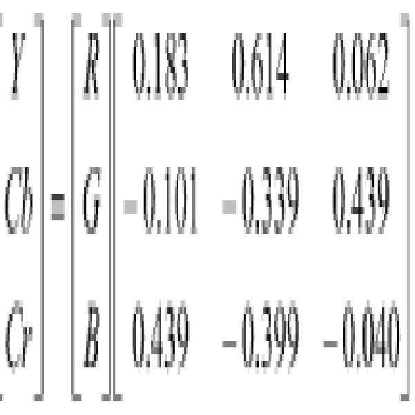
ITU-R BT.709 HD 표준, ITU-R BT.601 표준, 및 ITU-R BT.2020 표준을 포함하여 -그러나 이들로 제한되지 않는다-, 그외 다른 컬러 공간 변환 표준이 발명에 의해 구현될 수 있음을 알 것이다.Other color space conversion standards can be implemented by the invention, including but not limited to, ITU-R BT.709 HD standard, ITU-R BT.601 standard, and ITU-R BT.2020 standard. You will know that
백색 밸런스가 조명 영역에서 수행되고 있다면 이 변조는 백색 밸런스 변조에 더하여 부과된다.If white balance is being performed in the illumination area, this modulation is imposed in addition to white balance modulation.
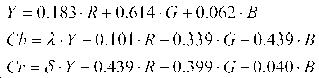
풀 컬러 이미지를 완성하는 것은 크로미넌스의 두 성분이 제공될 것을 요구한다. 그러나, 루미넌스를 위해 적용되었던 동일 알고리즘은 RGB 계수의 일부가 음이라는 사실에 반영되는 바와 같이 사인(sign)이 있기 때문에 크로미넌스 이미지에 직접 적용될 수 없다. 이에 대한 해결책은 모든 최종의 펄스 에너지가 포지티브가 되는 충분한 크기의 루미넌스 정도를 추가하는 것이다. ISP에서 컬러 융합 프로세스가 크로미넌스 프레임의 구성을 알고 있는 한, 이들은 적합한 량의 루미넌스를 이웃 프레임에서 감함으로써 디코딩될 수 있다. 펄스 에너지 부분은 다음에 의해 주어진다:Completing the full color image requires two components of chrominance to be provided. However, the same algorithm that was applied for luminance cannot be directly applied to the chrominance image because there is a sign as reflected in the fact that part of the RGB coefficient is negative. The solution is to add a degree of luminance of sufficient magnitude that all final pulse energies are positive. As long as the color fusion process at the ISP knows the composition of the chrominance frame, they can be decoded by subtracting an appropriate amount of luminance from the neighboring frame. The pulse energy portion is given by:
여기에서 From here
![]()
![]()
![]()
![]()
일반적인 경우에 대한 타이밍이 도 6a에 도시되었다. λ 팩터가 0.552와 같다면 적색 및 녹색 성분 둘 다는 정확하게 상쇄되는 것으로 판명되며, 이 경우에 Cb 정보엔 순 청색 정보만이 제공될 수 있다. 유사하게, δ= 0.650로 설정하는 것은 Cr 에 대해 청색 및 녹색 성분들을 상쇄시켜 순 적색이 된다. 이 특별한 예는 1/28의 정수배로서 λ 및 δ를 도시한 도 6b에 도시되었다. 이것은 디지털 프레임 재구축(나중 논의를 참조한다)에 대한 편리한 근사화이다.The timing for the general case is shown in FIG. 6A. If the λ factor is equal to 0.552, it turns out that both the red and green components are precisely canceled, in which case only pure blue information can be provided in the Cb information. Similarly, setting δ=0.650 cancels the blue and green components for Cr to become pure red. This particular example is shown in Figure 6b illustrates a λ and δ as an integral multiple of 1/2 8. This is a convenient approximation to digital frame reconstruction (see discussion later).
이제 도 7을 참조하면, 이 프로세스에 대한 일반적인 타이밍도가 도시되었다. 화소의 두 플래버를 위한 노출 기간은 도면에서 TX1 및 TX2로서 도시된, 이미지 센서 내에 두 내부 신호에 의해 제어된다. 사실, 이를 루미넌스 프레임에 대한 동적범위를 확장함과 동시에 행하는 것이 가능하며, 이것은 두 통합 시간이 프레임별로 조절될 수 있기 때문에 가장 필요하다(도 3a 내지 도 3c 참조). 이익은 모든 데이터가 두 프레임 대 3으로부터 도출된다면 컬러 모션 아티팩트가 덜 문제가 될 것이라는 것이다. 물론 크로미넌스 데이터에 대한 공간적 해상도의 후속 손실이 존재하는데, 그러나 이것은 앞서 논의된 이유로 이미지 질에 덜 중요하다.Referring now to Figure 7, a general timing diagram for this process is shown. The exposure period for the two flavers of the pixel is controlled by two internal signals in the image sensor, shown as TX1 and TX2 in the figure. In fact, it is possible to do this simultaneously with extending the dynamic range for the luminance frame, which is most necessary since the two integration times can be adjusted frame by frame (see FIGS. 3A to 3C). The benefit is that color motion artifacts will be less of a problem if all data is derived from two frames to three. Of course there is a subsequent loss of spatial resolution to the chrominance data, but this is less important for image quality for the reasons discussed above.
단색의 넓은 동적범위 어레이의 본연의 특성은 긴 통합 시간을 갖는 화소가 짧은 통합 시간 화소가 받는 광의 확대집합을 통합해야 한다는 것이다. WIDE 동적범위 USING 단색의 센서 명칭의 함께 계류중인 미국특허 출원번호 13/952,564은 전체가 본원에 개시된 것으로 하여 이 발명에 참조로 포함된다. 루미넌스 프레임에서 정규의 넓은 동적범위 동작에 있어서, 이것은 바람직하다. 크로미넌스 프레임들에 있어서, 예를 들면, 긴 노출의 시작부터 λY+Cb을 제공하고 짧은 노출 화소가 턴 온(두 화소 유형들은 이들의 전하가 동시에 전송되게 한다)되는 지점에서 δY+Cr으로 스위칭하기 위해 펄싱은 노출 기간과 함께 제어되어야 함을 의미한다. 컬러 융합 동안, 이것은 감안될 것이다. 도 8은 이 해결책을 위한 구체적 타이밍도이다.The intrinsic characteristic of a monochromatic wide dynamic range array is that a pixel with a long integration time must incorporate an enlarged set of light received by a short integration time pixel. US Patent Application No. 13/952,564, pending with the name of the WIDE dynamic range USING monochrome sensor, is incorporated herein by reference in its entirety as disclosed herein. For normal wide dynamic range operation in the luminance frame, this is desirable. For chrominance frames, for example, from the start of a long exposure, to δY+Cr at the point where it provides λY+Cb and the short exposure pixel is turned on (both pixel types allow their charges to be transferred simultaneously). To switch, this means that pulsing must be controlled along with the exposure period. During color fusion, this will be taken into account. 8 is a specific timing diagram for this solution.
전형적인 ISP은 먼저 임의의 필요한 센서 및 광학 정정(이를테면 결함 화소 제거, 렌즈 쉐이딩, 등)과, 이어 백색 밸런스, 디모자익(demosaic)/컬러 융합 및 컬러 정정을 처리하는 것을 수반한다.A typical ISP involves first processing any necessary sensors and optical corrections (such as defect pixel removal, lens shading, etc.), followed by white balance, demosaic/color fusion and color correction.
데이터를 표준 sRGB 공간에 두기 위해 감마를 최종으로 적용하기 전에, 전형적으로 YCbCr 또는 HSL와 같은 대안적 컬러 공간에서 수행되는 일부 동작(예를 들면, 에지 향상) 및/또는 조절(예를 들면, 포화)가 있을 수도 있을 것이다. 도 9는 R-G-B-G 펄싱 수법에 대해 적합하게 될 기본 ISP 코어를 도시한 것이다. 이 예에서, 데이터는 루미넌스 평면에서 에지 향상을 적용하고 크로미넌스의 필터링을 수행하기 위해 YCbCr로 변환되고 이어 다시 선형 RGB로 다시 변환된다.Some operations (e.g. edge enhancement) and/or adjustment (e.g. saturation) typically performed in alternative color spaces, such as YCbCr or HSL, before finally applying gamma to place the data in standard sRGB space ). 9 shows the basic ISP core that will be suitable for the R-G-B-G pulsing technique. In this example, the data is converted to YCbCr and then back to linear RGB to apply edge enhancement in the luminance plane and perform chrominance filtering.
Y-Cb-Y-Cr 펄싱 수법의 경우에, 이미지 데이터는 컬러 융합에 후에 YCbCr 공간 이미 내에 있다. 그러므로, 이 경우에 컬러 정정 등을 수행하기 위해 선형 RBG로 다시 변환하기 전에, 루미넌스 및 크로미넌스 기반의 동작을 미리 수행하는 것이 합당하. 도 10을 참조한다.In the case of the Y-Cb-Y-Cr pulsing technique, the image data is already within the YCbCr space after color fusion. Therefore, in this case, it is reasonable to perform luminance and chrominance-based operations in advance before converting back to linear RBG to perform color correction or the like. See FIG. 10.
컬러 융합 프로세스는 디모자익보다 더 수월하며, 이것은 공간적 보간이 없기 때문에 바이에르 패턴에 의해 필요로 된다. 그렇지만 이것은 도 11에 도시된 바와 같이, 각 화소에 대해 가용된 필요한 모든 정보를 갖기 위해서 프레임들의 버퍼링을 요구한다. 도 12a는 두 생 캡처된 이미지당 1 풀 컬러 이미지를 생성하는 Y-Cb-Y-Cr 패턴에 대한 데이터의 파이프라이닝의 일반적 상황을 도시한 것이다. 이것은 각 크로미넌스 샘플을 두 번 사용함으로써 달성된다. 도 12b에서 60Hz 최종 비디오를 제공하는 120Hz 프레임 캡처 레이트의 구체적 예가 도시되었다.The color fusion process is easier than demosaic, which is required by the Bayer pattern because there is no spatial interpolation. However, this requires buffering of frames to have all the necessary information available for each pixel, as shown in FIG. 12A shows the general situation of pipelining of data for a Y-Cb-Y-Cr pattern that produces one full color image per two raw captured images. This is achieved by using each chrominance sample twice. In FIG. 12B, a specific example of a 120 Hz frame capture rate is shown providing a 60 Hz final video.
각 화소에 대한 선형 Y, Cb 및 Cr 성분들은 이와 같이 계산될 수 있다:The linear Y, Cb and Cr components for each pixel can be calculated like this:
![]()
![]()
n='Cb' 프레임일 때n='Cb' frame
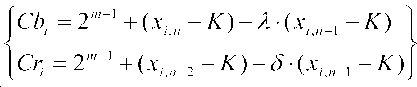
n='Cr' 프레임일 때n='Cr' frame
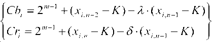
xi,n이 프레임 m 내 화소 i에 대한 입력 데이터인 경우, m은 ISP의 파이프라인 비트-폭이고 K는 컬러 융합 블록에(적용가능하다면) 입력에서 ISP 흑색 오프셋 레벨이다. 크로미넌스는 사인(sign)이 있기 때문에, 통상적으로 디지털 동적범위(2m-1)의 50%에 중심에 놓인다.If x i,n is the input data for pixel i in frame m, m is the pipeline bit-width of the ISP and K is the ISP black offset level at the input (if applicable) to the color fusion block. Since the chrominance is a sign, it is usually centered at 50% of the digital dynamic range (2 m-1 ).
앞서 기술된 바와 같이 동일 프레임에서 두 크로미넌스 성분들을 제공하기 위해서 두 노출이 사용된다면, 화소의 두 플래버는 두 버퍼로 분리된다. 비어있는 화소는 예를 들면 선형 보간을 사용하여 채워진다. 이 시점에서, 한 버퍼는 δY+Cr 데이터의 풀 이미지를 내포할 것이고 다른 것은 δY+Cr+λY+Cb을 내포할 것이다. δY+Cr 버퍼는 제 2 버퍼로부터 감하여져 λY+Cb를 제공한다. 이어서 Y 프레임으로부터 루미넌스 데이터의 적합한 부분이 각각에 대해 감해질 것이다.If two exposures are used to provide two chrominance components in the same frame as described above, the two flavors of the pixel are separated into two buffers. Empty pixels are filled using, for example, linear interpolation. At this point, one buffer will contain a full image of δY+Cr data and the other will contain δY+Cr+λY+Cb. The δY+Cr buffer is subtracted from the second buffer to provide λY+Cb. Then a suitable portion of the luminance data from the Y frame will be subtracted for each.
발명의 구현은 예를 들면, 이하 더 상세히 논의되는 바와 같이, 하나 이상의 프로세서 및 시스템 메모리와 같은, 컴퓨터 하드웨어를 포함하여, 전용 또는 범용 컴퓨터를 포함하거나 이용할 수 있다. 또한, 본 발명의 범위 내에서 구현들은 컴퓨터-실행가능 명령 및/또는 데이터 구조를 탑재 또는 저장하기 위한 물리적 및 그외 다른 컴퓨터-판독가능 매체를 포함할 수 있다. 이러한 컴퓨터-판독가능 매체는 범용 혹은 전용 컴퓨터 시스템에 의해 액세스될 수 있는 임의의 가용한 매체일 수 있다. 컴퓨터-실행가능 명령을 저장하는 컴퓨터-판독가능 매체는 컴퓨터 저장 매체(장치)일 수 있다. 컴퓨터-실행가능 명령을 탑재하는 컴퓨터-판독가능 매체는 전송 매체일 수 있다. 이에 따라, 제한이 아니라, 예로서, 발명의 구현들은 적어도 2개의 서로 구별되는 상이한 종류의 컴퓨터-판독가능 매체로서 컴퓨터 저장 매체(장치) 및 전송 매체를 포함할 수 있다.Implementations of the invention may include or utilize dedicated or general purpose computers, including computer hardware, such as, for example, one or more processors and system memory, as discussed in more detail below. In addition, implementations within the scope of the present invention may include physical and other computer-readable media for mounting or storing computer-executable instructions and/or data structures. Such computer-readable media can be any available media that can be accessed by a general purpose or dedicated computer system. The computer-readable medium for storing computer-executable instructions may be a computer storage medium (device). A computer-readable medium carrying computer-executable instructions may be a transmission medium. Accordingly, by way of example, and not limitation, implementations of the invention may include computer storage media (devices) and transmission media as at least two different kinds of computer-readable media that are distinct from each other.
컴퓨터 저장 매체(장치)는 컴퓨터-실행가능 명령 또는 데이터 구조 형태로 요망되는 프로그램 코드 수단을 저장하기 위해 사용될 수 있고 범용 또는 전용 컴퓨터에 의해 액세스될 수 있는, RAM, ROM, EEPROM, CD-ROM, 고체상태 드라이브("SSD")(예를 들면, RAM 기반), 플래시 메모리, 상-변화 메모리("PCM"), 이외 다른 유형의 메모리, 이외 다른 광학 디스크 저장장치, 자기 디스크 저장장치 혹은 이외 다른 자기 저장 장치, 혹은 이외 어떤 다른 매체를 포함한다.Computer storage media (devices) can be used to store desired program code means in the form of computer-executable instructions or data structures and can be accessed by a general purpose or dedicated computer, RAM, ROM, EEPROM, CD-ROM, Solid state drives ("SSD") (eg RAM based), flash memory, phase-change memory ("PCM"), other types of memory, other optical disk storage, magnetic disk storage or other Magnetic storage devices, or any other medium.
"네트워크"는 컴퓨터 시스템 및/또는 모듈 및/또는 이외 다른 전자 장치들 간에 전자 데이터를 수송할 수 있게 하는 하나 이상의 데이터 링크로서 정의된다. 구현예에서, 센서 및 카메라 제어 유닛은 서로, 및 다른 성분들 -이들이 연결된 네트워크를 통해 연결된- 과 통신하기 위해서 네트워크될 수 있다. 정보가 네트워크 또는 또 다른 통신 연결(하드와이어, 무선, 혹은 하드와이어되거나 무선의 조합)을 통해 컴퓨터에 전송 또는 제공될 때, 컴퓨터는 연결을 전송 매체로서 적합히 인지한다. 전송 매체는 네트워크 및/또는 데이터 링크를 포함할 수 있고, 이들은 요망되는 프로그램 코드 수단을 컴퓨터-실행가능 명령 또는 데이터 구조 형태로 탑재하기 위해 사용될 수 있고, 범용 또는 전용 컴퓨터에 의해 액세스될 수 있다. 위에 조합들은 또한 컴퓨터-판독가능 매체의 범위 내에 포함될 것이다."Network" is defined as one or more data links that enable the transport of electronic data between computer systems and/or modules and/or other electronic devices. In an implementation, the sensor and camera control unit can be networked to communicate with each other and other components-connected via a network to which they are connected. When information is transmitted or provided to a computer via a network or another communication connection (hardwired, wireless, or a hardwired or wireless combination), the computer properly recognizes the connection as a transmission medium. The transmission medium may include a network and/or data link, which can be used to mount the desired program code means in the form of computer-executable instructions or data structures, and can be accessed by a general purpose or dedicated computer. Combinations of the above will also be included within the scope of computer-readable media.
또한, 도 13에서 알 수 있는 바와 같이, 다양한 컴퓨터 시스템 성분들, 전송 매체에서 컴퓨터 저장 매체(장치)로(혹은 그 반대로) 자동으로 전송될 수 있는 컴퓨터-실행가능 명령 또는 데이터 구조 형태의 프로그램 코드 수단. 예를 들면, 네트워크 또는 데이터 링크를 통해 수신된 컴퓨터-실행가능 명령 또는 데이터 구조는 네트워크 인터페이스 모듈(예를 들면, "NIC") 내에 RAM 내에 버퍼되고, 이어서 종국에 컴퓨터 시스템 RAM에 및/또는 컴퓨터 시스템에 비휘발성 컴퓨터 저장 매체(장치)에 전송될 수 있다. 또한, RAM은 고체상태 드라이브(SSD 또는 PCIx 기반의 실시간 메모리 결속된 저장장치, 이를테면 융합IO)을 포함할 수 있다. 이에 따라, 컴퓨터 저장 매체(장치)는 전송 매체를 이용하는(또는 심지어는 주로) 컴퓨터 시스템 성분 내 포함될 수 있다.Also, as can be seen in Figure 13, various computer system components, program code in the form of computer-executable instructions or data structures that can be automatically transferred from a transmission medium to a computer storage medium (or vice versa). Way. For example, computer-executable instructions or data structures received over a network or data link are buffered in RAM within a network interface module (eg, "NIC"), and subsequently to computer system RAM and/or a computer. The system may be transferred to a non-volatile computer storage medium (device). In addition, the RAM may include a solid state drive (SSD or PCIx based real-time memory bound storage, such as converged IO). Accordingly, computer storage media (devices) may be included in computer system components using (or even predominantly) transmission media.
컴퓨터-실행가능 명령은 예를 들면, 프로세서에서 실행되었을 때, 범용 컴퓨터, 전용 컴퓨터, 또는 전용 처리 장치가 어떤 기능 또는 일 그룹의 기능들을 수행하게 하는 명령 및 데이터를 포함한다. 컴퓨터 실행가능 명령들은 예를 들면, 어셈블리 언어, 혹은 심지어 소스 코드와 같은 바이너리, 중간 포맷 명령일 수 있다. 요지가 구조적 특징들 및/또는 방법 단계들에 특정한 언어로 기술되었을지라도, 본원에 정의된 요지는 위에 기술된 특징 혹은 단계로 반드시 제한되는 것은 아님이 이해될 것이다. 그보다는, 기술된 특징 및 단계는 청구항을 구현하는 예시적 형태로서 개시된다.Computer-executable instructions include, for example, instructions and data that, when executed on a processor, cause a general purpose computer, dedicated computer, or dedicated processing device to perform certain functions or groups of functions. Computer-executable instructions may be, for example, assembly language, or even binary, intermediate format instructions such as source code. It will be understood that, although the subject matter has been described in language specific to structural features and/or method steps, the subject matter defined herein is not necessarily limited to the features or steps described above. Rather, the described features and steps are disclosed as example forms of implementing the claims.
당업자는 발명이 개인용 컴퓨터, 데스크탑 컴퓨터, 랩탑 컴퓨터, 메시지 프로세서, 제어 유닛, 카메라 제어 유닛, 휴대 장치, 핸드 피스, 다중-프로세서 시스템, 마이크로프로세서-기반 또는 프로그램가능 소비자 전자장치, 네트워크 PC, 미니컴퓨터, 메인프레임 컴퓨터, 모바일 전화, PDA, 태블릿, 페이저, 라우터, 스위치, 각종 저장 장치, 등을 포함하여, 많은 유형의 컴퓨터 시스템 구성을 가진 네트워크 계산 환경에서 실시될 수 있음을 알 것이다. 위에 언급된 계산 장치 중 어느 것이든 브릭 및 모타르 위치 옆에 혹은 이 내에 제공될 수 있음에 유의한다. 또한, 발명은 네트워크를 통해 링크되는(하드와이어된 데이터 링크, 무선 데이터 링크에 의해, 혹은 하드와이어된 및 무선 데이터 링크들의 조합에 의해)되는 로컬 및 원격 컴퓨터 시스템들 둘 다 작업을 수행하는 분산 시스템 환경에서 실시될 수도 있다. 분산 시스템 환경에서, 프로그램 모듈은 로컬 및 원격 메모리 저장 장치들 둘 다에 위치될 수 있다.Those skilled in the art will appreciate that the invention includes personal computers, desktop computers, laptop computers, message processors, control units, camera control units, portable devices, handpieces, multi-processor systems, microprocessor-based or programmable consumer electronics, network PCs, minicomputers. It will be appreciated that it can be implemented in a network computing environment with many types of computer system configurations, including mainframe computers, mobile phones, PDAs, tablets, pagers, routers, switches, and various storage devices. Note that any of the above-mentioned computing devices can be provided next to or within the brick and mortar positions. In addition, the invention is a distributed system that performs both local and remote computer systems that are linked through a network (either by a hardwired data link, by a wireless data link, or by a combination of hardwired and wireless data links). It can also be practiced in an environment. In a distributed system environment, program modules may be located in both local and remote memory storage devices.
또한, 적합한 경우, 본원에 기술된 기능은 하드웨어, 소프트웨어, 펌웨어, 디지털 성분들, 또는 아날로그 성분들 중 하나 이상에서 수행될 수 있다. 예를 들면, 하나 이상의 응용특정의 집적회로(ASIC) 또는 필드 프로그램가능 게이트 어레이(FPGA)는 본원에 기술된 시스템 및 절차 중 하나 이상을 수행하게 프로그램될 수 있다. 어떤 용어들은 특정 시스템 성분들을 언급하기 위해 다음 설명 및 청구항 전체에 걸쳐 사용된다. 당업자가 알게 되는 바와 같이, 성분들은 상이한 명칭들에 의해 언급될 수도 있다. 이 문서는 명칭은 상이하나 기능은 상이하지 않은 성분들 간을 구별하지는 않는다.Further, where appropriate, the functions described herein can be performed in one or more of hardware, software, firmware, digital components, or analog components. For example, one or more application specific integrated circuits (ASICs) or field programmable gate arrays (FPGAs) can be programmed to perform one or more of the systems and procedures described herein. Certain terms are used throughout the following description and claims to refer to specific system components. As will be appreciated by those skilled in the art, ingredients may be referred to by different names. This document does not distinguish between ingredients that differ in name but not function.
도 13은 예시적 계산 장치(100)를 도시한 블록도이다. 계산 장치(100)는 본원에서 논의되는 것들과 같은, 다양한 절차를 수행하기 위해 사용될 수 있다. 계산 장치(100)는 서버, 클라이언트, 혹은 이외 어떤 다른 계산 실체로서 기능할 수 있다. 계산 장치는 본원에서 논의되는 다양한 모니터링 기능을 수행할 수 있고, 본원에 기술된 응용 프로그램과 같은 하나 이상의 응용 프로그램을 실행할 수 있다. 계산 장치(100)는 데스크탑 컴퓨터, 노트북 컴퓨터, 서버 컴퓨터, 휴대 컴퓨터, 카메라 제어 유닛, 태블릿 컴퓨터, 등과 같은 매우 다양한 계산 장치 중 어느 것일 수 있다.13 is a block diagram illustrating an
계산 장치(100)는 하나 이상의 프로세서(들)(102), 하나 이상의 메모리 장치(들)(104), 하나 이상의 인터페이스(들)(106), 하나 이상의 대량 저장 장치(들)(108), 하나 이상의 입력/출력(I/O) 장치(들)(110), 및 디스플레이 장치(130) -이들 모두는 버스(112)에 결합된다- 를 포함한다. 프로세서(들)(102)는 메모리 장치(들)(104) 및/또는 대량 저장 장치(들)(108)에 저장되는 명령들을 실행하는 하나 이상의 프로세서 또는 제어기를 포함한다. 프로세서(들)(102)은 또한 캐시 메모리와 같은 다양한 유형의 컴퓨터-판독가능 매체를 포함할 수 있다.
메모리 장치(들)(104)는 휘발성 메모리(예를 들면, 랜덤 액세스 메모리(RAM)(114)) 및/또는 비휘발성 메모리(예를 들면, 판독전용 메모리(ROM)(116))와 같은 다양한 컴퓨터-판독가능 매체를 포함한다. 메모리 장치(들)(104)는 또한 플래시 메모리와 같은 재기입가능 ROM을 포함할 수 있다.The memory device(s) 104 may include various volatile memory (eg, random access memory (RAM) 114) and/or non-volatile memory (eg, read-only memory (ROM) 116). Computer-readable media. Memory device(s) 104 may also include a rewritable ROM, such as flash memory.
대량 저장 장치(들)(108)은 자기 테이프, 자기 디스크, 광학 디스크, 고체상태 메모리(예를 들면, 플래시 메모리), 등과 같은 다양한 컴퓨터 판독가능 매체를 포함한다. 도 13에 도시된 바와 같이, 특정 대량 저장 장치는 하드 디스크 드라이브(124)이다. 여러 드라이브들 또한 여러 컴퓨터 판독가능 매체로부터 판독 및/또는 이에 기입할 수 있게 대량 저장 장치(들)(108) 내에 포함될 수 있다. 대량 저장 장치(들)(108)는 착탈가능 매체(126) 및/또는 비착탈가능 매체를 포함한다.Mass storage device(s) 108 includes various computer readable media such as magnetic tapes, magnetic disks, optical disks, solid state memory (eg, flash memory), and the like. As shown in Figure 13, a particular mass storage device is a hard disk drive 124. Several drives may also be included in mass storage device(s) 108 for reading and/or writing to and from various computer readable media. Mass storage device(s) 108 includes removable medium 126 and/or non-removable medium.
I/O 장치(들)(110)은 데이터 및/또는 다른 정보가 계산 장치(100)에 입력되거나 이로부터 인출될 수 있게 하는 다양한 장치를 포함한다. 예시적 I/O 장치(들)(110)는 디지털 이미징 장치, 전자기 센서 및 방출기, 커서 제어 장치, 키보드, 키패드, 마이크로폰, 모니터 또는 이외 다른 디스플레이 장치, 스피커, 프린터, 네트워크 인터페이스 카드, 모뎀, 렌즈, CCD 또는 다른 이미지 캡처 장치, 등을 포함한다.I/O device(s) 110 includes various devices that allow data and/or other information to be input to or retrieved from
디스플레이 장치(130)는 계산 장치(100)의 하나 이상의 사용자에게 정보를 디스플레이할 수 있는 임의의 유형의 장치를 포함한다. 디스플레이 장치(130)의 예는 모니터, 디스플레이 단말, 비디오 프로젝션 장치, 등을 포함한다.Display device 130 includes any type of device capable of displaying information to one or more users of
인터페이스(들)(106)은 계산 장치(100)가 다른 시스템, 장치, 또는 계산 환경과 상호작용할 수 있게 하는 여러 인터페이스를 포함한다. 예시적 인터페이스(들)(106)은 이를테면 로컬 영역 네트워크(LAN), 광역 네트워크(WAN), 무선 네트워크, 및 인터넷에 대한 인터페이스와 같은, 임의의 수의 서로 다른 네트워크 인터페이스(120)를 포함할 수 있다. 이외 다른 인터페이스(들)은 사용자 인터페이스(118) 및 주변 장치 인터페이스(122)를 포함한다. 인터페이스(들)(106)는 또한 하나 이상의 사용자 인터페이스 요소(118)를 포함할 수 있다. 또한, 인터페이스(들)(106)는 프린터, 포인팅 장치(마우스, 트랙 패드, 등), 키보드, 등을 위한 인터페이스와 같은 하나 이상의 주변 인터페이스를 포함할 수 있다.The interface(s) 106 includes several interfaces that allow the
버스(112)는 프로세서(들)(102), 메모리 장치(들)(104), 인터페이스(들)(106), 대량 저장 장치(들)(108), 및 I/O 장치(들)(110)이 버스(112)에 결합된 다른 장치 또는 성분 뿐만 아니라, 서로 통신할 수 있게 한다. 버스(112)는 시스템 버스, PCI 버스, IEEE 1394 버스, USB 버스, 등과 같은 몇몇 유형들의 버스 구조 중 하나 이상을 나타낸다.
예시 목적을 위해, 프로그램 및 이외 다른 실행가능한 프로그램 성분은 이러한 프로그램 및 성분이 여러 시간들에서 계산 장치(100)의 서로 다른 저장 성분들 내 놓여지고 프로세서(들)(102)에 의해 실행되는 것으로 이해될지라도, 본원에 별개의 블록들로서 도시되었다. 대안적으로, 본원에 기술되는 시스템 및 절차는 하드웨어로, 혹은 하드웨어, 소프트웨어, 및/또는 펌웨어의 조합으로 구현될 수 있다. 예를 들면, 하나 이상의 응용특정의 집적회로(ASIC)는 본원에 기술된 시스템 및 절차 중 하나 이상을 수행하게 프로그램될 수 있다.For illustrative purposes, programs and other executable program components are understood to be such that these programs and components are placed in different storage components of the
도 14a 및 도 14b는 발명의 교시된 바 및 원리에 따라 3차원 이미지를 생성하기 위한 복수의 화소 어레이를 갖는 모노리식 센서(2900)의 구현의 사시도 및 측면도를 각각 도시한 것이다. 이러한 구현예는 3차원 이미지 캡처를 위해 바람직할 수 있는 것으로 두 화소 어레이(2902, 2904)는 사용 동안 오프셋될 수 있다. 또 다른 구현예에서, 제 1 화소 어레이(2902) 및 제 2 화소 어레이(2904)는 전자기 방사의 소정의 범위의 파장을 수신하는 것에 전용될 수 있고, 제 1 화소 어레이는 제 2 화소 어레이와는 상이한 범위의 파장에 전용된다.14A and 14B show perspective and side views, respectively, of an implementation of a
도 15a 및 도 15b는 복수의 기판 상에 형성된 이미지 센서(3000)의 구현의 사시도 및 측면도를 각각 도시한 것이다. 도시된 바와 같이, 화소 어레이를 형성하는 복수의 화소 컬럼(3004)은 제 1 기판(3002) 상에 위치되고, 복수의 회로 컬럼(3008)은 제 2 기판(3006) 상에 위치된다. 15A and 15B show perspective and side views, respectively, of an implementation of the
또한 도면에는 이의 연관된 또는 대응하는 컬럼의 회로에 한 컬럼의 화소들 간에 전기적 연결 및 통신이 도시되었다. 일 구현예에서, 단일 모노리식 기판/칩 상에 자신의 화소 어레이 및 지원회로와 함께 제조되었을 이미지 센서는 모든 또는 대부분의 지원회로로부터 분리된 화소 어레이를 가질 수 있다. 발명은 3차원 적층 기술을 사용하여 함께 적층될 적어도 2개의 기판/칩을 사용할 수 있다. Also shown in the drawings are electrical connections and communication between pixels of a column in the circuit of its associated or corresponding column. In one implementation, an image sensor that would have been fabricated with its own pixel array and supporting circuitry on a single monolithic substrate/chip may have a pixel array separate from all or most of the supporting circuitry. The invention may use at least two substrates/chips to be stacked together using a three-dimensional stacking technique.
두 기판/칩의 제 1(3002)은 이미지 CMOS 프로세스를 사용하여 처리될 수 있다. 제 1 기판/칩(3002)은 화소 어레이로만 혹은 제한된 회로에 의해 둘러싸인 화소 어레이로 구성될 수 있다. 제 2 또는 후속 기판/칩(3006)은 임의의 프로세스를 사용하여 처리될 수 있고, 이미지 CMOS 프로세스로부터 될 필요는 없다. 제 2 기판/칩(3006)은 기판/칩 상에 매우 제한된 공간 또는 영역 내에 다양한 다수의 기능을 통합하기 위해서 고밀도 디지털 프로세스, 혹은 예를 들면 정밀한 아날로그 기능을 통합하기 위해서 혼합-모드 또는 아날로그 프로세스, 혹은 무선 능력을 구현하기 위해서 RF 프로세스, 혹은 MEMS 장치를 통합하기 위해서 MEMS(마이크로-전기-기계 시스템)일 수 있는데, 그러나 이들로 제한되지 않는다.The first 3002 of both substrates/chips can be processed using an image CMOS process. The first substrate/
이미지 CMOS 기판/칩(3002)은 임의의 3차원 기술을 사용하여 제 2 또는 후속 기판/칩(3006)과 적층될 수 있다. 제 2 기판/칩(3006)은 주변 회로로서 제 1 이미지 CMOS 칩(3002)(모노리식 기판/칩 상에 구현된다면) 내 구현되고 따라서 화소 어레이 크기를 일정하게 유지하고 가능한 최대 범위에 최적화되면서 전체 시스템 영역을 증가시켰을 수도 있었을 대부분, 혹은 대다수의 회로를 지원할 수 있다. 두 기판/칩 간에 전기적 연결은 와이어본딩, 범프 및/또는 TSV(Through Silcon Via)일 수 있는 상호연결(3003, 3005)을 통해 행해질 수 있다.The image CMOS substrate/
도 16a 및 도 16b는 3차원 이미지를 생성하기 위한 복수의 화소 어레이를 갖는 이미지 센서(3100)의 구현예의 사시도 및 측면도를 각각 도시한 것이다. 3차원 이미지 센서는 복수의 기판 상에 형성될 수 있고 복수의 화소 어레이 및 다른 연관된 회로를 포함할 수 있고, 제 1 화소 어레이를 형성하는 복수의 화소 컬럼(3104a) 및 제 2 화소 어레이를 형성하는 복수의 화소 컬럼(3104b)는 각각 각각의 기판(3102a, 3102b) 상에 위치되며 복수의 회로 컬럼(3108a, 3108b)는 별도의 기판(3106) 상에 위치된다. 또한, 회로의 연관된 혹은 대응하는 컬럼에 화소의 컬럼들 간에 전기적 연결 및 통신이 도시되었다.16A and 16B respectively show perspective and side views of an embodiment of an
발명의 교시된 바 및 원리는 발명의 범위 내에서 재사용가능 장치 플랫폼, 제한된 사용 장치 플랫폼, 재-포즈가능 사용 장치 플랫폼, 또는 단일-사용/처분가능 장치 플랫폼에서 사용될 수 있음을 알 것이다. 재사용가능 장치 플랫폼에서 최종-사용자는 장치의 세정 및 살균에 책임이 있음을 알 것이다. 제한된 사용 장치 플랫폼에서 장치는 동작불가해지기 전에 어떤 특정된 시간량 동안 사용될 수 있다. 전형적인 새로운 장치는 추가의 사용전에 추가의 사용이 최종-사용자가 세정 및 살균할 것을 요구함과 함께 살균하여 전달된다. 재-포즈가능 사용 장치 플랫폼에서, 제 3자는 새로운 유닛보다 낮은 비용으로 추가의 사용을 위해 단일-사용 장치로 장치를 재처리(예를 들면, 세정, 패키징 및 살균)할 수 있다. 단일-사용/처분가능 장치 플랫폼에서, 장치는 작업실에서 살균하여 제공되고 처분되기 전에 1회만 사용된다.It will be appreciated that the teachings and principles of the invention can be used in a reusable device platform, a limited use device platform, a re-posable use device platform, or a single-use/disposable device platform within the scope of the invention. On the reusable device platform, the end-user will know that they are responsible for cleaning and sanitizing the device. In a limited use device platform, the device can be used for a certain amount of time before it becomes inoperative. A typical new device is delivered sterilized with additional use requiring end-user cleaning and sterilization prior to further use. In a re-posable use device platform, a third party can reprocess (eg, clean, package and sterilize) the device with a single-use device for further use at a lower cost than a new unit. In a single-use/disposable device platform, the device is provided sterile in the workroom and used only once prior to disposal.
또한, 발명의 교시된 바 및 원리는 적외선(IR), 자외선(UV), 및 X-선과 같은 가시 및 비가시 스펙트럼을 포함한, 전자기 에너지의 임의의 및 모든 파장을 포함할 수 있다.In addition, the teachings and principles of the invention can include any and all wavelengths of electromagnetic energy, including visible and invisible spectra such as infrared (IR), ultraviolet (UV), and X-rays.
실시예에서, 주변 광 부족 환경들에서 내시경에 사용하기 위한 디지털 이미징 방법은 광 부족 환경 내에 조명을 야기하게 전자기 방사의 파장의 복수의 펄스를 방출하게 방출기를 작동시키는 단계; 펄스는 전자기 스펙트럼의 제 1 부분을 포함하는 제 1 파장 범위 내에 있는 제 1 펄스를 포함하고; 펄스는 전자기 스펙트럼의 제 2 부분을 포함하는 제 2 파장 범위 내에 있는 제 2 펄스를 포함하고; 펄스는 전자기 스펙트럼의 제 3 부분을 포함하는 제 3 파장 범위 내에 있는 제 3 펄스를 포함하고; 소정의 간격으로 상기 복수의 펄스들을 펄싱하는 단계; 상기 펄스로부터 반사된 전자기 방사를 화소 어레이로 감지하여 복수의 이미지 프레임을 생성하는 단계; 상기 화소 어레이는 상기 방출기의 상기 펄스 간격에 대응하는 감지 간격으로 판독되고; 비디오 스트림을 형성하기 위해 복수의 이미지 프레임을 조합함으로써 이미지들의 스트림을 생성하는 단계를 포함할 수 있다. 실시예에서, 상기 제 1 펄스는 크로미넌스 적색을 포함한다. 실시예에서, 상기 제 2 펄스는 크로미넌스 청색을 포함한다. 실시예에서, 상기 제 3 펄스는 루미넌스 펄스을 포함한다. 실시예에서, 상기 루미넌스 펄스는 적색 펄스 및 청색 펄스 및 녹색 펄스를 펄싱함으로써 생성된다. 이러한 실시예에서, 상기 적색 펄스는 적색 펄스가 양의 크로미넌스 값을 갖게 청색 및 녹색 펄스에 관하여 변조된다. 실시예에서, 상기 청색 펄스는 청색 펄스가 양의 크로미넌스 값을 갖게 적색 및 녹색 펄스에 관하여 변조된다. 실시예에서, 상기 녹색 펄스는 녹색 펄스가 양의 크로미넌스 값을 갖게 청색 및 적색 펄스에 관하여 변조된다. 실시예에서, 방법은 각 펄스의 크로미넌스 값이 양이 되게 하는 값에 의해 복수의 펄스들을 변조하는 단계를 더 포함한다. 실시예에서, 방법은 이미지 스트림 구축 동안으로부터 펄스 변조 값을 제거하는 단계를 더 포함한다. 이러한 실시예에서, 변조의 프로세스는 루미넌스 값을 복수의 펄스에 더하는 단계를 포함한다. 실시예에서, 변조를 위한 루미넌스 값은 (1/2)8의 배수인 정수이다. 실시예에서, 0.552의 변조를 위한 루미넌스 값은 적색 크로미넌스 및 녹색 크로미넌스를 상쇄시킨다. 실시예에서, 0.650의 변조를 위한 루미넌스 값은 청색 크로미넌스 및 녹색 크로미넌스를 상쇄시킨다. 실시예에서, 방법은 이미지 프레임의 스트림을 생성하면서 노이즈를 감소시키는 단계를 포함한다. 실시예에서, 방법은 이미지 프레임의 스트림을 생성하면서 백색 밸런스를 조절하는 단계를 더 포함한다. 실시예에서, 상기 제 3 펄스는 제 1 및 제 2 펄스만큼 종종 2번의 펄스들인 루미넌스 펄스이다. 실시예에서, 상기 루미넌스 펄스는 화소 어레이 내에 긴 노출 화소 및 짧은 노출 화소들에 의해 감지된다. 실시예에서, 방법은 복수의 화소 어레이에 의해 발생된 데이터를 감지하고 상기 데이터를 3차원 이미지 스트림으로 조합하는 단계를 더 포함한다.In an embodiment, a digital imaging method for use in an endoscope in ambient light-poor environments includes operating an emitter to emit multiple pulses of a wavelength of electromagnetic radiation causing illumination within the light-poor environment; The pulse comprises a first pulse within a first wavelength range comprising a first portion of the electromagnetic spectrum; The pulse comprises a second pulse within a second wavelength range comprising a second portion of the electromagnetic spectrum; The pulse comprises a third pulse within a third wavelength range comprising a third portion of the electromagnetic spectrum; Pulsing the plurality of pulses at predetermined intervals; Generating a plurality of image frames by sensing electromagnetic radiation reflected from the pulses as a pixel array; The pixel array is read at a sensing interval corresponding to the pulse interval of the emitter; And generating a stream of images by combining a plurality of image frames to form a video stream. In an embodiment, the first pulse comprises chrominance red. In an embodiment, the second pulse comprises chrominance blue. In an embodiment, the third pulse comprises a luminance pulse. In an embodiment, the luminance pulse is generated by pulsing a red pulse and a blue pulse and a green pulse. In this embodiment, the red pulse is modulated with respect to the blue and green pulses so that the red pulse has a positive chrominance value. In an embodiment, the blue pulse is modulated with respect to the red and green pulses so that the blue pulse has a positive chrominance value. In an embodiment, the green pulse is modulated with respect to the blue and red pulses so that the green pulse has a positive chrominance value. In an embodiment, the method further comprises modulating the plurality of pulses by a value such that the chrominance value of each pulse is positive. In an embodiment, the method further includes removing the pulse modulation value from during image stream construction. In this embodiment, the process of modulation includes adding a luminance value to the plurality of pulses. In an embodiment, the luminance value for modulation is an integer that is a multiple of (1/2) 8 . In an embodiment, a luminance value for modulation of 0.552 cancels red chrominance and green chrominance. In an embodiment, a luminance value for modulation of 0.650 cancels blue chrominance and green chrominance. In an embodiment, the method includes reducing noise while generating a stream of image frames. In an embodiment, the method further comprises adjusting the white balance while generating a stream of image frames. In an embodiment, the third pulse is a luminance pulse, often two pulses, as many as the first and second pulses. In an embodiment, the luminance pulse is sensed by long and short exposed pixels in the pixel array. In an embodiment, the method further includes sensing data generated by the plurality of pixel arrays and combining the data into a three-dimensional image stream.
본원에 개시된 여러 특징들은 이 기술에 유의한 잇점 및 진보를 제공함을 알 것이다. 다음 청구항은 이들 특징들의 일부의 전형이다.It will be appreciated that the various features disclosed herein provide significant advantages and advances to this technology. The following claims are typical of some of these features.
발명의 전술한 상세한 설명에서, 발명의 여러 특징들은 발명을 간소화할 목적으로 단일 실시예에서 함께 그룹화된다. 발명의 이 방법은 청구된 발명이 각 청구항에 분명하게 인용된 것보다 더 많은 특징들을 요구하는 발명을 반영하는 것으로서 해석되지 않아야 한다. 그보다는, 발명의 측면들은 단일의 전술한 개시된 실시예의 모든 특징들 미만 이내에 놓여 있다.In the foregoing detailed description of the invention, various features of the invention are grouped together in a single embodiment for the purpose of simplifying the invention. This method of invention should not be construed as reflecting an invention in which the claimed invention requires more features than is expressly recited in each claim. Rather, aspects of the invention lie within less than all of the features of a single previously described embodiment.
위에 기술된 배열은 발명의 원리의 응용을 단지 예시하는 것임을 이해해야 한다. 발명의 정신 및 범위 내에서 당업자들에 의해 많은 수정들 및 대안적 배열들이 구상되며 청구된 청구항들은 이러한 수정들 및 배열들을 포함하게 의도된다. It should be understood that the arrangement described above is merely illustrative of the application of the principles of the invention. Many modifications and alternative arrangements are envisioned by those skilled in the art and within the spirit and scope of the invention and the claimed claims are intended to cover such modifications and arrangements.
이에 따라, 발명이 도면들에 도시되고 특징적으로 그리고 상세히 위에 기술되었지만 크기, 물질들, 형상, 형태, 기능 및 동작 방식, 조립 및 사용에 변화들을 포함하여 -이들로 제한되지 않는다- 수많은 수정들이 본원에 개시된 원리 및 개념 내에서 행해질 수 있음이 당업자들에게 명백할 것이다.Accordingly, although the invention has been shown in the drawings and has been described characteristically and in detail above, numerous modifications are disclosed herein including, but not limited to, changes in size, materials, shape, form, function and manner of operation, assembly and use It will be apparent to those skilled in the art that this can be done within the principles and concepts disclosed.
또한, 적합한 경우, 본원에 기술된 기능은 하드웨어, 소프트웨어, 펌웨어, 디지털 성분, 또는 아날로그 성분 중 하나 이상으로 수행될 수 있다. 예를 들면, 하나 이상의 응용특정의 집적회로(ASIC)는 본원에 기술된 시스템들 및 절차들 중 하나 이상을 수행하게 프로그램될 수 있다. 어떤 용어들은 특정 시스템 성분들을 언급하기 위해 다음 설명 및 청구항들 전체에 걸쳐 사용된다. 당업자가 알게 되는 바와 같이, 성분들은 상이한 명칭들에 의해 언급될 수도 있다. 이 문서는 명칭은 상이하나 기능은 상이하지 않은 성분들 간을 구별하지는 않는다.
Further, where appropriate, the functions described herein may be performed with one or more of hardware, software, firmware, digital components, or analog components. For example, one or more application specific integrated circuits (ASICs) can be programmed to perform one or more of the systems and procedures described herein. Certain terms are used throughout the following description and claims to refer to specific system components. As will be appreciated by those skilled in the art, ingredients may be referred to by different names. This document does not distinguish between ingredients that differ in name but not function.
Claims (52)
전자기 방사를 감지하기 위한, 화소들의 어레이를 포함하는 이미지 센서;
전자기 방사의 복수의 펄스를 방출하게 구성된 방출기; 및
프로세서를 포함하되, 상기 이미지 센서 및 상기 방출기와 전기적으로 통신하는 제어기;
상기 제어기는,
복수의 이미지 기준 프레임들을 생성하기 위해, 상기 방출기로부터 방출된 상기 전자기 방사의 복수의 펄스 각각을, 상기 이미지 센서의 판독 사이클과 동기화하고;
상기 복수의 이미지 프레임은,
루미넌스 데이터를 포함하는 루미넌스 프레임 및 크로미넌스 데이터를 포함하는 크로미넌스 프레임을 포함하고, 컬러 이미지를 형성하기 위해 조합되는,
시스템.
In a system for digital imaging in an ambient light shortage environment,
An image sensor comprising an array of pixels, for sensing electromagnetic radiation;
An emitter configured to emit a plurality of pulses of electromagnetic radiation; And
A controller comprising a processor, the controller in electrical communication with the image sensor and the emitter;
The controller,
To generate a plurality of image reference frames, each of the plurality of pulses of the electromagnetic radiation emitted from the emitter is synchronized with a read cycle of the image sensor;
The plurality of image frames,
A luminance frame comprising luminance data and a luminance frame including luminance data, and combined to form a color image,
system.
상기 방출기는,
각각이 전자기 스펙트럼 일부의 펄스를 방출하는 복수의 소스를 포함하는, 시스템.
According to claim 1,
The emitter,
A system, each comprising a plurality of sources emitting pulses of a portion of the electromagnetic spectrum.
상기 복수의 소스는, 동시에 작동되게 구성되는, 시스템.
According to claim 2,
The plurality of sources are configured to operate simultaneously.
상기 복수의 소스는, 미리 설정된 간격의 펄스를 생성하게 구성되는, 시스템.
According to claim 2,
The plurality of sources are configured to generate pulses of a predetermined interval.
상기 전자기 방사의 복수의 펄스는, 루미넌스 정보를 제공하기 위해, 광 에너지를 적색, 녹색 및 청색 광 에너지 영역에서 루미넌스, 크로미넌스 청색 및 크로미넌스 적색 광 에너지 영역으로 변환하는 색 변환 계수에 따라 변조되는, 시스템.
According to claim 1,
The plurality of pulses of the electromagnetic radiation are in accordance with a color conversion coefficient that converts light energy from red, green and blue light energy regions to luminance, chrominance blue and chrominance red light energy regions to provide luminance information. Modulated, system.
상기 전자기 방사의 복수의 펄스는, 크로미넌스 정보를 제공하기 위해, 광학 에너지를 적색, 녹색 및 청색 광학 에너지 영역에서 루미넌스, 크로미넌스 청색 및 크로미넌스 적색 광학 에너지 영역으로 변환하는 색 변환 계수에 따라 변조되는, , 시스템.
According to claim 1,
The plurality of pulses of the electromagnetic radiation converts optical energy from red, green and blue optical energy regions to luminance, chrominance blue and chrominance red optical energy regions to provide chrominance information. Modulated according to,, system.
7. The system of claim 6, wherein the chrominance information is blue.
7. The system of claim 6, wherein the chrominance information is red.
상기 방출기는, 루미넌스 - 크로미넌스 청색 - 루미넌스 - 크로미넌스 적색의 펄싱 패턴을 생성하는, 시스템.
According to claim 1,
The emitter generates a pulsing pattern of luminance-chrominance blue-luminance-chrominance red.
상기 방출기는,
루미넌스 - 크로미넌스 적색과 조합된 크로미넌스 청색 - 루미넌스 - 크로미넌스 적색과 조합된 크로미넌스 청색의 펄싱 패턴을 생성하는, 시스템.
According to claim 1,
The emitter,
Luminance-Chrominance Blue in combination with Chrominance Red-Luminance-A system that produces a pulsing pattern of chrominance blue in combination with Chrominance Red.
상기 제어기는,
결과적인 프레임들을 재구축하기 위해 1회 이상 크로미넌스 프레임들을 사용하게 구성된, 시스템.
According to claim 1,
The controller,
A system configured to use chrominance frames one or more times to reconstruct the resulting frames.
루미넌스 값은, 이미지 신호 프로세서에 의해, 크로미넌스 프레임에 더해지고,
상기 루미넌스 값은, (1/2)n의 배수인 정수인, 시스템.
According to claim 1,
The luminance value is added to the chrominance frame by the image signal processor,
The system of luminance is an integer multiple of (1/2) n .
상기 이미지 센서는, 개별적으로 판독되게 구성된, 균일한 단색 화소들을 포함하는, 시스템.
According to claim 1,
The image sensor comprises uniform monochromatic pixels, configured to be individually read.
상기 균일한 단색 화소들은,
상기 전자기 방사의 복수의 펄스에 노출된 후에 판단되고,
상기 전자기 방사의 복수의 펄스는,
긴 노출 및 짧은 노출을 갖는, 시스템.
The method of claim 13,
The uniform monochromatic pixels,
It is determined after exposure to a plurality of pulses of the electromagnetic radiation,
The plurality of pulses of the electromagnetic radiation,
System with long exposure and short exposure.
상기 이미지 센서는 단색 센서인, 시스템.
The method of claim 13,
The image sensor is a monochromatic sensor.
상기 이미지 센서는, 복수의 화소 감도들을 갖는 화소들을 포함하고,
상기 화소들은, 서로 다른 파장의 전자기 방사에 민감한,, 시스템.
According to claim 1,
The image sensor includes pixels having a plurality of pixel sensitivities,
The pixels are sensitive to electromagnetic radiation of different wavelengths.
상기 화소 감도들은 긴 노출 및 짧은 노출을 포함하는, 시스템.
The method of claim 16,
Wherein the pixel sensitivities include long exposure and short exposure.
상기 이미지 센서는,
긴 노출 화소 데이터 및 짧은 노출 화소 데이터의 루미넌스 프레임,
긴 노출 화소 데이터 및 짧은 노출 화소 데이터의 적색 크로미넌스 프레임, 및
긴 노출 화소 데이터 및 짧은 노출 화소 데이터의 청색 크로미넌스 프레임,
을 포함하는 프레임의 시퀀스를 생성하게 구성된, 시스템.
The method of claim 17,
The image sensor,
Luminance frame of long exposure pixel data and short exposure pixel data,
Red chrominance frame of long exposure pixel data and short exposure pixel data, and
Blue chrominance frame of long exposure pixel data and short exposure pixel data,
Configured to generate a sequence of frames comprising a system.
상기 전자기 방사의 복수의 펄스는, 루미넌스, 크로미넌스 적색 및 크로미넌스 청색을 포함하고,
상기 루미넌스 프레임은, 상기 적색 크로미넌스 프레임 및 상기 청색 크로미넌스 프레임 마다 2 번씩 나타나는,
시스템.
The method of claim 18,
The plurality of pulses of the electromagnetic radiation include luminance, chrominance red and chrominance blue,
The luminance frame appears twice each for the red chrominance frame and the blue chrominance frame,
system.
상기 방출기에 의해 방출되는 상기 전자기 방사의 복수의 펄스는 사람에게 보이지 않는 파장인, 시스템.
According to claim 1,
Wherein the plurality of pulses of the electromagnetic radiation emitted by the emitter are wavelengths invisible to humans.
상기 전자기 방사의 복수의 펄스는,
사람에게 보이는 파장 및 사람에게 보이지 않는 파장을 포함하는, 시스템.
According to claim 2,
The plurality of pulses of the electromagnetic radiation,
A system comprising a wavelength visible to a human and a wavelength invisible to a human.
상기 전자기 방사의 복수의 펄스는, 서로 상이한 크기들로 방출되는, 시스템.
According to claim 1,
The system, wherein the plurality of pulses of electromagnetic radiation are emitted in different sizes.
상기 서로 상이한 크기들은, 서로 상이한 파장들에 상기 이미지 센서의 감도에 대응하는, 시스템.
The method of claim 22,
Wherein the different sizes correspond to the sensitivity of the image sensor at different wavelengths.
상기 주변 광 부족 환경에 액세스하기 위한 내시경을 더 포함하되,
상기 내시경은,
상기 내시경에 부착된 핸드 피스를 가지며, 상기 핸드 피스의 조작에 의해 조정되는, 시스템.
According to claim 1,
Further comprising an endoscope for access to the ambient light shortage environment,
The endoscope,
A system having a hand piece attached to the endoscope and adjusted by manipulation of the hand piece.
상기 이미지 센서는, 상기 핸드 피스에 대한 원단 부분에서
상기 내시경 내에 배치된, 시스템.
The method of claim 24,
The image sensor, in the fabric portion for the hand piece
A system, disposed within the endoscope.
상기 이미지 센서는, 상기 핸드 피스 내에 배치된, 시스템.
The method of claim 24,
Wherein the image sensor is disposed within the hand piece.
전자기 방사의 상기 복수의 펄스는, 상기 방출기에서 상기 내시경의 선단으로 섬유 광학을 통해 전송되는, 시스템.
The method of claim 24,
The plurality of pulses of electromagnetic radiation are transmitted via fiber optics from the emitter to the tip of the endoscope.
상기 방출기는, 발광 다이오드들을 포함하는, 시스템.
According to claim 1,
Wherein the emitter comprises light emitting diodes.
상기 화소들의 어레이는, 복수의 부-세트들의 화소들을 포함하고,
상기 복수의 부-세트들의 화소들 각각은, 서로 다른 감도들을 갖는, 시스템.
According to claim 1,
The array of pixels includes a plurality of sub-sets of pixels,
Each of the pixels of the plurality of sub-sets has different sensitivities.
서로 상이한 부-세트들의 화소들에 대한 감도에 변화들은 개별적인 전역 노출 기간들에 의해 달성되는, 시스템.
The method of claim 29,
A change in sensitivity to pixels of different sub-sets is achieved by individual global exposure periods.
상기 방출기는 레이저 방출기인, 시스템.
According to claim 1,
The emitter is a laser emitter.
상기 광 부족 환경 내에 조명을 야기하기 위해, 전자기 방사의 복수의 펄스를 방출하도록, 방출기를 작동시키는 단계;
상기 복수의 펄스 각각은 전자기 스펙트럼 일부를 포함하는 파장 범위 내에 있고;
미리 설정된 간격으로 상기 방출기를 펄싱하는 단계;
상기 복수의 펄스로부터 반사된 전자기 방사를 화소 어레이로 감지하는 단계; 및
복수의 이미지 기준 프레임을 생성하기 위해, 제어기를 이용하여, 상기 방출기로부터 방출된 상기 전자기 방사의 복수의 펄스 각각을 상기 이미지 센서의 판독 사이클과 동기화하는 단계;
상기 화소 어레이는,
상기 방출기의 상기 펄스 간격에 대응하는 감지 간격으로 작동되고,
상기 복수의 이미지 기준 프레임은,
루미넌스 데이터를 포함하는 루미넌스 프레임 및 크로미넌스 데이터를 포함하는 크로민넌스 프레임을 포함하고,
상기 복수의 이미지 기준 프레임은, 컬러 이미지를 형성하기 위해 결합되는,
방법.
A digital imaging method for use in an endoscope in environments lacking ambient light, comprising:
Operating an emitter to emit a plurality of pulses of electromagnetic radiation to cause illumination within the light deficient environment;
Each of the plurality of pulses is within a wavelength range that includes a portion of the electromagnetic spectrum;
Pulsing the emitter at predetermined intervals;
Sensing electromagnetic radiation reflected from the plurality of pulses as a pixel array; And
Synchronizing each of the plurality of pulses of the electromagnetic radiation emitted from the emitter with a read cycle of the image sensor, using a controller, to generate a plurality of image reference frames;
The pixel array,
Operating at a sensing interval corresponding to the pulse interval of the emitter,
The plurality of image reference frames,
A luminance frame including luminance data and a chrominance frame including chrominance data,
The plurality of image reference frames are combined to form a color image,
Way.
상기 방출기는 각각이 전자기 스펙트럼 일부의 펄스를 방출하는 복수의 소스들을 포함하는, 방법.
The method of claim 32,
The emitter comprises a plurality of sources, each emitting a pulse of a portion of the electromagnetic spectrum.
34. The method of claim 33, further comprising operating the plurality of sources simultaneously.
35. The method of claim 34, further comprising pulsing the plurality of sources at predetermined intervals.
루미넌스 정보를 제공하기 위해, 광 에너지를 적색, 녹색 및 청색 광 에너지 영역에서 루미넌스, 크로미넌스 청색 및 크로미넌스 적색 광 에너지 영역으로 전환하는 색 변환 계수에 따라, 상기 전자기 방사의 복수의 펄스를 변조하는 단계를 더 포함하는,
방법.
The method of claim 32,
In order to provide luminance information, a plurality of pulses of the electromagnetic radiation are generated according to a color conversion coefficient that converts light energy from a red, green and blue light energy region to a luminance, chrominance blue and chrominance red light energy region. Further comprising the step of modulating,
Way.
크로미넌스 정보를 제공하기 위해, 광 에너지를 적색, 녹색 및 청색 광 에너지 영역에서 루미넌스, 크로미넌스 청색 및 크로미넌스 적색 광 에너지 영역으로 전환하는 색 변환 계수에 따라, 상기 전지기 방사의 복수의 펄스를 변조하는 단계를 더 포함하는, 방법.
The method of claim 32,
To provide chrominance information, a plurality of the cell emission is converted according to a color conversion coefficient that converts light energy from red, green, and blue light energy regions to luminance, chrominance blue, and chrominance red light energy regions. Further comprising modulating the pulse of the method.
39. The method of claim 37, wherein the chrominance information is blue.
The method of claim 37, wherein the chrominance information is red.
루미넌스 - 크로미넌스 청색 - 루미넌스 - 크로미넌스 적색의 펄싱 패턴을 생성하게 상기 방출기를 펄싱하는 단계;
를 더 포함하는, 방법.
The method of claim 32,
Pulsing the emitter to produce a pulsing pattern of luminance-chrominance blue-luminance-chrominance red;
The method further comprising.
루미넌스 - 크로미넌스 적색과 조합된 크로미넌스 청색 - 루미넌스 - 크로미넌스 적색과 조합된 크로미넌스 청색의 펄싱 패턴을 생성하게 상기 방출기를 펄싱하는 단계;
를 더 포함하는, 방법.
The method of claim 32,
Pulsing the emitter to produce a pulsing pattern of luminance-chrominance blue combined with chrominance red-luminance-chrominance blue combined with chrominance red;
The method further comprising.
상기 제어기는, 결과적인 프레임들을 재구축하기 위해 1회 이상 크로미넌스 프레임들을 사용하게 구성된, 방법.
The method of claim 32,
Wherein the controller is configured to use chrominance frames one or more times to reconstruct the resulting frames.
이미지 신호 프로세서에 의해 크로미넌스 프레임들에 루미넌스 값이 더해지고, 상기 루미넌스 값은 (1/2)n의 배수인 정수인, 방법.
The method of claim 32,
A method in which a luminance value is added to chrominance frames by an image signal processor, wherein the luminance value is an integer that is a multiple of (1/2) n .
33. The method of claim 32, wherein the image sensor comprises uniform monochromatic pixels configured to be individually read.
복수의 프레임 구간들에서 상기 이미지 센서로부터 데이터를 판독하는 단계를 포함하고 상기 복수의 구간들은 긴 노출 및 짧은 노출을 생성하는, 방법.
The method of claim 44,
Reading data from the image sensor in a plurality of frame periods, the plurality of periods generating long exposure and short exposure.
상기 이미지 센서는,
긴 노출 화소 데이터 및 짧은 노출 화소 데이터의 루미넌스 프레임,
긴 노출 화소 데이터 및 짧은 노출 화소 데이터의 적색 크로미넌스 프레임, 및
긴 노출 화소 데이터 및 짧은 노출 화소 데이터의 청색 크로미넌스 프레임을 포함하는 프레임의 시퀀스를 생성하게 구성된,
방법.
The method of claim 45,
The image sensor,
Luminance frame of long exposure pixel data and short exposure pixel data,
Red chrominance frame of long exposure pixel data and short exposure pixel data, and
Configured to generate a sequence of frames comprising blue chrominance frames of long exposure pixel data and short exposure pixel data,
Way.
루미넌스, 크로미넌스 적색 및 크로미넌스 청색을 포함하는 상기 전자기 방사의 복수의 펄스를 감지하는 단계를 더 포함하되,
상기 루미넌스는,
상기 크로미넌스 적색 및 크로미넌스 청색 마다 2 번씩 나타나는,
방법.
The method of claim 46,
Detecting a plurality of pulses of the electromagnetic radiation including luminance, chrominance red and chrominance blue,
The luminance is,
Appears twice for each of the chrominance red and chrominance blue,
Way.
33. The method of claim 32, wherein the pulse of electromagnetic radiation emitted by the emitter is a wavelength invisible to humans.
상기 전자기 방사의 복수의 펄스는, 사람에게 보이는 파장 및 사람에게 보이지 않는 파장을 포함하는, 방법.
The method of claim 33,
The method of claim 1, wherein the plurality of pulses of electromagnetic radiation comprises a wavelength visible to a person and a wavelength not visible to a person.
상기 전자기 방사의 복수의 펄스는 서로 상이한 크기들로 방출되는, 방법.
The method of claim 32,
The method, wherein the plurality of pulses of electromagnetic radiation are emitted in different sizes.
상기 서로 상이한 크기들은 서로 상이한 파장들에 상기 이미지 센서의 감도에 대응하는, 방법.
The method of claim 50,
Wherein the different sizes correspond to the sensitivity of the image sensor at different wavelengths.
상기 감지 간격에 대응하는 미리 설정된 블랭킹 간격으로 상기 화소 어레이를 블랭킹하는 단계를 더 포함하는, 방법The method of claim 32,
And blanking the pixel array at a preset blanking interval corresponding to the sensing interval.
Applications Claiming Priority (9)
| Application Number | Priority Date | Filing Date | Title |
|---|---|---|---|
| US201261676289P | 2012-07-26 | 2012-07-26 | |
| US61/676,289 | 2012-07-26 | ||
| US201361791473P | 2013-03-15 | 2013-03-15 | |
| US201361790719P | 2013-03-15 | 2013-03-15 | |
| US201361790487P | 2013-03-15 | 2013-03-15 | |
| US61/791,473 | 2013-03-15 | ||
| US61/790,487 | 2013-03-15 | ||
| US61/790,719 | 2013-03-15 | ||
| PCT/US2013/052426 WO2014018951A1 (en) | 2012-07-26 | 2013-07-26 | Ycbcr pulsed illumination scheme in a light deficient environment |
Publications (2)
| Publication Number | Publication Date |
|---|---|
| KR20150037960A KR20150037960A (en) | 2015-04-08 |
| KR102127100B1 true KR102127100B1 (en) | 2020-06-29 |
Family
ID=49997882
Family Applications (1)
| Application Number | Title | Priority Date | Filing Date |
|---|---|---|---|
| KR1020157002704A Active KR102127100B1 (en) | 2012-07-26 | 2013-07-26 | Ycbcr pulsed illumination scheme in a light deficient environment |
Country Status (12)
| Country | Link |
|---|---|
| US (6) | US9516239B2 (en) |
| EP (1) | EP2877080B1 (en) |
| JP (1) | JP6284937B2 (en) |
| KR (1) | KR102127100B1 (en) |
| CN (1) | CN104619237B (en) |
| AU (1) | AU2013295568B2 (en) |
| BR (1) | BR112015001293A2 (en) |
| CA (1) | CA2878514A1 (en) |
| IL (1) | IL236896B (en) |
| IN (1) | IN2015MN00022A (en) |
| MX (1) | MX346174B (en) |
| WO (1) | WO2014018951A1 (en) |
Families Citing this family (236)
| Publication number | Priority date | Publication date | Assignee | Title |
|---|---|---|---|---|
| US11871901B2 (en) | 2012-05-20 | 2024-01-16 | Cilag Gmbh International | Method for situational awareness for surgical network or surgical network connected device capable of adjusting function based on a sensed situation or usage |
| AU2013295553B2 (en) | 2012-07-26 | 2017-10-19 | DePuy Synthes Products, Inc. | Continuous video in a light deficient environment |
| JP6284937B2 (en) | 2012-07-26 | 2018-02-28 | デピュー シンセス プロダクツ, インコーポレーテッドDePuy Synthes Products, Inc. | YCbCr pulse illumination system in an environment with insufficient light |
| US8786732B2 (en) | 2012-10-31 | 2014-07-22 | Pixon Imaging, Inc. | Device and method for extending dynamic range in an image sensor |
| CA2906798A1 (en) * | 2013-03-15 | 2014-09-18 | Olive Medical Corporation | Super resolution and color motion artifact correction in a pulsed color imaging system |
| CA2906821A1 (en) | 2013-03-15 | 2014-09-18 | Olive Medical Corporation | Scope sensing in a light controlled environment |
| AU2014233193B2 (en) | 2013-03-15 | 2018-11-01 | DePuy Synthes Products, Inc. | Controlling the integral light energy of a laser pulse |
| US10210599B2 (en) * | 2013-08-09 | 2019-02-19 | Intuitive Surgical Operations, Inc. | Efficient image demosaicing and local contrast enhancement |
| WO2015143453A1 (en) | 2014-03-21 | 2015-09-24 | Olive Medical Corporation | Card edge connector for an imaging sensor |
| JP6541324B2 (en) | 2014-10-17 | 2019-07-10 | キヤノン株式会社 | Solid-state imaging device, method of driving the same, and imaging system |
| US11504192B2 (en) | 2014-10-30 | 2022-11-22 | Cilag Gmbh International | Method of hub communication with surgical instrument systems |
| US20160232672A1 (en) * | 2015-02-06 | 2016-08-11 | Qualcomm Incorporated | Detecting motion regions in a scene using ambient-flash-ambient images |
| WO2016159073A1 (en) * | 2015-03-31 | 2016-10-06 | 株式会社ニコン | Image processing device, image capturing device, and program |
| US11744447B2 (en) | 2015-09-04 | 2023-09-05 | Medos International | Surgical visualization systems and related methods |
| US11672562B2 (en) | 2015-09-04 | 2023-06-13 | Medos International Sarl | Multi-shield spinal access system |
| US11439380B2 (en) | 2015-09-04 | 2022-09-13 | Medos International Sarl | Surgical instrument connectors and related methods |
| US12150636B2 (en) | 2015-09-04 | 2024-11-26 | Medos International Sárl | Surgical instrument connectors and related methods |
| US10987129B2 (en) | 2015-09-04 | 2021-04-27 | Medos International Sarl | Multi-shield spinal access system |
| CN113143355A (en) | 2015-09-04 | 2021-07-23 | 美多斯国际有限公司 | Multi-shield spinal access system |
| WO2017149932A1 (en) * | 2016-03-03 | 2017-09-08 | ソニー株式会社 | Medical image processing device, system, method, and program |
| CN105919543A (en) * | 2016-05-31 | 2016-09-07 | 深圳市中科康医疗科技有限公司 | Multispectral endoscope imaging image acquisition method and system |
| BR112019013145A2 (en) | 2016-12-27 | 2020-01-07 | DePuy Synthes Products, Inc. | SYSTEMS, METHODS AND DEVICES TO PROVIDE LIGHTING IN AN ENDOSCOPIC IMAGE ENVIRONMENT |
| EP3565259A4 (en) * | 2016-12-28 | 2019-11-06 | Panasonic Intellectual Property Corporation of America | THREE-DIMENSIONAL MODEL DISTRIBUTION METHOD, THREE-DIMENSIONAL MODEL RECEIVING METHOD, THREE-DIMENSIONAL MODEL DISTRIBUTION DEVICE, AND THREE-DIMENSIONAL MODEL RECEIVING DEVICE |
| US10922846B2 (en) * | 2017-08-29 | 2021-02-16 | Guangdong Virtual Reality Technology Co., Ltd. | Method, device and system for identifying light spot |
| US11229436B2 (en) | 2017-10-30 | 2022-01-25 | Cilag Gmbh International | Surgical system comprising a surgical tool and a surgical hub |
| US11510741B2 (en) | 2017-10-30 | 2022-11-29 | Cilag Gmbh International | Method for producing a surgical instrument comprising a smart electrical system |
| US11801098B2 (en) | 2017-10-30 | 2023-10-31 | Cilag Gmbh International | Method of hub communication with surgical instrument systems |
| US11051836B2 (en) | 2017-10-30 | 2021-07-06 | Cilag Gmbh International | Surgical clip applier comprising an empty clip cartridge lockout |
| US11291510B2 (en) | 2017-10-30 | 2022-04-05 | Cilag Gmbh International | Method of hub communication with surgical instrument systems |
| US11911045B2 (en) | 2017-10-30 | 2024-02-27 | Cllag GmbH International | Method for operating a powered articulating multi-clip applier |
| US11311342B2 (en) | 2017-10-30 | 2022-04-26 | Cilag Gmbh International | Method for communicating with surgical instrument systems |
| US11045197B2 (en) | 2017-10-30 | 2021-06-29 | Cilag Gmbh International | Clip applier comprising a movable clip magazine |
| US11317919B2 (en) | 2017-10-30 | 2022-05-03 | Cilag Gmbh International | Clip applier comprising a clip crimping system |
| US11564756B2 (en) | 2017-10-30 | 2023-01-31 | Cilag Gmbh International | Method of hub communication with surgical instrument systems |
| JP2021508560A (en) | 2017-12-27 | 2021-03-11 | エシコン エルエルシーEthicon LLC | Fluorescence imaging in a light-deficient environment |
| US11998193B2 (en) | 2017-12-28 | 2024-06-04 | Cilag Gmbh International | Method for usage of the shroud as an aspect of sensing or controlling a powered surgical device, and a control algorithm to adjust its default operation |
| US11056244B2 (en) | 2017-12-28 | 2021-07-06 | Cilag Gmbh International | Automated data scaling, alignment, and organizing based on predefined parameters within surgical networks |
| US10892899B2 (en) | 2017-12-28 | 2021-01-12 | Ethicon Llc | Self describing data packets generated at an issuing instrument |
| US11602393B2 (en) | 2017-12-28 | 2023-03-14 | Cilag Gmbh International | Surgical evacuation sensing and generator control |
| US11284936B2 (en) | 2017-12-28 | 2022-03-29 | Cilag Gmbh International | Surgical instrument having a flexible electrode |
| US11937769B2 (en) | 2017-12-28 | 2024-03-26 | Cilag Gmbh International | Method of hub communication, processing, storage and display |
| US11744604B2 (en) | 2017-12-28 | 2023-09-05 | Cilag Gmbh International | Surgical instrument with a hardware-only control circuit |
| US11304720B2 (en) | 2017-12-28 | 2022-04-19 | Cilag Gmbh International | Activation of energy devices |
| US11096693B2 (en) | 2017-12-28 | 2021-08-24 | Cilag Gmbh International | Adjustment of staple height of at least one row of staples based on the sensed tissue thickness or force in closing |
| US20190200906A1 (en) | 2017-12-28 | 2019-07-04 | Ethicon Llc | Dual cmos array imaging |
| US11419630B2 (en) | 2017-12-28 | 2022-08-23 | Cilag Gmbh International | Surgical system distributed processing |
| US12062442B2 (en) | 2017-12-28 | 2024-08-13 | Cilag Gmbh International | Method for operating surgical instrument systems |
| US10987178B2 (en) | 2017-12-28 | 2021-04-27 | Ethicon Llc | Surgical hub control arrangements |
| US11257589B2 (en) | 2017-12-28 | 2022-02-22 | Cilag Gmbh International | Real-time analysis of comprehensive cost of all instrumentation used in surgery utilizing data fluidity to track instruments through stocking and in-house processes |
| US11633237B2 (en) | 2017-12-28 | 2023-04-25 | Cilag Gmbh International | Usage and technique analysis of surgeon / staff performance against a baseline to optimize device utilization and performance for both current and future procedures |
| US10932872B2 (en) | 2017-12-28 | 2021-03-02 | Ethicon Llc | Cloud-based medical analytics for linking of local usage trends with the resource acquisition behaviors of larger data set |
| BR112020013021A2 (en) | 2017-12-28 | 2020-11-24 | Ethicon Llc | adjustment of a function of the surgical device based on situational recognition |
| US10595887B2 (en) | 2017-12-28 | 2020-03-24 | Ethicon Llc | Systems for adjusting end effector parameters based on perioperative information |
| US11896443B2 (en) | 2017-12-28 | 2024-02-13 | Cilag Gmbh International | Control of a surgical system through a surgical barrier |
| US11589888B2 (en) | 2017-12-28 | 2023-02-28 | Cilag Gmbh International | Method for controlling smart energy devices |
| US11818052B2 (en) | 2017-12-28 | 2023-11-14 | Cilag Gmbh International | Surgical network determination of prioritization of communication, interaction, or processing based on system or device needs |
| US11896322B2 (en) | 2017-12-28 | 2024-02-13 | Cilag Gmbh International | Sensing the patient position and contact utilizing the mono-polar return pad electrode to provide situational awareness to the hub |
| US11160605B2 (en) | 2017-12-28 | 2021-11-02 | Cilag Gmbh International | Surgical evacuation sensing and motor control |
| US11100631B2 (en) | 2017-12-28 | 2021-08-24 | Cilag Gmbh International | Use of laser light and red-green-blue coloration to determine properties of back scattered light |
| US11666331B2 (en) | 2017-12-28 | 2023-06-06 | Cilag Gmbh International | Systems for detecting proximity of surgical end effector to cancerous tissue |
| US11069012B2 (en) | 2017-12-28 | 2021-07-20 | Cilag Gmbh International | Interactive surgical systems with condition handling of devices and data capabilities |
| US11109866B2 (en) | 2017-12-28 | 2021-09-07 | Cilag Gmbh International | Method for circular stapler control algorithm adjustment based on situational awareness |
| US11278281B2 (en) | 2017-12-28 | 2022-03-22 | Cilag Gmbh International | Interactive surgical system |
| US10898622B2 (en) | 2017-12-28 | 2021-01-26 | Ethicon Llc | Surgical evacuation system with a communication circuit for communication between a filter and a smoke evacuation device |
| US11423007B2 (en) | 2017-12-28 | 2022-08-23 | Cilag Gmbh International | Adjustment of device control programs based on stratified contextual data in addition to the data |
| US11026751B2 (en) | 2017-12-28 | 2021-06-08 | Cilag Gmbh International | Display of alignment of staple cartridge to prior linear staple line |
| US10944728B2 (en) | 2017-12-28 | 2021-03-09 | Ethicon Llc | Interactive surgical systems with encrypted communication capabilities |
| US11857152B2 (en) | 2017-12-28 | 2024-01-02 | Cilag Gmbh International | Surgical hub spatial awareness to determine devices in operating theater |
| US11389164B2 (en) | 2017-12-28 | 2022-07-19 | Cilag Gmbh International | Method of using reinforced flexible circuits with multiple sensors to optimize performance of radio frequency devices |
| US11419667B2 (en) | 2017-12-28 | 2022-08-23 | Cilag Gmbh International | Ultrasonic energy device which varies pressure applied by clamp arm to provide threshold control pressure at a cut progression location |
| US11903601B2 (en) | 2017-12-28 | 2024-02-20 | Cilag Gmbh International | Surgical instrument comprising a plurality of drive systems |
| US10943454B2 (en) | 2017-12-28 | 2021-03-09 | Ethicon Llc | Detection and escalation of security responses of surgical instruments to increasing severity threats |
| US11051876B2 (en) | 2017-12-28 | 2021-07-06 | Cilag Gmbh International | Surgical evacuation flow paths |
| US11832840B2 (en) | 2017-12-28 | 2023-12-05 | Cilag Gmbh International | Surgical instrument having a flexible circuit |
| US11464559B2 (en) | 2017-12-28 | 2022-10-11 | Cilag Gmbh International | Estimating state of ultrasonic end effector and control system therefor |
| US11076921B2 (en) | 2017-12-28 | 2021-08-03 | Cilag Gmbh International | Adaptive control program updates for surgical hubs |
| US20190201087A1 (en) | 2017-12-28 | 2019-07-04 | Ethicon Llc | Smoke evacuation system including a segmented control circuit for interactive surgical platform |
| US11571234B2 (en) | 2017-12-28 | 2023-02-07 | Cilag Gmbh International | Temperature control of ultrasonic end effector and control system therefor |
| US11832899B2 (en) | 2017-12-28 | 2023-12-05 | Cilag Gmbh International | Surgical systems with autonomously adjustable control programs |
| US11253315B2 (en) | 2017-12-28 | 2022-02-22 | Cilag Gmbh International | Increasing radio frequency to create pad-less monopolar loop |
| US11559308B2 (en) | 2017-12-28 | 2023-01-24 | Cilag Gmbh International | Method for smart energy device infrastructure |
| US11234756B2 (en) | 2017-12-28 | 2022-02-01 | Cilag Gmbh International | Powered surgical tool with predefined adjustable control algorithm for controlling end effector parameter |
| WO2019133144A1 (en) | 2017-12-28 | 2019-07-04 | Ethicon Llc | Detection and escalation of security responses of surgical instruments to increasing severity threats |
| US11576677B2 (en) | 2017-12-28 | 2023-02-14 | Cilag Gmbh International | Method of hub communication, processing, display, and cloud analytics |
| US11304763B2 (en) | 2017-12-28 | 2022-04-19 | Cilag Gmbh International | Image capturing of the areas outside the abdomen to improve placement and control of a surgical device in use |
| US11013563B2 (en) | 2017-12-28 | 2021-05-25 | Ethicon Llc | Drive arrangements for robot-assisted surgical platforms |
| US11317937B2 (en) | 2018-03-08 | 2022-05-03 | Cilag Gmbh International | Determining the state of an ultrasonic end effector |
| US12458351B2 (en) | 2017-12-28 | 2025-11-04 | Cilag Gmbh International | Variable output cartridge sensor assembly |
| US11844579B2 (en) | 2017-12-28 | 2023-12-19 | Cilag Gmbh International | Adjustments based on airborne particle properties |
| US11529187B2 (en) | 2017-12-28 | 2022-12-20 | Cilag Gmbh International | Surgical evacuation sensor arrangements |
| US20190206569A1 (en) | 2017-12-28 | 2019-07-04 | Ethicon Llc | Method of cloud based data analytics for use with the hub |
| US20190201039A1 (en) | 2017-12-28 | 2019-07-04 | Ethicon Llc | Situational awareness of electrosurgical systems |
| US20190201042A1 (en) | 2017-12-28 | 2019-07-04 | Ethicon Llc | Determining the state of an ultrasonic electromechanical system according to frequency shift |
| US11311306B2 (en) | 2017-12-28 | 2022-04-26 | Cilag Gmbh International | Surgical systems for detecting end effector tissue distribution irregularities |
| US11202570B2 (en) | 2017-12-28 | 2021-12-21 | Cilag Gmbh International | Communication hub and storage device for storing parameters and status of a surgical device to be shared with cloud based analytics systems |
| US10758310B2 (en) | 2017-12-28 | 2020-09-01 | Ethicon Llc | Wireless pairing of a surgical device with another device within a sterile surgical field based on the usage and situational awareness of devices |
| US11166772B2 (en) | 2017-12-28 | 2021-11-09 | Cilag Gmbh International | Surgical hub coordination of control and communication of operating room devices |
| US11432885B2 (en) | 2017-12-28 | 2022-09-06 | Cilag Gmbh International | Sensing arrangements for robot-assisted surgical platforms |
| US10849697B2 (en) | 2017-12-28 | 2020-12-01 | Ethicon Llc | Cloud interface for coupled surgical devices |
| US11324557B2 (en) | 2017-12-28 | 2022-05-10 | Cilag Gmbh International | Surgical instrument with a sensing array |
| US11969142B2 (en) | 2017-12-28 | 2024-04-30 | Cilag Gmbh International | Method of compressing tissue within a stapling device and simultaneously displaying the location of the tissue within the jaws |
| US10695081B2 (en) | 2017-12-28 | 2020-06-30 | Ethicon Llc | Controlling a surgical instrument according to sensed closure parameters |
| US12096916B2 (en) | 2017-12-28 | 2024-09-24 | Cilag Gmbh International | Method of sensing particulate from smoke evacuated from a patient, adjusting the pump speed based on the sensed information, and communicating the functional parameters of the system to the hub |
| US11786245B2 (en) | 2017-12-28 | 2023-10-17 | Cilag Gmbh International | Surgical systems with prioritized data transmission capabilities |
| US10892995B2 (en) | 2017-12-28 | 2021-01-12 | Ethicon Llc | Surgical network determination of prioritization of communication, interaction, or processing based on system or device needs |
| US11132462B2 (en) | 2017-12-28 | 2021-09-28 | Cilag Gmbh International | Data stripping method to interrogate patient records and create anonymized record |
| US11410259B2 (en) | 2017-12-28 | 2022-08-09 | Cilag Gmbh International | Adaptive control program updates for surgical devices |
| US11464535B2 (en) | 2017-12-28 | 2022-10-11 | Cilag Gmbh International | Detection of end effector emersion in liquid |
| US11364075B2 (en) | 2017-12-28 | 2022-06-21 | Cilag Gmbh International | Radio frequency energy device for delivering combined electrical signals |
| US20190201118A1 (en) | 2017-12-28 | 2019-07-04 | Ethicon Llc | Display arrangements for robot-assisted surgical platforms |
| US11147607B2 (en) | 2017-12-28 | 2021-10-19 | Cilag Gmbh International | Bipolar combination device that automatically adjusts pressure based on energy modality |
| US10918310B2 (en) | 2018-01-03 | 2021-02-16 | Biosense Webster (Israel) Ltd. | Fast anatomical mapping (FAM) using volume filling |
| US11659023B2 (en) | 2017-12-28 | 2023-05-23 | Cilag Gmbh International | Method of hub communication |
| US11179208B2 (en) | 2017-12-28 | 2021-11-23 | Cilag Gmbh International | Cloud-based medical analytics for security and authentication trends and reactive measures |
| US11308075B2 (en) | 2017-12-28 | 2022-04-19 | Cilag Gmbh International | Surgical network, instrument, and cloud responses based on validation of received dataset and authentication of its source and integrity |
| US11864728B2 (en) | 2017-12-28 | 2024-01-09 | Cilag Gmbh International | Characterization of tissue irregularities through the use of mono-chromatic light refractivity |
| US11969216B2 (en) | 2017-12-28 | 2024-04-30 | Cilag Gmbh International | Surgical network recommendations from real time analysis of procedure variables against a baseline highlighting differences from the optimal solution |
| US11273001B2 (en) | 2017-12-28 | 2022-03-15 | Cilag Gmbh International | Surgical hub and modular device response adjustment based on situational awareness |
| US11540855B2 (en) | 2017-12-28 | 2023-01-03 | Cilag Gmbh International | Controlling activation of an ultrasonic surgical instrument according to the presence of tissue |
| US11678881B2 (en) | 2017-12-28 | 2023-06-20 | Cilag Gmbh International | Spatial awareness of surgical hubs in operating rooms |
| US11266468B2 (en) | 2017-12-28 | 2022-03-08 | Cilag Gmbh International | Cooperative utilization of data derived from secondary sources by intelligent surgical hubs |
| US11304745B2 (en) | 2017-12-28 | 2022-04-19 | Cilag Gmbh International | Surgical evacuation sensing and display |
| US10966791B2 (en) | 2017-12-28 | 2021-04-06 | Ethicon Llc | Cloud-based medical analytics for medical facility segmented individualization of instrument function |
| US11446052B2 (en) | 2017-12-28 | 2022-09-20 | Cilag Gmbh International | Variation of radio frequency and ultrasonic power level in cooperation with varying clamp arm pressure to achieve predefined heat flux or power applied to tissue |
| US12127729B2 (en) | 2017-12-28 | 2024-10-29 | Cilag Gmbh International | Method for smoke evacuation for surgical hub |
| US11376002B2 (en) | 2017-12-28 | 2022-07-05 | Cilag Gmbh International | Surgical instrument cartridge sensor assemblies |
| US12376855B2 (en) | 2017-12-28 | 2025-08-05 | Cilag Gmbh International | Safety systems for smart powered surgical stapling |
| US11291495B2 (en) | 2017-12-28 | 2022-04-05 | Cilag Gmbh International | Interruption of energy due to inadvertent capacitive coupling |
| US11786251B2 (en) | 2017-12-28 | 2023-10-17 | Cilag Gmbh International | Method for adaptive control schemes for surgical network control and interaction |
| US20190201112A1 (en) | 2017-12-28 | 2019-07-04 | Ethicon Llc | Computer implemented interactive surgical systems |
| US12396806B2 (en) | 2017-12-28 | 2025-08-26 | Cilag Gmbh International | Adjustment of a surgical device function based on situational awareness |
| US11424027B2 (en) | 2017-12-28 | 2022-08-23 | Cilag Gmbh International | Method for operating surgical instrument systems |
| US20190201090A1 (en) | 2017-12-28 | 2019-07-04 | Ethicon Llc | Capacitive coupled return path pad with separable array elements |
| US11559307B2 (en) | 2017-12-28 | 2023-01-24 | Cilag Gmbh International | Method of robotic hub communication, detection, and control |
| US11304699B2 (en) | 2017-12-28 | 2022-04-19 | Cilag Gmbh International | Method for adaptive control schemes for surgical network control and interaction |
| JP6982677B2 (en) | 2018-02-28 | 2021-12-17 | オリンパス株式会社 | Subject observation system, light source device for endoscope, operation method of subject observation system, operation program of subject observation system |
| US11259830B2 (en) | 2018-03-08 | 2022-03-01 | Cilag Gmbh International | Methods for controlling temperature in ultrasonic device |
| US12303159B2 (en) | 2018-03-08 | 2025-05-20 | Cilag Gmbh International | Methods for estimating and controlling state of ultrasonic end effector |
| US11986233B2 (en) | 2018-03-08 | 2024-05-21 | Cilag Gmbh International | Adjustment of complex impedance to compensate for lost power in an articulating ultrasonic device |
| US11298148B2 (en) | 2018-03-08 | 2022-04-12 | Cilag Gmbh International | Live time tissue classification using electrical parameters |
| US10973520B2 (en) | 2018-03-28 | 2021-04-13 | Ethicon Llc | Surgical staple cartridge with firing member driven camming assembly that has an onboard tissue cutting feature |
| US11090047B2 (en) | 2018-03-28 | 2021-08-17 | Cilag Gmbh International | Surgical instrument comprising an adaptive control system |
| US11259806B2 (en) | 2018-03-28 | 2022-03-01 | Cilag Gmbh International | Surgical stapling devices with features for blocking advancement of a camming assembly of an incompatible cartridge installed therein |
| US11207067B2 (en) | 2018-03-28 | 2021-12-28 | Cilag Gmbh International | Surgical stapling device with separate rotary driven closure and firing systems and firing member that engages both jaws while firing |
| US11278280B2 (en) | 2018-03-28 | 2022-03-22 | Cilag Gmbh International | Surgical instrument comprising a jaw closure lockout |
| US11166716B2 (en) | 2018-03-28 | 2021-11-09 | Cilag Gmbh International | Stapling instrument comprising a deactivatable lockout |
| US11219453B2 (en) | 2018-03-28 | 2022-01-11 | Cilag Gmbh International | Surgical stapling devices with cartridge compatible closure and firing lockout arrangements |
| US11096688B2 (en) | 2018-03-28 | 2021-08-24 | Cilag Gmbh International | Rotary driven firing members with different anvil and channel engagement features |
| US11471156B2 (en) | 2018-03-28 | 2022-10-18 | Cilag Gmbh International | Surgical stapling devices with improved rotary driven closure systems |
| CN108632537B (en) * | 2018-05-04 | 2020-08-21 | Oppo广东移动通信有限公司 | Control method and device, imaging device, computer device, and readable storage medium |
| CN109803099B (en) * | 2018-12-24 | 2021-10-22 | 南京巨鲨显示科技有限公司 | Dynamic management method for display layers of video splicer |
| US11317915B2 (en) | 2019-02-19 | 2022-05-03 | Cilag Gmbh International | Universal cartridge based key feature that unlocks multiple lockout arrangements in different surgical staplers |
| US11331100B2 (en) | 2019-02-19 | 2022-05-17 | Cilag Gmbh International | Staple cartridge retainer system with authentication keys |
| US11751872B2 (en) | 2019-02-19 | 2023-09-12 | Cilag Gmbh International | Insertable deactivator element for surgical stapler lockouts |
| US11369377B2 (en) | 2019-02-19 | 2022-06-28 | Cilag Gmbh International | Surgical stapling assembly with cartridge based retainer configured to unlock a firing lockout |
| US11357503B2 (en) | 2019-02-19 | 2022-06-14 | Cilag Gmbh International | Staple cartridge retainers with frangible retention features and methods of using same |
| CN109949301B (en) * | 2019-03-26 | 2021-05-18 | 合肥工业大学 | Wireless endoscope camera shooting illumination system |
| US11540696B2 (en) | 2019-06-20 | 2023-01-03 | Cilag Gmbh International | Noise aware edge enhancement in a pulsed fluorescence imaging system |
| US11252326B2 (en) * | 2019-06-20 | 2022-02-15 | Cilag Gmbh International | Pulsed illumination in a laser mapping imaging system |
| US11937784B2 (en) | 2019-06-20 | 2024-03-26 | Cilag Gmbh International | Fluorescence imaging in a light deficient environment |
| US11233960B2 (en) | 2019-06-20 | 2022-01-25 | Cilag Gmbh International | Fluorescence imaging with fixed pattern noise cancellation |
| US11793399B2 (en) | 2019-06-20 | 2023-10-24 | Cilag Gmbh International | Super resolution and color motion artifact correction in a pulsed hyperspectral imaging system |
| US11550057B2 (en) | 2019-06-20 | 2023-01-10 | Cilag Gmbh International | Offset illumination of a scene using multiple emitters in a fluorescence imaging system |
| US11412920B2 (en) | 2019-06-20 | 2022-08-16 | Cilag Gmbh International | Speckle removal in a pulsed fluorescence imaging system |
| US12440085B2 (en) | 2019-06-20 | 2025-10-14 | Cilag Gmbh International | Image synchronization without input clock and data transmission clock in a pulsed laser mapping imaging system |
| US11288772B2 (en) | 2019-06-20 | 2022-03-29 | Cilag Gmbh International | Super resolution and color motion artifact correction in a pulsed fluorescence imaging system |
| US11122967B2 (en) | 2019-06-20 | 2021-09-21 | Cilag Gmbh International | Driving light emissions according to a jitter specification in a fluorescence imaging system |
| US11134832B2 (en) | 2019-06-20 | 2021-10-05 | Cilag Gmbh International | Image rotation in an endoscopic hyperspectral, fluorescence, and laser mapping imaging system |
| US12126887B2 (en) * | 2019-06-20 | 2024-10-22 | Cilag Gmbh International | Hyperspectral and fluorescence imaging with topology laser scanning in a light deficient environment |
| US11758256B2 (en) | 2019-06-20 | 2023-09-12 | Cilag Gmbh International | Fluorescence imaging in a light deficient environment |
| US11622094B2 (en) * | 2019-06-20 | 2023-04-04 | Cilag Gmbh International | Wide dynamic range using a monochrome image sensor for fluorescence imaging |
| US11187658B2 (en) | 2019-06-20 | 2021-11-30 | Cilag Gmbh International | Fluorescence imaging with fixed pattern noise cancellation |
| US11903563B2 (en) * | 2019-06-20 | 2024-02-20 | Cilag Gmbh International | Offset illumination of a scene using multiple emitters in a fluorescence imaging system |
| US11311183B2 (en) | 2019-06-20 | 2022-04-26 | Cilag Gmbh International | Controlling integral energy of a laser pulse in a fluorescence imaging system |
| US11237270B2 (en) | 2019-06-20 | 2022-02-01 | Cilag Gmbh International | Hyperspectral, fluorescence, and laser mapping imaging with fixed pattern noise cancellation |
| US11931009B2 (en) * | 2019-06-20 | 2024-03-19 | Cilag Gmbh International | Offset illumination of a scene using multiple emitters in a hyperspectral imaging system |
| US11700995B2 (en) * | 2019-06-20 | 2023-07-18 | Cilag Gmbh International | Speckle removal in a pulsed fluorescence imaging system |
| US10952619B2 (en) * | 2019-06-20 | 2021-03-23 | Ethicon Llc | Hyperspectral and fluorescence imaging and topology laser mapping with minimal area monolithic image sensor |
| US11389066B2 (en) | 2019-06-20 | 2022-07-19 | Cilag Gmbh International | Noise aware edge enhancement in a pulsed hyperspectral, fluorescence, and laser mapping imaging system |
| US11898909B2 (en) | 2019-06-20 | 2024-02-13 | Cilag Gmbh International | Noise aware edge enhancement in a pulsed fluorescence imaging system |
| US11712155B2 (en) | 2019-06-20 | 2023-08-01 | Cilag GmbH Intenational | Fluorescence videostroboscopy of vocal cords |
| US11172811B2 (en) | 2019-06-20 | 2021-11-16 | Cilag Gmbh International | Image rotation in an endoscopic fluorescence imaging system |
| US20200397262A1 (en) * | 2019-06-20 | 2020-12-24 | Ethicon Llc | Optical fiber waveguide in an endoscopic system for fluorescence imaging |
| US11398011B2 (en) | 2019-06-20 | 2022-07-26 | Cilag Gmbh International | Super resolution and color motion artifact correction in a pulsed laser mapping imaging system |
| US11516387B2 (en) | 2019-06-20 | 2022-11-29 | Cilag Gmbh International | Image synchronization without input clock and data transmission clock in a pulsed hyperspectral, fluorescence, and laser mapping imaging system |
| US11895397B2 (en) | 2019-06-20 | 2024-02-06 | Cilag Gmbh International | Image synchronization without input clock and data transmission clock in a pulsed fluorescence imaging system |
| US11674848B2 (en) | 2019-06-20 | 2023-06-13 | Cilag Gmbh International | Wide dynamic range using a monochrome image sensor for hyperspectral imaging |
| US11122968B2 (en) | 2019-06-20 | 2021-09-21 | Cilag Gmbh International | Optical fiber waveguide in an endoscopic system for hyperspectral imaging |
| US11375886B2 (en) * | 2019-06-20 | 2022-07-05 | Cilag Gmbh International | Optical fiber waveguide in an endoscopic system for laser mapping imaging |
| US11147436B2 (en) | 2019-06-20 | 2021-10-19 | Cilag Gmbh International | Image rotation in an endoscopic fluorescence imaging system |
| US11265491B2 (en) | 2019-06-20 | 2022-03-01 | Cilag Gmbh International | Fluorescence imaging with fixed pattern noise cancellation |
| US11788963B2 (en) | 2019-06-20 | 2023-10-17 | Cilag Gmbh International | Minimizing image sensor input/output in a pulsed fluorescence imaging system |
| US11280737B2 (en) | 2019-06-20 | 2022-03-22 | Cilag Gmbh International | Super resolution and color motion artifact correction in a pulsed fluorescence imaging system |
| US11925328B2 (en) | 2019-06-20 | 2024-03-12 | Cilag Gmbh International | Noise aware edge enhancement in a pulsed hyperspectral imaging system |
| US11633089B2 (en) | 2019-06-20 | 2023-04-25 | Cilag Gmbh International | Fluorescence imaging with minimal area monolithic image sensor |
| US10841504B1 (en) | 2019-06-20 | 2020-11-17 | Ethicon Llc | Fluorescence imaging with minimal area monolithic image sensor |
| US11412152B2 (en) | 2019-06-20 | 2022-08-09 | Cilag Gmbh International | Speckle removal in a pulsed hyperspectral imaging system |
| US11432706B2 (en) | 2019-06-20 | 2022-09-06 | Cilag Gmbh International | Hyperspectral imaging with minimal area monolithic image sensor |
| US11471055B2 (en) | 2019-06-20 | 2022-10-18 | Cilag Gmbh International | Noise aware edge enhancement in a pulsed fluorescence imaging system |
| US11533417B2 (en) | 2019-06-20 | 2022-12-20 | Cilag Gmbh International | Laser scanning and tool tracking imaging in a light deficient environment |
| US11892403B2 (en) | 2019-06-20 | 2024-02-06 | Cilag Gmbh International | Image synchronization without input clock and data transmission clock in a pulsed fluorescence imaging system |
| US11213194B2 (en) | 2019-06-20 | 2022-01-04 | Cilag Gmbh International | Optical fiber waveguide in an endoscopic system for hyperspectral, fluorescence, and laser mapping imaging |
| US11457154B2 (en) | 2019-06-20 | 2022-09-27 | Cilag Gmbh International | Speckle removal in a pulsed hyperspectral, fluorescence, and laser mapping imaging system |
| US11276148B2 (en) * | 2019-06-20 | 2022-03-15 | Cilag Gmbh International | Super resolution and color motion artifact correction in a pulsed fluorescence imaging system |
| US12013496B2 (en) | 2019-06-20 | 2024-06-18 | Cilag Gmbh International | Noise aware edge enhancement in a pulsed laser mapping imaging system |
| US11716543B2 (en) | 2019-06-20 | 2023-08-01 | Cilag Gmbh International | Wide dynamic range using a monochrome image sensor for fluorescence imaging |
| US11671691B2 (en) | 2019-06-20 | 2023-06-06 | Cilag Gmbh International | Image rotation in an endoscopic laser mapping imaging system |
| US11012599B2 (en) * | 2019-06-20 | 2021-05-18 | Ethicon Llc | Hyperspectral imaging in a light deficient environment |
| US11221414B2 (en) * | 2019-06-20 | 2022-01-11 | Cilag Gmbh International | Laser mapping imaging with fixed pattern noise cancellation |
| US11531112B2 (en) | 2019-06-20 | 2022-12-20 | Cilag Gmbh International | Offset illumination of a scene using multiple emitters in a hyperspectral, fluorescence, and laser mapping imaging system |
| US11624830B2 (en) | 2019-06-20 | 2023-04-11 | Cilag Gmbh International | Wide dynamic range using a monochrome image sensor for laser mapping imaging |
| US11986160B2 (en) | 2019-06-20 | 2024-05-21 | Cllag GmbH International | Image synchronization without input clock and data transmission clock in a pulsed hyperspectral imaging system |
| USD950728S1 (en) | 2019-06-25 | 2022-05-03 | Cilag Gmbh International | Surgical staple cartridge |
| USD964564S1 (en) | 2019-06-25 | 2022-09-20 | Cilag Gmbh International | Surgical staple cartridge retainer with a closure system authentication key |
| USD952144S1 (en) | 2019-06-25 | 2022-05-17 | Cilag Gmbh International | Surgical staple cartridge retainer with firing system authentication key |
| US12150623B2 (en) * | 2020-08-05 | 2024-11-26 | Gyrus Acmi, Inc. | Techniques for composition identification of an anatomical target |
| AU2021349199A1 (en) * | 2020-09-25 | 2023-04-06 | Boston Scientific Scimed, Inc. | Color extrapolation from monochrome image sensor |
| US11963683B2 (en) | 2020-10-02 | 2024-04-23 | Cilag Gmbh International | Method for operating tiered operation modes in a surgical system |
| US12016566B2 (en) | 2020-10-02 | 2024-06-25 | Cilag Gmbh International | Surgical instrument with adaptive function controls |
| US12213801B2 (en) | 2020-10-02 | 2025-02-04 | Cilag Gmbh International | Surgical visualization and particle trend analysis system |
| US12064293B2 (en) | 2020-10-02 | 2024-08-20 | Cilag Gmbh International | Field programmable surgical visualization system |
| US12472032B2 (en) | 2020-10-02 | 2025-11-18 | Cilag Gmbh International | Monitoring of user visual gaze to control which display system displays the primary information |
| US11748924B2 (en) | 2020-10-02 | 2023-09-05 | Cilag Gmbh International | Tiered system display control based on capacity and user operation |
| US20220104713A1 (en) | 2020-10-02 | 2022-04-07 | Ethicon Llc | Tiered-access surgical visualization system |
| US12484897B2 (en) | 2020-10-02 | 2025-12-02 | Cilag Gmbh International | Surgical instrument with adaptive configuration control |
| US11992372B2 (en) | 2020-10-02 | 2024-05-28 | Cilag Gmbh International | Cooperative surgical displays |
| US11672534B2 (en) | 2020-10-02 | 2023-06-13 | Cilag Gmbh International | Communication capability of a smart stapler |
| US11877897B2 (en) | 2020-10-02 | 2024-01-23 | Cilag Gmbh International | Situational awareness of instruments location and individualization of users to control displays |
| US11830602B2 (en) | 2020-10-02 | 2023-11-28 | Cilag Gmbh International | Surgical hub having variable interconnectivity capabilities |
| US11528434B1 (en) * | 2021-02-09 | 2022-12-13 | Verily Life Sciences Llc | Pulsed light imaging using rolling shutter image sensors |
| EP4319613A1 (en) | 2021-04-07 | 2024-02-14 | Pentax of America, Inc. | Laryngeal stroboscope utilizing solid state light sources |
| US12003763B2 (en) * | 2021-07-02 | 2024-06-04 | Bitmovin, Inc. | Per-title encoding using spatial and temporal resolution downscaling |
| US12238265B2 (en) | 2022-12-12 | 2025-02-25 | Cilag Gmbh International | Optical filter for improved multispectral imaging performance in stereo camera |
| US12316965B2 (en) | 2023-02-27 | 2025-05-27 | Cilag Gmbh International | Adaptive overlay stabilization of false color overlay heatmaps |
| US12470831B2 (en) | 2023-08-23 | 2025-11-11 | Cilag Gmbh International | Variable image sensor settings on a per-frame basis |
| US20250133277A1 (en) * | 2023-10-20 | 2025-04-24 | Cilag Gmbh International | Multispectral filter arrays for stereoscopic cameras |
Citations (2)
| Publication number | Priority date | Publication date | Assignee | Title |
|---|---|---|---|---|
| US20090021588A1 (en) | 2007-07-20 | 2009-01-22 | Border John N | Determining and correcting for imaging device motion during an exposure |
| US20110292258A1 (en) | 2010-05-28 | 2011-12-01 | C2Cure, Inc. | Two sensor imaging systems |
Family Cites Families (501)
| Publication number | Priority date | Publication date | Assignee | Title |
|---|---|---|---|---|
| US1953539A (en) | 1932-04-06 | 1934-04-03 | Cecil R Neal | Gas throttle |
| GB1239962A (en) | 1968-01-04 | 1971-07-21 | British Iron Steel Research | Measuring apparatus and methods |
| US4011403A (en) | 1976-03-30 | 1977-03-08 | Northwestern University | Fiber optic laser illuminators |
| JPS5850030B2 (en) | 1979-03-08 | 1983-11-08 | 日本放送協会 | Photoelectric conversion device and solid-state imaging plate using it |
| US4356534A (en) | 1979-10-19 | 1982-10-26 | Olympus Optical Co., Ltd. | Light supply device for an endoscope |
| JPS57164031A (en) | 1981-04-01 | 1982-10-08 | Olympus Optical Co | Light source apparatus for endoscope |
| JPS5883488A (en) | 1981-11-13 | 1983-05-19 | Hitachi Ltd | Signal processing circuit for video camera |
| US4436095A (en) | 1981-12-22 | 1984-03-13 | Thomson-Csf Broadcast, Inc. | Method and apparatus for imaging a body |
| JPS59201586A (en) | 1983-04-28 | 1984-11-15 | Canon Inc | Image pickup device |
| JPH0773335B2 (en) | 1983-10-24 | 1995-08-02 | 株式会社ニコン | Photoelectric conversion device |
| US4742388A (en) | 1984-05-18 | 1988-05-03 | Fuji Photo Optical Company, Ltd. | Color video endoscope system with electronic color filtering |
| DE3526993A1 (en) | 1984-07-31 | 1986-02-13 | Olympus Optical Co., Ltd., Tokio/Tokyo | Diaphragm arrangement of a light source for an endoscope |
| JPH0675568B2 (en) | 1984-08-31 | 1994-09-28 | オリンパス光学工業株式会社 | Light control device for endoscope |
| JPS6190539A (en) | 1984-10-09 | 1986-05-08 | Olympus Optical Co Ltd | Optical output stabilizer |
| KR890001908B1 (en) | 1985-09-19 | 1989-05-31 | 가부시끼가이샤 도시바 | Endoscope apparatus with solid state image pickup device |
| DE3607767C1 (en) | 1986-03-08 | 1987-04-02 | Wolf Gmbh Richard | Video endoscope |
| JPH0664243B2 (en) | 1986-04-30 | 1994-08-22 | オリンパス光学工業株式会社 | Endoscope |
| DE3715417A1 (en) | 1986-05-13 | 1987-11-19 | Olympus Optical Co | SEMICONDUCTOR IMAGE GENERATION DEVICE, AND ENDOSCOPE HERE EQUIPPED WITH IT |
| JPS6343639A (en) | 1986-08-11 | 1988-02-24 | オリンパス光学工業株式会社 | Electronic endoscope |
| JPS6363426A (en) | 1986-09-04 | 1988-03-19 | オリンパス光学工業株式会社 | Electronic endoscope |
| US4832003A (en) | 1986-09-12 | 1989-05-23 | Olympus Optical Co., Ltd. | Electronic endoscope tip |
| US5255087A (en) | 1986-11-29 | 1993-10-19 | Olympus Optical Co., Ltd. | Imaging apparatus and endoscope apparatus using the same |
| JPS63234941A (en) * | 1986-11-29 | 1988-09-30 | オリンパス光学工業株式会社 | Image pickup apparatus |
| DE3743920A1 (en) | 1986-12-26 | 1988-07-14 | Olympus Optical Co | ENDOSCOPE DEVICE |
| US4918521A (en) | 1987-01-20 | 1990-04-17 | Olympus Optical Co., Ltd. | Solid state imaging apparatus |
| US4853773A (en) * | 1987-01-31 | 1989-08-01 | Olympus Optical, Co., Ltd. | Endoscope signal processing apparatus using sequential and synchronous imaging devices |
| US4845555A (en) | 1987-02-13 | 1989-07-04 | Olympus Optical Co., Ltd. | Electronic endoscope apparatus |
| US4853772A (en) | 1987-02-26 | 1989-08-01 | Olympus Optical Co., Ltd. | Electronic endoscope apparatus having isolated patient and secondary circuitry |
| US4908701A (en) * | 1987-03-09 | 1990-03-13 | Canon Kabushiki Kaisha | Color image processing method and apparatus for color adjustment during image processing |
| JP2592455B2 (en) | 1987-06-11 | 1997-03-19 | オリンパス光学工業株式会社 | Light source device for endoscope |
| IL83213A (en) | 1987-07-16 | 1991-08-16 | Technion Res & Dev Foundation | Intelligent scan image sensor |
| DE3724761C1 (en) | 1987-07-25 | 1988-09-15 | Wolf Gmbh Richard | Video endoscope |
| JPS6464619A (en) | 1987-09-03 | 1989-03-10 | Olympus Optical Co | Control apparatus for endoscope |
| US5001556A (en) | 1987-09-30 | 1991-03-19 | Olympus Optical Co., Ltd. | Endoscope apparatus for processing a picture image of an object based on a selected wavelength range |
| US4884134A (en) | 1987-10-07 | 1989-11-28 | Olympus Optical Co., Ltd. | Video endoscope apparatus employing device shutter |
| US5021888A (en) | 1987-12-18 | 1991-06-04 | Kabushiki Kaisha Toshiba | Miniaturized solid state imaging device |
| US4959710A (en) | 1988-03-01 | 1990-09-25 | Olympus Optical Co., Ltd. | Electronic endoscope whereby the position of the insertable part can be known by a transmitted light outside a body |
| JPH0220816A (en) * | 1988-04-08 | 1990-01-24 | Olympus Optical Co Ltd | Light source device for endoscope |
| US4938205A (en) | 1988-05-27 | 1990-07-03 | The University Of Connecticut | Endoscope with traced raster and elemental photodetectors |
| US5200838A (en) | 1988-05-27 | 1993-04-06 | The University Of Connecticut | Lateral effect imaging system |
| JPH01303122A (en) | 1988-06-01 | 1989-12-07 | Toshiba Corp | Electronic endoscope device |
| JPH0210308A (en) * | 1988-06-29 | 1990-01-16 | Toshiba Corp | Endoscope device |
| USRE33854E (en) | 1989-02-03 | 1992-03-24 | sterilizable sheathpe with .[.heat.]. | |
| JPH0617942B2 (en) | 1989-02-15 | 1994-03-09 | 株式会社東芝 | Electronic endoscopic device |
| JP2991299B2 (en) | 1989-08-04 | 1999-12-20 | 株式会社東芝 | Endoscope device |
| JP2864130B2 (en) | 1989-08-25 | 1999-03-03 | 浜松ホトニクス株式会社 | Image processing device |
| US5103497A (en) | 1989-11-14 | 1992-04-07 | Hicks John W | Flying spot endoscope |
| US5133035A (en) | 1989-11-14 | 1992-07-21 | Hicks John W | Multifiber endoscope with multiple scanning modes to produce an image free of fixed pattern noise |
| US5196938A (en) | 1989-11-20 | 1993-03-23 | Eastman Kodak Company | Solid state fast frame recorder having independently selectable frame rate and exposure |
| JPH0439789A (en) | 1990-06-05 | 1992-02-10 | Mitsubishi Electric Corp | reader |
| JP3216650B2 (en) | 1990-08-27 | 2001-10-09 | オリンパス光学工業株式会社 | Solid-state imaging device |
| JP3164609B2 (en) | 1990-10-31 | 2001-05-08 | オリンパス光学工業株式会社 | Endoscope device |
| JP3034019B2 (en) | 1990-11-26 | 2000-04-17 | 旭光学工業株式会社 | Endoscope tip |
| JP2537587Y2 (en) | 1990-11-27 | 1997-06-04 | 旭光学工業株式会社 | Endoscope tip |
| JP2842687B2 (en) | 1990-11-27 | 1999-01-06 | 旭光学工業株式会社 | Electronic endoscope tip |
| US5627584A (en) | 1991-01-17 | 1997-05-06 | Olympus Optical Co., Ltd. | Endoscope system with centralized control of associated peripheral equipment |
| JP3065378B2 (en) | 1991-04-26 | 2000-07-17 | 富士写真光機株式会社 | Circuit board for solid-state imaging device for electronic endoscope |
| US5313306A (en) | 1991-05-13 | 1994-05-17 | Telerobotics International, Inc. | Omniview motionless camera endoscopy system |
| JP2964715B2 (en) | 1991-07-01 | 1999-10-18 | 富士写真光機株式会社 | Electronic endoscope system |
| US5188094A (en) | 1991-09-30 | 1993-02-23 | Adair Edwin Lloyd | Heat sterilizable electronic video endoscope |
| JPH05199989A (en) | 1991-10-25 | 1993-08-10 | Asahi Optical Co Ltd | Tip part of endoscope |
| US5241170A (en) | 1992-02-19 | 1993-08-31 | Itt Corporation | Fiber optic imaging device and methods |
| US5658238A (en) | 1992-02-25 | 1997-08-19 | Olympus Optical Co., Ltd. | Endoscope apparatus capable of being switched to a mode in which a curvature operating lever is returned and to a mode in which the curvature operating lever is not returned |
| JPH0630420A (en) | 1992-05-13 | 1994-02-04 | Olympus Optical Co Ltd | Face sequential type image pickup device |
| US5264925A (en) | 1992-06-26 | 1993-11-23 | Life Surgery, Inc. | Single sensor video imaging system and method using sequential color object illumination |
| US5408268A (en) | 1992-06-26 | 1995-04-18 | Apollo Camera, L.L.C. | Video imaging system and method using a single full frame sensor and sequential color object illumination |
| US5402768A (en) | 1992-09-01 | 1995-04-04 | Adair; Edwin L. | Endoscope with reusable core and disposable sheath with passageways |
| US5381784A (en) | 1992-09-30 | 1995-01-17 | Adair; Edwin L. | Stereoscopic endoscope |
| ATE177278T1 (en) | 1993-04-07 | 1999-03-15 | John M Ahern | ENDOSCOPE HAVING A CCD COLOR SENSOR ATTACHED TO ITS TIP |
| US5558841A (en) | 1993-04-26 | 1996-09-24 | Olympus Optical Co., Ltd. | Washing/sterilizing apparatus for an endoscope and method for washing/sterilizing its water supplying system |
| US5749830A (en) | 1993-12-03 | 1998-05-12 | Olympus Optical Co., Ltd. | Fluorescent endoscope apparatus |
| US5523786A (en) | 1993-12-22 | 1996-06-04 | Eastman Kodak Company | Color sequential camera in which chrominance components are captured at a lower temporal rate than luminance components |
| US6166768A (en) | 1994-01-28 | 2000-12-26 | California Institute Of Technology | Active pixel sensor array with simple floating gate pixels |
| US6021172A (en) | 1994-01-28 | 2000-02-01 | California Institute Of Technology | Active pixel sensor having intra-pixel charge transfer with analog-to-digital converter |
| US5949483A (en) | 1994-01-28 | 1999-09-07 | California Institute Of Technology | Active pixel sensor array with multiresolution readout |
| US5471515A (en) | 1994-01-28 | 1995-11-28 | California Institute Of Technology | Active pixel sensor with intra-pixel charge transfer |
| JPH08555A (en) | 1994-06-16 | 1996-01-09 | Fuji Photo Optical Co Ltd | Illumination device of endoscope |
| IL110595A0 (en) | 1994-08-09 | 1994-11-11 | Applitic Ltd | A random access multispectral video and illumination system |
| US5748234A (en) | 1994-09-13 | 1998-05-05 | Intel Corporation | Video processing system and method |
| US5784099A (en) | 1994-09-13 | 1998-07-21 | Intel Corporation | Video camera and method for generating time varying video images in response to a capture signal |
| US5550595A (en) | 1994-12-16 | 1996-08-27 | Intel Corporation | Apparatus and method for motion estimation with enhanced camera interface |
| US5665959A (en) | 1995-01-13 | 1997-09-09 | The United States Of America As Represented By The Administrator Of The National Aeronautics And Space Adminstration | Solid-state image sensor with focal-plane digital photon-counting pixel array |
| US5704836A (en) | 1995-03-23 | 1998-01-06 | Perception Systems, Inc. | Motion-based command generation technology |
| US6023315A (en) | 1995-07-04 | 2000-02-08 | Sharp Kabushiki Kaisha | Spatial light modulator and directional display |
| US5924978A (en) | 1995-08-04 | 1999-07-20 | Asahi Kogaku Kogyo Kabushiki Kaisha | Portable endoscope system with a bayonet switching mechanism. |
| JP3315859B2 (en) | 1996-04-03 | 2002-08-19 | 旭光学工業株式会社 | Electronic endoscope |
| US6038067A (en) | 1996-05-23 | 2000-03-14 | The Regents Of The University Of California | Scanning computed confocal imager |
| JP3535660B2 (en) | 1996-06-28 | 2004-06-07 | キヤノン株式会社 | Image reading apparatus and image reading method |
| US5857963A (en) | 1996-07-17 | 1999-01-12 | Welch Allyn, Inc. | Tab imager assembly for use in an endoscope |
| US5734418A (en) | 1996-07-17 | 1998-03-31 | Welch Allyn, Inc. | Endoscope with tab imager package |
| US5754313A (en) | 1996-07-17 | 1998-05-19 | Welch Allyn, Inc. | Imager assembly |
| JPH1073873A (en) | 1996-08-30 | 1998-03-17 | Minolta Co Ltd | Image photographing device |
| US5887049A (en) | 1996-11-12 | 1999-03-23 | California Institute Of Technology | Self-triggered X-ray sensor |
| JP3981173B2 (en) | 1996-12-24 | 2007-09-26 | オリンパス株式会社 | Imaging device |
| US5783909A (en) | 1997-01-10 | 1998-07-21 | Relume Corporation | Maintaining LED luminous intensity |
| US6142930A (en) | 1997-01-13 | 2000-11-07 | Asahi Kogaku Kogyo Kabushiki Kaisha | Electronic endoscope having compact construction |
| JPH10192232A (en) | 1997-01-14 | 1998-07-28 | Olympus Optical Co Ltd | Endoscope unit |
| WO1998035607A1 (en) | 1997-02-13 | 1998-08-20 | Matsushita Electric Industrial Co., Ltd. | Endoscope, method of manufacturing the same, and inserting member |
| JP3153147B2 (en) * | 1997-03-14 | 2001-04-03 | 松下電器産業株式会社 | Imaging device |
| US6215517B1 (en) | 1997-04-14 | 2001-04-10 | Asahi Kogaku Kogyo Kabushiki Kaisha | Electronic endoscope system |
| US6184922B1 (en) | 1997-07-31 | 2001-02-06 | Olympus Optical Co., Ltd. | Endoscopic imaging system in which still image-specific or motion picture-specific expansion unit can be coupled to digital video output terminal in freely uncoupled manner |
| US5929901A (en) | 1997-10-06 | 1999-07-27 | Adair; Edwin L. | Reduced area imaging devices incorporated within surgical instruments |
| US6043839A (en) | 1997-10-06 | 2000-03-28 | Adair; Edwin L. | Reduced area imaging devices |
| JPH1199126A (en) | 1997-09-29 | 1999-04-13 | Olympus Optical Co Ltd | Electronic endoscope |
| US6310642B1 (en) | 1997-11-24 | 2001-10-30 | Micro-Medical Devices, Inc. | Reduced area imaging devices incorporated within surgical instruments |
| US7030904B2 (en) | 1997-10-06 | 2006-04-18 | Micro-Medical Devices, Inc. | Reduced area imaging device incorporated within wireless endoscopic devices |
| US20110034769A1 (en) | 1997-10-06 | 2011-02-10 | Micro-Imaging Solutions Llc | Reduced area imaging device incorporated within wireless endoscopic devices |
| US5986693A (en) | 1997-10-06 | 1999-11-16 | Adair; Edwin L. | Reduced area imaging devices incorporated within surgical instruments |
| EP0912047B1 (en) * | 1997-10-23 | 2004-04-07 | Olympus Optical Co., Ltd. | Imaging apparatus comprising means for expanding the dynamic range |
| US6982740B2 (en) | 1997-11-24 | 2006-01-03 | Micro-Medical Devices, Inc. | Reduced area imaging devices utilizing selected charge integration periods |
| JP2001527372A (en) | 1997-12-31 | 2001-12-25 | ジェンテクス・コーポレーション | Vehicle vision system |
| US6704049B1 (en) | 1998-02-23 | 2004-03-09 | Micron Technology, Inc. | Interpolator for a CMOS image sensor using a digital register |
| US6222175B1 (en) | 1998-03-10 | 2001-04-24 | Photobit Corporation | Charge-domain analog readout for an image sensor |
| US6809766B1 (en) | 1998-03-11 | 2004-10-26 | Micro Technology, Inc. | Look ahead rolling shutter system in CMOS sensors |
| US6847399B1 (en) | 1998-03-23 | 2005-01-25 | Micron Technology, Inc. | Increasing readout speed in CMOS APS sensors through block readout |
| US6906745B1 (en) | 1998-04-23 | 2005-06-14 | Micron Technology, Inc. | Digital exposure circuit for an image sensor |
| US6977684B1 (en) | 1998-04-30 | 2005-12-20 | Canon Kabushiki Kaisha | Arrangement of circuits in pixels, each circuit shared by a plurality of pixels, in image sensing apparatus |
| US6444970B1 (en) | 1998-06-26 | 2002-09-03 | Scimed Life Systems, Inc. | Miniature low-noise photodiode system |
| US6485414B1 (en) | 1998-07-13 | 2002-11-26 | Ceramoptec Industries, Inc. | Color video diagnostic system for mini-endoscopes |
| US7119839B1 (en) | 1998-07-22 | 2006-10-10 | Micron Technology, Inc. | High resolution CMOS circuit using a matched impedance output transmission line |
| US6879340B1 (en) | 1998-08-19 | 2005-04-12 | Micron Technology Inc. | CMOS imager with integrated non-volatile memory |
| US6239456B1 (en) | 1998-08-19 | 2001-05-29 | Photobit Corporation | Lock in pinned photodiode photodetector |
| US6799065B1 (en) | 1998-12-08 | 2004-09-28 | Intuitive Surgical, Inc. | Image shifting apparatus and method for a telerobotic system |
| US6707499B1 (en) | 1998-12-08 | 2004-03-16 | Industrial Technology Research Institute | Technique to increase dynamic range of a CCD image sensor |
| JP2000180732A (en) | 1998-12-11 | 2000-06-30 | Asahi Optical Co Ltd | Electronic endoscope device |
| US6445139B1 (en) | 1998-12-18 | 2002-09-03 | Koninklijke Philips Electronics N.V. | Led luminaire with electrically adjusted color balance |
| JP2000199863A (en) | 1999-01-07 | 2000-07-18 | Sony Corp | Solid-state imaging device |
| JP2000210251A (en) | 1999-01-21 | 2000-08-02 | Olympus Optical Co Ltd | Endoscope unit |
| US6836288B1 (en) | 1999-02-09 | 2004-12-28 | Linvatec Corporation | Automatic exposure control system and method |
| US6873363B1 (en) | 1999-02-16 | 2005-03-29 | Micron Technology Inc. | Technique for flagging oversaturated pixels |
| US7116352B2 (en) | 1999-02-25 | 2006-10-03 | Visionsense Ltd. | Capsule |
| JP3784602B2 (en) | 1999-03-08 | 2006-06-14 | シャープ株式会社 | Image reading method and image reading system |
| US6429953B1 (en) | 1999-05-10 | 2002-08-06 | Sharp Laboratories Of America, Inc. | Super resolution scanning using color multiplexing of image capture devices |
| US6445022B1 (en) | 1999-04-23 | 2002-09-03 | Micron Technology, Inc. | Increasing pixel conversion gain in CMOS image sensors |
| EP1099405B1 (en) | 1999-05-18 | 2005-08-03 | Olympus Corporation | Endoscope |
| US6294775B1 (en) | 1999-06-08 | 2001-09-25 | University Of Washington | Miniature image acquistion system using a scanning resonant waveguide |
| DE29910795U1 (en) | 1999-06-21 | 1999-09-02 | Richard Wolf Gmbh, 75438 Knittlingen | Electronic endoscope |
| JP2000051150A (en) | 1999-07-12 | 2000-02-22 | Olympus Optical Co Ltd | Imaging device |
| WO2001011343A1 (en) | 1999-08-06 | 2001-02-15 | Cambridge Research & Instrumentation Inc. | Spectral imaging system |
| US6333205B1 (en) | 1999-08-16 | 2001-12-25 | Micron Technology, Inc. | CMOS imager with selectively silicided gates |
| US6464633B1 (en) * | 1999-08-23 | 2002-10-15 | Olympus Optical Co., Ltd. | Light source device for endoscope using DMD |
| JP2001067723A (en) | 1999-08-25 | 2001-03-16 | Toshiba Corp | Optical recording medium, optical recording / reproducing method, and optical recording / reproducing device |
| US6796939B1 (en) | 1999-08-26 | 2004-09-28 | Olympus Corporation | Electronic endoscope |
| DE19947812C2 (en) | 1999-10-05 | 2001-11-22 | Winter & Ibe Olympus | Illumination device for endoscopes with brightness control |
| US6139489A (en) | 1999-10-05 | 2000-10-31 | Ethicon Endo-Surgery, Inc. | Surgical device with integrally mounted image sensor |
| US6772181B1 (en) | 1999-10-29 | 2004-08-03 | Pentomics, Inc. | Apparatus and method for trigonometric interpolation |
| US6272269B1 (en) | 1999-11-16 | 2001-08-07 | Dn Labs Inc. | Optical fiber/waveguide illumination system |
| US6466618B1 (en) | 1999-11-19 | 2002-10-15 | Sharp Laboratories Of America, Inc. | Resolution improvement for multiple images |
| US6631230B1 (en) | 1999-12-22 | 2003-10-07 | Micron Technology, Inc. | Imaging application using coherent optical fiber bundle |
| US20010030744A1 (en) | 1999-12-27 | 2001-10-18 | Og Technologies, Inc. | Method of simultaneously applying multiple illumination schemes for simultaneous image acquisition in an imaging system |
| JP4433347B2 (en) | 2000-01-17 | 2010-03-17 | 富士フイルム株式会社 | Fluorescence imaging device |
| US7009648B2 (en) | 2000-02-22 | 2006-03-07 | Asulab S.A. | Method for operating a CMOS image sensor |
| US6738510B2 (en) * | 2000-02-22 | 2004-05-18 | Olympus Optical Co., Ltd. | Image processing apparatus |
| KR100798048B1 (en) | 2000-03-08 | 2008-01-24 | 기븐 이미징 리미티드 | A capsule for in vivo imaging |
| EP1189017B1 (en) | 2000-03-15 | 2013-01-23 | Omron Corporation | Displacement sensor |
| IL135571A0 (en) | 2000-04-10 | 2001-05-20 | Doron Adler | Minimal invasive surgery imaging system |
| JP2001308531A (en) | 2000-04-25 | 2001-11-02 | Nec Corp | Multilayer printed wiring board |
| US20010040632A1 (en) | 2000-05-09 | 2001-11-15 | Yang David Xiao Dong | Multiple sampling via a time-indexed method to achieve wide dynamic ranges |
| US6733441B2 (en) | 2000-05-11 | 2004-05-11 | Olympus Corporation | Endoscope device |
| US6552322B1 (en) | 2000-05-16 | 2003-04-22 | Micron Technology, Inc. | Shared photodetector pixel image sensor |
| US6961461B2 (en) | 2000-05-17 | 2005-11-01 | Tidal Photonics, Inc. | Apparatus and method for measurement, encoding and displaying of object color for digital imaging |
| JP4316118B2 (en) | 2000-07-14 | 2009-08-19 | 富士フイルム株式会社 | Fluorescence endoscope device |
| US7555333B2 (en) | 2000-06-19 | 2009-06-30 | University Of Washington | Integrated optical scanning image acquisition and display |
| US6975898B2 (en) | 2000-06-19 | 2005-12-13 | University Of Washington | Medical imaging, diagnosis, and therapy using a scanning single optical fiber system |
| KR100397663B1 (en) | 2000-06-23 | 2003-09-13 | (주) 픽셀플러스 | Cmos image sensor in which dataline is maintained as data of reset mode |
| ATE553596T1 (en) * | 2000-06-29 | 2012-04-15 | Koninkl Philips Electronics Nv | COLOR IMAGE RECORDING DEVICE |
| JP3606170B2 (en) | 2000-07-04 | 2005-01-05 | 住友金属工業株式会社 | Method for producing low nitrogen-containing chromium steel |
| JP2002045329A (en) | 2000-08-01 | 2002-02-12 | Fuji Photo Film Co Ltd | Fluorescent device displaying diagnostic image |
| JP2002076314A (en) | 2000-08-30 | 2002-03-15 | Texas Instr Japan Ltd | Ultra-small imaging device |
| CN1480000A (en) | 2000-10-12 | 2004-03-03 | ���ŷ� | 3D projection system and method based on digital light processing |
| JP2002112961A (en) | 2000-10-12 | 2002-04-16 | Asahi Optical Co Ltd | Electronic endoscope device using light emitting diode as light source |
| US6967725B2 (en) | 2000-10-13 | 2005-11-22 | Lucent Technologies Inc. | System and method for optical scanning |
| US6856712B2 (en) | 2000-11-27 | 2005-02-15 | University Of Washington | Micro-fabricated optical waveguide for use in scanning fiber displays and scanned fiber image acquisition |
| JP4608766B2 (en) | 2000-11-27 | 2011-01-12 | ソニー株式会社 | Method for driving solid-state imaging device and camera |
| US7079178B2 (en) | 2001-02-20 | 2006-07-18 | Jaroslav Hynecek | High dynamic range active pixel CMOS image sensor and data processing system incorporating adaptive pixel reset |
| US7184084B2 (en) | 2001-02-26 | 2007-02-27 | Florida Atlantic University | Method and apparatus for image sensing with CCD |
| JP2002336190A (en) | 2001-03-12 | 2002-11-26 | Olympus Optical Co Ltd | Endoscope |
| JP4846186B2 (en) | 2001-03-29 | 2011-12-28 | ギブン イメージング リミテッド | Method for timing control |
| US7586526B2 (en) | 2001-03-29 | 2009-09-08 | Canon Kabushiki Kaisha | Image sensing apparatus with at least two transfer speeds and its control method |
| US7102682B2 (en) | 2001-04-25 | 2006-09-05 | Hewlett-Packard Development Company, L.P. | Exposure control in a digital camera |
| US6512280B2 (en) | 2001-05-16 | 2003-01-28 | Texas Instruments Incorporated | Integrated CMOS structure for gate-controlled buried photodiode |
| US20030007686A1 (en) | 2001-06-29 | 2003-01-09 | Roever Jens A. | Combined color space matrix transformation and FIR filter |
| JP4390096B2 (en) | 2001-07-06 | 2009-12-24 | 富士フイルム株式会社 | Endoscope device |
| TNSN02063A1 (en) | 2001-07-07 | 2005-12-23 | Egyptian Natural Oil Co Natoil | The medical effect of jojoba oil |
| WO2003007237A1 (en) | 2001-07-12 | 2003-01-23 | Do Labs | Method and system for producing formatted data related to geometric distortions |
| AU2002317902A1 (en) | 2001-07-12 | 2003-01-29 | Do Labs | Method and system for producing formatted data related to defects |
| US7280139B2 (en) | 2001-07-20 | 2007-10-09 | Micron Technology, Inc. | Double sampling active pixel sensor with double sampling temperature sensor |
| US7106377B2 (en) | 2001-07-25 | 2006-09-12 | Hewlett-Packard Development Company, L.P. | Image capturing device capable of single pixel exposure duration control |
| US9149175B2 (en) | 2001-07-26 | 2015-10-06 | Given Imaging Ltd. | Apparatus and method for light control in an in-vivo imaging device |
| US6791739B2 (en) | 2001-08-08 | 2004-09-14 | Eastman Kodak Company | Electro-optic despeckling modulator and method of use |
| US6921920B2 (en) | 2001-08-31 | 2005-07-26 | Smith & Nephew, Inc. | Solid-state light source |
| US6692431B2 (en) | 2001-09-07 | 2004-02-17 | Smith & Nephew, Inc. | Endoscopic system with a solid-state light source |
| US8423110B2 (en) | 2002-01-09 | 2013-04-16 | Boston Scientific Scimed, Inc. | Imaging device and related methods |
| US6899675B2 (en) | 2002-01-15 | 2005-05-31 | Xillix Technologies Corp. | Fluorescence endoscopy video systems with no moving parts in the camera |
| US7545434B2 (en) | 2002-02-04 | 2009-06-09 | Hewlett-Packard Development Company, L.P. | Video camera with variable image capture rate and related methodology |
| US6809358B2 (en) | 2002-02-05 | 2004-10-26 | E-Phocus, Inc. | Photoconductor on active pixel image sensor |
| DE10214809A1 (en) | 2002-04-04 | 2003-10-23 | Wolf Gmbh Richard | Solid state video camera and brightness control therefor |
| US7141450B2 (en) | 2002-04-08 | 2006-11-28 | Lucent Technologies Inc. | Flip-chip alignment method |
| US7106367B2 (en) | 2002-05-13 | 2006-09-12 | Micron Technology, Inc. | Integrated CMOS imager and microcontroller |
| US6841947B2 (en) | 2002-05-14 | 2005-01-11 | Garmin At, Inc. | Systems and methods for controlling brightness of an avionics display |
| WO2003098913A2 (en) | 2002-05-16 | 2003-11-27 | Cbyond Inc. | Miniature camera head |
| AU2003248559A1 (en) | 2002-05-22 | 2003-12-12 | Beth Israel Deaconess Medical Center | Device for wavelength-selective imaging |
| WO2003105289A2 (en) | 2002-06-07 | 2003-12-18 | University Of North Carolina At Chapel Hill | Methods and systems for laser based real-time structured light depth extraction |
| US6998594B2 (en) | 2002-06-25 | 2006-02-14 | Koninklijke Philips Electronics N.V. | Method for maintaining light characteristics from a multi-chip LED package |
| US7532760B2 (en) | 2002-08-27 | 2009-05-12 | Aptina Imaging Corporation | CMOS image sensor apparatus with on-chip real-time pipelined JPEG compression module |
| EP1592992B1 (en) | 2003-01-24 | 2012-05-30 | University of Washington | Optical beam scanning system for compact image display or image acquisition |
| US7194129B1 (en) * | 2003-02-06 | 2007-03-20 | Biomorphic Vlsi, Inc. | Method and system for color space conversion of patterned color images |
| US7744528B2 (en) | 2003-02-26 | 2010-06-29 | Infinite Biomedical Technologies, Llc | Methods and devices for endoscopic imaging |
| JP4483344B2 (en) | 2003-03-13 | 2010-06-16 | チッソ株式会社 | Compound having silsesquioxane skeleton and polymer thereof |
| US8118732B2 (en) | 2003-04-01 | 2012-02-21 | Boston Scientific Scimed, Inc. | Force feedback control system for video endoscope |
| JP4328125B2 (en) | 2003-04-25 | 2009-09-09 | オリンパス株式会社 | Capsule endoscope apparatus and capsule endoscope system |
| WO2004103167A1 (en) | 2003-05-22 | 2004-12-02 | Olympus Corporation | Image recording device |
| JP4299588B2 (en) | 2003-05-29 | 2009-07-22 | 株式会社ルネサステクノロジ | Semiconductor integrated circuit device |
| US7567366B2 (en) | 2003-05-29 | 2009-07-28 | Seiko Epson Corporation | Image scanner provided with power saving mode and a system having a power saving mode |
| KR100539234B1 (en) | 2003-06-11 | 2005-12-27 | 삼성전자주식회사 | A CMOS type image sensor module having transparent polymeric encapsulation material |
| JP2005006856A (en) | 2003-06-18 | 2005-01-13 | Olympus Corp | Endoscope apparatus |
| JP4009560B2 (en) | 2003-06-19 | 2007-11-14 | オリンパス株式会社 | Endoscope apparatus and signal processing apparatus |
| IL156715A0 (en) | 2003-06-30 | 2004-01-04 | Medigus Ltd | Autoclavable imager assembly |
| PT2292174E (en) | 2003-07-28 | 2013-07-09 | Synergetics Inc | LIGHT SOURCE |
| US20050027164A1 (en) | 2003-07-29 | 2005-02-03 | Scimed Life Systems, Inc. | Vision catheter |
| US20050038322A1 (en) | 2003-08-11 | 2005-02-17 | Scimed Life Systems | Imaging endoscope |
| US7924307B2 (en) | 2003-08-14 | 2011-04-12 | Carl Zeiss Ag | Optical viewing system and method for operating the same |
| WO2005031292A1 (en) | 2003-09-26 | 2005-04-07 | Tidal Photonics, Inc. | Apparatus and methods relating to enhanced spectral measurement systems |
| US20050234302A1 (en) | 2003-09-26 | 2005-10-20 | Mackinnon Nicholas B | Apparatus and methods relating to color imaging endoscope systems |
| WO2005031436A1 (en) | 2003-09-26 | 2005-04-07 | Tidal Photonics, Inc. | Apparatus and methods relating to expanded dynamic range imaging endoscope systems |
| US20050113641A1 (en) | 2003-11-22 | 2005-05-26 | Bala John L. | Endoscopic imaging and intervention system |
| US7443437B2 (en) | 2003-11-26 | 2008-10-28 | Micron Technology, Inc. | Image sensor with a gated storage node linked to transfer gate |
| US7901348B2 (en) | 2003-12-12 | 2011-03-08 | University Of Washington | Catheterscope 3D guidance and interface system |
| EP1702554B1 (en) | 2004-01-07 | 2013-04-24 | Olympus Corporation | Receiving apparatus |
| US7446812B2 (en) | 2004-01-13 | 2008-11-04 | Micron Technology, Inc. | Wide dynamic range operations for imaging |
| JP2005204741A (en) | 2004-01-20 | 2005-08-04 | Olympus Corp | Electronic endoscope apparatus |
| US8134637B2 (en) | 2004-01-28 | 2012-03-13 | Microsoft Corporation | Method and system to increase X-Y resolution in a depth (Z) camera using red, blue, green (RGB) sensing |
| US8948263B2 (en) * | 2004-02-03 | 2015-02-03 | Broadcom Corporation | Read/write separation in video request manager |
| JP3813961B2 (en) | 2004-02-04 | 2006-08-23 | オリンパス株式会社 | Endoscope signal processing device |
| US20050200291A1 (en) | 2004-02-24 | 2005-09-15 | Naugler W. E.Jr. | Method and device for reading display pixel emission and ambient luminance levels |
| CA2558602C (en) | 2004-03-23 | 2012-09-11 | California Institute Of Technology | Forward scanning imaging optical fiber probe |
| WO2005101852A1 (en) | 2004-04-16 | 2005-10-27 | Iwane Laboratories, Ltd. | Highlight-suppressed image pickup apparatus |
| DE102005018047A1 (en) | 2004-04-19 | 2005-11-17 | Acmi Corp., Southborough | Electronic video camera for endoscope, has assembly of lens cell, lens cell holder, image sensor and motorized focusing system that are covered within cavity of enclosure |
| US7659911B2 (en) * | 2004-04-21 | 2010-02-09 | Andreas Wittenstein | Method and apparatus for lossless and minimal-loss color conversion |
| US20050277808A1 (en) | 2004-05-14 | 2005-12-15 | Elazar Sonnenschein | Methods and devices related to camera connectors |
| US8394034B2 (en) | 2004-05-21 | 2013-03-12 | Given Imaging Ltd. | Device, system and method for in-vivo sampling |
| JP4542370B2 (en) | 2004-05-24 | 2010-09-15 | オリンパス株式会社 | Intra-subject introduction device |
| IL162251A0 (en) | 2004-05-31 | 2005-11-20 | Medigus Ltd | A reusable laparoscopic or endoscopic camera head |
| US8149235B2 (en) | 2004-08-20 | 2012-04-03 | Microsoft Corporation | System and method for upscaling low-resolution images |
| US8480566B2 (en) | 2004-09-24 | 2013-07-09 | Vivid Medical, Inc. | Solid state illumination for endoscopy |
| US8602971B2 (en) | 2004-09-24 | 2013-12-10 | Vivid Medical. Inc. | Opto-Electronic illumination and vision module for endoscopy |
| US8556806B2 (en) | 2004-09-24 | 2013-10-15 | Vivid Medical, Inc. | Wavelength multiplexing endoscope |
| US8858425B2 (en) | 2004-09-24 | 2014-10-14 | Vivid Medical, Inc. | Disposable endoscope and portable display |
| US8827899B2 (en) | 2004-09-24 | 2014-09-09 | Vivid Medical, Inc. | Disposable endoscopic access device and portable display |
| US7298938B2 (en) | 2004-10-01 | 2007-11-20 | University Of Washington | Configuration memory for a scanning beam device |
| US20060087841A1 (en) | 2004-10-27 | 2006-04-27 | United Epitaxy Company, Ltd. | LED luminaire with feedback control |
| US20110310357A1 (en) | 2004-11-15 | 2011-12-22 | Kuo-Ching Chiang | Multiple rate projector |
| US8615038B2 (en) | 2004-12-06 | 2013-12-24 | Nokia Corporation | Video coding, decoding and hypothetical reference decoder |
| JP2008523695A (en) * | 2004-12-07 | 2008-07-03 | ブライト・イメージング・リミテッド | Method and apparatus for imaging scene with large luminance dispersion |
| US7784697B2 (en) | 2004-12-23 | 2010-08-31 | University Of Washington | Methods of driving a scanning beam device to achieve high frame rates |
| US7159782B2 (en) | 2004-12-23 | 2007-01-09 | University Of Washington | Methods of driving a scanning beam device to achieve high frame rates |
| US20070293720A1 (en) | 2005-01-05 | 2007-12-20 | Avantis Medical Systems, Inc. | Endoscope assembly and method of viewing an area inside a cavity |
| US8310530B2 (en) | 2006-05-19 | 2012-11-13 | Avantis Medical Systems, Inc. | Device and method for reducing effects of video artifacts |
| US8182422B2 (en) | 2005-12-13 | 2012-05-22 | Avantis Medical Systems, Inc. | Endoscope having detachable imaging device and method of using |
| US20060197664A1 (en) | 2005-01-18 | 2006-09-07 | Board Of Regents, The University Of Texas System | Method, system and apparatus for a time stamped visual motion sensor |
| US7944566B2 (en) | 2005-02-04 | 2011-05-17 | University Of Florida Research Foundation, Inc. | Single fiber endoscopic full-field optical coherence tomography (OCT) imaging probe |
| US7189961B2 (en) | 2005-02-23 | 2007-03-13 | University Of Washington | Scanning beam device with detector assembly |
| US7568628B2 (en) * | 2005-03-11 | 2009-08-04 | Hand Held Products, Inc. | Bar code reading device with global electronic shutter control |
| US20060226231A1 (en) | 2005-03-29 | 2006-10-12 | University Of Washington | Methods and systems for creating sequential color images |
| US8675125B2 (en) | 2005-04-27 | 2014-03-18 | Parellel Consulting Limited Liability Company | Minimized-thickness angular scanner of electromagnetic radiation |
| US7608807B2 (en) | 2005-05-05 | 2009-10-27 | Leviton Manufacturing Co., Inc. | Closed loop daylight harvesting light control system having auto-calibration |
| US8648287B1 (en) | 2005-05-27 | 2014-02-11 | Rambus Inc. | Image sensor using single photon jots and processor to create pixels |
| US7770799B2 (en) | 2005-06-03 | 2010-08-10 | Hand Held Products, Inc. | Optical reader having reduced specular reflection read failures |
| US7369140B1 (en) | 2005-06-03 | 2008-05-06 | Nvidia Corporation | System, apparatus and method for subpixel shifting of sample positions to anti-alias computer-generated images |
| US7798959B2 (en) | 2005-07-05 | 2010-09-21 | Hoya Corporation | Endoscope light source unit with light quantity control |
| JP4814563B2 (en) | 2005-07-06 | 2011-11-16 | Hoya株式会社 | Electronic endoscope device |
| WO2007010997A1 (en) | 2005-07-20 | 2007-01-25 | Olympus Medical Systems Corp. | Apparatus and system for detaining a device for introduction into body cavity |
| US7562573B2 (en) | 2005-07-21 | 2009-07-21 | Evigia Systems, Inc. | Integrated sensor and circuitry and process therefor |
| JP4761882B2 (en) | 2005-08-10 | 2011-08-31 | オプティスキャン ピーティーワイ リミテッド | Scanning confocal endoscope system and image display range adjustment method of the system |
| US20070041448A1 (en) * | 2005-08-17 | 2007-02-22 | Miller Casey L | Artifact and noise reduction in MPEG video |
| US7312879B2 (en) | 2005-08-23 | 2007-12-25 | University Of Washington | Distance determination in a scanned beam image capture device |
| JP2007067666A (en) | 2005-08-30 | 2007-03-15 | Alps Electric Co Ltd | Agc circuit |
| JP2007082664A (en) | 2005-09-21 | 2007-04-05 | Fujifilm Corp | Capsule endoscope |
| US7563010B2 (en) | 2005-10-07 | 2009-07-21 | Karl Storz Endovision, Inc. | Endoscopic light source safety and control system with optical sensor |
| JP4752447B2 (en) | 2005-10-21 | 2011-08-17 | ソニー株式会社 | Solid-state imaging device and camera |
| US7355155B2 (en) | 2005-10-21 | 2008-04-08 | Bwt Property, Inc. | Light emitting apparatus for medical applications |
| US7437092B2 (en) | 2005-10-26 | 2008-10-14 | Kyocera Mita Corporation | Image forming device |
| US7573519B2 (en) | 2005-10-26 | 2009-08-11 | Eastman Kodak Company | Method for correcting eclipse or darkle |
| EP1954193B1 (en) | 2005-11-23 | 2013-03-06 | University of Washington | Scanning beam with variable sequential framing using interrupted scanning resonance |
| JP2007143963A (en) | 2005-11-29 | 2007-06-14 | Osada Res Inst Ltd | Dental intraoral observation device |
| JP4812430B2 (en) | 2005-12-28 | 2011-11-09 | オリンパス株式会社 | Endoscope device |
| JP4947975B2 (en) | 2005-12-28 | 2012-06-06 | オリンパス株式会社 | Endoscope device and endoscope illumination device |
| EP1809025A3 (en) | 2006-01-17 | 2007-08-15 | STMicroelectronics (Research & Development) Limited | Memory enhanced image sensor |
| US20070182723A1 (en) * | 2006-01-31 | 2007-08-09 | Toshiba Matsushita Display Technology Co., Ltd. | Display device |
| EP1983883B1 (en) | 2006-02-07 | 2015-11-18 | Boston Scientific Limited | Medical device light source |
| JP4487944B2 (en) * | 2006-02-09 | 2010-06-23 | ソニー株式会社 | Solid-state imaging device |
| US20070276187A1 (en) | 2006-02-27 | 2007-11-29 | Wiklof Christopher A | Scanned beam imager and endoscope configured for scanning beams of selected beam shapes and/or providing multiple fields-of-view |
| US7935050B2 (en) | 2006-02-27 | 2011-05-03 | Microvision, Inc. | Endoscope tips, scanned beam endoscopes using same, and methods of use |
| JP2007240931A (en) | 2006-03-09 | 2007-09-20 | Seiko Epson Corp | Image display device and projector |
| EP1837826A1 (en) | 2006-03-20 | 2007-09-26 | Matsushita Electric Industrial Co., Ltd. | Image acquisition considering super-resolution post-interpolation |
| US8649848B2 (en) | 2006-03-28 | 2014-02-11 | The United States Of America, As Represented By The Secretary Of The Air Force | Synchronization of illumination source and sensor for improved visualization of subcutaneous structures |
| US7435217B2 (en) | 2006-04-17 | 2008-10-14 | Microvision, Inc. | Scanned beam imagers and endoscopes with positionable light collector |
| US7476197B2 (en) | 2006-04-17 | 2009-01-13 | Microvision, Inc. | Scanned beam imagers and endoscopes utilizing multiple light collectors |
| CA2648723A1 (en) | 2006-04-21 | 2007-11-01 | Tir Technology Lp | Method and apparatus for light intensity control |
| JP4864528B2 (en) | 2006-04-27 | 2012-02-01 | Hoya株式会社 | Endoscope device |
| US7916362B2 (en) | 2006-05-22 | 2011-03-29 | Eastman Kodak Company | Image sensor with improved light sensitivity |
| US7969097B2 (en) | 2006-05-31 | 2011-06-28 | Cree, Inc. | Lighting device with color control, and method of lighting |
| US8059174B2 (en) * | 2006-05-31 | 2011-11-15 | Ess Technology, Inc. | CMOS imager system with interleaved readout for providing an image with increased dynamic range |
| GB0613576D0 (en) | 2006-07-10 | 2006-08-16 | Leuven K U Res & Dev | Endoscopic vision system |
| JP2007029746A (en) | 2006-08-03 | 2007-02-08 | Olympus Corp | Endoscope apparatus |
| JP4948090B2 (en) | 2006-08-25 | 2012-06-06 | キヤノン株式会社 | Imaging apparatus and drive control method |
| WO2008085553A1 (en) | 2006-08-25 | 2008-07-17 | Eliezer Jacob | Improved digital camera with non-uniform image resolution |
| US7796870B2 (en) | 2007-01-16 | 2010-09-14 | Capso Vision, Inc. | Lighting control for in vivo capsule camera |
| US8213698B2 (en) | 2006-09-19 | 2012-07-03 | Capso Vision Inc. | Systems and methods for capsule camera control |
| US7986834B2 (en) * | 2006-11-08 | 2011-07-26 | Zoran Corporation | Method and apparatus for color image correction |
| KR100830582B1 (en) | 2006-11-13 | 2008-05-22 | 삼성전자주식회사 | Digital double sampling method and CMOS image sensor performing it and digital camera including it |
| US8184190B2 (en) | 2006-11-28 | 2012-05-22 | Youliza, Gehts B.V. Limited Liability Company | Simultaneous global shutter and correlated double sampling read out in multiple photosensor pixels |
| JP2008153313A (en) | 2006-12-15 | 2008-07-03 | Matsushita Electric Ind Co Ltd | Optical device apparatus, manufacturing method thereof, and camera module |
| JP2008178075A (en) | 2006-12-18 | 2008-07-31 | Sony Corp | Display control apparatus, display control method, and program |
| US8556807B2 (en) | 2006-12-21 | 2013-10-15 | Intuitive Surgical Operations, Inc. | Hermetically sealed distal sensor endoscope |
| US7783133B2 (en) | 2006-12-28 | 2010-08-24 | Microvision, Inc. | Rotation compensation and image stabilization system |
| US8514278B2 (en) | 2006-12-29 | 2013-08-20 | Ge Inspection Technologies Lp | Inspection apparatus having illumination assembly |
| US7679167B2 (en) | 2007-01-08 | 2010-03-16 | Visera Technologies Company, Limited | Electronic assembly for image sensor device and fabrication method thereof |
| US8305432B2 (en) | 2007-01-10 | 2012-11-06 | University Of Washington | Scanning beam device calibration |
| US8101903B2 (en) | 2007-01-23 | 2012-01-24 | Micron Technology, Inc. | Method, apparatus and system providing holographic layer as micro-lens and color filter array in an imager |
| KR101437196B1 (en) * | 2007-02-01 | 2014-09-03 | 소니 주식회사 | Image reproduction apparatus, image reproduction method, image pickup apparatus and control method thereof |
| KR20080076004A (en) * | 2007-02-14 | 2008-08-20 | 삼성전자주식회사 | Imager and its dynamic range expansion method |
| US7760258B2 (en) | 2007-03-07 | 2010-07-20 | Altasens, Inc. | Apparatus and method for stabilizing image sensor black level |
| JP4984981B2 (en) * | 2007-03-08 | 2012-07-25 | ソニー株式会社 | Imaging method, imaging apparatus, and driving apparatus |
| US7583872B2 (en) | 2007-04-05 | 2009-09-01 | University Of Washington | Compact scanning fiber device |
| US7813538B2 (en) | 2007-04-17 | 2010-10-12 | University Of Washington | Shadowing pipe mosaicing algorithms with application to esophageal endoscopy |
| DE102008018931A1 (en) | 2007-04-17 | 2008-11-13 | Gyrus ACMI, Inc., Southborough | Light source power based on a predetermined detected condition |
| EP1983759A1 (en) | 2007-04-19 | 2008-10-22 | Matsushita Electric Industrial Co., Ltd. | Estimation of separable adaptive interpolation filters for hybrid video coding |
| GB0709026D0 (en) | 2007-05-10 | 2007-06-20 | Isis Innovation | High speed imaging with slow scan cameras using pixel level dynami shuttering |
| US8831299B2 (en) | 2007-05-22 | 2014-09-09 | Intellectual Ventures Fund 83 Llc | Capturing data for individual physiological monitoring |
| US8212884B2 (en) | 2007-05-22 | 2012-07-03 | University Of Washington | Scanning beam device having different image acquisition modes |
| JP5346447B2 (en) | 2007-06-04 | 2013-11-20 | オリンパス株式会社 | Illumination device and endoscope device |
| CN101347324B (en) | 2007-07-17 | 2012-05-30 | 鸿富锦精密工业(深圳)有限公司 | Endoscope device |
| DE102007034704A1 (en) | 2007-07-18 | 2009-01-22 | Karl Storz Gmbh & Co. Kg | The image pick |
| US8538203B2 (en) | 2007-07-24 | 2013-09-17 | Sharp Laboratories Of America, Inc. | Image upscaling technique |
| US8098375B2 (en) | 2007-08-06 | 2012-01-17 | Lumencor, Inc. | Light emitting diode illumination system |
| EP2185165B1 (en) | 2007-08-06 | 2018-10-03 | Mesoblast, Inc. | STRO-1bright CELLS FOR USE IN TREATING CONNECTIVE TISSUE DISEASES |
| US8194061B2 (en) | 2007-08-09 | 2012-06-05 | Ee Systems Group Inc. | Process and system of power saving lighting |
| US20090074265A1 (en) | 2007-09-17 | 2009-03-19 | Capsovision Inc. | Imaging review and navigation workstation system |
| US7940311B2 (en) * | 2007-10-03 | 2011-05-10 | Nokia Corporation | Multi-exposure pattern for enhancing dynamic range of images |
| EP2207595A4 (en) | 2007-10-19 | 2012-10-24 | Lockheed Corp | SYSTEM AND METHOD FOR THE TREATMENT OF ANIMAL TISSUE USING LASER LIGHT |
| US20110255844A1 (en) | 2007-10-29 | 2011-10-20 | France Telecom | System and method for parsing a video sequence |
| US20090137893A1 (en) | 2007-11-27 | 2009-05-28 | University Of Washington | Adding imaging capability to distal tips of medical tools, catheters, and conduits |
| US7791009B2 (en) | 2007-11-27 | 2010-09-07 | University Of Washington | Eliminating illumination crosstalk while using multiple imaging devices with plural scanning devices, each coupled to an optical fiber |
| JP2009136447A (en) | 2007-12-05 | 2009-06-25 | Hoya Corp | Light source control system, shutter control system, endoscope processor and endoscope system |
| US20090154886A1 (en) | 2007-12-13 | 2009-06-18 | Microvision, Inc. | Multi-zone scanned-beam imager |
| TW200930066A (en) | 2007-12-21 | 2009-07-01 | Altek Corp | Digital photogrphic camera with brightness compensation and compensation method thereof |
| EP2561819B1 (en) | 2008-01-17 | 2015-01-07 | Syneron Medical Ltd. | Hair removal apparatus for personal use |
| US7901974B2 (en) | 2008-02-08 | 2011-03-08 | Omnivision Technologies, Inc. | Masked laser anneal during fabrication of backside illuminated image sensors |
| US20090208143A1 (en) | 2008-02-19 | 2009-08-20 | University Of Washington | Efficient automated urothelial imaging using an endoscope with tip bending |
| US20090227847A1 (en) * | 2008-03-07 | 2009-09-10 | John Tepper | Tunable Light Controller |
| US8306121B2 (en) | 2008-03-17 | 2012-11-06 | Ati Technologies Ulc | Method and apparatus for super-resolution of images |
| WO2009120228A1 (en) | 2008-03-24 | 2009-10-01 | General Electric Company | Image processing systems and methods for surgical applications |
| US8077240B2 (en) | 2008-04-23 | 2011-12-13 | Inernational Business Machines Corporation | Methods for enhancing quality of pixel sensor image frames for global shutter imaging |
| US8757812B2 (en) | 2008-05-19 | 2014-06-24 | University of Washington UW TechTransfer—Invention Licensing | Scanning laser projection display devices and methods for projecting one or more images onto a surface with a light-scanning optical fiber |
| US8212483B2 (en) | 2008-06-12 | 2012-07-03 | Infineon Technologies Austria Ag | Brightness controlled light source |
| US9531156B2 (en) | 2008-06-18 | 2016-12-27 | Versatile Power, Inc. | Endoscopic light source |
| US8164657B2 (en) | 2008-06-27 | 2012-04-24 | AltaSens, Inc | Pixel or column fixed pattern noise mitigation using partial or full frame correction with uniform frame rates |
| JP2010010478A (en) | 2008-06-27 | 2010-01-14 | Fujifilm Corp | Photoelectric conversion device, method of manufacturing the same, and image pick-up device |
| JP2010017377A (en) | 2008-07-11 | 2010-01-28 | Fujifilm Corp | Endoscope system, light source device for endoscope, and method for controlling operation of light source device for endoscope |
| CN201239130Y (en) | 2008-07-25 | 2009-05-20 | 比亚迪股份有限公司 | Connector and endoscope including the same |
| CN101634749B (en) | 2008-07-22 | 2012-01-25 | 比亚迪股份有限公司 | Endoscope |
| JP5435916B2 (en) | 2008-09-18 | 2014-03-05 | 富士フイルム株式会社 | Electronic endoscope system |
| WO2010039188A1 (en) | 2008-09-23 | 2010-04-08 | Amphenol Corporation | High density electrical connector |
| US8445824B2 (en) | 2008-10-24 | 2013-05-21 | Cree, Inc. | Lighting device |
| JP2010113312A (en) | 2008-11-10 | 2010-05-20 | Hoya Corp | Endoscope apparatus and endoscope processor |
| US20100121142A1 (en) | 2008-11-12 | 2010-05-13 | Ouyang Xiaolong | Minimally Invasive Imaging Device |
| JP5467756B2 (en) | 2008-11-14 | 2014-04-09 | Hoya株式会社 | Endoscope device |
| EP2365773B1 (en) | 2008-11-18 | 2019-06-12 | Stryker Corporation | Endoscopic led light source having a feedback control system |
| JP2010125270A (en) | 2008-12-01 | 2010-06-10 | Hoya Corp | Endoscope apparatus |
| JP2010125284A (en) | 2008-12-01 | 2010-06-10 | Fujifilm Corp | Imaging system |
| GB0821873D0 (en) * | 2008-12-01 | 2009-01-07 | Univ St Andrews | Apparatus and method for obtaining an image of a fluorescent pattern under ambient light |
| US20100137684A1 (en) | 2008-12-03 | 2010-06-03 | Hoya Corporation | Endoscope system with scanning function |
| JP5159894B2 (en) | 2008-12-05 | 2013-03-13 | オリンパス株式会社 | Illumination device and endoscope device |
| US7952096B2 (en) | 2008-12-08 | 2011-05-31 | Omnivision Technologies, Inc. | CMOS image sensor with improved backside surface treatment |
| TWI408620B (en) | 2008-12-12 | 2013-09-11 | Mstar Semiconductor Inc | Image processing method for determining motion vector of interpolation picture and related device |
| EP2371268B1 (en) | 2008-12-15 | 2016-05-04 | Olympus Corporation | Illumination device and endoscopic apparatus |
| CN102265176B (en) | 2008-12-22 | 2015-09-30 | 皇家飞利浦电子股份有限公司 | CMOS Imager with Single Photon Counting Capability |
| JP2010142597A (en) | 2008-12-22 | 2010-07-01 | Hoya Corp | Endoscope system |
| JP5342869B2 (en) | 2008-12-22 | 2013-11-13 | Hoya株式会社 | Endoscope apparatus, endoscope illumination apparatus, image forming apparatus, operation method of endoscope illumination apparatus, and operation method of image formation apparatus |
| US20100165087A1 (en) | 2008-12-31 | 2010-07-01 | Corso Jason J | System and method for mosaicing endoscope images captured from within a cavity |
| US8203581B2 (en) | 2009-01-07 | 2012-06-19 | Janlincia Llc | Method of LED dimming using ambient light feedback |
| JP2010158415A (en) | 2009-01-08 | 2010-07-22 | Hoya Corp | Light source apparatus for endoscope |
| WO2010079685A1 (en) | 2009-01-09 | 2010-07-15 | コニカミノルタホールディングス株式会社 | Motion vector generation apparatus and motion vector generation method |
| GB2467118A (en) | 2009-01-19 | 2010-07-28 | Sony Espana Sa | Video conferencing image compensation apparatus to compensate for the effect of illumination by the display of the scene in front of the display |
| JP2010194291A (en) | 2009-01-30 | 2010-09-09 | Fujifilm Corp | Endoscope device and method for driving the same |
| US10009582B2 (en) | 2009-02-13 | 2018-06-26 | Seesoon, Inc. | Pipe inspection system with replaceable cable storage drum |
| KR101094246B1 (en) | 2009-03-16 | 2011-12-19 | 이재웅 | CMOS image sensor with wide dynamic range |
| JP4900736B2 (en) | 2009-03-31 | 2012-03-21 | カシオ計算機株式会社 | Light source device and projector |
| WO2010126790A1 (en) | 2009-04-27 | 2010-11-04 | The Arizona Board Of Regents On Behalf Of The University Of Arizona | A novel multi-point scan architecture |
| JP2010253156A (en) * | 2009-04-28 | 2010-11-11 | Fujifilm Corp | Endoscope system, endoscope, and endoscope driving method |
| JP2010253155A (en) | 2009-04-28 | 2010-11-11 | Fujifilm Corp | Endoscope system, endoscope, and endoscope driving method |
| US20100305406A1 (en) | 2009-05-26 | 2010-12-02 | Ori Braun | System, device and method for gynecological use |
| US8405750B2 (en) | 2009-06-08 | 2013-03-26 | Aptina Imaging Corporation | Image sensors and image reconstruction methods for capturing high dynamic range images |
| WO2011019358A1 (en) | 2009-08-14 | 2011-02-17 | Hewlett-Packard Development Company, L.P. | Reducing temporal aliasing |
| WO2011028595A2 (en) | 2009-09-03 | 2011-03-10 | University Of Florida Research Foundation Inc. | Mems-based optical image scanning apparatus, methods, and systems |
| JP5277117B2 (en) * | 2009-09-03 | 2013-08-28 | 富士フイルム株式会社 | Imaging apparatus and control method thereof |
| US8351219B2 (en) | 2009-09-03 | 2013-01-08 | Visera Technologies Company Limited | Electronic assembly for an image sensing device |
| EP2478693B1 (en) | 2009-09-16 | 2017-04-19 | Medigus Ltd. | Small diameter video camera heads and visualization probes and medical devices containing them |
| US8605177B2 (en) * | 2009-09-16 | 2013-12-10 | Altasens, Inc. | Image sensor with wide dynamic range |
| WO2011041728A2 (en) | 2009-10-01 | 2011-04-07 | Jacobsen Stephen C | Needle delivered imaging device |
| JP5378147B2 (en) | 2009-10-21 | 2013-12-25 | オリンパス株式会社 | Endoscope and wireless endoscope system |
| US20130018256A1 (en) | 2009-11-25 | 2013-01-17 | Hanoch Kislev | Probing system for measuring the direction and speed of mucus flow in vivo |
| JP2011114558A (en) * | 2009-11-26 | 2011-06-09 | Fujifilm Corp | Imaging device and method |
| KR101709941B1 (en) | 2009-12-02 | 2017-02-27 | 삼성전자주식회사 | Image sensor, image processing apparatus having the same, and method for manufacturing the image sensor |
| WO2011087801A1 (en) | 2009-12-22 | 2011-07-21 | Integrated Endoscopy, Inc. | Endoscope with different color light sources |
| US20110184239A1 (en) | 2009-12-22 | 2011-07-28 | Integrated Endoscopy, Inc. | Methods and systems for disabling an endoscope after use |
| US20110181709A1 (en) | 2009-12-22 | 2011-07-28 | Integrated Endoscopy, Inc. | Systems and methods for endoscopic imaging with monochromatic detector |
| TWI410877B (en) * | 2009-12-22 | 2013-10-01 | Teco Image Sys Co Ltd | Contact image scanning device and scanning controlling method thereof |
| JP5287706B2 (en) | 2009-12-25 | 2013-09-11 | ソニー株式会社 | IMAGING DEVICE, IMAGING DEVICE CONTROL METHOD, AND PROGRAM |
| US8444272B2 (en) | 2010-01-25 | 2013-05-21 | Corning Incorporated | Multi-projector system using multiplexed illumination |
| JP5393554B2 (en) | 2010-03-23 | 2014-01-22 | 富士フイルム株式会社 | Electronic endoscope system |
| JP5438571B2 (en) | 2010-03-24 | 2014-03-12 | 富士フイルム株式会社 | Electronic endoscope system |
| CN102469932B (en) | 2010-04-01 | 2013-04-24 | 奥林巴斯医疗株式会社 | Light source device and endoscope system |
| US8698887B2 (en) | 2010-04-07 | 2014-04-15 | Olympus Corporation | Image pickup apparatus, endoscope and manufacturing method for image pickup apparatus |
| CA2835495A1 (en) | 2010-05-10 | 2011-11-17 | Nanamed,Llc | Method and device for imaging an interior surface of an intracorporeal cavity |
| US20110288374A1 (en) | 2010-05-10 | 2011-11-24 | Nanamed, Llc | Method and endoscopic device for examining or imaging an interior surface of a corporeal cavity |
| US8624505B2 (en) | 2010-05-28 | 2014-01-07 | Tsmc Solid State Lighting Ltd. | Light color and intensity adjustable LED |
| JP2012000160A (en) | 2010-06-14 | 2012-01-05 | Fujifilm Corp | Endoscope apparatus |
| US20120004508A1 (en) | 2010-07-02 | 2012-01-05 | Mcdowall Ian | Surgical illuminator with dual spectrum fluorescence |
| JP5481294B2 (en) | 2010-07-15 | 2014-04-23 | 富士フイルム株式会社 | Endoscope system |
| US8165351B2 (en) | 2010-07-19 | 2012-04-24 | General Electric Company | Method of structured light-based measurement |
| JP2012024450A (en) | 2010-07-27 | 2012-02-09 | Hoya Corp | Image storage system for electronic endoscope |
| US20140316199A1 (en) | 2010-07-29 | 2014-10-23 | Cannuflow, Inc. | Arthroscopic system |
| US9375139B2 (en) | 2010-07-29 | 2016-06-28 | Cannuflow, Inc. | Arthroscopic system |
| WO2012021212A1 (en) | 2010-08-10 | 2012-02-16 | Boston Scientific Scimed, Inc. | Endoscopic system for enhanced visualization |
| US20120041534A1 (en) | 2010-08-10 | 2012-02-16 | Boston Scientific Scimed, Inc. | Stent delivery system with integrated camera |
| JP4657379B1 (en) | 2010-09-01 | 2011-03-23 | 株式会社ナックイメージテクノロジー | High speed video camera |
| KR20150042871A (en) | 2010-09-08 | 2015-04-21 | 코비디엔 엘피 | Catheter with imaging assembly |
| FR2964567B1 (en) | 2010-09-14 | 2013-03-15 | Lvmh Rech | ORCHID EXTRACT |
| DE102010047288A1 (en) | 2010-09-27 | 2012-03-29 | Karl Storz Gmbh & Co. Kg | Image sensor module and method for producing an image sensor module |
| CN103124515B (en) * | 2010-09-30 | 2015-11-25 | 奥林巴斯株式会社 | camera device |
| US9456734B2 (en) | 2010-10-12 | 2016-10-04 | Optiscan Pty Ltd | Scanner for an endoscope |
| US9294755B2 (en) | 2010-10-20 | 2016-03-22 | Raytheon Company | Correcting frame-to-frame image changes due to motion for three dimensional (3-D) persistent observations |
| JP5682812B2 (en) | 2010-11-05 | 2015-03-11 | セイコーエプソン株式会社 | Frequency difference output device, frequency measurement device, electronic device, and frequency measurement method |
| JP5721406B2 (en) | 2010-11-24 | 2015-05-20 | Hoya株式会社 | Scanning confocal endoscope system |
| JP5637834B2 (en) | 2010-12-15 | 2014-12-10 | 富士フイルム株式会社 | Endoscope device |
| US8588524B2 (en) | 2010-12-15 | 2013-11-19 | Canon Kabushiki Kaisha | Image processing apparatus, image processing method and program |
| JP5959150B2 (en) | 2011-01-12 | 2016-08-02 | オリンパス株式会社 | Endoscope system |
| JP5752945B2 (en) | 2011-01-24 | 2015-07-22 | オリンパス株式会社 | Endoscope system |
| US8810663B2 (en) | 2011-01-27 | 2014-08-19 | Aptina Imaging Corporation | Methods for motion correction for high-dynamic-range imaging systems |
| JP5628062B2 (en) | 2011-02-01 | 2014-11-19 | 富士フイルム株式会社 | Electronic endoscope system |
| FR2972815B1 (en) | 2011-03-15 | 2013-03-22 | Commissariat Energie Atomique | BISPECTRAL OPTICAL HEAD FOR SINGLE USE FOR VIDEOENDOSCOPE AND VIDEOENDOSCOPE |
| WO2012122638A1 (en) | 2011-03-16 | 2012-09-20 | Arkalumen Inc. | Lighting apparatus and methods for controlling lighting apparatus using ambient light levels |
| JP5893124B2 (en) | 2011-03-24 | 2016-03-23 | イーオン サージカル リミテッド | Laparoscopic system |
| KR101788032B1 (en) | 2011-03-24 | 2017-10-19 | 삼성전자주식회사 | Depth sensor, depth information error compensation method thereof, and signal processing system having the depth sensor |
| CN103327877A (en) | 2011-03-31 | 2013-09-25 | 奥林巴斯医疗株式会社 | Scanning endoscope |
| CN103347432A (en) | 2011-03-31 | 2013-10-09 | 奥林巴斯医疗株式会社 | Scanning endoscope device |
| JP5881307B2 (en) | 2011-04-08 | 2016-03-09 | オリンパス株式会社 | An observation device that can detect the tip position of the insertion section using external light |
| JP5750982B2 (en) | 2011-04-12 | 2015-07-22 | ウシオ電機株式会社 | Light source device for projector |
| JP2012234393A (en) * | 2011-05-02 | 2012-11-29 | Sony Corp | Image processing device, image processing method, and program |
| CN103648378B (en) | 2011-05-12 | 2016-10-12 | 橄榄医疗公司 | For using the system and method for the vertically sub-row parallel digitizers of the hybrid stack-ups imageing sensor of interconnection |
| US20120296238A1 (en) | 2011-05-16 | 2012-11-22 | Tyco Healthcare Group Lp | System and Methods for Energy-Based Sealing of Tissue with Optical Feedback |
| US20130292571A1 (en) | 2011-06-02 | 2013-11-07 | Infrasign, Inc. | Optically multiplexed mid-infrared laser systems and uses thereof |
| JP5816464B2 (en) | 2011-06-07 | 2015-11-18 | オリンパス株式会社 | Insertion device |
| US20120319586A1 (en) | 2011-06-14 | 2012-12-20 | Scott Riesebosch | Led lamp with integrated light detector |
| EP2538661B1 (en) * | 2011-06-23 | 2014-07-16 | JVC KENWOOD Corporation | Image processing apparatus and image processing method |
| US8878920B2 (en) | 2011-07-12 | 2014-11-04 | Karl Storz Imaging, Inc. | Method and apparatus for protection from high intensity light |
| JP2013027432A (en) | 2011-07-26 | 2013-02-07 | Fujifilm Corp | Endoscope apparatus and method of manufacturing the same |
| US9179828B2 (en) | 2011-08-05 | 2015-11-10 | Olympus Corporation | Electronic endoscope apparatus |
| JP5709691B2 (en) | 2011-08-23 | 2015-04-30 | 富士フイルム株式会社 | Endoscope device |
| US9634878B1 (en) | 2011-09-08 | 2017-04-25 | See Scan, Inc. | Systems and methods for data transfer using self-synchronizing quadrature amplitude modulation (QAM) |
| JP2013090116A (en) | 2011-10-18 | 2013-05-13 | Olympus Corp | Solid state image sensor |
| EP2788814A4 (en) | 2011-11-30 | 2015-11-11 | Reald Inc | Laser beam scanned display apparatus and method thereof |
| JP2013119091A (en) | 2011-12-06 | 2013-06-17 | Jfe Steel Corp | Sheet bar centering control method for rough rolling mill, and rough rolling mill |
| US20130155305A1 (en) | 2011-12-19 | 2013-06-20 | Sony Corporation | Orientation of illustration in electronic display device according to image of actual object being illustrated |
| CH705952B1 (en) | 2011-12-23 | 2017-06-15 | Awaiba Consultadoria Desenvolvimento E Comércio De Componentes Microelectrónicos Unipessoal Lda | Endoscope arrangement. |
| JP5926955B2 (en) | 2011-12-28 | 2016-05-25 | オリンパス株式会社 | Imaging mechanism and endoscope apparatus |
| EP2615579A1 (en) | 2012-01-12 | 2013-07-17 | Thomson Licensing | Method and device for generating a super-resolution version of a low resolution input data structure |
| JP5620932B2 (en) | 2012-02-14 | 2014-11-05 | 富士フイルム株式会社 | Endoscope system, processor device for endoscope system, and method for operating endoscope system |
| JP5503035B2 (en) | 2012-03-13 | 2014-05-28 | 富士フイルム株式会社 | Endoscope substrate connector and endoscope using the same |
| US9277205B2 (en) | 2012-05-14 | 2016-03-01 | Intuitive Surgical Operations, Inc. | Single-chip sensor multi-function imaging |
| JP2013239074A (en) | 2012-05-16 | 2013-11-28 | Sony Corp | Information processing device, information processing method, and program |
| JP5469280B1 (en) | 2012-05-23 | 2014-04-16 | オリンパスメディカルシステムズ株式会社 | Calibration instrument for scanning endoscope |
| WO2013179760A1 (en) | 2012-06-01 | 2013-12-05 | オリンパスメディカルシステムズ株式会社 | Endoscopic system |
| US20130342690A1 (en) | 2012-06-26 | 2013-12-26 | Thomas H. Williams | Technique for Enhancing the Quality of Compressed Video Images |
| KR102040148B1 (en) | 2012-06-29 | 2019-11-04 | 삼성전자주식회사 | Fiber scanning optical probe and medical imaging apparatus employoing the same |
| US20140012078A1 (en) | 2012-07-05 | 2014-01-09 | Raymond Coussa | Accelorometer Based Endoscopic Light Source Safety System |
| CN104168815B (en) | 2012-07-24 | 2016-08-24 | 奥林巴斯株式会社 | Controls and camera systems |
| JP5677378B2 (en) | 2012-07-25 | 2015-02-25 | 富士フイルム株式会社 | Endoscope system |
| AU2013295553B2 (en) | 2012-07-26 | 2017-10-19 | DePuy Synthes Products, Inc. | Continuous video in a light deficient environment |
| JP6284937B2 (en) | 2012-07-26 | 2018-02-28 | デピュー シンセス プロダクツ, インコーポレーテッドDePuy Synthes Products, Inc. | YCbCr pulse illumination system in an environment with insufficient light |
| CA2878513A1 (en) | 2012-07-26 | 2014-01-30 | Olive Medical Corporation | Wide dynamic range using monochromatic sensor |
| US20140052004A1 (en) | 2012-08-15 | 2014-02-20 | Arthrex, Inc. | Endoscopic camera illumination system and method |
| US9198835B2 (en) | 2012-09-07 | 2015-12-01 | Covidien Lp | Catheter with imaging assembly with placement aid and related methods therefor |
| US20140078278A1 (en) | 2012-09-19 | 2014-03-20 | Omnivision Technologies, Inc. | Systems and Methods for Controlling Lighting Strength of a Camera System by Time-Matched Intermittent Illumination |
| CN103780847A (en) | 2012-10-24 | 2014-05-07 | 霍尼韦尔国际公司 | Chip on board-based highly-integrated imager |
| US20140142383A1 (en) | 2012-11-22 | 2014-05-22 | Gyrus Acmi, Inc. (D.B.A. Olympus Surgical Technologies America) | Endoscope Camera Head Memory |
| US9105550B2 (en) | 2013-01-11 | 2015-08-11 | Digimarc Corporation | Next generation imaging methods and systems |
| US9252180B2 (en) | 2013-02-08 | 2016-02-02 | Taiwan Semiconductor Manufacturing Company, Ltd. | Bonding pad on a back side illuminated image sensor |
| US11013398B2 (en) | 2013-03-13 | 2021-05-25 | Stryker Corporation | System for obtaining clear endoscope images |
| US9106784B2 (en) | 2013-03-13 | 2015-08-11 | Pelican Imaging Corporation | Systems and methods for controlling aliasing in images captured by an array camera for use in super-resolution processing |
| AU2014233193B2 (en) | 2013-03-15 | 2018-11-01 | DePuy Synthes Products, Inc. | Controlling the integral light energy of a laser pulse |
| CA2906821A1 (en) | 2013-03-15 | 2014-09-18 | Olive Medical Corporation | Scope sensing in a light controlled environment |
| CA2906798A1 (en) | 2013-03-15 | 2014-09-18 | Olive Medical Corporation | Super resolution and color motion artifact correction in a pulsed color imaging system |
| JP5863709B2 (en) | 2013-06-04 | 2016-02-17 | 富士フイルム株式会社 | Endoscope system |
| US9723186B2 (en) | 2014-02-19 | 2017-08-01 | Stmicroelectronics Pte Ltd | Low profile camera module with image compensation |
| WO2015143453A1 (en) | 2014-03-21 | 2015-09-24 | Olive Medical Corporation | Card edge connector for an imaging sensor |
| KR20160080166A (en) | 2014-12-29 | 2016-07-07 | 에스케이하이닉스 주식회사 | Embedded image sensor package and method of fabricating the same |
| JP2021508560A (en) | 2017-12-27 | 2021-03-11 | エシコン エルエルシーEthicon LLC | Fluorescence imaging in a light-deficient environment |
| US20190200906A1 (en) | 2017-12-28 | 2019-07-04 | Ethicon Llc | Dual cmos array imaging |
-
2013
- 2013-07-26 JP JP2015524499A patent/JP6284937B2/en not_active Expired - Fee Related
- 2013-07-26 AU AU2013295568A patent/AU2013295568B2/en not_active Ceased
- 2013-07-26 BR BR112015001293A patent/BR112015001293A2/en not_active Application Discontinuation
- 2013-07-26 MX MX2015001195A patent/MX346174B/en active IP Right Grant
- 2013-07-26 IN IN22MUN2015 patent/IN2015MN00022A/en unknown
- 2013-07-26 KR KR1020157002704A patent/KR102127100B1/en active Active
- 2013-07-26 WO PCT/US2013/052426 patent/WO2014018951A1/en not_active Ceased
- 2013-07-26 US US13/952,570 patent/US9516239B2/en active Active
- 2013-07-26 CA CA2878514A patent/CA2878514A1/en not_active Abandoned
- 2013-07-26 EP EP13822247.6A patent/EP2877080B1/en active Active
- 2013-07-26 CN CN201380038874.XA patent/CN104619237B/en active Active
-
2015
- 2015-01-22 IL IL236896A patent/IL236896B/en active IP Right Grant
-
2016
- 2016-12-05 US US15/369,170 patent/US9762879B2/en active Active
-
2017
- 2017-09-11 US US15/701,264 patent/US10277875B2/en active Active
-
2019
- 2019-04-29 US US16/398,114 patent/US10785461B2/en active Active
-
2020
- 2020-07-27 US US16/940,189 patent/US11070779B2/en active Active
-
2021
- 2021-07-13 US US17/374,907 patent/US11863878B2/en active Active
Patent Citations (2)
| Publication number | Priority date | Publication date | Assignee | Title |
|---|---|---|---|---|
| US20090021588A1 (en) | 2007-07-20 | 2009-01-22 | Border John N | Determining and correcting for imaging device motion during an exposure |
| US20110292258A1 (en) | 2010-05-28 | 2011-12-01 | C2Cure, Inc. | Two sensor imaging systems |
Also Published As
| Publication number | Publication date |
|---|---|
| US20180014000A1 (en) | 2018-01-11 |
| BR112015001293A2 (en) | 2017-07-04 |
| US20140160318A1 (en) | 2014-06-12 |
| CA2878514A1 (en) | 2014-01-30 |
| EP2877080A1 (en) | 2015-06-03 |
| US20170085853A1 (en) | 2017-03-23 |
| US9762879B2 (en) | 2017-09-12 |
| EP2877080A4 (en) | 2016-04-27 |
| JP6284937B2 (en) | 2018-02-28 |
| US20190253685A1 (en) | 2019-08-15 |
| MX2015001195A (en) | 2016-01-22 |
| IN2015MN00022A (en) | 2015-10-16 |
| US10277875B2 (en) | 2019-04-30 |
| MX346174B (en) | 2017-03-10 |
| US20200358994A1 (en) | 2020-11-12 |
| US10785461B2 (en) | 2020-09-22 |
| US11863878B2 (en) | 2024-01-02 |
| CN104619237A (en) | 2015-05-13 |
| IL236896B (en) | 2020-02-27 |
| WO2014018951A1 (en) | 2014-01-30 |
| JP2015525642A (en) | 2015-09-07 |
| HK1207551A1 (en) | 2016-02-05 |
| KR20150037960A (en) | 2015-04-08 |
| AU2013295568A1 (en) | 2015-03-05 |
| CN104619237B (en) | 2018-03-30 |
| US11070779B2 (en) | 2021-07-20 |
| US20210344885A1 (en) | 2021-11-04 |
| EP2877080B1 (en) | 2020-07-22 |
| US9516239B2 (en) | 2016-12-06 |
| IL236896A0 (en) | 2015-03-31 |
| AU2013295568B2 (en) | 2017-09-07 |
Similar Documents
| Publication | Publication Date | Title |
|---|---|---|
| KR102127100B1 (en) | Ycbcr pulsed illumination scheme in a light deficient environment | |
| JP7066891B2 (en) | Ultra-resolution and color motion artifact correction in pulse color imaging systems | |
| JP6804488B2 (en) | Continuous video in an environment with insufficient light | |
| KR102118310B1 (en) | Wide dynamic range using monochromatic sensor | |
| US11187657B2 (en) | Hyperspectral imaging with fixed pattern noise cancellation | |
| JP2016519593A (en) | Frame calibration for white balance and fixed pattern noise using a distal cap | |
| HK1207551B (en) | Ycbcr pulsed illumination scheme in a light deficient environment | |
| HK1207549B (en) | Continuous video in a light deficient environment |
Legal Events
| Date | Code | Title | Description |
|---|---|---|---|
| PA0105 | International application |
Patent event date: 20150130 Patent event code: PA01051R01D Comment text: International Patent Application |
|
| PG1501 | Laying open of application | ||
| PN2301 | Change of applicant |
Patent event date: 20170914 Comment text: Notification of Change of Applicant Patent event code: PN23011R01D |
|
| A201 | Request for examination | ||
| PA0201 | Request for examination |
Patent event code: PA02012R01D Patent event date: 20180524 Comment text: Request for Examination of Application |
|
| E902 | Notification of reason for refusal | ||
| PE0902 | Notice of grounds for rejection |
Comment text: Notification of reason for refusal Patent event date: 20190807 Patent event code: PE09021S01D |
|
| E701 | Decision to grant or registration of patent right | ||
| PE0701 | Decision of registration |
Patent event code: PE07011S01D Comment text: Decision to Grant Registration Patent event date: 20200409 |
|
| GRNT | Written decision to grant | ||
| PR0701 | Registration of establishment |
Comment text: Registration of Establishment Patent event date: 20200622 Patent event code: PR07011E01D |
|
| PR1002 | Payment of registration fee |
Payment date: 20200623 End annual number: 3 Start annual number: 1 |
|
| PG1601 | Publication of registration | ||
| PR1001 | Payment of annual fee |
Payment date: 20230518 Start annual number: 4 End annual number: 4 |
|
| PR1001 | Payment of annual fee |
Payment date: 20240522 Start annual number: 5 End annual number: 5 |