KR102123900B1 - Apparatus for heating smokable material - Google Patents
Apparatus for heating smokable material Download PDFInfo
- Publication number
- KR102123900B1 KR102123900B1 KR1020197003146A KR20197003146A KR102123900B1 KR 102123900 B1 KR102123900 B1 KR 102123900B1 KR 1020197003146 A KR1020197003146 A KR 1020197003146A KR 20197003146 A KR20197003146 A KR 20197003146A KR 102123900 B1 KR102123900 B1 KR 102123900B1
- Authority
- KR
- South Korea
- Prior art keywords
- article
- smokeable material
- housing
- electrodes
- smokeable
- Prior art date
- Legal status (The legal status is an assumption and is not a legal conclusion. Google has not performed a legal analysis and makes no representation as to the accuracy of the status listed.)
- Active
Links
- 239000000463 material Substances 0.000 title claims abstract description 205
- 238000010438 heat treatment Methods 0.000 title claims abstract description 59
- 238000000034 method Methods 0.000 claims abstract description 24
- 230000008859 change Effects 0.000 claims abstract description 19
- 230000008016 vaporization Effects 0.000 claims abstract description 6
- 238000009834 vaporization Methods 0.000 claims abstract description 3
- 230000007704 transition Effects 0.000 claims description 21
- 239000003990 capacitor Substances 0.000 claims description 20
- OKTJSMMVPCPJKN-UHFFFAOYSA-N Carbon Chemical compound [C] OKTJSMMVPCPJKN-UHFFFAOYSA-N 0.000 claims description 9
- 229910052755 nonmetal Inorganic materials 0.000 claims description 8
- 238000005516 engineering process Methods 0.000 claims description 7
- 229910052799 carbon Inorganic materials 0.000 claims description 5
- 230000003287 optical effect Effects 0.000 claims description 5
- 238000001514 detection method Methods 0.000 claims description 3
- 239000000976 ink Substances 0.000 description 17
- 239000000126 substance Substances 0.000 description 16
- 230000000391 smoking effect Effects 0.000 description 14
- 241000208125 Nicotiana Species 0.000 description 13
- 235000002637 Nicotiana tabacum Nutrition 0.000 description 13
- 239000003550 marker Substances 0.000 description 13
- 238000005259 measurement Methods 0.000 description 8
- 239000002245 particle Substances 0.000 description 6
- 230000008901 benefit Effects 0.000 description 5
- 238000004519 manufacturing process Methods 0.000 description 5
- RYGMFSIKBFXOCR-UHFFFAOYSA-N Copper Chemical compound [Cu] RYGMFSIKBFXOCR-UHFFFAOYSA-N 0.000 description 4
- 239000004696 Poly ether ether ketone Substances 0.000 description 4
- 235000019504 cigarettes Nutrition 0.000 description 4
- 230000007423 decrease Effects 0.000 description 4
- 230000005284 excitation Effects 0.000 description 4
- 229920002530 polyetherether ketone Polymers 0.000 description 4
- 230000008569 process Effects 0.000 description 4
- SNICXCGAKADSCV-JTQLQIEISA-N (-)-Nicotine Chemical compound CN1CCC[C@H]1C1=CC=CN=C1 SNICXCGAKADSCV-JTQLQIEISA-N 0.000 description 3
- 239000011248 coating agent Substances 0.000 description 3
- 238000000576 coating method Methods 0.000 description 3
- 229910052802 copper Inorganic materials 0.000 description 3
- 239000010949 copper Substances 0.000 description 3
- 238000007599 discharging Methods 0.000 description 3
- 239000011810 insulating material Substances 0.000 description 3
- 229960002715 nicotine Drugs 0.000 description 3
- SNICXCGAKADSCV-UHFFFAOYSA-N nicotine Natural products CN1CCCC1C1=CC=CN=C1 SNICXCGAKADSCV-UHFFFAOYSA-N 0.000 description 3
- 230000005855 radiation Effects 0.000 description 3
- 235000019505 tobacco product Nutrition 0.000 description 3
- 238000004804 winding Methods 0.000 description 3
- PXHVJJICTQNCMI-UHFFFAOYSA-N Nickel Chemical compound [Ni] PXHVJJICTQNCMI-UHFFFAOYSA-N 0.000 description 2
- 239000000443 aerosol Substances 0.000 description 2
- 239000000919 ceramic Substances 0.000 description 2
- 150000001875 compounds Chemical class 0.000 description 2
- 230000008878 coupling Effects 0.000 description 2
- 238000010168 coupling process Methods 0.000 description 2
- 238000005859 coupling reaction Methods 0.000 description 2
- -1 for example Substances 0.000 description 2
- 229910002804 graphite Inorganic materials 0.000 description 2
- 239000010439 graphite Substances 0.000 description 2
- 230000000977 initiatory effect Effects 0.000 description 2
- 230000001788 irregular Effects 0.000 description 2
- 238000007639 printing Methods 0.000 description 2
- 229910052720 vanadium Inorganic materials 0.000 description 2
- 229910010707 LiFePO 4 Inorganic materials 0.000 description 1
- HBBGRARXTFLTSG-UHFFFAOYSA-N Lithium ion Chemical compound [Li+] HBBGRARXTFLTSG-UHFFFAOYSA-N 0.000 description 1
- 229910052581 Si3N4 Inorganic materials 0.000 description 1
- 229910000831 Steel Inorganic materials 0.000 description 1
- 239000004676 acrylonitrile butadiene styrene Substances 0.000 description 1
- 239000000956 alloy Substances 0.000 description 1
- 229910045601 alloy Inorganic materials 0.000 description 1
- 229910052782 aluminium Inorganic materials 0.000 description 1
- XAGFODPZIPBFFR-UHFFFAOYSA-N aluminium Chemical compound [Al] XAGFODPZIPBFFR-UHFFFAOYSA-N 0.000 description 1
- PNEYBMLMFCGWSK-UHFFFAOYSA-N aluminium oxide Inorganic materials [O-2].[O-2].[O-2].[Al+3].[Al+3] PNEYBMLMFCGWSK-UHFFFAOYSA-N 0.000 description 1
- DMFGNRRURHSENX-UHFFFAOYSA-N beryllium copper Chemical compound [Be].[Cu] DMFGNRRURHSENX-UHFFFAOYSA-N 0.000 description 1
- 239000011230 binding agent Substances 0.000 description 1
- OJIJEKBXJYRIBZ-UHFFFAOYSA-N cadmium nickel Chemical compound [Ni].[Cd] OJIJEKBXJYRIBZ-UHFFFAOYSA-N 0.000 description 1
- 239000002041 carbon nanotube Substances 0.000 description 1
- 229910021393 carbon nanotube Inorganic materials 0.000 description 1
- 229910010293 ceramic material Inorganic materials 0.000 description 1
- 235000019506 cigar Nutrition 0.000 description 1
- 238000002485 combustion reaction Methods 0.000 description 1
- 239000004020 conductor Substances 0.000 description 1
- 239000011889 copper foil Substances 0.000 description 1
- PMHQVHHXPFUNSP-UHFFFAOYSA-M copper(1+);methylsulfanylmethane;bromide Chemical compound Br[Cu].CSC PMHQVHHXPFUNSP-UHFFFAOYSA-M 0.000 description 1
- 239000013078 crystal Substances 0.000 description 1
- 230000000694 effects Effects 0.000 description 1
- 239000013013 elastic material Substances 0.000 description 1
- 230000007613 environmental effect Effects 0.000 description 1
- 238000009472 formulation Methods 0.000 description 1
- 239000011521 glass Substances 0.000 description 1
- BHEPBYXIRTUNPN-UHFFFAOYSA-N hydridophosphorus(.) (triplet) Chemical compound [PH] BHEPBYXIRTUNPN-UHFFFAOYSA-N 0.000 description 1
- 238000007641 inkjet printing Methods 0.000 description 1
- 238000009413 insulation Methods 0.000 description 1
- 230000003993 interaction Effects 0.000 description 1
- 239000007788 liquid Substances 0.000 description 1
- 229910001416 lithium ion Inorganic materials 0.000 description 1
- 229910052751 metal Inorganic materials 0.000 description 1
- 239000002184 metal Substances 0.000 description 1
- 239000007769 metal material Substances 0.000 description 1
- 239000000203 mixture Substances 0.000 description 1
- 229910052759 nickel Inorganic materials 0.000 description 1
- 239000004033 plastic Substances 0.000 description 1
- 229920003023 plastic Polymers 0.000 description 1
- 238000012545 processing Methods 0.000 description 1
- 239000011347 resin Substances 0.000 description 1
- 229920005989 resin Polymers 0.000 description 1
- 238000007650 screen-printing Methods 0.000 description 1
- HQVNEWCFYHHQES-UHFFFAOYSA-N silicon nitride Chemical compound N12[Si]34N5[Si]62N3[Si]51N64 HQVNEWCFYHHQES-UHFFFAOYSA-N 0.000 description 1
- 239000000779 smoke Substances 0.000 description 1
- 239000010935 stainless steel Substances 0.000 description 1
- 229910001220 stainless steel Inorganic materials 0.000 description 1
- 239000010959 steel Substances 0.000 description 1
- 238000012360 testing method Methods 0.000 description 1
- 239000002470 thermal conductor Substances 0.000 description 1
- 238000012546 transfer Methods 0.000 description 1
- 230000000007 visual effect Effects 0.000 description 1
Images


Classifications
-
- A24F47/008—
-
- A—HUMAN NECESSITIES
- A24—TOBACCO; CIGARS; CIGARETTES; SIMULATED SMOKING DEVICES; SMOKERS' REQUISITES
- A24F—SMOKERS' REQUISITES; MATCH BOXES; SIMULATED SMOKING DEVICES
- A24F40/00—Electrically operated smoking devices; Component parts thereof; Manufacture thereof; Maintenance or testing thereof; Charging means specially adapted therefor
- A24F40/50—Control or monitoring
-
- A—HUMAN NECESSITIES
- A24—TOBACCO; CIGARS; CIGARETTES; SIMULATED SMOKING DEVICES; SMOKERS' REQUISITES
- A24F—SMOKERS' REQUISITES; MATCH BOXES; SIMULATED SMOKING DEVICES
- A24F40/00—Electrically operated smoking devices; Component parts thereof; Manufacture thereof; Maintenance or testing thereof; Charging means specially adapted therefor
- A24F40/40—Constructional details, e.g. connection of cartridges and battery parts
- A24F40/46—Shape or structure of electric heating means
-
- A—HUMAN NECESSITIES
- A24—TOBACCO; CIGARS; CIGARETTES; SIMULATED SMOKING DEVICES; SMOKERS' REQUISITES
- A24B—MANUFACTURE OR PREPARATION OF TOBACCO FOR SMOKING OR CHEWING; TOBACCO; SNUFF
- A24B15/00—Chemical features or treatment of tobacco; Tobacco substitutes, e.g. in liquid form
- A24B15/10—Chemical features of tobacco products or tobacco substitutes
- A24B15/16—Chemical features of tobacco products or tobacco substitutes of tobacco substitutes
- A24B15/167—Chemical features of tobacco products or tobacco substitutes of tobacco substitutes in liquid or vaporisable form, e.g. liquid compositions for electronic cigarettes
-
- A—HUMAN NECESSITIES
- A24—TOBACCO; CIGARS; CIGARETTES; SIMULATED SMOKING DEVICES; SMOKERS' REQUISITES
- A24F—SMOKERS' REQUISITES; MATCH BOXES; SIMULATED SMOKING DEVICES
- A24F40/00—Electrically operated smoking devices; Component parts thereof; Manufacture thereof; Maintenance or testing thereof; Charging means specially adapted therefor
- A24F40/20—Devices using solid inhalable precursors
-
- A—HUMAN NECESSITIES
- A24—TOBACCO; CIGARS; CIGARETTES; SIMULATED SMOKING DEVICES; SMOKERS' REQUISITES
- A24F—SMOKERS' REQUISITES; MATCH BOXES; SIMULATED SMOKING DEVICES
- A24F40/00—Electrically operated smoking devices; Component parts thereof; Manufacture thereof; Maintenance or testing thereof; Charging means specially adapted therefor
- A24F40/50—Control or monitoring
- A24F40/51—Arrangement of sensors
-
- A—HUMAN NECESSITIES
- A24—TOBACCO; CIGARS; CIGARETTES; SIMULATED SMOKING DEVICES; SMOKERS' REQUISITES
- A24F—SMOKERS' REQUISITES; MATCH BOXES; SIMULATED SMOKING DEVICES
- A24F40/00—Electrically operated smoking devices; Component parts thereof; Manufacture thereof; Maintenance or testing thereof; Charging means specially adapted therefor
- A24F40/50—Control or monitoring
- A24F40/53—Monitoring, e.g. fault detection
-
- A—HUMAN NECESSITIES
- A24—TOBACCO; CIGARS; CIGARETTES; SIMULATED SMOKING DEVICES; SMOKERS' REQUISITES
- A24F—SMOKERS' REQUISITES; MATCH BOXES; SIMULATED SMOKING DEVICES
- A24F47/00—Smokers' requisites not otherwise provided for
-
- A—HUMAN NECESSITIES
- A61—MEDICAL OR VETERINARY SCIENCE; HYGIENE
- A61M—DEVICES FOR INTRODUCING MEDIA INTO, OR ONTO, THE BODY; DEVICES FOR TRANSDUCING BODY MEDIA OR FOR TAKING MEDIA FROM THE BODY; DEVICES FOR PRODUCING OR ENDING SLEEP OR STUPOR
- A61M15/00—Inhalators
- A61M15/06—Inhaling appliances shaped like cigars, cigarettes or pipes
-
- G—PHYSICS
- G01—MEASURING; TESTING
- G01D—MEASURING NOT SPECIALLY ADAPTED FOR A SPECIFIC VARIABLE; ARRANGEMENTS FOR MEASURING TWO OR MORE VARIABLES NOT COVERED IN A SINGLE OTHER SUBCLASS; TARIFF METERING APPARATUS; MEASURING OR TESTING NOT OTHERWISE PROVIDED FOR
- G01D5/00—Mechanical means for transferring the output of a sensing member; Means for converting the output of a sensing member to another variable where the form or nature of the sensing member does not constrain the means for converting; Transducers not specially adapted for a specific variable
- G01D5/12—Mechanical means for transferring the output of a sensing member; Means for converting the output of a sensing member to another variable where the form or nature of the sensing member does not constrain the means for converting; Transducers not specially adapted for a specific variable using electric or magnetic means
- G01D5/14—Mechanical means for transferring the output of a sensing member; Means for converting the output of a sensing member to another variable where the form or nature of the sensing member does not constrain the means for converting; Transducers not specially adapted for a specific variable using electric or magnetic means influencing the magnitude of a current or voltage
- G01D5/24—Mechanical means for transferring the output of a sensing member; Means for converting the output of a sensing member to another variable where the form or nature of the sensing member does not constrain the means for converting; Transducers not specially adapted for a specific variable using electric or magnetic means influencing the magnitude of a current or voltage by varying capacitance
Landscapes
- Health & Medical Sciences (AREA)
- General Physics & Mathematics (AREA)
- Physics & Mathematics (AREA)
- Engineering & Computer Science (AREA)
- Chemical & Material Sciences (AREA)
- General Chemical & Material Sciences (AREA)
- Chemical Kinetics & Catalysis (AREA)
- Biomedical Technology (AREA)
- Heart & Thoracic Surgery (AREA)
- Animal Behavior & Ethology (AREA)
- General Health & Medical Sciences (AREA)
- Public Health (AREA)
- Veterinary Medicine (AREA)
- Hematology (AREA)
- Life Sciences & Earth Sciences (AREA)
- Anesthesiology (AREA)
- Pulmonology (AREA)
- Bioinformatics & Cheminformatics (AREA)
- Investigating Or Analyzing Materials By The Use Of Electric Means (AREA)
- Manufacturing Of Cigar And Cigarette Tobacco (AREA)
- Control Of Resistance Heating (AREA)
- Investigating Or Analyzing Materials Using Thermal Means (AREA)
- Catching Or Destruction (AREA)
Abstract
흡연가능 물질을 가열하여 흡연가능 물질의 적어도 하나의 성분을 기화시키는 것을 가능하게 하기 위한 장치(1)가 제공된다. 하나의 예에서, 장치(1)는 흡연가능 물질의 물품이 사용시에 장치(1)의 하우징(2)과 연관되는 경우에 커패시턴스의 변화를 감지하도록 배열된 용량성 센서(12, 13, 15)를 구비한다. 다른 예에서, 장치(1001)는 흡연가능 물질의 물품이 사용시에 장치(1001)의 하우징(1002)과 연관되는 경우에 전기 저항의 측정치를 제공하도록 배열된 저항성 센서(1050, 1013)를 구비한다. 일부 예들에서는, 커패시턴스 및 저항 감지의 조합이 사용될 수 있다. 다른 예에서, 센서는 적어도 2 개의 상이한 감지 기술들을 사용한다.An apparatus 1 is provided for heating a smokeable material to enable vaporization of at least one component of the smokeable material. In one example, the device 1 is a capacitive sensor 12, 13, 15 arranged to detect a change in capacitance when an article of smokeable material is associated with the housing 2 of the device 1 in use. It is provided. In another example, device 1001 includes resistive sensors 1050 and 1013 arranged to provide a measure of electrical resistance when an article of smokeable material is associated with housing 1002 of device 1001 in use. . In some examples, a combination of capacitance and resistance sensing can be used. In another example, the sensor uses at least two different sensing techniques.
Description
관련 출원에 대한 교차 참조Cross reference to related applications
본 출원은 2014년 3월 21일자로 출원된 미국 가특허 출원 제 61/968,780 호의 이익을 주장하며, 상기 특허문헌의 전체 내용이 본 명세서에 참조로 포함된다.This application claims the benefit of United States Provisional Patent Application No. 61/968,780, filed March 21, 2014, and the entire contents of the patent document are incorporated herein by reference.
기술분야Technology field
본 발명은 흡연가능 물질(smokable material)을 가열하도록 배열된 장치 및 흡연가능 물질의 물품(article)에 관한 것이다.The present invention relates to devices arranged to heat smokeable materials and articles of smokeable materials.
궐련들(cigarettes), 여송연들(cigars) 등과 같은 흡연 물품들은 사용 중에 담배를 연소시켜서 담배 연기를 생성한다. 연소 없이 화합물들을 방출하는 제품들을 생성함으로써 담배를 연소시키는 이러한 물품들에 대한 대안들을 제공하고자 하는 시도들이 있어 왔다. 이러한 제품들의 예들로는, 물질을 가열하지만 연소시키지는 않음으로써 화합물들을 방출하는 소위 무연소 가열(heat-not-burn) 제품들이 있다. 물질은 예를 들어, 니코틴(nicotine)을 함유할 수 있거나 함유하지 않을 수 있는 담배 또는 다른 비담배(non-tobacco) 제품들일 수 있다.Smoking articles, such as cigarettes, cigars, etc., burn cigarettes during use to produce cigarette smoke. Attempts have been made to provide alternatives to these articles that burn cigarettes by creating products that release compounds without combustion. Examples of these products are so-called heat-not-burn products that release compounds by heating the material but not burning it. The material can be, for example, tobacco or other non-tobacco products that may or may not contain nicotine.
본 발명의 제 1 태양에 따르면, 흡연가능 물질을 가열하여 상기 흡연가능 물질의 적어도 하나의 성분을 기화시키는 것을 가능하게 하기 위한 장치가 제공되며, 상기 장치는, According to a first aspect of the present invention, there is provided an apparatus for heating a smokeable substance to enable vaporizing at least one component of the smokeable substance, the apparatus comprising:
하우징(housing); 및 Housing; And
흡연가능 물질의 물품이 사용시에 하우징 내로 도입되었을(has been introduced) 경우에 흡연가능 물질의 물품이 식별될 수 있게 하기 위해 커패시턴스의 변화를 감지하도록 배열된 용량성 센서(capacitive sensor)를 포함한다.And a capacitive sensor arranged to sense a change in capacitance to enable the article of smokeable material to be identified if the article of smokeable material has been introduced into the housing in use.
예시적인 실시예에 있어서, 용량성 센서는 전극을 포함하고, 상기 장치는 사용시에 하우징 내로 도입된 흡연가능 물질의 물품 및 전극의 커패시턴스의 변화를 감지하도록 구성 및 배열된 프로세서(processor)를 포함한다.In an exemplary embodiment, the capacitive sensor comprises an electrode, and the device includes a processor configured and arranged to sense a change in the capacitance of the article and the article of smokeable material introduced into the housing in use. .
예시적인 실시예에 있어서, 용량성 센서는 적어도 2 개의 전극들을 포함하고, 상기 장치는 흡연가능 물질의 물품이 사용시에 하우징 내로 도입되는 경우에 적어도 2 개의 전극들의 커패시턴스의 변화를 감지하도록 구성 및 배열된 프로세서를 포함한다. 예시적인 실시예에 있어서, 적어도 2 개의 전극들은 사용시에 하우징 내로 도입된 흡연가능 물질의 물품의 적어도 일부분이 적어도 2 개의 전극들 사이에 배치될 수 있도록 배열된다.In an exemplary embodiment, the capacitive sensor comprises at least two electrodes, and the device is configured and arranged to sense a change in capacitance of the at least two electrodes when an article of smokeable material is introduced into the housing in use. It includes an old processor. In an exemplary embodiment, the at least two electrodes are arranged such that, in use, at least a portion of the article of smokeable material introduced into the housing can be disposed between the at least two electrodes.
예시적인 실시예에 있어서, 상기 장치는, 커패시턴스의 변화가 적어도 하나의 사전결정된 기준을 만족하면, 사용시에 하우징 내로 도입된 흡연가능 물질의 물품을 가열시키기 위해서 상기 장치가 단지 작동되도록 구성 및 배열된 회로를 포함한다.In an exemplary embodiment, the device is configured and arranged such that the device is only operated to heat an article of smokeable material introduced into the housing in use if the change in capacitance satisfies at least one predetermined criterion. Circuit.
예시적인 실시예에 있어서, 상기 장치는 충전 전압을 용량성 센서에 인가하여 용량성 센서를 상대적으로 높은 전압으로 충전하는 것과 용량성 센서가 상대적으로 낮은 전압으로 방전되게 하는 것을 교대로 행하도록 구성 및 배열된 회로를 포함하며, 상기 회로는, 사전결정된 기간에 용량성 센서에 대한 상대적으로 높은 전압과 상대적으로 낮은 전압 사이의 트랜지션들(transitions)의 수가 사전결정된 수보다 적다면, 사용시에 하우징 내로 도입된 흡연가능 물질의 물품을 가열시키기 위해서 상기 장치가 단지 작동되도록 배열된다. 예시적인 실시예에 있어서, 사전결정된 수는 흡연가능 물질의 물품이 하우징 내로 도입되지 않은 경우에 사전결정된 기간에 용량성 센서에 대한 상대적으로 높은 전압과 상대적으로 낮은 전압 사이의 트랜지션들의 수이다.In an exemplary embodiment, the device is configured to alternately apply a charging voltage to the capacitive sensor to charge the capacitive sensor at a relatively high voltage and to cause the capacitive sensor to discharge at a relatively low voltage. Arranged circuitry, which circuitry is introduced into the housing in use if the number of transitions between a relatively high voltage and a relatively low voltage for a capacitive sensor in a predetermined period of time is less than a predetermined number. The device is arranged to operate only to heat the article of smokeable material. In an exemplary embodiment, the predetermined number is the number of transitions between the relatively high voltage and the relatively low voltage for the capacitive sensor in a predetermined period of time when an article of smokeable material is not introduced into the housing.
예시적인 실시예에 있어서, 상기 장치는 흡연가능 물질의 물품이 사용시에 하우징 내로 도입되는 경우에 전기 저항의 측정치를 제공하도록 배열된 저항성 센서(resistive sensor)를 포함한다.In an exemplary embodiment, the device includes a resistive sensor arranged to provide a measure of electrical resistance when an article of smokeable material is introduced into the housing in use.
예시적인 실시예에 있어서, 상기 장치는 사용시에 하우징 내에 수용된 흡연가능 물질의 물품을 가열하도록 작동가능한 히터(heater)를 포함한다.In an exemplary embodiment, the device includes a heater operable to heat an article of smokeable material contained within the housing in use.
본 발명의 제 2 태양에 따르면, 흡연가능 물질을 가열하여 상기 흡연가능 물질의 적어도 하나의 성분을 기화시키는 것을 가능하게 하기 위한 장치가 제공되며, 상기 장치는, According to a second aspect of the invention, there is provided an apparatus for heating a smokeable substance to enable vaporizing at least one component of the smokeable substance, the apparatus comprising:
하우징; 및 housing; And
흡연가능 물질의 물품이 사용시에 상기 하우징 내로 도입되었을 경우에 흡연가능 물질의 물품이 식별될 수 있게 하기 위해 전기 저항의 측정치를 제공하도록 배열된 저항성 센서를 포함한다.And a resistive sensor arranged to provide a measure of electrical resistance to enable the article of smokeable material to be identified when the article of smokeable material is introduced into the housing in use.
예시적인 실시예에 있어서, 저항성 센서는 적어도 2 개의 전극들을 포함하고, 상기 장치는 흡연가능 물질의 물품이 사용시에 하우징 내로 도입되는 경우에 적어도 2 개의 전극들을 사용하여 전기 저항의 측정치를 제공하도록 구성 및 배열된 프로세서를 포함한다. 예시적인 실시예에 있어서, 적어도 2 개의 전극들은 사용시에 하우징 내로 도입된 흡연가능 물질의 물품의 적어도 일부분이 적어도 2 개의 전극들 사이에 이들과 접촉하여 배치될 수 있도록 배열되고, 적어도 2 개의 전극들은 사용시에 흡연가능 물질의 물품의 상기 적어도 일부분의 전기 저항의 측정치를 제공한다.In an exemplary embodiment, the resistive sensor comprises at least two electrodes, and the device is configured to provide a measure of electrical resistance using the at least two electrodes when an article of smokeable material is introduced into the housing in use. And an arranged processor. In an exemplary embodiment, the at least two electrodes are arranged such that at least a portion of the article of smokeable material introduced into the housing in use can be disposed in contact with them between the at least two electrodes, the at least two electrodes Provides a measure of the electrical resistance of the at least a portion of the article of smokeable material in use.
예시적인 실시예에 있어서, 상기 장치는, 전기 저항이 적어도 하나의 사전결정된 기준을 만족하면, 사용시에 하우징 내로 도입된 흡연가능 물질의 물품을 가열시키기 위해서 상기 장치가 단지 작동되도록 구성 및 배열된 회로를 포함한다.In an exemplary embodiment, the device is configured and arranged such that the device is only operated to heat an article of smokeable material introduced into the housing in use if the electrical resistance satisfies at least one predetermined criterion. It includes.
예시적인 실시예에 있어서, 상기 장치는 사용시에 하우징 내에 수용된 흡연가능 물질의 물품을 가열하도록 작동가능한 히터를 포함한다.In an exemplary embodiment, the device includes a heater operable to heat an article of smokeable material contained within the housing in use.
본 발명의 제 3 태양에 따르면, 흡연가능 물질을 가열하여 상기 흡연가능 물질의 적어도 하나의 성분을 기화시키는 것을 가능하게 하기 위한 장치가 제공되며, 상기 장치는, According to a third aspect of the present invention, there is provided an apparatus for enabling vaporization of at least one component of the smokeable substance by heating the smokeable substance, the apparatus comprising:
하우징; 및 housing; And
적어도 2 개의 상이한 감지 기술들을 사용함으로써 사용시에 하우징과 연관된 경우에 흡연가능 물질의 물품을 식별하도록 구성 및 배열된 센서 구조체(sensor arrangement)를 포함한다.And a sensor arrangement constructed and arranged to identify an article of smokeable material when in use by using at least two different sensing techniques.
예시적인 실시예에 있어서, 적어도 2 개의 상이한 감지 기술들 중 하나는 커패시턴스 감지를 사용하고, 적어도 2 개의 상이한 감지 기술들 중 다른 하나는 저항 감지를 사용한다.In an exemplary embodiment, one of the at least two different sensing techniques uses capacitance sensing and the other of the at least two different sensing technologies uses resistance sensing.
예시적인 실시예에 있어서, 적어도 2 개의 상이한 감지 기술들 중 하나는 전기적 감지(electrical sensing)를 사용하고, 적어도 2 개의 상이한 감지 기술들 중 다른 하나는 광학적 감지(optical sensing)를 사용한다. 적합한 광학적 감지 기술들은, 예를 들어 하나 또는 그 초과의 LED들(발광 다이오드들), 레이저 등과 같은 일부 종류의 광 이미터(optical emitter), 및 대응하는 검출기(detector) 또는 검출기들을 사용한, 예를 들어 바 코드들(통상의 선형 타입 또는 보다 최근의 이차원 타입일 수 있음)의 검출 및 사용을 포함한다. 예를 들어 흡입가능 물질 상에의 사용시의 표지(indicium) 또는 마커(marker) 등의 성질에 따라서, 가시광 또는 비가시광이 사용될 수 있다.In an exemplary embodiment, one of the at least two different sensing technologies uses electrical sensing, and the other of the at least two different sensing technologies uses optical sensing. Suitable optical sensing techniques are, for example, using some kind of optical emitter, such as one or more LEDs (light emitting diodes), lasers, and the like, or a corresponding detector or detectors. For example, it includes detection and use of bar codes (which may be a normal linear type or a more recent two-dimensional type). For example, depending on properties such as an indicator or a marker when used on an inhalable substance, visible light or invisible light may be used.
예시적인 실시예에 있어서, 상기 장치는 사용시에 하우징 내에 수용된 흡연가능 물질의 물품을 가열하도록 작동가능한 히터를 포함한다.In an exemplary embodiment, the device includes a heater operable to heat an article of smokeable material contained within the housing in use.
본 발명의 제 4 태양에 따르면, 흡연가능 물질의 물품이 제공되며, 상기 물품은 흡연가능 물질을 가열시키도록 배열된 장치의 센서에 의한 검출을 위한 비금속 전기 전도성 영역을 구비한다.According to a fourth aspect of the invention, an article of smokeable material is provided, the article having a non-metallic electrically conductive area for detection by a sensor of a device arranged to heat the smokeable substance.
예시적인 실시예에 있어서, 비금속 전기 전도성 영역은 상기 물품을 적어도 부분적으로 에워싸는 밴드재(band of material)의 형태이다.In an exemplary embodiment, the non-metal electrically conductive region is in the form of a band of material that at least partially surrounds the article.
예시적인 실시예에 있어서, 비금속 전기 전도성 영역은 탄소를 포함한다.In an exemplary embodiment, the non-metal electrically conductive region comprises carbon.
예시적인 실시예에 있어서, 비금속 전기 전도성 영역은 인쇄된 잉크(printed ink)이다.In an exemplary embodiment, the non-metal electrically conductive region is printed ink.
일부의 예시적인 실시예들에 있어서, 흡연가능 물질 물품은 하우징 내에 (적어도 부분적으로) 수용될 수 있다. 그러한 예시적인 실시예들에 있어서, 상기 장치 자체가 사용시에 하우징 내에 수용된 흡연가능 물질의 물품을 가열하도록 작동가능한 히터를 포함할 수 있다. 일부의 다른 예시적인 실시예들에 있어서, 흡연가능 물질 물품은 히터와 조합하여, 예를 들어 액체 또는 다른 형태인 흡연가능 물질을 포함할 수 있다. 그러한 예시적인 실시예들에 있어서, 일체형 히터를 갖는 흡연가능 물질 물품은 사용시에 장치에 연결될 수 있으며, 장치는 전형적으로 히터를 위한 전원 공급장치(power supply)를 포함한다.In some exemplary embodiments, the article of smokeable material may be received (at least partially) within the housing. In such exemplary embodiments, the device itself may include a heater operable to heat an article of smokeable material contained within the housing in use. In some other exemplary embodiments, the article of smokeable material may include a smokeable material, eg, in liquid or other form, in combination with a heater. In such exemplary embodiments, a smokeable material article having an integral heater can be connected to the device in use, and the device typically includes a power supply for the heater.
본 발명의 실시예들은 이제 첨부 도면들을 참조하여 단지 예로서 설명될 것이다.
도 1은 흡연가능 물질을 가열하기 위한 장치의 예의 사시도를 도시하고;
도 2는 흡연가능 물질을 가열하기 위한 장치의 예의 종단면도를 도시하고;
도 3은 흡연가능 물질 물품이 그 사이에 삽입된 전극들의 예의 사시도를 도시하고;
도 4는 감지 회로에의 전극들의 연결부의 예를 개략적으로 도시하고;
도 5는 전압 대 시간의 그래프의 예를 도시하고;
도 6은 흡연가능 물질 물품이 존재하지 않은 경우 및 흡연가능 물질 물품이 존재하는 경우에 시간 경과에 따른 검출된 전압의 변화의 예를 도시하고;
도 7은 전극 및 흡연가능 물질 물품의 예의 사시도를 도시하고;
도 8은 흡연가능 물질을 가열하기 위한 장치의 다른 예의 종단면도를 도시하고;
도 9는 흡연가능 물질 물품이 그 사이에 삽입된 전극들의 다른 예의 사시도를 도시하고;
도 10은 흡연가능 물질을 가열하기 위한 장치의 다른 예의 종단면도를 도시하고;
도 11은 흡연가능 물질 물품이 그 사이에 삽입된 전극들의 다른 예의 사시도를 도시하고;
도 12는 감지 회로에의 전극들의 연결부의 다른 예를 개략적으로 도시하고;
도 13은 흡연가능 물질 물품의 예의 개략적인 종단면을 도시하고;
도 14는 팁 페이퍼의 예를 도시하며;
도 15는 팁 페이퍼의 다른 예를 도시한다.Embodiments of the present invention will now be described by way of example only with reference to the accompanying drawings.
1 shows a perspective view of an example of a device for heating a smokeable substance;
2 shows a longitudinal sectional view of an example of a device for heating a smokeable material;
3 shows a perspective view of an example of electrodes with an article of smokeable material interposed therebetween;
4 schematically shows an example of a connection of electrodes to a sensing circuit;
5 shows an example of a graph of voltage versus time;
6 shows an example of a change in the detected voltage over time when the article of smokeable material is not present and when the article of smokeable material is present;
7 shows a perspective view of an example of an electrode and a smokeable material article;
8 shows a longitudinal cross-sectional view of another example of a device for heating a smokeable material;
9 shows a perspective view of another example of electrodes with an article of smokeable material interposed therebetween;
10 shows a longitudinal cross-sectional view of another example of a device for heating a smokeable material;
11 shows a perspective view of another example of electrodes with an article of smokeable material interposed therebetween;
12 schematically shows another example of the connection of the electrodes to the sensing circuit;
13 shows a schematic longitudinal section of an example of an article of smokeable material;
14 shows an example of tip paper;
15 shows another example of tip paper.
본 명세서에 사용된 바와 같이, 용어 "흡연가능 물질(smokable material)"은, 전형적으로 에어로졸(aerosol) 형태인, 가열시에 기화된 성분들을 제공하는 물질들을 포함한다. "흡연가능 물질"은 임의의 담배-함유 물질을 포함하고, 예를 들어 담배, 담배 파생물들, 팽화 담배(expanded tobacco), 재생 담배 또는 담배 대용품들 중 하나 또는 그 초과를 포함할 수 있다. 또한, "흡연가능 물질"은 제품에 따라서 니코틴을 함유할 수 있거나 함유하지 않을 수 있는 다른 비담배 제품들을 포함할 수도 있다.As used herein, the term “smokable material” includes materials that provide vaporized components upon heating, typically in the form of an aerosol. “Smokeable material” includes any tobacco-containing material, and may include, for example, one or more of tobacco, tobacco derivatives, expanded tobacco, recycled tobacco, or tobacco substitutes. In addition, “smoky material” may include other non-tobacco products that may or may not contain nicotine depending on the product.
도 1을 참조하면, 흡연가능 물질을 가열하여 상기 흡연가능 물질의 적어도 하나의 성분을 기화시켜서, 전형적으로 흡입될 수 있는 에어로졸을 형성하도록 배열된 장치(1)의 예의 사시도가 도시되어 있다. 장치(1)는 소위 "무연소 가열(heat-not-burn)" 장치(1)이다. 본 예에서, 장치(1)는 대체로 기다랗고, 원형 단면의 대체로 기다란 원통형 외측 하우징(2)을 갖는다. 외측 하우징(2)은 본 명세서에서는 때때로 마우스 단부(mouth end)로 지칭되는 개방 단부(3)를 갖는다. 외측 하우징(2)은 단열 물질로 형성될 수 있다. 특히 적합한 물질은 폴리에테르 에테르 케톤(PEEK)이지만, 예를 들어 아크릴로니트릴 부타디엔 스티렌(ABS)을 포함하는 다른 플라스틱들, 또는 다른 단열 물질들이 사용될 수 있다. 외측 하우징(2)의 최외측 표면은 금속 마무리(metallic finish)와 같은 장식용 코팅을 가질 수 있다. 외측 하우징(2)의 최내측 표면은 양호한 열 전도체인 물질로 부분적으로 또는 완전히 코팅될 수 있다. 예로서, 구리와 같은 금속 코팅이 이러한 목적을 위해 사용될 수 있다.Referring to FIG. 1, a perspective view of an example of a
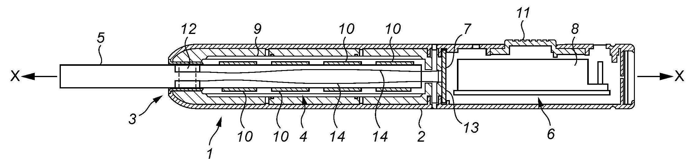
도 2는 흡연가능 물질을 가열하기 위한 장치(1)의 예의 단면도를 도시하고 있다. 장치(1)는 사용시에 가열 및 기화될 흡연가능 물질을 수용하는 가열 챔버(4)를 갖는다. 흡연가능 물질은 이 흡연가능 물질로 형성되거나 흡연가능 물질을 수용하는 물품(5)의 형태일 수 있으며, 이 물품(5)은 사용자에 의해 장치(1) 내로 제거가능하게 삽입될 수 있다. 흡연가능 물질 물품(5)은 대체로 기다란 원통체(cylinder), 예를 들어 카트리지(cartridge) 또는 카세트(cassette) 또는 로드(rod)일 수 있다. 흡연가능 물질 물품(5)은 사용시에 하우징(2) 내로 삽입된다. 흡연가능 물질 물품(5)의 단부는, 전형적으로 필터 등에의 연결을 위해, 하우징(2)의 개방 단부(3)를 통해 장치(1)의 외부로 돌출되며, 이 필터는 별개의 품목(item)이거나 흡연가능 물질 물품(5)을 구비하고, 이 필터를 통해서 사용자가 사용시에 흡입한다.2 shows a cross-sectional view of an example of a
또한, 장치(1)는 본 예에서 전기 제어 회로(7) 및 전원(8)을 포함하는 전자기기/전력 챔버(6)를 갖는다. 본 예에서, 가열 챔버(4) 및 전자기기/전력 챔버(6)는 장치(1)의 종축(X-X)을 따라 서로 인접하여 있다. 도시된 예에서, 전자기기/전력 챔버(6)는 마우스 단부(3)로부터 떨어져 있지만, 다른 위치들이 가능하다. 전기 제어 회로(7)는, 하기에서 추가로 논의되는 바와 같이, 흡연가능 물질의 가열을 제어하고 또한 흡연가능 물질 물품(5)을 인식 또는 식별하도록 구성 및 배열된 마이크로프로세서 구조체(microprocessor arrangement)와 같은 제어기를 포함할 수 있다. 사용시에, 전기 제어 회로(7)는, 예를 들어 사용자에 의해 흡연가능 물질 물품(5)에 대한 흡인의 개시시에 생기는 압력의 변화 또는 기류의 속도의 변화에 민감한 예를 들어 퍼프-작동식 센서(puff-actuated sensor)로부터의 신호를 수신할 수 있다. 그 후에, 전기 제어 회로(7)는 필요한 경우 "요구시에(on demand)" 흡연가능 물질 물품(5)을 가열시키도록 작동할 수 있다. 예를 들어 서미스터(thermistor), 전기-기계 디바이스, 기계 디바이스, 광학 디바이스, 광-기계식 디바이스, 미세 전기 기계 시스템들(micro electro mechanical systems; MEMS) 기반 센서를 포함하는, 퍼프-작동식 센서를 위한 다양한 구조체들이 이용가능하다. 대안예로서, 장치는 사용자가 퍼프(puff)를 개시하도록 수동으로 작동가능한 스위치를 구비할 수 있다.In addition, the
전원(8)은 배터리일 수 있으며, 이러한 배터리는 재충전가능한 배터리 또는 재충전가능하지 않은 배터리일 수 있다. 적합한 배터리들의 예들은 예를 들어 리튬-이온 배터리, 니켈 배터리(예를 들면, 니켈-카드뮴 배터리), 및/또는 알칼리 배터리 등을 포함한다. 특히 바람직한 타입의 배터리는 LiFePO4 배터리이다. 배터리(8)는 흡연가능 물질을 가열하기 위해(논의된 바와 같이, 흡연가능 물질을 연소시키지 않으면서 흡연가능 물질을 기화시키기 위해) 필요한 경우 그리고 전기 제어 회로(7)의 제어 하에서 전력을 공급하도록 가열 챔버(4)의 하나 또는 그 초과의 가열 요소들(하기에서 추가로 논의됨)에 전기적으로 결합된다. 본 예에서, 배터리(8)는 전기 제어 회로(7)의 인쇄 회로 기판 내에 수용된다. 다른 예들에서, 배터리(8) 및 전기 제어 회로(7)는, 예를 들어 장치(1)의 종축(X-X)을 따라 서로 인접하게 배열되는 것과 같이, 상이하게 배열될 수 있다.The
가열 챔버(4)는 외측 하우징(2) 내에 수용되는 히터 지지 슬리브(9) 내에 수용된다. 본 예에서, 히터 지지 슬리브(9)는 원형 단면의 대체로 기다란 원통체이다. 일 예에서, 히터 지지 슬리브(9)는 이중 벽 또는 "진공" 슬리브이며, 각 단부에서 서로 결합되고 작은 간격(d)으로 이격되는 외측 원통형 벽 및 내측 원통형 벽을 갖는다. 단지 하나의 예로서 그리고 축척(scale)의 개념을 제공하기 위해, 히터 지지 슬리브(9)는 길이가 약 50 ㎜이고 약 9 ㎜의 외경을 가질 수 있으며, 간격(d)은 약 0.1 ㎜ 내지 0.12 ㎜ 정도일 수 있다. 하나의 예에서 히터 지지 슬리브(9)의 기능들 중 하나는 가열 챔버(4)로부터의 외측 하우징(2)의 단열을 도와서, 외측 하우징(2)이 사용 중에 뜨거워지지 않게 하거나 적어도 너무 뜨거워서 만지지 못하게 되지 않게 하는 것이다. 히터 지지 슬리브(9)의 외측 및 내측 원통형 벽들 사이의 공간은 공기를 수용할 수 있다. 그러나, 히터 지지 슬리브(9)의 외측 및 내측 원통형 벽들 사이의 공간은 바람직하게는 히터 지지 슬리브(9)의 단열 특성들을 개선하도록 진공 배기된다. 대안예로서, 히터 지지 슬리브(9)의 외측 및 내측 원통형 벽들 사이의 공간은, 예를 들어 적합한 발포형 물질(foam-type material)을 포함하는 일부의 다른 단열 물질로 충전될 수 있다. 히터 지지 슬리브(9)의 물질은 히터 지지 슬리브(9)가 강성이어서 그 내부에 장착되는 구성요소들에 대한 구조적 안정성을 제공하도록 하는 것이 바람직하다. 적합한 물질의 예는 스테인리스강이다. 다른 적합한 물질들은 폴리에테르 에테르 케톤(PEEK), 세라믹스, 유리, 강, 알루미늄 등을 포함한다. The
장치(1)의 하나의 예에서, 히터 지지 슬리브(9)는 적어도 하나의 가열 요소(10)를 포함하고, 복수의 가열 요소들 또는 히터 세그먼트들(10)을 포함할 수 있다. 바람직하게는 적어도 2 개의 히터 세그먼트들(10)이 있지만, 다른 개수들의 히터 세그먼트들(10)을 갖는 구조체들이 가능하다. 도시된 특정 예에서는, 4 개의 히터 세그먼트들(10)이 있다. 본 예에서, 히터 세그먼트들(10)은 히터 지지 슬리브(9)의 종축(X-X)을 따라 또는 이에 평행하게 정렬된다. 전기 제어 회로(7) 및 히터 세그먼트들(10)에 대한 전력 연결부들은 바람직하게는 히터 세그먼트들(10)의 적어도 2 개, 보다 바람직하게는 모두가 서로 독립적으로 전력이 공급될 수 있도록 배열되고, 그에 따라 흡연가능 물질 물품(5)의 선택된 구역들은 예를 들어 소망에 따라 차례로(시간 경과에 따라) 또는 함께(동시에) 독립적으로 가열될 수 있다. 이러한 특정 예에서, 히터 세그먼트들(10)은, 사용시에 흡연가능 물질 물품(5)을 수용하는 중공형 내부를 갖는 대체로 환형 또는 원통형이다. 일 예에서, 히터 세그먼트들(10)은 세라믹스 재료로 제조될 수 있다. 예들은 적층 및 소결될 수 있는 알루미나 및 질화알루미늄 및 질화규소 세라믹스를 포함한다. 장치(1)는 사용자에 의한 작동을 위해 외측 하우징(2)을 통해 돌출하는 온/오프 스위치(11)를 구비한다.In one example of the
히터 세그먼트 또는 각 히터 세그먼트(10)를 위한 상이한 형상들 및 상이한 구성들이 사용될 수 있다. 또한, 예를 들어 적외선을 방사함으로써 가열하는 적외선 히터 세그먼트들(10), 또는 예를 들어 히터 세그먼트들(10) 주위에 저항 전기 권선에 의해 형성된 저항 가열 요소들을 포함하는 다른 가열 구조체들이 가능하다. 또 다른 상이한 가열 구조체들이 사용될 수도 있다.Different shapes and different configurations can be used for the heater segment or for each
때로는, 사용자에 의해 장치(1) 내로 도입되었을 특정 흡연가능 물질 물품(5)을 장치(1)가 식별 또는 인식할 수 있는 것이 바람직하다. 예를 들면, 실제로는, 특히 전기 제어 회로(7)에 의해 제공된 가열 제어 및 가열 구조체를 포함하는 전체로서의 장치(1)는 흔히 흡연가능 물질 물품(5)의 특정 구조체(예를 들면, 크기, 형상, 특정 흡연가능 물질 등의 하나 또는 그 초과)에 최적화될 것이며, 장치(1)는 (크게) 상이한 특성들을 갖는 흡연가능 물질 또는 흡연가능 물질 물품(5)과 함께 사용되는 것이 바람직하지 않을 것이다. 또한, 장치(1)가 이 장치(1) 내로 도입되었을 특정 흡연가능 물질 물품(5) 또는 적어도 일반 타입의 흡연가능 물질 물품(5)을 식별 또는 인식할 수 있다면, 이것은 장치(1)와 함께 사용되는 모조 또는 다른 가짜 흡연가능 물질 물품들(5)을 없애거나 적어도 줄이는 것을 도울 수 있다. 장치(1)는 인식하는 흡연가능 물질 물품(5)만을 가열할 것이고 인식하지 못하는 흡연가능 물질 물품(5)과는 함께 작동하지 않을 것이도록 배열될 수 있다. 장치(1)는 흡연가능 물질 물품(5)이 인식되지 않았다는 어떤 표시를 사용자에게 제공하도록 배열될 수 있다. 이러한 표시는 시각적(예를 들면, 예컨대 소정 기간 동안 연속적으로 조명되거나 번쩍일 수 있는 경고등) 및/또는 청각적(예를 들면, 경고 "비프(beep)" 등)일 수 있다. 대안적으로 또는 추가적으로, 장치(1)는 예를 들어 제 1 타입의 흡연가능 물질 물품(5)을 인식할 경우 제 1 가열 패턴을 따르고, 제 2 타입의 흡연가능 물질 물품(5)을 인식할 경우 상이한 제 2 가열 패턴을 따르도록 배열될 수 있다(선택적으로 다른 타입들의 흡연가능 물질 물품(5)에 대한 또 다른 가열 패턴들을 제공할 수도 있음). 가열 패턴들은 다수의 방식들, 예를 들어 흡연가능 물질로의 열의 전달 속도, 흡연가능 물질의 부분(들)이 먼저 가열되는 등의 다양한 가열 사이클들의 타이밍 등이 상이할 수 있다. 이것은 동일한 장치(1)가 사용자에게 최소의 상호작용을 요구하면서 상이한 기본 타입들의 흡연가능 물질 물품(5)과 함께 사용될 수 있게 한다.Sometimes, it is desirable for the
실시예의 일 예에서, 장치(1)는 흡연가능 물질의 물품(5)이 사용시에 하우징(2) 내에 수용될 때의 커패시턴스의 변화를 감지하기 위해 커패시턴스 감지(capacitive sensing)를 사용하도록 구성 및 배열된다. 실시예의 다른 예에서, 장치(1)는 하우징(2) 내에 수용된 흡연가능 물질 물품(5)을 감지하기 위해 저항 감지(resistive sensing)를 사용하도록 구성 및 배열된다. 실시예의 다른 예에서, 장치(1)는 하우징(2) 내에 수용된 흡연가능 물질 물품(5)을 감지하기 위해 커패시턴스 및 저항 감지의 조합을 사용하도록 구성 및 배열된다. 실시예의 일 예에서, 장치(1)는 흡연가능 물질 물품(5)이 하우징(2) 내에 수용될 때의 커패시턴스의 변화를 감지한다. 흡연가능 물질 물품(5)이 하우징(2) 내에 수용될 때의 커패시턴스는 사실상 흡연가능 물질 물품(5)이 하우징(2) 내에 존재하지 않을 때의 커패시턴스와 비교될 수 있다. 이러한 예들 중 임의의 예에서, 이것은 하우징 내에 수용된 특정 흡연가능 물질 물품(5)의 어떤 식별 또는 인식을 가능하게 한다. 실시예의 일 예에서, 흡연가능 물질 물품(5)은 본 명세서에서 설명된 바와 같이 장치(1)의 센서에 의해 감지될 수 있도록 제공된다. 실시예의 특정 예에서, 흡연가능 물질 물품(5)에는, 본 명세서에서 설명된 바와 같이 장치(1)의 센서에 의해 감지될 수 있는 스트립(strip) 또는 밴드(band) 또는 다른 마커(marker) 또는 표지(indicium) 또는 표지들(indicia)이 제공된다.In one example of embodiment, the
일반적으로, 본 명세서에 사용된 바와 같이 커패시턴스 감지는 흡연가능 물질 물품(5)이 장치(1) 내에 위치될 때의 커패시턴스의 변화를 효과적으로 감지함으로써 작동한다. 사실상, 실시예에서, 커패시턴스의 측정치(measure)가 얻어진다. 커패시턴스가 하나 또는 그 초과의 기준들을 만족하면, 흡연가능 물질 물품(5)이 장치(1)와 함께 사용하기에 적합한 것으로 결정될 수 있으며, 장치(1)는 그 후에 흡연가능 물질을 가열하도록 정상적으로 작동을 진행할 수 있다. 그렇지 않으면, 커패시턴스가 하나 또는 그 초과의 기준들을 만족하지 않으면, 흡연가능 물질 물품(5)이 장치(1)와 함께 사용하기에 적합하지 않은 것으로 결정될 수 있으며, 장치(1)는 흡연가능 물질을 가열하도록 기능하지 않고 및/또는 사용자에게 어떤 경고 메시지를 보낼 수 있다.Generally, capacitance sensing, as used herein, works by effectively sensing a change in capacitance when the
일반적으로, 본 명세서에 사용된 바와 같이 커패시턴스 감지는 2 개의 방식들 중 하나로 동작할 수 있다. 우선, 장치(1)에는, 사실상 커패시터(capacitor)의 하나의 "플레이트"를 제공하는 (적어도) 하나의 전극이 제공될 수 있으며, 커패시터의 다른 "플레이트"는 흡연가능 물질 물품(5)에 의해(또는 상기에서 언급되고 하기에서 추가로 논의되는 마커 또는 표지와 같은 적어도 흡연가능 물질 물품(5) 상의 일부 특징부에 의해) 제공된다. 이것의 일 예가 도 7에 개략적으로 도시되어 있으며, 도 7은 전극(70), 및 장치(1) 내의 감지 회로에 연결되는 연결 와이어(71)의 부분들만의 사시도를 도시하고 있으며, 도 7에는 장치(1)의 다른 부분들이 도시되어 있지 않다. 흡연가능 물질 물품(5)이 장치(1) 내로 삽입되는 경우, 장치(1)의 전극(70)과 흡연가능 물질 물품(5)의 조합에 의해 형성된 커패시턴스의 측정치가 얻어지고, 그 후에 장치(1)가 이어서 흡연가능 물질을 가열하도록 진행할 수 있는지를 결정하도록 하나 또는 그 초과의 기준들과 비교될 수 있다.In general, as used herein, capacitance sensing can operate in one of two ways. First of all, the
대안예로서, 장치(1)에는, 사실상 커패시터의 "플레이트들"의 쌍을 제공하는 (적어도) 2 개의 전극들이 제공될 수 있다. 흡연가능 물질 물품(5)은 장치(1) 내로 삽입될 때, 2 개의 전극들 사이로 삽입된다. 결과적으로, 장치(1)의 2 개의 전극들 사이에 형성된 커패시턴스가 변화된다. 장치(1)의 2 개의 전극들 사이에 형성된 이러한 커패시턴스의 측정치가 얻어지고, 그 후에 장치(1)가 이어서 흡연가능 물질을 가열하도록 진행할 수 있는지를 결정하도록 하나 또는 그 초과의 기준들과 비교될 수 있다.As an alternative, the
도 2에 도시된 예는 하우징(2) 내에 수용된 흡연가능 물질 물품(5)을 감지하기 위해 커패시턴스 감지를 허용하도록 (적어도) 2 개의 전극들을 사용하는 장치(1)의 일 예이다. 특히, 이러한 예에서, 장치(1)는 외측 하우징(2)의 개방 단부(3) 근처에 위치된 2 개의 전극들(12)을 구비한다. 2 개의 전극들(12)은 곡선형이고, 각 전극(12)은 흡연가능 물질 물품(5)이 하우징(2) 내에 수용될 때 통과하는 대체로 원형 개구를 규정하도록 단면이 거의 반원형이다. 도시된 예에서, 전극들(12)은 장치(1)의 종축에 대체로 평행하게 종방향으로 약간 연장되어, 전극들(12)의 보다 큰 중첩(overlap) 영역을 생성하고 따라서 유효한 커패시턴스를 증대시킨다. 전극들(12)은 연결 와이어들(14)을 통해서 감지 회로(13)에 연결된다. 감지 회로(13)는 전기 제어 회로(7)의 일부, 예를 들어 전술한 마이크로프로세서와 같은 제어기의 일부로서, 또는 별개의 회로로서 제공될 수 있다. 도시의 목적들을 위해, 도 3은 흡연가능 물질 물품(5)이 그 사이에 삽입된 상태로 (장치(1)의 다른 부분들 없이) 전극들(12) 및 연결 와이어들(14)의 부분들만의 사시도를 도시하고 있다. 도 4는 감지 회로(13)에의 전극들(12)의 연결부를 개략적으로 도시하고 있다. 감지 회로(13)는 전기 제어 회로(7)와 분리되어 있거나, 예를 들어 마이크로프로세서와 같은 제어기의 일부로서 전기 제어 회로(7)와 일체로 형성될 수 있고, 실제로 감지 회로(13)의 기능은 마이크로프로세서와 같은 제어기에 의해 전체적으로 제공될 수 있다는 것이 강조된다. 감지 회로(13)의 예가 도 4에 개략적으로 도시되어 있으며, 감지 회로(13)를 위한 다른 구조체들이 장치(1)의, 마이크로프로세서와 같은, 제어기의 일부로서든 별개의 회로로서든 가능하다는 것이 이해될 것이다.The example shown in FIG. 2 is an example of a
본 예에서, 전극들(12)과 감지 회로(13)의 조합은 용량성 센서(15)를 제공한다. 본 예에서, 감지 회로(13)는 커패시터 전극들(12) 중 하나에 전압을 공급하는 것과 커패시터 전극들(12) 중 하나로부터 전압이 배출되게 하는 것을 교대로 행한다. 커패시터 전극들(12) 중 다른 것은 (예를 들면, 장치(1)의 외측 하우징(2)에 전기적으로 연결됨으로써) 접지되어 있다.In this example, the combination of
보다 상세하게는, 일 예에서, 감지 회로(13)는 비반전 입력부(non-inverting input)(17) 및 반전 입력부(inverting input)(18)를 갖는 오피-앰프(op-amp)(operational amplifier; 연산 증폭기) 또는 다른 차동 증폭기(differential amplifier)(16)를 구비한다. 오피-앰프(16)의 출력부(19)는 인버터(inverter)(20)에 연결된다. 비반전 입력부(17)는 커패시터 전극들(12) 중 하나에 연결된다. 비반전 입력부(17)는 또한 저항기(21)를 통해서 인버터(20)의 출력부에 연결된다. 인버터(20)의 출력부는 또한 감지 회로(13)의 전압 제어부(21)에 연결된다. 전압 제어부(21)는 인버터(20)의 출력부를 통과하여 제 1 스위치(22)를 제어하고, 제 2 인버터(23)를 통해서 제 2 스위치(24)를 제어한다. 제 1 및 제 2 스위치들(22, 24)의 출력부들은 오피-앰프(16)의 반전 입력부(18)에 연결된다. 제 1 스위치(22)의 입력부는 상대적으로 높은 전압(VDD _SCALED)에 있고, 제 2 스위치(24)의 입력부는 상대적으로 낮은 전압(VDD/4)에 있다.More specifically, in one example, the
일 예에서, 장치(1)의 본 예의 작동은 하기와 같다. 우선, 장치(1)가 이 장치(1) 내에 삽입된 흡연가능 물질 물품(5)이 없는 상태에 있는 경우, 장치(1)는 감지 회로(13) 및 커패시터 전극들(12)의 조합에 의해 제공된 용량성 센서(15)의 교정을 주기적으로 행하여 기준 값을 설정하고, 이러한 기준 값에 대해 이후 측정치들이 평가될 것이다. 특히, 바람직하게는 장치(1)의 전기 제어 회로(7)의 제어기의 제어 하에서, 높은 "여기(excitation)" 전압이 전극들(12) 중 하나에 인가된다. 이것은 전극들(12) 중 하나 상의 전하 및 그에 따라 전압이 증가되게 하고, 이러한 증가는 용량성 센서(15)의 관련 부분들 내에 존재하는 저항 및 커패시턴스에 의해 규정된 특정 속도로 된다. 이러한 높은 "여기" 전압은 또한 전압 제어부(21)에 인가되어, 제 1 스위치(22)가 폐쇄되게 하고 제 2 스위치(24)가 개방되게 하고, 그에 따라 제 1 스위치(22)의 입력 전압(VDD _SCALED)이 오피-앰프(16)의 반전 입력부(18)에 인가된다.In one example, the operation of this example of the
오피-앰프(16)의 비반전 입력부(17)에 인가된 전극들(12) 중 하나 상의 전압이 사전결정된 값(본 예에서는, 제 1 스위치(22)의 입력 전압(VDD _SCALED))에 도달하면, 오피-앰프(16)의 출력부가 스위칭된다. 이것은 제 1 스위치(22)가 개방되게 하고 제 2 스위치(24)가 폐쇄되게 하고, 그에 따라 제 2 스위치(24)의 입력 전압(VDD/4)이 오피-앰프(16)의 반전 입력부(18)에 인가된다. 동시에, 전극들(12) 중 하나 상의 전하가 저항기(21)를 통해 배출되어, 전극들(12) 중 하나 상의 전압이 용량성 센서(15)의 관련 부분들 내에 존재하는 저항 및 커패시턴스에 의해 규정된 특정 속도로 강하되게 한다. 전극들(12) 중 하나 상의 전압이 제 2 사전결정된 값(본 예에서는, 제 2 스위치(24)의 입력 전압(VDD/4))까지 강하되면, 오피-앰프(16)의 출력부가 다시 복귀 스위칭되고, 이러한 프로세스가 반복된다.The voltage on one of the
이것의 효과는 도 5에서 알 수 있다. 도 5는 전압 대 시간의 그래프를 도시하고 있다. 굵은 선들은 전극들(12) 중 하나에 높은 전압을 인가하여 전극(12)을 충전하는 것과 그러한 전압을 제거하여 전극들(12) 중 하나 상의 전하가 멀리 배출되게 하는 것을 교대로 행하는 직사각형파(square wave) 타입의 전압을 나타내고 있다. (도시된 예에서, ACMPOUT가 높은 경우, VDD/4가 기준 전압으로서 선택되고, 인버터(20)로 인해, 전극들(12) 중 하나가 방전되기 시작한다. 커패시터 전압이 VDD/4 미만으로 강하하는 경우, ACMPOUT 레벨은 낮은 상태로 전환(toggle)되고, VDD_SCALED가 기준으로 선택되고, 전극들(12) 중 하나 상의 전하가 증가하기 시작한다. 커패시터 전압이 다시 VDD _SCALED에 도달하는 경우, ACMPOUT가 전환되고(높아지고), VDD/4가 기준 전압으로 다시 선택되며, 이러한 사이클이 반복된다.) 전극들(12) 중 하나의 충전 및 방전을 교대로 행하는 것은 옅은 회색 선으로 표시되어 있다. 전극들(12) 중 하나 상에서의 전하 또는 전압의 증가 및 그 후의 감소가 각각 특정 속도로 일어난다는 것을 알 수 있다.The effect of this can be seen in FIG. 5. 5 shows a graph of voltage versus time. The thick lines alternately perform a rectangular wave (which alternately applies a high voltage to one of the
그리고, 사용자 개시시에, 즉 사용자가 장치(1) 내로 흡연가능 물질 물품(5)을 삽입하고, (예를 들면, 일부 액추에이터 스위치(actuator switch)를 작동함으로써, 및/또는 퍼프-작동식 센서의 사용에 의해) 세션(session)을 개시하는 경우에, 장치(1)의 제어기는 유사한 방식으로 용량성 센서(15)를 판독한다. 특히, 또한, 바람직하게는 장치(1)의 전기 제어 회로(7)의 제어기의 제어 하에서, 높은 "여기" 전압이 전극들(12) 중 하나에 인가된다. 이것은 전극들(12) 중 하나 상의 전하 및 그에 따라 전압이 증가되게 하고, 이러한 증가는 용량성 센서(15)의 관련 부분들 내에 존재하는 저항 및 커패시턴스에 의해 규정된 특정 속도로 된다. 이러한 높은 "여기" 전압은 또한 전압 제어부(21)에 인가되어, 제 1 스위치(22)가 폐쇄되게 하고 제 2 스위치(24)가 개방되게 하고, 그에 따라 제 1 스위치(22)의 입력 전압(VDD_SCALED)이 오피-앰프(16)의 반전 입력부(18)에 인가된다. 오피-앰프(16)의 비반전 입력부(17)에 인가된 전극들(12) 중 하나 상의 전압이 사전결정된 값(본 예에서는, 제 1 스위치(22)의 입력 전압(VDD _SCALED))에 도달하면, 오피-앰프(16)의 출력부가 스위칭된다. 이것은 제 1 스위치(22)가 개방되게 하고 제 2 스위치(24)가 폐쇄되게 하고, 그에 따라 제 2 스위치(24)의 입력 전압(VDD/4)이 오피-앰프(16)의 반전 입력부(18)에 인가된다. 동시에, 전극들(12) 중 하나 상의 전하가 저항기(21)를 통해 배출되어, 전극들(12) 중 하나 상의 전압이 용량성 센서(15)의 관련 부분들 내에 존재하는 저항 및 커패시턴스에 의해 규정된 특정 속도로 강하되게 한다. 전극들(12) 중 하나 상의 전압이 제 2 사전결정된 값(본 예에서는, 제 2 스위치(24)의 입력 전압(VDD/4))까지 강하되면, 오피-앰프(16)의 출력부가 다시 복귀 스위칭되고, 이러한 프로세스가 반복된다.And, at user initiation, i.e., the user inserts the article of
이러한 경우에, 흡연가능 물질 물품(5)이 전극들(12) 사이에 존재하기 때문에, 용량성 센서(15)의 커패시턴스가 상이하다. 이것은 전극들(12) 중 하나 상의 전압의 증가 및 감소가 상이한 속도로(및 실제로 상이한 프로파일로) 일어난다는 것을 의미한다. 이것은 도 6에서 알 수 있으며, 여기서 상측 트레이스는 흡연가능 물질 물품(5)이 존재하지 않는 경우에 전극들(12) 중 하나 상의 검출된 전압의 변화를 나타내고(도 5에서와 같음), 하측 트레이스는 흡연가능 물질 물품(5)이 전극들(12) 사이에 존재하는 경우에 전극들(12) 중 하나 상의 검출된 전압의 변화를 나타내고 있다. 알 수 있는 바와 같이, 흡연가능 물질 물품(5)이 전극들(12) 사이에 존재하는 경우에, 본 경우에서 커패시턴스는 높아지고, 따라서 흡연가능 물질 물품(5)이 전극들(12) 사이에 존재하는 경우에 전압의 증가 속도 및 마찬가지로 전압의 감소 속도는 낮아진다.In this case, the capacitance of the
흡연가능 물질 물품(5)이 전극들(12) 사이에 존재하거나 존재하지 않는 경우의 이러한 커패시턴스 차이가 다수의 상이한 방식들로 검출되어, 흡연가능 물질 물품(5)이 존재하는지, 그리고 특히 정확하거나 적절한 흡연가능 물질 물품(5)이 존재하는지를 결정할 수 있다. 예를 들면, 도 6의 상측 및 하측 부분들에 개략적으로 도시된 전압 트레이스의 차이는 흡연가능 물질 물품(5)이 전극들(12) 사이에 존재하는 경우의 커패시턴스의 값의 측정치를 얻는데 사용될 수 있다. 다른 예에서, 장치(1)의 전기 제어 회로(7)의 제어기는 얼마나 많은 트랜지션들(transitions)(이를 테면, 고전압으로부터 저전압으로의 트랜지션)이 주어진 기간에 일어나는지를 카운트한다. 충전 및 방전의 속도들이 용량성 센서(15) 내에 존재하는 커패시턴스와 관련되기 때문에, 주어진 시간에 일어나는 트랜지션들의 수는 존재하는 커패시턴스와 관련되며: 흡연가능 물질 물품(5)이 존재하는 경우와 같은 보다 높은 커패시턴스는 주어진 기간에서의 적은 트랜지션들을 초래한다. 장치(1)의 전기 제어 회로(7)의 제어기는 주어진 기간에서의 트랜지션들의 수를 교정 프로세스 동안(즉, 흡연가능 물질 물품(5)이 존재하지 않는 경우)에 얻어진 것과 비교한다. 특정 기간에 걸친 트랜지션들의 수가 어떤 사전결정된 문턱값 미만이거나, 사전결정된 범위 내에 있다면, 흡연가능 물질 물품(5)은 진짜인 것으로 여겨지고, 세션이 완료되게 하여 흡연가능 물질 물품(5)이 가열되게 한다. 그러나, 특정 기간에 걸친 트랜지션들의 수가 사전결정된 문턱값 초과이거나, 사전결정된 범위 내에 있지 않다면, 흡연가능 물질 물품(5)은 진짜인 것으로 여겨지지 않고, 가열 세션이 시작하지 않을 것이며; 선택적으로, 사용자는 전술한 바와 같이 별도로 통보를 받을 수 있다. 대안예로서, 이를 테면 트랜지션들(이를 테면, 고전압으로부터 저전압으로의 트랜지션)의 수에 대한 절대 문턱 수를 사용하기보다는, 흡연가능 물질 물품(5)이 장치(1) 내에 존재하는 경우의 트랜지션들의 수에 대한 문턱 수는 흡연가능 물질 물품(5)이 장치(1) 내에 존재하지 않는 경우의 트랜지션들의 수의 특정 비율 또는 백분율일 수 있다(상기에서 언급된 교정 단계에서와 같음). 특정 기간에 걸친 용량성 센서에 대한 최대 전압과 최소 전압 사이의 트랜지션들의 수는 용량성 센서(15)의 충전/방전의 속도의 측정치라는 것이 이해될 것이다. 특정 예에서, 그리고 제한 없이, 일부의 명목 값들은 VDD _SCALED = 2.25 V, VDD/4 = 0.56 V이고, 측정 시간은 0.1 초이고, 측정당 트랜지션들 수는 1000이다. 특정의 실제 예에서, 시험 동안에, 흡연가능 물질 물품(5)이 장치(1) 내에 존재하지 않는 경우의 측정당 트랜지션들의 수는 1100인 반면, 흡연가능 물질 물품(5)이 장치(1) 내에 존재하는 경우의 측정당 트랜지션들의 수는 1050이었다.This difference in capacitance when the
하나의 전극(12)이 사실상 커패시터의 하나의 "플레이트"를 제공하고 커패시터의 다른 "플레이트"가 흡연가능 물질 물품(5)에 의해(또는 상기에서 언급되고 하기에서 추가로 논의되는 마커 또는 표지와 같은 적어도 흡연가능 물질 물품(5) 상의 일부 특징부에 의해) 제공되는 경우에 상기에서 설명된 바와 같이, 흡연가능 물질 물품(5)의 커패시턴스 감지를 위한 (적어도) 2 개의 전극들(12)을 갖는 장치(1)가 교대로 작동할 수 있다는 것에 주목할 수 있다. (이것은 2 개의 전극들(12) 사이의 커패시턴스가 감지되는 경우에 상기에서 설명된 특정 예와 대조적이다.) 흡연가능 물질 물품(5)이 장치(1) 내로 삽입되는 경우, 장치(1)의 전극(12)과 흡연가능 물질 물품(5)의 조합에 의해 형성된 커패시턴스의 측정치가 얻어지고, 그 후에 장치(1)가 이어서 흡연가능 물질을 가열하도록 진행할 수 있는지를 결정하도록 하나 또는 그 초과의 기준들과 비교될 수 있다. 이러한 목적을 위해 장치(1)의 개방 단부(3) 주위로 이격된 복수의 전극들(12)을 갖는 것은 장치(1)의 종축(X-X) 주위에서의 흡연가능 물질 물품(5)의 배향이 덜 중요하다는 점에서 유리한데, 이는 일반적으로 전극들(12) 중 적어도 하나가 흡연가능 물질 물품(5)이 충분히 커패시턴스를 감지하기에 충분하게 근접하여 있을 것이기 때문이다.One
도 2 내지 도 4의 특정 예에서, 2 개의 전극들(12)은 대체로 또는 거의 반원형이며, 흡연가능 물질 물품(5)이 하우징(2) 내에 수용될 때 통과하는 대체로 원형 개구를 규정하도록 외측 하우징(2)의 대향 측부들 상에서 서로를 향하여 있다. 전극들(12)을 위한 상이한 형상들 및 구조체들이 가능하다.In the particular example of FIGS. 2-4, the two
예를 들면, 도 8 및 도 9는 외측 하우징(802) 내에 수용된 흡연가능 물질 물품(805)을 감지하기 위해 커패시턴스 감지를 허용하도록 외측 하우징(802)의 개방 단부(803) 근처에 위치된 (적어도) 2 개의 전극들(812)을 사용하는 장치(801)의 다른 예를 도시하고 있다. 도 2 및 도 3의 예에서의 대응하는 품목들과 동일하거나 적어도 기능적으로 유사한 구성요소들 및 회로는 유사하지만 "800"만큼 증가된 참조부호들을 갖는다. 따라서, 도 8 및 도 9에 도시된 예시적인 장치(801)는 가열 챔버(804), 전기 제어 회로(807) 및 전원(808)을 포함하는 전자기기/전력 챔버(806), 히터 지지 슬리브(809), 복수의 가열 요소들 또는 히터 세그먼트들(810), 및 온/오프 스위치(811) 등을 구비하며, 이들 모두는 도 2 내지 도 4에 개략적으로 도시된 예의 대응하는 구성요소들과 동일하거나 적어도 기능적으로 유사할 수 있다. 예를 들어 적외선을 방사함으로써 가열하는 적외선 히터 세그먼트들(810), 또는 예를 들어 히터 세그먼트들(810) 주위에 저항 전기 권선에 의해 형성된 저항 가열 요소들을 포함하는 다른 가열 구조체들이 가능하다. 또 다른 상이한 가열 구조체들이 사용될 수도 있다.For example, FIGS. 8 and 9 are located near (at least) the
도 8 및 도 9의 예에서, 2 개의 전극들(812)이 서로 맞물려 있다. 도 2 및 도 3의 예와 같이, 전극들(812)은 연결 와이어들(814)을 통해서 감지 회로(813)에 연결된다. 감지 회로(813)는 전기 제어 회로(807)의 일부, 예를 들어 전술한 마이크로프로세서와 같은 제어기의 일부로서, 또는 별개의 회로로서 제공될 수 있다. 도시의 목적들을 위해, 도 9는 흡연가능 물질 물품(805)이 그 사이에 삽입된 상태로 (장치(801)의 다른 부분들 없이) 전극들(812)만의 사시도를 도시하고 있다. 상기 예에서와 같이, 전극들(812)과 감지 회로(813)의 조합은 용량성 센서를 제공한다. 본 예에서, 감지 회로(813)는 커패시터 전극들(812) 중 하나에 전압을 공급하는 것과 커패시터 전극들(812) 중 하나로부터 전압이 배출되게 하는 것을 교대로 행한다. 커패시터 전극들(812) 중 다른 것은 (예를 들면, 장치(801)의 외측 하우징(802)에 전기적으로 연결됨으로써) 접지되어 있다. 전극들(812)에 의해 제공된 커패시턴스, 및 흡연가능 물질 물품(805)이 하우징(802) 내에 수용되는 경우에 그러한 커패시턴스가 얼마나 변화하는지가 모니터링되어, 흡연가능 물질 물품(805)이 "진짜"인지 여부에 관한 결정이 이루어질 수 있게 한다. 이것은 전술한 주요 예와 유사하게, 즉, 흡연가능 물질 물품(805)이 하우징(802) 내에 수용되기 이전의 교정 단계 동안 및 그 후에 흡연가능 물질 물품(805)이 하우징(802) 내에 수용되는 경우 모두에서, 커패시터 전극들(812) 중 하나를 충전하는 것과 커패시터 전극들(812) 중 하나로부터 전압을 배출하는 것을 교대로 행하고, 주어진 기간에 일어나는 트랜지션들(이를 테면, 고전압으로부터 저전압으로의 트랜지션)의 수를 카운팅함으로써 실행될 수 있다. 그러나, 또한, 다른 방법들이 사용될 수도 있다.In the example of FIGS. 8 and 9, two
기술된 바와 같이, 도 8 및 도 9의 본 예에서, 2 개의 전극들(812)이 서로 맞물려 있다. 즉, 본 예에서, 각 전극(812)은 대체로 환형이고, 장치(801)의 종축에 대체로 평행하게 연장되는 다수의 성곽형상부들(castellations) 또는 "핑거부들(fingers)"(820)을 구비한다. 전극들(812)은 하나의 전극(812)의 핑거부들(820)이 다른 전극(820)의 핑거부들(820) 사이에 놓이도록 장치(801)의 외측 하우징(802)에 장착되어, 전극들(812)의 큰 중첩 영역을 생성하고 따라서 유효한 커패시턴스를 증대시킨다. 본 예에서, 각각의 전극들(812)의 핑거부들(820) 사이의 끼워맞춤은 꼭 끼워맞춤(snug fit)이지만, 이것이 바람직한 반면, 헐거움(비접촉) 끼워맞춤이 또한 가능하다.As described, in this example of FIGS. 8 and 9, the two
도 10 내지 도 12는 하우징 내에 수용된 흡연가능 물질 물품을 감지하기 위해 저항 감지가 사용되는 실시예의 예를 개략적으로 도시하고 있다. 도 2 및 도 3의 예에서의 대응하는 품목들과 동일하거나 적어도 기능적으로 유사한 구성요소들 및 회로는 유사하지만 "1000"만큼 증가된 참조부호들을 갖는다. 따라서, 도 10 내지 도 12에 도시된 예시적인 장치(1001)는 개방 단부(1003)를 갖는 외측 하우징(1002), 사용시에 흡연가능 물질 물품(1005)을 수용하는 가열 챔버(1004), 전기 제어 회로(1007) 및 전원(1008)을 포함하는 전자기기/전력 챔버(1006), 히터 지지 슬리브(1009), 복수의 가열 요소들 또는 히터 세그먼트들(1010), 및 온/오프 스위치(1011) 등을 구비하며, 이들 모두는 도 2 내지 도 4에 개략적으로 도시된 예의 대응하는 구성요소들과 동일하거나 적어도 기능적으로 유사할 수 있다. 예를 들어 적외선을 방사함으로써 가열하는 적외선 히터 세그먼트들(1010), 또는 예를 들어 히터 세그먼트들(1010) 주위에 저항 전기 권선에 의해 형성된 저항 가열 요소들을 포함하는 다른 가열 구조체들이 가능하다. 또 다른 상이한 가열 구조체들이 사용될 수도 있다.10-12 schematically illustrate examples of embodiments in which resistance sensing is used to sense articles of smokeable material contained within a housing. Components and circuits that are identical or at least functionally similar to corresponding items in the example of FIGS. 2 and 3 are similar but have the reference numerals increased by "1000". Accordingly, the
도 10 내지 도 12의 예에서, 장치(1001)는 외측 하우징(1002)의 개방 단부(1003) 근처에 위치된 적어도 2 개의 전기 전도성 저항 접점들 또는 전극들(1050)을 구비한다. 2 개의 전극들(1050)은 곡선형이고, 각 전극(1050)은 흡연가능 물질 물품(1005)이 하우징(1002) 내에 수용될 때 통과하는 대체로 원형 개구를 규정하도록 단면이 거의 반원형이다. 2 개의 전극들(1050)은 상대적으로 탄성 또는 탄력성 물질로 형성될 수 있고, 서로를 향해 약간 내측으로 편의(bias)되도록 배열될 수 있다. 이것은 흡연가능 물질 물품(1005)이 장치(1002) 내로 도입될 때 흡연가능 물질 물품(1005)과의 양호한 물리적 접촉을 보장하는 것을 돕는다.In the example of FIGS. 10-12, the
전극들(1050)은 연결 와이어들(1014)을 통해서 감지 회로(1013)에 연결된다. 감지 회로(1013)는 전기 제어 회로(1007)의 일부, 예를 들어 전술한 마이크로프로세서와 같은 제어기의 일부로서, 또는 별개의 회로로서 제공될 수 있다. 도시의 목적들을 위해, 도 11은 흡연가능 물질 물품(1005)이 그 사이에 삽입된 상태로 (장치(1001)의 다른 부분들 없이) 전극들(1050)만의 사시도를 도시하고 있다. 전극들(1050)과 감지 회로(1013)의 조합은 저항성 센서를 제공한다.The
전극들(1050)에 의해 효과적으로 측정된 저항, 및 흡연가능 물질 물품(1005)이 하우징(1002) 내에 수용되는 경우에 그러한 저항이 얼마나 변화하는지가 모니터링되어, 흡연가능 물질 물품(1005)이 "진짜"인지 여부에 관한 결정이 이루어질 수 있게 한다. 이것은 예를 들어 전기 제어 회로(1007)가 기준 전압(Vdd)이 전극들(1050)을 가로질러 인가되게 하고 출력되는 전류를 검출함으로써 실행될 수 있다. 높은 전류는 저항이 낮다는 것을 표시하고, 낮은 전류는 저항이 높다는 것을 표시한다. 저항의 절대 측정치가 얻어질 수 있다. 그러나, 또한, 다른 방법들이 사용될 수도 있다.The resistance effectively measured by the
실시예의 다른 예에서, 커패시턴스 및 저항 감지의 조합은 전술한 예들 중 임의의 예들의 조합을 이용하여 사용될 수 있다. 일반적으로, 이것은 흡연가능 물질 물품에 대한 보다 많은 정보가 얻어지게 한다. 이것은 흡연가능 물질 물품의 보다 정확한 식별이 얻어질 수 있게 하고, 및/또는 보다 많은 정보가 효과적으로 흡연가능 물질 물품에 인코딩될 수 있게 한다. 특정 실시예들에서, 이것은 또한, 어떤 이유 때문에 커패시턴스 감지 및 저항 감지 중 하나가 실패하면, 다른 것이 장치 내로 도입었던 흡연가능 물질 물품을 식별하는데 사용될 수 있다는 점에서 일부 중복성을 제공한다. 커패시턴스 감지 및 저항 감지는 장치 내의 동일한 전극 또는 전극들을 사용하여 실행될 수 있거나, 커패시턴스 감지 및 저항 감지는 자신 각자의 전용 전극 또는 전극들을 사용할 수 있다.In another example of an embodiment, a combination of capacitance and resistance sensing can be used using a combination of any of the examples described above. In general, this allows more information to be obtained about articles of smokeable material. This allows a more accurate identification of the smokeable material article to be obtained, and/or allows more information to be effectively encoded into the smokeable material article. In certain embodiments, this also provides some redundancy in that if one of the capacitance sensing and resistance sensing fails for some reason, the other can be used to identify the article of smokeable material that has been introduced into the device. Capacitance sensing and resistance sensing can be performed using the same electrode or electrodes in the device, or capacitance sensing and resistance sensing can use their own dedicated electrodes or electrodes.
전술한 전극 또는 전극들은, 예를 들어 커패시턴스 감지를 위한 커패시턴스 패드들의 형태이든 저항 감지를 위한 저항 접점들의 형태이든간에, 일반적으로 전기 전도성이다. 커패시턴스 감지를 위한 전극 또는 전극들의 경우에, 전극 또는 전극들은 바람직하게는 흡연가능 물질 물품이 사용시에 장치 내에 수용되거나 장치에 연결되는 경우에 흡연가능 물질 물품으로부터 전기적으로 절연되도록 장치 또는 하우징의 본체 내에 기계적으로 장착된다. 저항 감지를 위한 전극 또는 전극들의 경우에, 전극 또는 전극들은 바람직하게는 흡연가능 물질 물품이 사용시에 장치 내에 수용되거나 장치에 연결되는 경우에 흡연가능 물질 물품과 물리적으로 접촉하도록 장치 또는 하우징의 본체 내에 기계적으로 장착된다. 전극 또는 전극들에 적합한 물질들은, 예를 들어 커패시턴스 감지의 경우의 구리 포일(copper foil) 및 저항 감지의 경우의 베릴륨-구리를 포함하여, 구리 또는 구리-함유 합금들을 포함한다.The electrodes or electrodes described above are generally electrically conductive, for example in the form of capacitance pads for capacitance sensing or resistance contacts for resistance sensing. In the case of an electrode or electrodes for capacitance sensing, the electrode or electrodes are preferably within the body of the device or housing such that the smokeable material article is electrically insulated from the smokeable material article when it is received in use or connected to the device in use. Mechanically mounted. In the case of an electrode or electrodes for resistance sensing, the electrode or electrodes are preferably in the body of the device or housing to physically contact the smokeable material article when the smokeable material article is received in use or connected to the device in use. Mechanically mounted. Electrodes or materials suitable for the electrodes include copper or copper-containing alloys, including, for example, copper foil for capacitance sensing and beryllium-copper for resistance sensing.
도 13에는, 일부 마커 또는 표지(131)가 제공되거나 형성되는 흡연가능 물질 물품(130)의 예의 개략적인 종단면이 도시되어 있으며, 일부 마커 또는 표지(131)의 예들은 하기에서 추가로 설명될 것이다. 흡연가능 물질 물품(130)은 본 명세서에서 설명된 바와 같은 흡연가능 물질을 가열하기 위한 장치의 예들 중 적어도 일부와 함께 사용될 수 있다. 표지(indicium)(131)의 구조체는 특정 가열 장치에 대해 상이하고 그리고 그것에 대해 상이하게 최적화될 수 있다.13, a schematic longitudinal section of an example of an article of
흡연가능 물질 물품(130)은 흡연가능 물질의 로드(rod)(132)를 갖는다. 전술한 바와 같이, 흡연가능 물질은 예를 들어 임의의 담배-함유 물질을 포함할 수 있으며, 예를 들어 담배, 담배 파생물들, 팽화 담배, 재생 담배 또는 담배 대용품들 중 하나 또는 그 초과를 포함할 수 있다. 또한, "흡연가능 물질"은 제품에 따라서 니코틴을 함유할 수 있거나 함유하지 않을 수 있는 다른 비담배 제품들을 포함할 수도 있다. 흡연가능 물질의 로드(132)는 개방 튜브 필터(133)에 인접하여 있다. 로드(132) 및 필터(133)는 그 자체로 알려진 방식으로 팁 페이퍼(tipping paper)(134)로 감겨짐으로써 함께 조립 및 유지된다.The
도시된 예에서는, 마커 또는 표지(131)가 팁 페이퍼(134) 상에 제공된다. 도시된 예에서, 표지(131)는 조립된 흡연가능 물질 물품(130)에서 흡연가능 물질 물품(130)을 완전히 에워싸는 밴드재(band of material)의 형태이다. 이러한 구조체는, 가열 장치 내에서의 흡연가능 물질 물품(130)의 특정 배향이 중요하지 않으므로, 전술한 가열 장치의 예들에 의해 표지(131)의 특성들의 측정을 용이하게 한다. 다른 구조체들이 가능하다. 예를 들면, 모든 경우들에서, 표지(131)가 흡연가능 물질 물품(130)을 완전히 에워쌀 필요가 없을 수 있으며, 대신에 표지(131)는 흡연가능 물질 물품(130)을 에워싸는 규칙적이거나 불규칙적인 간격의 밴드들 또는 스트립들로, 또는 규칙적이거나 불규칙적인 체커보드 패턴(checkerboard pattern)과 같은 상이한 불연속적 패턴으로 형성될 수 있다. 도 14는 흡연가능 물질 물품(130)의 조립 이전의 팁 페이퍼(134)의 예를 도시하고 있으며, 여기서 팁 페이퍼(134)는 표지(131)의 단일 밴드를 갖는다. 도 15는 흡연가능 물질 물품(130)의 조립 이전의 팁 페이퍼(134)의 예를 도시하고 있으며, 여기서 팁 페이퍼(134)는 효과적으로 이중 폭이고 표지(131)의 한 쌍의 밴드들을 대향 에지들에 갖는다. 제조 동안에, 이중 폭 팁 페이퍼(134)는 흡연가능 물질 물품들(130)의 쌍들이 형성되므로 중심을 통해 절단된다.In the illustrated example, a marker or
축척의 개념을 제공하기 위해, 특정 예에서, 흡연가능 물질의 로드(132)는 약 53 ㎜의 길이를 갖고, 필터(133)는 30 ㎜의 길이를 갖고, 팁 페이퍼는 (흡연가능 물질 물품(130)의 길이에 평행한 방향에서) 35 ㎜의 폭을 가질 수 있다. 표지(131)는 (또한 흡연가능 물질 물품(130)의 길이에 평행한 방향에서) 약 4 ㎜의 폭을 가질 수 있다. 표지(131)의 두께는 흡연가능 물질 물품에 사용되는 제조 프로세스를 방해하지 않도록, 또는 흡연가능 물질 물품을 가열 장치 내로 삽입하는 것을 어렵게 하도록 작은 것이 바람직하다. 예를 들면, 두께는 0.03 ㎜ 내지 0.3 ㎜의 근사 범위일 수 있고, 보다 바람직하게는 약 0.03 내지 0.05 ㎜일 수 있다. 실제로, 흡연가능 물질 물품의 표면 내로 함침되면, 표지(131)는 효과적으로 전혀 두께를 갖지 않을 수 있다. 다른 한편으로는, 만족스러운 감지가 달성될 수 있게 하기 위해 최소 두께가 바람직한 특정 응용들이 있을 수 있다.To provide the concept of scaling, in certain examples, the
마커 또는 표지(131)는 다수의 상이한 방식들로 형성되고, 흡연가능 물질 물품(130)이 사용되고자 하는 가열 장치의 특정 감지 구조체에 따라서 다수의 상이한 물질들로 형성될 수 있다. 표지(131)는 예를 들어 흡연가능 물질 물품(130)의 외부에, 흡연가능 물질 물품(130)의 내부에, 흡연가능 물질 물품(130)의 내부 및 외부 모두에 제공되고, 및/또는 팁 페이퍼(134)의 물질 내로 함침될 수 있다. (표지(131)가 도시의 목적들을 위해 도 13에 과장된 형태로 도시되어 있다.) 저항 감지가 (그 자체로든, 또는 커패시턴스 감지와 같은 일부의 다른 감지와 조합하든간에) 사용되는 경우, 표지(131)는 바람직하게는 가열 장치의 저항 감지 전극들이 표지(131)와 양호한 전기적 접촉을 할 수 있도록 흡연가능 물질 물품(130)의 외측 상에 제공된다. 커패시턴스 감지가 사용되는 경우, 표지(131)가 흡연가능 물질 물품(130)의 내부 또는 외부에 제공될 수 있다. 표지(131)가 흡연가능 물질 물품(130)의 내부 및 외부에 제공될 수 있고, 및/또는 별개의 표지들(131)이 흡연가능 물질 물품(130)의 내부 및 외부에 제공될 수 있다. 마커 또는 표지(131)는 문자 그대로, 예를 들어 인쇄에 의해, 흡연가능 물질 물품(130) "상에 마킹될" 수 있다. 대안적으로, 마커 또는 표지(131)는 다른 기술들에 의해 흡연가능 물질 물품(130) 내에 또는 그 상에 제공될 수 있고, 예를 들어 제조 동안에 흡연가능 물질 물품(130)과 일체로 형성될 수 있다.The marker or
특정 예들에서, 그리고 흡연가능 물질 물품(130)을 감지 및 식별하는데 사용되는 감지의 성질에 따라서, 표지(131)는 전기 전도성 물질로 형성될 수 있다. 표지(131)는 예를 들어 전도성 잉크일 수 있다. 잉크는 예를 들어 윤전 그라비어(rotogravure) 인쇄 방법, 스크린 인쇄, 잉크젯 인쇄, 또는 임의의 다른 적합한 프로세스를 사용하여 팁 페이퍼(134) 상에 인쇄될 수 있다.In certain examples, and depending on the nature of the sensing used to sense and identify the
사용시에, 특히 흡연가능 물질 물품(130)이 가열 장치와 연관된 경우에 커패시턴스의 변화를 감지하도록 배열된 용량성 센서를 사용하는 가열 장치, 및 특히 사실상 커패시터의 "플레이트들"의 쌍을 제공하는 (적어도) 2 개의 전극들을 사용하는 가열 장치의 맥락에서, 하기의 고려사항들이 관련이 있다. 흡연가능 물질 물품(130)은, 전기 전도성 표지 또는 마커(131)와 함께, 하나의 센서 전극을 다른 센서 전극과 전기적으로 결합시키는 자신의 회로를 생성한다. 이러한 결합의 효과 및 결과는 흡연가능 물질 물품(130) 및/또는 특히 표지(131)의 고유 전기 저항 Ri 및 커패시턴스 C에 의해 영향을 받는다. 전기 저항 Ri는 일반적으로, 예를 들어 표지(131)를 위해 선택된 잉크 및 제제(formulation)의 타입에 의해, 그리고 표지(131)의 두께 및 폭에 의해 주로 결정된다. 따라서, 표지(131)를 위한 잉크의 선택뿐만 아니라, 그 도포 두께는 폭넓은 범위에 걸쳐 Ri 특성을 제어하는 방식을 제공한다. 정전 용량 C는 일반적으로, 표지(131)의 축방향 폭 및 가열 장치의 전극들로부터의 표지(131)의 거리에 의해 주로 결정된다. 이러한 거리는 결국, 서로로부터의 전극들의 간격 및 흡연가능 물질 물품(130)의 두께(예를 들면, 직경)에 의해 결정된다. 따라서, 흡연가능 물질 물품(130) 상의 표지(131)와 검출기 전극들 사이의 결합 또는 "C" 특성의 커패시턴스 결합은, 예를 들어 흡연가능 물질 물품(130)의 두께 또는 직경을 절절하게 설정하고 검출기 전극들 및 표지(131)의 축방향 폭들을 제어함으로써, 가열 장치 내에의 흡연가능 물질 물품(130)의 "끼워맞춤"을 통해 결정되거나 제어될 수 있다.In use, in particular a heating device using a capacitive sensor arranged to sense a change in capacitance when the
특히 적합한 물질은 비금속 전도성 잉크, 즉 전기 전도성이지만 비금속 물질들을 함유하거나 실질적으로 비금속인 물질들을 적어도 함유하는 잉크인 것으로 밝혀졌다. 잉크는 흑연의 형태일 수 있는, 예를 들어 탄소를 함유할 수 있다. 그러므로, 잉크는 탄소계 비금속 전기 전도성 잉크일 수 있다. 특정 예에 있어서의 잉크의 중량 비저항(weight resistivity)은 약 30,000 내지 300,000 오옴-그램/㎡의 범위일 수 있다. 특히 적합한 것으로 밝혀진 예들의 중량 비저항의 특정 값은 약 38,000 오옴-그램/㎡, 150,000 오옴-그램/㎡ 및 290,000 오옴-그램/㎡를 포함한다.Particularly suitable materials have been found to be non-metal conductive inks, ie inks that contain at least electrically conductive but non-metallic materials or materials that are substantially non-metallic. The ink may contain carbon, which may be in the form of graphite, for example. Therefore, the ink may be a carbon-based non-metal electrically conductive ink. The weight resistivity of the ink in a particular example can range from about 30,000 to 300,000 ohm-grams/
하나의 특정 예에서, 잉크는 흑연 분말 및 결합제(binder)로서 작용하는 수지를 주로 포함하거나 이들로 구성될 수 있다. 잉크는 여러 가지의 크고 작은 입자 크기들의 흑연을 사용할 수 있으며, 이들 중 보다 큰 입자들은 전기 전도를 위한 주요 경로를 형성하고, 보다 작은 입자들은 보다 큰 입자들 사이의 갭들을 "충전"한다. 보다 큰 크기의 입자들의 사용은 입자들 사이의 개별적인 접촉 지점들의 수를 감소시킴으로써 전기 전도성을 향상시키는 것을 돕는다. 다른 예에서, 잉크는 탄소 나노 튜브들을 사용하는 결정 구조를 가질 수 있다.In one particular example, the ink may mainly comprise or consist of graphite powder and a resin that acts as a binder. The ink can use a variety of large and small particle sizes of graphite, of which the larger particles form the main path for electrical conduction, and the smaller particles “fill” the gaps between the larger particles. The use of larger sized particles helps to improve electrical conductivity by reducing the number of individual contact points between particles. In another example, the ink can have a crystal structure using carbon nanotubes.
이러한 목적에 적합한 잉크들은 미국 오하이오 소재의 엔지니어드 머티리얼즈 시스템즈, 인크(Engineered Materials Systems, Inc.)에 의해 공급된 CI-2001 및 CI-2004 전도성 탄소 잉크들을 포함한다는 것이 알려졌다. 이러한 잉크들은, 예를 들어 접촉 영역들에서 물리적 및 환경적 보호를 제공하고 전기 저항 요건들에 맞게 조정하기 위해, 인쇄 전자(printed electronics)에, 예를 들어 인쇄 회로 기판들 등에 사용하도록 의도된다.It has been found that inks suitable for this purpose include CI-2001 and CI-2004 conductive carbon inks supplied by Engineered Materials Systems, Inc. of Ohio, USA. These inks are intended for use in printed electronics, for example printed circuit boards and the like, to provide physical and environmental protection in contact areas and adapt to electrical resistance requirements, for example.
종래 기술에 알려진 일부 기술들을 포함하는 다른 기술들과 비교하여, 본 발명의 실시예들은 다수의 이점들을 갖는다. 감지 구조체들은, 특히 커패시턴스 감지의 경우에, 양호한 신호-대-잡음비(signal-to-noise ratio)를 제공한다. 이것은 신호들을 처리하는데 적은 전력이 소비되고 보다 정확한 결정이 보다 신속하게 이루어질 수 있으므로 배터리-작동식 디바이스들에서 특별한 이익을 갖는다. 또한, 일반론적으로, 흡연가능 물질 물품들의 제조 동안에 제조 공차가 있을 것이고, 그에 따라 흡연가능 물질 물품들의 외경이 소정 범위에서 변할 것이다. 실제로는, 그러한 변동은 예를 들어 대략 2% 내지 5% 정도일 수 있다. 특정 경우에 있어서, 흡연가능 물질 물품들의 직경은 약 5.3 ㎜로부터 5.45 ㎜까지 변할 수 있다. 그러한 변동들은, 특히 본 명세서에 개시된 다양한 커패시턴스 감지 구조체들을 포함하는 본 감지 구조체들에 의해 잘 수용된다. 이것은, 그렇지 않으면 발생할 수 있어 진짜 흡연가능 물질 물품을 의도치않게 거부하는 "잘못된 부정들(false negatives)"의 수를 최소화하므로 중요하다. 본 감지 구조체들은 일부 다른 기술들보다 적은 입력/출력 연결부를 가지면서 적은 전기 구성요소들을 사용할 수 있다.Compared to other techniques, including some techniques known in the prior art, embodiments of the invention have a number of advantages. Sensing structures provide a good signal-to-noise ratio, especially in the case of capacitance sensing. This is of particular benefit in battery-operated devices because less power is consumed in processing signals and more accurate decisions can be made faster. Also, in general, there will be manufacturing tolerances during the manufacture of the smokeable material articles, so the outer diameter of the smokeable material articles will vary within a certain range. In practice, such variation can be, for example, on the order of approximately 2% to 5%. In certain cases, the diameter of articles of smokeable material can vary from about 5.3 mm to 5.45 mm. Such variations are well accommodated by the present sensing structures, particularly including the various capacitance sensing structures disclosed herein. This is important because it minimizes the number of "false negatives" that could otherwise occur and inadvertently reject an article of genuine smokeable material. The present sensing structures can use fewer electrical components while having fewer input/output connections than some other techniques.
다양한 과제들을 해결하고 본 기술을 발전시키기 위해, 본 개시의 전체는 청구된 발명이 실시될 수 있고 흡연가능 물질을 가열하지만 연소시키지는 않도록 배열된 우수한 장치를 제공하는 다양한 실시예들을 도시 및 예시로서 나타내고 있다. 본 개시의 이점들 및 특징들은 단지 실시예들의 대표적인 샘플이며, 철저하고 및/또는 배타적이지 않다. 이것들은 단지, 청구되고 다른 방식으로 개시된 특징들의 이해를 돕고 이들을 교시하도록 제시된다. 본 개시의 이점들, 실시예들, 예들, 기능들, 특징들, 구조들 및/또는 다른 태양들은 청구항들에 의해 규정된 바와 같은 본 개시에 관한 제한들 또는 청구항들에 대한 등가물들에 관한 제한들로서 고려되지 않아야 하며, 본 개시의 범위 및/또는 사상으로부터 벗어남이 없이 다른 실시예들이 이용될 수 있고 변형예들이 이루어질 수 있다는 것이 이해되어야 한다. 다양한 실시예들은 개시된 요소들, 구성요소들, 특징들, 부품들, 단계들, 수단들 등의 다양한 조합들을 적절하게 포함하거나, 이들로 구성되거나 또는 이들로 본질적으로 구성될 수 있다. 본 개시는 현재 청구되지는 않지만, 향후에 청구될 수 있는 다른 발명들을 포함할 수 있다.In order to solve various problems and advance the present technology, the entire disclosure of the present disclosure is shown by way of illustration and illustration of various embodiments that provide an excellent device in which the claimed invention can be practiced and arranged to heat but not burn a smokeable material. have. The advantages and features of the present disclosure are merely representative samples of the examples and are not exhaustive and/or exclusive. These are merely presented to aid in understanding and teach the features disclosed in the claimed and other ways. Advantages, embodiments, examples, functions, features, structures and/or other aspects of the present disclosure are limitations regarding the present disclosure or equivalents to the claims as defined by the claims. It should be understood that other embodiments can be used and variations can be made without departing from the scope and/or spirit of the present disclosure. Various embodiments may suitably include, consist of, or consist essentially of various combinations of the disclosed elements, components, features, parts, steps, means, and the like. This disclosure is not currently claimed, but may include other inventions that may be claimed in the future.
Claims (22)
하우징(housing);
흡연가능 물질의 물품(article)이 사용시에 상기 하우징 내로 도입되었을(has been introduced) 경우에 상기 흡연가능 물질의 물품이 식별될 수 있게 하기 위해 커패시턴스의 변화를 감지하도록 배열된 용량성 센서(capacitive sensor); 및
충전 전압을 상기 용량성 센서에 인가하여 상기 용량성 센서를 상대적으로 높은 전압으로 충전하는 것과 상기 용량성 센서가 상대적으로 낮은 전압으로 방전되게 하는 것을 교대로 행하도록 구성 및 배열된 회로;를 포함하고,
상기 회로는, 사전결정된 기간에 상기 용량성 센서에 대한 상대적으로 높은 전압과 상대적으로 낮은 전압 사이의 트랜지션들(transitions)의 수가 사전결정된 수보다 적다면, 사용시에 상기 하우징 내로 도입된 흡연가능 물질의 물품을 가열시키기 위해서만 상기 장치가 작동되도록 배열되는,
장치.An apparatus for heating a smokeable material to enable vaporizing at least one component of the smokeable material,
Housing;
A capacitive sensor arranged to detect a change in capacitance to enable the article of smokeable material to be identified if the article of smokeable material has been introduced into the housing in use. ); And
And circuits configured and arranged to alternately apply a charging voltage to the capacitive sensor to charge the capacitive sensor with a relatively high voltage and cause the capacitive sensor to discharge with a relatively low voltage. ,
The circuit can be used to detect the amount of smokeable material introduced into the housing in use if the number of transitions between a relatively high voltage and a relatively low voltage to the capacitive sensor in a predetermined period of time is less than a predetermined number. The device is arranged to operate only for heating the article,
Device.
상기 용량성 센서는 전극을 포함하고, 상기 장치는 사용시에 상기 하우징 내로 도입된 흡연가능 물질의 물품 및 상기 전극의 커패시턴스의 변화를 감지하도록 구성 및 배열된 프로세서(processor)를 포함하는,
장치.According to claim 1,
The capacitive sensor includes an electrode, and the device comprises a processor configured and arranged to sense a change in the capacitance of the article and the article of smokeable material introduced into the housing during use,
Device.
상기 용량성 센서는 적어도 2 개의 전극들을 포함하고, 상기 장치는 흡연가능 물질의 물품이 사용시에 상기 하우징 내로 도입되는 경우에 상기 적어도 2 개의 전극들의 커패시턴스의 변화를 감지하도록 구성 및 배열된 프로세서를 포함하는,
장치.According to claim 1,
The capacitive sensor comprises at least two electrodes, and the device comprises a processor configured and arranged to sense a change in capacitance of the at least two electrodes when an article of smokeable material is introduced into the housing in use. doing,
Device.
상기 적어도 2 개의 전극들은 사용시에 상기 하우징 내로 도입된 흡연가능 물질의 물품의 적어도 일부분이 상기 적어도 2 개의 전극들 사이에 배치될 수 있도록 배열되는,
장치.The method of claim 3,
The at least two electrodes are arranged such that, in use, at least a portion of the article of smokeable material introduced into the housing can be disposed between the at least two electrodes.
Device.
상기 커패시턴스의 변화가 적어도 하나의 사전결정된 기준을 만족하면, 사용시에 상기 하우징 내로 도입된 흡연가능 물질의 물품을 가열시키기 위해서만 상기 장치가 작동되도록 구성 및 배열된 회로를 포함하는,
장치.According to claim 1,
A circuit configured and arranged to operate the device only to heat an article of smokeable material introduced into the housing in use if the change in capacitance satisfies at least one predetermined criterion,
Device.
상기 사전결정된 수는 흡연가능 물질의 물품이 상기 하우징 내로 도입되지 않은 경우에 상기 사전결정된 기간에 상기 용량성 센서에 대한 상대적으로 높은 전압과 상대적으로 낮은 전압 사이의 트랜지션들의 수인,
장치.According to claim 1,
The predetermined number is the number of transitions between a relatively high voltage and a relatively low voltage for the capacitive sensor in the predetermined period when an article of smokeable material is not introduced into the housing,
Device.
흡연가능 물질의 물품이 사용시에 상기 하우징 내로 도입되는 경우에 전기 저항의 측정치를 제공하도록 배열된 저항성 센서(resistive sensor)를 포함하는,
장치.According to claim 1,
Comprising a resistive sensor arranged to provide a measure of electrical resistance when an article of smokeable material is introduced into the housing in use,
Device.
사용시에 상기 하우징 내에 수용된 흡연가능 물질의 물품을 가열하도록 작동가능한 히터(heater)를 포함하는,
장치.According to claim 1,
A heater operable to heat an article of smokeable material contained within the housing in use,
Device.
하우징; 및
적어도 2 개의 상이한 감지 기술들을 사용함으로써 사용시에 상기 하우징과 연관된 경우에 흡연가능 물질의 물품을 식별하도록 구성 및 배열된 센서 구조체(sensor arrangement)를 포함하고,
상기 적어도 2 개의 상이한 감지 기술들 중 하나는 커패시터 감지를 사용하고,
상기 커패시터 감지는 흡연가능 물질의 물품이 사용시에 상기 하우징 내로 도입되었을 경우에 상기 흡연가능 물질의 물품이 식별될 수 있게 하기 위해 커패시턴스의 변화를 감지하도록 배열된 용량성 센서를 사용하고,
상기 장치는 충전 전압을 상기 용량성 센서에 인가하여 상기 용량성 센서를 상대적으로 높은 전압으로 충전하는 것과 상기 용량성 센서가 상대적으로 낮은 전압으로 방전되게 하는 것을 교대로 행하도록 구성 및 배열된 회로를 포함하고,
상기 회로는, 사전결정된 기간에 상기 용량성 센서에 대한 상대적으로 높은 전압과 상대적으로 낮은 전압 사이의 트랜지션들(transitions)의 수가 사전결정된 수보다 적다면, 사용시에 상기 하우징 내로 도입된 흡연가능 물질의 물품을 가열시키기 위해서만 상기 장치가 작동되도록 배열되는,
장치.An apparatus for heating a smokeable material to enable vaporization of at least one component of the smokeable material,
housing; And
Comprising a sensor arrangement constructed and arranged to identify an article of smokeable material when in use by using at least two different sensing techniques, when associated with the housing,
One of the at least two different sensing techniques uses capacitor sensing,
The capacitor sensing uses a capacitive sensor arranged to detect a change in capacitance to enable the article of smokeable material to be identified when the article of smokeable material is introduced into the housing in use,
The device is configured and arranged to alternately apply a charging voltage to the capacitive sensor to alternately charge the capacitive sensor at a relatively high voltage and cause the capacitive sensor to discharge at a relatively low voltage. Including,
The circuit can be used to detect the amount of smokeable material introduced into the housing in use if the number of transitions between a relatively high voltage and a relatively low voltage to the capacitive sensor in a predetermined period of time is less than a predetermined number. The device is arranged to operate only for heating the article,
Device.
상기 적어도 2 개의 상이한 감지 기술들 중 다른 하나는 저항 감지를 사용하는,
장치.The method of claim 9,
The other of the at least two different sensing technologies uses resistance sensing,
Device.
상기 적어도 2 개의 상이한 감지 기술들 중 다른 하나는 광학적 감지(optical sensing)를 사용하는,
장치.The method of claim 9,
The other of the at least two different sensing technologies uses optical sensing,
Device.
사용시에 상기 하우징 내에 수용된 흡연가능 물질의 물품을 가열하도록 작동가능한 히터를 포함하는,
장치.The method of claim 11,
A heater operable to heat an article of smokeable material contained within the housing in use,
Device.
상기 물품은 흡연가능 물질을 가열시키도록 배열된 장치의 센서에 의한 검출을 위한 비금속 전기 전도성 영역을 구비하는,
물품.An article of smokeable material for use with the device according to claim 1,
The article has a non-metallic electrically conductive area for detection by a sensor of a device arranged to heat a smokeable material,
article.
상기 비금속 전기 전도성 영역은 상기 물품을 적어도 부분적으로 에워싸는 밴드재(band of material)의 형태인,
물품.The method of claim 13,
The non-metal electrically conductive region is in the form of a band of material that at least partially surrounds the article,
article.
상기 비금속 전기 전도성 영역은 탄소를 포함하는,
물품.The method of claim 13,
The non-metal electrically conductive region comprises carbon,
article.
상기 비금속 전기 전도성 영역은 인쇄된 잉크(printed ink)인,
물품.The method of claim 13,
The non-metal electrically conductive region is printed ink,
article.
Applications Claiming Priority (3)
| Application Number | Priority Date | Filing Date | Title |
|---|---|---|---|
| US201461968780P | 2014-03-21 | 2014-03-21 | |
| US61/968,780 | 2014-03-21 | ||
| PCT/EP2015/055972 WO2015140312A1 (en) | 2014-03-21 | 2015-03-20 | Apparatus for heating smokable material |
Related Parent Applications (1)
| Application Number | Title | Priority Date | Filing Date |
|---|---|---|---|
| KR1020167025874A Division KR101971169B1 (en) | 2014-03-21 | 2015-03-20 | Apparatus for heating smokable material |
Publications (2)
| Publication Number | Publication Date |
|---|---|
| KR20190014596A KR20190014596A (en) | 2019-02-12 |
| KR102123900B1 true KR102123900B1 (en) | 2020-06-17 |
Family
ID=52814070
Family Applications (2)
| Application Number | Title | Priority Date | Filing Date |
|---|---|---|---|
| KR1020197003146A Active KR102123900B1 (en) | 2014-03-21 | 2015-03-20 | Apparatus for heating smokable material |
| KR1020167025874A Active KR101971169B1 (en) | 2014-03-21 | 2015-03-20 | Apparatus for heating smokable material |
Family Applications After (1)
| Application Number | Title | Priority Date | Filing Date |
|---|---|---|---|
| KR1020167025874A Active KR101971169B1 (en) | 2014-03-21 | 2015-03-20 | Apparatus for heating smokable material |
Country Status (18)
| Country | Link |
|---|---|
| US (4) | US10687553B2 (en) |
| EP (5) | EP4660587A2 (en) |
| JP (1) | JP6348985B2 (en) |
| KR (2) | KR102123900B1 (en) |
| CN (1) | CN106455707B (en) |
| AU (1) | AU2015233388B2 (en) |
| BR (1) | BR112016021596B1 (en) |
| CA (1) | CA2940693C (en) |
| ES (1) | ES2954909T3 (en) |
| HU (1) | HUE062731T2 (en) |
| LT (1) | LT3119224T (en) |
| MY (1) | MY179623A (en) |
| PL (1) | PL3119224T3 (en) |
| PT (1) | PT3119224T (en) |
| RU (1) | RU2656195C2 (en) |
| UA (1) | UA123621C2 (en) |
| WO (1) | WO2015140312A1 (en) |
| ZA (1) | ZA201605859B (en) |
Cited By (1)
| Publication number | Priority date | Publication date | Assignee | Title |
|---|---|---|---|---|
| WO2023287047A1 (en) * | 2021-07-13 | 2023-01-19 | 주식회사 케이티앤지 | Aerosol generation device |
Families Citing this family (148)
| Publication number | Priority date | Publication date | Assignee | Title |
|---|---|---|---|---|
| US10244793B2 (en) | 2005-07-19 | 2019-04-02 | Juul Labs, Inc. | Devices for vaporization of a substance |
| KR102060691B1 (en) | 2011-09-06 | 2020-02-11 | 브리티시 아메리칸 토바코 (인베스트먼츠) 리미티드 | Heating smokeable material |
| US10279934B2 (en) | 2013-03-15 | 2019-05-07 | Juul Labs, Inc. | Fillable vaporizer cartridge and method of filling |
| US10039321B2 (en) | 2013-11-12 | 2018-08-07 | Vmr Products Llc | Vaporizer |
| US10076139B2 (en) | 2013-12-23 | 2018-09-18 | Juul Labs, Inc. | Vaporizer apparatus |
| US10159282B2 (en) | 2013-12-23 | 2018-12-25 | Juul Labs, Inc. | Cartridge for use with a vaporizer device |
| GB2558805B8 (en) | 2013-12-23 | 2018-12-19 | Juul Labs Uk Holdco Ltd | Vaporization device systems and methods |
| USD842536S1 (en) | 2016-07-28 | 2019-03-05 | Juul Labs, Inc. | Vaporizer cartridge |
| US10058129B2 (en) | 2013-12-23 | 2018-08-28 | Juul Labs, Inc. | Vaporization device systems and methods |
| USD825102S1 (en) | 2016-07-28 | 2018-08-07 | Juul Labs, Inc. | Vaporizer device with cartridge |
| US20160366947A1 (en) | 2013-12-23 | 2016-12-22 | James Monsees | Vaporizer apparatus |
| KR102123900B1 (en) | 2014-03-21 | 2020-06-17 | 브리티시 아메리칸 토바코 (인베스트먼츠) 리미티드 | Apparatus for heating smokable material |
| PT3209150T (en) * | 2014-10-24 | 2018-12-17 | Philip Morris Products Sa | An aerosol-generating device, system and method with a combustion gas detector |
| KR102755161B1 (en) | 2014-12-05 | 2025-01-15 | 쥴 랩스, 인크. | Calibrated dose control |
| US11924930B2 (en) | 2015-08-31 | 2024-03-05 | Nicoventures Trading Limited | Article for use with apparatus for heating smokable material |
| EP3352593B1 (en) * | 2015-09-24 | 2020-01-29 | Philip Morris Products S.a.s. | Aerosol-generating device with electrodes for measuring an electrical load |
| KR102652540B1 (en) | 2015-09-24 | 2024-04-01 | 필립모리스 프로덕츠 에스.에이. | Aerosol generating system with storage battery |
| US20170119046A1 (en) | 2015-10-30 | 2017-05-04 | British American Tobacco (Investments) Limited | Apparatus for Heating Smokable Material |
| SG11201806801VA (en) | 2016-02-11 | 2018-09-27 | Juul Labs Inc | Securely attaching cartridges for vaporizer devices |
| WO2017139595A1 (en) | 2016-02-11 | 2017-08-17 | Pax Labs, Inc. | Fillable vaporizer cartridge and method of filling |
| WO2017137510A1 (en) * | 2016-02-12 | 2017-08-17 | Philip Morris Products S.A. | Aerosol-generating system with liquid aerosol-forming substrate identification |
| US20170231277A1 (en) * | 2016-02-12 | 2017-08-17 | Oleg Mironov | Aerosol-generating system with liquid aerosol-forming substrate identification |
| KR102783174B1 (en) * | 2016-02-12 | 2025-03-19 | 필립모리스 프로덕츠 에스.에이. | Aerosol generating system with electrodes |
| RU2735170C2 (en) * | 2016-02-12 | 2020-10-28 | Филип Моррис Продактс С.А. | Aerosol generating system with puff detector |
| US11006668B2 (en) * | 2016-02-12 | 2021-05-18 | Altria Client Services Llc | Aerosol-generating system with electrodes |
| US10757976B2 (en) | 2016-02-12 | 2020-09-01 | Altria Client Services Llc | Aerosol-generating system with puff detector |
| US10405582B2 (en) | 2016-03-10 | 2019-09-10 | Pax Labs, Inc. | Vaporization device with lip sensing |
| CA3014587A1 (en) | 2016-04-29 | 2017-11-02 | Philip Morris Products S.A. | Aerosol-generating device with visual feedback device |
| US10849360B2 (en) | 2016-04-29 | 2020-12-01 | Altria Client Services Llc | Aerosol-generating device with visual feedback device |
| USD849996S1 (en) | 2016-06-16 | 2019-05-28 | Pax Labs, Inc. | Vaporizer cartridge |
| USD851830S1 (en) | 2016-06-23 | 2019-06-18 | Pax Labs, Inc. | Combined vaporizer tamp and pick tool |
| USD836541S1 (en) | 2016-06-23 | 2018-12-25 | Pax Labs, Inc. | Charging device |
| US12472316B2 (en) * | 2016-09-09 | 2025-11-18 | Rai Strategic Holdings, Inc. | Analog control component for an aerosol delivery device |
| PL3515219T3 (en) | 2016-09-20 | 2023-03-13 | Nicoventures Trading Limited | A method of manufacturing an aerosol provision apparatus and an aerosol provision apparatus |
| CN106418724A (en) * | 2016-10-28 | 2017-02-22 | 郭洪礼 | Electronic smoking apparatus |
| US11528941B2 (en) * | 2016-12-12 | 2022-12-20 | Philip Morris Products S.A. | Product recognition in aerosol generating devices |
| US10952473B2 (en) | 2016-12-22 | 2021-03-23 | Altria Client Services Llc | Aerosol-generating system with pairs of electrodes |
| CN115137104A (en) * | 2017-02-28 | 2022-10-04 | 菲利普莫里斯生产公司 | Aerosol-generating system with electrodes and sensors |
| US11013268B2 (en) * | 2017-02-28 | 2021-05-25 | Altria Client Services Llc | Aerosol-generating system with electrodes and sensors |
| GB201707194D0 (en) | 2017-05-05 | 2017-06-21 | Nicoventures Holdings Ltd | Electronic aerosol provision system |
| WO2018208078A2 (en) | 2017-05-11 | 2018-11-15 | 주식회사 케이티앤지 | Vaporizer and aerosol generation device including same |
| KR20180124739A (en) * | 2017-05-11 | 2018-11-21 | 주식회사 케이티앤지 | An aerosol generating device for controlling the temperature of a heater according to the type of cigarette and method thereof |
| GB201709982D0 (en) * | 2017-06-22 | 2017-08-09 | Nicoventures Holdings Ltd | Electronic vapour provision system |
| CA178742S (en) | 2017-06-26 | 2018-12-12 | Nicoventures Holdings Ltd | Electronic cigarette re-fill clearomiser |
| KR20190049391A (en) | 2017-10-30 | 2019-05-09 | 주식회사 케이티앤지 | Aerosol generating apparatus having heater |
| TWI787316B (en) * | 2017-09-08 | 2022-12-21 | 瑞士商菲利浦莫里斯製品股份有限公司 | Aerosol-generating device, non-transitory computer readable storage medium and method of identifying a consumable |
| CN107692317B (en) * | 2017-09-11 | 2019-07-16 | 云南中烟工业有限责任公司 | A device capable of automatically igniting or heating cigarettes |
| USD887632S1 (en) | 2017-09-14 | 2020-06-16 | Pax Labs, Inc. | Vaporizer cartridge |
| KR101983040B1 (en) * | 2017-09-26 | 2019-05-30 | 전자부품연구원 | Adiabatic tube and electric heating type smoking device using the same |
| US11099213B2 (en) * | 2017-10-20 | 2021-08-24 | Infineon Technologies Ag | Readout circuit for resistive and capacitive sensors |
| KR102180421B1 (en) | 2017-10-30 | 2020-11-18 | 주식회사 케이티앤지 | Apparatus for generating aerosols |
| EP3704972B1 (en) | 2017-10-30 | 2025-04-09 | KT&G Corporation | Aerosol generation device and heater for aerosol generation device |
| KR102057215B1 (en) | 2017-10-30 | 2019-12-18 | 주식회사 케이티앤지 | Method and apparatus for generating aerosols |
| KR102057216B1 (en) | 2017-10-30 | 2019-12-18 | 주식회사 케이티앤지 | An apparatus for generating aerosols and A heater assembly therein |
| JP2020536574A (en) | 2017-10-30 | 2020-12-17 | ケーティー・アンド・ジー・コーポレーション | Optical module and aerosol generator including it |
| KR102138245B1 (en) | 2017-10-30 | 2020-07-28 | 주식회사 케이티앤지 | Aerosol generating apparatus |
| EP3704965A4 (en) | 2017-10-30 | 2021-09-08 | KT&G Corporation | AEROSOL GENERATING DEVICE |
| JP6840289B2 (en) | 2017-10-30 | 2021-03-10 | ケイティー アンド ジー コーポレイション | Aerosol generator |
| KR102138246B1 (en) | 2017-10-30 | 2020-07-28 | 주식회사 케이티앤지 | Vaporizer and aerosol generating apparatus comprising the same |
| DK3750418T3 (en) | 2017-10-30 | 2024-04-02 | Kt & G Corp | AEROSOL GENERATION DEVICE AND METHOD OF CONTROLLING THE SAME |
| US11369145B2 (en) | 2017-10-30 | 2022-06-28 | Kt&G Corporation | Aerosol generating device including detachable vaporizer |
| DE102017222528B3 (en) | 2017-12-12 | 2019-01-24 | Heraeus Sensor Technology Gmbh | Heating unit for a system for providing an inhalable aerosol |
| HUE066440T2 (en) | 2017-12-28 | 2024-08-28 | Jt Int Sa | Induction heating assembly for a vapour generating device |
| TW201929702A (en) * | 2017-12-29 | 2019-08-01 | 瑞士商傑太日煙國際股份有限公司 | Heating assembly for a vapour generating device |
| GB201805258D0 (en) * | 2018-03-29 | 2018-05-16 | Nicoventures Holdings Ltd | Apparatus for generating aerosol from an aerosolisable medium, an article of aerosolisable medium and method of determing a parameter of an article |
| GB201805170D0 (en) * | 2018-03-29 | 2018-05-16 | Nicoventures Holdings Ltd | Electronic aerosol provision system |
| GB201805168D0 (en) | 2018-03-29 | 2018-05-16 | Nicoventures Holdings Ltd | A control device for an electronic aerosol provision system |
| GB201805257D0 (en) | 2018-03-29 | 2018-05-16 | Nicoventures Holdings Ltd | An aerosol delivery device, an article for use therewith, and a method of identifying an article |
| GB201805266D0 (en) * | 2018-03-29 | 2018-05-16 | Nicoventures Trading Ltd | Apparatus for generating aerosol from an aerosolisable medium and article of aerosolisable medium |
| GB201805169D0 (en) | 2018-03-29 | 2018-05-16 | Nicoventures Holdings Ltd | A control device for an electronic aerosol provision system |
| GB201805234D0 (en) | 2018-03-29 | 2018-05-16 | Nicoventures Trading Ltd | Aerosol generating device |
| GB201805268D0 (en) * | 2018-03-29 | 2018-05-16 | Nicoventures Trading Ltd | Apaaratus for generating aerosol from an aerosolisable medium, an article of aerosolisable medium and a method of operating an aerosol generating apparatus |
| GB201805192D0 (en) | 2018-03-29 | 2018-05-16 | Nicoventures Trading Ltd | Vapour provision system with aerosolisable substrate material carrying portion detection |
| CN108572202B (en) * | 2018-03-30 | 2020-10-27 | 深圳麦克韦尔科技有限公司 | Electronic cigarette state detection device and method and electronic cigarette |
| KR102447360B1 (en) * | 2018-04-25 | 2022-09-26 | 주식회사 케이티앤지 | aerosol generating device |
| KR102764842B1 (en) * | 2018-05-25 | 2025-02-06 | 제이티 인터내셔널 소시에떼 아노님 | A steam generating device having sensors for measuring stress strain generated by a steam generating material |
| JP7399890B2 (en) | 2018-06-07 | 2023-12-18 | フィリップ・モーリス・プロダクツ・ソシエテ・アノニム | Electric heating assembly for heating an aerosol-forming substrate |
| KR102323786B1 (en) * | 2018-06-18 | 2021-11-09 | 주식회사 이엠텍 | Fine particle generator |
| GB201810994D0 (en) * | 2018-07-04 | 2018-08-15 | British American Tobacco Investments Ltd | A consumable article for use with an apparatus for heating aersolisable material |
| KR102275097B1 (en) * | 2018-07-18 | 2021-07-08 | 주식회사 케이티앤지 | Aerosol generating apparatus and heater assembly thereof |
| EP3836811B1 (en) * | 2018-08-17 | 2022-10-05 | Philip Morris Products S.A. | Aerosol-generating device for use with an aerosol-generating article comprising means for article identification |
| US10939707B2 (en) | 2018-08-23 | 2021-03-09 | Rai Strategic Holdings, Inc. | Aerosol delivery device with segmented electrical heater |
| EP3861789B1 (en) | 2018-10-05 | 2025-01-29 | Samsung Electronics Co., Ltd. | Method and system for enabling distributed caching in wireless network |
| WO2020086617A1 (en) | 2018-10-22 | 2020-04-30 | Juul Labs, Inc. | Vaporizer heater and temperature sensing element |
| WO2020084756A1 (en) * | 2018-10-26 | 2020-04-30 | 日本たばこ産業株式会社 | Electronic device and method and program for operating electronic device |
| WO2020100034A1 (en) | 2018-11-13 | 2020-05-22 | Philip Morris Products S.A. | Heater array |
| GB201820890D0 (en) | 2018-12-20 | 2019-02-06 | Nicoventures Trading Ltd | Electronic aerosol provision system |
| GB201901066D0 (en) * | 2019-01-25 | 2019-03-13 | Nicoventures Trading Ltd | Aerosol generating apparatus, aerosol generating article and method of determining data associated with an aerosol generating article |
| KR20210126582A (en) * | 2019-02-15 | 2021-10-20 | 필립모리스 프로덕츠 에스.에이. | Aerosol-generating device with capacitive-based power control |
| US12501942B2 (en) | 2019-03-22 | 2025-12-23 | Imperial Tobacco Limited | Smoking substitute system |
| EP3711500A1 (en) * | 2019-03-22 | 2020-09-23 | Nerudia Limited | Smoking substitute system |
| BR112021019916A2 (en) * | 2019-04-04 | 2021-12-07 | Nicoventures Trading Ltd | Casing, apparatus for heating aerosolizable material, method of assembling a casing for apparatus for heating aerosolizable material |
| EP4190193A1 (en) | 2019-04-23 | 2023-06-07 | Philip Morris Products S.A. | Aerosol-generating device with puff detection and method for puff detection |
| KR20200144049A (en) | 2019-06-17 | 2020-12-28 | 주식회사 케이티앤지 | An aerosol generating device and an aerosol generating article |
| KR102389832B1 (en) * | 2019-06-18 | 2022-04-22 | 주식회사 케이티앤지 | Apparatus for generating aerosol by using microwave and method thereof |
| KR102337589B1 (en) | 2019-06-27 | 2021-12-08 | 에이치지에이티, 엘엘씨 | Tobacco Product Composition and Delivery Systems |
| KR102337229B1 (en) | 2019-08-05 | 2021-12-08 | 주식회사 케이티앤지 | Aerosol generating device and Aerosol generating system including the same |
| GB2586255A (en) | 2019-08-14 | 2021-02-17 | E Breathe Ltd | Improvements relating to aerosol generating systems |
| KR102412118B1 (en) | 2019-10-10 | 2022-06-22 | 주식회사 케이티앤지 | Aerosol generating device and operation method thereof |
| CN211794311U (en) * | 2020-01-03 | 2020-10-30 | 深圳市合元科技有限公司 | Heating components and electrically heated smoking sets |
| JP7204924B2 (en) | 2020-01-06 | 2023-01-16 | ケーティー アンド ジー コーポレイション | aerosol generator |
| WO2021141259A1 (en) | 2020-01-06 | 2021-07-15 | Kt&G Corporation | Aerosol generating system |
| JP7126026B2 (en) | 2020-01-06 | 2022-08-25 | ケーティー アンド ジー コーポレイション | aerosol generator |
| KR20210092082A (en) | 2020-01-15 | 2021-07-23 | 주식회사 케이티앤지 | Aerosol generating apparatus performing heating operation automatically |
| CN211910551U (en) * | 2020-01-16 | 2020-11-13 | 深圳市合元科技有限公司 | Heating assembly and low-temperature smoking set |
| KR102337231B1 (en) | 2020-02-07 | 2021-12-08 | 주식회사 케이티앤지 | An aerosol generating device and a method for controlling thereof |
| KR102328201B1 (en) * | 2020-02-07 | 2021-11-17 | 주식회사 케이티앤지 | Aerosol generating apparatus and method for operating the same |
| CN111418900B (en) | 2020-03-20 | 2023-11-03 | 深圳麦克韦尔科技有限公司 | Tobacco tar nicotine content detection system, method and device and electronic atomization device |
| DE102020110031A1 (en) * | 2020-04-09 | 2021-10-14 | Xeotech Gmbh | Device for generating an inhalable aerosol |
| KR102451070B1 (en) * | 2020-06-03 | 2022-10-05 | 주식회사 케이티앤지 | Apparatus for generating aerosol based on external heating |
| EP4164436B1 (en) | 2020-06-12 | 2025-04-09 | JT International S.A. | Method and system for identifying aerosol-generating articles |
| JP2023529871A (en) * | 2020-06-12 | 2023-07-12 | ジェイティー インターナショナル エス.エイ. | Method and system for identifying smoking articles |
| US12389949B2 (en) | 2020-07-31 | 2025-08-19 | Kt&G Corporation | Aerosol generating device including an electrode |
| KR102714160B1 (en) * | 2020-07-31 | 2024-10-08 | 주식회사 케이티앤지 | Aerosol generating device including an electrode |
| CN114098166A (en) * | 2020-09-01 | 2022-03-01 | 深圳市合元科技有限公司 | Aerosol generating device and infrared heater |
| CN112315031A (en) * | 2020-11-20 | 2021-02-05 | 河南中烟工业有限责任公司 | Cigarette detection method based on the change of dielectric constant of inter-electrode capacitance |
| KR102649316B1 (en) * | 2020-11-20 | 2024-03-19 | 주식회사 케이티앤지 | Heater assembly and aerosol generating apparatus having the same |
| WO2022167583A1 (en) | 2021-02-08 | 2022-08-11 | Jt International S.A. | An aerosol generating device, an aerosol generating system and a method for controlling the heating of such an aerosol generating device |
| WO2022175287A1 (en) * | 2021-02-16 | 2022-08-25 | Philip Morris Products S.A. | Aerosol-generating system with dielectric heater |
| WO2022195769A1 (en) * | 2021-03-17 | 2022-09-22 | 日本たばこ産業株式会社 | Suction device, program, and system |
| KR102671217B1 (en) * | 2021-05-21 | 2024-05-30 | 주식회사 케이티앤지 | Aerosol generating device |
| KR102552670B1 (en) * | 2021-05-31 | 2023-07-06 | 주식회사 케이티앤지 | Heater assembly for aerosol generating device and aerosol generating device including the same |
| KR102600665B1 (en) * | 2021-07-22 | 2023-11-09 | 주식회사 케이티앤지 | Aerosol generating apparatus for sensing aerosol generating article and operation method thereof |
| KR102792436B1 (en) * | 2021-10-19 | 2025-05-15 | 주식회사 케이티앤지 | Aerosol generating device |
| EP4418935A4 (en) * | 2021-10-20 | 2025-10-01 | Kt & G Corp | AEROSOL GENERATION DEVICE |
| JP7741321B2 (en) * | 2021-11-01 | 2025-09-17 | ケーティー アンド ジー コーポレイション | Aerosol generating device and system including the same |
| KR102668545B1 (en) * | 2021-11-02 | 2024-05-22 | 주식회사 케이티앤지 | Sidestream smoke removal device including smoking article recognition unit |
| CN114009849B (en) * | 2021-12-02 | 2024-08-27 | 北京温致科技有限公司 | Computer program product, aerosol-generating device and heating control method thereof |
| KR20240126060A (en) | 2021-12-28 | 2024-08-20 | 니뽄 다바코 산교 가부시키가이샤 | Aerosol generating device, method, and program |
| CN114259089B (en) * | 2021-12-28 | 2025-09-05 | 深圳麦克韦尔科技有限公司 | Electronic atomization device and heating method, liquid content detection method |
| JP7787910B2 (en) * | 2021-12-28 | 2025-12-17 | 日本たばこ産業株式会社 | Aerosol generating device, method, and program |
| EP4458175A4 (en) * | 2021-12-28 | 2026-01-21 | Japan Tobacco Inc | NON-COMBUSTION AROMA HOLDER |
| WO2023127326A1 (en) * | 2021-12-28 | 2023-07-06 | 日本たばこ産業株式会社 | Non-combustion flavor inhaler |
| JP7785958B2 (en) * | 2022-01-14 | 2025-12-15 | ケーティー アンド ジー コーポレイション | Aerosol generating device and method of operation thereof |
| WO2023157123A1 (en) * | 2022-02-16 | 2023-08-24 | 日本たばこ産業株式会社 | Aerosol generation system, control method, and program |
| USD1052164S1 (en) | 2022-02-28 | 2024-11-19 | Hzat, Llc | Tobacco aerosolization device |
| CN114568750A (en) * | 2022-03-04 | 2022-06-03 | 深圳麦时科技有限公司 | Aerosol generating device and induction control device thereof |
| WO2023164945A1 (en) * | 2022-03-04 | 2023-09-07 | 深圳麦时科技有限公司 | Aerosol generating device and sensing control device therefor |
| CN114568763A (en) * | 2022-03-04 | 2022-06-03 | 深圳麦时科技有限公司 | Aerosol generating device and atomization control device thereof |
| CN115024522A (en) * | 2022-07-04 | 2022-09-09 | 深圳麦时科技有限公司 | Aerosol generating device and induction control device thereof |
| CN115568636A (en) * | 2022-09-29 | 2023-01-06 | 深圳麦克韦尔科技有限公司 | Atomization assembly, electronic atomization device and detection method |
| KR20250099369A (en) | 2022-11-11 | 2025-07-01 | 니뽄 다바코 산교 가부시키가이샤 | Non-combustible flavor inhaler |
| JPWO2024100899A1 (en) | 2022-11-11 | 2024-05-16 | ||
| EP4674295A1 (en) | 2023-03-17 | 2026-01-07 | Japan Tobacco Inc. | Aerosol generation system, control method, and non-transitory storage medium |
| KR20250137193A (en) | 2023-03-17 | 2025-09-17 | 니뽄 다바코 산교 가부시키가이샤 | Aerosol generation system and control method |
| EP4666888A1 (en) | 2023-03-17 | 2025-12-24 | Japan Tobacco Inc. | Aerosol generation system, control method, and non-transitory recording medium |
| WO2025203252A1 (en) * | 2024-03-26 | 2025-10-02 | 日本たばこ産業株式会社 | Aerosol generation device |
| WO2025203250A1 (en) * | 2024-03-26 | 2025-10-02 | 日本たばこ産業株式会社 | Aerosol generation device and manufacturing method |
Citations (2)
| Publication number | Priority date | Publication date | Assignee | Title |
|---|---|---|---|---|
| KR100449444B1 (en) | 1995-04-20 | 2005-08-01 | 필립모리스 프로덕츠 인코포레이티드 | Electrothermal Smoking Cigarettes, Manufacturing Method and Electrothermal Absorption Research |
| KR100579783B1 (en) * | 1997-10-20 | 2006-05-15 | 필립모리스 프로덕츠 인코포레이티드 | Lighter operating system |
Family Cites Families (32)
| Publication number | Priority date | Publication date | Assignee | Title |
|---|---|---|---|---|
| JPH02301759A (en) * | 1989-05-16 | 1990-12-13 | Sharp Corp | Image forming apparatus equipped with an image glossing device |
| GB8915972D0 (en) | 1989-07-12 | 1989-08-31 | Kratos Analytical Ltd | An ion mirror for a time-of-flight mass spectrometer |
| US5505214A (en) | 1991-03-11 | 1996-04-09 | Philip Morris Incorporated | Electrical smoking article and method for making same |
| EP0553699A1 (en) * | 1992-01-30 | 1993-08-04 | Hauni Maschinenbau Aktiengesellschaft | Apparatus for testing the ends of cigarettes |
| US5303579A (en) * | 1993-02-03 | 1994-04-19 | Mefcor, Inc. | Conveyor-belt moisture control sensor apparatus |
| CN1131676C (en) | 1994-02-25 | 2003-12-24 | 菲利普莫里斯生产公司 | Electric smoking system and cigarette for delivering cigarette aroma |
| JPH11346747A (en) * | 1998-06-12 | 1999-12-21 | Japan Tobacco Inc | Device for winding up tobacco |
| JP2002007992A (en) | 2000-04-21 | 2002-01-11 | Sagawa Insatsu Kk | Electronic tag |
| US20020000225A1 (en) | 2000-06-02 | 2002-01-03 | Carlos Schuler | Lockout mechanism for aerosol drug delivery devices |
| WO2002028241A1 (en) | 2000-10-06 | 2002-04-11 | Boyd Coffee Company | Encoded coffee packet |
| CN100381083C (en) * | 2003-04-29 | 2008-04-16 | 韩力 | Non-combustible electronic spray cigarette |
| US8186359B2 (en) * | 2008-02-01 | 2012-05-29 | R. J. Reynolds Tobacco Company | System for analyzing a filter element associated with a smoking article, and associated method |
| EP2110033A1 (en) | 2008-03-25 | 2009-10-21 | Philip Morris Products S.A. | Method for controlling the formation of smoke constituents in an electrical aerosol generating system |
| EP2143346A1 (en) | 2008-07-08 | 2010-01-13 | Philip Morris Products S.A. | A flow sensor system |
| AT507187B1 (en) | 2008-10-23 | 2010-03-15 | Helmut Dr Buchberger | INHALER |
| EP2201850A1 (en) * | 2008-12-24 | 2010-06-30 | Philip Morris Products S.A. | An article including identification information for use in an electrically heated smoking system |
| US8360801B2 (en) | 2009-01-21 | 2013-01-29 | Apple Inc. | Contactless plug detect mechanism |
| EP2399636A1 (en) | 2010-06-23 | 2011-12-28 | Philip Morris Products S.A. | An improved aerosol generator and liquid storage portion for use with the aerosol generator |
| US20120174914A1 (en) | 2011-01-08 | 2012-07-12 | Nasser Pirshafiey | Electronic vapor inhaling device |
| EP3072406B1 (en) * | 2011-08-04 | 2019-05-01 | Fontem Holdings 1 B.V. | Electronic cigarette |
| TWI608804B (en) | 2011-10-27 | 2017-12-21 | 菲利浦莫里斯製品股份有限公司 | Method for controlling aerosol production in an electrically heated smoking device, electrically heated smoking device, circuit for an electrically heated smoking device, computer program, and computer readable storage medium |
| JP5611172B2 (en) | 2011-11-08 | 2014-10-22 | 三菱電機株式会社 | Hand dryer |
| US10448670B2 (en) | 2011-12-30 | 2019-10-22 | Philip Morris Products S.A. | Aerosol generating system with consumption monitoring and feedback |
| GB2502053B (en) | 2012-05-14 | 2014-09-24 | Nicoventures Holdings Ltd | Electronic smoking device |
| US9854841B2 (en) | 2012-10-08 | 2018-01-02 | Rai Strategic Holdings, Inc. | Electronic smoking article and associated method |
| CN203033452U (en) * | 2012-12-11 | 2013-07-03 | 浙江中烟工业有限责任公司 | Monitoring device of filter stick pneumatic conveying pipeline |
| CN105473012B (en) | 2013-06-14 | 2020-06-19 | 尤尔实验室有限公司 | Multiple heating elements with separate vaporizable materials in electronic vaporization equipment |
| IL279066B (en) | 2013-12-03 | 2022-09-01 | Philip Morris Products Sa | Aerosol-generating article and electrically operated system incorporating a taggant |
| KR102123900B1 (en) | 2014-03-21 | 2020-06-17 | 브리티시 아메리칸 토바코 (인베스트먼츠) 리미티드 | Apparatus for heating smokable material |
| TWI692274B (en) * | 2014-05-21 | 2020-04-21 | 瑞士商菲利浦莫里斯製品股份有限公司 | Induction heating device for heating aerosol to form substrate and method for operating induction heating system |
| MX2018003279A (en) * | 2015-09-24 | 2018-05-16 | Philip Morris Products Sa | Aerosol-generating article with capacitor. |
| US11006668B2 (en) * | 2016-02-12 | 2021-05-18 | Altria Client Services Llc | Aerosol-generating system with electrodes |
-
2015
- 2015-03-20 KR KR1020197003146A patent/KR102123900B1/en active Active
- 2015-03-20 KR KR1020167025874A patent/KR101971169B1/en active Active
- 2015-03-20 BR BR112016021596-6A patent/BR112016021596B1/en active IP Right Grant
- 2015-03-20 ES ES15714436T patent/ES2954909T3/en active Active
- 2015-03-20 PT PT157144361T patent/PT3119224T/en unknown
- 2015-03-20 HU HUE15714436A patent/HUE062731T2/en unknown
- 2015-03-20 LT LTEPPCT/EP2015/055972T patent/LT3119224T/en unknown
- 2015-03-20 JP JP2016558049A patent/JP6348985B2/en active Active
- 2015-03-20 EP EP25210900.4A patent/EP4660587A2/en active Pending
- 2015-03-20 CN CN201580015478.4A patent/CN106455707B/en active Active
- 2015-03-20 EP EP25221457.2A patent/EP4682473A2/en active Pending
- 2015-03-20 AU AU2015233388A patent/AU2015233388B2/en active Active
- 2015-03-20 WO PCT/EP2015/055972 patent/WO2015140312A1/en not_active Ceased
- 2015-03-20 EP EP15714436.1A patent/EP3119224B1/en active Active
- 2015-03-20 EP EP25210901.2A patent/EP4660588A2/en active Pending
- 2015-03-20 PL PL15714436.1T patent/PL3119224T3/en unknown
- 2015-03-20 UA UAA201609527A patent/UA123621C2/en unknown
- 2015-03-20 US US15/127,204 patent/US10687553B2/en active Active
- 2015-03-20 MY MYPI2016703296A patent/MY179623A/en unknown
- 2015-03-20 RU RU2016137560A patent/RU2656195C2/en active
- 2015-03-20 CA CA2940693A patent/CA2940693C/en active Active
- 2015-03-20 EP EP23178072.7A patent/EP4233581A3/en active Pending
-
2016
- 2016-08-23 ZA ZA2016/05859A patent/ZA201605859B/en unknown
-
2020
- 2020-05-06 US US15/929,508 patent/US11849769B2/en active Active
-
2023
- 2023-05-19 US US18/320,471 patent/US12364288B2/en active Active
-
2025
- 2025-06-27 US US19/252,509 patent/US20250318579A1/en active Pending
Patent Citations (2)
| Publication number | Priority date | Publication date | Assignee | Title |
|---|---|---|---|---|
| KR100449444B1 (en) | 1995-04-20 | 2005-08-01 | 필립모리스 프로덕츠 인코포레이티드 | Electrothermal Smoking Cigarettes, Manufacturing Method and Electrothermal Absorption Research |
| KR100579783B1 (en) * | 1997-10-20 | 2006-05-15 | 필립모리스 프로덕츠 인코포레이티드 | Lighter operating system |
Cited By (2)
| Publication number | Priority date | Publication date | Assignee | Title |
|---|---|---|---|---|
| WO2023287047A1 (en) * | 2021-07-13 | 2023-01-19 | 주식회사 케이티앤지 | Aerosol generation device |
| US12382997B2 (en) | 2021-07-13 | 2025-08-12 | Kt&G Corporation | Aerosol generating device |
Also Published As
Similar Documents
| Publication | Publication Date | Title |
|---|---|---|
| KR102123900B1 (en) | Apparatus for heating smokable material | |
| EP3799749B1 (en) | Aerosol generating device | |
| JP6930761B2 (en) | Device for heating smoking material | |
| EP3413732B1 (en) | Aerosol-generating system with liquid aerosol-forming substrate identification | |
| CA3127462C (en) | Aerosol generating apparatus, aerosol generating article and method of determining data associated with an aerosol generating article | |
| KR20260010695A (en) | Aerosol generating device having capacitive or magnetic object detection | |
| KR20260009292A (en) | Aerosol generating device with spatially separated object detection | |
| CN121038645A (en) | Aerosol supply device including sensor coil | |
| KR20260018169A (en) | Aerosol providing device including a capacitance sensor | |
| WO2024235812A1 (en) | Aerosol-generating device with spatially distanced article detection | |
| WO2022243271A1 (en) | Aerosol-generating article with biomarker sensor |
Legal Events
| Date | Code | Title | Description |
|---|---|---|---|
| A107 | Divisional application of patent | ||
| PA0104 | Divisional application for international application |
Comment text: Divisional Application for International Patent Patent event code: PA01041R01D Patent event date: 20190130 Application number text: 1020167025874 Filing date: 20160920 |
|
| PG1501 | Laying open of application | ||
| A201 | Request for examination | ||
| PA0201 | Request for examination |
Patent event code: PA02012R01D Patent event date: 20191016 Comment text: Request for Examination of Application |
|
| E902 | Notification of reason for refusal | ||
| PE0902 | Notice of grounds for rejection |
Comment text: Notification of reason for refusal Patent event date: 20191022 Patent event code: PE09021S01D |
|
| E701 | Decision to grant or registration of patent right | ||
| PE0701 | Decision of registration |
Patent event code: PE07011S01D Comment text: Decision to Grant Registration Patent event date: 20200427 |
|
| GRNT | Written decision to grant | ||
| PR0701 | Registration of establishment |
Comment text: Registration of Establishment Patent event date: 20200611 Patent event code: PR07011E01D |
|
| PR1002 | Payment of registration fee |
Payment date: 20200611 End annual number: 3 Start annual number: 1 |
|
| PG1601 | Publication of registration | ||
| PR1001 | Payment of annual fee |
Payment date: 20230601 Start annual number: 4 End annual number: 4 |