KR102113931B1 - Substrate treatment method and substrate treatment device - Google Patents
Substrate treatment method and substrate treatment device Download PDFInfo
- Publication number
- KR102113931B1 KR102113931B1 KR1020187002775A KR20187002775A KR102113931B1 KR 102113931 B1 KR102113931 B1 KR 102113931B1 KR 1020187002775 A KR1020187002775 A KR 1020187002775A KR 20187002775 A KR20187002775 A KR 20187002775A KR 102113931 B1 KR102113931 B1 KR 102113931B1
- Authority
- KR
- South Korea
- Prior art keywords
- substrate
- liquid
- thin film
- film region
- water
- Prior art date
- Legal status (The legal status is an assumption and is not a legal conclusion. Google has not performed a legal analysis and makes no representation as to the accuracy of the status listed.)
- Active
Links
Images


Classifications
-
- H10P72/0411—
-
- H—ELECTRICITY
- H01—ELECTRIC ELEMENTS
- H01L—SEMICONDUCTOR DEVICES NOT COVERED BY CLASS H10
- H01L21/00—Processes or apparatus adapted for the manufacture or treatment of semiconductor or solid state devices or of parts thereof
- H01L21/67—Apparatus specially adapted for handling semiconductor or electric solid state devices during manufacture or treatment thereof; Apparatus specially adapted for handling wafers during manufacture or treatment of semiconductor or electric solid state devices or components ; Apparatus not specifically provided for elsewhere
- H01L21/67005—Apparatus not specifically provided for elsewhere
- H01L21/67011—Apparatus for manufacture or treatment
- H01L21/67017—Apparatus for fluid treatment
- H01L21/67028—Apparatus for fluid treatment for cleaning followed by drying, rinsing, stripping, blasting or the like
- H01L21/6704—Apparatus for fluid treatment for cleaning followed by drying, rinsing, stripping, blasting or the like for wet cleaning or washing
-
- H10P72/0408—
-
- H—ELECTRICITY
- H01—ELECTRIC ELEMENTS
- H01L—SEMICONDUCTOR DEVICES NOT COVERED BY CLASS H10
- H01L21/00—Processes or apparatus adapted for the manufacture or treatment of semiconductor or solid state devices or of parts thereof
- H01L21/02—Manufacture or treatment of semiconductor devices or of parts thereof
- H01L21/02041—Cleaning
- H01L21/02043—Cleaning before device manufacture, i.e. Begin-Of-Line process
- H01L21/02052—Wet cleaning only
-
- H—ELECTRICITY
- H01—ELECTRIC ELEMENTS
- H01L—SEMICONDUCTOR DEVICES NOT COVERED BY CLASS H10
- H01L21/00—Processes or apparatus adapted for the manufacture or treatment of semiconductor or solid state devices or of parts thereof
- H01L21/02—Manufacture or treatment of semiconductor devices or of parts thereof
- H01L21/02104—Forming layers
- H01L21/02107—Forming insulating materials on a substrate
- H01L21/02296—Forming insulating materials on a substrate characterised by the treatment performed before or after the formation of the layer
- H01L21/02299—Forming insulating materials on a substrate characterised by the treatment performed before or after the formation of the layer pre-treatment
- H01L21/02307—Forming insulating materials on a substrate characterised by the treatment performed before or after the formation of the layer pre-treatment treatment by exposure to a liquid
-
- H—ELECTRICITY
- H01—ELECTRIC ELEMENTS
- H01L—SEMICONDUCTOR DEVICES NOT COVERED BY CLASS H10
- H01L21/00—Processes or apparatus adapted for the manufacture or treatment of semiconductor or solid state devices or of parts thereof
- H01L21/02—Manufacture or treatment of semiconductor devices or of parts thereof
- H01L21/02104—Forming layers
- H01L21/02107—Forming insulating materials on a substrate
- H01L21/02296—Forming insulating materials on a substrate characterised by the treatment performed before or after the formation of the layer
- H01L21/02318—Forming insulating materials on a substrate characterised by the treatment performed before or after the formation of the layer post-treatment
- H01L21/02343—Forming insulating materials on a substrate characterised by the treatment performed before or after the formation of the layer post-treatment treatment by exposure to a liquid
-
- H—ELECTRICITY
- H01—ELECTRIC ELEMENTS
- H01L—SEMICONDUCTOR DEVICES NOT COVERED BY CLASS H10
- H01L21/00—Processes or apparatus adapted for the manufacture or treatment of semiconductor or solid state devices or of parts thereof
- H01L21/02—Manufacture or treatment of semiconductor devices or of parts thereof
- H01L21/04—Manufacture or treatment of semiconductor devices or of parts thereof the devices having potential barriers, e.g. a PN junction, depletion layer or carrier concentration layer
- H01L21/18—Manufacture or treatment of semiconductor devices or of parts thereof the devices having potential barriers, e.g. a PN junction, depletion layer or carrier concentration layer the devices having semiconductor bodies comprising elements of Group IV of the Periodic Table or AIIIBV compounds with or without impurities, e.g. doping materials
- H01L21/30—Treatment of semiconductor bodies using processes or apparatus not provided for in groups H01L21/20 - H01L21/26
- H01L21/302—Treatment of semiconductor bodies using processes or apparatus not provided for in groups H01L21/20 - H01L21/26 to change their surface-physical characteristics or shape, e.g. etching, polishing, cutting
- H01L21/304—Mechanical treatment, e.g. grinding, polishing, cutting
-
- H—ELECTRICITY
- H01—ELECTRIC ELEMENTS
- H01L—SEMICONDUCTOR DEVICES NOT COVERED BY CLASS H10
- H01L21/00—Processes or apparatus adapted for the manufacture or treatment of semiconductor or solid state devices or of parts thereof
- H01L21/67—Apparatus specially adapted for handling semiconductor or electric solid state devices during manufacture or treatment thereof; Apparatus specially adapted for handling wafers during manufacture or treatment of semiconductor or electric solid state devices or components ; Apparatus not specifically provided for elsewhere
- H01L21/67005—Apparatus not specifically provided for elsewhere
- H01L21/67011—Apparatus for manufacture or treatment
- H01L21/6715—Apparatus for applying a liquid, a resin, an ink or the like
-
- H10P14/6508—
-
- H10P14/6534—
-
- H10P52/00—
-
- H10P70/15—
-
- H10P72/0406—
-
- H10P72/0414—
-
- H10P72/0448—
Landscapes
- Engineering & Computer Science (AREA)
- Physics & Mathematics (AREA)
- Condensed Matter Physics & Semiconductors (AREA)
- General Physics & Mathematics (AREA)
- Manufacturing & Machinery (AREA)
- Computer Hardware Design (AREA)
- Microelectronics & Electronic Packaging (AREA)
- Power Engineering (AREA)
- Cleaning Or Drying Semiconductors (AREA)
Abstract
기판 처리 방법은, 기판을 수평으로 유지하는 기판 유지 공정과, 상기 기판의 상면에 처리액을 공급하여, 당해 기판의 상면을 덮는 처리액의 액막을 형성하는 액막 형성 공정과, 상기 처리액의 액막의 주위를, 당해 처리액보다 낮은 표면장력을 갖는 저표면장력액의 증기를 포함하는 증기 분위기로 채우는 증기 분위기 충만 공정과, 상기 증기 분위기 충만 공정에 병행하여, 상기 기판에 기체를 분사하는 일 없이 상기 기판을 소정의 박막 영역 형성 속도로 회전시켜 처리액을 부분적으로 배제함으로써, 상기 처리액의 액막에 박막 영역을 형성하는 박막 영역 형성 공정과, 상기 증기 분위기 충만 공정에 병행하여, 상기 박막 영역을 상기 기판의 외주를 향하여 확대시키는 박막 영역 확대 공정과, 상기 박막 영역 확대 공정에 의해 상기 박막을 상기 상면의 전역으로 확대한 후에, 상기 상면으로부터 당해 박막을 제거하는 박막 제거 공정을 포함한다.The substrate processing method includes a substrate holding step of holding a substrate horizontally, a liquid film forming step of supplying a treatment liquid to an upper surface of the substrate to form a liquid film of a treatment liquid covering the upper surface of the substrate, and a liquid film of the treatment liquid A vapor atmosphere filling process for filling the surrounding with a vapor atmosphere containing vapor of a low surface tension liquid having a surface tension lower than that of the treatment liquid, and in parallel with the vapor atmosphere filling process, without jetting gas to the substrate The thin film region is formed in parallel with the thin film region forming process of forming a thin film region on the liquid film of the treatment liquid by partially rotating the substrate at a predetermined thin film region forming rate to exclude the treatment liquid, and the vapor atmosphere filling process. And a thin film region expanding step of expanding toward the outer periphery of the substrate, and a thin film removing step of expanding the thin film to the entire area of the upper surface by the thin film region expanding step and removing the thin film from the upper surface.
Description
본 발명은, 처리액을 사용하여 기판의 상면을 처리하는 기판 처리 방법 및 기판 처리 장치에 관한 것이다. 처리 대상이 되는 기판의 예에는, 반도체 웨이퍼, 액정 표시 장치용 기판, 플라즈마 디스플레이용 기판, FED (Field Emission Display) 용 기판, 광 디스크용 기판, 자기 디스크용 기판, 광 자기 디스크용 기판, 포토마스크용 기판, 세라믹 기판, 태양전지용 기판 등이 포함된다. The present invention relates to a substrate processing method and a substrate processing apparatus for processing an upper surface of a substrate using a processing liquid. Examples of substrates to be processed include semiconductor wafers, liquid crystal display substrates, plasma display substrates, FED (field emission display) substrates, optical disk substrates, magnetic disk substrates, magneto-optical disk substrates, and photomasks. And substrates for ceramics, ceramic substrates, and solar cells.
반도체 장치의 제조 공정에서는, 반도체 웨이퍼 등의 기판의 표면에 처리액을 공급하고, 그 기판의 표면이 처리액을 사용하여 처리된다. In the manufacturing process of a semiconductor device, a processing liquid is supplied to the surface of a substrate such as a semiconductor wafer, and the surface of the substrate is processed using the processing liquid.
예를 들어, 기판을 1 장씩 처리하는 매엽식의 기판 처리 장치는, 기판을 대략 수평으로 유지하면서, 그 기판을 회전시키는 스핀 척과, 이 스핀 척에 의해 회전되는 기판의 상면에 처리액을 공급하기 위한 노즐을 구비하고 있다. 예를 들어, 스핀 척에 유지된 기판에 대해 약액이 공급되고, 그 후에 린스액이 공급됨으로써, 기판 상의 약액이 린스액으로 치환된다. 그 후, 기판의 상면 상으로부터 린스액을 배제하기 위한 건조 처리가 실시된다. For example, a sheet-fed substrate processing apparatus that processes a substrate one by one supplies a spin chuck that rotates the substrate while maintaining the substrate approximately horizontal, and supplies a treatment liquid to an upper surface of the substrate rotated by the spin chuck. It is equipped with a nozzle for. For example, the chemical liquid is supplied to the substrate held on the spin chuck, and then the rinse liquid is supplied, whereby the chemical liquid on the substrate is replaced with the rinse liquid. Thereafter, a drying treatment for removing the rinse liquid from the upper surface of the substrate is performed.
건조 처리로서, 워터 마크의 발생을 억제하기 위해, 물보다 비점이 낮은 이소프로필알코올 (isopropyl alcohol : IPA) 의 증기를, 회전 상태에 있는 기판의 표면에 공급하는 수법이 알려져 있다. 예를 들어, 로타고니 건조 (특허문헌 1 참조) 는 이 수법의 하나의 예이다. As a drying treatment, in order to suppress the generation of water marks, a technique is known in which a vapor of isopropyl alcohol (IPA) having a boiling point lower than water is supplied to the surface of a substrate in a rotating state. For example, rotago drying (see Patent Document 1) is one example of this technique.
이와 같은 건조 방법으로서, 구체적으로는, 기판의 상면에 처리액 (린스액) 의 액막을 형성하고, 그 처리액의 액막에 저표면장력액 (IPA) 의 증기를 분사함으로써 액막 제거 영역을 형성한다. 그리고, 액막 제거 영역을 확대시켜, 액막 제거 영역을 기판의 상면의 전역으로 확대함으로써, 기판의 상면이 건조된다. As such a drying method, specifically, a liquid film removal region is formed by forming a liquid film of a treatment liquid (rinse liquid) on an upper surface of a substrate and spraying vapor of a low surface tension liquid (IPA) to the liquid film of the treatment liquid. . Then, the liquid film removal region is enlarged, and the liquid film removal region is expanded to the entire area of the upper surface of the substrate, thereby drying the upper surface of the substrate.
그러나, 이와 같은 건조 방법에서는, 처리액에 포함되는 파티클이 기판의 상면에 출현해 버리고, 그 결과 건조 후의 기판의 표면 (처리 대상면) 에 파티클이 발생할 우려가 있다. However, in such a drying method, particles contained in the treatment liquid appear on the upper surface of the substrate, and as a result, there is a fear that particles are generated on the surface of the substrate after drying (the surface to be treated).
그래서, 본 발명의 목적은, 파티클의 발생을 억제 또는 방지하면서, 기판의 상면을 건조시킬 수 있는 기판 처리 방법 및 기판 처리 장치를 제공하는 것이다. Therefore, it is an object of the present invention to provide a substrate processing method and a substrate processing apparatus capable of drying an upper surface of a substrate while suppressing or preventing generation of particles.
본 발명은, 기판을 수평으로 유지하는 기판 유지 공정과, 상기 기판의 상면에 처리액을 공급하여, 당해 기판의 상면을 덮는 처리액의 액막을 형성하는 액막 형성 공정과, 상기 처리액의 액막의 주위를, 당해 처리액보다 낮은 표면장력을 갖는 저표면장력액의 증기를 포함하는 증기 분위기로 채우는 증기 분위기 충만 공정과, 상기 증기 분위기 충만 공정에 병행하여, 상기 기판에 기체를 분사하는 일 없이 상기 기판을 소정의 박막 영역 형성 속도로 회전시켜 처리액을 부분적으로 배제함으로써, 상기 처리액의 액막에 박막 영역을 형성하는 박막 영역 형성 공정과, 상기 증기 분위기 충만 공정에 병행하여, 상기 박막 영역을 상기 기판의 외주를 향하여 확대시키는 박막 영역 확대 공정과, 상기 박막 영역 확대 공정에 의해 상기 박막을 상기 상면의 전역으로 확대한 후에, 상기 상면으로부터 당해 박막을 제거하는 박막 제거 공정을 포함하는, 기판 처리 방법을 제공한다. The present invention provides a substrate holding step of holding a substrate horizontally, a liquid film forming step of supplying a treatment liquid to an upper surface of the substrate, and forming a liquid film of a treatment liquid covering the upper surface of the substrate, and a liquid film of the treatment liquid. The atmosphere is filled with a vapor atmosphere containing a vapor of a low surface tension liquid having a surface tension lower than that of the treatment liquid, and the vapor atmosphere filling process is performed in parallel to the substrate without jetting gas to the substrate. The thin film region is formed in parallel with the thin film region forming process of forming a thin film region on the liquid film of the treatment liquid by partially rotating the substrate at a predetermined thin film region forming rate to exclude the treatment liquid, and the vapor atmosphere filling process. And a thin film region enlargement step of expanding toward the outer periphery of the substrate, and a thin film removal step of expanding the thin film to the entire area of the upper surface by the thin film region enlargement step and removing the thin film from the upper surface. Gives
이 방법에 의하면, 기판의 상면을 덮는 처리액의 액막의 전역의 주위를, 저표면장력액의 증기를 포함하는 증기 분위기 (이하, 간단히 「증기 분위기」라고 한다. 이 항에 있어서 동일) 로 채우면서 기판의 속도를 상승시키면, 액막의 일부분의 처리액이, 기판의 회전에 의한 원심력을 받아 직경 방향 외방으로 밀려 확산된다. 그 결과, 당해 일부분의 액막의 두께가 얇아져, 처리액의 박막이 형성된다. According to this method, the entire periphery of the entire liquid film of the processing liquid covering the upper surface of the substrate is filled with a vapor atmosphere (hereinafter, simply referred to as " vapor atmosphere. &Quot; the same in this section) containing the vapor of the low surface tension liquid. While increasing the speed of the substrate, the processing liquid of a part of the liquid film is subjected to centrifugal force by rotation of the substrate and is pushed outward in the radial direction to diffuse. As a result, the thickness of a portion of the liquid film becomes thin, and a thin film of the treatment liquid is formed.
처리액의 박막의 주위가 증기 분위기로 유지되고 있기 때문에, 처리액의 박막에 저표면장력액이 다량으로 용해되고, 그 때문에 처리액의 박막은, 저표면장력액을 높은 농도로 포함한다. 기판의 상면 전역의 주위가 증기 분위기로 유지되고 있기 때문에, 저표면장력액의 증기의 확산은 진행되지 않고, 그 결과 박막에 포함되는 저표면장력액의 증발의 진행이 억제 또는 방지된다. 따라서, 처리액의 액막의 당해 일부분에 있어서, 처리액의 전부를 완전히 제거할 수 없고, 당해 일부분에 처리액의 박막이 유지된다. 즉, 당해 일부분에 박막 영역이 형성된다. Since the periphery of the thin film of the processing liquid is maintained in a vapor atmosphere, a large amount of the low surface tension liquid is dissolved in the thin film of the processing liquid, and therefore, the thin film of the processing liquid contains the low surface tension liquid at a high concentration. Since the atmosphere around the entire upper surface of the substrate is maintained in a vapor atmosphere, diffusion of the vapor of the low surface tension liquid does not proceed, and as a result, the progress of evaporation of the low surface tension liquid contained in the thin film is suppressed or prevented. Therefore, in this portion of the liquid film of the treatment liquid, the entire treatment liquid cannot be completely removed, and a thin film of the treatment liquid is retained in the portion. That is, a thin film region is formed in the portion.
그리고, 기판의 상면을 덮는 처리액의 액막의 전역의 주위를 증기 분위기로 유지하면서, 박막 영역 형성 공정 및 박막 영역 확대 공정을 순차 실행한다. 그 때문에, 박막 영역의 확대 상황에 의하지 않고, 박막 영역의 확대 종료까지, 처리액의 액막에 있어서의, 처리액의 박막과의 경계 (이하, 「경계」라고 한다) 의 부근의 부분 (이하, 「경계 부근 부분」이라고 한다) 의 주위 및 처리액의 박막의 주위가 증기 분위기로 유지된다. Then, the thin film region forming step and the thin film region expanding step are sequentially performed while maintaining the entire surroundings of the liquid film of the treatment liquid covering the upper surface of the substrate in a vapor atmosphere. Therefore, regardless of the enlargement status of the thin film region, until the end of the thin film region enlargement, the portion near the boundary (hereinafter referred to as "border") of the treatment liquid in the liquid film of the treatment liquid (hereinafter referred to as "border") The area around the " referred to as " a portion near the boundary "
처리액의 액막의 경계 부근 부분의 주위 및 처리액의 박막의 주위를 증기 분위기로 유지한 상태에서 기판을 회전시키면, 서로 이어지는 처리액의 액막 및 처리액의 박막의 국소적인 두께의 차에 기초하는 저표면장력액의 농도차에서 기인하여, 처리액의 박막으로부터, 경계 부근 부분을 통하여 처리액의 액막의 내부를 향하는 방향으로 흐르는 마란고니 대류가 발생한다. 그 때문에, 박막 영역 형성 공정 및 박막 영역 확대 공정의 전체 기간에 걸쳐, 처리액의 박막으로부터 처리액의 액막의 내부로 향하는 마란고니 대류를 계속 발생시킬 수 있다. When the substrate is rotated while the periphery of the portion near the boundary of the liquid film of the processing liquid and the periphery of the thin film of the processing liquid are maintained in a vapor atmosphere, the difference in the local thicknesses of the liquid films of the processing liquid and the thin films of the processing liquids that follow each other Due to the difference in the concentration of the low surface tension liquid, a Marangoni convection flows from the thin film of the treatment liquid in a direction toward the inside of the liquid film of the treatment liquid through a portion near the boundary. For this reason, it is possible to continuously generate a Marangoni convection from the thin film of the processing liquid to the inside of the liquid film of the processing liquid over the entire period of the thin film region formation process and the thin film region expansion process.
따라서, 처리액의 액막의 경계 부근 부분에 포함되어 있는 파티클은, 마란고니 대류를 받아, 경계로부터 이반하는 방향을 향하여 이동한다. 그 때문에, 파티클이 처리액의 액막에 혼입된다. 박막 영역의 확대에 수반하여, 기판의 직경 방향 외방을 향하여 경계가 이동하지만, 파티클이 처리액의 액막에 혼입된 채로 박막 영역이 확대된다. 그리고, 처리액의 액막에 포함되어 있는 파티클은, 박막 영역에 출현하는 일 없이 처리액의 액막과 함께 기판의 상면으로부터 배출된다. 그 후, 기판의 상면으로부터 박막이 제거됨으로써, 기판의 상면이 건조된다.Therefore, the particles contained in the portion near the boundary of the liquid film of the processing liquid receive Marangoni convection and move toward the direction away from the boundary. Therefore, particles are mixed into the liquid film of the treatment liquid. With the enlargement of the thin film region, the boundary moves toward the radially outward side of the substrate, but the thin film region is enlarged while particles are mixed with the liquid film of the processing liquid. The particles contained in the liquid film of the treatment liquid are discharged from the upper surface of the substrate together with the liquid film of the treatment liquid without appearing in the thin film region. Thereafter, the thin film is removed from the upper surface of the substrate, thereby drying the upper surface of the substrate.
이로써, 기판의 건조 후에 있어서, 기판의 상면에 파티클이 잔존하는 일이 없다. 그러므로, 파티클의 발생을 억제 또는 방지하면서, 기판의 상면의 전역을 건조시킬 수 있다. Thereby, the particle does not remain on the upper surface of the substrate after drying of the substrate. Therefore, the entire area of the upper surface of the substrate can be dried while suppressing or preventing the generation of particles.
또, 박막이 저표면장력액을 다량으로 포함하기 때문에, 건조 후에 워터 마크의 발생을 억제할 수도 있다. In addition, since the thin film contains a large amount of the low surface tension liquid, it is also possible to suppress the occurrence of water marks after drying.
본 발명의 일 실시형태에서는, 상기 방법은, 상기 기판의 상방 공간을 포함하는 공간을, 외부로부터 차단된 차단 상태로 하는 차단 공정을 추가로 포함하고, 상기 차단 공정 후에 상기 공간에 상기 기체를 공급함으로써, 상기 증기 분위기 충만 공정이 실행된다. In one embodiment of the present invention, the method further includes a blocking process for setting a space including an upper space of the substrate to be blocked from the outside, and supplying the gas to the space after the blocking process By doing so, the vapor atmosphere filling step is performed.
이 방법에 의하면, 기판의 상방 공간을 포함하는 공간을 차단 상태로 함으로써, 당해 공간이 외부의 분위기의 외란의 영향을 거의 받지 않는다. 당해 공간에 상기 기체를 공급함으로써, 처리액의 액막의 주위를 증기 분위기로 채울 수 있다.According to this method, by setting the space including the upper space of the substrate to the blocked state, the space is hardly affected by the disturbance of the external atmosphere. By supplying the gas to the space, the atmosphere around the liquid film of the treatment liquid can be filled with a vapor atmosphere.
상기 방법은, 상기 공간을 상기 외부에 개방시키면서, 상기 기판을 소정의 고회전 속도로 회전시키는 개방 고속 회전 공정을 포함하고 있어도 된다.The method may include an open high-speed rotation step of rotating the substrate at a predetermined high rotation speed while opening the space to the outside.
이 방법에 의하면, 상기 공간을 외부에 개방시킴으로써, 신선한 기체가 기판의 상면에 접촉한다. 그 때문에, 기판의 상면의 각 지점에서 처리액의 증기의 확산이 진행되고, 그 결과 당해 각 지점에서 처리액의 증발이 진행된다. 그리고, 기판의 고속 회전에 의해, 기판의 상면 상의 처리액을 떨쳐낼 수 있다. 이로써, 기판의 상면으로부터 유기 용제의 박막이 완전히 제거되고, 따라서 기판의 상면을 건조시킬 수 있다. According to this method, by opening the space outside, fresh gas contacts the upper surface of the substrate. Therefore, diffusion of the vapor of the processing liquid proceeds at each point on the upper surface of the substrate, and as a result, evaporation of the processing liquid proceeds at each point. And the processing liquid on the upper surface of the substrate can be removed by high-speed rotation of the substrate. Thereby, the thin film of the organic solvent is completely removed from the upper surface of the substrate, so that the upper surface of the substrate can be dried.
또, 상기 방법은, 상기 액막 형성 공정에 병행하여, 상기 기판을 정지 상태로 시키거나 또는 상기 회전 축선 둘레로 패들 속도로 상기 기판을 회전시키는 패들 공정을 추가로 포함하고 있어도 된다. In addition, the method may further include a paddle process in which the substrate is stopped or the substrate is rotated at a paddle speed around the rotation axis in parallel with the liquid film forming process.
이 방법에 의하면, 액막 형성 공정에 병행하여 패들 공정을 실행하기 때문에, 기판의 상면에 형성되는 처리액의 액막의 경계 부근 부분의 두께를, 두껍게 유지할 수 있다. 처리액의 액막의 경계 부근 부분의 두께가 크면, 박막 영역 확대 공정에 있어서, 서로 이어지는 처리액의 액막 및 처리액의 박막에 있어서의 저표면장력액의 농도 구배를 크게 유지할 수 있고, 이로써 처리액의 액막 중에 발생하는 마란고니 대류를 강하게 할 수 있다.According to this method, since the paddle process is performed in parallel with the liquid film forming process, the thickness of the portion near the boundary of the liquid film of the processing liquid formed on the upper surface of the substrate can be kept thick. If the thickness of the portion near the boundary of the liquid film of the treatment liquid is large, in the thin film region enlargement step, the concentration gradient of the low surface tension liquid in the liquid film of the treatment liquid and the thin film of the treatment liquid that are connected to each other can be largely maintained. It can strengthen the Marangoni convection occurring in the liquid film.
상기 박막 영역 확대 공정은, 상기 기판을 상기 박막 영역 형성 속도보다 빠른 제 1 고속도로 회전시키는 제 1 고속 회전 공정을 포함하고 있어도 된다.The thin film region enlargement process may include a first high speed rotation process for rotating the substrate at a first highway that is faster than the thin film region formation speed.
이 방법에 의하면, 건조 영역 확대 공정 시에, 기판을 고속도로 회전시키므로, 기판에 강한 원심력이 작용하고, 이 원심력에 의해, 처리액의 액막의 계면 부근 부분에 있어서의 막두께의 차이를 한층 더 현저하게 할 수 있다. 이로써, 처리액의 액막의 계면 부근 부분 중에 생기는 저표면장력액의 농도 구배를 크게 유지할 수 있고, 따라서 처리액의 액막의 계면 부근 부분 중에 발생하는 마란고니 대류를 한층 더 강하게 할 수 있다.According to this method, a strong centrifugal force acts on the substrate at the time of rotating the substrate at the time of the drying region expansion step, and this centrifugal force makes the difference in film thickness at the portion near the interface of the liquid film of the treatment liquid more remarkable. I can do it. Thereby, the concentration gradient of the low surface tension liquid generated in the portion near the interface of the liquid film of the treatment liquid can be largely maintained, and accordingly, the Marangoni convection generated in the portion near the interface of the liquid film of the treatment liquid can be further strengthened.
또, 상기 박막 제거 공정은, 상기 기판을 상기 박막 영역 형성 속도보다 빠른 제 2 고속도로 회전시키는 제 2 고속 회전 공정과, 상기 제 2 고속 회전 공정에 병행하여, 상기 기판의 상면의 주위의 분위기를, 상기 증기 분위기로부터 상기 저표면장력액 이외의 기체의 분위기로 치환하는 분위기 치환 공정을 포함하고 있어도 된다.In addition, the thin film removal process is performed in parallel with the second high-speed rotation process of rotating the substrate at a second highway that is faster than the thin-film region formation speed, and the second high-speed rotation process, thereby creating an atmosphere around the upper surface of the substrate, An atmosphere substitution step may be included in which the vapor atmosphere is replaced with an atmosphere of a gas other than the low surface tension liquid.
이 방법에 의하면, 기판의 상면의 주위의 분위기를, 저표면장력액 이외의 기체의 분위기로 치환한 상태에서 기판을 고속 회전시킨다. 이 경우, 신선한 상기 기체가 기판의 상면에 접촉하기 때문에, 기판의 상면의 각 지점에서 저표면장력액의 확산이 진행되고, 당해 저표면장력액을 포함하는 박막의 증발이 진행된다. 그 때문에, 기판의 고속 회전에 의해 박막을 떨쳐낼 수 있고, 이로써 기판의 상면을 건조시킬 수 있다. According to this method, the substrate is rotated at a high speed in a state where the atmosphere around the upper surface of the substrate is replaced with an atmosphere of a gas other than the low surface tension liquid. In this case, since the fresh gas contacts the upper surface of the substrate, diffusion of the low surface tension liquid proceeds at each point on the top surface of the substrate, and evaporation of the thin film containing the low surface tension liquid proceeds. Therefore, the thin film can be removed by high-speed rotation of the substrate, whereby the top surface of the substrate can be dried.
상기 처리액은 물을 포함하고, 상기 저표면장력액은 유기 용제를 포함하고 있어도 된다. The treatment liquid contains water, and the low surface tension liquid may contain an organic solvent.
이 방법에 의하면, 기판의 상면을 덮는 물의 액막의 전역의 주위를, 유기 용제 증기를 포함하는 증기 분위기 (이하, 간단히 「유기 용제 증기 분위기」라고 한다. 이 항에 있어서 동일) 로 유지하면서 기판의 속도를 상승시키면, 액막의 일부분의 물이, 기판의 회전에 의한 원심력을 받아 직경 방향 외방으로 밀려 확산된다. 그 결과, 당해 일부분의 액막의 두께가 얇아져, 물의 박막이 형성된다.According to this method, while maintaining the surroundings of the entire liquid film of the water covering the upper surface of the substrate in a vapor atmosphere containing organic solvent vapor (hereinafter simply referred to as "organic solvent vapor atmosphere". In this section), the substrate is maintained. When the speed is increased, water of a part of the liquid film is subjected to centrifugal force due to the rotation of the substrate and is pushed outward in the radial direction to diffuse. As a result, the thickness of the liquid film of the portion becomes thin, and a thin film of water is formed.
물의 박막의 주위가 증기 분위기로 유지되고 있기 때문에, 물의 박막에 유기 용제가 다량으로 용해되고, 그 때문에 물의 박막은, 유기 용제를 높은 농도로 포함한다. 기판의 상면 전역의 주위가 유기 용제 증기 분위기로 유지되고 있기 때문에, 유기 용제 증기의 확산은 진행되지 않고, 그 결과 박막에 포함되는 유기 용제의 증발의 진행이 억제 또는 방지된다. 따라서, 물의 액막의 당해 일부분에 있어서, 물의 전부를 완전히 제거할 수 없고, 당해 일부분에 물의 박막이 유지된다. 즉, 당해 일부분에 박막 영역이 형성된다.Since the periphery of the thin film of water is maintained in a vapor atmosphere, a large amount of the organic solvent is dissolved in the thin film of water, and therefore, the thin film of water contains the organic solvent at a high concentration. Since the environment around the entire upper surface of the substrate is maintained in an organic solvent vapor atmosphere, diffusion of the organic solvent vapor does not proceed, and as a result, the progress of evaporation of the organic solvent contained in the thin film is suppressed or prevented. Therefore, in this part of the liquid film of water, all of the water cannot be completely removed, and a thin film of water is retained in the part. That is, a thin film region is formed in the portion.
그리고, 기판의 상면을 덮는 물의 액막의 전역의 주위를 유기 용제 증기 분위기로 유지하면서, 박막 영역 형성 공정 및 박막 영역 확대 공정을 순차 실행한다. 그 때문에, 박막 영역의 확대 상황에 의하지 않고, 박막 영역의 확대 종료까지, 물의 액막에 있어서의, 물의 박막과의 경계의 부근의 부분 (경계 부근 부분) 의 주위 및 물의 박막의 주위가 유기 용제 증기 분위기로 유지된다. Then, the thin film region formation process and the thin film region expansion process are sequentially performed while maintaining the entire surroundings of the liquid film of the water covering the upper surface of the substrate in an organic solvent vapor atmosphere. Therefore, regardless of the enlargement of the thin film region, until the end of the thin film region enlargement, in the liquid film of water, the periphery of the portion near the boundary with the thin film of water (the portion near the boundary) and the periphery of the thin film of water are organic solvent vapors. It is kept in the atmosphere.
물의 액막의 경계 부근 부분의 주위 및 물의 박막의 주위를 유기 용제 증기 분위기로 유지한 상태에서 기판을 회전시키면, 서로 이어지는 물의 액막 및 물의 박막의 국소적인 두께의 차에 기초하는 유기 용제의 농도차에서 기인하여, 물의 박막으로부터, 경계 부근 부분을 통하여 물의 액막의 내부를 향하는 방향으로 흐르는 마란고니 대류가 발생한다. 그 때문에, 박막 영역 형성 공정 및 박막 영역 확대 공정의 전체 기간에 걸쳐, 물의 박막으로부터 물의 액막의 내부로 향하는 마란고니 대류를 계속 발생시킬 수 있다. When the substrate is rotated while the periphery of the portion near the boundary of the liquid film and the periphery of the thin film of water are maintained in an organic solvent vapor atmosphere, the concentration difference of the organic solvent based on the difference in the local thicknesses of the liquid film of water and the thin film of water leading to each other Due to this, a Marangoni convection flows from the thin film of water in the direction toward the inside of the liquid film of water through the portion near the boundary. Therefore, the Marangoni convection from the thin film of water to the inside of the liquid film of water can continue to be generated over the entire period of the thin film region forming step and the thin film region expanding step.
따라서, 물의 액막의 경계 부근 부분에 포함되어 있는 파티클은, 마란고니 대류를 받아, 경계로부터 이반하는 방향을 향하여 이동한다. 그 때문에, 파티클이 물의 액막에 혼입된다. 박막 영역의 확대에 수반하여, 기판의 직경 방향 외방을 향하여 경계가 이동하지만, 파티클이 물의 액막에 혼입된 채로 박막 영역이 확대된다. 그리고, 물의 액막에 포함되어 있는 파티클은, 박막 영역에 출현하는 일 없이 물의 액막과 함께 기판의 상면으로부터 배출된다. 그 후, 기판의 상면으로부터 박막이 제거됨으로써, 기판의 상면이 건조된다. Therefore, the particles contained in the vicinity of the boundary of the liquid film of the water receive Marangoni convection and move toward the direction away from the boundary. Therefore, particles are mixed in the liquid film of water. With the enlargement of the thin film region, the boundary moves toward the radially outward side of the substrate, but the thin film region is enlarged while particles are mixed with the liquid film of water. The particles contained in the liquid film of water are discharged from the upper surface of the substrate together with the liquid film of water without appearing in the thin film region. Thereafter, the thin film is removed from the upper surface of the substrate, thereby drying the upper surface of the substrate.
이로써, 기판의 건조 후에 있어서, 기판의 상면에 파티클이 잔존하는 일이 없다. 그러므로, 파티클의 발생을 억제 또는 방지하면서, 기판의 상면의 전역을 건조시킬 수 있다. Thereby, the particle does not remain on the upper surface of the substrate after drying of the substrate. Therefore, the entire area of the upper surface of the substrate can be dried while suppressing or preventing the generation of particles.
또, 박막이 유기 용제를 다량으로 포함하기 때문에, 건조 후에 워터 마크의 발생을 억제할 수도 있다.Moreover, since the thin film contains a large amount of an organic solvent, it is also possible to suppress the occurrence of watermark after drying.
또, 본 발명은, 기판을 수평으로 유지하는 기판 유지 유닛과, 상기 기판의 상면에 처리액을 공급하기 위한 처리액 공급 유닛과, 상기 기판의 상면의 주위에, 물보다 낮은 표면장력을 갖는 저표면장력액의 증기를 포함하는 기체를 공급하는 기체 공급 유닛과, 상기 처리액 공급 유닛 및 상기 기체 공급 유닛을 제어하는 제어 장치를 포함하고, 상기 제어 장치는, 상기 기판의 상면에 처리액을 공급하여, 당해 기판의 상면을 덮는 처리액의 액막을 형성하는 액막 형성 공정과, 상기 처리액의 액막의 주위를, 상기 저표면장력액의 증기를 포함하는 증기 분위기로 채우는 증기 분위기 충만 공정과, 상기 증기 분위기 충만 공정에 병행하여, 상기 기판에 기체를 분사하는 일 없이 상기 기판을 소정의 박막 영역 형성 속도로 회전시켜 처리액을 부분적으로 배제함으로써, 상기 처리액의 액막에 박막 영역을 형성하는 박막 영역 형성 공정과, 상기 증기 분위기 충만 공정에 병행하여, 상기 박막 영역을 상기 기판의 외주를 향하여 확대시키는 박막 영역 확대 공정을 실행하는, 기판 처리 장치를 제공한다.In addition, the present invention provides a substrate holding unit for holding a substrate horizontally, a processing liquid supplying unit for supplying a processing liquid to the upper surface of the substrate, and a lower surface tension than water, around the upper surface of the substrate. A gas supply unit for supplying a gas containing vapor of the surface tension liquid, and a control device for controlling the processing liquid supply unit and the gas supply unit, wherein the control device supplies the processing liquid to the upper surface of the substrate Thus, a liquid film forming step of forming a liquid film of a treatment liquid covering the upper surface of the substrate, a vapor atmosphere filling step of filling the periphery of the liquid film of the treatment liquid with a vapor atmosphere containing vapor of the low surface tension liquid, and A thin film region forming a thin film region in the liquid film of the treatment liquid by partially removing the treatment liquid by rotating the substrate at a predetermined thin film region formation rate without spraying gas to the substrate in parallel with the vapor atmosphere filling process. There is provided a substrate processing apparatus that executes a thin film region expansion step of expanding the thin film region toward the outer periphery of the substrate in parallel with the forming step and the vapor atmosphere filling step.
이 구성에 의하면, 기판의 상면을 덮는 처리액의 액막의 전역의 주위를, 저표면장력액의 증기를 포함하는 증기 분위기로 채우면서, 기판의 속도를 상승시키면, 액막의 일부분의 처리액이, 기판의 회전에 의한 원심력을 받아 직경 방향 외방으로 밀려 확산된다. 그 결과, 당해 일부분의 액막의 두께가 얇아져, 처리액의 박막이 형성된다.According to this configuration, when the speed of the substrate is increased while filling the entire periphery of the liquid film of the treatment liquid covering the upper surface of the substrate with a vapor atmosphere containing the vapor of the low surface tension liquid, the treatment liquid of a part of the liquid film, It receives the centrifugal force by the rotation of the substrate and is pushed outward in the radial direction to diffuse. As a result, the thickness of a portion of the liquid film becomes thin, and a thin film of the treatment liquid is formed.
처리액의 박막의 주위가 증기 분위기로 유지되고 있기 때문에, 처리액의 박막에 저표면장력액이 다량으로 용해되고, 그 때문에 처리액의 박막은, 저표면장력액을 높은 농도로 포함한다. 기판의 상면 전역의 주위가 증기 분위기로 유지되고 있기 때문에, 저표면장력액의 증기의 확산은 진행되지 않고, 그 결과 박막에 포함되는 저표면장력액의 증발의 진행이 억제 또는 방지된다. 따라서, 처리액의 액막의 당해 일부분에 있어서, 처리액 전부를 완전히 제거할 수 없고, 당해 일부분에 처리액의 박막이 유지된다. 즉, 당해 일부분에 박막 영역이 형성된다.Since the periphery of the thin film of the processing liquid is maintained in a vapor atmosphere, a large amount of the low surface tension liquid is dissolved in the thin film of the processing liquid, and therefore, the thin film of the processing liquid contains the low surface tension liquid at a high concentration. Since the atmosphere around the entire upper surface of the substrate is maintained in a vapor atmosphere, diffusion of the vapor of the low surface tension liquid does not proceed, and as a result, the progress of evaporation of the low surface tension liquid contained in the thin film is suppressed or prevented. Therefore, in this portion of the liquid film of the treatment liquid, the entire treatment liquid cannot be completely removed, and a thin film of the treatment liquid is held in the portion. That is, a thin film region is formed in the portion.
그리고, 기판의 상면을 덮는 처리액의 액막의 전역의 주위를 증기 분위기로 유지하면서, 박막 영역 형성 공정 및 박막 영역 확대 공정을 순차 실행한다. 그 때문에, 박막 영역의 확대 상황에 의하지 않고, 박막 영역의 확대 종료까지, 처리액의 액막에 있어서의, 처리액의 박막과의 경계 (이하, 「경계」라고 한다) 의 부근의 부분 (이하, 「경계 부근 부분」이라고 한다) 의 주위 및 처리액의 박막의 주위가 증기 분위기로 유지된다. Then, the thin film region forming step and the thin film region expanding step are sequentially performed while maintaining the entire surroundings of the liquid film of the treatment liquid covering the upper surface of the substrate in a vapor atmosphere. Therefore, regardless of the enlargement status of the thin film region, until the end of the thin film region enlargement, the portion near the boundary (hereinafter referred to as "border") of the treatment liquid in the liquid film of the treatment liquid (hereinafter referred to as "border") The area around the " referred to as " a portion near the boundary "
처리액의 액막의 경계 부근 부분의 주위 및 처리액의 박막의 주위를 증기 분위기로 유지한 상태에서 기판을 회전시키면, 서로 이어지는 처리액의 액막 및 처리액의 박막의 국소적인 두께의 차에 기초하는 저표면장력액의 농도차에서 기인하여, 처리액의 박막으로부터, 경계 부근 부분을 통하여 처리액의 액막의 내부를 향하는 방향으로 흐르는 마란고니 대류가 발생한다. 그 때문에, 박막 영역 형성 공정 및 박막 영역 확대 공정의 전체 기간에 걸쳐, 처리액의 박막으로부터 처리액의 액막의 내부로 향하는 마란고니 대류를 계속 발생시킬 수 있다. When the substrate is rotated while the periphery of the portion near the boundary of the liquid film of the processing liquid and the periphery of the thin film of the processing liquid are maintained in a vapor atmosphere, the difference in the local thicknesses of the liquid films of the processing liquid and the thin films of the processing liquids that follow each other Due to the difference in the concentration of the low surface tension liquid, a Marangoni convection flows from the thin film of the treatment liquid in a direction toward the inside of the liquid film of the treatment liquid through a portion near the boundary. For this reason, it is possible to continuously generate marron convection from the thin film of the processing liquid to the inside of the liquid film of the processing liquid over the entire period of the thin film region formation process and the thin film region expansion process.
따라서, 처리액의 액막의 경계 부근 부분에 포함되어 있는 파티클은, 마란고니 대류를 받아, 경계로부터 이반하는 방향을 향하여 이동한다. 그 때문에, 파티클이 처리액의 액막에 혼입된다. 박막 영역의 확대에 수반하여, 기판의 직경 방향 외방을 향하여 경계가 이동하지만, 파티클이 처리액의 액막에 혼입된 채로 박막 영역이 확대된다. 그리고, 처리액의 액막에 포함되어 있는 파티클은, 박막 영역에 출현하는 일 없이 처리액의 액막과 함께 기판의 상면으로부터 배출된다. 그 후, 기판의 상면으로부터 박막이 제거됨으로써, 기판의 상면이 건조된다.Therefore, the particles contained in the portion near the boundary of the liquid film of the processing liquid receive Marangoni convection and move toward the direction away from the boundary. Therefore, particles are mixed into the liquid film of the treatment liquid. With the enlargement of the thin film region, the boundary moves toward the radially outward side of the substrate, but the thin film region is enlarged while particles are mixed with the liquid film of the processing liquid. The particles contained in the liquid film of the treatment liquid are discharged from the upper surface of the substrate together with the liquid film of the treatment liquid without appearing in the thin film region. Thereafter, the thin film is removed from the upper surface of the substrate, thereby drying the upper surface of the substrate.
이로써, 기판의 건조 후에 있어서, 기판의 상면에 파티클이 잔존하는 일이 없다. 그러므로, 파티클의 발생을 억제 또는 방지하면서, 기판의 상면의 전역을 건조시킬 수 있다. Thereby, the particle does not remain on the upper surface of the substrate after drying of the substrate. Therefore, the entire area of the upper surface of the substrate can be dried while suppressing or preventing the generation of particles.
또, 박막이 저표면장력액을 다량으로 포함하기 때문에, 건조 후에 워터 마크의 발생을 억제할 수도 있다.In addition, since the thin film contains a large amount of the low surface tension liquid, it is also possible to suppress the occurrence of water marks after drying.
본 발명의 일 실시형태에서는, 상기 기판 처리 장치는, 외부로부터 밀폐된 내부 공간을 갖고, 당해 내부 공간에 상기 기판 유지 유닛을 수용하는 밀폐 챔버를 추가로 포함한다.In one embodiment of the present invention, the substrate processing apparatus further includes an enclosed chamber having an interior space sealed from the outside and accommodating the substrate holding unit in the interior space.
이 구성에 의하면, 밀폐 챔버의 내부 공간에 기판을 수용함으로써, 밀폐 챔버의 내부 공간의 전역을 증기 분위기로 할 수 있다. 그 때문에, 기판의 상면 전역의 주위를 증기 분위기로 확실하게 유지할 수 있다. According to this configuration, the entire area of the interior space of the closed chamber can be made into a vapor atmosphere by accommodating the substrate in the interior space of the closed chamber. Therefore, it is possible to reliably maintain the entire area around the upper surface of the substrate in a vapor atmosphere.
또, 밀폐 챔버의 내부 공간 내에 저표면장력액의 액체가 존재하는 것만으로, 밀폐 챔버의 내부 공간을 증기 분위기로 할 수 있다. Further, only the liquid of the low surface tension liquid is present in the interior space of the closed chamber, and the interior space of the closed chamber can be made into a vapor atmosphere.
또, 상기 제 1 기체 공급 유닛은, 상기 내부 공간에 상기 기체를 공급하는 내부 기체 공급 유닛을 포함하고 있어도 된다.Further, the first gas supply unit may include an internal gas supply unit that supplies the gas to the internal space.
또, 상기 기체 공급 유닛은, 상기 내부 공간에 상기 기체를 공급하는 내부 기체 공급 유닛을 포함하고 있어도 된다. Further, the gas supply unit may include an internal gas supply unit that supplies the gas to the internal space.
이 구성에 의하면, 내부 기체 공급 유닛으로부터 내부 공간으로 저표면장력액의 증기를 포함하는 기체를 공급함으로써, 밀폐 챔버의 내부 공간의 전역을 증기 분위기로 할 수 있다. 이로써, 기판의 상면 전역의 주위를 증기 분위기로 유지하는 구성을 간단하게 실현할 수 있다. According to this configuration, by supplying the gas containing the vapor of the low surface tension liquid from the internal gas supply unit to the internal space, the entire interior space of the sealed chamber can be made into a vapor atmosphere. Thereby, the structure which maintains the surroundings of the entire upper surface of the substrate in a vapor atmosphere can be easily realized.
또, 상기 기체 공급 유닛은, 상기 저표면장력액의 액체를 토출하기 위한 노즐과, 상기 노즐에 상기 저표면장력액의 상기 액체를 공급하기 위한 저표면장력액 공급 유닛을 추가로 포함하고, 상기 기판 처리 장치는, 상기 노즐로부터 토출되는 상기 저표면장력액의 상기 액체를 수용하여, 당해 액체를 저장하는 것이 가능한 저류 용기를 추가로 포함하고 있어도 된다. Further, the gas supply unit further includes a nozzle for discharging the liquid of the low surface tension liquid, and a low surface tension liquid supply unit for supplying the liquid of the low surface tension liquid to the nozzle, wherein the The substrate processing apparatus may further include a storage container capable of receiving the liquid of the low surface tension liquid discharged from the nozzle and storing the liquid.
삭제delete
이 구성에 의하면, 저류 용기에 저류된 저표면장력액의 액체의 증발에 의해 생긴 저표면장력액의 증기를 사용하여, 밀폐 챔버의 내부 공간의 전역을 증기 분위기로 할 수 있다. 이로써, 기판의 상면 전역의 주위를 증기 분위기로 유지하는 구성을 간단하게 실현할 수 있다. According to this configuration, the whole of the interior space of the sealed chamber can be made into a vapor atmosphere by using the vapor of the low surface tension liquid generated by evaporation of the liquid of the low surface tension liquid stored in the storage container. Thereby, the structure which maintains the surroundings of the entire upper surface of the substrate in a vapor atmosphere can be easily realized.
상기 기판 처리 장치는, 상기 기판 유지 유닛을 수용하는 처리 챔버와, 상기 기판의 상면에 대향하는 대향면을 갖는 대향 부재를 추가로 포함하고, 상기 기체 공급 유닛은, 상기 대향면에 개구하고, 상기 기체를 토출하는 기체 토출구를 포함하고 있어도 된다. The substrate processing apparatus further includes a processing chamber accommodating the substrate holding unit, and an opposing member having an opposing surface opposite to an upper surface of the substrate, wherein the gas supply unit opens to the opposing surface, and the The gas discharge port for discharging the gas may be included.
이 구성에 의하면, 기체 토출구로부터 토출된 저표면장력액의 증기가, 대향면과 기판의 상면 사이의 공간으로 공급된다. 당해 공간의 전역을 증기 분위기로 함으로써, 대향면과 기판의 상면 사이의 공간을 그 외부로부터 차단할 수 있고, 이로써 기판의 상면 전역의 주위를 증기 분위기로 유지할 수 있다. According to this configuration, the vapor of the low surface tension liquid discharged from the gas discharge port is supplied to the space between the opposing surface and the upper surface of the substrate. By making the entire area of the space a vapor atmosphere, the space between the opposing surface and the upper surface of the substrate can be blocked from the outside, whereby the entire area of the entire upper surface of the substrate can be maintained in a vapor atmosphere.
상기 대향 부재는, 상기 기판의 상면 주연부에 대향하고, 당해 상면 주연부와의 사이에서, 상기 대향면의 중앙부와 상기 기판의 상면 중앙부 사이의 간격보다 좁은 협간격을 형성하는 대향 주연부를 가지고 있어도 된다.The opposing member may have an opposing periphery which opposes an upper surface periphery of the substrate, and forms a narrower gap between the upper periphery of the substrate than a gap between the center of the opposing surface and the center of the upper surface of the substrate.
이 구성에 의하면, 대향 부재의 대향 주연부와 기판의 상면 주연부 사이에 협간격이 형성되어 있으므로, 대향면과 기판의 상면 사이의 공간에 공급된 저표면장력액의 증기가, 당해 공간으로부터 배출되기 어렵다. 그 때문에, 당해 공간으로부터 저표면장력액의 증기가 유출되는 것을 한층 더 억제할 수 있다. 이로써, 기판의 상면 전역의 주위를, 보다 확실하게 증기 분위기로 유지할 수 있다. According to this configuration, since a narrow gap is formed between the opposite periphery of the opposing member and the upper surface periphery of the substrate, the vapor of the low surface tension liquid supplied to the space between the opposing surface and the upper surface of the substrate is difficult to be discharged from the space. . Therefore, it is possible to further suppress the outflow of vapor of the low surface tension liquid from the space. Thereby, the circumference around the entire upper surface of the substrate can be more reliably maintained in a vapor atmosphere.
상기 기체 토출구는, 상기 대향면에 복수 개 분산 배치되어 있어도 된다.A plurality of the gas discharge ports may be disposed on the opposite surface.
이 구성에 의하면, 기체 토출구가 복수 개로 분산 배치되어 있으므로, 기체 토출구로부터의 기체를, 기판 상의 처리액의 액막에 균일하게 공급할 수 있다. 이 경우, 각 기체 토출구로부터의 기체의 토출 압력을 서로 동일하게 할 수도 있고, 이로써 처리액의 액막이, 기체의 토출 압력에 밀려 변형되는 것을 확실하게 방지할 수 있다. 환언하면, 복수 개로 분산 배치된 기체 토출구는, 기판의 상면의 국소 지향하지 않는 형태이다. According to this configuration, since a plurality of gas discharge ports are dispersedly disposed, the gas from the gas discharge ports can be uniformly supplied to the liquid film of the processing liquid on the substrate. In this case, the discharge pressure of the gas from each gas discharge port can be made to be the same as each other, whereby it is possible to reliably prevent the liquid film of the treatment liquid from being deformed by being pushed against the gas discharge pressure. In other words, the gas discharge ports distributedly arranged in plural are non-locally directed on the upper surface of the substrate.
또, 상기 대향 부재를 승강시키는 승강 유닛을 추가로 포함하고, 상기 제어 유닛은, 상기 승강 유닛을 제어하여, 상기 승강 유닛의 높이를 상기 기판의 회전 속도의 변화에 따라 승강시켜도 된다.Further, a lifting unit for lifting the opposing member may be further included, and the control unit may control the lifting unit to raise and lower the height of the lifting unit according to a change in the rotational speed of the substrate.
기판의 상면에 처리액의 액막이 형성되어 있는 상태에서 기판의 회전 속도를 상승시키면, 처리액의 액막의 두께가 얇아진다. 그 때문에, 기판의 상면과 대향면 사이의 공간의 용적은 동일해도, 처리액의 액막이 박화한 분만큼, 처리액의 액막의 상면과 대향면 사이의 공간의 용적이 커진다. 이 경우, 기판의 상면과 대향면 사이의 공간에 포함되는 저표면장력액의 농도가 저하할 우려도 있다. When the rotational speed of the substrate is increased while the liquid film of the processing liquid is formed on the upper surface of the substrate, the thickness of the liquid film of the processing liquid becomes thin. Therefore, even if the volume of the space between the upper surface and the opposing surface of the substrate is the same, the volume of the space between the upper surface and the opposing surface of the liquid film of the processing liquid increases as much as the liquid film of the processing liquid thins. In this case, there is a possibility that the concentration of the low surface tension liquid contained in the space between the upper surface and the opposite surface of the substrate decreases.
이 구성에 의하면, 승강 유닛의 높이를, 기판의 회전 속도의 변화에 따라 승강시킨다. 기판의 회전 속도를 상승시키는 경우에는 승강 유닛을 하강시키고, 기판의 회전 속도를 저하시키는 경우에는 승강 유닛을 상승시킨다. 이로써, 이 경우 기판의 상면과 대향면 사이의 공간에 포함되는 저표면장력액의 증기의 농도를 높게 유지하는 것이 가능하다. 따라서, 박막 영역을 구성하는 박막의 증발의 진행을 억제할 수 있고, 이로써 박막의 소실을 방지할 수 있다.According to this configuration, the height of the lifting unit is raised and lowered according to the change in the rotational speed of the substrate. When raising the rotational speed of the substrate, the lifting unit is lowered, and when decreasing the rotational speed of the substrate, the lifting unit is raised. Thus, in this case, it is possible to keep the concentration of the vapor of the low surface tension liquid contained in the space between the upper surface and the opposite surface of the substrate high. Therefore, the progress of evaporation of the thin film constituting the thin film region can be suppressed, whereby the loss of the thin film can be prevented.
본 발명에 있어서의 전술한, 또는 또 다른 목적, 특징 및 효과는, 첨부 도면을 참조하여 다음에 서술하는 실시형태의 설명에 의해 명확하게 된다.The above-mentioned or further objects, features, and effects in the present invention will be clarified by the following description of embodiments with reference to the accompanying drawings.
도 1 은, 본 발명의 제 1 실시형태에 관련된 기판 처리 장치의 내부의 레이아웃을 설명하기 위한 도해적인 평면도이다.
도 2 는, 상기 기판 처리 장치에 구비된 처리 유닛의 구성예를 설명하기 위한 도해적인 단면도이다.
도 3 은, 상기 기판 처리 장치의 주요부의 전기적 구성을 설명하기 위한 블록도이다.
도 4 는, 상기 기판 처리 장치에 의한 기판 처리의 일례를 설명하기 위한 흐름도이다.
도 5 는, 상기 기판 처리 장치에 있어서 실행되는, 린스 공정 (도 4 의 S3) 및 스핀 드라이 공정 (도 4 의 S4) 의 상세를 설명하기 위한 타임 차트이다.
도 6a 는, 패들 린스 공정 (도 5 의 T1) 의 양태를 설명하기 위한 도해적인 단면도이다.
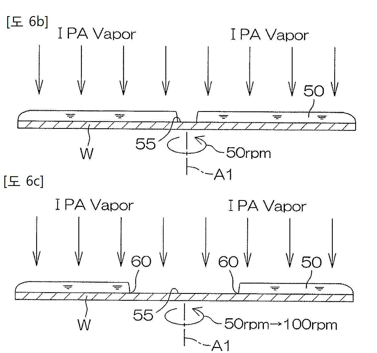
도 6b, 6c 는, 박막 영역 형성 공정 (도 5 의 T2) 및 박막 영역 확대 공정 (도 5 의 T3) 의 양태를 설명하기 위한 도해적인 단면도이다.
도 6d, 6e 는, 박막 영역 확대 공정 (도 5 의 T3) 의 양태를 설명하기 위한 도해적인 단면도이다.
도 7 은, 박막 영역 확대 공정 중에 있어서의, 물의 액막의 상태를 확대하여 나타내는 단면도이다.
도 8 은, 물의 액막의 내주 부분의 내부에 있어서의, 마란고니 대류의 발생 메커니즘을 설명하기 위한 도면이다.
도 9a, 9b 는, 박막 영역의 확대 중에 있어서의, 물의 액막의 내주 부분의 상태를 나타내는 평면도이다.
도 10 은, 참고 형태에 관련된, 기판의 상면 상의 물의 액막에 있어서의, 기액고 계면에 있어서의 흐름 분포 모델을 나타내는 도면이다.
도 11 은, 참고 형태에 관련된, 물의 액막의 내주 부분에 포함되는 미세 파티클의 이동을 나타내는 모식적인 단면도이다.
도 12 는, 참고 형태에 관련된, 물의 액막의 내주 부분에 포함되는 미세 파티클의 이동을 나타내는 모식적인 평면도이다.
도 13a, 13b 는, 참고 형태에 관련된, 액막 제거 영역의 확대 중에 있어서의, 물의 액막의 내주 부분의 상태를 나타내는 평면도이다.
도 14 는, 본 발명의 제 2 실시형태에 관련된 기판 처리 장치의 처리 유닛의 구성예를 설명하기 위한 도해적인 단면도이다.
도 15a 는, 본 발명의 제 3 실시형태에 관련된 기판 처리 장치의 처리 유닛의 구성예를 설명하기 위한 도해적인 단면도이다.
도 15b 는, 대향 부재의 저면도이다.
도 16 은, 본 발명의 제 3 실시형태에 관련된 기판 처리 장치에 있어서 실행되는, 린스 공정 (S3) 및 스핀 드라이 공정 (S4) 을 설명하기 위한 타임 차트이다.
도 17 은, 대향 부재를 제 2 근접 위치에 배치한 상태를 나타내는 단면도이다.
도 18 은, 본 발명의 제 3 실시형태에 관련된 기판 처리 장치의 변형예를 나타내는 단면도이다. 1 is a schematic plan view for explaining an interior layout of a substrate processing apparatus according to a first embodiment of the present invention.
2 is a schematic cross-sectional view for explaining a configuration example of a processing unit provided in the substrate processing apparatus.
3 is a block diagram for explaining the electrical configuration of the main part of the substrate processing apparatus.
4 is a flowchart for explaining an example of substrate processing by the substrate processing apparatus.
5 is a time chart for explaining details of a rinse step (S3 in FIG. 4) and a spin dry step (S4 in FIG. 4), which are performed in the substrate processing apparatus.
6A is a schematic cross-sectional view for explaining an aspect of a paddle rinse process (T1 in FIG. 5).
6B and 6C are schematic sectional views for explaining aspects of the thin film region forming step (T2 in FIG. 5) and the thin film region expanding step (T3 in FIG. 5).
6D and 6E are schematic sectional views for explaining an aspect of the thin film region enlargement process (T3 in FIG. 5).
7 is a cross-sectional view showing an enlarged state of a liquid film of water during a thin-film region enlargement process.
8 is a view for explaining a mechanism for generating Marangoni convection inside the inner periphery of the liquid film of water.
9A and 9B are plan views showing a state of an inner circumferential portion of a liquid film of water during enlargement of a thin film region.
10 is a view showing a flow distribution model at a gas-liquid-solid interface in a liquid film of water on an upper surface of a substrate according to a reference form.
11 is a schematic cross-sectional view showing movement of fine particles contained in an inner circumferential portion of a liquid film of water related to a reference form.
12 is a schematic plan view showing the movement of fine particles contained in an inner circumferential portion of a liquid film of water related to a reference form.
13A and 13B are plan views showing a state of an inner circumferential portion of a liquid film of water during enlargement of a liquid film removing region according to a reference form.
14 is a schematic cross-sectional view for explaining a configuration example of a processing unit of a substrate processing apparatus according to a second embodiment of the present invention.
15A is a schematic sectional view for explaining a configuration example of a processing unit of the substrate processing apparatus according to the third embodiment of the present invention.
15B is a bottom view of the opposing member.
16 is a time chart for explaining the rinse step (S3) and the spin dry step (S4) performed in the substrate processing apparatus according to the third embodiment of the present invention.
17 is a cross-sectional view showing a state in which the opposing member is disposed in the second proximity position.
18 is a cross-sectional view showing a modification of the substrate processing apparatus according to the third embodiment of the present invention.
도 1 은, 본 발명의 제 1 실시형태에 관련된 기판 처리 장치의 내부의 레이아웃을 설명하기 위한 도해적인 평면도이다. 기판 처리 장치 (1) 는, 실리콘 웨이퍼 등의 기판 (W) 을 한 장씩 처리하는 매엽식의 장치이다. 이 실시형태에서는, 기판 (W) 은, 원판상의 기판이다. 기판 처리 장치 (1) 는, 처리액으로 기판 (W) 을 처리하는 복수의 처리 유닛 (2) 과, 처리 유닛 (2) 에서 처리되는 복수 장의 기판 (W) 을 수용하는 캐리어 (C) 가 재치 (載置) 되는 로드 포트 (LP) 와, 로드 포트 (LP) 와 처리 유닛 (2) 사이에서 기판 (W) 을 반송하는 반송 로봇 (IR 및 CR) 과, 기판 처리 장치 (1) 를 제어하는 제어 장치 (3) 를 포함한다. 반송 로봇 (IR) 은, 캐리어 (C) 와 반송 로봇 (CR) 사이에서 기판 (W) 을 반송한다. 반송 로봇 (CR) 은, 반송 로봇 (IR) 과 처리 유닛 (2) 사이에서 기판 (W) 을 반송한다. 복수의 처리 유닛 (2) 은, 예를 들어 동일한 구성을 가지고 있다. 1 is a schematic plan view for explaining an interior layout of a substrate processing apparatus according to a first embodiment of the present invention. The
도 2 는, 처리 유닛 (2) 의 구성예를 설명하기 위한 도해적인 단면도이다.2 is a schematic sectional view for explaining a configuration example of the
처리 유닛 (2) 은, 내부 공간 (SP) 을 갖는 상자형의 처리 챔버 (밀폐 챔버)(4) 와, 처리 챔버 (4) 내에서 한 장의 기판 (W) 을 수평의 자세로 유지하여, 기판 (W) 의 중심을 통과하는 연직의 회전 축선 (A1) 둘레로 기판 (W) 을 회전시키는 스핀 척 (기판 유지 유닛)(5) 과, 스핀 척 (5) 에 유지되고 있는 기판 (W) 의 상면에 약액을 공급하기 위한 약액 공급 유닛 (6) 과, 스핀 척 (5) 에 유지되고 있는 기판 (W) 의 상면에 물 (처리액) 을 공급하기 위한 물 공급 유닛 (처리액 공급 유닛)(7) 과, 저표면장력액으로서의 유기 용제 증기의 일례로서의 IPA 의 증기 (IPA Vapor) 를 내부 공간 (SP) 에 공급하는 제 1 유기 용제 증기 공급 유닛 (내부 기체 공급 유닛, 기체 공급 유닛)(8) 과, 스핀 척 (5) 을 둘러싸는 통상의 처리 컵 (11) 을 포함한다. The
처리 챔버 (4) 는, 스핀 척 (5) 등을 수용하는 상자형의 격벽 (12) 과, 격벽 (12) 의 상부로부터 격벽 (12) 내 (처리 챔버 (4) 내에 상당) 로 청정 공기 (저표면장력액 이외의 기체의 분위기) 를 보내는 송풍 유닛 (40) 과, 격벽 (12) 에 형성된 반출 반입구를 개폐하는 셔터 (13) 와, 격벽 (12) 의 하부로부터 처리 챔버 (4) 내의 기체를 배출하는 배기 유닛 (14) 을 포함한다. The
송풍 유닛 (40) 은, 격벽 (12) 의 상방에 배치되어 있고, 격벽 (12) 의 천정에 장착되어, 당해 천정으로부터 처리 챔버 (4) 내로 청정 공기를 보낸다. 송풍 유닛 (40) 은, 청정 공기가 유통되는 청정 공기 배관 (41) 과, 청정 공기 배관 (41) 으로부터 내부 공간 (SP) 으로의 유기 용제 증기 (IPA Vapor) 의 공급 및 공급 정지를 전환하는 청정 공기 밸브 (42) 를 포함한다. 청정 공기 배관 (41) 의 하류단은, 내부 공간 (SP) 에 접속되어 있다. 청정 공기 밸브 (42) 가 개방되면, 청정 공기가, 청정 공기 배관 (41) 을 통하여 내부 공간 (SP) 으로 보내진다. The blowing
제 1 유기 용제 증기 공급 유닛 (8) 은, 격벽 (12) 의 상방에 배치되어 있고, 격벽 (12) 의 천정에 장착되어 있다. 제 1 유기 용제 증기 공급 유닛 (8) 은, 유기 용제 증기가 유통되는 제 1 유기 용제 증기 배관 (15) 을 포함한다. 제 1 유기 용제 증기 배관 (15) 의 하류단은, 내부 공간 (SP) 에 접속되어 있다. 제 1 유기 용제 증기 공급 유닛 (8) 은, 추가로 제 1 유기 용제 증기 배관 (15) 으로부터 내부 공간 (SP) 으로의 유기 용제 증기의 공급 및 공급 정지를 전환하는 제 1 유기 용제 증기 밸브 (16) 와, 제 1 유기 용제 증기 배관 (15) 의 개방도를 조절하여, 내부 공간 (SP) 에 공급되는 유기 용제 증기의 유량을 조정하기 위한 제 1 유량 조정 밸브 (17) 와, 제 1 유기 용제 증기 배관 (15) 을 유통하는 유기 용제 증기에 포함되는 티끌이나 먼지를 포획하는 제 1 필터 (15A) 를 포함한다. 도시는 하지 않지만, 제 1 유량 조정 밸브 (17) 는, 밸브 시트가 내부에 설치된 밸브 보디와, 밸브 시트를 개폐하는 밸브체와, 개방 위치와 폐쇄 위치 사이에서 밸브체를 이동시키는 액추에이터를 포함한다. 다른 유량 조정 밸브에 대해서도 동일하다. The 1st organic solvent
제 1 유기 용제 증기 밸브 (16) 가 개방되면, 유기 용제 증기 (티끌이나 먼지가 제거된 청정한 유기 용제 증기) 가, 제 1 유기 용제 증기 배관 (15) 을 통하여 내부 공간 (SP) 으로 보내진다. When the first organic
처리 챔버 (4) 는, 제 1 유기 용제 증기 공급 유닛 (8) 에 의해 내부 공간 (SP) 에 공급된 기체 (청정 공기나 유기 용제 증기) 를 정류하는 정류판 (18) 을 포함한다. 정류판 (18) 은, 내부 공간 (SP) 에 배치되어 있고, 구체적으로는 제 1 유기 용제 증기 공급 유닛 (8) 과, 스핀 척 (5) 사이의 높이에 배치되어 있는, 정류판 (18) 은, 수평의 자세로 유지되고 있다. 정류판 (18) 은, 격벽 (12) 의 내부를, 정류판 (18) 의 상방의 공간 (SP1) 과, 정류판 (18) 의 하방의 공간 (SP2) 으로 구획하고 있다. 격벽 (12) 의 천정면 (12a) 과 정류판 (18) 사이의 상방 공간 (SP1) 은, 공급된 기체 (청정 공기나 유기 용제 증기) 가 확산되기 위한 확산 공간이고, 정류판 (18) 과 격벽 (12) 의 플로어면 (12b) 사이의 하방 공간 (SP2) 은, 기판 (W) 의 처리가 실시되는 처리 공간이다. 상방 공간 (SP1) 의 높이는 하방 공간 (SP2) 의 높이보다 작다. 정류판 (18) 의 하면 (18a) 은, 평면으로 볼 때 스핀 척에 겹치는 대향부를 포함한다. 정류판 (18) 은, 상하 방향으로 관통하는 복수의 관통공 (18b) 이 그 전역에 형성된 다공 플레이트이다.The
제 1 유기 용제 증기 밸브 (16) 가 폐쇄된 상태에서 청정 공기 밸브 (42) 가 개방되면, 상방 공간 (SP1) 으로 청정 공기가 보내진다. 청정 공기 밸브 (42) 의 개방이 계속됨으로써, 상방 공간 (SP1) 에 청정 공기가 충만하고, 청정 공기는 관통공 (18b) 을 통과하여 정류판 (18) 의 전역으로부터 하방으로 흐른다. 이로써, 정류판 (18) 의 전역으로부터 하 방향을 향하는 균일한 청정 공기의 흐름이, 하방 공간 (SP2) 에 형성된다. When the
한편, 청정 공기 밸브 (42) 가 폐쇄된 상태에서 제 1 유기 용제 증기 밸브 (16) 가 개방되면, 상방 공간 (SP1) 으로 유기 용제 증기가 보내진다. 제 1 유기 용제 증기 밸브 (16) 의 개방이 계속됨으로써, 유기 용제 증기가 상방 공간 (SP1) 에 충만하고, 유기 용제 증기는 관통공 (18b) 을 통과하여 정류판 (18) 의 전역으로부터 하방으로 흐른다. 이로써, 정류판 (18) 의 전역으로부터 하 방향을 향하는 균일한 유기 용제 증기의 흐름이, 하방 공간 (SP2) 에 형성된다. On the other hand, when the first organic
배기 유닛 (14) 은, 처리 컵 (11) 내에 접속된 배기 덕트 (19) 와, 배기 덕트 (19) 를 통하여, 처리 챔버 (4) 의 내부 공간 (SP) 의 분위기를 흡인하는, 흡인 장치 등의 배기 장치 (20) 와, 배기 덕트 (19) 와 배기 장치 (20) 를 접속하는 배기 배관 (21) 과, 배기 배관 (21) 을 개폐하는 배기 밸브 (22) 를 포함한다. 배기 밸브 (22) 가 개방된 상태에서는, 내부 공간 (SP)(하방 공간 (SP2)) 의 분위기가 처리 챔버 (4) 밖으로 배출됨과 함께, 내부 공간 (SP)(하방 공간 (SP2)) 에 다운 플로우 (하강류) 가 형성된다. 한편, 배기 밸브 (22) 가 폐쇄된 상태에서는, 내부 공간 (SP)(하방 공간 (SP2)) 의 분위기가 처리 챔버 (4) 밖으로 배출되지 않는다.The
청정 공기 밸브 (42) 가 폐쇄된 상태에서, 또한 배기 밸브 (22) 가 폐쇄되면, 내부 공간 (SP) 이 외부로부터 폐색된 폐쇄 상태가 되고, 처리 챔버 (4) 는, 외부로부터 폐색된 밀폐 챔버로서 기능한다. When the
스핀 척 (5) 으로서, 기판 (W) 을 수평 방향으로 사이에 두고 기판 (W) 을 수평으로 유지하는 협지식의 척이 채용되어 있다. 구체적으로는, 스핀 척 (5) 은, 스핀 모터 (23) 와, 이 스핀 모터 (23) 의 구동축과 일체화된 스핀축 (24) 과, 스핀축 (24) 의 상단 (上端) 에 대략 수평으로 장착된 원판상의 스핀 베이스 (25) 를 포함한다.As the
스핀 베이스 (25) 는, 기판 (W) 의 외경보다 큰 외경을 갖는 수평의 원형의 상면 (25a) 을 포함한다. 상면 (25a) 에는, 그 주연부에 복수 개 (3 개 이상. 예를 들어 6 개) 의 협지 부재 (26) 가 배치되어 있다. 복수 개의 협지 부재 (26) 는, 스핀 베이스 (25) 의 상면 주연부에 있어서, 기판 (W) 의 외주 형상에 대응하는 원주 상에서 적당한 간격을 두고 예를 들어 등간격으로 배치되어 있다.The
약액 공급 유닛 (6) 은, 약액 노즐 (27) 을 포함한다. 약액 노즐 (27) 은, 예를 들어 연속류의 상태로 액을 토출하는 스트레이트 노즐이고, 스핀 척 (5) 의 상방에서, 그 토출구를 기판 (W) 의 상면 중앙부를 향하여 고정적으로 배치되어 있다. 약액 노즐 (27) 에는, 약액 공급원으로부터의 약액이 공급되는 약액 배관 (28) 이 접속되어 있다. 약액 배관 (28) 의 도중부에는, 약액 노즐 (27) 로부터의 약액의 공급/공급 정지를 전환하기 위한 약액 밸브 (29) 가 개재되어 있다. 약액 밸브 (29) 가 개방되면, 약액 배관 (28) 으로부터 약액 노즐 (27) 로 공급된 연속류의 약액이, 약액 노즐 (27) 의 하단 (下端) 에 설정된 토출구로부터 토출된다. 또, 약액 밸브 (29) 가 폐쇄되면, 약액 배관 (28) 으로부터 약액 노즐 (27) 로의 약액의 공급이 정지된다. The chemical
약액의 구체예는, 에칭액 및 세정액이다. 더욱 구체적으로는, 약액은, 불산, SC1 (암모니아과산화수소수 혼합액), SC2 (염산과산화수소수 혼합액), 불화암모늄, 버퍼드 불산 (불산과 불화암모늄의 혼합액) 등이어도 된다. Specific examples of the chemical solution are an etching solution and a cleaning solution. More specifically, the chemical liquid may be hydrofluoric acid, SC1 (a mixture of ammonia hydrogen peroxide water), SC2 (a mixture of hydrochloric acid hydrogen peroxide water), ammonium fluoride, buffered hydrofluoric acid (a mixture of hydrofluoric acid and ammonium fluoride), or the like.
물 공급 유닛 (7) 은, 물 노즐 (30) 을 포함한다. 물 노즐 (30) 은, 예를 들어 연속류의 상태로 액을 토출하는 스트레이트 노즐이고, 스핀 척 (5) 의 상방에서, 그 토출구를 기판 (W) 의 상면 중앙부를 향하여 고정적으로 배치되어 있다. 물 노즐 (30) 에는, 물 공급원으로부터의 물이 공급되는 물 배관 (31) 이 접속되어 있다. 물 배관 (31) 의 도중부에는, 물 노즐 (30) 로부터의 물의 공급/공급 정지를 전환하기 위한 물 밸브 (32) 가 개재되어 있다. 물 밸브 (32) 가 개방되면, 물 배관 (31) 으로부터 물 노즐 (30) 로 공급된 연속류의 물이, 물 노즐 (30) 의 하단에 설정된 토출구로부터 토출된다. 또, 물 밸브 (32) 가 폐쇄되면, 물 배관 (31) 으로부터 물 노즐 (30) 로의 물의 공급이 정지된다. 물 노즐 (30) 에 공급되는 물은, 예를 들어 탈이온수 (DIW) 이지만, DIW 로 한정하지 않고, 탄산수, 전해 이온수, 수소수, 오존수 및 희석 농도 (예를 들어, 10 ppm ∼ 100 ppm 정도) 의 염산수 중 어느 것이라도 된다. The
또한, 약액 노즐 (27) 및 물 노즐 (30) 은, 각각 스핀 척 (5) 에 대해 고정 적으로 배치되어 있을 필요는 없고, 예를 들어 스핀 척 (5) 의 상방에 있어서 수평면 내에서 요동 가능한 아암에 장착되어, 이 아암의 요동에 의해 기판 (W) 의 상면에 있어서의 처리액 (약액 또는 물) 의 착액 위치가 스캔되는, 이른바 스캔 노즐의 형태가 채용되어도 된다. In addition, the chemical
도 2 에 나타내는 바와 같이, 처리 컵 (11) 은, 스핀 척 (5) 에 유지되고 있는 기판 (W) 보다 외방 (회전 축선 (A1) 으로부터 멀어지는 방향) 에 배치되어 있다. 처리 컵 (11) 은, 스핀 베이스 (25) 를 둘러싸고 있다. 스핀 척 (5) 이 기판 (W) 을 회전시키고 있는 상태에서 처리액이 기판 (W) 에 공급되면, 기판 (W) 에 공급된 처리액이 기판 (W) 의 주위로 떨쳐내어진다. 처리액이 기판 (W) 에 공급될 때, 상향으로 개방된 처리 컵 (11) 의 상단부 (11a) 는, 스핀 베이스 (25) 보다 상방에 배치된다. 따라서, 기판 (W) 의 주위로 배출된 약액이나 물 등의 처리액은, 처리 컵 (11) 에 의해 수용된다. 그리고, 처리 컵 (11) 에 수용된 처리액은, 도시되지 않은 회수 장치 또는 폐액 장치로 보내진다. 2, the
도 3 은, 기판 처리 장치 (1) 의 주요부의 전기적 구성을 설명하기 위한 블록도이다.3 is a block diagram for explaining the electrical configuration of the main part of the
제어 장치 (3) 는, 미리 정해진 프로그램에 따라 스핀 모터 (23), 배기 장치 (20), 제 1 노즐 이동 유닛 (34) 등의 동작을 제어한다. 또한, 제어 장치 (3) 는, 약액 밸브 (29), 물 밸브 (32), 제 1 유기 용제 증기 밸브 (16), 제 1 유량 조정 밸브 (17), 청정 공기 밸브 (42) 등의 개폐 동작 등을 제어한다. The
도 4 는, 기판 처리 장치 (1) 에 의한 기판 처리의 일례를 설명하기 위한 흐름도이다. 도 5 는, 기판 처리 장치 (301) 에 있어서 실행되는, 린스 공정 (S3) 및 스핀 드라이 공정 (S4) 을 설명하기 위한 타임 차트이다. 도 6a ∼ 6e 는, 패들 린스 공정 (액막 형성 공정, 증기 분위기 충만 공정, 패들 공정) T1, 박막 영역 형성 공정 T2 및 박막 영역 확대 공정 (고속 회전 공정) T3 을 설명하기 위한 도해적인 도면이다.4 is a flowchart for explaining an example of substrate processing by the
도 1 ∼ 도 6e 를 참조하면서 기판 처리에 대해 설명한다.The substrate processing will be described with reference to FIGS. 1 to 6E.
미처리의 기판 (W) 은, 반송 로봇 (IR, CR) 에 의해 캐리어 (C) 로부터 처리 유닛 (2) 으로 반입되고, 처리 챔버 (4) 내로 반입되고, 기판 (W) 이 그 표면 (처리 대상면. 예를 들어 패턴 형성면) 을 상방을 향한 상태에서 스핀 척 (5) 에 수수되고, 스핀 척 (5) 에 기판 (W) 이 유지된다 (S1 : 기판 반입 공정 (기판 유지 공정)). 기판 (W) 의 반입에 앞서, 제 1 유기 용제 증기 밸브 (16) 는 폐쇄되고, 청정 공기 밸브 (42) 는 개방되고, 또한 배기 밸브 (22) 는 개방되어 있다. 그 때문에, 하방 공간 (SP2) 에는, 내부 공간 (SP)(하방 공간 (SP2)) 에 청정 공기의 다운 플로우 (하강류) 가 형성된다.The unprocessed substrate W is transported from the carrier C to the
반송 로봇 (CR) 이 처리 유닛 (2) 밖으로 퇴피한 후, 제어 장치 (3) 는, 약액 공정 (스텝 S2) 을 실행한다. 구체적으로는, 제어 장치 (3) 는, 스핀 모터 (23) 를 구동하여 스핀 베이스 (25) 를 소정의 액 처리 속도 (예를 들어 약 800 rpm) 로 회전시킨다. 또, 제어 장치 (3) 는, 약액 밸브 (29) 를 개방한다. 그것에 의해, 회전 상태의 기판 (W) 의 상면을 향하여, 약액 노즐 (27) 로부터 약액이 공급된다. 공급된 약액은 원심력에 의해 기판 (W) 의 전체면으로 골고루 퍼지고, 기판 (W) 에 약액을 사용한 약액 처리가 실시된다. 약액의 토출 개시로부터 미리 정하는 기간이 경과하면, 제어 장치 (3) 는, 약액 밸브 (29) 를 폐쇄하여, 약액 노즐 (27) 로부터의 약액의 토출을 정지한다. After the conveyance robot CR evacuates out of the
이어서, 제어 장치 (3) 는, 린스 공정 (스텝 S3) 을 실행한다. 린스 공정은, 기판 (W) 상의 약액을 물로 치환하여 기판 (W) 상으로부터 약액을 배제하는 공정이다. 구체적으로는, 제어 장치 (3) 는, 물 밸브 (32) 를 개방한다. 그것에 의해, 회전 상태의 기판 (W) 의 상면을 향하여, 물 노즐 (30) 로부터 물이 공급된다. 공급된 물은 원심력에 의해 기판 (W) 의 전체면으로 골고루 퍼진다. 이 물에 의해, 기판 (W) 상에 부착되어 있는 약액이 씻겨내어진다. Subsequently, the
물의 공급 개시로부터 미리 정하는 기간이 경과하면, 기판 (W) 의 상면 전역이 물로 덮여 있는 상태에서, 제어 장치 (3) 는, 스핀 모터 (23) 를 제어하여, 기판 (W) 의 회전 속도를 액 처리 속도로부터 패들 속도 (영 또는 약 40 rpm 이하의 저회전 속도. 예를 들어 약 10 rpm) 까지 단계적으로 감속시킨다. 그 후, 기판 (W) 의 회전 속도를 패들 속도로 유지한다 (패들 린스 공정 T1). 이로써, 도 6a 에 나타내는 바와 같이, 기판 (W) 의 상면에, 기판 (W) 의 상면 전역을 덮는 물의 액막이 패들상으로 지지된다. 이 상태에서는, 기판 (W) 의 상면의 물의 액막 (처리액의 액막)(50) 에 작용하는 원심력이 물과 기판 (W) 의 상면 사이에서 작용하는 표면장력보다 작거나, 혹은 상기 원심력과 상기 표면장력이 대략 길항하고 있다. 기판 (W) 의 감속에 의해, 기판 (W) 상의 물에 작용하는 원심력이 약해지고, 기판 (W) 상으로부터 배출되는 물의 양이 감소한다. 기판 (W) 의 상면으로부터 약액에 의해 파티클을 제거하는 약액 공정에 이어서 린스 공정이 실행되기 때문에, 물의 액막 (50) 에 파티클이 포함되는 경우가 있다. 또, 패들 린스 공정 T1 에 있어서, 패들상의 물의 액막 (50) 후에도 기판 (W) 에 대한 물의 공급이 속행되어도 된다.When a predetermined period elapses from the start of water supply, in a state where the entire upper surface of the substrate W is covered with water, the
또, 제어 장치 (3) 는, 패들 린스 공정 T1 의 개시에 동기하여, 청정 공기 밸브 (42) 를 폐쇄함과 함께, 제 1 유기 용제 증기 밸브 (16) 를 개방한다. 이로써, 내부 공간 (SP) 으로의 청정 공기의 공급은 정지되고, 내부 공간 (SP) 으로의 유기 용제 증기의 공급이 개시된다. 이로써, 유기 용제 증기가 관통공 (18b)(도 2 참조) 을 통하여 하방 공간 (SP2) 으로 공급된다. 또, 제어 장치 (3) 는, 배기 밸브 (22) 를 폐쇄한다. 이로써, 처리 챔버 (4) 의 내부 공간 (SP) 이 외부로부터 폐색되고, 처리 챔버 (4) 는 밀폐 챔버로서 기능한다. 이 상태에서는, 하방 공간 (SP2)(기판 (W) 의 상방의 공간을 포함하는 공간) 은, 처리 챔버 (4) 의 외부와 차단되어 있고 (차단 공정), 그 때문에 하방 공간 (SP2) 에 공급된 유기 용제 증기가 하방 공간 (SP2) 의 전역으로 골고루 퍼져, 하방 공간 (SP2) 에 충만한다. 그 결과, 기판 (W) 상의 물의 액막 (50) 의 주위를 유기 용제 증기 분위기로 채울 수 있다 (증기 분위기 충만 공정). In addition, the
외부 공간으로부터 차단된 하방 공간 (SP2) 은, 외부의 분위기의 외란의 영향을 거의 받지 않는다. 그 때문에, 이 이후 기판 (W) 의 상면 전역의 주위가 유기 용제 증기를 고농도로 포함하는 분위기 (이하, 「유기 용제 증기 분위기」라고 한다.) 로 유지된다. 패들상의 물의 액막 (50) 의 형성 후, 제어 장치 (3) 는, 물 밸브 (32) 를 폐쇄하여, 물 노즐 (30) 로부터의 물의 토출을 정지한다. 하방 공간 (SP2) 에 유기 용제 증기가 충만한 후, 패들 린스 공정 T1 이 종료한다 (린스 공정 (S3) 이 종료된다). The lower space SP2 blocked from the external space is hardly affected by the disturbance of the external atmosphere. Therefore, after this, the entire area around the upper surface of the substrate W is maintained in an atmosphere containing an organic solvent vapor at a high concentration (hereinafter referred to as "organic solvent vapor atmosphere"). After formation of the
이어서, 제어 장치 (3) 는, 스핀 드라이 공정 (스텝 S4) 을 실행한다. 구체적으로는, 제어 장치 (3) 는, 먼저 박막 영역 형성 공정 T2 를 실행한다. 박막 영역 형성 공정 T2 는, 도 6b 에 나타내는 바와 같이, 기판 (W) 의 물의 액막 (50) 의 중앙부에, 물의 대부분이 제거되어 매우 얇은 초박막 (물의 박막)(56)(도 7 참조) 이 잔존하는 원형의 박막 영역 (55) 을 형성하는 공정이다. 구체적으로는, 제어 장치 (3) 는, 스핀 모터 (23) 를 제어하여 기판 (W) 을 소정의 박막 영역 형성 속도 (예를 들어 약 50 rpm) 까지 가속시킨다. 기판 (W) 의 회전 속도가 상기 박막 영역 형성 속도 (예를 들어 약 50 rpm) 에 도달함으로써, 기판 (W) 상의 물의 액막 (50) 에 비교적 강한 원심력이 작용하여, 기판 (W) 의 상면 중앙부에 존재하는 물이 직경 방향 외방으로 밀려남으로써, 기판 (W) 의 상면 중앙부에 원형의 박막 영역 (55) 이 형성된다. 박막 영역 형성 속도는, 약 50 rpm 으로 했지만, 그 이상의 회전 속도여도 된다. Subsequently, the
전술한 바와 같이, 유기 용제 증기가 하방 공간 (SP2) 의 전역에 충만하고 있다. 그 때문에, 물의 액막 (50) 이, 유기 용제 증기의 토출 압력에 밀려 변형되는 일은 없다. 따라서, 박막 영역 형성 공정 T2 에 있어서, 물의 액막 (50)(벌크 (72)) 을 가능한 한 두껍게 유지할 수 있어, 벌크 (72) 와 박막 영역 (55) 의 막두께의 낙차를 크게 유지할 수 있다. 이로써, 물의 액막의 내주 부분 (70) 에 발생하는 마란고니 대류 (65) 를 강하게 할 수 있다. As described above, the organic solvent vapor is filled in the entire lower space SP2. Therefore, the
박막 영역 형성 공정 T2 에 이어서 박막 영역 확대 공정 T3 이 실행된다. Following the thin film region forming step T2, the thin film region expanding step T3 is performed.
박막 영역 확대 공정 T3 에서는, 제어 장치 (3) 는, 스핀 모터 (23) 를 제어하여, 기판 (W) 의 회전 속도를 소정의 건조 속도 (제 1 고속도. 제 2 고속도. 예를 들어 1000 rpm) 까지 상승시킨다. 이 기판 (W) 의 회전 속도의 상승에 수반하여, 도 6c, 6d 에 나타내는 바와 같이 박막 영역 (55) 이 확대된다. 박막 영역 (55) 의 확대에 의해, 물의 액막 (50) 과 박막 영역 (55) 의 경계 (60) 가 기판 (W) 의 직경 방향 외방을 향하여 이동한다. 그리고, 도 6e 에 나타내는 바와 같이, 박막 영역 (55) 이 기판 (W) 의 전역으로 확대됨으로써, 물의 액막 (50) 이 전부 기판 (W) 밖으로 배출된다. In the thin film region expansion step T3, the
박막 영역 확대 공정 T3 에서는, 물의 액막 (50) 은, 당해 액막에 유기 용제 증기의 강한 토출 압력이 가해지지 않기 때문에 변형되지 않는다. 그 때문에, 물의 액막 (50)(벌크 (72)) 을 가능한 한 두껍게 유지할 수 있어, 벌크 (72) 와 박막 영역 (55) 의 막두께의 낙차를 크게 유지할 수 있다. 이로써, 물의 액막의 내주 부분 (70) 에 발생하는 마란고니 대류 (65) 를 강하게 할 수 있다. In the thin film region expansion step T3, the
박막 영역 확대 공정 T3 에 있어서의, 기판 (W) 중앙부 상의 유기 용제 농도는 약 300 ppm 이상이고, 기판 (W) 주연부 상의 유기 용제 농도는 약 300 ppm 이상이며, 기판 (W) 중간부 (중앙부와 주연부의 중간 위치) 상의 유기 용제 농도는 약 300 ppm 이상이다.In the thin film region expansion process T3, the concentration of the organic solvent on the central portion of the substrate W is about 300 ppm or more, the concentration of the organic solvent on the periphery of the substrate W is about 300 ppm or more, and the middle portion of the substrate W is (with the central portion). The concentration of the organic solvent on the intermediate position of the periphery) is about 300 ppm or more.
박막 영역 확대 공정 T3 의 전체 기간에 걸쳐, 제 1 유기 용제 증기 공급 유닛 (8) 으로부터의 내부 공간 (SP) 에 대한 유기 용제 증기의 공급이 속행되고 있다. 그 때문에, 박막 영역 확대 공정 T3 의 전체 기간에 걸쳐, 기판 (W) 의 상면의 전역이 유기 용제 증기로 유지되고 있다. 그 때문에, 박막 영역 (55) 의 확대 상황에 의하지 않고, 물의 액막 (액막 중 초박막 (56) 이 형성되어 있지 않은 부분) 의 내주 부분 (경계 부근 부분)(70) 의 주위의 분위기를 유기 용제 증기 분위기로 계속 유지할 수 있다.Throughout the entire period of the thin film region expansion process T3, supply of the organic solvent vapor to the inner space SP from the first organic solvent
박막 영역 (55) 이 기판 (W) 의 상면의 전역으로 확대된 후, 제어 장치 (3) 는, 박막 영역 확대 공정 T3 을 종료시킨다. 박막 영역 확대 공정 T3 의 종료에 수반하여, 제어 장치 (3) 는, 제 1 유기 용제 증기 밸브 (16) 를 폐쇄하여, 제 1 유기 용제 증기 공급 유닛 (8) 으로부터의 내부 공간 (SP) 으로의 유기 용제 증기의 공급을 정지시킨다. 또, 제어 장치 (3) 는, 청정 공기 밸브 (42) 및 배기 밸브 (22) 를 개방함으로써, 내부 공간 (SP)(하방 공간 (SP2)) 에 청정 공기의 다운 플로우 (하강류) 를 형성한다. 이로써, 내부 공간 (SP)(하방 공간 (SP2)) 의 분위기가, 유기 용제 증기로부터 청정 공기로 치환된다.After the
그 후, 제어 장치 (3) 는, 기판 (W) 을, 약 1000 rpm 인 채로 회전 속행시킨다 (박막 제거 공정). 이로써, 하방 공간 (SP2) 에 도입된 신선한 청정 공기가 기판 (W) 의 상면에 접촉한다. 그 때문에, 기판 (W) 의 상면의 각 지점에서 수증기의 확산이 진행되고, 그 결과 당해 각 지점에서 물의 증발이 진행된다. 그리고, 기판 (W) 의 고속 회전에 의해, 기판 (W) 의 상면 상의 물을 떨쳐낼 수 있다. 이로써, 기판 (W) 의 상면으로부터 초박막 (56) 이 완전히 제거되고, 그러므로 기판 (W) 의 상면을 양호하게 건조시킬 수 있다.Thereafter, the
스핀 드라이 공정 (S4) 의 개시로부터 미리 정하는 기간이 경과하면, 제어 장치 (3) 는, 스핀 모터 (23) 를 제어하여 스핀 척 (5) 의 회전을 정지시킨다. 그 후, 반송 로봇 (CR) 이, 처리 유닛 (2) 에 진입하여, 처리가 완료된 기판 (W) 을 처리 유닛 (2) 밖으로 반출한다 (스텝 S5). 그 기판 (W) 은, 반송 로봇 (CR) 으로부터 반송 로봇 (IR) 으로 건네지고, 반송 로봇 (IR) 에 의해 캐리어 (C) 에 수납된다. When a predetermined period elapses from the start of the spin drying step (S4), the
도 7 은, 박막 영역 확대 공정 T3 중에 있어서의, 물의 액막 (50) 의 상태를 확대하여 나타내는 단면도이다. 7 is a cross-sectional view showing an enlarged state of the
기판 (W) 의 회전 속도가 박막 형성 속도까지 가속됨으로써, 물의 액막 (50) 의 중앙부의 물이, 기판 (W) 의 회전에 의한 원심력을 받아 직경 방향 외방으로 밀려 확산된다. 그 결과, 기판 (W) 의 상면 중앙부에 있어서의 물의 액막 (50) 의 두께가 얇아지고, 당해 부분에 물의 초박막 (56) 이 형성된다. As the rotational speed of the substrate W is accelerated to the thin film formation speed, the water in the central portion of the
물의 초박막 (56) 의 주위가 유기 용제 증기 분위기로 유지되고 있기 때문에, 물의 초박막 (56) 에 유기 용제가 다량으로 용해되고, 그 때문에 물의 초박막 (56) 은, 유기 용제를 높은 농도로 포함한다. 기판 (W) 의 상면 전역의 주위가 유기 용제 증기 분위기로 유지되고 있기 때문에, 유기 용제 증기의 확산은 진행되지 않고, 그 결과 물의 초박막 (56) 에 포함되는 유기 용제의 증발의 진행이 억제 또는 방지된다. 따라서, 물의 액막 (50) 의 중앙부에 있어서, 물의 전부를 완전히 제거하는 것은 가능하지 않고, 당해 일부분에 물의 초박막 (56) 이 유지된다. 즉, 당해 일부분에 박막 영역 (55) 이 형성된다. Since the circumference of the
내부 공간 (SP) 에 유기 용제 증기가 충만하고 있는 상태에서는, 기판 (W) 의 상면을 덮는 물의 액막 (50) 의 전역의 주위 및 물의 초박막 (56) 의 전역의 주위가, 유기 용제 증기 분위기로 유지된다. 그 때문에, 물의 액막 (50) 및 물의 초박막 (56) 에 유기 용제 증기가 용해된다. 그 때문에, 물의 액막의 내주 부분 (70) 의 내부에, 서로 이어지는 물의 액막 (50) 및 물의 초박막 (56) 의 국소적인 두께의 차에 기초하는 유기 용제의 농도차에서 기인하여, 물의 초박막 (56) 으로부터 물의 액막 (50) 의 벌크 (72) 측을 향해 흐르는 마란고니 대류 (65) 가 발생한다.In the state where the organic solvent vapor is filled in the inner space SP, the entire surroundings of the
물의 초박막 (56) 의 두께는, 가시광 이하의 파장 이하의 두께 (예를 들어 수 nm) 이다. 물의 초박막 (56) 의 두께는 가능한 한 얇은 것이 바람직하다. 이것에는, 두 가지의 이유가 있다. The thickness of the
첫 번째 이유는, 다음에 서술하는 바와 같다. 즉, 마란고니 대류 (65) 를 강하게 하기 위해서는, 물의 액막 (50) 과 물의 초박막 (56) 의 농도차를 크게 할 (즉, 물의 초박막 (56) 의 유기 용제 농도를 한층 더 진하게 할) 필요가 있다. 물의 초박막 (56) 을 한층 더 박막화함으로써, 단위 체적당의 유기 용제의 양이 증대하여, 물의 초박막 (56) 의 유기 용제 농도를 진하게 할 수 있다. The first reason is as described below. That is, in order to strengthen the
두 번째 이유는, 다음에 서술하는 바와 같다. 즉, 물의 초박막 (56) 이 두꺼우면, 유기 용제 농도는 물의 초박막 (56) 의 표층 부분에서 상대적으로 높고, 물의 초박막 (56) 의 기층 부분에서 상대적으로 낮아진다. 그 결과, 물의 초박막 (56) 중에서도 마란고니 대류가 발생하고, 물의 초박막 (56) 으로부터 벌크 (72) 로 흐르는 마란고니 대류 (65) 를 약하게 하는 결과가 된다.The second reason is as described below. That is, when the
도 8 은, 물의 액막의 내주 부분 (70) 의 내부에 있어서의, 마란고니 대류 (65) 의 발생 메커니즘을 설명하기 위한 도면이다. 8 is a view for explaining a mechanism for generating the
기판 (W) 이 회전하고, 또한 물의 액막 (50) 에 박막 영역 (55)(도 7 참조) 이 형성된 상태에서는, 기판 (W) 의 회전에 의해 발생하는 원심력에서 기인하여, 물의 액막 (50) 에 두께가 상이한 부분이 생긴다. 즉, 물의 액막 (50) 에 있어서의, 경계 (60) 의 근방 영역 (71)(이하, 간단히 「경계 근방 영역 (71)」 이라고 한다.) 에서는 액막의 두께 (H1) 가 매우 얇고, 또한 물의 액막 (50) 의 벌크 (72) 에서는 액막의 두께 (H2) 가 두껍다 (H2 > H1). 예를 들어, H1 = 수 nm 이고, H2 = 약 7 mm 이다. In the state where the substrate W rotates and the thin film region 55 (see FIG. 7) is formed in the
또, 경계 (60) 의 근방 영역 (71) 에 이어져 물의 초박막 (56) 이 형성된다. 물의 초박막 (56) 의 두께는, H3 으로 설정되어 있다. H3 = 수 nm 이다.In addition, an
물의 액막 (50) 및 물의 초박막 (56) 의 주위가, 유기 용제 증기의 고농도 상태로 유지되고 있다. 이 상태에서는, 유기 용제 증기가, 물의 액막 (50) 및 물의 초박막 (56) 의 각 지점에 균일하게 용해된다. 물의 초박막 (56) 에 있어서의 유기 용제 농도가, 벌크 (72) 에 있어서의 유기 용제 농도에 비해 상대적으로 높다. 그 결과, 서로 이어지는 물의 액막 (50) 및 물의 초박막 (56) 의 내부에 농도 구배가 생기고, 그 결과 초박막 (56) 으로부터 벌크 (72) 를 향하여 흐르는 마란고니 대류 (65) 가 발생한다. 이 마란고니 대류 (65) 는, 후술하는 제 2 부분 (70B)(도 10 참조) 에 발생하는 열대류 (76)(도 10 참조) 를 없앨 뿐만 아니라, 마란고니 대류 (65) 에 의해, 당해 제 2 부분 (70B)(도 10 참조) 에, 경계 근방 영역 (71) 으로부터 벌크 (72) 를 향하여 흐르는 새로운 흐름을 만든다. 따라서, 물의 액막의 내주 부분 (70)(구체적으로는, 도 10 에 나타내는 제 2 부분 (70B)) 에 미세 파티클 (P2) 이 포함되어 있는 경우에 있어서, 도 8 에 나타내는 바와 같이, 미세 파티클 (P2) 에, 마란고니 대류 (65) 를 받아 경계 근방 영역 (71) 으로부터 벌크 (72) 를 향하는 방향, 즉 경계 (60) 로부터 이반하는 방향의 강한 힘이 작용한다. 이로써, 경계 근방 영역 (71) 에 포함되어 있는 미세 파티클 (P2) 은, 직경 방향 외방 (경계 (60) 로부터 이반하는 방향) 을 향하여 이동한다. The circumference of the
도 9a, 9b 는, 박막 영역 (55) 의 확대 중에 있어서의, 물의 액막의 내주 부분 (70) 의 상태를 나타내는 평면도이다. 도 9a 에서는, 물의 액막의 내주 부분 (70)(구체적으로는, 도 10 에 나타내는 제 2 부분 (70B)) 에 미세 파티클 (P2) 이 포함되어 있는 상태이다. 미세 파티클 (P2) 은 경계 (60) 의 라인을 따라 늘어서 있다. 9A and 9B are plan views showing a state of an inner
이 경우, 물의 액막의 내주 부분 (70)(제 2 부분 (70B)) 에 포함되는 미세 파티클 (P2) 은, 경계 (60) 로부터 이반하는 방향으로 흐르는 마란고니 대류 (65) (도 7 참조) 를 받아, 직경 방향 외방 (경계 (60) 로부터 이반하는 방향) 을 향하여 이동하고, 그 결과 물의 액막 (50) 의 벌크 (72) 에 혼입된다. 그리고, 박막 영역 (55) 의 확대에 수반하여, 기판 (W) 의 직경 방향 외방 (벌크 (72) 를 향하는 방향) 을 향하여 경계 (60) 가 이동하지만, 미세 파티클 (P2) 이 벌크 (72) 에 혼입된 채로, 박막 영역 (55) 이 확대된다. 즉, 박막 영역 (55) 의 확대에 수반하여 경계 (60) 가 기판 (W) 의 직경 방향 외방을 향하여 이동하면, 이것에 아울러, 도 9b 에 나타내는 바와 같이, 미세 파티클 (P2) 도 직경 방향 외방을 향하여 이동한다. In this case, the fine particles P2 contained in the inner circumferential portion 70 (
그리고, 박막 영역 (55) 이 기판 (W) 의 전역으로 확대되고, 물의 액막 (50) 이 기판 (W) 의 상면으로부터 완전히 배출되는 (도 6e 에 나타내는 상태) 것에 의해, 기판 (W) 의 상면으로부터 큰 두께를 갖는 물의 액막 (50) 이 제거된다. 물의 액막 (50) 의 벌크 (72) 중에 포함되는 미세 파티클 (P2) 은, 박막 영역 (55) 에 출현하는 일 없이, 물의 액막 (50) 과 함께 기판 (W) 의 상면으로부터 제거된다.Then, the
또, 박막 영역 확대 공정 T3 의 종료 후에는, 내부 공간 (SP)(하방 공간 (SP2)) 의 분위기가, 유기 용제 증기로부터 청정 공기로 치환된다. 또, 기판 (W) 이 약 1000 rpm 의 고속인 채로 회전 속행된다. 이로써, 기판 (W) 의 상면으로부터 초박막 (56) 이 완전히 제거되고, 그러므로 기판 (W) 의 상면을 양호하게 건조시킬 수 있다.Moreover, after completion of the thin film region expansion step T3, the atmosphere of the internal space SP (lower space SP2) is replaced with clean air from the organic solvent vapor. Moreover, the rotation of the substrate W continues at a high speed of about 1000 rpm. Thereby, the
기판 (W) 의 상면의 주위의 분위기를 청정 공기로 치환한 상태에서, 기판 (W) 을 고속 회전시킨다. 이 경우, 신선한 청정 공기가 기판 (W) 의 상면에 접촉하기 때문에, 기판 (W) 의 상면의 각 지점에서 유기 용제의 확산이 진행되고, 당해 유기 용제를 포함하는 물의 초박막 (56) 의 증발이 진행된다. 그 때문에, 기판 (W) 의 고속 회전에 의해 물의 초박막 (56) 을 떨쳐낼 수 있고, 이로써 기판 (W) 의 상면을 완전히 건조시킬 수 있다. The substrate W is rotated at a high speed in a state where the atmosphere around the upper surface of the substrate W is replaced with clean air. In this case, since fresh clean air contacts the upper surface of the substrate W, diffusion of the organic solvent proceeds at each point on the upper surface of the substrate W, and evaporation of the
이상에 의해, 이 실시형태에 의하면, 기판 (W) 의 상면을 덮는 물의 액막 (50) 의 전역의 주위를 유기 용제 증기 분위기로 채우면서, 박막 영역 형성 공정 T2 및 박막 영역 확대 공정 T3 을 순차 실행한다. 그 때문에, 박막 영역 (55) 의 확대 상황에 의하지 않고, 박막 영역 (55) 의 확대 종료까지, 물의 액막의 내주 부분 (70) 의 주위 및 물의 초박막 (56) 의 주위가 유기 용제 증기 분위기로 유지된다. As described above, according to this embodiment, the thin film region forming step T2 and the thin film region expanding step T3 are sequentially executed while filling the entire periphery of the
물의 액막의 내주 부분 (70) 의 주위 및 물의 초박막 (56) 의 주위를 유기 용제 증기 분위기로 유지한 상태에서 기판 (W) 을 회전시키면, 서로 이어지는 물의 액막 (50) 및 물의 초박막 (56) 의, 국소적인 두께의 차에 기초하는 유기 용제의 농도차에서 기인하여, 물의 초박막 (56) 으로부터, 물의 액막의 내주 부분 (70) 을 통하여 물의 액막 (50) 의 벌크 (72) 로 향하는 방향으로 흐르는 마란고니 대류 (65) 가 발생한다. 그 때문에, 박막 영역 형성 공정 T2 및 박막 영역 확대 공정 T3 의 전체 기간에 걸쳐, 물의 초박막 (56) 으로부터 물의 액막 (50) 의 벌크 (72) 로 향하는 마란고니 대류 (65) 를 계속 발생시킬 수 있다. When the substrate W is rotated while the periphery of the inner
따라서, 물의 액막의 내주 부분 (70) 에 포함되어 있는 미세 파티클 (P2) 은, 마란고니 대류 (65) 를 받아, 벌크 (72) 를 향하는 방향, 즉 경계 (60) 로부터 이반하는 방향을 향하여 이동한다. 그 때문에, 파티클이 물의 액막 (50) 에 혼입된다. 박막 영역 (55) 의 확대에 수반하여, 기판 (W) 의 직경 방향 외방 (벌크 (72) 를 향하는 방향) 을 향하여 경계 (60) 가 이동하지만, 미세 파티클 (P2) 이 물의 액막 (50) 에 혼입된 채로, 박막 영역 (55) 이 확대된다. 그리고, 물의 액막 (50) 에 포함되어 있는 미세 파티클 (P2) 은, 박막 영역 (55) 에 출현하는 일 없이 물의 액막 (50) 과 함께 기판 (W) 의 상면으로부터 배출된다. 그 후, 기판 (W) 의 상면으로부터 초박막 (56) 이 제거됨으로써, 기판 (W) 의 상면이 건조된다. Accordingly, the fine particles P2 contained in the inner
이로써, 기판 (W) 의 건조 후에 있어서, 기판 (W) 의 상면에 미세 파티클 (P2) 이 잔존하는 일이 없다. 그러므로, 미세 파티클 (P2) 의 발생을 억제 또는 방지하면서, 기판 (W) 의 상면의 전역을 건조시킬 수 있다. Thereby, after drying of the board | substrate W, the fine particle P2 does not remain on the upper surface of the board | substrate W. Therefore, the entire upper surface of the substrate W can be dried while suppressing or preventing the generation of fine particles P2.
또, 초박막 (56) 이 유기 용제를 다량으로 포함하기 때문에, 건조 후에 워터 마크의 발생을 억제할 수도 있다.Moreover, since the
또, 패들 린스 공정 T1 에서는, 기판 (W) 에 큰 원심력이 작용하지 않기 때문에, 기판 (W) 의 상면에 형성되는 물의 액막 (50) 의 두께를, 두껍게 유지할 수 있다. 물의 액막 (50) 의 두께가 크면, 박막 영역 확대 공정 T3 에 있어서, 서로 이어지는 물의 액막 (50) 및 물의 초박막 (56) 중에 생기는, 유기 용제의 농도 구배를 크게 유지할 수 있고, 이로써 물의 액막의 내주 부분 (70) 중에 발생하는 마란고니 대류 (65) 를 강하게 할 수 있다. Moreover, in the paddle rinse step T1, since a large centrifugal force does not act on the substrate W, the thickness of the
또, 박막 영역 확대 공정 T3 시에, 기판 (W) 을 고속도로 회전시키므로, 기판 (W) 에 강한 원심력이 작용하고, 이 원심력에 의해, 서로 이어지는 물의 액막 (50) 및 물의 초박막 (56) 에 있어서의 막두께의 차이를 한층 더 현저하게 할 수 있다. 이로써, 물의 액막의 내주 부분 (70) 중에 생기는 유기 용제의 농도 구배를 크게 유지할 수 있고, 그러므로 물의 액막의 내주 부분 (70) 중에 발생하는 마란고니 대류 (65) 를 한층 더 강하게 할 수 있다.In addition, since the substrate W is rotated at a high speed during the thin film region enlargement step T3, a strong centrifugal force acts on the substrate W, and the centrifugal force causes the
또, 밀폐 챔버인 처리 챔버 (4) 의 내부 공간 (SP) 에 기판 (W) 을 수용하고, 또한 제 1 유기 용제 증기 공급 유닛 (8) 으로부터 내부 공간 (SP) 으로 유기 용제 증기를 공급함으로써, 당해 내부 공간 (SP) 의 전역을, 유기 용제 증기 분위기로 할 수 있고, 이로써 기판 (W) 의 상면 전역의 주위를, 유기 용제 증기 분위기로 확실하게 유지할 수 있다. Moreover, the substrate W is accommodated in the inner space SP of the
다음으로, 스핀 드라이 공정 (S4) 에 수반하는 파티클 발생의 메커니즘에 대해 설명한다.Next, the mechanism of particle generation accompanying the spin-drying step (S4) will be described.
도 10 은, 참고 형태에 관련된, 기판 (W) 의 상면 상의 물의 액막 (처리액의 액막)(50) 에 있어서의, 기액고 계면에 있어서의 흐름 분포 모델을 나타내는 도면이다. FIG. 10 is a view showing a flow distribution model at a gas-liquid interface at the liquid film (liquid film of a treatment liquid) 50 on the upper surface of the substrate W according to the reference form.
이 참고 형태에서는, 전술한 실시형태에 관련된 처리예와 마찬가지로, 패들 린스 공정 T1, 액막 제거 영역 형성 공정 (박막 영역 형성 공정 T2 에 상당) 및 액막 제거 영역 확대 공정 (박막 영역 확대 공정 T3 에 상당) 을 실행한다. 그러나, 액막 제거 영역 형성 공정 및 액막 제거 영역 확대 공정 (에 있어서, 기판 (W) 의 상면의 주위의 전역을 유기 용제 증기 분위기로 하는 것이 아니라, 당해 상면의 주위의 전역을 건조 공기 (Dry Air) 의 분위기로 하는 점에서, 이 참고 형태는 전술한 실시형태와 상위하다. 또, 이 참고 형태에서는, 박막 영역 형성 공정 T2 에 있어서, 전술한 실시형태와 달리, 기판 (W) 의 상면의 중앙부에 대한, 유기 용제 증기 분위기의 분사도 실시하지 않고, 기판 (W) 의 회전에 의한 원심력만으로 액막 제거 영역 (155)(전술한 실시형태의 박막 영역 (55) 에 상당) 을 형성하고 있다.In this reference form, similar to the treatment examples related to the above-described embodiments, the paddle rinse step T1, the liquid film removing region forming step (equivalent to the thin film region forming step T2) and the liquid film removing region expanding step (equivalent to the thin film region expanding step T3) Run However, in the step of forming the liquid film removal region and the step of expanding the liquid film removal region, the entire area around the upper surface of the substrate W is not made into an organic solvent vapor atmosphere, but the entire area around the upper surface is dried air (Dry Air). This reference form differs from the above-mentioned embodiment in terms of the atmosphere. In the reference form, in the thin film region forming step T2, unlike the above-described embodiment, in the center portion of the upper surface of the substrate W A liquid film removal region 155 (corresponding to the
이 경우, 도 10 에 나타내는 바와 같이, 액막 제거 영역 확대 공정에 있어서, 물의 액막의 내주 부분 (70) 의 내부에는, 열대류 (76) 가 발생하고 있다. 물의 액막의 내주 부분 (70) 중의 열대류 (76) 는, 벌크 (72) 측에 위치하는 제 1 영역 (70A) 에서는, 경계 (60) 측으로부터 이반하는 방향을 향해 흐르지만, 도 10 에 나타내는 바와 같이, 경계 근방 영역 (71) 을 포함하는, 경계 (60) 측의 제 2 부분 (70B) 에서는, 벌크 (72) 측으로부터 경계 (60) 측을 향하여 흐르고 있다. 따라서, 내주 부분 (70) 의 제 2 부분 (70B) 에 미세 파티클 (P2)(도 11 ∼ 도 13a 등 참조) 이 포함되어 있는 경우, 이 미세 파티클 (P2) 은, 경계 (60) 측으로 끌어당겨져, 경계 근방 영역 (71) 에 응집하도록 된다. 이와 같은 미세 파티클 (P2) 의 응집은, 전술한 열대류 (76) 뿐만 아니라, 인접하는 미세 파티클 (P2) 끼리의 반데르발스력이나 쿨롱력에서도 기인하고 있는 것이라고 생각된다.In this case, as shown in FIG. 10, in the liquid film removal region enlargement step, a
도 11 은, 참고 형태에 관련된, 물의 액막의 내주 부분 (70) 에 포함되는 미세 파티클 (P2) 의 이동을 나타내는 모식적인 단면도이다. 도 12 는, 참고 형태에 관련된, 물의 액막의 내주 부분 (70) 에 포함되는 미세 파티클 (P2) 의 이동을 나타내는 모식적인 평면도이다. 11 is a schematic cross-sectional view showing the movement of the fine particles P2 contained in the inner
도 11 에 나타내는 바와 같이, 물의 액막의 내주 부분 (70) 은, 기판 (W) 상면과의 경계 부근에 형성되는 경계층 (Boundary layer)(73) 과, 경계층 (73) 에 대해 기판 (W) 상면과 반대측에 형성되는 흐름층 (Flowing layer)(74) 을 포함한다. 물의 액막의 내주 부분 (70) 에 미세 파티클 (P2) 이 포함되는 경우, 흐름층 (74) 에서는, 파티클 (P) 은, 그 입경의 대소에 의하지 않고, 흐름의 영향을 강하게 받는다. 그 때문에, 흐름층 (74) 에 있는 파티클 (P) 은, 흐름을 따르는 방향을 따라 이동 가능하다. As shown in FIG. 11, the inner
한편, 경계층 (73) 에서는, 큰 파티클 (P1) 은 흐름의 영향을 받지만, 미세 파티클 (P2) 은, 흐름의 영향을 거의 받지 않는다. 즉, 경계층 (73) 에 있는 큰 파티클 (P1) 은, 경계층 (73) 내를 흐름을 따르는 방향을 따라 이동 가능하지만, 미세 파티클 (P2) 은, 경계층 (73) 내를 흐름을 따르는 방향 (F)(도 12 참조) 으로 이동하지 않는다. 그러나, 미세 파티클 (P2) 은 기판 (W) 의 상면에 부착되어 있는 것이 아니라, 기판 (W) 의 상면에 미소 간격을 두고 형성되어 있다. On the other hand, in the
도 10 에 나타내는 경계 근방 영역 (71) 에 있어서는, 물의 액막의 내주 부분 (70) 의 대부분이, 도 11 에 나타내는 경계층 (73) 이다. 그리고, 도 10 에 있어서, 경계 근방 영역 (71) 으로부터 벌크 (72) 측을 향함에 따라, 흐름층 (74) (도 11 참조) 의 비율이 증대한다. 따라서, 경계 근방 영역 (71) 에 있는 미세 파티클 (P2) 은, 별도의 큰 힘이 작용하지 않는 한, 흐름을 따르는 방향으로 이동하지 않는다. In the area near the
도 12 에 나타내는 바와 같이, 경계 근방 영역 (71) 에서는, 액막 (50) 의 두께차에 의해 육안으로 볼 때 간섭 무늬 (75) 가 보인다. 간섭 무늬 (75) 는, 등고선으로 되어 있다. As shown in FIG. 12, in the
미세 파티클 (P2) 은, 전술한 바와 같이, 흐름을 따르는 방향 (F)(도 12 참조) 으로 이동하지 않는 것이지만, 간섭 무늬 (75) 의 접선 방향 (D1, D2) 으로는 이동 가능하다. 미세 파티클 (P2) 은, 경계 근방 영역 (71) 에 있어서, 간섭 무늬 (75) 의 접선 방향 (D1, D2) 을 따라 열을 이루도록 늘어선다. 환언하면, 미세 파티클 (P2) 은 경계 (60) 의 라인을 따라 늘어서 있다. 미세 파티클 (P2) 은, 파티클 (P) 자체의 크기 별로 열을 이룬다. 비교적 대경을 갖는 미세 파티클 (P21) 은, 비교적 소경을 갖는 미세 파티클 (P22) 보다 직경 방향 외방에 배치되어 있다. As described above, the fine particles P2 do not move in the direction F along the flow (see FIG. 12), but can move in the tangential directions D1 and D2 of the
도 13a, 13b 는, 참고 형태에 관련된, 액막 제거 영역 (155)(전술한 실시형태의 박막 영역 (55) 에 상당) 의 확대 중에 있어서의, 물의 액막의 내주 부분 (70) 의 상태를 나타내는 평면도이다. 13A and 13B are plan views showing the state of the inner
도 13a 에서는, 물의 액막의 내주 부분 (70)(구체적으로는, 도 10 에 나타내는 제 2 부분 (70B)) 에 미세 파티클 (P2) 이 포함되어 있는 상태이다. 미세 파티클 (P2) 은 경계 (60) 의 라인을 따라 늘어서 있다.In Fig. 13A, the fine particle P2 is contained in the inner peripheral portion 70 (specifically, the
도 13b 에 나타내는 바와 같이, 액막 제거 영역 (155) 의 확대에 수반하여, 기판 (W) 의 직경 방향 외방 (벌크 (72) 를 향하는 방향) 을 향하여 경계 (60) 가 이동하면, 경계 근방 영역 (71) 에서는, 벌크 (72) 측으로부터 경계 (60) 측을 향하여 흐르는 열대류 (76)(도 10 참조) 가 생겨 있기 때문에, 미세 파티클 (P2) 에 직경 방향 내방으로 미는 힘이 작용한다. 액막 제거 영역 (155) 의 확대에 수반하여, 기판 (W) 의 직경 방향 외방 (벌크 (72) 를 향하는 방향) 을 향하여 경계 (60) 가 이동한다. 그러나, 미세 파티클 (P2) 이 직경 방향 (흐름을 따르는 방향) 으로 이동할 수 없기 때문에, 경계 (60) 가 이동해도 미세 파티클 (P2) 은 이동하지 않는다. 그 때문에, 경계 근방 영역 (71) 에 포함되는 미세 파티클 (P2) 이 경계 (60) 로부터 액막 제거 영역 (155) 으로 이동하고, 액막 제거 영역 (155) 상에 석출된다. 그리고, 물의 액막 (50) 이 제거된 후의 기판 (W) 의 상면에, 미세 파티클 (P2) 이 잔존한다. As shown in FIG. 13B, when the
도 14 는, 본 발명의 제 2 실시형태에 관련된 기판 처리 장치 (201) 의 처리 유닛 (202) 의 구성예를 설명하기 위한 도해적인 단면도이다. 14 is a schematic cross-sectional view for explaining a configuration example of a
제 2 실시형태에 있어서, 전술한 제 1 실시형태에 나타낸 각 부에 대응하는 부분에는, 도 1 ∼ 도 9 의 경우와 동일한 참조 부호를 붙이고 나타내고, 설명을 생략한다. In the second embodiment, portions corresponding to the respective parts shown in the above-described first embodiment are denoted by the same reference numerals as in the case of Figs. 1 to 9, and description is omitted.
처리 유닛 (202) 이 제 1 실시형태에 관련된 처리 유닛 (2) 과 상위한 점은, 제 1 유기 용제 증기 공급 유닛 (8) 을 폐지한 점, 및 저표면장력액으로서의 유기 용제의 액체의 일례로서의 IPA 의 액체를 토출하는 유기 용제 액체 토출 유닛 (저표면장력액 공급 유닛)(203) 을 구비한 점이다. The difference between the
유기 용제 액체 토출 유닛 (203) 은, IPA 의 액체를 토출하는 유기 용제 액체 노즐 (204)(노즐) 과, 유기 용제 액체 노즐 (204) 이 선단부에 장착된 제 2 노즐 아암 (205) 과, 제 2 노즐 아암 (205) 을 이동시킴으로써 유기 용제 액체 노즐 (204) 을 이동시키는 제 2 노즐 이동 유닛 (206) 과, 평면으로 볼 때 처리 컵 (11) 의 둘레에 배치된 대기 포트 (207)(저류 용기) 와, 대기 포트 (207) 내의 액의 배액/배액 정지를 전환하기 위한 배액 밸브 (208) 를 포함한다. 유기 용제 액체 토출 유닛 (203), 유기 용제 액체 노즐 (204) 및 대기 포트 (207) 에 의해, 기체 공급 유닛이 구성되어 있다. The organic solvent
유기 용제 액체 노즐 (204) 에는, 유기 용제 공급원으로부터의 상온의 액체의 유기 용제 (IPA) 를 유기 용제 액체 노즐 (204) 에 공급하는 유기 용제 배관 (209) 이 접속되어 있다. 유기 용제 배관 (209) 에는, 유기 용제 배관 (209) 으로부터 유기 용제 액체 노즐 (204) 로의 유기 용제의 액체의 공급 및 공급 정지를 전환하는 유기 용제 밸브 (210) 가 개재되어 있다. The organic solvent
대기 포트 (207) 는, 기판 (W) 의 상면으로부터 퇴피하는 퇴피 위치에 배치되어 있는 유기 용제 액체 노즐 (204) 로부터 토출되는 유기 용제의 액체를 수용하기 위한 포트이다. 대기 포트 (207) 는, 내부 공간 (211) 을 구획하는 상자상의 하우징 (212) 을 포함한다. 하우징 (212) 은, 하우징 (212) 의 상면에 형성된 개구 (213) 와, 하우징 (212) 의 저벽 (212a) 에 형성된 배출구 (214) 를 갖는다. 대기 포트 (207) 의 배출구 (214) 에는, 배액 배관 (215) 의 일단이 접속되어 있다. 배액 배관 (215) 의 타단은, 기외의 폐액 처리 설비에 접속되어 있다. 배액 배관 (215) 의 도중부에 배액 밸브 (208) 가 개재되어 있다. 제어 장치 (3) 는, 배액 밸브 (208) 의 개폐 동작을 제어한다. The
유기 용제 액체 노즐 (204) 이 퇴피 위치에 배치되어 있는 상태에서, 제어 장치 (3) 가 배액 밸브 (208) 를 폐쇄하면서, 유기 용제 밸브 (210) 를 개방하여 유기 용제 액체 노즐 (204) 로부터 유기 용제의 액체를 토출함으로써, 대기 포트 (207) 의 내부 공간 (211) 에 유기 용제의 액체를 저류할 수 있다. While the organic solvent
기판 처리 장치 (201) 에 있어서 실행되는 기판 처리가, 제 1 실시형태에 관련된 기판 처리 장치 (1) 의 경우와 상위한 점은, 제 1 유기 용제 증기 공급 유닛 (8) 으로부터 내부 공간 (SP) 으로 유기 용제 증기를 공급하는 수법이 아니라, 대기 포트 (207) 의 내부 공간 (211) 에 유기 용제의 액체를 저류해 두고, 이 유기 용제의 액체의 증발에 의해 생긴 유기 용제 증기를 내부 공간 (SP) 에 충만시키는 수법에 의해, 기판 (W) 의 상면의 주위의 전역을 유기 용제 증기 분위기로 유지하도록 한 점이다. The substrate processing performed in the
구체적으로는, 제어 장치 (3) 는, 패들 린스 공정 T1 의 개시에 동기하여, 청정 공기 밸브 (42) 를 폐쇄한다. 이로써, 내부 공간 (SP) 이 외부로부터 폐색된 폐쇄 상태가 되고, 처리 챔버 (4) 는, 외부로부터 폐색된 밀폐 챔버로서 기능한다.Specifically, the
또, 제어 장치 (3) 는, 패들 린스 공정 T1 의 개시에 동기하여, 배액 밸브 (208) 를 폐쇄하면서, 유기 용제 밸브 (210) 를 개방한다. 이로써, 대기 포트 (207) 의 내부 공간 (211) 에 유기 용제의 액체가 저류된다. 내부 공간 (211) 에 저류되어 있는 유기 용제의 액체가 소정량에 도달하면, 유기 용제 액체 노즐 (204) 로부터의 유기 용제의 액체의 토출이 정지된다. 내부 공간 (211) 에 저류되어 있는 유기 용제는, 비점이 물보다 낮고, 그 때문에 증발량이 많다. 유기 용제의 액체의 증발에 의해 생긴 유기 용제 증기는, 내부 공간 (SP) 에 공급되고, 내부 공간 (SP) 의 전역에 충만된다. In addition, the
또, 제어 장치 (3) 는, 박막 영역 확대 공정 T3 의 종료 후, 배액 밸브 (208) 를 개방한다. 이로써, 배액 배관 (215) 이 개방되고, 내부 공간 (211) 에 저류되어 있던 유기 용제의 액체가, 배액 배관 (215) 을 통해 기외의 폐액 처리 설비로 보내진다. 또, 제어 장치 (3) 는, 청정 공기 밸브 (42) 및 배기 밸브 (22) 를 개방하여, 내부 공간 (SP) 의 분위기를, 유기 용제 증기로부터 청정 공기로 치환한다. Moreover, the
도 15a 는, 본 발명의 제 3 실시형태에 관련된 기판 처리 장치 (301) 의 처리 유닛 (302) 의 구성예를 설명하기 위한 도해적인 단면도이다. 도 15b 는, 대향 부재 (305) 의 저면도이다. 15A is a schematic sectional view for explaining a configuration example of a
제 3 실시형태에 있어서, 전술한 제 1 실시형태에 나타낸 각 부에 대응하는 부분에는, 도 1 ∼ 도 9 의 경우와 동일한 참조 부호를 붙이고 나타내고, 설명을 생략한다. In the third embodiment, portions corresponding to the respective parts shown in the above-described first embodiment are denoted by the same reference numerals as in the case of Figs. 1 to 9, and description is omitted.
처리 유닛 (302) 이, 제 1 실시형태에 관련된 처리 유닛 (2) 과 상위한 하나의 점은, 밀폐 챔버가 아닌 처리 챔버 (304) 를 챔버로서 구비한 점이다. 요컨대, 처리 챔버 (304) 에는, 제 1 유기 용제 증기 공급 유닛 (8) 및 송풍 유닛 (40) 은 결합되어 있지 않고, 그것들 대신에 처리 챔버 (304) 는, 격벽 (12) 내에 청정 공기를 보내는 송풍 유닛으로서의 FFU (팬 필터 유닛)(320) 를 구비하고 있다. 또, 제 1 실시형태의 경우와 달리, 배기 유닛 (14) 의 배기 배관 (21) 은 개폐 가능하게 형성되어 있지 않다. One point that the
또, 처리 유닛 (302) 이, 제 1 실시형태에 관련된 처리 유닛 (2) 과 상위한 다른 점은, 처리 챔버 (304) 내에, 스핀 척 (5) 에 유지되고 있는 기판 (W) 의 상면에 대향하는 대향 부재 (305) 를 구비한 점이다. 대향 부재 (305) 에는, 저표면장력액으로서의 유기 용제 증기의 일례로서의 IPA 의 증기 (IPA Vapor) 를 기체 토출구 (310) 에 공급하는 제 2 유기 용제 증기 공급 유닛 (기체 공급 유닛)(330) 이 접속되어 있다. Moreover, the difference between the
FFU (320) 는 격벽 (12) 의 상방에 배치되어 있고, 격벽 (12) 의 천정에 장착되어 있다. FFU (320) 는, 격벽 (12) 의 천정으로부터 처리 챔버 (304) 내로 청정 공기를 보낸다. FFU (320) 및 배기 유닛 (14) 에 의해, 처리 챔버 (304) 내에 다운 플로우 (하강류) 가 형성된다.The
대향 부재 (305) 는 원판상이다. 대향 부재 (305) 의 직경은, 기판 (W) 의 직경과 동등하거나, 기판 (W) 의 직경보다 크다. 대향 부재 (305) 의 하면에는, 스핀 척 (5) 에 유지되어 있는 기판 (W) 의 상면에 대향하는, 평탄면으로 이루어지는 원형의 대향면 (306) 이 형성되어 있다. 대향면 (306) 은, 기판 (W) 의 상면의 전역과 대향하고 있다. 도 15b 에 나타내는 바와 같이, 대향면 (306) 에는, 그 중앙부 (기판 (W) 의 회전 중심에 대향하는 부분) 를 제외한 전역에, 다수 (복수) 의 기체 토출구 (310) 가 등밀도로 분산 배치되어 있다. The opposing
대향 부재 (305) 는 예를 들어, PFA (퍼플루오로알콕시에틸렌) 나 PTFE (폴리테트라플루오로에틸렌), PVC (폴리염화비닐) 등의 수지 재료를 사용하여 형성되어 있다. 대향 부재 (305) 는 중공이다. 상세하게는, 대향 부재 (305) 의 내부에는, 원판상의 제 1 기체 공급로 (333) 가 형성되어 있다. 제 1 기체 공급로 (333) 는, 모든 기체 토출구 (310) 와 연통되어 있다. The opposing
대향 부재 (305) 의 상면에는, 대향 부재 (305) 의 중심을 통과하는 연직 축선 (스핀 척 (5) 의 회전 축선 (A1) 과 일치하는 연직 축선) 을 중심 축선으로 하는 홀더 (307) 가 고정되어 있다. 홀더 (307) 에는, 승강 유닛 (308) 이 결합되어 있다. 대향 부재 (305) 는, 홀더 (307) 에 의해, 대향 부재 (305) 의 중심 축선이 스핀 척 (5) 의 회전 축선 (A1) 상에 위치하도록, 또한 수평 자세로 지지되어 있다. 홀더 (307) 는, 중공으로 형성되어 있고, 그 내부에는, 제 2 기체 공급로 (309) 가 연직 방향으로 연장된 상태로 삽입 통과되어 있다. 제 2 기체 공급로 (309) 는, 제 1 기체 공급로 (333) 와 연통되어 있다. On the upper surface of the opposing
제 2 유기 용제 증기 공급 유닛 (330) 은, 제 2 기체 공급로 (309) 에 접속된 제 2 유기 용제 증기 배관 (311) 을 구비하고 있다. 제 2 유기 용제 증기 배관 (311) 에는, 유기 용제 증기 공급원으로부터 유기 용제 증기가 공급된다. 제 2 유기 용제 증기 배관 (311) 에는, 제 2 유기 용제 증기 배관 (311) 을 개폐하기 위한 제 2 유기 용제 증기 밸브 (312) 와, 제 2 유기 용제 증기 배관 (311) 의 개방도를 조절하여, 각 기체 토출구 (310) 로부터 토출되는 유기 용제 증기의 유량을 조정하기 위한 제 2 유량 조정 밸브 (313) 와, 제 2 유기 용제 증기 배관 (311) 을 유통하는 유기 용제 증기에 포함되는 티끌이나 먼지를 포획하는 제 2 필터 (311A) 가 개재되어 있다. 제 2 유기 용제 증기 밸브 (312) 가 개방되면, 제 2 유기 용제 증기 배관 (311) 으로부터 제 2 기체 공급로 (309) 에 공급된 유기 용제 증기 (티끌이나 먼지가 제거된 청정한 유기 용제 증기) 가, 기체 토출구 (310) 로부터 하향으로 토출된다. The 2nd organic solvent
승강 유닛 (308) 은, 제어 장치 (3)(도 2 등 참조) 에 접속되어 있다. 제어 장치 (3) 는, 승강 유닛 (308) 을 제어하여, 대향 부재 (305) 의 대향면 (306) 이, 스핀 척 (5) 에 유지되고 있는 기판 (W) 의 상면에 근접하는 제 1 ∼ 제 3 근접 위치 (예를 들어, 제 2 근접 위치는 도 17 에 나타내는 위치) 와, 스핀 척 (5) 의 상방으로 크게 퇴피한 퇴피 위치 (도 15 에 나타내는 위치) 사이에서 승강시킨다. The
제어 장치 (3) 는, 예를 들어 마이크로 컴퓨터를 사용하여 구성되어 있다. 제어 장치 (3) 는 CPU 등의 연산 유닛, 고정 메모리 디바이스, 하드 디스크 드라이브 등의 기억 유닛, 및 입출력 유닛을 가지고 있다. 기억 유닛에는, 연산 유닛이 실행하는 프로그램이 기억되어 있다. The
제어 장치 (3) 는, 미리 정해진 프로그램에 따라, 승강 유닛 (308) 의 동작을 제어한다. 또한, 제어 장치 (3) 는, 제 2 유기 용제 증기 밸브 (312), 제 2 유량 조정 밸브 (313) 등의 개폐 동작 등을 제어한다. The
제 3 실시형태에 관련된 기판 처리 장치 (301) 에서는, 제 1 실시형태에 관련된 기판 처리 장치 (1) 의 경우와 동등의 기판 처리 (도 4 의 S1 ∼ S5) 가 실행된다. 이하, 제 3 실시형태에 관련된 기판 처리 장치 (301) 에 있어서 실행되는 기판 처리가, 제 1 실시형태에 관련된 기판 처리 장치 (1) 와 상위한 부분을 중심으로 설명한다.In the
기판 처리에서는, 미처리의 기판 (W) 이, 처리 유닛 (302) 에 반입되고, 처리 챔버 (304) 내로 반입된다. 기판 (W) 의 반입 시에는, 대향 부재 (305) 가 퇴피 위치에 배치되어 있다. 기판 (W) 의 반입 후, 제어 장치 (3) 는, 약액 공정 (도 4 의 S2) 및 린스 공정 (도 4 의 S3) 을 순차 실행한다. In the substrate processing, the unprocessed substrate W is carried into the
도 16 은, 기판 처리 장치 (301) 에 있어서 실행되는, 린스 공정 (도 4 의 S3) 및 스핀 드라이 공정 (도 4 의 S4) 을 설명하기 위한 타임 차트이다.16 is a time chart for explaining the rinse process (S3 in FIG. 4) and spin-dry process (S4 in FIG. 4) executed in the
린스 공정에서는, 물의 공급 개시로부터 미리 정하는 기간이 경과하면, 기판 (W) 의 상면 전역이 물로 덮여 있는 상태에서, 제어 장치 (3) 는, 스핀 모터 (23) 를 제어하여, 기판 (W) 의 회전 속도를 액 처리 속도로부터 패들 속도 (영 또는 약 40 rpm 이하의 저회전 속도. 예를 들어 약 10 rpm) 까지 단계적으로 감속시킨다. 즉, 패들 린스 공정 T11 이 실행된다. 패들 린스 공정 T11 은, 패들 린스 공정 T1 (도 5 참조) 과 동등의 공정이다. In the rinsing process, when a predetermined period elapses from the start of water supply, the
또, 제어 장치 (3) 는, 패들 린스 공정 T11 의 개시에 앞서, 승강 유닛 (308) 을 제어하여, 도 17 에 나타내는 바와 같이, 대향 부재 (305) 를 제 1 근접 위치까지 하강시킨다. 대향 부재 (305) 의 제 1 근접 위치는, 대향면 (306) 이, 패들 린스 공정 T11 중의 물의 액막 (50) 의 상면에 접액하지 않는 높이이고, 대향 부재 (305) 가 제 1 근접 위치에 위치할 때, 대향면 (306) 과 기판 (W) 의 상면 사이의 간격은 약 7 mm 이고, 대향면 (306) 과 기판 (W) 의 상면 사이에, 그 주위 (외부) 로부터 차단된 협공간 (기판 (W) 의 상방 공간)(321) 이 형성된다 (차단 공정). Moreover, before the start of the paddle rinse process T11, the
또, 제어 장치 (3) 는, 패들 린스 공정 T11 의 개시에 동기하여, 제 2 유기 용제 증기 밸브 (312) 를 개방하여, 기체 토출구 (310) 로부터 유기 용제 증기를 토출한다. 이때의 기체 토출구 (310) 로부터의 유기 용제 증기의 총토출 유량은, 저유량인 L1 (L/min) 이다. 또, 각 기체 토출구 (310) 로부터의 유기 용제 증기의 토출 유량은, 서로 동일하다. 각 기체 토출구 (310) 로부터 토출된 유기 용제 증기는 협공간 (321) 에 공급된다. 협공간 (321) 이 주위로부터 차단되어 있으므로, 공급된 유기 용제 증기는, 협공간 (321) 에 충만한다. 그 결과, 물의 액막 (50) 의 주위가, 유기 용제 증기로 채워진다 (증기 분위기 충만 공정). In addition, the
주위로부터 차단된 협공간 (321) 은, 주위의 분위기의 외란의 영향을 거의 받지 않는다. 그 때문에, 기판 (W) 의 상면 전역의 주위가 유기 용제 증기 분위기로 유지된다. 환언하면, 패들상의 물의 액막 (50) 이 형성된 기판 (W) 의 상면의 주위의 전역이, 유기 용제 증기 분위기로 유지된다. The
또, 기체 토출구 (310) 가 복수 개로 분산 배치되어 있으므로, 기체 토출구 (310) 로부터의 유기 용제 증기를, 기판 (W) 상의 물의 액막 (50) 에 균일하게 공급할 수 있다. 또, 각 기체 토출구 (310) 로부터의 유기 용제 증기의 토출 유량은, 서로 동일한 소(小)유량이기 때문에, 각 기체 토출구 (310) 로부터의 유기 용제 증기의 토출 압력이 서로 동일하다. 이로써, 물의 액막 (50) 이, 유기 용제 증기의 토출 압력에 밀려 변형되는 것을 확실하게 방지할 수 있다. 환언하면, 복수 개로 분산 배치된 기체 토출구 (310) 는, 기판 (W) 의 상면의 국소 지향하지 않는 형태이다. Moreover, since a plurality of
패들상의 물의 액막 (50) 의 형성 후, 제어 장치 (3) 는, 물 밸브 (32) 를 폐쇄하여, 물 노즐 (30) 로부터의 물의 토출을 정지한다. 이로써, 패들 린스 공정 T11 이 종료한다. After formation of the
이어서, 제어 장치 (3) 는, 스핀 드라이 공정 (도 4 의 S4) 을 실행한다. 제어 장치 (3) 는, 먼저 박막 영역 형성 공정 T12 를 실행한다. Next, the
또, 제어 장치 (3) 는, 기판 (W) 의 회전 속도의 상승에 동기하여, 승강 유닛 (308) 을 제어하여, 대향 부재 (305) 를, 제 1 근접 위치보다 하방에 설정된 제 2 근접 위치까지 하강시킨다. 대향 부재 (305) 가 제 2 근접 위치에 위치할 때, 대향면 (306) 과 기판 (W) 의 상면 사이의 간격은 약 5 mm 이고, 협공간 (321) 은 그때까지보다 한층 더 좁게 된다. In addition, the
제 3 실시형태에서는, 제어 장치 (3) 는, 스핀 모터 (23) 를 제어하여 기판 (W) 을 소정의 속도 (예를 들어 약 50 rpm) 까지 가속시킨다. 기판 (W) 의 회전 속도가 소정의 속도 (예를 들어 약 50 rpm) 에 도달함으로써, 기판 (W) 상의 물의 액막 (50) 에 비교적 강한 원심력이 작용한다. 이들에 의해, 기판 (W) 의 상면 중앙부에 원형의 박막 영역 (55) 이 형성된다. In the third embodiment, the
박막 영역 형성 공정 T12 에서는, 전술한 바와 같이 물의 액막 (50) 은, 당해 액막에 유기 용제 증기의 강한 토출 압력이 가해지지 않기 때문에 변형되지 않는다. 그 때문에, 물의 액막 (50)(벌크 (72)) 을 가능한 한 두껍게 유지할 수 있어, 벌크 (72) 와 박막 영역 (55) 의 막두께의 낙차를 크게 유지할 수 있다. 이로써, 물의 액막의 내주 부분 (70) 에 발생하는 마란고니 대류 (65) 를 강하게 할 수 있다. In the thin film region forming step T12, as described above, the
또, 박막 영역 형성 공정 T12 에서는, 기판 (W) 의 상면에 물의 액막 (50) 이 형성되어 있는 상태에서 기판 (W) 의 회전 속도를 상승시키기 때문에, 물의 액막 (50) 의 두께는, 패들 공정 T11 때보다 얇아진다. 그 때문에, 박막 영역 형성 공정 T12 에 있어서, 만일 대향 부재 (305) 의 높이를 제 1 근접 위치인 채로 유지하고 있으면, 물의 액막 (50) 이 박화한 분만큼, 물의 액막 (50) 의 상면과 대향면 (306) 사이의 공간의 용적이 커진다. 이 경우, 기판 (W) 의 상면과 대향면 (306) 사이의 공간에 포함되는 IPA 증기의 농도가 저하할 우려도 있다. 이 경우, 기판 (W) 의 상면에 공급되는 유기 용제 증기의 양이 감소하고, 그 결과 박막 영역 (55) 을 구성하는 초박막 (56) 의 전부 또는 일부가 소실될 (막 끊김, 구멍 형성) 우려도 있다.In addition, in the thin film region forming step T12, since the rotational speed of the substrate W is increased in the state where the
그러나, 제어 장치 (3) 는, 기판 (W) 의 회전 속도의 상승에 수반하여, 승강 유닛 (308) 을 제어하여, 대향 부재 (305) 를 제 2 근접 위치까지 하강시키고 있다. 이로써, 박막 영역 형성 공정 T12 에 있어서, 물의 액막 (50) 의 상면과 대향면 (306) 사이의 공간의 용적이, 패들 공정 T11 때와 동등하게 유지되고 있다. 이로써, 기판 (W) 의 상면과 대향면 (306) 사이의 공간에 포함되는 유기 용제 증기의 농도가 높게 유지된다. 따라서, 박막 영역 형성 공정 T12 에 있어서, 박막 영역 (55) 을 구성하는 초박막 (56) 의 증발의 진행을 억제할 수 있고, 이로써 박막 영역 형성 공정 T12 에 있어서의, 초박막 (56) 의 소실을 방지할 수 있다.However, the
박막 영역 형성 공정 T12 에 이어서 박막 영역 확대 공정 T13 이 실행된다. Following the thin film region forming step T12, a thin film region expanding step T13 is performed.
박막 영역 확대 공정 T13 에서는, 제어 장치 (3) 는, 스핀 모터 (23) 를 제어하여, 기판 (W) 의 회전 속도를, 소정의 건조 속도 (예를 들어 1000 rpm) 까지 상승시킨다. 이 기판 (W) 의 회전 속도의 상승에 수반하여, 박막 영역 (55) 이 확대된다 (도 6d, 6e 참조).In the thin film region expansion step T13, the
또, 제어 장치 (3) 는, 기판 (W) 의 회전 속도의 상승에 동기하여, 승강 유닛 (308) 을 제어하여, 대향 부재 (305) 를, 제 2 근접 위치보다 하방으로 설정된 제 3 근접 위치까지 하강시킨다. 대향 부재 (305) 가 제 3 근접 위치에 위치할 때, 대향면 (306) 과 기판 (W) 의 상면 사이의 간격은 약 3 mm 이고, 협공간 (321) 은 그때까지보다 한층 더 좁게 된다.In addition, the
박막 영역 (55) 의 확대에 의해, 물의 액막 (50) 의, 박막 영역 (55) 및 기판 (W) 상면과의 경계 (60) 가 기판 (W) 의 직경 방향 외방을 향하여 이동한다. 그리고, 박막 영역 (55) 이 기판 (W) 의 전역으로 확대됨으로써 (도 6e 참조), 물의 액막 (50) 이 모두 기판 (W) 밖으로 배출된다. By the enlargement of the
박막 영역 확대 공정 T13 에서는, 전술한 바와 같이, 물의 액막 (50) 은, 당해 액막에 유기 용제 증기의 강한 토출 압력이 가해지지 않기 때문에 변형되지 않는다. 그 때문에, 물의 액막 (50)(벌크 (72)) 을 가능한 한 두껍게 유지할 수 있어, 벌크 (72) 와 박막 영역 (55) 의 막두께의 낙차를 크게 유지할 수 있다. 이로써, 물의 액막의 내주 부분 (70) 에 발생하는 마란고니 대류 (65) 를 강하게 할 수 있다.In the thin film region expansion step T13, as described above, the
또, 박막 영역 확대 공정 T13 에서는, 기판 (W) 의 상면에 물의 액막 (50) 이 형성되어 있는 상태에서 기판 (W) 의 회전 속도를 상승시키기 때문에, 물의 액막 (50) 의 두께는, 박막 영역 형성 공정 T12 때보다 얇아진다. 그 때문에, 박막 영역 확대 공정 T13 에 있어서, 만일 대향 부재 (305) 의 높이를 제 2 근접 위치인 채로 유지하고 있으면, 물의 액막 (50) 이 박화한 분만큼, 물의 액막 (50) 의 상면과 대향면 (306) 사이의 공간의 용적이 커진다. 이 경우, 기판 (W) 의 상면과 대향면 (306) 사이의 공간에 포함되는 유기 용제 증기의 농도가 저하할 우려도 있다. 이 경우, 기판 (W) 의 상면에 공급되는 유기 용제 증기의 양이 감소하고, 그 결과 박막 영역 (55) 을 구성하는 초박막 (56) 의 전부 또는 일부가 소실될 (막 끊김, 구멍 형성) 우려도 있다.Further, in the thin film region expansion step T13, the rotational speed of the substrate W is increased in the state where the
그러나, 제어 장치 (3) 는, 기판 (W) 의 회전 속도의 상승에 수반하여, 승강 유닛 (308) 을 제어하여, 대향 부재 (305) 를 제 3 근접 위치까지 하강시키고 있다. 이로써, 박막 영역 확대 공정 T13 에 있어서, 물의 액막 (50) 의 상면과 대향면 (306) 사이의 공간의 용적이, 박막 영역 형성 공정 T12 때와 동등하게 유지되고 있다. 이로써, 기판 (W) 의 상면과 대향면 (306) 사이의 공간에 포함되는 유기 용제 증기의 농도가 높게 유지된다. 따라서, 박막 영역 확대 공정 T13 에 있어서, 박막 영역 (55) 을 구성하는 초박막 (56) 의 증발의 진행을 억제할 수 있고, 이로써 박막 영역 확대 공정 T13 에 있어서의, 초박막 (56) 의 소실을 방지할 수 있다. However, the
박막 영역 확대 공정 T13 의 전체 기간에 걸쳐, 기체 토출구 (310) 로부터의 유기 용제 증기의 토출이 속행되고 있다. 그 때문에, 박막 영역 확대 공정 T13 의 전체 기간에 걸쳐, 기판 (W) 의 상면의 전역이, 유기 용제 증기로 유지되고 있다. 그 때문에, 박막 영역 (55) 의 확대 상황에 의하지 않고, 물의 액막의 내주 부분 (70) 의 주위의 분위기를 유기 용제 증기 분위기로 계속 유지할 수 있다. The discharge of the organic solvent vapor from the
박막 영역 (55) 이 기판 (W) 의 상면의 전역으로 확대된 후, 제어 장치 (3) 는, 박막 영역 확대 공정 T13 이 종료한다. 박막 영역 확대 공정 T13 의 종료에 수반하여, 제어 장치 (3) 는, 제 2 유기 용제 증기 밸브 (312) 를 폐쇄하여, 기체 토출구 (310) 로부터의 유기 용제 증기의 토출을 정지시킨다. 또, 제어 장치 (3) 는, 승강 유닛 (308) 을 제어하여, 대향 부재 (305) 를 제 3 근접 위치로부터 이반 위치까지 상승시킨다. 이로써, 기판 (W) 의 상면의 전역의 분위기가, 유기 용제 증기로부터 청정 공기로 치환된다. After the
그 후, 제어 장치 (3) 는, 기판 (W) 을 약 1000 rpm 의 회전 속도인 채로 회전 속행시킨다 (박막 제거 공정). 이로써, 기판 (W) 의 상면으로부터 초박막 (56) 이 완전히 제거되고, 그러므로 기판 (W) 의 상면을 양호하게 건조시킬 수 있다. Thereafter, the
스핀 드라이 공정 (도 4 의 S4) 의 개시로부터 미리 정하는 기간이 경과하면, 제어 장치 (3) 는, 스핀 모터 (23) 를 제어하여 스핀 척 (5) 의 회전을 정지시킨다. 그 후, 반송 로봇 (CR) 에 의해, 처리가 완료된 기판 (W) 을 처리 유닛 (302) 밖으로 반출시킨다 (도 4 의 S5). When a predetermined period elapses from the start of the spin drying process (S4 in FIG. 4), the
이상, 본 발명의 3 개의 실시형태에 대해 설명했지만, 본 발명은, 또 다른 형태로 실시할 수도 있다.The three embodiments of the present invention have been described above, but the present invention can also be implemented in other forms.
도 18 은, 본 발명의 제 3 실시형태에 관련된 기판 처리 장치 (301) 의 변형예를 나타내는 도면이다. 18 is a diagram showing a modification of the
도 18 에 있어서, 제 3 실시형태와 공통되는 부분에는, 도 15 ∼ 도 17 의 경우와 동일한 참조 부호를 붙이고 설명을 생략한다. 도 18 에 나타내는 변형예에서는, 제 3 실시형태에 관련된 대향 부재 (305) 대신에 대향 부재 (305A) 가 형성되어 있다. In Fig. 18, portions common to those of the third embodiment are given the same reference numerals as in the case of Figs. 15 to 17, and description is omitted. In the modified example shown in Fig. 18, the opposing
대향 부재 (305A) 는, 원판상이다. 대향 부재 (305A) 의 직경은, 기판 (W) 의 직경과 동등해도 되고, 도 18 에 나타내는 바와 같이 기판 (W) 의 직경보다 커도 된다. 대향 부재 (305A) 의 하면에는, 스핀 척 (5) 에 유지되고 있는 기판 (W) 의 상면에 대향하는, 대향면 (306A) 이 형성되어 있다. 대향면 (306A) 의 중앙부는, 수평 평탄상으로 형성되어 있다. 대향면 (306A) 의 주연부에, 환상 돌기부 (352)(대향 주연부) 가 형성되어 있다. 환상 돌기부 (352) 의 하면에는, 직경 방향 외방을 향함에 따라 낮아지는 테이퍼면 (353) 이 형성되어 있다. 도 18 에 나타내는 바와 같이, 대향 부재 (305A) 의 직경이 기판 (W) 의 직경보다 큰 경우에는, 대향 부재 (305A) 의 주단연 (周端緣) 이, 평면으로 볼 때 기판 (W) 의 주단연보다 외방으로 돌출되어 있다. The opposing
대향 부재 (305A) 가 제 1 ∼ 제 3 근접 위치에 배치되어 있는 상태에서는, 도 18 에 나타내는 바와 같이, 테이퍼면 (353) 의 외주단 (353a) 이, 상하 방향에 관하여, 기판 (W) 의 상면보다 하방에 위치하고 있다. 따라서, 대향면 (306A) 과 기판 (W) 의 상면에 의해 구획되는 협공간 (기판 (W) 의 상방 공간)(371) 은, 그 주위 (외부) 로부터 거의 밀폐된 밀폐 공간을 형성하고, 당해 주위로부터 거의 완전히 차단되어 있다 (차단 공정). 그리고, 기판 (W) 의 상면의 주연부와, 환상 돌기부 (352)(즉 테이퍼면 (353)) 사이는, 대향면 (306A) 의 중앙부와 기판 (W) 의 상면의 중앙부 사이의 간격보다 현저하게 좁게 형성되어 있다.In the state in which the opposing
이 경우, 대향면 (306A) 과 기판 (W) 의 상면에 의해 구획되는 협공간 (371) 이, 그 외측 공간으로부터 거의 밀폐되어 있으므로, 협공간 (371) 에 공급된 유기 용제 증기가 당해 협공간 (371) 으로부터 거의 배출되지 않는다. 또, 주위의 분위기의 외란의 영향을 받는 일도 없다. 이들에 의해, 기판 (W) 의 상면의 전역을, 유기 용제 증기 분위기로 확실하게 계속 유지할 수 있다.In this case, since the
또, 제 3 실시형태 및 그 변형예인 도 18 의 형태에 있어서, 각 기체 토출구 (310) 가 연직 하방을 향하여 유기 용제 증기를 토출하는 구성을 예로 들어 설명했지만, 각 기체 토출구 (310) 가, 하방을 향함에 따라 외주 방향을 향하는 경사 방향으로 유기 용제 증기를 토출하는 구성을 채용할 수도 있다. In addition, in the third embodiment and the form of FIG. 18 which is a modification thereof, the configuration in which each
또, 제 3 실시형태 및 그 변형예인 도 18 의 형태에 있어서, 기체 토출구 (310) 는, 대향면 (306, 306A) 의 중앙부에 배치되어 있어도 된다. 이 경우, 대향면 (306, 306A) 의 중앙부에 배치된 기체 토출구 (310) 로부터의 유기 용제 증기의 토출 압력은, 다른 기체 토출구 (310) 로부터의 유기 용제 증기와 비교해 약한 압력인 것이 바람직하다. Moreover, in the form of FIG. 18 which is 3rd Embodiment and its modification, the
또, 기체 토출구 (310) 는 대향면 (306, 306A) 이외에 배치할 수도 있고, 예를 들어 스핀 베이스 (25) 의 주위이고, 또한 당해 스핀 베이스 (25) 에 지지되는 기판 (W) 보다 하방 위치에, 기체 토출구 (310) 를 형성하도록 해도 된다. Further, the
또, 전술한 제 1 및 제 2 실시형태에 있어서, 제 1 유기 용제 증기 공급 유닛 (8) 을, 유기 용제 증기를 공급하는 유닛인 것으로 하여 설명했지만, 공급 유닛 (8) 이, 유기 용제 증기와 불활성 가스 (예를 들어 질소 가스) 의 혼합 가스를 공급하는 구성이어도 된다. 마찬가지로, 전술한 제 3 실시형태에 있어서, 기체 토출구 (310) 에 유기 용제 증기를 공급하는 것으로 하여 설명했지만, 유기 용제 증기와 불활성 가스 (예를 들어 질소 가스) 의 혼합 가스를 공급하도록 해도 된다. In addition, in the above-described first and second embodiments, the first organic solvent
또, 전술한 각 실시형태에 있어서, 박막 영역 확대 공정 T3 에 있어서의 기판 (W) 의 회전 속도 (제 1 고속도) 와, 초박막 (56) 의 제거를 위한 (박막 제거 공정에 있어서의) 기판 (W) 의 회전 속도 (제 2 고속도) 를 동등의 속도 (1000 rpm) 로 했지만, 제 1 고속도와 제 2 고속도를 서로 다르게 하도록 해도 된다.In addition, in each of the above-described embodiments, the rotational speed (first high speed) of the substrate W in the thin film region enlargement step T3 and the substrate (in the thin film removing step) for removing the ultra thin film 56 ( Although the rotational speed (second high speed) of W) was set to the same speed (1000 rpm), the first high speed and the second high speed may be different from each other.
또, 전술한 각 실시형태에 있어서, 기판 (W) 의 회전 속도를 패들 속도로 유지함으로써 기판 (W) 상면에 패들상의 물의 액막 (50) 을 형성하고, 이 패들상의 물의 액막 (50) 에 박막 영역 (55) 을 형성하는 구성에 대해 설명했지만, 물의 액막 (50) 은 패들상으로 한정되지 않고, 패들 속도보다 고속으로 회전되고 있는 물의 액막에 박막 영역 (55) 을 형성하도록 해도 된다. Moreover, in each of the above-described embodiments, a
또, 전술한 각 실시형태에서는, 물보다 낮은 표면장력을 갖는 저표면장력액으로서, 유기 용제의 일례인 IPA 를 예로 들어 설명했지만, 이와 같은 저표면장력액으로서, IPA 이외에 예를 들어 메탄올, 에탄올, 아세톤, 및 HFE (하이드로플루오로에테르) 등의 유기 용제를 채용할 수 있다. Moreover, in each of the above-described embodiments, IPA, which is an example of an organic solvent, was described as an example of a low-surface-tension liquid having a surface tension lower than that of water. , Acetone, and organic solvents such as HFE (hydrofluoroether).
또, 전술한 각 실시형태에서는, 처리액의 액막 (물의 액막 (50)) 을 구성하는 처리액이 물인 경우를 예로 들어 설명했지만, 액막을 구성하는 처리액이, IPA (액체) 여도 된다. 이 경우, 저표면장력액의 증기로서 HFE 를 채용할 수 있다.Moreover, in each of the above-described embodiments, the case where the treatment liquid constituting the liquid film (water liquid film 50) of the treatment liquid is water is described as an example, but the treatment liquid constituting the liquid film may be IPA (liquid). In this case, HFE can be employed as the vapor of the low surface tension liquid.
또, 전술한 각 실시형태에서는, 기판 처리 장치 (1, 201, 301) 가 원판상의 기판 (W) 을 처리하는 장치인 경우에 대해 설명했지만, 기판 처리 장치 (1, 201, 301) 가, 액정 표시 장치용 유리 기판 등의 다각형의 기판을 처리하는 장치여도 된다. Moreover, in each of the above-described embodiments, the case where the
본 발명의 실시형태에 대해 상세하게 설명해 왔지만, 이들은 본 발명의 기술적 내용을 분명하게 하기 위해서 이용된 구체예에 지나지 않고, 본 발명은 이들 구체예로 한정되어 해석되어야 하는 것이 아니고, 본 발명의 범위는 첨부의 청구 범위에 의해서만 한정된다. Although the embodiments of the present invention have been described in detail, these are merely specific examples used to clarify the technical contents of the present invention, and the present invention is not limited to these specific examples and should be interpreted, and the scope of the present invention Is limited only by the appended claims.
본 출원은, 2015년 8월 18일에 일본 특허청에 제출된 일본 특허출원 2015-161326호에 대응하고 있고, 이 출원의 전체 개시는 여기에 인용에 의해 받아들여지는 것으로 한다. This application corresponds to Japanese Patent Application No. 2015-161326 filed with the Japan Patent Office on August 18, 2015, and the entire disclosure of this application is hereby incorporated by reference.
1 : 기판 처리 장치
4 : 처리 챔버 (밀폐 챔버)
5 : 스핀 척 (기판 유지 유닛)
7 : 물 공급 유닛 (처리액 공급 유닛)
8 : 제 1 유기 용제 증기 공급 유닛 (내부 기체 공급 유닛, 기체 공급 유닛)
201 : 기판 처리 장치
203 : 유기 용제 액체 토출 유닛 (저표면장력액 공급 유닛, 기체 공급 유닛)
204 : 유기 용제 액체 노즐 (노즐, 기체 공급 유닛)
207 : 대기 포트 (저류 용기, 기체 공급 유닛)
301 : 기판 처리 장치
304 : 처리 챔버
330 : 제 2 유기 용제 증기 공급 유닛 (기체 공급 유닛)
352 : 돌기부 (대향 주연부)
SP : 내부 공간
W : 기판1: Substrate processing device
4: processing chamber (closed chamber)
5: Spin chuck (substrate holding unit)
7: Water supply unit (treatment liquid supply unit)
8: First organic solvent vapor supply unit (internal gas supply unit, gas supply unit)
201: substrate processing apparatus
203: organic solvent liquid discharge unit (low surface tension liquid supply unit, gas supply unit)
204: organic solvent liquid nozzle (nozzle, gas supply unit)
207: standby port (reservoir, gas supply unit)
301: substrate processing apparatus
304: processing chamber
330: second organic solvent vapor supply unit (gas supply unit)
352: projection (opposite leading edge)
SP: internal space
W: Substrate
Claims (23)
상기 기판의 상면에 처리액을 공급하여, 당해 기판의 상면을 덮는 처리액의 액막을 형성하는 액막 형성 공정과,
상기 처리액의 액막의 주위를, 당해 처리액보다 낮은 표면장력을 갖는 저표면장력액의 증기를 포함하는 증기 분위기로 채우는 증기 분위기 충만 공정과,
상기 증기 분위기 충만 공정에 병행하여, 상기 기판에 기체를 분사하는 일 없이 상기 기판을 소정의 박막 영역 형성 속도로 회전시켜 처리액을 부분적으로 배제함으로써, 상기 처리액의 액막의 일부분의 두께가 얇아지는 박막 영역을 형성하는 박막 영역 형성 공정과,
상기 증기 분위기 충만 공정에 병행하여, 상기 박막 영역을 상기 기판의 외주를 향하여 확대시키는 박막 영역 확대 공정과,
상기 박막 영역 확대 공정에 의해 상기 박막 영역을 상기 상면의 전역으로 확대시킨 후에, 상기 상면으로부터 당해 박막 영역을 제거하는 박막 제거 공정을 포함하는, 기판 처리 방법. A substrate holding process for holding the substrate horizontally,
A liquid film forming step of supplying a processing liquid to the upper surface of the substrate to form a liquid film of the processing liquid covering the upper surface of the substrate;
A vapor atmosphere filling process for filling the periphery of the liquid film of the treatment liquid with a vapor atmosphere containing steam of a low surface tension liquid having a surface tension lower than that of the treatment liquid;
In parallel with the vapor atmosphere filling process, the substrate is rotated at a predetermined thin film region formation rate without jetting gas to the substrate to partially exclude the treatment liquid, so that the thickness of a portion of the liquid film of the treatment liquid becomes thinner. A thin film region forming process for forming a thin film region,
A thin film region expansion step of expanding the thin film region toward the outer periphery of the substrate in parallel with the vapor atmosphere filling step;
And a thin film removing step of expanding the thin film region to the entire area of the upper surface by the thin film region expanding step, and then removing the thin film region from the upper surface.
상기 기판의 상방 공간을 포함하는 공간을, 외부로부터 차단된 차단 상태로 하는 차단 공정을 추가로 포함하고, 상기 차단 공정 후에 상기 공간에 상기 기체를 공급함으로써, 상기 증기 분위기 충만 공정이 실행되는, 기판 처리 방법. According to claim 1,
A substrate comprising a space including an upper space of the substrate, a blocking process to be blocked from the outside, and further supplying the gas to the space after the blocking process, so that the vapor atmosphere filling process is performed. Treatment method.
상기 박막 제거 공정은, 상기 공간을 상기 외부에 개방시키면서, 상기 기판을 소정의 고회전 속도로 회전시키는 개방 고속 회전 공정을 포함하는, 기판 처리 방법. According to claim 2,
The thin film removing process includes an open high-speed rotation process of rotating the substrate at a predetermined high rotation speed while opening the space to the outside.
상기 액막 형성 공정에 병행하여, 상기 기판을 정지 상태로 시키거나 또는 상기 기판의 중앙부를 통과하는 연직의 회전 축선 둘레로 패들 속도로 상기 기판을 회전시키는 패들 공정을 추가로 포함하는, 기판 처리 방법. The method of claim 1 or 2,
In parallel with the liquid film forming process, the substrate processing method further includes a paddle process of bringing the substrate to a stationary state or rotating the substrate at a paddle speed around a vertical rotation axis passing through the center portion of the substrate.
상기 기판의 상면에 처리액을 공급하여, 당해 기판의 상면을 덮는 처리액의 액막을 형성하는 액막 형성 공정과,
상기 기판을 소정의 박막 영역 형성 속도로 회전시켜 처리액을 부분적으로 배제함으로써, 상기 처리액의 액막의 일부분의 두께가 얇아지는 박막 영역을 형성하는 박막 영역 형성 공정과,
상기 처리액보다 낮은 표면장력을 갖는 저표면장력액의 증기를, 상기 박막 영역 및 상기 처리액의 액막 중 상기 박막 영역의 주위의 주위 액막에 공급하여, 상기 박막 영역에 있어서의 저표면장력액의 농도가 상기 주위 액막에 있어서의 저표면장력액의 농도보다 높아지도록, 상기 박막 영역과 상기 주위 액막 사이에 농도 구배를 발생시키는 농도 구배 생성 공정과,
상기 농도 구배 생성 공정에 병행하여, 상기 박막 영역을 상기 기판의 외주를 향하여 확대시키는 박막 영역 확대 공정과,
상기 박막 영역 확대 공정에 의해 상기 박막 영역을 상기 상면의 전역으로 확대시킨 후에, 상기 상면으로부터 당해 박막 영역을 제거하는 박막 제거 공정을 포함하는, 기판 처리 방법.A substrate holding process for holding the substrate horizontally,
A liquid film forming step of supplying a processing liquid to the upper surface of the substrate to form a liquid film of the processing liquid covering the upper surface of the substrate;
A thin film region forming process of forming a thin film region in which a portion of the liquid film of the treatment liquid is thinned by partially removing the treatment liquid by rotating the substrate at a predetermined thin film region formation rate;
The vapor of the low surface tension liquid having a surface tension lower than that of the treatment liquid is supplied to the surrounding liquid film around the thin film region in the thin film region and the liquid film of the treatment liquid, and the low surface tension liquid in the thin film region is supplied. A concentration gradient generation process for generating a concentration gradient between the thin film region and the surrounding liquid film so that the concentration is higher than the concentration of the low surface tension liquid in the surrounding liquid film;
A thin film region enlargement step of expanding the thin film region toward the outer periphery of the substrate in parallel with the concentration gradient generating step;
And a thin film removing step of expanding the thin film region to the entire area of the upper surface by the thin film region expanding step, and then removing the thin film region from the upper surface.
상기 주위 액막이, 상기 박막 영역보다 두께가 두꺼운 후막 영역을 포함하는, 기판 처리 방법.The method of claim 5,
The peripheral liquid film includes a thick film region thicker than the thin film region.
상기 농도 구배 생성 공정이, 상기 박막 영역과 상기 후막 영역 사이에 발생하는 농도 구배에 기인하여, 상기 박막 영역으로부터 상기 후막 영역을 향하는 대류를 발생시키는 공정을 포함하는, 기판 처리 방법.The method of claim 6,
The concentration gradient generation process includes a step of generating convection from the thin film region toward the thick film region due to a concentration gradient occurring between the thin film region and the thick film region.
상기 농도 구배 생성 공정이, 상기 박막 영역 및 상기 후막 영역에 저표면장력액의 증기를 용해시킴으로써, 상기 박막 영역과 상기 후막 영역 사이에 농도 구배를 발생시키는 공정을 포함하는, 기판 처리 방법.The method according to claim 6 or 7,
The concentration gradient generating step includes a step of generating a concentration gradient between the thin film region and the thick film region by dissolving a vapor of a low surface tension liquid in the thin film region and the thick film region.
상기 박막 영역 확대 공정은, 상기 기판을 상기 박막 영역 형성 속도보다 빠른 제 1 고속도로 회전시키는 제 1 고속 회전 공정을 포함하는, 기판 처리 방법.The method of claim 1 or 5,
The thin film region enlargement process includes a first high speed rotation process for rotating the substrate at a first highway that is faster than the thin film region formation speed.
상기 처리액의 액막의 주위를, 상기 저표면장력액의 증기를 포함하는 증기 분위기로 채우는 공정을 추가로 포함하고,
상기 박막 제거 공정은,
상기 기판을 상기 박막 영역 형성 속도보다 빠른 제 2 고속도로 회전시키는 제 2 고속 회전 공정과,
상기 제 2 고속 회전 공정에 병행하여, 상기 기판의 상면의 주위의 분위기를, 상기 증기 분위기로부터 상기 저표면장력액 이외의 기체의 분위기로 치환하는 분위기 치환 공정을 포함하는, 기판 처리 방법. The method of claim 1 or 5,
Further comprising a process of filling the periphery of the liquid film of the treatment liquid with a vapor atmosphere containing the vapor of the low surface tension liquid,
The thin film removal process,
A second high-speed rotation process for rotating the substrate at a second highway that is faster than the thin film region formation speed,
And an atmosphere replacement step of replacing the atmosphere around the upper surface of the substrate with an atmosphere of a gas other than the low surface tension liquid in parallel with the second high-speed rotation step.
상기 처리액은 물을 포함하고,
상기 저표면장력액은 유기 용제를 포함하는, 기판 처리 방법. The method of claim 1 or 5,
The treatment liquid contains water,
The low surface tension liquid, the substrate processing method comprising an organic solvent.
상기 기판의 상면에 처리액을 공급하기 위한 처리액 공급 유닛과,
상기 기판의 상면의 주위에, 물보다 낮은 표면장력을 갖는 저표면장력액의 증기를 포함하는 기체를 공급하는 기체 공급 유닛과,
상기 처리액 공급 유닛 및 상기 기체 공급 유닛을 제어하는 제어 장치를 포함하고,
상기 제어 장치는, 상기 기판의 상면에 처리액을 공급하여, 당해 기판의 상면을 덮는 처리액의 액막을 형성하는 액막 형성 공정과, 상기 처리액의 액막의 주위를, 상기 저표면장력액의 증기를 포함하는 증기 분위기로 채우는 증기 분위기 충만 공정과, 상기 증기 분위기 충만 공정에 병행하여, 상기 기판에 기체를 분사하는 일 없이 상기 기판을 소정의 박막 영역 형성 속도로 회전시켜 처리액을 부분적으로 배제함으로써, 상기 처리액의 액막의 일부분의 두께가 얇아지는 박막 영역을 형성하는 박막 영역 형성 공정과, 상기 증기 분위기 충만 공정에 병행하여, 상기 박막 영역을 상기 기판의 외주를 향하여 확대시키는 박막 영역 확대 공정을 실행하는, 기판 처리 장치. A substrate holding unit for holding the substrate horizontally,
A processing liquid supply unit for supplying a processing liquid to the upper surface of the substrate;
A gas supply unit for supplying gas containing vapor of a low surface tension liquid having a surface tension lower than that of water, around the upper surface of the substrate;
And a control device for controlling the processing liquid supply unit and the gas supply unit,
The control device provides a liquid film forming step of supplying a treatment liquid to the upper surface of the substrate to form a liquid film of the treatment liquid covering the upper surface of the substrate, and a vapor of the low surface tension liquid around the liquid film of the treatment liquid In parallel with the vapor atmosphere filling process filled with a vapor atmosphere containing and the vapor atmosphere filling process, the substrate is rotated at a predetermined thin film region formation rate without jetting gas to the substrate to partially exclude the treatment liquid. , A thin film region forming process of forming a thin film region in which a portion of the liquid film of the processing liquid becomes thinner, and a thin film region expanding process of expanding the thin film region toward the outer periphery of the substrate in parallel with the vapor atmosphere filling process. Substrate processing apparatus.
상기 기판 처리 장치는, 외부로부터 밀폐된 내부 공간을 갖고, 당해 내부 공간에 상기 기판 유지 유닛을 수용하는 밀폐 챔버를 추가로 포함하는, 기판 처리 장치.The method of claim 12,
The substrate processing apparatus further includes an enclosed chamber having an interior space sealed from the outside and accommodating the substrate holding unit in the interior space.
상기 기체 공급 유닛은, 상기 내부 공간에 상기 기체를 공급하는 내부 기체 공급 유닛을 포함하는, 기판 처리 장치.The method of claim 13,
The gas supply unit includes an internal gas supply unit that supplies the gas to the interior space.
상기 기체 공급 유닛은,
상기 저표면장력액의 액체를 토출하기 위한 노즐과,
상기 노즐에 상기 저표면장력액의 상기 액체를 공급하기 위한 저표면장력액 공급 유닛을 추가로 포함하고,
상기 기판 처리 장치는, 상기 노즐로부터 토출되는 상기 저표면장력액의 상기 액체를 수용하여, 당해 액체를 저장하는 것이 가능한 저류 용기를 추가로 포함하는, 기판 처리 장치. The method according to claim 13 or 14,
The gas supply unit,
A nozzle for discharging the liquid of the low surface tension liquid,
And a low surface tension liquid supply unit for supplying the liquid of the low surface tension liquid to the nozzle,
The substrate processing apparatus further includes a storage container capable of receiving the liquid of the low surface tension liquid discharged from the nozzle and storing the liquid.
상기 기판 처리 장치는,
상기 기판 유지 유닛을 수용하는 처리 챔버와,
상기 기판의 상면에 대향하는 대향면을 갖는 대향 부재를 추가로 포함하고,
상기 기체 공급 유닛은, 상기 대향면에 개구하고, 상기 기체를 토출하는 기체 토출구를 포함하는, 기판 처리 장치.The method of claim 12 or 13,
The substrate processing apparatus,
A processing chamber accommodating the substrate holding unit,
Further comprising an opposing member having an opposing surface facing the upper surface of the substrate,
The gas supply unit includes a gas discharge port that opens on the opposite surface and discharges the gas.
상기 대향 부재는, 상기 기판의 상면 주연부에 대향하고, 당해 상면 주연부와의 사이에서, 상기 대향면의 중앙부와 상기 기판의 상면 중앙부 사이의 간격보다 좁은 협간격을 형성하는 대향 주연부를 갖는, 기판 처리 장치.The method of claim 16,
The opposing member has an opposite periphery which opposes an upper surface periphery of the substrate and forms a narrower gap between the upper periphery of the substrate than a distance between the central portion of the opposing surface and the central portion of the upper surface of the substrate. Device.
상기 기체 토출구는, 상기 대향면에 복수 개 분산 배치되어 있는, 기판 처리 장치. The method of claim 16,
A substrate processing apparatus in which a plurality of the gas discharge ports are dispersedly disposed on the opposite surface.
상기 대향 부재를 승강시키는 승강 유닛을 추가로 포함하고,
상기 제어 장치는, 상기 승강 유닛을 제어하여, 상기 승강 유닛의 높이를 상기 기판의 회전 속도의 변화에 따라 승강시키는, 기판 처리 장치.The method of claim 16,
Further comprising a lifting unit for lifting the opposing member,
The control device controls the lifting unit to raise and lower the height of the lifting unit according to a change in the rotational speed of the substrate.
상기 기판의 상면에 처리액을 공급하기 위한 처리액 공급 유닛과,
상기 기판의 상면의 주위에, 상기 처리액보다 낮은 표면장력을 갖는 저표면장력액의 증기를 포함하는 기체를 공급하는 기체 공급 유닛과,
상기 처리액 공급 유닛 및 상기 기체 공급 유닛을 제어하는 제어 장치를 포함하고,
상기 제어 장치는, 상기 기판의 상면에 처리액을 공급하여, 당해 기판의 상면을 덮는 처리액의 액막을 형성하는 액막 형성 공정과, 상기 기판을 소정의 박막 영역 형성 속도로 회전시켜 처리액을 부분적으로 배제함으로써, 상기 처리액의 액막의 일부분의 두께가 얇아지는 박막 영역을 형성하는 박막 영역 형성 공정과, 상기 처리액보다 낮은 표면장력을 갖는 저표면장력액의 증기를, 상기 박막 영역 및 상기 처리액의 액막 중 상기 박막 영역의 주위의 주위 액막에 공급하여, 상기 박막 영역에 있어서의 저표면장력액의 농도가 상기 주위 액막에 있어서의 저표면장력액의 농도보다 높아지도록, 상기 박막 영역과 상기 주위 액막 사이에 농도 구배를 발생시키는 농도 구배 생성 공정과, 상기 농도 구배 생성 공정에 병행하여, 상기 박막 영역을 상기 기판의 외주를 향하여 확대시키는 박막 영역 확대 공정과, 상기 박막 영역 확대 공정에 의해 상기 박막을 상기 상면의 전역으로 확대한 후에, 상기 상면으로부터 당해 박막 영역을 제거하는 박막 제거 공정을 실행하는, 기판 처리 장치.A substrate holding unit for holding the substrate horizontally,
A processing liquid supply unit for supplying a processing liquid to the upper surface of the substrate;
A gas supply unit for supplying gas containing vapor of a low surface tension liquid having a surface tension lower than that of the processing liquid, around the upper surface of the substrate;
And a control device for controlling the processing liquid supply unit and the gas supply unit,
The control device supplies a processing liquid to the upper surface of the substrate, forming a liquid film of a processing liquid covering the upper surface of the substrate, and a liquid film forming step of rotating the substrate at a predetermined thin film region formation rate to partially process the processing liquid. By excluding, the thin film region forming process of forming a thin film region in which a portion of the liquid film of the treatment liquid is thinned, and the vapor of the low surface tension liquid having a lower surface tension than the treatment liquid, the thin film region and the treatment It is supplied to the surrounding liquid film around the thin film region in the liquid film of the liquid, so that the concentration of the low surface tension liquid in the thin film region is higher than the concentration of the low surface tension liquid in the surrounding liquid film. The concentration gradient generation process for generating a concentration gradient between the surrounding liquid films, and the thin film region expansion process for expanding the thin film region toward the outer periphery of the substrate in parallel with the concentration gradient generation process, and the thin film region expansion process. After expanding the thin film to the entire area of the upper surface, a substrate processing apparatus for performing a thin film removal step of removing the thin film region from the upper surface.
상기 주위 액막이, 상기 박막 영역보다 두께가 두꺼운 후막 영역을 포함하는, 기판 처리 장치.The method of claim 20,
The peripheral liquid film includes a thick film region thicker than the thin film region.
상기 제어 장치가, 상기 농도 구배 생성 공정에 있어서, 상기 박막 영역과 상기 후막 영역 사이에 발생하는 농도 구배에 기인하여, 상기 박막 영역으로부터 상기 후막 영역을 향하는 대류를 발생시키는 공정을 실행하는, 기판 처리 장치.The method of claim 21,
Wherein the control device performs a process of generating convection from the thin film region toward the thick film region due to a concentration gradient occurring between the thin film region and the thick film region in the concentration gradient generating step. Device.
상기 제어 장치가, 상기 농도 구배 생성 공정에 있어서, 상기 박막 영역 및 상기 후막 영역에 저표면장력액의 증기를 용해시킴으로써, 상기 박막 영역과 상기 후막 영역 사이에 농도 구배를 발생시키는 공정을 실행하는, 기판 처리 장치.The method of claim 21 or 22,
The control device performs a process of generating a concentration gradient between the thin film region and the thick film region by dissolving a vapor of a low surface tension liquid in the thin film region and the thick film region in the concentration gradient generation step, Substrate processing device.
Applications Claiming Priority (3)
| Application Number | Priority Date | Filing Date | Title |
|---|---|---|---|
| JPJP-P-2015-161326 | 2015-08-18 | ||
| JP2015161326A JP6593920B2 (en) | 2015-08-18 | 2015-08-18 | Substrate processing method and substrate processing apparatus |
| PCT/JP2016/069932 WO2017029900A1 (en) | 2015-08-18 | 2016-07-05 | Substrate treatment method and substrate treatment device |
Publications (2)
| Publication Number | Publication Date |
|---|---|
| KR20180021184A KR20180021184A (en) | 2018-02-28 |
| KR102113931B1 true KR102113931B1 (en) | 2020-05-21 |
Family
ID=58051604
Family Applications (1)
| Application Number | Title | Priority Date | Filing Date |
|---|---|---|---|
| KR1020187002775A Active KR102113931B1 (en) | 2015-08-18 | 2016-07-05 | Substrate treatment method and substrate treatment device |
Country Status (6)
| Country | Link |
|---|---|
| US (1) | US11201067B2 (en) |
| JP (1) | JP6593920B2 (en) |
| KR (1) | KR102113931B1 (en) |
| CN (1) | CN107851571B (en) |
| TW (2) | TWI681453B (en) |
| WO (1) | WO2017029900A1 (en) |
Families Citing this family (3)
| Publication number | Priority date | Publication date | Assignee | Title |
|---|---|---|---|---|
| JP7235594B2 (en) * | 2019-05-30 | 2023-03-08 | 株式会社Screenホールディングス | Substrate processing method and substrate processing apparatus |
| KR102342742B1 (en) * | 2019-11-14 | 2021-12-28 | 한국과학기술원 | Free-energy droplet mixing and flow control method |
| JP2025099418A (en) * | 2023-12-21 | 2025-07-03 | キヤノン株式会社 | Substrate processing apparatus, method for processing substrate, and method for manufacturing article |
Citations (3)
| Publication number | Priority date | Publication date | Assignee | Title |
|---|---|---|---|---|
| JP2004128495A (en) * | 2002-09-30 | 2004-04-22 | Samsung Electronics Co Ltd | Wafer drying equipment |
| JP2007158270A (en) * | 2005-12-08 | 2007-06-21 | Ses Co Ltd | Single wafer processing device |
| JP2008034455A (en) * | 2006-07-26 | 2008-02-14 | Dainippon Screen Mfg Co Ltd | Equipment and method for processing substrate |
Family Cites Families (19)
| Publication number | Priority date | Publication date | Assignee | Title |
|---|---|---|---|---|
| US5271774A (en) * | 1990-03-01 | 1993-12-21 | U.S. Philips Corporation | Method for removing in a centrifuge a liquid from a surface of a substrate |
| US5660642A (en) * | 1995-05-26 | 1997-08-26 | The Regents Of The University Of California | Moving zone Marangoni drying of wet objects using naturally evaporated solvent vapor |
| US6701941B1 (en) * | 1997-05-09 | 2004-03-09 | Semitool, Inc. | Method for treating the surface of a workpiece |
| JPH11145099A (en) * | 1997-11-07 | 1999-05-28 | Dainippon Screen Mfg Co Ltd | Substrate treatment equipment |
| US7614411B2 (en) * | 2002-09-30 | 2009-11-10 | Lam Research Corporation | Controls of ambient environment during wafer drying using proximity head |
| JP4498893B2 (en) * | 2004-11-11 | 2010-07-07 | 大日本スクリーン製造株式会社 | Substrate processing method and substrate processing apparatus |
| US8211242B2 (en) * | 2005-02-07 | 2012-07-03 | Ebara Corporation | Substrate processing method, substrate processing apparatus, and control program |
| US8070884B2 (en) * | 2005-04-01 | 2011-12-06 | Fsi International, Inc. | Methods for rinsing microelectronic substrates utilizing cool rinse fluid within a gas enviroment including a drying enhancement substance |
| KR100696378B1 (en) * | 2005-04-13 | 2007-03-19 | 삼성전자주식회사 | Apparatus and method for cleaning a semiconductor substrate |
| JP2008034612A (en) | 2006-07-28 | 2008-02-14 | Dainippon Screen Mfg Co Ltd | Substrate processing equipment, and substrate processing method |
| JP4886544B2 (en) * | 2007-02-09 | 2012-02-29 | 大日本スクリーン製造株式会社 | Substrate processing method and substrate processing apparatus |
| US7964042B2 (en) * | 2007-07-30 | 2011-06-21 | Dainippon Screen Mfg. Co., Ltd. | Substrate processing apparatus and substrate processing method |
| JP5188216B2 (en) * | 2007-07-30 | 2013-04-24 | 大日本スクリーン製造株式会社 | Substrate processing apparatus and substrate processing method |
| JP5242242B2 (en) | 2007-10-17 | 2013-07-24 | 株式会社荏原製作所 | Substrate cleaning device |
| EP2051285B1 (en) | 2007-10-17 | 2011-08-24 | Ebara Corporation | Substrate cleaning apparatus |
| JP2009238793A (en) | 2008-03-26 | 2009-10-15 | Dainippon Screen Mfg Co Ltd | Substrate treatment method, and substrate treatment device |
| JP4927158B2 (en) * | 2009-12-25 | 2012-05-09 | 東京エレクトロン株式会社 | Substrate processing method, recording medium storing program for executing substrate processing method, and substrate processing apparatus |
| JP6304592B2 (en) * | 2014-03-25 | 2018-04-04 | 株式会社Screenホールディングス | Substrate processing method and substrate processing apparatus |
| JP6418554B2 (en) * | 2015-06-10 | 2018-11-07 | 株式会社Screenホールディングス | Substrate processing method and substrate processing apparatus |
-
2015
- 2015-08-18 JP JP2015161326A patent/JP6593920B2/en active Active
-
2016
- 2016-07-05 KR KR1020187002775A patent/KR102113931B1/en active Active
- 2016-07-05 WO PCT/JP2016/069932 patent/WO2017029900A1/en not_active Ceased
- 2016-07-05 CN CN201680044083.1A patent/CN107851571B/en active Active
- 2016-07-05 US US15/743,713 patent/US11201067B2/en active Active
- 2016-08-11 TW TW107136780A patent/TWI681453B/en active
- 2016-08-11 TW TW105125599A patent/TWI643257B/en active
Patent Citations (3)
| Publication number | Priority date | Publication date | Assignee | Title |
|---|---|---|---|---|
| JP2004128495A (en) * | 2002-09-30 | 2004-04-22 | Samsung Electronics Co Ltd | Wafer drying equipment |
| JP2007158270A (en) * | 2005-12-08 | 2007-06-21 | Ses Co Ltd | Single wafer processing device |
| JP2008034455A (en) * | 2006-07-26 | 2008-02-14 | Dainippon Screen Mfg Co Ltd | Equipment and method for processing substrate |
Also Published As
| Publication number | Publication date |
|---|---|
| CN107851571A (en) | 2018-03-27 |
| JP2017041510A (en) | 2017-02-23 |
| WO2017029900A1 (en) | 2017-02-23 |
| JP6593920B2 (en) | 2019-10-23 |
| TW201717273A (en) | 2017-05-16 |
| TWI643257B (en) | 2018-12-01 |
| KR20180021184A (en) | 2018-02-28 |
| US20180269079A1 (en) | 2018-09-20 |
| US11201067B2 (en) | 2021-12-14 |
| TWI681453B (en) | 2020-01-01 |
| TW201909271A (en) | 2019-03-01 |
| CN107851571B (en) | 2021-12-24 |
Similar Documents
| Publication | Publication Date | Title |
|---|---|---|
| KR102068443B1 (en) | Substrate processing method and substrate processing apparatus | |
| CN108475631B (en) | Substrate processing method | |
| JP6945314B2 (en) | Board processing equipment | |
| KR102262348B1 (en) | Substrate processing device and substrate processing method | |
| TWI775574B (en) | Substrate processing method and substrate processing apparatus | |
| JP6512554B2 (en) | Substrate processing method and substrate processing apparatus | |
| KR101866640B1 (en) | Substrate processing method and substrate processing apparatus | |
| CN107924834B (en) | Substrate processing method and substrate processing apparatus | |
| CN108511319B (en) | Substrate processing method and substrate processing apparatus | |
| CN107437516B (en) | Substrate processing apparatus and substrate processing method | |
| KR102113931B1 (en) | Substrate treatment method and substrate treatment device | |
| JP2017175041A (en) | Substrate processing apparatus and substrate processing method | |
| JP6817821B2 (en) | Substrate processing equipment and substrate processing method |
Legal Events
| Date | Code | Title | Description |
|---|---|---|---|
| A201 | Request for examination | ||
| P11-X000 | Amendment of application requested |
St.27 status event code: A-2-2-P10-P11-nap-X000 |
|
| P13-X000 | Application amended |
St.27 status event code: A-2-2-P10-P13-nap-X000 |
|
| PA0105 | International application |
St.27 status event code: A-0-1-A10-A15-nap-PA0105 |
|
| PA0201 | Request for examination |
St.27 status event code: A-1-2-D10-D11-exm-PA0201 |
|
| PG1501 | Laying open of application |
St.27 status event code: A-1-1-Q10-Q12-nap-PG1501 |
|
| D13-X000 | Search requested |
St.27 status event code: A-1-2-D10-D13-srh-X000 |
|
| D14-X000 | Search report completed |
St.27 status event code: A-1-2-D10-D14-srh-X000 |
|
| E902 | Notification of reason for refusal | ||
| PE0902 | Notice of grounds for rejection |
St.27 status event code: A-1-2-D10-D21-exm-PE0902 |
|
| T11-X000 | Administrative time limit extension requested |
St.27 status event code: U-3-3-T10-T11-oth-X000 |
|
| P11-X000 | Amendment of application requested |
St.27 status event code: A-2-2-P10-P11-nap-X000 |
|
| P13-X000 | Application amended |
St.27 status event code: A-2-2-P10-P13-nap-X000 |
|
| E701 | Decision to grant or registration of patent right | ||
| PE0701 | Decision of registration |
St.27 status event code: A-1-2-D10-D22-exm-PE0701 |
|
| PR0701 | Registration of establishment |
St.27 status event code: A-2-4-F10-F11-exm-PR0701 |
|
| PR1002 | Payment of registration fee |
St.27 status event code: A-2-2-U10-U12-oth-PR1002 Fee payment year number: 1 |
|
| PG1601 | Publication of registration |
St.27 status event code: A-4-4-Q10-Q13-nap-PG1601 |
|
| PR1001 | Payment of annual fee |
St.27 status event code: A-4-4-U10-U11-oth-PR1001 Fee payment year number: 4 |
|
| PR1001 | Payment of annual fee |
St.27 status event code: A-4-4-U10-U11-oth-PR1001 Fee payment year number: 5 |
|
| P22-X000 | Classification modified |
St.27 status event code: A-4-4-P10-P22-nap-X000 |